RU2603237C2 - Unit of connection of fibre-optic cable with connector having fibre locking means - Google Patents
Unit of connection of fibre-optic cable with connector having fibre locking meansDownload PDFInfo
- Publication number
- RU2603237C2 RU2603237C2RU2014106491/28ARU2014106491ARU2603237C2RU 2603237 C2RU2603237 C2RU 2603237C2RU 2014106491/28 ARU2014106491/28 ARU 2014106491/28ARU 2014106491 ARU2014106491 ARU 2014106491ARU 2603237 C2RU2603237 C2RU 2603237C2
- Authority
- RU
- Russia
- Prior art keywords
- fiber
- cable
- connector
- optic cable
- tip
- Prior art date
Links
- 239000000835fiberSubstances0.000titleclaimsdescription82
- 230000003287optical effectEffects0.000claimsabstractdescription50
- 239000013307optical fiberSubstances0.000claimsdescription45
- 238000006073displacement reactionMethods0.000claimsdescription19
- 239000000853adhesiveSubstances0.000claimsdescription6
- 230000001070adhesive effectEffects0.000claimsdescription6
- 239000003292glueSubstances0.000claimsdescription3
- 239000003822epoxy resinSubstances0.000claimsdescription2
- 239000002654heat shrinkable materialSubstances0.000claimsdescription2
- 229920000647polyepoxidePolymers0.000claimsdescription2
- 239000000834fixativeSubstances0.000claims1
- XLYOFNOQVPJJNP-UHFFFAOYSA-NwaterSubstancesOXLYOFNOQVPJJNP-UHFFFAOYSA-N0.000claims1
- 238000004891communicationMethods0.000abstractdescription8
- 230000000694effectsEffects0.000abstractdescription2
- 230000002787reinforcementEffects0.000abstract2
- 239000000126substanceSubstances0.000abstract1
- 230000005540biological transmissionEffects0.000description4
- 239000004020conductorSubstances0.000description3
- 229920000271Kevlar®Polymers0.000description2
- 239000004760aramidSubstances0.000description2
- 229920003235aromatic polyamidePolymers0.000description2
- 238000005253claddingMethods0.000description2
- 230000006835compressionEffects0.000description2
- 238000007906compressionMethods0.000description2
- 239000004761kevlarSubstances0.000description2
- 239000010410layerSubstances0.000description2
- 238000012986modificationMethods0.000description2
- 230000004048modificationEffects0.000description2
- 230000002265preventionEffects0.000description2
- 239000012783reinforcing fiberSubstances0.000description2
- 238000004904shorteningMethods0.000description2
- 229920006300shrink filmPolymers0.000description2
- 238000004026adhesive bondingMethods0.000description1
- 238000005452bendingMethods0.000description1
- 239000003795chemical substances by applicationSubstances0.000description1
- 238000007796conventional methodMethods0.000description1
- 238000013461designMethods0.000description1
- 238000005516engineering processMethods0.000description1
- 239000000463materialSubstances0.000description1
- 239000011241protective layerSubstances0.000description1
- 230000003014reinforcing effectEffects0.000description1
- 238000012546transferMethods0.000description1
Images


Classifications
- G—PHYSICS
- G02—OPTICS
- G02B—OPTICAL ELEMENTS, SYSTEMS OR APPARATUS
- G02B6/00—Light guides; Structural details of arrangements comprising light guides and other optical elements, e.g. couplings
- G02B6/24—Coupling light guides
- G02B6/36—Mechanical coupling means
- G02B6/38—Mechanical coupling means having fibre to fibre mating means
- G02B6/3807—Dismountable connectors, i.e. comprising plugs
- G02B6/3887—Anchoring optical cables to connector housings, e.g. strain relief features
- G02B6/3888—Protection from over-extension or over-compression
- G—PHYSICS
- G02—OPTICS
- G02B—OPTICAL ELEMENTS, SYSTEMS OR APPARATUS
- G02B6/00—Light guides; Structural details of arrangements comprising light guides and other optical elements, e.g. couplings
- G02B6/24—Coupling light guides
- G02B6/36—Mechanical coupling means
- G—PHYSICS
- G02—OPTICS
- G02B—OPTICAL ELEMENTS, SYSTEMS OR APPARATUS
- G02B6/00—Light guides; Structural details of arrangements comprising light guides and other optical elements, e.g. couplings
- G02B6/24—Coupling light guides
- G02B6/36—Mechanical coupling means
- G02B6/38—Mechanical coupling means having fibre to fibre mating means
- G02B6/3807—Dismountable connectors, i.e. comprising plugs
- G02B6/381—Dismountable connectors, i.e. comprising plugs of the ferrule type, e.g. fibre ends embedded in ferrules, connecting a pair of fibres
- G02B6/3818—Dismountable connectors, i.e. comprising plugs of the ferrule type, e.g. fibre ends embedded in ferrules, connecting a pair of fibres of a low-reflection-loss type
- G02B6/3821—Dismountable connectors, i.e. comprising plugs of the ferrule type, e.g. fibre ends embedded in ferrules, connecting a pair of fibres of a low-reflection-loss type with axial spring biasing or loading means
- G—PHYSICS
- G02—OPTICS
- G02B—OPTICAL ELEMENTS, SYSTEMS OR APPARATUS
- G02B6/00—Light guides; Structural details of arrangements comprising light guides and other optical elements, e.g. couplings
- G02B6/24—Coupling light guides
- G02B6/36—Mechanical coupling means
- G02B6/38—Mechanical coupling means having fibre to fibre mating means
- G02B6/3807—Dismountable connectors, i.e. comprising plugs
- G02B6/381—Dismountable connectors, i.e. comprising plugs of the ferrule type, e.g. fibre ends embedded in ferrules, connecting a pair of fibres
- G02B6/3826—Dismountable connectors, i.e. comprising plugs of the ferrule type, e.g. fibre ends embedded in ferrules, connecting a pair of fibres characterised by form or shape
- G—PHYSICS
- G02—OPTICS
- G02B—OPTICAL ELEMENTS, SYSTEMS OR APPARATUS
- G02B6/00—Light guides; Structural details of arrangements comprising light guides and other optical elements, e.g. couplings
- G02B6/24—Coupling light guides
- G02B6/36—Mechanical coupling means
- G02B6/38—Mechanical coupling means having fibre to fibre mating means
- G02B6/3807—Dismountable connectors, i.e. comprising plugs
- G02B6/3873—Connectors using guide surfaces for aligning ferrule ends, e.g. tubes, sleeves, V-grooves, rods, pins, balls
- G02B6/3885—Multicore or multichannel optical connectors, i.e. one single ferrule containing more than one fibre, e.g. ribbon type
- G—PHYSICS
- G02—OPTICS
- G02B—OPTICAL ELEMENTS, SYSTEMS OR APPARATUS
- G02B6/00—Light guides; Structural details of arrangements comprising light guides and other optical elements, e.g. couplings
- G02B6/24—Coupling light guides
- G02B6/36—Mechanical coupling means
- G02B6/38—Mechanical coupling means having fibre to fibre mating means
- G02B6/3807—Dismountable connectors, i.e. comprising plugs
- G02B6/3887—Anchoring optical cables to connector housings, e.g. strain relief features
- G02B6/3889—Anchoring optical cables to connector housings, e.g. strain relief features using encapsulation for protection, e.g. adhesive, molding or casting resin
- G—PHYSICS
- G02—OPTICS
- G02B—OPTICAL ELEMENTS, SYSTEMS OR APPARATUS
- G02B6/00—Light guides; Structural details of arrangements comprising light guides and other optical elements, e.g. couplings
- G02B6/44—Mechanical structures for providing tensile strength and external protection for fibres, e.g. optical transmission cables
- G02B6/4401—Optical cables
- G02B6/4429—Means specially adapted for strengthening or protecting the cables
- G02B6/4434—Central member to take up tensile loads
- G—PHYSICS
- G02—OPTICS
- G02B—OPTICAL ELEMENTS, SYSTEMS OR APPARATUS
- G02B6/00—Light guides; Structural details of arrangements comprising light guides and other optical elements, e.g. couplings
- G02B6/24—Coupling light guides
- G02B6/36—Mechanical coupling means
- G02B6/38—Mechanical coupling means having fibre to fibre mating means
- G02B6/3807—Dismountable connectors, i.e. comprising plugs
- G02B6/3869—Mounting ferrules to connector body, i.e. plugs
- G—PHYSICS
- G02—OPTICS
- G02B—OPTICAL ELEMENTS, SYSTEMS OR APPARATUS
- G02B6/00—Light guides; Structural details of arrangements comprising light guides and other optical elements, e.g. couplings
- G02B6/24—Coupling light guides
- G02B6/36—Mechanical coupling means
- G02B6/38—Mechanical coupling means having fibre to fibre mating means
- G02B6/3807—Dismountable connectors, i.e. comprising plugs
- G02B6/389—Dismountable connectors, i.e. comprising plugs characterised by the method of fastening connecting plugs and sockets, e.g. screw- or nut-lock, snap-in, bayonet type
- G02B6/3893—Push-pull type, e.g. snap-in, push-on
Landscapes
- Physics & Mathematics (AREA)
- General Physics & Mathematics (AREA)
- Optics & Photonics (AREA)
- Mechanical Coupling Of Light Guides (AREA)
Abstract
Description
Translated fromRussianОбласть техникиTechnical field
Изобретение в целом относится к системам волоконно-оптической связи, в частности к креплению одного или нескольких волокон в волоконно-оптическом кабеле, используемом в системах волоконно-оптической связи.The invention generally relates to fiber optic communication systems, in particular to attaching one or more fibers to a fiber optic cable used in fiber optic communication systems.
Предшествующий уровень техникиState of the art
Волоконно-оптические системы связи получают все большее распространение отчасти потому, что поставщики услуг хотят предоставлять клиентам возможности связи с высокой пропускной способностью (например, информации и речевых сигналов). В волоконно-оптических системах связи используются сети волоконно-оптических кабелей для передачи больших объемов информации и голосовых сигналов на относительно большие расстояния. Важной частью большинства волоконно-оптических систем связи являются оптические коннекторы. Оптические коннекторы позволяют осуществлять быстрое оптическое соединение двух световодов без необходимости их сращивания. Оптические коннекторы могут использоваться для оптического соединения двух отрезков оптического волокна. Оптические коннекторы также могут использоваться для подсоединения отрезков оптического волокна к пассивному и активному оборудованию.Fiber-optic communication systems are becoming more widespread, in part because service providers want to provide customers with high-bandwidth communication capabilities (such as information and voice signals). Fiber-optic communication systems use fiber-optic cable networks to transmit large amounts of information and voice signals over relatively long distances. An important part of most fiber optic communication systems are optical connectors. Optical connectors allow fast optical connection of two optical fibers without the need for splicing. Optical connectors can be used to optically connect two pieces of optical fiber. Optical connectors can also be used to connect pieces of optical fiber to passive and active equipment.
Типичный оптический коннектор содержит узел наконечника, установленный на дальнем конце корпуса коннектора. Для смещения узла наконечника в сторону дальнего конца корпуса коннектора используется пружина. Фиксация концевой части по меньшей мере одного оптического волокна обеспечивается наконечником (для фиксации концов нескольких оптических волокон используется многожильные наконечники). На дальней торцевой поверхности наконечника расположен заполированный торец оптического волокна. При соединении двух оптических коннекторов дальние торцевые поверхности наконечников упираются друг в друга и смещаются в сторону соответствующих корпусов коннекторов, преодолевая воздействие соответствующих пружин. При соединении оптических коннекторов их соответствующие световоды выравниваются по оси таким образом, что торцы оптоволокон располагаются строго напротив друг друга. Таким образом, оптический сигнал может быть передан из одного световода в другой через указанные выровненные торцевые поверхности световодов. Во многих типах оптических коннекторов выравнивание двух оптических коннекторов осуществляется с помощью переходника.A typical optical connector includes a tip assembly mounted at the distal end of the connector housing. A spring is used to bias the tip assembly toward the far end of the connector body. The fixation of the end portion of at least one optical fiber is provided by a tip (multicore tips are used to fix the ends of several optical fibers). On the far end surface of the tip is a polished end of the optical fiber. When two optical connectors are connected, the distant end surfaces of the tips abut against each other and are shifted towards the respective connector housings, overcoming the influence of the corresponding springs. When connecting optical connectors, their respective optical fibers are aligned along the axis so that the ends of the optical fibers are strictly opposite each other. Thus, an optical signal can be transmitted from one fiber to another through the indicated aligned end surfaces of the fibers. In many types of optical connectors, the alignment of two optical connectors is accomplished using an adapter.
Оптический коннектор часто крепится к концу соответствующего волоконно-оптического кабеля путем фиксации силовых элементов конструкции кабеля на корпусе коннектора. Такую фиксацию обычно осуществляют с помощью обычных методов, например обжатием или приклеиванием. Фиксация силовых элементов конструкции кабеля на корпусе коннектора является выгодной, поскольку она обеспечивает передачу воздействующих на кабель растягивающих нагрузок от силовых элементов непосредственно на корпус разъема. Таким образом, растягивающая нагрузка не передается на узел наконечника оптического коннектора. Если бы растягивающая нагрузка воздействовала на узел наконечника, она могла бы вызвать его смещение в осевом направлении с преодолением действия смещающей пружины, и при этом могло бы происходить оптическое разъединение одного коннектора с соответствующим сочлененным коннектором. Оптические коннекторы описанного выше типа могут быть отнесены к устойчивым на разрыв коннекторам.The optical connector is often attached to the end of the corresponding fiber optic cable by fixing the power elements of the cable structure on the connector body. This fixation is usually carried out using conventional methods, for example by squeezing or gluing. Fixing the power elements of the cable structure on the connector housing is advantageous because it provides the transmission of tensile loads acting on the cable from the power elements directly to the connector housing. Thus, the tensile load is not transmitted to the tip assembly of the optical connector. If the tensile load acted on the tip assembly, it could cause its axial displacement to overcome the biasing spring, and optical disconnection of one connector with the corresponding jointed connector could occur. Optical connectors of the type described above can be classified as tear-resistant connectors.
Раскрытие изобретенияDisclosure of invention
Одним из аспектов настоящего изобретения является средство крепления по меньшей мере одного световода к по меньшей мере одному силовому элементу кабеля и оболочке кабеля, обеспечивающее надежность соединения и надежные оптические характеристики.One aspect of the present invention is a means of attaching at least one fiber to at least one power element of the cable and the sheath of the cable, providing reliable connections and reliable optical characteristics.
В частности, объектом изобретения является узел соединения волоконно-оптического кабеля с коннектором. В состав этого узла входят оптический коннектор с узлом наконечника, один или несколько световодов, заключенных в кабельную оболочку, и средство фиксации. Оптический коннектор содержит корпус, имеющий дальнюю и ближнюю стороны, узел наконечника, включающий в себя наконечник и пружину. Дальняя торцевая поверхность наконечника расположена на дальней стороне корпуса коннектора. Между дальней и ближней сторонами корпуса коннектора установлена пружина. Пружина смещает наконечник по направлению к дальней стороне корпуса коннектора. Наконечник установлен с возможностью смещаться в осевом направлении относительно оптического коннектора из своего дальнего положения в ближнее положение. Дальнее и ближнее положения наконечника определяют величину осевого смещения. Перемещение наконечника из дальнего положения в сторону ближнего положения происходит с преодолением усилия пружины. Волоконно-оптический кабель содержит по меньшей мере один силовой элемент, обеспечивающий повышение стойкости волоконно-оптического кабеля к воздействию растягивающей нагрузки. Указанный по меньшей мере один силовой элемент прикреплен к корпусу коннектора рядом с ближней стороной его корпуса. По каналу оптического коннектора от ближней стороны его корпуса к наконечнику проходит по меньшей мере один световод. Дальняя часть этого по меньшей мере одного световода заделана в наконечнике. Для крепления указанного по меньшей мере одного световода к по меньшей мере одной кабельной оболочке и к по меньшей мере одному силовому элементу имеется средство фиксации.In particular, an object of the invention is a node for connecting a fiber optic cable to a connector. The structure of this assembly includes an optical connector with a tip assembly, one or more optical fibers enclosed in a cable sheath, and fixation means. The optical connector comprises a housing having a distal and a proximal side, a tip assembly including a tip and a spring. The far end surface of the tip is located on the far side of the connector body. A spring is installed between the far and near sides of the connector housing. A spring biases the tip toward the far side of the connector body. The tip is mounted with the ability to move axially relative to the optical connector from its distant position to the near position. The far and near positions of the tip determine the magnitude of the axial displacement. The movement of the tip from the distant position towards the near position occurs with overcoming the force of the spring. Fiber optic cable contains at least one power element, providing increased resistance of the fiber optic cable to the effects of tensile load. The specified at least one power element is attached to the housing of the connector next to the proximal side of its housing. At least one optical fiber passes through the channel of the optical connector from the near side of its body to the tip. The far portion of this at least one fiber is embedded in the tip. Fixing means are provided for attaching said at least one fiber to at least one cable sheath and to at least one power element.
Дополнительные особенности настоящего изобретения будут изложены в дальнейшем описании. Эти особенности могут быть использованы как по отдельности, так и в комбинации. Следует иметь в виду, что как приведенное выше общее описание, так и дальнейшее подробное описание изобретения приводятся в качестве примера и являются лишь объясняющими и никоим образом не ограничивают широкий круг изобретательских концепций, на которых основываются раскрываемые здесь варианты осуществления изобретения.Additional features of the present invention will be set forth in the following description. These features can be used both individually and in combination. It should be borne in mind that both the above general description and the further detailed description of the invention are given as an example and are only explanatory and in no way limit the wide range of inventive concepts on which the embodiments disclosed herein are based.
Краткое описание чертежейBrief Description of the Drawings
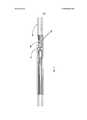
На фиг.1 схематично показан один из вариантов выполнения волоконно-оптического кабеля и оптического коннектора согласно настоящему изобретению, вид в разрезе;Figure 1 schematically shows one embodiment of a fiber optic cable and an optical connector according to the present invention, a sectional view;
на фиг.2 - волоконно-оптический кабель с открытым окном согласно изобретению, вид сверху;figure 2 - fiber optic cable with an open window according to the invention, top view;
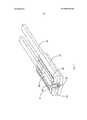
на фиг.3 - волоконно-оптический кабель, показанный на фиг.2, вид в перспективе в разрезе;figure 3 is a fiber optic cable shown in figure 2, a perspective view in section;
на фиг.4 - другой вариант выполнения волоконно-оптического кабеля с открытым окном согласно изобретению, вид сверху;figure 4 is another embodiment of a fiber optic cable with an open window according to the invention, a top view;
на фиг.5 - волоконно-оптический кабель, показанный на фиг.4, вид в перспективе в разрезе;figure 5 is a fiber optic cable shown in figure 4, a perspective view in section;
на фиг.6 - еще один вариант выполнения волоконно-оптического кабеля с открытым окном согласно изобретению, вид сверху;Fig.6 is another embodiment of a fiber optic cable with an open window according to the invention, a top view;
на фиг.7 - волоконно-оптический кабель, показанный на фиг.6, вид в перспективе в разрезе.in Fig.7 is a fiber optic cable shown in Fig.6, a perspective view in section.
Варианты осуществления изобретенияEmbodiments of the invention
На фиг.1 показан первый оптический коннектор 20, соединенный с волоконно-оптическим кабелем 46 и образующий с ним узел 100 соединения в соответствии с настоящим изобретением. Оптический коннектор 20 включает в себя корпус 32, проходящий от дальней стороны 22 до ближней стороны 24 оптического коннектора 20. Оптический коннектор 20 содержит также узел 26 наконечника, установленный рядом с дальней стороной 22 корпуса 32 коннектора. Узел 26 наконечника содержит наконечник 28, гнездо и пружину 31. Узел 26 наконечника установлен, по меньшей мере частично, внутри оптического коннектора 20. Ближняя сторона 24 оптического коннектора 20 служит для размещения, фиксации и защиты волоконно-оптического кабеля 46 от натяжения и изгиба.Figure 1 shows a first
Волоконно-оптический кабель 46 содержит кабельную оболочку 48, которая окружает по меньшей мере один световод 50, закрепленный с помощью средства 51 фиксации. Волоконно-оптический кабель 46 содержит также по меньшей мере один силовой элемент 52, образованный одной или несколькими несущими жилами (например, усиливающими волокнами типа арамидной или кевларовой нити). В некоторых вариантах осуществления изобретения средство 51 фиксации представляет собой любое подходящее устройство, систему или механизм крепления по меньшей мере одного световода 50 либо непосредственно к по меньшей мере одному силовому элементу 52, либо косвенным образом к этому по меньшей мере одному силовому элементу 52 с помощью промежуточной структуры, такой как кабельная оболочка 48. Соответственно, средство 51 фиксации обеспечивает крепление по меньшей мере одного световода 50 к по меньшей мере одному силовому элементу 52. В альтернативном варианте осуществления изобретения средство 51 фиксации представляет собой любое подходящее устройство, систему или механизм для крепления по меньшей мере одного световода 50 к кабельной оболочке 48.Fiber
Например, в месте, где установлено средство 51 фиксации, это средство фиксации предотвращает относительное осевое смещение между по меньшей мере одним силовым элементом 52 и по меньшей мере одним световодом 50. В некоторых вариантах осуществления изобретения, когда по меньшей мере один световод 50 косвенно прикреплен к по меньшей мере одному силовому элементу 52 с помощью средства 51 фиксации, это средство 51 фиксации в месте, где оно установлено, предотвращает осевое смещение между по меньшей мере одним световодом 50, по меньшей мере одним силовым элементом 52 и промежуточной структурой. Соответственно, средство 51 фиксации обеспечивает надежное соединение и надежные оптические характеристики. Предпочтительно средство 51 фиксации устанавливается в месте крепления световода, расположение которого по длине отличается от расположения места сращивания оптических волокон.For example, in the place where the fixing means 51 is installed, this fixing means prevents relative axial displacement between the at least one
На фиг.1-5 показаны варианты выполнения волоконно-оптического кабеля 46. На фиг.1 представлен вариант выполнения волоконно-оптического кабеля 46 с четырьмя световодами 50. В соответствии с изобретением может использоваться любое количество световодов (оптических волокон), например 1, 4, 8, 12 и т.д. Волоконно-оптический кабель 46 содержит также по меньшей мере один силовой элемент 52, образованный одной или несколькими несущими жилами (например, усиливающими волокнами типа арамидной или кевларовой нити). На фиг.1 показан вариант осуществления изобретения с двумя силовыми элементами 52. Следует отметить, что может использоваться любое количество силовых элементов, например 1, 2, 3, 4 и т.д. В некоторых не показанных на чертежах вариантах осуществления изобретения по меньшей мере один силовой элемент 52 может представлять собой усиливающий слой, расположенный вокруг одного световода 50. По меньшей мере один световод 50 по длине волоконно-оптического кабеля 46 проходит через открытое пространство, а по длине оптического коннектора 20 - по волоконному каналу. Дальний конец по меньшей мере одного световода 50 закреплен в наконечнике 28. Более подробную информацию по волоконно-оптическому кабелю можно найти в заявке США №12/607,748, поданной 10 октября 2009 г., которая в полном объеме включена в настоящее описание в качестве ссылки.Figures 1-5 show embodiments of a
Оптический коннектор 20 выполнен таким образом, чтобы его можно было механически соединять с аналогичным оптическим коннектором с помощью переходника. Более подробную информацию по переходнику можно найти в документе US 5214730, включенном в настоящее описание в своем полном объеме в качестве ссылки.The
Как показано на фиг.1, наконечник 28 узла 26 наконечника имеет дальнюю и ближнюю торцевые поверхности. Дальняя торцевая поверхность наконечника 28 расположена снаружи от дальней стороны 22 корпуса 32 коннектора, а ближняя торцевая поверхность - внутри корпуса 32 коннектора. Когда корпус 32 коннектора находится в собранном состоянии, показанном на фиг.1, гнездо наконечника и пружина 31 находятся между дальней и ближней сторонами 22 и 24 корпуса 32 коннектора. При такой конструкции пружина 31 обеспечивает смещение наконечника 28 по направлению к дальней стороне корпуса 32 коннектора. Соответственно, наконечник 28 может перемещаться в осевом направлении относительно оптического коннектора 20 из своего дальнего положения в ближнее положение. Дальнее и ближнее положения наконечника определяют величину осевого смещения AD. Таким образом, перемещение наконечника 28 из дальнего положения в ближнее происходит с преодолением смещающего действия пружины 31. При соединении двух оптических коннекторов 20 дальние торцевые поверхности их наконечников 28 упираются друг в друга, и происходит их смещение в сторону соответствующих корпусов 32 с преодолением при этом смещающего воздействия соответствующих пружин 31. Это смещение происходит в осевом направлении вдоль центральных осей сочлененных оптических коннекторов 20.As shown in FIG. 1, the
По меньшей мере один силовой элемент 52 повышает стойкость волоконно-оптического кабеля 46 к воздействию растягивающей нагрузки. Кроме того, в некоторых вариантах осуществления изобретения по меньшей мере один силовой элемент 52, помимо повышения стойкости волоконно-оптического кабеля 46 к воздействию растягивающей нагрузки, обеспечивает отделение по меньшей мере одного световода 50 от кабельной оболочки 48. Например, между по меньшей мере одним оптическим волокном 50 и кабельной оболочкой 48 может быть расположен по меньшей мере один силовой элемент 52. По меньшей мере один силовой элемент 52 может быть прикреплен к кабельной оболочке 48. В других случаях по меньшей мере один силовой элемент 52 не прикреплен к кабельной оболочке 48 и может скользить внутри этой оболочки 48. Более подробную информацию по силовым элементам можно найти в заявке US 2009/0297104, поданной 28 мая 2009 г. и в полном объеме включенной в настоящее описание в качестве ссылки.At least one
Как указано выше, в некоторых вариантах осуществления изобретения средство 51 фиксации представляет собой любое подходящее устройство, систему или механизм крепления по меньшей мере одного световода 50 к по меньшей мере одному силовому элементу 52. Например, средство 51 фиксации может крепить по меньшей мере один световод 50 к по меньшей мере одному силовому элементу 52 либо непосредственно, либо косвенным образом с помощью промежуточной структуры. В одном из вариантов осуществления изобретения, когда по меньшей мере один силовой элемент 52 крепится к кабельной оболочке 48, средство 51 фиксации крепит по меньшей мере один световод 50 к кабельной оболочке 48 и/или к силовому элементу 52. В другом варианте, когда по меньшей мере один силовой элемент 52 не прикреплен к кабельной оболочке 48, средство 51 фиксации крепит по меньшей мере один световод 50 к по меньшей мере одному силовому элементу 52. Как указано выше, средство 51 фиксации может представлять собой любое подходящее устройство, систему или механизм для крепления по меньшей мере одного световода 50 к кабельной оболочке 48.As indicated above, in some embodiments of the invention, the fixation means 51 is any suitable device, system or mechanism for attaching at least one
Как показано на фиг.1, по меньшей мере один световод 50 проходит через волоконный канал по всей длине оптического коннектора 20. Например, по меньшей мере один световод 50 проходит через корпус 32 коннектора и через наконечник 28. В некоторых случаях часть по меньшей мере одного световода 50, проходящего от наконечника 28 через оптический коннектор 20 к заключенной в оболочку части волоконно-оптического кабеля 46, содержит центральную часть, оболочку и один или несколько защитных слоев. В некоторых случаях часть по меньшей мере одного световода 50, проходящего через наконечник 28, содержит центральную часть и оболочку.As shown in FIG. 1, at least one
Оптический коннектор 20 является устойчивым на растяжение разъемом, в котором по меньшей мере один силовой элемент 52 волоконно-оптического кабеля 46 прикреплен к корпусу 32 коннектора, в результате чего на наконечник 26 не передаются растягивающие нагрузки. Вследствие такой конфигурации смещение наконечника 28 внутрь корпуса 32 коннектора приводит к вдавливанию (смещению) по меньшей мере одного световода 50 внутрь корпуса 32 и оболочки 48 волоконно-оптического кабеля 46. В описанном варианте осуществления изобретения наконечник 28 в процессе соединения может смещаться внутрь корпуса коннектора в осевом направлении на максимальное расстояние AD. Смещение AD в осевом направлении создает избыток длины световода, величина которого равна расстоянию осевого смещения AD.The
По меньшей мере один световод 50 также может быть подверженным влиянию и/или смещаться в результате осевого растяжения, вытягивания, сжатия, укорачивания и/или скручивания оболочки 48 волоконно-оптического кабеля 46.At least one
Без средства 51 фиксации осевое удлинение оболочки 48 может привести к передаче напряжения на один или несколько световодов 50, в результате чего наконечник 28 может втянуться в корпус коннектора, преодолевая действие пружины 31. При втягивании внутрь наконечника 28 может быть нарушено эффективное оптическое соединение с другим оптическим коннектором. В случае многожильного наконечника втягивающее усилие, передаваемое световодами 50 на наконечник 28, может легко преодолеть усилие пружины 31 без превышения предела прочности на разрыв отдельных световодов 50. При отсутствии средства 51 фиксации осевое сжатие/укорочение оболочки 48 вследствие изменения температуры или скручивания кабеля может привести к увеличению длины оптического волокна внутри разъема 20, вызывая тем самым микроизгиб световодов 50 и искажение сигнала.Without the fixing means 51, the axial extension of the
Описанные выше нежелательные смещения наконечника 28 и по меньшей мере одного световода могут быть уменьшены или предотвращены средством 51 фиксации согласно настоящему изобретению. Описанное средство 51 фиксации позволяет создать узел 100 соединения волоконно-оптического кабеля с коннектором, обеспечивающий более надежное соединение и более надежные оптические характеристики, чем использовавшиеся ранее узлы соединения волоконно-оптических кабелей коннектором, в которых не использовалось такое средство фиксации.The undesired displacements of
Как указано выше, в качестве средства 51 фиксации может использоваться любое подходящее устройство, система или механизм крепления по меньшей мере одного световода 50 в волоконно-оптическом кабеле 46. Средство 51 фиксации предотвращает передачу осевых нагрузок по меньшей мере одним световодом 50 в любом направлении на средство 51 фиксации. Предотвращение передачи осевых нагрузок предупреждает любое смещение световода в открытом пространстве волоконно-оптического кабеля 46 на дальний конец по меньшей мере одного световода 50, закрепленного в наконечнике 28. Предотвращение передачи нагрузки также предотвращает передачу через средство 51 фиксации смещения по меньшей мере одного световода 50, вызванного любым осевым смещением наконечника 28.As indicated above, any suitable device, system, or mechanism for attaching at least one
Расположение средства 51 фиксации в волоконно-оптическом кабеле 46 ограничено заданным расстоянием D от ближней стороны 24 корпуса 32 коннектора. Расстояние D является достаточным для компенсации допустимых макроизгибов по меньшей мере одного световода 50 из-за смещения наконечника 28 на величины осевого смещения AD. Кроме того, диаметр волоконно-оптического кабеля 46 является достаточно большим для компенсации избыточной длины по меньшей мере одного световода 50, соответствующей осевому смещению наконечника 28, для компенсации макроизгиба по меньшей мере одного световода 50.The location of the fixation means 51 in the
Например, заданное расстояние D может отмериваться от оптического коннектора 20, если в нем имеется пространство для размещения оптических волокон (см., например, оптический коннектор, раскрытый в заявке US 13/420,286 «Оптический коннектор», претендующей на приоритет относительно предварительной патентной заявки США с номером патентного реестра 02316.3202USP2, и относительно заявки с регистрационным номером No. 61/510,711 с совпадающей датой подачи, которые включены здесь в виде ссылки во всей своей полноте). Однако если в оптическом коннекторе 20 нет пространства для размещения оптических волокон, заданное расстояние D предпочтительно откладывается на самом волоконно-оптическом кабеле, чтобы компенсировать приемлемый макроизгиб по меньшей мере одного световода 50 вследствие осевого смещения AD наконечника 28. В некоторых случаях заданное расстояние D составляет приблизительно от 5 дюймов (12,7 см) до 3 футов (91,44 см). В некоторых случаях заданное расстояние D может составлять приблизительно от 6 дюймов (15,24 см) до 1,5 футов (45,72 см). В других случаях заданное расстояние D может составлять приблизительно от 1 фута (30,48 см) до 2 футов (60,96 см) или приблизительно более 1 фута (30,48 см). В других случаях заданное расстояние D составляет приблизительно от 1,5 дюймов (45,72 см) до 2,5 футов (76,20 см).For example, a predetermined distance D may be measured from the
В качестве средства 51 фиксации может использоваться клей, отверждаемое вещество, и/или закрепляющее вещество, такое как эпоксидная смола. securing medium Клей вводят с помощью иглы сквозь кабельную оболочку 48 в открытое пространство волоконно-оптического кабеля 46. В других вариантах осуществления изобретения кабельную оболочку 48 разрезают, в результате чего образуется открытое окно 60, через которое наносят клей на по меньшей мере один световод 50. В этих случаях открытое окно 60 может быть загерметизировано с помощью термоусадочной пленки, которой покрывают кабельную оболочку 48.As the fixing means 51, an adhesive, a curable material, and / or a fixing agent, such as an epoxy resin, can be used. securing medium The glue is introduced through a
В других вариантах осуществления изобретения средство 51 фиксации представляет собой постоянно деформированную область кабельной оболочки 48, деформирование которой было произведено с помощью горячего пресса с целью фиксации по меньшей мере одного световода 50 внутри волоконно-оптического кабеля 46. В других вариантах осуществления изобретения в качестве средства 51 фиксации может использоваться термоусадочная пленка или гофр, накладываемый на кабельную оболочку 48, чтобы сжать ее и зафиксировать на месте по меньшей мере один световод 50 внутри волоконно-оптического кабеля 46.In other embodiments of the invention, the fixation means 51 is a permanently deformed region of the
В некоторых вариантах осуществления изобретения средство 51 фиксации включает в себя фиксирующее устройство, такое как зажим или замок, прикрепленный к внутренней стороне оболочки 48. Такое фиксирующее устройство может быть размещено, по меньшей мере частично, внутри волоконно-оптического кабеля 46 через открытое окно 60 в оболочке 48. Фиксирующее устройство представляет собой твердотельную структуру, такую как зажим, расположенную, по меньшей мере частично, внутри оболочки 48 и удерживающую по меньшей мере одно оптическое волокно на месте относительно по меньшей мере одного силового элемента 52. Фиксирующее устройство может содержать отжимающий элемент и/или один или несколько зубцов 54, фиксирующих на месте зажим или гофр в открытом пространстве волоконно-оптического кабеля 46. Зубцы 54 предотвращают осевое смещение фиксирующего устройства относительно по меньшей мере одного силового элемента 52. В некоторых вариантах осуществления изобретения в средстве 51 фиксации в дополнение к фиксирующему устройству используется клей. Фиксирующие устройства могут содержать приемники (например, каналы, отверстия, карманы, и т.д.) для размещения световодов 50. Для фиксации световодов 50 в указанных приемниках может использоваться клей. Как указано выше, в некоторых вариантах осуществления изобретения герметизация открытого окна 60 производится с помощью слоя термоусаживающегося материала, нанесенного вокруг волоконно-оптического кабеля 46.In some embodiments, the fixation means 51 includes a fixation device, such as a clip or lock, attached to the inner side of the
На фиг.2, 4, и 6 показаны на виде сверху различные варианты выполнения волоконно-оптического кабеля 46 с открытым окном 60, а на фиг.3, 5 и 7, соответственно, показано то же в перспективе в поперечном разрезе. Как показано на фиг.2, 4 и 6, в открытом окне 60 волоконно-оптического кабеля 46 установлено средство 51 фиксации. На фиг.2, 4, и 6 показаны различные средства 51 фиксации, которые более наглядно представлены на фиг.3, 5, и 7. Например, фиксирующие устройства, показанные на фиг.3, 5 и 7, имеют различные варианты выполнения зажима с одним или несколькими зубцами 54. Зубцы 54 встроены в промежуточную структуру, такую как кабельная оболочка 48, и/или по меньшей мере один силовой элемент 52 с целью фиксации зажима в открытом пространстве внутри волоконно-оптического кабеля 46. В некоторых вариантах осуществления изобретения зажим также содержит отжимающий элемент. В некоторых вариантах осуществления отжимающий элемент зажимает один или несколько зубцов 54 в промежуточной структуре и/или в по меньшей мере одном силовом элементе 52. В других вариантах осуществления изобретения в средстве 51 фиксации также используется клей для фиксации по меньшей мере одного световода 50 внутри волоконно-оптического кабеля.Figures 2, 4, and 6 show, in a plan view, various embodiments of a
Например, зажим, показанный на фиг.2 и 3, имеет открытую часть 56, открывающуюся в сторону открытого окна 60, и пять зубцов 54, встроенных в кабельную оболочку 48.For example, the clip shown in FIGS. 2 and 3 has an
Зажим, показанный на фиг.4 и 5, имеет открытую часть 56, открывающуюся в сторону, противоположную открытому окну 60, и четыре зубца 54, встроенных в кабельную оболочку 48. Зажим, показанный на Фиг.4 и 5, содержит также отжимающий элемент. Этот отжимающий элемент является неотъемлемой частью зажима и смещает или заталкивает изогнутые концы 55 и зубцы 54 внутрь кабельной оболочки 48.The clip shown in FIGS. 4 and 5 has an
Зажим, показанный на фиг.6 и 7, имеет открытую часть 56, открывающуюся в сторону открытого окна 60, и два зубца 54, встроенных в кабельную оболочку 48. Зажим, показанный на фиг.6 и 7, также содержит отжимающий элемент для фиксации зажима и зубцов 54 в кабельной оболочке 48. Кроме того, этот зажим, показанный на фиг.6 и 7, содержит две лапки или отгибаемые пластинки 58 для фиксации зажима в требуемом положении внутри кабельной оболочки 48.The clip shown in FIGS. 6 and 7 has an
Возможны и другие изменения и модификации, очевидные специалистам в данной области техники, которые охватываются сущностью и объемом настоящего изобретения и определяются его формулой. Несмотря на то, что в целях раскрытия сущности настоящего изобретения выше были описаны различные варианты его осуществления, могут быть сделаны и другие различные изменения и модификации, находящиеся в пределах объема данного изобретения.Other changes and modifications are possible, obvious to experts in the given field of technology, which are covered by the essence and scope of the present invention and are determined by its formula. Although various embodiments have been described above to disclose the essence of the present invention, various other changes and modifications can be made that are within the scope of this invention.
Claims (21)
Translated fromRussianоптический коннектор, содержащий корпус, имеющий дальнюю сторону и ближнюю сторону; узел наконечника, включающий в себя наконечник и пружину, причем дальняя торцевая поверхность наконечника расположена на дальней стороне корпуса коннектора, а пружина установлена между дальней и ближней сторонами корпуса разъема с возможностью смещения наконечника относительно корпуса коннектора по направлению к дальней его стороне, так что наконечник может перемещаться в осевом направлении относительно коннектора из своего дальнего положения в ближнее положение, определяя величину своего осевого смещения, причем перемещение наконечника из дальнего положения в сторону ближнего положения происходит с преодолением усилия пружины;
волоконно-оптический кабель, содержащий по меньшей мере один световод, заключенный в кабельную оболочку, и по меньшей мере один силовой элемент для повышения стойкости волоконно-оптического кабеля к воздействию растягивающей нагрузки, причем указанный по меньшей мере один силовой элемент прикреплен к корпусу коннектора рядом с ближней стороной его корпуса, а по меньшей мере один световод проходит по каналу в оптическом коннекторе от ближней стороны его корпуса к наконечнику, и дальняя часть этого по меньшей мере одного световода заделана в наконечнике;
средство фиксации для крепления по меньшей мере одного световода к по меньшей мере одной кабельной оболочке и к по меньшей мере одному силовому элементу.1. A node for connecting a fiber optic cable to a connector, comprising:
an optical connector comprising a housing having a distal side and a proximal side; a tip assembly including a tip and a spring, the far end face of the tip being located on the far side of the connector body, and the spring is installed between the far and near sides of the connector body to bias the tip relative to the connector body toward its far side, so that the tip can to move in the axial direction relative to the connector from its distant position to the near position, determining the magnitude of its axial displacement, From the far position to the near position, the water tank overcomes the spring force;
a fiber optic cable comprising at least one optical fiber enclosed in a cable sheath and at least one power element to increase the resistance of the optical fiber cable to tensile load, said at least one power element being attached to the connector housing adjacent to the proximal side of its body, and at least one fiber passes through the channel in the optical connector from the proximal side of its body to the tip, and the far part of this at least one fiber has touched on at the tip;
fixation means for attaching at least one fiber to at least one cable sheath and to at least one power element.
Applications Claiming Priority (5)
| Application Number | Priority Date | Filing Date | Title |
|---|---|---|---|
| US201161510888P | 2011-07-22 | 2011-07-22 | |
| US61/510,888 | 2011-07-22 | ||
| US201161526996P | 2011-08-24 | 2011-08-24 | |
| US61/526,996 | 2011-08-24 | ||
| PCT/US2012/047402WO2013016135A2 (en) | 2011-07-22 | 2012-07-19 | Fiber optic connector and cable assembly having a fiber locking mechanism |
Publications (2)
| Publication Number | Publication Date |
|---|---|
| RU2014106491A RU2014106491A (en) | 2015-08-27 |
| RU2603237C2true RU2603237C2 (en) | 2016-11-27 |
Family
ID=47601720
Family Applications (1)
| Application Number | Title | Priority Date | Filing Date |
|---|---|---|---|
| RU2014106491/28ARU2603237C2 (en) | 2011-07-22 | 2012-07-19 | Unit of connection of fibre-optic cable with connector having fibre locking means |
Country Status (5)
| Country | Link |
|---|---|
| US (3) | US8864391B2 (en) |
| EP (1) | EP2734881B1 (en) |
| ES (1) | ES2734981T3 (en) |
| RU (1) | RU2603237C2 (en) |
| WO (1) | WO2013016135A2 (en) |
Cited By (1)
| Publication number | Priority date | Publication date | Assignee | Title |
|---|---|---|---|---|
| RU201818U1 (en)* | 2020-06-23 | 2021-01-14 | Общество с ограниченной ответственностью "Медицинские технологии и инновации" | Connector for connecting the catheter light guide to a laser source |
Families Citing this family (12)
| Publication number | Priority date | Publication date | Assignee | Title |
|---|---|---|---|---|
| RU2603237C2 (en) | 2011-07-22 | 2016-11-27 | Адс Телекоммьюникейшнз, Инк. | Unit of connection of fibre-optic cable with connector having fibre locking means |
| EP2737350A1 (en)* | 2011-07-29 | 2014-06-04 | Corning Cable Systems LLC | Fiber optic cable assemblies having a connector with a stable fiber length therein |
| US9829646B2 (en)* | 2013-11-04 | 2017-11-28 | CommScope Connectivity Belgium BVBA | Fiber optic connector having an optical fiber that is axially moveable within a ferrule |
| USD760167S1 (en) | 2014-05-01 | 2016-06-28 | Sonos, Inc. | Electrical plug-in connector |
| WO2016004347A1 (en)* | 2014-07-03 | 2016-01-07 | Adc Telecommunications, Inc. | Optical fiber connector for multi-fiber cable |
| EP3822676A1 (en) | 2015-04-02 | 2021-05-19 | CommScope Technologies LLC | Fiber optic network architecture using high fiber-count fiber optic connectors |
| USD796447S1 (en) | 2015-04-08 | 2017-09-05 | Sonos, Inc. | Power plug |
| EP3593187A4 (en) | 2017-03-07 | 2021-01-13 | CommScope Technologies LLC | System for locking optical fibers within a fiber optic cable |
| GB201707946D0 (en) | 2017-05-17 | 2017-06-28 | Optasense Holdings Ltd | Distributed fibre optic sensing |
| USD854016S1 (en) | 2017-09-28 | 2019-07-16 | Sonos, Inc. | Media plug adapter |
| TWM577968U (en)* | 2019-01-19 | 2019-05-11 | 擎宏電子企業有限公司 | Adapter board structure for power module of DC power supply |
| JP2021117439A (en)* | 2020-01-29 | 2021-08-10 | 株式会社フジクラ | Optical fiber cable and manufacturing method of optical fiber cable |
Family Cites Families (26)
| Publication number | Priority date | Publication date | Assignee | Title |
|---|---|---|---|---|
| ATE93068T1 (en)* | 1988-12-05 | 1993-08-15 | Kupferdraht Isolierwerk Ag | SELF-SUPPORTING OPTICAL CABLE. |
| AU635172B2 (en) | 1991-05-13 | 1993-03-11 | Nippon Telegraph & Telephone Corporation | Multifiber optical connector plug with low reflection and low insertion loss |
| US5673352A (en) | 1996-01-12 | 1997-09-30 | Alcatel Submarine Networks, Inc. | Fiber optic micro cable |
| JPH10311934A (en)* | 1997-05-12 | 1998-11-24 | Kiyousera Elco Kk | Plastic optical fiber connectors |
| US6493491B1 (en) | 1999-09-28 | 2002-12-10 | Alcatel | Optical drop cable for aerial installation |
| US7113679B2 (en) | 2000-05-26 | 2006-09-26 | Corning Cable Systems, Llc | Fiber optic drop cables and preconnectorized assemblies having toning portions |
| US6542674B1 (en) | 2000-08-25 | 2003-04-01 | Corning Cable Systems Llc | Fiber optic cables with strength members |
| US6546175B1 (en) | 2000-05-26 | 2003-04-08 | Corning Cable Systems Llc | Self-supporting fiber optic cable |
| US7090407B2 (en) | 2000-05-26 | 2006-08-15 | Corning Cable Systems Llc | Preconnectorized fiber optic drop cables and assemblies for efficient deployment |
| US6953287B2 (en)* | 2003-11-06 | 2005-10-11 | 3M Innovative Properties Company | Anchor for fiber optic cable |
| US7221831B2 (en)* | 2005-03-03 | 2007-05-22 | Nexans | Multi-tube fiber optic cable and system and method for making the same |
| US7264402B2 (en) | 2005-03-10 | 2007-09-04 | Corning Cable Systems Llc | Multi-fiber optic receptacle and plug assembly |
| US20060291787A1 (en) | 2005-06-27 | 2006-12-28 | Seddon David A | Fiber optic cable having strength component |
| US7463803B2 (en) | 2005-11-14 | 2008-12-09 | Corning Cable Systems Llc | Drop cable with fiber optic connector and methods for fabricating same |
| WO2008021253A2 (en) | 2006-08-14 | 2008-02-21 | Adc Telecommunications, Inc. | Factory spliced cable assembly |
| US7840109B2 (en) | 2006-08-14 | 2010-11-23 | Adc Telecommunications, Inc. | Factory spliced cable assembly |
| US7400814B1 (en) | 2007-01-13 | 2008-07-15 | Furukawa Electric North America, Inc. | Wall-mountable optical fiber and cable management apparatus |
| US7572065B2 (en) | 2007-01-24 | 2009-08-11 | Adc Telecommunications, Inc. | Hardened fiber optic connector |
| US7567741B2 (en)* | 2007-11-26 | 2009-07-28 | Corning Cable Systems Llc | Fiber optic cables and assemblies for fiber toward the subscriber applications |
| US7762726B2 (en) | 2007-12-11 | 2010-07-27 | Adc Telecommunications, Inc. | Hardened fiber optic connection system |
| CN102016669A (en)* | 2008-04-25 | 2011-04-13 | 3M创新有限公司 | Field terminable LC format optical connector with splice element |
| WO2009155037A2 (en) | 2008-05-28 | 2009-12-23 | Adc Telecommunications, Inc. | Fiber optic cable |
| WO2010062646A1 (en) | 2008-10-28 | 2010-06-03 | Adc Telecommunications, Inc. | Flat drop cable |
| US7621675B1 (en) | 2009-02-13 | 2009-11-24 | Ofs Fitel, Llc | Single-piece cable retention housing for hardened outside plant connector |
| US8636425B2 (en) | 2011-03-15 | 2014-01-28 | Adc Telecommunications, Inc. | Fiber optic connector |
| RU2603237C2 (en) | 2011-07-22 | 2016-11-27 | Адс Телекоммьюникейшнз, Инк. | Unit of connection of fibre-optic cable with connector having fibre locking means |
- 2012
- 2012-07-19RURU2014106491/28Apatent/RU2603237C2/ennot_activeIP Right Cessation
- 2012-07-19ESES12817330Tpatent/ES2734981T3/enactiveActive
- 2012-07-19WOPCT/US2012/047402patent/WO2013016135A2/enactiveApplication Filing
- 2012-07-19EPEP12817330.9Apatent/EP2734881B1/enactiveActive
- 2012-07-19USUS13/552,856patent/US8864391B2/ennot_activeExpired - Fee Related
- 2014
- 2014-09-18USUS14/490,219patent/US9500816B2/enactiveActive
- 2016
- 2016-11-16USUS15/353,206patent/US10254495B2/enactiveActive
Cited By (1)
| Publication number | Priority date | Publication date | Assignee | Title |
|---|---|---|---|---|
| RU201818U1 (en)* | 2020-06-23 | 2021-01-14 | Общество с ограниченной ответственностью "Медицинские технологии и инновации" | Connector for connecting the catheter light guide to a laser source |
Also Published As
| Publication number | Publication date |
|---|---|
| US8864391B2 (en) | 2014-10-21 |
| WO2013016135A2 (en) | 2013-01-31 |
| US10254495B2 (en) | 2019-04-09 |
| US20150104134A1 (en) | 2015-04-16 |
| US9500816B2 (en) | 2016-11-22 |
| WO2013016135A3 (en) | 2013-05-02 |
| ES2734981T3 (en) | 2019-12-13 |
| US20170192190A1 (en) | 2017-07-06 |
| EP2734881A4 (en) | 2015-03-25 |
| US20130183005A1 (en) | 2013-07-18 |
| EP2734881A2 (en) | 2014-05-28 |
| EP2734881B1 (en) | 2019-05-08 |
| RU2014106491A (en) | 2015-08-27 |
Similar Documents
| Publication | Publication Date | Title |
|---|---|---|
| RU2603237C2 (en) | Unit of connection of fibre-optic cable with connector having fibre locking means | |
| US9989711B2 (en) | Fiber optic connector and fiber optic cable assembly with fiber optic cable anchored to boot of fiber optic connector | |
| RU2591232C2 (en) | Fibre-optic connector | |
| US20170212313A1 (en) | Fiber optic connector and fiber optic cable assembly with fiber optic cable anchored to boot of fiber optic connector | |
| AU2017234669B2 (en) | Ruggedized female fiber optic connector cable assembly | |
| AU2010321868B2 (en) | Fiber optic cable assembly | |
| RU2611687C2 (en) | Multi-fibre optical connector | |
| CN101317112B (en) | Drop cable with fiber optic connector and methods for fabricating same | |
| ES2710111T3 (en) | Improved traction coating for pulling a fiber optic cable along a conduit | |
| US7537393B2 (en) | Connectorized fiber optic cabling and methods for forming the same | |
| US20160187590A1 (en) | Ruggedized fiber optic connector | |
| WO2008030432A2 (en) | Spliced-on connector system and method, splicer, and connector holder for producing the same | |
| US9664864B2 (en) | Method for terminating high fiber count cables | |
| US11327231B2 (en) | Flexible splice protector assembly and method for preparing same | |
| US20090034916A1 (en) | Fiber optic cable with in-line fiber optic splice | |
| WO2021199736A1 (en) | Housing structure, optical cable with traction end, and production method for housing structure | |
| KR102512811B1 (en) | Field-assembled fiber optic connector | |
| US12055768B2 (en) | Strain relief boot | |
| US7018113B1 (en) | Optical module package | |
| US20240411100A1 (en) | Cable entry transition to a cassette for a fiber optic cable configured to reduce stress on an optical fiber and reduce signal loss | |
| US11340404B2 (en) | Fiber array assembly using a fixing material for securing fiber optic bundles therein | |
| US11226464B2 (en) | Telecommunications fan-out arrangement |
Legal Events
| Date | Code | Title | Description |
|---|---|---|---|
| MM4A | The patent is invalid due to non-payment of fees | Effective date:20180720 |