RU2588005C2 - Optical communication system - Google Patents
Optical communication systemDownload PDFInfo
- Publication number
- RU2588005C2 RU2588005C2RU2014121636/07ARU2014121636ARU2588005C2RU 2588005 C2RU2588005 C2RU 2588005C2RU 2014121636/07 ARU2014121636/07 ARU 2014121636/07ARU 2014121636 ARU2014121636 ARU 2014121636ARU 2588005 C2RU2588005 C2RU 2588005C2
- Authority
- RU
- Russia
- Prior art keywords
- radiation
- optical
- source
- receiver
- communication
- Prior art date
Links
- 230000003287optical effectEffects0.000titleclaimsabstractdescription26
- 238000004891communicationMethods0.000titleclaimsabstractdescription23
- 230000005855radiationEffects0.000claimsabstractdescription57
- 238000000149argon plasma sinteringMethods0.000claimsdescription2
- 230000000694effectsEffects0.000abstract1
- 239000000126substanceSubstances0.000abstract1
- 230000005540biological transmissionEffects0.000description3
- 238000010586diagramMethods0.000description2
- 238000005516engineering processMethods0.000description2
- 238000004519manufacturing processMethods0.000description2
- 238000000034methodMethods0.000description2
- 239000013307optical fiberSubstances0.000description2
- CBENFWSGALASAD-UHFFFAOYSA-NOzoneChemical compound[O-][O+]=OCBENFWSGALASAD-UHFFFAOYSA-N0.000description1
- 239000003990capacitorSubstances0.000description1
- 238000006243chemical reactionMethods0.000description1
- 238000002474experimental methodMethods0.000description1
- 238000005286illuminationMethods0.000description1
- 239000000463materialSubstances0.000description1
- 230000007246mechanismEffects0.000description1
- 238000012545processingMethods0.000description1
- 239000011435rockSubstances0.000description1
- 239000004065semiconductorSubstances0.000description1
- 230000035945sensitivityEffects0.000description1
- 230000005236sound signalEffects0.000description1
- 230000003595spectral effectEffects0.000description1
- 238000012546transferMethods0.000description1
Images
Abstract
Description
Translated fromRussianИзобретение относится к беспроводным системам связи, в частности к системам связи через воздушную среду, и может быть использовано для передачи информации на пересеченной местности.The invention relates to wireless communication systems, in particular to communication systems through the air, and can be used to transmit information on rough terrain.
Из уровня техники известен источник информации, в котором достаточно полно изложены все вопросы, относящиеся к оптическим системам передачи информации. В книге приведена обобщенная схема оптического канала, рассмотрены особенности распространения оптического излучения и механизмы потерь в оптических волокнах. Описаны методы изготовления оптических волокон. Рассмотрен принцип действия и основные характеристики полупроводниковых лазеров и фотоприемников различных типов (см. Гауэр Дж. оптические системы связи. М.: Радио и связь, 1989, с. 423-424).The source of information is known from the prior art, in which all issues related to optical information transmission systems are fairly fully stated. The book gives a generalized diagram of the optical channel, considers the features of the propagation of optical radiation and the loss mechanisms in optical fibers. The methods for manufacturing optical fibers are described. The principle of operation and the main characteristics of semiconductor lasers and photodetectors of various types are considered (see Gower, J. Optical Communication Systems. M: Radio and Communication, 1989, pp. 423-424).
В патенте РФ №2380834, опубликованном 27.01.2010 по индексу МПК H04B 10/00, заявлены «Способ лазерной космической связи и комплекс для его осуществления».In the patent of the Russian Federation No. 2380834, published on January 27, 2010 according to the IPC index H04B 10/00, "The method of laser space communication and a complex for its implementation" are declared.
Данное изобретение относится к области космической лазерной связи и лазерной техники и предназначено для создания комплексов стационарной лазерной космической связи в ближнем космосе и дальнем космосе и в пределах всей солнечной системы. Техническим результатом является повышение дальности действия лазерной космической связи, увеличение объемов и скорости передачи информации между космическими аппаратами и наземными станциями в пределах солнечной системы. Для этого определяют доплеровский сдвиг частоты лазерного излучения от базовой части комплекса лазерной космической связи при его приеме в бортовой части комплекса, осуществляют сдвиг оптической частоты лазерного излучения в базовой части комплекса на отрицательную величину измеренного доплеровского сдвига, осуществляют квантовое усиление лазерного излучения и измерение сдвига его оптической частоты в бортовой части комплекса, а также сдвиг центральной частоты полосы приема и квантового усиления в бортовой и базовой частях комплекса, определяют параметры качества установленной лазерной космической связи, осуществляют генерацию лазерного излучения, прием и квантовое усиление сигналов лазерной связи с установленными сдвигами оптических частот.This invention relates to the field of space laser communication and laser technology and is intended to create complexes of stationary laser space communication in near space and deep space and throughout the solar system. The technical result is an increase in the range of laser space communications, an increase in the volume and speed of information transfer between spacecraft and ground stations within the solar system. To do this, determine the Doppler frequency shift of the laser radiation from the base part of the laser-space communication complex when it is received on the side of the complex, shift the optical frequency of the laser radiation in the base part of the complex by a negative value of the measured Doppler shift, quantum amplify the laser radiation and measure the shift of its optical frequency in the onboard part of the complex, as well as a shift in the center frequency of the reception band and quantum gain in the onboard and base parts of the complex ca determine quality parameters set space laser communication, generating a laser radiation, and the quantum receiving gain laser communication signals defined optical frequency shifts.
В данном случае речь идет о двусторонней связи между двумя независимо перемещающимися и удаленными приемно-передающими системами, оптические оси которых должны быть полностью совмещены в момент передачи информации. Указанные в примере зеркала частично соединяют оси приемника и передатчика, но внутри каждого приемо-передающего блока. Целью такого соединения не является передача внутри блока информации, предназначенной другому удаленному приемопередатчику. Этот внутренний канал предназначен для совместной калибровки по несущей частоте приемного и передающего каналов блока. Здесь идет речь о пересечении оптических осей внутри устройства.In this case, we are talking about two-way communication between two independently moving and remote receiving and transmitting systems, the optical axes of which must be fully aligned at the time of transmission of information. The mirrors indicated in the example partially connect the axes of the receiver and the transmitter, but inside each transceiver unit. The purpose of such a connection is not to transmit within the block information intended for another remote transceiver. This internal channel is designed for joint calibration on the carrier frequency of the receiving and transmitting channels of the unit. Here we are talking about the intersection of the optical axes inside the device.
Наиболее близкой к предлагаемому и выбранной в качестве прототипа является система оптической связи, содержащая разнесенные в пространстве источник направленного излучения, приемник излучения и устройства кодировки излучения и дешифровки сигнала с приемника, описанная в первом источнике информации - Гауэр Дж. Оптические системы связи. М.: Радио и связь, 1989, с. 423-424.Closest to the proposed and selected as a prototype is an optical communication system containing a spaced-apart source of directional radiation, a radiation receiver and a device for encoding radiation and decrypting the signal from the receiver, described in the first information source - Gower J. Optical communication systems. M .: Radio and communications, 1989, p. 423-424.
Источник излучения и приемник расположены на одной оптической оси. Источником излучения служит лазерный диод или лазерный источник в ИК-области. Приемник излучения - обычно, фотодиод. Источник излучения управляется устройством кодировки, формирующим амплитудную и частотную характеристики излучения. Промодулированное излучение через воздушную среду направляется на приемник излучения, который преобразует поступившее излучение в электрический сигнал. Устройство дешифровки восстанавливает передаваемую информацию путем обработки электрического сигнала.The radiation source and receiver are located on the same optical axis. The radiation source is a laser diode or a laser source in the infrared region. The radiation receiver is usually a photodiode. The radiation source is controlled by an encoding device forming the amplitude and frequency characteristics of the radiation. Modulated radiation through the air is sent to a radiation receiver, which converts the incoming radiation into an electrical signal. The decryption device restores the transmitted information by processing the electrical signal.
Основным недостатком этого устройства является то, что любое непрозрачное препятствие на пути излучения от источника к приемнику делает невозможным передачу информации, т.е. оно не пригодно к использованию на пересеченной местности, когда на пути излучения находятся дома, скалы или другие объекты.The main disadvantage of this device is that any opaque obstacle to the radiation from the source to the receiver makes it impossible to transmit information, i.e. it is not suitable for use on rough terrain when there are houses, rocks or other objects in the path of radiation.
Задачей нового изобретения является обеспечение возможности передачи информации с помощью оптического излучения в условиях пересеченной местности.The objective of the new invention is to provide the possibility of transmitting information using optical radiation in rough terrain.
Поставленная цель достигается в системе оптической связи, содержащей разнесенные в пространстве независимо перемещающиеся источник направленного излучения и приемник излучения, устройство кодировки излучения и устройство дешифровки сигнала с приемника излучения, в которой, в отличие от прототипа, источник направленного излучения и приемник излучения расположены на пересекающихся оптических осях, при этом зона пересечения оптических осей сопряжена с внешним отражающим или светорассеивающим объектом.The goal is achieved in an optical communication system containing spaced apart independently moving source of directional radiation and a radiation receiver, a radiation encoding device and a signal decoding device from a radiation receiver, in which, unlike the prototype, the directional radiation source and radiation receiver are located on intersecting optical axes, while the zone of intersection of the optical axes is conjugated with an external reflecting or light-scattering object.
Источником направленного излучения может служить лазер с длиной волны излучения в диапазоне 220-280 нм.A source of directional radiation can serve as a laser with a wavelength of radiation in the range of 220-280 nm.
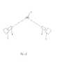
На чертеже изображена схема предлагаемого устройства, включающая:The drawing shows a diagram of the proposed device, including:
1. Источник направленного излучения.1. A source of directional radiation.
2. Устройство кодировки излучения.2. Radiation coding device.
3. Приемник излучения.3. The radiation receiver.
4. Устройство дешифровки сигнала.4. Signal decryption device.
5. Внешний объект.5. External object.
Устройство работает следующим образом:The device operates as follows:
Излучение источника направленного излучения 1 модулируется по амплитуде и частоте устройством кодировки излучения 2 и направляется на некий внешний объект 5 (например, стену здания). Часть излучения отражается или рассеивается этим объектом.The radiation from the directional radiation source 1 is modulated in amplitude and frequency by the
На этот же объект 5 направляется приемник излучения 3. Часть отраженного или рассеянного излучения регистрируется приемником 3 и дешифруется в устройстве дешифровки сигнала 4 для восстановления передаваемой информации.A
Пример реализации и использования:An example of implementation and use:
В качестве источника направленного излучения 1 использовали частотный лазер с длиной волны излучения 455 нм и полезной мощностью 1 Вт. Приемник оптического излучения 3 состоял из собирающего конденсора, диаметром 50 мм и фокусным расстоянием 80 мм и фотодиода. Устройство кодировки излучения 2 состояло из кодирующей микросхемы и ТТЛ (транзисторно-транзисторная логика). Устройство дешифровки сигнала 4 состояло из декодирующей микросхемы.As a source of directional radiation 1, a frequency laser with a radiation wavelength of 455 nm and a useful power of 1 W was used. The
В эксперименте аналоговый звуковой сигнал (человеческая речь) оцифровывался с помощью цифрового микрофона и подавался на устройство кодировки излучения 2, в котором кодирующие микросхемы осуществляли сжатие сигнала до уровня 10 кбит/с и, посредством ТТЛ модулировалась интенсивность излучения от источника направленного излучения 1. Частота следования световых импульсов составляла 15 кГц.In the experiment, an analog sound signal (human speech) was digitized using a digital microphone and supplied to
Внешним объектом 5 служила стена дома. Рассеянное от объекта 5 излучение частично попадало на приемник излучения 3, преобразовывалось в электрический сигнал, который поступал в устройство дешифровки сигнала 4. Там с помощью декодирующей микросхемы осуществлялось цифроаналоговое преобразование сигнала. Преобразованный сигнал можно было прослушать мультимедийным устройством (наушниками).
Экспериментально удалось передать человеческую речь на расстояние до 50 м.It was experimentally possible to transmit human speech to a distance of 50 m.
В дальнейшем предполагается усовершенствовать систему, применив лазер в диапазоне 220-280 нм. В этом спектральном диапазоне все солнечное излучение поглощается озоновым слоем в верхних слоях атмосферы, таким образом, уменьшается фоновая засветка приемника и повышается чувствительность системы.In the future, it is planned to improve the system by using a laser in the range of 220-280 nm. In this spectral range, all solar radiation is absorbed by the ozone layer in the upper atmosphere, thus reducing the background illumination of the receiver and increasing the sensitivity of the system.
Преимуществом заявленного устройства по сравнению с прототипом является то, что, в отличие от прототипа, заявленное устройство позволяет передавать информацию на пересеченной местности, когда прямой прием излучения невозможен.The advantage of the claimed device compared to the prototype is that, unlike the prototype, the claimed device allows you to transmit information on rough terrain when direct reception of radiation is impossible.
Представленные чертеж и описание позволяют, используя существующие материалы и технологии, изготовить предлагаемое устройство промышленным способом и использовать его для оптической передачи информации на пересеченной местности.The presented drawing and description allow, using existing materials and technologies, to manufacture the proposed device in an industrial way and use it for optical transmission of information on rough terrain.
Claims (1)
Translated fromRussianPriority Applications (1)
| Application Number | Priority Date | Filing Date | Title |
|---|---|---|---|
| RU2014121636/07ARU2588005C2 (en) | 2014-05-27 | Optical communication system |
Applications Claiming Priority (1)
| Application Number | Priority Date | Filing Date | Title |
|---|---|---|---|
| RU2014121636/07ARU2588005C2 (en) | 2014-05-27 | Optical communication system |
Publications (2)
| Publication Number | Publication Date |
|---|---|
| RU2014121636A RU2014121636A (en) | 2015-12-10 |
| RU2588005C2true RU2588005C2 (en) | 2016-06-27 |
Family
ID=
Citations (5)
| Publication number | Priority date | Publication date | Assignee | Title |
|---|---|---|---|---|
| GB2180116A (en)* | 1985-08-29 | 1987-03-18 | Johnson Service Co | Data telemetry system using diffused infrared light |
| US5909296A (en)* | 1997-04-04 | 1999-06-01 | The United States Of America As Represented By The Secretary Of The Air Force | Effective wide angle beam steering using spherical laser diode arrays |
| RU41397U1 (en)* | 2004-08-03 | 2004-10-20 | Общество с ограниченной ответственностью "Подсолнечник Технологии" | OPEN OPTICAL COMMUNICATION TERMINAL |
| RU2264691C2 (en)* | 2003-06-04 | 2005-11-20 | Меклин Интерпрайзез Лимитед | Open optical communication system |
| RU2346393C1 (en)* | 2007-06-29 | 2009-02-10 | Валерий Валерианович Рагульский | Terminal for clear optical communication |
Patent Citations (5)
| Publication number | Priority date | Publication date | Assignee | Title |
|---|---|---|---|---|
| GB2180116A (en)* | 1985-08-29 | 1987-03-18 | Johnson Service Co | Data telemetry system using diffused infrared light |
| US5909296A (en)* | 1997-04-04 | 1999-06-01 | The United States Of America As Represented By The Secretary Of The Air Force | Effective wide angle beam steering using spherical laser diode arrays |
| RU2264691C2 (en)* | 2003-06-04 | 2005-11-20 | Меклин Интерпрайзез Лимитед | Open optical communication system |
| RU41397U1 (en)* | 2004-08-03 | 2004-10-20 | Общество с ограниченной ответственностью "Подсолнечник Технологии" | OPEN OPTICAL COMMUNICATION TERMINAL |
| RU2346393C1 (en)* | 2007-06-29 | 2009-02-10 | Валерий Валерианович Рагульский | Terminal for clear optical communication |
Similar Documents
| Publication | Publication Date | Title |
|---|---|---|
| Kaushal et al. | Underwater optical wireless communication | |
| CN101656574B (en) | Portable wireless laser communication terminal machine | |
| Wang et al. | Experimental demonstration of indoor infrared optical wireless communications with a silicon photonic integrated circuit | |
| EP2883081A2 (en) | Friend or foe identification system and method | |
| CN1593028A (en) | Free-space optical communication system employing wavelength conversion | |
| CN106253993B (en) | A kind of long-range Terahertz communication system | |
| CN201048380Y (en) | Free atmosphere ultraviolet communication machine | |
| Kaur et al. | Performance analysis of inter-satellite optical wireless communication (IsOWC) system at 980 nm and 1550 nm wavelengths | |
| Malathy et al. | Modeling and performance investigation of 4× 20 Gbps underwater optical wireless communication link incorporating space division multiplexing of Hermite Gaussian modes | |
| Sharma et al. | Modeling of 2.5 Gbps-intersatellite link (ISL) in inter-satellite optical wireless communication (IsOWC) system | |
| CN102017470A (en) | Wireless data transmission using terahertz waves | |
| Spagnolo et al. | A brief survey on underwater optical wireless communications | |
| RU2588005C2 (en) | Optical communication system | |
| Leccese et al. | State-of-the art and perspectives of underwater optical wireless communications | |
| Parand et al. | Cellular tracked optical wireless demonstration link | |
| Hiruta et al. | A study on optical wireless train communication system using mobile object tracking technique | |
| Mendez et al. | A comparative study of underwater wireless optical communication for three different communication links | |
| Trisno et al. | Theoretical and experimental characterization of omnidirectional optical links for free space optical communications | |
| Leeson et al. | Optical wireless and millimeter waves for 5g access networks | |
| TW201801486A (en) | Optical fiber laser transmission system with laser light splitting device | |
| Мельник et al. | A Model of a Free-Space Optical Communication Line with a Smart Reflector | |
| O'Brien et al. | Building a quantum wireless network | |
| WO2020180392A3 (en) | Methods and apparatus for acoustic laser communications | |
| Mendez et al. | Design of Underwater wireless optical/acoustic link for reduction of back-scattering of transmitted light | |
| Singh et al. | Free Space Optical Communication: A Study |