RU2587307C2 - Surgical suturing instrument with variable system for forming staples - Google Patents
Surgical suturing instrument with variable system for forming staplesDownload PDFInfo
- Publication number
- RU2587307C2 RU2587307C2RU2013119984/14ARU2013119984ARU2587307C2RU 2587307 C2RU2587307 C2RU 2587307C2RU 2013119984/14 ARU2013119984/14 ARU 2013119984/14ARU 2013119984 ARU2013119984 ARU 2013119984ARU 2587307 C2RU2587307 C2RU 2587307C2
- Authority
- RU
- Russia
- Prior art keywords
- brackets
- cassette
- thrust plate
- distal
- trigger
- Prior art date
Links
- 238000005520cutting processMethods0.000claimsabstractdescription127
- 238000003825pressingMethods0.000claimsabstractdescription32
- 230000015572biosynthetic processEffects0.000claimsabstractdescription25
- 230000004044responseEffects0.000claimsdescription8
- 239000000126substanceSubstances0.000abstractdescription6
- 230000000694effectsEffects0.000abstractdescription4
- 239000010410layerSubstances0.000description566
- 239000011159matrix materialSubstances0.000description325
- 239000000463materialSubstances0.000description163
- 239000004744fabricSubstances0.000description118
- 229920000954PolyglycolidePolymers0.000description67
- 239000004633polyglycolic acidSubstances0.000description67
- 230000036961partial effectEffects0.000description63
- 230000033001locomotionEffects0.000description57
- 238000000034methodMethods0.000description47
- 229920001610polycaprolactonePolymers0.000description46
- 239000004632polycaprolactoneSubstances0.000description46
- 239000003814drugSubstances0.000description45
- 229940079593drugDrugs0.000description43
- 239000005014poly(hydroxyalkanoate)Substances0.000description42
- 238000013461designMethods0.000description40
- 230000006835compressionEffects0.000description33
- 238000007906compressionMethods0.000description33
- 229920000903polyhydroxyalkanoatePolymers0.000description31
- 238000010586diagramMethods0.000description30
- 239000010935stainless steelSubstances0.000description27
- 229910001220stainless steelInorganic materials0.000description27
- 229920003023plasticPolymers0.000description24
- 239000004033plasticSubstances0.000description24
- 229920002463poly(p-dioxanone) polymerPolymers0.000description24
- 239000000622polydioxanoneSubstances0.000description24
- 230000008569processEffects0.000description24
- 230000001681protective effectEffects0.000description24
- 210000003128headAnatomy0.000description22
- RTAQQCXQSZGOHL-UHFFFAOYSA-NTitaniumChemical compound[Ti]RTAQQCXQSZGOHL-UHFFFAOYSA-N0.000description21
- 239000010936titaniumSubstances0.000description21
- 239000007767bonding agentSubstances0.000description16
- 239000002775capsuleSubstances0.000description16
- 229910052719titaniumInorganic materials0.000description16
- 238000004519manufacturing processMethods0.000description15
- LCSKNASZPVZHEG-UHFFFAOYSA-N3,6-dimethyl-1,4-dioxane-2,5-dione;1,4-dioxane-2,5-dioneChemical groupO=C1COC(=O)CO1.CC1OC(=O)C(C)OC1=OLCSKNASZPVZHEG-UHFFFAOYSA-N0.000description14
- 229910052751metalInorganic materials0.000description14
- 239000002184metalSubstances0.000description14
- 230000007423decreaseEffects0.000description13
- 239000006260foamSubstances0.000description13
- 238000009434installationMethods0.000description13
- 229920000747poly(lactic acid)Polymers0.000description13
- 239000004626polylactic acidSubstances0.000description13
- 230000002829reductive effectEffects0.000description13
- 102000009123FibrinHuman genes0.000description12
- 108010073385FibrinProteins0.000description12
- BWGVNKXGVNDBDI-UHFFFAOYSA-NFibrin monomerChemical compoundCNC(=O)CNC(=O)CNBWGVNKXGVNDBDI-UHFFFAOYSA-N0.000description12
- 230000009471actionEffects0.000description12
- 239000002131composite materialSubstances0.000description12
- 229950003499fibrinDrugs0.000description12
- 230000002439hemostatic effectEffects0.000description12
- 229920000642polymerPolymers0.000description12
- 239000006261foam materialSubstances0.000description11
- 108090000623proteins and genesProteins0.000description11
- 102000004169proteins and genesHuman genes0.000description11
- 230000001225therapeutic effectEffects0.000description11
- 239000000017hydrogelSubstances0.000description10
- JVTAAEKCZFNVCJ-UHFFFAOYSA-Nlactic acidChemical compoundCC(O)C(O)=OJVTAAEKCZFNVCJ-UHFFFAOYSA-N0.000description10
- 239000000203mixtureSubstances0.000description10
- 239000000853adhesiveSubstances0.000description9
- 230000001070adhesive effectEffects0.000description9
- 230000008901benefitEffects0.000description9
- 238000005452bendingMethods0.000description8
- 230000005540biological transmissionEffects0.000description8
- 230000014759maintenance of locationEffects0.000description8
- 230000000149penetrating effectEffects0.000description8
- 239000004677NylonSubstances0.000description7
- 239000001913celluloseSubstances0.000description7
- 229920002678cellulosePolymers0.000description7
- 238000002513implantationMethods0.000description7
- 229920001778nylonPolymers0.000description7
- 239000000758substrateSubstances0.000description7
- 238000001356surgical procedureMethods0.000description7
- 238000003466weldingMethods0.000description7
- 230000004913activationEffects0.000description6
- 230000000740bleeding effectEffects0.000description6
- 238000006073displacement reactionMethods0.000description6
- 239000013013elastic materialSubstances0.000description6
- 238000011049fillingMethods0.000description6
- 239000004417polycarbonateSubstances0.000description6
- 229920000515polycarbonatePolymers0.000description6
- 229920001296polysiloxanePolymers0.000description6
- 238000012546transferMethods0.000description6
- 229910001200FerrotitaniumInorganic materials0.000description5
- PEDCQBHIVMGVHV-UHFFFAOYSA-NGlycerineChemical compoundOCC(O)COPEDCQBHIVMGVHV-UHFFFAOYSA-N0.000description5
- 238000001746injection mouldingMethods0.000description5
- 238000003780insertionMethods0.000description5
- 230000037431insertionEffects0.000description5
- 235000014655lactic acidNutrition0.000description5
- 239000004310lactic acidSubstances0.000description5
- 229920001643poly(ether ketone)Polymers0.000description5
- 239000011148porous materialSubstances0.000description5
- BQCADISMDOOEFD-UHFFFAOYSA-NSilverChemical compound[Ag]BQCADISMDOOEFD-UHFFFAOYSA-N0.000description4
- 108090000190ThrombinProteins0.000description4
- XEFQLINVKFYRCS-UHFFFAOYSA-NTriclosanChemical compoundOC1=CC(Cl)=CC=C1OC1=CC=C(Cl)C=C1ClXEFQLINVKFYRCS-UHFFFAOYSA-N0.000description4
- 239000004676acrylonitrile butadiene styreneSubstances0.000description4
- 239000011248coating agentSubstances0.000description4
- 238000000576coating methodMethods0.000description4
- 238000002224dissectionMethods0.000description4
- 229920001971elastomerPolymers0.000description4
- 239000013536elastomeric materialSubstances0.000description4
- 230000006870functionEffects0.000description4
- 239000011521glassSubstances0.000description4
- 230000003993interactionEffects0.000description4
- 239000007788liquidSubstances0.000description4
- 230000007246mechanismEffects0.000description4
- 230000007935neutral effectEffects0.000description4
- 229960004072thrombinDrugs0.000description4
- 229960003500triclosanDrugs0.000description4
- 230000037303wrinklesEffects0.000description4
- 229910000831SteelInorganic materials0.000description3
- 229940030225antihemorrhagicsDrugs0.000description3
- 239000004599antimicrobialSubstances0.000description3
- 230000000903blocking effectEffects0.000description3
- 238000004140cleaningMethods0.000description3
- 239000012530fluidSubstances0.000description3
- -1for exampleSubstances0.000description3
- 230000014509gene expressionEffects0.000description3
- 239000003292glueSubstances0.000description3
- 239000002874hemostatic agentSubstances0.000description3
- 238000002347injectionMethods0.000description3
- 239000007924injectionSubstances0.000description3
- 238000002483medicationMethods0.000description3
- 230000004048modificationEffects0.000description3
- 238000012986modificationMethods0.000description3
- 230000005855radiationEffects0.000description3
- 239000005060rubberSubstances0.000description3
- 229940116351sebacateDrugs0.000description3
- CXMXRPHRNRROMY-UHFFFAOYSA-Lsebacate(2-)Chemical compound[O-]C(=O)CCCCCCCCC([O-])=OCXMXRPHRNRROMY-UHFFFAOYSA-L0.000description3
- 230000035807sensationEffects0.000description3
- 238000000926separation methodMethods0.000description3
- 230000000087stabilizing effectEffects0.000description3
- 239000010959steelSubstances0.000description3
- XLYOFNOQVPJJNP-UHFFFAOYSA-NwaterSubstancesOXLYOFNOQVPJJNP-UHFFFAOYSA-N0.000description3
- OKTJSMMVPCPJKN-UHFFFAOYSA-NCarbonChemical compound[C]OKTJSMMVPCPJKN-UHFFFAOYSA-N0.000description2
- 102000008186CollagenHuman genes0.000description2
- 108010035532CollagenProteins0.000description2
- 239000004743PolypropyleneSubstances0.000description2
- PPBRXRYQALVLMV-UHFFFAOYSA-NStyreneChemical compoundC=CC1=CC=CC=C1PPBRXRYQALVLMV-UHFFFAOYSA-N0.000description2
- 229920004738ULTEM®Polymers0.000description2
- 238000004026adhesive bondingMethods0.000description2
- 229920000704biodegradable plasticPolymers0.000description2
- 239000008280bloodSubstances0.000description2
- 210000004369bloodAnatomy0.000description2
- 238000005219brazingMethods0.000description2
- 229910052799carbonInorganic materials0.000description2
- 229910010293ceramic materialInorganic materials0.000description2
- 230000008859changeEffects0.000description2
- 229920001436collagenPolymers0.000description2
- 238000010276constructionMethods0.000description2
- 230000003247decreasing effectEffects0.000description2
- 230000005489elastic deformationEffects0.000description2
- 238000001125extrusionMethods0.000description2
- 235000011187glycerolNutrition0.000description2
- 238000000227grindingMethods0.000description2
- 238000010438heat treatmentMethods0.000description2
- 230000023597hemostasisEffects0.000description2
- 239000007943implantSubstances0.000description2
- 230000000670limiting effectEffects0.000description2
- 238000011068loading methodMethods0.000description2
- 230000013011matingEffects0.000description2
- 239000007769metal materialSubstances0.000description2
- 239000002991molded plasticSubstances0.000description2
- 238000000465mouldingMethods0.000description2
- 229920001155polypropylenePolymers0.000description2
- 230000002028prematureEffects0.000description2
- 239000011241protective layerSubstances0.000description2
- 238000011084recoveryMethods0.000description2
- 239000004627regenerated celluloseSubstances0.000description2
- 238000009958sewingMethods0.000description2
- 229910052709silverInorganic materials0.000description2
- 239000004332silverSubstances0.000description2
- 125000006850spacer groupChemical group0.000description2
- 238000011477surgical interventionMethods0.000description2
- 239000011800void materialSubstances0.000description2
- 230000003313weakening effectEffects0.000description2
- 229910000838Al alloyInorganic materials0.000description1
- 241000894006BacteriaSpecies0.000description1
- 229920000049Carbon (fiber)Polymers0.000description1
- 229920001651CyanoacrylatePolymers0.000description1
- 240000001624Espostoa lanataSpecies0.000description1
- 235000009161Espostoa lanataNutrition0.000description1
- 108010010803GelatinProteins0.000description1
- 244000043261Hevea brasiliensisSpecies0.000description1
- 229920000106Liquid crystal polymerPolymers0.000description1
- 239000004977Liquid-crystal polymers (LCPs)Substances0.000description1
- MWCLLHOVUTZFKS-UHFFFAOYSA-NMethyl cyanoacrylateChemical compoundCOC(=O)C(=C)C#NMWCLLHOVUTZFKS-UHFFFAOYSA-N0.000description1
- 229920002292Nylon 6Polymers0.000description1
- 229920002302Nylon 6,6Polymers0.000description1
- 239000002033PVDF binderSubstances0.000description1
- 240000000220Panda oleosaSpecies0.000description1
- 235000016496Panda oleosaNutrition0.000description1
- 239000004696Poly ether ether ketoneSubstances0.000description1
- 239000004792ProleneSubstances0.000description1
- FAPWRFPIFSIZLT-UHFFFAOYSA-MSodium chlorideChemical compound[Na+].[Cl-]FAPWRFPIFSIZLT-UHFFFAOYSA-M0.000description1
- 244000019194Sorbus aucupariaSpecies0.000description1
- 244000269722Thea sinensisSpecies0.000description1
- 229910001069Ti alloyInorganic materials0.000description1
- 239000004775TyvekSubstances0.000description1
- 229920000690TyvekPolymers0.000description1
- 230000002745absorbentEffects0.000description1
- 239000002250absorbentSubstances0.000description1
- 239000002253acidSubstances0.000description1
- 150000007513acidsChemical class0.000description1
- XECAHXYUAAWDEL-UHFFFAOYSA-Nacrylonitrile butadiene styreneChemical compoundC=CC=C.C=CC#N.C=CC1=CC=CC=C1XECAHXYUAAWDEL-UHFFFAOYSA-N0.000description1
- 229920000122acrylonitrile butadiene styrenePolymers0.000description1
- 125000001931aliphatic groupChemical group0.000description1
- 229910045601alloyInorganic materials0.000description1
- 239000000956alloySubstances0.000description1
- WYTGDNHDOZPMIW-RCBQFDQVSA-NalstonineNatural productsC1=CC2=C3C=CC=CC3=NC2=C2N1C[C@H]1[C@H](C)OC=C(C(=O)OC)[C@H]1C2WYTGDNHDOZPMIW-RCBQFDQVSA-N0.000description1
- 229910052782aluminiumInorganic materials0.000description1
- XAGFODPZIPBFFR-UHFFFAOYSA-NaluminiumChemical compound[Al]XAGFODPZIPBFFR-UHFFFAOYSA-N0.000description1
- 239000003242anti bacterial agentSubstances0.000description1
- 230000000845anti-microbial effectEffects0.000description1
- 238000013459approachMethods0.000description1
- 230000003115biocidal effectEffects0.000description1
- 239000000560biocompatible materialSubstances0.000description1
- 210000001124body fluidAnatomy0.000description1
- 239000010839body fluidSubstances0.000description1
- 239000004917carbon fiberSubstances0.000description1
- 238000004891communicationMethods0.000description1
- 238000012790confirmationMethods0.000description1
- 239000000470constituentSubstances0.000description1
- 230000008878couplingEffects0.000description1
- 238000010168coupling processMethods0.000description1
- 238000005859coupling reactionMethods0.000description1
- 230000001186cumulative effectEffects0.000description1
- 229920006238degradable plasticPolymers0.000description1
- 230000000994depressogenic effectEffects0.000description1
- 229940066220doctor's choiceDrugs0.000description1
- 239000012636effectorSubstances0.000description1
- 239000000806elastomerSubstances0.000description1
- 238000002674endoscopic surgeryMethods0.000description1
- 238000005516engineering processMethods0.000description1
- 210000000887faceAnatomy0.000description1
- 239000000835fiberSubstances0.000description1
- 239000000945fillerSubstances0.000description1
- 229920002457flexible plasticPolymers0.000description1
- 239000008273gelatinSubstances0.000description1
- 229920000159gelatinPolymers0.000description1
- 235000019322gelatineNutrition0.000description1
- 235000011852gelatine dessertsNutrition0.000description1
- 238000001415gene therapyMethods0.000description1
- 230000035876healingEffects0.000description1
- 230000006872improvementEffects0.000description1
- 238000010348incorporationMethods0.000description1
- 238000007373indentationMethods0.000description1
- 208000015181infectious diseaseDiseases0.000description1
- 229910052500inorganic mineralInorganic materials0.000description1
- 238000011900installation processMethods0.000description1
- 235000000396ironNutrition0.000description1
- 238000005304joiningMethods0.000description1
- 230000007774longtermEffects0.000description1
- 239000012528membraneSubstances0.000description1
- VNWKTOKETHGBQD-UHFFFAOYSA-NmethaneChemical compoundCVNWKTOKETHGBQD-UHFFFAOYSA-N0.000description1
- 239000008267milkSubstances0.000description1
- 210000004080milkAnatomy0.000description1
- 235000013336milkNutrition0.000description1
- 239000011707mineralSubstances0.000description1
- 235000010755mineralNutrition0.000description1
- 229920003052natural elastomerPolymers0.000description1
- 229920001194natural rubberPolymers0.000description1
- HLXZNVUGXRDIFK-UHFFFAOYSA-Nnickel titaniumChemical compound[Ti].[Ti].[Ti].[Ti].[Ti].[Ti].[Ti].[Ti].[Ti].[Ti].[Ti].[Ni].[Ni].[Ni].[Ni].[Ni].[Ni].[Ni].[Ni].[Ni].[Ni].[Ni].[Ni].[Ni].[Ni]HLXZNVUGXRDIFK-UHFFFAOYSA-N0.000description1
- 229910001000nickel titaniumInorganic materials0.000description1
- 229920006284nylon filmPolymers0.000description1
- 210000000056organAnatomy0.000description1
- 230000035515penetrationEffects0.000description1
- 230000002085persistent effectEffects0.000description1
- 239000002985plastic filmSubstances0.000description1
- 229920000728polyesterPolymers0.000description1
- 229920002530polyetherether ketonePolymers0.000description1
- 229920000139polyethylene terephthalatePolymers0.000description1
- 239000005020polyethylene terephthalateSubstances0.000description1
- 229920001195polyisoprenePolymers0.000description1
- 239000002861polymer materialSubstances0.000description1
- 229920000131polyvinylidenePolymers0.000description1
- 229920002981polyvinylidene fluoridePolymers0.000description1
- 230000008092positive effectEffects0.000description1
- 230000004224protectionEffects0.000description1
- 230000009467reductionEffects0.000description1
- 230000000284resting effectEffects0.000description1
- 239000000565sealantSubstances0.000description1
- 238000007789sealingMethods0.000description1
- 239000003566sealing materialSubstances0.000description1
- 235000006414serbal de cazadoresNutrition0.000description1
- 238000007493shaping processMethods0.000description1
- 239000010802sludgeSubstances0.000description1
- 239000011780sodium chlorideSubstances0.000description1
- 239000000243solutionSubstances0.000description1
- 230000001954sterilising effectEffects0.000description1
- 238000004659sterilization and disinfectionMethods0.000description1
- 238000013268sustained releaseMethods0.000description1
- 239000012730sustained-release formSubstances0.000description1
- 230000008961swellingEffects0.000description1
- 229940126585therapeutic drugDrugs0.000description1
- 230000001960triggered effectEffects0.000description1
- 238000002604ultrasonographyMethods0.000description1
- 230000002792vascularEffects0.000description1
- 239000002759woven fabricSubstances0.000description1
Images


Classifications
- A—HUMAN NECESSITIES
- A61—MEDICAL OR VETERINARY SCIENCE; HYGIENE
- A61B—DIAGNOSIS; SURGERY; IDENTIFICATION
- A61B17/00—Surgical instruments, devices or methods
- A61B17/068—Surgical staplers, e.g. containing multiple staples or clamps
- A61B17/072—Surgical staplers, e.g. containing multiple staples or clamps for applying a row of staples in a single action, e.g. the staples being applied simultaneously
- A—HUMAN NECESSITIES
- A61—MEDICAL OR VETERINARY SCIENCE; HYGIENE
- A61B—DIAGNOSIS; SURGERY; IDENTIFICATION
- A61B17/00—Surgical instruments, devices or methods
- A61B17/00234—Surgical instruments, devices or methods for minimally invasive surgery
- A—HUMAN NECESSITIES
- A61—MEDICAL OR VETERINARY SCIENCE; HYGIENE
- A61B—DIAGNOSIS; SURGERY; IDENTIFICATION
- A61B17/00—Surgical instruments, devices or methods
- A61B17/00491—Surgical glue applicators
- A—HUMAN NECESSITIES
- A61—MEDICAL OR VETERINARY SCIENCE; HYGIENE
- A61B—DIAGNOSIS; SURGERY; IDENTIFICATION
- A61B17/00—Surgical instruments, devices or methods
- A61B17/064—Surgical staples, i.e. penetrating the tissue
- A—HUMAN NECESSITIES
- A61—MEDICAL OR VETERINARY SCIENCE; HYGIENE
- A61B—DIAGNOSIS; SURGERY; IDENTIFICATION
- A61B17/00—Surgical instruments, devices or methods
- A61B17/064—Surgical staples, i.e. penetrating the tissue
- A61B17/0643—Surgical staples, i.e. penetrating the tissue with separate closing member, e.g. for interlocking with staple
- A—HUMAN NECESSITIES
- A61—MEDICAL OR VETERINARY SCIENCE; HYGIENE
- A61B—DIAGNOSIS; SURGERY; IDENTIFICATION
- A61B17/00—Surgical instruments, devices or methods
- A61B17/068—Surgical staplers, e.g. containing multiple staples or clamps
- A—HUMAN NECESSITIES
- A61—MEDICAL OR VETERINARY SCIENCE; HYGIENE
- A61B—DIAGNOSIS; SURGERY; IDENTIFICATION
- A61B17/00—Surgical instruments, devices or methods
- A61B17/068—Surgical staplers, e.g. containing multiple staples or clamps
- A61B17/072—Surgical staplers, e.g. containing multiple staples or clamps for applying a row of staples in a single action, e.g. the staples being applied simultaneously
- A61B17/07207—Surgical staplers, e.g. containing multiple staples or clamps for applying a row of staples in a single action, e.g. the staples being applied simultaneously the staples being applied sequentially
- A—HUMAN NECESSITIES
- A61—MEDICAL OR VETERINARY SCIENCE; HYGIENE
- A61B—DIAGNOSIS; SURGERY; IDENTIFICATION
- A61B17/00—Surgical instruments, devices or methods
- A61B17/068—Surgical staplers, e.g. containing multiple staples or clamps
- A61B17/072—Surgical staplers, e.g. containing multiple staples or clamps for applying a row of staples in a single action, e.g. the staples being applied simultaneously
- A61B17/07292—Reinforcements for staple line, e.g. pledgets
- A—HUMAN NECESSITIES
- A61—MEDICAL OR VETERINARY SCIENCE; HYGIENE
- A61B—DIAGNOSIS; SURGERY; IDENTIFICATION
- A61B17/00—Surgical instruments, devices or methods
- A61B17/08—Wound clamps or clips, i.e. not or only partly penetrating the tissue ; Devices for bringing together the edges of a wound
- A—HUMAN NECESSITIES
- A61—MEDICAL OR VETERINARY SCIENCE; HYGIENE
- A61B—DIAGNOSIS; SURGERY; IDENTIFICATION
- A61B17/00—Surgical instruments, devices or methods
- A61B17/11—Surgical instruments, devices or methods for performing anastomosis; Buttons for anastomosis
- A61B17/115—Staplers for performing anastomosis, e.g. in a single operation
- A61B17/1155—Circular staplers comprising a plurality of staples
- A—HUMAN NECESSITIES
- A61—MEDICAL OR VETERINARY SCIENCE; HYGIENE
- A61B—DIAGNOSIS; SURGERY; IDENTIFICATION
- A61B17/00—Surgical instruments, devices or methods
- A61B17/28—Surgical forceps
- A61B17/29—Forceps for use in minimally invasive surgery
- A—HUMAN NECESSITIES
- A61—MEDICAL OR VETERINARY SCIENCE; HYGIENE
- A61B—DIAGNOSIS; SURGERY; IDENTIFICATION
- A61B17/00—Surgical instruments, devices or methods
- A61B17/28—Surgical forceps
- A61B17/29—Forceps for use in minimally invasive surgery
- A61B17/2909—Handles
- A—HUMAN NECESSITIES
- A61—MEDICAL OR VETERINARY SCIENCE; HYGIENE
- A61B—DIAGNOSIS; SURGERY; IDENTIFICATION
- A61B90/00—Instruments, implements or accessories specially adapted for surgery or diagnosis and not covered by any of the groups A61B1/00 - A61B50/00, e.g. for luxation treatment or for protecting wound edges
- A61B90/90—Identification means for patients or instruments, e.g. tags
- A61B90/92—Identification means for patients or instruments, e.g. tags coded with colour
- A—HUMAN NECESSITIES
- A61—MEDICAL OR VETERINARY SCIENCE; HYGIENE
- A61B—DIAGNOSIS; SURGERY; IDENTIFICATION
- A61B1/00—Instruments for performing medical examinations of the interior of cavities or tubes of the body by visual or photographical inspection, e.g. endoscopes; Illuminating arrangements therefor
- A61B1/00064—Constructional details of the endoscope body
- A—HUMAN NECESSITIES
- A61—MEDICAL OR VETERINARY SCIENCE; HYGIENE
- A61B—DIAGNOSIS; SURGERY; IDENTIFICATION
- A61B1/00—Instruments for performing medical examinations of the interior of cavities or tubes of the body by visual or photographical inspection, e.g. endoscopes; Illuminating arrangements therefor
- A61B1/005—Flexible endoscopes
- A61B1/0051—Flexible endoscopes with controlled bending of insertion part
- A—HUMAN NECESSITIES
- A61—MEDICAL OR VETERINARY SCIENCE; HYGIENE
- A61B—DIAGNOSIS; SURGERY; IDENTIFICATION
- A61B1/00—Instruments for performing medical examinations of the interior of cavities or tubes of the body by visual or photographical inspection, e.g. endoscopes; Illuminating arrangements therefor
- A61B1/005—Flexible endoscopes
- A61B1/008—Articulations
- A—HUMAN NECESSITIES
- A61—MEDICAL OR VETERINARY SCIENCE; HYGIENE
- A61B—DIAGNOSIS; SURGERY; IDENTIFICATION
- A61B17/00—Surgical instruments, devices or methods
- A61B17/064—Surgical staples, i.e. penetrating the tissue
- A61B17/0642—Surgical staples, i.e. penetrating the tissue for bones, e.g. for osteosynthesis or connecting tendon to bone
- A—HUMAN NECESSITIES
- A61—MEDICAL OR VETERINARY SCIENCE; HYGIENE
- A61B—DIAGNOSIS; SURGERY; IDENTIFICATION
- A61B17/00—Surgical instruments, devices or methods
- A61B17/064—Surgical staples, i.e. penetrating the tissue
- A61B17/0644—Surgical staples, i.e. penetrating the tissue penetrating the tissue, deformable to closed position
- A—HUMAN NECESSITIES
- A61—MEDICAL OR VETERINARY SCIENCE; HYGIENE
- A61B—DIAGNOSIS; SURGERY; IDENTIFICATION
- A61B17/00—Surgical instruments, devices or methods
- A61B17/28—Surgical forceps
- A61B17/29—Forceps for use in minimally invasive surgery
- A61B17/295—Forceps for use in minimally invasive surgery combined with cutting implements
- A—HUMAN NECESSITIES
- A61—MEDICAL OR VETERINARY SCIENCE; HYGIENE
- A61B—DIAGNOSIS; SURGERY; IDENTIFICATION
- A61B17/00—Surgical instruments, devices or methods
- A61B2017/00004—(bio)absorbable, (bio)resorbable or resorptive
- A—HUMAN NECESSITIES
- A61—MEDICAL OR VETERINARY SCIENCE; HYGIENE
- A61B—DIAGNOSIS; SURGERY; IDENTIFICATION
- A61B17/00—Surgical instruments, devices or methods
- A61B17/00234—Surgical instruments, devices or methods for minimally invasive surgery
- A61B2017/00292—Surgical instruments, devices or methods for minimally invasive surgery mounted on or guided by flexible, e.g. catheter-like, means
- A61B2017/003—Steerable
- A61B2017/00305—Constructional details of the flexible means
- A61B2017/00314—Separate linked members
- A—HUMAN NECESSITIES
- A61—MEDICAL OR VETERINARY SCIENCE; HYGIENE
- A61B—DIAGNOSIS; SURGERY; IDENTIFICATION
- A61B17/00—Surgical instruments, devices or methods
- A61B17/00234—Surgical instruments, devices or methods for minimally invasive surgery
- A61B2017/00292—Surgical instruments, devices or methods for minimally invasive surgery mounted on or guided by flexible, e.g. catheter-like, means
- A61B2017/003—Steerable
- A61B2017/00318—Steering mechanisms
- A61B2017/00323—Cables or rods
- A61B2017/00327—Cables or rods with actuating members moving in opposite directions
- A—HUMAN NECESSITIES
- A61—MEDICAL OR VETERINARY SCIENCE; HYGIENE
- A61B—DIAGNOSIS; SURGERY; IDENTIFICATION
- A61B17/00—Surgical instruments, devices or methods
- A61B2017/00526—Methods of manufacturing
- A—HUMAN NECESSITIES
- A61—MEDICAL OR VETERINARY SCIENCE; HYGIENE
- A61B—DIAGNOSIS; SURGERY; IDENTIFICATION
- A61B17/00—Surgical instruments, devices or methods
- A61B2017/00526—Methods of manufacturing
- A61B2017/0053—Loading magazines or sutures into applying tools
- A—HUMAN NECESSITIES
- A61—MEDICAL OR VETERINARY SCIENCE; HYGIENE
- A61B—DIAGNOSIS; SURGERY; IDENTIFICATION
- A61B17/00—Surgical instruments, devices or methods
- A61B2017/00831—Material properties
- A61B2017/00884—Material properties enhancing wound closure
- A—HUMAN NECESSITIES
- A61—MEDICAL OR VETERINARY SCIENCE; HYGIENE
- A61B—DIAGNOSIS; SURGERY; IDENTIFICATION
- A61B17/00—Surgical instruments, devices or methods
- A61B2017/00831—Material properties
- A61B2017/00946—Material properties malleable
- A—HUMAN NECESSITIES
- A61—MEDICAL OR VETERINARY SCIENCE; HYGIENE
- A61B—DIAGNOSIS; SURGERY; IDENTIFICATION
- A61B17/00—Surgical instruments, devices or methods
- A61B17/068—Surgical staplers, e.g. containing multiple staples or clamps
- A61B17/072—Surgical staplers, e.g. containing multiple staples or clamps for applying a row of staples in a single action, e.g. the staples being applied simultaneously
- A61B2017/07214—Stapler heads
- A61B2017/07221—Stapler heads curved
- A—HUMAN NECESSITIES
- A61—MEDICAL OR VETERINARY SCIENCE; HYGIENE
- A61B—DIAGNOSIS; SURGERY; IDENTIFICATION
- A61B17/00—Surgical instruments, devices or methods
- A61B17/068—Surgical staplers, e.g. containing multiple staples or clamps
- A61B17/072—Surgical staplers, e.g. containing multiple staples or clamps for applying a row of staples in a single action, e.g. the staples being applied simultaneously
- A61B2017/07214—Stapler heads
- A61B2017/07228—Arrangement of the staples
- A—HUMAN NECESSITIES
- A61—MEDICAL OR VETERINARY SCIENCE; HYGIENE
- A61B—DIAGNOSIS; SURGERY; IDENTIFICATION
- A61B17/00—Surgical instruments, devices or methods
- A61B17/068—Surgical staplers, e.g. containing multiple staples or clamps
- A61B17/072—Surgical staplers, e.g. containing multiple staples or clamps for applying a row of staples in a single action, e.g. the staples being applied simultaneously
- A61B2017/07214—Stapler heads
- A61B2017/07235—Stapler heads containing different staples, e.g. staples of different shapes, sizes or materials
- A—HUMAN NECESSITIES
- A61—MEDICAL OR VETERINARY SCIENCE; HYGIENE
- A61B—DIAGNOSIS; SURGERY; IDENTIFICATION
- A61B17/00—Surgical instruments, devices or methods
- A61B17/068—Surgical staplers, e.g. containing multiple staples or clamps
- A61B17/072—Surgical staplers, e.g. containing multiple staples or clamps for applying a row of staples in a single action, e.g. the staples being applied simultaneously
- A61B2017/07214—Stapler heads
- A61B2017/07242—Stapler heads achieving different staple heights during the same shot, e.g. using an anvil anvil having different heights or staples of different sizes
- A—HUMAN NECESSITIES
- A61—MEDICAL OR VETERINARY SCIENCE; HYGIENE
- A61B—DIAGNOSIS; SURGERY; IDENTIFICATION
- A61B17/00—Surgical instruments, devices or methods
- A61B17/068—Surgical staplers, e.g. containing multiple staples or clamps
- A61B17/072—Surgical staplers, e.g. containing multiple staples or clamps for applying a row of staples in a single action, e.g. the staples being applied simultaneously
- A61B2017/07214—Stapler heads
- A61B2017/0725—Stapler heads with settable gap between anvil and cartridge, e.g. for different staple heights at different shots
- A—HUMAN NECESSITIES
- A61—MEDICAL OR VETERINARY SCIENCE; HYGIENE
- A61B—DIAGNOSIS; SURGERY; IDENTIFICATION
- A61B17/00—Surgical instruments, devices or methods
- A61B17/068—Surgical staplers, e.g. containing multiple staples or clamps
- A61B17/072—Surgical staplers, e.g. containing multiple staples or clamps for applying a row of staples in a single action, e.g. the staples being applied simultaneously
- A61B2017/07214—Stapler heads
- A61B2017/07257—Stapler heads characterised by its anvil
- A61B2017/07264—Stapler heads characterised by its anvil characterised by its staple forming cavities, e.g. geometry or material
- A—HUMAN NECESSITIES
- A61—MEDICAL OR VETERINARY SCIENCE; HYGIENE
- A61B—DIAGNOSIS; SURGERY; IDENTIFICATION
- A61B17/00—Surgical instruments, devices or methods
- A61B17/068—Surgical staplers, e.g. containing multiple staples or clamps
- A61B17/072—Surgical staplers, e.g. containing multiple staples or clamps for applying a row of staples in a single action, e.g. the staples being applied simultaneously
- A61B2017/07214—Stapler heads
- A61B2017/07271—Stapler heads characterised by its cartridge
- A—HUMAN NECESSITIES
- A61—MEDICAL OR VETERINARY SCIENCE; HYGIENE
- A61B—DIAGNOSIS; SURGERY; IDENTIFICATION
- A61B17/00—Surgical instruments, devices or methods
- A61B17/068—Surgical staplers, e.g. containing multiple staples or clamps
- A61B17/072—Surgical staplers, e.g. containing multiple staples or clamps for applying a row of staples in a single action, e.g. the staples being applied simultaneously
- A61B2017/07214—Stapler heads
- A61B2017/07278—Stapler heads characterised by its sled or its staple holder
- A—HUMAN NECESSITIES
- A61—MEDICAL OR VETERINARY SCIENCE; HYGIENE
- A61B—DIAGNOSIS; SURGERY; IDENTIFICATION
- A61B17/00—Surgical instruments, devices or methods
- A61B17/068—Surgical staplers, e.g. containing multiple staples or clamps
- A61B17/072—Surgical staplers, e.g. containing multiple staples or clamps for applying a row of staples in a single action, e.g. the staples being applied simultaneously
- A61B2017/07214—Stapler heads
- A61B2017/07285—Stapler heads characterised by its cutter
- A—HUMAN NECESSITIES
- A61—MEDICAL OR VETERINARY SCIENCE; HYGIENE
- A61B—DIAGNOSIS; SURGERY; IDENTIFICATION
- A61B17/00—Surgical instruments, devices or methods
- A61B17/28—Surgical forceps
- A61B17/29—Forceps for use in minimally invasive surgery
- A61B2017/2901—Details of shaft
- A61B2017/2902—Details of shaft characterized by features of the actuating rod
- A—HUMAN NECESSITIES
- A61—MEDICAL OR VETERINARY SCIENCE; HYGIENE
- A61B—DIAGNOSIS; SURGERY; IDENTIFICATION
- A61B17/00—Surgical instruments, devices or methods
- A61B17/28—Surgical forceps
- A61B17/29—Forceps for use in minimally invasive surgery
- A61B2017/2901—Details of shaft
- A61B2017/2905—Details of shaft flexible
- A—HUMAN NECESSITIES
- A61—MEDICAL OR VETERINARY SCIENCE; HYGIENE
- A61B—DIAGNOSIS; SURGERY; IDENTIFICATION
- A61B17/00—Surgical instruments, devices or methods
- A61B17/28—Surgical forceps
- A61B17/29—Forceps for use in minimally invasive surgery
- A61B2017/2901—Details of shaft
- A61B2017/2908—Multiple segments connected by articulations
- A—HUMAN NECESSITIES
- A61—MEDICAL OR VETERINARY SCIENCE; HYGIENE
- A61B—DIAGNOSIS; SURGERY; IDENTIFICATION
- A61B17/00—Surgical instruments, devices or methods
- A61B17/28—Surgical forceps
- A61B17/29—Forceps for use in minimally invasive surgery
- A61B17/2909—Handles
- A61B2017/291—Handles the position of the handle being adjustable with respect to the shaft
- A—HUMAN NECESSITIES
- A61—MEDICAL OR VETERINARY SCIENCE; HYGIENE
- A61B—DIAGNOSIS; SURGERY; IDENTIFICATION
- A61B17/00—Surgical instruments, devices or methods
- A61B17/28—Surgical forceps
- A61B17/29—Forceps for use in minimally invasive surgery
- A61B17/2909—Handles
- A61B2017/2912—Handles transmission of forces to actuating rod or piston
- A61B2017/2919—Handles transmission of forces to actuating rod or piston details of linkages or pivot points
- A61B2017/292—Handles transmission of forces to actuating rod or piston details of linkages or pivot points connection of actuating rod to handle, e.g. ball end in recess
- A—HUMAN NECESSITIES
- A61—MEDICAL OR VETERINARY SCIENCE; HYGIENE
- A61B—DIAGNOSIS; SURGERY; IDENTIFICATION
- A61B17/00—Surgical instruments, devices or methods
- A61B17/28—Surgical forceps
- A61B17/29—Forceps for use in minimally invasive surgery
- A61B17/2909—Handles
- A61B2017/2912—Handles transmission of forces to actuating rod or piston
- A61B2017/2923—Toothed members, e.g. rack and pinion
- A—HUMAN NECESSITIES
- A61—MEDICAL OR VETERINARY SCIENCE; HYGIENE
- A61B—DIAGNOSIS; SURGERY; IDENTIFICATION
- A61B17/00—Surgical instruments, devices or methods
- A61B17/28—Surgical forceps
- A61B17/29—Forceps for use in minimally invasive surgery
- A61B2017/2926—Details of heads or jaws
- A61B2017/2927—Details of heads or jaws the angular position of the head being adjustable with respect to the shaft
- A—HUMAN NECESSITIES
- A61—MEDICAL OR VETERINARY SCIENCE; HYGIENE
- A61B—DIAGNOSIS; SURGERY; IDENTIFICATION
- A61B17/00—Surgical instruments, devices or methods
- A61B17/28—Surgical forceps
- A61B17/29—Forceps for use in minimally invasive surgery
- A61B2017/2926—Details of heads or jaws
- A61B2017/2931—Details of heads or jaws with releasable head
- A—HUMAN NECESSITIES
- A61—MEDICAL OR VETERINARY SCIENCE; HYGIENE
- A61B—DIAGNOSIS; SURGERY; IDENTIFICATION
- A61B17/00—Surgical instruments, devices or methods
- A61B17/28—Surgical forceps
- A61B17/29—Forceps for use in minimally invasive surgery
- A61B2017/2926—Details of heads or jaws
- A61B2017/2932—Transmission of forces to jaw members
- A61B2017/2933—Transmission of forces to jaw members camming or guiding means
- A61B2017/2936—Pins in guiding slots
- A—HUMAN NECESSITIES
- A61—MEDICAL OR VETERINARY SCIENCE; HYGIENE
- A61B—DIAGNOSIS; SURGERY; IDENTIFICATION
- A61B17/00—Surgical instruments, devices or methods
- A61B17/28—Surgical forceps
- A61B17/29—Forceps for use in minimally invasive surgery
- A61B2017/2946—Locking means
- Y—GENERAL TAGGING OF NEW TECHNOLOGICAL DEVELOPMENTS; GENERAL TAGGING OF CROSS-SECTIONAL TECHNOLOGIES SPANNING OVER SEVERAL SECTIONS OF THE IPC; TECHNICAL SUBJECTS COVERED BY FORMER USPC CROSS-REFERENCE ART COLLECTIONS [XRACs] AND DIGESTS
- Y10—TECHNICAL SUBJECTS COVERED BY FORMER USPC
- Y10T—TECHNICAL SUBJECTS COVERED BY FORMER US CLASSIFICATION
- Y10T29/00—Metal working
- Y10T29/49—Method of mechanical manufacture
- Y10T29/49826—Assembling or joining
- Y10T29/49863—Assembling or joining with prestressing of part
Landscapes
- Health & Medical Sciences (AREA)
- Life Sciences & Earth Sciences (AREA)
- Surgery (AREA)
- Molecular Biology (AREA)
- General Health & Medical Sciences (AREA)
- Biomedical Technology (AREA)
- Heart & Thoracic Surgery (AREA)
- Medical Informatics (AREA)
- Nuclear Medicine, Radiotherapy & Molecular Imaging (AREA)
- Animal Behavior & Ethology (AREA)
- Engineering & Computer Science (AREA)
- Public Health (AREA)
- Veterinary Medicine (AREA)
- Ophthalmology & Optometry (AREA)
- Oral & Maxillofacial Surgery (AREA)
- Pathology (AREA)
- Surgical Instruments (AREA)
- Slide Fasteners, Snap Fasteners, And Hook Fasteners (AREA)
Abstract
Description
Translated fromRussianПРЕДПОСЫЛКИ СОЗДАНИЯ ИЗОБРЕТЕНИЯBACKGROUND OF THE INVENTION
Область техникиTechnical field
Данное изобретение относится к хирургическим инструментам и, в различных вариантах осуществления, к хирургическим режущим и сшивающим инструментам, а также к кассетам для сшивания, которые предназначены для разрезания и сшивания тканей.This invention relates to surgical instruments and, in various embodiments, to surgical cutting and stapling instruments, as well as to staple cassettes that are designed to cut and stitch tissues.
Предпосылки создания изобретенияBACKGROUND OF THE INVENTION
Эндоскопические хирургические инструменты часто имеют преимущество по сравнению с традиционными устройствами для открытых хирургических вмешательств, поскольку разрез меньших размеров приводит к сокращению сроков восстановления после операции, а также уменьшает риск осложнений. Исходя из этого был разработан значительный ассортимент эндоскопических хирургических инструментов, помогающих точно расположить дистальную рабочую насадку в операционном поле с помощью канюли или троакара. Такие дистальные рабочие насадки осуществляют различные операции с тканями тела, позволяя добиться диагностического или терапевтического эффекта (это может быть, например, эндоскопический нож, щипцы, резак, устройство для наложения скобок, устройство для наложения зажимов, устройство доступа, устройство для подачи лекарственных препаратов/препаратов генной терапии, а также энергетические устройства, использующие ультразвук, радиочастотную энергию, лазер и т.п.).Endoscopic surgical instruments often have an advantage over traditional devices for open surgical interventions, since a smaller incision reduces the recovery time after surgery and also reduces the risk of complications. Based on this, a significant assortment of endoscopic surgical instruments has been developed to help accurately position the distal workpiece in the surgical field using a cannula or trocar. Such distal working nozzles carry out various operations with body tissues, allowing to achieve a diagnostic or therapeutic effect (this can be, for example, an endoscopic knife, forceps, a cutter, a device for applying brackets, a device for applying clamps, an access device, a device for delivering drugs / gene therapy drugs, as well as energy devices using ultrasound, radio frequency energy, a laser, etc.).
Во многих случаях при эндоскопической хирургии желательно использовать дистальные рабочие насадки минимальной величины, необходимой для проведения конкретной хирургической процедуры. Дистальные рабочие насадки уменьшенного размера обеспечивают лучший обзор операционного поля. Дистальные рабочие насадки уменьшенного размера также обеспечивают улучшенный доступ и повышенное удобство манипуляции в ограниченном пространстве. Конструкторы таких дистальных насадок сталкиваются с множеством трудностей при разработке дистальных рабочих насадок малой величины. Возможность изготовления дистальных рабочих насадок малой величины, в частности, малых эндоскопических ножей, предназначенных для резки и сшивания тканей, ограничивается необходимостью обеспечить достаточное рабочее усилие для прокладки ряда скобок и разрезания ткани. Величина рабочего усилия может изменяться в зависимости от толщины и состава тканей, подвергающихся воздействию. Например, для резания и сшивания более толстых тканей обычно требуется более значительное рабочее усилие. Для разрезания и сшивания более тонких тканей обычно требуется меньшее усилие. По этой причине многие из существующих эндоскопических ножей обычно имеют прочные системы смыкания с упорной пластиной и системы подачи скобок, которые предназначены для работы в определенном диапазоне толщины тканей. Такие устройства, однако, часто не приспособлены для работы с более тонкими тканями.In many cases, during endoscopic surgery, it is desirable to use distal working nozzles of the minimum size necessary for a specific surgical procedure. Reduced working distal tips provide a better view of the surgical field. Reduced size distal attachments also provide improved access and improved handling in tight spaces. Designers of such distal nozzles face many difficulties in developing small distal working nozzles. The ability to manufacture small distal workpieces, in particular, small endoscopic knives designed for cutting and stitching tissues, is limited by the need to provide sufficient working force for laying a number of staples and cutting tissue. The magnitude of the working effort may vary depending on the thickness and composition of the tissues exposed. For example, cutting and stitching thicker fabrics usually requires a more significant working force. Less force is usually required to cut and staple finer fabrics. For this reason, many of the existing endoscopic knives usually have strong locking systems with a thrust plate and bracket feeding systems that are designed to work in a specific range of tissue thicknesses. Such devices, however, are often not adapted to work with thinner fabrics.
Предыдущие модели эндоскопических резаков обычно разрезают ткань, одновременно подавая и размещая по обе стороны от разреза ряд скобок. Хотя такие инструменты весьма эффективны для процедур, в ходе которых требуется разрезать, а затем сшить ткань, они не дают хирургу возможность установить скрепляющие элементы без предварительного разрезания ткани. Аналогичным образом, модели эндоскопических ножей с изгибаемыми браншами обеспечивают улучшенный доступ в операционном поле, однако компоненты, которые обычно используются в таких устройствах, должны быть достаточно крупными для размещения механизма создания и передачи усилия, необходимого для выталкивания скобок и смыкания конечных зажимов, от рукоятки к дистальной рабочей насадке. Поэтому такие дистальные рабочие насадки зачастую слишком велики для эффективного проникновения в узкие полости тела.Previous models of endoscopic cutters usually cut tissue, while feeding and placing a series of brackets on both sides of the cut. Although such tools are very effective for procedures that require cutting and then stitching the fabric, they do not allow the surgeon to install fastening elements without first cutting the fabric. Similarly, models of endoscopic knives with flexible jaws provide improved access to the surgical field, however, the components that are commonly used in such devices must be large enough to accommodate the mechanism for creating and transmitting the force necessary to push the brackets and close the end clamps from the handle to distal working nozzle. Therefore, such distal working nozzles are often too large to effectively penetrate narrow body cavities.
Таким образом, существует потребность в хирургических инструментах для резания и сшивания тканей и в кассетах к ним, чтобы разрешить многие из проблем, упомянутых выше.Thus, there is a need for surgical instruments for cutting and stitching tissues and cassettes for them to solve many of the problems mentioned above.
Пояснения выше приводятся исключительно с целью освещения некоторых недостатков, обнаруживаемых в настоящее время в области техники, к которой относится изобретение, и не ограничивают объем изобретения.The explanations above are provided solely for the purpose of highlighting some of the disadvantages currently found in the technical field to which the invention relates, and do not limit the scope of the invention.
КРАТКОЕ ОПИСАНИЕ ИЗОБРЕТЕНИЯSUMMARY OF THE INVENTION
В соответствии по меньшей мере с одним из вариантов осуществления изобретения предлагается хирургический инструмент. В различных вариантах осуществления изобретения хирургический инструмент включает узел рукоятки, к которому оперативно крепится узел штока. Удлиненный узел штока имеет дистальный конец, который соединяется с дистальной рабочей насадкой, поддерживающей кассету с множеством несформированных скобок внутри. Дистальная рабочая насадка оснащена упорной пластиной, способной перемещаться из открытого положения, в котором скобкоформирующая поверхность упорной пластины и кассета со скобками находятся на некотором расстоянии друг от друга, в закрытое, когда упорная пластина входит в соприкосновение со скобками. В различных вариантах осуществления расстояние, на которое перемещается скобкоформирующая поверхность упорной пластины, входя в контакт со скобками в кассете, зависит от величины усилия срабатывания, приложенного к упорной пластине системой срабатывания, которая по меньшей мере частично опирается на удлиненный узел штока и располагается в узле рукоятки. Система срабатывания управляется пусковым триггером, который имеет подвижную опору в узле рукоятки, за счет чего величина усилия срабатывания, прикладываемого к подвижной упорной пластине, определяется силой нажатия на пусковой триггер.In accordance with at least one embodiment of the invention, a surgical instrument is provided. In various embodiments, the surgical instrument includes a handle assembly to which a stem assembly is operatively attached. The elongated rod assembly has a distal end that connects to a distal working nozzle supporting a cassette with many unformed brackets inside. The distal working nozzle is equipped with a thrust plate that can move from the open position, in which the bracket-forming surface of the thrust plate and the cassette with brackets are at a certain distance from each other, into the closed one, when the thrust plate comes into contact with the brackets. In various embodiments, the distance the bracket-forming surface of the thrust plate moves into contact with the brackets in the cassette depends on the amount of actuation force applied to the thrust plate by the actuation system, which is at least partially supported by an elongated stem assembly and located in the handle assembly . The response system is controlled by a trigger, which has a movable support in the handle assembly, due to which the magnitude of the trigger force applied to the movable thrust plate is determined by the force of pressing the trigger.
В соответствии с другими общими аспектами по меньшей мере одного из вариантов осуществления изобретения предлагается дистальная рабочая насадка для использования совместно с хирургическим инструментом. В различных вариантах осуществления изобретения дистальная рабочая насадка включает удлиненный канал, присоединяемый к одному из участков хирургического инструмента. В удлиненном канале устанавливается съемная кассета со скобками. В кассете находится множество несформированных скобок, опирающихся на сжимаемый материал. К удлиненному каналу подвижно присоединена упорная пластина, имеющая скобкоформирующую поверхность. Конструкция упорной пластины позволяет ей перемещаться из открытого положения, в котором скобкоформирующая поверхность отстоит от кассеты со скобками, в положение контакта, когда она сжимает кассету со скобками пропорционально величине движения срабатывания, приложенного к ней хирургическим инструментом таким образом, что по мере увеличения движения срабатывания скобкоформирующая поверхность все сильнее вдавливается в кассету со скобками, вступая в контакт с ними.In accordance with other general aspects of at least one embodiment of the invention, there is provided a distal workpiece for use with a surgical instrument. In various embodiments of the invention, the distal working nozzle includes an elongated channel attached to one of the sections of the surgical instrument. A removable cassette with brackets is installed in the elongated channel. In the cassette there are many unformed brackets based on compressible material. A thrust plate having a staple-forming surface is movably connected to the elongated channel. The design of the thrust plate allows it to move from the open position in which the bracket-forming surface is separated from the cassette with brackets to the contact position when it compresses the cartridge with brackets in proportion to the magnitude of the actuation movement applied to it by the surgical instrument in such a way that as the actuation movement increases, the staple-forming the surface is increasingly pressed into the cassette with brackets, making contact with them.
В соответствии с еще одним общим аспектом по меньшей мере одного из вариантов осуществления изобретения предлагается хирургический инструмент. В различных вариантах осуществления изобретения хирургический инструмент включает узел рукоятки, к которому оперативно крепится центральная модульная часть. Эта центральная модульная часть имеет дистальный конец, который крепится к удлиненному каналу. Внутрь удлиненного канала вставляется удаляемая кассета со скобками, содержащая множество несформированных скобок. К удлиненному каналу подвижно присоединена упорная пластина, имеющая скобкоформирующую поверхность. Конструкция упорной пластины позволяет ей перемещаться из открытого положения, в котором скобкоформирующая поверхность отстоит от кассеты со скобками, в положение контакта, когда она сжимает кассету со скобками пропорционально величине движения срабатывания, приложенного к ней хирургическим инструментом таким образом, что по мере увеличения движения срабатывания скобкоформирующая поверхность все сильнее вдавливается в кассету со скобками, вступая в контакт с ними. На жесткий элемент подвижно опирается рабочая трубка, имеющая дистальный конец, который предназначен для зацепления с упорной пластиной таким образом, что по мере нарастания усилия срабатывания дистальный конец рабочей трубки продвигается все дальше в дистальном направлении и входит в зацепление с упорной пластиной. Внутри узла рукоятки поворотным образом установлен пусковой триггер, который взаимодействует с рабочей трубкой таким образом, что она продвигается дистально вдоль центральной модульной части при повороте пускового триггера вокруг своей оси.In accordance with yet another general aspect of at least one embodiment of the invention, a surgical instrument is provided. In various embodiments, the surgical instrument includes a handle assembly to which a central modular portion is operatively attached. This central modular part has a distal end that is attached to an elongated channel. A removable cassette with brackets containing many unformed brackets is inserted inside the elongated channel. A thrust plate having a staple-forming surface is movably connected to the elongated channel. The design of the thrust plate allows it to move from the open position in which the bracket-forming surface is separated from the cassette with brackets to the contact position when it compresses the cartridge with brackets in proportion to the magnitude of the actuation movement applied to it by the surgical instrument in such a way that as the actuation movement increases, the staple-forming the surface is increasingly pressed into the cassette with brackets, making contact with them. A working tube having a distal end, which is designed to engage with the thrust plate in such a way that, as the actuation force increases, the distal end of the working tube moves further in the distal direction and engages with the thrust plate, is movably supported on the rigid element. A trigger is mounted in a rotary manner inside the handle assembly, which interacts with the working tube in such a way that it moves distally along the central modular part when the trigger is rotated around its axis.
КРАТКОЕ ОПИСАНИЕ ЧЕРТЕЖЕЙBRIEF DESCRIPTION OF THE DRAWINGS
Перечисленные и иные особенности и преимущества настоящего изобретения и способы их осуществления станут очевидными, а суть изобретения станет более понятной после ознакомления с описанием вариантов осуществления изобретения с сопроводительными чертежами.These and other features and advantages of the present invention and methods for their implementation will become apparent, and the essence of the invention will become more clear after reading the description of embodiments of the invention with the accompanying drawings.
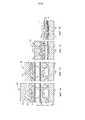
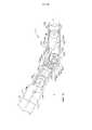
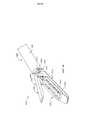
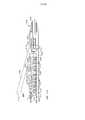
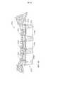
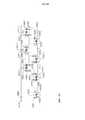
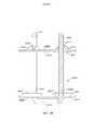
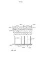
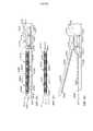
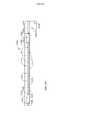
Фиг. 1 представляет собой поперечное сечение хирургического инструмента в одном из вариантов его осуществления согласно данному изобретению.FIG. 1 is a cross section of a surgical instrument in one embodiment of its implementation according to this invention.
Фиг. 1A представляет собой перспективное изображение одного из вариантов осуществления имплантируемой кассеты со скобками согласно данному изобретению.FIG. 1A is a perspective view of one embodiment of an implantable cassette with brackets according to this invention.
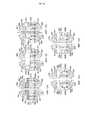
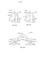
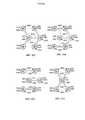
Фиг. 1B-1E иллюстрируют участки дистальной рабочей насадки, в различных вариантах осуществления согласно настоящему изобретению, во время захвата и сшивания тканей при помощи имплантируемой кассеты со скобками согласно одному из вариантов данного изобретения.FIG. 1B-1E illustrate portions of a distal working nozzle, in various embodiments according to the present invention, during the capture and stitching of tissues using an implantable cassette with brackets according to one embodiment of the present invention.
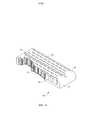
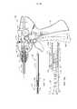
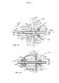
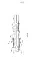
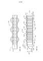
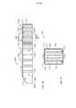
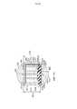
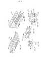
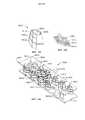
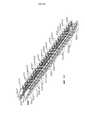
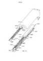
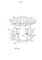
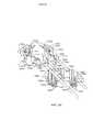
Фиг. 2 представляет собой трехмерное изображение дистальной рабочей насадки в одном из вариантов ее осуществления, с детализацией отдельных компонентов, а также изображение поперечного сечения части хирургического сшивающего устройства согласно данному изобретению.FIG. 2 is a three-dimensional image of a distal working nozzle in one of its embodiments, with details of individual components, as well as a cross-sectional image of part of a surgical stapling device according to this invention.
Фиг. 3 представляет собой боковую вертикальную проекцию упорной пластины в одном из ее вариантов согласно данному изобретению.FIG. 3 is a side elevational view of a thrust plate in one of its variants according to this invention.
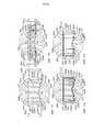
Фиг. 4 представляет собой поперечное сечение части узла рукоятки согласно Фиг. 1.FIG. 4 is a cross section of part of the handle assembly of FIG. one.
Фиг. 5 представляет собой частичное поперечное сечение узла рукоятки согласно Фиг. 1 (сечение вдоль линии 5-5 на Фиг. 1).FIG. 5 is a partial cross section of the handle assembly of FIG. 1 (section along line 5-5 in FIG. 1).
Фиг. 6 представляет собой изображение в перспективе части рабочей трансмиссии в одном из ее вариантов согласно данному изобретению.FIG. 6 is a perspective view of part of a working transmission in one of its variants according to this invention.
Фиг. 7 представляет собой частичное поперечное сечение узла рукоятки согласно Фиг. 1 (сечение вдоль линии 7-7 на Фиг. 1).FIG. 7 is a partial cross section of the handle assembly of FIG. 1 (section along line 7-7 in FIG. 1).
Фиг. 8 представляет собой частичное поперечное сечение узла рукоятки согласно Фиг. 7 (сечение вдоль линии 8-8 на Фиг. 7).FIG. 8 is a partial cross section of the handle assembly of FIG. 7 (section along line 8-8 in FIG. 7).
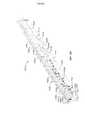
Фиг. 9 представляет собой поперечное сечение хирургического инструмента в одном из его вариантов согласно данному изобретению после присоединения дистальной рабочей насадки к центральному участку хирургического инструмента и до фиксации этого органа в рабочем положении.FIG. 9 is a cross-section of a surgical instrument in one of its variants according to this invention after attaching the distal working nozzle to the central portion of the surgical instrument and before fixing this organ in the working position.
Фиг. 9A представляет собой увеличенное изображение дистальной рабочей насадки и части хирургического инструмента согласно Фиг. 10.FIG. 9A is an enlarged view of a distal workpiece and part of the surgical instrument of FIG. 10.
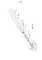
Фиг. 10 представляет собой поперечное сечение хирургического инструмента согласно Фиг. 9 после фиксации дистальной рабочей насадки на центральном участке хирургического инструмента.FIG. 10 is a cross section of the surgical instrument of FIG. 9 after fixing the distal working nozzle in the central portion of the surgical instrument.
Фиг. 10A представляет собой увеличенный вид дистальной рабочей насадки и части хирургического инструмента согласно Фиг. 10.FIG. 10A is an enlarged view of a distal workpiece and part of the surgical instrument of FIG. 10.
Фиг. 11 представляет собой поперечное сечение хирургического инструмента согласно Фиг. 9 и 10 после того, как первый рабочий адаптер был подведен к наклонной зажимающей поверхности упорной пластины.FIG. 11 is a cross section of the surgical instrument of FIG. 9 and 10 after the first working adapter has been brought to the inclined clamping surface of the thrust plate.
Фиг. 11A представляет собой увеличенный вид дистальной рабочей насадки и части хирургического инструмента согласно Фиг. 11 с тканью, зажатой между упорной пластиной и кассетой со скобками.FIG. 11A is an enlarged view of a distal workpiece and part of the surgical instrument of FIG. 11 with fabric sandwiched between the thrust plate and the cassette with brackets.
Фиг. 12 представляет собой поперечное сечение хирургического инструмента согласно Фиг. 9-11 после того, как первый рабочий адаптер был проведен через наклонную зажимающую поверхность упорной пластины.FIG. 12 is a cross-sectional view of the surgical instrument of FIG. 9-11 after the first working adapter has been inserted through the inclined clamping surface of the thrust plate.
Фиг. 12A представляет собой увеличенный вид дистальной рабочей насадки и части хирургического инструмента согласно Фиг. 12.FIG. 12A is an enlarged view of a distal workpiece and part of the surgical instrument of FIG. 12.
Фиг. 13 представляет собой поперечное сечение хирургического инструмента согласно Фиг. 9-12 после того, как первый рабочий адаптер прошел по наклонной части скобкоформирующей поверхности и полностью сформировал скобки в имплантируемой кассете со скобками.FIG. 13 is a cross section of the surgical instrument of FIG. 9-12 after the first working adapter passed along the inclined part of the bracket-forming surface and completely formed the brackets in the implantable cassette with brackets.
Фиг. 13А представляет собой увеличенный вид части хирургического инструмента согласно Фиг. 13.FIG. 13A is an enlarged view of a portion of the surgical instrument of FIG. 13.
Фиг. 14 представляет собой поперечное сечение хирургического инструмента согласно Фиг. 9-13 после того, как первый рабочий адаптер прошел по наклонной части скобкоформирующей поверхности и полностью сформировал скобки в имплантируемой кассете со скобками, а режущая планка выдвинулась в продольном направлении через дистальную рабочую насадку.FIG. 14 is a cross-sectional view of the surgical instrument of FIG. 9-13 after the first working adapter passed along the inclined part of the bracket-forming surface and completely formed the brackets in the implantable cassette with brackets, and the cutting bar extended in the longitudinal direction through the distal working nozzle.
Фиг. 14А представляет собой увеличенный вид части хирургического инструмента согласно Фиг. 14.FIG. 14A is an enlarged view of a portion of the surgical instrument of FIG. fourteen.
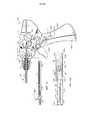
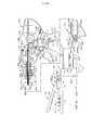
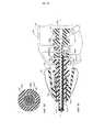
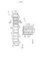
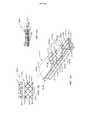
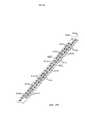
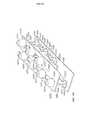
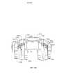
Фиг. 15 представляет собой трехмерное изображение другого варианта дистальной рабочей насадки согласно данному изобретению с детализацией отдельных компонентов, а также поперечное сечение части центрального модуля хирургического инструмента в одном из его вариантов согласно данному изобретению.FIG. 15 is a three-dimensional image of another variant of a distal working nozzle according to this invention with detailing of individual components, as well as a cross section of part of a central module of a surgical instrument in one of its variants according to this invention.
Фиг. 16 представляет собой частичное поперечное сечение дистальной рабочей насадки в варианте согласно Фиг. 15 в открытом положении, прикрепленной к хирургическому инструменту в одном из его вариантов.FIG. 16 is a partial cross section of a distal working nozzle in the embodiment of FIG. 15 in the open position attached to the surgical instrument in one of its variants.
Фиг. 17 представляет собой другое частичное поперечное сечение дистальной рабочей насадки в варианте осуществления согласно Фиг. 15 и 16 в полностью закрытом положении.FIG. 17 is another partial cross section of a distal working nozzle in the embodiment of FIG. 15 and 16 in the fully closed position.
Фиг. 18 представляет собой еще одно частичное поперечное сечение дистальной рабочей насадки в варианте осуществления согласно Фиг. 15-17 в крайнем рабочем положении до выдвижения дистального ножевого сегмента.FIG. 18 is another partial cross-sectional view of a distal working nozzle in the embodiment of FIG. 15-17 in the extreme working position before the extension of the distal knife segment.
Фиг. 19 представляет собой еще одно частичное поперечное сечение дистальной рабочей насадки в варианте осуществления согласно Фиг. 15-18 в крайнем рабочем положении после полного выдвижения дистального ножевого сегмента.FIG. 19 is another partial cross section of a distal working nozzle in the embodiment of FIG. 15-18 in the extreme working position after the full extension of the distal knife segment.
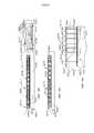
Фиг. 20 представляет собой поперечное сечение части узла рукоятки в другом варианте ее осуществления согласно данному изобретению.FIG. 20 is a cross-sectional view of a portion of a handle assembly in another embodiment according to the invention.
Фиг. 21 представляет собой частичное поперечное сечение части узла рукоятки согласно Фиг. 20 (сечение вдоль линии 21-21 на Фиг. 20).FIG. 21 is a partial cross section of a portion of the handle assembly of FIG. 20 (section along line 21-21 in FIG. 20).
Фиг. 22 представляет собой частичное поперечное сечение части узла рукоятки согласно Фиг. 20 (сечение вдоль линии 22-22 на Фиг. 20).FIG. 22 is a partial cross section of a portion of the handle assembly of FIG. 20 (section along line 22-22 in FIG. 20).
Фиг. 23 представляет собой частичное поперечное сечение части узла рукоятки согласно Фиг. 20 (сечение вдоль линии 23-23 на Фиг. 20).FIG. 23 is a partial cross section of a portion of the handle assembly of FIG. 20 (section along line 23-23 of FIG. 20).
Фиг. 24 представляет собой поперечное сечение части в другом варианте ее осуществления согласно данному изобретению.FIG. 24 is a cross-sectional view of a part in another embodiment according to the invention.
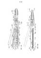
Фиг. 25 представляет собой частичное поперечное сечение боковой проекции дистальной рабочей насадки в другом варианте ее осуществления согласно данному изобретению, подсоединенной к соответствующему участку хирургического инструмента в одном из его вариантов согласно данному изобретению, с дистальной рабочей насадкой, поддерживающей кассету с хирургическими скобками в одном из ее вариантов ее осуществления согласно данному изобретению, и с упорной пластиной кассеты в открытом положении.FIG. 25 is a partial cross-sectional side view of a distal working nozzle in another embodiment of this invention connected to a corresponding portion of a surgical instrument in one embodiment of the invention, with a distal working nozzle supporting a cassette with surgical braces in one of its embodiments its implementation according to this invention, and with the thrust plate of the cartridge in the open position.
Фиг. 26 представляет собой еще одно частичное поперечное сечение боковой проекции дистальной рабочей насадки согласно Фиг. 25 в закрытом положении.FIG. 26 is another partial cross-sectional side view of a distal working nozzle according to FIG. 25 in the closed position.
Фиг. 27 представляет собой еще одно частичное поперечное сечение боковой проекции дистальной рабочей насадки согласно Фиг. 25 и 26 в момент, когда режущая планка начинает продвигаться сквозь дистальную рабочую насадку.FIG. 27 is another partial cross-sectional side view of a distal working nozzle according to FIG. 25 and 26 at the moment when the cutting bar begins to advance through the distal working nozzle.
Фиг. 28 представляет собой еще одно частичное поперечное сечение боковой проекции дистальной рабочей насадки согласно Фиг. 25-27 с проходящей через нее режущей планкой.FIG. 28 is another partial cross-sectional side view of a distal working nozzle according to FIG. 25-27 with a cutting bar passing through it.
Фиг. 29 представляет собой частичное поперечное сечение боковой проекции дистальной рабочей насадки в другом варианте ее осуществления согласно данному изобретению, подсоединенной к соответствующему участку хирургического инструмента в одном из его вариантов согласно данному изобретению, с дистальной рабочей насадкой, поддерживающей кассету с хирургическими скобками в другом варианте ее осуществления согласно данному изобретению, и с упорной пластиной кассеты в открытом положении.FIG. 29 is a partial cross-sectional side view of a distal working nozzle in another embodiment of this invention connected to a corresponding portion of a surgical instrument in one embodiment of this invention, with a distal working nozzle supporting a cassette with surgical braces in another embodiment according to this invention, and with the thrust plate of the cartridge in the open position.
Фиг. 30 представляет собой еще одно частичное поперечное сечение боковой проекции дистальной рабочей насадки согласно Фиг. 29 с проходящей через нее режущей планкой.FIG. 30 is another partial cross-sectional side view of a distal working nozzle according to FIG. 29 with a cutting bar passing through it.
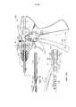
Фиг. 31 представляет собой поперечное сечение хирургического инструмента в другом варианте его осуществления согласно данному изобретению с упорной пластиной дистальной рабочей насадки, находящейся в открытом положении.FIG. 31 is a cross-sectional view of a surgical instrument in another embodiment according to the invention with an abutment plate of a distal working nozzle in an open position.
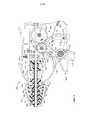
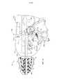
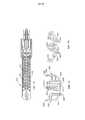
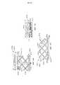
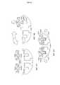
Фиг. 32 представляет собой трехмерное изображение дистальной рабочей насадки в одном из вариантов ее осуществления с детализацией отдельных компонентов, а также поперечное сечение части хирургического сшивающего инструмента в варианте его осуществления согласно Фиг. 31.FIG. 32 is a three-dimensional image of a distal working nozzle in one of its embodiments with detailing of individual components, as well as a cross section of a portion of a surgical stapling instrument in an embodiment according to FIG. 31.
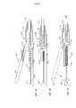
Фиг. 33 представляет собой вид сверху на дистальную рабочую насадку и часть удлиненного узла штока хирургического инструмента согласно Фиг. 31, части которого показаны в поперечном сечении, проведенном по линиям 33-33 на Фиг. 31.FIG. 33 is a plan view of a distal workpiece and part of an elongated stem assembly of the surgical instrument of FIG. 31, parts of which are shown in cross section taken along lines 33-33 of FIG. 31.
Фиг. 34 представляет собой вид сверху на дистальную рабочую насадку и часть удлиненного узла штока хирургического инструмента согласно Фиг. 31, части которого показаны в поперечном сечении.FIG. 34 is a plan view of a distal workpiece and part of an elongated rod assembly of the surgical instrument of FIG. 31, parts of which are shown in cross section.
Фиг. 35 представляет собой еще один вид сверху на дистальную рабочую насадку и часть удлиненного узла штока хирургического инструмента согласно Фиг. 31 с дистальной рабочей насадкой в изогнутой конфигурации и с дистальной рабочей насадкой в открытом положении.FIG. 35 is another top view of a distal workpiece and part of an elongated stem assembly of the surgical instrument of FIG. 31 with a distal working nozzle in a curved configuration and with a distal working nozzle in the open position.
Фиг. 36 представляет собой еще один вид сверху на дистальную рабочую насадку согласно Фиг. 35, с дистальной рабочей насадкой в закрытом или зажимающем положении.FIG. 36 is another top view of the distal working nozzle according to FIG. 35, with the distal working nozzle in the closed or clamping position.
Фиг. 37 представляет собой увеличенное изображение части дистальной рабочей насадки и хирургического инструмента согласно Фиг. 36.FIG. 37 is an enlarged view of a portion of a distal workpiece and the surgical instrument of FIG. 36.
Фиг. 38 представляет собой поперечное сечение части узла рукоятки хирургического инструмента согласно Фиг. 31.FIG. 38 is a cross-sectional view of a portion of the handle assembly of the surgical instrument of FIG. 31.
Фиг. 39 представляет собой еще одно поперечное сечение части узла рукоятки согласно Фиг. 38 (сечение по линии 39-39 на Фиг. 38).FIG. 39 is another cross section of a portion of the handle assembly of FIG. 38 (section along line 39-39 in FIG. 38).
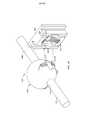
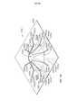
Фиг. 40 представляет собой частичное перспективное трехмерное изображение шарового шарнирного сочленения с детализацией отдельных компонентов в различных вариантах осуществления согласно данному изобретению.FIG. 40 is a partial perspective three-dimensional view of a spherical articulation with detail of individual components in various embodiments of the invention.
Фиг. 41 представляет собой вид сверху на дистальную рабочую насадку и часть удлиненного узла штока хирургического инструмента в другом варианте его осуществления согласно настоящему изобретению в неизогнутой ориентации.FIG. 41 is a plan view of a distal workpiece and part of an elongated rod assembly of a surgical instrument in another embodiment according to the present invention in an unbent orientation.
Фиг. 42 представляет собой еще один вид сверху на дистальную рабочую насадку и часть удлиненного узла штока согласно Фиг. 41, в изогнутом положении.FIG. 42 is another top view of a distal working nozzle and part of an elongated stem assembly according to FIG. 41, in a curved position.
Фиг. 43 представляет собой поперечное сечение хирургического инструмента в другом варианте осуществления согласно настоящему изобретению.FIG. 43 is a cross-sectional view of a surgical instrument in another embodiment according to the present invention.
Фиг. 44 представляет собой частичное поперечное сечение части шарнирного штока хирургического инструмента в варианте осуществления согласно Фиг. 43.FIG. 44 is a partial cross section of a portion of a hinge rod of a surgical instrument in the embodiment of FIG. 43.
Фиг. 44A представляет собой поперечное сечение части шарнирного штока согласно Фиг. 44.FIG. 44A is a cross-sectional view of a portion of the articulated rod of FIG. 44.
Фиг. 44В представляет собой еще одно поперечное сечение другой части шарнирного штока согласно Фиг. 44.FIG. 44B is another cross section of another part of the hinge rod of FIG. 44.
Фиг. 44С представляет собой еще одно поперечное сечение другой части шарнирного штока согласно Фиг. 44.FIG. 44C is another cross section of another part of the articulated rod of FIG. 44.
Фиг. 44D представляет собой еще одно поперечное сечение другой части шарнирного штока согласно Фиг. 44.FIG. 44D is another cross section of another part of the hinge rod according to FIG. 44.
Фиг. 44Е представляет собой еще одно поперечное сечение другой части шарнирного штока согласно Фиг. 44.FIG. 44E is another cross section of another part of the hinge rod according to FIG. 44.
Фиг. 44F представляет собой еще одно поперечное сечение другой части шарнирного штока согласно Фиг. 44.FIG. 44F is another cross section of another part of the hinge rod of FIG. 44.
Фиг. 45 представляет собой частичное поперечное сечение шарнирного штока согласно Фиг. 44 (сечение вдоль линии 45-45 на Фиг. 44).FIG. 45 is a partial cross section of the hinge rod of FIG. 44 (section along line 45-45 in FIG. 44).
Фиг. 46 представляет собой частичное поперечное сечение шарнирного штока согласно Фиг. 44 (сечение вдоль линии 46-46 на Фиг. 44).FIG. 46 is a partial cross section of the articulated rod of FIG. 44 (section along line 46-46 in FIG. 44).
Фиг. 47 представляет собой вид поперечного сечения хирургического инструмента согласно Фиг. 43 с дистальной рабочей насадкой в максимально изогнутом положении.FIG. 47 is a cross-sectional view of the surgical instrument of FIG. 43 with the distal working nozzle in the most curved position.
Фиг. 48 представляет собой поперечное сечение дистальной рабочей насадки согласно Фиг. 47, с гильзой в виде гармошки, расположенной поверх шарнирного сочленения.FIG. 48 is a cross-sectional view of the distal working nozzle of FIG. 47, with an accordion-shaped sleeve located on top of the articulation.
Фиг. 49 представляет собой вид поперечного сечения узла рукоятки хирургического инструмента в другом варианте его осуществления согласно данному изобретению.FIG. 49 is a cross-sectional view of a handle assembly of a surgical instrument in another embodiment according to the invention.
Фиг. 50 представляет собой поперечное сечение трехмерного изображения дистальной рабочей насадки и дистального конца удлиненного узла штока согласно Фиг. 49 с детализацией отдельных компонентов.FIG. 50 is a cross-sectional view of a three-dimensional image of a distal working nozzle and a distal end of an elongated stem assembly according to FIG. 49 detailing the individual components.
Фиг. 51 представляет собой другое поперечное сечение дистальной рабочей насадки и части удлиненного узла штока согласно Фиг. 50, с дистальной рабочей насадкой в открытом положении.FIG. 51 is another cross section of a distal working nozzle and part of an elongated stem assembly according to FIG. 50, with the distal working nozzle in the open position.
Фиг. 52 представляет собой другое поперечное сечение дистальной рабочей насадки и части удлиненного узла штока с дистальной рабочей насадкой в закрытом положении.FIG. 52 is another cross-sectional view of a distal working nozzle and part of an elongated rod assembly with a distal working nozzle in the closed position.
Фиг. 53 представляет собой другое поперечное сечение дистальной рабочей насадки и части удлиненного узла штока согласно Фиг. 49-52 с ножевым сегментом в крайнем рабочем положении.FIG. 53 is another cross-sectional view of a distal working nozzle and part of an elongated stem assembly according to FIG. 49-52 with a knife segment in the extreme working position.
Фиг. 54 представляет собой перспективное изображение дистальной рабочей насадки согласно Фиг. 51-53 в открытом положении.FIG. 54 is a perspective view of a distal working nozzle according to FIG. 51-53 in the open position.
Фиг. 55 представляет собой частичное поперечное сечение дистальной рабочей насадки согласно Фиг. 51-54 (сечение вдоль линии 55-55 на Фиг. 51).FIG. 55 is a partial cross section of the distal working nozzle of FIG. 51-54 (section along the line 55-55 in Fig. 51).
Фиг. 56 представляет собой частичное перспективное изображение удлиненного узла штока согласно другому варианту осуществления данного изобретения, присоединенного к дистальной рабочей насадке в одном из вариантов ее осуществления согласно данному изобретению.FIG. 56 is a partial perspective view of an elongated rod assembly according to another embodiment of the present invention attached to a distal workpiece in one embodiment of the invention.
Фиг. 57 представляет собой частичное поперечное сечение узла рукоятки хирургического инструмента в другом варианте его осуществления согласно данному изобретению.FIG. 57 is a partial cross-sectional view of the handle assembly of a surgical instrument in another embodiment of this invention.
Фиг. 58 представляет собой поперечное сечение части удлиненного узла штока согласно Фиг. 56 и 57 (сечение вдоль линии 58-58 на Фиг. 57).FIG. 58 is a cross-sectional view of a portion of the elongated stem assembly of FIG. 56 and 57 (section along line 58-58 in FIG. 57).
Фиг. 59 представляет собой увеличенное изображение части узла рукоятки согласно Фиг. 57.FIG. 59 is an enlarged view of a portion of the handle assembly of FIG. 57.
Фиг. 60 представляет собой поперечное сечение дистального участка удлиненного узла штока согласно Фиг. 56-59.FIG. 60 is a cross-sectional view of a distal portion of an elongated stem assembly according to FIG. 56-59.
Фиг. 61 представляет собой частичное перспективное изображение удлиненного узла штока согласно другому варианту осуществления данного изобретения, присоединенного к дистальной рабочей насадке в одном из вариантов ее осуществления согласно данному изобретению.FIG. 61 is a partial perspective view of an elongated rod assembly according to another embodiment of the present invention attached to a distal workpiece in one embodiment of the invention.
Фиг. 62 представляет собой поперечное сечение сегмента штока с изменяемой конфигурацией, принадлежащего к удлиненному узлу штока согласно Фиг. 61.FIG. 62 is a cross-sectional view of a variable-segment stem segment belonging to an elongated stem assembly according to FIG. 61.
Фиг. 63 представляет собой частичное перспективное изображение удлиненного узла штока согласно другому варианту осуществления данного изобретения, присоединенного к дистальной рабочей насадке в одном из вариантов ее осуществления согласно данному изобретению.FIG. 63 is a partial perspective view of an elongated rod assembly according to another embodiment of the present invention attached to a distal workpiece in one embodiment of the invention.
Фиг. 64 представляет собой поперечное сечение узла рукоятки хирургического инструмента в другом варианте его осуществления согласно данному изобретению.FIG. 64 is a cross section of the handle assembly of a surgical instrument in another embodiment according to the invention.
Фиг. 65 представляет собой поперечное сечение части удлиненного узла штока согласно Фиг. 63 и 64 (сечение вдоль линии 65-65 на Фиг. 64).FIG. 65 is a cross-sectional view of a portion of the elongated stem assembly of FIG. 63 and 64 (section along line 65-65 in FIG. 64).
Фиг. 66 представляет собой увеличенное изображение части узла рукоятки согласно Фиг. 64.FIG. 66 is an enlarged view of a portion of the handle assembly of FIG. 64.
Фиг. 67 представляет собой поперечное сечение части сегмента штока с изменяемой конфигурацией согласно Фиг. 63 с трубчатыми звеньями, соединенными практически в прямую линию.FIG. 67 is a cross-sectional view of a portion of a variable configuration rod segment of FIG. 63 with tubular links connected practically in a straight line.
Фиг. 68 представляет собой поперечное сечение части сегмента штока с изменяемой конфигурацией согласно Фиг. 63 и 67, где трубчатые звенья образуют практически искривленную (некоаксиальную) конфигурацию.FIG. 68 is a cross-sectional view of a portion of a variable configuration rod segment of FIG. 63 and 67, where the tubular links form a practically curved (non-coaxial) configuration.
Фиг. 69 представляет собой перспективное изображение альтернативного варианта осуществления кассеты со скобками согласно данному изобретению, установленной в хирургический режущий и сшивающий инструмент в одном из вариантов его осуществления согласно данному изобретению.FIG. 69 is a perspective view of an alternative embodiment of a cassette with brackets according to this invention installed in a surgical cutting and stapling instrument in one embodiment of its implementation according to this invention.
Фиг. 70 представляет собой вид сверху на кассету с хирургическими скобками и удлиненный канал устройства, изображенного на Фиг. 69.FIG. 70 is a plan view of a cassette with surgical braces and an elongated channel of the device of FIG. 69.
Фиг. 71 представляет собой вид сверху на другой вариант осуществления кассеты с хирургическими скобками согласно данному изобретению, установленной в удлиненном канале дистальной рабочей насадки в одном из вариантов ее осуществления согласно данному изобретению.FIG. 71 is a top view of another embodiment of a cassette with surgical brackets according to this invention mounted in an elongated channel of a distal working nozzle in one embodiment of its implementation according to this invention.
Фиг. 72 представляет собой вид снизу на упорную пластину в одном из вариантов осуществления согласно настоящему изобретению.FIG. 72 is a bottom view of a thrust plate in one embodiment of the present invention.
Фиг. 73 представляет собой частичное перспективное изображение множества скобок, образующих часть ряда скобок согласно одному из вариантов осуществления данного изобретения.FIG. 73 is a partial perspective view of a plurality of brackets forming part of a series of brackets according to one embodiment of the present invention.
Фиг. 74 представляет собой другое частичное перспективное изображение ряда скобок в варианте осуществления согласно Фиг. 73, со скобками, которые сформировались после контакта с упорной пластиной хирургического режущего и сшивающего инструмента.FIG. 74 is another partial perspective view of a series of brackets in the embodiment of FIG. 73, with brackets that have formed after contact with the thrust plate of a surgical cutting and stapling instrument.
Фиг. 75 представляет собой частичное перспективное изображение альтернативного исполнения скобок, образующих часть ряда скобок согласно другому варианту осуществления данного изобретения.FIG. 75 is a partial perspective view of an alternative embodiment of brackets forming part of a series of brackets according to another embodiment of the present invention.
Фиг. 76 представляет собой частичное перспективное изображение альтернативного исполнения скобок, образующих часть ряда скобок согласно еще одному из вариантов осуществления данного изобретения.FIG. 76 is a partial perspective view of an alternative embodiment of brackets forming part of a series of brackets according to another embodiment of the present invention.
Фиг. 77 представляет собой частичное перспективное изображение альтернативного исполнения скобок, образующих часть ряда скобок согласно другому варианту осуществления данного изобретения.FIG. 77 is a partial perspective view of an alternative embodiment of brackets forming part of a series of brackets according to another embodiment of the present invention.
Фиг. 78 представляет собой поперечное сечение дистальной рабочей насадки в одном из вариантов ее осуществления согласно данному изобретению с установленной кассетой со скобками в одном из вариантов ее осуществления согласно данному изобретению.FIG. 78 is a cross section of a distal working nozzle in one embodiment of its implementation according to this invention with an installed cassette with brackets in one of its embodiments according to this invention.
Фиг. 79 представляет собой поперечное сечение части удлиненного канала дистальной рабочей насадки согласно Фиг. 78 после извлечения корпусной части имплантируемой кассеты со скобками и самих скобок.FIG. 79 is a cross section of a portion of an elongated channel of a distal working nozzle according to FIG. 78 after removing the body of the implantable cartridge with brackets and the brackets themselves.
Фиг. 80 представляет собой поперечное сечение дистальной рабочей насадки в одном из вариантов ее осуществления согласно данному изобретению с установленной кассетой со скобками согласно другому варианту ее осуществления по данному изобретению.FIG. 80 is a cross section of a distal working nozzle in one embodiment of its implementation according to this invention with an installed cassette with brackets according to another embodiment of this invention.
Фиг. 81 представляет собой частичное поперечное сечение хирургического сшивающего инструмента в одном из вариантов осуществления согласно данному изобретению с кассетой со скобками, установленной в дистальной рабочей насадке указанного устройства, когда система блокировки кассеты готова перейти в незаблокированное положение.FIG. 81 is a partial cross section of a surgical stapling instrument in one embodiment of the present invention with a cassette with brackets mounted in a distal workpiece of said device when the cassette lock system is ready to move into an unlocked position.
Фиг. 82 представляет собой другое частичное поперечное сечение хирургического сшивающего инструмента согласно Фиг. 81, когда кассета со скобками извлечена из дистальной рабочей насадки и блокировочная система кассеты находится в блокирующем положении.FIG. 82 is another partial cross section of the surgical stapling instrument of FIG. 81, when the cassette with brackets is removed from the distal working nozzle and the cassette locking system is in the blocking position.
Фиг. 83A-83D представляют собой схему деформации хирургической скобки, расположенной внутри сминаемого корпуса кассеты со скобками, в соответствии по меньшей мере с одним вариантом осуществления изобретения.FIG. 83A-83D are a diagram of a deformation of a surgical brace located inside a crushable cassette with brackets in accordance with at least one embodiment of the invention.
Фиг. 84A представляет собой схему, иллюстрирующую расположение скобки внутри сдавливаемого корпуса кассеты со скобками.FIG. 84A is a diagram illustrating a bracket arrangement inside a squeezable cassette case with brackets.
Фиг. 84B представляет собой схему, иллюстрирующую, как корпус кассеты со скобками согласно Фиг. 84A сдавливается упорной пластиной.FIG. 84B is a diagram illustrating how the cassette case with brackets according to FIG. 84A is compressed by a thrust plate.
Фиг. 84С представляет собой схему, иллюстрирующую, как корпус кассеты со скобками согласно Фиг. 84A сдавливается упорной пластиной еще сильнее.FIG. 84C is a diagram illustrating how the cassette case with brackets according to FIG. 84A is pressed even further by the thrust plate.
Фиг. 84D представляет собой схему, иллюстрирующую скобку согласно Фиг. 84А в полностью сформированной конфигурации и раздавливаемую кассету согласно Фиг. 84А в полностью раздавленном состоянии.FIG. 84D is a diagram illustrating a bracket according to FIG. 84A in a fully formed configuration and a crushable cassette according to FIG. 84A in a completely crushed state.
Фиг. 85 представляет собой схему, изображающую положение скобки относительно поверхности кассеты со скобками и иллюстрирующую их потенциальное взаимное перемещение.FIG. 85 is a diagram illustrating the position of the bracket relative to the surface of the bracket cartridge and illustrating their potential mutual movement.
Фиг. 86 представляет собой поперечное сечение поверхности кассеты со скобками, в которой имеется паз (или желоб), форма которого предназначена для стабилизации основания скобки согласно Фиг. 85.FIG. 86 is a cross section of the surface of the cassette with brackets in which there is a groove (or trough), the shape of which is intended to stabilize the base of the bracket according to FIG. 85.
Фиг. 87 представляет собой поперечное сечение скобки, включая дополнительно сформованный сверху венец, и паз (или желоб), предназначенный для удержания части венца в соответствии как минимум с одним альтернативным вариантом осуществления.FIG. 87 is a cross-sectional view of a bracket including an additional crown formed from above and a groove (or trough) for holding a portion of the crown in accordance with at least one alternative embodiment.
Фиг. 88 представляет собой вид сверху на кассету со скобками в соответствии по крайней мере с одним вариантом осуществления, с заряженными скобками, помещенными в сминаемый корпус кассеты.FIG. 88 is a plan view of a cassette with brackets in accordance with at least one embodiment, with charged brackets placed in a cassette of the cassette.
Фиг. 89 представляет собой вертикальную проекцию кассеты со скобками согласно Фиг. 88.FIG. 89 is a vertical projection of a cassette with brackets according to FIG. 88.
Фиг. 90 представляет собой вертикальную проекцию кассеты со скобками в соответствии как минимум с одним вариантом осуществления, с защитным слоем, окружающим скобки внутри сминаемого корпуса кассеты.FIG. 90 is a vertical projection of a cassette with brackets in accordance with at least one embodiment, with a protective layer surrounding the brackets inside the cassette being squeezed out.
Фиг. 91 представляет собой поперечное сечение кассеты со скобками согласно Фиг. 90 (сечение вдоль линии 91-91 на Фиг. 90).FIG. 91 is a cross-sectional view of the cassette with brackets according to FIG. 90 (section along line 91-91 in FIG. 90).
Фиг. 92 представляет собой вертикальную проекцию кассеты со скобками в соответствии как минимум с одним вариантом осуществления, со скобками, которые по меньшей мере частично выходят за пределы сминаемого корпуса кассеты и защитного слоя, окружающего корпус кассеты.FIG. 92 is a vertical projection of a cassette with brackets in accordance with at least one embodiment, with brackets that at least partially extend beyond the creaseable cassette body and the protective layer surrounding the cassette body.
Фиг. 93 представляет собой поперечное сечение кассеты со скобками согласно Фиг. 92 (сечение вдоль линии 93-93 на Фиг. 92).FIG. 93 is a cross section of a cassette with brackets according to FIG. 92 (section along line 93-93 in FIG. 92).
Фиг. 94 представляет собой частичное перспективное изображение отдельных деталей кассеты со скобками в соответствии как минимум с одним вариантом осуществления, со скобками, которые по меньшей мере частично заключены в сминаемый корпус кассеты, при этом скобки по меньшей мере частично погружены в выемку со скобками, предусмотренную в корпусе кассеты.FIG. 94 is a partial perspective view of individual parts of the cartridge with brackets in accordance with at least one embodiment, with brackets that are at least partially enclosed in a crumpled cartridge case, with the brackets at least partially immersed in a recess with brackets provided in the housing cassettes.
Фиг. 95 представляет собой поперечное сечение кассеты со скобками согласно Фиг. 94 (сечение вдоль линии 95-95 на Фиг. 94).FIG. 95 is a cross-sectional view of a cassette with brackets according to FIG. 94 (section along line 95-95 in FIG. 94).
Фиг. 96 представляет собой частичное перспективное изображение отдельных деталей кассеты со скобками в соответствии как минимум с одним вариантом осуществления.FIG. 96 is a partial perspective view of individual parts of a cassette with brackets in accordance with at least one embodiment.
Фиг. 97 представляет собой частичное перспективное изображение отдельных деталей кассеты со скобками в соответствии как минимум с одним вариантом осуществления, со скобками, которые по меньшей мере частично заключены в сминаемый корпус кассеты, а также с выравнивающей матрицей, которая соединяет скобки и выравнивает их по отношению друг к другу.FIG. 97 is a partial perspective view of individual parts of the cartridge with brackets in accordance with at least one embodiment, with brackets that are at least partially enclosed in a crushable cassette body, as well as with an alignment matrix that connects the brackets and aligns them with respect to each other to a friend.
Фиг. 98 представляет собой поперечное сечение кассеты со скобками согласно Фиг. 97 (сечение вдоль линии 98-98 на Фиг. 97).FIG. 98 is a cross-sectional view of the cassette with brackets according to FIG. 97 (section along line 98-98 in FIG. 97).
Фиг. 99 представляет собой частичный разрез внутреннего слоя сжимаемого корпуса кассеты.FIG. 99 is a partial sectional view of the inner layer of a compressible cartridge case.
Фиг. 100 представляет собой схему, на которой показан внутренний слой согласно Фиг. 99, сжатый между передаточной и опорной пластинами.FIG. 100 is a diagram showing the inner layer of FIG. 99, squeezed between the transfer and support plates.
Фиг. 101 представляет собой схему, на которой изображены скобки, вставленные в сжатый внутренний слой согласно Фиг. 100.FIG. 101 is a diagram showing brackets inserted in a compressed inner layer according to FIG. one hundred.
Фиг. 102 представляет собой схему, на которой показана опорная пластина согласно Фиг. 100, отводимая от внутреннего слоя.FIG. 102 is a diagram showing a support plate according to FIG. 100 withdrawn from the inner layer.
Фиг. 103 представляет собой схему, на которой показана подструктура, состоящая из внутреннего слоя согласно Фиг. 99 и скобок согласно Фиг. 101, проходящих через наружный слой.FIG. 103 is a diagram showing a substructure consisting of an inner layer according to FIG. 99 and the brackets according to FIG. 101 passing through the outer layer.
Фиг. 104 представляет собой схему, на которой показано, как наружный слой, изображенный на Фиг. 103, затягивается, образуя закупоренную кассету со скобками.FIG. 104 is a diagram showing how the outer layer depicted in FIG. 103, is tightened, forming a clogged cassette with brackets.
Фиг. 105 представляет собой поперечное сечение закупоренной кассеты со скобками согласно Фиг. 104.FIG. 105 is a cross-sectional view of a clogged cassette with brackets according to FIG. 104.
Фиг. 106 представляет собой поперечное сечение кассеты со скобками и канала для кассеты со скобками в соответствии как минимум с одним вариантом осуществления.FIG. 106 is a cross-sectional view of a cassette with brackets and a channel for a cassette with brackets in accordance with at least one embodiment.
Фиг. 107 представляет собой схему, на которой изображена часть кассеты со скобками согласно Фиг. 106 в деформированном виде.FIG. 107 is a diagram showing a portion of a cassette with brackets according to FIG. 106 deformed.
Фиг. 108 представляет собой вертикальную проекцию дистальной рабочей насадки хирургического сшивающего устройства, включая упорную пластину в открытом положении и кассету со скобками, расположенную внутри канала для кассеты.FIG. 108 is a vertical projection of a distal working nozzle of a surgical stapler, including a stop plate in the open position and a cassette with brackets located inside the channel for the cassette.
Фиг. 109 представляет собой вертикальную проекцию дистальной рабочей насадки согласно Фиг. 108, на которой показаны упорная пластина в закрытом положении и кассета со скобками, зажатая между упорной пластиной и каналом для кассеты.FIG. 109 is a vertical projection of a distal working nozzle according to FIG. 108, which shows the stop plate in the closed position and the cassette with brackets sandwiched between the stop plate and the cassette channel.
Фиг. 110 представляет собой вертикальную проекцию дистальной рабочей насадки согласно Фиг. 108, на которой показана кассета со скобками согласно Фиг. 108, расположенная внутри канала для кассеты альтернативным образом.FIG. 110 is a vertical projection of a distal working nozzle according to FIG. 108 showing a cassette with brackets according to FIG. 108 located inside the cassette channel in an alternative manner.
Фиг. 111 представляет собой поперечное сечение дистальной рабочей насадки хирургического сшивающего устройства со сжимаемой кассетой со скобками, расположенной внутри канала для кассеты, и с дополнительным тампонирующим материалом, прикрепленным к упорной пластине.FIG. 111 is a cross-sectional view of a distal working nozzle of a surgical stapler with a compressible cassette with brackets located inside the channel for the cassette, and with additional plugging material attached to the abutment plate.
Фиг. 112 представляет собой поперечное сечение дистальной рабочей насадки согласно Фиг. 111, на котором упорная пластина изображена в закрытом положении.FIG. 112 is a cross section of the distal working nozzle according to FIG. 111, in which the thrust plate is depicted in the closed position.
Фиг. 113 представляет собой вид поперечное сечение альтернативного варианта осуществления дистальной рабочей насадки хирургического сшивающего устройства, включая кассету со скобками с водонепроницаемым слоем.FIG. 113 is a cross-sectional view of an alternative embodiment of a distal working nozzle of a surgical stapler, including a cassette with brackets with a waterproof layer.
Фиг. 114 представляет собой поперечное сечение другого альтернативного варианта осуществления дистальной рабочей насадки хирургического сшивающего устройства.FIG. 114 is a cross-section of another alternative embodiment of a distal working nozzle of a surgical stapler.
Фиг. 115 представляет собой поперечное сечение альтернативного варианта осуществления дистальной рабочей насадки хирургического сшивающего устройства, имеющего ступенчатую упорную пластину и кассету со скобками, корпус которой также обладает ступенчатой формой.FIG. 115 is a cross-section of an alternative embodiment of a distal working nozzle of a surgical stapler having a stepped thrust plate and a cassette with brackets, the body of which also has a stepped shape.
Фиг. 116 представляет собой поперечное сечение другого альтернативного варианта осуществления дистальной рабочей насадки хирургического сшивающего устройства.FIG. 116 is a cross-section of another alternative embodiment of a distal working nozzle of a surgical stapler.
Фиг. 117 представляет собой поперечное сечение альтернативного варианта осуществления дистальной рабочей насадки хирургического сшивающего устройства с наклонными поверхностями, контактирующими с тканями тела.FIG. 117 is a cross-sectional view of an alternative embodiment of a distal working head of a surgical stapler with inclined surfaces in contact with body tissues.
Фиг. 118 представляет собой поперечное сечение другого альтернативного варианта осуществления дистальной рабочей насадки хирургического сшивающего устройства с наклонными поверхностями, контактирующими с тканями тела.FIG. 118 is a cross-section of another alternative embodiment of a distal working nozzle of a surgical stapler with inclined surfaces in contact with body tissues.
Фиг. 119 представляет собой вид поперечное сечение альтернативного варианта осуществления дистальной рабочей насадки хирургического сшивающего инструмента, включая опорную вставку, предназначенную для поддержки кассеты со скобками.FIG. 119 is a cross-sectional view of an alternative embodiment of a distal working head of a surgical stapling instrument, including a support insert for supporting a cassette with brackets.
Фиг. 120 представляет собой поперечное сечение альтернативного варианта осуществления дистальной рабочей насадки хирургического сшивающего устройства, включая кассету со скобками с несколькими сжимаемыми слоями.FIG. 120 is a cross-sectional view of an alternative embodiment of a distal working nozzle of a surgical stapler, including a cassette with brackets with multiple compressible layers.
Фиг. 121 представляет собой поперечное сечение альтернативного варианта осуществления дистальной рабочей насадки хирургического сшивающего устройства, имеющего ступенчатую упорную пластину и кассету со скобками, сжимаемый корпус которой также обладает ступенчатой формой.FIG. 121 is a cross-sectional view of an alternative embodiment of a distal working head of a surgical stapler having a stepped thrust plate and a cassette with brackets, the compressible body of which also has a stepped shape.
Фиг. 122 представляет собой поперечное сечение другого альтернативного варианта осуществления дистальной рабочей насадки хирургического сшивающего устройства, имеющего ступенчатую упорную пластину и кассету со скобками, сжимаемый корпус которой также обладает ступенчатой формой.FIG. 122 is a cross-section of another alternative embodiment of a distal working nozzle of a surgical stapler having a stepped thrust plate and a cassette with brackets, the compressible body of which also has a stepped shape.
Фиг. 123 представляет собой поперечное сечение альтернативного варианта осуществления дистальной рабочей насадки хирургического сшивающего устройства, включая кассету со скобками, у которой поверхности, контактирующие с тканями тела, имеют изогнутую форму.FIG. 123 is a cross-section of an alternative embodiment of a distal working nozzle of a surgical stapler, including a cassette with brackets, in which the surfaces in contact with body tissues have a curved shape.
Фиг. 124 представляет собой поперечное сечение альтернативного варианта осуществления дистальной рабочей насадки хирургического сшивающего устройства, включая кассету со скобками, у которой поверхности, контактирующие с тканями тела, имеют наклонную форму.FIG. 124 is a cross-sectional view of an alternative embodiment of a distal working head of a surgical stapler, including a cassette with brackets, in which the surfaces in contact with body tissues are oblique.
Фиг. 125 представляет собой поперечное сечение сжимаемой кассеты со скобками, внутри которой находятся скобки и как минимум одно лекарственное средство.FIG. 125 is a cross-section of a compressible cassette with brackets, inside of which are brackets and at least one drug.
Фиг. 126 представляет собой схему, на которой показана сжимаемая кассета согласно Фиг. 125 после того, как была сжата и содержащиеся в ней скобки деформировались.FIG. 126 is a diagram showing a compressible cartridge according to FIG. 125 after it was compressed and the brackets contained in it were deformed.
Фиг. 127 представляет собой частичный разрез отдельных деталей кассеты со скобками в соответствии как минимум с одним вариантом осуществления.FIG. 127 is a partial sectional view of individual parts of a cassette with brackets in accordance with at least one embodiment.
Фиг. 128 представляет собой поперечное сечение кассеты со скобками согласно Фиг. 127.FIG. 128 is a cross section of a cassette with brackets according to FIG. 127.
Фиг. 129 представляет собой перспективное изображение имплантируемой кассеты со скобками, соответствующей по меньшей мере одному из альтернативных вариантов осуществления.FIG. 129 is a perspective view of an implantable cassette with brackets corresponding to at least one alternative embodiment.
Фиг. 130 представляет собой поперечное сечение имплантируемой кассеты со скобками согласно Фиг. 129.FIG. 130 is a cross-sectional view of an implantable cassette with brackets according to FIG. 129.
Фиг. 131 представляет собой перспективное изображение альтернативного варианта осуществления кассеты со скобками, включая деформируемые части, выступающие наружу из внешнего слоя корпуса кассеты со скобками.FIG. 131 is a perspective view of an alternative embodiment of a cartridge with brackets, including deformable parts protruding outward from the outer layer of the cartridge case with brackets.
Фиг. 132 представляет собой перспективное изображение альтернативного варианта осуществления кассеты со скобками, включая наружную часть корпуса кассеты, прикрепленную к внутренней части.FIG. 132 is a perspective view of an alternative embodiment of a cassette with brackets, including the outer part of the cassette body, attached to the inner part.
Фиг. 133 представляет собой поперечное сечение альтернативного варианта осуществления кассеты со скобками со множеством скобок, сжимаемым слоем и слоем прокладок.FIG. 133 is a cross section of an alternative embodiment of a cassette with brackets with many brackets, a compressible layer and a layer of gaskets.
Фиг. 134 представляет собой перспективное изображение слоя прокладок согласно Фиг. 133.FIG. 134 is a perspective view of the gasket layer of FIG. 133.
Фиг. 135 представляет собой перспективное изображение прокладки, отделенной от слоя прокладок, изображенного на Фиг. 133, и скобки, совмещенной с желобком в прокладке.FIG. 135 is a perspective view of a spacer separated from the spacer layer of FIG. 133, and brackets aligned with the groove in the gasket.
Фиг. 136 представляет собой перспективное изображение двух соединенных прокладок из слоя прокладок согласно Фиг. 133.FIG. 136 is a perspective view of two connected gaskets from the gasket layer of FIG. 133.
Фиг. 137 представляет собой перспективное изображение опорной рамы слоя прокладок согласно Фиг. 133 во время отделения прокладок.FIG. 137 is a perspective view of the support frame of the gasket layer of FIG. 133 during the separation of the gaskets.
Фиг. 138 представляет собой трехмерное перспективное изображение с детализацией отдельных компонентов для альтернативного варианта осуществления сжимаемой кассеты со скобками, включая скобки и систему для продвижения скобок к упорной пластине.FIG. 138 is a three-dimensional perspective view detailing the individual components for an alternative embodiment of a compressible cassette with brackets, including brackets and a system for moving the brackets to the thrust plate.
Фиг. 138A представляет собой частичный разрез альтернативного варианта осуществления кассеты со скобками согласно Фиг. 138.FIG. 138A is a partial sectional view of an alternative embodiment of the cassette with brackets according to FIG. 138.
Фиг. 139 представляет собой поперечное сечение кассеты со скобками согласно Фиг. 138;FIG. 139 is a cross section of a cassette with brackets according to FIG. 138;
Фиг. 140 представляет собой вертикальную проекцию салазок, предназначенных для передвижения кассеты согласно Фиг. 138 и перемещения скобок в направлении упорной пластины.FIG. 140 is a vertical projection of a slide designed to move the cartridge of FIG. 138 and moving the brackets in the direction of the thrust plate.
Фиг. 141 представляет собой схему скобконаправляющей планки, которая поднимается салазками согласно Фиг. 140 в направлении упорной пластины.FIG. 141 is a diagram of a staple bar that is lifted by the slide according to FIG. 140 towards the thrust plate.
Фиг. 142 представляет собой изображение перспективное отдельных деталей кассеты со скобками в соответствии по меньшей мере с одним альтернативным вариантом осуществления, где для позиционирования скобок используются скобконаправляющие планки.FIG. 142 is a perspective view of individual parts of a cassette with brackets in accordance with at least one alternative embodiment, where brackets are used to position the brackets.
Фиг. 143 представляет собой поперечное сечение кассеты со скобками согласно Фиг. 142, расположенной в канале для кассеты.FIG. 143 is a cross-section of a cassette with brackets according to FIG. 142 located in the channel for the cartridge.
Фиг. 144 представляет собой поперечное сечение кассеты со скобками согласно Фиг. 142, на котором показана упорная пластина, переведенная в закрытое положение, и скобки внутри кассеты, деформированные за счет соприкосновения с упорной пластиной.FIG. 144 is a cross section of the cassette with brackets according to FIG. 142, which shows a thrust plate in the closed position and brackets inside the cassette deformed by contact with the thrust plate.
Фиг. 145 представляет собой поперечное сечение кассеты для скобок согласно Фиг. 142, на котором показано, как скобки движутся кверху в направлении упорной пластины.FIG. 145 is a cross-sectional view of the bracket cassette of FIG. 142, which shows how the brackets move up towards the thrust plate.
Фиг. 146 представляет собой перспективное изображение альтернативного варианта осуществления кассеты со скобками, в котором гибкие стороны кассеты соединены полосами.FIG. 146 is a perspective view of an alternative embodiment of a cassette with brackets in which the flexible sides of the cassette are connected by stripes.
Фиг. 147 представляет собой перспективное изображение салазок и режущего сегмента в сборе.FIG. 147 is a perspective view of a slide and a cutting segment assembly.
Фиг. 148 представляет собой схему, на которой показано, как салазки и режущий сегмент согласно Фиг. 147 используются для поднятия скобок кассеты, изображенной на Фиг. 142.FIG. 148 is a diagram showing how the slide and the cutting segment of FIG. 147 are used to raise the brackets of the cassette shown in FIG. 142.
Фиг. 149 представляет собой схему, на которой изображены салазки, сконструированные для того, чтобы зацеплять и поднимать скобки, двигая их по направлению к упорной пластине, и блокировочная система, которая позволяет избирательно перемещать салазки в дистальном направлении.FIG. 149 is a diagram showing a slide designed to engage and lift the brackets by moving them toward the thrust plate, and a locking system that allows the slide to be selectively moved in the distal direction.
Фиг. 150A-150C иллюстрируют постепенное вхождение скобки в скобочный венец.FIG. 150A-150C illustrate the gradual entry of a bracket into a bracket crown.
Фиг. 151 представляет собой поперечное сечение кассеты со скобками, оснащенной опорным поддоном или стопором.FIG. 151 is a cross-sectional view of a cassette with brackets equipped with a support tray or stopper.
Фиг. 152 представляет собой частичное поперечное сечение сжимаемой кассеты со скобками в соответствии по меньшей мере с одним альтернативным вариантом осуществления.FIG. 152 is a partial cross section of a compressible cassette with brackets in accordance with at least one alternative embodiment.
Фиг. 153 представляет собой схему, на которой изображена кассета со скобками согласно Фиг. 152 в имплантированном состоянии.FIG. 153 is a diagram showing a cassette with brackets according to FIG. 152 in the implanted state.
Фиг. 154 представляет собой частичный разрез сжимаемой кассеты со скобками в соответствии по меньшей мере с одним альтернативным вариантом осуществления.FIG. 154 is a partial sectional view of a compressible cassette with brackets in accordance with at least one alternative embodiment.
Фиг. 155 представляет собой частичное поперечное сечение кассеты со скобками согласно Фиг. 154.FIG. 155 is a partial cross section of a cassette with brackets according to FIG. 154.
Фиг. 156 представляет собой схему, на которой изображена кассета со скобками согласно Фиг. 154 в имплантированном состоянии.FIG. 156 is a diagram showing a cassette with brackets according to FIG. 154 in the implanted state.
Фиг. 157 представляет собой частичное поперечное сечение раздавливаемой кассеты со скобками в соответствии по меньшей мере с одним альтернативным вариантом осуществления.FIG. 157 is a partial cross-sectional view of a crushable cassette with brackets in accordance with at least one alternative embodiment.
Фиг. 158 представляет собой частичный разрез сминаемой кассеты со скобками согласно как минимум одному варианту осуществления со множеством сминаемых элементов.FIG. 158 is a partial sectional view of a crease cartridge with brackets according to at least one embodiment with a plurality of crease elements.
Фиг. 159 представляет собой перспективное изображение сминаемого элемента согласно Фиг. 158 в несжатом состоянии.FIG. 159 is a perspective view of a crease member according to FIG. 158 uncompressed.
Фиг. 160 представляет собой перспективное изображение сминаемого элемента согласно Фиг. 159 в сжатом состоянии.FIG. 160 is a perspective view of a crease member according to FIG. 159 in a compressed state.
Фиг. 161А представляет собой частичное поперечное сечение дистальной рабочей насадки сшивающего хирургического инструмента, включая браншу, канал для кассеты со скобками, расположенный против бранши, и кассету со скобками внутри канала для кассеты, причем бранша оснащена прикрепленной к ней стопорной матрицей.FIG. 161A is a partial cross-sectional view of a distal working nozzle of a stapling surgical instrument, including a jaw, a cassette channel with brackets located against the jaw, and a cassette with brackets inside the cassette channel, the jaw equipped with a retaining matrix attached to it.
Фиг. 161B представляет собой частичное поперечное сечение дистальной рабочей насадки согласно Фиг. 161А, на котором показана бранша в движении по направлению к каналу для кассеты со скобками, кассета, сжимаемая между упорной пластиной и стопорной матрицей, а также скобка, по меньшей мере частично выступающая сквозь ткани, помещенные между стопорной матрицей и кассетой со скобками.FIG. 161B is a partial cross section of a distal working nozzle according to FIG. 161A, which shows the jaw in movement toward the channel for the cassette with brackets, the cassette being squeezed between the retaining plate and the retaining matrix, as well as the bracket, at least partially protruding through the tissue placed between the retaining matrix and the cassette with brackets.
Фиг. 161C представляет собой частичное поперечное сечение дистальной рабочей насадки согласно Фиг. 161А, на котором показана бранша в конечном положении и стопорная матрица в зацеплении со скобкой согласно Фиг. 161B.FIG. 161C is a partial cross section of the distal working nozzle of FIG. 161A, which shows the jaw in the final position and the retaining matrix meshed with the bracket according to FIG. 161B.
Фиг. 161D представляет собой частичное поперечное сечение дистальной рабочей насадки согласно Фиг. 161А, на котором показано, как бранша и канал для кассеты отводятся от имплантированной скобки и стопорной матрицы.FIG. 161D is a partial cross section of a distal working nozzle according to FIG. 161A, which shows how the jaw and cassette channel are retracted from the implanted bracket and retainer matrix.
Фиг. 162 представляет собой перспективное изображение стопорной прорези стопорной матрицы согласно по меньшей мере одному из альтернативных вариантов осуществления с множеством отдельных стопорных частей, предназначенных для вхождения в зацепление с проходящими сквозь них ножками-фиксаторами.FIG. 162 is a perspective view of a retaining slot of a retaining matrix according to at least one alternative embodiment with a plurality of separate retaining parts for engaging with locking legs passing through them.
Фиг. 163 представляет собой перспективное изображение стопорных прорезей стопорной матрицы согласно по меньшей мере одному альтернативному варианту осуществления с шестью отдельными стопорными частями.FIG. 163 is a perspective view of the locking slots of the locking matrix according to at least one alternative embodiment with six separate locking parts.
Фиг. 164 представляет собой перспективное изображение стопорных прорезей стопорной матрицы согласно по меньшей мере одному альтернативному варианту осуществления с восемью отдельными стопорными частями.FIG. 164 is a perspective view of locking slots of a locking matrix according to at least one alternative embodiment with eight separate locking parts.
Фиг. 165 представляет собой перспективное изображение стопорных прорезей стопорной матрицы согласно по меньшей мере одному альтернативному варианту осуществления с множеством отдельных стопорных частей, предназначенных для вхождения в зацепление с проходящими сквозь них ножками-фиксаторами.FIG. 165 is a perspective view of the locking slots of the locking matrix according to at least one alternative embodiment with a plurality of separate locking parts for engaging with locking legs passing through them.
Фиг. 166 представляет собой перспективное изображение стопорных прорезей стопорной матрицы согласно по меньшей мере одному альтернативному варианту осуществления с шестью отдельными стопорными частями.FIG. 166 is a perspective view of retaining slots of a retaining matrix according to at least one alternative embodiment with six separate retaining parts.
Фиг. 167 представляет собой перспективное изображение стопорных прорезей стопорной матрицы согласно по меньшей мере одному альтернативному варианту осуществления с восемью отдельными стопорными частями.FIG. 167 is a perspective view of the locking slots of the locking matrix according to at least one alternative embodiment with eight separate locking parts.
Фиг. 168 представляет собой перспективное изображение стопорных прорезей стопорной матрицы согласно по меньшей мере одному альтернативному варианту осуществления с множеством отдельных стопорных частей, отштампованных из листового металла.FIG. 168 is a perspective view of retaining slots of a retaining die according to at least one alternative embodiment with a plurality of individual retaining parts stamped from sheet metal.
Фиг. 169 представляет собой перспективное изображение стопорных прорезей стопорной матрицы согласно по меньшей мере одному альтернативному варианту осуществления с множеством отверстий, расположенных по периметру стопорных прорезей.FIG. 169 is a perspective view of the locking slots of the locking matrix according to at least one alternative embodiment with a plurality of holes located around the perimeter of the locking slots.
Фиг. 170 представляет собой вид сверху на стопорные прорези стопорной матрицы в соответствии по меньшей мере с одним альтернативным вариантом осуществления.FIG. 170 is a plan view of the locking slots of the locking matrix in accordance with at least one alternative embodiment.
Фиг. 171 представляет собой вид сверху на стопорные прорези стопорной матрицы в соответствии по меньшей мере с одним альтернативным вариантом осуществления.FIG. 171 is a plan view of the locking slots of the locking matrix in accordance with at least one alternative embodiment.
Фиг. 172 представляет собой вид сверху на стопорные прорези стопорной матрицы в соответствии по меньшей мере с одним альтернативным вариантом осуществления.FIG. 172 is a plan view of the locking slots of the locking matrix in accordance with at least one alternative embodiment.
Фиг. 173 представляет собой вид сверху на стопорные прорези стопорной матрицы в соответствии по меньшей мере с одним альтернативным вариантом осуществления.FIG. 173 is a plan view of the locking slots of the locking matrix in accordance with at least one alternative embodiment.
Фиг. 174 представляет собой вид сверху на стопорные прорези стопорной матрицы в соответствии по меньшей мере с одним альтернативным вариантом осуществления.FIG. 174 is a plan view of the locking slots of the locking matrix in accordance with at least one alternative embodiment.
Фиг. 175 представляет собой вид сверху на стопорные прорези стопорной матрицы, включающие стопорный язычок, выступающий внутрь прорези, согласно по меньшей мере одному варианту осуществления.FIG. 175 is a plan view of the locking slots of the locking matrix including a locking tab protruding into the slot according to at least one embodiment.
Фиг. 176 представляет собой вид сверху на стопорные прорези стопорной матрицы, включающие стопорный язычок, выступающий внутрь прорези, согласно по меньшей мере одному варианту осуществления.FIG. 176 is a plan view of the locking slots of the locking matrix, including the locking tab protruding into the slot according to at least one embodiment.
Фиг. 177 представляет собой перспективное изображение фиксирующей системы, состоящей из множества скобок, стопорной матрицы, находящейся в зацеплении со скобками, и выравнивающей матрицы, предназначенной для выравнивания скобок.FIG. 177 is a perspective view of a fixing system consisting of a plurality of brackets, a locking matrix engaged with the brackets, and an alignment matrix for aligning the brackets.
Фиг. 178 представляет собой перспективное изображение стопорной матрицы согласно Фиг. 177.FIG. 178 is a perspective view of a retainer matrix according to FIG. 177.
Фиг. 179 представляет собой перспективное изображение выравнивающей матрицы согласно Фиг. 177.FIG. 179 is a perspective view of the alignment matrix of FIG. 177.
Фиг. 180 представляет собой частичный вид сверху на стопорную матрицу согласно Фиг. 177, находящуюся в зацеплении со скобками согласно Фиг. 177.FIG. 180 is a partial top view of the retainer matrix of FIG. 177 engaged with brackets according to FIG. 177.
Фиг. 181 представляет собой частичный вид снизу на стопорную матрицу согласно Фиг. 177, находящуюся в зацеплении со скобками согласно Фиг. 177.FIG. 181 is a partial bottom view of the retainer matrix of FIG. 177 engaged with brackets according to FIG. 177.
Фиг. 182 представляет собой частичную вертикальную проекцию фиксирующей системы согласно Фиг. 177.FIG. 182 is a partial elevational view of the locking system of FIG. 177.
Фиг. 183 представляет собой частичное перспективное изображение фиксирующей системы согласно Фиг. 177.FIG. 183 is a partial perspective view of the locking system of FIG. 177.
Фиг. 184 представляет собой частичное поперечное сечение стопорной матрицы согласно Фиг. 177, находящейся в зацеплении со скобками согласно Фиг. 177.FIG. 184 is a partial cross-sectional view of the retainer matrix of FIG. 177 engaged with brackets according to FIG. 177.
Фиг. 185 представляет собой частичное поперечное сечение фиксирующей системы согласно Фиг. 177.FIG. 185 is a partial cross-sectional view of the locking system of FIG. 177.
Фиг. 186 представляет собой перспективное изображение фиксирующей системы согласно Фиг. 177, оснащенной дополнительно защитными колпачками, надетыми на ножки скобок.FIG. 186 is a perspective view of the locking system of FIG. 177, equipped with additional protective caps worn on the legs of the brackets.
Фиг. 187 представляет собой перспективный вид снизу на фиксирующую систему согласно Фиг. 186.FIG. 187 is a bottom perspective view of the locking system of FIG. 186.
Фиг. 188 представляет собой частичное перспективное изображение фиксирующей системы согласно Фиг. 186.FIG. 188 is a partial perspective view of the locking system of FIG. 186.
Фиг. 189 представляет собой частичное поперечное сечение фиксирующей системы согласно Фиг. 186.FIG. 189 is a partial cross-sectional view of the locking system of FIG. 186.
Фиг. 190 представляет собой вертикальную проекцию дистальной рабочей насадки согласно по меньшей мере одному варианту осуществления, включая браншу в открытом виде, стопорную матрицу и множество защитных колпачков, помещенных на браншу, а также кассету со скобками, расположенную в канале для кассеты.FIG. 190 is a vertical projection of a distal working nozzle according to at least one embodiment, including an open jaw, a retaining matrix and a plurality of protective caps placed on the jaw, as well as a cassette with brackets located in the cassette channel.
Фиг. 191 представляет собой вертикальную проекцию дистальной рабочей насадки согласно Фиг. 190 в закрытом положении.FIG. 191 is a vertical projection of a distal working nozzle according to FIG. 190 in the closed position.
Фиг. 192 представляет собой вертикальную проекцию дистальной рабочей насадки согласно Фиг. 190 в рабочем положении.FIG. 192 is a vertical projection of a distal working nozzle according to FIG. 190 in working position.
Фиг. 193 представляет собой вертикальную проекцию стопорной матрицы и защитных колпачков согласно Фиг. 190 в сборке с кассетой со скобками согласно Фиг. 190.FIG. 193 is a vertical projection of a retaining matrix and protective caps according to FIG. 190 in a cassette assembly with brackets according to FIG. 190.
Фиг. 194 представляет собой подробный вид сборки согласно Фиг. 193.FIG. 194 is a detailed view of the assembly of FIG. 193.
Фиг. 195 представляет собой вертикальную проекцию дистальной рабочей насадки согласно Фиг. 190, где показана бранша в открытом положении с тонким слоем ткани, помещенным между стопорной матрицей и кассетой со скобками.FIG. 195 is a vertical projection of a distal working nozzle according to FIG. 190, which shows the jaw in the open position with a thin layer of tissue placed between the retaining matrix and the cassette with brackets.
Фиг. 196 представляет собой вертикальную проекцию дистальной рабочей насадки согласно Фиг. 190, где показана бранша в закрытом положении на тонком слое тканей согласно Фиг. 195.FIG. 196 is a vertical projection of a distal working nozzle according to FIG. 190, which shows the jaw in the closed position on a thin layer of tissue according to FIG. 195.
Фиг. 197 представляет собой вертикальную проекцию дистальной рабочей насадки согласно Фиг. 190, где показана бранша в рабочем положении, зажимающая тонкий слой ткани согласно Фиг. 195, помещенный между стопорной матрицей и кассетой со скобками.FIG. 197 is a vertical projection of a distal working nozzle according to FIG. 190, which shows a jaw in the working position, clamping a thin layer of fabric according to FIG. 195 placed between the retaining matrix and the cassette with brackets.
Фиг. 198 представляет собой вертикальную проекцию стопорной матрицы и защитных колпачков согласно Фиг. 190 в сборке с кассетой со скобками согласно Фиг. 190, с помещенным между ними тонким слоем ткани согласно Фиг. 195.FIG. 198 is a vertical projection of a retaining die and protective caps according to FIG. 190 in a cassette assembly with brackets according to FIG. 190, with a thin layer of fabric placed between them according to FIG. 195.
Фиг. 199 представляет собой подробный вид сборки согласно Фиг. 198.FIG. 199 is a detailed view of the assembly of FIG. 198.
Фиг. 200 представляет собой поперечное сечение защитного колпачка, помещенного на кончик ножки скобки в соответствии по меньшей мере с одним альтернативным вариантом осуществления.FIG. 200 is a cross-sectional view of a protective cap placed on the tip of a bracket leg in accordance with at least one alternative embodiment.
Фиг. 201 представляет собой перспективное изображение множества защитных колпачков, запрессованных в лист материала.FIG. 201 is a perspective view of a plurality of protective caps pressed into a sheet of material.
Фиг. 202 представляет собой перспективное изображение бранши, имеющей множество углублений, предназначенных для размещения множества защитных колпачков.FIG. 202 is a perspective view of a jaw having a plurality of recesses for accommodating a plurality of protective caps.
Фиг. 203 представляет собой подробный вид части бранши, включающей лист, покрывающий защитные колпачки, размещенные внутри бранши согласно Фиг. 202.FIG. 203 is a detailed view of a portion of a jaw including a sheet covering protective caps placed inside the jaw of FIG. 202.
Фиг. 204 представляет собой поперечное сечение защитного колпачка, помещенного на кончик ножки скобки в соответствии как минимум с одним альтернативным вариантом осуществления, где у защитного колпачка имеется внутренняя формирующая поверхность.FIG. 204 is a cross-sectional view of a protective cap placed on the tip of a bracket leg in accordance with at least one alternative embodiment, where the protective cap has an internal forming surface.
Фиг. 205 представляет собой еще одно поперечное сечение защитного колпачка согласно Фиг. 204, на котором показано, как ножка скобки деформируется о формирующую поверхность.FIG. 205 is another cross section of the protective cap of FIG. 204, which shows how the bracket leg deforms against a forming surface.
Фиг. 206 представляет собой вид сверху на альтернативный вариант осуществления стопорной матрицы, состоящей из множества соединенных матричных элементов.FIG. 206 is a top view of an alternative embodiment of a retaining matrix consisting of a plurality of connected matrix elements.
Фиг. 207 представляет собой вид сверху на альтернативный вариант осуществления стопорной матрицы, состоящей из множества соединенных матричных элементов.FIG. 207 is a top view of an alternative embodiment of a retaining matrix consisting of a plurality of connected matrix elements.
Фиг. 208 представляет собой вид сверху на альтернативный вариант осуществления стопорной матрицы, состоящей из множества соединенных матричных элементов.FIG. 208 is a plan view of an alternative embodiment of a retaining matrix consisting of a plurality of connected matrix elements.
Фиг. 209 представляет собой вид сверху на альтернативный вариант осуществления ряда стопорных матриц, состоящих из множества соединенных матричных элементов.FIG. 209 is a plan view of an alternative embodiment of a series of retainer matrices consisting of a plurality of connected matrix elements.
Фиг. 210 представляет собой вид сверху на альтернативный вариант осуществления стопорной матрицы, состоящей из множества соединенных матричных элементов.FIG. 210 is a top view of an alternative embodiment of a retaining matrix consisting of a plurality of connected matrix elements.
Фиг. 211 представляет собой частичное трехмерное изображение с детализацией отдельных компонентов бранши, оснащенной стопорной матрицей, включающей сжимаемую крышку.FIG. 211 is a partial three-dimensional image detailing the individual components of a jaw equipped with a retaining matrix including a compressible cover.
Фиг. 212 представляет собой подробный вид стопорной матрицы согласно Фиг. 211.FIG. 212 is a detailed view of the locking matrix of FIG. 211.
Фиг. 213 представляет собой частичное поперечное сечение фиксирующей системы, в том числе стопорной матрицы, включающей сжимаемый слой и множество ячеек, в которых заключено одно или несколько лекарственных средств.FIG. 213 is a partial cross section of a fixing system, including a retaining matrix, including a compressible layer and a plurality of cells in which one or more drugs are enclosed.
Фиг. 214 представляет собой схему, на которой изображены ножки скобки, проколовшие ячейку согласно Фиг. 213, во время их контакта со стопорной матрицей.FIG. 214 is a diagram showing the brace legs piercing the cell of FIG. 213, during their contact with the retaining matrix.
Фиг. 215 представляет собой частичное поперечное сечение фиксирующей системы, в том числе стопорной матрицы, включающей сжимаемый слой.FIG. 215 is a partial cross-sectional view of a locking system, including a retaining matrix including a compressible layer.
Фиг. 216 представляет собой вертикальную проекцию модуля установки кассет, который включает держатель, первую установочную кассету и вторую установочную кассету.FIG. 216 is a vertical projection of a cartridge installation module that includes a holder, a first installation cartridge and a second installation cartridge.
Фиг. 217 представляет собой вертикальную проекцию дистальной рабочей насадки хирургического сшивающего устройства, состоящей из первой бранши и второй бранши, показанных в открытой конфигурации.FIG. 217 is a vertical projection of a distal working nozzle of a surgical stapler consisting of a first jaw and a second jaw shown in an open configuration.
Фиг. 218 представляет собой вертикальную проекцию дистальной рабочей насадки согласно Фиг. 217, на которой вторая бранша показана в закрытом положении, а модуль установки кассет согласно Фиг. 216 использован для первой бранши первой кассетой и второй бранши - второй кассетой.FIG. 218 is a vertical projection of a distal working nozzle according to FIG. 217, in which the second jaw is shown in the closed position, and the cartridge installation module according to FIG. 216 is used for the first jaw by the first cassette and the second jaw by the second cassette.
Фиг. 219 представляет собой вертикальную проекцию загруженной дистальной рабочей насадки согласно Фиг. 218, на которой модуль установки кассет извлечен из дистальной рабочей насадки, вторая бранша снова находится в открытом положении, а между первой и второй браншей находится слой ткани.FIG. 219 is a vertical projection of a loaded distal working nozzle according to FIG. 218, on which the cartridge installation module is removed from the distal working nozzle, the second jaw is again in the open position, and a layer of tissue is located between the first and second jaws.
Фиг. 220 представляет собой вертикальную проекцию загруженной дистальной рабочей насадки согласно Фиг. 219 в рабочей конфигурации.FIG. 220 is a vertical projection of a loaded distal working nozzle according to FIG. 219 in working configuration.
Фиг. 221 представляет собой вертикальную проекцию первой кассеты и второй кассеты в имплантированном состоянии.FIG. 221 is a vertical projection of a first cartridge and a second cartridge in an implanted state.
Фиг. 222 представляет собой вертикальную проекцию дистальной рабочей насадки согласно Фиг. 217, на котором показана часть первой кассеты, все еще находящейся в зацеплении с первой браншей, в соответствии по меньшей мере с одним вариантом осуществления.FIG. 222 is a vertical projection of a distal working nozzle according to FIG. 217, showing a portion of a first cartridge still engaged with the first jaw, in accordance with at least one embodiment.
Фиг. 223 представляет собой вертикальную проекцию альтернативного варианта осуществления модуля установки кассет, который включает держатель, первую установочную кассету и вторую установочную кассету.FIG. 223 is a vertical projection of an alternative embodiment of a cartridge installation module, which includes a holder, a first installation cartridge and a second installation cartridge.
Фиг. 224 представляет собой вертикальную проекцию модуля установки кассет согласно Фиг. 223 во время загрузки первой кассеты в первую браншу дистальной рабочей насадки и второй кассеты - во вторую браншу.FIG. 224 is a vertical view of the cartridge mounting module of FIG. 223 during loading of the first cartridge into the first jaw of the distal working nozzle and the second cartridge into the second jaw.
Фиг. 225 представляет собой поперечное сечение загруженной дистальной рабочей насадки согласно Фиг. 224.FIG. 225 is a cross-sectional view of the loaded distal working nozzle of FIG. 224.
Фиг. 226 представляет собой перспективное изображение хирургического сшивающего устройства, состоящего из верхней и нижней браншей, в соответствии по меньшей мере с одним вариантом осуществления, при этом некоторые части хирургического сшивающего устройства сняты.FIG. 226 is a perspective view of a surgical stapler consisting of upper and lower jaws, in accordance with at least one embodiment, with some parts of the surgical stapler removed.
Фиг. 227 представляет собой перспективное изображение хирургического сшивающего устройства согласно Фиг. 226 со снятой верхней браншей.FIG. 227 is a perspective view of the surgical stapler of FIG. 226 with the upper jaw removed.
Фиг. 228 представляет собой перспективное изображение скользящей упорной системы верхней бранши хирургического сшивающего устройства согласно Фиг. 226, которая состоит из первой скользящей упорной пластины и второй скользящей упорной пластины.FIG. 228 is a perspective view of a sliding stop system of the upper jaw of the surgical stapler of FIG. 226, which consists of a first sliding thrust plate and a second sliding thrust plate.
Фиг. 229 представляет собой вид с торца на скользящую упорную систему согласно Фиг. 228.FIG. 229 is an end view of a sliding stop system according to FIG. 228.
Фиг. 230 представляет собой вид сверху на скользящую упорную систему согласно Фиг. 228.FIG. 230 is a plan view of the sliding stop system of FIG. 228.
Фиг. 231 представляет собой схему, на которой показана скользящая упорная система согласно Фиг. 228 в нерабочем состоянии.FIG. 231 is a diagram showing a sliding stop system according to FIG. 228 inoperative.
Фиг. 232 представляет собой схему, на которой показана первая скользящая упорная пластина скользящей упорной системы согласно Фиг. 228 в нерабочем состоянии и еще не установленные скобки, расположенные в нижней бранше.FIG. 232 is a diagram showing a first sliding thrust plate of the sliding thrust system according to FIG. 228 inoperative and not yet installed brackets located in the lower branch.
Фиг. 233 представляет собой схему, на которой показаны уже установленные скобки в нижней бранше и первая скользящая упорная пластина из тех, что показаны на Фиг. 232, подтянутая в проксимальном направлении для деформирования первой группы ножек скобок.FIG. 233 is a diagram showing the brackets already installed in the lower jaw and the first sliding thrust plate of those shown in FIG. 232, pulled in the proximal direction to deform the first group of legs of brackets.
Фиг. 234 представляет собой схему, на которой показана первая группа скобок согласно Фиг. 233 в полностью деформированном состоянии.FIG. 234 is a diagram showing a first group of brackets according to FIG. 233 in a completely deformed state.
Фиг. 235 представляет собой схему, на которой показана вторая скользящая упорная пластина скользящей упорной системы согласно Фиг. 228, продвинутая в дистальном направлении для деформирования второй группы ножек скобок.FIG. 235 is a diagram showing a second sliding thrust plate of the sliding thrust system according to FIG. 228, advanced in the distal direction to deform the second group of legs of brackets.
Фиг. 236 представляет собой частичное перспективное изображение упорной пластины со множеством скобкоформирующих карманов по меньшей мере в одном варианте осуществления.FIG. 236 is a partial perspective view of a thrust plate with a plurality of bracketing pockets in at least one embodiment.
Фиг. 237 представляет собой поперечное сечение упорной пластины согласно Фиг. 236.FIG. 237 is a cross section of a thrust plate according to FIG. 236.
Фиг. 238 представляет собой схему, на которой показан первый шаг изготовления скобкоформирующих карманов согласно Фиг. 236.FIG. 238 is a diagram showing a first step of manufacturing the staple pockets of FIG. 236.
Фиг. 239 представляет собой схему, на которой показан второй шаг изготовления скобкоформирующих карманов согласно Фиг. 236.FIG. 239 is a diagram showing a second step of manufacturing the staple pockets of FIG. 236.
На Фиг. 240 показан вид сверху на систему скобкоформирующих карманов для упорной пластины согласно Фиг. 236.In FIG. 240 is a plan view of a bracket-shaped pocket system for a thrust plate according to FIG. 236.
Фиг. 241 представляет собой схему, на которой показан первый шаг процесса изготовления упорной пластины.FIG. 241 is a diagram showing a first step of a thrust plate manufacturing process.
Фиг. 242 представляет собой схему, на которой показан второй шаг процесса изготовления устройства согласно Фиг. 241.FIG. 242 is a diagram showing a second step of the manufacturing process of the device of FIG. 241.
Фиг. 243 представляет собой схему, на которой показан третий шаг процесса изготовления устройства согласно Фиг. 241.FIG. 243 is a diagram showing the third step of the manufacturing process of the device of FIG. 241.
Для указания аналогичных элементов на разных изображениях используются аналогичные цифровые обозначения. Иллюстрации, прилагаемые к настоящей заявке, предназначены исключительно для демонстрации предпочтительных вариантов осуществления изобретения и не ограничивают объем настоящего изобретения.To indicate similar elements in different images, similar numeric notations are used. The illustrations appended to this application are intended solely to demonstrate preferred embodiments of the invention and do not limit the scope of the present invention.
ПОДРОБНОЕ ОПИСАНИЕ ИЗОБРЕТЕНИЯDETAILED DESCRIPTION OF THE INVENTION
Автору настоящей заявки также принадлежат указанные ниже заявки на патент США, поданные того же числа, что и настоящая заявка, и в полном объеме включенные в настоящую заявку путем ссылки:The author of this application also owns the following US patent applications, filed on the same number as this application, and fully incorporated into this application by reference:
Заявка на патент США, порядковый номер _____, озаглавленная «Хирургический сшивающий инструмент с заменяемыми кассетами со скобками» (Surgical Stapling Instrument With Interchangeable Staple Cartridge Arrangements), запись в регистрационной книге № END6849USNP/100534.US Patent Application Serial Number _____, entitled “Surgical Stapling Instrument With Interchangeable Staple Cartridge Arrangements”, entry in registration book No. END6849USNP / 100534.
Заявка на патент США, порядковый номер _____, озаглавленная «Хирургические режущие и скрепляющие инструменты с раздельными и специальными системами для размещения средств фиксации и разрезания тканей» (Surgical Cutting and Fastening Instruments With Separate and Distinct Fastener Deployment and Tissue Cutting Systems), запись в регистрационной книге № END6839USNP/100524.US Patent Application Serial Number _____, entitled “Surgical Cutting and Fastening Instruments With Separate and Distinct Fastener Deployment and Tissue Cutting Systems”, entry in the registration book number END6839USNP / 100524.
Заявка на патент США, порядковый номер _____, озаглавленная «Хирургический сшивающий инструмент с компактными средствами управления шарнирным сочленением» (Surgical Stapling Instrument With Compact Articulation Control Arrangement), запись в регистрационной книге № END6847USNP/100532.US Patent Application Serial Number _____, entitled “Surgical Stapling Instrument With Compact Articulation Control Arrangement”, entry in registration book No. END6847USNP / 100532.
Заявка на патент США, порядковый номер _____, озаглавленная «Приспособления для смыкания браншей для хирургических инструментов» (Jaw Closure Arrangements For Surgical Instruments), запись в регистрационной книге № END6736USNP/100060.US Patent Application Serial Number _____, entitled “Jaw Closure Arrangements For Surgical Instruments”, entry in registration book No. END6736USNP / 100060.
Заявка на патент США, порядковый номер _____, озаглавленная «Хирургические инструменты с сегментированным штоком изменяемой конфигурации» (Surgical Instruments With Reconfigurable Shaft Segments), запись в регистрационной книге № END6734USNP/100058.US Patent Application Serial Number _____, entitled “Surgical Instruments With Reconfigurable Shaft Segments”, entry in registration book No. END6734USNP / 100058.
Заявка на патент США, порядковый номер _____, озаглавленная «Кассеты с хирургическими скобками для нелинейно расположенных скобок и хирургические сшивающие инструменты с общими скобкоформирующими карманами» (Surgical Staple Cartridges Supporting Non-Linearly Arranged Staples and Surgical Stapling Instruments With Common Staple-Forming Pockets), запись в регистрационной книге № END6735USNP/100059.US Patent Application Serial Number _____, entitled “Surgical Staple Cartridges Supporting Non-Linearly Arranged Staples and Surgical Stapling Instruments With Common Staple-Forming Pockets”, entry in the registration book No. END6735USNP / 100059.
Заявка на патент США, порядковый номер _____, озаглавленная «Кассеты с хирургическими скобками со съемными опорными конструкциями и хирургические сшивающие инструменты с системами для предотвращения срабатывания при отсутствующей кассете» (Surgical Staple Cartridges With Detachable Support Structures and Surgical Stapling Instruments With Systems For Preventing Actuation Motions When a Cartridge is Not Present), запись в регистрационной книге № END6855USNP/100540.US Patent Application, Serial Number _____, entitled "Surgical Staple Cartridges With Detachable Support Structures and Surgical Stapling Instruments With Systems For Preventing Actuation Motions When a Cartridge is Not Present), entry in registration book No. END6855USNP / 100540.
Заявка на патент США, порядковый номер _____, озаглавленная «Имплантируемые установочные кассеты неоднородной конфигурации» (Implantable Fastener Cartridge Having a Non-Uniform Arrangement), запись в регистрационной книге № END6840USNP/100525;US Patent Application Serial Number _____, entitled “Implantable Fastener Cartridge Having a Non-Uniform Arrangement”, entry in registration book No. END6840USNP / 100525;
Заявка на патент США, порядковый номер _____, озаглавленная «Имплантируемые установочные кассеты с опорным стопором» (Implantable Fastener Cartridge Comprising a Support Retainer), запись в регистрационной книге № END6841USNP/100526.US Patent Application Serial Number _____, entitled “Implantable Fastener Cartridge Comprising a Support Retainer”, entry in registration book No. END6841USNP / 100526.
Заявка на патент США, порядковый номер _____, озаглавленная «Имплантируемые установочные кассеты многослойного профиля» (Implantable Fastener Cartridge Comprising Multiple Layers), запись в регистрационной книге № END6842USNP/100527.US Patent Application Serial Number _____, entitled “Implantable Fastener Cartridge Comprising Multiple Layers”, entry in registration book No. END6842USNP / 100527.
Заявка на патент США, порядковый номер _____, озаглавленная «Имплантируемые установочные кассеты, допускающие избирательное ориентирование» (Selectively Orientable Implantable Fastener Cartridge), запись в регистрационной книге № END6843USNP/100528.US Patent Application Serial Number _____, entitled “Selectively Orientable Implantable Fastener Cartridge”, entry in Registration Book No. END6843USNP / 100528.
Заявка на патент США, порядковый номер _____, озаглавленная «Имплантируемые установочные кассеты с биоразлагаемыми слоями» (Implantable Fastener Cartridge Comprising Bioabsorbable Layers), запись в регистрационной книге № END6856USNP/100541.US Patent Application Serial Number _____, entitled “Implantable Fastener Cartridges Comprising Bioabsorbable Layers”, entry in registration book No. END6856USNP / 100541.
Заявка на патент США, порядковый номер _____, озаглавленная «Сжимаемые имплантируемые установочные кассеты» (Compressible Fastener Cartridge), запись в регистрационной книге № END6857USNP/100542.US Patent Application Serial Number _____, entitled “Compressible Fastener Cartridge”, entry in registration book No. END6857USNP / 100542.
Заявка на патент США, порядковый номер _____, озаглавленная «Средства фиксации с установочными кассетами» (Fasteners Supported By a Fastener Cartridge Support), запись в регистрационной книге № END6858USNP/100543.US Patent Application Serial Number _____, entitled “Fasteners Supported By a Fastener Cartridge Support”, entry in registration book No. END6858USNP / 100543.
Заявка на патент США, порядковый номер _____, озаглавленная «Сминаемые установочные кассеты» (Collapsible Fastener Cartridge), запись в регистрационной книге № END6859USNP/100544.US Patent Application Serial Number _____, entitled “Collapsible Fastener Cartridges”, entry in registration book No. END6859USNP / 100544.
Заявка на патент США, порядковый номер _____, озаглавленная «Фиксирующая система с множеством соединенных элементов стопорных матриц» (Fastener System Comprising a Plurality of Connected Retention Matrix Elements), запись в регистрационной книге № END6860USNP/100546.US Patent Application Serial Number _____, entitled Fastener System Comprising a Plurality of Connected Retention Matrix Elements, entry in registration book No. END6860USNP / 100546.
Заявка на патент США, порядковый номер _____, озаглавленная «Фиксирующая система со стопорной матрицей и выравнивающей матрицей» (Fastener System Comprising a Retention Matrix and an Alignment Matrix), запись в регистрационной книге № END6861USNP/100547.US Patent Application Serial Number _____, entitled Fastener System Comprising a Retention Matrix and an Alignment Matrix, entry in registration book No. END6861USNP / 100547.
Заявка на патент США, порядковый номер _____, озаглавленная «Фиксирующая система со стопорной матрицей» (Fastener System Comprising a Retention Matrix), запись в регистрационной книге № END6862USNP/100548.US Patent Application Serial Number _____, entitled “Fastener System Comprising a Retention Matrix”, entry in registration book No. END6862USNP / 100548.
Заявка на патент США, порядковый номер _____, озаглавленная «Фиксирующий инструмент для размещения фиксирующей системы со стопорной матрицей» (Fastening Instrument For Deploying a Fastener System Comprising a Retention Matrix), запись в регистрационной книге № END6863USNP/100549.US Patent Application Serial Number _____, entitled “Fastening Instrument For Deploying a Fastener System Comprising a Retention Matrix”, entry in registration book No. END6863USNP / 100549.
Заявка на патент США, порядковый номер _____, озаглавленная «Фиксирующая система со стопорной матрицей и крышкой» (Fastener System Comprising a Retention Matrix and a Cover), запись в регистрационной книге № END6864USNP/100550 иUS Patent Application Serial Number _____, entitled Fastener System Comprising a Retention Matrix and a Cover, entry in Registration Book No. END6864USNP / 100550 and
Заявка на патент США, порядковый номер _____, озаглавленная «Фиксирующая система с множеством установочных кассет» (Fastener System Comprising a Plurality of Fastener Cartridges), запись в регистрационной книге № END6865USNP/100551.US Patent Application Serial Number _____, entitled Fastener System Comprising a Plurality of Fastener Cartridges, entry in Registration Book No. END6865USNP / 100551.
Для более полного понимания конструкции, принципов работы, производства и использования устройств и способов, описанных в настоящем документе, ниже приводится описание отдельных примеров вариантов осуществления. Один или несколько примеров вариантов осуществления представлены на сопроводительных чертежах. Специалистам с достаточным опытом работы в данной области будет понятно, что устройства и способы, подробно описанные в настоящем документе и представленные на сопроводительных иллюстрациях, являются неограничивающими примерами вариантов осуществления и объем различных вариантов осуществления настоящего изобретения определяется только формулой изобретения. Особенности, проиллюстрированные или описанные применительно к одному примеру варианта осуществления, могут сочетаться с особенностями других вариантов осуществления. Предполагается, что объем настоящего изобретения охватывает все модификации и варианты.For a more complete understanding of the design, principles of operation, production and use of the devices and methods described herein, the following is a description of individual examples of embodiments. One or more examples of embodiments are presented in the accompanying drawings. Professionals with sufficient experience in this field will understand that the devices and methods described in detail herein and shown in the accompanying illustrations are non-limiting examples of embodiments and the scope of various embodiments of the present invention is determined only by the claims. Features illustrated or described with reference to one example of an embodiment may be combined with features of other embodiments. The scope of the present invention is intended to cover all modifications and variations.
Встречающиеся в тексте выражения «различные варианты осуществления», «некоторые варианты осуществления», «один вариант осуществления» или просто «вариант осуществления» и тому подобные означают, что данная характеристика, конструкция или свойство, описанные в связи с тем или иным вариантом осуществления, относятся как минимум к одному варианту осуществления. Таким образом, появление в текстах спецификаций фраз «в различных вариантах осуществления», «в одном варианте осуществления» или «в варианте осуществления» и тому подобных выражений не обязательно означает, что все они относятся к одному и тому же варианту осуществления. Более того, определенные характеристики, свойства или конструкции могут сочетаться любым допустимым образом в одном или нескольких вариантах осуществления. Таким образом, конкретные свойства, характеристики или конструкции, показанные или описанные в связи с одним вариантом осуществления, могут сочетаться целиком или частично, без ограничения, со свойствами, конструкциями и характеристиками одного или нескольких вариантов осуществления. Предполагается, что объем настоящего изобретения охватывает все модификации и варианты.The expressions “various embodiments”, “certain embodiments”, “one embodiment” or simply “an embodiment” and the like occurring in the text mean that this characteristic, design or property described in connection with a particular embodiment, relate to at least one embodiment. Thus, the appearance in the specification texts of the phrases “in various embodiments”, “in one embodiment” or “in an embodiment” and the like expressions does not necessarily mean that they all refer to the same embodiment. Moreover, certain characteristics, properties or designs may be combined in any suitable manner in one or more embodiments. Thus, the specific properties, characteristics or structures shown or described in connection with one embodiment may be combined in whole or in part, without limitation, with the properties, structures and characteristics of one or more embodiments. The scope of the present invention is intended to cover all modifications and variations.
Термины «проксимальный» и «дистальный» в настоящем документе определяются относительно врача, управляющего рукояткой хирургического инструмента. Термин «проксимальный» относится к части, лежащей ближе к врачу, а термин «дистальный» относится к части, удаленной от врача. Предлагается также для удобства и ясности применительно к чертежам использовать в настоящем документе такие пространственные термины, как «вертикальный», «горизонтальный», «вверх» и «вниз». Тем не менее, поскольку использование хирургических инструментов предполагает множество ориентаций и положений, указанные термины не следует толковать как ограничивающие и (или) абсолютные.The terms "proximal" and "distal" in this document are defined with respect to the physician managing the handle of the surgical instrument. The term "proximal" refers to the part lying closer to the doctor, and the term "distal" refers to the part removed from the doctor. It is also proposed for convenience and clarity in relation to the drawings to use in this document such spatial terms as “vertical”, “horizontal”, “up” and “down”. However, since the use of surgical instruments involves many orientations and provisions, these terms should not be interpreted as limiting and (or) absolute.
Для проведения лапароскопических и минимально инвазивных хирургических вмешательств используются различные образцы устройств и различные методики. Однако для специалистов с достаточным опытом работы в данной области будет весьма ценным то обстоятельство, что различные методы и устройства, описанные в данном документе, могут использоваться для самых разных хирургических процедур и действий, связанных с открытыми хирургическими операциями. По ходу данного подробного описания специалисты с достаточным опытом работы в данной области смогут еще в больше мере оценить, что разнообразные инструменты, описанные в данном документе, могут быть введены в тело любым способом - как через естественные отверстия, так и через разрез или пункционное отверстие, проделанное в тканях, и т.п. Рабочие органы или дистальные рабочие насадки таких инструментов могут быть введены непосредственно в тело пациента либо через устройство доступа, имеющего рабочий канал, через который можно провести дистальную рабочую насадку и удлиненный узел штока хирургического инструмента.For carrying out laparoscopic and minimally invasive surgical interventions, various device models and various techniques are used. However, for specialists with sufficient experience in this field, it will be very valuable that the various methods and devices described in this document can be used for a wide variety of surgical procedures and activities associated with open surgical operations. In the course of this detailed description, specialists with sufficient experience in this field will be able to further appreciate that the various tools described in this document can be inserted into the body in any way - either through natural holes, or through an incision or a puncture hole, done in tissues, etc. The working bodies or distal working nozzles of such instruments can be inserted directly into the patient’s body or through an access device having a working channel through which the distal working nozzle and the elongated rod assembly of the surgical instrument can be passed.
Что касается приведенных в документе фигур и чертежей, то одинаковые номера обозначают одни и те же компоненты на разных изображениях, например на Фиг. 1 приведен хирургический инструмент 10, который обладает несколькими уникальными положительными свойствами в рамках настоящего изобретения. Хирургический сшивающий инструмент 10 разработан для совершения манипуляций и/или для приведения в движение дистальных рабочих насадок 12 различных размеров и форм, которые могут присоединяться к нему подвижным образом. В варианте, отображенном на Фиг. 1 и 2, например, дистальная рабочая насадка 12 включает удлиненный канал 14, который образует нижнюю браншу 13 дистальной рабочей насадки 12. Удлиненный канал 14 сконструирован таким образом, чтобы поддерживать «имплантируемую» кассету со скобками 30, а также чтобы служить подвижной опорой для упорной пластины 20, которая работает как верхняя бранша 15 дистальной рабочей насадки 12.As for the figures and drawings shown in the document, the same numbers indicate the same components in different images, for example in FIG. 1 shows a
В различных вариантах осуществления удлиненный канал 14 может быть изготовлен, например, из нержавеющей стали марки 300 и 400, 17-4 и 17-7, из титана и т.п., а также может иметь боковые стенки, расположенные на некотором расстоянии друг от друга 16. Упорная пластина 20 может быть изготовлена, например, из нержавеющей стали марки 300 и 400, 17-4 и 17-7, из титана и т.п. и иметь внутреннюю поверхность, служащую для формирования скобок, которая обычно обозначается номером 22 и в свою очередь имеет множество карманов для формирования скобок 23.In various embodiments, the
См. Фиг. 1B-1E. Кроме того, упорная пластина 20 имеет раздвоенный наклонный модуль 24, выступающий из него в проксимальном направлении. Штифт упорной пластины 26 выступает с каждой из боковых сторон наклонного модуля 24 для зацепления с соответствующим отверстием или пазом 18 в боковых стенках 16 удлиненного канала 14, что облегчает подвижное или поворотное соединение этих частей.See FIG. 1B-1E. In addition, the
С различными вариантами осуществления хирургических инструментов, описываемых в данном документе, могут использоваться различные модели имплантируемых кассет со скобками. Конкретные конфигурации кассет со скобками и их конструкции будут более подробно оговорены далее. В вариантах осуществления, показанных на Фиг. 1А и 9-14, изображена имплантируемая кассета со скобками 30. По меньшей мере в одном варианте осуществления кассета со скобками 30 имеет часть корпуса 31, состоящую из сжимаемого кровоостанавливающего материала, такого как окисленная и восстановленная целлюлоза (ОВЦ), или из биологически разлагаемых вспененных материалов, на которые опираются ряды несформированных металлических скобок 32. Чтобы предотвратить воздействие на скобки и не допустить активации кровоостанавливающего материала во время заправки кассеты в устройство и позиционирования устройства, по меньшей мере в некоторых вариантах осуществления вся кассета может быть покрыта или обернута биологически разлагаемой пленкой 38, например пленкой из полидиоксанона, продаваемого под торговой маркой PDS®, или пленкой из полиглицеринсебаката (ПГС) либо другими биоразлагаемыми пленками, сделанными из ПГК (полигликолевой кислоты, торговая марка Vicryl), поликапролактона (ПКЛ), ПЛА или ПЛЛА (полимеров молочной кислоты), ПГА (полигидроксиалканоатов), ПГКЛ (полиглекапрона 25, торговая марка Monocryl) или из композитных материалов, содержащих ПГА, ПКЛ, ПЛА или ПДС, которые сохраняют непроницаемость до тех пор, пока в них не появится разрыв. Корпус 31 кассеты со скобками 30 имеет такой размер, чтобы он мог свободно проходить в удлиненный канал 14 и выходить из него, как показано на фигурах, таким образом, что каждая скобка 32 в нем оказывается на одном уровне с соответствующим скобкоформирующим карманом 23 на упорной пластине, когда упорная пластина 20 вступает в контакт с кассетой 30 с целью формирования скобок.With the various embodiments of the surgical instruments described herein, various models of implantable cassettes with brackets can be used. The specific configurations of the cassettes with brackets and their design will be discussed in more detail below. In the embodiments shown in FIG. 1A and 9-14, an implantable cassette with
Во время использования устройства дистальная рабочая насадка 12 помещается напротив целевой ткани тела, после чего этой дистальной рабочей насадкой 12 манипулируют таким образом, чтобы она захватила или зажала целевую ткань между верхней поверхностью 36 кассеты для скобок 30 и скобкоформирующей поверхностью 22 упорной пластины 20. Скобки 32 формируются за счет движения упорной пластины 20 по пути, который практически параллелен удлиненному каналу 14, в результате чего скобкоформирующая поверхность 22 (точнее, скобкоформирующие карманы 23 на ней), вступает в практически одновременный контакт с верхней поверхностью 36 кассеты 30. По мере продвижения упорной пластины 20 внутрь кассеты со скобками 30 ножки 34 скобок 32 вступают в контакт с соответствующими скобкоформирующими карманами 23 на упорной пластине 20, которые служат для того, чтобы изогнуть ножки скобки 34 и придать скобкам 32 форму буквы «В». Дальнейшее движение упорной пластины 20 в направлении удлиненного канала 14 приводит к дальнейшему сжатию скобок 32 до желаемой окончательной высоты формирования, обозначенной «FH».During use of the device, the distal working
Вышеописанный процесс в целом показан на Фиг. 1B-1E. Например, на Фиг. 1В показана дистальная рабочая насадка 12 с целевой тканью (обозначена буквой «Т») между упорной пластиной 20 и верхней поверхностью 36 имплантируемой кассеты со скобками 30. Фиг. 1С показывает начальное зажимающее положение упорной пластины 20, когда упорная пластина 20 смыкается на ткани, обозначенной буквой «Е», чтобы зажать эту целевую ткань «Т» между упорной пластиной 20 и верхней поверхностью 36 кассеты со скобками 30. На Фиг. 1D показан начальный момент образования скобки, когда упорная пластина 20 начинает сжимать кассету со скобками 30 таким образом, что ножки 34 скобок 32 начинают приобретать нужную форму вследствие контакта со скобкоформирующими карманами 23 на упорной пластине 20. Фиг. 1Е показывает скобку 32 в ее окончательно сформированном состоянии, проходящую сквозь целевую ткань, обозначенную буквой «Т»; при этом упорная пластина 20 убрана для большей ясности изображения. Как только скобки 32 будут сформированы и закреплены в целевой ткани, обозначенной буквой «Т», хирург перемещает упорную пластину 20 в открытое положение, чтобы корпус кассеты 31 и скобки 32 оставались зафиксированными в целевой ткани, а дистальную рабочую насадку 12 можно было извлечь из тела пациента. Дистальная рабочая насадка 12 формирует все скобки одновременно в тот момент, когда бранши 13 и 15 смыкаются. Остающийся в организме «раздавленный» материал корпуса 31 одновременно выполняет гемостатическую функцию (ОВЦ) и укрепляет ряд наложенных скобок (ПГА, ПДС или другие пленочные композитные материалы 38, упомянутые выше). Таким образом, поскольку скобки 32 не покидают корпус кассеты 31 во время формирования, вероятность того, что скобки 32 будут неправильно сформированы, сводится к минимуму. В данном документе выражение «имплантируемый» означает, что кроме скобок материал корпуса кассеты, в котором располагаются скобки, также остается в теле пациента и со временем полностью рассасывается. Такие имплантируемые кассеты со скобками отличаются от ранее использовавшихся конструкций кассет, которые оставались внутри дистальной рабочей насадки и извлекались вместе с ней наружу. Такие «удаляемые» кассеты со скобками обычно включают компоненты для продвижения скобок и поэтому могут иметь гораздо более крупные размеры, нежели дистальные рабочие насадки, предусматриваемые данным изобретением, которые разработаны для использования в сочетании с моделями уникальных и инновативных имплантируемых кассет со скобками, варианты осуществления которых составляют предмет данного изобретения.The above process is generally shown in FIG. 1B-1E. For example, in FIG. 1B shows a distal working
В различных вариантах осуществления дистальная рабочая насадка 12 имеет конструкцию, обеспечивающую ее присоединение к удлиненному узлу штока 40, который выдается наружу из узла рукоятки 100. Дистальная рабочая насадка 12 (в закрытом положении) и удлиненный узел штока 40 могут иметь сходную форму в поперечном сечении и размеры, позволяющие им оперативно проходить сквозь трубку троакара или рабочий канал другого инструмента, предназначенного для обеспечения доступа. В данном документе выражение «проходить оперативно» означает, что дистальная рабочая насадка и по меньшей мере часть удлиненного узла штока могут быть вставлены или проведены сквозь отверстие канала или трубки и ими можно будет манипулировать внутри канала или трубки для выполнения хирургической процедуры сшивания. В некоторых вариантах осуществления при закрытом положении браншей 13 и 15 дистальной рабочей насадки 12 ее поперечное сечение оказывается примерно круглым, что облегчает прохождение через отверстия и проходы круглого сечения. Однако дистальные рабочие насадки в различных вариантах осуществления согласно настоящему изобретению, а также удлиненные штоки в различных вариантах их осуществления могут быть специально изготовлены с поперечным сечением другой формы, которая обеспечит прохождение через отверстия и каналы для доступа с поперечным сечением некруглой формы. Таким образом, общий размер поперечного сечения закрытой дистальной рабочей насадки будет связан с размером прохода или отверстия, сквозь которое предполагается ее пропускать. Таким образом, например, если о дистальной рабочей насадке говорят, что она имеет размер 5 мм, это означает, что такая дистальная рабочая насадка может оперативно пройти через отверстие диаметром не менее 5 мм.In various embodiments, the distal working
В различных вариантах осуществления данного изобретения удлиненный узел штока 40 может иметь наружный диаметр, практически равный наружному диаметру дистальной рабочей насадки 12 в закрытом положении. Например, дистальная рабочая насадка размером 5 мм может быть соединена с удлиненным штоком 40, имеющим диаметр поперечного сечения 5 мм. По ходу данного детального описания станет очевидно, что различные варианты осуществления настоящего изобретения можно эффективно использовать в сочетании с дистальной рабочей насадкой различных размеров. Например, дистальную рабочую насадку размером 10 мм можно присоединить к удлиненному узлу штока, имеющему диаметр поперечного сечения, равный 5 мм. Напротив, для отверстия или прохода диаметром 10 мм или более удлиненный узел штока 40 может иметь поперечное сечение диаметром 10 мм или более, но при этом иметь возможность приводить в действие дистальную рабочую насадку диаметром 10 или 5 мм. Таким образом, наружный шток 40 может иметь внешний диаметр, как равный внешнему диаметру присоединенной к нему дистальной рабочей насадки 12 в закрытом состоянии, так и отличный от него.In various embodiments of the invention, the
Согласно описанию, удлиненный узел штока 40 выступает в дистальном направлении из узла рукоятки 100, образуя практически прямую линию вдоль продольной оси А-А. В различных вариантах осуществления, например, удлиненный узел штока 40 может иметь длину около 229-406 мм (9-16 дюймов). Однако удлиненный узел штока 40 может также выпускаться с другой длиной и в других вариантах осуществления может иметь шарниры или обладать любой другой конфигурацией, которая облегчает изменение положения дистальной рабочей насадки 12 относительно других частей штока или узла рукоятки, как это будет подробно обсуждено ниже. В различных вариантах осуществления удлиненный узел штока 40 имеет центральную модульную часть 50, которая проходит от узла рукоятки 100 до дистальной рабочей насадки 12. Проксимальный конец удлиненного канала 14 дистальной рабочей насадки 12 имеет пару стопорных шипов 17, выходящих из него, размер которых таков, что они точно входят в соответствующие им отверстия (или люльки) 52, находящиеся на дистальном конце центральной модульной части 50, что позволяет насаживать дистальную рабочую насадку 12 на удлиненный узел штока 40 и снимать ее оттуда. Центральная модульная часть 50 может быть, например, изготовлена из алюминиевого сплава 6061 или 7075, нержавеющей стали, титана и т.п.According to the description, the
В различных вариантах осуществления узел рукоятки 100 включает в себя корпус с захватом пистолетного типа, который может быть сборным и состоять из двух или более деталей. Например, узел рукоятки 100, показанный на фигурах, включает в себя правую часть корпуса 102 и левую часть корпуса 104 (Фиг. 5, 7 и 8), которые отлиты или иным образом сформованы из полимера или пластика и конструктивно совмещаются друг с другом. Такие части корпуса 102 и 104 могут соединяться защелками, при помощи литых или иным образом сформованных конструкций типа «шип-гнездо», а также соединяться на клею, винтах и т.п. Центральная модульная часть 50 имеет проксимальный конец 54 с фланцем 56. Фланец 56 имеет вращательную опору внутри желобка 106, образованного парой совместимых ребер 108, которые выступают из частей корпуса 102, 104. Такая конструкция облегчает подсоединение центральной модульной части 50 к рукоятке 100, позволяя центральной модульной части 50 вращаться относительно рукоятки 100 вокруг продольной оси A-A на 360°.In various embodiments, the implementation of the
Как показано далее на Фиг. 1 и 4, центральная модульная часть 50 проходит через монтажную втулку 60, которая закреплена в узле рукоятки 100 таким образом, что может в нем вращаться. Монтажная втулка 60 имеет проксимальный фланец 62 и дистальный фланец 64, которые образуют вращательный желобок 65, предназначенный для вращения выступающей торцевой части 101 узла рукоятки 100. Такая конструкция позволяет монтажной втулке 60 вращаться вокруг продольной оси А-А относительно узла рукоятки 100. Центральная часть 50 неподвижно скреплена с монтажной втулкой 60 шпонкой 66. Кроме того, к монтажной втулке 60 прикреплена поворотная головка 70. В одном из вариантов осуществления, например, поворотная головка 70 имеет пустотелую часть - монтажный фланец 72, размер которого соответствует вставляемой в него части монтажной втулки 60. В различных вариантах исполнения поворотная головка 70 может быть изготовлена, например, из стекла или нейлона с углеволокном в качестве наполнителя, поликарбоната, материала Ultem® и т.п. и крепится к монтажной втулке 60 шпонкой 66. Кроме того, на части монтажного фланца 74 образуется выступающий вовнутрь стопорный фланец 72, который конструктивно располагается внутри радиального желобка 68, созданного в монтажной втулке 60. Таким образом, хирург может вращать центральную часть 50 (и дистальную рабочую насадку 12, прикрепленную к ней) вокруг продольной оси А-А на 360°, взявшись за поворотную головку 70 и вращая ее относительно узла рукоятки 100.As shown further in FIG. 1 and 4, the central
В различных вариантах осуществления упорная пластина 20 удерживается в открытом положении пружиной упорной пластины 21 или другой отклоняющей конструкцией, как показано на Фиг. 1, 9A, 10A и 11A. Упорная пластина 20 избирательно перемещается из открытого положения в различные закрытые, или зажимающие, и рабочие положения при помощи системы срабатывания, которая в общем виде обозначена номером 109. Система срабатывания 109 включает «рабочую часть» 110, которая в различных вариантах исполнения представляет собой полую рабочую трубку 110. Полая рабочая трубка 110 совершает аксиальные движения вдоль центральной модульной части 50, образуя тем самым наружную часть удлиненного узла штока 40. Рабочая трубка 110 может быть изготовлена из полимера или другого пригодного материала и имеет проксимальный конец 112, который присоединен к рычагу срабатывания 114 системы срабатывания 109. См. Фиг. 4. В различных вариантах осуществления, например, рычаг срабатывания 114 может быть переформован на проксимальном конце 112 рабочей трубки 110. Однако возможны и другие варианты фиксации.In various embodiments, the
Как видно на Фиг. 1 и 4, рычаг срабатывания 114 может иметь вращательную опору в виде опорной муфты 120, которая конструктивно способна совершать аксиальные перемещения внутри узла рукоятки 100. В различных вариантах осуществления опорная муфта 120 имеет пару выступающих боковых ребер 122, размер которых позволяет им входить в специальные пазы 103 и 105, выполненные в правой и левой частях корпуса (102 и 104 соответственно). См. Фиг. 7. Таким образом, опорная муфта 120 способна скользить в аксиальном направлении внутри корпуса рукоятки 100, что позволяет рычагу срабатывания 114 и рабочей трубке 110 вращаться относительно корпуса вокруг продольной оси А-А. Как видно на Фиг. 4, в рабочей трубке 110 вырезан продольный паз 111, чтобы пропустить через нее шпонку 66, которая входит в центральную модульную часть 50 и облегчает аксиальное движение рабочей трубки 110 вдоль центральной модульной части 50.As seen in FIG. 1 and 4, the
Система срабатывания 109, кроме того, включает пусковой триггер 130, который служит для управления аксиальным движением рабочей трубки 110 по центральной модульной части 50. См. Фиг. 1. Такое аксиальное движение рабочей трубки 110 в дистальном направлении в рабочем взаимодействии с упорной пластиной 20 в данном документе называется рабочим движением или срабатыванием. Как видно на Фиг. 1, пусковой триггер 130 подвижно или поворотно соединен с модулем рукоятки 100 при помощи осевого штифта 132. Для отведения пускового триггера 130 от пистолетной рукоятки 107 узла рукоятки 100 в «открытое», или начальное, положение используется крутильная пружина 135. Как видно на Фиг. 1 и 4, пусковой триггер 130 имеет верхнюю часть 134, которая подвижным образом (с помощью штифта) соединена с рабочими тягами 136, которые также подвижным образом (с помощью штифтов) соединены с опорной муфтой 120. Таким образом, движение пускового триггера 130 из начального положения (Фиг. 1 и 9) по направлению к конечному положению ближе к пистолетной части 107 узла рукоятки 100 (Фиг. 14) приводит к тому, что рычаг срабатывания 114 и рабочая трубка 110 перемещаются дистально в направлении DD. Перемещение пускового триггера 130 в направлении от пистолетной части 107 узла рукоятки 100 (под действием крутильной пружины 135) приведет к тому, что рычаг срабатывания 114 и рабочая трубка 110 переместятся в проксимальном направлении PD вдоль центральной модульной части 50.The
Различные варианты осуществления данного изобретения могут применяться с имплантируемыми кассетами самых разных размеров и конфигураций. Например, для хирургического инструмента 10, работающего в сочетании с первым рабочим адаптером 140, можно использовать дистальную рабочую насадку 12 диаметром 5 мм, которая имеет в длину около 20 мм (возможна и другая длина), куда вставлена имплантируемая кассета со скобками 30. Такие дистальные рабочие насадки могут быть особенно удобны, например, для выполнения сравнительно тонких рассечений и сосудистых операций. Однако, как об этом будет подробнее рассказано ниже, хирургический инструмент 10 может также использоваться, например, в сочетании с дистальными рабочими насадками других размеров и с другими кассетами со скобками путем замены первого рабочего адаптера 140 вторым рабочим адаптером 150. В других вариантах осуществления удлиненный узел штока 40 может иметь конструкцию, которая позволяет присоединять к нему только дистальную рабочую насадку одной формы или одного размера. В таких вариантах осуществления, например, прижимные поверхности 146 или 158 (обычно имеющиеся на рабочих адаптерах 140 и 150 соответственно) встроены в дистальный конец рабочей трубки 110 в зависимости от конкретного размера дистальной рабочей насадки, с которым она будет использоваться.Various embodiments of the present invention can be used with implantable cassettes of a wide variety of sizes and configurations. For example, for a
Как показано на Фиг. 2, первый рабочий адаптер 140 является практически полым и имеет первую пружинную часть 142, которая выступает внутрь открытого дистального конца 116 рабочей трубки 110. На первой пружинной части 142 установлена первая стопорная кнопка 144 такого размера, чтобы она помещалась в стопорное отверстие 117, предусмотренное в дистальном конце рабочей трубки 110. См. Фиг. 1 и 2. Таким образом, чтобы отсоединить первый рабочий адаптер 140 от рабочей трубки 110, пользователь просто нажимает на стопорную кнопку 144, освобождая ее из стопорного отверстия 117, и извлекает рабочий адаптер 140 из рабочей трубки 110. Как видно на Фиг. 2, первый рабочий адаптер 140 имеет внутреннюю прижимную поверхность 146, конструкция которой предусматривает взаимодействие с раздвоенным модулем наклонных направляющих 24 упорной пластины 20.As shown in FIG. 2, the first working
В различных вариантах осуществления раздвоенные наклонные направляющие 24 упорной пластины 20 включают в себя пару зубцов 45, между которыми находится паз для лезвия (не показан). Каждый зубец 45 имеет проксимальную поверхность 27, которая практически параллельна нижней части удлиненного канала 14, когда упорная пластина 20 находится в закрытом положении. Проксимальная поверхность 27 затем переходит в зажимающую наклонную поверхность 28, расположенную дистально по отношению к проксимальной поверхности 27. См. Фиг. 3. Зажимающая наклонная поверхность 28 ориентирована под углом прижимания «А» по отношению к проксимальной поверхности 27. В различных вариантах исполнения, например, угол прижимания «А» может составлять приблизительно от 15 до 30 градусов. Как будет подробно рассмотрено ниже, когда первая прижимная поверхность 146 первого рабочего адаптера 140 соприкасается с зажимающей наклонной поверхностью 28, упорная пластина 20 перемещается по направлению к удлиненному каналу 14, а точнее в направлении расположенной внутри кассеты со скобками 30. По мере дальнейшего продвижения первого рабочего адаптера 140 в дистальном направлении первая прижимная поверхность 146 соприкасается со скобкоформирующей наклонной поверхностью 29 на каждом из зубцов 45 упорной пластины и все глубже вдавливает упорную пластину 20 в кассету 30, способствуя формированию внутри нее скобок 32. Как показано также на Фиг. 3, скобкоформирующая наклонная поверхность 29 ориентирована под формирующим углом «В» по отношению к зажимающей наклонной поверхности 27. В различных вариантах осуществления, например, формирующий угол «В» может составлять приблизительно от 5 до 20 градусов. Наклонный модуль 24 упорной пластины 20 может дополнительно иметь наклонную внутреннюю поверхность 25 (расположенную под углом «С», равным приблизительно от 5 до 40 градусов), и, когда упорная пластина 20 находится в открытом положении, наклонная нижняя поверхность 25 позволяет упорной пластине 20 повернуться на 15° в открытом положении (угол «β» на Фиг. 11А).In various embodiments, the forked
Теперь перейдем к разъяснению одного из способов съемного соединения дистальной рабочей насадки 12 и центральной модульной части 50. Процесс соединения начинается с того, что стопорные шипы 17 на удлиненном канале 14 вставляются в люльки 52 в центральной модульной части 50. После этого хирург нажимает на пусковой триггер 130 в направлении пистолетной части 107 узла рукоятки 100, чтобы рабочая трубка 110 продвинулась в дистальном направлении, а первый рабочий адаптер 140 оказался поверх проксимального концевого участка 47 удлиненного канала 14, таким образом удерживая шипы 17 в соответствующих люльках 52.Now we turn to the explanation of one of the methods for removably connecting the distal working
См. Фиг. 10 и 10A. Такое положение первого рабочего адаптера 140 поверх шипов 17 называется сочлененным. Различные варианты осуществления данного изобретения могут также иметь запорный модуль для дистальной рабочей насадки 160 для фиксации пускового триггера 130 в определенном положении после того, как дистальная рабочая насадка 12 была присоединена к центральной модульной части 50.See FIG. 10 and 10A. This position of the first working
Говоря более конкретно (см. Фиг. 5, 7 и 8), один вариант осуществления запорного модуля 160 для дистальной рабочей насадки включает стопорный штифт 162, который подвижным образом опирается на верхнюю часть 134 пускового триггера 130. Под действием пружины 166 стопорный штифт 162 отклоняется в сторону левой части корпуса 104. Когда пусковой триггер 130 находится в ненажатом (начальном) положении, стопорный штифт 162 отклоняется, примыкая к стопору начального положения 163, который выступает внутрь из левой части корпуса 104. См. Фиг. 7 и 8. Как уже обсуждалось выше, рабочая трубка 110 должна изначально быть перемещена дистально в сочлененное положение, в котором первый рабочий адаптер 140 удерживает стопорные шипы 17 дистальной рабочей насадки 12 в люльках для шипов 52 в центральной модульной части 50. Хирург продвигает рабочий адаптер 140 дистально в сочлененное положение, вытягивая пусковой триггер 130 из начального положения к пистолетной части рукоятки 107. При первоначальном нажатии пускового триггера 130 стопорный штифт 162 скользит, примыкая к стопору начального положения 163, до тех пор, пока рабочая трубка 110 не продвинет первый рабочий адаптер 140 в сочлененное положение, при котором стопорный штифт 162 уходит в запорную полость 164, сформированную в левой части корпуса 104. См. Фиг. 8. В различных вариантах осуществления стопорный штифт 162 входит в запорную полость 164, издавая слышимый щелчок или иной звук, а также создавая у хирурга тактильное ощущение того, что дистальная рабочая насадка 12 закрепилась на центральной модульной части 50. Кроме того, хирург не может непреднамеренно продолжить нажатие на пусковой триггер 130 для формирования скобок 32 в дистальной рабочей насадке 12, поскольку для начала формирования скобок он должен преднамеренно отклонить стопорный штифт 162, чтобы вывести его из запорной полости 164. Подобным же образом, если хирург отпустит пусковой триггер 130, когда устройство находится в сочлененном положении, стопорный штифт 162 задержит его в этом положении, не давая пусковому триггеру 130 вернуться в начальное положение и таким образом освобождая дистальную рабочую насадку 12 от соединения с центральной модульной частью 50.More specifically (see FIGS. 5, 7 and 8), one embodiment of a
В разных вариантах осуществления внутри левой части корпуса 104 узла рукоятки 100 устанавливается кнопка разблокирования пускового триггера 167, позволяющая хирургу преднамеренно высвободить стопорный штифт 162, чтобы иметь возможность нажимать на пусковой триггер 130 или дать ему вернуться в начальное положение. См. Фиг. 5, 7 и 8. Кнопка разблокирования пускового триггера 167 подвижным образом смонтирована в запорной полости 164 и удерживается пружиной в ненажатом положении (см. Фиг. 8). При нажатии кнопки разблокирования пускового триггера 167 она входит в контакт со стопорным штифтом 162 и выталкивает его из запорной полости 163, что позволяет снова нажимать на пусковой триггер 130.In various embodiments, inside the left side of the
Как было описано выше, хирургический инструмент 10 может использоваться в качестве щипцов для манипулирования тканями и их расположения в нужном порядке. Дальнейшее перемещение пускового триггера 130 по направлению к пистолетной части 107 после того, как пусковой триггер 130 был отпущен (путем нажатия кнопки разблокирования 167), приведет к тому, что рабочий адаптер 140 вступит в контакт с зажимающей наклонной поверхностью 28 упорной пластины 20. По мере того как прижимная поверхность 146 первого рабочего адаптера движется по зажимающей наклонной поверхности 28, упорная пластина двигается по направлению к кассете со скобками 30 в удлиненном канале 14. Таким образом, хирург может манипулировать упорной пластиной 20 в направлении к кассете 30 и от нее, чтобы захватывать и отпускать находящиеся между ними ткани, не формируя скобок.As described above, the
Различные варианты осуществления данного изобретения могут, кроме того, предусматривать кнопку разблокирования всей системы срабатывания 137, которая поворотно крепится к узлу рукоятки 100. См. Фиг. 1 и 4. В одном из вариантов осуществления кнопка разблокирования системы срабатывания 137 имеет защелку 138 на дистальном конце, которая ориентирована так, чтобы захватывать рычаг срабатывания 114, когда кнопка разблокирования системы срабатывания находится в первом фиксирующем положении. Как видно на Фиг. 1 и 4, пружина защелки 139 служит для удерживания кнопки разблокирования системы срабатывания 137 в первом фиксирующем положении (Фиг. 11 и 12). Как будет разъяснено далее, защелка 138 служит для фиксации рычага срабатывания 114 в точке, в которой положение рычага срабатывания 114 на центральной модульной части 50 соответствует точке, где прижимная поверхность 146 первого рабочего адаптера 140 готова дистально продвигать зажимающую наклонную поверхность 28 по упорной пластине 20. Становится понятно, что по мере того, как первый рабочий адаптер 140 аксиально продвигается по зажимающей наклонной поверхности 28, упорная пластина 20 будет двигаться по траектории, при которой ее скобкоформирующая поверхность 22 станет практически параллельной верхней поверхности 36 кассеты 30.Various embodiments of the present invention may further include an unlock button for the
После того как дистальная рабочая насадка 12 присоединена к центральной модульной части 50, можно начать процесс формирования скобок, нажав на кнопку разблокирования всей системы срабатывания 137, чтобы позволить рычагу срабатывания 114 продвигаться далее в дистальном направлении по центральной модульной части 50 и, наконец, прижать упорную пластину 20 к кассете со скобками 30. См. Фиг. 13. После нажатия кнопки разблокирования системы срабатывания 137 хирург продолжает нажимать на пусковой триггер 130 в направлении пистолетной рукоятки 107, тем самым заставляя прижимную поверхность 146 первой скобочной муфты 140 приподнимать соответствующую скобкоформирующую наклонную поверхность 29, которая с усилием прижимает упорную пластину 20 к скобкам 32 в кассете 30. Кнопка блокирования системы срабатывания 137 предотвращает непреднамеренное формирование скобок 32 до тех пор, пока хирург не будет готов начать процесс. В этом варианте осуществления хирург обязан нажать кнопку блокирования системы срабатывания 137, прежде чем он сможет продолжить нажимать пусковой триггер 130 далее для начала процесса формирования скобок.After the distal working
Хирургический инструмент 10 при необходимости может использоваться исключительно как устройство для сшивания тканей. Однако в различных вариантах осуществления данного изобретения устройство также может содержать режущую систему, в целом обозначенную номером 170. По меньшей мере в одном из вариантов осуществления изобретения режущая система 170 включает ножевой сегмент 172, который может быть избирательно выдвинут из нерабочего положения рядом с проксимальным концом дистальной рабочей насадки 12 (Фиг. 1 и 9-13) в рабочее положение (Фиг. 14) путем нажатия на пусковой триггер ножа 200. Ножевой сегмент 172 подвижным образом закреплен внутри центральной модульной части 50 и прикреплен или иным образом выступает из ножевого стержня 180. Ножевой сегмент 172 может быть изготовлен, например, из нержавеющей стали марки 420 или 440 с твердостью свыше 38 HRC (показатель твердости по шкале Рокуэлла) и имеет режущую кромку 176 на дистальном конце 174; он может плавно выдвигаться через паз 31 в упорной пластине 20 и через паз 33 в центре кассеты 30 и разрезать ткани, зажатые в дистальной рабочей насадке 12. См. Фиг. 14A. Как видно на Фиг. 4, ножевой стержень 180 выступает из центральной части 50 и имеет проксимальный конец 182. Проксимальный конец 182 подвижным образом взаимодействует с трансмиссией ножа 190, которая рабочим образом соединена с пусковым триггером ножа 200. В разных вариантах осуществления пусковой триггер ножа 200 прикреплен к поворотному штифту 132 таким образом, что его можно разворачивать или иным образом приводить в действие, не вызывая одновременного срабатывания пускового триггера 130. В разных вариантах осуществления к поворотному штифту 132 также присоединяется первая шестерня ножа 192, так что нажатие на пусковой триггер ножа 200 также поворачивает первую шестерню ножа 192. Возвратная пружина 202 закреплена между первой шестерней ножа 192 и корпусом рукоятки 100, чтобы удерживать пусковой триггер ножа 200 в начальном или ненажатом положении. См. Фиг. 1 и 4.
Как показано на Фиг. 5 и 6, различные варианты осуществления трансмиссии ножа 190 также предусматривают вторую шестерню ножа 194, которая вращательным образом опирается на шпиндель второй шестерни 193 и находится в зацеплении с первой шестерней ножа 192. Вторая шестерня ножа 194 находится в зацеплении с третьей шестерней ножа 196, которая опирается на шпиндель третьей шестерни 195. На шпиндель третьей шестерни 195 также надета четвертая шестерня ножа 198. Четвертая шестерня ножа 198 предназначена для того, чтобы входить в подвижное зацепление с несколькими кольцевыми зубьями или кольцами 184, выполненными на проксимальном конце стержня ножа 180. Таким образом, эта конструкция позволяет четвертой шестерне ножа 198 перемещать стержень ножа 180 в аксиальном направлении - дистально (DD) или проксимально (PD), позволяя стержню 180 вращаться вокруг горизонтальной оси А-А относительно четвертой шестерни ножа 198. Соответственно, хирург может переместить стержень 180 в аксиальном направлении, а в итоге - ножевой сегмент 172 в дистальном направлении, вытягивая пусковой триггер ножа 200 по направлению к пистолетной рукоятке 107 узла рукоятки 100.As shown in FIG. 5 and 6, various embodiments of the transmission of the
Различные варианты осуществления данного изобретения, кроме того, включают систему блокировки ножа 210, которая предотвращает выдвижение ножевого сегмента 72 до тех пор, пока пусковой триггер 130 не будет приведен в крайнее рабочее положение (нажат до упора), см. Фиг. 13 и 14). Эта особенность, следовательно, предотвращает включение системы выдвижения ножа 170 до тех пор, пока не будут сначала поставлены скобки или пока они не будут размещены и сформированы в тканях тела. Как видно на Фиг. 1, различные способы осуществления системы блокировки ножа 210 включают стопорную планку ножа 211, которая поворотно крепится внутри пистолетной части 107 узла рукоятки 100. Стопорная планка ножа 211 имеет активационный конец 212, который предназначен для вхождения в зацепление с пусковым триггером 130, когда пусковой триггер 130 находится в крайнем рабочем (нажатом) положении. Кроме того, стопорная планка 211 имеет стопорный крюк 214 на другом конце, который приспособлен для того, чтобы подцеплять стержень защелки 216 первой режущей шестерни 192. Пружина ножевого замка 218 используется для удерживания планки 211 в заблокированном положении, в котором стопорный крюк 214 сохраняет зацепление со стержнем защелки 216, предотвращая тем самым нажатие на пусковой триггер ножа 200 до тех пор, пока пусковой триггер 130 не окажется в крайнем рабочем положении. См. Фиг. 9.Various embodiments of the present invention further include a
Различные способы эксплуатации хирургического инструмента по меньшей мере в одном из вариантов его осуществления согласно данному изобретению будут теперь разъяснены со ссылками на Фиг. 9, 9A, 10, 10A, 11, 11A, 12, 12A, 13, 13A, 14 и 14A. Как можно себе представить на основании Фиг. 1, 9 и 9А, когда режущая планка 172 находится в изображенном начальном, или невыдвинутом, положении, режущая кромка 176 расположена проксимально по отношению к дистальному концу первого рабочего адаптера 140 таким образом, что пользователь не может коснуться острой режущей кромки 176. В альтернативных вариантах осуществления, в которых удлиненный узел штока приспособлен для использования с дистальной рабочей насадкой только одной формы или только одного размера (т.е. когда адаптеры 140 и 150 не используются), режущая кромка 176 режущей планки 172 будет расположена проксимально по отношению к дистальному концу рабочей трубки, чтобы и в этих вариантах осуществления пользователь не мог по неосторожности прикоснуться к режущей кромке 176.Various methods of operating a surgical instrument in at least one embodiment of the invention will now be explained with reference to FIGS. 9, 9A, 10, 10A, 11, 11A, 12, 12A, 13, 13A, 14 and 14A. As can be imagined based on FIG. 1, 9 and 9A, when the cutting
Фиг. 9 и 9А показывают дистальную рабочую насадку 12 после того, как она была присоединена к центральной модульной части 50, когда шипы 17 на дистальной рабочей насадке 12 были вставлены в специальные люльки 52 на центральной модульной части 50. Как показано на Фиг. 9, пусковой триггер 130 находится в ненажатом (или начальном) положении, а дистальная рабочая насадка 12 еще не присоединена к центральной модульной части 50 при помощи первого рабочего адаптера 140. «PO» обозначает расстояние, которое пусковой триггер 130 может пройти до того, как первый рабочий адаптер 140 начнет двигать кверху зажимающую наклонную поверхность 28, являющуюся частью упорной пластины 20. Пусковой триггер ножа 200 также находится в ненажатом заблокированном положении.FIG. 9 and 9A show the distal working
Фиг. 10 и Фиг. 10A иллюстрируют положение пускового триггера 130 после того, как он был выдвинут в положение, в котором дистальная рабочая насадка 12 заблокирована на центральной модульной части 50 при помощи первого рабочего адаптера 40. В контексте настоящего документа это положение называется «сочлененным». В сочлененном положении стопорный штифт 162 входит в запорную полость 164 (Фиг. 8), тем самым обеспечивая слышимое и тактильное подтверждение того, что дистальная рабочая насадка 12 теперь зафиксирована на центральной модульной части 50. Пусковой триггер 130 не может быть нажат сильнее до тех пор, пока хирург намеренно не нажмет кнопку разблокирования пускового триггера 167 (Фиг. 5, 7 и 8) для выведения стопорного штифта 62 из запорной полости 164. Расстояние, которое проходит дистальный конец 141 первого рабочего адаптера 140, обозначено как расстояние «l» (Фиг. 10A), а соответствующее расстояние, которое рычаг срабатывания 114 прошел по центральной модульной части 50, обозначено как расстояние «l'». На Фиг. 11 и 11А показано положение пускового триггера 130 после нажатия кнопки разблокирования (не показана) и после того, как хирург нажал на пусковой триггер 130, чтобы первый рабочий адаптер 140 продвинулся к началу зажимающих наклонных поверхностей 28 упорной пластины 20. Как видно на этих чертежах, пружина 21 упорной пластины 20 удерживает упорную пластину в открытом положении. Ход дистального конца первого рабочего адаптера 140 обозначен как расстояние «l1», а соответствующее расстояние, пройденное рычагом срабатывания 114 по центральной модульной части 50, обозначено как расстояние «l'1». Фиг. 12 и 12A показывают положение первого рабочего адаптера 140 после того, как он выдвинулся к началу скобкоформирующей наклонной плоскости 29 упорной пластины 20. Это положение показывает, насколько глубоко можно зажать ткани, прежде чем начнется формирование скобок. Это положение в данном документе называется «положение максимального зажима». Как показано на Фиг. 12, рычаг срабатывания 114 вошел в контакт с защелкой 138 на кнопке разблокирования пускового триггера 137, поэтому его нельзя продвинуть дальше в дистальном направлении до тех пор, пока не будет нажата кнопка 137. Как показано на Фиг. 12А, скобкоформирующая поверхность 22 упорной пластины 20 практически параллельна верхней поверхности 31 кассеты со скобками 30. Расстояние между скобкоформирующей поверхностью 22 упорной пластины 20 и верхней удерживающей поверхностью удлиненного канала 14 обозначено как «Cmax». В различных вариантах осуществления Cmax может составлять, например, приблизительно от 2,15 до 3,65 мм (около 0,085-0,144 дюйма) для кассет 30 с корпусом 31 приблизительно той же толщины. По меньшей мере в одном варианте осуществления толщина кассеты превышает размер скобки примерно на 0,25-0,76 мм (примерно 0,01-0,03 дюйма). Общее расстояние, которое первый рабочий адаптер 140 прошел от начального положения до положения максимального зажима, обозначено как «l2», а соответствующее расстояние, пройденное рычагом срабатывания 114 по центральной модульной части 50, обозначено как «l'2». Фиг. 13 и 13А показывают положение рычага срабатывания 114 в крайнем рабочем положении, когда скобки 32 в кассете 30 уже полностью сформированы. В этом положении расстояние между скобкоформирующей частью 22 упорной пластины 20 и верхней стопорной поверхностью удлиненного канала 14 обозначено как «Cmin». В различных вариантах осуществления расстояние Cmin может составлять, например, приблизительно от 0,38 до 0,76 мм (0,015-0,030 дюйма) для кассет, которые вмещают скобки с ножками длиной (в несформированном состоянии) примерно 1,90-3,40 мм (приблизительно 0,075-0,134 дюйма) (обозначено как расстояние «UF» на Фиг. 1А), а в полностью сформированном виде имеют высоту от 0,63 до 1,01 мм (примерно 0,025-0,04 дюйма), что обозначено как расстояние «FF» на Фиг. 1D. Общее расстояние, которое проходит первый рабочий адаптер 140 от начального положения до крайнего рабочего положения, обозначено как «l3», а соответствующее расстояние, проходимое при этом рычагом срабатывания 114 по центральной модульной части 50, обозначено как «l'3». На Фиг. 13 также видно, что пусковой триггер 130 находится в крайнем рабочем положении и соприкасается с активационным краем 212 стопорной планки ножа 211, чтобы вывести стопорный крюк 214 из зацепления со стержнем защелки 216 на первой шестерне ножа 192.FIG. 10 and FIG. 10A illustrate the position of the
Рассечение тканей, в особенности сосудов, может быть одним из самых напряженных моментов любой хирургической операции. В случае лапароскопической операции напряжение еще выше, поскольку в случае неудачи какой-либо манипуляции придется немедленно превращать лапароскопическую операцию в открытую во избежание катастрофических последствий. Таким образом, весьма желательно использовать хирургический сшивающий инструмент, который дает возможность по выбору врача разрезать ткани уже после того, как были установлены скобки. Эту потребность удовлетворяют различные варианты осуществления данного изобретения.Dissection of tissues, especially vessels, can be one of the most stressful moments of any surgical operation. In the case of a laparoscopic operation, the voltage is even higher, since in case of failure of any manipulation it will be necessary to immediately turn the laparoscopic operation into an open one in order to avoid catastrophic consequences. Thus, it is highly desirable to use a surgical stapling instrument, which makes it possible, according to the doctor’s choice, to cut the tissue after the brackets have been installed. This need is met by various embodiments of the present invention.
После того как скобки были установлены (сформированы) в целевой ткани, хирург может нажать кнопку разблокирования системы срабатывания 167, чтобы вернуть пусковой триггер 130 в начальное положение под действием крутильной пружины 135, которая позволяет упорной пластине 20 удерживаться в открытом положении под действием пружины 21. Пользуясь открытым положением, хирург может извлечь дистальную рабочую насадку 12, оставив имплантируемую кассету 30 и скобки 32 в теле пациента. В тех случаях, когда дистальная рабочая насадка вводилась через проход, рабочий канал и т.п., хирург возвращает упорную пластину 20 в закрытое положение, нажимая на пусковой триггер 130, чтобы дистальную рабочую насадку 12 можно было извлечь через проход или рабочий канал. Если, однако, хирург желает разрезать целевые ткани после установки скобок, он нажимает на пусковой триггер ножа 200 описанным выше образом, чтобы режущая планка 72 прошла сквозь целевые ткани до конца дистальной рабочей насадки, как показано на Фиг. 14, 14A. На Фиг. 14 показано, какое расстояние проходит пусковой триггер ножа 200 в различных вариантах осуществления при разной длине дистальной рабочей насадки/кассеты со скобками при выдвижении режущей планки 72 в крайнее рабочее положение внутри дистальной рабочей насадки 12. После этого хирург может нажать на пусковой триггер ножа 200, чтобы возвратная пружина 202 воздействием на трансмиссию привела режущую планку 72 в начальное (невыдвинутое) положение (Фиг. 13, 13A). После того как режущая планка 72 вернулась в начальное положение, хирург может раскрыть бранши дистальной рабочей насадки 13 и 15, чтобы оставить имплантируемую кассету 30 внутри пациента, а затем извлечь дистальную рабочую насадку 12 из тела пациента. Таким образом, хирургические инструменты, составляющие предмет данного изобретения, облегчают использование небольших имплантируемых кассет со скобками, которые могут быть введены через относительно небольшие рабочие каналы и проходы, предоставляя при этом хирургу возможность установки скобок без разрезания тканей или, при необходимости, также возможность разрезания тканей после того, как скобки были установлены.After the brackets have been installed (formed) in the target tissue, the surgeon can press the release button of the
Как указано выше, хирургический инструмент 10 может использоваться в сочетании с другими дистальными рабочими насадками, поддерживающими кассеты других размеров со скобками другой величины и в другом количестве. На Фиг. 15-19 показано использование дистальной рабочей насадки 12', которая оперативно поддерживает кассету 30' большего размера, чем кассета 30, со скобками 32', которые крупнее скобок 32. Например, скобки 32 в кассете 30 могут иметь величину приблизительно от 2,03 до 2,15 мм (примерно 0,080-0,085 дюйма), тогда как скобки 32' в кассете 30' могут иметь размер 1,90 мм (примерно 0,075 дюйма). В различных вариантах осуществления кассета 30' длиннее кассеты 30. Например, кассета 30 может иметь длину 20 мм (около 0,78 дюйма), тогда как кассета 30' может иметь длину 40 мм (около 1,57 дюйма). На Фиг. 15 показана трехмерная схема деталей дистальной рабочей насадки 12', второго рабочего адаптера 150 и дистального конца 55 центральной модульной части 50. Как видно на Фиг. 15, удлиненный канал 14' имеет пару боковых стенок 16', расположенных на расстоянии друг от друга, каждая из которых имеет паз или отверстие 18' для зацепления с соответствующим штифтом упорной пластины 26'. Упорная пластина 20' и удлиненный канал 14' могут совместно образовывать дистальную рабочую насадку 12', которая будет иметь такой общий диаметр, который позволит дистальной рабочей насадке 12' проходить через отверстие диаметром примерно 5,0 мм (около 0,20 дюйма). Упорная пластина 20' также имеет скобкоформирующую поверхность 22' с множеством скобкоформирующих карманов и раздвоенной наклонной поверхностью 24', выступающей в проксимальном направлении. Проксимальный конец 15' удлиненного канала 14' оснащен парой стопорных шипов 17', которые выступают наружу и по размерам совпадают с люльками для шипов 52 в центральной модульной части 50.As indicated above, the
Как показано на Фиг. 15, второй рабочий адаптер 150 имеет практически полый корпус 151 и проксимальную муфту 152, в которой имеется выдающийся внутрь стопорный выступ 154. Между корпусом 151 и проксимальной муфтой 152 имеется паз 156, что позволяет муфте 152 отклоняться относительно корпуса 151 и облегчать тем самым введение стопорного выступа 154 в соответствующее отверстие 117 на рабочей трубке 110. Чтобы отделить второй рабочий адаптер 150 от рабочей трубки 110, хирургу нужно нажать на проксимальную муфту 152 и вывести стопорный выступ 154 из отверстия 117, после чего второй рабочий адаптер 150 можно снять с рабочей трубки 110.As shown in FIG. 15, the second working
В различных вариантах осуществления упорная пластина 20' имеет наклонный раздвоенный модуль 24', состоящий из пары зубцов 45', каждый из которых имеет проксимальную поверхность 27', переходящую в зажимающую наклонную поверхность 28', расположенную дистально по отношению к проксимальной поверхности 27'. См. Фиг. 15. Зажимающая наклонная поверхность 28' расположена под углом «A'» по отношению к проксимальной поверхности 27'. В различных вариантах осуществления, например, угол «А'» может составлять приблизительно от 50 до 30 градусов. Как будет подробно рассмотрено ниже, когда вторая прижимная поверхность 158 второго рабочего адаптера 150 соприкасается с зажимающей наклонной поверхностью 28', упорная пластина 20' перемещается по направлению к удлиненному каналу 14', точнее - в направлении расположенной внутри него кассеты со скобками 30'. См. Фиг. 17. По мере дальнейшего продвижения второго рабочего адаптера 150 в дистальном направлении вторая прижимная поверхность 158 соприкасается со скобкоформирующей наклонной поверхностью 29' на каждом из зубцов 45 упорной пластины и все глубже вдавливает упорную пластину 20' в кассету 30', способствуя формированию внутри нее скобок 32'. См. Фиг. 18. Скобкоформирующая наклонная поверхность 29' расположена под углом «В'» по отношению к прижимающей наклонной поверхности 27'. В различных вариантах осуществления, например, угол «В'» может составлять приблизительно от 5 до 20 градусов. Между модулем наклонной плоскости 24' и дном удлиненного канала 14' может быть установлена пружина (не показана) для удержания упорной пластины 20' в этом открытом положении.In various embodiments, the abutment plate 20 'has an inclined bifurcated module 24', consisting of a pair of teeth 45 ', each of which has a proximal surface 27', turning into a clamping inclined surface 28 ', located distally relative to the proximal surface 27'. See FIG. 15. The clamping inclined surface 28 'is located at an angle "A" "with respect to the proximal surface 27'. In various embodiments, for example, the angle "A '" may be from about 50 to 30 degrees. As will be discussed in detail below, when the
Фиг. 16 показывает положение второго рабочего адаптера 150 после того, как хирург продвинул второй рабочий адаптер 150 в дистальном направлении к началу зажимающей наклонной поверхности 28'. Работа второго рабочего адаптера 150 управляется пусковым триггером 130 таким же образом, как это описано выше для первого рабочего адаптера 140. На Фиг. 17 показано положение второго рабочего адаптера 150 в положении максимального зажима. На Фиг. 18 показано положение второго рабочего адаптера 150 в крайнем рабочем положении, когда скобки 32' в кассете 30' сформированы и внедрены в зажимаемую ткань тела (не показана).FIG. 16 shows the position of the second working
Как показано выше, имплантируемая кассета 30' длиннее имплантируемой кассеты 30. Таким образом, как показано на Фиг. 15, дистальная рабочая насадка 12' также включает дистальный ножевой сегмент 124, который подвижным образом расположен внутри удлиненного канала 14'. Дистальный ножевой сегмент 124 имеет режущую кромку 125 и проксимальную часть 126, которая предназначена для вхождения в зацепление с режущей планкой 72. Таким образом, если хирург намерен разрезать ткани тела после того, как он установил скобки, он нажимает на пусковой триггер 200, как было описано выше, и перемещает ножевую планку 172 дистально, чтобы она вошла в контакт с ножевой частью 124 и продвинула ножевую часть 124 сквозь ткани тела, как показано на Фиг. 19. Дистальный ножевой сегмент 124 может иметь как минимум одну стопорную часть, которая скользит через соответственно проделанную прорезь (не показана) в удлиненном канале 14'. Благодаря такой конструкции становится возможным открыть дистальную рабочую насадку 12' после того, как скобки были установлены, а ткани разрезаны. Дистальный ножевой сегмент 124 остается на упорной пластине 20' и удаляется вместе с дистальной рабочей насадкой 12', когда ее извлекают из тела пациента.As shown above, the implantable cartridge 30 'is longer than the
Таким образом, различные варианты осуществления хирургического инструмента 10 предлагают раздельные механизмы сшивания и разрезания тканей, то есть хирург может устанавливать скобки без разрезания тканей. Различные варианты осуществления сшивающего инструмента, составляющего предмет данного изобретения, могут успешно применяться с дистальными рабочими насадками разнообразных размеров, способными использовать кассеты разного размера и вместимости. Хирургические инструменты могут поставляться в виде комплекта, который включает инструмент 10 и первый рабочий адаптер 140, а также второй рабочий адаптер 150, что позволяет инструменту работать с имплантируемыми кассетами разных размеров.Thus, various embodiments of the
В различных уникальных и новаторских вариантах осуществления данного изобретения используются сжимаемые кассеты со скобками, которые поддерживают скобки в стационарном положении для вступления в контакт с упорной пластиной. В отличие от предыдущих конструкций хирургических сшивателей, в которых используются элементы для перемещения скобок, скобки в кассетах в различных вариантах осуществления данного изобретения не перемещаются к упорной пластине. В различных вариантах осуществления данного изобретения сама упорная пластина движется к несформированным скобкам. Степень сформированности скобок зависит от того, насколько глубоко упорная пластина прижимается к скобкам. Такая конструкция позволяет хирургу регулировать степень формирующего воздействия, прилагаемого к скобкам, меняя тем самым высоту готовых скобок.In various unique and innovative embodiments of the invention, compressible cassettes with brackets are used that support the brackets in a stationary position to come into contact with the thrust plate. Unlike previous designs of surgical staplers, which use elements to move the brackets, the brackets in the cassettes in various embodiments of the present invention do not move to the thrust plate. In various embodiments of the invention, the thrust plate itself moves toward unformed brackets. The degree of formation of the brackets depends on how deeply the thrust plate is pressed against the brackets. This design allows the surgeon to adjust the degree of the forming effect applied to the brackets, thereby changing the height of the finished brackets.
В различных вариантах осуществления степень перемещения подвижной упорной пластины при срабатывании зависит от того, насколько сильно нажат пусковой триггер. Например, если хирургу нужно получить только частично сформированные скобки, пусковой триггер следует не полностью нажать в направлении пистолетной рукоятки 107. Для получения более сформированных скобок хирургу нужно просто сильнее нажать на пусковой триггер, вследствие чего упорная пластина сильнее прижмется к скобкам, вступая с ними в более плотный контакт. В данном документе выражение «вступать в контакт» означает, что скобкоформирующая поверхность (или скобкоформирующие карманы) вошла в соприкосновение с концами ножек скобок и начала деформировать, или изгибать, ножки, заставляя их принять сформированное положение. Степень сформированности относится к тому, насколько сильно были загнуты ножки скобок, что в конце концов сказывается на высоте сформированной скобки, как было указано выше. Специалисты с достаточным опытом работы в данной области смогут также понять, что, поскольку упорная пластина 20 движется практически параллельно относительно кассеты со скобками в процессе приложения к ней толкающего усилия, это приводит к тому, что скобки формируются практически одновременно и имеют практически одинаковую высоту.In various embodiments, the degree of movement of the movable thrust plate when triggered depends on how much the trigger is pressed. For example, if the surgeon needs to receive only partially formed brackets, the trigger should not be fully pressed in the direction of the
Фиг. 20-23 изображают альтернативный вариант осуществления хирургического инструмента 10 с модулем указателя высоты скобок 220. В разных вариантах осуществления указатель высоты скобок 220 включает в себя полосу указателя 222, соединенную с верхней частью 134 пускового триггера 130 и способную двигаться вместе с ним вокруг оси вращения. По мере того как пусковой триггер 130 вращается относительно пистолетной части 107 узла рукоятки 100, вдавливая упорную пластину 20 в кассету со скобками 30, как описано выше, полоса указателя 222 становится видна в окошке 223 с левой стороны корпуса 104. В этом варианте осуществления модуль указателя высоты скобки 220 также имеет три фиксатора 24, 26, 28 в левой части корпуса 104, которые соответствуют трем этапам формирования скобки. В частности, при первом нажатии пускового триггера 130 стопорный штифт 162 скользит, примыкая к стопору начального положения 163, до тех пор, пока рабочая трубка 110 не продвинет рабочий адаптер 140 или 150 в упомянутое выше сочлененное положение, при котором стопорный штифт 162 уходит в запорную полость 164, сформированную в левой части корпуса 104. Когда хирург желает закрыть бранши 13 и 35 дистальной рабочей насадки 12, он нажимает кнопку разблокирования 167, чтобы получить возможность еще сильнее нажать на пусковой триггер 130. При нажатии кнопки разблокирования 167 пускового триггер она касается стопорного штифта 162 и выталкивает его из запорной полости 163, что позволяет нажимать на пусковой триггер 130. Как описано выше, хирург теперь может использовать верхнюю и нижнюю бранши (13 и 15) дистальной рабочей насадки 12, чтобы захватывать ткани и осуществлять манипуляции с ними. Когда хирург хочет начать процесс формирования скобок, он нажимает кнопку разблокирования пускового триггера 167, тем самым позволяя рычагу срабатывания 114 продвигаться в дистальном направлении по мере давления на пусковой триггер 130.FIG. 20-23 depict an alternative embodiment of a
Дальнейшее нажатие на пусковой триггер 130 продвигает упорную пластину 20 вперед до вступления в контакт со скобками 32 в кассете 30. По мере дальнейшего нажатия на пусковой триггер 130 плоская часть 165 стопорного штифта 162 соскользнет со стопора начального положения 163 и упрется в первый фиксатор 224, отвечающий первой степени деформированности скобки, которая представлена первым символом высоты 230 скобки на левой стороне корпуса 104. См. Фиг. 20. Как показано на фигуре, первый символ высоты скобки 230 представляет собой картинку, на которой изображена скобка, только начавшая деформироваться. Для обозначения этого этапа деформированности скобки могут использовать и другие символы/обозначения. Когда стопорный штифт 162 входит в контакт с первым фиксатором 224, хирург может услышать щелчок. Вхождение стопорного штифта 162 в зацепление с первым фиксатором 224 дает также некоторый тактильный отклик, который хирург может ощутить через пусковой триггер 130. Кроме того, в окошке 223, прилегающем к первому символу высоты скобки 230, можно наблюдать полосу указателя высоты скобки 222. Если хирург желает продолжить формирование скобок 32 в кассете со скобками, он нажимает кнопку разблокирования 240 на левой части корпуса 104, чтобы сдвинуть стопорный штифт 162 с первого фиксатора 224. В различных вариантах осуществления кнопка 240 может быть встроена слева в корпус 104 с шарнирным элементом 242, являющимся частью левой стороны корпуса 104. Такая конструкция позволяет нажимать кнопку 240, вдавливая ее в торец 165 стопорного штифта 162 и сдвигая его с первого, второго и третьего фиксаторов 224, 226, 228. После того как стопорный штифт 162 сдвинулся с первого фиксатора 224, пусковой триггер 130 можно нажимать дальше до тех пор, пока стопорный штифт 162 не войдет в зацепление со вторым фиксатором образования скобок 226. Такое положение пускового триггера 130 приведет к тому, что упорная пластина 20 войдет в еще более плотный контакт со скобками 32 в кассете 30. При этом стопорный штифт 162 снова войдет в зацепление с фиксатором формирования скобок 226 (вторым), оповещая хирурга щелчком и тактильным ощущением о том, что пусковой триггер 130 занял второе формирующее положение. В этом положении в окошке 223 можно наблюдать полосу указателя высоты скобок 222, которая располагается рядом со вторым символом высоты скобки 232. Если хирург желает продолжить формирование скобок 32 в кассете со скобками 30, он нажимает кнопку разблокирования 240, чтобы сдвинуть стопорный штифт 162 со второго фиксатора 226. После этого пусковой триггер 130 можно нажимать дальше до тех пор, пока стопорный штифт 162 не войдет в зацепление с третьим фиксатором формирования скобок 228, который соответствует окончательному этапу формирования скобки. При этом стопорный штифт снова 162 войдет в зацепление с фиксатором формирования скобок 228 (третьим), оповещая хирурга щелчком и тактильным ощущением о том, что пусковой триггер 130 занял третье формирующее положение. В этом положении в окошке 223 можно наблюдать полосу указателя высоты скобок 222, которая располагается рядом с третьим символом высоты скобки 234. По достижении желаемой степени деформации скобок хирург может отвести стопорный штифт 162 от третьего фиксатора высоты скобки 228, чтобы пусковой триггер 130 мог вернуться в начальное положение. При необходимости хирург может далее выполнить рассечения тканей, как описано выше, прежде чем вернуть пусковой триггер 130 в исходное положение.Further pressing on the
Фиг. 24 иллюстрирует альтернативный вариант осуществления, при котором модуль указателя высоты скобок, в целом обозначенный номером 220', не имеет фиксаторов, соответствующих разной степени деформированности скобки. Однако и в этом варианте осуществления имеются полоса указателя высоты скобки 222 и окошко 223. Таким образом, хирург может контролировать степень деформированности скобки по положению полосы указателя высоты скобки 222 в окошке 223. В этом варианте осуществления также имеются символы указателя высоты 230, 232, 234, описанные выше. В дополнение к этому данный вариант осуществления может также включать символ несформированной скобки 229, который соответствует положению, при котором скобки 32 еще не начали деформироваться под воздействием упорной пластины 20. В остальном данный вариант осуществления функционирует таким же образом, как это описано выше.FIG. 24 illustrates an alternative embodiment in which the bracket height indicator module, generally indicated by 220 ′, does not have latches corresponding to different degrees of brace deformation. However, in this embodiment, there is a strip of the height indicator of the bracket 222 and a
Фиг. 25 и 26 показывают альтернативный вариант дистальной рабочей насадки 12”, сходный с описанным выше вариантом дистальной рабочей насадки 12', за исключением описанных ниже различий, касающихся расположения режущей планки 172'. Режущая планка 172' соединена со стержнем ножа 180 или выступает из него, а в остальном ее эксплуатация аналогична эксплуатации описанной выше режущей планки 172. Однако в этом варианте осуществления режущая планка 172' имеет длину, достаточную для того, чтобы пройти насквозь всю дистальной рабочую насадку 12”, и, следовательно, в дистальной рабочей насадке 12” отсутствует дистальный ножевой сегмент. Режущая планка 172' имеет верхний поперечный сегмент 173' и нижний поперечный сегмент 175', сформированные на ней. Верхний поперечный сегмент 173' ориентирован таким образом, чтобы свободно скользить в соответствующем удлиненном пазу 250 в упорной пластине 20”, а нижний поперечный сегмент 175' ориентирован так, чтобы скользить в удлиненном пазу 252 удлиненного канала 14” дистальной рабочей насадки 12”. В упорной пластине 20” также имеется паз расцепления (не показано), который устроен таким образом, что, когда режущая планка 172' доходит внутри дистальной рабочей насадки 12” до своего конечного положения, верхний поперечный сегмент 173' выскальзывает из соответствующего паза, позволяя тем самым упорной пластине 20” вернуться в открытое положение и отпустить сшитую скобками и разрезанную ткань. Упорная пластина 20” может быть во всем остальном идентична упорной пластине 20, описанной выше, а удлиненный канал 14” может во всем остальном быть идентичен удлиненному каналу 14", описанному выше.FIG. 25 and 26 show an alternative embodiment of the distal working
В этом варианте осуществления упорная пластина 20” отводится в полностью открытое положение (Фиг. 25) пружиной или другой открывающей конструкцией (не показана). Упорная пластина 20” перемещается из открытого положения в положение максимального зажима путем аксиального перемещения рабочего адаптера 150, как это описано выше. После того как рабочий адаптер 150 достиг положения максимального зажима (Фиг. 26), хирург может выдвинуть режущую планку 172” дистально, как это описано выше. Если хирург желает использовать дистальную рабочую насадку как щипцы для манипуляции тканями, он может проксимально переместить рабочий адаптер, чтобы упорная пластина 20” отодвинулась от удлиненного канала 14”, как показано на Фиг. 27 пунктирной линией. В этом варианте осуществления по мере того, как режущая планка 172” движется дистально, верхний поперечный сегмент 173' и нижний поперечный сегмент 175' сближают между собой упорную пластину 20” и удлиненный канал 14”, обеспечивая желаемую степень сформированности скобок по мере того, как режущая планка 172” продвигается в дистальном направлении через дистальную рабочую насадку 12”. См. Фиг. 28. Таким образом, в этом варианте осуществления формирование скобок происходит одновременно с разрезанием тканей, но сами по себе скобки могут быть последовательно сформированы по мере дистального продвижения режущей планки 172”.In this embodiment, the
Фиг. 29 и 30 иллюстрируют использование дистальной рабочей насадки 12” с упорной пластиной 20”, изготовленной, например, из нержавеющей стали, титана, ПГК (полигликолевой кислоты) или иного рассасывающегося пластика и поэтому обладающей известной упругостью. Эти чертежи также иллюстрируют использование стопорной матрицы 6250 и выравнивающей матрицы 6206, о которых подробнее будет рассказано ниже. Как видно на Фиг. 29, упорная пластина 20” отклоняется в положение полного формирования скобок по мере того, как режущая планка 172” проходит через нее в дистальном направлении.FIG. 29 and 30 illustrate the use of a 12 ”distal working nozzle with a 20” thrust plate made, for example, of stainless steel, titanium, PGA (polyglycolic acid) or other absorbable plastic and therefore possesses a known elasticity. These drawings also illustrate the use of the
Во многих хирургических ситуациях весьма желательно (или сопряжено со значительными преимуществами) такое исполнение режущего и сшивающего инструмента, при котором дистальная рабочая насадка может располагаться под углом к удлиненному узлу штока. В прежних вариантах осуществления таких устройств способность достигать узких областей была ограничена размерами и конструкцией инструментов, которые обеспечивали возможность поворота дистальной рабочей насадки под требуемым углом. На Фиг. 31-40 показан другой вариант осуществления хирургического инструмента, составляющего предмет данного изобретения, который допускает расположение дистальной рабочей насадки под углом к удлиненному узлу штока и в котором реализовано относительно компактное решение для управления шарнирным сочленением при помощи узла рукоятки.In many surgical situations, it is highly desirable (or associated with significant advantages) that the cutting and stapling instrument is designed so that the distal working nozzle can be positioned at an angle to the elongated stem assembly. In previous embodiments of such devices, the ability to reach narrow areas was limited by the size and design of the tools, which made it possible to rotate the distal working nozzle at the required angle. In FIG. 31-40 show another embodiment of a surgical instrument constituting the subject of the present invention, which allows the distal working nozzle to be positioned at an angle to the elongated stem assembly and which implements a relatively compact solution for controlling the articulation using the handle assembly.
Хирургический инструмент 310, выполненный по данному варианту осуществления, в значительной мере сходен с различными хирургическими инструментами 10, описанными выше, за исключением того, что в этом варианте осуществления используется узел шарнирного штока 312, который облегчает избирательное расположение дистальной рабочей насадки 12 по отношению к удлиненной продольной оси A-A. Хотя хирургический инструмент 310 будет описан в данном документе в сочетании с дистальной рабочей насадкой 12 вышеописанного типа, специалисты с достаточным опытом работы в данной области смогут оценить также то обстоятельство, что хирургический инструмент 310 может использоваться также в сочетании со вторым рабочим адаптером 150 для работы с дистальной рабочей насадкой 12' или дистальными рабочими насадками других конструкций. Как видно на Фиг. 31 и 32, модуль шарнирного штока 312 включает дистальную часть штока 314, поворотно соединенную с проксимальной частью штока 316, которая рабочим образом управляется при помощи узла рукоятки 100. В разных вариантах осуществления, например, дистальный участок штока 314 включает центральный дистальный сегмент 320, оснащенный парой люлек для шипов 322, в которые вставляются шипы 17. См. Фиг. 32. Центральный дистальный сегмент 320 имеет проксимальный конец 324 с поворотным основанием 326, из которого выступает поворотный штифт 328.The
Как видно на Фиг. 32, проксимальная часть штока 316 включает центральный проксимальный сегмент 330, оснащенный проксимальным поворотным основанием, к которому крепится направляющая ножа 332. Направляющая ножа 332 может, например, быть приварена или приклеена к центральному проксимальному сегменту 330 или же присоединена к нему другим способом. Поворотное отверстие 334 в направляющей ножа 332 на поворотном основании проксимальной части принимает поворотный штифт 328, что позволяет центральному дистальному сегменту 320 вращаться относительно центрального проксимального сегмента 330 вокруг первой оси вращения FA-FA, которая практически перпендикулярна продольной оси А-А. Хирургический инструмент 310, кроме того, включает дистальный рабочий трубчатый сегмент 370, который поворотно соединен с парой звеньев рабочей трубки 380, 382, обеспечивая вращательное движение вокруг второй оси SA-SA. Дистальный рабочий трубчатый сегмент 370 имеет стопорное отверстие 372, в которое входит стопорная кнопка для 144 первого рабочего адаптера 140. Пара звеньев рабочей трубки 380, 382 поворотно сочленена с проксимальным рабочим трубчатым сегментом 390, что позволяет им вращательно перемещаться относительно третьей оси вращения TA-TA. См. Фиг. 32.As seen in FIG. 32, the proximal portion of the stem 316 includes a central
В различных вариантах осуществления проксимальный рабочий трубчатый сегмент трубки 390 присоединен к поворотной головке 400, а та вращательно прикреплена к узлу рукоятки 100. См. Фиг. 31, 38 и 39. Поворотная головка 400 может быть сформована из полимерного материала или пластика и состоит из втулки 402 и фланцевой части 404, расположенной на расстоянии от втулки 402. Торцевая часть 101 узла рукоятки 100 занимает место между втулкой 402 и фланцевой частью 404, что позволяет поворотной головке 400 вращаться относительно узла рукоятки 100 вокруг продольной оси A-A. В других вариантах исполнения поворотная головка 400 может быть изготовлена из других материалов. В изображенном варианте осуществления проксимальный рабочий трубчатый сегмент 390 и проксимальный центральный сегмент 330 неподвижно присоединены к поворотной головке 400. Как видно на Фиг. 38 и 39, проксимальный центральный сегмент 330 и проксимальный рабочий трубчатый сегмент 390 соединены с поворотной головкой 400 шпонкой 406. Таким образом, хирург может вращать дистальную рабочую насадку 12 относительно корпуса рукоятки 100 на 360° вокруг продольной оси A-A поворотом головки 400.In various embodiments, the proximal working tubular segment of the
Как показано на Фиг. 37, 38 и 40, в различных вариантах осуществления дистальная рабочая насадка 12 может избирательно занимать различные положения относительно продольной оси A-A при помощи пары шарнирных элементов 420, 430, закрепленных на дистальном поворотном основании 326, и шарового элемента шарнира 440, который вращательно установлен в лунке 408 в поворотной головке 400. В различных вариантах осуществления шарнирные элементы 420, 430 могут включать в себя тросы, выполненные из многожильных пучков, материалом для которых служит нитинол, титан и т.п. Первый, или правый, шарнирный элемент 420 имеет дистальный конец 422, который снабжен проушиной 424, запрессованной в первое крепежное отверстие троса 327 на дистальном поворотном основании 326. Сходным образом второй, или левый, шарнирный элемент 430 имеет на дистальном конце 432 проушину 434, запрессованную в первое крепежное отверстие троса 329 на дистальном поворотном основании 326. См. Фиг. 37. Таким образом, дистальная рабочая насадка 12 может вращаться вправо вокруг первой оси FA-FA (Фиг. 35 и 36), если потянуть за правый шарнирный элемент 420, и дистальная рабочая насадка 12 может вращаться влево вокруг первой оси FA-FA, если потянуть за второй, или левый, шарнирный элемент 430. В различных вариантах осуществления правый шарнирный элемент 420 может скользить в правом тросовом канале 336, образованном в проксимальном центральном сегменте 330, а левый шарнирный элемент 430 может скользить в левом тросовом канале 338, образованном в проксимальном центральном сегменте 330.As shown in FIG. 37, 38 and 40, in various embodiments, the distal working
Обратившись к Фиг. 38-40, мы увидим, что первый шарнирный элемент 420 имеет проксимальный конец 426 со стопорным шариком 428, насаженным на него или прикрепленным к нему иным образом для вхождения в первый стопорный паз 442 шарового элемента 440, который вращательным образом крепится в лунке 401 поворотной головки 400. Подобным же образом, второй шарнирный элемент 430 имеет проксимальный конец 436, на котором насажен или иным образом закреплен стопорный шарик 438, входящий во второй стопорный паз 444 на шаровом элементе 440. На Фиг. 40 особенно хорошо видно, что шаровой элемент 440 имеет паз для исполнительного органа 446, благодаря которому обеспечивается беспрепятственное прохождение проксимального рабочего трубчатого сегмента 390 через шарнир. Как показано на Фиг. 38, паз 446 может сужаться от более широкого входного участка 448, 450 до прохода 452 в центре шарового элемента 440, благодаря чему проксимальный рабочий трубчатый сегмент 390 проходит через шарнир. Как будет подробно описано ниже, шаровой элемент шарнира 440 способен свободно вращаться или может быть поворотно закреплен в лунке 401; его также можно избирательно перемещать из нейтрального положения (показано на Фиг. 38 сплошной линией) в первое и второе регулировочные положения (показаны на Фиг. 38 пунктирной линией). Шаровой элемент шарнира 440 может совершать в лунке 401 также и аксиальные движения.Turning to FIG. 38-40, we will see that the
Как видно на Фиг. 40, хирургический инструмент 310 может включать блокировочную конструкцию, в целом обозначенную номером 453, для фиксации шарового элемента 440 в любом из регулировочных положений - нейтральном, первом или втором. В различных вариантах осуществления стопорная конструкция 453 состоит из серии стопорных фиксаторов 454, выполненных на шаровом элементе 440, которые совмещаются со стопорными ребрами 410, выполненных в углублении 408 во втулке 402, ориентированной внутри лунки 401 поворотной головки 400. Проход для исполнительного органа 412 идет через втулку 402 и соосен с пазом для исполнительного органа 446 в шаровом элементе 440 таким образом, чтобы через него мог проходить проксимальный рабочий трубчатый сегмент 390. Как видно на Фиг. 38 и 39, пружина шарнира 456 упирается в стопорную втулку пружины 414, являющуюся частью поворотной головки 400, отклоняя шаровой элемент 440 в проксимальном направлении так, что стопорные фиксаторы 454 входят в зацепление со стопорными ребрами 410 во втулке 402.As seen in FIG. 40, the
Чтобы облегчить шарнирные движения шарового элемента 440, из него по бокам выступает пара рукояток 458, 460, направленных в диаметрально противоположные стороны. В различных вариантах осуществления шаровой элемент шарнира 440 может быть выполнен, например, из поликарбоната, нейлона, материала Ultem®, может не иметь заполнения, иметь стеклянное заполнение, минеральное заполнение и т.п.; он также может иметь стопорные фиксаторы 454, наплавленные на него либо вырезанные в нем. Рукоятки 458 и 460 могут быть запрессованы на шаровом элементе шарнира 440, приварены к нему и т.п. Такие конструкции позволяют шаровому элементу 440 фиксироваться в любом из регулировочных положений - нейтральном, первом или втором. Переведя шаровой элемент 440 в положение, обеспечивающее желаемое угловое положение дистальной рабочей насадки, хирург может отпустить шаровой элемент 440, что позволит пружине исполнительного органа 456 отклонить шаровой элемент 440 проксимально таким образом, чтобы стопорные фиксаторы 454 вошли в зацепление со стопорными ребрами 410 на втулке 402. В различных вариантах осуществления пружина 456 может иметь такие размеры, чтобы шаровой элемент 440 мог возвращаться под ее действием в нейтральное положение, когда повернутая под углом дистальная рабочая насадка с усилием вытягивается назад через троакар или подобное отверстие. Более того, использование рукояток 458, 460 позволяет «настроить» степень шарнирного отклонения применительно к конкретной хирургической манипуляции.To facilitate the articulated movement of the
Как видно на Фиг. 38, первая, или правая, рукоятка шарнирного положения 458 выступает через правый паз 416 в поворотной головке 400, а вторая, или левая, рукоятка шарнирного положения 460 выступает через левый паз 418 в поворотной головке 400. Чтобы придать изогнутое положение дистальной рабочей насадке 12 относительно продольной оси А-А, хирург сначала передвигает правую и левую рукоятки 458 и 460 аксиально в дистальном направлении DD, чтобы расцепить стопорные фиксаторы 454 и ребра 410 во втулке 402 поворотной головки 400. После этого хирург может повернуть шаровой элемент 440 вокруг оси вращения, перемещая рукоятки 458 и 460 в нужном направлении и заставляя соответственным образом перемещаться шарнирные элементы 420 и 430. Например, дистальную рабочую насадку 12 можно развернуть вокруг оси вращения вправо, перемещая правую рукоятку 458 в проксимальном направлении PD, а левую рукоятку 460 - в дистальном направлении DD, прилагая тем самым тянущее усилие (усилие изгиба) к правому шарнирному элементу 420 и толкающее усилие - к левому шарнирному элементу 430. Подобным же образом, дистальную рабочую насадку 12 можно развернуть вокруг оси вращения влево, перемещая левую рукоятку 460 в проксимальном направлении PD, а правую рукоятку 458 - в дистальном направлении DD, прилагая тем самым тянущее усилие (усилие изгиба) к левому шарнирному элементу 430 и толкающее усилие - к правому шарнирному элементу 420. Различные диапазоны движения правой и левой рукояток шарнира 458 и 460 показаны пунктирной линией на Фиг. 38. Таким образом, дистальная рабочая насадка 12 может оптимально занимать самые различные угловые положения, т.е. может отклоняться от основного положения по часовой стрелке и против нее, при этом не требуя поворота удлиненного узла штока 40. На Фиг. 35 показан угол α, который в различных вариантах осуществления может составлять от 0° до 45°.As seen in FIG. 38, the first or right hinge handle 458 protrudes through the
Различные варианты осуществления хирургического инструмента 310 включают режущую планку 472, которая подвижным образом установлена внутри полого проксимального центрального сегмента 330 и проходит через опорный паз для ножа 333, который расширяется от узкой проксимальной части 335 к широкой дистальной части 337, позволяя режущей планке 472 гибко проходить внутри, приспосабливаясь к шарнирным перемещениям дистальной рабочей насадки 12 относительно оси А-А. См. Фиг. 37. В различных вариантах осуществления режущая планка 472 может быть выполнена, например, из нержавеющей стали марки 300 или 400 и иметь режущую кромку 476, сформированную на дистальном конце. Как видно на Фиг. 37, режущая планка 472 скользит через паз для ножа 473 в дистальном поворотном основании 326. Проксимальный конец 478 режущей планки 472 прикреплен к ножевому стержню 480, который проходит через центральный проксимальный сегмент 330 и входит в приводное зацепление с рабочей трансмиссией 190, как было описано выше. См. Фиг. 31. Стопорный штифт 406 проходит через продольный паз 392 (Фиг. 38) в проксимальном рабочем трубчатом сегменте 390, а затем сквозь отверстие 339 в проксимальном центральном сегменте 330 (Фиг. 39), после чего он входит в продольный паз 482 в ножевом стержне 480, что позволяет проксимальному рабочему трубчатому сегменту 390 и ножевому стержню 480 перемещаться в аксиальном направлении по отношению к проксимальному центральному сегменту 330 и узлу рукоятки 100. Таким образом, хирург получает возможность избирательно работать режущей планкой 472 для рассечения тканей, действуя пусковым триггером ножа 200, как это описано выше.Various embodiments of a
Различные варианты осуществления шарнирного соединения изложены в заявке на патент США № 12/775 809 (запись в регистрационной книге № END6755USNP), озаглавленной «Лапароскопические устройства с шарнирными дистальными рабочими насадками» (Laparoscopic Devices With Articulating End Effectors), оформленной на имя Фредерика Э. Шелтона IV и др. (Frederick E. Shelton IV, et al.), поданной 7 мая 2010 г., и в заявке на патент США № 12/775 699 (запись в регистрационной книге № END6756USNP), озаглавленной «Гибкие штоки для позиционирования с помощью рукояток» (Bendable Shaft For Handle Positioning), оформленной на имя Фредерика Э. Шелтона IV (Frederick E. Shelton IV), поданной 7 мая 2010 г., содержание которых включено в данный документ во всей полноте посредством ссылки на эти заявки. На Фиг. 41 и 42 показан альтернативный вариант шарнирного штока 490, который практически идентичен шарнирному штоку 340 и функционирует практически аналогичным образом, за исключением наличия промежуточного рабочего трубчатого сегмента 492, заменяющего звено рабочей трубки 380, используемое в шарнирном штоке 340. Как видно на Фиг. 41 и 42, промежуточный рабочий трубчатый сегмент 492 отходит от дистального рабочего трубчатого сегмента 370 и идет в сторону проксимального рабочего трубчатого сегмента 390. В различных вариантах осуществления промежуточный рабочий трубчатый сегмент 492 может быть изготовлен из нейлона, материала Isoplast® или из другого гибкого пластика. В различных вариантах осуществления промежуточный рабочий трубчатый сегмент 492 имеет два продольных центральных сжимающих участка 494, из которых выдаются многочисленные реберные сегменты 496, разделенные промежутками 498, тем самым образуя практически пустотелый трубчатый сегмент, через который могут оперативно проходить другие компоненты центрального модуля и режущая планка. Центральные участки 494 предназначены для передачи сжимающего движения от проксимального рабочего трубчатого сегмента 390 к дистальному рабочему трубчатому сегменту 370, которые имеют достаточную величину для приведения упорной пластины 20 в крайнее рабочее положение, что позволяет придать дистальной рабочей насадке 12 избирательно заданное положение под углом к продольной оси А-А. Промежуточный рабочий трубчатый сегмент 492 имеет дистальный конец 491, который прикреплен к дистальному рабочему трубчатому сегменту, например, шпонками, сочетанием выступа и паза, шипами и т.п., и проксимальный конец 493, который крепится к проксимальному рабочему трубчатому сегменту 390 такими же или сходными способами. В данном варианте осуществления дистальная рабочая насадка 12 может оптимально принимать самые различные угловые положения, т.е. может отклоняться от основного положения по часовой стрелке и против нее, при этом не требуя поворота удлиненного узла штока 490. На Фиг. 42 показан угол α, который в различных вариантах осуществления может составлять от 0° до 45°.Various options for the implementation of the swivel connection are set forth in US patent application No. 12/775 809 (entry in the registration book No. END6755USNP), entitled "Laparoscopic devices with articulated distal working nozzles" (Laparoscopic Devices With Articulating End Effectors), issued in the name of Frederick E. Shelton IV et al. (Frederick E. Shelton IV, et al.), Filed May 7, 2010, and in US patent application No. 12/775 699 (entry in the registration book number END6756USNP), entitled "Flexible rods for positioning using handles ”(Bendable Shaft For Handle Positioning), designed in the name of Frederick E Shelton IV (Frederick E. Shelton IV), filed May 7, 2010, the contents of which are incorporated herein in their entirety by reference to these applications. In FIG. 41 and 42 show an alternative version of the
Фиг. 43-47 представляют собой изображение другого варианта осуществления хирургического инструмента, составляющего предмет данного изобретения. Хирургический инструмент 510 в данном варианте осуществления в значительной мере сходен с хирургическим инструментом в варианте осуществления 310, описанном выше, за исключением разнообразных отличий, описанных ниже. Хотя хирургический инструмент 510 будет описан в данном документе в сочетании с дистальной рабочей насадкой 12 вышеописанного типа, специалисты с достаточным опытом работы в данной области оценят также и то обстоятельство, что данный хирургический инструмент может также использоваться в сочетании со вторым рабочим адаптером 150 для работы с дистальной рабочей насадкой 12' или с дистальными рабочими насадками другой конструкции. Различные варианты осуществления хирургического инструмента 510 включают шарнирный шток 512, облегчающий придание определенных положений дистальной рабочей насадке 12 относительно продольной оси А-А. Как видно на Фиг. 43 и 44, шарнирный шток 512 включает в себя дистальный центральный сегмент 520, имеющий пару люлек для шипов 522, в которые вставляются шипы 17. Дистальный центральный сегмент 520 имеет проксимальный конец 521, который поворотно крепится на дистальном конце 531 проксимального центрального сегмента 530. В частности, проксимальный конец 521 дистального центрального сегмента 520 имеет пару разделенных пространством дистальных выступов 523, которые поддерживают шарнирную шпонку 524, проходящую сквозь дистальный конец 531 проксимального центрального сегмента 530, определяя тем самым ось изгибания АА-АА, которая практически перпендикулярна продольной оси А-А. См. Фиг. 46.FIG. 43-47 are images of another embodiment of a surgical instrument constituting the subject of this invention. The
В различных вариантах осуществления дистальную рабочую насадку 12 можно изгибать в разнообразных положениях относительно продольной оси А-А. Например, угол α' на Фиг. 47 может иметь величину от 180° до 90°. Дистальная рабочая насадка 12 изгибается при помощи по меньшей мере одного шарнирного элемента 550, соединенного с шарнирным звеном 540. Шарнирное звено 540 имеет поворотное сочленение с дистальным концом 521 дистального центрального сегмента 520 (при помощи дистального штифта 542). См. Фиг. 43. Шарнирное звено 540 также имеет поворотное сочленение с дистальным концом 552 шарнирного стержня 550 (при помощи шпонки шарнирного стержня 554), как показано на Фиг. 46. Как видно на Фиг. 43, шарнирный элемент 550 проходит внутри шарнирного штока 512 и имеет проксимальный конец 556, входящий в поворотную головку 560, которая в свою очередь поворотно сочленена с модулем рукоятки 100. Проксимальный конец 556 шарнирного элемента 550 соединен с узлом управления шарнирным сочленением или кнопкой 558, которая скользящим образом соединена с поворотной головкой 560 и способна к избирательному аксиальному перемещению относительно нее. Таким образом, аксиальное перемещение кнопки 558 в дистальном направлении DD приведет к повороту дистальной рабочей насадки 12 вокруг продольной оси А-А, как показано на Фиг. 47. Чтобы вернуть дистальную рабочую насадку в начальное неизогнутое положение, при котором дистальная рабочая насадка расположена коаксиально по отношению к продольной оси А-А, хирург просто перемещает кнопку 558 в проксимальном направлении PD на поворотной головке 560.In various embodiments, the implementation of the distal working
Как и в некоторых вариантах осуществления, описанных выше, поворотная головка 560 закреплена без возможности вращения на монтажной втулке 570, которая вращательно закреплена на узле рукоятки 100. См. Фиг. 43 и 47. Монтажная втулка 570 имеет проксимальный фланец 572 и дистальный фланец 574, которые образуют друг с другом вращательный желобок 575, предназначенный для вращения выступающей торцевой части 101 узла рукоятки 100. Такая конструкция позволяет монтажной втулке 570 вращаться вокруг продольной оси А-А относительно узла рукоятки 100. Проксимальный центральный сегмент 530 плотно посажен на шпонки или иным образом прикреплен (приварен, приклеен) к монтажной втулке 570 таким образом, что вращение поворотной головки 560 вокруг продольной оси А-А приводит к тому, что вся дистальная рабочая насадка 12 вращается вокруг продольной оси А-А. Становится понятно, что такая конструкция может облегчать вращение дистальной рабочей насадки 12 на 360° вокруг продольной оси А-А.As in some of the embodiments described above, the pivoting
Этот вариант осуществления также предусматривает дистальный рабочий трубчатый сегмент 580, который соединен с первым рабочим адаптером 140 и способен аксиально перемещаться вдоль дистального центрального сегмента 520. В частности, стопорная кнопка 144 на первом рабочем адаптере 140 попадает в стопорное отверстие 581 на дистальном рабочем трубчатом сегменте 580, как описано выше. Дистальный рабочий трубчатый сегмент 580 приводится в движение по меньшей мере одной рабочей частью, прикрепленной к нему. В предпочтительном варианте осуществления дистальный рабочий трубчатый сегмент 580 приводится в движение парой тяг 582, 584, прикрепленных к нему. Тяги 582, 584 прикреплены к монтажному участку 585, который сочленен с проксимальным рабочим трубным сегментом 590, в свою очередь прикрепленным к рычагу срабатывания 114 так, как это описано выше. Также в проксимальный центральный сегмент 530 упирается верхняя трубчатая крышка 592, сочлененная с поворотной головкой 560 и вращающаяся вместе с ней. Проксимальная рабочая трубка 590 и монтажный участок 585 могут совершать аксиальные перемещения по отношению к трубчатой крышке 592. Тяги 582, 584 скользят в боковых каналах 526 в дистальной центральной части 520, как показано на Фиг. 44C. В различных вариантах осуществления тяги 582, 584 представляют собой тонкие гибкие детали, которые могут, например, быть изготовлены из нержавеющей стали и способны толкать дистальный рабочий трубчатый сегмент 580 так, чтобы он перемещал или закрывал упорную пластину 20 способом, описанным выше, вследствие чего в имплантируемой кассете со скобками 30 происходит формирование скобок 32. Срабатывание тяг 582, 584 достигается нажатием на пусковой триггер 130, как это описывалось выше. Возвращение пускового триггера 130 в исходное положение натягивает тяги 582, 584 и приводит к тому, что первый рабочий адаптер 140 переводит упорную пластину 20 либо в открытое положение, либо в такое положение, в котором упорная пластина 20 может быть переведена в открытое положение при помощи пружины (не показана).This embodiment also provides a distal working
Хирургический инструмент 510 может, кроме того, включать нож 534, который подвижно закреплен в пазу 528 в дистальном центральном сегменте 520. См. Фиг. 44B. В различных вариантах осуществления режущая планка 534 может быть выполнена, например, из нержавеющей стали марки 300 или 400 и иметь режущую кромку 535, сформированную на дистальном конце. Режущая планка 534 прикреплена к тяге 536, которая может быть изготовлена из нержавеющей стали марки 300 или 400. Такая тяга может иметь, например, толщину стали, равную 0,18-0,30 мм (0,007-0,012 дюйма), и быть изготовлена из материала, более твердого, чем стержень. Тяга ножа 536 проходит через дистальный центральный сегмент 520 и проксимальный центральный сегмент 530 и прикреплена к стержню ножа 480, который имеет подвижное приводное зацепление с трансмиссией 190, как это было описано выше. Таким образом, хирург получает возможность избирательно работать режущей планкой 534 для рассечения тканей, действуя пусковым триггером ножа 200, как это описано выше. В различных вариантах осуществления возможно также использование крышки 594, имеющей вид гармошки, которая предотвращает попадание грязи, тканей, мусора и т.п. в шарнирное соединение. См. Фиг. 48.
Фиг. 49-53 представляют собой изображение еще одного варианта осуществления хирургического инструмента согласно данному изобретению. Хирургический инструмент 610 согласно данному варианту осуществления в значительной мере сходен с хирургическим инструментом согласно варианту осуществления 10, описанному выше, за исключением разнообразных отличий, описанных ниже. Хирургический инструмент 610 предназначен для управления дистальной рабочей насадкой 612 с двумя подвижными браншами 613, 615. В различных вариантах осуществления дистальная рабочая насадка 612 имеет конструкцию, которая позволяет ей соединяться с удлиненным штоком 655, выступающим наружу из узла рукоятки 100. См. Фиг. 49. Удлиненный узел штока 655 включает удлиненный центральный модуль 658 и удлиненный запорный трубчатый модуль 680, который способен двигаться в аксиальном направлении вдоль центрального модуля 658 (как дистально, так и проксимально). Как показано на фигурах, удлиненный узел штока 655 выступает в дистальном направлении из узла рукоятки 100, образуя практически прямую линию вдоль продольной оси А-А. В различных вариантах осуществления длина удлиненного узла штока 655 может достигать от 228,8 до 406,4 мм (приблизительно от 9 до 16 дюймов), однако удлиненный узел штока 655 может иметь и другую длину.FIG. 49-53 are images of yet another embodiment of a surgical instrument according to this invention. The
Как показано на Фиг. 50 и 51, в различных вариантах осуществления нижняя бранша 613 дистальной рабочей насадки 612 может иметь удлиненный канал 614, а верхняя бранша 615 - упорную пластину 620. Удлиненный канал 614 имеет пару разделенных пространством стенок 616, каждая из которых заканчивается в выступающем вперед запорном кончике 618. Удлиненный канал 614 может быть изготовлен, например, из нержавеющей стали марки 17-4 или 400 и по своим размерам пригоден для того, чтобы в нем рабочим образом помещалась кассета со скобками 630 или кассета со скобками иной конфигурации. Упорная пластина 620 может быть изготовлена из нержавеющей стали марок 416, 17-4, 17-7 и др. По меньшей мере в одном варианте осуществления, например, дистальная рабочая насадка 612 (в закрытом положении) и удлиненный узел штока 655 имеют максимальный наружный диаметр, позволяющий устройству оперативно проходить через отверстие, которое имеет диаметр не менее 8-12 мм (приблизительно 0,31-0,47 дюйма). Однако дистальная рабочая насадка 612 и удлиненный главный вал 655 могут также иметь другие диаметры и другую форму. Дистальная рабочая насадка 612, кроме того, включает дистальный центральный сегмент 660, который может съемным образом быть соединен с дистальным концом проксимального центрального сегмента 670, как будет объяснено ниже.As shown in FIG. 50 and 51, in various embodiments, the
Упорная пластина 620 имеет скобкоформирующую поверхность 622 с множеством скобкоформирующих карманов. Кроме того, упорная пластина 620 имеет раздвоенную запорную часть 624, которая оснащена одним, а чаще двумя запорными кончиками 625, направленными книзу. Как видно на Фиг. 50-53, по меньшей мере в одном варианте осуществления запорные кончики 625 и соответствующие им запорные кончики 618 удлиненного канала 614 шарнирно закреплены на осевых проушинах 663 раздвоенного дистального конца 662 дистального центрального сегмента 660 (см. Фиг. 55) в центральном модуле 658 при помощи шарнирного штифта 626 таким образом, что при взгляде сбоку запорные кончики 625 и 618 образуют ножницеподобную конструкцию, в целом обозначаемую номером 628. В других вариантах осуществления упорная пластина 620 может быть подвижно сочленена с удлиненным каналом 614.The
Различные варианты осуществления дистальной рабочей насадки 612 также включают аксиально подвижный ножевой модуль 640, который включает ножевую пластину 642, оснащенную разделенными пространством режущими планками 644, отходящими от нее в дистальном направлении, которые аксиально скользят между проушинами 663 дистального центрального сегмента 660. См. Фиг. 55. Ножевой сегмент 646 прикреплен или сформирован на дистальном конце режущих планок 644. В различных вариантах осуществления режущие планки 644 и ножевой сегмент 646 могут быть, например, изготовлены из нержавеющей стали марки 300 или 400. На дистальном конце ножевого сегмента 646 сформирована режущая кромка 648. Нижний участок 649 ножевого сегмента 646 сформирован таким образом, чтобы захватывать салазки, которые перемещают скобки (650) и подвижным образом размещены в удлиненном канале 614. Салазки 650 могут крепиться в прорези или в серии прорезей (не показаны) в удлиненном канале 614, которые облегчают аксиальное перемещение салазок 650 из начального положения (Фиг. 50-52) в конечное (Фиг. 53) при сохранении контакта с удлиненным каналом 614. Салазки 650 имеют поверхность (или поверхности) 652, которая перемещает скобки и ориентирована таким образом, чтобы захватывать скобки 632 в кассете 630 и перемещать скобки 632 кверху в направлении скобкоформирующей поверхности 622 упорной пластины 620, в то время как ножевой сегмент 646 выдвигается в дистальном направлении через дистальную рабочую насадку 612.Various embodiments of the distal working
Также в различных вариантах осуществления гайка 668 дистального центрального сегмента вращательно соединена с проксимальным концом 664 дистального центрального сегмента 660, что позволяет ей двигаться, вращаясь вокруг продольной оси А-А. Гайка 668 имеет пару выступающих вовнутрь шипов 669, размеры которых таковы, что шипы входят в соответствующие прорези 674 в дистальном конце 672 проксимального центрального сегмента 670, выступающего из рукоятки 100, что позволяет дистальному центральному сегменту 660 вращаться относительно проксимального центрального сегмента 670. Как видно на Фиг. 49, проксимальный центральный сегмент 670 через штифт 66 соединен с поворотной головкой 70, которая вращательно насажена на рукоятку 100, как это описано выше, что позволяет вращать дистальную рабочую насадку 612 на 360° вокруг продольной оси А-А.Also in various embodiments, the
На Фиг. 49 также видно, что на проксимальном конце 671 проксимального центрального сегмента 670 образован фланец 676. Фланец 676 имеет вращательную опору внутри желобка 106, образованного парой совместимых ребер 108, которые выступают из частей корпуса 102, 104. Такая конструкция облегчает подсоединение центрального проксимального сегмента 670 к рукоятке 100, позволяя центральному проксимальному сегменту 670 вращаться относительно рукоятки 100 вокруг продольной оси A-A на 360°. Проксимальный затворный трубчатый сегмент 682 может быть изготовлен из полимера или другого пригодного материала и иметь проксимальный конец 683, который прикреплен к рычагу срабатывания 114, подвижно установленному внутри узла рукоятки 100 (способы такого крепления обсуждались выше). В различных вариантах осуществления, например, рычаг срабатывания 114 может быть переформован на проксимальном конце 683 проксимального затворного трубчатого сегмента 682. Однако возможны и другие варианты фиксации. Как описано выше, рычаг срабатывания 114 может иметь вращательную опору в виде опорной муфты 120, которая конструктивно способна совершать аксиальные перемещения внутри узла рукоятки 100. Как видно на Фиг. 49, продольный паз 681 выполнен вдоль проксимального затворного трубчатого сегмента 682 для того, чтобы шпонка центральной части 66 могла выходить через него в проксимальный центральный сегмент 670, облегчая аксиальное перемещение проксимального затворного трубчатого сегмента 682 по дистальному центральному сегменту 670.In FIG. 49, it is also seen that a
Как видно на Фиг. 49, пусковой триггер 130 имеет верхнюю часть 134, которая при помощи шарнирных штифтов соединена с рабочими тягами 636, 638, имеющих поворотное соединение с опорной муфтой 120. Таким образом, перемещение пускового триггера 130 в направлении пистолетной рукоятки 107 узла рукоятки 100 приведет к тому, что рычаг срабатывания 114 и проксимальный затворный трубчатый сегмент 682 переместятся в проксимальном направлении PD (показано пунктирной линией на Фиг. 49). Перемещение пускового триггера 130 в направлении от пистолетной рукоятки 107 узла рукоятки 100 приведет к тому, что рычаг срабатывания 114 и проксимальный затворный трубчатый сегмент 110 переместятся в дистальном направлении DD вдоль проксимального центрального сегмента 670.As seen in FIG. 49, the
Как видно на Фиг. 50-53, проксимальный затворный трубчатый сегмент 682 имеет дистальный конец 684, который изготовлен для прикрепления к проксимальному концу 692 дистального затворного трубчатого сегмента 690. В показанном на иллюстрации варианте осуществления дистальный затворный трубчатый сегмент 690 имеет такую конструкцию, которая позволяет ему крепиться на резьбе к дистальному концу 684 проксимального затворного трубчатого сегмента 682. Дистальный конец 694 дистального затворного трубчатого сегмента 690 имеет скошенную на конус приводную часть 696, которая предназначена для взаимодействия с ножницеобразной конструкцией 628 таким образом, что, когда дистальный затворный трубчатый сегмент 690 находится в положении, показанном на Фиг. 51, пружина дистальной рабочей насадки или пружины 617, расположенные между удлиненным каналом 614 и упорной пластиной 620, служат для отведения упорной пластины 620 в открытое положение, как показано на данном чертеже. Однако, когда дистальный затворный трубчатый сегмент 690 протягивается в проксимальном направлении PD, нарезная приводная часть 696 контактирует с ножницеобразной конструкцией 628 и разворачивает бранши 613 (удлиненный канал 614) и 615 (упорную пластину 620) в направлении друг к другу. См. Фиг. 52 и 53.As seen in FIG. 50-53, the proximal
Хирургический инструмент 610 может, кроме того, включать систему выдвижения ножа 639, состоящую из ножевого стержня 700, который проходит через проксимальный центральный сегмент 670 и имеет проксимальную концевую часть 702; последняя приводным образом взаимодействует с рабочей трансмиссией 190, которая рабочим образом крепится к пусковому триггеру ножа 200, как это описано выше. Таким образом, хирург может дистально продвигать стержень ножа 700, нажимая на пусковой триггер ножа 200, как было описано выше. Как видно на Фиг. 52 и 53, ножевой стержень 700 имеет раздвоенный дистальный конец 704, который включает верхний стержневой сегмент 706 и нижний стержневой сегмент 708, в которых зажата ножевая пластина 642. На Фиг. 51-54 показано, что верхний сегмент 706 способен проходить через верхний паз 773 в центральной гайке 668, а нижний сегмент ножевого стержня 708 способен проходить сквозь нижний паз 775 в центральной гайке 668.
Чтобы использовать хирургический инструмент 610, дистальную рабочую насадку 612 присоединяют к дистальному концу 672 проксимального центрального сегмента 670, вставляя шипы 669 центральной гайки 668 в соответствующие им люльки 674 на проксимальном центральном сегменте 670. См. Фиг. 50. После этого хирург может вращать дистальную рабочую насадку 612 относительно удлиненного узла штока 655, чтобы навинтить дистальный затворный трубчатый сегмент 690 на проксимальный затворный трубчатый сегмент 682 и получить затворный трубчатый модуль 680. Дистальная рабочая насадка 612 может иметь в своем составе кассету 630 со скобками, или же врач может вставить такую кассету в удлиненный канал 614 в этот момент или позднее. Когда дистальная рабочая насадка 612 присоединена к удлиненному узлу штока 655 хирургического инструмента 610, хирург может вставить дистальную рабочую насадку 612 и удлиненный узел штока 655 через проход для доступа в организм пациента (например, через троакар, эндоскоп и т.п. или через разрез, если проводится открытая хирургическая операция), чтобы зажать целевую ткань между браншами 613, 615 дистальной рабочей насадки. Как и в различных вариантах осуществления, описанных выше, бранши 613, 615 закрываются перемещением пускового триггера 130 относительно пистолетной рукоятки 107 на узле рукоятки 100. Зажав целевые ткани между браншами 613, 615 дистальной рабочей насадки, хирург может «выстрелить» скобками 632 или сформировать их в ткани, вдавливая упорную пластину 620 в кассету со скобками 630, как это описано выше. Если процедура не требует разрезания тканей, хирург после этого может отпустить пусковой триггер 130, чтобы упорная пластина 620 могла вернуться в открытое положение (под отклоняющим действием пружины 617) и тем самым освободить имплантируемую кассету со скобками 630 из дистальной рабочей насадки 612. После этого хирург снова может закрыть бранши 613, 615, чтобы дистальную рабочую насадку 612 можно было извлечь через проход или рабочий канал. Однако если хирург желает рассечь целевые ткани между рядами скобок 632, он может выпустить ножевой модуль 640, нажав на пусковой триггер 200 так, как это описано выше, чтобы ножевой сегмент 648 прошел в дистальном направлении через целевые ткани. По мере перемещения ножевого сегмента 648 дистально сквозь дистальную рабочую насадку 612 он вступает в контакт с салазками 650, которые усиливают контакт скобок 632 со скобкоформирующей поверхностью 622 упорной пластины 620 для дальнейшего формирования скобок 632. См. Фиг. 53. После этого хирург может раскрыть дистальную рабочую насадку 612 и отпустить разрезанные или сшитые ткани и имплантируемую кассету 630.To use the
Таким образом, уникальная и новаторская конструкция затворной трубки, которая закрывает бранши дистальной рабочей насадки путем перемещения затворной трубки в дистальном направлении, позволяет использовать затворные конструкции малых размеров, сохраняя возможность приложения значительного смыкающего усилия, необходимого для формирования скобок. Кроме того, данный вариант осуществления настоящего изобретения позволяет хирургу скреплять ткани скобками без их рассечения их в тех случаях, когда характер операции этого не требует.Thus, the unique and innovative design of the shutter tube, which closes the jaws of the distal working nozzle by moving the shutter tube in the distal direction, makes it possible to use the shutter structures of small dimensions, while maintaining the possibility of applying significant closing force required to form the brackets. In addition, this embodiment of the present invention allows the surgeon to staple tissue with brackets without dissecting them in cases where the nature of the operation does not require this.
Фиг. 56-60 иллюстрируют альтернативный вариант осуществления хирургического инструмента 810, который практически идентичен хирургическому инструменту 610, описанному выше, за исключением различий, указанных ниже. Хирургический инструмент 810, например, включает гибкий центральный модуль 820, имеющий проксимальный конец с фланцем 822 на нем, который вращается в желобке 106, образованном совместимыми ребрами 108, которые выступают внутрь из каждой половины корпуса 102, 104, образуя вместе узел рукоятки 100. См. Фиг. 57 и 58. Такая конструкция облегчает вращательное движение гибкого модуля 820 относительно узла рукоятки 100. В различных вариантах осуществления гибкий центральный модуль 820 может быть изготовлен, например, из нейлона, акрилонитрилбутадиенстирола (ABS), поликарбоната, жидкокристаллических полимеров, нержавеющей стали, титана и т.п. и иметь конфигурацию, позволяющую использовать его с дистальной рабочей насадкой 612 описанного выше типа.FIG. 56-60 illustrate an alternative embodiment of a
Кроме того, хирургический инструмент 810 включает удлиненный узел штока, в целом имеющий обозначение 830. В различных вариантах осуществления удлиненный узел штока 830 состоит из сегмента штока с изменяемой конфигурацией 840 и проксимального сегмента 844. Как видно на Фиг. 56, например, шток с изменяемой конфигурацией 840 может иметь дистальную монтажную муфту 842, которая неподвижно закреплена на части гибкого центрального модуля 820 при помощи, например, клея, сварки, крепежа и т.п. Шток с изменяемой конфигурацией 840 допускает выборочное изменение конфигурации между линейным вариантом, в котором все участки сегментированного штока с изменяемой конфигурацией 840 практически коаксиальны относительно друг друга (т.е. образуют практически прямую полую трубчатую конструкцию), и конфигурациями, в которых по меньшей мере одна из таких частей некоаксиальна или нелинейна по отношению к остальным частям штока с изменяемой конфигурацией 840. В варианте осуществления, показанном на Фиг. 56, например, шток с изменяемой конфигурацией 840 может быть изготовлен из нейлона, акрилонитрибутадиенстирола (ABS) или поликарбоната и т.п. и имеет множество ребер 846, которые облегчают изменение конфигурации сегмента 840 от состояния линейности или коаксиальности всех участков к нелинейным или некоаксиальным ориентациям (например, змеевидной, изогнутой и т.п.), а также сохранение такой ориентации до тех пор, пока пользователь не изменит конфигурацию штока 840 вручную или с помощью других хирургических инструментов, таких как щипцы и т.п. Таким образом, шток с изменяемой конфигурацией 840 представляет собой «пассивно изгибаемый механизм», что означает, что в устройстве фактически нет шарнирных механизмов, предназначенных для активного изменения угла изгибания отдельных элементов сегмента 840.In addition, the
В различных вариантах осуществления проксимальный сегмент 844 соединяется с сегментом изменяемой конфигурации 840 посредством, например, связующих элементов или штифтов и служит для облегчения вращательного присоединения штока с изменяемой конфигурации 840 к узлу рукоятки 100. По меньшей мере в одном варианте осуществления проксимальный сегмент 844 соединен с монтажной втулкой 60 таким образом, что он вращательно прикреплен к узлу рукоятки 100, как описано выше. См. Фиг. 57 и 59.In various embodiments, the
Также в различных вариантах осуществления затворный трубчатый сегмент 832 подвижно закреплен на участке гибкого центрального модуля 820, что позволяет ему избирательно перемещаться по этому модулю. См. Фиг. 56 и 60. Как видно на Фиг. 60, по меньшей мере в одном варианте осуществления затворный трубчатый сегмент 832 и центральный модуль 820 сформированы с противостоящими фланцами 833 и 821 соответственно, таким образом, что затворный трубчатый сегмент 832 не может соскользнуть с модуля 820, оставаясь при этом подвижно соединенным с ним. В различных вариантах осуществления гибкий затворный сегмент 848 соединен с рычагом срабатывания 114 или является его частью. См. Фиг. 57 и 59. Гибкий затворный сегмент 848 может быть изготовлен, например, из нержавеющей стали и пр. и имеет дистальный конец 849, который проходит через удлиненный паз 834 в центральном модуле 820 и соединяется с затворным трубчатым сегментом 832. Такая конструкция облегчает движение затворного сегмента 832 в дистальном направлении DD и проксимальном направлении PD по центральному модулю 820 при помощи пускового триггера 130, как это описано выше.Also, in various embodiments, the
Как указано на Фиг. 56, хирургический инструмент 810 может использоваться с дистальной рабочей насадкой 612, которая была подробно описана выше. В частности, дистальную рабочую насадку 612 можно съемным образом присоединять к гибкому центральному модулю 820, вставляя шипы 669 на гайке 668 в специальные пазы 825 на дистальном конце 825 центрального модуля 820. См. Фиг. 60. Дистальный конец 835 затворного трубчатого сегмента 832 имеет такую конструкцию, которая позволяет ему крепиться на резьбе к дистальному концу 692 проксимального затворного трубчатого сегмента 690, как это описано выше.As indicated in FIG. 56, a
По меньшей мере в одном варианте осуществления хирургический инструмент 810 может, кроме того, включать систему выдвижения ножа 639, состоящую из ножевого стержня 700, который проходит через проксимальный центральный сегмент 820 и имеет проксимальную концевую часть 702; последняя приводным образом взаимодействует с рабочей трансмиссией 190 рабочим образом прикрепленной к пусковому триггеру ножа 200, как это описано выше. Таким образом, хирург может дистально продвигать стержень ножа 700, нажимая на пусковой триггер ножа 200, как было описано выше. Ножевой стержень 700 имеет раздвоенный дистальный конец 704, включающий верхний стержневой сегмент 706 и нижний стержневой сегмент 708, в которых зажата ножевая пластина 642 дистальной рабочей насадки 612. См. Фиг. 60.In at least one embodiment, the
Чтобы использовать хирургический инструмент 810, дистальную рабочую насадку 612 присоединяют к дистальному концу 823 проксимального центрального сегмента 820, вставляя шипы 669 центральной гайки 668 в соответствующие им люльки на проксимальном центральном сегменте 825. После этого хирург или врач может повернуть дистальную рабочую насадку 612 и навинтить дистальный затворный трубчатый сегмент 690 на затворный трубчатый сегмент 832. Дистальная рабочая насадка 612 может иметь в своем составе кассету 630 со скобками, или же врач может вставить такую кассету в удлиненный канал 614 в этот момент. Как только дистальная рабочая насадка 612 будет присоединена к модулю удлиненной затворной трубки 830 хирургического инструмента 810, хирург может придать форму штоку с изменяемой конфигурацией 840 таким образом, чтобы участки удлиненного узла штока были коаксиально выровнены для введения через отверстия или рабочие каналы, которые входят в тело пациента (например, через троакар или эндоскоп либо через разрез, если проводится открытая операция). После этого хирург может изменить конфигурацию подвижного сегмента штока 840 таким образом, чтобы некоторые его участки были непараллельны по отношению к другим и ориентировали дистальную рабочую насадку 612, присоединенную к ним, в желаемом направлении относительно целевых тканей. Как и в различных вариантах осуществления, описанных выше, бранши 613, 615 закрываются путем перемещения пускового триггера 130 относительно пистолетной рукоятки 107 на узле рукоятки 100. Зажав целевые ткани между браншами 613, 615 дистальной рабочей насадки, хирург может «выстрелить» скобками 632 или сформировать их в ткани, вдавливая упорную пластину 620 в кассету со скобками 630, как это описано выше. Если процедура не требует разрезания тканей, хирург после этого может отпустить пусковой триггер 130, чтобы упорная пластина 620 могла вернуться в открытое положение (под отклоняющим действием пружины 617) и тем самым освободить имплантируемую кассету со скобками 630 из дистальной рабочей насадки 612. Хирург может затем заново закрыть бранши дистальной рабочей насадки 613, 615 и изменить конфигурацию подвижного сегмента штока 840 таким образом, чтобы дистальную рабочую насадку 612 можно было извлечь через проход или рабочий канал. Однако если хирург желает рассечь целевые ткани между рядами скобок 632, он может выпустить ножевой модуль 640, нажав на пусковой триггер 200 так, как это описано выше, чтобы ножевой сегмент 648 прошел в дистальном направлении через целевые ткани. По мере перемещения ножевого сегмента 648 дистально сквозь дистальную рабочую насадку 612 он вступает в контакт с салазками 650, которые усиливают контакт скобок 632 со скобкоформирующей поверхностью 622 упорной пластины 620 для дальнейшего формирования скобок 632. После этого хирург может раскрыть дистальную рабочую насадку 612 и отпустить разрезанные или сшитые ткани и имплантируемую кассету 630.To use the
Фиг. 61 и 62 иллюстрируют другой вариант осуществления хирургического инструмента 810', который практически идентичен инструменту 810, описанному ниже, за исключением штока с изменяемой конфигурацией 850, включающего участок удлиненного узла штока 830', который оперативно соединен с модулем рукоятки 100 для управления дистальной рабочей насадкой 612. В различных вариантах осуществления сегмент штока с изменяемой конфигурацией 850 состоит из множества подвижно соединенных трубчатых звеньев 852. Каждое трубчатое звено 852 может быть изготовлено, например, из нейлона, акрилонитрилбутадиенстирола (ABS), поликарбоната со стеклянным или углеродным наполнением или без него и т.п., а также имеет трубчатую корпусную часть 854. Трубчатая корпусная часть 854 может иметь сферический или шаровидный участок соединения 856, сформированный на ней, сквозь которую по проходу 858 пропущен центральный элемент конструкции. Кроме того, трубчатый проход 858 выходит в полую лунку 860, сформированную в трубчатом участке 854, который по размеру приспособлен для соединения с шаровой частью 856 прилегающего трубчатого звена 852. Шаровидные лунки 860 имеют такие размеры относительно шаровых выступов 856, что выступы 856 легко вставляются и фиксируются в них, сохраняя желаемую конфигурацию, начиная от такой, в которой сегмент штока представляет собой практически прямую линию, до такой, в которой сегмент 850 может быть изогнут (Фиг. 62) или иметь змееподобную конфигурацию (Фиг. 61).FIG. 61 and 62 illustrate another embodiment of a
Хотя шаровые сегменты 856 и соответствующие им лунки 860 подогнаны друг к другу так, чтобы между ними возникала определенная сила трения, которая удерживала бы сегмент 850 в требуемой ориентации до тех пор, пока к нему не будет применена внешняя сила, вариант осуществления, показанный на Фиг. 60 и 61, имеет блокировочную систему 862, которая обратимо удерживает или неподвижно фиксирует трубчатые звенья 852 вместе в требуемой конфигурации. Как видно на этих фигурах, замки 862 представляют собой как минимум одну, а чаще всего несколько гибких защелок с выступами или звеньев 864, сформированных по периметру трубчатого звена 852 ближе к одному из концов 853. В предпочтительном варианте осуществления используются четыре таких защелки 864. В других вариантах осуществления изобретения защелок 864 может быть 1, 2, 3 или более. Каждое трубчатое звено 852 имеет также замковую часть 866, отвечающую каждой защелке 864, расположенной с другого конца 865 каждого звена 852. Каждая такая замковая часть 866 имеет паз 868, куда входит часть соответствующей защелки 864, сформированной на прилегающем трубчатом звене 852.Although the
Для работы с хирургическим инструментом 810' дистальную рабочую насадку 612 присоединяют к дистальному концу 823 центрального модуля 820 так, как это описано выше. Дистальный затворный сегмент 690 дистальной рабочей насадки 612 навинчивается на затворный трубчатый сегмент 832. Как только дистальная рабочая насадка 612 будет присоединена к модулю удлиненной затворной трубки 830 хирургического инструмента 810', хирург может придать форму штоку с изменяемой конфигурацией 850 таким образом, чтобы участки удлиненного узла штока были коаксиально выровнены для введения через отверстия или рабочие каналы, которые входят в тело пациента (например, через троакар или эндоскоп либо через разрез, если проводится открытая операция). После этого хирург может, например, воспользоваться щипцами 869 для придания требуемой ориентации подвижным звеньям 852 подвижного сегмента штока 850, а затем нажать на соответствующие блокировочные выступы 864 на каждом звене 852, вставив их в соответствующие прорези 868, чтобы зафиксировать звенья 852 в требуемой ориентации. См. Фиг. 62. Как и в различных вариантах осуществления, описанных выше, бранши 613, 615 закрываются путем перемещения пускового триггера 130 относительно пистолетной рукоятки 107 на узле рукоятки 100. Зажав целевые ткани между браншами 613, 615 дистальной рабочей насадки, хирург может «выстрелить» скобками 632 или сформировать их в ткани, вдавливая упорную пластину 620 в кассету со скобками 630, как это описано выше. Если процедура не требует разрезания тканей, хирург после этого может отпустить пусковой триггер 130, чтобы упорная пластина 620 могла вернуться в открытое положение (под отклоняющим действием пружины 617) и тем самым освободить имплантируемую кассету со скобками 630 из дистальной рабочей насадки 612. Хирург может затем заново закрыть бранши дистальной рабочей насадки 613, 615 и воспользоваться щипцами 869 для выведения защелок 864 из соответствующих прорезей 868, чтобы звенья 852 могли выровняться и устройство можно было извлечь через проход или рабочий канал. Однако если хирург желает рассечь целевые ткани между рядами скобок 632, он может выпустить ножевой модуль 640, нажав на пусковой триггер 200 так, как это описано выше, чтобы ножевой сегмент 648 прошел в дистальном направлении через целевые ткани. По мере перемещения ножевого сегмента 648 дистально сквозь дистальную рабочую насадку 612 он вступает в контакт с салазками 650, которые усиливают контакт скобок 632 со скобкоформирующей поверхностью 622 упорной пластины 620 для дальнейшего формирования скобок 632. После этого хирург может раскрыть дистальную рабочую насадку 612 и отпустить разрезанные или сшитые ткани и имплантируемую кассету 630 со скобками.To work with a surgical instrument 810 ', a
Фиг. 63-68 иллюстрируют другой вариант исполнения хирургического инструмента 810", который практически идентичен вариантами осуществления 810 и 810', описанными выше, за исключением изменяемого сегмента штока 870 и соответствующей замковой системы 882 на удлиненном узле штока. В различных вариантах осуществления сегмент штока с изменяемой конфигурацией 870 включает в себя множество подвижно соединенных друг с другом трубчатых звеньев 872 и присоединен к проксимальному сегменту штока 871, который соединяется с монтажной втулкой 60, имеющей вращательную опору внутри узла рукоятки 100, как это было подробно описано выше. Каждое трубчатое звено 872 может быть изготовлено, например, из нейлона, акрилонитрилбутадиенстирола (ABS), поликарбоната со стеклянным или углеродным наполнением или без него и т.п., а также имеет трубчатую корпусную часть 874. См. Фиг. 67. Трубчатая корпусная часть 874 может иметь сферический или шаровидный участок соединения 876, сформированный на ней, сквозь который по проходу 878 пропущен центральный элемент конструкции. Кроме того, трубчатый проход 878 выходит в полую лунку 880, сформированную в трубчатом участке 854, который по размеру приспособлен для соединения с шаровой частью 876 прилегающего трубчатого звена 872. Шаровидные лунки 876 имеют такие размеры относительно шаровых выступов 880, что выступы 876 легко вставляются и фиксируются в них, сохраняя желаемую конфигурацию, начиная от такой, в которой сегмент штока представляет собой практически прямую линию, до такой, в которой сегмент 870 может быть изогнут (Фиг. 67) и принять искривленную (Фиг. 68) или змеевидную конфигурацию.FIG. 63-68 illustrate another embodiment of a
Хотя шаровые выступы 876 и лунки 880 могут быть, по меньшей мере в одном варианте осуществления, подогнаны друг к другу так, чтобы между ними возникала небольшая сила трения, удерживающая трубчатые звенья 872 изменяемого штока 870 в желаемой ориентации до тех пор, пока к ним не будет применена внешняя сила, варианты осуществления, отображенные на Фиг. 63-68, используют замковую систему 882 для того, чтобы обратимо удерживать или неподвижно фиксировать трубчатые звенья 872 в требуемой конфигурации. Как видно на Фиг. 67 и 68, замки 882 представляют собой по меньшей мере один, а чаще два избирательно раздуваемых запорных баллона 884, которые проходят через трубчатые звенья 872 в диаметрально противоположных направлениях. В различных вариантах осуществления запорные баллоны 884 могут быть выполнены, например, из нейлоновой пленки и т.п. и приспособлены для заполнения их средой под давлением из соответствующего источника 886. В варианте осуществления, показанном на Фиг. 64, источник среды под давлением 886 представляет собой насос 888, задача которого состоит в подаче воздуха под давлением в запорные баллоны 884. В частности, по меньшей мере в одном варианте осуществления насос 888 включает цилиндр 889 с поршнем 890 внутри. Поршень 890 снабжен кольцевым уплотнением 891 или другим видом уплотнения по периметру и прикреплен к нарезной рукоятке 892, которая через резьбу входит в зацепление с частью узла рукоятки 100. Таким образом, вкручивая рукоятку насоса 892 в узел рукоятки 100, можно накачать воздух из цилиндра 890 под давлением сквозь подающую трубку 893, которая выходит из цилиндра 890 в коллектор 894, укрепленный на центральном модуле 820. Сброс давления из запорных баллонов 884 можно выполнить, вращая рукоятку насоса 894 в противоположном направлении.Although the
Как видно на Фиг. 65, модуль коллектора 894 имеет кольцевой участок 895, который герметизирован кольцевыми прокладками 896 или прокладками иного типа с обоих концов. Кольцевой участок коллектора 895 сообщается с линией подачи 897, проходящей через проксимальный сегмент штока 871, который присоединен к линии нагнетания в запорные баллоны 884. Такая конструкция позволяет подавать сжатый воздух в запорные баллоны 884, одновременно содействуя вращательному движению центрального модуля 820 вокруг оси А-А относительно узла рукоятки 100. В данном документе выражение «среда под давлением» может означать, например, воздух, физиологический раствор или чаще всего глицерин. В альтернативных вариантах осуществления трубчатые участки могут быть заполнены каучуком очень малой жесткости или эластомером. Когда к такому каучуковому материалу прикладывается давление, он деформируется, заполняя пустоты и фиксируя шток практически так же, как это происходит с помощью жидкости.As seen in FIG. 65,
Чтобы использовать хирургический инструмент 810”, дистальную рабочую насадку 612 прикрепляют к дистальному концу 823 центрального модуля 820', как это описано выше. Дистальный затворный сегмент 690 дистальной рабочей насадки 612 навинчивается на затворный трубчатый сегмент 832. Как только дистальная рабочая насадка 612 будет присоединена к удлиненному узлу штока 830" хирургического инструмента 810", хирург может придать форму штоку с изменяемой конфигурацией 870 таким образом, чтобы участки удлиненного узла штока 830" были коаксиально выровнены для введения в тело пациента через отверстия или рабочие каналы (например, через троакар или эндоскоп либо через разрез, если проводится открытая операция). Таким образом, хирург может, например, использовать щипцы для придания желаемой ориентации подвижным сегментам 872 штока с изменяемой конфигурацией 870. После того как шток с изменяемой конфигурацией 870 ориентирован желаемым образом, хирург может ввернуть рукоятку насоса 892 в корпус рукоятки 100, чтобы подать давление в запорные баллоны 884 и зафиксировать подвижные звенья 872 в нужном положении, как показано на Фиг. 68. Как и в различных вариантах осуществления, описанных выше, бранши 613, 615 закрываются путем перемещения пускового триггера 130 относительно пистолетной рукоятки 107 на узле рукоятки 100. Зажав целевые ткани между браншами 613, 615 дистальной рабочей насадки, хирург может «выстрелить» скобками 632 или сформировать их в ткани, вдавливая упорную пластину 620 в кассету со скобками 630, как это описано выше. Если процедура не требует разрезания тканей, хирург после этого может отпустить пусковой триггер 130, чтобы упорная пластина 620 могла вернуться в открытое положение (под отклоняющим действием пружины 617) и тем самым освободить имплантируемую кассету со скобками 630 из дистальной рабочей насадки 612. Хирург затем может заново закрыть бранши дистальной рабочей насадки 613 и 615 и сбросить давление из запорных баллонов 884, вращая рукоятку насоса 892 в противоположном направлении. Для манипулирования подвижными звеньями 872 могут быть использованы щипцы, с помощью которых звеньям придается либо почти линейная коаксиальная конфигурация (см. Фиг. 67), либо любая другая конфигурация, в которой инструмент можно извлечь из тела пациента. Однако если хирург желает рассечь целевые ткани между рядами скобок 632, он может выпустить ножевой модуль 640, нажав на пусковой триггер 200 так, как это описано выше, чтобы ножевой сегмент 648 прошел в дистальном направлении через целевые ткани. По мере перемещения ножевого сегмента 648 дистально сквозь дистальную рабочую насадку 612 он вступает в контакт с салазками 650, которые усиливают контакт скобок 632 со скобкоформирующей поверхностью 622 упорной пластины 620 для дальнейшего формирования скобок 632. После этого хирург может раскрыть дистальную рабочую насадку 612 и отпустить разрезанные или сшитые ткани и имплантируемую кассету 630 со скобками.To use the
Различные варианты осуществления, описанные в данном документе, которые включают шток с изменяемой конфигурацией, представляют собой значительное улучшение по сравнению со стандартными, шарнирно изгибаемыми конструкциями, в которых используются фиксируемые шарниры. Такие хирургические инструменты обычно ограничены 1 или 2 степенями свободы в размещении дистальной рабочей насадки на участке разреза. Различные варианты осуществления данного изобретения позволяют хирургу в большей мере разнообразить положение дистальной рабочей насадки, предоставляя ему тем самым больше гибкости в использовании одного и того же инструмента через одно и то же входное отверстие.The various embodiments described herein, which include a configurable stem, represent a significant improvement over standard articulated bend designs that utilize lockable hinges. Such surgical instruments are usually limited to 1 or 2 degrees of freedom in placing the distal workpiece on the incision site. Various embodiments of the present invention allow the surgeon to more diversify the position of the distal working nozzle, giving him more flexibility in using the same tool through the same inlet.
Уникальные и новаторские свойства различных хирургических кассет со скобками и хирургических инструментов, составляющих предмет данного изобретения, позволяют располагать скобки в этих кассетах в одну ровную или ломаную линию, а также в несколько таких рядов. Может быть установлено множество таких рядов скобок по обеим сторонам удлиненной прорези, расположенной по центру кассеты, через которую проходит режущий сегмент. В одной из конфигураций, например, скобки в одном ряду могут быть практически параллельны скобкам в соседнем ряду или рядах, но иметь смещение относительно них. В других вариантах осуществления один или несколько рядов скобок могут располагаться нелинейно. Т.е. основание как минимум одной скобки в ряду может располагаться вдоль оси, которая практически перпендикулярна основаниям других скобок в том же самом ряду. Например, как будет подробно обсуждаться ниже, в альтернативных вариантах осуществления ряды скобок с каждой из сторон удлиненной прорези могут быть расположены зигзагообразно. Такое нелинейное расположение может стать возможным потому, что скобки не двигаются кверху, вдавливаясь в упорную пластину. Вместо этого в различных, описанных в данном документе, вариантах осуществления упорная пластина приводится в соприкосновение с ножками неподвижных скобок. Такие нелинейные варианты расположения скобок могут обеспечить лучшее скрепление тканей с использованием меньшего количества скобок, чем в разного рода линейных вариантах их расположения, которые использовались в предыдущих моделях кассет, когда скобки фактически вдавливались в упорную пластину.The unique and innovative properties of various surgical cassettes with brackets and surgical instruments that are the subject of this invention make it possible to arrange the brackets in these cassettes in one flat or broken line, as well as in several such rows. A plurality of such rows of brackets can be installed on both sides of an elongated slot located in the center of the cartridge through which the cutting segment passes. In one configuration, for example, the brackets in one row can be almost parallel to the brackets in the next row or rows, but have an offset relative to them. In other embodiments, one or more rows of brackets may be nonlinear. Those. the base of at least one bracket in a row can be located along an axis that is almost perpendicular to the bases of other brackets in the same row. For example, as will be discussed in detail below, in alternative embodiments, rows of brackets on each side of the elongated slot may be zigzagged. Such a non-linear arrangement may become possible because the brackets do not move upward, pushing into the thrust plate. Instead, in the various embodiments described herein, the thrust plate is brought into contact with the legs of the fixed brackets. Such non-linear options for the location of the brackets can provide better bonding of fabrics using fewer brackets than in various kinds of linear options for their location, which were used in previous models of cartridges, when the brackets were actually pressed into the thrust plate.
Фиг. 69 иллюстрирует способ применения одного из вариантов осуществления хирургической кассеты со скобками 900 в дистальной рабочей насадке 612' согласно данному изобретению. Дистальная рабочая насадка 612' может использоваться в сочетании с хирургическим инструментом 610 различными способами, описанными выше. Дистальная рабочая насадка 612' может быть идентична дистальной рабочей насадке 612, как описано выше, за исключением различий, описанных ниже. Как показано на Фиг. 69 и 70, в одном из вариантов осуществления хирургическая кассета со скобками 900 имеет корпус 902, в котором по центру проделан паз 904, проходящий через проксимальный конец 903 до участка, прилегающего к дистальному концу 605. Конструкция удлиненного паза 904 позволяет пропустить через него нож 646 хирургического инструмента 610, который затем аксиально перемещается и рассекает ткани, как это было описано выше. По меньшей мере в одном из вариантов осуществления корпус кассеты 902 состоит из сжимаемого кровоостанавливающего материала, такого как окисленная восстановленная целлюлоза (ОВЦ), или из биологически разлагаемого вспененного материала, сделанного, например, из ПГК (полигликолевой кислоты, торговая марка Vicryl), ПКЛ (поликапролактона), ПЛА или ПЛЛА (полимеров молочной кислоты), ПДС (полидиоксанона), ПГА (полигидроксиалканоатов), ПГКЛ (полиглекапрона 25, торговая марка Monocryl) или из композитных материалов, содержащих ПГА, ПКЛ, ПЛА или ПДС, на которые опираются ряды 920 и 930 несформированных скобок 922. Однако корпус кассеты 902 может быть также изготовлен из других материалов, которые служат опорой несформированным скобкам 922 в желаемой ориентации таким образом, чтобы они могли быть сжаты после того, как с ними соприкоснется упорная пластина 910. Как и в других различных вариантах осуществления, описанных выше, кассета 900 является имплантируемой и остается на скрепленной скобками ткани по окончании процедуры сшивания. С целью предотвращения воздействия на скобки 922 и недопущения активации кровоостанавливающего материала во время заправки кассеты в устройство и позиционирования устройства по меньшей мере в некоторых вариантах осуществления вся кассета 900 может быть покрыта или обернута биологически разлагаемой пленкой 906, например пленкой из полидиоксанона, продаваемого под торговой маркой PDS®, или пленкой из полиглицеринсебаката (ПГС), или другими биоразлагаемыми пленками, сделанными из ПГК (полигликолевой кислоты, торговая марка Vicryl), поликапролактона (ПКЛ), ПЛА или ПЛЛА (полимеров молочной кислоты), ПГА (полигидроксиалканоатов), ПГКЛ (полиглекапрона 25, торговая марка Monocryl) или из композитных материалов, содержащих ПГА, ПКЛ, ПЛА или ПДС, которые сохраняют непроницаемость до тех пор, пока в них не появится разрыв. Корпус 902 кассеты 900 имеет размеры, позволяющие ему вкладываться в удлиненный канал 614 дистальной рабочей насадки 612' и выниматься из него.FIG. 69 illustrates a method of using one embodiment of a surgical cassette with
В вариантах осуществления, показанных на Фиг. 69, 73 и 74, хирургическая кассета со скобками 900 оперативно поддерживает первый ряд 920 скобок 922 по одну сторону 907 удлиненного паза 904 и второй ряд 930 скобок 922 по другую сторону 909 удлиненного паза 904. В различных вариантах осуществления скобки 922 могут быть изготовлены из металла, например из титана, титановых сплавов (например, 6AI-4V Titanium, 3al-2.5V Titanium), нержавеющей стали и т.п., а также иметь основание скобки 924 и две направленные кверху ножки 926, выходящие из него. На каждой ножке 926 имеется острие для прокалывания тканей 928. В первом ряду 920 скобок 922 основание скобки 924 как минимум в случае одной скобки 922 заходит за основание другой скобки 922. В предпочтительном варианте осуществления основание 924 каждой скобки 922 заходит за основания 924 двух соседних скобок 922, за исключением основания 924 последней скобки 922 на каждом из концов первого ряда скобок 920. См. Фиг. 73. Таким образом, ряд скобок 920 имеет практически нелинейную конфигурацию. Точнее, при взгляде сверху первый ряд скобок 920 имеет практически зигзагообразный вид.In the embodiments shown in FIG. 69, 73 and 74, the surgical cassette with
Как видно из Фиг. 72, на упорной пластине 90 имеется два последовательных, продольно расположенных скобкоформирующих кармана 912, каждый из которых имеет практически зигзагообразную форму, соответствующую форме первого ряда 920 скобок 922, то есть когда упорная пластина 910 соприкасается со скобками 922, их ножки 926 приобретают форму, показанную на Фиг. 74. Таким образом, дистально расположенная ножка одной скобки входит в тот же самый карман, что и проксимально расположенная ножка следующей скобки, если смотреть в продольном направлении. Такое расположение позволяет размещать карманы более плотно вплоть до ситуации, в которой скобки начинают взаимодействовать друг с другом, т.е. накладываются друг на друга. В предыдущих вариантах схем расположения карманов между ними, как правило, выдерживалось расстояние от 0,13 до 0,38 мм (0,005-0,015 дюйма). В варианте исполнения, являющемся предметом данного изобретения, расстояние между карманами составляет от 0 до 0,51 мм (от 0 до 0,02 дюйма) с перекрыванием (как правило, в размере -0,51 мм (-0,020 дюйма)), поскольку одна скобка, например, соединяется со следующей. Такая схема позволяет разместить на 15-30% больше скобок на одном и том же участке. Кроме того, при взаимодействии скобок требуется меньше параллельных боковых рядов скобок. В предыдущих вариантах осуществления требовалось накладывать обычно по три ряда скобок с каждой из сторон разреза, чтобы предотвратить расхождение раны, из которой могло бы начаться кровотечение. Ряды взаимодействующих скобок значительно уменьшают вероятность появления проходов, по которым может выступить кровь. Другим заметным преимуществом различных схем с взаимным пересечением скобок согласно данному изобретению является повышенная прочность на разрыв, т.е. для того, чтобы вскрыть такой ряд скобок, нужно приложить гораздо большее усилие.As can be seen from FIG. 72, on the stop plate 90 there are two consecutive longitudinally arranged
Другой вариант скобкоформирующего кармана согласно данному изобретению может включать общий скобкоформирующий карман. В данном документе выражение «общий скобкоформирующий карман» означает, что один формирующий карман может формировать все скобки в одном ряду, тогда как в предыдущих конструкциях упорных пластин для каждой ножки каждой скобки предусматривался отдельный карман.Another embodiment of a staple pocket according to this invention may include a common staple pocket. In this document, the expression “common bracket-forming pocket” means that one forming pocket can form all the brackets in one row, whereas in the previous designs of the stop plates, a separate pocket was provided for each leg of each bracket.
Фиг. 75 иллюстрирует еще одни вариант осуществления скобок 922', в котором основание 924' имеет выступающую часть 928, что обеспечивает более плотное перекрывание оснований 924'. Как показано выше, кассета 900 имеет второй ряд 930 скобок 922, который находится по другую сторону 909 от удлиненного паза 904. Второй ряд 930 скобок 922 в значительной степени идентичен первому ряду 920 скобок 922. Таким образом, упорная пластина 910 имеет второй общий скобкоформирующий карман 912, который соответствует второму ряду скобок 930 и входит с ними в контракт. В альтернативных вариантах осуществления второй ряд 930 скобок 922 может отличаться от первого ряда 920 скобок по форме и, возможно, по количеству скобок.FIG. 75 illustrates yet another embodiment of the brackets 922 ', in which the base 924' has a protruding
Фиг. 71 иллюстрирует хирургическую кассету со скобками 900', которая практически идентична кассете со скобками 900, описанной выше, за исключением расположенных в ней рядов 920' и 930' скобок 922. Например, в данном варианте осуществления ряд 920' скобок 922 организован таким образом, что ось оснований S-S по меньшей мере одного основания скобки 924 практически перпендикулярна оси S-S основания скобки 924 по меньшей мере одной прилегающей скобки 922. Такой заранее заданный характер расположения скобок при взгляде на него сверху выглядит практически зигзагообразно. В варианте, показанном на Фиг. 76, соответствующие основания 924 скобок 922 могут дополнительно иметь опорную часть 927, сформованную сверху на основании, как это показано на фигуре. В разных вариантах осуществления опорная часть 927 может быть выполнена из таких не разлагаемых в организме материалов, как полиэфиркетон ПЭЭК, или из разлагаемых в организме пластиков, таких как ПГК (полигликолевая кислота, торговая марка Vicryl), поликапролактон (ПКЛ), ПЛА или ПЛЛА (полимеры молочной кислоты), ПГА (полигидроксиалканоаты), ПГКЛ (полиглекапрон 25, торговая марка Monocryl), или из композитных материалов, содержащих ПГА, ПКЛ, ПЛА или ПДС. Опорная часть основания 927 облегчает взаимодействие между скобками, при этом самим скобкам не нужно перекрываться. Таким образом, в данной схеме скобки образуются в форме буквы «В» или перевернутой «W», притом что ножки самих скобок не перекрываются. Тем не менее, венцы соединяются опорными частями, поэтому они ведут себя как перекрывающиеся скобки. Такая схема позволяет комбинированным карманам иметь два отдельных прохода для каждой ножки.FIG. 71 illustrates a surgical cassette with brackets 900 ', which is almost identical to the cassette with
Вариант осуществления, показанный на Фиг. 77, предлагает ряд скобок 920”, где ножки 926 соседних скобок 922 соединены при помощи соединителя 929, сформированного или иным образом надетого на ножки. В разных вариантах осуществления соединительная часть 929 может быть выполнена из таких материалов, как полиэфиркетон (ПЭЭК), или из разлагаемых в организме пластиков, таких как ПГК (полигликолевая кислота, торговая марка Vicryl), поликапролактон (ПКЛ), ПЛА или ПЛЛА (полимеры молочной кислоты), ПГА (полигидроксиалканоаты), ПГКЛ (полиглекапрон 25, торговая марка Monocryl), или из композитных материалов, содержащих ПГА, ПКЛ, ПЛА или ПДС. Такой ряд скобок 920" при взгляде сверху выглядит практически зигзагообразно. Хотя при объяснении конструкции хирургических кассет со скобками 900, 900' использовалось описание дистальной рабочей насадки 612' и хирургического сшивающего инструмента 610, следует понимать, что кассеты 900, 900' могут успешно использоваться с различными другими дистальными рабочими насадками и хирургическими инструментами, описанными выше, а также с соответствующими конструкциями скобкоформирующих карманов на упорных пластинах этих инструментов, используемыми для получения требуемой степени сформированности скобок вследствие прижатия упорных пластин к скобкам при их формировании.The embodiment shown in FIG. 77, offers a series of
Фиг. 78 и 79 иллюстрируют другой вариант осуществления хирургической кассеты 940, находящейся в удлиненном канале 14 хирургического сшивающего инструмента 10, составляющего предмет данного изобретения. По меньшей мере в одном варианте осуществления хирургическая кассета со скобками 940 включает корпус кассеты 942, имеющий центральный удлиненный паз 944, который пересекает корпус по меньшей мере частично. Конструкция удлиненного паза 944 позволяет пропустить через него нож хирургического инструмента 10, который затем аксиально перемещается и рассекает ткани, как это было описано выше. В разных вариантах осуществления корпус кассеты 942 состоит из сжимаемого кровоостанавливающего материала, такого как окисленная восстановленная целлюлоза (ОВЦ) или биологически разлагаемая пленка типов, описанных выше или ниже, в которой находятся ряды 946, 948, 950, 952 несформированных скобок 922. С целью предотвращения воздействия на скобки 922 и недопущения активации кровоостанавливающего материала во время заправки кассеты в устройство и позиционирования устройства по меньшей мере в некоторых вариантах осуществления вся кассета 940 может быть покрыта или обернута биологически разлагаемой пленкой 954, например пленкой из полидиоксанона, продаваемого под торговой маркой PDS®, или пленкой из полиглицеринсебаката (ПГС), или другими биоразлагаемыми пленками, сделанными из ПГК (полигликолевой кислоты, торговая марка Vicryl), поликапролактона (ПКЛ), ПЛА или ПЛЛА (полимеров молочной кислоты), ПГА (полигидроксиалканоатов), ПГКЛ (полиглекапрона 25, торговая марка Monocryl) или из композитных материалов, содержащих ПГА, ПКЛ, ПЛА или ПДС, которые сохраняют непроницаемость до тех пор, пока в них не появится разрыв.FIG. 78 and 79 illustrate another embodiment of a
В варианте осуществления, показанном на Фиг. 78, кассета 940, кроме того, включает опорную часть 960, соединенную с корпусом кассеты 942. В различных вариантах осуществления опорная часть кассеты 960 может быть изготовлена из жесткого материала, такого как титан, нержавеющая сталь, алюминий или сплавы ранее названных материалов и т.п., и частично внедрена в корпус кассеты 942. В различных вариантах осуществления опорная часть корпуса 960 может удерживаться на месте, например, пленкой 954. В других вариантах осуществления, в которых желательна ограниченная связь двух частей между собой, время от времени может использоваться цианакрилат для «приклеивания» двух компонентов друг к другу. В других вариантах осуществления корпус кассеты 942 может быть нагрет и «приварен» или «припаян» к опорной части 960. В различных вариантах осуществления опорная часть кассеты 960 образует по меньшей мере часть нижней поверхности корпуса кассеты 942 для совмещения с удлиненным каналом 14. В предпочтительном варианте осуществления опорная часть кассеты 960 имеет один или несколько шипов 962, выступающих из нее, что позволяет обратимо вставлять опорную часть 960 в удлиненный канал 14. Другие варианты осуществления соединений типа «шип-паз» могут также использоваться для обратимого соединения опорной части 960 с удлиненным каналом 14.In the embodiment shown in FIG. 78, the
В различных вариантах осуществления опорная часть кассеты 960 оснащена рядом опорных выступов 964, 966, 968, 970, 972, 974, 976, сформированных на ней для оказания определенной боковой поддержки основаниям 924 скобок 922 в рядах скобок 946, 948, 950, 952, как показано на Фиг. 78. Таким образом, по меньшей мере в некоторых вариантах осуществления опорные выступы в значительной мере совпадают по протяженности с рядами скобок. На Фиг. 80 показан альтернативный вариант осуществления кассеты 940', практически идентичной кассете 940, за исключением направленных кверху ребер 978, 979, 980, 981, 982, 983, выступающих из опорных выступов 964, 966, 968, 970, 972, 976 соответственно с целью обеспечения дополнительной боковой поддержки скобкам 922. В различных вариантах осуществления ребра могут быть сформированы заодно с опорной частью кассеты 960 и иметь высоту около 1/2 высоты кассеты или менее того. Таким образом, в предпочтительных вариантах осуществления, например, любые средства для поддержки пены не выходят за максимальную высоту сдавления пены. Поэтому, если кассета сконструирована так, чтобы сжиматься на 1/3 исходной высоты в процессе ее установки, то ребра будут выступать на высоту, составляющую от 66 до 10% ее высоты в несдавленном состоянии.In various embodiments, the support portion of the
В процессе использования, как только скобки 922 сформировались вследствие контакта с упорной пластиной 20, как это описано выше, упорная пластина 20 открывается и дистальная рабочая насадка 12 снимается со сшитой скобками ткани. Когда дистальная рабочая насадка 12 снимается со сшитой скобками ткани, корпус кассеты 942 остается присоединенным к сшитой ткани и тем самым отделяется от опорной части 960, которая остается в контакте с удлиненным каналом 14. В различных вариантах осуществления опорная часть кассеты 960 окрашена так, чтобы отличаться по цвету от материала, образующего корпус 942, а также от удлиненного канала 14. Такая схема позволяет хирургу легко определить отсутствие кассеты со скобками в дистальной рабочей насадке. Таким образом, хирург не сможет непреднамеренно попытаться использовать дистальную рабочую насадку снова, не вставив в нее предварительно новую кассету. Чтобы сделать это, хирургу нужно просто вынуть шипы опорной части 960 из пазов в удлиненном канале 14, чтобы туда можно было поместить опорную часть 960 новой кассеты 940. Хотя кассеты со скобками 940, 940' рассматривались в сочетании с хирургическим сшивающим инструментом 10, следует понимать, что эти кассеты могут быть эффективно использованы со множеством других хирургических инструментов, описанных в данном документе, без какого-либо нарушения замысла и области применения настоящего изобретения.During use, as soon as the
Фиг. 81 и 82 иллюстрируют вариант осуществления хирургического инструмента 10 в сочетании с дистальной рабочей насадкой 990, которая практически во всем идентична дистальной рабочей насадке 12, описанной ранее, за исключением запорной схемы 991, которая подвижно закреплена или иным образом размещена в удлиненном канале 14. В различных вариантах осуществления запорная схема 991 включает запорный рычаг 992, имеющий дистальный конец 993 и проксимальный конец 994. Рычаг 992 подвижно закреплен в удлиненном канале с помощью осевой части или шипа 995. Дистальная часть имеет листовую пружину 996 или другую отклоняющую часть, прикрепленную к ней для отклонения затворного рычага 992 в нажатое, или запирающее, положение, в котором проксимальный конец 994 входит в зацепление с дистальным концом 141 первого рабочего адаптера 141, не позволяя первой рабочей муфте 140 дистально продвигаться в положение срабатывания. Однако когда в удлиненный канал 14 вставляется кассета 30, эта кассета 30 продвигает затворный рычаг 992 в нерабочее, или размыкающее, положение, при котором муфта 140 может продвигаться дистально вдоль рычага 992 для осуществления процесса установки скобок. См. Фиг. 81.FIG. 81 and 82 illustrate an embodiment of a
В запирающем положении муфта 140 не может продвигаться дистально и осуществлять процесс установки скобок. Кроме того, пусковой триггер 130 не может быть полностью нажат до крайнего рабочего положения, в котором стопорная планка ножа 210 перемещается в разблокированное положение, позволяющее хирургу выдвигать режущую планку 172. Таким образом, в отсутствие кассеты в дистальной рабочей насадке 990 запорная система 991 находится в запирающем положении и предотвращает выдвижение режущей планки 172. Это значит, что хирург никак не сможет выдвинуть режущую планку 172 для разрезания тканей, если в дистальной рабочей насадке 990 не будет установлена кассета 30. Следует понимать, что запорная система 991, как она описана выше, может быть встроена во многие варианты осуществления хирургических инструментов, описанные в данном документе, не влияя на основной замысел и область применения данного изобретения.In the locked position, the
В различных вариантах осуществления кассета со скобками может состоять из корпуса кассеты и множества скобок, находящихся внутри корпуса кассеты. Во время использования кассета со скобками может быть введена в операционное поле и расположена сбоку от обрабатываемых тканей. С другой стороны тканей может находиться скобкоформирующая упорная пластина. В различных вариантах осуществления упорная пластина может быть закреплена на первой бранше, а кассета со скобками - на второй, при этом первая и вторая бранши могут перемещаться в направлении друг к другу. Как только кассета со скобками и упорная пластина займут нужное положение относительно тканей тела, скобки могут быть выдвинуты из корпуса кассеты таким образом, что они прокалывают ткани и вступают в контакт с упорной пластиной. После того как скобки покинули корпус кассеты, корпус можно удалить из операционного поля. В различных вариантах осуществления, представленных в данном документе, кассета со скобками или хотя бы ее часть может быть имплантирована вместе со скобками. По меньшей мере в одном варианте осуществления, как будет более подробно описано далее, кассета со скобками может включать корпус кассеты, который допускает сжимание, раздавливание и/или упругую деформацию упорной пластиной при перемещении упорной пластины из открытого положения в закрытое. При сжимании корпуса кассеты, его раздавливании или упругой деформации происходит деформирование скобок, находящихся внутри корпуса. В альтернативном варианте осуществления бранша, содержащая кассету, может перемещаться к упорной пластине в положение смыкания. В любом случае, в различных вариантах осуществления скобки могут быть деформированы, когда они по крайней мере частично находятся внутри корпуса кассеты. В некоторых вариантах осуществления скобки могут не выталкиваться из кассеты, тогда как в других вариантах осуществления они могут выталкиваться из кассеты вдоль части корпуса кассеты.In various embodiments, the cassette with brackets may consist of a cassette body and a plurality of brackets inside the cassette body. During use, the cassette with brackets can be inserted into the surgical field and is located on the side of the treated tissue. On the other side of the tissue, there may be a brace-forming thrust plate. In various embodiments, the thrust plate can be mounted on the first jaw, and the cassette with brackets on the second, while the first and second jaws can be moved towards each other. Once the cassette with brackets and the thrust plate have reached the desired position relative to body tissues, the brackets can be extended from the cassette body so that they pierce the tissue and come into contact with the thrust plate. After the brackets left the cassette case, the case can be removed from the surgical field. In various embodiments presented herein, a cassette with brackets, or at least a portion thereof, can be implanted with brackets. In at least one embodiment, as will be described in more detail below, the cassette with brackets may include a cassette housing that allows compression, crushing and / or elastic deformation of the thrust plate when moving the thrust plate from the open position to the closed. When compressing the cassette case, crushing it or elastic deformation, the brackets are deformed inside the case. In an alternative embodiment, the jaw containing the cartridge may move toward the abutment plate in the closing position. In any case, in various embodiments, the brackets may be deformed when they are at least partially located inside the cassette body. In some embodiments, the brackets may not be ejected from the cartridge, while in other embodiments, they may be ejected from the cartridge along part of the cartridge body.
Как показано на Фиг. 83A-83D, сжимаемая кассета, например кассета со скобками 1000, может включать сжимаемый имплантируемый корпус 1010 и, кроме того, множество скобок 1020, расположенных внутри сжимаемого корпуса 1010, хотя на Фиг. 83A-83D показана всего одна скобка 1020. На Фиг. 83A показана кассета со скобками 1000, установленная на опорную часть или находящаяся в канале для кассеты со скобками 1030, причем кассета 1000 показана в несжатом положении. В таком несжатом положении упорная пластина 1040 может находиться контакте с тканями «Т» или не контактировать с ними. При использовании упорная пластина 1040 может быть перемещена из открытого положения в контакт с тканями «Т», как показано на Фиг. 83В, тем самым приводя ткань «Т» в определенное положение относительно корпуса кассеты 1010. Хотя упорная пластина 1040 и может использоваться для размещения тканей «Т» поверх контактной поверхности 1019 корпуса кассеты 1010 (см. Фиг. 83В), сам корпус кассеты 1010 при этом практически не подвергается сжимающему воздействию или давлению в данной точке, так что скобки 1020 могут оставаться в исходном несжатом, или нерабочем, положении. Как показано на Фиг. 83А и 83В, корпус кассеты 1010 может состоять из одного или нескольких слоев, а ножки 1021 скобок 1020 могут выступать кверху сквозь эти слои. В различных вариантах осуществления корпус кассеты 1010 может состоять из первого слоя 1011, второго слоя 1012, третьего слоя 1013 (при этом второй слой 1012 расположен между первым слоем 1011 и третьим слоем 1013), а также четвертого слоя 1014 (при этом слой 1013 расположен между вторым слоем 1012 и четвертым слоем 1014). По меньшей мере в одном варианте осуществления основания 1022 скобок 1020 могут быть расположены в полостях 1015 в четвертом слое 1014, а ножки скобок 1021 могут выступать кверху из оснований 1022 и проходить, например, сквозь четвертый уровень 1014, третий уровень 1013 и второй уровень 1012. В различных вариантах осуществления каждая деформируемая ножка 1021 может иметь кончик, например острый кончик 1023, который может располагаться во втором слое 1012 кассеты 1000 в несжатом состоянии. По меньшей мере в одном варианте осуществления кончики 1023 могут не проникать внутрь первого слоя 1011 и/или не проходить сквозь него, тогда как в других вариантах осуществления кончики 1023 могут не проходить сквозь контактную поверхность 1019, когда кассета 1000 находится в несжатом состоянии. В некоторых других вариантах осуществления острые кончики 1023 могут располагаться в третьем уровне 1013 и/или в любом другом пригодном уровне, когда кассета находится в несжатом состоянии. В различных альтернативных вариантах осуществления корпус кассеты или кассета со скобками может иметь любое требуемое количество слоев, например их может быть меньше четырех или больше четырех.As shown in FIG. 83A-83D, a compressible cartridge, for example a cartridge with
В различных вариантах осуществления, как будет более подробно описано ниже, первый слой 1011 может состоять из тампонирующего материала и/или пластикового материала, такого как полидиоксанон (ПДС) и/или полигликолевая кислота (ПГК), а второй слой 1012 может быть выполнен из биоразлагаемой пленки и/или сжимаемого кровоостанавливающего материала, такого как окисленная и восстановленная целлюлоза (ОВЦ). В разных вариантах осуществления один или несколько слоев, включая первый слой 1011, второй слой 1012, третий слой 1013 и четвертый слой 1014, могут удерживать скобки 1020 внутри корпуса кассеты 1010 и, кроме того, обеспечивать взаимное расположение скобок 1020 относительно друг друга. В различных вариантах осуществления третий слой 1013 может быть выполнен из тампонирующего материала или сделан из несжимаемого или неэластичного материала, который может иметь форму, предназначенную для удержания ножек 1021 скобок 1020 в определенном положении относительно друг друга. Кроме того, второй слой 1012 и четвертый слой 1014, расположенные по разные стороны от слоя 1013, могут стабилизировать или уменьшать движения скобок 1020, даже несмотря на то, что второй слой 1012 и четвертый слой 1014 могут быть изготовлены из сжимаемой пены или эластичного материала. В некоторых вариантах осуществления кончики 1023 ножек скобок 1021 могут быть по крайней мере частично погружены в первый слой 1011. По меньшей мере в одном варианте осуществления первый слой 1011 и третий слой 1013 могут иметь такую конструкцию, которая позволяет им совместно и прочно поддерживать ножки 1021 в нужном положении. По меньшей мере в одном варианте осуществления первый слой 1011 и третий слой 1013 могут каждый состоять из листа биологически разлагаемого пластика, такого как полигликолевая кислота (ПГК), известная на рынке под торговой маркой Vicryl, полимолочная кислота (ПМК или ПМК-L), полидиоксанон (ПДС), полигидроксиалканоат (ПГА), полиглекапрон 25 (ПГКЛ), известный на рынке под торговой маркой Monocryl, поликапролактон (ПКЛ), и/или композита ПГК, ПМК, ПДС, ПГА, ПГКЛ и/или ПКЛ, а второй слой 1012 и четвертый слой 1014 каждый могут состоять по меньшей мере из одного кровоостанавливающего вещества или материала.In various embodiments, as will be described in more detail below, the
Хотя первый слой 1011 может быть сжимаемым, второй слой 1012 может быть значительно более сжимаемым, чем первый слой 1011. Например, второй слой 1012 может быть примерно вдвое, втрое, вчетверо, впятеро и/или в десять раз более сжимаемым, чем, например, первый слой 1011. Иными словами, второй слой 1012 может сжиматься примерно в два, три, четыре, пять и/или десять раз сильнее, чем первый слой 1011, под действием той же силы. В некоторых вариантах осуществления второй слой 1012 может находиться между слоями, сжимаемость которых примерно от двух до десяти раз превышает, например, сжимаемость первого слоя 1011. По меньшей мере в одном варианте осуществления второй слой 1012 может включать в себя множество воздушных пустот, причем количество и/или размер воздушных пустот во втором слое 1012 могут регулироваться с целью придания второму слою 1012 требуемой сжимаемости. Подобно сказанному выше, хотя третий слой 1013 может быть сжимаемым, четвертый слой 1014 может быть значительно более сжимаемым, нежели третий слой 1013. Например, четвертый слой 1014 может быть примерно вдвое, втрое, вчетверо, впятеро и/или в десять раз более сжимаемым, чем, например, третий слой 1013. Иными словами, четвертый слой 1014 может сжиматься примерно в два, три, четыре, пять и/или десять раз сильнее, чем третий слой 1013, под действием той же силы. В некоторых вариантах осуществления четвертый слой 1014 может находиться между слоями, сжимаемость которых примерно от двух до десяти раз превышает, например, сжимаемость третьего слоя 1013. По меньшей мере в одном варианте осуществления четвертый слой 1014 может включать в себя множество воздушных пустот, при этом количество и/или размер воздушных пустот в четвертом слое 1014 могут регулироваться с целью придания четвертому слою 1014 требуемой сжимаемости. При различных обстоятельствах сжимаемость корпуса кассеты или слоя корпуса кассеты может быть выражена через степень сжатия, т.е. как расстояние, на которое сжимается слой под действием данной силы. Например, слой с высокой степенью сжатия будет сжиматься на большее расстояние при действии определенной сжимающей силы, чем слой, имеющий меньшую степень сжатия. Таким образом, можно сказать, что второй слой 1012 может иметь большую степень сжатия, чем первый слой 1011, а четвертый слой 1014 может иметь большую степень сжатия, чем третий слой 1013. В различных вариантах осуществления второй слой 1012 и четвертый слой 1014 могут состоять из одного и того же материала и иметь одну и ту же степень сжатия. В различных вариантах осуществления второй слой 1012 и четвертый слой 1014 могут быть выполнены из материалов с разной степенью сжатия. Подобным же образом, в различных вариантах осуществления третий слой 1013 и первый слой 1011 могут состоять из одного и того же материала и иметь одну и ту же степень сжатия. В различных вариантах осуществления первый слой 1011 и третий слой 1013 могут быть выполнены из материалов с разной степенью сжатия.Although the
По мере того как упорная пластина 1040 продвигается в направлении закрытого положения, упорная пластина 1040 может вступить в контакт с тканями «Т» и приложить к тканям «Т» и кассете со скобками 1000 сжимающее усилие, как показано на Фиг. 83С. При таких обстоятельствах упорная пластина 1040 может протолкнуть верхнюю поверхность (или поверхность, контактирующую с тканями) 1019 корпуса кассеты 1010 книзу по направлению к опорной части кассеты со скобками 1030. В различных вариантах осуществления кассета со скобками 1030 может включать опорную поверхность кассеты 1031, которая может быть сконструирована так, чтобы поддерживать кассету 1000 по мере того, как кассета 1000 будет сжиматься между опорной поверхностью 1031 и поверхностью, контактирующей с тканями 1041, упорной пластины 1040. Вследствие давления, оказываемого упорной пластиной 1040, корпус кассеты 1010 может сжаться, а упорная пластина 1040 может войти в контакт со скобками 1020. В частности, в различных вариантах осуществления сжатие корпуса кассеты 1010 и направленное вниз движение поверхности 1019, контактирующей с тканями, может привести к тому, что кончики 1023 ножек скобок 1021 проколют первый слой 1011 корпуса кассеты 1010, пройдут сквозь ткани «Т» и войдут в скобкоформирующие карманы 1042 на упорной пластине 1040. По мере того как корпус кассеты 1010 будет все сильнее сжиматься упорной пластиной 1040, кончики 1023 могут войти в контакт со стенками, определяющими положение скобкоформирующих карманов 1042, и, как следствие, ножки 1021 могут деформироваться или загнуться внутрь, как показано, например, на Фиг. 83C. В то время как ножки 1021 деформируются, как показано на Фиг. 83С, основания 1022 скобок 1020 могут оставаться в контакте или поддерживаться опорной поверхностью кассеты 1030. В различных вариантах осуществления, как это будет более подробно объяснено ниже, кассета со скобками 1030 может состоять из множества опорных устройств, таких как желобки, пазы или выемки 1032, которые могут быть сконструированы таким образом, чтобы поддерживать скобки 1020 или хотя бы их основания 1022 по мере того, как сами скобки 1020 будут деформироваться. На Фиг. 83С также показаны полости 1015 в четвертом слое 1014, которые могут сминаться под действием сжимающей силы, приложенной к корпусу кассеты 1010. В дополнение к полостям 1015 корпус кассеты 1010 может также содержать одну или несколько полостей, таких как полости 1016, которые могут содержать внутри часть скобки или не содержать ее и которые имеют конструкцию, позволяющую корпусу кассеты 1010 сминаться. В разных вариантах осуществления полости 1015 или пустоты 1016 могут иметь конструкцию, позволяющую им сминаться так, что стенки, определяющие полости и/или пустоты, отклоняются книзу и касаются опорной поверхности кассеты 1031 и/или касаются слоя корпуса кассеты 1010, расположенного под полостями и/или пустотами.As the
Если сравнить изображения на Фиг. 83В и 83С, станет очевидно, что второй слой 1012 и четвертый слой 1014 в значительной мере претерпели сжатие под действием сжимающей силы, приложенной к ним упорной пластиной 1040. Заметно также, что первый слой 1011 и третий слой 1013 также были сжаты. По мере того как упорная пластина 1040 перемещается в закрытое положение, упорная пластина 1040 может продолжать сжимать корпус кассеты 1010, опуская контактную поверхность 1019 все ниже и ниже по направлению к опоре кассеты 1030. По мере все большего сжатия корпуса кассеты 1010 упорная пластина 1040 может деформировать скобки 1020 так, что они приобретут окончательную форму, показанную на Фиг. 83D. Как видно на Фиг. 83D, ножки 1021 каждой скобки 1020 могут быть загнуты книзу в направлении основания 1022 каждой скобки 1020, чтобы захватить по меньшей мере часть ткани «Т» первого слоя 1011, второго слоя 1012, третьего слоя 1013 и четвертого слоя 1014 между деформируемыми ножками 1021 и основанием 1022. Если сравнить изображения на Фиг. 83С и 83D, станет очевидно, что второй слой 1012 и четвертый слой 1014 в значительной мере претерпели сжатие под действием сжимающей силы, приложенной к ним упорной пластиной 1040. При сравнении Фиг. 83С и 83D можно также заметить, что первый слой 1011 и третий слой 1013 также претерпели сжатие. После того как скобки 1020 были полностью или по меньшей мере в достаточной степени сформированы, упорная пластина 1040 может быть отведена от ткани «Т», а опора кассеты 1030 может быть отведена и/или отсоединена от кассеты со скобками 1000. Как показано на Фиг. 83D, в результате описанных выше действий корпус кассеты 1010 может быть имплантирован вместе со скобками 1020. В различных вариантах осуществления имплантируемый корпус кассеты 1010 может поддерживать ткани вдоль ряда скобок. При некоторых обстоятельствах кровоостанавливающее вещество и/или другие соответствующие терапевтические медикаменты, содержащиеся в корпусе имплантируемой кассеты 1010, могут использоваться для воздействия на сшитые ткани на протяжении некоторого времени. Кровоостанавливающее вещество, как упоминалось выше, может уменьшить кровотечение сшитых скобками и/или рассеченных тканей, в то время как склеивающее или стягивающее ткани вещество может обеспечить ткани прочность с течением времени. Имплантируемый корпус кассеты 1010 может состоять из таких материалов, как ОВЦ (окисленная и восстановленная целлюлоза), белковая матрица, полигликолевая кислота (ПГК), известная на рынке под торговой маркой Vicryl, полимолочная кислота (ПМК или ПМК-L), полидиоксанон (ПДС), полигидроксиалканоат (ПГА), полиглекапрон 25 (ПГКЛ), известный на рынке под торговой маркой Monocryl, поликапролактон (ПКЛ) и/или композит ПГК, ПМК, ПДС, ПГА, ПГКЛ и/или ПКЛ. При некоторых обстоятельствах корпус кассеты 1010 может содержать антибиотик и/или вещество антимикробного действия, такое как коллоидное серебро и/или триклозан, благодаря чему уменьшается вероятность инфицирования операционного поля.If we compare the images in FIG. 83B and 83C, it will become apparent that the
В различных вариантах осуществления слои корпуса кассеты 1010 могут быть соединены друг с другом. По меньшей мере в одном из вариантов осуществления второй слой 1012 может быть приклеен к первому слою 1011, третий слой 1013 может быть приклеен ко второму слою 1012, а четвертый слой 1014 может быть приклеен к третьему слою 1013 с использованием по меньшей мере одного склеивающего вещества, такого как фибрин и/или белковый гидрогель. В определенных вариантах осуществления, хотя и не показанных на иллюстрациях, слои корпуса кассеты 1010 могут быть соединены друг с другом связующими механическими элементами. По меньшей мере в одном варианте осуществления первый слой 1011 и второй слой 1012 могут иметь соответствующие связующие элементы, такие как язычок и желобок или соединение типа «шип-паз». Сходным образом второй слой 1012 и третий слой 1013 могут каждый содержать соответствующие связующие элементы, тогда как третий слой 1013 и четвертый слой 1014 также могут содержать соответствующие связующие элементы. В некоторых, хотя и не показанных на иллюстрациях, вариантах осуществления кассета 1000 может содержать одну или несколько заклепок, например, которые могут проходить сквозь одни или несколько слоев корпуса кассеты 1010. По меньшей мере в одном таком варианте осуществления каждая заклепка может состоять из первого конца, или головки, расположенной поблизости от первого слоя 1011, и второй головки, расположенной вблизи четвертого слоя 1014, которая либо надевается на второй конец заклепки, либо сформирована на нем. Ввиду сжимаемости корпуса кассеты 1010 по меньшей мере одни вариант осуществления допускает, чтобы заклепка сжимала корпус кассеты 1010 таким образом, что головки заклепки при этом заглубляются относительно контактной поверхности 1019 и/или, например, днища 1018 корпуса кассеты 1010. По меньшей мере в одном из таких вариантов заклепки могут состоять из таких материалов, как ОВЦ (окисленная и восстановленная целлюлоза), белковая матрица, полигликолевая кислота (ПГК), известная на рынке под торговой маркой Vicryl, полимолочная кислота (ПМК или ПМК-L), полидиоксанон (ПДС), полигидроксиалканоат (ПГА), полиглекапрон 25 (ПГКЛ), известный на рынке под торговой маркой Monocryl, поликапролактон (ПКЛ) и/или композит ПГК, ПМК, ПДС, ПГА, ПГКЛ и/или ПКЛ. В некоторых вариантах осуществления слои корпуса кассеты 1010 могут не соединяться друг с другом ничем, кроме содержащихся внутри скобок 1020. По меньшей мере в одном варианте осуществления контакт за счет трения между ножками скобок 1021 и корпусом кассеты 1010, например, может удерживать слои корпуса кассеты 1010 вместе и, после того как скобки будут сформированы, слои оказываются захваченными в скобки 1020. В определенных вариантах осуществления по меньшей мере часть ножек 1021 может иметь шероховатую поверхность или шероховатое покрытие, которое повышает силу трения между скобками 1020 и корпусом кассеты 1010.In various embodiments, the layers of the
Как было описано выше, хирургический инструмент может иметь первую браншу, оснащенную опорой для кассеты 1030, и вторую браншу с упорной пластиной 1040. В различных вариантах осуществления, как будет описано подробнее ниже, кассета со скобками 1000 может иметь одно или несколько стопорных приспособлений, форма которых такова, что они входят в зацепление с опорой кассеты 1030 и тем самым обратимо удерживают кассету 1000 на опоре 1030. В некоторых вариантах осуществления кассета со скобками 1000 может быть приклеена к опоре 1030 по меньшей мере одним видом склеивающего вещества, например фибрином и/или белковым гидрогелем. Во время использования по меньшей мере при одном из обстоятельств, в особенности при проведении лапароскопических и эндоскопических операций, вторая бранша может быть приведена в закрытое положение относительно первой, например, таким образом, что первая и вторая бранши могут быть введены в операционное поле через троакар. По меньшей мере в одном из таких вариантов осуществления троакар может иметь внутреннее отверстие или канюлю диаметром 5 мм, сквозь которые могут быть вставлены первая и вторая бранши. В некоторых вариантах осуществления вторая бранша может быть приведена в частично закрытое положение, промежуточное по отношению к полностью открытому и закрытом положению, что позволяет ввести первую и вторую бранши через троакар, не деформируя скобки 1020, находящиеся в корпусе кассеты 1010. По меньшей мере в одном таком варианте осуществления упорная пластина 1040 может не прикладывать сжимающее усилие к корпусу кассеты со скобками 1010, когда вторая бранша находится в промежуточном полузакрытом положении, тогда как в определенных вариантах осуществления упорная пластина 1040 может сжимать корпус кассеты со скобками 1010, когда вторая бранша находится в полузакрытом промежуточном положении. Несмотря на то, что упорная пластина 1040 и может сжимать корпус кассеты 1010, находясь в таком промежуточном положении, упорная пластина 1040 может сжимать корпус кассеты со скобками 1010 с усилием, не достаточным для того, чтобы упорная пластина 1040 вошла в контакт со скобками 1020, и/или для того, чтобы упорная пластина 1040 смогла деформировать скобки 1020. Как только первая и вторая бранши будут проведены через троакар в операционное поле, вторую браншу можно будет открыть снова, а упорная пластина 1040 и кассета 1000 могут быть расположены относительно сшиваемой ткани так, как это было описано выше.As described above, the surgical instrument may have a first jaw equipped with a support for the
В различных вариантах осуществления, показанных на Фиг. 84А-84D, дистальная рабочая насадка хирургического сшивающего устройства может иметь имплантируемую кассету 1100, расположенную в промежутке между упорной пластиной 1140 и опорой кассетой 1130. Аналогичным образом упорная пластина 1140 может включать контактную поверхность 1141, кассета 1100 может иметь контактную поверхность 1119, а опора кассеты 1130 может включать опорную поверхность 1131, которая может быть сконструирована так, чтобы поддерживать кассету 1100.In the various embodiments shown in FIG. 84A-84D, the distal working tip of the surgical stapler may have an
На Фиг. 84А показано, как упорная пластина 1140 может быть использована для того, чтобы поместить ткани «Т» между контактной поверхностью 1119 кассеты со скобками 1100, не деформируя при этом саму кассету 1100. Когда упорная пластина 1140 находится в таком положении, ее контактная поверхность 1141 может быть расположена на расстоянии 1101а от опорной поверхности кассеты 1131, а контактная поверхность 1119 может располагаться на расстоянии 1102а от опорной поверхности кассеты 1131. После этого по мере того, как упорная пластина 1140 перемещается в направлении опоры кассеты со скобками 1130 (см. Фиг. 84В), она может толкать верхнюю поверхность или контактную поверхность 1119 кассеты со скобками 1100 вниз и сжимать первый слой 1111 и второй слой 1112 корпуса кассеты 1110. По мере того как слои 1111 и 1112 сжимаются (снова см. Фиг. 84В), второй слой 1112 может быть раздавлен, ножки 1121 скобок 1120 могут пронзить первый слой 1111 и войти в ткани «Т». По меньшей мере в одном варианте осуществления скобки 1120 могут быть по меньшей мере частично расположены в полостях или пустотах для скобок 1115 во втором слое 1112 и, когда второй слой 1112 сжимается, полости 1115 могут быть смяты и, как следствие, позволят второму слою 1112 смяться вокруг скобок 1120. В различных вариантах осуществления второй слой 1112 может включать крышки 1116, которые могут проходить над полостями для скобок 1115 и закрывать или по меньшей мере частично закрывать полости для скобок 1115. На Фиг. 84B показаны крышки 1116, которые частично были вдавлены в полости для скобок 1115. В определенных вариантах осуществления второй слой 1112 может включать один или несколько ослабленных участков, которые могут облегчить смятие второго слоя 1112. В различных вариантах осуществления такие ослабленные участки могут представлять собой, например, надрезы, перфорацию и/или тонкие поперечные разрезы, которые могут облегчить контролируемое смятие корпуса кассеты 1110. По меньшей мере в одном варианте осуществления первый слой 1111 может включать один или несколько ослабленных участков, которые могут облегчить проникновение ножек скобок 1121 через первый слой 1111. В различных вариантах осуществления такие ослабленные участки могут представлять собой, например, надрезы, перфорацию и/или тонкие поперечные разрезы, которые могут совпадать или в значительной мере совпадать с ножками скобок 1121.In FIG. 84A shows how the
Когда упорная пластина 1140 находится в нерабочем, частично закрытом, положении (снова см. Фиг. 84A), упорная пластина 1140 может находиться на расстоянии 1101a от опорной поверхности кассеты 1131 так, что между ними образуется зазор. Этот зазор может быть заполнен кассетой со скобками 1100 высотой 1102а и тканями тела «Т». По мере того как упорная пластина 1140 движется вниз, чтобы сжать кассету 1100 (снова см. Фиг. 84В), расстояние между контактной поверхностью 1141 и опорной поверхностью 1131 может быть определено как расстояние 1101b, которое короче расстояния 1101а. В различных ситуациях зазор между контактной поверхностью 1141 упорной пластины 1140 и опорной поверхностью кассеты 1131, определяемый расстоянием 1101b, может быть больше исходной высоты недеформированной кассеты со скобками 1102a. По мере того как упорная пластина 1140 приближается к опорной поверхности кассеты 1131 (см. Фиг. 84С), второй слой 1112 продолжает сминаться, а расстояние между ножками скобок 1121 и формирующими карманами 1142 может уменьшиться. Сходным образом расстояние между контактной поверхностью 1141 и опорной поверхностью кассеты 1131 может уменьшиться до расстояния 1101с, которое в различных вариантах осуществления может быть больше высоты недеформированной кассеты 1102а, равно ей или меньше нее. Как показано на Фиг. 84D, упорная пластина 1140 может быть приведена в окончательное, крайнее рабочее положение, в котором скобки 1120 либо сформированы полностью, либо по крайней мере достигли желаемой высоты. В таком положении поверхность 1141 упорной пластины 1140, контактирующая с тканями, может находиться на расстоянии 1101d от опорной поверхности кассеты 1131, при этом расстояние 1101d может быть короче исходной высоты недеформированной кассеты 1102а. На Фиг. 84D также показано, что полости для скобок 1115 могут быть полностью или в значительной мере смяты, а скобки 1120 могут полностью или в значительной мере быть окружены смятым вторым слоем 1112. В различных ситуациях упорная пластина 1140 может после этого отодвигаться от кассеты со скобками 1100. После того как упорная пластина 1140 выходит из контакта с кассетой со скобками 1100, корпус кассеты 1110 может хотя бы частично снова расшириться в различных участках, например в промежутках между соседними скобками 1120. По меньшей мере в одном из вариантов осуществления раздавленный корпус кассеты 1110 не испытывает снова упругого расширения. В различных вариантах осуществления сформированные скобки 1120 и, в дополнение к ним, корпус кассеты 1110, расположенный между соседними скобками 1120, могут оказывать сдавливающее воздействие (давление) на ткани «Т», что может иметь полезный терапевтический эффект.When the
Как уже обсуждалось выше и как показано на Фиг. 84А, каждая скобка 1120 в этом варианте осуществления может иметь отходящие от нее ножки 1121. Хотя скобки 1120 показаны с двумя ножками 1121, могут использоваться различные виды скобок, которые имеют одну ножку или, напротив, более двух ножек (например, три или четыре). Как показано на Фиг. 84А, каждая ножка скобки 1121 может проникать во второй слой 1112 корпуса кассеты 1110 так, что скобки 1120 удерживаются на месте слоем 1112. В различных вариантах осуществления скобки 1120 могут быть вставлены в полости для скобок 1115 в корпусе кассеты 1110 таким образом, что кончики 1123 ножек скобок 1121 входят в полости 1115 прежде оснований 1122. После того как кончики 1123 вошли в полости 1115, в различных вариантах осуществления кончики 1123 могут быть вдавлены в крышки 1116, тем самым рассекая второй слой 1112. В различных вариантах осуществления скобки 1120 могут быть заглублены внутрь второго слоя 1112 на достаточную глубину таким образом, что скобки 1120 не двигаются или почти не двигаются относительно второго слоя 1112. В определенных вариантах осуществления скобки 1120 могут быть погружены во второй слой 1112 на достаточную глубину так, что основания 1122 располагаются в полостях скобок 1115 или погружены внутрь этих полостей. В разнообразных других вариантах осуществления основания 1122 могут не быть расположены во втором слое 1112 или погружены в него. В определенных вариантах осуществления (см. Фиг. 84А) основания 1122 могут выступать за нижнюю поверхность 1118 корпуса кассеты 1110. В некоторых вариантах осуществления основания 1122 могут опираться на опорную поверхность кассеты 1130 или быть расположены непосредственно напротив нее. В различных вариантах осуществления опорная поверхность кассеты 1130 может иметь выступающие из нее опорные устройства и/или приспособления, устроенные внутри нее, и по меньшей мере в одном из таких вариантов осуществления основания 1122 скобок 1120 могут быть расположены внутри нее и поддерживаться одним или несколькими опорными желобками, пазами или канавками 1132, например, на опорной поверхности кассеты 1130, как более подробно описано ниже.As discussed above and as shown in FIG. 84A, each
В дополнение к вышесказанному (см. Фиг. 85), основания 1122 скобок 1120 могут размещаться непосредственно напротив опорной поверхности 1131 опоры кассеты 1130. В различных вариантах осуществления, включая варианты, в которых основания скобок 1122 имеют круговые или арочные нижние поверхности 1124, например, основания скобок 1122 могут двигаться или скользить вдоль опорной поверхности кассеты 1131. Такое скольжение может иметь место, когда упорная пластина 1140 прижимается к кончикам 1123 ножек скобок 1121 в ходе формирования скобок. В некоторых вариантах осуществления, как описано выше и как показано на Фиг. 86, опора кассеты 1130 может включать одну или несколько опорных пазов 1132, назначение которых состоит в том, чтобы устранять или, по крайней мере, уменьшать относительное перемещение оснований скобок 1122 вдоль опорной поверхности кассеты 1131. По меньшей мере в одном варианте осуществления каждый опорный паз 1132 может быть описан контуром поверхности, который полностью или в значительной мере совпадает с контуром нижней поверхности скобки, установленной внутри него. Например, нижняя поверхность 1124 основания 1122, отображенного на Фиг. 86, может иметь круглую или весьма близкую к круглой форму, а опорный паз 1132 также имеет форму круга или весьма близкую к нему форму. По меньшей мере в одном из таких вариантов осуществления поверхность, образующая паз 1132, может определяться радиусом кривизны, который больше радиуса кривизны, формирующего нижнюю поверхность 1124, или равен ему. Хотя пазы 1132 могут способствовать предотвращению или уменьшению относительного проскальзывания между скобками 1120 и опорой кассеты со скобками 1130, пазы 1132 также могут предназначаться для предотвращения или уменьшения вращательного движения между скобками 1120 и опорой кассеты 1130. В частности, по меньшей мере в одном варианте осуществления пазы 1132 могут быть выполнены таким образом, чтобы основания 1122 плотно входили в них, тем самым предотвращая или заметно уменьшая вращательное движение скобок 1120 вокруг осей 1129, за счет чего скобки 1120 не вращаются и не отклонятся от своего положения во время деформирования.In addition to the above (see Fig. 85), the
В различных вариантах осуществления (в дополнение к вышесказанному) каждая скобка 1120 может быть изготовлена из проволоки круглого или практически круглого сечения. В некоторых вариантах осуществления ножки и основания каждой скобки могут быть сформированы из проволоки некруглого поперечного сечения, например, это сечение может быть прямоугольным. По меньшей мере в одном варианте осуществления опора кассеты 1130 может включать соответствующие некруглые прорези, например прямоугольные, предназначенные для установки основания этих скобок. В различных вариантах осуществления (см. Фиг. 87) каждая скобка 1120 может иметь венец, например венец 1125, сформованный на основании 1122, при этом каждый венец 1125 может располагаться в опорном пазу на опоре кассеты 1130. По меньшей мере в одном варианте осуществления каждый венец 1125 может иметь квадратное и/или прямоугольное поперечное сечение, предназначенное для вхождения в прорезь квадратного и/или прямоугольного сечения, например в паз 1134, выполненный в опоре кассеты 1130. В различных вариантах осуществления венец 1125 может быть выполнен из биологически разлагаемого пластика, такого как полигликолевая кислота (ПГК), известная на рынке под торговой маркой Vicryl, полимолочная кислота (ПМК или ПМК-L), полидиоксанон (ПДС), полигидроксиалканоат (ПГА), полиглекапрон 25 (ПГКЛ), известный на рынке под торговой маркой Monocryl, поликапролактон (ПКЛ), и/или из композитных материалов ПГК, ПМК, ПДС, ПГА, ПГКЛ и/или ПКЛ и сформирован вокруг оснований 1122 скобок 1120, например, с помощью литья под давлением. Различные модели венцов и способы их создания изложены и описаны в заявке на патент США, серийный номер 11/541 123, озаглавленной «ХИРУРГИЧЕСКИЕ СКОБКИ, ИМЕЮЩИЕ СЖИМАЕМЫЕ ИЛИ РАЗДАВЛИВАЕМЫЕ ЧАСТИ ДЛЯ ЗАКРЕПЛЕНИЯ ВНУТРИ НИХ ТКАНЕЙ, И СШИВАЮЩИЕ ИНСТРУМЕНТЫ ДЛЯ УСТАНОВКИ ЭТИХ СКОБОК» (SURGICAL STAPLES HAVING COMPRESSIBLE OR CRUSHABLE MEMBERS FOR SECURING TISSUE THEREIN AND STAPLING INSTRUMENTS FOR DEPLOYING THE SAME), поданной 29 сентября 2006 года, полное содержание которой включено в данный документ посредством ссылки. См. Фиг. 87, на котором показано, что паз 1134 может иметь дополнительные направляющие или скошенные кромки 1135, предназначенные для облегчения размещения венцов 1125 в пазах 1134. В различных вариантах осуществления основания и/или венцы скобок 1120 могут располагаться внутри пазов 1134, когда кассета 1100 соединяется с опорой кассеты 1130. В различных вариантах осуществления или венцы 1125 скобок 1120 могут располагаться вровень с пазами 1134, когда кассета 1100 соединяется с опорой кассеты 1130. По меньшей мере в одном варианте осуществления венцы 1125 могут не входить в пазы 1134 до тех пор, пока к ножкам скобок 1121 не будет приложена сдавливающая сила и основания и/или венцы скобок 1120 не будут с усилием вдвинуты в пазы 1134.In various embodiments (in addition to the foregoing), each
В различных вариантах осуществления, как показано на Фиг. 88 и 89, кассета со скобками, например кассета со скобками 1200, может включать сжимаемый имплантируемый корпус 1210, состоящий из наружного слоя 1211 и внутреннего слоя 1212. Подобно описанным выше кассетам, кассета 1200 может включать множество скобок 1220, расположенных внутри корпуса 1210. В различных вариантах осуществления каждая скобка 1220 может состоять из основания 1222 и одной или нескольких ножек 1221, выходящих из него. По меньшей мере в одном варианте осуществления ножки скобок 1221 могут быть вставлены во внутренний слой 1212 и погружены на такую глубину, на которой основания 1222 скобок 1220 упираются и/или расположены напротив нижней поверхности 1218 внутреннего слоя 1212. В вариантах осуществления, показанных на Фиг. 88 и 89, внутренний слой 1212 не имеет полостей для скобок, предназначенных для размещения в них части скобок 1220, тогда как в других вариантах осуществления внутренний слой 1212 может иметь такие полости для скобок. В дополнение к вышесказанному, в различных вариантах осуществления, внутренний слой 1212 может состоять из сжимаемого материала, такого как биологически разлагаемая пленка и/или окисленная восстановленная целлюлоза (ОВЦ), конструкция которого позволяет корпусу 1210 сминаться при воздействии на него сжимающей нагрузки. В различных вариантах осуществления внутренний слой 1212 может состоять из лиофилизированной пены, состоящей, например, из полимолочной кислоты (ПМК) и/или полигликолевой кислоты (ПГК). ОВЦ продается под торговым названием Surgicel и может иметь вид ткани редкого плетения (наподобие хирургических тампонов), рыхлого волокна (ватные шарики) и/или пены. По меньшей мере в одном из вариантов осуществления внутренний слой 1212 может состоять из материала, включающего медикаменты, такие как замороженный высушенный тромбин и/или фибрин, которые находятся внутри слоя или нанесены на него как покрытие и могут, например, активироваться под воздействием воды и/или физиологических жидкостей организма пациента. По меньшей мере в одном из таких вариантов осуществления сухой замороженный тромбин и/или фибрин могут быть нанесены, например, на матрицу из материала Vicryl (ПГК). При определенных обстоятельствах, однако, активируемые медикаменты могут быть непреднамеренно активированы при доставке кассеты со скобками 1200 к операционному полю. В различных вариантах осуществления, показанных на Фиг. 88 и 89, наружный слой 1211 может состоять из водонепроницаемого или почти непроницаемого для воды материала, сквозь который жидкости не могут попасть или по крайней мере практически не могут попасть на внутренний слой 1212 до тех пор, пока корпус кассеты 1210 не будет сжат, ножки скобок не пройдут сквозь наружный слой 1211, и/или наружный слой 1211 не будет тем или иным способом надсечен. В различных вариантах осуществления наружный слой 1211 может состоять из тампонирующего материала и/или пластика, такого как полидиоксанон (ПДС) и/или полигликолевая кислота (ПГК). В некоторых вариантах осуществления наружный слой 1211 может включать обертку, окружающую внутренний слой 1212 и скобки 1220. Говоря более конкретно, по меньшей мере в одном варианте осуществления скобки 1220 могут быть погружены во внутренний слой 1212, а наружный слой 1211 может быть обернут вокруг вспомогательной конструкции, образованной внутренним слоем 1212 и скобками 1220, а затем загерметизирован.In various embodiments, as shown in FIG. 88 and 89, a cassette with brackets, for example a cassette with
В различных вариантах осуществления, как показано на Фиг. 90 и 91, кассета со скобками, например 1300, может включать сжимаемый имплантируемый корпус 1310, состоящий из наружного слоя 1311 и внутреннего слоя 1312. Подобно описанному выше устройству, кассета со скобками 1300 может, кроме того, содержать скобки 1320, расположенные внутри корпуса кассеты 1310, при этом каждая скобка 1320 может состоять из основания 1322 и одной или нескольких ножек отходящих от него ножек 1321. Подобно кассете со скобками 1200, основания 1322 скобок 1320 могут выходить за пределы нижней поверхности 1318 внутреннего слоя 1312, а наружный слой 1311 может окружать основания 1322. По меньшей мере в одном варианте осуществления наружный слой 1311 может быть в достаточной мере эластичным для того, что бы оборачивать основание каждой скобки 1322 таким образом, чтобы внешний слой 1311 повторял очертания оснований 1322. По меньшей мере в одном из альтернативных вариантов осуществления (см. Фиг. 89) наружный слой 1211 может быть достаточно жестким для того, чтобы оборачиваться вокруг каждого из оснований 1222, не повторяя их форму. В любом случае в различных вариантах осуществления наружный слой 1311 может быть расположен между основаниями 1322 скобок 1320 и опорной поверхностью кассеты со скобками, например опорными поверхностями 1031 или 1131, на которые опирается кассета со скобками 1300. По меньшей мере в одном варианте осуществления наружный слой 1311 может быть расположен между основаниями 1322 и опорными пазами, такими как 1032 или 1132, выполненными в опорной поверхности кассеты. В дополнение к вышесказанному, по меньшей мере в одном варианте осуществления, помимо вышеупомянутого, наружный слой 1311 может иметь такую конструкцию, которая ограничивает движение оснований 1322 и/или повышает коэффициент трения между основаниями 1322 и опорной поверхностью кассеты и/или опорными пазами, чтобы уменьшить их смещение относительно друг друга. В различных альтернативных вариантах осуществления, показанных на Фиг. 92 и 93, наружный слой кассеты со скобками, такой как кассета 1400, может не полностью окружать расположенные внутри скобки. По меньшей мере в одном из таких вариантов осуществления наружный слой 1411 сжимаемого имплантируемого корпуса кассеты 1410 может быть прикреплен к внутреннему слою 1412 до того, как ножки 1421 скобок 1420 будут вставлены в корпус кассеты 1410. В результате сказанного выше основания 1422 скобок 1420 могут выступать за внешний слой 1411 и по меньшей мере в одном из таких вариантов осуществления основания 1422 могут быть расположены непосредственно в опорных пазах 1032 или 1132, выполненных, например, в опорных поверхностях кассеты 1031 или 1131. В различных вариантах осуществления ножки скобок 1421 могут надрезать наружный слой 1411, когда они проходят через него. В различных ситуациях отверстия, сделанные ножками скобок 1421, могут плотно окружать ножки скобок 1421, полностью или практически полностью препятствуя протеканию какой-либо жидкости между ножками 1421 и наружным слоем 1411, что предотвращает или сильно уменьшает возможность утечки и/или преждевременной активации медикаментов, находящихся в корпусе кассеты 1410.In various embodiments, as shown in FIG. 90 and 91, the cassette with brackets, for example 1300, may include a compressible
Как уже обсуждалось выше и как показано на Фиг. 88 и 89, ножки 1221 скобок 1220 могут находиться внутри корпуса кассеты 1210 и основания 1222 скобок 1220 могут выступать наружу из нижней поверхности 1218 внутреннего слоя 1212. В дополнение к вышесказанному, в различных вариантах осуществления внутренний слой 1212 может не иметь полостей для скобок, предназначенных для размещения в них скобок 1220. В различных других вариантах осуществления, показанных на Фиг. 94 и 95, кассета со скобками, например кассета 1500, может иметь сжимаемый имплантируемый корпус 1510, в котором выполнены полости для скобок 1515, конструкция которых позволяет разместить внутри по меньшей мере часть скобки 1520. По меньшей мере в одном варианте осуществления верхняя часть ножек 1521 скобок 1520 может быть погружена во внутренний слой 1512, тогда как нижняя часть ножек 1521 и оснований 1522 может находиться внутри полостей для скобок 1515. В некоторых вариантах осуществления основания 1522 могут быть полностью размещены внутри полостей 1515, тогда как в некоторых других вариантах осуществления основания 1522 могут по меньшей мере частично выступать над нижней поверхностью 1518 внутреннего слоя 1512. Подобно вышесказанному, наружный слой 1511 может окружать внутренний слой 1512 и расположенные внутри скобки 1520. В некоторых других вариантах осуществления, отраженных на Фиг. 96, кассета 1600 может включать скобки 1620, расположенные внутри полостей 1615 в сжимаемом имплантируемом корпусе кассеты 1610, при этом по меньшей мере часть скобок 1620 не находится внутри внешнего слоя 1611. По меньшей мере в одном из вариантов осуществления каждая скобка 1620 может включать ножки 1621, которые по меньшей мере частично находятся внутри внутреннего слоя 1612, и, кроме того, основания 1622, которые выступают наружу вокруг внешнего слоя 1611.As discussed above and as shown in FIG. 88 and 89, the
В различных вариантах осуществления, показанных на Фиг. 97 и 98, кассета со скобками, например кассета 1700, может иметь сжимаемый имплантируемый корпус кассеты 1710 и множество скобок 1720, которые по меньшей мере частично расположены внутри корпуса 1710. Корпус кассеты 1710 может состоять из наружного слоя 1711, внутреннего слоя 1712 и в дополнение к ним из выравнивающей матрицы 1740, которая может иметь конструкцию, позволяющую выравнивать и/или удерживать скобки 1720 в определенном положении внутри корпуса кассеты 1710. По меньшей мере в одном варианте осуществления внутренний слой 1712 может иметь углубление 1741, предназначенное для размещения в нем выравнивающей матрицы 1740. В различных вариантах осуществления выравнивающая матрица 1140 может быть запрессована в углубление 1741 и/или иным пригодным для этого способом зафиксирована во внутреннем слое 1712, например, с использованием по меньшей мере одного склеивающего вещества, такого как фибрин и/или белковый гидрогель. По меньшей мере в одном варианте осуществления углубление 1741 может иметь такое устройство, что нижняя поверхность 1742 выравнивающей матрицы 1740 занимает положение, полностью или практически соосное нижней поверхности 1718 внутреннего слоя 1712. В некоторых вариантах осуществления нижняя поверхность 1742 выравнивающей матрицы может быть заглублена относительно нижней поверхности 1718 второго слоя 1712 и/или выступать из нее. В различных вариантах осуществления каждая скобка 1720 может иметь основание 1722 и одну или несколько ножек 1721, выступающих из основания 1722, при этом по меньшей мере часть ножек скобки 1721 может проходить сквозь выравнивающую матрицу 1740. Выравнивающая матрица 1740 может, кроме того, включать множество отверстий и/или пазов, сквозь которые проходят ножки скобок 1721. По меньшей мере в одном варианте осуществления каждое отверстие может иметь такую конфигурацию, которая позволяет ножке 1721 плотно входить в него, обеспечивая тем самым практически полное отсутствие взаимного движения между ножкой скобки и стенками отверстия. В некоторых вариантах осуществления отверстия выравнивающей матрицы могут не проходить насквозь через всю матрицу 1740, поэтому ножки скобок 1721 должны будут проколоть матрицу 1740 или прорезать ее по мере того, как эти ножки 1721 будут проходить сквозь нее.In the various embodiments shown in FIG. 97 and 98, a cassette with brackets, such as a
В различных вариантах осуществления выравнивающая матрица 1740 может состоять из литого пластикового корпуса, который по меньшей мере в одном из вариантов осуществления может быть более жестким или менее сжимаемым, чем внутренний слой 1712 и/или наружный слой 1711. По меньшей мере в одном таком варианте осуществления матрица 1740 может состоять из пластикового материала и/или иного другого пригодного материала, такого как полидиоксанон (ПДС) и/или полигликолевая кислота (ПГК). В некоторых вариантах осуществления выравнивающая матрица 1740 может быть соединена с внутренним слоем 1712 и ножки скобок 1721 могут затем проходить через выравнивающую матрицу 1740 и входить во внутренний слой 1712. В различных вариантах осуществления нижняя поверхность 1742 выравнивающей матрицы 1740 может иметь один или несколько желобков, пазов или канавок, конфигурация которых такова, что они могут по меньшей мере частично вмещать основания 1722 скобок 1720. Подобно вышесказанному, наружный слой 1711 может быть обернут вокруг вспомогательной конструкции, состоящей из внутреннего слоя 1712, выравнивающей матрицы 1740 и скобок 1720. Напротив, наружный слой 1711 может быть помещен вокруг вспомогательной конструкции, состоящей из внутреннего слоя 1712 и выравнивающей матрицы 1740, тогда как скобки 1720 могут затем быть вставлены через наружный слой 1711, выравнивающую матрицу 1740 и внутренний слой 1712. В любом случае в результате всего вышесказанного внутренний слой 1712, выравнивающая матрица 1740 и/или наружный слой 1711 могут быть сконфигурированы таким образом, чтобы удерживать скобки 1720 в одном и том же положении до тех пор, пока они не будут деформированы упорной пластиной, как это описано выше. По меньшей мере в одном таком варианте осуществления выравнивающая матрица 1740 может служить для удержания скобок 1720 на месте до того, как кассета со скобками 1700 будет имплантирована пациенту, и, кроме того, она удерживает на месте ткани вдоль ряда скобок после того, как кассета 1700 будет имплантирована. По меньшей мере в одном варианте осуществления скобки 1720 могут быть зафиксированы на месте выравнивающей матрицей 1740, не будучи при этом вставленными во внутренний слой 1712 и/или во внешний слой 1711.In various embodiments, the
В различных вариантах осуществления, показанных на Фиг. 99-105, кассета со скобками, например 1800, может быть собрана путем сжатия внутреннего слоя 1812, установки скобок, например скобок 1820, во внутренний слой 1812 и оборачивания наружного слоя 1811 вокруг внутреннего слоя 1812. Взглянув сначала на Фиг. 99, можно увидеть, что сжимаемый слой 1812 показан как содержащий множество полостей для скобок 1815, выполненных в нем, хотя предусмотрены и другие варианты осуществления, в которых внутренний слой 1812 не содержит описанных выше полостей. Теперь, обратившись к Фиг. 100, можно увидеть, что сжимаемый слой 1812 может располагаться между передаточной пластиной 1850 и опорной пластиной 1860 и что он сжимается между соответствующими сжимающими поверхностями 1852 и 1862. Как показано на Фиг. 100, верхняя и нижняя поверхности внутреннего слоя 1812 могут сжиматься в направлении друг к другу, в ответ на это внутренний слой 1812 будет выпячиваться в боковом направлении. В некоторых вариантах осуществления внутренний слой 1812 может быть сжат до высоты, составляющей примерно одну треть его исходной высоты. Например, высота или толщина его в сжатом состоянии может быть в диапазоне от приблизительно 1,52 мм (0,06 дюйма) до приблизительно 2,03 мм (0,08 дюйма). На Фиг. 100 также показано, что передаточная пластина 1850 может, кроме того, содержать множество скобок, таких как скобки 1820, расположенных во множестве гнезд для скобок 1853. Кроме того, передаточная пластина 1850 также может содержать множество направляющих 1851, конструкция которых предназначена для того, чтобы выталкивать скобки 1820 кверху и наружу из гнезд 1853. Как видно на Фиг. 101, направляющие 1851 могут использоваться для того, чтобы проталкивать ножки 1821 скобок 1820 внутрь сжатого внутреннего слоя 1812 и сквозь него. В различных вариантах осуществления направляющие 1851 могут иметь такую конструкцию, что их верхние поверхности располагаются заподлицо или практически заподлицо со сжимающей поверхностью 1852 передаточной пластины 1850, когда скобки 1820 полностью выведены из гнезд 1853 пластины 1850. В некоторых вариантах, как это также показано на Фиг. 101, опорная пластина 1860 может включать в себя множество приемных отверстий 1861, которые могут быть предназначены для принятия ножек скобок 1821 или по крайней мере кончиков ножек 1821 по мере того, как они проталкиваются сквозь внутренний слой 1812. Приемные отверстия 1861 или подобные им могут понадобиться в тех вариантах осуществления, в которых внутренний слой 1812 был сжат до меньшей высоты, чем высота скобок 1820. Таким образом, когда скобки 1820 оказались полностью вытолкнуты из гнезд 1853, ножки 1821 могут выступать наружу из верхней поверхности сжатого наружного слоя 1812. В некоторых других вариантах внутренний слой 1812 может быть сжат до высоты, которая больше высоты скобки 1820, в результате чего нет необходимости в оснащении опорной пластины 1860 приемными отверстиями 1861.In the various embodiments shown in FIG. 99-105, a cassette with brackets, for example 1800, can be assembled by compressing the
После того как скобки 1820 были вставлены во внутренний слой 1812 (см. Фиг. 102), опорная пластина 1860 может быть отведена от передаточной пластины 1850, чтобы внутренний слой 1812 мог восстановиться в размерах. В такой ситуации внутренний слой 1812 может испытать упругое расширение до исходной или практически до исходной высоты несжатого слоя. По мере того как слой 1812 претерпевает повторное расширение, высота внутреннего слоя 1812 может увеличиться так, что она превысит высоту скобок 1820, а ножки 1821 скобок 1820 больше не будут выступать из верхней поверхности внутреннего слоя 1812. В различных вариантах осуществления приемные отверстия 1861 могут иметь форму, позволяющую им удерживать ножки скобок 1821 в одном и том же положении до тех пор, пока опорная пластина 1860 не будет в достаточной мере отодвинута и ножки 1821 уже не будут находиться внутри приемных отверстий 1861. При таких обстоятельствах приемные отверстия 1861 могут помочь удерживать относительное взаимное расположение скобок 1820 внутри внутреннего слоя 1812 по мере того, как он претерпевает повторное расширение. При различных обстоятельствах внутренний слой 1812 и скобки 1820, расположенные в нем, могут представлять собой вспомогательную конструкцию 1801, которая, как показано на Фиг. 103, может быть вставлена в наружный слой 1811. По меньшей мере в одном варианте осуществления наружный слой 1811 может включать внутреннюю полость 1802, форма которой позволяет вставить в нее вспомогательную конструкцию 1801. При различных обстоятельствах с помощью инструмента, например плоскогубцев 1855, можно натянуть наружный слой 1811 на вспомогательную конструкцию 1801. Как только вспомогательная конструкция 1801 оказывается удовлетворительным образом размещена внутри наружного слоя 1811 (как показано на Фиг. 104), наружный слой 1811 можно загерметизировать. В различных вариантах осуществления наружный слой 1811 может быть загерметизирован путем теплового воздействия на определенный участок оболочки. В частности, по меньшей мере в одном варианте осуществления наружный слой 1811 может быть выполнен из пластикового материала, причем открытый конец наружного слоя 1811 может быть загерметизирован путем нагрева одним или несколькими нагревательными элементами, или «утюжками» 1856, чтобы скрепить и/или загерметизировать периметр открытого конца наружного слоя 1811. По меньшей мере в одном варианте осуществления, как показано на Фиг. 105, излишек 1857 наружного слоя 1811 может быть удален, после чего кассета со скобками 1800 может быть использована, как описано выше.After the
Как описано выше, кассета со скобками может располагаться внутри насадки для кассеты и/или закрепляться внутри нее. В различных других вариантах осуществления, показанных на Фиг. 106 и 107, насадка для кассеты может иметь канал для кассеты со скобками, например канал 1930, который может иметь конфигурацию, позволяющую разместить в нем часть кассеты со скобками, такой как кассета 1900. По меньшей мере в одном варианте осуществления канал кассеты со скобками 1930 может иметь нижнюю поверхность 1931, первую боковую опорную стенку 1940 и вторую боковую опорную стенку 1941. Во время использования кассета со скобками 1900 может быть расположена внутри канала 1930 таким образом, что кассета 1900 располагается напротив и/или прилегает к нижней опорной поверхности 1931 и находится между первой боковой опорной стенкой 1940 и второй боковой опорной стенкой 1941. В определенных вариантах осуществления первая боковая опорная стенка 1940 и вторая боковая опорная стенка 1941 могут иметь между собой боковой зазор. По меньшей мере в одном из таких вариантов осуществления кассета со скобками 1900 может иметь боковую ширину 1903, достигающую и/или превышающую величину бокового зазора, образованного опорными стенками 1940 и 1941, чтобы корпус сжимаемой имплантируемой кассеты 1910 кассеты 1900 мог быть надежно помещен между стенками 1940 и 1941. В некоторых других вариантах осуществления боковая ширина 1903 кассеты 1900 может быть короче, чем зазор между первой и второй стенками 1940 и 1941. В разных вариантах осуществления по меньшей мере часть стенок 1940 и 1941 и нижней опорной поверхности 1931 может быть образована штампованным металлическим каналом, причем по меньшей мере в одном варианте осуществления хотя бы часть боковой опорной стенки 1940 и/или боковой опорной стенки 1941 может быть выполнена из упругого материала, например эластомерного материала. Как показано в первую очередь на Фиг. 106, первая боковая сторона 1940 и вторая боковая сторона 1941 канала для кассеты со скобками 1930 могут состоять из жесткого участка 1933, выступающего кверху из нижней опорной поверхности 1931, и гибкой части 1934, которая выступает кверху из жесткого участка 1933.As described above, the cartridge with brackets may be located inside the nozzle for the cartridge and / or fixed inside it. In various other embodiments shown in FIG. 106 and 107, the cartridge nozzle may have a channel for the cartridge with brackets, for
В различных вариантах осуществления (в дополнение к сказанному выше) корпус кассеты 1910 кассеты со скобками 1900 может состоять из одного или нескольких сжимаемых слоев, например первого слоя 1911 и второго слоя 1912. Когда корпус кассеты 1910 сжимается упорной пластиной в направлении нижней опорной поверхности 1931, как описано выше, боковые участки корпуса кассеты 1910 могут выступать вбок. В вариантах осуществления, в которых кассета 1930 имеет жесткие боковые стенки, боковое расширение корпуса кассеты 1910 может быть предотвращено или по меньшей мере ограничено жесткими боковыми стенками, в результате внутри корпуса 1910 развивается значительное внутреннее давление или напряжение. В тех вариантах осуществления, в которых хотя бы часть кассеты 1930 имеет гибкие боковые стенки, эти гибкие боковые стороны сконструированы так, чтобы они могли отклоняться вбок, уменьшая тем самым внутреннее давление или напряжение, создаваемые внутри корпуса кассеты 1910. В тех вариантах осуществления, где канал для кассеты не имеет боковых стенок или имеет боковые стенки, которые значительно короче, чем сама кассета, боковые стенки корпуса кассеты могут беспрепятственно или почти беспрепятственно выдаваться вбок. В любом случае, как показано на Фиг. 107, кассета со скобками 2030 может иметь боковые стенки 2040 и 2041, которые могут полностью состоять из гибкого материала, например эластомерного материала. Канал кассеты 2030, кроме того, может иметь боковые пазы 2033, проходящие вдоль сторон нижней опорной поверхности 2031 канала для кассеты 2030, которые могут быть сконструированы так, чтобы боковые стенки 2040 и 2041 входили в них и закреплялись там по крайне мере частично. В определенных вариантах осуществления боковые стенки 2040 и 2041 могут быть защелкнуты или запрессованы в пазах 2033, тогда как по меньшей мере в некоторых вариантах боковые стороны 2040 и 2041 могут быть закреплены в пазах 2033 одним или несколькими склеивающими веществами. По меньшей мере в одном варианте осуществления боковые стенки 2040 и 2041 могут сниматься с нижней опорной поверхности 2031 во время использования. В любом случае сжимаемый имплантируемый корпус кассеты 2010 может быть снят и/или отделен от боковых стенок 2040 и 2041, когда корпус кассеты имплантируется вместе со скобками 2020.In various embodiments (in addition to the above), the
В различных вариантах осуществления (см. Фиг. 108) хирургический инструмент может иметь шток 2150 и дистальную рабочую насадку, которая выходит из дистального конца штока 2150. Дистальная рабочая насадка, подобная указанной выше, может включать канал кассеты со скобками 2130, упорную пластину 2140, которая перемещается из открытого положения в закрытое, а также кассету со скобками 2100, которая размещается между каналом кассеты со скобками 2130 и упорной пластиной 2140. Подобно указанному выше, кассета со скобками 2100 может иметь сжимаемый имплантируемый корпус 2110 и множество скобок 2120, расположенных в корпусе кассеты 2110. В различных вариантах осуществления канал кассеты со скобками 2130 может включать, во-первых, нижнюю поддерживающую поверхность 2131, с которой соприкасается кассета со скобками 2100, во-вторых, дистальный конец 2135 и, в-третьих, проксимальный конец 2136. По меньшей мере в одном варианте осуществления (см. Фиг. 108) кассета со скобками 2100 может иметь первый конец 2105, который можно расположить в дистальном конце 2135 канала кассеты со скобками 2130, а также второй конец 2106, который можно расположить в проксимальном конце 2136 канала кассеты со скобками 2130. В различных вариантах осуществления дистальный конец 2135 канала кассеты со скобками 2130 может иметь как минимум один дистальный удерживающий элемент, например удерживающую стенку 2137; схожим образом проксимальный конец 2136 может иметь как минимум один проксимальный удерживающий элемент, например удерживающую стенку 2138. По меньшей мере в одном подобном варианте осуществления расстояние между дистальной удерживающей стенкой 2137 и проксимальной удерживающей стенкой 2138 может быть равно длине кассеты со скобками 2100 или меньше нее. Таким образом, кассета со скобками 2100 может быть надежно зафиксирована при ее помещении в канал кассеты со скобками 2130.In various embodiments (see FIG. 108), the surgical instrument may have a
В различных вариантах осуществления (см. Фиг. 88 и 89) кассета со скобками, например кассета со скобками 1200, может иметь плоскую (или практически плоскую), обращенную к ткани поверхность 1219. По меньшей мере в одном подобном варианте осуществления корпус 1210 кассеты со скобками 1200 может включать первый конец 1205, имеющий первую высоту (толщину) 1207, а также второй конец 1206, имеющий вторую высоту (толщину) 1208, при этом первая высота 1207 может быть равна (или практически равна) второй высоте 1208. В определенных вариантах осуществления корпус кассеты 1210 может иметь постоянную (или практически постоянную) высоту (толщину) между первым концом 1205 и вторым концом 1206. По меньшей мере в одном подобном варианте осуществления обращенная к ткани поверхность 1219 может быть параллельна (или практически параллельна) нижней поверхности 1218 корпуса кассеты 1210. В различных вариантах осуществления (см. Фиг. 108) первый конец 2105 корпуса 2110 кассеты со скобками 2100 может иметь первую высоту 2107, которая отличается от второй высоты 2108 второго конца 2106. В показанном на фигуре варианте осуществления первая высота 2107 больше, чем вторая высота 2108, а в альтернативных вариантах осуществления вторая высота 2108 может быть больше, чем первая высота 2107. В различных вариантах осуществления высота корпуса кассеты 2110 может уменьшаться линейно или геометрически между первым концом 2105 и вторым концом 2106. По меньшей мере в одном подобном варианте осуществления обращенная к ткани поверхность 2119, расположенная между первым концом 2105 и вторым концом 2106, может быть ориентирована между ними под определенным углом. По меньшей мере в одном подобном варианте осуществления обращенная к ткани поверхность 2119 может быть не параллельна нижней поверхности 2118 корпуса кассеты 2110 и (или) параллельна поддерживающей поверхности 2131 канала кассеты со скобками 2130.In various embodiments (see Figs. 88 and 89), the cassette with brackets, for example the cassette with
В различных вариантах осуществления (см. Фиг. 108 и 109) упорная пластина 2140 может включать в себя обращенную к ткани поверхность 2141, которая может быть параллельна (или практически параллельна) поддерживающей поверхности 2131 канала кассеты со скобками 2130, когда упорная пластина 2140 находится в закрытом положении, как показано на Фиг. 109. Когда упорная пластина 2140 находится в закрытом положении, она может сжимать первый конец 2105 кассеты со скобками 2100 в большей степени, чем второй конец 2106. Это связано с тем, что первый конец 2105 может быть выше, чем более короткий второй конец 2106. При некоторых обстоятельствах, в том числе когда ткань «T», расположенная между обращенными к ткани поверхностями 2119 и 2141, имеет одинаковую (или практически одинаковую) толщину, давление, создаваемое тканью «T» и кассетой 2100, может быть выше в дистальном конце дистальной рабочей насадки по сравнению с его проксимальным концом. В частности, когда ткань «T» между упорной пластиной 2140 и кассетой со скобками 2100 имеет практически одинаковую толщину, участок ткани «T», расположенный между дистальным концом 2145 упорной пластины 2140 и первый концом 2105 кассеты со скобками 2100, может оказаться более сжатым, чем участок ткани «T», расположенный между проксимальным концом 2146 упорной пластины 2140 и вторым концом 2106 кассеты со скобками 2100. В различных вариантах осуществления внутри ткани «T» между проксимальным и дистальным концами дистальной рабочей насадки может создаваться градиент давления. В частности, по меньшей мере в одном варианте осуществления, когда ткань «T» между упорной пластиной 2140 и кассетой со скобками 2100 имеет практически одинаковую толщину, а высота кассеты со скобками 2100 уменьшается линейно от дистального конца к проксимальному, давление внутри ткани «T» может линейно возрастать от дистального конца дистальной рабочей насадки к ее проксимальному концу. Схожим образом, по меньшей мере в одном варианте осуществления, когда ткань «T» между упорной пластиной 2140 и кассетой со скобками 2100 имеет практически одинаковую толщину, а высота кассеты со скобками 2100 уменьшается геометрически от дистального конца к проксимальному, давление внутри ткани «T» может геометрически возрастать от дистального конца дистальной рабочей насадки к ее проксимальному концу.In various embodiments (see FIGS. 108 and 109), the
В различных вариантах осуществления (см. Фиг. 108) разные участки ткани «T», расположенной между кассетой со скобками 2100 и упорной пластиной 2140, могут иметь неодинаковую толщину. По меньшей мере в одной подобной ситуации участок ткани «T», расположенный между проксимальным концом 2146 упорной пластины 2140 и вторым концом 2106 кассеты со скобками 2100, может быть толще участка ткани «T», расположенного между дистальным концом 2145 упорной пластины 2140 и первым концом 2105 кассеты со скобками 2100. При подобных обстоятельствах более толстый участок ткани «T» целесообразно разместить над более коротким проксимальным концом 2106 кассеты со скобками 2100, а более тонкий участок ткани «T» целесообразно разместить над более высоким дистальным концом 2105. При использовании изделия рабочая муфта 2152 штока 2150 может быть смещена дистально вдоль центрального модуля 2151 и войти в контакт с кулачковой частью 2143 упорной пластины 2140 так, что упорная пластина 2140 повернется в направлении кассеты со скобками 2100, как показано на Фиг. 109. После того как упорная пластина 2140 повернута в полностью закрытое положение, ткань «Т» может быть сжата между обращенными к ткани поверхностями 2119 и 2141. Несмотря на то, что высота кассеты со скобками 2100 может быть неодинакова между проксимальным и дистальным концами дистальной рабочей насадки, давление (сжимающее усилие), оказываемое на ткань «Т», будет одинаковым или практически одинаковым на всем протяжении дистальной рабочей насадки. В частности, более тонкий участок ткани «Т» может быть связан с более высокой частью кассеты со скобками 2100, а более толстый участок ткани «Т» может быть связан с более низкой частью кассеты со скобками 2100. Суммарная (совокупная) высота ткани «Т» и кассеты со скобками 2100 может быть одинаковой или практически одинаковой между проксимальным и дистальным концами дистальной рабочей насадки, в результате давление, оказываемое упорной пластиной 2140 на указанную выше совокупную высоту, может быть одинаковым (или практически одинаковым) на всем протяжении дистальной рабочей насадки.In various embodiments (see FIG. 108), different portions of the “T” fabric located between the cassette with
В различных вариантах осуществления (см. Фиг. 108 и 109) кассета со скобками 2100 может иметь асимметричную конфигурацию. По меньшей мере в одном подобном варианте осуществления высота кассеты со скобками 2100 на уровне первого конца 2105, например, может быть больше, чем высота кассеты со скобками 2100 на уровне второго конца 2106. В определенных вариантах осуществления кассета со скобками 2100 и (или) канал кассеты со скобками 2130 могут включать в себя один или более выравнивающих и (или) удерживающих элементов, которые обеспечивают размещение кассеты со скобками 2100 в канале кассеты 2130 с соблюдением единственно верной ориентации, т.е. ориентации, при которой первый конец 2105 располагается в дистальном конце 2135 канала 2130, а второй конец 2106 располагается в проксимальном конце 2136 канала. В различных альтернативных вариантах осуществления кассета со скобками 2100 и (или) канал кассеты со скобками 2130 могут включать в себя один или более выравнивающих и (или) удерживающих элементов, которые обеспечивают размещение кассеты со скобками 2100 в канале кассеты 2130 с различной ориентацией. Например (см. Фиг. 110), кассета со скобками 2100 может быть размещена внутри канала кассеты 2130 так, что первый конец 2105 кассеты со скобками 2100 будет расположен в проксимальном конце 2136 канала кассеты 2130, а второй конец 2106 - в дистальном конце 2135 канала кассеты. В результате в различных вариантах осуществления более низкий конец кассеты со скобками 2100 может быть размещен ближе к дистальной удерживающей стенке 2137, а более высокий ее конец 2100 - ближе к проксимальной удерживающей стенке 2138. По меньшей мере в одном подобном варианте осуществления кассету со скобками 2100 можно подходящим образом разместить так, что она будет оказывать одинаковое (или практически одинаковое) сжимающее усилие на более толстый участок ткани «Т» в дистальной части дистальной рабочей насадки и на более тонкий участок ткани «Т» в проксимальной части дистальной рабочей насадки. В различных вариантах осуществления кассету со скобками 2100 можно избирательно ориентировать внутри канала кассеты 2130. По меньшей мере в одном подобном варианте осуществления выравнивающие и (или) удерживающие элементы кассеты со скобками 2100 могут быть симметричными, благодаря чему хирург может избирательно ориентировать кассету со скобками 2100 внутри канала кассеты 2130, используя варианты ориентации, приведенные в качестве примера на Фиг. 108 и 110.In various embodiments (see FIGS. 108 and 109), the cassette with
В дополнение к вышесказанному, корпус имплантируемой кассеты 2110 может включать продольную ось 2109, которая может расширяться между проксимальной и дистальной частями дистальной рабочей насадки, если кассета со скобками 2100 размещена в канале кассеты 2130. В различных вариантах осуществления толщина корпуса кассеты 2110 может уменьшаться и (или) увеличиваться на протяжении продольной оси 2109 между первым концом 2105 и вторым концом 2106. По меньшей мере в одном подобном варианте осуществления расстояние (высота) между нижней поверхностью 2118 и обращенной к ткани поверхностью 2119 может уменьшаться и (или) увеличиваться по направлению от первого конца 2105 ко второму концу 2106. В определенных вариантах осуществления толщина корпуса кассеты 2110 может и увеличиваться и уменьшаться вдоль продольной оси 2109. По меньшей мере в одном подобном варианте осуществления корпус кассеты 2110 может включать одну или несколько частей, которые имеют большую или меньшую толщину. В различных вариантах осуществления (см. Фиг. Z) кассета со скобками 2100 может включать множество скобок 2120, расположенных внутри нее. Во время использования изделия (см. выше) скобки 2120 могут быть деформированы при перемещении упорной пластины 2140 в закрытое положение. В определенных вариантах осуществления каждая скобка 2120 может иметь одинаковую (или практически одинаковую) высоту. Например, по меньшей мере в одном подобном варианте осуществления высота скобки - это расстояние от низа основания скобки до верха (кончика) ее самой длинной ножки.In addition to the above, the body of the
В различных вариантах осуществления скобки в кассете могут иметь различную высоту. По меньшей мере в одном подобном варианте осуществления кассета со скобками может включать первую группу скобок, которые имеют первую высоту и расположены в первой части сжимаемого корпуса кассеты, а также вторую группу скобок, которые имеют вторую высоту и расположены во второй части сжимаемого корпуса кассеты. По меньшей мере в одном варианте осуществления первая высота скобок может быть больше второй высоты, первая группа скобок может быть расположена в первом конце 2105 кассеты со скобками 2100, а вторая группа - во втором конце 2106. Согласно альтернативному варианту осуществления, более высокая группа скобок может быть расположена во втором конце 2106 кассеты со скобками 2100, а более низкая вторая группа скобок - в первом конце 2105. В определенных вариантах осуществления может быть использовано множество групп скобок, при этом каждая группа может иметь различную высоту. По меньшей мере в одном подобном варианте осуществления в корпусе кассеты 2110 между первой и второй группами скобок может быть расположена третья группа, имеющая среднюю высоту. В различных вариантах осуществления каждая скобка в ряду кассеты может иметь различную высоту. По меньшей мере в одном варианте осуществления наиболее высокая скобка в ряду может располагаться в первом конце ряда, а наиболее низкая - в противоположном конце ряда. По меньшей мере в одном подобном варианте осуществления скобки, расположенные между самой высокой и самой низкой скобками, могут иметь постепенно уменьшающуюся высоту (например, высота скобок может уменьшаться от самой высокой до самой низкой).In various embodiments, the brackets in the cassette may have different heights. In at least one such embodiment, the cassette with brackets may include a first group of brackets that have a first height and are located in the first part of the compressible cassette body, as well as a second group of brackets that have a second height and are located in the second part of the compressible cassette body. In at least one embodiment, the first height of the brackets may be greater than the second height, the first group of brackets may be located at the
В различных вариантах осуществления (см. Фиг. 111) дистальная рабочая насадка хирургического сшивающего устройства может включать в себя упорную пластину 2240, канал кассеты со скобками 2230, а также кассету со скобками 2200, поддерживаемую упомянутым каналом 2230. Кассета со скобками 2200 может включать сжимаемый имплантируемый корпус кассеты 2210 и множество скобок, например 2220a и 2220b, которые располагаются в корпусе. В различных вариантах осуществления канал кассеты со скобками 2230 может включать поверхность 2231, поддерживающую кассету, а также множество поддерживающих пазов для скобок, например поддерживающих пазов 2232a и 2232b, которые выполнены в этой поверхности. По меньшей мере в одном подобном варианте осуществления кассета со скобками 2200 может включать два внешних ряда скобок 2220a и два внутренних ряда скобок 2220b, при этом поддерживающие пазы 2232a могут поддерживать скобки 2220a, а поддерживающие пазы 2232b - скобки 2220b. В соответствии с Фиг. 111 и 112 упорная пластина 2240 может включать множество скобкоформирующих углублений (карманов) 2242, выполненных в пластине таким образом, чтобы принимать и деформировать скобки 2220a и 2220b при перемещении упорной пластины 2240 в направлении кассеты со скобками 2200. По меньшей мере в одном подобном варианте осуществления нижние поверхности поддерживающих пазов 2232a могут находиться на первом расстоянии 2201a от верхних поверхностей скобкоформирующих карманов 2242, в то время как нижние поверхности поддерживающих пазов 2232b могут находиться на втором расстоянии 2201b от верхних поверхностей скобкоформирующих карманов 2242. По меньшей мере в одном подобном варианте осуществления поддерживающие пазы 2232b располагаются ближе к упорной пластине 2240. Это связано с тем, что поддерживающая поверхность 2231, в которой выполнены эти пазы, имеет возвышение. Из-за различий в расстоянии 2201a и 2201b в различных вариантах осуществления внешние ряды скобок 2220a и внутренние ряды скобок 2220b при деформации могут принимать разную высоту. При различных обстоятельствах скобки при деформации принимающие разную высоту могут оказывать разное усилие на прошиваемую ткань «T». В дополнение к вышесказанному, скобки могут иметь разную высоту в недеформированном состоянии. По меньшей мере в одном подобном варианте осуществления (см. Фиг. 111) начальная (недеформированная) высота внешних скобок 2220a больше, чем начальная (недеформированная) высота внутренних скобок 2220b. Как показано на Фиг. 111 и 112, внутренние скобки 2220b, чья недеформированная высота ниже таковой у внешних скобок 2220a, могут также иметь деформированную высоту ниже таковой у внешних скобок 2220a. В различных альтернативных вариантах осуществления внутренние скобки 2220b могут иметь недеформированную высоту выше таковой у внешних скобок 2220a, при этом их деформированная высота может оказаться ниже, чем у внешних скобок 2220a.In various embodiments (see FIG. 111), the distal working tip of the surgical stapler may include a
В различных вариантах осуществления (в дополнение к вышесказанному) упорная пластина 2240 может быть приведена в закрытое положение, как показано на Фиг. 112, чтобы сжать корпус кассеты 2210 и деформировать скобки 2220a и 2220b. В определенных вариантах осуществления хирургическое сшивающее устройство, включающее дистальную рабочую насадку согласно Фиг. 111 и 112, может также включать режущий сегмент, предназначенный для рассечения ткани «T», расположенной между упорной пластиной 2240 и кассетой со скобками 2200. По меньшей мере в одном подобном варианте осуществления упорная пластина 2240, канал кассеты со скобками 2230 и (или) кассета со скобками 2200 могут иметь паз (желобок), который скользящим образом принимает режущий сегмент. В частности, упорная пластина 2240 может иметь участок с пазом 2249, канал кассеты со скобками 2230 может иметь участок с пазом 2239, кассета со скобками 2200 может иметь участок с пазом 2203; эти участки можно совместить (или практически совместить) друг с другом, когда упорная пластина 2240 находится в закрытом или почти закрытом положении. В различных вариантах осуществления режущий сегмент можно перемещать от проксимальной части дистальной рабочей насадки к дистальной части дистальной рабочей насадки после того, как упорная пластина 2240 была закрыта, а скобки 2220a и 2220b были деформированы. По меньшей мере в одном варианте осуществления режущий сегмент может перемещаться независимо от процесса деформации скобок. В определенных вариантах осуществления режущий сегмент можно перемещать одновременно с деформацией скобок. В любом случае по меньшей мере в одном варианте осуществления режущий сегмент можно использовать для рассечения ткани по линии, проложенной между внутренними рядами скобок 2220b.In various embodiments (in addition to the foregoing), the
В различных вариантах осуществления (см. Фиг. 112) внутренние скобки 2220b в деформированном состоянии могут иметь высоту меньше, чем внешние скобки 2220a, при этом внутренние скобки 2220b могут оказывать большее прижимное усилие на ткань, прилегающую к линии разреза, которая создается режущим сегментом. По меньшей мере в одном подобном варианте осуществления увеличенное прижимное усилие, создаваемое внутренними скобками 2220b, может обеспечивать различные терапевтические преимущества, например уменьшение кровотечения из рассеченной ткани «T», при этом уменьшенное прижимное усилие, создаваемое внешними скобками 2220a, может улучшить эластичность прошиваемой ткани. В различных вариантах осуществления (см. Фиг. 111 и 112) к упорной пластине 2240 может быть прикреплен как минимум один участок тампонирующего материала, например 2260. По меньшей мере в одном подобном варианте осуществления ножки скобок 2220a и 2220b могут разрезать тампонирующий материал 2260 и (или) проходить сквозь отверстия в тампонирующем материале 2260, когда кассета со скобками 2200 сжимается упорной пластиной 2240 и входит в контакт со скобкоформирующими карманами 2242 в упорной пластине 2240. По мере деформирования ножек скобок 2220a и 2220b ножки могут повторно вступать в контакт и (или) рассекать тампонирующий материал 2260. В различных вариантах осуществления тампонирующий материал 2260 может улучшать гемостаз и (или) обеспечивать надлежащую силу прошивания ткани скобками.In various embodiments (see FIG. 112), the
В различных вариантах осуществления (см. Фиг. 111 и 112) нижняя поверхность корпуса кассеты 2210 может включать ступенчатый контур, который сопоставляется (или почти полностью сопоставляется) со ступенчатым контуром поддерживающей поверхности кассеты 2231. В определенных вариантах осуществления нижняя поверхность корпуса кассеты 2210 может деформироваться, совмещаясь (или почти полностью совмещаясь) с контуром поддерживающей поверхности 2231 кассеты. В различных вариантах осуществления (см. Фиг. 113) дистальная рабочая насадка, похожая на изображенную на Фиг. 111, может включать размещенную в нем кассету со скобками 2300. Кассета со скобками 2300 может включать сжимаемый имплантируемый корпус 2310, который имеет внутренний слой 2312 и внешний слой 2311, при этом внешний слой 2311 может включать водонепроницаемый материал по меньшей мере в одном варианте осуществления. В различных вариантах осуществления внешний слой 2311 может расширяться вокруг скобок 2220a и 2220b и располагаться между скобками 2220a и 2220b и поддерживающими пазами 2232a и 2232b соответственно. В различных вариантах осуществления (см. Фиг. 114) дистальная рабочая насадка, похожая на изображенную на Фиг. 111, может включать кассету со скобками 2400, расположенную внутри него. Наподобие кассеты со скобками 2300, сжимаемый, имплантируемый корпус 2410 кассеты 2400 может включать внутренний слой 2412 и внешний слой 2411, тем не менее по меньшей мере в одном варианте осуществления корпус кассеты 2410 может не иметь паза для режущего сегмента. По меньшей мере в одном подобном варианте осуществления режущий сегмент может потребоваться для рассечения внутреннего слоя 2412 и (или) внешнего слоя 2411 по мере его продвижения через кассету со скобками.In various embodiments (see Figs. 111 and 112), the lower surface of the
В различных вариантах осуществления (см. Фиг. 115) дистальная рабочая насадка хирургического сшивающего устройства может включать упорную пластину 2540, канал кассеты со скобками 2530 и кассету со скобками 2500, расположенную в упомянутом канале кассеты 2530. Подобно указанному выше, кассета со скобками 2500 может включать сжимаемый имплантируемый корпус кассеты 2510, внешние ряды скобок 2220a и внутренние ряды скобок 2220b. Канал кассеты со скобками 2530 может включать плоскую (или практически плоскую) поддерживающую поверхность 2531, в которой выполнены поддерживающие пазы 2532. Упорная пластина 2540 может включать ступенчатую поверхность 2541 и множество выполненных в ней скобкоформирующих карманов, например 2542a и 2542b. Подобно указанному выше, расстояние между скобкоформирующими карманами 2542a и поддерживающими пазами 2532 может быть больше, чем расстояние между скобкоформирующими карманами 2452b и поддерживающими пазами 2532. В различных вариантах осуществления упорная пластина 2540 может также включать участок тампонирующего материала 2560, прикрепленного к ступенчатой поверхности 2541 упорной пластины 2540. По меньшей мере в одном подобном варианте осуществления тампонирующий материал 2560 может быть совмещен (или почти полностью совмещен) со ступенчатой поверхностью 2541. В различных вариантах осуществления тампонирующий материал 2560 может быть съемным образом прикреплен к поверхности 2541 по меньшей мере одним склеивающим веществом, например фибрином и (или) белковым гидрогелем. В определенных вариантах осуществления корпус кассеты 2510 может также включать ступенчатый профиль, который по меньшей мере в одном варианте осуществления параллелен (или практически параллелен) ступенчатой поверхности 2541 упорной пластины 2540. В частности, по меньшей мере в одном варианте осуществления упорная пластина 2540 может включать ступеньки 2548, выступающие из кассеты со скобками 2500, при этом высота ступенек 2548 может быть равна (или практически равна) высоте ступенек 2508, выступающих из корпуса кассеты 2510. В результате по меньшей мере в одном подобном варианте осуществления количество сжимаемого корпуса кассеты 2510, захватываемое первыми скобками 2220a, может отличаться от количества сжимаемого корпуса кассеты 2510, захватываемого вторыми скобками 2220b.In various embodiments (see FIG. 115), the distal working nozzle of the surgical stapler may include an
В различных вариантах осуществления (см. Фиг. 116) дистальная рабочая насадка может включать упорную пластину 2640, канал кассеты со скобками 2530, а также кассету со скобками 2600, расположенную между ними. Кассета со скобками 2600 может включать сжимаемый имплантируемый корпус кассеты 2610, который содержит внутренний слой 2612, внешний слой 2611 и множество скобок, например 2220a и 2200b. В различных вариантах осуществления упорная пластина 2640 может включать множество скобкоформирующих углублений 2642 в поверхности 2641, а канал кассеты со скобками 2530 может включать множество скобкоформирующих пазов 2532, выполненных в поддерживающей поверхности 2531. Как показано на Фиг. 116, упорная пластина 2641 может быть параллельна (или практически параллельна) поддерживающей поверхности кассеты 2531, при этом каждый скобкоформирующий карман 2642 может располагаться на равном (или практически равном) расстоянии от противоположного соответствующего поддерживающего паза 2532. В различных вариантах осуществления кассета со скобками 2600 может включать скобки с одинаковой (или практически одинаковой) исходной (недеформированной) высотой, а также одинаковой (или практически одинаковой) деформированной высотой. В других определенных вариантах осуществления внешние ряды могут включать скобки 2220a, а внутренние ряды могут включать скобки 2220b, при этом (как описано выше) скобки 2220a и 2220b могут иметь различную недеформированную высоту. Когда упорная пластина 2640 перемещается в направлении кассеты со скобками 2600 в закрытое положение, скобки 2220a и 2220b могут быть деформированы таким образом, что они будут иметь одинаковую (или практически одинаковую) деформированную высоту. По меньшей мере в одном подобном варианте осуществления деформированные внешние скобки 2220a и внутренние скобки 2220b могут иметь одинаковое (или практически одинаковое) количество сжимаемого корпуса кассеты 2610, тем не менее из-за того, что внешние скобки 2220a имеют большую высоту в недеформированном состоянии, чем внутренние скобки 2220b, и при этом могут иметь такую же высоту в деформированном состоянии, внешние скобки 2220a могут создавать большее прижимное усилие, чем внутренние скобки 2220b.In various embodiments (see FIG. 116), the distal working nozzle may include a
В различных вариантах осуществления (см. Фиг. 117) дистальная рабочая насадка хирургического сшивающего устройства может включать упорную пластину 2740, канал кассеты со скобками 2530 и кассету со скобками 2700, расположенную внутри упомянутого канала 2530. Подобно указанному выше, кассета со скобками 2700 может включать сжимаемый имплантируемый корпус кассеты 2710, который содержит внутренний слой 2712, внешний слой 2711 и множество скобок, например 2220a и 2220b. По меньшей мере в одном варианте осуществления толщина корпуса кассеты 2710 может изменяться на протяжении его ширины. По меньшей мере в одном подобном варианте осуществления корпус кассеты 2710 может включать центральную часть 2708 и боковые части 2709, при этом центральная часть 2708 может быть толще, чем боковые части 2709. В различных вариантах осуществления наиболее толстый участок корпуса кассеты 2710 может располагаться в его центральной части 2708, а наиболее тонкие участки корпуса кассеты 2710 - в его боковых частях 2709. По меньшей мере в одном подобном варианте осуществления толщина корпуса кассеты 2710 может постепенно уменьшаться между центральной частью 2708 и боковыми частями 2709. В определенных вариантах осуществления толщина корпуса кассеты 2710 может линейно и (или) геометрически уменьшаться между центральной частью 2708 и боковыми частями 2709. По меньшей мере в одном подобном варианте осуществления обращенная к ткани поверхность 2719 корпуса кассеты 2710 может включать две наклонные (угловые) поверхности, которые имеют направленный вниз склон от центральной части 2708 к боковым частям 2709. В различных вариантах осуществления упорная пластина 2740 может включать две наклонные (угловые) поверхности, которые параллельны (или почти параллельны) наклонным поверхностям, обращенным к ткани 2719. По меньшей мере в одном варианте осуществления упорная пластина 2740 может также включать по меньшей мере один участок тампонирующего материала 2760, присоединенный к наклонным поверхностям упорной пластины 2740.In various embodiments (see FIG. 117), the distal working tip of the surgical stapler may include a
В различных вариантах осуществления внутренние ряды в кассете со скобками 2700 могут содержать более высокие скобки 2220a, а внешние ряды - более низкие скобки 2220b. По меньшей мере в одном варианте осуществления более высокие скобки 2220a могут быть расположены внутри и (или) вблизи наиболее толстой части 2708, а скобки 2220b - внутри и (или) вблизи боковых частей 2709. В результате по меньшей мере в одном подобном варианте осуществления более высокие скобки 2220a могут захватывать больший объем материала имплантируемого корпуса кассеты 2710, чем более низкие скобки 2220b. Подобные обстоятельства могут привести к тому, что скобки 2220a будут оказывать большее прижимное усилие на ткань «T», чем скобки 2220b. В определенных вариантах осуществления, несмотря на то что высокие скобки 2220a могут захватывать больший объем материала корпуса кассеты 2710, чем низкие скобки 2220b, высокие скобки 2220a могут иметь большую деформированную высоту, чем низкие скобки 2220b (это связано с наклонной конструкцией скобкоформирующих карманов 2742a и 2742b). Эти особенности могут быть учтены для достижения требуемого прижимного усилия в ткани, захватываемой скобками 2220a и 2220b, например прижимное усилие скобок 2220a может быть больше прижимного усилия скобок 2220b, меньше него или равно ему. В различных альтернативных вариантах осуществления дистальной рабочей насадки согласно Фиг. 117 короткие скобки 2220b могут быть размещены внутри и (или) вблизи наиболее толстой центральной части 2708 корпуса кассеты 2710, а высокие скобки 2220a - внутри и (или) вблизи наиболее низких боковых частей 2709. Кроме того, хотя изображенная на фигуре кассета со скобками 2700 имеет внешний и внутренний ряды скобок; кассета со скобками 2700 она также может иметь дополнительные ряды скобок, например ряды, расположенные посередине между внутренним и внешним рядами. По меньшей мере в одном подобном варианте осуществления средние ряды могут включать скобки, чье значение недеформированной высоты может находиться между значениями недеформированных высот скобок 2220a и 2220b, а значение деформированной высоты - между значениями деформированных высот скобок 2220a и 2220b.In various embodiments, the inner rows in the cassette with
В различных вариантах осуществления (см. Фиг. 118) дистальная рабочая насадка хирургического сшивающего устройства может включать упорную пластину 2840, канал кассеты со скобками 2530 и кассету со скобками 2800, которая расположена внутри упомянутого канала 2530. Подобно указанному выше, кассета со скобками 2800 может включать сжимаемый имплантируемый корпус кассеты 2810, который содержит внутренний слой 2812, внешний слой 2811 и множество скобок, например 2220a и 2220b. По меньшей мере в одном варианте осуществления толщина корпуса кассеты 2810 может изменяться на протяжении его ширины. По меньшей мере в одном подобном варианте осуществления корпус кассеты 2810 может включать центральную часть 2808 и боковые части 2809, при этом центральная часть 2808 может иметь толщину меньше, чем у боковых частей 2809. В различных вариантах осуществления наиболее тонкий участок корпуса кассеты 2810 может располагаться в центральной части 2808, а наиболее толстый участок корпуса кассеты 2810 - в боковых частях 2809. По меньшей мере в одном подобном варианте осуществления толщина корпуса кассеты 2810 может постепенно увеличиваться между центральной частью 2808 и боковыми частями 2809. В определенных вариантах осуществления толщина корпуса кассеты 2810 может увеличиваться линейно и (или) геометрически между центральной частью 2808 и боковыми частями 2809. По меньшей мере в одном подобном варианте осуществления обращенная к ткани поверхность 2819 корпуса кассеты 2810 может включать две наклонные (угловые) поверхности, которые имеют направленный вверх склон от центральной части 2808 к боковым частям 2809. В различных вариантах осуществления упорная пластина 2840 может включать две наклонные (угловые) поверхности, которые параллельны (или почти параллельны) наклонным поверхностям 2819, обращенным к ткани. По меньшей мере в одном варианте осуществления упорная пластина 2840 может также включать по меньшей мере один участок тампонирующего материала 2860, присоединенный к наклонным поверхностям упорной пластины 2840. В различных вариантах осуществления (в дополнение к вышесказанному) внешние ряды в кассете со скобками 2800 могут содержать более высокие скобки 2220a, а внутренние ряды - более низкие скобки 2220b. По меньшей мере в одном варианте осуществления более высокие скобки 2220a могут быть расположены внутри и (или) вблизи наиболее толстых боковых сторон 2809, а скобки 2220b - внутри и (или) вблизи центральной части 2808. В результате по меньшей мере в одном подобном варианте осуществления более высокие скобки 2220a могут захватывать больший объем материала имплантируемого корпуса кассеты 2810, чем более низкие скобки 2220b.In various embodiments (see FIG. 118), the distal working tip of the surgical stapler may include an
Как описано выше (см. вариант, представленный на Фиг. 111), канал кассеты со скобками 2230 может иметь ступенчатую поддерживающую поверхность 2231, которая предназначена для поддержки скобок 2220a и 2220b с разной высотой относительно упорной пластины 2240. В различных вариантах осуществления канал кассеты со скобками 2230 может быть выполнен из металла, а ступеньки поддерживающей поверхности 2231 могут быть сформированы в этой поверхности, например, путем шлифовки. В различных вариантах осуществления (см. Фиг. 119) дистальная рабочая насадка хирургического инструмента может включать канал кассеты со скобками 2930, внутри которого расположен поддерживающий вкладыш 2935. В частности, по меньшей мере в одном варианте осуществления канал кассеты со скобками 2930 может иметь плоскую (или практически плоскую) поддерживающую поверхность 2931, которая предназначена для поддержки вкладыша 2935, имеющего ступенчатые поверхности для скобок 2220a и 2220b разной высоты (из кассеты со скобками 2200). По меньшей мере в одном подобном варианте осуществления вкладыш 2935 может иметь плоскую (или практически плоскую) нижнюю поверхность, которая размещается на поддерживающей поверхности 2931. Вкладыш 2935 может также иметь поддерживающие пазы (желобки) 2932a и 2932b, которые предназначены для поддержки скобок с разной высотой 2220a и 2220b соответственно. Подобно указанному выше, вкладыш 2935 может иметь паз для ножа 2939, который предназначен для приема режущего сегмента. В различных вариантах осуществления канал кассеты со скобками 2930 может быть выполнен из того же материала, что и поддерживающий вкладыш 2935 (или из другого материала). По меньшей мере в одном варианте осуществления канал кассеты со скобками 2930 и поддерживающий вкладыш 2935 могут оба быть выполнены из металла, а в других вариантах осуществления, например, канал кассеты со скобками 2930 может быть выполнен из металла, а поддерживающий вкладыш 2935 из пластика. В различных вариантах осуществления поддерживающий вкладыш 2935 может быть закреплен и (или) приварен в канале кассеты со скобками 2930. В определенных вариантах осуществления поддерживающий вкладыш 2935 может быть прижат к каналу кассеты со скобками 2930. По меньшей мере в одном варианте осуществления поддерживающий вкладыш 2935 может быть присоединен к каналу кассеты со скобками 2930 с помощью склеивающего вещества.As described above (see the embodiment of FIG. 111), the cassette channel with
В различных вариантах осуществления (см. Фиг. 120) дистальная рабочая насадка хирургического сшивающего устройства может включать упорную пластину 3040, канал кассеты со скобками 3030 и сжимаемую имплантируемую кассету со скобками 3000, расположенную в упомянутом канале 3030. Подобно указанному выше, упорная пластина 3040 может включать множество выполненных в ней скобкоформирующих карманов 3042, а также паз для ножа 3049, который может скользящим образом принимать в себя режущий сегмент. Подобно указанному выше, канал кассеты со скобками 3030 может включать множество поддерживающих пазов 3032 и паз для ножа 3039, который способен скользящим образом принимать в себя режущий сегмент. В различных вариантах осуществления кассета со скобками 3000 может включать первый слой 3011, второй слой 3012 и множество скобок, например 3020a и 3020b. По меньшей мере в одном варианте осуществления скобки 3020a могут иметь недеформированную высоту выше, чем у скобок 3020b. В различных вариантах осуществления первый слой 3011 может состоять из первого сжимаемого материала, а второй слой 3012 - из второго сжимаемого материала. В определенных вариантах осуществления первый сжимаемый материал может иметь коэффициент сжатия выше, чем у второго сжимаемого материала, при этом в других определенных вариантах осуществления первый сжимаемый материал может иметь коэффициент сжатия ниже, чем у второго сжимаемого материала. По меньшей мере в одном варианте осуществления первый сжимаемый слой может состоять из упругого материала с коэффициентом гибкости выше, чем у упругого материала второго сжимаемого слоя. В различных вариантах осуществления коэффициент упругости первого сжимаемого материала может быть выше коэффициента упругости второго сжимаемого материала. В других определенных вариантах осуществления коэффициент упругости первого сжимаемого материала может быть ниже коэффициента упругости второго сжимаемого материала. В различных вариантах осуществления первый сжимаемый слой может иметь первую жесткость, а второй сжимаемый слой - вторую жесткость, при этом первая жесткость будет отличаться от второй. В различных вариантах осуществления первый сжимаемый слой может иметь жесткость выше, чем жесткость второго сжимаемого слоя. В других определенных вариантах осуществления первый сжимаемый слой может иметь жесткость ниже, чем жесткость второго сжимаемого слоя.In various embodiments (see FIG. 120), the distal working tip of the surgical stapler may include a
В различных вариантах осуществления (см. Фиг. 120) второй слой 3012 кассеты со скобками 3000 может иметь одинаковую или практически одинаковую толщину на всем протяжении ширины кассеты. По меньшей мере в одном варианте осуществления толщина первого слоя 3011 может варьировать на протяжении ширины кассеты. По меньшей мере в одном подобном варианте осуществления первый слой 3011 может иметь одну или более ступенек 3008, которые могут увеличивать толщину корпуса кассеты 3010 в определенных его частях, например в центральной части. Как показано на Фиг. 120, более низкие скобки 3020b можно расположить в ступеньках 3008 (сопоставить со ступеньками), то есть в более толстых частях корпуса кассеты 3010, а более высокие скобки 3020a можно расположить в более тонких частях корпуса кассеты 3010. В различных вариантах осуществления из-за различий в толщине корпуса кассеты 3010 жесткость корпуса 3010 может быть выше вдоль внутренних рядов скобок 3020b, чем вдоль внешних рядов скобок 3020a. В различных вариантах осуществления первый слой 3011 может быть соединен со вторым слоем 3012. По меньшей мере в одном подобном варианте осуществления первый слой 3011 и второй слой 3012 могут включать связующие элементы, которые скрепляют слои 3011 и 3012. В определенных вариантах осуществления первый слой 3011 может включать первую пластинку, а второй слой 3012 может включать вторую пластинку, при этом первая пластинка может быть скреплена со второй пластинкой с помощью одного или нескольких склеивающих веществ. В различных вариантах осуществления кассета со скобками 3000 может включать паз для ножа 3003, который способен скользящим образом принимать в себя режущий сегмент.In various embodiments (see FIG. 120), the
В различных вариантах осуществления (см. Фиг. 121) кассета со скобками 3100 может включать сжимаемый имплантируемый корпус кассеты 3110, который содержит один слой сжимаемого материала и дополнительно множество скобок, например скобок 3020b. По меньшей мере в одном варианте осуществления толщина корпуса кассеты 3110 может изменяться на протяжении ширины кассеты. По меньшей мере в одном подобном варианте осуществления корпус кассеты 3110 может иметь ступеньки 3108, выступающие вдоль его боковых частей. В различных вариантах осуществления (см. Фиг. 122) кассета со скобками 3200 может включать сжимаемый имплантируемый корпус кассеты 3210, который содержит один слой сжимаемого материала и дополнительно множество скобок, например скобок 3020b. По меньшей мере в одном варианте осуществления толщина корпуса кассеты 3210 может изменяться на протяжении ширины кассеты. По меньшей мере в одном подобном варианте осуществления корпус кассеты 3210 может иметь ступеньки 3208, выступающие вдоль его центральной части. В различных вариантах осуществления (см. Фиг. 123) кассета со скобками 3300 может включать сжимаемый имплантируемый корпус кассеты 3310, при этом, подобно указанному выше, толщина корпуса кассеты 3310 может изменяться на протяжении его ширины. По меньшей мере в одном варианте осуществления толщина корпуса кассеты 3310 может увеличиваться геометрически между боковыми частями и центральной частью корпуса кассеты 3310. По меньшей мере в одном подобном варианте осуществления толщина корпуса кассеты 3310 может определяться дугообразным (искривленным) профилем, корпус может иметь дугообразную (искривленную), обращенную к ткани поверхность 3319. В определенных вариантах осуществления толщина корпуса кассеты 3310 и контур обращенной к ткани поверхности 3319 могут определяться одним или несколькими радиусами изгиба. В различных вариантах осуществления (см. Фиг. 124) кассета со скобками 3400 может включать сжимаемый имплантируемый корпус кассеты 3410, при этом толщина корпуса кассеты 3410 может возрастать линейно (или практически линейно) между боковыми частями и средней частью корпуса 3410.In various embodiments (see FIG. 121), the cassette with
В различных вариантах осуществления (см. Фиг. 125) кассета со скобками 3500 может включать сжимаемый имплантируемый корпус кассеты 3510, а также множество скобок 3520, размещенных внутри него. Имплантируемый корпус кассеты 3510 может включать первый внутренний слой 3512, второй внутренний слой 3513 и внешний слой 3511. По меньшей мере в одном варианте осуществления первый внутренний слой 3512 может иметь первую толщину, а второй внутренний слой 3513 может иметь вторую толщину, при этом второй внутренний слой 3513 может быть толще первого внутреннего слоя 3512. По меньшей мере в одном альтернативном варианте осуществления первый внутренний слой 3512 может быть толще, чем второй внутренний слой 3513. В другом альтернативном варианте осуществления первый внутренний слой 3512 может иметь одинаковую (или практически одинаковую) толщину со вторым внутренним слоем 3513. В определенных вариантах осуществления каждая скобка 3520 может включать основание 3522 и одну или более деформируемых ножек 3521, выходящих из основания 3522. В различных вариантах осуществления каждая ножка 3521 может включать кончик 3523, который внедрен в первый внутренний слой 3511, а каждое основание 3522 скобок 3520 может быть внедрено во второй внутренний слой 3512. По меньшей мере в одном варианте осуществления первый внутренний слой 3512 и (или) второй внутренний слой 3513 могут содержать лекарственное средство, а в различных вариантах осуществления внешний слой 3511 может герметичным образом покрывать первый внутренний слой 3512 и второй внутренний слой 3513, предотвращая утечку лекарственного средства из корпуса кассеты со скобками 3510 до прокалывания внешнего слоя 3511 скобками 3520. В дополнение к вышесказанному, упорная пластина может быть придавлена вниз в направлении ткани, расположенной на обращенной к ткани поверхности 3519 кассеты со скобками 3500, таким образом, что корпус кассеты 3510 сжимается, поверхность 3519 перемещается ниже (или практически ниже) кончиков скобок 3523, а кончики скобок 3523 нарушают целостность внешнего слоя (прокалывают его) 3511. После прокалывания наружного слоя 3511 ножками скобок 3521 по меньшей мере одно лекарственное средство «M» может вытекать из корпуса кассеты 3510 вокруг ножек скобок 3521. При различных обстоятельствах дополнительное сжатие корпуса кассеты 3510 может приводить к дополнительному выдавливанию лекарственного средства «M» из корпуса кассеты 3510, как показано на Фиг. 126.In various embodiments (see FIG. 125), a cassette with
В различных вариантах осуществления (см. Фиг. 125) внешний слой 3511 может включать водонепроницаемое (или практически водонепроницаемое) покрытие, которое предназначено для предотвращения преждевременного вытекания лекарственного средства из кассеты со скобками 3500, а также предотвращения попадания жидкости из операционного поля в кассету со скобками 3500. В определенных вариантах осуществления первый внутренний слой 3512 может содержать первое лекарственное средство (быть пропитан им), а второй внутренний слой 3513 - второе лекарственное средство, при этом второе лекарственное средство может отличаться от первого. По меньшей мере в одном варианте осуществления изначальное сжатие корпуса кассеты 3510, приводящее к нарушению целостности внешнего слоя 3511, как правило, может приводить к высвобождению первого лекарственного средства из первого внутреннего слоя 3512, а последующее сжатие корпуса кассеты 3510 может, как правило, приводить к высвобождению второго лекарственного средства из второго внутреннего слоя 3513. В подобных вариантах осуществления части первого и второго лекарственных средств могут высвобождаться одновременно, однако большая часть первого лекарственного средства высвобождается при исходном сжатии корпуса, а большая часть второго лекарственного средства - во время последующего сжатия корпуса. В определенных вариантах осуществления, подобно указанному выше, первый внутренний слой 3512 может содержать больше сжимаемого материала, чем второй внутренний слой 3513, а исходное прижимное усилие, которое меньше последующего прижимного усилия, может приводить к тому, что в первом внутреннем слое 3512 будет больший исходный прогиб, чем во втором внутреннем слое 3513. Увеличенный исходный прогиб в первом внутреннем слое 3512 может приводить к увеличению высвобождения первого лекарственного средства из первого внутреннего слоя 3512 (по сравнению со вторым лекарственным средством во втором внутреннем слое 3513). По меньшей мере в одном варианте осуществления первый внутренний слой 3512 может быть более пористым и (или) более гибким, чем второй внутренний слой 3513. По меньшей мере в одном подобном варианте осуществления первый внутренний слой 3512 и второй внутренний слой 3513 могут иметь множество пор 3508 и 3509 соответственно, в различных вариантах осуществления поры 3508 могут быть предназначены для хранения первого лекарственного средства в первом внутреннем слое 3512, а поры 3509 - для хранения второго лекарственного средства во втором внутреннем слое 3513. В определенных вариантах осуществления можно выбирать размер и плотность пор 3508 в первом внутреннем слое 3512 и пор 3509 во втором внутреннем слое 3513, чтобы добиться желаемого результата, как описано в настоящем документе.In various embodiments (see FIG. 125), the
В различных вариантах осуществления (см. Фиг. 125 и 126) внешний слой 3511, первый внутренний слой 3512 и (или) второй внутренний слой 3513 могут состоять из биорассасывающегося материала. По меньшей мере в одном варианте осуществления первый внутренний слой 3512 может быть выполнен из первого биорассасывающегося материала, второй внутренний слой 3513 может быть выполнен из второго биорассасывающегося материала, а внешний слой 3511 - из третьего биорассасывающегося материала, при этом первый, второй и (или) третий биорассасывающиеся материалы могут быть разными материалами. В определенных вариантах осуществления первый биорассасывающийся материал может иметь первую скорость биоабсорбции, второй биорассасывающийся материал может иметь вторую скорость биоабсорбции, а третий биорассасывающийся материал - третью скорость биоабсорбции, при этом первая, вторая и (или) третья скорости биоабсорбции могут быть различными. По меньшей мере в одном подобном варианте осуществления, когда материал биоабсорбируется с определенной скоростью, эта скорость может определяться объемом материала, который рассасывается организмом пациента за единицу времени. Как известно, организмы разных пациентов могут рассасывать различные материалы с различной скоростью; с учетом этой вариабельности скорость биоабсорбции выражается в средних величинах. В любом случае большая скорость указывает на больший объем материала, рассасываемый в единицу времени. В различных вариантах осуществления (см. Фиг. 125 и 126) первый внутренний слой 3512 и (или) второй внутренний слой 3513 могут быть выполнены из материала, который рассасывается быстрее, чем материал внешнего слоя 3511. По меньшей мере в одном подобном варианте осуществления первый внутренний слой 3512 и (или) второй внутренний слой 3513 могут состоять из биорассасывающейся пены, герметизирующего и (или) гемостатического материала, например из окисленной регенерированной целлюлозы (ORC), а наружный слой 3511 может состоять из тампонирующего материала и (или) пластмассы, например из полигликолевой кислоты (PGA) (торговое наименование - Vicryl), полимолочной кислоты (PLA или PLLA), полидиоксанона (PDS), полигидроксиалканоата (PHA), полиглекапрона 25 (PGCL) (торговое наименование - Monocryl), поликапролактона (PCL) и (или) смеси PGA, PLA, PDS, PHA, PGCL и (или) PCL. В подобных вариантах осуществления первый внутренний слой 3512 и (или) второй внутренний слой 3513 могут оказывать незамедлительное терапевтическое воздействие на ткань, например уменьшать кровотечение из ткани, при этом внешний слой 3514 может обеспечивать долговременную структурную поддержку и способен к биоабсорбции с более низкой скоростью.In various embodiments (see Figs. 125 and 126), the
Из-за более низкой скорости биоабсорбции внешний слой 3511 может служить опорой или структурно укреплять ткань со скобками в ходе ее заживления. В определенных вариантах осуществления один из внутренних слоев (первый внутренний слой 3512 или второй внутренний слой 3513) может состоять из материала, который биоабсорбируется быстрее, чем другой внутренний слой; по меньшей мере в одном варианте осуществления один из слоев может обеспечивать исходное высвобождение терапевтического материала, а другой слой - долговременное высвобождение того же и (или) другого терапевтического материала. По меньшей мере в одном подобном варианте осуществления скорость, с которой терапевтический материал может высвобождаться из слоя 3512 или 3513, может определяться функцией биоабсорбируемости субстрата, в котором распределено лекарственное средство. Например, по меньшей мере в одном варианте осуществления субстрат, из которого состоит первый внутренний слой 3512, может подвергаться биорассасыванию (биоабсорбции) быстрее, чем субстрат, из которого состоит второй внутренний слой 3513, в результате лекарственное средство может быстрее высвобождаться из первого внутреннего слоя 3512, чем из второго внутреннего слоя 3513. В различных вариантах осуществления, как описано в настоящем документе, один или более слоев 3511, 3512 и 3513 корпуса кассеты 3510 могут быть скреплены друг с другом с помощью одного или нескольких склеивающих веществ, например фибрина и (или) белкового гидрогеля. В определенных вариантах осуществления склеивающее вещество может быть водорастворимым и способствовать разъединению слоев при имплантации кассеты со скобками 3500 или через какое-то время после имплантации. По меньшей мере в одном подобном варианте осуществления склеивающее вещество может биоабсорбироваться быстрее, чем внешний слой 3511, первый внутренний слой 3512 и (или) второй внутренний слой 3513.Due to the lower bioabsorption rate, the
В различных вариантах осуществления (см. Фиг. 127 и 128) кассета со скобками, например кассета со скобками 3600, может включать корпус кассеты 3610, который содержит сжимаемый первый слой 3611, второй слой 3612, прикрепленный к первому слою 3611, а также съемный сжимаемый слой 3613, прикрепленный ко второму слою 3612. По меньшей мере в одном подобном варианте осуществления первый слой 3611 может состоять из сжимаемого вспененного материала, второй слой 3612 может состоять из слоистого материала, прикрепленного к первому слою 3611 с использованием одного или нескольких склеивающих веществ, третий слой 3613 может состоять из сжимаемого вспененного материала, который съемным образом прикреплен ко второму слою 3612 с использованием одного или нескольких склеивающих веществ. В различных вариантах осуществления кассета со скобками 3600 может также включать множество скобок, например скобок 3620, расположенных в корпусе кассеты 3610. По меньшей мере в одном подобном варианте осуществления каждая скобка 3620 может иметь основание 3622, расположенное в третьем слое 3613, а также одну или более деформируемых ножек 3621, выходящих из основания 3622 вверх сквозь второй слой 3612 и входящих в первый слой 3611. Во время использования изделия (в дополнение к вышесказанному) верхняя поверхность 3619 корпуса кассеты со скобками 3610 может быть перемещена вниз с помощью упорной пластины так, что ножки скобок 3621 проникнут сквозь верхнюю поверхность 3619 и целевую ткань и войдут в контакт с упорной пластиной. После того как ножки скобок 3621 успешно деформированы, упорную пластину можно убрать с кассеты со скобками 3600; в этом случае сжимаемые слои могут по меньшей мере частично расширяться. При различных обстоятельствах внедрение скобок в ткань приводит к кровотечению из ткани. По меньшей мере в одном варианте осуществления третий слой 3613 может состоять из абсорбирующего материала, например белкового гидрогеля, который способен впитывать кровь из прошитой скобками ткани. В дополнение к вышесказанному (или в качестве замены), третий слой 3613 может состоять из гемостатического и (или) герметизирующего материала, например лиофилизированного тромбина и (или) фибрина, которые могут использоваться для уменьшения кровотечения из ткани. В определенных вариантах осуществления третий слой 3613 может обеспечивать структурную поддержку первого слоя 3611 и второго слоя 3612, при этом третий слой 3613 может состоять из биорассасывающегося и (или) небиорассасывающегося материалов. В любом случае в различных вариантах осуществления третий слой 3613 может быть отсоединен от второго слоя 3612 после имплантации кассеты со скобками 3610. В вариантах осуществления, в которых третий слой 3613 состоит из материала, подходящего для имплантации, хирург может оставить третий слой 3613 корпуса кассеты 3610 или удалить его. По меньшей мере в одном варианте осуществления третий слой 3613 может быть целиком удален со второго слоя 3612.In various embodiments (see FIGS. 127 and 128), the cassette with brackets, for example the cassette with
В различных вариантах осуществления первый слой 3611 может состоять из первого вспененного материала, а третий слой 3613 может состоять из второго вспененного материала, который может отличаться от первого вспененного материала. По меньшей мере в одном варианте осуществления первый вспененный материал может иметь первую плотность, а второй вспененный материал - вторую плотность, при этом первая плотность может отличаться от второй плотности. По меньшей мере в одном подобном варианте осуществления вторая плотность может быть выше, чем первая плотность, в результате третий слой 3613 может быть менее сжимаемым (иметь меньшую скорость сжатия), чем первый слой 3611. По меньшей мере в одном альтернативном варианте осуществления первая плотность может быть выше, чем вторая плотность, в результате первый слой 3611 может быть менее сжимаемым (иметь меньшую скорость сжатия), чем третий слой 3613. В различных вариантах осуществления (см. Фиг. 129 и 130) кассета со скобками 3700, похожая на кассету со скобками 3600, может включать корпус кассеты 3710, который содержит первый сжимаемый вспененный слой 3711, второй слой 3712, прикрепленный к первому слою 3711, а также съемный третий сжимаемый вспененный слой 3713, съемным образом прикрепленный ко второму слою 3712. По меньшей мере в одном подобном варианте осуществления третий слой 3713 может включать множество скобкопринимающих пазов (прорезей) 3709, каждый из которых может принять по меньшей мере часть скобки 3620, например основание скобки 3622. В определенных вариантах осуществления скобки 3620 могут скользить в скобопринимающих пазах 3709 или, другими словами, третий слой 3713 может скользить относительно скобок 3620, когда кассета со скобками 3700 расположена напротив целевой ткани и сжимается упорной пластиной. По меньшей мере в одном варианте осуществления принимающие пазы 3709 могут иметь зазор между скобками 3620 и боковыми стенками 3709. По меньшей мере в одном подобном варианте осуществления в результате вышесказанного скобки 3620 могут не захватывать часть третьего слоя 3713 во время деформирования скобок 3620, как показано на Фиг. 129 и 130. В других определенных вариантах осуществления концы скобкопринимающих пазов 3709, расположенные вблизи ко второму слою 3712, могут быть закрыты частью третьего слоя 3713, в результате по меньшей мере часть третьего слоя 3713 может быть захвачена скобками 3620 во время их деформации. В любом случае третий слой 3713 может включать одно или несколько перфорированных отверстий и (или) насечек 3708, которые могут использоваться для облегчения удаления третьего слоя 3713 со второго слоя 3712 одной частью или более, как показано на Фиг. 129. На Фиг. 129 показано удаление одной из частей третьего слоя 3713 с помощью инструмента 3755. В различных вариантах осуществления изобретения перфорация 3708 может быть выполнена по линии, расположенной между первым и вторым рядами скобок.In various embodiments, the
В различных вариантах осуществления (см. Фиг. 129 и 130) основания 3622 скобок 3620 могут быть расположены в принимающих пазах 3709; при этом по меньшей мере в одном варианте осуществления боковые стенки принимающих пазов 3709 могут контактировать с ножками скобок 3621 и непрочно удерживать их на месте. В определенных вариантах осуществления (не показано на фигуре) третий слой 3713 может включать удлиненный паз, который окружает все скобки в ряду скобок. По меньшей мере в одном подобном варианте осуществления кассета со скобками, включающая четыре ряда скобок, может иметь удлиненный паз, соотнесенный с каждым рядом скобок в нижнем слое кассеты. В дополнение к вышесказанному, по меньшей мере часть кассеты со скобками 3600 и (или) кассеты со скобками 3700 может быть имплантирована внутри тела пациента, а часть кассеты со скобками может быть удалена из тела пациента. По меньшей мере в одном варианте осуществления (см. Фиг. 129 и 130) первый слой 3711 и второй слой 3712 могут быть захвачены скобками 3620 и имплантированы вместе с ними, третий слой 3713 может быть отделен (удален) с кассеты со скобками 3700. При различных обстоятельствах удаление части имплантированной кассеты со скобками может уменьшить количество материала, которое должно подвергнуться рассасыванию организмом пациента, что может обеспечить различные терапевтические преимущества. В случае отделения и удаления части кассеты со скобками, например, с помощью лапароскопического инструмента 3755, отделяемая часть кассеты может быть удалена из операционного поля с помощью троакара, например троакара с отверстием диаметром 5 мм. В определенных вариантах осуществления корпус кассеты может включать один съемный слой или более. Например, корпус кассеты 3710 может включать четвертый слой, при этом третий слой 3713 корпуса кассеты 3710 может состоять из гемостатического материала, а четвертый слой - из поддерживающего материала. По меньшей мере в одном подобном варианте осуществления хирург может удалить поддерживающий слой и при необходимости гемостатический слой.In various embodiments (see FIGS. 129 and 130),
В различных вариантах осуществления (см. Фиг. 131) кассета со скобками, например кассета со скобками 3800, может включать корпус кассеты 3810, содержащий внешний слой 3811 и внутренний слой 3812. Внутренний слой 3812 может состоять из сжимаемого вспененного материала, а внешний слой 3811 может по меньшей мере частично быть обернут вокруг внутреннего слоя 3812. По меньшей мере в одном варианте осуществления внешний слой 3811 может включать первую часть 3811a, располагающуюся на первой стороне внутреннего слоя 3812, а также вторую часть 3811b, располагающуюся на первой стороне внутреннего слоя 3812, при этом первая часть 3811a и вторая часть 3811b могут быть связаны гибкой петлей, например петлей 3809. По меньшей мере в одном подобном варианте осуществления минимум одно склеивающее вещество, например фибрин и (или) белковый гидрогель, можно нанести на первую сторону и (или) вторую сторону внутреннего слоя 3812, чтобы прикрепить к нему части внешнего слоя 3811. В различных вариантах осуществления внешний слой 3811 может включать одну или более крепежных деталей, которые выступают из него. По меньшей мере в одном подобном варианте осуществления внешний слой 3811 может включать множество деформируемых ножек 3821, выступающих из одной стороны внешнего слоя 3811, которые могут быть размещены в сжимаемом внутреннем слое 3812. По меньшей мере в одном подобном варианте осуществления ножки 3821 могут не выступать из второй стороны внутреннего слоя 3812, в одном альтернативном варианте осуществления ножки 3821 могут по меньшей мере частично выступать из внутреннего слоя 3812. В процессе сжатия сжимаемого корпуса кассеты 3810 (при использовании изделия) ножки 3821 могут прокалывать внутренний слой 3812 и вторую часть 3811b внешнего слоя 3811. В определенных вариантах осуществления вторая часть 3811b внешнего слоя 3811 может включать отверстия, например отверстия 3808, которые могут принимать ножки скобок 3821. В определенных вариантах осуществления по меньшей мере части кассеты со скобками 3800 могут иметь паз для ножа 3803, который может скользящим образом принимать в себя режущий сегмент. По меньшей мере в одном подобном варианте осуществления паз для ножа 3803 может не проходить сквозь всю толщину корпуса кассеты 3810. В результате режущий сегмент может надрезать корпус кассеты 3810 в ходе движения относительно корпуса.In various embodiments (see FIG. 131), the cassette with brackets, for example the cassette with
В различных вариантах осуществления (см. Фиг. 132) кассета со скобками 3900 может включать (наподобие кассеты со скобками 3800) корпус кассеты 3910, который содержит внутренний слой 3812 и внешний слой 3811, при этом внешний слой 3811 может включать первую часть 3811a, расположенную вблизи первой стороны внутреннего слоя 3812, а также вторую часть 3811b, расположенную вблизи второй стороны внутреннего слоя 3812. По меньшей мере в одном варианте осуществления (наподобие вышесказанному) внешний слой 3811 может включать одну или более крепежных деталей, выступающих из него. По меньшей мере в одном подобном варианте осуществления внешний слой 3811 может включать множество деформируемых ножек 3921, выступающих из одной стороны внешнего слоя 3811, которые могут быть размещены в сжимаемом внутреннем слое 3812. В определенных вариантах осуществления каждая деформируемая ножка 3921 может включать по меньшей мере один крючок или зубец 3923, который выступает из нее, зубцы могут вступать в контакт с со второй частью 3811b внешнего слоя 3811 и в результате удерживать внешний слой 3811 на внутреннем слое 3812. По меньшей мере в одном подобном варианте осуществления зубцы 3923 могут выступать из второй стороны внутреннего слоя 3812 и проходить через отверстия 3808 во второй части 3811b внешнего слоя 3811 так, что зубцы 3923 входят в контакт с внешней поверхности внешнего слоя 3811 и фиксируют наружный слой 3811 на внутреннем слое 3812. При формировании конструкции кассеты со скобками 3900 внутренний слой 3812 может быть по меньшей мере частично сжат для того, чтобы зубцы прокололи его и вошли в отверстия 3808. По меньшей мере в одном подобном варианте осуществления кассета со скобками 3900 может быть частично предварительно сжата при установке в канал кассеты. В определенных вариантах осуществления (в дополнение к вышесказанному) по меньшей мере часть ножек 3921 может быть внедрена в первую часть 3811a внешнего слоя 3811, при этом по меньшей мере в одном варианте осуществления внешний слой 3811 может состоять из пластмассового материала, например полидиоксанона (PDS) и (или) полигликолевой кислоты (PGA), пластмассовый материал может окружать (хотя бы частично) ножки 3921.In various embodiments (see FIG. 132), a cassette with
В различных вариантах осуществления (см. Фиг. 133-137) кассета со скобками, например кассета со скобками 4000, может включать корпус кассеты 4010, содержащий сжимаемый первый слой 4011 и второй слой 4012, а также множество скобок 4020, расположенных внутри корпуса кассеты 4010. В определенных вариантах осуществления (см. Фиг. 135) каждая скобка 4020 может включать основание 4022 и по меньшей мере одну деформируемую ножку 4023, выходящую из основания 4022. По меньшей мере в одном варианте осуществления (см. Фиг. 133) кассета со скобками 4000 может быть расположена между каналом кассеты со скобками 4030 и упорной пластиной 4040 дистальной рабочей насадки хирургического сшивающего устройства, при этом второй слой 4012 корпуса кассеты 4010 и (или) основания 4022 скобок 4020 могут быть расположены напротив канала кассеты со скобками 4030. В различных вариантах осуществления (см. Фиг. 134) второй слой 4012 может включать в себя слой прокладок 4060, связанных друг с другом посредством опорной рамы для прокладок 4061. По меньшей мере в одном подобном варианте осуществления прокладки 4060 и опорная рама для прокладок 4061 могут быть выполнены из отформованного пластмассового материала, например полигликолевой кислоты (PGA). Каждая прокладка 4060 может иметь одну (или более) прорезей или пазов 4062, которые способны принимать ножку скобки 4021 (ножка проходит сквозь паз, как показано на Фиг. 135 и 136). Каждая прокладка 4060 может также включать приемный паз 4063, который принимает основание 4022 скобки 4020. В различных вариантах осуществления (см. Фиг. 134) прокладки 4060 и (или) опорная рама прокладок 4061 могут включать множество перфорированных отверстий, насечек и подобных приспособлений, которые позволяют отсоединять прокладки 4060 от опорной рамы 4061 в нужном месте. Схожим образом (см. Фиг. 136) одну прокладку 4060 или более можно соединить друг с другом вдоль линии из перфорированных отверстий и (или) насечек 4064. При использовании изделия сжимаемый вспененный слой 4011 может быть размещен напротив целевой ткани «T», а корпус кассеты 4010 может быть сжат упорной пластиной 4040 так, что упорная пластина 4040 деформирует скобки 4020. Когда скобки 4020 деформированы, ножки 4021 каждой скобки 4020 могут захватить ткань «T», часть первого слоя 4011, а также прокладку 4060. После удаления канала кассеты со скобками 4030 из имплантированной кассеты со скобками 4060 опорная рама для прокладок 4061 может быть отсоединена от прокладок 4060 и (или) прокладки 4060 могут быть отсоединены друг от друга. При определенных обстоятельствах прокладки 4060 могут быть отсоединены от рамы 4061 и (или) друг от друга, когда скобки 4020 деформируются упорной пластиной 4040, как описано выше.In various embodiments (see FIGS. 133-137), a cassette with brackets, for example a cassette with
В различных вариантах осуществления, описанных в настоящем документе, скобки кассеты могут быть полностью деформированы упорной пластиной, когда пластина перемещается в закрытое положение. В других различных вариантах осуществления (см. Фиг. 138-141) скобки в кассете, например кассете 4100, могут быть деформированы упорной пластиной, когда та перемещается в закрытое положение, а также за счет системы подачи скобок, которая перемещает скобки в направлении закрытой упорной пластины. Кассета со скобками 4100 может включать сжимаемый корпус кассеты 4110, который может содержать вспененный материал, а также множество скобок 4120, по меньшей мере частично расположенных внутри сжимаемого корпуса кассеты 4110. В различных вариантах осуществления система подачи скобок может включать держатель скобконаправляющих планок 4160, множество скобконаправляющих планок 4162, расположенных в держателе 4160, а также поддон кассеты со скобками 4180, который может удерживать скобконаправляющие планки 4162 в держателе 4160. По меньшей мере в одном подобном варианте осуществления скобконаправляющие планки 4162 могут быть расположены в одном (или более) пазу 4163 держателя 4160, при этом боковые стенки пазов 4163 могут способствовать направлению скобконаправляющих планок 4162 вверх по направлению к упорной пластине. В различных вариантах осуществления скобки 4120 могут поддерживаться в пазах 4163 за счет скобконаправляющих планок 4162, при этом по меньшей мере в одном варианте осуществления скобки 4120 могут быть полностью расположены в пазах 4163, когда скобки 4120 и скобконаправляющие планки 4162 находятся в незадействованном положении. В других определенных вариантах осуществления по меньшей мере часть скобок 4120 может выступать вверх сквозь открытые концы 4161 пазов 4163, когда скобки 4120 и скобконаправляющие планки 4162 находятся в незадействованном положении. По меньшей мере в одном подобном варианте осуществления (см. Фиг. 139) основания скобок 4120 могут быть расположены внутри держателя 4160, а кончики скобок 4120 могут быть внедрены в сжимаемый корпус кассеты 4110. В определенных вариантах осуществления приблизительно одна треть высоты скобок 4120 может располагаться внутри держателя 4160 и приблизительно две третьих высоты скобок 4120 может располагаться внутри корпуса кассеты 4110. По меньшей мере в одном варианте осуществления (см. Фиг. 138A) кассета со скобками 4100 может также включать водонепроницаемое покрытие (мембрану) 4111, которое окружает корпус кассеты 4110 и держатель скобконаправляющих планок 4160.In the various embodiments described herein, the cassette brackets may be completely deformed by the abutment plate as the plate moves to the closed position. In other various embodiments (see Figs. 138-141), the brackets in the cassette, for example the
При использовании изделия кассета со скобками 4100 может быть расположена внутри канала кассеты, а упорная пластина может быть перемещена в направлении кассеты со скобками 4100 в закрытое положение. В различных вариантах осуществления упорная пластина может входить в контакт и сжимать сжимаемый корпус кассеты 4110 при переходе в закрытое положение. В определенных вариантах осуществления упорная пластина может не вступать в контакт со скобками 4120 при переходе в закрытое положение. В других определенных вариантах осуществления упорная пластина может вступать в контакт с ножками скобок 4120 и по меньшей мере частично деформировать скобки 4120 при переходе в закрытое положение. Во всех вариантах кассета со скобками 4100 может также включать салазки 4170, которые могут перемещаться продольно внутри кассеты со скобками 4100; салазки 4170 могут вступать в контакт со скобконаправляющими планками 4162 и перемещать планки 4162 и скобки 4120 в направлении упорной пластины. В различных вариантах осуществления салазки 4170 могут скользить между поддоном кассеты со скобками 4180 и скобконаправляющими планками 4162. В вариантах осуществления, в которых закрытие упорной пластины начинает процесс формирования скобок 4120, движение скобок 4120 вверх по направлению к упорной пластине может завершать процесс формирования и деформировать скобки 4120, приводя их к полностью сформированной (или по меньшей мере требуемой) высоте. В вариантах осуществления, в которых закрытие упорной пластины не деформирует скобки 4120, движение скобок 4120 вверх по направлению к упорной пластине может начинать и завершать процесс формирования и деформировать скобки 4120, приводя их к полностью сформированной (или по меньшей мере требуемой) высоте. В различных вариантах осуществления салазки 4170 могут перемещаться от проксимального конца кассеты со скобками 4100 к дистальному концу кассеты со скобками 4100 так, что скобки 4120, расположенные в проксимальном конце кассеты со скобками 4100, полностью формируются до полного формирования скобок 4120, расположенных в дистальном конце кассеты со скобками 4100. По меньшей мере в одном варианте осуществления (см. Фиг. 140) салазки 4170 могут включать по меньшей мере одну угловую или наклонную поверхность 4711, которая скользит под рычагами для подачи скобок 4162 и приподнимает их, как показано на Фиг. 141.When using the product, the cassette with
В различных вариантах осуществления (в дополнение к вышесказанному) скобки 4120 могут быть сформированы так, что они захватывают как минимум часть ткани «T» и как минимум часть сжимаемого корпуса 4110 кассеты со скобками 4100. После того как скобки 4120 сформированы, упорная пластина и канал кассеты со скобками 4130 хирургического сшивающего устройства могут быть перемещены от имплантированной кассеты со скобками 4100. При различных обстоятельствах поддон кассеты 4180 может быть прочно прикреплен к каналу кассеты со скобками 4130, при этом поддон кассеты 4180 может быть отсоединен от сжимаемого корпуса кассеты 4110 по мере вытягивания канала кассеты со скобками 4130 в направлении от имплантированного корпуса кассеты 4110. В различных вариантах осуществления (см. Фиг. 138) поддон кассеты 4180 может иметь противоположные боковые стенки 4181, между которыми съемным образом может быть расположен корпус кассеты 4110. По меньшей мере в одном подобном варианте осуществления сжимаемый корпус кассеты 4110 может быть сжат между боковыми стенками 4181 так, что останется возможность его отсоединения от поддона кассеты 4180 во время вытягивания поддона 4180. По меньшей мере в одном подобном варианте осуществления держатель скобконаправляющих планок 4160 может быть связан с поддоном кассеты 4180 таким образом, что держатель планки 4160, планка 4162 и (или) салазки 4170 могут остаться в поддоне кассеты 4180, когда поддон 4180 удаляется из операционного поля. В других определенных вариантах осуществления планки 4162 могут быть извлечены из держателя планок 4160 и оставлены в операционном поле. По меньшей мере в одном подобном варианте осуществления планки 4162 могут состоять из биорассасывающегося материала, например из полигликолевой кислоты (PGA) (торговое наименование - Vicryl), полимолочной кислоты (PLA или PLLA), полидиоксанона (PDS), полигидроксиалканоата (PHA), полиглекапрона 25 (PGCL) (торговое наименование - Monocryl), поликапролактона (PCL) и (или) смеси PGA, PLA, PDS, PHA, PGCL и (или) PCL. В различных вариантах осуществления планки 4162 могут быть прикреплены к скобкам 4120 таким образом, что планки 4162 развертываются в операционном поле вместе со скобками 4120. По меньшей мере в одном подобном варианте осуществления каждая планка 4162 может включать лоток, принимающий основания скобок 4120; при этом по меньшей мере в одном варианте осуществления лотки могут принимать основания скобок прессованным (прижимным) методом.In various embodiments (in addition to the above), the
В дополнение к вышесказанному, в определенных вариантах осуществления держатель скобконаправляющих планок 4160 и (или) салазки 4170 могут извлекаться из поддона кассеты 4180. По меньшей мере в одном подобном варианте осуществления салазки 4170 могут скользить между поддоном кассеты 4180 и держателем скобконаправляющих планок 4160 таким образом, что салазки 4170 сдвигают скобконаправляющие планки 4162 и скобки 4120 вверх; салазки 4170 могут также перемещать держатель скобконаправляющих планок 4160 вверх из поддона кассеты 4180. По меньшей мере в одном подобном варианте осуществления держатель планок 4160 и (или) салазки 4170 могут состоять из биорассасывающегося материала, например из полигликолевой кислоты (PGA) (торговое наименование - Vicryl), полимолочной кислоты (PLA или PLLA), полидиоксанона (PDS), полигидроксиалканоата (PHA), полиглекапрона 25 (PGCL) (торговое наименование - Monocryl), поликапролактона (PCL) и (или) смеси PGA, PLA, PDS, PHA, PGCL и (или) PCL. В различных вариантах осуществления салазки 4170 могут являться составляющей частью или быть прикреплены к ведущему стержню или режущему сегменту, который проталкивает салазки 4170 сквозь кассету со скобками 4100. В подобных вариантах осуществления салазки 4170 могут не извлекаться из поддона кассеты 4180 и оставаться в хирургическом сшивающем устройстве; в других вариантах осуществления, в которых салазки 4170 не прикреплены к ведущему стержню, салазки 4170 могут быть оставлены в операционном поле. В любом случае сжимаемость корпуса кассеты 4110 может обеспечивать использование более толстых кассет со скобками в дистальной рабочей насадке хирургического сшивающего устройства (корпус кассеты 4110 может сжиматься при закрытии упорной пластины сшивающего устройства). В определенных вариантах осуществления в результате того, что обеспечивается хотя бы частичная деформация скобок при закрытии упорной пластины, могут быть использованы более высокие скобки, например скобки с высотой приблизительно 4,57 мм (0,18 дюйма), скобки с приблизительной высотой 3,05 мм (0,12 дюйма) могут быть расположены в сжимаемом слое 4110, при этом сжимаемый слой 4110 может иметь несжатую высоту, равную приблизительно 3,56 мм (0,14 дюйма).In addition to the foregoing, in certain embodiments, the
В различных вариантах осуществления (см. Фиг. 142-145) кассета со скобками, например кассета со скобками 4200, может включать сжимаемый корпус кассеты 4210, множество скобок 4220, расположенных в корпусе кассеты, а также множество гибких боковых поддерживающих элементов 4234. В различных вариантах осуществления (см. Фиг. 143) кассета со скобками 4200 может быть расположена между упорной пластиной 4240 и каналом кассеты со скобками 4230, при этом по меньшей мере в одном варианте осуществления боковые поддерживающие элементы 4234 могут быть прикреплены к каналу кассеты со скобками 4230. Когда упорная пластина 4240 перемещается вниз для сжатия корпуса кассеты 4210 и хотя бы частично деформирует скобки 4220, как показано на Фиг. 144, боковые части корпуса кассеты 4210 могут выступать вбок и выдавливать боковые поддерживающие элементы 4234 наружу. По меньшей мере в одном подобном варианте осуществления боковые поддерживающие элементы 4234 могут быть прикреплены к корпусу кассеты 4210. Когда корпус кассеты 4210 выпирает по бокам, как описано выше, боковые поддерживающие элементы 4234 могут отсоединяться от корпуса кассеты 4210, как показано на Фиг. 144. По меньшей мере в одном варианте осуществления боковые поддерживающие элементы 4234 могут быть приклеены к корпусу кассеты 4210 с помощью по меньшей мере одного склеивающего вещества, например фибрина и (или) белкового гидрогеля. Подобно указанному выше, закрытие упорной пластины 4240 может приводить лишь к частичной деформации скобок 4220, при этом формирование скобок 4220 может быть завершено путем перемещения одних или более салазок 4270 сквозь кассету со скобками 4200, как показано на Фиг. 145. В различных вариантах осуществления (см. Фиг. 147 и 148) салазки 4270 могут быть перемещены от проксимального конца кассеты со скобками 4200 к дистальному концу кассеты со скобками 4200 режущим сегментом 4280. По меньшей мере в одном подобном варианте осуществления режущий сегмент 4280 может включать режущий элемент (нож) 4283, который проходит сквозь ткань «T» и (или) сжимаемый корпус кассеты 4210. В определенных вариантах осуществления режущий сегмент 4280 может включать кулачковые элементы 4282, которые проходят вдоль внешних поверхностей бранш 4230 и 4240, передвигая или удерживая бранши на месте. В различных вариантах осуществления в результате вышесказанного скобкам 4220 может быть придана окончательная форма одновременно (или практически одновременно) с рассечением ткани «T». По меньшей мере в одном подобном варианте осуществления салазки 4270 могут быть расположены дистально относительно ножа 4283. Таким образом, ткань «T» надрезается только после того, как, например, обрабатываемая часть ткани была полностью прошита скобками.In various embodiments (see FIGS. 142-145), a cassette with brackets, for example a cassette with
В различных вариантах осуществления (см. Фиг. 147 и 148) салазки 4270 могут включать отдельные скользящие элементы, которые совместно перемещаются режущим сегментом 4280. По меньшей мере в одном подобном варианте осуществления салазки 4270 могут находиться в кассете со скобками 4200, а режущий сегмент 4280 может проходить в кассету со скобками 4200 с помощью пускового стержня 4281. Таким образом, режущий сегмент 4280 входит в контакт с салазками 4270 и передвигает их в дистальном направлении. В определенных вариантах осуществления салазки 4270 могут быть соединены друг с другом. В любом случае каждые салазки 4270 могут включать угловую (кулачковую) поверхность 4271, которая может быть предназначена для поднятия скобок 4220, выровненных в одном ряду. В определенных вариантах осуществления угловые поверхности 4271 могут являться составляющими режущего сегмента 4280. По меньшей мере в одном варианте осуществления (см. Фиг. 147 и 148) каждая скобка 4200 может включать основание, как минимум один деформируемый элемент, выходящий из основания, а также венец 4229, нанесенный по меньшей мере на часть основания и (или) деформируемых элементов скобки 4200 и (или) расположенный вокруг нее. В различных вариантах осуществления такие венцы 4229 могут напрямую приводиться в движения салазками 4270. В частности, по меньшей мере в одном варианте осуществления венцы 4229 скобок 4220 могут быть выполнены так, что угловые поверхности 4271 салазок 4270 могут скользить под венцами 4229 и напрямую входить с ними в контакт без размещения между ними скобконаправляющих планок. В подобных вариантах осуществления каждый венец 4229 может включать как минимум одну взаимодействующую угловую (наклонную) поверхность, которая может вступать в контакт с угловой поверхностью 4271 салазок 4270. Таким образом, взаимодействующие угловые поверхности могут продвигать скобки 4220 вверх, когда салазки 4270 скользят под скобками 4220.In various embodiments (see FIGS. 147 and 148), the
В различных вариантах осуществления (см. Фиг. 146) кассета со скобками, например кассета со скобками 4300, может включать сжимаемый корпус 4310 и множество скобок 4320, расположенных внутри сжимаемого корпуса 4310. Подобно указанному выше, кассета со скобками 4300 может включать гибкие боковые поддерживающие элементы 4334, которые могут быть прикреплены к каналу кассеты со скобками и (или) приклеены к сжимаемому корпусу 4310. В дополнение к вышесказанному, гибкие боковые поддерживающие элементы 4334 могут быть соединены друг с другом одной или более связками (соединительными элементами) 4335, которые предназначены для удерживания боковых поддерживающих элементов 4334 вместе. При использовании изделия соединительные элементы 4335 могут предотвращать (или по крайней мере уменьшать) преждевременное отсоединение боковых поддерживающих элементов 4334 от корпуса кассеты 4310. В определенных вариантах осуществления соединительные элементы 4335 могут удерживать боковые поддерживающие элементы 4334 вместе после того, как кассета со скобками 4300 успешно сжата упорной пластиной. В подобных вариантах осуществления боковые поддерживающие элементы 4334 могут противостоять выбуханию (смещению вбок) боковых частей корпуса кассеты 4310. В определенных вариантах осуществления режущий сегмент, например 4280, может рассекать соединительные элементы 4335 по мере своего продвижения в дистальном направлении внутри корпуса кассеты 4310. По меньшей мере в одном подобном варианте осуществления режущий сегмент 4280 может проталкивать одни салазки или более, например салазки 4270, в дистальном направлении для формирования скобок 4320 с помощью упорной пластины. Салазки 4270 могут вести режущую кромку 4283 таким образом, что режущий сегмент 4280 не пересекает соединительный элемент 4335 до тех пор, пока скобки 4320, расположенные вблизи этого соединительного элемента 4335, не будут полностью сформированы (или по меньшей мере не приобретут требуемую высоту). При различных обстоятельствах соединительные элементы 4335 в сочетании с боковыми поддерживающими элементами 4334 могут предотвращать (или по крайней мере уменьшать) боковое движение сжимаемого корпуса кассеты 4310. Кроме того, они могут предотвращать (или по крайней мере уменьшать) боковое движение скобок 4320, расположенных в корпусе кассеты 4310. При подобных обстоятельствах соединительные элементы 4335 могут удерживать скобки 4320 в положении до их деформации. В дальнейшем соединительные элементы 4335 могут быть разрезаны для высвобождения боковых частей корпуса кассеты 4310. Как указано выше, боковые поддерживающие элементы 4334 могут быть соединены с каналом кассеты со скобками. В результате они могут быть удалены из операционного поля вместе с каналом кассеты после имплантации кассеты 4300. В определенных вариантах осуществления боковые поддерживающие элементы 4334 могут состоять из имплантируемого материала и быть оставленными в операционном поле. По меньшей мере в одном варианте осуществления соединительные элементы 4335 могут быть расположены между корпусом кассеты 4310 и тканью «T». После отсоединения соединительных элементов 4335 от боковых поддерживающих элементов 4334 соединительные элементы 4335 могут остаться имплантированными в теле пациента. По меньшей мере в одном подобном варианте осуществления соединительные элементы 4335 могут состоять из имплантируемого материала. В определенных вариантах осуществления соединительные элементы 4335 могут состоять из того же материала, что и боковые поддерживающие элементы 4334. В различных вариантах осуществления соединительные элементы 4335 и (или) боковые поддерживающие элементы 4334 могут состоять из гибкого биорассасывающегося материала, например из полигликолевой кислоты (PGA) (торговое наименование - Vicryl), полимолочной кислоты (PLA или PLLA), полидиоксанона (PDS), полигидроксиалканоата (PHA), полиглекапрона 25 (PGCL) (торговое наименование - Monocryl), поликапролактона (PCL) и (или) смеси PGA, PLA, PDS, PHA, PGCL и (или) PCL. В различных вариантах осуществления соединительный элемент может включать лист материала, который скрепляет боковые поддерживающие элементы 4334. В определенных вариантах осуществления кассета со скобками может включать соединительные элементы, выступающие из верхней поверхности корпуса кассеты 4310, и дополнительно соединительные элементы, выступающие вокруг нижней поверхности корпуса кассеты 4310.In various embodiments (see FIG. 146), the cassette with brackets, such as the cassette with
В различных вариантах осуществления (см. Фиг. 149) кассета со скобками может включать скобки, например скобки 4420, которые могут иметь проволочную часть, вставленную в венечную часть. По меньшей мере в одном варианте осуществления проволочная часть может состоять из металла, например титана и (или) нержавеющей стали, и (или) пластмассы, например полидиоксанона (PDS) и (или) полигликолевой кислоты (PGA). По меньшей мере в одном варианте осуществления венечная часть может состоять из металла, например титана и (или) нержавеющей стали, и (или) пластмассы, например полидиоксанона (PDS) и (или) полигликолевой кислоты (PGA). В определенных вариантах осуществления проволочная часть каждой скобки 4420 может включать основание 4422 и деформируемые ножки 4421, которые выступают из основания 4422, при этом венечная часть каждой скобки 4420 может иметь венец 4429, который принимает в себя по меньшей мере часть основания 4422. Для сборки различных частей каждой скобки 4420 (см. Фиг. 150A-150C) ножки 4421 проволочной части могут быть вставлены в просвет 4426 в венце 4429, при этом просвет 4426 может направлять ножки 4421 в камеру основания 4427. Проволочная часть может быть вставлена в венец 4429 таким образом, что ножки 4421 выходят из камеры основания 4427, а основание 4422 проволочной части входит в камеру основания 4427. По меньшей мере в одном подобном варианте осуществления камера основания 4427 может обеспечивать вращения проволочной части в коронке 4429 при входе основания 4422 в камеру 4427, ножки скобок 4421 могут быть направлены вверх (или почти вверх). В различных вариантах осуществления (см. Фиг. 149) венец 4429 может иметь выходные отверстия 4425, которые принимают внутрь себя ножки скобок 4421.In various embodiments (see FIG. 149), the cassette with brackets may include brackets, for
В различных вариантах осуществления (в дополнение к вышесказанному) хирургическое сшивающее устройство может включать салазки 4470, направленные поперек кассеты со скобками 4400 и канала кассеты со скобками 4430, и салазки могут перемещать скобки 4420, содержащиеся в корпусе кассеты 4410 в направлении упорной пластины. При различных обстоятельствах салазки 4470 могут быть перемещены от проксимального конца канала кассеты 4430 к дистальному концу канала кассеты 4430 с целью имплантации корпуса кассеты 4410 и скобок 4420. При определенных обстоятельствах салазки 4470 могут быть возвращены в проксимальный конец канала кассеты 4430, после этого в канал кассеты 4430 может быть вставлена другая кассета со скобками 4400. После размещения новой кассеты со скобками 4400 в канале кассеты 4430 салазки 4470 можно вновь переместить в дистальном направлении. В различных вариантах осуществления хирургическое сшивающее устройство может включать один или несколько запирающих элементов, которые могут предотвращать повторное дистальное смещение салазок 4470 до тех пор, пока в канале кассеты 4430 не будет установлена новая кассета 4400. По меньшей мере в одном подобном варианте осуществления (см. Фиг. 149) канал кассеты со скобками 4430 может включать запирающее плечо 4439, которое может предотвращать (или по меньшей мере ограничивать) дистальное смещение салазок 4470. В частности, салазки 4470 могут подпирать плечо 4439 до тех пор, пока салазки 4470 не будут хотя бы частично приподняты вверх над плечом 4439 с помощью поднимающего элемента 4428, который, например, выступает между самыми проксимальными скобками 4420 в кассете со скобками 4400. Другими словами, в отсутствие самых проксимальных скобок 4420 в новой кассете со скобками 4400 салазки 4470 не могут быть смещены дистально. Таким образом, салазки 4470 не могут быть перемещены в канале кассеты 4430, если в канале 4430 отсутствует кассета со скобками 4400 или находится использованная кассета со скобками 4400.In various embodiments (in addition to the above), the surgical stapler may include a
В дополнение к вышесказанному (см. Фиг. 151), кассета со скобками, например кассета со скобками 4500, может быть размещена в канале кассеты со скобками 4530 и включать сжимаемый корпус кассеты 4510, множество скобок 4520, расположенных в корпусе кассеты 4510, а также поддон кассеты 4580. В различных вариантах осуществления сжимаемый корпус кассеты 4510 может включать внешний слой 4511 и внутренний слой 4512, при этом по меньшей мере в одном варианте осуществления внешний слой 4511 может герметичным образом покрывать внутренний слой 4512. По меньшей мере в одном подобном варианте осуществления внешний слой 4511 может выступать из внутреннего слоя 4512 и поддона кассеты 4580. В других определенных вариантах осуществления внешний слой 4511 может лишь частично окружать внутренний слой 4512, по меньшей мере в одном подобном варианте осуществления внешний слой 4511 и поддон кассеты 4580 могут совместно окружать (или почти полностью окружать) внутренний слой 4512. В различных вариантах осуществления (в дополнение к вышесказанному) скобки 4520 могут поддерживаться поддоном кассеты 4580, при этом поддон кассеты 4580 может включать один или более поддерживающих каналов, предназначенных для поддержки скобок 4520. В определенных вариантах осуществления поддон кассеты 4580 может быть прикреплен к корпусу кассеты 4510, при этом по меньшей мере в одном подобном варианте осуществления корпус кассеты 4510 может сжиматься в боковых направлениях между противоположными боковыми стенками поддона кассеты 4580. В различных вариантах осуществления боковые стенки поддона кассеты 4580 могут поддерживать корпус кассеты 4510 с боков, по меньшей мере в одном подобном варианте осуществления поддон кассеты 4580 может включать одну или несколько стабилизирующих стенок 4582, которые выступают вверх из нижнего поддерживающего элемента 4583 в корпус кассеты 4510. По меньшей мере в одном подобном варианте осуществления корпус кассеты 4510 может включать один или несколько каналов, которые могут принимать и (или) блокировать стабилизирующие стенки 4582. В различных вариантах осуществления стабилизирующие стенки 4582 могут частично (или почти частично) выступать сквозь корпус кассеты 4510. По меньшей мере в одном подобном варианте осуществления стабилизирующие стенки 4582 могут выступать продольно сквозь кассету со скобками 4500 между первым рядом скобок 4520 и вторым рядом скобок 4520.In addition to the above (see Fig. 151), a cassette with brackets, for example a cassette with
В различных вариантах осуществления корпус кассеты 4510 и (или) поддон кассеты 4580 могут включать взаимодействующие удерживающие элементы, которые могут обеспечивать прижимание поддона кассеты 4580 и корпуса кассеты 4510 друг к другу. В определенных вариантах осуществления кассета со скобками 4500 может быть расположена внутри канала кассеты 4530 таким образом, что поддон кассеты 4580 располагается напротив и (или) прикрепляется к каналу кассеты 4530. По меньшей мере в одном варианте осуществления поддон кассеты 4580 может съемным образом прикрепляться к каналу кассеты 4530 таким образом, что после сжатия кассеты со скобками 4500 упорной пластиной 4540 и деформации скобок 4520 поддон кассеты 4580 может быть отсоединен от канала кассеты 4530 и имплантирован вместе с корпусом кассеты 4510. По меньшей мере в одном подобном варианте осуществления поддон кассеты 4580 может состоять из биорассасывающегося материала, например из полигликолевой кислоты (PGA) (торговое наименование - Vicryl), полимолочной кислоты (PLA или PLLA), полидиоксанона (PDS), полигидроксиалканоата (PHA), полиглекапрона 25 (PGCL) (торговое наименование - Monocryl), поликапролактона (PCL) и (или) смеси PGA, PLA, PDS, PHA, PGCL и (или) PCL. В определенных вариантах осуществления хирургическое сшивающее устройство может также включать пусковой механизм и (или) рычаг, который может быть смещен между каналом кассеты со скобками 4530 и нижней сопряженной поверхностью, передающей крутящий момент, поддона кассеты 4580, а пусковой механизм может приподнимать или выталкивать поддон кассеты 4580 из канала кассеты 4530. В определенных вариантах осуществления корпус кассеты 4510 может съемным образом быть прикреплен к поддону кассеты 4580 так, что после сжатия кассеты со скобками 4500 упорной пластиной 4540 и деформации скобок 4520 корпус кассеты 4510 может быть отсоединен от поддона кассеты 4580. По меньшей мере в одном подобном варианте осуществления поддон кассеты 4580 может оставаться прикрепленным к каналу кассеты 4530 так, что поддон кассеты 4580 удаляется из операционного поля вместе с каналом кассеты 4530. В определенных вариантах осуществления хирургическое сшивающее устройство может также включать пусковой механизм и (или) рычаг, который может быть смещен между поддоном кассеты со скобками 4580 и нижней сопряженной поверхностью, передающей крутящий момент, корпуса кассеты 4510, а пусковой механизм может приподнимать или выталкивать корпус кассеты 4510 из поддона 4580. По меньшей мере в одном подобном варианте осуществления кассета со скобками 4500 может также включать скобкоподающие планки, расположенные между поддоном кассеты 4580 и скобками 4520 так, что по мере дистального смещения пускового механизма скобкоподающие планки и скобки 4520 могут смещаться вверх в направлении упорной пластины. По меньшей мере в одном подобном варианте осуществления скобкоподающие планки могут хотя бы частично внедряться в сжимаемый корпус кассеты 4510.In various embodiments, the
В различных вариантах осуществления (подобно указанному выше) кассета со скобками 4500 может включать запирающий элемент, который предотвращает (или по меньшей мере ограничивает) дистальное смещение режущего сегмента до тех пор, пока неиспользованная кассета со скобками 4500 не будет размещена внутри канала кассеты 4530. В определенных вариантах осуществления поддон кассеты со скобками 4580 может включать поверхность, которая приподнимает режущий сегмент вверх и над фиксирующей поверхностью внутри канала кассеты 4530. В случае если кассета со скобками 4500 с поддоном кассеты 4580 отсутствует в канале кассеты 4530, режущий сегмент не может быть перемещен. По меньшей мере в одном варианте осуществления самые проксимальные скобки и (или) любые другие подходящие скобки внутри кассеты 4500 могут иметь поднимающую поверхность, которая может достаточным образом поднимать режущий сегмент над фиксирующей поверхностью. В дополнение к вышеуказанному (или в качестве замены), различные части кассеты со скобками 4500 могут состоять из материалов, имеющих разный цвет. В подобных вариантах осуществления хирург может визуально определять, присутствует ли неиспользованная и (или) использованная кассета со скобками в канале кассеты со скобками 4530. По меньшей мере в одном подобном варианте осуществления внешний слой 4511 корпуса кассеты 4510 может иметь первый цвет, поддон кассеты 4580 может иметь второй цвет, а канал кассеты со скобками 4530 - третий цвет. Увидев первый цвет, хирург определит, что в канале кассеты 4530 имеется неиспользованная кассета со скобками 4500. Увидев второй цвет, хирург определит, что в канале кассеты 4530 имеется использованная кассета со скобками 4500 и требуется переместить поддон кассеты 4580. Увидев третий цвет, хирург определит, что ни одна часть кассеты со скобками 4500 не присутствует в канале кассеты 4530.In various embodiments (like the above), the cartridge with
В различных вариантах осуществления (см. Фиг. 152) кассета со скобками, например кассета со скобками 4600, может включать сжимаемый имплантируемый корпус кассеты 4610 и множество скобок 4620, расположенных в этом корпусе. Корпус кассеты 4610 может включать внешний слой 4611 и внутренний слой 4612. В определенных вариантах осуществления внутренний слой 4612 может включать множество выполненных в нем углублений, например углублений (карманов) 4615, которые облегчают смятие корпуса кассеты 4610. По меньшей мере в одном подобном варианте осуществления внутренний слой 4612 может иметь гофрированную (сотовую) решетку, которая выдерживает сжимающее усилие (давление) до определенного порогового значения. Если пороговое значение не превышено, внутренний слой 4612 может деформироваться с линейной (или практически линейной) скоростью по мере применения сжимающего усилия. После того как сжимающее усилие (давление) превышает пороговое значение, внутренний слой 4612 может внезапно смяться (свернуться) под воздействием большой сжимающей нагрузки. В различных вариантах осуществления сетка внутреннего слоя 4612 может состоять из множества подслоев 4612a, которые могут быть взаимосвязаны друг с другом. По меньшей мере в одном варианте осуществления каждый подслой 4612a может включать множество сменяющих друг друга выступов и борозд (волн), которые могут быть сопоставлены со сменяющими друг друга выступами и бороздами прилегающего подслоя 4612a. По меньшей мере в одном подобном варианте осуществления борозды первого подслоя 4612a могут прилегать к выступам второго подслоя 4612a, схожим образом выступы первого подслоя 4612a могут прилегать к бороздам второго подслоя 4612a. В различных вариантах осуществления прилегающие подслои 4612a могут быть скреплены друг с другом и (или) внешним слоем 4611 посредством по меньшей мере одного склеивающего вещества, например фибрина и (или) белкового гидрогеля. На Фиг. 153 показана кассета со скобками 4600 после того, как был смят корпус кассеты 4610, а скобки 4620 были деформированы для захватывания и удерживания ткани «T» вплотную к корпусу кассеты 4610.In various embodiments (see FIG. 152), a cassette with brackets, for example a cassette with
В различных вариантах осуществления (см. Фиг. 154-156) кассета со скобками, например кассета со скобками 4700, может включать сжимаемый имплантируемый корпус кассеты 4710 и множество скобок 4720, расположенных в этом корпусе 4710. Подобно указанному выше, корпус кассеты 4710 может включать внешний слой 4711 и внутренний слой 4712, при этом внутренний слой 4712 может включать множество подслоев 4712a. Подобно указанному выше, каждый подслой 4712a может включать сменяющие друг друга борозды 4717 и выступы 4718, которые могут быть сопоставлены друг с другом и составлять карманы (углубления) 4715. По меньшей мере в одном подобном варианте осуществления борозды 4717 и (или) выступы 4718 могут идти вдоль осей, параллельных друг другу, и (или) осей, параллельных продольной оси 4709. В различных вариантах осуществления скобки 4720 могут быть выровнены во множестве рядов, которые идут вдоль осей, параллельных друг другу, и (или) осей, параллельных продольной оси 4709. В различных альтернативных вариантах осуществления (см. Фиг. 152 и 153) скобки 4620, содержащиеся в корпусе кассеты 4600, могут идти вдоль осей, перпендикулярных осям, вдоль которых идут борозды и выступы подслоев 4612a. Как показано на Фиг. 154-156, скобки 4720 могут идти вдоль борозд 4717 и выступов 4718, при этом сила трения между скобками 4720 и подслоями 4712a может удерживать скобки 4720 внутри корпуса кассеты 4710. В определенных вариантах осуществления множество подслоев 4712a могут быть выполнены из опорного материал и (или) пластмассового материала, например полидиоксанона (PDS) и (или) полигликолевой кислоты (PGA), подслои могут удерживать скобки 4720 в вертикальном положении и (или) удерживать скобки 4720 выровненными относительно друг друга, как показано на Фиг. 154 и 155. На Фиг. 156 показана кассета со скобками 4700 после того, как корпус кассеты 4710 был смят, а скобки 4720 были деформированы для захватывания и удерживания ткани «T» вплотную к корпусу кассеты 4710.In various embodiments (see FIGS. 154-156), a cassette with brackets, such as a cassette with
В различных вариантах осуществления (см. Фиг. 154-156) корпус кассеты 4710 может эластичным образом сминаться при сжатии. По меньшей мере в одном подобном варианте осуществления волны, сформированные в каждом подслое 4712a бороздами 4717 и выступами 4718, могут расплющиться (или практически полностью расплющиться) по мере сжатия корпуса кассеты 4710, что приводит к смятию (или практически полному смятию) полостей 4715 между подслоями. При различных обстоятельствах корпус кассеты 4710 или по меньшей мере части корпуса кассеты 4710 могут эластичным образом повторно расширяться после того, как сжимающее усилие (давление) перестает воздействовать на корпус кассеты 4710. По меньшей мере в одном подобном варианте осуществления соединения между бороздами 4717 и выступами 4718 прилегающих подслоев 4712a могут остаться незатронутыми (или практически незатронутыми) при сжатии корпуса кассеты 4710. Таким образом, после того, как сжимающее усилие (давление) перестает воздействовать на корпус кассеты 4710, подслои 4712a могут сместиться относительно друг друга, что приведет по меньшей мере к частичному повторному расширению корпуса кассеты 4710. В определенных вариантах осуществления корпус кассеты 4710 может быть эластическим образом деформирован (сдавлен) при сжатии, в результате корпус кассеты 4710 может не подвергаться повторному расширению после того, как сжимающее усилие (давление) перестает воздействовать на корпус кассеты 4710. В определенных вариантах осуществления (см. Фиг. 157) кассета со скобками, например кассета со скобками 4800, может включать сдавливаемый корпус кассеты 4810 с внешним слоем 4811 и внутренним слоем 4812, при этом внутренний слой 4812 может иметь гофрированную (сотовую) решетку, в которой выполнено множество углублений (карманов) 4815. В различных вариантах осуществления стенки, выполняющие сетку внутреннего слоя 4812, могут включать один (или более) участок ослабления (истончения) 4819, который обеспечивает нарушение целостности стенок сетки при сжатии корпуса кассеты 4810. При подобных обстоятельствах корпус кассеты 4810 может быть сдавлен во время имплантации кассеты со скобками 4800.In various embodiments (see FIGS. 154-156), the
В различных вариантах осуществления (см. Фиг. 158-160) кассета со скобками, например кассета со скобками 4900, может включать корпус кассеты 4910, содержащий внешний слой 4911 и множество сминаемых элементов 4912, расположенных между верхней и нижней частями внешнего слоя 4911. Как показано главным образом на Фиг. 158 и 159, кассета со скобками 4900 может также включать множество скобок 4920, при этом каждая скобка 4920 может быть расположена в сминаемом элементе 4912. В частности, каждый сминаемый элемент 4912 может иметь первую часть 4912a, вторую часть 4012b и третью часть 4012c, которые совместным образом образуют углубление 4915, принимающее скобку 4920. При использовании изделия (в дополнение к вышесказанному) кассета со скобками 4900 может быть расположена внутри канала кассеты со скобками и сжимающее усилие может быть применено к обращенной к ткани поверхности 4919 для сжатия корпуса кассеты 4910. По мере того как обращенная к ткани поверхность 4919 сдвигается вниз, может происходить смятие элемента 4912. При подобных обстоятельствах вторая часть 4912b каждого сминаемого элемента 4912 может быть смята в соответствующую первую часть 4912a, схожим образом третья часть 4912c каждого сворачиваемого элемента 4912 может быть смята в соответствующую вторую часть 4912b. По мере сжатия корпуса кассеты 4910 и смятия элементов 4912 скобки 4920, расположенные внутри сминаемых элементов 4912, могут быть деформированы, как показано на Фиг. 160. В различных вариантах осуществления вторая часть 4912b каждого сминаемого элемента 4912 может с помощью трения быть прижата к соответствующей первой части 4912a. После того как сжимающее усилие, применяемое к сминаемому элементу 4912, превысит удерживающее усилие первой части 4912a и второй части 4912b в развернутом положении (Фиг. 159), первая часть 4912a и вторая часть 4912b могут начать скользить относительно друг друга. Схожим образом третья часть 4912c каждого сминаемого элемента 4912 может с помощью трения быть прижата к соответствующей второй части 4912b. После того как сжимающее усилие, применяемое к сминаемому элементу 4912 превысит удерживающее усилие второй части 4912b и третьей части 4912c в развернутом положении (Фиг. 159), вторая часть 4912b и третья часть 4912c могут начать скользить относительно друг друга.In various embodiments (see FIGS. 158-160), the cassette with brackets, for example the cassette with
Во многих вариантах осуществления, описанных в настоящем документе, кассета со скобками может содержать множество скобок. В различных вариантах осуществления такие скобки могут быть выполнены из металлической проволоки и иметь U-образную (или практически U-образную) форму с двумя ножками. Существуют другие варианты осуществления, в которых скобки могут иметь отличающиеся конфигурации, например состоять из двух или более проволок, соединенных друг с другом, а также иметь три и более ножки. В различных вариантах осуществления проволока (или проволоки), используемые для формирования скобок, могут включать круглый (или почти круглый) надрез. По меньшей мере в одном варианте осуществления проволоки скобок могут включать другой подходящий надрез, например квадратный или прямоугольный. В определенных вариантах осуществления скобки могут состоять из пластмассовой проволоки. По меньшей мере в одном варианте осуществления скобки могут быть выполнены из металлической проволоки, покрытой пластмассой. В различных вариантах осуществления кассета может включать другие подходящие крепежные элементы в дополнение к скобкам или вместо них. По меньшей мере в одном подобном варианте осуществления такой крепежный элемент может иметь поворотные плечи, которые складываются под воздействием упорной пластины. В определенных вариантах осуществления могут использоваться крепежные элементы, состоящие из двух частей. По меньшей мере в одном подобном варианте осуществления кассета со скобками может включать множество первых крепежных частей и упорную пластину, которая может включать множество вторых крепежных частей, при этом первые и вторые крепежные части соединяются друг с другом, когда упорная пластина прижимается к кассете со скобками. В определенных вариантах осуществления, как описано выше, для завершения процесса формирования скобок могут использоваться перемещаемые салазки для подачи скобок, расположенные внутри кассеты со скобками. В определенных вариантах осуществления салазки для подачи скобок могут перемещаться в упорной пластине для сдвига одного (или более) скобкоформирующего элемента вниз в направлении кассеты и скобок (крепежных элементов), расположенных в ней.In many of the embodiments described herein, a cassette with brackets may contain many brackets. In various embodiments, the implementation of such brackets can be made of metal wire and have a U-shaped (or almost U-shaped) shape with two legs. There are other embodiments in which the brackets may have different configurations, for example, consisting of two or more wires connected to each other, and also have three or more legs. In various embodiments, the wire (or wires) used to form the brackets may include a round (or almost round) notch. In at least one embodiment, the staple wires may include another suitable notch, for example, square or rectangular. In certain embodiments, the brackets may consist of plastic wire. In at least one embodiment, the brackets may be made of plastic coated metal wire. In various embodiments, the cartridge may include other suitable fasteners in addition to or instead of brackets. In at least one such embodiment, such a fastener may have pivoting arms that fold under the action of the thrust plate. In certain embodiments, two-part fasteners may be used. In at least one such embodiment, the cassette with brackets may include a plurality of first mounting parts and a thrust plate, which may include a plurality of second fastening parts, wherein the first and second fastening parts are connected to each other when the thrust plate is pressed against the cassette with brackets. In certain embodiments of the implementation, as described above, to complete the process of forming the brackets can be used movable slide to feed the brackets located inside the cassette with brackets. In certain embodiments, the brackets can slide in the thrust plate to slide one (or more) of the bracketing element downward in the direction of the cassette and the brackets (fasteners) located therein.
В различных вариантах осуществления, описанных в настоящем документе, кассета со скобками может включать четыре ряда скобок. По меньшей мере в одном варианте осуществления четыре ряда скобок могут составлять два внутренних ряда скобок и два внешних ряда скобок. По меньшей мере в одном подобном варианте осуществления внутренний ряд скобок и внешний ряд скобок могут быть расположены на первой стороне паза для режущего сегмента (ножа) в кассете со скобками. Схожим образом внутренний ряд скобок и внешний ряд скобок могут быть расположены на второй стороне паза для режущего сегмента (ножа). В определенных вариантах осуществления кассета со скобками может не иметь паза для режущего сегмента, вместо паза такая кассета со скобками может иметь специальную часть, которая рассекается режущим сегментом. В различных вариантах осуществления внутренние ряды скобок могут находиться внутри кассеты со скобками таким образом, что они расположены на равном (или почти равном) расстоянии от паза режущего сегмента. Схожим образом внешние ряды скобок могут находиться внутри кассеты со скобками таким образом, что они расположены на равном (или почти равном) расстоянии от паза режущего сегмента. В различных вариантах осуществления кассета со скобками может включать четыре ряда скобок (а также больше или меньше четырех таких рядов). По меньшей мере в одном варианте осуществления кассета со скобками может включать шесть рядов скобок. По меньшей мере в одном подобном варианте осуществления кассета со скобками может включать три ряда скобок на первой стороне паза режущего сегмента и три ряда скобок на второй стороне паза режущего сегмента. В определенных вариантах осуществления кассета со скобками может включать нечетное число рядов скобок. Например, кассета со скобками может включать два ряда скобок на первой стороне паза режущего сегмента и три ряда скобок на второй стороне паза режущего сегмента. В различных вариантах осуществления ряды скобок могут включать скобки с одинаковой (или практически одинаковой) недеформированной высотой. В других определенных вариантах осуществления один (или более) ряд скобок может включать скобки, чья недеформированная высота отличается от таковой у других скобок. По меньшей мере в одном подобном варианте осуществления скобки на первой стороне паза режущего сегмента могут иметь первую недеформированную высоту, а скобки на второй стороне паза режущего сегмента - вторую недеформированную высоту, которая отличается от первой.In various embodiments described herein, a cassette with brackets may include four rows of brackets. In at least one embodiment, four rows of brackets may comprise two inner rows of brackets and two outer rows of brackets. In at least one such embodiment, the inner row of brackets and the outer row of brackets can be located on the first side of the groove for the cutting segment (knife) in the cassette with brackets. Similarly, the inner row of brackets and the outer row of brackets can be located on the second side of the groove for the cutting segment (knife). In certain embodiments, the cassette with brackets may not have a groove for the cutting segment, instead of the groove, such a cassette with brackets may have a special part that is cut by the cutting segment. In various embodiments, the implementation of the inner rows of brackets can be inside the cartridge with brackets so that they are located at an equal (or almost equal) distance from the groove of the cutting segment. Similarly, the outer rows of brackets can be inside the cassette with brackets so that they are located at an equal (or almost equal) distance from the groove of the cutting segment. In various embodiments, the cassette with brackets may include four rows of brackets (as well as more or less than four such rows). In at least one embodiment, the cassette with brackets may include six rows of brackets. In at least one such embodiment, the cassette with brackets may include three rows of brackets on the first side of the groove of the cutting segment and three rows of brackets on the second side of the groove of the cutting segment. In certain embodiments, a cassette with brackets may include an odd number of rows of brackets. For example, a cassette with brackets may include two rows of brackets on the first side of the groove of the cutting segment and three rows of brackets on the second side of the groove of the cutting segment. In various embodiments, the rows of brackets may include brackets with the same (or substantially the same) undeformed height. In other specific embodiments, one (or more) row of brackets may include brackets whose undeformed height differs from that of other brackets. In at least one such embodiment, the brackets on the first side of the groove of the cutting segment may have a first undeformed height, and the brackets on the second side of the groove of the cutting segment may have a second undeformed height that is different from the first.
В различных вариантах осуществления (см. Фиг. 161A-161D) дистальная рабочая насадка хирургического сшивающего устройства может включать часть для крепления кассеты, например канал кассеты со скобками 5030, кассета с крепежными элементами, например кассета 5000, может быть съемным образом размещена в канале кассеты со скобками 5030, а бранша 5040 - размещена напротив кассеты со скобками 5000 и канала кассеты со скобками 5030. Кассета со скобками 5000 может включать сжимаемый корпус 5010 и множество скобок 5020 и (или) любых других подходящих крепежных элементов, по меньшей мере частично расположенных в сжимаемом корпусе 5010. По меньшей мере в одном подобном варианте осуществления каждая скобка 5020 может включать основание 5022 и дополнительно ножки 5021, которые выступают вверх из основания 5022, при этом по меньшей мере часть ножек 5021 может быть внедрена в корпус кассеты 5010. В различных вариантах осуществления сжимаемый корпус 5010 может включать верхнюю (обращенную к ткани) поверхность 5019, а также нижнюю поверхность 5018, при этом нижняя поверхность 5018 может быть расположена вплотную к поддерживающей поверхности 5031 канала кассеты со скобками 5030 (и поддерживаться этой поверхностью). Подобно указанному выше, поддерживающая поверхность 5031 может включать множество выполненных в ней поддерживающих пазов 5032 (Фиг. 161D), которые могут принимать и поддерживать основания 5022 скобок 5020. В различных вариантах осуществления дистальная рабочая насадка хирургического сшивающего устройства может также включать удерживающую матрицу, например удерживающую матрицу 5050, которая может вступать в контакт со скобками 5020 и захватывать расположенную между ними ткань. По меньшей мере в одном подобном варианте осуществления удерживающая матрица 5050 может съемным образом быть установлена на браншу 5040. При использовании изделия, после того как кассета со скобками 5000 размещена в канале кассеты 5030, бранша 5040 и удерживающая матрица 5050 могут быть перемещены в направлении кассеты со скобками 5000 и канала кассеты 5030. По меньшей мере в одном варианте осуществления бранша 5040 может быть перемещена вниз вдоль оси 5099 таким образом, что бранша 5040 и канал кассеты со скобками 5030 останутся параллельными (или практически параллельными) друг другу после закрытия бранши 5040. В частности, по меньшей мере в одном подобном варианте осуществления бранша 5040 может быть закрыта таким образом, что обращенная к ткани поверхность 5051 удерживающей матрицы 5050 будет параллельна (или практически параллельна) обращенной к ткани поверхности 5019 кассеты со скобками 5000 по мере того, как бранша 5040 передвигается в направлении кассеты со скобками 5000.In various embodiments (see Fig. 161A-161D), the distal working tip of the surgical stapler may include a cassette mount portion, such as a cassette channel with
В различных вариантах осуществления (см. Фиг. 161A) удерживающая матрица 5050 может быть съемным образом прикреплена к бранше 5040, при этом во время прикрепления удерживающей матрицы 5050 к бранше 5040 удерживающая матрица 5050 и бранша 5040 остаются практически неподвижны относительно друг друга. По меньшей мере в одном варианте осуществления бранша 5040 может включать один или более удерживающих элементов, которые предназначены для удерживания матрицы 5050 на месте. По меньшей мере в одном подобном варианте осуществления удерживающая матрица 5050 может быть прижата (придавлена) к бранше 5040. В определенных вариантах осуществления удерживающая матрица 5050 может быть прикреплена к бранше 5040 с помощью по меньшей мере одного склеивающего вещества. В любом случае бранша 5040 может быть помещена в положение, в котором удерживающая матрица 5050 вступает в контакт с тканью «T», а ткань «T» располагается вплотную к обращенной к ткани поверхности 5019 кассеты со скобками 5000. Если ткань «T» расположена вплотную к кассете со скобками 5000 с помощью бранши 5040, сжимаемый корпус 5010 кассеты со скобками 5000 может быть сжат или не сжат с помощью бранши 5040. При любых обстоятельствах в различных вариантах осуществления ножки 5021 скобок 5200 могут не проходить сквозь обращенную к ткани поверхность 5019 кассеты со скобками 5000, как показано на Фиг. 161A. Кроме того, как показано на Фиг. 161A, бранша 5040 может удерживать ткань «T» вплотную к сжимаемому корпусу 5010, не входя при этом в контакт с удерживающей матрицей 5050 со скобками 5020. Подобные варианты осуществления могут позволить хирургу открывать и закрывать браншу 5040 несколько раз, чтобы добиться требуемого положения дистальной рабочей насадки в операционном поле, не повредив ткань «T». Существуют другие варианты осуществления, в которых кончики скобок 5023 могут выступать сквозь обращенную к ткани поверхность 5019 еще до того, как корпус кассеты 5010 будет сжат упорной пластиной 5040. После того как дистальная рабочая насадка надлежащим образом расположена (см. Фиг. 161B), бранша 5040 может быть смещена вниз в направлении канала кассеты со скобками 5030 таким образом, что сжимаемый корпус 5010 будет сжат упорной пластиной 5040, а обращенная к ткани поверхность 5019 будет продвинута вниз в направлении скобок 5020. По мере продвижения вниз обращенной к ткани поверхности 5019 кончики 5023 ножек скобок 5021 могут протыкать обращенную к ткани поверхность 5019 и (по меньшей мере) частично протыкать ткань «T». При подобных обстоятельствах удерживающая матрица 5050 может быть расположена над скобками 5020 таким образом, что удерживающие отверстия 5052 удерживающей матрицы 5050 сопоставляются (или практически сопоставляются) с кончиками 5023 ножек скобок 5021.In various embodiments (see FIG. 161A), the holding
По мере того как удерживающая матрица 5050 проталкивается вниз вдоль оси 5099 (см. Фиг. 161C), ножки 5021 скобок 5020 могут входить в удерживающие отверстия 5052. В различных вариантах осуществления ножки скобок 5021 могут вступать в контакт с боковыми стенками удерживающих отверстий 5052. В определенных вариантах осуществления, как подробно описано ниже, удерживающая матрица 5050 может включать один или более удерживающих элементов, которые направлены внутрь и (или) вокруг удерживающих отверстий 5052, входящих в контакт с ножками скобок 5021. В любом случае ножки скобок 5021 могут удерживаться в отверстиях 5052. При различных обстоятельствах кончики 5023 ножек скобок 5021 могут входить в удерживающие отверстия 5052 и тереться об удерживающие элементы и (или) боковые стенки отверстий 5052. По мере того как удерживающая матрица 5050 сдвигается в направлении оснований 5022 скобок 5020, ножки скобок 5021 могут скользить относительно боковых стенок и (или) удерживающих элементов. В результате вышесказанного между ножками скобок 5021 и удерживающей матрицей 5050 при скольжении может возникнуть сила трения. Эта сила трения может противостоять установке удерживающей матрицы 5050 на скобки 5020. В различных вариантах осуществления сила трения между удерживающей матрицей 5050 и скобками 5020 может быть постоянной (или практически постоянной) по мере того, как удерживающая матрица 5050 скользит вниз вдоль ножек 5021 скобок 5020. В определенных вариантах осуществления сила трения может увеличиваться и (или) уменьшаться по мере того, как удерживающая матрица 5050 скользит вниз вдоль ножек 5021. Это может быть вызвано геометрическими различиями ножек скобок 5021, удерживающих отверстий 5052 и (или) удерживающих элементов, которые направлены внутрь и (или) вокруг удерживающих отверстий 5052. В различных вариантах осуществления установке удерживающей матрицы 5050 в скобки 5020 может также противостоять сжимаемый корпус 5010 кассеты со скобками 5000. В частности, сжимаемый корпус 5010 может состоять из эластичного материала, который может оказывать противодействующую силу на удерживающую матрицу 5050, эта сила может возрастать вместе с расстоянием сжатия корпуса 5010. По меньшей мере в одном подобном варианте осуществления повышение противодействующей силы, создаваемой корпусом кассеты 5010, может быть линейно пропорционально (или практически линейно пропорционально) расстоянию, на которое сжимается корпус кассеты 5010. В определенных вариантах осуществления повышение противодействующей силы, создаваемой корпусом кассеты 5010, может быть геометрически пропорционально (или практически геометрически пропорционально) расстоянию, на которое сжимается корпус кассеты 5010.As the holding
В различных вариантах осуществления (в дополнение к вышесказанному) для преодоления силы трения и противодействующей силы, описанных выше, потребуется приложить достаточное пусковое усилие к бранше 5040 и удерживающей матрице 5050. При использовании изделия удерживающая матрица 5050 может быть расположена на любой подходящей глубине относительно скобок 5020. По меньшей мере в одном варианте осуществления удерживающая матрица 5050 может быть расположена на глубине относительно оснований 5022 скобок 5020, чтобы удерживать два или более слоя ткани и оказывать на ткань сжимающее усилие (давление). При различных обстоятельствах система, состоящая из удерживающей матрицы 5050 и скобок 5020, позволяет хирургу выбирать величину сжимающего усилия (давления), которое будет применено в отношении ткани, за счет изменения глубины расположения удерживающей матрицы 5050. Например, удерживающую матрицу 5050 можно сдвигать вниз к основаниям 5022 скобок 5020 до тех пор, пока не будет достигнута определенная глубина 5011 размещения удерживающей матрицы 5050 (расстояние до низа поддерживающих пазов 5032). Меньшая глубина 5011 может привести к увеличению сжимающего усилия (давления), которое будет применено к ткани «T». Большая глубина 5011 может привести к уменьшению сжимающего усилия (давления), которое будет применено к ткани «T». В различных вариантах осуществления сжимающее усилие, прилагаемое к ткани «T», может быть линейно пропорционально (или практически линейно пропорционально) глубине 5011, на которой расположена удерживающая матрица 5050. При различных обстоятельствах сжимающее усилие (давление), прилагаемое к ткани «T», может зависеть от толщины ткани «T», расположенной между удерживающей матрицей 5050 и кассетой со скобками 5020. В частности, для данного расстояния 5011 присутствие более толстой ткани «T» может привести к увеличению сжимающего усилия (давления) по сравнению с более тонкой тканью «T».In various embodiments (in addition to the foregoing), in order to overcome the frictional and counteracting forces described above, it will be necessary to apply a sufficient starting force to the
При различных обстоятельствах (в дополнение к вышесказанному) хирург может регулировать глубину размещения удерживающей матрицы 5050 с учетом толщины ткани «T» размещенной в дистальной рабочей насадке. Таким образом, можно обеспечить предварительно заданное давление на ткань «T» (безотносительно ее толщины). Например, хирург может расположить удерживающую матрицу 5050 на меньшей глубине 5011 для прошивания более тонкой ткани «T» или на большей глубине 5011 для прошивания более толстой ткани «T». Это может обеспечить одинаковое (или практически одинаковое) сжимающее усилие на всем протяжении ткани с переменной толщиной. В определенных вариантах осуществления (в дополнение к вышесказанному) хирург может определять величину сжимающего усилия, которое будет применено к ткани «T», расположенной между удерживающей матрицей 5050 и кассетой со скобками 5010. При различных обстоятельствах хирург может привести удерживающую матрицу 5050 к скобкам 5020 и разместить матрицу 5050 на первом расстоянии от оснований 5022 скобок 5020, чтобы применить к ткани первое сжимающее усилие. Хирург может также разместить удерживающую матрицу 5050 на втором расстоянии от оснований 5022 (меньше первого расстояния), чтобы применить к ткани второе сжимающее усилие (больше первого усилия). Хирург может также разместить удерживающую матрицу 5050 на третьем расстоянии от оснований 5022 (меньше второго расстояния), чтобы применить к ткани третье сжимающее усилие (больше второго усилия). В различных вариантах осуществления крепежная система, состоящая из удерживающей матрицы 5050 и скобок 5020, позволяет хирургу применять к целевой ткани широкий диапазон сжимающих усилий.Under various circumstances (in addition to the above), the surgeon can adjust the depth of placement of the retaining
В различных вариантах осуществления (см. Фиг. 161D) ножки скобок 5021 могут быть вставлены сквозь удерживающую матрицу 5050 так, что кончики ножек 5023 будут выступать над верхней поверхностью удерживающей матрицы 5050. По меньшей мере в одном варианте осуществления (см. Фиг. 161C) бранша 5040 может также иметь просветы 5042, которые принимают кончики ножек скобок 5023 по мере их прохождения сквозь удерживающие отверстия 5052 в матрице 5050. По меньшей мере в одном подобном варианте осуществления просветы 5042 могут быть сопоставлены с удерживающими отверстиями 5052 таким образом, что ножки 5021 не будут вступать в контакт с браншей 5040. В различных вариантах осуществления просветы 5042 могут иметь достаточную глубину, чтобы ножки скобок 5021 не вступали в контакт с браншей 5040, независимо от расстояния, на котором размещена удерживающая матрица 5050. После того как удерживающая матрица 5050 вступила в контакт со скобками 5020 и расположена в требуемом положении (см. Фиг. 161D), канал кассеты со скобками 5030 и браншу 5040 можно убрать от ткани «T». В частности, канал кассеты со скобками 5030 может быть отсоединен от имплантированной кассеты со скобками 5000, а упорная пластина 5040 может быть отсоединена от имплантированной удерживающей матрицы 5050. По мере того как бранша 5040 отходит от удерживающей матрицы 5050 и опоры скобок 5032 отходят от оснований скобок 5022, расстояние 5011 между удерживающей матрицей 5050 и нижней частью оснований 5022 выдерживается, даже несмотря на то, что бранша 5040 и канал для кассеты со скобками 5030 более не осуществляют их поддержку. В различных вариантах осуществления сила трения покоя между ножками скобок 5021 и удерживающей матрицей 5050 может оказаться достаточной для удержания матрицы 5050 на месте, несмотря на смещающее усилие, оказываемое на удерживающую матрицу 5050 сжатой кассетой 5010 и (или) сжатой тканью «T». По меньшей мере в одном подобном варианте осуществления корпус кассеты 5010 может состоять из эластичного материала, который при сжатии способен оказывать упругое смещающее усилие на удерживающую матрицу 5050 и скобки 5020, которое может разъединить удерживающую матрицу 5050 и скобки 5020. Этому смещающему усилию противодействует сила трения между ножками скобок 5021 и удерживающей матрицей 5050.In various embodiments (see FIG. 161D), the legs of the
В различных вариантах осуществления, как описано выше, удерживающая матрица может включать множество удерживающих отверстий, при этом каждое удерживающее отверстие может принимать ножку крепежного элемента. По меньшей мере в одном варианте осуществления (см. Фиг. 162) часть удерживающей матрицы 5150, показанной на этом чертеже, может включать удерживающее отверстие 5152, которое определяется периметром 5156. В различных вариантах осуществления периметр 5156 отверстия 5152 может иметь круговой (или практически круговой) профиль и (или) любой другой подходящий профиль. В определенных вариантах осуществления удерживающая матрица 5150 может включать один или более удерживающих элементов, например удерживающие элементы 5153, которые выступают в отверстие 5152 и могут вступать в контакт с ножкой крепежного элемента, когда она проникает сквозь отверстие. По меньшей мере в одном подобном варианте осуществления каждый удерживающий элемент 5153 может иметь консоль, которая может выступать внутрь в направлении центральной оси 5159, то есть в направлении центра отверстия 5152. В различных вариантах осуществления каждая консоль может включать первый конец, который прикреплен к корпусу удерживающей матрицы 5158, и второй конец, который формирует периметр 5156 удерживающего отверстия 5152. В определенных вариантах осуществления периметр 5156 удерживающего отверстия 5152 может определяться первым диаметром (шириной), а ножка крепежного элемента (скобки) может определяться вторым диаметром (шириной), при этом второй диаметр может быть больше первого. По меньшей мере в одном подобном варианте осуществления ножка крепежного элемента может вступать в контакт и прогибать один (или более) удерживающий элемент 5153 для увеличения диаметра удерживающего отверстия 5152 во время установки ножки в это отверстие. В определенных вариантах осуществления (в дополнение к вышесказанному) ножка крепежного элемента может определять периметр, который превышает периметр 5156 удерживающего отверстия 5152, и расширять периметр 5156 во время ее установки в отверстие.In various embodiments, as described above, the holding matrix may include a plurality of holding holes, with each holding hole may receive a leg of a fastener. In at least one embodiment (see FIG. 162), a portion of the holding
В различных вариантах осуществления (см. Фиг. 162) отверстие 5152 может формироваться деформируемыми элементами 5153, при этом каждый деформируемый элемент 5153 может прогибаться относительно других деформируемых элементов 5153 или независимо от них. По меньшей мере в одном подобном варианте осуществления прилегающие деформируемые элементы 5153 могут быть отделены друг от друга пазами 5154, которые могут допускать свободное прогибание каждого деформируемого элемента 5153 относительно друг друга. В определенных вариантах осуществления каждый паз 5154 может включать первый конец 5155 (в корпусе удерживающей матрицы 5158) и второй конец, открывающийся в удерживающее отверстие 5152, а также одинаковую (или практически одинаковую) ширину на всем своем протяжении (между первым концом 5155 и вторым концом). В различных других вариантах осуществления ширина каждого паза 5154 может быть неодинаковой. Ширина каждого паза 5154 может увеличиваться и (или) уменьшаться на расстоянии между первым и вторым концами. В определенных вариантах осуществления первые концы 5155 пазов 5154 могут включать расширенную часть, например кольцевую, которая обеспечивает следующие преимущества: (1) разгрузку натяжения оснований деформируемых элементов 5153, прикрепленных к корпусу удерживающей матрицы 5158, и (2) увеличение гибкости деформируемых элементов 5153. В различных вариантах осуществления существует возможность выбора геометрической формы деформируемых элементов 5153 и (или) пазов 5154. Это позволяет регулировать гибкость деформируемых элементов 5153. В определенных вариантах осуществления пазы 5154 могут быть удлинены для формирования деформируемых элементов 5153 увеличенной длины, которые являются более гибкими, чем деформируемые элементы 5153 меньшей длины. По меньшей мере в одном варианте осуществления существует возможность выбора ширины каждого деформируемого элемента 5153 для достижения требуемой гибкости В частности, деформируемые элементы с меньшей шириной могут быть более гибкими, чем деформируемые элементы с большей шириной. В определенных вариантах осуществления (см. Фиг. 162) первые концы консолей деформируемых элементов 5153, прикрепленные к корпусу удерживающей матрицы 5158, могут быть шире, чем вторые концы консолей. По меньшей мере в одном подобном варианте осуществления консоли могут сужаться линейным (или практически линейным) образом между первыми и вторыми концами.In various embodiments (see FIG. 162),
В различных вариантах осуществления (см. Фиг. 162) корпус удерживающей матрицы 5158 может включать плоский (или практически плоский) лист материала, который имеет обращенную к ткани поверхность 5151 и верхнюю поверхность 5157. По меньшей мере в одном подобном варианте осуществления обращенная к ткани поверхность 5151 и верхняя поверхность 5157 могут быть параллельны (или практически параллельны) друг другу. В различных вариантах осуществления каждый деформируемый элемент 5153 может иметь первую часть 5153a и вторую часть 5153b, при этом первая часть 5153a может выступать в первом направлении, а вторая часть 5153b может выступать во втором направлении, отличном от первого. По меньшей мере в одном подобном варианте осуществления корпус удерживающей матрицы 5158 может выполнять плоскость, а первые части 5153a деформируемых элементов 5153 могут лежать в этой плоскости. В различных вариантах осуществления вторые части 5153b деформируемых элементов 5153 могут выступать под углом относительно первых частей 5153a. По меньшей мере в одном подобном варианте осуществления вторые части 5153b могут выступать в направлении от верхней поверхности 5157 корпуса удерживающей матрицы 5158, в определенных вариантах осуществления вторые части 5153b могут сходиться в направлении центральной оси 5159 удерживающего отверстия 5152. В любом случае в различных вариантах осуществления вторые части 5153b могут отгибаться от центральной оси 5159, когда ножка крепежного элемента вставляется в отверстие. В вариантах осуществления, в которых ножка 5021 скобки 5020 вставляется в удерживающее отверстие 5152, деформируемые элементы 5153, как правило, могут деформироваться в направлении от оснований 5122 скобок 5120. В результате в определенных вариантах осуществления деформируемые элементы 5153 могут отгибаться в том же (или практически том же) направлении, в котором вставляются ножки скобок 5021.In various embodiments (see FIG. 162), the housing of the holding
В различных вариантах осуществления (см. Фиг. BD) вторые части 5153b деформируемых элементов 5153 могут включать острый кончик, который способен скользить вдоль ножки скобки 5021, когда ножка скобки 5021 вставляется в отверстие. Острые кончики вторых частей 5153b могут также цеплять ножку скобки 5021, если ножку 5021 потянуть в противоположном направлении, то есть в направлении удаления ножки 5021 из удерживающего отверстия 5052. При определенных обстоятельствах вторые части 5153b могут наклоняться под углом более 90 градусов относительно боков ножки скобки 5021, в результате вторые части 5153b могут «закапываться» (внедряться) в бок ножки скобки 5021, когда на ножку 5021 оказывается усилие, направленное на вытягивание ножки 5021 из отверстия 5052. В определенных вариантах осуществления ножки скобок 5021 могут иметь в своих поверхностях вмятины и (или) вогнутости (например, микровмятины), которые могут принимать кончики деформируемых элементов 5053. По меньшей мере в одном подобном варианте осуществления кончики деформируемых элементов 5053 могут попадать в эти вмятины в ножках скобок 5021, когда на ножку 5021 оказывается извлекающее усилие. В различных вариантах осуществления в результате внедрения вторых частей 5153b в ножки скобок 5021 усилие, направленное на удаление ножек скобок 5021 из удерживающих отверстий 5022, может лишь глубже закрепить вторые части 5153b в ножках 5021 и увеличить усилие, которое потребуется для удаления ножек 5021. Из-за того что вторые части 5153b отклоняются вверх, по меньшей мере в одном варианте осуществления вторые части 5153b могут в большей степени способствовать установке ножки скобки 5021 в удерживающее отверстие 5152 и в большей степени препятствовать удалению ножки скобки 5021 из отверстия. В результате по меньшей мере в одном варианте осуществления усилие, необходимое для установки ножки скобки 5021 в удерживающее отверстие 5022, может быть меньше, чем усилие, необходимое для удаления ножки скобки 5021 из удерживающего отверстия 5022. В различных вариантах осуществления усилие, необходимое для удаления ножки скобки 5021 из удерживающего отверстия 5022, может быть приблизительно на 50% больше, чем усилие, необходимое для установки ножки скобки 5021 в удерживающее отверстие 5022. В других различных вариантах осуществления усилие, необходимое для удаления ножки скобки 5021, может приблизительно на 10-100% превышать усилие, необходимое для установки ножки 5021. В определенных вариантах осуществления усилие, необходимое для удаления ножки скобки 5021, может приблизительно на 100, 150, 200% и (или) более 200% превышать усилие, необходимое для установки ножки скобки 5021.In various embodiments (see FIG. BD), the
В определенных вариантах осуществления (см. Фиг. 162) вторые части 5153b могут располагаться вокруг отверстия 5152 и образовывать карман. В частности, вторые части 5153b могут выполнять карман 5160, который принимает кончик ножки крепежного элемента, когда тот вставляется в отверстие 5152. В различных вариантах осуществления вторые части 5153b деформируемых элементов 5153 могут иметь круглый (или почти круглый) контур, который определяет круглый (или почти круглый) профиль кармана 1560. По меньшей мере в одном подобном варианте осуществления вторые части 5153b могут образовывать конический карман или карман, имеющий форму усеченного конуса. В различных вариантах осуществления карман может быть выполнен подходящим числом деформируемых элементов, например 4 деформируемыми элементами 5153 (см. Фиг. 162), 6 деформируемыми элементами 5153 (см. Фиг. 163) или 8 деформируемыми элементами 5153 (см. Фиг. 164). В определенных вариантах осуществления (см. Фиг. 165) деформируемые элементы удерживающей матрицы, например удерживающей матрицы 5250, могут образовывать фигуру, которая имеет пирамидальную (или практически пирамидальную) форму. В различных вариантах осуществления удерживающая матрица 5250 может включать множество удерживающих отверстий, например удерживающих отверстий 5252, которые могут определяться периметром 5256. В различных вариантах осуществления периметр 5256 может иметь многоугольный (или практически многоугольный) профиль и (или) любой другой подходящий профиль. В определенных вариантах осуществления удерживающая матрица 5250 может включать один или более удерживающих элементов, например удерживающих элементов 5253, которые выступают в отверстие 5252 и могут вступать в контакт с ножкой крепежного элемента, когда та вставляется в отверстие. По меньшей мере в одном подобном варианте осуществления каждый удерживающий элемент 5253 может иметь консоль, которая может выступать внутрь в направлении центральной оси 5259, то есть в направлении центра отверстия 5252. В различных вариантах осуществления каждая консоль может включать первый конец, который прикреплен к корпусу удерживающей матрицы 5258, и второй конец, который формирует периметр 5256 удерживающего отверстия 5252. В определенных вариантах осуществления периметр 5256 удерживающего отверстия 5252 может определяться первым диаметром (шириной), а ножка крепежного элемента (скобки) может определяться вторым диаметром (шириной), при этом второй диаметр может быть больше первого. По меньшей мере в одном подобном варианте осуществления ножка крепежного элемента может вступать в контакт и прогибать один (или более) удерживающий элемент 5253 для увеличения диаметра удерживающего отверстия 5252 во время установки ножки в это отверстие. В определенных вариантах осуществления (в дополнение к вышесказанному) ножка крепежного элемента может определять периметр, который превышает периметр 5256 удерживающего отверстия 5252, а ножка крепежного элемента может расширять периметр 5256 во время ее установки в отверстие.In certain embodiments (see FIG. 162), the
В различных вариантах осуществления (см. Фиг. 165) отверстие 5252 может формироваться деформируемыми элементами 5253, при этом каждый деформируемый элемент 5253 может прогибаться относительно других деформируемых элементов или независимо от них. По меньшей мере в одном подобном варианте осуществления прилегающие деформируемые элементы 5253 могут быть отделены друг от друга пазами 5254, которые могут допускать свободное прогибание каждого деформируемого элемента 5253 относительно друг друга. В различных вариантах осуществления корпус удерживающей матрицы 5258 может включать плоский (или практически плоский) лист материала, который имеет обращенную к ткани поверхность 5251 и верхнюю поверхность 5257. По меньшей мере в одном подобном варианте осуществления обращенная к ткани поверхность 5251 и верхняя поверхность 5257 могут быть параллельны (или практически параллельны) друг другу. В различных вариантах осуществления каждый деформируемый элемент 5253 может иметь первую часть 5253a и вторую часть 5253b, при этом первая часть 5253a может выступать в первом направлении, а вторая часть 5253b может выступать во втором направлении, отличном от первого. По меньшей мере в одном подобном варианте осуществления корпус удерживающей матрицы 5258 может выполнять плоскость, а первые части 5253a деформируемых элементов 5253 могут лежать в этой плоскости. В различных вариантах осуществления вторые части 5253b деформируемых элементов 5253 могут выступать под углом относительно первых частей 5253a. По меньшей мере в одном подобном варианте осуществления вторые части 5253b могут выступать в направлении от верхней поверхности 5257 корпуса удерживающей матрицы 5258, в определенных вариантах осуществления вторые части 5253b могут сходиться в направлении центральной оси 5259 удерживающего отверстия 5252. В любом случае в различных вариантах осуществления вторые части 5253b могут отгибаться от центральной оси 5259, когда ножка крепежного элемента вставляется в отверстие. В определенных вариантах осуществления (см. Фиг. 165) вторые части 5253b могут располагаться вокруг отверстия 5252 и образовывать карман. В частности, вторые части 5253b могут образовывать карман, который принимает кончик ножки крепежного элемента, когда тот вставляется в отверстие 5252. В различных вариантах осуществления вторые части 5253b деформируемых элементов 5253 могут образовывать многоугольный (или практически многоугольный) карман. В различных вариантах осуществления карман может быть образован подходящим числом деформируемых элементов, например 4 деформируемыми элементами 5253 (Фиг. 165), которые формируют квадрат, 6 деформируемыми элементами 5253 (Фиг. 166), которые формируют шестиугольник, или 8 деформируемыми элементами 5253 (Фиг. 167), которые формируют восьмиугольник.In various embodiments (see FIG. 165), the
В различных вариантах осуществления (см. Фиг. 168) удерживающая матрица, например удерживающая матрица 5350, может быть выполнена из плоского (или практически плоского) листового материала, например из титана и (или) нержавеющей стали. По меньшей мере в одном подобном варианте осуществления множество отверстий 5352 может быть сформировано в корпусе 5358 удерживающей матрицы 5350 с помощью одного (или более) процесса штамповки. Лист материала может быть расположен на чеканном штампе. При приведении в действие чеканного штампа в некоторых частях материала могут быть сформированы, например, пазы 5354, отверстия 5355 пазов 5354 и (или) периметр 5356 удерживающего отверстия 5352. Чеканный штамп может изгибать деформируемые элементы 5353, придавая им подходящую конфигурацию. По меньшей мере в одном подобном варианте осуществления чеканный штамп может деформировать вторые части 5353b вверх относительно первых частей 5353a (вдоль линии сгиба 5353c). В различных вариантах осуществления (см. Фиг. 169) удерживающая матрица, например удерживающая матрица 5450, может включать множество удерживающих отверстий 5452. Подобно указанному выше, периметр 5456 каждого удерживающего отверстия 5452 может определяться множеством деформируемых элементов 5453, которые разделены пазами (прорезями) 5454. По меньшей мере в одном подобном варианте осуществления каждый деформируемый элемент 5453 может быть целиком согнут вверх, при этом свободные концы консолей, составляющих деформируемые элементы 5453, могут определять периметр 5456. В различных вариантах осуществления удерживающая матрица 5450 может включать множество отверстий 5455, окружающих (или практически окружающих) удерживающее отверстие 5452. По меньшей мере в одном подобном варианте осуществления отверстия 5455 могут быть расположены в круговом массиве, окружающем периметр (периметр определяется зафиксированными концами консолей деформируемых элементов 5453). В определенных вариантах осуществления каждое отверстие 5455 может иметь круговой (или практически круговой) периметр и (или) периметр другой подходящей формы. При использовании изделия отверстия 5455 могут обеспечивать следующие преимущества: разгрузка натяжения оснований деформируемых элементов 5453, прикрепленных к корпусу удерживающей матрицы 5458, и увеличение гибкости деформируемых элементов 5453. В различных вариантах осуществления более крупные отверстия 5455 могут обеспечивать большую гибкость деформируемых элементов 5453, чем меньшие отверстия 5455. Кроме того, отверстия 5455, расположенные ближе к деформируемым элементам 5453, могут обеспечивать большую гибкость, чем отверстия 5455, расположенные дальше.In various embodiments (see FIG. 168), the holding matrix, for example the holding
В различных вариантах осуществления (см. Фиг. 170) удерживающая матрица, например удерживающая матрица 5550, может включать множество удерживающих отверстий 5552. Каждое удерживающее отверстие 5552 может включать удлиненный паз 5554, имеющий круглые (или практически круглые) концы 5555. По меньшей мере в одном подобном варианте осуществления концы 5555 могут иметь диаметр шире, чем размер паза 5554. В определенных вариантах осуществления удлиненный паз 5554 и концы 5555 могут быть расположены вдоль и (или) по центру продольной оси 5559. В различных вариантах осуществления паз 5554 и концы 5555 могут формировать два расположенных напротив друг друга края 5553, которые могут вступать в контакт с ножкой крепежного элемента и отгибаться по мере установки ножки крепежного элемента. По меньшей мере в одном варианте осуществления концы 5555, имеющие больший периметр (диаметр), могут формировать более длинные края 5553, которые обнаруживают большую гибкость, чем края 5553, сформированные концами 5555 с меньшим периметром (диаметром). В различных вариантах осуществления концы 5555 могут иметь одинаковый периметр (диаметр), по меньшей мере в одном подобном варианте осуществления каждый край 5553 может быть симметричен другому краю относительно оси, перпендикулярной (или практически перпендикулярной) продольной оси 5559. Концы 5555 могут иметь различные периметры и (или) диаметры, при этом каждый край 5553 может быть несимметричен другому краю относительно его оси. По меньшей мере в одном подобном альтернативном варианте осуществления края 5553 могут отклоняться от своих осей по мере того, как ножка крепежного элемента вставляется в удерживающее отверстие 5552. В различных вариантах осуществления (см. Фиг. 171) удерживающая матрица, например удерживающая матрица 5650, может включать множество удерживающих отверстий 5652. Каждое удерживающее отверстие 5652 может включать удлиненный паз 5654, имеющий круглые (или практически круглые) концы 5655. По меньшей мере в одном подобном варианте осуществления удлиненный паз 5654 и концы 5655 могут быть расположены вдоль и (или) по центру продольной оси 5659. В различных вариантах осуществления каждый конец 5655 может иметь диаметр, который равен или практически равен ширине паза 5654.In various embodiments (see FIG. 170), the holding matrix, such as the holding
В различных вариантах осуществления (см. Фиг. 172) удерживающая матрица, например удерживающая матрица 5750, может включать множество удерживающих отверстий 5752. Каждое удерживающее отверстие 5752 может включать множество пазов, например пазов 5754, с увеличенными концами 5755. По меньшей мере в одном подобном варианте осуществления пазы 5754 и концы 5755 могут быть расположены вдоль и (или) по центру продольных осей 5759. В различных вариантах осуществления оси 5759 могут быть направлены перпендикулярно (поперечно) относительно друг друга. В определенных вариантах осуществления пазы 5754 и концы 5755 могут формировать четыре края 5753, края могут вступать в контакт с ножкой крепежного элемента и отгибаться по мере того, как ножка крепежного элемента вставляется в удерживающее отверстие 5752. По меньшей мере в одном варианте осуществления каждый край 5753 может иметь треугольную (или практически треугольную) форму, например форму равностороннего треугольника. В различных других вариантах осуществления изобретения (см. Фиг. 173) удерживающая матрица, например удерживающая матрица 5850, может включать множество удерживающих отверстий 5852. Каждое удерживающее отверстие 5852 может включать множество пазов, например пазов 5854, с концами 5855, при этом пазы 5854 и концы 5855 могут быть расположены вдоль и (или) по центру продольных осей 5859. В различных вариантах осуществления оси 5859 могут быть направлены перпендикулярно (поперечно) относительно друг друга. В определенных вариантах осуществления пазы 5854 и концы 5855 могут формировать края 5853, края могут вступать в контакт с ножкой крепежного элемента и отгибаться по мере того, как ножка крепежного элемента вставляется в удерживающее отверстие 5852. По меньшей мере в одном варианте осуществления каждый край 5853 может иметь дугообразный профиль. В частности, каждый край 5853 может включать искривленный конец (в противоположность заостренному концу, изображенному на Фиг. 170), который может вступать в контакт с ножкой крепежного элемента.In various embodiments (see FIG. 172), a holding matrix, such as a holding
В различных вариантах осуществления (см. Фиг. 174) удерживающая матрица, например удерживающая матрица 5950, может включать множество удерживающих отверстий 5952. Каждое удерживающее отверстие 5952 может включать множество пазов, например пазов 5954, при этом каждый паз 5954 может идти вдоль и (или) по центру оси 5959. В различных вариантах осуществления оси 5959 могут располагаться поперечно относительно друг друга. По меньшей мере в одном подобном варианте осуществления оси 5959 могут быть расположены так, что все они идут через центр удерживающего отверстия 5952 и расположены на равном (или практически равном) расстоянии друг от друга. По меньшей мере в одном варианте осуществления каждый паз 5954 может включать открытый конец, направленный к центру удерживающего отверстия 5952, а также второй закрытый конец 5955, противоположный первому концу паза 5954. Подобно указанному выше, пазы 5954 и концы 5955 могут формировать три края 5953, которые могут вступать в контакт с ножкой крепежного элемента и отгибаться по мере того, как ножка крепежного элемента вставляется в удерживающее отверстие 5952. В различных вариантах осуществления каждый край 5953 может иметь дугообразную форму (дуга, протянутая между прилегающими концами 5955 пазов 5954). В различных вариантах осуществления (см. Фиг. 175) удерживающая матрица, например удерживающая матрица 6050, может включать множество удерживающих отверстий 6052. Каждое удерживающее отверстие 6052 может включать край 6053, который может вступать в контакт с ножкой крепежного элемента и отгибаться по мере того, как ножка крепежного элемента вставляется в удерживающее отверстие 6052. По меньшей мере в одном подобном варианте осуществления край 6053 может иметь основание, прикрепленное к корпусу удерживающей матрицы 6058, а также свободный край, имеющий дугообразный (искривленный) профиль 6056, который может вступать в контакт с ножкой крепежного элемента. В определенных вариантах осуществления ножка крепежного элемента может являться ножкой скобки, которая выполнена из закругленной проволоки, при этом дугообразный профиль 6056 может сопоставляться (или практически полностью сопоставляться) с искривленной поверхностью закругленной проволоки.In various embodiments (see FIG. 174), the holding matrix, for example the holding
В различных вариантах осуществления (см. Фиг. 175) корпус удерживающей матрицы 6058 может включать множество пазов 6054 и отверстий 6055, которые могут формировать край 6053 и различные части удерживающего отверстия 6052. По меньшей мере в одном варианте осуществления край 6053 может иметь прямоугольную конфигурацию с параллельными (или практически параллельными) сторонами. В определенных вариантах осуществления (см. Фиг. 176) удерживающая матрица, например удерживающая матрица 6150, может включать множество удерживающих отверстий 6152. Каждое удерживающее отверстие 6152 может включать край 6153, который может вступать в контакт с ножкой крепежного элемента и отгибаться по мере того, как ножка крепежного элемента вставляется в удерживающее отверстие 6152. По меньшей мере в одном подобном варианте осуществления край 6153 может иметь основание, прикрепленное к корпусу удерживающей матрицы 6158, а также свободный конец с дугообразным (искривленным) профилем 6156, который может вступать в контакт с ножкой крепежного элемента. В различных вариантах осуществления корпус удерживающей матрицы 6158 может включать множество пазов 6154 и отверстий 6155, которые могут формировать край 6153 и различные части удерживающих отверстий 6152. По меньшей мере в одном варианте осуществления край 6153 может иметь убывающую по конусу конфигурацию с дугообразными сторонами. По меньшей мере в одном подобном варианте осуществления размер края 6153 может уменьшаться геометрически (например, основание может быть шире, чем свободный конец).In various embodiments (see FIG. 175), the housing of the retaining matrix 6058 may include a plurality of
В различных вариантах осуществления, как описано выше, крепежная система может включать множество скобок, имеющих ножки, которые вставляются в множество удерживающих отверстий в удерживающей матрице. В определенных вариантах осуществления, как подробно описано ниже, скобки могут удерживаться в первой бранше, а удерживающая матрица может удерживаться во второй бранше, при этом хотя бы одна из бранш может быть перемещена в направлении другой бранши. При различных обстоятельствах скобки, расположенные в первой бранше, могут быть закреплены в ней таким образом, что их ножки оказываются сопоставленными с удерживающими отверстиями, когда удерживающая матрица входит в контакт со скобками. В определенных вариантах осуществления (см. Фиг. 177 и 178) крепежная система может включать кассету со скобками 6200, расположенную в первой бранше хирургического сшивающего устройства, и удерживающую матрицу 6250, расположенную во второй бранше хирургического сшивающего устройства. В дополнение к вышесказанному (см. Фиг. 184 и 185), удерживающая матрица 6250 может включать множество удерживающих отверстий 6252, при этом каждое удерживающее отверстие 6252 может иметь периметр 6256, который определяется одним или более деформируемыми элементами 6253. По меньшей мере в одном подобном варианте осуществления (в дополнение к вышесказанному) деформируемые элементы 6253, определяющие каждое отверстие 6252, могут также выполнять карман 6201. В различных вариантах осуществления каждый карман 6201 может включать искривленную и (или) вогнутую поверхность, которая может направлять кончик ножки скобки в отверстие 6252 в случае, если ножка скобки неправильно сопоставлена с удерживающим отверстием 6252 и сначала входит в контакт с деформируемыми элементами 6253 и (или) обращенной к ткани поверхностью 6251.In various embodiments, as described above, the fastening system may include a plurality of brackets having legs that are inserted into the plurality of holding holes in the holding matrix. In certain embodiments, as described in detail below, the brackets can be held in the first jaw, and the holding matrix can be held in the second jaw, with at least one of the jaws being moved in the direction of the other jaw. Under various circumstances, the brackets located in the first jaw can be fixed in it so that their legs are aligned with the holding holes when the holding matrix comes into contact with the brackets. In certain embodiments (see Figs. 177 and 178), the fastening system may include a cassette with
В различных вариантах осуществления (в дополнение к вышесказанному) крепежная система может также включать множество скобок 6220, которые имеют ножки 6221, вставляемые сквозь удерживающие отверстия 6252 в удерживающей матрице 6250. По меньшей мере в одном подобном варианте осуществления каждая скобка 6220 может иметь практически U-образную конфигурацию, состоящую из основания 6222, из которого выходят направленные вверх ножки 6221. В различных вариантах осуществления (см. Фиг. 180 и 181) удерживающие отверстия 6252 в удерживающей матрице 6250 могут располагаться в двух параллельных (или практически параллельных) продольных рядах, которые могут проходить вдоль (параллельно) продольной оси удерживающей матрицы. В определенных вариантах осуществления удерживающие отверстия 6252 в первом ряду могут располагаться в шахматном порядке с удерживающими отверстиями 6252 во втором ряду. По меньшей мере в одном подобном варианте осуществления каждая скобка 6220 может включать первую ножку 6221, расположенную в удерживающем отверстии 6252 в первом ряду, а также вторую ножку 6221, расположенную в удерживающем отверстии 6252 во втором ряду. Таким образом, основания 6222 могут выступать в направлении, поперечном продольной оси удерживающей матрицы 6250. По меньшей мере в одном подобном варианте осуществления скобки 6220 могут располагаться параллельно (или практически параллельно) друг другу. В частности, основание 6222a скобки 6220a может быть параллельно (или практически параллельно) основанию 6222b скобки 6220b, которое в свою очередь может быть параллельно (или практически параллельно) основанию 6222c скобки 6220c. По меньшей мере в одном варианте осуществления ножки 6221a скобок 6220a могут формировать плоскость, расположенную параллельно (или практически параллельно) плоскости, сформированной ножками 6221b скобок 6220b, которая в свою очередь может располагаться параллельно плоскости, сформированной ножками 6221 скобок 6220c.In various embodiments (in addition to the foregoing), the fastening system may also include a plurality of
В различных вариантах осуществления (см. Фиг. 177 и 179) кассета со скобками 6200 может включать множество скобок 6220 и дополнительно выравнивающую матрицу 6260, которая включает множество направляющих, например пазов, желобов и (или) отверстий, предназначенных для выравнивания скобок 6220. При различных обстоятельствах выравнивающая матрица 6260 может быть сконструирована таким образом, что ножки 6221 скобок 6220 выравниваются относительно удерживающих отверстий 6252 удерживающей матрицы 6250 до того, как удерживающая матрица 6250 войдет в контакт с ножками скобок 6221. В различных вариантах осуществления (см. Фиг. 182 и 183) выравнивающая матрица 6260 может включать множество выравнивающих отверстий 6262, которые могут принимать ножки 6221 скобок 6220. По меньшей мере в одном подобном варианте осуществления каждая скобка 6220 может включать основание 6222 и две ножки 6221, выступающие из основания 6222, при этом основания 6222 скобок 6220 могут выступать вокруг нижней поверхности 6264 удерживающей матрицы 6260, а ножки скобок 6221 могут выступать вверх через выравнивающие отверстия 6262. В определенных вариантах осуществления каждое выравнивающее отверстие 6262 может иметь круглую (или практически круглую) форму и определяться диаметром, который равен (или почти равен) диаметру ножки скобки 6221. В различных вариантах осуществления выравнивающая матрица 6260 может также включать множество приподнятых элементов 6263, которые выступают над верхней поверхностью 6261 выравнивающей матрицы 6260 и окружают (или частично окружают) выравнивающие отверстия 6262. В определенных вариантах осуществления приподнятые элементы 6263 могут увеличивать глубину выравнивающих отверстий 6262, при этом при различных обстоятельствах более глубокие отверстия 6262 могут обеспечивать лучшее выравнивание ножек скобок 6221 по сравнению с неглубокими отверстиями 6262.In various embodiments (see Figs. 177 and 179), the cassette with
При использовании изделия (в различных вариантах осуществления) первая бранша, поддерживающая кассету со скобками 6200, может быть расположена на одной стороне прошиваемой ткани, а вторая бранша, поддерживающая удерживающую матрицу 6250, может быть расположена на другой стороне ткани. В определенных вариантах осуществления после того, как бранши правильно расположены относительно ткани, вторая бранша и удерживающая матрица 6250 могут быть передвинуты в направлении кассеты со скобками 6200. По мере того как ножки скобок 6221 вставляются в удерживающие отверстия 6252 удерживающей матрицы 6250, в различных вариантах осуществления нижняя (обращенная к ткани) поверхность 6251 удерживающей матрицы 6250 может входить в контакт с тканью и прижимать ее к верхней (обращенной к ткани) поверхности 6261 выравнивающей матрицы 6260. В других различных вариантах осуществления, как подробно описано ниже, кассета со скобками 6200 может также включать сжимаемый корпус кассеты, расположенный над верхней поверхностью 6261 выравнивающей матрицы 6260. В определенных вариантах осуществления (см. Фиг. 179 и 183) выравнивающая матрица 6260 может также включать одно (или более) отверстие 6203. Когда выравнивающая матрица 6260 располагается вплотную к ткани, эти отверстия могут принимать в себя ее часть. В вариантах осуществления, в которых сжимаемый корпус кассеты расположен над выравнивающей матрицей 6260 и (или) вплотную к ней, часть сжимаемого корпуса кассеты может входить в отверстия 6203 при его сжатии. Схожим образом, удерживающая матрица 6250 может включать множество отверстий 6202, которые могут принимать в себя по меньшей мере часть ткани, когда удерживающая матрица 6250 располагается вплотную к ней.When using the product (in various embodiments), the first jaw supporting the cassette with
В дополнение к вышесказанному, по мере того, как ножки 6221 скобок 6220 вставляются в удерживающие отверстия 6252 удерживающей матрицы 6250, кончики ножек 6221 могут выступать вверх из верхней поверхности 6257 удерживающей матрицы 6250. При различных обстоятельствах, как описано выше, кончики ножек скобок 6221 могут оставаться несогнутыми после их установки в удерживающие отверстия 6252. В определенных вариантах осуществления (см. Фиг. 186-189) крепежная система, состоящая из кассеты со скобками 6200 и удерживающей матрицы 6250, может также включать множество защитных колпачков (крышек), например колпачков 6270, которые могут надеваться на ножки скобок 6221, выступающие из удерживающей матрицы 6250. В различных вариантах осуществления каждый колпачок 6270 может полностью (или частично) закрывать острый конец ножки скобки 6221 таким образом, что этот острый конец не будет контактировать с расположенной вблизи тканью. По меньшей мере в одном варианте осуществления (см. Фиг. 189) каждый колпачок 6270 может иметь отверстие 6271, которое плотно принимает в себя кончик ножки скобки 6221. В различных вариантах осуществления колпачки 6270 могут быть выполнены из эластомерного материала, например из силикона, полиизопрена, санопрена и (или) натурального каучука. По меньшей мере в одном варианте осуществления отверстие 6271 может иметь периметр (диаметр) меньше, чем периметр (диаметр) ножки скобки 6221. По меньшей мере в одном подобном варианте осуществления отверстие 6271 в защитном колпачке 6270 может расширяться для принятия в себя ножки скобки 6221. В различных альтернативных вариантах осуществления колпачки 6270 могут не иметь отверстий. В таких случаях кончики ножек скобок 6221 могут протыкать колпачки 6270 по мере установки в них ножек 6221. В любом случае в различных вариантах осуществления каждый колпачок 6270 будет накрывать ножку скобки 6221 до тех пор, пока основание 6272 колпачка 6270 не войдет в плотный контакт с верхней поверхностью 6257 удерживающей матрицы 6250. При различных обстоятельствах колпачки 6270 могут плотно прилегать к кончикам ножек скобок 6221 (снятие их с ножек будет затруднено). В определенных вариантах осуществления каждый колпачок 6270 может иметь коническую (или почти коническую) внешнюю поверхность. В различных вариантах осуществления колпачки 6270 могут иметь любую подходящую форму, например параболическую (или почти параболическую) внешнюю поверхность.In addition to the above, as the
В различных вариантах осуществления крепежная система, например та, что описана выше, может быть установлена в тканях с помощью хирургического сшивающего устройства (см. Фиг. 190-192). В различных вариантах осуществления дистальная рабочая насадка может включать первую браншу (канал кассеты со скобками) 6230, которая может поддерживать внутри себя кассету со скобками 6200, а также вторую браншу 6240, которая может поддерживать удерживающую матрицу 6250 и множество защитных колпачков 6270. Бранши 6230 и 6240 (см. главным образом Фиг. 190, на котором показана вторая бранша 6240 в открытой конфигурации) могут быть расположены относительно ткани «T» так, что ткань «T» окажется между удерживающей матрицей 6250 и кассетой со скобками 6200. В различных вариантах осуществления, как описано выше, кассета со скобками 6200 может также включать сжимаемый корпус кассеты, например корпус кассеты 6210, в котором могут быть расположены скобки 6220 и выравнивающая матрица 6260. По меньшей мере в одном подобном варианте осуществления ткань «T» может располагаться вплотную к верхней поверхности корпуса кассеты 6210. В определенных вариантах осуществления вторая бранша 6240 может включать множество углублений (отверстий) 6245, принимающих множество защитных колпачков 6270, и дополнительно один или более удерживающих элементов, предназначенных для удерживания удерживающей матрицы 6250 над колпачками 6270. По меньшей мере в одном подобном варианте осуществления удерживающая матрица 6250 может удерживать колпачки 6270 в отверстиях 6245. В различных вариантах осуществления (см. Фиг. 202) каждое отверстие 6245 может принимать в себя (полностью или частично) колпачок 6270. В определенных вариантах осуществления отверстия 6245 могут иметь размер, достаточный для надежного закрепления в них прижимным способом колпачков 6270. В некоторых вариантах осуществления для закрепления колпачков 6270 в отверстиях 6245 может использоваться по меньшей мере одно склеивающее вещество. По меньшей мере в одном подобном варианте осуществления склеивающее вещество может быть выбрано с учетом того, что колпачки 6270 могут отсоединяться от второй бранши 6240 после их взаимодействия с ножками скобок 6221, когда вторая бранша 6240 отодвигается от имплантированного крепежного комплекта. В определенных вариантах осуществления (см. Фиг. 203) вторая бранша 6240 может также включать по меньшей мере один покровный лист 6246, который может быть установлен на вторую браншу 6240 и удерживать колпачки 6270 в отверстиях 6245. По меньшей мере в одном подобном варианте осуществления хотя бы часть покровного листа 6246 может быть закреплена на бранше 6240 с помощью по меньшей мере одного склеивающего вещества. При использовании изделия (по меньшей мере в одном варианте осуществления) покровный лист 6246 может хотя бы частично отсоединяться от бранши 6240 до размещения дистальной рабочей насадки в операционное поле. В определенных вариантах осуществления покровный лист 6246 может быть выполнен из имплантируемого материала, например полидиоксанона (PDS) и (или) полигликолевой кислоты (PGA), который может протыкаться ножками скобок 6221 по мере того, как они выступают из удерживающей матрицы 6250. По меньшей мере в одном подобном варианте осуществления покровный лист 6246 может быть прикреплен к крепежной системе между крышками 6270 и удерживающей матрицей 6250.In various embodiments, a fastening system, such as that described above, can be installed in tissues using a surgical stapler (see Fig. 190-192). In various embodiments, the distal working nozzle may include a first jaw (cassette channel with brackets) 6230, which can support a cassette with
В дополнение к вышесказанному (см. Фиг. 191), бранша 6240 может быть перемещена из открытого положения в закрытое положение, в котором ткань «T» располагается вплотную к удерживающей матрице 6250 и корпусу кассеты 6210. В таком положении удерживающая матрица 6250 может еще не входить в контакт со скобками 6220. В различных вариантах осуществления бранша 6240 может перемещаться из открытого положения в закрытое с помощью подающего устройства 6235. По меньшей мере в одном подобном варианте осуществления бранша 6240 может включать дистальный штырек 6243 и проксимальный штырек 6244, которые выступают из нее, при этом дистальный штырек 6243 может скользить вертикально (или практически вертикально) в дистальном желобе 6233 канала кассеты 6230, а проксимальный штырек 6244 может скользить вертикально (или практически вертикально) в проксимальном желобе 6234 канала кассеты 6230. При использовании изделия подающее устройство 6235 может сдвигаться в проксимальном направлении для помещения штырьков 6243 и 6244 в верхние концы соответствующих желобов 6233 и 6234, как показано на Фиг. 191. По меньшей мере в одном подобном варианте осуществления подающее устройство 6235 может включать дистальный подающий желоб 6236 и проксимальный подающий желоб 6237, при этом боковые стенки подающих желобов 6236 и 6237 могут контактировать с дистальным штырьком 6243 и проксимальным штырьком 6244 соответственно и направлять штырьки 6243 и 6244 вверх по мере проксимального перемещения подающего устройства 6235. В частности, по мере того, как подающее устройство 6235 перемещается проксимально, дистальный штырек 6243 может перейти из наклонной первой части 6236a дистального желоба 6236 в среднюю (вторую) часть его 6236b. Схожим образом проксимальный штырек 6244 может перейти из наклонной первой части 6237a дистального желоба 6237 в среднюю (вторую) его часть 6237b. По мере того как штырьки 6243 и 6244 передвигаются вверх, бранша 6240 может быть повернута вниз в направлении ткани «T» в закрытое положение.In addition to the above (see Fig. 191), the
В дополнение к вышесказанному (см. Фиг. 192), подающее устройство 6235 может быть дополнительно смещено проксимально для продавливания второй бранши 6240 вниз в направлении первой бранши 6230, чтобы сжать корпус кассеты 6210, войти в контакт с удерживающей матрицей 6250 и множеством защитных колпачков 6270 на ножках скобок 6220. По меньшей мере в одном подобном варианте осуществления дополнительное проксимальное движение подающего устройства 6235 может привести к тому, что боковые стенки подающих желобов 6236 и 6237 войдут в контакт со штырьками 6243 и 6244 соответственно и направят штырьки 6243 и 6244 вниз в направлении нижних концов желобов 6233 и 6234 соответственно. При подобных обстоятельствах подающее устройство 6235 может быть перемещено проксимально таким образом, что дистальный штырек 6243 выйдет из второй части 6236b подающего желоба 6236 и войдет в наклонную третью часть 6236c, а проксимальный штырек 6244 выйдет из второй части 6237b подающего желоба 6237 и войдет в наклонную третью часть 6237c. По мере того как штырьки 6243 и 6244 смещаются вниз, вторая бранша 6240 может быть передвинута вниз в направлении первой бранши 6230 (в рабочее положение). По меньшей мере в одном подобном варианте осуществления вторая бранша 6240 может быть передвинута вниз так, что удерживающая матрица 6250 останется параллельной (или практически параллельной) верхней поверхности корпуса кассеты 6210 и (или) параллельной (или практически параллельной) выравнивающей матрице 6260. В любом случае после того, как удерживающая матрица 6250 и защитные колпачки 6270 вошли в контакт с ножками 6221 скобок 6220, как показано на Фиг. 194, вторая бранша 6240 может быть возвращена в открытое (или практически открытое) положение. По меньшей мере в одном подобном варианте осуществления подающее устройство 6235 может быть смещено дистально, чтобы продвинуть штырьки 6243 и 6244 в верхние концы желобов 6233 и 6234 соответственно, а затем смещено вниз в направлении нижних концов желобов 6233 и 6234 после того, как штырьки прошли сквозь средние части 6236b и 6237b соответствующих подающих желобов 6236 и 6237. После того как вторая бранша 6240 была открыта, первая бранша 6230 может быть отсоединена от имплантируемого корпуса кассеты 6200, а первая и вторая бранши 6230, 6240 могут быть отодвинуты от имплантированного комплекта крепежных элементов, как показано на Фиг. 193.In addition to the above (see FIG. 192), the
Еще раз взглянув на Фиг. 192, можно заметить, что штырьки 6243 и 6244 не показаны, так как они находятся в самой нижней точке соответствующих прорезей 6233 и 6234, даже несмотря на то, что удерживающая матрица 6250 и колпачки 6270 были зажаты ножками скобки 6221. Подобные обстоятельства могут возникнуть, когда между удерживающей матрицей 6250 и корпусом кассеты 6210 размещается толстая ткань «T». Если между удерживающей матрицей 6250 и корпусом кассеты 6210 размещена более тонкая ткань «T» (см. Фиг. 195), то штырьки 6243 и 6244 могут быть продвинуты далее вниз в соответствующих желобах 6233 и 6234, как показано на Фиг. 197. В целом по меньшей мере в одном подобном варианте осуществления подающее устройство 6235 может быть смещено проксимально для направления штырьков 6243 и 6244 вверх и вниз с помощью действий, описанных выше и показанных на Фиг. 195-197.Looking again at FIG. 192, you can see that
Из-за меньшей толщины ткани «T» удерживающая матрица 6250 и защитные колпачки 6270 могут быть далее продвинуты на ножки 6221 скобок 6220, как показано на Фиг. 198 и 199. В различных вариантах осуществления степень регулируемости, обеспечиваемая удерживающей матрицей 6250, позволяет добиться одинакового (или практически одинакового) прижимного усилия на прошиваемой ткани, независимо от ее толщины. В определенных вариантах осуществления степень регулируемости, обеспечиваемая удерживающей матрицей 6250, позволяет хирургу выбирать величину давления, оказываемого на ткань, путем выбора глубины размещения удерживающей матрицы 6250. По меньшей мере в одном подобном варианте осуществления диапазон глубины размещения удерживающей матрицы 6250 на ножки скобок 6221 может определяться длиной желобов 6233 и 6234.Due to the smaller fabric thickness “T”, the holding
В различных вариантах осуществления, как описано выше, защитные колпачки 6270 могут состоять из мягкого или гибкого материала, который способен захватывать концы ножек скобок 6221. В определенных вариантах осуществления защитные колпачки 6270 могут состоять из биорассасывающегося пластика, полигликолевой кислоты (PGA) (торговое наименование - Vicryl), полимолочной кислоты (PLA или PLLA), полидиоксанона (PDS), полигидроксиалканоата (PHA), полиглекапрона 25 (PGCL) (торговое наименование - Monocryl), поликапролактона (PCL) и (или) смеси PGA, PLA, PDS, PHA, PGCL и (или) PCL, а также из биосовместимого металла, например титана и (или) нержавеющей стали. Как показано на Фиг. 189, по меньшей мере в одном варианте осуществления каждый колпачок 6270 может быть не соединен с другими колпачками 6270. В других определенных вариантах осуществления один (или более) колпачок 6270 может быть установлен на удерживающую матрицу 6250. По меньшей мере в одном подобном варианте осуществления колпачки 6270 могут быть соединены с удерживающей матрицей 6250 с помощью по меньшей мере одного клеящего вещества, при этом отверстия 6271 в колпачках 6270 могут быть сопоставлены (или практически сопоставлены) с удерживающими отверстиями 6252 в удерживающей матрице 6270. В различных вариантах осуществления (см. Фиг. 200) защитный колпачок, например колпачок 6370, может иметь внутреннее углубление (купол) 6374, которое принимает в себя кончик ножки скобки 6221. По меньшей мере в одном подобном варианте осуществления колпачок 6370 может включать низ 6372 и отверстие 6371, начинающееся от низа 6372. В различных вариантах осуществления отверстие 6371 может определяться одним или несколькими деформируемые элементами 6373, которые способны отгибаться, когда в отверстие вставляется ножка скобки 6221. В определенных вариантах осуществления два или более колпачка 6370 могут быть соединены друг с другом, формируя массив колпачков 6370. По меньшей мере в одном подобном варианте осуществления (см. Фиг. 201) множество колпачков 6370 могут быть соединены друг с другом листом материала 6375. В определенных вариантах осуществления лист 6375 может быть достаточно жестким для обеспечения надлежащего порядка расположения колпачков 6370. По меньшей мере в одном варианте осуществления колпачки 6370 могут состоять из биосовместимого металла, например титана и (или) нержавеющей стали, а лист 6375 может состоять из биорассасывающегося пластика, полигликолевой кислоты (PGA) (торговое наименование - Vicryl), полимолочной кислоты (PLA или PLLA), полидиоксанона (PDS), полигидроксиалканоата (PHA), полиглекапрона 25 (PGCL) (торговое наименование - Monocryl), поликапролактона (PCL) и (или) смеси PGA, PLA, PDS, PHA, PGCL и (или) PCL. В различных вариантах осуществления лист 6375 может состоять из биорассасывающегося материала, включающего антимикробное средство, например коллоидное серебро и (или) триклозан, которое сохранено или распределено внутри материала и может высвобождаться по мере биорассасывания листа 6375.In various embodiments, as described above, the
В дополнение к вышесказанному, в различных вариантах осуществления лист 6375 может быть инжекционно отформован (отлит под давлением) вокруг колпачков 6370 посредством процесса инжекционной формовки таким образом, что колпачки 6370 будут внедрены в лист 6375. В других определенных вариантах осуществления лист 6375 может быть отформован с помощью процесса инжекционной формовки, при этом отверстия 6376 могут быть выполнены в листе 6375 в ходе инжекционной формовки и (или) после этого процесса с помощью процесса штамповки. В любом случае колпачки 6370 могут быть вставлены и закреплены в отверстиях 6376 с использованием прижимного прессованного соединения и (или) хотя бы одного склеивающего вещества. В определенных вариантах осуществления каждый колпачок 6370 может иметь круговой желоб, который окружает (или практически полностью окружает) периметр колпачка 6370 (этот периметр может принимать в себя периметр отверстия 6376). В определенных вариантах осуществления лист 6375 может состоять из гибкого и (или) пластичного материала, который допускает смещение колпачков 6370 относительно друг друга. По меньшей мере в одном подобном варианте осуществления гибкий лист 6375 может состоять из резины, пластика и (или) силиконового материала, а колпачки 6370 могут состоять из жесткого материала, например металла. Схожим образом по меньшей мере в одном подобном варианте осуществления гибкий материал может быть отформован вокруг колпачков 6370. В определенных вариантах осуществления колпачки 6370 могут быть продавлены в предварительно отформованный лист 6375. В различных вариантах осуществления для обеспечения требуемой жесткости листа 6375 может быть использован дюрометр. В определенных вариантах осуществления лист 6375 может иметь гибкую часть (полоску). В любом случае лист 6375 может обеспечивать одновременное размещение множества колпачков 6370 на дистальной рабочей насадке и (или) их выравнивание одновременно с дистальной рабочей насадкой. Кроме того, лист 6375, соединяющий колпачки 6370, после имплантации может укреплять ткань вдоль ряда скобок. В дополнение к листу, соединяющему колпачки 6370 (или вместо него), колпачки 6370 могут быть соединены множеством связей. По меньшей мере в одном подобном варианте осуществления подобные связи могут быть гибкими и допускать движение колпачков 6370 относительно друг друга.In addition to the above, in various embodiments,
В различных вариантах осуществления (см. Фиг. 204 и 205) защитный колпачок, например колпачок 6470, может включать формирующую поверхность, которая способна деформировать кончик ножки скобки. По меньшей мере в одном подобном варианте осуществления колпачок 6470 может иметь основание 6472, которое может включать отверстие 6471. В различных вариантах осуществления отверстие 6471 может плотно принимать в себя ножку скобки, например ножку скобки 6221. По меньшей мере в одном варианте осуществления отверстие 6471 может иметь диаметр (периметр), который может быть равен диаметру (периметру) ножки скобки 6221 или превышать его. В различных вариантах осуществления колпачок 6470 может также иметь углубление (купол) 6474, которое принимает в себя кончик ножки скобки 6221 по мере того, как ножка вставляется в кончик 6470 (см. главным образом Фиг. 205). Колпачок 6470 может также включать упорную пластину (скобкоформирующую поверхность) 6473, которая может отгибать и деформировать ножку скобки 6221. При различных обстоятельствах скобкоформирующая поверхность 6473 может быть искривленной и (или) вогнутой и способна закруглять ножку скобки 6221 по мере ее установки в колпачок 6470. В определенных вариантах осуществления ножка скобки 6221 может быть достаточным образом деформирована, чтобы не допустить ее удаления из отверстия 6471, в результате колпачок 6470 фиксируется к ножке скобки 6221. По меньшей мере в одном подобном варианте осуществления основание 6472 колпачка 6470 может иметь губу, выступающую вокруг отверстия 6471. Эта губа может предотвращать удаление из углубления 6474 деформированной ножки скобки 6221. При различных обстоятельствах в результате вышесказанного один (или более) колпачок 6470 может предотвращать отсоединение удерживающей матрицы, например удерживающей матрицы 6250, от скобок 6220. В различных вариантах осуществления (не показано на Фиг.) колпачок 6470 может располагаться симметрично (или практически симметрично), а отверстие 6471 может располагаться по центральной оси 6479 колпачка 6470. В различных альтернативных вариантах осуществления (см. Фиг. 204) отверстие 6471 может быть смещено относительно центральной оси 6479. По меньшей мере в одном подобном варианте осуществления смещенное отверстие 6471 позволяет ножке скобки 6221 контактировать с боковой стороной скобкоформирующей поверхности 6473 и выходить на другую сторону этой поверхности 6473 (в противоположность контакту с центром скобкоформирующей поверхности 6473, который происходит в вариантах осуществления с отверстием по центру 6471).In various embodiments (see FIGS. 204 and 205), a protective cap, such as
В различных вариантах осуществления, как описано выше, удерживающая матрица, например удерживающая матрица 6250, может состоять из листа материала и множества удерживающих отверстий 6252. По меньшей мере в некоторых вариантах осуществления лист материала, составляющий удерживающую матрицу 6250, может быть жестким или практически негибким. В других определенных вариантах осуществления удерживающая матрица может состоять из массива элементов удерживающей матрицы и множества гибких соединений (звеньев), которые связывают элементы матрицы друг с другом. В различных вариантах осуществления (см. Фиг. 206) удерживающая матрица 6550 (или ее часть) может включать множество корпусов элементов 6505, которые скреплены друг с другом с помощью одного (или более) звена 6507. По меньшей мере в одном варианте осуществления каждый корпус элемента 6505 может включать множество деформируемых деталей 6553, которые выполняют удерживающее отверстие 6552. В определенных вариантах осуществления корпусы элементов 6505 и звенья 6507 удерживающей матрицы 6550 могут состоять из одного материала и быть сформированы одновременно. В различных вариантах осуществления удерживающая матрица 6550 может быть отштампована или отлита из металлического материала, например из титана и (или) нержавеющей стали. По меньшей мере в одном варианте осуществления удерживающая матрица 6550 может состоять из пластмассы, например полиэфирэфиркетона (PEEK), полипропилена (торговое наименование - Prolene), полиэстера, терефталата полиэтилена (торговые наименования - Ethibond и Mersilene), поливинилиденфторида, поливинилиденфторид-со-гексафторпропилена, полигексафторпропилен-винилиденфторида (торговое наименование - Pronova) и (или) алифатических полимеров с длинной цепью найлона 6 и найлона 6,6 (торговое наименование - Ethilon& Nurolon), и может быть сформирована посредством инжекционной формовки. В определенных вариантах осуществления корпусы элементов 6505 могут быть сформированы не одновременно со звеньями 6507. В различных вариантах осуществления процесс изготовления может включать производство множества отдельных элементов 6505, их последующее соединение и внедрение в удерживающую матрицу. По меньшей мере в одном подобном варианте осуществления элементы 6505 могут быть отштампованы из металлического материала, например из титана и (или) нержавеющей стали, и помещены в пластмассу методом инжекционной формовки, при этом пластмассовый материал может формировать обод 6506, который полностью или частично окружает корпусы элементов 6505, а также соединительные звенья 6507, выходящие из ободьев 6506. В других определенных вариантах осуществления может быть сформирована одна (или более) соединяющая решетка, которая включает отверстия, выполненные во множестве ободьев 6506, при этом каждое такое отверстие может принимать в себя корпус элемента 6505. По меньшей мере в одном варианте осуществления каждый корпус элемента 6505 может иметь внешний периметр круглой (или практически круглой) формы. Каждый обод 6506 может иметь внутри себя круглое (или практически круглое) отверстие, при этом диаметр отверстия может быть равен диаметру корпуса элемента 6505 или быть меньше. По меньшей мере в одном подобном варианте осуществления корпусы элементов 6505 могут быть внедрены (вдавлены) в отверстия ободьев 6505. В определенных вариантах осуществления корпусы элементов 6505 могут быть закреплены в отверстиях с помощью по меньшей мере одного склеивающего вещества.In various embodiments, as described above, a holding matrix, such as a holding
В различных вариантах осуществления (в дополнение к вышесказанному) удерживающая матрица может включать множество корпусов элементов 6505, а также множество соединительных звеньев 6507, которые могут соединять корпусы элементов 6505 друг с другом в виде любого подходящего массива (примеры приведены на Фиг. 207-210). Независимо от типа массива в различных вариантах осуществления соединительные звенья 6507 могут допускать перемещение корпусов элементов 6505 и удерживающих отверстий 6552 относительно друг друга. По меньшей мере в одном подобном варианте осуществления решетка, состоящая из корпусов элементов 6505 и соединительных звеньев 6507 (составляющие удерживающей матрицы 6550), после взаимодействия с тканью может растягиваться, изгибаться, сжиматься и (или) деформироваться другим подходящим образом, что обеспечивает некоторое перемещение матрицы в ткани, однако не допускает ее значительного перемещения. В различных вариантах осуществления каждое соединительное звено 6507 может включать гибкую деталь, способную растягиваться, изгибаться и (или) сжиматься, что допускает изгиб удерживающей матрицы 6550 в местах соединения удерживающих элементов 6505. Каждое звено 6507 (см. Фиг. 206), выходящее из обода 6506, может определяться шириной. Эта ширина меньше, чем ширина корпуса элемента 6505 и (или) обода 6506. В определенных вариантах осуществления (см. Фиг. 207-210) одно (или более) звено 6507 может включать прямые части, идущие вдоль линии, проложенной между прилегающими корпусами элементов 6506. По меньшей мере в одном подобном варианте осуществления каждое звено 6507 может включать первый конец, прикрепленный к первому ободу 6506, а также второй конец, прикрепленный ко второму ободу 6506. В определенных вариантах осуществления (см. Фиг. 206) два или более звена 6507 могут быть соединены друг с другом. По меньшей мере в одном подобном варианте осуществления два или более звена 6507 могут быть соединены друг с другом с помощью промежуточной петли 6509. В различных вариантах осуществления петля 6509 может иметь уменьшенную толщину поперечного среза в одном (или более) направлении по сравнению с толщиной поперечного среза звеньев 6507, что может способствовать движению соединенных звеньев 6507 относительно друг друга. В определенных вариантах осуществления удерживающая матрица 6550 может также включать петли 6508, соединяющие звенья 6507 и ободья 6506; эти петли могут допускать движение звеньев 6507 и ободьев 6506 относительно друг друга. Схожим образом с петлями 6509 петли 6508 могут иметь уменьшенную толщину поперечного среза в одном (или более) направлении по сравнению с толщиной поперечного среза звеньев 6507.In various embodiments (in addition to the foregoing), the holding matrix may include a plurality of
В дополнение к вышесказанному, в различных вариантах осуществления соединенные звенья 6507 могут идти в разных направлениях. По меньшей мере в одном подобном варианте осуществления первое звено 6507 может идти в первом направлении, а второе звено 6507 - во втором направлении, при этом первое направление может отличаться от второго. В определенных вариантах осуществления первое звено 6507 может идти вдоль первой линии, а второе звено 6507 - вдоль второй линии, при этом первая и вторая линии могут пересекаться под углом, равным приблизительно 30, 45, 60 и (или) 90 градусов. В различных вариантах осуществления петли 6508 и (или) петли 6509 могут иметь шарнир, который допускает многократное движение звеньев 6507 относительно друг друга без их поломки. В определенных вариантах осуществления петли 6508 и (или) петли 6509 могут иметь хрупкие (легко ломаемые) части, которые могут ломаться при излишнем и (или) слишком частом сгибании. По меньшей мере в одном подобном варианте осуществления подобные хрупкие части могут допускать отламывание одной (или более) части удерживающей матрицы 6550 от другой части удерживающей матрицы 6550. В различных вариантах осуществления петли 6508 и (или) петли 6509 могут включать части удерживающей матрицы 6550, которые лучше поддаются разрезанию, чем другие части удерживающей матрицы 6550. В частности, имплантированная удерживающая матрица и ткань, закрепленная имплантированной удерживающей матрицей, могут быть (по разным причинам) неоднократно разрезаны режущим инструментом. Для облегчения прохождения режущего инструмента сквозь удерживающую матрицу 6550 петли 6508 и (или) петли 6509 могут иметь утонченные участки. В различных вариантах осуществления (в дополнение к вышесказанному) соединяющие звенья 6507 могут включать один или более чеканных участков, которые облегчают сгибание, отламывание и (или) разрезание соединительных звеньев 6507.In addition to the above, in various embodiments, the
В различных вариантах осуществления удерживающая матрица может включать множество элементов, например элементов корпусов матрицы 6505, которые могут быть внедрены в гибкий лист (полоску) материала. По меньшей мере в одном варианте осуществления гибкий лист может состоять из биорассасывающегося эластомерного материала, например из силикона, и иметь множество отверстий. По меньшей мере в одном подобном варианте осуществления процесс изготовления этого листа может включать формовку и последующее протыкание отверстий. В различных альтернативных вариантах осуществления гибкий лист может быть отформован, а отверстия в нем могут быть выполнены в процессе формовки. В любом случае элементы удерживающей матрицы 6505 могут быть вставлены и закреплены в гибком листе. В других определенных вариантах осуществления (подобно указанному выше) гибкий лист может быть отформован вокруг элементов матрицы 6505. По меньшей мере в одном варианте осуществления гибкий лист может быть выполнен из плетеной сети и (или) другого подходящего материала. Подобные варианты материала могут лучше поддаваться разрезанию.In various embodiments, the holding matrix may include a plurality of elements, for example,
В различных вариантах осуществления (см. Фиг. 211 и 212) крепежная система, состоящая из удерживающей матрицы, например удерживающей матрицы 6250, может также включать крышку, например крышку 6670, которая может покрывать кончики ножек скобок 6221, выступающих из верхней поверхности 6257 удерживающей матрицы 6250. В различных вариантах осуществления крышка 6670 может быть прикреплена к удерживающей матрице 6250. В определенных вариантах осуществления крышка 6670 и (или) удерживающая матрица 6250 могут включать удерживающие элементы, которые удерживают крышку 6670 на удерживающей матрице 6250. По меньшей мере в одном варианте осуществления для прикрепления крышки 6670 к удерживающей матрице 6250 может использоваться по меньшей мере одно склеивающее вещество. По меньшей мере в одном варианте осуществления крышка 6670 может состоять из одного слоя. Крышка 6670, показанная на фигуре, состоит из двух слоев (подробное описание приведено ниже). В различных вариантах осуществления (см. главным образом Фиг. 212) кончики ножек скобок 6221 могут выступать сквозь нижнюю поверхность 6673 крышки 6670, тем не менее крышка 6670 может иметь толщину, достаточную для того, чтобы не допустить проникновения кончиков ножек сквозь верхнюю поверхность 6675 крышки 6670. В результате по меньшей мере в одном подобном варианте осуществления кончики ножек скобок 6221 могут не выступать из крышки 6670. В различных вариантах осуществления крышка 6670 может включать множество слоев. По меньшей мере в одном подобном варианте осуществления крышка 6670 может включать первый слой 6671 и второй слой 6672. По меньшей мере в одном варианте осуществления первый слой 6671 и второй слой 6672 могут быть прикреплены друг к другу, при этом по меньшей мере в одном варианте осуществления второй слой 6672 может включать нижнюю поверхность 6676, приклеенную к первому слою 6671. В различных вариантах осуществления первый слой 6671 и второй слой 6672 могут иметь различную толщину. В определенных вариантах осуществления эти слои могут иметь одинаковую толщину. По меньшей мере в одном варианте осуществления первый слой 6671 и второй слой 6672 могут иметь практически одинаковую толщину и (или) длину. В альтернативных вариантах осуществления слои 6671 и 6672 могут иметь различные толщину и (или) длину.In various embodiments (see FIGS. 211 and 212), a fastening system consisting of a holding matrix, such as a holding
В различных вариантах осуществления (в дополнение к вышесказанному) первый слой 6671 может состоять из сжимаемого вспененного материала, сетчатого материала и (или) гидрогеля, которые могут быть разрезаны ножками скобок 6211. По меньшей мере в одном варианте осуществления второй слой 6672 может состоять из более прочного материала, например PGA, PDS и (или) другого подходящего опорного материала. По меньшей мере в одном подобном варианте осуществления ножки скобок 6221 могут прокалывать первый слой 6671, тем не менее в различных вариантах осуществления ножки скобок 6221 могут не прокалывать второй слой 6672. В определенных вариантах осуществления второй слой 6672 может состоять из достаточно жесткого (прочного) материала, который может контактировать с ножкой скобки 6221 и смещаться ею, однако не разрезаться (или лишь частично разрезаться кончиком ножки скобки 6221. Крышка может состоять из большего количества слоев, при этом один из слоев будет устойчив к прокалыванию скобками (не показано на Фиг.). При использовании изделия (по меньшей мере в одном подобном варианте осуществления) удерживающая матрица 6250 может располагаться вплотную к закрепляемой ткани и продавливаться вниз таким образом, что ножки 6221 скобок 6220 проталкиваются сквозь ткань «T» и удерживающие отверстия 6252 удерживающей матрицы 6250 и входят в первый слой 6271 крышки 6270. В различных вариантах осуществления кончики ножек скобок 6221 могут не входить (или лишь частично входить) во второй слой 6272 крышки 6270. После надлежащего расположения удерживающей матрицы 6250 бранша 6240 может быть открыта, а крышка 6670 и удерживающая матрица 6250 могут быть отсоединены от бранши 6240, как показано на Фиг. 211. Как показано на Фиг. 211, бранша 6640 может удерживать более чем одну удерживающую матрицу 6250 и крышку 6670. По меньшей мере в одном подобном варианте осуществления бранша 6640 может включать два канала 6679, каждый из которых может принимать в себя крышку 6670 и удерживающую матрицу 6250, расположенные таким образом, что обращенная к ткани поверхность 6251 каждой удерживающей матрицы 6250 будет направлена вниз от нижней поверхности бранши 6240. По меньшей мере в одном подобном варианте осуществления удерживающая матрица 6250 и крышка 6270 могут быть расположены в бранше 6640 с двух сторон от паза для ножа 6678. При использовании изделия удерживающая матрица 6250 и крышки 6670 могут быть установлены одновременно и (или) на одинаковую глубину относительно находящейся напротив кассеты со скобками, например кассеты 6200. Таким образом, в различных вариантах осуществления прошиваемая ткань может быть надрезана вдоль линии резки режущим сегментов, который упирается в паз для ножа 6678, после этого бранша 6640 может быть снова открыта. В определенных вариантах осуществления крышки 6670 могут быть не прикреплены к удерживающей матрице 6250. По меньшей мере в одном подобном варианте осуществления крышки 6670 могут быть расположены в каналах 6679 и удерживаться в каналах 6679 удерживающими матрицами 6250, которые фиксируются браншей 6640. В различных вариантах осуществления каждая удерживающая матрица 6250 может быть шире и (или) длиннее, чем соответствующие крышки 6670, удерживающие матрицы 6250 могут целиком удерживать крышки 6670 на месте. В определенных вариантах осуществления каждая удерживающая матрица 6250 может иметь одинаковую с крышкой 6670 длину и (или) ширину.In various embodiments (in addition to the foregoing), the
В различных вариантах осуществления, как описано выше, крепежная система может включать слой материала, который может быть прикреплен к удерживающей матрице, например удерживающей матрице 6250. По меньшей мере в одном варианте осуществления (см. Фиг. 215) слой материала 6870 может быть прикреплен к нижней поверхности 6251 удерживающей матрицы 6250. В определенных вариантах осуществления слой 6870 и (или) удерживающая матрица 6250 могут включать удерживающие элементы, которые предназначены для удерживания слоя 6870 вплотную к удерживающей матрице 6250. По меньшей мере в одном варианте осуществления по меньшей мере одно склеивающее вещество может использоваться для приклеивания слоя 6870 к удерживающей матрице 6250. В любом случае слой 6870 может включать нижнюю (обращенную к ткани) поверхность 6873, которая может контактировать с тканью «T», когда удерживающая матрица 6250 смещается вниз в направлении скобок 6220 для обеспечения взаимодействия удерживающих отверстий 6252 с ножками скобок 6221. По меньшей мере в одном подобном варианте осуществления слой 6870 может состоять из сжимаемого материала, например биорассасывающейся пены, которая может быть сжата между нижней поверхностью 6251 удерживающей матрицы 6250 и тканью «T». В различных вариантах осуществления слой 6870 может также включать по меньшей мере одно лекарственное средство, хранимое и (или) распределенное в слое. Это лекарственное средство может высвобождаться из слоя 6870 по мере его сжатия. По меньшей мере в одном варианте осуществления лекарственное средство может включать по меньшей мере одно тканевое герметизирующее средство, гемостатическое средство и (или) антимикробный материал, например ионизированное серебро и (или) триклозан. В различных вариантах осуществления сжатие слоя 6870 может привести к выдавливанию лекарственного средства из слоя 6870 таким образом, что поверхность ткани «T» полностью (или большей частью) будет покрыта лекарственным средством. Кроме того, по мере сжатия слоя 6870 и прокалывания ткани «T» и слоя 6870 ножками скобок 6221 лекарственное средство может стекать вниз по ножкам скобок 6221 и оказывать лечебное воздействие на ткань, прорезанную ножками скобок 6221. В различных вариантах осуществления корпус удерживающей матрицы 6250 может включать первый слой, состоящий из биосовместимого материала, например титана и (или) нержавеющей стали, а также нижний (второй) слой 6870, состоящий из биорассасывающегося материала, например окисленной регенерированной целлюлозы (ORC), биологически активных веществ, таких как фибрин и (или) тромбин (жидкий или лиофилизированный), глицерин, рассасывающийся свиной желатин (в виде хлопьев или пены) и (или) противомикробные средства, например ионизованное серебро и (или) триклозан. Дополнительные биорассасывающиеся материалы: Surgicel Nu-Knit, Surgicel Fibrillar, смесь коллагена и ORC, внедренная в коллагеновую матрицу (торговое наименование - Promogran), полигликолевая кислота (PGA) (торговое наименование - Vicryl), полимолочная кислота (PLA или PLLA), полидиоксанон (PDS), полигидроксиалканоат (PHA), полиглекапрон 25 (PGCL) (торговое наименование - Monocryl), поликапролактон (PCL) и (или) смесь PGA, PLA, PDS, PHA, PGCL и (или) PCL. Несмотря на то что на Фиг. 215 показан только один слой 6870, может использоваться любое подходящее число слоев. По меньшей мере в одном варианте осуществления первый слой, включающий первое лекарственное средство, может быть прикреплен к удерживающей матрице 6250, а второй слой, включающий второе (другое) лекарственное средство, может быть прикреплен к первому слою. По меньшей мере в одном подобном варианте осуществления может использоваться множество слоев, при этом каждый слой может включать различные лекарственные средства и (или) различные сочетания лекарственных средств.In various embodiments, as described above, the fastening system may include a layer of material that can be attached to a holding matrix, such as a holding
В различных вариантах осуществления (см. Фиг. 213) крепежная система может включать слой материала 6770, прикрепленный к нижней поверхности 6251 удерживающей матрицы 6250. В определенных вариантах осуществления слой 6770 и (или) удерживающая матрица 6250 могут включать удерживающие элементы, предназначенные для удерживания слоя 6770 вплотную к удерживающей матрице 6250. По меньшей мере в одном варианте осуществления по меньшей мере одно клеящее вещество может использоваться для приклеивания слоя 6770 к удерживающей матрице 6250. В любом случае слой 6770 может включать нижнюю (обращенную к ткани) поверхность 6773, которая может контактировать с тканью «T», когда удерживающая матрица 6250 смещается вниз в направлении скобок 6220 для обеспечения взаимодействия удерживающих отверстий 6252 с ножками скобок 6221. По меньшей мере в одном подобном варианте осуществления слой 6770 может состоять из сжимаемого материала, например из биорассасывающейся пены, которая может быть сжата между нижней поверхностью 6251 удерживающей матрицы 6250 и тканью «T». В различных вариантах осуществления слой 6770 может также включать одну (или более) капсулу (ячейку) 6774, в которой может храниться по меньшей мере одно лекарственное средство. В определенных вариантах осуществления (см. Фиг. 214) капсулы 6774 могут быть сопоставлены (или практически сопоставлены) с удерживающими отверстиями 6252 таким образом, что ножки скобок 6221, проталкиваемые сквозь ткань «T» и слой 6770, могут прокалывать и (или) другим образом нарушать целостность капсул 6774. После нарушения целостности капсул 6774 по меньшей мере одно лекарственное средство «M», находящееся в капсулах 6774, может вытекать на ткань «T». По меньшей мере в одном подобном варианте осуществления лекарственное средство «M» может включать жидкость, которая может стекать вниз по ножкам скобок 6221 и оказывать лечебное воздействие на ткань «T», прорезанную ножками скобок. В результате вышесказанного лекарственное средство, хранящееся в капсулах 6774, может оказывать местное терапевтическое воздействие на ткань. В определенных вариантах осуществления капсулы 6774 в листе 6770 могут содержать различные лекарственные средства. Например, первая группа капсул 6774 может содержать первое лекарственное средство или первую комбинацию лекарственных средств, а вторая группа капсул - другое лекарственное средство или другую комбинацию лекарственных средств. В различных вариантах осуществления слой 6770 может состоять из гибкого силиконового листа, а капсулы 6774 могут представлять собой пробелы (пустоты) в силиконовом листе. По меньшей мере в одном подобном варианте осуществления силиконовый лист может включать два слоя, которые могут быть прикреплены друг к другу, при этом капсулы 6774 могут располагаться между этими двумя слоями. В различных вариантах осуществления слой 6770 может включать один (или более) участок утончения (ослабления), например частичные перфорации, которые могут облегчать разрезание слоя 6770 и нарушение целостности капсул 6774 ножками 6221. В определенных вариантах осуществления по меньшей мере часть капсул 6774 может быть расположена внутри куполов 6777, при этом купола 6777 могут выступать за пределы листа 6770 вверх. По меньшей мере в одном подобном варианте осуществления купола 6777 и (или) по меньшей мере часть капсул 6774 могут располагаться в карманах 6201, сформированных внутри удерживающей матрицы 6250. В определенных вариантах осуществления капсулы 6774 могут включать отдельные ячейки, не связанные друг с другом. В других определенных вариантах осуществления капсулы 6774 могут иметь между собой гидравлическое сообщение, то есть быть связаны друг с другом ходами, трубками и (или) каналами внутри слоя 6770. Содержание патента США № 7 780 685 под названием «МЕХАНИЧЕСКАЯ И КЛЕЕВАЯ СИСТЕМА ФИКСАЦИИ» (ADHESIVE AND MECHANICAL FASTENER), опубликованного 24 августа 2010 г., в полном объеме включено в настоящую заявку посредством ссылки.In various embodiments (see FIG. 213), the fastener system may include a layer of
В различных вариантах осуществления (в дополнение к вышесказанному) кассета со скобками, включающая корпус кассеты, скобки и (или) выравнивающую матрицу, может загружаться в первую браншу дистальной рабочей насадки; схожим образом удерживающая матрица и (или) одна (или более) крышка могут загружаться во вторую браншу дистальной рабочей насадки. В определенных вариантах осуществления (см. Фиг. 216) инструмент, например загрузчик кассеты 6990, может использоваться для одновременной вставки двух и более кассет с крепежными элементами в дистальную рабочую насадку. По меньшей мере в одном варианте осуществления загрузчик кассеты 6990 может включать рукоятку 6991 и носитель кассеты 6992. Носитель кассеты 6992 может включать первый удерживающий участок, предназначенный для удержания корпуса 6210 кассеты со скобками 6200, и дополнительно второй удерживающий участок, предназначенный для удержания корпуса кассеты 6980, который поддерживает множество защитных колпачков 6270 и удерживающую матрица 6250 вдоль своей нижней поверхности. В различных вариантах осуществления первый и второй удерживающие участки могут включать одну (и более) удерживающую деталь, которая соприкасается с корпусами кассет 6210 и 6980. При использовании изделия (см. Фиг. 217 и 218) дистальная рабочая насадка может включать первую (нижнюю) браншу 6230 и вторую (верхнюю) браншу 6940. Кассета со скобками 6200 может быть загружена в первую браншу 6230, а корпус кассеты 6980 - во вторую браншу 6940. При различных обстоятельствах верхняя бранша 6940 может быть переведена из открытого положения (Фиг. 217) в закрытое положение (Фиг. 218) с помощью подающего устройства 6235. Использование подающего устройства 6235 описано выше и не приводится повторно в целях краткости изложения. После того как верхняя бранша 6940 приведена в закрытое положение (см. Фиг. 218), дистальный конец 6993 носителя кассеты 6992 может быть вставлен в дистальную рабочую насадку таким образом, что кассета со скобками 6200 проскользнет через дистальный конец 6938 первой бранши 6930, а затем в первую прилегающую часть (канал) 6939 в первой бранше 6230. Схожим образом, дистальный конец 6993 носителя кассеты 6992 может быть вставлен в дистальную рабочую насадку таким образом, что корпус кассеты 6980 проскользнет через дистальный конец 6948 второй бранши 6940, а затем во вторую прилегающую часть (канал) 6949 во второй бранше 6940. Хирург (или другой врач), держащий рукоять 6991 загрузчика кассеты 6990, может продавливать кассету со скобками 6200 и корпус кассеты 6980 сквозь каналы 6939 и 6949 соответственно до тех пор, пока кассета со скобками 6200 и корпус кассеты 6980 не будут полностью установлены в этих каналах.In various embodiments (in addition to the foregoing), a cassette with brackets including a cassette body, brackets and / or alignment matrix may be loaded into the first jaw of the distal working nozzle; similarly, the holding matrix and (or) one (or more) cover can be loaded into the second branch of the distal working nozzle. In certain embodiments (see FIG. 216), a tool, such as a
После размещения кассеты со скобками 6200 и корпуса кассеты 6980 каждый из этих элементов может войти в контакт с одним (или более) участком соответствующих бранш 6230 и 6940, как подробно описано ниже. В любом случае после размещения кассеты со скобками 6200 и корпуса кассеты 6980 (см. Фиг. 219) загрузчик кассеты 6990 может быть отсоединен от кассеты 6200 и корпуса 6980 и удален из дистальной рабочей насадки. По меньшей мере в одном подобном варианте осуществления удерживающая сила между кассетой со скобками 6200 и первой браншей 6230 может быть больше, чем удерживающая сила между кассетой со скобками 6200 и носителем кассеты 6992. Таким образом, когда носитель кассеты 6992 вынимается в дистальном направлении из дистальной рабочей насадки, кассета со скобками 6200 может остаться сзади в первой бранше 6230. Схожим образом, удерживающая сила между корпусом кассеты 6980 и второй браншей 6940 может быть больше, чем удерживающая сила между корпусом кассеты 6940 и носителем кассеты 6992. Таким образом, когда носитель кассеты 6992 вынимается в дистальном направлении из дистальной рабочей насадки, корпус кассеты 6940 может остаться сзади во второй бранше 6940. После удаления загрузчика кассеты 6990 из дистальной рабочей насадки загруженная первая бранша 6230 и загруженная вторая бранша 6940 могут быть надлежащим образом расположены относительно прошиваемой ткани «T». Вторая бранша 6940 (см. Фиг. 220) может быть смещена из открытого положения (Фиг. 219) в использованное положение (Фиг. 220) для обеспечения контакта между удерживающей матрицей 6250 (с множеством защитных колпачков 6270 на корпусе кассеты 6980) и скобками 6220, расположенными в кассете 6200.After placing the cartridge with
Вторая бранша 6940 (см. Фиг. 221 и 222) может быть повторно открыта, а множество защитных колпачков 6270 и удерживающая матрица 6250 могут быть сняты с корпуса кассеты 6980 таким образом, что колпачки 6270 и удерживающая матрица 6250 останутся в контакте с тканью «T» и кассетой со скобками 6200. По меньшей мере в одном варианте осуществления корпус кассеты 6980 может включать множество карманов, в которых съемным образом может располагаться множество колпачков 6270, а также один или несколько удерживающих пазов, которые съемным образом удерживают вплотную к кассете удерживающую матрицу 6250. В различных вариантах осуществления удерживающие детали второй бранши 6940, контактирующие с корпусом кассеты 6980, могут удерживать корпус кассеты 6980 во второй бранше 6940 после того, как вторая бранша 6940 была открыта. В определенных вариантах осуществления корпус кассеты 6980 может разрываться по мере открытия второй бранши 6940. Часть корпуса кассеты 6980 имплантируется вместе с колпачками 6270 и удерживающей матрицей 6250, а часть корпуса кассеты 6980 остается во второй бранше 6940. Схожим образом (см. Фиг. 221 и 222), удерживающие детали первой бранши 6230, контактирующие с корпусом кассеты 6210, могут удерживать корпус кассеты 6210 в первой бранше 6230 после того, как вторая бранша 6940 была открыта. В определенных вариантах осуществления корпус кассеты 6210 может разрываться по мере того, как первая бранша 6230 удаляется от имплантированной кассеты 6200. Часть корпуса кассеты 6210 имплантируется вместе со скобками 6220 и выравнивающей матрицей 6260, а часть корпуса кассеты 6210 остается в первой бранше 6230. В различных вариантах осуществления (см. Фиг. 223-225) кассета со скобками, например кассета со скобками 6900, может включать один (или более) продольный удерживающий паз 6913, проходящий вдоль длины корпуса кассеты 6910. Когда кассета со скобками 6900 вставляется в браншу 6930, удерживающий паз может принимать в себя одну (или более) продольную удерживающую направляющую 6916, которая выступает из бранши 6930. При использовании изделия (по меньшей мере в одном варианте осуществления) конец удерживающих пазов 6913 может быть сопоставлен с дистальными концами удерживающих направляющих 6916 перед тем, как кассета со скобками 6900 будет сдвинута в направлении дистального конца 6938 удерживающего канала 6939.The second jaw 6940 (see FIGS. 221 and 222) can be reopened, and the plurality of
В различных вариантах осуществления (см. Фиг. 225) бранша 6940 может включать два удерживающих канала 6949, при этом каждый удерживающий канал 6949 может принимать в себя корпус кассеты 6980, включающий множество колпачков 6270 и удерживающую матрицу 6250. В определенных вариантах осуществления каждый корпус кассеты 6980 может включать одно (или более) продольное удерживающее плечо 6917, которое может сдвигаться вдоль одной или нескольких продольных удерживающих направляющих 6918 второй бранши 6940 по мере того, как корпусы кассет 6980 вставляются в соответствующие удерживающие каналы 6949 в бранше 6940. В различных вариантах осуществления удерживающие направляющие прутки 6918 и удерживающие плечи 6917 могут совместно удерживать корпус кассеты 6980 во второй бранше 6940 по мере того, как корпусы кассет 6980 отделяются от колпачков 6270 и удерживающей матрицы 6250. В различных вариантах осуществления (см. Фиг. 224) вторая бранша 6940 может также включать один (или более) дистальный выступ (удерживающую деталь) 6915, который выдается из бранши и способен обратимым образом фиксировать корпусы кассет 6980 в соответствующих удерживающих каналах. По меньшей мере в одном подобном варианте осуществления вторая бранша 6940 может включать дистальный выступ 6915, который может располагаться относительно каждого удерживающего канала 6949 таким образом, что каждый корпус кассеты 6980 получает возможность обогнуть выступы 6915 по мере того, как корпусы кассет 6980 вставляются в каналы 6949. Как только корпусы кассет 6915 полностью размещены в каналах 6949, дистальные концы корпусов кассет 6980 могут пройти поверх выступов 6915. Чтобы удалить корпусы кассет 6980 после их использования, как описано выше, их можно потянуть назад поверх выступов 6915 и вынуть из удерживающих каналов 6949. Подобно указанному выше, первая бранша 6930 может включать один (или более) дистальный удерживающий выступ 6914, который выдается из бранши и может принимать один (или более) удерживающий желоб (паз) 6912 (Фиг. 223) корпуса кассеты 6910, когда кассета со скобками 6900 полностью установлена.In various embodiments (see FIG. 225), the
В различных вариантах осуществления (в дополнение к вышесказанному) первая кассета с множеством первых крепежных элементов может быть расположена в первой бранше хирургического сшивающего инструмента, а вторая кассета с множеством вторых крепежных элементов может быть расположена во второй бранше хирургического сшивающего устройства. При использовании изделия первая бранша и (или) вторая бранша могут быть смещены друг к другу, что приводит к взаимодействию между первыми и вторыми крепежными элементами и сшиванию ткани, расположенной между ними. В определенных вариантах осуществления первая кассета и вторая кассета могут взаимодействовать друг с другом по мере того, как первые крепежные элементы взаимодействуют со вторыми. По меньшей мере в одном варианте осуществления корпус первой кассеты может состоять из первого сжимаемого материала, а корпус второй кассеты - из второго сжимаемого материала, при этом первый корпус и (или) второй корпус могут быть прижаты к прошиваемой ткани. После прошивания ткани первая бранша может быть удалена от имплантированной первой кассеты, а вторая бранша может быть удалена от имплантированной второй кассеты. После этого для повторного использования хирургического сшивающего устройства в первую браншу можно установить другую первую кассету, а во вторую браншу - другую кассету. В некоторых вариантах осуществления используются скобки, а в других - другие типы крепежных элементов, например двухкомпонентные элементы, которые фиксируются, входя в контакт друг с другом. По меньшей мере в одном подобном варианте осуществления первая кассета может включать первый участок для хранения первых частей двухкомпонентных крепежных элементов, а вторая кассета может включать второй участок для хранения вторых частей двухкомпонентных крепежных элементов. В различных вариантах осуществления крепежные системы, описанные в настоящем документе, могут использовать различные крепежные элементы, состоящие из любого подходящего материала и (или) имеющие любую подходящую форму. В определенных вариантах осуществления крепежные элементы могут включать проникающие компоненты. Подобные проникающие компоненты могут состоять из полимерного, композитного и (или) многослойного субстрата. В качестве примера многослойного субстрата можно привести проволочный или листовой субстрат с эластомерным или полимерным покрытием. Субстрат может представлять собой тонкий лист, сконструированный таким образом, что проникающие компоненты ориентированы перпендикулярно (или практически перпендикулярно) относительно соединительных деталей. Проникающие компоненты могут иметь прямоугольный профиль, полукруглый профиль и (или) лучевой профиль. В различных вариантах осуществления крепежные элементы, описанные в настоящем документе, могут быть изготовлены с помощью любого подходящего процесса (например, процесса формовки выдавливанием). Другим возможным способом изготовления полых проникающих компонентов является микротехнология. Такие проникающие компоненты могут изготавливаться с помощью процесса, отличного от процесса продавливания проволоки, при их изготовлении может использоваться комбинация материалов.In various embodiments (in addition to the foregoing), a first cassette with a plurality of first fasteners may be located in a first branch of a surgical stapler, and a second cassette with a plurality of second fasteners may be located in a second branch of a surgical stapler. When using the product, the first jaw and (or) the second jaw can be shifted to each other, which leads to the interaction between the first and second fasteners and stitching of the fabric located between them. In certain embodiments, the first cassette and the second cassette can interact with each other as the first fasteners interact with the second. In at least one embodiment, the housing of the first cartridge may consist of a first compressible material, and the housing of the second cartridge may consist of a second compressible material, wherein the first housing and / or the second housing may be pressed against the fabric to be sewn. After flashing the tissue, the first jaw can be removed from the implanted first cassette, and the second jaw can be removed from the implanted second cassette. After that, to reuse the surgical stapler, another first cassette can be inserted in the first jaw and a different cassette in the second jaw. In some embodiments, brackets are used, while in others, other types of fasteners are used, for example, two-piece elements that are locked in contact with each other. In at least one such embodiment, the first cartridge may include a first portion for storing the first parts of the two-component fasteners, and the second cartridge may include a second portion for storing the second parts of the two-component fasteners. In various embodiments, the fastening systems described herein may use various fasteners consisting of any suitable material and / or having any suitable shape. In certain embodiments, fasteners may include penetrating components. Such penetrating components may consist of a polymer, composite and / or multilayer substrate. An example of a multilayer substrate is a wire or sheet substrate with an elastomeric or polymer coating. The substrate may be a thin sheet, designed so that the penetrating components are oriented perpendicular (or almost perpendicular) relative to the connecting parts. Penetrating components may have a rectangular profile, a semicircular profile and / or a beam profile. In various embodiments, the fasteners described herein may be fabricated using any suitable process (eg, extrusion molding process). Another possible method of manufacturing hollow penetrating components is microtechnology. Such penetrating components can be manufactured using a process other than the process of forcing the wire, a combination of materials may be used in their manufacture.
Как описано выше, кончики ножек скобок, выступающие сквозь удерживающую матрицу, могут быть покрыты колпачками и (или) крышками. В определенных вариантах осуществления кончики ножек скобок могут быть деформированы после прохождения сквозь удерживающую матрицу. По меньшей мере в одном варианте осуществления бранша, в которой содержится удерживающая матрица, может также включать упорные карманы, расположенные над удерживающими отверстиями и (или) сопоставленные с ним. Эти карманы могут деформировать ножки скобок по мере проникновения ножек сквозь удерживающую матрицу. В различных вариантах осуществления ножки каждой скобки могут быть изогнуты внутрь в направлении друг друга и (или) в направлении центра скобки. В других определенных вариантах осуществления одна (или более) ножка скобки может быть изогнута внутрь в направлении от других ножек и (или) от центра скобки. В различных вариантах осуществления независимо от направлении изгиба ножек скобок кончики ножек скобок могут контактировать с корпусом удерживающей матрицы и не входить повторно в ткань, прошитую скобками. По меньшей мере в одном варианте осуществления деформация ножек скобок после их прохождения сквозь удерживающую матрицу может фиксировать удерживающую матрицу на месте.As described above, the ends of the legs of the brackets protruding through the holding matrix can be covered with caps and / or caps. In certain embodiments, the ends of the legs of the brackets may be deformed after passing through the holding matrix. In at least one embodiment, the jaw containing the retaining matrix may also include abutment pockets located above and / or associated with the retaining holes. These pockets can deform the legs of the brackets as the legs penetrate the holding matrix. In various embodiments, the legs of each bracket may be bent inward toward each other and / or toward the center of the bracket. In other specific embodiments, one (or more) of the brace legs may be bent inward from other legs and / or from the center of the bracket. In various embodiments, regardless of the direction of curvature of the legs of the brackets, the ends of the legs of the brackets can contact the housing of the holding matrix and not re-enter the fabric stitched with brackets. In at least one embodiment, deformation of the legs of the brackets after they pass through the retaining matrix can lock the retaining matrix in place.
В различных вариантах осуществления (см. Фиг. 226 и 227) хирургический сшивающий инструмент, например хирургическое сшивающее устройство 7000, может включать первую браншу 7030 и вторую браншу 7040, при этом вторая бранша 7040 может быть смещена вперед и снята с первой бранши 7030 с помощью подающего устройства 6235. Использование подающего устройства 6235 описано выше и не приводится повторно в целях краткости изложения. В различных вариантах осуществления первая бранша 7030 может включать дистальный конец 7031 и проксимальный конец 7032, при этом первая бранша 7030 может иметь канал, идущий от дистального конца 7031 к проксимальному концу 7032 (этот канал предназначен для приема кассеты со скобками). В иллюстративных целях корпус кассеты не изображен на Фиг. 226. Подобная кассета может включать корпус, скобки 6220, расположенные внутри корпуса, а также скобкоподающие планки 7012, расположенные под скобками 6220. В определенных вариантах осуществления (не показано на Фиг. 226 в целях краткости изложения) вторая бранша 7040 может держать удерживающую матрицу (например, удерживающую матрицу 6250) над скобками 6220 и (или) передвигать удерживающую матрицу в направлении ножек скобок 6220, как описано выше. По меньшей мере в одном варианте осуществления хирургическое сшивающее устройство 7000 может также включать салазки 7010, расположенные на первой бранше 7030. Салазки могут скользить от дистального конца 7031 первой бранши 7030 к проксимальному концу 7032 и приподнимать скобкоподающие планки 7012, а также скобки 6220 вверх в направлении удерживающей матрицы и второй бранши 7040. В других различных вариантах осуществления салазки 7010 могут смещаться от проксимального конца 7032 к дистальному концу 7031 (чтобы установить скобки 6020). По меньшей мере в одном варианте осуществления салазки 7010 могут включать одну или несколько наклонных кулачковых поверхностей 7011, которые могут проскальзывать под скобкоподающими планками 7012 и приподнимать скобкоподающие планки 7012 вверх. В различных вариантах осуществления хирургическое сшивающее устройство 7000 может также включать толкающий (тянущий) рычаг, связанный с салазками 7010. Этот рычаг может смещаться проксимально и (или) дистально с помощью подающего устройства, расположенного на рукояти и (или) на штоке хирургического сшивающего устройства 7000.In various embodiments (see FIGS. 226 and 227), a surgical stapler, such as a
В различных вариантах осуществления (см. Фиг. 226) вторая бранша 7040 хирургического сшивающего устройства 7000 может включать раму 7041, дистальный конец 7048 и проксимальный конец 7049, который расположен напротив дистального конца 7048. В определенных вариантах осуществления вторая бранша 7040 может также включать направляющую систему, которая состоит из одного и более направляющих прутков, например направляющих прутков 7045 и 7046, которые проходят вдоль продольной оси рамы 7041. Направляющие, как подробно описано ниже, могут направлять одну (или более) упорную (кулачковую) пластину, которая может входить в контакт со скобками 6220 и деформировать их после того, как ножки 6221 скобок 6220 прошли сквозь удерживающую матрицу. По меньшей мере в одном подобном варианте осуществления направляющие прутки 7045 и 7046 могут включать направляющую проволоку (кабель), которая проходит вдоль верхней поверхности рамы 7041, огибает дистальный штырь 7047, а затем вновь проходит вдоль верхней поверхности рамы 7041. В различных вариантах осуществления, как указано выше (см. главным образом Фиг. 228 и 230), вторая бранша 7040 может также включать одну (или более) упорную (кулачковую) пластину, например первую упорную пластину 7050 и вторую упорную пластину 7060, которые могут смещаться продольно вдоль второй бранши 7040, деформируя ножки скобок 6220 после того, как те прошли сквозь удерживающую матрицу. По меньшей мере в одном варианте осуществления хирургическое сшивающее устройство 7000 может также включать первое ведущее, или подающее, устройство 7051, связанное и (или) действующее совместно с первой упорной пластиной 7050, подающее устройство может тянуть первую упорную пластину 7050 в проксимальном направлении и (или) толкать ее в дистальном направлении. Схожим образом, по меньшей мере в одном варианте осуществления хирургическое сшивающее устройство 7000 может также включать второе ведущее устройство, связанное и (или) действующее совместно со второй упорной пластиной 7060, подающее устройство может толкать вторую упорную пластину 7060 в дистальном направлении и (или) тянуть ее в проксимальном направлении. В различных вариантах осуществления первая упорная пластина 7050 может включать направляющие пазы 7052, а вторая упорная пластина 7060 может включать направляющие пазы 7062; направляющие пазы могут скользящим образом принимать прутки 7045 и 7046. По меньшей мере в одном подобном варианте осуществления направляющие прутки 7045 и 7046 могут плотно входить в направляющие пазы 7052 и 7062 так, что боковое (латеральное) смещение прутков будет ограничено или невозможно.In various embodiments (see FIG. 226), the
В определенных вариантах осуществления (в дополнение к вышесказанному) первая упорная пластина 7050 может быть вытянута в проксимальном направлении, а вторая упорная пластина 7060 может быть вытянута в дистальном направлении. По меньшей мере в одном варианте осуществления (см. Фиг. 226) направляющие прутки 7045 и 7046, а также дистальный штырь 7047 могут составлять блоковую систему, которая может тянуть вторую упорную пластину 7060 в дистальном и (или) проксимальном направлениях. По меньшей мере в одном подобном варианте осуществления направляющий пруток 7045 и направляющий пруток 7046 могут представлять собой непрерывную проволоку (кабель), который огибает дистальный штырь 7047, при этом часть непрерывной проволоки циклически продвинуть (протянуть) вокруг дистального штыря 7047. В различных вариантах осуществления направляющий пруток 7046 может быть закреплен на второй упорной пластине 7060 таким образом, что при движении непрерывного кабеля в первом направлении вторая упорная пластина 7060 может смещаться дистально в направлении дистального конца 7048 бранши 7040, а при движении непрерывного кабеля во втором (противоположном) направлении вторая упорная пластина 7060 может смещаться проксимально в направлении проксимального конца 7049. По меньшей мере в одном варианте осуществления (см. Фиг. 228) направляющий пруток 7046 может передавать тянущее усилие по направляющему пазу 7062. По меньшей мере в одном подобном варианте осуществления направляющий пруток 7045 может скользить в другом направляющем пазу 7062. В различных вариантах осуществления первая упорная пластина 7050 может действовать независимо от второй упорной пластины 7060, а блоковая система и направляющие пазы 7052 первой упорной пластины 7050 могут скользящим образом принимать направляющие прутки 7045 и 7046, допуская относительное движение прутка в пазу. В различных вариантах осуществления непрерывный кабель, включающий направляющие прутки 7045 и 7046, может иметь достаточную гибкость, способствующую открытию и закрытию верхней бранши 7040. Непрерывный кабель может также иметь достаточную гибкость, которая способствует вертикальному движению второй упорной пластины 7060 в направлении к нижней бранше 7030 и от нее (это более подробно описано ниже).In certain embodiments (in addition to the foregoing), the
В различных вариантах осуществления (см. Фиг. 228 и 230) первая упорная пластина 7050 может включать кулачковые толкатели 7055, которые могут заходить в кулачковые пазы (направляющие пазы), например в пазы 7070 (Фиг. 231), выполненные в раме 7041 второй бранши 7040. В частности, по меньшей мере в одном варианте осуществления рама 7041 может включать первый кулачковый паз 7070, идущий вдоль первой стороны рамы 7041, и второй кулачковый паз 7070, идущий вдоль второй (противоположной) стороны рамы 7041. При этом кулачковые толкатели 7055, выступающие из первой стороны первой упорной пластины 7050, могут входить в первый кулачковый паз 7070, а кулачковые толкатели 7055, выступающие из второй стороны первой упорной пластины 7050, могут входить во второй кулачковый паз 7070. По меньшей мере в одном подобном варианте осуществления контуры каждого кулачкового паза 7070 могут быть идентичны (или почти идентичны) друг другу, а также могут совмещаться (или почти полностью совмещаться) друг с другом. Схожим образом, в различных вариантах осуществления вторая упорная пластина 7060 может включать кулачковые толкатели 7065, которые могут заходить в кулачковые пазы 7070 (Фиг. 231), выполненные в раме 7041 второй бранши 7040. В частности, по меньшей мере в одном варианте осуществления кулачковые толкатели 7065, выступающие из первой стороны второй упорной пластины 7060, могут заходить в первый кулачковый паз 7070, а кулачковые толкатели 7065, выступающие из второй стороны второй упорной пластины 7060, могут входить во второй кулачковый паз 7070. При использовании изделия кулачковые толкатели 7055 первой упорной пластины 7050 и кулачковые толкатели 7065 второй упорной пластины 7060 могут скользить в кулачковых пазах 7070 таким образом, что первая упорная пластина 7050 и вторая упорная пластина 7060 следуют контурам пазов 7070 по мере того, как первая упорная пластина 7050 и вторая упорная пластина 7060 перемещаются в проксимальном и (или) дистальном направлениях. В различных вариантах осуществления каждый кулачковый паз 7070 может иметь множество верхних частей 7071 и множество нижних (ведущих) частей 7072, которые могут двигать упорные пластины 7050 и 7060 вертикально (в направлении нижней бранши 7030 и от нее) одновременно с продольным движением упорных пластин 7050 и 7060 (между дистальным концом 7048 и проксимальным концом 7049 рамы 7041), как подробно описано ниже.In various embodiments (see Figs. 228 and 230), the
Когда хирургическое сшивающее устройство 7000 находится в нерабочем состоянии (см. Фиг. 231), первая упорная пластина 7050 может быть расположена на дистальном конце 7048 рамы 7041, а вторая упорная пластина 7060 может быть расположена на проксимальном конце 7049 рамы 7041. Кроме того, скобки 6220 (см. Фиг. 232), расположенные в первой бранше 7030, могут быть еще не вставлены в ткань «T» и (или) удерживающую матрицу, когда хирургическое сшивающее устройство 7000 находится в нерабочем состоянии. При использовании изделия (см. Фиг. 233) скобки 6220 могут быть приведены вверх в углубления для скобок 7033 кассеты с помощью скобкоподающих планок 7012. Первая упорная пластина 7050 может быть смещена проксимально от дистального конца 7048 рамы 7041 в направлении дистального конца 7049 для взаимодействия с ножками 6221 скобок 6220. По меньшей мере в одном варианте осуществления скобки 6220 могут быть приведены вверх до того, как первая упорная пластина 7050 войдет в контакт с ножками скобок 6221. В различных вариантах осуществления все скобки 6220 могут быть перемещены вверх салазками 7010 до того, как первая упорная пластина 7050 будет перемещена вплотную к ножкам скобок 6221. Альтернативный вариант: салазки 7010 могут быть смещены проксимально одновременно с проксимальным движением упорной пластины 7050. В этом случае салазки 7010 могут идти раньше первой упорной пластины 7050 (скобки 6220 будут размещены раньше первой упорной пластины 7050). В различных вариантах осуществления (как показано на Фиг. 233) кулачковые пазы 7070 могут располагаться так, что скобкоформирующие поверхности, например скобкоформирующие (кулачковые) поверхности 7053 и 7054 первого кулачка 7050, могут контактировать по меньшей мере с некоторыми ножками скобок 6221, когда первый кулачок 7050 проходит через верхнее положение. При различных обстоятельствах кулачковые толкатели 7055 первой упорной пластины 7050 могут располагаться в верхней части 7071 кулачковых пазов 7070. Скобкоформирующие поверхности 7053 и 7054 находятся в приподнятом положении, и ножки скобок 6221 лишь частично деформируются, когда упорная пластина 7050 приводится в верхнее положение. По мере того как первый кулачок 7050 сдвигается вдоль кулачковых пазов 7070, как показано на Фиг. 234, кулачковые толкатели 7055 первой упорной пластины 7050 могут быть приведены в нижние части 7072 кулачковых пазов 7070. Скобкоформирующие поверхности 7053 и 7054 сдвигаются вертикально вниз в направлении ножек скобок 6021 для их приведения в окончательные сформированные конфигурации. После этого по мере дальнейшего продвижения первой упорной пластины 7050 вдоль кулачковых пазов 7070 первая упорная пластина 7050 может быть сдвинута вертикально вверх к другому комплекту верхних частей 7071 кулачковых пазов 7070. Как показано на Фиг. 233 и 234, первая упорная пластина 7050 может входить в контакт лишь с некоторыми, а не со всеми, ножками скобок. По меньшей мере в одном подобном варианте осуществления первая упорная пластина 7050 может деформировать лишь группу ножек скобок (например, дистальные ножки 6221 скобок 6220). По меньшей мере в одном подобном варианте осуществления первая упорная пластина 7050 может деформировать дистальные ножки скобок 6221 в направлении к центру скобок 6220. В различных вариантах осуществления каждая проксимальная ножка скобки 6221 может дважды входить в контакт с первой упорной пластиной 7050 (с первой скобкоформирующей поверхностью 7053 и второй скобкоформирующей поверхностью 7054, которая сопоставлена с первой поверхностью 7053). По меньшей мере в одном подобном варианте осуществления скобкоформирующие поверхности 7053 могут деформировать дистальные ножки скобок 6221, приводя их в частично деформированную конфигурацию, когда первая упорная пластина 7050 находится в верхнем положении; вторые скобкоформирующие поверхности 7054 могут деформировать дистальные ножки скобок 6221, приводя их в полностью деформированную конфигурацию, когда первая упорная пластина 7050 перемещается в нижнее положение. В различных вариантах осуществления (см. Фиг. 228 и 229) первая упорная пластина 7050 может включать множество первых скобкоформирующих поверхностей 7053 и вторых скобкоформирующих поверхностей 7054, которые деформируют дистальные ножки 6221 скобок 6220, если ножки скобок 6221 установлены в один или несколько рядов (линий). В различных вариантах осуществления, как подробно описано ниже, проксимальные ножки 6221 скобок 6020 могут деформироваться второй упорной пластиной 7060.When the
В различных вариантах осуществления (в дополнение к вышесказанному) первая упорная пластина 7050 может быть перемещена от дистального конца 7048 рамы 7041 к проксимальному концу 7049 для деформирования всех дистальных ножек 6221 скобок 6220. Можно заметить, что первая упорная пластина 7050 может двигаться вверх и вниз относительно недеформированных проксимальных ножек скобок 6221. Для компенсации подобных относительных движений в различных вариантах осуществления первая упорная пластина 7050 может включать один (или более) просвет 7057 (Фиг. 230). Просветы могут принимать несогнутые проксимальные ножки скобок 6221 по мере того, как первая упорная пластина 7050 сгибает дистальные ножки скобок 6221. Схожим образом (см. Фиг. 228), вторая упорная пластина 7060 может включать просвет 7067, который способен компенсировать вертикальное движение первого подающего устройства 7051, двигающееся вверх в вниз по мере того, как первая упорная пластина 7050 перемещается из верхнего положения в нижнее, как описано выше. После того как согнуты все ножки скобок 6221 (по меньшей мере в одном варианте осуществления), вторая упорная пластина 7060 может быть перемещена от проксимального конца 7049 рамы 7041 к дистальному концу 7048 с помощью подающего устройства 7061 упорной пластины. Подобно указанному выше (см. Фиг. 235), кулачковые толкатели 7065 второй упорной пластины 7060 могут скользить в кулачковых пазах 7070 так, что вторая упорная пластина 7060 перемещается между верхним и нижним (ведущим) положениями, деформируя проксимальные ножки скобок 6221 внутрь к центру скобок 6220. Подобно указанному выше, вторая упорная пластина 7060 может включать множество первых скобкоформирующих (кулачковых) поверхностей 7063, а также множество вторых скобкоформирующих (кулачковых) поверхностей 7064. Эти поверхности могут по меньшей мере частично и (или) полностью деформировать одну (или более) проксимальную ножку скобки 6021. Вторая упорная пластина 7060 (см. Фиг. 229) может включать множество первых скобкоформирующих поверхностей 7063 и множество вторых скобкоформирующих поверхностей 7064, которые способны деформировать проксимальные ножки 6221 скобок 6220, расположенные во множестве рядов (линий). Первые формирующие поверхности 7063 (см. Фиг. 229) и вторые скобкоформирующие поверхности 7064 второй упорной пластины 7060 могут быть не выровнены с первыми скобкоформирующими поверхностями 7053 и вторыми скобкоформирующими поверхностями 7054 первой упорной пластины 7050. В результате проксимальные ножки 6221 скобок 6220 могут быть расположены в рядах (линиях), отличных от рядов (линий) дистальных ножек 6221 скобок 6220. Можно заметить, что вторая упорная пластина 7060 может толкать первую упорную пластину 7050 по мере дистального смещения второй упорной пластины 7060. По меньшей мере в одном подобном варианте осуществления вторая упорная пластина 7060 может толкать первую упорную пластину 7050 назад к дистальному концу 7048 рамы 7041 так, что первая упорная пластина 7050 может вернуться в начальное (нерабочее) положение. После деформации всех проксимальных ножек 6221 скобок 6220 вторая упорная пластина 7060 может быть перемещена проксимально в начальное (нерабочее) положение. Таким образом, хирургическое сшивающее устройство 7000 может быть переустановлено для размещения новой кассеты со скобками в первую браншу 7030 и новой удерживающей матрицы во вторую браншу 7040, а затем повторно использовано.In various embodiments (in addition to the foregoing), the
В различных вариантах осуществления, как описано выше, хирургическое сшивающее устройство может включать две и более упорные пластины, которые перемещаются продольно, взаимодействуя с ножками множества скобок, которые расположены поперечно. В определенных вариантах осуществления хирургическое сшивающее устройство может включать упорную пластину, перемещаемую проксимально, например, для деформации первой группы ножек скобок и дистально, например, для деформации второй группы ножек скобок. По меньшей мере в одном подобном варианте осуществления подобная упорная пластина может включать формирующие поверхности, направленные в проксимальном и дистальном направлениях.In various embodiments, as described above, a surgical stapler may include two or more thrust plates that move longitudinally, interacting with the legs of a plurality of brackets that are laterally arranged. In certain embodiments, the surgical stapler may include a retaining plate that is moved proximally, for example, to deform the first group of brace legs and distally, for example, to deform the second group of brace legs. In at least one such embodiment, such a thrust plate may include forming surfaces directed in the proximal and distal directions.
В различных вариантах осуществления (см. Фиг. 236) подобная упорная пластина, например упорная пластина 7140, может включать нижнюю (обращенную к ткани) поверхность 7141, а также множество скобкоформирующих карманов 7142, выполненных в этой поверхности. По меньшей мере в одном варианте осуществления упорная пластина 7140 может включать более чем одну пластину, например пластину со скобкоформирующими карманами 7143, которая может быть приварена к раме 7144. По меньшей мере в одном подобном варианте осуществления пластина с карманами 7143 может располагаться в канале пластины 7145 в раме 7144 и быть приварена к раме 7144 с использованием сварочного паза 7146, проходящего вдоль рамы 7144 и обеспечивающего формирование продольного сварочного шва 7147. При различных обстоятельствах продольный сварочный шов 7147 может быть проложен непрерывно по всей длине сварочного желоба 7146 или представлять собой серию отдельных сварочных точек. В различных вариантах осуществления каждая пластина с карманами 7143 может включать две или более части, сваренные друг с другом. По меньшей мере в одном подобном варианте осуществления каждая пластина с карманами 7143 может включать первую часть пластины 7143a и вторую часть пластины 7143b, которые могут быть сварены друг с другом посредством шва 7148. В различных вариантах осуществления первая часть 7143a и вторая часть 7143b каждой пластины 7143 могут быть сварены друг с другом до того, как пластина 7143 привариваются к каналам пластины 7145 в раме 7144. По меньшей мере в одном подобном варианте осуществления первая часть пластины 7143a и вторая часть пластины 7143b могут иметь взаимодействующие профили, например зубчатые профили, показанные на Фиг. 236. Эти профили могут быть плотно скреплены друг с другом (место прикрепления формирует плотный шов 7148). По меньшей мере в одном варианте осуществления каждая пластина 7143 может иметь высоту приблизительно 0,51 мм (0,02 дюйма), которая может превышать глубину каналов пластин 7145. Таким образом, обращенные к ткани поверхности 7141 будут выступать из 7044 упорной пластины 7040. В определенных вариантах осуществления (см. Фиг. 237) пластины 7143 могут быть соединены друг с другом с помощью по меньшей мере одного сварочного шва 7149 на дистальных концах пластин 7143.In various embodiments (see FIG. 236), a similar abutment plate, for example,
Как показано на Фиг. 236 и 237, каждая пластина с карманами 7143 может включать множество скобкоформирующих карманов 7142. В различных вариантах осуществления скобкоформирующие карманы 7142 могут быть выполнены в пластинах 7143 с помощью любого подходящего производственного процесса, например шлифования и (или) электродной сварки. По меньшей мере в одном подобном варианте осуществления (см. Фиг. 238 и 239) процесс изготовления каждого скобкоформирующего кармана 7142 может включать следующие последовательные этапы: формирование глубокой лунки 7150, формирование искривленной (дугообразной) поверхности 7151, окружающей глубокую лунку 7150, формирование направляющего паза для ножек скобок 7152 в искривленной поверхности 7151. В других различных вариантах осуществления эти производственные этапы могут выполняться в другой применимой последовательности. В различных вариантах осуществления (см. Фиг. 240) скобкоформирующие карманы 7142 могут быть выполнены так, что внутренние края 7153 скобкоформирующих карманов будут разделены одинаковыми (или практически одинаковыми) зазорами 7154. По меньшей мере в одном подобном варианте осуществления зазор 7154 может быть равен приблизительно 0,20 мм (0,008 дюйма). Кроме того, по меньшей мере в одном подобном варианте осуществления скобкоформирующие карманы 7142 могут располагаться вдоль двух или более рядов (центральных линий), разделенных одинаковыми (или практически одинаковыми) промежутками 7155. По меньшей мере в одном подобном варианте осуществления промежуток 7155 между центральными рядами может быть равен приблизительно 0,89 мм (0,035 дюйма). В различных вариантах осуществления (см. Фиг. 240) каждый скобкоформирующий карман 7142 может сужаться (его ширина может меняться от малой ширины 7156 до большой ширины 7157). По меньшей мере в одном таком варианте осуществления малый размер по ширине 7156 может составлять, например, около 1,14 мм (0,045 дюйма), а большой размер по ширине 7157 - около 1,91 мм (0,075 дюйма). В различных вариантах осуществления пластины 7143 могут состоять из того же материала, что и рама 7144. По меньшей мере в одном подобном варианте осуществления пластины 7143 и рама 7144 могут состоять из нержавеющей стали, например стали марки 300 или 400, и (или) из титана. В других различных вариантах осуществления пластины 7143 и рама 7144 могут состоять из других материалов. По меньшей мере в одном подобном варианте осуществления пластины 7143 могут состоять из керамического материала, а рама 7144 - из нержавеющей стали и (или) титана. При различных обстоятельствах в зависимости от использованных материалов для закрепления пластин 7143 в раме 7144 может применяться по меньшей мере один процесс пайки (в дополнение или в качестве замены процессам сварки, которые описаны выше).As shown in FIG. 236 and 237, each plate with
В различных вариантах осуществления (см. Фиг. 241-243) упорная пластина 7240 может включать раму 7244 и множество пластин с карманами 7243, которые могут быть вставлены в раму 7244. Подобно указанному выше, каждая пластина с карманами 7243 может включать множество скобкоформирующих карманов 7242. По меньшей мере в одном варианте осуществления упорная пластина 7244 может включать удерживающие пазы 7246, которые могут принимать удерживающую направляющую 7247, выступающую из пластины с карманами 7243. Для сборки пластин с карманами 7243 на раме упорной пластины 7244 боковые стенки 7245 рамы упорной пластины 7244 могут изгибаться наружу, как показано на Фиг. 242. Это приводит к расширению удерживающих пазов 7246 таким образом, что каждый из них способен принять в себя удерживающую направляющую 7247 пластины с карманами 7243. После размещения удерживающих направляющих 7247 в удерживающих пазах 7246 боковые стенки 7245 могут высвободиться, как показано на Фиг. 243. Это позволяет раме 7244 эластично сжаться и (или) вернуться в несжатое состояние. При подобных обстоятельствах удерживающие пазы 7246 могут сжиматься и захватывать в себя удерживающие направляющие 7247. В определенных вариантах осуществления удерживающие направляющие 7247 и (или) удерживающие пазы 7246 могут включать одну или несколько совместно действующих конических поверхностей, которые после высвобождения пазов 7246 могут формировать коническое соединение, удерживающее направляющие 7247 в пазах 7246. Подобно указанному выше, пластины с карманами 7243 могут состоять из материала, идентичного материалу рамы 7244 (либо из другого материала). По меньшей мере в одном подобном варианте осуществления пластины 7243 могут состоять из керамического материала, а рама 7244 - из нержавеющей стали и (или) титана. При различных обстоятельствах в зависимости от используемого материала для закрепления пластин 7243 на раме 7244 может использоваться по меньшей мере один процесс пайки и (или) сварки.In various embodiments (see Figs. 241-243), the stop plate 7240 may include a
Описываемые в настоящем документе устройства могут иметь конструкцию, предполагающую утилизацию после разового использования, или же их конструкция может предусматривать многоразовое использование. В любом случае, однако, устройство можно подготовить для повторного использования после по крайней мере одного применения. Восстановление может предусматривать любую комбинацию стадий разборки устройства с последующей очисткой или заменой конкретных деталей, за которыми следует сборка. В частности, устройство можно разобрать, после чего любое число конкретных компонентов или деталей устройства можно выборочным образом заменить или удалить в любом сочетании. После очистки и/или замены конкретных компонентов устройство можно собрать вновь для последующего использования либо в мастерской по восстановлению, либо силами хирургической бригады непосредственно перед проведением хирургической процедуры. Специалистам с достаточным опытом работы в данной области будет очевидно, что для восстановления устройства могут использоваться самые различные способы разборки, очистки/замены и повторной сборки. Применение таких способов и собираемое в результате восстановленное устройство входят в объем настоящей заявки.The devices described herein may be designed to be disposed of after a single use, or their design may be reusable. In any case, however, the device can be prepared for reuse after at least one use. Recovery may include any combination of the steps of disassembling the device, followed by cleaning or replacing specific parts, followed by assembly. In particular, the device can be disassembled, after which any number of specific components or parts of the device can be selectively replaced or removed in any combination. After cleaning and / or replacing specific components, the device can be reassembled for later use either in the restoration workshop or by the surgical team immediately before the surgical procedure. It will be obvious to those skilled in the art that a variety of disassembling, cleaning / replacing and reassembling methods can be used to restore the device. The use of such methods and the resulting reconditioned device are included in the scope of this application.
Предпочтительно, описанный здесь предмет изобретения будет проходить обработку перед проведением хирургической операции. Сначала после получения нового или уже использованного инструмента его следует при необходимости очистить. Затем инструмент может быть стерилизован. Согласно одному способу стерилизации инструмент помещают в закрытый и герметичный контейнер, например пластиковый пакет или пакет Тайвек (TYVEK). Упомянутый контейнер с инструментом затем помещается в поле действия излучения, способного проникнуть внутрь контейнера, например гамма-излучения, рентгеновского излучения или пучка быстрых электронов. Излучение убивает бактерии, находящиеся на поверхности устройства и в контейнере. Стерилизованный таким образом инструмент может затем храниться в своем стерильном контейнере. Запечатанный контейнер сохраняет инструмент стерильным до момента его открытия в медицинском учреждении.Preferably, the subject matter described herein will undergo treatment prior to surgery. First, after receiving a new or already used tool, it should be cleaned if necessary. Then the instrument can be sterilized. According to one sterilization method, the instrument is placed in a closed and sealed container, for example a plastic bag or a Tyvek bag (TYVEK). Said tool container is then placed in a field of radiation capable of penetrating into the container, for example gamma radiation, X-rays or a beam of fast electrons. Radiation kills bacteria on the surface of the device and in the container. The instrument thus sterilized can then be stored in its sterile container. A sealed container keeps the instrument sterile until it is opened in a medical facility.
Любой патент, публикация или другая информация, которые полностью или частично включены в данный документ посредством ссылки, являются составной частью данного документа в той степени, в какой они не противоречат определениям, положениям и другой информации, представленной в настоящем документе. В связи с этим описание, представленное в настоящем документе, в необходимой мере, имеет преимущество перед любой информацией, противоречащей положениям данного документа, которая могла быть включена в указанный документ посредством ссылки. Любой материал или его часть, включенные в настоящий документ посредством ссылки и противоречащие указанным определениям, положениям или другой информации, представленной в настоящем документе, включаются в данный документ в той мере, в какой между включенным посредством ссылки материалом и настоящим документом не возникает противоречий.Any patent, publication, or other information that is fully or partially incorporated herein by reference is an integral part of this document to the extent that they do not contradict the definitions, provisions and other information presented in this document. In this regard, the description presented in this document, to the necessary extent, has an advantage over any information contrary to the provisions of this document, which could be included in the specified document by reference. Any material or part thereof, incorporated herein by reference and contrary to the definitions, provisions or other information provided herein, is included in this document to the extent that there is no conflict between the material incorporated by reference and this document.
Поскольку в описании настоящего изобретения представлены примеры вариантов осуществления, настоящее изобретение может быть модифицировано в рамках сущности и объема его содержания. Настоящая заявка охватывает все возможные варианты, способы применения или модификации изобретения, соответствующие его основным принципам. Кроме того, настоящая заявка охватывает такие отклонения от настоящего описания, которые подпадают под известную или общепринятую практику в области техники, к которой принадлежит настоящее изобретение.Since examples of embodiments are provided in the description of the present invention, the present invention can be modified within the spirit and scope of its content. This application covers all possible options, methods of application or modification of the invention, consistent with its basic principles. In addition, this application covers such deviations from the present description that fall under the well-known or generally accepted practice in the field of technology to which the present invention belongs.
Claims (6)
Translated fromRussianузел рукоятки; и
удлиненный узел штока, который функционально соединен с указанным узлом рукоятки, причем указанный удлиненный узел штока имеет дистальный конец, соединяемый с концевым зажимом, в который устанавливается кассета со скобками, содержащая множество несформированных скобок, и упорную пластину, которая способна перемещаться из открытого положения, где кассета со скобками и скобкоформирующая поверхность упорной пластины пространственно разделены, в формирующее зацепление со скобками, причем расстояние, проходимое упорной пластиной до вступления в контакт со скобками в кассете со скобками, зависит от величины усилия срабатывания, которое приложено к ней системой срабатывания, расположенной по меньшей мере частично в указанном удлиненном узле штока и указанном узле рукоятки и управляемой при помощи пускового триггера, имеющего подвижную опору на узле рукоятки; так что указанная величина усилия срабатывания, прилагаемого к указанной подвижной упорной пластине, зависит от степени нажатия пускового триггера в узле рукоятки,
при этом указанный удлиненный узел штока включает удлиненный центральный модуль, функционально прикрепленный к указанному узлу рукоятки и выступающий из него, причем указанный удлиненный центральный модуль имеет дистальный конец, который способен съемным образом соединяться с концевым зажимом, и где система срабатывания содержит рабочую трубку, подвижно опирающуюся на указанный центральный элемент и взаимодействующую с указанным пусковым триггером таким образом, что при нажатии на указанный пусковой триггер указанная рабочая трубка двигается вдоль указанного центрального элемента в дистальном направлении,
при этом дистальный конец указанной рабочей трубки сконструирован для входа в зацепление с упорной пластиной таким образом, чтобы величина усилия срабатывания росла по мере того, как указанный дистальный конец указанной рабочей трубки движется в дистальном направлении, в зацепление с указанной упорной пластиной,
при этом упорная пластина имеет наклонную часть, и причем указанная величина усилия срабатывания возрастает по мере того, как дистальный конец рабочей трубки двигается в дистальном направлении, вступая в сжимающее зацепление с указанной наклонной частью упорной пластины,
при этом указанная наклонная часть упорной пластины имеет проксимальную наклонную поверхность и зажимающую наклонную поверхность, которая ориентирована под углом смыкания относительно указанной проксимальной наклонной поверхности таким образом, что по мере того, как указанный дистальный конец указанной рабочей трубки вступает в зацепление с указанной зажимающей наклонной поверхностью, указанная упорная пластина перемещается в положение смыкания, в котором ткань может быть зажата между упорной пластиной и кассетой со скобками без формирования скобок в кассете со скобками.1. A surgical instrument containing:
handle assembly; and
an elongated rod assembly that is operatively connected to said handle assembly, said elongated rod assembly having a distal end connected to an end clip into which a cassette with brackets comprising a plurality of unformed brackets is mounted, and a thrust plate that is capable of moving from an open position, where the cassette with brackets and the bracket-forming surface of the thrust plate are spatially separated into forming engagement with the brackets, and the distance traveled by the thrust plate to contact with the brackets in the cassette with brackets depends on the magnitude of the actuation force that is applied to it by the actuation system located at least partially in the specified elongated stem assembly and the specified handle assembly and controlled by a trigger that has a movable support on the handle assembly ; so that the indicated magnitude of the actuation force applied to the specified movable thrust plate depends on the degree of pressing the trigger trigger in the handle assembly,
wherein said elongated stem assembly includes an elongated central module operatively attached to and protruding from said handle assembly, said elongated central module having a distal end that is removably connected to the end clamp, and where the actuation system comprises a working tube movably supported on the specified Central element and interacting with the specified trigger trigger in such a way that when you click on the specified trigger trigger specified working tube and moves along the specified central element in the distal direction,
while the distal end of the specified working tube is designed to engage with the thrust plate so that the magnitude of the actuation force grows as the specified distal end of the specified working tube moves in the distal direction, meshing with the specified thrust plate,
however, the thrust plate has an inclined part, and moreover, the specified magnitude of the response force increases as the distal end of the working tube moves in the distal direction, entering into compressive engagement with the specified inclined part of the thrust plate,
wherein said inclined portion of the thrust plate has a proximal inclined surface and a clamping inclined surface that is oriented at a closing angle relative to said proximal inclined surface so that as the specified distal end of said working tube engages with said clamping inclined surface, said thrust plate moves to the closing position, in which tissue can be sandwiched between the thrust plate and the cassette with brackets without brackets in the cassette with brackets.
узел рукоятки; и
удлиненный узел штока, который функционально соединен с указанным узлом рукоятки, причем указанный удлиненный узел штока имеет дистальный конец, соединяемый с концевым зажимом, в который устанавливается кассета со скобками, содержащая множество несформированных скобок, и упорную пластину, которая способна перемещаться из открытого положения, где кассета со скобками и скобкоформирующая поверхность упорной пластины пространственно разделены, в формирующее зацепление со скобками, причем расстояние, проходимое упорной пластиной до вступления в контакт со скобками в кассете со скобками, зависит от величины усилия срабатывания, которое приложено к ней системой срабатывания, расположенной по меньшей мере частично в указанном удлиненном узле штока и указанном узле рукоятки и управляемой при помощи пускового триггера, имеющего подвижную опору на узле рукоятки; так что указанная величина усилия срабатывания, прилагаемого к указанной подвижной упорной пластине, зависит от степени нажатия пускового триггера в узле рукоятки,
при этом указанный удлиненный узел штока включает удлиненный центральный модуль, функционально прикрепленный к указанному узлу рукоятки и выступающий из него, причем указанный удлиненный центральный модуль имеет дистальный конец, который способен съемным образом соединяться с концевым зажимом, и где система срабатывания содержит рабочую трубку, подвижно опирающуюся на указанный центральный элемент и взаимодействующую с указанным пусковым триггером таким образом, что при нажатии на указанный пусковой триггер указанная рабочая трубка двигается вдоль указанного центрального элемента в дистальном направлении,
при этом дистальный конец указанной рабочей трубки сконструирован для входа в зацепление с упорной пластиной таким образом, чтобы величина усилия срабатывания росла по мере того, как указанный дистальный конец указанной рабочей трубки движется в дистальном направлении, в зацепление с указанной упорной пластиной,
при этом упорная пластина имеет наклонную часть, и причем указанная величина усилия срабатывания возрастает по мере того, как дистальный конец рабочей трубки двигается в дистальном направлении, вступая в сжимающее зацепление с указанной наклонной частью упорной пластины,
при этом указанная наклонная часть упорной пластины дополнительно имеет скобкоформирующую наклонную поверхность, которая расположена под скобкоформирующим углом, отличным от угла смыкания, и, когда указанный дистальный конец указанной рабочей трубки вступает в зацепление с указанной скобкоформирующей наклонной поверхностью, указанная скобкоформирующая часть указанной упорной пластины приходит в формирующий контакт со скобками в кассете.2. A surgical instrument containing:
handle assembly; and
an elongated rod assembly that is operatively connected to said handle assembly, said elongated rod assembly having a distal end connected to an end clip into which a cassette with brackets comprising a plurality of unformed brackets is mounted, and a thrust plate that is capable of moving from an open position, where the cassette with brackets and the bracket-forming surface of the thrust plate are spatially separated into forming engagement with the brackets, and the distance traveled by the thrust plate to contact with the brackets in the cassette with brackets depends on the magnitude of the actuation force that is applied to it by the actuation system located at least partially in the specified elongated stem assembly and the specified handle assembly and controlled by a trigger that has a movable support on the handle assembly ; so that the indicated magnitude of the actuation force applied to the specified movable thrust plate depends on the degree of pressing the trigger trigger in the handle assembly,
wherein said elongated stem assembly includes an elongated central module operatively attached to and protruding from said handle assembly, said elongated central module having a distal end that is removably connected to the end clamp, and where the actuation system comprises a working tube movably supported on the specified Central element and interacting with the specified trigger trigger in such a way that when you click on the specified trigger trigger specified working tube and moves along the specified central element in the distal direction,
while the distal end of the specified working tube is designed to engage with the thrust plate so that the magnitude of the actuation force grows as the specified distal end of the specified working tube moves in the distal direction, meshing with the specified thrust plate,
however, the thrust plate has an inclined part, and moreover, the specified magnitude of the response force increases as the distal end of the working tube moves in the distal direction, entering into compressive engagement with the specified inclined part of the thrust plate,
wherein said inclined portion of the thrust plate additionally has a brace-forming inclined surface that is located at a bracket-forming angle different from the contact angle, and when said distal end of said working tube engages with said bracket-forming inclined surface, said bracket-forming part of said thrust plate comes into forming contact with brackets in the cartridge.
Applications Claiming Priority (24)
| Application Number | Priority Date | Filing Date | Title |
|---|---|---|---|
| US12/894,318US8814024B2 (en) | 2010-09-30 | 2010-09-30 | Fastener system comprising a plurality of connected retention matrix elements |
| US12/894,327US8978956B2 (en) | 2010-09-30 | 2010-09-30 | Jaw closure arrangements for surgical instruments |
| US12/894,389US8740037B2 (en) | 2010-09-30 | 2010-09-30 | Compressible fastener cartridge |
| US12/894,350US20120080478A1 (en) | 2010-09-30 | 2010-09-30 | Surgical staple cartridges with detachable support structures and surgical stapling instruments with systems for preventing actuation motions when a cartridge is not present |
| US12/894,360 | 2010-09-30 | ||
| US12/894,330US8757465B2 (en) | 2010-09-30 | 2010-09-30 | Fastener system comprising a retention matrix and an alignment matrix |
| US12/894,339US8840003B2 (en) | 2010-09-30 | 2010-09-30 | Surgical stapling instrument with compact articulation control arrangement |
| US12/894,360US9113862B2 (en) | 2010-09-30 | 2010-09-30 | Surgical stapling instrument with a variable staple forming system |
| US12/894,338US8864007B2 (en) | 2010-09-30 | 2010-09-30 | Implantable fastener cartridge having a non-uniform arrangement |
| US12/894,376US9044228B2 (en) | 2010-09-30 | 2010-09-30 | Fastener system comprising a plurality of fastener cartridges |
| US12/894,311US8763877B2 (en) | 2010-09-30 | 2010-09-30 | Surgical instruments with reconfigurable shaft segments |
| US12/894,306US9044227B2 (en) | 2010-09-30 | 2010-09-30 | Collapsible fastener cartridge |
| US12/894,322US8740034B2 (en) | 2010-09-30 | 2010-09-30 | Surgical stapling instrument with interchangeable staple cartridge arrangements |
| US12/894,377US8393514B2 (en) | 2010-09-30 | 2010-09-30 | Selectively orientable implantable fastener cartridge |
| US12/894,351US9113864B2 (en) | 2010-09-30 | 2010-09-30 | Surgical cutting and fastening instruments with separate and distinct fastener deployment and tissue cutting systems |
| US12/894,369US20120080344A1 (en) | 2010-09-30 | 2010-09-30 | Implantable fastener cartridge comprising a support retainer |
| US12/894,383US8752699B2 (en) | 2010-09-30 | 2010-09-30 | Implantable fastener cartridge comprising bioabsorbable layers |
| US12/894,345US8783542B2 (en) | 2010-09-30 | 2010-09-30 | Fasteners supported by a fastener cartridge support |
| US12/894,367US9033203B2 (en) | 2010-09-30 | 2010-09-30 | Fastening instrument for deploying a fastener system comprising a retention matrix |
| US12/894,361US8529600B2 (en) | 2010-09-30 | 2010-09-30 | Fastener system comprising a retention matrix |
| US12/894,388US8474677B2 (en) | 2010-09-30 | 2010-09-30 | Fastener system comprising a retention matrix and a cover |
| US12/894,312US8925782B2 (en) | 2010-09-30 | 2010-09-30 | Implantable fastener cartridge comprising multiple layers |
| US12/894,340US8899463B2 (en) | 2010-09-30 | 2010-09-30 | Surgical staple cartridges supporting non-linearly arranged staples and surgical stapling instruments with common staple-forming pockets |
| PCT/US2011/053546WO2012044634A1 (en) | 2010-09-30 | 2011-09-27 | Surgical stapling instrument with a variable staple forming system |
Publications (2)
| Publication Number | Publication Date |
|---|---|
| RU2013119984A RU2013119984A (en) | 2014-11-10 |
| RU2587307C2true RU2587307C2 (en) | 2016-06-20 |
Family
ID=48808084
Family Applications (1)
| Application Number | Title | Priority Date | Filing Date |
|---|---|---|---|
| RU2013119984/14ARU2587307C2 (en) | 2010-09-30 | 2011-09-27 | Surgical suturing instrument with variable system for forming staples |
Country Status (10)
| Country | Link |
|---|---|
| US (22) | US9113862B2 (en) |
| EP (23) | EP2621357B1 (en) |
| JP (1) | JP5917528B2 (en) |
| CN (14) | CN103118606B (en) |
| AU (19) | AU2011307379B2 (en) |
| BR (1) | BR112013007812B1 (en) |
| CA (20) | CA2812211C (en) |
| PL (4) | PL2621357T3 (en) |
| RU (1) | RU2587307C2 (en) |
| WO (22) | WO2012044550A1 (en) |
Families Citing this family (1475)
| Publication number | Priority date | Publication date | Assignee | Title |
|---|---|---|---|---|
| US5865361A (en) | 1997-09-23 | 1999-02-02 | United States Surgical Corporation | Surgical stapling apparatus |
| US11229472B2 (en) | 2001-06-12 | 2022-01-25 | Cilag Gmbh International | Modular battery powered handheld surgical instrument with multiple magnetic position sensors |
| EP1515645B1 (en) | 2002-06-17 | 2006-08-16 | Tyco Healthcare Group Lp | Annular support structures |
| US9060770B2 (en) | 2003-05-20 | 2015-06-23 | Ethicon Endo-Surgery, Inc. | Robotically-driven surgical instrument with E-beam driver |
| US20070084897A1 (en) | 2003-05-20 | 2007-04-19 | Shelton Frederick E Iv | Articulating surgical stapling instrument incorporating a two-piece e-beam firing mechanism |
| US8182501B2 (en) | 2004-02-27 | 2012-05-22 | Ethicon Endo-Surgery, Inc. | Ultrasonic surgical shears and method for sealing a blood vessel using same |
| US11998198B2 (en) | 2004-07-28 | 2024-06-04 | Cilag Gmbh International | Surgical stapling instrument incorporating a two-piece E-beam firing mechanism |
| US11890012B2 (en) | 2004-07-28 | 2024-02-06 | Cilag Gmbh International | Staple cartridge comprising cartridge body and attached support |
| US9072535B2 (en) | 2011-05-27 | 2015-07-07 | Ethicon Endo-Surgery, Inc. | Surgical stapling instruments with rotatable staple deployment arrangements |
| US8215531B2 (en) | 2004-07-28 | 2012-07-10 | Ethicon Endo-Surgery, Inc. | Surgical stapling instrument having a medical substance dispenser |
| US8905977B2 (en) | 2004-07-28 | 2014-12-09 | Ethicon Endo-Surgery, Inc. | Surgical stapling instrument having an electroactive polymer actuated medical substance dispenser |
| US20060079879A1 (en) | 2004-10-08 | 2006-04-13 | Faller Craig N | Actuation mechanism for use with an ultrasonic surgical instrument |
| US7823592B2 (en) | 2004-10-18 | 2010-11-02 | Tyco Healthcare Group Lp | Annular adhesive structure |
| US7845536B2 (en) | 2004-10-18 | 2010-12-07 | Tyco Healthcare Group Lp | Annular adhesive structure |
| US7938307B2 (en) | 2004-10-18 | 2011-05-10 | Tyco Healthcare Group Lp | Support structures and methods of using the same |
| US9364229B2 (en) | 2005-03-15 | 2016-06-14 | Covidien Lp | Circular anastomosis structures |
| US7934630B2 (en) | 2005-08-31 | 2011-05-03 | Ethicon Endo-Surgery, Inc. | Staple cartridges for forming staples having differing formed staple heights |
| US10159482B2 (en) | 2005-08-31 | 2018-12-25 | Ethicon Llc | Fastener cartridge assembly comprising a fixed anvil and different staple heights |
| US11246590B2 (en) | 2005-08-31 | 2022-02-15 | Cilag Gmbh International | Staple cartridge including staple drivers having different unfired heights |
| US7669746B2 (en) | 2005-08-31 | 2010-03-02 | Ethicon Endo-Surgery, Inc. | Staple cartridges for forming staples having differing formed staple heights |
| US11484312B2 (en) | 2005-08-31 | 2022-11-01 | Cilag Gmbh International | Staple cartridge comprising a staple driver arrangement |
| US9237891B2 (en) | 2005-08-31 | 2016-01-19 | Ethicon Endo-Surgery, Inc. | Robotically-controlled surgical stapling devices that produce formed staples having different lengths |
| US7673781B2 (en) | 2005-08-31 | 2010-03-09 | Ethicon Endo-Surgery, Inc. | Surgical stapling device with staple driver that supports multiple wire diameter staples |
| US8800838B2 (en) | 2005-08-31 | 2014-08-12 | Ethicon Endo-Surgery, Inc. | Robotically-controlled cable-based surgical end effectors |
| US20070191713A1 (en) | 2005-10-14 | 2007-08-16 | Eichmann Stephen E | Ultrasonic device for cutting and coagulating |
| US20070106317A1 (en) | 2005-11-09 | 2007-05-10 | Shelton Frederick E Iv | Hydraulically and electrically actuated articulation joints for surgical instruments |
| US7621930B2 (en) | 2006-01-20 | 2009-11-24 | Ethicon Endo-Surgery, Inc. | Ultrasound medical instrument having a medical ultrasonic blade |
| US11793518B2 (en) | 2006-01-31 | 2023-10-24 | Cilag Gmbh International | Powered surgical instruments with firing system lockout arrangements |
| US7845537B2 (en) | 2006-01-31 | 2010-12-07 | Ethicon Endo-Surgery, Inc. | Surgical instrument having recording capabilities |
| US8161977B2 (en) | 2006-01-31 | 2012-04-24 | Ethicon Endo-Surgery, Inc. | Accessing data stored in a memory of a surgical instrument |
| US9861359B2 (en) | 2006-01-31 | 2018-01-09 | Ethicon Llc | Powered surgical instruments with firing system lockout arrangements |
| US8186555B2 (en) | 2006-01-31 | 2012-05-29 | Ethicon Endo-Surgery, Inc. | Motor-driven surgical cutting and fastening instrument with mechanical closure system |
| US11224427B2 (en) | 2006-01-31 | 2022-01-18 | Cilag Gmbh International | Surgical stapling system including a console and retraction assembly |
| US20110024477A1 (en) | 2009-02-06 | 2011-02-03 | Hall Steven G | Driven Surgical Stapler Improvements |
| US8763879B2 (en) | 2006-01-31 | 2014-07-01 | Ethicon Endo-Surgery, Inc. | Accessing data stored in a memory of surgical instrument |
| US20120292367A1 (en) | 2006-01-31 | 2012-11-22 | Ethicon Endo-Surgery, Inc. | Robotically-controlled end effector |
| US8708213B2 (en) | 2006-01-31 | 2014-04-29 | Ethicon Endo-Surgery, Inc. | Surgical instrument having a feedback system |
| US8820603B2 (en) | 2006-01-31 | 2014-09-02 | Ethicon Endo-Surgery, Inc. | Accessing data stored in a memory of a surgical instrument |
| US7753904B2 (en) | 2006-01-31 | 2010-07-13 | Ethicon Endo-Surgery, Inc. | Endoscopic surgical instrument with a handle that can articulate with respect to the shaft |
| US20110295295A1 (en) | 2006-01-31 | 2011-12-01 | Ethicon Endo-Surgery, Inc. | Robotically-controlled surgical instrument having recording capabilities |
| US11278279B2 (en) | 2006-01-31 | 2022-03-22 | Cilag Gmbh International | Surgical instrument assembly |
| US9629626B2 (en)* | 2006-02-02 | 2017-04-25 | Covidien Lp | Mechanically tuned buttress material to assist with proper formation of surgical element in diseased tissue |
| US7793813B2 (en)* | 2006-02-28 | 2010-09-14 | Tyco Healthcare Group Lp | Hub for positioning annular structure on a surgical device |
| US8992422B2 (en) | 2006-03-23 | 2015-03-31 | Ethicon Endo-Surgery, Inc. | Robotically-controlled endoscopic accessory channel |
| US8236010B2 (en) | 2006-03-23 | 2012-08-07 | Ethicon Endo-Surgery, Inc. | Surgical fastener and cutter with mimicking end effector |
| EP2015681B1 (en) | 2006-05-03 | 2018-03-28 | Datascope Corp. | Tissue closure device |
| EP2018248B1 (en) | 2006-05-19 | 2015-11-04 | Applied Medical Resources Corporation | Surgical stapler |
| US8322455B2 (en) | 2006-06-27 | 2012-12-04 | Ethicon Endo-Surgery, Inc. | Manually driven surgical cutting and fastening instrument |
| US7740159B2 (en)* | 2006-08-02 | 2010-06-22 | Ethicon Endo-Surgery, Inc. | Pneumatically powered surgical cutting and fastening instrument with a variable control of the actuating rate of firing with mechanical power assist |
| US7506791B2 (en) | 2006-09-29 | 2009-03-24 | Ethicon Endo-Surgery, Inc. | Surgical stapling instrument with mechanical mechanism for limiting maximum tissue compression |
| US10130359B2 (en) | 2006-09-29 | 2018-11-20 | Ethicon Llc | Method for forming a staple |
| US10568652B2 (en) | 2006-09-29 | 2020-02-25 | Ethicon Llc | Surgical staples having attached drivers of different heights and stapling instruments for deploying the same |
| US11980366B2 (en) | 2006-10-03 | 2024-05-14 | Cilag Gmbh International | Surgical instrument |
| US8584921B2 (en) | 2006-10-06 | 2013-11-19 | Covidien Lp | Surgical instrument with articulating tool assembly |
| US7866525B2 (en) | 2006-10-06 | 2011-01-11 | Tyco Healthcare Group Lp | Surgical instrument having a plastic surface |
| US8028883B2 (en) | 2006-10-26 | 2011-10-04 | Tyco Healthcare Group Lp | Methods of using shape memory alloys for buttress attachment |
| US7845533B2 (en) | 2007-06-22 | 2010-12-07 | Tyco Healthcare Group Lp | Detachable buttress material retention systems for use with a surgical stapling device |
| US8459520B2 (en) | 2007-01-10 | 2013-06-11 | Ethicon Endo-Surgery, Inc. | Surgical instrument with wireless communication between control unit and remote sensor |
| US8652120B2 (en) | 2007-01-10 | 2014-02-18 | Ethicon Endo-Surgery, Inc. | Surgical instrument with wireless communication between control unit and sensor transponders |
| US11291441B2 (en) | 2007-01-10 | 2022-04-05 | Cilag Gmbh International | Surgical instrument with wireless communication between control unit and remote sensor |
| US8684253B2 (en) | 2007-01-10 | 2014-04-01 | Ethicon Endo-Surgery, Inc. | Surgical instrument with wireless communication between a control unit of a robotic system and remote sensor |
| US8632535B2 (en) | 2007-01-10 | 2014-01-21 | Ethicon Endo-Surgery, Inc. | Interlock and surgical instrument including same |
| US11039836B2 (en) | 2007-01-11 | 2021-06-22 | Cilag Gmbh International | Staple cartridge for use with a surgical stapling instrument |
| US20080169333A1 (en) | 2007-01-11 | 2008-07-17 | Shelton Frederick E | Surgical stapler end effector with tapered distal end |
| EP3087929B1 (en) | 2007-03-06 | 2020-04-29 | Covidien LP | Surgical stapling apparatus |
| US7673782B2 (en) | 2007-03-15 | 2010-03-09 | Ethicon Endo-Surgery, Inc. | Surgical stapling instrument having a releasable buttress material |
| US8911460B2 (en) | 2007-03-22 | 2014-12-16 | Ethicon Endo-Surgery, Inc. | Ultrasonic surgical instruments |
| US8226675B2 (en) | 2007-03-22 | 2012-07-24 | Ethicon Endo-Surgery, Inc. | Surgical instruments |
| US8057498B2 (en) | 2007-11-30 | 2011-11-15 | Ethicon Endo-Surgery, Inc. | Ultrasonic surgical instrument blades |
| US8142461B2 (en) | 2007-03-22 | 2012-03-27 | Ethicon Endo-Surgery, Inc. | Surgical instruments |
| US8893946B2 (en) | 2007-03-28 | 2014-11-25 | Ethicon Endo-Surgery, Inc. | Laparoscopic tissue thickness and clamp load measuring devices |
| US8038045B2 (en) | 2007-05-25 | 2011-10-18 | Tyco Healthcare Group Lp | Staple buttress retention system |
| US8534528B2 (en) | 2007-06-04 | 2013-09-17 | Ethicon Endo-Surgery, Inc. | Surgical instrument having a multiple rate directional switching mechanism |
| US11564682B2 (en) | 2007-06-04 | 2023-01-31 | Cilag Gmbh International | Surgical stapler device |
| US7832408B2 (en) | 2007-06-04 | 2010-11-16 | Ethicon Endo-Surgery, Inc. | Surgical instrument having a directional switching mechanism |
| US8931682B2 (en) | 2007-06-04 | 2015-01-13 | Ethicon Endo-Surgery, Inc. | Robotically-controlled shaft based rotary drive systems for surgical instruments |
| US7665646B2 (en) | 2007-06-18 | 2010-02-23 | Tyco Healthcare Group Lp | Interlocking buttress material retention system |
| US7753245B2 (en) | 2007-06-22 | 2010-07-13 | Ethicon Endo-Surgery, Inc. | Surgical stapling instruments |
| US8408439B2 (en) | 2007-06-22 | 2013-04-02 | Ethicon Endo-Surgery, Inc. | Surgical stapling instrument with an articulatable end effector |
| US8062330B2 (en) | 2007-06-27 | 2011-11-22 | Tyco Healthcare Group Lp | Buttress and surgical stapling apparatus |
| US11849941B2 (en) | 2007-06-29 | 2023-12-26 | Cilag Gmbh International | Staple cartridge having staple cavities extending at a transverse angle relative to a longitudinal cartridge axis |
| US8523889B2 (en) | 2007-07-27 | 2013-09-03 | Ethicon Endo-Surgery, Inc. | Ultrasonic end effectors with increased active length |
| US8882791B2 (en) | 2007-07-27 | 2014-11-11 | Ethicon Endo-Surgery, Inc. | Ultrasonic surgical instruments |
| US8808319B2 (en) | 2007-07-27 | 2014-08-19 | Ethicon Endo-Surgery, Inc. | Surgical instruments |
| US8512365B2 (en) | 2007-07-31 | 2013-08-20 | Ethicon Endo-Surgery, Inc. | Surgical instruments |
| US8430898B2 (en) | 2007-07-31 | 2013-04-30 | Ethicon Endo-Surgery, Inc. | Ultrasonic surgical instruments |
| US9044261B2 (en) | 2007-07-31 | 2015-06-02 | Ethicon Endo-Surgery, Inc. | Temperature controlled ultrasonic surgical instruments |
| US8061576B2 (en) | 2007-08-31 | 2011-11-22 | Tyco Healthcare Group Lp | Surgical instrument |
| EP2217157A2 (en) | 2007-10-05 | 2010-08-18 | Ethicon Endo-Surgery, Inc. | Ergonomic surgical instruments |
| US10010339B2 (en) | 2007-11-30 | 2018-07-03 | Ethicon Llc | Ultrasonic surgical blades |
| US7766209B2 (en) | 2008-02-13 | 2010-08-03 | Ethicon Endo-Surgery, Inc. | Surgical stapling instrument with improved firing trigger arrangement |
| US8540133B2 (en) | 2008-09-19 | 2013-09-24 | Ethicon Endo-Surgery, Inc. | Staple cartridge |
| US8561870B2 (en) | 2008-02-13 | 2013-10-22 | Ethicon Endo-Surgery, Inc. | Surgical stapling instrument |
| US8453908B2 (en) | 2008-02-13 | 2013-06-04 | Ethicon Endo-Surgery, Inc. | Surgical stapling instrument with improved firing trigger arrangement |
| US8573465B2 (en) | 2008-02-14 | 2013-11-05 | Ethicon Endo-Surgery, Inc. | Robotically-controlled surgical end effector system with rotary actuated closure systems |
| US7793812B2 (en) | 2008-02-14 | 2010-09-14 | Ethicon Endo-Surgery, Inc. | Disposable motor-driven loading unit for use with a surgical cutting and stapling apparatus |
| JP5410110B2 (en) | 2008-02-14 | 2014-02-05 | エシコン・エンド−サージェリィ・インコーポレイテッド | Surgical cutting / fixing instrument with RF electrode |
| US8657174B2 (en) | 2008-02-14 | 2014-02-25 | Ethicon Endo-Surgery, Inc. | Motorized surgical cutting and fastening instrument having handle based power source |
| US11986183B2 (en) | 2008-02-14 | 2024-05-21 | Cilag Gmbh International | Surgical cutting and fastening instrument comprising a plurality of sensors to measure an electrical parameter |
| US8752749B2 (en) | 2008-02-14 | 2014-06-17 | Ethicon Endo-Surgery, Inc. | Robotically-controlled disposable motor-driven loading unit |
| US9179912B2 (en) | 2008-02-14 | 2015-11-10 | Ethicon Endo-Surgery, Inc. | Robotically-controlled motorized surgical cutting and fastening instrument |
| US7866527B2 (en) | 2008-02-14 | 2011-01-11 | Ethicon Endo-Surgery, Inc. | Surgical stapling apparatus with interlockable firing system |
| US8622274B2 (en) | 2008-02-14 | 2014-01-07 | Ethicon Endo-Surgery, Inc. | Motorized cutting and fastening instrument having control circuit for optimizing battery usage |
| US8636736B2 (en) | 2008-02-14 | 2014-01-28 | Ethicon Endo-Surgery, Inc. | Motorized surgical cutting and fastening instrument |
| US8584919B2 (en) | 2008-02-14 | 2013-11-19 | Ethicon Endo-Sugery, Inc. | Surgical stapling apparatus with load-sensitive firing mechanism |
| US8459525B2 (en) | 2008-02-14 | 2013-06-11 | Ethicon Endo-Sugery, Inc. | Motorized surgical cutting and fastening instrument having a magnetic drive train torque limiting device |
| US7819298B2 (en) | 2008-02-14 | 2010-10-26 | Ethicon Endo-Surgery, Inc. | Surgical stapling apparatus with control features operable with one hand |
| US8758391B2 (en) | 2008-02-14 | 2014-06-24 | Ethicon Endo-Surgery, Inc. | Interchangeable tools for surgical instruments |
| US9585657B2 (en) | 2008-02-15 | 2017-03-07 | Ethicon Endo-Surgery, Llc | Actuator for releasing a layer of material from a surgical end effector |
| US8608044B2 (en) | 2008-02-15 | 2013-12-17 | Ethicon Endo-Surgery, Inc. | Feedback and lockout mechanism for surgical instrument |
| US11272927B2 (en) | 2008-02-15 | 2022-03-15 | Cilag Gmbh International | Layer arrangements for surgical staple cartridges |
| US20090206141A1 (en)* | 2008-02-15 | 2009-08-20 | Ethicon Endo-Surgery, Inc. | Buttress material having an activatable adhesive |
| US20090206131A1 (en) | 2008-02-15 | 2009-08-20 | Ethicon Endo-Surgery, Inc. | End effector coupling arrangements for a surgical cutting and stapling instrument |
| US8733611B2 (en)* | 2008-03-12 | 2014-05-27 | Covidien Lp | Ratcheting mechanism for surgical stapling device |
| US9089360B2 (en) | 2008-08-06 | 2015-07-28 | Ethicon Endo-Surgery, Inc. | Devices and techniques for cutting and coagulating tissue |
| US7954686B2 (en) | 2008-09-19 | 2011-06-07 | Ethicon Endo-Surgery, Inc. | Surgical stapler with apparatus for adjusting staple height |
| PL3476312T3 (en) | 2008-09-19 | 2024-03-11 | Ethicon Llc | Surgical stapler with apparatus for adjusting staple height |
| US9386983B2 (en) | 2008-09-23 | 2016-07-12 | Ethicon Endo-Surgery, Llc | Robotically-controlled motorized surgical instrument |
| US8210411B2 (en) | 2008-09-23 | 2012-07-03 | Ethicon Endo-Surgery, Inc. | Motor-driven surgical cutting instrument |
| US11648005B2 (en) | 2008-09-23 | 2023-05-16 | Cilag Gmbh International | Robotically-controlled motorized surgical instrument with an end effector |
| US9050083B2 (en) | 2008-09-23 | 2015-06-09 | Ethicon Endo-Surgery, Inc. | Motorized surgical instrument |
| US9005230B2 (en) | 2008-09-23 | 2015-04-14 | Ethicon Endo-Surgery, Inc. | Motorized surgical instrument |
| US7988028B2 (en) | 2008-09-23 | 2011-08-02 | Tyco Healthcare Group Lp | Surgical instrument having an asymmetric dynamic clamping member |
| US8628544B2 (en) | 2008-09-23 | 2014-01-14 | Covidien Lp | Knife bar for surgical instrument |
| US8608045B2 (en) | 2008-10-10 | 2013-12-17 | Ethicon Endo-Sugery, Inc. | Powered surgical cutting and stapling apparatus with manually retractable firing system |
| US20100147921A1 (en) | 2008-12-16 | 2010-06-17 | Lee Olson | Surgical Apparatus Including Surgical Buttress |
| US8414577B2 (en) | 2009-02-05 | 2013-04-09 | Ethicon Endo-Surgery, Inc. | Surgical instruments and components for use in sterile environments |
| US8517239B2 (en) | 2009-02-05 | 2013-08-27 | Ethicon Endo-Surgery, Inc. | Surgical stapling instrument comprising a magnetic element driver |
| US8485413B2 (en) | 2009-02-05 | 2013-07-16 | Ethicon Endo-Surgery, Inc. | Surgical stapling instrument comprising an articulation joint |
| US8397971B2 (en) | 2009-02-05 | 2013-03-19 | Ethicon Endo-Surgery, Inc. | Sterilizable surgical instrument |
| US8453907B2 (en) | 2009-02-06 | 2013-06-04 | Ethicon Endo-Surgery, Inc. | Motor driven surgical fastener device with cutting member reversing mechanism |
| US8444036B2 (en) | 2009-02-06 | 2013-05-21 | Ethicon Endo-Surgery, Inc. | Motor driven surgical fastener device with mechanisms for adjusting a tissue gap within the end effector |
| RU2525225C2 (en) | 2009-02-06 | 2014-08-10 | Этикон Эндо-Серджери, Инк. | Improvement of drive surgical suturing instrument |
| US9486215B2 (en) | 2009-03-31 | 2016-11-08 | Covidien Lp | Surgical stapling apparatus |
| US8348126B2 (en) | 2009-03-31 | 2013-01-08 | Covidien Lp | Crimp and release of suture holding buttress material |
| US8016178B2 (en) | 2009-03-31 | 2011-09-13 | Tyco Healthcare Group Lp | Surgical stapling apparatus |
| US7967179B2 (en) | 2009-03-31 | 2011-06-28 | Tyco Healthcare Group Lp | Center cinch and release of buttress material |
| US8365972B2 (en) | 2009-03-31 | 2013-02-05 | Covidien Lp | Surgical stapling apparatus |
| US9700339B2 (en) | 2009-05-20 | 2017-07-11 | Ethicon Endo-Surgery, Inc. | Coupling arrangements and methods for attaching tools to ultrasonic surgical instruments |
| US8650728B2 (en) | 2009-06-24 | 2014-02-18 | Ethicon Endo-Surgery, Inc. | Method of assembling a transducer for a surgical instrument |
| US8663220B2 (en) | 2009-07-15 | 2014-03-04 | Ethicon Endo-Surgery, Inc. | Ultrasonic surgical instruments |
| US10441345B2 (en) | 2009-10-09 | 2019-10-15 | Ethicon Llc | Surgical generator for ultrasonic and electrosurgical devices |
| US11090104B2 (en) | 2009-10-09 | 2021-08-17 | Cilag Gmbh International | Surgical generator for ultrasonic and electrosurgical devices |
| USRE47996E1 (en) | 2009-10-09 | 2020-05-19 | Ethicon Llc | Surgical generator for ultrasonic and electrosurgical devices |
| US9050093B2 (en) | 2009-10-09 | 2015-06-09 | Ethicon Endo-Surgery, Inc. | Surgical generator for ultrasonic and electrosurgical devices |
| US9168054B2 (en) | 2009-10-09 | 2015-10-27 | Ethicon Endo-Surgery, Inc. | Surgical generator for ultrasonic and electrosurgical devices |
| US9610080B2 (en) | 2009-10-15 | 2017-04-04 | Covidien Lp | Staple line reinforcement for anvil and cartridge |
| US10842485B2 (en) | 2009-10-15 | 2020-11-24 | Covidien Lp | Brachytherapy buttress |
| US20150231409A1 (en) | 2009-10-15 | 2015-08-20 | Covidien Lp | Buttress brachytherapy and integrated staple line markers for margin identification |
| US10293553B2 (en) | 2009-10-15 | 2019-05-21 | Covidien Lp | Buttress brachytherapy and integrated staple line markers for margin identification |
| US8157151B2 (en) | 2009-10-15 | 2012-04-17 | Tyco Healthcare Group Lp | Staple line reinforcement for anvil and cartridge |
| US9693772B2 (en) | 2009-10-15 | 2017-07-04 | Covidien Lp | Staple line reinforcement for anvil and cartridge |
| US20110114697A1 (en) | 2009-11-19 | 2011-05-19 | Ethicon Endo-Surgery, Inc. | Circular stapler introducer with multi-lumen sheath |
| US8851354B2 (en) | 2009-12-24 | 2014-10-07 | Ethicon Endo-Surgery, Inc. | Surgical cutting instrument that analyzes tissue thickness |
| US8220688B2 (en) | 2009-12-24 | 2012-07-17 | Ethicon Endo-Surgery, Inc. | Motor-driven surgical cutting instrument with electric actuator directional control assembly |
| US8267300B2 (en) | 2009-12-30 | 2012-09-18 | Ethicon Endo-Surgery, Inc. | Dampening device for endoscopic surgical stapler |
| US8608046B2 (en) | 2010-01-07 | 2013-12-17 | Ethicon Endo-Surgery, Inc. | Test device for a surgical tool |
| US8486096B2 (en) | 2010-02-11 | 2013-07-16 | Ethicon Endo-Surgery, Inc. | Dual purpose surgical instrument for cutting and coagulating tissue |
| US8961547B2 (en) | 2010-02-11 | 2015-02-24 | Ethicon Endo-Surgery, Inc. | Ultrasonic surgical instruments with moving cutting implement |
| US8469981B2 (en) | 2010-02-11 | 2013-06-25 | Ethicon Endo-Surgery, Inc. | Rotatable cutting implement arrangements for ultrasonic surgical instruments |
| US8579928B2 (en) | 2010-02-11 | 2013-11-12 | Ethicon Endo-Surgery, Inc. | Outer sheath and blade arrangements for ultrasonic surgical instruments |
| US8951272B2 (en) | 2010-02-11 | 2015-02-10 | Ethicon Endo-Surgery, Inc. | Seal arrangements for ultrasonically powered surgical instruments |
| US8858577B2 (en) | 2010-05-19 | 2014-10-14 | University Of Utah Research Foundation | Tissue stabilization system |
| GB2480498A (en) | 2010-05-21 | 2011-11-23 | Ethicon Endo Surgery Inc | Medical device comprising RF circuitry |
| US8795327B2 (en) | 2010-07-22 | 2014-08-05 | Ethicon Endo-Surgery, Inc. | Electrosurgical instrument with separate closure and cutting members |
| US9192431B2 (en) | 2010-07-23 | 2015-11-24 | Ethicon Endo-Surgery, Inc. | Electrosurgical cutting and sealing instrument |
| US8783543B2 (en) | 2010-07-30 | 2014-07-22 | Ethicon Endo-Surgery, Inc. | Tissue acquisition arrangements and methods for surgical stapling devices |
| US8789740B2 (en) | 2010-07-30 | 2014-07-29 | Ethicon Endo-Surgery, Inc. | Linear cutting and stapling device with selectively disengageable cutting member |
| US8801734B2 (en) | 2010-07-30 | 2014-08-12 | Ethicon Endo-Surgery, Inc. | Circular stapling instruments with secondary cutting arrangements and methods of using same |
| US8360296B2 (en) | 2010-09-09 | 2013-01-29 | Ethicon Endo-Surgery, Inc. | Surgical stapling head assembly with firing lockout for a surgical stapler |
| US8632525B2 (en) | 2010-09-17 | 2014-01-21 | Ethicon Endo-Surgery, Inc. | Power control arrangements for surgical instruments and batteries |
| US9289212B2 (en) | 2010-09-17 | 2016-03-22 | Ethicon Endo-Surgery, Inc. | Surgical instruments and batteries for surgical instruments |
| US20120078244A1 (en) | 2010-09-24 | 2012-03-29 | Worrell Barry C | Control features for articulating surgical device |
| US8733613B2 (en) | 2010-09-29 | 2014-05-27 | Ethicon Endo-Surgery, Inc. | Staple cartridge |
| US11925354B2 (en) | 2010-09-30 | 2024-03-12 | Cilag Gmbh International | Staple cartridge comprising staples positioned within a compressible portion thereof |
| US11812965B2 (en) | 2010-09-30 | 2023-11-14 | Cilag Gmbh International | Layer of material for a surgical end effector |
| US9307989B2 (en) | 2012-03-28 | 2016-04-12 | Ethicon Endo-Surgery, Llc | Tissue stapler having a thickness compensator incorportating a hydrophobic agent |
| US9016542B2 (en) | 2010-09-30 | 2015-04-28 | Ethicon Endo-Surgery, Inc. | Staple cartridge comprising compressible distortion resistant components |
| US8893949B2 (en)* | 2010-09-30 | 2014-11-25 | Ethicon Endo-Surgery, Inc. | Surgical stapler with floating anvil |
| US9220501B2 (en) | 2010-09-30 | 2015-12-29 | Ethicon Endo-Surgery, Inc. | Tissue thickness compensators |
| US9364233B2 (en) | 2010-09-30 | 2016-06-14 | Ethicon Endo-Surgery, Llc | Tissue thickness compensators for circular surgical staplers |
| US11298125B2 (en) | 2010-09-30 | 2022-04-12 | Cilag Gmbh International | Tissue stapler having a thickness compensator |
| US9629814B2 (en) | 2010-09-30 | 2017-04-25 | Ethicon Endo-Surgery, Llc | Tissue thickness compensator configured to redistribute compressive forces |
| US12364466B2 (en) | 2010-09-30 | 2025-07-22 | Cilag Gmbh International | Implantable layer comprising a plurality of layers |
| US9232941B2 (en) | 2010-09-30 | 2016-01-12 | Ethicon Endo-Surgery, Inc. | Tissue thickness compensator comprising a reservoir |
| US9301752B2 (en) | 2010-09-30 | 2016-04-05 | Ethicon Endo-Surgery, Llc | Tissue thickness compensator comprising a plurality of capsules |
| US12213666B2 (en) | 2010-09-30 | 2025-02-04 | Cilag Gmbh International | Tissue thickness compensator comprising layers |
| US9314246B2 (en) | 2010-09-30 | 2016-04-19 | Ethicon Endo-Surgery, Llc | Tissue stapler having a thickness compensator incorporating an anti-inflammatory agent |
| US9788834B2 (en) | 2010-09-30 | 2017-10-17 | Ethicon Llc | Layer comprising deployable attachment members |
| US9351730B2 (en) | 2011-04-29 | 2016-05-31 | Ethicon Endo-Surgery, Llc | Tissue thickness compensator comprising channels |
| RU2013119928A (en) | 2010-09-30 | 2014-11-10 | Этикон Эндо-Серджери, Инк. | A STAPLING SYSTEM CONTAINING A RETAINING MATRIX AND A LEVELING MATRIX |
| US9055941B2 (en)* | 2011-09-23 | 2015-06-16 | Ethicon Endo-Surgery, Inc. | Staple cartridge including collapsible deck |
| US9332974B2 (en) | 2010-09-30 | 2016-05-10 | Ethicon Endo-Surgery, Llc | Layered tissue thickness compensator |
| US9301753B2 (en) | 2010-09-30 | 2016-04-05 | Ethicon Endo-Surgery, Llc | Expandable tissue thickness compensator |
| US9113862B2 (en) | 2010-09-30 | 2015-08-25 | Ethicon Endo-Surgery, Inc. | Surgical stapling instrument with a variable staple forming system |
| US9386988B2 (en) | 2010-09-30 | 2016-07-12 | Ethicon End-Surgery, LLC | Retainer assembly including a tissue thickness compensator |
| US9277919B2 (en) | 2010-09-30 | 2016-03-08 | Ethicon Endo-Surgery, Llc | Tissue thickness compensator comprising fibers to produce a resilient load |
| US10945731B2 (en) | 2010-09-30 | 2021-03-16 | Ethicon Llc | Tissue thickness compensator comprising controlled release and expansion |
| US8695866B2 (en) | 2010-10-01 | 2014-04-15 | Ethicon Endo-Surgery, Inc. | Surgical instrument having a power control circuit |
| US9750502B2 (en) | 2010-10-01 | 2017-09-05 | Covidien Lp | Surgical stapling device for performing circular anastomosis and surgical staples for use therewith |
| US8998061B2 (en) | 2010-10-01 | 2015-04-07 | Covidien Lp | Surgical fastener applying apparatus |
| JP5711380B2 (en)* | 2010-10-22 | 2015-04-30 | メドロボティクス コーポレイション | Articulated robotic probe |
| US8348130B2 (en) | 2010-12-10 | 2013-01-08 | Covidien Lp | Surgical apparatus including surgical buttress |
| US9113940B2 (en)* | 2011-01-14 | 2015-08-25 | Covidien Lp | Trigger lockout and kickback mechanism for surgical instruments |
| US9084602B2 (en)* | 2011-01-26 | 2015-07-21 | Covidien Lp | Buttress film with hemostatic action for surgical stapling apparatus |
| US8852214B2 (en) | 2011-02-04 | 2014-10-07 | University Of Utah Research Foundation | System for tissue fixation to bone |
| US8479968B2 (en) | 2011-03-10 | 2013-07-09 | Covidien Lp | Surgical instrument buttress attachment |
| US9211122B2 (en) | 2011-03-14 | 2015-12-15 | Ethicon Endo-Surgery, Inc. | Surgical access devices with anvil introduction and specimen retrieval structures |
| US8800841B2 (en) | 2011-03-15 | 2014-08-12 | Ethicon Endo-Surgery, Inc. | Surgical staple cartridges |
| US8926598B2 (en) | 2011-03-15 | 2015-01-06 | Ethicon Endo-Surgery, Inc. | Surgical instruments with articulatable and rotatable end effector |
| US9044229B2 (en) | 2011-03-15 | 2015-06-02 | Ethicon Endo-Surgery, Inc. | Surgical fastener instruments |
| WO2012141679A1 (en)* | 2011-04-11 | 2012-10-18 | Hassan Chandra | Surgical technique(s) and/or device(s) |
| US8789737B2 (en) | 2011-04-27 | 2014-07-29 | Covidien Lp | Circular stapler and staple line reinforcement material |
| RU2606316C2 (en)* | 2011-04-29 | 2017-01-10 | Этикон Эндо-Серджери, Инк. | Staple cartridge with implanted compressed part and cap for introduction |
| AU2012250197B2 (en) | 2011-04-29 | 2017-08-10 | Ethicon Endo-Surgery, Inc. | Staple cartridge comprising staples positioned within a compressible portion thereof |
| US11207064B2 (en) | 2011-05-27 | 2021-12-28 | Cilag Gmbh International | Automated end effector component reloading system for use with a robotic system |
| US20130012958A1 (en)* | 2011-07-08 | 2013-01-10 | Stanislaw Marczyk | Surgical Device with Articulation and Wrist Rotation |
| US20130012983A1 (en)* | 2011-07-08 | 2013-01-10 | Tyco Healthcare Group Lp | Surgical Instrument with Flexible Shaft |
| US9351751B2 (en)* | 2011-07-08 | 2016-05-31 | Covidien Lp | Swinging bars with axial wheels to drive articulating cables |
| US9259265B2 (en) | 2011-07-22 | 2016-02-16 | Ethicon Endo-Surgery, Llc | Surgical instruments for tensioning tissue |
| US8833632B2 (en) | 2011-09-06 | 2014-09-16 | Ethicon Endo-Surgery, Inc. | Firing member displacement system for a stapling instrument |
| US9999408B2 (en) | 2011-09-14 | 2018-06-19 | Ethicon Endo-Surgery, Inc. | Surgical instrument with fluid fillable buttress |
| US20130075447A1 (en)* | 2011-09-22 | 2013-03-28 | II William B. Weisenburgh | Adjunct therapy device for applying hemostatic agent |
| US8985429B2 (en)* | 2011-09-23 | 2015-03-24 | Ethicon Endo-Surgery, Inc. | Surgical stapling device with adjunct material application feature |
| US9050084B2 (en) | 2011-09-23 | 2015-06-09 | Ethicon Endo-Surgery, Inc. | Staple cartridge including collapsible deck arrangement |
| US8899464B2 (en)* | 2011-10-03 | 2014-12-02 | Ethicon Endo-Surgery, Inc. | Attachment of surgical staple buttress to cartridge |
| US8864795B2 (en)* | 2011-10-03 | 2014-10-21 | Covidien Lp | Surgical forceps |
| US9675351B2 (en) | 2011-10-26 | 2017-06-13 | Covidien Lp | Buttress release from surgical stapler by knife pushing |
| DE102011085512A1 (en)* | 2011-10-31 | 2013-05-02 | Richard Wolf Gmbh | Handle for a medical instrument |
| US8584920B2 (en) | 2011-11-04 | 2013-11-19 | Covidien Lp | Surgical stapling apparatus including releasable buttress |
| US8740036B2 (en) | 2011-12-01 | 2014-06-03 | Covidien Lp | Surgical instrument with actuator spring arm |
| CA2798716A1 (en)* | 2011-12-13 | 2013-06-13 | Peermedical Ltd. | Removable tip endoscope |
| US9351731B2 (en) | 2011-12-14 | 2016-05-31 | Covidien Lp | Surgical stapling apparatus including releasable surgical buttress |
| US9237892B2 (en) | 2011-12-14 | 2016-01-19 | Covidien Lp | Buttress attachment to the cartridge surface |
| US9113885B2 (en) | 2011-12-14 | 2015-08-25 | Covidien Lp | Buttress assembly for use with surgical stapling device |
| US8967448B2 (en) | 2011-12-14 | 2015-03-03 | Covidien Lp | Surgical stapling apparatus including buttress attachment via tabs |
| US9010608B2 (en) | 2011-12-14 | 2015-04-21 | Covidien Lp | Releasable buttress retention on a surgical stapler |
| US9351732B2 (en) | 2011-12-14 | 2016-05-31 | Covidien Lp | Buttress attachment to degradable polymer zones |
| US9220505B2 (en)* | 2011-12-16 | 2015-12-29 | Ethicon Endo-Surgery, Inc. | Surgical stapling instrument with locking feature to lock anvil actuator |
| US9186148B2 (en) | 2012-01-05 | 2015-11-17 | Ethicon Endo-Surgery, Inc. | Tissue stapler anvil feature to prevent premature jaw opening |
| US9010609B2 (en) | 2012-01-26 | 2015-04-21 | Covidien Lp | Circular stapler including buttress |
| US9326773B2 (en) | 2012-01-26 | 2016-05-03 | Covidien Lp | Surgical device including buttress material |
| US9010612B2 (en) | 2012-01-26 | 2015-04-21 | Covidien Lp | Buttress support design for EEA anvil |
| WO2013119545A1 (en) | 2012-02-10 | 2013-08-15 | Ethicon-Endo Surgery, Inc. | Robotically controlled surgical instrument |
| US9931116B2 (en) | 2012-02-10 | 2018-04-03 | Covidien Lp | Buttress composition |
| US9044230B2 (en) | 2012-02-13 | 2015-06-02 | Ethicon Endo-Surgery, Inc. | Surgical cutting and fastening instrument with apparatus for determining cartridge and firing motion status |
| US8820606B2 (en) | 2012-02-24 | 2014-09-02 | Covidien Lp | Buttress retention system for linear endostaplers |
| US9078653B2 (en) | 2012-03-26 | 2015-07-14 | Ethicon Endo-Surgery, Inc. | Surgical stapling device with lockout system for preventing actuation in the absence of an installed staple cartridge |
| MX358135B (en) | 2012-03-28 | 2018-08-06 | Ethicon Endo Surgery Inc | Tissue thickness compensator comprising a plurality of layers. |
| JP6224070B2 (en) | 2012-03-28 | 2017-11-01 | エシコン・エンド−サージェリィ・インコーポレイテッドEthicon Endo−Surgery,Inc. | Retainer assembly including tissue thickness compensator |
| JP6193351B2 (en)* | 2012-03-28 | 2017-09-06 | エシコン・エンド−サージェリィ・インコーポレイテッドEthicon Endo−Surgery,Inc. | Tissue thickness compensator with at least one drug |
| BR112014024098B1 (en) | 2012-03-28 | 2021-05-25 | Ethicon Endo-Surgery, Inc. | staple cartridge |
| US9198662B2 (en) | 2012-03-28 | 2015-12-01 | Ethicon Endo-Surgery, Inc. | Tissue thickness compensator having improved visibility |
| US9237921B2 (en) | 2012-04-09 | 2016-01-19 | Ethicon Endo-Surgery, Inc. | Devices and techniques for cutting and coagulating tissue |
| US9226766B2 (en) | 2012-04-09 | 2016-01-05 | Ethicon Endo-Surgery, Inc. | Serial communication protocol for medical device |
| US9439668B2 (en) | 2012-04-09 | 2016-09-13 | Ethicon Endo-Surgery, Llc | Switch arrangements for ultrasonic surgical instruments |
| US9241731B2 (en) | 2012-04-09 | 2016-01-26 | Ethicon Endo-Surgery, Inc. | Rotatable electrical connection for ultrasonic surgical instruments |
| US9724118B2 (en) | 2012-04-09 | 2017-08-08 | Ethicon Endo-Surgery, Llc | Techniques for cutting and coagulating tissue for ultrasonic surgical instruments |
| JP5997365B2 (en)* | 2012-04-18 | 2016-09-28 | カーディカ インコーポレイテッド | Safety lockout for surgical staplers |
| DE102012007648A1 (en)* | 2012-04-18 | 2013-10-24 | Karl Storz Gmbh & Co. Kg | Micro-invasive medical instrument |
| TWI468144B (en)* | 2012-05-11 | 2015-01-11 | Univ Nat Central | A measuring and guiding device for reconstruction surgery |
| US11871901B2 (en) | 2012-05-20 | 2024-01-16 | Cilag Gmbh International | Method for situational awareness for surgical network or surgical network connected device capable of adjusting function based on a sensed situation or usage |
| US9101358B2 (en) | 2012-06-15 | 2015-08-11 | Ethicon Endo-Surgery, Inc. | Articulatable surgical instrument comprising a firing drive |
| US9364220B2 (en)* | 2012-06-19 | 2016-06-14 | Covidien Lp | Apparatus for endoscopic procedures |
| US8747238B2 (en) | 2012-06-28 | 2014-06-10 | Ethicon Endo-Surgery, Inc. | Rotary drive shaft assemblies for surgical instruments with articulatable end effectors |
| US12383267B2 (en) | 2012-06-28 | 2025-08-12 | Cilag Gmbh International | Robotically powered surgical device with manually-actuatable reversing system |
| US9072536B2 (en) | 2012-06-28 | 2015-07-07 | Ethicon Endo-Surgery, Inc. | Differential locking arrangements for rotary powered surgical instruments |
| BR112014032776B1 (en) | 2012-06-28 | 2021-09-08 | Ethicon Endo-Surgery, Inc | SURGICAL INSTRUMENT SYSTEM AND SURGICAL KIT FOR USE WITH A SURGICAL INSTRUMENT SYSTEM |
| US9028494B2 (en) | 2012-06-28 | 2015-05-12 | Ethicon Endo-Surgery, Inc. | Interchangeable end effector coupling arrangement |
| US20140005705A1 (en) | 2012-06-29 | 2014-01-02 | Ethicon Endo-Surgery, Inc. | Surgical instruments with articulating shafts |
| US20140001231A1 (en) | 2012-06-28 | 2014-01-02 | Ethicon Endo-Surgery, Inc. | Firing system lockout arrangements for surgical instruments |
| US9289256B2 (en) | 2012-06-28 | 2016-03-22 | Ethicon Endo-Surgery, Llc | Surgical end effectors having angled tissue-contacting surfaces |
| US11278284B2 (en) | 2012-06-28 | 2022-03-22 | Cilag Gmbh International | Rotary drive arrangements for surgical instruments |
| US9408606B2 (en) | 2012-06-28 | 2016-08-09 | Ethicon Endo-Surgery, Llc | Robotically powered surgical device with manually-actuatable reversing system |
| US20140005718A1 (en) | 2012-06-28 | 2014-01-02 | Ethicon Endo-Surgery, Inc. | Multi-functional powered surgical device with external dissection features |
| US9561038B2 (en) | 2012-06-28 | 2017-02-07 | Ethicon Endo-Surgery, Llc | Interchangeable clip applier |
| US9101385B2 (en) | 2012-06-28 | 2015-08-11 | Ethicon Endo-Surgery, Inc. | Electrode connections for rotary driven surgical tools |
| JP6290201B2 (en) | 2012-06-28 | 2018-03-07 | エシコン・エンド−サージェリィ・インコーポレイテッドEthicon Endo−Surgery,Inc. | Lockout for empty clip cartridge |
| US9282974B2 (en) | 2012-06-28 | 2016-03-15 | Ethicon Endo-Surgery, Llc | Empty clip cartridge lockout |
| US9125662B2 (en) | 2012-06-28 | 2015-09-08 | Ethicon Endo-Surgery, Inc. | Multi-axis articulating and rotating surgical tools |
| US9119657B2 (en) | 2012-06-28 | 2015-09-01 | Ethicon Endo-Surgery, Inc. | Rotary actuatable closure arrangement for surgical end effector |
| US9820768B2 (en) | 2012-06-29 | 2017-11-21 | Ethicon Llc | Ultrasonic surgical instruments with control mechanisms |
| US9393037B2 (en) | 2012-06-29 | 2016-07-19 | Ethicon Endo-Surgery, Llc | Surgical instruments with articulating shafts |
| US20140005702A1 (en) | 2012-06-29 | 2014-01-02 | Ethicon Endo-Surgery, Inc. | Ultrasonic surgical instruments with distally positioned transducers |
| US9198714B2 (en) | 2012-06-29 | 2015-12-01 | Ethicon Endo-Surgery, Inc. | Haptic feedback devices for surgical robot |
| US9283045B2 (en) | 2012-06-29 | 2016-03-15 | Ethicon Endo-Surgery, Llc | Surgical instruments with fluid management system |
| US9408622B2 (en) | 2012-06-29 | 2016-08-09 | Ethicon Endo-Surgery, Llc | Surgical instruments with articulating shafts |
| US9226767B2 (en) | 2012-06-29 | 2016-01-05 | Ethicon Endo-Surgery, Inc. | Closed feedback control for electrosurgical device |
| US9351754B2 (en) | 2012-06-29 | 2016-05-31 | Ethicon Endo-Surgery, Llc | Ultrasonic surgical instruments with distally positioned jaw assemblies |
| US9326788B2 (en) | 2012-06-29 | 2016-05-03 | Ethicon Endo-Surgery, Llc | Lockout mechanism for use with robotic electrosurgical device |
| US9271783B2 (en) | 2012-07-17 | 2016-03-01 | Covidien Lp | End-effector assembly including a pressure-sensitive layer disposed on an electrode |
| US9572576B2 (en) | 2012-07-18 | 2017-02-21 | Covidien Lp | Surgical apparatus including surgical buttress |
| US10390935B2 (en) | 2012-07-30 | 2019-08-27 | Conextions, Inc. | Soft tissue to bone repair devices, systems, and methods |
| US11253252B2 (en) | 2012-07-30 | 2022-02-22 | Conextions, Inc. | Devices, systems, and methods for repairing soft tissue and attaching soft tissue to bone |
| US10835241B2 (en) | 2012-07-30 | 2020-11-17 | Conextions, Inc. | Devices, systems, and methods for repairing soft tissue and attaching soft tissue to bone |
| US10219804B2 (en) | 2012-07-30 | 2019-03-05 | Conextions, Inc. | Devices, systems, and methods for repairing soft tissue and attaching soft tissue to bone |
| US9427309B2 (en) | 2012-07-30 | 2016-08-30 | Conextions, Inc. | Soft tissue repair devices, systems, and methods |
| US11957334B2 (en)* | 2012-07-30 | 2024-04-16 | Conextions, Inc. | Devices, systems, and methods for repairing soft tissue and attaching soft tissue to bone |
| US11944531B2 (en) | 2012-07-30 | 2024-04-02 | Conextions, Inc. | Devices, systems, and methods for repairing soft tissue and attaching soft tissue to bone |
| US20140048580A1 (en) | 2012-08-20 | 2014-02-20 | Covidien Lp | Buttress attachment features for surgical stapling apparatus |
| CN102813540A (en)* | 2012-08-28 | 2012-12-12 | 刘忠臣 | Sandwich stapler type digestive tract anastomosis incision stitching instrument |
| US9713474B2 (en) | 2012-09-17 | 2017-07-25 | The Cleveland Clinic Foundation | Endoscopic stapler |
| EP2900158B1 (en) | 2012-09-28 | 2020-04-15 | Ethicon LLC | Multi-function bi-polar forceps |
| US9161753B2 (en) | 2012-10-10 | 2015-10-20 | Covidien Lp | Buttress fixation for a circular stapler |
| US9386985B2 (en) | 2012-10-15 | 2016-07-12 | Ethicon Endo-Surgery, Llc | Surgical cutting instrument |
| US9095367B2 (en) | 2012-10-22 | 2015-08-04 | Ethicon Endo-Surgery, Inc. | Flexible harmonic waveguides/blades for surgical instruments |
| US10201365B2 (en) | 2012-10-22 | 2019-02-12 | Ethicon Llc | Surgeon feedback sensing and display methods |
| US9192384B2 (en) | 2012-11-09 | 2015-11-24 | Covidien Lp | Recessed groove for better suture retention |
| US20140131418A1 (en) | 2012-11-09 | 2014-05-15 | Covidien Lp | Surgical Stapling Apparatus Including Buttress Attachment |
| US20140135804A1 (en) | 2012-11-15 | 2014-05-15 | Ethicon Endo-Surgery, Inc. | Ultrasonic and electrosurgical devices |
| US9289207B2 (en) | 2012-11-29 | 2016-03-22 | Ethicon Endo-Surgery, Llc | Surgical staple with integral pledget for tip deflection |
| US9295466B2 (en) | 2012-11-30 | 2016-03-29 | Covidien Lp | Surgical apparatus including surgical buttress |
| US9681936B2 (en) | 2012-11-30 | 2017-06-20 | Covidien Lp | Multi-layer porous film material |
| US9402627B2 (en) | 2012-12-13 | 2016-08-02 | Covidien Lp | Folded buttress for use with a surgical apparatus |
| CN103156660B (en)* | 2012-12-26 | 2015-05-06 | 苏州天臣国际医疗科技有限公司 | Circular tube type anastomat |
| CN103908313A (en)* | 2012-12-29 | 2014-07-09 | 苏州天臣国际医疗科技有限公司 | Surgical operating instrument |
| US8517240B1 (en) | 2013-01-03 | 2013-08-27 | Just Right Surgical, Llc | Medical device and method of use |
| US9750497B2 (en) | 2013-01-03 | 2017-09-05 | Just Right Surgical, Llc | Device for use in laparoscopic surgery and method of use |
| US9204881B2 (en) | 2013-01-11 | 2015-12-08 | Covidien Lp | Buttress retainer for EEA anvil |
| US9433420B2 (en) | 2013-01-23 | 2016-09-06 | Covidien Lp | Surgical apparatus including surgical buttress |
| US9414839B2 (en) | 2013-02-04 | 2016-08-16 | Covidien Lp | Buttress attachment for circular stapling device |
| US9192383B2 (en) | 2013-02-04 | 2015-11-24 | Covidien Lp | Circular stapling device including buttress material |
| US9386984B2 (en) | 2013-02-08 | 2016-07-12 | Ethicon Endo-Surgery, Llc | Staple cartridge comprising a releasable cover |
| US20140224857A1 (en)* | 2013-02-08 | 2014-08-14 | Ethicon Endo-Surgery, Inc. | Staple cartridge comprising a compressible portion |
| CN105120771B (en) | 2013-02-08 | 2018-07-24 | 伊西康内外科公司 | Multi-thickness for surgical stapling device can plant layer |
| US9504470B2 (en) | 2013-02-25 | 2016-11-29 | Covidien Lp | Circular stapling device with buttress |
| US10092292B2 (en) | 2013-02-28 | 2018-10-09 | Ethicon Llc | Staple forming features for surgical stapling instrument |
| US9795379B2 (en)* | 2013-02-28 | 2017-10-24 | Ethicon Llc | Surgical instrument with multi-diameter shaft |
| US20140239047A1 (en) | 2013-02-28 | 2014-08-28 | Covidien Lp | Adherence concepts for non-woven absorbable felt buttresses |
| BR112015021082B1 (en) | 2013-03-01 | 2022-05-10 | Ethicon Endo-Surgery, Inc | surgical instrument |
| RU2672520C2 (en) | 2013-03-01 | 2018-11-15 | Этикон Эндо-Серджери, Инк. | Hingedly turnable surgical instruments with conducting ways for signal transfer |
| US9468438B2 (en) | 2013-03-01 | 2016-10-18 | Eticon Endo-Surgery, LLC | Sensor straightened end effector during removal through trocar |
| US20140252064A1 (en)* | 2013-03-05 | 2014-09-11 | Covidien Lp | Surgical stapling device including adjustable fastener crimping |
| US9782173B2 (en) | 2013-03-07 | 2017-10-10 | Covidien Lp | Circular stapling device including buttress release mechanism |
| US12161322B2 (en) | 2013-03-13 | 2024-12-10 | Covidien Lp | Surgical stapling apparatus |
| US9814463B2 (en) | 2013-03-13 | 2017-11-14 | Covidien Lp | Surgical stapling apparatus |
| US9345481B2 (en) | 2013-03-13 | 2016-05-24 | Ethicon Endo-Surgery, Llc | Staple cartridge tissue thickness sensor system |
| US9668729B2 (en) | 2013-03-13 | 2017-06-06 | Covidien Lp | Surgical stapling apparatus |
| US9717498B2 (en) | 2013-03-13 | 2017-08-01 | Covidien Lp | Surgical stapling apparatus |
| US9629628B2 (en) | 2013-03-13 | 2017-04-25 | Covidien Lp | Surgical stapling apparatus |
| US9402624B1 (en)* | 2013-03-14 | 2016-08-02 | Ascension Orthopedics, Inc. | Bone fixation staple |
| EP2967564B1 (en) | 2013-03-14 | 2018-09-12 | Applied Medical Resources Corporation | Surgical stapler with partial pockets |
| US10226273B2 (en) | 2013-03-14 | 2019-03-12 | Ethicon Llc | Mechanical fasteners for use with surgical energy devices |
| US9808244B2 (en) | 2013-03-14 | 2017-11-07 | Ethicon Llc | Sensor arrangements for absolute positioning system for surgical instruments |
| US9629629B2 (en) | 2013-03-14 | 2017-04-25 | Ethicon Endo-Surgey, LLC | Control systems for surgical instruments |
| KR102526549B1 (en) | 2013-03-15 | 2023-04-27 | 어플라이드 메디컬 리소시스 코포레이션 | Surgical stapler having actuation mechanism with rotatable shaft |
| US9241728B2 (en) | 2013-03-15 | 2016-01-26 | Ethicon Endo-Surgery, Inc. | Surgical instrument with multiple clamping mechanisms |
| US9486212B2 (en)* | 2013-03-15 | 2016-11-08 | Orthohelix Surgical Designs, Inc. | Bone staple storage, inserter, and method for use therewith |
| US9820742B2 (en) | 2013-03-15 | 2017-11-21 | Applied Medical Resources Corporation | Surgical stapler with expandable jaw |
| CA2902221A1 (en) | 2013-03-20 | 2014-09-25 | Bard Peripheral Vascular, Inc. | Biopsy device |
| RU2524125C1 (en)* | 2013-03-21 | 2014-07-27 | Государственное бюджетное образовательное учреждение высшего профессионального образования "Самарский государственный медицинский университет" Министерства здравоохранения Российской Федерации | Method for protection of mucoperiosteal flap in oroantral fistula repair |
| US9510827B2 (en)* | 2013-03-25 | 2016-12-06 | Covidien Lp | Micro surgical instrument and loading unit for use therewith |
| US9332984B2 (en) | 2013-03-27 | 2016-05-10 | Ethicon Endo-Surgery, Llc | Fastener cartridge assemblies |
| US20140291379A1 (en) | 2013-03-27 | 2014-10-02 | Ethicon Endo-Surgery, Inc. | Tissue thickness compensator comprising a cutting member path |
| US9572577B2 (en) | 2013-03-27 | 2017-02-21 | Ethicon Endo-Surgery, Llc | Fastener cartridge comprising a tissue thickness compensator including openings therein |
| US9795384B2 (en)* | 2013-03-27 | 2017-10-24 | Ethicon Llc | Fastener cartridge comprising a tissue thickness compensator and a gap setting element |
| US9826976B2 (en) | 2013-04-16 | 2017-11-28 | Ethicon Llc | Motor driven surgical instruments with lockable dual drive shafts |
| EP2986233B1 (en) | 2013-04-16 | 2022-06-15 | Teleflex Medical Incorporated | Needlescopic instrument with reusable handle and detachable needle assembly |
| BR112015026109B1 (en) | 2013-04-16 | 2022-02-22 | Ethicon Endo-Surgery, Inc | surgical instrument |
| US9687233B2 (en)* | 2013-05-09 | 2017-06-27 | Dextera Surgical Inc. | Surgical stapling and cutting apparatus—deployment mechanisms, systems and methods |
| DE102013208924A1 (en)* | 2013-05-14 | 2014-12-04 | Johnson & Johnson Medical Gmbh | Surgical implant comprising a layer with openings |
| US9574644B2 (en) | 2013-05-30 | 2017-02-21 | Ethicon Endo-Surgery, Llc | Power module for use with a surgical instrument |
| US10085746B2 (en) | 2013-06-28 | 2018-10-02 | Covidien Lp | Surgical instrument including rotating end effector and rotation-limiting structure |
| US9629633B2 (en)* | 2013-07-09 | 2017-04-25 | Covidien Lp | Surgical device, surgical adapters for use between surgical handle assembly and surgical loading units, and methods of use |
| US9775609B2 (en) | 2013-08-23 | 2017-10-03 | Ethicon Llc | Tamper proof circuit for surgical instrument battery pack |
| MX369362B (en) | 2013-08-23 | 2019-11-06 | Ethicon Endo Surgery Llc | Firing member retraction devices for powered surgical instruments. |
| BR112016003391B1 (en) | 2013-08-23 | 2021-12-28 | Ethicon Endo-Surgery, Llc | SURGICAL STAPLER |
| RU2669856C2 (en)* | 2013-08-23 | 2018-10-16 | ЭТИКОН ЭНДО-СЕРДЖЕРИ, ЭлЭлСи | Surgical instrument, body for application with surgical instrument and surgical instrument assembly |
| US9662108B2 (en) | 2013-08-30 | 2017-05-30 | Covidien Lp | Surgical stapling apparatus |
| PL2845549T3 (en)* | 2013-09-10 | 2016-12-30 | Surgical instrument with improved actuating mechanism | |
| US9814514B2 (en) | 2013-09-13 | 2017-11-14 | Ethicon Llc | Electrosurgical (RF) medical instruments for cutting and coagulating tissue |
| US20140171986A1 (en) | 2013-09-13 | 2014-06-19 | Ethicon Endo-Surgery, Inc. | Surgical Clip Having Comliant Portion |
| CN103505264B (en)* | 2013-09-18 | 2015-06-24 | 大连理工大学 | Minimally invasive surgical instrument for treating thoracolumbar spine burst fracture through vertebral pedicle tunnel |
| CA2924097C (en) | 2013-09-18 | 2018-03-06 | Teleflex Medical Incorporated | Exchanger surgical access port assembly |
| US9049905B2 (en)* | 2013-10-23 | 2015-06-09 | GM Global Technology Operations LLC | Clip and coupling assembly |
| US9655620B2 (en) | 2013-10-28 | 2017-05-23 | Covidien Lp | Circular surgical stapling device including buttress material |
| CN105682567B (en) | 2013-11-04 | 2021-09-10 | 柯惠Lp公司 | Surgical fastener applying apparatus |
| JP6366708B2 (en) | 2013-11-04 | 2018-08-01 | コヴィディエン リミテッド パートナーシップ | Surgical fastener application device |
| CN105682568B (en) | 2013-11-04 | 2018-10-23 | 柯惠Lp公司 | Surgical fasteners bringing device |
| ES2726985T3 (en) | 2013-11-05 | 2019-10-11 | Bard Inc C R | Biopsy device that has integrated vacuum |
| US10456129B2 (en) | 2013-11-08 | 2019-10-29 | Ethicon Llc | Positively charged implantable materials and method of forming the same |
| US20150134076A1 (en) | 2013-11-08 | 2015-05-14 | Ethicon Endo-Surgery, Inc. | Hybrid adjunct materials for use in surgical stapling |
| US9265926B2 (en) | 2013-11-08 | 2016-02-23 | Ethicon Endo-Surgery, Llc | Electrosurgical devices |
| US20150134077A1 (en)* | 2013-11-08 | 2015-05-14 | Ethicon Endo-Surgery, Inc. | Sealing materials for use in surgical stapling |
| US9936950B2 (en) | 2013-11-08 | 2018-04-10 | Ethicon Llc | Hybrid adjunct materials for use in surgical stapling |
| US9700311B2 (en) | 2013-11-08 | 2017-07-11 | Ethicon Llc | Tissue ingrowth materials and method of using the same |
| WO2015077356A1 (en) | 2013-11-19 | 2015-05-28 | Wheeler William K | Fastener applicator with interlock |
| CN110448377A (en)* | 2013-12-12 | 2019-11-15 | 柯惠Lp公司 | Gear train for robotic surgical system |
| GB2521228A (en) | 2013-12-16 | 2015-06-17 | Ethicon Endo Surgery Inc | Medical device |
| GB2521229A (en) | 2013-12-16 | 2015-06-17 | Ethicon Endo Surgery Inc | Medical device |
| MX369672B (en) | 2013-12-17 | 2019-11-15 | Standard Bariatrics Inc | Resection line guide for a medical procedure and method of using same. |
| DE102014117393A1 (en)* | 2013-12-19 | 2015-06-25 | Karl Storz Gmbh & Co. Kg | Turnable and bendable medical instrument |
| US9867613B2 (en) | 2013-12-19 | 2018-01-16 | Covidien Lp | Surgical staples and end effectors for deploying the same |
| US20150173749A1 (en) | 2013-12-23 | 2015-06-25 | Ethicon Endo-Surgery, Inc. | Surgical staples and staple cartridges |
| RU2678017C1 (en)* | 2013-12-23 | 2019-01-22 | ЭТИКОН ЭНДО-СЕРДЖЕРИ, ЭлЭлСи | Fastener cartridge comprising firing member configured to directly engage and eject fasteners from fastener cartridge |
| US9642620B2 (en) | 2013-12-23 | 2017-05-09 | Ethicon Endo-Surgery, Llc | Surgical cutting and stapling instruments with articulatable end effectors |
| US9724092B2 (en) | 2013-12-23 | 2017-08-08 | Ethicon Llc | Modular surgical instruments |
| US9839428B2 (en) | 2013-12-23 | 2017-12-12 | Ethicon Llc | Surgical cutting and stapling instruments with independent jaw control features |
| US20150173756A1 (en) | 2013-12-23 | 2015-06-25 | Ethicon Endo-Surgery, Inc. | Surgical cutting and stapling methods |
| JP6594881B2 (en)* | 2013-12-23 | 2019-10-23 | エシコン エルエルシー | Fastener cartridge with firing member including fastener moving surface |
| US9681870B2 (en) | 2013-12-23 | 2017-06-20 | Ethicon Llc | Articulatable surgical instruments with separate and distinct closing and firing systems |
| US20160324519A1 (en)* | 2013-12-31 | 2016-11-10 | Suzhou Touchstone International Medical Science Co ., Ltd. | Linear suturing and cutting device |
| US9795436B2 (en) | 2014-01-07 | 2017-10-24 | Ethicon Llc | Harvesting energy from a surgical generator |
| US9655616B2 (en)* | 2014-01-22 | 2017-05-23 | Covidien Lp | Apparatus for endoscopic procedures |
| US9700312B2 (en) | 2014-01-28 | 2017-07-11 | Covidien Lp | Surgical apparatus |
| US9962161B2 (en) | 2014-02-12 | 2018-05-08 | Ethicon Llc | Deliverable surgical instrument |
| US9848874B2 (en) | 2014-02-14 | 2017-12-26 | Covidien Lp | Small diameter endoscopic stapler |
| US9974541B2 (en)* | 2014-02-14 | 2018-05-22 | Covidien Lp | End stop detection |
| JP6462004B2 (en) | 2014-02-24 | 2019-01-30 | エシコン エルエルシー | Fastening system with launcher lockout |
| CN106232031A (en)* | 2014-02-24 | 2016-12-14 | 伊西康内外科有限责任公司 | Nail bin including the nail of band barb |
| US20140166724A1 (en) | 2014-02-24 | 2014-06-19 | Ethicon Endo-Surgery, Inc. | Staple cartridge including a barbed staple |
| US10499908B2 (en) | 2014-03-04 | 2019-12-10 | Maquet Cardiovascular Llc | Surgical implant and method and instrument for installing the same |
| WO2015134682A1 (en) | 2014-03-04 | 2015-09-11 | Maquet Cardiovascular Llc | Surgical implant and method and instrument for installing the same |
| US11583384B2 (en) | 2014-03-12 | 2023-02-21 | Conextions, Inc. | Devices, systems, and methods for repairing soft tissue and attaching soft tissue to bone |
| WO2015138760A1 (en) | 2014-03-12 | 2015-09-17 | Conextions, Inc. | Soft tissue repair devices, systems, and methods |
| US9554854B2 (en) | 2014-03-18 | 2017-01-31 | Ethicon Endo-Surgery, Llc | Detecting short circuits in electrosurgical medical devices |
| US10004497B2 (en) | 2014-03-26 | 2018-06-26 | Ethicon Llc | Interface systems for use with surgical instruments |
| US10013049B2 (en) | 2014-03-26 | 2018-07-03 | Ethicon Llc | Power management through sleep options of segmented circuit and wake up control |
| BR112016021815B1 (en)* | 2014-03-26 | 2022-07-19 | Ethicon Endo-Surgery, Llc. | METHOD TO CONTROL A SURGICAL INSTRUMENT |
| US20150272580A1 (en) | 2014-03-26 | 2015-10-01 | Ethicon Endo-Surgery, Inc. | Verification of number of battery exchanges/procedure count |
| US12232723B2 (en) | 2014-03-26 | 2025-02-25 | Cilag Gmbh International | Systems and methods for controlling a segmented circuit |
| US9913642B2 (en) | 2014-03-26 | 2018-03-13 | Ethicon Llc | Surgical instrument comprising a sensor system |
| BR112016021943B1 (en) | 2014-03-26 | 2022-06-14 | Ethicon Endo-Surgery, Llc | SURGICAL INSTRUMENT FOR USE BY AN OPERATOR IN A SURGICAL PROCEDURE |
| US20180132850A1 (en) | 2014-03-26 | 2018-05-17 | Ethicon Llc | Surgical instrument comprising a sensor system |
| US10092310B2 (en) | 2014-03-27 | 2018-10-09 | Ethicon Llc | Electrosurgical devices |
| US10463421B2 (en) | 2014-03-27 | 2019-11-05 | Ethicon Llc | Two stage trigger, clamp and cut bipolar vessel sealer |
| AU2015241193B2 (en) | 2014-03-29 | 2020-01-02 | Standard Bariatrics, Inc. | End effectors surgical stapling devices, and methods of using same |
| WO2015153324A1 (en) | 2014-03-29 | 2015-10-08 | Standard Bariatrics, Inc. | End effectors, surgical stapling devices, and methods of using same |
| US9757126B2 (en) | 2014-03-31 | 2017-09-12 | Covidien Lp | Surgical stapling apparatus with firing lockout mechanism |
| US9737355B2 (en) | 2014-03-31 | 2017-08-22 | Ethicon Llc | Controlling impedance rise in electrosurgical medical devices |
| US9913680B2 (en) | 2014-04-15 | 2018-03-13 | Ethicon Llc | Software algorithms for electrosurgical instruments |
| BR112016023825B1 (en) | 2014-04-16 | 2022-08-02 | Ethicon Endo-Surgery, Llc | STAPLE CARTRIDGE FOR USE WITH A SURGICAL STAPLER AND STAPLE CARTRIDGE FOR USE WITH A SURGICAL INSTRUMENT |
| US20150297225A1 (en) | 2014-04-16 | 2015-10-22 | Ethicon Endo-Surgery, Inc. | Fastener cartridges including extensions having different configurations |
| US10327764B2 (en) | 2014-09-26 | 2019-06-25 | Ethicon Llc | Method for creating a flexible staple line |
| BR112016023876B1 (en)* | 2014-04-16 | 2022-07-26 | Ethicon Endo-Surgery, Llc | FASTENER CARTRIDGE FOR USE WITH A FASTENING INSTRUMENT FOR FASTENING FABRIC |
| CN106456159B (en) | 2014-04-16 | 2019-03-08 | 伊西康内外科有限责任公司 | Fastener Cartridge Assembly and Nail Retainer Cover Arrangement |
| CN106456176B (en) | 2014-04-16 | 2019-06-28 | 伊西康内外科有限责任公司 | Fastener Cartridge Including Extensions With Different Configurations |
| US10470768B2 (en) | 2014-04-16 | 2019-11-12 | Ethicon Llc | Fastener cartridge including a layer attached thereto |
| US9668733B2 (en) | 2014-04-21 | 2017-06-06 | Covidien Lp | Stapling device with features to prevent inadvertent firing of staples |
| US9844378B2 (en) | 2014-04-29 | 2017-12-19 | Covidien Lp | Surgical stapling apparatus and methods of adhering a surgical buttress thereto |
| US9861366B2 (en) | 2014-05-06 | 2018-01-09 | Covidien Lp | Ejecting assembly for a surgical stapler |
| US12256926B2 (en) | 2014-05-12 | 2025-03-25 | Bolder Surgical, Llc | Device for use in laparoscopic surgery and method of use |
| EP3142569B1 (en) | 2014-05-15 | 2023-12-27 | Covidien LP | Surgical fastener applying apparatus |
| TWI558483B (en)* | 2014-05-20 | 2016-11-21 | Pull nail tool | |
| CN104042305A (en)* | 2014-05-29 | 2014-09-17 | 白少华 | Precision forceps for exploring bile duct |
| US10172611B2 (en) | 2014-06-10 | 2019-01-08 | Ethicon Llc | Adjunct materials and methods of using same in surgical methods for tissue sealing |
| US9826965B2 (en) | 2014-06-10 | 2017-11-28 | Ethicon Llc | Devices for sealing a body lumen |
| US10206686B2 (en) | 2014-06-10 | 2019-02-19 | Ethicon Llc | Bronchus sealants and methods of sealing bronchial tubes |
| US9848871B2 (en) | 2014-06-10 | 2017-12-26 | Ethicon Llc | Woven and fibrous materials for reinforcing a staple line |
| US10610226B2 (en) | 2014-06-10 | 2020-04-07 | Ethicon Endo-Surgery, Inc. | Methods and devices for sealing stapled tissue |
| US9801630B2 (en) | 2014-06-10 | 2017-10-31 | Ethicon Llc | Methods and devices for reinforcing a staple line |
| US9936954B2 (en) | 2014-06-10 | 2018-04-10 | Ethicon Llc | Devices and methods for sealing staples in tissue |
| ES2861258T3 (en) | 2014-06-11 | 2021-10-06 | Applied Med Resources | Circumferential Shot Surgical Stapler |
| US10045781B2 (en) | 2014-06-13 | 2018-08-14 | Ethicon Llc | Closure lockout systems for surgical instruments |
| US9543725B2 (en)* | 2014-06-18 | 2017-01-10 | Yu-Hsin Li | Pliers for crimping electrical terminals |
| JP5945642B2 (en)* | 2014-06-24 | 2016-07-05 | オリンパス株式会社 | Endoscope bending operation mechanism |
| EP3071131B1 (en) | 2014-07-15 | 2019-02-27 | Teleflex Medical Incorporated | Exchanger surgical access port assembly |
| US10285724B2 (en) | 2014-07-31 | 2019-05-14 | Ethicon Llc | Actuation mechanisms and load adjustment assemblies for surgical instruments |
| EP3178411B1 (en) | 2014-08-04 | 2023-12-20 | Olympus Corporation | Surgical instrument |
| US9795380B2 (en)* | 2014-09-02 | 2017-10-24 | Ethicon Llc | Devices and methods for facilitating closing and clamping of an end effector of a surgical device |
| US9788835B2 (en) | 2014-09-02 | 2017-10-17 | Ethicon Llc | Devices and methods for facilitating ejection of surgical fasteners from cartridges |
| BR112017004361B1 (en) | 2014-09-05 | 2023-04-11 | Ethicon Llc | ELECTRONIC SYSTEM FOR A SURGICAL INSTRUMENT |
| US10135242B2 (en) | 2014-09-05 | 2018-11-20 | Ethicon Llc | Smart cartridge wake up operation and data retention |
| WO2016037158A1 (en) | 2014-09-05 | 2016-03-10 | Standard Bariatrics, Inc. | Sleeve gastrectomy calibration tube and method of using same |
| US11311294B2 (en) | 2014-09-05 | 2022-04-26 | Cilag Gmbh International | Powered medical device including measurement of closure state of jaws |
| KR102773368B1 (en) | 2014-09-15 | 2025-02-27 | 어플라이드 메디컬 리소시스 코포레이션 | Surgical stapler with self-adjusting staple height |
| US20170281175A1 (en)* | 2014-09-15 | 2017-10-05 | Stepwise Ltd. | Tissue staplers, stapler heads, and methods of surgically fastening and cutting a bodily tissue |
| US9629747B2 (en) | 2014-09-17 | 2017-04-25 | Iantech, Inc. | Devices and methods for cutting lenticular tissue |
| CN112826657B (en) | 2014-09-17 | 2023-10-17 | 卡尔蔡司白内障医疗技术公司 | Device and method for removing lens tissue |
| US10105142B2 (en) | 2014-09-18 | 2018-10-23 | Ethicon Llc | Surgical stapler with plurality of cutting elements |
| US11523821B2 (en) | 2014-09-26 | 2022-12-13 | Cilag Gmbh International | Method for creating a flexible staple line |
| MX2017003957A (en)* | 2014-09-26 | 2017-11-30 | Ethicon Llc | Circular fastener cartridges for applying radially expandable fastener lines. |
| MX2017003959A (en)* | 2014-09-26 | 2017-12-04 | Ethicon Llc | Surgical staple and driver arrangements for staple cartridges. |
| CN107427300B (en) | 2014-09-26 | 2020-12-04 | 伊西康有限责任公司 | Surgical suture buttresses and auxiliary materials |
| US10076325B2 (en) | 2014-10-13 | 2018-09-18 | Ethicon Llc | Surgical stapling apparatus comprising a tissue stop |
| US9924944B2 (en) | 2014-10-16 | 2018-03-27 | Ethicon Llc | Staple cartridge comprising an adjunct material |
| US10517594B2 (en) | 2014-10-29 | 2019-12-31 | Ethicon Llc | Cartridge assemblies for surgical staplers |
| US11141153B2 (en) | 2014-10-29 | 2021-10-12 | Cilag Gmbh International | Staple cartridges comprising driver arrangements |
| US11504192B2 (en) | 2014-10-30 | 2022-11-22 | Cilag Gmbh International | Method of hub communication with surgical instrument systems |
| EP3213692A4 (en)* | 2014-10-31 | 2018-04-25 | Olympus Corporation | Surgical instrument |
| US9844376B2 (en) | 2014-11-06 | 2017-12-19 | Ethicon Llc | Staple cartridge comprising a releasable adjunct material |
| US10639092B2 (en) | 2014-12-08 | 2020-05-05 | Ethicon Llc | Electrode configurations for surgical instruments |
| US10736636B2 (en) | 2014-12-10 | 2020-08-11 | Ethicon Llc | Articulatable surgical instrument system |
| EP3229708B1 (en)* | 2014-12-11 | 2019-08-28 | Covidien LP | Stapler with automatic lockout mechanism |
| US9943309B2 (en) | 2014-12-18 | 2018-04-17 | Ethicon Llc | Surgical instruments with articulatable end effectors and movable firing beam support arrangements |
| US10085748B2 (en) | 2014-12-18 | 2018-10-02 | Ethicon Llc | Locking arrangements for detachable shaft assemblies with articulatable surgical end effectors |
| US9844374B2 (en) | 2014-12-18 | 2017-12-19 | Ethicon Llc | Surgical instrument systems comprising an articulatable end effector and means for adjusting the firing stroke of a firing member |
| US10117649B2 (en) | 2014-12-18 | 2018-11-06 | Ethicon Llc | Surgical instrument assembly comprising a lockable articulation system |
| US9844375B2 (en) | 2014-12-18 | 2017-12-19 | Ethicon Llc | Drive arrangements for articulatable surgical instruments |
| US9987000B2 (en) | 2014-12-18 | 2018-06-05 | Ethicon Llc | Surgical instrument assembly comprising a flexible articulation system |
| US10188385B2 (en) | 2014-12-18 | 2019-01-29 | Ethicon Llc | Surgical instrument system comprising lockable systems |
| MX389118B (en) | 2014-12-18 | 2025-03-20 | Ethicon Llc | SURGICAL INSTRUMENT WITH AN ANVIL THAT CAN BE SELECTIVELY MOVED ON A DISCRETE, NON-MOBILE AXIS RELATIVE TO A STAPLE CARTRIDGE. |
| BR112017012924B1 (en)* | 2014-12-18 | 2022-06-14 | Ethicon Llc | SURGICAL INSTRUMENT |
| US10835216B2 (en) | 2014-12-24 | 2020-11-17 | Covidien Lp | Spinneret for manufacture of melt blown nonwoven fabric |
| US10245095B2 (en) | 2015-02-06 | 2019-04-02 | Ethicon Llc | Electrosurgical instrument with rotation and articulation mechanisms |
| US10470767B2 (en) | 2015-02-10 | 2019-11-12 | Covidien Lp | Surgical stapling instrument having ultrasonic energy delivery |
| US10039545B2 (en) | 2015-02-23 | 2018-08-07 | Covidien Lp | Double fire stapling |
| US10085749B2 (en) | 2015-02-26 | 2018-10-02 | Covidien Lp | Surgical apparatus with conductor strain relief |
| US10285698B2 (en) | 2015-02-26 | 2019-05-14 | Covidien Lp | Surgical apparatus |
| US11154301B2 (en) | 2015-02-27 | 2021-10-26 | Cilag Gmbh International | Modular stapling assembly |
| US9993258B2 (en) | 2015-02-27 | 2018-06-12 | Ethicon Llc | Adaptable surgical instrument handle |
| US10180463B2 (en) | 2015-02-27 | 2019-01-15 | Ethicon Llc | Surgical apparatus configured to assess whether a performance parameter of the surgical apparatus is within an acceptable performance band |
| US10159483B2 (en) | 2015-02-27 | 2018-12-25 | Ethicon Llc | Surgical apparatus configured to track an end-of-life parameter |
| US9855040B2 (en) | 2015-03-04 | 2018-01-02 | Covidien Lp | Surgical stapling loading unit having articulating jaws |
| US10064642B2 (en)* | 2015-03-04 | 2018-09-04 | Covidien Lp | Surgical instrument for dissecting tissue |
| US10548504B2 (en) | 2015-03-06 | 2020-02-04 | Ethicon Llc | Overlaid multi sensor radio frequency (RF) electrode system to measure tissue compression |
| US10617412B2 (en) | 2015-03-06 | 2020-04-14 | Ethicon Llc | System for detecting the mis-insertion of a staple cartridge into a surgical stapler |
| US9901342B2 (en) | 2015-03-06 | 2018-02-27 | Ethicon Endo-Surgery, Llc | Signal and power communication system positioned on a rotatable shaft |
| US10045776B2 (en) | 2015-03-06 | 2018-08-14 | Ethicon Llc | Control techniques and sub-processor contained within modular shaft with select control processing from handle |
| JP2020121162A (en) | 2015-03-06 | 2020-08-13 | エシコン エルエルシーEthicon LLC | Time dependent evaluation of sensor data to determine stability element, creep element and viscoelastic element of measurement |
| US9993248B2 (en) | 2015-03-06 | 2018-06-12 | Ethicon Endo-Surgery, Llc | Smart sensors with local signal processing |
| US9895148B2 (en) | 2015-03-06 | 2018-02-20 | Ethicon Endo-Surgery, Llc | Monitoring speed control and precision incrementing of motor for powered surgical instruments |
| US10687806B2 (en) | 2015-03-06 | 2020-06-23 | Ethicon Llc | Adaptive tissue compression techniques to adjust closure rates for multiple tissue types |
| US9924961B2 (en) | 2015-03-06 | 2018-03-27 | Ethicon Endo-Surgery, Llc | Interactive feedback system for powered surgical instruments |
| US10441279B2 (en) | 2015-03-06 | 2019-10-15 | Ethicon Llc | Multiple level thresholds to modify operation of powered surgical instruments |
| US10245033B2 (en) | 2015-03-06 | 2019-04-02 | Ethicon Llc | Surgical instrument comprising a lockable battery housing |
| US9808246B2 (en) | 2015-03-06 | 2017-11-07 | Ethicon Endo-Surgery, Llc | Method of operating a powered surgical instrument |
| US20160262738A1 (en)* | 2015-03-12 | 2016-09-15 | Nir Altman | Superelastic articulating mechanism |
| US10321950B2 (en) | 2015-03-17 | 2019-06-18 | Ethicon Llc | Managing tissue treatment |
| US10342602B2 (en) | 2015-03-17 | 2019-07-09 | Ethicon Llc | Managing tissue treatment |
| US9918717B2 (en) | 2015-03-18 | 2018-03-20 | Covidien Lp | Pivot mechanism for surgical device |
| US10595929B2 (en) | 2015-03-24 | 2020-03-24 | Ethicon Llc | Surgical instruments with firing system overload protection mechanisms |
| US10433844B2 (en) | 2015-03-31 | 2019-10-08 | Ethicon Llc | Surgical instrument with selectively disengageable threaded drive systems |
| US11020578B2 (en) | 2015-04-10 | 2021-06-01 | Covidien Lp | Surgical stapler with integrated bladder |
| US10463368B2 (en) | 2015-04-10 | 2019-11-05 | Covidien Lp | Endoscopic stapler |
| WO2016178656A1 (en) | 2015-05-01 | 2016-11-10 | C. R. Bard, Inc. | Biopsy device |
| US10299789B2 (en) | 2015-05-05 | 2019-05-28 | Covidie LP | Adapter assembly for surgical stapling devices |
| US10117650B2 (en) | 2015-05-05 | 2018-11-06 | Covidien Lp | Adapter assembly and loading units for surgical stapling devices |
| US10039532B2 (en) | 2015-05-06 | 2018-08-07 | Covidien Lp | Surgical instrument with articulation assembly |
| EP4245227A3 (en) | 2015-05-08 | 2024-01-17 | Bolder Surgical, LLC | Surgical stapler |
| JP6511608B2 (en)* | 2015-05-15 | 2019-05-15 | 株式会社神戸製鋼所 | Isostatic pressure device and pressure processing method using the same |
| CN107635481B (en) | 2015-05-25 | 2021-01-05 | 柯惠有限合伙公司 | Minor diameter surgical suturing device |
| US10172615B2 (en) | 2015-05-27 | 2019-01-08 | Covidien Lp | Multi-fire push rod stapling device |
| US10349941B2 (en) | 2015-05-27 | 2019-07-16 | Covidien Lp | Multi-fire lead screw stapling device |
| US10034684B2 (en) | 2015-06-15 | 2018-07-31 | Ethicon Llc | Apparatus and method for dissecting and coagulating tissue |
| US11020140B2 (en) | 2015-06-17 | 2021-06-01 | Cilag Gmbh International | Ultrasonic surgical blade for use with ultrasonic surgical instruments |
| US10154841B2 (en)* | 2015-06-18 | 2018-12-18 | Ethicon Llc | Surgical stapling instruments with lockout arrangements for preventing firing system actuation when a cartridge is spent or missing |
| CN107771060B (en)* | 2015-06-18 | 2021-06-04 | 伊西康有限责任公司 | Dual-articulation drive system structure for articulating surgical instruments |
| US11051873B2 (en) | 2015-06-30 | 2021-07-06 | Cilag Gmbh International | Surgical system with user adaptable techniques employing multiple energy modalities based on tissue parameters |
| US10034704B2 (en) | 2015-06-30 | 2018-07-31 | Ethicon Llc | Surgical instrument with user adaptable algorithms |
| US11129669B2 (en) | 2015-06-30 | 2021-09-28 | Cilag Gmbh International | Surgical system with user adaptable techniques based on tissue type |
| US10357303B2 (en) | 2015-06-30 | 2019-07-23 | Ethicon Llc | Translatable outer tube for sealing using shielded lap chole dissector |
| US10898256B2 (en) | 2015-06-30 | 2021-01-26 | Ethicon Llc | Surgical system with user adaptable techniques based on tissue impedance |
| US11141213B2 (en) | 2015-06-30 | 2021-10-12 | Cilag Gmbh International | Surgical instrument with user adaptable techniques |
| US10154852B2 (en) | 2015-07-01 | 2018-12-18 | Ethicon Llc | Ultrasonic surgical blade with improved cutting and coagulation features |
| US10548599B2 (en) | 2015-07-20 | 2020-02-04 | Covidien Lp | Endoscopic stapler and staple |
| US9987012B2 (en) | 2015-07-21 | 2018-06-05 | Covidien Lp | Small diameter cartridge design for a surgical stapling instrument |
| US10064622B2 (en) | 2015-07-29 | 2018-09-04 | Covidien Lp | Surgical stapling loading unit with stroke counter and lockout |
| US10045782B2 (en) | 2015-07-30 | 2018-08-14 | Covidien Lp | Surgical stapling loading unit with stroke counter and lockout |
| US11154300B2 (en) | 2015-07-30 | 2021-10-26 | Cilag Gmbh International | Surgical instrument comprising separate tissue securing and tissue cutting systems |
| US10194913B2 (en) | 2015-07-30 | 2019-02-05 | Ethicon Llc | Surgical instrument comprising systems for assuring the proper sequential operation of the surgical instrument |
| EP3331455B1 (en) | 2015-08-06 | 2019-10-09 | Applied Medical Resources Corporation | Surgical stapler having locking articulation joint |
| US10835249B2 (en) | 2015-08-17 | 2020-11-17 | Ethicon Llc | Implantable layers for a surgical instrument |
| MX2018002392A (en) | 2015-08-26 | 2018-08-01 | Ethicon Llc | Staple cartridge assembly comprising various tissue compression gaps and staple forming gaps. |
| MX2022009705A (en) | 2015-08-26 | 2022-11-07 | Ethicon Llc | Surgical staples comprising hardness variations for improved fastening of tissue. |
| US10980538B2 (en) | 2015-08-26 | 2021-04-20 | Ethicon Llc | Surgical stapling configurations for curved and circular stapling instruments |
| BR112018003739B1 (en)* | 2015-08-26 | 2023-04-25 | Ethicon Llc | STAPLE CARTRIDGE SET FOR FABRIC STAPPING |
| RU2725081C2 (en) | 2015-08-26 | 2020-06-29 | ЭТИКОН ЭлЭлСи | Strips with surgical staples allowing the presence of staples with variable properties and providing simple loading of the cartridge |
| JP6887989B2 (en)* | 2015-08-26 | 2021-06-16 | エシコン エルエルシーEthicon LLC | Staple cartridge assembly with staple cavities to provide good staple guidance |
| US10086116B2 (en) | 2015-08-31 | 2018-10-02 | Ethicon Llc | Adjunct material to provide controlled drug release |
| US10213520B2 (en) | 2015-08-31 | 2019-02-26 | Ethicon Llc | Surgical adjuncts having medicants controllably releasable therefrom |
| US11020116B2 (en) | 2015-08-31 | 2021-06-01 | Ethicon Llc | Surgical adjuncts with medicants affected by activators |
| US10130738B2 (en) | 2015-08-31 | 2018-11-20 | Ethicon Llc | Adjunct material to promote tissue growth |
| US10285692B2 (en) | 2015-08-31 | 2019-05-14 | Ethicon Llc | Adjuncts for surgical devices including agonists and antagonists |
| US10349938B2 (en) | 2015-08-31 | 2019-07-16 | Ethicon Llc | Surgical adjuncts with medicants affected by activator materials |
| US10245034B2 (en) | 2015-08-31 | 2019-04-02 | Ethicon Llc | Inducing tissue adhesions using surgical adjuncts and medicants |
| US9937283B2 (en) | 2015-08-31 | 2018-04-10 | Ethicon Endo-Surgery, Llc | Adjunct material to provide drug elution from vessels |
| US10076324B2 (en) | 2015-08-31 | 2018-09-18 | Ethicon Llc | Adjunct material to provide controlled drug elution |
| US10279086B2 (en) | 2015-08-31 | 2019-05-07 | Ethicon Llc | Composite adjunct materials for delivering medicants |
| US10111661B2 (en) | 2015-08-31 | 2018-10-30 | Ethicon Llc | Matrix metalloproteinase inhibiting adjuncts for surgical devices |
| US10569071B2 (en) | 2015-08-31 | 2020-02-25 | Ethicon Llc | Medicant eluting adjuncts and methods of using medicant eluting adjuncts |
| US10499913B2 (en) | 2015-08-31 | 2019-12-10 | Ethicon Llc | Tubular surgical constructs including adjunct material |
| US10188389B2 (en) | 2015-08-31 | 2019-01-29 | Ethicon Llc | Adjunct material for delivery to colon tissue |
| US10188390B2 (en) | 2015-08-31 | 2019-01-29 | Ethicon Llc | Adjunct material to provide heterogeneous drug elution |
| US10076329B2 (en) | 2015-08-31 | 2018-09-18 | Ethicon Llc | Adjunct material to promote tissue growth in a colon |
| US10463366B2 (en) | 2015-08-31 | 2019-11-05 | Ethicon Llc | Adjunct materials for delivery to liver tissue |
| US10194936B2 (en) | 2015-08-31 | 2019-02-05 | Ethicon Endo-Surgery, Llc | Adjunct material for delivery to stomach tissue |
| US10172973B2 (en) | 2015-08-31 | 2019-01-08 | Ethicon Llc | Surgical adjuncts and medicants for promoting lung function |
| MX2018002632A (en)* | 2015-09-02 | 2019-02-25 | Ethicon Llc | Surgical staple driver arrays. |
| US10238390B2 (en)* | 2015-09-02 | 2019-03-26 | Ethicon Llc | Surgical staple cartridges with driver arrangements for establishing herringbone staple patterns |
| RU2732119C2 (en)* | 2015-09-02 | 2020-09-11 | ЭТИКОН ЭлЭлСи | Staple extractors for cartridge with surgical staples, having central supporting elements |
| MX2022006189A (en) | 2015-09-02 | 2022-06-16 | Ethicon Llc | Surgical staple configurations with camming surfaces located between portions supporting surgical staples. |
| ITUB20153493A1 (en)* | 2015-09-09 | 2017-03-09 | Gruppo Mecc Luciani S R L | EQUIPMENT FOR STUDIES APPLICATION. |
| US10285837B1 (en) | 2015-09-16 | 2019-05-14 | Standard Bariatrics, Inc. | Systems and methods for measuring volume of potential sleeve in a sleeve gastrectomy |
| US10327769B2 (en) | 2015-09-23 | 2019-06-25 | Ethicon Llc | Surgical stapler having motor control based on a drive system component |
| US10238386B2 (en) | 2015-09-23 | 2019-03-26 | Ethicon Llc | Surgical stapler having motor control based on an electrical parameter related to a motor current |
| US10105139B2 (en) | 2015-09-23 | 2018-10-23 | Ethicon Llc | Surgical stapler having downstream current-based motor control |
| US10363036B2 (en) | 2015-09-23 | 2019-07-30 | Ethicon Llc | Surgical stapler having force-based motor control |
| US10085751B2 (en) | 2015-09-23 | 2018-10-02 | Ethicon Llc | Surgical stapler having temperature-based motor control |
| US10076326B2 (en) | 2015-09-23 | 2018-09-18 | Ethicon Llc | Surgical stapler having current mirror-based motor control |
| US10111684B2 (en)* | 2015-09-25 | 2018-10-30 | Covidien Lp | Adapter assembly including a removable trocar assembly |
| US10299878B2 (en) | 2015-09-25 | 2019-05-28 | Ethicon Llc | Implantable adjunct systems for determining adjunct skew |
| US10433846B2 (en) | 2015-09-30 | 2019-10-08 | Ethicon Llc | Compressible adjunct with crossing spacer fibers |
| US11890015B2 (en) | 2015-09-30 | 2024-02-06 | Cilag Gmbh International | Compressible adjunct with crossing spacer fibers |
| US10980539B2 (en) | 2015-09-30 | 2021-04-20 | Ethicon Llc | Implantable adjunct comprising bonded layers |
| US10478188B2 (en) | 2015-09-30 | 2019-11-19 | Ethicon Llc | Implantable layer comprising a constricted configuration |
| US10194973B2 (en) | 2015-09-30 | 2019-02-05 | Ethicon Llc | Generator for digitally generating electrical signal waveforms for electrosurgical and ultrasonic surgical instruments |
| US10441371B2 (en)* | 2015-10-02 | 2019-10-15 | Vanderbilt University | Concentric tube robot |
| US10213204B2 (en) | 2015-10-02 | 2019-02-26 | Covidien Lp | Micro surgical instrument and loading unit for use therewith |
| ITUB20154593A1 (en) | 2015-10-13 | 2017-04-13 | Gd Spa | Method and wrapping unit for folding a blank intended to form a container so as to form a box-shaped front wall and two box-shaped side walls of a hinged lid of the container. |
| US10959771B2 (en) | 2015-10-16 | 2021-03-30 | Ethicon Llc | Suction and irrigation sealing grasper |
| US10595930B2 (en) | 2015-10-16 | 2020-03-24 | Ethicon Llc | Electrode wiping surgical device |
| CN111803163B (en) | 2015-10-20 | 2024-04-26 | 柯惠有限合伙公司 | Circular stapler with tissue gap indicator assembly |
| US10772632B2 (en) | 2015-10-28 | 2020-09-15 | Covidien Lp | Surgical stapling device with triple leg staples |
| US20170119123A1 (en)* | 2015-10-29 | 2017-05-04 | Nina Butler Sanders | Method and apparatus for attaching false hair |
| US10085745B2 (en)* | 2015-10-29 | 2018-10-02 | Ethicon Llc | Extensible buttress assembly for surgical stapler |
| US10441286B2 (en)* | 2015-10-29 | 2019-10-15 | Ethicon Llc | Multi-layer surgical stapler buttress assembly |
| US10314588B2 (en)* | 2015-10-29 | 2019-06-11 | Ethicon Llc | Fluid penetrable buttress assembly for a surgical stapler |
| US10335179B2 (en)* | 2015-11-24 | 2019-07-02 | Ethicon Llc | Surgical device with knife lockout |
| US10595864B2 (en) | 2015-11-24 | 2020-03-24 | Covidien Lp | Adapter assembly for interconnecting electromechanical surgical devices and surgical loading units, and surgical systems thereof |
| US10111660B2 (en) | 2015-12-03 | 2018-10-30 | Covidien Lp | Surgical stapler flexible distal tip |
| US10368865B2 (en) | 2015-12-30 | 2019-08-06 | Ethicon Llc | Mechanisms for compensating for drivetrain failure in powered surgical instruments |
| US10292704B2 (en) | 2015-12-30 | 2019-05-21 | Ethicon Llc | Mechanisms for compensating for battery pack failure in powered surgical instruments |
| US10179022B2 (en) | 2015-12-30 | 2019-01-15 | Ethicon Llc | Jaw position impedance limiter for electrosurgical instrument |
| US10265068B2 (en) | 2015-12-30 | 2019-04-23 | Ethicon Llc | Surgical instruments with separable motors and motor control circuits |
| US10575892B2 (en) | 2015-12-31 | 2020-03-03 | Ethicon Llc | Adapter for electrical surgical instruments |
| US10561474B2 (en) | 2015-12-31 | 2020-02-18 | Ethicon Llc | Surgical stapler with end of stroke indicator |
| US10045780B2 (en) | 2015-12-31 | 2018-08-14 | Ethicon Llc | Method of applying staples in lower anterior bowel resection |
| US10575848B2 (en) | 2015-12-31 | 2020-03-03 | Ethicon Llc | Surgical stapler with fixed jaw support pin |
| US10285693B2 (en) | 2015-12-31 | 2019-05-14 | Ethicon Llc | Surgical stapler with locking translatable pin |
| US10610219B2 (en) | 2015-12-31 | 2020-04-07 | Ethicon Llc | Surgical stapler with curved outer surface on anvil |
| US10258334B2 (en) | 2015-12-31 | 2019-04-16 | Ethicon Llc | Surgical stapler with variable height drivers for uniform staple formation |
| US10966717B2 (en) | 2016-01-07 | 2021-04-06 | Covidien Lp | Surgical fastener apparatus |
| US11051840B2 (en) | 2016-01-15 | 2021-07-06 | Ethicon Llc | Modular battery powered handheld surgical instrument with reusable asymmetric handle housing |
| US10716615B2 (en) | 2016-01-15 | 2020-07-21 | Ethicon Llc | Modular battery powered handheld surgical instrument with curved end effectors having asymmetric engagement between jaw and blade |
| US11129670B2 (en) | 2016-01-15 | 2021-09-28 | Cilag Gmbh International | Modular battery powered handheld surgical instrument with selective application of energy based on button displacement, intensity, or local tissue characterization |
| US12193698B2 (en) | 2016-01-15 | 2025-01-14 | Cilag Gmbh International | Method for self-diagnosing operation of a control switch in a surgical instrument system |
| US11229471B2 (en) | 2016-01-15 | 2022-01-25 | Cilag Gmbh International | Modular battery powered handheld surgical instrument with selective application of energy based on tissue characterization |
| US10660623B2 (en) | 2016-01-15 | 2020-05-26 | Covidien Lp | Centering mechanism for articulation joint |
| AU2016388454A1 (en)* | 2016-01-18 | 2018-07-19 | Covidien Lp | Endoscopic surgical clip applier |
| US10624785B2 (en) | 2016-01-30 | 2020-04-21 | Carl Zeiss Meditec Cataract Technology Inc. | Devices and methods for ocular surgery |
| BR112018016098B1 (en) | 2016-02-09 | 2023-02-23 | Ethicon Llc | SURGICAL INSTRUMENT |
| US11213293B2 (en) | 2016-02-09 | 2022-01-04 | Cilag Gmbh International | Articulatable surgical instruments with single articulation link arrangements |
| US10413291B2 (en) | 2016-02-09 | 2019-09-17 | Ethicon Llc | Surgical instrument articulation mechanism with slotted secondary constraint |
| US10349937B2 (en) | 2016-02-10 | 2019-07-16 | Covidien Lp | Surgical stapler with articulation locking mechanism |
| US10420559B2 (en) | 2016-02-11 | 2019-09-24 | Covidien Lp | Surgical stapler with small diameter endoscopic portion |
| US11224426B2 (en) | 2016-02-12 | 2022-01-18 | Cilag Gmbh International | Mechanisms for compensating for drivetrain failure in powered surgical instruments |
| US10258331B2 (en) | 2016-02-12 | 2019-04-16 | Ethicon Llc | Mechanisms for compensating for drivetrain failure in powered surgical instruments |
| US10448948B2 (en) | 2016-02-12 | 2019-10-22 | Ethicon Llc | Mechanisms for compensating for drivetrain failure in powered surgical instruments |
| US10555769B2 (en) | 2016-02-22 | 2020-02-11 | Ethicon Llc | Flexible circuits for electrosurgical instrument |
| US10531874B2 (en) | 2016-04-01 | 2020-01-14 | Ethicon Llc | Surgical cutting and stapling end effector with anvil concentric drive member |
| US11284890B2 (en) | 2016-04-01 | 2022-03-29 | Cilag Gmbh International | Circular stapling system comprising an incisable tissue support |
| JP7010838B2 (en) | 2016-04-01 | 2022-01-26 | エシコン エルエルシー | Surgical staple fasteners |
| US10413297B2 (en) | 2016-04-01 | 2019-09-17 | Ethicon Llc | Surgical stapling system configured to apply annular rows of staples having different heights |
| US10617413B2 (en) | 2016-04-01 | 2020-04-14 | Ethicon Llc | Closure system arrangements for surgical cutting and stapling devices with separate and distinct firing shafts |
| US10420552B2 (en) | 2016-04-01 | 2019-09-24 | Ethicon Llc | Surgical stapling system configured to provide selective cutting of tissue |
| CN109219405B (en)* | 2016-04-01 | 2022-05-24 | 伊西康有限责任公司 | Surgical Suture System |
| KR102388183B1 (en) | 2016-04-12 | 2022-04-19 | 어플라이드 메디컬 리소시스 코포레이션 | Reload Shaft Assembly for Surgical Stapler |
| AU2017250206B2 (en) | 2016-04-12 | 2022-03-24 | Applied Medical Resources Corporation | Surgical stapler having a powered handle |
| WO2017180706A1 (en) | 2016-04-12 | 2017-10-19 | Applied Medical Resources Corporation | Surgical stapler having articulation mechanism |
| US10456137B2 (en) | 2016-04-15 | 2019-10-29 | Ethicon Llc | Staple formation detection mechanisms |
| US11179150B2 (en) | 2016-04-15 | 2021-11-23 | Cilag Gmbh International | Systems and methods for controlling a surgical stapling and cutting instrument |
| US10357247B2 (en)* | 2016-04-15 | 2019-07-23 | Ethicon Llc | Surgical instrument with multiple program responses during a firing motion |
| US10335145B2 (en) | 2016-04-15 | 2019-07-02 | Ethicon Llc | Modular surgical instrument with configurable operating mode |
| US10828028B2 (en) | 2016-04-15 | 2020-11-10 | Ethicon Llc | Surgical instrument with multiple program responses during a firing motion |
| US10405859B2 (en) | 2016-04-15 | 2019-09-10 | Ethicon Llc | Surgical instrument with adjustable stop/start control during a firing motion |
| US10492783B2 (en) | 2016-04-15 | 2019-12-03 | Ethicon, Llc | Surgical instrument with improved stop/start control during a firing motion |
| US10426467B2 (en) | 2016-04-15 | 2019-10-01 | Ethicon Llc | Surgical instrument with detection sensors |
| US11607239B2 (en) | 2016-04-15 | 2023-03-21 | Cilag Gmbh International | Systems and methods for controlling a surgical stapling and cutting instrument |
| US20170296173A1 (en) | 2016-04-18 | 2017-10-19 | Ethicon Endo-Surgery, Llc | Method for operating a surgical instrument |
| EP4104775A1 (en) | 2016-04-18 | 2022-12-21 | Ethicon LLC | Surgical instrument comprising a lockout |
| US11317917B2 (en) | 2016-04-18 | 2022-05-03 | Cilag Gmbh International | Surgical stapling system comprising a lockable firing assembly |
| US10363037B2 (en) | 2016-04-18 | 2019-07-30 | Ethicon Llc | Surgical instrument system comprising a magnetic lockout |
| US10653420B2 (en) | 2016-04-20 | 2020-05-19 | Ethicon Llc | Compliant compensation features for end effector of surgical stapling instrument |
| US10258337B2 (en) | 2016-04-20 | 2019-04-16 | Ethicon Llc | Surgical staple cartridge with severed tissue edge adjunct |
| US10485607B2 (en) | 2016-04-29 | 2019-11-26 | Ethicon Llc | Jaw structure with distal closure for electrosurgical instruments |
| US10646269B2 (en) | 2016-04-29 | 2020-05-12 | Ethicon Llc | Non-linear jaw gap for electrosurgical instruments |
| US10702329B2 (en) | 2016-04-29 | 2020-07-07 | Ethicon Llc | Jaw structure with distal post for electrosurgical instruments |
| US10456193B2 (en) | 2016-05-03 | 2019-10-29 | Ethicon Llc | Medical device with a bilateral jaw configuration for nerve stimulation |
| US10561419B2 (en) | 2016-05-04 | 2020-02-18 | Covidien Lp | Powered end effector assembly with pivotable channel |
| US20170325878A1 (en)* | 2016-05-11 | 2017-11-16 | Ethicon Llc | Suction and irrigation sealing grasper |
| US11065022B2 (en) | 2016-05-17 | 2021-07-20 | Covidien Lp | Cutting member for a surgical instrument |
| EP3463143A4 (en) | 2016-05-26 | 2020-01-22 | Covidien LP | ROBOTIC SURGICAL ARRANGEMENTS |
| US10959731B2 (en)* | 2016-06-14 | 2021-03-30 | Covidien Lp | Buttress attachment for surgical stapling instrument |
| US10893863B2 (en) | 2016-06-24 | 2021-01-19 | Ethicon Llc | Staple cartridge comprising offset longitudinal staple rows |
| USD850617S1 (en) | 2016-06-24 | 2019-06-04 | Ethicon Llc | Surgical fastener cartridge |
| JP6980705B2 (en) | 2016-06-24 | 2021-12-15 | エシコン エルエルシーEthicon LLC | Stapling system for use with wire staples and punched staples |
| USD826405S1 (en) | 2016-06-24 | 2018-08-21 | Ethicon Llc | Surgical fastener |
| JP6957532B2 (en) | 2016-06-24 | 2021-11-02 | エシコン エルエルシーEthicon LLC | Staple cartridges including wire staples and punched staples |
| USD847989S1 (en) | 2016-06-24 | 2019-05-07 | Ethicon Llc | Surgical fastener cartridge |
| USD822206S1 (en) | 2016-06-24 | 2018-07-03 | Ethicon Llc | Surgical fastener |
| US10537382B2 (en) | 2016-06-24 | 2020-01-21 | Ethicon Llc | Surgical instrument with latching trigger lockout |
| US10245064B2 (en) | 2016-07-12 | 2019-04-02 | Ethicon Llc | Ultrasonic surgical instrument with piezoelectric central lumen transducer |
| US10893883B2 (en) | 2016-07-13 | 2021-01-19 | Ethicon Llc | Ultrasonic assembly for use with ultrasonic surgical instruments |
| US10842522B2 (en) | 2016-07-15 | 2020-11-24 | Ethicon Llc | Ultrasonic surgical instruments having offset blades |
| CN106108965B (en)* | 2016-07-28 | 2019-05-10 | 上海逸思医疗科技有限公司 | A staple-forming staple height adjustment mechanism of a stapler and a stapler comprising the adjustment mechanism |
| US10376305B2 (en) | 2016-08-05 | 2019-08-13 | Ethicon Llc | Methods and systems for advanced harmonic energy |
| US10285723B2 (en) | 2016-08-09 | 2019-05-14 | Ethicon Llc | Ultrasonic surgical blade with improved heel portion |
| USD847990S1 (en) | 2016-08-16 | 2019-05-07 | Ethicon Llc | Surgical instrument |
| US10500000B2 (en) | 2016-08-16 | 2019-12-10 | Ethicon Llc | Surgical tool with manual control of end effector jaws |
| US10952759B2 (en) | 2016-08-25 | 2021-03-23 | Ethicon Llc | Tissue loading of a surgical instrument |
| US10736649B2 (en) | 2016-08-25 | 2020-08-11 | Ethicon Llc | Electrical and thermal connections for ultrasonic transducer |
| US10751117B2 (en) | 2016-09-23 | 2020-08-25 | Ethicon Llc | Electrosurgical instrument with fluid diverter |
| US11696822B2 (en) | 2016-09-28 | 2023-07-11 | Conextions, Inc. | Devices, systems, and methods for repairing soft tissue and attaching soft tissue to bone |
| US11642126B2 (en) | 2016-11-04 | 2023-05-09 | Covidien Lp | Surgical stapling apparatus with tissue pockets |
| US10631857B2 (en) | 2016-11-04 | 2020-04-28 | Covidien Lp | Loading unit for surgical instruments with low profile pushers |
| US11026686B2 (en) | 2016-11-08 | 2021-06-08 | Covidien Lp | Structure for attaching buttress to anvil and/or cartridge of surgical stapling instrument |
| US10492784B2 (en) | 2016-11-08 | 2019-12-03 | Covidien Lp | Surgical tool assembly with compact firing assembly |
| US10603064B2 (en) | 2016-11-28 | 2020-03-31 | Ethicon Llc | Ultrasonic transducer |
| US10463371B2 (en) | 2016-11-29 | 2019-11-05 | Covidien Lp | Reload assembly with spent reload indicator |
| US11266430B2 (en) | 2016-11-29 | 2022-03-08 | Cilag Gmbh International | End effector control and calibration |
| US10758229B2 (en) | 2016-12-21 | 2020-09-01 | Ethicon Llc | Surgical instrument comprising improved jaw control |
| JP7010956B2 (en) | 2016-12-21 | 2022-01-26 | エシコン エルエルシー | How to staple tissue |
| US10568625B2 (en) | 2016-12-21 | 2020-02-25 | Ethicon Llc | Staple cartridges and arrangements of staples and staple cavities therein |
| US20180168615A1 (en) | 2016-12-21 | 2018-06-21 | Ethicon Endo-Surgery, Llc | Method of deforming staples from two different types of staple cartridges with the same surgical stapling instrument |
| JP2020501815A (en) | 2016-12-21 | 2020-01-23 | エシコン エルエルシーEthicon LLC | Surgical stapling system |
| MX2019007295A (en) | 2016-12-21 | 2019-10-15 | Ethicon Llc | Surgical instrument system comprising an end effector lockout and a firing assembly lockout. |
| US10993715B2 (en) | 2016-12-21 | 2021-05-04 | Ethicon Llc | Staple cartridge comprising staples with different clamping breadths |
| CN110099631B (en) | 2016-12-21 | 2022-08-26 | 爱惜康有限责任公司 | Articulatable surgical end effector with asymmetric shaft arrangement |
| US11419606B2 (en) | 2016-12-21 | 2022-08-23 | Cilag Gmbh International | Shaft assembly comprising a clutch configured to adapt the output of a rotary firing member to two different systems |
| US20180168648A1 (en) | 2016-12-21 | 2018-06-21 | Ethicon Endo-Surgery, Llc | Durability features for end effectors and firing assemblies of surgical stapling instruments |
| US10687810B2 (en) | 2016-12-21 | 2020-06-23 | Ethicon Llc | Stepped staple cartridge with tissue retention and gap setting features |
| US10980536B2 (en) | 2016-12-21 | 2021-04-20 | Ethicon Llc | No-cartridge and spent cartridge lockout arrangements for surgical staplers |
| JP7039596B2 (en)* | 2016-12-21 | 2022-03-22 | エシコン エルエルシー | Surgical stapler with independently operable closure and launch system |
| US10945727B2 (en) | 2016-12-21 | 2021-03-16 | Ethicon Llc | Staple cartridge with deformable driver retention features |
| CN110087565A (en) | 2016-12-21 | 2019-08-02 | 爱惜康有限责任公司 | Surgical stapling system |
| US10973516B2 (en) | 2016-12-21 | 2021-04-13 | Ethicon Llc | Surgical end effectors and adaptable firing members therefor |
| JP7080890B2 (en) | 2016-12-21 | 2022-06-06 | エシコン エルエルシー | Launch assembly with multiple fault condition fuses |
| US11134942B2 (en) | 2016-12-21 | 2021-10-05 | Cilag Gmbh International | Surgical stapling instruments and staple-forming anvils |
| US10695055B2 (en) | 2016-12-21 | 2020-06-30 | Ethicon Llc | Firing assembly comprising a lockout |
| CN110099638B (en) | 2016-12-21 | 2022-08-02 | 爱惜康有限责任公司 | Firing member pin configuration |
| US10582928B2 (en) | 2016-12-21 | 2020-03-10 | Ethicon Llc | Articulation lock arrangements for locking an end effector in an articulated position in response to actuation of a jaw closure system |
| US11684367B2 (en) | 2016-12-21 | 2023-06-27 | Cilag Gmbh International | Stepped assembly having and end-of-life indicator |
| US10898186B2 (en) | 2016-12-21 | 2021-01-26 | Ethicon Llc | Staple forming pocket arrangements comprising primary sidewalls and pocket sidewalls |
| US20180168625A1 (en) | 2016-12-21 | 2018-06-21 | Ethicon Endo-Surgery, Llc | Surgical stapling instruments with smart staple cartridges |
| US11090048B2 (en) | 2016-12-21 | 2021-08-17 | Cilag Gmbh International | Method for resetting a fuse of a surgical instrument shaft |
| US10542982B2 (en) | 2016-12-21 | 2020-01-28 | Ethicon Llc | Shaft assembly comprising first and second articulation lockouts |
| US10485543B2 (en) | 2016-12-21 | 2019-11-26 | Ethicon Llc | Anvil having a knife slot width |
| JP6983893B2 (en) | 2016-12-21 | 2021-12-17 | エシコン エルエルシーEthicon LLC | Lockout configuration for surgical end effectors and replaceable tool assemblies |
| US10813638B2 (en) | 2016-12-21 | 2020-10-27 | Ethicon Llc | Surgical end effectors with expandable tissue stop arrangements |
| JP7110198B2 (en)* | 2016-12-21 | 2022-08-01 | エシコン エルエルシー | Pair of Bilateral Asymmetrical Staple Forming Pockets |
| US10426471B2 (en) | 2016-12-21 | 2019-10-01 | Ethicon Llc | Surgical instrument with multiple failure response modes |
| JP7010957B2 (en) | 2016-12-21 | 2022-01-26 | エシコン エルエルシー | Shaft assembly with lockout |
| CN110114017B (en)* | 2016-12-21 | 2022-08-09 | 爱惜康有限责任公司 | Surgical stapling instrument and staple forming anvil |
| JP7071371B2 (en)* | 2016-12-21 | 2022-05-18 | エシコン エルエルシー | Arrangement of staple cartridges and staples and internal staple cavities |
| US10709901B2 (en) | 2017-01-05 | 2020-07-14 | Covidien Lp | Implantable fasteners, applicators, and methods for brachytherapy |
| CN106725681A (en)* | 2017-01-12 | 2017-05-31 | 常州健瑞宝医疗器械有限公司 | Linear cutting anastomat in chamber |
| US10874768B2 (en) | 2017-01-20 | 2020-12-29 | Covidien Lp | Drug eluting medical device |
| US10952767B2 (en) | 2017-02-06 | 2021-03-23 | Covidien Lp | Connector clip for securing an introducer to a surgical fastener applying apparatus |
| US11033325B2 (en) | 2017-02-16 | 2021-06-15 | Cilag Gmbh International | Electrosurgical instrument with telescoping suction port and debris cleaner |
| US10925601B2 (en) | 2017-02-17 | 2021-02-23 | Ethicon Llc | Surgical end effector adjunct attachment |
| US11006954B2 (en) | 2017-02-17 | 2021-05-18 | Ethicon Llc | Suction attachment of an adjunct to a surgical instrument |
| US10765426B2 (en) | 2017-02-17 | 2020-09-08 | Ethicon Llc | Systems for coupling adjuncts to an end effector |
| US10646221B2 (en) | 2017-02-17 | 2020-05-12 | Ethicon Llc | Surgical adjunct retaining mechanisms |
| US10478183B2 (en) | 2017-02-17 | 2019-11-19 | Ethicon Llc | Adjunct release for surgical staplers |
| US10575850B2 (en) | 2017-02-17 | 2020-03-03 | Ethicon Llc | Systems for release of adjunct in a surgical stapling device |
| US10555734B2 (en) | 2017-02-17 | 2020-02-11 | Ethicon Llc | Methods and systems for mating constrictable adjunct materials with end effectors |
| US11141150B2 (en) | 2017-02-17 | 2021-10-12 | Cilag Gmbh International | Buttress loader for surgical staplers |
| US10485544B2 (en) | 2017-02-17 | 2019-11-26 | Ethicon Llc | End effector having extension features for mating with adjuncts |
| US10478280B2 (en) | 2017-02-17 | 2019-11-19 | Ethicon Llc | Methods and devices for delivering and securing adjunct materials to a treatment site |
| US11202632B2 (en) | 2017-02-17 | 2021-12-21 | Cilag Gmbh International | Adjunct material with mating features |
| US10716564B2 (en) | 2017-02-17 | 2020-07-21 | Ethicon Llc | Stapling adjunct attachment |
| US10806451B2 (en)* | 2017-02-17 | 2020-10-20 | Ethicon Llc | Surgical stapler with cooperating distal tip features on anvil and staple cartridge |
| US10881402B2 (en) | 2017-02-17 | 2021-01-05 | Ethicon Llc | Surgical end effector adjunct attachment |
| US10729438B2 (en) | 2017-02-17 | 2020-08-04 | Ethicon Llc | Hybrid mechanism for attachment of an adjunct to a surgical instrument |
| US10869663B2 (en) | 2017-02-17 | 2020-12-22 | Ethicon Llc | End effector configured to mate with adjunct materials |
| US20180235625A1 (en) | 2017-02-17 | 2018-08-23 | Ethicon Llc | End effector with adjunct materials |
| US20180235618A1 (en) | 2017-02-22 | 2018-08-23 | Covidien Lp | Loading unit for surgical instruments with low profile pushers |
| US11350915B2 (en) | 2017-02-23 | 2022-06-07 | Covidien Lp | Surgical stapler with small diameter endoscopic portion |
| US10849621B2 (en) | 2017-02-23 | 2020-12-01 | Covidien Lp | Surgical stapler with small diameter endoscopic portion |
| US10925607B2 (en) | 2017-02-28 | 2021-02-23 | Covidien Lp | Surgical stapling apparatus with staple sheath |
| US10299790B2 (en) | 2017-03-03 | 2019-05-28 | Covidien Lp | Adapter with centering mechanism for articulation joint |
| US10368868B2 (en) | 2017-03-09 | 2019-08-06 | Covidien Lp | Structure for attaching buttress material to anvil and cartridge of surgical stapling instrument |
| US10799284B2 (en) | 2017-03-15 | 2020-10-13 | Ethicon Llc | Electrosurgical instrument with textured jaws |
| US10660641B2 (en) | 2017-03-16 | 2020-05-26 | Covidien Lp | Adapter with centering mechanism for articulation joint |
| US11096610B2 (en) | 2017-03-28 | 2021-08-24 | Covidien Lp | Surgical implants including sensing fibers |
| US11497546B2 (en) | 2017-03-31 | 2022-11-15 | Cilag Gmbh International | Area ratios of patterned coatings on RF electrodes to reduce sticking |
| US10765442B2 (en)* | 2017-04-14 | 2020-09-08 | Ethicon Llc | Surgical devices and methods for biasing an end effector to a closed configuration |
| US10603035B2 (en) | 2017-05-02 | 2020-03-31 | Covidien Lp | Surgical loading unit including an articulating end effector |
| US11324502B2 (en) | 2017-05-02 | 2022-05-10 | Covidien Lp | Surgical loading unit including an articulating end effector |
| US10524784B2 (en) | 2017-05-05 | 2020-01-07 | Covidien Lp | Surgical staples with expandable backspan |
| US10390826B2 (en) | 2017-05-08 | 2019-08-27 | Covidien Lp | Surgical stapling device with elongated tool assembly and methods of use |
| US10420551B2 (en) | 2017-05-30 | 2019-09-24 | Covidien Lp | Authentication and information system for reusable surgical instruments |
| US10478185B2 (en) | 2017-06-02 | 2019-11-19 | Covidien Lp | Tool assembly with minimal dead space |
| US10932784B2 (en)* | 2017-06-09 | 2021-03-02 | Covidien Lp | Handheld electromechanical surgical system |
| US11045199B2 (en)* | 2017-06-09 | 2021-06-29 | Covidien Lp | Handheld electromechanical surgical system |
| US10939911B2 (en) | 2017-06-13 | 2021-03-09 | Ethicon Llc | Surgical stapler with end effector coating |
| US20180353174A1 (en) | 2017-06-13 | 2018-12-13 | Ethicon Llc | Surgical Stapler with Controlled Healing |
| US11058804B2 (en) | 2017-06-13 | 2021-07-13 | Ethicon Llc | Surgical fastener device for the prevention of ECM degradation |
| US10980537B2 (en) | 2017-06-20 | 2021-04-20 | Ethicon Llc | Closed loop feedback control of motor velocity of a surgical stapling and cutting instrument based on measured time over a specified number of shaft rotations |
| US10307170B2 (en) | 2017-06-20 | 2019-06-04 | Ethicon Llc | Method for closed loop control of motor velocity of a surgical stapling and cutting instrument |
| US10646220B2 (en) | 2017-06-20 | 2020-05-12 | Ethicon Llc | Systems and methods for controlling displacement member velocity for a surgical instrument |
| USD879808S1 (en) | 2017-06-20 | 2020-03-31 | Ethicon Llc | Display panel with graphical user interface |
| USD890784S1 (en) | 2017-06-20 | 2020-07-21 | Ethicon Llc | Display panel with changeable graphical user interface |
| US11090046B2 (en) | 2017-06-20 | 2021-08-17 | Cilag Gmbh International | Systems and methods for controlling displacement member motion of a surgical stapling and cutting instrument |
| US10368864B2 (en) | 2017-06-20 | 2019-08-06 | Ethicon Llc | Systems and methods for controlling displaying motor velocity for a surgical instrument |
| US10779820B2 (en) | 2017-06-20 | 2020-09-22 | Ethicon Llc | Systems and methods for controlling motor speed according to user input for a surgical instrument |
| US11071554B2 (en) | 2017-06-20 | 2021-07-27 | Cilag Gmbh International | Closed loop feedback control of motor velocity of a surgical stapling and cutting instrument based on magnitude of velocity error measurements |
| US10881399B2 (en) | 2017-06-20 | 2021-01-05 | Ethicon Llc | Techniques for adaptive control of motor velocity of a surgical stapling and cutting instrument |
| US10881396B2 (en) | 2017-06-20 | 2021-01-05 | Ethicon Llc | Surgical instrument with variable duration trigger arrangement |
| US10624633B2 (en) | 2017-06-20 | 2020-04-21 | Ethicon Llc | Systems and methods for controlling motor velocity of a surgical stapling and cutting instrument |
| US10327767B2 (en) | 2017-06-20 | 2019-06-25 | Ethicon Llc | Control of motor velocity of a surgical stapling and cutting instrument based on angle of articulation |
| US11517325B2 (en) | 2017-06-20 | 2022-12-06 | Cilag Gmbh International | Closed loop feedback control of motor velocity of a surgical stapling and cutting instrument based on measured displacement distance traveled over a specified time interval |
| US11382638B2 (en) | 2017-06-20 | 2022-07-12 | Cilag Gmbh International | Closed loop feedback control of motor velocity of a surgical stapling and cutting instrument based on measured time over a specified displacement distance |
| US10813639B2 (en) | 2017-06-20 | 2020-10-27 | Ethicon Llc | Closed loop feedback control of motor velocity of a surgical stapling and cutting instrument based on system conditions |
| US10390841B2 (en) | 2017-06-20 | 2019-08-27 | Ethicon Llc | Control of motor velocity of a surgical stapling and cutting instrument based on angle of articulation |
| USD879809S1 (en) | 2017-06-20 | 2020-03-31 | Ethicon Llc | Display panel with changeable graphical user interface |
| US10888321B2 (en) | 2017-06-20 | 2021-01-12 | Ethicon Llc | Systems and methods for controlling velocity of a displacement member of a surgical stapling and cutting instrument |
| US11653914B2 (en) | 2017-06-20 | 2023-05-23 | Cilag Gmbh International | Systems and methods for controlling motor velocity of a surgical stapling and cutting instrument according to articulation angle of end effector |
| US11266405B2 (en) | 2017-06-27 | 2022-03-08 | Cilag Gmbh International | Surgical anvil manufacturing methods |
| US10856869B2 (en) | 2017-06-27 | 2020-12-08 | Ethicon Llc | Surgical anvil arrangements |
| US10993716B2 (en) | 2017-06-27 | 2021-05-04 | Ethicon Llc | Surgical anvil arrangements |
| US11090049B2 (en) | 2017-06-27 | 2021-08-17 | Cilag Gmbh International | Staple forming pocket arrangements |
| WO2019003031A1 (en)* | 2017-06-27 | 2019-01-03 | Ethicon Llc | Surgical anvil arrangements |
| US11324503B2 (en) | 2017-06-27 | 2022-05-10 | Cilag Gmbh International | Surgical firing member arrangements |
| US10772629B2 (en) | 2017-06-27 | 2020-09-15 | Ethicon Llc | Surgical anvil arrangements |
| US11564686B2 (en) | 2017-06-28 | 2023-01-31 | Cilag Gmbh International | Surgical shaft assemblies with flexible interfaces |
| US11246592B2 (en) | 2017-06-28 | 2022-02-15 | Cilag Gmbh International | Surgical instrument comprising an articulation system lockable to a frame |
| US10716614B2 (en) | 2017-06-28 | 2020-07-21 | Ethicon Llc | Surgical shaft assemblies with slip ring assemblies with increased contact pressure |
| US10758232B2 (en) | 2017-06-28 | 2020-09-01 | Ethicon Llc | Surgical instrument with positive jaw opening features |
| USD851762S1 (en) | 2017-06-28 | 2019-06-18 | Ethicon Llc | Anvil |
| USD906355S1 (en) | 2017-06-28 | 2020-12-29 | Ethicon Llc | Display screen or portion thereof with a graphical user interface for a surgical instrument |
| USD854151S1 (en) | 2017-06-28 | 2019-07-16 | Ethicon Llc | Surgical instrument shaft |
| US10903685B2 (en) | 2017-06-28 | 2021-01-26 | Ethicon Llc | Surgical shaft assemblies with slip ring assemblies forming capacitive channels |
| US10211586B2 (en) | 2017-06-28 | 2019-02-19 | Ethicon Llc | Surgical shaft assemblies with watertight housings |
| US10765427B2 (en) | 2017-06-28 | 2020-09-08 | Ethicon Llc | Method for articulating a surgical instrument |
| US11298128B2 (en) | 2017-06-28 | 2022-04-12 | Cilag Gmbh International | Surgical system couplable with staple cartridge and radio frequency cartridge, and method of using same |
| EP3420947B1 (en) | 2017-06-28 | 2022-05-25 | Cilag GmbH International | Surgical instrument comprising selectively actuatable rotatable couplers |
| US11259805B2 (en) | 2017-06-28 | 2022-03-01 | Cilag Gmbh International | Surgical instrument comprising firing member supports |
| USD869655S1 (en) | 2017-06-28 | 2019-12-10 | Ethicon Llc | Surgical fastener cartridge |
| US11484310B2 (en) | 2017-06-28 | 2022-11-01 | Cilag Gmbh International | Surgical instrument comprising a shaft including a closure tube profile |
| CN110799119B (en)* | 2017-06-28 | 2023-04-18 | 爱惜康有限责任公司 | Surgical instrument with axially movable closure member |
| US10398434B2 (en) | 2017-06-29 | 2019-09-03 | Ethicon Llc | Closed loop velocity control of closure member for robotic surgical instrument |
| US10932772B2 (en) | 2017-06-29 | 2021-03-02 | Ethicon Llc | Methods for closed loop velocity control for robotic surgical instrument |
| US10258418B2 (en) | 2017-06-29 | 2019-04-16 | Ethicon Llc | System for controlling articulation forces |
| US11007022B2 (en) | 2017-06-29 | 2021-05-18 | Ethicon Llc | Closed loop velocity control techniques based on sensed tissue parameters for robotic surgical instrument |
| US10898183B2 (en) | 2017-06-29 | 2021-01-26 | Ethicon Llc | Robotic surgical instrument with closed loop feedback techniques for advancement of closure member during firing |
| US10820920B2 (en) | 2017-07-05 | 2020-11-03 | Ethicon Llc | Reusable ultrasonic medical devices and methods of their use |
| US11471155B2 (en) | 2017-08-03 | 2022-10-18 | Cilag Gmbh International | Surgical system bailout |
| US11304695B2 (en) | 2017-08-03 | 2022-04-19 | Cilag Gmbh International | Surgical system shaft interconnection |
| US11974742B2 (en) | 2017-08-03 | 2024-05-07 | Cilag Gmbh International | Surgical system comprising an articulation bailout |
| US11944300B2 (en) | 2017-08-03 | 2024-04-02 | Cilag Gmbh International | Method for operating a surgical system bailout |
| US10849625B2 (en) | 2017-08-07 | 2020-12-01 | Covidien Lp | Surgical buttress retention systems for surgical stapling apparatus |
| CN111031946A (en) | 2017-08-09 | 2020-04-17 | 爱尔康公司 | Self-illuminating microsurgical intubation device |
| US10912562B2 (en) | 2017-08-14 | 2021-02-09 | Standard Bariatrics, Inc. | End effectors, surgical stapling devices, and methods of using same |
| US10624636B2 (en) | 2017-08-23 | 2020-04-21 | Covidien Lp | Surgical stapling device with floating staple cartridge |
| US10945733B2 (en) | 2017-08-23 | 2021-03-16 | Covidien Lp | Surgical buttress reload and tip attachment assemblies for surgical stapling apparatus |
| US10806452B2 (en) | 2017-08-24 | 2020-10-20 | Covidien Lp | Loading unit for a surgical stapling instrument |
| US11583358B2 (en) | 2017-09-06 | 2023-02-21 | Covidien Lp | Boundary scaling of surgical robots |
| EP3678579A4 (en) | 2017-09-08 | 2021-06-16 | Covidien LP | Energy disconnect for robotic surgical assemblies |
| US10729501B2 (en) | 2017-09-29 | 2020-08-04 | Ethicon Llc | Systems and methods for language selection of a surgical instrument |
| USD907648S1 (en) | 2017-09-29 | 2021-01-12 | Ethicon Llc | Display screen or portion thereof with animated graphical user interface |
| US11490951B2 (en) | 2017-09-29 | 2022-11-08 | Cilag Gmbh International | Saline contact with electrodes |
| US10765429B2 (en) | 2017-09-29 | 2020-09-08 | Ethicon Llc | Systems and methods for providing alerts according to the operational state of a surgical instrument |
| US10796471B2 (en) | 2017-09-29 | 2020-10-06 | Ethicon Llc | Systems and methods of displaying a knife position for a surgical instrument |
| US11399829B2 (en) | 2017-09-29 | 2022-08-02 | Cilag Gmbh International | Systems and methods of initiating a power shutdown mode for a surgical instrument |
| USD917500S1 (en) | 2017-09-29 | 2021-04-27 | Ethicon Llc | Display screen or portion thereof with graphical user interface |
| US11033323B2 (en) | 2017-09-29 | 2021-06-15 | Cilag Gmbh International | Systems and methods for managing fluid and suction in electrosurgical systems |
| USD907647S1 (en) | 2017-09-29 | 2021-01-12 | Ethicon Llc | Display screen or portion thereof with animated graphical user interface |
| US11484358B2 (en) | 2017-09-29 | 2022-11-01 | Cilag Gmbh International | Flexible electrosurgical instrument |
| US10743872B2 (en) | 2017-09-29 | 2020-08-18 | Ethicon Llc | System and methods for controlling a display of a surgical instrument |
| US11510741B2 (en) | 2017-10-30 | 2022-11-29 | Cilag Gmbh International | Method for producing a surgical instrument comprising a smart electrical system |
| US11801098B2 (en) | 2017-10-30 | 2023-10-31 | Cilag Gmbh International | Method of hub communication with surgical instrument systems |
| US11090075B2 (en) | 2017-10-30 | 2021-08-17 | Cilag Gmbh International | Articulation features for surgical end effector |
| US11026687B2 (en) | 2017-10-30 | 2021-06-08 | Cilag Gmbh International | Clip applier comprising clip advancing systems |
| US11564756B2 (en) | 2017-10-30 | 2023-01-31 | Cilag Gmbh International | Method of hub communication with surgical instrument systems |
| US11317919B2 (en) | 2017-10-30 | 2022-05-03 | Cilag Gmbh International | Clip applier comprising a clip crimping system |
| US11134944B2 (en) | 2017-10-30 | 2021-10-05 | Cilag Gmbh International | Surgical stapler knife motion controls |
| US11911045B2 (en) | 2017-10-30 | 2024-02-27 | Cllag GmbH International | Method for operating a powered articulating multi-clip applier |
| US11291510B2 (en) | 2017-10-30 | 2022-04-05 | Cilag Gmbh International | Method of hub communication with surgical instrument systems |
| US11229436B2 (en) | 2017-10-30 | 2022-01-25 | Cilag Gmbh International | Surgical system comprising a surgical tool and a surgical hub |
| US11925373B2 (en) | 2017-10-30 | 2024-03-12 | Cilag Gmbh International | Surgical suturing instrument comprising a non-circular needle |
| US11311342B2 (en) | 2017-10-30 | 2022-04-26 | Cilag Gmbh International | Method for communicating with surgical instrument systems |
| US10779903B2 (en) | 2017-10-31 | 2020-09-22 | Ethicon Llc | Positive shaft rotation lock activated by jaw closure |
| US10842490B2 (en) | 2017-10-31 | 2020-11-24 | Ethicon Llc | Cartridge body design with force reduction based on firing completion |
| CN107802303B (en)* | 2017-10-31 | 2020-08-11 | 无锡贝恩外科器械有限公司 | Single suture endoscope anastomat |
| US10993714B2 (en)* | 2017-11-28 | 2021-05-04 | Covidien Lp | Surgical stapling instrument and associated trigger mechanisms |
| US10925603B2 (en) | 2017-11-14 | 2021-02-23 | Covidien Lp | Reload with articulation stabilization system |
| AU2018369909B2 (en)* | 2017-11-15 | 2023-07-06 | The Coca-Cola Company | Dispenser with haptic feedback touch-to-pour user interface |
| US10863987B2 (en) | 2017-11-16 | 2020-12-15 | Covidien Lp | Surgical instrument with imaging device |
| CN107928732B (en)* | 2017-12-05 | 2019-12-13 | 宁波维尔凯迪医疗器械有限公司 | Safety mechanism and anastomat with same |
| US11141151B2 (en) | 2017-12-08 | 2021-10-12 | Covidien Lp | Surgical buttress for circular stapling |
| JP7312177B2 (en) | 2017-12-14 | 2023-07-20 | カール・ツァイス・メディテック・キャタラクト・テクノロジー・インコーポレイテッド | Apparatus and method for ophthalmic surgery |
| US10779825B2 (en) | 2017-12-15 | 2020-09-22 | Ethicon Llc | Adapters with end effector position sensing and control arrangements for use in connection with electromechanical surgical instruments |
| US10687813B2 (en) | 2017-12-15 | 2020-06-23 | Ethicon Llc | Adapters with firing stroke sensing arrangements for use in connection with electromechanical surgical instruments |
| US10743875B2 (en) | 2017-12-15 | 2020-08-18 | Ethicon Llc | Surgical end effectors with jaw stiffener arrangements configured to permit monitoring of firing member |
| US10869666B2 (en) | 2017-12-15 | 2020-12-22 | Ethicon Llc | Adapters with control systems for controlling multiple motors of an electromechanical surgical instrument |
| US11033267B2 (en) | 2017-12-15 | 2021-06-15 | Ethicon Llc | Systems and methods of controlling a clamping member firing rate of a surgical instrument |
| US10743874B2 (en) | 2017-12-15 | 2020-08-18 | Ethicon Llc | Sealed adapters for use with electromechanical surgical instruments |
| US10779826B2 (en) | 2017-12-15 | 2020-09-22 | Ethicon Llc | Methods of operating surgical end effectors |
| US11197670B2 (en) | 2017-12-15 | 2021-12-14 | Cilag Gmbh International | Surgical end effectors with pivotal jaws configured to touch at their respective distal ends when fully closed |
| US10828033B2 (en) | 2017-12-15 | 2020-11-10 | Ethicon Llc | Handheld electromechanical surgical instruments with improved motor control arrangements for positioning components of an adapter coupled thereto |
| US10966718B2 (en) | 2017-12-15 | 2021-04-06 | Ethicon Llc | Dynamic clamping assemblies with improved wear characteristics for use in connection with electromechanical surgical instruments |
| US11006955B2 (en) | 2017-12-15 | 2021-05-18 | Ethicon Llc | End effectors with positive jaw opening features for use with adapters for electromechanical surgical instruments |
| US11071543B2 (en) | 2017-12-15 | 2021-07-27 | Cilag Gmbh International | Surgical end effectors with clamping assemblies configured to increase jaw aperture ranges |
| US10729509B2 (en) | 2017-12-19 | 2020-08-04 | Ethicon Llc | Surgical instrument comprising closure and firing locking mechanism |
| USD910847S1 (en) | 2017-12-19 | 2021-02-16 | Ethicon Llc | Surgical instrument assembly |
| US11020112B2 (en) | 2017-12-19 | 2021-06-01 | Ethicon Llc | Surgical tools configured for interchangeable use with different controller interfaces |
| US11045270B2 (en) | 2017-12-19 | 2021-06-29 | Cilag Gmbh International | Robotic attachment comprising exterior drive actuator |
| US10835330B2 (en) | 2017-12-19 | 2020-11-17 | Ethicon Llc | Method for determining the position of a rotatable jaw of a surgical instrument attachment assembly |
| US10716565B2 (en) | 2017-12-19 | 2020-07-21 | Ethicon Llc | Surgical instruments with dual articulation drivers |
| US11547397B2 (en) | 2017-12-20 | 2023-01-10 | Conextions, Inc. | Devices, systems, and methods for repairing soft tissue and attaching soft tissue to bone |
| US10973509B2 (en) | 2017-12-20 | 2021-04-13 | Conextions, Inc. | Devices, systems, and methods for repairing soft tissue and attaching soft tissue to bone |
| US12102317B2 (en) | 2017-12-20 | 2024-10-01 | Conextions, Inc. | Devices, systems, and methods for repairing soft tissue and attaching soft tissue to bone |
| US12336705B2 (en) | 2017-12-21 | 2025-06-24 | Cilag Gmbh International | Continuous use self-propelled stapling instrument |
| US11179151B2 (en) | 2017-12-21 | 2021-11-23 | Cilag Gmbh International | Surgical instrument comprising a display |
| US11076853B2 (en) | 2017-12-21 | 2021-08-03 | Cilag Gmbh International | Systems and methods of displaying a knife position during transection for a surgical instrument |
| US11311290B2 (en) | 2017-12-21 | 2022-04-26 | Cilag Gmbh International | Surgical instrument comprising an end effector dampener |
| US11129680B2 (en) | 2017-12-21 | 2021-09-28 | Cilag Gmbh International | Surgical instrument comprising a projector |
| US12376855B2 (en) | 2017-12-28 | 2025-08-05 | Cilag Gmbh International | Safety systems for smart powered surgical stapling |
| US11364075B2 (en) | 2017-12-28 | 2022-06-21 | Cilag Gmbh International | Radio frequency energy device for delivering combined electrical signals |
| US11147607B2 (en) | 2017-12-28 | 2021-10-19 | Cilag Gmbh International | Bipolar combination device that automatically adjusts pressure based on energy modality |
| US11559308B2 (en) | 2017-12-28 | 2023-01-24 | Cilag Gmbh International | Method for smart energy device infrastructure |
| US11389164B2 (en) | 2017-12-28 | 2022-07-19 | Cilag Gmbh International | Method of using reinforced flexible circuits with multiple sensors to optimize performance of radio frequency devices |
| US10695081B2 (en) | 2017-12-28 | 2020-06-30 | Ethicon Llc | Controlling a surgical instrument according to sensed closure parameters |
| US11559307B2 (en) | 2017-12-28 | 2023-01-24 | Cilag Gmbh International | Method of robotic hub communication, detection, and control |
| US11540855B2 (en) | 2017-12-28 | 2023-01-03 | Cilag Gmbh International | Controlling activation of an ultrasonic surgical instrument according to the presence of tissue |
| US11026751B2 (en) | 2017-12-28 | 2021-06-08 | Cilag Gmbh International | Display of alignment of staple cartridge to prior linear staple line |
| US11013563B2 (en) | 2017-12-28 | 2021-05-25 | Ethicon Llc | Drive arrangements for robot-assisted surgical platforms |
| US11308075B2 (en) | 2017-12-28 | 2022-04-19 | Cilag Gmbh International | Surgical network, instrument, and cloud responses based on validation of received dataset and authentication of its source and integrity |
| US12396806B2 (en) | 2017-12-28 | 2025-08-26 | Cilag Gmbh International | Adjustment of a surgical device function based on situational awareness |
| US11612444B2 (en) | 2017-12-28 | 2023-03-28 | Cilag Gmbh International | Adjustment of a surgical device function based on situational awareness |
| WO2019133144A1 (en) | 2017-12-28 | 2019-07-04 | Ethicon Llc | Detection and escalation of security responses of surgical instruments to increasing severity threats |
| US11273001B2 (en) | 2017-12-28 | 2022-03-15 | Cilag Gmbh International | Surgical hub and modular device response adjustment based on situational awareness |
| US11253315B2 (en) | 2017-12-28 | 2022-02-22 | Cilag Gmbh International | Increasing radio frequency to create pad-less monopolar loop |
| US11832899B2 (en) | 2017-12-28 | 2023-12-05 | Cilag Gmbh International | Surgical systems with autonomously adjustable control programs |
| US11744604B2 (en) | 2017-12-28 | 2023-09-05 | Cilag Gmbh International | Surgical instrument with a hardware-only control circuit |
| US11179175B2 (en) | 2017-12-28 | 2021-11-23 | Cilag Gmbh International | Controlling an ultrasonic surgical instrument according to tissue location |
| US20190201112A1 (en) | 2017-12-28 | 2019-07-04 | Ethicon Llc | Computer implemented interactive surgical systems |
| US10944728B2 (en) | 2017-12-28 | 2021-03-09 | Ethicon Llc | Interactive surgical systems with encrypted communication capabilities |
| US11818052B2 (en) | 2017-12-28 | 2023-11-14 | Cilag Gmbh International | Surgical network determination of prioritization of communication, interaction, or processing based on system or device needs |
| US11696760B2 (en) | 2017-12-28 | 2023-07-11 | Cilag Gmbh International | Safety systems for smart powered surgical stapling |
| US11166772B2 (en) | 2017-12-28 | 2021-11-09 | Cilag Gmbh International | Surgical hub coordination of control and communication of operating room devices |
| US10898622B2 (en) | 2017-12-28 | 2021-01-26 | Ethicon Llc | Surgical evacuation system with a communication circuit for communication between a filter and a smoke evacuation device |
| US11278281B2 (en) | 2017-12-28 | 2022-03-22 | Cilag Gmbh International | Interactive surgical system |
| US11324557B2 (en) | 2017-12-28 | 2022-05-10 | Cilag Gmbh International | Surgical instrument with a sensing array |
| US11998193B2 (en) | 2017-12-28 | 2024-06-04 | Cilag Gmbh International | Method for usage of the shroud as an aspect of sensing or controlling a powered surgical device, and a control algorithm to adjust its default operation |
| US20190201039A1 (en) | 2017-12-28 | 2019-07-04 | Ethicon Llc | Situational awareness of electrosurgical systems |
| US11317937B2 (en) | 2018-03-08 | 2022-05-03 | Cilag Gmbh International | Determining the state of an ultrasonic end effector |
| US10892899B2 (en) | 2017-12-28 | 2021-01-12 | Ethicon Llc | Self describing data packets generated at an issuing instrument |
| US11602393B2 (en) | 2017-12-28 | 2023-03-14 | Cilag Gmbh International | Surgical evacuation sensing and generator control |
| US11832840B2 (en) | 2017-12-28 | 2023-12-05 | Cilag Gmbh International | Surgical instrument having a flexible circuit |
| US10849697B2 (en) | 2017-12-28 | 2020-12-01 | Ethicon Llc | Cloud interface for coupled surgical devices |
| US10918310B2 (en) | 2018-01-03 | 2021-02-16 | Biosense Webster (Israel) Ltd. | Fast anatomical mapping (FAM) using volume filling |
| US10932872B2 (en) | 2017-12-28 | 2021-03-02 | Ethicon Llc | Cloud-based medical analytics for linking of local usage trends with the resource acquisition behaviors of larger data set |
| US11857152B2 (en) | 2017-12-28 | 2024-01-02 | Cilag Gmbh International | Surgical hub spatial awareness to determine devices in operating theater |
| US12127729B2 (en) | 2017-12-28 | 2024-10-29 | Cilag Gmbh International | Method for smoke evacuation for surgical hub |
| US11446052B2 (en) | 2017-12-28 | 2022-09-20 | Cilag Gmbh International | Variation of radio frequency and ultrasonic power level in cooperation with varying clamp arm pressure to achieve predefined heat flux or power applied to tissue |
| US11257589B2 (en) | 2017-12-28 | 2022-02-22 | Cilag Gmbh International | Real-time analysis of comprehensive cost of all instrumentation used in surgery utilizing data fluidity to track instruments through stocking and in-house processes |
| US11576677B2 (en) | 2017-12-28 | 2023-02-14 | Cilag Gmbh International | Method of hub communication, processing, display, and cloud analytics |
| US11096693B2 (en) | 2017-12-28 | 2021-08-24 | Cilag Gmbh International | Adjustment of staple height of at least one row of staples based on the sensed tissue thickness or force in closing |
| US11304720B2 (en) | 2017-12-28 | 2022-04-19 | Cilag Gmbh International | Activation of energy devices |
| US11633237B2 (en) | 2017-12-28 | 2023-04-25 | Cilag Gmbh International | Usage and technique analysis of surgeon / staff performance against a baseline to optimize device utilization and performance for both current and future procedures |
| US11304763B2 (en) | 2017-12-28 | 2022-04-19 | Cilag Gmbh International | Image capturing of the areas outside the abdomen to improve placement and control of a surgical device in use |
| US11786245B2 (en) | 2017-12-28 | 2023-10-17 | Cilag Gmbh International | Surgical systems with prioritized data transmission capabilities |
| US11069012B2 (en) | 2017-12-28 | 2021-07-20 | Cilag Gmbh International | Interactive surgical systems with condition handling of devices and data capabilities |
| US11937769B2 (en) | 2017-12-28 | 2024-03-26 | Cilag Gmbh International | Method of hub communication, processing, storage and display |
| US10987178B2 (en) | 2017-12-28 | 2021-04-27 | Ethicon Llc | Surgical hub control arrangements |
| US11529187B2 (en) | 2017-12-28 | 2022-12-20 | Cilag Gmbh International | Surgical evacuation sensor arrangements |
| US11109866B2 (en) | 2017-12-28 | 2021-09-07 | Cilag Gmbh International | Method for circular stapler control algorithm adjustment based on situational awareness |
| US11419667B2 (en) | 2017-12-28 | 2022-08-23 | Cilag Gmbh International | Ultrasonic energy device which varies pressure applied by clamp arm to provide threshold control pressure at a cut progression location |
| US11424027B2 (en) | 2017-12-28 | 2022-08-23 | Cilag Gmbh International | Method for operating surgical instrument systems |
| US11100631B2 (en) | 2017-12-28 | 2021-08-24 | Cilag Gmbh International | Use of laser light and red-green-blue coloration to determine properties of back scattered light |
| US20190201142A1 (en) | 2017-12-28 | 2019-07-04 | Ethicon Llc | Automatic tool adjustments for robot-assisted surgical platforms |
| US20190201090A1 (en) | 2017-12-28 | 2019-07-04 | Ethicon Llc | Capacitive coupled return path pad with separable array elements |
| US12096916B2 (en) | 2017-12-28 | 2024-09-24 | Cilag Gmbh International | Method of sensing particulate from smoke evacuated from a patient, adjusting the pump speed based on the sensed information, and communicating the functional parameters of the system to the hub |
| US11464535B2 (en) | 2017-12-28 | 2022-10-11 | Cilag Gmbh International | Detection of end effector emersion in liquid |
| US11896443B2 (en) | 2017-12-28 | 2024-02-13 | Cilag Gmbh International | Control of a surgical system through a surgical barrier |
| US11969142B2 (en) | 2017-12-28 | 2024-04-30 | Cilag Gmbh International | Method of compressing tissue within a stapling device and simultaneously displaying the location of the tissue within the jaws |
| US11410259B2 (en) | 2017-12-28 | 2022-08-09 | Cilag Gmbh International | Adaptive control program updates for surgical devices |
| US11284936B2 (en) | 2017-12-28 | 2022-03-29 | Cilag Gmbh International | Surgical instrument having a flexible electrode |
| US11179208B2 (en) | 2017-12-28 | 2021-11-23 | Cilag Gmbh International | Cloud-based medical analytics for security and authentication trends and reactive measures |
| US11423007B2 (en) | 2017-12-28 | 2022-08-23 | Cilag Gmbh International | Adjustment of device control programs based on stratified contextual data in addition to the data |
| US11304699B2 (en) | 2017-12-28 | 2022-04-19 | Cilag Gmbh International | Method for adaptive control schemes for surgical network control and interaction |
| US11903601B2 (en) | 2017-12-28 | 2024-02-20 | Cilag Gmbh International | Surgical instrument comprising a plurality of drive systems |
| US11304745B2 (en) | 2017-12-28 | 2022-04-19 | Cilag Gmbh International | Surgical evacuation sensing and display |
| US10943454B2 (en) | 2017-12-28 | 2021-03-09 | Ethicon Llc | Detection and escalation of security responses of surgical instruments to increasing severity threats |
| US11160605B2 (en) | 2017-12-28 | 2021-11-02 | Cilag Gmbh International | Surgical evacuation sensing and motor control |
| US11432885B2 (en) | 2017-12-28 | 2022-09-06 | Cilag Gmbh International | Sensing arrangements for robot-assisted surgical platforms |
| US11234756B2 (en) | 2017-12-28 | 2022-02-01 | Cilag Gmbh International | Powered surgical tool with predefined adjustable control algorithm for controlling end effector parameter |
| US11266468B2 (en) | 2017-12-28 | 2022-03-08 | Cilag Gmbh International | Cooperative utilization of data derived from secondary sources by intelligent surgical hubs |
| US11589888B2 (en) | 2017-12-28 | 2023-02-28 | Cilag Gmbh International | Method for controlling smart energy devices |
| US11376002B2 (en) | 2017-12-28 | 2022-07-05 | Cilag Gmbh International | Surgical instrument cartridge sensor assemblies |
| US20190206569A1 (en) | 2017-12-28 | 2019-07-04 | Ethicon Llc | Method of cloud based data analytics for use with the hub |
| US11202570B2 (en) | 2017-12-28 | 2021-12-21 | Cilag Gmbh International | Communication hub and storage device for storing parameters and status of a surgical device to be shared with cloud based analytics systems |
| US11419630B2 (en) | 2017-12-28 | 2022-08-23 | Cilag Gmbh International | Surgical system distributed processing |
| US11864728B2 (en) | 2017-12-28 | 2024-01-09 | Cilag Gmbh International | Characterization of tissue irregularities through the use of mono-chromatic light refractivity |
| US11311306B2 (en) | 2017-12-28 | 2022-04-26 | Cilag Gmbh International | Surgical systems for detecting end effector tissue distribution irregularities |
| US11464559B2 (en) | 2017-12-28 | 2022-10-11 | Cilag Gmbh International | Estimating state of ultrasonic end effector and control system therefor |
| US11051876B2 (en) | 2017-12-28 | 2021-07-06 | Cilag Gmbh International | Surgical evacuation flow paths |
| US11969216B2 (en) | 2017-12-28 | 2024-04-30 | Cilag Gmbh International | Surgical network recommendations from real time analysis of procedure variables against a baseline highlighting differences from the optimal solution |
| US11666331B2 (en) | 2017-12-28 | 2023-06-06 | Cilag Gmbh International | Systems for detecting proximity of surgical end effector to cancerous tissue |
| US11056244B2 (en) | 2017-12-28 | 2021-07-06 | Cilag Gmbh International | Automated data scaling, alignment, and organizing based on predefined parameters within surgical networks |
| US11076921B2 (en) | 2017-12-28 | 2021-08-03 | Cilag Gmbh International | Adaptive control program updates for surgical hubs |
| US11678881B2 (en) | 2017-12-28 | 2023-06-20 | Cilag Gmbh International | Spatial awareness of surgical hubs in operating rooms |
| US12062442B2 (en) | 2017-12-28 | 2024-08-13 | Cilag Gmbh International | Method for operating surgical instrument systems |
| US10966791B2 (en) | 2017-12-28 | 2021-04-06 | Ethicon Llc | Cloud-based medical analytics for medical facility segmented individualization of instrument function |
| US11786251B2 (en) | 2017-12-28 | 2023-10-17 | Cilag Gmbh International | Method for adaptive control schemes for surgical network control and interaction |
| US11132462B2 (en) | 2017-12-28 | 2021-09-28 | Cilag Gmbh International | Data stripping method to interrogate patient records and create anonymized record |
| US11896322B2 (en) | 2017-12-28 | 2024-02-13 | Cilag Gmbh International | Sensing the patient position and contact utilizing the mono-polar return pad electrode to provide situational awareness to the hub |
| US11291495B2 (en) | 2017-12-28 | 2022-04-05 | Cilag Gmbh International | Interruption of energy due to inadvertent capacitive coupling |
| US11659023B2 (en) | 2017-12-28 | 2023-05-23 | Cilag Gmbh International | Method of hub communication |
| US10758310B2 (en) | 2017-12-28 | 2020-09-01 | Ethicon Llc | Wireless pairing of a surgical device with another device within a sterile surgical field based on the usage and situational awareness of devices |
| US10755813B2 (en) | 2017-12-28 | 2020-08-25 | Ethicon Llc | Communication of smoke evacuation system parameters to hub or cloud in smoke evacuation module for interactive surgical platform |
| US11571234B2 (en) | 2017-12-28 | 2023-02-07 | Cilag Gmbh International | Temperature control of ultrasonic end effector and control system therefor |
| US10892995B2 (en) | 2017-12-28 | 2021-01-12 | Ethicon Llc | Surgical network determination of prioritization of communication, interaction, or processing based on system or device needs |
| EP3737328B1 (en) | 2018-01-09 | 2025-04-30 | Covidien LP | STERILE INTERFACE MODULE FOR ROBOTIC SURGICAL DEVICES |
| US10945732B2 (en) | 2018-01-17 | 2021-03-16 | Covidien Lp | Surgical stapler with self-returning assembly |
| US10695140B2 (en) | 2018-02-15 | 2020-06-30 | Ethicon Llc | Near field communication between a surgical instrument and a robotic surgical system |
| US10702349B2 (en) | 2018-02-20 | 2020-07-07 | Ethicon Llc | Robotic surgical instrument communication |
| BR112020017001A2 (en)* | 2018-02-21 | 2020-12-15 | Ethicon Llc | KNITTED FRAMES FOR FABRIC |
| USD885574S1 (en) | 2018-02-21 | 2020-05-26 | Ethicon Llc | Knitted tissue scaffold |
| US10952724B2 (en) | 2018-02-21 | 2021-03-23 | Ethicon Llc | Three dimensional adjuncts |
| USD882782S1 (en) | 2018-02-21 | 2020-04-28 | Ethicon Llc | Three dimensional adjunct |
| US10813637B2 (en) | 2018-02-21 | 2020-10-27 | Ethicon Llc | Three dimensional adjuncts |
| US10695061B2 (en) | 2018-02-21 | 2020-06-30 | Ethicon Llc | Knitted tissue scaffolds |
| CN112040884A (en) | 2018-02-21 | 2020-12-04 | 爱惜康有限责任公司 | Knitted tissue scaffold |
| US11065000B2 (en) | 2018-02-22 | 2021-07-20 | Covidien Lp | Surgical buttresses for surgical stapling apparatus |
| KR20250038836A (en) | 2018-02-27 | 2025-03-19 | 어플라이드 메디컬 리소시스 코포레이션 | Surgical stapler having a powered handle |
| CA3090020A1 (en) | 2018-03-02 | 2019-09-06 | Covidien Lp | Surgical stapling instrument |
| US12303159B2 (en) | 2018-03-08 | 2025-05-20 | Cilag Gmbh International | Methods for estimating and controlling state of ultrasonic end effector |
| US11259830B2 (en) | 2018-03-08 | 2022-03-01 | Cilag Gmbh International | Methods for controlling temperature in ultrasonic device |
| US11986233B2 (en) | 2018-03-08 | 2024-05-21 | Cilag Gmbh International | Adjustment of complex impedance to compensate for lost power in an articulating ultrasonic device |
| US11534196B2 (en) | 2018-03-08 | 2022-12-27 | Cilag Gmbh International | Using spectroscopy to determine device use state in combo instrument |
| US11471156B2 (en) | 2018-03-28 | 2022-10-18 | Cilag Gmbh International | Surgical stapling devices with improved rotary driven closure systems |
| JP7348199B2 (en) | 2018-03-28 | 2023-09-20 | データスコープ コーポレイション | Device for atrial appendage exclusion |
| US20190298353A1 (en) | 2018-03-28 | 2019-10-03 | Ethicon Llc | Surgical stapling devices with asymmetric closure features |
| US11219453B2 (en) | 2018-03-28 | 2022-01-11 | Cilag Gmbh International | Surgical stapling devices with cartridge compatible closure and firing lockout arrangements |
| US11090047B2 (en) | 2018-03-28 | 2021-08-17 | Cilag Gmbh International | Surgical instrument comprising an adaptive control system |
| US10973520B2 (en) | 2018-03-28 | 2021-04-13 | Ethicon Llc | Surgical staple cartridge with firing member driven camming assembly that has an onboard tissue cutting feature |
| US11213294B2 (en) | 2018-03-28 | 2022-01-04 | Cilag Gmbh International | Surgical instrument comprising co-operating lockout features |
| US11096688B2 (en) | 2018-03-28 | 2021-08-24 | Cilag Gmbh International | Rotary driven firing members with different anvil and channel engagement features |
| US11589865B2 (en) | 2018-03-28 | 2023-02-28 | Cilag Gmbh International | Methods for controlling a powered surgical stapler that has separate rotary closure and firing systems |
| US11278280B2 (en) | 2018-03-28 | 2022-03-22 | Cilag Gmbh International | Surgical instrument comprising a jaw closure lockout |
| US11207067B2 (en) | 2018-03-28 | 2021-12-28 | Cilag Gmbh International | Surgical stapling device with separate rotary driven closure and firing systems and firing member that engages both jaws while firing |
| WO2019191015A1 (en) | 2018-03-29 | 2019-10-03 | Covidien Lp | Robotic surgical systems and instrument drive assemblies |
| JP6792742B2 (en)* | 2018-04-26 | 2020-11-25 | オリンパス株式会社 | Spiral tube and endoscope |
| US10758237B2 (en) | 2018-04-30 | 2020-09-01 | Covidien Lp | Circular stapling apparatus with pinned buttress |
| US11432818B2 (en) | 2018-05-09 | 2022-09-06 | Covidien Lp | Surgical buttress assemblies |
| US11426163B2 (en) | 2018-05-09 | 2022-08-30 | Covidien Lp | Universal linear surgical stapling buttress |
| US11284896B2 (en) | 2018-05-09 | 2022-03-29 | Covidien Lp | Surgical buttress loading and attaching/detaching assemblies |
| US10849622B2 (en) | 2018-06-21 | 2020-12-01 | Covidien Lp | Articulated stapling with fire lock |
| US11219460B2 (en) | 2018-07-02 | 2022-01-11 | Covidien Lp | Surgical stapling apparatus with anvil buttress |
| US12029507B2 (en) | 2018-07-26 | 2024-07-09 | Covidien Lp | Surgical robotic systems |
| US10736631B2 (en) | 2018-08-07 | 2020-08-11 | Covidien Lp | End effector with staple cartridge ejector |
| US10842492B2 (en) | 2018-08-20 | 2020-11-24 | Ethicon Llc | Powered articulatable surgical instruments with clutching and locking arrangements for linking an articulation drive system to a firing drive system |
| US11045192B2 (en) | 2018-08-20 | 2021-06-29 | Cilag Gmbh International | Fabricating techniques for surgical stapler anvils |
| US20200054321A1 (en)* | 2018-08-20 | 2020-02-20 | Ethicon Llc | Surgical instruments with progressive jaw closure arrangements |
| US11253256B2 (en) | 2018-08-20 | 2022-02-22 | Cilag Gmbh International | Articulatable motor powered surgical instruments with dedicated articulation motor arrangements |
| US10912559B2 (en) | 2018-08-20 | 2021-02-09 | Ethicon Llc | Reinforced deformable anvil tip for surgical stapler anvil |
| US11207065B2 (en) | 2018-08-20 | 2021-12-28 | Cilag Gmbh International | Method for fabricating surgical stapler anvils |
| US10779821B2 (en) | 2018-08-20 | 2020-09-22 | Ethicon Llc | Surgical stapler anvils with tissue stop features configured to avoid tissue pinch |
| US11083458B2 (en) | 2018-08-20 | 2021-08-10 | Cilag Gmbh International | Powered surgical instruments with clutching arrangements to convert linear drive motions to rotary drive motions |
| US11039834B2 (en) | 2018-08-20 | 2021-06-22 | Cilag Gmbh International | Surgical stapler anvils with staple directing protrusions and tissue stability features |
| US11291440B2 (en) | 2018-08-20 | 2022-04-05 | Cilag Gmbh International | Method for operating a powered articulatable surgical instrument |
| USD914878S1 (en) | 2018-08-20 | 2021-03-30 | Ethicon Llc | Surgical instrument anvil |
| US10856870B2 (en) | 2018-08-20 | 2020-12-08 | Ethicon Llc | Switching arrangements for motor powered articulatable surgical instruments |
| US11324501B2 (en) | 2018-08-20 | 2022-05-10 | Cilag Gmbh International | Surgical stapling devices with improved closure members |
| CN109822626B (en)* | 2018-09-13 | 2021-01-26 | 阳江市港富实业有限公司 | Scissors |
| US10849620B2 (en) | 2018-09-14 | 2020-12-01 | Covidien Lp | Connector mechanisms for surgical stapling instruments |
| US10806459B2 (en) | 2018-09-14 | 2020-10-20 | Covidien Lp | Drug patterned reinforcement material for circular anastomosis |
| US11510669B2 (en) | 2020-09-29 | 2022-11-29 | Covidien Lp | Hand-held surgical instruments |
| US10952729B2 (en) | 2018-10-03 | 2021-03-23 | Covidien Lp | Universal linear buttress retention/release assemblies and methods |
| CN113194852A (en)* | 2018-10-19 | 2021-07-30 | 耐氏体内吻合术医疗器械公司 | Apparatus and method for minimally invasive surgical treatment |
| US11090051B2 (en) | 2018-10-23 | 2021-08-17 | Covidien Lp | Surgical stapling device with floating staple cartridge |
| US11197673B2 (en) | 2018-10-30 | 2021-12-14 | Covidien Lp | Surgical stapling instruments and end effector assemblies thereof |
| WO2020102066A1 (en)* | 2018-11-13 | 2020-05-22 | Pulse Needlefree Systems, Inc. | Ball lock assembly with retention pin |
| US11607217B2 (en) | 2018-12-31 | 2023-03-21 | Cilag Gmbh International | Surgical stapler shaft formed of segments of different materials |
| US11259804B2 (en) | 2018-12-31 | 2022-03-01 | Cilag Gmbh International | Frame for surgical stapler and associated method of manufacture with stamping |
| US11134941B2 (en) | 2018-12-31 | 2021-10-05 | Cilag Gmbh International | Cartridge receiving jaw for surgical stapler and associated method of manufacture with stamping |
| US11103245B2 (en) | 2018-12-31 | 2021-08-31 | Cilag Gmbh International | Knife for surgical stapler and associated method of manufacture with MIM and hip |
| US11141777B2 (en) | 2018-12-31 | 2021-10-12 | Cilag Gmbh International | Multi-piece jaw assembly for surgical clip applier |
| US11291450B2 (en) | 2018-12-31 | 2022-04-05 | Cilag Gmbh International | Anvil for circular surgical stapler and associated method of manufacture with MIM |
| US11051809B2 (en) | 2018-12-31 | 2021-07-06 | Cilag Gmbh International | Cartridge receiving jaw for surgical stapler and associated method of manufacture with MIM |
| JP7475068B2 (en) | 2018-12-31 | 2024-04-26 | ヴィヴァシュア メディカル リミテッド | Adjustable Vascular Closure Device |
| US10912563B2 (en) | 2019-01-02 | 2021-02-09 | Covidien Lp | Stapling device including tool assembly stabilizing member |
| US11464511B2 (en) | 2019-02-19 | 2022-10-11 | Cilag Gmbh International | Surgical staple cartridges with movable authentication key arrangements |
| US11331100B2 (en) | 2019-02-19 | 2022-05-17 | Cilag Gmbh International | Staple cartridge retainer system with authentication keys |
| US11369377B2 (en) | 2019-02-19 | 2022-06-28 | Cilag Gmbh International | Surgical stapling assembly with cartridge based retainer configured to unlock a firing lockout |
| US11317915B2 (en) | 2019-02-19 | 2022-05-03 | Cilag Gmbh International | Universal cartridge based key feature that unlocks multiple lockout arrangements in different surgical staplers |
| US11357503B2 (en) | 2019-02-19 | 2022-06-14 | Cilag Gmbh International | Staple cartridge retainers with frangible retention features and methods of using same |
| EP3930588B1 (en) | 2019-02-27 | 2025-09-03 | Applied Medical Resources Corporation | Surgical stapling instrument having a two-position lockout mechanism |
| US11344297B2 (en) | 2019-02-28 | 2022-05-31 | Covidien Lp | Surgical stapling device with independently movable jaws |
| US11376000B2 (en)* | 2019-03-13 | 2022-07-05 | Covidien Lp | Surgical stapler anvil with directionally biased staple pockets |
| US11259808B2 (en) | 2019-03-13 | 2022-03-01 | Covidien Lp | Tool assemblies with a gap locking member |
| US11992282B2 (en) | 2019-03-15 | 2024-05-28 | Cilag Gmbh International | Motion capture controls for robotic surgery |
| US11696761B2 (en) | 2019-03-25 | 2023-07-11 | Cilag Gmbh International | Firing drive arrangements for surgical systems |
| US11147553B2 (en) | 2019-03-25 | 2021-10-19 | Cilag Gmbh International | Firing drive arrangements for surgical systems |
| US11172929B2 (en) | 2019-03-25 | 2021-11-16 | Cilag Gmbh International | Articulation drive arrangements for surgical systems |
| US11147551B2 (en) | 2019-03-25 | 2021-10-19 | Cilag Gmbh International | Firing drive arrangements for surgical systems |
| KR20210145248A (en) | 2019-03-29 | 2021-12-01 | 어플라이드 메디컬 리소시스 코포레이션 | Reload cover for surgical stapling system |
| US11284893B2 (en) | 2019-04-02 | 2022-03-29 | Covidien Lp | Stapling device with articulating tool assembly |
| US11284892B2 (en) | 2019-04-02 | 2022-03-29 | Covidien Lp | Loading unit and adapter with modified coupling assembly |
| US11241228B2 (en) | 2019-04-05 | 2022-02-08 | Covidien Lp | Surgical instrument including an adapter assembly and an articulating surgical loading unit |
| US11730472B2 (en) | 2019-04-25 | 2023-08-22 | Covidien Lp | Surgical system and surgical loading units thereof |
| US11432816B2 (en) | 2019-04-30 | 2022-09-06 | Cilag Gmbh International | Articulation pin for a surgical instrument |
| US11903581B2 (en) | 2019-04-30 | 2024-02-20 | Cilag Gmbh International | Methods for stapling tissue using a surgical instrument |
| US11648009B2 (en) | 2019-04-30 | 2023-05-16 | Cilag Gmbh International | Rotatable jaw tip for a surgical instrument |
| US20200345359A1 (en) | 2019-04-30 | 2020-11-05 | Ethicon Llc | Tissue stop for a surgical instrument |
| US11471157B2 (en) | 2019-04-30 | 2022-10-18 | Cilag Gmbh International | Articulation control mapping for a surgical instrument |
| US11452528B2 (en) | 2019-04-30 | 2022-09-27 | Cilag Gmbh International | Articulation actuators for a surgical instrument |
| US20200345357A1 (en) | 2019-04-30 | 2020-11-05 | Ethicon Llc | Intelligent firing associated with a surgical instrument |
| US20200345356A1 (en) | 2019-04-30 | 2020-11-05 | Ethicon Llc | Intelligent firing associated with a surgical instrument |
| US11426251B2 (en) | 2019-04-30 | 2022-08-30 | Cilag Gmbh International | Articulation directional lights on a surgical instrument |
| US11253254B2 (en) | 2019-04-30 | 2022-02-22 | Cilag Gmbh International | Shaft rotation actuator on a surgical instrument |
| US11596403B2 (en) | 2019-05-08 | 2023-03-07 | Covidien Lp | Surgical stapling device |
| US11478245B2 (en) | 2019-05-08 | 2022-10-25 | Covidien Lp | Surgical stapling device |
| US11628020B2 (en) | 2019-06-19 | 2023-04-18 | Virtuoso Surgical, Inc. | Insertable robot for minimally invasive surgery |
| USD950728S1 (en) | 2019-06-25 | 2022-05-03 | Cilag Gmbh International | Surgical staple cartridge |
| USD952144S1 (en) | 2019-06-25 | 2022-05-17 | Cilag Gmbh International | Surgical staple cartridge retainer with firing system authentication key |
| USD964564S1 (en) | 2019-06-25 | 2022-09-20 | Cilag Gmbh International | Surgical staple cartridge retainer with a closure system authentication key |
| US11241235B2 (en) | 2019-06-28 | 2022-02-08 | Cilag Gmbh International | Method of using multiple RFID chips with a surgical assembly |
| US11478241B2 (en) | 2019-06-28 | 2022-10-25 | Cilag Gmbh International | Staple cartridge including projections |
| US11246678B2 (en) | 2019-06-28 | 2022-02-15 | Cilag Gmbh International | Surgical stapling system having a frangible RFID tag |
| US11399837B2 (en) | 2019-06-28 | 2022-08-02 | Cilag Gmbh International | Mechanisms for motor control adjustments of a motorized surgical instrument |
| US11426167B2 (en) | 2019-06-28 | 2022-08-30 | Cilag Gmbh International | Mechanisms for proper anvil attachment surgical stapling head assembly |
| US11259803B2 (en) | 2019-06-28 | 2022-03-01 | Cilag Gmbh International | Surgical stapling system having an information encryption protocol |
| US11291451B2 (en) | 2019-06-28 | 2022-04-05 | Cilag Gmbh International | Surgical instrument with battery compatibility verification functionality |
| US11627959B2 (en) | 2019-06-28 | 2023-04-18 | Cilag Gmbh International | Surgical instruments including manual and powered system lockouts |
| US20200405307A1 (en) | 2019-06-28 | 2020-12-31 | Ethicon Llc | Control circuit comprising a coating |
| US11224497B2 (en) | 2019-06-28 | 2022-01-18 | Cilag Gmbh International | Surgical systems with multiple RFID tags |
| US11298127B2 (en) | 2019-06-28 | 2022-04-12 | Cilag GmbH Interational | Surgical stapling system having a lockout mechanism for an incompatible cartridge |
| US11638587B2 (en) | 2019-06-28 | 2023-05-02 | Cilag Gmbh International | RFID identification systems for surgical instruments |
| US11553971B2 (en) | 2019-06-28 | 2023-01-17 | Cilag Gmbh International | Surgical RFID assemblies for display and communication |
| US20200405308A1 (en) | 2019-06-28 | 2020-12-31 | Ethicon Llc | Surgical instrument including a firing lockout |
| US20200405306A1 (en) | 2019-06-28 | 2020-12-31 | Ethicon Llc | Surgical instrument including a firing system bailout |
| US11497492B2 (en) | 2019-06-28 | 2022-11-15 | Cilag Gmbh International | Surgical instrument including an articulation lock |
| US11376098B2 (en) | 2019-06-28 | 2022-07-05 | Cilag Gmbh International | Surgical instrument system comprising an RFID system |
| US11464601B2 (en) | 2019-06-28 | 2022-10-11 | Cilag Gmbh International | Surgical instrument comprising an RFID system for tracking a movable component |
| US11298132B2 (en) | 2019-06-28 | 2022-04-12 | Cilag GmbH Inlernational | Staple cartridge including a honeycomb extension |
| US11523822B2 (en) | 2019-06-28 | 2022-12-13 | Cilag Gmbh International | Battery pack including a circuit interrupter |
| US12004740B2 (en) | 2019-06-28 | 2024-06-11 | Cilag Gmbh International | Surgical stapling system having an information decryption protocol |
| US11219455B2 (en) | 2019-06-28 | 2022-01-11 | Cilag Gmbh International | Surgical instrument including a lockout key |
| US20200405292A1 (en) | 2019-06-28 | 2020-12-31 | Ethicon Llc | Surgical instrument including a battery unit |
| US11660163B2 (en) | 2019-06-28 | 2023-05-30 | Cilag Gmbh International | Surgical system with RFID tags for updating motor assembly parameters |
| US11684434B2 (en) | 2019-06-28 | 2023-06-27 | Cilag Gmbh International | Surgical RFID assemblies for instrument operational setting control |
| US11051807B2 (en) | 2019-06-28 | 2021-07-06 | Cilag Gmbh International | Packaging assembly including a particulate trap |
| US11771419B2 (en) | 2019-06-28 | 2023-10-03 | Cilag Gmbh International | Packaging for a replaceable component of a surgical stapling system |
| EP3996574B1 (en)* | 2019-07-10 | 2025-04-16 | Boston Scientific Scimed, Inc. | Systems and devices for fastening tissue |
| US11224424B2 (en) | 2019-08-02 | 2022-01-18 | Covidien Lp | Linear stapling device with vertically movable knife |
| US11969169B2 (en) | 2019-09-10 | 2024-04-30 | Covidien Lp | Anvil buttress loading unit for a surgical stapling apparatus |
| US11642130B2 (en)* | 2019-09-16 | 2023-05-09 | Cilag Gmbh International | Compressible non-fibrous adjuncts |
| US11490890B2 (en) | 2019-09-16 | 2022-11-08 | Cilag Gmbh International | Compressible non-fibrous adjuncts |
| MX2022003646A (en) | 2019-09-25 | 2022-07-12 | Janssen Pharmaceuticals Inc | INTERCONNECTION OF DRUG ADMINISTRATION SYSTEMS. |
| US11406385B2 (en) | 2019-10-11 | 2022-08-09 | Covidien Lp | Stapling device with a gap locking member |
| US11571208B2 (en) | 2019-10-11 | 2023-02-07 | Covidien Lp | Surgical buttress loading units |
| US12274635B2 (en) | 2019-11-04 | 2025-04-15 | Standard Bariatrics, Inc. | Systems and methods of performing surgery using laplace's law tension retraction during surgery |
| BR112022008009A2 (en) | 2019-11-04 | 2022-07-12 | Standard Bariatrics Inc | SYSTEMS AND METHODS OF PERFORMING SURGERY USING LAPLACE'S LAW TENSION RETRACTION DURING SURGERY |
| US11123068B2 (en) | 2019-11-08 | 2021-09-21 | Covidien Lp | Surgical staple cartridge |
| CN110946646B (en)* | 2019-11-11 | 2021-04-20 | 浙江天松医疗器械股份有限公司 | Multifunctional cutting pliers and installation method and operation method thereof |
| US11974743B2 (en) | 2019-12-02 | 2024-05-07 | Covidien Lp | Linear stapling device with a gap locking member |
| US11707274B2 (en) | 2019-12-06 | 2023-07-25 | Covidien Lp | Articulating mechanism for surgical instrument |
| US20210169399A1 (en)* | 2019-12-09 | 2021-06-10 | Himanshu Nandlal Shah | Device and Method for Detecting Uterine Activity |
| USD1013868S1 (en) | 2019-12-09 | 2024-02-06 | Fetal Life, Llc | Medical device |
| US11109862B2 (en) | 2019-12-12 | 2021-09-07 | Covidien Lp | Surgical stapling device with flexible shaft |
| US11523824B2 (en) | 2019-12-12 | 2022-12-13 | Covidien Lp | Anvil buttress loading for a surgical stapling apparatus |
| US12383260B2 (en) | 2019-12-13 | 2025-08-12 | Covidien Lp | Surgical stapler with universal tip reload |
| US20230056943A1 (en)* | 2019-12-13 | 2023-02-23 | Dinesh Vyas | Stapler apparatus and methods for use |
| US11925347B2 (en) | 2019-12-13 | 2024-03-12 | Dinesh Vyas | Stapler apparatus and methods for use |
| US12290258B2 (en)* | 2019-12-13 | 2025-05-06 | Dinesh Vyas | Stapler apparatus and methods for use |
| US11737747B2 (en) | 2019-12-17 | 2023-08-29 | Covidien Lp | Hand-held surgical instruments |
| US11291447B2 (en) | 2019-12-19 | 2022-04-05 | Cilag Gmbh International | Stapling instrument comprising independent jaw closing and staple firing systems |
| US11607219B2 (en) | 2019-12-19 | 2023-03-21 | Cilag Gmbh International | Staple cartridge comprising a detachable tissue cutting knife |
| US11234698B2 (en) | 2019-12-19 | 2022-02-01 | Cilag Gmbh International | Stapling system comprising a clamp lockout and a firing lockout |
| US11931033B2 (en) | 2019-12-19 | 2024-03-19 | Cilag Gmbh International | Staple cartridge comprising a latch lockout |
| US11844520B2 (en) | 2019-12-19 | 2023-12-19 | Cilag Gmbh International | Staple cartridge comprising driver retention members |
| US11559304B2 (en) | 2019-12-19 | 2023-01-24 | Cilag Gmbh International | Surgical instrument comprising a rapid closure mechanism |
| US11504122B2 (en) | 2019-12-19 | 2022-11-22 | Cilag Gmbh International | Surgical instrument comprising a nested firing member |
| US12035913B2 (en) | 2019-12-19 | 2024-07-16 | Cilag Gmbh International | Staple cartridge comprising a deployable knife |
| US11529139B2 (en) | 2019-12-19 | 2022-12-20 | Cilag Gmbh International | Motor driven surgical instrument |
| US11446029B2 (en) | 2019-12-19 | 2022-09-20 | Cilag Gmbh International | Staple cartridge comprising projections extending from a curved deck surface |
| US11576672B2 (en) | 2019-12-19 | 2023-02-14 | Cilag Gmbh International | Surgical instrument comprising a closure system including a closure member and an opening member driven by a drive screw |
| US11304696B2 (en) | 2019-12-19 | 2022-04-19 | Cilag Gmbh International | Surgical instrument comprising a powered articulation system |
| US11701111B2 (en) | 2019-12-19 | 2023-07-18 | Cilag Gmbh International | Method for operating a surgical stapling instrument |
| US11529137B2 (en) | 2019-12-19 | 2022-12-20 | Cilag Gmbh International | Staple cartridge comprising driver retention members |
| US11911032B2 (en) | 2019-12-19 | 2024-02-27 | Cilag Gmbh International | Staple cartridge comprising a seating cam |
| US11464512B2 (en) | 2019-12-19 | 2022-10-11 | Cilag Gmbh International | Staple cartridge comprising a curved deck surface |
| US11944366B2 (en) | 2019-12-30 | 2024-04-02 | Cilag Gmbh International | Asymmetric segmented ultrasonic support pad for cooperative engagement with a movable RF electrode |
| US11779329B2 (en) | 2019-12-30 | 2023-10-10 | Cilag Gmbh International | Surgical instrument comprising a flex circuit including a sensor system |
| US11937866B2 (en) | 2019-12-30 | 2024-03-26 | Cilag Gmbh International | Method for an electrosurgical procedure |
| US11986201B2 (en) | 2019-12-30 | 2024-05-21 | Cilag Gmbh International | Method for operating a surgical instrument |
| US20210196270A1 (en) | 2019-12-30 | 2021-07-01 | Ethicon Llc | Surgical instrument comprising a flex circuit |
| US11786294B2 (en) | 2019-12-30 | 2023-10-17 | Cilag Gmbh International | Control program for modular combination energy device |
| US12262937B2 (en) | 2019-12-30 | 2025-04-01 | Cilag Gmbh International | User interface for surgical instrument with combination energy modality end-effector |
| US11911063B2 (en) | 2019-12-30 | 2024-02-27 | Cilag Gmbh International | Techniques for detecting ultrasonic blade to electrode contact and reducing power to ultrasonic blade |
| US11660089B2 (en) | 2019-12-30 | 2023-05-30 | Cilag Gmbh International | Surgical instrument comprising a sensing system |
| US12082808B2 (en) | 2019-12-30 | 2024-09-10 | Cilag Gmbh International | Surgical instrument comprising a control system responsive to software configurations |
| US11812957B2 (en) | 2019-12-30 | 2023-11-14 | Cilag Gmbh International | Surgical instrument comprising a signal interference resolution system |
| US12064109B2 (en) | 2019-12-30 | 2024-08-20 | Cilag Gmbh International | Surgical instrument comprising a feedback control circuit |
| US11950797B2 (en) | 2019-12-30 | 2024-04-09 | Cilag Gmbh International | Deflectable electrode with higher distal bias relative to proximal bias |
| US12343063B2 (en) | 2019-12-30 | 2025-07-01 | Cilag Gmbh International | Multi-layer clamp arm pad for enhanced versatility and performance of a surgical device |
| US12336747B2 (en) | 2019-12-30 | 2025-06-24 | Cilag Gmbh International | Method of operating a combination ultrasonic / bipolar RF surgical device with a combination energy modality end-effector |
| US20210196362A1 (en) | 2019-12-30 | 2021-07-01 | Ethicon Llc | Electrosurgical end effectors with thermally insulative and thermally conductive portions |
| US11779387B2 (en) | 2019-12-30 | 2023-10-10 | Cilag Gmbh International | Clamp arm jaw to minimize tissue sticking and improve tissue control |
| US12076006B2 (en) | 2019-12-30 | 2024-09-03 | Cilag Gmbh International | Surgical instrument comprising an orientation detection system |
| US11696776B2 (en) | 2019-12-30 | 2023-07-11 | Cilag Gmbh International | Articulatable surgical instrument |
| US11684412B2 (en) | 2019-12-30 | 2023-06-27 | Cilag Gmbh International | Surgical instrument with rotatable and articulatable surgical end effector |
| US11937863B2 (en) | 2019-12-30 | 2024-03-26 | Cilag Gmbh International | Deflectable electrode with variable compression bias along the length of the deflectable electrode |
| US11452525B2 (en) | 2019-12-30 | 2022-09-27 | Cilag Gmbh International | Surgical instrument comprising an adjustment system |
| US12023086B2 (en) | 2019-12-30 | 2024-07-02 | Cilag Gmbh International | Electrosurgical instrument for delivering blended energy modalities to tissue |
| US12053224B2 (en) | 2019-12-30 | 2024-08-06 | Cilag Gmbh International | Variation in electrode parameters and deflectable electrode to modify energy density and tissue interaction |
| US20210196357A1 (en) | 2019-12-30 | 2021-07-01 | Ethicon Llc | Electrosurgical instrument with asynchronous energizing electrodes |
| US12114912B2 (en) | 2019-12-30 | 2024-10-15 | Cilag Gmbh International | Non-biased deflectable electrode to minimize contact between ultrasonic blade and electrode |
| US11786291B2 (en) | 2019-12-30 | 2023-10-17 | Cilag Gmbh International | Deflectable support of RF energy electrode with respect to opposing ultrasonic blade |
| US11963711B2 (en) | 2019-12-31 | 2024-04-23 | Applied Medical Resources Corporation | Electrosurgical system with tissue and maximum current identification |
| US11278282B2 (en) | 2020-01-31 | 2022-03-22 | Covidien Lp | Stapling device with selective cutting |
| US11452524B2 (en) | 2020-01-31 | 2022-09-27 | Covidien Lp | Surgical stapling device with lockout |
| US12156651B2 (en) | 2020-02-03 | 2024-12-03 | Covidien Lp | Surgical stapling device |
| JP7625610B2 (en)* | 2020-02-04 | 2025-02-03 | ボストン サイエンティフィック サイムド,インコーポレイテッド | Actuator Mechanism for the End Effector |
| CN115103642A (en) | 2020-02-14 | 2022-09-23 | 柯惠有限合伙公司 | surgical stapler |
| JP2023523507A (en) | 2020-02-14 | 2023-06-06 | コヴィディエン リミテッド パートナーシップ | A cartridge holder for surgical staples and having ridges on the peripheral wall for gripping tissue |
| US11344301B2 (en) | 2020-03-02 | 2022-05-31 | Covidien Lp | Surgical stapling device with replaceable reload assembly |
| US11344302B2 (en) | 2020-03-05 | 2022-05-31 | Covidien Lp | Articulation mechanism for surgical stapling device |
| US11707278B2 (en) | 2020-03-06 | 2023-07-25 | Covidien Lp | Surgical stapler tool assembly to minimize bleeding |
| US11246593B2 (en) | 2020-03-06 | 2022-02-15 | Covidien Lp | Staple cartridge |
| US11317911B2 (en) | 2020-03-10 | 2022-05-03 | Covidien Lp | Tool assembly with replaceable cartridge assembly |
| US11357505B2 (en) | 2020-03-10 | 2022-06-14 | Covidien Lp | Surgical stapling apparatus with firing lockout mechanism |
| US11406383B2 (en) | 2020-03-17 | 2022-08-09 | Covidien Lp | Fire assisted powered EGIA handle |
| US11547407B2 (en) | 2020-03-19 | 2023-01-10 | Covidien Lp | Staple line reinforcement for surgical stapling apparatus |
| US12108953B2 (en) | 2020-03-24 | 2024-10-08 | Covidien Lp | Surgical stapling device with replaceable staple cartridge |
| US11426159B2 (en) | 2020-04-01 | 2022-08-30 | Covidien Lp | Sled detection device |
| US11331098B2 (en) | 2020-04-01 | 2022-05-17 | Covidien Lp | Sled detection device |
| US11504117B2 (en) | 2020-04-02 | 2022-11-22 | Covidien Lp | Hand-held surgical instruments |
| KR102126675B1 (en)* | 2020-04-08 | 2020-06-26 | 이유민 | Laparoscope stapler |
| US11337699B2 (en) | 2020-04-28 | 2022-05-24 | Covidien Lp | Magnesium infused surgical buttress for surgical stapler |
| US11653921B2 (en) | 2020-05-04 | 2023-05-23 | Bolder Surgical, Llc | Anti-buckling actuation members for a surgical instrument |
| US11607216B2 (en) | 2020-05-06 | 2023-03-21 | Janssen Pharmaceuticals, Inc. | Adaptive responses from smart packaging of drug delivery absorbable adjuncts |
| US11937794B2 (en) | 2020-05-11 | 2024-03-26 | Covidien Lp | Powered handle assembly for surgical devices |
| US11406387B2 (en) | 2020-05-12 | 2022-08-09 | Covidien Lp | Surgical stapling device with replaceable staple cartridge |
| US11191537B1 (en) | 2020-05-12 | 2021-12-07 | Covidien Lp | Stapling device with continuously parallel jaws |
| US11534167B2 (en) | 2020-05-28 | 2022-12-27 | Covidien Lp | Electrotaxis-conducive stapling |
| USD967421S1 (en) | 2020-06-02 | 2022-10-18 | Cilag Gmbh International | Staple cartridge |
| USD966512S1 (en) | 2020-06-02 | 2022-10-11 | Cilag Gmbh International | Staple cartridge |
| USD975278S1 (en) | 2020-06-02 | 2023-01-10 | Cilag Gmbh International | Staple cartridge |
| USD974560S1 (en) | 2020-06-02 | 2023-01-03 | Cilag Gmbh International | Staple cartridge |
| USD975851S1 (en) | 2020-06-02 | 2023-01-17 | Cilag Gmbh International | Staple cartridge |
| USD976401S1 (en) | 2020-06-02 | 2023-01-24 | Cilag Gmbh International | Staple cartridge |
| USD975850S1 (en) | 2020-06-02 | 2023-01-17 | Cilag Gmbh International | Staple cartridge |
| US11191538B1 (en) | 2020-06-08 | 2021-12-07 | Covidien Lp | Surgical stapling device with parallel jaw closure |
| US11844517B2 (en) | 2020-06-25 | 2023-12-19 | Covidien Lp | Linear stapling device with continuously parallel jaws |
| US11324500B2 (en) | 2020-06-30 | 2022-05-10 | Covidien Lp | Surgical stapling device |
| CN115955943A (en) | 2020-06-30 | 2023-04-11 | 标准肥胖病研究公司 | Systems, devices, and methods for preventing or reducing insufflation loss during laparoscopic procedures |
| US12023027B2 (en) | 2020-07-02 | 2024-07-02 | Covidien Lp | Surgical stapling device with compressible staple cartridge |
| US11446028B2 (en) | 2020-07-09 | 2022-09-20 | Covidien Lp | Tool assembly with pivotable clamping beam |
| US12349902B2 (en) | 2020-07-09 | 2025-07-08 | Covidien Lp | Powered handle assembly for surgical devices |
| US11517305B2 (en) | 2020-07-09 | 2022-12-06 | Covidien Lp | Contoured staple pusher |
| EP4185215A4 (en) | 2020-07-21 | 2024-04-03 | Covidien LP | Shipping cover for staple cartridge |
| US11871925B2 (en) | 2020-07-28 | 2024-01-16 | Cilag Gmbh International | Surgical instruments with dual spherical articulation joint arrangements |
| US11266402B2 (en) | 2020-07-30 | 2022-03-08 | Covidien Lp | Sensing curved tip for surgical stapling instruments |
| US11439392B2 (en) | 2020-08-03 | 2022-09-13 | Covidien Lp | Surgical stapling device and fastener for pathological exam |
| US11395654B2 (en) | 2020-08-07 | 2022-07-26 | Covidien Lp | Surgical stapling device with articulation braking assembly |
| US11602342B2 (en) | 2020-08-27 | 2023-03-14 | Covidien Lp | Surgical stapling device with laser probe |
| USD1029255S1 (en) | 2020-09-01 | 2024-05-28 | Cilag Gmbh International | Stapling cartridge assembly with a compressible adjunct |
| US11707276B2 (en) | 2020-09-08 | 2023-07-25 | Covidien Lp | Surgical buttress assemblies and techniques for surgical stapling |
| US11678878B2 (en) | 2020-09-16 | 2023-06-20 | Covidien Lp | Articulation mechanism for surgical stapling device |
| IL301080A (en)* | 2020-09-25 | 2023-05-01 | Edwards Lifesciences Innovation Israel Ltd | anchor cartridges |
| US11660092B2 (en) | 2020-09-29 | 2023-05-30 | Covidien Lp | Adapter for securing loading units to handle assemblies of surgical stapling instruments |
| US11406384B2 (en) | 2020-10-05 | 2022-08-09 | Covidien Lp | Stapling device with drive assembly stop member |
| US11576674B2 (en) | 2020-10-06 | 2023-02-14 | Covidien Lp | Surgical stapling device with articulation lock assembly |
| US11399833B2 (en) | 2020-10-19 | 2022-08-02 | Covidien Lp | Anvil buttress attachment for surgical stapling apparatus |
| US11717289B2 (en) | 2020-10-29 | 2023-08-08 | Cilag Gmbh International | Surgical instrument comprising an indicator which indicates that an articulation drive is actuatable |
| US11931025B2 (en) | 2020-10-29 | 2024-03-19 | Cilag Gmbh International | Surgical instrument comprising a releasable closure drive lock |
| USD980425S1 (en) | 2020-10-29 | 2023-03-07 | Cilag Gmbh International | Surgical instrument assembly |
| KR20230096077A (en) | 2020-10-29 | 2023-06-29 | 어플라이드 메디컬 리소시스 코포레이션 | Working Shaft Retaining Mechanism for Surgical Stapler |
| EP4236819A1 (en) | 2020-10-29 | 2023-09-06 | Applied Medical Resources Corporation | Material combinations and processing methods for a surgical instrument |
| US12053175B2 (en) | 2020-10-29 | 2024-08-06 | Cilag Gmbh International | Surgical instrument comprising a stowed closure actuator stop |
| US11534259B2 (en) | 2020-10-29 | 2022-12-27 | Cilag Gmbh International | Surgical instrument comprising an articulation indicator |
| US11730475B2 (en) | 2020-10-29 | 2023-08-22 | Applied Medical Resources Corporation | Surgical stapler having a powered handle |
| US11617577B2 (en) | 2020-10-29 | 2023-04-04 | Cilag Gmbh International | Surgical instrument comprising a sensor configured to sense whether an articulation drive of the surgical instrument is actuatable |
| US11779330B2 (en) | 2020-10-29 | 2023-10-10 | Cilag Gmbh International | Surgical instrument comprising a jaw alignment system |
| US11517390B2 (en) | 2020-10-29 | 2022-12-06 | Cilag Gmbh International | Surgical instrument comprising a limited travel switch |
| US20220133303A1 (en) | 2020-10-29 | 2022-05-05 | Ethicon Llc | Surgical instrument comprising sealable interface |
| US11844518B2 (en) | 2020-10-29 | 2023-12-19 | Cilag Gmbh International | Method for operating a surgical instrument |
| US11452526B2 (en) | 2020-10-29 | 2022-09-27 | Cilag Gmbh International | Surgical instrument comprising a staged voltage regulation start-up system |
| US11896217B2 (en) | 2020-10-29 | 2024-02-13 | Cilag Gmbh International | Surgical instrument comprising an articulation lock |
| USD1013170S1 (en) | 2020-10-29 | 2024-01-30 | Cilag Gmbh International | Surgical instrument assembly |
| US11890007B2 (en) | 2020-11-18 | 2024-02-06 | Covidien Lp | Stapling device with flex cable and tensioning mechanism |
| US11707279B2 (en) | 2020-11-25 | 2023-07-25 | Cilag Gmbh International | Compressible knitted adjuncts with finished edges |
| US11648007B2 (en) | 2020-11-25 | 2023-05-16 | Cilag Gmbh International | Compressible knitted adjuncts with varying fiber features |
| US11690617B2 (en) | 2020-11-25 | 2023-07-04 | Cilag Gmbh International | Compressible knitted adjuncts with finished edges |
| US11678883B2 (en) | 2020-11-25 | 2023-06-20 | Cilag Gmbh International | Compressible knitted adjuncts with varying interconnections |
| US11446027B2 (en) | 2020-11-25 | 2022-09-20 | Cilag Gmbh International | Compressible knitted adjuncts with surface features |
| US11890010B2 (en) | 2020-12-02 | 2024-02-06 | Cllag GmbH International | Dual-sided reinforced reload for surgical instruments |
| US11653915B2 (en) | 2020-12-02 | 2023-05-23 | Cilag Gmbh International | Surgical instruments with sled location detection and adjustment features |
| US11653920B2 (en) | 2020-12-02 | 2023-05-23 | Cilag Gmbh International | Powered surgical instruments with communication interfaces through sterile barrier |
| US11744581B2 (en) | 2020-12-02 | 2023-09-05 | Cilag Gmbh International | Powered surgical instruments with multi-phase tissue treatment |
| US11737751B2 (en) | 2020-12-02 | 2023-08-29 | Cilag Gmbh International | Devices and methods of managing energy dissipated within sterile barriers of surgical instrument housings |
| US11944296B2 (en) | 2020-12-02 | 2024-04-02 | Cilag Gmbh International | Powered surgical instruments with external connectors |
| US11627960B2 (en) | 2020-12-02 | 2023-04-18 | Cilag Gmbh International | Powered surgical instruments with smart reload with separately attachable exteriorly mounted wiring connections |
| US11678882B2 (en) | 2020-12-02 | 2023-06-20 | Cilag Gmbh International | Surgical instruments with interactive features to remedy incidental sled movements |
| US11849943B2 (en) | 2020-12-02 | 2023-12-26 | Cilag Gmbh International | Surgical instrument with cartridge release mechanisms |
| US11737774B2 (en) | 2020-12-04 | 2023-08-29 | Covidien Lp | Surgical instrument with articulation assembly |
| CN112741658B (en)* | 2020-12-14 | 2022-01-07 | 苏州法兰克曼医疗器械有限公司 | Cutting anastomat driven by one-time percussion of cutting knife |
| US11819200B2 (en) | 2020-12-15 | 2023-11-21 | Covidien Lp | Surgical instrument with articulation assembly |
| US11553914B2 (en) | 2020-12-22 | 2023-01-17 | Covidien Lp | Surgical stapling device with parallel jaw closure |
| WO2022140080A1 (en) | 2020-12-23 | 2022-06-30 | Covidien Lp | Surgical instrument including a decoupling mechanism |
| US12239404B2 (en) | 2020-12-30 | 2025-03-04 | Cilag Gmbh International | Torque-based transition between operating gears |
| US11534170B2 (en) | 2021-01-04 | 2022-12-27 | Covidien Lp | Anvil buttress attachment for surgical stapling apparatus |
| US11759206B2 (en) | 2021-01-05 | 2023-09-19 | Covidien Lp | Surgical stapling device with firing lockout mechanism |
| US11744582B2 (en) | 2021-01-05 | 2023-09-05 | Covidien Lp | Surgical stapling device with firing lockout mechanism |
| US12279767B2 (en) | 2021-01-14 | 2025-04-22 | Applied Medical Resources Corporation | Surgical stapler having shaft recognition mechanism |
| US11759207B2 (en) | 2021-01-27 | 2023-09-19 | Covidien Lp | Surgical stapling apparatus with adjustable height clamping member |
| US11517313B2 (en) | 2021-01-27 | 2022-12-06 | Covidien Lp | Surgical stapling device with laminated drive member |
| US11723657B2 (en) | 2021-02-26 | 2023-08-15 | Cilag Gmbh International | Adjustable communication based on available bandwidth and power capacity |
| US12324580B2 (en) | 2021-02-26 | 2025-06-10 | Cilag Gmbh International | Method of powering and communicating with a staple cartridge |
| US12108951B2 (en) | 2021-02-26 | 2024-10-08 | Cilag Gmbh International | Staple cartridge comprising a sensing array and a temperature control system |
| US11980362B2 (en) | 2021-02-26 | 2024-05-14 | Cilag Gmbh International | Surgical instrument system comprising a power transfer coil |
| US11696757B2 (en) | 2021-02-26 | 2023-07-11 | Cilag Gmbh International | Monitoring of internal systems to detect and track cartridge motion status |
| US11950779B2 (en) | 2021-02-26 | 2024-04-09 | Cilag Gmbh International | Method of powering and communicating with a staple cartridge |
| US11751869B2 (en) | 2021-02-26 | 2023-09-12 | Cilag Gmbh International | Monitoring of multiple sensors over time to detect moving characteristics of tissue |
| US11793514B2 (en) | 2021-02-26 | 2023-10-24 | Cilag Gmbh International | Staple cartridge comprising sensor array which may be embedded in cartridge body |
| US11701113B2 (en) | 2021-02-26 | 2023-07-18 | Cilag Gmbh International | Stapling instrument comprising a separate power antenna and a data transfer antenna |
| US11925349B2 (en) | 2021-02-26 | 2024-03-12 | Cilag Gmbh International | Adjustment to transfer parameters to improve available power |
| US11744583B2 (en) | 2021-02-26 | 2023-09-05 | Cilag Gmbh International | Distal communication array to tune frequency of RF systems |
| US11730473B2 (en) | 2021-02-26 | 2023-08-22 | Cilag Gmbh International | Monitoring of manufacturing life-cycle |
| US11950777B2 (en) | 2021-02-26 | 2024-04-09 | Cilag Gmbh International | Staple cartridge comprising an information access control system |
| US11812964B2 (en) | 2021-02-26 | 2023-11-14 | Cilag Gmbh International | Staple cartridge comprising a power management circuit |
| US11749877B2 (en) | 2021-02-26 | 2023-09-05 | Cilag Gmbh International | Stapling instrument comprising a signal antenna |
| US11717300B2 (en) | 2021-03-11 | 2023-08-08 | Covidien Lp | Surgical stapling apparatus with integrated visualization |
| US11759202B2 (en) | 2021-03-22 | 2023-09-19 | Cilag Gmbh International | Staple cartridge comprising an implantable layer |
| US11723658B2 (en) | 2021-03-22 | 2023-08-15 | Cilag Gmbh International | Staple cartridge comprising a firing lockout |
| US11737749B2 (en) | 2021-03-22 | 2023-08-29 | Cilag Gmbh International | Surgical stapling instrument comprising a retraction system |
| US11717291B2 (en) | 2021-03-22 | 2023-08-08 | Cilag Gmbh International | Staple cartridge comprising staples configured to apply different tissue compression |
| US11826042B2 (en) | 2021-03-22 | 2023-11-28 | Cilag Gmbh International | Surgical instrument comprising a firing drive including a selectable leverage mechanism |
| US11826012B2 (en) | 2021-03-22 | 2023-11-28 | Cilag Gmbh International | Stapling instrument comprising a pulsed motor-driven firing rack |
| US11806011B2 (en) | 2021-03-22 | 2023-11-07 | Cilag Gmbh International | Stapling instrument comprising tissue compression systems |
| AU2022242751B2 (en) | 2021-03-23 | 2024-05-02 | Standard Bariatrics, Inc. | Systems and methods for preventing tissue migration in surgical staplers |
| US11896219B2 (en) | 2021-03-24 | 2024-02-13 | Cilag Gmbh International | Mating features between drivers and underside of a cartridge deck |
| US11903582B2 (en) | 2021-03-24 | 2024-02-20 | Cilag Gmbh International | Leveraging surfaces for cartridge installation |
| US11786239B2 (en) | 2021-03-24 | 2023-10-17 | Cilag Gmbh International | Surgical instrument articulation joint arrangements comprising multiple moving linkage features |
| US20220304682A1 (en) | 2021-03-24 | 2022-09-29 | Ethicon Llc | Fastener cartridge with non-repeating fastener rows |
| US11857183B2 (en) | 2021-03-24 | 2024-01-02 | Cilag Gmbh International | Stapling assembly components having metal substrates and plastic bodies |
| US11832816B2 (en) | 2021-03-24 | 2023-12-05 | Cilag Gmbh International | Surgical stapling assembly comprising nonplanar staples and planar staples |
| US11849944B2 (en) | 2021-03-24 | 2023-12-26 | Cilag Gmbh International | Drivers for fastener cartridge assemblies having rotary drive screws |
| US11944336B2 (en) | 2021-03-24 | 2024-04-02 | Cilag Gmbh International | Joint arrangements for multi-planar alignment and support of operational drive shafts in articulatable surgical instruments |
| US11793516B2 (en) | 2021-03-24 | 2023-10-24 | Cilag Gmbh International | Surgical staple cartridge comprising longitudinal support beam |
| US11786243B2 (en) | 2021-03-24 | 2023-10-17 | Cilag Gmbh International | Firing members having flexible portions for adapting to a load during a surgical firing stroke |
| US11849945B2 (en) | 2021-03-24 | 2023-12-26 | Cilag Gmbh International | Rotary-driven surgical stapling assembly comprising eccentrically driven firing member |
| US11896218B2 (en) | 2021-03-24 | 2024-02-13 | Cilag Gmbh International | Method of using a powered stapling device |
| US11744603B2 (en) | 2021-03-24 | 2023-09-05 | Cilag Gmbh International | Multi-axis pivot joints for surgical instruments and methods for manufacturing same |
| US12102323B2 (en) | 2021-03-24 | 2024-10-01 | Cilag Gmbh International | Rotary-driven surgical stapling assembly comprising a floatable component |
| US11974750B2 (en) | 2021-03-26 | 2024-05-07 | Covidien Lp | Surgical staple cartridge |
| US12059153B2 (en) | 2021-03-30 | 2024-08-13 | Cilag Gmbh International | Implantable adjuncts having adjustable degradation profile |
| US11864765B2 (en) | 2021-03-30 | 2024-01-09 | Cilag Gmbh International | Compressible adjuncts with fluid control features |
| US11504125B2 (en) | 2021-03-30 | 2022-11-22 | Cilag Gmbh International | Tissue thickness compensating adjuncts having regions of differential expansion |
| US11850332B2 (en) | 2021-03-30 | 2023-12-26 | Cilag Gmbh International | Method for treating tissue |
| US11627961B2 (en) | 2021-03-30 | 2023-04-18 | Cilag Gmbh International | Compressible adjuncts with different behavioral zones |
| US20220313255A1 (en) | 2021-03-30 | 2022-10-06 | Cilag Gmbh International | Smart packaging for tissue adjuncts |
| US11896226B2 (en) | 2021-03-30 | 2024-02-13 | Cilag Gmbh International | Compressible adjuncts with healing-dependent degradation profile |
| US11839374B2 (en) | 2021-03-30 | 2023-12-12 | Cilag Gmbh International | Compressible adjuncts with drug release features |
| US11849950B2 (en) | 2021-03-30 | 2023-12-26 | Cilag Gmbh International | Compressible adjuncts with drug dosage control features |
| US20220313256A1 (en) | 2021-03-30 | 2022-10-06 | Cilag Gmbh International | Passively powered packaging for tissue adjuncts |
| US20220313262A1 (en) | 2021-03-30 | 2022-10-06 | Cilag Gmbh International | Composite adjuncts that degrade through multiple different mechanisms |
| US11786240B2 (en) | 2021-03-30 | 2023-10-17 | Cilag Gmbh International | Using smart packaging in adjusting use of tissue adjuncts |
| US11602341B2 (en) | 2021-03-30 | 2023-03-14 | Cilag Gmbh International | Compressible adjuncts with drug release features |
| US20220313145A1 (en) | 2021-03-30 | 2022-10-06 | Cilag Gmbh International | Monitoring healing after tissue adjunct implantation |
| US11497495B2 (en) | 2021-03-31 | 2022-11-15 | Covidien Lp | Continuous stapler strip for use with a surgical stapling device |
| US11666330B2 (en) | 2021-04-05 | 2023-06-06 | Covidien Lp | Surgical stapling device with lockout mechanism |
| US20220346859A1 (en) | 2021-04-30 | 2022-11-03 | Cilag Gmbh International | Surgical instrument comprising independently activatable segmented electrodes |
| US20220346786A1 (en) | 2021-04-30 | 2022-11-03 | Cilag Gmbh International | Shaft system for surgical instrument |
| US20220346861A1 (en) | 2021-04-30 | 2022-11-03 | Cilag Gmbh International | Surgical systems configured to cooperatively control end effector function and application of therapeutic energy |
| US20220346860A1 (en) | 2021-04-30 | 2022-11-03 | Cilag Gmbh International | Surgical systems configured to control therapeutic energy application to tissue based on cartridge and tissue parameters |
| US20220346784A1 (en) | 2021-04-30 | 2022-11-03 | Cilag Gmbh International | Surgical instrument comprising a closure bar and a firing bar |
| US20220346785A1 (en) | 2021-04-30 | 2022-11-03 | Cilag Gmbh International | Surgical instrument comprising end effector with energy sensitive resistance elements |
| US11918275B2 (en) | 2021-04-30 | 2024-03-05 | Cilag Gmbh International | Electrosurgical adaptation techniques of energy modality for combination electrosurgical instruments based on shorting or tissue impedance irregularity |
| US20220346773A1 (en) | 2021-04-30 | 2022-11-03 | Cilag Gmbh International | Surgical staple for use with combination electrosurgical instruments |
| US11944295B2 (en) | 2021-04-30 | 2024-04-02 | Cilag Gmbh International | Surgical instrument comprising end effector with longitudinal sealing step |
| US20220346787A1 (en) | 2021-04-30 | 2022-11-03 | Cilag Gmbh International | Interchangeable end effector reloads |
| US11857184B2 (en) | 2021-04-30 | 2024-01-02 | Cilag Gmbh International | Surgical instrument comprising a rotation-driven and translation-driven tissue cutting knife |
| US20220346781A1 (en) | 2021-04-30 | 2022-11-03 | Cilag Gmbh International | Staple cartridge comprising staple drivers and stability supports |
| US12232796B2 (en) | 2021-04-30 | 2025-02-25 | Cilag Gmbh International | Electrosurgical techniques for sealing, short circuit detection, and system determination of power level |
| US11931035B2 (en) | 2021-04-30 | 2024-03-19 | Cilag Gmbh International | Articulation system for surgical instrument |
| US11826043B2 (en) | 2021-04-30 | 2023-11-28 | Cilag Gmbh International | Staple cartridge comprising formation support features |
| US11576670B2 (en) | 2021-05-06 | 2023-02-14 | Covidien Lp | Surgical stapling device with optimized drive assembly |
| BR112023023389A2 (en) | 2021-05-10 | 2024-01-23 | Cilag Gmbh Int | ABSORBABLE SURGICAL CLIP COMPRISING A COATING |
| EP4188238A1 (en) | 2021-05-10 | 2023-06-07 | Cilag GmbH International | Bioabsorbable staple comprising mechanisms for slowing the absorption of the staple |
| EP4178458A1 (en) | 2021-05-10 | 2023-05-17 | Cilag GmbH International | System of surgical staple cartridges comprising absorbable staples |
| US20220354487A1 (en) | 2021-05-10 | 2022-11-10 | Cilag Gmbh International | Method for implementing a staple system |
| US20220370065A1 (en) | 2021-05-10 | 2022-11-24 | Cilag Gmbh International | Dissimilar staple cartridges with different bioabsorbable components |
| WO2022238841A2 (en) | 2021-05-10 | 2022-11-17 | Cilag Gmbh International | Packaging assemblies for surgical staple cartridges containing bioabsorbable staples |
| US11812956B2 (en) | 2021-05-18 | 2023-11-14 | Covidien Lp | Dual firing radial stapling device |
| US11696755B2 (en) | 2021-05-19 | 2023-07-11 | Covidien Lp | Surgical stapling device with reload assembly removal lockout |
| CN117337154A (en) | 2021-05-21 | 2024-01-02 | 柯惠有限合伙公司 | Articulated assemblies for surgical devices |
| US11510673B1 (en) | 2021-05-25 | 2022-11-29 | Covidien Lp | Powered stapling device with manual retraction |
| US11771423B2 (en) | 2021-05-25 | 2023-10-03 | Covidien Lp | Powered stapling device with manual retraction |
| US11701119B2 (en) | 2021-05-26 | 2023-07-18 | Covidien Lp | Powered stapling device with rack release |
| WO2022249094A1 (en) | 2021-05-28 | 2022-12-01 | Cilag Gmbh International | Stapling instrument comprising a control system that controls a firiing stroke length |
| BR112023022500A2 (en) | 2021-05-28 | 2024-01-16 | Cilag Gmbh Int | CLIPPING INSTRUMENT COMPRISING A SHOT LOCK |
| WO2022249088A1 (en) | 2021-05-28 | 2022-12-01 | Cilag Gmbh International | Stapling instrument comprising a staple cartridge insertion stop |
| US11826047B2 (en) | 2021-05-28 | 2023-11-28 | Cilag Gmbh International | Stapling instrument comprising jaw mounts |
| EP4167872A1 (en) | 2021-05-28 | 2023-04-26 | Cilag GmbH International | Stapling instrument comprising jaw mounts |
| JP2024520515A (en) | 2021-05-28 | 2024-05-24 | シラグ・ゲーエムベーハー・インターナショナル | Stapling instrument with articulation control display - Patents.com |
| BR112023023286A2 (en) | 2021-05-28 | 2024-01-30 | Cilag Gmbh Int | CLIPPING INSTRUMENT COMPRISING A MOUNTED DRIVE AXIS ORIENTATION SENSOR |
| CN113288277B (en)* | 2021-05-31 | 2022-04-29 | 常州安康医疗器械有限公司 | Nail storehouse with mend seam function |
| US11576675B2 (en) | 2021-06-07 | 2023-02-14 | Covidien Lp | Staple cartridge with knife |
| US11510670B1 (en) | 2021-06-23 | 2022-11-29 | Covidien Lp | Buttress attachment for surgical stapling apparatus |
| US11596399B2 (en) | 2021-06-23 | 2023-03-07 | Covidien Lp | Anvil buttress attachment for surgical stapling apparatus |
| US11672538B2 (en) | 2021-06-24 | 2023-06-13 | Covidien Lp | Surgical stapling device including a buttress retention assembly |
| US11707275B2 (en) | 2021-06-29 | 2023-07-25 | Covidien Lp | Asymmetrical surgical stapling device |
| US11617579B2 (en) | 2021-06-29 | 2023-04-04 | Covidien Lp | Ultra low profile surgical stapling instrument for tissue resections |
| US11602344B2 (en) | 2021-06-30 | 2023-03-14 | Covidien Lp | Surgical stapling apparatus with firing lockout assembly |
| US11678879B2 (en) | 2021-07-01 | 2023-06-20 | Covidien Lp | Buttress attachment for surgical stapling apparatus |
| US11684368B2 (en) | 2021-07-14 | 2023-06-27 | Covidien Lp | Surgical stapling device including a buttress retention assembly |
| US12076013B2 (en) | 2021-08-03 | 2024-09-03 | Covidien Lp | Surgical buttress attachment assemblies for surgical stapling apparatus |
| US11540831B1 (en) | 2021-08-12 | 2023-01-03 | Covidien Lp | Staple cartridge with actuation sled detection |
| US11779334B2 (en) | 2021-08-19 | 2023-10-10 | Covidien Lp | Surgical stapling device including a manual retraction assembly |
| US11576671B1 (en) | 2021-08-20 | 2023-02-14 | Covidien Lp | Small diameter linear surgical stapling apparatus |
| US11707277B2 (en) | 2021-08-20 | 2023-07-25 | Covidien Lp | Articulating surgical stapling apparatus with pivotable knife bar guide assembly |
| US12023028B2 (en) | 2021-08-20 | 2024-07-02 | Covidien Lp | Articulating surgical stapling apparatus with pivotable knife bar guide assembly |
| US11801052B2 (en) | 2021-08-30 | 2023-10-31 | Covidien Lp | Assemblies for surgical stapling instruments |
| US11864761B2 (en) | 2021-09-14 | 2024-01-09 | Covidien Lp | Surgical instrument with illumination mechanism |
| WO2023052936A1 (en) | 2021-09-29 | 2023-04-06 | Cilag Gmbh International | Systems for controlling cooperative surgical instruments with variable surgical site access trajectories |
| US11660094B2 (en) | 2021-09-29 | 2023-05-30 | Covidien Lp | Surgical fastening instrument with two-part surgical fasteners |
| US12376910B2 (en) | 2021-09-29 | 2025-08-05 | Cilag Gmbh International | Methods for controlling cooperative surgical instruments |
| EP4221613A1 (en) | 2021-09-29 | 2023-08-09 | Cilag GmbH International | Surgical system for altering the body's sensing of food |
| US20230102358A1 (en) | 2021-09-29 | 2023-03-30 | Cilag Gmbh International | Surgical devices, systems, and methods using fiducial identification and tracking |
| EP4271295A1 (en) | 2021-09-29 | 2023-11-08 | Cilag GmbH International | Surgical devices, systems, and methods for control of one visualization with another |
| WO2023052941A1 (en) | 2021-09-29 | 2023-04-06 | Cilag Gmbh International | Surgical system for delivering energy to tissue in an anatomic space and monitoring a tissue parameter in a different anatomic space |
| WO2023052947A1 (en) | 2021-09-29 | 2023-04-06 | Cilag Gmbh International | Surgical devices, systems, and methods for control of one visualization with another |
| JP2024536180A (en) | 2021-09-29 | 2024-10-04 | シラグ・ゲーエムベーハー・インターナショナル | Surgical devices, systems and methods for controlling one visualization with another visualization - Patents.com |
| WO2023052935A1 (en) | 2021-09-29 | 2023-04-06 | Cilag Gmbh International | Surgical devices, systems, and methods for control of one visualization with another |
| US12295667B2 (en) | 2021-09-29 | 2025-05-13 | Cilag Gmbh International | Surgical devices, systems, and methods using multi-source imaging |
| US12137986B2 (en) | 2021-09-29 | 2024-11-12 | Cilag Gmbh International | Methods for controlling cooperative surgical instruments |
| US20230098670A1 (en) | 2021-09-29 | 2023-03-30 | Cilag Gmbh International | Surgical devices, systems, and methods using multi-source imaging |
| US11653922B2 (en) | 2021-09-29 | 2023-05-23 | Covidien Lp | Surgical stapling device with firing lockout mechanism |
| US12364545B2 (en) | 2021-09-29 | 2025-07-22 | Cilag Gmbh International | Surgical devices, systems, and methods using fiducial identification and tracking |
| US12290319B2 (en) | 2021-09-29 | 2025-05-06 | Cilag Gmbh International | Methods for controlling cooperative surgical instruments |
| US11849949B2 (en) | 2021-09-30 | 2023-12-26 | Covidien Lp | Surgical stapling device with firing lockout member |
| US11751875B2 (en) | 2021-10-13 | 2023-09-12 | Coviden Lp | Surgical buttress attachment assemblies for surgical stapling apparatus |
| US12035909B2 (en) | 2021-10-13 | 2024-07-16 | Covidien Lp | Surgical stapling device with firing lockout mechanism |
| US11980363B2 (en) | 2021-10-18 | 2024-05-14 | Cilag Gmbh International | Row-to-row staple array variations |
| US12239317B2 (en) | 2021-10-18 | 2025-03-04 | Cilag Gmbh International | Anvil comprising an arrangement of forming pockets proximal to tissue stop |
| US11957337B2 (en) | 2021-10-18 | 2024-04-16 | Cilag Gmbh International | Surgical stapling assembly with offset ramped drive surfaces |
| US12279845B2 (en) | 2021-10-18 | 2025-04-22 | Cilag Gmbh International | Cable-driven actuation system for robotic surgical tool attachment |
| US11992218B2 (en) | 2021-10-18 | 2024-05-28 | Cilag Gmbh International | Metal injection molded anvil for circular surgical stapler |
| US11877745B2 (en) | 2021-10-18 | 2024-01-23 | Cilag Gmbh International | Surgical stapling assembly having longitudinally-repeating staple leg clusters |
| US12251105B2 (en) | 2021-10-20 | 2025-03-18 | Cilag Gmbh International | Lockout arrangements for surgical instruments |
| US12089841B2 (en) | 2021-10-28 | 2024-09-17 | Cilag CmbH International | Staple cartridge identification systems |
| US11937816B2 (en) | 2021-10-28 | 2024-03-26 | Cilag Gmbh International | Electrical lead arrangements for surgical instruments |
| US12432790B2 (en) | 2021-10-28 | 2025-09-30 | Cilag Gmbh International | Method and device for transmitting UART communications over a security short range wireless communication |
| US20230135811A1 (en) | 2021-10-28 | 2023-05-04 | Cilag Gmbh International | Surgical instrument cartridge with unique resistor for surgical instrument identification |
| US12268386B2 (en) | 2021-10-29 | 2025-04-08 | Cilag Gmbh International | Displaceable adjunct attachment features for surgical stapler |
| US11950781B2 (en) | 2021-10-29 | 2024-04-09 | Cilag Gmbh International | Discrete adjunct attachment features for surgical stapler |
| US11998204B2 (en)* | 2021-10-29 | 2024-06-04 | Cilag Gmbh International | Compressible adjunct for surgical stapler |
| US11957342B2 (en) | 2021-11-01 | 2024-04-16 | Cilag Gmbh International | Devices, systems, and methods for detecting tissue and foreign objects during a surgical operation |
| US12268389B2 (en) | 2021-11-12 | 2025-04-08 | Covidien Lp | Surgical stapling device with firing lockout |
| US11806017B2 (en) | 2021-11-23 | 2023-11-07 | Covidien Lp | Anvil buttress loading system for surgical stapling apparatus |
| US20250010012A1 (en)* | 2021-12-01 | 2025-01-09 | Banyan Licensing L.L.C. | Respiratory apparatus |
| CN113974737B (en)* | 2021-12-14 | 2023-12-22 | 苏州法兰克曼医疗器械有限公司 | Electric cutting anastomat for endoscope |
| EP4482400A1 (en) | 2022-02-24 | 2025-01-01 | Covidien LP | Surgical medical devices |
| US12082811B2 (en)* | 2022-03-24 | 2024-09-10 | Cilag Gmbh International | Surgical stapler anvil jaw with variable firing member slot |
| US12161331B2 (en) | 2022-03-25 | 2024-12-10 | Cilag Gmbh International | Thermally formed tissue cushion adjunct for surgical stapler end effector |
| US12349933B2 (en) | 2022-03-25 | 2025-07-08 | Cilag Gmbh International | Tissue cushion adjunct for surgical stapler end effector |
| US12082834B2 (en) | 2022-03-25 | 2024-09-10 | Cilag Gmbh International | Tissue cushion adjunct with staple leg support features for surgical stapler end effector |
| US12295577B2 (en)* | 2022-03-25 | 2025-05-13 | Cilag Gmbh International | Tissue cushion adjuncts for surgical stapler end effector |
| US12114882B2 (en) | 2022-03-25 | 2024-10-15 | Cilag Gmbh International | Surgical stapler features for stapling variable thickness tissue |
| US20230309996A1 (en)* | 2022-03-29 | 2023-10-05 | Cilag Gmbh International | Surgical stapler cartridge with support features |
| US12137905B2 (en) | 2022-05-16 | 2024-11-12 | Covidien Lp | Gas-powered continuous feed surgical fastening device |
| US20240016119A1 (en)* | 2022-05-19 | 2024-01-18 | James Vernon Henrekin | Horse mane banding apparatus and method |
| US12193666B2 (en) | 2022-05-27 | 2025-01-14 | Covidien Lp | Replaceable staple cartridge with retractable knife |
| US12137904B2 (en) | 2022-06-15 | 2024-11-12 | Cilag Gmbh International | Impact mechanism for grasp clamp fire |
| CN120265218A (en) | 2022-09-29 | 2025-07-04 | 西拉格国际有限公司 | Utilizing local firing parameters to enable motor control regulation in surgical systems |
| US12239319B2 (en) | 2022-09-29 | 2025-03-04 | Cilag Gmbh International | Adjustment of a motor control command signal to adapt to system changes |
| WO2024069571A1 (en) | 2022-09-29 | 2024-04-04 | Cilag Gmbh International | Adaptive firing control algorithm based on mechanical actuation of user controls |
| EP4398812A1 (en) | 2022-09-29 | 2024-07-17 | Cilag GmbH International | Adapting tissue treatment motion parameters based on situational parameters |
| CN120187363A (en) | 2022-09-29 | 2025-06-20 | 西拉格国际有限公司 | Adaptation of independent firing and closing electric suturing system |
| WO2024069560A1 (en) | 2022-09-29 | 2024-04-04 | Cilag Gmbh International | Surgical systems with dynamic force to fire adjustments |
| WO2024069557A1 (en) | 2022-09-29 | 2024-04-04 | Cilag Gmbh International | Monitoring one drive system to adapt the motor driven aspect of a second drive system |
| WO2024069556A1 (en) | 2022-09-29 | 2024-04-04 | Cilag Gmbh International | Motor adjustments in absence of motor drive signal |
| WO2024188131A1 (en)* | 2023-03-10 | 2024-09-19 | 天臣国际医疗科技股份有限公司 | Surgical device |
| US12426880B2 (en) | 2023-05-19 | 2025-09-30 | Cilag Gmbh International | Surgical stapler cartridge having intermediate raised tissue engagement protrusions |
| CN116942232A (en)* | 2023-06-02 | 2023-10-27 | 杭州迈瑞医疗科技有限公司 | Surgical instrument, guide assembly thereof and detaching tool |
| US20240423618A1 (en) | 2023-06-22 | 2024-12-26 | Cilag Gmbh International | Modified surgical adjuncts and stapling assemblies |
| US12329379B2 (en) | 2023-10-13 | 2025-06-17 | Cilag Gmbh International | Surgical system with wireless array for power and data transfer |
| US20250120702A1 (en) | 2023-10-13 | 2025-04-17 | Cilag Gmbh International | Staple cartridge comprising wall structures to reduce cartridge deflection |
| US12357302B2 (en) | 2023-10-13 | 2025-07-15 | Cilag Gmbh International | Integral cartridge stiffening features to reduce cartridge deflection |
| US12295578B2 (en) | 2023-10-13 | 2025-05-13 | Cilag Gmbh International | Adjuncts for use with surgical stapling instruments |
| US12295576B2 (en) | 2023-10-13 | 2025-05-13 | Cilag Gmbh International | Zoned algorithm adaptive changes based on correlation of cooperative compression contributions of tissue |
| US12357308B2 (en) | 2023-10-13 | 2025-07-15 | Cilag Gmbh International | Pan-less staple cartridge assembly comprising retention features for holding staple drivers and sled |
| US20250120712A1 (en) | 2023-10-13 | 2025-04-17 | Cilag Gmbh International | Control surfaces on a staple driver of a surgical staple cartridge |
| US12310583B2 (en) | 2023-10-13 | 2025-05-27 | Cilag Gmbh International | Staple cartridges comprising trace retention features |
| US12349904B2 (en) | 2023-10-13 | 2025-07-08 | Cilag Gmbh International | Staple cartridges comprising staple retention features |
| US12279769B1 (en) | 2023-10-13 | 2025-04-22 | Cilag Gmbh International | Staple cartridge comprising a sled having a driver lift cam |
| CN117414170B (en)* | 2023-12-18 | 2024-02-20 | 深圳市健怡康医疗器械科技有限公司 | A great vessel anastomat for organ transplantation operation |
| CN119454191B (en)* | 2025-01-09 | 2025-04-01 | 北京天星医疗股份有限公司 | Medical suture device |
Citations (2)
| Publication number | Priority date | Publication date | Assignee | Title |
|---|---|---|---|---|
| RU61122U1 (en)* | 2006-07-14 | 2007-02-27 | Нина Васильевна Гайгерова | SURGICAL STAPER |
| RU2009105154A (en)* | 2008-02-15 | 2010-08-20 | Этикон Эндо-Серджери, Инк. (Us) | DISPOSABLE LOADING MODULES FOR SURGICAL CUTTING AND BINDING INSTRUMENT |
Family Cites Families (1284)
| Publication number | Priority date | Publication date | Assignee | Title |
|---|---|---|---|---|
| US1306107A (en) | 1919-06-10 | Assigotob to amebxcak | ||
| DE273689C (en) | 1913-08-07 | 1914-05-08 | ||
| US662587A (en) | 1900-05-18 | 1900-11-27 | Charles Chandler Blake | Insulated support for electric conductors. |
| US951393A (en) | 1909-04-06 | 1910-03-08 | John N Hahn | Staple. |
| US1671593A (en) | 1927-03-05 | 1928-05-29 | Arthur J Kercher | Temperature-control system |
| US2132295A (en) | 1937-05-05 | 1938-10-04 | Hawkins Earl | Stapling device |
| US2211117A (en) | 1937-09-06 | 1940-08-13 | Rieter Joh Jacob & Cie Ag | Device for drawing rovings in speeders and spinning machines |
| US2161632A (en) | 1937-12-20 | 1939-06-06 | Martin L Nattenheimer | Fastening device |
| US2526902A (en) | 1947-07-31 | 1950-10-24 | Norman C Rublee | Insulating staple |
| FR999646A (en) | 1949-11-16 | 1952-02-04 | Cable clamp device | |
| US2674149A (en) | 1952-03-01 | 1954-04-06 | Jerry S Benson | Multiple pronged fastener device with spreading means |
| FR1112936A (en) | 1954-10-20 | 1956-03-20 | Electric motor and three-speed control enclosed in a sheath | |
| US2853074A (en) | 1956-06-15 | 1958-09-23 | Edward A Olson | Stapling instrument for surgical purposes |
| DE1775926U (en) | 1958-06-11 | 1958-10-16 | Rudolf W Dipl Ing Ihmig | BALLPOINT REFILL. |
| US3032769A (en) | 1959-08-18 | 1962-05-08 | John R Palmer | Method of making a bracket |
| GB939929A (en) | 1959-10-30 | 1963-10-16 | Vasilii Fedotovich Goodov | Instrument for stitching blood vessels, intestines, bronchi and other soft tissues |
| US3166072A (en) | 1962-10-22 | 1965-01-19 | Jr John T Sullivan | Barbed clips |
| US3357296A (en) | 1965-05-14 | 1967-12-12 | Keuneth W Lefever | Staple fastener |
| US3490675A (en) | 1966-10-10 | 1970-01-20 | United States Surgical Corp | Instrument for placing lateral gastrointestinal anastomoses |
| GB1210522A (en) | 1966-10-10 | 1970-10-28 | United States Surgical Corp | Instrument for placing lateral gastro-intestinal anastomoses |
| GB1217159A (en) | 1967-12-05 | 1970-12-31 | Coventry Gauge & Tool Co Ltd | Torque limiting device |
| US3551987A (en) | 1968-09-12 | 1971-01-05 | Jack E Wilkinson | Stapling clamp for gastrointestinal surgery |
| US3643851A (en) | 1969-08-25 | 1972-02-22 | United States Surgical Corp | Skin stapler |
| US3744495A (en) | 1970-01-02 | 1973-07-10 | M Johnson | Method of securing prolapsed vagina in cattle |
| US3662939A (en) | 1970-02-26 | 1972-05-16 | United States Surgical Corp | Surgical stapler for skin and fascia |
| FR2084475A5 (en)* | 1970-03-16 | 1971-12-17 | Brumlik George | |
| US3717294A (en) | 1970-12-14 | 1973-02-20 | Surgical Corp | Cartridge and powering instrument for stapling skin and fascia |
| US3746002A (en) | 1971-04-29 | 1973-07-17 | J Haller | Atraumatic surgical clamp |
| CA960189A (en) | 1971-07-12 | 1974-12-31 | Hilti Aktiengesellschaft | Nail holder assembly |
| US3751902A (en) | 1972-02-22 | 1973-08-14 | Emhart Corp | Apparatus for installing insulation on a staple |
| US4198734A (en) | 1972-04-04 | 1980-04-22 | Brumlik George C | Self-gripping devices with flexible self-gripping means and method |
| GB1339394A (en) | 1972-04-06 | 1973-12-05 | Vnii Khirurgicheskoi Apparatur | Dies for surgical stapling instruments |
| USRE28932E (en) | 1972-09-29 | 1976-08-17 | United States Surgical Corporation | Surgical stapling instrument |
| US3819100A (en) | 1972-09-29 | 1974-06-25 | United States Surgical Corp | Surgical stapling instrument |
| US3821919A (en) | 1972-11-10 | 1974-07-02 | Illinois Tool Works | Staple |
| JPS5033988U (en) | 1973-07-21 | 1975-04-11 | ||
| US3885491A (en) | 1973-12-21 | 1975-05-27 | Illinois Tool Works | Locking staple |
| US3894174A (en) | 1974-07-03 | 1975-07-08 | Emhart Corp | Insulated staple and method of making the same |
| US4129059A (en) | 1974-11-07 | 1978-12-12 | Eck William F Van | Staple-type fastener |
| US4060089A (en) | 1975-09-03 | 1977-11-29 | United States Surgical Corporation | Surgical fastening method and device therefor |
| US4573468A (en) | 1977-05-26 | 1986-03-04 | United States Surgical Corporation | Hollow body organ stapling instrument and disposable cartridge employing relief vents |
| US4321002A (en) | 1978-03-27 | 1982-03-23 | Minnesota Mining And Manufacturing Company | Medical stapling device |
| US4207898A (en) | 1978-03-27 | 1980-06-17 | Senco Products, Inc. | Intralumenal anastomosis surgical stapling instrument |
| US4198982A (en) | 1978-03-31 | 1980-04-22 | Memorial Hospital For Cancer And Allied Diseases | Surgical stapling instrument and method |
| US4340331A (en) | 1979-03-26 | 1982-07-20 | Savino Dominick J | Staple and anviless stapling apparatus therefor |
| SU886900A1 (en) | 1979-03-26 | 1981-12-07 | Всесоюзный научно-исследовательский и испытательный институт медицинской техники | Surgical apparatus for applying line sutures |
| US4261244A (en) | 1979-05-14 | 1981-04-14 | Senco Products, Inc. | Surgical staple |
| US4275813A (en) | 1979-06-04 | 1981-06-30 | United States Surgical Corporation | Coherent surgical staple array |
| US4429695A (en) | 1980-02-05 | 1984-02-07 | United States Surgical Corporation | Surgical instruments |
| AU534210B2 (en) | 1980-02-05 | 1984-01-12 | United States Surgical Corporation | Surgical staples |
| US4396139A (en) | 1980-02-15 | 1983-08-02 | Technalytics, Inc. | Surgical stapling system, apparatus and staple |
| US4317451A (en) | 1980-02-19 | 1982-03-02 | Ethicon, Inc. | Plastic surgical staple |
| US4428376A (en) | 1980-05-02 | 1984-01-31 | Ethicon Inc. | Plastic surgical staple |
| US4331277A (en) | 1980-05-23 | 1982-05-25 | United States Surgical Corporation | Self-contained gas powered surgical stapler |
| DE3036217C2 (en) | 1980-09-25 | 1986-12-18 | Siemens AG, 1000 Berlin und 8000 München | Remote-controlled medical device |
| AU542936B2 (en) | 1980-10-17 | 1985-03-28 | United States Surgical Corporation | Self centering staple |
| US4500024A (en) | 1980-11-19 | 1985-02-19 | Ethicon, Inc. | Multiple clip applier |
| US4409057A (en)* | 1981-01-19 | 1983-10-11 | Minnesota Mining & Manufacturing Company | Staple supporting and removing strip |
| US4382326A (en) | 1981-01-19 | 1983-05-10 | Minnesota Mining & Manufacturing Company | Staple supporting and staple removing strip |
| US4379457A (en) | 1981-02-17 | 1983-04-12 | United States Surgical Corporation | Indicator for surgical stapler |
| SU1009439A1 (en) | 1981-03-24 | 1983-04-07 | Предприятие П/Я Р-6094 | Surgical suturing device for application of anastomosis on digestive tract |
| SU982676A1 (en) | 1981-04-07 | 1982-12-23 | Всесоюзный научно-исследовательский и испытательный институт медицинской техники | Surgical cramp |
| US4383634A (en) | 1981-05-26 | 1983-05-17 | United States Surgical Corporation | Surgical stapler apparatus with pivotally mounted actuator assemblies |
| US4485816A (en) | 1981-06-25 | 1984-12-04 | Alchemia | Shape-memory surgical staple apparatus and method for use in surgical suturing |
| FR2509490B1 (en) | 1981-07-09 | 1985-02-22 | Tractel Sa | RELEASE MECHANISM FOR TRACTION EQUIPMENT ACTING ON A CABLE THROUGH IT |
| US4475679A (en) | 1981-08-07 | 1984-10-09 | Fleury Jr George J | Multi-staple cartridge for surgical staplers |
| US4632290A (en) | 1981-08-17 | 1986-12-30 | United States Surgical Corporation | Surgical stapler apparatus |
| JPS5844033A (en) | 1981-09-11 | 1983-03-14 | 富士写真光機株式会社 | Adaptor type treating tool introducing apparatus for endoscope |
| US4402445A (en) | 1981-10-09 | 1983-09-06 | United States Surgical Corporation | Surgical fastener and means for applying same |
| US4809695A (en) | 1981-10-21 | 1989-03-07 | Owen M. Gwathmey | Suturing assembly and method |
| US4415112A (en) | 1981-10-27 | 1983-11-15 | United States Surgical Corporation | Surgical stapling assembly having resiliently mounted anvil |
| DE3204532C2 (en) | 1982-02-10 | 1983-12-08 | B. Braun Melsungen Ag, 3508 Melsungen | Surgical skin staple |
| DE3210466A1 (en) | 1982-03-22 | 1983-09-29 | Peter Dipl.-Kfm. Dr. 6230 Frankfurt Gschaider | Method and device for carrying out handling processes |
| US4664305A (en) | 1982-05-04 | 1987-05-12 | Blake Joseph W Iii | Surgical stapler |
| US4467805A (en) | 1982-08-25 | 1984-08-28 | Mamoru Fukuda | Skin closure stapling device for surgical procedures |
| US4604786A (en) | 1982-11-05 | 1986-08-12 | The Grigoleit Company | Method of making a composite article including a body having a decorative metal plate attached thereto |
| US4676245A (en) | 1983-02-09 | 1987-06-30 | Mamoru Fukuda | Interlocking surgical staple assembly |
| JPS59168848A (en) | 1983-03-11 | 1984-09-22 | エチコン・インコ−ポレ−テツド | Antiseptic surgical apparatus made of nonmetal having affinity to organism |
| US4506671A (en) | 1983-03-30 | 1985-03-26 | United States Surgical Corporation | Apparatus for applying two-part surgical fasteners |
| US4522327A (en) | 1983-05-18 | 1985-06-11 | United States Surgical Corporation | Surgical fastener applying apparatus |
| US4532927A (en) | 1983-06-20 | 1985-08-06 | Ethicon, Inc. | Two-piece tissue fastener with non-reentry bent leg staple and retaining receiver |
| GR81919B (en) | 1983-06-20 | 1984-12-12 | Ethicon Inc | |
| US4548202A (en) | 1983-06-20 | 1985-10-22 | Ethicon, Inc. | Mesh tissue fasteners |
| US4573469A (en) | 1983-06-20 | 1986-03-04 | Ethicon, Inc. | Two-piece tissue fastener with coinable leg staple and retaining receiver and method and instrument for applying same |
| US4693248A (en) | 1983-06-20 | 1987-09-15 | Ethicon, Inc. | Two-piece tissue fastener with deformable retaining receiver |
| US4531522A (en) | 1983-06-20 | 1985-07-30 | Ethicon, Inc. | Two-piece tissue fastener with locking top and method for applying same |
| SU1175891A1 (en) | 1983-08-16 | 1985-08-30 | Предприятие П/Я А-7840 | Device for moulding articles |
| US4944443A (en) | 1988-04-22 | 1990-07-31 | Innovative Surgical Devices, Inc. | Surgical suturing instrument and method |
| US4530453A (en) | 1983-10-04 | 1985-07-23 | United States Surgical Corporation | Surgical fastener applying apparatus |
| US4589416A (en) | 1983-10-04 | 1986-05-20 | United States Surgical Corporation | Surgical fastener retainer member assembly |
| US4667674A (en) | 1983-10-04 | 1987-05-26 | United States Surgical Corporation | Surgical fastener exhibiting improved hemostasis |
| US4505414A (en) | 1983-10-12 | 1985-03-19 | Filipi Charles J | Expandable anvil surgical stapler |
| US4610383A (en) | 1983-10-14 | 1986-09-09 | Senmed, Inc. | Disposable linear surgical stapler |
| JPS60137406U (en) | 1984-02-24 | 1985-09-11 | シ−アイ化成株式会社 | magnetic sheet |
| EP0162151B1 (en) | 1984-03-29 | 1989-05-24 | Siemens Aktiengesellschaft | Optical plural-line reading device for automatic character recognition |
| US4612933A (en) | 1984-03-30 | 1986-09-23 | Senmed, Inc. | Multiple-load cartridge assembly for a linear surgical stapling instrument |
| US4607638A (en) | 1984-04-20 | 1986-08-26 | Design Standards Corporation | Surgical staples |
| US5002553A (en) | 1984-05-14 | 1991-03-26 | Surgical Systems & Instruments, Inc. | Atherectomy system with a clutch |
| GB8417562D0 (en) | 1984-07-10 | 1984-08-15 | Surgical Design Services | Fasteners |
| US4741336A (en) | 1984-07-16 | 1988-05-03 | Ethicon, Inc. | Shaped staples and slotted receivers (case VII) |
| IN165375B (en) | 1984-07-16 | 1989-10-07 | Ethicon Inc | |
| US4605004A (en) | 1984-07-16 | 1986-08-12 | Ethicon, Inc. | Surgical instrument for applying fasteners said instrument including force supporting means (case IV) |
| US4655222A (en) | 1984-07-30 | 1987-04-07 | Ethicon, Inc. | Coated surgical staple |
| US4671445A (en) | 1984-08-09 | 1987-06-09 | Baxter Travenol Laboratories, Inc. | Flexible surgical stapler assembly |
| US4754909A (en) | 1984-08-09 | 1988-07-05 | Barker John M | Flexible stapler |
| US4573622A (en) | 1984-10-19 | 1986-03-04 | United States Surgical Corporation | Surgical fastener applying apparatus with variable fastener arrays |
| US4608981A (en) | 1984-10-19 | 1986-09-02 | Senmed, Inc. | Surgical stapling instrument with staple height adjusting mechanism |
| US4566620A (en) | 1984-10-19 | 1986-01-28 | United States Surgical Corporation | Articulated surgical fastener applying apparatus |
| US4580712A (en) | 1984-10-19 | 1986-04-08 | United States Surgical Corporation | Surgical fastener applying apparatus with progressive application of fastener |
| US4767044A (en) | 1984-10-19 | 1988-08-30 | United States Surgical Corporation | Surgical fastener applying apparatus |
| US4605001A (en) | 1984-10-19 | 1986-08-12 | Senmed, Inc. | Surgical stapling instrument with dual staple height mechanism |
| US4787387A (en) | 1984-11-08 | 1988-11-29 | American Cyanamid Company | Surgical closure element |
| JPS635697Y2 (en) | 1985-04-04 | 1988-02-17 | ||
| US4750902A (en) | 1985-08-28 | 1988-06-14 | Sonomed Technology, Inc. | Endoscopic ultrasonic aspirators |
| US4728020A (en) | 1985-08-30 | 1988-03-01 | United States Surgical Corporation | Articulated surgical fastener applying apparatus |
| SU1377053A1 (en) | 1985-10-02 | 1988-02-28 | В. Г. Сахаутдинов, Р. А. Талипов, Р. М. Халиков и 3. X. Гарифуллин | Surgical suturing apparatus |
| US4610250A (en) | 1985-10-08 | 1986-09-09 | United States Surgical Corporation | Two-part surgical fastener for fascia wound approximation |
| US4715520A (en) | 1985-10-10 | 1987-12-29 | United States Surgical Corporation | Surgical fastener applying apparatus with tissue edge control |
| SU1333319A2 (en) | 1985-12-10 | 1987-08-30 | Петрозаводский государственный университет им.О.В.Куусинена | Suture appliance for hollow organs |
| US4634419A (en) | 1985-12-13 | 1987-01-06 | Cooper Lasersonics, Inc. | Angulated ultrasonic surgical handpieces and method for their production |
| US4903697A (en) | 1986-03-27 | 1990-02-27 | Semion Resnick | Cartridge assembly for a surgical stapling instrument |
| US4827911A (en) | 1986-04-02 | 1989-05-09 | Cooper Lasersonics, Inc. | Method and apparatus for ultrasonic surgical fragmentation and removal of tissue |
| US4747820A (en) | 1986-04-09 | 1988-05-31 | Cooper Lasersonics, Inc. | Irrigation/aspiration manifold and fittings for ultrasonic surgical aspiration system |
| US4817847A (en) | 1986-04-21 | 1989-04-04 | Finanzaktiengesellschaft Globe Control | Instrument and a procedure for performing an anastomosis |
| SU1561964A1 (en) | 1986-04-24 | 1990-05-07 | Благовещенский государственный медицинский институт | Surgical suturing apparatus |
| GB8612267D0 (en) | 1986-05-20 | 1986-06-25 | Mixalloy Ltd | Flat products |
| FR2598905B1 (en) | 1986-05-22 | 1993-08-13 | Chevalier Jean Michel | DEVICE FOR INTERRUPTING THE CIRCULATION OF A FLUID IN A FLEXIBLE WALL CONDUIT, IN PARTICULAR A HOLLOW VISCERE AND CLIP ASSEMBLY COMPRISING THIS DEVICE |
| GB8613852D0 (en) | 1986-06-06 | 1986-07-09 | Neptune Measurement Ltd | Vortex shedding body |
| US4890613A (en) | 1986-09-19 | 1990-01-02 | Ethicon, Inc. | Two piece internal organ fastener |
| US4752024A (en) | 1986-10-17 | 1988-06-21 | Green David T | Surgical fastener and surgical stapling apparatus |
| JPH0755222B2 (en) | 1986-12-12 | 1995-06-14 | オリンパス光学工業株式会社 | Treatment tool |
| US4865030A (en) | 1987-01-21 | 1989-09-12 | American Medical Systems, Inc. | Apparatus for removal of objects from body passages |
| CA1322314C (en) | 1987-02-10 | 1993-09-21 | Paul Mulhauser | Venous cuff applicator |
| US4719917A (en) | 1987-02-17 | 1988-01-19 | Minnesota Mining And Manufacturing Company | Surgical staple |
| DE3709067A1 (en) | 1987-03-19 | 1988-09-29 | Ewald Hensler | Medical, especially surgical, instrument |
| US4777780A (en) | 1987-04-21 | 1988-10-18 | United States Surgical Corporation | Method for forming a sealed sterile package |
| US4941623A (en) | 1987-05-12 | 1990-07-17 | United States Surgical Corporation | Stapling process and device for use on the mesentery of the abdomen |
| US5285944A (en) | 1987-05-26 | 1994-02-15 | United States Surgical Corporation | Surgical stapler apparatus |
| US4844068A (en) | 1987-06-05 | 1989-07-04 | Ethicon, Inc. | Bariatric surgical instrument |
| US4848637A (en) | 1987-06-11 | 1989-07-18 | Pruitt J Crayton | Staple device for use on the mesenteries of the abdomen |
| US4773420A (en) | 1987-06-22 | 1988-09-27 | U.S. Surgical Corporation | Purse string applicator |
| US5158567A (en) | 1987-09-02 | 1992-10-27 | United States Surgical Corporation | One-piece surgical staple |
| US4821939A (en) | 1987-09-02 | 1989-04-18 | United States Surgical Corporation | Staple cartridge and an anvilless surgical stapler |
| SU1509051A1 (en) | 1987-09-14 | 1989-09-23 | Институт прикладной физики АН СССР | Appliance for suturing organs |
| US5015227A (en) | 1987-09-30 | 1991-05-14 | Valleylab Inc. | Apparatus for providing enhanced tissue fragmentation and/or hemostasis |
| US4931047A (en) | 1987-09-30 | 1990-06-05 | Cavitron, Inc. | Method and apparatus for providing enhanced tissue fragmentation and/or hemostasis |
| US4805617A (en) | 1987-11-05 | 1989-02-21 | Ethicon, Inc. | Surgical fastening systems made from polymeric materials |
| US5106627A (en) | 1987-11-17 | 1992-04-21 | Brown University Research Foundation | Neurological therapy devices |
| US4834720A (en) | 1987-12-24 | 1989-05-30 | Becton, Dickinson And Company | Implantable port septum |
| US4819853A (en) | 1987-12-31 | 1989-04-11 | United States Surgical Corporation | Surgical fastener cartridge |
| GB8800909D0 (en) | 1988-01-15 | 1988-02-17 | Ethicon Inc | Gas powered surgical stapler |
| US4805823A (en) | 1988-03-18 | 1989-02-21 | Ethicon, Inc. | Pocket configuration for internal organ staplers |
| DE8809501U1 (en)* | 1988-07-26 | 1988-11-24 | Schad, Karl, 7201 Kolbingen | Surgical instrument |
| US4869415A (en) | 1988-09-26 | 1989-09-26 | Ethicon, Inc. | Energy storage means for a surgical stapler |
| CA1308782C (en) | 1988-10-13 | 1992-10-13 | Gyrus Medical Limited | Screening and monitoring instrument |
| JPH0630945Y2 (en) | 1988-10-21 | 1994-08-22 | 株式会社イナックス | Siphon wash toilet |
| DE68924692T2 (en) | 1988-11-11 | 1996-04-25 | United States Surgical Corp | Surgical instrument. |
| US5197648A (en) | 1988-11-29 | 1993-03-30 | Gingold Bruce S | Surgical stapling apparatus |
| US4978333A (en) | 1988-12-20 | 1990-12-18 | Valleylab, Inc. | Resonator for surgical handpiece |
| US4986808A (en) | 1988-12-20 | 1991-01-22 | Valleylab, Inc. | Magnetostrictive transducer |
| US4930674A (en) | 1989-02-24 | 1990-06-05 | Abiomed, Inc. | Surgical stapler |
| US5186711A (en) | 1989-03-07 | 1993-02-16 | Albert Einstein College Of Medicine Of Yeshiva University | Hemostasis apparatus and method |
| NL8900600A (en) | 1989-03-13 | 1990-10-01 | Bso Buro Voor Systeemontwikkel | BILINGUAL KNOWLEDGE BANK. |
| US5522817A (en) | 1989-03-31 | 1996-06-04 | United States Surgical Corporation | Absorbable surgical fastener with bone penetrating elements |
| US5104397A (en) | 1989-04-14 | 1992-04-14 | Codman & Shurtleff, Inc. | Multi-position latching mechanism for forceps |
| SU1708312A1 (en) | 1989-05-16 | 1992-01-30 | Всесоюзный научно-исследовательский и испытательный институт медицинской техники | Surgical apparatus for suturing bone tissue |
| US5222976A (en) | 1989-05-16 | 1993-06-29 | Inbae Yoon | Suture devices particularly useful in endoscopic surgery |
| US5505363A (en) | 1989-05-26 | 1996-04-09 | United States Surgical Corporation | Surgical staples with plated anvils |
| US4978049A (en) | 1989-05-26 | 1990-12-18 | United States Surgical Corporation | Three staple drive member |
| US5040715B1 (en) | 1989-05-26 | 1994-04-05 | United States Surgical Corp | Apparatus and method for placing staples in laparoscopic or endoscopic procedures |
| US4932960A (en) | 1989-09-01 | 1990-06-12 | United States Surgical Corporation | Absorbable surgical fastener |
| CH677728A5 (en) | 1989-10-17 | 1991-06-28 | Bieffe Medital Sa | |
| US5088997A (en) | 1990-03-15 | 1992-02-18 | Valleylab, Inc. | Gas coagulation device |
| SU1722476A1 (en) | 1990-04-02 | 1992-03-30 | Свердловский Филиал Научно-Производственного Объединения "Фтизиопульмонология" | Appliance for temporary occlusion of tubular organs |
| US5002543A (en) | 1990-04-09 | 1991-03-26 | Bradshaw Anthony J | Steerable intramedullary fracture reduction device |
| US5116349A (en) | 1990-05-23 | 1992-05-26 | United States Surgical Corporation | Surgical fastener apparatus |
| US5074454A (en) | 1990-06-04 | 1991-12-24 | Peters Ronald L | Surgical stapler |
| US5342395A (en) | 1990-07-06 | 1994-08-30 | American Cyanamid Co. | Absorbable surgical repair devices |
| SU1752361A1 (en) | 1990-07-10 | 1992-08-07 | Производственное Объединение "Челябинский Тракторный Завод Им.В.И.Ленина" | Surgical sutural material |
| RU2008830C1 (en) | 1990-07-13 | 1994-03-15 | Константин Алексеевич Додонов | Electrosurgical apparatus |
| US5163598A (en) | 1990-07-23 | 1992-11-17 | Rudolph Peters | Sternum stapling apparatus |
| US5240231A (en) | 1990-07-31 | 1993-08-31 | Industrial Maintenance And Contract Services Limited Partnership | Slag control system |
| US5234447A (en) | 1990-08-28 | 1993-08-10 | Robert L. Kaster | Side-to-end vascular anastomotic staple apparatus |
| US5156315A (en) | 1990-09-17 | 1992-10-20 | United States Surgical Corporation | Arcuate apparatus for applying two-part surgical fasteners |
| US5156614A (en) | 1990-09-17 | 1992-10-20 | United States Surgical Corporation | Apparatus for applying two-part surgical fasteners |
| US5653373A (en) | 1990-09-17 | 1997-08-05 | United States Surgical Corporation | Arcuate apparatus for applying two-part surgical fasteners |
| EP0484677B2 (en) | 1990-10-05 | 2000-07-05 | United States Surgical Corporation | Apparatus for placing staples in laparoscopic or endoscopic procedures |
| US5042707A (en) | 1990-10-16 | 1991-08-27 | Taheri Syde A | Intravascular stapler, and method of operating same |
| USD330699S (en) | 1990-10-19 | 1992-11-03 | W. W. Cross, Inc. | Insulated staple |
| FR2668361A1 (en) | 1990-10-30 | 1992-04-30 | Mai Christian | OSTEOSYNTHESIS CLIP AND PLATE WITH SELF-RETENTIVE DYNAMIC COMPRESSION. |
| JPH04171869A (en) | 1990-11-05 | 1992-06-19 | Toshiba Corp | object detection device |
| US5129570A (en) | 1990-11-30 | 1992-07-14 | Ethicon, Inc. | Surgical stapler |
| US5122156A (en) | 1990-12-14 | 1992-06-16 | United States Surgical Corporation | Apparatus for securement and attachment of body organs |
| US5141144A (en) | 1990-12-18 | 1992-08-25 | Minnesota Mining And Manufacturing Company | Stapler and firing device |
| CA2055985A1 (en) | 1990-12-20 | 1992-06-21 | Daniel Shichman | Fascia clip |
| US5222963A (en) | 1991-01-17 | 1993-06-29 | Ethicon, Inc. | Pull-through circular anastomosic intraluminal stapler with absorbable fastener means |
| US5571285A (en) | 1991-02-19 | 1996-11-05 | Ethicon, Inc. | Surgical staple for insertion into tissue |
| CA2061885A1 (en) | 1991-03-14 | 1992-09-15 | David T. Green | Approximating apparatus for surgical jaw structure |
| US5336232A (en) | 1991-03-14 | 1994-08-09 | United States Surgical Corporation | Approximating apparatus for surgical jaw structure and method of using the same |
| US5171253A (en) | 1991-03-22 | 1992-12-15 | Klieman Charles H | Velcro-like closure system with absorbable suture materials for absorbable hemostatic clips and surgical strips |
| US5065929A (en) | 1991-04-01 | 1991-11-19 | Ethicon, Inc. | Surgical stapler with locking means |
| US5246156A (en) | 1991-09-12 | 1993-09-21 | Ethicon, Inc. | Multiple fire endoscopic stapling mechanism |
| US5297714A (en) | 1991-04-17 | 1994-03-29 | Ethicon, Inc. | Surgical staple with modified "B" shaped configuration |
| US5257713A (en) | 1991-05-07 | 1993-11-02 | United States Surgical Corporation | Surgical fastening device |
| US5413267A (en)* | 1991-05-14 | 1995-05-09 | United States Surgical Corporation | Surgical stapler with spent cartridge sensing and lockout means |
| US5137198A (en) | 1991-05-16 | 1992-08-11 | Ethicon, Inc. | Fast closure device for linear surgical stapling instrument |
| FI93607C (en) | 1991-05-24 | 1995-05-10 | John Koivukangas | Cutting Remedy |
| US5190517A (en) | 1991-06-06 | 1993-03-02 | Valleylab Inc. | Electrosurgical and ultrasonic surgical system |
| US5221036A (en) | 1991-06-11 | 1993-06-22 | Haruo Takase | Surgical stapler |
| US5282829A (en) | 1991-08-15 | 1994-02-01 | United States Surgical Corporation | Hollow body implants |
| GR920100358A (en) | 1991-08-23 | 1993-06-07 | Ethicon Inc | Surgical anastomosis stapling instrument. |
| US5350104A (en) | 1991-08-23 | 1994-09-27 | Ethicon, Inc. | Sealing means for endoscopic surgical anastomosis stapling instrument |
| US5263973A (en) | 1991-08-30 | 1993-11-23 | Cook Melvin S | Surgical stapling method |
| SE468416B (en) | 1991-09-27 | 1993-01-18 | Lars Erik Gustafsson | SETTING UPDATE CURRENT LUNG FUNCTION AND DEVICE TO INDICATE THESE LUNG FUNCTION |
| US5275608A (en) | 1991-10-16 | 1994-01-04 | Implemed, Inc. | Generic endoscopic instrument |
| CA2075141C (en) | 1991-10-17 | 1998-06-30 | Donald A. Morin | Anvil for surgical staplers |
| CA2078794C (en) | 1991-10-18 | 1998-10-06 | Frank J. Viola | Locking device for an apparatus for applying surgical fasteners |
| US5289963A (en) | 1991-10-18 | 1994-03-01 | United States Surgical Corporation | Apparatus and method for applying surgical staples to attach an object to body tissue |
| US5443198A (en) | 1991-10-18 | 1995-08-22 | United States Surgical Corporation | Surgical fastener applying apparatus |
| US5326013A (en) | 1991-10-18 | 1994-07-05 | United States Surgical Corporation | Self contained gas powered surgical apparatus |
| US5478003A (en) | 1991-10-18 | 1995-12-26 | United States Surgical Corporation | Surgical apparatus |
| US5307976A (en) | 1991-10-18 | 1994-05-03 | Ethicon, Inc. | Linear stapling mechanism with cutting means |
| US5711472A (en) | 1991-10-18 | 1998-01-27 | United States Surgical Corporation | Self contained gas powered surgical apparatus |
| CA2079756A1 (en) | 1991-10-18 | 1993-04-19 | David T. Green | Apparatus for applying surgical fasteners |
| US6250532B1 (en) | 1991-10-18 | 2001-06-26 | United States Surgical Corporation | Surgical stapling apparatus |
| US5312023A (en) | 1991-10-18 | 1994-05-17 | United States Surgical Corporation | Self contained gas powered surgical apparatus |
| AU657364B2 (en) | 1991-10-18 | 1995-03-09 | United States Surgical Corporation | Self contained gas powered surgical apparatus |
| US5364001A (en) | 1991-10-18 | 1994-11-15 | United States Surgical Corporation | Self contained gas powered surgical apparatus |
| US5497933A (en) | 1991-10-18 | 1996-03-12 | United States Surgical Corporation | Apparatus and method for applying surgical staples to attach an object to body tissue |
| DE4135502C1 (en) | 1991-10-28 | 1993-02-18 | Bader, Paul, 7070 Schwaebisch Gmuend, De | |
| US5197649A (en) | 1991-10-29 | 1993-03-30 | The Trustees Of Columbia University In The City Of New York | Gastrointestinal endoscoptic stapler |
| US5350400A (en) | 1991-10-30 | 1994-09-27 | American Cyanamid Company | Malleable, bioabsorbable, plastic staple; and method and apparatus for deforming such staple |
| US5395034A (en) | 1991-11-07 | 1995-03-07 | American Cyanamid Co. | Linear surgical stapling instrument |
| CA2106410C (en) | 1991-11-08 | 2004-07-06 | Stuart D. Edwards | Ablation electrode with insulated temperature sensing elements |
| DE4136890C2 (en) | 1991-11-09 | 1995-08-03 | Goetze Elastomere Gmbh | Housing cover |
| US5439467A (en) | 1991-12-03 | 1995-08-08 | Vesica Medical, Inc. | Suture passer |
| FR2685557B1 (en) | 1991-12-23 | 1995-06-23 | Baco Const Elect | ELECTRICAL APPARATUS WITH CONNECTION TERMINALS. |
| WO1993013716A1 (en) | 1992-01-13 | 1993-07-22 | Schneider (Usa) Inc. | Surgical cutting tool |
| US5383880A (en) | 1992-01-17 | 1995-01-24 | Ethicon, Inc. | Endoscopic surgical system with sensing means |
| US5433721A (en) | 1992-01-17 | 1995-07-18 | Ethicon, Inc. | Endoscopic instrument having a torsionally stiff drive shaft for applying fasteners to tissue |
| DE9290164U1 (en) | 1992-01-21 | 1994-09-15 | Valleylab, Inc., Boulder, Col. | Electrosurgical control for a trocar |
| US5284128A (en) | 1992-01-24 | 1994-02-08 | Applied Medical Resources Corporation | Surgical manipulator |
| US5271543A (en) | 1992-02-07 | 1993-12-21 | Ethicon, Inc. | Surgical anastomosis stapling instrument with flexible support shaft and anvil adjusting mechanism |
| DE9290173U1 (en) | 1992-02-07 | 1994-10-27 | Valleylab, Inc., Boulder, Col. | Ultrasonic surgical device |
| WO1993015648A1 (en) | 1992-02-07 | 1993-08-19 | Wilk Peter J | Endoscope with disposable insertion member |
| US5348259A (en) | 1992-02-10 | 1994-09-20 | Massachusetts Institute Of Technology | Flexible, articulable column |
| GB2264242A (en) | 1992-02-12 | 1993-08-25 | Johnson Matthey Plc | Heating catalytic converters |
| US5282806A (en) | 1992-08-21 | 1994-02-01 | Habley Medical Technology Corporation | Endoscopic surgical instrument having a removable, rotatable, end effector assembly |
| US5484095A (en) | 1992-03-31 | 1996-01-16 | United States Surgical Corporation | Apparatus for endoscopically applying staples individually to body tissue |
| US5281216A (en) | 1992-03-31 | 1994-01-25 | Valleylab, Inc. | Electrosurgical bipolar treating apparatus |
| US5223675A (en) | 1992-04-02 | 1993-06-29 | Taft Anthony W | Cable fastener |
| GB9207315D0 (en) | 1992-04-03 | 1992-05-13 | Donaldson William B M | Method and apparatus for ocular motility testing |
| US5236440A (en) | 1992-04-14 | 1993-08-17 | American Cyanamid Company | Surgical fastener |
| US5355897A (en) | 1992-04-16 | 1994-10-18 | Ethicon, Inc. | Method of performing a pyloroplasty/pylorectomy using a stapler having a shield |
| US5242457A (en) | 1992-05-08 | 1993-09-07 | Ethicon, Inc. | Surgical instrument and staples for applying purse string sutures |
| US5484451A (en) | 1992-05-08 | 1996-01-16 | Ethicon, Inc. | Endoscopic surgical instrument and staples for applying purse string sutures |
| US5389098A (en) | 1992-05-19 | 1995-02-14 | Olympus Optical Co., Ltd. | Surgical device for stapling and/or fastening body tissues |
| JPH0630945A (en) | 1992-05-19 | 1994-02-08 | Olympus Optical Co Ltd | Suturing apparatus |
| US5344059A (en) | 1992-05-19 | 1994-09-06 | United States Surgical Corporation | Surgical apparatus and anvil delivery system therefor |
| JPH0647050A (en) | 1992-06-04 | 1994-02-22 | Olympus Optical Co Ltd | Tissue suture and ligature device |
| US5658300A (en) | 1992-06-04 | 1997-08-19 | Olympus Optical Co., Ltd. | Tissue fixing surgical instrument, tissue-fixing device, and method of fixing tissues |
| US5263629A (en) | 1992-06-29 | 1993-11-23 | Ethicon, Inc. | Method and apparatus for achieving hemostasis along a staple line |
| US5258009A (en) | 1992-06-30 | 1993-11-02 | American Cyanamid Company | Malleable, bioabsorbable,plastic staple having a knotted configuration; and method and apparatus for deforming such staple |
| US5221281A (en) | 1992-06-30 | 1993-06-22 | Valleylab Inc. | Electrosurgical tubular trocar |
| US5258012A (en) | 1992-06-30 | 1993-11-02 | Ethicon, Inc. | Surgical fasteners |
| US5222975A (en) | 1992-07-13 | 1993-06-29 | Lawrence Crainich | Surgical staples |
| US5762458A (en) | 1996-02-20 | 1998-06-09 | Computer Motion, Inc. | Method and apparatus for performing minimally invasive cardiac procedures |
| US5368215A (en) | 1992-09-08 | 1994-11-29 | United States Surgical Corporation | Surgical apparatus and detachable anvil rod therefor |
| FR2695560B1 (en) | 1992-09-17 | 1994-11-04 | Oreal | Photostable filtering cosmetic composition containing a UV-A filter and a filter polymer of the benzotriazole silicone type. |
| JP2669277B2 (en) | 1992-09-18 | 1997-10-27 | 株式会社日立製作所 | Method and apparatus for estimating life of ceramic sintered body |
| US5485952A (en) | 1992-09-23 | 1996-01-23 | United States Surgical Corporation | Apparatus for applying surgical fasteners |
| US5423471A (en) | 1992-10-02 | 1995-06-13 | United States Surgical Corporation | Apparatus for applying two-part surgical fasteners in laparoscopic or endoscopic procedures |
| US5431323A (en) | 1992-10-09 | 1995-07-11 | Ethicon, Inc. | Endoscopic surgical instrument with pivotable and rotatable staple cartridge |
| US5381943A (en) | 1992-10-09 | 1995-01-17 | Ethicon, Inc. | Endoscopic surgical stapling instrument with pivotable and rotatable staple cartridge |
| US5601224A (en) | 1992-10-09 | 1997-02-11 | Ethicon, Inc. | Surgical instrument |
| US5662662A (en) | 1992-10-09 | 1997-09-02 | Ethicon Endo-Surgery, Inc. | Surgical instrument and method |
| US5718548A (en) | 1992-10-20 | 1998-02-17 | Clipmaster Corporation Pty Ltd | Staple assembly |
| CA2108605A1 (en) | 1992-10-21 | 1994-04-22 | Nagabhushanam Totakura | Bioabsorbable foam pledget |
| GB2272159A (en) | 1992-11-10 | 1994-05-11 | Andreas G Constantinides | Surgical/diagnostic aid |
| IL103737A (en) | 1992-11-13 | 1997-02-18 | Technion Res & Dev Foundation | Stapler device particularly useful in medical suturing |
| US5441483A (en) | 1992-11-16 | 1995-08-15 | Avitall; Boaz | Catheter deflection control |
| US5389104A (en) | 1992-11-18 | 1995-02-14 | Symbiosis Corporation | Arthroscopic surgical instruments |
| US5346504A (en) | 1992-11-19 | 1994-09-13 | Ethicon, Inc. | Intraluminal manipulator with a head having articulating links |
| AU672227B2 (en) | 1992-11-30 | 1996-09-26 | Sherwood Services Ag | An ultrasonic surgical handpiece and an energy initiator to maintain the vibration and linear dynamics |
| US5807393A (en) | 1992-12-22 | 1998-09-15 | Ethicon Endo-Surgery, Inc. | Surgical tissue treating device with locking mechanism |
| FR2699806B1 (en) | 1992-12-30 | 1995-03-24 | Duthoit Francois | Instrument, intended in particular to allow the extraction of pathological venous sections such as varicose veins. |
| DE4301272A1 (en) | 1993-01-19 | 1994-07-21 | Eltromat Ges Fuer Ind Elektron | Device for determining the register error between the individual colors in multi-color printing in a long web web-fed rotary printing press |
| US5468253A (en) | 1993-01-21 | 1995-11-21 | Ethicon, Inc. | Elastomeric medical device |
| US5358510A (en) | 1993-01-26 | 1994-10-25 | Ethicon, Inc. | Two part surgical fastener |
| US5304204A (en) | 1993-02-09 | 1994-04-19 | Ethicon, Inc. | Receiverless surgical fasteners |
| JPH08502438A (en) | 1993-02-22 | 1996-03-19 | ヴァリーラブ・インコーポレーテッド | Laparoscopic distraction tension retractor device and method |
| US5342396A (en) | 1993-03-02 | 1994-08-30 | Cook Melvin S | Staples |
| US5397324A (en) | 1993-03-10 | 1995-03-14 | Carroll; Brendan J. | Surgical stapler instrument and method for vascular hemostasis |
| US5312329A (en) | 1993-04-07 | 1994-05-17 | Valleylab Inc. | Piezo ultrasonic and electrosurgical handpiece |
| US5370645A (en) | 1993-04-19 | 1994-12-06 | Valleylab Inc. | Electrosurgical processor and method of use |
| CN1077048C (en) | 1993-04-20 | 2002-01-02 | 旭化成株式会社 | Lithographic printing original plate and method of making plate with same |
| DE69406845T2 (en) | 1993-04-20 | 1998-04-09 | United States Surgical Corp | Surgical stapling instrument |
| US5540375A (en) | 1993-04-20 | 1996-07-30 | United States Surgical Corporation | Endoscopic stapler |
| US6716232B1 (en)* | 1993-04-30 | 2004-04-06 | United States Surgical Corporation | Surgical instrument having an articulated jaw structure and a detachable knife |
| GB9309142D0 (en) | 1993-05-04 | 1993-06-16 | Gyrus Medical Ltd | Laparoscopic instrument |
| US5364003A (en) | 1993-05-05 | 1994-11-15 | Ethicon Endo-Surgery | Staple cartridge for a surgical stapler |
| US5415334A (en) | 1993-05-05 | 1995-05-16 | Ethicon Endo-Surgery | Surgical stapler and staple cartridge |
| US5352229A (en) | 1993-05-12 | 1994-10-04 | Marlowe Goble E | Arbor press staple and washer and method for its use |
| US5549621A (en) | 1993-05-14 | 1996-08-27 | Byron C. Sutherland | Apparatus and method for performing vertical banded gastroplasty |
| CA2124109A1 (en) | 1993-05-24 | 1994-11-25 | Mark T. Byrne | Endoscopic surgical instrument with electromagnetic sensor |
| FI96303C (en) | 1993-05-28 | 1996-06-10 | Kci Kone Cranes Int Oy | Procedure for aligning carrier wheels |
| GB9314391D0 (en) | 1993-07-12 | 1993-08-25 | Gyrus Medical Ltd | A radio frequency oscillator and an electrosurgical generator incorporating such an oscillator |
| US5478354A (en) | 1993-07-14 | 1995-12-26 | United States Surgical Corporation | Wound closing apparatus and method |
| US5582617A (en) | 1993-07-21 | 1996-12-10 | Charles H. Klieman | Surgical instrument for endoscopic and general surgery |
| US5709680A (en) | 1993-07-22 | 1998-01-20 | Ethicon Endo-Surgery, Inc. | Electrosurgical hemostatic device |
| US5372596A (en) | 1993-07-27 | 1994-12-13 | Valleylab Inc. | Apparatus for leakage control and method for its use |
| US5503320A (en) | 1993-08-19 | 1996-04-02 | United States Surgical Corporation | Surgical apparatus with indicator |
| US5447417A (en) | 1993-08-31 | 1995-09-05 | Valleylab Inc. | Self-adjusting pump head and safety manifold cartridge for a peristaltic pump |
| US5441193A (en) | 1993-09-23 | 1995-08-15 | United States Surgical Corporation | Surgical fastener applying apparatus with resilient film |
| US5405344A (en) | 1993-09-30 | 1995-04-11 | Ethicon, Inc. | Articulable socket joint assembly for an endoscopic instrument for surgical fastner track therefor |
| CA2133159A1 (en) | 1993-09-30 | 1995-03-31 | Eric J. Butterfield | Surgical instrument having improved manipulating means |
| US5542594A (en) | 1993-10-06 | 1996-08-06 | United States Surgical Corporation | Surgical stapling apparatus with biocompatible surgical fabric |
| CA2132917C (en) | 1993-10-07 | 2004-12-14 | John Charles Robertson | Circular anastomosis device |
| US6210403B1 (en) | 1993-10-07 | 2001-04-03 | Sherwood Services Ag | Automatic control for energy from an electrosurgical generator |
| US5496312A (en) | 1993-10-07 | 1996-03-05 | Valleylab Inc. | Impedance and temperature generator control |
| US5487499A (en) | 1993-10-08 | 1996-01-30 | United States Surgical Corporation | Surgical apparatus for applying surgical fasteners including a counter |
| US5560532A (en) | 1993-10-08 | 1996-10-01 | United States Surgical Corporation | Apparatus and method for applying surgical staples to body tissue |
| US5725554A (en) | 1993-10-08 | 1998-03-10 | Richard-Allan Medical Industries, Inc. | Surgical staple and stapler |
| US5562682A (en) | 1993-10-08 | 1996-10-08 | Richard-Allan Medical Industries, Inc. | Surgical Instrument with adjustable arms |
| GB9322464D0 (en) | 1993-11-01 | 1993-12-22 | Gyrus Medical Ltd | Electrosurgical apparatus |
| JP3414455B2 (en) | 1993-11-02 | 2003-06-09 | オリンパス光学工業株式会社 | Suture device |
| US5503635A (en) | 1993-11-12 | 1996-04-02 | United States Surgical Corporation | Apparatus and method for performing compressional anastomoses |
| US5449355A (en) | 1993-11-24 | 1995-09-12 | Valleylab Inc. | Retrograde tissue splitter and method |
| DE4340707C2 (en) | 1993-11-30 | 1997-03-27 | Wolf Gmbh Richard | manipulator |
| US5465894A (en) | 1993-12-06 | 1995-11-14 | Ethicon, Inc. | Surgical stapling instrument with articulated stapling head assembly on rotatable and flexible support shaft |
| US5743456A (en) | 1993-12-16 | 1998-04-28 | Stryker Corporation | Hand actuable surgical handpiece |
| US5422567A (en) | 1993-12-27 | 1995-06-06 | Valleylab Inc. | High frequency power measurement |
| WO1995017855A1 (en) | 1993-12-30 | 1995-07-06 | Valleylab, Inc. | Bipolar ultrasonic surgery |
| US5441191A (en) | 1993-12-30 | 1995-08-15 | Linden; Gerald E. | Indicating "staples low" in a paper stapler |
| US5782397A (en) | 1994-01-04 | 1998-07-21 | Alpha Surgical Technologies, Inc. | Stapling device |
| US5382247A (en) | 1994-01-21 | 1995-01-17 | Valleylab Inc. | Technique for electrosurgical tips and method of manufacture and use |
| US5452837A (en) | 1994-01-21 | 1995-09-26 | Ethicon Endo-Surgery, Inc. | Surgical stapler with tissue gripping ridge |
| JP2925036B2 (en) | 1994-01-31 | 1999-07-26 | ヴァリーラブ・インコーポレーテッド | Telescopic telescopic bipolar electrode for non-invasive therapy |
| US5597107A (en) | 1994-02-03 | 1997-01-28 | Ethicon Endo-Surgery, Inc. | Surgical stapler instrument |
| US5487500A (en) | 1994-02-03 | 1996-01-30 | Ethicon Endo-Surgery, Inc. | Surgical stapler instrument |
| US5465895A (en) | 1994-02-03 | 1995-11-14 | Ethicon Endo-Surgery, Inc. | Surgical stapler instrument |
| US5503638A (en) | 1994-02-10 | 1996-04-02 | Bio-Vascular, Inc. | Soft tissue stapling buttress |
| JPH0833642A (en) | 1994-02-25 | 1996-02-06 | Ethicon Endo Surgery Inc | Improved anvil receiving port for surgical stapler |
| WO1995023557A1 (en) | 1994-03-01 | 1995-09-08 | United States Surgical Corporation | Surgical stapler with anvil sensor and lockout |
| DE9404459U1 (en) | 1994-03-16 | 1994-07-14 | Chr. Renz GmbH & Co, 73540 Heubach | Device for packaging binding elements |
| US5484398A (en) | 1994-03-17 | 1996-01-16 | Valleylab Inc. | Methods of making and using ultrasonic handpiece |
| JP3421117B2 (en) | 1994-03-17 | 2003-06-30 | テルモ株式会社 | Surgical instruments |
| US5472442A (en) | 1994-03-23 | 1995-12-05 | Valleylab Inc. | Moveable switchable electrosurgical handpiece |
| US5541376A (en) | 1994-03-28 | 1996-07-30 | Valleylab Inc | Switch and connector |
| CA2145723A1 (en) | 1994-03-30 | 1995-10-01 | Steven W. Hamblin | Surgical stapling instrument with remotely articulated stapling head assembly on rotatable support shaft |
| US5695524A (en) | 1994-04-05 | 1997-12-09 | Tracor Aerospace, Inc. | Constant width, adjustable grip, staple apparatus and method |
| US5715987A (en) | 1994-04-05 | 1998-02-10 | Tracor Incorporated | Constant width, adjustable grip, staple apparatus and method |
| CA2144818C (en) | 1994-04-07 | 2006-07-11 | Henry Bolanos | Graduated anvil for surgical stapling instruments |
| US5370417A (en) | 1994-04-18 | 1994-12-06 | Davidson Textron Inc. | Automotive knee bolster |
| US5529235A (en) | 1994-04-28 | 1996-06-25 | Ethicon Endo-Surgery, Inc. | Identification device for surgical instrument |
| US5489058A (en) | 1994-05-02 | 1996-02-06 | Minnesota Mining And Manufacturing Company | Surgical stapler with mechanisms for reducing the firing force |
| US5470007A (en) | 1994-05-02 | 1995-11-28 | Minnesota Mining And Manufacturing Company | Laparoscopic stapler with overload sensor and interlock |
| US5628446A (en) | 1994-05-05 | 1997-05-13 | United States Surgical Corporation | Self-contained powered surgical apparatus |
| CA2148667A1 (en) | 1994-05-05 | 1995-11-06 | Carlo A. Mililli | Self-contained powered surgical apparatus |
| US5474566A (en) | 1994-05-05 | 1995-12-12 | United States Surgical Corporation | Self-contained powered surgical apparatus |
| US5843021A (en) | 1994-05-09 | 1998-12-01 | Somnus Medical Technologies, Inc. | Cell necrosis apparatus |
| US6704210B1 (en) | 1994-05-20 | 2004-03-09 | Medtronic, Inc. | Bioprothesis film strip for surgical stapler and method of attaching the same |
| US5814057A (en) | 1994-06-03 | 1998-09-29 | Gunze Limited | Supporting element for staple region |
| IT1268070B1 (en) | 1994-06-06 | 1997-02-20 | Cselt Centro Studi Lab Telecom | CIRCUIT IN CMOS TECHNOLOGY FOR HIGH SPEED PILOTING OF OPTICAL SOURCES. |
| US5732872A (en) | 1994-06-17 | 1998-03-31 | Heartport, Inc. | Surgical stapling instrument |
| FR2721603B1 (en) | 1994-06-22 | 1996-09-20 | Inst Francais Du Petrole | Rejuvenation process for a solid alkylation catalyst. |
| GB9413070D0 (en) | 1994-06-29 | 1994-08-17 | Gyrus Medical Ltd | Electrosurgical apparatus |
| EP0691154A1 (en) | 1994-07-07 | 1996-01-10 | The Boc Group, Inc. | Purification of nitric oxide |
| US5551622A (en) | 1994-07-13 | 1996-09-03 | Yoon; Inbae | Surgical stapler |
| US5833695A (en) | 1994-07-13 | 1998-11-10 | Yoon; Inbae | Surgical stapling system and method of applying staples from multiple staple cartridges |
| DE9412228U1 (en) | 1994-07-28 | 1994-09-22 | Loctite Europa E.E.I.G. (E.W.I.V.), 85748 Garching | Peristaltic pump for precise dosing of small amounts of liquid |
| GB9415539D0 (en) | 1994-08-02 | 1994-09-21 | Deas Alexander R | Bit resolution optimising mechanism |
| US5507426A (en) | 1994-08-05 | 1996-04-16 | United States Surgical Corporation | Apparatus for applying surgical fasteners |
| US5779130A (en) | 1994-08-05 | 1998-07-14 | United States Surgical Corporation | Self-contained powered surgical apparatus |
| EP0699418A1 (en) | 1994-08-05 | 1996-03-06 | United States Surgical Corporation | Self-contained powered surgical apparatus |
| US5509916A (en) | 1994-08-12 | 1996-04-23 | Valleylab Inc. | Laser-assisted electrosurgery system |
| US5480089A (en) | 1994-08-19 | 1996-01-02 | United States Surgical Corporation | Surgical stapler apparatus with improved staple pockets |
| CA2146508C (en) | 1994-08-25 | 2006-11-14 | Robert H. Schnut | Anvil for circular stapler |
| US5609601A (en) | 1994-09-23 | 1997-03-11 | United States Surgical Corporation | Endoscopic surgical apparatus with rotation lock |
| US5571116A (en) | 1994-10-02 | 1996-11-05 | United States Surgical Corporation | Non-invasive treatment of gastroesophageal reflux disease |
| US5685474A (en) | 1994-10-04 | 1997-11-11 | United States Surgical Corporation | Tactile indicator for surgical instrument |
| US5797538A (en) | 1994-10-05 | 1998-08-25 | United States Surgical Corporation | Articulating apparatus for applying surgical fasteners to body tissue |
| US5901895A (en) | 1994-10-05 | 1999-05-11 | United States Surgical Corporation | Articulating apparatus for applying surgical fasteners to body tissue |
| EP0705571A1 (en) | 1994-10-07 | 1996-04-10 | United States Surgical Corporation | Self-contained powered surgical apparatus |
| US5868760A (en) | 1994-12-07 | 1999-02-09 | Mcguckin, Jr.; James F. | Method and apparatus for endolumenally resectioning tissue |
| WO1996017856A1 (en) | 1994-12-09 | 1996-06-13 | Griffith University | Synthesis of bidentate phosphines |
| JPH08164141A (en) | 1994-12-13 | 1996-06-25 | Olympus Optical Co Ltd | Treating tool |
| US5632432A (en) | 1994-12-19 | 1997-05-27 | Ethicon Endo-Surgery, Inc. | Surgical instrument |
| US5713505A (en) | 1996-05-13 | 1998-02-03 | Ethicon Endo-Surgery, Inc. | Articulation transmission mechanism for surgical instruments |
| US5704534A (en) | 1994-12-19 | 1998-01-06 | Ethicon Endo-Surgery, Inc. | Articulation assembly for surgical instruments |
| US5613966A (en) | 1994-12-21 | 1997-03-25 | Valleylab Inc | System and method for accessory rate control |
| US5628743A (en) | 1994-12-21 | 1997-05-13 | Valleylab Inc. | Dual mode ultrasonic surgical apparatus |
| GB9425781D0 (en) | 1994-12-21 | 1995-02-22 | Gyrus Medical Ltd | Electrosurgical instrument |
| AU701320B2 (en) | 1994-12-22 | 1999-01-28 | Ethicon Endo-Surgery, Inc. | Impedance feedback monitor with query electrode for electrosurgical instrument |
| US5620452A (en) | 1994-12-22 | 1997-04-15 | Yoon; Inbae | Surgical clip with ductile tissue penetrating members |
| US5695494A (en) | 1994-12-22 | 1997-12-09 | Valleylab Inc | Rem output stage topology |
| US5466020A (en) | 1994-12-30 | 1995-11-14 | Valleylab Inc. | Bayonet connector for surgical handpiece |
| US5713895A (en) | 1994-12-30 | 1998-02-03 | Valleylab Inc | Partially coated electrodes |
| CA2210517A1 (en) | 1995-02-03 | 1996-08-08 | Valleylab, Inc. | Electrosurgical aspirator combined with a pencil |
| US5669907A (en) | 1995-02-10 | 1997-09-23 | Valleylab Inc. | Plasma enhanced bipolar electrosurgical system |
| CA2213126C (en) | 1995-02-15 | 2002-01-15 | Master Lock Company | Pin tumbler cylinder lock with shearable assembly pins and method and apparatus of manufacture |
| US5695504A (en) | 1995-02-24 | 1997-12-09 | Heartport, Inc. | Devices and methods for performing a vascular anastomosis |
| EP0729727A3 (en) | 1995-02-24 | 1998-11-04 | Nihon Kohden Corporation | Capnometer |
| US6213999B1 (en) | 1995-03-07 | 2001-04-10 | Sherwood Services Ag | Surgical gas plasma ignition apparatus and method |
| US5669904A (en) | 1995-03-07 | 1997-09-23 | Valleylab Inc. | Surgical gas plasma ignition apparatus and method |
| DE19509116C2 (en) | 1995-03-16 | 2000-01-05 | Deutsch Zentr Luft & Raumfahrt | Flexible structure |
| DE19509115C2 (en) | 1995-03-16 | 1997-11-27 | Deutsche Forsch Luft Raumfahrt | Surgical device for preparing an anastomosis using minimally invasive surgical techniques |
| US5575799A (en) | 1995-03-30 | 1996-11-19 | United States Surgical Corporation | Articulating surgical apparatus |
| US5619992A (en) | 1995-04-06 | 1997-04-15 | Guthrie; Robert B. | Methods and apparatus for inhibiting contamination of reusable pulse oximetry sensors |
| US5624452A (en) | 1995-04-07 | 1997-04-29 | Ethicon Endo-Surgery, Inc. | Hemostatic surgical cutting or stapling instrument |
| JPH10513390A (en) | 1995-04-21 | 1998-12-22 | ダブリュ.エル.ゴア アンド アソシエイツ,インコーポレイティド | Surgical pledget dispensing and feeding system |
| DE19515625C2 (en) | 1995-04-28 | 1998-02-19 | Boehringer Ingelheim Kg | Process for the production of enantiomerically pure tropic acid esters |
| US5553765A (en) | 1995-04-28 | 1996-09-10 | Ethicon Endo-Surgery, Inc. | Surgical stapler with improved operating lever mounting arrangement |
| JP3526487B2 (en) | 1995-05-08 | 2004-05-17 | 株式会社伊垣医療設計 | Medical sutures |
| AU5741296A (en) | 1995-05-12 | 1996-11-29 | Rodney C. Perkins | Translumenal circumferential injector |
| US5630540A (en) | 1995-05-24 | 1997-05-20 | United States Surgical Corporation | Surgical staple and staple drive member |
| US5628745A (en) | 1995-06-06 | 1997-05-13 | Bek; Robin B. | Exit spark control for an electrosurgical generator |
| WO1996039086A1 (en) | 1995-06-06 | 1996-12-12 | Valleylab Inc. | Power control for an electrosurgical generator |
| US5720744A (en) | 1995-06-06 | 1998-02-24 | Valleylab Inc | Control system for neurosurgery |
| US5599344A (en) | 1995-06-06 | 1997-02-04 | Valleylab Inc. | Control apparatus for electrosurgical generator power output |
| JPH10506564A (en) | 1995-06-06 | 1998-06-30 | ヴァリーラブ・インコーポレーテッド | Digital waveform generation for electrosurgical generators |
| EP1020523A3 (en) | 1995-06-07 | 2000-08-30 | Bioteknologisk Institut | Recombinant hexose oxidase, a method of producing same and use of such enzyme |
| US5731001A (en) | 1995-06-07 | 1998-03-24 | Magruder; Judy A. | Locking couplings for osmotic delivery devices |
| KR19990028365A (en) | 1995-06-23 | 1999-04-15 | 니겔 마크 고블 | Electrosurgical surgical instruments |
| GB9600377D0 (en) | 1996-01-09 | 1996-03-13 | Gyrus Medical Ltd | Electrosurgical instrument |
| US6293942B1 (en) | 1995-06-23 | 2001-09-25 | Gyrus Medical Limited | Electrosurgical generator method |
| GB9604770D0 (en) | 1995-06-23 | 1996-05-08 | Gyrus Medical Ltd | An electrosurgical generator and system |
| EP1025807B1 (en) | 1995-06-23 | 2004-12-08 | Gyrus Medical Limited | An electrosurgical instrument |
| US6015406A (en) | 1996-01-09 | 2000-01-18 | Gyrus Medical Limited | Electrosurgical instrument |
| US5902312A (en) | 1995-07-03 | 1999-05-11 | Frater; Dirk A. | System for mounting bolster material on tissue staplers |
| US5752644A (en) | 1995-07-11 | 1998-05-19 | United States Surgical Corporation | Disposable loading unit for surgical stapler |
| USRE38708E1 (en) | 1995-07-11 | 2005-03-01 | United States Surgical Corporation | Disposable loading unit for surgical stapler |
| AU6499596A (en) | 1995-07-18 | 1997-02-18 | Edwards, Garland U. | Flexible shaft |
| US5810855A (en) | 1995-07-21 | 1998-09-22 | Gore Enterprise Holdings, Inc. | Endoscopic device and method for reinforcing surgical staples |
| US5702409A (en) | 1995-07-21 | 1997-12-30 | W. L. Gore & Associates, Inc. | Device and method for reinforcing surgical staples |
| US5611709A (en) | 1995-08-10 | 1997-03-18 | Valleylab Inc | Method and assembly of member and terminal |
| US5839639A (en) | 1995-08-17 | 1998-11-24 | Lasersurge, Inc. | Collapsible anvil assembly and applicator instrument |
| US5782396A (en) | 1995-08-28 | 1998-07-21 | United States Surgical Corporation | Surgical stapler |
| US6032849A (en) | 1995-08-28 | 2000-03-07 | United States Surgical | Surgical stapler |
| US5762256A (en) | 1995-08-28 | 1998-06-09 | United States Surgical Corporation | Surgical stapler |
| DE19534618A1 (en)* | 1995-09-18 | 1997-03-20 | Karl Schad | Surgical instrument |
| US5814055A (en) | 1995-09-19 | 1998-09-29 | Ethicon Endo-Surgery, Inc. | Surgical clamping mechanism |
| US5776130A (en) | 1995-09-19 | 1998-07-07 | Valleylab, Inc. | Vascular tissue sealing pressure control |
| US5827271A (en) | 1995-09-19 | 1998-10-27 | Valleylab | Energy delivery system for vessel sealing |
| US5772659A (en) | 1995-09-26 | 1998-06-30 | Valleylab Inc. | Electrosurgical generator power control circuit and method |
| US5702387A (en) | 1995-09-27 | 1997-12-30 | Valleylab Inc | Coated electrosurgical electrode |
| EP0768640A3 (en) | 1995-10-13 | 1998-11-11 | Ampex Corporation | A small core magnetic head with non-magnetic side support |
| US5697542A (en) | 1995-10-19 | 1997-12-16 | Ethicon Endo-Surgery, Inc. | Endoscopic surgical stapler with compact profile |
| US5653721A (en) | 1995-10-19 | 1997-08-05 | Ethicon Endo-Surgery, Inc. | Override mechanism for an actuator on a surgical instrument |
| GB9521772D0 (en) | 1995-10-24 | 1996-01-03 | Gyrus Medical Ltd | An electrosurgical instrument |
| US5651491A (en) | 1995-10-27 | 1997-07-29 | United States Surgical Corporation | Surgical stapler having interchangeable loading units |
| CA2188738A1 (en) | 1995-10-27 | 1997-04-28 | Lisa W. Heaton | Surgical stapler having interchangeable loading units |
| US5941442A (en) | 1995-10-27 | 1999-08-24 | United States Surgical | Surgical stapler |
| ES2124154B1 (en) | 1995-11-08 | 1999-12-01 | Univ Politecnica De Valencia C | PREPARATION METHOD AND CATALYTIC PROPERTIES OF A MICROPOROUS SOLID WITH HIGH EXTERNAL SURFACE. |
| BR9612395A (en) | 1995-12-29 | 1999-07-13 | Gyrus Medical Ltd | Electrosurgical instrument and an electrosurgical electrode set |
| US6013076A (en) | 1996-01-09 | 2000-01-11 | Gyrus Medical Limited | Electrosurgical instrument |
| GB9600354D0 (en) | 1996-01-09 | 1996-03-13 | Gyrus Medical Ltd | Electrosurgical instrument |
| US5620289A (en) | 1996-02-09 | 1997-04-15 | Curry; Rinda M. | Colored staples |
| WO1997029680A1 (en) | 1996-02-13 | 1997-08-21 | Imagyn Medical, Inc. | Surgical access device and method of constructing same |
| US5820009A (en) | 1996-02-20 | 1998-10-13 | Richard-Allan Medical Industries, Inc. | Articulated surgical instrument with improved jaw closure mechanism |
| US5725536A (en) | 1996-02-20 | 1998-03-10 | Richard-Allen Medical Industries, Inc. | Articulated surgical instrument with improved articulation control mechanism |
| US6436107B1 (en) | 1996-02-20 | 2002-08-20 | Computer Motion, Inc. | Method and apparatus for performing minimally invasive surgical procedures |
| US5797537A (en) | 1996-02-20 | 1998-08-25 | Richard-Allan Medical Industries, Inc. | Articulated surgical instrument with improved firing mechanism |
| US6010054A (en) | 1996-02-20 | 2000-01-04 | Imagyn Medical Technologies | Linear stapling instrument with improved staple cartridge |
| US5855583A (en) | 1996-02-20 | 1999-01-05 | Computer Motion, Inc. | Method and apparatus for performing minimally invasive cardiac procedures |
| US5800379A (en) | 1996-02-23 | 1998-09-01 | Sommus Medical Technologies, Inc. | Method for ablating interior sections of the tongue |
| DE19609116A1 (en) | 1996-03-08 | 1997-09-18 | Eloma Gmbh | Meat roasting process and assembly, checks core temperature at given intervals |
| US5697543A (en) | 1996-03-12 | 1997-12-16 | Ethicon Endo-Surgery, Inc. | Linear stapler with improved firing stroke |
| IL117607A0 (en) | 1996-03-21 | 1996-07-23 | Dev Of Advanced Medical Produc | Surgical stapler and method of surgical fastening |
| WO1997035533A1 (en)* | 1996-03-25 | 1997-10-02 | Enrico Nicolo | Surgical mesh prosthetic material and methods of use |
| US5785232A (en) | 1996-04-17 | 1998-07-28 | Vir Engineering | Surgical stapler |
| US5836503A (en) | 1996-04-22 | 1998-11-17 | United States Surgical Corporation | Insertion device for surgical apparatus |
| US6149660A (en) | 1996-04-22 | 2000-11-21 | Vnus Medical Technologies, Inc. | Method and apparatus for delivery of an appliance in a vessel |
| US6050472A (en) | 1996-04-26 | 2000-04-18 | Olympus Optical Co., Ltd. | Surgical anastomosis stapler |
| US5772379A (en) | 1996-05-24 | 1998-06-30 | Evensen; Kenneth | Self-filling staple fastener |
| US6119913A (en) | 1996-06-14 | 2000-09-19 | Boston Scientific Corporation | Endoscopic stapler |
| GB2314274A (en) | 1996-06-20 | 1997-12-24 | Gyrus Medical Ltd | Electrode construction for an electrosurgical instrument |
| US5735874A (en) | 1996-06-21 | 1998-04-07 | Ethicon Endo-Surgery, Inc. | Variable position handle locking mechanism |
| US5702408A (en) | 1996-07-17 | 1997-12-30 | Ethicon Endo-Surgery, Inc. | Articulating surgical instrument |
| US6024748A (en) | 1996-07-23 | 2000-02-15 | United States Surgical Corporation | Singleshot anastomosis instrument with detachable loading unit and method |
| US6440146B2 (en) | 1996-07-23 | 2002-08-27 | United States Surgical Corporation | Anastomosis instrument and method |
| US6083234A (en) | 1996-07-23 | 2000-07-04 | Surgical Dynamics, Inc. | Anastomosis instrument and method |
| US5730758A (en) | 1996-09-12 | 1998-03-24 | Allgeyer; Dean O. | Staple and staple applicator for use in skin fixation of catheters |
| US5752965A (en) | 1996-10-21 | 1998-05-19 | Bio-Vascular, Inc. | Apparatus and method for producing a reinforced surgical fastener suture line |
| US5769892A (en) | 1996-10-22 | 1998-06-23 | Mitroflow International Inc. | Surgical stapler sleeve for reinforcing staple lines |
| GB9626512D0 (en) | 1996-12-20 | 1997-02-05 | Gyrus Medical Ltd | An improved electrosurgical generator and system |
| US6074401A (en) | 1997-01-09 | 2000-06-13 | Coalescent Surgical, Inc. | Pinned retainer surgical fasteners, instruments and methods for minimally invasive vascular and endoscopic surgery |
| US5908402A (en) | 1997-02-03 | 1999-06-01 | Valleylab | Method and apparatus for detecting tube occlusion in argon electrosurgery system |
| CA2283392C (en) | 1997-03-05 | 2009-06-30 | The Trustees Of Columbia University In The City Of New York | Electrothermal device for sealing and joining or cutting tissue |
| US6033399A (en) | 1997-04-09 | 2000-03-07 | Valleylab, Inc. | Electrosurgical generator with adaptive power control |
| US5919198A (en) | 1997-04-17 | 1999-07-06 | Ethicon Endo-Surgery, Inc. | Disposable cartridge with drivers |
| GB9708268D0 (en) | 1997-04-24 | 1997-06-18 | Gyrus Medical Ltd | An electrosurgical instrument |
| USH2037H1 (en) | 1997-05-14 | 2002-07-02 | David C. Yates | Electrosurgical hemostatic device including an anvil |
| DE19721076A1 (en) | 1997-05-20 | 1998-11-26 | Trw Repa Gmbh | Method for producing a rope section with a fastening element for a vehicle occupant restraint system, and rope section produced with this method |
| US5951552A (en) | 1997-06-30 | 1999-09-14 | Ethicon Endo-Surgery, Inc. | Capacitively coupled cordless electrosurgical instrument |
| US7021878B1 (en) | 1997-07-03 | 2006-04-04 | Trackers Company | Categorizing fasteners and construction connectors using visual identifiers |
| FR2765794B1 (en) | 1997-07-11 | 1999-09-03 | Joel Bardeau | DRAINAGE DEVICE, PARTICULARLY FOR COVERING |
| US6338737B1 (en) | 1997-07-17 | 2002-01-15 | Haviv Toledano | Flexible annular stapler for closed surgery of hollow organs |
| US5937951A (en) | 1997-07-18 | 1999-08-17 | Ethicon Endo-Surgery, Inc. | Skin stapler with rack and pinion staple feed mechanism |
| AU731398B2 (en) | 1997-07-18 | 2001-03-29 | Gyrus Medical Limited | An electrosurgical instrument |
| WO1999003408A1 (en) | 1997-07-18 | 1999-01-28 | Gyrus Medical Limited | An electrosurgical instrument |
| WO1999003409A1 (en) | 1997-07-18 | 1999-01-28 | Gyrus Medical Limited | An electrosurgical instrument |
| GB9900964D0 (en) | 1999-01-15 | 1999-03-10 | Gyrus Medical Ltd | An electrosurgical system |
| JP3811291B2 (en) | 1998-07-02 | 2006-08-16 | オリンパス株式会社 | Endoscope system |
| US6267761B1 (en) | 1997-09-09 | 2001-07-31 | Sherwood Services Ag | Apparatus and method for sealing and cutting tissue |
| WO1999012488A1 (en) | 1997-09-10 | 1999-03-18 | Sherwood Services Ag | Bipolar instrument for vessel fusion |
| AU9478498A (en) | 1997-09-11 | 1999-03-29 | Genzyme Corporation | Articulating endoscopic implant rotator surgical apparatus and method for using same |
| US5865361A (en) | 1997-09-23 | 1999-02-02 | United States Surgical Corporation | Surgical stapling apparatus |
| GB2329840C (en) | 1997-10-03 | 2007-10-05 | Johnson & Johnson Medical | Biopolymer sponge tubes |
| US5984949A (en) | 1997-10-06 | 1999-11-16 | Levin; John M. | Tissue hooks and tools for applying same |
| US5947984A (en) | 1997-10-10 | 1999-09-07 | Ethicon Endo-Surger, Inc. | Ultrasonic clamp coagulator apparatus having force limiting clamping mechanism |
| US6117148A (en) | 1997-10-17 | 2000-09-12 | Ravo; Biagio | Intraluminal anastomotic device |
| US6086600A (en) | 1997-11-03 | 2000-07-11 | Symbiosis Corporation | Flexible endoscopic surgical instrument for invagination and fundoplication |
| DE19749597C2 (en) | 1997-11-10 | 2003-04-10 | Brasseler Gmbh & Co Kg Geb | Dental instrument |
| US6050996A (en) | 1997-11-12 | 2000-04-18 | Sherwood Services Ag | Bipolar electrosurgical instrument with replaceable electrodes |
| US6187003B1 (en) | 1997-11-12 | 2001-02-13 | Sherwood Services Ag | Bipolar electrosurgical instrument for sealing vessels |
| US6228083B1 (en) | 1997-11-14 | 2001-05-08 | Sherwood Services Ag | Laparoscopic bipolar electrosurgical instrument |
| US6068627A (en) | 1997-12-10 | 2000-05-30 | Valleylab, Inc. | Smart recognition apparatus and method |
| US6171330B1 (en) | 1997-12-15 | 2001-01-09 | Sofradim Production | Pneumatic surgical instrument for the distribution and placement of connecting or fastening means |
| EP0923907A1 (en) | 1997-12-19 | 1999-06-23 | Gyrus Medical Limited | An electrosurgical instrument |
| US6033427A (en) | 1998-01-07 | 2000-03-07 | Lee; Benjamin I. | Method and device for percutaneous sealing of internal puncture sites |
| US6156056A (en) | 1998-01-09 | 2000-12-05 | Ethicon, Inc. | Suture buttress |
| GB2336214A (en) | 1998-01-16 | 1999-10-13 | David William Taylor | Preventionof multiple use of limited use devices |
| US6096074A (en) | 1998-01-27 | 2000-08-01 | United States Surgical | Stapling apparatus and method for heart valve replacement |
| KR19980033430A (en) | 1998-02-02 | 1998-07-25 | 이상욱 | Engine intake system |
| RU2141279C1 (en) | 1998-03-11 | 1999-11-20 | Кондратюк Георгий Константинович | Multipurpose attachment |
| US6099551A (en) | 1998-03-12 | 2000-08-08 | Shelhigh, Inc. | Pericardial strip and stapler assembly for dividing and sealing visceral tissues and method of use thereof |
| US6042601A (en) | 1998-03-18 | 2000-03-28 | United States Surgical Corporation | Apparatus for vascular hole closure |
| GB9807303D0 (en) | 1998-04-03 | 1998-06-03 | Gyrus Medical Ltd | An electrode assembly for an electrosurgical instrument |
| AU3157599A (en) | 1998-03-26 | 1999-10-18 | Gyrus Medical Limited | An electrosurgical instrument |
| GB2335858A (en) | 1998-04-03 | 1999-10-06 | Gyrus Medical Ltd | Resectoscope having pivoting electrode assembly |
| NL1008846C2 (en) | 1998-04-08 | 1999-03-16 | Cooeperatief Advies En Onderzo | Device for supporting a solar panel on a sloping roof. |
| US6517566B1 (en) | 1998-05-11 | 2003-02-11 | Surgical Connections, Inc. | Devices and methods for treating e.g. urinary stress incontinence |
| US6629630B2 (en) | 1998-06-19 | 2003-10-07 | Scimed Life Systems, Inc. | Non-circular resection device and endoscope |
| US6126058A (en) | 1998-06-19 | 2000-10-03 | Scimed Life Systems, Inc. | Method and device for full thickness resectioning of an organ |
| US6585144B2 (en) | 1998-06-19 | 2003-07-01 | Acimed Life Systems, Inc. | Integrated surgical staple retainer for a full thickness resectioning device |
| US6478210B2 (en) | 2000-10-25 | 2002-11-12 | Scimed Life Systems, Inc. | Method and device for full thickness resectioning of an organ |
| US6601749B2 (en) | 1998-06-19 | 2003-08-05 | Scimed Life Systems, Inc. | Multi fire full thickness resectioning device |
| US6228098B1 (en) | 1998-07-10 | 2001-05-08 | General Surgical Innovations, Inc. | Apparatus and method for surgical fastening |
| JP3806518B2 (en) | 1998-07-17 | 2006-08-09 | オリンパス株式会社 | Endoscopic treatment device |
| DE19836950B4 (en) | 1998-08-17 | 2004-09-02 | Deutsches Zentrum für Luft- und Raumfahrt e.V. | Surgical instrument in the form of a suturing device |
| WO2000024322A1 (en) | 1998-10-23 | 2000-05-04 | Applied Medical Resources Corporation | Surgical grasper with inserts and method of using same |
| AU756626B2 (en) | 1998-10-23 | 2003-01-16 | Covidien Ag | Open vessel sealing forceps with disposable electrodes |
| DE19851291A1 (en) | 1998-11-06 | 2000-01-05 | Siemens Ag | Data input unit suitable for use in operating theatre |
| US6200330B1 (en) | 1998-11-23 | 2001-03-13 | Theodore V. Benderev | Systems for securing sutures, grafts and soft tissue to bone and periosteum |
| US6102271A (en) | 1998-11-23 | 2000-08-15 | Ethicon Endo-Surgery, Inc. | Circular stapler for hemorrhoidal surgery |
| JP2000171730A (en) | 1998-12-08 | 2000-06-23 | Olympus Optical Co Ltd | Battery type portable endoscopic device |
| US6387113B1 (en) | 1999-02-02 | 2002-05-14 | Biomet, Inc. | Method and apparatus for repairing a torn meniscus |
| MC200005A1 (en) | 1999-02-02 | 2000-04-12 | Bizzio Nickolas | Injection pump for dye dispensing machine |
| DE19906191A1 (en) | 1999-02-15 | 2000-08-17 | Ingo F Herrmann | Mouldable endoscope for transmitting light and images with supplementary device has non-round cross section along longitudinal section for inserting in human or animal body opening |
| US6083242A (en) | 1999-02-17 | 2000-07-04 | Holobeam, Inc. | Surgical staples with deformation zones of non-uniform cross section |
| GB9905211D0 (en) | 1999-03-05 | 1999-04-28 | Gyrus Medical Ltd | Electrosurgery system and instrument |
| GB9905210D0 (en) | 1999-03-05 | 1999-04-28 | Gyrus Medical Ltd | Electrosurgical system |
| GB9905209D0 (en) | 1999-03-05 | 1999-04-28 | Gyrus Medical Ltd | Electrosurgery system |
| US6179776B1 (en) | 1999-03-12 | 2001-01-30 | Scimed Life Systems, Inc. | Controllable endoscopic sheath apparatus and related method of use |
| AU4187800A (en) | 1999-03-31 | 2000-10-16 | Peter L. Rosenblatt | Systems and methods for soft tissue reconstruction |
| JP2000287987A (en) | 1999-04-01 | 2000-10-17 | Olympus Optical Co Ltd | Chargeable battery type medical treatment apparatus |
| US6248117B1 (en) | 1999-04-16 | 2001-06-19 | Vital Access Corp | Anastomosis apparatus for use in intraluminally directed vascular anastomosis |
| US6325805B1 (en) | 1999-04-23 | 2001-12-04 | Sdgi Holdings, Inc. | Shape memory alloy staple |
| US6383201B1 (en)* | 1999-05-14 | 2002-05-07 | Tennison S. Dong | Surgical prosthesis for repairing a hernia |
| JP4503725B2 (en) | 1999-05-17 | 2010-07-14 | オリンパス株式会社 | Endoscopic treatment device |
| US6921412B1 (en) | 1999-05-18 | 2005-07-26 | Cryolife, Inc. | Self-supporting, shaped, three-dimensional biopolymeric materials and methods |
| GB9911954D0 (en) | 1999-05-21 | 1999-07-21 | Gyrus Medical Ltd | Electrosurgery system and instrument |
| GB9911956D0 (en) | 1999-05-21 | 1999-07-21 | Gyrus Medical Ltd | Electrosurgery system and method |
| DE19924311A1 (en) | 1999-05-27 | 2000-11-30 | Walter A Rau | Clip cutting device to cut body tissue and place staple on at least one side of cut line; has clamp head with staples and pressure plate part, with collagen and fibrin fleece underlay covering staples |
| GB9912627D0 (en) | 1999-05-28 | 1999-07-28 | Gyrus Medical Ltd | An electrosurgical instrument |
| GB9912625D0 (en) | 1999-05-28 | 1999-07-28 | Gyrus Medical Ltd | An electrosurgical generator and system |
| US6793652B1 (en) | 1999-06-02 | 2004-09-21 | Power Medical Interventions, Inc. | Electro-mechanical surgical device |
| US6315184B1 (en) | 1999-06-02 | 2001-11-13 | Powermed, Inc. | Stapling device for use with an electromechanical driver device for use with anastomosing, stapling, and resecting instruments |
| US7695485B2 (en) | 2001-11-30 | 2010-04-13 | Power Medical Interventions, Llc | Surgical device |
| US7951071B2 (en) | 1999-06-02 | 2011-05-31 | Tyco Healthcare Group Lp | Moisture-detecting shaft for use with an electro-mechanical surgical device |
| US6491201B1 (en) | 2000-02-22 | 2002-12-10 | Power Medical Interventions, Inc. | Fluid delivery mechanism for use with anastomosing, stapling, and resecting instruments |
| US8241322B2 (en) | 2005-07-27 | 2012-08-14 | Tyco Healthcare Group Lp | Surgical device |
| US6716233B1 (en) | 1999-06-02 | 2004-04-06 | Power Medical Interventions, Inc. | Electromechanical driver and remote surgical instrument attachment having computer assisted control capabilities |
| US8025199B2 (en) | 2004-02-23 | 2011-09-27 | Tyco Healthcare Group Lp | Surgical cutting and stapling device |
| US6443973B1 (en) | 1999-06-02 | 2002-09-03 | Power Medical Interventions, Inc. | Electromechanical driver device for use with anastomosing, stapling, and resecting instruments |
| US6264087B1 (en) | 1999-07-12 | 2001-07-24 | Powermed, Inc. | Expanding parallel jaw device for use with an electromechanical driver device |
| US7032798B2 (en) | 1999-06-02 | 2006-04-25 | Power Medical Interventions, Inc. | Electro-mechanical surgical device |
| US6517565B1 (en) | 1999-06-02 | 2003-02-11 | Power Medical Interventions, Inc. | Carriage assembly for controlling a steering wire steering mechanism within a flexible shaft |
| GB9913652D0 (en) | 1999-06-11 | 1999-08-11 | Gyrus Medical Ltd | An electrosurgical generator |
| FR2795301B1 (en) | 1999-06-25 | 2001-08-31 | Prec | ENDOSCOPIC SURGERY INSTRUMENT |
| US6333029B1 (en) | 1999-06-30 | 2001-12-25 | Ethicon, Inc. | Porous tissue scaffoldings for the repair of regeneration of tissue |
| US6325810B1 (en) | 1999-06-30 | 2001-12-04 | Ethicon, Inc. | Foam buttress for stapling apparatus |
| US6488196B1 (en) | 1999-06-30 | 2002-12-03 | Axya Medical, Inc. | Surgical stapler and method of applying plastic staples to body tissue |
| JP2001035827A (en) | 1999-07-16 | 2001-02-09 | Memc Kk | High concentration ozone water, preparation method thereof and cleaning method using the same |
| US6436110B2 (en) | 1999-07-23 | 2002-08-20 | Ethicon, Inc. | Method of securing a graft using a graft fixation device |
| US6402766B2 (en) | 1999-07-23 | 2002-06-11 | Ethicon, Inc. | Graft fixation device combination |
| US7063712B2 (en) | 2001-04-27 | 2006-06-20 | Cardica, Inc. | Anastomosis method |
| US6391038B2 (en) | 1999-07-28 | 2002-05-21 | Cardica, Inc. | Anastomosis system and method for controlling a tissue site |
| US7303570B2 (en)* | 1999-07-28 | 2007-12-04 | Cardica, Inc. | Anastomosis tool having a connector holder |
| US7766924B1 (en) | 1999-07-28 | 2010-08-03 | Cardica, Inc. | System for performing anastomosis |
| CA2380111A1 (en) | 1999-08-03 | 2001-02-08 | Smith & Nephew, Inc. | Controlled release implantable devices |
| AU6519100A (en) | 1999-08-05 | 2001-03-05 | Biocardia, Inc. | A system and method for delivering thermally sensitive and reverse-thermal gelation matrials |
| US7267679B2 (en) | 1999-09-13 | 2007-09-11 | Rex Medical, L.P | Vascular hole closure device |
| US7662161B2 (en) | 1999-09-13 | 2010-02-16 | Rex Medical, L.P | Vascular hole closure device |
| US6358224B1 (en) | 1999-09-24 | 2002-03-19 | Tyco Healthcare Group Lp | Irrigation system for endoscopic surgery |
| CA2322061A1 (en) | 1999-10-05 | 2001-04-05 | Anil K. Nalagatla | Stapling instrument having two staple forming surfaces |
| US6749560B1 (en) | 1999-10-26 | 2004-06-15 | Circon Corporation | Endoscope shaft with slotted tube |
| EP1095627A1 (en) | 1999-10-27 | 2001-05-02 | Everest Medical Corporation | Electrosurgical probe for surface treatment |
| CA2324532A1 (en) | 1999-10-28 | 2001-04-28 | Elio C. Burguera | Coupling system |
| DE19951940C2 (en) | 1999-10-28 | 2001-11-29 | Karlsruhe Forschzent | Clamping device that can be used endoscopically |
| GB9927338D0 (en) | 1999-11-18 | 2000-01-12 | Gyrus Medical Ltd | Electrosurgical system |
| US6494896B1 (en) | 1999-11-30 | 2002-12-17 | Closure Medical Corporation | Applicator for laparoscopic or endoscopic surgery |
| US6736825B2 (en) | 1999-12-14 | 2004-05-18 | Integrated Vascular Interventional Technologies, L C (Ivit Lc) | Paired expandable anastomosis devices and related methods |
| US6197042B1 (en) | 2000-01-05 | 2001-03-06 | Medical Technology Group, Inc. | Vascular sheath with puncture site closure apparatus and methods of use |
| HU225908B1 (en) | 2000-01-24 | 2007-12-28 | Ethicon Endo Surgery Europe | Surgical circular stapling head |
| US6193129B1 (en) | 2000-01-24 | 2001-02-27 | Ethicon Endo-Surgery, Inc. | Cutting blade for a surgical anastomosis stapling instrument |
| KR20000018255A (en) | 2000-01-26 | 2000-04-06 | 임인권 | Soot-Particle Filtering Method Using Metallic or Ceramic Balls and Soot-Particle Reduction Device Using The Same |
| GB0223348D0 (en) | 2002-10-08 | 2002-11-13 | Gyrus Medical Ltd | A surgical instrument |
| GB0002849D0 (en) | 2000-02-08 | 2000-03-29 | Gyrus Medical Ltd | An electrosurgical instrument and an electosurgery system including such an instrument |
| JP4447196B2 (en) | 2000-02-22 | 2010-04-07 | パワー メディカル インターベンションズ, エルエルシー | Telesurgical instrument attachment with electromechanical driver and computer control capability |
| US6533157B1 (en) | 2000-02-22 | 2003-03-18 | Power Medical Interventions, Inc. | Tissue stapling attachment for use with an electromechanical driver device |
| US7770773B2 (en) | 2005-07-27 | 2010-08-10 | Power Medical Interventions, Llc | Surgical device |
| US6488197B1 (en) | 2000-02-22 | 2002-12-03 | Power Medical Interventions, Inc. | Fluid delivery device for use with anastomosing resecting and stapling instruments |
| GB0004179D0 (en) | 2000-02-22 | 2000-04-12 | Gyrus Medical Ltd | Tissue resurfacing |
| US8016855B2 (en) | 2002-01-08 | 2011-09-13 | Tyco Healthcare Group Lp | Surgical device |
| US6273897B1 (en) | 2000-02-29 | 2001-08-14 | Ethicon, Inc. | Surgical bettress and surgical stapling apparatus |
| DE60136862D1 (en) | 2000-03-06 | 2009-01-15 | Tyco Healthcare | DEVICE FOR IMPLEMENTING A BYPASS IN THE DIGESTING SYSTEM |
| IL139788A (en) | 2000-11-20 | 2006-10-05 | Minelu Zonnenschein | Stapler for endoscopes |
| JP4477280B2 (en) | 2000-03-16 | 2010-06-09 | メディガス リミテッド | Gastric fistula wall forming device |
| JP4194209B2 (en) | 2000-03-30 | 2008-12-10 | キヤノン株式会社 | Semi-public system for mobile communication |
| US6837846B2 (en) | 2000-04-03 | 2005-01-04 | Neo Guide Systems, Inc. | Endoscope having a guide tube |
| US6858005B2 (en) | 2000-04-03 | 2005-02-22 | Neo Guide Systems, Inc. | Tendon-driven endoscope and methods of insertion |
| US6517528B1 (en) | 2000-04-13 | 2003-02-11 | Scimed Life Systems, Inc. | Magnetic catheter drive shaft clutch |
| RU2187249C2 (en) | 2000-04-27 | 2002-08-20 | Общество с ограниченной ответственностью "ЭНДОМЕДИУМ+" | Surgical instrument |
| US6387114B2 (en) | 2000-04-28 | 2002-05-14 | Scimed Life Systems, Inc. | Gastrointestinal compression clips |
| US7510566B2 (en) | 2000-05-19 | 2009-03-31 | Coapt Systems, Inc. | Multi-point tissue tension distribution device and method, a chin lift variation |
| US6485503B2 (en)* | 2000-05-19 | 2002-11-26 | Coapt Systems, Inc. | Multi-point tissue tension distribution device, a brow and face lift variation, and a method of tissue approximation using the device |
| US6419695B1 (en) | 2000-05-22 | 2002-07-16 | Shlomo Gabbay | Cardiac prosthesis for helping improve operation of a heart valve |
| DE10026683C2 (en) | 2000-05-30 | 2003-07-10 | Ethicon Endo Surgery Europe | Surgical stapling device |
| US6805273B2 (en) | 2002-11-04 | 2004-10-19 | Federico Bilotti | Surgical stapling instrument |
| DE10031436A1 (en) | 2000-06-28 | 2002-01-10 | Alexander Von Fuchs | Anti-slip protection for a housing head of medical instruments |
| US6863694B1 (en) | 2000-07-03 | 2005-03-08 | Osteotech, Inc. | Osteogenic implants derived from bone |
| EP2005914B1 (en) | 2000-07-20 | 2012-04-04 | CareFusion 2200, Inc. | Hand-actuated articulating surgical tool |
| EP1303222A1 (en) | 2000-07-21 | 2003-04-23 | Atropos Limited | A cannula |
| US8366787B2 (en) | 2000-08-04 | 2013-02-05 | Depuy Products, Inc. | Hybrid biologic-synthetic bioabsorbable scaffolds |
| AU2001288462A1 (en) | 2000-08-30 | 2002-03-13 | Cerebral Vascular Applications Inc. | Medical instrument |
| US6767356B2 (en) | 2000-09-01 | 2004-07-27 | Angiolink Corporation | Advanced wound site management systems and methods |
| US20040093024A1 (en) | 2000-09-01 | 2004-05-13 | James Lousararian | Advanced wound site management systems and methods |
| US7144729B2 (en) | 2000-09-01 | 2006-12-05 | Dfb Pharmaceuticals, Inc. | Methods and compositions for tissue regeneration |
| GB0021799D0 (en) | 2000-09-05 | 2000-10-18 | Gyrus Medical Ltd | Electrosurgery system |
| DE60144328D1 (en) | 2000-09-08 | 2011-05-12 | Abbott Vascular Inc | Surgical clamp |
| US6817508B1 (en) | 2000-10-13 | 2004-11-16 | Tyco Healthcare Group, Lp | Surgical stapling device |
| US7334717B2 (en) | 2001-10-05 | 2008-02-26 | Tyco Healthcare Group Lp | Surgical fastener applying apparatus |
| WO2003079909A2 (en) | 2002-03-19 | 2003-10-02 | Tyco Healthcare Group, Lp | Surgical fastener applying apparatus |
| US7055730B2 (en) | 2000-10-13 | 2006-06-06 | Tyco Healthcare Group Lp | Surgical fastener applying apparatus |
| US7407076B2 (en) | 2000-10-13 | 2008-08-05 | Tyco Healthcare Group Lp | Surgical stapling device |
| US6773438B1 (en) | 2000-10-19 | 2004-08-10 | Ethicon Endo-Surgery | Surgical instrument having a rotary lockout mechanism |
| US6551333B2 (en) | 2000-10-19 | 2003-04-22 | Ethicon Endo-Surgery, Inc. | Method for attaching hernia mesh |
| US20040267310A1 (en) | 2000-10-20 | 2004-12-30 | Racenet David C | Directionally biased staple and anvil assembly for forming the staple |
| US6913608B2 (en) | 2000-10-23 | 2005-07-05 | Viacor, Inc. | Automated annular plication for mitral valve repair |
| US6626906B1 (en) | 2000-10-23 | 2003-09-30 | Sdgi Holdings, Inc. | Multi-planar adjustable connector |
| US6793661B2 (en) | 2000-10-30 | 2004-09-21 | Vision Sciences, Inc. | Endoscopic sheath assemblies having longitudinal expansion inhibiting mechanisms |
| GB0026586D0 (en) | 2000-10-31 | 2000-12-13 | Gyrus Medical Ltd | An electrosurgical system |
| JP2002143078A (en) | 2000-11-08 | 2002-05-21 | Olympus Optical Co Ltd | Outside tube for endoscope |
| US8286845B2 (en) | 2000-11-27 | 2012-10-16 | Boston Scientific Scimed, Inc. | Full thickness resection device control handle |
| JP2002159500A (en) | 2000-11-28 | 2002-06-04 | Koseki Ika Kk | Ligament fixing system |
| US6398795B1 (en) | 2000-11-30 | 2002-06-04 | Scimed Life Systems, Inc. | Stapling and cutting in resectioning for full thickness resection devices |
| US6569085B2 (en) | 2001-08-16 | 2003-05-27 | Syntheon, Llc | Methods and apparatus for delivering a medical instrument over an endoscope while the endoscope is in a body lumen |
| US6503259B2 (en) | 2000-12-27 | 2003-01-07 | Ethicon, Inc. | Expandable anastomotic device |
| US7041868B2 (en) | 2000-12-29 | 2006-05-09 | Kimberly-Clark Worldwide, Inc. | Bioabsorbable wound dressing |
| EP1357844B1 (en) | 2001-01-24 | 2008-06-25 | Tyco Healthcare Group Lp | Anastomosis instrument and method for performing same |
| US6835199B2 (en) | 2001-01-31 | 2004-12-28 | Rex Medical, L.P. | Apparatus and method for resectioning gastro-esophageal tissue |
| US20020103494A1 (en) | 2001-01-31 | 2002-08-01 | Pacey John Allen | Percutaneous cannula delvery system for hernia patch |
| US8313496B2 (en) | 2001-02-02 | 2012-11-20 | Lsi Solutions, Inc. | System for endoscopic suturing |
| US6997931B2 (en) | 2001-02-02 | 2006-02-14 | Lsi Solutions, Inc. | System for endoscopic suturing |
| DE60224990T2 (en) | 2001-02-27 | 2009-02-05 | Tyco Healthcare Group Lp, Norwalk | EXTERNAL MIXING ARRANGEMENT |
| US7097644B2 (en) | 2001-03-30 | 2006-08-29 | Ethicon Endo-Surgery, Inc. | Medical device with improved wall construction |
| US20030181900A1 (en) | 2002-03-25 | 2003-09-25 | Long Gary L. | Endoscopic ablation system with a plurality of electrodes |
| US6769590B2 (en) | 2001-04-02 | 2004-08-03 | Susan E. Vresh | Luminal anastomotic device and method |
| EP2397080B1 (en) | 2001-04-03 | 2018-08-01 | Covidien LP | Surgical stapling device |
| US6638285B2 (en) | 2001-04-16 | 2003-10-28 | Shlomo Gabbay | Biological tissue strip and system and method to seal tissue |
| FR2823704B1 (en) | 2001-04-20 | 2003-07-04 | Renault | THERMAL MANAGEMENT DEVICE OF A MOTOR VEHICLE |
| WO2002085254A1 (en) | 2001-04-20 | 2002-10-31 | The Research Foundation Of State University Of Newyork | Apparatus and method for fixation of vascular grafts |
| DE10119867B4 (en) | 2001-04-24 | 2005-10-13 | Atlas Elektronik Gmbh | Underwater antenna |
| DE10121305A1 (en) | 2001-05-02 | 2002-12-12 | Ethicon Endo Surgery Europe | Surgical instrument |
| US6656193B2 (en) | 2001-05-07 | 2003-12-02 | Ethicon Endo-Surgery, Inc. | Device for attachment of buttress material to a surgical fastening device |
| US6503257B2 (en) | 2001-05-07 | 2003-01-07 | Ethicon Endo-Surgery, Inc. | Method for releasing buttress material attached to a surgical fastening device |
| US6630047B2 (en) | 2001-05-21 | 2003-10-07 | 3M Innovative Properties Company | Fluoropolymer bonding composition and method |
| IES20010547A2 (en) | 2001-06-07 | 2002-12-11 | Christy Cummins | Surgical Staple |
| DE20121753U1 (en) | 2001-06-15 | 2003-04-17 | BEMA GmbH + Co. KG Endochirurgische Instrumente, 78576 Emmingen-Liptingen | Handle for a surgical instrument comprises a locking device having a sliding element attached to one handle part and axially moving in a clamping housing attached to the other handle part |
| AU2002315397A1 (en) | 2001-06-20 | 2003-01-08 | Power Medical Interventions, Inc. | A method and system for integrated medical tracking |
| CN2488482Y (en) | 2001-07-05 | 2002-05-01 | 天津市华志计算机应用有限公司 | Joint locking mechanism for mechanical arm |
| DE20112837U1 (en) | 2001-08-02 | 2001-10-04 | Aesculap AG & Co. KG, 78532 Tuttlingen | Forceps or tweezers shaped surgical instrument |
| DE60216676T2 (en) | 2001-08-07 | 2007-10-04 | Universitair Medisch Centrum Utrecht | Device for connecting a surgical device with a stable base |
| DE10139153A1 (en) | 2001-08-09 | 2003-02-27 | Ingo F Herrmann | Disposable endoscope sheath |
| US6592608B2 (en) | 2001-12-07 | 2003-07-15 | Biopsy Sciences, Llc | Bioabsorbable sealant |
| IES20010748A2 (en) | 2001-08-09 | 2003-02-19 | Christy Cummins | Surgical Stapling Device and Method |
| US6692507B2 (en)* | 2001-08-23 | 2004-02-17 | Scimed Life Systems, Inc. | Impermanent biocompatible fastener |
| GB0425051D0 (en) | 2004-11-12 | 2004-12-15 | Gyrus Medical Ltd | Electrosurgical generator and system |
| US7282048B2 (en) | 2001-08-27 | 2007-10-16 | Gyrus Medical Limited | Electrosurgical generator and system |
| WO2004078051A2 (en) | 2001-08-27 | 2004-09-16 | Gyrus Medial Limited | Electrosurgical system |
| EP1287788B1 (en) | 2001-08-27 | 2011-04-20 | Gyrus Medical Limited | Electrosurgical system |
| US6629988B2 (en) | 2001-08-28 | 2003-10-07 | Ethicon, Inc. | Composite staple for completing an anastomosis |
| US6755338B2 (en) | 2001-08-29 | 2004-06-29 | Cerebral Vascular Applications, Inc. | Medical instrument |
| NL1018874C2 (en) | 2001-09-03 | 2003-03-05 | Michel Petronella Hub Vleugels | Surgical instrument. |
| US6747121B2 (en) | 2001-09-05 | 2004-06-08 | Synthes (Usa) | Poly(L-lactide-co-glycolide) copolymers, methods for making and using same, and devices containing same |
| US7447967B2 (en) | 2001-09-13 | 2008-11-04 | Texas Instruments Incorporated | MIMO hybrid-ARQ using basis hopping |
| GB2379878B (en) | 2001-09-21 | 2004-11-10 | Gyrus Medical Ltd | Electrosurgical system and method |
| US6578751B2 (en) | 2001-09-26 | 2003-06-17 | Scimed Life Systems, Inc. | Method of sequentially firing staples using springs and a rotary or linear shutter |
| US7108701B2 (en) | 2001-09-28 | 2006-09-19 | Ethicon, Inc. | Drug releasing anastomosis devices and methods for treating anastomotic sites |
| EP1432358B1 (en) | 2001-10-05 | 2015-08-12 | Covidien LP | Surgical stapling device |
| JP4245480B2 (en) | 2001-10-05 | 2009-03-25 | タイコ ヘルスケア グループ エルピー | Surgical stapling apparatus and method |
| US7464847B2 (en) | 2005-06-03 | 2008-12-16 | Tyco Healthcare Group Lp | Surgical stapler with timer and feedback display |
| US20060020336A1 (en) | 2001-10-23 | 2006-01-26 | Liddicoat John R | Automated annular plication for mitral valve repair |
| FR2831417B1 (en) | 2001-10-30 | 2004-08-06 | Eurosurgical | SURGICAL INSTRUMENT |
| DE10158246C1 (en) | 2001-11-28 | 2003-08-21 | Ethicon Endo Surgery Europe | Surgical stapling instrument |
| US6671185B2 (en) | 2001-11-28 | 2003-12-30 | Landon Duval | Intelligent fasteners |
| US7331968B2 (en) | 2004-06-14 | 2008-02-19 | Ethicon Endo-Surgery, Inc. | Endoscopic clip applier with threaded clip |
| US6839612B2 (en) | 2001-12-07 | 2005-01-04 | Institute Surgical, Inc. | Microwrist system for surgical procedures |
| US6974462B2 (en) | 2001-12-19 | 2005-12-13 | Boston Scientific Scimed, Inc. | Surgical anchor implantation device |
| US6939358B2 (en) | 2001-12-20 | 2005-09-06 | Gore Enterprise Holdings, Inc. | Apparatus and method for applying reinforcement material to a surgical stapler |
| EP1465555B1 (en) | 2001-12-21 | 2015-05-06 | QuickRing Medical Technologies Ltd. | Implantation system for annuloplasty rings |
| RU2225170C2 (en) | 2001-12-25 | 2004-03-10 | Дубровский Аркадий Вениаминович | Instrument having rotation device |
| JP4313205B2 (en) | 2001-12-27 | 2009-08-12 | ジラス メディカル リミティド | Surgical instruments |
| US6729119B2 (en) | 2001-12-28 | 2004-05-04 | The Schnipke Family Limited Liability Company | Robotic loader for surgical stapling cartridge |
| US6602252B2 (en) | 2002-01-03 | 2003-08-05 | Starion Instruments Corporation | Combined dissecting, cauterizing, and stapling device |
| DE60335080D1 (en) | 2002-01-16 | 2011-01-05 | Toyota Motor Co Ltd | TESTING PROCEDURE, STORAGE MEDIUM, PROGRAM, DRIVE |
| US20030170108A1 (en) | 2002-01-17 | 2003-09-11 | Hummer J. Robert | Tricycle forklift |
| WO2003062275A1 (en) | 2002-01-18 | 2003-07-31 | Protemix Corporation Limited | Glycoisoforms of adiponectin and uses thereof |
| DE10203282A1 (en) | 2002-01-29 | 2003-08-21 | Behrens Ag Friedrich Joh | Fasteners and process for its manufacture |
| EP1478263B1 (en) | 2002-01-30 | 2011-03-09 | Tyco Healthcare Group LP | Surgical imaging device |
| US7427607B2 (en) | 2002-02-20 | 2008-09-23 | Next21 K.K. | Drug administration method |
| US7247161B2 (en) | 2002-03-22 | 2007-07-24 | Gyrus Ent L.L.C. | Powered surgical apparatus, method of manufacturing powered surgical apparatus, and method of using powered surgical apparatus |
| JP4071642B2 (en) | 2002-03-25 | 2008-04-02 | 株式会社リコー | Paper processing apparatus and image forming system |
| US7137981B2 (en) | 2002-03-25 | 2006-11-21 | Ethicon Endo-Surgery, Inc. | Endoscopic ablation system with a distally mounted image sensor |
| US7128748B2 (en) | 2002-03-26 | 2006-10-31 | Synovis Life Technologies, Inc. | Circular stapler buttress combination |
| US7695488B2 (en) | 2002-03-27 | 2010-04-13 | Boston Scientific Scimed, Inc. | Expandable body cavity liner device |
| US7070083B2 (en) | 2002-04-11 | 2006-07-04 | Tyco Healthcare Group Lp | Surgical stapling apparatus including an anvil and cartridge each having cooperating mating surfaces |
| CA2479765C (en) | 2002-04-15 | 2009-01-27 | Cook Biotech Incorporated | Apparatus and method for producing a reinforced surgical staple line |
| EP2298187B1 (en) | 2002-04-16 | 2017-06-07 | Covidien LP | Surgical stapler and method |
| US8241308B2 (en) | 2002-04-24 | 2012-08-14 | Boston Scientific Scimed, Inc. | Tissue fastening devices and processes that promote tissue adhesion |
| WO2003090630A2 (en) | 2002-04-25 | 2003-11-06 | Tyco Healthcare Group, Lp | Surgical instruments including micro-electromechanical systems (mems) |
| AU2003224567A1 (en) | 2002-05-08 | 2003-11-11 | Radi Medical Systems Ab | Dissolvable medical sealing device |
| EP2292151B1 (en) | 2002-05-10 | 2014-08-27 | Covidien LP | Surgical stapling apparatus having a wound closure material applicator assembly |
| US7485141B2 (en) | 2002-05-10 | 2009-02-03 | Cordis Corporation | Method of placing a tubular membrane on a structural frame |
| US6736854B2 (en) | 2002-05-10 | 2004-05-18 | C. R. Bard, Inc. | Prosthetic repair fabric with erosion resistant edge |
| AU2003230359B2 (en) | 2002-05-10 | 2008-11-13 | Covidien Lp | Electrosurgical stapling apparatus |
| JP4316491B2 (en) | 2002-05-10 | 2009-08-19 | タイコ ヘルスケア グループ エルピー | Wound closure material applicator and stapler |
| AU2003234551A1 (en) | 2002-05-13 | 2003-11-11 | Tyco Healthcare Group, Lp | Surgical stapler and disposable loading unit having different size staples |
| US7967839B2 (en) | 2002-05-20 | 2011-06-28 | Rocky Mountain Biosystems, Inc. | Electromagnetic treatment of tissues and cells |
| US6638297B1 (en) | 2002-05-30 | 2003-10-28 | Ethicon Endo-Surgery, Inc. | Surgical staple |
| US6769594B2 (en) | 2002-05-31 | 2004-08-03 | Tyco Healthcare Group, Lp | End-to-end anastomosis instrument and method for performing same |
| US6543456B1 (en) | 2002-05-31 | 2003-04-08 | Ethicon Endo-Surgery, Inc. | Method for minimally invasive surgery in the digestive system |
| US7056330B2 (en) | 2002-05-31 | 2006-06-06 | Ethicon Endo-Surgery, Inc. | Method for applying tissue fastener |
| CA2489727C (en) | 2002-06-14 | 2011-04-26 | Power Medical Interventions, Inc. | Surgical device |
| EP1515645B1 (en) | 2002-06-17 | 2006-08-16 | Tyco Healthcare Group Lp | Annular support structures |
| US7112214B2 (en) | 2002-06-25 | 2006-09-26 | Incisive Surgical, Inc. | Dynamic bioabsorbable fastener for use in wound closure |
| GB2390024B (en) | 2002-06-27 | 2005-09-21 | Gyrus Medical Ltd | Electrosurgical system |
| US7699856B2 (en) | 2002-06-27 | 2010-04-20 | Van Wyk Robert A | Method, apparatus, and kit for thermal suture cutting |
| US20060089535A1 (en) | 2002-07-11 | 2006-04-27 | Dan Raz | Piston-actuated endoscopic steering system |
| IL150853A0 (en) | 2002-07-22 | 2003-02-12 | Niti Medical Technologies Ltd | Imppoved intussusception and anastomosis apparatus |
| WO2004011037A2 (en) | 2002-07-31 | 2004-02-05 | Tyco Heathcare Group, Lp | Tool member cover and cover deployment device |
| US9271753B2 (en) | 2002-08-08 | 2016-03-01 | Atropos Limited | Surgical device |
| US20040044364A1 (en) | 2002-08-29 | 2004-03-04 | Devries Robert | Tissue fasteners and related deployment systems and methods |
| US6981978B2 (en) | 2002-08-30 | 2006-01-03 | Satiety, Inc. | Methods and devices for maintaining a space occupying device in a relatively fixed location within a stomach |
| US7223230B2 (en) | 2002-09-06 | 2007-05-29 | C. R. Bard, Inc. | External endoscopic accessory control system |
| AU2003268480A1 (en) | 2002-09-06 | 2004-03-29 | Neville D. Alleyne | Seal for posterior lateral vertebral disk cavity |
| US7001408B2 (en) | 2002-09-20 | 2006-02-21 | Ethicon Endo-Surgery,Inc. | Surgical device with expandable member |
| WO2004028585A2 (en) | 2002-09-30 | 2004-04-08 | Sightline Technologies Ltd. | Piston-actuated endoscopic tool |
| US7326203B2 (en) | 2002-09-30 | 2008-02-05 | Depuy Acromed, Inc. | Device for advancing a functional element through tissue |
| JP4049217B2 (en) | 2002-10-02 | 2008-02-20 | イーメックス株式会社 | Conductive polymer molded article and apparatus using laminate |
| AU2003279854B2 (en) | 2002-10-04 | 2008-12-18 | Covidien Lp | Tool assembly for a surgical stapling device |
| JP4422027B2 (en) | 2002-10-04 | 2010-02-24 | タイコ ヘルスケア グループ エルピー | Surgical stapling device |
| ES2730694T3 (en) | 2002-10-04 | 2019-11-12 | Covidien Lp | Surgical stapler with universal joint and prior tissue support |
| ES2289334T3 (en) | 2002-10-04 | 2008-02-01 | Tyco Healthcare Group Lp | TOOL ASSEMBLY FOR SURGICAL STAPLING DEVICE. |
| CA2500785C (en) | 2002-10-04 | 2011-04-26 | Philip C. Roy | Pneumatic powered surgical stapling device |
| US6958035B2 (en) | 2002-10-15 | 2005-10-25 | Dusa Pharmaceuticals, Inc | Medical device sheath apparatus and method of making and using same |
| US20090149871A9 (en) | 2002-11-01 | 2009-06-11 | Jonathan Kagan | Devices and methods for treating morbid obesity |
| US7037344B2 (en) | 2002-11-01 | 2006-05-02 | Valentx, Inc. | Apparatus and methods for treatment of morbid obesity |
| NL1021935C2 (en) | 2002-11-15 | 2004-05-18 | Tno | Method for classifying a soil type, measuring device and computer program product for performing such a method. |
| CN1486667A (en) | 2002-11-22 | 2004-04-07 | Endoscope system with disposable sheath | |
| DE10257760A1 (en) | 2002-11-26 | 2004-06-17 | Stefan Koscher | Surgical instrument |
| US20040102783A1 (en) | 2002-11-27 | 2004-05-27 | Sutterlin Chester E. | Powered Kerrison-like Rongeur system |
| JP2004182840A (en) | 2002-12-03 | 2004-07-02 | Idemitsu Petrochem Co Ltd | Polyarylene sulfide resin and its composition, and their manufacturing method |
| KR100803798B1 (en) | 2002-12-16 | 2008-02-14 | 군제 가부시키가이샤 | Medical film |
| US20040121982A1 (en) | 2002-12-20 | 2004-06-24 | Leo Martis | Biocompatible dialysis fluids containing icodextrins |
| US20040147909A1 (en) | 2002-12-20 | 2004-07-29 | Gyrus Ent L.L.C. | Surgical instrument |
| GB0230055D0 (en) | 2002-12-23 | 2003-01-29 | Gyrus Medical Ltd | Electrosurgical method and apparatus |
| US6931830B2 (en) | 2002-12-23 | 2005-08-23 | Chase Liao | Method of forming a wire package |
| CN1323649C (en) | 2003-01-09 | 2007-07-04 | 盖拉斯医疗有限公司 | electrosurgical generator |
| GB0426648D0 (en) | 2004-12-03 | 2005-01-05 | Gyrus Medical Ltd | An electrosurgical generator |
| US6960220B2 (en) | 2003-01-22 | 2005-11-01 | Cardia, Inc. | Hoop design for occlusion device |
| US6821284B2 (en) | 2003-01-22 | 2004-11-23 | Novare Surgical Systems, Inc. | Surgical clamp inserts with micro-tractive surfaces |
| US20040225186A1 (en) | 2003-01-29 | 2004-11-11 | Horne Guy E. | Composite flexible endoscope insertion shaft with tubular substructure |
| US7341591B2 (en) | 2003-01-30 | 2008-03-11 | Depuy Spine, Inc. | Anterior buttress staple |
| EP2196288B1 (en) | 2003-02-07 | 2011-11-23 | MAX Kabushiki Kaisha | Staple Refill, Stapler |
| DE602004015729D1 (en) | 2003-02-11 | 2008-09-25 | Olympus Corp | ABOUT TUBE |
| US20040167572A1 (en) | 2003-02-20 | 2004-08-26 | Roth Noah M. | Coated medical devices |
| WO2004076051A2 (en) | 2003-02-21 | 2004-09-10 | Argonaut Technologies, Inc. | Reactor clamp |
| AU2004216886B9 (en) | 2003-03-05 | 2010-02-25 | Gyrus Medical Limited | Electrosurgical generator and system |
| IL154814A0 (en) | 2003-03-09 | 2003-10-31 | Edward G Shifrin | Sternal closure system, method and apparatus therefor |
| US20040193189A1 (en) | 2003-03-25 | 2004-09-30 | Kortenbach Juergen A. | Passive surgical clip |
| US7933644B2 (en) | 2003-03-26 | 2011-04-26 | Cytoptics Corporation | Instantaneous autonomic nervous function and cardiac predictability based on heart and pulse rate variability analysis |
| US7559449B2 (en) | 2003-03-26 | 2009-07-14 | Tyco Healthcare Group Lp | Energy stored in spring with controlled release |
| DE10314072B4 (en) | 2003-03-28 | 2009-01-15 | Aesculap Ag | Surgical instrument |
| DE10324844A1 (en) | 2003-04-01 | 2004-12-23 | Tuebingen Scientific Surgical Products Gmbh | Surgical instrument with instrument handle and zero point adjustment |
| CA2523270A1 (en) | 2003-04-25 | 2004-11-11 | Applied Medical Resources Corporation | Steerable kink-resistant sheath |
| US8714429B2 (en) | 2003-04-29 | 2014-05-06 | Covidien Lp | Dissecting tip for surgical stapler |
| US20040243151A1 (en) | 2003-04-29 | 2004-12-02 | Demmy Todd L. | Surgical stapling device with dissecting tip |
| JP4391762B2 (en) | 2003-05-08 | 2009-12-24 | オリンパス株式会社 | Surgical instrument |
| AU2003243219B2 (en) | 2003-05-09 | 2009-10-29 | Covidien Lp | Anastomotic staple with fluid dispensing capillary |
| US9060770B2 (en) | 2003-05-20 | 2015-06-23 | Ethicon Endo-Surgery, Inc. | Robotically-driven surgical instrument with E-beam driver |
| US7044352B2 (en) | 2003-05-20 | 2006-05-16 | Ethicon Endo-Surgery, Inc. | Surgical stapling instrument having a single lockout mechanism for prevention of firing |
| US6988649B2 (en) | 2003-05-20 | 2006-01-24 | Ethicon Endo-Surgery, Inc. | Surgical stapling instrument having a spent cartridge lockout |
| US7143923B2 (en) | 2003-05-20 | 2006-12-05 | Ethicon Endo-Surgery, Inc. | Surgical stapling instrument having a firing lockout for an unclosed anvil |
| US7380695B2 (en) | 2003-05-20 | 2008-06-03 | Ethicon Endo-Surgery, Inc. | Surgical stapling instrument having a single lockout mechanism for prevention of firing |
| US20070084897A1 (en) | 2003-05-20 | 2007-04-19 | Shelton Frederick E Iv | Articulating surgical stapling instrument incorporating a two-piece e-beam firing mechanism |
| US6978921B2 (en) | 2003-05-20 | 2005-12-27 | Ethicon Endo-Surgery, Inc. | Surgical stapling instrument incorporating an E-beam firing mechanism |
| US7380696B2 (en) | 2003-05-20 | 2008-06-03 | Ethicon Endo-Surgery, Inc. | Articulating surgical stapling instrument incorporating a two-piece E-beam firing mechanism |
| US7090637B2 (en) | 2003-05-23 | 2006-08-15 | Novare Surgical Systems, Inc. | Articulating mechanism for remote manipulation of a surgical or diagnostic tool |
| JP3521910B1 (en) | 2003-05-29 | 2004-04-26 | 清輝 司馬 | External forceps channel device for endoscope |
| US7905902B2 (en) | 2003-06-16 | 2011-03-15 | Ethicon Endo-Surgery, Inc. | Surgical implant with preferential corrosion zone |
| US20060052825A1 (en) | 2003-06-16 | 2006-03-09 | Ransick Mark H | Surgical implant alloy |
| US20040260315A1 (en) | 2003-06-17 | 2004-12-23 | Dell Jeffrey R. | Expandable tissue support member and method of forming the support member |
| US7494039B2 (en) | 2003-06-17 | 2009-02-24 | Tyco Healthcare Group Lp | Surgical stapling device |
| EP2474272B1 (en) | 2003-06-17 | 2020-11-04 | Covidien LP | Surgical stapling device |
| EP1635712B1 (en) | 2003-06-20 | 2015-09-30 | Covidien LP | Surgical stapling device |
| WO2004112652A2 (en) | 2003-06-20 | 2004-12-29 | Medtronic Vascular, Inc. | Device, system, and method for contracting tissue in a mammalian body |
| US7111769B2 (en)* | 2003-07-09 | 2006-09-26 | Ethicon Endo-Surgery, Inc. | Surgical instrument incorporating an articulation mechanism having rotation about the longitudinal axis |
| US6981628B2 (en) | 2003-07-09 | 2006-01-03 | Ethicon Endo-Surgery, Inc. | Surgical instrument with a lateral-moving articulation control |
| US7213736B2 (en) | 2003-07-09 | 2007-05-08 | Ethicon Endo-Surgery, Inc. | Surgical stapling instrument incorporating an electroactive polymer actuated firing bar track through an articulation joint |
| US7055731B2 (en) | 2003-07-09 | 2006-06-06 | Ethicon Endo-Surgery Inc. | Surgical stapling instrument incorporating a tapered firing bar for increased flexibility around the articulation joint |
| US6964363B2 (en) | 2003-07-09 | 2005-11-15 | Ethicon Endo-Surgery, Inc. | Surgical stapling instrument having articulation joint support plates for supporting a firing bar |
| US6786382B1 (en) | 2003-07-09 | 2004-09-07 | Ethicon Endo-Surgery, Inc. | Surgical stapling instrument incorporating an articulation joint for a firing bar track |
| US7931695B2 (en) | 2003-07-15 | 2011-04-26 | Kensey Nash Corporation | Compliant osteosynthesis fixation plate |
| CA2531909C (en) | 2003-07-16 | 2011-02-15 | Tyco Healthcare Group Lp | Surgical stapling device with tissue tensioner |
| JP4304697B2 (en)* | 2003-07-30 | 2009-07-29 | インターナショナル・ビジネス・マシーンズ・コーポレーション | Dynamic semiconductor memory device and operation method thereof |
| US20050059997A1 (en) | 2003-09-17 | 2005-03-17 | Bauman Ann M. | Circular stapler buttress |
| US7547312B2 (en) | 2003-09-17 | 2009-06-16 | Gore Enterprise Holdings, Inc. | Circular stapler buttress |
| US7303108B2 (en) | 2003-09-29 | 2007-12-04 | Ethicon Endo-Surgery, Inc. | Surgical stapling instrument incorporating a multi-stroke firing mechanism with a flexible rack |
| US6905057B2 (en) | 2003-09-29 | 2005-06-14 | Ethicon Endo-Surgery, Inc. | Surgical stapling instrument incorporating a firing mechanism having a linked rack transmission |
| US7083075B2 (en) | 2003-09-29 | 2006-08-01 | Ethicon Endo-Surgery, Inc. | Multi-stroke mechanism with automatic end of stroke retraction |
| US7000819B2 (en) | 2003-09-29 | 2006-02-21 | Ethicon Endo-Surgery, Inc. | Surgical stapling instrument having multistroke firing incorporating a traction-biased ratcheting mechanism |
| US7364061B2 (en) | 2003-09-29 | 2008-04-29 | Ethicon Endo-Surgery, Inc. | Surgical stapling instrument incorporating a multistroke firing position indicator and retraction mechanism |
| US6959852B2 (en) | 2003-09-29 | 2005-11-01 | Ethicon Endo-Surgery, Inc. | Surgical stapling instrument with multistroke firing incorporating an anti-backup mechanism |
| US20050070929A1 (en) | 2003-09-30 | 2005-03-31 | Dalessandro David A. | Apparatus and method for attaching a surgical buttress to a stapling apparatus |
| US7556647B2 (en) | 2003-10-08 | 2009-07-07 | Arbor Surgical Technologies, Inc. | Attachment device and methods of using the same |
| JP4170950B2 (en) | 2003-10-10 | 2008-10-22 | 松下電器産業株式会社 | Optical device and manufacturing method thereof |
| US7914543B2 (en) | 2003-10-14 | 2011-03-29 | Satiety, Inc. | Single fold device for tissue fixation |
| US8806973B2 (en) | 2009-12-02 | 2014-08-19 | Covidien Lp | Adapters for use between surgical handle assembly and surgical end effector |
| US9113880B2 (en) | 2007-10-05 | 2015-08-25 | Covidien Lp | Internal backbone structural chassis for a surgical device |
| EP1680028B1 (en) | 2003-10-17 | 2012-01-25 | Tyco Healthcare Group LP | Surgical stapling device |
| US8770459B2 (en) | 2003-10-17 | 2014-07-08 | Covidien Lp | Surgical stapling device with independent tip rotation |
| US7296722B2 (en) | 2003-10-17 | 2007-11-20 | Tyco Healthcare Group Lp | Surgical fastener applying apparatus with controlled beam deflection |
| US20090090763A1 (en) | 2007-10-05 | 2009-04-09 | Tyco Healthcare Group Lp | Powered surgical stapling device |
| US20050090817A1 (en) | 2003-10-22 | 2005-04-28 | Scimed Life Systems, Inc. | Bendable endoscopic bipolar device |
| US20050214318A1 (en) | 2003-10-23 | 2005-09-29 | Nmk Research, Llc | Immunogenic composition and method of developing a vaccine based on fusion protein |
| US7842028B2 (en) | 2005-04-14 | 2010-11-30 | Cambridge Endoscopic Devices, Inc. | Surgical instrument guide device |
| US7147650B2 (en) | 2003-10-30 | 2006-12-12 | Woojin Lee | Surgical instrument |
| JP2005131164A (en) | 2003-10-31 | 2005-05-26 | Olympus Corp | External channel for endoscope |
| JP2005131212A (en) | 2003-10-31 | 2005-05-26 | Olympus Corp | External channel for endoscope and endoscope device |
| JP2005131211A (en) | 2003-10-31 | 2005-05-26 | Olympus Corp | Externally mounted channel for endoscope |
| JP2005131173A (en) | 2003-10-31 | 2005-05-26 | Olympus Corp | Externally mounted channel for endoscope |
| JP2005131163A (en) | 2003-10-31 | 2005-05-26 | Olympus Corp | External channel for endoscope |
| JP2005137423A (en) | 2003-11-04 | 2005-06-02 | Olympus Corp | External channel for endoscope and branch member for external channel |
| JP4594612B2 (en) | 2003-11-27 | 2010-12-08 | オリンパス株式会社 | Insertion aid |
| GB2408936B (en) | 2003-12-09 | 2007-07-18 | Gyrus Group Plc | A surgical instrument |
| US8590764B2 (en) | 2003-12-24 | 2013-11-26 | Boston Scientific Scimed, Inc. | Circumferential full thickness resectioning device |
| CN1634601A (en) | 2003-12-26 | 2005-07-06 | 吉林省中立实业有限公司 | Method for sterilizing medical appliance |
| US7549563B2 (en) | 2003-12-30 | 2009-06-23 | Ethicon Endo-Surgery, Inc. | Rotating curved cutter stapler |
| US7147140B2 (en) | 2003-12-30 | 2006-12-12 | Ethicon Endo - Surgery, Inc. | Cartridge retainer for a curved cutter stapler |
| US6988650B2 (en) | 2003-12-30 | 2006-01-24 | Ethicon Endo-Surgery, Inc. | Retaining pin lever advancement mechanism for a curved cutter stapler |
| US7207472B2 (en) | 2003-12-30 | 2007-04-24 | Ethicon Endo-Surgery, Inc. | Cartridge with locking knife for a curved cutter stapler |
| US7147139B2 (en) | 2003-12-30 | 2006-12-12 | Ethicon Endo-Surgery, Inc | Closure plate lockout for a curved cutter stapler |
| US20050139636A1 (en) | 2003-12-30 | 2005-06-30 | Schwemberger Richard F. | Replaceable cartridge module for a surgical stapling and cutting instrument |
| US20050143759A1 (en) | 2003-12-30 | 2005-06-30 | Kelly William D. | Curved cutter stapler shaped for male pelvis |
| US7134587B2 (en) | 2003-12-30 | 2006-11-14 | Ethicon Endo-Surgery, Inc. | Knife retraction arm for a curved cutter stapler |
| US7204835B2 (en) | 2004-02-02 | 2007-04-17 | Gyrus Medical, Inc. | Surgical instrument |
| EP1789579A4 (en) | 2004-02-06 | 2008-12-17 | Virologic Inc | Method for determining reduced susceptibility of hiv to protease inhibitor treatment |
| GB0403020D0 (en) | 2004-02-11 | 2004-03-17 | Pa Consulting Services | Portable charging device |
| TW200539103A (en) | 2004-02-11 | 2005-12-01 | Koninkl Philips Electronics Nv | Electrophoretic display with reduced image retention using rail-stabilized driving |
| ES2285586T3 (en) | 2004-02-17 | 2007-11-16 | Tyco Healthcare Group Lp | SURGICAL ENGRAVING DEVICE WITH LOCKING MECHANISM. |
| GB2429651C (en) | 2004-02-17 | 2009-03-25 | Cook Biotech Inc | Medical devices and methods useful for applying bolster material |
| US6953138B1 (en) | 2004-02-18 | 2005-10-11 | Frank W. Dworak | Surgical stapler anvil with nested staple forming pockets |
| US8046049B2 (en) | 2004-02-23 | 2011-10-25 | Biosense Webster, Inc. | Robotically guided catheter |
| JP2005279253A (en) | 2004-03-02 | 2005-10-13 | Olympus Corp | Endoscope |
| US7066944B2 (en) | 2004-03-11 | 2006-06-27 | Laufer Michael D | Surgical fastening system |
| US8181840B2 (en)* | 2004-03-19 | 2012-05-22 | Tyco Healthcare Group Lp | Tissue tensioner assembly and approximation mechanism for surgical stapling device |
| ES2400050T3 (en) | 2004-03-19 | 2013-04-05 | Covidien Lp | Anvil set with improved cutting ring |
| JP2005285038A (en) | 2004-03-31 | 2005-10-13 | Nec Corp | Cellphone, message production method therefor and program |
| US7993381B2 (en) | 2004-04-01 | 2011-08-09 | Mac Beam, Inc. | Method and apparatus for treating the body |
| US7758612B2 (en) | 2004-04-27 | 2010-07-20 | Tyco Healthcare Group Lp | Surgery delivery device and mesh anchor |
| CA2562096A1 (en)* | 2004-05-03 | 2005-11-24 | Ams Research Corporation | Surgical implants and related methods |
| US8333764B2 (en) | 2004-05-12 | 2012-12-18 | Medtronic, Inc. | Device and method for determining tissue thickness and creating cardiac ablation lesions |
| GB2414185A (en) | 2004-05-20 | 2005-11-23 | Gyrus Medical Ltd | Morcellating device using cutting electrodes on end-face of tube |
| IES20040368A2 (en) | 2004-05-25 | 2005-11-30 | James E Coleman | Surgical stapler |
| JP2008505513A (en) | 2004-06-03 | 2008-02-21 | ワイデファイ インコーポレイテッド | Frequency conversion repeater with low cost, high performance local oscillator structure |
| DE102004027850A1 (en) | 2004-06-08 | 2006-01-05 | Henke-Sass Wolf Gmbh | Bendable section of an introducer tube of an endoscope and method for its manufacture |
| GB2415140A (en) | 2004-06-18 | 2005-12-21 | Gyrus Medical Ltd | A surgical instrument |
| US7059508B2 (en) | 2004-06-30 | 2006-06-13 | Ethicon Endo-Surgery, Inc. | Surgical stapling instrument incorporating an uneven multistroke firing mechanism having a rotary transmission |
| US7485133B2 (en) | 2004-07-14 | 2009-02-03 | Warsaw Orthopedic, Inc. | Force diffusion spinal hook |
| US20090078736A1 (en) | 2004-07-26 | 2009-03-26 | Van Lue Stephen J | Surgical stapler with magnetically secured components |
| US7410086B2 (en) | 2004-07-28 | 2008-08-12 | Ethicon Endo-Surgery, Inc. | Electroactive polymer-based actuation mechanism for circular stapler |
| US7143925B2 (en)* | 2004-07-28 | 2006-12-05 | Ethicon Endo-Surgery, Inc. | Surgical instrument incorporating EAP blocking lockout mechanism |
| US9072535B2 (en) | 2011-05-27 | 2015-07-07 | Ethicon Endo-Surgery, Inc. | Surgical stapling instruments with rotatable staple deployment arrangements |
| US7143926B2 (en) | 2005-02-07 | 2006-12-05 | Ethicon Endo-Surgery, Inc. | Surgical stapling instrument incorporating a multi-stroke firing mechanism with return spring rotary manual retraction system |
| CA2512948C (en) | 2004-07-28 | 2013-10-01 | Ethicon Endo-Surgery, Inc. | Surgical stapling instrument having an electroactive polymer actuated medical substance dispenser |
| US7354447B2 (en) | 2005-11-10 | 2008-04-08 | Ethicon Endo-Surgery, Inc. | Disposable loading unit and surgical instruments including same |
| US7857183B2 (en) | 2004-07-28 | 2010-12-28 | Ethicon Endo-Surgery, Inc. | Surgical instrument incorporating an electrically actuated articulation mechanism |
| US7407077B2 (en) | 2004-07-28 | 2008-08-05 | Ethicon Endo-Surgery, Inc. | Electroactive polymer-based actuation mechanism for linear surgical stapler |
| US7506790B2 (en) | 2004-07-28 | 2009-03-24 | Ethicon Endo-Surgery, Inc. | Surgical instrument incorporating an electrically actuated articulation mechanism |
| US8215531B2 (en) | 2004-07-28 | 2012-07-10 | Ethicon Endo-Surgery, Inc. | Surgical stapling instrument having a medical substance dispenser |
| US7147138B2 (en) | 2004-07-28 | 2006-12-12 | Ethicon Endo-Surgery, Inc. | Surgical stapling instrument having an electroactive polymer actuated buttress deployment mechanism |
| US8905977B2 (en) | 2004-07-28 | 2014-12-09 | Ethicon Endo-Surgery, Inc. | Surgical stapling instrument having an electroactive polymer actuated medical substance dispenser |
| US7210609B2 (en) | 2004-07-30 | 2007-05-01 | Tools For Surgery, Llc | Stapling apparatus having a curved anvil and driver |
| AU2005277448B2 (en) | 2004-08-17 | 2011-04-21 | Covidien Lp | Stapling support structures |
| EP1778752B1 (en) | 2004-08-19 | 2012-02-15 | Tyco Healthcare Group LP | Water-swellable copolymers and articles and coating made therefrom |
| US7182239B1 (en) | 2004-08-27 | 2007-02-27 | Myers Stephan R | Segmented introducer device for a circular surgical stapler |
| US7128254B2 (en) | 2004-09-07 | 2006-10-31 | Ethicon Endo-Surgery, Inc. | Surgical stapling instrument incorporating a multistroke firing mechanism having a rotary slip-clutch transmission |
| CA2579606C (en) | 2004-09-10 | 2012-04-17 | Ethicon Endo-Surgery, Inc. | Surgical stapling instrument |
| KR100646762B1 (en) | 2004-09-10 | 2006-11-23 | 인하대학교 산학협력단 | Surgical staples and surgical anastomosis device having the same |
| JP2006081687A (en)* | 2004-09-15 | 2006-03-30 | Max Co Ltd | Medical stapler |
| WO2006044581A2 (en) | 2004-10-13 | 2006-04-27 | Medtronic, Inc. | Single-use transurethral needle ablation device |
| US8257356B2 (en) | 2004-10-15 | 2012-09-04 | Baxano, Inc. | Guidewire exchange systems to treat spinal stenosis |
| US7857813B2 (en) | 2006-08-29 | 2010-12-28 | Baxano, Inc. | Tissue access guidewire system and method |
| US8372094B2 (en) | 2004-10-15 | 2013-02-12 | Covidien Lp | Seal element for anastomosis |
| US7455682B2 (en) | 2004-10-18 | 2008-11-25 | Tyco Healthcare Group Lp | Structure containing wound treatment material |
| WO2006044799A2 (en) | 2004-10-18 | 2006-04-27 | Tyco Healthcare Group, Lp | Extraluminal sealant applicator and method |
| US7717313B2 (en) | 2004-10-18 | 2010-05-18 | Tyco Healthcare Group Lp | Surgical apparatus and structure for applying sprayable wound treatment material |
| US7922743B2 (en) | 2004-10-18 | 2011-04-12 | Tyco Healthcare Group Lp | Structure for applying sprayable wound treatment material |
| ES2748926T3 (en) | 2004-10-18 | 2020-03-18 | Covidien Lp | Surgical fixings coated with wound treatment materials |
| US7938307B2 (en) | 2004-10-18 | 2011-05-10 | Tyco Healthcare Group Lp | Support structures and methods of using the same |
| US7823592B2 (en) | 2004-10-18 | 2010-11-02 | Tyco Healthcare Group Lp | Annular adhesive structure |
| US7328829B2 (en) | 2004-12-13 | 2008-02-12 | Niti Medical Technologies Ltd. | Palm size surgical stapler for single hand operation |
| US7121446B2 (en) | 2004-12-13 | 2006-10-17 | Niti Medical Technologies Ltd. | Palm-size surgical stapler for single hand operation |
| JP2005131423A (en) | 2005-01-06 | 2005-05-26 | Sansei R & D:Kk | Mounting structure of game machine frame in pachinko game machine |
| DE102005001502A1 (en) | 2005-01-10 | 2006-07-20 | Fraunhofer-Gesellschaft zur Förderung der angewandten Forschung e.V. | Radiation shield |
| US20060161185A1 (en) | 2005-01-14 | 2006-07-20 | Usgi Medical Inc. | Methods and apparatus for transmitting force to an end effector over an elongate member |
| US20060173470A1 (en) | 2005-01-31 | 2006-08-03 | Oray B N | Surgical fastener buttress material |
| US7654431B2 (en) | 2005-02-18 | 2010-02-02 | Ethicon Endo-Surgery, Inc. | Surgical instrument with guided laterally moving articulation member |
| US7784662B2 (en) | 2005-02-18 | 2010-08-31 | Ethicon Endo-Surgery, Inc. | Surgical instrument with articulating shaft with single pivot closure and double pivot frame ground |
| US7780054B2 (en) | 2005-02-18 | 2010-08-24 | Ethicon Endo-Surgery, Inc. | Surgical instrument with laterally moved shaft actuator coupled to pivoting articulation joint |
| US20060289602A1 (en) | 2005-06-23 | 2006-12-28 | Ethicon Endo-Surgery, Inc. | Surgical instrument with articulating shaft with double pivot closure and single pivot frame ground |
| US7559450B2 (en) | 2005-02-18 | 2009-07-14 | Ethicon Endo-Surgery, Inc. | Surgical instrument incorporating a fluid transfer controlled articulation mechanism |
| US7559452B2 (en) | 2005-02-18 | 2009-07-14 | Ethicon Endo-Surgery, Inc. | Surgical instrument having fluid actuated opposing jaws |
| US7674263B2 (en) | 2005-03-04 | 2010-03-09 | Gyrus Ent, L.L.C. | Surgical instrument and method |
| US7699846B2 (en) | 2005-03-04 | 2010-04-20 | Gyrus Ent L.L.C. | Surgical instrument and method |
| US20060201989A1 (en) | 2005-03-11 | 2006-09-14 | Ojeda Herminio F | Surgical anvil and system for deploying the same |
| US7942890B2 (en) | 2005-03-15 | 2011-05-17 | Tyco Healthcare Group Lp | Anastomosis composite gasket |
| US20070203510A1 (en) | 2006-02-28 | 2007-08-30 | Bettuchi Michael J | Annular disk for reduction of anastomotic tension and methods of using the same |
| US7784663B2 (en) | 2005-03-17 | 2010-08-31 | Ethicon Endo-Surgery, Inc. | Surgical stapling instrument having load sensing control circuitry |
| JP4857585B2 (en) | 2005-04-04 | 2012-01-18 | 日立工機株式会社 | Cordless power tool |
| US7837694B2 (en) | 2005-04-28 | 2010-11-23 | Warsaw Orthopedic, Inc. | Method and apparatus for surgical instrument identification |
| DE102005020377B4 (en) | 2005-05-02 | 2021-08-12 | Robert Bosch Gmbh | Method for operating an electric machine tool |
| US7806871B2 (en) | 2005-05-09 | 2010-10-05 | Boston Scientific Scimed, Inc. | Method and device for tissue removal and for delivery of a therapeutic agent or bulking agent |
| DE102005023693A1 (en) | 2005-05-23 | 2006-12-07 | Robert Bosch Gmbh | Device for controlling at least one vehicle component for the protection of at least one vehicle occupant |
| EP1883358B1 (en) | 2005-05-25 | 2009-12-02 | Gyrus Medical, Inc. | A surgical instrument |
| US20060291981A1 (en) | 2005-06-02 | 2006-12-28 | Viola Frank J | Expandable backspan staple |
| CA2549209C (en) | 2005-06-02 | 2014-03-25 | Tyco Healthcare Group Lp | Multiple coil staple and staple applier |
| AU2006344427B2 (en) | 2005-06-03 | 2012-03-01 | Covidien Lp | Surgical stapler with timer and feedback display |
| US7717312B2 (en) | 2005-06-03 | 2010-05-18 | Tyco Healthcare Group Lp | Surgical instruments employing sensors |
| CA2609970C (en) | 2005-06-03 | 2014-08-12 | Tyco Healthcare Group Lp | Battery powered surgical instrument |
| EP2241270B1 (en) | 2005-06-28 | 2012-10-10 | Stryker Corporation | Control assembly for a motorized surgical tool that contains a sensor that monitors the state of the motor rotor |
| US8573462B2 (en) | 2006-05-19 | 2013-11-05 | Ethicon Endo-Surgery, Inc. | Electrical surgical instrument with optimized power supply and drive |
| US7959050B2 (en) | 2005-07-26 | 2011-06-14 | Ethicon Endo-Surgery, Inc | Electrically self-powered surgical instrument with manual release |
| US8679154B2 (en) | 2007-01-12 | 2014-03-25 | Ethicon Endo-Surgery, Inc. | Adjustable compression staple and method for stapling with adjustable compression |
| US8627995B2 (en) | 2006-05-19 | 2014-01-14 | Ethicon Endo-Sugery, Inc. | Electrically self-powered surgical instrument with cryptographic identification of interchangeable part |
| US8579176B2 (en) | 2005-07-26 | 2013-11-12 | Ethicon Endo-Surgery, Inc. | Surgical stapling and cutting device and method for using the device |
| WO2007014354A2 (en) | 2005-07-27 | 2007-02-01 | Power Medical Interventions, Inc. | Staple pocket arrangement for surgical stapler |
| US7758512B2 (en) | 2005-07-28 | 2010-07-20 | Ethicon Endo-Surgery, Inc. | Electroactive polymer-based lumen traversing device |
| US20070027551A1 (en) | 2005-07-29 | 2007-02-01 | Farnsworth Ted R | Composite self-cohered web materials |
| DE102005036927A1 (en) | 2005-08-05 | 2007-02-08 | Technische Universität Darmstadt | Device for measuring the geometric change of an object, tensile testing machine and use of the device |
| US7641092B2 (en) | 2005-08-05 | 2010-01-05 | Ethicon Endo - Surgery, Inc. | Swing gate for device lockout in a curved cutter stapler |
| JP2007048132A (en) | 2005-08-11 | 2007-02-22 | Tamura Gakuen | Visitor guidance system for large-scale facility, such as airport |
| US7401721B2 (en) | 2005-08-15 | 2008-07-22 | Tyco Healthcare Group Lp | Surgical stapling instruments including a cartridge having multiple staple sizes |
| US7398908B2 (en) | 2005-08-15 | 2008-07-15 | Tyco Healthcare Group Lp | Surgical stapling instruments including a cartridge having multiple staple sizes |
| US7407075B2 (en) | 2005-08-15 | 2008-08-05 | Tyco Healthcare Group Lp | Staple cartridge having multiple staple sizes for a surgical stapling instrument |
| US7669746B2 (en) | 2005-08-31 | 2010-03-02 | Ethicon Endo-Surgery, Inc. | Staple cartridges for forming staples having differing formed staple heights |
| US7934630B2 (en) | 2005-08-31 | 2011-05-03 | Ethicon Endo-Surgery, Inc. | Staple cartridges for forming staples having differing formed staple heights |
| US7673781B2 (en) | 2005-08-31 | 2010-03-09 | Ethicon Endo-Surgery, Inc. | Surgical stapling device with staple driver that supports multiple wire diameter staples |
| US8800838B2 (en) | 2005-08-31 | 2014-08-12 | Ethicon Endo-Surgery, Inc. | Robotically-controlled cable-based surgical end effectors |
| US7500979B2 (en) | 2005-08-31 | 2009-03-10 | Ethicon Endo-Surgery, Inc. | Surgical stapling device with multiple stacked actuator wedge cams for driving staple drivers |
| US9237891B2 (en) | 2005-08-31 | 2016-01-19 | Ethicon Endo-Surgery, Inc. | Robotically-controlled surgical stapling devices that produce formed staples having different lengths |
| JP4348440B2 (en) | 2005-09-01 | 2009-10-21 | 有洙 安 | Bed mattress using permeable reinforcing material and foam and method for producing the same |
| US20070051375A1 (en) | 2005-09-06 | 2007-03-08 | Milliman Keith L | Instrument introducer |
| US7407078B2 (en) | 2005-09-21 | 2008-08-05 | Ehthicon Endo-Surgery, Inc. | Surgical stapling instrument having force controlled spacing end effector |
| US7467740B2 (en) | 2005-09-21 | 2008-12-23 | Ethicon Endo-Surgery, Inc. | Surgical stapling instruments having flexible channel and anvil features for adjustable staple heights |
| EP1767163A1 (en) | 2005-09-22 | 2007-03-28 | Sherwood Services AG | Bipolar forceps with multiple electrode array end effector assembly |
| EP1769768A1 (en) | 2005-09-28 | 2007-04-04 | DePuy Orthopädie GmbH | Surgical instrument calibration |
| US7357287B2 (en) | 2005-09-29 | 2008-04-15 | Ethicon Endo-Surgery, Inc. | Surgical stapling instrument having preloaded firing assistance mechanism |
| AU2006222753B2 (en) | 2005-09-30 | 2012-09-27 | Ethicon Endo-Surgery, Inc. | Electroactive polymer-based actuation mechanism for linear surgical stapler |
| US7635074B2 (en) | 2005-10-04 | 2009-12-22 | Tyco Healthcare Group Lp | Staple drive assembly |
| EP2919295B1 (en) | 2005-10-31 | 2018-08-29 | Black & Decker, Inc. | Method of arranging the components of a battery pack |
| US20070102472A1 (en) | 2005-11-04 | 2007-05-10 | Ethicon Endo-Surgery, Inc. | Electrosurgical stapling instrument with disposable severing / stapling unit |
| US7673783B2 (en) | 2005-11-04 | 2010-03-09 | Ethicon Endo-Surgery, Inc. | Surgical stapling instruments structured for delivery of medical agents |
| US7607557B2 (en) | 2005-11-04 | 2009-10-27 | Ethicon Endo-Surgery, Inc. | Surgical stapling instruments structured for pump-assisted delivery of medical agents |
| US7328828B2 (en) | 2005-11-04 | 2008-02-12 | Ethicon Endo-Surgery, Inc, | Lockout mechanisms and surgical instruments including same |
| US7799039B2 (en) | 2005-11-09 | 2010-09-21 | Ethicon Endo-Surgery, Inc. | Surgical instrument having a hydraulically actuated end effector |
| US7673780B2 (en) | 2005-11-09 | 2010-03-09 | Ethicon Endo-Surgery, Inc. | Articulation joint with improved moment arm extension for articulating an end effector of a surgical instrument |
| US20070106317A1 (en) | 2005-11-09 | 2007-05-10 | Shelton Frederick E Iv | Hydraulically and electrically actuated articulation joints for surgical instruments |
| US7651017B2 (en) | 2005-11-23 | 2010-01-26 | Ethicon Endo-Surgery, Inc. | Surgical stapler with a bendable end effector |
| US7246734B2 (en) | 2005-12-05 | 2007-07-24 | Ethicon Endo-Surgery, Inc. | Rotary hydraulic pump actuated multi-stroke surgical instrument |
| US7670334B2 (en) | 2006-01-10 | 2010-03-02 | Ethicon Endo-Surgery, Inc. | Surgical instrument having an articulating end effector |
| US7845537B2 (en) | 2006-01-31 | 2010-12-07 | Ethicon Endo-Surgery, Inc. | Surgical instrument having recording capabilities |
| US8161977B2 (en) | 2006-01-31 | 2012-04-24 | Ethicon Endo-Surgery, Inc. | Accessing data stored in a memory of a surgical instrument |
| US7766210B2 (en) | 2006-01-31 | 2010-08-03 | Ethicon Endo-Surgery, Inc. | Motor-driven surgical cutting and fastening instrument with user feedback system |
| US8708213B2 (en) | 2006-01-31 | 2014-04-29 | Ethicon Endo-Surgery, Inc. | Surgical instrument having a feedback system |
| US20110295295A1 (en) | 2006-01-31 | 2011-12-01 | Ethicon Endo-Surgery, Inc. | Robotically-controlled surgical instrument having recording capabilities |
| US7464846B2 (en) | 2006-01-31 | 2008-12-16 | Ethicon Endo-Surgery, Inc. | Surgical instrument having a removable battery |
| US7464849B2 (en) | 2006-01-31 | 2008-12-16 | Ethicon Endo-Surgery, Inc. | Electro-mechanical surgical instrument with closure system and anvil alignment components |
| US20120292367A1 (en) | 2006-01-31 | 2012-11-22 | Ethicon Endo-Surgery, Inc. | Robotically-controlled end effector |
| US7422139B2 (en) | 2006-01-31 | 2008-09-09 | Ethicon Endo-Surgery, Inc. | Motor-driven surgical cutting fastening instrument with tactile position feedback |
| US20070175955A1 (en) | 2006-01-31 | 2007-08-02 | Shelton Frederick E Iv | Surgical cutting and fastening instrument with closure trigger locking mechanism |
| US7770775B2 (en) | 2006-01-31 | 2010-08-10 | Ethicon Endo-Surgery, Inc. | Motor-driven surgical cutting and fastening instrument with adaptive user feedback |
| US7891531B1 (en) | 2006-01-31 | 2011-02-22 | Ward Gary L | Sub-miniature surgical staple cartridge |
| US20070175950A1 (en) | 2006-01-31 | 2007-08-02 | Shelton Frederick E Iv | Disposable staple cartridge having an anvil with tissue locator for use with a surgical cutting and fastening instrument and modular end effector system therefor |
| US7644848B2 (en) | 2006-01-31 | 2010-01-12 | Ethicon Endo-Surgery, Inc. | Electronic lockouts and surgical instrument including same |
| US7416101B2 (en) | 2006-01-31 | 2008-08-26 | Ethicon Endo-Surgery, Inc. | Motor-driven surgical cutting and fastening instrument with loading force feedback |
| US20070175951A1 (en) | 2006-01-31 | 2007-08-02 | Shelton Frederick E Iv | Gearing selector for a powered surgical cutting and fastening instrument |
| US7753904B2 (en) | 2006-01-31 | 2010-07-13 | Ethicon Endo-Surgery, Inc. | Endoscopic surgical instrument with a handle that can articulate with respect to the shaft |
| US7568603B2 (en) | 2006-01-31 | 2009-08-04 | Ethicon Endo-Surgery, Inc. | Motor-driven surgical cutting and fastening instrument with articulatable end effector |
| US8186555B2 (en) | 2006-01-31 | 2012-05-29 | Ethicon Endo-Surgery, Inc. | Motor-driven surgical cutting and fastening instrument with mechanical closure system |
| US7575144B2 (en) | 2006-01-31 | 2009-08-18 | Ethicon Endo-Surgery, Inc. | Surgical fastener and cutter with single cable actuator |
| US20110024477A1 (en) | 2009-02-06 | 2011-02-03 | Hall Steven G | Driven Surgical Stapler Improvements |
| US9629626B2 (en) | 2006-02-02 | 2017-04-25 | Covidien Lp | Mechanically tuned buttress material to assist with proper formation of surgical element in diseased tissue |
| CN201263101Y (en) | 2006-02-20 | 2009-06-24 | 布莱克和戴克公司 | DC motor with double commutator strip set and selectable series/parallel connection adjacent coil |
| CN100520351C (en) | 2006-03-03 | 2009-07-29 | 北京工业大学 | Single-nano-thread in-situ mechanical characteristic detection and structure analysis method and apparatus |
| US8992422B2 (en) | 2006-03-23 | 2015-03-31 | Ethicon Endo-Surgery, Inc. | Robotically-controlled endoscopic accessory channel |
| US8236010B2 (en) | 2006-03-23 | 2012-08-07 | Ethicon Endo-Surgery, Inc. | Surgical fastener and cutter with mimicking end effector |
| US8721630B2 (en) | 2006-03-23 | 2014-05-13 | Ethicon Endo-Surgery, Inc. | Methods and devices for controlling articulation |
| US9675375B2 (en) | 2006-03-29 | 2017-06-13 | Ethicon Llc | Ultrasonic surgical system and method |
| US20070243227A1 (en) | 2006-04-14 | 2007-10-18 | Michael Gertner | Coatings for surgical staplers |
| US20070246505A1 (en) | 2006-04-24 | 2007-10-25 | Medical Ventures Inc. | Surgical buttress assemblies and methods of uses thereof |
| US7278563B1 (en) | 2006-04-25 | 2007-10-09 | Green David T | Surgical instrument for progressively stapling and incising tissue |
| EP2015681B1 (en) | 2006-05-03 | 2018-03-28 | Datascope Corp. | Tissue closure device |
| EP2486862B1 (en) | 2006-05-19 | 2019-03-27 | Ethicon Endo-Surgery, Inc. | Electrical surgical instrument |
| US8105350B2 (en) | 2006-05-23 | 2012-01-31 | Cambridge Endoscopic Devices, Inc. | Surgical instrument |
| WO2007138571A2 (en) | 2006-06-01 | 2007-12-06 | Mor Research Applications Ltd. | Membrane augmentation, such as of for treatment of cardiac valves, and fastening devices for membrane augmentation |
| US7615067B2 (en) | 2006-06-05 | 2009-11-10 | Cambridge Endoscopic Devices, Inc. | Surgical instrument |
| DE202007003114U1 (en) | 2006-06-13 | 2007-06-21 | Olympus Winter & Ibe Gmbh | Medical forceps has a removable tool that fits into a retaining sleeve that has a snap action element that prevents rotation |
| US20070286892A1 (en) | 2006-06-13 | 2007-12-13 | Uri Herzberg | Compositions and methods for preventing or reducing postoperative ileus and gastric stasis in mammals |
| DE502006006482C5 (en) | 2006-06-21 | 2017-08-17 | Steffpa Gmbh | DEVICE FOR INTRODUCING AND POSITIONING SURGICAL INSTRUMENTS |
| US8322455B2 (en) | 2006-06-27 | 2012-12-04 | Ethicon Endo-Surgery, Inc. | Manually driven surgical cutting and fastening instrument |
| DE602006010845D1 (en) | 2006-07-07 | 2010-01-14 | Ethicon Endo Surgery Inc | Surgical stapling device |
| CA2592221C (en) | 2006-07-11 | 2014-10-07 | Tyco Healthcare Group Lp | Skin staples with thermal properties |
| US7740159B2 (en) | 2006-08-02 | 2010-06-22 | Ethicon Endo-Surgery, Inc. | Pneumatically powered surgical cutting and fastening instrument with a variable control of the actuating rate of firing with mechanical power assist |
| US20080029574A1 (en) | 2006-08-02 | 2008-02-07 | Shelton Frederick E | Pneumatically powered surgical cutting and fastening instrument with actuator at distal end |
| US7431189B2 (en) | 2006-08-02 | 2008-10-07 | Ethicon Endo-Surgery, Inc. | Pneumatically powered surgical cutting and fastening instrument with mechanical linkage coupling end effector and trigger motion |
| WO2008021969A2 (en) | 2006-08-09 | 2008-02-21 | Coherex Medical, Inc. | Methods, systems and devices for reducing the size of an internal tissue opening |
| US7708758B2 (en)* | 2006-08-16 | 2010-05-04 | Cambridge Endoscopic Devices, Inc. | Surgical instrument |
| US8794496B2 (en) | 2006-09-11 | 2014-08-05 | Covidien Lp | Rotating knob locking mechanism for surgical stapling device |
| US7780663B2 (en) | 2006-09-22 | 2010-08-24 | Ethicon Endo-Surgery, Inc. | End effector coatings for electrosurgical instruments |
| US20100133317A1 (en) | 2006-09-29 | 2010-06-03 | Shelton Iv Frederick E | Motor-Driven Surgical Cutting And Fastening Instrument with Tactile Position Feedback |
| US20080082114A1 (en) | 2006-09-29 | 2008-04-03 | Mckenna Robert H | Adhesive Mechanical Fastener for Lumen Creation Utilizing Tissue Necrosing Means |
| US20110087276A1 (en) | 2009-10-09 | 2011-04-14 | Ethicon Endo-Surgery, Inc. | Method for forming a staple |
| US7506791B2 (en)* | 2006-09-29 | 2009-03-24 | Ethicon Endo-Surgery, Inc. | Surgical stapling instrument with mechanical mechanism for limiting maximum tissue compression |
| US10130359B2 (en) | 2006-09-29 | 2018-11-20 | Ethicon Llc | Method for forming a staple |
| US8708210B2 (en) | 2006-10-05 | 2014-04-29 | Covidien Lp | Method and force-limiting handle mechanism for a surgical instrument |
| EP1908422B1 (en) | 2006-10-06 | 2009-07-08 | Ethicon Endo-Surgery, Inc. | Improvements relating to an anastomotic ring applier |
| US8584921B2 (en) | 2006-10-06 | 2013-11-19 | Covidien Lp | Surgical instrument with articulating tool assembly |
| US20080086078A1 (en) | 2006-10-06 | 2008-04-10 | Powell Darrel M | Devices for reduction of post operative ileus |
| US7845533B2 (en) | 2007-06-22 | 2010-12-07 | Tyco Healthcare Group Lp | Detachable buttress material retention systems for use with a surgical stapling device |
| US8028883B2 (en) | 2006-10-26 | 2011-10-04 | Tyco Healthcare Group Lp | Methods of using shape memory alloys for buttress attachment |
| JP5033988B2 (en) | 2006-10-30 | 2012-09-26 | 株式会社大一商会 | Game machine |
| US7708180B2 (en) | 2006-11-09 | 2010-05-04 | Ethicon Endo-Surgery, Inc. | Surgical fastening device with initiator impregnation of a matrix or buttress to improve adhesive application |
| US7780685B2 (en) | 2006-11-09 | 2010-08-24 | Ethicon Endo-Surgery, Inc. | Adhesive and mechanical fastener |
| US7721930B2 (en) | 2006-11-10 | 2010-05-25 | Thicon Endo-Surgery, Inc. | Disposable cartridge with adhesive for use with a stapling device |
| US8114100B2 (en)* | 2006-12-06 | 2012-02-14 | Ethicon Endo-Surgery, Inc. | Safety fastener for tissue apposition |
| US7434716B2 (en) | 2006-12-21 | 2008-10-14 | Tyco Healthcare Group Lp | Staple driver for articulating surgical stapler |
| US7738971B2 (en) | 2007-01-10 | 2010-06-15 | Ethicon Endo-Surgery, Inc. | Post-sterilization programming of surgical instruments |
| US7900805B2 (en) | 2007-01-10 | 2011-03-08 | Ethicon Endo-Surgery, Inc. | Surgical instrument with enhanced battery performance |
| US7721936B2 (en) | 2007-01-10 | 2010-05-25 | Ethicon Endo-Surgery, Inc. | Interlock and surgical instrument including same |
| US7721931B2 (en) | 2007-01-10 | 2010-05-25 | Ethicon Endo-Surgery, Inc. | Prevention of cartridge reuse in a surgical instrument |
| US8684253B2 (en) | 2007-01-10 | 2014-04-01 | Ethicon Endo-Surgery, Inc. | Surgical instrument with wireless communication between a control unit of a robotic system and remote sensor |
| US7954682B2 (en) | 2007-01-10 | 2011-06-07 | Ethicon Endo-Surgery, Inc. | Surgical instrument with elements to communicate between control unit and end effector |
| US20110174861A1 (en) | 2007-01-10 | 2011-07-21 | Shelton Iv Frederick E | Surgical Instrument With Wireless Communication Between Control Unit and Remote Sensor |
| US8632535B2 (en) | 2007-01-10 | 2014-01-21 | Ethicon Endo-Surgery, Inc. | Interlock and surgical instrument including same |
| US8652120B2 (en) | 2007-01-10 | 2014-02-18 | Ethicon Endo-Surgery, Inc. | Surgical instrument with wireless communication between control unit and sensor transponders |
| US8459520B2 (en) | 2007-01-10 | 2013-06-11 | Ethicon Endo-Surgery, Inc. | Surgical instrument with wireless communication between control unit and remote sensor |
| US20080169333A1 (en) | 2007-01-11 | 2008-07-17 | Shelton Frederick E | Surgical stapler end effector with tapered distal end |
| US20080169328A1 (en) | 2007-01-11 | 2008-07-17 | Shelton Frederick E | Buttress material for use with a surgical stapler |
| WO2008089404A2 (en) | 2007-01-19 | 2008-07-24 | Synovis Life Technologies, Inc. | Circular stapler anvil introducer |
| US20080200762A1 (en) | 2007-02-16 | 2008-08-21 | Stokes Michael J | Flexible endoscope shapelock |
| ATE530131T1 (en) | 2007-02-16 | 2011-11-15 | Zepeda Marco Antonio Lopez | UTERUS MANIPULATOR FOR COMPLETE REMOVAL OF THE HUMAN UTERUM |
| US9888924B2 (en) | 2007-03-06 | 2018-02-13 | Covidien Lp | Wound closure material |
| US8011555B2 (en) | 2007-03-06 | 2011-09-06 | Tyco Healthcare Group Lp | Surgical stapling apparatus |
| EP3087929B1 (en) | 2007-03-06 | 2020-04-29 | Covidien LP | Surgical stapling apparatus |
| US8011550B2 (en) | 2009-03-31 | 2011-09-06 | Tyco Healthcare Group Lp | Surgical stapling apparatus |
| US7431188B1 (en) | 2007-03-15 | 2008-10-07 | Tyco Healthcare Group Lp | Surgical stapling apparatus with powered articulation |
| US7673782B2 (en) | 2007-03-15 | 2010-03-09 | Ethicon Endo-Surgery, Inc. | Surgical stapling instrument having a releasable buttress material |
| US7422136B1 (en) | 2007-03-15 | 2008-09-09 | Tyco Healthcare Group Lp | Powered surgical stapling device |
| CA2681186C (en) | 2007-03-22 | 2015-07-21 | Tyco Healthcare Group Lp | Apparatus for forming variable height surgical fasteners |
| US8056787B2 (en) | 2007-03-28 | 2011-11-15 | Ethicon Endo-Surgery, Inc. | Surgical stapling and cutting instrument with travel-indicating retraction member |
| US8893946B2 (en) | 2007-03-28 | 2014-11-25 | Ethicon Endo-Surgery, Inc. | Laparoscopic tissue thickness and clamp load measuring devices |
| US7490749B2 (en) | 2007-03-28 | 2009-02-17 | Ethicon Endo-Surgery, Inc. | Surgical stapling and cutting instrument with manually retractable firing member |
| US8006885B2 (en) | 2007-04-09 | 2011-08-30 | Tyco Healthcare Group Lp | Surgical stapling apparatus with powered retraction |
| EP2144660A4 (en) | 2007-04-09 | 2016-05-04 | Creative Surgical Llc | FRAME DEVICE |
| US7950560B2 (en) | 2007-04-13 | 2011-05-31 | Tyco Healthcare Group Lp | Powered surgical instrument |
| JP4348714B2 (en) | 2007-05-10 | 2009-10-21 | シャープ株式会社 | Data transmission system and data transmission method |
| US7931660B2 (en) | 2007-05-10 | 2011-04-26 | Tyco Healthcare Group Lp | Powered tacker instrument |
| US7823761B2 (en) | 2007-05-16 | 2010-11-02 | The Invention Science Fund I, Llc | Maneuverable surgical stapler |
| US7832611B2 (en) | 2007-05-16 | 2010-11-16 | The Invention Science Fund I, Llc | Steerable surgical stapler |
| US7810691B2 (en) | 2007-05-16 | 2010-10-12 | The Invention Science Fund I, Llc | Gentle touch surgical stapler |
| US8038045B2 (en) | 2007-05-25 | 2011-10-18 | Tyco Healthcare Group Lp | Staple buttress retention system |
| US7810693B2 (en) | 2007-05-30 | 2010-10-12 | Ethicon Endo-Surgery, Inc. | Surgical stapling and cutting instrument with articulatable end effector |
| US20080300624A1 (en)* | 2007-05-30 | 2008-12-04 | Ethicon Endo-Surgery, Inc. | Tissue Stabilizer and Fastener |
| US7798386B2 (en) | 2007-05-30 | 2010-09-21 | Ethicon Endo-Surgery, Inc. | Surgical instrument articulation joint cover |
| US7549564B2 (en) | 2007-06-22 | 2009-06-23 | Ethicon Endo-Surgery, Inc. | Surgical stapling instrument with an articulating end effector |
| US8157145B2 (en) | 2007-05-31 | 2012-04-17 | Ethicon Endo-Surgery, Inc. | Pneumatically powered surgical cutting and fastening instrument with electrical feedback |
| US20080296346A1 (en) | 2007-05-31 | 2008-12-04 | Shelton Iv Frederick E | Pneumatically powered surgical cutting and fastening instrument with electrical control and recording mechanisms |
| US7832408B2 (en) | 2007-06-04 | 2010-11-16 | Ethicon Endo-Surgery, Inc. | Surgical instrument having a directional switching mechanism |
| US8931682B2 (en) | 2007-06-04 | 2015-01-13 | Ethicon Endo-Surgery, Inc. | Robotically-controlled shaft based rotary drive systems for surgical instruments |
| US7819299B2 (en) | 2007-06-04 | 2010-10-26 | Ethicon Endo-Surgery, Inc. | Surgical instrument having a common trigger for actuating an end effector closing system and a staple firing system |
| US7905380B2 (en) | 2007-06-04 | 2011-03-15 | Ethicon Endo-Surgery, Inc. | Surgical instrument having a multiple rate directional switching mechanism |
| US7665646B2 (en) | 2007-06-18 | 2010-02-23 | Tyco Healthcare Group Lp | Interlocking buttress material retention system |
| US7950561B2 (en) | 2007-06-18 | 2011-05-31 | Tyco Healthcare Group Lp | Structure for attachment of buttress material to anvils and cartridges of surgical staplers |
| US7731072B2 (en) | 2007-06-18 | 2010-06-08 | Ethicon Endo-Surgery, Inc. | Surgical stapling and cutting instrument with improved anvil opening features |
| US7753245B2 (en) | 2007-06-22 | 2010-07-13 | Ethicon Endo-Surgery, Inc. | Surgical stapling instruments |
| US7604150B2 (en) | 2007-06-22 | 2009-10-20 | Ethicon Endo-Surgery, Inc. | Surgical stapling instrument with an anti-back up mechanism |
| US8408439B2 (en) | 2007-06-22 | 2013-04-02 | Ethicon Endo-Surgery, Inc. | Surgical stapling instrument with an articulatable end effector |
| US7597229B2 (en) | 2007-06-22 | 2009-10-06 | Ethicon Endo-Surgery, Inc. | End effector closure system for a surgical stapling instrument |
| US7441685B1 (en) | 2007-06-22 | 2008-10-28 | Ethicon Endo-Surgery, Inc. | Surgical stapling instrument with a return mechanism |
| US7658311B2 (en) | 2007-06-22 | 2010-02-09 | Ethicon Endo-Surgery, Inc. | Surgical stapling instrument with a geared return mechanism |
| US8062330B2 (en)* | 2007-06-27 | 2011-11-22 | Tyco Healthcare Group Lp | Buttress and surgical stapling apparatus |
| US8348972B2 (en) | 2007-07-11 | 2013-01-08 | Covidien Lp | Surgical staple with augmented compression area |
| US7556185B2 (en) | 2007-08-15 | 2009-07-07 | Tyco Healthcare Group Lp | Surgical instrument with flexible drive mechanism |
| US9005238B2 (en) | 2007-08-23 | 2015-04-14 | Covidien Lp | Endoscopic surgical devices |
| US7967181B2 (en) | 2007-08-29 | 2011-06-28 | Tyco Healthcare Group Lp | Rotary knife cutting systems |
| US7624902B2 (en) | 2007-08-31 | 2009-12-01 | Tyco Healthcare Group Lp | Surgical stapling apparatus |
| US9597080B2 (en) | 2007-09-24 | 2017-03-21 | Covidien Lp | Insertion shroud for surgical instrument |
| US8517241B2 (en) | 2010-04-16 | 2013-08-27 | Covidien Lp | Hand-held surgical devices |
| EP2044888B1 (en) | 2007-10-05 | 2016-12-07 | Covidien LP | Articulation mechanism for a surgical instrument |
| AU2008311321B2 (en) | 2007-10-08 | 2012-11-08 | W. L. Gore & Associates, Inc. | Apparatus for supplying surgical staple line reinforcement |
| US20120289979A1 (en) | 2007-10-08 | 2012-11-15 | Sherif Eskaros | Apparatus for Supplying Surgical Staple Line Reinforcement |
| EP2995276B1 (en)* | 2007-10-17 | 2017-07-05 | Davol, Inc. | Fixating means between a mesh and mesh deployment means especially useful for hernia repair surgeries |
| US7922063B2 (en) | 2007-10-31 | 2011-04-12 | Tyco Healthcare Group, Lp | Powered surgical instrument |
| US7954687B2 (en) | 2007-11-06 | 2011-06-07 | Tyco Healthcare Group Lp | Coated surgical staples and an illuminated staple cartridge for a surgical stapling instrument |
| ATE535448T1 (en) | 2007-11-16 | 2011-12-15 | Msk Verpackung Syst Gmbh | DEVICE FOR COVERING A TUBULAR FILM OR A FOIL COVER OVER A STACK OF GOODS |
| JP5377944B2 (en) | 2007-11-30 | 2013-12-25 | 住友ベークライト株式会社 | Gastrostomy sheath, sheathed dilator, gastrostomy sheath with insertion aid, gastrostomy catheter kit |
| CN101455577A (en)* | 2007-12-12 | 2009-06-17 | 苏州天臣国际医疗科技有限公司 | Medical cutting bookbinding device |
| US8727199B2 (en) | 2008-01-03 | 2014-05-20 | Covidien Lp | Surgical stapler |
| US20090198272A1 (en) | 2008-02-06 | 2009-08-06 | Lawrence Kerver | Method and apparatus for articulating the wrist of a laparoscopic grasping instrument |
| US8453908B2 (en) | 2008-02-13 | 2013-06-04 | Ethicon Endo-Surgery, Inc. | Surgical stapling instrument with improved firing trigger arrangement |
| US8540133B2 (en) | 2008-09-19 | 2013-09-24 | Ethicon Endo-Surgery, Inc. | Staple cartridge |
| US7766209B2 (en) | 2008-02-13 | 2010-08-03 | Ethicon Endo-Surgery, Inc. | Surgical stapling instrument with improved firing trigger arrangement |
| US8561870B2 (en) | 2008-02-13 | 2013-10-22 | Ethicon Endo-Surgery, Inc. | Surgical stapling instrument |
| US20090206133A1 (en) | 2008-02-14 | 2009-08-20 | Ethicon Endo-Surgery, Inc. | Articulatable loading units for surgical stapling and cutting instruments |
| US8758391B2 (en) | 2008-02-14 | 2014-06-24 | Ethicon Endo-Surgery, Inc. | Interchangeable tools for surgical instruments |
| US8459525B2 (en) | 2008-02-14 | 2013-06-11 | Ethicon Endo-Sugery, Inc. | Motorized surgical cutting and fastening instrument having a magnetic drive train torque limiting device |
| US7866527B2 (en) | 2008-02-14 | 2011-01-11 | Ethicon Endo-Surgery, Inc. | Surgical stapling apparatus with interlockable firing system |
| US7810692B2 (en) | 2008-02-14 | 2010-10-12 | Ethicon Endo-Surgery, Inc. | Disposable loading unit with firing indicator |
| US8584919B2 (en) | 2008-02-14 | 2013-11-19 | Ethicon Endo-Sugery, Inc. | Surgical stapling apparatus with load-sensitive firing mechanism |
| US8573465B2 (en) | 2008-02-14 | 2013-11-05 | Ethicon Endo-Surgery, Inc. | Robotically-controlled surgical end effector system with rotary actuated closure systems |
| US7819297B2 (en) | 2008-02-14 | 2010-10-26 | Ethicon Endo-Surgery, Inc. | Surgical stapling apparatus with reprocessible handle assembly |
| US7913891B2 (en) | 2008-02-14 | 2011-03-29 | Ethicon Endo-Surgery, Inc. | Disposable loading unit with user feedback features and surgical instrument for use therewith |
| US7857185B2 (en) | 2008-02-14 | 2010-12-28 | Ethicon Endo-Surgery, Inc. | Disposable loading unit for surgical stapling apparatus |
| US7793812B2 (en) | 2008-02-14 | 2010-09-14 | Ethicon Endo-Surgery, Inc. | Disposable motor-driven loading unit for use with a surgical cutting and stapling apparatus |
| US9179912B2 (en) | 2008-02-14 | 2015-11-10 | Ethicon Endo-Surgery, Inc. | Robotically-controlled motorized surgical cutting and fastening instrument |
| US7819296B2 (en) | 2008-02-14 | 2010-10-26 | Ethicon Endo-Surgery, Inc. | Surgical stapling apparatus with retractable firing systems |
| US7861906B2 (en) | 2008-02-14 | 2011-01-04 | Ethicon Endo-Surgery, Inc. | Surgical stapling apparatus with articulatable components |
| US8752749B2 (en) | 2008-02-14 | 2014-06-17 | Ethicon Endo-Surgery, Inc. | Robotically-controlled disposable motor-driven loading unit |
| US8657174B2 (en) | 2008-02-14 | 2014-02-25 | Ethicon Endo-Surgery, Inc. | Motorized surgical cutting and fastening instrument having handle based power source |
| US8636736B2 (en) | 2008-02-14 | 2014-01-28 | Ethicon Endo-Surgery, Inc. | Motorized surgical cutting and fastening instrument |
| US7819298B2 (en) | 2008-02-14 | 2010-10-26 | Ethicon Endo-Surgery, Inc. | Surgical stapling apparatus with control features operable with one hand |
| US7980443B2 (en) | 2008-02-15 | 2011-07-19 | Ethicon Endo-Surgery, Inc. | End effectors for a surgical cutting and stapling instrument |
| US20090206141A1 (en) | 2008-02-15 | 2009-08-20 | Ethicon Endo-Surgery, Inc. | Buttress material having an activatable adhesive |
| US8608044B2 (en) | 2008-02-15 | 2013-12-17 | Ethicon Endo-Surgery, Inc. | Feedback and lockout mechanism for surgical instrument |
| US20090206131A1 (en) | 2008-02-15 | 2009-08-20 | Ethicon Endo-Surgery, Inc. | End effector coupling arrangements for a surgical cutting and stapling instrument |
| US7959051B2 (en) | 2008-02-15 | 2011-06-14 | Ethicon Endo-Surgery, Inc. | Closure systems for a surgical cutting and stapling instrument |
| US9585657B2 (en) | 2008-02-15 | 2017-03-07 | Ethicon Endo-Surgery, Llc | Actuator for releasing a layer of material from a surgical end effector |
| US20090242610A1 (en) | 2008-03-26 | 2009-10-01 | Shelton Iv Frederick E | Disposable loading unit and surgical instruments including same |
| US8231041B2 (en) | 2008-04-14 | 2012-07-31 | Tyco Healthcare Group Lp | Variable compression surgical fastener cartridge |
| US20090255974A1 (en) | 2008-04-14 | 2009-10-15 | Tyco Healthcare Group Lp | Single loop surgical fastener apparatus for applying variable compression |
| US8231040B2 (en) | 2008-04-14 | 2012-07-31 | Tyco Healthcare Group Lp | Variable compression surgical fastener cartridge |
| US8100310B2 (en) | 2008-04-14 | 2012-01-24 | Tyco Healthcare Group Lp | Variable compression surgical fastener apparatus |
| US7926691B2 (en) | 2008-04-14 | 2011-04-19 | Tyco Healthcare Group, L.P. | Variable compression surgical fastener cartridge |
| US8028884B2 (en) | 2008-04-22 | 2011-10-04 | Tyco Healthcare Group Lp | Cartridge for applying varying amounts of tissue compression |
| US8795308B2 (en) | 2008-05-09 | 2014-08-05 | Elmer Valin | Laparoscopic gastric and intestinal trocar |
| US8091756B2 (en) | 2008-05-09 | 2012-01-10 | Tyco Healthcare Group Lp | Varying tissue compression using take-up component |
| US8186556B2 (en)* | 2008-05-09 | 2012-05-29 | Tyco Healthcare Group Lp | Variable compression surgical fastener apparatus |
| US7922061B2 (en) | 2008-05-21 | 2011-04-12 | Ethicon Endo-Surgery, Inc. | Surgical instrument with automatically reconfigurable articulating end effector |
| DE112009001239T5 (en) | 2008-05-21 | 2011-04-07 | Cook Biotech, Inc., West Lafayette | Apparatus and methods for attaching reinforcing materials to surgical fasteners |
| US8016176B2 (en) | 2008-06-04 | 2011-09-13 | Tyco Healthcare Group, Lp | Surgical stapling instrument with independent sequential firing |
| US8011551B2 (en) | 2008-07-01 | 2011-09-06 | Tyco Healthcare Group Lp | Retraction mechanism with clutch-less drive for use with a surgical apparatus |
| US8211125B2 (en) | 2008-08-15 | 2012-07-03 | Ethicon Endo-Surgery, Inc. | Sterile appliance delivery device for endoscopic procedures |
| US8047236B2 (en) | 2008-09-12 | 2011-11-01 | Boston Scientific Scimed, Inc. | Flexible conduit with locking element |
| US8083120B2 (en) | 2008-09-18 | 2011-12-27 | Ethicon Endo-Surgery, Inc. | End effector for use with a surgical cutting and stapling instrument |
| US20100069942A1 (en) | 2008-09-18 | 2010-03-18 | Ethicon Endo-Surgery, Inc. | Surgical instrument with apparatus for measuring elapsed time between actions |
| US7837080B2 (en) | 2008-09-18 | 2010-11-23 | Ethicon Endo-Surgery, Inc. | Surgical stapling instrument with device for indicating when the instrument has cut through tissue |
| US7954686B2 (en) | 2008-09-19 | 2011-06-07 | Ethicon Endo-Surgery, Inc. | Surgical stapler with apparatus for adjusting staple height |
| US9386983B2 (en) | 2008-09-23 | 2016-07-12 | Ethicon Endo-Surgery, Llc | Robotically-controlled motorized surgical instrument |
| US8210411B2 (en) | 2008-09-23 | 2012-07-03 | Ethicon Endo-Surgery, Inc. | Motor-driven surgical cutting instrument |
| US9050083B2 (en) | 2008-09-23 | 2015-06-09 | Ethicon Endo-Surgery, Inc. | Motorized surgical instrument |
| US9005230B2 (en) | 2008-09-23 | 2015-04-14 | Ethicon Endo-Surgery, Inc. | Motorized surgical instrument |
| US8608045B2 (en) | 2008-10-10 | 2013-12-17 | Ethicon Endo-Sugery, Inc. | Powered surgical cutting and stapling apparatus with manually retractable firing system |
| US8020743B2 (en) | 2008-10-15 | 2011-09-20 | Ethicon Endo-Surgery, Inc. | Powered articulatable surgical cutting and fastening instrument with flexible drive member |
| US7918377B2 (en) | 2008-10-16 | 2011-04-05 | Ethicon Endo-Surgery, Inc. | Surgical stapling instrument with apparatus for providing anvil position feedback |
| CN101721236A (en)* | 2008-10-29 | 2010-06-09 | 苏州天臣国际医疗科技有限公司 | Surgical cutting and binding apparatus |
| US8231042B2 (en) | 2008-11-06 | 2012-07-31 | Tyco Healthcare Group Lp | Surgical stapler |
| GB0822110D0 (en) | 2008-12-03 | 2009-01-07 | Angiomed Ag | Catheter sheath for implant delivery |
| US20100147921A1 (en) | 2008-12-16 | 2010-06-17 | Lee Olson | Surgical Apparatus Including Surgical Buttress |
| US8770460B2 (en) | 2008-12-23 | 2014-07-08 | George E. Belzer | Shield for surgical stapler and method of use |
| US20110278343A1 (en) | 2009-01-29 | 2011-11-17 | Cardica, Inc. | Clamping of Hybrid Surgical Instrument |
| US8517239B2 (en) | 2009-02-05 | 2013-08-27 | Ethicon Endo-Surgery, Inc. | Surgical stapling instrument comprising a magnetic element driver |
| US8397971B2 (en) | 2009-02-05 | 2013-03-19 | Ethicon Endo-Surgery, Inc. | Sterilizable surgical instrument |
| US20100193566A1 (en) | 2009-02-05 | 2010-08-05 | Ethicon Endo-Surgery, Inc. | Surgical stapling instrument |
| US8485413B2 (en) | 2009-02-05 | 2013-07-16 | Ethicon Endo-Surgery, Inc. | Surgical stapling instrument comprising an articulation joint |
| US8414577B2 (en) | 2009-02-05 | 2013-04-09 | Ethicon Endo-Surgery, Inc. | Surgical instruments and components for use in sterile environments |
| US8453907B2 (en) | 2009-02-06 | 2013-06-04 | Ethicon Endo-Surgery, Inc. | Motor driven surgical fastener device with cutting member reversing mechanism |
| US8444036B2 (en) | 2009-02-06 | 2013-05-21 | Ethicon Endo-Surgery, Inc. | Motor driven surgical fastener device with mechanisms for adjusting a tissue gap within the end effector |
| US8245899B2 (en) | 2009-02-06 | 2012-08-21 | Ethicon Endo-Surgery, Inc. | Driven surgical stapler improvements |
| US20110024478A1 (en) | 2009-02-06 | 2011-02-03 | Shelton Iv Frederick E | Driven Surgical Stapler Improvements |
| US20130066304A1 (en) | 2009-02-27 | 2013-03-14 | Modular Surgical, Inc. | Apparatus and methods for hybrid endoscopic and laparoscopic surgery |
| US7918376B1 (en) | 2009-03-09 | 2011-04-05 | Cardica, Inc. | Articulated surgical instrument |
| US8317071B1 (en) | 2009-03-09 | 2012-11-27 | Cardica, Inc. | Endocutter with auto-feed buttress |
| US8066167B2 (en) | 2009-03-23 | 2011-11-29 | Ethicon Endo-Surgery, Inc. | Circular surgical stapling instrument with anvil locking system |
| US7988027B2 (en) | 2009-03-31 | 2011-08-02 | Tyco Healthcare Group Lp | Crimp and release of suture holding buttress material |
| US8016178B2 (en) | 2009-03-31 | 2011-09-13 | Tyco Healthcare Group Lp | Surgical stapling apparatus |
| US8328064B2 (en) | 2009-05-06 | 2012-12-11 | Covidien Lp | Pin locking mechanism for a surgical instrument |
| US8056789B1 (en) | 2009-06-03 | 2011-11-15 | Cardica, Inc. | Staple and feeder belt configurations for surgical stapler |
| US9463260B2 (en) | 2009-06-29 | 2016-10-11 | Covidien Lp | Self-sealing compositions |
| US8276802B2 (en) | 2009-07-11 | 2012-10-02 | Tyco Healthcare Group Lp | Surgical instrument with double cartridge and anvil assemblies |
| US20110011916A1 (en) | 2009-07-16 | 2011-01-20 | New York University | Anastomosis device |
| US8328062B2 (en) | 2009-07-21 | 2012-12-11 | Covidien Lp | Surgical instrument with curvilinear tissue-contacting surfaces |
| US8276801B2 (en) | 2011-02-01 | 2012-10-02 | Tyco Healthcare Group Lp | Surgical stapling apparatus |
| US8360299B2 (en) | 2009-08-11 | 2013-01-29 | Covidien Lp | Surgical stapling apparatus |
| US8733612B2 (en) | 2009-08-17 | 2014-05-27 | Covidien Lp | Safety method for powered surgical instruments |
| US8152041B2 (en) | 2009-10-14 | 2012-04-10 | Tyco Healthcare Group Lp | Varying tissue compression aided by elastic members |
| US8413872B2 (en)* | 2009-10-28 | 2013-04-09 | Covidien Lp | Surgical fastening apparatus |
| US8162138B2 (en) | 2009-11-09 | 2012-04-24 | Containmed, Inc. | Universal surgical fastener sterilization caddy |
| US20110114697A1 (en) | 2009-11-19 | 2011-05-19 | Ethicon Endo-Surgery, Inc. | Circular stapler introducer with multi-lumen sheath |
| US8136712B2 (en) | 2009-12-10 | 2012-03-20 | Ethicon Endo-Surgery, Inc. | Surgical stapler with discrete staple height adjustment and tactile feedback |
| US8220688B2 (en) | 2009-12-24 | 2012-07-17 | Ethicon Endo-Surgery, Inc. | Motor-driven surgical cutting instrument with electric actuator directional control assembly |
| US8851354B2 (en) | 2009-12-24 | 2014-10-07 | Ethicon Endo-Surgery, Inc. | Surgical cutting instrument that analyzes tissue thickness |
| US8267300B2 (en) | 2009-12-30 | 2012-09-18 | Ethicon Endo-Surgery, Inc. | Dampening device for endoscopic surgical stapler |
| US8608046B2 (en) | 2010-01-07 | 2013-12-17 | Ethicon Endo-Surgery, Inc. | Test device for a surgical tool |
| US8313509B2 (en) | 2010-01-19 | 2012-11-20 | Covidien Lp | Suture and retainer assembly and SULU |
| US8348127B2 (en)* | 2010-04-07 | 2013-01-08 | Covidien Lp | Surgical fastener applying apparatus |
| US20110275901A1 (en) | 2010-05-07 | 2011-11-10 | Ethicon Endo-Surgery, Inc. | Laparoscopic devices with articulating end effectors |
| US20110276083A1 (en) | 2010-05-07 | 2011-11-10 | Ethicon Endo-Surgery, Inc. | Bendable shaft for handle positioning |
| US8646674B2 (en) | 2010-05-11 | 2014-02-11 | Ethicon Endo-Surgery, Inc. | Methods and apparatus for delivering tissue treatment compositions to stapled tissue |
| US8464925B2 (en) | 2010-05-11 | 2013-06-18 | Ethicon Endo-Surgery, Inc. | Methods and apparatus for delivering tissue treatment compositions to stapled tissue |
| US8789740B2 (en) | 2010-07-30 | 2014-07-29 | Ethicon Endo-Surgery, Inc. | Linear cutting and stapling device with selectively disengageable cutting member |
| US8801734B2 (en) | 2010-07-30 | 2014-08-12 | Ethicon Endo-Surgery, Inc. | Circular stapling instruments with secondary cutting arrangements and methods of using same |
| US8783543B2 (en) | 2010-07-30 | 2014-07-22 | Ethicon Endo-Surgery, Inc. | Tissue acquisition arrangements and methods for surgical stapling devices |
| WO2012016967A1 (en)* | 2010-08-01 | 2012-02-09 | Seckin Tamer A | Surgical method and apparatus |
| US8360296B2 (en) | 2010-09-09 | 2013-01-29 | Ethicon Endo-Surgery, Inc. | Surgical stapling head assembly with firing lockout for a surgical stapler |
| US8632525B2 (en) | 2010-09-17 | 2014-01-21 | Ethicon Endo-Surgery, Inc. | Power control arrangements for surgical instruments and batteries |
| US9289212B2 (en) | 2010-09-17 | 2016-03-22 | Ethicon Endo-Surgery, Inc. | Surgical instruments and batteries for surgical instruments |
| US20120078244A1 (en) | 2010-09-24 | 2012-03-29 | Worrell Barry C | Control features for articulating surgical device |
| US8733613B2 (en) | 2010-09-29 | 2014-05-27 | Ethicon Endo-Surgery, Inc. | Staple cartridge |
| US9386988B2 (en) | 2010-09-30 | 2016-07-12 | Ethicon End-Surgery, LLC | Retainer assembly including a tissue thickness compensator |
| US9055941B2 (en) | 2011-09-23 | 2015-06-16 | Ethicon Endo-Surgery, Inc. | Staple cartridge including collapsible deck |
| US9314246B2 (en) | 2010-09-30 | 2016-04-19 | Ethicon Endo-Surgery, Llc | Tissue stapler having a thickness compensator incorporating an anti-inflammatory agent |
| US9277919B2 (en) | 2010-09-30 | 2016-03-08 | Ethicon Endo-Surgery, Llc | Tissue thickness compensator comprising fibers to produce a resilient load |
| US9307989B2 (en) | 2012-03-28 | 2016-04-12 | Ethicon Endo-Surgery, Llc | Tissue stapler having a thickness compensator incorportating a hydrophobic agent |
| US9351730B2 (en) | 2011-04-29 | 2016-05-31 | Ethicon Endo-Surgery, Llc | Tissue thickness compensator comprising channels |
| US9016542B2 (en) | 2010-09-30 | 2015-04-28 | Ethicon Endo-Surgery, Inc. | Staple cartridge comprising compressible distortion resistant components |
| US9232941B2 (en) | 2010-09-30 | 2016-01-12 | Ethicon Endo-Surgery, Inc. | Tissue thickness compensator comprising a reservoir |
| US9301752B2 (en) | 2010-09-30 | 2016-04-05 | Ethicon Endo-Surgery, Llc | Tissue thickness compensator comprising a plurality of capsules |
| US8893949B2 (en) | 2010-09-30 | 2014-11-25 | Ethicon Endo-Surgery, Inc. | Surgical stapler with floating anvil |
| US20120248169A1 (en) | 2010-09-30 | 2012-10-04 | Ethicon Endo-Surgery, Inc. | Methods for forming tissue thickness compensator arrangements for surgical staplers |
| US9220501B2 (en) | 2010-09-30 | 2015-12-29 | Ethicon Endo-Surgery, Inc. | Tissue thickness compensators |
| US9364233B2 (en) | 2010-09-30 | 2016-06-14 | Ethicon Endo-Surgery, Llc | Tissue thickness compensators for circular surgical staplers |
| US9332974B2 (en) | 2010-09-30 | 2016-05-10 | Ethicon Endo-Surgery, Llc | Layered tissue thickness compensator |
| US9301753B2 (en) | 2010-09-30 | 2016-04-05 | Ethicon Endo-Surgery, Llc | Expandable tissue thickness compensator |
| US9788834B2 (en) | 2010-09-30 | 2017-10-17 | Ethicon Llc | Layer comprising deployable attachment members |
| US9113862B2 (en) | 2010-09-30 | 2015-08-25 | Ethicon Endo-Surgery, Inc. | Surgical stapling instrument with a variable staple forming system |
| US8695866B2 (en) | 2010-10-01 | 2014-04-15 | Ethicon Endo-Surgery, Inc. | Surgical instrument having a power control circuit |
| USD650074S1 (en) | 2010-10-01 | 2011-12-06 | Ethicon Endo-Surgery, Inc. | Surgical instrument |
| US8523043B2 (en) | 2010-12-07 | 2013-09-03 | Immersion Corporation | Surgical stapler having haptic feedback |
| US8348130B2 (en) | 2010-12-10 | 2013-01-08 | Covidien Lp | Surgical apparatus including surgical buttress |
| US9084602B2 (en) | 2011-01-26 | 2015-07-21 | Covidien Lp | Buttress film with hemostatic action for surgical stapling apparatus |
| US9211122B2 (en) | 2011-03-14 | 2015-12-15 | Ethicon Endo-Surgery, Inc. | Surgical access devices with anvil introduction and specimen retrieval structures |
| US9044229B2 (en) | 2011-03-15 | 2015-06-02 | Ethicon Endo-Surgery, Inc. | Surgical fastener instruments |
| US8540131B2 (en) | 2011-03-15 | 2013-09-24 | Ethicon Endo-Surgery, Inc. | Surgical staple cartridges with tissue tethers for manipulating divided tissue and methods of using same |
| US8800841B2 (en) | 2011-03-15 | 2014-08-12 | Ethicon Endo-Surgery, Inc. | Surgical staple cartridges |
| US8857693B2 (en) | 2011-03-15 | 2014-10-14 | Ethicon Endo-Surgery, Inc. | Surgical instruments with lockable articulating end effector |
| US20120234895A1 (en) | 2011-03-15 | 2012-09-20 | Ethicon Endo-Surgery, Inc. | Surgical staple cartridges and end effectors with vessel measurement arrangements |
| US8926598B2 (en) | 2011-03-15 | 2015-01-06 | Ethicon Endo-Surgery, Inc. | Surgical instruments with articulatable and rotatable end effector |
| AU2012201645B2 (en) | 2011-04-29 | 2015-04-16 | Covidien Lp | Surgical stapling apparatus |
| US9492170B2 (en)* | 2011-08-10 | 2016-11-15 | Ethicon Endo-Surgery, Inc. | Device for applying adjunct in endoscopic procedure |
| US8833632B2 (en) | 2011-09-06 | 2014-09-16 | Ethicon Endo-Surgery, Inc. | Firing member displacement system for a stapling instrument |
| US9050084B2 (en) | 2011-09-23 | 2015-06-09 | Ethicon Endo-Surgery, Inc. | Staple cartridge including collapsible deck arrangement |
| US8585721B2 (en)* | 2011-10-12 | 2013-11-19 | Covidien Lp | Mesh fixation system |
| US8967448B2 (en)* | 2011-12-14 | 2015-03-03 | Covidien Lp | Surgical stapling apparatus including buttress attachment via tabs |
| US20130256373A1 (en) | 2012-03-28 | 2013-10-03 | Ethicon Endo-Surgery, Inc. | Devices and methods for attaching tissue thickness compensating materials to surgical stapling instruments |
| US9198662B2 (en) | 2012-03-28 | 2015-12-01 | Ethicon Endo-Surgery, Inc. | Tissue thickness compensator having improved visibility |
| AU2013203675B2 (en)* | 2012-05-31 | 2014-11-27 | Covidien Lp | Hand held surgical handle assembly, surgical adapters for use between surgical handle assembly and surgical end effectors, and methods of use |
| US20140048580A1 (en) | 2012-08-20 | 2014-02-20 | Covidien Lp | Buttress attachment features for surgical stapling apparatus |
| US20140224857A1 (en) | 2013-02-08 | 2014-08-14 | Ethicon Endo-Surgery, Inc. | Staple cartridge comprising a compressible portion |
| US9386984B2 (en) | 2013-02-08 | 2016-07-12 | Ethicon Endo-Surgery, Llc | Staple cartridge comprising a releasable cover |
| US9918713B2 (en)* | 2013-12-09 | 2018-03-20 | Covidien Lp | Adapter assembly for interconnecting electromechanical surgical devices and surgical loading units, and surgical systems thereof |
- 2010
- 2010-09-30USUS12/894,360patent/US9113862B2/enactiveActive
- 2010-09-30USUS12/894,312patent/US8925782B2/enactiveActive
- 2010-09-30USUS12/894,350patent/US20120080478A1/ennot_activeAbandoned
- 2010-09-30USUS12/894,306patent/US9044227B2/enactiveActive
- 2010-09-30USUS12/894,322patent/US8740034B2/enactiveActive
- 2010-09-30USUS12/894,383patent/US8752699B2/enactiveActive
- 2010-09-30USUS12/894,318patent/US8814024B2/enactiveActive
- 2010-09-30USUS12/894,351patent/US9113864B2/enactiveActive
- 2010-09-30USUS12/894,339patent/US8840003B2/enactiveActive
- 2010-09-30USUS12/894,340patent/US8899463B2/enactiveActive
- 2010-09-30USUS12/894,389patent/US8740037B2/enactiveActive
- 2010-09-30USUS12/894,377patent/US8393514B2/enactiveActive
- 2010-09-30USUS12/894,376patent/US9044228B2/enactiveActive
- 2010-09-30USUS12/894,330patent/US8757465B2/enactiveActive
- 2010-09-30USUS12/894,369patent/US20120080344A1/ennot_activeAbandoned
- 2010-09-30USUS12/894,327patent/US8978956B2/enactiveActive
- 2010-09-30USUS12/894,367patent/US9033203B2/enactiveActive
- 2010-09-30USUS12/894,361patent/US8529600B2/ennot_activeExpired - Fee Related
- 2010-09-30USUS12/894,338patent/US8864007B2/enactiveActive
- 2010-09-30USUS12/894,345patent/US8783542B2/enactiveActive
- 2010-09-30USUS12/894,388patent/US8474677B2/ennot_activeExpired - Fee Related
- 2010-09-30USUS12/894,311patent/US8763877B2/enactiveActive
- 2011
- 2011-09-23AUAU2011307379Apatent/AU2011307379B2/ennot_activeCeased
- 2011-09-23AUAU2011307380Apatent/AU2011307380B2/ennot_activeCeased
- 2011-09-23EPEP11767539.7Apatent/EP2621357B1/enactiveActive
- 2011-09-23WOPCT/US2011/053057patent/WO2012044550A1/enactiveApplication Filing
- 2011-09-23AUAU2011307377Apatent/AU2011307377B2/ennot_activeCeased
- 2011-09-23CACA2812211Apatent/CA2812211C/ennot_activeExpired - Fee Related
- 2011-09-23CACA2812213Apatent/CA2812213C/ennot_activeExpired - Fee Related
- 2011-09-23EPEP20110767536patent/EP2621352B1/ennot_activeNot-in-force
- 2011-09-23CACA2813206Apatent/CA2813206C/ennot_activeExpired - Fee Related
- 2011-09-23PLPL11767539Tpatent/PL2621357T3/enunknown
- 2011-09-23CACA2811954Apatent/CA2811954C/ennot_activeExpired - Fee Related
- 2011-09-23EPEP11767542.1Apatent/EP2621359B1/enactiveActive
- 2011-09-23CNCN201180046498.XApatent/CN103118606B/ennot_activeExpired - Fee Related
- 2011-09-23CACA2811961Apatent/CA2811961C/ennot_activeExpired - Fee Related
- 2011-09-23CNCN201180046842.5Apatent/CN103124525B/enactiveActive
- 2011-09-23EPEP11767541.3Apatent/EP2621361B1/enactiveActive
- 2011-09-23EPEP11767540.5Apatent/EP2621358B1/enactiveActive
- 2011-09-23CNCN201180047616.9Apatent/CN103140179B/enactiveActive
- 2011-09-23CNCN201180046490.3Apatent/CN103153206B/ennot_activeExpired - Fee Related
- 2011-09-23WOPCT/US2011/053098patent/WO2012044554A1/enactiveApplication Filing
- 2011-09-23WOPCT/US2011/053106patent/WO2012044555A2/enactiveApplication Filing
- 2011-09-23PLPL11767541Tpatent/PL2621361T3/enunknown
- 2011-09-23AUAU2011307376Apatent/AU2011307376B2/ennot_activeCeased
- 2011-09-23PLPL11767536Tpatent/PL2621352T3/enunknown
- 2011-09-23AUAU2011307381Apatent/AU2011307381B2/ennot_activeCeased
- 2011-09-23EPEP11767538.9Apatent/EP2621345B1/enactiveActive
- 2011-09-23WOPCT/US2011/053087patent/WO2012044553A2/enactiveApplication Filing
- 2011-09-23WOPCT/US2011/053076patent/WO2012044551A1/enactiveApplication Filing
- 2011-09-23CACA2811960Apatent/CA2811960C/enactiveActive
- 2011-09-23EPEP18160322.6Apatent/EP3406204B1/enactiveActive
- 2011-09-23WOPCT/US2011/053083patent/WO2012044552A2/enactiveApplication Filing
- 2011-09-27CNCN201180047217.2Apatent/CN103153207B/enactiveActive
- 2011-09-27EPEP11767871.4Apatent/EP2621364B1/enactiveActive
- 2011-09-27RURU2013119984/14Apatent/RU2587307C2/ennot_activeIP Right Cessation
- 2011-09-27BRBR112013007812-0Apatent/BR112013007812B1/enactiveIP Right Grant
- 2011-09-27CACA2813199Apatent/CA2813199C/ennot_activeExpired - Fee Related
- 2011-09-27EPEP11767870.6Apatent/EP2621363B1/enactiveActive
- 2011-09-27EPEP11770249.8Apatent/EP2621376B1/enactiveActive
- 2011-09-27AUAU2011307271Apatent/AU2011307271B2/ennot_activeCeased
- 2011-09-27JPJP2013531738Apatent/JP5917528B2/enactiveActive
- 2011-09-27CACA2812221Apatent/CA2812221C/enactiveActive
- 2011-09-27EPEP17173389.2Apatent/EP3251612B1/enactiveActive
- 2011-09-27PLPL11767871Tpatent/PL2621364T3/enunknown
- 2011-09-27WOPCT/US2011/053538patent/WO2012044630A1/enactiveApplication Filing
- 2011-09-27CNCN2011800476188Apatent/CN103124529A/enactivePending
- 2011-09-27CACA2813205Apatent/CA2813205C/ennot_activeExpired - Fee Related
- 2011-09-27WOPCT/US2011/053546patent/WO2012044634A1/enactiveApplication Filing
- 2011-09-27WOPCT/US2011/053544patent/WO2012044632A2/enactiveApplication Filing
- 2011-09-27AUAU2011307269Apatent/AU2011307269B2/ennot_activeCeased
- 2011-09-27WOPCT/US2011/053542patent/WO2012044631A1/enactiveApplication Filing
- 2011-09-27AUAU2011307270Apatent/AU2011307270B2/ennot_activeCeased
- 2011-09-27EPEP11770248.0Apatent/EP2621368B1/enactiveActive
- 2011-09-27CNCN201180047613.5Apatent/CN103140182B/enactiveActive
- 2011-09-27AUAU2011307273Apatent/AU2011307273B2/ennot_activeCeased
- 2011-09-27CACA2811968Apatent/CA2811968C/enactiveActive
- 2011-09-28EPEP11770251.4Apatent/EP2621369B1/enactiveActive
- 2011-09-28EPEP18192467.1Apatent/EP3443913B1/enactiveActive
- 2011-09-28WOPCT/US2011/053605patent/WO2012044654A2/enactiveApplication Filing
- 2011-09-28AUAU2011307282Apatent/AU2011307282B2/ennot_activeCeased
- 2011-09-28EPEP11767872.2Apatent/EP2621365B1/enactiveActive
- 2011-09-28EPEP11767874.8Apatent/EP2621367B1/enactiveActive
- 2011-09-28WOPCT/US2011/053579patent/WO2012044643A2/enactiveApplication Filing
- 2011-09-28CACA2813210Apatent/CA2813210C/ennot_activeExpired - Fee Related
- 2011-09-28CNCN201180047047.8Apatent/CN103124527B/enactiveActive
- 2011-09-28WOPCT/US2011/053580patent/WO2012044644A2/enactiveApplication Filing
- 2011-09-28AUAU2011307292Apatent/AU2011307292B2/ennot_activeCeased
- 2011-09-28WOPCT/US2011/053602patent/WO2012044653A1/enactiveApplication Filing
- 2011-09-28AUAU2011307283Apatent/AU2011307283B8/ennot_activeCeased
- 2011-09-28CACA2813222Apatent/CA2813222C/ennot_activeExpired - Fee Related
- 2011-09-28CNCN201180047614.XApatent/CN103124528B/enactiveActive
- 2011-09-28CACA2813221Apatent/CA2813221C/ennot_activeExpired - Fee Related
- 2011-09-28EPEP11767873.0Apatent/EP2621366B1/enactiveActive
- 2011-09-29CNCN201180047225.7Apatent/CN103153202B/enactiveActive
- 2011-09-29CACA2813414Apatent/CA2813414C/enactiveActive
- 2011-09-29WOPCT/US2011/054056patent/WO2012044848A1/enactiveApplication Filing
- 2011-09-29EPEP11770275.3Apatent/EP2621370B1/enactiveActive
- 2011-09-29CNCN201180047030.2Apatent/CN103153205B/enactiveActive
- 2011-09-29WOPCT/US2011/054063patent/WO2012044853A1/enactiveApplication Filing
- 2011-09-29WOPCT/US2011/054067patent/WO2012044854A1/enactiveApplication Filing
- 2011-09-29AUAU2011308695Apatent/AU2011308695B2/ennot_activeCeased
- 2011-09-29CACA2812535Apatent/CA2812535C/ennot_activeExpired - Fee Related
- 2011-09-29CACA2812537Apatent/CA2812537C/ennot_activeExpired - Fee Related
- 2011-09-29AUAU2011308765Apatent/AU2011308765B8/ennot_activeCeased
- 2011-09-29WOPCT/US2011/054048patent/WO2012044844A2/enactiveApplication Filing
- 2011-09-29CACA2812541Apatent/CA2812541C/enactiveActive
- 2011-09-29AUAU2011308710Apatent/AU2011308710B2/ennot_activeCeased
- 2011-09-29AUAU2011308760Apatent/AU2011308760B2/ennot_activeCeased
- 2011-09-29CNCN2011800472242Apatent/CN103153208A/enactivePending
- 2011-09-29AUAU2011308711Apatent/AU2011308711B2/ennot_activeCeased
- 2011-09-29CNCN201180047369.2Apatent/CN103140181B/enactiveActive
- 2011-09-29AUAU2011308716Apatent/AU2011308716B2/ennot_activeCeased
- 2011-09-29CACA2812546Apatent/CA2812546C/ennot_activeExpired - Fee Related
- 2011-09-29CNCN201180046991.1Apatent/CN103140177B/enactiveActive
- 2011-09-29WOPCT/US2011/053981patent/WO2012044815A1/enactiveApplication Filing
- 2011-09-29WOPCT/US2011/054076patent/WO2012044859A1/enactiveApplication Filing
- 2011-09-29EPEP11767879.7Apatent/EP2621346B1/enactiveActive
- 2011-09-29WOPCT/US2011/054038patent/WO2012044838A1/enactiveApplication Filing
- 2011-09-29EPEP11770279.5Apatent/EP2621372B1/enactiveActive
- 2011-09-29EPEP11770276.1Apatent/EP2621354B1/enactiveActive
- 2011-09-29EPEP11770277.9Apatent/EP2621371B1/enactiveActive
- 2011-09-29WOPCT/US2011/053989patent/WO2012044820A1/enactiveApplication Filing
- 2011-09-29CACA2813209Apatent/CA2813209C/ennot_activeExpired - Fee Related
- 2011-09-29CACA2812773Apatent/CA2812773C/ennot_activeExpired - Fee Related
- 2011-09-29EPEP11770273.8Apatent/EP2621353B1/enactiveActive
- 2011-09-29AUAU2011308705Apatent/AU2011308705B2/ennot_activeCeased
Patent Citations (2)
| Publication number | Priority date | Publication date | Assignee | Title |
|---|---|---|---|---|
| RU61122U1 (en)* | 2006-07-14 | 2007-02-27 | Нина Васильевна Гайгерова | SURGICAL STAPER |
| RU2009105154A (en)* | 2008-02-15 | 2010-08-20 | Этикон Эндо-Серджери, Инк. (Us) | DISPOSABLE LOADING MODULES FOR SURGICAL CUTTING AND BINDING INSTRUMENT |
Also Published As
Similar Documents
| Publication | Publication Date | Title |
|---|---|---|
| RU2587307C2 (en) | Surgical suturing instrument with variable system for forming staples | |
| RU2599335C2 (en) | Surgical suturing instrument with compact joint control facilities | |
| RU2586247C2 (en) | Surgical suturing instrument with replaceable cassettes with staples | |
| RU2586246C2 (en) | Compressible fastener cartridge | |
| RU2629240C2 (en) | Surgical stapler with hinged abutment | |
| JP5902180B2 (en) | Fastening system including retention matrix and alignment matrix | |
| JP5902177B2 (en) | Implantable fastener cartridge including support retainer | |
| JP5917527B2 (en) | Surgical cutting and fastening instrument having separate and separate fastener deployment and tissue cutting systems | |
| JP5859550B2 (en) | Foldable fastener cartridge | |
| RU2586441C2 (en) | Suturing instrument for placement of suturing system comprising retention matrix | |
| JP5863808B2 (en) | Fasteners supported by a fastener cartridge support | |
| RU2604034C2 (en) | Suturing system comprising retaining matrix and coating | |
| RU2593987C2 (en) | Surgical staple cartridges with detachable retaining structures | |
| RU2575622C2 (en) | Surgical instruments with reconfigured shaft segments | |
| RU2596051C2 (en) | Suturing system comprising retaining matrix | |
| JP6014039B2 (en) | Implantable fastener cartridge including a bioabsorbable layer | |
| JP5859549B2 (en) | Selectable orientable implantable fastener cartridge | |
| JP5931072B2 (en) | Jaw closure configuration for surgical instruments | |
| RU2587932C2 (en) | Device for connection of tissues with set of cassettes for suturing | |
| RU2602946C2 (en) | Implanted staple unit comprising of several layers | |
| RU2578847C2 (en) | Suturing system comprising set of coupled elements of retention matrix | |
| RU2587940C2 (en) | Crumpled staple unit for stapling apparatus | |
| JP5863809B2 (en) | Fastener system including a plurality of fastener cartridges | |
| JP5902178B2 (en) | Surgical staple cartridge for supporting non-linearly configured staples and a surgical stapling instrument having a common staple forming pocket |
Legal Events
| Date | Code | Title | Description |
|---|---|---|---|
| MM4A | The patent is invalid due to non-payment of fees | Effective date:20200928 |