RU2587159C2 - Mobile terminal and interface connection method therefor - Google Patents
Mobile terminal and interface connection method thereforDownload PDFInfo
- Publication number
- RU2587159C2 RU2587159C2RU2013142958/07ARU2013142958ARU2587159C2RU 2587159 C2RU2587159 C2RU 2587159C2RU 2013142958/07 ARU2013142958/07 ARU 2013142958/07ARU 2013142958 ARU2013142958 ARU 2013142958ARU 2587159 C2RU2587159 C2RU 2587159C2
- Authority
- RU
- Russia
- Prior art keywords
- connector
- pin
- battery
- voltage
- mobile terminal
- Prior art date
Links
Images


Classifications
- H—ELECTRICITY
- H02—GENERATION; CONVERSION OR DISTRIBUTION OF ELECTRIC POWER
- H02J—CIRCUIT ARRANGEMENTS OR SYSTEMS FOR SUPPLYING OR DISTRIBUTING ELECTRIC POWER; SYSTEMS FOR STORING ELECTRIC ENERGY
- H02J7/00—Circuit arrangements for charging or depolarising batteries or for supplying loads from batteries
- H02J7/00047—Circuit arrangements for charging or depolarising batteries or for supplying loads from batteries with provisions for charging different types of batteries
- G—PHYSICS
- G06—COMPUTING OR CALCULATING; COUNTING
- G06F—ELECTRIC DIGITAL DATA PROCESSING
- G06F13/00—Interconnection of, or transfer of information or other signals between, memories, input/output devices or central processing units
- G06F13/38—Information transfer, e.g. on bus
- G06F13/382—Information transfer, e.g. on bus using universal interface adapter
- H—ELECTRICITY
- H02—GENERATION; CONVERSION OR DISTRIBUTION OF ELECTRIC POWER
- H02J—CIRCUIT ARRANGEMENTS OR SYSTEMS FOR SUPPLYING OR DISTRIBUTING ELECTRIC POWER; SYSTEMS FOR STORING ELECTRIC ENERGY
- H02J3/00—Circuit arrangements for AC mains or AC distribution networks
- H02J3/008—Circuit arrangements for AC mains or AC distribution networks involving trading of energy or energy transmission rights
- H—ELECTRICITY
- H02—GENERATION; CONVERSION OR DISTRIBUTION OF ELECTRIC POWER
- H02J—CIRCUIT ARRANGEMENTS OR SYSTEMS FOR SUPPLYING OR DISTRIBUTING ELECTRIC POWER; SYSTEMS FOR STORING ELECTRIC ENERGY
- H02J7/00—Circuit arrangements for charging or depolarising batteries or for supplying loads from batteries
- H02J7/00032—Circuit arrangements for charging or depolarising batteries or for supplying loads from batteries characterised by data exchange
- H02J7/00038—Circuit arrangements for charging or depolarising batteries or for supplying loads from batteries characterised by data exchange using passive battery identification means, e.g. resistors or capacitors
- H02J7/00041—Circuit arrangements for charging or depolarising batteries or for supplying loads from batteries characterised by data exchange using passive battery identification means, e.g. resistors or capacitors in response to measured battery parameters, e.g. voltage, current or temperature profile
- H—ELECTRICITY
- H02—GENERATION; CONVERSION OR DISTRIBUTION OF ELECTRIC POWER
- H02J—CIRCUIT ARRANGEMENTS OR SYSTEMS FOR SUPPLYING OR DISTRIBUTING ELECTRIC POWER; SYSTEMS FOR STORING ELECTRIC ENERGY
- H02J7/00—Circuit arrangements for charging or depolarising batteries or for supplying loads from batteries
- H02J7/0013—Circuit arrangements for charging or depolarising batteries or for supplying loads from batteries acting upon several batteries simultaneously or sequentially
- H—ELECTRICITY
- H02—GENERATION; CONVERSION OR DISTRIBUTION OF ELECTRIC POWER
- H02J—CIRCUIT ARRANGEMENTS OR SYSTEMS FOR SUPPLYING OR DISTRIBUTING ELECTRIC POWER; SYSTEMS FOR STORING ELECTRIC ENERGY
- H02J7/00—Circuit arrangements for charging or depolarising batteries or for supplying loads from batteries
- H02J7/0042—Circuit arrangements for charging or depolarising batteries or for supplying loads from batteries characterised by the mechanical construction
- H02J7/0044—Circuit arrangements for charging or depolarising batteries or for supplying loads from batteries characterised by the mechanical construction specially adapted for holding portable devices containing batteries
- H—ELECTRICITY
- H02—GENERATION; CONVERSION OR DISTRIBUTION OF ELECTRIC POWER
- H02J—CIRCUIT ARRANGEMENTS OR SYSTEMS FOR SUPPLYING OR DISTRIBUTING ELECTRIC POWER; SYSTEMS FOR STORING ELECTRIC ENERGY
- H02J7/00—Circuit arrangements for charging or depolarising batteries or for supplying loads from batteries
- H02J7/0042—Circuit arrangements for charging or depolarising batteries or for supplying loads from batteries characterised by the mechanical construction
- H02J7/0045—Circuit arrangements for charging or depolarising batteries or for supplying loads from batteries characterised by the mechanical construction concerning the insertion or the connection of the batteries
- H—ELECTRICITY
- H02—GENERATION; CONVERSION OR DISTRIBUTION OF ELECTRIC POWER
- H02J—CIRCUIT ARRANGEMENTS OR SYSTEMS FOR SUPPLYING OR DISTRIBUTING ELECTRIC POWER; SYSTEMS FOR STORING ELECTRIC ENERGY
- H02J7/00—Circuit arrangements for charging or depolarising batteries or for supplying loads from batteries
- H02J7/0047—Circuit arrangements for charging or depolarising batteries or for supplying loads from batteries with monitoring or indicating devices or circuits
- G—PHYSICS
- G06—COMPUTING OR CALCULATING; COUNTING
- G06F—ELECTRIC DIGITAL DATA PROCESSING
- G06F1/00—Details not covered by groups G06F3/00 - G06F13/00 and G06F21/00
- G06F1/26—Power supply means, e.g. regulation thereof
- G—PHYSICS
- G06—COMPUTING OR CALCULATING; COUNTING
- G06F—ELECTRIC DIGITAL DATA PROCESSING
- G06F11/00—Error detection; Error correction; Monitoring
- G06F11/30—Monitoring
- G06F11/34—Recording or statistical evaluation of computer activity, e.g. of down time, of input/output operation ; Recording or statistical evaluation of user activity, e.g. usability assessment
- G06F11/3466—Performance evaluation by tracing or monitoring
- G06F11/3485—Performance evaluation by tracing or monitoring for I/O devices
- H—ELECTRICITY
- H02—GENERATION; CONVERSION OR DISTRIBUTION OF ELECTRIC POWER
- H02J—CIRCUIT ARRANGEMENTS OR SYSTEMS FOR SUPPLYING OR DISTRIBUTING ELECTRIC POWER; SYSTEMS FOR STORING ELECTRIC ENERGY
- H02J2310/00—The network for supplying or distributing electric power characterised by its spatial reach or by the load
- H02J2310/10—The network having a local or delimited stationary reach
- H02J2310/20—The network being internal to a load
- H02J2310/22—The load being a portable electronic device
- H—ELECTRICITY
- H04—ELECTRIC COMMUNICATION TECHNIQUE
- H04M—TELEPHONIC COMMUNICATION
- H04M1/00—Substation equipment, e.g. for use by subscribers
- H04M1/02—Constructional features of telephone sets
- H04M1/0202—Portable telephone sets, e.g. cordless phones, mobile phones or bar type handsets
- H04M1/026—Details of the structure or mounting of specific components
- H04M1/0274—Details of the structure or mounting of specific components for an electrical connector module
- H—ELECTRICITY
- H04—ELECTRIC COMMUNICATION TECHNIQUE
- H04M—TELEPHONIC COMMUNICATION
- H04M1/00—Substation equipment, e.g. for use by subscribers
- H04M1/72—Mobile telephones; Cordless telephones, i.e. devices for establishing wireless links to base stations without route selection
- H04M1/724—User interfaces specially adapted for cordless or mobile telephones
- H04M1/72403—User interfaces specially adapted for cordless or mobile telephones with means for local support of applications that increase the functionality
- H04M1/72409—User interfaces specially adapted for cordless or mobile telephones with means for local support of applications that increase the functionality by interfacing with external accessories
Landscapes
- Engineering & Computer Science (AREA)
- Power Engineering (AREA)
- Theoretical Computer Science (AREA)
- General Engineering & Computer Science (AREA)
- Physics & Mathematics (AREA)
- General Physics & Mathematics (AREA)
- Signal Processing (AREA)
- Computer Hardware Design (AREA)
- Quality & Reliability (AREA)
- Telephone Function (AREA)
- Charge And Discharge Circuits For Batteries Or The Like (AREA)
- Telephone Set Structure (AREA)
- Power Sources (AREA)
Abstract
Description
Translated fromRussianОБЛАСТЬ ТЕХНИКИ, К КОТОРОЙ ОТНОСИТСЯ ИЗОБРЕТЕНИЕFIELD OF THE INVENTION
Настоящее изобретение относится к мобильному терминалу и способу интерфейсного подключения для него. Более конкретно, настоящее изобретение относится к мобильному терминалу и способу его интерфейсного подключения для подключения внешних устройств, таких как адаптер, кабель по стандарту универсальной последовательной шины (USB), стыковочная станция, дополнительное устройство и т.п., к мобильному терминалу.The present invention relates to a mobile terminal and an interface connection method for it. More specifically, the present invention relates to a mobile terminal and a method for its interface connection for connecting external devices, such as an adapter, a universal serial bus (USB) cable, a docking station, an additional device, and the like, to a mobile terminal.
УРОВЕНЬ ТЕХНИКИBACKGROUND
Мобильный терминал может быть смартфоном, персональным цифровым устройством (PDA), машиной для видеоигр, приемным устройством по стандарту цифровой широковещательной передачи мультимедиа (DMB), проигрывателем типа аудиоуровня 3 (MP3) по стандарту Экспертной группы по киноизображению (MPEG), камерой и т.п. Мобильному терминалу требуется зарядный соединитель для зарядки аккумулятора. Кроме того, мобильный терминал может включать в себя соединитель для обмена данными с внешним устройством. Помимо этого, мобильный терминал может включать в себя различные соединители согласно типу.The mobile terminal can be a smartphone, a personal digital device (PDA), a video game machine, a digital broadcast multimedia (DMB) receiver, an audio level 3 (MP3) player according to the standard of the Motion Picture Experts Group (MPEG), a camera, etc. P. The mobile terminal requires a charging connector to charge the battery. In addition, the mobile terminal may include a connector for communicating with an external device. In addition, the mobile terminal may include various connectors according to type.
В последние годы существует потребность в расширении функционала интерфейса в мобильном терминале. Например, мобильный терминал должен включать в себя зарядный соединитель низкого напряжения и зарядный соединитель высокого напряжения с учетом времени зарядки и емкости аккумулятора. Кроме того, мобильный терминал должен включать в себя различные типы соединителей, такие как соединитель аудиоввода-вывода и соединитель видеоввода-вывода. Относительно требования по расширению функционала, если мобильный терминал включает в себя различные типы соединителей, он может иметь неэстетичный внешний вид. Кроме того, существует множество конструктивных ограничений по размеру и толщине.In recent years, there is a need to expand the functionality of the interface in the mobile terminal. For example, a mobile terminal should include a low voltage charging connector and a high voltage charging connector, taking into account charging time and battery capacity. In addition, the mobile terminal must include various types of connectors, such as an audio I / O connector and a video I / O connector. Regarding the requirement to expand the functionality, if the mobile terminal includes various types of connectors, it may have an unaesthetic appearance. In addition, there are many design limitations in size and thickness.
Следовательно, существует потребность в мобильном терминале для реализации различных интерфейсов посредством одного соединителя и в способе для этого.Therefore, there is a need for a mobile terminal to implement various interfaces through a single connector and a method for this.
СУЩНОСТЬ ИЗОБРЕТЕНИЯSUMMARY OF THE INVENTION
ТЕХНИЧЕСКАЯ ЗАДАЧАTECHNICAL PROBLEM
Аспекты настоящего изобретения заключаются в том, чтобы разрешить вышеуказанные проблемы и/или недостатки и предоставить, по меньшей мере, преимущества, описанные ниже. Соответственно, аспект настоящего изобретения состоит в том, чтобы предоставить мобильный терминал для реализации различных интерфейсов посредством одного соединителя и способ для этого.Aspects of the present invention are to solve the above problems and / or disadvantages and provide at least the advantages described below. Accordingly, an aspect of the present invention is to provide a mobile terminal for implementing various interfaces through a single connector, and a method for this.
Другой аспект настоящего изобретения состоит в том, чтобы предоставить мобильный терминал для распознавания типа внешнего устройства, подключенного к одному соединителю.Another aspect of the present invention is to provide a mobile terminal for recognizing the type of external device connected to one connector.
РЕШЕНИЕ ЗАДАЧИTHE SOLUTION OF THE PROBLEM
В соответствии с аспектом настоящего изобретения, предоставляется мобильный терминал. Терминал включает в себя аккумулятор, соединитель, включающий в себя штырьковый вывод для передачи данных и первый и второй питающие штырьковые выводы для зарядки аккумулятора, запоминающее устройство для сохранения опорного напряжения, указывающего выделенный адаптер аккумулятора, и контроллер для распознавания внешнего устройства, подключенного к соединителю, в качестве выделенного адаптера, когда напряжение вводится из первого и второго питающих штырьковых выводов, и напряжение, вводимое из штырькового вывода для передачи данных, является опорным напряжением, и для зарядки аккумулятора посредством мощности, вводимой в первый и второй питающие штырьковые выводы.In accordance with an aspect of the present invention, a mobile terminal is provided. The terminal includes a battery, a connector including a pin terminal for data transfer and a first and second power pin terminals for charging the battery, a memory device for storing a reference voltage indicating a dedicated battery adapter, and a controller for recognizing an external device connected to the connector, as a dedicated adapter, when a voltage is input from the first and second supply pin terminals, and a voltage input from the pin terminal for data transmission, is the reference voltage, and for charging the battery by means of the power input to the first and second supply pin terminals.
Соединитель дополнительно может содержать аккумуляторный штырьковый вывод для приема мощности во время технологического процесса или разработки, зажимный штырьковый вывод включения питания для сообщения приема мощности из первого и второго питающих штырьковых выводов наружу и штырьковый вывод для передачи и приема тестового сигнала.The connector may further comprise a battery pin for receiving power during the process or development, a pin pin for powering on to receive power from the first and second power pin terminals to the outside, and a pin terminal for transmitting and receiving a test signal.
В соответствии с другим аспектом настоящего изобретения, предоставляется мобильный терминал. Терминал включает в себя соединитель, включающий в себя штырьковый вывод для определения дополнительного устройства и штырьковый вывод для идентификации дополнительного устройства, запоминающее устройство для сохранения справочной таблицы и для идентификации дополнительного устройства и контроллер для сравнения напряжения, вводимого из штырькового вывода, и для идентификации дополнительного устройства с помощью справочной таблицы, когда напряжение, вводимое из штырькового вывода для определения дополнительного устройства, изменяется, чтобы распознавать тип дополнительного устройства, подключенного к соединителю.In accordance with another aspect of the present invention, a mobile terminal is provided. The terminal includes a connector including a pin for determining an additional device and a pin for identifying an additional device, a memory device for storing a lookup table and for identifying an additional device, and a controller for comparing voltage input from the pin output and for identifying an additional device using the look-up table, when the voltage input from the pin output to determine an additional device changes etsya to recognize the type of auxiliary device connected to the connector.
В соответствии с другим аспектом настоящего изобретения, предоставляется способ интерфейсного подключения мобильного терминала, включающего в себя соединитель со штырьковым выводом для передачи данных и первый и второй питающие штырьковые выводы для зарядки аккумулятора мобильного терминала. Способ включает в себя определение того, является или нет напряжение, вводимое из штырькового вывода для передачи данных, предварительно заданным опорным напряжением, когда напряжение вводится из первого и второго питающих штырьковых выводов, распознавание внешнего устройства, подключенного к соединителю, в качестве выделенного адаптера аккумулятора, когда напряжение, вводимое из штырькового вывода для передачи данных, является предварительно заданным опорным напряжением, и зарядку аккумулятора с помощью мощности, вводимой из первого и второго питающих штырьковых выводов, когда внешнее устройство, подключенное к соединителю, распознается в качестве выделенного адаптера аккумулятора.In accordance with another aspect of the present invention, there is provided a method for interface connecting a mobile terminal including a connector with a pin terminal for transmitting data and a first and second power pin terminal for charging a battery of the mobile terminal. The method includes determining whether or not the voltage inputted from the pin terminal for data transfer is a predetermined reference voltage when the voltage is input from the first and second power pin terminals, recognizing an external device connected to the connector as a dedicated battery adapter, when the voltage inputted from the pin terminal for data transfer is a predetermined reference voltage, and charging the battery with the power input from the first o and the second supply pin, when an external device connected to the connector is recognized as a dedicated battery adapter.
ПРЕИМУЩЕСТВА ИЗОБРЕТЕНИЯAdvantages of the Invention
Примерные варианты осуществления настоящего изобретения могут реализовывать различные интерфейсы посредством одного соединителя и распознавать тип внешнего устройства, подключенного к соединителю. Кроме того, примерные варианты осуществления настоящего изобретения могут использовать один соединитель в качестве тестового порта от стадии разработки продукта до стадии его производства, и различные типы адаптеров могут подключаться к одному соединителю, чтобы заряжать аккумулятор. Примерные варианты осуществления настоящего изобретения имеют такое преимущество, что потребители могут подключать различные дополнительные устройства к мобильному терминалу с тем, чтобы использовать их.Exemplary embodiments of the present invention can implement various interfaces through a single connector and recognize the type of external device connected to the connector. In addition, exemplary embodiments of the present invention can use a single connector as a test port from the product development stage to the production stage, and various types of adapters can connect to a single connector to charge the battery. Exemplary embodiments of the present invention have the advantage that consumers can connect various additional devices to a mobile terminal in order to use them.
Другие аспекты, преимущества и характерные признаки изобретения должны стать очевидными специалистам в данной области техники из последующего подробного описания, которое, при рассмотрении вместе с прилагаемыми чертежами, раскрывает примерные варианты осуществления изобретения.Other aspects, advantages, and features of the invention should become apparent to those skilled in the art from the following detailed description, which, when taken in conjunction with the accompanying drawings, discloses exemplary embodiments of the invention.
КРАТКОЕ ОПИСАНИЕ ЧЕРТЕЖЕЙBRIEF DESCRIPTION OF THE DRAWINGS
Вышеуказанные и другие аспекты, признаки и преимущества настоящего изобретения должны стать более понятными из последующего описания, рассматриваемого вместе с прилагаемыми чертежами, из которых:The above and other aspects, features and advantages of the present invention should become more apparent from the following description, taken in conjunction with the accompanying drawings, of which:
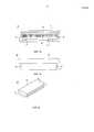
Фиг. 1A является видом в вертикальном сечении, иллюстрирующим штекерный соединитель согласно примерному варианту осуществления настоящего изобретения;FIG. 1A is a vertical sectional view illustrating a plug connector according to an exemplary embodiment of the present invention;
Фиг. 1B является видом сверху, иллюстрирующим штекерный соединитель согласно примерному варианту осуществления настоящего изобретения;FIG. 1B is a plan view illustrating a plug connector according to an exemplary embodiment of the present invention;
Фиг. 2A является видом в перспективе, иллюстрирующим гнездовой соединитель согласно примерному варианту осуществления настоящего изобретения;FIG. 2A is a perspective view illustrating a female connector according to an exemplary embodiment of the present invention;
Фиг. 2B является видом в вертикальном сечении, иллюстрирующим гнездовой соединитель согласно примерному варианту осуществления настоящего изобретения;FIG. 2B is a vertical sectional view illustrating a female connector according to an exemplary embodiment of the present invention;
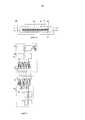
Фиг. 3 является блок-схемой, иллюстрирующей адаптер и мобильный терминал согласно примерному варианту осуществления настоящего изобретения;FIG. 3 is a block diagram illustrating an adapter and a mobile terminal according to an exemplary embodiment of the present invention;
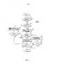
Фиг. 4 является блок-схемой последовательности операций, иллюстрирующей способ интерфейсного подключения мобильного терминала согласно примерному варианту осуществления настоящего изобретения;FIG. 4 is a flowchart illustrating an interface method for connecting a mobile terminal according to an exemplary embodiment of the present invention;
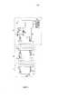
Фиг. 5 является блок-схемой, иллюстрирующей дополнительное устройство и мобильный терминал согласно примерному варианту осуществления настоящего изобретения;FIG. 5 is a block diagram illustrating an accessory device and a mobile terminal according to an exemplary embodiment of the present invention;
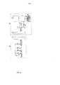
Фиг. 6 является блок-схемой, иллюстрирующей стыковочную станцию согласно примерному варианту осуществления настоящего изобретения;FIG. 6 is a block diagram illustrating a docking station according to an exemplary embodiment of the present invention;
Фиг. 7 является блок-схемой последовательности операций, иллюстрирующей способ интерфейсного подключения мобильного терминала согласно примерному варианту осуществления настоящего изобретения;FIG. 7 is a flowchart illustrating an interface method for connecting a mobile terminal according to an exemplary embodiment of the present invention;
Фиг. 8 является блок-схемой последовательности операций, иллюстрирующей способ интерфейсного подключения мобильного терминала согласно примерному варианту осуществления настоящего изобретения;FIG. 8 is a flowchart illustrating an interface method for connecting a mobile terminal according to an exemplary embodiment of the present invention;
Фиг. 9 является блок-схемой, иллюстрирующей мобильный терминал и стыковочную станцию согласно примерному варианту осуществления настоящего изобретения; иFIG. 9 is a block diagram illustrating a mobile terminal and a docking station according to an exemplary embodiment of the present invention; and
Фиг. 10 является блок-схемой, иллюстрирующей клавишную панель и мобильный терминал согласно примерному варианту осуществления настоящего изобретения, а также стыковочную станцию.FIG. 10 is a block diagram illustrating a keypad and a mobile terminal according to an exemplary embodiment of the present invention, as well as a docking station.
Следует отметить, что на всех чертежах аналогичные ссылочные позиции используются для того, чтобы иллюстрировать идентичные или аналогичные элементы, признаки и конструкции.It should be noted that in all the drawings, similar reference numerals are used to illustrate identical or similar elements, features and structures.
ПРЕДПОЧТИТЕЛЬНЫЙ ВАРИАНТ ОСУЩЕСТВЛЕНИЯ ИЗОБРЕТЕНИЯBEST MODE FOR CARRYING OUT THE INVENTION
Последующее описание со ссылкой на прилагаемые чертежи предоставляется для того, чтобы помочь в полном понимании примерных вариантов осуществления изобретения, заданного посредством формулы изобретения и ее эквивалентов. Оно включает в себя различные сведения, чтобы помочь в этом понимании, но они должны рассматриваться просто как примерные. Соответственно, специалисты в данной области техники должны распознать, что различные изменения и модификации вариантов осуществления, описанных в данном документе, могут осуществляться без отступления от сущности и объема изобретения. Помимо этого, описания хорошо известных функций и конструкций могут быть опущены для ясности и краткости.The following description with reference to the accompanying drawings is provided in order to help fully understand the exemplary embodiments of the invention defined by the claims and their equivalents. It includes various information to help in this understanding, but it should be considered merely as an example. Accordingly, those skilled in the art will recognize that various changes and modifications to the embodiments described herein can be made without departing from the spirit and scope of the invention. In addition, descriptions of well-known functions and constructions may be omitted for clarity and conciseness.
Термины и слова, используемые в последующем описании и формуле изобретения, не ограничены библиографическими значениями, а используются автором изобретения просто для того, чтобы предоставлять ясное и согласованное понимание изобретения. Соответственно, специалистам в данной области техники должно быть очевидным, что последующее описание примерных вариантов осуществления настоящего изобретения предоставляется только для цели иллюстрации, а не для цели ограничения изобретения, заданного посредством прилагаемой формулы изобретения и ее эквивалентов.The terms and words used in the following description and claims are not limited to bibliographic meanings, but are used by the inventor simply to provide a clear and consistent understanding of the invention. Accordingly, it should be apparent to those skilled in the art that the following description of exemplary embodiments of the present invention is provided only for the purpose of illustration, and not for the purpose of limiting the invention defined by the appended claims and their equivalents.
Следует понимать, что термины в единственном числе включают в себя несколько объектов ссылки, если контекст явно не предписывает иное. Таким образом, например, ссылка на "поверхность компонента" включает в себя ссылку на одну или более таких поверхностей.It should be understood that the terms in the singular include several reference objects, unless the context clearly dictates otherwise. Thus, for example, a reference to a “component surface” includes a reference to one or more such surfaces.
Под термином "по существу" подразумевается, что изложенная характеристика, параметр или значение не обязательно достигаются точно, но отклонения или варьирования, включающие в себя, например, допуски, погрешность измерения, ограничения по точности измерения и другие факторы, известные специалистам в данной области техники, могут возникать в величинах, которые не препятствуют эффекту, который должна предоставлять характеристика.The term "essentially" means that the described characteristic, parameter or value is not necessarily achieved accurately, but deviations or variations, including, for example, tolerances, measurement error, limitations on measurement accuracy and other factors known to specialists in this field of technology , can occur in quantities that do not interfere with the effect that the characteristic should provide.
Примерные варианты осуществления настоящего изобретения предоставляют мобильный терминал и способ его интерфейсного подключения для подключения внешних устройств, таких как адаптер, кабель по стандарту универсальной последовательной шины (USB), стыковочная станция, дополнительное устройство и т.п., к мобильному терминалу.Exemplary embodiments of the present invention provide a mobile terminal and a method for its interface connection for connecting external devices, such as an adapter, a universal serial bus (USB) cable, a docking station, an additional device, and the like, to a mobile terminal.
Фиг. 1A-10, описанные ниже, и различные примерные варианты осуществления, используемые для того, чтобы описывать принципы настоящего раскрытия сущности в данном патентном документе, служат только в качестве иллюстрации и не должны рассматриваться каким-либо образом, который ограничивает объем раскрытия сущности. Специалисты в данной области техники должны понимать, что принципы настоящего раскрытия сущности могут быть реализованы в любой надлежащим образом скомпонованной системе связи. Термины, используемые для того, чтобы описывать различные варианты осуществления, являются примерными. Следует понимать, что они предоставляются просто для того, чтобы помочь в понимании описания, и что их использование и определения никоим образом не ограничивают объем изобретения. Термины "первый", "второй" и т.п. используются для того, чтобы различать объекты, имеющие идентичную терминологию, и никоим образом не имеют намерение представлять хронологический порядок, если явно не указано иное. Набор задается как непустой набор, включающий в себя, по меньшей мере, один элемент.FIG. 1A-10, described below, and various exemplary embodiments used to describe the principles of the present disclosure in this patent document, are merely illustrative and should not be construed in any way that limits the scope of the disclosure. Specialists in the art should understand that the principles of the present disclosure can be implemented in any properly arranged communication system. The terms used to describe various embodiments are exemplary. It should be understood that they are provided merely to help in understanding the description, and that their use and definitions in no way limit the scope of the invention. The terms "first", "second", etc. used to distinguish between objects that have the same terminology, and in no way intend to represent a chronological order, unless explicitly stated otherwise. A set is defined as a non-empty set that includes at least one element.
Фиг. 1A является видом в вертикальном сечении, иллюстрирующим штекерный соединитель согласно примерному варианту осуществления настоящего изобретения. Фиг. 1B является видом сверху, иллюстрирующим штекерный соединитель согласно примерному варианту осуществления настоящего изобретения.FIG. 1A is a vertical sectional view illustrating a plug connector according to an exemplary embodiment of the present invention. FIG. 1B is a plan view illustrating a plug connector according to an exemplary embodiment of the present invention.
Ссылаясь на фиг. 1A и 1B, штекерный соединитель 10 может включать в себя корпус 11, позиционирующую штырьковые выводы часть 12, множество штырьковых выводов 13, эластичные части 14 и держатель 15. Позиционирующая штырьковые выводы часть 12 располагается в корпусе 11. Множество штырьковых выводов 13 располагается во множестве пазов 12a, которые формируются в позиционирующей штырьковые выводы части 12. Эластичные части 14 располагаются на обеих сторонах корпуса 11. Держатель 15 поддерживает корпус 11.Referring to FIG. 1A and 1B, the
В вышеприведенной конструкции, как показано на фиг. 1A, передняя поверхность корпуса 11 является открытой, так что корпус 11 подключается к гнездовому соединителю. Позиционирующая штырьковые выводы часть 12 располагается в корпусе 11. Кроме того, корпус 11 формирует промежуток 11a, так что позиционирующая штырьковые выводы часть гнездового соединителя, которая будет описана ниже, может быть вставлена в корпус 11 таким образом, что она контактирует с позиционирующей штырьковые выводы частью 12 со стороны штекерного соединителя 10.In the above construction, as shown in FIG. 1A, the front surface of the
Множество штырьковых выводов 13 располагается во множестве пазов 12a, которые формируются в позиционирующей штырьковые выводы части 12. Число для множества пазов 12a может составлять тридцать. Тем не менее, число пазов 12a не ограничено этим и может быть модифицировано согласно конструктивным целям. Здесь, штырьковые выводы 13 могут быть расположены во множестве пазов 12a, но могут быть расположены в некоторых из них, как показано на фиг. 1A. Другими словами, число штырьковых выводов 13 может быть определено согласно применению штекерного соединителя 10. Например, если кабель, включающий в себя штекерный соединитель 10, ограничивается только предназначением для передачи данных, необязательно располагать штырьковые выводы 13 во всех пазах 12a. Иными словами, достаточно располагать штырьковые выводы 13 только в соответствующих пазах 12a.A plurality of
Множество штырьковых выводов 13 имеет упругость и частично выступает из пазов 12a наружу, как показано на фиг. 1A. При вставке в корпус 11 позиционирующая штырьковые выводы часть со стороны гнездового соединителя плотно прилегает к штырьковому выводу со стороны гнездового соединителя.The plurality of
Эластичные части 14 обеспечивают возможность плотной вставки штекерного соединителя 10 в гнездовой соединитель. Эластичные части 14 располагаются в пазах (не показаны), сформированных на обеих сторонах корпуса 11, и частично выступают наружу, как показано на фиг. 1A и фиг. 1B.The
Фиг. 2A является видом в перспективе, иллюстрирующим гнездовой соединитель согласно примерному варианту осуществления настоящего изобретения. Фиг. 2B является видом в вертикальном сечении, иллюстрирующим гнездовой соединитель согласно примерному варианту осуществления настоящего изобретения.FIG. 2A is a perspective view illustrating a female connector according to an exemplary embodiment of the present invention. FIG. 2B is a vertical sectional view illustrating a female connector according to an exemplary embodiment of the present invention.
Ссылаясь на фиг. 2A, 2B, гнездовой соединитель 20 может включать в себя корпус 21, позиционирующую штырьковые выводы часть 22 и множество штырьковых выводов 23. Позиционирующая штырьковые выводы часть 22 располагается в корпусе 21. Множество штырьковых выводов 23 располагается во множестве пазов 22a, которые формируются в позиционирующей штырьковые выводы части 22.Referring to FIG. 2A, 2B, the
В вышеприведенной конструкции, корпус 21 формирует промежуток 21a, и его передняя поверхность является открытой, так что корпус 11 штекерного соединителя 10 может быть вставлен в корпус 21 гнездового соединителя 20. Кроме того, как показано на фиг. 2B, пазы 21b формируются на обеих внутренних сторонах корпуса 21. В этом случае, эластичные части 14 вставляются в пазы 21b. Как проиллюстрировано выше, эластичные части 14 вставляются в пазы 21b. Соответственно, если пользователь не вынимает штекерный соединитель 10, штекерный соединитель 10 плотно вставляется в гнездовой соединитель 20.In the above construction, the
Множество штырьковых выводов 23 располагается во множестве пазов 22a, которые формируются в позиционирующей штырьковые выводы части 22. Число для множества пазов 22a является идентичным числу для множества пазов 12a.A plurality of
Штырьковые выводы 23 могут быть расположены во множестве пазов 22a, как показано на фиг. 2B, или в некоторых пазах 22a. Мобильный терминал монтирует гнездовой соединитель 20, а не штекерный соединитель 10. Следовательно, для расширения функционала интерфейса штырьковые выводы располагаются во всем множестве пазов 22a.
Множество штырьковых выводов 23 располагается в позиционирующей штырьковые выводы части 22. Когда корпус 11 штекерного соединителя 10 вставляется в корпус 21 гнездового соединителя 20, множество штырьковых выводов 23 контактируют с множеством штырьковых выводов 13.A plurality of
Нижеприведенная таблица 1 иллюстрирует функции штырьковых выводов согласно примерному варианту осуществления настоящего изобретения. Как указано в таблице 1, число штырьковых выводов составляет тридцать. Все или некоторые штырьковые выводы располагаются в соединителях 10 или 20. В следующей таблице 1, "Номер штырькового вывода" означает местоположение штырькового вывода в соединителе. Первый штырьковый вывод находится в пазу, сформированном в самой правой стороне позиционирующей штырьковые выводы части 12 или 22. Штырьковый вывод, имеющий номер штырькового вывода, равный тридцатому штырьковому выводу, находится в пазу, сформированном в самой левой стороне позиционирующей штырьковые выводы части 12 или 22.The following table 1 illustrates the functions of the pin terminals according to an exemplary embodiment of the present invention. As indicated in table 1, the number of pin pins is thirty. All or some of the pin pins are located in
В дальнейшем в этом документе, на основе вышеприведенного соединителя и таблицы 1 описываются адаптер, стыковочная станция, дополнительное устройство и мобильный терминал согласно примерному варианту осуществления настоящего изображения.Hereinafter, on the basis of the above connector and table 1, an adapter, a docking station, an additional device and a mobile terminal according to an exemplary embodiment of the present image are described.
Фиг. 3 является блок-схемой, иллюстрирующей адаптер и мобильный терминал согласно примерному варианту осуществления настоящего изобретения.FIG. 3 is a block diagram illustrating an adapter and a mobile terminal according to an exemplary embodiment of the present invention.
Ссылаясь на фиг. 3, адаптер 30 может включать в себя штекер 31, преобразователь 32, соединитель 33 и усиливающую схему 34. Штекер 31 подключается к розетке, которая подает мощность переменного тока. Преобразователь 32 преобразует мощность переменного тока, вводимую из штекера 31, в мощность постоянного тока (например, 5 В/2 А). Соединитель 33 включает в себя первый, второй, третий, четвертый, седьмой и восьмой штырьковые выводы. Усиливающая схема 34 повышает мощность постоянного тока, вводимую из преобразователя 32, например, до 1,16 В и выводит повышенное напряжение в третий и четвертый штырьковые выводы. Усиливающая схема 34 повышает мощность постоянного тока для заземляющего вывода (GND) и выводит повышенную мощность в первый и второй штырьковые выводы. Здесь, преобразованная мощность постоянного тока из преобразователя 32 обходит седьмой и восьмой штырьковые выводы.Referring to FIG. 3, the
Кроме того, адаптер 30 может использоваться для зарядки большой емкости. Преобразователь 32 может преобразовывать мощность переменного тока, например, в 12 В/2 А, 12 В/5 А для зарядки большой емкости и выводить преобразованную мощность в двенадцатый и тринадцатый штырьковые выводы, представляющие собой штырьковые выводы для зарядки большой емкости, вместо седьмого и восьмого штырьковых выводов. Адаптер 30 дополнительно может включать в себя преобразователь для зарядки большой емкости, а также преобразователь 32. Преобразователь для зарядки большой емкости может подключаться к двенадцатому и тринадцатому штырьковым выводам.In addition,
Кроме того, поскольку адаптер 30 включает в себя вспомогательный соединитель, а также соединитель 33, он может быть использован в качестве кабеля передачи данных, допускающего выполнение передачи данных между двумя устройствами. Как результат, адаптер 30 может передавать и принимать данные через третий и четвертый штырьковые выводы соединителя 33.In addition, since the
Как проиллюстрировано на фиг. 3, мобильный терминал 40 может включать в себя соединитель 41, аккумулятор 42, запоминающее устройство 44 и контроллер 43. Контроллер 43 распознает тип внешнего устройства, подключенного к соединителю 41, и заряжает аккумулятор на основе распознанной информации. Соединитель 41 может включать в себя все тридцать штырьковых выводов для расширения функционала интерфейса.As illustrated in FIG. 3, the
Ниже приводятся основные функции контроллера 43. Если напряжение прикладывается к шине подачи напряжения (VBUS), подключенной к первому и второму штырьковым выводам, контроллер 43 определяет, вводится или нет разностный сигнал через линии USB D+ и D-, подключенные к третьему и четвертому штырьковым выводам, соответственно. Если разностный сигнал не вводится, контроллер 43 распознает подключенное внешнее устройство в качестве адаптера. Если разностный сигнал вводится, контроллер 43 распознает внешнее устройство в качестве USB-кабеля передачи данных с функцией зарядки. Если мощность зарядки, вводимая из седьмого и восьмого штырьковых выводов, находится в диапазоне номинальной мощности, например, от 5 Вт до 20 Вт, контроллер 43 заряжает аккумулятор 42. С другой стороны, если мощность зарядки, вводимая из седьмого и восьмого штырьковых выводов, находится за пределами диапазона номинальной мощности, контроллер 43 не заряжает аккумулятор 42. Например, если входная мощность зарядки меньше 5 Вт, контроллер 43 распознает то, что время зарядки является большим, и не заряжает аккумулятор 42. Если входная мощность зарядки превышает 5 Вт, контроллер 43 распознает то, что время жизни аккумулятора сокращается вследствие избыточной зарядки, и не заряжает аккумулятор 42.The basic functions of controller 43 are given below. If voltage is applied to a voltage supply bus (VBUS) connected to the first and second pin terminals, controller 43 determines whether or not a differential signal is input via USB lines D + and D- connected to the third and fourth pin terminals , respectively. If a differential signal is not input, the controller 43 recognizes the connected external device as an adapter. If a differential signal is input, the controller 43 recognizes the external device as a USB data cable with a charging function. If the charging power inputted from the seventh and eighth pin terminals is in the range of the rated power, for example, from 5 W to 20 W, the controller 43 charges the
Кроме того, контроллер 43 определяет, является или нет подключенный адаптер выделенным адаптером, подходящим для номинальной мощности мобильного терминала 40. В качестве определенного результата, если подключенный адаптер является выделенным адаптером, контроллер 43 заряжает аккумулятор 42. Если подключенный адаптер является невыделенным адаптером, контроллер 43 не заряжает аккумулятор 42. В вышеприведенной процедуре, если внешнее устройство распознается в качестве адаптера, контроллер 43 определяет напряжение линий USB D+ и D-. Если определенное напряжение, например, равно 1,16 В с учетом заданного диапазона ошибок, контроллер 43 распознает то, что подключенный адаптер является выделенным адаптером. Здесь, опорное напряжение в 1,16 В сохраняется в запоминающем устройстве 44. Иными словами, контроллер 43 сравнивает напряжение линий USB D+ и D- с опорным напряжением, сохраняемым в запоминающем устройстве 44. Если напряжение линий USB D+ и D- является идентичным с опорным напряжением, контроллер 43 распознает то, что адаптер, подключенный к соединителю 41, является выделенным адаптером. С другой стороны, если определенное напряжение не равно 1,16 В, контроллер 43 распознает то, что подключенный адаптер является невыделенным адаптером, и не заряжает аккумулятор 42. Хотя подключенный адаптер является невыделенным адаптером, контроллер 43 также может заряжать аккумулятор 42. Если мощность зарядки, вводимая из седьмого и восьмого штырьковых выводов, находится в диапазоне номинальной мощности, контроллер 43 может заряжать аккумулятор 42.In addition, the controller 43 determines whether or not the connected adapter is a dedicated adapter suitable for the rated power of the
Кроме того, контроллер 43 может включать в себя зарядную схему, которая уменьшает или увеличивает напряжение либо электрический ток, чтобы заряжать аккумулятор 42. Зарядная схема может быть включена в адаптер 30 вместо мобильного терминала 40. Такой адаптер означает зарядное устройство, отличающееся от адаптера без зарядной схемы.In addition, the controller 43 may include a charging circuit that reduces or increases the voltage or electric current to charge the
Кроме того, контроллер 43 может заряжать аккумулятор 42 за небольшое время с использованием мощности зарядки, вводимой из двенадцатого и тринадцатого штырьковых выводов. Тем не менее, как проиллюстрировано выше, например, когда мощность зарядки равна или превышает 30 Вт, что может чрезмерно заряжать аккумулятор 42, контроллер 43 может уменьшать напряжение или электрический ток.In addition, the controller 43 can charge the
Кроме того, контроллер 43 может принимать мощность из девятого и десятого штырьковых выводов. Поскольку принимаемая мощность используется для того, чтобы изготавливать или разрабатывать мобильный терминал 40, она не может заряжать аккумулятор 42. Когда контроллер 43 принимает мощность из девятого и десятого штырьковых выводов, он выводит сигнал, указывающий то, что мобильный терминал 40 тестируется, во внешнее устройство через пятый штырьковый вывод. Кроме того, когда мобильный терминал 40 тестируется, контроллер 43 может передавать и принимать сигнал по стандарту универсального асинхронного приемопередающего устройства (UART), представляющий собой тестовый сигнал, через двадцатый и двадцать первый штырьковые выводы.In addition, the controller 43 may receive power from the ninth and tenth pin terminals. Since the received power is used to manufacture or design the
Фиг. 4 является блок-схемой последовательности операций, иллюстрирующей способ интерфейсного подключения мобильного терминала согласно примерному варианту осуществления настоящего изобретения.FIG. 4 is a flowchart illustrating an interface method for connecting a mobile terminal according to an exemplary embodiment of the present invention.
Ссылаясь на фиг. 4, контроллер 43 определяет, прикладывается или нет напряжение через VBUS-линию, на этапе 51. Если на этапе 51 определено, что напряжение прикладывается через VBUS-линию, контроллер 43 определяет, вводятся или нет данные (разностный сигнал) через линию D (линии USB D+ и D-), на этапе 52. Если на этапе 52 определено то, что данные вводятся через линию D, контроллер 43 распознает внешнее устройство, подключенное к соединителю 41, в качестве USB-кабеля передачи данных на этапе 53, и процесс переходит к этапу 54. Контроллер 43 определяет, можно или нет заряжать аккумулятор 42, на этапе 54. При этом то, можно или нет заряжать аккумулятор 42, описано ранее. Соответственно, описание этого опускается. Если на этапе 54 определено то, что аккумулятор 42 можно заряжать, контроллер 43 заряжает аккумулятор 42 на этапе 58.Referring to FIG. 4, the controller 43 determines whether or not voltage is applied via the VBUS line in
Напротив, если на этапе 52 определено то, что данные не вводятся через линию D, контроллер 43 распознает внешнее устройство, подключенное к соединителю 41, в качестве адаптера на этапе 55, и процесс переходит к этапу 56. Контроллер 43 определяет, является или нет напряжение линии D опорным напряжением, например, в 1,16 В, на этапе 56. Если на этапе 56 определено то, что напряжение линии D является опорным напряжением, контроллер 43 распознает подключенный адаптер в качестве выделенного адаптера на этапе 57 и заряжает аккумулятор 42 на этапе 58.On the contrary, if it is determined in
Напротив, если на этапе 56 определено то, что напряжение линии D не является опорным напряжением, контроллер 43 распознает подключенный адаптер в качестве невыделенного адаптера на этапе 59, и процесс переходит к этапу 60. Контроллер 43 определяет, можно или нет заряжать аккумулятор 42, на этапе 60. Если на этапе 60 определено то, что аккумулятор 42 можно заряжать, контроллер 43 заряжает аккумулятор 42 на этапе 58.On the contrary, if it is determined in
Фиг. 5 является блок-схемой, иллюстрирующей дополнительное устройство и мобильный терминал согласно примерному варианту осуществления настоящего изобретения.FIG. 5 is a block diagram illustrating an accessory device and a mobile terminal according to an exemplary embodiment of the present invention.
Ссылаясь на фиг. 5, дополнительное устройство 60 может включать в себя соединитель 61 и резистор 62 идентификации дополнительных устройств (RID). Дополнительное устройство 60 может наращивать или изменять функции и преимущества мобильного терминала 70. Например, дополнительное устройство 60 может включать в себя наушник, головную гарнитуру, камеру, клавишную панель, мышь, стыковочную станцию, кабель передачи данных, кабель передачи данных с функцией зарядки, адаптер, зарядное устройство, внешний жесткий диск или запоминающее USB-устройство.Referring to FIG. 5,
В вышеприведенной конструкции, соединитель 61 может включать в себя тринадцатый и четырнадцатый штырьковые выводы. Тринадцатый штырьковый вывод соединяется с землей через резистор 62 идентификации дополнительных устройств (RID). Четырнадцатый штырьковый вывод непосредственно соединяется с землей.In the above construction, the
Соединитель 61 может включать в себя, по меньшей мере, один штырьковый вывод, а также вышеприведенные штырьковые выводы. Например, когда дополнительное устройство 60 является наушником, соединитель 61 дополнительно включает в себя двадцать седьмой и двадцать восьмой штырьковые выводы. Когда дополнительное устройство 60 является камерой, соединитель 61 дополнительно включает в себя третий и четвертый штырьковые выводы. Когда необходимо подавать мощность в дополнительное устройство 60, соединитель 61 дополнительно включает в себя первый, второй и шестой штырьковые выводы. Резистор 62 идентификации дополнительных устройств имеет различные сопротивления в зависимости от типа дополнительного устройства. Например, сопротивления резистора 62 идентификации дополнительных устройств могут быть перечислены в следующей таблице 2.The
Как проиллюстрировано на фиг. 5, мобильный терминал 70 может включать в себя соединитель 71, запоминающее устройство 72, модуль 73 сравнения, аналого-цифровой преобразователь (ADC) 78 и контроллер 74. Контроллер 74 распознает тип внешнего устройства, подключенного к соединителю 71, и может включать в себя все тридцать штырьковых выводов для расширения функционала интерфейса.As illustrated in FIG. 5, the
Ниже приводятся основные функции контроллера 71. Если уровень напряжения линии 75 определения дополнительных устройств изменяется с высокого уровня (Vcc) на низкий уровень (GND), контроллер 71 распознает то, что дополнительное устройство 60 подключается к соединителю 71. Здесь, как показано на фиг. 5, линия определения дополнительных устройств подключает контроллер 71 к четырнадцатому штырьковому выводу и Vcc.The basic functions of the
Когда уровень напряжения, вводимого из модуля 73 сравнения, изменяется с низкого на высокий уровень, т.е. когда сигнал прерывания вводится из модуля 73 сравнения в то время, когда мобильный терминал 70 находится в режиме ожидания, контроллер 71 активируется. Здесь, отрицательный (-) входной контактный вывод модуля 73 сравнения подключается к тринадцатому штырьковому выводу и нагрузочному напряжению (например, 3,3 В) через нагрузочный резистор (например, 10 кОм). Положительный (+) контактный вывод модуля 73 сравнения подключается к опорному напряжению (например, 3,15 В). Модуль 73 сравнения сравнивает напряжение (3,3 В или VRID), вводимое из отрицательного (-) входного контактного вывода, с опорным напряжением, вводимым из положительного (+) контактного вывода. Когда входное напряжение (3,3 В или VRID) меньше опорного напряжения, модуль 73 сравнения выводит сигнал с высоким уровнем. Когда входное напряжение (3,3 В или VRID) равно или превышает опорное напряжение, модуль 73 сравнения выводит сигнал с низким уровнем. Здесь, VRID означает напряжение через резистор 62 идентификации (RID).When the voltage level inputted from the
Кроме того, контроллер 71 сравнивает напряжение, вводимое из линии 76 идентификации дополнительных устройств, подключенной к тринадцатому штырьковому выводу, со справочной таблицей 72a, чтобы распознавать тип дополнительного устройства 60, подключенного к соединителю 71. Здесь, как показано на фиг. 5, один конец линии 76 идентификации дополнительных устройств подключается к ADC 78, а другой его конец подключается к линии, подключающей тринадцатый штырьковый вывод к нагрузочному резистору. ADC 78 преобразует входной аналоговый сигнал в цифровой сигнал и выводит цифровой сигнал в контроллер 74. Контроллер 74 анализирует цифровой сигнал, вводимый из ADC 78, чтобы вычислять напряжение. ADC 78 может быть включен в контроллер 74. Справочная таблица 72a сохраняется в запоминающем устройстве 72, как проиллюстрировано в таблице 2. В примерных вариантах осуществления настоящего изобретения, дополнительное устройство 60 имеет различные резисторы RID идентификации (62) по типу. Соответственно, напряжение, вводимое в контроллер 74 через линию 76 идентификации, различается посредством дополнительных устройств, подключенных к соединителю 71. Когда напряжение, вводимое из линии 76 идентификации дополнительных устройств, составляет 3,3 В в состоянии низкого уровня напряжения линии 75 определения дополнительных устройств, контроллер 71 распознает подключенное дополнительное устройство в качестве стыковочной станции. Когда входное напряжение составляет 2,2 В, контроллер 71 распознает подключенное дополнительное устройство в качестве комплекта для подключения камеры.In addition, the
Фиг. 6 является блок-схемой, иллюстрирующей стыковочную станцию согласно примерному варианту осуществления настоящего изобретения.FIG. 6 is a block diagram illustrating a docking station according to an exemplary embodiment of the present invention.
Ссылаясь на фиг. 6, стыковочная станция 80 подключает другое дополнительное устройство 60 к мобильному терминалу 70. Стыковочная станция 80 может включать в себя первый соединитель 81, подключенный к другому дополнительному устройству 61, и второй соединитель 82, подключенный к мобильному терминалу 70. Первый соединитель 81 включает в себя тринадцатый штырьковый вывод и, по меньшей мере, еще один другой штырьковый вывод. Второй соединитель 82 включает в себя тринадцатый и четырнадцатый штырьковые выводы и, по меньшей мере, еще один другой штырьковый вывод. Тринадцатый штырьковый вывод первого соединителя 81 подключается к тринадцатому штырьковому выводу второго соединителя 82 без отдельного резистора. Четырнадцатый штырьковый вывод второго соединителя 82 соединяется с землей.Referring to FIG. 6, the
Если линия 75 определения дополнительных устройств имеет напряжение высокого уровня, и напряжение, приложенное из линии 76 идентификации дополнительных устройств, является нагрузочным напряжением (3,3 В), контроллер 74 распознает то, что стыковочная станция 80 подключается к соединителю 71, и другое дополнительное устройство 60 не подключается к стыковочной станции 80.If the
В состоянии, в котором линия 75 определения дополнительных устройств имеет напряжение высокого уровня, и напряжение, приложенное из линии 76 идентификации дополнительных устройств, не является нагрузочным напряжением (3,3 В), если напряжение, приложенное из линии 76 идентификации дополнительных устройств, изменяется на нагрузочное напряжение (3,3 В), контроллер 74 распознает то, что другое дополнительное устройство 60 извлечено из стыковочной станции 80.In a state in which the
Фиг. 7 является блок-схемой последовательности операций, иллюстрирующей способ интерфейсного подключения мобильного терминала согласно примерному варианту осуществления настоящего изобретения. Предполагается, что блок-схема последовательности операций способа по фиг. 7 начинается в активном режиме, допускающем определение изменения уровня напряжения линии 75 определения дополнительных устройств посредством контроллера 74.FIG. 7 is a flowchart illustrating an interface method for connecting a mobile terminal according to an exemplary embodiment of the present invention. It is assumed that the flowchart of FIG. 7 starts in the active mode, allowing the determination of the change in the voltage level of the
Ссылаясь на фиг. 7, последовательность операций проиллюстрирована в случае подключения дополнительного устройства 60 к мобильному терминалу 70 пользователем, подключения стыковочной станции 80 к мобильному терминалу 70 и затем подключения дополнительного устройства 60 к стыковочной станции 80 пользователем либо подключения дополнительного устройства 60 к стыковочной станции 80 и затем подключения стыковочной станции 80 к мобильному терминалу 70.Referring to FIG. 7, the flowchart is illustrated in the case of connecting the
На этапе 91, контроллер 74 определяет, является или нет уровень напряжения в линии 75 определения дополнительных устройств низким. Если на этапе 91 определено то, что уровень напряжения линии 75 определения дополнительных устройств является низким, процесс переходит к этапу 92. Контроллер 74 определяет, является или нет напряжение линии 76 идентификации дополнительных устройств нагрузочным напряжением (3,3 В), на этапе 92.At
Если на этапе 92 определено то, что напряжение линии 76 идентификации дополнительных устройств является нагрузочным напряжением, процесс переходит к этапу 93. Контроллер 74 распознает дополнительное устройство, подключенное к соединителю 71, в качестве стыковочной станции 80 на этапе 93, и процесс переходит к этапу 94. Контроллер 74 определяет, поддерживает или нет линия 76 идентификации дополнительных устройств нагрузочное напряжение (3,3 В), на этапе 94. Если на этапе 94 определено то, что линия 76 идентификации дополнительных устройств не поддерживает нагрузочное напряжение, процесс переходит к этапу 95. Напротив, если на этапе 94 определено то, что линия 76 идентификации дополнительных устройств поддерживает нагрузочное напряжение, процесс переходит к этапу 97. Контроллер 74 распознает тип дополнительного устройства 60, подключенного к стыковочной станции 80, на этапе 95, и процесс переходит к этапу 96. Контроллер 74 определяет, является или нет напряжение линии 76 идентификации дополнительных устройств нагрузочным напряжением (3,3 В), на этапе 96. Если на этапе 96 определено то, что напряжение линии 76 идентификации дополнительных устройств является нагрузочным напряжением, процесс переходит к этапу 97. Контроллер 74 определяет, является или нет уровень напряжения линии 75 определения дополнительных устройств высоким, на этапе 97. Если на этапе 97 определено то, что уровень напряжения линии 75 определения дополнительных устройств является высоким, контроллер 74 распознает то, что подключение между стыковочной станцией 80 и дополнительным устройством 60 прекращается, и процесс завершается. Напротив, если на этапе 97 определено то, что уровень напряжения линии 75 определения дополнительных устройств является низким, процесс переходит к этапу 93.If it is determined in
С другой стороны, если на этапе 92 определено то, что напряжение линии 76 идентификации дополнительных устройств не является нагрузочным напряжением, процесс переходит к этапу 98. Контроллер 74 распознает тип дополнительного устройства, подключенного к соединителю 71, посредством обращения к справочной таблице 72a на этапе 98, и процесс переходит к этапу 96. В этом случае, соединитель 71 непосредственно подключается к дополнительному устройству 60 или подключается к дополнительному устройству 60 через стыковочную станцию 80.On the other hand, if it is determined in
Фиг. 8 является блок-схемой последовательности операций, иллюстрирующей способ интерфейсного подключения мобильного терминала согласно примерному варианту осуществления настоящего изобретения.FIG. 8 is a flowchart illustrating an interface method for connecting a mobile terminal according to an exemplary embodiment of the present invention.
Ссылаясь на фиг. 8, например, когда отсутствует ввод от пользователя через средство пользовательского интерфейса (например, сенсорный экран) в течение предварительно заданного времени, контроллер 74 переключает рабочий режим мобильного терминала 70 из активного режима на режим ожидания на этапе 101. Здесь, режим ожидания может задаваться как режим, в котором только минимальная функция выполняется для экономии ресурса аккумулятора. Например, контроллер 74 закрывает экран в режиме ожидания. Кроме того, контроллер 74 не реагирует на изменение уровня напряжения линии определения 75.Referring to FIG. 8, for example, when there is no input from the user through the user interface means (eg, touch screen) for a predetermined time, the
Когда сигнал прерывания из модуля 73 сравнения вводится в контроллер 74 на этапе 102, он прекращает режим ожидания, и процесс переходит к этапу 103. На этапе 103, контроллер 74 распознает тип дополнительного устройства, подключенного к соединителю 71, посредством обращения к справочной таблице 72a. В этом случае, соединитель 71 непосредственно подключается к дополнительному устройству 60 или подключается к дополнительному устройству 60 через стыковочную станцию 80.When the interrupt signal from the
Фиг. 9 является блок-схемой, иллюстрирующей мобильный терминал и стыковочную станцию согласно примерному варианту осуществления настоящего изобретения.FIG. 9 is a block diagram illustrating a mobile terminal and a docking station according to an exemplary embodiment of the present invention.
Ссылаясь на фиг. 9, мобильный терминал 110 может включать в себя соединитель 111 и контроллер 112. Соединитель 111 включает в себя семнадцатый, восемнадцатый и девятнадцатый штырьковые выводы. Контроллер 112 управляет выводом аудио-видеосигнала по стандарту линии сигналов высокой четкости для подключения мобильных устройств (MHL). Здесь, как показано на фиг. 9, линия 113 идентификации MHL подключает контроллер 112 к девятнадцатому штырьковому выводу и Vcc.Referring to FIG. 9, the
Стыковочная станция 120 включает в себя соединитель 121, кодер 122 и контактный вывод 123 по стандарту мультимедийного интерфейса высокой четкости (HDMI). Соединитель 121 включает в себя семнадцатый, восемнадцатый и девятнадцатый штырьковые выводы. Кодер 121 преобразует MHL в HDMI и выводит HDMI в контактный вывод 123 HDMI. Контактный вывод 123 HDMI подключается к HDMI-кабелю.
Если уровень напряжения линии 113 идентификации MHL изменяется с высокого на низкий уровень, контроллер 112 распознает то, что стыковочная станция 120, включающая в себя кодер 112, подключается к соединителю 111, и выводит MHL в стыковочную станцию 120 через семнадцатый и восемнадцатый штырьковые выводы.If the voltage level of the
Фиг. 10 является блок-схемой, иллюстрирующей клавишную панель и мобильный терминал согласно примерному варианту осуществления настоящего изобретения.FIG. 10 is a block diagram illustrating a keypad and a mobile terminal according to an exemplary embodiment of the present invention.
Ссылаясь на фиг. 10, клавишная панель 130 может включать в себя соединитель 131 с двадцать четвертым штырьковым выводом, множество переключателей 132 и множество резисторов R1, R2, R3,..., Rn, формирующих множество наборов. Один контактный вывод каждого набора соединяется с землей, а другой его контактный вывод подключается к двадцать четвертому штырьковому выводу. Здесь, каждый из множества резисторов R1, R2, R3,..., Rn имеет значение клавиши, перечисленное в нижеприведенной таблице 3.Referring to FIG. 10, the
Ссылаясь на фиг. 10, мобильный терминал 140 может включать в себя соединитель 141, контроллер 142, запоминающее устройство 143, модуль 144 сравнения и ADC 145. Соединитель включает в себя двадцать четвертый штырьковый вывод. Контроллер 142 распознает тип клавишной панели 130, подключенной к соединителю 141. Запоминающее устройство 143 сохраняет справочную таблицу 143a значений клавиш, приведенную в таблице 3. Когда клавишная панель 130 подключается к соединителю 141, модуль 144 сравнения формирует и выводит сигнал прерывания в контроллер 142. ADC 145 преобразует аналоговый сигнал, вводимый из двадцать четвертого штырькового вывода, в цифровой сигнал и выводит цифровой сигнал в контроллер 142.Referring to FIG. 10, the
Когда пользователь нажимает на клавишную панель 130, чтобы формировать сигнал прерывания из модуля 144 сравнения, контроллер 142 сравнивает напряжение, вводимое из линии 146 определения значений клавиш, со справочной таблицей 143a значений клавиш, чтобы распознавать тип нажатой клавиши.When the user presses the
Хотя изобретение показано и описано со ссылкой на его конкретные примерные варианты осуществления, специалисты в данной области техники должны понимать, что различные изменения по форме и содержанию могут осуществляться без отступления от сущности изобретения, заданного посредством прилагаемой формулы изобретения и ее эквивалентов.Although the invention has been shown and described with reference to its specific exemplary embodiments, those skilled in the art should understand that various changes in form and content can be made without departing from the spirit of the invention as defined by the appended claims and their equivalents.
Claims (10)
Translated fromRussian- аккумулятор (42);
- соединитель (41), включающий в себя штырьковый вывод для передачи данных и первый и второй питающие штырьковые выводы для зарядки аккумулятора (42);
- запоминающее устройство (44), выполненное с возможностью сохранения опорного напряжения, указывающего выделенный адаптер аккумулятора (42); и
- контроллер (43), выполненный с возможностью распознавания внешнего устройства, подключенного к соединителю, в качестве выделенного адаптера, когда напряжение вводится из первого и второго питающих штырьковых выводов, и напряжение, вводимое из штырькового вывода для передачи данных, является опорным напряжением, и зарядки аккумулятора (42) с помощью мощности, вводимой в первый и второй питающие штырьковые выводы, и распознавания, когда напряжение вводится из первого и второго питающих штырьковых выводов, и напряжение, вводимое из штырькового вывода для передачи данных, не является опорным напряжением, внешнего устройства, подключенного к соединителю (41), в качестве невыделенного зарядного устройства, и определения возможно ли заряжать аккумулятор (42) используя невыделенное зарядное устройство и зарядки аккумулятора (42), если определено, что возможно заряжать аккумулятор (42) используя невыделенное зарядное устройство.1. Mobile terminal (40), comprising:
- battery (42);
- a connector (41) including a pin terminal for data transfer and a first and second supply pin terminals for charging a battery (42);
- a storage device (44), configured to store a reference voltage indicating a dedicated battery adapter (42); and
- a controller (43) configured to recognize an external device connected to the connector as a dedicated adapter when the voltage is input from the first and second supply pin terminals and the voltage input from the pin terminal for data transmission is a reference voltage, and charging the battery (42) using the power input to the first and second supply pin terminals, and recognition when the voltage is input from the first and second supply pin terminals, and the voltage input from the pins The data output terminal is not the reference voltage of the external device connected to the connector (41) as an unallocated charger, and whether it is possible to charge the battery (42) using an unallocated charger and charging the battery (42), if specified, that it is possible to charge the battery (42) using a non-dedicated charger.
при этом запоминающее устройство (44) выполнено с возможностью сохранения справочной таблицы для идентификации дополнительного устройства, и
контроллер (43) выполнен с возможностью сравнения напряжения, вводимого из штырькового вывода для идентификации дополнительного устройства, со справочной таблицей, когда напряжение, вводимое из штырькового вывода для определения дополнительного устройства, изменяется для того, чтобы распознавать тип дополнительного устройства, подключенного к соединителю (41).2. The mobile terminal (40) according to claim 1, wherein the connector (41) further comprises a pin terminal for determining an additional device and a pin terminal for identifying an additional device,
wherein the storage device (44) is configured to save a lookup table for identifying an additional device, and
the controller (43) is configured to compare the voltage input from the pin output for identifying an additional device with a look-up table when the voltage input from the pin output to identify an additional device is changed in order to recognize the type of additional device connected to the connector (41 )
первый, второй, пятнадцатый, шестнадцатый и тридцатый штырьковые выводы соединителя (41) являются вторыми питающими штырьковыми выводами,
третий и четвертый штырьковые выводы соединителя являются штырьковыми выводами для передачи данных, и
тринадцатый и четырнадцатый штырьковые выводы соединителя являются штырьковыми выводами для определения дополнительного устройства и штырьковым выводом для идентификации дополнительного устройства, соответственно.5. The mobile terminal according to claim 2, in which the seventh and eighth pin terminals of the connector (41) are the first supply pin terminals,
the first, second, fifteenth, sixteenth and thirtieth pin terminals of the connector (41) are second supply pin terminals,
the third and fourth pin terminals of the connector are pin terminals for transmitting data, and
the thirteenth and fourteenth pin terminals of the connector are pin terminals for determining an additional device and pin terminals for identifying an additional device, respectively.
пятый штырьковый вывод соединителя (41) является зажимным штырьковым выводом включения питания, и
двадцатый и двадцать первый штырьковые выводы соединителя (41) являются штырьковыми выводами для передачи и приема тестового сигнала, соответственно.9. The mobile terminal (40) according to claim 8, in which the ninth and tenth pin terminals of the connector (41) are a battery terminal,
the fifth pin terminal of the connector (41) is a clamp pin terminal of the power on, and
the twentieth and twenty-first pin terminals of the connector (41) are pin terminals for transmitting and receiving a test signal, respectively.
- определяют (56), является или нет напряжение, вводимое из штырькового вывода для передачи данных, предварительно заданным опорным напряжением, когда напряжение вводится из первого и второго питающих штырьковых выводов;
- распознают (57) внешнее устройство, подключенное к соединителю (41), в качестве выделенного адаптера аккумулятора (42), когда напряжение, вводимое из штырькового вывода для передачи данных, является предварительно заданным опорным напряжением; и
- заряжают (58) аккумулятор (42) с помощью мощности, вводимой из первого и второго питающих штырьковых выводов, когда внешнее устройство, подключенное к соединителю (41), распознается в качестве выделенного адаптера аккумулятора (42), и
распознают (59), когда напряжение вводится из первого и второго питающих штырьковых выводов, и напряжение, вводимое из штырькового вывода для передачи данных, не является опорным напряжением, внешнее устройство, подключенное к соединителю (41), в качестве невыделенного зарядного устройства, и определяют(60), возможно ли заряжать аккумулятор (42), используя невыделенное зарядное устройство, и заряжают (58) аккумулятор (42), если определено, что возможно заряжать аккумулятор (42), используя невыделенное зарядное устройство.10. A method for interface connection of a mobile terminal (40), including a connector (41) with a pin terminal for data transfer and a first and second power pin terminals for charging a battery (42) of a mobile terminal (40), the method comprising the steps of which:
- determine (56) whether or not the voltage inputted from the pin terminal for data transfer is a predetermined reference voltage when the voltage is input from the first and second supply pin terminals;
- recognize (57) an external device connected to the connector (41) as a dedicated battery adapter (42) when the voltage input from the pin terminal for data transfer is a predetermined reference voltage; and
- charge (58) the battery (42) using the power input from the first and second supply pin terminals when an external device connected to the connector (41) is recognized as a dedicated battery adapter (42), and
recognize (59) when the voltage is input from the first and second supply pin terminals, and the voltage input from the pin terminal for data transfer is not a reference voltage, an external device connected to the connector (41) as an unallocated charger, and determine (60) whether it is possible to charge the battery (42) using a non-dedicated charger, and charge (58) the battery (42) if it is determined that it is possible to charge the battery (42) using a non-dedicated charger.
Applications Claiming Priority (3)
| Application Number | Priority Date | Filing Date | Title |
|---|---|---|---|
| KR1020110024814AKR101846925B1 (en) | 2011-03-21 | 2011-03-21 | Mobile terminal and interface method |
| KR10-2011-0024814 | 2011-03-21 | ||
| PCT/KR2012/001610WO2012128486A2 (en) | 2011-03-21 | 2012-03-05 | Mobile terminal and interface method thereof |
Publications (2)
| Publication Number | Publication Date |
|---|---|
| RU2013142958A RU2013142958A (en) | 2015-03-27 |
| RU2587159C2true RU2587159C2 (en) | 2016-06-20 |
Family
ID=46878276
Family Applications (1)
| Application Number | Title | Priority Date | Filing Date |
|---|---|---|---|
| RU2013142958/07ARU2587159C2 (en) | 2011-03-21 | 2012-03-05 | Mobile terminal and interface connection method therefor |
Country Status (9)
| Country | Link |
|---|---|
| US (2) | US9037756B2 (en) |
| EP (1) | EP2689632B1 (en) |
| JP (1) | JP6173297B2 (en) |
| KR (1) | KR101846925B1 (en) |
| CN (1) | CN103444258B (en) |
| BR (1) | BR112013024204A2 (en) |
| CA (1) | CA2830435A1 (en) |
| RU (1) | RU2587159C2 (en) |
| WO (1) | WO2012128486A2 (en) |
Cited By (1)
| Publication number | Priority date | Publication date | Assignee | Title |
|---|---|---|---|---|
| RU2809933C1 (en)* | 2019-11-20 | 2023-12-19 | Фрезениус Каби (Наньчан) Ко., Лтд. | Slave computer, connector, slave computer node and communication system |
Families Citing this family (40)
| Publication number | Priority date | Publication date | Assignee | Title |
|---|---|---|---|---|
| US8841886B2 (en)* | 2009-09-11 | 2014-09-23 | Nxp B.V. | Power charging of mobile devices via a HDMI interface |
| US9312599B2 (en) | 2013-01-08 | 2016-04-12 | Voxx International Corporation | Low profile omni-directional planar antenna with WiFi video streaming capability through broadband network |
| US11797469B2 (en) | 2013-05-07 | 2023-10-24 | Snap-On Incorporated | Method and system of using USB user interface in electronic torque wrench |
| CN104238396A (en)* | 2013-06-18 | 2014-12-24 | 深圳市蓝韵实业有限公司 | Automatic accessory recognizing system and implementation method |
| WO2015030815A1 (en)* | 2013-08-30 | 2015-03-05 | Hewlett-Packard Development Company, L.P. | Identification of a unique attribute of a power adapter based on an adjust pin |
| EP3084557A4 (en)* | 2013-12-19 | 2017-09-13 | Thomson Licensing | Method and apparatus for charging electronic device with usb connection |
| CN103762690B (en) | 2014-01-28 | 2016-08-24 | 广东欧珀移动通信有限公司 | Charging system |
| KR102240508B1 (en)* | 2014-03-10 | 2021-04-16 | 삼성전자주식회사 | Method and apparatus for controlling power output from electronic device to external electronic device |
| CN104267781B (en)* | 2014-08-07 | 2018-12-18 | 惠州Tcl移动通信有限公司 | The reusable mobile terminal of docking station and its method of docking station multiplexing |
| CN105676986B (en)* | 2014-11-20 | 2019-01-22 | 鸿富锦精密工业(武汉)有限公司 | Electronic equipment interface switching system |
| US10488903B2 (en) | 2015-03-24 | 2019-11-26 | Huawei Technologies Co., Ltd. | Extended base of mobile terminal and power supply management method for extended base |
| EP3086434A1 (en)* | 2015-04-24 | 2016-10-26 | HILTI Aktiengesellschaft | Mains powered battery charger, charging system and handheld machine tool |
| CN105098900B (en) | 2015-08-05 | 2018-05-29 | 青岛海信移动通信技术股份有限公司 | Mobile terminal, can directly charge source adapter and charging method |
| WO2017088138A1 (en)* | 2015-11-26 | 2017-06-01 | 广东欧珀移动通信有限公司 | Charging device for mobile terminal |
| US9851755B2 (en)* | 2015-12-15 | 2017-12-26 | Lenovo (Singapore) Pte. Ltd. | Hot swapping batteries in a mobile device |
| CN107104469A (en)* | 2016-02-19 | 2017-08-29 | 德业科技股份有限公司 | Power supply device and method capable of adjusting charging current according to pull-down resistance value of mobile device |
| CA3024096A1 (en)* | 2016-05-13 | 2017-11-16 | Carter-Hoffmann LLC | Transportable warming cart |
| KR20180004388A (en)* | 2016-07-03 | 2018-01-11 | 삼성전자주식회사 | Terminal, input apparatus and power controlling method thereof |
| CN106300319B (en)* | 2016-08-08 | 2018-08-17 | 华东光电集成器件研究所 | A kind of integrated circuit anti-plug detection protective device |
| KR20180044602A (en)* | 2016-10-24 | 2018-05-03 | 삼성전자주식회사 | Method for detecting cable insertion and an electronic device thereof |
| CN108271094B (en)* | 2016-12-30 | 2021-06-11 | 维沃移动通信有限公司 | Processing method of access equipment and mobile terminal |
| TW201830940A (en)* | 2017-02-08 | 2018-08-16 | 陳淑玲 | Wearable device with three-wire transmission |
| CN108666826B (en)* | 2017-03-31 | 2020-06-23 | 中兴通讯股份有限公司 | Adapter, terminal equipment and adapter system |
| SG10202103518RA (en)* | 2017-05-31 | 2021-05-28 | Canon Kk | Adapter device, imaging apparatus, and accessory |
| CN108989615B (en) | 2017-05-31 | 2021-01-15 | 佳能株式会社 | Image pickup apparatus and accessory |
| RU2724459C2 (en) | 2017-05-31 | 2020-06-23 | Кэнон Кабусики Кайся | Lens device, an image capturing device on which lens device can be mounted, and a camera system |
| RU2724453C2 (en) | 2017-05-31 | 2020-06-23 | Кэнон Кабусики Кайся | Lens device, an image capturing device on which a lens device can be mounted, and a camera system |
| CN113347341A (en) | 2017-05-31 | 2021-09-03 | 佳能株式会社 | Accessory, image pickup apparatus capable of mounting accessory, and camera system |
| TWI771631B (en) | 2017-05-31 | 2022-07-21 | 日商佳能股份有限公司 | Mount apparatus and accessory for imaging apparatus |
| EP3988998B1 (en) | 2017-05-31 | 2024-11-27 | Canon Kabushiki Kaisha | Lens mount, accessory, camera mount, image pickup apparatus, and camera system |
| KR102317505B1 (en)* | 2017-06-09 | 2021-10-26 | 삼성에스디아이 주식회사 | battery pack and charging control method for battery pack |
| US20180365189A1 (en)* | 2017-06-16 | 2018-12-20 | Bernoulli Enterprise, Inc. | Method and Apparatus for Device Identification Using a Serial Port |
| CN108833858B (en) | 2018-03-29 | 2021-01-26 | 中磊电子股份有限公司 | Video doorbell system |
| CN108667095B (en)* | 2018-05-16 | 2024-01-12 | 济南保特电子设备有限公司 | Power management distributor |
| JP7123638B2 (en)* | 2018-06-06 | 2022-08-23 | キヤノン株式会社 | Accessories and imagers |
| KR102787543B1 (en) | 2019-09-20 | 2025-04-01 | 삼성전자주식회사 | An electronic device supporting connection with external device and power consumption reducing method when using in connection with the external device |
| KR20220064153A (en)* | 2020-11-11 | 2022-05-18 | 삼성전자주식회사 | Electronic device comprising combinable groove |
| US11934285B2 (en)* | 2021-01-15 | 2024-03-19 | Google Llc | Identification/communication interface between consumer electronic devices and accessory devices |
| CN113127396A (en)* | 2021-04-29 | 2021-07-16 | 东莞市小精灵教育软件有限公司 | Equipment function expansion method, intelligent terminal and accessory expansion connector |
| CN119071384B (en)* | 2024-07-24 | 2025-07-04 | 荣耀终端股份有限公司 | Icon display method, electronic device, chip system and storage medium |
Citations (2)
| Publication number | Priority date | Publication date | Assignee | Title |
|---|---|---|---|---|
| RU2345507C2 (en)* | 2005-04-27 | 2009-01-27 | Эл Джи Электроникс Инк. | Mobile communication terminal using multifunctional pocket, and method of application thereof |
| RU2369980C2 (en)* | 2003-12-12 | 2009-10-10 | Сони Эрикссон Мобайл Коммьюникейшнз Аб | Algorithm of accessories identification for system adapter socket |
Family Cites Families (25)
| Publication number | Priority date | Publication date | Assignee | Title |
|---|---|---|---|---|
| JP2530098B2 (en)* | 1993-08-30 | 1996-09-04 | 八重洲無線株式会社 | Portable electronic device, its battery pack, its charger, and its attachment |
| US5783926A (en)* | 1996-11-05 | 1998-07-21 | Ericsson, Inc. | Apparatus for identifying accessories connected to radiotelephone equipment |
| US5859522A (en)* | 1997-07-16 | 1999-01-12 | Motorola, Inc. | Accessory identification apparatus and method |
| JPH1166862A (en)* | 1997-08-14 | 1999-03-09 | Nec Corp | Semiconductor memory |
| WO2000065445A1 (en)* | 1999-04-23 | 2000-11-02 | Palm, Inc. | System and method for detection of an accessory device connected to a portable computer |
| JP2010136388A (en)* | 2000-02-29 | 2010-06-17 | Willcom Inc | Digital camera for handheld terminal, and digital camera system |
| JP2002101156A (en)* | 2000-09-22 | 2002-04-05 | Sony Corp | Portable telephone and method for processing voice |
| GB0212262D0 (en)* | 2002-05-28 | 2002-07-10 | Sendo Int Ltd | Accessory detection and identification |
| US20030231168A1 (en)* | 2002-06-18 | 2003-12-18 | Jory Bell | Component for use as a portable computing device and pointing device in a modular computing system |
| KR100479203B1 (en)* | 2002-12-31 | 2005-03-28 | 주식회사 팬택앤큐리텔 | Apparatus for recognizing charger |
| GB2402819B (en) | 2003-06-11 | 2005-08-03 | Research In Motion Ltd | Universal serial bus charger for a mobile device |
| CN2660763Y (en)* | 2003-11-14 | 2004-12-01 | 联想(北京)有限公司 | Intelligence charging seat of PDA or cell phone |
| US20070132733A1 (en)* | 2004-06-08 | 2007-06-14 | Pranil Ram | Computer Apparatus with added functionality |
| EP1717910B1 (en) | 2005-04-27 | 2011-12-14 | LG Electronics Inc. | Mobile communications terminal using multi-functional socket and method thereof |
| US20070145945A1 (en) | 2005-12-28 | 2007-06-28 | Mcginley James W | Method and apparatus to authenticate battery charging device |
| US8532678B2 (en)* | 2006-03-08 | 2013-09-10 | Tomtom International B.V. | Portable GPS navigation device |
| US8065544B2 (en)* | 2007-05-03 | 2011-11-22 | Microchip Technology Incorporated | Interrupt/wake-up of an electronic device in a low power sleep mode when detecting a sensor or frequency source activated frequency change |
| KR20090028196A (en)* | 2007-09-14 | 2009-03-18 | 삼성전자주식회사 | Charging device and method of mobile terminal |
| KR100793071B1 (en)* | 2007-10-23 | 2008-01-10 | 주식회사 자티전자 | Portable terminal and method for managing power savings according to external environment changes |
| KR100974519B1 (en)* | 2008-01-17 | 2010-08-10 | (주)블루버드 소프트 | Portable terminal and battery charging method thereof |
| US20100007355A1 (en)* | 2008-07-10 | 2010-01-14 | Litepoint Corporation | Method for testing radio frequency (rf) receiver to provide power correction data |
| US8180397B2 (en) | 2009-10-28 | 2012-05-15 | Research In Motion Limited | Mobile communications device accessory identification system, an improved accessory for use with a mobile communications device, and a method of identifying same |
| JP5644347B2 (en)* | 2010-01-28 | 2014-12-24 | 株式会社リコー | Power control apparatus, image forming apparatus, and power control program |
| US8350522B2 (en) | 2010-03-10 | 2013-01-08 | Apple Inc. | External power source voltage drop compensation for portable devices |
| US20120071215A1 (en)* | 2010-09-16 | 2012-03-22 | Motorola Mobility, Inc. | Method and Apparatus for Controlling a Smart Phone Charger |
- 2011
- 2011-03-21KRKR1020110024814Apatent/KR101846925B1/ennot_activeExpired - Fee Related
- 2012
- 2012-03-05RURU2013142958/07Apatent/RU2587159C2/ennot_activeIP Right Cessation
- 2012-03-05WOPCT/KR2012/001610patent/WO2012128486A2/ennot_activeCeased
- 2012-03-05CNCN201280014120.6Apatent/CN103444258B/ennot_activeExpired - Fee Related
- 2012-03-05BRBR112013024204Apatent/BR112013024204A2/ennot_activeApplication Discontinuation
- 2012-03-05EPEP12760978.2Apatent/EP2689632B1/ennot_activeNot-in-force
- 2012-03-05CACA2830435Apatent/CA2830435A1/ennot_activeAbandoned
- 2012-03-05JPJP2014500984Apatent/JP6173297B2/ennot_activeExpired - Fee Related
- 2012-03-06USUS13/413,167patent/US9037756B2/enactiveActive
- 2015
- 2015-05-06USUS14/705,499patent/US9627899B2/ennot_activeExpired - Fee Related
Patent Citations (2)
| Publication number | Priority date | Publication date | Assignee | Title |
|---|---|---|---|---|
| RU2369980C2 (en)* | 2003-12-12 | 2009-10-10 | Сони Эрикссон Мобайл Коммьюникейшнз Аб | Algorithm of accessories identification for system adapter socket |
| RU2345507C2 (en)* | 2005-04-27 | 2009-01-27 | Эл Джи Электроникс Инк. | Mobile communication terminal using multifunctional pocket, and method of application thereof |
Cited By (1)
| Publication number | Priority date | Publication date | Assignee | Title |
|---|---|---|---|---|
| RU2809933C1 (en)* | 2019-11-20 | 2023-12-19 | Фрезениус Каби (Наньчан) Ко., Лтд. | Slave computer, connector, slave computer node and communication system |
Also Published As
| Publication number | Publication date |
|---|---|
| JP6173297B2 (en) | 2017-08-02 |
| CN103444258B (en) | 2017-09-29 |
| KR101846925B1 (en) | 2018-04-09 |
| RU2013142958A (en) | 2015-03-27 |
| AU2012232019A1 (en) | 2013-08-01 |
| WO2012128486A3 (en) | 2013-01-03 |
| WO2012128486A2 (en) | 2012-09-27 |
| EP2689632A2 (en) | 2014-01-29 |
| US20150263555A1 (en) | 2015-09-17 |
| US20120246350A1 (en) | 2012-09-27 |
| CA2830435A1 (en) | 2012-09-27 |
| BR112013024204A2 (en) | 2017-09-26 |
| EP2689632A4 (en) | 2015-04-22 |
| JP2014510491A (en) | 2014-04-24 |
| US9627899B2 (en) | 2017-04-18 |
| EP2689632B1 (en) | 2018-06-13 |
| CN103444258A (en) | 2013-12-11 |
| KR20120107237A (en) | 2012-10-02 |
| US9037756B2 (en) | 2015-05-19 |
Similar Documents
| Publication | Publication Date | Title |
|---|---|---|
| RU2587159C2 (en) | Mobile terminal and interface connection method therefor | |
| CN108718020B (en) | hub | |
| CN108988431B (en) | Multi-protocol charging device and multi-protocol charging method | |
| US9866055B2 (en) | Automatic scheme to detect multi-standard charger types | |
| US8248035B2 (en) | Voltage converting apparatus | |
| US20070075680A1 (en) | Charging mode control circuit | |
| KR101216145B1 (en) | Method and apparatus for charging for battery of portable terminal | |
| TWM376027U (en) | Embedded type electric charging socket | |
| CN113535622B (en) | Power switching systems, USB sockets and electronic devices | |
| CN116707047A (en) | Charge and discharge circuit, electronic equipment and electronic system | |
| CN112688373A (en) | Charging method and device and data line | |
| US10193286B2 (en) | Electronic device and control method thereof | |
| TW201535128A (en) | Electric system | |
| CN104281184B (en) | Adaptive power supply system and method for supplying power to | |
| CN100358211C (en) | Charging set for handset | |
| CN105811554A (en) | Battery bridging and charging device and method | |
| US11881736B2 (en) | Power system | |
| CN112086830B (en) | Data line circuit communicating with iOS device | |
| US10476290B2 (en) | Charging two-terminal portable electronic devices | |
| WO2005112220A1 (en) | A portable electronic equipment and an extending head of the equipment and a charging interface of the charging device of the equipment | |
| CN219247497U (en) | Bluetooth adapter and Bluetooth adapter system | |
| CN218783273U (en) | Special electrifying device for Type L | |
| KR200458625Y1 (en) | Data cable | |
| CN106532790B (en) | Mobile power supply device and power supply control method thereof | |
| CN116526233A (en) | Adapter and charging system |
Legal Events
| Date | Code | Title | Description |
|---|---|---|---|
| MM4A | The patent is invalid due to non-payment of fees | Effective date:20190306 |