RU2580529C1 - Thermal interface material - Google Patents
Thermal interface materialDownload PDFInfo
- Publication number
- RU2580529C1 RU2580529C1RU2014138814/28ARU2014138814ARU2580529C1RU 2580529 C1RU2580529 C1RU 2580529C1RU 2014138814/28 ARU2014138814/28 ARU 2014138814/28ARU 2014138814 ARU2014138814 ARU 2014138814ARU 2580529 C1RU2580529 C1RU 2580529C1
- Authority
- RU
- Russia
- Prior art keywords
- tim
- shrink material
- shrink
- heat
- layer
- Prior art date
Links
- 239000000463materialSubstances0.000titleclaimsabstractdescription156
- 230000004913activationEffects0.000claimsabstractdescription30
- 238000010438heat treatmentMethods0.000claimsabstractdescription11
- 229920000642polymerPolymers0.000claimsdescription32
- 239000011159matrix materialSubstances0.000claimsdescription23
- 238000000034methodMethods0.000claimsdescription22
- 239000000178monomerSubstances0.000claimsdescription15
- 238000006116polymerization reactionMethods0.000claimsdescription5
- 230000003213activating effectEffects0.000claimsdescription4
- 239000000758substrateSubstances0.000claimsdescription4
- 230000000694effectsEffects0.000abstractdescription8
- 238000012546transferMethods0.000abstractdescription2
- 239000000126substanceSubstances0.000abstract1
- 239000000835fiberSubstances0.000description13
- 239000004519greaseSubstances0.000description6
- 230000013011matingEffects0.000description6
- 238000004132cross linkingMethods0.000description5
- 239000011888foilSubstances0.000description5
- 230000008569processEffects0.000description5
- 239000000945fillerSubstances0.000description4
- 238000004519manufacturing processMethods0.000description4
- 230000007246mechanismEffects0.000description4
- -1polytetrafluoroethylenePolymers0.000description4
- 239000004698PolyethyleneSubstances0.000description3
- 238000013461designMethods0.000description3
- 238000002474experimental methodMethods0.000description3
- 229920000573polyethylenePolymers0.000description3
- 230000009467reductionEffects0.000description3
- 239000004831Hot glueSubstances0.000description2
- 239000004743PolypropyleneSubstances0.000description2
- NIXOWILDQLNWCW-UHFFFAOYSA-Nacrylic acid groupChemical groupC(C=C)(=O)ONIXOWILDQLNWCW-UHFFFAOYSA-N0.000description2
- 229910052782aluminiumInorganic materials0.000description2
- XAGFODPZIPBFFR-UHFFFAOYSA-NaluminiumChemical compound[Al]XAGFODPZIPBFFR-UHFFFAOYSA-N0.000description2
- 230000008859changeEffects0.000description2
- 238000005520cutting processMethods0.000description2
- 125000004122cyclic groupChemical group0.000description2
- 230000017525heat dissipationEffects0.000description2
- 239000002654heat shrinkable materialSubstances0.000description2
- 229910052751metalInorganic materials0.000description2
- 239000002184metalSubstances0.000description2
- 238000000465mouldingMethods0.000description2
- 239000005026oriented polypropyleneSubstances0.000description2
- 239000004798oriented polystyreneSubstances0.000description2
- 229920001296polysiloxanePolymers0.000description2
- 229920001343polytetrafluoroethylenePolymers0.000description2
- 239000004810polytetrafluoroethyleneSubstances0.000description2
- 229920006300shrink filmPolymers0.000description2
- 238000009736wettingMethods0.000description2
- ZMHWQAHZKUPENF-UHFFFAOYSA-N1,2-dichloro-3-(4-chlorophenyl)benzeneChemical compoundC1=CC(Cl)=CC=C1C1=CC=CC(Cl)=C1ClZMHWQAHZKUPENF-UHFFFAOYSA-N0.000description1
- QJGLDKKUHNLMCZ-UHFFFAOYSA-N1,2-difluoropropane;etheneChemical compoundC=C.CC(F)CFQJGLDKKUHNLMCZ-UHFFFAOYSA-N0.000description1
- 229920002449FKMPolymers0.000description1
- 239000002033PVDF binderSubstances0.000description1
- 239000011358absorbing materialSubstances0.000description1
- 239000000654additiveSubstances0.000description1
- 239000000853adhesiveSubstances0.000description1
- 230000001070adhesive effectEffects0.000description1
- 238000013459approachMethods0.000description1
- 230000000712assemblyEffects0.000description1
- 238000000429assemblyMethods0.000description1
- 230000009286beneficial effectEffects0.000description1
- 230000015572biosynthetic processEffects0.000description1
- 239000000969carrierSubstances0.000description1
- 239000000919ceramicSubstances0.000description1
- 238000006243chemical reactionMethods0.000description1
- 239000003795chemical substances by applicationSubstances0.000description1
- 239000003086colorantSubstances0.000description1
- 239000004020conductorSubstances0.000description1
- 238000001816coolingMethods0.000description1
- 238000005336crackingMethods0.000description1
- 230000032798delaminationEffects0.000description1
- 230000001419dependent effectEffects0.000description1
- 238000011161developmentMethods0.000description1
- 238000006073displacement reactionMethods0.000description1
- 239000013013elastic materialSubstances0.000description1
- 238000010894electron beam technologyMethods0.000description1
- 238000005516engineering processMethods0.000description1
- 238000001125extrusionMethods0.000description1
- 239000004744fabricSubstances0.000description1
- 229920001973fluoroelastomerPolymers0.000description1
- 229920002313fluoropolymerPolymers0.000description1
- 239000004811fluoropolymerSubstances0.000description1
- 239000000499gelSubstances0.000description1
- 239000003292glueSubstances0.000description1
- 229920001684low density polyethylenePolymers0.000description1
- 239000004702low-density polyethyleneSubstances0.000description1
- 239000002923metal particleSubstances0.000description1
- 238000002156mixingMethods0.000description1
- 239000000203mixtureSubstances0.000description1
- 238000012986modificationMethods0.000description1
- 230000004048modificationEffects0.000description1
- 150000002978peroxidesChemical class0.000description1
- 239000012782phase change materialSubstances0.000description1
- 239000004033plasticSubstances0.000description1
- 229920003023plasticPolymers0.000description1
- 229920000728polyesterPolymers0.000description1
- 239000002861polymer materialSubstances0.000description1
- 229920000098polyolefinPolymers0.000description1
- 239000004800polyvinyl chlorideSubstances0.000description1
- 229920002981polyvinylidene fluoridePolymers0.000description1
- 238000002360preparation methodMethods0.000description1
- 238000004080punchingMethods0.000description1
- 230000005855radiationEffects0.000description1
- 238000000926separation methodMethods0.000description1
- 238000004904shorteningMethods0.000description1
- 229920002379silicone rubberPolymers0.000description1
- 239000004945silicone rubberSubstances0.000description1
- 239000002904solventSubstances0.000description1
- 230000003746surface roughnessEffects0.000description1
- 229920001187thermosetting polymerPolymers0.000description1
Images


Classifications
- F—MECHANICAL ENGINEERING; LIGHTING; HEATING; WEAPONS; BLASTING
- F28—HEAT EXCHANGE IN GENERAL
- F28F—DETAILS OF HEAT-EXCHANGE AND HEAT-TRANSFER APPARATUS, OF GENERAL APPLICATION
- F28F3/00—Plate-like or laminated elements; Assemblies of plate-like or laminated elements
- B—PERFORMING OPERATIONS; TRANSPORTING
- B29—WORKING OF PLASTICS; WORKING OF SUBSTANCES IN A PLASTIC STATE IN GENERAL
- B29C—SHAPING OR JOINING OF PLASTICS; SHAPING OF MATERIAL IN A PLASTIC STATE, NOT OTHERWISE PROVIDED FOR; AFTER-TREATMENT OF THE SHAPED PRODUCTS, e.g. REPAIRING
- B29C55/00—Shaping by stretching, e.g. drawing through a die; Apparatus therefor
- B29C55/02—Shaping by stretching, e.g. drawing through a die; Apparatus therefor of plates or sheets
- B29C55/10—Shaping by stretching, e.g. drawing through a die; Apparatus therefor of plates or sheets multiaxial
- B29C55/12—Shaping by stretching, e.g. drawing through a die; Apparatus therefor of plates or sheets multiaxial biaxial
- F—MECHANICAL ENGINEERING; LIGHTING; HEATING; WEAPONS; BLASTING
- F21—LIGHTING
- F21V—FUNCTIONAL FEATURES OR DETAILS OF LIGHTING DEVICES OR SYSTEMS THEREOF; STRUCTURAL COMBINATIONS OF LIGHTING DEVICES WITH OTHER ARTICLES, NOT OTHERWISE PROVIDED FOR
- F21V29/00—Protecting lighting devices from thermal damage; Cooling or heating arrangements specially adapted for lighting devices or systems
- F21V29/50—Cooling arrangements
- F21V29/70—Cooling arrangements characterised by passive heat-dissipating elements, e.g. heat-sinks
- F—MECHANICAL ENGINEERING; LIGHTING; HEATING; WEAPONS; BLASTING
- F28—HEAT EXCHANGE IN GENERAL
- F28F—DETAILS OF HEAT-EXCHANGE AND HEAT-TRANSFER APPARATUS, OF GENERAL APPLICATION
- F28F21/00—Constructions of heat-exchange apparatus characterised by the selection of particular materials
- H—ELECTRICITY
- H01—ELECTRIC ELEMENTS
- H01L—SEMICONDUCTOR DEVICES NOT COVERED BY CLASS H10
- H01L23/00—Details of semiconductor or other solid state devices
- H01L23/34—Arrangements for cooling, heating, ventilating or temperature compensation ; Temperature sensing arrangements
- H01L23/36—Selection of materials, or shaping, to facilitate cooling or heating, e.g. heatsinks
- H01L23/373—Cooling facilitated by selection of materials for the device or materials for thermal expansion adaptation, e.g. carbon
- H01L23/3737—Organic materials with or without a thermoconductive filler
- H—ELECTRICITY
- H01—ELECTRIC ELEMENTS
- H01L—SEMICONDUCTOR DEVICES NOT COVERED BY CLASS H10
- H01L23/00—Details of semiconductor or other solid state devices
- H01L23/34—Arrangements for cooling, heating, ventilating or temperature compensation ; Temperature sensing arrangements
- H01L23/42—Fillings or auxiliary members in containers or encapsulations selected or arranged to facilitate heating or cooling
- B—PERFORMING OPERATIONS; TRANSPORTING
- B29—WORKING OF PLASTICS; WORKING OF SUBSTANCES IN A PLASTIC STATE IN GENERAL
- B29K—INDEXING SCHEME ASSOCIATED WITH SUBCLASSES B29B, B29C OR B29D, RELATING TO MOULDING MATERIALS OR TO MATERIALS FOR MOULDS, REINFORCEMENTS, FILLERS OR PREFORMED PARTS, e.g. INSERTS
- B29K2101/00—Use of unspecified macromolecular compounds as moulding material
- B29K2101/12—Thermoplastic materials
- B—PERFORMING OPERATIONS; TRANSPORTING
- B29—WORKING OF PLASTICS; WORKING OF SUBSTANCES IN A PLASTIC STATE IN GENERAL
- B29K—INDEXING SCHEME ASSOCIATED WITH SUBCLASSES B29B, B29C OR B29D, RELATING TO MOULDING MATERIALS OR TO MATERIALS FOR MOULDS, REINFORCEMENTS, FILLERS OR PREFORMED PARTS, e.g. INSERTS
- B29K2105/00—Condition, form or state of moulded material or of the material to be shaped
- B29K2105/0002—Condition, form or state of moulded material or of the material to be shaped monomers or prepolymers
- B—PERFORMING OPERATIONS; TRANSPORTING
- B29—WORKING OF PLASTICS; WORKING OF SUBSTANCES IN A PLASTIC STATE IN GENERAL
- B29K—INDEXING SCHEME ASSOCIATED WITH SUBCLASSES B29B, B29C OR B29D, RELATING TO MOULDING MATERIALS OR TO MATERIALS FOR MOULDS, REINFORCEMENTS, FILLERS OR PREFORMED PARTS, e.g. INSERTS
- B29K2105/00—Condition, form or state of moulded material or of the material to be shaped
- B29K2105/25—Solid
- B29K2105/253—Preform
- B29K2105/256—Sheets, plates, blanks or films
- B—PERFORMING OPERATIONS; TRANSPORTING
- B29—WORKING OF PLASTICS; WORKING OF SUBSTANCES IN A PLASTIC STATE IN GENERAL
- B29K—INDEXING SCHEME ASSOCIATED WITH SUBCLASSES B29B, B29C OR B29D, RELATING TO MOULDING MATERIALS OR TO MATERIALS FOR MOULDS, REINFORCEMENTS, FILLERS OR PREFORMED PARTS, e.g. INSERTS
- B29K2995/00—Properties of moulding materials, reinforcements, fillers, preformed parts or moulds
- B29K2995/0012—Properties of moulding materials, reinforcements, fillers, preformed parts or moulds having particular thermal properties
- B29K2995/0013—Conductive
- B—PERFORMING OPERATIONS; TRANSPORTING
- B29—WORKING OF PLASTICS; WORKING OF SUBSTANCES IN A PLASTIC STATE IN GENERAL
- B29L—INDEXING SCHEME ASSOCIATED WITH SUBCLASS B29C, RELATING TO PARTICULAR ARTICLES
- B29L2009/00—Layered products
- F—MECHANICAL ENGINEERING; LIGHTING; HEATING; WEAPONS; BLASTING
- F21—LIGHTING
- F21Y—INDEXING SCHEME ASSOCIATED WITH SUBCLASSES F21K, F21L, F21S and F21V, RELATING TO THE FORM OR THE KIND OF THE LIGHT SOURCES OR OF THE COLOUR OF THE LIGHT EMITTED
- F21Y2101/00—Point-like light sources
- F—MECHANICAL ENGINEERING; LIGHTING; HEATING; WEAPONS; BLASTING
- F21—LIGHTING
- F21Y—INDEXING SCHEME ASSOCIATED WITH SUBCLASSES F21K, F21L, F21S and F21V, RELATING TO THE FORM OR THE KIND OF THE LIGHT SOURCES OR OF THE COLOUR OF THE LIGHT EMITTED
- F21Y2115/00—Light-generating elements of semiconductor light sources
- F21Y2115/10—Light-emitting diodes [LED]
- H—ELECTRICITY
- H01—ELECTRIC ELEMENTS
- H01L—SEMICONDUCTOR DEVICES NOT COVERED BY CLASS H10
- H01L2924/00—Indexing scheme for arrangements or methods for connecting or disconnecting semiconductor or solid-state bodies as covered by H01L24/00
- H01L2924/0001—Technical content checked by a classifier
- H01L2924/0002—Not covered by any one of groups H01L24/00, H01L24/00 and H01L2224/00
- Y—GENERAL TAGGING OF NEW TECHNOLOGICAL DEVELOPMENTS; GENERAL TAGGING OF CROSS-SECTIONAL TECHNOLOGIES SPANNING OVER SEVERAL SECTIONS OF THE IPC; TECHNICAL SUBJECTS COVERED BY FORMER USPC CROSS-REFERENCE ART COLLECTIONS [XRACs] AND DIGESTS
- Y10—TECHNICAL SUBJECTS COVERED BY FORMER USPC
- Y10T—TECHNICAL SUBJECTS COVERED BY FORMER US CLASSIFICATION
- Y10T29/00—Metal working
- Y10T29/49—Method of mechanical manufacture
- Y10T29/4935—Heat exchanger or boiler making
- Y10T29/49366—Sheet joined to sheet
Landscapes
- Engineering & Computer Science (AREA)
- Physics & Mathematics (AREA)
- General Engineering & Computer Science (AREA)
- Chemical & Material Sciences (AREA)
- Condensed Matter Physics & Semiconductors (AREA)
- General Physics & Mathematics (AREA)
- Computer Hardware Design (AREA)
- Microelectronics & Electronic Packaging (AREA)
- Power Engineering (AREA)
- Materials Engineering (AREA)
- Mechanical Engineering (AREA)
- Thermal Sciences (AREA)
- Cooling Or The Like Of Semiconductors Or Solid State Devices (AREA)
- Cooling Or The Like Of Electrical Apparatus (AREA)
- Led Device Packages (AREA)
- Laminated Bodies (AREA)
Abstract
Description
Translated fromRussianОбласть техники, к которой относится изобретениеFIELD OF THE INVENTION
Данное изобретение относится к области материалов теплового интерфейса для терморегулирования теплогенерирующих компонентов, а конкретнее - к материалу теплового интерфейса в соответствии с преамбулой независимого пункта формулы изобретения.This invention relates to the field of thermal interface materials for thermoregulating heat-generating components, and more particularly, to a thermal interface material in accordance with the preamble of the independent claim.
Предпосылки создания изобретенияBACKGROUND OF THE INVENTION
Материалы теплового интерфейса (Thermal Interface Materials - TIM) представляют собой теплопроводные материалы, как правило предназначенные для действия в качестве теплового интерфейса между теплогенерирующим компонентом, например электрическим компонентом, и теплопроводящим элементом, например радиатором или теплоотводом, и для заполнения любых пустот или неровностей, которые могут существовать в сопрягаемых поверхностях теплогенерирующего компонента и теплопроводящего элемента. Последнее увеличивает площадь контакта между теплогенерирующим компонентом и радиатором, тем самым эффективно снижая тепловое полное сопротивление между ними и обеспечивая эффективный теплоперенос. Чтобы быть эффективными, TIM предпочтительно имеют очень низкое объемное удельное тепловое сопротивление и вязкость, достаточно низкую, чтобы они могли течь от точек контакта по направлению к любым пустотам, которые могут существовать между сопрягаемыми поверхностями. TIM должен также оставаться на месте, как только он притечет, и должен оставаться эластичным во время изменений температуры. Если вязкость слишком низкая, TIM может вытекать из промежутков между сопрягаемыми поверхностями, оставляя пустоты и приводя к повышенному тепловому полному сопротивлению.Thermal Interface Materials (TIMs) are heat-conducting materials that are typically designed to act as a heat interface between a heat-generating component, such as an electrical component, and a heat-conducting element, such as a radiator or heat sink, and to fill in any voids or irregularities that can exist in mating surfaces of a heat generating component and a heat conducting element. The latter increases the contact area between the heat-generating component and the radiator, thereby effectively reducing the thermal impedance between them and providing effective heat transfer. To be effective, TIMs preferably have a very low volume resistivity and a viscosity low enough to flow from the contact points towards any voids that may exist between the mating surfaces. TIM should also remain in place as soon as it flows, and should remain elastic during temperature changes. If the viscosity is too low, TIM may leak out of the gaps between the mating surfaces, leaving voids and resulting in increased thermal resistance.
В продаже имеется ряд используемых TIM, таких как термопаста или консистентная термосмазка, материалы с изменяемым фазовым состоянием, мягкие термопрокладки и т.д. Самая важная функция TIM состоит в том, чтобы гарантировать максимизированный физический контакт между двумя граничными поверхностями, т.е. сопрягаемыми поверхностями теплогенерирующего компонента и теплопроводящего элемента. Только при выполнении этой функции играет свою роль объемная проводимость TIM. Без надлежащего физического контакта с обеими граничными поверхностями объемная проводимость оказывает незначительное влияние на тепловое сопротивление. Именно по этой причине термопаста или консистентная термосмазка обычно является термически наилучшим исполнительным средством, несмотря на свою (в общем случае) относительно низкую объемную проводимость: структура пасты такова, что она обладает исключительно хорошей смачивающей способностью и поэтому устанавливает максимальный физический контакт между граничными поверхностями. Для демонстрации аналогичного поведения созданы материалы с изменяемым фазовым состоянием (PCM). Обеспечению максимального физического контакта уделяется большое внимание и при разработке материалов мягких термопрокладок. Основной движущий фактор использования термогелей и заполнителей зазоров также основан на максимальном физическом контакте с обеими граничными поверхностями. Для всех этих TIM существует определенная зависимость давления контакта от тепловых характеристик граничной поверхности, которая является наибольшей для материалов мягких термопрокладок: чем выше давление, тем лучше физический контакт (больше суммарная площадь контакта). И, наконец, существуют также термоклеи, которые решают вышеупомянутые вопросы, но сами тоже имеют конкретные недостатки, как будет описано в нижеследующем абзаце.A number of TIMs are on sale, such as thermal grease or grease, phase-change materials, soft thermal pads, etc. The most important function of TIM is to guarantee maximized physical contact between two boundary surfaces, i.e. mating surfaces of the heat-generating component and the heat-conducting element. Only when performing this function does TIM bulk conductivity play a role. Without proper physical contact with both boundary surfaces, bulk conductivity has little effect on thermal resistance. It is for this reason that thermal grease or thermal grease is usually the thermally best performance agent, despite its (generally) relatively low bulk conductivity: the structure of the paste is such that it has extremely good wetting ability and therefore establishes maximum physical contact between the boundary surfaces. To demonstrate a similar behavior, materials with a variable phase state (PCM) were created. Ensuring maximum physical contact is also given great attention when developing materials for soft thermal linings. The main driving factor for the use of thermal gels and gap fillers is also based on maximum physical contact with both boundary surfaces. For all these TIMs, there is a definite dependence of the contact pressure on the thermal characteristics of the boundary surface, which is the largest for soft thermal liner materials: the higher the pressure, the better the physical contact (the larger the total contact area). And finally, there are also hot melt adhesives that solve the above issues, but they themselves also have specific disadvantages, as will be described in the following paragraph.
Поскольку для гарантии физического контакта, а значит и оптимальных тепловых характеристик, TIM обычно требует минимального давления контакта, это усложняет разработки систем в том смысле, что система должна гарантировать такое минимальное давление на протяжении срока службы. Вышеупомянутое требование к давлению контакта для достижения оптимальных тепловых характеристик имеет ряд недостатков. Прежде всего, система, в которой используется TIM, должна быть тщательно продумана в контексте задаваемого или требуемого минимального давления контакта между граничными поверхностями, на которых удерживается TIM. Конструктивными особенностями, которые позволяют воплотить давление контакта, могут быть винты, зажимы, и т.д., что увеличивает стоимость системы. Кроме того, установление заранее определенного давления на поверхностях TIM затруднено, особенно при использовании пластичных компонентов или компонентов, имеющих определенный допуск. Давление, прикладываемое извне, следует прикладывать аккуратно. Слишком большая геометрическая неравномерность в прикладываемом давлении может заставлять граничные поверхности изменять форму (например, коробиться, искривляться и т.д.). При этом возникает обычный риск того, что физический контакт между TIM и обеими граничными поверхностями (частично) утрачивается, поэтому такое приложенное давление контакта нейтрализует тепловые характеристики, поскольку установление физического контакта является самой важной функцией TIM, как пояснялось выше. Кроме того, само давление контакта может вызывать «выдавливание» TIM в условиях циклических температурных воздействий за счет включения и выключения (обычной эксплуатации) устройства. Этот эффект наблюдался много раз, особенно в случае термопаст и РСМ, в котором TIM последовательно загрязняет другие критические части системы. Помимо этого, следует тщательно выбирать толщину и твердость TIM в связи со свойствами или характеристиками обеих граничных поверхностей, такими как шероховатость и кривизна. Это значит, что выбранные TIM должны быть способными превосходить заданные свойства поверхностей. Наконец, все эти проблемы обычно преодолеваются термоклеем. Однако клей сам имеет огромный недостаток, внося риски трещинообразования и отслаивания в условиях циклических температурных воздействий, обуславливаемые (зачастую - присущими ему) несоответствиями коэффициентов теплового расширения (СТЕ), особенно на протяжении больших площадей поверхностей. Кроме того, для клея всегда требуется процесс отверждения некоторого типа, который усложняет процесс сборки и значительно повышает издержки производства.Since TIM usually requires a minimum contact pressure to guarantee physical contact, and therefore optimal thermal characteristics, this complicates the development of systems in the sense that the system must guarantee such a minimum pressure over its lifetime. The aforementioned requirement for contact pressure to achieve optimum thermal performance has several disadvantages. First of all, the system in which TIM is used must be carefully thought out in the context of the set or required minimum contact pressure between the boundary surfaces on which the TIM is held. The design features that make it possible to realize contact pressure can be screws, clamps, etc., which increases the cost of the system. In addition, setting a predetermined pressure on TIM surfaces is difficult, especially when using plastic components or components having a certain tolerance. External pressure should be applied carefully. Too much geometric irregularity in the applied pressure can cause the boundary surfaces to change shape (for example, warp, bend, etc.). In this case, there is a usual risk that the physical contact between TIM and both boundary surfaces is (partially) lost, therefore, this applied contact pressure neutralizes the thermal characteristics, since the establishment of physical contact is the most important function of TIM, as explained above. In addition, the contact pressure itself can cause “extrusion” of TIM under cyclic temperature conditions due to the switching on and off (normal operation) of the device. This effect has been observed many times, especially in the case of thermal grease and PCM, in which TIM sequentially contaminates other critical parts of the system. In addition, the TIM thickness and hardness should be carefully selected in relation to the properties or characteristics of both boundary surfaces, such as roughness and curvature. This means that the selected TIMs must be able to exceed the specified surface properties. Finally, all these problems are usually overcome by hot melt adhesive. However, the glue itself has a huge drawback, introducing the risks of cracking and peeling under cyclic temperature influences, caused (often by its inherent) mismatch of thermal expansion coefficients (CTE), especially over large surface areas. In addition, some type of curing process is always required for the adhesive, which complicates the assembly process and significantly increases production costs.
Сущность изобретенияSUMMARY OF THE INVENTION
Ввиду вышеизложенного, задача изобретения состоит в том, чтобы разработать альтернативный и усовершенствованный материал теплового интерфейса (TIM) и применение теплового интерфейса на основе TIM, а также в том, чтобы по меньшей мере частично смягчить проблемы, рассмотренные выше. Эта цель достигается посредством TIM в соответствии с данным изобретением, охарактеризованным в п. 1 формулы изобретения.In view of the foregoing, the object of the invention is to develop an alternative and improved thermal interface material (TIM) and application of a thermal interface based on TIM, as well as to at least partially mitigate the problems discussed above. This goal is achieved by TIM in accordance with this invention described in paragraph 1 of the claims.
Таким образом, в соответствии с аспектом данного изобретения, предложен материал теплового интерфейса, TIM, содержащий: слой TIM, который содержит активируемый усадочный материал. Усадочный материал распределен в слое TIM так, что при активации этого усадочного материала толщина слоя TIM увеличивается, и это преимущественно обеспечивает усовершенствованный материал, TIM, в котором физические размеры являются по меньшей мере частично управляемыми. Поскольку слой TIM имеет в направлениях «x» и «y» протяженность, которая является гораздо большей, чем в направлении «z», поведение усадки усадочного материала, представляющего собой, например, волокна теплопоглощающего материала, распределенного по случайному закону в слое TIM, оказывает доминирующее воздействие в направлениях «x» и «y» благодаря относительно малому размеру в направлении «z» нанесения TIM. Одинаковая усадка во всех направлениях даст в направлениях «x» и «y» наибольшие размеры, т.е. наибольшее относительное смещение материала, тем самым вытягивая материал из матрицы TIM на этом пути, что приводит к увеличению размера TIM в направлении «z». Для обеспечения эффективного увеличения толщины TIM усадка TIM в направлениях «x» и «y» предпочтительно должна быть в 5-10 раз больше, чем в направлении «z».Thus, in accordance with an aspect of the present invention, there is provided a thermal interface material, TIM, comprising: a TIM layer that contains an activated shrink material. The shrink material is distributed in the TIM layer so that upon activation of this shrink material, the thickness of the TIM layer increases, and this advantageously provides an improved material, TIM, in which the physical dimensions are at least partially controllable. Since the TIM layer has a length in the x and y directions that is much larger than in the z direction, the behavior of shrinkage of the shrink material, which is, for example, fiber heat-absorbing material distributed randomly in the TIM layer, dominant effect in the x and y directions due to the relatively small size in the z direction of TIM application. The same shrinkage in all directions will give the largest dimensions in the “x” and “y” directions, i.e. the greatest relative displacement of the material, thereby pulling the material from the TIM matrix along this path, which leads to an increase in the TIM size in the z direction. In order to provide an effective increase in the thickness of TIM, the shrinkage of TIM in the x and y directions should preferably be 5-10 times greater than in the z direction.
Увеличение высоты после активации усадочного материала можно с выгодой использовать в тепловом интерфейсе. Так, TIM в соответствии с данным изобретением наносят между теплогенерирующим компонентом и теплопроводящим элементом, например светоизлучающим диодом, СИДом на печатной плате и радиатором или теплоотводом. Активация усадочного материала TIM, осуществляемая затем, например, посредством тепла из самого СИДа или посредством внешнего источника тепла, вызывает наращивание высоты TIM. После этого, посредством запрета разделения в направлении «z» между СИДом и радиатором, результирующее ограниченное пространство в направлении «z» для TIM, т.е. расширение TIM в направлении «z», увеличивает давление контакта, а значит и физический контакт с обеими пограничными поверхностями СИДа и радиатора. Следовательно, посредством этого устраняется существующая в известных технических решениях потребность в иных путях обеспечения на протяжении срока службы минимального прикладываемого извне давления контакта между СИДом и радиатором или теплоотводом, например, посредством зажатия с целью гарантии минимального давления контакта на протяжении срока службы. Это значительно смягчает требования к конструкции системы в контексте давления контакта и потенциально обеспечивает огромное снижение расходов и по «спецификации материалов» (СМ), и на сборку системы, поскольку теперь надо лишь сохранять обе пограничные поверхности на своих местах, а TIM сам «позаботится» о физическом контакте.The increase in height after activation of the shrink material can be advantageously used in the thermal interface. Thus, TIM in accordance with this invention is applied between a heat-generating component and a heat-conducting element, such as a light emitting diode, a LED on a printed circuit board and a radiator or heat sink. The activation of the shrink material TIM, then carried out, for example, by means of heat from the LED itself or by means of an external heat source, causes an increase in the TIM height. After that, by prohibiting separation in the z direction between the LED and the heat sink, the resulting limited space in the z direction for TIM, i.e. extending TIM in the z direction increases contact pressure, and hence physical contact with both boundary surfaces of the LED and the radiator. Therefore, this eliminates the need for other well-known technical solutions for other ways to ensure the minimum contact pressure exerted externally between the LED and the radiator or heat sink over the service life, for example, by clamping in order to guarantee the minimum contact pressure throughout the service life. This greatly softens the requirements for the design of the system in the context of contact pressure and potentially provides a huge reduction in costs for both “material specifications” (SM) and assembly of the system, since now you just need to keep both boundary surfaces in place, and TIM itself will “take care” about physical contact.
Кроме того, тепловой интерфейс в соответствии с данным изобретением также преимущественно корректирует любые свойства кривизны и шероховатости поверхности, поэтому будет гораздо устойчивее к внешним воздействиям при использовании, чем другие TIM, имеющиеся сегодня на рынке. Следовательно, TIM того типа, который предложен согласно данному изобретению, обладает потенциалом замены весьма значительного количества TIM, используемых сегодня в любой системе, любом устройстве или любой отрасли промышленности.In addition, the thermal interface in accordance with this invention also mainly corrects any properties of curvature and surface roughness, therefore, it will be much more resistant to external influences when used than other TIMs available on the market today. Therefore, TIM of the type proposed according to this invention has the potential to replace the very significant amount of TIM used today in any system, any device or any industry.
В соответствии с вариантом выполнения TIM усадочный материал предусмотрен заранее в определенном ориентированном направлении в пределах TIM. Ориентированное направление может быть выбрано как одно из единственного направления, нескольких направлений, радиального направления, сетки и т.д. Усадочный материал может дополнительно содержать ориентированные волокна или случайным образом ориентированные волокна в пределах некоторой выбранной плоскости и т.д. Ориентацию усадочного материала предпочтительно выбирают так, чтобы дополнительно облегчить увеличение толщины слоя TIM и облегчить достижение эффекта улучшенного поверхностного контакта в месте, где наиболее необходима диссипация тепла.According to the TIM embodiment, the shrink material is provided in advance in a specific oriented direction within TIM. The oriented direction can be selected as one of a single direction, several directions, radial direction, grid, etc. The shrink material may further comprise oriented fibers or randomly oriented fibers within a selected plane, etc. The orientation of the shrink material is preferably chosen so as to further facilitate the increase in the thickness of the TIM layer and to facilitate the effect of improved surface contact in the place where heat dissipation is most needed.
В соответствии с вариантом выполнения TIM ориентированное направление выбирают в пределах плоскости «ху» слоя TIM, что эффективно для дальнейшего увеличения усадки в направлениях «х» и «у» слоя TIM, а значит и для увеличения общей толщины TIM.In accordance with the TIM embodiment, the oriented direction is selected within the xy plane of the TIM layer, which is effective for further increasing shrinkage in the x and y directions of the TIM layer, and hence for increasing the total TIM thickness.
В соответствии с вариантом выполнения TIM слой TIM представляет собой многослойный TIM, содержащий чередующиеся субслои TIM и слои усадочного материала. Многослойный TIM выгоден, например, тем, что позволяет разным субслоям TIM иметь направленное сцепление или трение по меньшей мере с одним слоем усадочного материала, что заставляет субслои TIM эффективно адаптироваться к усадочному материалу, когда его активируют, т.е. возвращать материал к размерам «x» и «y». Многослойный TIM можно производить, например, посредством наслаивания разных слоев, которое обеспечивает простой и дешевый способ сборки двух разных материалов воедино для формирования одного листового материала.According to an embodiment of TIM, the TIM layer is a multilayer TIM containing alternating TIM sublayers and shrink layers. A multilayer TIM is advantageous, for example, in that it allows different TIM sublayers to have directional adhesion or friction with at least one layer of shrink material, which makes TIM sublayers adapt effectively to the shrink material when it is activated, i.e. return material to sizes "x" and "y". A multilayer TIM can be produced, for example, by layering different layers, which provides a simple and cheap way to assemble two different materials together to form one sheet material.
В соответствии с вариантом выполнения TIM усадочный материал содержит мономеры, а активация усадочного материала вызывает полимеризацию мономеров. Поскольку мономеры сцепляются друг с другом во время полимеризации, плотность усадочного материала увеличивается, что вызывает сокращение объема усадочного материала. Смешивая мономеры и предлагаемый материал TIM перед полимеризацией и выбирая мономеры, которые образуют полимерные системы с поперечными межмолекулярными связями (сшитые системы), можно с выгодой обеспечить проходные каналы для предлагаемого материала TIM, достаточные для того, чтобы направлять тепло через TIM (в отличие от случая применения слоистого термоусадочного материала, который может вызывать закупоривание теплового пути замкнутой или незамкнутой поверхностью со свойствами меньшей теплопроводности). Кроме того, использование укладки мономеров и/или полимеров допускает способы активации, предусматривающие не нагрев, а, например, ультрафиолетовое облучение или другие химические реакции.According to the TIM embodiment, the shrink material contains monomers, and activation of the shrink material causes the polymers to polymerize. As the monomers adhere to each other during polymerization, the density of the shrink material increases, which causes a reduction in the volume of shrink material. By mixing the monomers and the proposed TIM material before polymerization and choosing the monomers that form the polymer systems with transverse intermolecular bonds (crosslinked systems), it is possible to advantageously provide passage channels for the proposed TIM material that are sufficient to direct heat through TIM (unlike the case the use of layered heat-shrink material, which can cause blockage of the heat path by a closed or open surface with properties of lower thermal conductivity). In addition, the use of a stack of monomers and / or polymers allows activation methods involving not heating, but, for example, ultraviolet irradiation or other chemical reactions.
В соответствии с вариантом выполнения TIM усадочный материал представляет собой расширенную полимерную матрицу, а активация усадочного материала вызывает релаксацию расширенной полимерной матрицы обратно в нерасширенное состояние. Следовательно, усадка усадочного материала в данном случае основана на расширении. Это применимо для случая, в котором полимерная матрица может быть приготовлена заранее и опционально расширена в процессе, инициируемом извне перед введением ее в слой TIM, или в качестве части многослойного TIM перед применением ее между субслоями TIM. Кроме того, это позволит резать и/или формовать термоусадочный материал с приданием конкретных форм для оказания влияния на возможные поведения усадки в направлениях усадки и прочность по сравнению с предлагаемым материалом TIM. Резание и/или формование термоусадочного материала может включать в себя вырубное штампование и/или перфорирование с получением повторяющихся или ориентированных рисунков фольги термоусадочного материала.According to the TIM embodiment, the shrink material is an expanded polymer matrix, and activation of the shrink material causes the expanded polymer matrix to relax back to its unexpanded state. Therefore, the shrinkage of the shrink material in this case is based on expansion. This is applicable for the case in which the polymer matrix can be prepared in advance and optionally expanded in a process initiated externally before introducing it into the TIM layer, or as part of a multilayer TIM before applying it between TIM sublayers. In addition, it will allow you to cut and / or mold heat-shrink material with the giving of specific forms to influence the possible behavior of shrinkage in the directions of shrinkage and strength compared with the proposed material TIM. Cutting and / or molding of heat-shrinkable material may include die-cutting and / or punching to produce repeating or oriented patterns of heat-shrinkable foil.
В соответствии с третьим аспектом изобретения предложен способ обеспечения материала теплового интерфейса, TIM, заключающийся в том, что: обеспечивают слой TIM, обеспечивают в слое TIM активируемый усадочный материал, опционально ориентируют усадочный материал в ориентированном направлении, при этом после активации усадочного материала толщина слоя TIM увеличивается.In accordance with a third aspect of the invention, there is provided a method for providing a thermal interface material, TIM, comprising: providing a TIM layer, providing activated shrink material in the TIM layer, optionally orienting the shrink material in an oriented direction, wherein after activating the shrink material, the thickness of the TIM layer increases.
В соответствии с вариантом выполнения способа усадочный материал представляет собой материал на основе мономеров, при этом активация усадочного материала вызывает полимеризацию этих мономеров.According to an embodiment of the method, the shrink material is a material based on monomers, wherein activation of the shrink material causes the polymerization of these monomers.
В соответствии с вариантами выполнения TIM, теплового интерфейса и соответствующих способов их получения, усадочный материал предпочтительно является активируемым при нагревании. Это выгодно тем, что для обеспечения активации усадочного материала можно использовать сам теплогенерирующий компонент. Кроме того, есть ряд поставляемых промышленностью усадочных материалов, активируемых при нагревании, свойства которых убедительно подтверждены документальными доказательствами и которые пригодны для использования в TIM.In accordance with the TIM embodiments, the thermal interface and the corresponding methods for their preparation, the shrink material is preferably activated by heating. This is advantageous in that, to ensure the activation of the shrink material, the heat generating component itself can be used. In addition, there are a number of heat-activated shrinkable materials supplied by the industry that are convincingly supported by documentary evidence and suitable for use at TIM.
В соответствии с вариантом осуществления способа усадочный материал представляет собой полимерную матрицу, при этом этап ориентации усадочного материала заключается в том, что:According to an embodiment of the method, the shrink material is a polymer matrix, wherein the step of orienting the shrink material is that:
(опционально нагревают полимерную матрицу), механически растягивают полимерную матрицу в направлении, соответствующем плоскости «ху» слоя TIM, и после этого блокируют (например, путем быстрого охлаждения) растянутую полимерную матрицу, тем самым обеспечивая расширенную полимерную матрицу.(optionally heating the polymer matrix), mechanically stretch the polymer matrix in the direction corresponding to the xy plane of the TIM layer, and then block (for example, by rapid cooling) the expanded polymer matrix, thereby providing an expanded polymer matrix.
В соответствии с вариантом осуществления способа этапы обеспечения слоя TIM и обеспечения активируемого усадочного материала в слое TIM дополнительно включают в себя обеспечение многослойного TIM посредством чередующейся укладки стопой по меньшей мере одного субслоя TIM и по меньшей мере одного слоя усадочного материала.According to an embodiment of the method, the steps of providing a TIM layer and providing activated shrink material in a TIM layer further include providing a multilayer TIM by alternately stacking at least one TIM sublayer and at least one shrink layer.
Кроме того, как упоминалось прежде и в соответствии с четвертым аспектом изобретения, предложен тепловой интерфейс, получаемый посредством обеспечения TIM в соответствии с изобретением и дальнейшего расположения TIM между теплогенерирующим компонентом и теплопроводящей подложкой. Расстояние между теплогенерирующим компонентом и теплопроводящей подложкой ограничено. Способ обеспечения теплового интерфейса может дополнительно включать в себя активацию термоусадочного материала, например, посредством нагревания TIM или некоторую другую активацию, которая применима для конкретного усадочного материала, используемого в TIM.In addition, as mentioned before and in accordance with the fourth aspect of the invention, there is provided a thermal interface obtained by providing a TIM in accordance with the invention and further positioning the TIM between the heat generating component and the heat conducting substrate. The distance between the heat generating component and the heat conducting substrate is limited. The method for providing a thermal interface may further include activating the heat shrink material, for example, by heating TIM or some other activation that is applicable to the particular shrink material used in TIM.
Другие задачи, признаки и преимущества станут очевидными из нижеследующего подробного изложения, из прилагаемых зависимых пунктов формулы изобретения, а также из чертежей.Other objectives, features and advantages will become apparent from the following detailed description, from the attached dependent claims, as well as from the drawings.
Краткое описание чертежейBrief Description of the Drawings
Вышеупомянутые, а также дополнительные задачи, признаки и преимущества данного изобретения станут более понятными из нижеследующего иллюстративного, но не ограничительного, подробного описания предпочтительных вариантов осуществления данного изобретения, приводимого со ссылками на прилагаемые чертежи, где одинаковые позиции будут использоваться для сходных элементов, при этом:The above, as well as additional objectives, features and advantages of the present invention will become more clear from the following illustrative, but not restrictive, detailed description of the preferred embodiments of the present invention, given with reference to the accompanying drawings, where the same position will be used for similar elements, while:
на фиг. 1а) представлен схематический перспективный вид сбоку куска материала теплового интерфейса, TIM, в соответствии с данным изобретением перед активацией, а фиг. 1b) иллюстрирует тот же TIM, который показан на фиг. 1a), когда он активирован;in FIG. 1a) is a schematic perspective side view of a piece of thermal interface material, TIM, in accordance with this invention before activation, and FIG. 1b) illustrates the same TIM as shown in FIG. 1a) when it is activated;
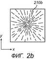
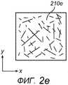
на фиг. 2a)-g) представлены схематические иллюстрации направлений и рисунков ориентации усадочного материала в TIM в соответствии с вариантами осуществления данного изобретения;in FIG. 2a) to g) are schematic illustrations of directions and patterns of orientation of shrink material at TIM in accordance with embodiments of the present invention;
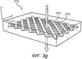
на фиг. 3a)-g) представлены схематические иллюстрации другого многослойного TIM в соответствии с вариантами осуществления данного изобретения; иin FIG. 3a) to g) are schematic illustrations of another multilayer TIM in accordance with embodiments of the present invention; and
на фиг. 4a)-c) представлены схематические сечения теплового интерфейса в электрическом узле в соответствии с вариантами осуществления данного изобретения, когда этот интерфейс расположен между теплогенерирующим компонентом и радиатором или теплоотводом.in FIG. 4a) to c) are schematic sections of a thermal interface in an electrical assembly in accordance with embodiments of the present invention when this interface is located between a heat generating component and a radiator or heat sink.
Подробное описание предпочтительных вариантов осуществленияDetailed Description of Preferred Embodiments
Теперь будут описаны возможные варианты выполнения материала теплового интерфейса, TIM, и применения соответствующего ему теплового интерфейса, способы изготовления такого TIM и теплового интерфейса.Now will be described possible embodiments of the material of the thermal interface, TIM, and the application of its corresponding thermal interface, methods of manufacturing such TIM and thermal interface.
Этапы способов описываются как непрерывная последовательность, однако некоторые из этапов могут выполняться в другом порядке или они могут чередоваться с несколькими дополнительными технологическими этапами.The steps of the methods are described as a continuous sequence, however, some of the steps may be performed in a different order, or they may alternate with several additional process steps.
Обращаясь теперь к фиг. 1a), где иллюстрируется вариант выполнения TIM 100 в соответствии с данным изобретением, TIM 100 содержит слой 105 TIM, т.е. по существу плоскую структуру материала, как с верхней поверхностью 101, так и с нижней поверхностью 102, имеющий толщину d1 в направлении «z», которая мала по сравнению с протяженностью физических размеров слоя в плоскости «xy». В пределах слоя 105 TIM распределен усадочный материал 110. Усадочный материал 110 в этом возможном варианте осуществления представляет собой усадочные волокна термочувствительного полимера, введенные в слой 105 предлагаемого материала TIM во время его производства. Слой 105 TIM можно формировать в процессе формования. Волокна в данном случае смешаны случайным образом в материале 100 слоя TIM. В альтернативном варианте осуществления волокна термоусадочного материала 110 заранее расположены в форме сетки и впрессованы в эластичное вещество слоя 105 TIM, оказываясь полностью заключенными в TIM 100. На фиг. 1b) изображен TIM 100 после активации усадочных волокон термочувствительного полимера усадочного материала 110. Когда TIM 100, показанный на фиг. 1a), подвергается нагреванию, усадочные волокна реагируют на нагревание, укорачиваясь и оттягивая слой предлагаемого материала TIM от границ слоя 105 TIM внутрь. Поведение усадки волокон имеет доминирующее влияние в направлениях «x» и «y» благодаря относительно малому размеру TIM в направлении «z». Этот механизм увеличивает высоту активированного TIM 100' так, что для TIM 100', активированного при нагревании, получается новая высота d2.Turning now to FIG. 1a), where an embodiment of TIM 100 according to the invention is illustrated, TIM 100 comprises a TIM layer 105, i.e. essentially flat structure of the material, with both the upper surface 101 and the lower surface 102, having a thickness d1 in the z direction, which is small compared with the length of the physical dimensions of the layer in the xy plane. Shrink material 110 is distributed within the TIM layer 105. The shrink material 110 in this possible embodiment is heat-sensitive polymer shrink fibers introduced into the layer 105 of the TIM material according to the invention during production. Layer 105 TIM can be formed in the molding process. The fibers in this case are mixed randomly in the material 100 of the TIM layer. In an alternative embodiment, the fibers of the shrink material 110 are pre-arranged in the form of a mesh and pressed into the elastic material of the TIM layer 105, being completely enclosed in TIM 100. In FIG. 1b) TIM 100 is shown after activation of the shrink fibers of the heat-sensitive polymer of the shrink material 110. When TIM 100 shown in FIG. 1a), it undergoes heating, shrink fibers react to heating, shortening and pulling the layer of the proposed material TIM from the boundaries of the layer 105 TIM inward. The behavior of fiber shrinkage has a dominant effect in the x and y directions due to the relatively small TIM size in the z direction. This mechanism increases the height of the activated TIM 100 'so that for the TIM 100' activated by heating, a new height d2 is obtained.
Усадочный материал можно вводить в слой TIM в виде волокон усадочного материала, мономеров, полимерных композиций или даже незакрепленных слоистых структур, как будет описано ниже.The shrink material can be introduced into the TIM layer in the form of shrink fibers, monomers, polymer compositions or even loose layered structures, as will be described below.
Чтобы оптимизировать влияние усадочного материала в слое TIM и облегчить увеличение высоты в слое TIM, усадочный материал в предпочтительных вариантах осуществления располагают в заранее определенной ориентации в пределах слоя TIM. В целом, предпочтительным является любое направление ориентации, за исключением направления толщины (направления «z») TIM.In order to optimize the effect of the shrink material in the TIM layer and to facilitate the increase in height in the TIM layer, the shrink material in preferred embodiments is arranged in a predetermined orientation within the TIM layer. In general, any orientation direction is preferred except for the thickness direction (z direction) TIM.
На фиг. 2a)-2g) изображены некоторые предпочтительные ориентации усадочного материала 210a-e′′ в пределах плоскости «ху» TIM: на фиг. 2a) показан усадочный материал 210a, ориентированный в единственном направлении n, на фиг. 2b) показан усадочный материал 210b в радиальной ориентации, на фиг. 2c) показан усадочный материал 210c в окружной ориентации, на фиг. 2d) показан усадочный материал 210d в структуре сетки поперечных межмолекулярных связей (сшитой сетки), на фиг. 2e) показан усадочный материал 210e, содержащий случайным образом ориентированные длинные и короткие волокна и/или полимеры, на фиг. 2f) показан усадочный материал 210f структуры слоев полимера с сетчатой структурой, а на фиг. 2g) показано, как обеспечивают усадочный материал в форме расширенной полимерной матрицы, в данном случае - сформированной путем использования разрезаемой усадочной фольги 210e', которая растянута для образования расширенной усадочной фольги 210e′′. Подход, предусматривающий применение расширенной полимерной матрицы, будет отдельно рассмотрен ниже.In FIG. 2a) to 2g), some preferred orientations of the
В соответствии с идеей изобретения можно воспользоваться и другими механизмами для обеспечения усадочного материала. Во-первых, если усадочный материал содержит, например, многие мономеры, то при активации усадочного материала упомянутые мономеры полимеризуются. Это увеличивает плотность материала, поскольку мономеры оказываются сцепленными друг с другом, занимая вследствие этого меньше пространства. Соответственно, объем термоусадочного материала сокращается, что приводит к увеличению высоты TIM.In accordance with the idea of the invention, other mechanisms can be used to provide shrink material. Firstly, if the shrink material contains, for example, many monomers, then upon activation of the shrink material, said monomers polymerize. This increases the density of the material, since the monomers are linked to each other, thereby occupying less space. Accordingly, the volume of heat shrink material is reduced, which leads to an increase in the height TIM.
Такое сокращение также может быть основано на расширении. В соответствии с вариантом осуществления (не показан), сам предлагаемый материал TIM выполнен с возможностью обеспечения усадочного материала. Этот процесс предусматривает обычное производство TIM с последующим нагреванием для создания возможности растяжения TIM, а затем механическое растяжение TIM. В заключение, в этом расширенном состоянии TIM быстро охлаждают. Затем, при нагревании, т.е. активации, полимеры в пределах TIM релаксируют обратно, приобретая размеры, характерные в нерасширенном состоянии, при этом TIM сохраняет свой первоначальный объем с эффектом расширения в результате. В соответствии с вариантами осуществления, которые предусматривают использование расширенной полимерной матрицы, расширенную полимерную матрицу подготавливают как слой в пределах TIM, что поясняется ниже, а TIM последовательно нагревают, растягивают и быстро охлаждают. Опционально, расширенную полимерную матрицу подготавливают, нагревают и быстро охлаждают перед введением в слой TIM. Опционально, термоусадочный материал растягивают при комнатной температуре и механически блокируют, например, путем наслаивания растянутого термоусадочного материала на слой TIM для сохранения его расширения до тех пор, пока не потребуется его активация.Such a reduction may also be based on expansion. According to an embodiment (not shown), the TIM material itself is configured to provide shrink material. This process involves the usual production of TIM followed by heating to create the possibility of stretching TIM, and then mechanical stretching TIM. In conclusion, in this expanded state, TIM is rapidly cooled. Then, when heated, i.e. activation, polymers within TIM relax back, acquiring sizes characteristic of an unexpanded state, while TIM retains its original volume with the expansion effect as a result. In accordance with embodiments that use an expanded polymer matrix, an expanded polymer matrix is prepared as a layer within TIM, as explained below, and TIM is sequentially heated, stretched, and rapidly cooled. Optionally, an expanded polymer matrix is prepared, heated, and rapidly cooled before being introduced into the TIM layer. Optionally, the heat-shrink material is stretched at room temperature and mechanically blocked, for example, by layering the stretched heat-shrink material on the TIM layer to maintain its expansion until activation is required.
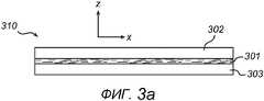
Обращаясь теперь к фиг. 3, как упоминалось ранее, идея данного изобретения раскрывает многослойный TIM. В целом, термин «многослойный TIM» в соответствии с данным изобретением обозначает TIM, сформированный путем чередующейся укладки стопой по меньшей мере одного слоя усадочного материала и по меньшей мере одного субслоя TIM, причем последний представляет собой, например, мягкую термопрокладку. На фиг. 3a)-3d) изображены TIM 310 и 311, содержащие один слой 301 усадочного материала, расположенный вместе с одним субслоем 302 TIM или двумя субслоями 302, 303 TIM.Turning now to FIG. 3, as previously mentioned, the idea of the present invention discloses a layered TIM. In General, the term "multilayer TIM" in accordance with this invention refers to TIM formed by alternately stacking at least one layer of shrink material and at least one TIM sublayer, the latter being, for example, a soft thermal pad. In FIG. 3a) -3d),
На фиг. 3a) усадочный материал 301 показан наслоенным между субслоями 302, 303 TIM, позволяя им обоим иметь непосредственный контакт (сцепление) с усадочным слоем. На фиг. 3b) многослойный TIM 311 показан содержащим один субслой 302 TIM, на который наложен усадочный слой 301. Усадочный слой 301 может быть скомпонован как сетка. Двухслойный TIM применим, например, для упрощенных сборок и когда для использования в качестве теплового интерфейса применяются или желательны более тонкие материалы. Это выгодно с точки зрения экономической перспективы. Слой усадочного материала может также предусматривать расположения в TIM, отличающиеся от проиллюстрированных здесь применительно к двухслойному TIM: расположение в виде открытой структуры, как изображено на фиг. 3c) и фиг. 3g), или закрытой структуры, как изображено на фиг. 3d). При открытой структуре, как изображено подробнее для TIM 313 на фиг. 3g), усадочный материал расположен так, что усадочная структура 314, которая может быть сеткой, ориентированными волокнами, расширенной полимерной матрицей и т.д., имеет отверстия 315, расположенные в плоскости «ху» TIM 313, для облегчения диссипации тепла через TIM 313 в направлении «z». Обращаясь снова к фиг. 3d), для закрытой структуры термоусадочный материал 301' по существу равномерно распределен по существу по всей плоскости «xy» TIM 311'. Термоусадочный материал 301' в данном случае представляет собой тонкую растянутую усадочную фольгу, при этом толщину фольги предпочтительно выбирают так, чтобы не создавать большую закупорку на пути тепла.In FIG. 3a) shrink
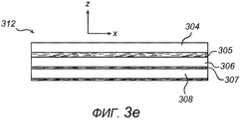
Как изображено на фиг. 3e), TIM в вариантах осуществления может содержать несколько слоев усадочного материала. В данном случае два слоя 305 и 307 усадочного материала уложены стопой между тремя субслоями 309, 306, и 308 TIM. Усадочный материал предпочтительно ориентирован в пределах каждого слоя усадочного материала. Для разных слоев применимы разные ориентации, как изображено на фиг. 3f). Здесь схематически показано, как слой 305 усадочного материала и слой 306 усадочного материала - оба - ориентированы в двух разных направлениях в плоскости «ху». Опционально, для разных усадочных слоев и/или разных слоев TIM выбирают разные материалы, в зависимости от конкретного приложения TIM.As shown in FIG. 3e), TIM in embodiments may comprise several layers of shrink material. In this case, two layers of
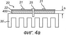
На фиг. 4 изображено применение теплового интерфейса, где используется TIM 400 в соответствии с идеей данного изобретения. Чтобы обеспечить тепловой интерфейс, сначала располагают еще не активированный TIM 400 между теплогенерирующим компонентом 20, который содержит СИДы 21, расположенные на печатной плате, ПП, 22 и радиатором или теплоотводом 30. Для определения положения теплогенерирующего компонента 20 на радиаторе 30 и для ограничения максимального интервала h между теплогенерирующим компонентом 20 и радиатором 30 используется крепежное средство 25, в данном случае винт или штырь, монтируемый методом прессовой посадки или расклепываемый. TIM 400 размещают с увеличенной границей между ПП 22 и радиатором 30. При первом использовании СИДов 21, TIM 400 подвергается воздействию тепла, проходящего через ПП 22, а усадочный материал в TIM 400 активируется. Как описано ранее, активация усадочного материала обуславливает увеличенную толщину TIM, которая в данном случае - благодаря ограниченному расстоянию h между теплогенерирующим компонентом 20 и теплопроводящим элементом, т.е. в данном случае радиатором 30, - в свою очередь увеличивает соответствующие поверхностные давления первой и второй поверхностей (101 и 102, см. фиг. 1) TIM на теплогенерирующий компонент 20 и радиатор 30. Механизм усадки увеличивает объем TIM в термореактивной области, что приводит к расширению TIM (в направлении «z») при поддержании необходимой плотности предлагаемого материала TIM для эффективной диссипации тепла. Вследствие этого увеличенное давление поверхности TIM на нагретую поверхность контакта повышает рабочие характеристики TIM.In FIG. 4 illustrates the use of a thermal interface where
В соответствии с вариантом осуществления теплового интерфейса (как изображено на фиг. 4b), для обеспечения ограниченного максимального промежутка h между теплогенерирующим компонентом 20 и радиатором 30 используют несколько крепежных средств, в данном случае - два винта 25. Применимы также другие крепежные средства, например механическая структура 26 (как изображено на фиг. 4c).According to an embodiment of the thermal interface (as shown in FIG. 4b), several fasteners are used to provide a limited maximum gap h between the
В экспериментальной модели для демонстрации улучшенного поведения при термическом воздействии (не показано), обеспечиваемого идеей данного изобретения, вариант осуществления теплового интерфейса, аналогичного тепловому интерфейсу (изображенному на фиг. 4a), обеспечивали путем использования структуры TIM, аналогичного TIM (показанному на 3a), в качестве TIM 400. Используемый TIM содержит слой усадочного материала, являющегося промышленно поставляемым материалом усадочных трубок, который вскрывали, перфорировали и наслаивали между двумя слоями TIM, каждый из которых представляет собой мягкую термопрокладку GapPad 1450, имеющую объявленную толщину 20 мил, что составляет приблизительно 0,5 мм, (Bergquist). Мягкие термопрокладки заменяют путем удаления розового облицовочного слоя. TIM заключали между двумя алюминиевыми пластинами, которые были разделены промежутком с фиксированной разностью высот. По обе стороны TIM размещали термопары. Кроме того, поверх одной из алюминиевых пластин располагали мощный резистор. Эту сборку вместе с консистентной термосмазкой размещали на холодной пластине с фиксированной температурой (25°C). В эксперименте измеряли разность температур перед активацией (посредством внешнего источника тепла с температурой 120°C) усадочного материала TIM и после активации, отсюда выводили тепловое сопротивление, а из него выводили соотношение разностей температур перед активацией усадки и после этой активации, см. таблицу 1.In an experimental model to demonstrate the improved thermal behavior (not shown) provided by the idea of the present invention, an embodiment of a thermal interface similar to the thermal interface (shown in FIG. 4a) was provided by using a TIM structure similar to TIM (shown in 3a), as
Довольно приблизительный эксперимент, который был далек от оптимального применительно к предлагаемому материалу TIM, усадочному материалу, температурным условиям между верхней и нижней металлическими пластинами и т.д., показывает, что замысел данного изобретения обеспечивает достаточно улучшенный тепловой контакт для граничной поверхности между двумя сопрягаемыми поверхностями металлических пластин. Кроме того, после эксперимента образец разбирали, чтобы проверить состояние TIM, который продемонстрировал усадку в единственном направлении в плоскости «ху» (что и ожидалось, поскольку усадочная трубка была выполнена имеющей единственное направление усадки). Помимо этого, расслаивание TIM не наблюдалось.A fairly approximate experiment, which was far from optimal with respect to the proposed TIM material, shrinkage material, temperature conditions between the upper and lower metal plates, etc., shows that the design of this invention provides a sufficiently improved thermal contact for the boundary surface between two mating surfaces metal plates. In addition, after the experiment, the sample was disassembled to check the state of TIM, which showed shrinkage in a single direction in the xy plane (which was expected since the shrink tube was made with a single direction of shrinkage). In addition, TIM delamination was not observed.
Материалы для слоя или субслоев TIM и соответствующий ему усадочный материал, как говорилось выше, в типичном случае выбирали на основании конкретного приложения, в котором используется TIM. В принципе, в качестве материала слоя TIM применим любой подходящий материал мягких термопрокладок. В настоящее время существует большое количество промышленно поставляемых материалов мягких термопрокладок. Эти материалы в типичном случае представляют собой соединение силиконовых или акриловых носителей с так называемыми наполнителями. Силиконовые или акриловые носители облегчают хорошее смачивание сопрягаемых поверхностей. Наполнители в типичном случае представляют собой керамические или металлические частицы, предусматриваемые для обеспечения теплопроводности материала мягких термопрокладок. Ассортимент имеющихся в наличии материалов мягких термопрокладок очень широк.The materials for the TIM layer or sublayers and the corresponding shrink material, as mentioned above, were typically selected based on a particular application that uses TIM. In principle, any suitable material for soft thermal linings is applicable as the material of the TIM layer. Currently, there are a large number of industrially supplied materials for soft thermal pads. These materials are typically a combination of silicone or acrylic carriers with so-called fillers. Silicone or acrylic media facilitate good wetting of mating surfaces. The fillers are typically ceramic or metal particles provided to provide thermal conductivity for the soft thermal pad material. The range of materials available for soft thermal pads is very wide.
В соответствии с еще одной идеей данного изобретения материал слоя или субслоев TIM в типичном случае выбирают так, чтобы он обеспечивал приемлемое механическое соединение с усадочным материалом, что важно для сохранения структурной целостности TIM в сборке после активации усадочного материала. Например, в качестве материала матрицы или субслоев TIM применимы материалы мягких термопрокладок, которые являются эластичными до некоторой степени. Примерами этих материалов мягких термопрокладок являются семейство Gap Pad (Bergquist Company), семейство Sil Pad (Bergquist Company), семейство T-Flex (Laird Technologies) и т.д.In accordance with another idea of the present invention, the TIM layer or sublayer material is typically selected to provide acceptable mechanical bonding to the shrink material, which is important to maintain the structural integrity of the TIM in the assembly after shrink material is activated. For example, as a matrix material or TIM sublayers, soft thermal liner materials that are flexible to some extent are applicable. Examples of these soft padding materials are the Gap Pad family (Bergquist Company), the Sil Pad family (Bergquist Company), the T-Flex family (Laird Technologies), etc.
В вариантах выполнения TIM в качестве материала матрицы или субслоев TIM предпочтительно выбирают более мягкий материал мягких термопрокладок, упрощающий деформацию TIM в процессе усадки (в направлениях «x» и «y») с одновременным расширением в перпендикулярном направлении («z»).In TIM embodiments, the material of the matrix or TIM sublayers is preferably a softer material of soft thermal pads, which simplifies the deformation of TIM during shrinkage (in the “x” and “y” directions) while expanding in the perpendicular direction (“z”).
Термоусадочный материал, применимый для TIM, предлагаемого в данном изобретении, может содержать усадочные волокна термочувствительных полимеров, сравнимые с полимерами, применяемыми в усадочных трубках, например: политетрафторэтилен, ПТФЭ (фторполимер), фторэластомеры типа Viton®, поливинидиденфоторид, ПВФ, фторированный этилен-пропилен, ФЭП, эластомерные материалы, кремнийорганический каучук, полиолефиновые трубки, поливинилхлорид (ПВХ), термоусадочную пленку из полиэтилена, усадочную ткань и другие (усадочная пленка также может быть сделана из ориентированного полистирола, ОПС, ориентированного полиэтилена, ОПЭ, ориентированного полипропилена, ОПП, и ориентированных сложных полиэфиров). Эти материалы поставляются промышленностью и в общем случае оказываются весьма подходящими для использования в системах терморегулирования. Они эластичны, способны к быстрой усадке и производятся в широком ассортименте цветов.The heat-shrinkable material applicable to the TIM of this invention may contain shrink fibers of heat-sensitive polymers comparable to those used in shrink tubes, for example: polytetrafluoroethylene, PTFE (fluoropolymer), fluoroelastomers such as Viton®, polyvinylidene fluoride, ethylene propylene fluoride , FEP, elastomeric materials, silicone rubber, polyolefin tubes, polyvinyl chloride (PVC), shrink film made of polyethylene, shrink fabric and others (shrink film can also be made made of oriented polystyrene, OPS, oriented polyethylene, OPE, oriented polypropylene, OPP, and oriented polyesters). These materials are supplied by industry and, in general, are very suitable for use in thermal control systems. They are flexible, capable of rapid shrinkage and are available in a wide range of colors.
Опционально используют термоусадочные полимерные материалы, которые способны к образованию поперечных межмолекулярных связей (сшиванию) после нанесения и, опционально, после расположения в предпочтительной ориентации. В зависимости от материала формирование поперечных межмолекулярных связей (сшивание) можно осуществить посредством использования пучков электронов, пероксидов или влажности. Например, когда используют термоусадочный полиэтилен (сшитый полиэтилен низкой плотности), сшивание можно осуществлять посредством облучения электронами. Сшивание преимущественно увеличивает механическую целостность TIM, т.е. способствует поддержанию TIM своей формы как перед усадкой, так и после нее.Heat-shrinkable polymeric materials are optionally used, which are capable of forming transverse intermolecular bonds (crosslinking) after application and, optionally, after being placed in the preferred orientation. Depending on the material, the formation of transverse intermolecular bonds (crosslinking) can be achieved by using electron beams, peroxides or humidity. For example, when heat shrink polyethylene (crosslinked low density polyethylene) is used, crosslinking can be accomplished by electron irradiation. Crosslinking advantageously increases the mechanical integrity of TIM, i.e. helps to maintain TIM of its shape both before and after shrinkage.
В возможных вариантах осуществления здесь и по всему тексту описания употребление термина «усадочный материал», как правило, относится к термоусадочным материалам, которые представляют собой усадочные полимерные материалы, в которых усадка активируется посредством нагревания. Усадка в полимерном материале изменяется не только с изменением используемого полимера, но и с введением различных добавок и наполнителей, которые смешаны с полимером. Кроме того, следует отметить, что, как должно быть очевидно специалисту в данной области, для воплощения замысла данного изобретения применимы усадочные материалы других типов с некоторым другим механизмом активации усадочного материала, например активации растворителем, активации по времени, активации излучением и ультразвуковой активации, и они находятся в рамках объема притязаний этой заявки.In possible embodiments, the use of the term “shrink material” as used herein generally refers to shrink materials, which are shrink polymeric materials in which shrink is activated by heating. Shrinkage in the polymer material changes not only with the change in the polymer used, but also with the introduction of various additives and fillers that are mixed with the polymer. In addition, it should be noted that, as should be obvious to a person skilled in the art, other types of shrink materials with some other mechanism of shrink material activation, for example, solvent activation, time activation, radiation activation and ultrasonic activation, are applicable to realize the intent of the present invention, and they are within the scope of the claims of this application.
Специалист в данной области техники поймет, что данное изобретение ни в коей мере не ограничивается вышеописанными вариантами осуществления. Наоборот, в рамках объема притязаний прилагаемой формулы изобретения возможны многочисленные модификации и изменения.One skilled in the art will understand that the invention is in no way limited to the above described embodiments. On the contrary, within the scope of the claims of the appended claims, numerous modifications and changes are possible.
Claims (15)
Translated fromRussianслой (105) TIM, содержащий
активируемый усадочный материал (110);
причем упомянутый усадочный материал распределен в слое TIM так, что при активации этого усадочного материала толщина упомянутого слоя TIM увеличивается.1. Material (100) thermal interface (TIM), containing:
layer (105) TIM containing
activated shrink material (110);
wherein said shrink material is distributed in the TIM layer so that upon activation of this shrink material, the thickness of said TIM layer increases.
обеспечивают слой TIM;
обеспечивают в упомянутом слое TIM активируемый усадочный материал, расположенный так, что после активации упомянутого усадочного материала толщина упомянутого слоя TIM увеличивается.9. A method of providing thermal interface material (TIM), which consists in the fact that:
provide a TIM layer;
provide, in said TIM layer, an activated shrink material arranged so that after activation of said shrink material, the thickness of said TIM layer increases.
расположение упомянутого усадочного материала в ориентированном направлении.10. The method of claim 9, further comprising:
the location of said shrinkage material in an oriented direction.
механически растягивают упомянутую полимерную матрицу в направлении, соответствующем плоскости "ху" слоя TIM; и после этого
блокируют упомянутую растянутую полимерную матрицу, тем самым обеспечивая расширенную полимерную матрицу.12. The method of claim 9 or 10, wherein said shrink material is a polymer matrix, and wherein said step of orienting said shrink material is that:
mechanically stretching said polymer matrix in a direction corresponding to the xy plane of the TIM layer; and after that
block said stretched polymer matrix, thereby providing an expanded polymer matrix.
обеспечивают TIM согласно способу по п. 9 или 10; и
располагают упомянутый TIM между теплогенерирующим компонентом и теплопроводящей подложкой, при этом расстояние между теплогенерирующим компонентом и теплопроводящей подложкой ограничено.14. A method of providing a thermal interface, which consists in the fact that:
provide TIM according to the method of claim 9 or 10; and
positioning said TIM between the heat generating component and the heat transferring substrate, while the distance between the heat generating component and the heat transferring substrate is limited.
Applications Claiming Priority (3)
| Application Number | Priority Date | Filing Date | Title |
|---|---|---|---|
| US201261614065P | 2012-03-22 | 2012-03-22 | |
| US61/614,065 | 2012-03-22 | ||
| PCT/IB2013/051907WO2013140295A2 (en) | 2012-03-22 | 2013-03-11 | Thermal interface material |
Publications (1)
| Publication Number | Publication Date |
|---|---|
| RU2580529C1true RU2580529C1 (en) | 2016-04-10 |
Family
ID=48227358
Family Applications (1)
| Application Number | Title | Priority Date | Filing Date |
|---|---|---|---|
| RU2014138814/28ARU2580529C1 (en) | 2012-03-22 | 2013-03-11 | Thermal interface material |
Country Status (8)
| Country | Link |
|---|---|
| US (1) | US9316447B2 (en) |
| EP (1) | EP2828889B1 (en) |
| JP (1) | JP5893764B2 (en) |
| CN (1) | CN104145332B (en) |
| ES (1) | ES2551914T3 (en) |
| PL (1) | PL2828889T3 (en) |
| RU (1) | RU2580529C1 (en) |
| WO (1) | WO2013140295A2 (en) |
Families Citing this family (16)
| Publication number | Priority date | Publication date | Assignee | Title |
|---|---|---|---|---|
| WO2016020218A1 (en)* | 2014-08-08 | 2016-02-11 | Koninklijke Philips N.V. | Led device with flexible thermal interface |
| GB201502329D0 (en) | 2015-02-12 | 2015-04-01 | Trimble Navigation Ltd | Geographical positioning in time |
| CN105938821B (en)* | 2015-03-03 | 2020-04-28 | 台湾积体电路制造股份有限公司 | Thermally enhanced heat sink |
| CN105138725A (en)* | 2015-07-21 | 2015-12-09 | 厦门大学 | Method for manufacturing heat rectification component |
| US10371345B2 (en)* | 2015-12-28 | 2019-08-06 | Eaton Intelligent Power Limited | Light emitting diode (LED) module for LED luminaire |
| JP6691792B2 (en)* | 2016-02-26 | 2020-05-13 | 株式会社小糸製作所 | Vehicle lighting |
| US11014203B2 (en) | 2016-07-11 | 2021-05-25 | Laird Technologies, Inc. | System for applying interface materials |
| US10741519B2 (en) | 2016-07-11 | 2020-08-11 | Laird Technologies, Inc. | Systems of applying materials to components |
| JP6988409B2 (en) | 2017-04-03 | 2022-01-05 | 株式会社デンソー | The camera module |
| US10098267B1 (en) | 2017-06-06 | 2018-10-09 | Robert Bosch Llc | Housing for a camera and method of manufacture |
| US10667396B2 (en)* | 2017-08-25 | 2020-05-26 | Tactotek Oy | Multilayer structure for hosting electronics and related method of manufacture |
| JP2019053941A (en)* | 2017-09-19 | 2019-04-04 | 株式会社小糸製作所 | Lamp fitting unit and vehicle lamp fitting |
| USD881822S1 (en) | 2017-10-06 | 2020-04-21 | Laird Technologies, Inc. | Material having an edge shape |
| USD879046S1 (en) | 2017-10-06 | 2020-03-24 | Laird Technologies, Inc. | Material having edging |
| USD999405S1 (en) | 2017-10-06 | 2023-09-19 | Laird Technologies, Inc. | Material having edging |
| US11141823B2 (en) | 2018-04-28 | 2021-10-12 | Laird Technologies, Inc. | Systems and methods of applying materials to components |
Citations (5)
| Publication number | Priority date | Publication date | Assignee | Title |
|---|---|---|---|---|
| US5545473A (en)* | 1994-02-14 | 1996-08-13 | W. L. Gore & Associates, Inc. | Thermally conductive interface |
| US6451422B1 (en)* | 1999-12-01 | 2002-09-17 | Johnson Matthey, Inc. | Thermal interface materials |
| US6673434B2 (en)* | 1999-12-01 | 2004-01-06 | Honeywell International, Inc. | Thermal interface materials |
| TW200535868A (en)* | 2004-04-16 | 2005-11-01 | Hon Hai Prec Ind Co Ltd | Thermal interface material and methode for making same |
| US20100127299A1 (en)* | 2008-11-25 | 2010-05-27 | Cooper Technologies Company | Actively Cooled LED Lighting System and Method for Making the Same |
Family Cites Families (23)
| Publication number | Priority date | Publication date | Assignee | Title |
|---|---|---|---|---|
| FR2311952A1 (en) | 1975-04-30 | 1976-12-17 | Sopelem | PROCESS FOR ASSEMBLY OF PARTS IN A HOUSING |
| DE4041444C1 (en) | 1990-12-21 | 1991-11-07 | Elos Electronic Gmbh, 2085 Quickborn, De | Synthetic resin bolts for fixing semiconductor elements - made in pin shape of material which pulls together and thickens on heating |
| JPH06302728A (en)* | 1993-04-12 | 1994-10-28 | Oki Electric Ind Co Ltd | Lsi heat dissipation structure of ceramic multilayer board |
| US5591034A (en) | 1994-02-14 | 1997-01-07 | W. L. Gore & Associates, Inc. | Thermally conductive adhesive interface |
| US5940687A (en)* | 1997-06-06 | 1999-08-17 | International Business Machines Corporation | Wire mesh insert for thermal adhesives |
| JP2002020501A (en)* | 2000-07-03 | 2002-01-23 | Polymatech Co Ltd | Thermo-conductive resin substrate and semiconductor package |
| US6610635B2 (en) | 2000-09-14 | 2003-08-26 | Aos Thermal Compounds | Dry thermal interface material |
| JP2002179818A (en)* | 2000-12-15 | 2002-06-26 | Nitto Denko Corp | Porous composite sheet for prepreg and wiring board prepreg |
| CN100444365C (en)* | 2001-05-24 | 2008-12-17 | 弗莱氏金属公司 | thermal interface material |
| JP3492656B2 (en)* | 2001-08-28 | 2004-02-03 | 埼玉日本電気株式会社 | Manufacturing method of heat conductive sheet |
| US6746768B2 (en) | 2001-12-26 | 2004-06-08 | Advanced Energy Technology Inc. | Thermal interface material |
| US6761813B2 (en)* | 2002-01-31 | 2004-07-13 | Intel Corporation | Heat transfer through covalent bonding of thermal interface material |
| US7252877B2 (en)* | 2003-02-04 | 2007-08-07 | Intel Corporation | Polymer matrices for polymer solder hybrid materials |
| US7229683B2 (en)* | 2003-05-30 | 2007-06-12 | 3M Innovative Properties Company | Thermal interface materials and method of making thermal interface materials |
| US7118801B2 (en)* | 2003-11-10 | 2006-10-10 | Gore Enterprise Holdings, Inc. | Aerogel/PTFE composite insulating material |
| US7081669B2 (en) | 2003-12-04 | 2006-07-25 | Intel Corporation | Device and system for heat spreader with controlled thermal expansion |
| JP4529470B2 (en)* | 2004-02-17 | 2010-08-25 | 三菱電機株式会社 | Adhesive and electronic component using the same |
| JP2006032626A (en)* | 2004-07-15 | 2006-02-02 | Matsushita Electric Ind Co Ltd | HEAT CONDUCTIVE MATERIAL, SEMICONDUCTOR DEVICE, AND SEMICONDUCTOR DEVICE MANUFACTURING METHOD |
| JP2006066594A (en)* | 2004-08-26 | 2006-03-09 | Fujitsu Ltd | Heat dissipation device and electronic device |
| JP2006086246A (en) | 2004-09-15 | 2006-03-30 | Yokogawa Electric Corp | Semiconductor chip mounting structure |
| JP4648351B2 (en)* | 2007-03-30 | 2011-03-09 | 住友ベークライト株式会社 | Heat transfer sheet and heat dissipation structure |
| JP2012012425A (en)* | 2010-06-29 | 2012-01-19 | Dainippon Printing Co Ltd | Heat-conductive sheet |
| JP5941287B2 (en)* | 2012-01-19 | 2016-06-29 | 富士高分子工業株式会社 | Heat dissipation sheet and manufacturing method thereof |
- 2013
- 2013-03-11WOPCT/IB2013/051907patent/WO2013140295A2/enactiveApplication Filing
- 2013-03-11CNCN201380012426.2Apatent/CN104145332B/enactiveActive
- 2013-03-11RURU2014138814/28Apatent/RU2580529C1/enactive
- 2013-03-11EPEP13719621.8Apatent/EP2828889B1/enactiveActive
- 2013-03-11JPJP2014557165Apatent/JP5893764B2/enactiveActive
- 2013-03-11USUS14/386,191patent/US9316447B2/enactiveActive
- 2013-03-11PLPL13719621Tpatent/PL2828889T3/enunknown
- 2013-03-11ESES13719621.8Tpatent/ES2551914T3/enactiveActive
Patent Citations (5)
| Publication number | Priority date | Publication date | Assignee | Title |
|---|---|---|---|---|
| US5545473A (en)* | 1994-02-14 | 1996-08-13 | W. L. Gore & Associates, Inc. | Thermally conductive interface |
| US6451422B1 (en)* | 1999-12-01 | 2002-09-17 | Johnson Matthey, Inc. | Thermal interface materials |
| US6673434B2 (en)* | 1999-12-01 | 2004-01-06 | Honeywell International, Inc. | Thermal interface materials |
| TW200535868A (en)* | 2004-04-16 | 2005-11-01 | Hon Hai Prec Ind Co Ltd | Thermal interface material and methode for making same |
| US20100127299A1 (en)* | 2008-11-25 | 2010-05-27 | Cooper Technologies Company | Actively Cooled LED Lighting System and Method for Making the Same |
Also Published As
| Publication number | Publication date |
|---|---|
| EP2828889B1 (en) | 2015-09-02 |
| JP5893764B2 (en) | 2016-03-23 |
| ES2551914T3 (en) | 2015-11-24 |
| CN104145332B (en) | 2017-05-10 |
| PL2828889T3 (en) | 2016-02-29 |
| CN104145332A (en) | 2014-11-12 |
| US20150036363A1 (en) | 2015-02-05 |
| EP2828889A2 (en) | 2015-01-28 |
| JP2015510274A (en) | 2015-04-02 |
| US9316447B2 (en) | 2016-04-19 |
| WO2013140295A2 (en) | 2013-09-26 |
| WO2013140295A3 (en) | 2014-01-23 |
Similar Documents
| Publication | Publication Date | Title |
|---|---|---|
| RU2580529C1 (en) | Thermal interface material | |
| Hong et al. | Anisotropic thermal conductive composite by the guided assembly of boron nitride nanosheets for flexible and stretchable electronics | |
| KR102233540B1 (en) | Heat-conductive adhesive sheet, manufacturing method for same, and electronic device using same | |
| CN115516570B (en) | Thermal interface material | |
| KR101065911B1 (en) | Flexible heat sink | |
| US20040130057A1 (en) | Process and apparatus for microreplication | |
| KR102389426B1 (en) | Thermally conductive adhesive sheet, production method therefor, and electronic device using same | |
| TW200403147A (en) | Release film | |
| JP3920611B2 (en) | Cushion material for heat press and method for producing the same | |
| JP6236631B2 (en) | Manufacturing method of heat conductive sheet | |
| JP3437361B2 (en) | Mold for resin molding | |
| KR101457797B1 (en) | Heat conduction sheet and heat conduction sheet manufacturing method | |
| WO2004044960A2 (en) | Thermal interface composite structure and method of making same | |
| JP2015149476A (en) | Heat conduction member and electronic component | |
| JP3492656B2 (en) | Manufacturing method of heat conductive sheet | |
| TWM540741U (en) | Multi-layer composite heat conduction structure | |
| JP2944308B2 (en) | Manufacturing method of multilayer printed circuit board | |
| JP7573703B2 (en) | Heat dissipation sheet and its manufacturing method | |
| JP7274466B2 (en) | Fluoroelastomer encased elastomer tools for composite manufacturing | |
| KR20240079182A (en) | Composite thermal conductive element and method for making the same | |
| JP2018027681A5 (en) | ||
| JP6105549B2 (en) | Thermally conductive pad material including a perforated liner | |
| JP6736785B2 (en) | Method for enhancing electrical connection in 3D printed objects | |
| CN107953628B (en) | Three-dimensional high-thermal-conductivity gasket and preparation method thereof | |
| JP2004322471A (en) | Laminated film for release |
Legal Events
| Date | Code | Title | Description |
|---|---|---|---|
| PC41 | Official registration of the transfer of exclusive right | Effective date:20170629 |