RU2579737C2 - Real-time hifu therapy monitoring and control in set of measurements - Google Patents
Real-time hifu therapy monitoring and control in set of measurementsDownload PDFInfo
- Publication number
- RU2579737C2 RU2579737C2RU2013103058/14ARU2013103058ARU2579737C2RU 2579737 C2RU2579737 C2RU 2579737C2RU 2013103058/14 ARU2013103058/14 ARU 2013103058/14ARU 2013103058 ARU2013103058 ARU 2013103058ARU 2579737 C2RU2579737 C2RU 2579737C2
- Authority
- RU
- Russia
- Prior art keywords
- therapeutic
- control
- location
- module
- treatment
- Prior art date
Links
- 238000005259measurementMethods0.000titleabstractdescription7
- 238000002560therapeutic procedureMethods0.000titledescription46
- 238000012544monitoring processMethods0.000titledescription40
- 238000002679ablationMethods0.000claimsabstractdescription79
- 230000001225therapeutic effectEffects0.000claimsabstractdescription65
- 230000006378damageEffects0.000claimsabstractdescription54
- 230000008859changeEffects0.000claimsabstractdescription23
- 238000002604ultrasonographyMethods0.000claimsabstractdescription20
- 230000000694effectsEffects0.000claimsabstractdescription19
- 238000004458analytical methodMethods0.000claimsabstractdescription18
- 238000012546transferMethods0.000claimsabstractdescription15
- 230000004044responseEffects0.000claimsabstractdescription4
- 230000005284excitationEffects0.000claimsabstractdescription3
- 238000011282treatmentMethods0.000claimsdescription95
- 238000006073displacement reactionMethods0.000claimsdescription26
- 230000035939shockEffects0.000claimsdescription14
- 230000005855radiationEffects0.000claimsdescription11
- 230000002093peripheral effectEffects0.000claimsdescription5
- 239000000126substanceSubstances0.000abstractdescription2
- 208000027418Wounds and injuryDiseases0.000abstract1
- 239000003814drugSubstances0.000abstract1
- 208000014674injuryDiseases0.000abstract1
- 210000001519tissueAnatomy0.000description62
- 238000000034methodMethods0.000description33
- 239000000523sampleSubstances0.000description13
- 230000017074necrotic cell deathEffects0.000description12
- 238000012545processingMethods0.000description11
- 206010028980NeoplasmDiseases0.000description9
- 239000004744fabricSubstances0.000description7
- 238000003384imaging methodMethods0.000description7
- 230000003902lesionEffects0.000description7
- 230000036461convulsionEffects0.000description6
- 230000000875corresponding effectEffects0.000description5
- 238000010317ablation therapyMethods0.000description3
- 238000003491arrayMethods0.000description3
- 238000011088calibration curveMethods0.000description3
- 239000013256coordination polymerSubstances0.000description3
- 230000007423decreaseEffects0.000description3
- 238000002595magnetic resonance imagingMethods0.000description3
- 238000010606normalizationMethods0.000description3
- 230000001174ascending effectEffects0.000description2
- 230000008901benefitEffects0.000description2
- 230000005540biological transmissionEffects0.000description2
- 238000004364calculation methodMethods0.000description2
- 230000001419dependent effectEffects0.000description2
- 238000001514detection methodMethods0.000description2
- 238000002592echocardiographyMethods0.000description2
- 230000001747exhibiting effectEffects0.000description2
- 230000008014freezingEffects0.000description2
- 238000007710freezingMethods0.000description2
- 230000006870functionEffects0.000description2
- 238000010438heat treatmentMethods0.000description2
- 238000001727in vivoMethods0.000description2
- 210000004185liverAnatomy0.000description2
- 230000008569processEffects0.000description2
- 206010002091AnaesthesiaDiseases0.000description1
- 238000012935AveragingMethods0.000description1
- 0CC=CCCCC*CCCCCC=NChemical compoundCC=CCCCC*CCCCCC=N0.000description1
- 230000002159abnormal effectEffects0.000description1
- 230000009471actionEffects0.000description1
- 230000037005anaesthesiaEffects0.000description1
- 238000013459approachMethods0.000description1
- 206010003119arrhythmiaDiseases0.000description1
- 230000015572biosynthetic processEffects0.000description1
- 230000000903blocking effectEffects0.000description1
- 210000004204blood vesselAnatomy0.000description1
- 238000002512chemotherapyMethods0.000description1
- 238000004590computer programMethods0.000description1
- 230000002596correlated effectEffects0.000description1
- 238000010586diagramMethods0.000description1
- 238000002594fluoroscopyMethods0.000description1
- 210000005003heart tissueAnatomy0.000description1
- 230000017525heat dissipationEffects0.000description1
- 238000010562histological examinationMethods0.000description1
- 238000000338in vitroMethods0.000description1
- 230000003211malignant effectEffects0.000description1
- 230000003287optical effectEffects0.000description1
- 230000003534oscillatory effectEffects0.000description1
- 230000001902propagating effectEffects0.000description1
- 238000011160researchMethods0.000description1
- 230000029058respiratory gaseous exchangeEffects0.000description1
- 230000033764rhythmic processEffects0.000description1
- 230000035945sensitivityEffects0.000description1
- 238000001356surgical procedureMethods0.000description1
- 230000002277temperature effectEffects0.000description1
- 230000002123temporal effectEffects0.000description1
- 238000012360testing methodMethods0.000description1
Images


Classifications
- A—HUMAN NECESSITIES
- A61—MEDICAL OR VETERINARY SCIENCE; HYGIENE
- A61N—ELECTROTHERAPY; MAGNETOTHERAPY; RADIATION THERAPY; ULTRASOUND THERAPY
- A61N7/00—Ultrasound therapy
- A—HUMAN NECESSITIES
- A61—MEDICAL OR VETERINARY SCIENCE; HYGIENE
- A61B—DIAGNOSIS; SURGERY; IDENTIFICATION
- A61B8/00—Diagnosis using ultrasonic, sonic or infrasonic waves
- A61B8/44—Constructional features of the ultrasonic, sonic or infrasonic diagnostic device
- A61B8/4483—Constructional features of the ultrasonic, sonic or infrasonic diagnostic device characterised by features of the ultrasound transducer
- A61B8/4488—Constructional features of the ultrasonic, sonic or infrasonic diagnostic device characterised by features of the ultrasound transducer the transducer being a phased array
- A—HUMAN NECESSITIES
- A61—MEDICAL OR VETERINARY SCIENCE; HYGIENE
- A61N—ELECTROTHERAPY; MAGNETOTHERAPY; RADIATION THERAPY; ULTRASOUND THERAPY
- A61N7/00—Ultrasound therapy
- A61N7/02—Localised ultrasound hyperthermia
- A—HUMAN NECESSITIES
- A61—MEDICAL OR VETERINARY SCIENCE; HYGIENE
- A61B—DIAGNOSIS; SURGERY; IDENTIFICATION
- A61B90/00—Instruments, implements or accessories specially adapted for surgery or diagnosis and not covered by any of the groups A61B1/00 - A61B50/00, e.g. for luxation treatment or for protecting wound edges
- A61B90/36—Image-producing devices or illumination devices not otherwise provided for
- A61B90/37—Surgical systems with images on a monitor during operation
- A61B2090/378—Surgical systems with images on a monitor during operation using ultrasound
- A—HUMAN NECESSITIES
- A61—MEDICAL OR VETERINARY SCIENCE; HYGIENE
- A61B—DIAGNOSIS; SURGERY; IDENTIFICATION
- A61B8/00—Diagnosis using ultrasonic, sonic or infrasonic waves
- A61B8/48—Diagnostic techniques
- A61B8/485—Diagnostic techniques involving measuring strain or elastic properties
- A—HUMAN NECESSITIES
- A61—MEDICAL OR VETERINARY SCIENCE; HYGIENE
- A61N—ELECTROTHERAPY; MAGNETOTHERAPY; RADIATION THERAPY; ULTRASOUND THERAPY
- A61N7/00—Ultrasound therapy
- A61N2007/0052—Ultrasound therapy using the same transducer for therapy and imaging
- A—HUMAN NECESSITIES
- A61—MEDICAL OR VETERINARY SCIENCE; HYGIENE
- A61N—ELECTROTHERAPY; MAGNETOTHERAPY; RADIATION THERAPY; ULTRASOUND THERAPY
- A61N7/00—Ultrasound therapy
- A61N2007/0082—Scanning transducers
- A—HUMAN NECESSITIES
- A61—MEDICAL OR VETERINARY SCIENCE; HYGIENE
- A61N—ELECTROTHERAPY; MAGNETOTHERAPY; RADIATION THERAPY; ULTRASOUND THERAPY
- A61N7/00—Ultrasound therapy
- A61N2007/0086—Beam steering
- A61N2007/0095—Beam steering by modifying an excitation signal
Landscapes
- Health & Medical Sciences (AREA)
- Life Sciences & Earth Sciences (AREA)
- General Health & Medical Sciences (AREA)
- Animal Behavior & Ethology (AREA)
- Veterinary Medicine (AREA)
- Nuclear Medicine, Radiotherapy & Molecular Imaging (AREA)
- Public Health (AREA)
- Radiology & Medical Imaging (AREA)
- Engineering & Computer Science (AREA)
- Biomedical Technology (AREA)
- Medical Informatics (AREA)
- Physics & Mathematics (AREA)
- Molecular Biology (AREA)
- Surgery (AREA)
- Heart & Thoracic Surgery (AREA)
- Gynecology & Obstetrics (AREA)
- Pathology (AREA)
- Biophysics (AREA)
- Surgical Instruments (AREA)
- Ultra Sonic Daignosis Equipment (AREA)
Abstract
Description
Translated fromRussianОБЛАСТЬ ИЗОБРЕТЕНИЯFIELD OF THE INVENTION
Настоящее изобретение относится к переносу энергии для того, чтобы вызывать изменение механического свойства биологической ткани, и, более конкретно, к исследованию эффекта переноса более чем в одном пространственном измерении.The present invention relates to energy transfer in order to cause a change in the mechanical properties of biological tissue, and, more specifically, to study the effect of transfer in more than one spatial dimension.
УРОВЕНЬ ТЕХНИКИBACKGROUND
Абляционную терапию опухолей с использованием фокусированного ультразвука высокой интенсивности (HIFU) изучали в течение многих лет, и совсем недавно она вышла на рынок в Соединенных Штатах и в клинические испытания.Ablative tumor therapy using High Intensity Focused Ultrasound (HIFU) has been studied for many years, and most recently it entered the market in the United States and in clinical trials.
Опухоль, такую как раковая опухоль, можно лечить медицинским путем посредством хирургического вмешательства и/или химиотерапии. Абляционная терапия предлагает менее инвазивную альтернативу. Абляцию можно осуществлять с помощью различных альтернатив, например посредством нагрева (например, радиочастотная (РЧ) абляция, абляция фокусированным ультразвуком высокой интенсивности (HIFU), микроволны и лазер), заморозки (например, криогенная абляция) или химического воздействия.A tumor, such as a cancerous tumor, can be treated medically through surgery and / or chemotherapy. Ablation therapy offers a less invasive alternative. Ablation can be accomplished using various alternatives, for example, by heating (e.g., radiofrequency (RF) ablation, high intensity focused ultrasound (HIFU) ablation, microwaves and laser), freezing (e.g. cryogenic ablation), or chemical exposure.
HIFU является неинвазивной в том отношении, что тепловую энергию подают извне организма для того, чтобы фокусировать на опухоли, но энергию не концентрируют в достаточной мере для того, чтобы нанести вред коже или более внутренней ткани пациента до того, как ее сконцентрируют на опухолевой мишени.HIFU is non-invasive in that heat is supplied from outside the body in order to focus on the tumor, but the energy is not concentrated enough to harm the skin or more of the patient’s internal tissue before it is concentrated on the tumor target.
Тепловая абляция, такая как HIFU абляция, повышает температуру в фокусной точке до тех пор, пока опухоль, которая может быть озлокачествленной, не будет подвергнута некрозу, т.е. убита, в этой точке абляции. Подвергнутая некрозу ткань организма известна как повреждение. Затем процедуру перемещают к другой точке абляции и продолжают точка за точкой до тех пор, пока не будет выполнена абляция всей опухоли.Thermal ablation, such as HIFU ablation, raises the temperature at the focal point until the tumor, which may be malignant, undergoes necrosis, i.e. killed at this point of ablation. Necrosis of body tissue is known as damage. Then the procedure is moved to another ablation point and continues point by point until the entire tumor is ablated.
Абляцию направляют в соответствии с изображением зоны, подвергаемой лечению. Формирование изображений может происходить в форме ультразвукового, магнитно-резонансного формирования изображений (МРТ) или рентгеновского формирования изображений, такого как рентгеноскопия.Ablation is directed in accordance with the image of the zone being treated. Imaging can take the form of ultrasound, magnetic resonance imaging (MRI) or x-ray imaging, such as fluoroscopy.
Для того, чтобы направлять HIFU при абляции, используют МРТ, но это дорого. Затраты могут сдерживать использование этого способа в исследовательских центрах по всему миру. Также существует потенциальная проблема МР-совместимости оборудования для тепловой абляции.In order to guide HIFU during ablation, an MRI is used, but it is expensive. Costs can constrain the use of this method in research centers around the world. There is also a potential issue with the MR compatibility of thermal ablation equipment.
Для мониторинга HIFU абляции предложена сила акустического излучения посредством ультразвука.To monitor HIFU ablation, the strength of acoustic radiation through ultrasound is proposed.
Ультразвуковая волна передает целевой ткани организма «толчок», который концентрируется в фокусной точке волны. Данные формирования изображений до и после толчка могут выявлять информацию о свойствах ткани организма, подвергшейся толчку.An ultrasonic wave transmits a “push” to the target body tissue, which is concentrated at the focal point of the wave. Imaging data before and after the shock can reveal information about the properties of the body tissue that has undergone the shock.
Более конкретно, ткань, подвергнутая некрозу посредством HIFU терапии или посредством других средств, в конкретном местоположении становится, в некоторой точке, жестче, чем необработанная ткань. Соответственно, для того же количества толкающей силы возникает меньшее осевое смещение. Толчок и последующее слежение позволяют обнаружить уменьшенное смещение и, следовательно, могут быть использованы для обнаружения присутствия повреждения, сформированного посредством абляции.More specifically, tissue subjected to necrosis by HIFU therapy or by other means at a particular location becomes, at some point, tougher than untreated tissue. Accordingly, for the same amount of pushing force, a smaller axial displacement occurs. A push and subsequent tracking can detect a reduced displacement and, therefore, can be used to detect the presence of damage formed by ablation.
Lizzi et. al. («Lizzi») предсказывают использование смещений, связанных с силой излучения, в мониторинге HIFU абляции в реальном времени. F. Lizzi, R. Muratore, C. Deng, J. A. Ketterling, S. K. Alam. S. Mikaelian и A. Kalisz. Ultrasound in Med. & Biol. Vol. 29. № 11. 1593-1605 (2003).Lizzi et. al. (“Lizzi”) predict the use of radiation-related biases in real-time monitoring of HIFU ablation. F. Lizzi, R. Muratore, C. Deng, J. A. Ketterling, S. K. Alam. S. Mikaelian and A. Kalisz. Ultrasound in Med. & Biol. Vol. 29. No. 11. 1593-1605 (2003).
Исследование Lizzi предлагает то, что терапию можно продолжать до тех пор, пока она не приведет к предварительно определяемому изменению в характеристиках движения в реакции на толкание.The Lizzi study suggests that therapy can be continued until it leads to a pre-determined change in motion characteristics in response to pushing.
СУЩНОСТЬ ИЗОБРЕТЕНИЯSUMMARY OF THE INVENTION
В одном из аспектов по настоящему изобретению предлагают то, что необходима концептуализация и реализация более полно удовлетворяющего способа мониторинга абляции.In one aspect of the present invention, it is proposed that conceptualization and implementation of a more fully satisfying method for monitoring ablation is necessary.
Настоящее изобретение относится к преодолению ограничений известного уровня техники в мониторинге абляции посредством предоставления реализации точного, быстрого, низкозатратного, простого и удобного метода.The present invention relates to overcoming the limitations of the prior art in monitoring ablation by providing an accurate, fast, low-cost, simple, and convenient method.
МРТ-способы известного уровня техники для мониторинга лечения HIFU абляцией на основе температуры являются точными, но требуют использования дорогостоящего МР-комплекса.Prior art MRI methods for monitoring HIFU treatment based on temperature-based ablation are accurate, but require the use of an expensive MR complex.
Известный уровень техники в направляемой ультразвуком HIFU (USgHIFU) терапии относится к оценке степени сформированного повреждения, точка абляции за точкой абляции, после применения терапии.The prior art in ultrasound-guided HIFU (USgHIFU) therapy refers to assessing the degree of damage formed, the ablation point after the ablation point, after applying the therapy.
Время, затрачиваемое в этой оценке, увеличивает длительность процедуры абляции.The time spent in this assessment increases the duration of the ablation procedure.
Вдобавок, типичный способ состоит в том, чтобы вводить интенсивность абляции и длительность времени и затем осуществлять абляцию в точке абляции. Однако авторы настоящего изобретения наблюдали, что время лечения не является хорошим индикатором размера повреждения. Таким образом, существует потребность в такой процедуре для того, чтобы оценивать размер повреждения (и гарантировать, что желаемый размер повреждения достигнут согласно плану лечения) перед перемещением фокуса терапии в следующую точку абляции.In addition, a typical method is to introduce the ablation rate and the length of time and then carry out the ablation at the ablation point. However, the authors of the present invention have observed that treatment time is not a good indicator of the extent of damage. Thus, there is a need for such a procedure in order to assess the extent of damage (and ensure that the desired size of damage is achieved according to the treatment plan) before moving the focus of therapy to the next ablation point.
Кроме того, поскольку ультразвуковые решения, используемые в настоящее время, недостаточно точны в предсказании дозы (т.е. длительности применения HIFU при текущей интенсивности), подход состоит в передозировке во время лечения, чтобы гарантировать некроз всей зоны.In addition, since the ultrasound solutions currently in use are not accurate enough in predicting the dose (i.e., the duration of HIFU administration at current intensity), the approach is to overdose during treatment to ensure necrosis of the entire area.
Исследование Lizzi предсказывает использование силы акустического излучения, ультразвукового метода, в мониторинге HIFU в реальном времени, и прерывании HIFU, основываясь на предварительно определяемом изменении характеристик движения.A Lizzi study predicts the use of acoustic radiation power, the ultrasonic method, in real-time monitoring of HIFUs, and interruption of HIFUs based on a predefined change in motion characteristics.
Однако исследование Lizzi не определяет точно, какое конкретное изменение будет аккуратно служить в качестве индикации того, когда следует прерывать терапию или когда и как совершают определение предварительно определяемого изменения.However, the Lizzi study does not determine exactly which particular change will neatly serve as an indication of when therapy should be interrupted or when and how a predetermined change is determined.
Будет полезным иметь надежный индикатор того, когда терапию следует останавливать, который позволит в реальном времени надежно автоматически продолжать абляцию.It will be useful to have a reliable indicator of when the therapy should be stopped, which will allow real-time reliable automatic continuation of ablation.
Чтобы лучше преодолеть один или несколько из этих вопросов, и в соответствии с одним из аспектов по настоящему изобретению, предыдущая переуступленная патентная заявка на основе раскрытия изобретения №776510, озаглавленного «Real-Time Ablation Monitoring for Desired Lesion Size» (далее в настоящем документе «заявка '510») раскрывает точный, быстрый, низкозатратный простой и удобный способ остановки абляции ткани организма в точке абляции.In order to better overcome one or more of these issues, and in accordance with one aspect of the present invention, the previous assigned patent application based on the disclosure of invention No. 776510, entitled "Real-Time Ablation Monitoring for Desired Lesion Size" (hereinafter " application '510 ") discloses an accurate, fast, low-cost simple and convenient way to stop the ablation of body tissue at the point of ablation.
Настоящее раскрытие продолжает и расширяет эту методику. Как описано в заявке '510, предложенное основано на оценке изменений вдоль одного осевого направления и оценке поперечных размеров повреждения по этому измерению на основе экспериментально полученного a priori соотношения между латеральным размером повреждения и изменением смещения через параметр NDD.The present disclosure continues and expands this technique. As described in the '510 application, the proposed one is based on the assessment of changes along one axial direction and the assessment of the transverse dimensions of the damage from this measurement based on the experimentally obtained a priori relationship between the lateral size of the damage and the change in displacement through the NDD parameter.
В соответствии с настоящим изобретением этот мониторинг смещения осуществляют в двух или трех измерениях. Например, многоэлементые терапевтические и диагностические решетки можно комбинировать для того, чтобы управлять формированием повреждения во множестве пространственных измерений. Также мониторинг смещения в конкретном местоположении можно сместить от фокуса терапии в направлении по азимуту и/или по подъему. Дополнительно, предложены меры для снижения времени, затрачиваемого на терапию в случаях, в которых область лечения относительно гомогенна, чтобы обобщенные допущения можно было получить из ограниченного количества такого мониторинга.In accordance with the present invention, this bias monitoring is carried out in two or three dimensions. For example, multielement therapeutic and diagnostic arrays can be combined to control the formation of damage in multiple spatial dimensions. Also, displacement monitoring at a particular location can be shifted from the focus of therapy in the direction of azimuth and / or elevation. Additionally, measures have been proposed to reduce the time spent on therapy in cases in which the treatment area is relatively homogeneous so that generalized assumptions can be obtained from a limited amount of such monitoring.
В одной версии настоящего изобретения устройство управления обеспечено для блока, который испускает пучок для изменения механического свойства, такого как жесткость, биологической ткани. Устройство подает основанный на силе акустического излучения толкающий пучок, фокус которого, в направлении по азимуту и/или по подъему, смещен от самого последнего фокуса меняющего механическое свойство пучка.In one version of the present invention, a control device is provided for a unit that emits a beam to change the mechanical property, such as stiffness, of the biological tissue. The device delivers a push beam, based on the strength of the acoustic radiation, whose focus, in the azimuth and / or elevation direction, is offset from the most recent focus, which changes the mechanical property of the beam.
В одном из аспектов смещение происходит к целевой периферии повреждения, создаваемого посредством меняющего механическое свойство пучка с использованием этого самого последнего фокуса.In one aspect, the displacement occurs to the target periphery of the damage created by changing the mechanical property of the beam using this very last focus.
Меняющий механическое свойство пучок в дополнительном аспекте удерживают в текущем местоположении до тех пор, пока не будет определено, что лечение в текущем местоположении завершено.Changing the mechanical property of the beam in an additional aspect is held at the current location until it is determined that the treatment at the current location is completed.
В одном из вариантов осуществления меняющий механическое свойство пучок повторно рассеивают с использованием толкающего пучка и следящего пучка в реальном времени. Основываясь на определении, касающемся завершения лечения, зависящего от местоположения, в реальном времени, происходит сканирование в реальном времени от текущего местоположения внутри области лечения внутри ткани к следующему местоположению внутри области.In one embodiment, the mechanical property-changing beam is re-scattered using a push beam and a follow-up beam in real time. Based on the determination regarding the completion of the location-dependent treatment in real time, a real-time scan takes place from the current location within the treatment area within the tissue to the next location within the area.
В дополнительной версии устройство управления для блока для переноса энергии для того, чтобы подвергать изменению механического свойства биологической ткани, включает в себя многоканальную решетку ультразвуковых преобразователей. Решетка сконфигурирована с возможностью электронно осуществлять направление следящего пучка в направлении по азимуту и/или по подъему. Слежение содержит смещение, обусловленное толчком ткани для того, чтобы оценить эффект переноса энергии.In an additional version, the control device for the energy transfer unit in order to subject the mechanical properties of the biological tissue to a change includes a multichannel array of ultrasonic transducers. The grating is configured to electronically direct the tracking beam in the azimuth and / or elevation direction. Tracking contains bias due to tissue push in order to evaluate the effect of energy transfer.
В вариации этого аспекта решетка является двумерной и сконфигурирована с возможностью осуществлять направление в направлениях как по азимуту, так и по подъему.In a variation of this aspect, the lattice is two-dimensional and configured to carry out direction in both azimuth and elevation directions.
В одном дополнительном аспекте смещение применяют к характеристической кривой для того, чтобы предсказать размер повреждения.In one additional aspect, the offset is applied to the characteristic curve in order to predict the size of the damage.
В другом аспекте во время прерывания в переносе энергии осуществляют направление следящего пучка от местоположения к местоположению внутри области лечения внутри ткани.In another aspect, during an interruption in energy transfer, a follow-up beam is directed from a location to a location within the treatment area within the tissue.
Согласно конкретному аспекту, перед введением тепловых эффектов в линию или слой лечения внутри ткани посредством переноса энергии создают базовую линию, используемую в решениях о том, завершено ли лечение в местоположениях внутри линии или слоя, это создание основано на результатах сканирования линии или слоя с использованием толчков и следящих импульсов.According to a specific aspect, before introducing thermal effects into a line or treatment layer within the tissue by means of energy transfer, a baseline is created that is used to decide whether treatment is completed at locations within the line or layer, this creation is based on the results of scanning the line or layer using shocks and tracking pulses.
В еще одном аспекте определено, что местоположение внутри области лечения внутри указанной ткани более не подлежит лечению пучком, посредством которого происходит перенос энергии.In yet another aspect, it is determined that the location within the treatment area within the tissue is no longer subject to beam treatment through which energy transfer occurs.
В соответствии со связанным, другим аспектом, осуществление направления, слежение и определение осуществляют в реальном времени.In accordance with a related, other aspect, the implementation of direction, tracking and determination is carried out in real time.
В дополнительном связанном аспекте осуществление направления, слежение, определение и принятие решения о том, что лечение области завершено, осуществляют автоматически и без необходимости вмешательства пользователя.In an additional related aspect, the implementation of the direction, tracking, determining and deciding that the treatment of the area is completed, is carried out automatically and without the need for user intervention.
В качестве одного другого аспекта устройство управления сконфигурировано с возможностью осуществлять направление толкающего пучка от местоположения к местоположению внутри области лечения внутри ткани во время прерывания в переносе энергии.As one other aspect, the control device is configured to direct the push beam from a location to a location within the treatment area within the tissue during an interruption in energy transfer.
В другом, но связанном аспекте, следящий пучок смещают от толчка к целевой периферии повреждения, формируемого в настоящее время.In another but related aspect, the follow-up beam is biased from the push to the target periphery of the damage currently being generated.
В дополнительном аспекте управляемый блок включает в себя многоканальную решетку ультразвуковых преобразователей, сконфигурированную с возможностью осуществлять направление пучка, посредством которого происходит перенос энергии, в направлении по азимуту и/или по подъему.In a further aspect, the controllable unit includes a multi-channel array of ultrasonic transducers configured to direct the beam through which energy is transferred in the azimuth and / or elevation direction.
В дополнительной версии устройство сконфигурировано с возможностью сканирования пучка для изменения механического свойства биологической ткани внутри области лечения и мониторинга смещения в конкретном местоположении внутри области, в качестве характерной для области.In an additional version, the device is configured to scan a beam to change the mechanical properties of biological tissue within the treatment area and monitor displacement at a specific location within the area as being characteristic of the area.
В связанном подаспекте несмотря на то, что мониторинг не осуществляют, сканирование местоположения за местоположением осуществляют в пробегах, которые повторяют, пропуская местоположения, для которых определено, что лечение завершено.In the associated sub-aspect, although monitoring is not performed, location-by-location scanning is performed in runs that repeat, skipping locations for which it is determined that treatment has been completed.
В альтернативном подаспекте, когда определено, что меняющее механическое свойство лечение в текущем местоположении внутри области не следует применять более, сканирование осуществляют в следующем местоположении, если следующее местоположение подлежит лечению, и, без необходимости в каком-либо толкании или каком-либо слежении, лечение повторяют в следующем местоположении, которое теперь служит в качестве текущего местоположения для целей любого дополнительного повторения.In an alternative subaspect, when it is determined that the treatment changing the mechanical property at the current location within the area should no longer be applied, the scan is performed at the next location if the next location is to be treated and, without the need for any pushing or tracking, treatment repeated at the next location, which now serves as the current location for the purpose of any additional repetition.
В конкретной версии устройство управления для блока, сконфигурированного с возможностью испускать пучок для того, чтобы подвергать изменению механическое свойство биологической ткани, осуществляет сканирование меняющего механическое свойство пучка, чтобы повторно перекрыть область лечения внутри ткани. Сканирование пропускает какое-либо местоположение, для которого определено более не получать лечение. Сканирование также происходит посредством пучка для слежения, во время прерывания лечения, по меньшей мере, одного несфокусированного толчка в область.In a particular version, a control device for a unit configured to emit a beam in order to alter the mechanical property of the biological tissue, scans the mechanical property of the beam to re-block the treatment area within the tissue. The scan skips any location for which it is determined to no longer receive treatment. Scanning also takes place by means of a tracking beam, during interruption of treatment of at least one unfocused push into the region.
Подробности о новом управлении абляцией изложены дополнительно ниже с помощью следующих чертежей.Details of the new ablation control are further described below using the following drawings.
КРАТКОЕ ОПИСАНИЕ ЧЕРТЕЖЕЙBRIEF DESCRIPTION OF THE DRAWINGS
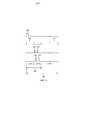
На фиг. 1 представлена примерная функциональная диаграмма абляционной системы;In FIG. 1 is an exemplary functional diagram of an ablation system;
на фиг. 2 представлен один тип предложенной схемы хронирования сигналов;in FIG. 2 shows one type of the proposed signal timing scheme;
на фиг. 3 представлен пример того, как базовую линию начальных значений смещения получают для использования в оценке прогресса абляции на всем протяжении области лечения;in FIG. Figure 3 shows an example of how a baseline of initial bias values is obtained for use in assessing ablation progress throughout the treatment area;
на фиг. 4 представлен один из примеров графика типичного смещения с течением времени в единицах циклов мониторинга/терапии и квадратической кривой, аппроксимированной к начальной части графика для обнаружения пиков;in FIG. Figure 4 shows one example of a graph of typical bias over time in units of monitoring / therapy cycles and a quadratic curve approximated to the initial portion of the graph for peak detection;
на фиг. 5 представлен примерный график нормализованного смещения с течением времени;in FIG. 5 is an exemplary graph of normalized bias over time;
на фиг. 6 представлен пример графика диаметра повреждения в зависимости от нормализованной разности смещений;in FIG. 6 is an example of a graph of damage diameter versus normalized offset difference;
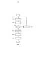
на фиг. 7 представлена блок-схема последовательности операций примера получения и инициализации устройства управления абляцией;in FIG. 7 is a flowchart of an example of acquiring and initializing an ablation control device;
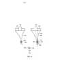
на фиг. 8 представлена иллюстрация, изображающая пример фокуса толчка, смещаемого от фокуса терапевтического пучка, эффект которого измеряют;in FIG. 8 is an illustration showing an example of a focus of a shock displaced from the focus of a therapeutic beam whose effect is measured;
на фиг. 9 представлена блок-схема последовательности операций, демонстрирующая примерную процедуру в реальном времени для того, чтобы автоматически и без необходимости вмешательства пользователя осуществлять детальный мониторинг абляции, которую осуществляют в одном местоположении за раз;in FIG. 9 is a flowchart illustrating an example real-time procedure in order to automatically and without the need for user intervention perform detailed monitoring of ablation, which is performed at one location at a time;
на фиг. 10 представлена блок-схема последовательности операций, демонстрирующая примерную процедуру в реальном времени для того, чтобы автоматически и без необходимости вмешательства пользователя осуществлять детальный мониторинг абляции, которую осуществляют в одном местоположении за раз;in FIG. 10 is a flowchart showing an example real-time procedure in order to automatically and without the need for user intervention perform detailed monitoring of ablation, which is performed at one location at a time;
на фиг. 11 представлена блок-схема последовательности операций процедуры в реальном времени для того, чтобы автоматически и без необходимости вмешательства пользователя осуществлять мониторинг, эффективный по времени, относительно гомогенной области лечения из одного местоположения, характерного для всей области; иin FIG. 11 is a flowchart of a real-time procedure in order to automatically and without the need for user intervention to monitor, time-efficient, with respect to a homogeneous treatment area from a single location characteristic of the entire area; and
на фиг. 12 представлена блок-схема последовательности операций, являющаяся примером процедуры в реальном времени для того, чтобы автоматически и без необходимости вмешательства пользователя осуществлять мониторинг, эффективный по времени, области лечения, проявляющей некоторую степень однородности.in FIG. 12 is a flowchart illustrating an example of a real-time procedure in order to automatically and without the need for user intervention to monitor a time-effective treatment area exhibiting a certain degree of uniformity.
ПОДРОБНОЕ ОПИСАНИЕ ВАРИАНТОВ ОСУЩЕСТВЛЕНИЯDETAILED DESCRIPTION OF EMBODIMENTS
На фиг. 1 изображен, в форме иллюстративного и неограничивающего примера, меняющий механическое свойство, или «абляционный», блок 110, его устройство 115 управления для мониторинга терапии во множестве пространственных измерений и устройство 120 отображения в режиме реального времени.In FIG. 1 depicts, in the form of an illustrative and non-limiting example, changing the mechanical property, or “ablative,”
Абляционный блок 110 включает в себя многоэлементную диагностическую решетку 125, помещенную софокусно с терапевтической решеткой 130 или решеткой (130) «терапии».The
Устройство 115 управления содержит комбинированный модуль 135 схемы совпадений и многоканального мощного усилителя, логический модуль 140 запуска и управления и модуль 145 многоканального сбора и анализа ультразвуковых данных. Устройство 115 управления можно реализовать, например, в качестве электрического блока, аналоговых электронных компонентов, гибридной схемы или твердотельного устройства, содержащего интегральную схему, которая включает в себя любую форму RAM, ROM, ASIC, PLD, или их сочетание. Каждый из модулей 135, 140, 145 можно реализовать в программном обеспечении, встроенном программном обеспечении или аппаратном обеспечении или их сочетании.The
Терапевтическую решетку 130 можно реализовать как преобразователь фокусированного ультразвука высокой интенсивности (HIFU) и, подобно диагностической решетке 125, можно реализовать в виде, например, линейной решетки, фазированной решетки или двумерного (2D) матричного преобразователя. Преобразователь HIFU 130 фокусирует ультразвук (который представляет собой радиочастоту или «РЧ» энергию), чтобы тем самым осуществить абляцию опухоли или другой цели абляции. Преобразователь HIFU 130 также доставляет ультразвук в форме толчка формирования изображений силы акустического излучения (ARFI) и получает обратно эхо от субъекта абляции. Термин «субъект абляции» далее в настоящем документе относится к медицинскому пациенту, получающему терапию, человеку или животному, или к любой ткани организма, такой как когда проводят тестирование. Решетки 125, 130 вмещают в зонд (не показан), который должен быть помещен на пациенте посредством компьютерного управления или вручную. Альтернативно зонд можно помещать на конце гибкого вала, который должен быть введен внутрь, например, через рот пациента под анестезией. Зонд может содержать схему формирования пучка или схема может находиться в логическом модуле 140 запуска и управления.The
Сигналы возбуждения для терапевтической решетки 130 обеспечены модулем 135 схемы совпадений/многоканального мощного усилителя.The excitation signals for the
Управляющую логику устройства 115 управления применяют для того, чтобы обеспечивать запускающие и управляющие сигналы, чтобы синхронизировать хронирование трех типов акустических пучков, которые рассеивают. Во-первых, имеют место меняющие механическое свойство, или «терапевтические», пучки, из терапевтической решетки 130, для изменения механического свойства биологической ткани. Во-вторых, имеют место толкающие пучки, от терапевтической решетки, для оценки эффекта терапевтических пучков. В-третьих, имеют место следящие пучки, из диагностической решетки 125, при выполнении оценки, для слежения за смещением ткани в связи с толчком. Запуск можно стробировать для того, чтобы следовать конкретному снимку в такт сердцебиения и/или циклов дыхания в зависимости от местоположения места абляции in vivo, подвергнутого абляции. С управляющей логикой связан графический пользовательский интерфейс (GUI), который имеет средства ввода/вывода пользовательского интерфейса, которые могут включать клавиши, номеронабиратели, ползунки, шаровые манипуляторы, чувствительные к прикосновению экраны, курсоры и любые другие известные и подходящие исполнительные механизмы для описания границ и параметров лечения. Управляющую логику можно реализовать в форме программного обеспечения на базе ПК, например, на базе LabVIEW™.The control logic of the
Модуль 145 многоканального сбора и анализа ультразвуковых данных взаимодействует с диагностической решеткой 125 для того, чтобы обрабатывать сигналы с обратным рассеянием, чтобы тем самым вычислять изменение в механических смещениях. Вычисление служит в качестве меры жесткости, чтобы тем самым обнаружить завершение терапии в текущем местоположении, которое лечат. Размеры повреждения на основе текущего вычисления необязательно могут быть отображены на устройстве 120 отображения в режиме реального времени в качестве изображения и/или наложены на изображение в B-режиме.The multichannel ultrasound data acquisition and
Управляющий сигнал 150 также подают с модуля 145 многоканального сбора и анализа ультразвуковых данных в логический модуль 140 запуска и управления, чтобы на основе анализа мониторинга остановить терапию, когда достигнута желаемая конечная точка лечения для текущего местоположения или области лечения.The
Другие стрелки 155, 160, 165, 170 показывают соотношение управления, в соответствии с рассмотренным выше.The
На фиг. 2 проиллюстрирована одна схема для синхронизации толкающих, следящих и терапевтических импульсов соответствующих пучков в устройстве 115 управления абляцией. В представленном примерном варианте осуществления за главным запускающим сигналом 205 следует толчок 210 от преобразователя HIFU 130. Длительность толчка задают между 10 и 15 миллисекундами (мс), в зависимости от механических свойств ткани, подвергаемой абляции. После толчка 210 следуют первый и второй следящие импульсы 215, 220, исходящие из диагностической решетки 125. Следящие импульсы 215, 220 используют для того, чтобы воспринимать структуры на различных глубинах вдоль линии приема в ткани организма. Первый следящий импульс 215 исходит непосредственно после толчка 210, чтобы запросить значение натянутой ткани. Второй следящий импульс 220 исходит приблизительно на 12 мс позже и представляет значение расслабленной ткани (или равновесие). Модуль 145 многоканального сбора и анализа ультразвуковых данных регистрирует соответствующие возвратные эхо 225, 230 этих двух следящих импульсов 215, 220, непосредственно следующие за каждым из двух импульсов. Различия между РЧ данными, извлеченными из этих двух возвратных эхо 225, 230, представляют смещение ткани организма, которое произошло в реакции на толчок 210. Вся эта последовательность представляет собой часть 235 мониторинга цикла 240 мониторинг-терапия и длится между 20 и 30 мс. Терапевтическая часть 245, во время которой преобразователь HIFU 130 доставляет терапию, значительно длительнее и длится между 2970 и 2980 мс. Следовательно, весь цикл 240 мониторинг-терапия длится в течение приблизительно 3 секунд.In FIG. 2 illustrates one circuit for synchronizing pushing, tracking, and therapeutic pulses of respective beams in an
Другие возможные последовательности по времени могут быть заменены на последовательность на фиг. 2, например, где первый следящий импульс 215 предшествует толчку, и второй следящий импульс 220 возникает после толчка. Как на фиг. 2, пространственное положение, выявленное в результате первого следящего импульса 215, сравнивают с пространственным положением, выявленным в результате второго следящего импульса 220, чтобы получить смещение, возникающее в результате толчка. В качестве дополнительного примера, мониторинг можно осуществлять одновременно с толканием. Также вызванное смещение может быть колебательным, как при формировании изображений гармонического движения (HMI).Other possible time sequences may be replaced by the sequence in FIG. 2, for example, where the
В связи со сфокусированной природой ультразвукового луча, применяемого в толчке 210, максимальное смещение находится в фокусе. Однако смещение в меньшей степени происходит в осевом и радиальном направлении вдали от фокуса. На смещение с течением времени действует тепло, доставляемое терапевтическим ультразвуковым лучом от преобразователя HIFU 130.Due to the focused nature of the ultrasound beam used in the
Чтобы получить преимущество большего и более заметного смещения и для однородности в измерении от точки абляции к точке абляции желательно фокусировать пучок, доставляющий толчок 210, в фокус терапевтического ультразвукового луча (или «фокус терапии»), чтобы два фокуса совпадали. Два пучка исходят из одного и того же преобразователя HIFU 130. Несмотря на то, что терапевтический пучок имеет более высокую мощность, чем толкающий пучок, два пучка совместно используют одни и те же параметры фокусировки и один и тот же фокус (или «фокусная точка»).In order to take advantage of a larger and more noticeable bias and for uniformity in measurement from the ablation point to the ablation point, it is desirable to focus the beam delivering the
Следящие импульсы 215, 220 исходят от отдельной решетки 125, чем та, что создает толчок/фокус терапии; однако две решетки 125, 130 можно конфигурировать в фиксированном пространственном соотношении, помещая одну софокусно с другой.The tracking
На фиг. 3 представлен пример того, как базовую линию 301 начальных значений 306 смещения получают для использования в оценке прогресса абляции на всей области лечения. На фиг. 3 график представляет смещения 304 вдоль линии 225 приема. Под термином «начальное смещение» 306 понимают максимум смещений 304 вдоль линии 225 приема, все возникают от толчка 210 в одном местоположении сканирования базовой линии перед терапией. Кроме того, поскольку линия 225 приема выровнена относительно толкающего пучка, местоположение начального смещения 306 представляет собой не только местоположение пространственно максимального смещения вдоль линии приема, но оценку пространственно максимального смещения в трехмерном пространстве. Поскольку толчок и терапевтические пучки софокусны, фокус 302 терапии совпадает с местоположением начального смещения 306.In FIG. 3 shows an example of how a
Перед началом лечения можно использовать формирование изображений в B-режиме, чтобы отображать объем 308 лечения на экране для того, чтобы клиницист мог определить целевую ткань, например, посредством вычерчивания границы на экране. Объем 308 лечения внутри биологической ткани 309 включает в себя одну или несколько областей 310 лечения. Область 310 лечения включает в себя одну или несколько линий 312 лечения - каждый один ряд или слоев 314 лечения, каждый имеет множество рядов повреждений 316, 318, 320, 322, 324.., идущих бок о бок. Сбоку на фиг. 3 показан вид сверху (как обозначено стрелкой «I», здесь перпендикулярной листу чертежа) области 310 лечения в случае осуществления направления в 3D. Показана часть верхнего слоя 314. Если решетки 125, 130 выполнены с возможностью осуществления направления в 2D, линию 312 можно сканировать в направлении 325a по азимуту или по подъему 325b, и решетку можно механически перемещать для того, чтобы лечить любую латеральную смежную линию. С другой стороны, если решетки конфигурируют с возможностью осуществления направления в 3D, слой 314 и любой подлежащий слой можно сканировать в направлении по азимуту 325 и/или по подъему 325b.Before starting treatment, you can use imaging in B-mode to display the volume of
Терапевтическую решетку 130, если она представляет собой, например, линейную решетку, конфигурируют с возможностью электронно осуществлять направление терапевтического пучка 336 и толкающего пучка 326 в направлении 325a по азимуту. Если вместо этого терапевтическая решетка 130 представляет собой 2D решетку, ее конфигурируют с возможностью электронно осуществлять направление терапевтического пучка 336 и толкающего пучка 326 в направлении 325a по азимуту, в направлении 325b по подъему или в комбинации 325c двух направлений.The
Аналогичным образом, для диагностической решетки 125, если она представляет собой линейную решетку, ее конфигурируют с возможностью электронно осуществлять направление следящего пучка 328 импульсов 215, 220 в направлении 325a по азимуту. Если вместо этого диагностическая решетка 125, подобно терапевтической решетке 130, представляет собой 2D решетку, ее конфигурируют с возможностью электронно осуществлять направление следящего пучка 328 в направлении 325a по азимуту, в направлении 325b по подъему или в комбинации 325c двух направлений.Similarly, for the
Базовая линия представляет собой решетку полученных начальных смещений 306, соответственно решетка является одномерной в случае линии 312 и двумерной в случае слоя 314. Для вариантов осуществления, в которых повреждения 316-324 формируют одно за одним, лечение в реальном времени по одной линии 312 или слою 314 может переходить к получению базовой линии для следующего, например, лежащей выше или ниже, линии или слоя с небольшой паузой или без паузы, чтобы тепловые эффекты не рассеивались. Для вариантов осуществления, в которых повреждения формируют одновременно, следующая линия 312 или слой 314 могут быть не смежными, чтобы укоротить паузу или избежать ее.The baseline is the lattice of the obtained
Клиницист также может вводить размер повреждения, который может быть в форме нормализованной разности смещений, которая дополнительно рассмотрена ниже. Альтернативно, размер повреждения задают автоматически.The clinician can also enter the size of the damage, which can be in the form of a normalized difference in displacement, which is further discussed below. Alternatively, the damage size is set automatically.
Для получения базовой линии за толкающим пучком 326 в начальном местоположении 324 следует следящий пучок 328 импульсов 215, 220. Продольно совпадающие соответствующие линии 225, 230 приема (на фиг. 3 показана только линия 225) для импульсов 215, 220 взаимно коррелированы для того, чтобы измерять смещение, максимум которого представляет собой начальное смещение 306. Затем проводят сканирование толкающего пучка 326 и следящего пучка 328 до следующего местоположения 322, и процедуру повторяют.To obtain the baseline, the
В некоторых вариантах осуществления значение 330 базовой линии получают для промежуточного местоположения 332, в целевой периферии повреждения 320, где прогнозируют встретить смежное повреждение 318. Толкающий пучок 334 подвергают слежению за фокусами в местоположении 332 встречи. Это выполняют для уточнения или «точной подстройки» размера повреждения, как рассмотрено дополнительно ниже применительно к фиг. 8.In some embodiments, a baseline value of 330 is obtained for an intermediate location 332, at the target periphery of
Значение базовой линии и/или промежуточное значение базовой линии в целевой периферии, например, местоположения 320, можно использовать при принятии решения о том, когда завершено лечение меняющим механическое свойство, или «терапевтическим», пучком 336 в этом местоположении, как рассмотрено непосредственно ниже.The baseline value and / or the intermediate baseline value at the target periphery, for example,
На фиг. 4 представлен пример графика типичного смещения с течением времени в единицах циклов 240 мониторинга/терапии и квадратической кривой, аппроксимированной к начальной части графика для обнаружения пиков. Нулевой номер цикла на графике относится к началу циклов 240 мониторинга-терапии. В примере на фиг. 4 показано, что начальное смещение 405 составляет приблизительно 110 мкм. Начальное смещение 405 варьируется от точки абляции к точке абляции, от индивидуума к индивидууму и от образца ткани к образцу ткани по причине неоднородностей ткани организма. Продвигаясь во времени, с каждым последующим циклом 240 мониторинга-терапии, выполняют измерение эффекта 407 или «теплового эффекта» терапевтического пучка 336 в текущем местоположении 316 внутри области 310 лечения внутри ткани 309, оказываемого на смещение 410 ткани в фокус 302 терапии. Смещение 410, посредством толчков во время части 210 толчка, изначально возрастает с течением времени в связи с тем, что приложенное тепло размягчает ткань. После некоторого времени терапии смещение 410 достигает пика 415 и начинает снижаться, что указывает на то, что ткань становится жестче (т.е. после некроза). Снижение наблюдают до тех пор, пока терапия не достигнет точки остановки в смещениях 410 или «смещения 420 конечной точки». После того, как терапию выключают, снижение смещения 410 замедляется по мере охлаждения ткани. Однако эффект температуры, оказываемый на некроз клеток, все еще существует, даже несмотря на то, что перенос энергии больше не применяют, например, посредством пучка, чтобы изменить механическое свойство биологической ткани.In FIG. 4 is an example of a graph of a typical bias over time in units of monitoring /
Квадратическую кривую 425 можно аппроксимировать к смещениям 410 в реальном времени, чтобы обнаружить пик 415. Пик 415 обнаруживают, когда наклон квадратической кривой 425 становится нулевым и начинает приобретать отрицательное значение. Пик 415 можно оценивать посредством усреднения измерений смещения 410, например, для пяти циклов, внутри интервала около точки нулевого наклона. Причина для обнаружения пика 415 будет подробно рассмотрена ниже применительно к фиг. 5.
На фиг. 5 представлен примерный график нормализованного смещения 505 с течением времени или, более конкретно, в соответствии с номером 510 цикла. На фиг. 5 график, обозначаемый далее в настоящем документе характеристической кривой 515, можно получать из графика смещения на фиг. 4 посредством деления каждого смещения 410 на начальное смещение 405. Слово «характеристическая» в термине «характеристическая кривая», как используют в настоящем документе, относится к отличающему признаку или атрибуту. Отличающий признак или атрибут может принадлежать организму или биологической ткани. Характеристическая кривая 515 также может представлять собой комбинацию, такую как среднее, некоторого числа таких полученных кривых, основываясь на эмпирическом наблюдении в различных точках абляции. В связи с отмеченными выше неоднородностями ткани организма, шкалу времени на фиг. 5 (номеров 510 цикла) можно сжимать или расширять, в зависимости от точки абляции, индивидуума или образца ткани. Таким образом, расход времени для нормализованного смещения является переменным. Однако форма характеристической кривой 515 остается постоянной для данного типа ткани организма, например, печени, груди, сердца. Посредством импликации после идентификации точки на характеристической кривой 515 идентифицируют все точки. Это значимо, поскольку некоторые точки на характеристической кривой 515 ассоциированы с конкретными размерами повреждения. Таким образом, способность идентифицировать то, что текущая абляция в точке абляции достигла конкретной точки на характеристической кривой 515, может вести к точному предсказанию 540, т.е., например, при NDD 0,5, того, когда останавливать абляцию, чтобы добиться желаемого размера повреждения. Здесь предсказание 540 основывается на «центральном» NDD, NDD в фокусе 302 терапии. Однако параметр NDD, полученный из фокуса толкающего пучка для оценки эффекта самого последнего фокуса 302 терапевтического пучка, может быть смещен в направлении по азимуту 325a и/или по подъему 325b. Смещение может представлять собой, например, предсказанную точку 332 встречи на целевой периферии повреждения 320. «Периферический» NDD можно использовать, или он может вносить вклад, в принятие решения в реальном времени о том, что лечение в текущем местоположении 320 завершено. «Периферический» NDD от 0,1 до 0,15, например, который может подразумевать достаточный прогресс в начале некроза в предсказанной точке 320 встречи с тем, что будет следующим, смежным повреждением 318, может показывать, что лечение завершено в текущем местоположении 320.In FIG. 5 is an exemplary graph of normalized
Во время текущей абляции предварительно нормализованные смещения 410 доступны в реальном времени. Метод, рассмотренный в переуступленной заявке '510, состоит в регистрации одного или нескольких смещений 410 с ассоциированным нормализованным смещением(ями) 505 характеристической кривой 515.During current ablation,
Две точки ориентира на характеристической кривой 515 представляют собой нормализованное начальное смещение 530, которое по правилу устанавливают равным единице, и нормализованное пиковое смещение 535.The two reference points on the
Ассоциированные предварительные нормализованные смещения представляют собой, соответственно, начальное смещение 405 и пиковое смещение 415.The associated preliminary normalized biases are, respectively, the
Более конкретно, начальное смещение 405 можно регистрировать на начальном нормализованном смещении 530. Регистрация позволяет посредством характеристической кривой 515 использовать начальное смещение 405 в предсказании, когда смещаемую по ширине абляцию следует останавливать, чтобы достичь предварительно определяемого размера повреждения после остановки. Начальное смещение 405 соответственно представляет собой одно из значений, которые могут служить как то, что обозначают далее в настоящем документе точкой регистрации, независимой от скорости прогресса терапии (TPRI), как рассмотрено в дополнительных деталях ниже.More specifically, the initial offset 405 can be recorded at the initial normalized offset 530. The registration allows the characteristic offset 515 to be used to predict the initial offset 405 in the prediction when the width-shifted ablation should be stopped in order to achieve a predefined damage size after the stop. The initial offset 405, respectively, is one of the values that can serve as what is designated hereinafter as a registration point independent of the rate of progress of therapy (TPRI), as discussed in further detail below.
Пиковое смещение 415 происходит одновременно с нормализованным пиковым смещением 535. Соответственно, пиковое смещение 415, подобно начальному смещению 405, может служить как точка регистрации TPRI.Peak offset 415 occurs simultaneously with the normalized peak offset 535. Accordingly, peak offset 415, like the initial offset 405, can serve as a TPRI recording point.
Для ее эффективности в качестве предиктора размера повреждения регистрация точки регистрации TPRI на характеристической кривой 515 полагается на функциональное соотношение между декрементами в нормализованном смещении 505 и эмпирическими значениями размера повреждения. С этой целью нормализованную разность (NDD) 540 смещений определяют как разность между нормализованным пиковым смещением 535 и конечной точкой нормализованного смещения 505. Значения NDD 540 0, 0,25 и 0,5 показаны на фиг. 5. Таким образом, например, при NDD, равной 0, нормализованное пиковое смещение 535 и нормализованное смещение конечной точки 505 одинаковы, что будет подразумевать, что применение энергии абляции остановлено при пиковом смещении 415 (или, эквивалентно, при нормализованном пиковом смещении 535). Конкретный размер повреждения ассоциирован с каждым значением NDD 540.For its effectiveness as a predictor of damage size, recording the TPRI registration point on
На фиг. 6 представлен пример графика 600 зависимости диаметра повреждения от NDD 540. Абляцию проводили экспериментально на различных образцах ткани и различных местах внутри образца. Абляцию останавливали, и образец непосредственно охлаждали для того, чтобы остановить некроз. Измеряли размер повреждения. Форма повреждения зависит от геометрии преобразователя и характеристик его акустического пучка. В случае HIFU форма повреждения обычно является эллипсовидной с большой осью вдоль продольного центра пучка. Диаметр повреждения на фиг. 6 соответственно относится к максимальному диаметру повреждения, перпендикулярному продольному центру пучка. Для каждого измерения отмечены время лечения, значение 420 смещения 420 конечной точки и пиковое значение 415 смещения. Основываясь на этих фактических данных, на график наносили точки наблюдений, связывающие диаметр повреждения с NDD 540. На фиг. 6 показаны некоторые нанесенные на график точки наблюдений для типа 602 ткани, который в этом случае представляет собой печень. Обнаружено, что соотношение описано посредством полиномиальной аппроксимации второго порядка с хорошим совпадением, и что параметры полинома варьируются с типом ткани. Параметры также будут варьироваться с формой повреждения, несмотря на то, что форма повреждения типично не будет варьироваться. Следовательно, далее в настоящем документе предполагают, что когда кривые классифицируются по типу ткани, не существует необходимости дополнительно осуществлять классификацию по форме повреждения. Как показано посредством различных интенсивностей HIFU наблюдений 605-630, аппроксимированная функция инвариантна по интенсивности лечения. Время лечения для шести образцов перечислено в скобках. Можно видеть, что время лечения не является хорошим индикатором размера повреждения в связи с неоднородностями ткани. Наблюдение 615, например, показывает большее время лечения для достижения меньшего размера повреждения в сравнении с наблюдением 625. Для наблюдений, выполненных в различных частях одного и того же образца ткани или для различных образцов ткани, обнаружено, что размеры повреждений не коррелируются хорошо со временем лечения. Преимущественно, методология по заявке '510, которая также изложена выше в настоящем документе и более подробно ниже, преодолевает чувствительность к неоднородности ткани.In FIG. Figure 6 shows an example of a
На фиг. 7 предоставлен пример подготовки и инициализации устройства 115 управления абляцией. Абляцию осуществляют на конкретном образце ткани (этап S710). Абляцию прерывают для текущего образца ткани, который непосредственно охлаждают для того, чтобы остановить некроз. Регистрируют смещение 420 конечной точки и пиковое смещение 415. После гистологического исследования сформированного повреждения регистрируют размер повреждения (этап S720). Затем выполняют запрос о том, было ли это последним наблюдением (этап S730). Если это не является последним наблюдением, выполняют следующее наблюдение на текущем образце ткани или другом образце ткани, или на другом типе ткани (этап S740). С другой стороны, если это является последним наблюдением, наблюдения группируют по типу ткани (этап S750). Аппроксимированные кривые 600 (или «калибровочные кривые») получают посредством типа ткани, используя зарегистрированные данные и аппроксимацию квадратических кривых (этап S760). Калибровочные кривые 600 - каждая со своим идентификатором типа 602 ткани - отправляют устройству 115 управления абляцией. Также каждую характеристическую кривую 515, идентифицируемую посредством типа ткани, делают доступной для устройства 115 управления абляцией. Характеристические кривые 515 аналогичным образом получают из эмпирического наблюдения, как указано выше (этап S770).In FIG. 7, an example of preparing and initializing an
Когда получают базовую линию 301, терапевтический пучок 336 применяют и прерывают для исполнения одной или нескольких частей 235 мониторинга для соответствующих местоположений 316-324, в зависимости от протокола, как дополнительно рассмотрено в подробностях ниже. Прерывания терапии происходят поочередно для того, чтобы сделать возможной каждый раз одну или несколько частей 235 мониторинга. В мониторинге вызываемых толчками смещений 410 в заданном местоположении получают одну или несколько TPRI точек регистрации в реальном времени и осуществляют обработку в реальном времени. Обработка вовлекает в себя регистрацию точки(чек) (например, начального смещения 405, пикового смещения 415) на соответствующей точке(ах) (т.е. нормализованное начальное смещение 530, нормализованное пиковое смещение 535) на подходящей характеристической кривой 515. Можно использовать следующую формулу:When
HD=(NPD-NDD)×RP/CP
где HD обозначает смещение, при котором абляция должна быть остановлена;where HD denotes the offset at which ablation should be stopped;
RP обозначает TPRI точку регистрации;RP stands for TPRI registration point;
CP обозначает соответствующую точку характеристической (т.е. нормализованной) кривой 515;CP denotes the corresponding point of the characteristic (i.e., normalized)
NPD обозначает нормализованное пиковое смещение 535; иNPD denotes the normalized peak offset 535; and
NDD обозначает нормализованную разность 540 смещений.NDD stands for the normalized difference of 540 offsets.
Таким образом, определение HD, т.е. смещение 420 конечной точки, сделано возможным посредством регистрации точки(чек) регистрации TPRI с помощью характеристической кривой 515.Thus, the definition of HD, i.e. endpoint offset 420 is made possible by registering a TPRI registration point (check) with a
Следовательно, например, если начальное смещение 405 служит в качестве точки регистрации TPRI, возможность возникает после завершения части 235 мониторинга первого из циклов 240 мониторинг-терапия. Перед этим завершением начальное смещение 405 еще не известно и, следовательно, не может быть применено как RP в формуле (1), приведенной выше.Therefore, for example, if the initial offset 405 serves as the TPRI registration point, the possibility arises after the completion of the
Величину RP/CP в формуле (1) можно рассматривать в качестве коэффициента нормализации. Когда желаемый размер повреждения оценивают относительно калибровочной кривой 600, идентифицируют NDD 540. NDD 540 вычитают из NPD 535, чтобы получить нормализованную форму смещения 420 конечной точки. Нормализованную форму умножают на коэффициент нормализации, чтобы получить «денормализованное» смещение конечной точки (или HD в формуле (1)). Если используют более чем одну точку регистрации, соответствующие коэффициенты нормализации можно усреднять для использования в уравнении (1).The value of RP / CP in formula (1) can be considered as a normalization coefficient. When the desired damage size is evaluated relative to a
На фиг. 8 изображен в качестве иллюстрации фокус толчка, являющийся смещенным 830 от фокуса терапевтического пучка, эффект которого измеряют.In FIG. 8 depicts by way of illustration the focus of a push that is offset 830 from the focus of a therapeutic beam whose effect is measured.
Терапевтический пучок 836 применяют в местоположении 840 и сохраняют позиционно фиксированным в этом местоположении. Во время прерывания в терапевтическом пучке 836, имеющем фокус 844, толкающий пучок 848, имеющий фокус 852, применят к точке 856 на целевой периферии 860 повреждения 840, создаваемого посредством терапевтического пучка 836, имеющего самый последний фокус 844. Фокус 852 толкающего пучка 848 предназначен для оценки эффекта самого последнего фокуса 844 терапевтического пучка 836, фокусы 844, 852 являются смещенными 830 в по меньшей мере одном из направления по азимуту и направления по подъему. За толкающим пучком 848 следует пара 864 из первого и второго следящих импульсов для того, чтобы формировать изображения ткани 309 в натянутом и расслабленном положении, соответственно. Как указано выше по отношению к фиг. 3, «периферическая» NDD от 0,1 до 0,15, например, которая может влечь за собой достаточный прогресс в начале некроза в предсказанной точке 856 встречи с тем, что будет следующим, смежным повреждением 868, может указывать на то, что лечение завершено в текущем местоположении 840.The
Альтернативно, вместо смещения от терапевтического пучка 836 как толчка, так и слежения, можно смещать, например, только слежение. Получение базовой линии, соответственно, будет включать в себя начальные смещения, основываясь на толчках «в центре повреждения», но следящие импульсы 210, 215 выровнены согласно смещению 830. Следовательно, на фиг. 8 толчок 848 будет выровнен не только относительно предсказанной точки встречи 856, но по центру относительно текущего местоположения 840. Однако следящий пучок 864 должен оставаться выровненным согласно смещению 830. Аналогичным образом во время терапии толкающий пучок выравнивают по центру относительно повреждения 840, тогда как следящие импульсы 864, приведенные в качестве примера на фиг. 8, выравнивают согласно смещению 830, как показано.Alternatively, instead of offsetting both the jolt and the tracking from the
На фиг. 9 продемонстрирована процедура 900 в реальном времени для того, чтобы автоматически и без необходимости вмешательства пользователя осуществлять детальный мониторинг абляции, который осуществляют в одном местоположении 840 в один момент времени. Изначально получают базовую линию 301, используемую в решениях о том, завершено ли лечение в некотором местоположении 840 (этап S910). Фокус 844 терапевтического пучка удерживают в текущем местоположении 840 (этап S920). Испускают терапевтический пучок 836 (этап S930). Терапевтический пучок 836 прерывают, т.е. терапевтическую часть 245 цикла 240 мониторинг-терапия завершают, например, после приблизительно 3 секунд или конкретного числа циклов, чтобы испускать толкающий пучок 848 и пару 864 следящих импульсов (этап S940). Если определено, что лечение в текущем местоположении 840 еще не завершено (этап S950), обработка возвращается к этапу S930. Иным образом, если определено, что лечение в текущем местоположении 840 выполнено и что текущее местоположение, следовательно, более не подлежит лечению, и существует следующее местоположение в области 310 лечения (этап S960), формирующая пучок логика для терапевтической решетки 130 осуществляет направление для сканирования до следующего местоположения 868 (этап S970), которая становится текущим местоположением для целей дополнительного повторения. Обработка возвращается к этапу S920. Если, с другой стороны, лечение в области 310 лечения завершено (этап S960), процедура заканчивается.In FIG. 9, a real-
На фиг. 10 представлена процедура в реальном времени для того, чтобы автоматически и без необходимости вмешательства пользователя осуществлять детальный мониторинг абляции, который осуществляют одновременно на всей области 310 лечения. Сначала получают базовую линию 301 (этап S1005). Затем терапевтический пучок 836 непрерывно сканирует область 310 лечения местоположение за местоположением в пробегах, которые повторяют, но проскакивает зарегистрированные местоположения 316-324.., для которых лечение завершено. Каждый пробег, кроме пропускания, перекрывает область 310. В слое 314, например, самые нижние местоположения 316-324 (в перспективе вида сверху) могут составлять часть охвата слева направо, затем такой охват продолжается выше ряд за рядом, чтобы составить один пробег. Сканирование продолжают до тех пор, пока не прерывают лечение, например, до истечения периода времени приблизительно в 3 секунды (этап S1010). Первое местоположение 316 становится текущим местоположением (этап S1015). Происходит испускание толкающего пучка 848 и пары 864 следящих импульсов 215, 220 (этап S1020). Если принимают решение о том, что лечение для текущего местоположения завершено (этап S1025), местоположение регистрируют (этап S1030). Если, пропуская зарегистрированные местоположения, имеет место следующее местоположение в области 310 лечения (этап S1035), формирующая пучок логика для терапевтической решетки 130 осуществляет направление для сканирования, т.е. толкающий пучок 848 и следящий пучок 328 импульсов 215, 220, к следующему местоположению (этап S1040), и обработка возвращается к этапу S1020. Иным образом, если мониторинг достиг завершения для текущего прерывания в терапии, и если лечение области 310 лечения еще не завершено (этап S1045), обработка возвращается к этапу S1010.In FIG. 10, a real-time procedure is presented in order to automatically and without the need for user intervention perform detailed monitoring of ablation, which is carried out simultaneously throughout the
Описанные выше схемы 900, 1000 мониторинга можно использовать клинически, где присутствие неоднородностей ткани и/или кровеносных сосудов может привести к местоположениям 840 с линией 312 лечения или слоем 314, достигающим некроза быстрее, чем другие, при той же применяемой терапевтической мощности. В таких случаях методы мониторинга в описанных выше процедурах 900, 1000 будут помогать оптимизировать доставку терапии, снижать чрезмерное лечение и тем самым также длительность лечения. Вдобавок, основываясь на процессе рассеяния тепла для того же количества тепла, применяемого по всей сканируемой линии 312 или слою 314, подъем температуры в краевых зонах будет, как правило, ниже, чем в центре, вследствие мощного теплового градиента на краях. Таким образом, центр должен будет подлежать лечению меньше, чем краевые зоны. Протоколы мониторинга описанных выше процедур 900, 1000 мониторинга разработаны для того, соответственно, чтобы предоставлять обратную связь, чтобы продолжить или остановить терапию.The
На фиг. 11 показана процедура 1100 в реальном времени для того, чтобы автоматически и без необходимости вмешательства пользователя осуществлять мониторинг, эффективный по времени, относительно гомогенной области 310 лечения из одного местоположения 316, характерного для всей области. Получают значение 330 базовой линии, или «начальное значение 306 смещения», для конкретного местоположения 332, которое подлежит слежению (этап S1110). Терапию применяют или к конкретному местоположению 316, или к области 310 лечения посредством непрерывного ее сканирования пробег за пробегом. В любом случае, терапию продолжают до прерывания, когда время истекает (этап S1120). Толкающий пучок 848 и пару 864 следящих импульсов 215, 220 испускают в одно конкретное местоположение 316 (этап S1130). Если лечение, как судят посредством мониторинга одного конкретного местоположения 316, еще не завершено (этап S1140), обработка возвращается на этап S1120. Иным образом, если определяют, что лечение, как судят, завершено (этап S1140), формирующая пучок логика для терапевтической решетки 130 осуществляет направление для сканирования до следующего местоположения, которое становится текущим местоположением для целей повторения (этап S1150). Лечение применяют к текущему местоположению в течение той же длительности, в течение которой его применяли к конкретному местоположению 316, без необходимости какого-либо толкания или слежения в настоящий момент (этап S1160). Если существует следующее местоположение (этап S1170), обработка возвращается к этапу S1150.In FIG. 11, a real-
На фиг. 12 приведен пример процедуры 1200 в реальном времени для того, чтобы автоматически и без необходимости вмешательства пользователя осуществлять мониторинг, эффективный по времени, области 310 лечения, проявляющей некоторую степень однородности. Базовую линию 301 получают с использованием одного или нескольких несфокусированных толчков 210 - каждый для воздействия на пространственную зону внутри области 310, более широкой, чем для сфокусированного толчка. На каждый несфокусированный толчок испускают одну или несколько пар 864 следящих импульсов 215, 220, положение пар взаимно разнесено в пространстве (этап S1205). Область 310 непрерывно сканируют, перекрывают ее повторно пробег за пробегом, но пропускают зарегистрированные местоположения, сканирование прерывают по истечении периода времени (этап S1210). Логика направлена на первый несфокусированный толчок 210 (этап S1215). Логика направлена на первое местоположение 316, покрываемое посредством текущего несфокусированного пучка 210 (этап S1220). Испускают текущий несфокусированный пучок 210, за чем следует пара 864 следящих импульсов 215, 220 (этап S1225). Если лечение для текущего местоположения 316 завершено (этап S1230), текущее местоположение регистрируют (этап S1235). В любом случае, если имеет место следующее местоположение 316 для слежения текущего несфокусированного толчка 210 (этап S1240), учитывающего пропускание зарегистрированных местоположений 316, формирующая пучок логика осуществляет направление для сканирования, т.е. пучка для несфокусированного толчка 210 и следящего пучка 328 импульсов 215, 220, к следующему местоположению (этап S1245), и обработка возвращается к этапу S1225. Если, с другой стороны, завершено слежение за текущим несфокусированным толчком 210 (этап S1240), и имеет место следующий несфокусированный толчок (этап S1250), обработка возвращается к этапу S1220. Альтернативно, в том случае, когда испущены все несфокусированные толчки для области 310 лечения (этап S1255), но терапия для области лечения еще не завершена, обработка возвращается к этапу S1210.In FIG. 12 illustrates an example of a real-
Энергию переносят для того, чтобы вызывать изменение механического свойства биологической ткани, как при абляции. Эффект переноса исследуют более чем в одном пространственном измерении, например, для того, чтобы принять решение об остановке абляции для области лечения, т.е. линии или слоя, или для местоположения внутри области. Решения об остановке можно принимать, основываясь на продольном смещении к центру повреждения и/или к периферии повреждения обработанной ткани, оцениваемом в реальном времени в сравнении с характеристической кривой. Осуществление направления в направлении по азимуту и/или по подъему предоставляют, например, посредством линейных, или 2D, многоканальных ультразвуковых решеток для терапии и формирования изображений. Протоколы, которые могут быть включены, предназначены для сканирования обширных областей и осуществления завершения местоположение за местоположением как для (HIFU) терапии, так и для смещения слежения (на основе усиленного акустического излучения) обрабатываемой ткани. Детальный мониторинг от местоположения к местоположению можно использовать для относительно негомогенной ткани; тогда как, более быстрый, более разреженный и более генерализованный мониторинг можно использовать для относительно гомогенной ткани.Energy is transferred in order to cause a change in the mechanical properties of biological tissue, as in ablation. The transfer effect is examined in more than one spatial dimension, for example, in order to decide on stopping ablation for the treatment area, i.e. line or layer, or for a location within an area. Stop decisions can be made based on a longitudinal offset to the center of damage and / or to the periphery of the damage to the treated tissue, evaluated in real time in comparison with the characteristic curve. The implementation of the direction in the direction of the azimuth and / or the rise provide, for example, through linear, or 2D, multi-channel ultrasonic arrays for therapy and imaging. Protocols that can be included are designed to scan large areas and complete location by location for both (HIFU) therapy and bias tracking (based on amplified acoustic radiation) of the treated tissue. Detailed location-to-location monitoring can be used for relatively inhomogeneous tissue; whereas, faster, more sparse and more generalized monitoring can be used for relatively homogeneous tissue.
В соответствии с настоящим изобретением, предложены точные, быстрые, простые и удобные методы абляции ткани организма в реальном времени во множестве пространственных измерений. Предусмотрена удобная и экономичная реализация для всех типов ультразвука, делающая возможным более распространенное использование этого типа лечения в Соединенных Штатах и развивающихся рынках.In accordance with the present invention, accurate, quick, simple and convenient methods for ablation of body tissue in real time in a variety of spatial dimensions are provided. A convenient and cost-effective implementation is provided for all types of ultrasound, making possible the more widespread use of this type of treatment in the United States and emerging markets.
HIFU, являющийся ультразвуковым способом, предоставляет недорогое устройство абляционной терапии всех типов ультразвука с признаками, изложенными выше в настоящем документе. Тем не менее, любая другая форма абляционной терапии, которая аналогичным образом подвергает ткань организма изменению в механических свойствах, входит в предполагаемый объем настоящего изобретения, например, посредством нагревания (например, радиочастотная (РЧ) абляция, абляция фокусированным ультразвуком высокой интенсивности (HIFU), микроволны, лазер), заморозки (например, криогенная абляция) или химического действия.HIFU, which is an ultrasonic method, provides an inexpensive ablation therapy device for all types of ultrasound with the features set forth above in this document. However, any other form of ablation therapy that likewise exposes the body tissue to a change in mechanical properties is included in the intended scope of the present invention, for example, by heating (e.g. radiofrequency (RF) ablation, high intensity focused ultrasound (HIFU) ablation, microwaves, laser), freezing (e.g. cryogenic ablation), or chemical action.
Настоящее изобретение не ограничено абляцией опухолей. Облегчение сердечной аритмии, например, можно выполнять посредством подвергания некрозу конкретной линии в сердечной ткани, чтобы тем самым блокировать аномальный электрический путь через сердце. Такой способ можно выполнять с использованием способов абляции по настоящему изобретению.The present invention is not limited to tumor ablation. Relief of cardiac arrhythmia, for example, can be accomplished by exposing a specific line in the cardiac tissue to necrosis, thereby blocking the abnormal electrical path through the heart. Such a method can be performed using the ablation methods of the present invention.
Кроме того, несмотря на то, что способ по настоящему изобретению преимущественно можно применять в предоставлении медицинского лечения, объем настоящего изобретения не ограничен этим. Более широко - способы по настоящему изобретению направлены на перенос энергии для того, чтобы вызывать изменение механического свойства биологической ткани in vivo, in vitro или ex vivo, и чтобы исследовать, более чем в одном пространственном измерении, эффект переноса.In addition, although the method of the present invention can advantageously be used in providing medical treatment, the scope of the present invention is not limited to this. More broadly, the methods of the present invention are directed to energy transfer in order to cause a change in the mechanical properties of biological tissue in vivo, in vitro or ex vivo, and to investigate, in more than one spatial dimension, the transfer effect.
Несмотря на то, что изобретение проиллюстрировано и описано в подробностях на чертежах и в указанном выше описании, такую иллюстрацию и описание следует рассматривать иллюстративными или примерными и неограничивающими; изобретение не ограничено раскрытыми вариантами осуществления.Although the invention is illustrated and described in detail in the drawings and in the above description, such illustration and description should be considered illustrative or exemplary and non-limiting; the invention is not limited to the disclosed embodiments.
Например, возможно приведение изобретения в действие в одном из вариантов осуществления, где решение об остановке для местоположения основано и на наблюдении в реальном времени центрального и одного или нескольких периферических NDD для местоположения, и гистологически основанной корреляции между размером повреждения и соответственно смещенными NDD. Смещение может относиться к толканию и/или смещению и не должно быть ограничено периферией или от центра повреждения, формируемого в настоящее время. Также в другом аспекте электронное осуществление направления терапевтических и следящих пучков не ограничено дискретными местоположениями или протоколом какого-либо конкретного направления.For example, it is possible to actuate the invention in one embodiment where the stop decision for a location is based on both real-time observation of the central and one or more peripheral NDDs for the location, and a histologically based correlation between the size of the damage and the correspondingly offset NDDs. Displacement may relate to pushing and / or displacement and should not be limited to the periphery or from the center of the damage currently being generated. Also in another aspect, the electronic implementation of the direction of therapeutic and servo beams is not limited to discrete locations or a protocol of any particular direction.
Специалисты в данной области могут понять и реализовать другие вариации раскрытых вариантов осуществления при практическом осуществлении описываемого в заявке изобретения, изучив чертежи, раскрытие и приложенную формулу изобретения. В формуле изобретения слово «содержит» не исключает другие элементы или этапы, и формы единственного числа не исключают множественного. Любые ссылочные позиции в формуле изобретения не следует толковать в качестве ограничения объема.Specialists in this field can understand and implement other variations of the disclosed embodiments in the practical implementation of the invention described in the application, having studied the drawings, the disclosure and the attached claims. In the claims, the word “comprises” does not exclude other elements or steps, and the singular forms do not exclude the plural. Any reference position in the claims should not be construed as limiting the scope.
Компьютерную программу можно хранить мгновенно, временно или в течение более длительного периода времени на подходящем считываемом компьютером носителе, таком как оптический носитель хранения или твердотельный носитель. Такой носитель является невременным только в том смысле, что не является временным, распространяющимся сигналом и, таким образом, может быть реализован, например, в виде регистровой памяти, кэша процессора или RAM.The computer program can be stored instantly, temporarily or for a longer period of time on a suitable computer-readable medium, such as an optical storage medium or solid-state medium. Such a carrier is non-temporal only in the sense that it is not a temporary, propagating signal and, thus, can be implemented, for example, in the form of register memory, processor cache or RAM.
Один процессор или другой блок может выполнять функции нескольких элементов, перечисленных в формуле изобретения. Сам факт того, что некоторые меры перечислены во взаимно различных зависимых пунктах формулы изобретения не указывает на то, что комбинацию этих мер нельзя использовать с выгодой.One processor or another unit can perform the functions of several elements listed in the claims. The fact that some measures are listed in mutually different dependent claims does not indicate that a combination of these measures cannot be used to advantage.
Claims (15)
Translated fromRussianкомбинированный модуль (135) согласующей схемы и многоканального усилителя;
логический модуль (140) запуска и управления; и
модуль (145) многоканального сбора и анализа ультразвуковых данных,
при этом логический модуль (140) запуска и управления выводит запускающие и управляющие сигналы для того, чтобы синхронизировать выбор времени и электронное управление тремя типами акустических пучков, включающих в себя терапевтические пучки, толкающие пучки и следящие пучки, которые перемежаются,
при этом комбинированный модуль (135) согласующей схемы и многоканального усилителя отвечает на запускающие и управляющие сигналы, подаваемые логическим модулем (140) запуска и управления для того, чтобы применять сигналы возбуждения к терапевтической решетке (130), чтобы испускать основанный на силе акустического излучения толкающий пучок, имеющий точку фокусировку для оценки эффекта в упомянутой последней по времени точке фокусировки упомянутого терапевтического пучка, которая смещена (830) от упомянутой последней по времени точки фокусировки упомянутого терапевтического пучка в по меньшей мере одном из направления по азимуту и по подъему, и
при этом модуль (145) многоканального сбора и анализа ультразвуковых данных отвечает на запускающие и управляющие сигналы, подаваемые логическим модулем (140) запуска и управления для того, чтобы электронным образом управлять следящим пучком для контроля изменения в конкретном местоположении, которое смещено (i) от упомянутой последней по времени точки фокусировки упомянутого терапевтического пучка в по меньшей мере одном из направления по азимуту и по подъему, и (ii) к целевой периферии (860) повреждения, формируемого упомянутым терапевтическим пучком, причем следящий пучок осуществляет слежение за изменением, обусловленным толчком упомянутой биологической ткани в ответ на упомянутый основанный на силе акустического излучения толкающий пучок, отдельно от терапевтического пучка, чтобы оценить эффект энергии, перенесенной упомянутым меняющим механическое свойство терапевтическим пучком.1. The control device (115) for the ablation system, which includes the ablation unit (110), and the ablation unit includes a therapeutic array and a multi-element diagnostic array (125) placed in focus with the therapeutic array (130), and the therapeutic array emits a therapeutic beam for energy transfer to change the mechanical property (304) of the biological tissue and a push beam based on the strength of the acoustic radiation to evaluate the effects of the therapeutic beam, wherein pevticheskogo beam have the latest time point (844) focusing said control device comprises:
combined module (135) matching circuit and multi-channel amplifier;
logic module (140) start and control; and
module (145) for multichannel collection and analysis of ultrasonic data,
wherein the trigger and control logic module (140) outputs triggering and control signals in order to synchronize the timing and electronic control of three types of acoustic beams, including therapeutic beams, push beams and tracking beams that are interleaved,
the combined module (135) of the matching circuit and the multi-channel amplifier responds to the triggering and control signals supplied by the trigger and control logic module (140) in order to apply the excitation signals to the therapeutic grating (130) in order to emit a pusher based on the strength of the acoustic radiation a beam having a focal point for evaluating the effect at said last time focal point of said therapeutic beam that is offset (830) from said last time focal point laps said therapeutic beam in at least one of the directions in azimuth and elevation, and
wherein the module (145) for multichannel acquisition and analysis of ultrasonic data responds to triggering and control signals supplied by the logic module (140) for triggering and controlling in order to electronically control the tracking beam to control changes in a specific location that is offset (i) from said last time point of focus of said therapeutic beam in at least one of the azimuth and elevation directions, and (ii) to the target periphery (860) of the damage formed by said therapeutically a beam, the tracking beam tracking the change caused by the push of said biological tissue in response to said push beam, based on the strength of the acoustic radiation, separately from the therapeutic beam in order to evaluate the effect of the energy transferred by said therapeutic beam changing the mechanical property.
Applications Claiming Priority (3)
| Application Number | Priority Date | Filing Date | Title |
|---|---|---|---|
| US35815810P | 2010-06-24 | 2010-06-24 | |
| US61/358,158 | 2010-06-24 | ||
| PCT/IB2011/051855WO2011161559A1 (en) | 2010-06-24 | 2011-04-27 | Real-time monitoring and control of hifu therapy in multiple dimensions |
Publications (2)
| Publication Number | Publication Date |
|---|---|
| RU2013103058A RU2013103058A (en) | 2014-07-27 |
| RU2579737C2true RU2579737C2 (en) | 2016-04-10 |
Family
ID=44357996
Family Applications (1)
| Application Number | Title | Priority Date | Filing Date |
|---|---|---|---|
| RU2013103058/14ARU2579737C2 (en) | 2010-06-24 | 2011-04-27 | Real-time hifu therapy monitoring and control in set of measurements |
Country Status (6)
| Country | Link |
|---|---|
| US (1) | US20130096597A1 (en) |
| EP (1) | EP2585170A1 (en) |
| JP (1) | JP5759540B2 (en) |
| CN (1) | CN102958565B (en) |
| RU (1) | RU2579737C2 (en) |
| WO (1) | WO2011161559A1 (en) |
Families Citing this family (122)
| Publication number | Priority date | Publication date | Assignee | Title |
|---|---|---|---|---|
| US20130296743A1 (en)* | 2012-05-02 | 2013-11-07 | Siemens Medical Solutions Usa, Inc. | Ultrasound for Therapy Control or Monitoring |
| US11871901B2 (en) | 2012-05-20 | 2024-01-16 | Cilag Gmbh International | Method for situational awareness for surgical network or surgical network connected device capable of adjusting function based on a sensed situation or usage |
| EP2866723A4 (en) | 2012-06-27 | 2016-12-14 | Monteris Medical Corp | GUIDED THERAPY BY IMAGE OF A FABRIC |
| FR3012042B1 (en)* | 2013-10-23 | 2015-12-04 | Edap Tms France | APPARATUS FOR GENERATING FOCUSED ULTRASONIC WAVES WITH REDUCED PROCESSING TIME |
| US10143442B2 (en)* | 2013-10-24 | 2018-12-04 | Ge Medical Systems Global Technology, Llc | Ultrasonic diagnosis apparatus |
| US10675113B2 (en) | 2014-03-18 | 2020-06-09 | Monteris Medical Corporation | Automated therapy of a three-dimensional tissue region |
| US9433383B2 (en) | 2014-03-18 | 2016-09-06 | Monteris Medical Corporation | Image-guided therapy of a tissue |
| US20150265353A1 (en)* | 2014-03-18 | 2015-09-24 | Monteris Medical Corporation | Image-guided therapy of a tissue |
| CN106163414B (en)* | 2014-03-27 | 2020-01-07 | 皇家飞利浦有限公司 | Method for thermal damage size control based on normalized displacement difference |
| WO2015171342A1 (en)* | 2014-05-06 | 2015-11-12 | King Randy L | Device, system, and method for non-invasive sterilization of mammals and other animals |
| US11504192B2 (en) | 2014-10-30 | 2022-11-22 | Cilag Gmbh International | Method of hub communication with surgical instrument systems |
| US20170100091A1 (en)* | 2015-10-08 | 2017-04-13 | General Electric Company | Ultrasound system and method for use with a heat-affected region |
| WO2017113177A1 (en)* | 2015-12-30 | 2017-07-06 | 深圳先进技术研究院 | Method and device for high-intensity focused ultrasound damage determination |
| AU2017278615B2 (en)* | 2016-06-06 | 2022-06-16 | Sofwave Medical Ltd. | Ultrasound transducer and system |
| JP2018093899A (en)* | 2016-12-08 | 2018-06-21 | 国立大学法人 東京大学 | Ultrasonic medical device |
| EP3644844A4 (en)* | 2017-06-30 | 2021-03-10 | Butterfly Network, Inc. | Elasticity imaging in high intensity focused ultrasound |
| US11564756B2 (en) | 2017-10-30 | 2023-01-31 | Cilag Gmbh International | Method of hub communication with surgical instrument systems |
| US11925373B2 (en) | 2017-10-30 | 2024-03-12 | Cilag Gmbh International | Surgical suturing instrument comprising a non-circular needle |
| US11291510B2 (en) | 2017-10-30 | 2022-04-05 | Cilag Gmbh International | Method of hub communication with surgical instrument systems |
| US11317919B2 (en) | 2017-10-30 | 2022-05-03 | Cilag Gmbh International | Clip applier comprising a clip crimping system |
| US11911045B2 (en) | 2017-10-30 | 2024-02-27 | Cllag GmbH International | Method for operating a powered articulating multi-clip applier |
| US11510741B2 (en) | 2017-10-30 | 2022-11-29 | Cilag Gmbh International | Method for producing a surgical instrument comprising a smart electrical system |
| US11801098B2 (en) | 2017-10-30 | 2023-10-31 | Cilag Gmbh International | Method of hub communication with surgical instrument systems |
| US11311342B2 (en) | 2017-10-30 | 2022-04-26 | Cilag Gmbh International | Method for communicating with surgical instrument systems |
| US11026687B2 (en) | 2017-10-30 | 2021-06-08 | Cilag Gmbh International | Clip applier comprising clip advancing systems |
| US11896322B2 (en) | 2017-12-28 | 2024-02-13 | Cilag Gmbh International | Sensing the patient position and contact utilizing the mono-polar return pad electrode to provide situational awareness to the hub |
| US11559307B2 (en) | 2017-12-28 | 2023-01-24 | Cilag Gmbh International | Method of robotic hub communication, detection, and control |
| US11308075B2 (en) | 2017-12-28 | 2022-04-19 | Cilag Gmbh International | Surgical network, instrument, and cloud responses based on validation of received dataset and authentication of its source and integrity |
| US11179175B2 (en) | 2017-12-28 | 2021-11-23 | Cilag Gmbh International | Controlling an ultrasonic surgical instrument according to tissue location |
| US11696760B2 (en) | 2017-12-28 | 2023-07-11 | Cilag Gmbh International | Safety systems for smart powered surgical stapling |
| US11013563B2 (en) | 2017-12-28 | 2021-05-25 | Ethicon Llc | Drive arrangements for robot-assisted surgical platforms |
| US11464535B2 (en) | 2017-12-28 | 2022-10-11 | Cilag Gmbh International | Detection of end effector emersion in liquid |
| US11026751B2 (en) | 2017-12-28 | 2021-06-08 | Cilag Gmbh International | Display of alignment of staple cartridge to prior linear staple line |
| US11202570B2 (en) | 2017-12-28 | 2021-12-21 | Cilag Gmbh International | Communication hub and storage device for storing parameters and status of a surgical device to be shared with cloud based analytics systems |
| US11376002B2 (en) | 2017-12-28 | 2022-07-05 | Cilag Gmbh International | Surgical instrument cartridge sensor assemblies |
| US11076921B2 (en) | 2017-12-28 | 2021-08-03 | Cilag Gmbh International | Adaptive control program updates for surgical hubs |
| US11559308B2 (en) | 2017-12-28 | 2023-01-24 | Cilag Gmbh International | Method for smart energy device infrastructure |
| US11659023B2 (en) | 2017-12-28 | 2023-05-23 | Cilag Gmbh International | Method of hub communication |
| US11304763B2 (en) | 2017-12-28 | 2022-04-19 | Cilag Gmbh International | Image capturing of the areas outside the abdomen to improve placement and control of a surgical device in use |
| US11571234B2 (en) | 2017-12-28 | 2023-02-07 | Cilag Gmbh International | Temperature control of ultrasonic end effector and control system therefor |
| US11291495B2 (en) | 2017-12-28 | 2022-04-05 | Cilag Gmbh International | Interruption of energy due to inadvertent capacitive coupling |
| US11786251B2 (en) | 2017-12-28 | 2023-10-17 | Cilag Gmbh International | Method for adaptive control schemes for surgical network control and interaction |
| US11786245B2 (en) | 2017-12-28 | 2023-10-17 | Cilag Gmbh International | Surgical systems with prioritized data transmission capabilities |
| US11464559B2 (en) | 2017-12-28 | 2022-10-11 | Cilag Gmbh International | Estimating state of ultrasonic end effector and control system therefor |
| US20190206569A1 (en) | 2017-12-28 | 2019-07-04 | Ethicon Llc | Method of cloud based data analytics for use with the hub |
| US11903601B2 (en) | 2017-12-28 | 2024-02-20 | Cilag Gmbh International | Surgical instrument comprising a plurality of drive systems |
| US11529187B2 (en) | 2017-12-28 | 2022-12-20 | Cilag Gmbh International | Surgical evacuation sensor arrangements |
| US11602393B2 (en) | 2017-12-28 | 2023-03-14 | Cilag Gmbh International | Surgical evacuation sensing and generator control |
| US20190201142A1 (en) | 2017-12-28 | 2019-07-04 | Ethicon Llc | Automatic tool adjustments for robot-assisted surgical platforms |
| US11832899B2 (en) | 2017-12-28 | 2023-12-05 | Cilag Gmbh International | Surgical systems with autonomously adjustable control programs |
| US11389164B2 (en) | 2017-12-28 | 2022-07-19 | Cilag Gmbh International | Method of using reinforced flexible circuits with multiple sensors to optimize performance of radio frequency devices |
| US11540855B2 (en) | 2017-12-28 | 2023-01-03 | Cilag Gmbh International | Controlling activation of an ultrasonic surgical instrument according to the presence of tissue |
| US12396806B2 (en) | 2017-12-28 | 2025-08-26 | Cilag Gmbh International | Adjustment of a surgical device function based on situational awareness |
| US11253315B2 (en) | 2017-12-28 | 2022-02-22 | Cilag Gmbh International | Increasing radio frequency to create pad-less monopolar loop |
| US11744604B2 (en) | 2017-12-28 | 2023-09-05 | Cilag Gmbh International | Surgical instrument with a hardware-only control circuit |
| US11832840B2 (en) | 2017-12-28 | 2023-12-05 | Cilag Gmbh International | Surgical instrument having a flexible circuit |
| US11666331B2 (en) | 2017-12-28 | 2023-06-06 | Cilag Gmbh International | Systems for detecting proximity of surgical end effector to cancerous tissue |
| US11969216B2 (en) | 2017-12-28 | 2024-04-30 | Cilag Gmbh International | Surgical network recommendations from real time analysis of procedure variables against a baseline highlighting differences from the optimal solution |
| US12376855B2 (en) | 2017-12-28 | 2025-08-05 | Cilag Gmbh International | Safety systems for smart powered surgical stapling |
| US12127729B2 (en) | 2017-12-28 | 2024-10-29 | Cilag Gmbh International | Method for smoke evacuation for surgical hub |
| US20190201112A1 (en) | 2017-12-28 | 2019-07-04 | Ethicon Llc | Computer implemented interactive surgical systems |
| US11132462B2 (en) | 2017-12-28 | 2021-09-28 | Cilag Gmbh International | Data stripping method to interrogate patient records and create anonymized record |
| US12062442B2 (en) | 2017-12-28 | 2024-08-13 | Cilag Gmbh International | Method for operating surgical instrument systems |
| US11419630B2 (en) | 2017-12-28 | 2022-08-23 | Cilag Gmbh International | Surgical system distributed processing |
| US11266468B2 (en) | 2017-12-28 | 2022-03-08 | Cilag Gmbh International | Cooperative utilization of data derived from secondary sources by intelligent surgical hubs |
| US10892995B2 (en) | 2017-12-28 | 2021-01-12 | Ethicon Llc | Surgical network determination of prioritization of communication, interaction, or processing based on system or device needs |
| US12096916B2 (en) | 2017-12-28 | 2024-09-24 | Cilag Gmbh International | Method of sensing particulate from smoke evacuated from a patient, adjusting the pump speed based on the sensed information, and communicating the functional parameters of the system to the hub |
| US11424027B2 (en) | 2017-12-28 | 2022-08-23 | Cilag Gmbh International | Method for operating surgical instrument systems |
| US11937769B2 (en) | 2017-12-28 | 2024-03-26 | Cilag Gmbh International | Method of hub communication, processing, storage and display |
| US11304745B2 (en) | 2017-12-28 | 2022-04-19 | Cilag Gmbh International | Surgical evacuation sensing and display |
| US11998193B2 (en) | 2017-12-28 | 2024-06-04 | Cilag Gmbh International | Method for usage of the shroud as an aspect of sensing or controlling a powered surgical device, and a control algorithm to adjust its default operation |
| US11818052B2 (en) | 2017-12-28 | 2023-11-14 | Cilag Gmbh International | Surgical network determination of prioritization of communication, interaction, or processing based on system or device needs |
| US10918310B2 (en) | 2018-01-03 | 2021-02-16 | Biosense Webster (Israel) Ltd. | Fast anatomical mapping (FAM) using volume filling |
| US11633237B2 (en) | 2017-12-28 | 2023-04-25 | Cilag Gmbh International | Usage and technique analysis of surgeon / staff performance against a baseline to optimize device utilization and performance for both current and future procedures |
| US11304699B2 (en) | 2017-12-28 | 2022-04-19 | Cilag Gmbh International | Method for adaptive control schemes for surgical network control and interaction |
| US11364075B2 (en) | 2017-12-28 | 2022-06-21 | Cilag Gmbh International | Radio frequency energy device for delivering combined electrical signals |
| US11576677B2 (en) | 2017-12-28 | 2023-02-14 | Cilag Gmbh International | Method of hub communication, processing, display, and cloud analytics |
| US11896443B2 (en) | 2017-12-28 | 2024-02-13 | Cilag Gmbh International | Control of a surgical system through a surgical barrier |
| US11423007B2 (en) | 2017-12-28 | 2022-08-23 | Cilag Gmbh International | Adjustment of device control programs based on stratified contextual data in addition to the data |
| US11589888B2 (en) | 2017-12-28 | 2023-02-28 | Cilag Gmbh International | Method for controlling smart energy devices |
| US11324557B2 (en) | 2017-12-28 | 2022-05-10 | Cilag Gmbh International | Surgical instrument with a sensing array |
| US11678881B2 (en) | 2017-12-28 | 2023-06-20 | Cilag Gmbh International | Spatial awareness of surgical hubs in operating rooms |
| WO2019133144A1 (en) | 2017-12-28 | 2019-07-04 | Ethicon Llc | Detection and escalation of security responses of surgical instruments to increasing severity threats |
| US11278281B2 (en) | 2017-12-28 | 2022-03-22 | Cilag Gmbh International | Interactive surgical system |
| US11612444B2 (en) | 2017-12-28 | 2023-03-28 | Cilag Gmbh International | Adjustment of a surgical device function based on situational awareness |
| US11166772B2 (en) | 2017-12-28 | 2021-11-09 | Cilag Gmbh International | Surgical hub coordination of control and communication of operating room devices |
| US11446052B2 (en) | 2017-12-28 | 2022-09-20 | Cilag Gmbh International | Variation of radio frequency and ultrasonic power level in cooperation with varying clamp arm pressure to achieve predefined heat flux or power applied to tissue |
| US11257589B2 (en) | 2017-12-28 | 2022-02-22 | Cilag Gmbh International | Real-time analysis of comprehensive cost of all instrumentation used in surgery utilizing data fluidity to track instruments through stocking and in-house processes |
| US11304720B2 (en) | 2017-12-28 | 2022-04-19 | Cilag Gmbh International | Activation of energy devices |
| US11109866B2 (en) | 2017-12-28 | 2021-09-07 | Cilag Gmbh International | Method for circular stapler control algorithm adjustment based on situational awareness |
| US11969142B2 (en) | 2017-12-28 | 2024-04-30 | Cilag Gmbh International | Method of compressing tissue within a stapling device and simultaneously displaying the location of the tissue within the jaws |
| US20190201090A1 (en) | 2017-12-28 | 2019-07-04 | Ethicon Llc | Capacitive coupled return path pad with separable array elements |
| US11432885B2 (en) | 2017-12-28 | 2022-09-06 | Cilag Gmbh International | Sensing arrangements for robot-assisted surgical platforms |
| US11311306B2 (en) | 2017-12-28 | 2022-04-26 | Cilag Gmbh International | Surgical systems for detecting end effector tissue distribution irregularities |
| US20190201039A1 (en) | 2017-12-28 | 2019-07-04 | Ethicon Llc | Situational awareness of electrosurgical systems |
| US11317937B2 (en) | 2018-03-08 | 2022-05-03 | Cilag Gmbh International | Determining the state of an ultrasonic end effector |
| US11857152B2 (en) | 2017-12-28 | 2024-01-02 | Cilag Gmbh International | Surgical hub spatial awareness to determine devices in operating theater |
| US10758310B2 (en) | 2017-12-28 | 2020-09-01 | Ethicon Llc | Wireless pairing of a surgical device with another device within a sterile surgical field based on the usage and situational awareness of devices |
| US11864728B2 (en) | 2017-12-28 | 2024-01-09 | Cilag Gmbh International | Characterization of tissue irregularities through the use of mono-chromatic light refractivity |
| US11410259B2 (en) | 2017-12-28 | 2022-08-09 | Cilag Gmbh International | Adaptive control program updates for surgical devices |
| US11419667B2 (en) | 2017-12-28 | 2022-08-23 | Cilag Gmbh International | Ultrasonic energy device which varies pressure applied by clamp arm to provide threshold control pressure at a cut progression location |
| US11259830B2 (en) | 2018-03-08 | 2022-03-01 | Cilag Gmbh International | Methods for controlling temperature in ultrasonic device |
| US12303159B2 (en) | 2018-03-08 | 2025-05-20 | Cilag Gmbh International | Methods for estimating and controlling state of ultrasonic end effector |
| US11534196B2 (en) | 2018-03-08 | 2022-12-27 | Cilag Gmbh International | Using spectroscopy to determine device use state in combo instrument |
| US11986233B2 (en) | 2018-03-08 | 2024-05-21 | Cilag Gmbh International | Adjustment of complex impedance to compensate for lost power in an articulating ultrasonic device |
| US11213294B2 (en) | 2018-03-28 | 2022-01-04 | Cilag Gmbh International | Surgical instrument comprising co-operating lockout features |
| US11090047B2 (en) | 2018-03-28 | 2021-08-17 | Cilag Gmbh International | Surgical instrument comprising an adaptive control system |
| US11471156B2 (en) | 2018-03-28 | 2022-10-18 | Cilag Gmbh International | Surgical stapling devices with improved rotary driven closure systems |
| US11589865B2 (en) | 2018-03-28 | 2023-02-28 | Cilag Gmbh International | Methods for controlling a powered surgical stapler that has separate rotary closure and firing systems |
| US11278280B2 (en) | 2018-03-28 | 2022-03-22 | Cilag Gmbh International | Surgical instrument comprising a jaw closure lockout |
| EP3829713B1 (en) | 2018-08-02 | 2025-10-01 | Sofwave Medical Ltd. | System for fat tissue treatment |
| US11464511B2 (en) | 2019-02-19 | 2022-10-11 | Cilag Gmbh International | Surgical staple cartridges with movable authentication key arrangements |
| US11331100B2 (en) | 2019-02-19 | 2022-05-17 | Cilag Gmbh International | Staple cartridge retainer system with authentication keys |
| US11369377B2 (en) | 2019-02-19 | 2022-06-28 | Cilag Gmbh International | Surgical stapling assembly with cartridge based retainer configured to unlock a firing lockout |
| US11317915B2 (en) | 2019-02-19 | 2022-05-03 | Cilag Gmbh International | Universal cartridge based key feature that unlocks multiple lockout arrangements in different surgical staplers |
| US11357503B2 (en) | 2019-02-19 | 2022-06-14 | Cilag Gmbh International | Staple cartridge retainers with frangible retention features and methods of using same |
| USD950728S1 (en) | 2019-06-25 | 2022-05-03 | Cilag Gmbh International | Surgical staple cartridge |
| USD952144S1 (en) | 2019-06-25 | 2022-05-17 | Cilag Gmbh International | Surgical staple cartridge retainer with firing system authentication key |
| USD964564S1 (en) | 2019-06-25 | 2022-09-20 | Cilag Gmbh International | Surgical staple cartridge retainer with a closure system authentication key |
| IT201900025306A1 (en)* | 2019-12-23 | 2021-06-23 | Imedicals S R L | DEVICE AND METHOD FOR MONITORING HIFU TREATMENTS |
| CN116803216A (en) | 2020-12-31 | 2023-09-22 | 苏维夫医疗有限公司 | Cooling of multiple ultrasonic exciters mounted on multiple printed circuit boards |
| CN114061457B (en)* | 2021-11-18 | 2023-12-05 | 中国工程物理研究院激光聚变研究中心 | Target positioning system and method for tightly focused laser device based on two-photon fluorescence effect |
Citations (2)
| Publication number | Priority date | Publication date | Assignee | Title |
|---|---|---|---|---|
| WO2006042163A2 (en)* | 2004-10-06 | 2006-04-20 | Guided Therapy Systems, L.L.C. | Method and system for cosmetic enhancement |
| RU2295366C2 (en)* | 2001-01-03 | 2007-03-20 | Ультрашейп Инк. | Method for carrying out ultrasonic correction of body shape without surgical intervention |
Family Cites Families (13)
| Publication number | Priority date | Publication date | Assignee | Title |
|---|---|---|---|---|
| WO2001045550A2 (en)* | 1999-12-23 | 2001-06-28 | Therus Corporation | Ultrasound transducers for imaging and therapy |
| US7166075B2 (en) | 2002-03-08 | 2007-01-23 | Wisconsin Alumni Research Foundation | Elastographic imaging of in vivo soft tissue |
| US7691060B2 (en)* | 2003-10-10 | 2010-04-06 | Angelsen Bjoern A J | Probe for 3-dimensional scanning and focusing of an ultrasound beam |
| US20050215899A1 (en)* | 2004-01-15 | 2005-09-29 | Trahey Gregg E | Methods, systems, and computer program products for acoustic radiation force impulse (ARFI) imaging of ablated tissue |
| US8211019B2 (en)* | 2005-01-21 | 2012-07-03 | Chikayoshi Sumi | Clinical apparatuses |
| US20070010805A1 (en)* | 2005-07-08 | 2007-01-11 | Fedewa Russell J | Method and apparatus for the treatment of tissue |
| JP4489048B2 (en)* | 2006-04-27 | 2010-06-23 | 株式会社日立メディコ | Ultrasonic therapy device |
| US20080097207A1 (en)* | 2006-09-12 | 2008-04-24 | Siemens Medical Solutions Usa, Inc. | Ultrasound therapy monitoring with diagnostic ultrasound |
| US8225666B2 (en)* | 2007-05-09 | 2012-07-24 | University Of Rochester | Shear modulus estimation by application of spatially modulated impulse acoustic radiation force approximation |
| US8235902B2 (en)* | 2007-09-11 | 2012-08-07 | Focus Surgery, Inc. | System and method for tissue change monitoring during HIFU treatment |
| US10492854B2 (en)* | 2007-12-05 | 2019-12-03 | Biosense Webster, Inc. | Catheter-based acoustic radiation force impulse system |
| JP5679988B2 (en)* | 2008-12-22 | 2015-03-04 | コーニンクレッカ フィリップス エヌ ヴェ | Ablation control device for real-time monitoring of tissue displacement against applied force |
| US20110144544A1 (en)* | 2009-12-15 | 2011-06-16 | General Electric Company | Ultrasound transducer assembly and methods of using |
- 2011
- 2011-04-27RURU2013103058/14Apatent/RU2579737C2/ennot_activeIP Right Cessation
- 2011-04-27EPEP11724773.4Apatent/EP2585170A1/ennot_activeWithdrawn
- 2011-04-27USUS13/805,396patent/US20130096597A1/ennot_activeAbandoned
- 2011-04-27JPJP2013515995Apatent/JP5759540B2/ennot_activeExpired - Fee Related
- 2011-04-27CNCN201180030723.0Apatent/CN102958565B/ennot_activeExpired - Fee Related
- 2011-04-27WOPCT/IB2011/051855patent/WO2011161559A1/enactiveApplication Filing
Patent Citations (2)
| Publication number | Priority date | Publication date | Assignee | Title |
|---|---|---|---|---|
| RU2295366C2 (en)* | 2001-01-03 | 2007-03-20 | Ультрашейп Инк. | Method for carrying out ultrasonic correction of body shape without surgical intervention |
| WO2006042163A2 (en)* | 2004-10-06 | 2006-04-20 | Guided Therapy Systems, L.L.C. | Method and system for cosmetic enhancement |
Non-Patent Citations (1)
| Title |
|---|
| Liang Zhai et al. An integrated Indenter-ARFI Imaging System for Tissue Stiffness Quantification. Ultrasonic imaging, 30(2), April 2008, pp.95-111. Bing K.F. et al. Concurrent ARFI imaging and HIFU ablation using a diagnostic transducer array and ultrasound system with custom beam sequences. Ultrasonics Symposium (IUS), 2009, IEEE, рр.65-68.* |
Also Published As
| Publication number | Publication date |
|---|---|
| CN102958565B (en) | 2016-01-20 |
| WO2011161559A1 (en) | 2011-12-29 |
| US20130096597A1 (en) | 2013-04-18 |
| JP5759540B2 (en) | 2015-08-05 |
| EP2585170A1 (en) | 2013-05-01 |
| JP2013529492A (en) | 2013-07-22 |
| CN102958565A (en) | 2013-03-06 |
| RU2013103058A (en) | 2014-07-27 |
Similar Documents
| Publication | Publication Date | Title |
|---|---|---|
| RU2579737C2 (en) | Real-time hifu therapy monitoring and control in set of measurements | |
| JP6838057B2 (en) | Systems and methods for aligning images obtained using various imaging modality and verifying image registration | |
| CN105392428B (en) | System and method for mapping the measurement of ultrasonic shear wave elastogram | |
| JP5629101B2 (en) | Treatment support apparatus and treatment support system | |
| RU2532958C2 (en) | Ablation control device for real-time monitoring of tissue dislocation in response to applied force | |
| US20060052706A1 (en) | Phased array ultrasound for cardiac ablation | |
| JPH06315541A (en) | Treatment device using image diagnostic device | |
| JP6042132B2 (en) | Ultrasonic therapy device | |
| WO2018051182A1 (en) | Therapeutic ultrasound with reduced interference from microbubbles | |
| JPH0884740A (en) | Treatment equipment | |
| WO2011080712A1 (en) | Method and system for tissue recognition | |
| CN115135381A (en) | Adaptive Single Bubble-Based Autofocus and Power Adjustment in Ultrasound Procedures | |
| WO2014135987A2 (en) | Frequency optimization in ultrasound treatment | |
| WO2005120373A1 (en) | Ultrasonic curing device | |
| EP3539477B1 (en) | Photoacoustic image evaluation device and program | |
| JP2012045198A (en) | Treatment support device, and treatment support system | |
| JP4192184B2 (en) | Ultrasonic therapy device | |
| JP2013128731A (en) | Ultrasound treatment apparatus and surgery assistance system | |
| CN106163414B (en) | Method for thermal damage size control based on normalized displacement difference | |
| JP2011050625A (en) | Treatment support system | |
| JP2004358264A (en) | Ultrasound therapy equipment | |
| JP4012177B2 (en) | Ultrasonic therapy device | |
| JP5463214B2 (en) | Treatment support apparatus and treatment support system | |
| JP3959411B2 (en) | Ultrasonic therapy device | |
| De Tommasi et al. | Current Status and Future Potential of Thermometry Based on Computed Tomography Imaging |
Legal Events
| Date | Code | Title | Description |
|---|---|---|---|
| MM4A | The patent is invalid due to non-payment of fees | Effective date:20190428 |