RU2579736C2 - Surgical tip for endoscopic resection - Google Patents
Surgical tip for endoscopic resectionDownload PDFInfo
- Publication number
- RU2579736C2 RU2579736C2RU2012116224/14ARU2012116224ARU2579736C2RU 2579736 C2RU2579736 C2RU 2579736C2RU 2012116224/14 ARU2012116224/14 ARU 2012116224/14ARU 2012116224 ARU2012116224 ARU 2012116224ARU 2579736 C2RU2579736 C2RU 2579736C2
- Authority
- RU
- Russia
- Prior art keywords
- tip
- insert
- tissue
- possibility
- channel
- Prior art date
Links
Images


Classifications
- A—HUMAN NECESSITIES
- A61—MEDICAL OR VETERINARY SCIENCE; HYGIENE
- A61B—DIAGNOSIS; SURGERY; IDENTIFICATION
- A61B17/00—Surgical instruments, devices or methods
- A61B17/32—Surgical cutting instruments
- A61B17/320016—Endoscopic cutting instruments, e.g. arthroscopes, resectoscopes
- A61B17/32002—Endoscopic cutting instruments, e.g. arthroscopes, resectoscopes with continuously rotating, oscillating or reciprocating cutting instruments
- A—HUMAN NECESSITIES
- A61—MEDICAL OR VETERINARY SCIENCE; HYGIENE
- A61B—DIAGNOSIS; SURGERY; IDENTIFICATION
- A61B17/00—Surgical instruments, devices or methods
- A61B17/16—Instruments for performing osteoclasis; Drills or chisels for bones; Trepans
- A61B17/1613—Component parts
- A61B17/1622—Drill handpieces
- A—HUMAN NECESSITIES
- A61—MEDICAL OR VETERINARY SCIENCE; HYGIENE
- A61B—DIAGNOSIS; SURGERY; IDENTIFICATION
- A61B17/00—Surgical instruments, devices or methods
- A61B2017/0046—Surgical instruments, devices or methods with a releasable handle; with handle and operating part separable
- A—HUMAN NECESSITIES
- A61—MEDICAL OR VETERINARY SCIENCE; HYGIENE
- A61B—DIAGNOSIS; SURGERY; IDENTIFICATION
- A61B17/00—Surgical instruments, devices or methods
- A61B2017/0046—Surgical instruments, devices or methods with a releasable handle; with handle and operating part separable
- A61B2017/00464—Surgical instruments, devices or methods with a releasable handle; with handle and operating part separable for use with different instruments
- A—HUMAN NECESSITIES
- A61—MEDICAL OR VETERINARY SCIENCE; HYGIENE
- A61B—DIAGNOSIS; SURGERY; IDENTIFICATION
- A61B17/00—Surgical instruments, devices or methods
- A61B17/22—Implements for squeezing-off ulcers or the like on inner organs of the body; Implements for scraping-out cavities of body organs, e.g. bones; for invasive removal or destruction of calculus using mechanical vibrations; for removing obstructions in blood vessels, not otherwise provided for
- A61B2017/22079—Implements for squeezing-off ulcers or the like on inner organs of the body; Implements for scraping-out cavities of body organs, e.g. bones; for invasive removal or destruction of calculus using mechanical vibrations; for removing obstructions in blood vessels, not otherwise provided for with suction of debris
- A—HUMAN NECESSITIES
- A61—MEDICAL OR VETERINARY SCIENCE; HYGIENE
- A61B—DIAGNOSIS; SURGERY; IDENTIFICATION
- A61B90/00—Instruments, implements or accessories specially adapted for surgery or diagnosis and not covered by any of the groups A61B1/00 - A61B50/00, e.g. for luxation treatment or for protecting wound edges
- A61B90/08—Accessories or related features not otherwise provided for
- A61B2090/0813—Accessories designed for easy sterilising, i.e. re-usable
- A—HUMAN NECESSITIES
- A61—MEDICAL OR VETERINARY SCIENCE; HYGIENE
- A61B—DIAGNOSIS; SURGERY; IDENTIFICATION
- A61B90/00—Instruments, implements or accessories specially adapted for surgery or diagnosis and not covered by any of the groups A61B1/00 - A61B50/00, e.g. for luxation treatment or for protecting wound edges
- A61B90/30—Devices for illuminating a surgical field, the devices having an interrelation with other surgical devices or with a surgical procedure
- A61B2090/306—Devices for illuminating a surgical field, the devices having an interrelation with other surgical devices or with a surgical procedure using optical fibres
- A—HUMAN NECESSITIES
- A61—MEDICAL OR VETERINARY SCIENCE; HYGIENE
- A61B—DIAGNOSIS; SURGERY; IDENTIFICATION
- A61B2217/00—General characteristics of surgical instruments
- A61B2217/002—Auxiliary appliance
- A61B2217/005—Auxiliary appliance with suction drainage system
Landscapes
- Health & Medical Sciences (AREA)
- Surgery (AREA)
- Life Sciences & Earth Sciences (AREA)
- Biomedical Technology (AREA)
- Medical Informatics (AREA)
- Orthopedic Medicine & Surgery (AREA)
- Veterinary Medicine (AREA)
- Engineering & Computer Science (AREA)
- Public Health (AREA)
- Heart & Thoracic Surgery (AREA)
- Nuclear Medicine, Radiotherapy & Molecular Imaging (AREA)
- Molecular Biology (AREA)
- Animal Behavior & Ethology (AREA)
- General Health & Medical Sciences (AREA)
- Dentistry (AREA)
- Oral & Maxillofacial Surgery (AREA)
- Surgical Instruments (AREA)
- Endoscopes (AREA)
- External Artificial Organs (AREA)
Abstract
Description
Translated fromRussianПерекрестная ссылка на родственные заявкиCross reference to related applications
[0001] Данная международная заявка подана с испрашиванием приоритета по американским заявкам на изобретения №61/247722 и №61/251381, описания которых включены в данную заявку во всей полноте посредством ссылки.[0001] This international application has been filed with priority claimed in US patent applications for inventions No. 61/247722 and No. 61/251381, the descriptions of which are incorporated into this application in its entirety by reference.
Область техникиTechnical field
[0002] Данная заявка относится к хирургическим наконечникам, в частности к хирургическим наконечникам, обеспечивающим пользователю удобство чистки и стерилизации.[0002] This application relates to surgical tips, in particular to surgical tips, providing the user with the convenience of cleaning and sterilization.
Уровень техникиState of the art
[0003] Из уровня техники известны хирургические наконечники, используемые для приведения в действие резцов во время хирургического вмешательства; такие хирургические наконечники и резцы описаны в американском патенте №5871493, текст которого включен в настоящую заявку во всей полноте посредством ссылки. К сожалению, эти наконечники в силу их конструкции не удобны для чистки и стерилизации. В частности, затруднен доступ к зонам, окружающим место присоединения резца и вход в аспирационный канал, и потому не всегда оказывается возможным прочистить их должным образом перед стерилизацией. Соответственно, в данной области техники имеется необходимость в разработке наконечников, удобных для чистки и стерилизации.[0003] Surgical tips are known in the art for actuating incisors during surgery; such surgical tips and incisors are described in US patent No. 5871493, the text of which is incorporated into this application in its entirety by reference. Unfortunately, these tips are not convenient for cleaning and sterilizing due to their design. In particular, access to the areas surrounding the junction of the incisor and the entrance to the suction channel is difficult, and therefore it is not always possible to clean them properly before sterilization. Accordingly, in the art there is a need to develop tips that are convenient for cleaning and sterilization.
Сущность изобретенияSUMMARY OF THE INVENTION
[0004] В соответствии со своим первым аспектом настоящее изобретение относится к хирургическому наконечнику, содержащему вставку, выполненную с возможностью съемного крепления к наконечнику, причем эта вставка выполнена с возможностью аспирации жидкости и ткани через себя во время хирургического вмешательства. Согласно одному из вариантов изобретения данный наконечник имеет канавку, выполненную с возможностью размещения в ней указанной вставки. В другом варианте изобретения указанная вставка имеет дистальную часть и проксимальную часть, причем проксимальная часть выполнена с возможностью подсоединения к всасывающему устройству. Согласно еще одному варианту изобретения указанная вставка имеет по меньшей мере одну лапку, выполненную с возможностью размещения в отверстии, предусмотренном в наконечнике. В другом варианте изобретения указанная вставка имеет по меньшей мере две лапки, выполненные с возможностью размещения в отверстиях, предусмотренных в наконечнике. В соответствии с еще одним вариантом изобретения наконечник имеет аспирационный канал, находящийся на одной оси с указанной канавкой, вследствие чего обеспечивается возможность аспирации жидкости и ткани по указанному каналу и во вставку.[0004] In accordance with its first aspect, the present invention relates to a surgical tip comprising an insert configured to be removably attached to the tip, the insert being adapted to aspirate fluid and tissue through itself during surgery. According to one embodiment of the invention, this tip has a groove configured to accommodate said insert. In another embodiment of the invention, said insert has a distal portion and a proximal portion, the proximal portion being adapted to be connected to a suction device. According to yet another embodiment of the invention, said insert has at least one foot configured to fit into an opening provided in the tip. In another embodiment of the invention, said insert has at least two legs configured to fit into openings provided in the tip. In accordance with another embodiment of the invention, the tip has an aspiration channel located on the same axis with the specified groove, which makes it possible to aspirate the fluid and tissue through the specified channel and into the insert.
[0005] В одном из вариантов изобретения указанный наконечник содержит клапан, прикрепляемый к наконечнику съемным образом, причем этот клапан выполнен с возможностью размещения в первом положении или втором положении. Согласно другому варианту изобретения размещение указанного клапана в первом положении обеспечивает возможность аспирации жидкости и ткани через канал и вставку, тогда как размещение клапана во втором положении предотвращает аспирацию жидкости и ткани через канал и вставку. В соответствии с еще одним вариантом изобретения указанный наконечник имеет отверстие для доступа. В другом варианте изобретения указанный наконечник содержит заглушку, размещаемую в отверстии для доступа.[0005] In one embodiment of the invention, said tip comprises a valve that is removably attached to the tip, the valve being arranged to be placed in a first position or a second position. According to another embodiment of the invention, placing said valve in a first position allows fluid and tissue to be aspirated through the channel and insert, while placing the valve in the second position prevents fluid and tissue from being aspirated through the channel and insert. In accordance with another embodiment of the invention, said tip has an access opening. In another embodiment of the invention, said tip comprises a plug placed in an access opening.
[0006] В соответствии со своим вторым аспектом настоящее изобретение относится к хирургическому наконечнику, содержащему вставку, выполненную с возможностью съемного крепления к наконечнику, причем при вынимании вставки обеспечивается доступ к внутренней части наконечника. Согласно одному из вариантов изобретения указанная внутренняя часть включает в себя приводной вал и вход в аспирационный канал. В другом варианте изобретения указанная вставка прикреплена к наконечнику посредством фиксатора с защелкой.[0006] In accordance with its second aspect, the present invention relates to a surgical tip comprising an insert configured to be removably attached to the tip, and when the insert is removed, access to the inside of the tip is provided. According to one embodiment of the invention, said inner part includes a drive shaft and an inlet to the suction channel. In another embodiment of the invention, said insert is attached to the tip by means of a snap fastener.
[0007] В соответствии с еще одним своим аспектом настоящее изобретение относится к способу извлечения ткани во время эндоскопической процедуры. Данный способ включает следующие этапы: обеспечение наличия устройства, содержащего хирургический наконечник, имеющий вставку, выполненную с возможностью съемного крепления к наконечнику, и резец, прикрепляемый к указанному наконечнику; и введение указанного резца в участок тела для разрезания ткани и для ее извлечения посредством указанного устройства.[0007] In accordance with another of its aspects, the present invention relates to a method for extracting tissue during an endoscopic procedure. This method includes the following steps: providing a device containing a surgical tip having an insert configured to be removably attached to the tip and a cutter attached to the specified tip; and introducing said cutter into a portion of the body to cut the tissue and to extract it by means of said device.
[0008] Согласно одному из вариантов изобретения ткань извлекают через указанную вставку. В другом варианте изобретения способ дополнительно содержит этап извлечения указанной вставки из наконечника и ее замены другой вставкой. Согласно еще одному варианту изобретения к вставке прикрепляют всасывающее устройство для извлечения ткани. В соответствии с другим вариантом изобретения способ дополнительно содержит этап извлечения вставки из наконечника с обеспечением доступа к внутренней части наконечника, которая включает в себя приводной вал и аспирационный канал. В еще одном варианте изобретения способ дополнительно содержит этап чистки указанной внутренней части наконечника. Согласно еще одному варианту изобретения указанный хирургический наконечник имеет отверстие для доступа и установленную в нем заглушку, причем данный способ дополнительно содержит этап снятия заглушки и чистки внутренней части наконечника.[0008] According to one embodiment of the invention, tissue is removed through said insert. In another embodiment of the invention, the method further comprises the step of removing said insert from the tip and replacing it with another insert. According to another embodiment of the invention, a suction device for extracting tissue is attached to the insert. In accordance with another embodiment of the invention, the method further comprises the step of removing the insert from the tip with access to the inside of the tip, which includes a drive shaft and an aspiration channel. In yet another embodiment of the invention, the method further comprises the step of cleaning said inside of the tip. According to another embodiment of the invention, said surgical tip has an access opening and a plug installed therein, the method further comprising the step of removing the plug and cleaning the inside of the tip.
[0009] Другие области применения настоящего изобретения становятся очевидными из рассмотрения нижеприведенного подробного описания. При этом следует понимать, что подробное описание и представленные в нем конкретные примеры, относящиеся к предпочтительным вариантам осуществления изобретения, призваны лишь полнее проиллюстрировать изобретение, но не должны рассматриваться как ограничение объема его правовой охраны.[0009] Other applications of the present invention will become apparent from consideration of the following detailed description. It should be understood that the detailed description and specific examples presented therein relating to preferred embodiments of the invention are intended only to more fully illustrate the invention, but should not be construed as limiting the scope of its legal protection.
Краткое описание чертежейBrief Description of the Drawings
[0010] Сопроводительные чертежи, являющиеся неотъемлемой частью заявки, иллюстрируют некоторые варианты предложенного изобретения и вместе с описанием служат для пояснения принципов, свойств и особенностей данного изобретения. На чертежах изображено следующее:[0010] The accompanying drawings, which are an integral part of the application, illustrate some variations of the proposed invention and together with the description serve to explain the principles, properties and features of this invention. The drawings show the following:
[0011] фиг.1 в аксонометрии изображает первый вариант предложенного хирургического наконечника;[0011] FIG. 1 is a perspective view of a first embodiment of a proposed surgical tip;
[0012] фиг.2 в аксонометрии с пространственным разделением деталей изображает хирургический наконечник, показанный на фиг.1;[0012] figure 2 in a perspective view with a spatial separation of the parts depicts the surgical tip shown in figure 1;
[0013] фиг.3 в аксонометрии изображает показанный на фиг.1 хирургический наконечник без вставки;[0013] FIG. 3 is a perspective view of the surgical tip shown in FIG. 1 without an insert;
[0014] в сечении изображает показанный на фиг.1 хирургический наконечник без вставки;[0014] in cross section depicts the surgical tip shown in figure 1 without insertion;
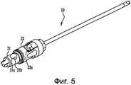
[0015] фиг.5 в аксонометрии изображает резец, используемый с хирургическим наконечником, показанным на фиг.1;[0015] FIG. 5 is a perspective view of a cutter used with the surgical tip shown in FIG. 1;
[0016] фиг.6 сбоку изображает второй вариант предложенного хирургического наконечника.[0016] FIG. 6 is a side view illustrating a second embodiment of the proposed surgical tip.
Подробное описание вариантов изобретенияDetailed Description of Embodiments
[0017] Последующее описание предпочтительных вариантов изобретения следует рассматривать как носящее пояснительный характер, но не ограничивающее объем правовой охраны изобретения.[0017] The following description of preferred embodiments of the invention should be construed as having an explanatory character, but not limiting the scope of legal protection of the invention.
[0018] На фиг.1-4 представлен первый вариант предложенного хирургического наконечника 10. Наконечник 10 включает в себя корпус 11, имеющий дистальный конец 11а и проксимальный конец 11b. В дистальном конце 11а наконечника 10 предусмотрено цилиндрическое отверстие 12, обеспечивающее присоединение хирургического резца 20 (фиг.5). Внутри отверстия 12 располагается приводной вал 13, соединенный с двигателем 14, установленным внутри наконечника 10. Наконечник 10 снабжен кнопочными выключателями 15, вырабатывающими сигналы для управления двигателем 14. Наконечник 10 используют в хирургической системе и способе, компоненты и этапы которых описаны в указанном американском патенте №5871493. Наконечник 10 связан с остальной частью системы кабелем 16, присоединенным к проксимальному концу 11b наконечника 10. Кабель 16 может быть подключен с помощью соединителя, такого как резьбовой соединитель, показанный и описанный в американском патенте №5871493.[0018] Figures 1-4 show a first embodiment of the proposed
[0019] Хирургический резец 20, который более подробно описан в американском патенте №5871493, включает в себя внутренний режущий элемент 21, расположенный внутри наружного режущего элемента 22. Резец 20 крепят к наконечнику 10 с образованием устройства, в котором втулки 21а и 22а элементов 21 и 22 находятся в отверстии 12. Данное устройство используется для резания и извлечения ткани из участка тела пациента, подвергаемого хирургическому вмешательству. Втулка 21а внутреннего режущего элемента 21 имеет отверстие 21b, позволяющее таким материалам, как жидкость и ткань, втягиваемым через режущий элемент 21, проходить в аспирационный канал 17 наконечника 10. Наконечник 10 также содержит ручку 18, которая управляет клапаном 19 и таким образом регулирует поток, проходящий по аспирационному каналу 17. Ручка 18 поворачивается вокруг оси 100, перпендикулярной продольной оси 200 наконечника 10, между первым положением, в котором она смещена вперед к дистальному концу 11a, как показано на фиг.1, и вторым положением, в котором она смещена назад к проксимальному концу 11b. Нахождение ручки 18 в первом положении обеспечивает открывание клапана 19, а нахождение ручки 18 во втором положении обеспечивает закрывание клапана 19 или наоборот. Ручка 18 и клапан 19 выполнены с возможностью съемного крепления к наконечнику 10, например, способом, описанным в американском патенте №5871493, или каким-либо иным способом, известным специалистам данной области техники.[0019] Surgical cutter 20, which is described in more detail in US Patent No. 5871493, includes an
[0020] В канавке 11c корпуса 11 установлена вставка 30, которая находится в совмещении с аспирационным каналом 17. Эта вставка 30 содержит дистальный конец 31, проксимальный конец 32, катетер 33, проходящий по всей длине вставки 30, а также прикрепленные к ней лапки 34. Вставку 30 устанавливают в канавку 11c таким образом, чтобы лапки 34 входили в отверстия 11d, выполненные в корпусе 11. Вставку 30 можно помещать в канавку 11с следующим образом. Дистальный конец 31 вводят в канавку 11с через отверстие 11c' и проталкивают вставку 30 в продольном направлении к дистальному концу 11a наконечника 10 до тех пор, пока лапки 34 не войдут в отверстия 11d. При установке вставки 30 в канавку 11с может произойти сокращение размера лапок 34 в радиальном направлении, поскольку лапки 34 будут прижиматься к вставке 30, чтобы войти в отверстие 11c'. В настоящей заявке описан случай использования двух лапок 34 и двух отверстий 11d под них. Однако конструкция может предусматривать лишь одну лапку и одно отверстие либо большее количество лапок и отверстий. Кроме того, под объем притязаний данного изобретения подпадает конструкция, согласно которой лапок 34 и отверстий 11d не имеется вовсе. На дистальном конце 31 вставки 30 может располагаться уплотнительное кольцо 40 круглого сечения, значительно снижающее возможность утечки жидкости и ткани из аспирационного канала 17, о котором рассказано ниже.[0020] An
[0021] Проксимальный конец 32 вставки 30 содержит раструб 35, который во время использования наконечника подсоединяют к источнику всасывания (не показан), чтобы отсасывать жидкость и ткань через вставку 30 при открытом клапане 19. После использования наконечника вставку 30 можно вынуть из канавки 11с, обеспечив тем самым доступ к аспирационному каналу 17, особенно к той его части, где находится клапан 19. В результате, пользователю обеспечивается возможность для чистки и стерилизации указанных частей. После чистки и стерилизации этих частей старую вставку можно удалить и вместо нее вставить в канавку 11c новую вставку.[0021] The
[0022] В корпусе 11 предусмотрено еще отверстие 50 для доступа, расположенное ближе к дистальному концу 11a корпуса 11. Во время использования наконечника это отверстие 50 для доступа закрыто заглушкой 60. После использования заглушку 60 снимают, обеспечивая доступ к внутренней части наконечника 10, т.е. к отверстию 12 и компонентам внутри отверстия 12, а именно к приводному валу 13, с целью чистки и стерилизации указанных внутренних частей. После чистки и стерилизации этих частей можно произвести чистку заглушки 60 и затем вставить ее обратно в отверстие 50 для доступа.[0022] In the
[0023] На фиг.6 показано поперечное сечение второго варианта предложенного хирургического наконечника 300. Этот наконечник 300 аналогичен наконечнику 10, за исключением того, что он оснащен вставкой 400, выполненной с возможностью съемного крепления к дистальному концу 301а. Наконечник 300 может дополнительно иметь (или не иметь) канавку 11c с вставкой 30, присутствующими в наконечнике 10. Наконечник 300 может иметь в своем составе фиксатор 310 c лапкой 310a, которая входит в зацепление с отверстием 410 вставки 400 и действует в качестве защелки, обеспечивающей крепление вставки 400 к наконечнику 300. Вставка 400, подобно заглушке 60 наконечника 10, закрывает внутреннюю часть наконечника 300, т.е. отверстие 302 и компоненты внутри отверстия 302, такие как приводной вал и аспирационный канал (не показаны). Вставку 400 прикрепляют к наконечнику 300 перед его использованием. После использования наконечника вставку 400 снимают, чтобы обеспечить возможность чистки и стерилизации указанной внутренней части и расположенных в ней компонентов. После чистки и стерилизации вставку 400 также можно почистить и прикрепить обратно к наконечнику 300. Кроме того, вставку 400 можно удалить и вместо нее прикрепить к наконечнику 300 новую.[0023] FIG. 6 shows a cross section of a second embodiment of the proposed
[0024] Согласно вариантам изобретения, раскрытым в рамках настоящей заявки, вставки 30 и 400 наконечников 10 и 300 изготовлены из пластмассы. Тем не менее можно использовать и другие материалы. Вставки 30 и 400 можно изготавливать посредством таких технологических процессов, как литьевое формование, вытяжка при штамповке и других процессов, известных специалистам данной области техники. Заглушку 60 изготавливают из аналогичных материалов и посредством аналогичных технологических процессов. Канавку 11c, отверстия 11d и отверстие 50 для доступа выполняют путем механической обработки или других технологических процессов, известных специалистам данной области техники.[0024] According to embodiments of the invention disclosed herein, inserts 30 and 400 of
[0025] Следует понимать, что в приведенные в качестве примера варианты выполнения изобретения, раскрытые в данном описании со ссылкой на приложенные чертежи, можно вносить различные изменения, не выходящие за пределы объема раскрытия изобретения. Поэтому все, что говорится в данном описании, и все, что показано на соответствующих фигурах, следует понимать как служащее для пояснения изобретения, а не для ограничения объема его притязаний. Это означает, что объем притязаний настоящего изобретения не ограничивается какими-либо из описываемых его вариантов, а определяется пунктами приложенной формулы и их эквивалентами.[0025] It should be understood that in the exemplary embodiments of the invention disclosed herein with reference to the accompanying drawings, various changes may be made without departing from the scope of the invention. Therefore, everything that is said in this description, and everything that is shown in the relevant figures, should be understood as serving to explain the invention, and not to limit the scope of its claims. This means that the scope of the claims of the present invention is not limited to any of the described variants, but is determined by the paragraphs of the attached claims and their equivalents.
Claims (20)
Translated fromRussianвставку, выполненную с возможностью съемного крепления к наконечнику, причем эта вставка выполнена с возможностью аспирации жидкости и ткани через себя во время хирургического вмешательства и выполнена с возможностью снятия с наконечника для замены вставки и обеспечения доступа к вставке для стерилизации, вставка содержит деформируемые лапки, выполненные с возможностью размещения в отверстиях наконечника, наконечник содержит:
канавку в своем корпусе, выполненную с возможностью размещения в ней указанной вставки;
аспирационный канал, находящийся на одной оси с указанной канавкой в корпусе наконечника, вследствие чего обеспечивается возможность аспирации жидкости и ткани по указанному аспирационному каналу и во вставку; и
съемный клапан.1. A surgical tip containing:
an insert made with the possibility of removable attachment to the tip, and this insert is made with the possibility of aspiration of fluid and tissue through itself during surgery and is made with the possibility of removal from the tip to replace the insert and provide access to the insert for sterilization, the insert contains deformable legs made with the possibility of placement in the holes of the tip, the tip contains:
a groove in its housing, configured to accommodate said insert;
an aspiration channel located on the same axis as the specified groove in the tip body, whereby it is possible to aspirate the liquid and tissue along the specified aspiration channel and into the insert; and
removable valve.
вставку, выполненную с возможностью съемного крепления к корпусу наконечника, причем при вынимании вставки обеспечивается доступ к внутренней части наконечника; вставка включает деформируемые лапки, выполненные с возможностью размещения в отверстиях наконечника;
съемный клапан;
канавку в своем корпусе, выполненную с возможностью размещения в ней указанной вставки,
аспирационный канал, находящийся на одной оси с указанной канавкой, вследствие чего обеспечивается возможность аспирации жидкости и ткани по указанному каналу и во вставку.7. A surgical tip containing:
an insert made with the possibility of removable attachment to the body of the tip, and when removing the insert provides access to the inner part of the tip; the insert includes deformable tabs arranged to fit in the holes of the tip;
removable valve;
a groove in its housing, configured to accommodate the indicated insert,
the suction channel, located on the same axis with the specified groove, as a result of which the possibility of aspiration of the fluid and tissue through the specified channel and into the insert.
обеспечение наличия устройства, содержащего:
хирургический наконечник, имеющий вставку, выполненную с возможностью съемного крепления к наконечнику, вставка выполнена с возможностью снятия с наконечника для замены вставки и обеспечения доступа к вставке для стерилизации, вставка содержит деформируемые лапки, выполненные с возможностью размещения в отверстиях наконечника;
резец, прикрепляемый к указанному наконечнику; и
введение указанного резца в участок тела для разрезания ткани и для ее извлечения посредством указанного устройства;
при этом хирургический наконечник содержит:
канавку в своем корпусе, выполненную с возможностью размещения в ней указанной вставки,
съемный клапан;
аспирационный канал, находящийся на одной оси с указанной канавкой в корпусе наконечника, вследствие чего обеспечивается возможность аспирации жидкости и ткани по указанному каналу и во вставку.10. A method of extracting tissue during an endoscopic procedure, comprising the following steps:
ensuring the availability of a device containing:
a surgical tip having an insert configured to be removably attached to the tip, the insert is removable from the tip to replace the insert and provide access to the insert for sterilization, the insert contains deformable legs configured to fit in the holes of the tip;
a cutter attached to the specified tip; and
introducing said cutter into a portion of the body to cut tissue and to extract it by means of said device;
wherein the surgical tip contains:
a groove in its housing, configured to accommodate the indicated insert,
removable valve;
the suction channel, which is on the same axis with the specified groove in the body of the tip, as a result of which it is possible to aspirate the fluid and tissue along the specified channel and into the insert.
Applications Claiming Priority (5)
| Application Number | Priority Date | Filing Date | Title |
|---|---|---|---|
| US24772209P | 2009-10-01 | 2009-10-01 | |
| US61/247,722 | 2009-10-01 | ||
| US25138109P | 2009-10-14 | 2009-10-14 | |
| US61/251,381 | 2009-10-14 | ||
| PCT/US2010/050875WO2011041520A1 (en) | 2009-10-01 | 2010-09-30 | Surgical handpiece for endoscopic resection |
Publications (2)
| Publication Number | Publication Date |
|---|---|
| RU2012116224A RU2012116224A (en) | 2013-11-10 |
| RU2579736C2true RU2579736C2 (en) | 2016-04-10 |
Family
ID=43446662
Family Applications (1)
| Application Number | Title | Priority Date | Filing Date |
|---|---|---|---|
| RU2012116224/14ARU2579736C2 (en) | 2009-10-01 | 2010-09-30 | Surgical tip for endoscopic resection |
Country Status (8)
| Country | Link |
|---|---|
| US (1) | US9301771B2 (en) |
| EP (1) | EP2482738B1 (en) |
| JP (2) | JP5784613B2 (en) |
| CN (1) | CN102639070B (en) |
| AU (1) | AU2010300561B2 (en) |
| BR (1) | BR112012007537A2 (en) |
| RU (1) | RU2579736C2 (en) |
| WO (1) | WO2011041520A1 (en) |
Cited By (1)
| Publication number | Priority date | Publication date | Assignee | Title |
|---|---|---|---|---|
| RU2797115C1 (en)* | 2023-02-08 | 2023-05-31 | федеральное государственное бюджетное образовательное учреждение высшего образования "Башкирский государственный медицинский университет" Министерства здравоохранения Российской Федерации | Endoscopic handle for aspiration of biological fluids |
Families Citing this family (9)
| Publication number | Priority date | Publication date | Assignee | Title |
|---|---|---|---|---|
| USD674479S1 (en)* | 2010-09-29 | 2013-01-15 | Sound Surgical Technologies Llc | Handpiece for use in power assisted lipoplasty |
| DE102010050352A1 (en)* | 2010-11-05 | 2012-05-10 | Hopp-Elektronik Gmbh & Co. Kg | Surgical instrument |
| USD680640S1 (en)* | 2011-09-29 | 2013-04-23 | Sound Surgical Technologies Llc | Handpiece |
| US10245042B2 (en)* | 2012-03-13 | 2019-04-02 | Medtronic Xomed, Inc. | Check valve vented sterilizable powered surgical handpiece |
| KR101319285B1 (en)* | 2012-05-08 | 2013-10-18 | (주)울텍 | Wound healing device and wound healing apparatus with the same |
| EP2925239B1 (en)* | 2012-11-30 | 2017-05-24 | Gyrus Acmi, Inc. | A microdebrider with interchangeable replaceable parts and a method of installing the parts. |
| DE102014115873A1 (en)* | 2014-10-31 | 2016-05-04 | Karl Storz Gmbh & Co. Kg | Disassemblable medical instrument |
| JP2017153520A (en)* | 2016-02-29 | 2017-09-07 | セイコーエプソン株式会社 | Surgical handpiece, liquid injection device, and suction device |
| USD977095S1 (en)* | 2020-05-29 | 2023-01-31 | Medos International Sarl | Handpiece |
Citations (3)
| Publication number | Priority date | Publication date | Assignee | Title |
|---|---|---|---|---|
| US5810809A (en)* | 1997-01-13 | 1998-09-22 | Enhanced Orthopaedic Technologies, Inc. | Arthroscopic shaver incorporating electrocautery |
| DE19859217A1 (en)* | 1998-12-21 | 2000-07-27 | Wolf Gmbh Richard | Electromotor drive for a surgical tool has a drive unit placed as a first module within a housing that forms a second module |
| RU2365920C2 (en)* | 2003-12-19 | 2009-08-27 | Джилсон, Инк. | Way and device for automatic loading of tests of liquid chromatography |
Family Cites Families (28)
| Publication number | Priority date | Publication date | Assignee | Title |
|---|---|---|---|---|
| DE1869217U (en) | 1962-04-19 | 1963-03-21 | Bochumer Ver Fuer Gussstahlfab | FLEXIBLE LINE FOR EXTRACTION OF HOT GASES, ESPECIALLY FOR TAP DEGASSING STEEL AND OTHER METALS. |
| SU862234A1 (en) | 1979-12-28 | 1981-09-07 | Каунасский Политехнический Институт Им.Антанаса Снечкуса | Attachment for wire twisting |
| US4852551A (en)* | 1988-04-22 | 1989-08-01 | Opielab, Inc. | Contamination-free endoscope valves for use with a disposable endoscope sheath |
| EP0625037A4 (en)* | 1992-02-05 | 1995-06-14 | Inventive Systems Inc | Improved phacoemulsification handpiece. |
| US5692518A (en)* | 1993-07-02 | 1997-12-02 | Rachman Scientific, Inc. | Skin test applicator |
| US5549565A (en)* | 1993-07-13 | 1996-08-27 | Symbiosis Corporation | Reusable surgical trocar with disposable valve assembly |
| US5827323A (en) | 1993-07-21 | 1998-10-27 | Charles H. Klieman | Surgical instrument for endoscopic and general surgery |
| US5871493A (en) | 1995-10-31 | 1999-02-16 | Smith & Nephew Endoscopy Inc. | Surgical instrument handpiece and system |
| US5624393A (en)* | 1996-01-03 | 1997-04-29 | Diamond; Eric L. | Irrigation system for surgical instruments |
| DE19622486C1 (en) | 1996-06-05 | 1997-10-16 | Wolf Gmbh Richard | Electric motor drive with planetary multi-stage gear for surgical instrument |
| US7776014B2 (en)* | 1998-01-29 | 2010-08-17 | Peter Visconti | Disposable surgical suction/irrigation trumpet valve tube cassette |
| JP4157183B2 (en)* | 1998-02-17 | 2008-09-24 | オリンパス株式会社 | Endoscopic treatment tool |
| US6007497A (en)* | 1998-06-30 | 1999-12-28 | Ethicon Endo-Surgery, Inc. | Surgical biopsy device |
| US20010047183A1 (en) | 2000-04-05 | 2001-11-29 | Salvatore Privitera | Surgical device for the collection of soft tissue |
| US8282573B2 (en)* | 2003-02-24 | 2012-10-09 | Senorx, Inc. | Biopsy device with selectable tissue receiving aperture orientation and site illumination |
| US6312441B1 (en)* | 1999-03-04 | 2001-11-06 | Stryker Corporation | Powered handpiece for performing endoscopic surgical procedures |
| US6120462A (en)* | 1999-03-31 | 2000-09-19 | Ethicon Endo-Surgery, Inc. | Control method for an automated surgical biopsy device |
| US6436067B1 (en)* | 1999-12-03 | 2002-08-20 | Stryker Corporation | Powered surgical handpiece with suction conduit including a stepped valve to regulate flow through the suction conduit |
| US6585664B2 (en)* | 2000-08-02 | 2003-07-01 | Ethicon Endo-Surgery, Inc. | Calibration method for an automated surgical biopsy device |
| US6997931B2 (en)* | 2001-02-02 | 2006-02-14 | Lsi Solutions, Inc. | System for endoscopic suturing |
| US6620111B2 (en)* | 2001-04-20 | 2003-09-16 | Ethicon Endo-Surgery, Inc. | Surgical biopsy device having automatic rotation of the probe for taking multiple samples |
| US6623425B2 (en)* | 2001-07-23 | 2003-09-23 | Cartledge Medical Products, Llc | Modified laryngoscope blade to reduce dental injuries during intubation |
| AU2003213816B2 (en)* | 2002-03-08 | 2008-06-05 | Vicentra B.V. | Low profile, pivotal connection infusion assembly |
| EP1524940B1 (en)* | 2002-03-19 | 2011-08-24 | Bard Dublin ITC Limited | Biopsy device and biopsy needle module that can be inserted into the biopsy device |
| CA2499391A1 (en)* | 2002-09-20 | 2004-04-01 | Sherwood Services Ag | Electrosurgical instrument for fragmenting, cutting and coagulating tissue |
| US8323250B2 (en)* | 2007-04-30 | 2012-12-04 | Medtronic Minimed, Inc. | Adhesive patch systems and methods |
| CN101711129B (en) | 2007-05-17 | 2012-07-04 | 普罗德克斯有限公司 | Handheld medical device |
| RU2528925C1 (en) | 2013-04-10 | 2014-09-20 | Открытое акционерное общество Акционерная холдинговая компания "Всероссийский научно-исследовательский и проектно-конструкторский институт металлургического машиностроения имени академика Целикова" (ОАО АХК "ВНИИМЕТМАШ") | Continuous casting machine with rotary mould |
- 2010
- 2010-09-30RURU2012116224/14Apatent/RU2579736C2/ennot_activeIP Right Cessation
- 2010-09-30AUAU2010300561Apatent/AU2010300561B2/ennot_activeCeased
- 2010-09-30EPEP10770667.3Apatent/EP2482738B1/enactiveActive
- 2010-09-30BRBR112012007537Apatent/BR112012007537A2/ennot_activeIP Right Cessation
- 2010-09-30CNCN201080044170.XApatent/CN102639070B/enactiveActive
- 2010-09-30USUS12/894,828patent/US9301771B2/enactiveActive
- 2010-09-30JPJP2012532309Apatent/JP5784613B2/ennot_activeExpired - Fee Related
- 2010-09-30WOPCT/US2010/050875patent/WO2011041520A1/enactiveApplication Filing
- 2015
- 2015-04-08JPJP2015079214Apatent/JP6138849B2/ennot_activeExpired - Fee Related
Patent Citations (3)
| Publication number | Priority date | Publication date | Assignee | Title |
|---|---|---|---|---|
| US5810809A (en)* | 1997-01-13 | 1998-09-22 | Enhanced Orthopaedic Technologies, Inc. | Arthroscopic shaver incorporating electrocautery |
| DE19859217A1 (en)* | 1998-12-21 | 2000-07-27 | Wolf Gmbh Richard | Electromotor drive for a surgical tool has a drive unit placed as a first module within a housing that forms a second module |
| RU2365920C2 (en)* | 2003-12-19 | 2009-08-27 | Джилсон, Инк. | Way and device for automatic loading of tests of liquid chromatography |
Non-Patent Citations (1)
| Title |
|---|
| АГАФОНОВА В.В. и др. Способ выполнения факоэмульсификации осложнённых катаракт. Вестник ОГУ, 2004, декабрь, с.15. SETHI H.S. et al. Closed chamber globe stabilization and needle capsulorhexis using irrigation hand piece of bimanual irrigation and aspiration system. BMC Opthalmol. 2005 Aug 18,5:21 (Abstract), PMID:16107224[PubMed " indexed for MEDLINE].* |
Cited By (1)
| Publication number | Priority date | Publication date | Assignee | Title |
|---|---|---|---|---|
| RU2797115C1 (en)* | 2023-02-08 | 2023-05-31 | федеральное государственное бюджетное образовательное учреждение высшего образования "Башкирский государственный медицинский университет" Министерства здравоохранения Российской Федерации | Endoscopic handle for aspiration of biological fluids |
Also Published As
| Publication number | Publication date |
|---|---|
| WO2011041520A1 (en) | 2011-04-07 |
| JP2015128673A (en) | 2015-07-16 |
| US20110245599A1 (en) | 2011-10-06 |
| JP2013506502A (en) | 2013-02-28 |
| EP2482738A1 (en) | 2012-08-08 |
| JP6138849B2 (en) | 2017-05-31 |
| CN102639070A (en) | 2012-08-15 |
| US9301771B2 (en) | 2016-04-05 |
| BR112012007537A2 (en) | 2016-12-06 |
| EP2482738B1 (en) | 2020-08-12 |
| AU2010300561B2 (en) | 2016-01-28 |
| RU2012116224A (en) | 2013-11-10 |
| JP5784613B2 (en) | 2015-09-24 |
| AU2010300561A1 (en) | 2012-04-19 |
| CN102639070B (en) | 2015-08-12 |
Similar Documents
| Publication | Publication Date | Title |
|---|---|---|
| RU2579736C2 (en) | Surgical tip for endoscopic resection | |
| US11191553B2 (en) | Connector for surgical handpiece | |
| TWI611800B (en) | Transformer irrigation/aspiration device | |
| TWI453005B (en) | Distal plastic end infusion/aspiration tip | |
| CN107949343A (en) | For extracting the device and its application method of root pipe | |
| US20090012362A1 (en) | Rigid Arthroscope System | |
| JP6975227B2 (en) | Connector for surgical handpiece | |
| KR20040002700A (en) | Indwelling catheter set | |
| US20140114128A1 (en) | Applicator for an endoscope | |
| EP3272266A1 (en) | Endoscope device | |
| JP2937101B2 (en) | Endoscope device | |
| JP2005211453A (en) | Endoscope | |
| US10314467B2 (en) | Endoscope | |
| JP6697301B2 (en) | Medical equipment | |
| KR20160141412A (en) | Egress cannula | |
| KR20150117517A (en) | Trocar lens apparatus comprising wiping material | |
| KR101479284B1 (en) | Suction catheter for surgical | |
| US20220087699A1 (en) | Connector for Surgical Handpiece | |
| JP4358558B2 (en) | Endoscope attachment | |
| KR20080003156U (en) | Suction cannula | |
| KR20170009396A (en) | The internal structure of visibility is widened endoscope |
Legal Events
| Date | Code | Title | Description |
|---|---|---|---|
| HE9A | Changing address for correspondence with an applicant | ||
| MM4A | The patent is invalid due to non-payment of fees | Effective date:20181001 |