RU2578655C2 - Calibration system for pressure-sensitive catheters - Google Patents
Calibration system for pressure-sensitive cathetersDownload PDFInfo
- Publication number
- RU2578655C2 RU2578655C2RU2010152701/14ARU2010152701ARU2578655C2RU 2578655 C2RU2578655 C2RU 2578655C2RU 2010152701/14 ARU2010152701/14 ARU 2010152701/14ARU 2010152701 ARU2010152701 ARU 2010152701ARU 2578655 C2RU2578655 C2RU 2578655C2
- Authority
- RU
- Russia
- Prior art keywords
- probe
- latch
- distal tip
- calibration
- measurements
- Prior art date
Links
- 239000000523sampleSubstances0.000claimsabstractdescription65
- 238000005259measurementMethods0.000claimsabstractdescription30
- 230000004044responseEffects0.000claimsabstractdescription7
- 238000000034methodMethods0.000claimsdescription23
- 230000006870functionEffects0.000claimsdescription11
- 239000012530fluidSubstances0.000claimsdescription4
- 239000007788liquidSubstances0.000claims1
- 239000003814drugSubstances0.000abstract1
- 239000000126substanceSubstances0.000abstract1
- 238000010586diagramMethods0.000description5
- 239000000463materialSubstances0.000description5
- 238000003780insertionMethods0.000description4
- 230000037431insertionEffects0.000description4
- 239000011810insulating materialSubstances0.000description3
- 229910001000nickel titaniumInorganic materials0.000description3
- 230000009467reductionEffects0.000description3
- 238000007792additionMethods0.000description2
- 239000004744fabricSubstances0.000description2
- 230000003287optical effectEffects0.000description2
- 230000008569processEffects0.000description2
- 239000013598vectorSubstances0.000description2
- 238000009530blood pressure measurementMethods0.000description1
- 230000000747cardiac effectEffects0.000description1
- 238000006243chemical reactionMethods0.000description1
- 239000011248coating agentSubstances0.000description1
- 238000000576coating methodMethods0.000description1
- 238000010276constructionMethods0.000description1
- 230000001419dependent effectEffects0.000description1
- 238000013461designMethods0.000description1
- 238000002059diagnostic imagingMethods0.000description1
- 238000002405diagnostic procedureMethods0.000description1
- 238000002565electrocardiographyMethods0.000description1
- 230000005284excitationEffects0.000description1
- 238000010438heat treatmentMethods0.000description1
- 239000007943implantSubstances0.000description1
- 238000013507mappingMethods0.000description1
- 238000012544monitoring processMethods0.000description1
- HLXZNVUGXRDIFK-UHFFFAOYSA-Nnickel titaniumChemical compound[Ti].[Ti].[Ti].[Ti].[Ti].[Ti].[Ti].[Ti].[Ti].[Ti].[Ti].[Ni].[Ni].[Ni].[Ni].[Ni].[Ni].[Ni].[Ni].[Ni].[Ni].[Ni].[Ni].[Ni].[Ni]HLXZNVUGXRDIFK-UHFFFAOYSA-N0.000description1
- 210000000056organAnatomy0.000description1
- 238000007781pre-processingMethods0.000description1
- 230000001225therapeutic effectEffects0.000description1
- 238000002560therapeutic procedureMethods0.000description1
Images


Classifications
- G—PHYSICS
- G01—MEASURING; TESTING
- G01D—MEASURING NOT SPECIALLY ADAPTED FOR A SPECIFIC VARIABLE; ARRANGEMENTS FOR MEASURING TWO OR MORE VARIABLES NOT COVERED IN A SINGLE OTHER SUBCLASS; TARIFF METERING APPARATUS; MEASURING OR TESTING NOT OTHERWISE PROVIDED FOR
- G01D18/00—Testing or calibrating apparatus or arrangements provided for in groups G01D1/00 - G01D15/00
- G01D18/001—Calibrating encoders
- A—HUMAN NECESSITIES
- A61—MEDICAL OR VETERINARY SCIENCE; HYGIENE
- A61B—DIAGNOSIS; SURGERY; IDENTIFICATION
- A61B5/00—Measuring for diagnostic purposes; Identification of persons
- A61B5/145—Measuring characteristics of blood in vivo, e.g. gas concentration or pH-value ; Measuring characteristics of body fluids or tissues, e.g. interstitial fluid or cerebral tissue
- A61B5/1495—Calibrating or testing of in-vivo probes
- A—HUMAN NECESSITIES
- A61—MEDICAL OR VETERINARY SCIENCE; HYGIENE
- A61B—DIAGNOSIS; SURGERY; IDENTIFICATION
- A61B5/00—Measuring for diagnostic purposes; Identification of persons
- A61B5/68—Arrangements of detecting, measuring or recording means, e.g. sensors, in relation to patient
- A61B5/6846—Arrangements of detecting, measuring or recording means, e.g. sensors, in relation to patient specially adapted to be brought in contact with an internal body part, i.e. invasive
- A61B5/6885—Monitoring or controlling sensor contact pressure
- A—HUMAN NECESSITIES
- A61—MEDICAL OR VETERINARY SCIENCE; HYGIENE
- A61B—DIAGNOSIS; SURGERY; IDENTIFICATION
- A61B2560/00—Constructional details of operational features of apparatus; Accessories for medical measuring apparatus
- A61B2560/02—Operational features
- A61B2560/0223—Operational features of calibration, e.g. protocols for calibrating sensors
Landscapes
- Life Sciences & Earth Sciences (AREA)
- Health & Medical Sciences (AREA)
- Physics & Mathematics (AREA)
- Molecular Biology (AREA)
- Animal Behavior & Ethology (AREA)
- Pathology (AREA)
- Engineering & Computer Science (AREA)
- Biomedical Technology (AREA)
- Heart & Thoracic Surgery (AREA)
- Medical Informatics (AREA)
- Veterinary Medicine (AREA)
- Surgery (AREA)
- Biophysics (AREA)
- General Health & Medical Sciences (AREA)
- Public Health (AREA)
- Optics & Photonics (AREA)
- General Physics & Mathematics (AREA)
- Media Introduction/Drainage Providing Device (AREA)
- Measuring And Recording Apparatus For Diagnosis (AREA)
- Measuring Fluid Pressure (AREA)
Abstract
Description
Translated fromRussianОБЛАСТЬ ИЗОБРЕТЕНИЯFIELD OF THE INVENTION
Настоящее изобретение в целом относится к инвазивным зондам и, в частности, к калибровке датчиков давления инвазивных зондов.The present invention relates generally to invasive probes and, in particular, to the calibration of pressure sensors of invasive probes.
ПРЕДПОСЫЛКИ СОЗДАНИЯ ИЗОБРЕТЕНИЯBACKGROUND OF THE INVENTION
Многие медицинские манипуляции предусматривают размещение в теле пациента различных объектов, таких как датчики, трубки, катетеры, элементы капельниц и имплантаты. Для слежения за такими объектами разработаны системы определения положения указанных объектов. Одним из известных в данной области техники способов определения положения является магнитное позиционирование. В системе магнитного позиционирования генераторы магнитного поля, координаты положения которых известны, обычно размещаются возле пациента. Датчик магнитного поля, установленный на дистальном конце зонда, под воздействием указанного магнитного поля генерирует электрические сигналы, которые подвергаются обработке для определения координат положения дистального конца зонда. Указанные способы и системы описаны в патентах США №№ 5391199, 6690963, 6484118, 6239724, 6618612 и 6332089, международной заявке согласно Договору о патентной кооперации (PCT) № WO 1996/005768 и патентных заявках США №№ 2002/0065455 A1, 2003/0120150 A1 и 2004/0068178 A1, которые включены в настоящее описание изобретения посредством ссылки.Many medical procedures involve placing various objects in the patient’s body, such as sensors, tubes, catheters, dropper elements and implants. To track such objects, systems have been developed for determining the position of these objects. One of the methods for determining the position known in the art is magnetic positioning. In a magnetic positioning system, magnetic field generators whose position coordinates are known are usually located near the patient. A magnetic field sensor mounted on the distal end of the probe, under the influence of the specified magnetic field generates electrical signals that are processed to determine the position coordinates of the distal end of the probe. These methods and systems are described in US patent No. 5391199, 6690963, 6484118, 6239724, 6618612 and 6332089, international application under the Patent Cooperation Treaty (PCT) No. WO 1996/005768 and US patent applications No. 2002/0065455 A1, 2003 / 0120150 A1 and 2004/0068178 A1, which are incorporated herein by reference.
При размещении зонда в теле пациента может потребоваться, чтобы дистальный наконечник зонда находился в непосредственном контакте с тканями тела. Наличие контакта можно контролировать, например, посредством измерения давления в зоне контакта между дистальным наконечником зонда и тканями тела. В патентных заявках США №№ 2007/0100332 и 2009/0093806, содержание которых включено в настоящий документ посредством ссылки, описаны способы измерения давления в зоне контакта между дистальным концом катетера и тканями полости тела пациента с использованием датчика усилия, встроенного в катетер. Дистальный наконечник катетера связан с дистальным концом вводимой части катетера упругим элементом, таким как пружина, который деформируется при воздействии на дистальный наконечник катетера усилия, когда указанный наконечник прижимается к эндокардиальной ткани. Магнитный датчик положения катетера обеспечивает измерение отклонения (положения и ориентации) дистального наконечника катетера относительно дистального конца вводимой части. Перемещение дистального наконечника катетера относительно вводимой части катетера указывает наличие деформации упругого элемента и, таким образом, обеспечивает определение давления.When placing the probe in the patient’s body, it may be necessary for the distal tip of the probe to be in direct contact with body tissues. The presence of contact can be controlled, for example, by measuring the pressure in the contact area between the distal tip of the probe and body tissues. US patent applications Nos. 2007/0100332 and 2009/0093806, the contents of which are incorporated herein by reference, describe methods for measuring pressure in the contact zone between the distal end of the catheter and the tissues of the patient’s body cavity using a force sensor integrated into the catheter. The distal tip of the catheter is connected to the distal end of the insertion portion of the catheter by an elastic element, such as a spring, that deforms when a force is applied to the distal tip of the catheter when the tip is pressed against the endocardial tissue. A magnetic catheter position sensor provides a measurement of the deviation (position and orientation) of the distal tip of the catheter relative to the distal end of the insertion portion. The movement of the distal tip of the catheter relative to the inserted portion of the catheter indicates the presence of deformation of the elastic element and, thus, provides a determination of pressure.
КРАТКОЕ ОПИСАНИЕ ИЗОБРЕТЕНИЯSUMMARY OF THE INVENTION
В качестве одного из вариантов осуществления настоящего изобретения предлагается устройство калибровки, содержащее фиксатор, чувствительное устройство и процессор для калибровки. Фиксатор соединяется с зондом таким образом, что дистальный наконечник зонда прижимается к точке в фиксаторе и обеспечивает первые измерения, чувствительные к деформации дистального наконечника относительно дистального конца зонда в ответ на давление, приложенное на дистальный наконечник. Чувствительное устройство, соединенное с фиксатором, выполнено с возможностью обеспечивать вторые измерения механической силы, приложенной дистальным наконечником к месту соединения катетера и фиксатора. Процессор для калибровки выполнен с возможностью приема первых измерений с зонда и приема вторых измерений с чувствительного устройства. На основе первых и вторых измерений процессор вычисляет один или более калибровочных коэффициентов для оценки давления как функции первых измерений.As one embodiment of the present invention, there is provided a calibration device comprising a latch, a sensitive device, and a processor for calibration. The latch is connected to the probe so that the distal tip of the probe is pressed against a point in the latch and provides first measurements that are sensitive to the deformation of the distal tip relative to the distal end of the probe in response to pressure applied to the distal tip. A sensitive device connected to the latch is configured to provide second measurements of the mechanical force applied by the distal tip to the junction of the catheter and latch. The processor for calibration is configured to receive first measurements from the probe and receive second measurements from a sensitive device. Based on the first and second measurements, the processor calculates one or more calibration factors to evaluate pressure as a function of the first measurements.
В некоторых вариантах осуществления фиксатор присоединен так, чтобы прижимать зонд к указанной точке под одним или более заданными углами. Процессор выполнен с возможностью вычисления калибровочных коэффициентов как функции заданных углов. Устройство может дополнительно содержать колпак, закрывающий фиксатор. Колпак имеет множество входных отверстий, выполненных для направления зонда к указанной точке фиксатора под заданными углами. В других вариантах устройство может содержать держатель для закрепления дистального наконечника, направляющую, соединенную с держателем и выполненную с возможностью размещения держателя под множеством углов относительно указанной точки фиксатора, и подъемное устройство для подъема фиксатора, которое обеспечивает плотный контакт дистального наконечника с фиксатором. Устройство дополнительно может содержать устройство ввода, соединенное с процессором для калибровки и предназначенное для приема заданных углов.In some embodiments, the latch is attached so as to press the probe to a specified point at one or more predetermined angles. The processor is configured to calculate calibration coefficients as a function of predetermined angles. The device may further comprise a cap closing the latch. The cap has many inlets made to guide the probe to the specified point of the latch at predetermined angles. In other embodiments, the device may include a holder for securing the distal tip, a guide connected to the holder and configured to place the holder at many angles relative to the specified point of the latch, and a lifting device for lifting the latch, which provides a tight contact between the distal tip and the latch. The device may further comprise an input device connected to the processor for calibration and designed to receive the specified angles.
В другом варианте осуществления фиксатор имеет воронкообразный колпачок. В еще одном варианте осуществления фиксатор удерживает зонд в жидкости с регулируемой температурой. В еще одном варианте осуществления чувствительное устройство включает датчик нагрузки. В одном из вариантов осуществления настоящего изобретения процессор для калибровки выполнен с возможностью сохранения калибровочных коэффициентов памяти, присоединенной к зонду. Устройством памяти может служить энергонезависимая память (E2PROM).In another embodiment, the latch has a funnel-shaped cap. In yet another embodiment, the retainer holds the probe in a temperature-controlled fluid. In yet another embodiment, the sensitive device includes a load sensor. In one embodiment of the present invention, the calibration processor is configured to store calibration coefficients of memory attached to the probe. A non-volatile memory (E2 PROM) can serve as a memory device.
Также в настоящем документе, в соответствии с одним из вариантов осуществления настоящего изобретения, предлагается способ калибровки, включающий введение зонда с дистальным наконечником в фиксатор и прижатие дистального наконечника к точке фиксатора так, чтобы вызвать деформацию дистального наконечника относительно дистального конца зонда в ответ на давление, приложенное к дистальному наконечнику; прием с зонда первых измерений, указывающих на деформацию; прием с чувствительного устройства, соединенного с фиксатором, вторых измерений, указывающих на механическую силу, приложенную дистальным наконечником к фиксатору. На основе первых и вторых измерений рассчитывается один или более калибровочных коэффициентов для оценки давления как функции первых измерений.Also provided herein, in accordance with one embodiment of the present invention, a calibration method is provided, comprising inserting a distal tip probe into the retainer and pressing the distal tip against the fixation point so as to cause the distal tip to deform relative to the distal end of the probe in response to pressure, attached to the distal tip; receiving from the probe the first measurements indicating deformation; receiving from a sensitive device connected to the latch second measurements indicating the mechanical force exerted by the distal tip to the latch. Based on the first and second measurements, one or more calibration factors are calculated to evaluate the pressure as a function of the first measurements.
КРАТКОЕ ОПИСАНИЕ ФИГУРBRIEF DESCRIPTION OF THE FIGURES
Настоящее изобретение описано в данном документе на основе примера осуществления со ссылкой на прилагаемые рисунки:The present invention is described herein based on an embodiment with reference to the accompanying drawings:
На Фиг.1 представлено схематическое изображение системы калибровки чувствительных к давлению катетеров в соответствии с одним из вариантов осуществления настоящего изобретения.1 is a schematic illustration of a pressure sensitive catheter calibration system in accordance with one embodiment of the present invention.
На Фиг.2 представлена блок-схема, иллюстрирующая способ калибровки чувствительного к давлению катетера в соответствии с одним из вариантов осуществления настоящего изобретения.2 is a flowchart illustrating a method for calibrating a pressure-sensitive catheter in accordance with one embodiment of the present invention.
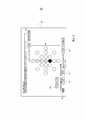
На Фиг.3 представлена схема графического интерфейса пользователя системы калибровки чувствительного к давлению катетера в соответствии с одним из вариантов осуществления настоящего изобретения.FIG. 3 is a graphical graphical user interface diagram of a pressure sensitive catheter calibration system in accordance with one embodiment of the present invention.
На Фиг.4 представлено схематическое изображение системы калибровки чувствительного к давлению катетера в соответствии с альтернативным вариантом осуществления настоящего изобретения.4 is a schematic illustration of a pressure sensitive catheter calibration system in accordance with an alternative embodiment of the present invention.
На Фиг.5 представлена подробная схема дистального наконечника чувствительного к давлению катетера, контактирующего с тканью эндокарда, в соответствии с одним из вариантов осуществления настоящего изобретения.Figure 5 presents a detailed diagram of the distal tip of a pressure-sensitive catheter in contact with endocardial tissue, in accordance with one embodiment of the present invention.
ПОДРОБНОЕ ОПИСАНИЕ ВАРИАНТОВ ОСУЩЕСТВЛЕНИЯ НАСТОЯЩЕГО ИЗОБРЕТЕНИЯDETAILED DESCRIPTION OF EMBODIMENTS OF THE PRESENT INVENTION
Некоторые инвазивные зонды содержат датчики давления для измерения давления контакта между зондом и тканями тела пациента. Например, дистальный наконечник сердечного катетера может включать в себя датчик давления, который деформируется в результате давления дистального наконечника на ткань эндокарда. Датчик положения, размещенный в катетере, измеряет отклонение дистального наконечника и, таким образом, обеспечивает индикацию контактного давления. Однако в большинстве практических ситуаций соотношение между фактическим контактным давлением и показаниями датчика положения отличается для различных катетеров.Some invasive probes contain pressure sensors to measure the contact pressure between the probe and the patient’s body tissues. For example, the distal tip of the cardiac catheter may include a pressure sensor that deforms as a result of the pressure of the distal tip on the endocardial tissue. A position sensor located in the catheter measures the deflection of the distal tip and thus provides an indication of contact pressure. However, in most practical situations, the relationship between the actual contact pressure and the position sensor is different for different catheters.
Для обеспечения точного измерения давления в соответствии с вариантами осуществления настоящего изобретения предлагаются способы и устройства для калибровки зондов (например, катетеров), использующих датчики давления. В некоторых вариантах осуществления устройство калибровки содержит фиксатор, в который катетер вводится под заданным углом, и чувствительное устройство (например, датчика нагрузки), измеряющее механическую силу, приложенную катетером к точке фиксатора. Когда катетер вводится в фиксатор под заданным углом и давит на указанную точку, измеряется степень деформации (например, отклонение в сторону от продольной оси) его дистального наконечника, а чувствительное устройство при этом измеряет силу.To provide accurate pressure measurements in accordance with embodiments of the present invention, methods and devices for calibrating probes (eg, catheters) using pressure sensors are provided. In some embodiments, the calibration device comprises a latch into which the catheter is inserted at a predetermined angle, and a sensing device (eg, a load sensor) that measures the mechanical force exerted by the catheter at the latch point. When a catheter is inserted into the latch at a predetermined angle and presses on a specified point, the degree of deformation (for example, a deviation to the side from the longitudinal axis) of its distal tip is measured, and the sensitive device measures force.
В некоторых вариантах осуществления процессор для калибровки принимает от катетера информацию о степени отклонения от продольной оси, а от чувствительного устройства о силе, и вычисляет калибровочные коэффициенты для оценки давления катетера, зависящего от величины отклонения.In some embodiments, the calibration processor receives from the catheter information about the degree of deviation from the longitudinal axis, and from the sensing device about the force, and calculates calibration coefficients to estimate the pressure of the catheter depending on the amount of deviation.
В некоторых вариантах осуществления калибровка производится при разных значениях углов между катетером и точкой фиксатора. В некоторых примерах осуществления калибровочные коэффициенты хранятся в устройстве постоянной памяти, соединенном с катетером. В дальнейшем при использовании катетера в медицинской системе фактическое давление дистального наконечника катетера на ткани тела можно с высокой точностью вычислять по величине отклонения с помощью калибровочных коэффициентов.In some embodiments, calibration is performed at different angles between the catheter and the fixation point. In some embodiments, calibration coefficients are stored in a read-only memory device connected to a catheter. Subsequently, when using a catheter in a medical system, the actual pressure of the distal tip of the catheter on the body tissue can be calculated with high accuracy by the value of the deviation using calibration factors.
На Фиг.10 представлена система калибровки 20 для чувствительного к давлению катетера, в соответствии с одним из вариантов осуществления настоящего изобретения. Система 10 включает устройство калибровки 12 вместе и калибровочное устройство 52. В описанном ниже варианте осуществления для калибровки зонда 42 используется система 10; в настоящем примере она представляет собой катетер для терапевтических и (или) диагностических процедур на сердце или других органах тела.Figure 10 shows a
Зонд 42 имеет дистальный конец 14 с дистальным наконечником 16, соединенным с дистальным концом с помощью сочленения 18. Дистальный конец 14 и дистальный наконечник 16 покрыты гибким изолирующим материалом 22. Сочленение 18 также покрыто гибким изолирующим материалом, который может быть аналогичным материалу 22 или может являться специальным материалом, позволяющим сочленению беспрепятственно сгибаться и сжиматься (последний материал на Фиг.1 не изображен с целью демонстрации внутренней структуры катетера). Дистальный наконечник 16, как правило, жестче дистального конца 14.The
Дистальный наконечник 16 соединен с дистальным концом 14 упругим элементом 20. На Фиг.1 упругий элемент имеет форму спиральной пружины, хотя для этой цели можно использовать упругие компоненты других типов. Упругий элемент 14 позволяет дистальному наконечнику 16 и дистальному концу 20 в ограниченных пределах смещаться относительно друг друга в ответ на давление, приложенное к дистальному наконечнику.The
Дистальный наконечник 16 содержит магнитный датчик положения 24, состоящий из одной или нескольких миниатюрных катушек. Как правило, в датчике используется несколько катушек, ориентированных по разным осям. На дистальном конце 14 рядом с упругим элементом 20 находится миниатюрный генератор магнитного поля 26. Обычно генератор поля 26 представляет собой катушку, через которую проходит ток, поступающий в катетер от калибровочного устройства 52. В другом варианте осуществления датчик положения 24 может представлять собой либо магнитный датчик другого типа (электрод, выполняющий роль датчика положения), либо иной датчик положения, например, датчик, измеряющий сопротивление, или ультразвуковой датчик положения. Хотя на Фиг.1 показан зонд с одним датчиком положения, в различных вариантах осуществления настоящего изобретения могут использоваться зонды с несколькими датчиками положения.The
Магнитное поле, созданное генератором 24 магнитного поля, вызывает генерирование в катушках датчика 26 электрических сигналов, имеющих частоту, соответствующую частоте сигналов возбуждения генератора магнитного поля. Амплитуда этих сигналов будет варьировать в зависимости от положения и ориентации дистального наконечника 16 относительно дистального конца 14. Процессор для калибровки 46 в калибровочном устройстве 52 обрабатывает эти сигналы, определяя деформацию относительно продольной оси и значение угла между дистальным наконечником и дистальным концом 14 (Из-за осевой симметрии поля, создаваемого катушкой, с помощью одной катушки в генераторе поля 26 можно определить только амплитуду отклонения, но не его направление. В другом варианте осуществления изобретения в генераторе 26 магнитного поля может находиться две и более катушек: в этом случае можно определить также и направление отклонения). Деформация и отклонение могут быть представлены в виде суммы векторов, которая дает общую деформацию дистального наконечника 16 относительно дистального конца 14.The magnetic field generated by the
Движение дистального наконечника 16 по отношению к дистальному концу 14 определяет степень деформации упругого элемента 20. Таким образом, комбинация генератора поля 26 с датчиком 24 является системой, чувствительной к давлению. Так как система одновременно определяет деформацию и отклонение, она обеспечивает точное измерение давления, независимо от направления, приложенного к дистальному наконечнику 16 давления, - фронтально или под углом. Дополнительная информация, касающаяся зонда и датчика положения такого типа, представлена в патентных заявках США №№ 2009/0093806 и 2009/0138007, указанных выше.The movement of the
В зонде 42 предусмотрено устройство постоянной памяти 44, например, энергонезависимая память (E2PROM), в которой хранятся коэффициенты, вычисленные во время калибровки. Как было указано ранее, при последующем использовании катетера в медицинской системе фактическое давление, которое оказывает дистальный наконечник катетера на ткани тела, может быть определено с высокой степенью точности путем измерения отклонения и использования коэффициентов калибровки, сохраненных в памяти 44.The
Устройство калибровки 12 содержит фиксатор 28, который принимает калибруемый зонд. В варианте осуществления, представленном на Фиг.1, фиксатор 28 состоит из чашки (например, в виде воронкообразного колпачка) с верхней частью 36 и основанием 40. В рассматриваемом варианте верхняя часть 36 чашки шире, чем основание 40. В других вариантах осуществления могут быть использованы фиксаторы с любой другой механической конфигурацией.The calibration device 12 includes a
В фиксаторе 28 может находиться жидкость с регулируемой температурой 34, примерно равной температуре человеческого тела (поддерживается, например, с помощью термостата и нагревательного элемента). При применении данного способа процедура калибровки зонда 42 проводится при температуре, близкой к рабочей температуре зонда при его нахождении в теле человека. Регулировка температуры может быть важна, так как упругость и другие механические свойства элементов зонда могут сильно зависеть от температуры. Например, в сочленении 18 могут находиться такие элементы, как пружина из никель-титанового сплава (также называется NiTi или нитинол) и пластиковое наружное покрытие (т.е. изолирующий материал 22), упругость которых может изменяться в зависимости от температуры жидкости 34.In the
Контролируя угол между катетером 42 и фиксатором 28, оператор (не показан) вводит катетер в одно из входных отверстий 38 колпака 30, закрывающего фиксатор 28. Каждое из входных отверстий определяет разные углы введения катетера. Входные отверстия направляют дистальный наконечник 16 так, что он прижимается к указанной точке фиксатора 28. В конфигурации, показанной на Фиг.1, входные отверстия 38 направляют дистальный наконечник 16 так, что он давит на основание 40.By controlling the angle between the
Кроме фиксатора 28 и колпака 30, устройство калибровки 12 содержит датчик нагрузки 32, соединенный с основанием 40. Датчик нагрузки измеряет уменьшение механической силы, с которой дистальный наконечник прижимается к основанию 40. Хотя система, изображенная на Фиг.1, измеряет снижение силы с помощью датчика нагрузки 32, в системе 10 можно использовать для измерения уменьшения силы датчики других типов. Использование таких датчиков также будет считаться другим вариантом осуществления настоящего изобретения.In addition to the
Датчик нагрузки 32 и зонд 42 соединены с калибровочным устройством 52 с помощью подходящих интерфейсов (например, кабелей и разъемов). Калибровочное устройство 52 состоит из процессора для калибровки 46, памяти 48, дисплея 54 и устройства ввода 50, например, клавиатуры. Процессор 46 обычно представляет собой обычный компьютера с подходящим устройством предварительной обработки данных и интерфейсом, пригодным для приема сигналов от датчика положения 24 и датчика нагрузки 32, а также для контроля других компонентов калибровочного устройства 52. В процессоре 46 может быть установлено специальное программное обеспечение для выполнения функций, описанных ниже. Программное обеспечение можно загрузить в процессор 46 в электронной форме носителя, например, передать по сети или загрузить с физического носителя - оптического, магнитного или другого носителя цифровой информации. В альтернативном варианте некоторые или все функции процессора 46 могут выполнять специализированные или программируемые цифровые аппаратные компоненты.The
На Фиг.2 представлена структурная схема, иллюстрирующая способ калибровки чувствительного к давлению катетера в соответствии с одним из вариантов осуществления настоящего изобретения. Для калибровки зонда 42 оператор вводит катетер в одно из входных отверстий 38 (этап 60) и прижимает дистальный наконечник 16 к основанию 40 (этап 62). Фиксатор 28 и колпак 30 выполнены так, чтобы дистальный наконечник 16 упирался в основание 40 (то есть в одну и ту же точку фиксатора), независимо от того, какое входное отверстие используется для калибровки. Как правило, угол между катетером и основанием 40 меняется, в зависимости от того, через какое входное отверстие был введен катетер.FIG. 2 is a structural diagram illustrating a method for calibrating a pressure-sensitive catheter in accordance with one embodiment of the present invention. To calibrate the
Давление дистального наконечника 16 на основание 40 является причиной изгибания катетера 42 в сочленении 18, из-за чего дистальный наконечник отклоняется. Датчик положения 24 на дистальном наконечнике 16 отправляет сигнал, показывающий степень отклонения дистального наконечника относительно дистального конца 14. Одновременно с этим датчик нагрузки 32 измеряет снижение механической силы, с которой дистальный наконечник 16 давит на основание 40. Результаты измерений отклонения и снижения давления поступают в калибровочное устройство 52, а оператор с помощью клавиатуры 50 вводит угол для данного этапа калибровки.The pressure of the
В некоторых вариантах осуществления входные отверстия 38 имеют соответствующие идентификационные номера. Во время калибровки оператор вводит идентификационный номер используемого входного отверстия в калибровочное устройство 52 с помощью устройства ввода 50. В альтернативном варианте осуществления в колпаке 30 может находиться один или более датчиков ближнего радиуса действия, которые автоматически обнаруживают, в какое отверстие был введен катетер. Когда оператор вводит во входное отверстие катетер 42, датчики ближнего радиуса действия направляют электрические сигналы в калибровочное устройство 52. Процессор 46 анализирует эти сигналы и определяет, какое входное отверстие было задействовано. Можно использовать датчики ближнего действия любого типа, например, оптические датчики или датчики Холла.In some embodiments, the
Калибровочное устройство 52 получает информацию об отклонении от датчика 24 зонда (этап 64), о снижении силы давления - от датчика нагрузки 32 (этап 66), а о том, какой угол введения используется, - от оператора. На основании этих трех значений процессор 46 вычисляет калибровочные коэффициенты для расчета деформации зонда 42 (этап 68). При расчете с использованием полученного с помощью датчика положения 24 значения и вектора силы, полученного с датчика нагрузки 32, и с учетом угла введения, при помощи калибровочного коэффициента рассчитывается давление на дистальный наконечник 16. Другими словами, с помощью калибровочного коэффициента данные об отклонении наконечника 16 преобразуются в фактическое значение давления при заданным угле введения.The
Если потребуется калибровка дополнительных точек (этап 70), то нужно будет вернуться к этапу 60. Если необходимости в этом нет, то процессор 46 сохраняет калибровочную таблицу в памяти 44, присоединенной к зонду (этап 72), и на этом калибровка заканчивается. В некоторых вариантах осуществления оператор может многократно собирать данные при одном и том же угле введения (при введении зонда через одно и то же входное отверстие 38), но при разном давлении зонда.If you need to calibrate additional points (step 70), you will need to return to step 60. If this is not necessary, then the
При сохранении калибровочной таблицы процессор 46 может сохранять в памяти 44 также и аналитические расчеты на основе вычисленных коэффициентов. В другом варианте осуществления процессор 46 может сохранять в памяти 44 таблицу перекодировки для интерполяции измерений. В некоторых вариантах осуществления процессор 46 может сохранять в памяти 44 комбинированные данные (например, коэффициенты, выбранные для соответствующей области).When saving the calibration table, the
На Фиг.3 схематично изображен графический интерфейс пользователя (GUI) 80, используемый для управления процессом калибровки катетера 42, в соответствии с одним из вариантов осуществления настоящего изобретения. В данном варианте осуществления GUI 80 выводится на дисплей 54. Оператор с помощью устройства ввода 50 вводит в текстовое поле 82 идентификатор (например, серийный номер) калибруемого катетера. GUI 80 выводит схему 84, которая представляет собой диаграмму входных отверстий 38. Статус каждого входного отверстия во время процедуры калибровки представлен цветом. Например, в данном варианте осуществления входное отверстие, которое в настоящий момент калибруется, обозначено черным цветом, входные отверстия, которые уже калибровались, обозначены серым цветом, а входные отверстия, с которыми еще не работали, - белым цветом. Возвращаясь к этапу 70 на Фиг.2, необходимо отметить, что если нужно выполнить калибровку дополнительных точек, пользователь нажимает кнопку «Следующее» 86 и вводит идентификатор следующего входного отверстия, подлежащего калибровке.Figure 3 schematically depicts a graphical user interface (GUI) 80 used to control the calibration process of the
В GUI 80 могут быть дополнительные поля или характеристики, например, текстовое поле 87 (необходимое давление катетера) и текстовое поле 88 (фактическое давление катетера). На панели 89 с левой стороны экрана отображается фактическое давление. GUI, изображенный на Фиг.3, является только примером. Можно использовать и любой другой подходящий GUI.
На Фиг.4 схематично изображена система калибровки 90 катетера 42, соответствующая альтернативному варианту осуществления настоящего изобретения. В системе 90 держатель 92, удерживая дистальный конец 14, оставляет снаружи в сочленении 18 дистальный наконечник 16. Проксимальный конец держателя 92 соединен с направляющей 94. Направляющая 94 имеет форму арки и соединена с подставкой 96 через сочленение 98. Сочленение 98 позволяет направляющей 94 поворачиваться относительно подставки. Перемещение держателя 92 вдоль направляющей 94 и повороты направляющей позволяют дистальному наконечнику 16 прижиматься к воронкообразному колпачку 28 под множеством углов. Для деформации дистального наконечника 16 (из-за ограниченной способности направляющей 90 поворачиваться и траектории держателя 92, ограниченной направляющей) подъемное устройство 100 поднимает воронкообразный колпачок 28 и датчик нагрузки 32 так, чтобы воронкообразный колпачок прижался к дистальному наконечнику 16. Датчик нагрузки (не показан на рисунке), соединенный с подъемным устройством, измеряет давление наконечника катетера на воронкообразный колпачок. При использовании калибровочной установки, изображенной на Фиг.4, калибровочное устройство 52 действует примерно так же, как и во время работы установки, представленной на Фиг.1 выше.Figure 4 schematically shows a
На Фиг.5 изображена подробная схема дистального наконечника 16, контактирующего с эндокардиальной тканью 110 сердца 112 в соответствии с одним из вариантов осуществления настоящего изобретения. В этом варианте осуществления дистальный наконечник 16 содержит электрод 114. Во время некоторых процедур (электрофизиологической диагностики и терапевтических процедур), например, при внутрисердечном электрокартировании, важно поддерживать надлежащее давление электрода 114 на ткань 110. Так как медик (не показан) прижимает дистальный наконечник 16 к ткани эндокарда 110, катетер изгибается в сочленении 18. Для хорошего контакта дистального наконечника с тканью тела необходимо достаточное давление. Недостаточный электрический контакт может привести к получению неточных показаний. С другой стороны, избыточное давление может деформировать ткань и стать причиной искажения схемы.Figure 5 shows a detailed diagram of a
Когда наконечник 16 давит на ткань 110, датчик 24 измеряет отклонение наконечника 16 от дистального конца 14. Система медицинской визуализации (например, система картирования, не показана) с помощью калибровочных коэффициентов, хранящихся в памяти 44, присоединенной к зонду, преобразует полученные результаты в точные значения давления. Таким образом, калибровка инвазивного зонда с использованием вариантов осуществления настоящего изобретения обеспечивает медицинскому работнику возможность точного контроля силы воздействия зонда на ткань.When the
Соответствующие конструкции, материалы, операции и аналоги всех средств или этапов калибровки, а также функциональные элементы, указанные в формуле изобретения, охватывают любую конструкцию, материал или операцию, предназначенные для осуществления указанной функции совместно с другими указанными элементами в соответствии с формулой изобретения. Настоящее описание изобретения представлено для иллюстративных целей и не является исчерпывающим или ограничивающим объем изобретения указанными вариантами осуществления настоящего изобретения. Для специалистов в данной области техники очевидно, что в пределах объема и сущности изобретения могут быть реализованы другие варианты осуществления изобретения. Рассмотренный пример осуществления изобретения был выбран и описан с целью наиболее эффективного представления сущности изобретения и его практического применения для обеспечения понимания специалистами в данной области техники различных вариантов осуществления настоящего изобретения, пригодных для конкретных указанных случаев применения изобретения.Appropriate constructions, materials, operations and analogues of all means or stages of calibration, as well as functional elements specified in the claims, encompass any design, material or operation designed to perform this function together with other specified elements in accordance with the claims. The present description of the invention is presented for illustrative purposes and is not exhaustive or limiting the scope of the invention to these embodiments of the present invention. For specialists in the art it is obvious that within the scope and essence of the invention can be implemented by other embodiments of the invention. The considered embodiment of the invention was selected and described in order to most effectively present the essence of the invention and its practical application in order to ensure that specialists in the art will understand the various embodiments of the present invention that are suitable for the specific cases indicated.
Очевидно, что прилагаемая формула изобретения охватывает все указанные признаки и преимущества в пределах сущности и объема настоящего изобретения. Поскольку для специалистов в данной области техники очевидно, что возможны различные изменения и дополнения указанных вариантов осуществления изобретения, изобретение не ограничивается конкретными вариантами осуществления изобретения, описанными в настоящем документе. Согласно указанному выше, все соответствующие изменения, дополнения и аналоги вариантов осуществления изобретения находятся в пределах сущности и сферы действия настоящего изобретения.Obviously, the appended claims cover all of these features and advantages within the spirit and scope of the present invention. Since it will be apparent to those skilled in the art that various changes and additions are possible to these embodiments of the invention, the invention is not limited to the specific embodiments of the invention described herein. According to the above, all relevant changes, additions and analogues of embodiments of the invention are within the essence and scope of the present invention.
Claims (19)
Translated fromRussianфиксатор для приема зонда, присоединенный так, чтобы дистальный наконечник зонда прижимался к точке в фиксаторе и обеспечивал первые измерения, чувствительные к деформации дистального наконечника относительно дистального конца зонда в ответ на давление, приложенное на дистальный наконечник;
чувствительное устройство, соединенное с фиксатором и выполненное с возможностью обеспечивать вторые измерения механической силы, приложенной дистальным наконечником к точке фиксатора; и
процессор для калибровки, выполненный с возможностью приема первых измерений с зонда, приема вторых измерений с чувствительного устройства и вычисления на основе первых и вторых измерений одного или более калибровочных коэффициентов для оценки давления как функции первых измерений.1. A device for calibration, comprising:
a retainer for receiving the probe, attached so that the distal tip of the probe is pressed against a point in the retainer and provides first measurements that are sensitive to deformation of the distal tip relative to the distal end of the probe in response to pressure applied to the distal tip;
a sensitive device connected to the latch and configured to provide second measurements of the mechanical force applied by the distal tip to the latch point; and
a calibration processor configured to receive first measurements from the probe, receive second measurements from a sensitive device, and calculate, based on the first and second measurements, one or more calibration factors to evaluate pressure as a function of the first measurements.
введение зонда с дистальным наконечником в фиксатор и прижатие дистального наконечника к точке фиксатора так, чтобы вызвать деформацию дистального наконечника относительно дистального конца зонда в ответ на давление, приложенное к дистальному наконечнику;
прием с зонда первых измерений, указывающих на деформацию;
прием с чувствительного устройства, соединенного с фиксатором, вторых измерений, указывающих на механическую силу, приложенную дистальным наконечником к указанной точке; и
вычисление на основе первых и вторых измерений одного или более калибровочных коэффициентов для оценки давления как функции первых измерений.11. The calibration method, including:
inserting the distal tip probe into the fixture and pressing the distal tip against the fixture point so as to deform the distal tip relative to the distal end of the probe in response to pressure applied to the distal tip;
receiving from the probe the first measurements indicating deformation;
receiving from a sensitive device connected to the clamp, second measurements indicating the mechanical force applied by the distal tip to the specified point; and
calculating, based on the first and second measurements, one or more calibration factors for estimating pressure as a function of the first measurements.
Applications Claiming Priority (2)
| Application Number | Priority Date | Filing Date | Title |
|---|---|---|---|
| US12/646,242 | 2009-12-23 | ||
| US12/646,242US8521462B2 (en) | 2009-12-23 | 2009-12-23 | Calibration system for a pressure-sensitive catheter |
Publications (2)
| Publication Number | Publication Date |
|---|---|
| RU2010152701A RU2010152701A (en) | 2012-06-27 |
| RU2578655C2true RU2578655C2 (en) | 2016-03-27 |
Family
ID=43708703
Family Applications (1)
| Application Number | Title | Priority Date | Filing Date |
|---|---|---|---|
| RU2010152701/14ARU2578655C2 (en) | 2009-12-23 | 2010-12-22 | Calibration system for pressure-sensitive catheters |
Country Status (10)
| Country | Link |
|---|---|
| US (2) | US8521462B2 (en) |
| EP (1) | EP2338411B1 (en) |
| JP (1) | JP5722023B2 (en) |
| CN (1) | CN102160820B (en) |
| AU (1) | AU2010241467B2 (en) |
| CA (1) | CA2722997C (en) |
| DK (1) | DK2338411T3 (en) |
| ES (1) | ES2448366T3 (en) |
| IL (1) | IL209449A (en) |
| RU (1) | RU2578655C2 (en) |
Families Citing this family (31)
| Publication number | Priority date | Publication date | Assignee | Title |
|---|---|---|---|---|
| US8535308B2 (en) | 2007-10-08 | 2013-09-17 | Biosense Webster (Israel), Ltd. | High-sensitivity pressure-sensing probe |
| US8357152B2 (en) | 2007-10-08 | 2013-01-22 | Biosense Webster (Israel), Ltd. | Catheter with pressure sensing |
| US8437832B2 (en) | 2008-06-06 | 2013-05-07 | Biosense Webster, Inc. | Catheter with bendable tip |
| US9101734B2 (en) | 2008-09-09 | 2015-08-11 | Biosense Webster, Inc. | Force-sensing catheter with bonded center strut |
| US9326700B2 (en) | 2008-12-23 | 2016-05-03 | Biosense Webster (Israel) Ltd. | Catheter display showing tip angle and pressure |
| US8600472B2 (en) | 2008-12-30 | 2013-12-03 | Biosense Webster (Israel), Ltd. | Dual-purpose lasso catheter with irrigation using circumferentially arranged ring bump electrodes |
| US8475450B2 (en) | 2008-12-30 | 2013-07-02 | Biosense Webster, Inc. | Dual-purpose lasso catheter with irrigation |
| US10688278B2 (en) | 2009-11-30 | 2020-06-23 | Biosense Webster (Israel), Ltd. | Catheter with pressure measuring tip |
| US8521462B2 (en) | 2009-12-23 | 2013-08-27 | Biosense Webster (Israel), Ltd. | Calibration system for a pressure-sensitive catheter |
| US8529476B2 (en) | 2009-12-28 | 2013-09-10 | Biosense Webster (Israel), Ltd. | Catheter with strain gauge sensor |
| US8374670B2 (en) | 2010-01-22 | 2013-02-12 | Biosense Webster, Inc. | Catheter having a force sensing distal tip |
| US8798952B2 (en)* | 2010-06-10 | 2014-08-05 | Biosense Webster (Israel) Ltd. | Weight-based calibration system for a pressure sensitive catheter |
| US8226580B2 (en) | 2010-06-30 | 2012-07-24 | Biosense Webster (Israel), Ltd. | Pressure sensing for a multi-arm catheter |
| US8380276B2 (en) | 2010-08-16 | 2013-02-19 | Biosense Webster, Inc. | Catheter with thin film pressure sensing distal tip |
| US8731859B2 (en)* | 2010-10-07 | 2014-05-20 | Biosense Webster (Israel) Ltd. | Calibration system for a force-sensing catheter |
| US8979772B2 (en) | 2010-11-03 | 2015-03-17 | Biosense Webster (Israel), Ltd. | Zero-drift detection and correction in contact force measurements |
| US8333103B2 (en)* | 2011-03-30 | 2012-12-18 | Biosense Webster (Israel), Ltd. | Calibration of a force measuring system for large bend angles of a catheter |
| US9220433B2 (en) | 2011-06-30 | 2015-12-29 | Biosense Webster (Israel), Ltd. | Catheter with variable arcuate distal section |
| US9662169B2 (en) | 2011-07-30 | 2017-05-30 | Biosense Webster (Israel) Ltd. | Catheter with flow balancing valve |
| US9687289B2 (en) | 2012-01-04 | 2017-06-27 | Biosense Webster (Israel) Ltd. | Contact assessment based on phase measurement |
| JP2014077691A (en)* | 2012-10-10 | 2014-05-01 | Ntn Corp | Calibration device of measuring device and calibration method |
| US9204841B2 (en) | 2012-12-31 | 2015-12-08 | Biosense Webster (Israel) Ltd. | Catheter with serially connected sensing structures and methods of calibration and detection |
| US10456051B2 (en)* | 2012-12-31 | 2019-10-29 | Volcano Corporation | Pressure sensor calibration systems and methods |
| US9204820B2 (en) | 2012-12-31 | 2015-12-08 | Biosense Webster (Israel) Ltd. | Catheter with combined position and pressure sensing structures |
| US10568686B2 (en) | 2013-11-21 | 2020-02-25 | Biosense Webster (Israel) Ltd. | Multi-electrode balloon catheter with circumferential and point electrodes |
| RU2596073C2 (en)* | 2014-09-17 | 2016-08-27 | Юрий Эдуардович Халабуда | Method of digital signal processing of pressure sensors |
| CN109069840B (en) | 2016-02-04 | 2022-03-15 | 心脏起搏器股份公司 | Delivery system with force sensor for leadless cardiac devices |
| CN108158559B (en)* | 2018-02-07 | 2023-09-12 | 北京先通康桥医药科技有限公司 | Imaging system probe calibration device and calibration method thereof |
| US10976148B2 (en)* | 2018-05-15 | 2021-04-13 | Biosense Webster (Israel) Ltd. | Calibration jig for a catheter comprising a position sensor |
| KR102721769B1 (en)* | 2018-12-21 | 2024-10-25 | 한국전기연구원 | System for estimating performance of motor driven endoscope |
| US20250195825A1 (en)* | 2023-12-17 | 2025-06-19 | Biosense Webster (Israel) Ltd. | Force and torque jig |
Citations (4)
| Publication number | Priority date | Publication date | Assignee | Title |
|---|---|---|---|---|
| US4383431A (en)* | 1980-11-03 | 1983-05-17 | The Perkin-Elmer Corporation | Auto-zero system for pressure transducers |
| US4384470A (en)* | 1981-04-13 | 1983-05-24 | Joseph Fiore | Method and apparatus for testing blood vessel catheters |
| US4672974A (en)* | 1985-06-14 | 1987-06-16 | Lee Arnold St J | Method and apparatus for "zeroing" and calibrating a catheter-tip gauge-pressure transducer |
| US20090138007A1 (en)* | 2007-10-08 | 2009-05-28 | Assaf Govari | High-sensitivity pressure-sensing probe |
Family Cites Families (228)
| Publication number | Priority date | Publication date | Assignee | Title |
|---|---|---|---|---|
| US3841150A (en) | 1973-11-02 | 1974-10-15 | Honeywell Inc | Strain gauge transducer signal conditioning circuitry |
| GB1509422A (en)* | 1974-06-28 | 1978-05-04 | Siemens Ag | Device for detecting physiological pressures |
| US3971364A (en) | 1975-05-16 | 1976-07-27 | Nasa | Catheter tip force transducer for cardiovascular research |
| US4856993A (en) | 1985-03-29 | 1989-08-15 | Tekscan, Inc. | Pressure and contact sensor system for measuring dental occlusion |
| US4764114A (en)* | 1986-01-13 | 1988-08-16 | Foster-Miller, Inc. | Analysis system |
| US4930494A (en) | 1988-03-09 | 1990-06-05 | Olympus Optical Co., Ltd. | Apparatus for bending an insertion section of an endoscope using a shape memory alloy |
| SE8801517L (en)* | 1988-04-22 | 1989-10-23 | Radisensor Ab | CATHETS FOR INTRAVASCULAR PRESSURE Saturation |
| US5263493A (en) | 1992-02-24 | 1993-11-23 | Boaz Avitall | Deflectable loop electrode array mapping and ablation catheter for cardiac chambers |
| JPH06115043A (en)* | 1992-10-06 | 1994-04-26 | Matsushita Electric Ind Co Ltd | Offset printing method and apparatus |
| US5462527A (en) | 1993-06-29 | 1995-10-31 | C.R. Bard, Inc. | Actuator for use with steerable catheter |
| US5836894A (en) | 1992-12-21 | 1998-11-17 | Artann Laboratories | Apparatus for measuring mechanical parameters of the prostate and for imaging the prostate using such parameters |
| US5368564A (en) | 1992-12-23 | 1994-11-29 | Angeion Corporation | Steerable catheter |
| JPH06269391A (en)* | 1993-03-19 | 1994-09-27 | Olympus Optical Co Ltd | Body cavity diagnosing treatment apparatus |
| US5860974A (en) | 1993-07-01 | 1999-01-19 | Boston Scientific Corporation | Heart ablation catheter with expandable electrode and method of coupling energy to an electrode on a catheter shaft |
| IL116699A (en) | 1996-01-08 | 2001-09-13 | Biosense Ltd | Method of constructing cardiac map |
| US5391199A (en)* | 1993-07-20 | 1995-02-21 | Biosense, Inc. | Apparatus and method for treating cardiac arrhythmias |
| US5487757A (en) | 1993-07-20 | 1996-01-30 | Medtronic Cardiorhythm | Multicurve deflectable catheter |
| US5558091A (en) | 1993-10-06 | 1996-09-24 | Biosense, Inc. | Magnetic determination of position and orientation |
| US5673695A (en) | 1995-08-02 | 1997-10-07 | Ep Technologies, Inc. | Methods for locating and ablating accessory pathways in the heart |
| WO1995010978A1 (en) | 1993-10-19 | 1995-04-27 | Ep Technologies, Inc. | Segmented electrode assemblies for ablation of tissue |
| US5730127A (en) | 1993-12-03 | 1998-03-24 | Avitall; Boaz | Mapping and ablation catheter system |
| US5437284A (en)* | 1993-12-30 | 1995-08-01 | Camino Laboratories, Inc. | System and method for in vivo calibration of a sensor |
| US5499542A (en) | 1994-04-22 | 1996-03-19 | Westinghouse Electric Corporation | Diametral force sensor |
| JPH07313527A (en)* | 1994-05-27 | 1995-12-05 | Shimadzu Corp | Position display device for surgical instruments |
| US5680860A (en) | 1994-07-07 | 1997-10-28 | Cardiac Pathways Corporation | Mapping and/or ablation catheter with coilable distal extremity and method for using same |
| AU1693095A (en) | 1994-08-19 | 1996-03-14 | Biosense, Inc. | Medical diagnosis, treatment and imaging systems |
| JPH0871086A (en)* | 1994-09-06 | 1996-03-19 | Shimadzu Corp | Position display device for surgical instruments |
| US5876336A (en) | 1994-10-11 | 1999-03-02 | Ep Technologies, Inc. | Systems and methods for guiding movable electrode elements within multiple-electrode structure |
| US5542434A (en) | 1994-10-28 | 1996-08-06 | Intelliwire Inc. | Guide wire with deflectable tip and method |
| US6690963B2 (en)* | 1995-01-24 | 2004-02-10 | Biosense, Inc. | System for determining the location and orientation of an invasive medical instrument |
| JPH08266486A (en)* | 1995-03-31 | 1996-10-15 | Olympus Optical Co Ltd | Hardness measuring apparatus |
| US5563354A (en) | 1995-04-03 | 1996-10-08 | Force Imaging Technologies, Inc. | Large area sensing cell |
| US6272672B1 (en) | 1995-09-06 | 2001-08-07 | Melvin E. Conway | Dataflow processing with events |
| US5685878A (en) | 1995-11-13 | 1997-11-11 | C.R. Bard, Inc. | Snap fit distal assembly for an ablation catheter |
| US5697377A (en) | 1995-11-22 | 1997-12-16 | Medtronic, Inc. | Catheter mapping system and method |
| US5728149A (en) | 1995-12-20 | 1998-03-17 | Medtronic, Inc. | Integral spiral band electrode for transvenous defibrillation leads |
| US6915149B2 (en)* | 1996-01-08 | 2005-07-05 | Biosense, Inc. | Method of pacing a heart using implantable device |
| AU709081B2 (en)* | 1996-02-15 | 1999-08-19 | Biosense, Inc. | Medical procedures and apparatus using intrabody probes |
| IL125755A (en)* | 1996-02-15 | 2003-05-29 | Biosense Inc | Catheter calibration and usage monitoring system |
| US6618612B1 (en)* | 1996-02-15 | 2003-09-09 | Biosense, Inc. | Independently positionable transducers for location system |
| ES2241037T3 (en) | 1996-02-15 | 2005-10-16 | Biosense Webster, Inc. | PRECISE DETERMINATION OF THE POSITION OF ENDOSCOPES. |
| US5769843A (en) | 1996-02-20 | 1998-06-23 | Cormedica | Percutaneous endomyocardial revascularization |
| US6177792B1 (en) | 1996-03-26 | 2001-01-23 | Bisense, Inc. | Mutual induction correction for radiator coils of an objects tracking system |
| JP4183753B2 (en)* | 1996-05-06 | 2008-11-19 | バイオセンス・ウェブスター・インコーポレイテッド | Radiator calibration |
| US5662124A (en) | 1996-06-19 | 1997-09-02 | Wilk Patent Development Corp. | Coronary artery by-pass method |
| US5826576A (en) | 1996-08-08 | 1998-10-27 | Medtronic, Inc. | Electrophysiology catheter with multifunction wire and method for making |
| US5902248A (en) | 1996-11-06 | 1999-05-11 | Millar Instruments, Inc. | Reduced size catheter tip measurement device |
| US6048329A (en) | 1996-12-19 | 2000-04-11 | Ep Technologies, Inc. | Catheter distal assembly with pull wires |
| SI0901341T1 (en) | 1997-01-03 | 2005-04-30 | Biosense Webster, Inc. | Bend-responsive catheter |
| IL126016A (en) | 1997-01-03 | 2003-06-24 | Biosense Inc | Conformal catheter |
| JP3762509B2 (en)* | 1997-02-21 | 2006-04-05 | オリンパス株式会社 | Tactile sensor |
| US5944022A (en) | 1997-04-28 | 1999-08-31 | American Cardiac Ablation Co. Inc. | Catheter positioning system |
| US5974320A (en) | 1997-05-21 | 1999-10-26 | Telefonaktiebolaget Lm Ericsson (Publ) | Providing a neighborhood zone within a mobile telecommunications network |
| US5861024A (en) | 1997-06-20 | 1999-01-19 | Cardiac Assist Devices, Inc | Electrophysiology catheter and remote actuator therefor |
| US6490474B1 (en) | 1997-08-01 | 2002-12-03 | Cardiac Pathways Corporation | System and method for electrode localization using ultrasound |
| US5964757A (en) | 1997-09-05 | 1999-10-12 | Cordis Webster, Inc. | Steerable direct myocardial revascularization catheter |
| US6123699A (en) | 1997-09-05 | 2000-09-26 | Cordis Webster, Inc. | Omni-directional steerable catheter |
| US5916147A (en) | 1997-09-22 | 1999-06-29 | Boury; Harb N. | Selectively manipulable catheter |
| JPH11221229A (en) | 1997-09-24 | 1999-08-17 | Eclipse Surgical Technol Inc | Catheter |
| US6201387B1 (en) | 1997-10-07 | 2001-03-13 | Biosense, Inc. | Miniaturized position sensor having photolithographic coils for tracking a medical probe |
| US6296615B1 (en) | 1999-03-05 | 2001-10-02 | Data Sciences International, Inc. | Catheter with physiological sensor |
| US6351549B1 (en) | 1997-10-24 | 2002-02-26 | Ultratouch Corporation | Detection head for an apparatus for detecting very small breast anomalies |
| DE19750441C2 (en) | 1997-11-14 | 2000-01-27 | Markus Becker | Device for detecting and controlling postures for therapeutic use in a sitting position |
| US6052611A (en)* | 1997-11-28 | 2000-04-18 | Picker International, Inc. | Frameless stereotactic tomographic scanner for image guided interventional procedures |
| US6183463B1 (en) | 1997-12-01 | 2001-02-06 | Cordis Webster, Inc. | Bidirectional steerable cathether with bidirectional control handle |
| US6171277B1 (en) | 1997-12-01 | 2001-01-09 | Cordis Webster, Inc. | Bi-directional control handle for steerable catheter |
| US6120476A (en) | 1997-12-01 | 2000-09-19 | Cordis Webster, Inc. | Irrigated tip catheter |
| US5947320A (en) | 1997-12-11 | 1999-09-07 | Containers Accessories, Inc. | Molded drum, lid and ring-clamp system with enhanced containment integrity |
| US6239724B1 (en)* | 1997-12-30 | 2001-05-29 | Remon Medical Technologies, Ltd. | System and method for telemetrically providing intrabody spatial position |
| US6231546B1 (en) | 1998-01-13 | 2001-05-15 | Lumend, Inc. | Methods and apparatus for crossing total occlusions in blood vessels |
| US6301496B1 (en) | 1998-07-24 | 2001-10-09 | Biosense, Inc. | Vector mapping of three-dimensionally reconstructed intrabody organs and method of display |
| US6226542B1 (en) | 1998-07-24 | 2001-05-01 | Biosense, Inc. | Three-dimensional reconstruction of intrabody organs |
| WO2000010456A1 (en) | 1998-08-02 | 2000-03-02 | Super Dimension Ltd. | Intrabody navigation system for medical applications |
| US6198974B1 (en) | 1998-08-14 | 2001-03-06 | Cordis Webster, Inc. | Bi-directional steerable catheter |
| AU5882599A (en) | 1998-09-24 | 2000-04-10 | Super Dimension Ltd. | System and method for determining the location of a catheter during an intra-body medical procedure |
| JP3645107B2 (en) | 1998-10-27 | 2005-05-11 | テルモ株式会社 | Medical tube |
| US6292678B1 (en) | 1999-05-13 | 2001-09-18 | Stereotaxis, Inc. | Method of magnetically navigating medical devices with magnetic fields and gradients, and medical devices adapted therefor |
| US6696844B2 (en) | 1999-06-04 | 2004-02-24 | Engineering & Research Associates, Inc. | Apparatus and method for real time determination of materials' electrical properties |
| JP4160701B2 (en)* | 1999-09-21 | 2008-10-08 | 株式会社ミツトヨ | Hardness testing machine |
| US6892091B1 (en) | 2000-02-18 | 2005-05-10 | Biosense, Inc. | Catheter, method and apparatus for generating an electrical map of a chamber of the heart |
| US6612992B1 (en) | 2000-03-02 | 2003-09-02 | Acuson Corp | Medical diagnostic ultrasound catheter and method for position determination |
| US6464693B1 (en)* | 2000-03-06 | 2002-10-15 | Plc Medical Systems, Inc. | Myocardial revascularization |
| WO2001070117A2 (en)* | 2000-03-23 | 2001-09-27 | Microheart, Inc. | Pressure sensor for therapeutic delivery device and method |
| DE10015246A1 (en) | 2000-03-28 | 2001-10-04 | Basf Ag | Continuous reaction of organic compound with hydroperoxide using catalyst involves using at least two parallel reactors |
| US6569160B1 (en) | 2000-07-07 | 2003-05-27 | Biosense, Inc. | System and method for detecting electrode-tissue contact |
| JP4656700B2 (en)* | 2000-07-11 | 2011-03-23 | オリンパス株式会社 | Endoscopic surgery system |
| US6484118B1 (en)* | 2000-07-20 | 2002-11-19 | Biosense, Inc. | Electromagnetic position single axis system |
| US7789876B2 (en) | 2000-08-14 | 2010-09-07 | Tyco Healthcare Group, Lp | Method and apparatus for positioning a catheter relative to an anatomical junction |
| US6584856B1 (en) | 2000-08-30 | 2003-07-01 | William J. Biter | Method of sensing strain in a material by driving an embedded magnetoelastic film-coated wire to saturation |
| US6436059B1 (en) | 2000-09-12 | 2002-08-20 | Claudio I. Zanelli | Detection of imd contact and alignment based on changes in frequency response characteristics |
| CA2333224A1 (en) | 2001-01-31 | 2002-07-31 | University Technologies International Inc. | Non-invasive diagnostic method and apparatus for musculoskeletal systems |
| US6620177B2 (en)* | 2001-02-15 | 2003-09-16 | Novare Surgical Systems, Inc. | Anastomosis occlusion device |
| US6585718B2 (en) | 2001-05-02 | 2003-07-01 | Cardiac Pacemakers, Inc. | Steerable catheter with shaft support system for resisting axial compressive loads |
| US20020193781A1 (en) | 2001-06-14 | 2002-12-19 | Loeb Marvin P. | Devices for interstitial delivery of thermal energy into tissue and methods of use thereof |
| US6835173B2 (en) | 2001-10-05 | 2004-12-28 | Scimed Life Systems, Inc. | Robotic endoscope |
| JP2003116890A (en)* | 2001-10-10 | 2003-04-22 | Ryusyo Industrial Co Ltd | Hardness measurement device |
| GB0126232D0 (en) | 2001-11-01 | 2002-01-02 | Renishaw Plc | Calibration of an analogue probe |
| US6741878B2 (en) | 2001-12-14 | 2004-05-25 | Biosense Webster, Inc. | Basket catheter with improved expansion mechanism |
| US7729742B2 (en)* | 2001-12-21 | 2010-06-01 | Biosense, Inc. | Wireless position sensor |
| DE10203371A1 (en) | 2002-01-29 | 2003-08-07 | Siemens Ag | Intravascular catheter with magnetic component in tip, allows magnetic field generated to be varied after introducing catheter into patient |
| US6814733B2 (en) | 2002-01-31 | 2004-11-09 | Biosense, Inc. | Radio frequency pulmonary vein isolation |
| US6976967B2 (en) | 2002-02-19 | 2005-12-20 | Medtronic, Inc. | Apparatus and method for sensing spatial displacement in a heart |
| US20030187389A1 (en) | 2002-03-29 | 2003-10-02 | Scimed Life Systems, Inc. | Center support for steerable electrophysiology catheter |
| US6909919B2 (en) | 2002-09-06 | 2005-06-21 | Cardiac Pacemakers, Inc. | Cardiac lead incorporating strain gauge for assessing cardiac contractility |
| US6997924B2 (en) | 2002-09-17 | 2006-02-14 | Biosense Inc. | Laser pulmonary vein isolation |
| US20040068178A1 (en)* | 2002-09-17 | 2004-04-08 | Assaf Govari | High-gradient recursive locating system |
| US6871085B2 (en) | 2002-09-30 | 2005-03-22 | Medtronic, Inc. | Cardiac vein lead and guide catheter |
| US7306593B2 (en) | 2002-10-21 | 2007-12-11 | Biosense, Inc. | Prediction and assessment of ablation of cardiac tissue |
| US7599730B2 (en) | 2002-11-19 | 2009-10-06 | Medtronic Navigation, Inc. | Navigation system for cardiac therapies |
| US7156816B2 (en) | 2002-11-26 | 2007-01-02 | Biosense, Inc. | Ultrasound pulmonary vein isolation |
| US6945956B2 (en) | 2002-12-23 | 2005-09-20 | Medtronic, Inc. | Steerable catheter |
| EP1589872A4 (en) | 2003-01-16 | 2009-05-06 | Galil Medical Ltd | Device, system, and method for detecting and localizing obstruction within a blood vessel |
| JP3966468B2 (en) | 2003-02-12 | 2007-08-29 | 学校法人日本大学 | Apparatus for measuring elasticity characteristics of living tissue |
| US7297116B2 (en) | 2003-04-21 | 2007-11-20 | Wisconsin Alumni Research Foundation | Method and apparatus for imaging the cervix and uterine wall |
| US7090639B2 (en)* | 2003-05-29 | 2006-08-15 | Biosense, Inc. | Ultrasound catheter calibration system |
| US7235070B2 (en) | 2003-07-02 | 2007-06-26 | St. Jude Medical, Atrial Fibrillation Division, Inc. | Ablation fluid manifold for ablation catheter |
| JP4253540B2 (en) | 2003-07-24 | 2009-04-15 | オリンパス株式会社 | Medical instrument |
| US6973339B2 (en) | 2003-07-29 | 2005-12-06 | Biosense, Inc | Lasso for pulmonary vein mapping and ablation |
| US7763012B2 (en) | 2003-09-02 | 2010-07-27 | St. Jude Medical, Cardiology Division, Inc. | Devices and methods for crossing a chronic total occlusion |
| US7435232B2 (en) | 2003-09-05 | 2008-10-14 | William Marsh Rice University | Noninvasive tissue assessment |
| US7758587B2 (en) | 2003-10-08 | 2010-07-20 | Boston Scientific Scimed, Inc. | Medical device guidance from an anatomical reference |
| US7682358B2 (en) | 2003-10-30 | 2010-03-23 | Medtronic, Inc. | Steerable catheter |
| US7397364B2 (en)* | 2003-11-11 | 2008-07-08 | Biosense Webster, Inc. | Digital wireless position sensor |
| US7077823B2 (en) | 2003-11-19 | 2006-07-18 | Biosense Webster, Inc. | Bidirectional steerable catheter with slidable mated puller wires |
| DE10357856B4 (en)* | 2003-12-11 | 2008-01-03 | Sartorius Ag | measuring device |
| US6964205B2 (en) | 2003-12-30 | 2005-11-15 | Tekscan Incorporated | Sensor with plurality of sensor elements arranged with respect to a substrate |
| US8046049B2 (en) | 2004-02-23 | 2011-10-25 | Biosense Webster, Inc. | Robotically guided catheter |
| WO2005084542A1 (en) | 2004-03-04 | 2005-09-15 | Agency For Science, Technology And Research | Apparatus for medical and/or simulation procedures |
| DE102004017834B4 (en) | 2004-04-13 | 2011-01-27 | Siemens Ag | catheter device |
| US7311704B2 (en) | 2004-05-27 | 2007-12-25 | St. Jude Medical, Atrial Fibrillation Division, Inc. | Spring-tip, flexible electrode catheter for tissue ablation |
| US7632265B2 (en) | 2004-05-28 | 2009-12-15 | St. Jude Medical, Atrial Fibrillation Division, Inc. | Radio frequency ablation servo catheter and method |
| JP4441627B2 (en) | 2004-06-02 | 2010-03-31 | 独立行政法人産業技術総合研究所 | Pressure sensor dynamic calibration apparatus and dynamic calibration method |
| JP4465535B2 (en) | 2004-06-09 | 2010-05-19 | 株式会社日立メディコ | Elastic image display method and ultrasonic diagnostic apparatus |
| US7377906B2 (en) | 2004-06-15 | 2008-05-27 | Biosense Webster, Inc. | Steering mechanism for bi-directional catheter |
| US7769428B2 (en) | 2004-06-29 | 2010-08-03 | Stereotaxis, Inc. | Navigation of remotely actuable medical device using control variable and length |
| JP4009621B2 (en) | 2004-07-02 | 2007-11-21 | オリンパス株式会社 | Endoscope |
| US7627361B2 (en) | 2004-08-24 | 2009-12-01 | Stereotaxis, Inc. | Methods and apparatus for steering medical device in body lumens |
| JP4350004B2 (en) | 2004-08-25 | 2009-10-21 | 独立行政法人産業技術総合研究所 | 3D drag sensor |
| NZ554561A (en) | 2004-10-20 | 2011-02-25 | Alfa Laval Corp Ab | Permeate Tube |
| WO2006052940A2 (en) | 2004-11-05 | 2006-05-18 | Asthmatx, Inc. | Medical device with procedure improvement features |
| US20060173480A1 (en) | 2005-01-31 | 2006-08-03 | Yi Zhang | Safety penetrating method and apparatus into body cavities, organs, or potential spaces |
| US8007440B2 (en) | 2005-02-08 | 2011-08-30 | Volcano Corporation | Apparatus and methods for low-cost intravascular ultrasound imaging and for crossing severe vascular occlusions |
| US7959601B2 (en) | 2005-02-14 | 2011-06-14 | Biosense Webster, Inc. | Steerable catheter with in-plane deflection |
| US8075498B2 (en) | 2005-03-04 | 2011-12-13 | Endosense Sa | Medical apparatus system having optical fiber load sensing capability |
| US8182433B2 (en) | 2005-03-04 | 2012-05-22 | Endosense Sa | Medical apparatus system having optical fiber load sensing capability |
| US7752920B2 (en)* | 2005-12-30 | 2010-07-13 | Intuitive Surgical Operations, Inc. | Modular force sensor |
| US8375808B2 (en)* | 2005-12-30 | 2013-02-19 | Intuitive Surgical Operations, Inc. | Force sensing for surgical instruments |
| US8128621B2 (en) | 2005-05-16 | 2012-03-06 | St. Jude Medical, Atrial Fibrillation Division, Inc. | Irrigated ablation electrode assembly and method for control of temperature |
| US7337085B2 (en) | 2005-06-10 | 2008-02-26 | Qsi Corporation | Sensor baseline compensation in a force-based touch device |
| US7465288B2 (en) | 2005-06-28 | 2008-12-16 | St. Jude Medical, Atrial Fibrillation Division, Inc. | Actuation handle for a catheter |
| US7536218B2 (en) | 2005-07-15 | 2009-05-19 | Biosense Webster, Inc. | Hybrid magnetic-based and impedance-based position sensing |
| US8192374B2 (en)* | 2005-07-18 | 2012-06-05 | Stereotaxis, Inc. | Estimation of contact force by a medical device |
| US20080200843A1 (en) | 2005-08-09 | 2008-08-21 | Ohio Universtiy | Method and Apparatus for Measurement of Human Tissue Properties in Vivo |
| US7756576B2 (en) | 2005-08-26 | 2010-07-13 | Biosense Webster, Inc. | Position sensing and detection of skin impedance |
| US8679109B2 (en) | 2005-10-13 | 2014-03-25 | St. Jude Medical, Atrial Fibrillation Division, Inc. | Dynamic contact assessment for electrode catheters |
| BRPI0618421A2 (en) | 2005-10-27 | 2011-08-30 | St Jude Medical Atrial Fibrill | systems and methods for electrode contact evaluation |
| US20070106114A1 (en) | 2005-11-09 | 2007-05-10 | Pentax Corporation | Endoscope-shape monitoring system |
| US8403925B2 (en) | 2006-12-06 | 2013-03-26 | St. Jude Medical, Atrial Fibrillation Division, Inc. | System and method for assessing lesions in tissue |
| BRPI0621017A2 (en) | 2005-12-06 | 2011-11-29 | St Jude Medical Atrial Fibrill Div | tissue ablation electrode junction evaluation |
| US20090177111A1 (en) | 2006-12-06 | 2009-07-09 | Miller Stephan P | System and method for displaying contact between a catheter and tissue |
| US20070167818A1 (en) | 2005-12-06 | 2007-07-19 | Osborn Thomas W Iii | Device and system for in-vivo measurement of biomechanical properties of internal tissues |
| US20070197927A1 (en) | 2005-12-22 | 2007-08-23 | Physical Logic Ag | Method for detecting cardiovascular problems using micro or nano vibrations |
| US20070156114A1 (en) | 2005-12-29 | 2007-07-05 | Worley Seth J | Deflectable catheter with a flexibly attached tip section |
| US20070167740A1 (en) | 2005-12-30 | 2007-07-19 | Grunewald Debby E | Magnetic stabilization of catheter location sensor |
| US20070161882A1 (en) | 2006-01-06 | 2007-07-12 | Carlo Pappone | Electrophysiology catheter and system for gentle and firm wall contact |
| US7860553B2 (en)* | 2006-02-09 | 2010-12-28 | Biosense Webster, Inc. | Two-stage calibration of medical probes |
| US7976541B2 (en) | 2006-02-15 | 2011-07-12 | Boston Scientific Scimed, Inc. | Contact sensitive probes with indicators |
| US7662151B2 (en) | 2006-02-15 | 2010-02-16 | Boston Scientific Scimed, Inc. | Contact sensitive probes |
| US7918850B2 (en) | 2006-02-17 | 2011-04-05 | Biosense Wabster, Inc. | Lesion assessment by pacing |
| EP1986563B1 (en) | 2006-02-22 | 2012-12-26 | Hansen Medical, Inc. | System and apparatus for measuring distal forces on a working instrument |
| JP4981023B2 (en) | 2006-03-02 | 2012-07-18 | 株式会社日立メディコ | Automatic compression apparatus and ultrasonic diagnostic apparatus using the same |
| JP4878513B2 (en) | 2006-03-27 | 2012-02-15 | 国立大学法人 名古屋工業大学 | Apparatus and method for measuring compressive force of flexible linear body |
| US7520858B2 (en) | 2006-06-05 | 2009-04-21 | Physical Logic Ag | Catheter with pressure sensor and guidance system |
| US8048063B2 (en) | 2006-06-09 | 2011-11-01 | Endosense Sa | Catheter having tri-axial force sensor |
| US8728010B2 (en) | 2006-08-24 | 2014-05-20 | Boston Scientific Scimed, Inc. | Elongate medical device including deformable distal end |
| US20080051704A1 (en) | 2006-08-28 | 2008-02-28 | Patel Rajnikant V | Catheter and system for using same |
| US8047715B2 (en) | 2006-11-03 | 2011-11-01 | Koninklijke Philips Electronics N.V. | Multiple rotation C-arm |
| US7681432B2 (en) | 2006-12-12 | 2010-03-23 | Agilent Technologies, Inc. | Calibrating force and displacement sensors of mechanical probes |
| US7996057B2 (en)* | 2007-01-31 | 2011-08-09 | Biosense Webster, Inc. | Ultrasound catheter calibration with enhanced accuracy |
| US8517999B2 (en) | 2007-04-04 | 2013-08-27 | St. Jude Medical, Atrial Fibrillation Division, Inc. | Irrigated catheter with improved fluid flow |
| US8187267B2 (en) | 2007-05-23 | 2012-05-29 | St. Jude Medical, Atrial Fibrillation Division, Inc. | Ablation catheter with flexible tip and methods of making the same |
| WO2008124643A1 (en) | 2007-04-05 | 2008-10-16 | Velomedix, Inc. | Device and method for safe access to a body cavity |
| US8577447B2 (en) | 2007-05-01 | 2013-11-05 | St. Jude Medical, Atrial Fibrillation Division, Inc. | Optic-based contact sensing assembly and system |
| US8989842B2 (en) | 2007-05-16 | 2015-03-24 | General Electric Company | System and method to register a tracking system with intracardiac echocardiography (ICE) imaging system |
| US8157789B2 (en) | 2007-05-24 | 2012-04-17 | Endosense Sa | Touch sensing catheter |
| US8137275B2 (en) | 2007-06-28 | 2012-03-20 | Siemens Medical Solutions Usa, Inc. | Tissue complex modulus and/or viscosity ultrasound imaging |
| US20090010021A1 (en) | 2007-07-06 | 2009-01-08 | Smith Jeffrey T | Recreational apparatus and method of making the same |
| US8357152B2 (en) | 2007-10-08 | 2013-01-22 | Biosense Webster (Israel), Ltd. | Catheter with pressure sensing |
| US8702690B2 (en) | 2007-11-16 | 2014-04-22 | St. Jude Medical, Atrial Fibrillation Division, Inc. | Device and method for real-time lesion estimation during ablation |
| JP5171535B2 (en) | 2007-12-14 | 2013-03-27 | Ntn株式会社 | Load detection device and load detection method |
| US20090158511A1 (en) | 2007-12-20 | 2009-06-25 | Maze Jack E | Male urinal |
| US20090275966A1 (en) | 2008-05-05 | 2009-11-05 | Miroslav Mitusina | Flexible inner members having flexible regions comprising a plurality of intertwined helical cuts |
| US8777870B2 (en) | 2008-05-15 | 2014-07-15 | Michel H. Malek | Functional discography catheter |
| EP2127604A1 (en) | 2008-05-30 | 2009-12-02 | Nederlandse Organisatie voor toegepast- natuurwetenschappelijk onderzoek TNO | An instrument for minimally invasive surgery |
| GB0810317D0 (en) | 2008-06-05 | 2008-07-09 | King S College London | Sensor |
| CN101347331B (en) | 2008-06-06 | 2011-09-07 | 微创医疗器械(上海)有限公司 | Method for simulating bending shape of catheter and magnetic induction catheter |
| US8437832B2 (en) | 2008-06-06 | 2013-05-07 | Biosense Webster, Inc. | Catheter with bendable tip |
| US9101734B2 (en) | 2008-09-09 | 2015-08-11 | Biosense Webster, Inc. | Force-sensing catheter with bonded center strut |
| US8394026B2 (en) | 2008-11-03 | 2013-03-12 | University Of British Columbia | Method and apparatus for determining viscoelastic parameters in tissue |
| US8083691B2 (en)* | 2008-11-12 | 2011-12-27 | Hansen Medical, Inc. | Apparatus and method for sensing force |
| US20100137845A1 (en) | 2008-12-03 | 2010-06-03 | Immersion Corporation | Tool Having Multiple Feedback Devices |
| US9326700B2 (en) | 2008-12-23 | 2016-05-03 | Biosense Webster (Israel) Ltd. | Catheter display showing tip angle and pressure |
| US8374723B2 (en) | 2008-12-31 | 2013-02-12 | Intuitive Surgical Operations, Inc. | Obtaining force information in a minimally invasive surgical procedure |
| US8864757B2 (en) | 2008-12-31 | 2014-10-21 | St. Jude Medical, Atrial Fibrillation Division, Inc. | System and method for measuring force and torque applied to a catheter electrode tip |
| EP2381998B1 (en) | 2008-12-31 | 2018-04-25 | St. Jude Medical, Atrial Fibrillation Division, Inc. | Optic-based contact sensing assembly and system |
| CA2703347C (en) | 2009-05-08 | 2016-10-04 | Endosense Sa | Method and apparatus for controlling lesion size in catheter-based ablation treatment |
| WO2011028716A1 (en) | 2009-09-01 | 2011-03-10 | Massachusetts Institute Of Technology | Nonlinear system identification technique for testing the efficacy of skin care products |
| WO2011028719A2 (en) | 2009-09-01 | 2011-03-10 | Massachusetts Institute Of Technology | Nonlinear system identification techniques and devices for discovering dynamic and static tissue properties |
| JP5665040B2 (en) | 2009-09-10 | 2015-02-04 | 学校法人上智学院 | Displacement measuring method and apparatus, and ultrasonic diagnostic apparatus |
| EP2488245B1 (en) | 2009-10-12 | 2019-02-20 | Corindus, Inc. | Catheter system with percutaneous device movement algorithm |
| US10688278B2 (en) | 2009-11-30 | 2020-06-23 | Biosense Webster (Israel), Ltd. | Catheter with pressure measuring tip |
| US8521462B2 (en) | 2009-12-23 | 2013-08-27 | Biosense Webster (Israel), Ltd. | Calibration system for a pressure-sensitive catheter |
| US8374819B2 (en) | 2009-12-23 | 2013-02-12 | Biosense Webster (Israel), Ltd. | Actuator-based calibration system for a pressure-sensitive catheter |
| US8529476B2 (en) | 2009-12-28 | 2013-09-10 | Biosense Webster (Israel), Ltd. | Catheter with strain gauge sensor |
| US8374670B2 (en) | 2010-01-22 | 2013-02-12 | Biosense Webster, Inc. | Catheter having a force sensing distal tip |
| US8798952B2 (en) | 2010-06-10 | 2014-08-05 | Biosense Webster (Israel) Ltd. | Weight-based calibration system for a pressure sensitive catheter |
| US8226580B2 (en) | 2010-06-30 | 2012-07-24 | Biosense Webster (Israel), Ltd. | Pressure sensing for a multi-arm catheter |
| US8380276B2 (en) | 2010-08-16 | 2013-02-19 | Biosense Webster, Inc. | Catheter with thin film pressure sensing distal tip |
| US8731859B2 (en) | 2010-10-07 | 2014-05-20 | Biosense Webster (Israel) Ltd. | Calibration system for a force-sensing catheter |
| US8979772B2 (en) | 2010-11-03 | 2015-03-17 | Biosense Webster (Israel), Ltd. | Zero-drift detection and correction in contact force measurements |
| US10307205B2 (en) | 2010-12-10 | 2019-06-04 | Biosense Webster (Israel) Ltd. | System and method for detection of metal disturbance based on orthogonal field components |
| US9211094B2 (en) | 2010-12-10 | 2015-12-15 | Biosense Webster (Israel), Ltd. | System and method for detection of metal disturbance based on contact force measurement |
| US9044244B2 (en) | 2010-12-10 | 2015-06-02 | Biosense Webster (Israel), Ltd. | System and method for detection of metal disturbance based on mutual inductance measurement |
| US9277872B2 (en) | 2011-01-13 | 2016-03-08 | Rhythmia Medical, Inc. | Electroanatomical mapping |
| US8333103B2 (en) | 2011-03-30 | 2012-12-18 | Biosense Webster (Israel), Ltd. | Calibration of a force measuring system for large bend angles of a catheter |
| US8523787B2 (en) | 2011-06-03 | 2013-09-03 | Biosense Webster (Israel), Ltd. | Detection of tenting |
| US20120316407A1 (en) | 2011-06-12 | 2012-12-13 | Anthony Brian W | Sonographer fatigue monitoring |
| US20130018306A1 (en) | 2011-07-13 | 2013-01-17 | Doron Moshe Ludwin | System for indicating catheter deflection |
- 2009
- 2009-12-23USUS12/646,242patent/US8521462B2/enactiveActive
- 2010
- 2010-11-16AUAU2010241467Apatent/AU2010241467B2/ennot_activeCeased
- 2010-11-18ILIL209449Apatent/IL209449A/enactiveIP Right Grant
- 2010-11-30CACA2722997Apatent/CA2722997C/ennot_activeExpired - Fee Related
- 2010-12-22JPJP2010285639Apatent/JP5722023B2/enactiveActive
- 2010-12-22RURU2010152701/14Apatent/RU2578655C2/ennot_activeIP Right Cessation
- 2010-12-22DKDK10252191.1Tpatent/DK2338411T3/enactive
- 2010-12-22ESES10252191.1Tpatent/ES2448366T3/enactiveActive
- 2010-12-22EPEP10252191.1Apatent/EP2338411B1/enactiveActive
- 2010-12-23CNCN201010623268.2Apatent/CN102160820B/enactiveActive
- 2013
- 2013-08-26USUS13/975,778patent/US8990039B2/enactiveActive
Patent Citations (4)
| Publication number | Priority date | Publication date | Assignee | Title |
|---|---|---|---|---|
| US4383431A (en)* | 1980-11-03 | 1983-05-17 | The Perkin-Elmer Corporation | Auto-zero system for pressure transducers |
| US4384470A (en)* | 1981-04-13 | 1983-05-24 | Joseph Fiore | Method and apparatus for testing blood vessel catheters |
| US4672974A (en)* | 1985-06-14 | 1987-06-16 | Lee Arnold St J | Method and apparatus for "zeroing" and calibrating a catheter-tip gauge-pressure transducer |
| US20090138007A1 (en)* | 2007-10-08 | 2009-05-28 | Assaf Govari | High-sensitivity pressure-sensing probe |
Also Published As
| Publication number | Publication date |
|---|---|
| US8521462B2 (en) | 2013-08-27 |
| CA2722997C (en) | 2019-05-21 |
| JP5722023B2 (en) | 2015-05-20 |
| EP2338411B1 (en) | 2013-11-27 |
| ES2448366T3 (en) | 2014-03-13 |
| DK2338411T3 (en) | 2014-01-06 |
| RU2010152701A (en) | 2012-06-27 |
| CN102160820B (en) | 2014-12-24 |
| US20140032152A1 (en) | 2014-01-30 |
| EP2338411A1 (en) | 2011-06-29 |
| CA2722997A1 (en) | 2011-06-23 |
| IL209449A0 (en) | 2011-02-28 |
| US20110153253A1 (en) | 2011-06-23 |
| US8990039B2 (en) | 2015-03-24 |
| IL209449A (en) | 2014-09-30 |
| AU2010241467A1 (en) | 2011-07-07 |
| JP2011131059A (en) | 2011-07-07 |
| AU2010241467B2 (en) | 2015-07-23 |
| CN102160820A (en) | 2011-08-24 |
Similar Documents
| Publication | Publication Date | Title |
|---|---|---|
| RU2578655C2 (en) | Calibration system for pressure-sensitive catheters | |
| RU2559016C2 (en) | Calibration device based on executive element for pressure-sensitive catheter | |
| CA2741947C (en) | Weight-based calibration system for a pressure sensitive catheter | |
| US8731859B2 (en) | Calibration system for a force-sensing catheter | |
| US8529476B2 (en) | Catheter with strain gauge sensor | |
| DK2401980T3 (en) | Pressure sensing a multi-arm catheter | |
| JP2014100568A (en) | Use of position and force measurements to estimate tissue thickness | |
| AU2015203487B2 (en) | Calibration system for a pressure-sensitive catheter |
Legal Events
| Date | Code | Title | Description |
|---|---|---|---|
| MM4A | The patent is invalid due to non-payment of fees | Effective date:20191223 |