RU2576234C2 - Locking device for fixing cork - Google Patents
Locking device for fixing corkDownload PDFInfo
- Publication number
- RU2576234C2 RU2576234C2RU2014131760/12ARU2014131760ARU2576234C2RU 2576234 C2RU2576234 C2RU 2576234C2RU 2014131760/12 ARU2014131760/12 ARU 2014131760/12ARU 2014131760 ARU2014131760 ARU 2014131760ARU 2576234 C2RU2576234 C2RU 2576234C2
- Authority
- RU
- Russia
- Prior art keywords
- sleeve
- flange
- cover
- locking device
- container
- Prior art date
Links
- 239000007799corkSubstances0.000titleabstractdescription22
- 239000000463materialSubstances0.000claimsdescription7
- 239000002991molded plasticSubstances0.000claimsdescription2
- 238000000926separation methodMethods0.000claims2
- 238000004806packaging method and processMethods0.000abstract1
- 239000000126substanceSubstances0.000abstract1
- 210000002105tongueAnatomy0.000description6
- 230000002427irreversible effectEffects0.000description2
- 239000007788liquidSubstances0.000description2
- 239000000203mixtureSubstances0.000description2
- 239000004033plasticSubstances0.000description2
- 229920003023plasticPolymers0.000description2
- 239000013543active substanceSubstances0.000description1
- 238000009395breedingMethods0.000description1
- 230000001488breeding effectEffects0.000description1
- 238000005266castingMethods0.000description1
- 238000010790dilutionMethods0.000description1
- 239000012895dilutionSubstances0.000description1
- 239000003814drugSubstances0.000description1
- 230000005489elastic deformationEffects0.000description1
- 229920001971elastomerPolymers0.000description1
- 239000000806elastomerSubstances0.000description1
- 229920002457flexible plasticPolymers0.000description1
- 239000012530fluidSubstances0.000description1
- 238000004108freeze dryingMethods0.000description1
- 238000001746injection mouldingMethods0.000description1
- 238000009434installationMethods0.000description1
- 238000012792lyophilization processMethods0.000description1
- 238000004519manufacturing processMethods0.000description1
- 238000000034methodMethods0.000description1
- 239000000843powderSubstances0.000description1
- 238000003825pressingMethods0.000description1
- 238000007789sealingMethods0.000description1
- XLYOFNOQVPJJNP-UHFFFAOYSA-NwaterSubstancesOXLYOFNOQVPJJNP-UHFFFAOYSA-N0.000description1
- 238000003466weldingMethods0.000description1
Images


Classifications
- B—PERFORMING OPERATIONS; TRANSPORTING
- B65—CONVEYING; PACKING; STORING; HANDLING THIN OR FILAMENTARY MATERIAL
- B65D—CONTAINERS FOR STORAGE OR TRANSPORT OF ARTICLES OR MATERIALS, e.g. BAGS, BARRELS, BOTTLES, BOXES, CANS, CARTONS, CRATES, DRUMS, JARS, TANKS, HOPPERS, FORWARDING CONTAINERS; ACCESSORIES, CLOSURES, OR FITTINGS THEREFOR; PACKAGING ELEMENTS; PACKAGES
- B65D41/00—Caps, e.g. crown caps or crown seals, i.e. members having parts arranged for engagement with the external periphery of a neck or wall defining a pouring opening or discharge aperture; Protective cap-like covers for closure members, e.g. decorative covers of metal foil or paper
- B65D41/32—Caps or cap-like covers with lines of weakness, tearing-strips, tags, or like opening or removal devices, e.g. to facilitate formation of pouring openings
- B65D41/46—Snap-on caps or cap-like covers
- B65D41/48—Snap-on caps or cap-like covers non-metallic, e.g. made of paper or plastics
- A—HUMAN NECESSITIES
- A61—MEDICAL OR VETERINARY SCIENCE; HYGIENE
- A61J—CONTAINERS SPECIALLY ADAPTED FOR MEDICAL OR PHARMACEUTICAL PURPOSES; DEVICES OR METHODS SPECIALLY ADAPTED FOR BRINGING PHARMACEUTICAL PRODUCTS INTO PARTICULAR PHYSICAL OR ADMINISTERING FORMS; DEVICES FOR ADMINISTERING FOOD OR MEDICINES ORALLY; BABY COMFORTERS; DEVICES FOR RECEIVING SPITTLE
- A61J1/00—Containers specially adapted for medical or pharmaceutical purposes
- A61J1/14—Details; Accessories therefor
- A61J1/20—Arrangements for transferring or mixing fluids, e.g. from vial to syringe
- A61J1/2096—Combination of a vial and a syringe for transferring or mixing their contents
- B—PERFORMING OPERATIONS; TRANSPORTING
- B65—CONVEYING; PACKING; STORING; HANDLING THIN OR FILAMENTARY MATERIAL
- B65D—CONTAINERS FOR STORAGE OR TRANSPORT OF ARTICLES OR MATERIALS, e.g. BAGS, BARRELS, BOTTLES, BOXES, CANS, CARTONS, CRATES, DRUMS, JARS, TANKS, HOPPERS, FORWARDING CONTAINERS; ACCESSORIES, CLOSURES, OR FITTINGS THEREFOR; PACKAGING ELEMENTS; PACKAGES
- B65D51/00—Closures not otherwise provided for
- B65D51/002—Closures to be pierced by an extracting-device for the contents and fixed on the container by separate retaining means
- B—PERFORMING OPERATIONS; TRANSPORTING
- B65—CONVEYING; PACKING; STORING; HANDLING THIN OR FILAMENTARY MATERIAL
- B65D—CONTAINERS FOR STORAGE OR TRANSPORT OF ARTICLES OR MATERIALS, e.g. BAGS, BARRELS, BOTTLES, BOXES, CANS, CARTONS, CRATES, DRUMS, JARS, TANKS, HOPPERS, FORWARDING CONTAINERS; ACCESSORIES, CLOSURES, OR FITTINGS THEREFOR; PACKAGING ELEMENTS; PACKAGES
- B65D51/00—Closures not otherwise provided for
- B65D51/18—Arrangements of closures with protective outer cap-like covers or of two or more co-operating closures
- A—HUMAN NECESSITIES
- A61—MEDICAL OR VETERINARY SCIENCE; HYGIENE
- A61J—CONTAINERS SPECIALLY ADAPTED FOR MEDICAL OR PHARMACEUTICAL PURPOSES; DEVICES OR METHODS SPECIALLY ADAPTED FOR BRINGING PHARMACEUTICAL PRODUCTS INTO PARTICULAR PHYSICAL OR ADMINISTERING FORMS; DEVICES FOR ADMINISTERING FOOD OR MEDICINES ORALLY; BABY COMFORTERS; DEVICES FOR RECEIVING SPITTLE
- A61J1/00—Containers specially adapted for medical or pharmaceutical purposes
- A61J1/14—Details; Accessories therefor
- A61J1/1412—Containers with closing means, e.g. caps
- A61J1/1418—Threaded type
- A—HUMAN NECESSITIES
- A61—MEDICAL OR VETERINARY SCIENCE; HYGIENE
- A61J—CONTAINERS SPECIALLY ADAPTED FOR MEDICAL OR PHARMACEUTICAL PURPOSES; DEVICES OR METHODS SPECIALLY ADAPTED FOR BRINGING PHARMACEUTICAL PRODUCTS INTO PARTICULAR PHYSICAL OR ADMINISTERING FORMS; DEVICES FOR ADMINISTERING FOOD OR MEDICINES ORALLY; BABY COMFORTERS; DEVICES FOR RECEIVING SPITTLE
- A61J1/00—Containers specially adapted for medical or pharmaceutical purposes
- A61J1/14—Details; Accessories therefor
- A61J1/20—Arrangements for transferring or mixing fluids, e.g. from vial to syringe
- A61J1/2003—Accessories used in combination with means for transfer or mixing of fluids, e.g. for activating fluid flow, separating fluids, filtering fluid or venting
- A61J1/2006—Piercing means
- A61J1/201—Piercing means having one piercing end
- B—PERFORMING OPERATIONS; TRANSPORTING
- B65—CONVEYING; PACKING; STORING; HANDLING THIN OR FILAMENTARY MATERIAL
- B65D—CONTAINERS FOR STORAGE OR TRANSPORT OF ARTICLES OR MATERIALS, e.g. BAGS, BARRELS, BOTTLES, BOXES, CANS, CARTONS, CRATES, DRUMS, JARS, TANKS, HOPPERS, FORWARDING CONTAINERS; ACCESSORIES, CLOSURES, OR FITTINGS THEREFOR; PACKAGING ELEMENTS; PACKAGES
- B65D2251/00—Details relating to container closures
- B65D2251/0003—Two or more closures
- B65D2251/0006—Upper closure
- B65D2251/0015—Upper closure of the 41-type
- B—PERFORMING OPERATIONS; TRANSPORTING
- B65—CONVEYING; PACKING; STORING; HANDLING THIN OR FILAMENTARY MATERIAL
- B65D—CONTAINERS FOR STORAGE OR TRANSPORT OF ARTICLES OR MATERIALS, e.g. BAGS, BARRELS, BOTTLES, BOXES, CANS, CARTONS, CRATES, DRUMS, JARS, TANKS, HOPPERS, FORWARDING CONTAINERS; ACCESSORIES, CLOSURES, OR FITTINGS THEREFOR; PACKAGING ELEMENTS; PACKAGES
- B65D2251/00—Details relating to container closures
- B65D2251/0003—Two or more closures
- B65D2251/0068—Lower closure
- B65D2251/0075—Lower closure of the 39-type
- B—PERFORMING OPERATIONS; TRANSPORTING
- B65—CONVEYING; PACKING; STORING; HANDLING THIN OR FILAMENTARY MATERIAL
- B65D—CONTAINERS FOR STORAGE OR TRANSPORT OF ARTICLES OR MATERIALS, e.g. BAGS, BARRELS, BOTTLES, BOXES, CANS, CARTONS, CRATES, DRUMS, JARS, TANKS, HOPPERS, FORWARDING CONTAINERS; ACCESSORIES, CLOSURES, OR FITTINGS THEREFOR; PACKAGING ELEMENTS; PACKAGES
- B65D2401/00—Tamper-indicating means
- B65D2401/15—Tearable part of the closure
- B65D2401/35—Vertical or axial lines of weakness
Landscapes
- Engineering & Computer Science (AREA)
- Mechanical Engineering (AREA)
- Health & Medical Sciences (AREA)
- Pharmacology & Pharmacy (AREA)
- Life Sciences & Earth Sciences (AREA)
- Animal Behavior & Ethology (AREA)
- General Health & Medical Sciences (AREA)
- Public Health (AREA)
- Veterinary Medicine (AREA)
- Closures For Containers (AREA)
Abstract
Description
Translated fromRussianОбласть техники, к которой относится изобретениеFIELD OF THE INVENTION
Настоящее изобретение относится к стопорному устройству для фиксации пробки на имеющей фланец емкости, содержащему крышку, имеющую по меньшей мере одну внутреннюю канавку и выполненную такой формы, чтобы закрывать пробку и окружать фланец, делая пробку недоступной, и втулку, помещающуюся внутри крышки и снабженную нижними внутренними стопорами, предназначенными для того, чтобы упираться снизу во фланец для прижима втулки к емкости, и внешними стопорами, способными взаимодействовать с канавкой для крепления втулки к крышке.The present invention relates to a locking device for fixing the cork on a container having a flange, comprising a lid having at least one inner groove and shaped to close the cork and surround the flange, making the cork inaccessible, and a sleeve placed inside the lid and provided with lower inner stoppers designed to abut against the bottom of the flange for pressing the sleeve against the container, and external stoppers that can interact with the groove for attaching the sleeve to the cover.
Изобретение также относится к укупориваемой пробкой емкости (контейнеру), имеющей фланец и снабженной стопорным устройством для фиксации пробки на фланце.The invention also relates to a cork stopper of a container (container) having a flange and provided with a locking device for fixing the cork to the flange.
Уровень техникиState of the art
Такие стопорные устройства преимущественно используются в области медицины для надежной фиксации пробки, применяемой для укупорки емкости с фланцем (закраиной), содержащей, например, активное вещество в жидкой, порошкообразной или лиофилизированной форме. Применение таких стопорных устройств обеспечивает герметичность емкости и целостность ее содержимого, облегчая выявление произошедшего ранее вскрытия емкости. Такого рода стопорные устройства чаще всего встречаются на укупориваемых пробками емкостях с фланцами.Such locking devices are mainly used in the field of medicine for reliable fixation of the cork used to seal the container with a flange (flange) containing, for example, the active substance in liquid, powder or lyophilized form. The use of such locking devices ensures the tightness of the container and the integrity of its contents, facilitating the identification of the previously opened opening of the container. This type of locking device is most often found on corked containers with flanges.
В публикации FR 2893922 раскрыто такое стопорное устройство, содержащее крышку с выполненным в ней отверстием, проходящим в осевом направлении и закрываемым колпачком, который предназначен для перекрытия как пробки, так и фланца емкости. Эта крышка имеет внешнюю стенку и внутреннюю стенку, между которыми имеется удлиненный кольцевой промежуток, в котором расположены по меньшей мере одна верхняя кольцевая канавка и нижняя кольцевая канавка. Это стопорное устройство также содержит управляющий элемент, снабженный внешними упругими язычками, расположенный внутри удлиненного промежутка и способный перемещаться между верхним положением, в котором его упругие язычки входят в верхнюю круглую канавку, и нижним положением, в котором его упругие язычки входят в нижнюю кольцевую канавку. Управляющий элемент выполнен с отверстием, обращенным к отверстию в крышке и закрытым отделяемым колпачком, соединенным с управляющим элементом точечной сваркой. Управляющий элемент также имеет острую кольцевую кромку, ориентированную в направлении отверстия в крышке. Наконец, пробка имеет боковую выемку, которая при поднятом управляющем элементе позволяет выходить из емкости молекулам воды во время лиофилизации содержимого емкости. По завершении процесса лиофилизации управляющий элемент возвращают в его нижнее положение, в котором емкость герметично укупорена. При нахождении управляющего элемента в нижнем положении кольцевая кромка колпачка врезается в пробку, ограничивая на ней чистый и стерильный участок. Перед применением колпачок отделяют от управляющего элемента, разрывая точки сварного соединения. Таким образом, пользователь может ввести иглу через отверстие в крышке и отверстие в управляющем элементе в пробку и проткнуть пробку, например, чтобы впрыснуть в емкость восстанавливающую жидкость, а затем извлечь из емкости полученную смесь путем ее втягивания.The publication FR 2893922 discloses such a locking device comprising a cover with an opening made therein, extending in the axial direction and closed by a cap, which is designed to overlap both the plug and the container flange. This cover has an outer wall and an inner wall, between which there is an elongated annular gap in which at least one upper annular groove and the lower annular groove are located. This locking device also contains a control element provided with external elastic tongues located inside the elongated gap and able to move between the upper position in which its elastic tongues enter the upper circular groove and the lower position in which its elastic tongues enter the lower annular groove. The control element is made with a hole facing the hole in the lid and a closed detachable cap connected to the control element by spot welding. The control element also has a sharp annular edge oriented in the direction of the hole in the lid. Finally, the plug has a lateral recess, which, when the control element is raised, allows water molecules to escape from the container during lyophilization of the contents of the container. Upon completion of the lyophilization process, the control element is returned to its lower position, in which the container is hermetically sealed. When the control element is in the lower position, the annular edge of the cap cuts into the cork, restricting a clean and sterile area to it. Before use, the cap is separated from the control element, breaking the weld point. Thus, the user can insert the needle through the hole in the cap and the hole in the control element into the stopper and pierce the stopper, for example, to inject reducing fluid into the container and then remove the mixture from the container by drawing it in.
В публикации FR 2950865 также раскрыто стопорное устройство, содержащее крышку с выполненным в ней отверстием, проходящим в осевом направлении и закрываемым колпачком, который предназначен для перекрытия как пробки, так и фланца емкости. Это стопорное устройство также имеет обойму, помещающуюся внутри крышки и образованную верхним кольцом и нижним кольцом, соединенными полосками, разделенными боковыми промежутками. Отверстие в верхнем кольце обоймы расположено таким образом, что оно совмещено с отверстием в крышке. Таким образом, после снятия колпачка пользователь может ввести иглу шприца через отверстие в крышке и отверстие в обойме в пробку и проткнуть пробку, например, чтобы впрыснуть в емкость восстанавливающую жидкость, а затем извлечь из емкости полученную смесь путем ее втягивания. После сборки стопорного устройства между верхним кольцом обоймы и крышкой сдавливаются фиксирующие лапки, расположенные под колпачком. После снятия колпачка эти фиксирующие лапки невозможно вернуть в исходные положения. Поэтому снятие колпачка является необратимым, и колпачок невозможно вернуть в его исходное положение. Это обеспечивает легкость выявления произошедшего ранее использования емкости.The publication FR 2950865 also discloses a locking device comprising a lid with an opening made therein, extending in the axial direction and closed by a cap that is designed to overlap both the plug and the container flange. This locking device also has a clip placed inside the cover and formed by the upper ring and lower ring, connected by strips separated by side gaps. The hole in the upper ring of the casing is positioned so that it is aligned with the hole in the cover. Thus, after removing the cap, the user can insert the syringe needle through the hole in the cap and the hole in the cage into the cork and pierce the cork, for example, to inject a reducing liquid into the container, and then remove the mixture from the container by drawing it in. After assembling the locking device, the locking tabs located under the cap are squeezed between the upper ring of the cage and the cover. After removing the cap, these locking tabs cannot be returned to their original positions. Therefore, the removal of the cap is irreversible, and the cap cannot be returned to its original position. This makes it easy to identify previously used capacities.
Известные стопорные устройства обеспечивают возможность доступа к содержимому емкости лишь через область, меньшую горловины емкости. Возможности извлечения содержимого из такой емкости фактически ограничиваются втягиванием содержимого через иглу, введенную в емкость через пробку. Такие устройства не дают возможности доступа ко всему содержимому емкости с использованием всей площади проходного сечения горловины. Кроме того, известные устройства не позволяют прикрепить фланец емкости, например, к фланцу другой емкости для перемещения, в частности переливания, содержимого из одной емкости в другую. Таким образом, возможности применения известных стопорных устройств ограничены, и поэтому эти устройства не удовлетворяют существующим потребностям.Known locking devices provide the ability to access the contents of the container only through an area smaller than the neck of the container. The ability to extract contents from such a container is actually limited by drawing the contents through a needle inserted into the container through the cork. Such devices do not provide access to the entire contents of the tank using the entire passage area of the neck. In addition, the known devices do not allow the flange of the container to be attached, for example, to the flange of another container for moving, in particular transfusion, contents from one container to another. Thus, the use of known locking devices is limited, and therefore, these devices do not satisfy existing needs.
Раскрытие изобретенияDisclosure of invention
Изобретение направлено на устранение вышеупомянутых недостатков, для чего в одном варианте осуществления изобретения предложено стопорное устройство для фиксации пробки, посаженной на емкость с фланцем (ободком), причем изготовление предлагаемого в изобретении устройства упрощается благодаря ограничению количества требуемых материалов, а легкость его сборки обеспечивает возможность простой, эффективной, быстрой и необратимой фиксации пробки на емкости, а также возможность выполняемого после вскрытия емкости присоединения ее фланца к другой емкости, при этом доступ во внутреннее пространство емкости обеспечивается через все проходное сечение горловины емкости.The invention is aimed at eliminating the aforementioned disadvantages, for which, in one embodiment of the invention, there is provided a locking device for fixing a stopper mounted on a container with a flange (rim), moreover, the manufacture of the device according to the invention is simplified by limiting the amount of required materials, and its ease of assembly allows easy effective, quick and irreversible fixation of the cork on the container, as well as the possibility of connecting its flange after opening the container and to another tank, while access to the internal space of the tank is provided through the entire passage section of the neck of the tank.
Таким образом, объектом изобретения является стопорное устройство для фиксации укупорочной пробки на имеющей фланец емкости, содержащее крышку, имеющую по меньшей мере одну внутреннюю канавку и выполненную такой формы, чтобы закрывать пробку и окружать фланец, препятствуя доступу к пробке, и втулку, помещающуюся внутри крышки и снабженную нижними внутренними стопорами, предназначенными для того, чтобы упираться снизу во фланец для сцепления втулки с емкостью, и внешними стопорами, способными взаимодействовать с канавкой для сцепления втулки с крышкой, отличающееся тем, что крышка имеет по меньшей мере один ослабленный участок, отрыв которого позволяет раскрыть крышку и снять ее с фланца, причем втулка образована кольцом, из которого выступают лапки, предназначенные для охватывания пробки, и которое выполнено по меньшей мере с одной деформируемой и разрушаемой перемычкой, расположенной с противоположной лапкам стороны втулки и способной, с одной стороны, к упругой радиальной деформации, позволяющей протиснуть фланец во втулку, а с другой стороны - к разрыву, позволяющему снять втулку с фланца и затем извлечь пробку из емкости.Thus, an object of the invention is a locking device for fixing the cork stopper on a container having a flange, comprising a lid having at least one inner groove and made in such a form as to close the cork and surround the flange, preventing access to the cork, and a sleeve placed inside the lid and equipped with lower inner stops designed to abut against the bottom of the flange for engaging the sleeve with the container, and external stoppers capable of interacting with the groove for engagement lugs with a lid, characterized in that the lid has at least one weakened portion, the detachment of which allows the lid to be opened and removed from the flange, the sleeve being formed by a ring from which protruding tabs for covering the cork, and which is made with at least one deformable and destructible jumper located on the opposite side of the tabs of the sleeve and capable, on the one hand, of elastic radial deformation, allowing the flange to penetrate into the sleeve, and on the other hand, to rupture, allowing y remove the sleeve from the flange and then remove the plug from the container.
Идея, положенная в основу изобретения, заключается в применении крышки и втулки, которые можно раскрывать по отдельности, освобождая всю поверхность фланца и таким образом обеспечивая возможность его присоединения.The idea underlying the invention is the use of a cover and a sleeve that can be opened individually, freeing the entire surface of the flange and thus providing the possibility of its attachment.
Предлагаемое изобретение в предпочтительных вариантах его осуществления может характеризоваться следующими отличительными признаками:The invention in preferred embodiments can be characterized by the following features:
- свободные концы лапок не связаны между собой, т.е. являются независимыми друг от друга;- the free ends of the legs are not interconnected, i.e. are independent of each other;
- каждая лапка снабжена по меньшей мере одним выдающимся внутрь выступом, диаметр которого меньше диаметра кольца и который предназначен для того, чтобы опираться на фланец;- each foot is provided with at least one protruding inward protrusion, the diameter of which is smaller than the diameter of the ring and which is designed to rely on the flange;
- втулка также имеет верхние внутренние стопоры, прижимаемые к пробке;- the sleeve also has upper internal stoppers pressed against the plug;
- крышка имеет диск (верхнюю стенку), из которого в осевом направлении выходит юбка (боковая стенка), причем ослабленный участок крышки ограничен двойной канавкой, толщина материала в зоне которой меньше толщины материала остальной части крышки и которая имеет по меньшей мере один первый отрезок, проходящий по меньшей мере по части юбки, и по меньшей мере один второй отрезок, проходящий по меньшей мере по части диска, а стопорное устройство также содержит удаляемый колпачок, связанный с ослабленным участком крышки по меньшей мере в одной точке крепления таким образом, что удаление колпачка инициирует отрыв ослабленного участка;- the cover has a disk (upper wall), from which the skirt (side wall) extends axially, the weakened portion of the cover is limited by a double groove, the thickness of the material in the zone of which is less than the thickness of the material of the rest of the cover and which has at least one first segment, passing at least in part of the skirt and at least one second segment extending in at least in part of the disk, and the locking device also contains a removable cap associated with the weakened portion of the cover in at least one ke attachment so that removal of the cap initiates detachment weakened portion;
- крышка имеет шарнирный участок, толщина которого меньше толщины материала остальной части крышки, который расположен диаметрально противоположно первому отрезку канавки, ограничивающей ослабленный участок крышки, и который после отрыва ослабленного участка обеспечивает возможность радиального раскрытия крышки, т.е. разведения ее частей друг от друга в радиальном направлении;- the lid has a hinge section, the thickness of which is less than the thickness of the material of the rest of the lid, which is located diametrically opposite to the first segment of the groove defining the weakened section of the lid, and which, after breaking off the weakened section, allows the lid to open radially breeding its parts from each other in the radial direction;
- по меньшей мере один элемент из числа крышки, втулки и колпачка изготовлен из литой пластмассы.- at least one element from the number of the cap, sleeve and cap is made of molded plastic.
Объектом изобретения является также укупориваемая пробкой емкость, имеющая фланец и снабженная описанным выше стопорным устройством для фиксации пробки сверху на фланце.The object of the invention is also a cork-sealed container having a flange and equipped with the locking device described above for fixing the cork from above on the flange.
Краткое описание чертежейBrief Description of the Drawings
Для более наглядного раскрытия преимуществ изобретения и его новизны ниже рассматривается один вариант осуществления изобретения, приведенный исключительно в качестве примера, не ограничивающего других возможностей осуществления, и поясняемый чертежами, на которых показано:To more clearly disclose the advantages of the invention and its novelty, one embodiment of the invention is considered below, given solely as an example, not limiting the other options for implementation, and illustrated by the drawings, which show:
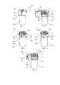
на фиг. 1-3 - перспективные изображения составных частей предлагаемого стопорного устройства;in FIG. 1-3 - perspective images of the components of the proposed locking device;
на фиг. 4 - схематический продольный разрез емкости, имеющей фланец и снабженной предлагаемым в изобретении стопорным устройством, находящимся в замкнутом, т.е. запирающем пробку, состоянии;in FIG. 4 is a schematic longitudinal section through a container having a flange and provided with a locking device according to the invention in a closed position, i.e. locking cork condition;
на фиг. 5 и 6 - перспективные изображения, иллюстрирующие две стадии сборки части предлагаемого стопорного устройства на емкости с фланцем;in FIG. 5 and 6 are perspective images illustrating two stages of assembly of a part of the proposed locking device on a container with a flange;
на фиг. 7-11 - перспективные изображения, иллюстрирующие пять стадий размыкания предлагаемого стопорного устройства, смонтированного на емкости с фланцем.in FIG. 7-11 are perspective images illustrating five stages of opening the proposed locking device mounted on a container with a flange.
Осуществление изобретенияThe implementation of the invention
Предлагаемое стопорное устройство 1, представленное на чертежах, предназначено для того, чтобы после его сборки обеспечивать фиксацию (блокировку) укупорочной пробки на емкости 101 и тем самым гарантировать как герметичность пробки, так и целостность содержимого емкости 101. Емкость 101 выполнена с фланцем 102, ограничиваемым горловиной 103, проходное сечение которой меньше, чем поперечное сечение остальной части емкости 101. Пробка 100 выполнена грибовидной формы с ножкой 104, вставляемой в горловину 103, и шляпкой 105, прилегающей к верхнему торцу фланца 102. Для обеспечения оптимальной герметичности пробка 100 выполнена, например, из эластомера. Стопорное устройство 1 содержит крышку 2, колпачок 3 и втулку 4.The proposed locking device 1, shown in the drawings, is designed to ensure that after its assembly to fix (lock) the cork stopper on the
Как показано на фиг. 2А и 2Б, крышка 2, которая выполнена из пластмассы, имеет диск 20, из которого в осевом направлении выходит юбка 21. В нижней части юбки 21 выполнена внутренняя, т.е. проходящая по внутренней поверхности, кольцевая канавка 22, а также в юбке имеется выемка 23, которая проходит в осевом направлении, пересекая канавку 22, по всей высоте юбки 21 и за счет уменьшения толщины стенки юбки 21 образует шарнирный участок Z1 крышки. На внешней поверхности крышки 2 выполнена двойная канавка 25, 26, 27, вдоль которой стенка крышки 2 имеет уменьшенную толщину. Двойная канавка 25, 26, 27 содержит два первых отрезка 25, ориентированных в осевом направлении и проходящих по высоте юбки 21 параллельно друг другу. В рассматриваемом примере первые отрезки 25 канавки проходят перпендикулярно свободному краю юбки 21. Вместе с тем, первые отрезки 25 канавки также могут проходить под углом к свободному краю юбки 21. Два первых отрезка 25 канавки продолжаются двумя вторыми отрезками 26, которые параллельно друг другу проходят по диску 20 в направлении его центра, ориентированы радиально относительно юбки 21 и на концах соединяются круглым отрезком 27 канавки. Таким образом, двойная канавка 25, 26, 27 служит границей ослабленного участка Z2, который можно оторвать для разделения крышки 2, что позволяет раскрыть крышку и снять ее с фланца 102 емкости 101. Для облегчения раскрытия крышки 2 первые отрезки 25 ее ослабленного участка Z2 находятся диаметрально противоположно шарнирному участку Z1. По центру диска 20 через него, а именно через его ослабленный участок Z2, проходит отверстие 28. Диск 20 выполнен с расчетом на его закрытие показанным на фиг. 1 удаляемым колпачком 3, имеющим по центру замок 30, который виден на фиг. 2Б (до его вщелкивания) и на фиг. 4 (после его вщелкивания) и выполнен с возможностью вхождения в отверстие 28 крышки 2, к которой он может быть прикреплен путем защелкивания, как показано на фиг. 4. Таким образом, замок 30 и отверстие 28 образуют точку крепления колпачка 3 к крышке 2, в частности точку крепления колпачка 3 к ослабленному участку Z2 крышки. Колпачок 3, будучи выполнен из более гибкой пластмассы по сравнению с крышкой 2, легко деформируется. Таким образом, край колпачка 3 можно приподнять и затем потянуть колпачок, который, в свою очередь, потянет за собой вверх ослабленный участок Z2 крышки. Таким образом, крышка 2 выполнена таким образом, что когда она расположена поверх пробки 100, она закрывает последнюю, окружая фланец 102 емкости 101 и делая пробку 100 недоступной.As shown in FIG. 2A and 2B, the
Как показано на фиг. 3, втулка 4, которая изготовлена из пластмассы, образована по существу цилиндрическим кольцом 40, из которого выступают лапки 41. Втулка 4 выполнена таким образом, чтобы помещаться внутри крышки 2 и окружать фланец 102 емкости 100. На своей внутренней поверхности кольцо 40 имеет три нижних внутренних стопора 42, расположенных в одной проходящей поперек осевого направления плоскости, а также три верхних внутренних стопора 43, расположенных в другой проходящей поперек осевого направления, отличной от вышеупомянутой плоскости. Нижние внутренние стопоры 42 и верхние внутренние стопоры 43 расположены в шахматном порядке и расположены на одинаковых расстояниях друг от друга, т.е. равномерно распределены в окружном направлении. Как верхние внутренние стопоры 43, так и нижние внутренние стопоры 42 выполнены в виде гибких язычков, выполненных наклонными и ориентированными в направлении лапок 41. На своей внутренней поверхности кольцо 40 имеет пять внешних стопоров 44, расположенных на одинаковых расстояниях друг от друга в проходящей поперек осевого направления плоскости, отличной от двух вышеупомянутых плоскостей. В рассматриваемом примере внешние стопоры 44 расположены, в осевом направлении, между нижними внутренними стопорами 42 и верхними внутренними стопорами 43. Кольцо 40 имеет перемычку 45, расположенную с противоположной лапкам 41 стороны втулки и имеющую высоту, уменьшенную по сравнению с высотой остальной части кольца 40. Перемычка 45 выполнена упруго деформируемой и таким образом обеспечивает возможность небольшой упругой радиальной деформации кольца 40, а также возможность разведения и отклонения наружу участков стенки кольца 40, расположенных по обе стороны перемычки 45. Кроме того, перемычку 45 можно разорвать, что позволяет после разрыва перемычки снять втулку 4 с фланца 102 емкости 101. Лапки 41 выступают из кольца 40 в осевом направлении. В рассматриваемом примере втулка имеет пять лапок 41, и они расположены по окружности кольца 40, за исключением занимаемого перемычкой 45 участка кольца, на одинаковых расстояниях друг от друга. Каждая лапка 41 расположена (в окружном направлении) между одним верхним внутренним язычком 43 и одним нижним внутренним язычком 42. Свободный конец каждой из лапок 41 не связан со свободным концом ни одной из других лапок, т.е. свободные концы лапок являются независимыми друг от друга. Каждая лапка 41 смещена относительно оси вовнутрь кольца 40 с образованием выдающегося внутрь выступа 46, предназначенного для того, чтобы опираться на фланец 102.As shown in FIG. 3, the
Крышка 2, втулка 4 и колпачок 3 могут изготавливаться методом литья, например с помощью машины для литья под давлением.The
Сборку стопорного устройства 1 и его установку на фланце 102 емкости 101 выполняют следующим образом. На первом этапе описанным выше образом на крышке 2 путем защелкивания фиксируют колпачок 3, вщелкивая замок 30 колпачка в отверстие 28. На втором этапе втулку 4 и ее лапки 41 располагают таким образом, чтобы они были обращены к внутренней поверхности юбки 21 крышки 2, после чего втулку 4 вставляют в крышку 2. При введении втулки в крышку внешние стопоры 44 втулки 4 сначала упруго деформируются, а затем заскакивают в канавку 22. Таким образом втулка 4 фиксируется в крышке 2. На третьем этапе используют емкость 101, имеющую фланец 102 и укупоренную пробкой 100, вводят эту емкость в крышку 2, имеющую втулку 4. При введении емкости в крышку перемычка 45, растягиваясь, допускает упругую деформацию втулки 4 внутри крышки 2, позволяя пробке 100 и фланцу 102 пройти во втулку 4, как показано на фиг. 5, на которой показаны только втулка 4 и емкость 101. После такого протискивания фланца 102 через втулку 4 последняя принимает свою первоначальную форму, как показано на фиг. 6. В этом состоянии фланец 102 расположен и заблокирован между нижними внутренними стопорами 42 и верхними внутренними стопорами 43. Пробка 100, которая обеспечивает герметичную укупорку емкости 101 и подпирается верхними внутренними стопорами 43, зажата между лапками 41. Таким образом пробка 100 крепится к емкости 101 посредством стопорного устройства 1, которое полностью окружает пробку 100 и тем самым делает ее недоступной.The assembly of the locking device 1 and its installation on the
Ниже со ссылкой на фиг. 7-11 описывается процесс снятия стопорного устройства 1. На первом этапе пользователь захватывает край колпачка 3, чтобы приподнять его и приложить к нему тянущее усилие. Это тянущее усилие передается с колпачка 3 на ослабленный участок Z2 крышки через замок 30, вщелкнутый в отверстие 28. Таким образом создается тянущее усилие, достаточное для отрыва ослабленного участка Z2 крышки. Как показано на фиг. 7, это действие вызывает разделение и раскрытие крышки 2. На втором этапе, как показано на фиг. 8, крышку 2 раскрывают, разводя ее части, находящиеся с обеих сторон шарнирного участка Z1. Крышку 2 снимают с емкости, которая на фиг. 9 показана только с втулкой 4. На третьем этапе, как показано на фиг. 10, перемычку 45 разрывают и, как показано на фиг. 11, раскрывают втулку 4, раздвигая ее в стороны. На четвертом этапе пробку 100 извлекают из емкости 101.Below with reference to FIG. 7-11, the process of removing the locking device 1 is described. At the first stage, the user grasps the edge of the
Изобретение обеспечивает достижение упомянутых выше целей. Теперь фланец 102, который после снятия крышки 2 и втулки 4 полностью освобождается, можно соединить с любыми соединительными средствами с целью перемещения содержимого емкости 101 и/или введения в емкость 101 продукта.The invention provides the achievement of the above objectives. Now, the
Разумеется, что возможности осуществления настоящего изобретения не ограничиваются рассмотренными выше в описании одного из вариантов его осуществления, который может быть видоизменен любым образом, не выходящим за рамки сущности изобретения.Of course, that the possibilities of implementing the present invention are not limited to those discussed above in the description of one of the variants of its implementation, which can be modified in any way that does not go beyond the essence of the invention.
Claims (8)
Translated fromRussianApplications Claiming Priority (3)
| Application Number | Priority Date | Filing Date | Title |
|---|---|---|---|
| FR1251306AFR2986782B1 (en) | 2012-02-13 | 2012-02-13 | PLUG LOCKING DEVICE ON FLANGE CONTAINER, PLUG-IN CLOSURE FLANGE CONTAINER PROVIDED WITH SUCH LATCHING DEVICE |
| FR12/51306 | 2012-02-13 | ||
| PCT/EP2013/052273WO2013120739A1 (en) | 2012-02-13 | 2013-02-06 | Locking device for a cap |
Publications (2)
| Publication Number | Publication Date |
|---|---|
| RU2014131760A RU2014131760A (en) | 2016-02-20 |
| RU2576234C2true RU2576234C2 (en) | 2016-02-27 |
Family
ID=47666141
Family Applications (1)
| Application Number | Title | Priority Date | Filing Date |
|---|---|---|---|
| RU2014131760/12ARU2576234C2 (en) | 2012-02-13 | 2013-02-06 | Locking device for fixing cork |
Country Status (16)
| Country | Link |
|---|---|
| US (1) | US9382044B2 (en) |
| EP (1) | EP2814752B1 (en) |
| JP (1) | JP5932061B2 (en) |
| KR (1) | KR101578685B1 (en) |
| CN (1) | CN104245528B (en) |
| AU (1) | AU2013220588B2 (en) |
| BR (1) | BR112014019552B1 (en) |
| CA (1) | CA2856894C (en) |
| ES (1) | ES2582178T3 (en) |
| FR (1) | FR2986782B1 (en) |
| IL (1) | IL233593B (en) |
| MX (1) | MX347990B (en) |
| NZ (1) | NZ627609A (en) |
| RU (1) | RU2576234C2 (en) |
| WO (1) | WO2013120739A1 (en) |
| ZA (1) | ZA201405002B (en) |
Families Citing this family (21)
| Publication number | Priority date | Publication date | Assignee | Title |
|---|---|---|---|---|
| EP3016628B1 (en)* | 2013-07-03 | 2018-03-28 | SiO2 Medical Products, Inc. | Parenteral vial cap |
| EP3056450B1 (en)* | 2013-10-08 | 2018-02-14 | Toyo Seikan Group Holdings, Ltd. | External member for container lid |
| GB201506691D0 (en)* | 2015-04-20 | 2015-06-03 | Greif Int Holding Bv | Closure caps |
| US10421585B2 (en) | 2017-03-31 | 2019-09-24 | Core Nutrition, Llc | Overcap for a bottle having an inner skirt and outer skirt |
| DE202018103049U1 (en)* | 2018-03-28 | 2018-06-11 | Kissling Elektrotechnik Gmbh | Seal for a pulse generator |
| JP7072998B2 (en)* | 2018-11-30 | 2022-05-23 | 株式会社吉野工業所 | Cap with seal |
| FR3098504B1 (en)* | 2019-07-09 | 2021-06-04 | A Raymond Et Cie | locking cap for neck container |
| FR3098505B1 (en)* | 2019-07-09 | 2021-06-04 | A Raymond Et Cie | snap-off locking cap for neck container |
| JP7307264B2 (en)* | 2019-07-23 | 2023-07-11 | ウエスト ファーマスーティカル サービシーズ インコーポレイテッド | vial closure assembly |
| WO2021060252A1 (en)* | 2019-09-25 | 2021-04-01 | 日本山村硝子株式会社 | Cap |
| FR3106339B1 (en)* | 2020-01-16 | 2021-12-24 | A Raymond Et Cie | Locking cap for necked container with a cap with separable fastening tabs |
| IT202000031778A1 (en)* | 2020-12-22 | 2022-06-22 | Guala Closures Spa | CLOSURE WITH TEAR SEAL |
| CN113148427A (en)* | 2021-04-15 | 2021-07-23 | 苏州新劢德医疗器械科技有限公司 | Locking cover using annular elastic ring top cover as anti-counterfeit label |
| ES2971882T3 (en) | 2021-05-06 | 2024-06-10 | Kaisha Packaging Private Ltd | Tamper-evident plastic closure for vials for storing substances for medical or pharmaceutical applications and use thereof |
| CA208550S (en) | 2021-06-11 | 2023-07-10 | Kaisha Packaging Private Ltd | Tamper evident plastic closure for vials for medical purposes |
| FR3125022B1 (en)* | 2021-07-09 | 2023-06-30 | Aptar Stelmi Sas | Closing device for a fluid reservoir |
| FR3144116B1 (en) | 2022-12-22 | 2024-11-15 | A Raymond Et Cie | Breakable locking cap for neck container |
| FR3145350B1 (en)* | 2023-02-01 | 2025-01-17 | A Raymond Et Cie | BI-INJECTED CAGE WITH A LOCKING CAP FOR PHARMACEUTICAL BOTTLE |
| KR102842354B1 (en)* | 2023-02-27 | 2025-08-04 | 정규영 | Battery attachment device for drones |
| WO2024184344A1 (en) | 2023-03-06 | 2024-09-12 | Roncadelle Operations Srl | Vial cap |
| EP4588663A1 (en) | 2024-01-22 | 2025-07-23 | Roncadelle Operations Srl | Vial cap |
Citations (5)
| Publication number | Priority date | Publication date | Assignee | Title |
|---|---|---|---|---|
| EP0411383A1 (en)* | 1989-08-03 | 1991-02-06 | Abbott Laboratories | Retortable closure for plastic container |
| EP0749910A1 (en)* | 1995-06-19 | 1996-12-27 | Pohl GmbH & Co. KG | Cover for injection or infussion bottles |
| US5901866A (en)* | 1998-02-13 | 1999-05-11 | Comar Inc. | Break away overcap |
| FR2893922A1 (en)* | 2005-11-30 | 2007-06-01 | Biocorp Rech Et Dev Sa | Plug device for medication container e.g. glass vial, has manoeuvring element comprising annular edge engaged between external skirt of ring of cover and lip that forms locking unit and radially extends towards central axis of ring |
| FR2950865A1 (en)* | 2009-10-01 | 2011-04-08 | Raymond A & Cie | LOCKING CAP FOR A COLLARED CONTAINER WITH A FASTENING CAPSULE |
Family Cites Families (85)
| Publication number | Priority date | Publication date | Assignee | Title |
|---|---|---|---|---|
| US2162752A (en) | 1934-10-19 | 1939-06-20 | John Hamberger | Tamperproof closure |
| US2162754A (en) | 1937-06-05 | 1939-06-20 | John Hamberger | Tamperproof closure and container |
| US2961119A (en) | 1957-11-25 | 1960-11-22 | Charles F Leach | Closure devices |
| US3117701A (en) | 1958-04-11 | 1964-01-14 | Continental Can Co | Dispensing closure and container |
| US3193128A (en) | 1962-06-12 | 1965-07-06 | West Co | Container closure |
| FR2036746A1 (en) | 1969-03-14 | 1970-12-31 | Transfusions Sanguines | Sterile uncorking and restoppering bottles - of plasma derivs for lyophilisation |
| US3603471A (en) | 1969-11-24 | 1971-09-07 | Precision Sampling Corp | Septum valves |
| US3823841A (en) | 1972-04-13 | 1974-07-16 | American Hospital Supply Corp | Closure system for sterile medical liquid container |
| IT1000576B (en) | 1974-01-08 | 1976-04-10 | Fiscem Spa | CLOSURE FOR PART CONTAINERS FOR BOTTLES AND BOTTLES |
| FI66807C (en)* | 1977-05-09 | 1984-12-10 | Asicomo As | CAPSULE FOR BEHAOLLARLOCK AND FOAR FARANDE FOER TILLVERKNING AV DETSAMMA |
| US4211333A (en) | 1978-06-05 | 1980-07-08 | Merck & Co., Inc. | Tamperproof container |
| US4251003A (en) | 1979-01-19 | 1981-02-17 | Toni Casutt | Bottle closing device |
| JPS5859749U (en)* | 1981-10-16 | 1983-04-22 | オリンパス光学工業株式会社 | container cap |
| FR2529531A1 (en) | 1982-07-01 | 1984-01-06 | Lyonnaise Bouchage | MEANS FOR CLOSING A CONTAINER OF THE TYPE COMPRISING AN ALUMINUM SHEET OR LIKE OPENER, FIXED BY BONDING OR WELDING ON THE SURROUNDING OF THE ORIFICE OF THE CONTAINER |
| US4664277A (en)* | 1983-03-14 | 1987-05-12 | The West Company | Bonded closure assembly |
| DE3715175C1 (en)* | 1987-05-07 | 1988-11-24 | Pohl Metall Kunststoff | Cap for infusion and transfusion bottles |
| DE3902672A1 (en) | 1988-06-28 | 1990-02-08 | Wez Kunststoff | LOCKING ARRANGEMENT FOR PHARMACEUTICAL BOTTLES |
| JPH0378947A (en) | 1989-08-22 | 1991-04-04 | Ricoh Co Ltd | Dot array fluorescent tube |
| US5085332B1 (en) | 1991-04-11 | 1994-04-05 | Gettig Technologies Inc | Closure assembly |
| US5088612A (en) | 1991-06-10 | 1992-02-18 | Comar, Inc. | Vial cap |
| DE4132896C1 (en)* | 1991-10-04 | 1993-01-21 | Pohl Gmbh & Co Kg, 7500 Karlsruhe, De | |
| US5303835A (en) | 1992-06-24 | 1994-04-19 | Habley Medical Technology Corporation | Lyophilization cap and method |
| US5314084A (en)* | 1992-08-21 | 1994-05-24 | The West Company, Incorporated | Two piece all plastic seal |
| US5305835A (en) | 1992-09-23 | 1994-04-26 | Ingersoll-Rand Company | Nonrotary piston for jackhammer and removable splined nut therefor |
| DE4238682A1 (en) | 1992-11-17 | 1994-05-19 | Pohl Gmbh & Co Kg | Infusion bottle |
| DE9306796U1 (en) | 1993-05-06 | 1993-07-15 | Pharma-Gummi Wimmer West Gmbh, 5180 Eschweiler | Cap for closing a bottle |
| US5494170A (en) | 1993-05-06 | 1996-02-27 | Becton Dickinson And Company | Combination stopper-shield closure |
| JP2757117B2 (en) | 1993-10-21 | 1998-05-25 | 三共株式会社 | Vial container |
| IT1266657B1 (en)* | 1993-11-03 | 1997-01-09 | Guala Spa | WARRANTY CLOSURE FOR BOTTLES AND SIMILAR |
| DE4415679A1 (en) | 1994-05-04 | 1995-12-21 | Hoechst Ag | Tamper-evident cap for injection and infusion bottles |
| US5562219A (en) | 1994-09-22 | 1996-10-08 | Valois, S.A. | Device for attaching a dispenser member to a receptacle |
| DK0769456T3 (en) | 1995-10-18 | 2000-12-18 | Daikyo Seiko Ltd | Plastic cap and method for making it |
| JPH09278051A (en) | 1996-04-09 | 1997-10-28 | Taisei Kako Kk | Crown-form lid having locking mechanism |
| DE19622689A1 (en) | 1996-06-05 | 1997-12-11 | Fresenius Ag | Tamper-evident closure for nozzle-like openings in containers |
| US5718348A (en)* | 1996-09-12 | 1998-02-17 | Comar, Inc. | Overcap assembly for gear finish vial |
| US5819964A (en) | 1996-09-27 | 1998-10-13 | Becton Dickinson And Company | Lyophilization closure assembly for a medicament container for use during a lyophilization process |
| US5817082A (en) | 1996-11-08 | 1998-10-06 | Bracco Diagnostics Inc. | Medicament container closure with integral spike access means |
| GB9623544D0 (en) | 1996-11-12 | 1997-01-08 | Micromass Ltd | Sample vial and vial closure device for use in gas analysis and method of using the same |
| DE19708909A1 (en) | 1997-03-05 | 1998-09-10 | Bericap Gmbh & Co Kg | Plastic screw closure for bottles |
| US5972297A (en) | 1997-09-12 | 1999-10-26 | Becton, Dickinson & Company | Ball and socket closure for specimen collection container incorporating a septum |
| EP0909719B1 (en) | 1997-10-15 | 2002-07-24 | Taisei Kako Co., Ltd., | Closure for vial container |
| US6382442B1 (en) | 1998-04-20 | 2002-05-07 | Becton Dickinson And Company | Plastic closure for vials and other medical containers |
| US6378714B1 (en) | 1998-04-20 | 2002-04-30 | Becton Dickinson And Company | Transferset for vials and other medical containers |
| US6681475B2 (en) | 1998-04-20 | 2004-01-27 | Becton Dickinson And Company | Method of sealing a medical container with a plastic closure |
| US6904662B2 (en) | 1998-04-20 | 2005-06-14 | Becton, Dickinson And Company | Method of sealing a cartridge or other medical container with a plastic closure |
| CN2373391Y (en)* | 1999-03-18 | 2000-04-12 | 骆耕野 | Teared cap type anti-counterfeit bottle cap |
| US6568439B1 (en) | 1999-04-20 | 2003-05-27 | Jms Co., Ltd. | Container cap and liquid communication adapter |
| US6716396B1 (en) | 1999-05-14 | 2004-04-06 | Gen-Probe Incorporated | Penetrable cap |
| US6604561B2 (en) | 2000-02-11 | 2003-08-12 | Medical Instill Technologies, Inc. | Medicament vial having a heat-sealable cap, and apparatus and method for filling the vial |
| US7243689B2 (en) | 2000-02-11 | 2007-07-17 | Medical Instill Technologies, Inc. | Device with needle penetrable and laser resealable portion and related method |
| DE10007367A1 (en)* | 2000-02-18 | 2001-08-23 | Helvoet Pharma | Cap unit for infusion and transfusion bottles comprises plastic lid with radial planned break lines which run into circumferential weakening zone running concentrically around the lid center point |
| US6765541B1 (en) | 2000-04-24 | 2004-07-20 | The United States Of America As Represented By The Secretary Of The Navy | Capacitatively shunted quadrifilar helix antenna |
| US6341706B1 (en) | 2000-06-01 | 2002-01-29 | Color Access, Inc. | Snap-on plastic neck for glass containers |
| US6591998B2 (en) | 2000-12-21 | 2003-07-15 | Sulzer Carbomedics Inc. | Leakproof container for implantable prosthetic device |
| DE10138191B4 (en)* | 2001-08-03 | 2004-02-26 | Helvoet Pharma Belgium N.V. | Cap for infusion or transfusion bottles |
| US20030098286A1 (en) | 2001-11-27 | 2003-05-29 | Bloom Kenneth S. | Plastic closure, method of manufacture, and closure and container package for high-temperature applications |
| FR2835811B1 (en) | 2002-02-12 | 2004-05-21 | Pechiney Capsules | FUNCTIONAL INSERT FOR CONTAINER SPOUT, TYPICALLY A BOTTLE, AND CAPSULE INCLUDING LEDIT INSERT |
| US6739781B2 (en) | 2002-04-22 | 2004-05-25 | Seaquist Closures Foreign, Inc. | Scrubbing structure |
| EP1501740B1 (en) | 2002-05-02 | 2008-01-16 | Bormioli Rocco & Figlio S.p.A. | Child-proof capsule with security strip |
| ITVI20020131A1 (en) | 2002-06-17 | 2003-12-17 | Vacutest Kima Srl | CAP WITH PROTECTION FOR TEST TUBES |
| RU2295483C2 (en) | 2002-07-12 | 2007-03-20 | Берикап | Sealing device with hinge-fastened cap molded in closed position |
| US7611026B1 (en) | 2002-08-12 | 2009-11-03 | Rexam Closure Systems Inc. | Tamper-evident closure having a sealing disk and package for high-temperature applications |
| NZ538754A (en) | 2002-09-03 | 2010-04-30 | Medical Instill Tech Inc | Sealed vial with a reseable stopper and methods of making and filling same |
| US8303914B2 (en) | 2003-01-06 | 2012-11-06 | Becton, Dickinson And Company | Tube closure with removable septum for direct instrument access |
| AT500525A1 (en) | 2003-04-17 | 2006-01-15 | Greiner Bio One Gmbh | RECEIVING DEVICE AND SEALING DEVICE AND CAP SHAPED LOCKING DEVICE |
| EP1632439B1 (en) | 2003-06-03 | 2008-09-10 | Taisei Kako Co., Ltd. | Cap of container |
| FR2856982B1 (en) | 2003-07-02 | 2006-04-28 | Pechiney Capsules | IMPROVED CAPSULES AND PROCESS FOR MAKING SAME |
| CA2534758A1 (en) | 2003-08-04 | 2005-02-10 | Abacus (C.I.) Limited As Trustee Of The Bayview Trust | Closure with frangible tamper-evident band |
| FR2876035B1 (en) | 2003-11-14 | 2007-03-30 | Plastic Omnium Cie | SAFETY ASSEMBLY FOR EQUIPPING A SYRINGE AND SYRINGE ASSEMBLY |
| US7712618B2 (en) | 2004-07-20 | 2010-05-11 | The Zebra Company | Container cap with locking/unlocking mechanism that propels lid to open position |
| CN101031478B (en) | 2004-09-30 | 2011-03-16 | 泰特拉-拉瓦尔金融控股公司 | Capped container |
| TWI356795B (en) | 2004-11-15 | 2012-01-21 | Sig Technology Ltd | Flat self-opening closure for combipacks or for co |
| ITBO20050336A1 (en) | 2005-05-10 | 2006-11-11 | Pelliconi Abruzzo Srl | CLOSING ELEMENT IN PLASTIC MATERIAL FOR LIQUID CONTAINERS |
| EP1926556A2 (en) | 2005-09-20 | 2008-06-04 | BioMerieux, Inc. | Specimen enclosure apparatus and containers and closure devices for the same |
| JP4774280B2 (en) | 2005-11-18 | 2011-09-14 | 日本クラウンコルク株式会社 | Resin cap |
| CN2866366Y (en)* | 2005-11-29 | 2007-02-07 | 四川省宜宾五粮液集团有限公司 | Antifaking packaging bottle |
| PL1971531T3 (en) | 2005-11-30 | 2010-01-29 | Biocorp Rech Et Developpement | Plug device for a container and container provided with one such device |
| GB0602382D0 (en)* | 2006-02-07 | 2006-03-15 | Dubois Ltd | Packaging article |
| KR100757795B1 (en) | 2006-06-21 | 2007-09-11 | 채동석 | Stopper and container with stopper |
| EP2074982A1 (en) | 2006-10-17 | 2009-07-01 | JMS Co., Ltd. | Communication member and medical container using the same |
| FR2908396B1 (en) | 2006-11-10 | 2010-12-10 | Biocorp Rech Et Dev | CLOSURE DEVICE, CONTAINER EQUIPPED WITH SUCH DEVICE AND METHOD FOR MANUFACTURING SUCH A DEVICE |
| ES1064802Y (en) | 2007-01-30 | 2007-08-01 | Betapack Sa | PLUG FOR EDIBLE OIL CONTAINER BOTTLES AND OTHER FOOD LIQUIDS |
| FR2912384B1 (en) | 2007-02-09 | 2009-04-10 | Biocorp Rech Et Dev Sa | CLOSURE DEVICE FOR A CONTAINER, CONTAINER EQUIPPED WITH SUCH A DEVICE AND METHOD FOR CLOSING A LOT OF SUCH A CONTAINER |
| DE102008051351A1 (en) | 2008-10-10 | 2010-04-15 | Friedrich Sanner Gmbh & Co. Kg | Closure for pressing and locking with a container |
| FR2950035B1 (en) | 2009-09-15 | 2011-09-02 | Raymond A & Cie | LOCKING COIFFE FOR CONTAINER WITH COLLAR |
- 2012
- 2012-02-13FRFR1251306Apatent/FR2986782B1/ennot_activeExpired - Fee Related
- 2013
- 2013-02-06WOPCT/EP2013/052273patent/WO2013120739A1/enactiveApplication Filing
- 2013-02-06BRBR112014019552-8Apatent/BR112014019552B1/enactiveIP Right Grant
- 2013-02-06KRKR1020147020667Apatent/KR101578685B1/enactiveActive
- 2013-02-06CACA2856894Apatent/CA2856894C/enactiveActive
- 2013-02-06CNCN201380007545.9Apatent/CN104245528B/enactiveActive
- 2013-02-06EPEP13702806.4Apatent/EP2814752B1/enactiveActive
- 2013-02-06USUS14/375,372patent/US9382044B2/enactiveActive
- 2013-02-06ESES13702806.4Tpatent/ES2582178T3/enactiveActive
- 2013-02-06MXMX2014009127Apatent/MX347990B/enactiveIP Right Grant
- 2013-02-06JPJP2014556026Apatent/JP5932061B2/enactiveActive
- 2013-02-06RURU2014131760/12Apatent/RU2576234C2/enactive
- 2013-02-06AUAU2013220588Apatent/AU2013220588B2/enactiveActive
- 2013-02-06NZNZ627609Apatent/NZ627609A/enunknown
- 2014
- 2014-07-09ZAZA2014/05002Apatent/ZA201405002B/enunknown
- 2014-07-10ILIL233593Apatent/IL233593B/enactiveIP Right Grant
Patent Citations (5)
| Publication number | Priority date | Publication date | Assignee | Title |
|---|---|---|---|---|
| EP0411383A1 (en)* | 1989-08-03 | 1991-02-06 | Abbott Laboratories | Retortable closure for plastic container |
| EP0749910A1 (en)* | 1995-06-19 | 1996-12-27 | Pohl GmbH & Co. KG | Cover for injection or infussion bottles |
| US5901866A (en)* | 1998-02-13 | 1999-05-11 | Comar Inc. | Break away overcap |
| FR2893922A1 (en)* | 2005-11-30 | 2007-06-01 | Biocorp Rech Et Dev Sa | Plug device for medication container e.g. glass vial, has manoeuvring element comprising annular edge engaged between external skirt of ring of cover and lip that forms locking unit and radially extends towards central axis of ring |
| FR2950865A1 (en)* | 2009-10-01 | 2011-04-08 | Raymond A & Cie | LOCKING CAP FOR A COLLARED CONTAINER WITH A FASTENING CAPSULE |
Also Published As
| Publication number | Publication date |
|---|---|
| IL233593B (en) | 2018-06-28 |
| KR101578685B1 (en) | 2015-12-18 |
| CN104245528A (en) | 2014-12-24 |
| CA2856894A1 (en) | 2013-08-22 |
| MX2014009127A (en) | 2014-09-11 |
| AU2013220588A1 (en) | 2014-08-21 |
| NZ627609A (en) | 2016-03-31 |
| JP2015509893A (en) | 2015-04-02 |
| FR2986782B1 (en) | 2014-03-07 |
| US9382044B2 (en) | 2016-07-05 |
| ES2582178T3 (en) | 2016-09-09 |
| KR20140116145A (en) | 2014-10-01 |
| EP2814752B1 (en) | 2016-04-13 |
| MX347990B (en) | 2017-05-19 |
| HK1200419A1 (en) | 2015-08-07 |
| US20150014316A1 (en) | 2015-01-15 |
| CN104245528B (en) | 2016-04-20 |
| RU2014131760A (en) | 2016-02-20 |
| AU2013220588B2 (en) | 2015-06-11 |
| FR2986782A1 (en) | 2013-08-16 |
| EP2814752A1 (en) | 2014-12-24 |
| BR112014019552B1 (en) | 2021-01-19 |
| CA2856894C (en) | 2016-04-26 |
| WO2013120739A1 (en) | 2013-08-22 |
| JP5932061B2 (en) | 2016-06-08 |
| BR112014019552A2 (en) | 2017-06-27 |
| IL233593A0 (en) | 2014-08-31 |
| ZA201405002B (en) | 2018-12-19 |
Similar Documents
| Publication | Publication Date | Title |
|---|---|---|
| RU2576234C2 (en) | Locking device for fixing cork | |
| RU2705038C2 (en) | Closure device with opening indication and indicator cap for such device | |
| US9758281B2 (en) | Tamper-evident closure assembly having two tamper-evidencing members, and related methods | |
| US5269429A (en) | Closure cap for infusion or transfusion bottles | |
| RU2133701C1 (en) | Reusable plastic cap showing up its opening | |
| RU2605173C2 (en) | Device for closure and vessel equipped with such device | |
| RU2699156C1 (en) | Sealing device for bottles equipped with an easily detachable protective strip | |
| JP2005525971A (en) | Device for connecting between container and container and ready-to-use assembly comprising this device | |
| RU2730702C2 (en) | Vessel sealing system | |
| RU2597561C2 (en) | Device for closure and vessel equipped with such device | |
| JPS59187557A (en) | Tearing opening type cover assembly | |
| KR20230150987A (en) | Fluid product container sealing device | |
| JPH085487B2 (en) | Closure device for chemical bottles | |
| JP6986733B2 (en) | cap | |
| RU2660044C1 (en) | Synthetic resin container lid | |
| US20140263326A1 (en) | Closure for container | |
| RU127044U1 (en) | BOTTLE PROTECTIVE COVER | |
| RU163873U1 (en) | BOTTLE CAP CAP | |
| RU2013143392A (en) | CAPPING DEVICE AND LIQUID BOTTLE COOKING UNIT | |
| RU176561U1 (en) | CAPPING FACILITY FOR CAPACITY | |
| RU2838527C1 (en) | Plastic capping device for parenteral preparations | |
| HK1200419B (en) | Locking device for a cap | |
| JP5669706B2 (en) | Hinge cap | |
| JPH0724742U (en) | Medicated bottle lid | |
| JP5411751B2 (en) | Cap removal structure |