RU2566317C2 - Capsule, system and method for beverage preparation - Google Patents
Capsule, system and method for beverage preparationDownload PDFInfo
- Publication number
- RU2566317C2 RU2566317C2RU2012101435/12ARU2012101435ARU2566317C2RU 2566317 C2RU2566317 C2RU 2566317C2RU 2012101435/12 ARU2012101435/12 ARU 2012101435/12ARU 2012101435 ARU2012101435 ARU 2012101435ARU 2566317 C2RU2566317 C2RU 2566317C2
- Authority
- RU
- Russia
- Prior art keywords
- wall
- capsule
- peripheral
- protrusions
- fluid
- Prior art date
Links
- 239000002775capsuleSubstances0.000titleclaimsabstractdescription184
- 235000013361beverageNutrition0.000titleclaimsabstractdescription43
- 238000000034methodMethods0.000titleclaimsabstractdescription13
- 238000002360preparation methodMethods0.000titleabstractdescription6
- 230000002093peripheral effectEffects0.000claimsabstractdescription68
- 239000012530fluidSubstances0.000claimsabstractdescription54
- 239000000463materialSubstances0.000claimsabstractdescription26
- 239000004698PolyethyleneSubstances0.000claimsabstractdescription8
- 229920000573polyethylenePolymers0.000claimsabstractdescription8
- -1polyethylenePolymers0.000claimsabstractdescription7
- 230000003993interactionEffects0.000claimsabstractdescription4
- 238000007789sealingMethods0.000claimsdescription47
- 235000013353coffee beverageNutrition0.000claimsdescription22
- 238000000926separation methodMethods0.000claimsdescription13
- XLYOFNOQVPJJNP-UHFFFAOYSA-NwaterSubstancesOXLYOFNOQVPJJNP-UHFFFAOYSA-N0.000claimsdescription11
- 239000011148porous materialSubstances0.000claimsdescription8
- 230000036961partial effectEffects0.000claimsdescription5
- 229920006254polymer filmPolymers0.000claimsdescription2
- 238000007599dischargingMethods0.000claims1
- 230000008569processEffects0.000abstractdescription4
- 230000006378damageEffects0.000abstractdescription3
- 239000000126substanceSubstances0.000abstractdescription2
- 238000001914filtrationMethods0.000abstract2
- 230000000694effectsEffects0.000abstract1
- 239000000047productSubstances0.000description46
- 239000003826tabletSubstances0.000description35
- 230000008901benefitEffects0.000description17
- 238000010411cookingMethods0.000description6
- 230000002829reductive effectEffects0.000description6
- 239000000835fiberSubstances0.000description5
- 238000009736wettingMethods0.000description5
- 230000004048modificationEffects0.000description4
- 238000012986modificationMethods0.000description4
- 239000000243solutionSubstances0.000description4
- 238000005056compactionMethods0.000description3
- 230000000670limiting effectEffects0.000description3
- 238000003860storageMethods0.000description3
- 239000013589supplementSubstances0.000description3
- 238000011144upstream manufacturingMethods0.000description3
- DNJVYWXIDISQRD-UHFFFAOYSA-NCafestolNatural productsC1CC2(CC3(CO)O)CC3CCC2C2(C)C1C(C=CO1)=C1CC2DNJVYWXIDISQRD-UHFFFAOYSA-N0.000description2
- 230000009471actionEffects0.000description2
- 238000004026adhesive bondingMethods0.000description2
- DNJVYWXIDISQRD-JTSSGKSMSA-NcafestolChemical compoundC([C@H]1C[C@]2(C[C@@]1(CO)O)CC1)C[C@H]2[C@@]2(C)[C@H]1C(C=CO1)=C1CC2DNJVYWXIDISQRD-JTSSGKSMSA-N0.000description2
- HVYWMOMLDIMFJA-DPAQBDIFSA-NcholesterolChemical compoundC1C=C2C[C@@H](O)CC[C@]2(C)[C@@H]2[C@@H]1[C@@H]1CC[C@H]([C@H](C)CCCC(C)C)[C@@]1(C)CC2HVYWMOMLDIMFJA-DPAQBDIFSA-N0.000description2
- 239000007891compressed tabletSubstances0.000description2
- 238000009826distributionMethods0.000description2
- 239000002657fibrous materialSubstances0.000description2
- 230000007246mechanismEffects0.000description2
- 239000003921oilSubstances0.000description2
- 238000003466weldingMethods0.000description2
- 208000032963Capsule physical issueDiseases0.000description1
- 229920003043Cellulose fiberPolymers0.000description1
- 239000004743PolypropyleneSubstances0.000description1
- 239000000853adhesiveSubstances0.000description1
- 230000001070adhesive effectEffects0.000description1
- 230000002411adverseEffects0.000description1
- 230000004323axial lengthEffects0.000description1
- 230000015572biosynthetic processEffects0.000description1
- 239000008280bloodSubstances0.000description1
- 210000004369bloodAnatomy0.000description1
- 230000008859changeEffects0.000description1
- 230000000295complement effectEffects0.000description1
- 238000000280densificationMethods0.000description1
- 230000001419dependent effectEffects0.000description1
- 239000013013elastic materialSubstances0.000description1
- 238000000605extractionMethods0.000description1
- 230000005484gravityEffects0.000description1
- 230000036541healthEffects0.000description1
- 239000004615ingredientSubstances0.000description1
- 238000001746injection mouldingMethods0.000description1
- 239000007788liquidSubstances0.000description1
- 238000004519manufacturing processMethods0.000description1
- 238000000465mouldingMethods0.000description1
- 230000035515penetrationEffects0.000description1
- 239000004033plasticSubstances0.000description1
- 229920003023plasticPolymers0.000description1
- 229920006255plastic filmPolymers0.000description1
- 239000002985plastic filmSubstances0.000description1
- 229920001155polypropylenePolymers0.000description1
- 230000009467reductionEffects0.000description1
- 230000002441reversible effectEffects0.000description1
- 239000012209synthetic fiberSubstances0.000description1
- 229920002994synthetic fiberPolymers0.000description1
- 238000003856thermoformingMethods0.000description1
Images


Classifications
- A—HUMAN NECESSITIES
- A47—FURNITURE; DOMESTIC ARTICLES OR APPLIANCES; COFFEE MILLS; SPICE MILLS; SUCTION CLEANERS IN GENERAL
- A47J—KITCHEN EQUIPMENT; COFFEE MILLS; SPICE MILLS; APPARATUS FOR MAKING BEVERAGES
- A47J31/00—Apparatus for making beverages
- A47J31/24—Coffee-making apparatus in which hot water is passed through the filter under pressure, i.e. in which the coffee grounds are extracted under pressure
- A47J31/34—Coffee-making apparatus in which hot water is passed through the filter under pressure, i.e. in which the coffee grounds are extracted under pressure with hot water under liquid pressure
- A47J31/36—Coffee-making apparatus in which hot water is passed through the filter under pressure, i.e. in which the coffee grounds are extracted under pressure with hot water under liquid pressure with mechanical pressure-producing means
- A—HUMAN NECESSITIES
- A23—FOODS OR FOODSTUFFS; TREATMENT THEREOF, NOT COVERED BY OTHER CLASSES
- A23F—COFFEE; TEA; THEIR SUBSTITUTES; MANUFACTURE, PREPARATION, OR INFUSION THEREOF
- A23F5/00—Coffee; Coffee substitutes; Preparations thereof
- A23F5/24—Extraction of coffee; Coffee extracts; Making instant coffee
- A23F5/26—Extraction of water soluble constituents
- A23F5/262—Extraction of water soluble constituents the extraction liquid flowing through a stationary bed of solid substances, e.g. in percolation columns
- B—PERFORMING OPERATIONS; TRANSPORTING
- B65—CONVEYING; PACKING; STORING; HANDLING THIN OR FILAMENTARY MATERIAL
- B65D—CONTAINERS FOR STORAGE OR TRANSPORT OF ARTICLES OR MATERIALS, e.g. BAGS, BARRELS, BOTTLES, BOXES, CANS, CARTONS, CRATES, DRUMS, JARS, TANKS, HOPPERS, FORWARDING CONTAINERS; ACCESSORIES, CLOSURES, OR FITTINGS THEREFOR; PACKAGING ELEMENTS; PACKAGES
- B65D85/00—Containers, packaging elements or packages, specially adapted for particular articles or materials
- B65D85/70—Containers, packaging elements or packages, specially adapted for particular articles or materials for materials not otherwise provided for
- B65D85/804—Disposable containers or packages with contents which are mixed, infused or dissolved in situ, i.e. without having been previously removed from the package
- B65D85/8043—Packages adapted to allow liquid to pass through the contents
- A—HUMAN NECESSITIES
- A47—FURNITURE; DOMESTIC ARTICLES OR APPLIANCES; COFFEE MILLS; SPICE MILLS; SUCTION CLEANERS IN GENERAL
- A47J—KITCHEN EQUIPMENT; COFFEE MILLS; SPICE MILLS; APPARATUS FOR MAKING BEVERAGES
- A47J31/00—Apparatus for making beverages
- A47J31/06—Filters or strainers for coffee or tea makers ; Holders therefor
- A47J31/0657—Filters or strainers for coffee or tea makers ; Holders therefor for brewing coffee under pressure, e.g. for espresso machines
- A47J31/0668—Filters or strainers for coffee or tea makers ; Holders therefor for brewing coffee under pressure, e.g. for espresso machines specially adapted for cartridges
- A47J31/0673—Means to perforate the cartridge for creating the beverage outlet
- A—HUMAN NECESSITIES
- A47—FURNITURE; DOMESTIC ARTICLES OR APPLIANCES; COFFEE MILLS; SPICE MILLS; SUCTION CLEANERS IN GENERAL
- A47J—KITCHEN EQUIPMENT; COFFEE MILLS; SPICE MILLS; APPARATUS FOR MAKING BEVERAGES
- A47J31/00—Apparatus for making beverages
- A47J31/24—Coffee-making apparatus in which hot water is passed through the filter under pressure, i.e. in which the coffee grounds are extracted under pressure
- A47J31/34—Coffee-making apparatus in which hot water is passed through the filter under pressure, i.e. in which the coffee grounds are extracted under pressure with hot water under liquid pressure
- A47J31/36—Coffee-making apparatus in which hot water is passed through the filter under pressure, i.e. in which the coffee grounds are extracted under pressure with hot water under liquid pressure with mechanical pressure-producing means
- A47J31/3604—Coffee-making apparatus in which hot water is passed through the filter under pressure, i.e. in which the coffee grounds are extracted under pressure with hot water under liquid pressure with mechanical pressure-producing means with a mechanism arranged to move the brewing chamber between loading, infusing and ejecting stations
- A47J31/3623—Cartridges being employed
- A47J31/3628—Perforating means therefor
- A—HUMAN NECESSITIES
- A47—FURNITURE; DOMESTIC ARTICLES OR APPLIANCES; COFFEE MILLS; SPICE MILLS; SUCTION CLEANERS IN GENERAL
- A47J—KITCHEN EQUIPMENT; COFFEE MILLS; SPICE MILLS; APPARATUS FOR MAKING BEVERAGES
- A47J31/00—Apparatus for making beverages
- A47J31/24—Coffee-making apparatus in which hot water is passed through the filter under pressure, i.e. in which the coffee grounds are extracted under pressure
- A47J31/34—Coffee-making apparatus in which hot water is passed through the filter under pressure, i.e. in which the coffee grounds are extracted under pressure with hot water under liquid pressure
- A47J31/36—Coffee-making apparatus in which hot water is passed through the filter under pressure, i.e. in which the coffee grounds are extracted under pressure with hot water under liquid pressure with mechanical pressure-producing means
- A47J31/3666—Coffee-making apparatus in which hot water is passed through the filter under pressure, i.e. in which the coffee grounds are extracted under pressure with hot water under liquid pressure with mechanical pressure-producing means whereby the loading of the brewing chamber with the brewing material is performed by the user
- A47J31/3676—Cartridges being employed
- A47J31/368—Permeable cartridges being employed
- A—HUMAN NECESSITIES
- A47—FURNITURE; DOMESTIC ARTICLES OR APPLIANCES; COFFEE MILLS; SPICE MILLS; SUCTION CLEANERS IN GENERAL
- A47J—KITCHEN EQUIPMENT; COFFEE MILLS; SPICE MILLS; APPARATUS FOR MAKING BEVERAGES
- A47J31/00—Apparatus for making beverages
- A47J31/40—Beverage-making apparatus with dispensing means for adding a measured quantity of ingredients, e.g. coffee, water, sugar, cocoa, milk, tea
- A47J31/407—Beverage-making apparatus with dispensing means for adding a measured quantity of ingredients, e.g. coffee, water, sugar, cocoa, milk, tea with ingredient-containing cartridges; Cartridge-perforating means
- B—PERFORMING OPERATIONS; TRANSPORTING
- B65—CONVEYING; PACKING; STORING; HANDLING THIN OR FILAMENTARY MATERIAL
- B65D—CONTAINERS FOR STORAGE OR TRANSPORT OF ARTICLES OR MATERIALS, e.g. BAGS, BARRELS, BOTTLES, BOXES, CANS, CARTONS, CRATES, DRUMS, JARS, TANKS, HOPPERS, FORWARDING CONTAINERS; ACCESSORIES, CLOSURES, OR FITTINGS THEREFOR; PACKAGING ELEMENTS; PACKAGES
- B65D65/00—Wrappers or flexible covers; Packaging materials of special type or form
- B65D65/38—Packaging materials of special type or form
- B65D65/46—Applications of disintegrable, dissolvable or edible materials
- B65D65/466—Bio- or photodegradable packaging materials
- B—PERFORMING OPERATIONS; TRANSPORTING
- B65—CONVEYING; PACKING; STORING; HANDLING THIN OR FILAMENTARY MATERIAL
- B65D—CONTAINERS FOR STORAGE OR TRANSPORT OF ARTICLES OR MATERIALS, e.g. BAGS, BARRELS, BOTTLES, BOXES, CANS, CARTONS, CRATES, DRUMS, JARS, TANKS, HOPPERS, FORWARDING CONTAINERS; ACCESSORIES, CLOSURES, OR FITTINGS THEREFOR; PACKAGING ELEMENTS; PACKAGES
- B65D85/00—Containers, packaging elements or packages, specially adapted for particular articles or materials
- B65D85/70—Containers, packaging elements or packages, specially adapted for particular articles or materials for materials not otherwise provided for
- B65D85/804—Disposable containers or packages with contents which are mixed, infused or dissolved in situ, i.e. without having been previously removed from the package
- B65D85/8043—Packages adapted to allow liquid to pass through the contents
- B65D85/8046—Pods, i.e. closed containers made only of filter paper or similar material
- B—PERFORMING OPERATIONS; TRANSPORTING
- B65—CONVEYING; PACKING; STORING; HANDLING THIN OR FILAMENTARY MATERIAL
- B65D—CONTAINERS FOR STORAGE OR TRANSPORT OF ARTICLES OR MATERIALS, e.g. BAGS, BARRELS, BOTTLES, BOXES, CANS, CARTONS, CRATES, DRUMS, JARS, TANKS, HOPPERS, FORWARDING CONTAINERS; ACCESSORIES, CLOSURES, OR FITTINGS THEREFOR; PACKAGING ELEMENTS; PACKAGES
- B65D85/00—Containers, packaging elements or packages, specially adapted for particular articles or materials
- B65D85/70—Containers, packaging elements or packages, specially adapted for particular articles or materials for materials not otherwise provided for
- B65D85/804—Disposable containers or packages with contents which are mixed, infused or dissolved in situ, i.e. without having been previously removed from the package
- B65D85/8043—Packages adapted to allow liquid to pass through the contents
- B65D85/8061—Filters
- A—HUMAN NECESSITIES
- A47—FURNITURE; DOMESTIC ARTICLES OR APPLIANCES; COFFEE MILLS; SPICE MILLS; SUCTION CLEANERS IN GENERAL
- A47J—KITCHEN EQUIPMENT; COFFEE MILLS; SPICE MILLS; APPARATUS FOR MAKING BEVERAGES
- A47J31/00—Apparatus for making beverages
- A47J31/005—Portable or compact beverage making apparatus, e.g. for travelling, for use in automotive vehicles
- A—HUMAN NECESSITIES
- A47—FURNITURE; DOMESTIC ARTICLES OR APPLIANCES; COFFEE MILLS; SPICE MILLS; SUCTION CLEANERS IN GENERAL
- A47J—KITCHEN EQUIPMENT; COFFEE MILLS; SPICE MILLS; APPARATUS FOR MAKING BEVERAGES
- A47J31/00—Apparatus for making beverages
- A47J31/06—Filters or strainers for coffee or tea makers ; Holders therefor
- A47J31/0657—Filters or strainers for coffee or tea makers ; Holders therefor for brewing coffee under pressure, e.g. for espresso machines
- A47J31/0663—Filters or strainers for coffee or tea makers ; Holders therefor for brewing coffee under pressure, e.g. for espresso machines to be used with loose coffee
- A—HUMAN NECESSITIES
- A47—FURNITURE; DOMESTIC ARTICLES OR APPLIANCES; COFFEE MILLS; SPICE MILLS; SUCTION CLEANERS IN GENERAL
- A47J—KITCHEN EQUIPMENT; COFFEE MILLS; SPICE MILLS; APPARATUS FOR MAKING BEVERAGES
- A47J31/00—Apparatus for making beverages
- A47J31/40—Beverage-making apparatus with dispensing means for adding a measured quantity of ingredients, e.g. coffee, water, sugar, cocoa, milk, tea
- B—PERFORMING OPERATIONS; TRANSPORTING
- B65—CONVEYING; PACKING; STORING; HANDLING THIN OR FILAMENTARY MATERIAL
- B65D—CONTAINERS FOR STORAGE OR TRANSPORT OF ARTICLES OR MATERIALS, e.g. BAGS, BARRELS, BOTTLES, BOXES, CANS, CARTONS, CRATES, DRUMS, JARS, TANKS, HOPPERS, FORWARDING CONTAINERS; ACCESSORIES, CLOSURES, OR FITTINGS THEREFOR; PACKAGING ELEMENTS; PACKAGES
- B65D85/00—Containers, packaging elements or packages, specially adapted for particular articles or materials
- B65D85/70—Containers, packaging elements or packages, specially adapted for particular articles or materials for materials not otherwise provided for
- B65D85/804—Disposable containers or packages with contents which are mixed, infused or dissolved in situ, i.e. without having been previously removed from the package
Landscapes
- Engineering & Computer Science (AREA)
- Mechanical Engineering (AREA)
- Food Science & Technology (AREA)
- Life Sciences & Earth Sciences (AREA)
- Chemical & Material Sciences (AREA)
- Polymers & Plastics (AREA)
- Biodiversity & Conservation Biology (AREA)
- Apparatus For Making Beverages (AREA)
- Tea And Coffee (AREA)
Abstract
Description
Translated fromRussianИзобретение относится к системе, предназначенной для приготовления заданного количества напитка, пригодного для потребления, посредством использования экстрагируемого продукта, включающей в себя сменную капсулу и устройство, содержащее устройство для выдачи текучей среды, предназначенное для подачи некоторого количества текучей среды, такой как вода, под давлением, составляющим по меньшей мере шесть бар, в сменную капсулу, и приемное гнездо, предназначенное для удерживания сменной капсулы; при этом сменная капсула содержит периферическую первую стенку, вторую стенку, закрывающую периферическую первую стенку на первом конце, и третью стенку, закрывающую периферическую первую стенку на втором открытом конце, противоположном по отношению ко второй стенке, при этом первая, вторая и третья стенки ограничивают внутреннее пространство, в котором содержится экстрагируемый продукт; кроме того, устройство для выдачи текучей среды выполнено с возможностью подачи текучей среды в экстрагируемый продукт через вторую стенку для образования напитка; и приемное гнездо имеет опорную поверхность, причем третья стенка расположена так, чтобы она опиралась на опорную поверхность для выпуска приготовленного напитка из капсулы через третью стенку и через опорную поверхность. Изобретение также относится к капсуле и к способу приготовления напитка.The invention relates to a system for preparing a predetermined quantity of a beverage suitable for consumption by using an extractable product comprising a replaceable capsule and a device comprising a fluid dispensing device for supplying a certain amount of a fluid, such as water, under pressure at least six bar into a replaceable capsule and a receptacle for holding the replaceable capsule; wherein the replaceable capsule comprises a peripheral first wall, a second wall covering the peripheral first wall at the first end, and a third wall covering the peripheral first wall at the second open end, opposite to the second wall, while the first, second and third walls define an inner the space in which the extracted product is contained; in addition, a device for dispensing a fluid is configured to supply fluid to an extractable product through a second wall to form a beverage; and the receptacle has a supporting surface, and the third wall is located so that it rests on the supporting surface to release the prepared beverage from the capsule through the third wall and through the supporting surface. The invention also relates to a capsule and to a method for preparing a beverage.
Подобная система, например, известна из документа WO2007/135136А1, в котором описано устройство для варки, предназначенное для варки напитка посредством капсулы, содержащей ингредиент напитка. Данное известное устройство для варки содержит основной корпус, а также первую и вторую части для удерживания капсулы, предназначенные для по меньшей мере частичного удерживания капсулы. Указанная первая часть для удерживания капсулы имеет вышеупомянутую опорную поверхность, предназначенную для того, чтобы на нее опиралась третья стенка капсулы. Указанная вторая часть для удерживания капсулы выполнена с возможностью перемещения относительно первой части для удерживания капсулы в корпусе и соединена с корпусом посредством закрывающего механизма, содержащего средство в виде вилочного шарнира или эквивалентные средства для обеспечения перемещения из открытого положения, в котором две части находятся на расстоянии друг относительно друга для обеспечения возможности вставки капсулы между двумя частями, в закрытое положение, в котором первая и вторая удерживающие части закрыты вокруг капсулы. Данное известное устройство для варки дополнительно содержит рычаг, образующий ручку для ручного манипулирования и предназначенный для обеспечения приведения в действие второй удерживающей части посредством закрывающего механизма для перемещения ее из открытого положения в закрытое положение, и наоборот.A similar system, for example, is known from WO2007 / 135136A1, which describes a brewing apparatus for brewing a beverage by means of a capsule containing a beverage ingredient. This known cooking device comprises a main body as well as first and second capsule holding parts for at least partially holding the capsule. Said first capsule holding portion has the aforementioned abutment surface so that the third wall of the capsule rests on it. Said second capsule holding part is movable relative to the first capsule holding part in the housing and is connected to the housing by a closing mechanism comprising means in the form of a fork hinge or equivalent means for providing movement from an open position in which the two parts are spaced apart relative to each other to allow the capsule to be inserted between the two parts in a closed position in which the first and second holding parts are closed District capsules. This known cooking device further comprises a lever forming a handle for manual manipulation and designed to actuate the second holding part by means of a closing mechanism for moving it from an open position to a closed position, and vice versa.
Корпус данного известного устройства выполнен с верхним проходным отверстием, предназначенным для вставки новой капсулы в устройство, когда удерживающие части переведены в открытое положение. Корпус также имеет нижнее проходное отверстие для выбрасывания израсходованной капсулы, как только процесс варки, который происходит при закрытом положении удерживающих частей, будет завершен и удерживающие части будут снова открыты.The housing of this known device is made with an upper passage hole designed to insert a new capsule into the device when the holding parts are moved to the open position. The housing also has a lower opening for ejecting the expended capsule as soon as the cooking process, which occurs when the holding parts are closed, is completed and the holding parts are opened again.
После вставки новой капсулы в известное устройство удерживающие части могут быть переведены в закрытое положение. При данном закрытом положении может выполняться процесс варки. Во время данного процесса варки вторая стенка капсулы прокалывается прокалывающими элементами, такими как лезвия, так что капсула будет открыта для обеспечения возможности поступления воды под давлением в капсулу. В этот момент третья стенка капсулы интенсивно контактно взаимодействует с опорной поверхностью первой удерживающей части. Действительно, указанное интенсивное контактное взаимодействие приводит к прилипанию капсулы к опорной поверхности.After inserting a new capsule into a known device, the holding parts can be moved to the closed position. With this closed position, a cooking process may be performed. During this cooking process, the second wall of the capsule is pierced by piercing elements, such as blades, so that the capsule will be opened to allow pressurized water to enter the capsule. At this moment, the third wall of the capsule interacts intensively in contact with the supporting surface of the first holding part. Indeed, the specified intense contact interaction leads to the adhesion of the capsule to the supporting surface.
Во время начальной фазы повторного открытия удерживающих частей капсула будет по-прежнему находиться в контактном взаимодействии с прокалывающими элементами, при этом указанные прокалывающие элементы присоединены ко второй удерживающей части и могут перемещаться вместе со второй удерживающей частью. Таким образом, при повторном открытии прокалывающие элементы обеспечивают отделение капсулы от опорной поверхности первой удерживающей части, и они тянут капсулу от данной опорной поверхности. Для обеспечения возможности того, чтобы капсула упала вниз под действием силы тяжести через нижнее проходное отверстие в корпусе, капсула снова должна быть освобождена, на этот раз от прокалывающих элементов. На странице 19, строки 1-12 документа WO2007/135136А1 описан один способ освобождения капсулы от прокалывающих элементов. Данный способ предусматривает использование обеспечивающей компенсацию длины части трубки средства подачи воды, при этом указанная часть не может перемещаться относительно корпуса. Компенсирующая часть трубки толкает капсулу таким образом, что капсула выходит из контактного взаимодействия с прокалывающими элементами, когда вторая удерживающая часть перемещается от первой удерживающей части.During the initial phase of the re-opening of the holding parts, the capsule will still be in contact with the piercing elements, with these piercing elements attached to the second holding part and can move together with the second holding part. Thus, upon reopening, the piercing elements separate the capsule from the abutment surface of the first holding portion, and they pull the capsule away from that abutment surface. To ensure that the capsule falls down due to gravity through the lower passage in the housing, the capsule must again be released, this time from the piercing elements. On
Задача изобретения заключается в разработке по меньшей мере альтернативного решения, в соответствии с которым капсула отделяется от опорной поверхности. Более точно, задача изобретения состоит в разработке такого альтернативного решения, которое является менее сложным, чем вышеописанное известное решение, и указанное альтернативное решение работает даже в тех случаях, когда такие прокалывающие элементы, как описанные выше, отсутствуют в системе, или в тех случаях, когда подобные прокалывающие элементы неактивны во время варки при определенных типах капсул.The objective of the invention is to develop at least an alternative solution, in accordance with which the capsule is separated from the supporting surface. More precisely, the objective of the invention is to develop such an alternative solution that is less complex than the above-described known solution, and the specified alternative solution works even in cases where such piercing elements, as described above, are absent in the system, or in those cases when such piercing elements are inactive during cooking with certain types of capsules.
Для этого в соответствии с изобретением разработана капсула согласно пункту 1 формулы изобретения. Кроме того, в соответствии с изобретением разработана система согласно пункту 30 формулы изобретения. Кроме того, в соответствии с изобретением разработан способ согласно пункту 42 формулы изобретения. Конкретные варианты осуществления изобретения приведены в зависимых пунктах формулы изобретения.For this, in accordance with the invention, a capsule according to
Поскольку третья стенка капсулы содержит тканый или нетканый фильтрующий материал, такой как фильтровальная бумага, образует самую дальнюю от центра границу капсулы в ее аксиальном направлении и выполнена так, что она опирается на опорную поверхность, тканый или нетканый фильтрующий материал на указанной самой дальней от центра границе капсулы контактирует с опорной поверхностью, в результате чего предотвращается прилипание капсулы к опорной поверхности после использования капсулы и ускоряется отделение капсулы. Следовательно, в соответствии с решением по изобретению отделение капсулы от опорной поверхности не требует активных средств прокалывания, подобных описанным для известного устройства, не говоря уже о дополнительных мерах для последующего освобождения капсулы от подобных средств прокалывания. Следует понимать, что нетканый фильтрующий материал может представлять собой волокнистый нетканый материал. Следует понимать, что тканый фильтрующий материал может представлять собой волокнистый тканый материал. Волокна волокнистого материала могут, например, включать синтетические волокна, такие как полиэтиленовые (РЕ) волокна, и/или натуральные волокна, такие как целлюлозные волокна. Нетканый фильтрующий материал может выполнять функцию предотвращения прилипания даже лучше, чем тканый фильтрующий материал, возможно, вследствие произвольной ориентации волокон в нетканом фильтрующем материале.Since the third wall of the capsule contains a woven or non-woven filter material, such as filter paper, forms the farthest border from the center of the capsule in its axial direction and is made so that it rests on a supporting surface, a woven or non-woven filter material at the specified farthest from the center the capsule contacts the supporting surface, as a result of which the capsule does not adhere to the supporting surface after using the capsule and capsule separation is accelerated. Therefore, in accordance with the decision of the invention, the separation of the capsule from the supporting surface does not require active puncturing means similar to those described for the known device, not to mention additional measures for the subsequent release of the capsule from such piercing means. It should be understood that the non-woven filter material may be a fibrous non-woven material. It should be understood that the woven filter material may be a fibrous woven material. The fibers of the fibrous material may, for example, include synthetic fibers, such as polyethylene (PE) fibers, and / or natural fibers, such as cellulose fibers. Non-woven filter material can perform the function of preventing adhesion even better than woven filter material, possibly due to the arbitrary orientation of the fibers in the non-woven filter material.
Сменная капсула предпочтительно содержит некоторое количество экстрагируемого продукта и таким образом пригодна и предназначена для приготовления одной порции напитка, предпочтительно одной чашки напитка, например, от 30 до 200 мл приготовленного напитка. Таким образом, сменная капсула представляет собой упаковку для одной порции. В одном варианте выполнения капсула содержит 4-8 граммов, предпочтительно, приблизительно, 7 граммов экстрагируемого напитка, например обжаренного и молотого кофе.The replaceable capsule preferably contains a certain amount of extractable product and is thus suitable and intended for preparing one serving of a drink, preferably one cup of a drink, for example, 30 to 200 ml of a prepared beverage. Thus, the replaceable capsule is a package for one serving. In one embodiment, the capsule contains 4-8 grams, preferably about 7 grams of extractable beverage, for example, roasted and ground coffee.
Сменная капсула предпочтительно выполнена с возможностью удаления после однократного использования.The replaceable capsule is preferably removable after a single use.
В одном варианте выполнения устройство для выдачи текучей среды выполнено с возможностью подачи текучей среды в экстрагируемый продукт под давлением, составляющим приблизительно 4-20 бар, предпочтительно, 9-15 бар. Существует возможность того, что устройство для выдачи текучей среды будет выполнено с возможностью подачи текучей среды в сменную капсулу под давлением, составляющим, например, по меньшей мере 6 бар (абсолютное давление).In one embodiment, the fluid delivery device is configured to supply fluid to the product to be extracted at a pressure of about 4-20 bar, preferably 9-15 bar. There is a possibility that the device for dispensing a fluid will be configured to supply fluid to the replaceable capsule under a pressure of, for example, at least 6 bar (absolute pressure).
Опорная поверхность предпочтительно имеет желобчатые канавки на стороне, обращенной к третьей стенке, которые предназначены для выпуска приготовленного напитка из капсулы через канавки. Следовательно, приготовленный напиток может быть выпущен из капсулы через третью стенку в желобчатые канавки. Это обеспечивает улучшенный отток напитка из капсулы.The supporting surface preferably has grooved grooves on the side facing the third wall, which are designed to discharge the prepared beverage from the capsule through the grooves. Consequently, the prepared beverage can be released from the capsule through the third wall into the grooved grooves. This provides an improved outflow of the beverage from the capsule.
Следует отметить, что в документе WO 03/105644 (посредством ссылки на ЕР 0 904 717) описано устройство для приготовления напитка, имеющее приемное гнездо для имеющего форму таблетки мешочка, изготовленного из фильтровальной бумаги и заполненного молотым кофе, при этом приемное гнездо имеет дно, имеющее желобчатые канавки. Тем не менее, данное известное устройство не предназначено и не пригодно для подачи жидкости в капсулу согласно изобретению под высоким давлением. В документе WO 03/105644 упомянуто сравнительно низкое давление, составляющее 1,4 атмосферы, при котором вода подается в мешочек, и, как правило, предполагают, что имеющий форму таблетки мешочек, изготовленный из фильтровальной бумаги, будет разрушаться при подаче воды под высоким давлением, составляющим, например, более приблизительно шести бар.It should be noted that document WO 03/105644 (by reference to EP 0 904 717) describes a device for preparing a beverage having a receptacle for a tablet-shaped bag made of filter paper and filled with ground coffee, the receptacle having a bottom, having grooved grooves. However, this known device is not intended and not suitable for supplying liquid to the capsule according to the invention under high pressure. WO 03/105644 mentions a relatively low pressure of 1.4 atmospheres at which water is supplied to a bag, and it is generally assumed that a tablet-shaped bag made of filter paper will break when high pressure water is supplied comprising, for example, more than about six bars.
Однако автором изобретения было установлено, что в отличие от распространенного мнения вполне технически осуществимо выполнение листообразной третьей стенки, имеющей достаточно высокую прочность на разрыв и/или создающей достаточно низкое сопротивление потоку, так что третья стенка при использовании не разрывается и/или не разрушается и остается неповрежденной.However, it was found by the inventor that, in contrast to the prevailing opinion, it is technically feasible to perform a leaf-shaped third wall having a sufficiently high tensile strength and / or creating a sufficiently low flow resistance, so that the third wall does not break and / or does not collapse when used and remains intact.
Опорная поверхность предпочтительно имеет между желобчатыми канавками выступы, на которые при использовании опирается третья стенка. Выступы предпочтительно образуют по меньшей мере 10%, предпочтительно, по меньшей мере 25%, наиболее предпочтительно, по меньшей мере 50% той части опорной поверхности, которая при использовании перекрывает второй открытый конец. Третья стенка при использовании совпадает с той частью площади поверхности третьей стенки, которая предпочтительно опирается на выступы на, по меньшей мере 10%, предпочтительно, на по меньшей мере 25%, наиболее предпочтительно, на по меньшей мере 50% той части площади поверхности третьей стенки, которая перекрывает второй открытый конец. Следовательно, при использовании выступы опорной поверхности обеспечивают хорошую опору для третьей стенки, в результате чего легко обеспечивается возможность того, что третья стенка при использовании не будет разрываться и/или разрушаться и будет оставаться неповрежденной.The abutment surface preferably has protrusions between the grooved grooves on which the third wall rests in use. The protrusions preferably form at least 10%, preferably at least 25%, most preferably at least 50% of that part of the abutment surface which, in use, overlaps the second open end. The third wall when used coincides with that part of the surface area of the third wall, which preferably rests on the protrusions for at least 10%, preferably at least 25%, most preferably at least 50% of that part of the surface area of the third wall that overlaps the second open end. Therefore, in use, the protrusions of the abutment surface provide good support for the third wall, as a result of which it is easily ensured that the third wall during use will not break and / or collapse and remain intact.
Выступы предпочтительно имеют края, при этом края не являются острыми. Края предпочтительно имеют радиус кривизны, составляющий по меньшей мере 50 мкм, предпочтительно, по меньшей мере, 100 мкм. Таким образом, существует возможность простым образом обеспечить то, что при использовании третья стенка не будет разрываться и/или разрушаться и будет оставаться неповрежденной.The protrusions preferably have edges, while the edges are not sharp. The edges preferably have a radius of curvature of at least 50 μm, preferably at least 100 μm. Thus, it is possible in a simple manner to ensure that, when used, the third wall will not tear and / or collapse and will remain intact.
В одном варианте выполнения выступы имеют выпуклую вершину. Следовательно, когда при использовании третья стенка прижимается к выступам, площадь поверхности, на которой третья стенка будет опираться на выступы, увеличивается, в результате чего уменьшается локальное давление, действующее на третью стенку со стороны выступов. Таким образом, существует возможность простым образом обеспечить то, что при использовании третья стенка не будет разрываться и/или разрушаться и останется неповрежденной.In one embodiment, the protrusions have a convex apex. Therefore, when in use the third wall is pressed against the protrusions, the surface area on which the third wall will rest on the protrusions increases, resulting in a decrease in local pressure acting on the third wall from the side of the protrusions. Thus, it is possible to simply ensure that, when used, the third wall will not tear and / or collapse and will remain intact.
Контактная зона опорной поверхности, предназначенная для контактного взаимодействия с третьей стенкой, может иметь, помимо локальных углублений и/или локальных выступов на ней, по существу неизогнутую форму. Однако в альтернативном варианте подобная контактная зона может иметь, помимо локальных углублений и/или локальных выступов на ней, по существу, изогнутую форму, такую как, по существу, выпуклая форма.The contact area of the abutment surface, intended for contact interaction with the third wall, can have, in addition to local recesses and / or local protrusions on it, a substantially unbent shape. However, in an alternative embodiment, such a contact zone may have, in addition to local recesses and / or local protrusions on it, a substantially curved shape, such as a substantially convex shape.
В одном варианте выполнения третья стенка образована из листа фильтровальной бумаги. Фильтровальная бумага обеспечивает получение недорогой третьей стенки. Кроме того, параметры фильтровальной бумаги, такие как плотность, толщина и/или содержание полиэтилена, могут быть легко выбраны для получения третьей стенки, имеющей достаточно высокую прочность на разрыв и/или создающей достаточно низкое сопротивление потоку.In one embodiment, the third wall is formed from a sheet of filter paper. Filter paper provides an inexpensive third wall. In addition, filter paper parameters, such as density, thickness and / or polyethylene content, can be easily selected to obtain a third wall having a sufficiently high tensile strength and / or creating a sufficiently low flow resistance.
Кроме того, третья стенка, будучи пористой, может обеспечить преимущество, заключающееся в том, что напиток может выпускаться из капсулы, по существу, на всем поперечном сечении внутреннего пространства. Следовательно, напиток может вытекать из внутреннего пространства очень равномерно. Это может обеспечить предотвращение наличия преференциальных траекторий потока текучей среды в пределах внутреннего пространства. Известно, что преференциальныые траектории потока текучей среды уменьшают воспроизводимость/повторяемость процесса приготовления напитка.In addition, the third wall, being porous, can provide the advantage that the beverage can be discharged from the capsule substantially along the entire cross section of the interior. Consequently, the beverage can flow out of the interior very evenly. This can prevent the presence of preferential fluid paths within the interior. It is known that preferential fluid flow paths reduce the reproducibility / repeatability of the beverage preparation process.
Кроме того, если экстрагируемый продукт представляет собой обжаренный и молотый кофе, выполнение перфорированной и/или пористой третьей стенки, например, из фильтровальной бумаги обеспечивает преимущество, заключающееся в том, что третья стенка может обеспечить отфильтровывание масел из напитка, например, из кофе перед подачей кофе в контейнер, такой как чашка. Это может быть предпочтительным для удаления из кофе масел, которые отрицательно влияют на вкус и/или качество кофе. Особенно предпочтительно отфильтровать кафестол (cafestol) из кофе, поскольку установлено, что кафестол повышает содержание холестерина в крови. Таким образом, выполнение гибкой перфорированной и/или пористой третьей стенки может обеспечить повышение качества кофе с точки зрения здоровья потребителя.In addition, if the product to be extracted is roasted and ground coffee, making a perforated and / or porous third wall, for example of filter paper, provides the advantage that the third wall can filter the oils from the drink, for example, from coffee before serving coffee in a container such as a cup. It may be preferable to remove oils from coffee that adversely affect the taste and / or quality of the coffee. It is particularly preferable to filter cafestol from coffee, as it has been found that cafestol raises blood cholesterol. Thus, the implementation of a flexible perforated and / or porous third wall can provide an increase in the quality of coffee from the point of view of consumer health.
В альтернативном предпочтительном варианте выполнения третья стенка выполнена с множеством выходных отверстий. Параметры третьей стенки, такие как плотность, толщина, число выходных отверстий, размер и/или форма выходных отверстий, могут быть легко выбраны для получения третьей стенки, имеющей достаточно высокую прочность на разрыв и/или создающей достаточно низкое сопротивление потоку.In an alternative preferred embodiment, the third wall is provided with a plurality of outlet openings. Parameters of the third wall, such as density, thickness, number of outlet openings, size and / or shape of the outlet openings, can be easily selected to obtain a third wall having a sufficiently high tensile strength and / or creating a sufficiently low flow resistance.
Множество выходных отверстий предпочтительно распределены, по существу, по всей поверхности третьей стенки. Это обеспечивает преимущество, заключающееся в том, что напиток может отводиться из капсулы, по существу, на всем поперечном сечении внутреннего пространства. Следовательно, напиток может вытекать из внутреннего пространства очень равномерно. Это может обеспечить предотвращение возникновения преференциальных траекторий потока текучей среды. Тем не менее, также существует возможность того, что выходные отверстия будут распределены на части поверхности третьей стенки, при этом остальная поверхность третьей стенки будет свободна от выходных отверстий. Например, существует возможность того, что периферическая зона поверхности третьей стенки будет свободна от выходных отверстий.The plurality of outlet openings are preferably distributed substantially over the entire surface of the third wall. This provides the advantage that the beverage can be discharged from the capsule substantially along the entire cross section of the interior. Consequently, the beverage can flow out of the interior very evenly. This can prevent the occurrence of preferential fluid flow paths. However, there is also the possibility that the outlet openings will be distributed on a part of the surface of the third wall, while the remaining surface of the third wall will be free from the outlet openings. For example, there is the possibility that the peripheral zone of the surface of the third wall will be free of outlet openings.
В соответствии со вторым аспектом изобретения вторая стенка является перфорированной и/или пористой. Вторая стенка предпочтительно имеет достаточно высокую прочность на разрыв и/или создает достаточно низкое сопротивление потоку, так что вторая стенка при использовании не разрывается и/или не разрушается и остается неповрежденной. Это имеет преимущество, заключающееся в том, что предотвращаются внезапные воздействия резкого изменения давления на третью стенку, например, вызываемые разрывом второй стенки.According to a second aspect of the invention, the second wall is perforated and / or porous. The second wall preferably has a sufficiently high tensile strength and / or creates a sufficiently low flow resistance, so that the second wall does not break and / or does not collapse when used and remains intact. This has the advantage that sudden impacts of a sudden change in pressure on the third wall are prevented, for example, caused by a rupture of the second wall.
Вторая стенка предпочтительно образована из гибкого пористого листа, такого как лист фильтровальной бумаги, из гибкой пленки, такой как полимерная пленка, выполненной с множеством входных отверстий, или вторая стенка является в основном жесткой и содержит множество входных отверстий. Следовательно, входной фильтр может быть выполнен простым образом.The second wall is preferably formed of a flexible porous sheet, such as a filter paper sheet, of a flexible film, such as a polymer film made with many inlets, or the second wall is essentially rigid and contains many inlets. Therefore, the input filter can be performed in a simple manner.
В одном варианте выполнения множество входных отверстий распределены, по существу, по всей поверхности соответственно пленки или второй стенки. Это обеспечивает преимущество, заключающееся в том, что текучая среда может подаваться, по существу, на всем поперечном сечении внутреннего пространства. Следовательно, экстрагируемый продукт будет смачиваться очень равномерно. Это обеспечивает дополнительное преимущество, заключающееся в том, что риск возникновения преференциальных траекторий потока текучей среды в экстрагируемом продукте в капсуле уменьшается, и воспроизводимость/повторяемость крепости напитка усиливается еще больше. Тем не менее, также существует возможность того, что входные отверстия будут распределены на части поверхности пленки или второй стенки, при этом остальная поверхность пленки или второй стенки будет свободной от входных отверстий. Следует понимать, что пористая вторая стенка обеспечивает такое же преимущество.In one embodiment, the plurality of inlets are distributed substantially over the entire surface of the film or second wall, respectively. This provides the advantage that the fluid can be supplied substantially over the entire cross section of the interior. Therefore, the extracted product will be wetted very evenly. This provides an additional advantage in that the risk of preferential fluid flow paths in the extractable product in the capsule is reduced, and the reproducibility / repeatability of the beverage strength is further enhanced. However, there is also the possibility that the inlet openings will be distributed on a part of the surface of the film or the second wall, while the remaining surface of the film or the second wall will be free of inlet openings. It should be understood that the porous second wall provides the same advantage.
В дополнительном варианте выполнения капсула выполнена с множеством боковых входных отверстий, расположенных на окружной периферической первой стенке. Это обеспечивает преимущество, заключающееся в том, что экстрагируемый продукт будет по меньшей мере частично также смачиваться сбоку. Это обеспечивает преимущество, заключающееся в том, что текучая среда может подаваться в экстрагируемый продукт очень равномерно и регулируемым образом.In an additional embodiment, the capsule is made with many lateral inlets located on the peripheral peripheral first wall. This provides the advantage that the extractable product will at least partially also be wetted from the side. This provides the advantage that the fluid can be supplied into the product to be extracted in a very uniform and controlled manner.
В соответствии с дополнительным аспектом изобретения все внутреннее пространство занято экстрагируемым продуктом. Следовательно, обеспечивается оптимальное использование увеличенного внутреннего объема капсулы. Кроме того, это обеспечивает преимущество, заключающееся в том, что экстрагируемый продукт не может быть смещен внутри внутреннего пространства, когда текучая среда течет через капсулу, так что будет отсутствовать возможность образования каких-либо преференциальных траекторий.In accordance with a further aspect of the invention, the entire interior is occupied by the extractable product. Therefore, optimal use of the increased internal volume of the capsule is ensured. In addition, this provides the advantage that the extracted product cannot be displaced inside the interior when the fluid flows through the capsule, so that there will be no possibility of the formation of any preferential trajectories.
Как правило, вторая стенка может образовывать одно целое с периферической первой стенкой. Это обеспечивает преимущество, заключающееся в том, что капсула может быть просто образована, по существу, из чашеобразного конструктивного элемента, образующего окружную периферическую первую стенку и вторую стенку в сочетании с гибкой листообразной третьей стенкой. Третья стенка может быть присоединена к периферической первой стенке, например, посредством склеивания, сварки, фальцевания или подобного.Typically, the second wall may be integral with the peripheral first wall. This provides the advantage that the capsule can simply be formed essentially of a cup-shaped structural element forming a peripheral peripheral first wall and a second wall in combination with a flexible sheet-like third wall. The third wall may be attached to the peripheral first wall, for example, by gluing, welding, folding, or the like.
В одном варианте выполнения капсула содержит выступающую внутрь закраину, при этом вторая стенка или третья стенка прикреплена к выступающей внутрь закраине. Следовательно, существует возможность присоединения, например, листообразной второй стенки или третьей стенки к закраине. Таким образом может быть получена простая и прочная конструкция капсулы.In one embodiment, the capsule comprises an inwardly extending flange, wherein a second wall or third wall is attached to the inwardly extending flange. Therefore, it is possible to attach, for example, a leaf-shaped second wall or a third wall to the flange. In this way, a simple and robust capsule design can be obtained.
В одном варианте выполнения капсула содержит выступающую наружу закраину, при этом вторая стенка или третья стенка прикреплена к выступающей наружу закраине. Следовательно, существует возможность присоединения, например, листообразной второй стенки или третьей стенки к закраине. Таким образом может быть получена простая и прочная конструкция капсулы.In one embodiment, the capsule comprises an outwardly extending rim, wherein a second wall or third wall is attached to the outwardly extending rim. Therefore, it is possible to attach, for example, a leaf-shaped second wall or a third wall to the flange. In this way, a simple and robust capsule design can be obtained.
В более общем случае предусмотрено то, что третья стенка может простираться, например, до периферического края периферической первой стенки. Кроме того, в более общем случае предусмотрено то, что вторая стенка может простираться, например, до периферического края периферической первой стенки.More generally, it is contemplated that the third wall may extend, for example, to the peripheral edge of the peripheral first wall. In addition, in a more general case, it is provided that the second wall can extend, for example, to the peripheral edge of the peripheral first wall.
В конкретном варианте выполнения капсула дополнительно содержит донный герметизирующий элемент, присоединенный с возможностью по меньшей мере частичного отделения ко второй стенке для герметичного закрытия, например, пористой или перфорированной второй стенки перед использованием. Следовательно, может быть предотвращено поступление воздуха во внутреннее пространство через, например, пористую или перфорированную вторую стенку перед использованием капсулы, что позволяет увеличить срок годности продукта внутри капсулы при хранении.In a specific embodiment, the capsule further comprises a bottom sealing element attached with the possibility of at least partial separation to the second wall for hermetically closing, for example, a porous or perforated second wall before use. Therefore, air can be prevented from entering the interior through, for example, a porous or perforated second wall prior to use of the capsule, thereby increasing the shelf life of the product inside the capsule during storage.
В конкретном варианте выполнения капсула дополнительно содержит крышечный герметизирующий элемент, присоединенный с возможностью по меньшей мере частичного отделения к третьей стенке для герметичного закрытия третьей стенки перед использованием. Следовательно, может быть предотвращено поступление воздуха во внутреннее пространство через третью стенку перед использованием капсулы, что позволяет увеличить срок годности продукта внутри капсулы при хранении.In a specific embodiment, the capsule further comprises a lid sealing element attached with the possibility of at least partial separation to the third wall to seal the third wall before use. Therefore, air can be prevented from entering the interior through the third wall before using the capsule, thereby increasing the shelf life of the product inside the capsule during storage.
В соответствии с дополнительным аспектом изобретения крышечный герметизирующий элемент выполнен с возможностью частичного отделения от третьей стенки под действием давления текучей среды во внутреннем пространстве, при этом крышечный герметизирующий элемент остается прикрепленным к третьей стенке по меньшей мере в одном месте. Следовательно, пользователю капсулы не нужно будет снимать крышечный герметизирующий элемент с капсулы. Когда текучая среда будет поступать во внутреннее пространство, давление будет увеличиваться до тех пор, пока герметизирующий элемент не отделится частично от третьей стенки, и возникнет возможность вытекания напитка наружу через третью стенку. Разъединяемое соединение может быть образовано, например, в виде так называемого отдираемого герметизирующего элемента. Поскольку крышечный герметизирующий элемент постоянно прикреплен к третьей стенке по меньшей мере в одном месте, крышечный герметизирующий элемент не будет полностью отделяться от капсулы. Это имеет преимущество, заключающееся в том, что будет обеспечено автоматическое удаление крышечного герметизирующего элемента из устройства при выбрасывании использованной капсулы.In accordance with an additional aspect of the invention, the lid sealing element is configured to partially detach from the third wall under the influence of fluid pressure in the interior, while the lid sealing element remains attached to the third wall in at least one place. Therefore, the capsule user will not need to remove the cap sealing element from the capsule. When the fluid enters the interior, the pressure will increase until the sealing element partially separates from the third wall, and it becomes possible for the beverage to flow out through the third wall. The releasable connection may be formed, for example, in the form of a so-called peelable sealing element. Since the lid sealing element is permanently attached to the third wall in at least one place, the lid sealing element will not completely separate from the capsule. This has the advantage that automatic removal of the lid sealing element from the device will be ensured when the used capsule is discarded.
Капсула предпочтительно содержит придающие жесткость ребра, выполненные за одно целое с периферической первой стенкой и/или второй стенкой для повышения жесткости капсулы.The capsule preferably comprises stiffening ribs integrally formed with the peripheral first wall and / or second wall to increase the rigidity of the capsule.
Как правило, периферическая первая стенка может иметь любую форму, такую как цилиндрическая, полусферическая, форма усеченного конуса или многоугольная, такая как шестиугольная или восьмиугольная.Typically, the peripheral first wall may be of any shape, such as cylindrical, hemispherical, truncated cone, or polygonal, such as hexagonal or octagonal.
Экстрагируемый продукт предпочтительно содержит обжаренный и молотый кофе. Таким образом, капсула пригодна для приготовления заданного количества кофе за счет подачи заданного количества горячей воды под высоким давлением в капсулу.The extractable product preferably contains roasted and ground coffee. Thus, the capsule is suitable for preparing a predetermined amount of coffee by supplying a predetermined amount of hot water under high pressure to the capsule.
В соответствии с дополнительным аспектом изобретения экстрагируемый продукт спрессован в таблетку. Это обеспечивает преимущество, заключающееся в том, что риск возникновения преференциальных траекторий потока в спрессованной таблетке экстрагируемого продукта уменьшается. Следует понимать, что при использовании спрессованной таблетки вторая стенка может быть исключена из капсулы, поскольку риск рассыпания экстрагируемого продукта значительно уменьшается.In accordance with a further aspect of the invention, the extractable product is compressed into a tablet. This provides the advantage that the risk of preferential flow paths in the compressed tablet of the product being extracted is reduced. It should be understood that when using a compressed tablet, the second wall can be excluded from the capsule, since the risk of spilling of the extracted product is significantly reduced.
Таблетка предпочтительно содержит по меньшей мере один канал, проходящий от стороны таблетки, обращенной ко второй стенке, в направлении третьей стенки. Таким образом канал образует средство для введения, предназначенное для равномерного смачивания таблетки.The tablet preferably comprises at least one channel extending from the side of the tablet facing the second wall towards the third wall. In this way, the channel forms an administration means for uniformly wetting the tablet.
Также существует возможность того, что экстрагируемый продукт будет спрессован с образованием множества таблеток, предпочтительно с взаимно различающейся плотностью уплотнения. Например, существует возможность того, что экстрагируемый продукт будет подан в виде одной стопы таблеток, имеющих взаимно различающиеся степени уплотнения. Например, существует возможность того, что степень уплотнения таблеток будет увеличиваться в направлении от второй стенки к третьей стенке. Таким образом, усилие, требуемое для полного смачивания таблетки, также будет увеличиваться в направлении от второй стенки к третьей, при этом будет гарантироваться то, что каждая расположенная ближе/выше по потоку таблетка уже будет надлежащим образом смочена при смачивании таблетки, расположенной дальше по потоку, в результате чего будет обеспечиваться очень равномерное смачивание всего объема экстрагируемого продукта.There is also the possibility that the extractable product will be compressed to form multiple tablets, preferably with a mutually different densification density. For example, there is the possibility that the extractable product will be served in the form of a single stack of tablets having mutually varying degrees of compaction. For example, it is possible that the degree of compaction of the tablets will increase in the direction from the second wall to the third wall. Thus, the force required to completely wet the tablet will also increase in the direction from the second wall to the third, while ensuring that each tablet located closer / upstream is already adequately wetted by wetting the tablet located upstream As a result, very uniform wetting of the entire volume of the extracted product will be ensured.
Далее изобретение будет дополнительно разъяснено посредством не ограничивающих примеров со ссылкой на схематические фигуры на приложенных чертежах, на которых:The invention will now be further explained by way of non-limiting examples with reference to the schematic figures in the attached drawings, in which:
фиг.1а показывает пример первого варианта выполнения системы для приготовления напитка в соответствии с изобретением;figa shows an example of a first embodiment of a system for preparing a beverage in accordance with the invention;
фиг.1b показывает пример второго варианта выполнения системы для приготовления напитка в соответствии с изобретением;fig.1b shows an example of a second embodiment of a system for preparing a beverage in accordance with the invention;
фиг.2а и 2b показывают возможные варианты выполнения опорной поверхности системы в соответствии с изобретением;figa and 2b show possible embodiments of the supporting surface of the system in accordance with the invention;
фиг.3а-3d показывают варианты выполнения капсул в соответствии с изобретением;figa-3d show embodiments of capsules in accordance with the invention;
фиг.4а, 4b и 4с показывают примеры дополнительных вариантов выполнения капсулы в соответствии с изобретением; иfiga, 4b and 4c show examples of additional embodiments of the capsule in accordance with the invention; and
фиг.5а и 5b показывают примеры дополнительных вариантов выполнения капсулы в соответствии с изобретением.figa and 5b show examples of additional embodiments of the capsule in accordance with the invention.
Фиг.1а показывает пример первого варианта выполнения системы 1 для приготовления заданного количества (напитка), пригодного для потребления посредством использования экстрагируемого продукта в соответствии с изобретением. Система 1 включает в себя сменную открытую капсулу 2 и устройство 4. Устройство 4 содержит приемное гнездо 6 для удерживания сменной капсулы 2. На фиг.1а между капсулой 2 и приемным гнездом 6 для ясности изображен зазор. Следует понимать, что при использовании капсула 2 может находиться в контакте с приемным гнездом 6. В данном примере приемное гнездо 6 имеет форму, комплементарную по отношению к форме капсулы 2. В данном примере приемное гнездо 6 содержит верхнюю часть 8 и опорную поверхность 10.1 a shows an example of a first embodiment of a
Устройство 4 дополнительно содержит устройство 12 для выдачи текучей среды, предназначенное для подачи некоторого количества текучей среды, такой как горячая вода, под высоким давлением, составляющим, например, более приблизительно шести бар (абсолютное давление), в сменную капсулу 2.The device 4 further comprises a
В системе 1, показанной на фиг.1а, сменная капсула 2 имеет в основном жесткую периферическую первую стенку 14, вторую стенку 16, закрывающую периферическую первую стенку 14 на первом конце 18, и третью стенку 20, закрывающую периферическую первую стенку 14 на втором открытом конце 22, противоположном по отношению ко второй стенке 16. Периферическая первая стенка 14, вторая стенка 16 и третья стенка 20 ограничивают внутреннее пространство 24, в котором содержится экстрагируемый продукт, в данном примере обжаренный и молотый кофе. В данном примере сменная капсула 2 содержит некоторое количество экстрагируемого продукта, например, приблизительно 7 граммов обжаренного и молотого кофе, пригодного для приготовления одной порции напитка, предпочтительно одной чашки напитка, например, от 30 до 200 мл приготовленного напитка. Таким образом, сменная капсула представляет собой упаковку для одной порции.In the
В примере согласно фиг.1а периферическая первая стенка 14 является в основном жесткой. Периферическая первая стенка 14 может содержать, например, пластик и может быть образована, например, литьевым прессованием, вакуумным формованием, термоформованием или подобным способом.In the example of FIG. 1a, the peripheral
В данном примере вторая стенка 16 выполнена за одно целое с периферической первой стенкой 14. В данном примере вторая стенка 16 является в основном жесткой. В данном случае вторая стенка 16 имеет множество входных отверстий 26 для обеспечения возможности поступления текучей среды в капсулу 2.In this example, the
В данном примере третья стенка 20 является гибкой и листообразной. Кроме того, в данном примере третья стенка является пористой. В данном примере третья стенка 20 изготовлена из тканого или нетканого фильтрующего материала, такого как фильтровальная бумага. В данном примере тканый или нетканый фильтрующий материал, такой как фильтровальная бумага, содержит полиэтиленовые (РЕ) волокна. Следовательно, тканый или нетканый фильтрующий материал представляет собой волокнистый материал. В данном примере третья стенка 20 присоединена к окружной периферической первой стенки 14 посредством термосварки. В данном примере третья стенка 20 образует самую дальнюю от центра границу капсулы 2 в ее аксиальном направлении. На фиг.1а можно видеть, что третья стенка 20 опирается на опорную поверхность 10 приемного элемента 6.In this example, the
Система 1, показанная на фиг.1а, функционирует нижеописанным образом для приготовления чашки кофе.The
Капсулу 2 размещают в приемном гнезде 6. Третью стенку 20 вводят в контактное взаимодействие с опорной поверхностью 10. Текучая среда, в данном случае горячая вода под давлением, подается в экстрагируемый продукт во внутреннем пространстве 24 через входные отверстия 26. Вода будет смачивать молотый кофе и обеспечивать экстрагирование желательных веществ для образования кофейного напитка. Приготовленный кофе будет выходить из капсулы 2 через пористую третью стенку 20. Кофейный напиток далее отводится из приемного элемента 6 через множество выпускных каналов 28 и может подаваться в контейнер 30, такой как чашка.The
В примере согласно фиг.1а множество входных отверстий 26 распределены, по существу, по всей второй стенке 16. Таким образом, текучая среда подается в экстрагируемый продукт через множество входных отверстий 26, что вызывает смачивание экстрагируемого продукта, по существу, на всем поперечном сечении капсулы 2. Следовательно, обеспечивается очень равномерная подача текучей среды в экстрагируемый продукт. Таким образом, в значительной степени уменьшается риск возникновения преференциальных траекторий, по которым текучая среда проходит через экстрагируемый продукт.In the example of FIG. 1 a, a plurality of
В примере согласно фиг.1а третья стенка 20, образующая выходную зону капсулы 2, через которую напиток, в данном случае кофе, может выходить из капсулы, образована из пористого листа в виде тканого или нетканого фильтрующего материала, такого как фильтровальная бумага. В данном примере вся третья стенка 20 образована в виде пористого листа. В данном примере третья стенка 20 образует, по существу, непрерывный проницаемый для текучих сред лист, перекрывающий, по существу, весь второй открытый конец 22 капсулы 2. Таким образом, текучая среда может отводиться из капсулы 2 на большой площади. Следовательно, обеспечивается очень равномерный выпуск напитка из экстрагируемого продукта. Таким образом, в значительной степени уменьшается риск возникновения преференциальных траекторий, по которым текучая среда проходит через экстрагируемый продукт.In the example of FIG. 1 a, a
Фиг.1b показывает пример второго варианта выполнения системы 1 для приготовления заданного количества напитка, пригодного для потребления, посредством использования экстрагируемого продукта в соответствии с изобретением. Система, показанная на фиг.1b, в значительной степени идентична системе, показанной на фиг.1а. Аналогичные элементы обозначены аналогичными ссылочными позициями.Fig. 1b shows an example of a second embodiment of a
В примере согласно фиг.1b опорная поверхность 10 имеет желобчатые канавки 32 на стороне, обращенной к третьей стенке 20, которые предназначены для отвода приготовленного напитка из капсулы 2 по канавкам 32. Между канавками 32 находятся выступы 34. Следовательно, третья стенка 20, опирающаяся на опорную поверхность 10, опирается на выступы 34. Следует понимать, что в примере согласно фиг.1b приготовленный напиток может отводиться из капсулы 2 через третью стенку 20 по желобчатым канавкам 32. Это обеспечивает улучшенный отток напитка из капсулы 2.In the example of FIG. 1b, the supporting
Третья стенка 20 выполнена такой, что она не разрывается у выступов 34, например, такой, что она будет иметь такую достаточно высокую прочность на разрыв, что она не будет разрываться у выступов 34 под действием давления текучей среды внутри капсулы 2. В альтернативном варианте или в качестве дополнения третья стенка 20 создает достаточно низкое сопротивление потоку для напитка, выходящего из капсулы 2, так что третья стенка 20 не прижимается к выступам 34 с усилием, достаточным для разрыва ее у выступов 34, так что третья стенка 20 остается неповрежденной. Следует понимать, что третья стенка 20 может деформироваться у выступов 34 под действием давления текучей среды и/или напитка, находящегося во внутреннем пространстве, но она не будет разрушаться или разрываться.The
Фиг.2а и 2b показывают виды в плане вариантов выполнения опорной поверхности 10 приемного элемента 6.Figa and 2b show views in plan of embodiments of the supporting
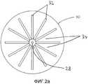
В примере согласно фиг.2а опорная поверхность 10 имеет множество ориентированных в радиальном направлении канавок 32, разделенных в радиальном направлении выступами 34. Радиальные канавки 32 сообщаются друг с другом в центре опорной поверхности 10. Кроме того, в центре опорной поверхности выполнен один выпускной канал 28 для обеспечения возможности прохода напитка через опорную поверхность, например, в контейнер 30, подобный показанному на фиг.1b.In the example of FIG. 2 a, the supporting
В примере согласно фиг.2b опорная поверхность 10 имеет множество ориентированных взаимно ортогонально канавок 32. В данном примеры выступы 34 образованы «островками» между канавками 32. В данном примере «островки» являются, по существу квадратными, хотя возможны другие формы, такие как прямоугольная, круглая, треугольная, удлиненная или каплеобразная. Целесообразно то, что в данном примере выступы 34 образуют приблизительно 25% той части опорной поверхности 10, которая при использовании совпадает с частью площади поверхности третьей стенки 20, перекрывающей второй открытый конец 22. В данном примере третья стенка 20 опирается на выступы 34 на приблизительно 25% той части площади поверхности третьей стенки 20, которая перекрывает второй открытый конец 22. Таким образом, обеспечивается хорошая опора для третьей стенки 20 при условии, что третья стенка не разрывается или не разрушается, когда текучая среда подается в капсулу 2 под давлением.In the example of FIG. 2b, the supporting
В примерах согласно фиг.2а и 2b выступы 34 имеют края, которые не являются острыми. Таким образом, края выступов не будут прорезать третью стенку. В данных примерах радиус кривизны краев составляет приблизительно 50 мкм, хотя возможны и другие радиусы, например, составляющие 100, 200 или 500 мкм.In the examples of FIGS. 2a and 2b, the
В непоказанном варианте выполнения выступы 34 выполнены с выпуклой вершиной. Следовательно, когда третья стенка 20 будет поджиматься к выступам 34, площадь поверхности, на которой выступы 34 будут обеспечивать опору для третьей стенки 20, увеличивается, в результате чего уменьшается локальное давление, действующее на третью стенку 20 со стороны выступов 34. Таким образом существует возможность обеспечения простым образом того, что третья стенка при использовании не будет разрываться и/или разрушаться и будет оставаться неповрежденной. В качестве примера подобных выпуклых выступов, например, может быть предусмотрено то, что «островки», показанные на фиг.2b, будут куполообразными.In a not shown embodiment, the
В данном примере опорная поверхность имеет множество выпускных каналов 28.In this example, the abutment surface has a plurality of
Следует понимать, что возможны альтернативные конфигурации желобчатых канавок 32. К подобным альтернативам относятся концентрические канавки, параллельные канавки, одна или несколько спиральных канавок, комбинации данных и/или показанных канавок и т.д. Кроме того, следует понимать, что в общем случае опорная поверхность 10 может содержать один или множество выпускных каналов 28.It should be understood that alternate configurations of the
Фиг.3а-3d показывают варианты выполнения капсул 2 в соответствии с изобретением.Figa-3d show embodiments of
В варианте выполнения согласно фиг.3а вторая стенка 16 образует одно целое с периферической первой стенкой 14, как на фиг.1а и 1b. Вторая стенка 16 имеет множество входных отверстий 26, выполненных во второй стенке 16. Третья стенка 20 образована из гибкой пленки 36, выполненной с множеством выходных отверстий 38. Показанная на фиг.3а капсула 2 содержит выступающую наружу закраину 40 на втором конце 22 периферической первой стенки 14. Третья стенка 20 прикреплена к выступающему наружу ободку 40, например, посредством склеивания, сварки, термосварки или тому подобного. Следовательно, третья стенка может быть прочно прикреплена к закраине. Следует понимать, что существует возможность того, что выступающая наружу закраина 40 будет простираться между верхней частью 8 приемного элемента 6 и опорной поверхностью 10 приемного элемента 6, так что закраина 40 будет зажиматься между верхней частью 8 и опорной поверхностью 10. Следовательно, третья стенка 20 будет прижиматься к закраине 40 при использовании, то есть при приложении давления текучей среды, в результате чего уменьшается риск отделения третьей стенки 20 от закраины 40.In the embodiment of FIG. 3a, the
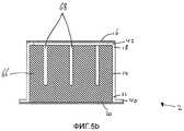
В варианте выполнения согласно фиг.3b третья стенка 20 образована из тканого или нетканого фильтрующего материала, такого как фильтровальная бумага, как на фиг.1а и 1b. В варианте выполнения согласно фиг.3b вторая стенка 16 также образована из гибкого пористого листа, такого как фильтровальная бумага. В данном примере вторая стенка 16 прикреплена к выступающей внутрь закраине 42. В данном примере вторая стенка 16 прикреплена к внутренней стороне выступающей внутрь закраине 42.In the embodiment of FIG. 3b, the
В варианте выполнения согласно фиг.3с третья стенка 20 образована из тканого или нетканого фильтрующего материала, такого как фильтровальная бумага, как на фиг.1а, 1b и 3b. В варианте выполнения согласно фиг.3с вторая стенка 16 также образована из пористого листа, такого как фильтровальная бумага. В данном примере вторая стенка 16 прикреплена к наружной стороне выступающего внутрь ободка 42. Следовательно, уменьшается риск того, что текучая среда под давлением будет вызывать отрыв второй стенки 16 от выступающей внутрь закраины 42. Существует возможность того, что вторая стенка 16 будет свешиваться с периферического края капсулы 2. Следовательно, будет обеспечиваться большая площадь поверхности для прикрепления второй стенки 16 к выступающей внутрь закраине 42 и периферической первой стенке 14, в результате чего будет получено более прочное соединение.In the embodiment of FIG. 3c, the
В варианте выполнения согласно фиг.3d третья стенка 20 выполнена с множеством выходных отверстий 30, как на фиг.3а. В варианте выполнения согласно фиг.3d вторая стенка 16 также образована из пленки 44, выполненной с множеством входных отверстий 26.In the embodiment according to fig.3d, the
Во всех вариантах выполнения согласно фиг.3а-3d третья стенка 20 образована из тканого или нетканого фильтрующего материала, такого как фильтровальная бумага. Более точно, во всех вариантах выполнения согласно фиг.3а-3d вся третья стенка 20 образована только из тканого или нетканого фильтрующего материала, такого как фильтровальная бумага. Было установлено, что, как правило, никакого поддерживающего конструктивного элемента, такого как, по существу, жесткая сетка, например, расположенного по ходу потока за третьей стенкой, не требуется для обеспечения опоры для третьей стенки 20 с целью предотвращения разрыва и/или разрушения третьей стенки, поскольку капсула расположена так, что третья стенка 20 опирается на опорную поверхность 10 приемного гнезда 6 устройства 4, предусмотренного в системе 1. Будет очевидно, что все варианты выполнения капсулы 2, показанные на фиг.3а-3d, могут быть использованы в сочетании с опорной поверхностью 10, имеющей желобчатые канавки 32. Следует понимать, что в результате простых испытаний будут определены параметры третьей стенки, такие как материал, толщина, наличие выходных отверстий, размер выходных отверстий, число выходных отверстий и т.д., которые обеспечат то, что третья стенка 20 капсулы 2 будет иметь достаточно высокую прочность на разрыв и/или будет создавать достаточно низкое сопротивление потоку, так что третья стенка при использовании не будет разрываться и/или разрушаться и будет оставаться неповрежденной.In all the embodiments of FIGS. 3a-3d, the
Во всех вариантах выполнения согласно фиг.3b-3d вторая стенка 16 образована из гибкого листообразного материала. Более точно, во всех вариантах выполнения согласно фиг.3b-3d вторая стенка образована только из гибкого листообразного материала. Было установлено, что, как правило, никакого опорного конструктивного элемента, такого как, по существу, жесткая сетка, например, расположенная по ходу потока за второй стенкой, не требуется для обеспечения опоры для второй стенки с целью предотвращения разрыва и/или разрушения второй стенки 16.In all embodiments of FIGS. 3b-3d, the
Во всех вариантах выполнения согласно фиг.3а-3d третья стенка образует самую дальнюю от центра границу капсулы в ее аксиальном направлении.In all the embodiments according to figa-3d, the third wall forms the capsule boundary farthest from the center in its axial direction.
Следует понимать, что капсула 2 может иметь любую вторую стенку 16 в соответствии с любым из показанных вариантов выполнения в сочетании с любой третьей стенкой 20 в соответствии с любым из показанных вариантов выполнения.It should be understood that the
На фиг.3а-3d (и 4а, 5а и 5b) закраина рядом со вторым концом 22 выступает наружу. Следует понимать, что в альтернативном варианте или в качестве дополнения капсула 2 может содержать закраину, выступающую внутрь рядом со вторым концом 22 и предназначенную для прикрепления третьей стенки 20 к ней. На фиг.3b-3d (и 5а и 5b) закраина рядом с первым концом 18 выступает внутрь. Следует понимать, что в альтернативном варианте или в качестве дополнения капсула 2 может содержать закраину, выступающую наружу рядом с первым концом 18 и предназначенную для прикрепления второй стенки 16 к нему.On figa-3d (and 4A, 5A and 5b) the flange near the
Как правило, выходные отверстия 38 листа или поры пористого листа выполнены с такими размерами, что размер отверстия 38 или поры будет достаточно мал для удерживания экстрагируемого продукта, такого как молотый кофе, внутри капсулы 2. Кроме того, как правило, входные отверстия 26 второй стенки или поры пористого листа выполнены с такими размерами, что размер отверстия 26 или поры будет достаточно мал для удерживания экстрагируемого продукта, такого как молотый кофе, внутри капсулы 2.Typically, the
В общем случае входные отверстия 26 предпочтительно распределены, по существу, по всей поверхности второй стенки 16, по меньшей мере, по существу, по всей поверхности отверстия, ограниченного выступающей внутрь закраиной 42. В качестве опции, входные отверстия 26 также имеются в периферической первой стенке 14, например, в той части окружной периферической первой стенки 14, которая находится рядом с первым концом 18. Это создает возможность равномерной подачи текучей среды в экстрагируемый продукт, находящийся внутри капсулы 2.In general, the
В общем случае выходные отверстия 38 предпочтительно распределены, по существу, по всей поверхности третьей стенки, по меньшей мере, по существу, по всей поверхности отверстия, ограниченного выступающей наружу закраиной 40. Это создает возможность равномерного отвода напитка из экстрагируемого продукта, находящегося внутри капсулы 2.In general, the
В примерах согласно фиг.1а, 1b и 3а-3d входные отверстия 26 и выходные отверстия 38 имеют круглое поперечное сечение. Отверстия 26, 38 с круглым поперечным сечением легко образовать при изготовлении. В качестве опции поперечное сечение входных отверстий 26 постепенно сужается по направлению к внутреннему пространству 24. Это обеспечивает преимущество, заключающееся в том, что входные отверстия будут функционировать, как сопла, которые обеспечивают вход струи текучей среды во внутреннее пространство 24.In the examples of FIGS. 1a, 1b and 3a-3d, the
Следует понимать, что входные отверстия 26 и/или выходные отверстия 38 также могут иметь альтернативные формы. Отверстия 26, 38, например, могут иметь форму удлиненных прорезей. Малый размер прорезей предпочтительно будет достаточно малым для удерживания экстрагируемого продукта внутри капсулы 2.It should be understood that the
В конкретном варианте выполнения прорези могут иметь форму, которая образует язычок в плоскости второй стенки 16. В этом случае прорези могут быть, по существу, U-образными, такими как полукруглые, подковообразными, прямоугольными или V-образными. Это имеет преимущество, заключающееся в том, что язычок может отгибаться наружу от плоскости второй стенки 16 под действием потока текучей среды, проходящего через отверстие, образуемое язычком. Таким образом, может быть обеспечен поток текучей среды с большим объемом. Если вторая стенка выполнена из упругого материала, язычок будет сгибаться назад в направлении плоскости второй стенки, как только поток текучей среды прекратится, в результате чего предотвращается рассыпание экстрагируемого продукта (перед приготовлением напитка и) после приготовления напитка.In a particular embodiment, the slots may have a shape that forms a tongue in the plane of the
Фиг.4а показывает пример дополнительного варианта выполнения капсулы 2 в соответствии с изобретением. Фиг.4а показывает модификацию капсулы, показанной на фиг.3а. Следует понимать, что данная модификация может быть применена для любой капсулы 2, упомянутой выше. В примере согласно фиг.4а капсула 2 дополнительно содержит донный герметизирующий элемент 46. Донный герметизирующий элемент 46 закрывает входные отверстия 26 (или пористый лист) перед использованием. Донный герметизирующий элемент 46 присоединен ко второй стенке 16 с возможностью его по меньшей мере частичного отделения. В данном примере донный герметизирующий элемент 46 содержит выступ 48 для обеспечения возможности легкого удаления/отделения донного герметизирующего элемента 46 пользователем капсулы 2. Показанная на фиг.4а капсула 2 дополнительно содержит крышечный герметизирующий элемент 50. Крышечный герметизирующий элемент 50 закрывает выходные отверстия 38 (или пористый лист) перед использованием. Крышечный герметизирующий элемент 50 присоединен к третьей стенке 20 с возможностью его по меньшей мере частичного отделения. В данном примере крышечный герметизирующий элемент 50 содержит выступ 52 для обеспечения возможности легкого удаления/отделения крышечного герметизирующего элемента 50 пользователем капсулы 2. Донный герметизирующий элемент 46 и крышечный герметизирующий элемент 50 обеспечивают увеличение срока годности продукта внутри капсулы при хранении за счет предотвращения поступления воздуха в капсулу через отверстия 26, 38 или пористый лист.4a shows an example of a further embodiment of a
В конкретном варианте выполнения (непоказанном) выступ 48 донного герметизирующего элемента 46 соединен с выступом 52 крышечного герметизирующего элемента 50. Таким образом, донный герметизирующий элемент 46 и крышечный герметизирующий элемент 50 могут быть выполнены как одно целое. Следовательно, может быть предотвращена ситуация, при которой пользователь случайно забудет удалить один из донного герметизирующего элемента и крышечного герметизирующего элемента.In a specific embodiment (not shown), the protrusion 48 of the
Фиг.4b и 4с показывают пример вида в плане дополнительного варианта выполнения капсулы 2, если смотреть со стороны третьей стенки. В варианте выполнения согласно фиг.4b и 4с капсула содержит крышечный герметизирующий элемент 50. Крышечный герметизирующий элемент 50 присоединен к третьей стенке 20 посредством разъединяемого герметичного соединения 54. В данном примере разъединяемое герметичное соединение образует окружное периферийное герметичное соединение рядом с периферическим краем третьей стенки 20. Разъединяемое герметичное соединение 54 выполнено с возможностью отделения от третьей стенки 20 под действием давления текучей среды во внутреннем пространстве 24. Разъединяемое герметичное соединение может представлять собой, например, расслаиваемое соединение с заданным сопротивлением разделению. Следовательно, не требуется, чтобы пользователь снимал крышечный герметизирующий элемент 50 с капсулы 2, поскольку герметичное соединение разъединяется автоматически во время приготовления напитка.Figures 4b and 4c show an example of a plan view of an additional embodiment of
В варианте выполнения согласно фиг.4b и 4с крышечный герметизирующий элемент 50 дополнительно прикреплен к третьей стенке 20 посредством постоянного соединения 56. Постоянное соединение может представлять собой, например, клеевое или сварное соединение. На фиг.4b постоянное соединение расположено рядом с центром третьей стенки 20. На фиг.4с постоянное соединение 56 расположено рядом с окружным периферийным краем третьей стенки 20. Это обеспечивает преимущество, заключающееся в том, что разъединяемое герметичное соединение может быть разъединено под действием давления для обеспечения возможности выпуска напитка из капсулы в то время, как крышечный герметизирующий элемент 50 будет оставаться присоединенным к третьей стенке 20 по меньшей мере в одном месте. Следовательно, отсутствует необходимость в удалении крышечного герметизирующего элемента 50 отдельно, что делает использование более простым, и крышечный герметизирующий элемент 50 не может быть утерян.In the embodiment of FIGS. 4b and 4c, the
Следует понимать, что вместо прикрепления к третьей стенке 20 или в дополнение к прикреплению к третьей стенке 20 крышечный герметизирующий элемент 50 может быть также при креплен к закраине, расположенному рядом со вторым концом 22, и/или к периферической первой стенке.It should be understood that instead of attaching to the
Следует понимать, что капсула 2 в альтернативном варианте или в качестве дополнения может быть аналогичным образом выполнена с донным герметизирующим элементом 46, например, расположенным с внутренней стороны второй стенки 16, выполненным с возможностью отделения от второй стенки 16 под действием давления текучей среды, подаваемой в капсулу 2, и, если требуется, предусмотренным с по меньшей мере одним постоянным соединением между второй стенкой и донным герметизирующим элементом 46. Следует понимать, что вместо или помимо прикрепления ко второй стенке 16 донный герметизирующий элемент 46 также может быть прикреплен к ободку, расположенному рядом с первым концом 18, и/или к окружной периферической первой стенке.It should be understood that the
Также следует понимать, что крышечный герметизирующий элемент 50 и/или донный герметизирующий элемент 46 также могут быть использованы в сочетании с альтернативными капсулами, в которых третья стенка не образует самой дальней от центра границы капсулы в ее аксиальном направлении, например, с капсулой, имеющей проходящую в аксиальном направлении закраину, выступающую за третью стенку.It should also be understood that the
Периферическая первая стенка 14 предпочтительно является, по существу, жесткой. Следовательно, у капсулы будет отсутствовать склонность к деформированию при транспортировке, погрузочно-разгрузочных операциях и/или манипулировании, так что капсула 2 всегда будет соответствовать приемному гнезду 6. Кроме того, периферическая первая стенка 14 предпочтительно является упругой, так что любая возможная деформация периферической первой стенки будет обратимой, как только усилие, вызывающее деформацию, будет снято. Для повышения жесткости капсулы 2 капсула 2 может содержать придающие жесткость ребра, образующие одно целое с периферической первой стенкой 14. Придающие жесткость ребра могут простираться от первого конца 18 по направлению ко второму концу 22. В альтернативном варианте или в качестве дополнения придающие жесткость ребра могут простираться в направлении вдоль окружности. В том случае, когда вторая стенка 16 образует одно целое с периферической первой стенкой 14, придающие жесткость ребра также могут составлять одно целое со второй стенкой 16.The peripheral
Тем не менее, существует возможность того, что периферическая первая стенка будет образована из гибкого листа, предпочтительно составляющего одно целое со второй стенкой. Следовательно, по существу, вся капсула может быть изготовлена из гибкого листа, что обеспечивает уменьшение количества материала, необходимого для выполнения капсулы. Если требуется, по меньшей мере один из ободков 40, 42 может быть, по существу, жестким для облегчения манипулирования капсулой.However, there is the possibility that the peripheral first wall will be formed from a flexible sheet, preferably integrally with the second wall. Therefore, essentially the entire capsule can be made of a flexible sheet, which provides a reduction in the amount of material needed to make the capsule. If required, at least one of the
В этих примерах периферическая первая стенка является по существу цилиндрической. Следует понимать, что капсула в соответствии с изобретением не ограничена данной формой. Окружная периферическая первая стенка может, например, иметь форму усеченного конуса, может быть полусферической или многоугольной, такой как шестиугольная, восьмиугольная и т.д.In these examples, the peripheral first wall is substantially cylindrical. It should be understood that the capsule in accordance with the invention is not limited to this form. The peripheral peripheral first wall may, for example, have the shape of a truncated cone, may be hemispherical or polygonal, such as hexagonal, octagonal, etc.
В соответствии с дополнительным аспектом изобретения экстрагируемый продукт во внутреннем пространстве 24 уплотнен/спрессован. Фиг.5а показывает пример, в котором экстрагируемый продукт спрессован в множество таблеток 58, 60, 62, 64, в данном примере - четыре таблетки. На фиг.5а показано, что таблетки уложены в стопу во внутреннем пространстве 24. На фиг.5а показано, что каждая таблетка 58, 60, 62, 64 перекрывает по существу все поперечное сечение внутреннего пространства 24 капсулы 2. В данном примере плотность, то есть степень уплотнения таблеток, различается для каждой из таблеток. Плотность таблеток 58, 60, 62, 64 увеличивается в направлении от второй стенки 16 к третьей стенке 20. Это обеспечивает преимущество, заключающееся в том, что текучая среда будет легче смачивать таблетку с меньшей плотностью, чем таблетку с более высокой плотностью, так что каждая расположенная выше по потоку таблетка будет уже надлежащим образом смочена, когда вода будет смачивать последующую расположенную ниже по потоку таблетку. Таким образом, будет обеспечено смачивание экстрагируемого продукта с высокой степенью равномерности. Несмотря на то, что в данном примере показаны четыре уложенные в стопу таблетки, следует понимать, что может быть использовано любое число таблеток. В усовершенствованном варианте выполнения существует возможность того, что разделительный лист будет расположен между двумя соседними таблетками. Разделительный лист может быть пористым и/или перфорированным. Разделительный лист может представлять собой, например, пластиковую пленку, выполненную с отверстиями. Разделительный лист также может представлять собой тканый или нетканый фильтрующий материал, такой как лист фильтровальной бумаги.In accordance with a further aspect of the invention, the extractable product in the
Фиг.5b показывает пример капсулы 2, содержащей одну таблетку 66 спрессованного экстрагируемого продукта. В примере согласно фиг.5b таблетка 66 имеет каналы 68, проходящие в таблетку 66 от той стороны таблетки 66, которая обращена ко второй стенке 16, в направлении третьей стенки 20. Длина каналов 68 меньше толщины таблетки 66 в направлении вдоль канала 68. Таким образом каналы 68 не образуют кратчайших сквозных каналов для прохода текучей среды через таблетку 66, а образуют канал для прохода текучей среды в сердцевину таблетки 66. Данные каналы 68 обеспечивают возможность заданного проникновения текучей среды в таблетку. Таким образом, может быть обеспечено предпочтительное смачивание спрессованного экстрагируемого продукта.Fig. 5b shows an example of a
В примерах согласно фиг.5а и 5b вторая стенка 16 и третья стенка 20 капсулы, по существу, такие, как показанные на фиг.3с. Следует понимать, что таблетка 66 или множество таблеток 58, 60, 62, 64 могут быть использованы в сочетании с любой капсулой 2, упомянутой выше. Также следует понимать, что в том случае, если экстрагируемый продукт спрессован в таблетку (-и), необязательно наличие второй стенки 16 капсулы, поскольку отсутствует вероятность рассыпания экстрагируемого продукта из капсулы 2 перед использованием.In the examples of FIGS. 5a and 5b, the
В вышеприведенном описании изобретение было описано со ссылкой на определенные примеры вариантов выполнения изобретения. Тем не менее, очевидно, что в них могут быть выполнены различные модификации и изменения без отхода от рассматриваемых более широко сущности и объема изобретения, определенных в приложенной формуле изобретения.In the above description, the invention has been described with reference to certain examples of embodiments of the invention. However, it is obvious that various modifications and changes can be made in them without departing from the broader essence and scope of the invention defined in the attached claims.
Например, существует возможность того, что капсула 2 будет содержаться в воздухонепроницаемой обертке перед использованием для увеличения срока годности при хранении.For example, there is a possibility that the
Например, существует возможность того, что капсула 2 будет изготовлена из материалов, поддающихся биологическому разложению.For example, it is possible that
В данных примерах третья стенка представляет собой, по существу, однородный пористый и/или перфорированный лист. Также существует возможность того, что пористость не будет однородной и/или распределение перфорационных отверстий не будет равномерным. Например, существует возможность того, что только часть третьей стенки будет пористой. Для этого пористый лист может быть, например, частично закрыт, покрыт или пропитан непористым материалом. Кроме того, существует возможность того, что только часть третьей стенки будет перфорированной. Подобная пористая и/или перфорированная часть может представлять собой, например, центральную часть или кольцеобразную часть третьей стенки. Также существует возможность того, что первая часть третьей стенки будет пористой, в то время как вторая часть третьей стенки будет перфорированной.In these examples, the third wall is a substantially uniform porous and / or perforated sheet. There is also the possibility that the porosity will not be uniform and / or the distribution of the perforations will not be uniform. For example, there is the possibility that only part of the third wall will be porous. For this, the porous sheet may, for example, be partially covered, coated or impregnated with a non-porous material. In addition, there is the possibility that only part of the third wall will be perforated. Such a porous and / or perforated portion may be, for example, a central portion or an annular portion of a third wall. There is also the possibility that the first part of the third wall will be porous, while the second part of the third wall will be perforated.
В данных примерах вторая стенка является пористой, по существу, с однородной пористостью и/или по существу равномерно перфорированной. Также существует возможность того, что пористость не будет однородной и/или распределение перфорационных отверстий не будет равномерным. Например, существует возможность того, что только часть второй стенки будет пористой. Для этого пористый материал может быть, например, частично закрыт, покрыт или пропитан непористым материалом. Кроме того, существует возможность того, что только часть второй стенки будет перфорированной. Подобная пористая и/или перфорированная часть может представлять собой, например, центральную часть или кольцеобразную часть второй стенки. Также существует возможность того, что первая часть второй стенки будет пористой, в то время как вторая часть второй стенки будет перфорированной.In these examples, the second wall is porous, with substantially uniform porosity and / or substantially uniformly perforated. There is also the possibility that the porosity will not be uniform and / or the distribution of the perforations will not be uniform. For example, it is possible that only part of the second wall will be porous. For this, the porous material may, for example, be partially covered, coated or impregnated with a non-porous material. In addition, there is the possibility that only part of the second wall will be perforated. Such a porous and / or perforated portion may be, for example, a central portion or an annular portion of a second wall. There is also the possibility that the first part of the second wall will be porous, while the second part of the second wall will be perforated.
В качестве примеров целесообразных вариантов выполнения капсул в соответствии с изобретением можно рассмотреть подобные капсулы с нижеуказанными характеристиками. Периферическая первая стенка может иметь, по существу, форму усеченного конуса со следующими размерами: длиной в аксиальном направлении, составляющей приблизительно 24 миллиметра, наружным диаметром на первом конце, составляющим приблизительно 25 миллиметров, и наружным диаметром на втором конце, составляющим приблизительно 30 миллиметров. Независимо от того, применяется ли подобная форма усеченного конуса или нет, одна из окружной периферической первой стенки и второй стенки или как окружная периферическая первая стенка, так и вторая стенка могут быть выполнены из полипропилена и могут иметь толщину стенки, за исключением локальных изменений, таких как в зоне ребер, составляющую от 0,5 до 0,9 миллиметра, предпочтительно от 0,65 до 0,75 миллиметра, более предпочтительно 0,7 миллиметра. В этом случае вторая стенка может составлять одно целое с периферической первой стенкой.As examples of suitable capsule embodiments in accordance with the invention, similar capsules with the following characteristics may be considered. The peripheral first wall may have a substantially truncated cone shape with the following dimensions: an axial length of approximately 24 millimeters, an outer diameter at the first end of approximately 25 millimeters, and an outer diameter at the second end of approximately 30 millimeters. Regardless of whether a similar shape of the truncated cone is used or not, one of the peripheral peripheral first wall and the second wall or both the peripheral peripheral first wall and the second wall can be made of polypropylene and can have a wall thickness, except for local changes, such as in the area of the ribs, comprising from 0.5 to 0.9 millimeters, preferably from 0.65 to 0.75 millimeters, more preferably 0.7 millimeters. In this case, the second wall may be integral with the peripheral first wall.
Тем не менее, другие модификации, варианты и альтернативы также возможны. Соответственно, описания, чертежи и примеры следует рассматривать в иллюстративном, а не в ограничивающем смысле. В формуле изобретения любые ссылочные позиции, указанные в скобках, не следует рассматривать как ограничивающие формулу изобретения. Термин «содержащий» не исключает наличия других признаков/элементов или этапов, отличающихся от тех, которые перечислены в формуле изобретения. Кроме того, слова в единственном числе не следует рассматривать как ограниченные значением «только один», но вместо этого они используются в значении «по меньшей мере один» и не исключают множества. Сам факт того, что определенные меры приведены в отличающихся друг от друга пунктах формулы изобретения, не означает того, что комбинация данных мер не может быть использована наилучшим образом.However, other modifications, variations and alternatives are also possible. Accordingly, descriptions, drawings and examples should be considered in an illustrative and not in a limiting sense. In the claims, any reference numbers indicated in parentheses should not be construed as limiting the claims. The term “comprising” does not exclude the presence of other features / elements or steps that are different from those listed in the claims. In addition, singular words should not be construed as being limited to “only one,” but instead they are used in the meaning of “at least one” and do not exclude plurals. The fact that certain measures are given in claims that differ from each other does not mean that a combination of these measures cannot be used in the best way.
Claims (37)
Translated fromRussianсменную капсулу и
устройство, содержащее приемное гнездо, предназначенное для удерживания сменной капсулы в контактном взаимодействии с опорной поверхностью, и устройство для выдачи текучей среды, предназначенное для подачи некоторого количества текучей среды под давлением, составляющим по меньшей мере шесть бар, в сменную капсулу,
при этом сменная капсула содержит
периферическую первую стенку;
вторую стенку, закрывающую периферическую первую стенку на первом конце; и
гибкую листообразную перфорированную и/или пористую третью стенку, закрывающую периферическую первую стенку на втором открытом конце, противоположном по отношению ко второй стенке,
причем
первая, вторая и третья стенки ограничивают внутреннее пространство, в котором содержится экстрагируемый продукт, и
третья стенка образует самую дальнюю границу капсулы в ее аксиальном направлении и содержит одно из фильтровальной бумаги и тканого или нетканого фильтрующего материала,
при этом опорная поверхность содержит желобчатые канавки на стороне, обращенной к третьей стенке для выпуска приготовленного напитка из капсулы через канавки, а также содержит между желобчатыми канавками выступы, на которые третья стенка при использовании опирается, и
третья стенка снабжена множеством выходных отверстий для выпуска, при использовании, приготовленного напитка из капсулы,
при этом параметры третьей стенки, такие как плотность, толщина, содержание полиэтилена, присутствие выходных отверстий, число выходных отверстий, размер и форма выходных отверстий, выбираются для обеспечения, чтобы третья стенка имела по меньшей мере одно из достаточно высокой прочности на разрыв и достаточно низкого сопротивления потоку, так чтобы третья стенка при использовании оставалась неповрежденной и не разрывалась, не разрушалась и/или не прилипала к контактной поверхности.1. A system for preparing a predetermined quantity of a drink suitable for consumption by using an extractable product, comprising
replaceable capsule and
a device containing a receptacle for holding the removable capsule in contact with the abutment surface, and a fluid dispensing device for supplying a quantity of fluid under pressure of at least six bar to the removable capsule,
wherein the replaceable capsule contains
peripheral first wall;
a second wall covering the peripheral first wall at the first end; and
a flexible sheet-like perforated and / or porous third wall covering the peripheral first wall at the second open end opposite to the second wall,
moreover
the first, second, and third walls define an interior space in which the product to be extracted is contained, and
the third wall forms the farthest border of the capsule in its axial direction and contains one of filter paper and a woven or non-woven filter material,
the supporting surface comprises grooved grooves on the side facing the third wall for discharging the prepared beverage from the capsule through the grooves, and also comprises protrusions between the grooved grooves on which the third wall rests in use, and
the third wall is provided with a plurality of outlet openings for using, in use, the prepared beverage from the capsule,
the parameters of the third wall, such as density, thickness, polyethylene content, the presence of outlet openings, the number of outlet openings, the size and shape of the outlet openings, are selected to ensure that the third wall has at least one of a sufficiently high tensile strength and sufficiently low resistance to flow, so that the third wall during use remains intact and does not burst, does not collapse and / or does not adhere to the contact surface.
гибким пористым листом, таким как лист фильтровальной бумаги,
гибкой пленкой, такой как полимерная пленка, выполненной с множеством входных отверстий, или
вторая стенка является в основном жесткой и содержит множество входных отверстий.14. The system of claim 1, wherein the second wall is formed
a flexible porous sheet, such as a filter paper sheet,
a flexible film, such as a polymer film made with many inlets, or
the second wall is basically rigid and contains many inlets.
обеспечение сменной капсулы, содержащей периферическую первую стенку, вторую стенку, закрывающую периферическую первую стенку на первом конце, и гибкую листообразную перфорированную и/или пористую третью стенку, закрывающую периферическую первую стенку на втором открытом конце, противоположном по отношению ко второй стенке, при этом первая, вторая и третья стенки ограничивают внутреннее пространство, в котором содержится экстрагируемый продукт, причем третья стенка образует самую дальнюю от центра границу капсулы в ее аксиальном направлении, содержит фильтровальную бумагу или нетканый фильтрующий материал и снабжена множеством выходных отверстий;
обеспечение устройства, содержащего приемное гнездо, предназначенное для удерживания сменной капсулы, устройство для выдачи текучей среды, предназначенное для подачи некоторого количества текучей среды, такой как вода, под давлением, составляющим по меньшей мере шесть бар, в сменную капсулу, и выпускной канал, который при использовании сообщается по текучей среде с капсулой для выпуска приготовленного напитка из капсулы и подачи напитка в контейнер, такой как чашка;
размещение сменной капсулы так, чтобы ее третья стенка находилась в контакте с опорной поверхностью приемного элемента;
подачу текучей среды под давлением в экстрагируемый продукт для приготовления напитка и
выбор параметров третьей стенки, таких как плотность, толщина, содержание полиэтилена, присутствие выходных отверстий, число выходных отверстий, размер и форма выходных отверстий, для обеспечения, чтобы третья стенка имела по меньшей мере одно из достаточно высокой прочности на разрыв и достаточно низкого сопротивления потоку, так чтобы третья стенка при использовании оставалась неповрежденной и не разрывалась, не разрушалась и/или не прилипала к контактной поверхности.35. A method of preparing a predetermined quantity of a drink suitable for consumption by using an extractable product, comprising
providing a replaceable capsule comprising a peripheral first wall, a second wall covering a peripheral first wall at a first end, and a flexible sheet-like perforated and / or porous third wall covering a peripheral first wall at a second open end opposite to the second wall, wherein the first , the second and third walls limit the internal space in which the extracted product is contained, and the third wall forms the capsule boundary furthest from the center in its axial ION comprises a filter paper or non-woven filter material and is provided with a plurality of outlet openings;
providing a device comprising a receptacle for holding a removable capsule; a fluid dispensing device for supplying a quantity of a fluid, such as water, at a pressure of at least six bar, to the replaceable capsule, and an outlet that when used, is in fluid communication with the capsule to release the prepared beverage from the capsule and dispense the beverage into a container such as a cup;
placing a removable capsule so that its third wall is in contact with the supporting surface of the receiving element;
supplying fluid under pressure to an extractable product for preparing a beverage; and
selection of parameters of the third wall, such as density, thickness, polyethylene content, presence of outlet openings, number of outlet openings, size and shape of outlet openings, to ensure that the third wall has at least one of a sufficiently high tensile strength and a sufficiently low flow resistance so that the third wall during use remains intact and does not tear, does not collapse and / or does not adhere to the contact surface.
приемное гнездо содержит средство прокалывания второй стенки, предназначенное для прокалывания второй стенки альтернативной капсулы для образования по меньшей мере одного входного отверстия для подачи текучей среды в экстрагируемый продукт через указанное по меньшей мере одно входное отверстие; и
вторая стенка капсулы содержит входной фильтр, предназначенный для подачи через него текучей среды в экстрагируемый продукт, при этом указанный входной фильтр при использовании расположен на некотором расстоянии от средства прокалывания дна, так что капсула системы не прокалывается средством прокалывания второй стенки и вторая стенка остается неповрежденной.37. The method according to p. 36, in which
the receptacle comprises a second wall puncturing means for piercing the second wall of the alternative capsule to form at least one inlet for supplying fluid to the product to be extracted through the at least one inlet; and
the second wall of the capsule contains an inlet filter designed to supply fluid through it to the product to be extracted, while the specified inlet filter is used at a certain distance from the bottom piercing means, so that the capsule of the system is not pierced by the piercing means of the second wall and the second wall remains intact.
Applications Claiming Priority (9)
| Application Number | Priority Date | Filing Date | Title |
|---|---|---|---|
| EP09162984.0 | 2009-06-17 | ||
| EP09162927 | 2009-06-17 | ||
| EP09162941.0 | 2009-06-17 | ||
| EP09162927.9 | 2009-06-17 | ||
| EP09162941 | 2009-06-17 | ||
| EP09162917.0 | 2009-06-17 | ||
| EP09162917 | 2009-06-17 | ||
| EP09162984 | 2009-06-17 | ||
| PCT/NL2009/050828WO2010137958A1 (en) | 2009-06-17 | 2009-12-30 | Capsule, system and method for preparing a beverage |
Related Child Applications (1)
| Application Number | Title | Priority Date | Filing Date |
|---|---|---|---|
| RU2015139266ADivisionRU2689877C2 (en) | 2009-06-17 | 2009-12-30 | Capsule, beverage preparation system and method |
Publications (2)
| Publication Number | Publication Date |
|---|---|
| RU2012101435A RU2012101435A (en) | 2013-07-27 |
| RU2566317C2true RU2566317C2 (en) | 2015-10-20 |
Family
ID=41647206
Family Applications (7)
| Application Number | Title | Priority Date | Filing Date |
|---|---|---|---|
| RU2012101455/12ARU2568860C2 (en) | 2009-06-17 | 2009-12-30 | System, method and capsule for preparing beverage |
| RU2012101435/12ARU2566317C2 (en) | 2009-06-17 | 2009-12-30 | Capsule, system and method for beverage preparation |
| RU2012101447/12ARU2601936C2 (en) | 2009-06-17 | 2009-12-30 | Capsule, system, and method for beverage preparation, and method for making said capsules |
| RU2012101438/12ARU2604440C2 (en) | 2009-06-17 | 2009-12-30 | Capsule, system, and method for beverage preparation, and method for making said capsules |
| RU2015139266ARU2689877C2 (en) | 2009-06-17 | 2009-12-30 | Capsule, beverage preparation system and method |
| RU2012101458/12ARU2526212C2 (en) | 2009-06-17 | 2009-12-30 | System, method and capsule for beverage preparation |
| RU2012101437/12ARU2536397C2 (en) | 2009-06-17 | 2009-12-30 | System, method and capsule for beverage preparation |
Family Applications Before (1)
| Application Number | Title | Priority Date | Filing Date |
|---|---|---|---|
| RU2012101455/12ARU2568860C2 (en) | 2009-06-17 | 2009-12-30 | System, method and capsule for preparing beverage |
Family Applications After (5)
| Application Number | Title | Priority Date | Filing Date |
|---|---|---|---|
| RU2012101447/12ARU2601936C2 (en) | 2009-06-17 | 2009-12-30 | Capsule, system, and method for beverage preparation, and method for making said capsules |
| RU2012101438/12ARU2604440C2 (en) | 2009-06-17 | 2009-12-30 | Capsule, system, and method for beverage preparation, and method for making said capsules |
| RU2015139266ARU2689877C2 (en) | 2009-06-17 | 2009-12-30 | Capsule, beverage preparation system and method |
| RU2012101458/12ARU2526212C2 (en) | 2009-06-17 | 2009-12-30 | System, method and capsule for beverage preparation |
| RU2012101437/12ARU2536397C2 (en) | 2009-06-17 | 2009-12-30 | System, method and capsule for beverage preparation |
Country Status (23)
| Country | Link |
|---|---|
| US (10) | US9604776B2 (en) |
| EP (8) | EP2865613B1 (en) |
| JP (7) | JP5567667B2 (en) |
| KR (6) | KR102171931B1 (en) |
| CN (8) | CN102574634B (en) |
| AU (7) | AU2009347090B2 (en) |
| BR (7) | BRPI0925329B1 (en) |
| CA (6) | CA2765468A1 (en) |
| CY (1) | CY1116909T1 (en) |
| DE (1) | DE202009018817U1 (en) |
| DK (7) | DK2442699T3 (en) |
| ES (7) | ES2877152T3 (en) |
| HR (1) | HRP20121059T1 (en) |
| IL (3) | IL217023A (en) |
| MX (4) | MX382200B (en) |
| PL (7) | PL2361030T3 (en) |
| PT (4) | PT2310301E (en) |
| RS (1) | RS52628B (en) |
| RU (7) | RU2568860C2 (en) |
| SG (3) | SG176853A1 (en) |
| SI (1) | SI2367741T1 (en) |
| SM (1) | SMT201300029B (en) |
| WO (6) | WO2010137965A1 (en) |
Cited By (1)
| Publication number | Priority date | Publication date | Assignee | Title |
|---|---|---|---|---|
| RU2790623C1 (en)* | 2022-02-21 | 2023-02-28 | Акционерное Общество "Астрата" | Combined coffee maker |
Families Citing this family (133)
| Publication number | Priority date | Publication date | Assignee | Title |
|---|---|---|---|---|
| US10865039B2 (en)* | 2010-12-04 | 2020-12-15 | Adrian Rivera | Single serving brewing material holder |
| US11832755B2 (en) | 2007-07-13 | 2023-12-05 | Adrian Rivera | Brewing material container for a beverage brewer |
| US12396588B2 (en) | 2007-07-13 | 2025-08-26 | Adrian Rivera Maynez Enterprises, Inc. | Brewing material container for a beverage brewer |
| US12342955B2 (en) | 2020-10-30 | 2025-07-01 | Adrian Rivera Maynez Enterprises, Inc. | Brewing material container for a beverage brewer |
| US11337543B2 (en) | 2007-07-13 | 2022-05-24 | Adrian Rivera | Brewing material holder |
| US10722066B2 (en) | 2010-12-04 | 2020-07-28 | Adrian Rivera | Windowed single serving brewing material holder |
| EP2865613B1 (en)* | 2009-06-17 | 2017-09-06 | Koninklijke Douwe Egberts B.V. | System, method and capsule for preparing a beverage |
| US10071851B2 (en) | 2010-07-12 | 2018-09-11 | Robert Bao Vu | Apparatus and products for producing beverages, and methods for making and using same |
| SMT201900157T1 (en) | 2010-07-22 | 2019-05-10 | K Fee System Gmbh | Portion capsule having an identifier |
| BR112013011242A2 (en)* | 2010-11-11 | 2016-11-01 | Nestec S A Ch | capsule, beverage production machine and system for preparing a nutritional product |
| US8950315B2 (en)* | 2010-11-15 | 2015-02-10 | Conair Corporation | Brewed beverage appliance and method |
| US20220007877A1 (en)* | 2010-12-04 | 2022-01-13 | Adrian Rivera | Beverage Brewing Material Filter Cup |
| GB2488799A (en)* | 2011-03-08 | 2012-09-12 | Kraft Foods R & D Inc | Drinks Pod without Piercing of Outer Shell |
| USD694620S1 (en) | 2011-03-08 | 2013-12-03 | Kraft Foods R&D, Inc. | Beverage cartridge |
| GB2489409B (en) | 2011-03-23 | 2013-05-15 | Kraft Foods R & D Inc | A capsule and a system for, and a method of, preparing a beverage |
| PT105599B (en)* | 2011-03-30 | 2020-03-30 | Novadelta Comercio E Ind De Cafes Lda | CAPSULE INCLUDING THE PERFORMANCE ELEMENT, METHOD AND PROCESSING DEVICE OF THIS CAPSULE |
| US8707855B2 (en) | 2011-05-09 | 2014-04-29 | Eko Brands, Llc | Beverage Brewing Device |
| GB2493211B (en)* | 2011-07-29 | 2014-01-22 | Kraft Foods R & D Inc | A method and a system for making a beverage, and a beverage cartridge |
| US9428328B2 (en) | 2011-09-01 | 2016-08-30 | 2266170 Ontario Inc. | Beverage capsule |
| ITMI20111847A1 (en) | 2011-10-10 | 2013-04-11 | Goglio Spa | CARTRIDGE FOR COFFEE AND SOLUBLE PRODUCTS IN GENERAL |
| DE102011115833A1 (en)* | 2011-10-13 | 2013-04-18 | K-Fee System Gmbh | Portion capsule for making a drink with a portion capsule |
| ITVR20120121A1 (en)* | 2012-06-08 | 2013-12-09 | Coffee Star S A | CAPSULE FOR THE PREPARATION OF DRINKS |
| DE102012105282A1 (en)* | 2012-06-18 | 2013-12-19 | K-Fee System Gmbh | Portion capsule and method of making a beverage with a portion capsule |
| KR102075814B1 (en)* | 2012-06-22 | 2020-02-10 | 터치 커피 & 베버리지스, 엘엘씨. | Beverage brewing system |
| ITVR20120133A1 (en)* | 2012-07-03 | 2014-01-04 | Coffee Star S A | CAPSULE FOR THE PREPARATION OF DRINKS |
| RU2650060C2 (en)* | 2012-07-16 | 2018-04-06 | Туттоэспрессо С.Р.Л. | Capsule and system for beverage preparation |
| CA2822791C (en) | 2012-08-03 | 2020-03-31 | 1675119 Ontario Inc. | Beverage cartridge with separating elements |
| USD708057S1 (en) | 2012-09-10 | 2014-07-01 | Kraft Foods R & D, Inc. | Beverage cartridge |
| USD697797S1 (en) | 2012-09-12 | 2014-01-21 | Kraft Foods R&D, Inc. | Beverage cartridge |
| EP2730523B1 (en) | 2012-11-12 | 2016-04-06 | 2266170 Ontario, Inc. | Beverage capsule and process and system for making same |
| DE102012111684A1 (en)* | 2012-11-30 | 2014-06-05 | K-Fee System Gmbh | Portion capsule for producing a cream-free coffee beverage |
| DE102012111685A1 (en)* | 2012-11-30 | 2014-06-05 | K-Fee System Gmbh | Portion capsule for making coffee drinks with and without crema |
| AU2013354828A1 (en) | 2012-12-07 | 2015-07-09 | 2266170 Ontario Inc. | Container with removable portion |
| DE102012223291A1 (en) | 2012-12-14 | 2014-06-18 | K-Fee System Gmbh | Portion capsule and method of making a beverage with a portion capsule |
| ITTO20121125A1 (en) | 2012-12-21 | 2014-06-22 | Lavazza Luigi Spa | CARTRIDGE FOR THE PREPARATION OF A LIQUID PRODUCT AND PROCEDURE FOR REALIZING IT |
| ITBS20130005A1 (en)* | 2013-01-22 | 2014-07-23 | Capitani Srl | CAPSULE AND METHOD OF DISPOSAL OF SUCH CAPSULE |
| KR20150116868A (en) | 2013-02-12 | 2015-10-16 | 코닌클리케 도우베 에그베르츠 비.브이. | Capsule, system and method for preparing a beverage |
| EP2961671B1 (en)* | 2013-02-26 | 2017-06-21 | K-fee System GmbH | Portion capsule and method for producing a beverage by means of a portion capsule |
| US9783361B2 (en)* | 2013-03-14 | 2017-10-10 | Starbucks Corporation | Stretchable beverage cartridges and methods |
| CN105246795A (en) | 2013-04-03 | 2016-01-13 | 皇家戴维艾格伯茨有限公司 | Coffee pad with a relatively large outlet opening for use in a coffee machine |
| CA3123615C (en) | 2013-04-03 | 2024-04-16 | Koninklijke Douwe Egberts B.V. | Pad with a relatively large outlet opening comprising a soluble beverage preparation product for use in a coffee machine |
| RU2015146994A (en) | 2013-04-03 | 2017-05-11 | Конинклейке Дауве Егбертс Б.В. | COFFEE LOAD FOR USE IN A COFFEE MACHINE |
| CA2905217C (en) | 2013-04-03 | 2016-11-08 | 2266170 Ontario Inc. | Capsule machine and components |
| PL2981480T3 (en)* | 2013-04-03 | 2019-08-30 | Koninklijke Douwe Egberts B.V. | Pad comprising a soluble beverage preparation product for use in a coffee machine |
| US10154752B2 (en) | 2013-05-23 | 2018-12-18 | 2266170 Ontario Inc. | Capsule housing |
| UA117832C2 (en)* | 2013-05-29 | 2018-10-10 | К-Фее Зюстем Гмбх | PORTION COVER CONTAINING LIQUID DISTRIBUTOR |
| RU2016101192A (en) | 2013-06-18 | 2017-07-19 | Нестек С.А. | CAPSULE FILTER |
| WO2015022191A1 (en)* | 2013-08-14 | 2015-02-19 | Merck Patent Gmbh | High pressure extraction capsule |
| US10611507B2 (en) | 2013-08-20 | 2020-04-07 | 2266170 Ontario Inc. | Capsule with control member |
| US10314319B2 (en)* | 2013-11-20 | 2019-06-11 | 2266170 Ontario Inc. | Method and apparatus for accelerated or controlled degassing of roasted coffee |
| EP3086693B1 (en)* | 2013-12-23 | 2021-02-17 | The Coca-Cola Company | Dispensing ingredients from a beverage cartridge |
| EP3089639B1 (en) | 2014-01-03 | 2018-07-11 | Koninklijke Douwe Egberts B.V. | Exchangeable supply pack for a beverage dispensing machine, doser, pump assembly and method of manufacturing. |
| US9504348B2 (en) | 2014-03-11 | 2016-11-29 | Starbucks Corporation | Cartridge ejection systems and methods for single-serve beverage production machines |
| US20150257586A1 (en)* | 2014-03-11 | 2015-09-17 | Starbucks Corporation Dba Starbucks Coffee Company | Single-serve beverage production machine |
| US9439532B2 (en) | 2014-03-11 | 2016-09-13 | Starbucks Corporation | Beverage production machines with multi-chambered basket units |
| US10442610B2 (en) | 2014-03-11 | 2019-10-15 | Starbucks Corporation | Pod-based restrictors and methods |
| US10336531B2 (en) | 2014-03-21 | 2019-07-02 | 2266170 Ontario Inc. | Capsule with steeping chamber |
| DK3122660T3 (en)* | 2014-03-24 | 2019-10-14 | Nestle Sa | COFFEE COVER AND SYSTEM FOR PREPARING A COFFEE EXTRACT WITH SUCH A COVER |
| US10940986B2 (en)* | 2014-05-07 | 2021-03-09 | Matteo ROSSOMANDO | Biodegradable container or capsule |
| US20170081569A1 (en) | 2014-05-27 | 2017-03-23 | Amcor Flexibles Rorschach Ag | Heat-Sealable Structure for Aluminum Disposable Beverage-Brewing Containers |
| EP3157839B1 (en)* | 2014-06-18 | 2018-10-31 | Luigi Lavazza S.p.A. | Cartridge for preparing a liquid product and method for producing it |
| JP2017531476A (en) | 2014-10-01 | 2017-10-26 | クラフト・フーズ・グループ・ブランズ・エルエルシー | Coffee pod |
| USD757536S1 (en) | 2014-10-01 | 2016-05-31 | Kraft Foods Group Brands Llc | Container |
| RU2017121291A (en)* | 2014-12-16 | 2019-01-17 | Паспарту Каффе' С.Р.Л. | PACKED FOOD PRODUCT AND METHOD FOR PRODUCING PACKED FOOD PRODUCT |
| ITUB201543371U1 (en)* | 2015-05-26 | 2016-11-26 | Marco Verri | PRODUCT TO REALIZE THROUGH INFUSION A RESPECTIVE BEVERAGE. |
| CN104523148A (en)* | 2014-12-18 | 2015-04-22 | 成都快典科技有限公司 | Grinding and brewing device of coffee machine |
| US10543977B2 (en)* | 2014-12-23 | 2020-01-28 | Starbucks Corporation | Pressure regulated beverage cartridges |
| US9877495B2 (en) | 2015-01-09 | 2018-01-30 | Starbucks Corporation | Method of making a sweetened soluble beverage product |
| WO2016135105A1 (en) | 2015-02-27 | 2016-09-01 | K-Fee System Gmbh | Single serve capsule comprising a filter element connected thereto by sealing |
| RU2015111652A (en)* | 2015-03-31 | 2016-10-27 | Чинарбек Орозонович Отунчиев | PORTION CAPSULE FOR BREWING A COFFEE BEVERAGE IN A COFFEE MACHINE, ENRICHED AT LEAST ONE ADDITION |
| ES2743219T3 (en) | 2015-05-15 | 2020-02-18 | Douwe Egberts Bv | A capsule, a system for preparing a drinkable beverage from said capsule and use of said capsule in a beverage preparation device |
| AU2016264690A1 (en) | 2015-05-15 | 2017-12-14 | Koninklijke Douwe Egberts B.V. | A capsule, a system for preparing a potable beverage from such a capsule and use of such a capsule in a beverage preparation device |
| NL2016781B1 (en) | 2015-05-15 | 2016-12-30 | Douwe Egberts Bv | A capsule, a system for preparing a potable beverage from such a capsule and use of such a capsule in a beverage preparation device |
| DK3134332T3 (en) | 2015-05-15 | 2019-08-26 | Douwe Egberts Bv | COVER, SYSTEM FOR PREPARING A DRINKABLE BEVERAGE FROM SUCH A COVER AND USING SUCH A COVER IN A BEVERAGE COOKING DEVICE |
| ES2690990T3 (en) | 2015-05-15 | 2018-11-23 | Koninklijke Douwe Egberts B.V. | A capsule, a system for preparing a drinkable beverage from said capsule and use of said capsule in a beverage preparation device |
| EP3566977B2 (en) | 2015-05-15 | 2025-07-09 | Koninklijke Douwe Egberts B.V. | A capsule, a system for preparing a potable beverage from such a capsule and use of such a capsule in a beverage preparation device |
| PT3307647T (en) | 2015-06-10 | 2019-10-28 | K Fee System Gmbh | Capsule with a three layer fleece |
| US10342377B2 (en) | 2015-06-16 | 2019-07-09 | Starbucks Corporation | Beverage preparation systems with adaptable brew chambers |
| US9968217B2 (en) | 2015-06-16 | 2018-05-15 | Starbucks Corporation | Beverage preparation systems with brew chamber securing mechanisms |
| US10602874B2 (en) | 2015-06-16 | 2020-03-31 | Starbucks Corporation Dba Starbucks Coffee Company | Beverage preparation systems with brew chamber access mechanisms |
| NL2015067B1 (en) | 2015-07-01 | 2017-01-30 | Douwe Egberts Bv | A container for containing a beverage base material, a beverage preparation system including an automatic beverage preparation apparatus and such a container, an automatic beverage preparation apparatus for use in such a beverage preparation system and a method of preparing a beverage using such a beverage preparation system. |
| WO2017006332A1 (en)* | 2015-07-09 | 2017-01-12 | Nofar Gil | Espresso beverage formulation comprising collagen peptides |
| WO2017009369A1 (en) | 2015-07-13 | 2017-01-19 | K-Fee System Gmbh | Filter element having a cut-out |
| ITUB20152539A1 (en)* | 2015-07-28 | 2017-01-28 | Matteo Rossomando | Biodegradable container or capsule. |
| WO2017046352A1 (en) | 2015-09-18 | 2017-03-23 | K-Fee System Gmbh | Adapter for a single serve capsule |
| CN105125407B (en)* | 2015-09-22 | 2019-01-18 | 王爱英 | A kind of decocting container |
| AU2016346005B2 (en) | 2015-10-27 | 2022-05-19 | Koninklijke Douwe Egberts B.V. | Capsule, system and method for preparing a beverage |
| DE102016000406B4 (en) | 2016-01-14 | 2023-06-01 | Smiics Gmbh | Device for preparing baby food |
| US10457431B2 (en)* | 2016-01-25 | 2019-10-29 | Darryl Ingvard Jensen | Coffee pod point of sale fabrication device |
| ITUA20161785A1 (en)* | 2016-03-17 | 2017-09-17 | De Longhi Appliances Srl | DOUBLE WALL FILTER FOR COFFEE MACHINE´ |
| ITUA20161788A1 (en) | 2016-03-17 | 2017-09-17 | De Longhi Appliances Srl | DOUBLE WALL FILTER FOR COFFEE MACHINE 'WITH IMPROVED DELIVERY |
| ITUA20161783A1 (en) | 2016-03-17 | 2017-09-17 | De Longhi Appliances Srl | REMOVABLE FILTER WITH DOUBLE WALL FOR COFFEE MACHINE WITH TIGHTENING ELEMENT |
| FR3050725B1 (en)* | 2016-04-29 | 2019-07-12 | Ahlstrom Corporation | COMPOSTABLE OPERATOR FOR CAPTURING CAPSULE AND CAPSULE OBSTRUCTED BY THE OPERCULE |
| NL2016779B1 (en) | 2016-05-13 | 2017-11-16 | Douwe Egberts Bv | A capsule and a system for preparing a potable beverage from such a capsule |
| NL2016780B1 (en) | 2016-05-13 | 2017-11-16 | Douwe Egberts Bv | A capsule, a system for preparing a potable beverage from such a capsule and use of such a capsule in a beverage preparation device |
| NL2019218B1 (en)* | 2016-08-03 | 2018-07-06 | Douwe Egberts Bv | Capsule, system and use of the system for preparing double beverages like a double espresso, a double lungo and a double ristretto |
| WO2018024587A1 (en) | 2016-08-03 | 2018-02-08 | Nestec S.A. | Capsule for the preparation of a beverage containing pellets |
| KR101876513B1 (en)* | 2016-09-22 | 2018-07-09 | 청호나이스 주식회사 | Capsule Assembly Containing Raw Material for Beverage |
| NL2019254B9 (en) | 2016-10-07 | 2018-09-10 | Douwe Egberts Bv | A capsule, a system for preparing a potable beverage from such a capsule and use of such a capsule in a beverage preparation device |
| NL2017587B1 (en) | 2016-10-07 | 2018-04-16 | Douwe Egberts Bv | Capsule, system and method for preparing a beverage |
| CN106579488A (en)* | 2016-11-24 | 2017-04-26 | 周南 | Coffee roasting machine capable of monitoring roasting degree in real time and monitoring method |
| IT201600122725A1 (en)* | 2016-12-02 | 2018-06-02 | Gruppo Cimbali Spa | Method and machine for dispensing doses of ground coffee |
| GB2558900B (en)* | 2017-01-18 | 2019-06-26 | Coleman Paul | Heating apparatus and method of heating |
| EP3372527A1 (en)* | 2017-03-10 | 2018-09-12 | Delica AG | Capsule for preparing a beverage |
| WO2018169426A1 (en)* | 2017-03-17 | 2018-09-20 | Novadelta - Comércio E Indústria De Cafés, S.A. | Beverage preparation device having a compact structure and method for operating said device |
| EP3398766A1 (en)* | 2017-05-03 | 2018-11-07 | jura-plast GmbH | Cover film for closing of cup type containers |
| CN110769726A (en)* | 2017-05-03 | 2020-02-07 | 雀巢产品有限公司 | Method for preparing tea |
| NL2019253B1 (en) | 2017-07-14 | 2019-01-28 | Douwe Egberts Bv | Assembly of a capsule and a brew chamber, brew chamber, beverage preparation machine, capsule and use of a capsule. |
| NL2019260B1 (en)* | 2017-07-17 | 2019-01-30 | Douwe Egberts Bv | A pad containing roasted and ground coffee for preparing at least a coffee part of a beverage in a beverage preparing device |
| CN107468064A (en)* | 2017-08-17 | 2017-12-15 | 亚月(武汉)智能科技有限公司 | Capsule pouring and boiling device with concentration control function |
| KR101918468B1 (en)* | 2017-10-30 | 2018-11-14 | 이성배 | Multi tea capsule |
| ES2900060T3 (en) | 2017-11-29 | 2022-03-15 | Goglio Spa | One capsule for soluble or extractable products |
| EP3511266A1 (en)* | 2018-01-15 | 2019-07-17 | Axel Nickel | Capsule containing beverage powder and filler, particularly for preparing brewed coffee |
| JP6410383B1 (en)* | 2018-01-19 | 2018-10-24 | 日本紙工株式会社 | Manufacturing method of filter molded products |
| GB2573088B (en)* | 2018-02-09 | 2022-04-06 | Douwe Egberts Bv | Beverage powder and method |
| BR112020015699A2 (en)* | 2018-03-14 | 2020-12-08 | Société des Produits Nestlé S.A. | DRINKING MACHINE WITH A PARTIALLY CLOSED DISPENSING FACE |
| EP3764850A1 (en) | 2018-03-14 | 2021-01-20 | Société des Produits Nestlé S.A. | Beverage machine with a non-homogeneous ingredient extraction configuration |
| CA3094348C (en)* | 2018-04-23 | 2021-06-29 | 2266170 Ontario Inc. | Capsules and other containers with optimized recycling attributes and methods for making same |
| US10881582B2 (en) | 2018-06-11 | 2021-01-05 | Glaxosmithkline Consumer Healthcare Holdings (Us) Llc | Individual dose pack |
| US12227323B2 (en) | 2018-07-27 | 2025-02-18 | Gcs German Capsule Solution Gmbh | Method for producing a portion capsule |
| KR102798249B1 (en)* | 2018-11-01 | 2025-04-18 | 소시에떼 데 프로듀이 네슬레 소시에떼아노님 | Coffee container for making beverages and method of making coffee container |
| US12060219B2 (en) | 2018-12-12 | 2024-08-13 | Societe Des Produits Nestle S.A. | Capsule for food or beverage preparation having a displaceable membrane for engagement with opening means |
| DE202018107372U1 (en)* | 2018-12-21 | 2020-03-24 | Eversys Holding Sa | Device for feeding coffee powder into a brewing chamber of a coffee machine |
| DE202019103392U1 (en)* | 2019-06-17 | 2020-09-18 | Otto Altmann | Filled coffee capsule and coffee machine for brewing the filled coffee capsule |
| AU2020322645A1 (en)* | 2019-07-31 | 2022-01-27 | Société des Produits Nestlé S.A. | Container for beverage preparation |
| EP3788884A1 (en)* | 2019-09-05 | 2021-03-10 | Delica AG | Compostable capsule and production and use thereof |
| WO2021101456A1 (en)* | 2019-11-19 | 2021-05-27 | Vihakapirom Thanit | Reusable capsule for beverage preparation |
| JP7408484B2 (en)* | 2020-05-22 | 2024-01-05 | サーモス株式会社 | beverage extraction machine |
| US11805934B1 (en) | 2020-10-21 | 2023-11-07 | Adrian Rivera | Brewing material lid and container for a beverage brewer |
| US20250098889A1 (en)* | 2020-11-25 | 2025-03-27 | Adrian Rivera | Beverage Brewing Material Filter Cup |
| TW202227339A (en) | 2020-11-27 | 2022-07-16 | 瑞士商雀巢製品股份有限公司 | Capsule and system for preparing a beverage |
| CN119816401A (en) | 2022-09-22 | 2025-04-11 | 雀巢产品有限公司 | Method for obtaining an outlet opening of a capsule |
| USD1040672S1 (en) | 2024-03-19 | 2024-09-03 | Dominic Symons | Dosing scale |
Citations (2)
| Publication number | Priority date | Publication date | Assignee | Title |
|---|---|---|---|---|
| WO2006126104A2 (en)* | 2005-04-14 | 2006-11-30 | Cafe Do Brasil S.P.A. | Machine for preparing beverages from capsule preparations and related interchangeable extraction unit |
| RU2337601C2 (en)* | 2003-01-24 | 2008-11-10 | Крафт Фудз Р Унд Д, Инк. | Cartridge and method for drinks preparation |
Family Cites Families (224)
| Publication number | Priority date | Publication date | Assignee | Title |
|---|---|---|---|---|
| US7490542B2 (en)* | 1920-02-11 | 2009-02-17 | I.T.A.Ca S.R.L. | Cartridge for coffee and soluble products and relative method of producing a beverage and apparatus for extracting a beverage |
| US2005390A (en)* | 1932-12-31 | 1935-06-18 | Celanese Corp | Shuttleless loom and thread measuring and cutting mechanism therefor |
| FR757358A (en)* | 1933-06-22 | 1933-12-26 | Improvement in the filters of steam or water pressure coffee machines | |
| US2292101A (en)* | 1941-04-22 | 1942-08-04 | Brown William Francis | Beverage cartridge |
| US2451195A (en) | 1944-09-19 | 1948-10-12 | William F Brown | Beverage package and apparatus |
| FR1231110A (en) | 1959-04-06 | 1960-09-27 | Perforated box containing coffee powder (ground or in the soluble state) intended to be placed inside individual or collective filters | |
| CH434609A (en)* | 1965-04-13 | 1967-04-30 | Gay Alphonse | Cartridge for the preparation of a drink and use of this cartridge |
| CH458099A (en)* | 1966-02-09 | 1968-06-15 | Mazuranic Jankovic Mladen | Installation for the preparation of a drink |
| US3445237A (en)* | 1966-06-28 | 1969-05-20 | Lester Gidge | Preshaped cartridge for,and method of packaging,percolator ground coffee |
| BE688979A (en)* | 1966-10-27 | 1967-03-31 | ||
| FR1543608A (en)* | 1966-10-27 | 1968-10-25 | charging element for coffee making machine or similar infusion | |
| FR1534274A (en) | 1967-08-11 | 1968-07-26 | Individual filter for storing and preparing drinks | |
| LU57420A1 (en) | 1968-11-02 | 1969-03-04 | ||
| FR2041380A5 (en) | 1969-04-22 | 1971-01-29 | Bourgogne Emboutissage S | |
| CA948388A (en)* | 1970-02-27 | 1974-06-04 | Paul B. Hansen | Pattern bonded continuous filament web |
| GB1364462A (en)* | 1970-10-28 | 1974-08-21 | Telco Group Management Ltd | Cartridge containing devices for use in the making of beverages and cartridges therefor |
| FR2127329A5 (en)* | 1971-03-04 | 1972-10-13 | Mpg Ets | |
| US3844206A (en)* | 1971-11-19 | 1974-10-29 | R Weber | Infusor apparatus |
| DE2258462A1 (en) | 1972-11-27 | 1974-06-12 | Battelle Memorial Institute | TIGHTLY SEALED STORAGE PACKAGE FOR FINELY GRINDED BODIES |
| CH605293A5 (en)* | 1976-12-17 | 1978-09-29 | Nestle Sa | |
| US4254694A (en)* | 1978-06-08 | 1981-03-10 | Ernesto Illy | Coffee machine |
| US4229481A (en)* | 1978-06-16 | 1980-10-21 | Fornari Hector C | Process and means to make aromatic infusions |
| US4321139A (en) | 1980-05-07 | 1982-03-23 | American Home Products Corporation | Filtering unit for biological fluids |
| IT1194662B (en)* | 1980-06-11 | 1988-09-22 | Giuseppe Stefano Piana | MACHINE FOR THE PREPARATION OF ESPRESSO COFFEE, CAPPUCCINO, TEA, BROTH OR OTHER INFUSIONS, AUTOMATICALLY OPERATED, BY A DISPOSABLE FILTER, CONTAINING ONE OR MORE DOSES OF PRODUCTS, INTRODUCED AS A COIN |
| US4417504A (en) | 1981-04-02 | 1983-11-29 | Mitsumoto Coffee Co., Ltd. | Regular coffee set |
| NL8300213A (en)* | 1983-01-20 | 1984-08-16 | Douwe Egberts Tabaksfab | DEVICE FOR PREPARING HOT DRINKS. |
| FR2556323B1 (en) | 1983-12-08 | 1986-10-31 | Munier Rene | DOSE FOR THE PREPARATION OF BEVERAGES, ESPECIALLY EXPRESS COFFEE |
| FI83197C (en)* | 1984-10-23 | 1991-06-10 | Mars G B Ltd | DRYCKPAOSE. |
| KR870000045A (en) | 1985-06-28 | 1987-02-16 | 가다오가 죠지 | Coffee strainer |
| JPH0775590B2 (en)* | 1985-07-12 | 1995-08-16 | ソシエテ デ プロデユイ ネツスル ソシエテ アノニム | Pressurized pouring type coffee extractor |
| DK164632C (en)* | 1985-11-11 | 1992-12-14 | Douwe Egberts Tabaksfab | DISPOSABLE FILTER PATRON |
| DE3623952A1 (en) | 1986-07-16 | 1988-01-28 | Erich H Dipl Ing Woltermann | FILTER FOR PORTIONED BREWING COFFEE OR TEA |
| NL8602863A (en)* | 1986-11-12 | 1988-06-01 | Philips Nv | FILTERING DEVICE. |
| GB8630757D0 (en) | 1986-12-23 | 1987-02-04 | Gen Foods Ltd | Beverage packages |
| FR2617389B1 (en)* | 1987-06-30 | 1991-05-24 | Desaltera | FILTER CARTRIDGE AND MACHINE FOR THE PREPARATION OF AN EXPRESS BEVERAGE |
| CH673082A5 (en)* | 1987-10-01 | 1990-02-15 | Nestle Sa | |
| US4921712A (en)* | 1988-08-19 | 1990-05-01 | Malmquist Neil A | Automatic low volume beverage brewing system |
| BE1002512A6 (en)* | 1988-09-28 | 1991-03-05 | Sas | Coffee design filter. |
| JPH02289207A (en)* | 1989-04-28 | 1990-11-29 | Ajinomoto General Foods Inc | Pressurizing drip drink package |
| DE69015629T2 (en) | 1990-07-27 | 1995-05-04 | Nestle Sa | Process for extracting open coffee capsules, coffee capsule and extraction device for carrying out this method. |
| EP0471094B1 (en)* | 1990-07-27 | 1993-12-01 | Societe Des Produits Nestle S.A. | Insert to be fitted in a cartridge holder |
| ATE93373T1 (en)* | 1990-07-27 | 1993-09-15 | Nestle Sa | METHOD FOR BREWING CLOSED PORTION PACKS AND APPARATUS FOR CARRYING OUT THESE METHOD. |
| US5190653A (en)* | 1990-10-30 | 1993-03-02 | Kraft General Foods, Inc. | Coffee brewer filtration device |
| WO1992007775A1 (en) | 1990-10-31 | 1992-05-14 | Coffea S.A. | Method for preparing a liquid product and device for implementing same |
| US5243164A (en) | 1990-12-14 | 1993-09-07 | Gee Associates | Beverage maker |
| NL9002815A (en)* | 1990-12-19 | 1992-07-16 | Sara Lee De Nv | FILTER CARTRIDGE. |
| EP0512148A1 (en)* | 1991-05-10 | 1992-11-11 | Societe Des Produits Nestle S.A. | Enclosed cartridge for making a beverage |
| US5897899A (en) | 1991-05-08 | 1999-04-27 | Nestec S.A. | Cartridges containing substances for beverage preparation |
| TW199884B (en)* | 1991-05-08 | 1993-02-11 | Sociere Des Produits Nestle S A | |
| EP0512142A1 (en) | 1991-05-08 | 1992-11-11 | Societe Des Produits Nestle S.A. | Method for producing beverages by means of sealed cartridges and apparatus for accomplishing the method |
| AU1505192A (en) | 1991-05-10 | 1992-11-12 | Societe Des Produits Nestle S.A. | Sealed cartridge for the prepartion of a beverage |
| DK0521510T3 (en)* | 1991-07-05 | 1997-05-12 | Nestle Sa | Rigid coffee cartridge and process for making it |
| ES2080196T3 (en)* | 1991-07-05 | 1996-02-01 | Nestle Sa | DEVICE FOR THE EXTRACTION OF CARTRIDGES. |
| ZA924490B (en)* | 1991-07-05 | 1993-03-31 | Nestle Sa | A flexible package with a stiffening element and a process for its production |
| DE4212112A1 (en) | 1992-04-10 | 1993-10-14 | Sandler C H Gmbh | Multi-layer filter material |
| JPH0646815A (en)* | 1992-07-02 | 1994-02-22 | Gureesu Sangyo Kk | Capsule containing material to be extracted |
| KR100295123B1 (en)* | 1992-07-06 | 2001-09-17 | 뷜르 로망 엘. | Sealed flexible bag and its manufacturing method |
| US6068871A (en)* | 1992-07-06 | 2000-05-30 | Nestec S.A. | Beverage preparation from a substance compacted into a cake and contained in a sachet |
| US5840189A (en) | 1992-09-16 | 1998-11-24 | Keurig, Inc. | Beverage filter cartridge |
| US5325765A (en) | 1992-09-16 | 1994-07-05 | Keurig, Inc. | Beverage filter cartridge |
| WO1995001293A1 (en)* | 1993-06-29 | 1995-01-12 | The Procter & Gamble Company | Tea filter pack for automatic brewers |
| FR2709655B1 (en) | 1993-09-06 | 1995-11-24 | Cafes Cie Mediterraneenne | Express coffee machine using ground coffee packaging of the pre-dosed tablet type. |
| UA29495C2 (en)* | 1993-12-20 | 2000-11-15 | Компані Медітерранеенн Де Кафе (С.А.) | Automatic device to make hot drinks by means of brewing |
| CA2123330C (en)* | 1993-12-23 | 2004-08-31 | Ruth Lisa Levy | Ribbed clothlike nonwoven fabric and process for making same |
| DE9403616U1 (en)* | 1994-03-03 | 1995-07-06 | Maxs Ag, Sachseln | Pot-shaped permanent filter insert |
| GB9425032D0 (en)* | 1994-12-09 | 1995-02-08 | Robertson James P | Flavouring |
| EP0844195B1 (en)* | 1996-11-22 | 2001-10-24 | Societe Des Produits Nestle S.A. | Closed container containing a pulverized substance |
| PT891734E (en)* | 1997-07-14 | 2001-01-31 | Nestle Sa | DEVICE FOR THE CONFECTIONING OF BEVERAGES |
| NL1007171C2 (en) | 1997-09-30 | 1999-03-31 | Sara Lee De Nv | Assembly for use in a coffee machine for preparing coffee, holder and pouch of that assembly. |
| USD408679S (en) | 1998-05-14 | 1999-04-27 | Keurig, Inc. | Coffee brewer |
| US20030226792A1 (en) | 1998-11-26 | 2003-12-11 | Filterwerk Mann & Hummel Gmbh | Multilayer filter element |
| DE19854565A1 (en) | 1998-11-26 | 2000-05-31 | Mann & Hummel Filter | Multi-layer filter element |
| US6142063A (en) | 1999-01-19 | 2000-11-07 | Keurig, Inc. | Automated beverage brewing system |
| US6079315A (en) | 1999-01-19 | 2000-06-27 | Keurig, Inc. | Beverage filter cartridge holder |
| US6082247A (en) | 1999-01-19 | 2000-07-04 | Keurig, Inc. | Apparatus for consecutively dispensing an equal volume of liquid |
| JP2000262405A (en)* | 1999-03-18 | 2000-09-26 | Soc Prod Nestle Sa | Sealed cartridge for drink extraction |
| IT1307241B1 (en) | 1999-04-08 | 2001-10-30 | Lavazza Luigi Spa | WASTE DISPOSABLE FOR USE IN A MACHINE FOR THE EXTRACTION AND DISPENSING OF BEVERAGES. |
| JP4376357B2 (en)* | 1999-05-28 | 2009-12-02 | 株式会社クラレ | Sheet material for coffee extraction with biodegradability |
| CA2325978A1 (en)* | 1999-11-16 | 2001-05-16 | Robert Hale | Beverage filter cartridge system |
| US20020039867A1 (en)* | 1999-12-21 | 2002-04-04 | The Procter & Gamble Company | Substance encapsulating laminate web |
| US6607762B2 (en) | 2000-02-18 | 2003-08-19 | Keurig, Incorporated | Disposable single serve beverage filter cartridge |
| US6589577B2 (en) | 2000-02-18 | 2003-07-08 | Keurig, Inc. | Disposable single serve beverage filter cartridge |
| US6645537B2 (en) | 2000-02-18 | 2003-11-11 | Keurig, Incorporated | Beverage filter cartridge |
| ES2246201T3 (en)* | 2000-05-09 | 2006-02-16 | Societe Des Produits Nestle S.A. | DEVICE FOR THE REMOVAL OF A SUBSTANCE. |
| US6499388B2 (en)* | 2000-06-14 | 2002-12-31 | Fianara Interational B. V. | Coffee machine for brewing coffee power pre-packed in a cartridge |
| US6440256B1 (en) | 2000-06-20 | 2002-08-27 | Keurig, Incorporated | Method of forming and inserting filter elements in cup-shaped containers |
| ATE268557T1 (en)* | 2000-09-06 | 2004-06-15 | Mars Uk Ltd | METHOD AND DEVICE FOR BREWING COFFEE |
| EP1203554A1 (en)* | 2000-11-03 | 2002-05-08 | Societe Des Produits Nestle S.A. | Device for extracting food material stored in a reloading cartridge |
| US20030096038A1 (en)* | 2000-12-22 | 2003-05-22 | Cai Edward Z. | Drink cartridge and method of manufacturing the same |
| US6777007B2 (en)* | 2002-07-06 | 2004-08-17 | Edward Z. Cai | Pod and method for making fluid comestible |
| US6740345B2 (en)* | 2000-12-22 | 2004-05-25 | Edward Zhihua Cai | Beverage making cartridge |
| DE20100166U1 (en) | 2001-01-05 | 2001-03-29 | Melitta Haushaltsprodukte GmbH & Co. KG, 32427 Minden | Portion pack for the production of a brewed beverage |
| WO2002074143A2 (en)* | 2001-03-16 | 2002-09-26 | The Procter & Gamble Company | Beverage brewing devices for preparing creamy beverages |
| US20030039731A1 (en)* | 2001-03-16 | 2003-02-27 | The Procter & Gamble Co. | Beverage brewing devices |
| US6832542B2 (en)* | 2001-03-23 | 2004-12-21 | Nestec S.A. | Method and device for preparing a hot beverage |
| ATE272966T1 (en) | 2001-03-23 | 2004-08-15 | Nestle Sa | CAPSULE AND METHOD FOR PREPARING HOT BEVERAGES AND APPARATUS USING SUCH A CAPSULE |
| US6606938B2 (en) | 2001-04-06 | 2003-08-19 | Keurig, Incorporated | Two step puncturing and venting of single serve filter cartridge in a beverage brewer |
| US6666130B2 (en) | 2001-04-06 | 2003-12-23 | Keurig, Incorporated | Baffle operated liquid heating and dispensing system for a single serve beverage brewer |
| ITMI20010741A1 (en) | 2001-04-06 | 2002-10-06 | Tuttoespresso Spa | METHOD FOR THE OPENING OF SEALED CONTAINERS FOR FOOD PRODUCTS |
| US6708600B2 (en) | 2001-04-06 | 2004-03-23 | Keurig, Incorporated | Puncturing and venting of single serve beverage filter cartridge |
| US6644173B2 (en) | 2001-04-11 | 2003-11-11 | Keuring, Incorporated | Beverage filter cartridge holder |
| US6658989B2 (en) | 2001-04-11 | 2003-12-09 | Keurig, Incorporated | Re-usable beverage filter cartridge |
| US6655260B2 (en) | 2001-04-11 | 2003-12-02 | Keurig, Incorporated | Beverage filter cartridge holder |
| CA2443591A1 (en) | 2001-04-18 | 2002-10-31 | Keurig, Incorporated | System for monitoring and controlling the operation of a single serve beverage brewer |
| USD452433S1 (en) | 2001-05-17 | 2001-12-25 | Keurig, Incorporated | Cup shaped container |
| USD452434S1 (en) | 2001-05-17 | 2001-12-25 | Keurig, Incorporated | Cup shaped container |
| USD462865S1 (en) | 2001-06-04 | 2002-09-17 | Keurig, Incorporated | Coffee brewer |
| EP1273528B1 (en)* | 2001-06-28 | 2005-11-23 | Societe Des Produits Nestle S.A. | Soft closed capsule |
| DK1808382T3 (en) | 2002-01-16 | 2013-03-25 | Nestle Sa | Closed capsule with a beaker with opening means |
| KR100535744B1 (en) | 2002-03-07 | 2006-01-10 | 넥솔테크(주) | Sealed container for liquid food extraction |
| ATE325756T1 (en) | 2002-03-14 | 2006-06-15 | Robert Hale | CARTRIDGE FOR BEVERAGES, METHOD FOR PRODUCING THE SAME AND FILTER THEREOF |
| DE10211327B4 (en) | 2002-03-14 | 2015-09-24 | Caffitaly System S.P.A. | Portion capsule with a particulate extractable by water substance for the preparation of a beverage |
| CA2421128C (en)* | 2002-03-14 | 2008-05-20 | Robert Hale | Beverage cartridge and filter assembly |
| NL1020755C2 (en) | 2002-05-31 | 2003-12-02 | Antonius Klaassen | Filter for extraction device. |
| NL1020834C2 (en) | 2002-06-12 | 2003-12-15 | Sara Lee De Nv | Device and method for preparing a beverage suitable for consumption with a fine-bubble froth layer. |
| EP1514775B1 (en)* | 2002-06-14 | 2010-10-13 | Kubota Corporation | Semi tracked-type working vehicle |
| US20040045443A1 (en) | 2002-06-19 | 2004-03-11 | Lazaris Nicholas G. | Disposable beverage filter package |
| AU2003243960A1 (en)* | 2002-07-01 | 2004-01-19 | Ohki Co., Ltd. | Nonwoven fabric and tea bag |
| USD474110S1 (en) | 2002-07-30 | 2003-05-06 | Keurig, Incorporated | Cup shaped container |
| USD474111S1 (en) | 2002-07-30 | 2003-05-06 | Keurig, Incorporated | Cup shaped container |
| CN100334965C (en) | 2002-09-11 | 2007-09-05 | 雀巢技术公司 | Pet food and its production method |
| USD489215S1 (en) | 2002-09-12 | 2004-05-04 | Keurig, Incorporated | Coffee brewer |
| US7097074B2 (en) | 2003-01-24 | 2006-08-29 | Kraft Foods R&D, Inc. | Machine for the preparation of beverages |
| US7537765B2 (en)* | 2003-01-29 | 2009-05-26 | Panacos Pharmaceuticals, Inc. | Inhibition of HIV-1 replication by disruption of the processing of the viral capsid-spacer peptide 1 protein |
| USD554299S1 (en) | 2003-02-21 | 2007-10-30 | Jw Pet Company, Inc. | Birdcage attachment |
| BRPI0407994A (en)* | 2003-03-03 | 2006-03-07 | Procter & Gamble | liquid infusion pouches containing insoluble materials |
| ITTV20030058A1 (en)* | 2003-04-02 | 2004-10-03 | Hausbrandt Trieste 1892 S P A | SINGLE-DOSE PLASTIC CAPSULES FOR POWDER COFFEE AND SIMILAR. |
| US8505440B2 (en)* | 2003-07-22 | 2013-08-13 | The Coca-Cola Company | System for varying coffee intensity |
| US6948420B2 (en) | 2003-07-22 | 2005-09-27 | The Coca-Cola Company | Coffee and tea pod |
| US8327754B2 (en)* | 2003-07-22 | 2012-12-11 | The Coca-Cola Company | Coffee and tea pod |
| DK1500357T3 (en)* | 2003-07-23 | 2006-06-19 | Monodor Sa | Process for preparing a beverage from a capsule and device for initiating the process |
| US20050051478A1 (en) | 2003-09-10 | 2005-03-10 | Basil Karanikos | Beverage filter cartridge |
| GB2406329A (en)* | 2003-09-29 | 2005-03-30 | Mars Inc | Apparatus for making multiple beverages with reduced cross-contamination |
| US7279188B2 (en)* | 2003-12-01 | 2007-10-09 | Nestec S.A. | Capsule with foam conditioning feature |
| USD502362S1 (en) | 2003-12-03 | 2005-03-01 | Keurig, Incorporated | Disposable beverage filter cartridge |
| ITMI20032423A1 (en)* | 2003-12-11 | 2005-06-12 | Francisfrancisi Internat S R L | CARTRIDGE FOR THE PREPARATION OF A BEVERAGE. |
| US7523695B2 (en) | 2003-12-12 | 2009-04-28 | Keurig, Incorporated | System for dispensing metered volumes of heated water to the brew chamber of a single serve beverage brewer |
| US7165488B2 (en) | 2003-12-12 | 2007-01-23 | Keurig, Incorporated | Brew chamber for a single serve beverage brewer |
| DE102004002005A1 (en) | 2004-01-14 | 2005-08-11 | Schifferle, René | Portion capsule with ground coffee for making a coffee beverage |
| DE102004002004A1 (en) | 2004-01-14 | 2005-08-11 | Schifferle, René | Coffee machine for brewing coffee powder packaged in a capsule |
| US20050158426A1 (en)* | 2004-01-20 | 2005-07-21 | Ruguo Hu | Beverage portioned package for preparing a foamy beverage from soluble powder |
| MY138658A (en) | 2004-02-20 | 2009-07-31 | Nestec Sa | System for dispensing short and long coffee beverages |
| US20050205601A1 (en) | 2004-03-01 | 2005-09-22 | Jon Taylor | Water dispensing systrem with vaccum-filled metering chamber |
| EP1579793B1 (en) | 2004-03-26 | 2007-07-11 | ILLYCAFFE' S.p.A. | Beverage extraction assembly for extracting a beverage from a particulate substance contained in a cartridge |
| ES2290574T3 (en)* | 2004-03-26 | 2008-02-16 | Illycaffe' S.P.A. | INTEGRATED CARTRIDGE TO REMOVE A DRINK FROM A SUBSTANCE IN PARTICLES. |
| ES2290573T5 (en)* | 2004-03-26 | 2011-03-04 | Illycaffe' S.P.A. | INTEGRATED CARTRIDGE TO REMOVE A DRINK FROM A SUBSTANCE IN PARTICLES. |
| DE602004007880T2 (en) | 2004-03-26 | 2008-04-10 | Illycaffe S.P.A. | Integrated capsule for the preparation of a beverage from a powder substance |
| WO2005092160A1 (en)* | 2004-03-26 | 2005-10-06 | Illycaffe's.P.A. | Integrated cartridge for extracting a beverage from a particulate substance |
| USD513572S1 (en) | 2004-06-03 | 2006-01-17 | Keurig, Incorporated | Coffee brewer |
| ITTO20040441A1 (en)* | 2004-06-29 | 2004-09-29 | Sgl Italia Srl | METHOD AND INFUSION DEVICE FOR THE SELECTIVE REALIZATION OF AN "AMERICAN" AND "ESPRESSO" TYPE COFFEE FROM A SAME CAPTAIN CONTAINING COFFEE POWDER. |
| JP2006034683A (en)* | 2004-07-28 | 2006-02-09 | Asahi Kasei Fibers Corp | Soup stock bag |
| NL1026834C2 (en) | 2004-08-12 | 2006-02-14 | Sara Lee De Nv | Prepare tea using a tea pad and coffee maker. |
| NL1032292C2 (en)* | 2004-08-12 | 2007-05-30 | Sara Lee De Nv | Beverage preparing system is designed for producing beverage with froth layer and beverage without froth layer in two different conditions |
| RU2379225C2 (en) | 2004-08-23 | 2010-01-20 | Нестек С.А. | Capsule for preparation and supply of beverage by injecting the liquid under pressure into capsule |
| EP2298671B9 (en)* | 2004-09-17 | 2013-05-15 | Tuttoespresso S.r.l. | Disposable capsule for beverages |
| GB0423545D0 (en)* | 2004-10-22 | 2004-11-24 | Kraft Foods R & D Inc | Pod for preparing a beverage |
| RU2378968C2 (en)* | 2004-10-25 | 2010-01-20 | Нестек С.А. | Capsule with folding sealing element |
| DK1702543T3 (en)* | 2004-10-25 | 2008-01-07 | Nestec Sa | Capsule with sealants |
| US20060096911A1 (en)* | 2004-11-08 | 2006-05-11 | Brey Larry A | Particle-containing fibrous web |
| DE102004056224A1 (en) | 2004-11-19 | 2006-05-24 | Tchibo Gmbh | System with a coffee maker and a portion capsule |
| DE102005016297A1 (en)* | 2005-04-08 | 2006-10-12 | Tchibo Gmbh | portion capsule |
| ITBO20050249A1 (en)* | 2005-04-19 | 2006-10-20 | Aroma System S R L | PERFORMANCE OF CAPSULES AND USER EQUIPMENT TO OBTAIN EXPRESS TYPE OF INFUSIONS |
| US7360418B2 (en) | 2005-06-28 | 2008-04-22 | Keurig, Incorporated | Method and apparatus for sensing liquid level using baseline characteristic |
| US20060292012A1 (en) | 2005-06-28 | 2006-12-28 | Keurig, Incorporated | Method and apparatus for pump control |
| US7377162B2 (en) | 2005-06-28 | 2008-05-27 | Keurig, Incorporated | Method and apparatus for liquid level sensing |
| US7640845B2 (en) | 2005-09-12 | 2010-01-05 | Keurig, Incorporated | Drain for beverage forming machine |
| SI1775234T1 (en)* | 2005-10-14 | 2008-10-31 | Nestec Sa | Capsule for the preparation of a beverage |
| EP1792849A1 (en)* | 2005-12-02 | 2007-06-06 | Tuttoespresso S.p.a. | Pressure beverage cartridge and preparation method |
| DE102005058336A1 (en)* | 2005-12-02 | 2007-06-06 | Tchibo Gmbh | portion capsule |
| US7815955B2 (en)* | 2005-12-19 | 2010-10-19 | The Folgers Coffee Company | Processes for controlling the strength of an extractable beverage |
| NL1031177C2 (en) | 2006-02-17 | 2007-08-20 | Meccano Asia Ltd | Package for preparation of food product e.g. beverage, includes reservoir and mixing element which are produced monolithically by injection molding |
| US7513192B2 (en) | 2006-03-23 | 2009-04-07 | Keurig, Incorporated | Beverage forming device with opening/closing mechanism for a beverage cartridge receiver |
| EP1839543B1 (en)* | 2006-03-31 | 2008-06-25 | Nestec S.A. | Capsule with outer sealing material pressurized by a fluid |
| ES2284388B1 (en)* | 2006-04-17 | 2008-07-01 | German Diaz Blanco | PLASTIC CASE OR FOOD ALUMINUM SYSTEM FOR ONLY USE WITH GRINDED AND PRESSED COFFEE INCORPORATED TO PLACE IN EXPRESS COFFEE HOLDER. |
| ATE435170T1 (en) | 2006-04-24 | 2009-07-15 | Nestec Sa | CAPSULE FOR BEVERAGE PREPARATION WITH SEALING ELEMENT AND METHOD FOR PRODUCING SAME |
| GB2468047B (en) | 2006-04-27 | 2010-12-08 | Kraft Foods R & D Inc | System, pod and method for preparing a beverage |
| ITMI20060945A1 (en)* | 2006-05-12 | 2007-11-13 | Illycaffe Spa | PROCEDURE OF EXTRACTION OF COFFEE ESPRESSO PARTICULARLY FROM A CARTRIDGE WITH SEVERAL CREAM GENERATOR AND BEVERAGE OBTAINED FROM THE PROCEDURE. |
| EP1859714B2 (en)* | 2006-05-24 | 2015-05-27 | Nestec S.A. | Brewing device and brewing capsule system with a capsule holder for facilitating insertion and removal of capsules |
| DE602006009232D1 (en) | 2006-05-24 | 2009-10-29 | Nestec Sa | Brewing device for capsule with locking mechanism with variable transmission ratio |
| NL2000098C2 (en)* | 2006-06-12 | 2007-12-13 | Drie Mollen Holding B V | Coffee bag. |
| ES2341271T3 (en)* | 2006-07-24 | 2010-06-17 | Nestec S.A. | METHOD FOR THE SUPPLY OF A LONG COFFEE EXTRACT FROM A CAPSULE IN A REDUCED FLOW TIME. |
| US8573114B2 (en) | 2006-09-07 | 2013-11-05 | Keurig, Incorporated | Method and apparatus for beverage formation with liquid delivery control |
| ATE471895T1 (en) | 2006-09-19 | 2010-07-15 | Rpc Bramlage Gmbh | STORAGE AND PROCESS CONTAINER FOR A BEVERAGE MACHINE |
| ITBO20060723A1 (en) | 2006-10-20 | 2008-04-21 | Aroma System Srl | CAPSULES CONTAINING HYDRO-SOLUBLE PRODUCTS OR INFUSION PRODUCTS TO OBTAIN HOT DRINKS |
| NL2000402C2 (en) | 2006-12-22 | 2008-06-24 | Friesland Brands Bv | Cup with drain opening for preparation of a liquid product, and counter-pressure body. |
| GB0704095D0 (en)* | 2007-03-02 | 2007-04-11 | Mars Inc | Beverage preparation material |
| EP1975087B2 (en) | 2007-03-19 | 2018-05-16 | Nestec S.A. | Capsule with flow regulating technology |
| ITRM20070074U1 (en)* | 2007-03-27 | 2008-09-28 | Espressaroma Spa | IMPROVEMENT TO PODS FOR FEEDING MACHINES FOR EXPRESS DRINKS |
| DE602007008364D1 (en)* | 2007-04-18 | 2010-09-23 | Illycaffe Spa | Rigid filter for brewing beverages suitable capsules, in particular espresso coffee |
| ITMO20070143A1 (en) | 2007-04-27 | 2008-10-28 | Massimiliano Pineschi | CAPSULE TO CONTAIN DOSAGES OF SOLUBLE BEVERAGES |
| EP1997748A1 (en)* | 2007-06-01 | 2008-12-03 | Marco Reati | Precharged ground coffee capsule, method for its production and apparatus for implementing said method |
| BRPI0812339B1 (en)* | 2007-06-05 | 2020-08-11 | Société Des Produits Nestlé S.A | SYSTEM AND METHOD FOR THE PREPARATION OF A FOOD LIQUID AND DEVICE FOR THE PREPARATION OF LIQUID FOOD |
| ITMO20070323A1 (en)* | 2007-10-22 | 2009-04-23 | Illycaffe Spa | CONTAINER |
| PT2134611E (en)* | 2008-01-29 | 2010-08-31 | Sara Lee De Nv | System and method for preparing a beverage |
| US8151694B2 (en) | 2008-08-01 | 2012-04-10 | Keurig, Incorporated | Beverage forming apparatus with centrifugal pump |
| US8221811B2 (en) | 2008-12-18 | 2012-07-17 | Whirlpool Corporation | Liquid flow control and beverage preparation apparatuses, methods and systems |
| AU2009335236B2 (en) | 2009-01-05 | 2015-07-23 | Société des Produits Nestlé S.A. | Capsule with flow control and filtering member |
| JP5972575B2 (en)* | 2009-01-12 | 2016-08-17 | エシカル コーヒー カンパニー ソシエテ アノニム | Capsule with a rupturable film used in the preparation of beverages |
| EP2364930B1 (en) | 2009-03-19 | 2018-12-05 | Nestec S.A. | Capsule for preparing coffee in a device comprising a cartridge holder with relief and recessed elements |
| EP2230195B1 (en)* | 2009-03-19 | 2018-04-25 | Nestec S.A. | Capsule with filtering insert for preparing a coffee beverage |
| IT1395414B1 (en)* | 2009-03-20 | 2012-09-14 | Lavazza Luigi Spa | CAPSULE FOR THE PREPARATION OF A BEVERAGE, IN PARTICULAR COFFEE, AND PORTA-CAPSULE GROUP FOR ITS USE |
| EP2239212B1 (en) | 2009-04-09 | 2015-11-11 | Nestec S.A. | Capsule for preparation of a beverage with a delivery wall forming a confined flowpath |
| US9750370B2 (en) | 2009-05-29 | 2017-09-05 | Keurig Green Mountain, Inc. | Cartridge with filter guard |
| EP2865613B1 (en)* | 2009-06-17 | 2017-09-06 | Koninklijke Douwe Egberts B.V. | System, method and capsule for preparing a beverage |
| PT2966007T (en)* | 2009-06-17 | 2017-12-20 | Douwe Egberts Bv | Capsule, system and method for preparing a predetermined quantity of beverage suitable for consumption |
| CN105193269B (en) | 2009-06-17 | 2019-04-19 | 皇家戴维艾格伯茨有限公司 | It is used to prepare system, packing and the method for beverage |
| PL2442695T3 (en)* | 2009-06-17 | 2015-08-31 | Douwe Egberts Bv | Capsule and system for preparing a beverage comprising soluble substance |
| WO2010137960A1 (en)* | 2009-06-17 | 2010-12-02 | Sara Lee/De N.V. | System, method and capsule for preparing a beverage |
| AU2010321054B2 (en) | 2009-11-19 | 2015-07-09 | Société des Produits Nestlé S.A. | Capsule and method for preparing a beverage such as coffee from said capsule |
| GB2480828B (en) | 2010-06-01 | 2013-06-19 | Kraft Foods R & D Inc | Improvements in the preparation of beverage and food products |
| AU2011278538B2 (en) | 2010-07-14 | 2015-04-30 | Ekaterra Research and Development UK Limited | Method for brewing beverage and cartridge containing infusible material |
| US8361527B2 (en)* | 2010-09-02 | 2013-01-29 | Keurig, Incorporated | Beverage cartridge |
| US8895090B2 (en)* | 2010-09-22 | 2014-11-25 | K-Fee System Gmbh | Portion capsule and method for producing the same |
| DE102011012881A1 (en) | 2010-09-22 | 2012-03-22 | Krüger Gmbh & Co. Kg | Portion capsule and method of making a beverage with a portion capsule |
| IT1402944B1 (en) | 2010-12-15 | 2013-09-27 | Sarong Spa | CAP FOR BEVERAGE AND RELATIVE MACHINE TO USE THIS CAP |
| GB2488799A (en) | 2011-03-08 | 2012-09-12 | Kraft Foods R & D Inc | Drinks Pod without Piercing of Outer Shell |
| US20120271844A1 (en)* | 2011-04-20 | 2012-10-25 | Microsoft Corporation | Providng relevant information for a term in a user message |
| JP6180508B2 (en)* | 2012-04-26 | 2017-08-16 | フォンテム ホールディングス 1 ビー. ブイ. | Electronic cigarette with sealed cartridge |
| KR20150116868A (en)* | 2013-02-12 | 2015-10-16 | 코닌클리케 도우베 에그베르츠 비.브이. | Capsule, system and method for preparing a beverage |
| US9783361B2 (en)* | 2013-03-14 | 2017-10-10 | Starbucks Corporation | Stretchable beverage cartridges and methods |
| US10442610B2 (en)* | 2014-03-11 | 2019-10-15 | Starbucks Corporation | Pod-based restrictors and methods |
| ITUA20161788A1 (en)* | 2016-03-17 | 2017-09-17 | De Longhi Appliances Srl | DOUBLE WALL FILTER FOR COFFEE MACHINE 'WITH IMPROVED DELIVERY |
| CA3094348C (en)* | 2018-04-23 | 2021-06-29 | 2266170 Ontario Inc. | Capsules and other containers with optimized recycling attributes and methods for making same |
| US10881582B2 (en)* | 2018-06-11 | 2021-01-05 | Glaxosmithkline Consumer Healthcare Holdings (Us) Llc | Individual dose pack |
- 2009
- 2009-12-30EPEP14193025.5Apatent/EP2865613B1/enactiveActive
- 2009-12-30CNCN200980160989.XApatent/CN102574634B/ennot_activeExpired - Fee Related
- 2009-12-30ESES15174082Tpatent/ES2877152T3/enactiveActive
- 2009-12-30PTPT97961262Tpatent/PT2310301E/enunknown
- 2009-12-30DKDK09796129.6Tpatent/DK2442699T3/enactive
- 2009-12-30EPEP09796121.3Apatent/EP2361030B1/enactiveActive
- 2009-12-30MXMX2015002893Apatent/MX382200B/enunknown
- 2009-12-30CNCN201610340635.5Apatent/CN106037487A/enactivePending
- 2009-12-30PLPL09796121Tpatent/PL2361030T3/enunknown
- 2009-12-30ESES09796126.2Tpatent/ES2443949T3/enactiveActive
- 2009-12-30AUAU2009347090Apatent/AU2009347090B2/enactiveActive
- 2009-12-30EPEP15174082.6Apatent/EP2952125B1/ennot_activeRevoked
- 2009-12-30JPJP2012516020Apatent/JP5567667B2/ennot_activeExpired - Fee Related
- 2009-12-30DKDK09796121.3Tpatent/DK2361030T3/enactive
- 2009-12-30RURU2012101455/12Apatent/RU2568860C2/ennot_activeIP Right Cessation
- 2009-12-30DEDE202009018817Upatent/DE202009018817U1/ennot_activeExpired - Lifetime
- 2009-12-30BRBRPI0925329-7Apatent/BRPI0925329B1/enactiveIP Right Grant
- 2009-12-30RURU2012101435/12Apatent/RU2566317C2/enactive
- 2009-12-30RSRS20120568Apatent/RS52628B/enunknown
- 2009-12-30CNCN201510535813.5Apatent/CN105105632A/enactivePending
- 2009-12-30SGSG2011092707Apatent/SG176853A1/enunknown
- 2009-12-30KRKR1020157015562Apatent/KR102171931B1/enactiveActive
- 2009-12-30ESES09796121.3Tpatent/ES2551132T3/enactiveActive
- 2009-12-30AUAU2009347085Apatent/AU2009347085B2/ennot_activeCeased
- 2009-12-30CNCN200980160982.8Apatent/CN102548458B/enactiveActive
- 2009-12-30JPJP2012516014Apatent/JP2012530531A/enactivePending
- 2009-12-30PTPT97961247Tpatent/PT2307288E/enunknown
- 2009-12-30DKDK09796124.7Tpatent/DK2307288T3/enactive
- 2009-12-30WOPCT/NL2009/050838patent/WO2010137965A1/enactiveApplication Filing
- 2009-12-30WOPCT/NL2009/050820patent/WO2010137952A1/enactiveApplication Filing
- 2009-12-30AUAU2009347076Apatent/AU2009347076B2/enactiveActive
- 2009-12-30BRBRPI0925314-9Apatent/BRPI0925314A2/ennot_activeIP Right Cessation
- 2009-12-30WOPCT/NL2009/050839patent/WO2010137966A1/enactiveApplication Filing
- 2009-12-30ESES09796113.0Tpatent/ES2477885T5/enactiveActive
- 2009-12-30CACA2765468Apatent/CA2765468A1/ennot_activeAbandoned
- 2009-12-30BRBRPI0925325Apatent/BRPI0925325A2/ennot_activeIP Right Cessation
- 2009-12-30AUAU2009347087Apatent/AU2009347087B2/ennot_activeCeased
- 2009-12-30CACA2765388Apatent/CA2765388C/enactiveActive
- 2009-12-30AUAU2009347082Apatent/AU2009347082B2/enactiveActive
- 2009-12-30CACA2765136Apatent/CA2765136C/ennot_activeExpired - Fee Related
- 2009-12-30AUAU2009347089Apatent/AU2009347089B2/ennot_activeCeased
- 2009-12-30JPJP2012516008Apatent/JP5600349B2/enactiveActive
- 2009-12-30JPJP2012516021Apatent/JP5576934B2/enactiveActive
- 2009-12-30PTPT97961304Tpatent/PT2367741E/enunknown
- 2009-12-30DKDK09796130.4Tpatent/DK2367741T3/enactive
- 2009-12-30HRHRP20121059ATpatent/HRP20121059T1/enunknown
- 2009-12-30PLPL09796130Tpatent/PL2367741T3/enunknown
- 2009-12-30EPEP09796113.0Apatent/EP2367464B2/enactiveActive
- 2009-12-30PLPL09796113Tpatent/PL2367464T5/enunknown
- 2009-12-30EPEP09796124.7Apatent/EP2307288B1/enactiveActive
- 2009-12-30EPEP09796126.2Apatent/EP2310301B1/ennot_activeRevoked
- 2009-12-30CACA2765134Apatent/CA2765134C/enactiveActive
- 2009-12-30RURU2012101447/12Apatent/RU2601936C2/enactive
- 2009-12-30CACA2765322Apatent/CA2765322C/enactiveActive
- 2009-12-30BRBR122019016192-5Apatent/BR122019016192B1/enactiveIP Right Grant
- 2009-12-30KRKR1020127001043Apatent/KR20120027532A/ennot_activeCeased
- 2009-12-30KRKR1020157014058Apatent/KR101649459B1/enactiveActive
- 2009-12-30MXMX2011013568Apatent/MX2011013568A/enactiveIP Right Grant
- 2009-12-30DKDK15174082.6Tpatent/DK2952125T3/enactive
- 2009-12-30WOPCT/NL2009/050828patent/WO2010137958A1/enactiveApplication Filing
- 2009-12-30KRKR1020127001335Apatent/KR101539830B1/enactiveActive
- 2009-12-30RURU2012101438/12Apatent/RU2604440C2/ennot_activeIP Right Cessation
- 2009-12-30MXMX2011013474Apatent/MX2011013474A/enactiveIP Right Grant
- 2009-12-30ESES09796129Tpatent/ES2418486T3/enactiveActive
- 2009-12-30RURU2015139266Apatent/RU2689877C2/enactive
- 2009-12-30EPEP09796129Apatent/EP2442699B1/enactiveActive
- 2009-12-30JPJP2012516017Apatent/JP5558565B2/ennot_activeExpired - Fee Related
- 2009-12-30PTPT97961296Tpatent/PT2442699E/enunknown
- 2009-12-30CNCN200980160935.3Apatent/CN102481063B/enactiveActive
- 2009-12-30WOPCT/NL2009/050834patent/WO2010137963A1/enactiveApplication Filing
- 2009-12-30CNCN200980160961.6Apatent/CN102574631B/enactiveActive
- 2009-12-30SISI200930462Tpatent/SI2367741T1/enunknown
- 2009-12-30ESES09796124Tpatent/ES2530676T3/enactiveActive
- 2009-12-30PLPL09796124Tpatent/PL2307288T3/enunknown
- 2009-12-30DKDK09796126.2Tpatent/DK2310301T3/enactive
- 2009-12-30CNCN200980160941.9Apatent/CN102482030B/ennot_activeExpired - Fee Related
- 2009-12-30BRBRPI0925309Apatent/BRPI0925309A2/ennot_activeIP Right Cessation
- 2009-12-30RURU2012101458/12Apatent/RU2526212C2/ennot_activeIP Right Cessation
- 2009-12-30BRBRPI0925306-8Apatent/BRPI0925306B1/enactiveIP Right Grant
- 2009-12-30PLPL09796126Tpatent/PL2310301T3/enunknown
- 2009-12-30MXMX2011013464Apatent/MX2011013464A/enactiveIP Right Grant
- 2009-12-30BRBRPI0925310Apatent/BRPI0925310A2/enactiveIP Right Grant
- 2009-12-30KRKR1020127001314Apatent/KR20120030554A/ennot_activeWithdrawn
- 2009-12-30ESES09796130Tpatent/ES2396586T3/enactiveActive
- 2009-12-30DKDK09796113.0Tpatent/DK2367464T4/enactive
- 2009-12-30KRKR1020147012903Apatent/KR101617976B1/ennot_activeExpired - Fee Related
- 2009-12-30PLPL09796129Tpatent/PL2442699T3/enunknown
- 2009-12-30JPJP2012516018Apatent/JP5576933B2/ennot_activeExpired - Fee Related
- 2009-12-30WOPCT/NL2009/050832patent/WO2010137961A1/enactiveApplication Filing
- 2009-12-30RURU2012101437/12Apatent/RU2536397C2/enactive
- 2009-12-30PLPL15174082Tpatent/PL2952125T3/enunknown
- 2009-12-30EPEP09796130Apatent/EP2367741B1/enactiveActive
- 2009-12-30SGSG2011093259Apatent/SG177255A1/enunknown
- 2009-12-30CNCN200980160981.3Apatent/CN102573580B/ennot_activeExpired - Fee Related
- 2009-12-30SGSG2011092129Apatent/SG176821A1/enunknown
- 2009-12-30CACA2765325Apatent/CA2765325C/ennot_activeExpired - Fee Related
- 2011
- 2011-12-08USUS13/314,856patent/US9604776B2/ennot_activeExpired - Fee Related
- 2011-12-12USUS13/323,640patent/US9271601B2/enactiveActive
- 2011-12-12USUS13/323,397patent/US8808777B2/enactiveActive
- 2011-12-13USUS13/324,756patent/US9656798B2/ennot_activeExpired - Fee Related
- 2011-12-13USUS13/324,819patent/US20120251670A1/ennot_activeAbandoned
- 2011-12-15ILIL217023Apatent/IL217023A/enactiveIP Right Grant
- 2011-12-15ILIL217021Apatent/IL217021A/ennot_activeIP Right Cessation
- 2011-12-15ILIL217026Apatent/IL217026A/enactiveIP Right Grant
- 2011-12-15USUS13/327,010patent/US8906435B2/ennot_activeExpired - Fee Related
- 2012
- 2012-12-21CYCY20121101255Tpatent/CY1116909T1/enunknown
- 2013
- 2013-03-13SMSM201300029Tpatent/SMT201300029B/enunknown
- 2014
- 2014-06-19JPJP2014126051Apatent/JP6146744B2/enactiveActive
- 2014-07-18USUS14/335,510patent/US20140328981A1/ennot_activeAbandoned
- 2014-11-13USUS14/540,301patent/US20150093484A1/ennot_activeAbandoned
- 2016
- 2016-01-22USUS15/004,812patent/US11939143B2/enactiveActive
- 2016-05-17AUAU2016203200Apatent/AU2016203200B2/enactiveActive
- 2016-10-05USUS15/286,005patent/US10392184B2/enactiveActive
Patent Citations (2)
| Publication number | Priority date | Publication date | Assignee | Title |
|---|---|---|---|---|
| RU2337601C2 (en)* | 2003-01-24 | 2008-11-10 | Крафт Фудз Р Унд Д, Инк. | Cartridge and method for drinks preparation |
| WO2006126104A2 (en)* | 2005-04-14 | 2006-11-30 | Cafe Do Brasil S.P.A. | Machine for preparing beverages from capsule preparations and related interchangeable extraction unit |
Cited By (3)
| Publication number | Priority date | Publication date | Assignee | Title |
|---|---|---|---|---|
| RU2829546C2 (en)* | 2019-06-24 | 2024-10-31 | Брэйн Корп Са | Beverage preparation capsule |
| RU2805672C2 (en)* | 2019-07-31 | 2023-10-23 | Сосьете Де Продюи Нестле С.А. | Container for preparing beverages |
| RU2790623C1 (en)* | 2022-02-21 | 2023-02-28 | Акционерное Общество "Астрата" | Combined coffee maker |
Also Published As
Similar Documents
| Publication | Publication Date | Title |
|---|---|---|
| RU2566317C2 (en) | Capsule, system and method for beverage preparation | |
| RU2568085C2 (en) | System, capsule and method of beverage preparation | |
| RU2470847C2 (en) | System, method and capsule for drink preparation | |
| RU2701998C2 (en) | System and method for preparation of specified quantity of beverage | |
| RU2514481C2 (en) | System, device and method of preparing beverage | |
| CN102573582A (en) | Capsule and system for preparing beverages containing soluble substances | |
| WO2010016753A1 (en) | System, method and capsule for preparing a beverage | |
| AU2017219053B2 (en) | System, method and capsule for preparing a beverage | |
| HK1169928B (en) | Capsule, system and method for preparing a beverage | |
| JP6185895B2 (en) | Beverage preparation system, method and capsule |