RU2559131C2 - Method and device for monitoring of torsional oscillations of rotary shaft of turbine engine - Google Patents
Method and device for monitoring of torsional oscillations of rotary shaft of turbine engineDownload PDFInfo
- Publication number
- RU2559131C2 RU2559131C2RU2012127282/28ARU2012127282ARU2559131C2RU 2559131 C2RU2559131 C2RU 2559131C2RU 2012127282/28 ARU2012127282/28 ARU 2012127282/28ARU 2012127282 ARU2012127282 ARU 2012127282ARU 2559131 C2RU2559131 C2RU 2559131C2
- Authority
- RU
- Russia
- Prior art keywords
- signal
- frequency
- spectrum
- stage
- shaft
- Prior art date
Links
- 238000000034methodMethods0.000titleclaimsabstractdescription23
- 230000010355oscillationEffects0.000titleclaimsabstractdescription9
- 238000012544monitoring processMethods0.000titleclaimsdescription32
- 238000001228spectrumMethods0.000claimsabstractdescription51
- 230000001133accelerationEffects0.000claimsabstractdescription14
- 238000012806monitoring deviceMethods0.000claimsdescription28
- 230000003595spectral effectEffects0.000claimsdescription19
- 230000003534oscillatory effectEffects0.000claimsdescription12
- 238000011156evaluationMethods0.000claimsdescription8
- 239000004233Indanthrene blue RSSubstances0.000claimsdescription5
- 238000004590computer programMethods0.000claimsdescription5
- 239000004106carminic acidSubstances0.000claimsdescription4
- 239000004148curcuminSubstances0.000claimsdescription2
- 239000004173sunset yellow FCFSubstances0.000claimsdescription2
- 238000005259measurementMethods0.000abstractdescription3
- 230000000694effectsEffects0.000abstractdescription2
- 239000000126substanceSubstances0.000abstract1
- 238000001514detection methodMethods0.000description5
- 230000006870functionEffects0.000description4
- 238000012423maintenanceMethods0.000description4
- 238000004891communicationMethods0.000description3
- 239000001752chlorophylls and chlorophyllinsSubstances0.000description2
- 238000010586diagramMethods0.000description2
- 230000003287optical effectEffects0.000description2
- 230000004044responseEffects0.000description2
- 230000005540biological transmissionEffects0.000description1
- 238000004364calculation methodMethods0.000description1
- 238000013461designMethods0.000description1
- 239000000446fuelSubstances0.000description1
- 238000002347injectionMethods0.000description1
- 239000007924injectionSubstances0.000description1
- 230000007257malfunctionEffects0.000description1
- 238000004377microelectronicMethods0.000description1
- 238000012545processingMethods0.000description1
- 230000001902propagating effectEffects0.000description1
- 230000035939shockEffects0.000description1
Images


Classifications
- G—PHYSICS
- G01—MEASURING; TESTING
- G01H—MEASUREMENT OF MECHANICAL VIBRATIONS OR ULTRASONIC, SONIC OR INFRASONIC WAVES
- G01H1/00—Measuring characteristics of vibrations in solids by using direct conduction to the detector
- G01H1/003—Measuring characteristics of vibrations in solids by using direct conduction to the detector of rotating machines
- G01H1/006—Measuring characteristics of vibrations in solids by using direct conduction to the detector of rotating machines of the rotor of turbo machines
Landscapes
- Physics & Mathematics (AREA)
- General Physics & Mathematics (AREA)
- Measurement Of Mechanical Vibrations Or Ultrasonic Waves (AREA)
- Testing Of Devices, Machine Parts, Or Other Structures Thereof (AREA)
Abstract
Description
Translated fromRussianПРЕДПОСЫЛКИ ИЗОБРЕТЕНИЯBACKGROUND OF THE INVENTION
Настоящее изобретение относится к общей области турбинных двигателей.The present invention relates to the general field of turbine engines.
В частности, оно относится к мониторингу авиационных турбинных двигателей, оборудованных одним или более вращающимися валами, например, такими как турбореактивный двигатель или турбовинтовой двигатель.In particular, it relates to monitoring aircraft turbine engines equipped with one or more rotating shafts, such as, for example, a turbojet engine or a turboprop.
Известным образом, вращающийся вал турбореактивного двигателя, например, ротор низкого давления, подвергается постоянному скручивающему усилию.In a known manner, a rotating shaft of a turbojet engine, for example, a low pressure rotor, is subjected to a constant torsional force.
Кроме того, конкретные воздействия могут динамически формировать колебания во вращающемся валу на определенной частоте, известной как частота крутильных колебаний вала. Эта определенная частота характеризует первую крутильную моду вала. В порядке примера, для ротора низкого давления турбореактивного двигателя, эта частота низка по сравнению с частотой вращения ротора.In addition, specific effects can dynamically generate vibrations in a rotating shaft at a specific frequency, known as the frequency of torsional vibrations of the shaft. This specific frequency characterizes the first torsional shaft mode. By way of example, for a low pressure rotor of a turbojet engine, this frequency is low compared to the rotor speed.
Таким образом, возможно, что импульсный впрыск топлива в турбореактивный двигатель входит в резонанс с этой первой крутильной модой вала турбореактивного двигателя. В зависимости от амплитуды этого резонанса, может формироваться шум в кабине или может существовать риск разрушения вала в результате усталости при вибрации.Thus, it is possible that pulsed fuel injection into a turbojet engine resonates with this first torsional shaft mode of a turbojet engine. Depending on the amplitude of this resonance, noise may be generated in the cab or there may be a risk of shaft damage due to vibration fatigue.
Поэтому требуется мониторинг крутильных колебаний вращающегося вала турбореактивного двигателя во избежание таких недостатков.Therefore, monitoring of torsional vibrations of a rotating shaft of a turbojet engine is required to avoid such disadvantages.
ЗАДАЧА И СУЩНОСТЬ ИЗОБРЕТЕНИЯSUMMARY AND SUMMARY OF THE INVENTION
Цель изобретения, таким образом, состоит в том, чтобы предложить надежный способ мониторинга крутильных колебаний вращающегося вала турбинного двигателя посредством использования сигналов, полученных от датчиков, которые уже присутствуют в турбинном двигателе.The aim of the invention, therefore, is to provide a reliable method for monitoring the torsional vibrations of a rotating shaft of a turbine engine by using signals received from sensors that are already present in the turbine engine.
Эта цель достигается посредством способа мониторинга крутильных колебаний вращающегося вала турбинного двигателя, причем способ содержит:This goal is achieved by a method for monitoring torsional vibrations of a rotating shaft of a turbine engine, the method comprising:
- этап получения колебательного сигнала ускорения от датчика, расположенного на неподвижной детали турбинного двигателя, причем этот колебательный сигнал характеризуется несущей частотой;- the stage of obtaining the vibrational acceleration signal from the sensor located on the stationary part of the turbine engine, and this vibrational signal is characterized by a carrier frequency;
- этап оценивания частотного спектра колебательного сигнала;- the stage of estimating the frequency spectrum of the oscillatory signal;
- этап поиска пары спектральных линий с амплитудами, превышающими, по меньшей мере, первый порог, причем линии распределены в спектре с обеих сторон от несущей частоты колебательного сигнала, и отстоят от нее на частоту крутильных колебаний вала; и- the step of searching for a pair of spectral lines with amplitudes exceeding at least the first threshold, the lines being distributed in the spectrum on both sides of the carrier frequency of the vibrational signal, and separated from it by the frequency of torsional vibrations of the shaft; and
- при необходимости, этап выдачи предупреждающего сообщения.- if necessary, the stage of issuing a warning message.
Соответственно, изобретение также предоставляет устройство мониторинга для мониторинга крутильных колебаний вращающегося вала турбинного двигателя, причем устройство содержит:Accordingly, the invention also provides a monitoring device for monitoring torsional vibrations of a rotating shaft of a turbine engine, the device comprising:
- средство получения для получения колебательного сигнала ускорения от датчика, расположенного на неподвижной детали турбинного двигателя, причем колебательный сигнал характеризуется несущей частотой;- means of obtaining to obtain an oscillatory acceleration signal from a sensor located on a fixed part of a turbine engine, the oscillatory signal being characterized by a carrier frequency;
- средство оценивания для оценивания частотного спектра колебательного сигнала;- evaluation means for estimating the frequency spectrum of the oscillatory signal;
- средство поиска для поиска пары спектральных линий с амплитудами, превышающими, по меньшей мере, первый порог, причем линии распределены в спектре с обеих сторон от несущей частоты колебательного сигнала, и отстоят от нее на величину частоты крутильных колебаний вала; и- search means for searching for a pair of spectral lines with amplitudes exceeding at least the first threshold, the lines being distributed in the spectrum on both sides of the carrier frequency of the vibrational signal, and separated from it by the value of the frequency of torsional vibrations of the shaft; and
- средство выдачи для выдачи предупреждающего сообщения, активируемое при необходимости.- issuing means for issuing a warning message, activated when necessary.
Предпочтительно, но без ограничения, изобретение применимо, в частности, для мониторинга низкочастотных крутильных колебаний вращающегося вала турбинного двигателя. Термин "низкочастотный" употребляется здесь для обозначения частоты, которая значительно ниже частоты вращения вращающегося вала, находящегося под мониторингом, например частота крутильных колебаний равна 30% частоты вращения вала.Preferably, but without limitation, the invention is applicable, in particular, for monitoring low-frequency torsional vibrations of a rotating shaft of a turbine engine. The term "low frequency" is used here to mean a frequency that is significantly lower than the rotational speed of the rotating shaft being monitored, for example, the torsional vibration frequency is 30% of the rotational speed of the shaft.
Преимущественно, изобретение позволяет использовать сигналы, получаемые от датчиков, которые уже присутствуют в турбинном двигателе, т.е. вибродатчиков, таких как, акселерометры, тензодатчики, микрофоны и т.д., для мониторинга крутильных колебаний, которым подвергаются вращающиеся валы турбинного двигателя. Соответствующая обработка этих сигналов позволяет выдавать предупреждающее сообщение в случае избыточной амплитуды колебаний и, при необходимости, предлагать внеплановое техническое обслуживание для ограничения шума в кабине, или даже для предотвращения поломки вращающегося вала.Advantageously, the invention allows the use of signals obtained from sensors that are already present in a turbine engine, i.e. vibration sensors, such as accelerometers, strain gauges, microphones, etc., for monitoring the torsional vibrations to which the rotating shafts of a turbine engine are subjected. Appropriate processing of these signals allows you to issue a warning message in case of excessive vibration amplitude and, if necessary, offer unscheduled maintenance to limit noise in the cab, or even to prevent breakage of the rotating shaft.
Авторы изобретения обратили внимание, проницательно, что в присутствие дисбаланса на вращающемся валу, считывание и анализ колебательных сигналов ускорения, полученных от датчиков, расположенных на неподвижной детали турбинного двигателя, позволяет простым и надежным образом выявлять наличие крутильных колебаний с предварительно определенными уровнями амплитуды. На практике, хотя много усилий отдается для устранения дисбаланса, повреждающего вал ротора, дисбаланс никогда не удается полностью устранить. Другими словами, вращающиеся валы никогда не бывают полностью сбалансированы, поэтому всегда можно осуществлять их мониторинг посредством изобретения.The inventors drew attention, penetratingly, that in the presence of an imbalance on a rotating shaft, the reading and analysis of vibrational acceleration signals received from sensors located on a fixed part of a turbine engine allows a simple and reliable way to detect the presence of torsional vibrations with predetermined amplitude levels. In practice, although a lot of effort is devoted to eliminating the imbalance that damages the rotor shaft, the imbalance can never be completely eliminated. In other words, rotating shafts are never completely balanced, therefore, it is always possible to monitor them by means of the invention.
Способ мониторинга согласно изобретению представляет преимущество возможности реализации в реальном времени или после всего лишь короткой задержки, например, в устройстве мониторинга на борту летательного аппарата, снабженного турбинным двигателем. Устройство мониторинга может, в частности, быть включено в состав турбинного двигателя, а более точно, в устройство для мониторинга турбинного двигателя, общеизвестного как блок мониторинга двигателя (EMU).The monitoring method according to the invention represents the advantage of real-time implementation or after only a short delay, for example, in a monitoring device on board an aircraft equipped with a turbine engine. The monitoring device may, in particular, be included in a turbine engine, and more specifically, in a device for monitoring a turbine engine, commonly known as an engine monitoring unit (EMU).
В варианте воплощения, устройство мониторинга может располагаться на стенде вспомогательного оборудования и под крылом летательного аппарата совместно с оборудованием, специально предназначенным для мониторинга турбинного двигателя.In an embodiment, the monitoring device may be located on the booth of auxiliary equipment and under the wing of the aircraft in conjunction with equipment specifically designed for monitoring a turbine engine.
В еще одном варианте воплощения, способ мониторинга можно реализовать в наземном устройстве, предназначенном для мониторинга турбинного двигателя.In yet another embodiment, the monitoring method can be implemented in a ground-based device for monitoring a turbine engine.
Следует заметить, что способ изобретения можно легко комбинировать с другими способами обнаружения для повышения надежности обнаружения и, таким образом, улучшения диагностики при обслуживании, доставляемой конечному пользователю турбинного двигателя.It should be noted that the method of the invention can be easily combined with other detection methods to increase the reliability of detection and, thus, improve diagnostics during maintenance delivered to the end user of the turbine engine.
В турбинном двигателе основным источником дисбаланса является крыльчатка. Тем не менее, сама турбина двигателя обычно также вносит дисбаланс. В таких обстоятельствах имеет место комбинация дисбалансов, которые осциллируют в противофазе.In a turbine engine, the impeller is the main source of imbalance. However, the engine turbine itself usually also introduces an imbalance. In such circumstances, there is a combination of imbalances that oscillate in antiphase.
В конкретной реализации, изобретение преимущественно опирается на это наблюдение, для установления связи уровня достоверности с предупреждающим сообщением. С этой целью, способ мониторинга также содержит:In a specific implementation, the invention primarily relies on this observation to establish a relationship between the confidence level and the warning message. To this end, the monitoring method also comprises:
- этап оценивания сигнала огибающей колебательного сигнала;- the step of evaluating the envelope signal of the oscillatory signal;
- этап оценивания частотного спектра сигнала огибающей;- the stage of estimating the frequency spectrum of the envelope signal;
- этап поиска, на котором осуществляют поиск, по меньшей мере, одной спектральной линии в спектре сигнала огибающей, амплитуда которого превышает второй порог, и который существует на величине, кратной частоте крутильных колебаний вала; и- a search step, which searches for at least one spectral line in the spectrum of the envelope signal, the amplitude of which exceeds the second threshold, and which exists at a multiple of the frequency of torsional vibrations of the shaft; and
- этап оценивания уровня достоверности, связанного с предупреждающим сообщением, как функции результата этапа поиска.- the stage of assessing the level of reliability associated with the warning message as a function of the result of the search stage.
В соответствии с этой реализацией, устройство мониторинга также может содержать:In accordance with this implementation, the monitoring device may also contain:
- средство оценивания для оценивания сигнала огибающей колебательного сигнала;- evaluation means for evaluating the envelope signal of the oscillatory signal;
- средство оценивания для оценивания частотного спектра сигнала огибающей;- evaluation means for estimating the frequency spectrum of the envelope signal;
- средство поиска для поиска, по меньшей мере, одной спектральной линии в спектре сигнала огибающей, амплитуда которого превышает второй порог, и который существует на величине, кратной частоте крутильных колебаний вала; и- search means for searching at least one spectral line in the spectrum of the envelope signal, the amplitude of which exceeds the second threshold, and which exists at a multiple of the frequency of torsional vibrations of the shaft; and
- средство оценивания для оценивания уровня достоверности, связанного с предупреждающим сообщением, как функции результата поиска.- an assessment tool for assessing the level of confidence associated with the warning message as a function of the search result.
Сигнал огибающей можно получить, например, из сигнала, который является результатом применения преобразования Гильберта к колебательному сигналу.The envelope signal can be obtained, for example, from a signal that is the result of applying the Hilbert transform to an oscillating signal.
Таким образом, предпочтительно, в этой конкретной реализации, предупреждающему сообщению присваивается более высокий уровень достоверности, когда линия с амплитудой, превышающей второй порог, выявляется в спектре сигнала огибающей на частоте, кратной частоте крутильных колебаний вала. Таким образом, обнаружение таких линий служит подтверждением выданного предупреждения в отношении крутильных колебаний вращающегося вала.Thus, preferably, in this particular implementation, a warning message is assigned a higher confidence level when a line with an amplitude greater than the second threshold is detected in the spectrum of the envelope signal at a frequency that is a multiple of the frequency of torsional vibrations of the shaft. Thus, the detection of such lines confirms the warning issued regarding torsional vibrations of the rotating shaft.
Тем не менее, можно видеть, что отсутствие каких-либо линий в спектре сигнала огибающей не отменяет предупреждение, выданное вследствие превышения первого порога спектральными линиями в спектре колебательного сигнала.Nevertheless, it can be seen that the absence of any lines in the spectrum of the envelope signal does not cancel the warning issued due to the excess of the first threshold by spectral lines in the spectrum of the vibrational signal.
В конкретной реализации, способ мониторинга также содержит:In a specific implementation, the monitoring method also comprises:
- этап поиска, на котором осуществляют поиск, по меньшей мере, еще одной пары спектральных линий, распределенных в спектре колебательного сигнала с обеих сторон от несущей частоты и отстоящих от нее на величину, кратную частоте крутильных колебаний вала; и- the search stage, which searches for at least one more pair of spectral lines distributed in the spectrum of the vibrational signal on both sides of the carrier frequency and spaced from it by an amount multiple of the frequency of torsional vibrations of the shaft; and
- этап оценивания уровня опасности, связанного с предупреждающим сообщением, причем этот уровень опасности зависит от количества пар линий, найденных на этапе поиска, амплитуды которых превышают, по меньшей мере, третий порог.- the stage of assessing the danger level associated with the warning message, and this danger level depends on the number of pairs of lines found at the search stage, the amplitudes of which exceed at least the third threshold.
В соответствии с этой реализацией, устройство мониторинга также содержит:In accordance with this implementation, the monitoring device also contains:
- средство поиска для поиска, по меньшей мере, еще одной пары спектральных линий, распределенных в спектре колебательного сигнала с обеих сторон от несущей частоты и отстоящих от нее на величину, кратную частоте крутильных колебаний вала; и- search means for searching at least one more pair of spectral lines distributed in the spectrum of the vibrational signal on both sides of the carrier frequency and spaced from it by an amount multiple of the frequency of torsional vibrations of the shaft; and
- средство оценивания для оценивания уровня опасности, связанного с предупреждающим сообщением, причем уровень опасности зависит от количества пар, найденных средством поиска, амплитуды которых превышают, по меньшей мере, третий порог.- an assessment tool for assessing a hazard level associated with a warning message, the hazard level depending on the number of pairs found by the search tool whose amplitudes exceed at least a third threshold.
В другом аспекте изобретения, изобретение также предоставляет турбинный двигатель, включающий в себя:In another aspect of the invention, the invention also provides a turbine engine, including:
- устройство мониторинга в соответствии с изобретением; и- a monitoring device in accordance with the invention; and
- акселерометр, расположенный на неподвижной детали турбинного двигателя и выполненный с возможностью доставки колебательного сигнала ускорения на устройство мониторинга.- an accelerometer located on a fixed part of the turbine engine and configured to deliver an oscillating acceleration signal to the monitoring device.
В порядке примера, такой турбинный двигатель представляет собой турбореактивный двигатель.By way of example, such a turbine engine is a turbojet engine.
В конкретной реализации, различные этапы способа мониторинга определяются инструкциями компьютерной программы.In a specific implementation, the various steps of the monitoring method are determined by the instructions of the computer program.
Следовательно, изобретение также предоставляет компьютерную программу на носителе данных, причем программа подходит для реализации в устройстве мониторинга или, в более общем случае, на компьютере, причем программа включает в себя инструкции, выполненные с возможностью реализации вышеописанных этапов способа мониторинга.Therefore, the invention also provides a computer program on a storage medium, the program being suitable for implementation in a monitoring device or, more generally, on a computer, the program including instructions configured to implement the above steps of the monitoring method.
Программа может быть составлена с использованием любого языка программирования, и может иметь вид исходного кода, объектного кода или кода промежуточного между исходным кодом и объектным кодом, например, в частично компилированной форме или в любой другой требуемой форме.A program may be compiled using any programming language, and may take the form of source code, object code, or code intermediate between the source code and the object code, for example, in a partially compiled form or in any other desired form.
Изобретение предоставляет машиночитаемый носитель данных, включающий в себя, как упомянуто выше, инструкции компьютерной программы.The invention provides a computer-readable storage medium including, as mentioned above, computer program instructions.
Носителем данных может быть любой элемент или устройство, способное хранить программы. Например, носитель может содержать средство хранения, такое как, постоянная память (ROM), например, ROM на основе компакт-диска (CD) или ROM на основе микроэлектронной схемы, или даже средство магнитной записи, например, дискета или жесткий диск.A storage medium may be any element or device capable of storing programs. For example, the medium may comprise storage means, such as read-only memory (ROM), for example, compact disc (CD) ROM or microelectronic circuit ROM, or even magnetic recording means, for example, a floppy disk or hard disk.
Кроме того, носитель данных может представлять собой распространяющийся носитель, например, электрический или оптический сигнал, пригодный для переноса по электрическому или оптическому кабелю, посредством радиоволн или другими средствами. Программу согласно изобретению, в частности, можно загружать из сети типа Интернет.In addition, the storage medium may be a propagating medium, for example, an electrical or optical signal, suitable for transmission through an electric or optical cable, by radio waves or other means. The program according to the invention, in particular, can be downloaded from a network such as the Internet.
Альтернативно, носитель данных может представлять интегральную схему, в которую встроена программа, причем схема выполнена с возможностью выполнения или использования при выполнении данного способа.Alternatively, the storage medium may be an integrated circuit in which the program is embedded, the circuit being configured to be implemented or used in the implementation of this method.
КРАТКОЕ ОПИСАНИЕ ЧЕРТЕЖЕЙBRIEF DESCRIPTION OF THE DRAWINGS
Другие характеристики и преимущества настоящего изобретения явствуют из нижеследующего описания, приведенного со ссылкой на прилагаемые чертежи, демонстрирующие вариант осуществления, не носящий ограничительного характера. В чертежах:Other characteristics and advantages of the present invention will be apparent from the following description, given with reference to the accompanying drawings, showing a non-limiting embodiment. In the drawings:
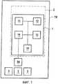
- фиг. 1 - схема устройства мониторинга в соответствии с изобретением, в конкретном варианте осуществления;- FIG. 1 is a diagram of a monitoring device in accordance with the invention, in a particular embodiment;
- фиг. 2 - схема предложенной согласно изобретению модели дисбаланса в плоскости крыльчатки, связанного с дисбалансом в плоскости турбины и воздействующего на вращающийся вал турбореактивного двигателя;- FIG. 2 is a diagram of an unbalance model proposed in accordance with the invention in the plane of the impeller associated with an imbalance in the plane of the turbine and acting on a rotating shaft of a turbojet engine;
- фиг. 3A и 3B - блок-схемы, показывающие основные этапы способа мониторинга в соответствии с изобретением при реализации устройством мониторинга, показанным на фиг. 1, в конкретной реализации;- FIG. 3A and 3B are flowcharts showing the main steps of the monitoring method in accordance with the invention when implemented by the monitoring device shown in FIG. 1, in a specific implementation;
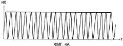
- фиг. 4A-4C показывают примеры колебательных сигналов x(t);- FIG. 4A-4C show examples of vibrational signals x (t);
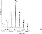
- фиг. 5A-5C показывают частотные спектры колебательных сигналов, показанных на фиг. 4A-4C, соответственно; и- FIG. 5A-5C show the frequency spectra of the vibrational signals shown in FIG. 4A-4C, respectively; and
- фиг. 6 показывает спектр огибающей колебательного сигнала, показанного на фиг. 4C.- FIG. 6 shows the envelope spectrum of the vibrational signal shown in FIG. 4C.
ПОДРОБНОЕ ОПИСАНИЕ ВАРИАНТА ОСУЩЕСТВЛЕНИЯDETAILED DESCRIPTION OF EMBODIMENT
Изобретение относится к мониторингу турбинного двигателя, а более конкретно к мониторингу крутильных колебаний, которым подвергается вращающийся вал турбинного двигателя в процессе работы.The invention relates to monitoring a turbine engine, and more particularly to monitoring torsional vibrations to which a rotating shaft of a turbine engine is subjected during operation.
Принцип, на котором преимущественно базируется изобретение, состоит в том, что крутильные колебания вращающегося вала турбинного двигателя имеют место вокруг его рабочей скорости, и в присутствие связанного с ним дисбаланса на роторе, формируют частотную и, возможно, также амплитудную модуляцию колебательных сигналов, доставляемых вибродатчиками, расположенными на неподвижных деталях турбинного двигателя. Таким образом, изобретение использует тот факт, что, наблюдая и анализируя эти колебательные сигналы, можно выявлять крутильные колебания избыточной амплитуды.The principle on which the invention is mainly based is that torsional vibrations of a rotating shaft of a turbine engine take place around its operating speed, and in the presence of an associated imbalance on the rotor, frequency and, possibly, also amplitude modulation of the vibrational signals delivered by the vibration sensors is formed located on the stationary parts of the turbine engine. Thus, the invention exploits the fact that by observing and analyzing these vibrational signals, torsional vibrations of excessive amplitude can be detected.
Как упомянуто выше, на практике, невозможно полностью сбалансировать вращающиеся валы турбинного двигателя, поэтому таким валам всегда присущ некоторый дисбаланс. Поэтому, собственно говоря, не существует никаких препятствий для реализации изобретения.As mentioned above, in practice, it is not possible to fully balance the rotating shafts of a turbine engine, so some shocks are always inherent in such shafts. Therefore, in fact, there are no obstacles to the implementation of the invention.
В турбинном двигателе, основным источником дисбаланса является крыльчатка. Тем не менее, нередко турбина также дает свой вклад в дисбаланс, осциллируя в противофазе с дисбалансом, который существует в плоскости крыльчатки. Изобретение преимущественно применимо в обоих этих обстоятельствах.In a turbine engine, the impeller is the main source of imbalance. However, often the turbine also contributes to the imbalance by oscillating in antiphase with the imbalance that exists in the plane of the impeller. The invention is advantageously applicable in both of these circumstances.
Ниже делается ссылка на фиг. 1, которая показывает конкретный вариант осуществления устройства 1 мониторинга в соответствии с изобретением, в его окружении.Reference is now made to FIG. 1, which shows a specific embodiment of a
В этом конкретном варианте осуществления, вращающийся вал ABP низкого давления (фиг. 2) турбореактивного двигателя TR, установленного на летательном аппарате (не показан) подлежит мониторингу в соответствии с изобретением. Тем не менее, эти предположения не служат ограничением, и изобретение также применяется к другим турбинным двигателям, например, к турбовинтовому двигателю.In this particular embodiment, the low pressure rotating shaft ABP (FIG. 2) of a turbojet engine TR mounted on an aircraft (not shown) is to be monitored in accordance with the invention. However, these assumptions are not intended to be limiting, and the invention also applies to other turbine engines, such as a turboprop.
В описанном здесь варианте осуществления, устройство 1 мониторинга находится на борту летательного аппарата и встроено в устройство мониторинга или EMU 2 летательного аппарата.In the embodiment described here, the
Альтернативно, устройство мониторинга согласно изобретению может располагаться на стенде вспомогательного оборудования и под крылом летательного аппарата совместно с оборудованием, специально предназначенным для мониторинга турбореактивного двигателя TR, или может быть реализовано в наземном устройстве, предназначенном для мониторинга турбореактивного двигателя.Alternatively, the monitoring device according to the invention may be located on the auxiliary equipment bench and under the wing of the aircraft in conjunction with equipment specially designed for monitoring the TR turbojet engine, or may be implemented in a ground device designed for monitoring the turbojet engine.
Известным образом, турбореактивный двигатель TR предоставляется с множеством рабочих датчиков 3, например датчиками для считывания: позиции, скорости, температуры, давления, вибрации и т.д. Эти датчики пригодны для доставки различных измерений на EMU 2, чтобы он мог осуществлять мониторинг работы турбореактивного двигателя TR.In a known manner, a TR turbojet engine is provided with a plurality of
Среди этих датчиков, в частности, есть акселерометр 3A, размещенный на неподвижной детали турбореактивного двигателя TR (например, на одном из подшипников вращающегося вала ABP). Такой датчик обычно используется в турбореактивных двигателях или, в более общем случае, в турбинных двигателях, и он не описан здесь более подробно.Among these sensors, in particular, there is an
Традиционно, акселерометр 3A выполнен с возможностью предоставлять электрический сигнал или колебательный сигнал ускорения в момент времени t, и этот сигнал обозначается x(t) и представляет величину пропорциональную измеренному ускорению. В этом примере, этот электрический сигнал является результатом ускорений, сообщаемых неподвижной детали, на которой располагается акселерометр 3A, как результат дисбаланса, присутствующего на вращающемся валу низкого давления турбореактивного двигателя TR в процессе работы. Сигнал поступает на EMU 2 и, в частности, на устройство 1 мониторинга.Conventionally, the
Альтернативно, следует отметить, что для доставки на EMU 2 колебательного сигнала, пропорционального ускорению, можно использовать другие вибродатчики, такие как, например, микрофон или тензодатчик. В смысле, подразумеваемом в изобретении, считается, что такой сигнал составляет колебательный сигнал ускорения.Alternatively, it should be noted that other vibration sensors, such as, for example, a microphone or strain gauge, can be used to deliver an oscillating signal proportional to acceleration to the
В этом примере, устройство 1 мониторинга представляет аппаратную архитектуру компьютера.In this example, the
Оно содержит, в частности, процессор 11, оперативную память (RAM) 12, ROM 13 и средство 14 для связи с оборудованием на борту летательного аппарата, таким как, например, акселерометр 3A. Известным образом, такое оборудование и устройство 1 мониторинга, отвечающее изобретению осуществляют связь через шины или линии цифровых данных летательного аппарата и известны специалисту в данной области техники.It contains, in particular, a
Устройство 1 мониторинга также включает в себя средство 15 для связи с сервером оператора летательного аппарата (не показан), например, посредством адресно-отчетной системы авиационной связи (ACARS).The
ROM 13 включает в себя компьютерную программу в соответствии с изобретением, которая выполнена с возможностью выполнения основных этапов способа мониторинга, отвечающего изобретению, описанного ниже со ссылкой на фиг. 2-6.
Здесь предполагается, что вращающийся вал низкого давления ABP, подвергаемый мониторингу, представляет дисбаланс в плоскости крыльчатки в сочетании с дисбалансом в плоскости турбины турбореактивного двигателя TR. В результате влияния кручения вала, эти два дисбаланса осциллируют в противофазе.It is assumed here that the ABP low-pressure rotating shaft being monitored represents an imbalance in the plane of the impeller in combination with an imbalance in the plane of the turbine of the turbojet engine TR. As a result of the influence of shaft torsion, these two imbalances oscillate in antiphase.
Фиг. 2 показывает модель в векторной форме этих дисбалансов, которые обозначены соответственно

При этой модели, колебательный сигнал x(t), доставляемый акселерометром 3A в момент времени t может быть записан в следующей форме:With this model, the vibrational signal x (t) delivered by the

где:Where:
- Ωp обозначает угловую несущую частоту, несущую колебательный сигнал x(t), и представляет скорость вращения вала. Следует понимать, что:- Ωp denotes the angular carrier frequency carrying the oscillatory signal x (t), and represents the speed of rotation of the shaft. It should be understood that:

где Fp обозначает несущую частоту, несущую колебательный сигнал;where Fp denotes a carrier frequency carrying an oscillating signal;
- Ωm обозначает угловую частоту кручения вращающегося вала. Следует понимать, что:- Ωm denotes the angular torsion frequency of the rotating shaft. It should be understood that:

где Fm обозначает частоту крутильных колебаний вращающегося вала. Эта частота крутильных колебаний известна и зависит от характеристик вращающегося вала;where Fm denotes the frequency of torsional vibrations of a rotating shaft. This torsional frequency is known and depends on the characteristics of the rotating shaft;
- θmF и θmT обозначают амплитуды крутильных колебаний, соответственно, в плоскости крыльчатки и в плоскости турбины;- θmF and θmT denote the amplitude of the torsional oscillations, respectively in the plane of the impeller and in the plane of the turbine;
- F и T представляют пиковые амплитуды колебательного сигнала x(t), доставляемого акселерометром. Амплитуда F является функцией вектора дисбаланса
- φF обозначает фазовую позицию, соответствующую угловой позиции вектора дисбаланса
- φT обозначает фазовую позицию, соответствующую угловой позиции вектора дисбаланса
Со ссылкой на фиг. 3A и 3B, ниже приведено подробное описание основных этапов способа мониторинга согласно изобретению в конкретной реализации.With reference to FIG. 3A and 3B, the following is a detailed description of the main steps of the monitoring method according to the invention in a particular implementation.
В описанной реализации, способ мониторинга содержит две стадии:In the described implementation, the monitoring method comprises two stages:
- первую стадию P1 (показанную на фиг. 3A), в течение которой обнаруживается присутствие крутильных колебаний во вращающемся валу ABP, и, при необходимости, амплитуда упомянутых колебаний подвергается мониторингу и оценивается их опасность; и- the first stage P1 (shown in Fig. 3A), during which the presence of torsional vibrations in the rotating shaft ABP is detected, and, if necessary, the amplitude of these vibrations is monitored and their danger is evaluated; and
- вторую стадию P2 (показанную на фиг. 3B), которая реализуется в этом примере, только если на стадии P1 регистрируются крутильные колебания избыточной амплитуды, и в течение которой уровень достоверности связывается с обнаружением.- the second stage P2 (shown in Fig. 3B), which is implemented in this example only if torsional vibrations of excessive amplitude are detected in stage P1, and during which the level of confidence is associated with the detection.
Таким образом, на стадии P1, колебательный сигнал ускорения x(t) от датчика 3A непрерывно доставляется через средство 14 связи на устройство 1 мониторинга и сохраняется в RAM 12 (этап E10).Thus, in step P1, the acceleration vibrational signal x (t) from the
В порядке указания, на фиг. 4A-4C представлен внешний вид сигнала x(t) для следующих примеров:By way of indication, in FIG. 4A-4C show the appearance of the signal x (t) for the following examples:
- фиг. 4A показывает сигнал x(t), полученный, когда дисбаланс в плоскости турбины равен нулю или близок к нулю (т.е. T≈0), и для крутильных колебаний малой амплитуды (в данном случае, порядка нескольких градусов);- FIG. 4A shows the signal x (t) obtained when the imbalance in the turbine plane is zero or close to zero (i.e., T≈0), and for torsional vibrations of small amplitude (in this case, of the order of several degrees);
- фиг. 4B показывает сигнал x(t), полученный, когда дисбаланс в плоскости турбины равен нулю или близок к нулю (т.е. T≈0), для крутильных колебаний большой амплитуды; и- FIG. 4B shows the signal x (t) obtained when the imbalance in the turbine plane is zero or close to zero (i.e., T≈0) for large-amplitude torsional vibrations; and
- фиг. 4C показывает сигнал x(t), полученный в присутствие дисбаланса в плоскости турбины и дисбаланса в плоскости крыльчатки.- FIG. 4C shows the signal x (t) obtained in the presence of an imbalance in the plane of the turbine and an imbalance in the plane of the impeller.
Как показано на этих фигурах, сигнал x(t) не является синусоидальным, но представляет асимметрии относительно своей несущей частоты Fp.As shown in these figures, the signal x (t) is not sinusoidal, but represents asymmetries with respect to its carrier frequency Fp .
Эти асимметрии характеризуются наличием пар спектральных линий боковых полос в частотном спектре сигнала x(t) которые симметрично распределены относительно основной линии R0, которая связана с дисбалансом(ами) большей или меньшей амплитуды.These asymmetries are characterized by the presence of pairs of spectral lines of the side bands in the frequency spectrum of the signal x (t) which are symmetrically distributed relative to the main line R0 , which is associated with an imbalance (s) of greater or lesser amplitude.
В соответствии с изобретением, анализ количества и амплитуд этих линий боковых полос, присутствующих в частотном спектре сигнала x(t), позволяет выявлять присутствие крутильных колебаний избыточной амплитуды и определять опасность идентифицированного таким образом явления.In accordance with the invention, an analysis of the number and amplitudes of these sideband lines present in the frequency spectrum of the signal x (t) makes it possible to detect the presence of torsional vibrations of excessive amplitude and to determine the danger of the phenomenon identified in this way.
Таким образом, частотный спектр сигнала x(t), хранящийся в памяти 12, оценивается (этап E20). Этот частотный спектр записывается X(f), где f обозначает частоту. В описанном примере, X(f) получается путем оценивания преобразования Фурье сигнала x(t), взятого в пределах временного окна, записанного как W, предварительно определенной длины. Получение частотного спектра сигнала, изменяющегося во времени, само по себе известно и не описано здесь более подробно.Thus, the frequency spectrum of the signal x (t) stored in the
В порядке примера, фиг. 5A, 5B и 5C показывают спектры X(f) сигналов x(t), показанных, соответственно, на фиг. 4A, 4B и 4C.By way of example, FIG. 5A, 5B and 5C show the spectra X (f) of the signals x (t) shown respectively in FIG. 4A, 4B and 4C.
Можно видеть, что в этих спектрах присутствуют пары линий боковых полос, которые располагаются с обеих сторон от основной линии, которая находится на несущей частоте Fp, и которые отстоят от нее на величину частоты Fm крутильных колебаний. Эти пары линий имеют изменяющиеся амплитуды. Ri и R-i обозначают пару спектральных линий, присутствующих на частотах Fi и F-i и удовлетворяющих условиям:You can see that in these spectra there are pairs of lines of the side bands, which are located on both sides of the main line, which is located at the carrier frequency Fp , and which are separated from it by the value of the frequency Fm of torsional vibrations. These pairs of lines have varying amplitudes. Ri and R-i denote a pair of spectral lines present at frequencies Fi and F-i and satisfy the conditions:


гдеi - целое число.wherei is an integer.
В соответствии с изобретением, первоначально производится поиск на предмет присутствия первой пары линий боковых полос, находящихся на частотах ±Fm с обеих сторон от основной линии R0 (этап E30).In accordance with the invention, a search is initially made for the presence of a first pair of sideband lines located at frequencies ± Fm on both sides of the main line R0 (step E30).
Этот поиск осуществляется с использованием техник, известных специалисту в данной области техники. Например, величины, принимаемые спектром X(f) в предварительно определенном диапазоне, выбранном около частот ±Fm, сравниваются с порогом, отображающим уровень шума.This search is carried out using techniques known to those skilled in the art. For instance, the values of received spectrum X (f) in a predetermined range about a selected frequency ± Fm, compared to a threshold reflecting noise.
Если поиск не позволяет обнаружить линии на частотах ±Fm, тогда делают вывод, что первая крутильная мода вала не возбуждена. В результате, предупреждение не выдается (этап E50). Затем выбирается новое окно W колебательного сигнала x(t), и этапы E20 и E30 повторяются на этом новом окне.If the search does not allow detecting lines at frequencies ± Fm , then it is concluded that the first torsional shaft mode is not excited. As a result, a warning is not issued (step E50). Then, a new window W of the oscillation signal x (t) is selected, and steps E20 and E30 are repeated on this new window.
В противном случае, если на этапе поиска обнаруживается первая пара линий боковых полос R1 и R-1 на частотах ±Fm, то после этого определяется амплитуда этих линий. Эта амплитуда задается величинами линий в спектре X(f).Otherwise, if at the search stage the first pair of lines of the side bands R1 and R-1 is detected at frequencies ± Fm , then the amplitude of these lines is determined. This amplitude is determined by the values of the lines in the spectrum of X (f).
После этого, определенные таким образом относительные амплитуды первой пары линий R1 и R-1 сравниваются с предварительно заданным порогом S11 (этап E40). Термин "относительная амплитуда" употребляется здесь в смысле отношения амплитуды рассматриваемой линии к амплитуде основной линии R0.After that, the relative amplitudes of the first pair of lines R1 and R-1 thus determined are compared with a predetermined threshold S11 (step E40). The term "relative amplitude" is used here in the sense of the ratio of the amplitude of the line in question to the amplitude of the main line R0 .
Альтернативно, также непосредственно можно сравнивать "абсолютные" амплитуды линий R1 и R-1 с предварительно заданным порогом.Alternatively, it is also possible to directly compare the "absolute" amplitudes of the lines R1 and R-1 with a predetermined threshold.
Порог S11 составляет первый порог в смысле, подразумеваемом в изобретении. Он предварительно задан, и в этом примере он представляет относительную амплитуду линий боковых полос, за пределами которой крутильные колебания вызывают опасения и требуют выдачи предупреждения или планирования технического обслуживания. Этот порог определяется экспериментально.The threshold S11 is the first threshold in the sense implied by the invention. It is predefined, and in this example it represents the relative amplitude of the sideband lines, beyond which torsional vibrations are worrying and require a warning or maintenance planning. This threshold is determined experimentally.
В другом варианте реализации, следует понимать, что этапы E30 и E40 могут быть реализованы одновременно, путем непосредственного поиска первой пары линий с использованием порога S11.In another implementation, it should be understood that steps E30 and E40 can be implemented simultaneously, by directly searching for the first pair of lines using threshold S11 .
Если, по меньшей мере, одна относительная амплитуда линий R1 и/или R-1 меньше порога S11, то считается, что нет необходимости выдавать предупреждение (этап E50): затем выбирается новое окно W колебательного сигнала x(t), и этапы E20-E40 повторяются на этом новом окне.If at least one relative amplitude of the lines R1 and / or R-1 is less than the threshold S11 , then it is considered that there is no need to give a warning (step E50): then a new window W of the oscillation signal x (t) is selected, and the steps E20-E40 are repeated on this new window.
Если наоборот обе относительные амплитуды линий R1 и R-1 превышают первый порог S11, то принимается решение выдавать предупреждающее сообщение M (этап E60).If, on the contrary, both relative amplitudes of the lines R1 and R-1 exceed the first threshold S11 , then a decision is made to issue a warning message M (step E60).
В описанном здесь варианте реализации, это предупреждающее сообщение M связано с двумя дополнительными элементами информации, которые характеризуют предупреждение, а именно, во-первых, уровнем опасности предупреждения и, во-вторых, уровнем достоверности предупреждения.In the embodiment described here, this warning message M is associated with two additional information elements that characterize the warning, namely, firstly, the danger level of the warning and, secondly, the reliability level of the warning.
В другом варианте реализации, предупреждающее сообщение M связано с тем или иным из этих элементов информации.In another implementation, the warning message M is associated with one or another of these information elements.
В еще одном варианте реализации, предупреждающее сообщение M отправляется сразу же после обнаружения, что амплитуды линий R1 и R-1 пересекают первый порог, причем эта информация не связана с предупреждением.In yet another embodiment, a warning message M is sent immediately after detecting that the amplitudes of lines R1 and R-1 cross the first threshold, and this information is not related to the warning.
Для оценивания уровня опасности предупреждения, в спектре сигнала x(t) производится поиск, чтобы увидеть, присутствуют ли другие пары линий боковых полос (например, R2/R-2, R3/R-3 и т.д.) с обеих сторон от основной линии R0, на частотах, кратных частоте крутильных колебаний вала ABP, и определяются амплитуды этих пар линий (этап E70).To evaluate the hazard level of a warning, a signal is searched in the signal spectrum x (t) to see if other pairs of sideband lines are present (e.g., R2 / R-2 , R3 / R-3 , etc.) from both sides of the main line R0 at frequencies that are multiples of the frequency of torsional vibrations of the shaft ABP, and the amplitudes of these pairs of lines are determined (step E70).
Учитываются только линии, амплитуды которых превышают предварительно определенный уровень шума.Only lines whose amplitudes exceed a predetermined noise level are taken into account.
Затем относительные амплитуды этих линий сравниваются с соответствующими предварительно определенными порогами ("третьими" порогами в смысле, подразумеваемом в изобретении) (этап E80).Then, the relative amplitudes of these lines are compared with the corresponding predetermined thresholds (“third” thresholds in the sense implied by the invention) (step E80).
Например, со ссылкой на фиг. 5A, относительные амплитуды линий R2 и R-2 сравниваются с порогом S12. Порог S12 выбирается отличным от порога S11.For example, with reference to FIG. 5A, the relative amplitudes of the lines R2 and R-2 are compared with a threshold S12 . The threshold S12 is selected different from the threshold S11 .
Альтернативно, пороги S11 и S12 могут быть одинаковыми. Также следует понимать, что соответствующие амплитуды каждой линии в паре линий также можно сравнивать с разными соответствующими порогами.Alternatively, thresholds S11 and S12 may be the same. It should also be understood that the corresponding amplitudes of each line in a pair of lines can also be compared with different corresponding thresholds.
После этого сравнения, устройство 1 мониторинга оценивает количество N пар линий боковых полос, которые симметрично распределены с обеих сторон от основной линии R0 на частотах, кратных частоте крутильных колебаний вала, и для которых амплитуды превышают третьи пороги (этап E90).After this comparison, the
Это количество N составляет оценку уровня опасности предупреждения в смысле, подразумеваемом в изобретении: чем больше значение N, тем более опасным считается явление крутильных колебаний, которым подвергается вал ABP.This amount of N is an estimate of the warning danger level in the sense implied by the invention: the higher the value of N, the more dangerous is the phenomenon of torsional vibrations to which the shaft ABP is subjected.
В примере на фиг. 4A, предполагается, что это количество равно 2, поскольку оно включает в себя пару линий на частотах ±Fm и пару линий на частотах ±2Fm.In the example of FIG. 4A, it is assumed that this number is 2, since it includes a pair of lines at frequencies ± Fm and a pair of lines at frequencies ± 2Fm .
Затем количество N вставляется в предварительно определенное поле сообщения M.Then, the number N is inserted into the predefined message field M.
После этой первой стадии P1, реализуется вторая стадия P2 для установления связи уровня достоверности с предупреждающим сообщением M (фиг. 3B).After this first stage P1, the second stage P2 is implemented to establish the relationship of the confidence level with the warning message M (FIG. 3B).
С этой целью, в описанной здесь реализации, производится поиск в сигнале x(t) на предмет присутствия характеристики, которая подтверждала бы предупреждение, идентифицированное на стадии P1, т.е. присутствие амплитудной модуляции в сигнале x(t).For this purpose, in the implementation described here, a search is performed in the signal x (t) for the presence of a characteristic that would confirm the warning identified at stage P1, i.e. the presence of amplitude modulation in the signal x (t).
Фиг. 4C показывает пример сигнала x(t), в котором можно наблюдать не только асимметрии относительно несущей частоты Fp, но также присутствие амплитудной модуляции.FIG. 4C shows an example of a signal x (t) in which not only asymmetries with respect to the carrier frequency Fp can be observed, but also the presence of amplitude modulation.
Таким образом, во время стадии P2, устройство 1 мониторинга формирует сигнал x'(t) огибающей из сигнала x(t) временного ряда (этап E100).Thus, during step P2, the
Для этого первоначально оценивается преобразование Гильберта
Затем сигнал x'(t) огибающей в момент времени t сигнала x(t) получается с использованием следующего уравнения:Then, the envelope signal x '(t) at time t of the signal x (t) is obtained using the following equation:

Следует понимать, что частота сигнала x'(t) огибающей равна частоте Fm крутильных колебаний вала ротора.It should be understood that the frequency of the envelope signal x '(t) is equal to the frequency Fm of torsional vibrations of the rotor shaft.
Затем спектр x'(t) сигнала огибающей, обозначенный X'(f), гдеf обозначает частоту, оценивается устройством мониторинга, с использованием преобразования Фурье, как описано выше для спектра X(f) (этап E110).Then, the spectrum x '(t) of the envelope signal indicated by X' (f), wheref is the frequency, is estimated by the monitoring device using the Fourier transform, as described above for the spectrum X (f) (step E110).
На фиг. 6 показан спектр x'(t) сигнала огибающей, соответствующего сигналу x(t), показанному на фиг. 4C. В спектре могут наблюдаться основная спектральная линия R'1 на частоте Fm крутильных колебаний, и гармоника R'2 на частоте 2Fm.In FIG. 6 shows the spectrum x ′ (t) of the envelope signal corresponding to the signal x (t) shown in FIG. 4C. In the spectrum, the main spectral line R ′1 can be observed at a frequency Fm of torsional vibrations, and the harmonic R ′2 at a frequency of 2Fm .
В более общем случае, следует отметить, что о присутствии амплитудной модуляции свидетельствует присутствие в спектре сигнала огибающей спектральной линии R'1, которую называют основной линией на частоте Fm крутильных колебаний вала, и, возможно, гармоник R'i на частотах F'i, кратных частоте крутильных колебаний, такой что:In a more general case, it should be noted that the presence of amplitude modulation is indicated by the presence in the signal spectrum of the envelope of the spectral line R '1 , which is called the main line at the frequency Fm of torsional vibrations of the shaft, and, possibly, harmonics R'i at frequencies F 'i multiples of the frequency of torsional vibrations, such that:

гдеi обозначает целое число большее 1.wherei denotes an integer greater than 1.
Таким образом, в спектре X'(f) производится поиск, чтобы определить, присутствует ли спектральная линия R'1 в сигнале X'(f) на частоте Fm крутильных колебаний вала (этап E120). Этот поиск осуществляется аналогично этапу E30 поиска.Thus, 'is searched to determine if there is a spectral line of R (f)'1 signal X '(f) at the frequency Fm of the shaft torsional oscillations (step E120) spectrum X. This search is carried out similarly to search step E30.
Если ни одной линии не обнаружено (другими словами, если в колебательном сигнале x(t) не обнаружено никакой амплитудной модуляции), то предупреждающему сообщению M по умолчанию присваивается средний уровень достоверности (этап E130). В описанном здесь примере, этот средний уровень достоверности выражается флагом, установленным со значением "средний" и включенным в предварительно определенное поле сообщения M.If no lines are detected (in other words, if no amplitude modulation is detected in the waveform x (t)), then the warning message M is assigned the default level of confidence (step E130). In the example described here, this average confidence level is expressed by a flag set to "average" and included in a predefined message field M.
Если линия R'1 обнаружена, то определяется ее амплитуда: эта амплитуда задается величиной линии в спектре X'(f).If the line R '1 is detected, then its amplitude is determined: this amplitude is determined by the value of the line in the spectrum X' (f).
После этого, определенная таким образом амплитуда сравнивается с предварительно заданным порогом S2 (этап E140), полученным экспериментальным путем. Порог S2 является "вторым" порогом в смысле, подразумеваемом в изобретении.After that, the amplitude thus determined is compared with a predetermined threshold S2 (step E140) obtained experimentally. Threshold S2 is a “second” threshold in the sense implied by the invention.
Как описано выше со ссылкой на этапы E30 и E40, в другой реализации, этапы E120 и E140 можно осуществлять одновременно, путем поиска линии в сигнале X'(f) на частоте Fm крутильных колебаний непосредственно с порогом S2. Если амплитуда линии R'1 больше порога S2, то предупреждающему сообщению M присваивается высокий уровень достоверности (этап E150). В описанном здесь примере, этот высокий уровень достоверности выражается флагом, установленным со значением "высокий" и включенным в предварительно определенное поле сообщения M.As described above with reference to steps E30 and E40, in another implementation, steps E120 and E140 can be performed simultaneously by searching for a line in the signal X ′ (f) at a frequency Fm of torsional vibrations directly with threshold S2. If the amplitude of the line R '1 is greater than the threshold S2, then the warning message M is assigned a high level of confidence (step E150). In the example described here, this high level of confidence is expressed by the flag set to "high" and included in the predefined message field M.
В противном случае, предупреждающему сообщению M присваивается средний уровень достоверности (т.е. флаг устанавливается со значением "средний") и оно включается в соответствующее поле сообщения (этап E130).Otherwise, the warning message M is assigned an average confidence level (i.e., the flag is set to "average") and it is included in the corresponding message field (step E130).
Другими словами, высокий уровень достоверности в смысле, подразумеваемом в изобретении, подтверждает, что обнаружены крутильные колебания избыточной амплитуды на стадии P1. Тем не менее, средний уровень достоверности не означает, что обнаружение ошибочно.In other words, a high level of confidence in the sense implied by the invention confirms that torsional vibrations of excessive amplitude were detected in stage P1. However, an average confidence level does not mean that the detection is erroneous.
Естественно, для оценивания уровня достоверности можно принять в рассмотрение некоторое другое количество спектральных линий. Например, можно наблюдать линии, находящиеся на частоте крутильных колебаний совместно с одной или более гармониками, и соответственно адаптировать уровень достоверности.Naturally, to assess the level of reliability, one can take into account some other number of spectral lines. For example, you can observe the lines located at the frequency of torsional vibrations in conjunction with one or more harmonics, and accordingly adapt the level of confidence.
Следует отметить, что две стадии P1 (этапы E10-E90) и P2 (этапы E100-E150) можно осуществлять с одним и тем же результатом либо одновременно, либо, напротив, последовательно (в любом порядке).It should be noted that the two stages P1 (steps E10-E90) and P2 (steps E100-E150) can be performed with the same result either simultaneously or, conversely, sequentially (in any order).
В конце этапов E130 и E150, устройство 1 мониторинга выдает предупреждающее сообщение M (этап E160). В этом примере, предупреждающее сообщение содержит уровень достоверности и уровень опасности, оцененные, соответственно, на этапах E130/E150 и E90.At the end of steps E130 and E150, the
В порядке примера, это сообщение M выдается средством 14 пилоту летательного аппарата, чтобы пилот мог изменить рабочую скорость турбореактивного двигателя TR.As an example, this message M is issued by
Альтернативно, сообщение M может передаваться средством 15 на сервер оператора летательного аппарата, и оно может содержать предложение произвести техническое обслуживание турбореактивного двигателя TR.Alternatively, the message M can be transmitted by
В еще одном варианте осуществления изобретения, уровень достоверности, связанный с предупреждающим сообщением M, можно объединить, до выдачи сообщения M, с обнаруженными неисправностями, полученными из других алгоритмов мониторинга, реализованных на турбореактивном двигателе.In yet another embodiment of the invention, the confidence level associated with the warning message M can be combined, prior to the issuance of message M, with detected malfunctions obtained from other monitoring algorithms implemented on a turbojet engine.
Claims (7)
Translated fromRussian- этап (Е10), на котором получают колебательный сигнал ускорения от акселерометра (3А), расположенного на неподвижной детали турбинного двигателя, причем этот колебательный сигнал характеризуется несущей частотой;
- этап (Е20), на котором оценивают частотный спектр колебательного сигнала;
- этап (Е30, Е40), на котором ищут пару спектральных линий с амплитудами, превышающими, по меньшей мере, первый порог, причем линии распределены в спектре с обеих сторон от несущей частоты колебательного сигнала и отстоят от нее на частоту крутильных колебаний вала;
- этап (Е100), на котором оценивают сигнал огибающей колебательного сигнала;
- этап (Е110), на котором оценивают частотный спектр сигнала огибающей;
- этап (Е120) поиска, на котором осуществляют поиск, по меньшей мере, одной спектральной линии в спектре сигнала огибающей, амплитуда которого превышает второй порог, и который существует на величине, кратной частоте крутильных колебаний вала; и
- этап (Е130, Е150), на котором оценивают уровень достоверности, связанный с предупреждающим сообщением, как функцию результата этапа (Е120) поиска; и
- при необходимости, этап (Е160), на котором выдают предупреждающее сообщение.1. A method for monitoring torsional vibrations of a rotating shaft (ATS) of a turbine engine (TR), the method comprising:
- step (E10), which receives the vibrational acceleration signal from the accelerometer (3A) located on a stationary part of the turbine engine, and this vibrational signal is characterized by a carrier frequency;
- stage (E20), which assesses the frequency spectrum of the oscillatory signal;
- stage (E30, E40), in which a pair of spectral lines with amplitudes exceeding at least the first threshold is searched, and the lines are distributed in the spectrum on both sides of the carrier frequency of the vibrational signal and are separated from it by the frequency of torsional vibrations of the shaft;
- step (E100), in which the envelope signal of the oscillatory signal is evaluated;
- stage (E110), which assesses the frequency spectrum of the envelope signal;
- search step (E120), which searches for at least one spectral line in the spectrum of the envelope signal, the amplitude of which exceeds the second threshold, and which exists at a multiple of the frequency of torsional vibrations of the shaft; and
- a step (E130, E150), at which the level of confidence associated with the warning message is evaluated as a function of the result of the search step (E120); and
- if necessary, step (E160), at which a warning message is issued.
- этап (Е70) поиска, на котором осуществляют поиск, по меньшей мере, одной другой пары спектральных линий, распределенных в спектре колебательного сигнала с обеих сторон от несущей частоты и отстоящих от нее на величину, кратную частоте крутильных колебаний вала; и
- этап (Е90), на котором оценивают уровень опасности, связанный с предупреждающим сообщением, причем этот уровень опасности зависит от количества пар линий, найденных на этапе (Е70) поиска, амплитуды которых превышают, по меньшей мере, третий порог.3. The monitoring method according to claim 1, further comprising
- a search step (E70), which searches for at least one other pair of spectral lines distributed in the spectrum of the vibrational signal on both sides of the carrier frequency and spaced apart by a multiple of the frequency of torsional vibrations of the shaft; and
- stage (E90), which assesses the level of danger associated with the warning message, and this level of danger depends on the number of pairs of lines found in stage (E70) search, the amplitudes of which exceed at least the third threshold.
- средство (11) получения для получения колебательного сигнала ускорения от акселерометра (3А), расположенного на неподвижной детали турбинного двигателя, причем колебательный сигнал характеризуется несущей частотой;
- средство (11) оценивания для оценивания частотного спектра колебательного сигнала;
- средство (11) поиска для поиска пары спектральных линий с амплитудами, превышающими, по меньшей мере, первый порог, причем линии распределены в спектре с обеих сторон от несущей частоты колебательного сигнала и отстоят от нее на частоту крутильных колебаний вала;
- средство (11) оценивания для оценивания сигнала огибающей колебательного сигнала;
- средство (11) оценивания для оценивания частотного спектра сигнала огибающей;
- средство (11) поиска для осуществления поиска, по меньшей мере, одной спектральной линии в спектре сигнала огибающей, амплитуда которого превышает второй порог и который существует на величине, кратной частоте крутильных колебаний вала; и
- средство (11) оценивания для оценивания уровня достоверности, связанного с предупреждающим сообщением, как функции результата поиска; и
- средство (14, 15) выдачи для выдачи предупреждающего сообщения, активируемое при необходимости.5. A monitoring device (1) for monitoring the torsional vibrations of a rotating shaft (ATS) of a turbine engine (TR), the device comprising:
- means (11) for obtaining an oscillatory acceleration signal from an accelerometer (3A) located on a stationary part of a turbine engine, the oscillating signal being characterized by a carrier frequency;
- evaluation means (11) for estimating the frequency spectrum of the vibrational signal;
- search means (11) for searching for a pair of spectral lines with amplitudes exceeding at least the first threshold, the lines being distributed in the spectrum on both sides of the carrier frequency of the vibrational signal and spaced from it by the frequency of torsional vibrations of the shaft;
- evaluation means (11) for estimating the envelope signal of the oscillating signal;
- evaluation means (11) for estimating the frequency spectrum of the envelope signal;
- search means (11) for searching at least one spectral line in the spectrum of the envelope signal, the amplitude of which exceeds the second threshold and which exists at a multiple of the frequency of torsional vibrations of the shaft; and
- evaluation means (11) for assessing the level of confidence associated with the warning message as a function of the search result; and
- means (14, 15) of issuing for issuing a warning message, activated if necessary.
- средство поиска для поиска, по меньшей мере, одной другой пары спектральных линий, распределенных в спектре колебательного сигнала с обеих сторон от несущей частоты и отстоящих от нее на величину, кратную частоте крутильных колебаний вала; и
- средство (11) оценивания для оценивания уровня опасности, связанного с предупреждающим сообщением, причем уровень опасности зависит от количества пар, найденных средством поиска, амплитуды которых превышают, по меньшей мере, третий порог.6. The monitoring device (1) according to claim 5, further comprising:
- search means for searching at least one other pair of spectral lines distributed in the spectrum of the vibrational signal on both sides of the carrier frequency and spaced from it by an amount multiple of the frequency of torsional vibrations of the shaft; and
- evaluation means (11) for assessing the danger level associated with the warning message, the danger level depending on the number of pairs found by the search means, the amplitudes of which exceed at least the third threshold.
- устройство (1) мониторинга по п. 5; и
- акселерометр (3А), расположенный на неподвижной детали турбинного двигателя и выполненный с возможностью доставки колебательного сигнала ускорения на устройство мониторинга.7. A turbine engine (TR) including
- a monitoring device (1) according to claim 5; and
- an accelerometer (3A) located on a stationary part of a turbine engine and configured to deliver an oscillation acceleration signal to a monitoring device.
Applications Claiming Priority (3)
| Application Number | Priority Date | Filing Date | Title |
|---|---|---|---|
| FR0958527 | 2009-11-30 | ||
| FR0958527AFR2953289B1 (en) | 2009-11-30 | 2009-11-30 | METHOD AND DEVICE FOR MONITORING TORSION VIBRATIONS OF A ROTARY SHAFT OF A TURBOMACHINE. |
| PCT/FR2010/052467WO2011064490A1 (en) | 2009-11-30 | 2010-11-22 | Method and device for monitoring torsional vibrations of a rotary shaft of a turbine engine |
Publications (2)
| Publication Number | Publication Date |
|---|---|
| RU2012127282A RU2012127282A (en) | 2014-01-10 |
| RU2559131C2true RU2559131C2 (en) | 2015-08-10 |
Family
ID=42041902
Family Applications (1)
| Application Number | Title | Priority Date | Filing Date |
|---|---|---|---|
| RU2012127282/28ARU2559131C2 (en) | 2009-11-30 | 2010-11-22 | Method and device for monitoring of torsional oscillations of rotary shaft of turbine engine |
Country Status (9)
| Country | Link |
|---|---|
| US (1) | US9097575B2 (en) |
| EP (1) | EP2507598B1 (en) |
| JP (1) | JP5694361B2 (en) |
| CN (1) | CN102713539B (en) |
| BR (1) | BR112012013075B1 (en) |
| CA (1) | CA2782043C (en) |
| FR (1) | FR2953289B1 (en) |
| RU (1) | RU2559131C2 (en) |
| WO (1) | WO2011064490A1 (en) |
Cited By (1)
| Publication number | Priority date | Publication date | Assignee | Title |
|---|---|---|---|---|
| RU2789297C1 (en)* | 2022-02-15 | 2023-02-01 | Артем Владиславович Дьяченко | Torsiograph |
Families Citing this family (12)
| Publication number | Priority date | Publication date | Assignee | Title |
|---|---|---|---|---|
| FR2956481B1 (en)* | 2010-02-18 | 2012-02-10 | Snecma | METHOD FOR DETECTING RESONANCE OF A ROTOR SHAFT OF A TURBOMOTEUR |
| US9719366B2 (en)* | 2013-06-12 | 2017-08-01 | General Electric Company | Methods and systems for blade health monitoring |
| CA2969414C (en) | 2014-12-02 | 2018-11-06 | Siemens Aktiengesellschaft | Apparatus and method for monitoring a device having a movable part |
| US10082443B2 (en)* | 2016-02-26 | 2018-09-25 | General Electric Technology Gmbh | System and method for monitoring bearing health in a journal assembly |
| WO2017160272A1 (en) | 2016-03-14 | 2017-09-21 | Halliburton Energy Services, Inc. | Downhole vibration characterization |
| GB2551112B (en)* | 2016-05-25 | 2020-04-15 | Ge Aviat Systems Ltd | Aircraft component monitoring system |
| EP3396337B1 (en)* | 2017-04-24 | 2023-12-27 | General Electric Technology GmbH | Torsional vibration monitoring and diagnostics system and method |
| FR3105406B1 (en) | 2019-12-18 | 2021-12-24 | Arianegroup Sas | Method and device for analyzing the vibrations of an element. |
| EP3875925A1 (en)* | 2020-03-07 | 2021-09-08 | Honeywell International Inc. | Airfield luminaire vibration monitoring |
| CN111504449A (en)* | 2020-04-23 | 2020-08-07 | 华能四川水电有限公司 | Method and system for monitoring unstable working condition of unit |
| US11626003B2 (en)* | 2021-02-23 | 2023-04-11 | Rheem Manufacturing Company | Systems and methods for monitoring and detecting a fault in a fluid storage tank |
| EP4092289A1 (en)* | 2021-05-17 | 2022-11-23 | Rolls-Royce Deutschland Ltd & Co KG | System for vibration management in rotating machinery |
Citations (3)
| Publication number | Priority date | Publication date | Assignee | Title |
|---|---|---|---|---|
| WO1992005438A1 (en)* | 1990-09-19 | 1992-04-02 | Rem Technologies, Inc. | Crack detection method for shaft at rest |
| RU2296970C2 (en)* | 2005-06-02 | 2007-04-10 | Открытое акционерное общество "Научно-производственное объединение "Сатурн" | Method for diagnosing self-excited vibrations of working wheel of turbo-machine (variants) |
| WO2009129617A1 (en)* | 2008-04-24 | 2009-10-29 | Mike Jeffrey | A method and system for determining an imbalance of a wind turbine rotor |
Family Cites Families (25)
| Publication number | Priority date | Publication date | Assignee | Title |
|---|---|---|---|---|
| JPS54151075A (en)* | 1978-05-18 | 1979-11-27 | Mitsubishi Heavy Ind Ltd | Monitoring method for vibration of rotary blade |
| US4408294A (en)* | 1981-03-27 | 1983-10-04 | General Electric Company | Method for on-line detection of incipient cracks in turbine-generator rotors |
| JPS57179625A (en)* | 1981-04-30 | 1982-11-05 | Hitachi Ltd | Method for diagnosing vibration in rotary machine |
| US4488240A (en)* | 1982-02-01 | 1984-12-11 | Becton, Dickinson And Company | Vibration monitoring system for aircraft engines |
| JPS58219424A (en)* | 1982-06-15 | 1983-12-20 | Kawasaki Steel Corp | Apparatus for inspecting rotary equipment |
| JPS59176629A (en)* | 1983-03-25 | 1984-10-06 | Nippon Denso Co Ltd | Method and device for inspecting timbre of acoustic generating equipment |
| JPS62151725A (en)* | 1985-12-26 | 1987-07-06 | Toshiba Corp | Crack occurrence abnormality diagnosis device for rotating shaft system |
| JPH076832B2 (en)* | 1989-05-31 | 1995-01-30 | 株式会社東芝 | Method and apparatus for vibration analysis of rotating equipment |
| US5501105A (en)* | 1991-10-02 | 1996-03-26 | Monitoring Technology Corp. | Digital signal processing of encoder signals to detect resonances in rotating machines |
| US5365787A (en)* | 1991-10-02 | 1994-11-22 | Monitoring Technology Corp. | Noninvasive method and apparatus for determining resonance information for rotating machinery components and for anticipating component failure from changes therein |
| US5483833A (en)* | 1994-03-22 | 1996-01-16 | Martin Marietta Energy Systems, Inc. | Method and apparatus for monitoring aircraft components |
| US6128959A (en)* | 1994-11-07 | 2000-10-10 | Eaton Corporation | Driveline vibration analyzer |
| US5825657A (en)* | 1996-02-23 | 1998-10-20 | Monitoring Technology Corporation | Dynamic, non-uniform clock for resampling and processing machine signals |
| US5686669A (en)* | 1996-02-29 | 1997-11-11 | Monitoring Technology Corporation | Apparatus and method for analyzing the condition and performance of turbomachines by processing signals representing rotor motion |
| DE19800217A1 (en)* | 1998-01-06 | 1999-07-15 | Flender Engineering & Service | Process for the automated diagnosis of diagnostic objects |
| US6729186B1 (en)* | 2002-02-28 | 2004-05-04 | Eaton Corporation | Multi-channel vibration analyzer |
| WO2004025232A2 (en)* | 2002-09-10 | 2004-03-25 | Alstom Technology Ltd | Method and device for detecting oscillations of the shafting of an electric machine |
| JP2005538371A (en)* | 2002-09-10 | 2005-12-15 | アルストム テクノロジー リミテッド | Apparatus and method for monitoring and / or analyzing an electrical machine during operation |
| JP2005172029A (en)* | 2003-12-08 | 2005-06-30 | Honda Motor Co Ltd | Damper |
| US20050171736A1 (en)* | 2004-02-02 | 2005-08-04 | United Technologies Corporation | Health monitoring and diagnostic/prognostic system for an ORC plant |
| JP2006113002A (en)* | 2004-10-18 | 2006-04-27 | Nsk Ltd | Abnormality diagnosis system for mechanical equipment |
| WO2007007333A2 (en)* | 2005-07-12 | 2007-01-18 | Technion Research And Development Foundation Ltd. | System and method for active detection of asymmetry in rotating structures |
| US7693673B2 (en)* | 2007-06-06 | 2010-04-06 | General Electric Company | Apparatus and method for identifying a defect and/or operating characteristic of a system |
| JP5146008B2 (en) | 2007-06-11 | 2013-02-20 | 日本精工株式会社 | Abnormality diagnosis apparatus and abnormality diagnosis method |
| CA2724453C (en)* | 2008-06-17 | 2014-08-12 | Exxonmobil Upstream Research Company | Methods and systems for mitigating drilling vibrations |
- 2009
- 2009-11-30FRFR0958527Apatent/FR2953289B1/enactiveActive
- 2010
- 2010-11-22EPEP10799088.9Apatent/EP2507598B1/enactiveActive
- 2010-11-22CACA2782043Apatent/CA2782043C/enactiveActive
- 2010-11-22USUS13/512,765patent/US9097575B2/enactiveActive
- 2010-11-22WOPCT/FR2010/052467patent/WO2011064490A1/enactiveApplication Filing
- 2010-11-22CNCN201080054361.4Apatent/CN102713539B/enactiveActive
- 2010-11-22BRBR112012013075Apatent/BR112012013075B1/enactiveIP Right Grant
- 2010-11-22RURU2012127282/28Apatent/RU2559131C2/enactive
- 2010-11-22JPJP2012541552Apatent/JP5694361B2/enactiveActive
Patent Citations (3)
| Publication number | Priority date | Publication date | Assignee | Title |
|---|---|---|---|---|
| WO1992005438A1 (en)* | 1990-09-19 | 1992-04-02 | Rem Technologies, Inc. | Crack detection method for shaft at rest |
| RU2296970C2 (en)* | 2005-06-02 | 2007-04-10 | Открытое акционерное общество "Научно-производственное объединение "Сатурн" | Method for diagnosing self-excited vibrations of working wheel of turbo-machine (variants) |
| WO2009129617A1 (en)* | 2008-04-24 | 2009-10-29 | Mike Jeffrey | A method and system for determining an imbalance of a wind turbine rotor |
Cited By (1)
| Publication number | Priority date | Publication date | Assignee | Title |
|---|---|---|---|---|
| RU2789297C1 (en)* | 2022-02-15 | 2023-02-01 | Артем Владиславович Дьяченко | Torsiograph |
Also Published As
| Publication number | Publication date |
|---|---|
| US9097575B2 (en) | 2015-08-04 |
| JP5694361B2 (en) | 2015-04-01 |
| BR112012013075B1 (en) | 2020-04-14 |
| WO2011064490A1 (en) | 2011-06-03 |
| FR2953289B1 (en) | 2012-04-27 |
| US20120229290A1 (en) | 2012-09-13 |
| RU2012127282A (en) | 2014-01-10 |
| EP2507598A1 (en) | 2012-10-10 |
| CA2782043A1 (en) | 2011-06-03 |
| FR2953289A1 (en) | 2011-06-03 |
| EP2507598B1 (en) | 2019-08-14 |
| BR112012013075A2 (en) | 2016-11-22 |
| CN102713539B (en) | 2016-01-27 |
| CA2782043C (en) | 2018-03-20 |
| CN102713539A (en) | 2012-10-03 |
| JP2013512446A (en) | 2013-04-11 |
Similar Documents
| Publication | Publication Date | Title |
|---|---|---|
| RU2559131C2 (en) | Method and device for monitoring of torsional oscillations of rotary shaft of turbine engine | |
| US8380450B2 (en) | Determination of blade vibration frequencies and/or amplitudes | |
| US9453760B2 (en) | Device and method for evaluation of vibrations | |
| EP2610604B1 (en) | Method for oscillation measurement on rotor blades of wind power installations | |
| CN105426644A (en) | Method, device, and system for modal damping identification | |
| JP5698766B2 (en) | Method for automatically detecting suction of at least one foreign object by a gas turbine engine | |
| US8474307B2 (en) | Method for detecting resonance in a rotor shaft of a turbine engine | |
| KR101949622B1 (en) | Method for operating a machine plant having a shaft train | |
| Guglielmo et al. | Full load stability test (FLST) on LNG compressor | |
| Chen et al. | Torsional vibration feature extraction method from lateral vibrations based on decomposed forward and backward whirl motions | |
| Rao et al. | In situ detection of turbine blade vibration and prevention | |
| Kocur et al. | Shop rotordynamic testing-options, objectives, benefits and practices | |
| Gautam et al. | Integrated analysis of additive and multiplicative internal excitation parameters in misaligned-bowed-internally damped rotor systems with active magnetic bearings: Numerical and experimental identification | |
| Dovhan et al. | Development of the system for vibration diagnosis of bearing assemblies using an analog interface | |
| Tamrakar et al. | Crack Depth Estimation in Shaft for an Overhung Rotating Shaft System: An Experimental Investigation | |
| EP2503307A1 (en) | Method for assessment of the winding head vibration of an electric machine | |
| CN116429236B (en) | Method and device for suppressing coherent fading noise of optical fiber sensing data | |
| Amirza et al. | Investigation of Dynamic Characteristics of Vibrating Components and Structure Through Vibration Measurement and Operational Modal Analysis | |
| Buchczik et al. | Calibration of accelerometers using multisinusoidal excitation | |
| EP3978892B1 (en) | Method of measurement of the acting forces in a structure and/or the temperature in the structure | |
| Keller Jr | Comparison of resistance-based strain gauges and fiber bragg gratings in the presence of electromagnetic interference emitted from an electric motor | |
| Ibraheem et al. | Experimental Investigation for Single Plan Balancing Impellers between Bearings Using Frequency Response Function | |
| Al–Taee et al. | A Novel Experimental Study of Single–Plane Balancing Method of Crankshaft without Phase Angles Data. | |
| Robinette et al. | Determining Physical Properties for Rotating Components Using a Free-Free Torsional FRF Technique | |
| Chandra et al. | Detection and monitoring of shaft misalignment in rotors using Hilbert Huang transform |
Legal Events
| Date | Code | Title | Description |
|---|---|---|---|
| PD4A | Correction of name of patent owner |