RU2558451C2 - Guide element and device for hole formation in bone - Google Patents
Guide element and device for hole formation in boneDownload PDFInfo
- Publication number
- RU2558451C2 RU2558451C2RU2013126188/14ARU2013126188ARU2558451C2RU 2558451 C2RU2558451 C2RU 2558451C2RU 2013126188/14 ARU2013126188/14 ARU 2013126188/14ARU 2013126188 ARU2013126188 ARU 2013126188ARU 2558451 C2RU2558451 C2RU 2558451C2
- Authority
- RU
- Russia
- Prior art keywords
- guide element
- hole
- hollow body
- inlet
- shaft
- Prior art date
Links
- 210000000988bone and boneAnatomy0.000titleclaimsdescription50
- 230000015572biosynthetic processEffects0.000titledescription3
- 238000003801millingMethods0.000claimsabstractdescription37
- 210000001519tissueAnatomy0.000claimsabstractdescription6
- 238000007789sealingMethods0.000claimsdescription28
- 230000033001locomotionEffects0.000claimsdescription26
- 239000012528membraneSubstances0.000claimsdescription19
- 239000012530fluidSubstances0.000claimsdescription16
- 238000005553drillingMethods0.000claimsdescription8
- 230000007423decreaseEffects0.000claimsdescription6
- 239000011796hollow space materialSubstances0.000claimsdescription4
- 238000003698laser cuttingMethods0.000claimsdescription3
- 230000003993interactionEffects0.000claims1
- 238000011109contaminationMethods0.000abstractdescription6
- 230000000694effectsEffects0.000abstractdescription4
- 208000015181infectious diseaseDiseases0.000abstractdescription4
- 239000007787solidSubstances0.000abstractdescription4
- 239000003814drugSubstances0.000abstract2
- 239000000126substanceSubstances0.000abstract1
- 210000004086maxillary sinusAnatomy0.000description25
- 210000004400mucous membraneAnatomy0.000description20
- 210000003128headAnatomy0.000description17
- 210000004379membraneAnatomy0.000description17
- 238000000034methodMethods0.000description15
- 210000001847jawAnatomy0.000description14
- 239000000463materialSubstances0.000description14
- 230000008901benefitEffects0.000description6
- 230000006378damageEffects0.000description6
- 239000007943implantSubstances0.000description5
- 206010011878DeafnessDiseases0.000description3
- 230000009471actionEffects0.000description3
- 210000000214mouthAnatomy0.000description3
- 238000002360preparation methodMethods0.000description3
- 238000001356surgical procedureMethods0.000description3
- FAPWRFPIFSIZLT-UHFFFAOYSA-MSodium chlorideChemical compound[Na+].[Cl-]FAPWRFPIFSIZLT-UHFFFAOYSA-M0.000description2
- 210000001909alveolar processAnatomy0.000description2
- 238000005452bendingMethods0.000description2
- 239000000316bone substituteSubstances0.000description2
- 230000036512infertilityEffects0.000description2
- 238000001746injection mouldingMethods0.000description2
- 238000003780insertionMethods0.000description2
- 230000037431insertionEffects0.000description2
- 238000012423maintenanceMethods0.000description2
- 239000002504physiological saline solutionSubstances0.000description2
- 238000000926separation methodMethods0.000description2
- 238000004659sterilization and disinfectionMethods0.000description2
- 230000008961swellingEffects0.000description2
- 206010000060Abdominal distensionDiseases0.000description1
- 108010009565Bio-GideProteins0.000description1
- 230000002745absorbentEffects0.000description1
- 239000002250absorbentSubstances0.000description1
- 238000010521absorption reactionMethods0.000description1
- 230000033228biological regulationEffects0.000description1
- 208000024330bloatingDiseases0.000description1
- 210000001136chorionAnatomy0.000description1
- 238000004140cleaningMethods0.000description1
- 230000000295complement effectEffects0.000description1
- 230000006835compressionEffects0.000description1
- 238000007906compressionMethods0.000description1
- 230000008878couplingEffects0.000description1
- 238000010168coupling processMethods0.000description1
- 238000005859coupling reactionMethods0.000description1
- 230000003247decreasing effectEffects0.000description1
- 230000001419dependent effectEffects0.000description1
- 238000002845discolorationMethods0.000description1
- 238000006073displacement reactionMethods0.000description1
- 238000000605extractionMethods0.000description1
- 238000011010flushing procedureMethods0.000description1
- 230000005802health problemEffects0.000description1
- 230000002706hydrostatic effectEffects0.000description1
- 238000002955isolationMethods0.000description1
- 239000007788liquidSubstances0.000description1
- 230000014759maintenance of locationEffects0.000description1
- 238000004519manufacturing processMethods0.000description1
- 230000000813microbial effectEffects0.000description1
- 210000004877mucosaAnatomy0.000description1
- 229920000642polymerPolymers0.000description1
- 238000003825pressingMethods0.000description1
- 230000008569processEffects0.000description1
- 230000009467reductionEffects0.000description1
- 238000010079rubber tappingMethods0.000description1
- 239000011780sodium chlorideSubstances0.000description1
- 239000000243solutionSubstances0.000description1
- 229910001220stainless steelInorganic materials0.000description1
- 239000010935stainless steelSubstances0.000description1
- 238000003860storageMethods0.000description1
- 238000002604ultrasonographyMethods0.000description1
- 210000000689upper legAnatomy0.000description1
Images


Classifications
- A—HUMAN NECESSITIES
- A61—MEDICAL OR VETERINARY SCIENCE; HYGIENE
- A61C—DENTISTRY; APPARATUS OR METHODS FOR ORAL OR DENTAL HYGIENE
- A61C1/00—Dental machines for boring or cutting ; General features of dental machines or apparatus, e.g. hand-piece design
- A61C1/08—Machine parts specially adapted for dentistry
- A61C1/082—Positioning or guiding, e.g. of drills
- A—HUMAN NECESSITIES
- A61—MEDICAL OR VETERINARY SCIENCE; HYGIENE
- A61C—DENTISTRY; APPARATUS OR METHODS FOR ORAL OR DENTAL HYGIENE
- A61C8/00—Means to be fixed to the jaw-bone for consolidating natural teeth or for fixing dental prostheses thereon; Dental implants; Implanting tools
- A—HUMAN NECESSITIES
- A61—MEDICAL OR VETERINARY SCIENCE; HYGIENE
- A61B—DIAGNOSIS; SURGERY; IDENTIFICATION
- A61B17/00—Surgical instruments, devices or methods
- A61B17/16—Instruments for performing osteoclasis; Drills or chisels for bones; Trepans
- A61B17/17—Guides or aligning means for drills, mills, pins or wires
- A61B17/1739—Guides or aligning means for drills, mills, pins or wires specially adapted for particular parts of the body
- A61B17/176—Guides or aligning means for drills, mills, pins or wires specially adapted for particular parts of the body for the jaw
- A—HUMAN NECESSITIES
- A61—MEDICAL OR VETERINARY SCIENCE; HYGIENE
- A61C—DENTISTRY; APPARATUS OR METHODS FOR ORAL OR DENTAL HYGIENE
- A61C1/00—Dental machines for boring or cutting ; General features of dental machines or apparatus, e.g. hand-piece design
- A61C1/0046—Dental lasers
- A—HUMAN NECESSITIES
- A61—MEDICAL OR VETERINARY SCIENCE; HYGIENE
- A61C—DENTISTRY; APPARATUS OR METHODS FOR ORAL OR DENTAL HYGIENE
- A61C1/00—Dental machines for boring or cutting ; General features of dental machines or apparatus, e.g. hand-piece design
- A61C1/08—Machine parts specially adapted for dentistry
- A—HUMAN NECESSITIES
- A61—MEDICAL OR VETERINARY SCIENCE; HYGIENE
- A61C—DENTISTRY; APPARATUS OR METHODS FOR ORAL OR DENTAL HYGIENE
- A61C3/00—Dental tools or instruments
- A61C3/02—Tooth drilling or cutting instruments; Instruments acting like a sandblast machine
- A—HUMAN NECESSITIES
- A61—MEDICAL OR VETERINARY SCIENCE; HYGIENE
- A61C—DENTISTRY; APPARATUS OR METHODS FOR ORAL OR DENTAL HYGIENE
- A61C8/00—Means to be fixed to the jaw-bone for consolidating natural teeth or for fixing dental prostheses thereon; Dental implants; Implanting tools
- A61C8/0089—Implanting tools or instruments
- A61C8/0092—Implanting tools or instruments for sinus lifting
Landscapes
- Health & Medical Sciences (AREA)
- Oral & Maxillofacial Surgery (AREA)
- Life Sciences & Earth Sciences (AREA)
- Dentistry (AREA)
- Animal Behavior & Ethology (AREA)
- General Health & Medical Sciences (AREA)
- Public Health (AREA)
- Veterinary Medicine (AREA)
- Epidemiology (AREA)
- Orthopedic Medicine & Surgery (AREA)
- Surgery (AREA)
- Nuclear Medicine, Radiotherapy & Molecular Imaging (AREA)
- Engineering & Computer Science (AREA)
- Biomedical Technology (AREA)
- Heart & Thoracic Surgery (AREA)
- Medical Informatics (AREA)
- Molecular Biology (AREA)
- Otolaryngology (AREA)
- Physics & Mathematics (AREA)
- Optics & Photonics (AREA)
- Surgical Instruments (AREA)
- Dental Tools And Instruments Or Auxiliary Dental Instruments (AREA)
Abstract
Description
Translated fromRussianОбласть изобретенияField of Invention
Настоящее изобретение относится к направляющему элементу согласно ограничительной части пункта 1 формулы изобретения и к устройству для перфорирования продолжения глухого отверстия, выполненного в твердой ткани, в частности в челюстной кости, согласно пункту 15 формулы изобретения.The present invention relates to a guide element according to the restrictive part of claim 1 and to a device for perforating a continuation of a blind hole made in hard tissue, in particular in the jaw bone, according to paragraph 15 of the claims.
Предпосылки изобретенияBACKGROUND OF THE INVENTION
Такое продолжение высверленного в кости отверстия требуется, например, в области хирургической стоматологии при выполнении процедуры, называемой синус-лифтингом. Синус-лифтинг - это операция, при которой слизистую оболочку верхнечелюстной (гайморовой) пазухи или синусную мембрану или мембрану Шнайдера частично отделяют и поднимают для образования пространства между костью и слизистой оболочкой верхнечелюстной пазухи. В образованную полость затем вводят аутокость, например, из бугра верхней челюсти, косой линии нижней челюсти, области подбородка или из гребня бедренной кости (костно-замещающие материалы, костный трансплантат) или синтетический костно-замещающий материал, например, костно-замещающий материал марки Bio-Oss® от компании Geistlich AG, который часто смешивают с аутокостью. Этот материал рассчитан на превращение в костную ткань в течение 6 месяцев, чтобы обеспечить твердую основу для имплантата.Such a continuation of a hole drilled in the bone is required, for example, in the field of surgical dentistry when performing a procedure called sinus lift. Sinus lifting is an operation in which the mucous membrane of the maxillary (maxillary) sinus or the sinus membrane or Schneider membrane is partially separated and raised to form the space between the bone and the mucous membrane of the maxillary sinus. An autobone is then introduced into the cavity formed, for example, from the tuber of the upper jaw, oblique line of the lower jaw, the area of the chin or from the crest of the femur (bone-replacing materials, bone graft) or synthetic bone-replacing material, for example, bone-replacing material of the brand Bio -Oss® from Geistlich AG, which is often mixed with autobone. This material is designed to be converted to bone within 6 months to provide a solid base for the implant.
Известный метод синус-лифтинга состоит в приготовлении слизисто-надкостничного лоскута, щечно в области больших коренных зубов, и фрезеровании овального окна в обнаженной таким образом кости, не повреждая нижележащую слизистую оболочку верхнечелюстной пазухи. Овальный костный диск, который прикреплен к слизистой оболочке верхнечелюстной пазухи, затем осторожно сдвигают в направлении верхнечелюстной пазухи, при этом осторожно отделяют слизистую оболочку от кости вокруг окна с использованием специальных инструментов. Вследствие того, что слизистая оболочка верхнечелюстной пазухи очень хрупкая, соизмеримо с хорионом яйца, эту процедуру следует производить очень осторожно из-за опасности повреждения слизистой оболочки верхнечелюстной пазухи. Образующееся при этом пространство в верхнечелюстной пазухе далее заполняют костно-замещающим материалом и покрывают щечное окно пленкой. Пленку обычно изготавливают из абсорбирующего материала, такого как мембрана марки Bio-Gide® компании Geistlich AG. После этого слизисто-надкостничный лоскут плотно сшивают. Этот способ сравнительно инвазивный и вызывает стресс у пациента вследствие сильного вздутия (опухания) и обесцвечивания в течение периода длительностью до 10 дней и, к тому же, может повлечь за собой возникновение боли. Эту хирургическую операцию часто называют «открытым» «классическим» синус-лифтингом. В случае если остается достаточная остаточная высота кости, например высота в 5 мм, имплантаты могут быть введены при синус-лифтинге в одно и то же время (одномоментный синус-лифтинг). Имплантаты могут быть подвержены воздействию полной нагрузки только после отверждения костно-замещающего материала. Когда остаточная высота кости слишком мала, введение имплантатов осуществляют при выполнении второй операции приблизительно через 6-8 месяцев после проведения синус-лифтинга (повторный синус-лифтинг).A well-known method of sinus lifting is to prepare a mucosal-periosteal flap, buccally in the region of large molars, and milling an oval window in this way naked, without damaging the underlying mucous membrane of the maxillary sinus. The oval bone disk, which is attached to the mucous membrane of the maxillary sinus, is then carefully shifted in the direction of the maxillary sinus, while the mucous membrane is carefully separated from the bone around the window using special tools. Due to the fact that the mucous membrane of the maxillary sinus is very fragile, commensurate with the chorion of the egg, this procedure should be done very carefully because of the risk of damage to the mucous membrane of the maxillary sinus. The resulting space in the maxillary sinus is then filled with bone-replacing material and the buccal window is covered with a film. The film is typically made from an absorbent material, such as a Bio-Gide® membrane from Geistlich AG. After this, the mucoperiosteal flap is tightly sutured. This method is relatively invasive and causes stress in the patient due to severe bloating (swelling) and discoloration over a period of up to 10 days and, moreover, may lead to pain. This surgery is often referred to as an “open” “classic” sinus lift. If there remains a sufficient residual bone height, for example a height of 5 mm, implants can be inserted during sinus lift at the same time (simultaneous sinus lift). Implants can be exposed to full load only after the curing of the bone replacement material. When the residual bone height is too small, the introduction of implants is carried out during the second operation approximately 6-8 months after sinus lift (repeated sinus lift).
Новый способ, так называемый синус-лифтинг с доступом со стороны альвеолярного гребня, не требует отгибания костной пластинки. Доступ к верхнечелюстной пазухе предоставляется от гребня челюсти. В лишенной зубов части гребня челюсти перфорируют слизистую оболочку полости рта вплоть до кости при помощи специального перфоратора слизистой оболочки (перфоратор Джеша) и выполняют в кости фрезерованием глухое отверстие вплоть до места, находящегося непосредственно под слизистой оболочкой верхнечелюстной пазухи, с помощью цилиндрической фрезерной машины. Используемый для этого перфоратор автоматически поднимает диск слизистой оболочки от кости и формирует центральное сквозное отверстие для дальнейшего сверления или фрезерования. Отверстие фрезеруют под костным дном верхнечелюстной пазухи, обычно антрально, то есть, начиная с крестовой головки цилиндрического фрезерного инструмента диаметром, например, приблизительно от 3,5 до 1 мм, при этом толщину кости предварительно измеряют при помощи выполнения рентгеновского снимка. Ввиду того, что слизистая оболочка верхнечелюстной пазухи не должна быть повреждена фрезерным инструментом, челюстная кость не должна быть просверлена фрезерным инструментом полностью, насквозь, так что в основании глухого отверстия остается тонкая костная пластинка, к задней стороне которой примыкает слизистая оболочка верхнечелюстной пазухи. Обычно эту тонкую костную пластинку затем осторожно проталкивают цилиндрическим инструментом в направлении верхнечелюстной пазухи, так что она проталкивается в направлении верхнечелюстной пазухи одновременно со слизистой оболочкой верхнечелюстной пазухи, которая прикреплена выше костного диска к верхней части костного диска. Это «продавливание» костного диска является важным моментом для процедуры ввиду того, что избыточное вжатие костного диска приводит к поднятию слизистой оболочки верхнечелюстной пазухи в форме палатки и приведению ее в напряженное состояние, что может вести к повреждению слизистой оболочки верхнечелюстной пазухи. После этого слизистую оболочку верхнечелюстной пазухи осторожно приподнимают и далее через кость вводят во вновь образовавшееся пространство костно-замещающий материал. Затем имплантат чаще всего непосредственно закрепляют в высверленном отверстии.The new method, the so-called sinus lift with access from the alveolar ridge, does not require bending of the bone plate. Access to the maxillary sinus is provided from the crest of the jaw. In the toothless part of the crest of the jaw, the mucous membrane of the oral cavity is perforated up to the bone using a special mucosal perforator (Jesh perforator) and a blind hole is made in the bone by milling up to the place directly under the mucous membrane of the maxillary sinus using a cylindrical milling machine. The perforator used for this automatically lifts the mucous disk from the bone and forms a central through hole for further drilling or milling. The hole is milled under the bone bottom of the maxillary sinus, usually antrum, that is, starting from the cross head of a cylindrical milling tool with a diameter of, for example, from about 3.5 to 1 mm, while the thickness of the bone is pre-measured using x-ray. Due to the fact that the mucous membrane of the maxillary sinus should not be damaged by the milling tool, the jaw should not be completely drilled through the milling tool, so that a thin bone plate remains at the base of the blind hole, to the back of which the mucous membrane of the maxillary sinus adjoins. Typically, this thin bone plate is then gently pushed with a cylindrical instrument in the direction of the maxillary sinus, so that it is pushed in the direction of the maxillary sinus simultaneously with the mucosa of the maxillary sinus, which is attached above the bone disc to the upper part of the bone disc. This “squeezing” of the bone disc is an important point for the procedure due to the fact that excessive compression of the bone disc leads to the lifting of the mucous membrane of the maxillary sinus in the form of a tent and putting it into tension, which can lead to damage to the mucous membrane of the maxillary sinus. After that, the mucous membrane of the maxillary sinus is carefully lifted and then a bone-replacing material is introduced into the newly formed space through the bone. Then the implant is most often directly fixed in the drilled hole.
Несмотря на то что разработаны в значительной мере усовершенствованные способы для отделения слизистой оболочки верхнечелюстной пазухи настолько осторожно, насколько это возможно, и отведение ее от челюстной кости на достаточное расстояние через малое высверленное отверстие, диаметр которого обычно составляет всего лишь около 4 мм, момент, в который выполняют перфорирование челюстной кости, остается критическим моментом, требующим большого опыта и особого умения врача, причем, даже в случае принятия мер предосторожности, все же существует опасность повреждения слизистой оболочки верхнечелюстной пазухи при перфорировании костной пластинки. Для того чтобы сделать процедуру синус-лифтинга более безопасной, нужны средства, облегчающие это перфорирование продолжения высверленного в челюстной кости отверстия, и одновременно с этим уменьшающие опасность повреждения хрупкой синусной мембраны, находящейся сзади челюстной кости.Despite the fact that significantly improved methods have been developed for separating the mucous membrane of the maxillary sinus as carefully as possible, and diverting it from the jawbone to a sufficient distance through a small drilled hole, the diameter of which is usually only about 4 mm, the moment at which perform perforation of the jawbone, remains a critical moment, requiring great experience and special skill of the doctor, and, even if precautionary measures are taken, there are still There is a risk of damage to the mucous membrane of the maxillary sinus when perforating the bone plate. In order to make the sinus lift procedure safer, tools are needed to facilitate this perforation of the continuation of the hole drilled in the jawbone and at the same time reduce the risk of damage to the fragile sinus membrane located behind the jawbone.
Такое эффективное средство известно из документа WO 2010/048648 A1, где описано устройство, которое имеет корпус трубчатой формы с дистальным рабочим отверстием и входом, расположенным напротив рабочего отверстия, причем этот вход закрыт уплотнительным элементом, через который проходит вал рабочего инструмента, например фрезерного инструмента. На трубчатом корпусе расположено соединение для создания внутреннего давления. Трубчатый корпус герметично вводят в заранее выполненное в челюстной кости глухое отверстие, при этом дистальное рабочее отверстие примыкает к концу глухого отверстия, в основном обеспечивая изолирование внутреннего пространства. Теперь посредством соединения, например, при помощи присоединенного к соединению шприца, может быть создано повышенное давление заключенной внутри трубчатого корпуса рабочей среды, предпочтительно, раствора NaCl. С помощью рабочего инструмента, управление которым может осуществляться с внешней стороны, костный диск, который остается между глухим отверстием и верхнечелюстной пазухой, сфрезеровывают в области рабочего отверстия. В момент, когда головка рабочего инструмента перфорирует кость и заходит в область под синусной мембраной, избыточное давление внутри трубчатого корпуса побуждает рабочую среду проходить через свободное отверстие и отжимать находящуюся там синусную мембрану назад в сторону удаления от кости и таким образом, что она выходит за пределы рабочей зоны рабочего инструмента и зоны опасности. Выпуск рабочей среды вызывает понижение давления, что указывает на перфорирование кости и, к тому же, предупреждает избыточное вспучивание синусной мембраны.Such an effective tool is known from document WO 2010/048648 A1, which describes a device that has a tubular body with a distal working hole and an inlet located opposite the working hole, this entrance being closed by a sealing element through which the shaft of the working tool, for example a milling tool, passes . A connection is located on the tubular body to create internal pressure. The tubular body is hermetically inserted into a blind hole pre-made in the jawbone, while the distal working hole is adjacent to the end of the blind hole, mainly providing isolation of the internal space. Now, by means of the connection, for example, by means of a syringe connected to the connection, an increased pressure of the working medium enclosed within the tubular body, preferably a NaCl solution, can be created. Using a working tool, which can be controlled from the outside, a bone disc that remains between the deaf hole and the maxillary sinus is milled in the area of the working hole. At the moment when the head of the working tool perforates the bone and enters the area under the sinus membrane, excess pressure inside the tubular body causes the working medium to pass through the free hole and squeeze the sinus membrane located there back to the side away from the bone and so that it extends beyond working area of the working tool and danger zone. The release of the working medium causes a decrease in pressure, which indicates bone perforation and, in addition, prevents excessive swelling of the sinus membrane.
Такое устройство безопасно в обращении и с помощью такого устройства можно добиться превосходного результата хирургического лечения при минимальном риске для слизистой оболочки верхнечелюстной пазухи. Но оно имеет недостаток, заключающийся в том, что выполнение очистки этого устройства обходится сравнительно дорого и затруднено. В частности, очень трудно очистить узкий соединительный канал, через который в трубчатый корпус или камеру давления подается среда под давлением, настолько тщательно, чтобы не оставались загрязнения. Обычно повторное использование медицинского оборудования или медицинских изделий в области хирургии несет определенную опасность заражения пациента, и любое загрязнение может вести к возникновению проблем со здоровьем, заболеванию или даже смерти пациента. Несмотря на то, что тщательная повторная стерилизация устройства позволяет убить основную часть микробов, такая повторная стерилизация требует больших затрат времени, вызывает в материале механические напряжения и является дорогостоящей и все же не исключает определенную опасность остаточного микробного загрязнения.Such a device is safe to handle and with the help of such a device you can achieve an excellent result of surgical treatment with minimal risk for the mucous membrane of the maxillary sinus. But it has the disadvantage that cleaning this device is relatively expensive and difficult. In particular, it is very difficult to clean the narrow connecting channel through which pressure medium is supplied to the tubular body or pressure chamber so thoroughly that no contamination remains. Typically, the reuse of medical equipment or medical devices in the field of surgery carries a certain risk of infection for the patient, and any contamination can lead to health problems, illness or even death of the patient. Despite the fact that a thorough re-sterilization of the device allows you to kill the bulk of the microbes, such a re-sterilization is time consuming, causes mechanical stresses in the material and is expensive and yet does not exclude a certain risk of residual microbial contamination.
Краткое описаниеShort description
Таким образом, цель настоящего изобретения заключается в дальнейшем усовершенствовании вышеупомянутого устройства при одновременном сохранении его полезных функциональных возможностей в плане повышения его защищенности от загрязнения и уменьшения опасности инфицирования пациента.Thus, the aim of the present invention is to further improve the aforementioned device while maintaining its useful functionality in terms of increasing its protection against contamination and reducing the risk of infection of the patient.
Эта цель достигается за счет создания особым образом выполненного направляющего элемента согласно отличительным признакам пункта 1 формулы изобретения.This goal is achieved by creating a specially made guide element according to the distinguishing features of paragraph 1 of the claims.
Направляющий элемент согласно изобретению может быть расположен на хирургическом устройстве как более дешевый заменяемый компонент и может использоваться как расходное изделие однократного использования.The guide element according to the invention can be located on the surgical device as a cheaper replaceable component and can be used as a disposable consumable.
Направляющий элемент особенно подходит, сформирован и сконфигурирован для размещения его на устройстве, предназначенном для перфорирования продолжения глухого отверстия, выполненного в твердой ткани, в частности в челюстной кости. Такое устройство содержит пустотелый корпус, который образует внутреннюю камеру давления и имеет дистальное рабочее отверстие и входное отверстие, расположенное напротив рабочего отверстия. Это устройство, к тому же, в основном соответствует устройству, известному из документа WO 2010/048648 A1.The guide element is particularly suitable, formed and configured to be placed on a device designed to perforate the continuation of a blind hole made in hard tissue, in particular in the jaw bone. Such a device comprises a hollow body that forms an internal pressure chamber and has a distal working hole and an inlet located opposite the working hole. This device, moreover, basically corresponds to the device known from document WO 2010/048648 A1.
Направляющий элемент согласно изобретению вводится во входное отверстие устройства с облеганием, в результате чего введение направляющего элемента вызывает герметичное закрывание устройства. Направляющий элемент имеет также сквозное отверстие, через которое может быть пропущен и введен снизу в пустотелый корпус устройства вал рабочего инструмента, например фрезерного инструмента. Кроме того, в направляющем элементе выполнено соединение для подачи рабочей среды, чтобы установить в камере требуемое внутреннее давление. Это давление служит для отодвигания синусной мембраны после перфорирования кости.The guide element according to the invention is inserted into the inlet of the device with a fit, as a result of which the introduction of the guide element causes the device to be sealed. The guide element also has a through hole through which the shaft of a working tool, for example a milling tool, can be passed and inserted from below into the hollow body of the device. In addition, a connection for supplying a working medium is made in the guide element in order to set the required internal pressure in the chamber. This pressure serves to move the sinus membrane after perforating the bone.
При этом направляющий элемент согласно изобретению гарантирует, что при правильном применении, может быть сформирована камера давления в первую очередь, или может быть достигнуто соответствующее давление. Кроме того, среда под давлением также подается исключительно через направляющий элемент, в отличие от устройства по документу WO 2010/048648, в котором среда под давлением подается через неподвижную боковую соединительную муфту, которая заходит непосредственно в камеру давления и которую трудно очистить. Кроме этих двух функций, направляющий элемент также обеспечивает возможность герметичного ввода вала рабочего инструмента в глухое отверстие и в то же время вал имеет возможность перемещения для удаления оставшейся пластинки костного дна.Moreover, the guide element according to the invention ensures that, when used correctly, a pressure chamber can be formed in the first place, or an appropriate pressure can be achieved. In addition, the pressurized medium is also supplied exclusively through the guide element, in contrast to the device of WO 2010/048648, in which the pressurized medium is supplied through a fixed lateral coupling that goes directly into the pressure chamber and which is difficult to clean. In addition to these two functions, the guide element also provides the ability to tightly enter the shaft of the working tool into a blind hole and at the same time the shaft has the ability to move to remove the remaining plate of the bone floor.
Существенным преимуществом является то, что направляющий элемент может быть заменен и после его использования по назначению может быть отсоединен и удален, что повышает безопасность хирургической операции и существенно снижает опасность инфицирования пациента.A significant advantage is that the guide element can be replaced and after its intended use can be disconnected and removed, which increases the safety of the surgical operation and significantly reduces the risk of infection of the patient.
Направляющий элемент, таким образом, может изготавливаться, реализовываться и храниться как отдельный компонент в асептической упаковке, аналогично шприцу или игле шприца, который вынимают из упаковки непосредственно перед проведением хирургической операции и соединяют с хирургическим инструментами и после использования утилизируют. Такая утилизация устройства по документу WO 2010/048648 нецелесообразно, потому что это дорогостоящий прецизионный компонент, изготовленный из нержавеющей стали. Таким образом, также обеспечивается соблюдение или отсутствие превышения срока годности и гарантируется безопасность в эксплуатации.Thus, the guide element can be manufactured, sold and stored as a separate component in an aseptic package, similar to a syringe or syringe needle, which is removed from the package immediately before the surgical operation and connected to the surgical instruments and disposed of after use. Such disposal of a device according to WO 2010/048648 is not practical because it is an expensive, precision component made of stainless steel. Thus, compliance with or absence of exceeding the expiration date is also ensured and operational safety is guaranteed.
Другие предпочтительные варианты конструктивного исполнения направляющего элемента согласно изобретению описаны в зависимых пунктах формулы изобретения.Other preferred embodiments of the guide element according to the invention are described in the dependent claims.
В частности, предпочтительно, когда под действием направляющего элемента обеспечивается герметичное и по существу непроницаемое для текучей среды закрытие входного отверстия. Даже если допустить возможность существования небольшой негерметичности соединения и/или утечки рабочей среды под давлением, при закрытии входного отверстия как можно плотнее направляющим элементом требуемое увеличение давления и поддержание давления обеспечиваются значительно лучше. К тому же лучше, быстрее и более надежно может быть выявлено понижение давления, которое происходит тогда, когда в кости выполняют перфорационное отверстие, и вовремя можно остановить вращение фрезы.In particular, it is preferable when, under the action of the guide element, the inlet closure is hermetically sealed and substantially impermeable to fluid. Even if we allow the possibility of a small leak in the connection and / or leakage of the working medium under pressure, when closing the inlet as tightly as possible with the guide element, the required increase in pressure and pressure maintenance are much better. Moreover, a decrease in pressure, which occurs when a perforation hole is made in the bone, can be detected better, faster and more reliably, and the rotation of the cutter can be stopped in time.
Также весьма предпочтительно, чтобы сквозное отверстие направляющего элемента обеспечивало поддержание герметичности и по существу непроницаемости для текучей среды и направление вала, для обеспечения в первую очередь достижения в камере давления внутреннего давления обычно в пределах приблизительно от 2 до 2,5 бар, а затем поддержания этого давления. В то же время сквозное отверстие должно быть выполнено с обеспечением возможности совершения, по меньшей мере, одного поступательного движения, движения приведения в действие и/или движения управления вала, например, вращения, движения по окружности и/или движения вала по оси вперед при удалении пластинки костного дна глухого отверстия при отсутствии существенного отрицательного влияния на герметизирующие свойства.It is also highly preferred that the through hole of the guide member maintains tightness and substantially impermeability to the fluid and the direction of the shaft, to ensure, first of all, that the pressure inside the chamber reaches internal pressure, typically in the range of about 2 to 2.5 bar, and then that pressure. At the same time, the through hole must be made to allow at least one translational movement, actuation movement and / or shaft control movement, for example, rotation, circumferential movement and / or forward movement of the shaft when removed plates of the bone bottom of a blind hole in the absence of a significant negative effect on the sealing properties.
В данном контексте в частности предпочтительно, когда внутри сквозного отверстия для дополнительного уплотнения вала располагается уплотнительный элемент, например уплотнительное кольцо. Это обеспечивает повышение степени герметичности системы. В тех примерах осуществления изобретения, в которых используется традиционный приводимый во вращение фрезерный инструмент, уплотнительный элемент выполняет функцию уплотнения вала и должен уплотнять вращающийся вал без существенного ограничения свободы его перемещения. Этого требует, чтобы уплотнительный элемент имел сравнительно высокое качество, и ведет к быстрому износу уплотнительного элемента.In this context, it is particularly preferable when a sealing element, such as an o-ring, is located inside the through hole for additional shaft sealing. This provides an increase in the degree of tightness of the system. In those embodiments of the invention in which a conventional rotary milling tool is used, the sealing element has the function of sealing the shaft and must seal the rotating shaft without significantly restricting its freedom of movement. This requires that the sealing element has a relatively high quality and leads to rapid wear of the sealing element.
Выполнение уплотнительного элемента цельным или в виде одной детали, в частности, в виде стерилизуемой пластмассовой детали одноразового применения, получаемой литьем под давлением, дает преимущество, заключающееся в простоте ее изготовления, рентабельности и обеспечивает стерильность работы.The implementation of the sealing element as a whole or in the form of a single part, in particular in the form of a sterilizable disposable plastic part obtained by injection molding, gives the advantage of simplicity of its manufacture, cost-effectiveness and ensures sterility of operation.
В другом предпочтительном варианте конструктивного исполнения направляющего элемента сквозное отверстие расположено в имеющей форму диска головной части направляющего элемента, предпочтительно по центру, и соединение выполнено в виде муфты для соединения трубопровода и, предпочтительно, проходит в радиальном направлении наружу.In another preferred embodiment of the guide element, the through hole is located in the disk-shaped head of the guide element, preferably in the center, and the connection is in the form of a sleeve for connecting the pipe and preferably extends radially outward.
Для обеспечения надежной подачи рабочей среды или среды под давлением, в направляющем элементе может быть образован внутренний канал, закрытый со всех сторон, который соединяет соединение с выпускным отверстием, ведущим во впускное отверстие.In order to ensure a reliable supply of a working or pressurized medium, an inner channel can be formed in the guide member, closed on all sides, which connects the connection to the outlet leading to the inlet.
В данном контексте в предпочтительном варианте канал проходит отдельно от сквозного отверстия на протяжении всей его длины.In this context, in a preferred embodiment, the channel extends separately from the through hole throughout its length.
В наиболее предпочтительном варианте первая подсекция канала, проксимальна к соединению, проходит перпендикулярно к центральной продольной оси симметрии сквозного отверстия и вторая, смежная с ней подсекция канала, по существу параллельна центральной продольной оси сквозного отверстия. Таким образом, формирование канала в направляющем элементе может быть обеспечено очень простым путем, также, например, последующим сверлением.Most preferably, the first channel subsection proximal to the connection extends perpendicularly to the central longitudinal axis of symmetry of the through hole and the second adjacent channel subsection is substantially parallel to the central longitudinal axis of the through hole. Thus, the formation of the channel in the guide element can be provided in a very simple way, also, for example, by subsequent drilling.
Для того чтобы обеспечить герметичность ввода направляющего элемента во входное отверстие с обеспечением при этом возможности вращательного движения, в соответствии с другим предпочтительным примером осуществления изобретения на той стороне направляющего элемента, которая обращена к входному отверстию, предпочтительно образован цилиндрический выступ, который, предпочтительно, окружен уплотнительным элементом, например уплотнительным кольцом.In order to ensure the tightness of the input of the guide element into the inlet while still allowing rotational movement, in accordance with another preferred embodiment of the invention, on the side of the guide element which faces the inlet, a cylindrical protrusion is preferably formed, which is preferably surrounded by a sealing element, for example a sealing ring.
В другом предпочтительном примере осуществления изобретения на той стороне направляющего элемента, которая обращена к входному отверстию, образована втулка в форме усеченного конуса, открытая в нижней части, через которую проходит по центру сквозное отверстие. Это обеспечивает удлинение сквозного отверстия и усиление эффекта уплотнения, а также направление вала.In another preferred embodiment, on the side of the guide element that faces the inlet, a truncated cone-shaped sleeve is open at the bottom through which the through hole passes in the center. This ensures that the through hole is lengthened and the seal effect is enhanced, as well as the direction of the shaft.
В соответствии с наиболее предпочтительным примером осуществления изобретения втулка прилегает к валу немного плотнее и с обеспечением большего изолирующего действия, чем рассверленная часть сквозного отверстия. Таким образом, основное уплотнение вала обеспечивается втулкой, особенно ее передней, наиболее удаленной частью, и она охватывает вал особенно плотно и с обеспечением непроницаемого уплотнения. Другие части сквозного отверстия тоже хорошо уплотняют на протяжении всей своей длины, но остается небольшой люфт между валом и внутренней поверхностью сквозного отверстия. Это допускает возможность существования небольших радиальных смещений вала, опора для которых обеспечивается предпочтительно за счет упругости материала направляющего элемента, допускающей небольшую деформацию. Из-за малой толщины материала втулки в любом случае она является более гибкой и допускает колебания вала. При этом втулка повышает степень герметичности, а также подвижность фрезерного инструмента.In accordance with the most preferred embodiment of the invention, the sleeve abuts the shaft slightly denser and provides greater insulating action than the drilled part of the through hole. Thus, the main shaft seal is provided by the sleeve, especially its front, most distant part, and it covers the shaft especially tightly and with an impermeable seal. Other parts of the through hole also seal well throughout their entire length, but there remains a slight play between the shaft and the inner surface of the through hole. This allows the possibility of the existence of small radial displacements of the shaft, the support for which is provided preferably due to the elasticity of the material of the guide element, allowing slight deformation. Due to the small thickness of the sleeve material, in any case, it is more flexible and allows the shaft to oscillate. In this case, the sleeve increases the degree of tightness, as well as the mobility of the milling tool.
Из конструктивных соображений целесообразно, чтобы втулка была образована на цилиндрическом выступе, и больший диаметр втулки был, предпочтительно, меньше диаметра выступа.For structural reasons, it is advisable that the sleeve was formed on a cylindrical protrusion, and the larger diameter of the sleeve was preferably less than the diameter of the protrusion.
Ввиду того, что, согласно предпочтительному примеру осуществления изобретения, направляющий элемент вводится в хирургический инструмент вращательным и поворотным движением, целесообразно, чтобы нижняя сторона направляющего элемента, которая обращена к входному отверстию, была гладкой и плоской, чтобы обеспечить легкий поворот направляющего элемента.Due to the fact that, according to a preferred embodiment of the invention, the guide element is inserted into the surgical instrument by rotational and pivoting movements, it is advisable that the lower side of the guide element, which faces the inlet, is smooth and flat to allow easy rotation of the guide element.
Целесообразно, чтобы было предусмотрено наличие выступающего сбоку фиксирующего элемента, который может быть зафиксирован разъемным соединением в соответствующем фиксирующем сквозном отверстии устройства, который обеспечивает безопасное рабочее положение и в то же время легкое удаление.It is advisable that a locking element protruding from the side is provided, which can be fixed by a detachable connection in a corresponding fixing through hole of the device, which ensures a safe working position and at the same time easy removal.
В следующем аспекте, изобретение относится к устройству или хирургическому инструменту для перфорирования продолжения глухого отверстия, выполненного в твердой ткани, в частности в челюстной кости. Это устройство содержит рабочий инструмент, например фрезерный инструмент, направляющий элемент, выполненный согласно изобретению, и пустотелый корпус, который образует камеру давления. Пустотелый корпус имеет предпочтительно цилиндрическую внутреннюю полость с дистальным рабочим отверстием и входным отверстием, расположенным напротив рабочего отверстия. Входное отверстие закрыто направляющим элементом, кроме того, через сквозное отверстие пропущен или может быть пропущен и может быть введен в полость пустотелого корпуса вал рабочего инструмента. Кроме того, к соединению направляющего элемента может быть подсоединен трубопровод для ввода текучей рабочей среды, предназначенной для создания внутреннего давления в камере давления.In a further aspect, the invention relates to a device or surgical instrument for perforating a continuation of a blind hole made in hard tissue, in particular in the jaw bone. This device contains a working tool, for example a milling tool, a guide element made according to the invention, and a hollow body that forms a pressure chamber. The hollow body preferably has a cylindrical internal cavity with a distal working hole and an inlet located opposite the working hole. The inlet is closed by the guide element, in addition, the shaft of the working tool can be passed through the through hole or can be passed and can be inserted into the cavity of the hollow body. In addition, a conduit may be connected to the connection of the guide member for introducing a fluid medium designed to create internal pressure in the pressure chamber.
С помощью такого устройства достигаются вышеупомянутые преимущества и обеспечивается безопасное и своевременное удаление синусной мембраны из зоны опасности, то есть рабочей области рабочего инструмента. В то же время значительно уменьшается опасность загрязнения ввиду возможности замены направляющего элемента.With the help of such a device, the above-mentioned advantages are achieved and safe and timely removal of the sinus membrane from the danger zone, that is, the working area of the working tool, is ensured. At the same time, the risk of contamination is significantly reduced due to the possibility of replacing the guide element.
Согласно наиболее предпочтительному примеру осуществления изобретения, сверлильная головка фрезерного инструмента значительно меньше, чем глухое отверстие, и имеет наконечник с малой поверхностью, который может быть сильно искривленным. Этим обеспечивается точечное перфорирование костной пластинки, что уменьшает опасность для синусной мембраны. Таким образом, текучая среда может уже пройти через малое вначале отверстие до того, как сверлильная готовка пройдет насквозь по всему своему диаметру и войдет в контакт с синусной мембраной. Начальное перфорирование по большой поверхности, как это имеет место при использовании плоских сверлильных головок, нецелесообразно.According to a most preferred embodiment of the invention, the drilling head of the milling tool is significantly smaller than the blind hole, and has a tip with a small surface, which can be very curved. This ensures punctate puncture of the bone plate, which reduces the danger to the sinus membrane. In this way, the fluid may already pass through the initially small opening before the drill preparation passes through its entire diameter and comes into contact with the sinus membrane. Initial perforation over a large surface, as is the case when using flat drilling heads, is impractical.
В предпочтительных вариантах конструктивного исполнения данного устройства предусмотрено, например, что направляющий элемент закрывает входное отверстие, а вместе с ним и камеру давления, при этом обеспечивается герметичность и по существу непроницаемость для текучей среды и, предпочтительно, постоянное давления внутри камеры давления, составляющее, по меньшей мере, 2 бара.In preferred embodiments, the design of this device provides, for example, that the guide element closes the inlet, and with it the pressure chamber, while ensuring tightness and substantially impermeability to the fluid and, preferably, a constant pressure inside the pressure chamber, comprising at least 2 bars.
Следующим преимуществом является то, что вал поддерживают и направляют в сквозном отверстии с обеспечением герметичности и по существу непроницаемости для текучей среды и, предпочтительно, постоянного давления внутри камеры давления, составляющего, по меньшей мере, 2 бара, и при этом одновременно обеспечивается, по меньшей мере, поступательное движение, приводное движение и/или управляющее движение вала, например, вращение, движение по окружности и/или осевое перемещение вала вперед. Как упоминалось выше, это обеспечивает достижение и поддержание давления, требуемого для отодвигания синусной мембраны, при одновременном сохранении подвижности рабочего инструмента.A further advantage is that the shaft is supported and guided in the through hole to ensure tightness and substantially impermeability to the fluid and, preferably, constant pressure inside the pressure chamber of at least 2 bar, while at the same time providing at least at least, translational motion, drive motion and / or control motion of the shaft, for example, rotation, circumferential motion and / or axial movement of the shaft forward. As mentioned above, this ensures the achievement and maintenance of the pressure required to move the sinus membrane, while maintaining the mobility of the working tool.
Для обеспечения простоты удаления направляющего элемента и предупреждения повторного использования направляющего элемента по неосторожности, целесообразно закрепление направляющего элемента на пустотелом корпусе разъемным соединением и с исключением возможности разрушения с обеспечением легкого и простого удаления с него.To ensure ease of removal of the guide element and to prevent reuse of the guide element by negligence, it is advisable to fasten the guide element to the hollow body with a detachable connection and with the exception of the possibility of destruction with the provision of easy and simple removal from it.
Расположенная на пустотелом корпусе рукоятка может обеспечить очень легкое обращение. При этом хирург или стоматолог может надежно разместить пустотелый корпус в глухом отверстии и снова удалить пустотелый корпус.A handle located on the hollow housing can provide very easy handling. In this case, the surgeon or dentist can reliably place the hollow body in the blind hole and again remove the hollow body.
Конструктивные преимущества и простота в использовании в примере осуществления изобретения достигают за счет расположения направляющего элемента в углубленной области на дистальном конце рукоятки.The structural advantages and ease of use in the example embodiment of the invention are achieved due to the location of the guide element in a recessed area at the distal end of the handle.
Когда проводят трубопровод, то, при размещении фиксирующих элементов в образованном в рукоятке желобе, обеспечивается надежное и эффективное в пространственном отношении удерживание трубопровода, и исключается возможность изгибания или непреднамеренного извлечения из соединения.When conducting the pipeline, then, when the fixing elements are placed in the gutter formed in the handle, reliable and spatially effective retention of the pipeline is ensured, and the possibility of bending or unintentional extraction from the connection is excluded.
Для обеспечения стабильности рабочего положения, согласно предпочтительному усовершенствованному варианту конструкции, в граничной поверхности углубленной области может быть выполнено фиксирующее сквозное отверстие, в котором может быть зафиксирован соответствующий фиксирующий элемент направляющего элемента, и направляющий элемент может быть зафиксирован в этом положении, причем зацепление осуществляется, в частности, путем вращения и поворота направляющего элемента на угол в пределах приблизительно от 30° до 50°, при этом осью вращения служит сквозное отверстие.To ensure the stability of the working position, according to a preferred improved embodiment, a fixing through hole can be made in the boundary surface of the recessed region, in which the corresponding locking element of the guide element can be fixed, and the guide element can be fixed in this position, and engagement is carried out in in particular, by rotation and rotation of the guide element at an angle in the range from about 30 ° to 50 °, while the axis of rotation eniya serves as a through hole.
В данном контексте предпочтительно, в частности, для обеспечения возможности вращения простым путем, чтобы ввод направляющего элемента во входное отверстие с цилиндрическим выступом был осуществлен с обеспечением непроницаемости для текучей среды, в частности вплоть до стопора.In this context, it is preferable, in particular, to allow rotation in a simple way, so that the insertion of the guide element into the inlet with a cylindrical protrusion is carried out to ensure impermeability to the fluid, in particular up to the stopper.
Для обеспечения возможности подвода среды под давлением и одновременно с этим пропускания вала через сквозное отверстие через направляющий элемент, целесообразно, чтобы наружная стенка втулки была расположена на расстоянии от имеющей вид раструба внутренней стенки входного отверстия.In order to enable the medium to be supplied under pressure and at the same time to pass the shaft through the through hole through the guide element, it is advisable that the outer wall of the sleeve be located at a distance from the bell-shaped inner wall of the inlet.
Для обеспечения герметичности ввода в высверленное отверстие в челюстной кости верхняя часть пустотелого корпуса, которая подлежит вводу в глухое отверстие, может быть выполнена конической. Коническая область может быть вдавлена в глухое отверстие путем приложения усилия вручную. Это предпочтительно, в частности, тогда, когда имеется удлинитель рукоятки, который препятствует вращению инструмента, который введен в высверленное отверстие в ротовой области. Вращение инструмента может служить для ввинчивания инструмента в высверленное отверстие. Для этой цели в другом примере осуществления изобретения на пустотелом корпусе в той области, которая должна быть введена в глухое отверстие, может быть предусмотрено наличие самонарезающей резьбы. Этим обеспечивается надежное размещение пустотелого корпуса в высверленном отверстии и улучшается уплотнение к внутренней стенке высверленного отверстия.To ensure the tightness of the input into the drilled hole in the jawbone, the upper part of the hollow body, which is to be inserted into the blind hole, can be made conical. The conical region can be pressed into the blind hole by applying force manually. This is preferable, in particular, when there is an extension of the handle, which prevents the rotation of the tool, which is inserted into the drilled hole in the oral region. The rotation of the tool can serve to screw the tool into the drilled hole. For this purpose, in another exemplary embodiment of the invention, a self-tapping thread may be provided on the hollow body in the area to be inserted into the blind hole. This ensures reliable placement of the hollow body in the drilled hole and improves the seal to the inner wall of the drilled hole.
Для дополнительного улучшения уплотнения фланец, который может быть предусмотрен на наружной стороне пустотелого корпуса и может быть выровнен вдоль пустотелого корпуса и прикреплен к пустотелому корпусу с возможностью съема, имеет коническое уплотнительное крепление, которое доходит до места между пустотелым корпусом и стенкой глухого отверстия. Этот фланец прижат конусом к слизистой оболочке полости рта и затем закреплен, например, при помощи винта с внутренним шестигранником, обеспечивая тем самым также герметичное закрывание этого конца камеры давления.To further improve the sealing, the flange, which can be provided on the outside of the hollow body and can be aligned along the hollow body and can be detachably attached to the hollow body, has a conical sealing fastener that reaches the point between the hollow body and the blind hole wall. This flange is pressed with a cone to the mucous membrane of the oral cavity and then secured, for example, by means of a screw with an internal hexagon, thereby ensuring also hermetic closure of this end of the pressure chamber.
Для обеспечения медленной подачи вперед фрезерной головки и во избежание резкого продвижения вперед насколько это возможно, между направляющим элементом и рабочим инструментом может быть введена эластичная мембрана.To ensure a slow forward feed of the milling head and to avoid a sharp advance forward as far as possible, an elastic membrane can be inserted between the guide element and the working tool.
Согласно еще одному предпочтительному примеру осуществления изобретения, рабочий инструмент представляет собой рабочий инструмент, которому сообщается вращательное движение, например фрезерный инструмент, или неповоротный рабочий инструмент, например ультразвуковой остеотом или лазерное режущее устройство. Такие рабочие инструменты подробно описаны в документе WO 2010/048648 A1 и введены в настоящую заявку посредством ссылки. В контексте данного изобретения термин неповоротный означает, что рабочий инструмент и уплотняющий элемент контактируют друг с другом без возникновения относительных скоростей ввиду того, что рабочий инструмент не вращается вокруг своей главной оси. Вследствие этого нет необходимости уплотнять вращающийся вал посредством уплотнения для вращающихся валов, что обеспечивает уменьшение механического напряжения на уплотняющем элементе.According to another preferred embodiment of the invention, the working tool is a working tool that is notified of rotational movement, for example a milling tool, or a fixed tool, for example an ultrasonic osteotome or a laser cutting device. Such work tools are described in detail in document WO 2010/048648 A1 and are incorporated into this application by reference. In the context of this invention, the term non-rotatable means that the working tool and the sealing element are in contact with each other without the occurrence of relative speeds due to the fact that the working tool does not rotate around its main axis. As a result of this, there is no need to seal the rotary shaft by means of a seal for rotary shafts, which provides a reduction in mechanical stress on the sealing element.
Рабочий инструмент может представлять собой пьезоэлектрический хирургический инструмент, предпочтительно ультразвуковой остеотом, который работает в диапазоне от 20 до 200 мкм. Альтернативно, рабочий инструмент может представлять собой лазерный режущий инструмент, который имеет, предпочтительно, импульсный CO2-лазер или твердотельный лазер, в котором длина волны лазера, предпочтительно, подстраивается в соответствии с абсорбционными характеристиками костной ткани и который может быть связан с эндоскопом.The working tool may be a piezoelectric surgical instrument, preferably an ultrasound osteotome, which operates in the range of 20 to 200 microns. Alternatively, the working tool may be a laser cutting tool, which preferably has a pulsed CO2 laser or solid state laser, in which the laser wavelength is preferably adjusted to the absorption characteristics of the bone tissue and which can be connected to an endoscope.
В еще одном предпочтительном варианте осуществления изобретения фрезерный инструмент может быть соединен с ручным или автоматическим устройством управления посредством соединения. Это обеспечивает возможность точного регулирования и контроля внутреннего давления, причем перфорирование кости может быть мгновенно распознано по понижению давления и при необходимости фрезерный инструмент может быть отключен.In yet another preferred embodiment of the invention, the milling tool can be connected to a manual or automatic control device by means of a connection. This allows precise regulation and control of internal pressure, and the perforation of the bone can be instantly recognized by lowering the pressure and, if necessary, the milling tool can be turned off.
Когда устройство имеет устройство для создания или излучения механических или электромагнитных колебаний, дополнительные колебания, предпочтительно, не создающие повышенное давление ультразвуковые колебания могут быть предусмотрены в системе или рабочей среде для более быстрого отделения синусной мембраны.When the device has a device for generating or emitting mechanical or electromagnetic vibrations, additional vibrations, preferably not creating increased pressure, ultrasonic vibrations can be provided in the system or in the working medium for faster separation of the sinus membrane.
В еще одном предпочтительном примере осуществления изобретения диаметр вала уменьшается по направлению к сверлильной головке, по меньшей мере, на одну ступень. Частичное сечение вала, которое расположено в области камеры высокого давления, имеет меньший диаметр, чем частичное сечение вала, которое расположено герметично в области сквозного отверстия. Таким образом, вал с обеспечением герметичности установлен в сквозном отверстии, однако остается камера давления достаточного размера и вал имеет достаточную подвижность, что позволяет производить по возможности полное удаление остающейся костной пластинки.In another preferred embodiment, the shaft diameter decreases at least one step towards the drill head. A partial section of the shaft, which is located in the region of the high-pressure chamber, has a smaller diameter than a partial section of the shaft, which is sealed in the region of the through hole. Thus, the shaft with the provision of tightness is installed in the through hole, however, there remains a pressure chamber of sufficient size and the shaft has sufficient mobility, which allows for the complete removal of the remaining bone plate.
Изобретение также относится к комплекту, включающему направляющий элемент, предлагаемый согласно изобретению, и трубопровод для соединения с направляющим элементом, и как факультативный вариант, шприц для создания требуемого внутреннего давления, причем направляющий элемент и трубопровод, а также шприц стерилизованы и асептически упакованы в закрытый контейнер, предпочтительно полиэтиленовый мешок. Этим облегчается хранение и транспортировка, и обеспечивается возможность стерильность при работе.The invention also relates to a kit comprising a guiding element according to the invention and a conduit for connecting to a guiding element, and, optionally, a syringe to create the required internal pressure, the guiding element and the conduit as well as the syringe being sterilized and aseptically packed in a closed container preferably a plastic bag. This facilitates storage and transportation, and provides sterility during operation.
Другие преимущества и примеры осуществления изобретения очевидны из подробного описания изобретения и прилагаемых графических материалов.Other advantages and embodiments of the invention are apparent from the detailed description of the invention and the accompanying graphic materials.
Краткое описание графических материаловA brief description of the graphic materials
Для того чтобы понять сущность изобретения и увидеть, как его можно практически осуществить, ниже приведено описание примеров осуществления изобретения, не ограничивающих его объем, со ссылкой на прилагаемые чертежи, на которых:In order to understand the essence of the invention and see how it can be practically implemented, the following is a description of examples of the invention, not limiting its scope, with reference to the accompanying drawings, in which:
На фиг. 1 изображен вид в перспективе направляющего элемента, выполненного согласно изобретению, косая проекция.In FIG. 1 is a perspective view of a guide member made according to the invention, an oblique projection.
На фиг. 2 изображен направляющий элемент по фиг.1, косая проекция, вид снизу.In FIG. 2 shows the guide element of FIG. 1, oblique projection, bottom view.
На фиг. 3 изображено устройство в целом с направляющим элементом, выполненным согласно изобретению, пустотелый корпус и рабочий инструментIn FIG. 3 shows the device as a whole with a guide element made according to the invention, a hollow body and a working tool
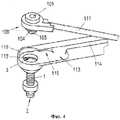
На фиг. 4-7 изображена последовательность подготовки и сборки устройства.In FIG. 4-7 shows the sequence of preparation and assembly of the device.
На фиг. 4 показан ввод направляющего элемента в пустотелый корпус.In FIG. 4 shows the insertion of a guide element into a hollow body.
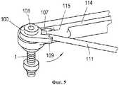
На фиг. 5 показан поворот введенного направляющего элемента.In FIG. 5 shows the rotation of the inserted guide element.
На фиг. 6 показан вид устройства после сцепления с направляющим элементом с фиксацией.In FIG. 6 shows a view of a device after engaging with a locking member.
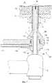
На фиг. 7 показан вид устройства в разрезе с введенным валом рабочего инструмента в момент перфорирования рабочим инструментом костной пластинки.In FIG. 7 shows a sectional view of the device with the inserted tool shaft at the time of perforation of the bone plate with the working tool.
Подробное описаниеDetailed description
На фиг. 1 изображена косая проекция, вид сверху, наиболее предпочтительного варианта конструктивного исполнения направляющего элемента 100 согласно изобретению. Изображенный здесь направляющий элемент 100 изготовлен из стерилизуемого полимера, что является известным в области медицинской техники. Направляющий элемент выполнен цельным или как одна деталь и изготовлен путем литья под давлением. Однако уплотнения и высверленные отверстия могут выполнять позже.In FIG. 1 shows an oblique projection, a top view of the most preferred embodiment of the
В дисковидной головной части 110 направляющего элемента 100 по центру образовано цилиндрическое сквозное отверстие 101, которое проходит через весь направляющий элемент 100. Во время работы вал 5 рабочего инструмента 6, например фрезерного инструмента, пропущен через это сквозное отверстие 101. Диаметр сквозного отверстия 101 немного больше, чем диаметр вала 5 рабочего инструмента 6, в результате чего фрезерный инструмент 5, 6 остается в подвижном состоянии в пустотелом корпусе 1, и рабочая среда может проходить вокруг фрезерного инструмента 5, 6.A cylindrical through
К головной части 110 примыкает соединение 108, выполненное в виде муфты, предназначенное для крепления трубопровода 111, который не показан на этой фигуре. Трубопровод 111 введен в эту муфту. Соединение 108 проходит радиально наружу от центра сквозного отверстия 101, и центральная продольная ось лежит в той плоскости дисковидной головной части 110, которая ориентирована параллельно поверхности.Adjacent to the
Смежно с соединением 108 образован рабочий выступ 109, который проходит по касательной к головной части 110 параллельно соединению 108 и выступает относительно соединения 108 вверх, а также в продольном направлении. Рабочий выступ 109 служит, с одной стороны, для фиксации соединения с трубопроводом 111 и для более надежного захвата во время поворота.Adjacent to the joint 108, a
Между головной частью 110 и соединением 108 создан немного смещенный вниз выступающий фиксирующий элемент 107, обеспечивающий возможность крепления направляющего элемента 100 к устройству разъемным соединением.Between the
Как видно из фиг. 3-7, на верхней стороне направляющего элемента 100, в частности для улучшения направления и герметичности, может быть образовано цилиндрическое возвышение, расположенное вокруг сквозного отверстия 101.As can be seen from FIG. 3-7, a cylindrical elevation located around the through
На фигуре 2 изображена косая проекция направляющего элемента 100 с противоположной стороны в виде снизу. Нижняя поверхность 106 направляющего элемента 100, которая во время работы обращена к кости 24, является гладкой и плоской, что обеспечивает возможность хорошего скольжения, вращения и поворота. В головной части 110 образован цилиндрический выступ 104, который окружен уплотнительным элементом 4, выполненным в виде уплотнительного кольца, которое размещено в желобе. При этом направляющий элемент 100 введен в устройство с облеганием, как показано на следующих фигурах.The figure 2 shows an oblique projection of the
На выступе 104 создана втулка 105, выполненная в виде усеченного конуса, сходящегося на конус в направлении вверх. Наибольший диаметр основания втулки 105 приблизительно на 30-40% меньше, чем диаметр цилиндрического выступа 104.On the
Аналогично головной части 110, цилиндрический выступ 104 и втулка 105 расположены концентрично вокруг центральной продольной оси сквозного отверстия 101, и сквозное отверстие 101 проходит сквозь них по их центру.Similarly to the
От соединения 108 проходит канал 102, закрытый со всех сторон и расположенный полностью внутри направляющего элемента 101, который обеспечивает соединение соединения с выпускным отверстием 103. Выпускное отверстие 103 ведет наружу на поверхности основания цилиндрического выступа 104, смежного к втулке 105, и обеспечивает введение жидкой рабочей среды или среды под давлением, в большинстве случаев физиологического солевого раствора, во входное отверстие 3 устройства. Канал 102 вдоль всей своей длины отделен от сквозного отверстия 101. Канал 102 имеет первую подсекцию, находящуюся вблизи соединения 108, и в начале его имеет увеличенный диаметр, и этот канал расположен перпендикулярно и радиально относительно продольной оси сквозного отверстия 101. Далее диаметр канала 102 уменьшается, и канал изгибается под прямым углом. Этот смежный второй участок длины проходит по существу параллельно центральной продольной оси сквозного отверстия 101. Таким образом, канал 102 может быть образован конструктивно просто в цельном направляющем элементе, например двумя последующими высверленными отверстиями.A
На фиг. 3 изображен вид в перспективе предлагаемого согласно изобретению устройства. Это устройство, приведенное как пример и не носящее ограничительного характера, предназначенное для перфорирования продолжения глухого отверстия в челюстной кости 24, содержит рабочий инструмент 6 в виде фрезерного инструмента 6 и направляющий элемент 100, описанный выше, который жестко соединен с пустотелым корпусом 1.In FIG. 3 is a perspective view of a device according to the invention. This device, shown as an example and not restrictive, designed to perforate the continuation of a blind hole in the jaw bone 24, contains a working
Пустотелый корпус 1 расположен на рукоятке 112, которая выполнена в виде плоского небольшого стержня. Направляющий элемент 100 расположен в углубленной области 113 на переднем конце рукоятки 112. Пустотелый корпус 1 имеет по существу цилиндрическое внутреннее пространство 12, дистальное рабочее отверстие 2 и входное отверстие 3 напротив рабочего отверстия 2. Через это входное отверстие 3 во внутреннее пространство 12 пустотелого корпуса 1 вводятся среда под давлением, а также вал 5 рабочего инструмента 6. Пустотелый корпус 1 выполнен по существу в виде трубчатого тела, как описано в документе WO 2010/048648.The hollow body 1 is located on the handle 112, which is made in the form of a flat small rod. The
Для обеспечения возможности образования камеры 7 давления внутри пустотелого корпуса 1, необходимо герметизировать внутреннее пространство 12 пустотелого корпуса 1 и вал 5 фрезерного инструмента 6 в области входного отверстия 3. Эта камера 7 давления и созданное в ней давление обеспечивают своевременное выталкивание синусной мембраны 26 из зоны опасности при осуществлении перфорирования костной пластинки.To ensure the possibility of the formation of the pressure chamber 7 inside the hollow body 1, it is necessary to seal the inner space 12 of the hollow body 1 and the
Сформированная камера 7 давления в любом случае может быть расположена полностью внутри пустотелого корпуса 1, когда рабочее отверстие 2 герметизировано находящимся вровень с ним основанием глухого отверстия. Однако камера 7 давления также может простираться вверх до области, находящейся снаружи данного пустотелого корпуса 1, которая ограничена стенкой глухого отверстия и коническим уплотнительным элементом или фланцем 11. Во время работы обе эти особенности оказывают уплотняющее действие и дополняют друг друга для того, чтобы обеспечить в системе герметичность и непроницаемость для текучей среды настолько, насколько это возможно.In any case, the formed pressure chamber 7 can be located completely inside the hollow body 1, when the working hole 2 is sealed with the base of the blind hole located flush with it. However, the pressure chamber 7 can also extend upward to an area outside of this hollow body 1, which is limited by the wall of the blind hole and the conical sealing element or flange 11. During operation, both of these features have a sealing effect and complement each other in order to ensure system tightness and impermeability to the fluid as much as possible.
Входное отверстие 3 на другом конце камеры 7 давления закрыто с обеспечением герметичности и непроницаемости для текучей среды введенным плотно и с облеганием направляющим элементом 100. Следует отметить, что вал 5 введен заранее и проходит через сквозное отверстие 101, однако он все еще не выходит через рабочее отверстие 2 и, таким образом, еще находится в нерабочем положении. В соединении 108 уже осуществлено соединение трубопровода 111, что обеспечивает возможность подачи рабочей среды под давлением внутрь пустотелого корпуса 1. Трубопровод 111 проходит в желобе 114, который выполнен в виде рукоятки 112. Этот желоб изогнут в двух местах в форме меандра для закрепления трубки на этих крепежных элементах 117. Трубопровод 111 может вести к шприцу или ручному или автоматическому устройству регулирования давления, при помощи которого давление может создаваться и регулироваться.The
На фиг. 4-7 поэтапно изображена подготовка устройства к процедуре синус-лифтинга.In FIG. 4-7, the preparation of the device for the sinus lift procedure is shown in stages.
На фиг. 4 направляющий элемент 100 уже соединен с трубопроводом 111, но еще не прикреплен к пустотелому корпусу 1. В передней части рукоятки 112 различима углубленная область 113, в которой размещен направляющий элемент 100. В самой дистальной передней части углубленной области 113 находится входное отверстие 3, которое обеспечивает доступ к внутреннему пространству 12 пустотелого корпуса 1. Входное отверстие 3 сначала очень широкое и имеет цилиндрическую форму на первом участке своей длины вплоть до стопора или кольцеобразной стопорной поверхности 119, где его диаметр по отношению к диаметру сквозного отверстия 101 уменьшается. В этой цилиндрической области входного отверстия 3 цилиндрический выступ 104 направляющего элемента 100 введен с облеганием, причем нижняя поверхность цилиндрического выступа 104 затем прилегает к стопору 119. Это обеспечивает безопасное вращение или поворот и одновременно с этим направление и герметичность посадки, причем центральное продольное сквозное отверстие 101 образует ось вращения.In FIG. 4, the
Входное отверстие 3 сходится на конус в направлении вниз и образует полость в форме раструба. Внутри пустотелого корпуса 1 по существу цилиндрическое полое пространство 12 проходит вплоть до рабочего отверстия 2.The
На фиг. 5 направляющий элемент 100 уже введен выступом 104 во входное отверстие 2 с облеганием и с обеспечением герметичности. Далее направляющий элемент 100 вращают или поворачивают на угол приблизительно от 30° до 40° в указанном стрелкой направлении до тех пор, пока соединение 108 по существу не будет ориентировано по направлению к началу желоба 114. На практике поворот осуществляют путем захвата рабочего выступа 109 и нажатия на него. Фиксирующий элемент 107 может быть посажен в соответствующий фиксирующий паз 115 в рукоятке 112, в частности в вертикальной граничной поверхности углубленной области 113, с облеганием и посадкой с натягом, что обеспечивает фиксацию местоположения направляющего элемента 100.In FIG. 5, the
На фиг. 6 это сцепление уже достигнуто и трубопровод 111 уже введен в желоб 114 и зафиксирован в нем. Теперь устройство подготовлено, и пустотелый корпус фактически теперь герметично введен в предварительно просверленное глухое отверстие в челюстной кости 24 пациента.In FIG. 6, this engagement has already been achieved and
На фиг. 7 устройство изображено в поперечном разрезе с введенным валом 5 рабочего инструмента 6 во время процедуры синус-лифтинга в тот момент, когда при помощи рабочего инструмента 6 перфорируют костную пластинку челюстной кости 24 верхней челюсти. На фиг. 7 устройство изображено в пространственно правильном положении по отношению к пациенту, которое имеет место на практике.In FIG. 7, the device is shown in cross section with the introduced
Как и в случае традиционного синус-лифтинга с доступом со стороны альвеолярного гребня, глухое отверстие формируют в челюстной кости 24 при выполнении предварительной процедуры, начиная с челюстного гребня, при этом между концом глухого отверстия и верхнечелюстной пазухой 25 остается костная пластинка толщиной приблизительно 1 мм. Это необходимо для предупреждения повреждения слизистой оболочки 26 верхнечелюстной пазухи, которая примыкает к челюстной кости 24 в верхнечелюстной пазухе 25.As in the case of traditional sinus lifting with access from the alveolar ridge, a deaf hole is formed in the jaw bone 24 during the preliminary procedure, starting from the jaw crest, while a bone plate about 1 mm thick remains between the end of the deaf hole and the maxillary sinus 25. This is necessary to prevent damage to the mucous membrane 26 of the maxillary sinus, which is adjacent to the jaw bone 24 in the maxillary sinus 25.
Затем с обеспечением герметичности пустотелый корпус 1 вводят в подготовленное глухое отверстие до тех пор, пока рабочее отверстие 2 не упрется в костную пластинку. Во время этой процедуры пустотелый корпус 1 находится в неподвижном состоянии, местоположение его остается неизменным и он может быть даже ввинчен.Then, in order to ensure tightness, the hollow body 1 is inserted into the prepared blind hole until the working hole 2 abuts against the bone plate. During this procedure, the hollow body 1 is stationary, its location remains unchanged and it can even be screwed.
Для улучшения уплотняющего действия фланец 10 смещают на трубчатом корпусе 1 по направлению к челюстной кости 24 так, что коническая уплотняющая часть 11, которая расположена на фланце 10, сильно прижимается к слизистой оболочке 27 полости рта на наружной границе глухого отверстия, и глухое отверстие герметизируется. В факультативном варианте возможно также использование коффердама. После этого внутри камеры 7 давления может быть установлено гидростатическое давление величиной приблизительно от 0,5 до 3 бар.To improve the sealing action, the flange 10 is displaced on the tubular body 1 towards the jaw bone 24 so that the conical sealing part 11, which is located on the flange 10, is strongly pressed against the mucous membrane of the oral cavity 27 at the outer border of the blind hole, and the blind hole is sealed. In the optional embodiment, the use of a rubber dam is also possible. After that, a hydrostatic pressure of about 0.5 to 3 bar can be set inside the pressure chamber 7.
Рабочая среда, находящаяся в камере 7 давления, служит одновременно для рассеяния тепла, выделяемого фрезой, и в качестве охладителя для вращающегося вала 5. Малые количества рабочей среды, которые могут просачиваться вдоль вращающегося вала 5, не составляют проблемы для выполнения устройством возложенной на него функции, потому что через соединение 108 может поддерживаться давление рабочей среды в камере 7 давления. При этом хорошие герметизирующие свойства имеют большое значение в связи с тем, что момент перфорирования костной пластинки легко распознать по понижению давления, когда камера давления герметизирована.The working medium in the pressure chamber 7 serves simultaneously to dissipate the heat generated by the cutter and as a cooler for the
После этого через сквозное отверстие 101 и входное отверстие 3 вводят внутрь пустотелого корпуса 1 вал 5 рабочего инструмента 6. Вал 5 выполнен с диаметром, уменьшающимся по направлению к его концу. Таким образом, диаметр вала 5 уменьшается в области места впуска входного отверстия 3 приблизительно на одну четвертую часть. В результате этого между валом 5 и внутренней поверхностью полого пространства 12 остается достаточно свободного места для образования камеры 7 давления и обеспечения такой свободы перемещения для фрезерного инструмента 6, которая достаточна для совершения кувыркательных движений. В концевой области сверлильной головки фрезерного инструмента 6 диаметр опять уменьшается на одну четверть. Кроме того, самый дальний конец или сверлильная головка фрезерного инструмента 6 или вала 5 сравнительно сильно искривлена или по существу выполнена точечной в целях обеспечения, насколько это возможно, точечного с малой поверхностью перфорирования костной пластинки.After that, through the through
Вал 5 полностью проходит через сквозное отверстие 101, входное отверстие 3 и внутреннее полое пространство 12 пустотелого корпуса 1 и выходит через рабочее отверстие 2, что позволяет обрабатывать оставшуюся костную пластинку. Дистальная часть вала 5 с меньшим диаметром может быть сравнительно легко направлена через сквозное отверстие 101, затем задняя часть, диаметр которой больше, с облеганием устанавливается в сквозном отверстии 101.The
Вал 5, таким образом, герметично прилегает в этой области к внутренней поверхности сквозного отверстия 101 или также дополнительно герметизируется, направляется и поддерживается в области цилиндрического выступа 104 и втулки 105. Внутри сквозного отверстия 101 может быть также предусмотрено наличие дополнительного уплотнения, например уплотнительного кольца, однако в настоящем предпочтительном примере осуществления изобретения это не предусмотрено.The
При этом вал 5 имеет возможность перемещения в осевом направлении, то есть вверх и вниз как указано стрелкой, что требуется особенно в случае вращающихся фрезерных инструментов 6, чтобы обеспечить необходимое продвижение вперед для проведения фрезерования через костную пластинку в челюстной кости 24. Кроме того, возможно также, например, вследствие гибкости материала направляющего элемента 100, перемещение вала 5 вращательным или кувыркательным движением, чтобы удалить пластину костного основания настолько широко и полно, насколько это возможно.In this case, the
Это вращательное движение возможно также при использовании рабочего инструмента с валом 5, который вращается вокруг своей собственной оси. Вал 5, тем не менее, установлен с обеспечением непроницаемости для текучей среды и герметичности, в частности в области втулки 105, и в камере 7 может быть установлено достаточно высокое давление, когда пустотелый корпус 1 вводится в глухое отверстие с обеспечением герметизации.This rotational movement is also possible when using a working tool with a
Теперь через соединение 108 во входное отверстие 3 может быть введена рабочая среда, например физиологический солевой раствор. Ввиду того, что наружная стенка втулки 105 расположена на расстоянии от внутренней стенки имеющего форму раструба входного отверстия 3, промывочная среда проходит с наружной стороны вдоль втулки 105 и вдоль вала 5 во внутреннее пространство 12 или камеру 7 давления.Now, through a
Фрезерный инструмент 6 по фиг 7 затем постепенно перемещают дальше вниз, так что фрезерная головка выходит на нижнем конце через рабочее отверстие 2 и касается пластинки костного дна, при этом продвижение вала 5 или фрезерного инструмента 6 является очень медленным, например со скоростью около 1 мм/мин.The
Как только выполнено перфорирование пластинки костного дна минимально в одном месте, что облегчается за счет точечной сверлильной или фрезерной головки, рабочая среда, находящаяся под давлением, мгновенно выходит через минимальное отверстие и синусная мембрана 26 мгновенно выталкивается из зоны опасности от сверлильной головки и слегка отделяется от челюстной кости 24 до того, как сверлильная головка сможет полностью пройти через отверстие. Это соответствует ситуации, показанной на фиг. 7.As soon as the bone bottom plate is perforated in at least one place, which is facilitated by a point drilling or milling head, the pressure medium immediately exits through the minimum hole and the sinus membrane 26 is instantly pushed out of the danger zone from the drilling head and slightly separated from jawbone 24 before the drill head can completely pass through the hole. This corresponds to the situation shown in FIG. 7.
Далее фрезерный инструмент выключают и синусную мембрану 26 дополнительно отделяют, как известно из документа WO 2010/048648, чтобы увеличить пространство для костно-замещающего материала, например путем дополнительного подвода среды под давлением и, в зависимости от обстоятельств, путем введения колебаний.Next, the milling tool is turned off and the sinus membrane 26 is further separated, as is known from document WO 2010/048648, in order to increase the space for the bone-substitute material, for example by additional supply of medium under pressure and, depending on the circumstances, by introducing vibrations.
Вал 5 может оставаться в сквозном отверстии 101 на некоторое время в качестве уплотнительного элемента. Или же вал 5 может быть также удален и сквозное отверстие 101 может быть герметично закрыто путем введения пробки. Это дает возможность далее прикладывать давление или поддерживать постоянное давление.The
В зависимости от конкретного случая, для облегчения дальнейшего отделения синусной мембраны 26, в рабочую среду могут быть введены колебания, например ультразвуковые колебания.Depending on the particular case, in order to facilitate further separation of the sinus membrane 26, vibrations, for example ultrasonic vibrations, can be introduced into the working medium.
Для замены или удаления направляющего элемента 100 после проведения процедуры, направляющий элемент 100 захватывают в месте нахождения рабочего выступа 109 и поворачивают в противоположном направлении, указанном стрелкой на фиг. 5. На самом конце передней части рукоятки 112 образована непрерывно увеличивающаяся наружная кромка 116, которая взаимодействует с нижней поверхностью 106, поджимает направляющий элемент100 вверх во время поворота и в результате поднимает направляющий элемент 100 так, что он выходит из входного отверстия 3.To replace or remove the
Согласно изобретению предусмотрено также, что направляющий элемент 100 распространяется как стерилизованная и асептически упакованная деталь или медицинское изделие одноразового применения или сам по себе, или в комбинации с трубопроводом 111. Непосредственно перед началом процедуры хирург или стоматолог может распечатать упаковку и извлечь гарантированно стерильный направляющий элемент 100 и трубопровод 111, прикрепить их к полому корпусу 1 и расположить рабочий инструмент соответствующим образом. Для получения информации, что касается функционирования устройства и, в частности, применения его на пациенте, дается ссылка на описание к документу WO 2010/048648 A1.According to the invention, it is also provided that the
Claims (31)
Translated fromRussianслучая, шприц, причем направляющий элемент (100) и трубопровод (111) и шприц стерилизованы и упакованы асептически в закрытом контейнере, предпочтительно в полиэтиленовом мешке.31. A kit containing a guide element (100) according to paragraphs. 1-12, and at least one pipeline (111) and, depending on the particular
case, a syringe, and the guide element (100) and the pipe (111) and the syringe are sterilized and packaged aseptically in a closed container, preferably in a plastic bag.
Applications Claiming Priority (3)
| Application Number | Priority Date | Filing Date | Title |
|---|---|---|---|
| ATA1839/2010 | 2010-11-09 | ||
| ATA1839/2010AAT510402B1 (en) | 2010-11-09 | 2010-11-09 | GUIDE ELEMENT AND DEVICE FOR INTRODUCING A BONE HOLE |
| PCT/AT2011/000406WO2012061854A1 (en) | 2010-11-09 | 2011-09-30 | Guide element and device for creating a hole in a bone |
Publications (2)
| Publication Number | Publication Date |
|---|---|
| RU2013126188A RU2013126188A (en) | 2014-12-20 |
| RU2558451C2true RU2558451C2 (en) | 2015-08-10 |
Family
ID=44860172
Family Applications (1)
| Application Number | Title | Priority Date | Filing Date |
|---|---|---|---|
| RU2013126188/14ARU2558451C2 (en) | 2010-11-09 | 2011-09-30 | Guide element and device for hole formation in bone |
Country Status (12)
| Country | Link |
|---|---|
| US (2) | US20130344453A1 (en) |
| EP (1) | EP2637596B8 (en) |
| JP (1) | JP5868415B2 (en) |
| KR (1) | KR101901380B1 (en) |
| CN (1) | CN103260542B (en) |
| AT (1) | AT510402B1 (en) |
| AU (1) | AU2011326346B2 (en) |
| BR (1) | BR112013011569A2 (en) |
| IL (1) | IL226269B (en) |
| RU (1) | RU2558451C2 (en) |
| WO (1) | WO2012061854A1 (en) |
| ZA (1) | ZA201303901B (en) |
Cited By (1)
| Publication number | Priority date | Publication date | Assignee | Title |
|---|---|---|---|---|
| RU186276U1 (en)* | 2018-04-13 | 2019-01-15 | Алексей Евгеньевич Яблоков | DEVICE FOR PREPARING AND COLLECTING AUTO-LAST-PLASTIC MATERIAL CONTAINING MEMORY PEPTIDS AND ENRICHED WITH A CONCENTRATED BLOOD BLOOD WITH PRP FACTOR, FOR IMPLEMENTATION OF A TREATMENT |
Families Citing this family (18)
| Publication number | Priority date | Publication date | Assignee | Title |
|---|---|---|---|---|
| DE102011001888A1 (en)* | 2011-04-07 | 2012-10-11 | Marcus Abboud | Method for producing a guide channel in a drilling template |
| AT513103B1 (en)* | 2012-06-28 | 2014-07-15 | Jeder Gmbh | Device for penetratingly extending a blind hole introduced into hard tissue, in particular the jawbone |
| JP6423585B2 (en)* | 2012-10-01 | 2018-11-14 | 株式会社インプラントデント | Dental implant embedding hole forming assist device |
| CN105491975B (en) | 2013-08-26 | 2018-09-28 | 医乐世医疗技术蒂默什达拉公司 | Dental drill system |
| EP3038560B1 (en)* | 2013-08-26 | 2018-05-30 | Elos Medtech Timmersdala AB | Dental surgery device |
| KR101645090B1 (en)* | 2014-07-24 | 2016-08-12 | 김래회 | Implant apparatus and method using the same procedure |
| KR101851521B1 (en) | 2015-09-15 | 2018-04-24 | 정재봉 | guider osteotome for lifting of maxillary sinus |
| IL243401A (en)* | 2015-12-29 | 2017-12-31 | Zion Karmon Ben | Devices and methods for elevating the schneiderian membrane |
| CN107496041B (en)* | 2017-08-08 | 2020-07-31 | 青岛市中心医院 | Reconfigurable guide plate for oral implant |
| EP3810026A1 (en)* | 2018-06-25 | 2021-04-28 | Angelus Industria De Produtos Odontologicos S/A | Injection systems in the radicular canal system and use thereof |
| KR20210110862A (en)* | 2019-01-04 | 2021-09-09 | 비악스 덴탈 테크놀로지스 엘엘씨 | Tooth preparation system with lateral prongs to limit three-dimensional movement |
| CN110507437A (en)* | 2019-08-23 | 2019-11-29 | 雅客智慧(北京)科技有限公司 | Dentistry implant cavity preparation system and cavity preparation method |
| CN112168384B (en)* | 2020-10-30 | 2022-03-15 | 深圳市速航科技发展有限公司 | Root canal therapy device with compound motion mode |
| CN113662691A (en)* | 2021-03-16 | 2021-11-19 | 梁光强 | Tool box for lifting inside of maxillary sinus |
| AT524563B1 (en)* | 2021-04-09 | 2022-07-15 | Eder Dr Klaus | Device for use in a crestal sinus lift |
| CN115479547A (en)* | 2021-06-16 | 2022-12-16 | 欣竑科技有限公司 | Nondestructive milling cutter core thickness measuring device |
| CN114948280B (en)* | 2022-05-13 | 2023-02-03 | 四川大学 | A variable positioning device and positioning method for a dental drill |
| CN119184889B (en)* | 2024-11-27 | 2025-03-14 | 德州市红拳医疗器械有限公司 | Tooth implantation positioning device |
Citations (2)
| Publication number | Priority date | Publication date | Assignee | Title |
|---|---|---|---|---|
| SU1644922A1 (en)* | 1989-04-03 | 1991-04-30 | Научно-исследовательский институт радиофизики им.акад.А.А.Расплетина | Jig for perforation of bone tissue |
| SU1672924A3 (en)* | 1986-04-01 | 1991-08-23 | Хута Баильдон (Инопредприятие) | Guide for drilling holes in bones |
Family Cites Families (20)
| Publication number | Priority date | Publication date | Assignee | Title |
|---|---|---|---|---|
| BE821274A (en)* | 1974-10-18 | 1975-02-17 | PROCESS FOR CLEANING, DRYING AND FILLING HAIR TUBES OR OTHER CONDUITS CLOSED TO ONE OF THEIR ENDS AND END DIAMETER | |
| CH685852A5 (en)* | 1991-10-18 | 1995-10-31 | Meditec Sa | A sealing apparatus by the vacuum dental root canals |
| EP0553712A1 (en)* | 1992-01-29 | 1993-08-04 | Kaltenbach & Voigt Gmbh & Co. | Laser treatment device, especially for medical or dental use |
| DE9416194U1 (en)* | 1994-08-19 | 1995-01-05 | Richter, Uwe, Dr., 69121 Heidelberg | Attachment for a drilling device and device for explanting and transforming bone |
| DE10129948B4 (en)* | 2001-06-21 | 2012-11-22 | Christian Edlhuber | Osteotom |
| CN2516125Y (en)* | 2002-01-08 | 2002-10-16 | 郑州市一美牙科工业有限公司 | Self-rotary hollow drive axle for electric dental drill head |
| US7510397B2 (en)* | 2004-10-15 | 2009-03-31 | Hochman Mark N | Method and apparatus for performing maxillary sinus elevation |
| WO2007065978A1 (en)* | 2005-12-08 | 2007-06-14 | Georges Antoine Creps | Drilling device and drilling method for insertion of a dental implant |
| DE202006004954U1 (en)* | 2006-03-28 | 2006-06-01 | Bauer, Florian, Dr.med.dent. | Medical drilling system for use in dental therapy, has driller guided through sleeve completely up to stopper, where drilling depth is determined such that driller projects above sleeve at defined length |
| IL175477A (en)* | 2006-05-08 | 2013-09-30 | Efraim Kfir | Assembly for lifting the sinus membrane for use in dental implant surgery |
| US7803159B2 (en)* | 2006-11-29 | 2010-09-28 | Mi4Spine, Llc | Disc space preparation device for spinal surgery |
| AT504552B1 (en) | 2006-12-11 | 2008-09-15 | Eder Klaus Dr | SURGICAL INSTRUMENT FOR IMPROVING A CRESTAL SINUSLIFT |
| CN201058047Y (en)* | 2007-01-26 | 2008-05-14 | 蒋毅 | Disposable Thoracentesis Kit |
| EP2182995A1 (en)* | 2007-06-27 | 2010-05-12 | Roland Dricot | Structure for forming bone |
| EP2214584A2 (en)* | 2007-11-15 | 2010-08-11 | Medizinische Universität Wien | Method and device for carrying out a percrestale sinus lift |
| WO2009151926A2 (en)* | 2008-05-23 | 2009-12-17 | Spine View, Inc. | Method and devices for treating spinal stenosis |
| PL2367498T3 (en)* | 2008-10-28 | 2013-12-31 | Jeder Gmbh | Milling device for making a hole in the bone |
| AT507208B1 (en)* | 2008-10-28 | 2010-03-15 | Eder Klaus Dr | MILLING DEVICE FOR INTRODUCING BONE DRILLING |
| CA2749266C (en)* | 2009-01-13 | 2017-05-09 | Innovative Implant Technology, Llc | Maxillary bone cutting and injection system and method of using the same |
| JP5554129B2 (en)* | 2010-04-13 | 2014-07-23 | 医療法人社団進盛会 | Maxillary sinus mucosal stripping device |
- 2010
- 2010-11-09ATATA1839/2010Apatent/AT510402B1/ennot_activeIP Right Cessation
- 2011
- 2011-09-30EPEP11773981.3Apatent/EP2637596B8/ennot_activeNot-in-force
- 2011-09-30WOPCT/AT2011/000406patent/WO2012061854A1/enactiveApplication Filing
- 2011-09-30CNCN201180054063.XApatent/CN103260542B/ennot_activeExpired - Fee Related
- 2011-09-30AUAU2011326346Apatent/AU2011326346B2/ennot_activeCeased
- 2011-09-30KRKR1020137014604Apatent/KR101901380B1/ennot_activeExpired - Fee Related
- 2011-09-30USUS13/884,188patent/US20130344453A1/ennot_activeAbandoned
- 2011-09-30BRBR112013011569Apatent/BR112013011569A2/enactiveSearch and Examination
- 2011-09-30RURU2013126188/14Apatent/RU2558451C2/enactive
- 2011-09-30JPJP2013537998Apatent/JP5868415B2/ennot_activeExpired - Fee Related
- 2013
- 2013-05-09ILIL226269Apatent/IL226269B/enactiveIP Right Grant
- 2013-05-28ZAZA2013/03901Apatent/ZA201303901B/enunknown
- 2016
- 2016-12-27USUS15/391,367patent/US10080625B2/ennot_activeExpired - Fee Related
Patent Citations (2)
| Publication number | Priority date | Publication date | Assignee | Title |
|---|---|---|---|---|
| SU1672924A3 (en)* | 1986-04-01 | 1991-08-23 | Хута Баильдон (Инопредприятие) | Guide for drilling holes in bones |
| SU1644922A1 (en)* | 1989-04-03 | 1991-04-30 | Научно-исследовательский институт радиофизики им.акад.А.А.Расплетина | Jig for perforation of bone tissue |
Cited By (1)
| Publication number | Priority date | Publication date | Assignee | Title |
|---|---|---|---|---|
| RU186276U1 (en)* | 2018-04-13 | 2019-01-15 | Алексей Евгеньевич Яблоков | DEVICE FOR PREPARING AND COLLECTING AUTO-LAST-PLASTIC MATERIAL CONTAINING MEMORY PEPTIDS AND ENRICHED WITH A CONCENTRATED BLOOD BLOOD WITH PRP FACTOR, FOR IMPLEMENTATION OF A TREATMENT |
Also Published As
| Publication number | Publication date |
|---|---|
| US20130344453A1 (en) | 2013-12-26 |
| AT510402B1 (en) | 2012-04-15 |
| JP5868415B2 (en) | 2016-02-24 |
| AU2011326346A1 (en) | 2013-06-27 |
| WO2012061854A1 (en) | 2012-05-18 |
| EP2637596B8 (en) | 2018-05-23 |
| US10080625B2 (en) | 2018-09-25 |
| KR101901380B1 (en) | 2018-09-27 |
| US20170105812A1 (en) | 2017-04-20 |
| BR112013011569A2 (en) | 2016-08-09 |
| AT510402A4 (en) | 2012-04-15 |
| JP2014500744A (en) | 2014-01-16 |
| KR20140044766A (en) | 2014-04-15 |
| RU2013126188A (en) | 2014-12-20 |
| CN103260542B (en) | 2017-04-05 |
| IL226269B (en) | 2018-05-31 |
| IL226269A0 (en) | 2013-07-31 |
| CN103260542A (en) | 2013-08-21 |
| EP2637596A1 (en) | 2013-09-18 |
| ZA201303901B (en) | 2018-12-19 |
| EP2637596B1 (en) | 2018-03-28 |
| AU2011326346B2 (en) | 2016-04-21 |
Similar Documents
| Publication | Publication Date | Title |
|---|---|---|
| RU2558451C2 (en) | Guide element and device for hole formation in bone | |
| US9615841B2 (en) | Device for making a borehole into a bone | |
| EP3150164B1 (en) | Apparatus for sinus lift and lateral ridge augmentation | |
| US8398643B2 (en) | Maxillary bone cutting and injection system and method of using the same | |
| US10045687B2 (en) | Dental implants, devices and methods associated with dental implantation procedures | |
| US8702423B2 (en) | Cortical drilling | |
| JP2012509092A6 (en) | Milling device for creating perforations in bone | |
| US20150320522A1 (en) | Angular connector/milling cutter | |
| JP6894438B2 (en) | Equipment and methods for raising the Schneider membrane | |
| IL214635A (en) | Implants and implant for sinus lift and lateral ridge augmentation |