RU2555281C2 - Method and device for ply-by-ply making of 3d article - Google Patents
Method and device for ply-by-ply making of 3d articleDownload PDFInfo
- Publication number
- RU2555281C2 RU2555281C2RU2011130284/02ARU2011130284ARU2555281C2RU 2555281 C2RU2555281 C2RU 2555281C2RU 2011130284/02 ARU2011130284/02 ARU 2011130284/02ARU 2011130284 ARU2011130284 ARU 2011130284ARU 2555281 C2RU2555281 C2RU 2555281C2
- Authority
- RU
- Russia
- Prior art keywords
- layer
- film
- curing
- flexible film
- contact
- Prior art date
Links
- 238000000034methodMethods0.000titleclaimsabstractdescription87
- 239000000463materialSubstances0.000claimsabstractdescription193
- 239000007788liquidSubstances0.000claimsabstractdescription67
- 239000007787solidSubstances0.000claimsabstractdescription19
- 238000004519manufacturing processMethods0.000claimsabstractdescription16
- 230000033001locomotionEffects0.000claimsdescription39
- 230000008569processEffects0.000abstractdescription46
- 230000000694effectsEffects0.000abstractdescription8
- 238000006073displacement reactionMethods0.000abstractdescription3
- 239000000126substanceSubstances0.000abstractdescription3
- 238000010327methods by industryMethods0.000abstract1
- 238000007711solidificationMethods0.000abstract1
- 230000008023solidificationEffects0.000abstract1
- 239000010408filmSubstances0.000description165
- 238000001723curingMethods0.000description58
- 229920000642polymerPolymers0.000description44
- 238000010438heat treatmentMethods0.000description17
- 230000005855radiationEffects0.000description13
- 230000007246mechanismEffects0.000description9
- 239000004848polyfunctional curativeSubstances0.000description9
- 239000011248coating agentSubstances0.000description8
- 238000000576coating methodMethods0.000description8
- 230000006870functionEffects0.000description8
- 239000000243solutionSubstances0.000description7
- 238000000926separation methodMethods0.000description6
- 239000000853adhesiveSubstances0.000description5
- 230000001070adhesive effectEffects0.000description5
- 230000008901benefitEffects0.000description5
- 238000010276constructionMethods0.000description5
- 238000005096rolling processMethods0.000description5
- 230000009471actionEffects0.000description4
- 238000001816coolingMethods0.000description4
- 238000001704evaporationMethods0.000description4
- 230000008020evaporationEffects0.000description4
- 239000002699waste materialSubstances0.000description4
- 230000008859changeEffects0.000description3
- 238000005516engineering processMethods0.000description3
- 239000003822epoxy resinSubstances0.000description3
- 239000012530fluidSubstances0.000description3
- 239000011159matrix materialSubstances0.000description3
- 229920000058polyacrylatePolymers0.000description3
- 229920000647polyepoxidePolymers0.000description3
- 238000012546transferMethods0.000description3
- 238000004458analytical methodMethods0.000description2
- 238000000149argon plasma sinteringMethods0.000description2
- 238000004140cleaningMethods0.000description2
- 230000002349favourable effectEffects0.000description2
- 238000001879gelationMethods0.000description2
- 239000011521glassSubstances0.000description2
- 239000000203mixtureSubstances0.000description2
- 238000012986modificationMethods0.000description2
- 230000004048modificationEffects0.000description2
- 239000000178monomerSubstances0.000description2
- 230000003287optical effectEffects0.000description2
- 229920001296polysiloxanePolymers0.000description2
- 238000000110selective laser sinteringMethods0.000description2
- WSSSPWUEQFSQQG-UHFFFAOYSA-N4-methyl-1-penteneChemical compoundCC(C)CC=CWSSSPWUEQFSQQG-UHFFFAOYSA-N0.000description1
- NIXOWILDQLNWCW-UHFFFAOYSA-MAcrylateChemical compound[O-]C(=O)C=CNIXOWILDQLNWCW-UHFFFAOYSA-M0.000description1
- 239000004925Acrylic resinSubstances0.000description1
- 238000005411Van der Waals forceMethods0.000description1
- 230000032683agingEffects0.000description1
- XAGFODPZIPBFFR-UHFFFAOYSA-NaluminiumChemical compound[Al]XAGFODPZIPBFFR-UHFFFAOYSA-N0.000description1
- 229910052782aluminiumInorganic materials0.000description1
- 230000009286beneficial effectEffects0.000description1
- 230000005540biological transmissionEffects0.000description1
- 230000015572biosynthetic processEffects0.000description1
- 238000006243chemical reactionMethods0.000description1
- 239000003795chemical substances by applicationSubstances0.000description1
- 238000004891communicationMethods0.000description1
- 239000002131composite materialSubstances0.000description1
- 230000001276controlling effectEffects0.000description1
- 125000004122cyclic groupChemical group0.000description1
- 238000013016dampingMethods0.000description1
- 230000001419dependent effectEffects0.000description1
- 238000013461designMethods0.000description1
- 230000006866deteriorationEffects0.000description1
- 238000010790dilutionMethods0.000description1
- 239000012895dilutionSubstances0.000description1
- 239000006185dispersionSubstances0.000description1
- 238000010894electron beam technologyMethods0.000description1
- 238000002474experimental methodMethods0.000description1
- 239000000835fiberSubstances0.000description1
- 239000000945fillerSubstances0.000description1
- 238000011049fillingMethods0.000description1
- 230000004907fluxEffects0.000description1
- 150000002605large moleculesChemical class0.000description1
- 238000001459lithographyMethods0.000description1
- 229920002521macromoleculePolymers0.000description1
- 210000002445nippleAnatomy0.000description1
- 239000012788optical filmSubstances0.000description1
- 230000010355oscillationEffects0.000description1
- 239000011148porous materialSubstances0.000description1
- 238000003825pressingMethods0.000description1
- 238000012545processingMethods0.000description1
- KCTAWXVAICEBSD-UHFFFAOYSA-Nprop-2-enoyloxy prop-2-eneperoxoateChemical compoundC=CC(=O)OOOC(=O)C=CKCTAWXVAICEBSD-UHFFFAOYSA-N0.000description1
- 230000001681protective effectEffects0.000description1
- 230000009467reductionEffects0.000description1
- 230000001105regulatory effectEffects0.000description1
- 230000005654stationary processEffects0.000description1
- 239000000758substrateSubstances0.000description1
- 238000012360testing methodMethods0.000description1
- 238000001029thermal curingMethods0.000description1
- 230000007704transitionEffects0.000description1
- KNXVOGGZOFOROK-UHFFFAOYSA-Ntrimagnesium;dioxido(oxo)silane;hydroxy-oxido-oxosilaneChemical compound[Mg+2].[Mg+2].[Mg+2].O[Si]([O-])=O.O[Si]([O-])=O.[O-][Si]([O-])=O.[O-][Si]([O-])=OKNXVOGGZOFOROK-UHFFFAOYSA-N0.000description1
- 238000009736wettingMethods0.000description1
- 230000037303wrinklesEffects0.000description1
Images


Classifications
- B—PERFORMING OPERATIONS; TRANSPORTING
- B29—WORKING OF PLASTICS; WORKING OF SUBSTANCES IN A PLASTIC STATE IN GENERAL
- B29C—SHAPING OR JOINING OF PLASTICS; SHAPING OF MATERIAL IN A PLASTIC STATE, NOT OTHERWISE PROVIDED FOR; AFTER-TREATMENT OF THE SHAPED PRODUCTS, e.g. REPAIRING
- B29C64/00—Additive manufacturing, i.e. manufacturing of three-dimensional [3D] objects by additive deposition, additive agglomeration or additive layering, e.g. by 3D printing, stereolithography or selective laser sintering
- B29C64/10—Processes of additive manufacturing
- B29C64/106—Processes of additive manufacturing using only liquids or viscous materials, e.g. depositing a continuous bead of viscous material
- B29C64/124—Processes of additive manufacturing using only liquids or viscous materials, e.g. depositing a continuous bead of viscous material using layers of liquid which are selectively solidified
- B29C64/129—Processes of additive manufacturing using only liquids or viscous materials, e.g. depositing a continuous bead of viscous material using layers of liquid which are selectively solidified characterised by the energy source therefor, e.g. by global irradiation combined with a mask
Landscapes
- Chemical & Material Sciences (AREA)
- Engineering & Computer Science (AREA)
- Materials Engineering (AREA)
- Physics & Mathematics (AREA)
- Manufacturing & Machinery (AREA)
- Mechanical Engineering (AREA)
- Optics & Photonics (AREA)
Abstract
Description
Translated fromRussianОбласть использования изобретения и предпосылки его созданияThe scope of the invention and the prerequisites for its creation
Изобретение относится к способу послойного изготовления материального объекта согласно ограничительной части п. 1 формулы изобретения. Изобретение также относится к системе для послойного изготовления материального объекта.The invention relates to a method for layer-by-layer production of a material object according to the restrictive part of paragraph 1 of the claims. The invention also relates to a system for layer-by-layer production of a material object.
Такой способ известен. Например, он известен из патента США №6547552, согласно которому небольшой объем жидкости спрессовывают между пленкой и материальным объектом для получения тонкого слоя жидкости, который может быть отвержден. Гибкая пленка пригодна для пропуска отверждающего излучения. Первоначально сформированный твердый слой материального объекта приклеивают к нижней стороне несущей пластины посредством выборочного отверждения жидкости. Последовательно сформированные твердые слои (каждый) приклеивают к ранее сформированному твердому слою, соответственно.This method is known. For example, it is known from US patent No. 6547552, according to which a small volume of liquid is pressed between the film and the material object to obtain a thin layer of liquid that can be cured. The flexible film is suitable for transmitting curing radiation. The initially formed solid layer of the material object is adhered to the underside of the carrier plate by selectively curing the liquid. Consistently formed solid layers (each) are glued to a previously formed solid layer, respectively.
Каждый раз после отверждения нового слоя платформу для направления пленки перемещают для отслаивания пленки от ранее отвержденных слоев, приклеенных к объекту, для отделения последнего сформированного твердого слоя от пленки.Each time after curing a new layer, the film guiding platform is moved to peel the film from previously cured layers adhered to the object to separate the last formed solid layer from the film.
Существует потребность в увеличении скорости процесса изготовления.There is a need to increase the speed of the manufacturing process.
Краткое описание изобретенияSUMMARY OF THE INVENTION
Задачей изобретения является обеспечение возможности более быстрого изготовления материального объекта.The objective of the invention is to enable faster production of a material object.
Таким образом, согласно первому аспекту изобретения создан способ по п. 1 формулы изобретения.Thus, according to a first aspect of the invention, there is provided a method according to claim 1.
Согласно данному способу в соответствии с первым аспектом изобретения создана конструкционная форма; и циклы способа повторно выполняют, где каждый цикл способа включает этапы:According to this method, in accordance with the first aspect of the invention, a structural form is created; and the cycles of the method are re-performed, where each cycle of the method includes the steps of:
- обеспечения слоя жидкости ограниченной высоты на конструкционной форме, которая не контактирует с материальным объектом;- providing a liquid layer of limited height on a structural form that does not come into contact with a material object;
- перемещения, друг относительно друга, конструкционной формы в предварительно определенное положение относительно материального объекта для осуществления последующего такого цикла способа для отверждения предварительно определенной области последующего такого слоя жидкости;- displacement, relative to each other, of the structural form to a predetermined position relative to the material object for the implementation of the subsequent such cycle of the method for curing a predetermined area of the subsequent such liquid layer;
- отверждения предварительно определенной области слоя жидкости для получения твердого слоя материального объекта, где твердый слой, таким образом, имеет предварительно определенную форму; иcuring a predetermined region of the liquid layer to obtain a solid layer of a material object, where the solid layer thus has a predetermined shape; and
- отделения упомянутого твердого слоя от упомянутой конструкционной формы;- separating said solid layer from said structural form;
где согласно способу, по меньшей мере, в одном из упомянутых циклов способа упомянутое перемещение упомянутой конструкционной формы и упомянутое отверждение упомянутой предварительно определенной области осуществляют таким образом, чтобы они происходили одновременно. Благоприятные эффекты такого одновременного перемещения и отверждения объясняются следующим образом.where according to the method, in at least one of the aforementioned cycles of the method, said movement of said structural form and said curing of said predetermined region are carried out so that they occur simultaneously. The beneficial effects of such simultaneous movement and curing are explained as follows.
Во-первых, благодаря одновременному перемещению и отверждению обеспечивается увеличение скорости самого процесса.Firstly, due to the simultaneous movement and curing, an increase in the speed of the process itself is ensured.
Это означает, что для начала отверждения слоя не нужно ожидать, пока все части слоя будут обеспечены жидкостью. Следовательно, имеет место небольшой простой отверждающих средств или его нет вообще. Кроме того, работа упрощается, и стоимость материала может быть снижена.This means that to begin the curing of the layer does not need to wait until all parts of the layer are provided with liquid. Therefore, there is a small simple hardening agents or not at all. In addition, the work is simplified, and the cost of the material can be reduced.
Кроме того, согласно второму аспекту изобретения создана система по п. 8 формулы изобретения.In addition, according to a second aspect of the invention, a system according to claim 8 is created.
Конкретные варианты осуществления изобретения представлены в зависимых пунктах формулы изобретения.Specific embodiments of the invention are presented in the dependent claims.
Эти и другие аспекты изобретения станут очевидными после ознакомления с вариантами осуществления, описанными и поясненными ниже.These and other aspects of the invention will become apparent after reading the embodiments described and explained below.
Краткое описание чертежейBrief Description of the Drawings
Дополнительные детали, аспекты и варианты осуществления изобретения описаны, только в виде примеров, со ссылками на чертежи.Additional details, aspects, and embodiments of the invention are described, by way of example only, with reference to the drawings.
На фиг. 1 схематически показан боковой вид в сечении примера варианта осуществления системы согласно изобретению;In FIG. 1 is a schematic cross-sectional side view of an example embodiment of a system according to the invention;
на фиг. 2 схематически показан боковой вид в сечении другого примера варианта осуществления системы согласно изобретению;in FIG. 2 is a schematic cross-sectional side view of another example embodiment of a system according to the invention;
на фиг. 3-5 схематически показаны боковые виды в сечении дополнительных примеров других вариантов осуществления системы согласно изобретению;in FIG. 3-5 are schematic side views in cross section of further examples of other embodiments of a system according to the invention;
на фиг. 6 показано схематическое представление варианта осуществления аппарата согласно настоящему изобретению;in FIG. 6 is a schematic representation of an embodiment of an apparatus according to the present invention;
на фиг. 7 проиллюстрированы эффекты подъема объекта, имеющего большое поперечное сечение;in FIG. 7 illustrates the effects of lifting an object having a large cross section;
на фиг. 8 проиллюстрирован процесс остаточного подъема пленки;in FIG. 8 illustrates the process of residual film lift;
на фиг. 9 показан схематически вариант осуществления, содержащий перфорированную пластину;in FIG. 9 is a schematic illustration of an embodiment comprising a perforated plate;
на фиг. 10 показан схематически вариант осуществления, в котором минимизировано испарение полимера;in FIG. 10 schematically shows an embodiment in which polymer evaporation is minimized;
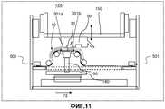
на фиг. 11 показан схематически вариант осуществления, содержащий нагреватели полимера;in FIG. 11 schematically shows an embodiment comprising polymer heaters;
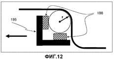
на фиг. 12 показан детально узел вала;in FIG. 12 shows in detail a shaft assembly;
на фиг. 13 подробно проиллюстрирован процесс оптического пропуска пленки;in FIG. 13 illustrates in detail the process of optical film skipping;
на фиг. 14 проиллюстрирован процесс отверждения при двух направлениях перемещения; иin FIG. 14 illustrates a curing process in two directions of travel; and
на фиг. 15 показан вариант осуществления, представленный на фиг. 14, в реверсивных режимах.in FIG. 15 shows the embodiment of FIG. 14, in reverse modes.
Подробное описание изобретенияDETAILED DESCRIPTION OF THE INVENTION
Каждый из примеров, представленных на фиг. 1-6, относится к системе по п. 8, на которой можно выполнять пример способа по п. 1. На соответствующих чертежах иногда одинаковыми номерами позиций обозначены подобные или идентичные части или аспекты систем.Each of the examples shown in FIG. 1-6, relates to a system according to claim 8, on which you can perform an example of the method according to claim 1. In the corresponding drawings, sometimes identical or identical parts or aspects of systems are indicated by the same reference numbers.
Следовательно, каждый из примеров, представленных на фиг. 1-6, относится к примерному варианту осуществления системы для послойного изготовления материального объекта 5. Системы могут содержать: конструкционную форму 6, на которую наносят слой жидкости; отвердитель 9 для отверждения предварительно определенной области слоя 10 жидкости 3 таким образом, чтобы получить твердый слой 4 материального объекта 5, где твердый слой, таким образом, имеет предварительно определенную форму; отделитель 18, 19′, 19″ для отделения упомянутого твердого слоя от упомянутой конструкционной формы; и перемещающее устройство 18 для перемещения, друг относительно друга, формы 6 для изготовления в предварительно определенное положение относительно материального объекта 5 для осуществления последующего такого цикла способа для отверждения предварительно определенной области последующего такого слоя жидкости. Предпочтительно, но не обязательно, система содержит выдачное устройство 2 для выдачи ограниченного объема жидкости, приклеиваемой к конструкционной форме, и для регулирования объема, для образования слоя жидкости ограниченной высоты. До перемещения конструкционной формы к материальному объекту слой жидкости не контактирует с материальным объектом. Кроме того, слой жидкости может быть сформирован посредством выдачи упомянутого слоя из резервуара; и упомянутое перемещение упомянутой конструкционной формы, и упомянутую выдачу упомянутого слоя жидкости можно осуществлять таким образом, чтобы они происходили одновременно.Therefore, each of the examples shown in FIG. 1-6, relates to an exemplary embodiment of a system for layer-by-layer production of a
На фиг. 1 показана система 12 согласно изобретению.In FIG. 1 shows a
В этом варианте осуществления система 12 содержит аппликатор 2 жидкости, который в показанном примере заполнен жидкостью 3. Система 12 дополнительно содержит конструкционную форму, выполненную в виде гибкой пленки 6. На пленке 6 формируют слой жидкости ограниченной высоты, подлежащий введению в контакт с материальным объектом 5. Система 1 дополнительно содержит отвердитель 9 для отверждения предварительно определенной области 10 слоя жидкости 3, где упомянутый слой 10 жидкости соединен с формой 6 для изготовления таким образом, чтобы получить твердый слой 4 материального объекта 5, где твердый слой, таким образом, имеет предварительно определенную форму.In this embodiment, the
В одном варианте осуществления отвердитель 9 представляет собой источник энергии, выполненный таким образом, чтобы он проецировал рисунок сквозь пленку 6 при контакте слоя жидкости 3 с материальным объектом 5. В частности, источник энергии 9 выполнен, по меньшей мере, для частичного отверждения, по меньшей мере, части пересекающегося рисунка в слое жидкости. Для обеспечения возможности того, чтобы с помощью света или другого излучения отвердителя 9 происходило отверждение слоя жидкости 3, конструкционная форма 6 (гибкая пленка 6) предпочтительно является по существу прозрачной для излучения.In one embodiment, the
Как пояснено в некоторой степени дополнительно ниже, система 1 может дополнительно содержать отделитель для отделения упомянутого твердого слоя 4 от упомянутой конструкционной формы 6. Кроме того, с помощью отделителя удаляют неотвержденные части с материального объекта таким образом, чтобы получить твердый слой 14 материального объекта 5, причем указанный твердый слой, таким образом, имеет предварительно определенную форму.As explained to some extent further below, system 1 may further comprise a separator for separating said solid layer 4 from said
Система 1 дополнительно содержит перемещающее устройство 18, выполненное для перемещения, друг относительно друга, конструкционной формы 6 в предварительно определенное положение относительно материального объекта 5 для осуществления последующего такого цикла способа для отверждения предварительно определенной области последующего такого слоя 4. Таким образом, с помощью перемещающего устройства можно располагать конструкционную форму на последующих этапах для образования множества слоев материального объекта.The system 1 further comprises a
В одном варианте осуществления перемещающее устройство содержит перемещаемую платформу 18 для направления пленки, расположенную под конструкционной формой 6. Кроме того, в показанном примерном варианте осуществления источник энергии 9 расположен на перемещаемой платформе 18 для направления пленки, между элементами 19 для направления пленки, для экспонирования слоя неотвержденного материала сквозь пленку 6.In one embodiment, the moving device comprises a movable
В одном варианте осуществления каждый раз после отверждения и отделения нового слоя, несущую пластину (z-платформу) 15 вместе с материальным объектом 5, содержащим отвержденные слои, приклеенные к материальному объекту, перемещают вверх. Следовательно, способ послойного изготовления материального объекта является циклическим способом, согласно которому описанные этапы позиционирования, отверждения и отделения вместе входят в состав одного этапа цикла способа.In one embodiment, each time after curing and separating a new layer, the carrier plate (z-platform) 15 together with the
В одном варианте осуществления система выполнена таким образом, чтобы для осуществления, по меньшей мере, одного из упомянутых циклов способа, ограниченный объем жидкости 3 выдавали и приклеивали к конструкционной форме 6 и регулировали для образования слоя 10 жидкости ограниченной высоты, который не контактирует с материальным объектом. Это пояснено в примерном варианте осуществления следующим образом:In one embodiment, the system is designed so that to implement at least one of the process cycles, a limited volume of
Гибкая пленка 6 содержит сторону, контактирующую с жидкостью, которую вводят в контакт с жидкостью 3 для образования слоя 10 жидкости. По меньшей мере, верхние части (см. фиг. 1) направляющего устройства 18 находятся в прижимном контакте со стороной гибкой пленки 6, противоположной стороне, контактирующей с жидкостью. В показанном примере упомянутый прижимной контакт реализуют посредством перемещения скольжением или перемещения качением направляющего устройства 18 вдоль упомянутой противоположной стороны гибкой пленки 6. Нижние части (см. фиг. 1) направляющего устройства 18 находятся в контакте качения с несущей платформой посредством валиков 17. И направляющее устройство 18, и отвердитель 9 установлены с возможностью перемещения относительно базовой поверхности 7 посредством этих валиков 17 в любом одном или в обоих направлениях, указанных стрелкой 73 на фиг. 1. Отвердитель может быть перемещаемым относительно направляющего устройства 18.The
В показанном примере пленка 6 является прозрачной для излучения отвердителя 9. В качестве примера здесь принято, что, в течение времени осуществления цикла способа направляющее устройство 18 и отвердитель 9 синхронно перемещают вправо по стрелке 73 на фиг. 1. Затем в мгновенный момент времени, как показано на фиг. 1, контактирующие части слоя 10 вводят в контакт с материальным объектом 5 для отверждения определенных частей слоя 10′. Во время перемещения направляющего устройства 18 и отвердителя 9 эти контактирующие части 10 изменяются в зависимости от времени. Таким образом, со временем, контактирующие части 10 могут меняться в зависимости, в частности, от расположения направляющего устройства 18 относительно материального объекта 5.In the shown example, the
На фиг. 1, с левой стороны чертежа, эти контактирующие части 10 отделены от упомянутых других, уже отвержденных частей слоя 10.In FIG. 1, on the left side of the drawing, these contacting
Перемещаемая z-платформа 14 может быть перемещена в направлении z до того, как новый слой отверждаемого материала будет подан к материальному объекту 5. Под направлением z здесь понимают направление, поперечное слою отверждаемого материала 3, расположенного на пленке 6. Z-платформа 14 может быть поднята в то время, когда платформу 18 для направления пленки 18 не перемещают. В этом варианте осуществления с помощью элементов качения 17 обеспечивают возможность перемещения z-платформы 14. Материальный объект 5 присоединен к z-платформе 15, и в каждом цикле способа новый слой укладывают стопой снизу. С целью обеспечения большей ясности слой отверждаемого материала показан чрезмерно увеличенным по толщине.The movable z-
Аппарат 12 может содержать направляющее устройство в виде платформы 18 для направления пленки, для обеспечения слоя отверждаемого материала, присоединяемого к материальному объекту 5. Аппарат 12 может дополнительно содержать удаляющее устройство для удаления неотвержденного материала от слоя с наружной стороны пересекающегося рисунка. В варианте осуществления, представленном на фиг. 1, платформа 18 для направления пленки выполнена для выдачи слоя отверждаемого материала на пленку, освещения слоя для отверждения следующего фигурного слоя, присоединяемого к материальному объекту 5, и для удаления неотвержденного материала от слоя с наружной стороны рисунка. В качестве альтернативы удаление неотвержденного материала от слоя с наружной стороны пересекающегося рисунка можно выполнять посредством, например, удаления неотвержденного материала с помощью вентилятора. Этот способ особенно пригоден, когда неотвержденный материал обладает сухой, порошкообразной структурой или является жидкостью малой вязкости.The
Платформа 18 для направления пленки может быть перемещаемой в направлении поперечном направлению z. В одном варианте осуществления перемещение платформы 18 для направления пленки обеспечивают с помощью элементов качения 17. Возможны также и другие способы перемещения, например, скольжением. Платформа 18 для направления пленки дополнительно содержит элементы 19, 19′, 19″ и 19′″ для направления пленки, выступающие от платформы 18 для направления пленки 6 вдоль материального объекта 5 таким образом, чтобы переносить слой отверждаемого материала к материальному объекту 5. В проиллюстрированном варианте осуществления 1 элементы 19 для направления пленки содержат валики. Платформу 18 для направления пленки можно перемещать возвратно-поступательно. Двумя элементами 19, 19′ для направления пленки, установленными на платформе 18, определена контактная высота, определенная высотой Н, где материальный объект 5 контактирует со слоем 10 жидкости, и, по меньшей мере, одна позиция НО, отстоящая от контактной высоты Н, для направления пленки 6 к контактной высоте или от нее для контакта с материальным объектом 5 посредством перемещения вдоль материального объекта 5, при удерживании в то же время пленки в зафиксированном состоянии относительно материального объекта 5, по меньшей мере, во время контакта.The
Пленка 6 может быть выполнена таким образом, чтобы с ее помощью можно было переносить отверждаемый слой 10 материала, подаваемого из выдачного устройства 2, к материальному объекту 5, и чтобы нести удаляемый неотвержденный материал от материального объекта 5, возможно, к резервуару 23 для отходов. Обычно неотвержденный материал с наружной стороны пересекающегося рисунка приклеивается к перемещаемой пленке 6, так как силы сцепления между неотвержденным материалом и пленкой 6 больше сил сцепления между неотвержденным материалом и материальным объектом 5.The
Пленку 6 и платформу 18 для направления пленки можно перемещать независимо. В одном рабочем режиме, на первом этапе, пленку 6 перемещают таким образом, чтобы обеспечить слой отверждаемого материала под материальным объектом 5. Отверждаемый материал в это время еще не находится в контакте с материальным объектом 5. На втором этапе платформу 18 для направления пленки перемещают вдоль материального объекта 5 для переноса слоя отверждаемого материала к материальному объекту 5, экспонируют отверждаемый материал и удаляют неотвержденный материал. На втором этапе пленку 6 по существу не перемещают относительно материального объекта 5 в направлении, поперечном направлению z.The
Аппарат 12 может содержать источник энергии 9, выполненный, по меньшей мере, для частичного отверждения, по меньшей мере, части пересекающегося рисунка в слое отверждаемого материала 3. В варианте осуществления, представленном на фиг. 1, источник энергии 9 содержит множество отдельно вводимых в действие светодиодов (СД), расположенных рядами и колонками (не показано). Источник энергии 9 может быть расположен с возможностью перемещения относительно слоя отверждаемого материала 3 таким образом, чтобы его можно было перемещать в направлении 8, параллельном слою отверждаемого материала 3. Движением источника энергии 9 можно управлять посредством контроллера, с помощью которого можно также управлять свечением СД. При использовании источник энергии 9 можно перемещать прямолинейно в направлении, которое проходит под углом к направлениям рядов и колонок массива 32 СД для повышения эффективного использования системы. Эта технология более подробно описана в заявке ЕР 07150447.6, находящейся одновременно на рассмотрении в патентном ведомстве, зарегистрированной на имя Заявителя, которая включена в данное описание путем ссылки для дополнительной информации при рассмотрении данного аспекта. Источник энергии 9 может быть расположен на перемещаемой платформе 18 для направления пленки между выступающими элементами 19 для направления пленки таким образом, чтобы экспонировать слой неотвержденного материала сквозь пленку 6. Источник энергии может быть покрыт прозрачной пластиной, например, стеклянной пластиной, для улучшения процесса направления пленки 6.
Сочетание использования источника света, содержащего множество отдельно вводимых в действие СД, и частичного отверждения, по меньшей мере, части пересекающегося рисунка может быть благоприятным фактором. Перед дальнейшим объяснением этого решения, дано несколько более подробное описание источника света, содержащего СД, используемого в данном варианте осуществления.The combination of using a light source containing a plurality of separately commissioned LEDs and partially curing at least a portion of the intersecting pattern may be a favorable factor. Before further explaining this solution, a slightly more detailed description of the light source containing the LED used in this embodiment is given.
Источник света, содержащий СД, может иметь двухмерную матрицу, обычно содержащую около 80×120 светоизлучающих диодов (СД), которые действуют через многолинзовый массив (не показан) на слой отверждаемого материала 3. Длина матрицы обычно составляет около 60 см. СД отдельно вводят в действие для описания пересекающегося рисунка с управляемой скоростью отдельным СД, обычно составляющей порядка наносекунд, посредством множества электрических цепей, выборочно соединяемых с соответствующими СД. В данном примере, соответственно, источник энергии 9 может быть представлен в виде двухмерного массива СД, расположенных в плоскости, параллельной слою отверждаемого материала 3.The light source containing the LED can have a two-dimensional matrix, usually containing about 80 × 120 light-emitting diodes (LEDs), which act through a multi-lens array (not shown) on the cured
Если требуется полностью отвердить весь пересекающийся рисунок, то источник света, содержащий СД, можно обычно перемещать по слою неотвержденного материала со скоростью сканирования, составляющей около 10 см/с.If you want to completely harden the entire intersecting pattern, the light source containing the LED can usually be moved along a layer of uncured material with a scanning speed of about 10 cm / s.
На фиг. 2 подробно показан дополнительный вариант осуществления, согласно которому подпроцессы ″обеспечения слоя″ 20 и ″отверждения″ 30 можно осуществлять одновременно. Кроме того, этап отделения 40 можно также осуществлять при том же рабочем перемещении платформы 180 для направления пленки. Кроме того, можно одновременно осуществлять дополнительные подпроцессы, которые могут включать одновременное исполнение других этапов процесса (помимо нанесения покрытия - подъема - экспонирования - отслаивания), таких как чистка пленки, чистка объекта, последующее отверждение, нагрев, охлаждение (компенсация экзотермической реакции и предварительное отверждение). Этапы предварительного и последующего отверждения можно осуществлять посредством сообщения тепла или использования специального излучения, как это дополнительно описано в качестве примера со ссылкой на фиг. 6.In FIG. 2, an additional embodiment is shown in detail, according to which the sub-processes ″ providing a layer ″ 20 and ″ curing ″ 30 can be carried out simultaneously. In addition, the
Функциональные блоки для осуществления процесса, с помощью которых осуществляют эти этапы процесса, предпочтительно сохраняют на ограниченной протяженности в направлении перемещения, посредством чего повышают степень одновременности исполнения и, таким образом, повышают общую эффективность. Следует отметить, что подсистемы для обеспечения слоя и удаления слоя можно взаимно заменять при реверсировании перемещения платформы 180; на фиг. 2 показано (стрелкой 73) перемещение слева направо. Такой процесс отверждения с использованием возвратно-поступательного движения дополнительно представлен в качестве примера на фиг. 14 и 15. Однако возможно также использование процесса отверждения при одном направлении перемещения, согласно которому слой обеспечивают и отверждают только при одном направлении перемещения; а перемещение ″обратным ходом″ выполняют посредством платформы 180 без осуществления процессов обеспечения слоя и его отверждения. Это может зависеть от того, как быстро можно перемещать блок экспонирования 90 в обратном направлении из конечной точки в начальную точку.Functional blocks for carrying out the process by which these process steps are carried out are preferably stored for a limited extent in the direction of movement, thereby increasing the degree of simultaneity of execution and, thus, increasing overall efficiency. It should be noted that the subsystems for providing the layer and removing the layer can be mutually replaced when reversing the movement of the
Отверждающие средства в примере, содержащем блок экспонирования 90 для осуществления отверждения, могут иметь размер, ограниченный в направлении платформы 180 для направления пленки, так как в этом направлении, при сканирующем перемещении, может быть построена полная длина материального объекта 5. Одновременное осуществление процессов обеспечения слоя 20 и отверждения 30 можно использовать для достижения дополнительного выигрыша требуемого времени выполнения процесса.The curing means in the example containing the curing
В качестве дополнительного преимущества, в противоположность последовательному режиму работы, блок обеспечения слоя 20 и блок экспонирования 30, используемые для осуществления упомянутых подпроцессов, можно использовать более эффективно (близко к 100% времени). Кроме того, так как все части машины для выполнения отдельных этапов процесса могут быть сделаны относительно небольших размеров, может быть обеспечена высокая скорость выполнения процесса, благодаря чему может быть сокращено время выполнения всех подпроцессов.As an additional advantage, in contrast to the sequential mode of operation, the
На чертежах изображена машина, в которой продукт создают посредством последовательного добавления слоев к нижней стороне продукта 50, прикрепленного к ″держателю 150 продукта″.The drawings show a machine in which a product is created by sequentially adding layers to the underside of a
″Рабочая зона″ является достаточно большой для размещения продукта 50, подлежащего изготовлению. Настоящее изобретение особенно пригодно, когда рабочая зона является относительно большой, например, около 50×50 см2.The ″ work area ″ is large enough to accommodate the
На фиг. 2 ″держателем 150 продукта″ определена рабочая зона, составляющая, по меньшей мере, около 50 см в длину (слева направо на чертеже) и около 50 см в ширину (перпендикулярно плоскости чертежа).In FIG. 2 ″
В одном варианте осуществления для получения каждого слоя всегда требуется выполнение двух этапов процесса: (1) обеспечение (20) слоя полимера 10, экспонирование (30) полимера 10; во многих случаях применения также производят удаление (40) неэкспонированного полимера 10 с поверхности ″построения″ (″отслаивание″ - в примере, представленном на чертеже).In one embodiment, to obtain each layer, two steps of the process are always required: (1) providing (20) the
Обычно эти процессы можно осуществлять во всей рабочей зоне.Typically, these processes can be carried out throughout the work area.
Согласно одному аспекту изобретения процессы можно выполнять только на небольшой части рабочей зоны за один раз. Требуется такое технологическое оборудование (например, блок экспонирования), с помощью которого можно обрабатывать часть рабочей зоны в любой момент времени.According to one aspect of the invention, processes can only be performed on a small part of the work area at a time. Such technological equipment is required (for example, an exposure unit) with which you can process part of the working area at any time.
Таким образом, хотя на фиг. 2 изображена одна платформа 180 для направления пленки, покрывающая, по меньшей мере, один размер по длине рабочей зоны, может быть обеспечена многоместная платформа, с помощью которой можно осуществлять процессы параллельно и одновременно в различных частях рабочей зоны. Благодаря этому можно значительно сократить общее время выполнения процесса:Thus, although in FIG. 2 depicts one
- В одном варианте осуществления для выполнения каждого из 3 процессов требуется время выполнения процесса TP(i), где i=1…3, которое определяют, используя следующие данные:- In one embodiment, the execution of each of the 3 processes requires a process time TP (i), where i = 1 ... 3, which is determined using the following data:
- TP(i) - чистое время выполнения процесса; например, требуемое время экспонирования (например, при меньшем потоке испускаемого света требуется более продолжительный период времени экспонирования); или скорость, с которой процесс может быть осуществлен (перемещение [м/с] слева направо); это, в свою очередь, определяют, исходя, например, из свойств полимера и продукта (например, продукт может только противостоять небольшим силам, возникающим при меньшей скорости перемещения);- TP (i) - net time of the process; for example, the required exposure time (for example, with a lower flux of emitted light, a longer exposure time is required); or the speed with which the process can be carried out (moving [m / s] from left to right); this, in turn, is determined on the basis of, for example, the properties of the polymer and the product (for example, the product can only withstand small forces arising at a lower speed of movement);
- время ввода и время вывода; в примере, представленном на фиг. 2, устройство, в котором процесс перемещения изображен как возвратно-поступательное перемещение платформы 18 для направления пленки, в противоположность стационарному технологическому оборудованию, расстояние на которое производят перемещение равно длине рабочей зоны + длина LPE(i) направляющей платформы, в результате чего получается дополнительное время выполнения процесса ТРЕ(i)=LPE(i)/v, где v - скорость перемещения;- input time and output time; in the example of FIG. 2, a device in which the movement process is depicted as the reciprocating movement of the
- таким образом, общее время обработки одного слоя составляет:- thus, the total processing time of one layer is:
- обычно в стационарных системах; ТР1+ТР2+ТР3;- usually in stationary systems; TP1 + TP2 + TP3;
- в системах с перемещаемой платформой: максимум (ТР1, ТР2, ТР3)+ТРЕ1+ТРЕ2+ТРЕ3.- in systems with a movable platform: maximum (TP1, TP2, TP3) + TP1 + TP2 + TP3.
Из этого следует, что ТР1, ТР2 и ТР3 предпочтительно являются сравнимыми величинами, и что технологическое оборудование может быть сделано небольшим в сравнении с рабочей зоной. При большой рабочей зоне с помощью устройства, содержащего перемещаемую платформу для направления пленки, таким образом, можно обеспечить сокращение времени выполнения процесса.It follows that TP1, TP2 and TP3 are preferably comparable values, and that the process equipment can be made small in comparison with the working area. With a large working area using a device containing a movable platform for guiding the film, thus, it is possible to ensure a reduction in the execution time of the process.
Для укорочения платформы в направлении длины обычно ограничивают по длине блок экспонирования 9; например, для рабочих зон размером около 50 см, только около 6 см по длине может быть занято элементами (″пикселями″, каждый из которых содержит СД и микролинзу) размером 2×2 мм, и при этом обеспечивается высокое разрешение, составляющее около 15 пиксел./мм по ширине рабочей зоны.To shorten the platform in the length direction, the
Кроме того, механизм нанесения покрытия 20 и механизм отслаивания 40 предпочтительно ограничены в длину, которая также обычно составляет около нескольких сантиметров. В качестве валиков механизма нанесения покрытия предпочтительно используют рифленые валики 190 как пример профилированного аппликатора для сплющивания и регулирования объема слоя, обеспечиваемого с помощью выдачного устройства. При использовании правильно спроектированного профиля обеспечивается возможность равномерного распространения жидкости по пленке посредством прижима профиля к пленке и обеспечивается возможность проникновения жидкости в углубления профиля и, таким образом, формирование слоя равномерной высоты. Система 120 обеспечена устройством 200 для демпфирования колебаний и защитным колпаком 250. Может быть предусмотрен контроллер для управления этапами способа, осуществляемого посредством системы 120.In addition, the
На фиг. 3 показан схематически пример, где схематически изображена каретка 181 для направления пленки. В одном варианте осуществления платформа для направления пленки содержит, по меньшей мере, два элемента 19 для направления пленки, установленные на платформе, с помощью которых определяют высоту Н контакта и, по меньшей мере, одну позицию, отстоящую от высоты контакта, для направления пленки 6 к или от высоты контакта, для контакта с материальным объектом 5 посредством перемещения вдоль материального объекта 5 в то время, как имеются противоположные концы, зафиксированные относительно материального объекта, по меньшей мере, во время контакта. Платформу можно перемещать в обоих направлениях, чтобы ее можно было использовать либо как механизм для нанесения покрытия, либо как механизм для отслаивания, благодаря чему на машине можно использовать два направления перемещения; в таком варианте осуществления не требуется перемещение всего механизма из конечного положения сканирования обратно в начальное положение сканирования. Соответственно за один цикл, при котором каретку возвращают в ее исходное положение, можно изготавливать два слоя.In FIG. 3 shows a schematic example where a
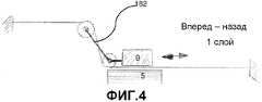
На фиг. 4 показан альтернативный вариант осуществления, согласно которому каретку 182 перемещают в одном направлении. Здесь в результате перемещения каретки вперед и назад изготавливают один слой.In FIG. 4 shows an alternative embodiment, according to which the
На фиг. 5 показано устройство платформы 183 для направления пленки, в которой элементы для направления пленки содержат направляющее устройство 192 отделителя и направляющее устройство 191 аппликатора, при этом направляющее устройство 192 отделителя имеет меньший радиус кривизны, чем направляющее устройство аппликатора. Направление рабочего перемещения указано стрелкой 73. Предпочтительно при работе с двумя направлениями перемещения эта система содержит систему изменения для изменения положений направляющего устройства 192 отделителя и направляющего устройства 191 аппликатора относительно направления перемещения 73 платформы.In FIG. 5 shows a device of a
Хотя в описанных вариантах осуществления конструкционная форма выполнена в виде гибкой пленки, возможно использование и других конструкционных форм без отступления от объема изобретения, в частности, жестких форм, таких как барабаны, плоские формы и т.п. Кроме того, хотя средства перемещения обычно выполняют в виде каретки 18, 180, 181, 182, 183, можно использовать и другие системы, в частности, конструкции, содержащие барабан, для перемещения конструкционной формы к материальному объекту.Although in the described embodiments, the implementation of the structural form is made in the form of a flexible film, it is possible to use other structural forms without departing from the scope of the invention, in particular, rigid forms such as drums, flat forms, etc. In addition, although the means of movement are usually made in the form of a
Согласно дополнительному аспекту изобретения создан аппарат для построения объемной модели посредством укладывания стопой слоев при быстром построении прототипов или быстром процессе изготовления, где аппарат содержит: платформу 14, выполненную для удерживания модели; аппликатор 18, выполненный для обеспечения слоя отверждаемого материала, присоединяемого к модели; первый источник энергии 9, выполненный, по меньшей мере, для частичного отверждения, по меньшей мере, части пересекающегося рисунка в слое отверждаемого материала; удаляющее устройство для удаления неотвержденного материала от слоя с наружной стороны пересекающегося рисунка; и второй источник энергии 100 для последующего отверждения слоя, где второй источник энергии может содержать широкодиапазонный источник энергии. На фиг. 6 дополнительно изображен вариант осуществления, где, согласно одному аспекту настоящего изобретения, система 12 содержит перемещаемую платформу 18 для направления пленки, где упомянутая платформа 18 для направления пленки установлена с возможностью перемещения в направлении, поперечном направлению z, и упомянутая платформа 18 для направления пленки содержит элемент 19 для направления пленки, выступающий от платформы 18 для направления пленки 6, вдоль модели 5 таким образом, чтобы наносить слой отверждаемого материала 3 на модель 5.According to an additional aspect of the invention, an apparatus is provided for constructing a three-dimensional model by stacking layers in a rapid prototyping or rapid manufacturing process, where the apparatus comprises: a
Согласно дополнительному аспекту первый источник энергии 9 может быть расположен на перемещаемой платформе 18 для направления пленки, между выступающими элементами 19 для направления пленки таким образом, чтобы экспонировать слой неотвержденного материала сквозь пленку 6.According to a further aspect, the
Под термином ″отверждаемый материал″ при использовании в данном описании понимают любой отверждаемый материал (т.е. материал, который может быть полимеризован и/или сшит) посредством воздействия, например ультрафиолетового излучения, лазера, ионизированного излучения (включая, но не ограничивая данным перечнем, воздействие электронным лучом, гамма-излучением или рентгеновским излучением) или сочетанием любых воздействий из указанных выше. Под термином ″отверждаемый материал″ следует также понимать композитные материалы, содержащие смесь как отверждаемых, так и неотверждаемых материалов, например, полимера, смешанного с волокном и/или наполнителями.The term "curable material" when used in this description refers to any curable material (i.e. material that can be polymerized and / or crosslinked) by exposure to, for example, ultraviolet radiation, a laser, ionized radiation (including, but not limited to this list exposure to electron beam, gamma radiation or x-ray radiation), or a combination of any of the above. The term "curable material" should also mean composite materials containing a mixture of both curable and non-curable materials, for example, a polymer mixed with fiber and / or fillers.
Под частичным отверждением понимают отверждение до такой степени, при которой пересекающийся рисунок остается стабильным при удалении неотвержденного материала от слоя с наружной стороны пересекающегося рисунка. Отверждаемый материал не полностью отверждают, но только до такой степени, что материал оказывается по существу стабилизированным, и не удаляется вместе с неотвержденным материалом во время этапа удаления неотвержденного материала с наружной стороны пересекающегося рисунка.Partial curing is understood to mean curing to the extent that the intersecting pattern remains stable as the uncured material is removed from the layer on the outside of the intersecting pattern. The curable material is not completely cured, but only to the extent that the material is substantially stabilized and is not removed together with the uncured material during the step of removing the uncured material from the outside of the intersecting pattern.
В показанном варианте осуществления, представленном на фиг. 6, может быть использована экономически эффективным способом дополнительная энергия, требующаяся для полного отверждения на этапе последующего отверждения, посредством применения широкодиапазонного источника энергии 100. Использование широкодиапазонного источника энергии 100 пригодно, так как неотвержденный материал с наружной стороны пересекающегося рисунка может быть удален в первую очередь.In the embodiment shown in FIG. 6, the additional energy required for complete curing in the subsequent curing step can be used in a cost-effective way by using a wide-
Для полного отверждения пересекающегося рисунка требуется определенное время экспонирования. Частичное отверждение пересекающегося рисунка означает отверждение рисунка в меньшей степени. Когда источник энергии действует с той же мощностью, при которой осуществляют полное отверждение, время экспонирования может быть сокращено, а скорость процессов RM и RP увеличена.A complete curing of the intersecting pattern requires a certain exposure time. Partial curing of an intersecting pattern means less curing of the pattern. When the energy source operates with the same power at which complete curing is carried out, the exposure time can be reduced, and the speed of the RM and RP processes can be increased.
При переходе полимера, отверждаемого посредством воздействия ультрафиолетовым излучением, из жидкого состояния в твердое состояние, он проходит через так называемую точку гелеобразования. В этой точке все мономеры химически связываются с образованием одной большой молекулы. При большем отверждении образуется больше связей, например, поперечных связей, так что модуль упругости материала увеличивается. Степень отверждения, требующаяся при частичном отверждении, может быть определена посредством отверждения отверждаемого материала до степени, соответствующей или близкой к точке гелеобразования материала, при которой пересекающийся рисунок остается стабильным при удалении неотвержденного материала от слоя с наружной стороны пересекающегося рисунка. На практике, отверждение до степени, соответствующей или близкой к точке гелеобразования материала, может быть интерпретировано как степень отверждения в диапазоне около 80%-120% от степени отверждения в точке гелеобразования.During the transition of the polymer, which is cured by exposure to ultraviolet radiation, from a liquid state to a solid state, it passes through the so-called gelation point. At this point, all monomers chemically bind to form one large molecule. With greater cure, more bonds are formed, for example, transverse bonds, so that the elastic modulus of the material increases. The degree of cure required during partial cure can be determined by curing the curable material to a degree corresponding to or close to the gel point of the material at which the intersecting pattern remains stable when the uncured material is removed from the layer from the outside of the intersecting pattern. In practice, curing to a degree corresponding to or close to the gel point of the material can be interpreted as a degree of cure in the range of about 80% -120% of the degree of cure at the gel point.
Эту степень отверждения рс в точке гелеобразования определяют по формуле pc=2/favg. В этой формуле favg означает среднее значение ″функциональности″, отнесенное к количеству химических связей на мономер, свойство полимера. Обычно значения favg находятся в диапазоне от около 3 до 6. Это означает, что точку гелеобразования достигают при степени отверждения рс, находящейся между значениями от около 2/3 до 1/3.This degree of curing pc at the gel point is determined by the formula pc = 2 / favg. In this formula, favg means the average value of ″ functionality ″, referred to the number of chemical bonds per monomer, a property of the polymer. Typically, favg values range from about 3 to 6. This means that the gelation point is reached at a curing degree of pc between between about 2/3 to 1/3.
Степень отверждения, используемая для регулярного изготовления, может составлять около 0,9. Потенциальная производительность, повышенная благодаря частичному отверждению, может при этом составлять от около 35% до около 170%. Характеристика типичных отверждаемых материалов, используемых в процессах RP и RM, является такой, что они могут быть частично отвержденными до определенной степени, и если энергию сообщают в течение определенного времени после частичного отверждения, эта энергия будет прибавляться к энергии для частичного отверждения до тех пор, пока материал ни станет полностью отвержденным. Энергия, сообщаемая во время частичного отверждения, не теряется или, по меньшей мере, по существу сохраняется.The degree of cure used for regular manufacture may be about 0.9. Potential productivity enhanced by partial cure may be in the range of about 35% to about 170%. The characteristic of typical curable materials used in the RP and RM processes is that they can be partially cured to a certain extent, and if energy is reported for a certain time after partial curing, this energy will be added to the energy for partial curing until until the material becomes fully cured. The energy provided during partial curing is not lost or at least substantially conserved.
Отверждение, по меньшей мере, части пересекающегося рисунка включает также полное отверждение, в противоположность частичному отверждению, описанному выше, растра в слое отверждаемого материала 3, где упомянутый растр выполняют таких размеров, чтобы удерживался неотвержденный материал. Материал может быть, таким образом, полностью отвержден, но только растр отверждают вместо полного пересекающегося рисунка.The curing of at least a portion of the intersecting pattern also includes complete curing, in contrast to the partial curing described above, of the raster in the
Количество материала, которое должно быть экспонировано для отверждения растра, меньше количества материала, которое должно быть экспонировано для отверждения всего пересекающегося рисунка. Лазерный источник можно, например, перемещать на более короткое расстояние, благодаря чему увеличивают скорость процессов RP и RM. Растры можно дополнительно оптимизировать для улучшения последовательности включения и выключения отдельных СД источника света, содержащего СД. Этим можно дополнительно повысить выходную мощность СД и скорость построения.The amount of material that must be exposed to cure the raster is less than the amount of material that must be exposed to cure the entire intersecting pattern. The laser source can, for example, be moved a shorter distance, thereby increasing the speed of the RP and RM processes. Rasters can be further optimized to improve the sequence of turning on and off individual LEDs of a light source containing LEDs. This can further increase the output power of the LED and the speed of construction.
Также возможно сочетание частичного отверждения и отверждения, по меньшей мере, части пересекающегося рисунка, например, отверждение растра пересекающегося рисунка, только до определенной степени. Этим можно дополнительно повысить скорость процессов RP и RM.It is also possible to combine partial curing and curing of at least a portion of the intersecting pattern, for example, curing the raster of the intersecting pattern, only to a certain extent. This can further increase the speed of the RP and RM processes.
Один способ удаления неотвержденного материала с наружной стороны пересекающегося рисунка заключается в сдувании материала. Этот способ особенно пригоден, когда неотвержденный материал обладает сухой, порошкообразной структурой или является жидкостью малой вязкости.One way to remove uncured material from the outside of the intersecting pattern is to blow off the material. This method is particularly suitable when the uncured material has a dry, powdery structure or is a low viscosity liquid.
Одна возможность удерживания неотвержденного материала внутри растра во время этапа удаления неотвержденного материала может быть реализована посредством придания растру таких размеров, чтобы обеспечить капилляры для удерживания неотвержденного материала. При использовании механизма капиллярности размеры растра, например, соотносятся с вязкостью неотвержденного материала.One possibility of retaining uncured material within the raster during the uncured material removal step can be realized by resizing the raster so as to provide capillaries for retaining the uncured material. When using the capillarity mechanism, the size of the raster, for example, correlates with the viscosity of the uncured material.
Другая возможность удерживания неотвержденного материала внутри растра во время этапа удаления неотвержденного материала заключается в обеспечении дополнительного материала внутри растра после того, как был сначала удален по существу весь неотвержденный материал от слоя. При этом вводят дополнительный этап процесса. Однако этим также обеспечивают возможность заполнения объекта дополнительным материалом, отличающимся от слоя отверждаемого материала, если требуемые характеристики поверхности модели отличаются от характеристик материала внутри модели. Поверхность может, например, быть ровной или мягкой, в то время, как внутренность должна быть легкой или жесткой. Дополнительный материал может быть клейким для удерживания материала внутри растра.Another possibility of retaining uncured material within the raster during the uncured material removal step is to provide additional material inside the raster after essentially all of the uncured material has been removed from the layer first. An additional process step is introduced. However, this also provides the ability to fill the object with additional material that is different from the cured material layer, if the required surface characteristics of the model differ from the characteristics of the material inside the model. The surface may, for example, be smooth or soft, while the interior should be light or hard. Additional material may be adhesive to hold material within the raster.
После, по меньшей мере, частичного отверждения, по меньшей мере, части пересекающегося рисунка и удаления неотвержденного материала с наружной стороны растра, слой может быть подвержен последующему отверждению с использованием широкодиапазонного источника энергии 100. Широкодиапазонный источник энергии 100, например, является обычно широкодиапазонным источником ультрафиолетового излучения, но он не ограничен только источником ультрафиолетового термолюминесцентного излучения (UVTL). Однако предусмотрено также использование широкодиапазонного теплового источника.After at least partially curing at least part of the intersecting pattern and removing the uncured material from the outside of the raster, the layer may be subjected to subsequent curing using a wide-
На фиг. 6 показан вариант осуществления аппарата 12 для построения объемной модели посредством укладывания стопой слоев при быстром построении прототипов или быстром процессе изготовления согласно настоящему изобретению. Аппарат 12 содержит платформу 14 для удерживания модели. В данном варианте осуществления платформа 14 является перемещаемой z-платформой 15, которую можно перемещать в направлении z до того, как с помощью аппликатора 18 присоединят к модели слой отверждаемого материала. При перемещении в направлении z направление может быть поперечным относительно слоя отверждаемого материала. Платформу 14 можно поднимать в то время, когда аппликатор 18 не перемещают, но также можно опускать аппликатор 18 вниз, пока расстояние между моделью 5 и аппликатором 18 увеличивается. В этом варианте осуществления с помощью элементов качения 17 обеспечивают возможность перемещения z-платформы 15.In FIG. 6 shows an embodiment of an
На фиг. 6 показано, что модель 5 присоединена снизу к z-платформе 15 и что новый слой укладывают стопой снизу. С целью обеспечения большей ясности слой отверждаемого материала показан чрезмерно увеличенным по толщине.In FIG. 6 shows that
В одном варианте осуществления аппарат 12 содержит аппликатор 18 для присоединения слоя отверждаемого материала к модели 5. Аппарат 12 дополнительно содержит удаляющее устройство для удаления неотвержденного материала от слоя с наружной стороны пересекающегося рисунка. В варианте осуществления, представленном на фиг. 6, аппликатор 18 предназначен как для обеспечения слоя отверждаемого материала и присоединения слоя отверждаемого материала к модели 5, так и для удаления неотвержденного материала от слоя с наружной стороны пересекающегося рисунка. Это удобно, но в качестве альтернативы удаление неотвержденного материала от слоя с наружной стороны пересекающегося рисунка можно выполнять, например, посредством удаления неотвержденного материала с помощью вентилятора. Этот способ особенно пригоден, когда неотвержденный материал обладает сухой, порошкообразной структурой или является жидкостью малой вязкости.In one embodiment, the
В данном варианте осуществления аппликатор 18 выполнен в виде перемещаемой платформы для направления пленки. Платформа 18 для направления пленки 18 выполнена с возможностью перемещения в направлении, поперечном направлению z. Перемещение платформы 18 для направления пленки может быть обеспечено с помощью элементов качения 17. Возможно также использование и других способов перемещения, например, скольжение. Платформа 18 для направления пленки дополнительно содержит элементы 19, 19′, 19″ и 19′″ для направления пленки, выступающие от платформы 18 для направления пленки 20 вдоль модели 5 таким образом, чтобы наносить слой отверждаемого материала на модель 5. В одном варианте осуществления элементы 19 для направления пленки содержат четыре валика 21.In this embodiment, the
В варианте осуществления, проиллюстрированном на фиг. 6, пленка 6 выполнена для несения отверждаемого материала, подаваемого из подающего резервуара 2 к модели 5 и для несения удаляемого неотвержденного материала от модели 5 к резервуару 23 для отходов. Обычно неотвержденный материал с наружной стороны пересекающегося рисунка приклеивается к перемещаемой пленке 6, так как силы сцепления между неотвержденным материалом и пленкой 6 больше сил сцепления между неотвержденным материалом и моделью 5.In the embodiment illustrated in FIG. 6, the
Аппликатор 18 может дополнительно содержать подающий резервуар 2 для хранения отверждаемого материала и резервуар 23 для отходов для хранения неотвержденного материала, удаляемого от слоя с наружной стороны пересекающегося рисунка. Резервуары могут быть открытыми или закрытыми. Открытый резервуар может обладать преимуществом, заключающимся в том, что его заполнение или опустошение может быть более легким. В закрытом резервуаре хранение отверждаемого материала в определенных рабочих условиях до использования или повторного использования может быть более легким. В этом варианте осуществления пленка 6 может быть выполнена для несения отверждаемого материала, подаваемого из закрытого подающего резервуара 2 к модели 5 и для несения удаляемого неотвержденного материала от модели 5 к резервуару 23 для отходов. В этом варианте осуществления аппликатор 18 может дополнительно содержать исполнительный механизм (не показан) для перемещения пленки 6 к модели 5 и от нее.The
Пленку 6 и платформу 18 для направления пленки можно перемещать независимо. В одном рабочем режиме на первом этапе пленку 6 перемещают таким образом, чтобы обеспечить слой отверждаемого материала под моделью 5. Отверждаемый материал в это время еще не находится в контакте с моделью 5. На втором этапе платформу 18 для направления пленки перемещают вдоль модели 5 для нанесения слоя отверждаемого материала на модель 5, экспонирования отверждаемого материала и удаления неотвержденного материала. На втором этапе пленку 6 по существу не перемещают относительно модели 5 в направлении, поперечном направлению z.The
В одном варианте осуществления аппарат 12 согласно настоящему изобретению содержит первый источник энергии 9, выполненный, по меньшей мере, для частичного отверждения, по меньшей мере, части пересекающегося рисунка в слое отверждаемого материала 3. В варианте осуществления, представленном на фиг. 6, первый источник энергии 9 содержит множество отдельно приводимых в действие СД, расположенных в виде рядов и колонок (не показано). Первый источник энергии 9 может быть расположен с возможностью перемещения под слоем отверждаемого материала 3 таким образом, чтобы его можно было перемещать в направлении, параллельном слою отверждаемого материала 3. Движением первого источника энергии 9 можно управлять посредством контроллера, с помощью которого можно также управлять свечением СД. При использовании первый источник энергии 9 можно перемещать прямолинейно в направлении, которое проходит под углом к направлениям рядов и колонок массива 32 СД для повышения эффективного использования системы. Эта технология более подробно описана в заявке ЕР 07150447.6, находящейся одновременно на рассмотрении в патентном ведомстве, зарегистрированной на имя Заявителя, которая включена в данное описание путем ссылки для дополнительной информации при рассмотрении данного аспекта. Первый источник энергии 9 может быть расположен на перемещаемой платформе 18 для направления пленки между выступающими элементами 19 для направления пленки таким образом, чтобы можно было экспонировать слой неотвержденного материала сквозь пленку 6. Источник энергии может быть покрыт прозрачной пластиной, например, стеклянной пластиной, для улучшения процесса направления пленки 6.In one embodiment,
Сочетание использования источника света, содержащего множество отдельно вводимых в действие СД, и частичного отверждения, по меньшей мере, части пересекающегося рисунка может быть благоприятным фактором. Перед дальнейшим объяснением этого решения дано несколько более подробное описание источника света, содержащего СД, используемого в данном варианте осуществления.The combination of using a light source containing a plurality of separately commissioned LEDs and partially curing at least a portion of the intersecting pattern may be a favorable factor. Before further explanation of this solution, a slightly more detailed description of the light source containing the LED used in this embodiment is given.
В одном варианте осуществления источник света 32, содержащий СД, имеет двухмерную матрицу, обычно содержащую около 80×120 светоизлучающих диодов (СД), которые действуют через многолинзовый массив (не показан) на слой отверждаемого материала 3. Длина матрицы обычно составляет около 60 см. СД могут быть отдельно введены в действие для описания пересекающегося рисунка с управляемой скоростью отдельных СД, обычно составляющей порядка наносекунд, посредством множества электрических цепей, выборочно соединенных с соответствующими СД. В данном примере, соответственно, первый источник энергии 9 может быть представлен в виде двухмерного массива СД, расположенных в плоскости, параллельной слою отверждаемого материала 3, и между многолинзовым массивом и подложкой.In one embodiment, the
Когда весь пересекающийся рисунок полностью отвержден, источник света, содержащий СД обычно перемещают поверх слоя неотвержденного материала со скоростью сканирования, составляющей около 10 см/с.When the entire intersecting pattern is completely cured, the light source containing the LED is usually moved over a layer of uncured material with a scanning speed of about 10 cm / s.
На фиг. 7 проиллюстрирована проблема, которая может возникнуть при большом поперечном сечении объекта: капиллярные силы в узком пространстве между пленкой 6 и объектом 50 приводят к сужению этого пространства. В результате этого пленка может подняться из предназначенного для нее положения Р в более высокое положение Q, что может сделать слой в местах 1010, подлежащих экспонированию более тонким. Таким образом, новый слой становится слишком тонким. Этот эффект может накапливаться во время формирования ряда слоев, и точность изготовления продукта может сильно снизиться. Даже может быть прерван процесс построения, если накопленная потеря толщины станет такой, что при формировании определенного слоя больше не будет контакта между слоем жидкости, перемещаемым к продукту, и самим продуктом. Решением этой проблемы является приложение компенсирующей силы, направленной вниз, к пленке, посредством создания перепада давления, действующего на пленку.In FIG. 7 illustrates the problem that can occur with a large cross-section of the object: capillary forces in the narrow space between the
Это может быть сделано посредством добавления вакуум-камеры 210 под пленкой, более конкретно - вокруг блока экспонирования. Во внутреннем пространстве 212 камеры создают разрежение посредством отсоса воздуха 213 через присоединенный трубопровод 211.This can be done by adding a
В варианте осуществления камера 210 близко установлена (узкое пространство имеет, например, ширину - 1 мм) вокруг экспонирующей головки 30, для предотвращения выпучивания пленки вниз в области узкого пространства. Неожиданно, несмотря на узость пространства, требуемое разрежение, создаваемое для предотвращения проблемы подъема пленки, очень небольшое, обычно составляющее 10 мбар или меньше. При анализе было установлено, что разрежение эффективно действует на всю площадь экспонирующей головки 30.In an embodiment, the
На фиг. 8 показан некоторый остаточный подъем пленки 66. Этого обычно не происходит, так как полимер здесь уже экспонирован (на этом чертеже экспонирующую головку перемещают справа налево), и является достаточно прочным, чтобы противостоять капиллярным силам, но в случае, если подъем все же происходит (в зависимости, например, от скорости отверждения используемого полимера), его можно устранить посредством расширения вакуум-камеры или введения дополнительной вакуум-камеры, но всегда требуется внимательно следить за тем, чтобы узкие пространства для пропуска разрежения, идущего из камеры к нижней стороне пленки, были небольшими (~1 мм) для удерживания пленки от выпучивания вниз.In FIG. Figure 8 shows some residual lift of the
На фиг. 9 показана в качестве примера перфорированная пластина, составляющая верхнюю сторону 901 протяженной вакуум-камеры 900 вокруг экспонирующей головки.In FIG. 9 shows, by way of example, a perforated plate constituting the
Специалисту в данной области техники должно быть понятно, что описанный выше способ контролирования большой площади пленки с помощью очень небольшого разрежения может быть применен с использованием различных вариантов осуществления, не обязательно только вокруг экспонирующей головки, но во всех тех случаях, где побочные силы имеют тенденцию к перемещению пленки от предназначенного для нее положения. Например, очень небольшое разрежение может быть приложено, например, посредством создания вакуума или с помощью вакуум-камеры расположенной в месте или вблизи места расположения отслаивающего валика или в месте или вблизи места, где пленку 6 отделяют от последнего отвержденного слоя объекта 50. Для стабилизации разрежения предпочтительно, чтобы протяженная вакуум-камера 900 вокруг экспонирующей головки имела стенки, расположенные близко к пленке, чтобы утечки здесь были небольшими.One skilled in the art will appreciate that the above-described method of controlling a large area of a film by using a very small vacuum can be applied using various embodiments, not only around the exposure head, but in all cases where side forces tend to moving the film from its intended position. For example, a very small vacuum can be applied, for example, by creating a vacuum or using a vacuum chamber located at or near the location of the peeling roller or at or near the place where the
На фиг. 10 показан вариант осуществления, в котором минимизировано испарение полимера. Для уменьшения испарения, благоприятно удалять полимер с пленки в областях, где пленка только что была отделена (или отслоена) от объекта 50. Это можно делать посредством добавления удаляющего устройства, или ракли, 1001, которую перемещают вместе с узлом 20 для нанесения покрытия или узлом 40 для отслаивания, таким образом, формируя резервуар для материала 1002. Предпочтительно, чтобы эта ракля была расположена под углом α, приблизительно составляющим 10°, к пленке 6. Было определено, что при приблизительно таком угле обеспечивается наилучшее соскабливание при одном направлении перемещения и обеспечивается возможность прохода полимера в противоположном направлении перемещения, и, таким образом, обнаруживается любое количество полимера, оставшегося на пленке, и полимер сталкивается на край машины.In FIG. 10 shows an embodiment in which polymer evaporation is minimized. To reduce evaporation, it is advantageous to remove the polymer from the film in areas where the film has just been separated (or peeled) from the
Следует отметить, что в области 1002 образован резервуар, так как это место окружено со всех сторон раклей 1001 и идущей вверх частью пленки 6. Ракля 1001 может содержать выступающие части с отверстиями для пропуска оси нижнего валика 190, и уплотнения вокруг отверстий для пропуска оси. В варианте осуществления с двумя направлениями перемещения резервуар 1002 сформирован с каждой стороны каретки 180. И может быть также валик 190 (например, валик Мейера) для обеспечения слоя жидкости с каждой стороны платформы для направления пленки.It should be noted that a reservoir is formed in the
В варианте осуществления толщина слоя жидкости, обеспечиваемая с помощью валиков для нанесения покрытия (валиков Мейера), по меньшей мере, равна толщине следующего слоя, но предпочтительно немного больше. Например, для построения объекта из слоев толщиной 50 мкм, хорошим значением для толщины слоя жидкости является значение, составляющее около 70-80 мкм. Таким образом, при перемещении пленки со слоем жидкости к объекту пространство толщиной 50 мкм между пленкой и предыдущим слоем на объекте оказывается полностью заполненным жидким полимером. Избыток полимера (20-30 мкм) поджимают вперед перед валиком, которым поднимают пленку к объекту, или в стороны в пространства, которые могут иметься в объекте, сформированном до этого.In an embodiment, the thickness of the liquid layer provided by the coating rollers (Meyer rollers) is at least equal to the thickness of the next layer, but preferably slightly larger. For example, to construct an object from layers with a thickness of 50 microns, a good value for the thickness of the liquid layer is a value of about 70-80 microns. Thus, when a film with a liquid layer moves to an object, the space with a thickness of 50 μm between the film and the previous layer on the object is completely filled with liquid polymer. The excess polymer (20-30 microns) is pushed forward in front of the roller, which lifts the film to the object, or to the sides in the spaces that may be in the object formed before.
Валики, с помощью которых формируют слой жидкости (например, валики Мейера) предпочтительно являются рифлеными, или профилированными, таким образом, чтобы количество полимера, которое транспортируют в углублениях валика Мейера со стороны резервуара от валика Мейера к стороне блока экспонирования от валика Мейера, было достаточным для обеспечения требующейся толщины слоя жидкости (например 70-80 мкм). Следует отметить, что жидкость, находящаяся в углублениях, только частично остается на пленке позади валиков Мейера, а часть остается на валике Мейера. Таким образом, размер углублений следует определять экспериментально.The rollers with which the liquid layer is formed (for example, Meyer rollers) are preferably corrugated or profiled so that the amount of polymer that is transported in the recesses of the Meyer roller from the reservoir side from the Meyer roller to the side of the exposure unit from the Meyer roller to provide the required thickness of the liquid layer (for example 70-80 microns). It should be noted that the liquid located in the recesses only partially remains on the film behind the Meyer rollers, and some remains on the Meyer roller. Thus, the size of the recesses should be determined experimentally.
На фиг. 11 изображен в качестве примера вариант осуществления, в котором полимер нагревают, и на фиг. 11 раскрыто оборудование, используемое для нагрева и размещения для улучшения условий воздействия рабочей температуры на полимер.In FIG. 11 shows, by way of example, an embodiment in which the polymer is heated, and FIG. 11 discloses equipment used for heating and placement to improve the exposure of the polymer to operating temperature.
Для хорошего осуществления процесса построения объекта, между экспонированием и отделением полимера от пленки полимер должен быть отвержден в определенной степени для того, чтобы можно было приклеить вновь сформированный слой к ранее созданным слоям объекта. Для многих полимеров, например, для DSM Somos 8120 (эпоксиакрилат), экспонируемого при 365 нм, отверждение происходит быстрее при более высокой температуре. Фактически было установлено (в варианте осуществления), что упомянутый полимер действует хорошо при использовании его при температуре выше комнатной, предпочтительно - приблизительно в диапазоне от 30°С до 40°С. Таким образом, предпочтительно иметь возможность нагревать полимер до температуры выше комнатной (что позволяет сокращать время между экспонированием и отделением). Неожиданно было найдено элегантное решение, заключающееся во введении небольшой нагревательной балки 301а, 301b, поддерживаемой в тепловом контакте с нижней стороной (не находящейся в контакте с жидкостью) пленки, расположенной вблизи экспонирующей головки. При работе с двумя направлениями перемещения может быть добавлен второй нагреватель 301b, расположенный с противоположной стороны от экспонирующей головки 30.For a good construction process, between exposure and separation of the polymer from the film, the polymer must be cured to a certain extent so that the newly formed layer can be adhered to the previously created layers of the object. For many polymers, such as the DSM Somos 8120 (epoxy acrylate) exposed at 365 nm, cure is faster at higher temperatures. In fact, it was found (in an embodiment) that said polymer works well when used at temperatures above room temperature, preferably in the range of about 30 ° C to 40 ° C. Thus, it is preferable to be able to heat the polymer to a temperature above room temperature (thereby reducing the time between exposure and separation). Unexpectedly, an elegant solution was found consisting in the introduction of a
Нагревательная балка 301 предпочтительно расположена вблизи экспонирующей головки для того, чтобы нагреваемая область была небольшой, и для того, чтобы вся система была компактной (и, следовательно, быстродействующей). В случае если используют также вакуум-камеру, то нагревательная балка (нагревательные балки) может быть расположена либо внутри, либо с наружной стороны вакуум-камеры.The heating beam 301 is preferably located near the exposure head so that the heated area is small, and so that the entire system is compact (and therefore fast). If you also use a vacuum chamber, the heating beam (heating beams) can be located either inside or on the outside of the vacuum chamber.
На первый взгляд, можно подумать, что с помощью такой небольшой балки невозможно повысить температуру в достаточной степени, так как пленка находится в контакте с балкой только в течение очень короткого периода времени, например, 0,2 с (ширина нагревательной балки - 2 см, скорость перемещения - 10 см/с); но авторами установлено, что это возможно. Анализ показал, что этого времени достаточно для того, чтобы тепло, выделяемое балкой, проникало в пленку со слоем полимера, так как слой полимера и пленка являются тонкими (например, 0,2 мм в сумме). Температура балки не должна даже быть много выше целевой температуры для достижения этого. Например, для достижения температуры пленки и полимера 30°С обычно требуется, чтобы температура нагревательной балки была около 40°С.At first glance, one might think that with such a small beam it is impossible to increase the temperature sufficiently, since the film is in contact with the beam only for a very short period of time, for example, 0.2 s (the width of the heating beam is 2 cm, travel speed - 10 cm / s); but the authors found that this is possible. The analysis showed that this time is sufficient for the heat released by the beam to penetrate the film with a polymer layer, since the polymer layer and the film are thin (for example, 0.2 mm in total). The beam temperature should not even be much higher than the target temperature to achieve this. For example, to achieve a film and polymer temperature of 30 ° C, it is usually required that the temperature of the heating beam is about 40 ° C.
Нагревательную балку предпочтительно изготавливают из материала с высокой теплопроводностью. Например, она может содержать алюминиевый корпус (например, из квадратной трубы размером приблизительно 2×2 см), нагреваемый, например, электрическим нагревателем, расположенным внутри.The heating beam is preferably made of a material with high thermal conductivity. For example, it may comprise an aluminum casing (for example, of a square pipe of approximately 2 x 2 cm), heated, for example, by an electric heater located inside.
В варианте осуществления нижняя сторона объекта, построенного ранее, и верх блока экспонирования, имеют температуру, равную или близкую к целевой температуре (например, 30°С). Это состояние возникает автоматически после выполнения ряда циклов. Таким образом, процесс построения в данном варианте осуществления может быть начат после осуществления ряда ″холостых″ циклов, т.е. циклов, в которых не выполняют экспонирование и не производят вертикальное перемещение z-платформы 150. При этом нагревается нижняя сторона платформы 150 и верх блока экспонирования до требуемой для выполнения процесса температуры. Альтернативно можно использовать и другие нагревательные средства для предварительного нагрева этих частей до запуска действительного процесса построения.In an embodiment, the lower side of the object constructed earlier and the top of the exposure unit have a temperature equal to or close to the target temperature (for example, 30 ° C). This condition occurs automatically after a series of cycles. Thus, the construction process in this embodiment can be started after a series of “idle” cycles, i.e. cycles in which the exposure is not performed and the z-
Например, нагревательный элемент может быть встроен в платформу 150, и предварительный нагрев платформы и верха блока экспонирования можно осуществлять с помощью платформы, находящейся близко к экспонирующей головке (например, на расстоянии 1 мм или меньше).For example, a heating element may be built into the
Экзотермические полимерыExothermic Polymers
Процесс отверждения большинства полимеров является экзотермическим, т.е. в процессе отверждения генерируется тепло. Следовательно, количество тепла, требуемое для нагрева нагревательными балками, будет изменяться в зависимости от используемого полимера. Может даже требоваться некоторое охлаждение для поддержания температуры процесса от слишком большого ее повышения. Следовательно, нагревательные балки могут быть снабжены охлаждающим элементом, расположенным внутри, и количество выделяемого тепла/холода можно регулировать (автоматически или вручную), на основании данных датчика температуры, например, встроенного в верх блока экспонирования. Подобно этому, платформа, несущая объект, может содержать не только нагреватель, но также и охлаждающий элемент.The curing process for most polymers is exothermic, i.e. during curing heat is generated. Therefore, the amount of heat required for heating with heating beams will vary depending on the polymer used. Some cooling may even be required to maintain the process temperature from raising it too much. Therefore, the heating beams can be equipped with a cooling element located inside, and the amount of heat / cold generated can be adjusted (automatically or manually), based on data from a temperature sensor, for example, built into the top of the exposure unit. Similarly, the platform supporting the object may contain not only a heater, but also a cooling element.
Этот способ нагрева намного предпочтительнее нагревательной системы большего размера, например, системы, содержащей несколько перемещаемых блоков машины и резервуар с полимером, находящийся под повышенной температурой. С помощью созданного изобретением способа нагрева можно делать нагреваемую часть всей системы как можно меньшего размера и, таким образом, требуется намного меньшее количество энергии. Другим преимуществом является то, что полимер находится при повышенной температуре только во время фазы процесса, когда это требуется (от экспонирования до отделения); его можно охлаждать сразу же после этого и, таким образом, предотвращать любые нежелательные эффекты в неэкспонированном полимере, такие как старение, испарение или тепловое отверждение.This heating method is much preferable to a larger heating system, for example, a system containing several movable machine blocks and a polymer reservoir under elevated temperature. Using the heating method created by the invention, it is possible to make the heated part of the entire system as small as possible, and thus a much smaller amount of energy is required. Another advantage is that the polymer is at elevated temperature only during the process phase when it is required (from exposure to separation); it can be cooled immediately afterwards and thus prevent any undesirable effects in the unexposed polymer, such as aging, evaporation or thermal curing.
На фиг. 12 представлен чертеж, на котором специально показан радиус валика. Кроме того, на фиг. 12 изображены подшипники 198, установленные с наружной стороны валика. Оптимальный радиус r отслаивающих валиков находится в диапазоне, не превышающем 10 мм. Хотя можно предположить, что с помощью валика большего радиуса r можно постепенно и более ″щадяще″ производить отслаивание и, таким образом, обеспечивать достаточный период времени для отделения от пленки последнего отвержденного слоя, неожиданно было установлено, что при небольшом радиусе валик работает лучше: при его использовании обеспечивается возможность работы с более высокой скоростью отделения без повреждения последнего отвержденного слоя.In FIG. 12 is a drawing which specifically shows the radius of the roller. In addition, in FIG. 12
Радиус, равный приблизительно 10 мм или менее, является предпочтительным, обычно - даже равный приблизительно 6 мм или менее. Кроме того, при небольшом диаметре, в сочетании с большой шириной рабочей зоны (например, 50 см), жесткость конструкции валика может быть перспективной. Валик должен противостоять силе натяжения пленки, и все же оставаться прямым. Ось, проходящая через центр валика, обычно не является достаточно жесткой. Благоприятно то, что отслаивающий валик поддерживают с помощью подшипников с наружной стороны. Они могут быть расположены во многих положениях вдоль длины валика, как это необходимо для достижения требующейся прямолинейности. На фиг. 12 показаны подшипники, расположенные с наружной стороны и выполненные в виде подшипников скольжения 198, установленных на жесткой раме 195 блока отслаивания; конечно, можно также использовать и любой другой тип подшипника, в частности, роликовые подшипники. В варианте осуществления использовано, по меньшей мере, четыре подшипника. В другом варианте осуществления, по меньшей мере, один подшипник расположен на горизонтальном основании рамы блока отслаивания, и, по меньшей мере, один подшипник расположен на вертикальной стенке рамы блока отслаивания.A radius of about 10 mm or less is preferred, usually even about 6 mm or less. In addition, with a small diameter, in combination with a large width of the working area (for example, 50 cm), the rigidity of the roller structure can be promising. The roller should withstand the tension of the film, and still remain straight. The axis passing through the center of the roller is usually not rigid enough. Advantageously, the peeling roller is supported by bearings from the outside. They can be located in many positions along the length of the roller, as necessary to achieve the required straightness. In FIG. 12 shows bearings located on the outside and made in the form of sliding
Пленка может быть зажата по длине в зажимах 501 (см. фиг. 11). Может быть обеспечен механизм (не показан) для удерживания пленки по длине под предварительно определенным натяжением. Оптимальное натяжение зависит от типа и толщины пленки, но может обычно составлять около 10 Н/см ширины пленки (500 Н для пленки шириной 50 см). При таком натяжении можно удерживать пленку в плоском состоянии в области, где это необходимо: в части, находящейся на высоте контакта (Н на фиг. 1) с объектом. Важно, чтобы натяжение по длине было достаточным для поддержания пленки в плоском состоянии во всей этой области, включая ее боковые края, и чтобы не требовались зажимы или другие натяжные устройства на боковых краях.The film can be clamped along the length of the clips 501 (see Fig. 11). A mechanism (not shown) for holding the film in length under a predetermined tension may be provided. The optimum tension depends on the type and thickness of the film, but can usually be about 10 N / cm film width (500 N for a
В другом варианте осуществления изобретения используют также типы пленки, обычно (но не исключительно; нет полного представления о том, какие точно свойства пленки являются определяющими в этом отношении) обладающие более низким модулем упругости, где натяжение по длине с помощью зажимов 501 не достаточно для поддержания пленки в плоском состоянии во всей соответствующей области. В частности, боковые края в этом варианте осуществления могут обладать тенденцией к подъему или опусканию, или к образованию складок и отклонению от предназначенной плоскости. В таких случаях решение может быть найдено в добавлении боковых зажимов, которые могут принимать одну из следующих форм или другие формы:In another embodiment of the invention, film types are also used, usually (but not exclusively; there is no complete picture of what exact properties of the film are determining in this respect) having a lower modulus of elasticity, where the tension along the length with
Край пленки может быть перфорированным и может содержать отверстия, расположенные с регулярными интервалами, например, 2 см; на каретке блока экспонирования должны быть обеспечены соответствующие звездочки, по меньшей мере, одна для каждой стороны пленки, зубья которой сопряжены с перфорацией, где упомянутые звездочки отжимают наружу, например, с помощью пружины таким образом, чтобы звездочки оказывали силовое воздействие, направленное наружу, на края пленки, и, таким образом, обеспечивали натяжение пленки по ширине над блоком экспонирования.The edge of the film may be perforated and may contain holes located at regular intervals, for example, 2 cm; on the carriage of the exposure unit there must be provided at least one sprocket for each side of the film, the teeth of which are associated with perforation, where the sprocket is pressed outward, for example, by means of a spring so that the sprocket exerts a force directed outward on the edges of the film, and thus ensured the tension of the film in width over the exposure unit.
В варианте осуществления использовано усовершенствованное решение в сравнении с простыми звездочками: зубчатые ремни, зубцы которых сопряжены с перфорацией пленки, которые имеют определенную длину (например, 5-20 см), идущую параллельно плоскости пленки.In the embodiment, an improved solution is used in comparison with simple sprockets: toothed belts, the teeth of which are associated with perforation of the film, which have a certain length (for example, 5-20 cm), running parallel to the plane of the film.
Ряд перемещаемых механических захватов может быть расположен на раме машины вдоль боковых сторон пленки. Каждый захват выводят вперед, захватывают им край пленки и оказывают посредством него силовое воздействие, направленное наружу, на край пленки, на участок ее длинны, находящийся перед захватом на уровне Н по высоте. И так с момента прохода подъемного валика 19 перед захватом и почти до появления отслаивающего валика 19 перед захватом.A series of movable mechanical grippers may be located on the machine frame along the sides of the film. Each capture is brought forward, it captures the edge of the film and through it exerts a force acting outward, on the edge of the film, on a portion of its length, which is located before the capture at level H in height. And so, from the moment of passage of the lifting
Над пленкой может быть обеспечен зажим с отсосом. Зажим представляет собой длинное, узкое устройство с каждой стороны рабочей зоны, имеющее длину, приблизительно равную длине рабочей зоны (области построения объекта). Нижняя поверхность каждого зажима является поверхностью с отсосом, обычно выполняемой посредством использования пористого материала, покрытого вакуум-камерой.Above the film, a suction clip can be provided. The clamp is a long, narrow device on each side of the working area, having a length approximately equal to the length of the working area (object construction area). The bottom surface of each clamp is a suction surface, typically made by using a porous material coated with a vacuum chamber.
Как только часть края пленки поднимают из нижнего уровня до уровня Н, где она соприкасается с зажимом с отсосом, этот участок пленки может быть поддержан присосом к зажиму, и он не может больше перемещаться. Около подъемного валика пленка находится под натяжением и, следовательно, также натянута по ширине, и в этом состоянии натянутости по ширине оба края зафиксированы в зажимах с отсосом. Благодаря использованию зажимов пленка остается натянутой по ширине даже после прохода подъемного валика.As soon as part of the edge of the film is raised from the lower level to level H, where it is in contact with the suction clip, this portion of the film can be supported by a suction to the clip, and it can no longer move. Near the lifting roller, the film is under tension and therefore also stretched in width, and in this state of tension in width, both edges are fixed in suction clamps. Thanks to the use of clamps, the film remains stretched in width even after the passage of the lifting roller.
Такой же эффект, как и при использовании зажимов с отсосом, может быть реализован посредством использования клейкой поверхности вместо поверхности с отсосом. Например, чистый мягкий силиконовый лист, например, толщиной 1 мм, взаимодействует как клейкий лист по отношению ко многим материалам в виде пленки. Если такой клейкий материал закреплен на жесткой зажимной раме и расположен таким образом, чтобы подъемными валиками поднимались и прижимались края пленки к клейкому материалу, то мы получаем требующийся эффект натяжения по ширине.The same effect as when using clamps with a suction can be realized by using an adhesive surface instead of a surface with a suction. For example, a clean, soft silicone sheet, for example 1 mm thick, interacts as an adhesive sheet with respect to many film materials. If such an adhesive material is fixed on a rigid clamping frame and is positioned so that the edges of the film rise and press against the adhesive material with lifting rollers, we obtain the required tension effect across the width.
На фиг. 13 раскрыта интересная деталь, так как было установлено, что требуется только, чтобы сторона пленки, отдаленная от слоя 10 жидкости, была оптически чистой; может быть допущено, чтобы сторона, обращенная к слою 10 жидкости, обладала рассеивающей способностью, так как неожиданно оказалось, что ее рассеивающую способность можно ликвидировать посредством смачивания полимером, наносимым на поверхность. Благодаря этому можно сократить потребность в пленке при производстве.In FIG. 13, an interesting detail is disclosed, since it has been found that it is only required that the side of the film remote from the
Пленка 6 образует оптический путь между экспонирующей головкой 38 и полимером, подлежащим экспонированию, и, следовательно, оказывает влияние на светопропускание. В варианте осуществления, проиллюстрированном на фиг. 13а, экспонирующая головка может быть выполнена таким образом, чтобы получалась резкая фокусировка 401 на полпути в слое полимера 10 (см. фиг. 13а). В таком варианте осуществления рассеивающие (матовые) структуры на оптическом пути неблагоприятны. Например, матовая нижняя или верхняя поверхности пленки давали бы рассеивание света такое, которое проиллюстрировано на фиг. 13b. Подобным же образом, рассеивающая способность объемного материала пленки (см. фиг. 13с) приводила бы к рассеиванию света, которое может нарушить резкую фокусировку 401.The
Проводили эксперименты с пленкой, которая была матовой с одной стороны. Удерживая в памяти фиг. 13b, авторы клали пленку матовой стороной вверх для того, чтобы эффект рассеивания был меньше. Неожиданно авторы наблюдали, что рассеивание на верхней, матовой поверхности пропало в тот момент, когда на верхнюю поверхность был нанесен слой полимера. Неожиданно было установлено, что требуется, в определенных вариантах осуществления изобретения, чтобы только одна из поверхностей (и массив) пленки была оптически чистой (нерассеивающей), и может быть допущено, чтобы другая поверхность была матовой. Матовую сторону при этом использовали в качестве стороны, контактирующей с полимером. Это открытие является важным, так как значительно более сложно изготавливать пленку, которая была бы оптически чистой с обеих сторон.Conducted experiments with a film that was matte on one side. Keeping in mind the FIG. 13b, the authors laid the film with the matte side up so that the scattering effect was less. Unexpectedly, the authors observed that dispersion on the upper, dull surface disappeared at the moment when a polymer layer was deposited on the upper surface. It has been unexpectedly found that, in certain embodiments of the invention, it is required that only one of the surfaces (and the array) of the film is optically clean (non-scattering), and it can be allowed that the other surface is matte. The matte side was used as the side in contact with the polymer. This discovery is important since it is much more difficult to produce a film that is optically clean on both sides.
Следует отметить, что сторона пленки, обращенная к слою жидкости, должна быть такой, чтобы ее можно было легко отделять (полностью или частично) от отвержденного полимера. Материалы, отвечающие этим требованиям, включают (но их состав не ограничен данным перечнем): поли-4-метил-пентен (ТРХ) (объемный), силиконIt should be noted that the side of the film facing the liquid layer should be such that it can be easily separated (fully or partially) from the cured polymer. Materials that meet these requirements include (but their composition is not limited to this list): poly-4-methyl-pentene (TPX) (bulk), silicone
(нанесенный в виде покрытия на пленку из различных материалов) и другие материалы, от которых можно легко отделять слой полимера.(applied as a coating on a film of various materials) and other materials from which the polymer layer can be easily separated.
Были произведены успешные испытания способа согласно изобретению и системы для его осуществления с использованием полиакрилата и эпоксидной смолы (и эпоксидной смолы и полиакрилата), и с применением экспонирования ультрафиолетовым излучением с длиной волны около 365-375 нм. Среди них были следующие коммерческие типы:Successful tests have been made of the method according to the invention and the system for its implementation using polyacrylate and epoxy resin (and epoxy resin and polyacrylate), and using exposure to ultraviolet radiation with a wavelength of about 365-375 nm. Among them were the following commercial types:
DSM Somos 8120 (эпоксидная смола и полиакрилат)DSM Somos 8120 (epoxy resin and polyacrylate)
Envisiontec R5 Profactory (акрилат).Envisiontec R5 Profactory (Acrylate).
Для предотвращения слипания между нижней стороной пленки и верхней стороной экспонирующей головки, которое может происходить из-за действия ван-дер-вальсовых сил, если эти поверхности очень гладкие, может быть произведено очень слабое натирание тальком (порошком) или подобным веществом.To prevent adhesion between the lower side of the film and the upper side of the exposure head, which may occur due to the action of the van der Waals forces, if these surfaces are very smooth, very slight rubbing with talc (powder) or a similar substance can be performed.
На фиг. 14 представлен дополнительный вариант осуществления с двумя направлениями перемещения. Хотя способ отверждения можно осуществлять либо путем перемещения в одном направлении, либо путем перемещения в двух направлениях, как было ранее рассмотрено, преимущество использования аппарата с двумя направлениями перемещения может заключаться в том, что время полезного действия последнего может быть увеличено благодаря исключению необходимости возврата всех кареток, занятых в процессе, обратно в их исходное положение до начала нового цикла. Вместо этого после перемещения в одном направлении, можно мгновенно изменять направления движения каретки (кареток) на противоположное и начать процесс в противоположном направлении.In FIG. 14 shows an additional embodiment with two directions of movement. Although the curing method can be carried out either by moving in one direction or by moving in two directions, as previously discussed, the advantage of using an apparatus with two directions of movement can be that the useful time of the latter can be increased by eliminating the need to return all the carriages employed in the process, back to their starting position before the start of a new cycle. Instead, after moving in one direction, you can instantly change the direction of movement of the carriage (carriages) to the opposite and start the process in the opposite direction.
В одном примере варианта осуществления с двумя направлениями перемещения определенные элементы машины могут быть выполнены в зеркальном отображении таким образом, чтобы действие таких элементов можно было переключать при переключении направления перемещения. Это можно пояснить следующим образом (см. фиг. 14);In one example of an embodiment with two directions of movement, certain elements of the machine can be mirrored so that the action of such elements can be switched when switching the direction of movement. This can be explained as follows (see Fig. 14);
Как показано на этом чертеже, первый этап процесса осуществляют в направлении 74 справа налево. Нижний валик 19aL обладает функцией обеспечения слоя жидкости, верхний валик 19аН обладает функцией подъема пленки с покрытием вверх до уровня Н;As shown in this drawing, the first stage of the process is carried out in the
- На стороне экспонирующей головки 30 против валиков 19aL и 19аН, расположены: верхний валик 19bН, обладающий функцией отслаивающего валика, и нижний валик 19bL, обладающий функцией направления пленки назад к нижнему уровню НО (см. фиг. 1).- On the side of the
После полного выполнения одного цикла справа налево (пленка была полностью отслоена от продукта) сразу же может быть начат новый цикл слева направо. Теперь функции элементов 19bН и 19аН взаимно меняются и функции элементов 19bL и 19aL взаимно меняются.After the complete execution of one cycle from right to left (the film was completely peeled from the product), a new cycle can immediately be started from left to right. Now the functions of the elements 19bH and 19aH are mutually changing and the functions of the elements 19bL and 19aL are mutually changing.
Так верхние валики 19bН и 19аН могут быть спроектированы таким образом, чтобы они были пригодны для выполнения функций подъема и отслаивания. Это ограничение может привести к ухудшению дизайна, касающегося, например, радиуса валика, так как радиус валика механизма отслаивания является предпочтительно небольшим, как это пояснено со ссылкой на фиг. 12.Thus, the upper rollers 19bH and 19aH can be designed in such a way that they are suitable for lifting and peeling functions. This limitation can lead to a deterioration in design regarding, for example, the radius of the roller, since the radius of the roller of the peeling mechanism is preferably small, as explained with reference to FIG. 12.
В таком случае может быть использовано решение, связанное с переключением, рассмотренное со ссылкой на фиг. 5,. Кроме того, нижние валики 19aL и 19bL могут быть выполнены таким образом, чтобы они были пригодны как для обеспечения слоя жидкости надлежащей толщины, так и для направления пленки. Резервуар может присутствовать с каждой из сторон (Х2а и X2b).In such a case, a switching-related decision discussed with reference to FIG. 5,. In addition, the lower rollers 19aL and 19bL can be made in such a way that they are suitable both for providing a liquid layer of the correct thickness and for guiding the film. A reservoir may be present on each side (X2a and X2b).
Следует отметить, что ракли Х4а и Х4b предпочтительно присутствуют даже в случае использования одного направления перемещения (даже в таком случае полимер предпочтительно должен быть оставлен в пространстве, определенном с помощью раклей).It should be noted that the squeegees X4a and X4b are preferably present even if one direction of travel is used (even then the polymer should preferably be left in the space defined by the squeegee).
В одном примере варианта осуществления с двумя направлениями перемещения можно использовать отдельные каретки 180 с для блока экспонирования и каретки 180а и 180b для оборудования с каждой стороны блока экспонирования, в противоположность ранее раскрытым одиночным кареткам.In one example of an embodiment with two directions of travel, separate carriages 180 s for the exposure unit and carriages 180a and 180b for equipment on each side of the exposure unit, as opposed to previously disclosed single carriages, can be used.
Этим обеспечивается преимущество, заключающееся в том, что расстояния между каретками могут быть оптимизированы для каждого направления перемещения, в зависимости от времени, требующегося для выполнения различных подпроцессов.This provides the advantage that the distances between the carriages can be optimized for each direction of movement, depending on the time required to perform various subprocesses.
Один пример заключается в том, что требуется некоторое время на отверждение между временем экспонирования и отслаивания, чтобы, таким образом, придать полимеру достаточную прочность для выдерживания процесса отслаивания. Таким образом, одна предпочтительная конфигурация представляется такой, в которой блок экспонирования следует сразу же за блоком для нанесения покрытия, но отслаивающий валик следует за блоком экспонирования на определенном расстоянии, соответствующем требуемому времени отверждения до отслаивания. На фиг. 15 показаны различные расстояния между блоками при выполнении процесса в двух направлениях 74 и 73.One example is that it takes some time to cure between the exposure time and the peeling time, so as to give the polymer sufficient strength to withstand the peeling process. Thus, one preferred configuration is one in which the exposure unit immediately follows the coating unit, but the peeling roller follows the exposure unit at a certain distance corresponding to the required cure time before peeling. In FIG. 15 shows the different distances between the blocks when performing the process in two
Приведенные подробные чертежи, специальные примеры и конкретные формулировки выполнены только для иллюстрации. Хотя конкретные варианты осуществления аппарата 12, 120 описаны и показаны в данном описании как используемые для построения модели 5, 50, располагаемой верхней стороной вниз, идеи настоящего изобретения могут быть применены к аппаратам, в которых модели строят, располагая их правой стороной вверх, или даже при любой другой ориентации. Аспекты настоящего изобретения могут быть также применены в аппаратах для обычных технологий быстрого изготовления прототипов опытных моделей (RP) и RM, подобных Selective Laser Sintering (SLS) и Stereo Lithography (SLA). В приведенном выше подробном описании изобретение представлено со ссылками на конкретные примеры вариантов осуществления. Однако должно быть понятно, что в данное описание могут быть внесены различные модификации и изменения без отступления от расширенного смысла сущности и объема изобретения, представленных в прилагаемой формуле изобретения. Кроме того, объект может иметь любые пригодные размеры и формы. Изобретение также не ограничено физическими устройствами или блоками, включенными в непрограммируемую аппаратуру, но может быть также применено в программируемых устройствах или блоках, пригодных для выполнения устройствами требующихся функций посредством работы согласно пригодной управляющей программе. Кроме того, устройства могут быть физически распределены по ряду аппаратов, в то же время функционально действуя как одно устройство. Также, устройства, функционально представляющие отдельные устройства, могут быть интегрированы в одно физическое устройство. Однако возможны также и другие модификации, варианты осуществления и альтернативные решения. Подробные описания и чертежи, соответственно, следует рассматривать скорее в иллюстративном, нежели в ограничительном смысле. Хотя в определенных вариантах осуществления детализированы некоторые необязательные признаки как дополнительные аспекты изобретения, предполагается, что описание охватывает, и в нем конкретно раскрыты, все сочетания этих признаков, если четко не указано иное или они физически невозможны.The detailed drawings, specific examples, and specific language given are for illustrative purposes only. Although specific embodiments of the
Claims (17)
Translated fromRussian- обеспечивают гибкую пленку (б); и
- повторно осуществляют циклы, на которых:
- обеспечивают слои жидкого отверждаемого материала на гибкой пленке, которая не контактирует с объемным объектом;
- перемещают гибкую пленку в предварительно заданное положение относительно изготавливаемого объемного объекта и наносят слой жидкого отверждаемого материала на изготавливаемый объемный объект;
- отверждают предварительно заданную область слоя (10) жидкого отверждаемого материала (3);
- удаляют неотвержденные части указанного слоя от изготавливаемого объемного объекта таким образом, чтобы получить твердый слой (14) объемного объекта (5) предварительно заданной формы;
причем для по меньшей мере одного из упомянутых циклов упомянутое перемещение упомянутой гибкой пленки и упомянутое отверждение упомянутой предварительно заданной области осуществляют одновременно.1. A method for layer-by-layer manufacturing of a three-dimensional object (5), comprising the steps of:
- provide a flexible film (b); and
- re-carry out cycles in which:
- provide layers of liquid curable material on a flexible film that does not come into contact with a bulk object;
- move the flexible film to a predetermined position relative to the manufactured bulk object and apply a layer of liquid curable material to the manufactured bulk object;
- cure a predetermined region of the layer (10) of the liquid curable material (3);
- remove the uncured parts of the specified layer from the manufactured volumetric object in such a way as to obtain a solid layer (14) of the volumetric object (5) of a predetermined shape;
moreover, for at least one of said cycles, said movement of said flexible film and said curing of said predetermined region are carried out simultaneously.
- отверждают, по меньшей мере, часть пересекающегося рисунка изготавливаемого объемного объекта в слое жидкого отверждаемого материала с помощью первого источника энергии (9), таким образом, чтобы стабилизировать, по меньшей мере, часть пересекающегося рисунка;
- удаляют неотвержденный материал от слоя с наружной стороны пересекающегося рисунка; и
- осуществляют последующее отверждение слоя с помощью второго источника энергии (100), причем второй источник энергии (100) является широкодиапазонным источником энергии (100).6. The method according to claim 1, which further includes the steps in which:
- curing at least a part of the intersecting pattern of the manufactured volumetric object in the layer of liquid curable material using the first energy source (9), so as to stabilize at least part of the intersecting pattern;
- remove the uncured material from the layer on the outside of the intersecting pattern; and
- carry out the subsequent curing of the layer using a second energy source (100), and the second energy source (100) is a wide-range energy source (100).
- гибкую пленку (6), выполненную для обеспечения слоя жидкого отверждаемого материала ограниченной высоты, не контактирующего с изготавливаемым объемным объектом, подлежащего введению в контакт с изготавливаемым объемным объектом;
- отверждающие средства (90) для отверждения предварительно заданной области слоя (10) жидкого отверждаемого материала (3) с получением твердого слоя (14) изготавливаемого объемного объекта (5) предварительно заданной формы;
- средства удаления для удаления неотвержденного материала от слоя с наружной стороны пересекающегося рисунка;
- перемещающие средства для перемещения гибкой пленки в предварительно заданное положение относительно изготавливаемого объемного объекта, выполненные с возможностью нанесения слоя жидкого отверждаемого материала на изготавливаемый объемный объект для отверждения предварительно заданной области последующего такого слоя жидкого отверждаемого материала;
отличающаяся тем, что
гибкая пленка (6) выполнена с возможностью перемещения одновременно с функционированием отверждающих средств (90) для обеспечения контакта слоя жидкого отверждаемого материала с объемным объектом (5) при отверждении предварительно заданной области такого слоя.8. A system for layer-by-layer manufacturing of a three-dimensional object (5), comprising:
- a flexible film (6), made to provide a layer of liquid curable material of a limited height, not in contact with the manufactured volumetric object, to be brought into contact with the manufactured volumetric object;
- curing agents (90) for curing a predetermined region of the layer (10) of the liquid curable material (3) to obtain a solid layer (14) of the manufactured bulk object (5) of a predetermined shape;
- removal means for removing uncured material from the layer on the outside of the intersecting pattern;
- moving means for moving the flexible film to a predetermined position relative to the manufactured bulk object, configured to apply a layer of liquid curable material to the manufactured bulk object to cure a predetermined region of a subsequent such layer of liquid curable material;
characterized in that
the flexible film (6) is movable simultaneously with the functioning of curing agents (90) to ensure that the layer of liquid curable material contacts the bulk object (5) during curing of a predetermined region of such a layer.
- первый источник энергии (9), выполненный для, по меньшей мере, частичного отверждения, по меньшей мере, части пересекающегося рисунка в слое отверждаемого материала (3), причем источник энергии (9) расположен на перемещаемой платформе для направления гибкой пленки между выступающими элементами (19) таким образом, чтобы экспонировать слой неотвержденного материала сквозь гибкую пленку (6).15. The system of claim 12, wherein said curing agents (90) further comprise:
- the first energy source (9), made for at least partially curing at least part of the intersecting pattern in the layer of curable material (3), and the energy source (9) is located on a movable platform for directing a flexible film between the protruding elements (19) so as to expose a layer of uncured material through the flexible film (6).
- отделяющие средства (19′; 19′′) для отделения упомянутого твердого слоя от упомянутой гибкой пленки и
- второй источник энергии (100) для последующего отверждения указанного слоя, причем второй источник энергии (9) содержит широкодиапазонный источник энергии (100), расположенный на перемещаемой платформе для направления гибкой пленки, для последующего отверждения указанного слоя.16. The system of claim 15, wherein said curing agents (90) further comprise:
- separating means (19 ′; 19 ′ ′) for separating said solid layer from said flexible film; and
- a second energy source (100) for subsequent curing of the specified layer, and the second energy source (9) contains a wide-range energy source (100) located on a movable platform for guiding the flexible film, for subsequent curing of the specified layer.
Applications Claiming Priority (5)
| Application Number | Priority Date | Filing Date | Title |
|---|---|---|---|
| EP08172644AEP2199067A1 (en) | 2008-12-22 | 2008-12-22 | Additional light source |
| EP08172644.0 | 2008-12-22 | ||
| EP09164821AEP2272653A1 (en) | 2009-07-07 | 2009-07-07 | Method and apparatus for layerwise production of a 3D object |
| EP09164821.2 | 2009-07-07 | ||
| PCT/NL2009/050783WO2010074566A1 (en) | 2008-12-22 | 2009-12-18 | Method and apparatus for layerwise production of a 3d object |
Publications (2)
| Publication Number | Publication Date |
|---|---|
| RU2011130284A RU2011130284A (en) | 2013-01-27 |
| RU2555281C2true RU2555281C2 (en) | 2015-07-10 |
Family
ID=42287968
Family Applications (1)
| Application Number | Title | Priority Date | Filing Date |
|---|---|---|---|
| RU2011130284/02ARU2555281C2 (en) | 2008-12-22 | 2009-12-18 | Method and device for ply-by-ply making of 3d article |
Country Status (9)
| Country | Link |
|---|---|
| US (1) | US8905739B2 (en) |
| EP (1) | EP2379310B1 (en) |
| JP (1) | JP5873720B2 (en) |
| KR (1) | KR20110104532A (en) |
| CN (1) | CN102325644B (en) |
| BR (1) | BRPI0923627A2 (en) |
| CA (1) | CA2747854C (en) |
| RU (1) | RU2555281C2 (en) |
| WO (1) | WO2010074566A1 (en) |
Cited By (2)
| Publication number | Priority date | Publication date | Assignee | Title |
|---|---|---|---|---|
| WO2018056960A1 (en)* | 2016-09-20 | 2018-03-29 | Hewlett-Packard Development Company, Lp | 3d printing with multiple build modules |
| RU2793043C2 (en)* | 2018-09-01 | 2023-03-28 | Нубуру, Инк. | Additive manufacturing system with addressable laser array and real-time feedback control for each source |
Families Citing this family (49)
| Publication number | Priority date | Publication date | Assignee | Title |
|---|---|---|---|---|
| US8678805B2 (en) | 2008-12-22 | 2014-03-25 | Dsm Ip Assets Bv | System and method for layerwise production of a tangible object |
| KR20110104532A (en) | 2008-12-22 | 2011-09-22 | 네덜란제 오르가니자티에 포오르 토에게파스트-나투우르베텐샤펠리즈크 온데르조에크 테엔오 | Apparatus and method for producing layer units of three-dimensional objects |
| US8777602B2 (en) | 2008-12-22 | 2014-07-15 | Nederlandse Organisatie Voor Tobgepast-Natuurwetenschappelijk Onderzoek TNO | Method and apparatus for layerwise production of a 3D object |
| GB0917936D0 (en) | 2009-10-13 | 2009-11-25 | 3D Printer Aps | Three-dimensional printer |
| EP2512779B1 (en) | 2009-12-17 | 2017-01-25 | DSM IP Assets B.V. | Substrate-based additive fabrication process |
| DE102010008960A1 (en)* | 2010-02-23 | 2011-08-25 | EOS GmbH Electro Optical Systems, 82152 | Method and device for producing a three-dimensional object that is particularly suitable for use in microtechnology |
| JP6086065B2 (en)* | 2010-10-22 | 2017-03-01 | ディーエスエム アイピー アセッツ ビー.ブイ. | Additive modeling apparatus and method for layered manufacturing of tangible objects |
| EP2447044B1 (en) | 2010-11-01 | 2014-01-08 | DSM IP Assets B.V. | Apparatus and method of additive fabrication comprising a reciprocable foil guiding system |
| CN103608167B (en) | 2011-06-15 | 2017-03-01 | 帝斯曼知识产权资产管理有限公司 | Addition process manufacturing process based on base material and device |
| US10150254B2 (en)* | 2011-06-22 | 2018-12-11 | Dsm Ip Assets, B.V. | Apparatus and method for the separation of a foil from a material layer |
| EP2726264B1 (en) | 2011-06-28 | 2016-11-23 | Global Filtration Systems, A DBA of Gulf Filtration Systems Inc. | Apparatus for forming three-dimensional objects using an ultraviolet laser diode |
| US9075409B2 (en) | 2011-06-28 | 2015-07-07 | Global Filtration Systems | Apparatus and method for forming three-dimensional objects using linear solidification |
| AU2012300179B2 (en) | 2011-08-20 | 2017-08-03 | Zydex Pty Ltd | Apparatus and method for making an object |
| WO2013177620A1 (en)* | 2012-05-29 | 2013-12-05 | Zydex Pty Ltd | Device for making an object and a method for making an object |
| US20150102531A1 (en) | 2013-10-11 | 2015-04-16 | Global Filtration Systems, A Dba Of Gulf Filtration Systems Inc. | Apparatus and method for forming three-dimensional objects using a curved build platform |
| EP3068610B1 (en)* | 2013-11-14 | 2021-01-27 | Structo Pte. Ltd | Additive manufacturing device and method |
| US11104117B2 (en) | 2014-02-20 | 2021-08-31 | Global Filtration Systems | Apparatus and method for forming three-dimensional objects using a tilting solidification substrate |
| US10144205B2 (en) | 2014-02-20 | 2018-12-04 | Global Filtration Systems | Apparatus and method for forming three-dimensional objects using a tilting solidification substrate |
| CN103878369B (en)* | 2014-03-28 | 2016-03-30 | 兴化市兴东铸钢有限公司 | A kind of three-dimensional porous metal material sinter molding device and forming method |
| US9873223B2 (en)* | 2014-10-05 | 2018-01-23 | X Development Llc | Shifting a curing location during 3D printing |
| RU2601836C2 (en)* | 2014-11-06 | 2016-11-10 | Вячеслав Рубинович Шулунов | Device for making articles by roll powder sintering |
| WO2016126796A2 (en) | 2015-02-05 | 2016-08-11 | Carbon3D, Inc. | Method of additive manufacturing by intermittent exposure |
| WO2016140886A1 (en) | 2015-03-05 | 2016-09-09 | Carbon3D, Inc. | Fabrication of three dimensional objects with multiple operating modes |
| US10843402B2 (en) | 2015-03-13 | 2020-11-24 | Carbon, Inc. | Three-dimensional printing with reduced pressure build plate unit |
| US9902112B2 (en) | 2015-04-07 | 2018-02-27 | Global Filtration Systems | Apparatus and method for forming three-dimensional objects using linear solidification and a vacuum blade |
| CN107209790A (en)* | 2015-04-23 | 2017-09-26 | 惠普发展公司有限责任合伙企业 | Lattice structure for three-dimensional body is represented |
| US10792868B2 (en)* | 2015-09-09 | 2020-10-06 | Carbon, Inc. | Method and apparatus for three-dimensional fabrication |
| CA3005229C (en)* | 2015-11-13 | 2021-02-16 | Paxis Llc | Additive manufacturing apparatus, system, and method |
| US10046512B2 (en)* | 2016-04-14 | 2018-08-14 | Xerox Corporation | Electro-photographic 3-D printing using dissolvable paper |
| ES2929298T3 (en)* | 2016-12-05 | 2022-11-28 | Covestro Deutschland Ag | Method and system for manufacturing an article by layer construction in the stamping process |
| US11938673B2 (en)* | 2017-09-29 | 2024-03-26 | Arkema Inc. | Material extrusion 3-D printing on compatible thermoplastic film |
| WO2019079450A1 (en) | 2017-10-20 | 2019-04-25 | Formlabs, Inc. | Techniques for application of light in additive fabrication and related systems and methods |
| US11390027B2 (en)* | 2018-06-01 | 2022-07-19 | Formlabs, Inc. | Techniques for force sensing in additive fabrication and related systems and methods |
| US10946480B2 (en)* | 2018-07-02 | 2021-03-16 | The Boeing Company | Foil fusion additive manufacturing system and method |
| US11141911B2 (en)* | 2018-08-03 | 2021-10-12 | 3D Systems, Inc. | High productivity three-dimensional printer |
| CN110815812A (en)* | 2018-08-08 | 2020-02-21 | 严铜 | Parallel printing method of multi-nozzle 3D printer |
| EP3842865A1 (en)* | 2019-12-23 | 2021-06-30 | Cubicure GmbH | Systems and methods for lithography-based additive manufacturing three-dimensional (3d) structures |
| US11440263B2 (en) | 2019-12-23 | 2022-09-13 | Cubicure Gmbh | System for the lithography-based additive manufacturing of three-dimensional (3D) structures |
| ES2853373B2 (en)* | 2020-03-13 | 2022-02-01 | Barcelona Three Dimensional Printers S L | MACHINE FOR ADDITIVE MANUFACTURING AND RELATED ADDITIVE MANUFACTURING METHOD |
| US11260581B2 (en)* | 2020-06-03 | 2022-03-01 | Sakuu Corporation | Jetted material printer with pressure-assisted fluid extraction |
| KR102255247B1 (en)* | 2020-10-20 | 2021-05-21 | 손승범 | Bottom-up type 3d printer and manufacturing method of 3d printing structure using the same |
| KR102257085B1 (en)* | 2020-11-05 | 2021-05-26 | 손승범 | Top-down type 3d printer using high viscosity photocurable resin and manufacturing method of 3d printing structure using the same |
| US11707883B2 (en)* | 2020-11-20 | 2023-07-25 | General Electric Company | Foil interaction device for additive manufacturing |
| CN114619667A (en)* | 2020-12-11 | 2022-06-14 | 中国科学院福建物质结构研究所 | Synchronous pushing and linear stripping device for printing ultrahigh-viscosity resin and resin preparation method |
| US11865780B2 (en) | 2021-02-26 | 2024-01-09 | General Electric Company | Accumalator assembly for additive manufacturing |
| EP4105002A1 (en)* | 2021-06-16 | 2022-12-21 | General Electric Company | Peeling device for additive manufacturing |
| US11826950B2 (en) | 2021-07-09 | 2023-11-28 | General Electric Company | Resin management system for additive manufacturing |
| US12403654B2 (en)* | 2022-09-30 | 2025-09-02 | General Electric Company | Systems and methods for additive manufacturing |
| WO2024197214A1 (en) | 2023-03-22 | 2024-09-26 | Carbon, Inc. | Combination additive and subtractive manufacturing methods and apparatus for light polymerizable resins |
Citations (4)
| Publication number | Priority date | Publication date | Assignee | Title |
|---|---|---|---|---|
| SU303203A1 (en)* | В. М. Дегтев, А. А. Куликов , Н. Ш. Пинский | DEVICE FOR MAKING LAMINATED MATERIAL | ||
| RU2080963C1 (en)* | 1992-12-14 | 1997-06-10 | Николай Константинович Толочко | Method of making three-dimensional products of powder materials |
| US5637169A (en)* | 1990-09-27 | 1997-06-10 | 3D Systems, Inc. | Method of building three dimensional objects with sheets |
| US6547552B1 (en)* | 2000-02-08 | 2003-04-15 | Efrem V. Fudim | Fabrication of three-dimensional objects by irradiation of radiation-curable materials |
Family Cites Families (201)
| Publication number | Priority date | Publication date | Assignee | Title |
|---|---|---|---|---|
| US3545997A (en) | 1966-01-26 | 1970-12-08 | Pitney Bowes Inc | Method for coating on a substrate |
| JPS57176721U (en) | 1981-04-30 | 1982-11-09 | ||
| US5554336A (en) | 1984-08-08 | 1996-09-10 | 3D Systems, Inc. | Method and apparatus for production of three-dimensional objects by stereolithography |
| US5236637A (en) | 1984-08-08 | 1993-08-17 | 3D Systems, Inc. | Method of and apparatus for production of three dimensional objects by stereolithography |
| US4575330A (en) | 1984-08-08 | 1986-03-11 | Uvp, Inc. | Apparatus for production of three-dimensional objects by stereolithography |
| US5174943A (en) | 1984-08-08 | 1992-12-29 | 3D Systems, Inc. | Method for production of three-dimensional objects by stereolithography |
| US5344298A (en) | 1984-08-08 | 1994-09-06 | 3D Systems, Inc. | Apparatus for making three-dimensional objects by stereolithography |
| US4929402A (en) | 1984-08-08 | 1990-05-29 | 3D Systems, Inc. | Method for production of three-dimensional objects by stereolithography |
| US4801477A (en) | 1987-09-29 | 1989-01-31 | Fudim Efrem V | Method and apparatus for production of three-dimensional objects by photosolidification |
| DE3882981T2 (en) | 1987-03-02 | 1994-03-31 | Efrem V Fudim | DEVICE AND METHOD FOR PRODUCING THREE-DIMENSIONAL OBJECTS BY PHOTO FASTENING. |
| US4752498A (en) | 1987-03-02 | 1988-06-21 | Fudim Efrem V | Method and apparatus for production of three-dimensional objects by photosolidification |
| US5711911A (en) | 1988-04-18 | 1998-01-27 | 3D Systems, Inc. | Method of and apparatus for making a three-dimensional object by stereolithography |
| US5267013A (en) | 1988-04-18 | 1993-11-30 | 3D Systems, Inc. | Apparatus and method for profiling a beam |
| JP3004667B2 (en) | 1988-04-18 | 2000-01-31 | スリーディー、システムズ、インコーポレーテッド | Conversion of CAD / CAM stereolithographic data |
| US5076974A (en) | 1988-04-18 | 1991-12-31 | 3 D Systems, Inc. | Methods of curing partially polymerized parts |
| US5059359A (en) | 1988-04-18 | 1991-10-22 | 3 D Systems, Inc. | Methods and apparatus for production of three-dimensional objects by stereolithography |
| US5256340A (en) | 1988-04-18 | 1993-10-26 | 3D Systems, Inc. | Method of making a three-dimensional object by stereolithography |
| US5965079A (en) | 1995-04-25 | 1999-10-12 | 3D Systems, Inc. | Method and apparatus for making a three-dimensional object by stereolithography |
| US6036911A (en) | 1988-04-18 | 2000-03-14 | 3D Systems, Inc. | Method of making a three-dimensional object by stereolithography |
| US5182055A (en) | 1988-04-18 | 1993-01-26 | 3D Systems, Inc. | Method of making a three-dimensional object by stereolithography |
| US5141680A (en) | 1988-04-18 | 1992-08-25 | 3D Systems, Inc. | Thermal stereolighography |
| US5164128A (en) | 1988-04-18 | 1992-11-17 | 3D Systems, Inc. | Methods for curing partially polymerized parts |
| US5015424A (en) | 1988-04-18 | 1991-05-14 | 3D Systems, Inc. | Methods and apparatus for production of three-dimensional objects by stereolithography |
| US5184307A (en) | 1988-04-18 | 1993-02-02 | 3D Systems, Inc. | Method and apparatus for production of high resolution three-dimensional objects by stereolithography |
| EP0686480B1 (en) | 1988-04-18 | 2001-11-28 | 3D Systems, Inc. | Stereolithographic supports |
| US5137662A (en) | 1988-11-08 | 1992-08-11 | 3-D Systems, Inc. | Method and apparatus for production of three-dimensional objects by stereolithography |
| US5495328A (en) | 1988-04-18 | 1996-02-27 | 3D Systems, Inc. | Apparatus and method for calibrating and normalizing a stereolithographic apparatus |
| US5130064A (en) | 1988-04-18 | 1992-07-14 | 3D Systems, Inc. | Method of making a three dimensional object by stereolithography |
| EP0362982B1 (en) | 1988-04-18 | 1997-03-26 | 3D Systems, Inc. | Stereolithographic curl reduction |
| US5182056A (en) | 1988-04-18 | 1993-01-26 | 3D Systems, Inc. | Stereolithography method and apparatus employing various penetration depths |
| US4996010A (en) | 1988-04-18 | 1991-02-26 | 3D Systems, Inc. | Methods and apparatus for production of three-dimensional objects by stereolithography |
| JP2963478B2 (en) | 1988-04-18 | 1999-10-18 | スリーディー、システムズ、インコーポレーテッド | Method and apparatus for forming a three-dimensional object |
| US5776409A (en) | 1988-04-18 | 1998-07-07 | 3D Systems, Inc. | Thermal stereolithograp using slice techniques |
| US4999143A (en) | 1988-04-18 | 1991-03-12 | 3D Systems, Inc. | Methods and apparatus for production of three-dimensional objects by stereolithography |
| US5174931A (en) | 1988-09-26 | 1992-12-29 | 3D Systems, Inc. | Method of and apparatus for making a three-dimensional product by stereolithography |
| US5258146A (en) | 1988-09-26 | 1993-11-02 | 3D Systems, Inc. | Method of and apparatus for measuring and controlling fluid level in stereolithography |
| US5135379A (en)* | 1988-11-29 | 1992-08-04 | Fudim Efrem V | Apparatus for production of three-dimensional objects by photosolidification |
| US5171490A (en) | 1988-11-29 | 1992-12-15 | Fudim Efrem V | Method and apparatus for production of three-dimensional objects by irradiation of photopolymers |
| US5143663A (en) | 1989-06-12 | 1992-09-01 | 3D Systems, Inc. | Stereolithography method and apparatus |
| US5248456A (en) | 1989-06-12 | 1993-09-28 | 3D Systems, Inc. | Method and apparatus for cleaning stereolithographically produced objects |
| JPH03244528A (en) | 1989-09-28 | 1991-10-31 | Three D Syst Inc | Device and method forming substantially flat and solid face for processing planograph |
| US5234636A (en) | 1989-09-29 | 1993-08-10 | 3D Systems, Inc. | Methods of coating stereolithographic parts |
| US5133987A (en)* | 1989-10-27 | 1992-07-28 | 3D Systems, Inc. | Stereolithographic apparatus and method |
| US5182715A (en) | 1989-10-27 | 1993-01-26 | 3D Systems, Inc. | Rapid and accurate production of stereolighographic parts |
| US5143817A (en) | 1989-12-22 | 1992-09-01 | E. I. Du Pont De Nemours And Company | Solid imaging system |
| US5317344A (en) | 1989-12-22 | 1994-05-31 | Eastman Kodak Company | Light emitting diode printhead having improved signal distribution apparatus |
| US5358673A (en) | 1990-02-15 | 1994-10-25 | 3D Systems, Inc. | Applicator device and method for dispensing a liquid medium in a laser modeling machine |
| US5071337A (en) | 1990-02-15 | 1991-12-10 | Quadrax Corporation | Apparatus for forming a solid three-dimensional article from a liquid medium |
| US5693144A (en) | 1990-03-19 | 1997-12-02 | 3D Systems, Inc. | Vibrationally enhanced stereolithographic recoating |
| US5096530A (en) | 1990-06-28 | 1992-03-17 | 3D Systems, Inc. | Resin film recoating method and apparatus |
| US5158858A (en) | 1990-07-05 | 1992-10-27 | E. I. Du Pont De Nemours And Company | Solid imaging system using differential tension elastomeric film |
| US5569349A (en) | 1990-10-04 | 1996-10-29 | 3D Systems, Inc. | Thermal stereolithography |
| US5597520A (en) | 1990-10-30 | 1997-01-28 | Smalley; Dennis R. | Simultaneous multiple layer curing in stereolithography |
| US5209878A (en) | 1990-10-30 | 1993-05-11 | 3D Systems, Inc. | Surface resolution in three-dimensional objects by inclusion of thin fill layers |
| US5192469A (en) | 1990-10-30 | 1993-03-09 | 3D Systems, Inc. | Simultaneous multiple layer curing in stereolithography |
| US5999184A (en) | 1990-10-30 | 1999-12-07 | 3D Systems, Inc. | Simultaneous multiple layer curing in stereolithography |
| US5238639A (en) | 1990-10-31 | 1993-08-24 | 3D Systems, Inc. | Method and apparatus for stereolithographic curl balancing |
| JPH0784033B2 (en)* | 1992-02-20 | 1995-09-13 | 帝人製機株式会社 | Stereolithography apparatus and stereolithography method |
| US5611880A (en) | 1992-02-10 | 1997-03-18 | Teijin Seiki Co., Ltd. | Photoforming method and apparatus |
| FR2692065A1 (en) | 1992-06-05 | 1993-12-10 | Laser Int Sa | Process for the production of industrial parts by the action of light on a liquid polymerizable or crosslinkable material without the need for supports. |
| US5306446A (en) | 1992-07-10 | 1994-04-26 | Howe Robert J | Apparatus with roller and for irradiation of photopolymers |
| JP2706611B2 (en)* | 1993-10-14 | 1998-01-28 | 帝人製機株式会社 | Stereolithography method and stereolithography device |
| AU4971396A (en) | 1995-02-01 | 1996-08-21 | 3D Systems, Inc. | Rapid recoating of three-dimensional objects formed on a cross-sectional basis |
| DE69610028T2 (en) | 1995-06-14 | 2001-01-11 | United Technologies Corp., Hartford | Process for producing a strong object with permanent dimensions |
| US6270335B2 (en) | 1995-09-27 | 2001-08-07 | 3D Systems, Inc. | Selective deposition modeling method and apparatus for forming three-dimensional objects and supports |
| US5943235A (en) | 1995-09-27 | 1999-08-24 | 3D Systems, Inc. | Rapid prototyping system and method with support region data processing |
| US5855836A (en) | 1995-09-27 | 1999-01-05 | 3D Systems, Inc. | Method for selective deposition modeling |
| GB9524018D0 (en) | 1995-11-23 | 1996-01-24 | Univ Nottingham | Method of making a three-dimensional article |
| GB9601910D0 (en) | 1996-01-31 | 1996-04-03 | Rolls Royce Plc | A method of investment casting and a method of making an investment casting mould |
| US5855718A (en) | 1996-10-07 | 1999-01-05 | 3D Systems, Inc. | Method of and apparatus for making partially solidified three-dimensional objects on a layer-by-layer basis from a solidifiable medium |
| US5840239A (en) | 1997-01-31 | 1998-11-24 | 3D Systems, Inc. | Apparatus and method for forming three-dimensional objects in stereolithography utilizing a laser exposure system having a diode pumped frequency quadrupled solid state laser |
| US6529265B1 (en) | 1997-04-14 | 2003-03-04 | Dicon A/S | Illumination unit and a method for point illumination of a medium |
| US6001297A (en) | 1997-04-28 | 1999-12-14 | 3D Systems, Inc. | Method for controlling exposure of a solidfiable medium using a pulsed radiation source in building a three-dimensional object using stereolithography |
| US6084980A (en) | 1997-05-13 | 2000-07-04 | 3D Systems, Inc. | Method of and apparatus for deriving data intermediate to cross-sectional data descriptive of a three-dimensional object |
| US5945058A (en) | 1997-05-13 | 1999-08-31 | 3D Systems, Inc. | Method and apparatus for identifying surface features associated with selected lamina of a three-dimensional object being stereolithographically formed |
| US5936861A (en) | 1997-08-15 | 1999-08-10 | Nanotek Instruments, Inc. | Apparatus and process for producing fiber reinforced composite objects |
| US6107008A (en) | 1997-08-29 | 2000-08-22 | Lockheed Martin Energy Research | Ionizing radiation post-curing of objects produced by stereolithography and other methods |
| US5902538A (en) | 1997-08-29 | 1999-05-11 | 3D Systems, Inc. | Simplified stereolithographic object formation methods of overcoming minimum recoating depth limitations |
| US6103176A (en) | 1997-08-29 | 2000-08-15 | 3D Systems, Inc. | Stereolithographic method and apparatus for production of three dimensional objects using recoating parameters for groups of layers |
| JP4145978B2 (en) | 1997-11-11 | 2008-09-03 | ナブテスコ株式会社 | Stereolithography apparatus and method |
| AU2496699A (en) | 1998-02-06 | 1999-08-23 | Express Tool, Inc. | Thermally efficient mold apparatus and method |
| US6309581B1 (en) | 1998-02-13 | 2001-10-30 | Milwaukee School Of Engineering | Method of making a three dimensional object |
| US6641897B2 (en) | 1998-02-13 | 2003-11-04 | The Milwaukee School Of Engineering | Three dimensional object |
| US6347101B1 (en) | 1998-04-16 | 2002-02-12 | 3D Systems, Inc. | Laser with absorption optimized pumping of a gain medium |
| US6157663A (en) | 1998-04-16 | 2000-12-05 | 3D Systems, Inc. | Laser with optimized coupling of pump light to a gain medium in a side-pumped geometry |
| DE19825448C2 (en) | 1998-06-06 | 2000-07-13 | Actech Gmbh Adv Casting Tech | Method and device for the direct production of a lost casting mold for metal castings |
| US5989476A (en) | 1998-06-12 | 1999-11-23 | 3D Systems, Inc. | Process of making a molded refractory article |
| ATE243616T1 (en) | 1998-10-12 | 2003-07-15 | Dicon As | RAPID PROTOTYPING APPARATUS AND RAPID PROTOTYPING METHOD |
| US6932145B2 (en) | 1998-11-20 | 2005-08-23 | Rolls-Royce Corporation | Method and apparatus for production of a cast component |
| CA2351322C (en) | 1998-11-20 | 2008-07-29 | Rolls-Royce Corporation | Method and apparatus for production of a cast component |
| JP3068072B2 (en)* | 1998-11-25 | 2000-07-24 | 株式会社アフィット | Stereolithography method and stereolithography device |
| US6622062B1 (en) | 1999-01-19 | 2003-09-16 | 3D Systems, Inc. | Method and apparatus for forming three-dimensional objects using line width compensation with small features retention |
| US6406658B1 (en) | 1999-02-08 | 2002-06-18 | 3D Systems, Inc. | Stereolithographic method and apparatus for production of three dimensional objects using multiple beams of different diameters |
| US6399010B1 (en) | 1999-02-08 | 2002-06-04 | 3D Systems, Inc. | Method and apparatus for stereolithographically forming three dimensional objects with reduced distortion |
| US6200514B1 (en) | 1999-02-09 | 2001-03-13 | Baker Hughes Incorporated | Process of making a bit body and mold therefor |
| US6132665A (en) | 1999-02-25 | 2000-10-17 | 3D Systems, Inc. | Compositions and methods for selective deposition modeling |
| AU3775700A (en) | 1999-03-19 | 2000-10-09 | Laser Optronic Technologies (Proprietary) Limited | Manufacture of hollow metallic articles |
| US6627376B1 (en) | 1999-04-27 | 2003-09-30 | Teijin Seiki Co., Ltd. | Stereolithographic apparatus and method for manufacturing three-dimensional object with photohardenable resin |
| US6409902B1 (en) | 1999-08-06 | 2002-06-25 | New Jersey Institute Of Technology | Rapid production of engineering tools and hollow bodies by integration of electroforming and solid freeform fabrication |
| US6395811B1 (en) | 1999-11-11 | 2002-05-28 | 3D Systems, Inc. | Phase change solid imaging material |
| US6133353A (en) | 1999-11-11 | 2000-10-17 | 3D Systems, Inc. | Phase change solid imaging material |
| US7153135B1 (en) | 1999-11-15 | 2006-12-26 | Thomas Richard J | Method for automatically creating a denture using laser altimetry to create a digital 3-D oral cavity model and using a digital internet connection to a rapid stereolithographic modeling machine |
| DE19957370C2 (en) | 1999-11-29 | 2002-03-07 | Carl Johannes Fruth | Method and device for coating a substrate |
| JP2001205708A (en) | 2000-01-27 | 2001-07-31 | Teijin Seiki Co Ltd | Optical three-dimensional molding method and apparatus |
| US6558606B1 (en) | 2000-01-28 | 2003-05-06 | 3D Systems, Inc. | Stereolithographic process of making a three-dimensional object |
| US6397922B1 (en) | 2000-05-24 | 2002-06-04 | Massachusetts Institute Of Technology | Molds for casting with customized internal structure to collapse upon cooling and to facilitate control of heat transfer |
| US20010048183A1 (en) | 2000-05-31 | 2001-12-06 | Sanyo Electric Co., Ltd | Optical shaping apparatus and optical shaping process |
| US7318718B2 (en) | 2000-06-06 | 2008-01-15 | Teijin Seiki Co., Ltd. | Stereolithographic apparatus and method for manufacturing three-dimensional object |
| US6500378B1 (en) | 2000-07-13 | 2002-12-31 | Eom Technologies, L.L.C. | Method and apparatus for creating three-dimensional objects by cross-sectional lithography |
| FR2811922B1 (en) | 2000-07-20 | 2003-01-10 | Optoform Sarl Procedes De Prot | METAL POWDER LOADED PASTE COMPOSITION, PROCESS FOR OBTAINING METAL PRODUCTS FROM THE SAME, AND METAL PRODUCT OBTAINED BY SAID PROCESS |
| US6877349B2 (en) | 2000-08-17 | 2005-04-12 | Industrial Origami, Llc | Method for precision bending of sheet of materials, slit sheets fabrication process |
| US6915178B2 (en) | 2000-09-06 | 2005-07-05 | O'brien Dental Lab, Inc. | Dental prosthesis manufacturing process, dental prosthesis pattern & dental prosthesis made thereby |
| DE20106887U1 (en) | 2001-04-20 | 2001-09-06 | Envision Technologies GmbH, 45768 Marl | Device for producing a three-dimensional object |
| DE10119817A1 (en) | 2001-04-23 | 2002-10-24 | Envision Technologies Gmbh | Separation layer between a flat baseplate and layers of cured polymer formed during fabrication of three-dimensional objects comprises a low adhesion film or a gel |
| US7095484B1 (en) | 2001-06-27 | 2006-08-22 | University Of South Florida | Method and apparatus for maskless photolithography |
| US6699424B2 (en) | 2001-06-29 | 2004-03-02 | 3D Systems, Inc. | Method for forming three-dimensional objects |
| US6902246B2 (en) | 2001-10-03 | 2005-06-07 | 3D Systems, Inc. | Quantized feed system for solid freeform fabrication |
| US6841589B2 (en) | 2001-10-03 | 2005-01-11 | 3D Systems, Inc. | Ultra-violet light curable hot melt composition |
| US6841116B2 (en) | 2001-10-03 | 2005-01-11 | 3D Systems, Inc. | Selective deposition modeling with curable phase change materials |
| JP4551087B2 (en) | 2001-10-03 | 2010-09-22 | スリーディー システムズ インコーポレーテッド | Phase change support material composition |
| US6752948B2 (en) | 2001-10-03 | 2004-06-22 | 3D Systems, Inc. | Post processing three-dimensional objects formed by selective deposition modeling |
| US6916441B2 (en) | 2001-10-03 | 2005-07-12 | 3D Systems, Inc. | Post processing three-dimensional objects formed by solid freeform fabrication |
| US6927018B2 (en) | 2001-10-29 | 2005-08-09 | Hewlett-Packard Development Company, L.P. | Three dimensional printing using photo-activated building materials |
| KR100531688B1 (en) | 2001-12-12 | 2005-11-29 | 주식회사 캐리마 | Developing and printing apparatus |
| US6936212B1 (en) | 2002-02-07 | 2005-08-30 | 3D Systems, Inc. | Selective deposition modeling build style providing enhanced dimensional accuracy |
| JP3792168B2 (en) | 2002-03-12 | 2006-07-05 | ナブテスコ株式会社 | Optical three-dimensional modeling method and apparatus |
| US20030190472A1 (en) | 2002-04-03 | 2003-10-09 | 3D Systems, Inc. | Thermoplastic polymer filled pastes |
| US6855482B2 (en) | 2002-04-09 | 2005-02-15 | Day International, Inc. | Liquid transfer articles and method for producing the same using digital imaging photopolymerization |
| GB0208226D0 (en) | 2002-04-09 | 2002-05-22 | Rolls Royce Plc | Apparatus and method for forming a body |
| US7270528B2 (en) | 2002-05-07 | 2007-09-18 | 3D Systems, Inc. | Flash curing in selective deposition modeling |
| US6989225B2 (en) | 2002-07-18 | 2006-01-24 | 3D Systems, Inc. | Stereolithographic resins with high temperature and high impact resistance |
| US6833231B2 (en) | 2002-07-31 | 2004-12-21 | 3D Systems, Inc. | Toughened stereolithographic resin compositions |
| KR20040022725A (en) | 2002-09-05 | 2004-03-18 | 주식회사 캐리마 | Digital enlarger |
| JP2004146402A (en)* | 2002-10-21 | 2004-05-20 | Advantest Corp | Electron beam exposure system and method for correcting deflection amount |
| US6771226B1 (en) | 2003-01-07 | 2004-08-03 | Northrop Grumman Corporation | Three-dimensional wideband antenna |
| US20040137368A1 (en) | 2003-01-13 | 2004-07-15 | 3D Systems, Inc. | Stereolithographic resins containing selected oxetane compounds |
| JP4183119B2 (en)* | 2003-02-19 | 2008-11-19 | 大日本スクリーン製造株式会社 | Stereolithography equipment |
| US20040170923A1 (en) | 2003-02-27 | 2004-09-02 | 3D Systems, Inc. | Colored stereolithographic resins |
| US6814926B2 (en) | 2003-03-19 | 2004-11-09 | 3D Systems Inc. | Metal powder composition for laser sintering |
| JP2004325872A (en) | 2003-04-25 | 2004-11-18 | Fuji Photo Film Co Ltd | Exposure apparatus and exposure method |
| US20040229002A1 (en) | 2003-05-15 | 2004-11-18 | 3D Systems, Inc. | Stereolithographic seal and support structure for semiconductor wafer |
| KR100527283B1 (en) | 2003-05-22 | 2005-11-08 | 최상철 | Internet education method rewarded for lecture participation |
| KR100527054B1 (en) | 2003-05-22 | 2005-11-09 | 김영준 | A voltage controlled starting relay for an induction motor |
| KR100506253B1 (en) | 2003-05-26 | 2005-08-10 | 재단법인서울대학교산학협력재단 | Device and Method for minimizing transmission delay in data communication system |
| CA2529935A1 (en) | 2003-06-06 | 2004-12-16 | Huntsman Advanced Materials (Switzerland) Gmbh | Optical microelectromechanical structure |
| US7074029B2 (en) | 2003-07-23 | 2006-07-11 | 3D Systems, Inc. | Accumulation, control and accounting of fluid by-product from a solid deposition modeling process |
| US20050040562A1 (en) | 2003-08-19 | 2005-02-24 | 3D Systems Inc. | Nanoparticle-filled stereolithographic resins |
| WO2005025838A1 (en) | 2003-09-11 | 2005-03-24 | Nabtesco Corporation | Optical 3-dimensional object formation and device |
| US7261542B2 (en) | 2004-03-18 | 2007-08-28 | Desktop Factory, Inc. | Apparatus for three dimensional printing using image layers |
| DE102004022606A1 (en)* | 2004-05-07 | 2005-12-15 | Envisiontec Gmbh | Method for producing a three-dimensional object with improved separation of hardened material layers from a building level |
| JP5113518B2 (en) | 2004-05-07 | 2013-01-09 | エンビジョンテク・ゲゼルシャフト・ミット・ベシュレンクテル・ハフツング | Method for producing a three-dimensional object with improved separation of the curable material layer from the component surface |
| WO2005110722A1 (en) | 2004-05-10 | 2005-11-24 | Envisiontec Gmbh | Method for producing a three-dimensional object with resolution enhancement by means of pixel shift |
| US20060078638A1 (en) | 2004-10-08 | 2006-04-13 | 3D Systems, Inc. | Stereolithographic apparatus |
| US7758799B2 (en) | 2005-04-01 | 2010-07-20 | 3D Systems, Inc. | Edge smoothness with low resolution projected images for use in solid imaging |
| US7358283B2 (en) | 2005-04-01 | 2008-04-15 | 3D Systems, Inc. | Radiation curable compositions useful in image projection systems |
| WO2006110489A2 (en) | 2005-04-08 | 2006-10-19 | University Of Utah Research Foundation | Rapid prototyping of microstructures using a cutting plotter |
| US7906061B2 (en) | 2005-05-03 | 2011-03-15 | 3D Systems, Inc. | Bubble-free cross-sections for use in solid imaging |
| KR20080035514A (en) | 2005-05-20 | 2008-04-23 | 훈츠만 어드밴스트 머티리얼스(스위처랜드) 게엠베하 | Rapid prototyping apparatus and method of rapid prototyping |
| US7251019B2 (en) | 2005-07-20 | 2007-07-31 | Asml Netherlands B.V. | Lithographic apparatus and device manufacturing method utilizing a continuous light beam in combination with pixel grid imaging |
| US20070063366A1 (en) | 2005-09-19 | 2007-03-22 | 3D Systems, Inc. | Removal of fluid by-product from a solid deposition modeling process |
| US20070071902A1 (en) | 2005-09-23 | 2007-03-29 | The Boeing Company | Rapid part fabrication employing integrated components |
| US7621733B2 (en) | 2005-09-30 | 2009-11-24 | 3D Systems, Inc. | Rapid prototyping and manufacturing system and method |
| US7585450B2 (en) | 2005-09-30 | 2009-09-08 | 3D Systems, Inc. | Rapid prototyping and manufacturing system and method |
| US7690909B2 (en) | 2005-09-30 | 2010-04-06 | 3D Systems, Inc. | Rapid prototyping and manufacturing system and method |
| US20070075461A1 (en) | 2005-09-30 | 2007-04-05 | 3D Systems, Inc. | Rapid prototyping and manufacturing system and method |
| US20070077323A1 (en) | 2005-09-30 | 2007-04-05 | 3D Systems, Inc. | Rapid prototyping and manufacturing system and method |
| US7520740B2 (en) | 2005-09-30 | 2009-04-21 | 3D Systems, Inc. | Rapid prototyping and manufacturing system and method |
| DE102006019963B4 (en) | 2006-04-28 | 2023-12-07 | Envisiontec Gmbh | Device and method for producing a three-dimensional object by layer-by-layer solidifying a material that can be solidified under the influence of electromagnetic radiation using mask exposure |
| DE102006019964C5 (en) | 2006-04-28 | 2021-08-26 | Envisiontec Gmbh | Device and method for producing a three-dimensional object by means of mask exposure |
| US7931460B2 (en) | 2006-05-03 | 2011-04-26 | 3D Systems, Inc. | Material delivery system for use in solid imaging |
| US7467939B2 (en) | 2006-05-03 | 2008-12-23 | 3D Systems, Inc. | Material delivery tension and tracking system for use in solid imaging |
| EP1876012A1 (en) | 2006-07-07 | 2008-01-09 | Nederlandse Organisatie voor Toegepast-Natuuurwetenschappelijk Onderzoek TNO | System and method for producing a tangible object |
| EP1880831A1 (en)* | 2006-07-11 | 2008-01-23 | Nederlandse Organisatie voor Toegepast-Natuuurwetenschappelijk Onderzoek TNO | Method and system for layerwise production of a tangible object |
| EP1880832A1 (en) | 2006-07-18 | 2008-01-23 | Nederlandse Organisatie voor Toegepast-Natuuurwetenschappelijk Onderzoek TNO | Method and system for layerwise production of a tangible object |
| US7636610B2 (en) | 2006-07-19 | 2009-12-22 | Envisiontec Gmbh | Method and device for producing a three-dimensional object, and computer and data carrier useful therefor |
| EP1880830B1 (en) | 2006-07-19 | 2011-12-21 | Envisiontec GmbH | Method and device for producing a three-dimensional object, and computer and data carrier useful thereof |
| US9415544B2 (en) | 2006-08-29 | 2016-08-16 | 3D Systems, Inc. | Wall smoothness, feature accuracy and resolution in projected images via exposure levels in solid imaging |
| EP2083992B1 (en) | 2006-11-10 | 2016-08-03 | Envisiontec GmbH | Continuous, generative method and apparatus for the production of a three-dimensional object |
| US7892474B2 (en) | 2006-11-15 | 2011-02-22 | Envisiontec Gmbh | Continuous generative process for producing a three-dimensional object |
| JP5018076B2 (en) | 2006-12-22 | 2012-09-05 | ソニー株式会社 | Stereolithography apparatus and stereolithography method |
| US7731887B2 (en) | 2007-01-17 | 2010-06-08 | 3D Systems, Inc. | Method for removing excess uncured build material in solid imaging |
| US8105066B2 (en) | 2007-01-17 | 2012-01-31 | 3D Systems, Inc. | Cartridge for solid imaging apparatus and method |
| US7771183B2 (en) | 2007-01-17 | 2010-08-10 | 3D Systems, Inc. | Solid imaging system with removal of excess uncured build material |
| US20080226346A1 (en) | 2007-01-17 | 2008-09-18 | 3D Systems, Inc. | Inkjet Solid Imaging System and Method for Solid Imaging |
| US7706910B2 (en)* | 2007-01-17 | 2010-04-27 | 3D Systems, Inc. | Imager assembly and method for solid imaging |
| US20080181977A1 (en) | 2007-01-17 | 2008-07-31 | Sperry Charles R | Brush assembly for removal of excess uncured build material |
| US7614866B2 (en) | 2007-01-17 | 2009-11-10 | 3D Systems, Inc. | Solid imaging apparatus and method |
| US8003039B2 (en) | 2007-01-17 | 2011-08-23 | 3D Systems, Inc. | Method for tilting solid image build platform for reducing air entrainment and for build release |
| US8221671B2 (en) | 2007-01-17 | 2012-07-17 | 3D Systems, Inc. | Imager and method for consistent repeatable alignment in a solid imaging apparatus |
| US7787005B2 (en) | 2007-01-26 | 2010-08-31 | Seiko Epson Corporation | Print head and image forming device using the same |
| ATE553910T1 (en) | 2007-07-04 | 2012-05-15 | Envisiontec Gmbh | METHOD AND DEVICE FOR PRODUCING A THREE-DIMENSIONAL OBJECT |
| EP2075110A1 (en) | 2007-12-27 | 2009-07-01 | Nederlandse Organisatie voor toegepast- natuurwetenschappelijk onderzoek TNO | Layerwise production method and illumination system for use therein |
| WO2009102200A1 (en) | 2008-02-14 | 2009-08-20 | Nederlandse Organistie Voor Toegepast-Natuurwetenschappelijk Onderzoek Tno | Method and system for layerwise production of a tangible object |
| US8876513B2 (en) | 2008-04-25 | 2014-11-04 | 3D Systems, Inc. | Selective deposition modeling using CW UV LED curing |
| KR100930788B1 (en) | 2008-10-28 | 2009-12-09 | 주식회사 캐리마 | Large, compact photoforming device. |
| KR20110104532A (en) | 2008-12-22 | 2011-09-22 | 네덜란제 오르가니자티에 포오르 토에게파스트-나투우르베텐샤펠리즈크 온데르조에크 테엔오 | Apparatus and method for producing layer units of three-dimensional objects |
| EP2199067A1 (en) | 2008-12-22 | 2010-06-23 | Nederlandse Centrale Organisatie Voor Toegepast Natuurwetenschappelijk Onderzoek TNO | Additional light source |
| KR101155684B1 (en) | 2008-12-30 | 2012-06-13 | 주식회사 캐리마 | Rapid Layer upon layer form Stereolithography |
| EP2218571A1 (en) | 2009-01-30 | 2010-08-18 | Nederlandse Organisatie voor toegepast -natuurwetenschappelijk onderzoek TNO | Illumination system for use in a stereolithography apparatus |
| EP2226683A1 (en) | 2009-03-06 | 2010-09-08 | Nederlandse Organisatie voor toegepast -natuurwetenschappelijk onderzoek TNO | Illumination system for use in a stereolithography apparatus |
| KR101006414B1 (en) | 2010-03-10 | 2011-01-06 | 주식회사 캐리마 | High-speed Stacked Photonic Device |
- 2009
- 2009-12-18KRKR1020117017080Apatent/KR20110104532A/ennot_activeCeased
- 2009-12-18USUS13/141,360patent/US8905739B2/enactiveActive
- 2009-12-18EPEP09775350.3Apatent/EP2379310B1/enactiveActive
- 2009-12-18BRBRPI0923627Apatent/BRPI0923627A2/ennot_activeIP Right Cessation
- 2009-12-18WOPCT/NL2009/050783patent/WO2010074566A1/enactiveApplication Filing
- 2009-12-18CNCN200980157273.4Apatent/CN102325644B/enactiveActive
- 2009-12-18CACA2747854Apatent/CA2747854C/enactiveActive
- 2009-12-18RURU2011130284/02Apatent/RU2555281C2/ennot_activeIP Right Cessation
- 2009-12-18JPJP2011543451Apatent/JP5873720B2/enactiveActive
Patent Citations (4)
| Publication number | Priority date | Publication date | Assignee | Title |
|---|---|---|---|---|
| SU303203A1 (en)* | В. М. Дегтев, А. А. Куликов , Н. Ш. Пинский | DEVICE FOR MAKING LAMINATED MATERIAL | ||
| US5637169A (en)* | 1990-09-27 | 1997-06-10 | 3D Systems, Inc. | Method of building three dimensional objects with sheets |
| RU2080963C1 (en)* | 1992-12-14 | 1997-06-10 | Николай Константинович Толочко | Method of making three-dimensional products of powder materials |
| US6547552B1 (en)* | 2000-02-08 | 2003-04-15 | Efrem V. Fudim | Fabrication of three-dimensional objects by irradiation of radiation-curable materials |
Cited By (3)
| Publication number | Priority date | Publication date | Assignee | Title |
|---|---|---|---|---|
| WO2018056960A1 (en)* | 2016-09-20 | 2018-03-29 | Hewlett-Packard Development Company, Lp | 3d printing with multiple build modules |
| US11167496B2 (en) | 2016-09-20 | 2021-11-09 | Hewlett-Packard Development Company, L.P. | 3D printing with multiple build modules |
| RU2793043C2 (en)* | 2018-09-01 | 2023-03-28 | Нубуру, Инк. | Additive manufacturing system with addressable laser array and real-time feedback control for each source |
Also Published As
| Publication number | Publication date |
|---|---|
| CA2747854C (en) | 2018-04-03 |
| KR20110104532A (en) | 2011-09-22 |
| CN102325644A (en) | 2012-01-18 |
| CA2747854A1 (en) | 2010-07-01 |
| JP2012513325A (en) | 2012-06-14 |
| JP5873720B2 (en) | 2016-03-01 |
| RU2011130284A (en) | 2013-01-27 |
| WO2010074566A1 (en) | 2010-07-01 |
| BRPI0923627A2 (en) | 2016-01-19 |
| US8905739B2 (en) | 2014-12-09 |
| US20120168989A1 (en) | 2012-07-05 |
| EP2379310A1 (en) | 2011-10-26 |
| CN102325644B (en) | 2014-12-10 |
| EP2379310B1 (en) | 2018-11-28 |
Similar Documents
| Publication | Publication Date | Title |
|---|---|---|
| RU2555281C2 (en) | Method and device for ply-by-ply making of 3d article | |
| US8777602B2 (en) | Method and apparatus for layerwise production of a 3D object | |
| US8678805B2 (en) | System and method for layerwise production of a tangible object | |
| JP7645266B2 (en) | Systems and methods for lithography-based additive manufacturing of three-dimensional (3D) structures | |
| JP6086065B2 (en) | Additive modeling apparatus and method for layered manufacturing of tangible objects | |
| EP3808540B1 (en) | Apparatus for separation of cured resin layer from resin support in additive manufacturing | |
| US9738034B2 (en) | Device for processing photo-polymerizable material for layer-by-layer generation of a shaped body | |
| CN101067720B (en) | Solid imaging system | |
| CN111688188A (en) | Method and apparatus for additive manufacturing using common components | |
| US20080206383A1 (en) | Solid Imaging System with Removal of Excess Uncured Build Material | |
| US20080226346A1 (en) | Inkjet Solid Imaging System and Method for Solid Imaging | |
| JP2017524563A (en) | A more efficient method for producing three-dimensional objects using rapid prototyping | |
| WO2008088642A2 (en) | Imager assembly and method for solid imaging | |
| US11951679B2 (en) | Additive manufacturing system | |
| US11845222B2 (en) | Increasing throughput in additive manufacturing using a rotating build platform | |
| JP2022517030A (en) | Equipment and methods for generating relief carriers | |
| CN118322548A (en) | Three-dimensional printing device and three-dimensional printing method | |
| US20240033993A1 (en) | Systems and methods for additive manufacturing | |
| US20240033992A1 (en) | Systems and methods for additive manufacturing | |
| JP2007290273A (en) | Optical article manufacturing method, optical article, image projection screen, and image projection apparatus |
Legal Events
| Date | Code | Title | Description |
|---|---|---|---|
| MM4A | The patent is invalid due to non-payment of fees | Effective date:20161219 |