RU2554100C2 - Electric power accumulation device and its electrode - Google Patents
Electric power accumulation device and its electrodeDownload PDFInfo
- Publication number
- RU2554100C2 RU2554100C2RU2012111683/07ARU2012111683ARU2554100C2RU 2554100 C2RU2554100 C2RU 2554100C2RU 2012111683/07 ARU2012111683/07 ARU 2012111683/07ARU 2012111683 ARU2012111683 ARU 2012111683ARU 2554100 C2RU2554100 C2RU 2554100C2
- Authority
- RU
- Russia
- Prior art keywords
- electroactive material
- electrode
- lead
- electrically conductive
- carbon
- Prior art date
Links
Images


Classifications
- H—ELECTRICITY
- H01—ELECTRIC ELEMENTS
- H01G—CAPACITORS; CAPACITORS, RECTIFIERS, DETECTORS, SWITCHING DEVICES, LIGHT-SENSITIVE OR TEMPERATURE-SENSITIVE DEVICES OF THE ELECTROLYTIC TYPE
- H01G11/00—Hybrid capacitors, i.e. capacitors having different positive and negative electrodes; Electric double-layer [EDL] capacitors; Processes for the manufacture thereof or of parts thereof
- H01G11/22—Electrodes
- H01G11/26—Electrodes characterised by their structure, e.g. multi-layered, porosity or surface features
- H—ELECTRICITY
- H01—ELECTRIC ELEMENTS
- H01G—CAPACITORS; CAPACITORS, RECTIFIERS, DETECTORS, SWITCHING DEVICES, LIGHT-SENSITIVE OR TEMPERATURE-SENSITIVE DEVICES OF THE ELECTROLYTIC TYPE
- H01G11/00—Hybrid capacitors, i.e. capacitors having different positive and negative electrodes; Electric double-layer [EDL] capacitors; Processes for the manufacture thereof or of parts thereof
- H01G11/04—Hybrid capacitors
- H—ELECTRICITY
- H01—ELECTRIC ELEMENTS
- H01G—CAPACITORS; CAPACITORS, RECTIFIERS, DETECTORS, SWITCHING DEVICES, LIGHT-SENSITIVE OR TEMPERATURE-SENSITIVE DEVICES OF THE ELECTROLYTIC TYPE
- H01G11/00—Hybrid capacitors, i.e. capacitors having different positive and negative electrodes; Electric double-layer [EDL] capacitors; Processes for the manufacture thereof or of parts thereof
- H01G11/22—Electrodes
- H01G11/26—Electrodes characterised by their structure, e.g. multi-layered, porosity or surface features
- H01G11/28—Electrodes characterised by their structure, e.g. multi-layered, porosity or surface features arranged or disposed on a current collector; Layers or phases between electrodes and current collectors, e.g. adhesives
- H—ELECTRICITY
- H01—ELECTRIC ELEMENTS
- H01G—CAPACITORS; CAPACITORS, RECTIFIERS, DETECTORS, SWITCHING DEVICES, LIGHT-SENSITIVE OR TEMPERATURE-SENSITIVE DEVICES OF THE ELECTROLYTIC TYPE
- H01G11/00—Hybrid capacitors, i.e. capacitors having different positive and negative electrodes; Electric double-layer [EDL] capacitors; Processes for the manufacture thereof or of parts thereof
- H01G11/22—Electrodes
- H01G11/30—Electrodes characterised by their material
- H01G11/32—Carbon-based
- H01G11/40—Fibres
- H—ELECTRICITY
- H01—ELECTRIC ELEMENTS
- H01G—CAPACITORS; CAPACITORS, RECTIFIERS, DETECTORS, SWITCHING DEVICES, LIGHT-SENSITIVE OR TEMPERATURE-SENSITIVE DEVICES OF THE ELECTROLYTIC TYPE
- H01G11/00—Hybrid capacitors, i.e. capacitors having different positive and negative electrodes; Electric double-layer [EDL] capacitors; Processes for the manufacture thereof or of parts thereof
- H01G11/22—Electrodes
- H01G11/30—Electrodes characterised by their material
- H01G11/46—Metal oxides
- H—ELECTRICITY
- H01—ELECTRIC ELEMENTS
- H01G—CAPACITORS; CAPACITORS, RECTIFIERS, DETECTORS, SWITCHING DEVICES, LIGHT-SENSITIVE OR TEMPERATURE-SENSITIVE DEVICES OF THE ELECTROLYTIC TYPE
- H01G11/00—Hybrid capacitors, i.e. capacitors having different positive and negative electrodes; Electric double-layer [EDL] capacitors; Processes for the manufacture thereof or of parts thereof
- H01G11/84—Processes for the manufacture of hybrid or EDL capacitors, or components thereof
- H01G11/86—Processes for the manufacture of hybrid or EDL capacitors, or components thereof specially adapted for electrodes
- H—ELECTRICITY
- H01—ELECTRIC ELEMENTS
- H01M—PROCESSES OR MEANS, e.g. BATTERIES, FOR THE DIRECT CONVERSION OF CHEMICAL ENERGY INTO ELECTRICAL ENERGY
- H01M10/00—Secondary cells; Manufacture thereof
- H01M10/06—Lead-acid accumulators
- H—ELECTRICITY
- H01—ELECTRIC ELEMENTS
- H01M—PROCESSES OR MEANS, e.g. BATTERIES, FOR THE DIRECT CONVERSION OF CHEMICAL ENERGY INTO ELECTRICAL ENERGY
- H01M4/00—Electrodes
- H01M4/02—Electrodes composed of, or comprising, active material
- H01M4/14—Electrodes for lead-acid accumulators
- H—ELECTRICITY
- H01—ELECTRIC ELEMENTS
- H01M—PROCESSES OR MEANS, e.g. BATTERIES, FOR THE DIRECT CONVERSION OF CHEMICAL ENERGY INTO ELECTRICAL ENERGY
- H01M4/00—Electrodes
- H01M4/02—Electrodes composed of, or comprising, active material
- H01M4/14—Electrodes for lead-acid accumulators
- H01M4/16—Processes of manufacture
- H01M4/20—Processes of manufacture of pasted electrodes
- H—ELECTRICITY
- H01—ELECTRIC ELEMENTS
- H01M—PROCESSES OR MEANS, e.g. BATTERIES, FOR THE DIRECT CONVERSION OF CHEMICAL ENERGY INTO ELECTRICAL ENERGY
- H01M4/00—Electrodes
- H01M4/02—Electrodes composed of, or comprising, active material
- H01M4/36—Selection of substances as active materials, active masses, active liquids
- H01M4/362—Composites
- H01M4/366—Composites as layered products
- H—ELECTRICITY
- H01—ELECTRIC ELEMENTS
- H01M—PROCESSES OR MEANS, e.g. BATTERIES, FOR THE DIRECT CONVERSION OF CHEMICAL ENERGY INTO ELECTRICAL ENERGY
- H01M4/00—Electrodes
- H01M4/02—Electrodes composed of, or comprising, active material
- H01M4/36—Selection of substances as active materials, active masses, active liquids
- H01M4/48—Selection of substances as active materials, active masses, active liquids of inorganic oxides or hydroxides
- H—ELECTRICITY
- H01—ELECTRIC ELEMENTS
- H01M—PROCESSES OR MEANS, e.g. BATTERIES, FOR THE DIRECT CONVERSION OF CHEMICAL ENERGY INTO ELECTRICAL ENERGY
- H01M4/00—Electrodes
- H01M4/02—Electrodes composed of, or comprising, active material
- H01M4/62—Selection of inactive substances as ingredients for active masses, e.g. binders, fillers
- H01M4/624—Electric conductive fillers
- H01M4/625—Carbon or graphite
- H—ELECTRICITY
- H01—ELECTRIC ELEMENTS
- H01M—PROCESSES OR MEANS, e.g. BATTERIES, FOR THE DIRECT CONVERSION OF CHEMICAL ENERGY INTO ELECTRICAL ENERGY
- H01M4/00—Electrodes
- H01M4/02—Electrodes composed of, or comprising, active material
- H01M4/64—Carriers or collectors
- H01M4/66—Selection of materials
- H01M4/663—Selection of materials containing carbon or carbonaceous materials as conductive part, e.g. graphite, carbon fibres
- H—ELECTRICITY
- H01—ELECTRIC ELEMENTS
- H01M—PROCESSES OR MEANS, e.g. BATTERIES, FOR THE DIRECT CONVERSION OF CHEMICAL ENERGY INTO ELECTRICAL ENERGY
- H01M4/00—Electrodes
- H01M4/02—Electrodes composed of, or comprising, active material
- H01M4/64—Carriers or collectors
- H01M4/70—Carriers or collectors characterised by shape or form
- H01M4/72—Grids
- H01M4/73—Grids for lead-acid accumulators, e.g. frame plates
- H—ELECTRICITY
- H01—ELECTRIC ELEMENTS
- H01M—PROCESSES OR MEANS, e.g. BATTERIES, FOR THE DIRECT CONVERSION OF CHEMICAL ENERGY INTO ELECTRICAL ENERGY
- H01M4/00—Electrodes
- H01M4/02—Electrodes composed of, or comprising, active material
- H01M4/64—Carriers or collectors
- H01M4/70—Carriers or collectors characterised by shape or form
- H01M4/72—Grids
- H01M4/74—Meshes or woven material; Expanded metal
- H—ELECTRICITY
- H01—ELECTRIC ELEMENTS
- H01M—PROCESSES OR MEANS, e.g. BATTERIES, FOR THE DIRECT CONVERSION OF CHEMICAL ENERGY INTO ELECTRICAL ENERGY
- H01M2300/00—Electrolytes
- H01M2300/0002—Aqueous electrolytes
- H01M2300/0005—Acid electrolytes
- H01M2300/0011—Sulfuric acid-based
- Y—GENERAL TAGGING OF NEW TECHNOLOGICAL DEVELOPMENTS; GENERAL TAGGING OF CROSS-SECTIONAL TECHNOLOGIES SPANNING OVER SEVERAL SECTIONS OF THE IPC; TECHNICAL SUBJECTS COVERED BY FORMER USPC CROSS-REFERENCE ART COLLECTIONS [XRACs] AND DIGESTS
- Y02—TECHNOLOGIES OR APPLICATIONS FOR MITIGATION OR ADAPTATION AGAINST CLIMATE CHANGE
- Y02E—REDUCTION OF GREENHOUSE GAS [GHG] EMISSIONS, RELATED TO ENERGY GENERATION, TRANSMISSION OR DISTRIBUTION
- Y02E60/00—Enabling technologies; Technologies with a potential or indirect contribution to GHG emissions mitigation
- Y02E60/10—Energy storage using batteries
- Y—GENERAL TAGGING OF NEW TECHNOLOGICAL DEVELOPMENTS; GENERAL TAGGING OF CROSS-SECTIONAL TECHNOLOGIES SPANNING OVER SEVERAL SECTIONS OF THE IPC; TECHNICAL SUBJECTS COVERED BY FORMER USPC CROSS-REFERENCE ART COLLECTIONS [XRACs] AND DIGESTS
- Y02—TECHNOLOGIES OR APPLICATIONS FOR MITIGATION OR ADAPTATION AGAINST CLIMATE CHANGE
- Y02E—REDUCTION OF GREENHOUSE GAS [GHG] EMISSIONS, RELATED TO ENERGY GENERATION, TRANSMISSION OR DISTRIBUTION
- Y02E60/00—Enabling technologies; Technologies with a potential or indirect contribution to GHG emissions mitigation
- Y02E60/13—Energy storage using capacitors
- Y—GENERAL TAGGING OF NEW TECHNOLOGICAL DEVELOPMENTS; GENERAL TAGGING OF CROSS-SECTIONAL TECHNOLOGIES SPANNING OVER SEVERAL SECTIONS OF THE IPC; TECHNICAL SUBJECTS COVERED BY FORMER USPC CROSS-REFERENCE ART COLLECTIONS [XRACs] AND DIGESTS
- Y02—TECHNOLOGIES OR APPLICATIONS FOR MITIGATION OR ADAPTATION AGAINST CLIMATE CHANGE
- Y02P—CLIMATE CHANGE MITIGATION TECHNOLOGIES IN THE PRODUCTION OR PROCESSING OF GOODS
- Y02P70/00—Climate change mitigation technologies in the production process for final industrial or consumer products
- Y02P70/50—Manufacturing or production processes characterised by the final manufactured product
- Y—GENERAL TAGGING OF NEW TECHNOLOGICAL DEVELOPMENTS; GENERAL TAGGING OF CROSS-SECTIONAL TECHNOLOGIES SPANNING OVER SEVERAL SECTIONS OF THE IPC; TECHNICAL SUBJECTS COVERED BY FORMER USPC CROSS-REFERENCE ART COLLECTIONS [XRACs] AND DIGESTS
- Y10—TECHNICAL SUBJECTS COVERED BY FORMER USPC
- Y10T—TECHNICAL SUBJECTS COVERED BY FORMER US CLASSIFICATION
- Y10T29/00—Metal working
- Y10T29/49—Method of mechanical manufacture
- Y10T29/49002—Electrical device making
- Y10T29/49108—Electric battery cell making
- Y10T29/49115—Electric battery cell making including coating or impregnating
Landscapes
- Engineering & Computer Science (AREA)
- Chemical & Material Sciences (AREA)
- Power Engineering (AREA)
- Chemical Kinetics & Catalysis (AREA)
- Electrochemistry (AREA)
- General Chemical & Material Sciences (AREA)
- Microelectronics & Electronic Packaging (AREA)
- Materials Engineering (AREA)
- Manufacturing & Machinery (AREA)
- Composite Materials (AREA)
- Inorganic Chemistry (AREA)
- Battery Electrode And Active Subsutance (AREA)
- Secondary Cells (AREA)
- Electric Double-Layer Capacitors Or The Like (AREA)
- Gas Exhaust Devices For Batteries (AREA)
- Cell Electrode Carriers And Collectors (AREA)
Abstract
Description
Translated fromRussianОбласть техникиTechnical field
Данное изобретение в общем относится к электродам, устройствам аккумулирования электроэнергии, содержащим такие электроды, и к способам производства электродов и устройств аккумулирования электроэнергии.This invention generally relates to electrodes, power storage devices containing such electrodes, and to methods for producing electrodes and power storage devices.
Предпосылки изобретенияBACKGROUND OF THE INVENTION
Хотя было сделано много значительных улучшений в области разработки новых батарей и сетей электропитания для устройств транспорта и связи, различные типы батарей могут представлять проблемы при использовании в конкретных условиях. Например, батареи, в настоящий момент используемые в транспортных средствах с электрическим питанием, имеют ряд проблем. К этим батареям предъявляются высокие требования по току, отводимому от батареи и подаваемому на нее на различных стадиях в процессе работы транспортного средства. Например, в электрических транспортных средствах (электромобилях) от батареи требуется высокая скорость разрядки для обеспечения ускорения, а высокая скорость зарядки батареи связана с рекуперативным торможением. В ситуации, когда используются свинцово-кислотные аккумуляторные батареи, в частности, в гибридных электромобилях, высокая скорость разрядки и зарядки батареи может привести к образованию слоя сульфата свинца на поверхности отрицательной пластины и к генерации газообразных водорода и кислорода на положительной и отрицательной пластинах. Этот эффект в значительной степени возникает в результате высоких требований к току батареи. Условия состояния частичного заряда (partial state-of-charge, PSoC), при которых эти батареи обычно работают, - это 20-100% для электромобилей, 40-60% для гибридных электромобилей и 70-90% для «мягких», или «умеренных», гибридных электромобилей. Это является высокоскоростным состоянием частичного заряда (high rate partial state-of-charge, HRPSoC). При смоделированном рабочем цикле HRPSoC, таком как режимы работы гибридных или «мягких» гибридных электромобилей, свинцово-кислотные аккумуляторные батареи могут преждевременно выйти из строя, в первую очередь, из-за прогрессивного накопления сульфата свинца на поверхностях отрицательных пластин. Это происходит из-за того, что сульфат свинца не может быть эффективно преобразован обратно в губчатый свинец в ходе зарядки как при рекуперативном торможении, так и от двигателя. В итоге, этот слой сульфата свинца развивается до такой степени, что эффективная площадь поверхности пластины заметно сокращается, и пластина уже не может выдавать более высокий ток, необходимый автомобилю. Это существенно уменьшает потенциальный срок службы батареи.Although many significant improvements have been made in the development of new batteries and power networks for transport and communications devices, various types of batteries can be problematic when used in specific conditions. For example, the batteries currently used in electric powered vehicles have a number of problems. These batteries have high requirements for the current drawn from the battery and supplied to it at various stages during the operation of the vehicle. For example, in electric vehicles (electric vehicles) a high discharge rate is required from the battery to provide acceleration, and a high battery charging rate is associated with regenerative braking. In situations where lead-acid batteries are used, in particular in hybrid electric vehicles, a high rate of battery discharge and charging can lead to the formation of a layer of lead sulfate on the surface of the negative plate and to the generation of gaseous hydrogen and oxygen on the positive and negative plates. This effect is largely due to the high demands on battery current. Partial state-of-charge (PSoC) conditions under which these batteries usually operate are 20–100% for electric vehicles, 40–60% for hybrid electric vehicles, and 70–90% for soft vehicles, or “ moderate "hybrid electric vehicles. This is a high rate partial state-of-charge (HRPSoC) state. With a simulated HRPSoC duty cycle, such as hybrid or “soft” hybrid electric vehicle operating modes, lead-acid batteries can fail prematurely, primarily due to progressive accumulation of lead sulfate on the surfaces of negative plates. This is due to the fact that lead sulfate cannot be effectively converted back to sponge lead during charging both during regenerative braking and from the engine. As a result, this layer of lead sulfate develops to such an extent that the effective surface area of the plate is noticeably reduced, and the plate can no longer produce the higher current required by the car. This significantly reduces the potential battery life.
Портативные и перезаряжаемые устройства аккумулирования энергии, такие как перезаряжаемые электрохимические батареи и конденсаторы, становятся все более существенными для обеспечения питания ряда современных устройств транспорта и связи. Как было указано выше, во многих устройствах требуется сочетание высокой мгновенной мощности или высокой скорости заряда-разряда с высоким уровнем энергии. Были разработаны гибридные электроды и батареи, в которых электроактивный конденсатор сочетается с электрохимической батареей для того, чтобы удовлетворить требованиям по максимальной мощности при применениях с импульсным потреблением мощности. Хотя такого рода комбинированная конструкция может значительно улучшить эксплуатационные характеристики батареи, например, обеспечивая увеличенный срок службы, все же остаются различные проблемы, связанные с такими гибридными устройствами, которые по-прежнему ограничивают их общие эксплуатационные характеристики и срок службы.Portable and rechargeable energy storage devices, such as rechargeable electrochemical batteries and capacitors, are becoming increasingly essential to power a number of modern transport and communications devices. As indicated above, many devices require a combination of high instantaneous power or high charge-discharge rate with a high energy level. Hybrid electrodes and batteries have been developed in which the electroactive capacitor is combined with an electrochemical battery in order to meet the maximum power requirements for applications with pulsed power consumption. Although this kind of combined design can significantly improve battery performance, for example, providing longer life, there are still various problems associated with such hybrid devices that still limit their overall performance and life.
Следовательно, существует потребность в предоставлении альтернативных электродов и устройств аккумулирования электроэнергии, включая усовершенствованные свинцово-кислотные аккумуляторные батареи, которые имеют улучшенные срок службы и/или эксплуатационные характеристики по сравнению с существующими батареями.Therefore, there is a need to provide alternative electrodes and power storage devices, including improved lead acid batteries, which have improved battery life and / or performance compared to existing batteries.
Сущность изобретенияSUMMARY OF THE INVENTION
Данное изобретение, в целом, предусматривает электрод для устройства аккумулирования электроэнергии. Изобретение также предусматривает содержащее этот электрод устройство аккумулирования электроэнергии, такое как свинцово-кислотная аккумуляторная батарея, содержащая такой электрод.The present invention generally provides an electrode for an electric energy storage device. The invention also provides for an electric energy storage device comprising this electrode, such as a lead acid battery containing such an electrode.
В первом аспекте предусмотрен электрод для устройства аккумулирования электроэнергии, содержащий:In a first aspect, an electrode is provided for an electric energy storage device, comprising:
токоотвод;down conductor;
первый электроактивный материал;first electroactive material;
второй электроактивный материал; иsecond electroactive material; and
электропроводный мат;conductive mat;
при этом:wherein:
первый электроактивный материал обладает более высокой плотностью энергии, чем второй электроактивный материал, а второй электроактивный материал обладает способностью к более высокой скорости заряда-разряда, чем первый электроактивный материал; иthe first electroactive material has a higher energy density than the second electroactive material, and the second electroactive material has the ability to a higher charge-discharge rate than the first electroactive material; and
электропроводный мат обеспечивает конструктивную и проводящую опору для по меньшей мере одного из первого электроактивного материала и второго электроактивного материала.the electrically conductive mat provides structural and conductive support for at least one of the first electroactive material and the second electroactive material.
В одном варианте реализации электропроводный мат способен обеспечить конструктивную опору для по меньшей мере одного из первого электроактивного материала и второго электроактивного материала для уменьшения их оползания с электрода. В другом варианте реализации электропроводный слой является листом из углеродного волокна, например, нетканым листом из углеродного волокна. Электропроводный мат может быть пористым и/или может содержать сетку из взаимосвязанных электропроводных волокон.In one embodiment, the electrically conductive mat is capable of providing structural support for at least one of the first electroactive material and the second electroactive material to reduce their creep from the electrode. In another embodiment, the electrically conductive layer is a carbon fiber sheet, for example, a nonwoven carbon fiber sheet. The conductive mat may be porous and / or may comprise a network of interconnected conductive fibers.
Каждый из первого электроактивного материала, второго электроактивного материала и электропроводного мата может быть предусмотрен на токоотводе, или друг на друге, в виде покрытия, слоя или области, в любом порядке или в любой компоновке, и может быть выполнен с другими покрытиями, слоями (включая промежуточные слои) или материалами. Любые одна или более областей, один или более слоев или одно или более покрытий могут содержать первый и второй электроактивные материалы, или же любые одна или более областей, один или более слоев или одно или более покрытий могут содержать первый электроактивный материал и/или второй электроактивный материал, необязательно с одной или более добавками, которые могут включать в себя связующие или связующие агенты, загустители, волокна, проводящие материалы и порообразующие агенты. Первый электроактивный материал может быть смешан в различных количествах со вторым электроактивным материалом в любых одной или более областей, одном или более покрытиях или одном или более слоях, или же первый электропроводный материал может быть обеспечен в одной или более областей, одном или более покрытий или одном или более слоев, отдельных от второго электроактивного материала.Each of the first electroactive material, the second electroactive material and the conductive mat can be provided on the down conductor, or on top of each other, in the form of a coating, layer or region, in any order or in any arrangement, and can be made with other coatings, layers (including intermediate layers) or materials. Any one or more regions, one or more layers or one or more coatings may contain the first and second electroactive materials, or any one or more regions, one or more layers or one or more coatings may contain the first electroactive material and / or second electroactive material, optionally with one or more additives, which may include binders or binders, thickeners, fibers, conductive materials and pore-forming agents. The first electroactive material may be mixed in various amounts with the second electroactive material in any one or more areas, one or more coatings or one or more layers, or the first electroconductive material may be provided in one or more areas, one or more coatings or one or more layers separate from the second electroactive material.
В одном варианте реализации электропроводный мат содержит одно или более покрытий, один или более слоев или одну или более областей, содержащих по меньшей мере один из первого электроактивного материала и второго электроактивного материала. В другом варианте реализации электропроводный мат содержит одно или более покрытий, один или более слоев или одну или более областей, состоящих из первого электроактивного материала или второго электроактивного материала, необязательно с одной или более добавками. В другом варианте реализации электропроводный мат предусмотрен в виде промежуточного слоя, отделяющего первый электроактивный материал от второго электроактивного материала. В другом варианте реализации по меньшей мере один из первого электроактивного материала и второго электроактивного материала нанесен на и/или введен в электропроводный мат.In one embodiment, the electrically conductive mat comprises one or more coatings, one or more layers, or one or more regions containing at least one of the first electroactive material and the second electroactive material. In another embodiment, the electrically conductive mat comprises one or more coatings, one or more layers, or one or more regions consisting of a first electroactive material or a second electroactive material, optionally with one or more additives. In another embodiment, the electrically conductive mat is provided as an intermediate layer separating the first electroactive material from the second electroactive material. In another embodiment, at least one of the first electroactive material and the second electroactive material is deposited on and / or inserted into the electrically conductive mat.
В другом варианте реализации один из первого и второго электроактивных материалов предусмотрен в виде первого отдельного слоя, нанесенного на токоотвод, а другой из первого и второго электроактивных материалов предусмотрен в виде второго отдельного слоя, нанесенного на первый отдельный слой, и при этом электропроводный мат предусмотрен в виде третьего отдельного слоя, находящегося в контакте со вторым отдельным слоем.In another embodiment, one of the first and second electroactive materials is provided in the form of a first separate layer deposited on the collector, and the other of the first and second electroactive materials is provided in the form of a second separate layer deposited on the first separate layer, and wherein the electrically conductive mat is provided in as a third separate layer in contact with the second separate layer.
В другом варианте реализации первый электроактивный материал предусмотрен в виде первого отдельного слоя, нанесенного на токоотвод, а электропроводный мат предусмотрен в виде второго отдельного слоя, находящегося в контакте с первым отдельным слоем, и второй электроактивный материал предусмотрен в виде третьего отдельного слоя, нанесенного на второй отдельный слой.In another embodiment, the first electroactive material is provided in the form of a first separate layer deposited on the down conductor, and the electrically conductive mat is provided in the form of a second separate layer in contact with the first separate layer, and the second electroactive material is provided in the form of a third separate layer deposited on the second separate layer.
Первый электроактивный материал может быть выбран из группы, состоящей из La, Li, Na, Al, Fe, Ζn, Cd, Pb, Sn, Bi, V, Mn, Co, Ni, Ag и их сплавов, оксидов, гидроксидов, гидридов, карбидов, нитридов или сульфитов, углерода, полианилина, политиофена, полифторфенилтиофена, полипиррола, n- или р-допированных полимеров, окислительно-восстановительных полимеров, а также их смесей. В одном варианте реализации первый электроактивный материал является материалом на основе свинца, например, губчатым свинцом, который обычно используется на отрицательном электроде для свинцово-кислотной аккумуляторной батареи, или диоксидом свинца, который обычно используется на положительном электроде для свинцово-кислотной аккумуляторной батареи, или материалом, способным образовывать электродный материал губчатый свинец или диоксид свинца при его активации.The first electroactive material can be selected from the group consisting of La, Li, Na, Al, Fe, Ζn, Cd, Pb, Sn, Bi, V, Mn, Co, Ni, Ag and their alloys, oxides, hydroxides, hydrides, carbides, nitrides or sulfites, carbon, polyaniline, polythiophene, polyfluorophenylthiophene, polypyrrole, n- or p-doped polymers, redox polymers, and also mixtures thereof. In one embodiment, the first electroactive material is lead-based material, such as sponge lead, which is commonly used on a negative electrode for a lead-acid battery, or lead dioxide, which is commonly used on a positive electrode for a lead-acid battery, or capable of forming electrode material sponge lead or lead dioxide upon activation.
Второй электроактивный материал может быть выбран из группы, состоящей из Nb, Hf, Ti, Та, Li, Fe, Zn, Sn, Ru, Ag, Pt, Ir, Pb, Mo, W, Ni, Co и их сплавов, оксидов, гидроксидов, гидридов, карбидов, нитридов или сульфитов, углерода, полианилина, политиофена, полифторфенилтиофена, полипиррола, n- или р-допированных полимеров, окислительно-восстановительных полимеров, а также их смесей. В одном варианте реализации второй электроактивный материал выбран из группы, состоящей из углерода с большой площадью поверхности, оксида рутения, оксида серебра, оксида кобальта и проводящих полимеров. Углерод с большой площадью поверхности может быть активированным углем, углеродной сажей, аморфным углеродом, углеродными наночастицами, углеродными нанотрубками или их смесью. В одном варианте реализации второй электроактивный материал является активированным углем.The second electroactive material may be selected from the group consisting of Nb, Hf, Ti, Ta, Li, Fe, Zn, Sn, Ru, Ag, Pt, Ir, Pb, Mo, W, Ni, Co and their alloys, oxides, hydroxides, hydrides, carbides, nitrides or sulfites, carbon, polyaniline, polythiophene, polyfluorophenylthiophene, polypyrrole, n- or p-doped polymers, redox polymers, as well as mixtures thereof. In one embodiment, the second electroactive material is selected from the group consisting of carbon with a large surface area, ruthenium oxide, silver oxide, cobalt oxide and conductive polymers. Carbon with a large surface area may be activated carbon, carbon black, amorphous carbon, carbon nanoparticles, carbon nanotubes, or a mixture thereof. In one embodiment, the second electroactive material is activated carbon.
Во втором аспекте предусмотрено устройство аккумулирования электроэнергии, содержащее по меньшей мере одну пару отрицательного и положительного электродов, причем по меньшей мере один электрод является электродом по описанному здесь первому аспекту.In a second aspect, there is provided an electric energy storage device comprising at least one pair of negative and positive electrodes, wherein at least one electrode is an electrode according to the first aspect described herein.
Электрод по первому аспекту может содержать отрицательный электрод устройства аккумулирования электроэнергии, причем первый электроактивный материал выбран из одного или более из группы, состоящей из кадмия, гидридов металлов, свинца и цинка. В одном варианте реализации первый электроактивный материал является свинцом.The electrode according to the first aspect may comprise a negative electrode of an electric energy storage device, wherein the first electroactive material is selected from one or more of the group consisting of cadmium, metal hydrides, lead and zinc. In one embodiment, the first electroactive material is lead.
Электрод по первому аспекту может содержать положительный электрод устройства аккумулирования электроэнергии, причем первый электроактивный материал выбран из одного или более из группы, состоящей из оксида никеля, оксида свинца и серебра. В одном варианте реализации первый электроактивный материал является оксидом свинца.The electrode according to the first aspect may comprise a positive electrode of an electric energy storage device, wherein the first electroactive material is selected from one or more of the group consisting of nickel oxide, lead oxide and silver. In one embodiment, the first electroactive material is lead oxide.
В одном варианте реализации устройство аккумулирования электроэнергии предназначено для работы под сжимающей силой менее примерно 80 кПа.In one embodiment, the electrical energy storage device is designed to operate under a compressive force of less than about 80 kPa.
В третьем аспекте предусмотрено устройство аккумулирования электроэнергии, содержащее по меньшей мере один положительный электрод на основе диоксида свинца и по меньшей мере один отрицательный электрод на основе губчатого свинца в электролитическом растворе серной кислоты, причем упомянутый по меньшей мере один отрицательный электрод на основе губчатого свинца содержит:In a third aspect, there is provided an electric energy storage device comprising at least one positive electrode based on lead dioxide and at least one negative electrode based on sponge lead in an electrolytic solution of sulfuric acid, said at least one negative electrode based on sponge lead;
токоотвод;down conductor;
первый слой, нанесенный на токоотвод, причем первый слой содержит губчатый свинец;a first layer deposited on the down conductor, the first layer containing spongy lead;
второй слой, находящийся в контакте с первым слоем, причем второй слой содержит электропроводный мат, содержащий сетку из взаимосвязанных электропроводных углеродных волокон;a second layer in contact with the first layer, the second layer comprising an electrically conductive mat comprising a network of interconnected electrically conductive carbon fibers;
третий слой, нанесенный на второй слой, причем третий слой содержит второй электроактивный материал;a third layer deposited on a second layer, the third layer containing a second electroactive material;
при этом губчатый свинец обладает более высокой плотностью энергии, чем второй электроактивный материал, а второй электроактивный материал обладает способностью к более высокой скорости заряда-разряда, чем губчатый свинец.however, sponge lead has a higher energy density than the second electroactive material, and the second electroactive material has the ability to a higher charge-discharge rate than sponge lead.
В четвертом аспекте предусмотрен способ изготовления электрода по описанному здесь первому аспекту, содержащий:In a fourth aspect, there is provided a method of manufacturing an electrode according to the first aspect described herein, comprising:
формирование композиционного слоя, содержащего по меньшей мере один из первого электроактивного материала и второго электроактивного материала, нанесенный на и/или введенный в электропроводный мат; иforming a composite layer comprising at least one of a first electroactive material and a second electroactive material deposited on and / or inserted into the electrically conductive mat; and
соединение композиционного слоя с токоотводом.connection of the composite layer with the down conductor.
В одном варианте реализации способ дополнительно содержит формирование покрытия из первого электроактивного материала на токоотводе и соединение композиционного слоя с покрытием из первого электроактивного материала на токоотводе.In one embodiment, the method further comprises forming a coating of the first electroactive material on the collector and connecting the composite layer to a coating of the first electroactive material on the collector.
Краткое описание чертежейBrief Description of the Drawings
Предпочтительные варианты реализации данного изобретения будут сейчас описаны и проиллюстрированы только в качестве примера со ссылкой на приложенные чертежи, на которых:Preferred embodiments of the present invention will now be described and illustrated by way of example only with reference to the attached drawings, in which:
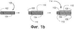
Фигуры 1а и 1b показывают ступенчатый процесс для получения двух типов компоновок электрода в соответствии с вариантами реализации данного изобретения;Figures 1a and 1b show a step-by-step process for obtaining two types of electrode arrangements in accordance with embodiments of the present invention;
Фигуры 2а и 2b показывают ступенчатый процесс для получения двух типов компоновок, показанных на Фигурах 1а и 1b, соответственно, с использованием токоотвода, сформированного из решетки из сплава свинца;Figures 2a and 2b show a stepwise process for obtaining the two types of arrangements shown in Figures 1a and 1b, respectively, using a collector formed from a lead alloy grating;
Фигура 3 показывает оборудование для испытаний и компоновку, используемые для определения характеристик циклирования электродов под воздействием интервала сжатий при включении в работающий элемент;Figure 3 shows the testing equipment and layout used to determine the characteristics of the cycling of the electrodes under the influence of the compression interval when included in the working element;
Фигура 4 показывает профиль испытаний с использованием последовательности зарядки и разрядки, применяемой с оборудованием для испытаний и компоновкой по Фигуре 3;Figure 4 shows a test profile using the charging and discharging sequence used with the testing equipment and arrangement of Figure 3;
Фигура 5 является графиком, показывающим характеристики циклирования под различными сжимающими силами набора из четырех элементов, сделанных из различных отрицательных электродов по различным вариантам реализации данного изобретения;Figure 5 is a graph showing cycling characteristics under various compressive forces of a set of four elements made of various negative electrodes according to various embodiments of the present invention;
Фигура 6 является графиком, показывающим общую зависимость между числом циклов и силой сжатия элемента для испытанных электродов;6 is a graph showing a general relationship between the number of cycles and the compression force of an element for the tested electrodes;
Фигура 7 является графиком, показывающим профиль зарядки и разрядки, задействованный при испытании нетканых листов из углеродного волокна, включая изменения напряжения элемента, потенциала положительного электрода и потенциала отрицательного электрода в ходе зарядки и разрядки при 20 мА в одном цикле;7 is a graph showing a charge and discharge profile involved in testing carbon fiber nonwoven sheets, including changes in cell voltage, positive electrode potential and negative electrode potential during charging and discharging at 20 mA in one cycle;
Фигура 8 является графиком, показывающим изменения напряжения элемента и потенциала отрицательного электрода со временем для набора из 10 циклов, задействованных при испытании нетканых листов из углеродного волокна;Figure 8 is a graph showing changes in cell voltage and negative electrode potential over time for a set of 10 cycles involved in testing carbon fiber nonwoven sheets;
Фигура 9 является графиком, показывающим изменения напряжения элемента, потенциала положительного электрода и потенциала отрицательного электрода в ходе зарядки и разрядки при 50 мА в одном цикле, задействованном при испытании нетканых листов из углеродного волокна;Figure 9 is a graph showing changes in cell voltage, potential of the positive electrode and potential of the negative electrode during charging and discharging at 50 mA in one cycle involved in testing non-woven carbon fiber sheets;
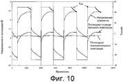
Фигура 10 является графиком, показывающим изменения напряжения элемента и потенциала отрицательного электрода со временем для набора из 4 циклов, задействованных при испытании нетканого листа из углеродного волокна;Figure 10 is a graph showing changes in cell voltage and negative electrode potential over time for a set of 4 cycles involved in testing a non-woven carbon fiber sheet;
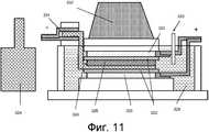
Фигура 11 показывает конфигурацию элемента, применяемую для испытания изменений четырех различных составов электроактивного материала с высокой скоростью заряда-разряда в соответствии с различными вариантами реализации данного изобретения;Figure 11 shows the configuration of an element used to test changes in four different compositions of electroactive material with a high charge-discharge rate in accordance with various embodiments of the present invention;
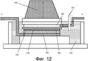
Фигура 12 показывает конфигурацию элемента, применяемую для испытания изменений различных электропроводных матов в соответствии с различными вариантами реализации данного изобретения;Figure 12 shows the configuration of the element used to test changes in various conductive mats in accordance with various embodiments of the present invention;
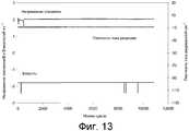
Фигура 13 является графиком, показывающим изменения напряжения элемента и емкости для протокола зарядки/разрядки высоким током для элемента, содержащего конденсаторный состав, намазанный непосредственно на свинцовый лист элемента, причем конденсаторный состав содержит 20 вес. % оксида свинца, 20 вес. % углеродной сажи и 35 вес. % активированного угля;Figure 13 is a graph showing changes in cell voltage and capacitance for a high current charging / discharging protocol for a cell containing a capacitor composition smeared directly on a lead sheet of the cell, wherein the capacitor composition contains 20 weight. % lead oxide, 20 weight. % carbon black and 35 weight. % activated carbon;
Фигура 14 является графиком, показывающим изменения напряжения элемента и емкости для протокола зарядки/разрядки высоким током для элемента, содержащего конденсаторный состав, намазанный непосредственно на свинцовый лист элемента, причем конденсаторный состав содержит 20 вес. % оксида свинца, 20 вес. % углеродной сажи и 45 вес. % активированного угля;14 is a graph showing changes in cell voltage and capacitance for a high current charging / discharging protocol for a cell containing a capacitor composition smeared directly on a lead sheet of the cell, wherein the capacitor composition contains 20 weight. % lead oxide, 20 weight. % carbon black and 45 weight. % activated carbon;
Фигура 15 является графиком, показывающим изменения напряжения элемента и емкости для протокола зарядки/разрядки высоким током для элемента, содержащего нетканый лист из углеродного волокна 8000040 с намазанным на него конденсаторным составом, содержащим 20 вес. % оксида свинца, 30 вес. % углеродной сажи и 35 вес. % активированного угля;Figure 15 is a graph showing changes in cell voltage and capacitance for a high current charging / discharging protocol for a cell containing a non-woven carbon fiber sheet 8000040 with a smeared capacitor composition containing 20 weight. % lead oxide, 30 weight. % carbon black and 35 weight. % activated carbon;
Фигура 16 является графиком, показывающим изменения напряжения элемента и емкости для протокола зарядки/разрядки высоким током для элемента, содержащего нетканый лист из углеродного волокна 8000030 (1 дюйм) с намазанным на него конденсаторным составом, содержащим 20 вес. % оксида свинца, 30 вес. % углеродной сажи и 35 вес. % активированного угля;Figure 16 is a graph showing changes in cell voltage and capacitance for a high current charging / discharging protocol for a cell containing a non-woven carbon fiber sheet 8000030 (1 inch) with a coated capacitor composition containing 20 weight. % lead oxide, 30 weight. % carbon black and 35 weight. % activated carbon;
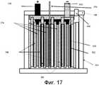
Фигура 17 показывает конфигурацию элемента, применяемую для испытания характеристик клапанно-регулируемого свинцово-кислотного (VRLA) 2-вольтового аккумуляторного элемента, содержащего нетканые листы из углеродного волокна, составляющие конденсаторный материал;Figure 17 shows the configuration of the cell used to test the valve-regulated lead-acid (VRLA) characteristics of a 2-volt battery cell containing carbon fiber nonwoven sheets constituting a capacitor material;
Фигура 18 является графиком, показывающим профиль циклирования зарядки и разрядки при 42 В при испытании характеристик элемента по Фигуре 17;Figure 18 is a graph showing the cycling profile of charging and discharging at 42 V when testing the characteristics of the cell of Figure 17;
Фигура 19 является графиком, показывающим изменения напряжения элемента и емкости при испытании элемента, такого как на Фигуре 17;Figure 19 is a graph showing changes in cell voltage and capacitance when testing a cell, such as in Figure 17;
Фигура 20 показывает установку и процесс в соответствии с вариантом реализации изобретения для изготовления композиционного слоя, содержащего электропроводный мат, покрытый электроактивным материалом с высокой скоростью заряда-разряда; иFigure 20 shows the installation and process in accordance with an embodiment of the invention for manufacturing a composite layer comprising an electrically conductive mat coated with an electroactive material with a high charge-discharge rate; and
Фигура 21 показывает установку и процесс в соответствии с вариантом реализации изобретения для изготовления двухстороннего электрода с композиционным слоем, нанесенным на каждую из его сторон.Figure 21 shows the installation and process in accordance with an embodiment of the invention for manufacturing a double-sided electrode with a composite layer deposited on each of its sides.
Подробное описание аббревиатурDetailed abbreviations
В примерах будут сделаны ссылки на следующие аббревиатуры, где:In the examples, references will be made to the following abbreviations, where:
АРР - примененияAPP - Applications
С - Градусы ЦельсияC - Degrees Celsius
Cl - КлассCl - Class
[ ] - Концентрация[] - Concentration
F - Градусы ФаренгейтаF - Fahrenheit
h - Часh - Hour
HRPSoC - Высокоскоростное состояние частичного зарядаHRPSoC - High Speed Partial Charge State
Μn - Среднечисловой молекулярный весΜn - Number-average molecular weight
Mw - Средневесовой молекулярный весMw - Weight average molecular weight
MW - Молекулярный весMW - Molecular Weight
PSoC - Условия состояния частичного зарядаPSoC - Partial Charge Condition Conditions
RH - Относительная влажностьRH - Relative Humidity
SG - Удельный вес или относительная плотность относительно водыSG - Specific gravity or relative density relative to water
SEM - Сканирующая электронная микроскопияSEM - Scanning Electron Microscopy
Wt% - Процентное весовое содержание конкретного компонента в составеWt% - The percentage weight content of a particular component in the composition
XPS - Рентгеновская фотоэлектронная спектроскопияXPS - X-ray photoelectron spectroscopy
Подробное описаниеDetailed description
В попытке выявить альтернативные материалы и компоновки в электродах для батарей с улучшенными характеристиками было обнаружено, что электропроводный мат, используемый с электродами, содержащими сочетание двух различных электроактивных материалов, причем один из электроактивных материалов обладает более высокой плотностью энергии и способностью к более низкой скорости заряда-разряда, чем другой электроактивный материал, может обеспечить определенные преимущества, включая увеличенный срок службы. Неограничивающие конкретные варианты реализации данного изобретения описаны ниже.In an attempt to identify alternative materials and layouts in battery electrodes with improved characteristics, it was found that an electrically conductive mat used with electrodes containing a combination of two different electroactive materials, one of the electroactive materials having a higher energy density and the ability to lower charge rate A discharge than other electroactive material can provide certain benefits, including longer life. Non-limiting specific embodiments of the present invention are described below.
Электрод по данному изобретению содержит первый электроактивный материал и второй электроактивный материал, причем первый электроактивный материал обладает более высокой плотностью энергии, чем второй электроактивный материал, а второй электроактивный материал обладает способностью к более высокой скорости заряда-разряда, чем первый электроактивный материал. Для удобства электроактивный материал, обладающий более высокой плотностью энергии (первый электроактивный материал), называется далее «электроактивным материалом с высокой энергией», а электроактивный материал, обладающий способностью к более высокой скорости заряда-разряда (второй электроактивный материал), называется далее «электроактивным материалом с высокой скоростью заряда-разряда».The electrode according to this invention contains a first electroactive material and a second electroactive material, the first electroactive material having a higher energy density than the second electroactive material, and the second electroactive material has the ability to a higher charge-discharge rate than the first electroactive material. For convenience, an electroactive material having a higher energy density (first electroactive material) is hereinafter referred to as “high energy electroactive material”, and an electroactive material having a higher charge-discharge rate (second electroactive material) is hereinafter referred to as “electroactive material” with a high charge-discharge rate. "
Данное изобретение, в общем, относится к электроду для высокоскоростных и высокоэнергетических устройств аккумулирования электроэнергии, содержащих токоотвод, электроактивный материал с высокой энергией, электроактивный материал с высокой скоростью заряда-разряда, электропроводный мат для обеспечения конструктивной и проводящей опоры для по меньшей мере одного из электроактивных материалов с высокой энергией и высокой скоростью заряда-разряда. Электроды по описанному здесь первому аспекту могут быть использованы в высокоскоростных и высокоэнергетических устройствах аккумулирования электроэнергии.This invention generally relates to an electrode for high speed and high energy electric energy storage devices comprising a collector, high energy electroactive material, high charge and discharge electroactive material, conductive mat to provide structural and conductive support for at least one of the electroactive materials with high energy and high charge-discharge rate. The electrodes of the first aspect described herein can be used in high speed and high energy power storage devices.
Общие терминыGeneral terms
Термин «высокоскоростной» или «с высокой скоростью заряда-разряда» в общем относится к способности устройства или материала обеспечивать высокую скорость или высокий ток электрического разряда и повторного заряда, чему способствует устройство или материал, имеющие низкое внутреннее сопротивление и большую площадь поверхности. Хорошо известно, что высокая скорость разряда обеспечивается традиционными конденсаторными материалами электродов, способными к емкостному аккумулированию (хранению) энергии, такими как углерод с большой площадью поверхности.The term “high speed” or “high charge-discharge rate” generally refers to the ability of a device or material to provide a high speed or high current of electric discharge and recharge, aided by a device or material having a low internal resistance and a large surface area. It is well known that a high discharge rate is provided by traditional capacitor electrode materials capable of capacitive energy storage (storage), such as carbon with a large surface area.
Термин «высокоэнергетический» или «с высокой энергией» в общем относится к способности устройства или материала обеспечивать высокую величину электрического разряда или повторного заряда, обычно обеспечиваемую при длительной продолжительности электрического разряда или повторного заряда, но с малой скоростью. Считается, что материал с высокой энергией обеспечивается традиционным материалом электродов батареи, способным к электрохимическому аккумулированию (хранению) энергии, такому как свинцовая паста, применяемая в свинцово-кислотных аккумуляторных батареях.The term “high energy” or “high energy” generally refers to the ability of a device or material to provide a high amount of electric discharge or recharge, usually provided for a long duration of an electric discharge or recharge, but at a low speed. It is believed that a material with high energy is provided by a traditional battery electrode material capable of electrochemically storing (storing) energy, such as lead paste used in lead-acid batteries.
Термин «электроактивный», «активный электродный материал» или схожие термины относятся к способности материала принимать, хранить или обеспечивать источник электрического заряда и включают в себя материалы электродов конденсатора, способные к емкостному аккумулированию энергии, и материалы электродов батареи, способные к электрохимическому аккумулированию энергии.The term “electroactive”, “active electrode material” or similar terms refers to the ability of a material to receive, store or provide a source of electrical charge and includes capacitor electrode materials capable of capacitive energy storage and battery electrode materials capable of electrochemical energy storage.
Другие конкретные термины были описаны ниже, где они соответственно описаны со ссылкой на конкретные варианты реализации.Other specific terms have been described below, where they are respectively described with reference to specific implementations.
Структура электродаElectrode structure
Электроды обычно содержат токоотвод (обычно решетку или пластину) с нанесенным на него активным электродным материалом. Активный электродный материал наиболее часто наносят в виде пасты на область токоотвода. Паста может содержать иные добавки или материалы, отличные от активного электродного материала.Electrodes typically comprise a down conductor (usually a grid or plate) with active electrode material deposited thereon. Active electrode material is most often applied in the form of a paste to the area of the collector. The paste may contain other additives or materials other than the active electrode material.
Электрод может иметь любую подходящую форму, хотя обычно имеет форму плоской пластины (решетки) или спирально намотанной пластины для призматических или спирально-закрученных элементов. Для простоты конструкции обычно предпочтительны плоские пластины или решетки. Токоотводы обычно обеспечивают основную структуру электрода и, как правило, выполнены из электропроводных металлов, например, обычно в качестве токоотвода в свинцово-кислотных аккумуляторных батареях используется сплав свинца. Более того, материалы, используемые для токоотвода, должны быть устойчивы к среде электролита.The electrode may have any suitable shape, although it usually takes the form of a flat plate (lattice) or a spirally wound plate for prismatic or spiral-wound elements. For simplicity of design, flat plates or grids are generally preferred. Down conductors usually provide the basic structure of the electrode and, as a rule, are made of electrically conductive metals, for example, a lead alloy is usually used as a lead collector in lead-acid batteries. Moreover, the materials used for the down conductor must be resistant to the electrolyte environment.
Как описано выше, данное изобретение в общем предусматривает электрод для высокоскоростного и высокоэнергетического устройства аккумулирования электроэнергии, содержащий: токоотвод, электроактивный материал с высокой энергией, электроактивный материал с высокой скоростью заряда-разряда и электропроводный мат, который обеспечивает электропроводящую конструктивную и механическую опору для электроактивного материала с высокой скоростью заряда-разряда и/или высокой энергией.As described above, the present invention generally provides an electrode for a high speed and high energy power storage device comprising: a collector, a high energy electroactive material, a high charge and discharge electroactive material, and an electrically conductive mat that provides an electrically conductive structural and mechanical support for the electroactive material with high charge-discharge rate and / or high energy.
Каждый из электроактивного материала с высокой энергией, электроактивного материала с высокой скоростью заряда-разряда и электропроводного мата может быть предусмотрен на токоотводе, или друг на друге, в виде покрытия, слоя или области и в любом порядке или любой компоновке, и может быть выполнен с другими материалами или слоями. Различные компоновки и варианты реализации электрода описаны следующим образом.Each of the high-energy electroactive material, the high charge-discharge electroactive material and the conductive mat can be provided on the collector, or on top of each other, in the form of a coating, layer or region and in any order or any arrangement, and can be made with other materials or layers. Various arrangements and embodiments of the electrode are described as follows.
Первый и второй электроактивные материалы могут быть перемешены в любых одном или более покрытиях, одном или более слоях или одной или более областях, необязательно с одной или более другими добавками. Первый электроактивный материал может быть также отделен от второго электроактивного материала в любых одном или более покрытиях, одном или более слоях или одной или более областях.The first and second electroactive materials can be mixed in any one or more coatings, one or more layers, or one or more areas, optionally with one or more other additives. The first electroactive material may also be separated from the second electroactive material in any one or more coatings, one or more layers, or one or more areas.
В одном варианте реализации электрод имеет отдельные первую(ые) и вторую(ые) области, причем электроактивный материал с высокой энергией расположен в одной или более первых областях, а электроактивный материал с высокой скоростью заряда-разряда расположен в одной или более вторых областях. Первая(ые) и вторая(ые) области могут быть смежными, разнесенными, перекрывающимися или наслоенными одна на другой. Области могут быть предусмотрены на токоотводе и/или на электропроводном мате, причем мат выполнен с возможностью поддерживать (т.е. обеспечивать опору) для любой из областей. Электропроводный мат помогает предотвратить сползание электроактивных материалов с электрода в процессе использования. В другом примере электропроводный мат может быть расположен в виде слоя поверх токоотвода с расположенными на поверхности электропроводного мата первой(ыми) и второй(ыми) областями.In one embodiment, the electrode has separate first (s) and second (s) regions, wherein the high energy electroactive material is located in one or more of the first regions, and the electroactive material with a high charge-discharge rate is located in one or more second regions. The first (s) and second (s) areas may be adjacent, spaced, overlapping, or layered one on top of the other. Regions may be provided on the down conductor and / or on the electrically conductive mat, the mat being configured to support (i.e. provide support) for any of the regions. An electrically conductive mat helps prevent electroactive materials from sliding off the electrode during use. In another example, the electrically conductive mat may be arranged as a layer on top of the collector with the first (s) and second (s) regions located on the surface of the electrically conductive mat.
В другом варианте реализации один из электроактивньгх материалов с высокой скоростью заряда-разряда и с высокой энергией может быть предусмотрен в виде первого отдельного слоя, нанесенного на токоотвод, а другой из электроактивных материалов с высокой скоростью заряда-разряда и с высокой энергией может быть тогда предусмотрен в виде второго отдельного слоя, нанесенного на первый отдельный слой, причем электропроводный мат является третьим отдельным слоем, находящимся в контакте со вторым отдельным слоем. В альтернативном варианте реализации электроактивный материал с высокой энергией может быть предусмотрен в виде первого отдельного слоя, нанесенного на токоотвод, а электропроводный мат может быть предусмотрен в виде второго отдельного слоя, находящегося в контакте с первым отдельным слоем, а электроактивный материал с высокой скоростью заряда-разряда предусмотрен в виде третьего отдельного слоя, нанесенного на второй отдельный слой.In another embodiment, one of the electroactive materials with a high charge-discharge rate and with high energy can be provided in the form of a first separate layer deposited on the collector, and the other of electroactive materials with a high charge-discharge rate and with high energy can then be provided in the form of a second separate layer deposited on the first separate layer, the electrically conductive mat being the third separate layer in contact with the second separate layer. In an alternative embodiment, the implementation of the high energy electroactive material may be provided in the form of a first separate layer deposited on the collector, and the conductive mat may be provided in the form of a second separate layer in contact with the first separate layer, and the electroactive material with a high charge rate the discharge is provided in the form of a third separate layer deposited on a second separate layer.
Электроактивный материал с высокой скоростью заряда-разряда и/или с высокой энергией может быть нанесен на и/или введен в электропроводный мат с образованием композиционного слоя. В одном варианте реализации электрод содержит композиционный слой, содержащий электропроводный мат, покрытый по меньшей мере одним из электроактивных материалов с высокой скоростью заряда-разряда и высокой энергией, а, предпочтительно, по меньшей мере электроактивным материалом с высокой скоростью заряда-разряда. Относительно изготовления электрода или устройства, содержащего такой электрод, композиционные слои могут быть предварительно изготовлены и храниться, а затем собираться в электрод или устройство в подходящий момент времени, что обеспечивает определенную эффективность при изготовлении таких электродов и устройств. Например, композиционный слой может наноситься одновременно на каждую сторону двухстороннего электрода для обеспечения эффективного производства электрода.Electroactive material with a high charge-discharge rate and / or with high energy can be deposited on and / or introduced into the electrically conductive mat to form a composite layer. In one embodiment, the electrode comprises a composite layer comprising an electrically conductive mat coated with at least one of an electroactive material with a high charge-discharge rate and high energy, and preferably at least an electroactive material with a high charge-discharge rate. Regarding the manufacture of an electrode or device containing such an electrode, the composite layers can be pre-made and stored, and then collected in an electrode or device at a suitable time, which provides a certain efficiency in the manufacture of such electrodes and devices. For example, a composite layer can be applied simultaneously on each side of a double-sided electrode to ensure efficient electrode production.
В другом варианте реализации электропроводный мат предусмотрен в виде промежуточного слоя, отделяющего электроактивный материал с высокой энергией от электроактивного материала с высокой скоростью заряда-разряда. Промежуточный слой может быть предусмотрен в виде отдельного слоя. Пористость электропроводного мата может быть также выбрана для предотвращения проникновения электроактивного материала с высокой скоростью заряда-разряда через электропроводный мат. Выбранная пористость будет зависеть от природы устройства и окружающей среды, в которой устройство предназначено работать. Например, электроактивный материал с высокой скоростью заряда-разряда может быть нанесен на одну сторону электропроводного мата, а электроактивный материал с высокой энергией может быть нанесен на противоположную сторону электропроводного мата, причем пористость электропроводного мата выбрана для сохранения разделения электроактивных материалов с высокой скоростью заряда-разряда и с высокой энергией.In another embodiment, the electrically conductive mat is provided as an intermediate layer separating high energy electroactive material from electroactive material with a high charge-discharge rate. The intermediate layer may be provided as a separate layer. The porosity of the electrically conductive mat can also be selected to prevent the penetration of electroactive material with a high charge-discharge rate through the electrically conductive mat. The selected porosity will depend on the nature of the device and the environment in which the device is intended to operate. For example, an electroactive material with a high charge-discharge rate can be deposited on one side of the electrically conductive mat, and an electroactive material with high energy can be deposited on the opposite side of the electrically conductive mat, and the porosity of the electrically conductive mat is selected to maintain separation of electroactive materials with a high charge-discharge rate and with high energy.
Указанные выше компоновки электрода подходят для формирования как отрицательных, так и положительных электродов батарей.The above electrode arrangements are suitable for forming both negative and positive battery electrodes.
Электроактивные материалыElectroactive materials
«Электроактивный материал с высокой энергией» обладает более высокой плотностью энергии, чем «электроактивный материал с высокой скоростью заряда-разряда», а «электроактивный материал с высокой скоростью заряда-разряда» обладает способностью к более высокой скорости заряда-разряда, чем «электроактивный материал с высокой энергией». Будет понятно, что абсолютные значения скорости заряда-разряда или энергии для этих материалов зависят от ряда факторов, включая количества и тип материала, а также окружающие среды и конфигурации, в которых эти материалы используются.An “electroactive material with a high energy” has a higher energy density than an “electroactive material with a high charge-discharge rate”, and an “electroactive material with a high charge-discharge rate” has the ability to have a higher charge-discharge rate than an “electroactive material” with high energy. " It will be understood that the absolute values of the charge-discharge rate or energy for these materials depend on a number of factors, including the quantity and type of material, as well as the environments and configurations in which these materials are used.
«Электроактивным материалом с высокой энергией» может быть любой материал, традиционно применяемый в электродах батарей для обеспечения высокой плотности энергии. Эти материалы обычно обеспечивают непрерывную выдачу энергии, но с меньшей скоростью или мощностью по сравнению с материалами с высокой скоростью заряда-разряда. Примеры некоторых обычных материалов с высокой энергией, которые использовались для анодов в перезаряжаемых водных батареях, включают в себя кадмий, гидриды металлов, свинец и цинк, при том что такие материалы для катодов изготавливались из оксида никеля, оксида свинца, серебра и кислорода или воздуха (с катализатором). Примеры анодных материалов с высокой энергией для Li-ионных перезаряжаемых батарей включают в себя углерод (с интеркаляцией Li), WO3, и TiS2, и SnOx, с соответствующими катодными материалами, включающими в себя LixNiyOz, LiCoO2, LiMn2O2, LixTiyOz и LiV6O13, где x, у и z изменяются в интервале от 0,1 до 10. Другие материалы с высокой энергией включают в себя La, Li, Na, Al, Fe, Zn, Cd, Pb, Sn, Bi, С, V, Mn, Co, Ni, Ag и их оксиды, гидроксиды, гидриды, карбиды, нитриды или сульфиты, и полианилин, политиофен, полифторфенилтиофен, полипиррол, n- или р-допированные полимеры, окислительно-восстановительные полимеры и их смеси. Например, устройство аккумулирования электроэнергии может содержать системы на основе иона лития, металлического лития, гидрида металла-лития, гидрида металла-никеля, никеля и цинка, и устройства или электродные системы на основе никеля и серебра.A “high energy electroactive material” can be any material conventionally used in battery electrodes to provide a high energy density. These materials usually provide continuous energy output, but at a lower speed or power compared to materials with a high charge-discharge rate. Examples of some common high-energy materials that have been used for anodes in rechargeable water batteries include cadmium, metal hydrides, lead and zinc, while such cathode materials are made of nickel oxide, lead oxide, silver and oxygen or air ( with catalyst). Examples of high energy anode materials for Li-ion rechargeable batteries include carbon (intercalated Li), WO3 , and TiS2 , and SnOx , with corresponding cathode materials including Lix Niy Oz , LiCoO2 , LiMn2 O2 , Lix Tiy Oz and LiV6 O13 , where x, y and z vary in the range from 0.1 to 10. Other high-energy materials include La, Li, Na, Al, Fe , Zn, Cd, Pb, Sn, Bi, C, V, Mn, Co, Ni, Ag and their oxides, hydroxides, hydrides, carbides, nitrides or sulfites, and polyaniline, polythiophene, polyfluorophenylthiophene, polypyrrole, n- or p- doped redox polymers ovitelnye polymers and mixtures thereof. For example, an electric energy storage device may include systems based on lithium ion, lithium metal, lithium metal hydride, nickel metal hydride, nickel and zinc, and nickel and silver based devices or electrode systems.
В одном варианте реализации электроактивный материал с высокой энергией является материалом на основе свинца, например, для свинцово-кислотной аккумуляторной батареи, губчатым свинцом для использования в качестве материала отрицательного электрода и диоксидом свинца для использования в качестве материала положительного электрода.In one embodiment, the high energy electroactive material is lead based, for example, for a lead acid battery, sponge lead for use as a negative electrode material, and lead dioxide for use as a positive electrode material.
«Электроактивный материал с высокой скоростью заряда-разряда» может быть любым материалом с высокой скоростью (или с высокой мощностью) заряда-разряда, который обычно демонстрирует свойства конденсаторов. Такие материалы хорошо известны в данной области техники. Эти материалы обычно обеспечивают начальную выдачу с высокой скоростью заряда-разряда или с высокой энергией в течении короткого промежутка времени, но имеют малую плотность энергии по сравнению с материалом с высокой энергией. Примеры некоторых материалов с высокой скоростью заряда-разряда, которые использовались в конденсаторах, включают в себя углерод с большой площадью поверхности, оксид рутения, оксид серебра, оксид кобальта и проводящие полимеры (такие как полианилин, политиофен, полифторфенилтиофен, n- или p-допированные полимеры, окислительно-восстановительные полимеры или полипиррол). Примерами углеродных материалов с высокой площадью поверхности являются активированный углерод, углеродная сажа, аморфный углерод, углеродные наночастицы, углеродные нанотрубки, углеродные волокна и их смеси. Другие материалы с высокой скоростью заряда-разряда включают в себя С, Nb, Hf, Ti, Та, Li, Fe, Zn, Sn, Ru, Ag, Pt, Ir, Pb, Mo, W, Ni, Co и их оксиды, гидроксиды, гидриды, карбиды, нитриды или сульфиты, а также их смеси.“Electroactive material with a high charge-discharge rate” can be any material with a high speed (or high power) charge-discharge, which usually demonstrates the properties of capacitors. Such materials are well known in the art. These materials usually provide initial delivery with a high charge-discharge rate or with high energy for a short period of time, but have a low energy density compared to a material with high energy. Examples of some high charge-discharge materials that have been used in capacitors include large surface area carbon, ruthenium oxide, silver oxide, cobalt oxide and conductive polymers (such as polyaniline, polythiophene, polyfluorophenylthiophene, n- or p-doped polymers, redox polymers or polypyrrole). Examples of carbon materials with a high surface area are activated carbon, carbon black, amorphous carbon, carbon nanoparticles, carbon nanotubes, carbon fibers and mixtures thereof. Other materials with a high charge-discharge rate include C, Nb, Hf, Ti, Ta, Li, Fe, Zn, Sn, Ru, Ag, Pt, Ir, Pb, Mo, W, Ni, Co and their oxides, hydroxides, hydrides, carbides, nitrides or sulfites, as well as mixtures thereof.
Электроактивный материал с высокой энергией и электроактивный материал с высокой скоростью заряда-разряда обычно предусмотрены в виде областей, слоев или покрытий на электроде. Электроактивный материал может быть нанесен или наложен в виде покрытия на токоотвод, электропроводный мат или один или более других компонентов электродов, например, в виде пасты со связующим или связующими агентами, такими как карбоксиметилцеллюлоза, неопрен, бутадиенстирольный каучук, политетрафторэтилен (ПТФЭ) или поливинилиденфторид (ПВДФ)/кайнар и их сочетания, и, необязательно, с одной или более другими добавками, включая проводящие материалы, такие как углеродная сажа, пластмассовые или углеродные волокна, загустители или порообразующие агенты. Электроактивный материал с высокой энергией может быть нанесен на токоотвод, электропроводный мат или один или более других компонентов электрода без необходимости в использовании связующего или связующего(их) агента(ов).Electroactive material with high energy and electroactive material with a high charge-discharge rate are usually provided in the form of regions, layers or coatings on the electrode. The electroactive material can be applied or coated as a coating on a down conductor, an electrically conductive mat, or one or more other electrode components, for example, in the form of a paste with binders or binders, such as carboxymethyl cellulose, neoprene, styrene butadiene rubber, polytetrafluoroethylene (PTFE) or polyvinylidene fluoride PVDF) / Kainar and combinations thereof, and optionally with one or more other additives, including conductive materials such as carbon black, plastic or carbon fibers, thickeners or porosity developing agents. High energy electroactive material can be applied to a down conductor, an electrically conductive mat, or one or more other electrode components without the need for a binder or binder (s) agent (s).
Паста для нанесения электроактивного материала с высокой скоростью заряда-разряда на один или более компонентов электродов часто содержит другие материалы для достижения нужного баланса между площадью поверхности (и, следовательно, емкостью) и проводимостью. На данный момент, из соображений затрат, активированный уголь является наиболее подходящим источников электроактивного материала с высокой скоростью заряда-разряда. Подходящий материал из активированного угля может иметь площадь поверхности по меньшей мере 500 м2/г, например, в интервале примерно 1000-3500 м2/г.Подходящий материал из углеродной сажи может иметь площадь поверхности в интервале 20-1000 м2/г.A paste for applying an electroactive material with a high charge-discharge rate to one or more electrode components often contains other materials to achieve the desired balance between surface area (and therefore capacitance) and conductivity. At the moment, for cost reasons, activated carbon is the most suitable source of electroactive material with a high charge-discharge rate. Suitable material of the activated carbon can have a surface area of at least 500 m2 / g, e.g., in the range of about 1000-3500 m2 /g.Podhodyaschy material of carbon black may have a surface area in the range of 20-1000 m2 / g.
Электроактивные материалы могут быть использованы в сочетании с одной или более добавками. Добавка может включать в себя связующее или связующие агенты, загустители, волокна, проводящие материалы и порообразующие агенты. Добавки могут быть предусмотрены в смеси или пасте, содержащей электроактивный материал, для формирования части области, покрытия или слоя, и для улучшения характеристик электрода.Electroactive materials may be used in combination with one or more additives. The additive may include a binder or binders, thickeners, fibers, conductive materials and pore-forming agents. Additives may be provided in a mixture or paste containing electroactive material to form part of a region, coating or layer, and to improve electrode performance.
Порообразующий агент может быть выбран из одного или более из группы, состоящей из порошка цинка, порошка камфары, порошка нафталина и порошка алюминия. Порообразующий агент увеличивает пористость области, покрытия или слоя, содержащих электроактивный материал, и облегчает подачу электролита к поверхности электрода для улучшения высокоскоростного разряда.The pore-forming agent may be selected from one or more of the group consisting of zinc powder, camphor powder, naphthalene powder and aluminum powder. The pore-forming agent increases the porosity of the region, coating or layer containing electroactive material, and facilitates the supply of electrolyte to the surface of the electrode to improve high-speed discharge.
Проводящий материал обеспечивает достаточную величину электропроводности в области, покрытии или слое и может включать в себя углеродную сажу или другие проводящие материалы. Проводящий материал может быть предусмотрен в количестве по меньшей мере 5% по весу области, покрытия, слоя, смеси или пасты, например, в интервале от 10 до 60% по весу.The conductive material provides a sufficient amount of electrical conductivity in the region, coating or layer and may include carbon black or other conductive materials. The conductive material may be provided in an amount of at least 5% by weight of the region, coating, layer, mixture or paste, for example, in the range of 10 to 60% by weight.
Связующее или связующий агент полезны для усиления связывания материалов друг с другом и на поверхности токоотвода, электрода или электропроводного мата. Связующее может также обеспечивать электрическое соединение между материалами, областями, слоями, покрытиями или компонентами электрода, и способствовать поддержанию достаточной степени пористости, когда материалы высушены. Связующее или связующий агент могут включать в себя полихлоропрен, бутадиенстирольный каучук (БСК), политетрафторэтилен (ПТФЭ), поливинилиденфторид (ПВДФ). Связующее может быть предусмотрено в интервале от 1 до 20% по весу в области, покрытии или слое, например, в интервале от 5 до 15% по весу.A binder or binder is useful for enhancing the bonding of materials to each other and on the surface of a collector, electrode or conductive mat. The binder can also provide an electrical connection between the materials, regions, layers, coatings, or electrode components, and help maintain a sufficient degree of porosity when the materials are dried. The binder or binding agent may include polychloroprene, styrene butadiene rubber (BSK), polytetrafluoroethylene (PTFE), polyvinylidene fluoride (PVDF). A binder may be provided in the range of 1 to 20% by weight in the region, coating or layer, for example in the range of 5 to 15% by weight.
Загуститель, который можно также назвать связующим или связующим агентом, полезен для приготовления смеси материалов в виде пасты. Для водной пасты подходят производные целлюлозы, такие как карбоксиметилцеллюлоза (КМЦ) и метилцеллюлоза (МЦ), соли полиакриловой кислоты, поливиниловый спирт и им подобные, а для органической пасты подходят NMP(N-метил-2-пиррилидон, 1-метил-2-пиррилидон), диметилсульфоксид(ДМСО) и им подобные. Загустители могут быть предусмотрены таким образом, чтобы сухой остаток не превышал 10% по весу для поддержания достаточной величины электропроводности, например, в интервале от 1 до 6% по весу в области, покрытии или слое.A thickener, which can also be called a binding or binding agent, is useful for preparing a mixture of materials in the form of a paste. Cellulose derivatives such as carboxymethyl cellulose (CMC) and methyl cellulose (MC), polyacrylic acid salts, polyvinyl alcohol and the like are suitable for water paste, and NMP (N-methyl-2-pyrrylidone, 1-methyl-2- pyrrylidone), dimethyl sulfoxide (DMSO) and the like. Thickeners can be provided so that the dry residue does not exceed 10% by weight to maintain a sufficient conductivity, for example, in the range of 1 to 6% by weight in the region, coating or layer.
Волокна могут включать в себя пластмассовые, стеклянные или углеродные волокна. Волокна могут обеспечивать армирующий материал и улучшать проницаемость газа, получаемого в электроде в процессе работы. Пластмассовые волокна могут включать в себя сложнополиэфирную смолу, такую как полиэтилентерефталат (ПЭТ) или подобные. Волокна являются обычно короткими, например, в интервале от 1 до 30 мкм в толщину и от 0,05 до 4,0 мм в длину. Волокна могут быть предусмотрены в количестве менее чем примерно 15% по весу, например, в интервале от 4 до 12% по весу.The fibers may include plastic, glass, or carbon fibers. The fibers can provide reinforcing material and improve the permeability of the gas produced in the electrode during operation. Plastic fibers may include a polyester resin such as polyethylene terephthalate (PET) or the like. The fibers are usually short, for example, in the range from 1 to 30 μm in thickness and from 0.05 to 4.0 mm in length. Fibers may be provided in an amount of less than about 15% by weight, for example, in the range of 4 to 12% by weight.
Подходящая смесь этих материалов может содержать 0-80% углеродной сажи, 15-95% активированного угля, 0-10% пластмассовых и/или углеродных волокон, а остальное - связующее на уровне 5-25%. Все измерения указаны по весу, если не указано иное. В приведенных выше и далее вариантах реализации будет понятно, что углеродная сажа может быть заменена на другие проводящие материалы или смеси проводящих материалов, а активированный уголь может быть заменен другими материалами с высокой скоростью заряда-разряда или смесями материалов с высокой скоростью заряда-разряда. Если не указано иное, эти смеси могут быть использованы для положительного или отрицательного электродов, хотя могут существовать дополнительные преимущества при использовании для определенных электродов и конфигураций в конкретных типах систем батарей.A suitable mixture of these materials may contain 0-80% carbon black, 15-95% activated carbon, 0-10% plastic and / or carbon fibers, and the rest is a binder of 5-25%. All measurements are by weight unless otherwise indicated. In the above and further embodiments, it will be understood that carbon black can be replaced with other conductive materials or mixtures of conductive materials, and activated carbon can be replaced with other materials with a high charge-discharge rate or mixtures of materials with a high charge-discharge rate. Unless otherwise indicated, these mixtures can be used for positive or negative electrodes, although there may be additional advantages when used for certain electrodes and configurations in specific types of battery systems.
Другая подходящая смесь может содержать 1-95% активированного угля (в качестве материала с высокой скоростью заряда-разряда), 5-20% связующего (например, неопрена и/или карбоксиметилцеллюлозы), 0-80% углеродной сажи и 0-5% пластмассовых и/или углеродных волокон. Преимущества обеспечиваются вариантами реализации, в которых электроактивный материал с высокой скоростью заряда-разряда распределен на проводящем материале или компоненте, или внутри проводящего материала или компонента, или в контакте с проводящим материалом или компонентом (например, при наслоении или покрытии), таким как углеродная сажа или электропроводный мат. Для определенных вариантов реализации, где электроактивный материал с высокой скоростью заряда-разряда находится в контакте с электропроводным матом, количество использованного проводящего материала (например, углеродной сажи) в смеси может быть уменьшено или исключено. Например, паста, содержащая электроактивный материал с высокой скоростью заряда-разряда, связующий агент и проводящий материал, которая была бы подходящей для нанесения на электропроводный мат, может содержать менее 30 вес. %, менее 20 вес. %, менее 10 вес. % или менее 5 вес. % проводящего материала. Связующие агенты или загустители могут быть предусмотрены в интервале 5-25%. Паста может также содержать более 60 вес. %, более 70 вес. %, более 80 вес. % или более 90 вес. % электроактивного материала с высокой скоростью заряда-разряда. Проводящие материалы, такие как углеродная сажа, обычно включают в себя примеси, которые могут вызвать проблемы газообразования в определенных системах батарей. Электропроводный мат в этих вариантах реализации может поэтому придать проводящие свойства области электроактивного материала с высокой скоростью заряда-разряда в дополнение к свойствам конструктивной и механической опоры. Будет понятно, что в тех вариантах реализации, где электроактивный материал с высокой скоростью заряда-разряда отделен от электропроводного мата, проводящий материал, такой как углеродная сажа, может быть использован в смеси с электроактивным материалом с высокой скоростью заряда-разряда для улучшения характеристик.Another suitable mixture may contain 1-95% activated carbon (as a material with a high charge-discharge rate), 5-20% binder (e.g. neoprene and / or carboxymethyl cellulose), 0-80% carbon black and 0-5% plastic and / or carbon fibers. Advantages are provided by embodiments in which an electroactive material with a high charge-discharge rate is distributed on a conductive material or component, or within a conductive material or component, or in contact with a conductive material or component (e.g., when layered or coated), such as carbon black or conductive mat. For certain embodiments, where an electroactive material with a high charge-discharge rate is in contact with an electrically conductive mat, the amount of used conductive material (eg, carbon black) in the mixture can be reduced or eliminated. For example, a paste containing an electroactive material with a high charge-discharge rate, a binder, and a conductive material that would be suitable for application to an electrically conductive mat may contain less than 30 weight. %, less than 20 weight. %, less than 10 weight. % or less than 5 weight. % conductive material. Binders or thickeners may be provided in the range of 5-25%. The paste may also contain more than 60 weight. %, more than 70 weight. %, more than 80 weight. % or more than 90 weight. % of electroactive material with a high charge-discharge rate. Conductive materials, such as carbon black, typically include impurities that can cause gas generation problems in certain battery systems. The conductive mat in these embodiments may therefore impart conductive properties to the area of the electroactive material with a high charge-discharge rate in addition to the properties of the structural and mechanical support. It will be understood that in embodiments where an electroactive material with a high charge-discharge rate is separated from an electrically conductive mat, a conductive material such as carbon black can be used in admixture with an electroactive material with a high charge-discharge rate to improve performance.
В варианте реализации электроактивный материал с высокой скоростью заряда-разряда является активированным углем, предпочтительно, имеющим площадь поверхности между примерно 1000 и 3500 м2/г.Активированный уголь может быть приготовлен в виде пасты при помощи связующего или загустителя, например, смеси неопрена и/или карбоксиметилцеллюлозы в количестве 5-20%. Паста может содержать 80-95% активированного угля и 5-20% связывающего, например, паста содержит 85% активированного угля и 15% связывающего. Как было указано ранее, эти варианты реализации могут обеспечить дополнительные преимущества для конфигураций электрода, где электроактивный материал с высокой скоростью заряда-разряда находится в контакте с электропроводным матом (например, областью, покрытием или слоем электроактивного материала с высокой скоростью заряда-разряда, предусмотренными на электропроводном мате).In an embodiment, the electroactive material with a high charge-discharge rate is activated carbon, preferably having a surface area between about 1000 and 3500 m2 / g. Activated carbon can be prepared in the form of a paste using a binder or thickener, for example, a mixture of neoprene and / or carboxymethyl cellulose in an amount of 5-20%. The paste may contain 80-95% activated carbon and 5-20% binder, for example, the paste contains 85% activated carbon and 15% binder. As indicated earlier, these embodiments can provide further benefits for electrode configurations where the high charge-discharge electroactive material is in contact with the conductive mat (e.g., a region, coating, or layer of high-charge charge-discharge electroactive material provided on conductive mate).
В другом варианте реализации паста содержит: активированный уголь в интервале примерно 20-50% по весу; углеродную сажу в интервале примерно 30-60% по весу; и связующее в интервале от примерно 5 до 25% по весу. Например, паста может содержать: активированный уголь в количестве примерно 35% по весу; углеродную сажу в количестве примерно 45% по весу; связующее в количестве примерно 10% по весу, и остаток, включающий одну или более других добавок. В одном варианте реализации паста может содержать 35% активированного угля, 45% углеродной сажи, 15% связующего и 5% частиц пластмассовых/углеродных волокон. Как указано ранее, эти варианты реализации могут обеспечить дополнительные преимущества для конфигураций электрода, где электроактивный материал с высокой скоростью заряда-разряда не находится в контакте с электропроводным матом.In another embodiment, the paste comprises: activated carbon in the range of about 20-50% by weight; carbon black in the range of about 30-60% by weight; and a binder in the range of from about 5 to 25% by weight. For example, a paste may contain: activated carbon in an amount of about 35% by weight; carbon black in an amount of about 45% by weight; a binder in an amount of about 10% by weight, and a residue comprising one or more other additives. In one embodiment, the paste may contain 35% activated carbon, 45% carbon black, 15% binder, and 5% plastic / carbon fiber particles. As indicated previously, these embodiments may provide additional benefits for electrode configurations where the electroactive material with a high charge-discharge rate is not in contact with the electrically conductive mat.
Обычно отношение электроактивного материала с высокой скоростью заряда-разряда к электроактивному материалу с высокой энергией, используемых в одном электроде, находится в интервале примерно от 3:17 до 1:19 соответственно в расчете по весу. Например, примерно 10 г электроактивного материала с высокой скоростью заряда-разряда могут быть использованы в качестве слоя на электроде, предварительно покрытом 100 г электроактивного материала с высокой энергией.Typically, the ratio of an electroactive material with a high charge-discharge rate to a high energy electroactive material used in a single electrode is in the range of about 3:17 to 1:19, respectively, based on weight. For example, approximately 10 g of electroactive material with a high charge-discharge rate can be used as a layer on an electrode pre-coated with 100 g of high energy electroactive material.
Электропроводный матConductive mat
Электропроводный мат может содержать любой материал, который имеет высокую степень электропроводности и, следовательно, малое внутреннее сопротивление, который способен обеспечивать физическую или механическую опору для электроактивного материала с высокой скоростью заряда-разряда и/или высокой энергией на электроде. Электропроводный мат обеспечивает опору для электроактивных материалов с высокой скоростью заряда-разряда и/или высокой энергией, способствуя предотвращению сползания этих материалов с электрода в ходе зарядки и разрядки устройства аккумулирования энергии. Электропроводный мат обычно устойчив в среде желаемого электролита. Электропроводный мат служит токоотводом (например, увеличивая проводимость) и обеспечивает физическую опору для электроактивного материала (например, увеличивая механическую прочность). Электропроводный мат может быть пористым и может содержать сетку из взаимосвязанных электропроводных волокон, например, нетканый лист из углеродного волокна. Электропроводный мат может быть тканым или нетканым.The electrically conductive mat may contain any material that has a high degree of electrical conductivity and, therefore, low internal resistance, which is able to provide physical or mechanical support for the electroactive material with a high charge-discharge rate and / or high energy on the electrode. The electrically conductive mat provides support for electroactive materials with a high charge-discharge rate and / or high energy, helping to prevent these materials from sliding off the electrode during charging and discharging of the energy storage device. The conductive mat is typically stable in the environment of the desired electrolyte. An electrically conductive mat serves as a down conductor (for example, increasing conductivity) and provides physical support for the electroactive material (for example, increasing mechanical strength). The electrically conductive mat may be porous and may comprise a network of interconnected electrically conductive fibers, for example, a nonwoven carbon fiber sheet. The conductive mat may be woven or non-woven.
Электропроводный мат может обеспечивать опору для первого электроактивного материала, второго электроактивного материала или обоих электроактивных материалов.The conductive mat may provide support for the first electroactive material, the second electroactive material, or both of the electroactive materials.
Электропроводный мат обеспечивает несущий (опорный) слой, который может быть связан с электропроводным материалом с высокой скоростью заряда-разряда и/или с высокой энергией с помощью какой-либо адгезии, присоединения, съемного присоединения (прикрепления) или без присоединения. С электропроводным матом, электроактивным материалом с высокой скоростью заряда-разряда и/или высокой энергией могут быть также связаны другие промежуточные слои с помощью адгезии, присоединения, съемного присоединения или без присоединения. Электропроводный мат обычно является полужестким или жестким и может быть в виде пленки, мембраны, матрицы или листа. Электропроводный мат может содержать лист или слой, содержащий сетку из взаимосвязанных электропроводных волокон, расположенных на нем, например, углеродных волокон, удерживаемых на несущем листе. В зависимости от предполагаемого применения, электропроводный мат может быть выбран из материалов, которые ограничивают газообразование в ходе высокоскоростной зарядки или разрядки устройства аккумулирования энергии.The electrically conductive mat provides a carrier (support) layer that can be bonded to the electrically conductive material at a high charge-discharge rate and / or with high energy through any adhesion, attachment, removable attachment (attachment) or without attachment. Other intermediate layers can also be bonded to an electrically conductive mat, an electroactive material with a high charge-discharge rate and / or high energy by means of adhesion, bonding, removable bonding or without bonding. The electrical conductive mat is typically semi-rigid or rigid and may be in the form of a film, membrane, matrix, or sheet. The electrically conductive mat may comprise a sheet or layer comprising a network of interconnected electrically conductive fibers located thereon, for example, carbon fibers held on a carrier sheet. Depending on the intended application, the electrically conductive mat may be selected from materials that limit gas generation during high-speed charging or discharging of the energy storage device.
Пример электропроводного мата включает в себя слой, образованный из материала из углеродного волокна, такого как нетканый лист из углеводородного волокна. Другие примеры электропроводного мата могут включать в себя взаимосвязанные сетки, образованные из материалов, включающих в себя проводящую керамику, проводящие стеклянные волокна и проводящие пластмассы. Будет понятно, что электропроводный мат обладает некой степенью пористости, чтобы дать возможность просачиваться жидкому электролиту. Например, подходящая пористость может быть в интервале 40-80%.An example of an electrically conductive mat includes a layer formed of a carbon fiber material, such as a nonwoven sheet of hydrocarbon fiber. Other examples of the electrically conductive mat may include interconnected grids formed from materials including conductive ceramics, conductive glass fibers, and conductive plastics. It will be understood that the electrically conductive mat has a certain degree of porosity to allow liquid electrolyte to seep out. For example, suitable porosity may be in the range of 40-80%.
Одним особым примером подходящего электропроводного мата будет нетканый лист из углеродного волокна, имеющий следующие свойства:One particular example of a suitable electrically conductive mat is a nonwoven carbon fiber sheet having the following properties:
- удельный вес: 10-70 г/м2;- specific gravity: 10-70 g / m2 ;
- толщина: 0,06-0,55 мм;- thickness: 0.06-0.55 mm;
- прочность на разрыв в продольном направлении: 0,91-4,3 кН/м;- tensile strength in the longitudinal direction: 0.91-4.3 kN / m;
- прочность на разрыв в поперечном направлении: 0,52-4,3 кН/м;- tensile strength in the transverse direction: 0.52-4.3 kN / m;
- удельное поверхностное сопротивление: 3-10 Ом/м2 для постоянного тока.- specific surface resistance: 3-10 Ohm / m2 for direct current.
В одном варианте реализации электропроводный мат является листом из углеродного волокна, который предпочтительно является тонким нетканым листом, обеспечивающим частично упорядоченную структуру, гарантирующую хорошую электронную проводимость вдоль волокон, и практически неизменное пространственное фиксирование волокон, гарантирующее хороший контакт между ними. Как и в случае других углеродных материалов, этот лист имеет низкое внутреннее сопротивление, что является идеальной характеристикой, необходимой для использования в сочетании с конденсаторным материалом с высокой скоростью заряда-разряда и электрохимическими материалами с высокой энергией. Изобретатель обнаружил, что в электродах, содержащих материал с высокой энергией и материал с высокой скоростью заряда-разряда, материал с высокой скоростью заряда-разряда может частично сползать в ходе циклирования. Изобретатель также обнаружил, что это сползание может быть уменьшено или предотвращено путем использования электропроводного мата для обеспечения конструктивной опоры для материала с высокой скоростью заряда-разряда.In one embodiment, the electrically conductive mat is a carbon fiber sheet, which is preferably a thin nonwoven sheet that provides a partially ordered structure to guarantee good electronic conductivity along the fibers and virtually unchanged spatial fixation of the fibers to ensure good contact between them. As with other carbon materials, this sheet has a low internal resistance, which is an ideal characteristic required for use in combination with a capacitor material with a high charge-discharge rate and high-energy electrochemical materials. The inventor has found that in electrodes containing high energy material and a high charge-discharge rate material, a high charge-discharge rate material can partially slide during cycling. The inventor also found that this creep can be reduced or prevented by using an electrically conductive mat to provide structural support for a material with a high charge-discharge rate.
В некоторых вариантах реализации материал с высокой скоростью заряда-разряда и/или высокой энергией нанесен на и введен в электропроводный мат.В этой компоновке электропроводный мат способствует предотвращению сползания материалов с высокой скоростью заряда-разряда и/или с высокой энергией с электрода в ходе высокоскоростной зарядки и разрядки устройства аккумулирования энергии, например, при газообразовании в свинцово-кислотных аккумуляторных батареях.In some embodiments, a material with a high charge-discharge rate and / or high energy is deposited on and inserted into the electrically conductive mat. In this arrangement, the electrically conductive mat helps prevent materials with a high charge-discharge rate and / or high energy from sliding off the electrode during high-speed charging and discharging an energy storage device, for example, during gas generation in lead-acid batteries.
В другом варианте реализации электропроводный мат может обеспечивать опору для отдельного слоя или отдельной области электроактивных материалов с высокой скоростью заряда-разряда и/или высокой энергией, а, предпочтительно, для по меньшей мере отдельного слоя или отдельной области электроактивного материала с высокой скоростью заряда-разряда.In another embodiment, the electrically conductive mat may provide support for a single layer or separate region of electroactive materials with a high charge-discharge rate and / or high energy, and, preferably, for at least a separate layer or separate region of an electroactive material with a high charge-discharge rate .
В другом варианте реализации по меньшей мере одна область внутри и/или на поверхности электроактивного мата содержит электроактивный материал с высокой скоростью заряда-разряда и/или высокой энергией. Электропроводный мат может быть выбран обладающим некой степенью пористости, так что любой материал, нанесенный на одну сторону мата, не может просочиться или пройти через него на противоположную сторону мата.In another embodiment, at least one region within and / or on the surface of the electroactive mat contains electroactive material with a high charge-discharge rate and / or high energy. The electrically conductive mat can be selected to have a certain degree of porosity, so that any material deposited on one side of the mat cannot leak or pass through it on the opposite side of the mat.
Электроактивный материал с высокой скоростью заряда-разряда и/или с высокой энергией может быть нанесен на и/или введен в электропроводный мат с образованием композиционного слоя. В таких вариантах реализации электропроводный мат, за счет изготовления композиционных слоев, делает возможным эффективный процесс изготовления устройств аккумулирования энергии. Например, композиционные слои могут предварительно изготавливаться и храниться, а затем собираться в электрод или устройство в подходящий момент времени.Electroactive material with a high charge-discharge rate and / or with high energy can be deposited on and / or introduced into the electrically conductive mat to form a composite layer. In such embodiments, the conductive mat, through the manufacture of composite layers, makes possible an efficient manufacturing process for energy storage devices. For example, composite layers can be prefabricated and stored and then collected in an electrode or device at a suitable point in time.
Было показано, что применение электропроводного мата в виде нетканого листа из углеродного волокна в устройстве аккумулирования электроэнергии позволило достичь максимального числа циклов (обычно в интервале примерно от 6000 до 8000 циклов) при меньших силах сжатия по сравнению с силами для традиционных электродов или гибридных/композиционных электродов, не имеющих электропроводного мата, например, менее 70 кПа по сравнению с более чем 80 кПа. В одном варианте реализации электропроводный мат используется в гибридном или композиционном электроде (т.е. электроды содержат в себя как конденсаторный материал с высокой скоростью заряда-разряда, так и аккумуляторный материал с высокой энергией), причем устройства аккумулирования электроэнергии работают под силой сжатия менее примерно 70 кПа, менее примерно 60 кПа, а, предпочтительно, между примерно 30 и 60 кПа. Будет понятно, что все же могут быть применены сжимающие силы, выходящие за эти интервалы.It has been shown that the use of a conductive mat in the form of a non-woven sheet of carbon fiber in an electric energy storage device made it possible to achieve a maximum number of cycles (usually in the range of about 6000 to 8000 cycles) with lower compression forces compared to forces for traditional electrodes or hybrid / composite electrodes having no electrically conductive mat, for example, less than 70 kPa compared to more than 80 kPa. In one embodiment, an electrically conductive mat is used in a hybrid or composite electrode (i.e., the electrodes comprise both a capacitor material with a high charge-discharge rate and a high-energy battery material), wherein the electric energy storage devices operate under a compression force of less than about 70 kPa, less than about 60 kPa, and preferably between about 30 and 60 kPa. It will be understood that, nevertheless, compressive forces beyond these intervals can be applied.
Устройства аккумулирования электроэнергииPower Storage Devices
Устройство аккумулирования электроэнергии включает в себя по меньшей мере одну пару положительного и отрицательного электродов, причем по меньшей мере один электрод является электродом по описанному здесь первому аспекту.The electric power storage device includes at least one pair of positive and negative electrodes, the at least one electrode being the electrode of the first aspect described herein.
Устройство аккумулирования электроэнергии, например, свинцово-кислотная аккумуляторная батарея, обычно собрана с анодом и катодом (или положительным и отрицательным электродами). Применительно к свинцово-кислотным аккумуляторным батареям, устройство обычно будет содержать по меньшей мере один положительный электрод на основе диоксида свинца, пористый непроводящий сепаратор и по меньшей мере один отрицательный электрод на основе губчатого свинца, соединенные вместе в растворе электролита, содержащем серную кислоту. Устройство аккумулирования электроэнергии может быть клапанно-регулируемым устройством.An electric energy storage device, for example, a lead acid battery, is typically assembled with an anode and cathode (or positive and negative electrodes). For lead-acid batteries, a device will typically comprise at least one lead dioxide-based positive electrode, a porous non-conductive separator, and at least one sponge-lead negative electrode connected together in an electrolyte solution containing sulfuric acid. The power storage device may be a valve-controlled device.
Материалы с высокой скоростью заряда-разряда и с высокой энергией могут быть нанесены на токоотвод различными способами, например, наложенными друг на друга слоями (которые могут включать или не включать в себя промежуточный слой, например, электропроводный мат), смежными слоями, или перемешанными друг с другом, или в виде частиц одного материала, покрытых другим материалом, с образованием смеси, наносимой на токоотвод. Электропроводный мат выполнен для обеспечения физической или механической опоры для материалов с высокой скоростью заряда-разряда и/или высокой энергией. Преимущественно, электропроводный мат может позволить нанести на него и/или ввести в него практически ровный слой электроактивного материала с высокой скоростью заряда-разряда и/или с высокой энергией, и может способствовать эффективному производству таких электродов.Materials with a high charge-discharge rate and with high energy can be applied to the collector in various ways, for example, layers superimposed on each other (which may or may not include an intermediate layer, for example, an electrically conductive mat), adjacent layers, or mixed with each other with another, or in the form of particles of one material coated with another material, with the formation of a mixture applied to the down conductor. The electrically conductive mat is made to provide physical or mechanical support for materials with a high charge-discharge rate and / or high energy. Advantageously, the electrically conductive mat can allow a substantially even layer of electroactive material with a high charge-discharge rate and / or high energy to be deposited on and / or introduced into it and can contribute to the efficient production of such electrodes.
Устройство аккумулирования электроэнергии может содержать один или более отрицательный электрод, положительный электрод, или одну или более пару положительного и отрицательного электродов, как здесь описано. Активный интервал электрохимического потенциала электроактивных материалов с высокой энергией и высокой скоростью заряда-разряда на данном электроде должен перекрывать весь желаемый рабочий интервал этого электрода. Материалы с высокой энергией и с высокой скоростью заряда-разряда должны также иметь доступ к электролиту, который может поставлять противоионы и замыкать электрическую цепь элемента аккумулирования энергии. Также должна учитываться химическая совместимость, например, если два материала делят между собой один общий электролит, они оба должны быть устойчивы в этом электролите.The electric power storage device may comprise one or more negative electrodes, a positive electrode, or one or more pairs of positive and negative electrodes, as described herein. The active interval of the electrochemical potential of electroactive materials with high energy and high charge-discharge rate on this electrode should cover the entire desired working interval of this electrode. Materials with high energy and with a high charge-discharge rate should also have access to an electrolyte, which can supply counterions and close the electric circuit of the energy storage element. Chemical compatibility should also be taken into account, for example, if two materials share the same common electrolyte, they should both be stable in this electrolyte.
Электроактивные материалы с высокой скоростью заряда-разряда и с высокой энергией обычно расположены на одном и том же токоотводе так, что они находятся в электрическом контакте. Примеры такого расположения включают в себя: двухстороннее, распределенное, послойное, бок о бок, и порошки с покрытием. Обеспечение отдельных фаз различных материалов делает возможной лучшую предсказуемость характеристик электрода. Другие примеры включают в себя области, которые расположены бок о бок в одной плоскости, такие как чередующиеся области двух материалов в шахматном порядке одинаковых форм или чередующиеся полосы каждого материала.Electroactive materials with a high charge-discharge rate and with high energy are usually located on the same collector so that they are in electrical contact. Examples of this arrangement include: double-sided, distributed, layered, side by side, and coated powders. Providing individual phases of various materials makes better predictability of electrode performance possible. Other examples include areas that are located side by side in the same plane, such as alternating regions of two materials in a checkerboard pattern of the same shape or alternating stripes of each material.
Отрицательный электрод устройства аккумулирования электроэнергии может содержать электроактивный материал с высокой энергией, выбранный из одного или более из группы, состоящей из кадмия, гидридов металлов, свинца и цинка. В одном варианте реализации электроактивный материал с высокой энергией является свинцом.The negative electrode of the electric energy storage device may comprise a high energy electroactive material selected from one or more of the group consisting of cadmium, metal hydrides, lead and zinc. In one embodiment, the high energy electroactive material is lead.
Положительный электрод устройства аккумулирования электроэнергии может содержать электроактивный материал с высокой энергией, выбранный из одного или более из группы, состоящей из оксида никеля, оксида свинца и серебра. В одном варианте реализации электроактивный материал с высокой энергией является диоксидом свинца.The positive electrode of the electric energy storage device may comprise a high energy electroactive material selected from one or more of the group consisting of nickel oxide, lead oxide and silver. In one embodiment, the high energy electroactive material is lead dioxide.
В одном варианте реализации положительный электрод является положительным электродом из диоксида свинца, а отрицательный электрод является отрицательным электродом из губчатого свинца. Электролитом предпочтительно является электролитический раствор серной кислоты.In one embodiment, the positive electrode is a positive electrode of lead dioxide, and the negative electrode is a negative electrode of sponge lead. The electrolyte is preferably an electrolytic solution of sulfuric acid.
В одном варианте реализации устройство аккумулирования электроэнергии содержит по меньшей мере один положительный электрод на основе диоксида свинца и по меньшей мере один отрицательный электрод на основе губчатого свинца в электролитическом растворе серной кислоты, причем отрицательный электрод содержит:In one embodiment, the electric energy storage device comprises at least one positive electrode based on lead dioxide and at least one negative electrode based on sponge lead in an electrolytic solution of sulfuric acid, wherein the negative electrode comprises:
токоотвод;down conductor;
первый слой, нанесенный на токоотвод, причем первый слой содержит губчатый свинец;a first layer deposited on the down conductor, the first layer containing spongy lead;
второй слой, находящийся в контакте с первым слоем, причем второй слой содержит электропроводный мат, содержащий сетку из взаимосвязанных электропроводных углеродных волокон;a second layer in contact with the first layer, the second layer comprising an electrically conductive mat comprising a network of interconnected electrically conductive carbon fibers;
третий слой, нанесенный на второй слой, причем третий слой содержит второй электроактивный материал,a third layer deposited on a second layer, the third layer containing a second electroactive material,
при этом губчатый свинец обладает более высокой плотностью энергии, чем второй электроактивный материал, а второй электроактивный материал обладает способностью к более высокой скорости заряда-разряда, чем губчатый свинец. Устройство аккумулирования электроэнергии обычно дополнительно содержит пористый непроводящий сепаратор, разделяющий упомянутый по меньшей мере один положительный электрод на основе диоксида свинца и упомянутый по меньшей мере один отрицательный электрод на основе губчатого свинца. В некоторых вариантах реализации второй слой разделяет первый и третий слои.however, sponge lead has a higher energy density than the second electroactive material, and the second electroactive material has the ability to a higher charge-discharge rate than sponge lead. The electric power storage device typically further comprises a porous non-conductive separator separating said at least one lead dioxide positive electrode and said at least one sponge lead negative electrode. In some embodiments, the second layer separates the first and third layers.
Устройство аккумулирования электроэнергии может быть в виде неводной или водной систем. Неводные системы обычно основаны на ионах лития. Водные системы могут быть кислотными, нейтральными или щелочными. В обеих системах могут использоваться электролиты, которые являются твердыми, жидкими или гелеобразными, и в обеих системах могут использоваться традиционные сепараторы, пропитанные подходящим жидким электролитом. В водных электролитических системах обычно используются кислотные, нейтральные или щелочные электролиты, и они могут включать в себя смешанные ионные электролиты.The electric energy storage device may be in the form of a non-aqueous or aqueous system. Non-aqueous systems are usually based on lithium ions. Aqueous systems may be acidic, neutral, or alkaline. Both systems can use electrolytes that are solid, liquid, or gel-like, and both systems can use traditional separators impregnated with a suitable liquid electrolyte. In aqueous electrolytic systems, acidic, neutral, or alkaline electrolytes are commonly used, and they may include mixed ionic electrolytes.
Электроактивные материалы с высокой скоростью заряда-разряда и высокой энергией могут быть изготовлены на одном и том же электроде с применением одной из описанных выше компоновок. Важно отметить, что относительные количества или удельные содержания электроактивных материалов с высокой скоростью заряда-разряда и высокой энергией повлияют на окончательные характеристики устройства аккумулирования электроэнергии. Если применение требует максимальной (пиковой) мощности в течение относительно длительных интервалов времени, тогда удельное содержание электроактивного материала с высокой скоростью заряда-разряда должно быть увеличено. Если длительность импульсов относительно невелика или нужен меньший ток, то удельное содержание электроактивного материала с высокой скоростью заряда-разряда может быть уменьшено.Electroactive materials with a high charge-discharge rate and high energy can be manufactured on the same electrode using one of the above configurations. It is important to note that the relative amounts or specific contents of electroactive materials with a high charge-discharge rate and high energy will affect the final characteristics of the electric power storage device. If the application requires maximum (peak) power over relatively long time intervals, then the specific content of electroactive material with a high charge-discharge rate should be increased. If the pulse duration is relatively short or less current is needed, the specific content of electroactive material with a high charge-discharge rate can be reduced.
Будет также понятно, что в одном варианте реализации батарея может содержать чередующуюся последовательность положительных и отрицательных электродов с электролитом, контактирующим с электродами, а также первым проводником для непосредственного соединения положительных электродов и вторым проводником для непосредственного соединения отрицательных электродов, причем по меньшей мере одна пара соседних областей положительного и отрицательного электродов образуют конденсатор (путем аккумулирования емкостной энергии), и по меньшей мере одна пара соседних областей положительного и отрицательного электродов образуют аккумуляторную батарею (путем аккумулирования энергии в виде электрохимического потенциала между парами двух электродов).It will also be understood that in one embodiment, the battery may comprise an alternating sequence of positive and negative electrodes with an electrolyte in contact with the electrodes, as well as a first conductor for directly connecting the positive electrodes and a second conductor for directly connecting the negative electrodes, with at least one pair of adjacent areas of positive and negative electrodes form a capacitor (by accumulating capacitive energy), and at least D, one pair of adjacent areas of the positive and negative electrodes forming the battery (by storing energy as electrochemical potential between the two pairs of electrodes).
Указанные выше варианты реализации устройств аккумулирования электроэнергии могут уменьшить или предотвратить проблемы сульфатирования в устройствах, имеющих такие проблемы, например, высокоэффективных свинцово-кислотных аккумуляторных батареях, работающих в условиях высокоскоростного состояния частичного заряда. В одном варианте реализации предусмотрено применение устройств аккумулирования электроэнергии в соответствии с описанными выше вариантами реализации при условиях состояния частичного заряда (PSoC) в интервале примерно 20-100% (например, типичном для электромобилей), в интервале примерно 40-60% (например, типичном для гибридных электромобилей) или в интервале примерно 70-90% (например, типичном для «мягких» или «умеренных» гибридных электромобилей).The above embodiments of electric power storage devices can reduce or prevent sulfation problems in devices having such problems, for example, high-performance lead-acid batteries operating under high-speed partial charge conditions. In one embodiment, the implementation provides for the use of electric energy storage devices in accordance with the above embodiments under partial charge (PSoC) conditions in the range of about 20-100% (e.g., typical for electric vehicles), in the range of about 40-60% (e.g., typical for hybrid electric vehicles) or in the range of about 70-90% (for example, typical of “soft” or “moderate” hybrid electric vehicles).
ЭлектролитElectrolyte
Будет понятно, что для различных типов батарей и устройств аккумулирования энергии обычно потребуются различные электролитические системы. В случае свинцово-кислотных аккумуляторных батарей может быть использован любой подходящий кислотный электролит. Электролит может быть в виде жидкости или геля. Для свинцово-кислотных аккумуляторных батарей электролит обычно является сернокислотным электролитом. В случае других типов батарей электролит может быть водным или органическим электролитом, включая щелочи, такие как гидроксид калия и другие гидроксиды, содержащие ионы лития органические растворители, полимерные электролиты, ионные жидкие электролиты в жидком или твердом состоянии и так далее. Подходящие электролиты для выбранных материалов положительного и отрицательного электродов батареи могут быть легко подобраны специалистом в данной области техники.It will be understood that various types of batteries and energy storage devices will typically require different electrolytic systems. In the case of lead acid batteries, any suitable acidic electrolyte may be used. The electrolyte may be in the form of a liquid or gel. For lead acid batteries, the electrolyte is usually a sulfuric acid electrolyte. In the case of other types of batteries, the electrolyte may be an aqueous or organic electrolyte, including alkalis, such as potassium hydroxide and other hydroxides containing lithium ions, organic solvents, polymer electrolytes, ionic liquid electrolytes in a liquid or solid state, and so on. Suitable electrolytes for the selected materials of the positive and negative electrodes of the battery can be easily selected by a person skilled in the art.
Шины или проводникиTires or conductors
Шина свинцово-кислотной аккумуляторной батареи может быть любой подходящей конструкции и может быть сделана из любого подходящего проводящего материала, известного в данной области техники. Термин «соединен с», используемый в контексте шин, относится к электрическому соединению, хотя предпочтителен непосредственный физический контакт. В случае, когда батарея не относится к типичной конфигурации свинцово-кислотной аккумуляторной батареи с шинами, может быть использован любой проводник, и конфигурация и материалы будут хорошо известны в данной области техники.The lead acid battery bus may be of any suitable design and may be made of any suitable conductive material known in the art. The term “connected to” as used in the context of tires refers to an electrical connection, although direct physical contact is preferred. In the case where the battery is not a typical configuration of a lead acid battery with tires, any conductor may be used, and the configuration and materials will be well known in the art.
Другие признаки батареиOther signs of battery
Обычно, компоненты батареи будут размещаться внутри корпуса батареи с другими признаками, подходящими к типу используемой батареи. Например, в случае свинцово-кислотных аккумуляторных батарей, свинцово-кислотная аккумуляторная батарея может иметь либо конструкцию со свободным электролитом, либо конструкцию клапанным регулированием. Когда свинцово-кислотная аккумуляторная батарея является клапанно-регулируемой свинцово-кислотной аккумуляторной батареей, эта батарея может иметь любую подходящую конструкцию и может, например, содержать гелевый электролит. Особые признаки блока батареи, подходящие для таких конструкций, хорошо известны в области техники изобретения.Typically, battery components will be housed inside the battery case with other indications appropriate to the type of battery used. For example, in the case of lead-acid batteries, the lead-acid battery may be either a free electrolyte design or a valve-controlled design. When the lead-acid battery is a valve-regulated lead-acid battery, this battery may be of any suitable design and may, for example, contain a gel electrolyte. Particular features of a battery pack suitable for such designs are well known in the art.
Давление, которое может быть приложено к свинцово-кислотной аккумуляторной батарее, может лежать в интервале 5-20 кПа для конструкции со свободным электролитом и 20-80 кПа для клапанно-регулируемой конструкции свинцово-кислотной аккумуляторной батареи.The pressure that can be applied to the lead-acid battery may lie in the range of 5-20 kPa for the free electrolyte structure and 20-80 kPa for the valve-controlled design of the lead-acid battery.
СепараторыSeparators
Обычно, каждый из положительного и отрицательного электродов отделен от соседних электродов пористыми сепараторами. Сепараторы поддерживают надлежащее разделяющее расстояние между соседними электродами. Сепараторы, расположенные между непосредственно соседними отрицательными электродами на основе свинца и положительными электродами на основе диоксида свинца, могут быть сделаны из любого подходящего пористого материала, обычно используемого в данной области техники, такого как пористые полимерные материалы или пропитывающийся войлок из стеклянного микроволокна («AGM»). Разделяющее расстояние (соответствующее толщине сепаратора) обычно составляет 1-2,5 миллиметра для этих сепараторов. Подходящими полимерными материалами, используемыми для формирования сепараторов между положительным и отрицательным электродами, образующими аккумуляторную часть, являются полиэтилен и AGM. Полиэтиленовые сепараторы подходят при толщине между 1 и 1,5 миллиметрами, в то время как AGM-сепараторы подходят при толщине между 1,2 и 2,5 миллиметрами.Typically, each of the positive and negative electrodes is separated from adjacent electrodes by porous separators. Separators maintain proper separation distance between adjacent electrodes. Separators located between directly adjacent lead negative electrodes and lead dioxide positive electrodes can be made of any suitable porous material commonly used in the art, such as porous polymeric materials or glass microfibre impregnated felt (“AGM” ) The separation distance (corresponding to the thickness of the separator) is usually 1-2.5 millimeters for these separators. Suitable polymeric materials used to form the separators between the positive and negative electrodes forming the battery portion are polyethylene and AGM. Polyethylene separators are suitable for thicknesses between 1 and 1.5 millimeters, while AGM separators are suitable for thicknesses between 1.2 and 2.5 millimeters.
В случае сепараторов, расположенных между положительным электродом и отрицательным электродом конденсатора, они подходят с гораздо меньшей толщиной, чем сепараторы из аккумуляторной части свинцово-кислотной аккумуляторной батареи. Преимущественно, сепараторы имеют толщину между 0,01 и 0,1 миллиметра, а, более предпочтительно, между 0,03 и 0,07 миллиметра. Эти сепараторы подходящим образом сделаны из микропористого полимерного материала, такого как микропористый полипропилен. Другие сепараторы представляют собой AGM, и толщина этого типа сепараторов составляет между 0,1 и 1 миллиметром, а, предпочтительно, между 0,1 и 0,5 миллиметра.In the case of separators located between the positive electrode and the negative electrode of the capacitor, they are suitable with a much smaller thickness than the separators from the battery of the lead-acid battery. Preferably, the separators have a thickness between 0.01 and 0.1 millimeters, and more preferably between 0.03 and 0.07 millimeters. These separators are suitably made of microporous polymeric material such as microporous polypropylene. Other separators are AGMs, and the thickness of this type of separators is between 0.1 and 1 millimeter, and preferably between 0.1 and 0.5 millimeters.
Формирование свинцово-кислотных аккумуляторных батарейLead Acid Battery Formation
После сборки надлежащих компонентов вместе в корпусе батареи, свинцово-кислотная аккумуляторная батарея обычно должна быть сформирована. Операция формирования хорошо известна в данной области техники. Следует понимать, что ссылки на материалы «на основе свинца» и «на основе диоксида свинца» используются для указания на сам свинец или диоксид свинца, материалы, содержащие метал/диоксид металла, или на материалы, которые преобразуются в свинец или диоксид свинца, как это может иметь место, на заданном электроде.After assembling the proper components together in the battery case, a lead-acid battery usually needs to be formed. The forming operation is well known in the art. It should be understood that references to “lead-based” and “lead dioxide-based” materials are used to indicate lead or lead dioxide itself, materials containing metal / metal dioxide, or materials that are converted to lead or lead dioxide, as this may take place on a given electrode.
Как обозначено использованной выше формулировкой, свинцово-кислотная аккумуляторная батарея содержит по меньшей мере один электрод каждого типа. Число отдельных элементов (состоящих из отрицательной и положительной пластин) в батарее зависит от желаемого напряжения каждой батареи. Для 36-вольтной батареи, подходящей для использования в качестве батареи «мягкого» гибридного электромобиля (которая может быть заряжена вплоть до 42 вольт), придется использовать 18 элементов.As indicated by the formula used above, a lead acid battery contains at least one electrode of each type. The number of individual cells (consisting of negative and positive plates) in a battery depends on the desired voltage of each battery. For a 36-volt battery suitable for use as a battery of a “soft” hybrid electric car (which can be charged up to 42 volts), 18 cells will have to be used.
Компоновка электродовElectrode layout
Обычно, положительный и отрицательный электроды перемежаются, так что каждый положительный электрод имеет один отрицательный электрод с одной стороны от себя. Тем не менее, будет понятно, что могут быть использованы и другие компоновки электродов в зависимости от предполагаемого применения.Typically, the positive and negative electrodes are interleaved, so that each positive electrode has one negative electrode on one side of itself. However, it will be understood that other electrode arrangements may be used depending on the intended application.
РаботаWork
Электрод, содержащий конденсаторный материал с высокой скоростью заряда-разряда, будет иметь меньшее внутреннее сопротивление, чем электрод, содержащий только аккумуляторный материал с высокой энергией, и поэтому электрод с конденсаторным материалом с высокой скоростью заряда-разряда будет поглощать и отдавать заряд в ходе высокоскоростной зарядки (для генеративного торможения) или в ходе высокоскоростной разрядки (ускорение транспортного средства и запуск двигателя) раньше электрода, содержащего только аккумуляторный материал с высокой энергией. Электрод, содержащий аккумуляторный материал с высокой энергией, делает возможными высокие эксплуатационные свойства и придаст свинцово-кислотной аккумуляторной батарее значительно больший срок службы. Электроды, содержащий как аккумуляторный материал с высокой энергией, так и конденсаторный материал с высокой скоростью заряда-разряда, обеспечивают простую и эффективную конструкцию, которая делает возможной высокоскоростную работу наряду со свойствами высокой энергии, обычно характерными для свинцово-кислотных аккумуляторных батарей.An electrode containing a capacitor material with a high charge-discharge rate will have lower internal resistance than an electrode containing only a high-energy battery material, and therefore an electrode with a capacitor material with a high charge-discharge rate will absorb and give off charge during high-speed charging (for generative braking) or during high-speed discharge (vehicle acceleration and engine start) before the electrode containing only battery material with high juice energy. An electrode containing high-energy battery material makes high performance possible and gives the lead-acid battery a significantly longer life. The electrodes, containing both high-energy battery material and high charge-discharge capacitor material, provide a simple and efficient design that enables high-speed operation along with high-energy properties typically found in lead-acid batteries.
Относительно свинцово-кислотных аккумуляторных батарей, во время зарядки и разрядки батареи большим током на поверхности электрода может происходить образование сульфата свинца, которое в соответствии с вариантом реализации данного изобретения может быть минимизировано путем применения электроактивного материала с высокой скоростью заряда-разряда в сочетании с электропроводным матом.Regarding lead-acid batteries, during the charging and discharging of the battery with a large current, lead sulfate can form on the electrode surface, which, according to an embodiment of the present invention, can be minimized by using an electroactive material with a high charge-discharge rate in combination with an electrically conductive mat .
Каждый элемент батареи или пара электродов могут обеспечить напряжение в 2 вольта. Свинцово-кислотная аккумуляторная батарея по одному варианту реализации, подходящая для применения в широком диапазоне областей применения батарей в электромобилях, может содержать 8 отрицательных электродов и 9 положительных электродов, причем 4 из отрицательных электродов являются отрицательными электродами на основе свинца. Вариации в этой компоновке и относительном числе электродов также допустимы, при условии, что есть минимум по одному каждого электрода.Each battery cell or pair of electrodes can provide a voltage of 2 volts. According to one embodiment of the lead-acid storage battery, suitable for use in a wide range of battery applications in electric vehicles, it may contain 8 negative electrodes and 9 positive electrodes, 4 of the negative electrodes being lead-based negative electrodes. Variations in this arrangement and the relative number of electrodes are also acceptable, provided that there is at least one of each electrode.
Конкретные добавки для электродовSpecific electrode additives
Если имеет место несовпадение в диапазоне потенциала или в рабочем интервале потенциала одного из электродов, может произойти газообразование водорода и/или кислорода. Для того, чтобы подавить газообразование водорода, электроды могут включать в себя добавку или смесь добавок, включающих в себя оксид, гидроксид или сульфат свинца, цинка, кадмия, серебра и висмута, или их смесь. Обычно, предпочтительно, чтобы добавка включала в себя по меньшей мере один оксид, гидроксид или сульфат свинца или цинка. Для удобства подходящей добавкой является один или более оксидов, выбранных из оксида свинца, оксида цинка, оксида кадмия, оксида серебра и оксида висмута. Электрод может содержать добавку в дополнение к конденсаторному материалу с высокой скоростью заряда-разряда и/или аккумуляторному материалу с высокой энергией. По причине токсичности соединения кадмия не являются предпочтительными, и поэтому в состав входит соединение свинца и/или соединение цинка, и, необязательно, соединение серебра. Из соображений затрат обычно избегают использования оксида серебра и оксида висмута.If there is a mismatch in the potential range or in the working range of the potential of one of the electrodes, gas formation of hydrogen and / or oxygen may occur. In order to suppress the gas formation of hydrogen, the electrodes may include an additive or a mixture of additives including oxide, hydroxide or sulfate of lead, zinc, cadmium, silver and bismuth, or a mixture thereof. Generally, it is preferred that the additive includes at least one oxide of lead or zinc or hydroxide or sulfate. For convenience, a suitable additive is one or more oxides selected from lead oxide, zinc oxide, cadmium oxide, silver oxide and bismuth oxide. The electrode may contain an additive in addition to a capacitor material with a high charge-discharge rate and / or a high-energy battery material. Due to the toxicity, cadmium compounds are not preferred, and therefore a lead compound and / or a zinc compound and, optionally, a silver compound are included. For cost reasons, silver oxide and bismuth oxide are generally avoided.
Безотносительно того, в какой форме добавляется добавка, при контакте с электролитом (например, серной кислотой) добавка может прореагировать и преобразоваться в другое соединение металла, производное от исходного оксида, сульфата или гидроксида металла. Ссылки на оксиды, сульфаты и гидроксиды данных добавок следует читать как охватывающие продукты реакций между добавками и электролитом. Аналогично, если при заряженном или разряженном состоянии устройства аккумулирования электроэнергии добавка преобразуется в другую форму в результате окислительно-восстановительных реакций, ссылки на оксиды, сульфаты и гидроксиды следует читать как охватывающие продукты окислительно-восстановительных реакций этих добавок.Regardless of the form in which the additive is added, upon contact with an electrolyte (e.g., sulfuric acid), the additive can react and transform into another metal compound derived from the starting metal oxide, sulfate or hydroxide. References to the oxides, sulfates and hydroxides of these additives should be read as covering reaction products between the additives and the electrolyte. Similarly, if, when the electric energy storage device is charged or discharged, the additive is converted to another form as a result of redox reactions, references to oxides, sulfates and hydroxides should be read as covering the products of redox reactions of these additives.
В одном варианте реализации добавка содержит: Pb2O3 («свинцовый сурик»); оксид, гидроксид или сульфат сурьмы; и, необязательно, одну или более добавок, выбранных из оксидов, гидроксидов и сульфатов железа и свинца.In one embodiment, the additive comprises: Pb2 O3 (“lead red lead”); antimony oxide, hydroxide or sulfate; and, optionally, one or more additives selected from oxides, hydroxides and sulfates of iron and lead.
Соединение сурьмы полезно при подавлении газообразования (кислорода) на положительном электроде. Тем не менее, если оно мигрирует к отрицательному электроду, оно окажет неблагоприятное воздействие на газообразование водорода на этом электроде. В отсутствие агента для закрепления соединения сурьмы на положительном электроде, когда соединение сурьмы приходит в контакт с электролитом, оно может раствориться в электролите и отложиться на отрицательном электроде при приложении тока. Свинцовый сурик используется для закрепления или предотвращения переноса сурьмы к отрицательному электроду. Соединения (т.е. оксиды, сульфаты или гидроксиды) свинца и железа также выгодны и также могут быть использованы в смеси добавок.Antimony compound is useful in suppressing gas formation (oxygen) at the positive electrode. However, if it migrates to the negative electrode, it will have an adverse effect on the gas production of hydrogen on this electrode. In the absence of an agent for fixing the antimony compound to the positive electrode, when the antimony compound comes into contact with the electrolyte, it can dissolve in the electrolyte and deposit on the negative electrode when current is applied. Lead minium is used to fix or prevent the transfer of antimony to the negative electrode. Compounds (i.e., oxides, sulfates or hydroxides) of lead and iron are also advantageous and can also be used in a mixture of additives.
В каждом случае добавка используется в количестве, достаточном для избегания газообразования водорода и кислорода. Оно обычно является тем количеством, которое увеличивает диапазон потенциала отрицательного и положительного электродов конденсатора от обычных ±0,9 В или ±1,0 В до по меньшей мере ±1,2 В, а, предпочтительно, до по меньшей мере ±1,3 В. В общем случае общее содержание оксидов может быть между 5-40 вес. % в расчете на весь состав активного материала (включая материал с высокой скоростью заряда-разряда или высокой энергией, связующее и любой другой компонент в составе высушенной пасты).In each case, the additive is used in an amount sufficient to avoid gas formation of hydrogen and oxygen. It is usually the amount that increases the potential range of the negative and positive electrodes of the capacitor from ordinary ± 0.9 V or ± 1.0 V to at least ± 1.2 V, and preferably to at least ± 1.3 B. In general, the total oxide content may be between 5-40 weight. % based on the entire composition of the active material (including material with a high charge-discharge rate or high energy, a binder and any other component in the composition of the dried paste).
Добавка к отрицательному электроду может содержать между 1-40 вес. % соединения Pb (более предпочтительно, 1-20%), 1-20 вес. % соединения Zn (более предпочтительно, 1-10%), 0-5 вес. % соединения Cd и 0-5 вес. % соединения Ag. Предпочтительно, сумма находится в интервале 5-40 вес. %, указанном выше. Применение добавки ZnO в отдельности дает хорошие результаты, как и отдельное применение PbO или смеси PbO и ZnO.The negative electrode additive may contain between 1-40 weight. % compound Pb (more preferably 1-20%), 1-20 weight. % compound Zn (more preferably 1-10%), 0-5 weight. % compound Cd and 0-5 weight. % compound Ag. Preferably, the amount is in the range of 5-40 weight. % indicated above. The use of the ZnO additive alone gives good results, as does the separate use of PbO or a mixture of PbO and ZnO.
Добавка к положительному электроду может содержать между 0-30 вес. % Pb в виде оксида, сульфата или гидроксида, 1-10 вес. % Pb2O3, 0-2 вес. % Fe в виде оксида, сульфата или гидроксида и от 0,05 до 1 вес. % Sb в виде оксида, сульфата или гидроксида. Предпочтительно, Sb добавляется в виде оксида. Предпочтительно, сумма находится в интервале 5-40 вес. %, указанном выше.The additive to the positive electrode may contain between 0-30 weight. % Pb in the form of oxide, sulfate or hydroxide, 1-10 weight. % Pb2 O3 , 0-2 weight. % Fe in the form of oxide, sulfate or hydroxide and from 0.05 to 1 weight. % Sb in the form of oxide, sulfate or hydroxide. Preferably, Sb is added as an oxide. Preferably, the amount is in the range of 5-40 weight. % indicated above.
Добавки к электродам для свинцово-кислотных аккумуляторных батарей могут быть предусмотрены, как обсуждалось ранее, во избежание газообразования водорода. Добавки могут быть включены в состав батарей других типов, включая никелевые перезаряжаемые батареи, литиевые или литий-ионные перезаряжаемые батареи и так далее. Подходящие материалы положительного электрода батареи могут включать в себя оксид никеля, оксид серебра, оксид марганца, литиевые полимерные материалы, смешанные оксиды лития, включая оксиды лития-никеля, оксиды лития-кобальта, оксиды лития-марганца и оксиды лития-ванадия, и литиевые проводящие полимерные катодные материалы. Подходящие материалы отрицательного электрода батареи могут включать в себя цинк, кадмий, гидроксиды металлов, литий в виде металла или сплава с другими металлами, такими как алюминий, и материалы с интеркаляцией ионов лития. Подробности об этих электродных материалах, применяемых в различных типах батарей, и альтернативы им могут быть собраны из различных публикаций в области техники изобретения.Electrode additives for lead-acid batteries may be provided, as previously discussed, to prevent the formation of hydrogen gas. Additives can be included in other types of batteries, including nickel rechargeable batteries, lithium or lithium-ion rechargeable batteries, and so on. Suitable battery positive electrode materials may include nickel oxide, silver oxide, manganese oxide, lithium polymer materials, mixed lithium oxides, including lithium nickel oxides, lithium cobalt oxides, lithium manganese oxides and lithium vanadium oxides, and lithium conductive polymer cathode materials. Suitable negative battery electrode materials may include zinc, cadmium, metal hydroxides, lithium in the form of a metal or alloy with other metals such as aluminum, and lithium ion intercalation materials. Details of these electrode materials used in various types of batteries and alternatives to them can be collected from various publications in the field of the invention.
Процесс изготовленияManufacturing process
Процесс изготовления описанного здесь электрода может включать в себя формирование композиционного слоя, содержащего по меньшей мере один из первого электроактивного материала и второго электроактивного материала, нанесенный на и/или введенный в электропроводный мат; и соединение композиционного слоя с токоотводом.The manufacturing process of the electrode described herein may include forming a composite layer comprising at least one of a first electroactive material and a second electroactive material deposited on and / or inserted into the electrically conductive mat; and connecting the composite layer to the collector.
Токоотвод, с которым будет осуществлено соединение, может включать в себя отложение, слой или покрытие первого электроактивного материала, второго электроактивного материала, других добавок или смесей добавок, прочих электродных материалов или их сочетаний. Процесс может дополнительно включать в себя формирование покрытия из первого электроактивного материала на токоотводе и соединение композиционного слоя с покрытием из первого электроактивного материала на токоотводе.The collector with which the connection will be made may include deposition, layer or coating of a first electroactive material, a second electroactive material, other additives or mixtures of additives, other electrode materials, or combinations thereof. The process may further include forming a coating of the first electroactive material on the collector and bonding the composite layer to a coating of the first electroactive material on the collector.
Первый электроактивный материал, второй электроактивный материал и электропроводный мат соответствуют различным вариантам реализации тех признаков, что описаны здесь. Композиционный слой, такой как электропроводный мат, покрытый электроактивным электродным материалом с высокой скоростью заряда-разряда, может быть сформирован в виде многослойного листа, что позволяет разрезать его до заданного размера в ходе обработки (Фигура 13).The first electroactive material, the second electroactive material and the electrically conductive mat correspond to various embodiments of the features described herein. A composite layer, such as an electrically conductive mat coated with an electroactive electrode material with a high charge-discharge rate, can be formed into a multilayer sheet, which allows it to be cut to a predetermined size during processing (Figure 13).
Относительно обработки и изготовления электрода или устройства, электропроводный мат обеспечивает ряд преимуществ. Например, содержащие электропроводный мат композиционные слои могут быть предварительно изготовлены и храниться, а затем могут быть собраны в электрод или устройство в нужный момент времени, что обеспечивает определенную эффективность изготовления таких электродов и устройств. Например, композиционный слой может быть нанесен одновременно на каждую сторону двухстороннего электрода для обеспечения эффективного процесса производства такого электрода (Фигура 14).Regarding the processing and manufacture of an electrode or device, a conductive mat provides several advantages. For example, composite layers containing an electrically conductive mat can be prefabricated and stored, and then assembled into an electrode or device at the right time, which provides a certain manufacturing efficiency for such electrodes and devices. For example, a composite layer can be applied simultaneously on each side of a double-sided electrode to provide an efficient manufacturing process for such an electrode (Figure 14).
Специалисты в данной области техники поймут то, что в показанном в отдельных вариантах реализации изобретении могут быть проделаны многочисленные вариации и/или модификации без выхода за рамки идеи или объема широко описанного изобретения. Данные варианты реализации, таким образом, должны считаться во всех отношениях только иллюстративными, а не ограничивающими.Those skilled in the art will understand that numerous variations and / or modifications can be made in the individual embodiments shown without departing from the spirit or scope of the broadly described invention. These options for implementation, therefore, should be considered in all respects only illustrative and not restrictive.
Следует понимать, что, если здесь ссылаются на какую-любо публикацию уровня техники, такая ссылка не предлагает допущения, что эта публикация образует часть общего знания в данной области техники в Австралии или любой другой стране.It should be understood that if reference is made here to any publication of the prior art, such a link does not suggest that this publication forms part of the general knowledge of the art in Australia or any other country.
В формуле изобретения, которая приведена далее, и в предшествующем ей описании изобретения, за исключением ситуаций, когда контекст требует другого в связи с языком изложения или подразумеваемым утверждением, слово «содержать» или его вариации, такие как «содержит» или «содержащий», используются в смысле, подразумевающим включение, т.е. для определения наличия указанных признаков, но не исключая наличие или добавление других признаков в различных вариантах реализации изобретения.In the claims that follow, and in the preceding description of the invention, unless the context requires another in connection with the language of the statement or the implied statement, the word “contain” or its variations, such as “contains” or “comprising”, are used in the sense implying inclusion, i.e. to determine the presence of these features, but not excluding the presence or addition of other features in various embodiments of the invention.
ЭКСПЕРИМЕНТАЛЬНАЯ ЧАСТЬEXPERIMENTAL PART
1. Приготовление отрицательных и положительных электродов1. Preparation of negative and positive electrodes
Электроактивный материал с высокой энергией для отрицательного электрода сформировали в виде пасты смешиванием оксида свинца, углеродной сажи, пластмассовых волокон, расширителя и раствора серной кислоты. Потом эту пасту намазали на решетку из сплава свинца, имеющую следующие размеры: толщина: 1,7 мм, высота: 75 мм и ширина: 75 мм.The high energy electroactive material for the negative electrode was formed into a paste by mixing lead oxide, carbon black, plastic fibers, an expander and a sulfuric acid solution. Then this paste was spread on a lead alloy grate, having the following dimensions: thickness: 1.7 mm, height: 75 mm and width: 75 mm.
Электроактивный материал с высокой энергией для положительного электрода сформировали в виде пасты смешиванием оксида свинца, пластмассовых волокон и раствора серной кислоты, но без расширителя. Затем эту пасту намазали на решетки того же типа, что и используемая для отрицательных электродов.The high energy electroactive material for the positive electrode was formed into a paste by mixing lead oxide, plastic fibers and a solution of sulfuric acid, but without an expander. Then this paste was spread on gratings of the same type as that used for negative electrodes.
Электроды подвергали дозреванию и высушивали, а затем собирали в элемент. Отрицательный электрод прокладывали между двумя положительными электродами и отделяли полимерными сепараторами. Элемент затем дополняли серной кислотой 1,07 sg. Электроды подвергали формированию для преобразования электроактивного материала с высокой энергией положительного электрода в диоксид свинца (PbO2), а электроактивного материала с высокой энергией отрицательного электрода - в губчатый свинец. После формирования электроды промывали водой и высушивали.The electrodes were ripened and dried, and then assembled into a cell. A negative electrode was laid between two positive electrodes and separated by polymer separators. The element was then supplemented with sulfuric acid 1.07 sg. The electrodes were formed to convert an electroactive material with a high energy positive electrode into lead dioxide (PbO2 ), and an electroactive material with a high energy negative electrode into sponge lead. After formation, the electrodes were washed with water and dried.
Фигуры 1а и 1b показывают ступенчатый процесс получения двух типов компоновок на электроде (112 и 114) с нанесением электропроводного мата и электроактивного материала с высокой скоростью заряда-разряда на токоотвод, уже покрытый электроактивным материалом с высокой энергией. Как показано на Фигуре 1а, токоотвод (102) покрыт электроактивным свинцовым материалом (104) с высокой энергией для обеспечения сформированного отрицательного электрода (106) (т.е. токоотвод, уже содержащий электроактивный материал с высокой энергией). Каждая из двух сторон сформированного отрицательного электрода (106) может быть накрыта электропроводным матом в виде нетканого листа (108) из углеродного волокна. Электроактивный материал (110) с высокой скоростью заряда-разряда может быть затем пастирован на листы из углеродного волокна для формирования электрода, содержащего электроактивный материал (112) как с высокой энергией, так и с высокой скоростью заряда-разряда, обеспечивающий способность к высокой энергии и высокой скорости заряда-разряда, который может также называться в общем «гибридным» или «композиционным» электродом. Использованным электроактивным материалом с высокой скоростью заряда-разряда являлся активированный уголь, который, предпочтительно, имеет площадь поверхности примерно 2000 м2/г и приготовлен в виде пасты с использованием связующей смеси из неопрена и карбоксиметилцеллюлозы. Например, конденсаторный материал пасты может содержать 85% активированного угля и 15% о связующей смеси. Альтернативная компоновка этого гибридного электрода показана на Фигуре 1b, на которой конденсаторный материал (110) с высокой скоростью заряда-разряда может быть изначально нанесен на сформированный отрицательный электрод (106) (т.е. электрод, уже содержащий покрытие из электроактивного материала с высокой энергией), а затем накрыт листом (108) из углеродного волокна. В данной компоновке токоотводы для электродов были сформированы из плоских свинцовых решеток, и поэтому указанный выше процесс был применен к каждой стороне плоских решеток. Композиционные электроды затем высушивали при 80°C в течение 1 ч.Figures 1a and 1b show a step-by-step process of obtaining two types of arrangements on an electrode (112 and 114) with the application of an electrically conductive mat and an electroactive material with a high charge-discharge rate on a collector already coated with high-energy electroactive material. As shown in Figure 1a, the collector (102) is coated with high energy electroactive lead material (104) to provide a formed negative electrode (106) (i.e., the collector already containing high energy electroactive material). Each of the two sides of the formed negative electrode (106) can be covered with an electrically conductive mat in the form of a non-woven sheet (108) of carbon fiber. Electroactive material (110) with a high charge-discharge rate can then be pasted onto sheets of carbon fiber to form an electrode containing electroactive material (112) with both high energy and high charge-discharge rate, providing high energy and high charge-discharge rate, which may also be referred to as a “hybrid” or “composite” electrode. The used electroactive material with a high charge-discharge rate was activated carbon, which preferably has a surface area of about 2000 m2 / g and is prepared in the form of a paste using a binder mixture of neoprene and carboxymethyl cellulose. For example, a capacitor paste material may contain 85% activated carbon and 15% about the binder mixture. An alternative arrangement of this hybrid electrode is shown in Figure 1b, in which a capacitor material (110) with a high charge-discharge rate can be initially deposited on the formed negative electrode (106) (i.e., an electrode already containing a coating of high energy electroactive material ) and then covered with carbon fiber sheet (108). In this arrangement, the current collectors for the electrodes were formed from flat lead gratings, and therefore, the above process was applied to each side of the flat gratings. The composite electrodes were then dried at 80 ° C for 1 h.
Состав пасты для электроактивного материала с высокой энергией для свинцового отрицательного электрода включал оксид свинца (1 кг), 0,8 г волокна, 15,0 г BaSO4, 12 г углеродной сажи, 3 г ванисперса, 86,6 мл H2SO4 (отн. пл. 1,36), 140 мл воды, с отношением кислоты к оксиду 5,5% и плотностью пасты 4,1 г/см3. Состав пасты для положительного электрода на основе диоксида свинца включал 1 кг оксида свинца, 0,8 г волокна, 120 мл H2SO4 (отн. пл. 1,360), 90 мл воды, с отношением кислоты к оксиду 5,4% и плотностью пасты 4,2 г/мл. Оксид свинца преобразовывали в диоксид свинца и свинец методами формирования с образованием отрицательного электрода. Будет понятно, что ванисперс и BaSO4 (известный как расширитель) способствуют пористости и дисперсности Pb и PbSO4 путем предотвращения вырастания больших частиц в ходе работы.The composition of the paste for high-energy electroactive material for the lead negative electrode included lead oxide (1 kg), 0.8 g of fiber, 15.0 g of BaSO4 , 12 g of carbon black, 3 g of vanispers, 86.6 ml of H2 SO4 (rel. pl. 1.36), 140 ml of water, with an acid to oxide ratio of 5.5% and a paste density of 4.1 g / cm3 . The composition of the paste for the positive electrode based on lead dioxide included 1 kg of lead oxide, 0.8 g of fiber, 120 ml of H2 SO4 (rel. Pl. 1,360), 90 ml of water, with a ratio of acid to oxide of 5.4% and density paste 4.2 g / ml. Lead oxide was converted to lead dioxide and lead by formation methods with the formation of a negative electrode. It will be understood that vanispers and BaSO4 (known as an expander) contribute to the porosity and dispersion of Pb and PbSO4 by preventing the growth of large particles during operation.
Электроактивный материал с высокой скоростью заряда-разряда был сделан из 45 вес. % углеродной сажи с удельной площадью поверхности 60 м2/г, 4 вес. % карбоксиметилцеллюлозы, 11 вес. % неопрена и 35 вес. % активированного угля с удельной площадью поверхности 1500 м2/г и 5 вес. % пластмассового волокна.Electroactive material with a high charge-discharge rate was made from 45 weight. % carbon black with a specific surface area of 60 m2 / g, 4 weight. % carboxymethyl cellulose, 11 weight. % neoprene and 35 weight. % activated carbon with a specific surface area of 1500 m2 / g and 5 weight. % plastic fiber.
Приготовили четыре типа элементов, причем каждый элемент имел разную компоновку отрицательного электрода в соответствии с тем, что описано в Таблице 1 ниже.Four types of elements were prepared, each element having a different arrangement of the negative electrode in accordance with what is described in Table 1 below.

Таким образом, элемент 3 в приведенной выше Таблице 1 содержит отрицательный электрод, сформированный в соответствии с компоновкой электрода (112) на Фигуре 1a, а элемент 4 в приведенной выше Таблице 1 содержит отрицательный электрод, сформированный в соответствии с компоновкой электрода (114) на Фигуре 1b.Thus,
Фигуры 2а и 2b повторяют ступенчатый процесс получения двух типов компоновок, показанных на Фигурах 1а и 1b соответственно, хотя ступенчатый процесс и начинается с токоотвода, сформированного из решетки (102) из сплава свинца. Признаки, описанные выше для Фигур 1а и 1b, применимы, соответственно, к другим признакам, приведенным на Фигурах 2а и 2b.Figures 2a and 2b repeat the step-by-step process of obtaining the two types of arrangements shown in Figures 1a and 1b, respectively, although the step-by-step process begins with a down conductor formed from a lead alloy grating (102). The features described above for Figures 1a and 1b are applicable, respectively, to the other features shown in Figures 2a and 2b.
Гибридные или композиционные электроды затем подвергали дозреванию и высушивают. Высушенные композиционные отрицательные электроды и положительные электроды вместе с сепаратором собирали в контейнер элемента и заполняли контейнер раствором серной кислоты. Подавали заданный ток в течение заданного времени для преобразования оксида свинца, основного сульфата свинца и сульфата свинца в диоксид свинца на положительных электродах и в губчатый свинец на отрицательных электродах.The hybrid or composite electrodes were then ripened and dried. The dried composite negative electrodes and positive electrodes together with the separator were collected in a container of the element and the container was filled with a solution of sulfuric acid. A predetermined current was supplied for a predetermined time to convert lead oxide, basic lead sulfate and lead sulfate to lead dioxide on positive electrodes and to spongy lead on negative electrodes.
Использованный электропроводный мат являлся (нетканым) листом из углеродного волокна, который был коммерческим продуктом, поставляемым Hollingsworth and Vose, США, имеющим следующие свойства:The electrically conductive mat used was a (non-woven) carbon fiber sheet, which was a commercial product supplied by Hollingsworth and Vose, USA, having the following properties:
- удельный вес: 10 г/м2;- specific gravity: 10 g / m2 ;
- толщина: 0,063 мм;- thickness: 0,063 mm;
- прочность на разрыв в продольном направлении: 0,91 кН/м;- tensile strength in the longitudinal direction: 0.91 kN / m;
- прочность на разрыв в поперечном направлении: 0,52 кН/м;- tensile strength in the transverse direction: 0.52 kN / m;
- удельное поверхностное сопротивление: 6,5 Ом/м2 для постоянного тока. Использованный лист из углеродного волокна предпочтительно является тонким, с- surface resistivity: 6.5 Ohm / m2 for direct current. The carbon fiber sheet used is preferably thin, with
двумя особыми преимуществами обеспечения частично упорядоченной структуры, гарантирующей хорошую электронную проводимость вдоль волокон, и практически неизменного пространственного фиксирования волокон, гарантирующего хороший контакт между ними. Как и в случае других углеродных материалов, этот лист имеет низкое внутреннее сопротивление, что является идеальной характеристикой, необходимой для использования в электрохимическом конденсаторе. Лист помогает сохранять структуру электроактивного материала с высокой скоростью заряда-разряда, который, как было выявлено, частично сползает во время циклирования, и этот эффект может быть уменьшен или предотвращен, когда электроактивный материал с высокой скоростью заряда-разряда наносится на и/или вводится в лист из углеродного волокна.two special advantages of providing a partially ordered structure, guaranteeing good electronic conductivity along the fibers, and virtually unchanged spatial fixation of the fibers, guaranteeing good contact between them. As with other carbon materials, this sheet has a low internal resistance, which is an ideal characteristic required for use in an electrochemical capacitor. The sheet helps maintain the structure of the electroactive material with a high charge-discharge rate, which has been found to partially slide during cycling, and this effect can be reduced or prevented when the electroactive material with a high charge-discharge rate is applied to and / or introduced into carbon fiber sheet.
2. Результаты оценки характеристик конфигураций электродов элементов 1-42. The results of evaluating the characteristics of the configurations of the electrodes of elements 1-4
Фигура 3 показывает экспериментальную установку, используемую для испытания характеристик элементов 1-4 (Таблица 1). Отрицательные электроды (302) накрыли сепаратором (304) из полимерного/стеклянного войлока и поместили между двумя положительными электродами (306). Два положительных электрода соединили перемычкой (308) из чистого свинца. Электроды вместе с сепараторами затем поместили в пластмассовый мешок (не показан) и весь узел поместили в контейнер (310) элемента. Затем залили в пластмассовый мешок раствор (312) серной кислоты 1,30 sg. В пластмассовый мешок вставили электрод (313) сравнения из серебра/сульфата серебра для измерения потенциала положительных и отрицательных электродов в ходе испытания. После выдержки электродов в течении 30 мин элемент полностью заряжали и определяли 1-часовую емкость. После определения емкости элемент подвергали испытаниям циклированием при различных сжатиях элемента. Требуемой силы сжатия добивались поворотом болта (314) по часовой стрелке, который нажимал на нагрузочный элемент (316) и на поршень (318) напротив группы элементов для обеспечения требуемой степени сжатия. Характеристики циклирования элементов 1-4 (Таблица 1) оценивали в широких интервалах усилий сжатия, например, от 10 до 90 кПа.Figure 3 shows the experimental setup used to test the characteristics of elements 1-4 (Table 1). Negative electrodes (302) were covered with a polymer / glass felt separator (304) and placed between two positive electrodes (306). Two positive electrodes were connected by a jumper (308) from pure lead. The electrodes together with the separators were then placed in a plastic bag (not shown) and the entire assembly was placed in a container (310) of the cell. Then, 1.30 sg of sulfuric acid solution (312) was poured into a plastic bag. A silver / silver sulfate reference electrode (313) was inserted into a plastic bag to measure the potential of the positive and negative electrodes during the test. After holding the electrodes for 30 minutes, the cell was fully charged and a 1-hour capacity was determined. After determining the capacity, the element was subjected to cycling tests at various element compressions. The required compression force was achieved by turning the bolt (314) clockwise, which pressed on the load element (316) and on the piston (318) opposite the group of elements to provide the required compression ratio. The cycling characteristics of elements 1-4 (Table 1) were evaluated over wide ranges of compression forces, for example, from 10 to 90 kPa.
Фигура 4 показывает профиль испытаний с использованием последовательности зарядки и разрядки, применяемой с оборудованием для испытаний и компоновкой в соответствии с Фигурой 3, описанным выше как экспериментальная установка. Профиль испытаний показан на Фигуре 4. Процедура испытаний заключалась в следующем:Figure 4 shows a test profile using the charging and discharging sequence used with the testing equipment and layout in accordance with Figure 3, described above as an experimental setup. The test profile is shown in Figure 4. The test procedure was as follows:
(i) разряжают при токе С А до 50% SoC (C=1-h емкость элемента);(i) discharge at current C A up to 50% SoC (C = 1-h cell capacity);
(ii) дают элементу постоять при разомкнутой цепи в течение 1 часа (время перерыва);(ii) allow the element to stand with the circuit open for 1 hour (break time);
(iii) заряжают элемент при постоянном напряжении 2,45 В максимальным током 4С А в течение 30-33 с (отметим, что отклонение во времени зарядки связано с поддержанием равного количества заряда, подводимого на данном этапе зарядки, и заряда, выдаваемого на этапе ν разрядки);(iii) charge the cell at a constant voltage of 2.45 V with a maximum current of 4 ° C for 30-33 s (note that the deviation in charging time is associated with maintaining an equal amount of charge supplied at this stage of charging and the charge issued at stage ν discharge);
(iv) дают элементу постоять при разомкнутой цепи в течение 10 с;(iv) allow the element to stand with an open circuit for 10 s;
(v) разряжают элемент при тока 4С А в течение 30 с;(v) discharge the element at a current of 4C for 30 s;
(vi) дают элементу постоять при разомкнутой цепи в течение 10 с;(vi) allow the element to stand with an open circuit for 10 s;
(vii) повторяют этапы с (iii) по (vi) до тех пор, пока напряжение элемента не достигнет напряжения отключения 1,83 В на этапе разрядки.(vii) repeat steps (iii) to (vi) until the cell voltage reaches a cut-off voltage of 1.83 V in the discharge step.
Фигура 5 является графиком, показывающим характеристики циклирования при различных силах сжатия для элементов 1-4 (Таблица 1), относящихся к четырем различным конфигурациям электродов. Для заданного типа элемента, в общем, увеличение числа циклов с увеличением силы сжатия отражает три области с различными скоростями увеличения, а именно, области I, II и III. Изменение числа циклов с увеличением силы сжатия может быть схематически показано на Фигуре 6. Увеличение числа циклов в зависимости от силы сжатия мало в области I, где сила сжатия элемента все еще мала. Число циклов начинает увеличиваться, когда сила сжатия достигает определенного значения (область II). Наконец, увеличение числа циклов замедляется и становится фактически неизменным, когда сила сжатия превышает определенное значение.5 is a graph showing cycling characteristics at various compression forces for elements 1-4 (Table 1) relating to four different electrode configurations. For a given type of element, in general, an increase in the number of cycles with an increase in compression force reflects three regions with different rates of increase, namely, regions I, II and III. The change in the number of cycles with increasing compression force can be shown schematically in Figure 6. The increase in the number of cycles depending on the compression force is small in region I, where the compression force of the element is still small. The number of cycles begins to increase when the compression force reaches a certain value (region II). Finally, the increase in the number of cycles slows down and becomes virtually unchanged when the compression force exceeds a certain value.
В области I наблюдается медленное увеличение числа циклов с увеличением силы сжатия, сходное для всех элементов 1-4. Со ссылкой на Фигуру 5, элемент 1 (сформированная отрицательная пластина без покрытия из электроактивного материала с высокой скоростью заряда-разряда или электропроводного мата) показан кривой «1», элемент 2 (сформированная отрицательная пластина, покрытая электроактивным материалом с высокой скоростью заряда-разряда, но без какого-либо листа из углеродного волокна) показан кривой «2», элемент 3 (сформированная отрицательная пластина, покрытая электроактивным конденсаторным материалом с высокой скоростью заряда-разряда и затем накрытая листом из углеродного волокна) показан кривой «3», а элемент 4 (сформированная отрицательная пластина, накрытая листом из углеродного волокна и затем покрытая конденсаторным материалом) показан кривой «4». Ссылка на «сформированную отрицательную пластину» означает токоотвод, покрытый электроактивным материалом с высокой энергией, который в данном испытании являлся материалом на основе свинца, преобразуемым в материал на основе диоксида свинца. Увеличение числа циклов для каждого элемента оказалось в следующем порядке: элемент 1<элемент 2<элемент 3≤элемент 4.In region I, a slow increase in the number of cycles with an increase in the compression force is observed, which is similar for all
В области II увеличение числа циклов с увеличением силы сжатия для каждого элемента становится более быстрым по сравнению с областью I, и увеличение числа циклов для элементов оказалось в следующем порядке: элемент 1<элемент 2<элемент 3≤элемент 4.In region II, an increase in the number of cycles with an increase in the compression force for each element becomes faster compared to region I, and an increase in the number of cycles for elements is in the following order:
В области III предельный уровень числа циклов возрастает у элементов в следующем порядке: элемент 1<элемент 2≈элемент 3≈элемент 4.In region III, the limiting level of the number of cycles increases for the elements in the following order:
Наконец, элемент 3 и элемент 4 демонстрируют более быстрое увеличение числа циклов, чем элемент 1 и элемент 2, и оба этих элемента достигают максимального уровня числа циклов, когда сила сжатия больше 60 кПа. С другой стороны, элемент 1 и элемент 2 достигают соответствующего им максимального числа циклов, когда силы сжатия больше 80 и 70 кПа соответственно. Это указывает на то, что добавление нетканого листа из углеродного волокна помогает элементам 3 и 4 достичь максимального числа циклов быстрее, чем элементы 1 и 2, даже при более низкой силе сжатия, например, 60 кПа.Finally,
3. Функция электропроводного мата3. The function of the conductive mat
Следующий этап включил в себя эксперименты (Фигуры 7-10) для определения того, способствовало ли или нет добавление нетканого листа из углеродного волокна: (i) удержанию электроактивного конденсаторного материала с высокой скоростью заряда-разряда вместе и, следовательно, увеличению проводимости, а также механической прочности конденсаторного слоя; (ii) обеспечению дополнительной энергии и мощности конденсаторному слою, (iii) как увеличению проводимости и механической прочности конденсаторного слоя, так и обеспечению дополнительной энергии и мощности.The next step included experiments (Figures 7-10) to determine whether or not the addition of a nonwoven carbon fiber sheet contributed to: (i) holding the electroactive capacitor material with a high charge-discharge rate together and, consequently, increasing conductivity, as well as mechanical strength of the capacitor layer; (ii) providing additional energy and power to the capacitor layer; (iii) both increasing the conductivity and mechanical strength of the capacitor layer, and providing additional energy and power.
Нетканый лист из углеродного волокна обрезали до формы с высотой (75 мм) и шириной (75 мм), аналогичными этим параметрам решеток из сплава свинца, используемых для положительных свинцово-кислотных электродов, но с иной толщиной (например, 0,5 мм у нетканого листа из углеродного волокна против 1,7 мм у положительной решетки из сплава свинца). Нетканый лист из углеродного волокна накрывали стекловойлочным сепаратором и прокладывали между двумя положительными свинцово-кислотными электродами (с высокой энергией). Два положительных электрода соединяли перемычкой из чистого свинца. Электроды вместе с сепараторами затем поместили в пластмассовый мешок, и весь узел поместили в контейнер элемента. Затем в пластиковый мешок залили раствор серной кислоты 1,30 sg. После выдержки электродов в течение 30 мин элемент подвергали воздействию следующей последовательности:A non-woven carbon fiber sheet was cut to a shape with a height (75 mm) and a width (75 mm) similar to these parameters of lead alloy gratings used for positive lead-acid electrodes, but with a different thickness (for example, 0.5 mm for non-woven carbon fiber sheet versus 1.7 mm on a positive lead alloy lattice). The carbon fiber nonwoven sheet was covered with a glass-fiber separator and laid between two positive high-energy lead-acid electrodes. Two positive electrodes were connected by a jumper of pure lead. The electrodes together with the separators were then placed in a plastic bag, and the entire assembly was placed in an element container. Then, a sulfuric acid solution of 1.30 sg was poured into a plastic bag. After holding the electrodes for 30 minutes, the cell was exposed to the following sequence:
(i) заряжают элемент при постоянном напряжении (2,45 В) максимальным током 0,02 А в течение 20 с;(i) charge the cell at a constant voltage (2.45 V) with a maximum current of 0.02 A for 20 s;
(ii) дают элементу постоять при разомкнутой цепи в течение 10 с;(ii) allow the element to stand with an open circuit for 10 s;
(iii) разряжают элемент при токе 0,02 А до тех пор, пока напряжение элемента не достигнет значения напряжения отключения 1 В;(iii) discharge the cell at a current of 0.02 A until the cell voltage reaches a cut-off voltage of 1 V;
(iv) дают элементу постоять при разомкнутой цепи в течение 10 с;(iv) allow the element to stand with an open circuit for 10 s;
(v) перезаряжают элемент при постоянном напряжении 2,45 В максимальным током 0,02 А в течение 20 с;(v) recharge the cell at a constant voltage of 2.45 V with a maximum current of 0.02 A for 20 s;
(vi) дают элементу постоять при разомкнутой цепи в течение 10 с;(vi) allow the element to stand with an open circuit for 10 s;
(vii) повторяют этапы с (iii) по (vi) 10 раз.(vii) repeat steps (iii) to (vi) 10 times.
Фигура 7 показывает изменения напряжения элемента, потенциала положительного электрода и потенциала отрицательного электрода в ходе зарядки и разрядки при 20 мА в одном цикле. Фигура 8 показывает изменения напряжения элемента и потенциала отрицательного электрода со временем для набора из 10 циклов. Ясно, что напряжение элемента и потенциал отрицательного электрода быстро падают до 1 В и -0,1 В в течение 1,0 сек. Следовательно, разрядная емкость нетканого листа из углеродного волокна очень мала, а именно, примерно от 0,005 до 0,013 мА·ч. Вес нетканого листа из углеродного волокна равен 0,38 г и, следовательно, удельная емкость составляет от 0,013 до 0,034 мА·ч на грамм.Figure 7 shows changes in the cell voltage, the potential of the positive electrode and the potential of the negative electrode during charging and discharging at 20 mA in one cycle. Figure 8 shows changes in cell voltage and negative electrode potential over time for a set of 10 cycles. It is clear that the cell voltage and the potential of the negative electrode rapidly drop to 1 V and -0.1 V for 1.0 sec. Therefore, the discharge capacity of the nonwoven carbon fiber sheet is very small, namely, from about 0.005 to 0.013 mAh. The weight of the non-woven sheet of carbon fiber is 0.38 g and, therefore, the specific capacity is from 0.013 to 0.034 mA · h per gram.
Фигура 9 показывает изменения напряжения элемента, потенциала положительного электрода и потенциала отрицательного электрода в ходе разрядки и зарядки при 50 мА в одном цикле (отметим, что количество заряда, подводимого в течение последующего этапа зарядки, на 20% больше, чем на предыдущем этапе зарядки). Фигура 10 показывает изменения напряжения элемента и потенциала отрицательного электрода со временем для набора из 4 циклов. В отличие от непокрытого нетканого листа из углеродного волокна, покрытый конденсаторным материалом нетканый лист из углеродного волокна дает гораздо более длительное время разряда и, следовательно, гораздо большую емкость, а именно, 20-25 мА·ч против 0,005-0,01 мА·ч. Вес покрытого конденсаторным материалом листа из углеродного волокна составляет 1,92 г, и, следовательно, удельная емкость покрытого конденсаторным материалом листа из углеродного волокна по сравнению с удельной емкостью непокрытого листа составляет от 10,417 до 13,021 мА·ч на грамм против от 0,013 до 0,034 мА·ч на грамм. Это указывает на то, что нетканый лист из углеродного волокна добавлен как для увеличения механической прочности, так и проводимости конденсаторного слоя, а не для обеспечения дополнительной энергии или мощности.Figure 9 shows the changes in the cell voltage, the potential of the positive electrode and the potential of the negative electrode during discharge and charging at 50 mA in one cycle (note that the amount of charge supplied during the next stage of charging is 20% more than in the previous stage of charging) . Figure 10 shows the changes in cell voltage and negative electrode potential over time for a set of 4 cycles. Unlike an uncoated carbon fiber nonwoven sheet, a carbon fiber nonwoven sheet coated with a capacitor material gives a much longer discharge time and, therefore, a much larger capacity, namely, 20-25 mAh versus 0.005-0.01 mAh . The weight of the carbon fiber sheet coated with a capacitor material is 1.92 g, and therefore, the specific capacity of the carbon fiber sheet coated with a capacitor material is 10.417 to 13.021 mAh per gram versus 0.013 to 0.034 mA compared to the specific capacity of the uncoated sheet · H per gram. This indicates that a nonwoven carbon fiber sheet has been added both to increase the mechanical strength and conductivity of the capacitor layer, and not to provide additional energy or power.
Следующий эксперимент был проведен для определения того, может ли или нет в процессе пастирования электроактивный конденсаторный материал с высокой скоростью заряда-разряда проходить через поры нетканого листа из углеродного волокна и контактировать с соседней поверхностью отрицательной свинцово-кислотной пластины. Электроактивный конденсаторный материал с высокой скоростью заряда-разряда приготовили смешиванием углеродной сажи, активированного угля, связующего и воды. Конденсаторную пасту затем нанесли на среднюю область нетканого листа из углеродного волокна, который был помещен на белую бумагу. Наблюдали, что, в зависимости от пористости нетканого листа из углеродного волокна, конденсаторный материал может или не может проходить насквозь до соседней поверхности. Это указывает на то, что может быть предписано использование нетканых листов из углеродного волокна, имеющих пористость, которая предотвращает просачивание или прохождение электроактивного конденсаторного материала с высокой скоростью заряда-разряда или его пасты через лист из углеродного волокна на противоположную поверхность.The following experiment was carried out to determine whether or not an electroactive capacitor material with a high charge-discharge rate can pass through the pores of a nonwoven carbon fiber sheet and contact the adjacent surface of a negative lead-acid plate during pasting. An electroactive capacitor material with a high charge-discharge rate was prepared by mixing carbon black, activated carbon, a binder, and water. The capacitor paste was then applied to the middle region of a non-woven carbon fiber sheet that was placed on white paper. It has been observed that, depending on the porosity of the nonwoven carbon fiber sheet, the capacitor material may or may not pass through to an adjacent surface. This indicates that the use of non-woven carbon fiber sheets having porosity can be prescribed, which prevents leakage or passage of the electroactive capacitor material at a high charge-discharge rate or its paste through the carbon fiber sheet to the opposite surface.
4. Характеристики электроактивного материала с высокой скоростью заряда-разряда4. Characteristics of electroactive material with a high charge-discharge rate
Следующим этапом проведенных экспериментов является определение оптимального состава электроактивного (конденсаторного) материала с высокой скоростью заряда-разряда. Приготовили четыре типа конденсаторных составов, как показано в Таблице 2, и нанесли их на четыре нетканых листа из углеродного волокна, которые имеют одинаковые свойства и были получены от компании Hollingworth and Vose. Лист из углеродного волокна обрезали до формы с высотой 75 мм и шириной 75 мм, сходными этими размерами у положительного свинцово-кислотного электрода.The next stage of the experiments is to determine the optimal composition of the electroactive (capacitor) material with a high charge-discharge rate. Four types of capacitor compositions were prepared, as shown in Table 2, and applied to four carbon fiber nonwoven sheets that have the same properties and were obtained from Hollingworth and Vose. The carbon fiber sheet was cut to form with a height of 75 mm and a width of 75 mm, similar in size to the positive lead-acid electrode.

Конфигурация системы, используемой для испытания типов элементов 1-4 из Таблицы 2 показана на Фигуре 11. Конденсаторный электрод включал в себя нетканый лист (324) из углеродного волокна и конденсаторный материал (326), и нетканый лист из углеродного волокна действовал токоотводом в данном варианте реализации. Конденсаторный электрод накрыли стекловойлочным сепаратором (322) и проложили между двумя положительными свинцово-кислотными электродами (с высокой энергией) (320). Для электрического контакта полоску нетканого листа из углеродного волокна зажали двумя листами (334) из металлического свинца. Группу пластин затем поместили горизонтально в пластмассовый контейнер. Блок свинца весом 15 кг (332) поместили на пластмассовый лист, расположенный на группе пластин, чтобы обеспечить силу сжатия 10 кПа, как показано на Фигуре 11. В контейнер элемента залили раствор (328) серной кислоты 1,30 sg до уровня немного выше верхнего положительного электрода и вставили электрод (330) сравнения из серебра/сульфата серебра. После выдержки электродов в течение 30 мин, элемент подвергли воздействию следующей последовательности:The configuration of the system used to test the types of elements 1-4 from Table 2 is shown in Figure 11. The capacitor electrode included a non-woven sheet (324) of carbon fiber and a capacitor material (326), and the non-woven sheet of carbon fiber had a current collector in this embodiment implementation. The capacitor electrode was covered with a glass-glass separator (322) and laid between two positive lead-acid electrodes (high energy) (320). For electrical contact, a strip of non-woven sheet of carbon fiber was clamped with two sheets of lead metal (334). The group of plates was then placed horizontally in a plastic container. A lead block weighing 15 kg (332) was placed on a plastic sheet located on a group of plates to provide a compressive force of 10 kPa, as shown in Figure 11. A solution of (sulfuric acid) 1.30 sg was poured into the element container to a level slightly above the top a positive electrode and a silver / silver sulfate reference electrode (330) was inserted. After holding the electrodes for 30 minutes, the cell was exposed to the following sequence:
(i) заряжают элемент при постоянном напряжении (2,45 В) максимальным током 0,02 А в течение 1 ч;(i) charge the cell at a constant voltage (2.45 V) with a maximum current of 0.02 A for 1 hour;
(ii) дают элементу постоять при разомкнутой цепи в течение 10 с;(ii) allow the element to stand with an open circuit for 10 s;
(iii) разряжают элемент при токе 0,05 А до тех пор, пока напряжение элемента не достигнет значения напряжения отключения 1 В;(iii) discharge the cell at a current of 0.05 A until the cell voltage reaches a cut-off voltage of 1 V;
(iv) дают элементу постоять при разомкнутой цепи в течение 10 с;(iv) allow the element to stand with an open circuit for 10 s;
(v) перезаряжают элемент при постоянном напряжении 2,45 В максимальным током 0,05 А до тех пор, пока не будет достигнут 20% избыточный заряд;(v) recharge the cell at a constant voltage of 2.45 V with a maximum current of 0.05 A until a 20% excess charge is reached;
(vi) дают элементу постоять при разомкнутой цепи в течение 10 с;(vi) allow the element to stand with an open circuit for 10 s;
(vii) повторяют этапы с (iii) по (vi) 10 раз.(vii) repeat steps (iii) to (vi) 10 times.
Емкость на 10-ом цикле также приведена в Таблице 2. Она показывает, что емкость увеличивается с увеличением активированного угля и уменьшением, или даже удалением, углеродной сажи. Это указывает на то, что нетканый лист из углеродного волокна имеет достаточную проводимость, так что электроактивному материалу с высокой скоростью заряда-разряда не требуется добавление углеродной сажи.The capacity on the 10th cycle is also shown in Table 2. It shows that the capacity increases with increasing activated carbon and decreasing, or even removing, carbon black. This indicates that the nonwoven carbon fiber sheet has sufficient conductivity, so that carbon black is not required for electroactive material with a high charge-discharge rate.
5. Характеристики электропроводного мата5. Characteristics of the conductive mat
Были также проведены эксперименты для определения оптимальных нетканых листов из углеродного волокна. В этом эксперименте применяли указанные выше установку (смотри Фигуру 11) и процедуру испытаний. Использовали тот же состав электроактивного (конденсаторного) материала с высокой скоростью заряда-разряда, т.е. 10 вес. % углеродной сажи, 70 вес. % активированного угля, 4 вес. % карбоксиметилцеллюлозы, 11 вес. % неопрена и 5 вес. % пластмассового волокна, и нанесли его на различные типы нетканых листов из углеродного волокна, а именно, 8000018, 8000030 (1-дюймовый), 8000030 (0,5-дюймовый), 8000040, 8000154. Эти нетканые листы из углеродного волокна имеют различные свойства и толщины. Результаты показывают, что нетканые листы 8000030 (1-дюймовый), 8000030 (0,5-дюймовый) и 8000040 из углеродного волокна дают похожие характеристики.Experiments were also conducted to determine the optimal non-woven carbon fiber sheets. In this experiment, the above setup (see Figure 11) and the test procedure were used. We used the same composition of electroactive (capacitor) material with a high charge-discharge rate, i.e. 10 weight % carbon black, 70 weight. % activated carbon, 4 wt. % carboxymethyl cellulose, 11 weight. % neoprene and 5 weight. % plastic fiber, and applied to various types of carbon fiber non-woven sheets, namely, 8000018, 8000030 (1-inch), 8000030 (0.5-inch), 8000040, 8000154. These carbon fiber non-woven sheets have different properties and thickness. The results show that the non-woven sheets 8000030 (1-inch), 8000030 (0.5-inch) and 8000040 carbon fiber give similar characteristics.
Следующий эксперимент был проведен для оценки трех указанных выше листов из углеродного волокна при большем токе разряда (Фигура 12). Экспериментальная установка была модифицирована так, чтобы элемент мог разряжаться и заряжаться с большими скоростями. Нетканые листы из углеродного волокна и листы из чистого металлического свинца (толщина = примерно 1 мм) обрезали до формы с высотой 75 мм и шириной 75 мм, которая аналогична форме положительного свинцово-кислотного электрода. Три листа из углеродного волокна покрыли одинаковым составом конденсаторного материала с высокой скоростью заряда-разряда из: 85 вес. % активированного угля, 4 вес. % карбоксиметилцеллюлозы и 11 вес. % неопрена (Таблица 3). Каждый покрытый лист из углеродного волокна, который содержал нетканый лист (334) из углеродного волокна и конденсаторный материал (336), собирали вместе с листом (338) из металлического свинца, стекловойлочным сепаратором (340) и положительным свинцово-кислотным электродом (342) в пластмассовом контейнере, как показано на Фигуре 12. В отличие от компоновки на Фигуре 11, лист из металлического свинца действовал токоотводом, что позволяло току протекать в конденсаторный слой и из конденсаторного слоя. В контейнер элемента залили раствор серной кислоты 1,30 gs до уровня немного выше верхнего положительного электрода. После выдержки электродов в течение 30 мин элемент подвергали воздействию в следующей последовательности:The following experiment was conducted to evaluate the three above-mentioned sheets of carbon fiber at a higher discharge current (Figure 12). The experimental setup was modified so that the element could be discharged and charged at high speeds. Non-woven carbon fiber sheets and sheets of pure metallic lead (thickness = about 1 mm) were cut to a shape with a height of 75 mm and a width of 75 mm, which is similar to the shape of a positive lead-acid electrode. Three sheets of carbon fiber were coated with the same composition of a capacitor material with a high charge-discharge rate of: 85 weight. % activated carbon, 4 wt. % carboxymethyl cellulose and 11 weight. % neoprene (table 3). Each coated carbon fiber sheet that contained a nonwoven carbon fiber sheet (334) and capacitor material (336) was assembled together with a metal lead sheet (338), a glass-glass separator (340), and a positive lead-acid electrode (342) in a plastic container, as shown in Figure 12. Unlike the layout in Figure 11, a sheet of metallic lead acted as a down conductor, which allowed current to flow into and out of the capacitor layer. 1.30 gs sulfuric acid solution was poured into the element container to a level slightly above the upper positive electrode. After holding the electrodes for 30 minutes, the cell was exposed in the following sequence:
(i) заряжают элемент при постоянном напряжении (2,45 В) максимальным током 0,02 А в течение 1 ч;(i) charge the cell at a constant voltage (2.45 V) with a maximum current of 0.02 A for 1 hour;
(ii) дают элементу постоять при разомкнутой цепи в течение 10 с;(ii) allow the element to stand with an open circuit for 10 s;
(iii) разряжают элемент при токе 0,15 А до тех пор, пока напряжение элемента не достигнет значения напряжения отключения 1 В;(iii) discharge the cell at a current of 0.15 A until the cell voltage reaches a cut-off voltage of 1 V;
(iv) дают элементу постоять при разомкнутой цепи в течение 10 с;(iv) allow the element to stand with an open circuit for 10 s;
(v) перезаряжают элемент при постоянном напряжении 2,45 В максимальным током 0,15 А до тех пор, пока не будет достигнут 20% избыточный заряд;(v) recharge the cell at a constant voltage of 2.45 V with a maximum current of 0.15 A until a 20% excess charge is reached;
(vi) дают элементу постоять при разомкнутой цепи в течение 10 с;(vi) allow the element to stand with an open circuit for 10 s;
(vii) повторяют этапы с (iii) по (vi) 10 раз.(vii) repeat steps (iii) to (vi) 10 times.
Результаты показывают, что с модификацией конденсаторного электрода, как показано на Фигуре 12, элементы были способны разряжаться и заряжаться с большими скоростями по сравнению со теми, что скомпонованы на Фигуре 11. Три элемента не дают существенной разницы в емкости, а именно, в интервале от 175 до 180 мА·ч на грамм (Таблица 3). Это указывает на то, что нетканые листы из углеродного волокна, т.е. 8000030 (1-дюймовый), 8000030 (0,5-дюймовый) и 8000040, могут быть использованы в качестве электропроводной и механической опоры для конденсаторного материала.The results show that with the modification of the capacitor electrode, as shown in Figure 12, the elements were able to discharge and charge at higher speeds compared to those arranged in Figure 11. Three elements do not give a significant difference in capacity, namely, in the range from 175 to 180 mAh per gram (Table 3). This indicates that the nonwoven carbon fiber sheets, i.e. 8000030 (1-inch), 8000030 (0.5-inch) and 8000040, can be used as electrically conductive and mechanical supports for capacitor material.

6. Характеристики электроактивного материала с высокой скоростью заряда-разряда с оксидом свинца6. Characteristics of electroactive material with a high charge-discharge rate with lead oxide
Были также проведены эксперименты для изучения эффекта добавления оксида свинца в электроактивный материал с высокой скоростью заряда-разряда. Это было сделано для определения того, может ли конденсаторный материал обеспечить дополнительную энергию, т.е. способен ли он разделить энергию с электроактивным материалом с высокой скоростью заряда-разряда. В данном эксперименте использовали установку, как на Фигуре 12. Электроактивный (конденсаторный) состав с высокой скоростью заряда-разряда изменяли, меняя содержания оксида свинца, углеродной сажи и активированного угля. Его наносили непосредственно на лист свинца или нетканый лист из углеродного волокна (8000030 или 8000040). Состав и конфигурация элемента приведены в Таблице 4. Эксперимент проведен с целью оценки различных составов и конфигураций при большем токе разряда.Experiments were also conducted to study the effect of adding lead oxide to an electroactive material with a high charge-discharge rate. This was done to determine if the capacitor material can provide additional energy, i.e. whether he is able to share energy with electroactive material with a high charge-discharge rate. In this experiment, a setup was used as in Figure 12. The electroactive (capacitor) composition with a high charge-discharge rate was changed by changing the contents of lead oxide, carbon black and activated carbon. It was applied directly to a sheet of lead or a nonwoven carbon fiber sheet (8000030 or 8000040). The composition and configuration of the element are shown in Table 4. The experiment was conducted to evaluate various compositions and configurations at a higher discharge current.

Нетканые листы из углеродного волокна и листы из чистого металлического свинца (толщина = примерно 1 мм) обрезали до формы с высотой 75 мм и шириной 75 мм, которая аналогична форме положительного свинцово-кислотного электрода. 4 типа элементов покрыли составами с оксидом свинца, углеродной сажей и активированным углеродом, как перечислено выше (Таблица 4), со следующими добавками: 5 вес. % карбоксиметилцеллюлозы и 10 вес. % неопрена. Элементы 1 и 2 состояли из углеродного конденсаторного материала с высокой скоростью заряда-разряда, намазанного непосредственно на листы свинца (338) и затем обернутого стекловойлочным сепаратором (340) и собранного с положительным свинцово-кислотным электродом (342) в пластмассовом контейнере, как показано на Фигуре 12. В отличие от компоновки элементов 1 и 2, элементы 3 и 4 имели углеродный конденсаторный материал с высокой скоростью заряда-разряда, намазанный на обозначенные как 8000040 и 8000030 (1-дюймовый) нетканые листы (334) из углеродного волокна соответственно. Затем их расположили сверху листа свинца (338) и затем обернули стекловойл очным сепаратором (340) и собрали с положительным свинцово-кислотным электродом (342) в пластмассовом контейнере, как показано на Фигуре 12.Non-woven carbon fiber sheets and sheets of pure metallic lead (thickness = about 1 mm) were cut to a shape with a height of 75 mm and a width of 75 mm, which is similar to the shape of a positive lead-acid electrode. 4 types of elements were coated with compounds with lead oxide, carbon black and activated carbon, as listed above (Table 4), with the following additives: 5 weight. % carboxymethyl cellulose and 10 weight. % neoprene.
В контейнер элемента залили раствор серной кислоты 1,30 sg до уровня немного выше верхнего положительного электрода. После выдержки электродов в течение 30 мин элемент подвергли воздействию следующей последовательности:A solution of sulfuric acid 1.30 sg was poured into the container of the element to a level slightly above the upper positive electrode. After holding the electrodes for 30 minutes, the cell was exposed to the following sequence:
(i) заряжают элемент при постоянном напряжении (2,45 В) максимальным током 0,02 А в течение 1,5 ч;(i) charge the cell at a constant voltage (2.45 V) with a maximum current of 0.02 A for 1.5 hours;
(ii) дают элементу постоять при разомкнутой цепи в течение 10 с;(ii) allow the element to stand with an open circuit for 10 s;
(iii) разряжают элемент при токе 0,5 А до тех пор, пока напряжение элемента не достигнет значения напряжения отключения 1 В;(iii) discharge the cell at a current of 0.5 A until the cell voltage reaches a cut-off voltage of 1 V;
(iv) дают элементу постоять при разомкнутой цепи в течение 10 с;(iv) allow the element to stand with an open circuit for 10 s;
(v) перезаряжают элемент при постоянном напряжении 2,45 В максимальным током 0,5 А до тех пор, пока не будет достигнут 10% избыточный заряд;(v) recharge the cell at a constant voltage of 2.45 V with a maximum current of 0.5 A until a 10% excess charge is reached;
(vi) дают элементу постоять при разомкнутой цепи в течение 10 с;(vi) allow the element to stand with an open circuit for 10 s;
(vii) повторяют этапы с (iii) по (vi) 50 раз;(vii) repeating steps (iii) to (vi) 50 times;
(viii) повторяют этапы со (ii) по (vii) с напряжением отключения 1,75 В на этапе (iii).(viii) repeating steps (ii) to (vii) with a cut-off voltage of 1.75 V in step (iii).
Результаты показывают, что при добавлении оксида свинца в конденсаторный электрод элементы были способны разряжаться при больших скоростях по сравнению с элементами, которые не содержали оксида свинца. Тем не менее, емкости, приведенные в Таблице 4, у элементов, разряжаемых до 1,0 В, намного ниже по сравнению с емкостями конденсатора с высоким содержанием активированного угля (смотри Таблицу 3). Емкость, зарегистрированная при разряде до 1,75 В, приписана присутствующему в конденсаторе оксиду свинца.The results show that when lead oxide was added to the capacitor electrode, the cells were able to discharge at high speeds compared to cells that did not contain lead oxide. However, the capacities shown in Table 4 for cells discharged up to 1.0 V are much lower compared to capacitors with a high activated carbon content (see Table 3). Capacitance recorded during discharges up to 1.75 V is attributed to lead oxide present in the capacitor.
Указанные выше элементы затем подвергали другому эксперименту для проверки их способности принимать более высокие токи. Элементы подвергли воздействию следующей последовательности:The above elements were then subjected to another experiment to test their ability to receive higher currents. Elements were exposed to the following sequence:
(i) заряжают элемент при постоянном напряжении (2,65 В) максимальным током 0,02 А в течение 1,5 ч;(i) charge the cell at a constant voltage (2.65 V) with a maximum current of 0.02 A for 1.5 hours;
(ii) дают элементу постоять при разомкнутой цепи в течение 10 с;(ii) allow the element to stand with an open circuit for 10 s;
(iii) разряжают элемент при токе 0,5 А в течение 20 с;(iii) discharge the cell at a current of 0.5 A for 20 s;
(iv) дают элементу постоять при разомкнутой цепи в течение 10 с;(iv) allow the element to stand with an open circuit for 10 s;
(ν) перезаряжают элемент при постоянном напряжении 2,45 В максимальным током 70% от 0,5 А до тех пор, пока не будет достигнут 100%» заряд при регулировке времени;(ν) recharge the cell at a constant voltage of 2.45 V with a maximum current of 70% from 0.5 A until a 100% charge is reached when adjusting the time;
(vi) дают элементу постоять при разомкнутой цепи в течение 10 с;(vi) allow the element to stand with an open circuit for 10 s;
(ix) повторяют этапы с (iii) по (vi) до тех пор, пока напряжение элемента не достигнет значения напряжения отключения 1,75 В;(ix) repeating steps (iii) to (vi) until the cell voltage reaches a cut-off voltage value of 1.75 V;
(x) повторяют этапы со (ii) по (vii), увеличивая ток разряда до 1 А. Увеличивают ток зарядки до 1 А на этапе (v). Балансируют заряд, проходящий в элемент, путем регулирования времени в ходе зарядки (т.е. этапа (v)) так, чтобы заряд был равным или большим, чем разряд. Если ток разряда приводит к достижению элементом напряжения отключения, то он является максимальным током разряда;(x) repeat steps (ii) to (vii), increasing the discharge current to 1 A. Increase the charging current to 1 A in step (v). The charge passing into the cell is balanced by adjusting the time during charging (i.e., step (v)) so that the charge is equal to or greater than the discharge. If the discharge current causes the element to reach the cut-off voltage, then it is the maximum discharge current;
(xi) повторяют этапы со (ii) по (vii), увеличивая ток разряда и токи заряда до 2 А. Балансируют заряд, проходящий в элемент, путем регулирования времени в ходе зарядки (т.е. этапа (ν)) так, чтобы заряд был равным или большим, чем разряд. Если ток разряда может быть увеличен до величины более 2 А, то поддерживают ток заряда равным 2 А и изменяют время для того, чтобы заряд мог соответствовать разряду.(xi) repeat steps (ii) to (vii), increasing the discharge current and charge currents to 2 A. Balance the charge passing into the cell by adjusting the time during charging (i.e., step (ν)) so that the charge was equal to or greater than the discharge. If the discharge current can be increased to more than 2 A, then the charge current is kept at 2 A and the time is changed so that the charge can correspond to the discharge.
Результаты для элемента 1 показаны на Фигуре 13, для элемента 2 - на Фигуре 14, для элемента 3 - на Фигуре 15, а для элемента 4 - на Фигуре 16. Результаты для элемента 1 указывали на то, что он был способен поддерживать ток разряда вплоть до 0,5 А. Результаты для элементов 2, 3 и 4 показали, что ток разряда может быть увеличен вплоть до 5 А (89 мА*-см-2) при емкости вплоть до 4 мА·ч·г-1.The results for
7. Характеристики клапанно-регулируемого элемента7. Characteristics of the valve element
Были также проведены элементы для определения характеристик клапанно-регулируемого свинцово-кислотного (VRLA) 2-вольтового аккумуляторного элемента, содержащего электропроводный мат в виде нетканого листа из углеродного волокна, включающего в себя конденсаторный материал с высокой скоростью заряда-разряда. В данном эксперименте использовали установку как на Фигуре 17.Elements were also performed to characterize a valve-regulated lead-acid (VRLA) 2-volt battery cell containing an electrically conductive mat in the form of a non-woven sheet of carbon fiber including a capacitor material with a high charge-discharge rate. In this experiment, used the installation as in Figure 17.
Электроактивный (конденсаторный) состав (350) с высокой скоростью заряда-разряда, состоявший из 86 вес. % активированного угля, 4 вес. % карбоксиметилцеллюлозы и 10 вес. % неопрена, нанесли на 8 кусков обозначенных как 8000040 нетканых листов (352) из углеродного волокна. Эти листы обрезали до формы с высотой 75 мм и шириной 75 мм, которая аналогична форме положительных свинцово-кислотных электродов (354) и отрицательных свинцово-кислотных электродов (356). Элемент имеет 4 положительных электрода и 5 отрицательных электродов. Нетканые листы из углеродного волокна затем поместили на отрицательные электроды так, что нетканый лист из углеродного волокна обращен к отрицательному электроду. Нетканые листы из углеродного волокна вставляли за отрицательными электродами только в том случае, когда отрицательные электроды были обращены к положительному электроду. Положительные электроды точечно приварили на положительный токоотвод (358). Отрицательные электроды точечно приварили на отрицательный токоотвод (360). Стекловойлочные сепараторы (362) вставили между углеродным конденсаторным нетканым листом из углеродного волокна и положительным электродом. Перемежающиеся отрицательные электроды, углеродные конденсаторные нетканые листы из углеродного волокна, положительные электроды и стекловойлочные сепараторы поместили в акриловый контейнер (364) и сжали до 70 кПа. Контейнер плотно закрыли акриловой крышкой (366), оборудованной клапаном (368) давления. В стекловойлочный сепаратор вставили электрод (370) сравнения из серебра/сульфата серебра для регистрации положительного потенциала.Electroactive (capacitor) composition (350) with a high charge-discharge rate, consisting of 86 weight. % activated carbon, 4 wt. % carboxymethyl cellulose and 10 weight. % neoprene, applied to 8 pieces designated as 80,000,040 non-woven carbon fiber sheets (352). These sheets were cut to a shape with a height of 75 mm and a width of 75 mm, which is similar to the shape of positive lead-acid electrodes (354) and negative lead-acid electrodes (356). The element has 4 positive electrodes and 5 negative electrodes. The carbon fiber nonwoven sheets were then placed on the negative electrodes so that the carbon fiber nonwoven sheet faces the negative electrode. Non-woven carbon fiber sheets were inserted behind the negative electrodes only when the negative electrodes were facing the positive electrode. Positive electrodes were spot-welded to the positive collector (358). Negative electrodes were spot-welded to the negative collector (360). Glass-glass separators (362) were inserted between the carbon capacitor non-woven carbon fiber sheet and the positive electrode. Alternating negative electrodes, carbon capacitor non-woven sheets of carbon fiber, positive electrodes and glass-fiber separators were placed in an acrylic container (364) and compressed to 70 kPa. The container was tightly closed with an acrylic lid (366) equipped with a pressure valve (368). A silver / silver sulfate reference electrode (370) was inserted into the glass-glass separator to record a positive potential.
В контейнер элемента залили раствор серной кислоты 1,30 sg до уровня, немного превышающего верх стекловойлочных сепараторов. После выдержки элемента в течение 8 часов элемент заряжали в течение 24 часов с максимальным напряжением зарядки 2,55 В и при 6 А. После зарядки кислоту отрегулировали до 1,30 sg, а избыток кислоты удалили из элемента. Элемент подвергли следующим экспериментам:A solution of sulfuric acid 1.30 sg was poured into the container of the element to a level slightly higher than the top of the glass-glass separators. After holding the cell for 8 hours, the cell was charged for 24 hours with a maximum charging voltage of 2.55 V and at 6 A. After charging, the acid was adjusted to 1.30 sg and the excess acid was removed from the cell. The element was subjected to the following experiments:
1) определение 1-ч емкости (С1);1) determination of 1-hour capacity (C1);
2) определение характеристик циклирования элемента с использованием 42 В профиля для моделирования работы в условиях вождения мягкого гибрида.2) determination of the cycling characteristics of the element using a 42 V profile to simulate operation in a soft hybrid driving environment.
1-ч емкость элемента определяли, используя следующий профиль, и определяли при каждых 10000 циклов, завершенных в ходе испытания циклированием по 42 В профилю:1-h capacity of the element was determined using the following profile, and was determined for every 10,000 cycles completed during the test by cycling in 42 V profile:
(i) заряжают элемент при постоянном напряжении (2,45 В) максимальным током 2,5 А в течение 1,5 ч;(i) charge the cell at a constant voltage (2.45 V) with a maximum current of 2.5 A for 1.5 hours;
(ii) разряжают элемент при токе 9,95 А до тех пор, пока напряжение элемента не достигнет значения напряжения отключения 1,67 В;(ii) discharge the cell at a current of 9.95 A until the cell voltage reaches a cut-off voltage of 1.67 V;
(iv) разряжают элемент при постоянном напряжении 2,45 В максимальным током 9,95 А до тех пор, пока не будет достигнут заряд 115% или не пройдет 30 ч; (v) повторяют с этапа (ii) 18 раз;(iv) discharge the cell at a constant voltage of 2.45 V with a maximum current of 9.95 A until a charge of 115% is reached or 30 hours pass; (v) repeated from step (ii) 18 times;
(vi) используют уравнение Пейкерта для определения 1-ч емкости.(vi) use the Peckert equation to determine 1-hour capacity.
Начальную емкость элемента определили равной 9,22 А·ч. Таким образом, скорость заряда-разряда С1 составляла 9,22 А, и это значение использовали в испытании 42 В циклированием.The initial capacity of the element was determined equal to 9.22 Ah. Thus, the charge-discharge rate C1 was 9.22 A, and this value was used in the 42 V test by cycling.
Следующий эксперимент изучал характеристики элемента под воздействием профиля 42 В циклирования, приведенного на Фигуре 18. Этот профиль включал в себя следующие этапы при С1=9,4 А:The following experiment studied the characteristics of the element under the influence of the profile 42 In cycling, shown in Figure 18. This profile included the following steps at C1 = 9.4 A:
(i) измерение внутреннего сопротивления (iR)(i) internal resistance measurement (iR)
- импульс тока в - 12 А в течение 100 мс;- current pulse at - 12 A for 100 ms;
(ii) Работа на холостом ходу(ii) Idling
- разряд током 1,4 С1 в течение 60 с, если напряжение элемента достигает напряжения отключения (НО) 1,2 В, то завершение циклирования;- discharge with a current of 1.4 C1 for 60 s, if the cell voltage reaches a cut-off voltage (BUT) of 1.2 V, then the completion of cycling;
(iii) Работа при запуске(iii) Startup work
- разряд током 12 С1 в течение 0,5 с, если НО<1,2 В, то завершение циклирования;- discharge with a current of 12 C1 for 0.5 s, if BUT <1.2 V, then the completion of cycling;
(iv) Работа при подаче энергии(iv) Power Operation
- разряд током 6 С1 в течение 0,5 с, если НО<1,2 В, то завершение циклирования; (v) Работа при заряде двигателя- discharge with a current of 6 C1 for 0.5 s, if BUT <1.2 V, then the completion of cycling; (v) Engine charge operation
- заряд током 1,4 С1 в течение 70 с, или с МНЗ (максимальным напряжением зарядки) 2,45 В;- a charge with a current of 1.4 C1 for 70 s, or with an overcurrent protection (maximum charging voltage) of 2.45 V;
- 0 ток в течение 5 с;- 0 current for 5 s;
- заряд током 3,2 С1 в течение 5 с, или с МНЗ=2,45 В;- a charge of 3.2 Cl for 5 s, or with an overcurrent protection = 2.45 V;
(vi) Повторяют с этапа (i) до тех пор, пока не будет выполнено 10000 циклов;(vi) Repeat from step (i) until 10,000 cycles are completed;
(vii) Проверка остаточной емкости(vii) Residual capacity check
- разряд током С1, НО<1,67 В;- discharge by current C1, NO <1.67 V;
(viii) Полный заряд в течение 24 ч и испытание на 1 ч емкость(viii) Full charge for 24 hours and test for 1 hour capacity
- заряд током 0,5 С1 в течение 24 ч с МНЗ=2,45 В;- charge current of 0.5 C1 for 24 hours with an overcurrent protection = 2.45 V;
- разряд током С1 до тех пор, пока не выполнится условие НО<1,67 В;- discharge by current C1 until the condition NO <1.67 V is fulfilled;
(ix) Полный заряд в течение 24 ч - конец профиля(ix) Full charge within 24 hours - end of profile
- заряд током 0,5 С1 в течение 24 ч или с емкостью зарядки/разрядки=115%;- charge with a current of 0.5 C1 for 24 hours or with a charge / discharge capacity = 115%;
(x) Начало следующих 10000 циклов испытания до тех пор, пока не выполнится условие НО<1,2 В.(x) Beginning of the next 10,000 test cycles until condition NO <1.2 V.
Результаты 42 В циклирования показаны на Фигуре 19. Емкость определяли каждые 10000 циклов, завершенных в ходе испытания циклированием с 42 В профилем. График показал, что элемент еще не достиг напряжения отключения 1,2 В, т.е. еще не вышел из строя, после 27389 циклов. Емкость элемента снимали каждые 10000 циклов. Емкость немного возрастала в ходе первых 7389 циклов (элемент перестал циклироваться в этой точке из-за отказа питания) и далее постепенно снижалась, чем дольше элемент циклировали.The 42 B cycling results are shown in Figure 19. The capacity was determined every 10,000 cycles completed during the 42 B profile cycling test. The graph showed that the element has not yet reached a cut-off voltage of 1.2 V, i.e. not yet out of order, after 27389 cycles. The capacity of the element was removed every 10,000 cycles. The capacity increased slightly during the first 7389 cycles (the element stopped cycling at this point due to a power failure) and then gradually decreased, the longer the element was cycled.
8. Производство вариантов композиционного слоя и электродов8. Production of composite layer and electrode options
Примеры двух производственных процессов, включающих в себя конденсаторный композиционный слой, т.е. композиционный слой, содержащий (конденсаторный) электроактивный материал с высокой скоростью заряда-разряда, нанесенный на электропроводный мат, который выполнен в виде нетканого листа из углеродного волокна, показаны на Фигурах 20 и 21.Examples of two manufacturing processes including a capacitor composite layer, i.e. a composite layer containing a (capacitor) electroactive material with a high charge-discharge rate deposited on a conductive mat, which is made in the form of a non-woven sheet of carbon fiber, shown in Figures 20 and 21.
Фигура 20 показывает процесс получения конденсаторного композиционного слоя или листа, который может храниться и использоваться позже с отрицательными и положительными свинцово-кислотными пластинами вместе с сепаратором во время сборки батареи. Одна отрицательная свинцово-кислотная пластина может быть собрана с двумя конденсаторными композиционными листами, расположенными с обеих сторон отрицательной свинцово-кислотной пластины (Фигура 21).Figure 20 shows a process for producing a capacitor composite layer or sheet that can be stored and used later with negative and positive lead acid plates together with a separator during battery assembly. One negative lead-acid plate can be assembled with two capacitor composite sheets located on both sides of the negative lead-acid plate (Figure 21).
На Фигуре 20 ленту нетканого материала (350) из углеродного волокна подают конвейерной лентой (352) к пастонамазочной машине или бункеру (354), где конденсаторную пасту (356), содержащую электроактивный материал с высокой скоростью заряда-разряда, наносят на ленту. Далее на поверхность конденсаторной композиционной ленты наносят бумажную ленту (358) для облегчения обращения, и композиционный слой разрезают на пластины вращающимся резаком (360), чтобы форма пластины имела заданную длину. Конденсаторные композиционные пластины далее пропускают через сушилку (362) с обдувом горячим воздухом, где поверхностная влага конденсаторной композиционной пластины удаляется. Конденсаторные композиционные пластины складывают стопкой и далее транспортируют в сушильную печь.In FIG. 20, a carbon fiber nonwoven material belt (350) is conveyed by a conveyor belt (352) to a pastry machine or hopper (354), where a capacitor paste (356) containing electroactive material with a high charge-discharge rate is applied to the belt. Next, a paper tape (358) is applied to the surface of the capacitor composite tape to facilitate handling, and the composite layer is cut into plates with a rotary cutter (360) so that the shape of the plate has a predetermined length. The condenser composite plates are then passed through a hot air dryer (362), where the surface moisture of the condenser composite plate is removed. The capacitor composite plates are stacked and then transported to a drying oven.
Фигура 21 показывает одновременное нанесение двух конденсаторных композиционных слоев (с высокой скоростью заряда-разряда) на электродный слой, содержащий токоотвод, покрытый электроактивным материалом с высокой энергией. Для формирования электродного слоя отрицательную свинцово-кислотную (аккумуляторную) пасту (372) с высокой энергией наносят пастонамазочной машиной (370) на токоотвод, который выполнен в виде непрерывной литой решетки (366) из сплава свинца, и подают в пастонамазочную машину с помощью конвейерной ленты (368). Два конденсаторных композиционных слоя (376), которые были ранее сформированы, прижимают с двух сторон электродного слоя (374) с непрерывным пастированием парными валиками (378) для формирования композиционного электродного компонента. Пастирование двух конденсаторных композиционных слоев может быть осуществлено одновременно работающим при постоянном добавлении смесителем пасты и пастонамазочными машинами. Весь композиционный электродный компонент (380) затем разрезают вращающимся резаком (382), чтобы форма пластины имела заданную длину (384). Композиционные пластины (384) далее транспортируют через сушилку (386) с обдувом горячим воздухом, где поверхностная влага композиционных пластин удаляется. Композиционные пластины складывают стопкой (388) и далее транспортируют на технологические стадии дозревания и высушивания.Figure 21 shows the simultaneous deposition of two capacitor composite layers (with a high charge-discharge rate) on an electrode layer containing a collector coated with a high energy electroactive material. To form the electrode layer, a negative lead-acid (battery) paste (372) with high energy is applied by a pasting machine (370) to a down conductor, which is made in the form of a continuous cast grating (366) of lead alloy, and fed into a pasting machine using a conveyor belt (368). Two capacitor composite layers (376), which were previously formed, are pressed on both sides of the electrode layer (374) with continuous pasting by pair rollers (378) to form a composite electrode component. The pasting of two capacitor composite layers can be carried out simultaneously working with the constant addition of a paste mixer and pasta machines. The entire composite electrode component (380) is then cut with a rotary cutter (382) so that the shape of the plate has a predetermined length (384). The composite plates (384) are then transported through a dryer (386) with hot air blowing, where the surface moisture of the composite plates is removed. The composite plates are stacked (388) and then transported to the technological stages of ripening and drying.
Claims (15)
Translated fromRussianтокоотвод;
первый электроактивный материал; и
второй электроактивный материал;
при этом:
первый электроактивный материал обладает более высокой плотностью энергии, чем второй электроактивный материал, и является материалом на основе свинца, а второй электроактивный материал обладает способностью к более высокой скорости заряда-разряда, чем первый электроактивный материал, и является одним или более из активированного угля, углеродной сажи, аморфного углерода, углеродных наночастиц, углеродных нанотрубок, углеродных волокон, оксида рутения, оксида серебра, оксида кобальта и проводящих полимеров; и
электрод содержит электропроводный мат, который обеспечивает конструктивную и проводящую опору для по меньшей мере одного из первого электроактивного материала и второго электроактивного материала, при этом электропроводный мат содержит пористую сетку из взаимосвязанных электропроводных волокон.1. An electrode for a power storage device, comprising:
down conductor;
first electroactive material; and
second electroactive material;
wherein:
the first electroactive material has a higher energy density than the second electroactive material and is a lead based material, and the second electroactive material has a higher charge-discharge rate than the first electroactive material and is one or more of activated carbon, carbon carbon black, amorphous carbon, carbon nanoparticles, carbon nanotubes, carbon fibers, ruthenium oxide, silver oxide, cobalt oxide and conductive polymers; and
the electrode comprises an electrically conductive mat which provides structural and conductive support for at least one of the first electroactive material and the second electroactive material, wherein the electrically conductive mat contains a porous network of interconnected electrically conductive fibers.
токоотвод;
первый слой, нанесенный на токоотвод, причем первый слой содержит губчатый свинец в качестве первого электроактивного материала;
второй слой, находящийся в контакте с первым слоем, причем второй слой содержит электропроводный мат, содержащий сетку из взаимосвязанных электропроводных углеродных волокон;
третий слой, нанесенный на второй слой, причем третий слой содержит второй электроактивный материал;
при этом губчатый свинец обладает более высокой плотностью энергии, чем второй электроактивный материал, а второй электроактивный материал обладает способностью к более высокой скорости заряда-разряда, чем губчатый свинец, и является одним или более из активированного угля, углеродной сажи, аморфного углерода, углеродных наночастиц, углеродных нанотрубок, углеродных волокон, оксида рутения, оксида серебра, оксида кобальта и проводящих полимеров.13. An electric power storage device comprising at least one positive electrode based on lead dioxide and at least one negative electrode based on sponge lead in an electrolytic solution of sulfuric acid, said at least one negative electrode based on sponge lead;
down conductor;
a first layer deposited on the down conductor, the first layer containing spongy lead as the first electroactive material;
a second layer in contact with the first layer, the second layer comprising an electrically conductive mat comprising a network of interconnected electrically conductive carbon fibers;
a third layer deposited on a second layer, the third layer containing a second electroactive material;
wherein sponge lead has a higher energy density than the second electroactive material, and the second electroactive material has a higher charge-discharge rate than sponge lead, and is one or more of activated carbon, carbon black, amorphous carbon, carbon nanoparticles carbon nanotubes, carbon fibers, ruthenium oxide, silver oxide, cobalt oxide and conductive polymers.
упомянутых первого электроактивного материала и второго электроактивного материала, нанесенных на и/или введенных в электропроводный мат; и соединение композиционного слоя с токоотводом.14. A method of manufacturing an electrode according to any one of paragraphs. 1-6, containing: the formation of a composite layer containing at least one of
said first electroactive material and a second electroactive material deposited on and / or inserted into the electrically conductive mat; and connecting the composite layer to the collector.
Applications Claiming Priority (11)
| Application Number | Priority Date | Filing Date | Title |
|---|---|---|---|
| JP2009196200 | 2009-08-27 | ||
| JP2009-196200 | 2009-08-27 | ||
| AU2010900189AAU2010900189A0 (en) | 2010-01-19 | Electrical storage device and electrode thereof | |
| AU2010900189 | 2010-01-19 | ||
| AU2010901283 | 2010-03-26 | ||
| AU2010901283AAU2010901283A0 (en) | 2010-03-26 | Electrical storage device and electrode thereof | |
| US34402010P | 2010-05-07 | 2010-05-07 | |
| US61/344,020 | 2010-05-07 | ||
| US34417910P | 2010-06-04 | 2010-06-04 | |
| US61/344,179 | 2010-06-04 | ||
| PCT/AU2010/001113WO2011029130A1 (en) | 2009-08-27 | 2010-08-27 | Electrical storage device and electrode thereof |
Publications (2)
| Publication Number | Publication Date |
|---|---|
| RU2012111683A RU2012111683A (en) | 2013-10-10 |
| RU2554100C2true RU2554100C2 (en) | 2015-06-27 |
Family
ID=43731848
Family Applications (1)
| Application Number | Title | Priority Date | Filing Date |
|---|---|---|---|
| RU2012111683/07ARU2554100C2 (en) | 2009-08-27 | 2010-08-27 | Electric power accumulation device and its electrode |
Country Status (11)
| Country | Link |
|---|---|
| US (1) | US9401508B2 (en) |
| EP (1) | EP2471129B1 (en) |
| JP (1) | JP5715630B2 (en) |
| KR (1) | KR101833287B1 (en) |
| CN (1) | CN102725883B (en) |
| AU (1) | AU2010292966B2 (en) |
| CA (1) | CA2772087C (en) |
| ES (1) | ES2609657T3 (en) |
| MX (1) | MX2012002415A (en) |
| RU (1) | RU2554100C2 (en) |
| WO (1) | WO2011029130A1 (en) |
Cited By (1)
| Publication number | Priority date | Publication date | Assignee | Title |
|---|---|---|---|---|
| RU2698706C1 (en)* | 2017-12-27 | 2019-08-29 | Тойота Дзидося Кабусики Кайся | Rechargeable storage battery and method of its manufacturing |
Families Citing this family (39)
| Publication number | Priority date | Publication date | Assignee | Title |
|---|---|---|---|---|
| AR064292A1 (en) | 2006-12-12 | 2009-03-25 | Commw Scient Ind Res Org | ENHANCED ENERGY STORAGE DEVICE |
| AR067238A1 (en) | 2007-03-20 | 2009-10-07 | Commw Scient Ind Res Org | OPTIMIZED DEVICES FOR ENERGY STORAGE |
| EP2424011A4 (en) | 2009-04-23 | 2014-01-15 | Furukawa Battery Co Ltd | PROCESS FOR PRODUCING A NEGATIVE PLATE FOR LEAD STORAGE BATTERY, AND LEAD STORAGE BATTERY |
| JP5711483B2 (en) | 2009-08-27 | 2015-04-30 | 古河電池株式会社 | Method for producing negative electrode plate of composite capacitor for lead storage battery and lead storage battery |
| JP5797384B2 (en) | 2009-08-27 | 2015-10-21 | 古河電池株式会社 | Composite capacitor negative electrode plate for lead acid battery and lead acid battery |
| JP2012133959A (en) | 2010-12-21 | 2012-07-12 | Furukawa Battery Co Ltd:The | Composite capacitor negative electrode plate for lead storage battery, and lead storage battery |
| EP2735008A4 (en)* | 2011-07-18 | 2015-08-19 | Indian Inst Scient | ENERGY STORAGE DEVICE, INORGANIC GLOLORED ELECTROLYTE AND METHODS THEREOF |
| WO2013011516A1 (en) | 2011-07-20 | 2013-01-24 | Vulcan Automotive Industries Ltd | Funcionalized carbon nanotube composite for use in lead acid battery |
| US20130171502A1 (en)* | 2011-12-29 | 2013-07-04 | Guorong Chen | Hybrid electrode and surface-mediated cell-based super-hybrid energy storage device containing same |
| RU2638532C2 (en) | 2012-03-08 | 2017-12-14 | Аркэктив Лимитед | Improved construction of lead-acid battery |
| US10411236B2 (en)* | 2012-04-12 | 2019-09-10 | Johns Manville | Mat made of glass fibers or polyolefin fibers used as a separator in a lead-acid battery |
| JP5994977B2 (en)* | 2012-06-26 | 2016-09-21 | 三菱自動車工業株式会社 | Secondary battery |
| US9692039B2 (en) | 2012-07-24 | 2017-06-27 | Quantumscape Corporation | Nanostructured materials for electrochemical conversion reactions |
| KR101678537B1 (en)* | 2013-07-31 | 2016-11-22 | 삼성에스디아이 주식회사 | Secondary battery |
| JP6497537B2 (en)* | 2013-11-18 | 2019-04-10 | 株式会社Gsユアサ | Positive electrode active material for lithium secondary battery, electrode for lithium secondary battery, lithium secondary battery |
| CN103700881B (en)* | 2013-12-10 | 2017-01-04 | 中山市电赢科技有限公司 | A kind of lithium iron phosphate high-power power lithium ion secondary battery and preparation method thereof |
| US20150243974A1 (en)* | 2014-02-25 | 2015-08-27 | Quantumscape Corporation | Hybrid electrodes with both intercalation and conversion materials |
| CN103972466B (en)* | 2014-05-15 | 2016-05-04 | 武汉瀚兴日月电源有限公司 | Positive pole of a kind of high-temperature lithium thionyl chloride battery and preparation method thereof |
| CN105098293A (en)* | 2014-05-19 | 2015-11-25 | 清华大学 | Hybrid energy storage device |
| WO2015191255A1 (en)* | 2014-06-10 | 2015-12-17 | Cabot Corporation | Electrode compositions comprising carbon additives |
| RU2686305C2 (en) | 2014-06-17 | 2019-04-25 | ОСВ ИНТЕЛЛЕКЧУАЛ КАПИТАЛ, ЭлЭлСи | Reduced water loss bonded board for lead-acid accumulators |
| JP6814045B2 (en)* | 2014-06-17 | 2021-01-13 | オーシーヴィー インテレクチュアル キャピタル リミテッド ライアビリティ カンパニー | Anti-sulfation adhesive mat for lead-acid batteries |
| WO2016025866A1 (en) | 2014-08-15 | 2016-02-18 | Quantumscape Corporation | Doped conversion materials for secondary battery cathodes |
| CN106136836B (en)* | 2015-03-23 | 2019-05-31 | 佛山市顺德区美的电热电器制造有限公司 | For the composite coating of electromagnetic oven cooker, electromagnetic oven cooker and preparation method thereof |
| US9741499B2 (en) | 2015-08-24 | 2017-08-22 | Nanotek Instruments, Inc. | Production process for a supercapacitor having a high volumetric energy density |
| US10446331B2 (en)* | 2015-09-22 | 2019-10-15 | Analog Devices, Inc. | Wafer-capped rechargeable power source |
| US9922775B2 (en)* | 2015-10-13 | 2018-03-20 | Nanotek Instruments, Inc. | Continuous process for producing electrodes for supercapacitors having high energy densities |
| CN107565086B (en)* | 2016-06-30 | 2022-12-13 | 卢云峰 | Preparation method of battery plate |
| US10135051B2 (en) | 2016-12-15 | 2018-11-20 | Hollingsworth & Vose Company | Battery components comprising fibers |
| CN107121472B (en)* | 2017-05-25 | 2023-09-08 | 天能电池集团股份有限公司 | Lead-acid battery negative lead paste electrode, special mold and test tank for electrochemical testing |
| US10157714B1 (en) | 2017-08-07 | 2018-12-18 | Nanotek Instruments, Inc. | Supercapacitor electrode having highly oriented and closely packed expanded graphite flakes and production process |
| WO2019077952A1 (en)* | 2017-10-20 | 2019-04-25 | 日本碍子株式会社 | Zinc secondary battery |
| KR20210080541A (en) | 2018-11-15 | 2021-06-30 | 어드밴스드 배터리 컨셉츠, 엘엘씨 | Active materials useful for balancing power and energy density in battery assemblies |
| CN114097131B (en) | 2019-05-24 | 2024-05-14 | 高级电池概念有限责任公司 | Battery assembly with integral edge seal and method of forming seal |
| CN112259711A (en)* | 2020-09-30 | 2021-01-22 | 超威电源集团有限公司 | Battery plate stacking method and device |
| TWI831408B (en)* | 2021-11-18 | 2024-02-01 | 國立虎尾科技大學 | Method for lead carbon compression moulding, lead-carbon electrode plate cassette, and lead-carbon battery |
| TWI841082B (en)* | 2022-06-29 | 2024-05-01 | 國立虎尾科技大學 | Lead-acid battery electrode sheet and method for making thereof, and lead-acid battery |
| CN115312744B (en)* | 2022-09-16 | 2024-10-22 | 湖南工商大学 | A nitrogen-sulfur co-doped carbon dot-regulated polypyrrole-derived carbon material and its preparation method and application in potassium ion batteries |
| US20240234841A1 (en)* | 2023-01-10 | 2024-07-11 | Voltaxplore Inc. | Multi-cycle formation methods for secondary battery cells |
Citations (4)
| Publication number | Priority date | Publication date | Assignee | Title |
|---|---|---|---|---|
| US5518833A (en)* | 1994-05-24 | 1996-05-21 | Eagle-Picher Industries, Inc. | Nonwoven electrode construction |
| US5744258A (en)* | 1996-12-23 | 1998-04-28 | Motorola,Inc. | High power, high energy, hybrid electrode and electrical energy storage device made therefrom |
| RU2214652C2 (en)* | 1999-07-01 | 2003-10-20 | Сквиррел Холдингз Лтд. | Bipolar electrode for electrochemical reduction-oxidation reactions |
| WO2008113133A1 (en)* | 2007-03-20 | 2008-09-25 | Commonwealth Scientific And Industrial Research Organisation | Optimised energy storage device |
Family Cites Families (223)
| Publication number | Priority date | Publication date | Assignee | Title |
|---|---|---|---|---|
| JP2856162B2 (en) | 1996-07-30 | 1999-02-10 | 日本電気株式会社 | Electric double layer capacitor and method of manufacturing the same |
| US2938063A (en) | 1957-12-06 | 1960-05-24 | Nat Lead Co | Storage battery active material |
| US3881954A (en) | 1974-03-18 | 1975-05-06 | Westinghouse Electric Corp | Method of producing a lead dioxide battery plate |
| US4215190A (en) | 1979-06-08 | 1980-07-29 | Ferrando William A | Lightweight battery electrode |
| JPS5816839A (en) | 1981-07-24 | 1983-01-31 | Sumitomo Rubber Ind Ltd | Method of vulcanizing elastomer product |
| JPS59105266A (en) | 1982-12-08 | 1984-06-18 | Matsushita Electric Ind Co Ltd | lead acid battery |
| US4507372A (en) | 1983-04-25 | 1985-03-26 | California Institute Of Technology | Positive battery plate |
| DE3436290A1 (en) | 1983-10-08 | 1985-04-25 | Honda Giken Kogyo K.K., Tokio/Tokyo | Sealed lead-acid battery |
| US4882132A (en) | 1983-12-27 | 1989-11-21 | Monsanto Company | Solvent extraction of cobalt using hydroxamic acids |
| US4567284A (en) | 1983-12-27 | 1986-01-28 | Monsanto Company | Cobalt complex of N-alkylalkanohydroxamic acid |
| US4975253A (en) | 1983-12-27 | 1990-12-04 | Monsanto Company | Solvent extraction of nickel using hydroxamic acids |
| JPS61283173A (en) | 1985-06-10 | 1986-12-13 | Sharp Corp | Power source element |
| JPH0831336B2 (en)* | 1985-10-29 | 1996-03-27 | 新神戸電機株式会社 | Anode plate for sealed lead acid battery |
| JPS62103976U (en) | 1985-12-19 | 1987-07-02 | ||
| JPS63103187A (en) | 1986-10-20 | 1988-05-07 | 日本軽金属株式会社 | Exhaust double window device |
| US4770954A (en) | 1987-10-16 | 1988-09-13 | Halliburton Company | Switching power supply and method |
| DE68926642T2 (en) | 1988-01-22 | 1996-11-28 | Japan Storage Battery Co Ltd | ALKALINE BATTERIES AND METHOD FOR THE PRODUCTION THEREOF |
| JPH03129667A (en)* | 1989-06-05 | 1991-06-03 | Shin Kobe Electric Mach Co Ltd | Electrode for battery and battery using this electrode |
| FR2652950B1 (en) | 1989-10-10 | 1996-07-19 | Japan Storage Battery Co Ltd | WATERPROOF ALKALINE SECONDARY BATTERY. |
| JPH03129667U (en) | 1990-04-13 | 1991-12-26 | ||
| CH678556A5 (en) | 1990-12-17 | 1991-09-30 | Hugues Edwin Luedi Baertschi | |
| JPH04233170A (en) | 1990-12-27 | 1992-08-21 | Yuasa Corp | Capacitor integrated battery |
| JPH04294515A (en) | 1991-03-25 | 1992-10-19 | Matsushita Electric Ind Co Ltd | Energy storing element |
| US5154989A (en) | 1991-09-04 | 1992-10-13 | Medtronic, Inc. | Energy storage device |
| US5260855A (en) | 1992-01-17 | 1993-11-09 | Kaschmitter James L | Supercapacitors based on carbon foams |
| JPH06128317A (en) | 1992-06-01 | 1994-05-10 | Tonen Corp | α-olefin polymerization catalyst component |
| FR2692077A1 (en) | 1992-06-03 | 1993-12-03 | Sorapec | Accumulators with bipolar electrodes. |
| US5464453A (en) | 1992-09-18 | 1995-11-07 | Pinnacle Research Institute, Inc. | Method to fabricate a reliable electrical storage device and the device thereof |
| AU681351B2 (en) | 1992-09-18 | 1997-08-28 | Ultracap Technologies Corporation | Energy storage device and methods of manufacture |
| US5384685A (en) | 1992-09-18 | 1995-01-24 | Pinnacle Research Institute, Inc. | Screen printing of microprotrusions for use as a space separator in an electrical storage device |
| US5252105A (en) | 1992-10-06 | 1993-10-12 | General Motors Corporation | Method of forming lead-acid battery electrode |
| US5491399A (en) | 1993-05-28 | 1996-02-13 | William E. Gregory | Lead acid battery rejuvenator |
| US5604426A (en) | 1993-06-30 | 1997-02-18 | Asahi Glass Company Ltd. | Electric apparatus with a power supply including an electric double layer capacitor |
| US5393617A (en) | 1993-10-08 | 1995-02-28 | Electro Energy, Inc. | Bipolar electrochmeical battery of stacked wafer cells |
| JP3185508B2 (en) | 1993-12-29 | 2001-07-11 | 日本電池株式会社 | Sealed lead-acid battery |
| US5429893A (en) | 1994-02-04 | 1995-07-04 | Motorola, Inc. | Electrochemical capacitors having dissimilar electrodes |
| US5439756A (en) | 1994-02-28 | 1995-08-08 | Motorola, Inc. | Electrical energy storage device and method of charging and discharging same |
| US5419977A (en) | 1994-03-09 | 1995-05-30 | Medtronic, Inc. | Electrochemical device having operatively combined capacitor |
| JPH07249405A (en) | 1994-03-10 | 1995-09-26 | Haibaru:Kk | Battery |
| US5458043A (en) | 1994-07-28 | 1995-10-17 | The United States Of America As Represented By The Secretary Of The Air Force | Battery charging capacitors electromagnetic launcher |
| AU2124495A (en)* | 1994-10-12 | 1996-05-06 | Bipolar Technologies Corporation | Bipolar battery cells, batteries, and methods |
| US5705259A (en) | 1994-11-17 | 1998-01-06 | Globe-Union Inc. | Method of using a bipolar electrochemical storage device |
| US5526223A (en) | 1994-12-01 | 1996-06-11 | Motorola, Inc. | Electrode materials and electrochemical capacitors using same |
| US5574353A (en) | 1995-03-31 | 1996-11-12 | Motorola, Inc. | Electrochemical charge storage device having constant voltage discharge |
| JP2984908B2 (en)* | 1995-09-19 | 1999-11-29 | 大電株式会社 | Electrode of secondary battery and secondary battery having the same |
| US5587250A (en) | 1995-09-27 | 1996-12-24 | Motorola, Inc. | Hybrid energy storage system |
| US5626729A (en) | 1996-02-01 | 1997-05-06 | Motorola, Inc. | Modified polymer electrodes for energy storage devices and method of making same |
| US20040112486A1 (en) | 1996-03-01 | 2004-06-17 | Aust Karl T. | Thermo-mechanical treated lead and lead alloys especially for current collectors and connectors in lead-acid batteries |
| JPH1021900A (en) | 1996-07-01 | 1998-01-23 | Tokuyama Corp | Positive plate for sealed lead-acid battery and sealed lead-acid battery |
| US5821007A (en) | 1996-08-19 | 1998-10-13 | Motorola, Inc. | Power source for an electrical device |
| JPH1094182A (en) | 1996-09-13 | 1998-04-10 | Honda Motor Co Ltd | Power supply and electric vehicle |
| US5849426A (en) | 1996-09-20 | 1998-12-15 | Motorola, Inc. | Hybrid energy storage system |
| US5670266A (en) | 1996-10-28 | 1997-09-23 | Motorola, Inc. | Hybrid energy storage system |
| IT1285994B1 (en) | 1996-11-25 | 1998-06-26 | Eliodoro S A | METHOD FOR INCREASING THE EFFICIENCY OF PHOTO-ELECTRO-CHEMICAL CELLS AND PHOTO-ELECTRO-CHEMICAL CELLS OBTAINED WITH THIS METHOD |
| JP3661725B2 (en) | 1996-12-20 | 2005-06-22 | 旭硝子株式会社 | Power supply |
| US6330925B1 (en)* | 1997-01-31 | 2001-12-18 | Ovonic Battery Company, Inc. | Hybrid electric vehicle incorporating an integrated propulsion system |
| US6011379A (en) | 1997-03-12 | 2000-01-04 | U.S. Nanocorp, Inc. | Method for determining state-of-charge using an intelligent system |
| US5993983C1 (en) | 1997-03-14 | 2001-09-18 | Century Mfg Co | Portable power supply using hybrid battery technology |
| US5935724A (en) | 1997-04-04 | 1999-08-10 | Wilson Greatbatch Ltd. | Electrochemical cell having multiplate electrodes with differing discharge rate regions |
| US5935728A (en) | 1997-04-04 | 1999-08-10 | Wilson Greatbatch Ltd. | Electrochemical cell having multiplate and jellyroll electrodes with differing discharge rate regions |
| JP4003845B2 (en) | 1997-04-17 | 2007-11-07 | 日立マクセル株式会社 | Hybrid element of electric double layer capacitor and battery |
| US5916699A (en) | 1997-05-13 | 1999-06-29 | Motorola, Inc. | Hybrid energy storage system |
| BR9705871C3 (en) | 1997-05-26 | 2004-08-10 | Guacemmi Participacoees Societ | Radiant system in accumulators and resulting product |
| US6316563B2 (en) | 1997-05-27 | 2001-11-13 | Showa Denko K.K. | Thermopolymerizable composition and use thereof |
| US6087812A (en) | 1997-06-13 | 2000-07-11 | Motorola, Inc. | Independent dual-switch system for extending battery life under transient loads |
| US5821006A (en) | 1997-07-07 | 1998-10-13 | Motorola, Inc. | Hybrid cell/capacitor assembly for use in a battery pack |
| JPH1141664A (en) | 1997-07-24 | 1999-02-12 | Toshiba Corp | Wireless telephone equipment |
| US6117585A (en) | 1997-07-25 | 2000-09-12 | Motorola, Inc. | Hybrid energy storage device |
| US6190805B1 (en) | 1997-09-10 | 2001-02-20 | Showa Denko Kabushiki Kaisha | Polymerizable compound, solid polymer electrolyte using the same and use thereof |
| JPH1197319A (en) | 1997-09-17 | 1999-04-09 | Ckd Corp | Jig for chip type capacitor |
| HU223721B1 (en) | 1997-11-11 | 2004-12-28 | Zakrytoe Akcionernoe Obshhestvo "Esma" | Capacitor with dual electric layer |
| JPH11224699A (en) | 1998-02-04 | 1999-08-17 | Fuji Electric Co Ltd | Energy storage element |
| US6765363B2 (en) | 1998-03-10 | 2004-07-20 | U.S. Microbattery, Inc. | Micro power supply with integrated charging capability |
| US6610440B1 (en) | 1998-03-10 | 2003-08-26 | Bipolar Technologies, Inc | Microscopic batteries for MEMS systems |
| US6511775B2 (en) | 1998-03-20 | 2003-01-28 | Ensci Inc. | Separator containing efficiency improving additives for a lead acid batteries |
| DE19815127A1 (en) | 1998-04-03 | 1999-10-07 | Basf Ag | Agents with copolymers of N-vinylcarboxamides and monomers with a hydrophobic residue, and use of these copolymers |
| US6088217A (en) | 1998-05-31 | 2000-07-11 | Motorola, Inc. | Capacitor |
| JP2000013915A (en) | 1998-06-26 | 2000-01-14 | Mitsubishi Materials Corp | Electricity storing device |
| JP2000021408A (en) | 1998-06-30 | 2000-01-21 | Shin Kobe Electric Mach Co Ltd | Non-aqueous electrolyte secondary battery |
| US6208502B1 (en) | 1998-07-06 | 2001-03-27 | Aerovox, Inc. | Non-symmetric capacitor |
| EP1115130A4 (en) | 1998-08-25 | 2007-05-02 | Fuji Heavy Ind Ltd | ELECTRODE MATERIAL AND MANUFACTURING METHOD |
| JP2000077076A (en) | 1998-09-02 | 2000-03-14 | Toyota Motor Corp | Lead-based alloy for storage batteries |
| US6331365B1 (en) | 1998-11-12 | 2001-12-18 | General Electric Company | Traction motor drive system |
| US6222723B1 (en) | 1998-12-07 | 2001-04-24 | Joint Stock Company “Elton” | Asymmetric electrochemical capacitor and method of making |
| JP3105204B2 (en) | 1999-02-15 | 2000-10-30 | 株式会社東芝 | Non-aqueous electrolyte secondary battery |
| US6252762B1 (en) | 1999-04-21 | 2001-06-26 | Telcordia Technologies, Inc. | Rechargeable hybrid battery/supercapacitor system |
| WO2001001553A1 (en) | 1999-06-25 | 2001-01-04 | The Board Of Trustees Of The University Of Illinois | Dynamically-switched power converter |
| US6310789B1 (en) | 1999-06-25 | 2001-10-30 | The Procter & Gamble Company | Dynamically-controlled, intrinsically regulated charge pump power converter |
| JP3348405B2 (en) | 1999-07-22 | 2002-11-20 | エヌイーシートーキン株式会社 | Secondary battery and capacitor using indole polymer |
| US20030129458A1 (en) | 1999-09-02 | 2003-07-10 | John C. Bailey | An energy system for delivering intermittent pulses |
| JP2001110418A (en) | 1999-10-13 | 2001-04-20 | Toyota Central Res & Dev Lab Inc | Positive electrode for lithium secondary battery and lithium secondary battery using the same |
| JP4845244B2 (en) | 1999-10-25 | 2011-12-28 | 京セラ株式会社 | Lithium battery |
| US6576365B1 (en) | 1999-12-06 | 2003-06-10 | E.C.R. - Electro Chemical Research Ltd. | Ultra-thin electrochemical energy storage devices |
| DE60128411T2 (en) | 2000-02-16 | 2008-01-17 | Nisshinbo Industries, Inc. | Multilayer electrode structure and method for its production |
| JP2001284188A (en) | 2000-04-03 | 2001-10-12 | Asahi Glass Co Ltd | Method for producing carbon material for electric double layer capacitor electrode and method for producing electric double layer capacitor using this carbon material |
| US6555265B1 (en) | 2000-04-06 | 2003-04-29 | Hawker Energy Products, Inc. | Value regulated lead acid battery |
| KR100359055B1 (en) | 2000-04-25 | 2002-11-07 | 한국과학기술연구원 | Thin film super capacitor and its fabrication method |
| JP2001319655A (en) | 2000-05-10 | 2001-11-16 | Nec Corp | Secondary battery and capacitor using polyquinoxaline ether |
| JP2001332264A (en) | 2000-05-25 | 2001-11-30 | Shin Kobe Electric Mach Co Ltd | Small control valve type lead storage battery |
| WO2001095410A1 (en) | 2000-06-07 | 2001-12-13 | Andelman Marc D | Fluid and electrical connected flow-through electrochemical cells, system and method |
| JP4825344B2 (en) | 2000-06-07 | 2011-11-30 | Fdk株式会社 | Battery / capacitor composite element |
| WO2002052664A2 (en) | 2000-06-23 | 2002-07-04 | Millenium Energy, Llc | Novel compositions for use in batteries, capacitors, fuel cells and for hydrogen production |
| US6333123B1 (en) | 2000-06-28 | 2001-12-25 | The Gillette Company | Hydrogen recombination catalyst |
| JP2002047372A (en) | 2000-07-31 | 2002-02-12 | Nitto Denko Corp | Porous film, method for producing the same, and battery |
| JP2002050543A (en) | 2000-08-04 | 2002-02-15 | Matsushita Electric Ind Co Ltd | Chip type multilayer capacitor |
| JP5020432B2 (en) | 2000-08-04 | 2012-09-05 | パナソニック株式会社 | Chip type multilayer capacitor |
| US6623884B1 (en) | 2000-08-07 | 2003-09-23 | Wilson Greatbatch Ltd. | Electrochemical lithium ion secondary cell having multiplate and jellyroll electrodes with differing discharge rate regions |
| US6541140B1 (en) | 2000-08-07 | 2003-04-01 | Wilson Greatbatch Technologies, Inc. | Electrochemical lithium ion secondary cell having multiplate electrodes with differing discharge rate regions |
| JP2002075788A (en) | 2000-09-05 | 2002-03-15 | Nec Corp | Electric double-layer capacitor and laminate of battery cells |
| JP3471304B2 (en) | 2000-09-18 | 2003-12-02 | Necトーキン株式会社 | Secondary battery and capacitor using indole compound |
| US6517972B1 (en) | 2000-09-29 | 2003-02-11 | Telcordia Technologies, Inc. | High energy density hybrid battery/supercapacitor system |
| JP2002118036A (en) | 2000-10-10 | 2002-04-19 | Sanshin:Kk | Electricity storage electronic component and composite electrode body |
| CN1357899A (en) | 2000-12-13 | 2002-07-10 | 中国科学院成都有机化学研究所 | Application of carbon nanotube as electrode material of super capacitor |
| US7119047B1 (en) | 2001-02-26 | 2006-10-10 | C And T Company, Inc. | Modified activated carbon for capacitor electrodes and method of fabrication thereof |
| US7110242B2 (en) | 2001-02-26 | 2006-09-19 | C And T Company, Inc. | Electrode for electric double layer capacitor and method of fabrication thereof |
| JP2002298853A (en) | 2001-03-28 | 2002-10-11 | Tagawa Kazuo | Lithium secondary battery and electric doublelayer capacitor |
| EP1248307A1 (en) | 2001-04-03 | 2002-10-09 | Hitachi, Ltd. | Lead-acid battery |
| JP2002367613A (en) | 2001-04-03 | 2002-12-20 | Hitachi Ltd | Lead storage battery |
| JP3573102B2 (en) | 2001-04-20 | 2004-10-06 | ソニー株式会社 | Negative electrode active material and non-aqueous electrolyte secondary battery |
| TW543230B (en) | 2001-04-24 | 2003-07-21 | Reveo Inc | Hybrid electrochemical cell system |
| US6628504B2 (en) | 2001-05-03 | 2003-09-30 | C And T Company, Inc. | Electric double layer capacitor |
| US6466429B1 (en) | 2001-05-03 | 2002-10-15 | C And T Co., Inc. | Electric double layer capacitor |
| US6653014B2 (en) | 2001-05-30 | 2003-11-25 | Birch Point Medical, Inc. | Power sources for iontophoretic drug delivery systems |
| WO2002099956A2 (en) | 2001-06-05 | 2002-12-12 | Us Microbattery, Inc. | Micro power supply with integrated charging capability |
| US20040121204A1 (en) | 2001-06-07 | 2004-06-24 | Adelman Marc D. | Fluid electrical connected flow-through electrochemical cells, system and method |
| JP4364460B2 (en) | 2001-08-07 | 2009-11-18 | 古河電池株式会社 | Negative electrode for lead acid battery |
| KR20030014988A (en) | 2001-08-14 | 2003-02-20 | 한국전자통신연구원 | Hybrid power source device and method for manufacturing the same |
| JP2003087988A (en) | 2001-09-06 | 2003-03-20 | Furukawa Electric Co Ltd:The | Power storage device |
| JP3794553B2 (en) | 2001-09-06 | 2006-07-05 | 株式会社デンソー | Lithium secondary battery electrode and lithium secondary battery |
| JP3815774B2 (en) | 2001-10-12 | 2006-08-30 | 松下電器産業株式会社 | Electrochemical element including electrolyte |
| WO2003055791A2 (en) | 2001-10-17 | 2003-07-10 | Applied Materials, Inc. | Improved etch process for etching microstructures |
| JP4004769B2 (en) | 2001-10-17 | 2007-11-07 | Necトーキン株式会社 | Electrolytic solution and electrochemical cell using the same |
| FR2831318B1 (en) | 2001-10-22 | 2006-06-09 | Commissariat Energie Atomique | QUICK RECHARGE ENERGY STORAGE DEVICE IN THE FORM OF THIN FILMS |
| JP2003132941A (en) | 2001-10-29 | 2003-05-09 | Matsushita Electric Ind Co Ltd | Solid electrolyte secondary battery with integrated capacitor |
| JP3809549B2 (en) | 2001-11-22 | 2006-08-16 | 株式会社日立製作所 | Power supply device, distributed power supply system, and electric vehicle equipped with the same |
| JP2003200739A (en) | 2002-01-08 | 2003-07-15 | Nissan Motor Co Ltd | Power storage device and use thereof |
| JP2005293850A (en) | 2002-03-08 | 2005-10-20 | Akira Fujishima | Electrode for stationary energy storage, stationary energy storage, and stationary energy storage method |
| KR100416617B1 (en) | 2002-03-25 | 2004-02-05 | 삼성전자주식회사 | Data input method and buffer for improving tDQSS window |
| WO2003088385A1 (en) | 2002-04-18 | 2003-10-23 | The Furukawa Battery Co., Ltd. | Lead-based alloy for lead storage battery, plate for lead storage battery and lead storage battery |
| US6706079B1 (en) | 2002-05-03 | 2004-03-16 | C And T Company, Inc. | Method of formation and charge of the negative polarizable carbon electrode in an electric double layer capacitor |
| US7105252B2 (en) | 2002-05-22 | 2006-09-12 | Firefly Energy, Inc. | Carbon coated battery electrodes |
| JP2004055541A (en) | 2002-05-31 | 2004-02-19 | Hitachi Maxell Ltd | Composite energy element |
| JP3969223B2 (en) | 2002-07-10 | 2007-09-05 | クラレケミカル株式会社 | Activated carbon and electrode for electric double layer capacitor using activated carbon |
| EP1418428A1 (en) | 2002-11-07 | 2004-05-12 | GenOdyssee | Method to provide natural therapeutic agents with high therapeutic index |
| CA2394056A1 (en) | 2002-07-12 | 2004-01-12 | Hydro-Quebec | Particles with a non-conductive or semi-conductive core covered by a conductive layer, the processes for obtaining these particles and their use in electrochemical devices |
| JP3657245B2 (en) | 2002-07-18 | 2005-06-08 | Necトーキン株式会社 | Secondary battery and capacitor using indole compound |
| WO2004012964A1 (en) | 2002-08-01 | 2004-02-12 | Japan Storage Battery Co., Ltd. | Vehicle power source device and vehicle using the power source device |
| JP2004134369A (en) | 2002-08-13 | 2004-04-30 | Shin Kobe Electric Mach Co Ltd | Lithium secondary battery and electric vehicle |
| EP1391961B1 (en) | 2002-08-19 | 2006-03-29 | Luxon Energy Devices Corporation | Battery with built-in load leveling |
| AU2002952234A0 (en) | 2002-10-24 | 2002-11-07 | Commonwealth Scientific And Industrial Research Organisation | Lead compositions for lead-acid batteries |
| JP4833504B2 (en) | 2002-11-22 | 2011-12-07 | 日立マクセルエナジー株式会社 | Electrochemical capacitor and hybrid power supply comprising the same |
| JP4375042B2 (en) | 2003-02-18 | 2009-12-02 | 三菱化学株式会社 | Negative electrode material and negative electrode for non-aqueous lithium ion secondary battery, and non-aqueous lithium ion secondary battery |
| US7006346B2 (en) | 2003-04-09 | 2006-02-28 | C And T Company, Inc. | Positive electrode of an electric double layer capacitor |
| JP2004355823A (en) | 2003-05-27 | 2004-12-16 | Nec Tokin Corp | Hybrid type electricity storage component |
| JP2005026349A (en) | 2003-06-30 | 2005-01-27 | Tdk Corp | Electrode capacitor electrode manufacturing method and electrochemical capacitor manufacturing method |
| JP2005032938A (en) | 2003-07-11 | 2005-02-03 | Sanyo Electric Co Ltd | Electric double layer capacitor and battery |
| JP4329434B2 (en) | 2003-07-30 | 2009-09-09 | 三菱化学株式会社 | Positive electrode for lithium secondary battery and lithium secondary battery using the same |
| JP2005080470A (en) | 2003-09-02 | 2005-03-24 | Japan Radio Co Ltd | Power storage device |
| PL2273602T3 (en) | 2003-09-18 | 2015-10-30 | Commw Scient Ind Res Org | High performance energy storage devices |
| JP2005129446A (en) | 2003-10-27 | 2005-05-19 | Hitachi Ltd | Electrochemical energy storage device |
| TWI276240B (en) | 2003-11-26 | 2007-03-11 | Ind Tech Res Inst | Fuel cell power supply device |
| JP2005160271A (en) | 2003-11-28 | 2005-06-16 | Honda Motor Co Ltd | Hybrid power supply device, motor drive device, and vehicle |
| TWI268005B (en) | 2003-12-01 | 2006-12-01 | Yi-Hsuan Huang | Active additive for lead-acid battery and its application |
| JP2005183632A (en) | 2003-12-18 | 2005-07-07 | Mitsubishi Chemicals Corp | Electrochemical device and electric double layer capacitor or battery using the same |
| JP4294515B2 (en) | 2004-03-08 | 2009-07-15 | 積水ハウス株式会社 | Intrusion trick experience device |
| JP4148175B2 (en) | 2004-03-31 | 2008-09-10 | 新神戸電機株式会社 | Lead alloy and lead storage battery using the same |
| JP2005294497A (en) | 2004-03-31 | 2005-10-20 | Kyocera Chemical Corp | Electric double-layer capacitor and battery |
| JP2005327489A (en) | 2004-05-12 | 2005-11-24 | Matsushita Electric Ind Co Ltd | Positive electrode for storage element |
| JP2005332655A (en) | 2004-05-19 | 2005-12-02 | Hitachi Ltd | Energy storage device, module using the same, and electric vehicle |
| JP4617727B2 (en) | 2004-06-08 | 2011-01-26 | パナソニック株式会社 | Secondary power supply |
| EP1783792A4 (en) | 2004-07-09 | 2008-10-22 | Osaka Gas Co Ltd | Active carbon for electric double layer capacitor, active carbon electrode for electric double layer capacitor and electric double layer capacitor utilizing the same |
| JP2006156002A (en) | 2004-11-26 | 2006-06-15 | Nissan Motor Co Ltd | Solid electrolyte battery |
| KR100758482B1 (en) | 2004-12-07 | 2007-09-12 | 주식회사 엘지화학 | Surface-treated microporous membrane and electrochemical device prepared thereby |
| KR100570359B1 (en) | 2004-12-23 | 2006-04-12 | 비나텍주식회사 | Hybrid battery |
| WO2007058421A1 (en) | 2005-11-16 | 2007-05-24 | Vina Technology Co., Ltd. | Hybrid battery |
| US20060172196A1 (en) | 2005-01-11 | 2006-08-03 | Matsushita Electric Industrial Co., Ltd. | Non-aqueous electrolyte rechargeable battery and manufacturing method of negative electrode employed therein |
| JP2006252902A (en) | 2005-03-10 | 2006-09-21 | Kawasaki Heavy Ind Ltd | Hybrid battery |
| KR100700711B1 (en) | 2005-04-15 | 2007-03-27 | 주식회사 에너랜드 | Hybrid electric energy storage device |
| JP4839669B2 (en) | 2005-04-28 | 2011-12-21 | 日本ゼオン株式会社 | Composite particles for electrochemical device electrodes |
| JP4894165B2 (en) | 2005-05-19 | 2012-03-14 | パナソニック株式会社 | Secondary battery discharge circuit, and secondary battery pack and electronic device having the same |
| JP5092272B2 (en)* | 2005-05-31 | 2012-12-05 | 新神戸電機株式会社 | Lead-acid battery and method for producing lead-acid battery |
| JP4506571B2 (en) | 2005-06-07 | 2010-07-21 | トヨタ自動車株式会社 | Vehicle power supply system and vehicle |
| US7649335B2 (en) | 2005-06-07 | 2010-01-19 | Toyota Jidosha Kabushiki Kaisha | Vehicular power supply system and vehicle |
| DE102005038351A1 (en) | 2005-08-11 | 2007-02-15 | Siemens Ag | Electrochemical energy storage |
| JP4594987B2 (en) | 2005-09-22 | 2010-12-08 | 本田技研工業株式会社 | Polarized electrode and electric double layer capacitor |
| WO2007047809A2 (en) | 2005-10-19 | 2007-04-26 | Railpower Technologies Corp. | Design of a large low maintenance battery pack for a hybrid locomotive |
| US20070128472A1 (en) | 2005-10-27 | 2007-06-07 | Tierney T K | Cell Assembly and Casing Assembly for a Power Storage Device |
| JP4957011B2 (en) | 2006-02-21 | 2012-06-20 | トヨタ自動車株式会社 | Battery pack structure |
| KR100614118B1 (en) | 2006-02-24 | 2006-08-22 | 주식회사 비츠로셀 | Hybrid battery |
| JP2007280803A (en) | 2006-04-07 | 2007-10-25 | Teijin Ltd | Hybrid laminated electrode and hybrid secondary power source using the same |
| JP2008022605A (en) | 2006-07-11 | 2008-01-31 | Fdk Energy Co Ltd | Battery with built-in capacitor |
| CN101517817B (en) | 2006-07-31 | 2013-03-20 | 株式会社Lg化学 | Hybrid Electrode Assembly of Capacitor-Battery Structure |
| JP2008047452A (en) | 2006-08-18 | 2008-02-28 | Shin Kobe Electric Mach Co Ltd | Paste type electrode plate and manufacturing method thereof |
| ES2500167T3 (en)* | 2006-10-23 | 2014-09-30 | Axion Power International, Inc. | Hybrid energy storage device and its manufacturing method |
| JP4997948B2 (en) | 2006-12-07 | 2012-08-15 | 新神戸電機株式会社 | Lead acid battery |
| AR064292A1 (en) | 2006-12-12 | 2009-03-25 | Commw Scient Ind Res Org | ENHANCED ENERGY STORAGE DEVICE |
| JP5041351B2 (en) | 2006-12-15 | 2012-10-03 | 日本カーボン株式会社 | Method for producing negative electrode active material for lithium ion secondary battery and negative electrode active material for lithium ion secondary battery |
| JP5029809B2 (en) | 2007-01-15 | 2012-09-19 | 信越化学工業株式会社 | Non-aqueous electrolyte and secondary battery using the same |
| CA2677940C (en) | 2007-02-16 | 2013-10-22 | Universal Supercapacitors Llc | Electrochemical supercapacitor/lead-acid battery hybrid electrical energy storage device |
| JP4983304B2 (en) | 2007-02-26 | 2012-07-25 | 新神戸電機株式会社 | Energy conversion device |
| CN100481609C (en) | 2007-06-25 | 2009-04-22 | 中南大学 | A super capacitance cell |
| CN101730661B (en) | 2007-07-04 | 2013-03-20 | 新日本石油株式会社 | Production method of activated carbon for electric double layer capacitor electrode |
| KR101310176B1 (en) | 2007-07-20 | 2013-09-24 | 에낙스 가부시키가이샤 | Electric energy storage device and its manufacturing method |
| US7948739B2 (en) | 2007-08-27 | 2011-05-24 | Nanotek Instruments, Inc. | Graphite-carbon composite electrode for supercapacitors |
| JP2009081949A (en) | 2007-09-26 | 2009-04-16 | Toshiba Corp | Battery protection device and battery pack system including the same |
| CN100555715C (en) | 2007-09-28 | 2009-10-28 | 深圳市今星光实业有限公司 | A kind of lead-acid accumulator anode diachylon |
| JP2009104827A (en) | 2007-10-22 | 2009-05-14 | Hitachi Ltd | Image display device |
| JP2009135056A (en) | 2007-12-03 | 2009-06-18 | Shin Kobe Electric Mach Co Ltd | Power supply |
| DE102007058837A1 (en) | 2007-12-05 | 2009-06-10 | Technische Universität Clausthal | Electrochemical energy conversion system |
| WO2009094931A1 (en) | 2008-01-28 | 2009-08-06 | Ang Yang | Charge-and-work type charging battery |
| FR2927472B1 (en) | 2008-02-11 | 2010-07-30 | Commissariat Energie Atomique | HYBRID SYSTEM FOR STORING ELECTRIC ENERGY WITH BIPOLAR ELECTRODES |
| JP4834021B2 (en) | 2008-03-14 | 2011-12-07 | メタウォーター株式会社 | Methane fermentation treatment method |
| EP2276099A1 (en) | 2008-04-16 | 2011-01-19 | Nisshinbo Holdings, Inc. | Accumulator |
| US8017273B2 (en) | 2008-04-28 | 2011-09-13 | Ut-Battelle Llc | Lightweight, durable lead-acid batteries |
| GB2472554B (en) | 2008-05-05 | 2012-12-05 | Ada Technologies Inc | High performance carbon nanocomposites for ultracapacitors |
| US8936874B2 (en)* | 2008-06-04 | 2015-01-20 | Nanotek Instruments, Inc. | Conductive nanocomposite-based electrodes for lithium batteries |
| WO2010008392A1 (en) | 2008-07-18 | 2010-01-21 | Meadwestvaco Corporation | Enhanced negative plates for lead acid batteries |
| US9166231B2 (en) | 2008-09-22 | 2015-10-20 | Zeon Corporation | Lead acid battery electrode comprising a porous carbon material layer and a lead acid battery |
| CN101414691A (en) | 2008-11-27 | 2009-04-22 | 苏州大学 | Sealing lead-acid cell for carbon plate negative plate |
| EP2424011A4 (en) | 2009-04-23 | 2014-01-15 | Furukawa Battery Co Ltd | PROCESS FOR PRODUCING A NEGATIVE PLATE FOR LEAD STORAGE BATTERY, AND LEAD STORAGE BATTERY |
| JP5711483B2 (en) | 2009-08-27 | 2015-04-30 | 古河電池株式会社 | Method for producing negative electrode plate of composite capacitor for lead storage battery and lead storage battery |
| JP5797384B2 (en) | 2009-08-27 | 2015-10-21 | 古河電池株式会社 | Composite capacitor negative electrode plate for lead acid battery and lead acid battery |
| JP2012133959A (en) | 2010-12-21 | 2012-07-12 | Furukawa Battery Co Ltd:The | Composite capacitor negative electrode plate for lead storage battery, and lead storage battery |
- 2010
- 2010-08-27RURU2012111683/07Apatent/RU2554100C2/enactive
- 2010-08-27ESES10814794.3Tpatent/ES2609657T3/enactiveActive
- 2010-08-27CACA2772087Apatent/CA2772087C/ennot_activeExpired - Fee Related
- 2010-08-27CNCN201080048315.3Apatent/CN102725883B/ennot_activeExpired - Fee Related
- 2010-08-27KRKR1020127007914Apatent/KR101833287B1/ennot_activeExpired - Fee Related
- 2010-08-27USUS13/392,774patent/US9401508B2/enactiveActive
- 2010-08-27MXMX2012002415Apatent/MX2012002415A/enactiveIP Right Grant
- 2010-08-27JPJP2012525822Apatent/JP5715630B2/enactiveActive
- 2010-08-27EPEP10814794.3Apatent/EP2471129B1/ennot_activeNot-in-force
- 2010-08-27WOPCT/AU2010/001113patent/WO2011029130A1/enactiveApplication Filing
- 2010-08-27AUAU2010292966Apatent/AU2010292966B2/ennot_activeCeased
Patent Citations (4)
| Publication number | Priority date | Publication date | Assignee | Title |
|---|---|---|---|---|
| US5518833A (en)* | 1994-05-24 | 1996-05-21 | Eagle-Picher Industries, Inc. | Nonwoven electrode construction |
| US5744258A (en)* | 1996-12-23 | 1998-04-28 | Motorola,Inc. | High power, high energy, hybrid electrode and electrical energy storage device made therefrom |
| RU2214652C2 (en)* | 1999-07-01 | 2003-10-20 | Сквиррел Холдингз Лтд. | Bipolar electrode for electrochemical reduction-oxidation reactions |
| WO2008113133A1 (en)* | 2007-03-20 | 2008-09-25 | Commonwealth Scientific And Industrial Research Organisation | Optimised energy storage device |
Cited By (1)
| Publication number | Priority date | Publication date | Assignee | Title |
|---|---|---|---|---|
| RU2698706C1 (en)* | 2017-12-27 | 2019-08-29 | Тойота Дзидося Кабусики Кайся | Rechargeable storage battery and method of its manufacturing |
Also Published As
| Publication number | Publication date |
|---|---|
| AU2010292966B2 (en) | 2014-07-24 |
| JP2013502698A (en) | 2013-01-24 |
| AU2010292966A1 (en) | 2012-03-29 |
| EP2471129B1 (en) | 2016-11-16 |
| RU2012111683A (en) | 2013-10-10 |
| KR20120106718A (en) | 2012-09-26 |
| WO2011029130A1 (en) | 2011-03-17 |
| KR101833287B1 (en) | 2018-03-02 |
| EP2471129A4 (en) | 2014-01-01 |
| CN102725883A (en) | 2012-10-10 |
| CA2772087C (en) | 2018-08-21 |
| MX2012002415A (en) | 2012-06-25 |
| EP2471129A1 (en) | 2012-07-04 |
| US9401508B2 (en) | 2016-07-26 |
| ES2609657T3 (en) | 2017-04-21 |
| CN102725883B (en) | 2015-08-26 |
| JP5715630B2 (en) | 2015-05-07 |
| CA2772087A1 (en) | 2011-03-17 |
| US20120244429A1 (en) | 2012-09-27 |
Similar Documents
| Publication | Publication Date | Title |
|---|---|---|
| RU2554100C2 (en) | Electric power accumulation device and its electrode | |
| KR102166391B1 (en) | Secondary zinc-manganese dioxide batteries for high power applications | |
| US8383271B2 (en) | Electrode and method for manufacturing the same | |
| US9287540B2 (en) | Separators for a lithium ion battery | |
| KR101168740B1 (en) | Electrode Assembly of Improved Power Property and Secondary Battery Comprising the Same | |
| JP5602092B2 (en) | Alkaline secondary battery using negative electrode plate for alkaline secondary battery | |
| CN104508868B (en) | Electrode having improved cycle life and lithium secondary battery including the same | |
| JP2009545875A (en) | Capacitor-battery hybrid electrode assembly | |
| JP2001110418A (en) | Positive electrode for lithium secondary battery and lithium secondary battery using the same | |
| CN107534129A (en) | Electrode, electrode group and nonaqueous electrolyte battery | |
| CN111527627A (en) | Method for manufacturing an anode and anode thus obtained | |
| CN113346042B (en) | Electrode for lithium ion secondary battery and lithium ion secondary battery | |
| US20230163389A1 (en) | Method and system for formation of cylindrical and prismatic can cells | |
| JP2012043658A (en) | Lithium ion secondary battery and manufacturing method thereof | |
| CN113394369A (en) | Electrode for lithium ion secondary battery, and lithium ion secondary battery | |
| US20240222618A1 (en) | Cathode with a composite nickel structure and method to manufacture the same | |
| KR20120054143A (en) | Secondary battery electrode and production method thereof and secondary battery | |
| WO2015025663A1 (en) | Negative electrode, electricity storage device and vehicle | |
| BR112012004280A2 (en) | electrical storage device and electrode thereof | |
| JP2025532024A (en) | Lithium secondary battery structure including a composite conductive current collector | |
| JP2025086557A (en) | lead acid battery | |
| JP2025501606A (en) | Solid electrolyte membrane and all-solid-state battery including the same | |
| CN111357134A (en) | Electrodes with current collecting multi-arrays | |
| JP2009295317A (en) | Cylindrical alkaline storage battery and method of manufacturing the same |