RU2553796C2 - Production of 3d body - Google Patents
Production of 3d bodyDownload PDFInfo
- Publication number
- RU2553796C2 RU2553796C2RU2013112124/02ARU2013112124ARU2553796C2RU 2553796 C2RU2553796 C2RU 2553796C2RU 2013112124/02 ARU2013112124/02 ARU 2013112124/02ARU 2013112124 ARU2013112124 ARU 2013112124ARU 2553796 C2RU2553796 C2RU 2553796C2
- Authority
- RU
- Russia
- Prior art keywords
- temperature
- powder
- path
- fusion
- specific energy
- Prior art date
Links
- 238000004519manufacturing processMethods0.000titleclaimsabstractdescription21
- 239000000843powderSubstances0.000claimsabstractdescription56
- 238000004364calculation methodMethods0.000claimsabstractdescription43
- 230000004927fusionEffects0.000claimsabstractdescription30
- 230000000694effectsEffects0.000claimsabstractdescription16
- 238000000034methodMethods0.000claimsdescription43
- 239000000463materialSubstances0.000claimsdescription34
- 238000009826distributionMethods0.000claimsdescription33
- 238000002844meltingMethods0.000claimsdescription27
- 230000008018meltingEffects0.000claimsdescription27
- 230000008859changeEffects0.000claimsdescription14
- 230000036962time dependentEffects0.000claimsdescription8
- 230000001105regulatory effectEffects0.000claimsdescription3
- 238000010586diagramMethods0.000abstractdescription2
- 238000010276constructionMethods0.000abstract1
- IDLFZVILOHSSID-OVLDLUHVSA-NcorticotropinChemical compoundC([C@@H](C(=O)N[C@@H](CO)C(=O)N[C@@H](CCSC)C(=O)N[C@@H](CCC(O)=O)C(=O)N[C@@H](CC=1NC=NC=1)C(=O)N[C@@H](CC=1C=CC=CC=1)C(=O)N[C@@H](CCCNC(N)=N)C(=O)N[C@@H](CC=1C2=CC=CC=C2NC=1)C(=O)NCC(=O)N[C@@H](CCCCN)C(=O)N1[C@@H](CCC1)C(=O)N[C@@H](C(C)C)C(=O)NCC(=O)N[C@@H](CCCCN)C(=O)N[C@@H](CCCCN)C(=O)N[C@@H](CCCNC(N)=N)C(=O)N[C@@H](CCCNC(N)=N)C(=O)N1[C@@H](CCC1)C(=O)N[C@@H](C(C)C)C(=O)N[C@@H](CCCCN)C(=O)N[C@@H](C(C)C)C(=O)N[C@@H](CC=1C=CC(O)=CC=1)C(=O)N1[C@@H](CCC1)C(=O)N[C@@H](CC(N)=O)C(=O)NCC(=O)N[C@@H](C)C(=O)N[C@@H](CCC(O)=O)C(=O)N[C@@H](CC(O)=O)C(=O)N[C@@H](CCC(O)=O)C(=O)N[C@@H](CO)C(=O)N[C@@H](C)C(=O)N[C@@H](CCC(O)=O)C(=O)N[C@@H](C)C(=O)N[C@@H](CC=1C=CC=CC=1)C(=O)N1[C@@H](CCC1)C(=O)N[C@@H](CC(C)C)C(=O)N[C@@H](CCC(O)=O)C(=O)N[C@@H](CC=1C=CC=CC=1)C(O)=O)NC(=O)[C@@H](N)CO)C1=CC=C(O)C=C1IDLFZVILOHSSID-OVLDLUHVSA-N0.000abstract1
- 238000010327methods by industryMethods0.000abstract1
- 239000000126substanceSubstances0.000abstract1
- 230000006870functionEffects0.000description18
- 230000014509gene expressionEffects0.000description8
- 239000000047productSubstances0.000description7
- 230000001276controlling effectEffects0.000description4
- 238000010894electron beam technologyMethods0.000description3
- 238000005457optimizationMethods0.000description3
- 230000004044responseEffects0.000description3
- 238000012937correctionMethods0.000description2
- 230000006378damageEffects0.000description2
- 238000010438heat treatmentMethods0.000description2
- 239000000155meltSubstances0.000description2
- 238000010309melting processMethods0.000description2
- 238000012546transferMethods0.000description2
- 238000009825accumulationMethods0.000description1
- 230000006978adaptationEffects0.000description1
- 230000008901benefitEffects0.000description1
- 230000005540biological transmissionEffects0.000description1
- 230000015572biosynthetic processEffects0.000description1
- 238000004891communicationMethods0.000description1
- 238000001816coolingMethods0.000description1
- 230000001419dependent effectEffects0.000description1
- 238000011161developmentMethods0.000description1
- 230000018109developmental processEffects0.000description1
- 239000006185dispersionSubstances0.000description1
- 230000005670electromagnetic radiationEffects0.000description1
- 238000005516engineering processMethods0.000description1
- 239000012467final productSubstances0.000description1
- 238000007710freezingMethods0.000description1
- 238000007499fusion processingMethods0.000description1
- 230000008571general functionEffects0.000description1
- 230000010354integrationEffects0.000description1
- 230000003993interactionEffects0.000description1
- 239000000203mixtureSubstances0.000description1
- 239000012768molten materialSubstances0.000description1
- 239000002245particleSubstances0.000description1
- 230000008569processEffects0.000description1
- 230000005855radiationEffects0.000description1
- 238000005245sinteringMethods0.000description1
- 239000013589supplementSubstances0.000description1
Images


Classifications
- B—PERFORMING OPERATIONS; TRANSPORTING
- B22—CASTING; POWDER METALLURGY
- B22F—WORKING METALLIC POWDER; MANUFACTURE OF ARTICLES FROM METALLIC POWDER; MAKING METALLIC POWDER; APPARATUS OR DEVICES SPECIALLY ADAPTED FOR METALLIC POWDER
- B22F10/00—Additive manufacturing of workpieces or articles from metallic powder
- B22F10/20—Direct sintering or melting
- B22F10/28—Powder bed fusion, e.g. selective laser melting [SLM] or electron beam melting [EBM]
- B—PERFORMING OPERATIONS; TRANSPORTING
- B22—CASTING; POWDER METALLURGY
- B22F—WORKING METALLIC POWDER; MANUFACTURE OF ARTICLES FROM METALLIC POWDER; MAKING METALLIC POWDER; APPARATUS OR DEVICES SPECIALLY ADAPTED FOR METALLIC POWDER
- B22F10/00—Additive manufacturing of workpieces or articles from metallic powder
- B22F10/30—Process control
- B22F10/36—Process control of energy beam parameters
- B—PERFORMING OPERATIONS; TRANSPORTING
- B29—WORKING OF PLASTICS; WORKING OF SUBSTANCES IN A PLASTIC STATE IN GENERAL
- B29C—SHAPING OR JOINING OF PLASTICS; SHAPING OF MATERIAL IN A PLASTIC STATE, NOT OTHERWISE PROVIDED FOR; AFTER-TREATMENT OF THE SHAPED PRODUCTS, e.g. REPAIRING
- B29C41/00—Shaping by coating a mould, core or other substrate, i.e. by depositing material and stripping-off the shaped article; Apparatus therefor
- B29C41/003—Shaping by coating a mould, core or other substrate, i.e. by depositing material and stripping-off the shaped article; Apparatus therefor characterised by the choice of material
- B—PERFORMING OPERATIONS; TRANSPORTING
- B29—WORKING OF PLASTICS; WORKING OF SUBSTANCES IN A PLASTIC STATE IN GENERAL
- B29C—SHAPING OR JOINING OF PLASTICS; SHAPING OF MATERIAL IN A PLASTIC STATE, NOT OTHERWISE PROVIDED FOR; AFTER-TREATMENT OF THE SHAPED PRODUCTS, e.g. REPAIRING
- B29C41/00—Shaping by coating a mould, core or other substrate, i.e. by depositing material and stripping-off the shaped article; Apparatus therefor
- B29C41/34—Component parts, details or accessories; Auxiliary operations
- B29C41/52—Measuring, controlling or regulating
- B—PERFORMING OPERATIONS; TRANSPORTING
- B29—WORKING OF PLASTICS; WORKING OF SUBSTANCES IN A PLASTIC STATE IN GENERAL
- B29C—SHAPING OR JOINING OF PLASTICS; SHAPING OF MATERIAL IN A PLASTIC STATE, NOT OTHERWISE PROVIDED FOR; AFTER-TREATMENT OF THE SHAPED PRODUCTS, e.g. REPAIRING
- B29C64/00—Additive manufacturing, i.e. manufacturing of three-dimensional [3D] objects by additive deposition, additive agglomeration or additive layering, e.g. by 3D printing, stereolithography or selective laser sintering
- B29C64/10—Processes of additive manufacturing
- B29C64/141—Processes of additive manufacturing using only solid materials
- B29C64/153—Processes of additive manufacturing using only solid materials using layers of powder being selectively joined, e.g. by selective laser sintering or melting
- B—PERFORMING OPERATIONS; TRANSPORTING
- B29—WORKING OF PLASTICS; WORKING OF SUBSTANCES IN A PLASTIC STATE IN GENERAL
- B29C—SHAPING OR JOINING OF PLASTICS; SHAPING OF MATERIAL IN A PLASTIC STATE, NOT OTHERWISE PROVIDED FOR; AFTER-TREATMENT OF THE SHAPED PRODUCTS, e.g. REPAIRING
- B29C64/00—Additive manufacturing, i.e. manufacturing of three-dimensional [3D] objects by additive deposition, additive agglomeration or additive layering, e.g. by 3D printing, stereolithography or selective laser sintering
- B29C64/30—Auxiliary operations or equipment
- B29C64/386—Data acquisition or data processing for additive manufacturing
- B29C64/393—Data acquisition or data processing for additive manufacturing for controlling or regulating additive manufacturing processes
- B—PERFORMING OPERATIONS; TRANSPORTING
- B33—ADDITIVE MANUFACTURING TECHNOLOGY
- B33Y—ADDITIVE MANUFACTURING, i.e. MANUFACTURING OF THREE-DIMENSIONAL [3-D] OBJECTS BY ADDITIVE DEPOSITION, ADDITIVE AGGLOMERATION OR ADDITIVE LAYERING, e.g. BY 3-D PRINTING, STEREOLITHOGRAPHY OR SELECTIVE LASER SINTERING
- B33Y50/00—Data acquisition or data processing for additive manufacturing
- B33Y50/02—Data acquisition or data processing for additive manufacturing for controlling or regulating additive manufacturing processes
- G—PHYSICS
- G05—CONTROLLING; REGULATING
- G05D—SYSTEMS FOR CONTROLLING OR REGULATING NON-ELECTRIC VARIABLES
- G05D23/00—Control of temperature
- G—PHYSICS
- G16—INFORMATION AND COMMUNICATION TECHNOLOGY [ICT] SPECIALLY ADAPTED FOR SPECIFIC APPLICATION FIELDS
- G16Z—INFORMATION AND COMMUNICATION TECHNOLOGY [ICT] SPECIALLY ADAPTED FOR SPECIFIC APPLICATION FIELDS, NOT OTHERWISE PROVIDED FOR
- G16Z99/00—Subject matter not provided for in other main groups of this subclass
- B—PERFORMING OPERATIONS; TRANSPORTING
- B22—CASTING; POWDER METALLURGY
- B22F—WORKING METALLIC POWDER; MANUFACTURE OF ARTICLES FROM METALLIC POWDER; MAKING METALLIC POWDER; APPARATUS OR DEVICES SPECIALLY ADAPTED FOR METALLIC POWDER
- B22F10/00—Additive manufacturing of workpieces or articles from metallic powder
- B22F10/30—Process control
- B22F10/36—Process control of energy beam parameters
- B22F10/366—Scanning parameters, e.g. hatch distance or scanning strategy
- B—PERFORMING OPERATIONS; TRANSPORTING
- B22—CASTING; POWDER METALLURGY
- B22F—WORKING METALLIC POWDER; MANUFACTURE OF ARTICLES FROM METALLIC POWDER; MAKING METALLIC POWDER; APPARATUS OR DEVICES SPECIALLY ADAPTED FOR METALLIC POWDER
- B22F10/00—Additive manufacturing of workpieces or articles from metallic powder
- B22F10/80—Data acquisition or data processing
- B—PERFORMING OPERATIONS; TRANSPORTING
- B29—WORKING OF PLASTICS; WORKING OF SUBSTANCES IN A PLASTIC STATE IN GENERAL
- B29K—INDEXING SCHEME ASSOCIATED WITH SUBCLASSES B29B, B29C OR B29D, RELATING TO MOULDING MATERIALS OR TO MATERIALS FOR MOULDS, REINFORCEMENTS, FILLERS OR PREFORMED PARTS, e.g. INSERTS
- B29K2105/00—Condition, form or state of moulded material or of the material to be shaped
- B29K2105/25—Solid
- B29K2105/251—Particles, powder or granules
- B—PERFORMING OPERATIONS; TRANSPORTING
- B33—ADDITIVE MANUFACTURING TECHNOLOGY
- B33Y—ADDITIVE MANUFACTURING, i.e. MANUFACTURING OF THREE-DIMENSIONAL [3-D] OBJECTS BY ADDITIVE DEPOSITION, ADDITIVE AGGLOMERATION OR ADDITIVE LAYERING, e.g. BY 3-D PRINTING, STEREOLITHOGRAPHY OR SELECTIVE LASER SINTERING
- B33Y10/00—Processes of additive manufacturing
- Y—GENERAL TAGGING OF NEW TECHNOLOGICAL DEVELOPMENTS; GENERAL TAGGING OF CROSS-SECTIONAL TECHNOLOGIES SPANNING OVER SEVERAL SECTIONS OF THE IPC; TECHNICAL SUBJECTS COVERED BY FORMER USPC CROSS-REFERENCE ART COLLECTIONS [XRACs] AND DIGESTS
- Y02—TECHNOLOGIES OR APPLICATIONS FOR MITIGATION OR ADAPTATION AGAINST CLIMATE CHANGE
- Y02P—CLIMATE CHANGE MITIGATION TECHNOLOGIES IN THE PRODUCTION OR PROCESSING OF GOODS
- Y02P10/00—Technologies related to metal processing
- Y02P10/25—Process efficiency
Landscapes
- Engineering & Computer Science (AREA)
- Materials Engineering (AREA)
- Chemical & Material Sciences (AREA)
- Manufacturing & Machinery (AREA)
- Physics & Mathematics (AREA)
- Mechanical Engineering (AREA)
- Optics & Photonics (AREA)
- Automation & Control Theory (AREA)
- Plasma & Fusion (AREA)
- General Physics & Mathematics (AREA)
- Powder Metallurgy (AREA)
- Laser Beam Processing (AREA)
- Welding Or Cutting Using Electron Beams (AREA)
Abstract
Description
Translated fromRussianОБЛАСТЬ ТЕХНИКИFIELD OF TECHNOLOGY
Настоящее изобретение относится к способу изготовления трехмерного тела посредством последовательного предоставления слоев порошка и сплавления вместе выбранных зон упомянутых слоев, зоны при этом соответствуют последовательным поперечным сечениям трехмерного тела.The present invention relates to a method for manufacturing a three-dimensional body by sequentially providing layers of powder and fusing together selected zones of said layers, the zones corresponding to successive cross-sections of a three-dimensional body.
УРОВЕНЬ ТЕХНИКИBACKGROUND
Оборудование для послойного изготовления трехмерного объекта с использованием порошкового материала, слои которого могут быть сплавлены с другом и отверждены посредством их облучения лучом электромагнитного излучения или электронов высокой энергии, известно, например, из US 4863538, US 5647931 и SE 524467. Такое оборудование включает, например, устройство для подачи порошка, средства для последовательного нанесения слоев порошка на вертикально регулируемую платформу или рабочую зону и средства для направления луча по рабочей зоне. Порошок спекается или плавится и застывает, по мере того как луч, слой за слоем, перемещается по рабочей зоне.Equipment for the layer-by-layer production of a three-dimensional object using a powder material, the layers of which can be fused with each other and cured by irradiation with a beam of electromagnetic radiation or high-energy electrons, is known, for example, from US 4863538, US 5647931 and SE 524467. Such equipment includes, for example , a device for supplying powder, means for sequentially applying layers of powder on a vertically adjustable platform or working area, and means for directing the beam along the working area. The powder is sintered or melted and solidifies as the beam, layer by layer, moves along the working area.
При плавлении или спекании порошка, используя луч высокой энергии, важно осуществлять полное управление температурой облучаемого материала для обеспечения объекта соответствующими свойствами материала и предотвращения геометрической деформации. Например, слишком высокая локальная температура может привести к разрушению изготавливаемого объекта, а слишком неравномерное распределение температуры может стать причиной трещин. Кроме того, для обеспечения полного сплавления, температура верхних слоев порошка должна во время плавления поддерживаться выше минимального уровня. Кроме управления температурой, также важно пытаться снижать время изготовления, т.е. пытаться перемещать луч по выбранной площади с максимальной эффективностью.When melting or sintering a powder using a high energy beam, it is important to fully control the temperature of the irradiated material to provide the object with the appropriate material properties and prevent geometric deformation. For example, too high local temperature can lead to destruction of the fabricated object, and too uneven temperature distribution can cause cracks. In addition, to ensure complete fusion, the temperature of the upper layers of the powder should be maintained above the minimum level during melting. In addition to controlling temperature, it is also important to try to reduce manufacturing time, i.e. try to move the beam over the selected area with maximum efficiency.
Только выбранные части или зоны каждого слоя порошка сплавляются вместе. Луч перемещается вдоль определенной траектории по каждой выбранной зоне в соответствии с шаблоном сканирования или штриховым шаблоном, что обеспечивает полное сплавление зон. Часто этот шаблон сканирования имеет вид параллельных линий, распределенных с одинаковым интервалом по выбранной зоне. Каждая их этих выбранных зон может включать несколько частей и соответствует поперечному сечению объекта, создаваемого на порошковой основе.Only selected portions or zones of each powder layer are fused together. The beam moves along a certain path along each selected zone in accordance with the scanning pattern or dashed pattern, which ensures complete fusion of the zones. Often this scan pattern takes the form of parallel lines distributed at equal intervals over a selected area. Each of these selected zones can include several parts and corresponds to a cross section of an object created on a powder basis.
Перемещение луча в соответствии с шаблоном в виде параллельных линий может быть выполнено путем поочередного сканирования вдоль линий. Вследствие передачи теплоты с нагретого материала вдоль уже просканированных линий, температура материала вдоль определенной линии, по которой будет перемещаться луч, будет выше начальной температуры (т.е. выше температуры материала, когда сканируется первая линия). По меньшей мере, при использовании луча высокой энергии, это повышение температуры должно учитываться для поддержания соответствующей локальной температуры в пределах материала.Moving the beam in accordance with the pattern in the form of parallel lines can be performed by scanning along the lines one by one. Due to the transfer of heat from the heated material along the already scanned lines, the temperature of the material along a certain line along which the beam will move will be higher than the initial temperature (i.e. above the temperature of the material when the first line is scanned). At the very least, when using a high energy beam, this temperature increase must be taken into account to maintain an appropriate local temperature within the material.
Один из способов такого учета заключается в изменении энергии луча в ответ на повышение температуры. Это может быть выполнено, например, посредством изменения мощности луча или изменения скорости перемещения луча по слою порошка. Примером является повышение скорости луча в точках поворота луча, где конец первой линии перемещения расположен близко к началу второй линии перемещения. Однако, для выполнения этого надлежащим образом, необходимо иметь информацию о температуре материала. Эта температура, или более точно, температура поверхности порошковой основы, может быть измерена с помощью тепловой камеры. Поправки в реальном времени или управление лучом на основании информации с такой камеры, однако, надлежащим образом осуществить затруднительно вследствие длительного времени отклика системы (если даже принимаются меры для незамедлительного понижения температуры при обнаружении повышенной температуры, температура вполне вероятно продолжит повышаться в течение некоторого времени). Тепловая камера может быть еще полезной для проверки, после завершения изготовления, наличия отклонений от нормы в процессе изготовления.One way to take this into account is to change the energy of the beam in response to an increase in temperature. This can be done, for example, by changing the beam power or changing the speed of the beam moving along the powder layer. An example is an increase in the speed of the beam at the turning points of the beam, where the end of the first line of movement is located close to the beginning of the second line of movement. However, to do this properly, you must have information about the temperature of the material. This temperature, or more precisely, the surface temperature of the powder base, can be measured using a heat chamber. Real-time corrections or beam control based on information from such a camera, however, is difficult to properly implement due to the long response time of the system (even if measures are taken to immediately lower the temperature when an elevated temperature is detected, the temperature is likely to continue to rise over time). A thermal chamber may still be useful for checking, after completion of manufacture, the presence of deviations from the norm in the manufacturing process.
US 5904890 раскрывает способ, в котором скорость перемещения луча меняется как функция длины сканируемых линий при использовании шаблона сканирования с параллельными линиями. Скорость луча ниже для более длинных линий сканирования и выше для более коротких линий для предотвращения изменяющегося охлаждения при нахождении луча в стороне от определенной зоны. Целью является достижение равномерной плотности изготавливаемого продукта. Этот способ может быть полезным при упомянутом выше повышении температуры, если скорость луча является высокой по сравнению с длиной линий сканирования. Однако, если линии сканирования длинные, скорость луча должна регулироваться только в конце линий сканирования, и если линии распределены по нескольким выбранным зонам одного слоя порошка или с использованием другого шаблона, повышение температуры не будет одинаковым для всех частей зоны (зон). Кроме того, если энергия луча высокая, может потребоваться более сложный шаблон сканирования. В таких случаях, повышение температуры не будет учтено надлежащим образом, т.е. изменением скорости луча в зависимости от длины линий сканирования.US 5904890 discloses a method in which the speed of a beam varies as a function of the length of the scanned lines when using a scan pattern with parallel lines. Beam speed is lower for longer scan lines and higher for shorter lines to prevent variable cooling when the beam is away from a specific area. The goal is to achieve a uniform density of the manufactured product. This method may be useful in raising the temperature mentioned above if the beam speed is high compared to the length of the scan lines. However, if the scan lines are long, the beam speed should be adjusted only at the end of the scan lines, and if the lines are distributed over several selected zones of one layer of powder or using a different template, the temperature increase will not be the same for all parts of the zone (s). In addition, if the energy of the beam is high, a more complex scanning pattern may be required. In such cases, the temperature increase will not be taken into account properly, i.e. a change in the speed of the beam depending on the length of the scan lines.
WO 2008/013483 раскрывает способ, в котором параллельные линии сканируются в конкретном порядке таким образом, что минимальное безопасное расстояние устанавливается между последовательно сканируемыми линиями. Таким образом, повышение температуры (и накопление заряженных частиц) между линиями сканирования учитывается путем предотвращения возникновения препятствий передаче тепла между последовательно сканируемыми линиями. Способ в первую очередь предназначен для подогрева слоя порошка при использовании луча с высокой скоростью и высокой мощностью, но может быть также использован для предотвращения возникновения препятствий передаче тепла на этапе плавления порошка. Однако это может привести к значительно продолжительному процессу изготовления.WO 2008/013483 discloses a method in which parallel lines are scanned in a specific order such that a minimum safety distance is established between successively scanned lines. Thus, an increase in temperature (and the accumulation of charged particles) between the scanning lines is taken into account by preventing the transmission of heat between successively scanned lines. The method is primarily intended for heating the powder layer using a beam with high speed and high power, but can also be used to prevent the occurrence of heat transfer during the powder melting stage. However, this can lead to a significantly longer manufacturing process.
Таким образом, существует необходимость в более продуманной стратегии сканирования, которая позволит осуществлять полное управление температурой, а также эффективное изготовление с точки зрения временных затрат.Thus, there is a need for a more elaborate scanning strategy that will allow for full temperature control, as well as efficient manufacturing in terms of time.
СУЩНОСТЬ ИЗОБРЕТЕНИЯSUMMARY OF THE INVENTION
Целью изобретения является предоставление способа, описанного выше, для изготовления трехмерного тела, этот способ обладает улучшенными возможностями управления температурой и ускорения изготовления. Эта цель достигается способом, определяемым техническими параметрами, содержащимися в независимом пункте 1 формулы изобретения. Зависимые пункты формулы изобретения содержат преимущественные варианты воплощения, дополнительные разработки и варианты изобретения.The aim of the invention is the provision of the method described above for the manufacture of a three-dimensional body, this method has improved capabilities for controlling temperature and speeding up production. This goal is achieved in a manner determined by the technical parameters contained in the
Изобретение относится к способу изготовления трехмерного тела посредством последовательного создания слоев порошка и сплавления вместе выбранных зон упомянутых слоев, зоны при этом соответствуют последовательным поперечным сечениям трехмерного тела, где способ включает следующие этапы по меньшей мере для одного из упомянутых слоев: нанесение указанного по меньшей мере одного слоя порошка на рабочую зону, и сплавление вместе выбранной зоны указанного по меньшей мере одного слоя порошка посредством подачи энергии из излучающей пушки на выбранную зону.The invention relates to a method for manufacturing a three-dimensional body by sequentially creating powder layers and fusing together selected zones of said layers, the zones being consistent with successive cross-sections of a three-dimensional body, where the method comprises the following steps for at least one of said layers: applying said at least one a layer of powder to the working area, and fusing together the selected area of the specified at least one layer of powder by supplying energy from the emitting gun to the selected zone.
Изобретение отличается тем, что способ включает следующие этапы: установление заданной траектории луча, предназначенной для использования при сплавлении вместе выбранной зоны указанного по меньшей мере одного слоя порошка; вычисление температуры в указанном по меньшей мере одном слое порошка вдоль заданной траектории луча как функции воздействия удельной энергии воображаемого луча, для которого принимается, что он перемещается вдоль заданной траектории луча; регулирование воздействия удельной энергии воображаемого луча вдоль заданной траектории луча в зависимости от вычисленной температуры и от условий, установленных для этапа сплавления вместе выбранной зоны; и предоставление, на основании вычислений и регулировок, рабочей схемы воздействия удельной энергии реального луча, предназначенной для использования для заданной траектории луча при сплавлении вместе выбранной зоны по меньшей мере одного слоя.The invention is characterized in that the method includes the following steps: establishing a predetermined beam path intended for use in fusing together a selected area of said at least one layer of powder; calculating the temperature in said at least one layer of powder along a given beam path as a function of the specific energy of an imaginary beam, for which it is assumed that it moves along a given beam path; regulation of the impact of the specific energy of an imaginary beam along a given path of the beam depending on the calculated temperature and on the conditions established for the fusion stage together of the selected zone; and the provision, based on calculations and adjustments, of a working scheme for the influence of the specific energy of the real beam, intended for use for a given path of the beam when fusing together a selected area of at least one layer.
Термин "заданная траектория луча" относится к шаблону сканирования или линейчатому шаблону, используемому для выбранной зоны, и относится по меньшей мере к части траектории, по которой пятно луча должно двигаться при перемещении луча по выбранной зоне для плавления/сплавления порошка в пределах этой зоны. В принципе, заданная траектория луча может иметь любой вид, если она обеспечивает полное сплавление порошка в пределах заданной зоны, т.е. она может быть, например, прерывистой или непрерывной и включать как прямолинейные, так и криволинейные участки. Дополнительно, траектория луча может меняться, даже если линейчатый шаблон не меняется, например, если линии сканируются в другом порядке, или если одна линия сканируется в противоположном направлении.The term "predetermined beam path" refers to a scan pattern or line pattern used for a selected area, and refers to at least a portion of the path along which the beam spot should move when the beam moves along a selected area for powder melting / fusion within that area. In principle, a given beam path can be of any kind if it provides complete fusion of the powder within a given zone, i.e. it can be, for example, discontinuous or continuous and include both rectilinear and curved sections. Additionally, the beam path may vary even if the line pattern does not change, for example, if the lines are scanned in a different order, or if one line is scanned in the opposite direction.
Этап "вычисления температуры в указанном по меньшей мере одном слое порошка вдоль заданной траектории луча как функции воздействия удельной энергии воображаемого луча, для которого принимается, что он перемещается вдоль заданной траектории луча" означает, что локальная температура или распределение локальной температуры определяется для точек заданной траектории луча или близко к заданной траектории луча вдоль ее продолжения, например, посредством вычисления локальной температуры (распределения) в ряде точек, распределенных вдоль заданной траектории луча, учитывая энергию, воздействующую на материал посредством воображаемого луча, для которого принимается, что он обеспечивает воздействие удельной энергии по мере перемещения вдоль заданной траектории луча.The step of "calculating the temperature in the at least one layer of powder along a given path of the beam as a function of the specific energy of the imaginary beam, for which it is assumed that it moves along a given path of the beam" means that the local temperature or the distribution of local temperature is determined for points of a given path beam or close to a given beam path along its extension, for example, by calculating the local temperature (distribution) at a number of points distributed along given the path of the beam, given the energy acting on the material through an imaginary beam, for which it is assumed that it provides the impact of specific energy as it moves along a given path of the beam.
Локальная температура слоя порошка в определенной точке вдоль заданной траектории луча (т.е. в определенный момент времени) зависит, например, от начального распределения температуры в слое материала, тепловых свойств материала (таких как удельная теплопроводность), истории воздействия удельной энергии воображаемого луча (включая текущее положение луча и величину энергии или мощности, воздействующей на материал при перемещении луча в текущее положение), и геометрического шаблона траектории луча.The local temperature of the powder layer at a certain point along a given path of the beam (i.e., at a certain point in time) depends, for example, on the initial temperature distribution in the material layer, the thermal properties of the material (such as thermal conductivity), the history of the specific energy of the imaginary beam ( including the current position of the beam and the amount of energy or power acting on the material when the beam moves to the current position), and the geometric template of the path of the beam.
Термин "воздействие удельной энергии луча" относится к энергии, с которой луч (воображаемый или реальный) воздействует в единицу времени на единицу площади слоя (мощность луча и размер пятна), т.е. мощность, воздействующая на единицу площади, деленная на скорость луча. Таким образом, изменение воздействия удельной энергии может быть осуществлено посредством изменения скорости, с которой луч перемещается по поверхности слоя, изменения мощности луча и/или изменением размера пятна луча (т.е. площади поверхности, подвергаемой воздействию луча в определенный момент времени). При вычислениях, история воздействия удельной энергии воображаемого луча также включает, таким образом, изменения скорости, мощности или размера пятна. Также, форма луча и распределение энергии/мощности луча могут меняться и включаться в вычисления.The term "impact of the specific energy of the beam" refers to the energy with which the beam (imaginary or real) acts per unit time on the unit area of the layer (beam power and spot size), i.e. power acting per unit area divided by the speed of the beam. Thus, a change in the effect of specific energy can be achieved by changing the speed at which the beam moves along the surface of the layer, changing the power of the beam and / or changing the size of the spot of the beam (i.e., the surface area exposed to the beam at a certain point in time). In calculations, the history of exposure to the specific energy of an imaginary ray also includes, therefore, changes in speed, power, or spot size. Also, the shape of the beam and the distribution of the energy / power of the beam can vary and be included in the calculations.
Вычисления могут быть сложными и длительными и могут применяться различные упрощения, позволяющие выполнять достаточно точные вычисления температуры, с учетом истории воздействия удельной энергии (которое может значительно влиять на температуру в точке заданной траектории луча, которой луч еще не достиг, но в которую тепло уже было передано от предыдущих уже "сплавленных" участков заданной траектории луча).The calculations can be complex and lengthy and various simplifications can be applied that make it possible to carry out fairly accurate temperature calculations, taking into account the history of specific energy (which can significantly affect the temperature at a point of a given beam path, which the beam has not yet reached, but into which the heat has already been transmitted from previous already “fused” sections of a given beam path).
Этап "регулирование воздействия удельной энергии воображаемого луча вдоль заданной траектории луча в зависимости от вычисленной температуры и условий, установленных для этапа сплавления вместе выбранной зоны" означает, что по меньшей мере один из параметров луча, т.е. скорость луча, мощность и/или размер луча, регулируется на определенном участке заданной траектории луча, если, например, вычисления показывают, что температура становится выше в определенной точке, чем значение, заданное для максимальной температуры (что может привести, например, к повышению скорости луча или уменьшению мощности луча в точках, близких к этой конкретной точке, или изменению истории воздействия удельной энергии для снижения косвенного, вследствие теплопроводности, нагревания этой точки от предыдущих участков траектории луча).The step "controlling the influence of the specific energy of an imaginary beam along a predetermined path of the beam depending on the calculated temperature and the conditions established for the step of fusing together the selected zone" means that at least one of the parameters of the beam, i.e. the speed of the beam, the power and / or size of the beam, is regulated on a certain section of a given path of the beam, if, for example, calculations show that the temperature becomes higher at a certain point than the value specified for the maximum temperature (which can lead, for example, to an increase in speed beam or reducing the beam power at points close to that particular point, or changing the history of specific energy exposure to reduce indirect, due to thermal conductivity, heating of this point from previous sections of the path teaching).
Регулировки воздействия удельной энергии воображаемого луча вдоль заданной траектории луча могут осуществляться таким образом, что повторные вычисления температуры вдоль заданной траектории (ее участков) луча выполняются с использованием других параметров луча. Альтернативно, или в качестве дополнения, возможно использовать набор предварительно определенных данных, относящихся к материалу, предназначенному для сплавления, где указанный набор данных включает соответствующие значения воздействия удельной энергии в виде функции вычисляемой температуры и набора условий. Такие предварительно определенные данные являются преимущественными для избегания вычислений, отнимающих много времени, и могут быть использованы, например, при вычислении температуры ряда точек, распределенных вдоль заданной траектории луча. В зависимости от температуры, вычисляемой в "следующей" точке, расположенной относительно близко к точке, соответствующей текущему положению воображаемого луча, соответствующее значение воздействия удельной энергии, которое должно использоваться при перемещении луча от текущего положения до достижения "следующей" точки, может быть получено непосредственно из предварительно определенных данных. Эта процедура повторяется для остающихся точек, распределенных вдоль заданной траектории луча. Таким образом, при использовании этого способа, воздействие удельной энергии регулируется ступенчато вдоль заданной траектории луча.Adjustments of the effect of the specific energy of an imaginary beam along a given path of the beam can be carried out in such a way that repeated calculations of the temperature along a given path (of its sections) of the beam are performed using other parameters of the beam. Alternatively, or as a supplement, it is possible to use a set of predefined data related to the material intended for fusion, where the specified data set includes the corresponding values of the specific energy exposure as a function of the calculated temperature and a set of conditions. Such predefined data is advantageous for avoiding time-consuming calculations, and can be used, for example, in calculating the temperature of a number of points distributed along a given beam path. Depending on the temperature calculated at the “next” point, which is relatively close to the point corresponding to the current position of the imaginary beam, the corresponding value of the specific energy impact that should be used when moving the beam from the current position to reaching the “next” point can be obtained directly from predefined data. This procedure is repeated for the remaining points distributed along a given beam path. Thus, when using this method, the effect of specific energy is regulated stepwise along a predetermined path of the beam.
Термин "рабочая схема" (для воздействия удельной энергии) относится к воздействию удельной энергии, т.е. как предполагается изменять скорость, мощность и размер пятна реального луча во времени (или в зависимости от положения вдоль траектории луча, так как это положение зависит от времени) во время выполнения этапа сплавления порошка. Таким образом, рабочая схема содержит информацию о том, как скорость, мощность и размер пятна луча должны меняться при сплавлении выбранной зоны. Этап предоставления или определения/установления этой рабочей схемы представляет собой извлечение и сводку результатов с предыдущих этапов. В примере выше с описанием ступенчатых регулировок воздействия удельной энергии, рабочая схема включает ступенчатые изменения параметров луча. Рабочая схема также может включать информацию о настройках параметров луча для участков заданной траектории луча, где вычисления температуры и регулировки воздействия удельной энергии могут не потребоваться, например, для начального участка заданной траектории луча.The term "working scheme" (for the influence of specific energy) refers to the impact of specific energy, i.e. as it is supposed to change the speed, power and spot size of the real beam in time (or depending on the position along the path of the beam, since this position depends on time) during the execution of the powder fusion step. Thus, the working diagram contains information on how the speed, power and spot size of the beam should change when the selected zone is fused. The step of providing or defining / establishing this workflow is to extract and summarize the results from previous steps. In the example above with the description of stepwise adjustments of the specific energy impact, the working scheme includes stepwise changes in the beam parameters. The operating scheme may also include information about the settings of the beam parameters for sections of a given beam path, where temperature calculations and adjustments to the effect of specific energy may not be required, for example, for the initial section of a given beam path.
Температура в материале соотносится с содержащейся в нем энергией. Поэтому, возможно вместо вычисления истинной температуры вычислять и использовать другой параметр, относящийся к энергии и температуре. Термин "вычисляемая температура" охватывает также такие соотносимые параметры.The temperature in the material is related to the energy contained in it. Therefore, it is possible instead of calculating the true temperature to calculate and use another parameter related to energy and temperature. The term "calculated temperature" also covers such related parameters.
Этапы установления заданной траектории луча посредством вычисления температуры вдоль заданной траектории луча, регулирования воображаемого воздействия удельной энергии и определения рабочей схемы не обязательно выполнять поочередно или строго в заданном порядке. Например, вычисления и регулировки могут выполняться повторно, и рабочая схема может быть определена поэтапно для участков всей траектории луча. Дополнительно, хотя этап установления заданной траектории луча может быть достаточно простым - предварительно установленный линейчатый шаблон с расположенными с одинаковым интервалом параллельных прямых линий и данным направлением сканирования - этот этап может включать вычисления и регулировки для определения наиболее подходящего линейчатого шаблона и наиболее подходящей окончательно выбранной заданной территории луча.The steps of establishing a given beam path by calculating the temperature along a given beam path, controlling the imaginary effect of specific energy, and determining a working circuit need not be performed alternately or strictly in a given order. For example, calculations and adjustments can be performed repeatedly, and the working scheme can be determined in stages for sections of the entire path of the beam. Additionally, although the step of establishing a given beam path can be quite simple — a pre-installed line pattern with parallel straight lines spaced at the same interval and this scan direction — this step may include calculations and adjustments to determine the most suitable line pattern and the most suitable finally selected area ray.
Соответственно, если кратко, изобретение относится к способу, в котором воздействие удельной энергии луча, которое должно использоваться при сплавлении вместе порошка, может быть предварительно установлено для изменения в ответ на повышение температуры для конкретного шаблона сканирования, который должен использоваться, посредством вычисления результирующей температуры вдоль траектории луча для различных воздействий удельной энергии и условий. Другими словами, способ изобретения позволяет предварительно определять, посредством вычислений и адаптации, как воздействие удельной энергии луча должно меняться во времени (или в зависимости от положения выбранной зоны), когда он перемещается вдоль шаблона траектории и плавит порошок.Accordingly, in brief, the invention relates to a method in which the effect of the specific energy of the beam, which is to be used when fusing the powder together, can be pre-set to change in response to an increase in temperature for a particular scan template to be used by calculating the resulting temperature along beam paths for various effects of specific energy and conditions. In other words, the method of the invention allows you to preliminarily determine, by calculation and adaptation, how the effect of the specific energy of the beam should change in time (or depending on the position of the selected zone) when it moves along the path pattern and melts the powder.
Различные условия могут использоваться при вычислениях для оптимизации рабочей схемы и воздействия удельной энергии, такие как минимизация времени изготовления, предотвращение превышения определенной максимальной температуры, предотвращение превышения определенной температуры в течение определенного интервала времени, минимизация максимальной получаемой температуры, получение равномерной ширины расплавленного материала вдоль траектории луча, и различные комбинации этих условий, такие как компромисс между временем изготовления и максимальной получаемой температурой. Различные возможные траектории луча могут быть оценены перед выбором заданной траектории.Various conditions can be used in the calculations to optimize the operating scheme and the impact of specific energy, such as minimizing manufacturing time, preventing exceeding a certain maximum temperature, preventing exceeding a certain temperature during a certain time interval, minimizing the maximum temperature obtained, obtaining a uniform width of the molten material along the path of the beam , and various combinations of these conditions, such as a trade-off between manufacturing time and the maximum temperature obtained. Various possible beam paths can be evaluated before selecting a given path.
Для упрощения и ускорения вычислений, условия могут включать предварительно заданные (предварительно вычисленные) значения одного или двух параметров луча (скорость, мощность и размер пятна) и/или предварительно установленную траекторию луча, такую как набор параллельных линий, расположенных на одинаковом расстоянии друг от друга.To simplify and speed up the calculations, the conditions may include pre-set (pre-calculated) values of one or two beam parameters (speed, power and spot size) and / or a pre-set beam path, such as a set of parallel lines located at the same distance from each other .
Способ согласно изобретению имеет родовой характер и применим к любой геометрии выбранной зоны. Необходимо отметить, что слой порошка может включать несколько выбранных зон с одинаковой или разной геометрией.The method according to the invention has a generic character and is applicable to any geometry of the selected zone. It should be noted that the powder layer may include several selected zones with the same or different geometry.
После определения соответствующей рабочей схемы воздействия удельной энергии, эта схема используется для фактического плавления/сплавления вместе (участка) выбранной зоны определенного слоя. Способ изобретения предпочтительно используется для всех или по меньшей мере большинства слоев формируемого объекта.After determining the appropriate operating scheme for the impact of specific energy, this scheme is used for the actual melting / fusion together (section) of the selected zone of a certain layer. The method of the invention is preferably used for all or at least most layers of an object to be formed.
Преимущество изобретения заключается в том, что оно обеспечивает полное управление температурой и распределением температуры выбранной зоны и позволяет тщательно планировать этап сплавления. В свою очередь, это может быть использовано для предотвращения достижения повышенных температур (которые могут привести к разрушению изготавливаемого продукта), для получения однородного распределения температуры (что позволяет улучшить свойства продукта благодаря снижению напряжения и предотвращению образования трещин) и для ускорения изготовления (что позволяет достичь большей рентабельности производства).An advantage of the invention is that it provides complete control of the temperature and temperature distribution of the selected zone and allows you to carefully plan the fusion stage. In turn, this can be used to prevent the achievement of elevated temperatures (which can lead to the destruction of the manufactured product), to obtain a uniform temperature distribution (which improves the properties of the product by reducing stress and preventing crack formation) and to accelerate the production (which allows to achieve greater profitability of production).
В преимущественном варианте воплощения изобретения способ включает этап использования рабочей схемы воздействия удельной энергии при сплавлении рабочей зоны по меньшей мере одного слоя порошка.In an advantageous embodiment of the invention, the method includes the step of using a working pattern of the specific energy impact when fusing the working area of at least one layer of powder.
В дополнительном преимущественном варианте воплощения изобретения воздействие удельной энергии представляет собой энергию воздействия луча в единицу времени на единицу площади, деленную на скорость луча, и это воздействие удельной энергии можно менять посредством изменения скорости луча, мощности луча и/или размера пятна луча.In a further advantageous embodiment of the invention, the specific energy is the energy of the beam per unit time per unit area divided by the speed of the beam, and this specific energy can be changed by changing the speed of the beam, the power of the beam and / or the size of the beam spot.
В дополнительном преимущественном варианте воплощения изобретения способ включает использование набора предварительно определенных данных, относящихся к материалу, предназначенного для сплавления, где указанный набор данных включает значения воздействия удельной энергии, которые должны быть выбраны как функция вычисленной температуры и набора условий.In a further advantageous embodiment of the invention, the method includes the use of a set of predefined data related to the material intended for fusion, where the specified data set includes the values of the specific energy, which should be selected as a function of the calculated temperature and set of conditions.
В дополнительном преимущественном варианте воплощения изобретения набор условий для этапа сплавления включает одно или несколько из следующих условий для указанного по меньшей мере одного слоя порошка: максимальная температура; рабочая температура; глубина плавления и ширина плавления.In a further advantageous embodiment of the invention, the set of conditions for the fusion step includes one or more of the following conditions for said at least one layer of powder: maximum temperature; working temperature; melting depth and melting width.
В дополнительном преимущественном варианте воплощения изобретения этап вычисления температуры включает этап решения уравнения зависящей от времени теплоты.In a further advantageous embodiment of the invention, the step of calculating the temperature includes the step of solving the equation of time-dependent heat.
В дополнительном преимущественном варианте воплощения изобретения этап вычисления температуры включает вычисление распределения локальной температуры вдоль заданной траектории луча.In a further advantageous embodiment of the invention, the step of calculating the temperature includes calculating a local temperature distribution along a predetermined beam path.
В дополнительном преимущественном варианте воплощения изобретения этап вычисления температуры включает несколько вычислений, выполняемых для ряда точек, распределенных вдоль заданной траектории луча, или точек, расположенных рядом.In a further advantageous embodiment of the invention, the step of calculating the temperature includes several calculations performed for a number of points distributed along a predetermined path of the beam, or points adjacent.
В варианте этого варианта воплощения, максимальное расстояние между соседними точками вычисления устанавливается посредством указания предельного значения допустимого изменения воздействия удельной энергии между соседними точками. Например, если изменяется только скорость луча, устанавливается максимально допустимое изменение скорости луча.In an embodiment of this embodiment, the maximum distance between adjacent calculation points is set by indicating the limit value of the allowable change in the specific energy impact between the neighboring points. For example, if only the speed of the beam changes, the maximum allowable change in the speed of the beam is set.
В дополнительном преимущественном варианте воплощения изобретения этап установления заданной траектории луча включает этапы вычислений температуры вдоль множества возможных траекторий луча и выбора заданной траектории луча из указанного множества траекторий луча.In a further advantageous embodiment of the invention, the step of establishing a predetermined beam path includes the steps of calculating the temperature along a plurality of possible beam paths and selecting a predetermined beam path from the plurality of beam paths.
КРАТКОЕ ОПИСАНИЕ ЧЕРТЕЖЕЙBRIEF DESCRIPTION OF THE DRAWINGS
В описании изобретения, приведенном ниже, ссылки выполняются на следующие фигуры, где:In the description of the invention below, references are made to the following figures, where:
Фигура 1 показывает, в схематическом виде, пример известного устройства для изготовления трехмерного продукта, к которому способ изобретения может быть применен,Figure 1 shows, in schematic form, an example of a known device for manufacturing a three-dimensional product, to which the method of the invention can be applied,
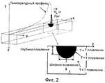
Фигура 2 показывает схематический вид профиля поверхностной температуры и соответствующую глубину плавления и ширину плавления в зоне, где луч перемещается в направлении положительных осей x,Figure 2 shows a schematic view of the surface temperature profile and the corresponding melting depth and melting width in the area where the beam moves in the direction of the positive x-axis,
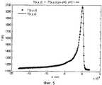
Фигуры 3-5 показывают некоторые профили распределения температуры, рассчитанные с использованием МКЭ (метода конечных элементов), вместе с аппроксимированными распределениями в соответствии с рядом Гаусса в уравнении 3.Figures 3-5 show some temperature distribution profiles calculated using the FEM (finite element method), together with approximated distributions in accordance with the Gaussian series in
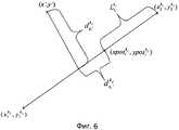
Фигура 6 показывает расстояния точка-линия и точка-точка,


Фигура 7 показывает пример заданной траектории луча для выбранной зоны, имеющей вид равнобедренной трапеции, где заданная траектория луча такая, что луч начинает сканирование линий снизу вверх, меняя направление слева направо и справа налево, иFigure 7 shows an example of a predetermined beam path for a selected zone having the shape of an isosceles trapezoid, where a given beam path is such that the beam starts scanning lines from bottom to top, changing direction from left to right and from right to left, and
Фигура 8 показывает определенную рабочую схему для воздействия удельной энергии луча, которая должна использоваться для заданной траектории луча, показанной на Фигуре 7, где воздействие удельной энергии в этом примере изменяется посредством изменения скорости луча.Figure 8 shows a specific operating circuit for the influence of the specific energy of the beam, which should be used for a given path of the beam shown in Figure 7, where the effect of the specific energy in this example is changed by changing the speed of the beam.
ОПИСАНИЕ ПРИМЕРОВ ВАРИАНТОВ ВОПЛОЩЕНИЯ ИЗОБРЕТЕНИЯDESCRIPTION OF EXAMPLES OF EMBODIMENTS OF THE INVENTION
Фигура 1 показывает пример известного устройства 1 для изготовления трехмерного продукта. Устройство 1 включает регулируемый в вертикальном направлении рабочий стол 2, на котором осуществляется изготовление трехмерного продукта 3, один или более дозаторов 4 порошка, средства 28, предназначенные для последовательного распределения тонкого слоя порошка на рабочем столе 2 для формирования порошковой основы 5, излучающую пушку 6 в виде электронной пушки для подачи энергии в порошковую основу 5 для сплавления участков порошковой основы 5, отклоняющие и формирующие луч катушки 7 для направления и формирования электронного луча, испускаемого излучающей пушкой 6 на упомянутый рабочий стол 2, и блок управления 8, предназначенный для управления различными компонентами устройства 1.Figure 1 shows an example of a known
В типовом рабочем цикле, рабочий стол 2 опускают, новый слой порошка наносят на рабочую зону сверху порошковой основы 5, и электронный луч перемещают по выбранным участкам верхнего слоя 5′ порошковой основы 5. В принципе, этот цикл повторяется до окончательного изготовления продукта. Специалист в этой области знаком с общей функцией и составом устройств для изготовления трехмерного продукта, как устройств, относящихся к типу, показанному на Фигуре 1, так и устройств, оборудованных лазерной пушкой вместо электронной пушки.In a typical work cycle, the work table 2 is lowered, a new layer of powder is applied to the work area on top of the
Традиционно аппараты, оборудованные электронной пушкой, работают с использованием вакуума, обычно при давлении ниже по меньшей мере 10-2 мбар, для предотвращения взаимодействия электронного луча с атомами или молекулами, содержащимися в пространстве между электронной пушкой и рабочей площадью.Traditionally, apparatuses equipped with an electron gun operate using a vacuum, usually at a pressure below at least 10-2 mbar, to prevent the interaction of the electron beam with atoms or molecules contained in the space between the electron gun and the working area.
Пример выбранной зоны слоя порошка, имеющего вид равнобедренной трапеции, показан на Фигуре 7. Также показана заданная траектория луча.An example of a selected zone of a powder layer having the shape of an isosceles trapezoid is shown in Figure 7. A predetermined beam path is also shown.
Далее будет описан вариант воплощения способа изобретения. В примере этого варианта воплощения, заданная траектория луча проходит по множеству параллельных и прямых линий (линии сканирования или штриховые линии), расположенных на равном расстоянии друг от друга. Регулируемым параметром луча в этом примере является скорость луча. В вычислениях скорость луча регулируется таким образом, что ширина расплавляемого материала при данной глубине (смотрите ширину плавления и глубину плавления на Фигуре 2) становится одинаковой вдоль всей траектории луча. Это позволяет использовать фиксированное расстояние между параллельными участками траектории луча. Остальные параметры определяются предварительно (или вычисляются с использованием других предварительно определенных параметров).Next will be described an embodiment of the method of the invention. In the example of this embodiment, the predetermined beam path traverses a plurality of parallel and straight lines (scan lines or dashed lines) located at an equal distance from each other. The adjustable beam parameter in this example is the speed of the beam. In calculations, the speed of the beam is controlled in such a way that the width of the material to be melted at a given depth (see melting width and melting depth in Figure 2) becomes the same along the entire path of the beam. This allows you to use a fixed distance between parallel sections of the beam path. The remaining parameters are predefined (or calculated using other predefined parameters).
В порядке обзора, вариант воплощения способа может быть описан следующим образом:In an overview, an embodiment of the method may be described as follows:
1. Данные, состоящие из температурных профилей и соответствующих параметров луча (размер пятна и скорость луча) для различных наборов свойств материала, температур материала и мощностей луча, создаются и хранятся в базе данных. Эти данные получаются посредством вычислений с использованием МКЭ на простой геометрии, подобной контрольному ящику, показанному на Фигуре 2.1. Data consisting of temperature profiles and corresponding beam parameters (spot size and beam speed) for various sets of material properties, material temperatures and beam powers are created and stored in a database. This data is obtained through calculations using FEM on simple geometry similar to the control box shown in Figure 2.
2. Машина, используемая для изготовления трехмерного тела, вычисляет в реальном времени распределение локальной температуры для каждой из ряда точек, распределенных вдоль траектории (пути) луча, путем решения уравнения зависящей от времени теплоты. Решение уравнения получается посредством расширения температурных профилей сплавленных ранее (т.е. воображаемо сплавленных) штриховых линий Гауссовыми образующими. Температурные профили, соответствующие используемому лучу и параметрам материала, получаются из базы данных.2. The machine used to make the three-dimensional body calculates in real time the distribution of the local temperature for each of a number of points distributed along the path (path) of the beam by solving the equation of time-dependent heat. The solution to the equation is obtained by expanding the temperature profiles of previously dashed (i.e. imaginatively fused) dashed lines by Gaussian generators. Temperature profiles corresponding to the beam used and material parameters are obtained from the database.
3. Параметры луча в конкретной точке выбираются в зависимости от вычисленного распределения локальной температуры и получаются из предварительно вычисленных данных, хранящихся в базе данных (путем сравнения вычисленного распределения температуры с предварительно вычисленными температурными профилями для используемого материала и выбора параметров луча, соответствующих профилю, который лучше всего подходит для вычисленного распределения).3. The parameters of the beam at a particular point are selected depending on the calculated distribution of local temperature and are obtained from pre-calculated data stored in the database (by comparing the calculated temperature distribution with pre-calculated temperature profiles for the material used and selecting the parameters of the beam corresponding to the profile that is better just suitable for computed distribution).
4. После окончания штриховой линии, температурный профиль в конце линии также аппроксимируется Гауссовыми функциями, и этапы 2 и 3 (т.е. два предыдущих этапа) повторяются для следующей штриховой линии.4. After the end of the dash line, the temperature profile at the end of the line is also approximated by Gaussian functions, and steps 2 and 3 (ie the two previous steps) are repeated for the next dash line.
Выражение, что вычисления выполняются в реальном времени, означает, что сплавление порошка осуществляется одновременно с вычислениями. Обычно, вычисления рабочей схемы параметра луча для последующего слоя выполняются во время сплавления предыдущего слоя. В принципе, возможно выполнять все вычисления и определения рабочей схемы перед началом процесса сплавления первого слоя, но это приведет к необходимости времени ожидания перед началом изготовления. В другом крайнем режиме, вычисления и определения рабочей схемы выполняются для точек вдоль траектории луча, очень близких к позиции реального луча, но это приведет к очень небольшому запасу для выполнения коррекций или повторным вычислениям в случае каких либо отклонений в вычислениях или сплавлении.The expression that the calculations are performed in real time means that the powder is fused simultaneously with the calculations. Typically, the calculation of the working scheme of the beam parameter for the next layer is performed during the fusion of the previous layer. In principle, it is possible to carry out all the calculations and definitions of the working circuit before starting the fusion process of the first layer, but this will lead to the need for waiting time before starting production. In the other extreme mode, calculations and definitions of the working scheme are performed for points along the path of the beam that are very close to the position of the real beam, but this will lead to a very small margin for performing corrections or repeated calculations in case of any deviations in the calculations or fusion.
Введение в вариант воплощения способаIntroduction to an embodiment of the method
Для получения соответствующих данных, необходимых для управления процессом плавления в соответствии с описываемым способом, рассмотрим уравнение зависящей от времени теплоты без источника теплоты для области гомогенного материалаTo obtain the relevant data necessary to control the melting process in accordance with the described method, we consider the equation of time-dependent heat without a heat source for the region of a homogeneous material
-∞<X<∞, -∞<Y<∞ и -∞<Z<0;-∞ <X <∞, -∞ <Y <∞ and -∞ <Z <0;
Уравнение 1аEquation 1a

где T(x,y,z,t) - зависящее от времени распределение температуры; λ - удельная теплопроводность; cp - теплоемкость; ρ - плотность материала.where T (x, y, z, t) is the time-dependent temperature distribution; λ is the thermal conductivity; cp is the specific heat; ρ is the density of the material.
Граничные условия выражаются следующим образом:Boundary conditions are expressed as follows:
Уравнение 1бEquation 1b
T=T0; x,y→±∞, z→-∞T = T0 ; x, y → ± ∞, z → -∞
Понятие Гауссова источника при перемещении z=0 в направлении x используется для описания воображаемого энергетического луча. Принимается, что излучение через эту же верхнюю поверхность происходит в соответствии с законом Стефана-БольцманаThe concept of a Gaussian source when moving z = 0 in the x direction is used to describe an imaginary energy ray. It is assumed that radiation through the same upper surface occurs in accordance with the Stefan-Boltzmann law
Уравнение 1вEquation 1c

где Pin - поглощаемая мощность луча; vx - скорость луча; σ - дисперсия (размер пятна луча); radcoeff - коэффициент излучения с поверхности; Tsur - температура окружающей среды над поверхностью.where Pin is the absorbed power of the beam; vx is the beam velocity; σ is the dispersion (beam spot size); radcoeff - emissivity from the surface; Tsur - ambient temperature above the surface.
T0 - рабочая температура, т.е. требуемая температура материала перед плавлением/сплавлением.T0 - operating temperature, i.e. required material temperature before melting / fusion.
Для сокращения времени, необходимого для генерирования данных, имеет смысл исключить временную зависимость, принимая, что распределение температуры вокруг движущегося пятна достигло стационарного состояния (x=x-tvx, dt=-dx/vx).To reduce the time required to generate data, it makes sense to exclude the time dependence, assuming that the temperature distribution around the moving spot has reached a stationary state (x = x-tvx , dt = -dx / vx ).
Уравнение 2аEquation 2a

Уравнение 2бEquation 2b

Уравнение 2сEquation 2c
T(±∞,±∞,-∞)=T0T (± ∞, ± ∞, -∞) = T0
Уравнения теплоты выше могут быть решены, используя, например, МКЭ для нескольких различных наборов свойств материала, настройки T0 и луча. Эта процедура иллюстрируется на Фигуре 2.The heat equations above can be solved using, for example, the FEM for several different sets of material properties, T0 and beam settings. This procedure is illustrated in Figure 2.
Фигура 2 иллюстрирует "контрольный ящик", где луч перемещается в направлении положительных осей x. Температурный профиль на поверхности показан вместе с участком, в котором объем плавления представлен изотермой, соответствующей температуре плавления материала. Здесь, параметры луча vx и σ были оптимизированы для получения заданного профиля объема плавления в значениях глубины плавления и ширины плавления. Кроме того, максимальная температура в пределах материала была ограничена величиной Tmax. Несомненно, могут использоваться другие условия для оптимизации параметров луча. Например, минимизация температурных градиентов в объемах плавления могла бы быть одним из таких условий.Figure 2 illustrates a "control box" where the beam moves in the direction of the positive x-axis. The temperature profile on the surface is shown together with the section in which the melting volume is represented by an isotherm corresponding to the melting temperature of the material. Here, the beam parameters vx and σ were optimized to obtain a given profile of the melting volume in terms of melting depth and melting width. In addition, the maximum temperature within the material was limited by the value of Tmax. Undoubtedly, other conditions can be used to optimize the beam parameters. For example, minimizing temperature gradients in melting volumes could be one such condition.
Температурные профили, необходимые для описания подачи энергии в конце штриховой линии, будут получены посредством аппроксимации T(x,y,z) в Уравнении 2а рядом Гауссовых функций. При этом, впоследствии будет возможно получить аналитическое решение для температурного распределения в полубесконечной области даже для произвольного количества штриховых линий. Ряд T′(x,y,z) будет иметь вид:The temperature profiles needed to describe the energy supply at the end of the dashed line will be obtained by approximating T (x, y, z) in Equation 2a by a series of Gaussian functions. In this case, subsequently it will be possible to obtain an analytical solution for the temperature distribution in the semi-infinite region even for an arbitrary number of dashed lines. The series T ′ (x, y, z) will have the form:
Уравнение 3

Параметры Aj, xposi, σx, σy, σz иa могут быть получены с поточечной нелинейной квадратичной связи между T(x,y,z) и T′(x,y,z). Здесь, xposi - x-положение экспоненциального члена i вдоль траектории луча. В системе координат луча оно будет иметь отрицательное значение, так как принимается, что луч перемещается в положительном направлении x с точкой отсчета x=0.The parameters Aj , xposi , σx , σy , σz anda can be obtained with a pointwise nonlinear quadratic connection between T (x, y, z) and T (x, y, z). Here, xposi is the x-position of the exponential term i along the ray path. In the coordinate system of the beam, it will have a negative value, since it is assumed that the beam moves in the positive direction x with a reference point x = 0.
На Фигурах 3-5 показаны некоторые распределения температуры, вычисленные с использованием МКЭ, вместе с аппроксимированным распределением в соответствии с Уравнением 3.Figures 3-5 show some temperature distributions calculated using FEM, together with an approximated distribution in accordance with
Приемлемость связи в основном определяется количеством используемых Гауссовых функций. В примере ниже, N равно значению от 10 до 12, означающему, что от 30 до 36 Гауссовых функций используется для каждого температурного профиля.The acceptability of communication is mainly determined by the number of Gaussian functions used. In the example below, N is equal to a value from 10 to 12, meaning that 30 to 36 Gaussian functions are used for each temperature profile.
Зависящее от времени распределение температуры в материалеTime-dependent temperature distribution in the material
Зависящее от времени распределение температуры, T′′(x,y,z,t), в материале после сканирования лучом одной линии получается посредством использования функций Грина и свертки вместе с начальными условиями T′(x′,y′,z′), полученными из Уравнения 3:The time-dependent temperature distribution, T ′ ′ (x, y, z, t), in the material after scanning with a single line beam is obtained by using the Green's functions and convolution together with the initial conditions T ′ (x ′, y ′, z ′), derived from Equation 3:
Уравнение 4Equation 4

гдеWhere

Здесь мы приняли, что температура материала равна Tsurf и отличается от T0. Потери теплоты через поверхность принимаются равными нулю:Here we assumed that the temperature of the material is Tsurf and different from T0 . The heat loss through the surface is taken equal to zero:

После сканирования лучом M линий, правая часть Уравнения 4 заменяется суммой:After scanning a ray of M lines, the right side of Equation 4 is replaced by the sum:
Уравнение 5

где tj - время окончания сканирования линии j; Toj - температура вокруг пятна после окончания сканирования линии j;

При вставке выражения для T′(x,y,z) (Уравнение 4) в Уравнение 5 необходимо учитывать, что координаты x, xposi и y в Уравнении 3 относятся к локальной системе координат с центром в конечной точке линии j и осями x в направлении перемещения луча для этой линии, в то время, как координаты x′ и y′ в Уравнении 5 относятся к глобальной системе координат, определяемой поверхностью участка. Кроме того, если траектория луча для линии у должна описываться несколькими сегментами линии, имеющими различные направления, y в Уравнении 3 необходимо заменить на

Таким способом может быть рассмотрен любой вид траекторий луча. Однако необходимо помнить, что распределение температуры в Уравнении 3 получается из прямолинейного моделирования. Таким образом, если кривизна траектории луча значительная, то простое использование членов в Уравнении 3 вдоль этой траектории на одинаковом расстоянии, как определяется значениями xposi, может привести к неудовлетворительной аппроксимации. В таком случае может потребоваться решение с использованием МКЭ для криволинейной траектории.In this way, any kind of ray paths can be considered. However, it must be remembered that the temperature distribution in
На Фигуре 6 показаны расстояния точка-линия и точка-точка,


Для каждого сегмента линии kj, содержащего по меньшей мере один экспоненциальный член, расположенный в (


Здесь мы приняли, что луч перемещается с точки 1 в точку 2, и что сегмент 1 является последним прямым сегментом линии j. Таким образом, линейные сегменты суммируются в обратном направлении.Here we assumed that the ray moves from

Совместное использование даст нам следующее выражение для зависящего от времени распределения температуры после сканирования лучом M линий:Sharing will give us the following expression for the time-dependent temperature distribution after scanning with a beam of M lines:
Уравнение 6Equation 6


где:Where:
kj - количество прямых линейных сегментов для штриховой траектории j;kj is the number of straight linear segments for the dashed path j;

В последующих разделах будут выведены аналитические выражения для членов в пределах суммирований. Однако, необходимо отметить, что использование выражения выше для T′(x,y,z,t) позволит вычислить температуру для более или менее любого вида траектории луча, и что вычисления могут эффективно выполняться при использовании многопроцессорной конфигурации, что означает возможность вычислений в реальном времени.In the following sections, analytical expressions for the members within the summation will be derived. However, it should be noted that using the expression above for T ′ (x, y, z, t) will allow us to calculate the temperature for more or less any kind of beam path, and that the calculations can be effectively performed using a multiprocessor configuration, which means that it can be calculated in real time.
Свойства и интегрирование Гауссовых функцийProperties and integration of Gaussian functions
Для решения выражения в Уравнении 6 необходимо знать некоторые свойства Гауссовых функций.To solve the expression in Equation 6, it is necessary to know some properties of Gaussian functions.
1. Результатом перемножения двух Гауссовых функций является другая Гауссова функция:1. The result of the multiplication of two Gaussian functions is another Gaussian function:


2. Интегралы одного Гауссиана:2. Integrals of one Gaussian:


Интегралы для вычисления T′(x,y,z,t)Integrals for computing T ′ (x, y, z, t)
Сначала рассмотрим интегралы в направлении z:First, consider the integrals in the z direction:

где:Where:


Затем рассмотрим интегралы x и y.Then we consider the integrals x and y.

В случае, когда все линейные сегменты параллельны, нет необходимости в дифференцировании между x и y, так как система координат может быть легко преобразована для совмещения со штриховыми линиями. Таким образом, в примере ниже все линии принимаются как параллельные оси x.In the case where all linear segments are parallel, there is no need to differentiate between x and y, as the coordinate system can be easily transformed to align with dashed lines. Thus, in the example below, all lines are accepted as parallel to the x axis.


где:Where:


Если линейные сегменты не параллельны и имеют произвольное направление, требуются некоторые алгебраические действия. В этом случае, сначала рассмотрим x-интегрирование:If the linear segments are not parallel and have an arbitrary direction, some algebraic actions are required. In this case, first consider x-integration:

где:Where:


Таким образом:In this way:

Теперь рассмотрим y-интегрирование:Now consider y-integration:

где:Where:


Общее итоговое выражениеGeneral summary expression

Положения экспоненциальных членов:Exponential Member Provisions:


где:Where:


Параллельные линии:Parallel lines:


где:Where:


Произвольное направление штриховых линий:Arbitrary direction of dashed lines:


где:Where:


Вычисление параметров луча вдоль штриховой линииCalculation of beam parameters along the dashed line
При сканировании (воображаемого) луча вдоль штриховых траекторий, температура вокруг пятна может быть теперь вычислена из выражения в Уравнении 6 и вставкой предварительно вычисленных Гауссовых функций для температурных профилей для предыдущих штриховых линий.When scanning an (imaginary) ray along dashed paths, the temperature around the spot can now be calculated from the expression in Equation 6 and by inserting pre-calculated Gaussian functions for temperature profiles for previous dashed lines.
Зная температуру и имея доступ к оптимизированным данным для параметров луча для различных условий, становится возможным регулировать энергию луча (т.е. воздействие удельной энергии) соответствующим образом.Knowing the temperature and having access to optimized data for the beam parameters for various conditions, it becomes possible to adjust the beam energy (i.e., the effect of specific energy) accordingly.
ПримерExample
В следующем штриховом примере (смотрите Фигуру 7), трапеция будет расплавлена при постоянной мощности луча, и при этом будет меняться скорость луча для обеспечения постоянной глубины плавления и ширины плавления. Заданная траектория луча устанавливается такой, что луч начинает сканировать линии на Фигуре 7 снизу вверх, меняя свое направление слева направо и справа налево.In the following line example (see Figure 7), the trapezoid will be melted at a constant beam power, and the beam speed will change to provide a constant melting depth and melting width. The predetermined beam path is set such that the beam begins to scan the lines in Figure 7 from bottom to top, changing its direction from left to right and from right to left.
Размер луча был оптимизирован для Tsurf, температуры участка перед сплавлением, и максимальная температура в бассейне расплава ограничивается величиной Tmax. Это означает, что первая штриховая линия сканируется при постоянной скорости и фиксированном размере пятна. Все другие линии сканируются при таком же размере пятна и мощности, но с другой изменяющейся скоростью. Скорость в каждой из точек вычислений, распределенных вдоль заданной траектории луча, получается сначала посредством вычисления распределения температуры вокруг точки, и затем на основании данных зависимости скорости от температуры, хранящихся в базе данных. Данные скорости в базе данных были оптимизированы для конкретных настроек луча (мощность и размер луча) и температуры таким образом, что глубина плавления и ширина плавления одинаковые для всех линий. В конце каждой штриховой линии, температурный профиль, созданный с помощью воображаемого луча, моделируется Гауссовыми функциями, взятыми с базы данных. Температурный диапазон в базе данных охватывал значения от Tsurf до Tmelt, и заданный этап температуры для предварительно вычисленных данных составлял 20 К. Для выбора ближайших значений скорости и Гауссовых функций для вычисленной температуры использовалась таблица поиска.The beam size was optimized for Tsurf, the temperature of the site before fusion, and the maximum temperature in the melt pool is limited to Tmax. This means that the first dashed line is scanned at a constant speed and a fixed spot size. All other lines are scanned at the same spot size and power, but with a different changing speed. The speed at each of the calculation points distributed along a given path of the beam is obtained first by calculating the temperature distribution around the point, and then based on the data of the velocity versus temperature stored in the database. The speed data in the database were optimized for specific beam settings (power and beam size) and temperature so that the melting depth and melting width are the same for all lines. At the end of each dashed line, the temperature profile created using an imaginary ray is modeled by Gaussian functions taken from the database. The temperature range in the database covered the values from Tsurf to Tmelt, and the set temperature stage for pre-calculated data was 20 K. To select the closest values of speed and Gaussian functions for the calculated temperature, a search table was used.
Результирующие профили скорости вдоль каждой штриховой линии показаны на Фигуре 8. Эти профили основаны на вычислениях распределений локальной температуры вдоль заданной траектории луча и соответствуют определенной рабочей схеме воздействия удельной энергии луча, которая должна использоваться для заданной траектории луча при сплавлении выбранной зоны по меньшей мере одного слоя; воздействие удельной энергии в этом примере изменяется посредством изменения скорости луча.The resulting velocity profiles along each dashed line are shown in Figure 8. These profiles are based on calculations of the local temperature distributions along a given beam path and correspond to a specific working pattern of the specific beam energy that should be used for a given beam path when fusing a selected area of at least one layer ; the effect of specific energy in this example is changed by changing the speed of the beam.
В примере выше, для получения температуры и скорости вдоль линий использовался ступенчатый режим. Это означает, во-первых, что температура в конкретной точке вдоль линии была вычислена с использованием Уравнения 6 для параллельных линий. Во-вторых, скорость была получена на основании температуры с использованием базы данных в качестве поисковой таблицы. Следующую точку вдоль штриховой линии можно вычислить, используя фиксированное расстояние Δr, и тогда этап времени был бы равен Δr/скорость. Однако, так как градиенты температуры меняются довольно резко относительно времени и координат пространства, методика фиксированного расстояния не была достаточной эффективной. В некоторых местах требуется небольшой этап, в то время как в других местах требуется больший этап. Вместо этого было использовано максимально допустимое изменение скорости. При этом могла быть получена максимально допустимая разница в температуре, и посредством численного вычисления производных температуры по времени и координатам пространства мог быть получен максимально допустимый пространственный этап.In the example above, a step mode was used to obtain temperature and speed along the lines. This means, firstly, that the temperature at a particular point along the line was calculated using Equation 6 for parallel lines. Secondly, the speed was obtained based on temperature using a database as a lookup table. The next point along the dashed line can be calculated using a fixed distance Δr, and then the time step would be equal to Δr / speed. However, since temperature gradients change quite sharply with respect to time and space coordinates, the fixed-distance technique was not sufficiently effective. In some places a small stage is required, while in other places a larger stage is required. Instead, the maximum allowable change in speed was used. In this case, the maximum allowable difference in temperature could be obtained, and by numerically calculating the temperature derivatives with respect to time and space coordinates, the maximum allowable spatial stage could be obtained.
Выведенный алгоритм был очень эффективным, и при включении в вычисления в реальном времени тысяч штриховых линий не возникало никаких проблем. Термин "вычисление в реальном времени" относится к вычислению, в котором время для вычисления скорости вдоль штриховых линий меньше фактического времени плавления.The derived algorithm was very efficient, and when you included thousands of dashed lines in real-time calculations, there were no problems. The term "real-time calculation" refers to a calculation in which the time to calculate the speed along the dashed lines is less than the actual melting time.
Изобретение не ограничивается вариантами воплощения, описанными выше, и которые могут быть модифицированы различными способами в рамках пунктов формулы изобретения. Например, возможно использовать более подробное и комплексное описание процесса плавления при оптимизации параметров луча и создании базы данных; порошок может моделироваться как неоднородный материал вместе с энтальпиями плавления и детальной моделью процесса плавления-замерзания.The invention is not limited to the embodiments described above, and which may be modified in various ways within the scope of the claims. For example, it is possible to use a more detailed and comprehensive description of the melting process when optimizing beam parameters and creating a database; the powder can be modeled as a heterogeneous material together with melting enthalpies and a detailed model of the melting-freezing process.
Вычисления в соответствии с Уравнением 6 могут быть использованы для оптимизации штриховой методики с целью, например, минимизации времени плавления/сплавления. Для такой оптимизации нет необходимости в выполнении всех вычислений в реальном времени, пока они возможны с практической точки зрения. Однако, может быть более преимущественно выполнять вычисления для каждой возможной штриховой методики в реальном времени. Таким образом, не будет необходимости в сохранении всех данных, полученных во время выполнения этапа оптимизации. Вместо этого, информация, которую нужно сохранять во время этапа оптимизации, может быть ограничена, например, углами наклона штриховых линий, расстояниями между штриховыми линиями, положением штриховых линий относительно участка и т.п.The calculations in accordance with Equation 6 can be used to optimize the stroke technique with the goal of, for example, minimizing the melting / fusion time. For such optimization, there is no need to perform all calculations in real time, while they are possible from a practical point of view. However, it may be more advantageous to perform calculations for each possible stroke technique in real time. Thus, there will be no need to save all the data obtained during the optimization phase. Instead, the information that needs to be stored during the optimization step may be limited, for example, by the angles of the dashed lines, the distances between the dashed lines, the position of the dashed lines relative to the plot, and the like.
Описываемый способ может комбинироваться, например, со способом, используемым для вычисления мощности луча, необходимой для поддержания конкретной температуры изготавливаемых частей, как описано в WO 2004/056511. Таким образом, общая подаваемая энергия может быть вычислена на основании расчета энергетического равновесия, включая геометрию части, в то время как способ, описываемый в этой заявке, используется для управления воздействием локальной энергии или мощности луча во время сплавления.The described method can be combined, for example, with the method used to calculate the beam power necessary to maintain the specific temperature of the manufactured parts, as described in WO 2004/056511. Thus, the total supplied energy can be calculated based on the calculation of energy equilibrium, including the geometry of the part, while the method described in this application is used to control the effect of local energy or beam power during fusion.
Описываемый способ использует модель однородного материала для получения локальной температуры (распределений) вдоль штриховых линий. Однако, локальные различия в свойствах материала могут моделироваться посредством использования различных значений D в различных точках. Например, очень тонкие участки могут моделироваться как имеющие более низкую удельную теплопроводность. Способ не содержит ограничений для расширения базы данных оптимизированными данными даже для таких участков. Подобным образом, возможно учитывать тот факт, что нижние слои в порошковой основе расположены ближе к регулируемому рабочему столу, который, вероятно, имеет тепловые свойства, отличающиеся от тепловых свойств порошковой основы.The described method uses a homogeneous material model to obtain local temperature (distributions) along dashed lines. However, local differences in material properties can be modeled by using different D values at different points. For example, very thin sections can be modeled as having lower thermal conductivity. The method does not contain restrictions for expanding the database with optimized data even for such areas. Similarly, it is possible to take into account the fact that the lower layers in the powder base are located closer to the adjustable work table, which probably has thermal properties different from the thermal properties of the powder base.
Возможно устанавливать заданную траекторию луча только для части выбранной зоны перед вычислением и определением рабочей схемы для этой части выбранной зоны. Дополнительно, возможно вычислять и определять рабочую схему только для части полностью установленной заданной траектории луча. Этап сплавления выбранной зоны по меньшей мере одного слоя, может инициироваться во время выполнения этапов установления заданной траектории луча, вычисления температуры и т.п. для еще не сплавленного участка выбранной зоны. Дополнительно, по меньшей мере один слой порошка может включать более одной выбранной зоны; эти выбранные зоны (часть) могут иметь различный вид и могут управляться отдельно.It is possible to set a given beam path only for a part of a selected zone before calculating and determining a working pattern for that part of a selected zone. Additionally, it is possible to calculate and determine a working circuit only for a part of a fully established predetermined beam path. The fusion step of the selected zone of at least one layer may be initiated during the steps of establishing a given beam path, calculating temperature, and the like. for not yet fused section of the selected zone. Additionally, at least one layer of powder may include more than one selected zone; these selected zones (part) can have a different look and can be controlled separately.
Как объяснено выше, в вычислениях температуры вдоль заданной траектории луча энергия, доставляемая (воображаемым) лучом вдоль траектории в определенный момент времени, учитывается, когда выполняется вычисление температуры для этого же момента времени. Таким путем повышение температуры учитывается надлежащим образом.As explained above, in calculations of the temperature along a given path of the beam, the energy delivered by the (imaginary) beam along the path at a certain point in time is taken into account when the temperature is calculated for the same point in time. In this way, temperature increases are taken into account appropriately.
В примере, описанном выше, вычисления температуры выполняются для ряда позиций, распределенных вдоль заданной траектории луча, и в каждой из этих позиций вычисляется распределение локальной температуры. Дополнительно, распределение локальной температуры вычисляется для позиции, находящейся на один этап впереди относительно позиции воображаемого луча. Воздействие удельной энергии, используемое при перемещении луча на один этап к следующей позиции спереди получается из базы данных, содержащей ряд предварительно определенных воздействий удельной энергии (т.е. скоростей луча в описываемом примере) для различных распределений локальной температуры (для используемых порошковых материалов и для определенных условия сплавления), где вычисленное распределение локальной температуры в следующей позиции используется для выбора надлежащего значения или надлежащих значений из базы данных.In the example described above, temperature calculations are performed for a number of positions distributed along a given beam path, and the local temperature distribution is calculated at each of these positions. Additionally, the local temperature distribution is calculated for a position one step ahead of the position of the imaginary beam. The specific energy impact used when moving the beam one step to the next front position is obtained from a database containing a number of predefined specific energy effects (i.e., the beam velocities in the described example) for various local temperature distributions (for the used powder materials and for defined fusion conditions), where the calculated local temperature distribution at the next position is used to select the appropriate value or appropriate values from the database.
Claims (10)
Translated fromRussian- нанесение указанного по меньшей мере одного слоя порошка на рабочую зону,
- сплавление выбранной зоны указанного по меньшей мере одного слоя порошка посредством подачи энергии из излучающей пушки на выбранную зону,
отличающийся тем, что включает этапы:
- установления заданной траектории луча, предназначенной для использования при сплавлении выбранной зоны указанного по меньшей мере одного слоя порошка,
- вычисления температуры в указанном по меньшей мере одном слое порошка вдоль заданной траектории луча как функции воздействия удельной энергии воображаемого луча, для которого принимается, что он перемещается вдоль заданной траектории луча,
- регулирования воздействия удельной энергии воображаемого луча вдоль заданной траектории луча в зависимости от вычисленной температуры и от условий, установленных для этапа сплавления выбранной зоны, и
- предоставления на основании упомянутых вычислений и регулировок рабочей схемы воздействия удельной энергии реального луча, предназначенной для использования для заданной траектории луча при сплавлении выбранной зоны по меньшей мере одного слоя.1. A method of manufacturing a three-dimensional body, comprising sequentially providing layers of powder and fusing together selected zones of the said layers, the zones corresponding to successive cross-sections of the three-dimensional body, with at least one of the said layers performing the following steps:
- applying the specified at least one layer of powder to the working area,
- fusion of the selected zone of the specified at least one layer of powder by supplying energy from the radiating gun to the selected zone,
characterized in that it includes the steps of:
- establishing a predetermined beam path intended for use in fusion of a selected area of the specified at least one layer of powder,
- calculating the temperature in the specified at least one layer of powder along a given path of the beam as a function of the specific energy of the imaginary beam, for which it is assumed that it moves along a given path of the beam,
- regulating the impact of the specific energy of the imaginary beam along a given path of the beam depending on the calculated temperature and on the conditions established for the fusion stage of the selected zone, and
- providing, based on the above calculations and adjustments of the working scheme, the specific energy of the real beam intended for use for a given beam path when fusing the selected zone of at least one layer.
- выполнения вычислений температуры вдоль множества возможных траекторий луча и
- выбора заданной траектории луча из указанного множества траекторий луча.10. The method according to claim 1, 2 or 9, characterized in that the step of establishing a given beam path includes the steps of:
- performing temperature calculations along the set of possible ray paths and
- selection of a given beam path from the specified set of beam paths.
Applications Claiming Priority (1)
| Application Number | Priority Date | Filing Date | Title |
|---|---|---|---|
| PCT/SE2011/050093WO2012102655A1 (en) | 2011-01-28 | 2011-01-28 | Method for production of a three-dimensional body |
Publications (2)
| Publication Number | Publication Date |
|---|---|
| RU2013112124A RU2013112124A (en) | 2015-03-10 |
| RU2553796C2true RU2553796C2 (en) | 2015-06-20 |
Family
ID=46581041
Family Applications (1)
| Application Number | Title | Priority Date | Filing Date |
|---|---|---|---|
| RU2013112124/02ARU2553796C2 (en) | 2011-01-28 | 2011-01-28 | Production of 3d body |
Country Status (8)
| Country | Link |
|---|---|
| US (1) | US9073265B2 (en) |
| EP (1) | EP2667987B1 (en) |
| JP (1) | JP5712306B2 (en) |
| KR (1) | KR101820553B1 (en) |
| CN (1) | CN103338880B (en) |
| BR (1) | BR112013009155B1 (en) |
| RU (1) | RU2553796C2 (en) |
| WO (1) | WO2012102655A1 (en) |
Families Citing this family (151)
| Publication number | Priority date | Publication date | Assignee | Title |
|---|---|---|---|---|
| US8992816B2 (en) | 2008-01-03 | 2015-03-31 | Arcam Ab | Method and apparatus for producing three-dimensional objects |
| CN102470439B (en) | 2009-07-15 | 2016-03-02 | 阿卡姆股份公司 | Manufacture the method and apparatus of three-dimensional body |
| EP2667987B1 (en) | 2011-01-28 | 2019-03-06 | Arcam Ab | Method for production of a three-dimensional object |
| EP2797730B2 (en) | 2011-12-28 | 2020-03-04 | Arcam Ab | Method and apparatus for detecting defects in freeform fabrication |
| IN2014DN03184A (en) | 2011-12-28 | 2015-05-22 | Arcam Ab | |
| US10189086B2 (en) | 2011-12-28 | 2019-01-29 | Arcam Ab | Method and apparatus for manufacturing porous three-dimensional articles |
| JP5599957B2 (en)* | 2012-03-09 | 2014-10-01 | パナソニック株式会社 | Manufacturing method of three-dimensional shaped object |
| WO2013167194A1 (en) | 2012-05-11 | 2013-11-14 | Arcam Ab | Powder distribution in additive manufacturing |
| WO2014071968A1 (en) | 2012-11-06 | 2014-05-15 | Arcam Ab | Powder pre-processing for additive manufacturing |
| DE112013006045T5 (en) | 2012-12-17 | 2015-09-17 | Arcam Ab | Additive manufacturing method and device |
| US9505172B2 (en) | 2012-12-17 | 2016-11-29 | Arcam Ab | Method and apparatus for additive manufacturing |
| US10464172B2 (en) | 2013-02-21 | 2019-11-05 | Nlight, Inc. | Patterning conductive films using variable focal plane to control feature size |
| CN105144346B (en) | 2013-02-21 | 2017-12-15 | 恩耐公司 | The laser scribing of sandwich construction |
| US9842665B2 (en) | 2013-02-21 | 2017-12-12 | Nlight, Inc. | Optimization of high resolution digitally encoded laser scanners for fine feature marking |
| US9550207B2 (en) | 2013-04-18 | 2017-01-24 | Arcam Ab | Method and apparatus for additive manufacturing |
| US9676031B2 (en) | 2013-04-23 | 2017-06-13 | Arcam Ab | Method and apparatus for forming a three-dimensional article |
| US9415443B2 (en)* | 2013-05-23 | 2016-08-16 | Arcam Ab | Method and apparatus for additive manufacturing |
| US9468973B2 (en) | 2013-06-28 | 2016-10-18 | Arcam Ab | Method and apparatus for additive manufacturing |
| US9505057B2 (en) | 2013-09-06 | 2016-11-29 | Arcam Ab | Powder distribution in additive manufacturing of three-dimensional articles |
| US9676032B2 (en) | 2013-09-20 | 2017-06-13 | Arcam Ab | Method for additive manufacturing |
| EP2865465B1 (en)* | 2013-09-27 | 2018-01-17 | Ansaldo Energia IP UK Limited | Method for manufacturing a metallic component by additive laser manufacturing |
| DE102013017792A1 (en)* | 2013-10-28 | 2015-04-30 | Cl Schutzrechtsverwaltungs Gmbh | Method for producing a three-dimensional component |
| US10434572B2 (en) | 2013-12-19 | 2019-10-08 | Arcam Ab | Method for additive manufacturing |
| DE102013224693A1 (en) | 2013-12-02 | 2015-06-03 | Eos Gmbh Electro Optical Systems | Method for the accelerated production of objects by means of generative production |
| US9802253B2 (en) | 2013-12-16 | 2017-10-31 | Arcam Ab | Additive manufacturing of three-dimensional articles |
| US10130993B2 (en) | 2013-12-18 | 2018-11-20 | Arcam Ab | Additive manufacturing of three-dimensional articles |
| US9789563B2 (en) | 2013-12-20 | 2017-10-17 | Arcam Ab | Method for additive manufacturing |
| KR101872628B1 (en)* | 2014-01-16 | 2018-06-28 | 휴렛-팩커드 디벨롭먼트 컴퍼니, 엘.피. | Generating a three-dimensional object |
| US10252474B2 (en) | 2014-01-16 | 2019-04-09 | Hewlett-Packard Development Company, L.P. | Temperature determination based on emissivity |
| US10220564B2 (en) | 2014-01-16 | 2019-03-05 | Hewlett-Packard Development Company, L.P. | Generating three-dimensional objects |
| WO2015108560A1 (en)* | 2014-01-16 | 2015-07-23 | Hewlett-Packard Development Company, L.P. | Temperature determination based on emissivity |
| US10889059B2 (en) | 2014-01-16 | 2021-01-12 | Hewlett-Packard Development Company, L.P. | Generating three-dimensional objects |
| DE102014201818A1 (en)* | 2014-01-31 | 2015-08-06 | Eos Gmbh Electro Optical Systems | Method and device for improved control of energy input in a generative layer construction process |
| US9789541B2 (en) | 2014-03-07 | 2017-10-17 | Arcam Ab | Method for additive manufacturing of three-dimensional articles |
| JP2015182419A (en)* | 2014-03-26 | 2015-10-22 | 日本電子株式会社 | Three-dimensional additive manufacturing apparatus and three-dimensional additive manufacturing method |
| US20150283613A1 (en) | 2014-04-02 | 2015-10-08 | Arcam Ab | Method for fusing a workpiece |
| JP6030597B2 (en)* | 2014-04-04 | 2016-11-24 | 株式会社松浦機械製作所 | Three-dimensional modeling apparatus and manufacturing method of three-dimensional shaped object |
| US10069271B2 (en) | 2014-06-02 | 2018-09-04 | Nlight, Inc. | Scalable high power fiber laser |
| US10618131B2 (en) | 2014-06-05 | 2020-04-14 | Nlight, Inc. | Laser patterning skew correction |
| US9486878B2 (en) | 2014-06-20 | 2016-11-08 | Velo3D, Inc. | Apparatuses, systems and methods for three-dimensional printing |
| CN105720463B (en) | 2014-08-01 | 2021-05-14 | 恩耐公司 | Protection and monitoring of back reflection in optical fiber and fiber-optic transmission lasers |
| EP3183108B1 (en) | 2014-08-20 | 2020-12-09 | Etxe-Tar, S.A. | Method and system for additive manufacturing using a light beam |
| US9310188B2 (en) | 2014-08-20 | 2016-04-12 | Arcam Ab | Energy beam deflection speed verification |
| US10786865B2 (en) | 2014-12-15 | 2020-09-29 | Arcam Ab | Method for additive manufacturing |
| US9721755B2 (en) | 2015-01-21 | 2017-08-01 | Arcam Ab | Method and device for characterizing an electron beam |
| US9837783B2 (en) | 2015-01-26 | 2017-12-05 | Nlight, Inc. | High-power, single-mode fiber sources |
| WO2017137391A1 (en) | 2016-02-10 | 2017-08-17 | Trumpf Laser- Und Systemtechnik Gmbh | Method for producing a layer or a sub-region of a layer of a three-dimensional component; and corresponding computer program |
| DE102015202347A1 (en) | 2015-02-10 | 2016-08-11 | Trumpf Laser- Und Systemtechnik Gmbh | Irradiation device, processing machine and method for producing a layer of a three-dimensional component |
| US10098746B1 (en) | 2015-02-13 | 2018-10-16 | Nextstep Arthropedix, LLC | Medical implants having desired surface features and methods of manufacturing |
| US10050404B2 (en) | 2015-03-26 | 2018-08-14 | Nlight, Inc. | Fiber source with cascaded gain stages and/or multimode delivery fiber with low splice loss |
| US11014161B2 (en) | 2015-04-21 | 2021-05-25 | Arcam Ab | Method for additive manufacturing |
| JP6483551B2 (en) | 2015-07-03 | 2019-03-13 | 株式会社アスペクト | Powder bed fusion unit |
| US10520671B2 (en) | 2015-07-08 | 2019-12-31 | Nlight, Inc. | Fiber with depressed central index for increased beam parameter product |
| US10807187B2 (en) | 2015-09-24 | 2020-10-20 | Arcam Ab | X-ray calibration standard object |
| WO2017059883A1 (en)* | 2015-10-05 | 2017-04-13 | Hewlett-Packard Development Company L.P. | Fusing in additive manufacturing systems |
| US10583483B2 (en) | 2015-10-15 | 2020-03-10 | Arcam Ab | Method and apparatus for producing a three-dimensional article |
| US10065270B2 (en) | 2015-11-06 | 2018-09-04 | Velo3D, Inc. | Three-dimensional printing in real time |
| US10525531B2 (en) | 2015-11-17 | 2020-01-07 | Arcam Ab | Additive manufacturing of three-dimensional articles |
| US10610930B2 (en) | 2015-11-18 | 2020-04-07 | Arcam Ab | Additive manufacturing of three-dimensional articles |
| US11179807B2 (en) | 2015-11-23 | 2021-11-23 | Nlight, Inc. | Fine-scale temporal control for laser material processing |
| WO2017091505A1 (en)* | 2015-11-23 | 2017-06-01 | Nlight, Inc. | Fine-scale temporal control for laser material processing |
| WO2017091606A1 (en) | 2015-11-23 | 2017-06-01 | Nlight, Inc. | Predictive modification of laser diode drive current waveform in high power laser systems |
| US10286603B2 (en) | 2015-12-10 | 2019-05-14 | Velo3D, Inc. | Skillful three-dimensional printing |
| WO2017127573A1 (en) | 2016-01-19 | 2017-07-27 | Nlight, Inc. | Method of processing calibration data in 3d laser scanner systems |
| US20170239719A1 (en) | 2016-02-18 | 2017-08-24 | Velo3D, Inc. | Accurate three-dimensional printing |
| US10831180B2 (en)* | 2016-02-25 | 2020-11-10 | General Electric Company | Multivariate statistical process control of laser powder bed additive manufacturing |
| US11247274B2 (en) | 2016-03-11 | 2022-02-15 | Arcam Ab | Method and apparatus for forming a three-dimensional article |
| JP6732502B2 (en)* | 2016-03-31 | 2020-07-29 | キヤノン株式会社 | 3D modeling method, program, recording medium, and 3D modeling apparatus |
| US10766197B2 (en) | 2016-03-31 | 2020-09-08 | Hexcel Corporation | Apparatus and method for selective laser sintering an object with a void |
| US11179894B2 (en)* | 2016-05-12 | 2021-11-23 | Hewlett-Packard Development Company, L.P. | Managing thermal contributions between layers during additive manufacturing |
| US10953599B2 (en)* | 2016-05-12 | 2021-03-23 | Hewlett-Packard Development Company, L.P. | Printer warming device control |
| US10549348B2 (en) | 2016-05-24 | 2020-02-04 | Arcam Ab | Method for additive manufacturing |
| US11325191B2 (en) | 2016-05-24 | 2022-05-10 | Arcam Ab | Method for additive manufacturing |
| US10525547B2 (en) | 2016-06-01 | 2020-01-07 | Arcam Ab | Additive manufacturing of three-dimensional articles |
| WO2017216630A1 (en)* | 2016-06-13 | 2017-12-21 | Dmg Mori Co., Ltd. | Systems and methods for temperature control in an additive manufacturing process |
| EP3492244A1 (en) | 2016-06-29 | 2019-06-05 | VELO3D, Inc. | Three-dimensional printing system and method for three-dimensional printing |
| US11691343B2 (en) | 2016-06-29 | 2023-07-04 | Velo3D, Inc. | Three-dimensional printing and three-dimensional printers |
| CN106180707B (en)* | 2016-07-01 | 2018-01-23 | 西安铂力特增材技术股份有限公司 | A kind of method that printing strategy is adjusted according to part real-time temperature field |
| US10864578B2 (en)* | 2016-08-29 | 2020-12-15 | Honeywell Federal Manufacturing & Technologies, Llc | Device for controlling additive manufacturing machinery |
| US10394223B2 (en)* | 2016-08-29 | 2019-08-27 | Honeywell Federal Manufacturing & Technologies, Llc | Device for controlling additive manufacturing machinery |
| US10871766B2 (en)* | 2016-08-29 | 2020-12-22 | Honeywell Federal Manufacturing & Technologies, Llc | Device for controlling additive manufacturing machinery |
| US10394222B2 (en)* | 2016-08-29 | 2019-08-27 | Honeywell Federal Manufacturing & Technologies, Llc | Device for controlling additive manufacturing machinery |
| BE1024495B1 (en)* | 2016-09-27 | 2018-03-13 | Materialise N.V. | ENERGY DENSITY CLASSIFICATION IN ADDITIVE PRODUCTION ENVIRONMENTS |
| CN109791252B (en) | 2016-09-29 | 2021-06-29 | 恩耐公司 | Adjustable beam characteristics |
| US10732439B2 (en) | 2016-09-29 | 2020-08-04 | Nlight, Inc. | Fiber-coupled device for varying beam characteristics |
| US10730785B2 (en) | 2016-09-29 | 2020-08-04 | Nlight, Inc. | Optical fiber bending mechanisms |
| US20180093418A1 (en) | 2016-09-30 | 2018-04-05 | Velo3D, Inc. | Three-dimensional objects and their formation |
| US10792757B2 (en) | 2016-10-25 | 2020-10-06 | Arcam Ab | Method and apparatus for additive manufacturing |
| US20180126460A1 (en) | 2016-11-07 | 2018-05-10 | Velo3D, Inc. | Gas flow in three-dimensional printing |
| US10987752B2 (en) | 2016-12-21 | 2021-04-27 | Arcam Ab | Additive manufacturing of three-dimensional articles |
| US20180186082A1 (en) | 2017-01-05 | 2018-07-05 | Velo3D, Inc. | Optics in three-dimensional printing |
| US10821512B2 (en)* | 2017-01-06 | 2020-11-03 | General Electric Company | Systems and methods for controlling microstructure of additively manufactured components |
| EP3363562A1 (en)* | 2017-02-16 | 2018-08-22 | Siemens Aktiengesellschaft | Improved additive manufacturing |
| US10315252B2 (en) | 2017-03-02 | 2019-06-11 | Velo3D, Inc. | Three-dimensional printing of three-dimensional objects |
| US10695865B2 (en) | 2017-03-03 | 2020-06-30 | General Electric Company | Systems and methods for fabricating a component with at least one laser device |
| US10449696B2 (en) | 2017-03-28 | 2019-10-22 | Velo3D, Inc. | Material manipulation in three-dimensional printing |
| WO2018182596A1 (en) | 2017-03-29 | 2018-10-04 | Hewlett-Packard Development Company, L.P. | Energy dosing for additive manufacturing |
| EP3607389B1 (en) | 2017-04-04 | 2023-06-07 | Nlight, Inc. | Optical fiducial generation for galvanometric scanner calibration |
| US11059123B2 (en) | 2017-04-28 | 2021-07-13 | Arcam Ab | Additive manufacturing of three-dimensional articles |
| DE102017207832A1 (en)* | 2017-05-09 | 2018-11-15 | Eos Gmbh Electro Optical Systems | Position-specific energy input |
| EP4249255A3 (en)* | 2017-05-18 | 2023-11-08 | Honeywell Federal Manufacturing & Technologies, LLC | Device for controlling additive manufacturing machinery |
| US11532760B2 (en) | 2017-05-22 | 2022-12-20 | Howmedica Osteonics Corp. | Device for in-situ fabrication process monitoring and feedback control of an electron beam additive manufacturing process |
| US11292062B2 (en) | 2017-05-30 | 2022-04-05 | Arcam Ab | Method and device for producing three-dimensional objects |
| EP3441214B1 (en)* | 2017-08-09 | 2022-09-28 | CL Schutzrechtsverwaltungs GmbH | Apparatus for additively manufacturing of three-dimensional objects |
| US10710307B2 (en) | 2017-08-11 | 2020-07-14 | Applied Materials, Inc. | Temperature control for additive manufacturing |
| CN111050956B (en) | 2017-09-06 | 2022-04-29 | 株式会社Ihi | Three-dimensional modeling apparatus and three-dimensional modeling method |
| JP6887926B2 (en)* | 2017-09-21 | 2021-06-16 | 日本電子株式会社 | Manufacturing method of three-dimensional structure and manufacturing equipment of three-dimensional structure |
| US11185926B2 (en) | 2017-09-29 | 2021-11-30 | Arcam Ab | Method and apparatus for additive manufacturing |
| JP7277103B2 (en)* | 2017-10-27 | 2023-05-18 | キヤノン株式会社 | Manufacturing method of ceramic model |
| TWI642536B (en)* | 2017-10-30 | 2018-12-01 | 國立成功大學 | Method of performing powder bed fusion process |
| JP6919714B2 (en)* | 2017-10-31 | 2021-08-18 | 株式会社Ihi | 3D modeling device and 3D modeling method |
| US10529070B2 (en) | 2017-11-10 | 2020-01-07 | Arcam Ab | Method and apparatus for detecting electron beam source filament wear |
| US11072117B2 (en) | 2017-11-27 | 2021-07-27 | Arcam Ab | Platform device |
| US10821721B2 (en) | 2017-11-27 | 2020-11-03 | Arcam Ab | Method for analysing a build layer |
| EP3501758A1 (en)* | 2017-12-22 | 2019-06-26 | Heraeus Additive Manufacturing GmbH | Method of determining at least one printing process parameter value, computer-readable storage medium and additives manufacturing plant |
| US11517975B2 (en) | 2017-12-22 | 2022-12-06 | Arcam Ab | Enhanced electron beam generation |
| US12350754B2 (en) | 2017-12-22 | 2025-07-08 | Arcam Ab | Electron beam source and the use of the same |
| US10272525B1 (en) | 2017-12-27 | 2019-04-30 | Velo3D, Inc. | Three-dimensional printing systems and methods of their use |
| US10144176B1 (en) | 2018-01-15 | 2018-12-04 | Velo3D, Inc. | Three-dimensional printing systems and methods of their use |
| US10800101B2 (en) | 2018-02-27 | 2020-10-13 | Arcam Ab | Compact build tank for an additive manufacturing apparatus |
| US11267051B2 (en) | 2018-02-27 | 2022-03-08 | Arcam Ab | Build tank for an additive manufacturing apparatus |
| US11224943B2 (en) | 2018-03-07 | 2022-01-18 | Divergent Technologies, Inc. | Variable beam geometry laser-based powder bed fusion |
| US10695867B2 (en) | 2018-03-08 | 2020-06-30 | General Electric Company | Controlling microstructure of selected range of layers of object during additive manufacture |
| US11400519B2 (en) | 2018-03-29 | 2022-08-02 | Arcam Ab | Method and device for distributing powder material |
| US10518480B2 (en)* | 2018-04-02 | 2019-12-31 | Nanotronics Imaging, Inc. | Systems, methods, and media for artificial intelligence feedback control in additive manufacturing |
| US11084225B2 (en) | 2018-04-02 | 2021-08-10 | Nanotronics Imaging, Inc. | Systems, methods, and media for artificial intelligence process control in additive manufacturing |
| DE102018205689A1 (en)* | 2018-04-13 | 2019-10-17 | Eos Gmbh Electro Optical Systems | Method and device for improving the component homogeneity of objects produced by an additive manufacturing method |
| DE102018205688A1 (en) | 2018-04-13 | 2019-10-17 | Eos Gmbh Electro Optical Systems | Method and device for improving the component quality of objects produced by an additive manufacturing method |
| KR20210006378A (en)* | 2018-04-23 | 2021-01-18 | 머티어리얼리스 엔브이 | Thermal control of laser sintering |
| DE102018110294A1 (en) | 2018-04-27 | 2019-10-31 | Eos Gmbh Electro Optical Systems | Method and device for generating control data for an additive manufacturing device |
| EP3597333A1 (en) | 2018-07-19 | 2020-01-22 | Howmedica Osteonics Corporation | System and process for in-process electron beam profile and location analyses |
| KR102145356B1 (en)* | 2018-08-29 | 2020-08-19 | 한국생산기술연구원 | Porous component manufacturing method using selective laser melting lamination molding and porous component manufactured thereof |
| US20200147868A1 (en)* | 2018-11-09 | 2020-05-14 | General Electric Company | Method for Detecting Errors and Compensating for Thermal Dissipation in an Additive Manufacturing Process |
| US11534961B2 (en) | 2018-11-09 | 2022-12-27 | General Electric Company | Melt pool monitoring system and method for detecting errors in a multi-laser additive manufacturing process |
| EP3671489A1 (en)* | 2018-12-20 | 2020-06-24 | Siemens Aktiengesellschaft | Method for determining building regulations for an additive production method, method for creating a database with corrective measures for the management of an additives production process and a computer program product |
| EP3902679A1 (en) | 2018-12-30 | 2021-11-03 | Stratasys Ltd. | Printing head for non-cartesian inkjet printing |
| EP3906149B1 (en) | 2018-12-31 | 2023-12-13 | Stratasys Ltd. | Method and system for controlling a cooling system in three-dimensional printing |
| FR3092019B1 (en)* | 2019-01-28 | 2022-01-14 | Addup | Additive manufacturing by slew rate modulation |
| FR3092020B1 (en)* | 2019-01-28 | 2021-01-08 | Addup | Additive manufacturing by laser power modulation |
| CN112823090A (en)* | 2019-02-26 | 2021-05-18 | 惠普发展公司,有限责任合伙企业 | Determining melting energy curves in 3D printing |
| CA3148849A1 (en) | 2019-07-26 | 2021-02-04 | Velo3D, Inc. | Quality assurance in formation of three-dimensional objects |
| WO2021050034A1 (en)* | 2019-09-09 | 2021-03-18 | Hewlett-Packard Development Company, L.P. | Fusing build material based on thermal transfer |
| FR3101268B1 (en)* | 2019-09-27 | 2021-10-01 | Addup | ADAPTIVE TRAJECTORY FOR ADDITIVE MANUFACTURING USING LASER SOURCE |
| US11225027B2 (en) | 2019-10-29 | 2022-01-18 | Applied Materials, Inc. | Melt pool monitoring in multi-laser systems |
| RU2750994C1 (en)* | 2020-06-02 | 2021-07-07 | федеральное государственное автономное образовательное учреждение высшего образования "Пермский национальный исследовательский политехнический университет" | Method for controlling surfacing process |
| US12263636B2 (en) | 2020-11-02 | 2025-04-01 | General Electric Company | In-process optical based monitoring and control of additive manufacturing processes |
| KR102595671B1 (en)* | 2021-11-08 | 2023-10-27 | 성균관대학교산학협력단 | Method and apparatus for visualizing of stack, computer-readable storage medium and computer program |
| CN114799213A (en)* | 2022-03-30 | 2022-07-29 | 湖南华曙高科技股份有限公司 | Laser scanning method, device and storage medium for powder bed melting process |
| US12343933B2 (en) | 2022-08-25 | 2025-07-01 | The Boeing Company | Methods of additively manufacturing a manufactured component and systems that perform the methods |
| US20240190082A1 (en)* | 2022-12-13 | 2024-06-13 | The Boeing Company | Methods of additively manufacturing a manufactured component, additive manufacturing systems that perform the methods, and storage media that directs additive manufacturing systems to perform the methods |
| CN119426624B (en)* | 2025-01-13 | 2025-04-11 | 宁波市特种设备检验研究院 | Heat input regulation and control method and system for electric arc additive continuous forming |
Citations (6)
| Publication number | Priority date | Publication date | Assignee | Title |
|---|---|---|---|---|
| US5837960A (en)* | 1995-08-14 | 1998-11-17 | The Regents Of The University Of California | Laser production of articles from powders |
| US5904890A (en)* | 1996-02-20 | 1999-05-18 | Eos Gmbh Electro Optical Systems | Apparatus and method for producing three-dimensional objects |
| WO2004056511A1 (en)* | 2002-12-19 | 2004-07-08 | Arcam Ab | Arrangement and method for producing a three-dimensional product |
| EP1952932A2 (en)* | 2007-01-31 | 2008-08-06 | General Electric Company | Laser net shape manufacturing using an adaptive toolpath deposition method |
| EP2119530A1 (en)* | 2008-05-15 | 2009-11-18 | General Electric Company | Preheating Using a Laser Beam |
| RU2401179C1 (en)* | 2006-07-27 | 2010-10-10 | Аркам Аб | Method and device for fabrication of 3d products |
Family Cites Families (82)
| Publication number | Priority date | Publication date | Assignee | Title |
|---|---|---|---|---|
| JPS56156767A (en) | 1980-05-02 | 1981-12-03 | Sumitomo Electric Ind Ltd | Highly hard substance covering material |
| US4863538A (en) | 1986-10-17 | 1989-09-05 | Board Of Regents, The University Of Texas System | Method and apparatus for producing parts by selective sintering |
| EP0289116A1 (en) | 1987-03-04 | 1988-11-02 | Westinghouse Electric Corporation | Method and device for casting powdered materials |
| US4927992A (en) | 1987-03-04 | 1990-05-22 | Westinghouse Electric Corp. | Energy beam casting of metal articles |
| US4818562A (en) | 1987-03-04 | 1989-04-04 | Westinghouse Electric Corp. | Casting shapes |
| US5876550A (en) | 1988-10-05 | 1999-03-02 | Helisys, Inc. | Laminated object manufacturing apparatus and method |
| US5182170A (en) | 1989-09-05 | 1993-01-26 | Board Of Regents, The University Of Texas System | Method of producing parts by selective beam interaction of powder with gas phase reactant |
| US5252264A (en) | 1991-11-08 | 1993-10-12 | Dtm Corporation | Apparatus and method for producing parts with multi-directional powder delivery |
| US5393482A (en)* | 1993-10-20 | 1995-02-28 | United Technologies Corporation | Method for performing multiple beam laser sintering employing focussed and defocussed laser beams |
| DE4400523C2 (en) | 1994-01-11 | 1996-07-11 | Eos Electro Optical Syst | Method and device for producing a three-dimensional object |
| US5906863A (en) | 1994-08-08 | 1999-05-25 | Lombardi; John | Methods for the preparation of reinforced three-dimensional bodies |
| DE19511772C2 (en) | 1995-03-30 | 1997-09-04 | Eos Electro Optical Syst | Device and method for producing a three-dimensional object |
| DE19846478C5 (en) | 1998-10-09 | 2004-10-14 | Eos Gmbh Electro Optical Systems | Laser-sintering machine |
| DE19853947C1 (en) | 1998-11-23 | 2000-02-24 | Fraunhofer Ges Forschung | Process chamber for selective laser fusing of material powder comprises a raised section in the cover surface above the structure volume, in which a window is arranged for the coupling in of the laser beam |
| FR2790418B1 (en) | 1999-03-01 | 2001-05-11 | Optoform Sarl Procedes De Prot | RAPID PROTOTYPING PROCESS ALLOWING THE USE OF PASTY MATERIALS, AND DEVICE FOR IMPLEMENTING SAME |
| US6811744B2 (en) | 1999-07-07 | 2004-11-02 | Optomec Design Company | Forming structures from CAD solid models |
| US6391251B1 (en) | 1999-07-07 | 2002-05-21 | Optomec Design Company | Forming structures from CAD solid models |
| DE19939616C5 (en) | 1999-08-20 | 2008-05-21 | Eos Gmbh Electro Optical Systems | Device for the generative production of a three-dimensional object |
| JP2001113605A (en)* | 1999-10-18 | 2001-04-24 | Toyota Motor Corp | 3D additive manufacturing design method |
| DE19952998B4 (en) | 1999-11-04 | 2004-04-15 | Exner, Horst, Prof. Dr.-Ing. | Device for the direct production of bodies in the layer structure of pulverulent substances |
| SE521124C2 (en) | 2000-04-27 | 2003-09-30 | Arcam Ab | Device and method for making a three-dimensional product |
| SE520565C2 (en) | 2000-06-16 | 2003-07-29 | Ivf Industriforskning Och Utve | Method and apparatus for making objects by FFF |
| US20020020164A1 (en) | 2000-07-26 | 2002-02-21 | Cleveland Bradley A. | Tubular body with deposited features and method of manufacture therefor |
| US6751516B1 (en) | 2000-08-10 | 2004-06-15 | Richardson Technologies, Inc. | Method and system for direct writing, editing and transmitting a three dimensional part and imaging systems therefor |
| DE10047615A1 (en) | 2000-09-26 | 2002-04-25 | Generis Gmbh | Swap bodies |
| DE10058748C1 (en) | 2000-11-27 | 2002-07-25 | Markus Dirscherl | Method for producing a component and device for carrying out the method |
| US6492651B2 (en) | 2001-02-08 | 2002-12-10 | 3D Systems, Inc. | Surface scanning system for selective deposition modeling |
| US6419203B1 (en) | 2001-07-20 | 2002-07-16 | Chi Hung Dang | Vibration isolator with parallelogram mechanism |
| JP3724437B2 (en) | 2002-02-25 | 2005-12-07 | 松下電工株式会社 | Manufacturing method and manufacturing apparatus for three-dimensional shaped object |
| DE10235434A1 (en) | 2002-08-02 | 2004-02-12 | Eos Gmbh Electro Optical Systems | Device for producing a three-dimensional object by e.g. selective laser sintering comprises a support and a material-distributing unit which move relative to each other |
| DE10236697A1 (en)* | 2002-08-09 | 2004-02-26 | Eos Gmbh Electro Optical Systems | Method and device for producing a three-dimensional object by means of sintering |
| US20040084814A1 (en) | 2002-10-31 | 2004-05-06 | Boyd Melissa D. | Powder removal system for three-dimensional object fabricator |
| AU2003261497B2 (en) | 2002-11-08 | 2009-02-26 | Howmedica Osteonics Corp. | Laser-produced porous surface |
| US20060147332A1 (en) | 2004-12-30 | 2006-07-06 | Howmedica Osteonics Corp. | Laser-produced porous structure |
| US20040148048A1 (en) | 2002-11-11 | 2004-07-29 | Farnworth Warren M. | Methods for recognizing features as one or more objects are being fabricated by programmed material consolidation techniques |
| SE524467C2 (en) | 2002-12-13 | 2004-08-10 | Arcam Ab | Apparatus for manufacturing a three-dimensional product, the apparatus comprising a housing |
| SE524421C2 (en)* | 2002-12-19 | 2004-08-10 | Arcam Ab | Apparatus and method for making a three-dimensional product |
| DE20305843U1 (en) | 2003-02-26 | 2003-06-26 | Laserinstitut Mittelsachsen e.V., 09648 Mittweida | Mechanism for manufacturing miniature or microstructure bodies with at least one support for bodies |
| DE10310385B4 (en) | 2003-03-07 | 2006-09-21 | Daimlerchrysler Ag | Method for the production of three-dimensional bodies by means of powder-based layer-building methods |
| US6815636B2 (en) | 2003-04-09 | 2004-11-09 | 3D Systems, Inc. | Sintering using thermal image feedback |
| US20100174392A1 (en)* | 2003-06-10 | 2010-07-08 | Fink Jeffrey E | Optimal dimensional and mechanical properties of laser sintered hardware by thermal analysis and parameter optimization |
| GB0317387D0 (en) | 2003-07-25 | 2003-08-27 | Univ Loughborough | Method and apparatus for combining particulate material |
| CA2436267C (en) | 2003-07-30 | 2010-07-27 | Control And Metering Limited | Vibrating table assembly for bag filling apparatus |
| DE102004009127A1 (en) | 2004-02-25 | 2005-09-15 | Bego Medical Ag | Method and device for producing products by sintering and / or melting |
| DE102004009126A1 (en) | 2004-02-25 | 2005-09-22 | Bego Medical Ag | Method and device for generating control data sets for the production of products by free-form sintering or melting and device for this production |
| WO2006091097A2 (en) | 2005-01-14 | 2006-08-31 | Cam Implants B.V. | Two-dimensional and three-dimensional structures with a pattern identical to that of e.g. cancellous bone |
| DE102005015870B3 (en)* | 2005-04-06 | 2006-10-26 | Eos Gmbh Electro Optical Systems | Device and method for producing a three-dimensional object |
| DE102005016940B4 (en) | 2005-04-12 | 2007-03-15 | Eos Gmbh Electro Optical Systems | Apparatus and method for applying layers of powdered material to a surface |
| US7807947B2 (en) | 2005-05-09 | 2010-10-05 | 3D Systems, Inc. | Laser sintering process chamber gas curtain window cleansing in a laser sintering system |
| WO2006121374A1 (en) | 2005-05-11 | 2006-11-16 | Arcam Ab | Powder application system |
| DE102005056260B4 (en) | 2005-11-25 | 2008-12-18 | Prometal Rct Gmbh | Method and device for the surface application of flowable material |
| US7557491B2 (en) | 2006-02-09 | 2009-07-07 | Citizen Holdings Co., Ltd. | Electronic component package |
| DE102006014694B3 (en) | 2006-03-28 | 2007-10-31 | Eos Gmbh Electro Optical Systems | Process chamber and method for processing a material with a directed beam of electromagnetic radiation, in particular for a laser sintering device |
| DE102006023484A1 (en) | 2006-05-18 | 2007-11-22 | Eos Gmbh Electro Optical Systems | Apparatus and method for layering a three-dimensional object from a powdery building material |
| JP5108884B2 (en) | 2006-07-27 | 2012-12-26 | アルカム アーベー | Method and apparatus for generating a three-dimensional object |
| WO2008057844A1 (en) | 2006-11-09 | 2008-05-15 | Valspar Sourcing, Inc. | Powder compositions and methods of manufacturing articles therefrom |
| DE102006055052A1 (en) | 2006-11-22 | 2008-05-29 | Eos Gmbh Electro Optical Systems | Apparatus for layering a three-dimensional object |
| DE102006055078A1 (en) | 2006-11-22 | 2008-06-05 | Eos Gmbh Electro Optical Systems | Apparatus for layering a three-dimensional object |
| DE102007018126A1 (en) | 2007-04-16 | 2008-10-30 | Eads Deutschland Gmbh | Production method for high-temperature components and component produced therewith |
| US7515986B2 (en)* | 2007-04-20 | 2009-04-07 | The Boeing Company | Methods and systems for controlling and adjusting heat distribution over a part bed |
| CN101678455B (en) | 2007-05-15 | 2012-09-26 | 阿卡姆股份公司 | Method and apparatus for generating three-dimensional products |
| DE102007029142A1 (en) | 2007-06-25 | 2009-01-02 | 3D-Micromac Ag | Layer application device for electrostatic layer application of a powdery material and apparatus and method for producing a three-dimensional object |
| ATE553910T1 (en) | 2007-07-04 | 2012-05-15 | Envisiontec Gmbh | METHOD AND DEVICE FOR PRODUCING A THREE-DIMENSIONAL OBJECT |
| DE102007056984A1 (en) | 2007-11-27 | 2009-05-28 | Eos Gmbh Electro Optical Systems | Method for producing a three-dimensional object by means of laser sintering |
| US20100310404A1 (en) | 2007-12-06 | 2010-12-09 | Ulf Ackelid | Apparataus and method for producing a three-dimensional object |
| US8992816B2 (en) | 2008-01-03 | 2015-03-31 | Arcam Ab | Method and apparatus for producing three-dimensional objects |
| DE102008012064B4 (en) | 2008-02-29 | 2015-07-09 | Cl Schutzrechtsverwaltungs Gmbh | Method and device for producing a hybrid molding produced by a hybrid process and hybrid molding produced by the process |
| DE202008005417U1 (en) | 2008-04-17 | 2008-07-03 | Hochschule Mittweida (Fh) | Device for producing objects from powder particles for the safe handling of a quantity of powder particles |
| JP5272871B2 (en) | 2008-04-21 | 2013-08-28 | パナソニック株式会社 | Additive manufacturing equipment |
| EP2398611B1 (en) | 2009-02-18 | 2014-04-16 | Arcam Ab | Apparatus for producing a three-dimensional object |
| CN102470439B (en) | 2009-07-15 | 2016-03-02 | 阿卡姆股份公司 | Manufacture the method and apparatus of three-dimensional body |
| FR2949667B1 (en) | 2009-09-09 | 2011-08-19 | Obl | POROUS STRUCTURE WITH A CONTROLLED PATTERN, REPEAT IN SPACE, FOR THE PRODUCTION OF SURGICAL IMPLANTS |
| KR101869106B1 (en) | 2009-11-12 | 2018-06-19 | 스미스 앤드 네퓨, 인크. | Controlled randomized porous structures and methods for making same |
| EP2667987B1 (en) | 2011-01-28 | 2019-03-06 | Arcam Ab | Method for production of a three-dimensional object |
| IN2014DN03184A (en) | 2011-12-28 | 2015-05-22 | Arcam Ab | |
| US10189086B2 (en) | 2011-12-28 | 2019-01-29 | Arcam Ab | Method and apparatus for manufacturing porous three-dimensional articles |
| WO2013159811A1 (en) | 2012-04-24 | 2013-10-31 | Arcam Ab | Safety protection method and apparatus for additive manufacturing device |
| WO2013167194A1 (en) | 2012-05-11 | 2013-11-14 | Arcam Ab | Powder distribution in additive manufacturing |
| WO2014071968A1 (en) | 2012-11-06 | 2014-05-15 | Arcam Ab | Powder pre-processing for additive manufacturing |
| US9505172B2 (en) | 2012-12-17 | 2016-11-29 | Arcam Ab | Method and apparatus for additive manufacturing |
| DE112013006045T5 (en) | 2012-12-17 | 2015-09-17 | Arcam Ab | Additive manufacturing method and device |
| GB201310762D0 (en) | 2013-06-17 | 2013-07-31 | Rolls Royce Plc | An additive layer manufacturing method |
- 2011
- 2011-01-28EPEP11857319.5Apatent/EP2667987B1/enactiveActive
- 2011-01-28WOPCT/SE2011/050093patent/WO2012102655A1/enactiveApplication Filing
- 2011-01-28CNCN201180043206.7Apatent/CN103338880B/enactiveActive
- 2011-01-28JPJP2013551939Apatent/JP5712306B2/enactiveActive
- 2011-01-28USUS13/881,597patent/US9073265B2/enactiveActive
- 2011-01-28BRBR112013009155-0Apatent/BR112013009155B1/ennot_activeIP Right Cessation
- 2011-01-28KRKR1020137007421Apatent/KR101820553B1/ennot_activeExpired - Fee Related
- 2011-01-28RURU2013112124/02Apatent/RU2553796C2/enactive
Patent Citations (6)
| Publication number | Priority date | Publication date | Assignee | Title |
|---|---|---|---|---|
| US5837960A (en)* | 1995-08-14 | 1998-11-17 | The Regents Of The University Of California | Laser production of articles from powders |
| US5904890A (en)* | 1996-02-20 | 1999-05-18 | Eos Gmbh Electro Optical Systems | Apparatus and method for producing three-dimensional objects |
| WO2004056511A1 (en)* | 2002-12-19 | 2004-07-08 | Arcam Ab | Arrangement and method for producing a three-dimensional product |
| RU2401179C1 (en)* | 2006-07-27 | 2010-10-10 | Аркам Аб | Method and device for fabrication of 3d products |
| EP1952932A2 (en)* | 2007-01-31 | 2008-08-06 | General Electric Company | Laser net shape manufacturing using an adaptive toolpath deposition method |
| EP2119530A1 (en)* | 2008-05-15 | 2009-11-18 | General Electric Company | Preheating Using a Laser Beam |
Also Published As
| Publication number | Publication date |
|---|---|
| KR101820553B1 (en) | 2018-01-19 |
| JP2014508668A (en) | 2014-04-10 |
| KR20130139247A (en) | 2013-12-20 |
| CN103338880A (en) | 2013-10-02 |
| BR112013009155A2 (en) | 2016-07-26 |
| EP2667987A1 (en) | 2013-12-04 |
| WO2012102655A1 (en) | 2012-08-02 |
| EP2667987B1 (en) | 2019-03-06 |
| JP5712306B2 (en) | 2015-05-07 |
| EP2667987A4 (en) | 2017-11-08 |
| CN103338880B (en) | 2015-04-22 |
| US9073265B2 (en) | 2015-07-07 |
| US20130300035A1 (en) | 2013-11-14 |
| RU2013112124A (en) | 2015-03-10 |
| BR112013009155B1 (en) | 2018-02-06 |
Similar Documents
| Publication | Publication Date | Title |
|---|---|---|
| RU2553796C2 (en) | Production of 3d body | |
| CN100453218C (en) | Device and method for producing three-dimensional products | |
| JP5095917B2 (en) | Three-dimensional product manufacturing apparatus and method | |
| EP1583628B1 (en) | Arrangement and method for production of a three dimensional object | |
| CN100515618C (en) | Apparatus and method for manufacturing three-dimensional product | |
| CN110545986A (en) | Homogenization of energy input | |
| Merschroth et al. | Development of a Geometrically Based Methodology for Local Process Control in Powder Bed Fusion | |
| US20250276370A1 (en) | Method and Device for Generating Irradiation Control Data for a Device for Additive Manufacturing of a Component |
Legal Events
| Date | Code | Title | Description |
|---|---|---|---|
| HE4A | Change of address of a patent owner | Effective date:20191008 |