RU2552232C2 - Manufacturing method of ultra-wideband antenna system with controlled directivity pattern - Google Patents
Manufacturing method of ultra-wideband antenna system with controlled directivity patternDownload PDFInfo
- Publication number
- RU2552232C2 RU2552232C2RU2013106920/08ARU2013106920ARU2552232C2RU 2552232 C2RU2552232 C2RU 2552232C2RU 2013106920/08 ARU2013106920/08 ARU 2013106920/08ARU 2013106920 ARU2013106920 ARU 2013106920ARU 2552232 C2RU2552232 C2RU 2552232C2
- Authority
- RU
- Russia
- Prior art keywords
- order
- sin
- antenna system
- aperture
- antenna
- Prior art date
Links
- 238000004519manufacturing processMethods0.000titleclaimsabstractdescription11
- 230000005855radiationEffects0.000claimsdescription19
- 230000015572biosynthetic processEffects0.000claimsdescription3
- 230000000694effectsEffects0.000abstractdescription4
- 238000004891communicationMethods0.000abstractdescription2
- 238000004870electrical engineeringMethods0.000abstractdescription2
- 238000007493shaping processMethods0.000abstract1
- 239000000126substanceSubstances0.000abstract1
- 238000000034methodMethods0.000description16
- 230000005284excitationEffects0.000description15
- 238000009826distributionMethods0.000description7
- 230000004044responseEffects0.000description7
- 230000008569processEffects0.000description6
- 230000001902propagating effectEffects0.000description6
- 230000005540biological transmissionEffects0.000description5
- 230000014509gene expressionEffects0.000description5
- 238000001465metallisationMethods0.000description4
- 239000004020conductorSubstances0.000description3
- 238000013461designMethods0.000description3
- 238000012545processingMethods0.000description3
- 230000005684electric fieldEffects0.000description2
- 238000005516engineering processMethods0.000description2
- 230000009471actionEffects0.000description1
- 230000008859changeEffects0.000description1
- 230000006835compressionEffects0.000description1
- 238000007906compressionMethods0.000description1
- 238000010276constructionMethods0.000description1
- 230000003247decreasing effectEffects0.000description1
- 238000011161developmentMethods0.000description1
- 238000010586diagramMethods0.000description1
- 238000004880explosionMethods0.000description1
- 230000010354integrationEffects0.000description1
- 230000003993interactionEffects0.000description1
- 230000007246mechanismEffects0.000description1
- 230000000737periodic effectEffects0.000description1
- 238000010587phase diagramMethods0.000description1
- 238000004904shorteningMethods0.000description1
- 230000008054signal transmissionEffects0.000description1
- 239000000758substrateSubstances0.000description1
- 230000007704transitionEffects0.000description1
Images


Landscapes
- Variable-Direction Aerials And Aerial Arrays (AREA)
Abstract
Description
Translated fromRussianПредлагаемое изобретение относится к электротехнике, а именно к радиотехнике, и может быть использовано при изготовлении антенных систем с повышенной полосой пропускания посредством использования поперечных и продольных излучателей.The present invention relates to electrical engineering, namely to radio engineering, and can be used in the manufacture of antenna systems with increased passband through the use of transverse and longitudinal emitters.
Такие излучатели реализуют рупорные, линзовые, зеркальные, дискретные антенны, антенны поверхностных волн, периодические спиральные и логарифмические структуры, а также антенны в виде открытых продольных излучателей (см. Кюн Р. Микроволновые антенны, М., Судостроение 1967 г. [1]; Рамзей В. Частотно-независимые антенны, М., Мир, 1968 г., с. 3-23, 51-80 [2]; Сборник Сверхширокополосные антенны, М., Мир, 1964 г. [3]; С.Щелкунов, Г.Фрис Антенны, М., Сов. Радио, 1955 г., c.420-550 [4]; Х. Мейнике, Ф. Гундлих Радиотехнический справочник. М.- Л.: Госэнергоиздат, 1960 г. [5]).Such emitters realize horn, lens, mirror, discrete antennas, surface wave antennas, periodic spiral and logarithmic structures, as well as antennas in the form of open longitudinal emitters (see Kuehn R. Microwave antennas, M., Shipbuilding 1967 [1]; Ramsey V. Frequency-independent antennas, M., Mir, 1968, pp. 3-23, 51-80 [2]; Collection of Ultra-wideband antennas, M., Mir, 1964 [3]; S. Shchelkunov, G. Fries Antennas, M., Sov. Radio, 1955, p.420-550 [4]; H. Meinike, F. Gundlich Radio Technical Reference. M.- L .: Gosenergoizdat, 1960 [5]) .
Эти известные антенные системы являются эффективными устройствами, позволяющими получать требуемые технические параметры в ограниченной полосе частот. Однако, при попытке создания антенных систем с полосой пропускания от нескольких октав - до декады возникают значительные технические трудности с обеспечением высоких требований к электрическим параметрам (ширина диаграммы направленности (ДН), низкий уровень боковых лепестков (УБЛ), коэффициент усиления (КУ), коэффициент отражения (КО)). Необходимо также обеспечить линейность фазочастотной характеристики (ФЧХ) в указанной полосе частот.These known antenna systems are efficient devices that allow you to obtain the required technical parameters in a limited frequency band. However, when trying to create antenna systems with a bandwidth from a few octaves to a decade, significant technical difficulties arise with ensuring high requirements for electrical parameters (radiation pattern width (DN), low level of side lobes (UBL), gain (KU), coefficient reflection (KO)). It is also necessary to ensure the linearity of the phase-frequency characteristic (PFC) in the specified frequency band.
Антенна находит применение лишь в тех случаях, когда ее электрические свойства в требуемом диапазоне частот постоянны или изменяются в допустимых пределах. Требуемая полоса пропускания определяется используемым методом передачи (обработки) сигнала (информации). Обычно антенные системы (АС) изготавливают таким образом, чтобы как характеристики излучения, так и согласование с линией питания удовлетворяли этим условиям. Более высокие требования к АС предъявляются в тех случаях, когда необходимо обеспечить выбор нескольких несущих частот (информационных каналов) и обеспечить одновременную (параллельную) передачу больших информационных потоков. В таких случаях необходимая полоса пропускания информационного канала определяется не только используемым способом передачи сигналов, а также и оперативными требованиями. При этом иногда требуется получить отношение граничных частот (нижняя - верхняя) диапазона до 1:30. В пределах такого диапазона электрические свойства АС должны оставаться практически постоянными, особенно резко возрастают требования по обеспечению линейности ФЧХ.The antenna is used only in those cases when its electrical properties in the required frequency range are constant or vary within acceptable limits. The required bandwidth is determined by the used method of transmission (processing) of the signal (information). Typically, antenna systems (AS) are made in such a way that both the radiation characteristics and the matching with the power line satisfy these conditions. Higher requirements for speakers are imposed in cases where it is necessary to ensure the selection of several carrier frequencies (information channels) and to provide simultaneous (parallel) transmission of large information flows. In such cases, the necessary bandwidth of the information channel is determined not only by the signal transmission method used, but also by operational requirements. In this case, sometimes it is required to obtain the ratio of the boundary frequencies (lower - upper) of the range up to 1:30. Within this range, the electrical properties of the speakers should remain almost constant, especially the requirements to ensure the linearity of the phase response are increasing sharply.
Вид излучения и его реакция на узел возбуждения (согласование с линией питания) зависят от геометрической формы конструкции и от отношения ее линейных размеров к длине волны.The type of radiation and its reaction to the excitation node (matching with the power line) depend on the geometric shape of the structure and on the ratio of its linear dimensions to the wavelength.
Если размеры антенны изменяются пропорционально длине волны, то ее электрические свойства не меняются.If the dimensions of the antenna vary in proportion to the wavelength, then its electrical properties do not change.
Если же абсолютные размеры антенны несравнимы с длиной волны, то очевидно, что ее свойства не будут зависеть от частоты. Такая антенна идентична ее произвольно увеличенной или уменьшенной модели.If the absolute dimensions of the antenna are not comparable with the wavelength, then it is obvious that its properties will not depend on the frequency. Such an antenna is identical to its arbitrarily enlarged or reduced model.
В 50-е годы была разработана теория частотно-независимых антенн. У такой антенны структура имеет электрические характеристики, которые теоретически не зависят от частоты, например, «EQUIANQULAR antennas» (равноугольная антенна). Конструкция такой структуры определяется только заданием углов, но включает в себя такие понятия, какIn the 1950s, a theory of frequency-independent antennas was developed. For such an antenna, the structure has electrical characteristics that are theoretically independent of frequency, for example, “EQUIANQULAR antennas” (equiangular antenna). The design of such a structure is determined only by setting angles, but includes concepts such as
- бесконечно большой размер апертуры,- infinitely large aperture size,
- бесконечно малые расстояния между точками узла возбуждения.- infinitesimal distances between the points of the excitation node.
Типичными примерами таких конструкций являются многочисленные спиральные, самодополнительные, логарифмические и логопериодические антенны, а также биконические рупоры с различными видами пространственных и поверхностных структур [2],[3]. Однако их конструкции не могут быть реализованы в виде идеальных частотно-независимых антенн, поскольку не могут иметь места ни бесконечные размеры антенны, ни бесконечно малые размеры узла возбуждения.Typical examples of such structures are numerous spiral, self-complementary, logarithmic and log-periodic antennas, as well as biconical horns with various types of spatial and surface structures [2], [3]. However, their designs cannot be implemented in the form of ideal frequency-independent antennas, since neither the infinite dimensions of the antenna nor the infinitely small dimensions of the excitation node can take place.
Используемый частотный диапазон у реальных антенн ограничивается:The used frequency range for real antennas is limited:
- на длинных волнах - конечными размерами всей антенны; появляется так называемый «концевой эффект», т.е. заметное обратное влияние искажения поля, обусловленного приближением к граничной частоте, на излучение и согласование (примерным практическим приделом считается длина волны, при которой максимальный размер антенны составляет 0.5
- на коротких волнах - конечными размерами узла возбуждения, т.е. с уменьшением длины волны возникают типы волн (моды) более высокого порядка, оказывающие влияние как на излучение, так и на согласование.- at short waves - the final dimensions of the excitation node, i.e. with decreasing wavelengths, higher-order types of waves (modes) arise that affect both radiation and matching.
Значит, в случае реальных антенн с повышенной полосой пропускания добавляются другие дополнительные факторы, которые при известных обстоятельствах могут иметь большее значение, чем основные теоретические принципы, положенные в основу теории частотно-независимых антенн.This means that in the case of real antennas with increased bandwidth, other additional factors are added, which under certain circumstances may be more important than the basic theoretical principles underlying the theory of frequency-independent antennas.
«Концевой эффект» вызывает искажение поля. В случае, когда излучение вдоль антенны становится незначительно, ее можно сконструировать таким образом, чтобы имело место возможно большее излучение. Для этого нужно искусственно создать разрывы непрерывности (скачки) вдоль апертуры (раскрыва) или включить в тракт неоднородности.The “end effect” causes field distortion. In the case where the radiation along the antenna becomes insignificant, it can be designed so that as much radiation as possible takes place. To do this, you need to artificially create discontinuity gaps (jumps) along the aperture (aperture) or incorporate heterogeneity into the path.
Основным недостатком способа изготовления частотно-независимых антенных систем на базе спиральных, самодополнительных, логарифмических и логопериодических структур является отсутствие линейности ФЧХ, что не позволяет их использовать в радиолокационных системах сбора информации и системах передачи и обработки больших информационных потоков. Кроме того, патентный поиск, выполненный заявителем, показал, что способы управления диаграммой направленности (ДН) в частотно-независимых антеннах не известны.The main disadvantage of the method of manufacturing frequency-independent antenna systems based on spiral, self-complementary, logarithmic and log-periodic structures is the lack of linear phase response, which does not allow their use in radar systems for collecting information and transmission systems and processing large information streams. In addition, a patent search performed by the applicant has shown that methods for controlling the radiation pattern in frequency-independent antennas are not known.
Известен способ изготовления антенных систем с повышенной полосой пропускания, структура которых представляет собой геометрическую прогрессию элементов, где каждый последующий/предыдущий элемент подобен предыдущему/последующему, отличаясь только коэффициентом частотного расширения «f». Такие элементы обычно включаются последовательно, друг за другом, образуя антенную решетку с последовательным возбуждением и продольным излучением (решетка осевого излучения). Фазовый центр такой антенны в процессе излучения сигнала (при изменении частоты) перемещается вдоль структуры, чем и объясняется нарушение линейности ФЧХ [2], [3]. При этом их недостатком является громоздкость и нелинейность ФЧХ.A known method of manufacturing antenna systems with increased bandwidth, the structure of which is a geometric progression of elements, where each subsequent / previous element is similar to the previous / next, differing only in the frequency expansion coefficient "f". Such elements are usually connected in series, one after another, forming an antenna array with sequential excitation and longitudinal radiation (axial radiation array). The phase center of such an antenna in the process of signal emission (when the frequency changes) moves along the structure, which explains the violation of the linear phase response [2], [3]. However, their disadvantage is the bulkiness and nonlinearity of the phase response.
Техническим результатом предлагаемого изобретения является разработка способа изготовления антенных систем с динамическим амплитудно-фазовым распределением (АФР) на раскрыве, повышенной полосой пропускания, линейной ФЧХ и управляемой диаграммой направленности при отношении граничных частот диапазона более 1:30.The technical result of the invention is the development of a method for manufacturing antenna systems with dynamic amplitude-phase distribution (AFR) at the aperture, increased passband, linear phase response and a controlled radiation pattern with respect to the cutoff frequencies of the range of more than 1:30.
В отличие от рассмотренного способа в предлагаемом техническом решении излучающий раскрыв формируется путем параллельно-последовательного наращивания размера излучающего элемента, при этом каждый последующий элемент содержит в себе два предыдущих, включенных параллельно. Причем переход от предыдущего элемента к последующему сопровождается неоднородностью в виде скачка размера апертуры сформированного таким образом элемента. Процесс формирования АФР на раскрыве каждого последующего элемента полностью повторяется (совершенно одинаков) разница только в линейных размерах апертуры (пределах интегрирования) и месте включения управляющего элемента. В таком случае время можно рассматривать не только как аргумент функции формирования АФР, но и как хронологический параметр процесса излучения. Такой способ изготовления излучающих элементов позволяет упорядочить процесс взаимодействия полей различных структур и превратить его из случайного в счетный и управлять ДН такого элемента.In contrast to the considered method, in the proposed technical solution, the radiating opening is formed by parallel-sequentially increasing the size of the radiating element, with each subsequent element containing two previous ones connected in parallel. Moreover, the transition from the previous element to the next is accompanied by heterogeneity in the form of a jump in the size of the aperture of the element thus formed. The process of forming AFR at the aperture of each subsequent element is completely repeated (exactly the same), the difference is only in the linear dimensions of the aperture (integration limits) and where the control element is turned on. In this case, time can be considered not only as an argument of the function of formation of AFR, but also as a chronological parameter of the radiation process. This method of manufacturing radiating elements allows you to streamline the process of interaction of fields of various structures and turn it from random to countable and control the pattern of such an element.
Это достигается тем, что раскрыв антенной системы формируют посредством субрупора «m» порядка, обеспечивающего требуемую полосу пропускания, гдеm=1,2,….n, при этом управляющий элемент типа фазовращателя или регулируемой линии задержки установлен в одно из плеч возбуждающей системы.This is achieved by opening the antenna system by means of a sub-order “m” of order providing the required bandwidth, wherem = 1,2, ... .n , while the control element is of the phase shifter or adjustable delay line type installed in one of the arms of the exciting system.
В отличие от рассмотренного способа сформированная таким образом структура в электрической плоскости (плоскости - Е) ведет себя подобно синфазной АР с параллельно включенными элементами, а в ортогональной плоскости (плоскости - Н) как АР с последовательно включенными элементами, при этом управление лучом может быть реализовано только в электрической плоскости (плоскости - Е).In contrast to the considered method, the structure thus formed in the electric plane (plane - E) behaves like an in-phase AR with elements connected in parallel, and in the orthogonal plane (plane - H) like an AR with elements connected in series, while beam control can be realized only in the electric plane (plane - E).
Представленные чертежи поясняют суть предлагаемого способа изготовления сверхширокополосной антенной системы с управляемой диаграммой направленности.The presented drawings explain the essence of the proposed method for manufacturing an ultra-wideband antenna system with a controlled radiation pattern.
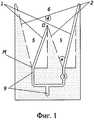
На фиг. 1 изображена двухуровневая широкополосная антенна, субрупор порядка (уровня) «m=1».In FIG. 1 shows a two-level broadband antenna, a sub-order of the order (level) “m = 1”.
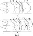
На фиг. 2 поясняется принцип суперпозиции распространяющихся мод для случаев синфазного, (равноамплитудного- а и неравноамплитудного- б) возбуждения апертуры двухуровневой антенны (субрупор порядка «m=1»).In FIG. 2, the principle of superposition of propagating modes for the cases of in-phase (equal- amplitude- a and unequal- amplitude- b ) aperture excitation of a two-level antenna (sub-order of the order "m = 1") is explained.
На фиг. 3 изображена многоуровневая широкополосная антенна, субрупор порядка «m=3».In FIG. 3 shows a multi-level broadband antenna, a sub-order of the order "m = 3".
На фиг. 4 поясняется иерархия построения многоуровневого излучающего раскрыва (субрупора порядка «m=3»), образованного из субрупоров порядка «m=0,1,2».In FIG. 4, the hierarchy of constructing a multi-level radiating aperture (sub-order of the order "m = 3"), formed from sub-groups of the order "m = 0,1,2", is explained.
На фиг. 5 представлено поведение ДН субрупора порядка «m=1» (двухуровневая антенна) при изменении отношения амплитуд мод Н10, Н20.In FIG. Figure 5 shows the behavior of the subunit DNs of the order “m = 1” (two-level antenna) when the amplitude ratio of the modes H10 , H20 changes.
На фигурах 1, 2, 3, 4, 5 обозначены:In the figures 1, 2, 3, 4, 5 are indicated:
1 - образующие плоских рупоров, выполненные на токонесущей стороне платы в виде микрополосковых проводников;1 - generators of flat horns made on the current-carrying side of the board in the form of microstrip conductors;
2 - образующие плоских рупоров, выполненные на экранной стороне платы в виде «среза» экрана (удаления металлизации);2 - generators of flat horns made on the screen side of the board in the form of a "cut" of the screen (removal of metallization);
3 - управляющий элемент типа фазовращатель, регулируемая линия задержки,3 - control element type phase shifter, adjustable delay line,
4 - поверхности экранной стороны платы, на которых удалена металлизация, обозначены в кружках;4 - surfaces of the screen side of the board on which metallization is removed are indicated in circles;
5 - плоский рупор нулевого (низшего) уровня, субрупор порядка «m=0»;5 - a flat horn of zero (lower) level, a subgroup of order "m = 0";
6 - плоский рупор первого уровня, субрупор порядка «m=1»;6 - a flat mouthpiece of the first level, a subunit of order "m = 1";
7 - плоский рупор второго уровня, субрупор порядка «m=2»;7 - a flat horn of the second level, a subunit of the order of "m = 2";
8 - плоский рупор третьего уровня субрупор порядка «m=3»;8 - a flat horn of the third level sub-horn of the order "m = 3";
9 - система возбуждения апертуры широкополосной антенны, выполненная в виде набора параллельно-последовательно включенных микрополосковых проводников, имеющих многоуровневую иерархию построения и симметричных относительно входа (точки О2');9 is a system for exciting the aperture of a broadband antenna, made in the form of a set of parallel-sequentially connected microstrip conductors having a multi-level hierarchy of construction and symmetrical with respect to the input (point O2 ');
М - точка пространственного наложения (пересечения) образующих 1, 2 рупоров нулевого уровня, в которой реализован узел возбуждения;M is the point of spatial overlapping (intersection) of the
α - угол между образующими 1 и 2, который характеризует угол раскрыва рупора нулевого уровня;α is the angle between
О, О1, О2 - точки, через которые проходят оси симметрии, перпендикулярные раскрыву, они же точки соединения (электрического контакта) образующих 1, 2 рупоров нулевого, первого, второго и т. д. уровней соответственно (субрупоров порядка «m=0,1,2,…n);О, О1, О2 - points through which the axis of symmetry pass, perpendicular to the opening, they are the connection points (electrical contact) forming 1, 2 horns of the zero, first, second, etc. levels, respectively (sub-order of the order “m = 0, 1,2, ... n);
аm - размер раскрыва (апертуры) субрупора уровня - m=0,1,…n;andm is the size of the aperture (aperture) of the sub-level level - m = 0.1, ... n;
Lm - размер пространственного скачка субрупора уровня - m=0, 1, 2,..n;Lm - the size of the spatial jump of the sub-level level - m = 0, 1, 2, .. n;
g - коэффициент частотного расширения структуры.g is the coefficient of frequency expansion of the structure.
Система 9 возбуждения апертуры широкополосной антенны (субрупора уровня «m») - сплошные линии - микрополосковые проводники, выполненные на токонесущей стороне платы, которые реализуют систему возбуждения.The excitation system 9 of the aperture of a broadband antenna (sub-band of level "m") - solid lines - microstrip conductors made on the current-carrying side of the board, which implement the excitation system.
Затушеванная часть экранной стороны платы соответствует наличию металлизации, пунктиром обозначены контуры поверхности экранной стороны платы, на которой удалена металлизация.The shaded part of the screen side of the board corresponds to the presence of metallization, dotted lines indicate the contours of the surface of the screen side of the board on which metallization is removed.
Решетчатая структура (субрупор) представляет из себя набор плоских ТЕМ рупоров (изготовленных по полосковой технологии) нулевого уровня «m=0»5. Импеданс исходного рупора определяется выражениемZ=120Ln(ctg


Описанный процесс с субрупором порядка «m=1,2,…n» продолжается до тех пор, пока не будет сформирован нужный раскрыв (апертура)аm=a0(2+g)m, обеспечивающий требуемую полосу пропускания.The described process with a sub-order of the order “m = 1,2, ... n” continues until the desired opening (aperture) is formedandm= a0(2 + g)m , which provides the required bandwidth.
С теоретической точки зрения, нет никаких ограничений на создание широкополосной антенны (апертура которой реализована в виде субрупора порядка «m=0,1,….n») с любой требуемой полосой пропускания.From a theoretical point of view, there are no restrictions on the creation of a broadband antenna (the aperture of which is implemented as a subunit of the order of "m = 0.1, ... .n") with any required bandwidth.
Продолжение образующих 1, 2 для субрупоров всех уровней не обязательно должно выполняться на диэлектрической подложке, они могут быть исполнены в виде проводящих стержней или проволок, для которых диэлектрической основой является окружающая среда (свободное пространство). Также они не обязательно должны быть прямыми, а могут быть ломаными или экспонентами - это определяется выбранным коэффициентом частотного расширения структуры«g» и особенностями конкретного исполнения.The continuation of the
В таком случае: общее количество элементов субрупора, формирующих протяженную структуру с требуемым размером раскрыва (апертуры) широкополосной антенны с динамическим амплитудно-фазовым распределением, определяется выражениемIn this case: the total number of sub-element elements forming an extended structure with the required aperture (aperture) of a broadband antenna with dynamic amplitude-phase distribution is determined by the expression
Nm = 2m+1-1,гдеm =0,1,2,…n.Nm= 2m + 1-1, wherem = 0,1,2, ... n.
Необходимо подчеркнуть, что исходный рупор обладает линейной ФЧХ [4]. Операции, посредством которых формируются субрупоры любого уровня, также являются строго линейными, значит, и ФЧХ субрупора порядка«m» будет линейной.It must be emphasized that the original horn has a linear phase response [4]. The operations by means of which subgroups of any level are formed are also strictly linear, which means that the phase response of a subgroup of order“m” will be linear.
Из рассмотренной процедуры формирования решетчатой структуры на базе субрупоров порядкаmследует,что субрупоры любого уровня (порядка), кроме нулевого, построены по одинаковой схеме, механизм формирования структуры поля на апертуре субрупора любого уровня совершенно одинаков, а отличаются они только граничными условиями. Причем суть отличия граничных условий заключается в том, что изменяются только пределы, характеризующие размер апертуры (раскрыв). А это значит, что предложенный способ конструирования сверхширокополосных антенн строго подчиняется теории многоуровневых иерархических систем. (М. Месарович и др. Теория иерархических многоуровневых систем, М., Мир, 1973 г. [6]) c вложенными процессами, что особенно наглядно иллюстрирует фиг. 4. Из фиг. 1, 4 следует, что субрупор любого уровня в первом приближении можно рассматривать как сверхширокополосную антенну в виде свернутого рупора, который характеризуется не только повышенной полосой пропускания, но и коэффициентом пространственного укорочения (сжатия):From a consideration on the basis of orderm subruporov procedure of forming the lattice structure it impliesthat subrupory any level (of the order), other than zero, are constructed by the same scheme, the mechanism of formation of the field structure on every level of the aperture subrupora absolutely identical, and they differ only by the boundary conditions. Moreover, the essence of the difference in the boundary conditions is that only the limits characterizing the size of the aperture are changed (opening). And this means that the proposed method for designing ultra-wideband antennas is strictly subordinate to the theory of multi-level hierarchical systems. (M. Mesarovich et al. Theory of hierarchical multilevel systems, M., Mir, 1973 [6]) with nested processes, which is especially clearly illustrated in Fig. 4. From FIG. 1, 4 it follows that, at a first approximation, a subunit of any level can be considered as an ultra-wideband antenna in the form of a rolled-up horn, which is characterized not only by an increased bandwidth, but also by a spatial shortening (compression) coefficient:

где

Амплитудно-фазовое распределение (АФР) на апертуре рупора Lh является однородным неуправляемым, а АФР на апертуре субрупора порядка «m=1» фиг. 1 является динамическим, легко управляемым по любой из точек входа. Как следует из фиг. 2, при равноамплитудном возбуждении результирующее распределение на раскрыве является симметричным относительно центра, а при неравноамплитудном несимметричным (смещенным), причем величина этого смещения зависит от соотношения амплитуд четных и нечетных распространяющихся мод. Пространственные моды характеризуются различной углочастотной зависимостью, поэтому соотношение их амплитуд определяет направление положения максимума диаграммы направленности антенны.The amplitude-phase distribution (AFR) at the horn aperture Lh is homogeneous uncontrolled, and the AFR at the sub-aperture of the order “m = 1” of FIG. 1 is dynamic, easily manageable at any of the entry points. As follows from FIG. 2, with equal-amplitude excitation, the resulting distribution in the aperture is symmetric about the center, and with unequal-amplitude asymmetric (biased), the magnitude of this shift depends on the ratio of the amplitudes of the even and odd propagating modes. Spatial modes are characterized by different angular-frequency dependences; therefore, the ratio of their amplitudes determines the direction of the maximum position of the antenna pattern.
Для простейшего случая возбуждения апертуры четной и нечетной распространяющимися модами распределение электрического поля на раскрыве можно представить в видеFor the simplest case of excitation of an even and odd aperture by propagating modes, the distribution of the electric field in the aperture can be represented as


где


Нормированная ДН субрупора порядка «m=1» (двухуровневой антенны) описывается выражениемThe normalized DN of the sub-order of the order “m = 1” (two-level antenna) is described by the expression


где
U=
На фиг. 5 представлены нормированные ДН многомодового (двухуровневого) элемента для случая


При


Диаграмма направленности.Radiation pattern.
Напряженность поля, создаваемая прямоугольным раскрывом со сторонами “а” и “b”, описывается выражениемThe field strength created by a rectangular opening with sides “a” and “b” is described by the expression


S=


S - диаграмма направленности раскрыва с размерами “a”, “b” по полю,S - radiation pattern of the aperture with dimensions “a”, “b” in the field,
E(x,y) - распределение электрического поля при возбуждении апертуры типами колебаний
С учетом (2), (3) диаграмма направленности по полю описывается выражениямиIn view of (2), (3), the field radiation pattern is described by the expressions


Коэффициент направленного действия (КНД) прямоугольного раскрыва определяется какCoefficient of directional action (KND) of a rectangular aperture is defined as


c учетом (7), (3), (3'):taking into account (7), (3), (3 '):


- полная излучаемая мощность.- total radiated power.
Нормированное значения КНД и фазовая диаграмма прямоугольного раскрыва с размерами “a”, “в” и распределением поля (3), (3') описываются выражениямиThe normalized KND values and the phase diagram of a rectangular aperture with dimensions “a”, “c” and field distribution (3), (3 ') are described by the expressions


Предлагаемое техническое решение - это новый способ изготовления микрополосковых (полосковых) антенн, выполняемый с применением современной технологии печатных плат, отличающийся компактностью и высокой технологичностью. АС, изготовленные по предлагаемому способу, будут особенно эффективными в областях применения, где для излучения используются сверхкороткие импульсы, длительностью порядка пико- и наносекунды - это цифровые системы связи и передачи данных, подповерхностная локация, радиолокационное сверхразрешение, системы имитации электромагнитного импульса ядерного взрыва, линии беспроводной передачи электрической энергии, а также радиолокационные системы сбора информации, обработки больших информационных потоков и конструирования ФАР с размерами элементов больше длины волны и широкоугольным сканированием.The proposed technical solution is a new method of manufacturing microstrip (strip) antennas, performed using modern technology of printed circuit boards, characterized by compactness and high adaptability. AS made by the proposed method will be especially effective in applications where ultrashort pulses are used for radiation, of the order of picosecond and nanosecond durations - these are digital communication and data transmission systems, subsurface location, radar superresolution, systems for simulating an electromagnetic pulse of a nuclear explosion, lines wireless transmission of electrical energy, as well as radar systems for collecting information, processing large information flows and designing headlamps with a size and elements of the wavelength and wide-angle scanning.
Claims (1)
Translated fromRussianPriority Applications (1)
| Application Number | Priority Date | Filing Date | Title |
|---|---|---|---|
| RU2013106920/08ARU2552232C2 (en) | 2013-02-11 | 2013-02-11 | Manufacturing method of ultra-wideband antenna system with controlled directivity pattern |
Applications Claiming Priority (1)
| Application Number | Priority Date | Filing Date | Title |
|---|---|---|---|
| RU2013106920/08ARU2552232C2 (en) | 2013-02-11 | 2013-02-11 | Manufacturing method of ultra-wideband antenna system with controlled directivity pattern |
Publications (2)
| Publication Number | Publication Date |
|---|---|
| RU2013106920A RU2013106920A (en) | 2014-09-20 |
| RU2552232C2true RU2552232C2 (en) | 2015-06-10 |
Family
ID=51583247
Family Applications (1)
| Application Number | Title | Priority Date | Filing Date |
|---|---|---|---|
| RU2013106920/08ARU2552232C2 (en) | 2013-02-11 | 2013-02-11 | Manufacturing method of ultra-wideband antenna system with controlled directivity pattern |
Country Status (1)
| Country | Link |
|---|---|
| RU (1) | RU2552232C2 (en) |
Citations (7)
| Publication number | Priority date | Publication date | Assignee | Title |
|---|---|---|---|---|
| US5187489A (en)* | 1991-08-26 | 1993-02-16 | Hughes Aircraft Company | Asymmetrically flared notch radiator |
| RU2052878C1 (en)* | 1993-04-01 | 1996-01-20 | Борис Иосифович Суховецкий | Wide-band array |
| RU2250542C1 (en)* | 2003-06-30 | 2005-04-20 | Орлов Александр Борисович | Horn antenna |
| US7180457B2 (en)* | 2003-07-11 | 2007-02-20 | Raytheon Company | Wideband phased array radiator |
| RU2407118C1 (en)* | 2009-11-27 | 2010-12-20 | Федеральное государственное унитарное предприятие "Научно-исследовательский институт телевидения" | Wideband antenna array |
| RU2427060C1 (en)* | 2010-01-11 | 2011-08-20 | Открытое акционерное общество "Центральное конструкторское бюро автоматики" | Ultra-wideband horn antenna |
| US8325099B2 (en)* | 2009-12-22 | 2012-12-04 | Raytheon Company | Methods and apparatus for coincident phase center broadband radiator |
- 2013
- 2013-02-11RURU2013106920/08Apatent/RU2552232C2/ennot_activeIP Right Cessation
Patent Citations (7)
| Publication number | Priority date | Publication date | Assignee | Title |
|---|---|---|---|---|
| US5187489A (en)* | 1991-08-26 | 1993-02-16 | Hughes Aircraft Company | Asymmetrically flared notch radiator |
| RU2052878C1 (en)* | 1993-04-01 | 1996-01-20 | Борис Иосифович Суховецкий | Wide-band array |
| RU2250542C1 (en)* | 2003-06-30 | 2005-04-20 | Орлов Александр Борисович | Horn antenna |
| US7180457B2 (en)* | 2003-07-11 | 2007-02-20 | Raytheon Company | Wideband phased array radiator |
| RU2407118C1 (en)* | 2009-11-27 | 2010-12-20 | Федеральное государственное унитарное предприятие "Научно-исследовательский институт телевидения" | Wideband antenna array |
| US8325099B2 (en)* | 2009-12-22 | 2012-12-04 | Raytheon Company | Methods and apparatus for coincident phase center broadband radiator |
| RU2427060C1 (en)* | 2010-01-11 | 2011-08-20 | Открытое акционерное общество "Центральное конструкторское бюро автоматики" | Ultra-wideband horn antenna |
Also Published As
| Publication number | Publication date |
|---|---|
| RU2013106920A (en) | 2014-09-20 |
Similar Documents
| Publication | Publication Date | Title |
|---|---|---|
| US7724200B2 (en) | Antenna device, array antenna, multi-sector antenna, high-frequency wave transceiver | |
| Vashist et al. | A review on the development of Rotman lens antenna | |
| JP3718527B2 (en) | Planar antenna | |
| KR101927708B1 (en) | Microstrip Balun-fed four-arm Sinuous Antenna | |
| Yektakhah et al. | A wideband circularly polarized omnidirectional antenna based on excitation of two orthogonal circular TE 21 modes | |
| US20150372369A1 (en) | Power division and recombination network with internal signal adjustment | |
| CN108028471A (en) | Multi-mode composite material antenna | |
| Nikkhah et al. | Rotman lens design with wideband DRA array | |
| Emadeddin et al. | A compact ultra-wideband multibeam antenna system | |
| US3553692A (en) | Antenna arrays having phase and amplitude control | |
| JPH1117438A (en) | Wide band antenna array | |
| RU2407118C1 (en) | Wideband antenna array | |
| JP2021111938A (en) | Antenna device and search device | |
| RU2182392C1 (en) | Antenna | |
| Ayyappan et al. | A Novel Low Profile Turbinella Shaped Antenna for 5G Millimeter Wave Applications. | |
| RU2552232C2 (en) | Manufacturing method of ultra-wideband antenna system with controlled directivity pattern | |
| CN101814659A (en) | Triangular slotted waveguide array antenna | |
| CN102365788B (en) | Antenna device | |
| Levy et al. | A novelistic fractal antenna for ultra wideband (UWB) applications | |
| Foster | Antennas and UWB signals | |
| RU2505893C2 (en) | Unidirectional cone antenna | |
| CN113517524A (en) | E-plane waveguide cross power divider based on symmetric feed | |
| RU2207670C1 (en) | Antenna | |
| RU2654914C1 (en) | Wireless antenna | |
| Hadei et al. | Design, simulation, and fabrication of microstrip lens with non-uniform contour for 360 degree scanning |
Legal Events
| Date | Code | Title | Description |
|---|---|---|---|
| MM4A | The patent is invalid due to non-payment of fees | Effective date:20160212 |