RU2549396C1 - Water-flow regulator - Google Patents
Water-flow regulatorDownload PDFInfo
- Publication number
- RU2549396C1 RU2549396C1RU2014112846/06ARU2014112846ARU2549396C1RU 2549396 C1RU2549396 C1RU 2549396C1RU 2014112846/06 ARU2014112846/06 ARU 2014112846/06ARU 2014112846 ARU2014112846 ARU 2014112846ARU 2549396 C1RU2549396 C1RU 2549396C1
- Authority
- RU
- Russia
- Prior art keywords
- water
- membrane
- flexible
- flexible tape
- flow regulator
- Prior art date
Links
- XLYOFNOQVPJJNP-UHFFFAOYSA-NwaterSubstancesOXLYOFNOQVPJJNP-UHFFFAOYSA-N0.000claimsabstractdescription35
- 238000011144upstream manufacturingMethods0.000claimsdescription11
- 210000000056organAnatomy0.000claimsdescription2
- 239000012528membraneSubstances0.000abstractdescription20
- 238000010276constructionMethods0.000abstract1
- 230000000694effectsEffects0.000abstract1
- 239000000126substanceSubstances0.000abstract1
- 230000007423decreaseEffects0.000description3
- NMFHJNAPXOMSRX-PUPDPRJKSA-N[(1r)-3-(3,4-dimethoxyphenyl)-1-[3-(2-morpholin-4-ylethoxy)phenyl]propyl] (2s)-1-[(2s)-2-(3,4,5-trimethoxyphenyl)butanoyl]piperidine-2-carboxylateChemical compoundC([C@@H](OC(=O)[C@@H]1CCCCN1C(=O)[C@@H](CC)C=1C=C(OC)C(OC)=C(OC)C=1)C=1C=C(OCCN2CCOCC2)C=CC=1)CC1=CC=C(OC)C(OC)=C1NMFHJNAPXOMSRX-PUPDPRJKSA-N0.000description2
- 238000007789sealingMethods0.000description2
- 239000003381stabilizerSubstances0.000description2
- 238000005452bendingMethods0.000description1
- 230000002349favourable effectEffects0.000description1
- 238000009434installationMethods0.000description1
- 230000007704transitionEffects0.000description1
Images

Landscapes
- Flow Control (AREA)
Abstract
Description
Translated fromRussianИзобретение относится к гидротехнике и может быть использовано для регулирования расхода воды на трубчатых и диафрагмовых водовыпусках.The invention relates to hydraulic engineering and can be used to control the flow of water on tubular and diaphragm outlets.
Известен стабилизатор расхода воды (см. а.с. №1198465, М.кл. - G05D 7/00, 1985 г.), содержащий коробчатый щит, донный затвор, выполненный в виде сообщенной с верхним и нижним бьефами емкости, образованной напорным щитом, установленным на горизонтальной оси вращения и соединенным с гибкой оболочкой, закрепленной в устоях сооружения, и клапан, выполненный в виде установленного на сливном отверстии щита с козырьком, соединенного через тягу с рычагом, плечо которого связано посредством регулировочного винта с донным затвором.A known flow rate stabilizer (see AS No. 1198465, M.cl. - G05D 7/00, 1985), comprising a box-shaped shield, a bottom shutter, made in the form of a tank formed by a pressure shield connected with the upper and lower bouts mounted on a horizontal axis of rotation and connected to a flexible shell fixed in the abutments of the structure, and a valve made in the form of a shield mounted on the drain hole with a visor connected through a rod to a lever, the shoulder of which is connected by means of an adjustment screw to the bottom bolt.
Однако известный стабилизатор расхода воды обладает нерегулируемыми протечками при практически закрытом исполнительном органе.However, the known water flow stabilizer has unregulated leaks with a practically closed actuator.
Наиболее близким к изобретению является регулятор расхода воды (см. а.с. №1275383, М.кл. - G05D 7/01, 1984 г.), содержащий водовыпускную трубу прямоугольного сечения с седлом, перекрываемым запорным органом, выполненным в виде гибкой ленты, образующей с корпусом водовыпускной трубы управляющую полость, сообщенную с верхним бьефом и снабженную сливным каналом, на котором установлен выполненный в виде втулки с профилированными вырезами клапан, установленный на мембране второго мембранного корпуса, полость которого сообщена с управляющей полостью, и связанный посредством штока с мембраной первого мембранного корпуса, полость которого сообщена с верхним бьефом.Closest to the invention is a water flow regulator (see AS No. 1275383, Mcl - G05D 7/01, 1984), containing a water outlet pipe of rectangular cross section with a saddle, overlapped by a locking element made in the form of a flexible tape forming a control cavity connected with the upper pool and equipped with a drain channel, which is configured as a sleeve with profiled cut-outs, which is installed on the membrane of the second membrane body, the cavity of which is in communication with the control cavity, and with yazanny rod through the first membrane to the membrane housing, which cavity communicates with the upper pool.
Однако данный регулятор расхода воды не обеспечивает герметичного перекрытия водовыпускного отверстия, обладает нерегулируемыми протечками при закрытом запорном органе, т.к. при практически закрытом положении давления в управляющей полости и перед гибкой лентой со стороны верхнего бьефа уравновешены, а жесткость гибкой ленты при изгибе препятствует герметичному перекрытию водовыпускного отверстия.However, this water flow regulator does not provide a tight shutoff of the water outlet, has unregulated leaks with a closed shut-off body, because when the pressure position in the control cavity is almost closed and before the flexible tape from the upstream side, they are balanced, and the stiffness of the flexible tape during bending prevents the hermetic closure of the water outlet.
Техническим результатом является экономия воды за счет исключения нерегулируемых протечек.The technical result is to save water by eliminating unregulated leaks.
Технический результат достигается тем, что в регуляторе расхода воды, содержащем водовыпускную трубу прямоугольного сечения с седлом, перекрываемым запорным органом, выполненным в виде гибкой ленты, образующей с корпусом водовыпускной трубы управляющую полость, сообщенную с верхним бьефом и снабженную устройством для слива, на котором установлен клапан, соединенный штоком с мембраной мембранного корпуса, полость которого сообщена с верхним бьефом, согласно изобретению запорный орган в виде гибкой ленты на участке ее примыкания к грани проходного сечения водовыпускной трубы, со стороны верхнего бьефа, снабжен консольно закрепленной гибкой вставкой шириной, большей ширины щели при полностью закрытом запорном органе.The technical result is achieved by the fact that in the water flow regulator containing a rectangular outlet pipe with a saddle overlapped by a locking member made in the form of a flexible tape forming a control cavity in communication with the upstream pipe and equipped with a drainage device on which is installed a valve connected by a rod with a membrane of the membrane body, the cavity of which is connected to the upper pool, according to the invention, a locking member in the form of a flexible tape at the site of its adjoining to the gran water discharge pipe passage section, from the upstream side, is provided with cantilevered flexible insert secured width greater than the slot width at the fully closed shut-off organ.
Новизна заявленного технического решения заключается в том, что за счет дополнительного элемента, а именно гибкой вставки, консольно закрепленной на участке примыкания гибкой ленты запорного органа к грани проходного сечения водовыпускной трубы, со стороны верхнего бьефа, обеспечивается исключение нерегулируемых протечек.The novelty of the claimed technical solution lies in the fact that due to an additional element, namely a flexible insert, cantileverly mounted on the junction of the flexible tape of the locking member to the edge of the passage section of the water outlet pipe, from the upstream side, unregulated leaks are eliminated.
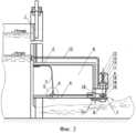
Сущность изобретения поясняется чертежом, где на фиг.1 изображен общий вид регулятора расхода воды; на фиг.2 - общий вид регулятора расхода воды с перекрытым проходным отверстием в седле; на фиг.3 - узел А на фиг.2.The invention is illustrated in the drawing, where figure 1 shows a General view of a water flow controller; figure 2 is a General view of the water flow controller with a blocked passage hole in the saddle; figure 3 - node a in figure 2.
Регулятор расхода воды содержит плоский щит 1 с закрепленной на нем водовыпускной трубой 2 прямоугольного сечения. Внутри водовыпускной трубы 2 размещен запорный орган, выполненный в виде гибкой ленты 3, снабженной на участке ее примыкания к грани проходного сечения водовыпускной трубы 2, со стороны верхнего бьефа, консольно закрепленной гибкой вставкой 5. Гибкая лента 3 закреплена одним концом к верхней стенке водовыпускной трубы 2, а другим - к седлу 4 в основании водовыпускной трубы 2. Гибкая вставка 5 имеет ширину, большую ширины щели седла 4 при полностью закрытом запорном органе 3. Гибкая лента 3 образует с корпусом водовыпускной трубы 2 управляющую полость 6 со сливным каналом 7. Регулятор содержит первый 8 и второй 9 мембранные корпусы. Полость первого мембранного корпуса 8 соединена трубопроводом 10 с верхним бьефом. Мембрана 11 первого мембранного корпуса 8 посредством штока 12 с винтом уставки 13 и пружиной 14 соединена с жестким центром 15, закрепленным на мембране 16 второго мембранного корпуса 9, сообщенного трубопроводом 17 с управляющей полостью 6. Внутри выходного патрубка сливного канала 7 установлен клапан, выполненный в виде втулки 18 с профилированными вырезами 19. Нижнее основание втулки 18 закреплено на мембране 16 второго мембранного корпуса 9.The water flow controller contains a flat shield 1 with a
Регулятор расхода воды работает следующим образом. Первоначальной установкой плоского щита 1 задается степень открытия водовыпускного отверстия гидротехнического сооружения. При повышении уровня воды в верхнем бьефе благодаря наличию трубопровода 10 давление в первом мембранном корпусе 8 возрастает, мембрана 11 прогибается, сжимая пружину 14 и перемещая шток 12. Вместе со штоком 12 перемещается жесткий центр 15, закрепленный на мембране 16 второго мембранного корпуса 9, сообщенного трубопроводом 17 с управляющей полостью 6. В свою очередь втулка 18, имеющая профилированные вырезы 19, также перемещается. Данное действие приведет к уменьшению степени открытия сливного канала 7 и, как следствие, к уменьшению расхода воды, сбрасываемой из управляющей полости 6. Давление в последней начинает возрастать, равенство между расходом воды, поступающим в управляющую полость 6 через зазоры между корпусом водовыпускной трубы 2 и незакрепленными краями гибкой ленты 3, и сбрасываемым расходом нарушится, гибкая лента 3 с консольно закрепленной гибкой вставкой 5 приходит в движение и начинает перекрывать проходное отверстие в седле 4 в основании водовыпускной трубы 2. После окончания переходного процесса равенство между поступающим и сбрасываемым расходами восстанавливается и гибкая лента 3 с консольно закрепленной гибкой вставкой 5 занимает новое положение. При этом по мере перемещения жесткого центра 15 благодаря наличию втулки 18 с профилированными вырезами 19 площадь проходного сечения сливного канала 7 изменяется по закону, обеспечивающему такую расходную характеристику из управляющей полости 6, при которой новому положению гибкой ленты 3 с консольно закрепленной гибкой вставкой 5 соответствует степень открытия проходного сечения в седле 4 в основании водовыпускной трубы 2, позволяющая компенсировать увеличение расхода при повышении уровня воды в верхнем бьефе. При понижении уровня воды в верхнем бьефе цикл работы повторяется в обратном порядке. Настройка регулятора расхода на другой режим осуществляется винтом уставки 13.The water flow controller operates as follows. The initial installation of the flat shield 1 sets the degree of opening of the water outlet of the hydraulic structure. When the water level in the upstream rises due to the presence of the
При необходимости полностью перекрыть проходное отверстие в седле 4 в основании водовыпускной трубы 2 винт уставки 13 устанавливают в положение, обеспечивающее закрытие сливного канала 7 и, как следствие, к исключению расхода воды, сбрасываемой из управляющей полости 6. Давление в последней начинает возрастать, гибкая лента 3 приходит в движение и начинает перекрывать проходное отверстие в седле 4. Однако на момент самого закрытия проходного отверстия в седле 4 в основании водовыпускной трубы 2 давления со стороны верхнего бьефа перед лентой и за лентой в управляющей полости 6 уравновешиваются и лента 3 находится в безразличном состоянии. При этом жесткость самой ленты, необходимая при герметизации проходного отверстия в седле 4 по бокам, в данном случае будет препятствовать герметизации проходного отверстия именно со стороны верхнего бьефа. Запорный орган в виде гибкой ленты 3 на участке ее примыкания к грани проходного сечения водовыпускной трубы 2, со стороны верхнего бьефа, снабжен консольно закрепленной гибкой вставкой 5 шириной, большей ширины щели при полностью закрытом запорном органе 3, что способствует наиболее благоприятному гидравлическому режиму контакта гибкой ленты 3 и основанию водовыпускной трубы 2, обеспечивая режим герметизации.If necessary, completely block the passage hole in the
Claims (1)
Translated fromRussianPriority Applications (1)
| Application Number | Priority Date | Filing Date | Title |
|---|---|---|---|
| RU2014112846/06ARU2549396C1 (en) | 2014-04-02 | 2014-04-02 | Water-flow regulator |
Applications Claiming Priority (1)
| Application Number | Priority Date | Filing Date | Title |
|---|---|---|---|
| RU2014112846/06ARU2549396C1 (en) | 2014-04-02 | 2014-04-02 | Water-flow regulator |
Publications (1)
| Publication Number | Publication Date |
|---|---|
| RU2549396C1true RU2549396C1 (en) | 2015-04-27 |
Family
ID=53289727
Family Applications (1)
| Application Number | Title | Priority Date | Filing Date |
|---|---|---|---|
| RU2014112846/06ARU2549396C1 (en) | 2014-04-02 | 2014-04-02 | Water-flow regulator |
Country Status (1)
| Country | Link |
|---|---|
| RU (1) | RU2549396C1 (en) |
Cited By (1)
| Publication number | Priority date | Publication date | Assignee | Title |
|---|---|---|---|---|
| RU2675290C2 (en)* | 2015-12-08 | 2018-12-18 | Федеральное государственное бюджетное образовательное учреждение высшего профессионального образования "Кубанский государственный аграрный университет" | Water flow regulator for orifice water outlets |
Citations (6)
| Publication number | Priority date | Publication date | Assignee | Title |
|---|---|---|---|---|
| SU364788A1 (en)* | Всесоюзный научно нсследовательский институт гидротехники Б. Е. Веденеева | PLATE FOR PIPELINE | ||
| DE2822299A1 (en)* | 1977-05-23 | 1978-12-07 | Stein Bendixen | Flow regulator for fluid - has flexible walled chamber filled with low density fluid and acting as throttle valve |
| US4545403A (en)* | 1982-03-24 | 1985-10-08 | Hansjorg Brombach | Flow regulating device |
| SU1198465A1 (en)* | 1984-05-11 | 1985-12-15 | Киргизский Сельскохозяйственный Институт Ордена "Знак Почета" Им.К.И.Скрябина | Water discharge stabilizer |
| SU1275383A1 (en)* | 1984-12-11 | 1986-12-07 | Киргизский Ордена "Знак Почета" Сельскохозяйственный Институт Им.К.И.Скрябина | Flow governor |
| WO2004070322A2 (en)* | 2003-01-29 | 2004-08-19 | Wwetco, Llc | Apparatus and method for fluid flow control |
- 2014
- 2014-04-02RURU2014112846/06Apatent/RU2549396C1/ennot_activeIP Right Cessation
Patent Citations (6)
| Publication number | Priority date | Publication date | Assignee | Title |
|---|---|---|---|---|
| SU364788A1 (en)* | Всесоюзный научно нсследовательский институт гидротехники Б. Е. Веденеева | PLATE FOR PIPELINE | ||
| DE2822299A1 (en)* | 1977-05-23 | 1978-12-07 | Stein Bendixen | Flow regulator for fluid - has flexible walled chamber filled with low density fluid and acting as throttle valve |
| US4545403A (en)* | 1982-03-24 | 1985-10-08 | Hansjorg Brombach | Flow regulating device |
| SU1198465A1 (en)* | 1984-05-11 | 1985-12-15 | Киргизский Сельскохозяйственный Институт Ордена "Знак Почета" Им.К.И.Скрябина | Water discharge stabilizer |
| SU1275383A1 (en)* | 1984-12-11 | 1986-12-07 | Киргизский Ордена "Знак Почета" Сельскохозяйственный Институт Им.К.И.Скрябина | Flow governor |
| WO2004070322A2 (en)* | 2003-01-29 | 2004-08-19 | Wwetco, Llc | Apparatus and method for fluid flow control |
Cited By (1)
| Publication number | Priority date | Publication date | Assignee | Title |
|---|---|---|---|---|
| RU2675290C2 (en)* | 2015-12-08 | 2018-12-18 | Федеральное государственное бюджетное образовательное учреждение высшего профессионального образования "Кубанский государственный аграрный университет" | Water flow regulator for orifice water outlets |
Similar Documents
| Publication | Publication Date | Title |
|---|---|---|
| RU2557376C1 (en) | Water flow regulator for orifice water outlets | |
| EP3209912B1 (en) | Improved valve | |
| KR101146131B1 (en) | Using buoyancy for automatic closing pide door devices and method of control | |
| RU2559680C1 (en) | Water flow rate stabiliser | |
| SU606561A3 (en) | Flat gate valve | |
| RU2549396C1 (en) | Water-flow regulator | |
| JP2014166327A5 (en) | ||
| RU2519508C1 (en) | Water flow controller | |
| WO2014150467A3 (en) | Fluidic components suitable for fuel cell systems including pressure regulators and valves | |
| CN105951689A (en) | Structure integrating reservoir pre-discharging and ecological flow discharging | |
| RU2538811C1 (en) | Mouth of drain manifold | |
| CN211574272U (en) | Double-gate valve hydraulic control valve set | |
| CN106194256B (en) | A kind of free-draining structure suitable for adverse slope tunnel | |
| RU2675290C2 (en) | Water flow regulator for orifice water outlets | |
| RU2756510C1 (en) | Apparatus for water flow rate regulation | |
| RU2756708C1 (en) | Water flow rate stabiliser | |
| RU2756511C1 (en) | Water flow rate regulator | |
| RU2520068C1 (en) | Water flow rate stabiliser | |
| US2150359A (en) | Automatic sewer regulator | |
| CN212377389U (en) | Water pressure adjustable valve for water pipe | |
| KR101612517B1 (en) | Gate pump equipped with flap valve having variable load | |
| CN202164685U (en) | Flushing device | |
| CN202674418U (en) | Water-draining valve for flood gate of underground tunnel | |
| US10443752B2 (en) | Drip proof outlet diffuser for a faucet | |
| RU2666662C1 (en) | Flooding consequences prevention method |
Legal Events
| Date | Code | Title | Description |
|---|---|---|---|
| MM4A | The patent is invalid due to non-payment of fees | Effective date:20160403 |