RU2537423C2 - Floor panel and floor covering consisting of many such panels - Google Patents
Floor panel and floor covering consisting of many such panelsDownload PDFInfo
- Publication number
- RU2537423C2 RU2537423C2RU2012100772/03ARU2012100772ARU2537423C2RU 2537423 C2RU2537423 C2RU 2537423C2RU 2012100772/03 ARU2012100772/03 ARU 2012100772/03ARU 2012100772 ARU2012100772 ARU 2012100772ARU 2537423 C2RU2537423 C2RU 2537423C2
- Authority
- RU
- Russia
- Prior art keywords
- floor panel
- connecting part
- spike
- downward
- upward
- Prior art date
Links
- 238000000034methodMethods0.000claimsabstractdescription18
- 230000000694effectsEffects0.000claimsabstractdescription3
- 239000002023woodSubstances0.000claimsdescription7
- 239000004033plasticSubstances0.000claimsdescription6
- 238000006073displacement reactionMethods0.000claimsdescription5
- 239000000463materialSubstances0.000claimsdescription4
- 229920005989resinPolymers0.000claimsdescription2
- 239000011347resinSubstances0.000claimsdescription2
- 230000005489elastic deformationEffects0.000claims1
- 238000010276constructionMethods0.000abstractdescription3
- 239000000126substanceSubstances0.000abstract1
- 230000007246mechanismEffects0.000description28
- 230000000295complement effectEffects0.000description16
- 239000011094fiberboardSubstances0.000description9
- 230000008901benefitEffects0.000description7
- 238000010521absorption reactionMethods0.000description4
- 238000009408flooringMethods0.000description3
- 230000003993interactionEffects0.000description3
- 238000004519manufacturing processMethods0.000description3
- 230000008569processEffects0.000description3
- 239000011093chipboardSubstances0.000description2
- 238000005516engineering processMethods0.000description2
- 239000002184metalSubstances0.000description2
- 239000007787solidSubstances0.000description2
- 239000004753textileSubstances0.000description2
- 241000208202LinaceaeSpecies0.000description1
- 235000004431Linum usitatissimumNutrition0.000description1
- 239000004640Melamine resinSubstances0.000description1
- 229920000877Melamine resinPolymers0.000description1
- 230000002411adverseEffects0.000description1
- 230000000903blocking effectEffects0.000description1
- 230000015556catabolic processEffects0.000description1
- 230000006835compressionEffects0.000description1
- 238000007906compressionMethods0.000description1
- 230000008878couplingEffects0.000description1
- 238000010168coupling processMethods0.000description1
- 238000005859coupling reactionMethods0.000description1
- 230000007423decreaseEffects0.000description1
- 238000009499grossingMethods0.000description1
- 238000010438heat treatmentMethods0.000description1
- 230000002452interceptive effectEffects0.000description1
- 239000000123paperSubstances0.000description1
- 230000001737promoting effectEffects0.000description1
- 230000007704transitionEffects0.000description1
Images


Classifications
- E—FIXED CONSTRUCTIONS
- E04—BUILDING
- E04F—FINISHING WORK ON BUILDINGS, e.g. STAIRS, FLOORS
- E04F15/00—Flooring
- E04F15/02—Flooring or floor layers composed of a number of similar elements
- E04F15/02038—Flooring or floor layers composed of a number of similar elements characterised by tongue and groove connections between neighbouring flooring elements
- E—FIXED CONSTRUCTIONS
- E04—BUILDING
- E04C—STRUCTURAL ELEMENTS; BUILDING MATERIALS
- E04C2/00—Building elements of relatively thin form for the construction of parts of buildings, e.g. sheet materials, slabs, or panels
- E04C2/30—Building elements of relatively thin form for the construction of parts of buildings, e.g. sheet materials, slabs, or panels characterised by the shape or structure
- E04C2/38—Building elements of relatively thin form for the construction of parts of buildings, e.g. sheet materials, slabs, or panels characterised by the shape or structure with attached ribs, flanges, or the like, e.g. framed panels
- E—FIXED CONSTRUCTIONS
- E04—BUILDING
- E04C—STRUCTURAL ELEMENTS; BUILDING MATERIALS
- E04C2/00—Building elements of relatively thin form for the construction of parts of buildings, e.g. sheet materials, slabs, or panels
- E04C2/30—Building elements of relatively thin form for the construction of parts of buildings, e.g. sheet materials, slabs, or panels characterised by the shape or structure
- E04C2/40—Building elements of relatively thin form for the construction of parts of buildings, e.g. sheet materials, slabs, or panels characterised by the shape or structure composed of a number of smaller components rigidly or movably connected together, e.g. interlocking, hingedly connected of particular shape, e.g. not rectangular of variable shape or size, e.g. flexible or telescopic panels
- E—FIXED CONSTRUCTIONS
- E04—BUILDING
- E04F—FINISHING WORK ON BUILDINGS, e.g. STAIRS, FLOORS
- E04F15/00—Flooring
- E04F15/02—Flooring or floor layers composed of a number of similar elements
- E—FIXED CONSTRUCTIONS
- E04—BUILDING
- E04F—FINISHING WORK ON BUILDINGS, e.g. STAIRS, FLOORS
- E04F2201/00—Joining sheets or plates or panels
- E04F2201/01—Joining sheets, plates or panels with edges in abutting relationship
- E04F2201/0123—Joining sheets, plates or panels with edges in abutting relationship by moving the sheets, plates or panels parallel to the abutting edges
- E—FIXED CONSTRUCTIONS
- E04—BUILDING
- E04F—FINISHING WORK ON BUILDINGS, e.g. STAIRS, FLOORS
- E04F2201/00—Joining sheets or plates or panels
- E04F2201/01—Joining sheets, plates or panels with edges in abutting relationship
- E04F2201/0138—Joining sheets, plates or panels with edges in abutting relationship by moving the sheets, plates or panels perpendicular to the main plane
- E04F2201/0146—Joining sheets, plates or panels with edges in abutting relationship by moving the sheets, plates or panels perpendicular to the main plane with snap action of the edge connectors
- E—FIXED CONSTRUCTIONS
- E04—BUILDING
- E04F—FINISHING WORK ON BUILDINGS, e.g. STAIRS, FLOORS
- E04F2201/00—Joining sheets or plates or panels
- E04F2201/03—Undercut connections, e.g. using undercut tongues or grooves
- E—FIXED CONSTRUCTIONS
- E04—BUILDING
- E04F—FINISHING WORK ON BUILDINGS, e.g. STAIRS, FLOORS
- E04F2201/00—Joining sheets or plates or panels
- E04F2201/04—Other details of tongues or grooves
- F—MECHANICAL ENGINEERING; LIGHTING; HEATING; WEAPONS; BLASTING
- F16—ENGINEERING ELEMENTS AND UNITS; GENERAL MEASURES FOR PRODUCING AND MAINTAINING EFFECTIVE FUNCTIONING OF MACHINES OR INSTALLATIONS; THERMAL INSULATION IN GENERAL
- F16B—DEVICES FOR FASTENING OR SECURING CONSTRUCTIONAL ELEMENTS OR MACHINE PARTS TOGETHER, e.g. NAILS, BOLTS, CIRCLIPS, CLAMPS, CLIPS OR WEDGES; JOINTS OR JOINTING
- F16B5/00—Joining sheets or plates, e.g. panels, to one another or to strips or bars parallel to them
- F16B5/0004—Joining sheets, plates or panels in abutting relationship
- F16B5/0056—Joining sheets, plates or panels in abutting relationship by moving the sheets, plates or panels or the interlocking key perpendicular to the main plane
- Y—GENERAL TAGGING OF NEW TECHNOLOGICAL DEVELOPMENTS; GENERAL TAGGING OF CROSS-SECTIONAL TECHNOLOGIES SPANNING OVER SEVERAL SECTIONS OF THE IPC; TECHNICAL SUBJECTS COVERED BY FORMER USPC CROSS-REFERENCE ART COLLECTIONS [XRACs] AND DIGESTS
- Y10—TECHNICAL SUBJECTS COVERED BY FORMER USPC
- Y10T—TECHNICAL SUBJECTS COVERED BY FORMER US CLASSIFICATION
- Y10T428/00—Stock material or miscellaneous articles
- Y10T428/24—Structurally defined web or sheet [e.g., overall dimension, etc.]
- Y10T428/24479—Structurally defined web or sheet [e.g., overall dimension, etc.] including variation in thickness
- Y10T428/24488—Differential nonuniformity at margin
Landscapes
- Engineering & Computer Science (AREA)
- Architecture (AREA)
- Civil Engineering (AREA)
- Structural Engineering (AREA)
- Floor Finish (AREA)
- Glass Compositions (AREA)
- Road Repair (AREA)
- Laminated Bodies (AREA)
- Building Environments (AREA)
Abstract
Description
Translated fromRussianИзобретение относится к панели пола, в частности ламинированной панели пола. Изобретение также относится к покрытию пола, состоящему из множества взаимно соединенных панелей пола в соответствии с изобретением. Изобретение также относится к способу взаимного соединения двух панелей пола, в частности ламинированных панелей пола, в соответствии с изобретением.The invention relates to a floor panel, in particular a laminated floor panel. The invention also relates to a floor covering consisting of a plurality of interconnected floor panels in accordance with the invention. The invention also relates to a method for interconnecting two floor panels, in particular laminated floor panels, in accordance with the invention.
В последние десять лет отмечен огромный прогресс в продвижении на рынке ламината для твердого покрытия пола. Важным аспектом при разработке изделия из ламината является легкость, с которой может быть уложен ламинированный пол. В патенте США 6490836 описан ламинат, состоящий из панелей пола, которые могут быть взаимно соединены, причем соединение двух панелей пола может быть осуществлено посредством зацепления панелей пола друг с другом под углом с последующим поворачиванием панелей пола относительно друг друга, в результате чего панели пола могут по существу быть сцеплены друг с другом. Хотя известный ламинат может быть относительно легко уложен пользователем, известное покрытие пола также имеет ряд недостатков. Существенным недостатком известного покрытия пола является то, что вследствие поворотного движения, требующегося для осуществления соединения, к деталям пола прикладывают относительно большие усилия, что может приводить к серьезному повреждению (поломке). Другой недостаток известного ламината состоит в том, что для обеспечения взаимного соединения панелей пола требуется относительно большой объем пространства, что значительно затрудняет, или даже делает невозможным, соединение панели пола со смежной панелью пола, в ограниченном пространстве, например, рядом со стеной или под батареей отопления.The last ten years have seen tremendous progress in promoting the market for laminate flooring for hard flooring. An important aspect in developing a laminate product is the ease with which a laminate floor can be laid. US Pat. No. 6,490,836 describes a laminate consisting of floor panels that can be interconnected, the connection of two floor panels being possible by engaging the floor panels at an angle, and then rotating the floor panels relative to each other, whereby the floor panels can essentially be interlocked with each other. Although the known laminate flooring can be relatively easy to lay by the user, the known floor covering also has a number of disadvantages. A significant drawback of the known floor covering is that due to the pivoting movement required to make the connection, relatively high forces are applied to the floor parts, which can lead to serious damage (breakdown). Another disadvantage of the known laminate is that a relatively large amount of space is required to ensure mutual connection of the floor panels, which makes it difficult or even impossible to connect the floor panel to an adjacent floor panel in a limited space, for example, next to a wall or under a battery heating.
Задачей изобретения является создание усовершенствованной панели пола, которая может быть более удобно соединена со смежной панелью пола.The objective of the invention is to provide an improved floor panel, which can be more conveniently connected to an adjacent floor panel.
Для достижения данной цели изобретение обеспечивает панель пола, содержащую расположенный в центре внутренний слой, содержащий верхнюю сторону и нижнюю сторону, по меньшей мере, одну первую упругую соединительную деталь и вторую упругую соединительную деталь, соединенные соответственно с противоположными краями внутреннего слоя, причем первая соединительная деталь содержит один шип, по меньшей мере, один направленный вверх торец, расположенный на расстоянии от направленного вверх шипа, и один направленный вверх паз, образованный между направленным вверх шипом и направленным вверх торцом, причем, по меньшей мере, часть стороны направленного вверх шипа, обращенной к направленному вверх торцу, продолжается в направлении нормали верхней стороны внутреннего слоя, по меньшей мере, часть стороны направленного вверх шипа, обращенной к направленному вверх торцу, образует выравнивающий край, предназначенный для соединения первой соединительной детали со второй соединительной деталью смежной панели пола, по меньшей мере, часть стороны направленного вверх шипа, обращенной от направленного вверх торца, содержит первый блокировочный элемент, который соединен по существу жестко с направленным вверх шипом и приспособлен для взаимодействия со вторым блокировочным элементом второй соединительной детали смежной панели пола, причем вторая соединительная деталь содержит один направленный вниз шип, по меньшей мере, один направленный вниз торец, расположенный на расстоянии от направленного вниз шипа, и один направленный вниз паз, образованный между направленным вниз шипом и направленным вниз торцом, причем, по меньшей мере, часть стороны направленного вниз шипа, обращенной к направленному вниз торцу, продолжается в направлении нормали нижней стороны внутреннего слоя, по меньшей мере, часть стороны направленного вниз шипа, обращенной от направленного вниз торца, образует выравнивающий край, предназначенный для соединения второй соединительной детали с первой соединительной деталью смежной панели пола, при этом направленный вниз торец содержит второй блокировочный элемент, который соединен по существу жестко с направленным вниз торцом и приспособлен для взаимодействия с первым блокировочным элементом первой соединительной детали смежной панели пола, причем направленный вверх паз приспособлен для приема, по меньшей мере, части направленного вниз шипа смежной панели, и при этом направленный вниз паз приспособлен для приема, по меньшей мере, части направленного вверх шипа смежной панели. Поскольку соединительные детали имеют специальную форму и, кроме того, обладают некоторой упругостью, выполненные по существу с возможностью взаимного дополнения соединительные детали смежных панелей пола могут быть соединены друг с другом относительно просто, но прочно и эффективно. Во время соединения смежных панелей пола усилие прикладывают к одной или обеим соединительным деталям, в результате чего одна или обе соединительные детали будут упруго деформироваться (упруго сдвигаться), вследствие чего объем, занимаемый направленным вниз пазом и/или направленным вверх пазом будет увеличен так, что направленный вверх шип и направленный вниз шип могут быть относительно просто размещены соответственно в направленном вниз пазу и направленном вверх пазу. Затем в результате обеспечения упругого возвращения вставленных с усилием соединительных деталей в первоначальное положение осуществляется надежное, зафиксированное соединение между двумя соединительными деталями и тем самым между двумя панелями пола. Данное зафиксированное соединение, в котором обе соединительные детали относительно надежно взаимно сцепляются, будет противодействовать трению деталей соединения друг о друга, при этом соединение как таковое будет обычно создавать относительно малый шум. Применяемые выравнивающие края, обычно также называемые фасками или направляющими поверхностями, в данном случае облегчают сцепление двух соединительных деталей посредством по существу линейного смещения соединительных деталей относительно друг друга. Применение взаимодействующих друг с другом блокировочных элементов предотвращает по существу вертикальное смещение двух панелей пола относительно друг друга. Поскольку как первый блокировочный элемент, так и второй блокировочный элемент соединены по существу жестко соответственно с направленным вверх шипом и направленным вниз торцом, может быть осуществлена относительно надежная и прочная фиксация, поскольку не используются относительно непрочные упругие блокировочные элементы, в которых, кроме того, относительно быстро может проявляться усталость материала. Фиксация в панели пола в соответствии с изобретением осуществляется посредством деформирования первой соединительной детали и/или второй соединительной детали относительно внутреннего слоя, в результате чего блокировочные элементы могут входить в зацепление вокруг друг друга или друг в друга. В результате жесткого соединения с направленным вверх шипом и направленным вниз торцом деформация самих блокировочных элементов не происходит или почти не происходит. Первый блокировочный элемент, как вариант, может быть выполнен за одно целое с направленным вверх шипом, причем первый блокировочный элемент может быть образован, например, посредством выпуклого (с деформацией наружу) или углубленного (с деформацией внутрь) края направленного вверх шипа. Второй блокировочный элемент может быть также выполнен за одно целое с направленным вниз шипом, причем второй блокировочный элемент, например, может быть образован посредством деформированного углубленного или выступающего края направленного вниз торца. Выступающий вверх паз первой соединительной детали имеет преимущественно такую форму, что он приспособлен для приема с возможностью фиксации, по меньшей мере, части направленного вниз шипа второй соединительной детали смежной панели пола. Таким образом, первая фиксация осуществляется посредством удерживания направленного вниз шипа одной панели пола в направленном вверх пазу смежной панели пола и посредством удерживания направленного вверх шипа смежной панели пола в направленном вверх пазу панели пола, а вторая фиксация будет образована посредством применения блокировочных элементов. Понятно, что нормаль означает нормальный вектор плоскости, т.е. вектор, перпендикулярный данной плоскости и соответственно исходящий из упомянутой плоскости. Если бы верхняя сторона или нижняя сторона внутреннего слоя не была бы совершенно плоской, например, из-за того, что верхняя сторона или нижняя сторона внутреннего слоя имеют форму, которая является (до некоторой степени) профилированной, то плоскость, образуемая верхней стороной или нижней стороной внутреннего слоя, может быть принята за основу для определения однозначного направления нормали верхней стороны или нижней стороны внутреннего слоя. Поскольку панель пола обычно опирается на плоскую горизонтальную поверхность, направление нормали как верхней стороны внутреннего слоя, так и нижней стороны внутреннего слоя будет ориентировано по существу вертикально. Особая ориентация стороны направленного вверх шипа, обращенной к направленному вверх торцу, стороны направленного вниз шипа, обращенной к направленному вниз торцу, обеспечивает первый блокировочный механизм (внутренний фиксатор) во время соединения панели пола со смежной панелью пола. Поэтому, благодаря особой угловой ориентации стенок шипов, обращенных к соответствующим торцам, маловероятно, что приложение (например) вертикального усилия к соединению приведет к отсоединению взаимодействующих соединительных деталей, поскольку соответствующие стенки шипов прижаты друг к другу, что является серьезным препятствием для отделения стенок шипов друг от друга и последующего отсоединения соединительных деталей. Кроме того, на расстоянии от первого блокировочного механизма образован второй блокировочный механизм (наружный фиксатор) посредством блокировочных элементов, которые взаимодействуют друг с другом, а также на расстоянии от вышеупомянутых (внутренних) стенок шипов, в соединенном положении двух панелей пола. В случае возможного отказа одного из блокировочных механизмов фиксация соединения между двумя панелями пола будет обеспечиваться в максимально возможной степени, это обеспечивает относительно надежное соединение между двумя панелями пола, в результате чего может быть в максимально возможной степени предотвращено нежелательное взаимное смещение или отсоединение панелей пола. Поскольку панель пола в соответствии с изобретением будет осуществлять многократную фиксацию, когда данную панель пола соединяют со смежной панелью пола, между панелями пола может быть осуществлено относительно прочное, надежное и долговечное соединение.To achieve this goal, the invention provides a floor panel comprising a centrally located inner layer comprising an upper side and a lower side, at least one first elastic connecting part and a second elastic connecting part, respectively connected to opposite edges of the inner layer, the first connecting part contains one tenon, at least one upward facing end located at a distance from the upward tenon, and one upward groove formed between at the upwardly directed spike and upwardly directed end, with at least a portion of the upwardly directed stud facing toward the upwardly directed end, extending in the direction normal to the upper side of the inner layer, at least a portion of the upwardly directed stud directed toward the upward the end face, forms a leveling edge, designed to connect the first connecting part with the second connecting part of an adjacent floor panel, at least part of the side of the upwardly facing stud, facing away from the upwardly facing end face comprises a first locking element which is connected substantially rigidly to the upwardly directed spike and adapted to cooperate with the second locking element of the second connecting part of the adjacent floor panel, the second connecting part comprising one downwardly directed spike, at least one downwardly directed an end face located at a distance from the downward tenon and one downward groove formed between the downward tenon and the downward end, and at least at least, a part of the side of the downward-facing spike facing the downward-facing end continues in the normal direction of the lower side of the inner layer, at least part of the side of the downward-facing spike facing away from the downward-facing end forms a leveling edge for connecting the second connecting part with a first connecting part of an adjacent floor panel, wherein the downwardly facing end contains a second locking element which is connected substantially rigidly to the downwardly facing end and flax for interacting with the first locking element of the first connecting part of an adjacent floor panel, wherein the upwardly directed groove is adapted to receive at least a portion of the downward tenon of the adjacent panel, and the downwardly directed groove is adapted to receive at least a portion of the upward spike adjacent panel. Since the connecting parts have a special shape and, in addition, have some elasticity, made essentially complementary to the connecting parts of adjacent floor panels can be connected to each other relatively simple, but durable and efficient. During the connection of adjacent floor panels, a force is applied to one or both of the connecting parts, as a result of which one or both of the connecting parts will elastically deform (elastically shift), as a result of which the volume occupied by the downward groove and / or upward groove will be increased so that the upwardly directed spike and the downwardly directed spike can be relatively easily placed respectively in the downwardly directed groove and upwardly directed groove. Then, as a result of ensuring the elastic return of the force-inserted connecting parts to the initial position, a reliable, fixed connection is made between the two connecting parts and thereby between the two floor panels. This fixed connection, in which both connecting parts are relatively reliably interlocked, will counteract the friction of the connection parts against each other, while the connection itself will usually produce relatively low noise. The leveling edges used, usually also called chamfers or guide surfaces, in this case facilitate the adhesion of the two connecting parts by means of a substantially linear displacement of the connecting parts relative to each other. The use of interlocking interlocking elements prevents the substantially vertical displacement of the two floor panels relative to each other. Since both the first interlocking element and the second interlocking element are connected substantially rigidly respectively to the upward spike and downwardly facing end, a relatively reliable and strong fixation can be made, since relatively weak elastic interlocking elements are not used, in which, in addition, relatively material fatigue can quickly occur. The fixing in the floor panel in accordance with the invention is carried out by deforming the first connecting part and / or the second connecting part relative to the inner layer, as a result of which the locking elements can mesh around each other or into each other. As a result of a rigid connection with an upwardly directed spike and a downwardly directed end, deformation of the locking elements themselves does not occur or almost does not occur. The first locking element, as an option, can be made integrally with the upwardly directed spike, the first locking element can be formed, for example, by the convex (with deformation outward) or deepened (with deformation inward) edges of the upwardly directed spike. The second locking element may also be integral with the downwardly oriented spike, wherein the second locking element, for example, may be formed by a deformed recessed or protruding edge of the downwardly facing end. The upwardly extending groove of the first connecting part is advantageously shaped so that it is adapted to receive with the possibility of fixing at least a part of the downwardly directed spike of the second connecting part of the adjacent floor panel. Thus, the first fixation is carried out by holding the downward spike of one floor panel in the upward groove of the adjacent floor panel and by holding the upward spike of the adjacent floor panel in the upward groove of the floor panel, and the second fixation will be formed by using locking elements. It is clear that normal means the normal plane vector, i.e. a vector perpendicular to a given plane and, accordingly, emanating from said plane. If the upper side or lower side of the inner layer were not completely flat, for example, because the upper side or lower side of the inner layer had a shape that is (to some extent) shaped, then the plane formed by the upper side or lower side of the inner layer can be taken as the basis for determining the unique direction of the normal to the upper side or the lower side of the inner layer. Since the floor panel usually rests on a flat horizontal surface, the normal direction of both the upper side of the inner layer and the lower side of the inner layer will be oriented essentially vertically. The special orientation of the side of the upward facing tenon facing the upward facing end, the side of the downward facing tenon facing the downward facing end provides the first locking mechanism (internal lock) during connection of the floor panel to an adjacent floor panel. Therefore, due to the special angular orientation of the stud walls facing the respective ends, it is unlikely that applying (for example) a vertical joint force will disconnect the interacting connecting parts, since the respective stud walls are pressed against each other, which is a serious obstacle to separating the stud walls from a friend and the subsequent disconnection of the connecting parts. In addition, at a distance from the first locking mechanism, a second locking mechanism (external lock) is formed by locking elements that interact with each other, as well as at a distance from the aforementioned (internal) stud walls, in the connected position of two floor panels. In the event of a possible failure of one of the locking mechanisms, fixing the connection between the two floor panels will be ensured as much as possible, this provides a relatively reliable connection between the two floor panels, as a result of which unwanted mutual displacement or detachment of the floor panels can be prevented as much as possible. Since the floor panel according to the invention will repeatedly fix when this floor panel is connected to an adjacent floor panel, a relatively strong, reliable and durable connection can be made between the floor panels.
В предпочтительном варианте осуществления, по меньшей мере, одна соединительная деталь содержит перемычку, соединенную с внутренним слоем, и концевую часть, упруго соединенную с перемычкой, причем концевая часть выполнена с возможностью упругого (гибкого) смещения в направлении, образующем угол, в частности по существу прямой угол, с плоскостью, образуемой внутренним слоем. Таким образом, в данном случае концевые части соединительных деталей преимущественно упруго смещаются в направлении вверх и/или вниз. Направленный вверх торец первой соединительной детали в данном случае образует часть перемычки первой соединительной детали, при этом направленный вверх шип первой соединительной детали образует часть концевой части первой соединительной детали. Направленный вниз торец второй соединительной детали в данном случае также образует часть перемычки второй соединительной детали, при этом направленный вниз шип второй соединительной детали образует часть концевой части второй соединительной детали. Как уже было отмечено, пазы соединительных деталей могут быть на время расширены посредством упругого смещения, в результате чего может быть облегчено осуществление соединения между двумя соединительными деталями.In a preferred embodiment, the at least one connecting part comprises a jumper connected to the inner layer and an end part elastically connected to the jumper, the end part being capable of resiliently (flexibly) displacing in a direction forming an angle, in particular essentially right angle, with the plane formed by the inner layer. Thus, in this case, the end parts of the connecting parts are predominantly resiliently displaced in the up and / or down direction. The upwardly facing end of the first connecting part in this case forms a part of the bridge of the first connecting part, while the upward spike of the first connecting part forms part of the end part of the first connecting part. The downwardly facing end face of the second connecting part in this case also forms a part of the bridge of the second connecting part, while the downwardly spike of the second connecting part forms part of the end part of the second connecting part. As already noted, the grooves of the connecting parts can be temporarily expanded by elastic displacement, as a result of which the connection between the two connecting parts can be facilitated.
Для того чтобы специально увеличить прочность на растяжение узла соединенных панелей пола, соединительные детали выполнены так, что, по меньшей мере, часть стороны направленного вверх шипа, обращенной к направленному вверх торцу, продолжается в направлении нормали верхней стороны внутреннего слоя, и, по меньшей мере, часть стороны направленного вниз шипа, обращенной к направленному вниз торцу, продолжается в направлении нормали нижней стороны внутреннего слоя.In order to specifically increase the tensile strength of the assembly of the connected floor panels, the connecting parts are configured such that at least a portion of the upwardly oriented stud facing the upwardly directed end continues in the normal direction of the upper side of the inner layer, and at least , part of the side of the downward-facing spike facing the downward-facing end extends toward the normal direction of the lower side of the inner layer.
Каждый направленный вверх шип и направленный вниз шип, предпочтительно, по существу жесткий, что означает, что шипы не подвержены деформации. Шипы сами по себе являются относительно жесткими и, следовательно, негибкими. Кроме того, шипы, предпочтительно, по существу сплошные, что означает, что шипы являются по существу плотными и соответственно полностью заполненными материалом и, следовательно, не содержат на верхней поверхности пазов, которые могли бы ослаблять конструкцию шипа и соответственно соединение панелей пола, которое должно быть реализовано. При применении жесткого сплошного шипа получается относительно прочный и долговечный шип, посредством которого может быть осуществлено надежное и прочное соединение панелей пола без использования отдельных дополнительных элементов для осуществления прочного соединения.Each upward tenon and downward tenon is preferably substantially rigid, which means that the tenons are not subject to deformation. The spikes themselves are relatively stiff and therefore inflexible. In addition, the spikes are preferably substantially continuous, which means that the spikes are substantially dense and accordingly completely filled with material and therefore do not contain grooves on the upper surface that could weaken the spike construction and therefore the connection of the floor panels, which should be implemented. When using a rigid solid tenon, a relatively strong and durable tenon is obtained, by means of which a reliable and durable connection of the floor panels can be made without the use of separate additional elements for a strong connection.
В одном варианте осуществления панели пола, по меньшей мере, часть направленного вверх торца, примыкающая к верхней стороне панели пола, приспособлена для образования контакта с, по меньшей мере, частью направленного вниз шипа, примыкающей к верхней стороне другой панели пола в соединенном состоянии данных панелей пола. Контакт данных поверхностей приводит к увеличению эффективной контактной поверхности между соединительными элементами и, следовательно, к увеличению прочности и стойкости соединения между двумя панелями пола. В предпочтительном варианте осуществления верхняя сторона панели пола приспособлена для соединения по существу бесшовного с верхней стороной другой панели пола, в результате чего может быть образовано бесшовное соединение между двумя панелями пола и, в частности, их верхних поверхностей.In one embodiment of the floor panel, at least a portion of the upward facing end adjacent to the upper side of the floor panel is adapted to contact at least a portion of the downward tenon adjacent to the upper side of the other floor panel in the connected state of these panels gender. The contact of these surfaces leads to an increase in the effective contact surface between the connecting elements and, therefore, to an increase in the strength and durability of the connection between the two floor panels. In a preferred embodiment, the upper side of the floor panel is adapted to join substantially seamlessly with the upper side of the other floor panel, whereby a seamless connection can be formed between the two floor panels and, in particular, their upper surfaces.
В другом варианте осуществления первый блокировочный элемент расположен на расстоянии от верхней стороны верхнего шипа. Это является предпочтительным, поскольку обычно это приводит к ситуации, когда первый блокировочный элемент расположен на более низком уровне, чем направленный вверх выравнивающий край панели пола, что имеет преимущество в том, что может быть уменьшена максимальная деформация второй соединительной детали, при этом процесс соединения и процесс деформации могут осуществляться поэтапно. Меньшая деформация приводит к меньшему напряжению материала, что предпочтительно с точки зрения срока службы соединительной детали(деталей) и соответственно панели(панелей) пола. В данном варианте осуществления второй блокировочный элемент расположен соответственно на расстоянии от верхней стороны направленного вниз паза.In another embodiment, the first locking member is spaced apart from the upper side of the upper spike. This is preferable because it usually leads to a situation where the first locking element is located at a lower level than the upwardly aligned leveling edge of the floor panel, which has the advantage that the maximum deformation of the second connecting part can be reduced, while the joining process and the deformation process can be carried out in stages. Less deformation leads to less stress of the material, which is preferable from the point of view of the service life of the connecting part (s) and, accordingly, the panel (s) of the floor. In this embodiment, the second locking element is located respectively at a distance from the upper side of the downwardly directed groove.
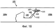
В другом варианте осуществления эффективная высота направленного вверх выровненного края больше, чем эффективная высота направленного вверх шипа. Это обычно приводит к тому, что направленный вниз выравнивающий край панели пола не входит в контакт с другой панелью пола в случае предварительно выровненного положения (промежуточного положения), которое показано, например, на фиг.18. Бесконтактное предварительное выравнивание в селективном положении препятствует или противодействует проталкиванию направленного вниз выравнивающего края панели пола вдоль верхней поверхности другой панели пола, что может повреждать панели пола.In another embodiment, the effective height of the upwardly aligned edge is greater than the effective height of the upwardly spike. This usually leads to the fact that the downward-aligned leveling edge of the floor panel does not come into contact with another floor panel in the case of a pre-aligned position (intermediate position), which is shown, for example, in Fig. 18. Non-contact pre-alignment in a selective position prevents or counteracts pushing the downward-facing leveling edge of the floor panel along the upper surface of another floor panel, which can damage the floor panels.
В одном варианте осуществления угол, образуемый, по меньшей мере, частью стороны направленного вверх шипа, обращенной к направленному вверх торцу, и нормалью верхней стороны внутреннего слоя, по существу равен углу, образуемому, по меньшей мере, частью стороны направленного вниз шипа, обращенной к направленному вниз торцу, и нормалью нижней стороны внутреннего слоя. Таким образом, может быть осуществлено соединение с тугой посадкой двух частей шпунта друг с другом, это обычно увеличивает прочность соединения между двумя панелями пола. В одном варианте осуществления угол, образуемый, с одной стороны, направлением, в котором продолжается, по меньшей мере, часть стороны направленного вверх шипа, обращенной к направленному вверх торцу, и, с другой стороны, нормалью верхней стороны внутреннего слоя, находится в пределах от 0 до 60 градусов, конкретно от 0 до 45 градусов, более конкретно от 0 до 10 градусов. В другом варианте осуществления угол, образуемый, с одной стороны, направлением, в котором продолжается, по меньшей мере, часть стороны направленного вниз шипа, обращенной к направленному вниз торцу, и, с другой стороны, нормалью нижней стороны внутреннего слоя, находится в пределах от 0 до 60 градусов, конкретно от 0 до 45 градусов, более конкретно от 0 до 10 градусов. Возможный угол наклона стороны шипа, обращенной к торцу, обычно также зависит от средств производства, применяемых для изготовления панели пола. В одном варианте осуществления угол наклона направленного вниз выровненного края меньше, чем угол наклона, по меньшей мере, верхней части направленного вверх торца, в результате чего между обеими поверхностями образуется расширительная камера, которая предпочтительна для обеспечения зазора и компенсации расширения, например, вследствие поглощения влаги панелями пола.In one embodiment, the angle formed by at least a portion of the upwardly facing side of the spike facing the upwardly facing end and the normal of the upper side of the inner layer is substantially equal to the angle formed by at least part of the downwardly facing spike facing downward facing, and normal to the lower side of the inner layer. Thus, it can be connected with a tight fit of the two parts of the tongue to each other, this usually increases the strength of the connection between the two floor panels. In one embodiment, the angle formed, on the one hand, by the direction in which at least part of the upward-facing stud extends to the upwardly facing end, and, on the other hand, the normal to the upper side of the inner layer, is in the range from 0 to 60 degrees, specifically from 0 to 45 degrees, more specifically from 0 to 10 degrees. In another embodiment, the angle formed, on the one hand, by the direction in which at least part of the side of the downward tenon extends toward the downward end and, on the other hand, the normal to the lower side of the inner layer, is in the range from 0 to 60 degrees, specifically from 0 to 45 degrees, more specifically from 0 to 10 degrees. The possible angle of inclination of the spike side facing the end face also usually depends on the means of production used to make the floor panel. In one embodiment, the angle of inclination of the downward aligned alignment edge is less than the angle of inclination of at least the upper portion of the upwardly directed end, as a result of which an expansion chamber is formed between both surfaces, which is preferred to provide clearance and expansion compensation, for example due to moisture absorption floor panels.
В одном варианте, по меньшей мере, часть верхней стороны направленного вверх шипа продолжается в направлении к нормали верхней стороны внутреннего слоя. Это приводит к тому, что толщина направленного вверх шипа уменьшается в направлении стороны шипа, обращенной от направленного вверх торца. В результате того, что направленный вниз паз по существу соединяется с верхней стороной направленного вверх шипа, в соединенном положении двух панелей пола в соответствии с изобретением, в котором верхняя сторона направленного вниз паза продолжается в направлении нормали нижней стороны внутреннего слоя, может быть предусмотрена вторая соединительная деталь, которая, с одной стороны, является относительно прочной и твердой, а с другой стороны, обеспечивает достаточную упругость, чтобы обеспечить осуществление соединения с первой соединительной деталью смежной панели пола.In one embodiment, at least a portion of the upper side of the upwardly directed spike extends toward the normal to the upper side of the inner layer. This leads to the fact that the thickness of the upward tenon decreases in the direction of the side of the tenon facing away from the upwardly facing end. As a result of the fact that the downward groove is substantially connected to the upper side of the upward spike, in the connected position of the two floor panels in accordance with the invention, in which the upper side of the downward groove extends in the direction normal to the lower side of the inner layer, a second connecting groove can be provided a part which, on the one hand, is relatively strong and solid, and on the other hand, provides sufficient resilience to allow the connection with the first joint itelnoy part of the adjacent floor panels.
Выравнивающие края, предпочтительно, образованы посредством плоской поверхности с возможностью обеспечения направления другой соединительной детали в процессе соединения панелей пола, который должен осуществляться по возможности преимущественно контролируемым способом. В другом варианте осуществления, по меньшей мере, часть выравнивающего края второй соединительной детали имеет по существу более пологую ориентацию по сравнению с, по меньшей мере, частью направленного вверх торца первой соединительной детали. В результате применения данного средства в соединенном положении обычно образуется воздушный зазор между выравнивающим краем второй соединительной детали и торцом первой соединительной детали. Данный зазор, специально образуемый между двумя соединительными деталями, обычно предпочтителен во время соединения сменных панелей пола, поскольку данный зазор не препятствует временной деформации соединительных деталей, что облегчает соединение соединительных деталей. Кроме того, образуемый зазор предпочтителен с целью компенсации расширения панели пола, например, в результате поглощения влаги, что невозможно себе представить, когда панель пола, по меньшей мере, частично изготовлена из дерева.The alignment edges are preferably formed by means of a flat surface with the possibility of providing direction to the other connecting part in the process of joining the floor panels, which should be carried out in a predominantly controlled manner. In another embodiment, at least a portion of the alignment edge of the second connecting part has a substantially flatter orientation compared to at least a portion of the upwardly facing end of the first connecting part. As a result of using this tool in the connected position, an air gap is usually formed between the alignment edge of the second connecting part and the end face of the first connecting part. This gap, specially formed between the two connecting parts, is usually preferable during the connection of removable floor panels, since this gap does not prevent temporary deformation of the connecting parts, which facilitates the connection of the connecting parts. In addition, the gap formed is preferable in order to compensate for the expansion of the floor panel, for example, as a result of the absorption of moisture, which is impossible to imagine when the floor panel is at least partially made of wood.
В одном варианте осуществления часть направленного вверх торца первой соединительной детали, соединяющаяся с внутренним слоем, образует упорную поверхность для, по меньшей мере, части стороны направленного вниз шипа, обращенной от направленного вниз торца. Таким образом, может быть осуществлена тугая посадка, по меньшей мере, верхней стороны панелей пола, что обычно предпочтительно с точки зрения пользователя. При этом часть направленного вверх торца первой соединительной детали, соединяющейся с внутренним слоем, предпочтительно, ориентирована по существу вертикально. При этом, по меньшей мере, часть стороны направленного вниз шипа, обращенной от направленного вниз торца, также, предпочтительно, ориентирована по существу вертикально. Применение по существу вертикальных упорных поверхностей в обеих соединительных деталях имеет преимущество в том, что в соединенном положении соединительные детали могут соединяться друг с другом относительно туго и прочно.In one embodiment, a portion of the upward-facing end of the first connecting part connecting to the inner layer forms a thrust surface for at least a portion of the downward-facing tenon side facing away from the downwardly facing end. Thus, a tight fit of at least the upper side of the floor panels can be made, which is usually preferred from the point of view of the user. In this case, a part of the upward-facing end of the first connecting part connecting to the inner layer is preferably oriented substantially vertically. At the same time, at least part of the side of the downward-facing spike facing away from the downward-facing end is also preferably oriented substantially vertically. The use of substantially vertical abutment surfaces in both connecting parts has the advantage that in the connected position, the connecting parts can be connected to each other relatively tightly and firmly.
Обычно предпочтительно, направленный вверх паз приспособлен для размещения с прессовой посадкой направленного вниз шипа смежной панели. Размещение направленного вверх паза или, по меньшей мере, его части, с прессовой посадкой в направленном вниз шипе имеет преимущество в том, что направленный вниз шип охвачен посредством относительно тугой посадки направленным вверх пазом, что обычно увеличивает жесткость соединенной конструкции. То же самое относится к варианту осуществления, в котором направленный вниз паз приспособлен для размещения с прессовой посадкой направленного вверх шипа смежной панели.It is usually preferred that the upwardly directed groove is adapted to press fit the downwardly oriented spike of an adjacent panel. Placing the upward groove, or at least a portion thereof, with a press fit in the downward tenon has the advantage that the downward tenon is covered by a relatively tight fit with the upward notch, which typically increases the rigidity of the connected structure. The same applies to an embodiment in which the downwardly directed groove is adapted to press fit the upwardly directed spike of an adjacent panel.
В одном варианте осуществления направленный вверх торец и направленный вниз торец продолжаются в по существу параллельном направлении. Это позволяет соединять торцы, а также блокировочные элементы, относительно плотно друг к другу в соединенном положении, что обычно усиливает фиксирующий эффект, реализуемый блокировочными элементами.In one embodiment, the upwardly facing end and the downwardly facing end extend in a substantially parallel direction. This allows you to connect the ends, as well as the locking elements, relatively tightly to each other in the connected position, which usually enhances the locking effect realized by the locking elements.
В другом варианте осуществления первый блокировочный элемент содержит, по меньшей мере, один внешний выступ, а второй блокировочный элемент содержит, по меньшей мере, одну выемку, которой внешний выступ приспособлен для, по меньшей мере, частичного размещения в выемке смежной соединенной панели пола с целью реализации зафиксированного соединения. Данный вариант осуществления является в общем предпочтительным с точки зрения технологии производства. Первый блокировочный элемент и второй блокировочный элемент, предпочтительно, имеют дополняющую друг друга форму, в результате чего осуществляется соединение посредством совмещения формы блокировочных элементов смежных панелей пола друг с другом, что повышает эффективность фиксации.In another embodiment, the first locking element comprises at least one external protrusion, and the second locking element comprises at least one recess, with which the external protrusion is adapted to at least partially accommodate an adjacent connected floor panel in the recess for the purpose implementing a fixed connection. This embodiment is generally preferred in terms of production technology. The first locking element and the second locking element preferably have a complementary shape, as a result of which the connection is made by combining the shape of the locking elements of adjacent floor panels with each other, which increases the fixing efficiency.
В одном варианте осуществления панели пола в соответствии с изобретением первый блокировочный элемент расположен на расстоянии от верхней стороны направленного вверх шипа. Размещение первого блокировочного элемента на расстоянии от верхней стороны направленного вверх шипа имеет ряд преимуществ. Первое преимущество заключается в том, что такое размещение первого блокировочного элемента способно облегчить соединение между смежными панелями пола, поскольку первый блокировочный элемент будет расположен ниже (нижней части) выравнивающего края направленного вверх шипа, в результате чего соединение между двумя соединительными деталями может осуществляться поэтапно. В процессе соединения стороны шипов, обращенные к соответствующим торцам, будут сначала входить в контакт друг с другом, после чего блокировочные элементы будут зацепляться друг за друга, что обычно требует меньшего максимального поворота (амплитуды), и соответственно деформации второй соединительной детали смежной панели пола, чем в том случае, если бы первый выравнивающий край и первый блокировочный элемент были расположены на более или менее одинаковой высоте. Другое преимущество размещения блокировочного элемента на расстоянии от верхней стороны направленного верх шипа заключается в том, что расстояние для упругого соединения между каждой соединительной деталью и внутренним слоем, обычно образованное упругой перемычкой каждой соединительной детали, увеличено, в результате чего крутящий момент, прикладываемый к соединительным деталям, может быть относительно быстро компенсирован блокировочными элементами, что может дополнительно повысить надежность фиксации.In one embodiment of the floor panel in accordance with the invention, the first locking element is located at a distance from the upper side of the upwardly directed spike. Placing the first blocking element at a distance from the upper side of the upwardly directed spike has several advantages. The first advantage is that this arrangement of the first locking element is able to facilitate the connection between adjacent floor panels, since the first locking element will be located below (the lower part) of the alignment edge of the upward spike, as a result of which the connection between the two connecting parts can be carried out in stages. During the connection, the sides of the spikes facing the respective ends will first come into contact with each other, after which the locking elements will engage with each other, which usually requires less maximum rotation (amplitude), and accordingly deformation of the second connecting part of the adjacent floor panel, than if the first leveling edge and the first locking element were located at more or less the same height. Another advantage of placing the locking element at a distance from the upper side of the spike directed at the top is that the distance for the elastic connection between each connecting part and the inner layer, usually formed by the elastic bridge of each connecting part, is increased, as a result of which the torque applied to the connecting parts , can be relatively quickly compensated by the locking elements, which can further increase the reliability of the fixation.
Можно представить себе первую соединительную деталь, содержащую множество направленных вверх шипов, расположенных на расстоянии друг от друга, причем между каждыми двумя смежными направленными вверх шипами расположен направленный вверх паз, и вторую соединительную деталь, содержащую множество направленных вниз пазов, расположенных на расстоянии друг от друга, предназначенных для размещения вышеупомянутых направленных вверх шипов.One can imagine a first connecting part containing a plurality of upwardly directed spikes spaced apart from each other, with an upwardly extending groove located between each two adjacent upwardly oriented spikes and a second connecting part containing a plurality of downwardly spaced apart spans designed to accommodate the aforementioned upward spikes.
В одном варианте осуществления множество сторон панели пола содержат первую соединительную деталь, и множество сторон панели пола содержат вторую соединительную деталь, причем каждая первая соединительная деталь и каждая вторая соединительная деталь находятся на противоположных сторонах панели пола. Таким образом, каждая сторона панели пола может содержать соединительную деталь, что увеличивает дополнительные возможности для соединения панели пола. Благодаря размещению первой соединительной детали и второй соединительной детали на противоположных сторонах, пользователю будет относительно просто укладывать пол, образованный панелями пола в соответствии с изобретением, поскольку каждая панель пола может быть образована одинаковым способом.In one embodiment, the plurality of sides of the floor panel comprise a first connecting part, and the plurality of sides of the floor panel comprise a second connecting part, with each first connecting part and each second connecting part being on opposite sides of the floor panel. Thus, each side of the floor panel may include a connecting part, which increases the additional possibilities for connecting the floor panel. By arranging the first connecting part and the second connecting part on opposite sides, it will be relatively simple for the user to lay the floor formed by the floor panels in accordance with the invention, since each floor panel can be formed in the same way.
Первая соединительная деталь и вторая соединительная деталь, предпочтительно, образуют неотъемлемую часть внутреннего слоя. С точки зрения конструкции, технологии производства и материально-технического обеспечения данное выполненное за одно целое соединение между внутренним слоем и соединительными деталями является вообще предпочтительным.The first connecting part and the second connecting part, preferably, form an integral part of the inner layer. From the point of view of design, production technology and logistics, this connection made between the inner layer and the connecting parts is generally preferable.
В одном варианте осуществления панель пола изготовлена, по меньшей мере, частично из дерева. Панель пола в данном случае может представлять собой деревянную доску и/или панель паркетного пола. Впрочем, панель пола в соответствии с изобретением также особенно пригодна для применения в виде панели ламинированного пола, в которой панель пола содержит слоистый материал несущего слоя, содержащий деревянное изделие, и, по меньшей мере, один верхний слой, расположенный на верхней стороне несущего слоя. При этом верхний слой обычно имеет упрочненную (износостойкую) и прозрачную форму, и, в частности, пропитан смолой. Несущий слой обычно содержит древесноволокнистую плиту (ДВП), в частности ДВП средней плотности или ДВП высокой плотности. Между верхним слоем и несущим слоем может быть размещен декоративный слой, обычно образованный фотоснимком древесины или облицовочных плиток, напечатанным на бумаге, обычно пропитанной меламиновой смолой. Деревянная или плиточная структура может быть дополнительно вдавлена в верхний слой, в результате чего верхний слой фактически также образует рельефный слой. Верхний слой может быть также изготовлен, по меньшей мере, частично, из пластмассы, металла или текстиля, в частности коврового покрытия. Можно также представить себе панель пола, изготовленную не из дерева, а изготовленную целиком из пластмассы, металла и/или текстиля.In one embodiment, the floor panel is made at least partially of wood. The floor panel in this case may be a wooden board and / or parquet floor panel. However, the floor panel in accordance with the invention is also particularly suitable for use in the form of a laminated floor panel, in which the floor panel contains a laminate of the carrier layer containing the wood product, and at least one upper layer located on the upper side of the carrier layer. In this case, the top layer usually has a hardened (wear-resistant) and transparent shape, and, in particular, is impregnated with resin. The carrier layer typically comprises a fiberboard (MDF), in particular medium density fiberboard or high density fiberboard. Between the top layer and the carrier layer, a decorative layer can be placed, usually formed by a photograph of wood or tiles, printed on paper, usually impregnated with melamine resin. The wood or tile structure can be further pressed into the top layer, as a result of which the top layer actually also forms a relief layer. The top layer may also be made, at least in part, of plastic, metal or textile, in particular carpet. You can also imagine a floor panel made not of wood, but made entirely of plastic, metal and / or textile.
В одном варианте осуществления панель пола изготовлена, по меньшей мере, частично из пластмассы. В этом случае можно представить себе панель пола в соответствии с изобретением, изготовленную по существу целиком из пластмассы.In one embodiment, the floor panel is made at least partially of plastic. In this case, it is possible to imagine a floor panel in accordance with the invention, made essentially entirely of plastic.
Изобретение также относится к покрытию пола, состоящему из взаимно соединенных панелей пола в соответствии с изобретением.The invention also relates to a floor covering consisting of interconnected floor panels in accordance with the invention.
Изобретение также относится к способу взаимного соединения двух панелей пола в соответствии с изобретением, включающему этапы: А) обеспечения контакта второй соединительной детали первой панели пола с первой соединительной деталью второй панели пола; В) приложения усилия ко второй соединительной детали первой панели пола в направлении первой соединительной детали второй панели пола, так что концевая часть второй соединительной детали первой панели пола будет поворачиваться в направлении вверх и/или концевая часть первой соединительной детали второй панели пола будет поворачиваться в направлении вниз, в результате чего направленный вниз шип второй соединительной детали первой панели пола размещается, по меньшей мере, частично, в частности по существу, в направленном вверх пазу первой соединительной детали второй панели пола; и С) снятия усилия, прикладываемого во время этапа В), в результате чего, по меньшей мере, одна деформированная соединительная деталь будет поворачиваться обратно в исходное положение, и направленный вниз шип второй соединительной детали первой панели пола будет зафиксирован в направленном вверх пазу первой соединительной детали второй панели пола. Во время этапа А) достигается промежуточное положение, в котором панели пола предварительно выравниваются относительно друг друга. Во время этапа В) обычно будет происходить по существу линейное перемещение панелей пола относительно друг друга, которое приводит к временной деформации, по меньшей мере, одной из соединительных деталей и последующему осуществлению соединения защелкой между двумя соединительными деталями. В соединенном положении первая соединительная деталь и вторая соединительная деталь уже вообще не будут подвергаться деформации, и первая соединительная деталь и вторая соединительная деталь снова принимают по существу первоначальную (ненапряженную) форму. Предполагается, что данное снятие напряжения в соединенном положении увеличивает долговечность соединительных деталей, и, таким образом, долговечность соединения панелей пола. В одном варианте осуществления во время этапа А) вторая соединительная деталь первой панели пола входит в контакт не только со стороной направленного вверх шипа, обращенной к направленному вверх торцу, но и со стороной направленного вверх шипа, обращенной от направленного вверх торца второй соединительной детали второй панели пола, в результате чего может быть достигнуто относительно устойчивое промежуточное положение (положение предварительного выравнивания). В другом варианте осуществления во время этапа А) выравнивающий край первой соединительной детали первой панели пола расположен на расстоянии от второй соединительной детали второй панели пола, что будет облегчать соединение панелей пола и предотвращать задевание (верхней поверхности) панелей пола друг за друга, которое может нежелательно повреждать панели пола.The invention also relates to a method for interconnecting two floor panels in accordance with the invention, comprising the steps of: A) making the second connecting part of the first floor panel in contact with the first connecting part of the second floor panel; C) applying force to the second connecting part of the first floor panel in the direction of the first connecting part of the second floor panel, so that the end part of the second connecting part of the first floor panel will rotate upward and / or the end part of the first connecting part of the second floor panel will rotate in the direction down, as a result of which the downwardly directed spike of the second connecting part of the first floor panel is positioned at least partially, in particular substantially in the upwardly directed groove of the first oh connecting part of the second floor panel; and C) relieving the force exerted during step B), whereby at least one deformed joint will rotate back to its original position, and the downward spike of the second joint part of the first floor panel will be locked in the upward groove of the first joint details of the second floor panel. During step A), an intermediate position is reached in which the floor panels are pre-aligned with each other. During step B), there will usually be a substantially linear movement of the floor panels relative to each other, which leads to temporary deformation of at least one of the connecting parts and subsequent latching between the two connecting parts. In the connected position, the first connecting part and the second connecting part will no longer be subjected to deformation, and the first connecting part and the second connecting part again take on a substantially original (unstressed) shape. It is assumed that this stress relieving in the connected position increases the durability of the connecting parts, and thus the durability of the connection of the floor panels. In one embodiment, during step A), the second connecting part of the first floor panel comes into contact not only with the side of the upwardly facing tenon facing the upward facing end, but also with the side of the upwardly facing tenon facing away from the upward facing end of the second connecting part of the second panel floor, as a result of which a relatively stable intermediate position (pre-alignment position) can be achieved. In another embodiment, during step A), the alignment edge of the first connecting part of the first floor panel is located at a distance from the second connecting part of the second floor panel, which will facilitate the connection of the floor panels and prevent the floor panels (upper surface) from interfering, which may be undesirable damaging floor panels.
Изобретение будет описано на основе неограничивающих примерных вариантов осуществления, показанных в прилагаемых чертежах, где:The invention will be described based on non-limiting exemplary embodiments shown in the accompanying drawings, where:
Фиг.1 представляет собой вид сбоку панели пола в соответствии с изобретением,Figure 1 is a side view of a floor panel in accordance with the invention,
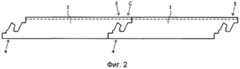
Фиг.2 представляет собой вид сбоку узла соединенных панелей пола в соответствии с фиг.1,Figure 2 is a side view of a unit of connected floor panels in accordance with figure 1,
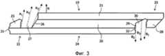
Фиг.3 представляет собой вид сбоку другой панели пола в соответствии с изобретением,Figure 3 is a side view of another floor panel in accordance with the invention,
Фиг.4 представляет собой вид сбоку части узла соединенных панелей пола в соответствии с фиг.3,FIG. 4 is a side view of a portion of a unit of connected floor panels in accordance with FIG. 3,
Фиг.5 представляет собой перспективный вид панели пола в соответствии с фиг.3,FIG. 5 is a perspective view of a floor panel in accordance with FIG. 3,
Фиг.6 представляет собой поперечный вид сбоку другой панели пола в соответствии с изобретением,6 is a transverse side view of another floor panel in accordance with the invention,
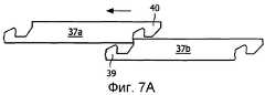
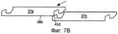
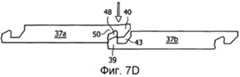
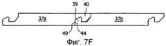
Фиг.7А-7F изображают последовательные этапы способа реализации соединения между двумя панелями пола в соответствии с фиг.6,7A-7F depict successive steps of a method for realizing a connection between two floor panels in accordance with FIG. 6,
Фиг.8 представляет собой перспективный вид панели пола в соответствии с фиг.6 и 7,Fig. 8 is a perspective view of a floor panel in accordance with Figs. 6 and 7,
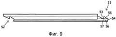
Фиг.9 представляет собой другой поперечный вид сбоку панели пола в соответствии с фиг.6-8,Fig.9 is another transverse side view of the floor panel in accordance with Fig.6-8,
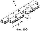
Фиг.10А-10G изображают первый способ укладывания пола, состоящего из панелей пола в соответствии с фиг.6-9,10A-10G depict a first method for laying a floor consisting of floor panels in accordance with FIGS. 6-9,
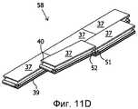
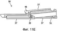
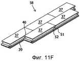
Фиг.11А-11G изображают второй способ укладывания пола, состоящего из панелей пола в соответствии с фиг.6-9,11A-11G depict a second method of laying the floor, consisting of floor panels in accordance with Fig.6-9,
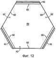
Фиг.12 представляет собой вид сверху другого варианта осуществления панели пола в соответствии с изобретением,12 is a top view of another embodiment of a floor panel in accordance with the invention,
Фиг.13 изображает подробный вид части панели пола в соответствии с фиг.6-11G,Fig.13 depicts a detailed view of part of the floor panel in accordance with Fig.6-11G,
Фиг.14 изображает вид сбоку части узла другого варианта осуществления соединенных панелей пола в соответствии с изобретением,Fig.14 depicts a side view of part of a node of another variant implementation of the connected floor panels in accordance with the invention,
Фиг.15 изображает вид сбоку части узла другого варианта осуществления соединенных панелей пола в соответствии с изобретением,Fig. 15 is a side view of a portion of a node of another embodiment of connected floor panels in accordance with the invention,
Фиг.16 изображает вид сбоку части узла другого варианта осуществления соединенных панелей пола в соответствии с изобретением,Fig.16 depicts a side view of part of a node of another variant implementation of the connected floor panels in accordance with the invention,
Фиг.17 изображает вид сбоку части узла другого варианта осуществления соединенных панелей пола в соответствии с изобретением,FIG. 17 is a side view of a portion of a node of another embodiment of connected floor panels in accordance with the invention,
Фиг.18 изображает вид сбоку части узла другого варианта осуществления соединенных панелей пола в соответствии с изобретением,Fig. 18 is a side view of part of a node of another embodiment of connected floor panels in accordance with the invention,
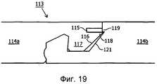
Фиг.19 изображает вид сбоку части узла другого варианта осуществления соединенных панелей пола в соответствии с изобретением,Fig. 19 is a side view of a portion of a node of another embodiment of connected floor panels in accordance with the invention,
Фиг.20 изображает подробный геометрический чертеж промежуточного положения (положения предварительного выравнивания) ориентации двух панелей пола, которое показано на фиг.7С.FIG. 20 is a detailed geometric drawing of an intermediate position (pre-alignment position) of the orientation of two floor panels, which is shown in FIG.
На фиг.1 показан вид сбоку панели 1 пола в соответствии с изобретением. Панель 1 пола содержит пластинчатую внутреннюю часть 2, которая изготовлена из древесно-волокнистой плиты (ДВП), в частности из ДВП средней плотности или ДВП высокой плотности, или древесно-стружечной плиты (ДСП), и на которой расположен верхний слой 3. Противоположные продольные стороны внутреннего слоя 2 содержат первую соединительную деталь 4 и вторую соединительную деталь 5. Часть панели 1 пола, находящаяся между первой соединительной деталью 4 и второй соединительной деталью 5, которая изображена пунктирными линиями, образует центральную часть панели 1 пола. Первая соединительная деталь 4 содержит направленный вверх шип 7, направленный вверх торец 8 и направленный вверх паз 9, образованный между направленным вверх шипом 7 и направленным вверх торцом 8. Вторая соединительная деталь 5 содержит направленный вниз шип 10, направленный вниз торец 11 и направленный вниз паз 12, образованный между направленным вниз шипом 10 и направленным вниз торцом 11. Как показано, направленный вверх шип 7, направленный вверх торец 8 и направленный вверх паз 9 продолжаются в направлении (указанном стрелкой А) нормали центральной части 6 (показанной стрелкой N1) центральной панели 1 пола. То же самое относится к направлению, в котором продолжаются направленный вниз шип 10, направленный вниз торец 11 и направленный вниз паз 12 (см. стрелки В и N2). В данном примерном варианте осуществления угол α, образованный стрелками А и N1, равен углу β, образованному стрелками В и N2, причем данные углы равны 30°. Первая соединительная деталь 4 содержит гребень 13, который в соединенном положении взаимодействует с выемкой 14, расположенной во второй соединительной детали 5 смежной панели 1 пола (см. фиг.2) с целью осуществления фиксации между двумя панелями 1 пола. Кроме того, обе соединительные детали 4, 5 содержат предохранительный выступ 15, 16, приспособленный для размещения в дополняющем принимающем пространстве 17, 18 соединительных деталей 4, 5. Направленный вниз шип 10 содержит расположенный под углом наружный конец 10а, одна сторона которого расположена по существу горизонтально, а другая сторона - по существу вертикально. Таким образом образованы по существу горизонтальная упорная поверхность и по существу вертикальная упорная поверхность, приспособленные для взаимодействия с соответственно выполненным направленным вверх пазом 9, в результате чего осуществляется закрепление(фиксация) соединения между двумя панелями 2 пола (см. фиг.2). Как показано на фиг.2, соединительные детали 4, 5 сцепляются друг с другом посредством совмещения по форме. Соединение может быть осуществлено посредством простого смещения первой соединительной детали 4 панели 1 пола в линейном направлении (указанном стрелкой С) в направлении второй соединительной детали 2 смежной панели 1 пола, в результате чего соединительные детали прочно сцепляются друг с другом. Горизонтальные силы, воздействующие на узел в результате, например, сжатия или расширения панелей 1 пола, или вертикальные силы, воздействующие на узел в результате, например, расширения панелей 1 пола, не будут оказывать неблагоприятного влияния на образованное соединение, поэтому никакого отсоединения панелей 1 пола или образования зазоров между панелями 1 пола не будет происходить.1 shows a side view of a
На фиг.3 показан вид сбоку другой панели 19 пола в соответствии с изобретением. Панель 19 пола содержит пластинчатый внутренний слой 20, который изготовлен из древесно-волокнистой плиты (ДВП), в частности ДВП средней плотности или ДВП высокой плотности, или древесно-стружечной плиты (ДСП), и на котором расположен верхний слой 21. Противоположные продольные стороны внутреннего слоя 20 содержат первую соединительную деталь 22 и вторую соединительную деталь 23, которая выполнена взаимодополняющей относительно первой соединительной детали 22. Часть панели 19 пола, расположенная между первой соединительной деталью 22 и второй соединительной деталью 23, которая изображена пунктирными линиями, представляет собой центральную часть 24 панели 19 пола. Первая соединительная деталь 22 содержит направленный вверх шип 25, направленный вверх торец 26 и направленный вверх паз 27, образованный между направленным вверх шипом 25 и направленным вверх торцом 26. Вторая соединительная деталь 23 содержит направленный вниз шип 28, направленный вниз торец 29 и направленный вниз паз 30, образованный между направленным вниз шипом 28 и направленным вниз торцом 29. Как показано, направленный вверх шип 25, направленный вверх торец 26 и направленный вверх паз 27 продолжаются в направлении (указанном стрелками А1, А2 и А3) нормали центральной части 24 (указанной стрелкой N) панели 19 пола. То же самое относится к направлению, в котором продолжаются направленный вниз шип 28 и направленный вниз паз 30 (см. стрелки В1 и В3). В данном примерном варианте осуществления направленный вниз торец 29 продолжается в направлении, по существу соответствующем нормали центральной части 24 панели 19 пола. Как показано, первая соединительная деталь 22 содержит наружный выступ 31, а вторая соединительная деталь 23 содержит дополняющую выемку 32, предназначенные для обеспечения осуществления фиксации во время соединения панели 19 пола со смежной панелью 19 пола (см. фиг.4). Как показано на фиг.4, направленный вверх паз 27 первой соединительной детали 22 панели 19 пола и направленный вниз шип 28 второй соединительной детали 23 смежной панели 19 пола заключают между собой воздушное пространство 33. На фиг.5 дополнительно показано, что боковые края 34 (концевые поверхности) панели 19 пола содержат направленный вверх профиль 35 и дополняющий направленный вниз профиль 36 для осуществления бокового соединения между двумя панелями 19 пола, размещенными рядом друг с другом на концевых поверхностях 34.Figure 3 shows a side view of another
На фиг.6 показан вид сбоку другой прямоугольной панели 37 пола в соответствии с изобретением. Панель 37 пола содержит внутренний слой 38, содержащий верхнюю сторону 38а и нижнюю сторону 38b, и соединительные детали 39, 40, расположенные на противоположных продольных сторонах внутреннего слоя 38 и выполненные за одно целое с внутренним слоем 38. Первая соединительная деталь 39 содержит направленный вверх шип 41, направленный вверх торец 42 и направленный вверх паз 43, образованный между направленным вверх шипом 41 и направленным вверх торцом 42. Сторона 41а направленного вверх шипа 41, обращенная к направленному вверх торцу 42, продолжается в направлении нормали N1 верхней стороны 38а внутреннего слоя 38. Таким образом, касательная R1 и нормаль N1 верхней стороны 38а внутреннего слоя 38 направлены друг к другу (в сходящейся ориентации), причем угол, образуемый R1 и N1, равен 5˚. Другая сторона 41b направленного вверх шипа 41, обращенная к направленному вверх торцу 42, образует выравнивающий край, обеспечивающий облегченную реализацию соединения со смежной панелью пола. Как показано, данная сторона 41b, выполняющая функцию выравнивающего края, направлена от нормали N1 верхней стороны 38а внутреннего слоя. При этом верхняя сторона 41d направленного вверх шипа 41 продолжается в направлении нормали N1 верхней стороны 38а внутреннего слоя и проходит под углом вниз в направлении стороны 41е направленного вверх шипа 41, обращенной от направленного вверх торца 42. Данное закругление кромок обеспечивает дополнительную возможность придания дополняющей второй соединительной детали 40 более надежной и, следовательно, более прочной формы. Сторона 41е направленного вверх шипа 41, обращенная от направленного вверх торца 42, ориентирована по существу вертикально и, кроме того, содержит наружный выступ 44. Нижняя часть 42а направленного вверх торца 42 ориентирована диагонально, а верхняя часть 42b направленного вверх торца 42, как показано, является по существу вертикальной и образует упорную поверхность для второй соединительной детали 40. В данном примерном варианте осуществления нижняя стенка 43а направленного вверх паза 43 ориентирована по существу горизонтально. Перемычка 45, расположенная между нижней стенкой 43а направленного вверх паза 43 и нижней стороной 39а, обладает некоторой упругостью и приспособлена для обеспечения поворота направленного вверх шипа 41 относительно направленного вверх торца 42, который приводит к (временному) расширению направленного вверх паза 43, тем самым облегчая соединение панели 37 пола со смежной панелью пола (см. фиг.7А-7F). Вторая соединительная деталь 40 является по существу дополняющей по отношению к первой соединительной детали 39. Вторая соединительная деталь 40 содержит направленный вниз шип 46, направленный вниз торец 47 и направленный вниз паз 48, образованный между направленным вниз шипом 46 и направленным вниз торцом 47. Сторона 46а направленного вниз шипа 46, обращенная к направленному вниз торцу 47, расположена в направлении нормали N2 нижней стороны 38b внутреннего слоя 38. Это означает, что касательная R2 стороны 46а направленного вниз шипа 46 и нормаль нижней стороны 38b внутреннего слоя 38 взаимно сходятся. В данном примерном варианте осуществления касательная R2 и нормаль N2 образуют угол, равный 5˚. Сторона 46b, обращенная от направленного вниз торца 47, ориентирована диагонально, однако имеет более пологую ориентацию по сравнению с дополняющей стороной 42а направленного вверх торца 42, в результате чего в соединенном положении (см. также фиг.7F) образуется зазор (воздушное пространство), который будет вообще облегчать соединение между двумя панелями 37 пола. Расположенная под углом сторона 46b направленного вниз шипа 46 также выполняет функцию выравнивающего края, предназначенного для дополнительного облегчения соединения между двумя панелями 37 пола. Другая сторона 46с, обращенная от направленного вниз торца 47, имеет по существу вертикальную форму и образует дополняющую упорную поверхность для упорной поверхности 42b направленного вверх торца 42 (смежной панели пола). Направленный вниз шип 46 дополнительно содержит сторону 46d, которая обращена к направленному вниз торцу 47 и которая выполняет функцию выравнивающего края для первой соединительной детали 39 смежной панели пола. Поскольку верхняя сторона 41d направленного вверх шипа 41 имеет наклонную ориентацию, верхняя сторона 48а направленного вниз паза 48 также имеет наклонную ориентацию, в результате чего (среднее) расстояние между верхней стороной 48а направленного вниз паза 48 и верхней стороной 40а второй соединительной детали 40 достаточно большое, чтобы обеспечить по существу достаточную прочность второй соединительной детали 40. Направленный вниз торец 47 ориентирован по существу вертикально и содержит выемку 49, выполненную с возможностью размещения наружного выступа 44 направленного вверх шипа 41 (смежной панели пола).6 shows a side view of another
Перемычка 50, расположенная между верхней стороной 48а направленного вниз паза 48 и верхней стороной 40а, обладает некоторой упругостью и приспособлена для обеспечения поворота направленного вниз шипа 46 относительно направленного вниз торца 47, который приводит к (временному) расширению направленного вниз паза 48, тем самым облегчая соединение панели 37 пола со смежной панелью пола (см. фиг.7А-7F). Показанная панель 37 пола может представлять собой панель паркетного пола, доску, ламинированную панель пола или пластмассовую панель пола.The
На фиг.7А-7F показаны последовательные этапы способа реализации соединения между двумя панелями 37а, 37b пола в соответствии с фиг.6. На первом (необязательном) этапе, который показан на фиг.7А, вторую соединительную деталь 40 первой панели 37а пола перемещают в направлении первой соединительной детали 39 второй панели 37b пола посредством скольжения первой панели 37а пола по второй панели 37b пола (см. стрелку). Затем, как показано на фиг.7В, вторую соединительную деталь 40 первой панели 37а пола совмещают с первой соединительной деталью 39 второй панели 37b пола посредством перемещения нижней стороны 38b внутреннего слоя 38 первой панели 37а пола вдоль верхней стороны 41d направленного вверх шипа 41 второй панели 37b пола (см. стрелку) до тех пор, пока выравнивающий край 46а направленного вниз шипа 46 первой панели 37а пола не будет опираться на выравнивающий край 41b направленного вверх шипа 41 второй панели 37а пола (фиг.7С). При этом другой выравнивающий край 46b направленного вниз шипа 46 первой панели 37 пола будет также преимущественно входить в контакт с верхней стороной 38а внутреннего слоя 38. Затем посредством оказания усилия вниз на, по меньшей мере, перемычку 50 второй соединительной детали 40 первой панели 37а пола, направленный вниз шип 46 будет поворачиваться в направлении вверх относительно направленного вниз торца 47, при этом направленный вверх шип 41 второй панели 37b пола будет также преимущественно поворачиваться относительно направленного вверх торца 42 второй панели 37b пола (фиг.7D). Во время данной временной деформации соединительных деталей 39, 40 как направленный вниз паз 48 первой панели 37а пола, так и направленный вверх паз 43 второй панели 37b пола будут подвергаться расширению, так что направленный вниз шип 46 первой панели 37а пола может быть размещен, по меньшей мере, частично в направленном вверх пазу 43 второй панели 37b пола, а направленный вверх шип 41 второй панели 37b пола может быть размещен, по меньшей мере, частично в направленном вниз пазу 48 первой панели 37а пола (фиг.7Е). После того как усилие на панели 37а, 37b пола ослабляют, деформация будет по существу закончена, и панели 37а, 37b пола будут взаимно соединены. Дополнительная фиксация осуществляется в данном случае за счет того, что блокировочные элементы 44, 49 обеих панелей 37а, 37b пола взаимодействуют друг с другом в соединенном положении. Отсоединение же панелей 37а, 37b пола может быть осуществлено посредством перемещения свободного внешнего конца, обращенного от второй панели 37b пола, первой панели 37а пола в направлении вверх, после чего панели 37а, 37b пола отцепляются друг от друга. По желанию, перемещение первой панели 37а пола в направлении вверх может быть облегчено посредством использования инструмента, например, такого как клин. Другим способом отсоединения панелей 37а, 37b пола является перемещение панелей 37а, 37b пола вдоль друг друга, в результате чего соединительные детали 39, 40 могут быть удалены друг от друга, что приводит к отсоединению панелей 37а, 37b пола.FIGS. 7A-7F show successive steps of a method for realizing a connection between two
На фиг.8 показан вид в перспективе панели 37 пола в соответствии с фиг.6 и 7, на котором также показано, что первая соединительная деталь 51 и вторая соединительная деталь 52 расположены на противоположных коротких сторонах прямоугольной панели 37 пола. На фиг.9 показан поперечный вид сбоку коротких сторон панели 37 пола. Как показано, первая соединительная деталь 51 по структуре в значительной степени соответствует первой соединительной детали 39, показанной на фиг.6, а вторая соединительная деталь 52 по структуре в значительной степени соответствует второй соединительной детали 40, показанной на фиг.6. Однако первая соединительная деталь 51, показанная на фиг.8, содержит менее глубокий направленный вверх паз 53 по сравнению с направленным вверх пазом 43 длинной стороны панели 37 пола, которая показана на фиг.6. Кроме того, первый блокировочный элемент 54 соединяется с верхней стороной 55 направленного вверх шипа 56 первой соединительной детали 51. К тому же, плоская нижняя сторона 57, образующая направленный вверх паз 43, имеет меньшие размеры по сравнению с данной нижней стороной, которая показана на фиг.6, и направленный вверх шип 56 имеет меньшие размеры по сравнению с направленным вверх шипом 41, который показан на фиг.6. Вторая соединительная деталь 52, показанная на фиг.8, соответствующим образом изменена относительно второй соединительной детали 40, которая показана на фиг.6. Изменение размеров первой соединительной детали 51 и второй соединительной детали 52, расположенных на коротких сторонах, относительно первой соединительной детали 39 и второй соединительной детали 40, расположенных на длинных сторонах, в частности, имеет целью облегчить взаимное соединение панелей 37 пола, как дополнительно показано на фиг.10А-10G (первый способ) и фиг.11А-11G (второй способ).FIG. 8 is a perspective view of the
На фиг.10А-10G показан первый способ укладывания пола 58, состоящего из панелей пола 37 в соответствии с фиг.6-9. Когда панель 37а пола должна быть соединена с уже уложенными панелями 37 пола (фиг.10А), соответствующая панель 37 пола может быть продвинута в поперечном направлении (см. стрелку А) по уже уложенным панелям 37 пола (фиг.10В и 10С), при этом первую соединительную деталь 39 одной или более уже уложенных панелей 37 пола соединяют со второй соединительной деталью 40 панели 37 пола для укладывания. После соединения продольных сторон панелей 37 пола панель 37 пола для укладывания перемещают в продольном направлении (см. стрелку В) (фиг.10D и 10Е), в результате чего короткие стороны панелей пола могут быть соединены друг с другом посредством обеспечения взаимодействия второй соединительной детали 52 панели 37 пола для укладывания с первой соединительной деталью 51 смежной панели 37 пола.On figa-10G shows the first method of laying the
На фиг.11А-11G показан второй способ укладывания пола 58, состоящего из панелей 37 пола в соответствии с фиг.6-9. Когда панель 37а пола должна быть соединена с уже уложенными панелями 37 пола (фиг.11А), угловая точка 37а соответствующей панели 37 пола для укладывания может быть размещена в углу, образованном уже соединенными панелями пола (фиг.11В и 11С и последовательно фиг.11D и 11Е), после чего панель 37 пола для укладывания поворачивают в направлении вниз, в результате чего вторая соединительная деталь 40 панели 37 пола для укладывания будет взаимодействовать (в данном случае) с множеством первых соединительных деталей 39 уже уложенных панелей 37 пола, и таким образом вторая соединительная деталь 52 панели 37 пола для укладывания будет взаимодействовать с первой соединительной деталью 51 смежной панели 37 пола. В соответствии с данным вторым способом длинная сторона и короткая сторона (более или менее) одновременно соединяются друг с другом.On figa-11G shows a second method of laying
На фиг.12 показан вид сверху альтернативной панели 59 пола в соответствии с изобретением. Панель 59 пола содержит шесть равных сторон 60, причем стороны 60 попеременно содержат первую соединительную деталь 61 и вторую соединительную деталь 62. Первая соединительная деталь 61 по структуре аналогична первой соединительной детали 39, которая показана на фиг.6, а вторая соединительная деталь 62 по структуре аналогична второй соединительной детали 40, которая показана на фиг.6. Может быть изготовлен пол с сотовым рисунком посредством соединения шестиугольных панелей 59 пола посредством взаимодействия первых соединительных деталей 61 и вторых соединительных деталей 62 разных панелей 59 пола.12 is a plan view of an
На фиг.13 показан подробный вид части панели 37 пола в соответствии с фиг.6-11G, на котором подробно показана первая соединительная деталь 39. Помимо всех уже описанных конкретных поверхностей, на фиг.13 также показано, что верхняя часть 42b направленного вверх торца 42 является по существу вертикальной и содержит наклонную выступающую соединительную поверхность 63. Преимущество применения выступающей соединительной поверхности 63 заключается в том, что вторая соединительная деталь 40 смежной панели 37 (показанная пунктирными линиями) будет способна плотно прилегать к выступающей соединительной поверхности 63, причем между двумя соединительными деталями 39, 40, прямо под выступающей соединительной поверхностью 63, образуется также воздушный зазор 64. Данный зазор, специально образованный между двумя соединительными деталями 39, 40, обычно предпочтителен для надежного соединения соединительных деталей 39, 40 друг с другом, поскольку неровности в форме панели 37 пола или расширение панели 37 пола могут быть скорректированы воздушным зазором 64. Выше уже было отмечено, что сторона 46b, обращенная от направленного вниз торца, имеет более пологую ориентацию, чем дополняющая сторона 42а направленного вверх торца 42, в результате чего в соединенном положении образуется также дополнительный воздушный зазор 65, который будет вообще дополнительно облегчать соединение между двумя панелями 37 пола.On Fig shows a detailed view of a part of the
На фиг.14 показан вид сбоку части узла 51 другого варианта осуществления панелей 52а, 52b пола в соответствии с изобретением. С конструктивной точки зрения показанная панель 52, 52b пола в значительной степени подобна панели 37 пола, которая показана на фиг.6, при этом панели пола взаимно соединены посредством трех блокировочных механизмов. Первый блокировочный механизм также предусмотрен в панели 37 пола, которая показана на фиг.6, и основан на взаимодействии между наружным выступом 53, расположенным на наружной поверхности 54 направленного вверх шипа 55 правой панели 52b пола, и выемкой 56, расположенной на направленном вниз торце 57 левой панели 52а пола. Второй блокировочный механизм, который также предусмотрен в панели 37 пола, показанной на фиг.6, образован посредством сцепления наклонной поверхности 58 направленного вниз шипа 59 левой панели 52а пола с наклонной поверхностью 60 направленного вверх шипа 55, которое приводит к фиксации направленного вниз шипа 59 левой панели 52а пола в направленном вверх пазу 61 правой панели 52b пола. Третий блокировочный механизм образован посредством применения дополнительного наружного выступа 62, расположенного на наружной поверхности 63 направленного вниз шипа 59, и который, более конкретно, расположен между выравнивающим краем 64 и вертикальным верхним концом 65 наружной поверхности 63 направленного вниз шипа 59, левой панели 52а пола. Упомянутый дополнительный выступ 55 взаимодействует и соединяется защелкой с дополняющей выемкой 66, выполненной на направленном вверх торце 67 правой панели 52b пола. Между направленным вниз шипом 59 и направленным вверх торцом 67 предусмотрена расширительная камера 68, для того чтобы обеспечить компенсацию люфта в случае расширения панелей 52, 52b пола, например, вследствие поглощения влаги.FIG. 14 is a side view of part of a
На фиг.15 показан вид сбоку части узла 69 другого варианта осуществления панелей 70а, 70b пола в соответствии с изобретением, содержащего три блокировочных механизма. Первый блокировочный механизм основан на взаимодействии между наружным выступом 71, расположенным на наружной поверхности 72 направленного вверх шипа 73 правой панели 70b пола, и выемкой 74, расположенной в направленном вниз торце 75 левой панели 70а пола. Второй блокировочный механизм образован посредством сцепления наклонной поверхности 76 направленного вниз шипа 77 левой панели 70а пола с наклонной поверхностью 78 направленного вверх шипа 73, которое приводит к фиксации направленного вниз шипа 78 левой панели 70а пола в направленном вверх пазу 79 правой панели 70b пола. Третий блокировочный механизм образован посредством применения дополнительного наружного выступа 80, расположенного на наружной поверхности 81 направленного вниз шипа 77, и который, более конкретно, расположен между выравнивающим краем 82 и вертикальным верхним концом 83 наружной поверхности 81 направленного вниз шипа 77, левой панели 70а пола, причем между выступом 80 и вертикальным верхним концом 83 предусмотрен плавный переход. Упомянутый дополнительный выступ 80 взаимодействует и соединяется защелкой с дополняющей выемкой 84, выполненной на направленном вверх торце 85 правой панели 70b пола. Между направленным вниз шипом 77 и направленным вверх торцом 85 предусмотрена расширительная камера 86, для того чтобы обеспечить компенсацию люфта в случае расширения панелей 70, 70b пола, например, вследствие поглощения влаги.On Fig shows a side view of part of a
На фиг.16 показан вид сбоку части узла 87 другого варианта осуществления панелей 88а, 88b пола в соответствии с изобретением, содержащего три блокировочных механизма. Первый и второй блокировочные механизмы аналогичны первому и второму блокировочным механизмам, которые показаны на фиг.6, 14 и 15. Третий блокировочный механизм основан на применении наружного выступа 89, расположенного на наружной поверхности 90 направленного вниз шипа 91 левой панели 88а пола, который взаимодействует с дополняющей выемкой 92 направленного вверх торца 93 правой панели 88b пола. Выступ 89 выполнен с возможностью небольшой деформации относительно основной части направленного вниз шипа 91 благодаря наличию по существу вертикальной прорези 94, расположенной рядом с выступом 89, выполненной в выравнивающем крае 95 направленного вниз шипа 91. Данная гибкость облегчает заскакивание выступа 89 в выемку 92 и, таким образом, осуществление соединения между панелями 88а, 88b пола.On Fig shows a side view of part of a
На фиг.17 показан вид сбоку части узла 96 другого варианта осуществления панелей 97а, 97b пола в соответствии с изобретением, содержащего три блокировочных механизма. Первый и второй блокировочные механизмы аналогичны первому и второму блокировочным механизмам, показанным на фиг.6, 14-16. Третий блокировочный механизм также основан на применении наружного выступа 98, расположенного на наружной поверхности 99 направленного вниз шипа 100 левой панели пола, который взаимодействует с дополняющей выемкой 101 направленного вверх торца 102 правой панели 97b пола. Выступ 98 выполнен с возможностью небольшой деформации относительно основной части направленного вниз шипа 100 благодаря наличию по существу вертикальной прорези 103, выполненной на горизонтальной нижней поверхности 104 направленного вниз шипа 100. Данная гибкость облегчает заскакивание выступа 98 в выемку 101 и таким образом осуществление соединения между панелями 97а, 97b пола.On Fig shows a side view of part of a
На фиг.18 показан вид сбоку части узла 105 другого варианта осуществления панелей 106а, 106b пола в соответствии с изобретением, содержащего три блокировочных механизма. Первый и второй блокировочные механизмы аналогичны первому и второму блокировочным механизмам, которые показаны на предыдущих чертежах. Третий блокировочный механизм основан на применении прорези 107, расположенной на наружной поверхности 108 направленного вниз шипа 109 левой панели 106а пола, которая взаимодействует с горизонтально перемещаемым пружинным штифтом 110, содержащимся в расположенной напротив выемке 111 направленного вверх торца 112 правой панели 106а пола. Наружный конец пружинного штифта 110 имеет форму конуса, чтобы облегчить соединение обеих панелей 106а, 106b пола.On Fig shows a side view of part of a
На фиг.19 показан вид сбоку части узла 113 другого варианта осуществления панелей 114а, 114b пола в соответствии с изобретением, содержащего три блокировочных механизма. Первый и второй блокировочные механизмы аналогичны первому и второму блокировочным механизмам, которые показаны на предыдущих чертежах. Третий блокировочный механизм основан на применении горизонтальной прорези 115, расположенной на наружной поверхности 116 направленного вниз шипа 117 левой панели 114а пола, причем упомянутая прорезь 115 ограничена выступающим фиксирующим краем 118, который взаимодействует с дополняющим противоположным краем 119, образующим часть направленного вверх торца 120 правой панели 114b пола.FIG. 19 is a side view of part of a
На фиг.20 показана деталь панелей 37а, 37b пола в соответствии с фиг.7С, которая рассматривается как промежуточное положение, в котором осуществляется предварительное выравнивание панелей 37а-37b пола. Ссылочные позиции на фиг.18 определяются следующим образом:FIG. 20 shows a detail of the
а: точка контакта между панелью 37а пола и панелью 37b пола, в которой панели 37а и 37b пола не деформированы;a: the point of contact between the
b: точка контакта между панелью 37а пола и панелью 37b пола, в которой направленный вверх шип 41 подвергается деформации, чтобы позволить направленному вниз шипу 46 войти в направленный вверх паз 43;b: the point of contact between the
с: точка на наклонной стороне g панели 37а пола, которая совмещается с плоскостью верхней поверхности панели 37b пола;c: a point on the inclined side g of the
d: верхний угол d панели 37b пола;d: upper corner d of the
е: самая верхняя точка в своде направленного вниз паза 48;e: the highest point in the arch of the
f: расположенная под углом сторона направленного вниз шипа 46, обращенная к направленному вниз пазу 48;f: angled side of the
g: расположенная под углом сторона направленного вниз шипа 46, обращенная от направленного вниз паза 48;g: angled side of the downward-facing
w1: реальная ширина w1 направленного вниз шипа 46 определяется расстоянием между линией l1, проходящей через точку а панели 37b пола в направлении, перпендикулярном верхней поверхности панели 37b пола, и линией l2, проходящей через точку с панели 37а пола в направлении, перпендикулярном верхней поверхности панели пола 37b в направлении, параллельном угловому внешнему концу 120 направленного вниз шипа 46;w1 : the actual width w1 of the downward spike 46 is determined by the distance between the line l1 passing through a point a of the
w2: эффективная ширина w2 направленного вниз шипа 46 определяется кратчайшим расстоянием между линией l1 и линией l2 в направлении, параллельном верхней поверхности панели 37b пола;w2 : the effective width w2 of the downward spike 46 is determined by the shortest distance between line l1 and line l2 in a direction parallel to the upper surface of
w3: ширина w3 направленного вверх паза 43 определяется кратчайшим расстоянием между линией l1 и линией l3, проходящей через угол d панели 37b пола в направлении, перпендикулярном верхней поверхности панели 37b пола;w3 : the width w3 of the
w4: ширина w4 направленного вниз шипа 46 определяется кратчайшим расстоянием между линией l4, проходящей через точку b панели 37b пола в направлении, перпендикулярном верхней поверхности панели 37b пола, и линией l3;w4 : the width w4 of the downward spike 46 is determined by the shortest distance between the line l4 passing through the point b of the
h1: реальная высота направленного вниз шипа 46, которая определяется кратчайшим расстоянием между угловым внешним концом 120 направленного вниз шипа 46 и линией, проходящей через точку с параллельно угловому внешнему концу 120 направленного вниз шипа 46;h1 : the actual height of the
h2: эффективная высота направленного вниз паза 48, которая определяется кратчайшим расстоянием между линией l5, проходящей через точку а панели 37b пола в направлении, параллельном верхней поверхности панели 37b пола, и линией l6, проходящей через точку е в своде направленного вниз паза 48 в направлении, параллельном линии l5;h2 : effective height of the
δ: угол между линией, проходящей через точку с панели 37а пола в направлении, параллельном угловому внешнему концу 121 направленного вниз шипа 46, и линией, проходящей через точку с панели 37а пола в направлении, параллельном верхней поверхности панели 37b пола; иδ: angle between a line passing through a point from the
φ: угол между линией l1 и торцом f панели 37а пола.φ: angle between line l1 and end face f of
Панели 37а, 37b пола, которые показаны в данной взаимной ориентации, являются недеформированными. Между верхним углом d панели 37b пола и точкой с панели 37а пола имеется небольшое пространство, для того чтобы не повредить угол d усилием, оказываемым на панель 37а пола. Панели 37а и 37b пола могут быть соединены, как описано со ссылкой на фиг.7. Во время соединения вторая соединительная деталь 40 будет деформироваться. Точка контакта между панелями 37а и 37b пола в данном случае будет перемещаться из точки а в точку b, при этом будет обеспечена возможность вставки направленного вниз шипа 46 в направленный вверх паз 43 панели 37b пола.The
Для того чтобы обеспечить эффективное соединение панелей 37а и 37b пола, необходимо обеспечить следующие соотношения между размерами панелей 37а, 37b пола:In order to ensure effective connection of the
w2<w3w2 <w3
w2≤w4w2 ≤w4
w3>w4w3 > w4
w2≈w1∗cos δw2 ≈w1 ∗ cos δ
h1≈h2∗cos φh1 ≈h2 ∗ cos φ
δ<φδ <φ
w2<w3∗cos δw2 <w3 ∗ cos δ
Очевидно, что изобретение не ограничено примерными вариантами осуществления, показанными и описанными в данном документе, и что в пределах объема прилагаемой формулы изобретения возможно множество вариантов, которые будут очевидны для специалиста в данной области техники.Obviously, the invention is not limited to the exemplary embodiments shown and described herein, and that many variations are possible within the scope of the appended claims that will be apparent to those skilled in the art.
Claims (42)
Translated fromRussian- расположенный по центру внутренний слой, содержащий верхнюю сторону и нижнюю сторону,
- по меньшей мере, одну первую упругую соединительную деталь и вторую упругую соединительную деталь, соединенные соответственно с противоположными краями внутреннего слоя,
○ причем первая соединительная деталь содержит один направленный вверх шип, по меньшей мере, один направленный вверх торец, расположенный на расстоянии от направленного вверх шипа, и один направленный вверх паз, образованный между направленным вверх шипом и направленным вверх торцом, причем:
◦ по меньшей мере, часть стороны направленного вверх шипа, обращенной к направленному вверх торцу, продолжается в направлении нормали верхней стороны внутреннего слоя,
◦ по меньшей мере, часть стороны направленного вверх шипа, обращенной к направленному вверх торцу, образует направленный вверх выравнивающий край, предназначенный для соединения первой соединительной детали со второй соединительной деталью смежной панели пола,
◦ по меньшей мере, часть стороны направленного вверх шипа, обращенной от направленного вверх торца, содержит первый блокировочный элемент, соединенный по существу жестко с направленным вверх шипом и выполненный с возможностью взаимодействия со вторым блокировочным элементом второй соединительной детали смежной панели пола,
○ причем вторая соединительная деталь содержит один направленный вниз шип, по меньшей мере, один направленный вниз торец, расположенный на расстоянии от направленного вниз шипа, и один направленный вниз паз, образованный между направленным вниз шипом и направленным вниз торцом, причем:
◦ по меньшей мере, часть стороны направленного вниз шипа, обращенной к направленному вниз торцу, продолжается в направлении нормали нижней стороны внутреннего слоя,
◦ по меньшей мере, часть стороны направленного вниз шипа, обращенной от направленного вниз торца, образует направленный вниз выравнивающий край, предназначенный для соединения второй соединительной детали с первой соединительной деталью смежной панели пола,
◦ направленный вниз торец содержит второй блокировочный элемент, соединенный по существу жестко с направленным вниз торцом и выполненный с возможностью взаимодействия с первым блокировочным элементом первой соединительной детали смежной панели пола,
причем направленный вверх паз выполнен с возможностью размещения, по меньшей мере, части направленного вниз шипа смежной панели, причем направленный вниз паз выполнен с возможностью размещения, по меньшей мере, части направленного вверх шипа смежной панели.1. A floor panel comprising:
a centrally located inner layer comprising an upper side and a lower side,
at least one first elastic connecting part and a second elastic connecting part, respectively connected to opposite edges of the inner layer,
○ wherein the first connecting part comprises one upward tenon, at least one upward facing end located at a distance from the upward tenon, and one upward groove formed between the upward tenon and the upward end, wherein:
◦ at least a portion of the side of the upwardly facing spike facing the upwardly facing end continues in the normal direction of the upper side of the inner layer,
◦ at least part of the side of the upward-facing spike facing the upward-facing end forms an upwardly aligned alignment edge for connecting the first connecting part to the second connecting part of an adjacent floor panel,
◦ at least a portion of the side of the upwardly facing tenon facing away from the upwardly facing end comprises a first locking member connected substantially rigidly to the upward facing tenon and configured to interact with a second locking member of a second connecting part of an adjacent floor panel,
○ wherein the second connecting part comprises one downward tenon, at least one downward end located at a distance from the downward tenon, and one downward groove formed between the downward tenon and the downward end, wherein:
◦ at least a portion of the side of the downward-facing spike facing the downward-facing end extends toward the normal direction of the lower side of the inner layer
◦ at least a portion of the downward-facing tenon side facing away from the downwardly facing end face forms a downwardly aligned alignment edge for connecting the second connecting part to the first connecting part of an adjacent floor panel,
◦ the downward facing end includes a second locking element connected substantially rigidly to the downward facing end and configured to interact with the first locking element of the first connecting part of an adjacent floor panel,
wherein the upwardly directed groove is configured to accommodate at least a portion of the downwardly disposed spike of an adjacent panel, the downwardly directed groove is configured to accommodate at least a portion of the upwardly directed spike of an adjacent panel.
А) приводят вторую соединительную деталь первой панели пола в контакт с первой соединительной деталью второй панели пола;
В) прикладывают усилие ко второй соединительной детали первой панели пола в направлении первой соединительной детали второй панели пола, так что концевая часть второй соединительной детали первой панели пола будет поворачиваться в направлении вверх и/или концевая часть первой соединительной детали второй панели пола будет поворачиваться в направлении вниз, в результате чего направленный вниз шип второй соединительной детали первой панели пола размещается, по меньшей мере, частично, в частности, по существу, в направленном вверх пазу первой соединительной детали второй панели пола, и
С) снимают усилие, прикладываемое во время этапа В), в результате чего, по меньшей мере, одна деформированная соединительная деталь будет поворачиваться обратно в исходное положение, и направленный вниз шип второй соединительной детали первой панели пола будет зафиксирован в направленном вверх пазу первой соединительной детали второй панели пола, при этом второй блокировочный элемент, соединенный по существу жестко с направленным вниз торцом, будет взаимодействовать с первым блокировочным элементом, расположенным на стороне направленного вверх шипа, обращенной от направленного вверх торца, и соединенным по существу жестко с направленным вверх шипом второй панели пола.40. A method for interconnecting two floor panels according to any one of claims 1 to 38, comprising the steps of:
A) bring the second connecting part of the first floor panel into contact with the first connecting part of the second floor panel;
B) apply force to the second connecting part of the first floor panel in the direction of the first connecting part of the second floor panel, so that the end part of the second connecting part of the first floor panel will rotate upward and / or the end part of the first connecting part of the second floor panel will rotate in the direction downward, as a result of which the downwardly directed spike of the second connecting part of the first floor panel is positioned at least partially, in particular substantially in the upwardly directed groove rvoy connecting part of the second floor panel, and
C) the force applied during step B) is removed, as a result of which at least one deformed connecting part will turn back to its original position, and the downward spike of the second connecting part of the first floor panel will be fixed in the upward groove of the first connecting part the second floor panel, while the second locking element connected essentially rigidly with the downward facing end will interact with the first locking element located on the side directed th upward spike facing away from the end face upward, and connected substantially rigidly to an upwardly directed spike second floor panels.
Applications Claiming Priority (5)
| Application Number | Priority Date | Filing Date | Title |
|---|---|---|---|
| NL2003019ANL2003019C2 (en) | 2009-06-12 | 2009-06-12 | FLOOR PANEL AND FLOOR COVERAGE CONSISING OF MULTIPLE OF SUCH FLOOR PANELS. |
| NL2003019 | 2009-06-12 | ||
| NLPCT/NL2009/050540 | 2009-09-09 | ||
| PCT/NL2009/050540WO2010143943A1 (en) | 2009-06-12 | 2009-09-09 | Floor panel and floor covering consisting of a plurality of such floor panels |
| PCT/NL2010/050365WO2010143962A2 (en) | 2009-06-12 | 2010-06-14 | Floor panel and floor covering consisting of a plurality of such floor panels |
Publications (2)
| Publication Number | Publication Date |
|---|---|
| RU2012100772A RU2012100772A (en) | 2013-07-20 |
| RU2537423C2true RU2537423C2 (en) | 2015-01-10 |
Family
ID=41327542
Family Applications (1)
| Application Number | Title | Priority Date | Filing Date |
|---|---|---|---|
| RU2012100772/03ARU2537423C2 (en) | 2009-06-12 | 2010-06-14 | Floor panel and floor covering consisting of many such panels |
Country Status (20)
| Country | Link |
|---|---|
| US (11) | US8745952B2 (en) |
| EP (8) | EP3231959B1 (en) |
| CN (2) | CN104831899B (en) |
| CA (5) | CA2965644C (en) |
| CY (6) | CY1115579T1 (en) |
| DE (1) | DE202010018229U1 (en) |
| DK (6) | DK3176345T3 (en) |
| ES (8) | ES2713748T3 (en) |
| HR (6) | HRP20140566T1 (en) |
| HU (5) | HUE029427T2 (en) |
| LT (4) | LT3176345T (en) |
| NL (1) | NL2003019C2 (en) |
| NO (1) | NO3070228T3 (en) |
| PL (8) | PL3070228T3 (en) |
| PT (6) | PT3070228T (en) |
| RU (1) | RU2537423C2 (en) |
| SI (6) | SI3070228T1 (en) |
| SM (1) | SMT202000654T1 (en) |
| TR (3) | TR201902376T4 (en) |
| WO (2) | WO2010143943A1 (en) |
Families Citing this family (100)
| Publication number | Priority date | Publication date | Assignee | Title |
|---|---|---|---|---|
| NL2003019C2 (en)* | 2009-06-12 | 2010-12-15 | 4Sight Innovation Bv | FLOOR PANEL AND FLOOR COVERAGE CONSISING OF MULTIPLE OF SUCH FLOOR PANELS. |
| PL2473687T3 (en) | 2009-09-04 | 2019-10-31 | Vaelinge Innovation Ab | A method of assembling resilient floorboards which are provided with a mechanical locking system |
| US11725395B2 (en) | 2009-09-04 | 2023-08-15 | Välinge Innovation AB | Resilient floor |
| US8365499B2 (en) | 2009-09-04 | 2013-02-05 | Valinge Innovation Ab | Resilient floor |
| PL4092213T3 (en) | 2010-01-11 | 2024-03-25 | Välinge Innovation AB | Floor covering with interlocking design |
| CN102619323A (en)* | 2011-01-27 | 2012-08-01 | 张国平 | Plastic material barb type lock floor |
| CN102155083B (en)* | 2011-01-29 | 2014-07-23 | 刘谦益 | Floor connection structure |
| JP6254519B2 (en)* | 2011-03-18 | 2017-12-27 | イノテック インターナショナル プロプライエタリー リミテッド | Vertical joining system and related surface coating system |
| US8806832B2 (en) | 2011-03-18 | 2014-08-19 | Inotec Global Limited | Vertical joint system and associated surface covering system |
| UA109938C2 (en) | 2011-05-06 | 2015-10-26 | MECHANICAL LOCKING SYSTEM FOR CONSTRUCTION PANELS | |
| CN102493625B (en)* | 2011-12-21 | 2014-12-10 | 张家铭 | Locking type plate connector and its plate |
| BE1022209B1 (en)* | 2012-01-12 | 2016-03-01 | I.V.C. N.V. | FLOOR PANEL |
| EP2812510B1 (en) | 2012-02-07 | 2018-03-07 | Flooring Industries Limited, SARL | Floor panel for forming a floor covering, floor covering formed from such floor panels and method for manufacturing such floor panels |
| US10760283B2 (en) | 2012-02-23 | 2020-09-01 | Admiral Composite Technologies, Inc. | Deck system and components |
| US9394698B2 (en)* | 2012-02-23 | 2016-07-19 | Admiral Composite Technologies, Inc. | Deck system and components |
| US9353533B2 (en) | 2012-02-23 | 2016-05-31 | Admiral Composite Technologies, Inc. | Deck system components |
| US9216541B2 (en) | 2012-04-04 | 2015-12-22 | Valinge Innovation Ab | Method for producing a mechanical locking system for building panels |
| US9803381B1 (en)* | 2013-03-07 | 2017-10-31 | Homecare Products, Inc. | Ramp and/or platform assembly |
| EA201992325A1 (en) | 2013-03-25 | 2020-05-31 | Велинге Инновейшн Аб | FLOOR PANELS EQUIPPED WITH MECHANICAL FIXING SYSTEM AND METHOD FOR PRODUCING SUCH FIXING SYSTEM |
| CN109854597B (en) | 2013-09-16 | 2021-03-19 | 瓦林格创新股份有限公司 | Combination product and method for assembling the same |
| US9726210B2 (en) | 2013-09-16 | 2017-08-08 | Valinge Innovation Ab | Assembled product and a method of assembling the product |
| CA2861259C (en)* | 2013-11-01 | 2016-06-14 | Groupe Isolofoam Inc. | Rigid insulating panel and rigid insulation panel assembly |
| WO2015070890A1 (en)* | 2013-11-12 | 2015-05-21 | Grigorij Wagner | Flooring component |
| MX376334B (en)* | 2014-01-10 | 2025-03-07 | Vaelinge Innovation Ab | FURNITURE BOARD. |
| US9714672B2 (en) | 2014-01-10 | 2017-07-25 | Valinge Innovation Ab | Panels comprising a mechanical locking device and an assembled product comprising the panels |
| WO2015130169A1 (en) | 2014-02-26 | 2015-09-03 | Innovations 4 Flooring Holding N.V. | Panel interconnectable with similar panels for forming a covering |
| USD928988S1 (en) | 2014-02-26 | 2021-08-24 | I4F Licensing Nv | Panel interconnectable with similar panels for forming a covering |
| EP3851684A1 (en) | 2014-05-09 | 2021-07-21 | Välinge Innovation AB | Mechanical locking system for building panels |
| FR3024990B1 (en) | 2014-08-25 | 2018-11-16 | Gerflor | FLOOR PANEL FOR REALIZING A COATING. |
| US9752328B2 (en)* | 2014-08-27 | 2017-09-05 | James Hardie Technology Limited | Cladding element |
| EP3186459B1 (en) | 2014-08-29 | 2019-06-26 | Välinge Innovation AB | Vertical joint system for a surface covering panel |
| WO2016046800A1 (en) | 2014-09-26 | 2016-03-31 | Flooring Industries Limited, Sarl | Floor panel for forming a floor covering and method for manufacturing a floor panel. |
| NO3031998T3 (en)* | 2014-12-08 | 2018-02-24 | ||
| ES2758673T3 (en) | 2014-12-19 | 2020-05-06 | Vaelinge Innovation Ab | Panels comprising a mechanical locking device |
| BR112017012681B1 (en) | 2014-12-22 | 2022-05-03 | Ceraloc Innovation Ab | Set of essentially identical floor panels |
| ES2826556T3 (en)* | 2015-01-15 | 2021-05-18 | Flooring Ind Ltd Sarl | Floor panel to form a floor covering |
| US12071770B2 (en) | 2015-01-16 | 2024-08-27 | Unilin Bv | Floor panel for forming a floor covering |
| WO2016114712A1 (en) | 2015-01-16 | 2016-07-21 | Ceraloc Innovation Ab | Mechanical locking system for floor panels |
| BE1022985B1 (en)* | 2015-01-16 | 2016-10-27 | Flooring Industries Limited Sarl | Floor panel for forming a floor covering |
| EP3285620A4 (en) | 2015-04-21 | 2018-11-14 | Välinge Innovation AB | Panel with a slider |
| KR20170141223A (en) | 2015-04-30 | 2017-12-22 | 뵈린게 이노베이션 에이비이 | A panel having a fastening device |
| UA125554C2 (en) | 2015-09-22 | 2022-04-20 | Велінге Інновейшн Аб | Panels comprising a mechanical locking device and an assembled product comprising the panels |
| MX2018006522A (en) | 2015-12-03 | 2018-11-29 | Vaelinge Innovation Ab | Panels comprising a mechanical locking device and an assembled product comprising the panels. |
| CA3008157C (en) | 2015-12-17 | 2023-08-22 | Valinge Innovation Ab | A method for producing a mechanical locking system for panels |
| MX2018007995A (en)* | 2015-12-31 | 2019-01-10 | Flooring Ind Ltd Sarl | Floor panel for forming a floor covering. |
| BE1023779B1 (en) | 2015-12-31 | 2017-07-24 | Flooring Industries Limited Sarl | FLOOR PANEL FOR FORMING A FLOOR COVERING |
| BE1023818B1 (en) | 2016-01-15 | 2017-08-01 | Flooring Industries Limited Sarl | Floor panel for forming a floor covering |
| EP3407765B1 (en) | 2016-01-26 | 2021-03-03 | Välinge Innovation AB | Panels comprising a mechanical locking device to obtain a furniture product |
| KR20180109957A (en) | 2016-02-04 | 2018-10-08 | 뵈린게 이노베이션 에이비이 | Set of panels for assembled products |
| CA3011703A1 (en) | 2016-02-09 | 2017-08-17 | Valinge Innovation Ab | Element and method for providing dismantling groove |
| US10415613B2 (en) | 2016-02-09 | 2019-09-17 | Valinge Innovation Ab | Set of panel-shaped elements for a composed element |
| JP6921834B2 (en) | 2016-02-15 | 2021-08-18 | ベーリンゲ、イノベイション、アクチボラグVaelinge Innovation Ab | How to form panels for furniture products |
| AU2017335148B2 (en) | 2016-09-30 | 2023-04-20 | Välinge Innovation AB | Set of panels assembled by vertical displacement and locked together in the vertical and horizontal direction |
| CN117703894A (en) | 2016-10-27 | 2024-03-15 | 瓦林格创新股份有限公司 | Panel assembly with mechanical locking means |
| CN113356508A (en) | 2017-03-21 | 2021-09-07 | 地板工业有限公司 | Panel panel |
| US11015351B2 (en)* | 2017-03-21 | 2021-05-25 | Flooring Industries Limited, Sarl | Floor panel for forming a floor covering |
| NL2018781B1 (en)* | 2017-04-26 | 2018-11-05 | Innovations4Flooring Holding N V | Panel and covering |
| HRP20230089T1 (en) | 2017-05-15 | 2023-03-17 | Välinge Innovation AB | Elements and a locking device for an assembled product |
| NL2018970B1 (en)* | 2017-05-23 | 2018-12-04 | Innovations 4 Flooring Holding Nv | Multi-purpose tile system |
| UA125235C2 (en)* | 2017-07-18 | 2022-02-02 | Зайло Текнолоджіз Аґ | PANELS WITH REMOVABLE EMBROIDERED EDGE FOR WALL, CEILING OR FLOOR COVERINGS |
| EP3701104B1 (en)* | 2017-10-26 | 2023-03-01 | Flooring Industries Limited, SARL | Plurality of floor panels and floor panels used hereby |
| CN111465773B (en) | 2017-12-22 | 2021-11-02 | 瓦林格创新股份有限公司 | Panel set, method for assembling the panel set and locking device for furniture products |
| RU2740868C1 (en) | 2017-12-22 | 2021-01-21 | Велинге Инновейшн Аб | Set of panels, method of their assembling and locking device for furniture product |
| AU2018400651B2 (en) | 2018-01-09 | 2024-06-13 | Välinge Innovation AB | Set of panels |
| NL2020256B1 (en)* | 2018-01-09 | 2019-07-15 | Innovations4Flooring Holding N V | Panel |
| EP4324999A3 (en) | 2018-01-11 | 2024-05-15 | Unilin, BV | Set of floor panels and method for installing this set of floor panels |
| MY204146A (en) | 2018-03-23 | 2024-08-09 | Vlinge Innovation Ab | Panels comprising a mechanical locking device and an assembled product comprising the panels |
| EP3543427A1 (en) | 2018-03-23 | 2019-09-25 | Franz Eschlbeck | Panel, second panel, panel connection and method of manufacturing the panel connection |
| DE202018101660U1 (en) | 2018-03-23 | 2018-04-23 | Franz Eschlbeck | Panel, second panel and panel connection |
| US10590659B2 (en) | 2018-04-05 | 2020-03-17 | 888804 Ontario Limited | Pre-finished insulated panel system for cladding a building |
| PL3781822T3 (en) | 2018-04-18 | 2024-11-18 | Välinge Innovation AB | Set of panels with a mechanical locking device |
| US11448252B2 (en) | 2018-04-18 | 2022-09-20 | Valinge Innovation Ab | Set of panels with a mechanical locking device |
| EA202092409A1 (en) | 2018-04-18 | 2021-02-26 | Велинге Инновейшн Аб | SYMMETRIC TONGUE AND T-SHAPED KNOT |
| PL3781824T3 (en) | 2018-04-18 | 2024-06-24 | Välinge Innovation AB | Set of panels with a mechanical locking device |
| US11614114B2 (en) | 2018-04-19 | 2023-03-28 | Valinge Innovation Ab | Panels for an assembled product |
| CN108468395B (en)* | 2018-04-20 | 2019-05-17 | 重庆大学 | The mounting structure being connect for wall with wall and its assembly, method for dismounting |
| CN108532793B (en)* | 2018-04-20 | 2019-05-17 | 重庆大学 | Assembled wallboard and its assembly method, method for dismounting |
| NL2020972B1 (en)* | 2018-05-23 | 2019-12-02 | Innovations4Flooring Holding N V | Multi-purpose tile system, tile covering, and tile |
| CN112429138B (en)* | 2018-08-26 | 2022-10-21 | 深圳市领航致远科技有限公司 | Car shell of car and car of riding instead of walk |
| PT3844407T (en) | 2018-08-30 | 2024-06-18 | Vaelinge Innovation Ab | Set of panels with a mechanical locking device |
| NL2021884B1 (en)* | 2018-10-26 | 2020-05-13 | I4F Licensing Nv | Panel, in particular a floor panel or wall panel |
| NL2021887B1 (en)* | 2018-10-26 | 2020-05-13 | I4F Licensing Nv | Multi-purpose tile system, tile covering, and tile |
| EA202191590A1 (en) | 2018-12-05 | 2021-10-18 | И4Ф Лайсенсинг Нв | DECORATIVE PANEL AND DECORATIVE FLOOR COVERING CONSISTS OF THE SPECIFIED PANELS |
| EP4137705B1 (en) | 2019-01-30 | 2024-09-25 | I4F Licensing Nv | Floor panel and floor covering |
| EA202192054A1 (en) | 2019-01-30 | 2021-12-31 | И4Ф Лайсенсинг Нв | PANEL AND COATING CONTAINING PANEL |
| RU192866U1 (en)* | 2019-04-05 | 2019-10-03 | Общество с ограниченной ответственностью "АКВАТОН" | PANEL WITH CONNECTIVITY WITH SIMILAR PANELS FOR FORMING COVERINGS |
| BE1027299B1 (en)* | 2019-05-22 | 2020-12-22 | Flooring Ind Ltd Sarl | Floor panel for forming a floor covering |
| CN110259008B (en)* | 2019-06-06 | 2021-08-17 | 东莞市唯美陶瓷工业园有限公司 | Ceramic tile and processing method thereof |
| CA3149193A1 (en) | 2019-09-06 | 2021-03-11 | Antonio Giuseppe Perra | Floor panel having inclined flanks and floor made thereof |
| EP3798386A1 (en)* | 2019-09-24 | 2021-03-31 | Välinge Innovation AB | Set of panels with mechanically locking edges |
| HUE062883T2 (en) | 2019-11-07 | 2023-12-28 | Lignum Tech Ag | Panels with a detachable protruding lip for wall-, ceiling- or floor coverings |
| WO2022224086A1 (en) | 2021-04-21 | 2022-10-27 | Flooring Industries Limited, Sarl | Decorative panel and method for manufacturing a decorative panel |
| EP4079527B1 (en) | 2021-04-21 | 2025-10-01 | Unilin, BV | Decorative panel and method for manufacturing a decorative panel |
| BE1029518B1 (en)* | 2021-06-23 | 2023-01-30 | Flooring Ind Ltd Sarl | Decorative panel |
| EP4359621A1 (en)* | 2021-06-23 | 2024-05-01 | Unilin, BV | Decorative panel |
| MX2024003694A (en)* | 2021-09-30 | 2024-04-09 | I4F Licensing Nv | INTERCONNECTABLE PANEL WITH SIMILAR PANELS TO FORM A COVERING. |
| CN215978833U (en)* | 2021-10-15 | 2022-03-08 | 杭州金盟道路设施有限公司 | Spliced wallboard |
| DE202023102907U1 (en) | 2022-09-27 | 2023-08-09 | Flooring Industries Limited, Sarl | Device for testing panels |
| CN119895226A (en) | 2022-09-27 | 2025-04-25 | 尤尼林有限公司 | Method for inspecting sheet material and apparatus therefor |
| BE1030916B1 (en) | 2022-09-27 | 2024-04-22 | Flooring Ind Ltd Sarl | Method for inspecting panels, and equipment used for this |
Citations (3)
| Publication number | Priority date | Publication date | Assignee | Title |
|---|---|---|---|---|
| FR2826391A1 (en)* | 2001-06-20 | 2002-12-27 | Arnaud Becker | Assembly mechanism for panel edges comprises male and female parts fitting longitudinal edges, male part being elastically deformable |
| US6505452B1 (en)* | 1999-06-30 | 2003-01-14 | Akzenta Paneele + Profile Gmbh | Panel and fastening system for panels |
| RU2352738C2 (en)* | 1996-06-11 | 2009-04-20 | Инилин Бехер Б.В. | Floor coating |
Family Cites Families (207)
| Publication number | Priority date | Publication date | Assignee | Title |
|---|---|---|---|---|
| GB816243A (en) | 1956-10-16 | 1959-07-08 | Seby Carl J | Improvements in or relating to elements for forming floor covering or the like |
| US792979A (en) | 1903-01-19 | 1905-06-20 | Elisha J Fulghum | Wood flooring. |
| GB316243A (en) | 1928-04-26 | 1929-07-26 | David Sidney Bilantz | Improvements in and relating to gramophones and the like |
| CH345451A (en) | 1956-06-27 | 1960-03-31 | Piodi Roberto | Rubber floor or similar material |
| US3082488A (en) | 1957-05-16 | 1963-03-26 | Nusbaum Mortimer | Floor or like tile |
| FR1293043A (en) | 1961-03-27 | 1962-05-11 | Piraud Plastiques Ets | Flooring Tile |
| US3428471A (en) | 1967-11-08 | 1969-02-18 | Mannington Mills | Method for the manufacture of embossed vinyl floor coverings and products obtained thereby |
| US3514393A (en) | 1969-04-15 | 1970-05-26 | Axel Verner Eisby | Electrical apparatus for treating surfaces of work pieces to improve the adhesion of printing inks or adhesives thereto |
| SE0001325L (en) | 2000-04-10 | 2001-06-25 | Valinge Aluminium Ab | Locking systems for joining floorboards and floorboards provided with such locking systems and floors formed from such floorboards |
| US3650549A (en) | 1970-06-18 | 1972-03-21 | Exxon Research Engineering Co | Drain, waste and vent expansion joint |
| US3723220A (en) | 1970-12-01 | 1973-03-27 | Exxon Research Engineering Co | High-pressure laminates with deeply embossed surface |
| US4136224A (en) | 1971-12-11 | 1979-01-23 | Dai Nippon Printing Co., Ltd. | Decorative laminated structures and method of making the same |
| US3870591A (en) | 1972-06-27 | 1975-03-11 | Armstrong Cork Co | Dimensionally stable, flexible plastic surface coverings |
| US3921312A (en)* | 1974-11-26 | 1975-11-25 | Craig Fuller | Educational construction |
| US4018957A (en) | 1975-04-01 | 1977-04-19 | Gaf Corporation | Coated fabric sheet-type material having resilient backing and process for making same |
| CA1059386A (en) | 1975-05-23 | 1979-07-31 | Congoleum Industries | Processes of applying urethane top coatings to resilient floor coverings |
| US4296582A (en) | 1975-12-31 | 1981-10-27 | Star Manufacturing Company Of Oklahoma | Construction system and fasteners therefore |
| US4113909A (en) | 1977-01-27 | 1978-09-12 | Norfield Corporation | Method for forming expanded panels from thermoformable material and the resultant product |
| US4164389A (en) | 1977-01-27 | 1979-08-14 | Norfield Corporation | Apparatus for forming expanded panels |
| SE414067B (en) | 1977-03-30 | 1980-07-07 | Wicanders Korkfabriker Ab | DISCOVERED FLOOR ELEMENT WITH NOTE AND SPONGE FIT |
| US4180615A (en) | 1977-11-07 | 1979-12-25 | Gaf Corporation | Vinyl tile and production thereof |
| FR2416988A1 (en) | 1978-02-08 | 1979-09-07 | Marty Parquets | Tongue and groove joint for timber panelling - has minor tongue which yields under lateral forces to allow for dehydration warping etc. |
| DE2835924A1 (en) | 1978-08-16 | 1980-02-28 | Pelt & Hooykaas | WALL PANELING OR FLOOR PANELING |
| US4426820A (en) | 1979-04-24 | 1984-01-24 | Heinz Terbrack | Panel for a composite surface and a method of assembling same |
| US4315050A (en) | 1980-01-25 | 1982-02-09 | Norfield Corporation | Laminates structure of an expanded core panel and a flat sheet of material which does not easily bond and a process for making the same |
| US4312686A (en) | 1980-02-11 | 1982-01-26 | American Biltrite Inc. | Printed and embossed floor covering and method and apparatus for its manufacture |
| US4329307A (en) | 1980-03-31 | 1982-05-11 | American Hoechst Corporation | Method for forming plastic sheet |
| IT1140962B (en) | 1980-05-20 | 1986-10-10 | Guidotti & C Spa Labor | NICOTINIC GLUCOSAMINE DERIVATIVES, PROCEDURE FOR PREPARATION AND RELATED COMPOSITIONS |
| CA1162471A (en) | 1980-06-25 | 1984-02-21 | Terence C. O'neill | Decorative laminate of thermoplastic material |
| US4449346A (en) | 1980-11-12 | 1984-05-22 | Tremblay J Gerard | Panel assembly |
| US4337321A (en) | 1980-12-02 | 1982-06-29 | The Dow Chemical Company | Multi-staged foaming of thermoplastic resin |
| JPS6059379B2 (en) | 1981-03-31 | 1985-12-25 | 住友ゴム工業株式会社 | floor paving structure |
| EP0085196A1 (en) | 1982-01-29 | 1983-08-10 | JANSSEN & FRITSEN B.V. | Couplable mat |
| US4393187A (en) | 1982-06-23 | 1983-07-12 | Congoleum Corporation | Stain resistant, abrasion resistant polyurethane coating composition, substrate coated therewith and production thereof |
| US4456643A (en) | 1982-07-29 | 1984-06-26 | Armstrong World Industries, Inc. | Decorative laminate |
| US4689259A (en) | 1982-09-29 | 1987-08-25 | Armstrong World Industries, Inc. | Floor tile product and process |
| DE3244953C2 (en) | 1982-12-04 | 1984-11-29 | Röhm GmbH, 6100 Darmstadt | Process for the production of a hollow plastic sheet |
| US4571353A (en) | 1984-04-26 | 1986-02-18 | Interface Flooring Systems, Inc. | Interlocking carpet tile |
| DE3418282A1 (en) | 1984-05-17 | 1985-11-21 | Hoechst Ag, 6230 Frankfurt | DECORATIVE PLATE WITH IMPROVED SURFACE PROPERTIES |
| US4599264A (en) | 1984-10-24 | 1986-07-08 | Armstrong World Industries, Inc. | Decorative laminate |
| US4644720A (en) | 1984-11-01 | 1987-02-24 | Schneider Raymond H | Hardwood flooring system |
| US4696132A (en) | 1985-04-22 | 1987-09-29 | Leblanc J T | Foldable shelter system and method of construction |
| EP0214643B1 (en) | 1985-09-09 | 1991-04-03 | Wolfgang Rosner | Groove and tongue joint between two adjoining wooden panels |
| CA1293436C (en) | 1985-11-01 | 1991-12-24 | Jack Henry Witman | Stain and scratch resistant resilient surface coverings |
| US4698258A (en) | 1986-05-22 | 1987-10-06 | Harkins Jr Joseph C | Surface covering product and process therefor |
| AT388704B (en) | 1986-06-12 | 1989-08-25 | Isovolta | LAMINATE PANEL AND COMPONENT MADE FROM IT WITH AT LEAST ONE ROUNDED SURFACE AREA |
| US4710415A (en) | 1986-09-11 | 1987-12-01 | Compo Industries, Inc. | Reinforced foam anti-fatigue floor tile module and method of making same |
| NO863756L (en) | 1986-09-22 | 1988-03-23 | Spydevold Baard | METHOD FOR CELLPLAST PREPARATION. |
| US5103614A (en) | 1987-05-12 | 1992-04-14 | Eidai Industry Co., Ltd. | Soundproofing woody flooring |
| JPH0540190Y2 (en) | 1987-10-29 | 1993-10-13 | ||
| SE460274B (en) | 1988-02-18 | 1989-09-25 | Perstorp Ab | PROCEDURES FOR PREPARING A RESISTANT, DECORATIVE TEMPORARY LAMINATE |
| CA1292112C (en) | 1988-03-16 | 1991-11-19 | Alexander V. Parasin | Tongue and groove profile |
| US5022200A (en) | 1988-07-08 | 1991-06-11 | Sico Incorporated | Interlocking sections for portable floors and the like |
| SE467150B (en) | 1988-08-25 | 1992-06-01 | Perstorp Ab | DECORATIVE HEARD PLASTIC LAMINATE WITH EXTREMELY FOREIGN Durability |
| US5303526A (en) | 1989-02-08 | 1994-04-19 | Robbins, Inc. | Resilient portable floor system |
| JPH0324538U (en) | 1989-07-13 | 1991-03-13 | ||
| NO894583L (en) | 1989-07-17 | 1991-01-18 | Placell As | PROCEDURE FOR CELLPLAST MANUFACTURING. |
| US5066531A (en) | 1989-09-05 | 1991-11-19 | Ametek | Variable thickness foam plank |
| US5643677A (en) | 1989-09-15 | 1997-07-01 | Armstrong World Industries, Inc. | Aminoplast/polyurethane wear layer for PVC support surface |
| US5122212A (en) | 1989-10-27 | 1992-06-16 | American Biltrite, Inc. | Method and apparatus for the manufacture of printed and embossed floor covering |
| NL9000933A (en) | 1990-04-19 | 1991-11-18 | Hollandsche Betongroep Nv | SPORTS FLOOR. |
| US5050653A (en) | 1990-06-01 | 1991-09-24 | Brown Donald W | Laminated wood process for using waste offcut strips and products thereof |
| DE4122099C1 (en) | 1991-04-12 | 1992-10-01 | Bayer Ag, 5090 Leverkusen, De | |
| US5182892A (en) | 1991-08-15 | 1993-02-02 | Louisiana-Pacific Corporation | Tongue and groove board product |
| US5458953A (en) | 1991-09-12 | 1995-10-17 | Mannington Mills, Inc. | Resilient floor covering and method of making same |
| US5349796A (en) | 1991-12-20 | 1994-09-27 | Structural Panels, Inc. | Building panel and method |
| AU2973792A (en) | 1991-12-20 | 1993-06-24 | Geon Company, The | Polyvinyl chloride compositions having high surface tension |
| GB2262940A (en) | 1991-12-23 | 1993-07-07 | Amtico Co | Floor coverings |
| US5834081A (en) | 1991-12-30 | 1998-11-10 | The Amtico Company Limited | Tiles, method of manufacturing tiles from plastic material and equipment for facilitating such manufacture |
| US5830937A (en) | 1992-02-04 | 1998-11-03 | Congoleum Corporation | Coating and wearlayer compositions for surface coverings |
| JPH08503493A (en) | 1992-02-04 | 1996-04-16 | コンゴレアム コーポレーション | Decorative floor coverings having the appearance of ceramic tiles and compositions and methods for making the floor coverings |
| US5425986A (en) | 1992-07-21 | 1995-06-20 | Masco Corporation | High pressure laminate structure |
| US5985429A (en) | 1992-08-31 | 1999-11-16 | Andersen Corporation | Polymer fiber composite with mechanical properties enhanced by particle size distribution |
| JP2693093B2 (en) | 1992-10-05 | 1997-12-17 | カウンシル・オブ・フォーレスト・インダストリーズ・オブ・ブリティッシュ・コロンビア | Panel with protrusions and grooves |
| US5318832A (en) | 1992-11-02 | 1994-06-07 | Gencorp Inc. | Anti-fracture, water-resistant, masonry-bondable membrane |
| US5593008A (en) | 1992-12-14 | 1997-01-14 | Magnusson; Thorsten | Dual purpose case |
| DE4242530C2 (en) | 1992-12-16 | 1996-09-12 | Walter Friedl | Building element for walls, ceilings or roofs of buildings |
| US5274979A (en) | 1992-12-22 | 1994-01-04 | Tsai Jui Hsing | Insulating plate unit |
| WO1994017996A1 (en) | 1993-02-08 | 1994-08-18 | Mannington Mills, Inc. | Self-induced tension surface covering having a wear surface face-in roll packaging |
| GB9306187D0 (en) | 1993-03-25 | 1993-05-19 | Amtico Co | Floor coverings |
| SE501014C2 (en) | 1993-05-10 | 1994-10-17 | Tony Pervan | Grout for thin liquid hard floors |
| GB2285012A (en) | 1993-12-22 | 1995-06-28 | Amtico Company Limited The | Plastic floor coverings |
| DE9401365U1 (en) | 1994-01-27 | 1994-03-17 | DLW AG, 74321 Bietigheim-Bissingen | Plate-shaped floor element |
| JP3461569B2 (en) | 1994-05-02 | 2003-10-27 | 大建工業株式会社 | Floor material |
| US5824415A (en) | 1994-06-22 | 1998-10-20 | Dai Nippon Printing Co., Ltd. | Decorative material |
| AU3153895A (en) | 1994-07-29 | 1996-03-04 | Sico Incorporated | Floor panel |
| US5508103A (en) | 1995-01-30 | 1996-04-16 | Marley Mouldings Inc. | Extrusion product with decorative enhancement and process of making the same |
| SE9500810D0 (en) | 1995-03-07 | 1995-03-07 | Perstorp Flooring Ab | Floor tile |
| US6421970B1 (en) | 1995-03-07 | 2002-07-23 | Perstorp Flooring Ab | Flooring panel or wall panel and use thereof |
| US5780147A (en) | 1995-03-14 | 1998-07-14 | Daiso Co., Ltd. | Laminate having improved dimensional stability and heat resistance |
| JP3631798B2 (en) | 1995-03-30 | 2005-03-23 | 大建工業株式会社 | Architectural floorboard |
| US5670237A (en) | 1995-06-07 | 1997-09-23 | Mannington Mills, Inc. | Method for making a surface covering product and products resulting from said method |
| US5901510A (en) | 1995-10-27 | 1999-05-11 | Ellingson; Robert T. | Doorjamb assembly with extruded unitary molding and stop members |
| US5755068A (en) | 1995-11-17 | 1998-05-26 | Ormiston; Fred I. | Veneer panels and method of making |
| GB9523780D0 (en) | 1995-11-21 | 1996-01-24 | Amtico Co | Floor coverings |
| CA2189836C (en) | 1995-12-04 | 2004-05-25 | Angela S. Rosenberry | Coating composition and floor covering including the composition |
| US5630304A (en) | 1995-12-28 | 1997-05-20 | Austin; John | Adjustable interlock floor tile |
| JP3658714B2 (en) | 1996-02-09 | 2005-06-08 | アイン興産株式会社 | Pattern formation method for woody synthetic board |
| CN2301491Y (en) | 1996-03-06 | 1998-12-23 | 陈全富 | Composite PVC flooring |
| FR2746127B1 (en) | 1996-03-13 | 1998-05-07 | ASSEMBLY PROFILE FOR FLOORING BLADES | |
| JPH10979A (en) | 1996-06-17 | 1998-01-06 | Kobe Steel Ltd | Emergency road laying and vehicle removing |
| US6131355A (en) | 1996-11-21 | 2000-10-17 | Crane Plastics Company Limited Partnership | Deck plank |
| US5836128A (en) | 1996-11-21 | 1998-11-17 | Crane Plastics Company Limited Partnership | Deck plank |
| US5747133A (en) | 1996-12-19 | 1998-05-05 | E. I. Du Pont De Nemours And Company | Decorative composite floor coverings |
| US5968630A (en) | 1997-02-11 | 1999-10-19 | Tenneco Protective Packaging, Inc. | Laminate film-foam flooring composition |
| US7014802B1 (en) | 1997-02-20 | 2006-03-21 | Mannington Mills, Of Delaware, Inc. | Methods to make a surface covering having a natural appearance |
| US6228463B1 (en) | 1997-02-20 | 2001-05-08 | Mannington Mills, Inc. | Contrasting gloss surface coverings optionally containing dispersed wear-resistant particles and methods of making the same |
| US5797237A (en) | 1997-02-28 | 1998-08-25 | Standard Plywoods, Incorporated | Flooring system |
| FR2761295B1 (en) | 1997-04-01 | 2002-08-09 | Gerflor Sa | COMPOSITE SHEET, FLOOR COVERING COMPRISING SAME, AND METHODS OF MAKING SAME |
| US5791144A (en) | 1997-05-09 | 1998-08-11 | Alliedsignal Inc. | Turbocharger pressure compensation system |
| IT1293573B1 (en) | 1997-07-07 | 1999-03-08 | Elmex Foam Italia S P A | MAT WITH INTERLOCKABLE MODULAR ELEMENTS FOR SPORTS ENCOUNTERS, SUCH AS FIGHTING, KARATE, JUDO AND SIMILAR AND RELATIVE PROCEDURE |
| US5836632A (en) | 1997-07-29 | 1998-11-17 | Jerry M. Ball | Load balancing lifting apparatus |
| JPH1144084A (en) | 1997-07-30 | 1999-02-16 | Natl House Ind Co Ltd | Laying structure of floor plate material |
| KR100258600B1 (en) | 1997-10-06 | 2000-06-15 | 성재갑 | Melamine Sheet Laminated Vinyl Chloride Flooring |
| JP4036509B2 (en) | 1997-11-07 | 2008-01-23 | 株式会社バンダイナムコゲームス | Image generating apparatus and information storage medium |
| US6324809B1 (en) | 1997-11-25 | 2001-12-04 | Premark Rwp Holdings, Inc. | Article with interlocking edges and covering product prepared therefrom |
| BE1012141A6 (en) | 1998-07-24 | 2000-05-02 | Unilin Beheer Bv | FLOOR COVERING, FLOOR PANEL THEREFOR AND METHOD for the realization of such floor panel. |
| SE515789C2 (en) | 1999-02-10 | 2001-10-08 | Perstorp Flooring Ab | Floor covering material comprising floor elements which are intended to be joined vertically |
| SE514645C2 (en) | 1998-10-06 | 2001-03-26 | Perstorp Flooring Ab | Floor covering material comprising disc-shaped floor elements intended to be joined by separate joint profiles |
| US5989668A (en) | 1998-10-16 | 1999-11-23 | Nelson; Thomas J. | Waterproof laminate panel |
| US6098365A (en) | 1998-11-19 | 2000-08-08 | Apa - The Engineered Wood Association | Radius tongue and groove profile |
| CN2361725Y (en) | 1999-02-10 | 2000-02-02 | 宁波保税区中欧实业有限公司 | Press-paving locking strengthening composite floor |
| SE517478C2 (en) | 1999-04-30 | 2002-06-11 | Valinge Aluminium Ab | Locking system for mechanical hoisting of floorboards, floorboard provided with the locking system and method for producing mechanically foldable floorboards |
| KR100395314B1 (en) | 1999-04-14 | 2003-08-21 | 미쯔이카가쿠 가부시기가이샤 | Laminated Product |
| IT1311220B1 (en) | 1999-04-20 | 2002-03-04 | Patt Srl | SLAT FLOOR AND METHOD FOR ITS INSTALLATION |
| DE29911462U1 (en)* | 1999-07-02 | 1999-11-18 | Akzenta Paneele & Profile Gmbh | Fastening system for panels |
| DE19933343A1 (en)* | 1999-07-16 | 2001-02-01 | Ledermann & Co | Method of laying floor tiles consists of interlocking tongues and grooves in adjoining surface edges |
| US6333076B1 (en) | 1999-07-28 | 2001-12-25 | Armstrong World Industries, Inc. | Composition and method for manufacturing a surface covering product having a controlled gloss surface coated wearlayer |
| DE29914604U1 (en) | 1999-08-20 | 2001-01-04 | KRONOTEX GmbH Holz- und Kunstharzwerkstoffe Export Import, 16909 Heiligengrabe | Panel, especially floor panel |
| US6449918B1 (en) | 1999-11-08 | 2002-09-17 | Premark Rwp Holdings, Inc. | Multipanel floor system panel connector with seal |
| CA2387803C (en) | 1999-12-09 | 2010-02-09 | Valspar Sourcing, Inc. | Abrasion resistant coatings |
| US6250040B1 (en) | 1999-12-10 | 2001-06-26 | Guerry E Green | Solid core vinyl screen door |
| US7763345B2 (en) | 1999-12-14 | 2010-07-27 | Mannington Mills, Inc. | Thermoplastic planks and methods for making the same |
| US6617009B1 (en) | 1999-12-14 | 2003-09-09 | Mannington Mills, Inc. | Thermoplastic planks and methods for making the same |
| US7169460B1 (en) | 1999-12-14 | 2007-01-30 | Mannington Mills, Inc. | Thermoplastic planks and methods for making the same |
| EP1242220B1 (en) | 1999-12-20 | 2004-05-12 | Polymer Sheet Applications Inc. | Method for forming composite material and composite material therefrom |
| SE516696C2 (en) | 1999-12-23 | 2002-02-12 | Perstorp Flooring Ab | Process for producing surface elements comprising an upper decorative layer as well as surface elements produced according to the method |
| EP1157176B1 (en) | 1999-12-27 | 2003-10-22 | Kronospan Technical Company Ltd. | Panels with coupling means |
| DE10001076C1 (en) | 2000-01-13 | 2001-10-04 | Huelsta Werke Huels Kg | Panel element to construct floor covering; has groove and spring on opposite longitudinal sides and has groove and tongue on opposite end faces, to connect and secure adjacent panel elements |
| SE518184C2 (en) | 2000-03-31 | 2002-09-03 | Perstorp Flooring Ab | Floor covering material comprising disc-shaped floor elements which are joined together by means of interconnecting means |
| DE20008708U1 (en) | 2000-05-16 | 2000-09-14 | Kronospan Technical Co. Ltd., Nikosia | Panels with coupling agents |
| DE10120062B4 (en) | 2001-04-24 | 2008-03-20 | Kronotec Ag | floor panel |
| DE20108941U1 (en) | 2001-05-29 | 2001-08-16 | ANDY - OSMANN Holzprodukte GmbH, 47441 Moers | Panel, in particular laminate panel |
| DE20109840U1 (en)* | 2001-06-17 | 2001-09-06 | Kronospan Technical Co. Ltd., Nikosia | Plates with push-in profile |
| US20020189183A1 (en) | 2001-06-19 | 2002-12-19 | Ricciardelli Thomas E. | Decorative interlocking tile |
| US20030019174A1 (en) | 2001-07-25 | 2003-01-30 | Manuel Bolduc | Method for installing wood flooring |
| US8028486B2 (en) | 2001-07-27 | 2011-10-04 | Valinge Innovation Ab | Floor panel with sealing means |
| DE20122778U1 (en) | 2001-08-10 | 2007-10-25 | Akzenta Paneele + Profile Gmbh | Panel and fastening system for panels |
| US20030041730A1 (en) | 2001-08-30 | 2003-03-06 | Beall Douglas M. | Honeycomb with varying channel size |
| SE525558C2 (en) | 2001-09-20 | 2005-03-08 | Vaelinge Innovation Ab | System for forming a floor covering, set of floorboards and method for manufacturing two different types of floorboards |
| US20030093964A1 (en)* | 2001-10-16 | 2003-05-22 | Bushey Richard D. | Floor grid system |
| EP1308577A3 (en) | 2001-10-31 | 2003-10-15 | E.F.P. Floor Products Fussböden GmbH | Flooring system with a plurality of panels |
| DE20203311U1 (en) | 2002-03-01 | 2002-05-08 | hülsta-werke Hüls GmbH & Co. KG, 48703 Stadtlohn | panel member |
| DE10214972A1 (en) | 2002-04-04 | 2003-10-30 | Akzenta Paneele & Profile Gmbh | Panel and locking system for panels |
| EP1520947B1 (en) | 2002-04-13 | 2010-11-17 | Kronoplus Technical AG | Panelling with edging and laying aid |
| DE20206751U1 (en) | 2002-04-29 | 2002-08-08 | Kronospan Tech Co Ltd | Panels connectable by lowering |
| EP1900889B1 (en) | 2002-05-31 | 2012-03-07 | Flooring Technologies Ltd. | Flooring panel |
| CN100368652C (en)* | 2002-06-19 | 2008-02-13 | 魏策帕尔克特股份有限两合公司 | Panel element and a connection system for panel element |
| DE10231921A1 (en) | 2002-06-28 | 2004-01-22 | E.F.P. Floor Products Fussböden GmbH | Laminate floor panels are held together by interlocking sections, upper section having tongue which fits into a groove in lower section which is locked in place by tab with slot behind to provide flexibility |
| DE10242647B4 (en) | 2002-09-13 | 2007-06-14 | Kronotec Ag | paneling |
| US7617651B2 (en) | 2002-11-12 | 2009-11-17 | Kronotec Ag | Floor panel |
| DE60312212T2 (en) | 2002-11-13 | 2008-01-10 | Aktiebolag Gustaf Kähr | FLOOR PLATE AND FLOOR COVER FOR ELASTIC FLOOR |
| DE50309830D1 (en)* | 2002-11-15 | 2008-06-26 | Flooring Technologies Ltd | Device consisting of two interconnected construction panels and an insert for locking these building panels |
| DE20219110U1 (en) | 2002-12-09 | 2003-03-13 | Kronospan Technical Company Ltd., Engomi, Nikosia | Panels with cable duct |
| US7845140B2 (en) | 2003-03-06 | 2010-12-07 | Valinge Innovation Ab | Flooring and method for installation and manufacturing thereof |
| KR20040099514A (en) | 2003-05-19 | 2004-12-02 | 리스카 테크놀로지 리미티드 | Improved process for dissolving polyvinyl chloride resin for the manufacture of PVC solution |
| KR100566083B1 (en)* | 2003-08-07 | 2006-03-30 | 주식회사 한솔홈데코 | Prefab flooring |
| DE20313661U1 (en) | 2003-09-05 | 2003-11-13 | Kronospan Technical Co. Ltd., Nikosia | Panel with protected V-groove |
| SE526596C2 (en) | 2004-01-13 | 2005-10-11 | Vaelinge Innovation Ab | Floating floor with mechanical locking system that allows movement between the floorboards |
| US20050183370A1 (en)* | 2004-02-06 | 2005-08-25 | Cripps Milo F. | Interlocking Tile |
| ES2378330T3 (en)* | 2004-10-22 | 2012-04-11 | Välinge Innovation AB | A method of providing floor panels with a mechanical locking system |
| US20060156666A1 (en) | 2005-01-20 | 2006-07-20 | Caufield Francis J | Synthetic boards for exterior water-resistant applications |
| US8215078B2 (en)* | 2005-02-15 | 2012-07-10 | Välinge Innovation Belgium BVBA | Building panel with compressed edges and method of making same |
| DE202005004537U1 (en)* | 2005-03-17 | 2005-06-16 | Schulte, Johannes | Panel for floor, wall or ceiling covering has rectangular panel with engaging locking strips, whereby respective coupling protrusions and channels interlock and facing flanks of protrusions are in contact |
| US20060260253A1 (en) | 2005-05-23 | 2006-11-23 | Quality Craft Ltd. | Laminate flooring panel bevel and method of manufacturing same |
| DE102005028072B4 (en) | 2005-06-16 | 2010-12-30 | Akzenta Paneele + Profile Gmbh | floor panel |
| DE102005059540A1 (en) | 2005-08-19 | 2007-06-14 | Bauer, Jörg R. | Reliably fastened to each other, flat components, and component |
| CN2841817Y (en)* | 2005-08-29 | 2006-11-29 | 德尔集团苏州木业研究院有限公司 | Automatic interlinked lock catch floor |
| US20070130872A1 (en) | 2005-12-08 | 2007-06-14 | Goodwin Milton W | Wide width lock and fold laminate |
| DE102006011887A1 (en)* | 2006-01-13 | 2007-07-19 | Akzenta Paneele + Profile Gmbh | Blocking element, panel with separate blocking element, method of installing a panel covering of panels with blocking elements, and method and device for pre-assembling a blocking element on a panel |
| CN101037891A (en)* | 2006-03-17 | 2007-09-19 | 四川升达林产工业集团有限公司 | Floor with lock connection mode |
| HUE027794T2 (en) | 2006-04-14 | 2016-11-28 | Yekalon Ind Inc | A floor block, a floor system and a laying method therefor |
| BE1017157A3 (en) | 2006-06-02 | 2008-03-04 | Flooring Ind Ltd | FLOOR COVERING, FLOOR ELEMENT AND METHOD FOR MANUFACTURING FLOOR ELEMENTS. |
| CN101067351A (en)* | 2006-07-21 | 2007-11-07 | 朱赛瑜 | Floor lock latch |
| US8689512B2 (en) | 2006-11-15 | 2014-04-08 | Valinge Innovation Ab | Mechanical locking of floor panels with vertical folding |
| PL2570565T3 (en) | 2006-11-15 | 2019-05-31 | Vaelinge Innovation Ab | Mechanical locking of floor panels with vertical folding |
| DE102006058655B4 (en) | 2006-12-11 | 2010-01-21 | Ulrich Windmöller Consulting GmbH | floor panel |
| KR100870496B1 (en) | 2007-04-27 | 2008-11-25 | 주식회사 이지테크 | Flooring Flooring for Vertical Construction |
| US8220217B2 (en)* | 2007-07-20 | 2012-07-17 | Innovaris Ag | Flooring system |
| DE102007035811A1 (en) | 2007-07-31 | 2009-02-05 | Hamberger Industriewerke Gmbh | Bond between laid floorboards has macro tooth structures along the longitudinal and narrow edges, meshing together, with hooks at the narrow ends |
| DE102008031167B4 (en) | 2008-07-03 | 2015-07-09 | Flooring Technologies Ltd. | Method for connecting and locking glueless laying floor panels |
| DE202008010555U1 (en) | 2008-08-08 | 2009-12-17 | Akzenta Paneele + Profile Gmbh | Plastic panel with hook profile |
| US8037656B2 (en) | 2008-08-08 | 2011-10-18 | Liu David C | Flooring boards with press down locking mechanism |
| DE202008011589U1 (en) | 2008-09-01 | 2008-11-27 | Akzenta Paneele + Profile Gmbh | Plastic floor panel with mechanical locking edges |
| CN101492950B (en) | 2008-09-10 | 2011-01-12 | 滁州扬子木业有限公司 | Floor with fastening device |
| NL2003019C2 (en)* | 2009-06-12 | 2010-12-15 | 4Sight Innovation Bv | FLOOR PANEL AND FLOOR COVERAGE CONSISING OF MULTIPLE OF SUCH FLOOR PANELS. |
| US8365499B2 (en) | 2009-09-04 | 2013-02-05 | Valinge Innovation Ab | Resilient floor |
| PT2339092T (en) | 2009-12-22 | 2019-07-19 | Flooring Ind Ltd Sarl | Method for producing covering panels |
| DE102010063976B4 (en) | 2010-12-22 | 2013-01-17 | Akzenta Paneele + Profile Gmbh | paneling |
| DE202011110452U1 (en) | 2011-01-28 | 2014-02-11 | Akzenta Paneele + Profile Gmbh | paneling |
| EA201992325A1 (en)* | 2013-03-25 | 2020-05-31 | Велинге Инновейшн Аб | FLOOR PANELS EQUIPPED WITH MECHANICAL FIXING SYSTEM AND METHOD FOR PRODUCING SUCH FIXING SYSTEM |
| NL2020972B1 (en)* | 2018-05-23 | 2019-12-02 | Innovations4Flooring Holding N V | Multi-purpose tile system, tile covering, and tile |
| US11060302B2 (en)* | 2019-01-10 | 2021-07-13 | Valinge Innovation Ab | Unlocking system for panels |
| EP4034730B1 (en)* | 2019-09-23 | 2025-05-07 | Unilin, BV | Floor or wall covering |
| EP4086408B1 (en)* | 2021-05-05 | 2024-10-16 | Bart Oerlemans BV | Panel |
| NL2028776B1 (en)* | 2021-07-19 | 2023-01-25 | I4F Licensing Nv | Multi-purpose tile system, tile covering, and tile |
| US20240229452A1 (en)* | 2023-01-10 | 2024-07-11 | Välinge Innovation AB | Set of building panels comprising a locking device |
- 2009
- 2009-06-12NLNL2003019Apatent/NL2003019C2/enactive
- 2009-09-09WOPCT/NL2009/050540patent/WO2010143943A1/enactiveApplication Filing
- 2010
- 2010-06-14EPEP17168052.3Apatent/EP3231959B1/enactiveActive
- 2010-06-14EPEP18207086.2Apatent/EP3486401B1/enactiveActive
- 2010-06-14PLPL16155968Tpatent/PL3070228T3/enunknown
- 2010-06-14HRHRP20140566ATpatent/HRP20140566T1/enunknown
- 2010-06-14HUHUE13199885Apatent/HUE029427T2/enunknown
- 2010-06-14HUHUE16205089Apatent/HUE042153T2/enunknown
- 2010-06-14PTPT161559687Tpatent/PT3070228T/enunknown
- 2010-06-14EPEP16155968.7Apatent/EP3070228B1/enactiveActive
- 2010-06-14PTPT17168052Tpatent/PT3231959T/enunknown
- 2010-06-14EPEP23214434.5Apatent/EP4325070B1/enactiveActive
- 2010-06-14PLPL18207086.2Tpatent/PL3486401T3/enunknown
- 2010-06-14PTPT182070862Tpatent/PT3486401T/enunknown
- 2010-06-14ESES16205089Tpatent/ES2713748T3/enactiveActive
- 2010-06-14DKDK16205089.2Tpatent/DK3176345T3/enactive
- 2010-06-14ESES17168052Tpatent/ES2712687T3/enactiveActive
- 2010-06-14LTLTEP16205089.2Tpatent/LT3176345T/enunknown
- 2010-06-14PLPL13199885Tpatent/PL2719845T3/enunknown
- 2010-06-14LTLTEP17168052.3Tpatent/LT3231959T/enunknown
- 2010-06-14CACA2965644Apatent/CA2965644C/enactiveActive
- 2010-06-14SISI201031696Tpatent/SI3070228T1/enunknown
- 2010-06-14EPEP10730565.8Apatent/EP2440724B1/enactiveActive
- 2010-06-14ESES13199885.8Tpatent/ES2578008T3/enactiveActive
- 2010-06-14LTLTEP18207086.2Tpatent/LT3486401T/enunknown
- 2010-06-14DEDE202010018229.8Upatent/DE202010018229U1/ennot_activeExpired - Lifetime
- 2010-06-14SISI201030634Tpatent/SI2440724T1/enunknown
- 2010-06-14SISI201032042Tpatent/SI3486401T1/enunknown
- 2010-06-14PTPT131998858Tpatent/PT2719845T/enunknown
- 2010-06-14CACA3101282Apatent/CA3101282C/enactiveActive
- 2010-06-14DKDK13199885.8Tpatent/DK2719845T3/enactive
- 2010-06-14RURU2012100772/03Apatent/RU2537423C2/enactive
- 2010-06-14LTLTEP16155968.7Tpatent/LT3070228T/enunknown
- 2010-06-14TRTR2019/02376Tpatent/TR201902376T4/enunknown
- 2010-06-14DKDK10730565.8Tpatent/DK2440724T3/enactive
- 2010-06-14SISI201031856Tpatent/SI3231959T1/enunknown
- 2010-06-14TRTR2018/07375Tpatent/TR201807375T4/enunknown
- 2010-06-14PLPL16205089Tpatent/PL3176345T3/enunknown
- 2010-06-14PTPT16205089Tpatent/PT3176345T/enunknown
- 2010-06-14PLPL23214434.5Tpatent/PL4325070T3/enunknown
- 2010-06-14PLPL17168052Tpatent/PL3231959T3/enunknown
- 2010-06-14CNCN201410557939.8Apatent/CN104831899B/enactiveActive
- 2010-06-14DKDK17168052.3Tpatent/DK3231959T3/enactive
- 2010-06-14CACA2764957Apatent/CA2764957C/enactiveActive
- 2010-06-14HUHUE16155968Apatent/HUE038195T2/enunknown
- 2010-06-14PTPT107305658Tpatent/PT2440724E/enunknown
- 2010-06-14PLPL10730565Tpatent/PL2440724T3/enunknown
- 2010-06-14EPEP16205089.2Apatent/EP3176345B1/enactiveActive
- 2010-06-14EPEP20198916.7Apatent/EP3789562B1/enactiveActive
- 2010-06-14DKDK16155968.7Tpatent/DK3070228T3/enactive
- 2010-06-14DKDK18207086.2Tpatent/DK3486401T3/enactive
- 2010-06-14ESES18207086Tpatent/ES2836888T3/enactiveActive
- 2010-06-14EPEP13199885.8Apatent/EP2719845B1/enactiveActive
- 2010-06-14SMSM20200654Tpatent/SMT202000654T1/enunknown
- 2010-06-14SISI201031208Apatent/SI2719845T1/enunknown
- 2010-06-14ESES23214434Tpatent/ES3024087T3/enactiveActive
- 2010-06-14ESES16155968.7Tpatent/ES2671413T3/enactiveActive
- 2010-06-14HUHUE18207086Apatent/HUE051967T2/enunknown
- 2010-06-14WOPCT/NL2010/050365patent/WO2010143962A2/enactiveApplication Filing
- 2010-06-14TRTR2019/02605Tpatent/TR201902605T4/enunknown
- 2010-06-14CACA2908083Apatent/CA2908083C/enactiveActive
- 2010-06-14SISI201031857Tpatent/SI3176345T1/enunknown
- 2010-06-14CACA3217506Apatent/CA3217506A1/enactivePending
- 2010-06-14NONO16155968Apatent/NO3070228T3/nounknown
- 2010-06-14ESES10730565.8Tpatent/ES2474465T3/enactiveActive
- 2010-06-14HUHUE17168052Apatent/HUE042686T2/enunknown
- 2010-06-14CNCN201080035772.9Apatent/CN102725463B/enactiveActive
- 2010-06-14PLPL20198916.7Tpatent/PL3789562T3/enunknown
- 2010-06-14ESES20198916Tpatent/ES2976591T3/enactiveActive
- 2011
- 2011-12-12USUS13/316,871patent/US8745952B2/enactiveActive
- 2014
- 2014-04-14USUS14/251,766patent/US8978336B2/enactiveActive
- 2014-06-19CYCY20141100449Tpatent/CY1115579T1/enunknown
- 2015
- 2015-02-09USUS14/617,543patent/US9217250B2/enactiveActive
- 2015-12-15USUS14/969,576patent/US10053868B2/enactiveActive
- 2016
- 2016-06-06HRHRP20160613TTpatent/HRP20160613T1/enunknown
- 2016-06-15CYCY20161100526Tpatent/CY1117665T1/enunknown
- 2018
- 2018-05-22HRHRP20180805TTpatent/HRP20180805T1/enunknown
- 2018-05-30CYCY20181100577Tpatent/CY1120298T1/enunknown
- 2018-08-02USUS16/053,036patent/US10738478B2/enactiveActive
- 2018-08-02USUS16/053,132patent/US10738479B2/enactiveActive
- 2019
- 2019-02-12CYCY20191100185Tpatent/CY1121585T1/enunknown
- 2019-02-14CYCY20191100201Tpatent/CY1121520T1/enunknown
- 2019-02-14HRHRP20190307TTpatent/HRP20190307T1/enunknown
- 2019-02-22HRHRP20190353TTpatent/HRP20190353T1/enunknown
- 2019-03-25USUS16/363,372patent/US10738480B2/enactiveActive
- 2019-03-26USUS16/364,693patent/US10738481B2/enactiveActive
- 2019-03-26USUS16/364,738patent/US10738482B2/enactiveActive
- 2020
- 2020-07-20USUS16/932,911patent/US11668100B2/enactiveActive
- 2020-12-04HRHRP20201941TTpatent/HRP20201941T1/enunknown
- 2020-12-08CYCY20201101152Tpatent/CY1123806T1/enunknown
- 2022
- 2022-12-23USUS18/088,016patent/US20230127455A1/enactivePending
Patent Citations (4)
| Publication number | Priority date | Publication date | Assignee | Title |
|---|---|---|---|---|
| RU2352738C2 (en)* | 1996-06-11 | 2009-04-20 | Инилин Бехер Б.В. | Floor coating |
| US6505452B1 (en)* | 1999-06-30 | 2003-01-14 | Akzenta Paneele + Profile Gmbh | Panel and fastening system for panels |
| RU2224070C2 (en)* | 1999-06-30 | 2004-02-20 | Акцента Панееле + Профиле Гмбх | Plate and attachment system thereof |
| FR2826391A1 (en)* | 2001-06-20 | 2002-12-27 | Arnaud Becker | Assembly mechanism for panel edges comprises male and female parts fitting longitudinal edges, male part being elastically deformable |
Also Published As
Similar Documents
| Publication | Publication Date | Title |
|---|---|---|
| RU2537423C2 (en) | Floor panel and floor covering consisting of many such panels | |
| UA113738C2 (en) | MECHANICAL LOCKING SYSTEM FOR FLOOR PANELS | |
| EA044206B1 (en) | FLOOR PANEL AND FLOOR |
Legal Events
| Date | Code | Title | Description |
|---|---|---|---|
| HZ9A | Changing address for correspondence with an applicant | ||
| PC41 | Official registration of the transfer of exclusive right | Effective date:20200928 |