RU2536512C2 - Indoor positioning system based on global positioning system signals and pseudolites with outdoor directional antennae - Google Patents
Indoor positioning system based on global positioning system signals and pseudolites with outdoor directional antennaeDownload PDFInfo
- Publication number
- RU2536512C2 RU2536512C2RU2012132635/07ARU2012132635ARU2536512C2RU 2536512 C2RU2536512 C2RU 2536512C2RU 2012132635/07 ARU2012132635/07 ARU 2012132635/07ARU 2012132635 ARU2012132635 ARU 2012132635ARU 2536512 C2RU2536512 C2RU 2536512C2
- Authority
- RU
- Russia
- Prior art keywords
- gps
- receiver
- location
- satellites
- measured
- Prior art date
Links
- 230000000694effectsEffects0.000claimsabstractdescription20
- 238000000034methodMethods0.000claimsdescription25
- 238000004422calculation algorithmMethods0.000claimsdescription19
- 230000001934delayEffects0.000claimsdescription16
- 238000005259measurementMethods0.000claimsdescription16
- 238000007667floatingMethods0.000claimsdescription12
- 230000005540biological transmissionEffects0.000claimsdescription10
- 238000004364calculation methodMethods0.000claimsdescription7
- 238000012986modificationMethods0.000claimsdescription2
- 230000004048modificationEffects0.000claimsdescription2
- 239000000126substanceSubstances0.000abstract1
- 230000005855radiationEffects0.000description6
- 238000004088simulationMethods0.000description5
- 230000007423decreaseEffects0.000description3
- 238000005516engineering processMethods0.000description3
- 239000002184metalSubstances0.000description3
- 229910052751metalInorganic materials0.000description3
- 230000003321amplificationEffects0.000description2
- 238000004891communicationMethods0.000description2
- 238000013461designMethods0.000description2
- 238000003199nucleic acid amplification methodMethods0.000description2
- 230000010287polarizationEffects0.000description2
- 230000002238attenuated effectEffects0.000description1
- 238000010276constructionMethods0.000description1
- 230000003203everyday effectEffects0.000description1
- 238000001914filtrationMethods0.000description1
- 150000002739metalsChemical class0.000description1
- 238000012544monitoring processMethods0.000description1
- 238000012545processingMethods0.000description1
- 238000011160researchMethods0.000description1
- 230000001360synchronised effectEffects0.000description1
Images


Classifications
- G—PHYSICS
- G01—MEASURING; TESTING
- G01S—RADIO DIRECTION-FINDING; RADIO NAVIGATION; DETERMINING DISTANCE OR VELOCITY BY USE OF RADIO WAVES; LOCATING OR PRESENCE-DETECTING BY USE OF THE REFLECTION OR RERADIATION OF RADIO WAVES; ANALOGOUS ARRANGEMENTS USING OTHER WAVES
- G01S19/00—Satellite radio beacon positioning systems; Determining position, velocity or attitude using signals transmitted by such systems
- G01S19/01—Satellite radio beacon positioning systems transmitting time-stamped messages, e.g. GPS [Global Positioning System], GLONASS [Global Orbiting Navigation Satellite System] or GALILEO
- G01S19/03—Cooperating elements; Interaction or communication between different cooperating elements or between cooperating elements and receivers
- G01S19/10—Cooperating elements; Interaction or communication between different cooperating elements or between cooperating elements and receivers providing dedicated supplementary positioning signals
- G01S19/11—Cooperating elements; Interaction or communication between different cooperating elements or between cooperating elements and receivers providing dedicated supplementary positioning signals wherein the cooperating elements are pseudolites or satellite radio beacon positioning system signal repeaters
- G01S19/115—Airborne or satellite based pseudolites or repeaters
- G—PHYSICS
- G01—MEASURING; TESTING
- G01S—RADIO DIRECTION-FINDING; RADIO NAVIGATION; DETERMINING DISTANCE OR VELOCITY BY USE OF RADIO WAVES; LOCATING OR PRESENCE-DETECTING BY USE OF THE REFLECTION OR RERADIATION OF RADIO WAVES; ANALOGOUS ARRANGEMENTS USING OTHER WAVES
- G01S19/00—Satellite radio beacon positioning systems; Determining position, velocity or attitude using signals transmitted by such systems
- G01S19/01—Satellite radio beacon positioning systems transmitting time-stamped messages, e.g. GPS [Global Positioning System], GLONASS [Global Orbiting Navigation Satellite System] or GALILEO
- G01S19/03—Cooperating elements; Interaction or communication between different cooperating elements or between cooperating elements and receivers
- G01S19/10—Cooperating elements; Interaction or communication between different cooperating elements or between cooperating elements and receivers providing dedicated supplementary positioning signals
- G01S19/11—Cooperating elements; Interaction or communication between different cooperating elements or between cooperating elements and receivers providing dedicated supplementary positioning signals wherein the cooperating elements are pseudolites or satellite radio beacon positioning system signal repeaters
- G—PHYSICS
- G01—MEASURING; TESTING
- G01S—RADIO DIRECTION-FINDING; RADIO NAVIGATION; DETERMINING DISTANCE OR VELOCITY BY USE OF RADIO WAVES; LOCATING OR PRESENCE-DETECTING BY USE OF THE REFLECTION OR RERADIATION OF RADIO WAVES; ANALOGOUS ARRANGEMENTS USING OTHER WAVES
- G01S19/00—Satellite radio beacon positioning systems; Determining position, velocity or attitude using signals transmitted by such systems
- G01S19/38—Determining a navigation solution using signals transmitted by a satellite radio beacon positioning system
- G01S19/39—Determining a navigation solution using signals transmitted by a satellite radio beacon positioning system the satellite radio beacon positioning system transmitting time-stamped messages, e.g. GPS [Global Positioning System], GLONASS [Global Orbiting Navigation Satellite System] or GALILEO
- G01S19/42—Determining position
- H—ELECTRICITY
- H01—ELECTRIC ELEMENTS
- H01Q—ANTENNAS, i.e. RADIO AERIALS
- H01Q1/00—Details of, or arrangements associated with, antennas
- H01Q1/007—Details of, or arrangements associated with, antennas specially adapted for indoor communication
- H—ELECTRICITY
- H01—ELECTRIC ELEMENTS
- H01Q—ANTENNAS, i.e. RADIO AERIALS
- H01Q13/00—Waveguide horns or mouths; Slot antennas; Leaky-waveguide antennas; Equivalent structures causing radiation along the transmission path of a guided wave
- H01Q13/02—Waveguide horns
Landscapes
- Engineering & Computer Science (AREA)
- Radar, Positioning & Navigation (AREA)
- Remote Sensing (AREA)
- Computer Networks & Wireless Communication (AREA)
- Physics & Mathematics (AREA)
- General Physics & Mathematics (AREA)
- Position Fixing By Use Of Radio Waves (AREA)
- Radio Relay Systems (AREA)
Abstract
Description
Translated fromRussianОбласть техники, к которой относится изобретениеFIELD OF THE INVENTION
Это изобретение относится к системе определения местоположения в помещении, основанной на сигналах глобальной системы определения местоположения (GPS), предназначенной для повышения охвата помещения наружными сигналами GPS.This invention relates to an indoor positioning system based on signals from a global positioning system (GPS) designed to increase indoor coverage of GPS signals.
Предшествующий уровень техникиState of the art
Глобальная система определения местоположения (GPS) представляет собой радионавигационную систему, которая обеспечивает точное и надежное определение местоположения, навигацию и услуги службы времени, свободно доступные для гражданского населения. Система GPS предоставляет информацию о местоположении и точном времени любому, кто имеет приемник GPS. Система GPS обеспечивает определение местоположения и предоставляет информацию о времени в любой момент и где угодно в мире.The Global Positioning System (GPS) is a radio navigation system that provides accurate and reliable positioning, navigation and time services that are freely available to civilians. The GPS system provides location and exact time information to anyone with a GPS receiver. GPS provides positioning and time information anytime, anywhere in the world.
Система GPS состоит из 24 рабочих спутников GPS, совершающих два оборота в сутки вокруг Земли на высоте приблизительно 20200 км, управляющих и контролирующих станций на сетевой стороне, а также приемников GPS на пользовательской стороне. Спутники GPS передают радиочастотные сигналы на частоте 1575,42 МГц из космоса и приемники GPS принимают эти радиочастотные сигналы и преобразуют с понижением частоты в промежуточную частоту (ПЧ) для осуществления корреляции и дальнейшей обработки в полосе частот. Приемники GPS осуществляют корреляцию преобразованного с понижением частоты сигнала с локально генерируемым опорным сигналом и измеряют так называемые псевдодальности между спутником GPS и приемником GPS. Псевдодальность представляет собой фактическое расстояние между спутником GPS и приемником GPS, если время приемника GPS синхронизировано со временем GPS. Однако первоначально имеется отклонение показания часов приемника GPS от времени GPS и это отклонение показания часов сказывается на измерении псевдодальности. После получения псевдодальностей для по меньшей мере четырех спутников GPS приемником GPS предоставляются местоположение самого себя и время GPS.The GPS system consists of 24 working GPS satellites, making two orbits per day around the Earth at an altitude of approximately 20,200 km, control and monitoring stations on the network side, as well as GPS receivers on the user side. GPS satellites transmit radio frequency signals at a frequency of 1575.42 MHz from space, and GPS receivers receive these radio frequency signals and convert them down to an intermediate frequency (IF) for correlation and further processing in the frequency band. GPS receivers correlate the down-converted signal with the locally generated reference signal and measure the so-called pseudorange between the GPS satellite and the GPS receiver. Pseudorange is the actual distance between the GPS satellite and the GPS receiver if the time of the GPS receiver is synchronized with the GPS time. However, initially there is a deviation of the GPS receiver clock from the GPS time and this deviation of the clock affects the measurement of pseudorange. After obtaining pseudorange for at least four GPS satellites, the GPS receiver provides the location of itself and the GPS time.
Приемники GPS повышают качество повседневной жизни, предоставляя доступное средство для точной прокладки маршрута и навигации вне помещения. Кроме того, имеются некоторые области применения определения местоположения в помещении, в которых использование системы GPS может быть очень полезным. Пожарный, пытающийся погасить пожар в здании, или пациент, пытающийся найти дорогу в больнице, или человек, ожидающий освобождения после землетрясения, являются некоторыми типичными примерами применений в помещении.GPS receivers enhance the quality of everyday life by providing affordable means for accurate route planning and outdoor navigation. In addition, there are some indoor location applications where GPS can be very useful. A firefighter trying to put out a fire in a building, or a patient trying to find a way in a hospital, or a person waiting to be released after an earthquake, are some typical examples of indoor applications.
Сигналы GPS приходят с расстояния 20200 км и уровни этих сигналов являются достаточными только для того, чтобы приемник GPS выполнял обнаружение и оценивание псевдодальностей и посылал сообщения по сигналам GPS при открытом небе. Однако вследствие дополнительных потерь (которые составляют приблизительно 20-30 дБ) обычный приемник GPS не может обнаруживать сигналы GPS в здании, туннеле, шахте и под строительным мусором.GPS signals come from a distance of 20,200 km and the levels of these signals are sufficient only for the GPS receiver to detect and evaluate pseudorange and send messages on GPS signals in the open sky. However, due to additional losses (which are approximately 20-30 dB), a conventional GPS receiver cannot detect GPS signals in a building, tunnel, shaft, and under construction debris.
Один способ повышения уровней сигналов GPS в закрытых пространствах заключается в использовании активных радиочастотных ретрансляторов GPS. Активный ретранслятор GPS принимает сигнал GPS вне помещения антенной GPS и после фильтрации и усиления ретранслятор GPS переизлучает сигнал GPS другой антенной GPS к местам, где уровень сигнала GPS является слишком низким для определения местоположения. Для определения местоположения в помещении необходимо размещать многочисленные ретрансляторы GPS: требуются по меньшей мере три ретранслятора для определения местоположения в двух измерениях и четыре ретранслятора для трех измерений. Однако необходимо быть очень осторожным при усилении многочисленных сигналов GPS. Прием многочисленных сигналов GPS на многочисленных антеннах и затем переизлучение тех же самых сигналов GPS от различных антенн является причиной интерференции сигналов. При этом уменьшается покрытие сигналами GPS, а также возрастает ошибка при определении местоположения. Для исключения связанной с интерференцией проблемы ретрансляторы и их антенны следует проектировать так, чтобы конкретный сигнал GPS мог приниматься только одним ретранслятором. Ретранслятор может принимать много различных сигналов GPS; однако другие ретрансляторы не должны принимать сигнал GPS, который принимается еще одним ретранслятором. Иначе говоря, набор сигналов GPS, принимаемых ретрансляторами, должен быть взаимоисключающим. Например, ретранслятор 1: спутники 2, 4 и 5 GPS, ретранслятор 2: спутники 3, 6 и 9 GPS, ретранслятор 3: 15, 16 и 17, и т.д.One way to increase GPS signal levels in confined spaces is to use active radio frequency GPS repeaters. The active GPS repeater receives the GPS signal outdoors from the GPS antenna, and after filtering and amplifying the GPS repeater, the GPS signal re-radiates the other GPS antenna to places where the GPS signal level is too low for positioning. To determine the location in a room, multiple GPS repeaters must be deployed: at least three repeaters are required for positioning in two dimensions and four repeaters for three dimensions. However, you must be very careful when amplifying multiple GPS signals. Receiving multiple GPS signals at multiple antennas and then re-emitting the same GPS signals from different antennas is the cause of signal interference. This reduces the coverage of GPS signals, and also increases the error in determining the location. To avoid interference-related problems, repeaters and their antennas should be designed so that a specific GPS signal can only be received by one relay. The repeater can receive many different GPS signals; however, other repeaters should not receive a GPS signal, which is received by another repeater. In other words, the set of GPS signals received by the transponders must be mutually exclusive. For example, repeater 1:
Другой момент, который является очень критичным при определении местоположения в помещении, заключается в использовании алгоритмов GPS для вычисления местоположения на основании измерений псевдодальностей. При использовании обычного приемника GPS совместно с немодифицированными алгоритмами вычисляемое местоположение становится ошибочным. При размещении в здании активных радиочастотных ретрансляторов для увеличения покрытия сигналами GPS в помещении и использовании обычного приемника GPS для вычисления его местоположения вследствие распространения высокочастотных волн от спутника GPS к приемнику GPS не по линии прямой видимости вычисленное местоположение может быть неточным местоположением с большой ошибкой. Пример определения местоположения в двух измерениях можно видеть на фиг.3, где М1, М2 и М3 представляют местоположения спутников GPS; и N1, N2 и N3 представляют местоположения радиочастотных ретрансляторов GPS. «А» является фактическим местоположением приемника GPS. Если отсутствует отклонение показания часов приемника GPS в точке А и значения временных задержек радиочастотных ретрансляторов GPS прокалиброваны, обычными алгоритмами GPS проводится поиск пересечения линии 1, линии 2 и линии 3 и извлекается местоположение только в пределах треугольной области D даже в случае отсутствия ошибки измерения псевдодальностей. Поэтому для точного вычисления местоположения в помещении модифицируют алгоритмы для определения местоположения.Another point that is very critical in determining indoor location is to use GPS algorithms to calculate location based on pseudorange measurements. When using a conventional GPS receiver in conjunction with unmodified algorithms, the calculated location becomes erroneous. When active RF transponders are placed in a building to increase the coverage of GPS signals in the room and use a conventional GPS receiver to calculate its location due to the propagation of high-frequency waves from the GPS satellite to the GPS receiver outside the line of sight, the calculated location may be an inaccurate location with a big error. An example of positioning in two dimensions can be seen in FIG. 3, where M1, M2 and M3 represent the locations of the GPS satellites; and N1, N2, and N3 represent locations of GPS radio frequency repeaters. “A” is the actual location of the GPS receiver. If there is no deviation of the GPS receiver’s clock at point A and the time delays of the GPS radio frequency transmitters are calibrated, conventional GPS algorithms search for the intersection of
В патентной заявке США № US 2006208946 блок ретранслятора GPS, предназначенный для передачи сигналов в помещение, содержит направленную приемную антенну для приема сигналов GPS с одного или нескольких спутников GPS из заранее выбранного участка неба, передающую антенну для передачи принимаемых сигналов GPS и радиочастотное усилительное средство для повышения уровней принимаемых сигналов GPS до передачи в закрытое помещение. Один или несколько таких блоков ретрансляторов GPS используют для воспроизведения сигналов группировки спутников GPS в здании или подземном помещении, чтобы создавать покрытие сигналами GPS в этих условиях. Нет упоминания об алгоритмах в этом применении. После ретрансляции сигналов GPS дополнительные алгоритмы определения местоположения в помещении должны применяться для вычисления местоположения приемника GPS. Если алгоритмы определения местоположения не являются модифицированными, вычисляемое местоположение не может быть точным.In US Patent Application No. US 2006208946, a GPS repeater unit for transmitting signals to a room comprises a directional receiving antenna for receiving GPS signals from one or more GPS satellites from a predetermined portion of the sky, a transmitting antenna for transmitting received GPS signals, and an RF amplifier for increase the levels of received GPS signals before transmission to a closed room. One or more of these GPS repeater units are used to reproduce the constellation of GPS satellites in a building or underground to create GPS coverage under these conditions. There is no mention of algorithms in this application. After relaying GPS signals, additional indoor location algorithms should be used to calculate the location of the GPS receiver. If the location algorithms are not modified, the calculated location may not be accurate.
В патентном документе Китая № CN1776447 оборудование для покрытия сигналом GPS включает в себя источник сигнала GPS, антенну, фильтр, усилитель и систему покрытия сигналом помещения. Для ввода сигнала от источника сигнала GPS установленная наружная приемная антенна соединена с последовательно соединенными фильтром, усилителем и системой покрытия сигналом помещения. Когда сигнал GPS необходим, согласно изобретению происходит усиление сигнала GPS для покрываемого места. Ничего не сказано относительно алгоритмов в этом применении. После ретрансляции сигналов GPS должны применяться алгоритмы определения местоположения в помещении. Если алгоритмы определения местоположения не являются модифицированными, вычисляемое местоположение не может быть точным.In Chinese Patent Document No. CN1776447, GPS signal coverage equipment includes a GPS signal source, an antenna, a filter, an amplifier, and a room signal coverage system. To input the signal from the GPS signal source, the installed external receiving antenna is connected to the filter, amplifier, and room signal coverage system connected in series. When a GPS signal is needed, according to the invention, the GPS signal is amplified for a covered place. Nothing is said about the algorithms in this application. After relaying GPS signals, indoor location algorithms should be applied. If the location algorithms are not modified, the calculated location may not be accurate.
В патентном документе Кореи № KR 20080060502 система для измерений в помещении с использованием ретранслятора GPS с коммутацией включает в себя спутник GPS, опорную антенну GPS, ретранслятор GPS с коммутацией, передающую антенну GPS, расположенный в помещении приемник GPS и измерительный сервер. Опорная антенна GPS принимает со спутника GPS информацию о расстоянии. Ретранслятор GPS с коммутацией регулирует время коммутации GPS. В дополнение к этому ретранслятор GPS с коммутацией усиливает сигнал GPS. Передающая антенна GPS связана с ретранслятором GPS с коммутацией и установлена на стене или потолке для передачи сигнала GPS к ретранслятору GPS. Расположенный в помещении приемник GPS измеряет сигнал, передаваемый с ретранслятора GPS с коммутацией через передающую антенну GPS, и вычисляет расстояние между передающей антенной GPS и расположенным в помещении приемником GPS. Измерительный сервер оценивает местоположение расположенного в помещении приемника GPS путем применения измерительного алгоритма к значению, измеряемому в передающей антенне GPS и ретрансляторе GPS с коммутацией. В этом изобретении отсутствует информация относительно направленных антенн.In Korean Patent Document No. KR 20080060502, a room measurement system using a switched GPS repeater includes a GPS satellite, a GPS reference antenna, a switched GPS repeater, a GPS antenna, an indoor GPS receiver and a measurement server. The GPS reference antenna receives distance information from the GPS satellite. The GPS repeater with switching adjusts the GPS switching time. In addition, a GPS repeater with switching amplifies the GPS signal. The GPS transmit antenna is connected to the GPS repeater and is mounted on a wall or ceiling to transmit the GPS signal to the GPS repeater. A GPS receiver located in the room measures the signal transmitted from the GPS repeater with switching through the GPS transmitting antenna and calculates the distance between the GPS transmitting antenna and the GPS receiver located in the room. The measurement server estimates the location of the GPS receiver located in the room by applying the measurement algorithm to the value measured in the GPS transmit antenna and the GPS repeater with switching. In this invention there is no information regarding directional antennas.
В патентной заявке США № US 2003066345 система содержит множество передающих блоков, размещенных на протяжении зоны обслуживания. Каждый передающий блок многократно передает сигнал, включающий в себя информацию о местоположении, относящуюся к местоположению, связанному с передающим блоком. Приемный блок принимает сигнал, передаваемый от передающего блока, и определяет местоположение приемного блока на основании принимаемого показания. Передающие блоки размещены с обеспечением равномерного покрытия зоны обслуживания, в результате чего обеспечивается определение местоположения в помещении и в районах городской застройки, в которых система GPS не функционирует надлежащим образом. В патентной заявке США № US 2003066345 раскрыты система и способ для автоматического определения местоположения с использованием радиочастотного указания. Оно применяется при нахождении местоположения с использованием радиочастотных сигналов. В этом изобретении нет никакой информации относительно систем GPS.In US Patent Application No. US2003066345, a system comprises a plurality of transmitting units located throughout a service area. Each transmitting unit repeatedly transmits a signal including location information related to a location associated with the transmitting unit. The receiving unit receives a signal transmitted from the transmitting unit and determines the location of the receiving unit based on the received reading. The transmitting units are placed with uniform coverage of the service area, as a result of which location is determined in the room and in urban areas in which the GPS system does not function properly. US Patent Application No. US2003066345 discloses a system and method for automatically determining a location using radio frequency indications. It is used when locating using radio frequency signals. There is no information regarding GPS systems in this invention.
Были проведены большие научно-исследовательские работы по нахождению местоположения в помещении и имеются экспериментальные системы для определения местоположения с использованием различных радиочастотных технологий. В некоторых из этих радиочастотных технологий используется радиочастотная инфраструктура, недавно установленная в зданиях, а для некоторых из этих систем для нахождения местоположения используется уже имеющаяся радиочастотная инфраструктура. Например, сверхширокополосные микроволновые системы используются [1] для основных систем определения местоположения и некоторые из этих способов нахождения местоположения, базирующихся на недавно установленном оборудовании, кратко изложены в [2]. В этих системах используются собственные аппаратные средства для позиционирования и, следовательно, для получения высокоточных местоположений. Однако размещение этих систем является сложной задачей и требует больших затрат. Имеются примеры радиочастотных систем определения местоположения с использованием уже имеющейся инфраструктуры, такой как беспроводная локальная сеть [3], технология Bluetooth [4], система радиочастотной идентификации [5] или глобальная система связи с подвижными объектами [6]. Поскольку все эти системы развернуты преимущественно для целей связи, большей части их присущи недостатки в части точности определения местоположения или зоны покрытия. Наконец, имеются системы, в которых сигнал GPS ретранслируется в помещение с использованием антенн и усилителей, описанных в патентной заявке [7]. В этой заявке описан способ, заключающийся в приеме сигналов GPS из участков небесного свода и после усиления в переизлучении сигналов в помещение. Недостатком этого способа является непрямое прохождение радиочастотных сигналов со спутника GPS к радиочастотному ретранслятору и затем от радиочастотного ретранслятора к радиочастотному приемнику GPS. В этой заявке нет никаких сведений относительно алгоритмов, которые используются в приемнике GPS.A lot of research work has been done to find the location in the room and there are experimental systems for determining the location using various radio frequency technologies. Some of these radio frequency technologies use the radio frequency infrastructure recently installed in buildings, and some of these systems use the existing radio frequency infrastructure to find the location. For example, ultra-wideband microwave systems are used [1] for basic positioning systems, and some of these location-based location methods based on newly installed equipment are summarized in [2]. These systems use proprietary hardware for positioning and therefore for obtaining high-precision locations. However, the placement of these systems is challenging and expensive. There are examples of radio frequency positioning systems using existing infrastructure, such as a wireless local area network [3], Bluetooth technology [4], a radio frequency identification system [5], or a global communication system with moving objects [6]. Since all these systems are deployed primarily for communication purposes, most of them have inherent disadvantages in terms of the accuracy of determining the location or coverage area. Finally, there are systems in which a GPS signal is relayed to a room using antennas and amplifiers described in the patent application [7]. This application describes a method consisting in receiving GPS signals from sections of the vault of heaven and after amplification in the re-emission of signals to the room. The disadvantage of this method is the indirect passage of radio frequency signals from the GPS satellite to the radio frequency repeater and then from the radio frequency repeater to the radio frequency GPS receiver. There is no information in this application regarding the algorithms that are used in the GPS receiver.
Краткое изложение изобретенияSUMMARY OF THE INVENTION
Задача изобретения заключается в создании системы определения местоположения в помещении, в которой повышено покрытие помещения сигналами GPS, принимаемыми вне помещения.The objective of the invention is to create a system for determining the location in the room, which increased coverage of the room with GPS signals received outdoors.
Дальнейшая задача изобретения заключается в создании системы определения местоположения в помещении, которая имеет такую же точность определения местоположения, как точность определения местоположения системой GPS вне помещения.A further object of the invention is to provide an indoor positioning system that has the same positioning accuracy as GPS location accuracy outdoors.
Краткое описание чертежейBrief Description of the Drawings
Система определения местоположения в помещении, предназначенная для решения задач настоящего изобретения, показана на сопровождающих чертежах, на которых:The indoor location system for solving the problems of the present invention is shown in the accompanying drawings, in which:
фиг.1 - схематичный вид системы определения местоположения в помещении;figure 1 is a schematic view of a system for determining the location in the room;
фиг.2 - схематичный вид радиочастотного ретранслятора GPS с направленными антеннами GPS и антенной GPS;2 is a schematic view of a radio frequency GPS repeater with directional GPS antennas and a GPS antenna;
фиг.3 - иллюстрация прохождения сигнала вне прямой видимости для примера двумерной системы GPS, используемой в помещении;figure 3 is an illustration of the passage of the signal out of line of sight for an example of a two-dimensional GPS system used indoors;
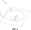
фиг.4 - схематичный вид направленной антенны GPS;4 is a schematic view of a directional GPS antenna;
фиг.5 - графическое представление измеренных обратных потерь антенны GPS, полученных моделированием обратных потерь направленной антенны GPS и измеренных обратных потерь направленной антенны GPS в зависимости от частоты;5 is a graphical representation of the measured return loss of the GPS antenna obtained by modeling the return loss of the directional GPS antenna and the measured return loss of the directional GPS antenna as a function of frequency;
фиг.6 - графическое представление полученной моделированием и измеренной диаграмм направленности излучения антенны GPS и направленной антенны GPS, соответственно;6 is a graphical representation of the obtained simulation and measured radiation patterns of the GPS antenna and the directional GPS antenna, respectively;
фиг.7 - графическое представление измеренных диаграмм направленности излучения направленной антенны GPS в плоскостях φ=0° и φ=90°;7 is a graphical representation of the measured radiation patterns of the directional GPS antenna in the planes φ = 0 ° and φ = 90 °;
фиг.8 - графическое представление способа вычисления местоположения приемником GPS;Fig. 8 is a graphical representation of a method of calculating a location by a GPS receiver;
фиг.9 - графическое представление распределения для приемника GPS в плоскости «расстояние - число событий»; иFig.9 is a graphical representation of the distribution for the GPS receiver in the plane "distance - the number of events"; and
фиг.10 - графическое представление вычисленного местоположения приемника GPS и реального местоположения приемника GPS в плоскости «расстояние - число попыток».figure 10 is a graphical representation of the calculated location of the GPS receiver and the actual location of the GPS receiver in the plane "distance - the number of attempts."
Перечень позицийList of items
Подробное описание изобретенияDETAILED DESCRIPTION OF THE INVENTION
На фиг.1 система (1) определения местоположения в помещении содержит по меньшей мере три направленные антенны (2а, 2b и 2с) глобальной системы определения местоположения (GPS) для приема специфических сигналов GPS, приходящих с по меньшей мере трех спутников (S1, S4 и S7) GPS, по меньшей мере три радиочастотных ретранслятора (3a, 3b и 3с) GPS для усиления сигналов GPS, приходящих от направленных антенн (2a, 2b и 2с) GPS, по меньшей мере три антенны (6a, 6b и 6с) GPS для передачи сигналов GPS, приходящих от радиочастотных ретрансляторов (3a, 3b и 3с) GPS в помещение, по меньшей мере один приемник (7) GPS для приема своей (7) антенной (8) сигналов GPS, приходящих от антенн (6a, 6b и 6с) GPS, и способ (100) вычисления местоположения для вычисления времени GPS и нахождения местоположения в двух измерениях.1, the indoor location system (1) comprises at least three directional antennas (2a, 2b and 2c) of a global positioning system (GPS) for receiving specific GPS signals coming from at least three satellites (S1, S4 and S7) GPS, at least three radio frequency transponders (3a, 3b and 3c) GPS for amplifying GPS signals coming from directional antennas (2a, 2b and 2c) GPS, at least three GPS antennas (6a, 6b and 6c) GPS for transmitting GPS signals coming from radio frequency transponders (3a, 3b and 3c) GPS to the room, at least about yn receiver (7) for receiving its GPS (7) the antenna (8), GPS signals coming from the antennas (6a, 6b, 6c) GPS, and a method (100) for calculating the location calculation time and GPS location finding in two dimensions.
Если имеются три радиочастотных ретранслятора (3) GPS, то может быть выполнено определение местоположения в двух измерениях и может стать доступным время GPS.If there are three radio frequency transponders (3) GPS, then the location can be determined in two dimensions and the GPS time may become available.
Если имеются четыре радиочастотных ретранслятора (3) GPS, то может быть выполнено определение местоположения в трех измерениях и может стать доступным время GPS.If there are four radio frequency transponders (3) GPS, then the location can be determined in three dimensions and the GPS time may become available.
Согласно фиг.2, каждый радиочастотный ретранслятор (3) GPS включает в себя полосовой фильтр (4) для снижения уровня шума, малошумящий усилитель (5) для усиления сигнала GPS и линию (Т) передачи для передачи сигналов GPS от направленной антенны (2) GPS к антенне (6) GPS. Кроме того, имеются линии (Т) передачи между направленными антеннами (2) GPS и радиочастотными ретрансляторами (3) GPS и между радиочастотными ретрансляторами (3) GPS и направленными антеннами (2) GPS.2, each GPS radio frequency repeater (3) includes a bandpass filter (4) to reduce noise, a low noise amplifier (5) to amplify the GPS signal, and a transmission line (T) for transmitting GPS signals from a directional antenna (2) GPS to antenna (6) GPS. In addition, there are transmission lines (T) between the directional antennas (2) GPS and the radio frequency transmitters (3) GPS and between the radio frequency repeaters (3) GPS and the directional antennas (2) GPS.
Направленные антенны (2) GPS излучают более значительную мощность в заданных угловых направлениях, что позволяет улучшать характеристики при передаче, приеме и ослаблять помехи от нежелательных источников. В системе (1) определения местоположения в помещении направленные антенны (2a, 2b и 2с) GPS расположены за пределами здания (В), туннеля или развалин. При использовании антенн (6a, 6b и 6с) GPS вне помещения вместо направленных антенн (2a, 2b и 2с) GPS один сигнал GPS принимается несколькими антеннами (6a, 6b и 6с) GPS. Поэтому, когда эти сигналы GPS переизлучаются в здание (В), они интерферируют друг с другом внутри здания (В). Следовательно, в соответствии с этим ослабляются сигналы GPS, покрывающие помещение, поскольку при интерференции сигналы GPS плавно уменьшаются и образуются глубокие провалы диаграммы направленности внутри здания (В). Вследствие этой интерференции также возрастает ошибка при нахождении местоположения приемника (7) GPS. В системе (1) определения местоположения в помещении сигнал одного спутника (S) GPS принимается только одной направленной антенной (2) GPS. Например, как видно на фиг.1, направленная антенна (2а) GPS принимает сигнал GPS только с одного спутника (S1) GPS, при этом другая направленная антенна (2b) GPS принимает сигнал GPS только с другого спутника (S4) GPS и еще одна направленная антенна (2с) GPS принимает сигнал GPS только с еще одного спутника (S7) GPS, что обусловлено соответствующей конфигурацией их диаграмм направленности излучения. Направленные антенны (2) GPS принимают сигналы всех спутников (S) GPS, которые находятся в пределах направления главного лепестка диаграммы направленности. Направленность этих антенн (2a, 2b и 2с) можно выбирать из условия регулирования уровней перекрестных сигналов GPS.Directional antennas (2) GPS emit more significant power in predetermined angular directions, which allows to improve the characteristics of transmission, reception and reduce interference from unwanted sources. In the indoor positioning system (1), directional antennas (2a, 2b and 2c) GPS are located outside the building (B), a tunnel or debris. When using GPS antennas (6a, 6b and 6c) outdoors instead of directional GPS antennas (2a, 2b and 2c), one GPS signal is received by several GPS antennas (6a, 6b and 6c). Therefore, when these GPS signals are re-emitted into the building (B), they interfere with each other inside the building (B). Therefore, in accordance with this, GPS signals covering the room are attenuated, since upon interference, GPS signals gradually decrease and deep dips of the radiation pattern inside the building (B) are formed. Due to this interference, the error in finding the location of the GPS receiver (7) also increases. In the indoor positioning system (1), the signal of one satellite (S) GPS is received by only one directional antenna (2) GPS. For example, as can be seen in FIG. 1, a GPS directional antenna (2a) receives a GPS signal from only one GPS satellite (S1), while another GPS directional antenna (2b) only receives a GPS signal from another GPS satellite (S4) and another a directional antenna (2c) GPS receives a GPS signal from only one more satellite (S7) GPS, due to the corresponding configuration of their radiation patterns. The directional antennas (2) GPS receive signals from all satellites (S) GPS that are within the direction of the main lobe of the radiation pattern. The directivity of these antennas (2a, 2b and 2c) can be selected from the condition for adjusting the levels of GPS cross signals.
В этом изобретении, как показано на фиг. 4, используются направленные антенны (2) GPS с боковыми коническими плавающими отражателями (С) для повышения направленности антенн (2). Что касается фиг.4, то антенна (6) GPS, которая помещена на опорную плиту (Р), используется в конструкции направленной антенны (2) GPS, а повышение направленности достигается использованием конического плавающего отражателя (С). В этом изобретении предпочтительно, чтобы направленные антенны (2a, 2b и 2с) GPS работали на частоте 1575,42 МГц с правой круговой поляризацией (RHCP).In this invention, as shown in FIG. 4, GPS directional antennas (2) with side conical floating reflectors (C) are used to increase the directivity of the antennas (2). As for figure 4, the GPS antenna (6), which is placed on the base plate (P), is used in the design of the directional antenna (2) GPS, and the increase in directivity is achieved using a conical floating reflector (C). In this invention, it is preferable that the directional antennas (2a, 2b and 2c) of the GPS operate at a frequency of 1575.42 MHz with right circular polarization (RHCP).
Боковые конические плавающие отражатели (С) предпочтительно изготавливать из металла и тем самым повышать направленность направленных антенн (2) GPS. Конический плавающий отражатель (С) не соприкасается с опорной плитой (Р). Отражение от металлов для повышения коэффициента усиления антенн используют во многих антеннах, таких как параболическая антенна. Многочисленные волны, приходящие на антенну, отражаются от металлических поверхностей синфазно с повышением уровня сигнала на антенне. Антенну (6) GPS используют в конструкции направленной антенны (2) GPS, а повышения направленности достигают путем использования конического плавающего отражателя (С) вокруг антенны (6) GPS. Конический плавающий отражатель (С) изготавливают и объединяют с антенной (6) GPS и затем измеряют характеристики направленной антенны (2) GPS.Lateral conical floating reflectors (C) are preferably made of metal and thereby increase the directivity of directional antennas (2) GPS. The conical floating reflector (C) is not in contact with the base plate (P). Reflection from metals to increase the antenna gain is used in many antennas, such as a parabolic antenna. Numerous waves arriving at the antenna are reflected from metal surfaces in phase with increasing signal level at the antenna. GPS antenna (6) is used in the design of GPS directional antenna (2), and directivity increases are achieved by using a conical floating reflector (C) around the GPS antenna (6). A conical floating reflector (C) is made and combined with the GPS antenna (6) and then the characteristics of the GPS directional antenna (2) are measured.
Полученные моделированием и измеренные обратные потери направленной антенны (2) GPS совместно с измеренными обратными потерями антенны (6) GPS в этом изобретении можно видеть на фиг.5. Как видно из фиг.5, конический плавающий отражатель (С) несколько изменяет входной импеданс. Однако направленная антенна (2) GPS все же имеет обратные потери ниже 12 дБ на частоте 1575,42 МГц.Obtained by simulation and measured return loss of the directional antenna (2) GPS together with the measured return loss of the antenna (6) GPS in this invention can be seen in Fig.5. As can be seen from figure 5, the conical floating reflector (C) slightly changes the input impedance. However, the GPS directional antenna (2) still has return loss below 12 dB at a frequency of 1575.42 MHz.
При работе радиочастотный ретранслятор (3) GPS принимает сигналы GPS направленной антенной (2) GPS, расположенной за пределами здания (В), и переизлучает эти сигналы GPS в закрытое помещение или закрытое пространство. Когда сигнал GPS принимается от направленной антенны (2) GPS, сигнал GPS сначала фильтруется полосовым фильтром (4), затем он усиливается малошумящим усилителем (5) и в заключение еще раз фильтруется полосовым фильтром (4) и после этого переизлучается в здание (В) радиочастотным ретранслятором (3) GPS. После усиления сигнал GPS передается с помощью антенны (6) GPS к приемнику (7) GPS. Типичный радиочастотный ретранслятор (3) GPS с антеннами (2, 6) показан на фиг.2. В этом изобретении для радиочастотных ретрансляторов (3a, 3b и 3с) GPS требуется только источник питания постоянного тока.In operation, the radio frequency repeater (3) GPS receives GPS signals with a directional antenna (2) GPS located outside the building (B), and re-emits these GPS signals in an indoor or enclosed space. When a GPS signal is received from a directional antenna (2) GPS, the GPS signal is first filtered by a band-pass filter (4), then it is amplified by a low-noise amplifier (5) and finally filtered again by a band-pass filter (4) and then re-emitted to the building (B) radio frequency repeater (3) GPS. After amplification, the GPS signal is transmitted using the GPS antenna (6) to the GPS receiver (7). A typical GPS radio frequency repeater (3) with antennas (2, 6) is shown in FIG. In this invention, for radio frequency transponders (3a, 3b, and 3c), GPS requires only a DC power supply.
Антенна (6) GPS принимает сигнал GPS от радиочастотного ретранслятора (3) GPS и передает этот сигнал GPS к приемнику (7) GPS. Каждая антенна (6) GPS хорошо согласована на частоте родственной направленной антенны (2) GPS и имеет правую круговую поляризацию.The GPS antenna (6) receives the GPS signal from the radio frequency repeater (3) GPS and transmits this GPS signal to the GPS receiver (7). Each GPS antenna (6) is well matched at the frequency of a related GPS directional antenna (2) and has right circular polarization.
Полученные моделированием и измеренные диаграммы направленности излучения антенны (6) GPS и направленной антенны (2) GPS в этом изобретении можно видеть на фиг.6. На уровне 3 дБ ширина главного лепестка направленной антенны (2) GPS составляет 60°. Коэффициент усиления возрастает, когда угловая ширина главного лепестка уменьшается. Уменьшение угловой ширины главного лепестка при наличии конического плавающего отражателя (С) можно без труда видеть на фиг.6. Измеренное осевое отношение направленной антенны (2) GPS, составляющее 1 дБ, свидетельствует, что, как показано на фиг.7, направленная антенна (2) GPS является кругополяризованной на частоте GPS. Полученный моделированием коэффициент усиления направленной антенны (2) GPS составляет 10 дБ, а измеренный максимальный коэффициент усиления системы в целом (антенны (6) GPS и конического плавающего отражателя (С)) составляет 9 дБ. Полученный моделированием коэффициент усиления антенны (6) GPS составляет 4 дБ. Конический плавающий отражатель (С) придает антенне (6) GPS дополнительный коэффициент усиления 5 дБ.Obtained by simulation and measured radiation patterns of the antenna (6) GPS and the directional antenna (2) GPS in this invention can be seen in Fig.6. At 3 dB, the width of the main lobe of the directional antenna (2) GPS is 60 °. The gain increases when the angular width of the main lobe decreases. The decrease in the angular width of the main lobe in the presence of a conical floating reflector (C) can be easily seen in Fig.6. A measured axial ratio of the GPS directional antenna (2) of 1 dB indicates that, as shown in FIG. 7, the GPS directional antenna (2) is circularly polarized at the GPS frequency. The GPS gain of the directional antenna (2) obtained by the simulation is 10 dB, and the measured maximum gain of the system as a whole (GPS antenna (6) and the conical floating reflector (C)) is 9 dB. The GPS antenna gain (6) obtained by the simulation is 4 dB. The conical floating reflector (C) gives the GPS antenna (6) an additional 5 dB gain.
Приемник (7) GPS принимает своей (7) антенной (8) сигналы GPS, приходящие от антенн (6) GPS, и вычисляет местоположение. В этом изобретении предпочтительно, чтобы приемник (7) GPS работал на частоте 1575,42 МГц. Кроме того, в этом изобретении приемник (7) GPS реализует новый способ (100) вычисления местоположения.The GPS receiver (7) receives with its (7) antenna (8) the GPS signals coming from the GPS antennas (6) and calculates the location. In this invention, it is preferable that the GPS receiver (7) operate at a frequency of 1575.42 MHz. In addition, in this invention, the GPS receiver (7) implements a new location method (100).
Способ вычисления местоположения заключается в приеме конкретного сигнала GPS с заданного направления и усиления этого сигнала GPS только от радиочастотного ретранслятора (3) GPS, соединенного с направленной антенной (2) GPS. В случае определения местоположения в двух измерениях это следует повторить на по меньшей мере трех различных сигналах GPS для трех различных радиочастотных ретрансляторов (3) GPS. Этим ослабляется проблема самоинтерференции сигналов GPS.The method for calculating the location consists in receiving a specific GPS signal from a given direction and amplifying this GPS signal only from a radio frequency repeater (3) GPS connected to a directional antenna (2) GPS. In case of positioning in two dimensions, this should be repeated on at least three different GPS signals for three different GPS radio frequency transmitters (3). This alleviates the problem of GPS self-interference.
Для вычисления местоположения приемника (7) GPS псевдодальности (расстояние плюс отклонение показания часов, плюс временная задержка) измеряются в помещении приемником (7) GPS. Однако, когда сигналы GPS приходят со спутника (S) GPS, они следуют по радиочастотному тракту: спутник (S1, или S4, или S7) GPS к радиочастотному ретранслятору (3а, или 3b, или 3с) GPS и от радиочастотного ретранслятора (3а, или 3b, или 3с) GPS к приемнику (7) GPS, который, как показано на фиг.1, не находится на прямой линии. Поскольку радиочастотный тракт не является прямой линией и также включает в себя задержки радиочастотного ретранслятора (3) GPS, малошумящего усилителя (5), полосового фильтра (4), линий (Т) передачи и антенн (2, 6), приемник (7) GPS вычисляет с использованием нескорректированных измерений псевдодальностей свое (7) местоположение с ошибкой. Предполагается, что все аппаратные задержки в радиочастотном ретрансляторе (3) GPS со стороны направленной антенны (2) GPS, антенны (6) GPS, полосового фильтра (4), малошумящего усилителя (5) и линий (Т) передачи могут быть заранее измерены с помощью схемного анализатора и прокалиброваны на основании измерений псевдодальностей. В этом случае, если в приемнике (7) GPS используется немодифицированный алгоритм вычисления местоположения, он (7) ищет решение следующей системы (Y) уравнений для определения местоположения в двух измерениях:To calculate the location of the GPS receiver (7), pseudorange (distance plus clock deviation, plus time delay) is measured indoors by the GPS receiver (7). However, when GPS signals come from the GPS satellite (S), they follow the radio frequency path: GPS satellite (S1, or S4, or S7) to the radio frequency repeater (3a, or 3b, or 3c) of the GPS and from the radio frequency repeater (3a, or 3b, or 3c) GPS to a GPS receiver (7), which, as shown in FIG. 1, is not in a straight line. Since the radio frequency path is not a straight line and also includes delays of the radio frequency repeater (3) GPS, low-noise amplifier (5), band-pass filter (4), transmission lines (T) and antennas (2, 6), GPS receiver (7) calculates, using unadjusted measurements of pseudorange, its (7) location with an error. It is assumed that all hardware delays in the radio frequency repeater (3) GPS from the directional antenna (2) GPS, antenna (6) GPS, band-pass filter (4), low-noise amplifier (5) and transmission lines (T) can be pre-measured with using a circuit analyzer and calibrated based on pseudorange measurements. In this case, if an unmodified location algorithm is used in the GPS receiver (7), he (7) is looking for a solution to the following system (Y) of equations for determining the location in two dimensions:
R1+R4+Δt∗c=PR1,
R2+R5+Δt∗c=PR2,
R3+R6+Δt∗c=PR3,
гдеR1,R2,R3 представляют собой расстояния между спутником (S1, или S4, или S7) GPS и радиочастотным ретранслятором (3а, или 3b, или 3с) GPS иR4,R5 иR6 представляют собой расстояния между радиочастотными ретрансляторами (3а, 3b и 3с) GPS и приемником (7) GPS, показанными на фиг.1. «с» является скоростью света и Δt является отклонением показания часов приемника (7) GPS от реального времени GPS иPR1,PR2,PR3 являются измеряемыми псевдодальностями спутников (S1, S4 и S7) GPS, соответственно. В предположении, что эти псевдодальности не содержат аппаратных задержек радиочастотных ретрансляторов (2) GPS, радиочастотные ретрансляторы (2) GPS калибруют, а ошибки, которые возникают вследствие отклонения показания часов спутников (S) GPS, отклонения показания часов приемника (7) GPS, инструментальных задержек спутника (S) GPS, ионосферного эффекта и тропосферных эффектов и вращения Земли, удаляются из уравнений (Y) при поиске решения приемником (7) GPS, но при этом местоположение вычисляется с ошибкой, поскольку путь сигнала GPS со спутников (S) GPS до приемника (7) GPS не является прямой линией.where
Взамен в этом изобретении предложено решать нижеследующую систему (Z) уравнений, чтобы ослаблять влияние непрямой линии радиочастотного тракта при вычислении местоположения:Instead, this invention proposes to solve the following system of equations (Z) in order to attenuate the influence of the indirect line of the radio frequency path in calculating the location:
R4+Δt∗c=PR1-R1,
R5+Δt∗c=PR2-R2,
R6+Δt∗c=PR3-R3.
В предположении, что правые части системы (Z) уравнений являются известными, левыми частями системы (Z) уравнений точно определяются правильные окружности дальностей GPS, берущие начало из мест нахождения радиочастотных ретрансляторов (3a, 3b и 3с) GPS. Эту систему (Z) уравнений можно легко решить, чтобы найти пересечение окружностей и получить точное местоположение приемника (7) GPS. Правые части системы (Z) уравнений являются известными, посколькуPR1,PR2 иPR3 являются измеряемыми псевдодальностями, аR1,R2 иR3 можно легко вычислить, поскольку местоположения радиочастотных ретрансляторов (3a, 3b и 3с) GPS являются известными, как и местоположения спутников (S1, S4 и S7) GPS. Например,R1 можно вычислять как расстояние между радиочастотным ретранслятором (3а) GPS и спутником (S1) GPS.Under the assumption that the right-hand sides of the system of equations (Z) of equations are known, the left-hand sides of the system of (Z) equations accurately determine the correct circle of GPS distances originating from the locations of the radio frequency repeaters (3a, 3b and 3c) of the GPS. This system of equations (Z) can be easily solved to find the intersection of circles and get the exact location of the GPS receiver (7). The right-hand sides of the equation system (Z) are known since
Способ (100) вычисления местоположения приемника (7) GPS включает в себя:The method (100) for calculating the location of the GPS receiver (7) includes:
- измерение (101) псевдодальностей для различных спутников (S) GPS,- measurement (101) of pseudorange for various satellites (S) GPS,
- принятие (102) решения относительно пар: радиочастотные (РЧ) ретрансляторы (3) GPS - спутники (S) GPS,- making (102) decisions regarding pairs: radio frequency (RF) repeaters (3) GPS satellites (S) GPS,
- нахождение (103) решения для приближенного отклонения показания часов приемника (7) GPS,- finding (103) solutions for the approximate deviation of the clock receiver (7) GPS,
- получение (104) местоположений спутников (S) GPS,- receiving (104) GPS satellite locations (S),
- вычисление (105) расстояний между радиочастотными ретрансляторами (3) GPS и спутниками (S) GPS,- calculation (105) of the distance between the radio frequency transponders (3) GPS and the satellites (S) GPS,
- модифицирование (106) измеренных псевдодальностей,- modification (106) of the measured pseudorange,
- измерение (107) местоположения в помещении приемника (7) GPS, а также отклонения показаний часов между часами спутников (S) GPS и приемника (7) GPS с использованием метода наименьших квадратов или точных алгоритмов,- measurement (107) of the location in the room of the GPS receiver (7), as well as the deviation of the clock between the clocks of the (S) GPS satellites and the GPS receiver (7) using the least squares method or exact algorithms,
- проверка (108) точности измеренного местоположения в помещении приемника (7) GPS,- checking (108) the accuracy of the measured location in the premises of the receiver (7) GPS,
- на этапе (108) проверки точности измеренного местоположения в помещении приемника (7) GPS, если измеренное местоположение в помещении приемника (7) GPS не является точным, нахождение приемником (7) GPS места приемника (7) GPS и затем вычисление (104) местоположения спутников (S) GPS (иначе говоря, осуществление перехода к этапу 103),- in step (108) of checking the accuracy of the measured location in the GPS receiver (7), if the measured location in the GPS receiver (7) is not accurate, the GPS receiver (7) locates the receiver (7) GPS and then calculates (104) GPS satellite (S) locations (in other words, proceeding to step 103),
- на этапе (108) поверки точности измеренного местоположения в помещении приемника (7) GPS, если измеренное местоположение в помещении приемника (7) GPS является точным, прекращение (109) этапов операции вычисления местоположения, показанных на фиг.8.- in step (108) of checking the accuracy of the measured location in the GPS receiver (7), if the measured location in the GPS receiver (7) is accurate, stopping (109) the steps of the location calculation operation shown in Fig. 8.
Приемник (7) GPS измеряет (101) псевдодальности для различных спутников (S) GPS по сигналам, приходящим от различных радиочастотных ретрансляторов (3) GPS. Приемник (7) GPS измеряет псевдодальности, связанные с расстояниямиR1+R4,R2+R5 иR3+R6. Эти псевдодальности включают в себя значения отклонений показаний часов приемника (7) GPS и спутников (S) GPS от реального времени GPS, значения временных задержек радиочастотных ретрансляторов (3a, 3b и 3с) GPS и нежелательные эффекты, такие как инструментальные задержки спутников (S) GPS, ионосферный эффект, и тропосферные эффекты, и вращение Земли. Значения отклонений показаний часов спутников (S) GPS от реального времени GPS могут быть легко определены приемником (7) GPS на основании сообщений GPS. После нахождения значений отклонений показаний часов спутников (S) GPS приемник (7) GPS регулирует время GPS спутников GPS. Приемник (7) GPS включает в себя базу данных о местоположениях и значениях временных задержек радиочастотных ретрансляторов (3a, 3b и 3с) GPS, которые обусловлены полосовыми фильтрами (4), малошумящими усилителями (5) и линиями (Т) передачи внутри радиочастотных ретрансляторов (3a, 3b и 3с) GPS. Все значения временных задержек радиочастотных ретрансляторов (3a, 3b и 3с) GPS и местоположения их (3a, 3b и 3с) измеряются заблаговременно и сохраняются в базе данных, которая содержится в приемнике (7) GPS.The GPS receiver (7) measures (101) the pseudorange for various (S) GPS satellites from signals coming from various radio frequency transponders (3) GPS. The GPS receiver (7) measures the pseudo-ranges associated with the
Для приемника (7) GPS известны из базы данных местоположения радиочастотных ретрансляторов (3a, 3b и 3с) GPS и также известны угловые положения спутников (S) GPS в геоцентрической земной системе координат из сообщений GPS. Один радиочастотный ретранслятор (3) GPS может принимать сигналы GPS с различных спутников (S) GPS. Например, как видно на фиг.1, радиочастотный ретранслятор (3а) GPS может принимать сигнал GPS с двух спутников (S1 и S2) GPS, тогда как другой радиочастотный ретранслятор (3b) GPS может принимать сигнал GPS с трех спутников (S3, S4 и S5) GPS и еще один радиочастотный ретранслятор (3с) GPS может принимать сигнал GPS с других трех спутников (S6, S7 и S8) GPS. Приемник (7) GPS принимает решение относительно того, какие сигналы GPS и с каких радиочастотных ретрансляторов (3) GPS приходят, на основании угловой информации от радиочастотных ретрансляторов (3a, 3b и 3с) GPS и сигналов GPS. В соответствии с этими данными приемник (7) GPS принимает (102) решение относительно пар: радиочастотные ретрансляторы (3) GPS - спутники (S) GPS.For the receiver (7), GPSs are known from the GPS location database of the radio frequency repeaters (3a, 3b and 3c) and the angular positions of the GPS satellites (S) in the geocentric earth coordinate system from GPS messages are also known. One radio frequency repeater (3) GPS can receive GPS signals from various (S) GPS satellites. For example, as can be seen in FIG. 1, a GPS radio frequency repeater (3a) can receive a GPS signal from two GPS satellites (S1 and S2), while another GPS radio frequency repeater (3b) can receive a GPS signal from three satellites (S3, S4 and S5) GPS and another radio frequency repeater (3c) GPS can receive a GPS signal from the other three GPS satellites (S6, S7 and S8). The GPS receiver (7) makes a decision regarding which GPS signals and from which radio frequency transmitters (3) the GPS come from based on angular information from the radio frequency transmitters (3a, 3b and 3c) of the GPS and GPS signals. In accordance with these data, the GPS receiver (7) makes (102) a decision regarding the pairs: radio frequency repeaters (3) GPS satellites (S) GPS.
Приемник (7) GPS находит решение для приближенного отклонения показания часов приемника (7) GPS путем нахождения своего (7) приближенного местоположения с использованием измерения немодифицированных псевдодальностей. Сначала приемник (7) GPS находит свое (7) приближенное местоположение с помощью измеренных и немодифицированных псевдодальностей. Приемник (7) GPS находит свое (7) приближенное время GPS путем предоставления себе (7) возможности получения привязки местоположения к измеренным и немодифицированным псевдодальностям и получения отклонения показания часов от этого приближенного времени GPS.The GPS receiver (7) finds a solution for the approximate deviation of the clock of the GPS receiver (7) by finding its (7) approximate location using unmodified pseudorange measurements. First, the GPS receiver (7) finds its (7) approximate location using measured and unmodified pseudo-ranges. The GPS receiver (7) finds its (7) approximate GPS time by allowing itself (7) to obtain a location reference to the measured and unmodified pseudo-ranges and to obtain a deviation of the clock from this approximate GPS time.
После нахождения решения для приближенного отклонения показания часов приемника (7) GPS приемник GPS получает (104) местоположения спутников (S) GPS. Приемник (7) GPS получает местоположения спутников (S) GPS в соответствии с приближенным временем GPS самого приемника (7). Точное время GPS следует знать, чтобы знать точное местоположение спутников (S) GPS, но ошибки при нахождении времени GPS не порождают большую ошибку местоположения спутников (S) GPS. Например, временная ошибка 1 мкс влечет за собой ошибку измерения местоположения приемника (7) GPS, соответствующую расстоянию 300 м, однако она влечет за собой ошибку измерения местоположений спутников (S) GPS, соответствующую расстоянию 2,9 мм (2∗π∗2000 км при 12 ч, 2,9 км при 1 с, 2,9 м при 1 мс и 2,9 мм при 1 мкс). После получения лучших местоположений спутников (S) GPS местоположение приемника (7) GPS и отклонение показания часов может быть оценено более точно приемником (7) GPS итерационным способом.After finding a solution for the approximate deviation of the clock of the receiver (7) GPS receiver GPS receives (104) the location of the satellite (S) GPS. The GPS receiver (7) obtains the locations of the GPS satellites (S) in accordance with the approximate GPS time of the receiver (7). The exact GPS time should be known in order to know the exact location of the (S) GPS satellites, but errors in finding the GPS time do not give rise to a large error in the location of the (S) GPS satellites. For example, a temporary error of 1 μs entails an error in measuring the location of the GPS receiver (7) corresponding to a distance of 300 m, however, it entails an error in measuring the location of satellites (S) GPS corresponding to a distance of 2.9 mm (2 ∗ π ∗ 2000 km at 12 h, 2.9 km at 1 s, 2.9 m at 1 ms and 2.9 mm at 1 μs). After obtaining the best locations of the (S) GPS satellites, the location of the GPS receiver (7) and the clock deviation can be more accurately estimated by the GPS receiver (7) in an iterative manner.
Приемник (7) GPS вычисляет (105) расстояния между радиочастотными ретрансляторами (3) GPS и спутниками (S) GPS, осуществляя корреляцию кода спутников (S) GPS c локально генерируемым кодом GPS.The GPS receiver (7) calculates (105) the distance between the radio frequency transponders (3) GPS and the satellites (S) GPS, by correlating the satellite code (S) GPS with the locally generated GPS code.
Когда путь сигнала GPS (со спутника (S) GPS до радиочастотного ретранслятора (3) GPS и затем от радиочастотного ретранслятора (3) GPS до приемника (7) GPS) определен, приемник (7) GPS модифицирует (106) измеренные псевдодальности путем вычитания расстояний между радиочастотными ретрансляторами (3) GPS и спутниками (S) GPS и нежелательных воздействий на псевдодальность, таких как значения отклонений показаний часов приемника (7) GPS и спутников (S) GPS, значения временных задержек радиочастотных ретрансляторов (3a, 3b и 3с) GPS и нежелательные эффекты, такие как инструментальные задержки спутников (S) GPS, ионосферный эффект и тропосферные эффекты и вращение Земли, из измеренных псевдодальностей, что представлено в системе (Z) уравнений.When the GPS signal path (from satellite (S) GPS to the radio frequency repeater (3) GPS and then from the radio frequency repeater (3) GPS to the GPS receiver (7)) is determined, the GPS receiver (7) modifies the measured pseudorange (106) by subtracting the distances between radio frequency transponders (3) GPS and GPS satellites (S) and undesirable effects on pseudorange, such as deviations of the clock of the receiver (7) GPS and satellite (S) GPS, time delays of radio frequency transponders (3a, 3b and 3c) GPS and unwanted effects like a tool total delays of satellites (S) GPS, ionospheric effect and tropospheric effects and Earth rotation, from measured pseudorange, which is presented in system (Z) of equations.
R4+Δt∗c=PR1-R1,
R5+Δt∗c=PR2-R2,
R6+Δt∗c=PR3-R3.
Значения отклонений показаний часов спутников (S) GPS от реального времени GPS могут быть легко определены на основании сообщений GPS приемником (7) GPS. После нахождения значений отклонений показаний часов спутников (S) GPS приемник (7) GPS регулирует время GPS спутников GPS. Модифицированная псевдодальность представляет собой псевдодальность между радиочастотным ретранслятором (3) GPS и приемником (7) GPS для трех различных спутников (S) GPS.The deviations of the GPS satellite clock (S) from the real-time GPS can be easily determined based on the GPS messages from the GPS receiver (7). After finding the deviation values of the clocks of the satellites (S), the GPS receiver (7) GPS adjusts the time of the GPS GPS satellites. The modified pseudorange is the pseudorange between the radio frequency repeater (3) GPS and the receiver (7) GPS for three different satellites (S) GPS.
Приемник (7) GPS измеряет (107) местоположение в помещении самого себя (7), а также отклонение показания часов путем использования метода наименьших квадратов или точных алгоритмов. Система (Z) уравнений может быть решена в точных формах или с получением пересечения трех окружностей или пересечения двух гипербол. Если имеются три радиочастотных ретранслятора (3) GPS и измерения псевдодальности по трем временам прихода от радиочастотных ретрансляторов (3) GPS, приемник (7) GPS использует регулярные методы наименьших квадратов или точные алгоритмы, такие как триангуляция на основании разностей времен прихода), для нахождения местоположения в помещении приемника (7) GPS, а также отклонения показания часов. Время и местоположение приемника (7) GPS вычисляются с такой же точностью, как и приемника (7) GPS вне помещения. Разность времен прихода используется, если в компонентах системы (спутнике (S) GPS и приемника (7) GPS) используется одно и то же время, но отклонение показаний часов между спутником (S) GPS и приемником (7) GPS является неизбежным. Путем вычитания уравнений (Z) друг из друга отклонение показаний часов может быть исключено и получены уравнения разности времен прихода. При вычитании уравнений времен прихода получаются уравнения разности времен прихода.The GPS receiver (7) measures (107) the location in the room of himself (7), as well as the deviation of the clock by using the least squares method or exact algorithms. The system (Z) of equations can be solved in exact forms or with the intersection of three circles or the intersection of two hyperbolas. If there are three radio frequency transponders (3) GPS and pseudorange measurements over three arrival times from radio frequency transponders (3) GPS, the receiver (7) GPS uses regular least squares methods or precise algorithms such as triangulation based on arrival time differences) to find location in the premises of the receiver (7) GPS, as well as deviations of the clock. The time and location of the GPS receiver (7) is calculated with the same accuracy as the outdoor GPS receiver (7). The difference in arrival times is used if the same time is used in the system components (GPS satellite (S) and GPS receiver (7)), but a clock deviation between the GPS satellite (S) and GPS receiver (7) is unavoidable. By subtracting equations (Z) from each other, the deviation of the clock can be eliminated and equations of the difference in arrival times can be obtained. Subtracting the equations of the times of arrival, we obtain the equations of the difference of the times of arrival.
Приемник (7) GPS исследует (108) точность измеренного положения в помещении приемника (7) GPS путем сравнения решения для отклонения показания часов, которое использует для нахождения местоположения спутника (S) GPS и для удаления нежелательных эффектов, с нахождением решения для отклонения показания часов после определения местоположения. Приемник (7) GPS вычитает значение отклонения показания часов на этапе (107) из значения отклонения показания часов на этапе (103). Затем приемник (7) GPS сравнивает абсолютное значение разности между значением отклонения показания часов на этапе (103) и значением отклонения показания часов на этапе (107) на предмет, оно меньше чем 0,1 мс или нет. Если абсолютное значение меньше чем 0,1 мс, приемник (7) GPS определяет, что измеренное свое (7) местоположение является точным. В противном случае приемник (7) GPS определяет, что измеренное свое (7) местоположение не является точным.The GPS receiver (7) examines (108) the accuracy of the measured position in the GPS receiver (7) by comparing the clock deviation solution, which it uses to find the GPS satellite location (S) and removing unwanted effects, and finding the clock deviation solution after determining the location. The GPS receiver (7) subtracts the deviation of the clock at step (107) from the deviation of the clock at step (103). Then, the GPS receiver (7) compares the absolute value of the difference between the deviation value of the clock in step (103) and the deviation value of the clock in step (107) for an item that is less than 0.1 ms or not. If the absolute value is less than 0.1 ms, the GPS receiver (7) determines that its measured (7) location is accurate. Otherwise, the GPS receiver (7) determines that its measured (7) location is not accurate.
Если измеренное местоположение является точным, приемник (7) GPS прекращает выполнение (109) операции вычисления местоположения.If the measured location is accurate, the GPS receiver (7) stops the location calculation operation (109).
Если измеренное местоположение не является точным, приемник (7) GPS итерационно находит (103) решение для приближенного отклонения показания часов путем нахождения своего (7) местоположения.If the measured location is not accurate, the GPS receiver (7) iteratively finds (103) a solution for approximating the clock reading by finding its (7) location.
Один результат измерений из результатов способа (100) вычисления местоположения дан на фиг.9 и фиг.10. Приемник (7) GPS был расположен в середине 60-метрового коридора, где отсутствовал сигнал GPS без радиочастотного ретранслятора (2) GPS. Когда радиочастотный ретранслятор (2) GPS включали, можно было вычислять местоположение, показанное на фиг.9 и фиг.10. Среднее значение 100 выборок (10-секундных данных) составляет 33 м, тогда как истинное местоположение находится на расстоянии 33 м от радиочастотного ретранслятора (2) GPS. Эти и другие измерения выполнялись в одном и том же коридоре и были получены следующие результаты, сведенные в таблицу 1.One measurement result from the results of the location calculation method (100) is given in FIG. 9 and FIG. 10. The GPS receiver (7) was located in the middle of the 60-meter corridor, where there was no GPS signal without a radio frequency repeater (2) GPS. When the GPS radio frequency repeater (2) was turned on, the location shown in FIG. 9 and FIG. 10 could be calculated. The average value of 100 samples (10 second data) is 33 m, while the true location is 33 m from the radio frequency repeater (2) GPS. These and other measurements were performed in the same corridor and the following results were obtained, summarized in table 1.
Как видно из таблицы, средняя ошибка меньше 5 м для всех мест в коридоре.As can be seen from the table, the average error is less than 5 m for all places in the corridor.
Хотя это изобретение относится к глобальной системе определения местоположения (GPS), концепцию повышения уровня сигнала в помещении можно также применять к спутникам Галилео, а также к системам, в которых используются гибридные спутники систем GPS и Галилео.Although this invention relates to a global positioning system (GPS), the concept of increasing the signal level in a room can also be applied to Galileo satellites, as well as to systems using hybrid GPS and Galileo satellites.
В объеме этой основной концепции можно разрабатывать различные осуществления обладающей признаками изобретения системы (1) определения местоположения в помещении на основании сигнала GPS. Изобретение не может быть ограничено примерами, описанными в этой заявке; оно по существу соответствует формуле изобретения.Within the scope of this basic concept, various implementations of the inventive system (1) for determining location in a room based on a GPS signal can be developed. The invention cannot be limited by the examples described in this application; it essentially corresponds to the claims.
Список литературыBibliography


Claims (13)
Translated fromRussianвключающий в себя следующие этапы:
этап (101) измерения псевдодальностей для различных спутников (S) GPS,
этап (102) принятия решения относительно того, какие сигналы GPS приходят от какого RF ретранслятора (3) GPS, на основании угловой информации направленных антенн RF ретрансляторов (3а, 3b и 3с) GPS и сигналов GPS,
этап (103) определения приближенного отклонения часов приемника (7) GPS путем нахождения приближенного местоположения приемника GPS с использованием немодифицированного измерения псевдодальности,
этап (104) получения местоположений спутников (S) GPS,
этап (105) вычисления расстояний между RF ретрансляторами (3) GPS, местоположения которых уже сохранены в базе данных приемника (7) GPS, и спутниками (S) GPS, путем осуществления корреляции кода спутника GPS с локально генерируемым кодом GPS,
этап (106) модифицирования измеренных псевдодальностей путем вычитания расстояний между RF ретрансляторами (3) GPS и спутниками (S) GPS и нежелательных воздействий на псевдодальности, таких как значения отклонений часов приемника (7) GPS и спутников (S) GPS от реального времени GPS, значения временных задержек RF ретрансляторов (3а, 3b и 3с) GPS, и нежелательных эффектов, таких как инструментальные задержки спутников (S) GPS, ионосферный эффект и тропосферные эффекты, и вращение Земли, из измеренных псевдодальностей,
этап (107) измерения местоположения внутри помещения приемника (7) GPS и отклонения между часами спутников (S) GPS и приемника (7) GPS с использованием метода наименьших квадратов или точных алгоритмов, таких как триангуляция на основании разностей времен прихода,
этап (108) проверки точности измеренного местоположения внутри помещения приемника (7) GPS путем сравнения значения отклонения часов на этапе (103) со значением отклонения часов на этапе (107),
при этом, если на этапе (108) измеренное местоположение внутри помещения приемника (7) GPS не является точным, то выполняется определение приемником (7) GPS места приемника (7) GPS и возврат к этапу (103), и
если на этапе (108) измеренное местоположение внутри помещения приемника (7) GPS является точным, то способ определения местоположения завершается.1. The method (100) for determining the location indoors, based on the calculation of the time of the global positioning system and finding the location in two dimensions, in the global positioning system (GPS) indoors, containing at least three directional antennas (2a, 2b and 2c) GPS for receiving certain GPS signals coming from at least three GPS satellites (S1, S4 and S7) GPS, at least three radio frequency (RF) GPS repeaters (3a, 3b and 3c) for amplifying GPS signals coming from directional antennas (2a, 2b and 2c) GPS, at least three GPS antennas (6a, 6b and 6c) for transmitting GPS signals coming from radio frequency transmitters (3a, 3b and 3c) GPS to the room, at least one GPS receiver (7) for receiving GPS signals coming from GPS antennas (6a, 6b and 6c) using its (7) antenna (8),
including the following steps:
pseudorange measurement step (101) for various (S) GPS satellites,
a decision step (102) as to which GPS signals come from which RF repeater (3) GPS, based on the angular information of the directional antennas of the RF repeaters (3a, 3b and 3c) of GPS and GPS signals,
step (103) of determining the approximate deviation of the clock of the GPS receiver (7) by finding the approximate location of the GPS receiver using an unmodified pseudorange measurement,
a step (104) for obtaining GPS satellite locations (S),
step (105) of calculating the distances between the RF GPS repeaters (3) GPS, the locations of which are already stored in the GPS receiver database (7), and the GPS satellites (S), by correlating the GPS satellite code with the locally generated GPS code,
step (106) of modifying the measured pseudorange by subtracting the distances between the RF transponders (3) GPS and the satellites (S) GPS and undesirable effects on the pseudorange, such as the deviations of the clock of the receiver (7) GPS and satellite (S) GPS from the real-time GPS, the values of the time delays of the RF repeaters (3a, 3b and 3c) of the GPS, and undesirable effects, such as instrumental delays of the satellites (S) GPS, the ionospheric effect and tropospheric effects, and the rotation of the Earth, from the measured pseudorange,
step (107) measuring the location of the indoor location of the GPS receiver (7) and the deviation between the clocks of the satellites (S) GPS and the GPS receiver (7) using the least squares method or exact algorithms such as triangulation based on differences in arrival times,
step (108) of checking the accuracy of the measured location inside the GPS receiver (7) by comparing the clock deviation in step (103) with the clock deviation in step (107),
if, at step (108), the measured location inside the GPS receiver (7) is not accurate, then the receiver (7) determines the GPS position of the GPS receiver (7) and returns to step (103), and
if at step (108) the measured indoor location of the GPS receiver (7) is accurate, then the positioning method is completed.
R4+Δt*c=PR1-R1,
R5+Δt*c=PR2-R2, (Z)
R6+Δt*c=PR3-R3
где
R1, R2, R3 - расстояния между спутником (S1 или S4 или S7) GPS и RF ретранслятором (3а, или 3b, или 3с) GPS,
R4, R5 и R6 - расстояния между радиочастотными ретрансляторами (3а, 3b и 3с) GPS и приемником (7) GPS,
с - скорость света,
Δt - отклонение часов приемника (7) GPS и
PR1, PR2, PR3 - измеренные псевдодальности спутников (S1, S4 и S7) GPS, соответственно.5. The method according to claim 1, characterized in that at the step (106) of modifying the measured pseudoranges, said modification of the measured pseudoranges by subtracting the distances between the radio frequency transponders (3) GPS and the satellites (S) GPS and undesirable effects on the pseudorange, such as values of clock deviations GPS receiver (7) and GPS satellites (S) GPS from real-time GPS, time delays of radio frequency repeaters (3a, 3b and 3c) GPS and unwanted effects, such as instrumental delays of satellite (S) GPS, ionospheric effect t and tropospheric effects, and the rotation of the Earth, from the measured pseudorange, is carried out in accordance with the system (Z) of equations
R4 + Δt * c = PR1-R1,
R5 + Δt * c = PR2-R2, (Z)
R6 + Δt * c = PR3-R3
Where
R1, R2, R3 - the distance between the satellite (S1 or S4 or S7) GPS and the RF repeater (3a, or 3b, or 3c) GPS,
R4, R5 and R6 are the distances between the radio frequency transponders (3a, 3b and 3c) of the GPS and the receiver (7) of the GPS,
c is the speed of light
Δt is the deviation of the receiver clock (7) GPS and
PR1, PR2, PR3 are the measured pseudorange of GPS satellites (S1, S4 and S7), respectively.
Applications Claiming Priority (1)
| Application Number | Priority Date | Filing Date | Title |
|---|---|---|---|
| PCT/IB2009/056002WO2011080541A1 (en) | 2009-12-31 | 2009-12-31 | Indoor positioning system based on gps signals and pseudolites with outdoor directional antennas |
Publications (2)
| Publication Number | Publication Date |
|---|---|
| RU2012132635A RU2012132635A (en) | 2014-02-20 |
| RU2536512C2true RU2536512C2 (en) | 2014-12-27 |
Family
ID=42782207
Family Applications (1)
| Application Number | Title | Priority Date | Filing Date |
|---|---|---|---|
| RU2012132635/07ARU2536512C2 (en) | 2009-12-31 | 2009-12-31 | Indoor positioning system based on global positioning system signals and pseudolites with outdoor directional antennae |
Country Status (11)
| Country | Link |
|---|---|
| US (1) | US20120286992A1 (en) |
| EP (1) | EP2519835A1 (en) |
| JP (1) | JP2013516606A (en) |
| KR (1) | KR20120107128A (en) |
| CN (1) | CN102782521A (en) |
| AU (1) | AU2009357510B2 (en) |
| CA (1) | CA2784086A1 (en) |
| IL (1) | IL220191A0 (en) |
| RU (1) | RU2536512C2 (en) |
| SG (1) | SG181542A1 (en) |
| WO (1) | WO2011080541A1 (en) |
Families Citing this family (27)
| Publication number | Priority date | Publication date | Assignee | Title |
|---|---|---|---|---|
| US8791857B2 (en)* | 2010-10-06 | 2014-07-29 | Electronics And Telecommunications Research Institute | System and method for indoor location tracking using pseudo GPS signal transmitter |
| US9476984B2 (en) | 2013-02-05 | 2016-10-25 | Dali Systems Co. Ltd. | Feedback based indoor localization using digital off-air access units |
| US20140320340A1 (en)* | 2013-02-21 | 2014-10-30 | Dali Systems Co. Ltd. | Indoor localization using analog off-air access units |
| US9958548B2 (en)* | 2013-03-08 | 2018-05-01 | Dali Systems Co. Ltd. | Indoor trilateralization using digital off-air access units |
| US9851445B2 (en) | 2013-04-23 | 2017-12-26 | Dali Systems Co. Ltd. | Real-time locating system using GPS time difference of arrival with digital off-air access units and remote units |
| CN103675872B (en)* | 2013-12-13 | 2016-01-06 | 清华大学 | Based on positioning system and the localization method thereof in GNSS signal source |
| CN104793227B (en)* | 2014-01-21 | 2019-06-28 | 香港理工大学 | GPS indoor positioning system and indoor positioning method based on GPS indoor positioning system |
| CN103901456B (en)* | 2014-04-14 | 2016-11-16 | 东南大学 | A GPS terminal indoor positioning system and method |
| CN104133221B (en)* | 2014-07-24 | 2016-10-12 | 中国人民解放军信息工程大学 | A kind of fake satellite positioning system based on general purpose receiver |
| KR101649512B1 (en)* | 2014-10-29 | 2016-08-30 | 국방과학연구소 | Synchronized-pseudolite navigation system using relay station |
| US10849205B2 (en) | 2015-10-14 | 2020-11-24 | Current Lighting Solutions, Llc | Luminaire having a beacon and a directional antenna |
| FR3052436B1 (en)* | 2016-06-09 | 2021-07-09 | Codol Jean Marie | DEVICE AND METHOD FOR POSITIONING A UNDERWATER DEVICE |
| CN109211235A (en)* | 2017-06-29 | 2019-01-15 | 深圳市耀航信息技术有限公司 | Indoor fake satellite positioning system and method |
| US11790618B1 (en)* | 2018-04-10 | 2023-10-17 | Robert Edwin Douglas | Enhanced 3D training environment |
| TWI671539B (en)* | 2018-07-16 | 2019-09-11 | 劉勉志 | Fireman positioning system |
| CN110726969B (en)* | 2018-07-16 | 2022-03-15 | 刘勉志 | Firefighter positioning system |
| JP7271886B2 (en)* | 2018-09-20 | 2023-05-12 | セイコーエプソン株式会社 | POSITIONING SYSTEM, Pseudo-station control device, and pseudo-satellite control method |
| CN110221315A (en)* | 2019-06-27 | 2019-09-10 | Oppo广东移动通信有限公司 | Indoor locating system and method, terminal, trunking, electronic equipment |
| KR102228526B1 (en)* | 2019-12-19 | 2021-03-16 | 한국항공우주연구원 | Satellite navigation signal wireless repeater |
| US11550062B2 (en) | 2019-12-24 | 2023-01-10 | All.Space Networks Ltd. | High-gain multibeam GNSS antenna |
| EP4118459A1 (en) | 2020-03-13 | 2023-01-18 | Sabanci Üniversitesi | A gnss repeater architecture and location finding method for indoor positioning systems using lower frequencies than gnss signals |
| US11792763B2 (en)* | 2020-09-21 | 2023-10-17 | Charter Communications Operating, Llc | Wireless station location detection and management |
| CN112698370B (en)* | 2020-12-15 | 2024-06-18 | 南京航空航天大学 | Indoor satellite navigation positioning method based on virtual orbit satellite |
| CN114779297B (en)* | 2022-01-10 | 2025-02-25 | 北京邮电大学 | Terminal positioning method and related device |
| WO2024085877A1 (en)* | 2022-10-20 | 2024-04-25 | Zeku, Inc. | Apparatus and method of an adaptive global navigation satellite system search technique |
| KR102721183B1 (en)* | 2022-12-15 | 2024-10-22 | 한국항로표지기술원 | System for inspecting synchronous flicker performance of lantern and method thereof |
| KR102816107B1 (en)* | 2024-12-31 | 2025-06-04 | 주식회사 아이디씨티 | Apparatus for outputting GNSS signal and method for controlling the same |
Citations (2)
| Publication number | Priority date | Publication date | Assignee | Title |
|---|---|---|---|---|
| RU2161318C2 (en)* | 1996-04-05 | 2000-12-27 | Дисковижн Ассошиейтс | System and method of positioning |
| US6201497B1 (en)* | 1997-09-30 | 2001-03-13 | Dlb Limited | Enhanced global navigation satellite system |
Family Cites Families (12)
| Publication number | Priority date | Publication date | Assignee | Title |
|---|---|---|---|---|
| JPS58179599U (en)* | 1982-05-20 | 1983-12-01 | ナイルス部品株式会社 | Vehicle proximity sensor |
| JPH03224305A (en)* | 1990-01-30 | 1991-10-03 | Mitsubishi Electric Corp | Horn antenna |
| JPH07280917A (en)* | 1994-04-13 | 1995-10-27 | Universal Syst:Kk | Method for retransmitting gps radio waves to gps-radio-wave unreceivable space |
| JP2853670B2 (en)* | 1996-08-06 | 1999-02-03 | 日本電気株式会社 | Position detection system |
| US6968737B2 (en) | 1997-01-02 | 2005-11-29 | Lucent Technologies Inc. | Position determining system using transmitted position information |
| JP3593960B2 (en)* | 2000-08-21 | 2004-11-24 | 日本電気株式会社 | Multi-beam antenna equipment |
| JP3719505B2 (en)* | 2001-08-17 | 2005-11-24 | 株式会社デンソー | Signal radiation device, position detection device, position specifying program, and navigation device |
| GB0305888D0 (en)* | 2003-03-14 | 2003-04-16 | Squared Ltd J | System and method for global positioning system repeater |
| JP4597547B2 (en)* | 2004-02-26 | 2010-12-15 | 船井電機株式会社 | GPS signal transmission system |
| CN1776447A (en) | 2005-10-26 | 2006-05-24 | 武汉虹信通信技术有限责任公司 | GPS signal blind zone covering device |
| JP4816174B2 (en)* | 2006-03-17 | 2011-11-16 | トヨタ自動車株式会社 | Positioning method, positioning device |
| KR20080060502A (en) | 2006-12-27 | 2008-07-02 | 건국대학교 산학협력단 | Indoor positioning system and positioning method using GPS switching repeater |
- 2009
- 2009-12-31JPJP2012546509Apatent/JP2013516606A/enactivePending
- 2009-12-31SGSG2012041646Apatent/SG181542A1/enunknown
- 2009-12-31CACA2784086Apatent/CA2784086A1/ennot_activeAbandoned
- 2009-12-31KRKR1020127020121Apatent/KR20120107128A/ennot_activeCeased
- 2009-12-31RURU2012132635/07Apatent/RU2536512C2/ennot_activeIP Right Cessation
- 2009-12-31EPEP09802014Apatent/EP2519835A1/ennot_activeWithdrawn
- 2009-12-31USUS13/520,179patent/US20120286992A1/ennot_activeAbandoned
- 2009-12-31WOPCT/IB2009/056002patent/WO2011080541A1/enactiveApplication Filing
- 2009-12-31CNCN2009801632345Apatent/CN102782521A/enactivePending
- 2009-12-31AUAU2009357510Apatent/AU2009357510B2/ennot_activeCeased
- 2012
- 2012-06-05ILIL220191Apatent/IL220191A0/enunknown
Patent Citations (2)
| Publication number | Priority date | Publication date | Assignee | Title |
|---|---|---|---|---|
| RU2161318C2 (en)* | 1996-04-05 | 2000-12-27 | Дисковижн Ассошиейтс | System and method of positioning |
| US6201497B1 (en)* | 1997-09-30 | 2001-03-13 | Dlb Limited | Enhanced global navigation satellite system |
Non-Patent Citations (1)
Also Published As
| Publication number | Publication date |
|---|---|
| CN102782521A (en) | 2012-11-14 |
| KR20120107128A (en) | 2012-09-28 |
| SG181542A1 (en) | 2012-07-30 |
| AU2009357510A1 (en) | 2012-06-21 |
| AU2009357510B2 (en) | 2014-05-29 |
| WO2011080541A1 (en) | 2011-07-07 |
| US20120286992A1 (en) | 2012-11-15 |
| EP2519835A1 (en) | 2012-11-07 |
| RU2012132635A (en) | 2014-02-20 |
| JP2013516606A (en) | 2013-05-13 |
| CA2784086A1 (en) | 2011-07-07 |
| IL220191A0 (en) | 2012-07-31 |
Similar Documents
| Publication | Publication Date | Title |
|---|---|---|
| RU2536512C2 (en) | Indoor positioning system based on global positioning system signals and pseudolites with outdoor directional antennae | |
| US20110285589A1 (en) | Network Location and Synchronization of Peer Sensor Stations in a Wireless Geolocation Network | |
| US10175364B2 (en) | Systems and methods for estimating whether a receiver is inside or outside a building | |
| Mautz | Overview of current indoor positioning systems | |
| US6707424B1 (en) | Integrated positioning system and method | |
| JP5468135B2 (en) | Diversity time and frequency location receiver | |
| Ozsoy et al. | Indoor positioning based on global positioning system signals | |
| CN100401093C (en) | Method and apparatus for determining error estimates for hybrid positioning systems | |
| US7916577B2 (en) | Method and system for recognizing location by using sound sources with different frequencies | |
| Montillet et al. | Deploying a Locata network to enable precise positioning in urban canyons | |
| WO2021176308A1 (en) | Indoor-outdoor dual-use high precision positioning system | |
| Jiang et al. | Precise indoor positioning and attitude determination using terrestrial ranging signals | |
| MacGougan et al. | Tightly-coupled GPS/UWB integration | |
| US20240353576A1 (en) | Pulsed wireless gps-denied positioning/navigation/timing system | |
| US10536920B1 (en) | System for location finding | |
| US20050176443A1 (en) | Cellular phone geolocation system | |
| Kostyukovich et al. | Locating an Object Inside a Room under Line-of-Sight Conditions Between Transmitter and Receiver | |
| HK1178254A (en) | Indoor positioning system based on gps signals and pseudolites with outdoor directional antennas | |
| RU2543521C1 (en) | Method and system for multifrequency positioning in shielded space | |
| HK40085375A (en) | Indoor-outdoor dual-use high precision positioning system | |
| Rusu-Casandra | POSSIBLE APPLICATIONS OF ELORAN SYSTEM FOR POSITIONING AND TIMING SYNCHRONIZATION IN UNDERGROUND MINING | |
| Wang et al. | Indoor propagation effects on ToA bias for joint GNSS and terrestrial radio based localization | |
| Özsoy | An indoor positioning system based on global positioning system: design, implementation and analysis | |
| Virkes et al. | Aspects of terrestrial radio propagation in positioning systems | |
| NESTORAS | 5G POSITIONING |
Legal Events
| Date | Code | Title | Description |
|---|---|---|---|
| MM4A | The patent is invalid due to non-payment of fees | Effective date:20160101 |