RU2536080C2 - Efficient collimation of light with optical wedge - Google Patents
Efficient collimation of light with optical wedgeDownload PDFInfo
- Publication number
- RU2536080C2 RU2536080C2RU2012105980/28ARU2012105980ARU2536080C2RU 2536080 C2RU2536080 C2RU 2536080C2RU 2012105980/28 ARU2012105980/28 ARU 2012105980/28ARU 2012105980 ARU2012105980 ARU 2012105980ARU 2536080 C2RU2536080 C2RU 2536080C2
- Authority
- RU
- Russia
- Prior art keywords
- light
- angle
- visible surface
- reflection
- optical
- Prior art date
Links
Images


Classifications
- G—PHYSICS
- G02—OPTICS
- G02B—OPTICAL ELEMENTS, SYSTEMS OR APPARATUS
- G02B27/00—Optical systems or apparatus not provided for by any of the groups G02B1/00 - G02B26/00, G02B30/00
- G02B27/30—Collimators
- G—PHYSICS
- G02—OPTICS
- G02B—OPTICAL ELEMENTS, SYSTEMS OR APPARATUS
- G02B5/00—Optical elements other than lenses
- G02B5/04—Prisms
- G02B5/045—Prism arrays
- G—PHYSICS
- G02—OPTICS
- G02B—OPTICAL ELEMENTS, SYSTEMS OR APPARATUS
- G02B6/00—Light guides; Structural details of arrangements comprising light guides and other optical elements, e.g. couplings
- G—PHYSICS
- G02—OPTICS
- G02B—OPTICAL ELEMENTS, SYSTEMS OR APPARATUS
- G02B6/00—Light guides; Structural details of arrangements comprising light guides and other optical elements, e.g. couplings
- G02B6/0001—Light guides; Structural details of arrangements comprising light guides and other optical elements, e.g. couplings specially adapted for lighting devices or systems
- G02B6/0011—Light guides; Structural details of arrangements comprising light guides and other optical elements, e.g. couplings specially adapted for lighting devices or systems the light guides being planar or of plate-like form
- G02B6/0033—Means for improving the coupling-out of light from the light guide
- G02B6/0035—Means for improving the coupling-out of light from the light guide provided on the surface of the light guide or in the bulk of it
- G02B6/0045—Means for improving the coupling-out of light from the light guide provided on the surface of the light guide or in the bulk of it by shaping at least a portion of the light guide
- G02B6/0046—Tapered light guide, e.g. wedge-shaped light guide
- G—PHYSICS
- G02—OPTICS
- G02B—OPTICAL ELEMENTS, SYSTEMS OR APPARATUS
- G02B6/00—Light guides; Structural details of arrangements comprising light guides and other optical elements, e.g. couplings
- G02B6/0001—Light guides; Structural details of arrangements comprising light guides and other optical elements, e.g. couplings specially adapted for lighting devices or systems
- G02B6/0011—Light guides; Structural details of arrangements comprising light guides and other optical elements, e.g. couplings specially adapted for lighting devices or systems the light guides being planar or of plate-like form
- G02B6/0033—Means for improving the coupling-out of light from the light guide
- G02B6/005—Means for improving the coupling-out of light from the light guide provided by one optical element, or plurality thereof, placed on the light output side of the light guide
- G02B6/0055—Reflecting element, sheet or layer
- Y—GENERAL TAGGING OF NEW TECHNOLOGICAL DEVELOPMENTS; GENERAL TAGGING OF CROSS-SECTIONAL TECHNOLOGIES SPANNING OVER SEVERAL SECTIONS OF THE IPC; TECHNICAL SUBJECTS COVERED BY FORMER USPC CROSS-REFERENCE ART COLLECTIONS [XRACs] AND DIGESTS
- Y10—TECHNICAL SUBJECTS COVERED BY FORMER USPC
- Y10S—TECHNICAL SUBJECTS COVERED BY FORMER USPC CROSS-REFERENCE ART COLLECTIONS [XRACs] AND DIGESTS
- Y10S385/00—Optical waveguides
- Y10S385/901—Illuminating or display apparatus
Landscapes
- Physics & Mathematics (AREA)
- General Physics & Mathematics (AREA)
- Optics & Photonics (AREA)
- Planar Illumination Modules (AREA)
- Optical Couplings Of Light Guides (AREA)
Abstract
Description
Translated fromRussianПРЕДШЕСТВУЮЩИЙ УРОВЕНЬ ТЕХНИКИBACKGROUND OF THE INVENTION
Оптическим коллиматором является устройство, которое собирает лучи от точечного источника света, такого как электролампа или светоизлучающий диод, и заставляет эти лучи выходить параллельно из поверхности. Примеры коллиматоров включают линзы или сферические зеркала, встречающиеся в импульсной лампе или автомобильной фаре. В этих примерах имеется объем пространства между точечным источником и поверхностью, из которой выходит коллимированный свет. В некоторых средах использования это пространство может быть неудобным, поскольку оно может увеличивать габаритный размер оптического устройства, которое использует коллиматор.An optical collimator is a device that collects rays from a point source of light, such as an electric lamp or light emitting diode, and causes these rays to exit in parallel from the surface. Examples of collimators include lenses or spherical mirrors found in a flash lamp or car headlight. In these examples, there is a volume of space between the point source and the surface from which the collimated light exits. In some usage environments, this space may be inconvenient because it can increase the overall size of an optical device that uses a collimator.
КРАТКОЕ ОПИСАНИЕ СУЩНОСТИ ИЗОБРЕТЕНИЯSUMMARY OF THE INVENTION
Соответственно, в документе раскрыты различные варианты осуществления, которые относятся к оптическим коллиматорам. Например, в одном раскрытом варианте осуществления представлен оптический коллиматор, содержащий оптический волновод, имеющий первый конец, включающий в себя первый световой интерфейс, второй конец, противолежащий первому концу, видимую поверхность, которая включает в себя второй световой интерфейс, проходящий, по меньшей мере частично, между первым концом и вторым концом, и заднюю поверхность, противолежащую видимой поверхности. Видимая поверхность содержит первый критический угол внутреннего отражения по отношению к нормали видимой поверхности, и задняя поверхность конфигурируется, чтобы являться отражательной под первым критическим углом внутреннего отражения. Кроме того, концевой отражатель размещен на втором конце оптического волновода и включает в себя структуру многогранной линзы, содержащую множество граней, скошенных для обеспечения того, чтобы основная (составляющая большинство) часть видимой поверхности однородно освещалась при введении равномерно распределенного света в первый конец, а также для обеспечения того, чтобы основная часть введенного света выходила из видимой поверхности.Accordingly, various embodiments are disclosed herein that relate to optical collimators. For example, in one disclosed embodiment, an optical collimator is provided comprising an optical waveguide having a first end including a first light interface, a second end opposite the first end, a visible surface that includes a second light interface passing at least partially between the first end and the second end, and a rear surface opposite the visible surface. The visible surface comprises a first critical angle of internal reflection with respect to the normal of the visible surface, and the rear surface is configured to be reflective at the first critical angle of internal reflection. In addition, the end reflector is located on the second end of the optical waveguide and includes a multifaceted lens structure containing many beveled faces to ensure that the main (majority) part of the visible surface is uniformly illuminated when uniformly distributed light is introduced into the first end, and to ensure that the main part of the entered light comes out of the visible surface.
Это краткое описание сущности изобретения приведено, чтобы в упрощенной форме представить подборку понятий, которые дополнительно описываются ниже в подробном описании. Это краткое описание сущности изобретения не предназначено для идентификации ключевых признаков или существенных признаков заявленного изобретения, и также оно не предназначено, чтобы использоваться для ограничения объема заявленного изобретения. Кроме того, заявленное изобретение не ограничивается реализациями, которые разрешают какие-либо или все недостатки, отмеченные в любой части этого раскрытия.This brief description of the invention is given in a simplified form to present a selection of concepts that are further described below in the detailed description. This summary of the invention is not intended to identify key features or essential features of the claimed invention, nor is it intended to be used to limit the scope of the claimed invention. In addition, the claimed invention is not limited to implementations that resolve any or all of the disadvantages noted in any part of this disclosure.
КРАТКОЕ ОПИСАНИЕ ЧЕРТЕЖЕЙBRIEF DESCRIPTION OF THE DRAWINGS
Фиг.1 - показ вариантов осуществления оптического устройства и оптического клина, позиционированного внутри оптического устройства.Figure 1 - showing embodiments of an optical device and an optical wedge positioned inside the optical device.
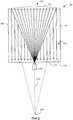
Фиг.2 - схематичный вид в плане, показывающий вариант осуществления оптического клина.2 is a schematic plan view showing an embodiment of an optical wedge.
Фиг.3 и 4 - показ траекторий лучей через поперечное сечение для варианта осуществления по Фиг.2.Figures 3 and 4 show ray paths through a cross section for the embodiment of Figure 2.
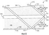
Фиг.5 - показ схематичного увеличенного поперечного сечения концевого отражателя для варианта осуществления по Фиг.2.FIG. 5 is a schematic enlarged cross-sectional view of an end reflector for the embodiment of FIG. 2.
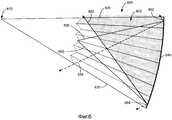
Фиг.6 и 7 - показ траекторий лучей по Фиг.2 в виде путей через набор реплик (экземпляров-копий) для варианта осуществления по Фиг.2.6 and 7 - showing the ray paths of FIG. 2 in the form of paths through a set of replicas (copies) for the embodiment of FIG. 2.
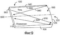
Фиг.8 и 9 - показ траекторий лучей через перспективный вид исполнения оптического клина, содержащего отражательные стороны.Figs. 8 and 9 show ray paths through a perspective view of an optical wedge comprising reflective sides.
Фиг.10 - показ варианта осуществления способа коллимирования света.10 is a view showing an embodiment of a method for collimating light.
ПОДРОБНОЕ ОПИСАНИЕ СУЩНОСТИ ИЗОБРЕТЕНИЯDETAILED DESCRIPTION OF THE INVENTION
В документе раскрыты различные варианты осуществления оптических коллиматоров в форме клиновидных световодов, или оптических клиньев. Оптический клин является световодом, который проводит свет между одним световым интерфейсом на конце клина и другим световым интерфейсом на лицевой поверхности клина с помощью полного внутреннего отражения. В каждом из вариантов осуществления, раскрытых в документе, используется изломанный оптический путь, чтобы давать возможность свету расходиться «веером» до требуемого размера перед коллимацией, что может давать возможность уменьшения размера объема между источником света и поверхностью (например, лицевой поверхностью клина), где выходит коллимированный свет. Такие оптические клинья могут находить различные применения, включая, но неограничительно, такие как задняя подсветка для жидкокристаллического устройства отображения (LCD).The document discloses various embodiments of optical collimators in the form of wedge-shaped optical fibers, or optical wedges. An optical wedge is a light guide that conducts light between one light interface at the end of the wedge and another light interface on the front surface of the wedge using total internal reflection. In each of the embodiments disclosed in the document, a broken optical path is used to allow the light to “fan out” to the desired size before collimation, which may make it possible to reduce the size of the volume between the light source and the surface (for example, the face of the wedge), where a collimated light comes out. Such optical wedges can find various applications, including but not limited to, such as backlighting for a liquid crystal display device (LCD).
Предмет настоящего раскрытия теперь описывается в качестве примера и со ссылкой на конкретные иллюстративные варианты осуществления. На сопроводительных чертежах будет отмечено, что виды для иллюстративных вариантов осуществления могут быть вычерчены не в масштабе, и характеристические отношения для некоторых признаков могут быть увеличены, чтобы более легко понять выбранные признаки или взаимосвязи.The subject of the present disclosure is now described by way of example and with reference to specific illustrative embodiments. In the accompanying drawings, it will be noted that views for illustrative embodiments may not be drawn to scale, and characteristic relationships for some features may be enlarged to more easily understand the selected features or relationships.
На Фиг.1 показан вариант осуществления оптической системы 10, которая может быть сконфигурирована, чтобы обеспечивать для контроллера 16 функциональность как отображения, так и ввода с помощью широкоформатной сенсорной поверхности 12 отображения. Контроллер 16 может быть любым устройством, сконфигурированным для предоставления данных отображения на оптическую систему и приема входных данных от нее. В некоторых вариантах осуществления контроллер может содержать весь или часть компьютера; в других вариантах осуществления контроллер может быть любым устройством, с возможностью взаимодействия связанным с компьютером через проводную или беспроводную линию связи. Контроллер 16 содержит запоминающее устройство 14 и процессор 15. Запоминающее устройство 14 может использоваться, чтобы хранить команды для исполнения процессором 15, включая подпрограммы для управления оптической системой 10.Figure 1 shows an embodiment of an optical system 10 that can be configured to provide both display and input functionality to the controller 16 using the widescreen touch display surface 12. The controller 16 may be any device configured to provide mapping data to an optical system and receive input from it. In some embodiments, the controller may comprise all or part of a computer; in other embodiments, the controller may be any device that can interact with a computer through a wired or wireless communication line. The controller 16 includes a storage device 14 and a processor 15. The storage device 14 may be used to store instructions for execution by the processor 15, including routines for controlling the optical system 10.
Для обеспечения функциональности отображения, оптическая система 10 может быть сконфигурирована с возможностью проецировать видимое изображение на сенсорную поверхность 12 отображения. Для обеспечения функциональности ввода оптическая система может быть сконфигурирована с возможностью ввода с оцифровкой, по меньшей мере, частичного изображения объектов, помещенных на сенсорную поверхность отображения - пальцев, электронных устройств, бумажных карт, пищевых продуктов или напитков, например. Соответственно, оптическая система может быть сконфигурирована с возможностью освещать такие объекты и обнаруживать свет, отраженный от объектов. Таким образом, оптическая система может регистрировать позицию, опорную поверхность и другие характеристики любого подходящего объекта, помещенного на сенсорную поверхность отображения.To provide display functionality, the optical system 10 may be configured to project a visible image onto the touch surface 12 of the display. To provide input functionality, the optical system can be configured to capture and digitize at least a partial image of objects placed on the touch surface of the display — fingers, electronic devices, paper cards, food or drinks, for example. Accordingly, the optical system can be configured to illuminate such objects and detect light reflected from objects. Thus, the optical system can record the position, reference surface and other characteristics of any suitable object placed on the touch surface of the display.
Оптическая система 10 включает в себя оптический клин 100, светонаправляющее устройство 20, световой клапан 22, диффузор 24 и источник 102 света. Источник 102 света и световой клапан 22 могут быть с возможностью взаимодействия связаны с контроллером 16 и сконфигурированы для обеспечения образа визуального отображения для сенсорной поверхности 12 отображения. Источник 102 света может быть любым источником света, сконфигурированным с возможностью излучать видимый свет, таким как один или несколько светоизлучающих диодов, например. Свет от источника 102 света проецируется через оптический клин 100 и направляется на световой клапан 22 через светонаправляющее устройство 20. В некоторых вариантах осуществления светонаправляющее устройство 20 может содержать тонкий слой из призм, сконфигурированных с возможностью направлять свет в направлении под прямым углом к световому клапану 22. Многочисленные светопропускающие элементы светового клапана 22 могут использоваться, чтобы модулировать свет от светонаправляющего устройства 20 по отношению к цвету и интенсивности. В некоторых вариантах осуществления световой клапан может содержать жидкокристаллическое устройство отображения, но также могут использоваться другие модулирующие свет устройства. Таким образом, источник света и световой клапан могут вместе создавать визуальное изображение. Визуальное изображение проецируется через диффузор 24 и тем самым предоставляется на сенсорную поверхность 12 отображения.The optical system 10 includes an
Оптическая система 10 дополнительно может быть сконфигурирована с возможностью обеспечивать функциональность ввода для контроллера 16. Соответственно, иллюстративная оптическая система включает в себя детектор 38, инфракрасные излучатели 72 и освещающий световод 74. Детектор 38 может содержать камеру, такую как чувствительную к инфракрасному излучению цифровую камеру, например, или любое другое подходящее устройство захвата изображения. Инфракрасные излучатели 72 могут содержать один или несколько инфракрасных светоизлучающих диодов, например, или любой другой подходящий источник света. Освещающим световодом может быть любая оптика, сконфигурированная с возможностью принимать ввод инфракрасного света в одной или нескольких входных зонах 76 и пропускать инфракрасный свет, отраженный от объектов, касающихся экрана устройства отображения, через выходную зону 78.The optical system 10 may further be configured to provide input functionality for the controller 16. Accordingly, an exemplary optical system includes a detector 38, infrared emitters 72, and a light guide 74. The detector 38 may include a camera, such as an infrared sensitive digital camera, for example, or any other suitable image capture device. Infrared emitters 72 may include one or more infrared light emitting diodes, for example, or any other suitable light source. The illuminating light guide can be any optics configured to receive infrared light input in one or more input zones 76 and transmit infrared light reflected from objects touching the screen of the display device through the output zone 78.
Например, инфракрасный свет может быть введен инфракрасными излучателями 72 во входную зону 76 освещающего световода 74. Инфракрасный свет может проходить через освещающий световод 74 с помощью полного внутреннего отражения и может рассеиваться наружу по сенсорной поверхности 12 отображения (например, благодаря рассеивающим элементам, не показанным, расположенным по сенсорной поверхности 12 отображения), пока не столкнется с одним или несколькими объектами, контактирующими с сенсорной поверхностью 12 отображения, например объектом 40. Порция инфракрасного света может отражаться от одного или нескольких объектов и выходить из освещающего световода 74 в выходной зоне 78. Инфракрасный свет может проходить от выходной зоны 78 через диффузор 24 и световой клапан 22 и сталкиваться с поверхностью оптического клина 100, который может быть сконфигурирован с возможностью направлять падающий инфракрасный свет на детектор 38. Однако будет понятно, что являются возможными многочисленные другие конфигурации освещения, и они находятся в рамках настоящего раскрытия.For example, infrared light can be introduced by infrared emitters 72 into the entrance area 76 of the light guide 74. The infrared light can pass through the light guide 74 with total internal reflection and can be scattered outward on the display surface 12 (for example, due to scattering elements not shown, located on the touch surface 12 of the display) until it collides with one or more objects in contact with the touch surface 12 of the display, for example, object 40. Portion infrared light can be reflected from one or more objects and exit the light guide 74 in the output zone 78. Infrared light can pass from the output zone 78 through the diffuser 24 and the light valve 22 and collide with the surface of the
Обращаясь далее к Фиг.2, оптический клин 100 может быть сконфигурирован с возможностью коллимировать свет от источника 102 света, размещенного рядом с тонким концом 110 оптического клина 100, так что коллимированный свет выходит из видимой поверхности 150 оптического клина 100, как показано траекториями лучей на Фиг.2. Термин "видимая поверхность" означает, что видимая поверхность 150 ближе к наблюдателю, чем задняя поверхность (не являющаяся видимой на Фиг.2), которая является противоположной видимой поверхности 150. Каждая из видимой и задней поверхностей ограничена сторонами 130 и 140, тонким концом 110 и толстым концом 120. На Фиг.2 видимая поверхность 150 обращена к наблюдателю страницы, и задняя поверхность скрыта этим видом оптического клина 100.Turning further to FIG. 2, the
Оптический клин 100 сконфигурирован так, что световые лучи, введенные в световой интерфейс тонкого конца 110, могут расходиться веером по мере приближения к толстому концу 120, содержащему концевой отражатель 125. Световые лучи подаются на концевой отражатель 125 с помощью полного внутреннего отражения от видимой поверхности 150 и задней поверхности. В предпочтительном варианте осуществления концевой отражатель 125 является криволинейным с одинаковым радиусом кривизны с центром кривизны 200, и источник 102 света вводит свет в фокальной точке концевого отражателя 125, фокальная точка находится на одной второй радиуса кривизны. На толстом конце 120 каждый из световых лучей отражается от концевого отражателя 125 параллельно каждому из других световых лучей. Световые лучи проходят от толстого конца 120 в направлении тонкого конца 110, пока световые лучи не пересекут видимую поверхность 150 под критическим углом отражения видимой поверхности 150, и световые лучи выходят в виде коллимированного света. В альтернативном варианте осуществления концевой отражатель 125 может быть параболическим или иметь другую подходящую кривизну, чтобы коллимировать свет.The
В других вариантах осуществления множество источников света может размещаться рядом с тонким концом 110 и вдоль него. Использование множества источников света может повысить яркость коллимированного света, выходящего из видимой поверхности 150, по сравнению с использованием единственного источника света. В таких вариантах осуществления, чтобы внести поправку на кривизну поля (изображения) и/или сферическую аберрацию, может быть желательным немного уменьшить стороны 130 и 140 оптического клина 100 с тем, чтобы источник света по отношению к любой стороне осевой линии 210 мог оставаться в фокальной точке концевого отражателя 125. Укорочение сторон 130 и 140 может сделать тонкий конец 110 выпуклым, как проиллюстрировано кривой 115. Подходящую кривизну можно найти путем использования алгоритма построения хода луча, чтобы прослеживать лучи под критическим углом отражения видимой поверхности 150 оптического клина 100 обратно через оптический клин 100, пока лучи не дойдут до фокальной точки вблизи тонкого конца 110.In other embodiments, a plurality of light sources may be located adjacent to and along the
На Фиг.3 и 4 показаны траектории лучей через схематичное поперечное сечение оптического клина 100. На Фиг.3 показан путь первого луча 300 через оптический клин 100, и на Фиг.4 показан путь второго луча 400 через оптический клин 100, причем лучи 300 и 400 представляют лучи, расположенные на противоположных сторонах конуса света, который вводится в тонкий конец 110 оптического клина 100. Как может быть видно на фигурах Фиг.3 и 4, луч 300 выходит из видимой поверхности 150 рядом с тонким концом 110 оптического клина 100, тогда как луч 400 выходит из видимой поверхности 150 рядом с толстым концом 120 оптического клина 100.Figures 3 and 4 show ray paths through a schematic cross section of an
Лучи 300 и 400 выходят из видимой поверхности 150, если только лучи 300 и 400 пересекают видимую поверхность 150 под углом, меньшим или равным критическому углу внутреннего отражения по отношению к нормали видимой поверхности 150. Этот критический угол может называться в документе "первый критический угол". Аналогично, лучи отражаются внутренне в оптическом клине 100 при пересечении лучами видимой поверхности 150 под углом больше первого критического угла внутреннего отражения по отношению к нормали видимой поверхности 150. Кроме того, лучи отражаются внутренне в оптическом клине 100, когда лучи пересекают заднюю поверхность 160 под углом больше критического угла внутреннего отражения по отношению к нормали задней поверхности 160. Этот критический угол может называться в документе "второй критический угол".
Как пояснено более подробно ниже со ссылкой на Фиг.5, может быть желательным, чтобы первый критический угол и второй критический угол отличались, с тем чтобы свет, падающий на заднюю поверхность 160 под первым критическим углом, отражался обратно к видимой поверхности 150. Это может помочь препятствовать потере света через заднюю поверхность 160 и, следовательно, может повысить оптическую эффективность оптического клина 100. Первый критический угол является функцией показателя преломления для оптического клина 100 и показателя преломления материала, контактирующего с видимой поверхностью 150 (например, воздух или слой оболочки), тогда как второй критический угол является функцией показателя преломления оптического клина 100 и материала, смежного с задней поверхностью 160. В некоторых вариантах осуществления, таких как показаны на Фиг.3-4, слой оболочки 170 может накладываться только на заднюю поверхность 160, так что видимая поверхность 150 контактирует с воздухом. В других вариантах осуществления видимая поверхность 150 может содержать слой оболочки (не показан) с другим показателем преломления, чем у задней поверхности 160.As explained in more detail below with reference to FIG. 5, it may be desirable for the first critical angle and the second critical angle to be different so that light incident on the
Любой подходящий материал или материалы могут использоваться в качестве слоев оболочки для достижения требуемых критических углов внутреннего отражения для видимой и/или задней поверхностей оптического клина. В варианте осуществления в качестве примера оптический клин 100 формируется из полиметилметакрилата, или PMMA, с показателем преломления 1,492. Показатель преломления воздуха составляет приблизительно 1,000. По существу, критический угол поверхности без оболочки составляет приблизительно 42,1 градуса. Далее, примерный слой оболочки может содержать Teflon AF (компания EI DuPont de Nemours & Co., Уилмингтон, штат Делавэр), аморфный фторполимер с показателем преломления 1,33. Критический угол поверхности PMMA с покрытием Teflon AF составляет 63,0 градуса. Будет понятно, что эти примеры описаны с целью иллюстрации и не подразумеваются ограничивающими каким-либо образом.Any suitable material or materials may be used as cladding layers to achieve the required critical internal reflection angles for the visible and / or rear surfaces of the optical wedge. In an embodiment, by way of example, an
В других вариантах осуществления задняя поверхность 160 может включать в себя зеркало. В качестве неограничительных примеров зеркало может быть образовано наложением отражательного покрытия на заднюю поверхность 160 или помещением зеркала рядом с задней поверхностью 160. Таким образом, задняя поверхность 160 может отражать падающий свет, пересекающий заднюю поверхность 160. Если задняя поверхность 160 сконфигурирована для отражения некоторого или всего падающего света, задняя поверхность 160 может именоваться в документе "отражательная задняя поверхность". Неограничительные примеры отражательной задней поверхности включают заднюю поверхность, имеющую зеркальную поверхность, зеркало, помещенное рядом с задней поверхностью, заднюю поверхность, имеющую второй критический угол внутреннего отражения по отношению к нормали задней поверхности, причем второй критический угол отражения меньше первого критического угла отражения, или любую другую конфигурацию, в которой задняя поверхность является отражательной к внутренне падающему свету под первым критическим углом внутреннего отражения.In other embodiments, the
Форма оптического клина 100 и концевого отражателя 125 может быть сконфигурирована с возможностью обеспечить, чтобы основная часть видимой поверхности 150 была однородно освещенной при введении равномерно распределенного света в тонкий конец 110, а также обеспечить, чтобы основная часть введенного света выходила из видимой поверхности 150. Как упомянуто выше, оптический клин 100 является коническим по всей длине, так что лучи, введенные на тонком конце 110, проходят на концевой отражатель 125 с помощью полного внутреннего отражения. Концевой отражатель 125 содержит структуру многогранной линзы, сконфигурированную для уменьшения угла луча по отношению к нормали к каждой поверхности из видимой поверхности 150 и задней поверхности 160. Кроме того, уменьшающаяся толщина оптического клина 100 от толстого конца 120 к тонкому концу 110 обеспечивает, что углы луча уменьшаются относительно нормали к каждой поверхности, если лучи проходят к тонкому концу 110. Если луч падает на видимую поверхность 150 под углом меньше первого критического угла, луч будет выходить из видимой поверхности 150.The shape of the
В некоторых вариантах осуществления источник 102 света может быть позиционирован в фокальной точке концевого отражателя 125. В таких вариантах осуществления концевой отражатель 125 может быть криволинейным с радиусом кривизны, который составляет две длины оптического клина 100. В варианте осуществления по Фиг.3-4 угол конусности оптического клина 100 сконфигурирован так, чтобы угол на толстом конце 120 и видимая поверхность 150 составляли прямой угол и угол на толстом конце 120 и задняя поверхность 160 составляли прямой угол. Если тонкий конец 110 находится в фокальной точке концевого отражателя 125, тонкий конец 110 составляет одну вторую толщины толстого конца 120. В других вариантах осуществления каждая из этих структур может иметь любую другую подходящую конфигурацию.In some embodiments, the
В изображенном варианте осуществления концевой отражатель 125 является сферически криволинейным от стороны 130 к стороне 140 и от видимой поверхности 150 к задней поверхности 160. В других вариантах осуществления концевой отражатель 125 может быть цилиндрически криволинейным с одинаковым радиусом кривизны от видимой поверхности 150 и задней поверхности 160 и центром кривизны, где видимая поверхность 150 и задняя поверхность 160 пересекутся, если продлены. Цилиндрически криволинейный концевой отражатель может работать на изгиб сильнее, чем сферически криволинейный концевой отражатель 125, что может быть выгодным в приложениях большого формата. Другие подходящие кривые могут использоваться для концевого отражателя 125, такие как параболические, например. Кроме того, кривизна концевого отражателя 125 в плоскости, перпендикулярной сторонам 130 и 140, может отличаться от кривизны концевого отражателя 125 в плоскости, параллельной сторонам 130 и 140.In the depicted embodiment, the
Как упомянуто выше, может быть желательным, чтобы критические углы отражения для видимой поверхности 150 и задней поверхности 160 были различными. Это поможет препятствовать потере света через заднюю поверхность 160, как проиллюстрировано на Фиг.5, на которой показано схематичное увеличенное поперечное сечение концевого отражателя 125 из варианта осуществления оптического клина по Фиг.2-4. Концевой отражатель 125 содержит структуру многогранной линзы, содержащую множество граней, расположенных под углом относительно поверхности толстого конца 120. В множестве граней чередуются грани, обращенные к видимой поверхности 150, такие как грань 530, и грани, обращенные к задней поверхности 160, такие как грань 540. Концевой отражатель 125 соответствует общей кривизне, как описано выше, причем нормаль 542 концевого отражателя и нормаль 532 концевого отражателя проходят к центру кривизны. Каждая из множества граней имеет высоту и угол по отношению к нормали поверхности концевого отражателя. Например, одна из граней, обращенных к видимой поверхности 150, имеет высоту 538 и угол 536 относительно нормали 532 концевого отражателя и нормали 534 грани. В качестве другого примера, одна из граней, обращенных к задней поверхности 160, имеет высоту 548 и угол 546 относительно нормали 542 концевого отражателя и нормали 544 грани.As mentioned above, it may be desirable that the critical reflection angles for the
Высота каждой из множества граней может влиять на однородность и яркость коллимированного света, выходящего из видимой поверхности 150. Например, более большие грани могут создавать оптические пути, которые отличаются от идеального фокусного расстояния, каковое может вызвать полосчатость по Френелю. По существу, в вариантах осуществления, где такая полосчатость может вызывать проблемы, может быть желательным делать высоту каждой из множества граней менее 500 микрон, например, с тем чтобы такая полосчатость была менее заметной.The height of each of the many faces can affect the uniformity and brightness of the collimated light coming out of the
Подобным образом, угол каждой из множества граней также может влиять на однородность и яркость коллимированного света, выходящего из видимой поверхности 150. Луч 500 иллюстрирует, каким образом углы граней могут влиять на путь луча через оптический клин 100. Луч 500 вводится в тонкий конец 110, проходит через оптический клин 100 и достигает концевого отражателя 125. Половина луча 500 достигает грани 530, обращенной к видимой поверхности 150. Часть луча 500, достигающая грань 530, отражается в виде луча 510 к видимой поверхности 150. Луч 510 пересекает видимую поверхность 150 под углом, меньшим или равным первому критическому углу внутреннего отражения относительно нормали видимой поверхности 150, и таким образом выходит из видимой поверхности 150 в виде луча 512.Similarly, the angle of each of the many faces can also affect the uniformity and brightness of the collimated light exiting the
Другая половина луча 500 достигает грань 540, обращенную к задней поверхности 160. Порция луча 500, достигающая грань 540, отражается в виде луча 520 к задней поверхности 160. Вследствие различия между критическими углами видимой поверхности 150 и задней поверхности 160 луч 520 пересекает заднюю поверхность 160 под углом, который больше второго критического угла внутреннего отражения относительно нормали задней поверхности 160, и таким образом отражается в виде луча 522 к видимой поверхности 150. Луч 522 затем пересекает видимую поверхность 150 под углом, меньшим или равным первому критическому углу внутреннего отражения относительно нормали видимой поверхности 150, и таким образом выходит в виде луча 524. Таким образом, основная часть (и в некоторых вариантах осуществления, по существу весь) света, который отражается от концевого отражателя 125, выходит из видимой поверхности 150.The other half of the
Вследствие света, раздельно отражаемого гранями, обращенными к видимой поверхности 150, и гранями, обращенными к задней поверхности 160, перекрытие наложенных первого и второго изображений, организованных в ориентации «голова-хвост», может формироваться у видимой поверхности 150. Степень перекрытия между этими изображениями может определяться согласно углам граней 530 и 540. Например, два изображения являются полностью перекрывающимися в случае, если каждая грань имеет угол относительно нормали поверхности концевого отражателя в три восьмых от разности между углом в девяносто градусов и первым критическим углом отражения, как пояснено более подробно ниже. В этом случае по существу весь свет, вводимый в оптический клин 100, выходит из видимой поверхности 150. Изменение граней от этого значения уменьшает величину перекрытия между изображениями, так что отображается только одно или другое из двух изображений, где углы граней составляют 1/4 или 1/2 от разности между углом 90 градусов и первым критическим углом отражения. Кроме того, изменение углов граней от трех восьмых от разности между углом девяносто градусов и первым критическим углом отражения также обеспечивает, что некоторый свет выходит из тонкого конца оптического клина 100, а не из видимой поверхности 150. Там, где углы граней составляют 1/4 или 1/2 от разности между 90 градусами и первым критическим углом отражения, видимая поверхность также может быть однородно освещена, но половина света выходит из тонкого конца оптического клина 100 и, следовательно, теряется. Будет понятно, что в зависимости от требуемой среды применения может быть подходящим использовать углы граней, отличные от трех восьмых разности между углом девяносто градусов и первым критическим углом отражения, чтобы получить коллимированный свет. Такие среды применения могут включать, но не ограничиваются указанными, среды, в которых любые области неперекрывающегося света (который появится имеющим более низкую интенсивность относительно перекрывающихся областей) не находятся в поле зрения, наблюдаемого пользователем.Due to the light separately reflected by the faces facing the
В альтернативном варианте осуществления структура многогранной линзы концевого отражателя 125 может содержать дифракционную решетку. Уравнение решетки может использоваться, чтобы вычислять угол дифракции для данного угла падения и данной длины волны света. Поскольку угол дифракции зависит от длины волны света, концевой отражатель, содержащий дифракционную решетку, может быть желательным, если вводимый свет является монохроматическим.In an alternative embodiment, the structure of the polyhedral
На Фиг.6 и 7 иллюстрируется прохождение света через оптический клин 100 в виде путей лучей через набор оптических клиньев, причем каждый оптический клин является репликой исполнения оптического клина 100, чтобы дополнительно проиллюстрировать идеи, показанные на Фиг.5. Трассировка лучей через набор реплик оптического клина является оптически эквивалентной прослеживанию пути луча внутри оптического клина. Итак, таким образом, каждое внутреннее отражение луча показано в виде прохода луча через границу от одного оптического клина к смежному оптическому клину. На Фиг.6 видимая поверхность показана в виде видимой поверхности 620 самого верхнего клина из набора оптических клиньев 600. Задняя поверхность показана в виде задней поверхности 630 самого нижнего клина из набора оптических клиньев 600. Толстые концы набора оптических клиньев 600 объединены, чтобы образовать являющееся приближенно кривой 640, центрированной относительно оси 610, где все поверхности сходятся. На Фиг.6 толстый конец каждого клина показан имеющим одинаковую общую кривизну. Однако будет понятно, что толстый конец каждого клина может иметь любую другую подходящую кривизну.Figures 6 and 7 illustrate the passage of light through an
На Фиг.6 также изображены два луча света 650 и 660, расположенные на противоположных сторонах конуса света, который вводится в тонкий конец оптических клиньев набора 600. Для каждого луча 650 и 660 после отражения от концевого отражателя половина луча появляется вблизи толстого конца оптических клиньев набора 600 (и, следовательно, из представленного оптического клина), как показано сплошными линиями 652 и 662, и половина луча появляется из тонкого конца набора оптических клиньев, как показано пунктирными линиями 654 и 664. Лучи, вводимые под любым углом между этими двумя предельными, также будут расщепляться согласно многогранной структуре в концевом отражателе и выходят из видимой поверхности и задней поверхности оптического клина сходным образом. Лучи, выходящие из видимой поверхности 620, параллельные лучам 652 и 662, представлены затененной областью 602. Как упомянуто выше, будет понятно, что лучи, показанные в виде излучаемых через заднюю поверхность 630 оптического клина, вместо этого могут отражаться задней поверхностью и затем выходить из видимой поверхности, используя оболочку (не показано) на задней поверхности оптического клина, которая имеет более низкий показатель преломления, чем оболочка (не показано), используемая на видимой поверхности оптического клина. Таким образом, по существу весь свет, который вводится в тонкий конец такого оптического клина, может излучаться от видимой поверхности оптического клина.6 also shows two
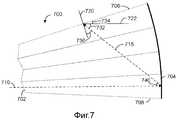
Чтобы видимая поверхность была однородно освещенной (например, где изображения, отраженные от граней 530 и 540, являются полностью перекрывающимися), луч, вводимый на тонком конце и проходящий горизонтально на концевой отражатель, совпадающий с нормалью концевого отражателя, отражается от грани, обращенной к видимой поверхности, и проходит в центр видимой поверхности, пересекая видимую поверхность под критическим углом для видимой поверхности. На Фиг. 7 показано схематичное описание пути такого луча через набор оптических клиньев 700. Луч 710 вводится на тонком конце 702 оптического клина и отражается от концевого отражателя 704 в виде луча 715. Луч 715 проходит к центру видимой поверхности 706, пересекая видимую поверхность 706 под критическим углом отражения 730 относительно нормали видимой поверхности 72. Сумма углов 732 и 734 является разностью угла 90 градусов и критического угла отражения 730. Когда тонкий конец оптического клина составляет одну вторую от толщины толстого конца оптического клина, центральная точка клина составляет три четвертых от толщины оптического клина. Используя параксиальное приближение, угол 732 составляет три четвертых разности угла 90 градусов и критического угла отражения 730. Горизонтальная линия 722 параллельна вводимому лучу 710, таким образом, угол 740 равен углу 732. Из закона отражения угол падения равен углу отражения, таким образом, угол грани может быть одной второй угла 740. Следовательно, для видимой поверхности, которая будет однородно освещена, каждая грань, обращенная к видимой поверхности, может образовать угол относительно нормали к поверхности концевого отражателя в три восьмых от разности между углом 90 градусов и критическим углом отражения 730, как упомянуто выше.In order for the visible surface to be uniformly illuminated (for example, where the images reflected from
Любой подходящий источник света может использоваться для ввода света в оптический клин 100. Примеры включают, но не ограничиваются указанными, светоизлучающие диоды (LED). Будет отмечено, что свет излучается от открытого LED по модели ламбертовского источника. Однако для повышенной оптической эффективности относительно открытого LED может требоваться, чтобы свет вводился в оптический клин так, чтобы все лучи были под углами между двумя лучами 650 и 660, показанными на Фиг.6 сплошной линией, то есть под углами относительно плоскости оптического клина, которые являются между 0° и одной второй разности угла девяносто градусов минус критический угол. Следовательно, LED может быть помещен в фокальную точку концентратора, спроектированного так, чтобы его толщина на выходе приблизительно равнялась толщине тонкого конца и диапазон углов его эмиссии приблизительно равнялся диапазону, показанному лучами 650 и 660.Any suitable light source may be used to introduce light into the
В некоторых вариантах осуществления множество источников света могут быть позиционированы рядом с тонким концом оптического клина и вдоль него, чтобы повысить интенсивность выходного коллимированного света. Выход из оптического клина 100 такого массива источников света может быть проанализирован путем анализа каждого из источников света и затем объединения результатов с использованием принципа суперпозиции. Это может помочь в проектном решении системы, которая выдает однородно коллимированный свет, используя такой массив источников света, как проиллюстрировано на Фиг.8 и 9, на которых показан схематичный вид путей лучей через примерный оптический клин. Оптический клин 100 на Фиг.8 и 9 содержит тонкий конец 110, толстый конец 120, стороны 130 и 140 и видимую поверхность 150 со средней линией 850. Толстый конец 120 включает в себя концевой отражатель 125. Стороны 130 и 140 могут быть отражательными. Источники света 802 и 902 размещаются смежными тонкому концу 110, равноотстоящими от средней линии 850.In some embodiments, multiple light sources can be positioned near and along the thin end of the optical wedge to increase the intensity of the output collimated light. The exit from the
На Фиг.8 конус света, ограниченный лучами 810 и 830, вводится на тонком конце 110 посредством источника света 802. Луч 830 пересекает концевой отражатель 125 и отражается в виде луча 840. Луч 810 пересекает концевой отражатель 125 и отражается в виде луча 820 после дополнительного отражения от стороны 140. Как показано на Фиг.8, коллимированный свет, излучаемый от видимой поверхности 150, может не быть однородным в этой конфигурации. Например, область между лучом 820 и стороной 140, помеченная "Отражение", может быть более яркой, чем область между лучом 820 и стороной 130 вследствие лучей, отраженных от стороны 140, излучаемых от видимой поверхности, в дополнение к лучам, отраженным непосредственно от концевого отражателя 125 в области между лучом 820 и стороной 140. Кроме того, область между стороной 130 и лучом 840, помеченная "Тень", может быть более тусклой, чем область между лучом 840 и стороной 140 вследствие тени, обусловленной лучом 840, отражаемым от стороны 130.8, a cone of light bounded by
На Фиг.9 источник света 902 находится на том же расстоянии от средней линии 850, что и источник света 802, но позиционирован на противоположной стороне средней линии 850. Конус света, ограниченный лучами 910 и 930, вводится на тонком конце 110 источником света 902. Луч 930 пересекает концевой отражатель 125 и отражается в виде луча 940. Луч 910 пересекает концевой отражатель 125 и отражается в виде луча 920 после дополнительного отражения от стороны 130. Как описано выше относительно Фиг.8, коллимированный свет, излучаемый от видимой поверхности 150, может не являться однородным в этой конфигурации. Область между лучом 920 и стороной 130, помеченная "Отражение", может быть более яркой, чем область между лучом 920 и стороной 140. Кроме того, область между стороной 140 и лучом 940, помеченная "Тень", может быть более тусклой, чем область между лучом 840 и стороной 140.9, the
При позиционировании источников света 802 и 902 на одинаковых расстояниях от средней линии 850, границы области "Отражение" на Фиг.8 могут приводиться в соответствие с границами области "Тень" на Фиг.9. Аналогично, границы области "Тень" на Фиг.8 могут приводиться в соответствие с границами области "Отражение" на Фиг.9. Области тени и отражения могут взаимно компенсировать друг друга, если яркость источников света 802 и 902 является сходной, так что свет, вводимый на тонком конце 110 каждым источником света, имеет сходную яркость и однородность.When positioning the
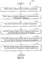
На Фиг.10 показан примерный способ 1000 выполнения коллимации света с помощью оптического волновода. Оптический волновод может содержать первый конец, второй конец, противоположный первому концу и содержащий концевой отражатель, содержащий множество граней, видимую поверхность, проходящую между первым концом и вторым концом, и заднюю поверхность, противолежащую видимой поверхности. Видимая поверхность может иметь первый критический угол отражения, и задняя поверхность может иметь второй критический угол отражения, причем первый и второй критические углы отражения являются различными. В одном варианте осуществления оптическим волноводом является оптический клин по Фиг.2, где тонким концом оптического клина является первый конец оптического волновода и толстым концом оптического клина является второй конец оптического волновода. В альтернативном варианте осуществления оптический волновод может иметь постоянную толщину, например первый конец и второй конец имеют одинаковую толщину. Оптический волновод может включать в себя оболочку на видимой и/или задней поверхности с показателем преломления, который изменяется линейно между первым концом и вторым концом. Этот вариант осуществления будет действовать аналогично оптическому клину, когда свет вводится в первый конец оптического волновода. В еще одном варианте осуществления оптический волновод может иметь постоянную толщину, показатель преломления, изменяющийся линейно между первым концом и вторым концом, и оболочки на видимой и/или задней поверхности с постоянным показателем преломления. Этот вариант осуществления также будет действовать аналогично оптическому клину при введении света в первый конец оптического волновода.10 shows an
Возвращаясь к Фиг.10, на этапе 1010 свет может быть введен в первый конец оптического волновода, и затем на этапе 1020 свет может передаваться на концевой отражатель с помощью полного внутреннего отражения. На этапе 1030 свет может внутренне отражаться от концевого отражателя. Свет, внутренне отраженный от концевого отражателя, может отражаться от первого множества граней и второго множества граней, каждая грань из первого множества граней имеет нормаль, которая указывает, по меньшей мере частично, на видимую поверхность, и каждая грань из второго множества граней имеет нормаль, которая указывает, по меньшей мере частично, на заднюю поверхность. Кроме того, в некоторых вариантах осуществления каждая грань из первого множества граней может иметь угол в три восьмых от разности между углом 90 градусов и критическим углом отражения и каждая грань из второго множества граней может иметь угол в три восьмых от разности между углом 90 градусов и критическим углом отражения. В других вариантах осуществления грани могут иметь другие подходящие углы, которые не вызывают неподходящие изменения интенсивности света.Returning to FIG. 10, at 1010, light can be introduced into the first end of the optical waveguide, and then at 1020, light can be transmitted to the end reflector using total internal reflection. At 1030, light may be reflected internally from the end reflector. Light internally reflected from the end reflector may be reflected from the first plurality of faces and the second plurality of faces, each face of the first plurality of faces has a normal that indicates at least partially to the visible surface, and each face of the second plurality of faces has a normal, which indicates, at least in part, the rear surface. In addition, in some embodiments, each face of the first set of faces can have an angle of three-eighths of the difference between the angle of 90 degrees and the critical angle of reflection, and each face of the second set of faces can have an angle of three-eighths of the difference between the angle of 90 degrees and the critical angle of reflection. In other embodiments, the faces may have other suitable angles that do not cause inappropriate changes in light intensity.
Вследствие угла, под которым грани на концевом отражателе скошены, на этапе 1040 первая порция света может излучаться от видимой поверхности, причем первая порция света пересекает видимую поверхность под первым критическим углом отражения. На этапе 1050 вторая порция света может внутренне отражаться от задней поверхности под углом, равным первому критическому углу отражения, когда второй критический угол отражения меньше первого критического угла отражения. На этапе 1060 вторая порция света затем может излучаться от видимой поверхности после внутреннего отражения от задней поверхности.Due to the angle at which the faces on the end reflector are beveled, at 1040, a first portion of the light can be emitted from the visible surface, the first portion of the light crossing the visible surface at the first critical reflection angle. At 1050, a second portion of light may be reflected internally from the rear surface at an angle equal to the first critical reflection angle when the second critical reflection angle is less than the first critical reflection angle. At 1060, a second portion of light can then be emitted from the visible surface after internal reflection from the rear surface.
Среди потенциальных применений такого плоскопанельного коллиматора является таковой, освещающий жидкокристаллическую панель. Жидкокристаллическое устройство отображения является недорогим способом отображения видео и содержит жидкокристаллическую панель, сзади которой помещается подсветка. Прошлые клиновые задние подсветки использовали тонкий прозрачный клин с источниками света вдоль толстого конца и пленки, направляющие свет через жидкокристаллическую панель к наблюдателю с тем, чтобы он мог видеть выведенное на экран изображение. Предпринимается значительное усилие для обеспечения того, чтобы излучение от задней подсветки являлось достаточно рассеянным с тем, чтобы отображаемое изображение можно было видеть из широкого поля зрения. Например, некоторые прошлые клинья заполнялись рассеивающими узлами. При рассеянном освещении, однако, трудно использовать жидкокристаллическую панель все-таки в отличие от традиционного дисплея.Among the potential applications of such a flat panel collimator is one that illuminates a liquid crystal panel. A liquid crystal display device is an inexpensive way to display video and includes a liquid crystal panel, behind which is placed a backlight. Past wedge-shaped backlights used a thin, transparent wedge with light sources along the thick end and films directing light through the LCD panel to the observer so that he could see the image displayed on the screen. Considerable effort is being made to ensure that the radiation from the backlight is sufficiently diffused so that the displayed image can be seen from a wide field of view. For example, some past wedges were filled with scattering nodes. In diffuse lighting, however, it is difficult to use a liquid crystal panel after all, unlike a traditional display.
Существуют многие приложения, где является желательным проецировать видеоизображение. Это может выполняться путем помещения линзы перед жидкокристаллическим экраном. Однако при рассеянном освещении линза должна быть большой и, следовательно, дорогой. Плоскопанельный коллиматор может быть тонким средством освещения небольшой жидкокристаллической панели или другого пространственного модулятора света коллимированным светом, который можно конденсировать через небольшую проекционную линзу. Если пространственный модулятор света является отражательным, как в случае цифрового микрозеркального устройства, не требуется светоделительный элемент или другое пространство для освещения. Следовательно, проекционную линзу можно подвести к модулятору света так близко, как требуется.There are many applications where it is desirable to project a video image. This can be done by placing the lens in front of the liquid crystal screen. However, in diffuse lighting, the lens should be large and therefore expensive. A flat panel collimator can be a subtle means of illuminating a small liquid crystal panel or other spatial light modulator with collimated light that can be condensed through a small projection lens. If the spatial light modulator is reflective, as in the case of a digital micromirror device, a beam splitter or other space for lighting is not required. Therefore, the projection lens can be brought to the light modulator as close as required.
В некоторых приложениях может требоваться проецировать на экран изображение только в несколько миллиметров. Это может выполняться таким же образом, как солнце проецирует тень деревьев на землю: осветить большую жидкокристаллическую панель коллимированным светом, и его тень, например изображение, может формироваться на диффузоре, отстоящем на расстояние в несколько миллиметров от жидкокристаллической панели. Одно применение для этого находится там, где требуется наличие видеоизображения на каждой клавише клавиатуры. Если бы отдельный экран отображения подлежал формированию на каждой клавише клавиатуры, стоимость такого количества небольших отображений могла стать чрезмерной. Однако, используя подсветку коллимирующего оптического клина, как описано выше, прозрачные клавиши могут быть снабжены диффузионными поверхностями и помещены поверх жидкокристаллической панели с коллимированной подсветкой. Таким образом, изображение может проецироваться вплоть до каждой клавиши из различных областей одной большой, но дешевой панели.In some applications, it may be necessary to project an image of only a few millimeters onto the screen. This can be done in the same way that the sun projects a tree shadow onto the ground: illuminate a large LCD panel with collimated light, and its shadow, such as an image, can form on a diffuser a few millimeters from the LCD panel. One application for this is where a video image is required on each key of the keyboard. If a separate display screen were to be formed on each key of the keyboard, the cost of so many small displays could become excessive. However, using the backlight of a collimating optical wedge, as described above, the transparent keys can be provided with diffusion surfaces and placed on top of a collimated backlight LCD. Thus, the image can be projected up to each key from different areas of one large, but cheap panel.
Другое примерное применение для теневой проекции состоит в проекции изображения на диффузор, где пальцы или объекты, которые касаются диффузора, должны восприниматься с помощью инфракрасной камеры сзади. Устройства, такие как SURFACE корпорации Microsoft, разработанное и продаваемое корпорацией Microsoft Corporation, Редмонд, штат Вашингтон, содержат видеопроектор, инфракрасную лампу, камеру и диффузор. Проектор создает видеоизображение на диффузоре, и лампа освещает объекты поблизости так, что они выглядят размытыми, когда удалены от диффузора, но резкими в момент касания. Оптика обработки изображений может быть сделана тонкой путем направления камеры на диффузор через оптический клин, такой как исполнения, описанные выше. Если жидкокристаллическое устройство отображения освещается рассеянным светом, проецируемое изображение может быть пространственно отдельным от диффузора и, следовательно, может быть размытым. Следовательно, жидкокристаллическая панель может быть освещена коллимированным светом, как раскрыто выше, с тем чтобы видимое изображение без размытия формировалось в диффузоре. В некоторых вариантах осуществления панель для обеспечения коллимированного видимого освещения и детектирования инфракрасного изображения является одной и той же и концевой отражатель содержит грани под углом согласно данному раскрытию, которые отражают видимый свет, но пропускают инфракрасный свет, и вне их помещаются грани или эквиваленты, которые отражают инфракрасный свет и скошены так, чтобы формировать одиночное однозначно (идентифицируемое) изображение.Another exemplary application for shadow projection is to project an image onto a diffuser, where fingers or objects that touch the diffuser should be perceived using an infrared camera at the back. Devices such as Microsoft's SURFACE, developed and marketed by Microsoft Corporation, Redmond, Wash., Include a video projector, infrared lamp, camera, and diffuser. The projector creates a video image on the diffuser, and the lamp illuminates objects nearby so that they look blurry when removed from the diffuser, but sharp at the moment of contact. Image processing optics can be made thin by directing the camera at the diffuser through an optical wedge, such as the designs described above. If the liquid crystal display device is illuminated by diffused light, the projected image may be spatially separate from the diffuser and, therefore, may be blurred. Therefore, the liquid crystal panel can be illuminated with collimated light, as disclosed above, so that a visible image without blurring is formed in the diffuser. In some embodiments, the panel for providing collimated visible illumination and detecting an infrared image is the same and the end reflector contains faces at an angle according to this disclosure that reflect visible light but transmit infrared light, and edges or equivalents which reflect infrared light and beveled so as to form a single, uniquely (identifiable) image.
Будет понятно, что конфигурации и/или подходы, описанные в документе, являются иллюстративными по характеру и что эти конкретные варианты осуществления или примеры нельзя рассматривать в ограничительном смысле, поскольку возможны многочисленные изменения. Предмет настоящего раскрытия включает в себя все новые и неочевидные комбинации и подкомбинации различных процессов, систем и конфигураций и другие признаки, функции, действия и/или характеристики, раскрытые в документе, а также любой и все эквиваленты таковых.It will be understood that the configurations and / or approaches described herein are illustrative in nature and that these specific embodiments or examples should not be construed in a limiting sense as numerous changes are possible. The subject of this disclosure includes all new and non-obvious combinations and subcombinations of various processes, systems and configurations and other features, functions, actions and / or characteristics disclosed in the document, as well as any and all equivalents thereof.
Claims (15)
Translated fromRussianоптический волновод, имеющий
первый конец, содержащий первый световой интерфейс;
второй конец, противоположный первому концу;
видимую поверхность, содержащую второй световой интерфейс, проходящий, по меньшей мере, частично между первым концом и вторым концом и имеющий первый критический угол внутреннего отражения по отношению к нормали видимой поверхности;
заднюю поверхность, противолежащую видимой поверхности, при этом задняя поверхность является конфигурируемой, чтобы быть отражательной для внутренне падающего света под первым критическим углом внутреннего отражения; и
концевой отражатель, расположенный на втором конце оптического волновода, причем концевой отражатель содержит структуру многогранной линзы, содержащую множество граней, скошенных для обеспечения того, чтобы основная часть видимой поверхности была однородно освещенной при введении равномерно распределенного света в первый конец, и также для обеспечения того, чтобы основная часть вводимого света выходила из видимой поверхности.1. An optical collimator containing:
optical waveguide having
a first end comprising a first light interface;
the second end opposite the first end;
a visible surface comprising a second light interface extending at least partially between the first end and the second end and having a first critical angle of internal reflection with respect to the normal to the visible surface;
a rear surface opposite the visible surface, wherein the rear surface is configurable to be reflective to the incident light at a first critical angle of internal reflection; and
an end reflector located at the second end of the optical waveguide, the end reflector comprising a multifaceted lens structure containing a plurality of bevels to ensure that the main part of the visible surface is uniformly illuminated when uniformly distributed light is introduced into the first end, and also to ensure so that the bulk of the input light comes out of the visible surface.
введение света в первый конец оптического волновода;
подачу света на концевой отражатель с помощью полного внутреннего отражения;
внутреннее отражение света от концевого отражателя;
излучение первой порции света от видимой поверхности под критическим углом отражения;
внутреннее отражение второй порции света от задней поверхности под углом, равным критическому углу отражения, и затем излучение второй порции света от видимой поверхности после внутреннего отражения второй порции света от задней поверхности.13. A method of performing collimation of light using an optical waveguide, wherein the optical waveguide comprises a first end, a second end opposite the first end and comprising an end reflector, a visible surface extending between the first end and the second end, and a rear surface opposite to the visible surface, this method contains:
introducing light into the first end of the optical waveguide;
the supply of light to the end reflector using total internal reflection;
internal reflection of light from the end reflector;
radiation of the first portion of light from the visible surface at a critical angle of reflection;
internal reflection of the second portion of light from the rear surface at an angle equal to the critical angle of reflection, and then radiation of the second portion of light from the visible surface after internal reflection of the second portion of light from the rear surface.
Applications Claiming Priority (5)
| Application Number | Priority Date | Filing Date | Title |
|---|---|---|---|
| US23592209P | 2009-08-21 | 2009-08-21 | |
| US61/235,922 | 2009-08-21 | ||
| US12/621,399 | 2009-11-18 | ||
| US12/621,399US20110044582A1 (en) | 2009-08-21 | 2009-11-18 | Efficient collimation of light with optical wedge |
| PCT/US2010/046129WO2011022625A2 (en) | 2009-08-21 | 2010-08-20 | Efficient collimation of light with optical wedge |
Publications (2)
| Publication Number | Publication Date |
|---|---|
| RU2012105980A RU2012105980A (en) | 2013-08-27 |
| RU2536080C2true RU2536080C2 (en) | 2014-12-20 |
Family
ID=43605440
Family Applications (1)
| Application Number | Title | Priority Date | Filing Date |
|---|---|---|---|
| RU2012105980/28ARU2536080C2 (en) | 2009-08-21 | 2010-08-20 | Efficient collimation of light with optical wedge |
Country Status (9)
| Country | Link |
|---|---|
| US (4) | US20110044582A1 (en) |
| EP (1) | EP2467749B1 (en) |
| JP (1) | JP2013502697A (en) |
| KR (1) | KR20120049890A (en) |
| CN (1) | CN102483522B (en) |
| BR (1) | BR112012008188A2 (en) |
| CA (1) | CA2768068A1 (en) |
| RU (1) | RU2536080C2 (en) |
| WO (1) | WO2011022625A2 (en) |
Families Citing this family (252)
| Publication number | Priority date | Publication date | Assignee | Title |
|---|---|---|---|---|
| US9471170B2 (en) | 2002-11-04 | 2016-10-18 | Neonode Inc. | Light-based touch screen with shift-aligned emitter and receiver lenses |
| US20100238139A1 (en)* | 2009-02-15 | 2010-09-23 | Neonode Inc. | Optical touch screen systems using wide light beams |
| US9213443B2 (en)* | 2009-02-15 | 2015-12-15 | Neonode Inc. | Optical touch screen systems using reflected light |
| US9778794B2 (en) | 2001-11-02 | 2017-10-03 | Neonode Inc. | Light-based touch screen |
| US9052771B2 (en)* | 2002-11-04 | 2015-06-09 | Neonode Inc. | Touch screen calibration and update methods |
| US9052777B2 (en) | 2001-11-02 | 2015-06-09 | Neonode Inc. | Optical elements with alternating reflective lens facets |
| US8674966B2 (en) | 2001-11-02 | 2014-03-18 | Neonode Inc. | ASIC controller for light-based touch screen |
| US8587562B2 (en)* | 2002-11-04 | 2013-11-19 | Neonode Inc. | Light-based touch screen using elliptical and parabolic reflectors |
| US8902196B2 (en)* | 2002-12-10 | 2014-12-02 | Neonode Inc. | Methods for determining a touch location on a touch screen |
| GB0522968D0 (en) | 2005-11-11 | 2005-12-21 | Popovich Milan M | Holographic illumination device |
| GB0718706D0 (en) | 2007-09-25 | 2007-11-07 | Creative Physics Ltd | Method and apparatus for reducing laser speckle |
| US9063614B2 (en) | 2009-02-15 | 2015-06-23 | Neonode Inc. | Optical touch screens |
| US20100231498A1 (en)* | 2009-03-13 | 2010-09-16 | Microsoft Corporation | Image display via multiple light guide sections |
| US11726332B2 (en) | 2009-04-27 | 2023-08-15 | Digilens Inc. | Diffractive projection apparatus |
| US9335604B2 (en) | 2013-12-11 | 2016-05-10 | Milan Momcilo Popovich | Holographic waveguide display |
| US8358901B2 (en)* | 2009-05-28 | 2013-01-22 | Microsoft Corporation | Optic having a cladding |
| US8354806B2 (en)* | 2009-08-21 | 2013-01-15 | Microsoft Corporation | Scanning collimation of light via flat panel lamp |
| US20110044582A1 (en)* | 2009-08-21 | 2011-02-24 | Microsoft Corporation | Efficient collimation of light with optical wedge |
| US11320571B2 (en) | 2012-11-16 | 2022-05-03 | Rockwell Collins, Inc. | Transparent waveguide display providing upper and lower fields of view with uniform light extraction |
| US8233204B1 (en) | 2009-09-30 | 2012-07-31 | Rockwell Collins, Inc. | Optical displays |
| US10795160B1 (en) | 2014-09-25 | 2020-10-06 | Rockwell Collins, Inc. | Systems for and methods of using fold gratings for dual axis expansion |
| US11300795B1 (en) | 2009-09-30 | 2022-04-12 | Digilens Inc. | Systems for and methods of using fold gratings coordinated with output couplers for dual axis expansion |
| US11204540B2 (en) | 2009-10-09 | 2021-12-21 | Digilens Inc. | Diffractive waveguide providing a retinal image |
| TWI412838B (en)* | 2009-11-23 | 2013-10-21 | Coretronic Corp | Touch display apparatus and backlight module |
| US8659826B1 (en) | 2010-02-04 | 2014-02-25 | Rockwell Collins, Inc. | Worn display system and method without requiring real time tracking for boresight precision |
| US8793104B2 (en) | 2010-08-12 | 2014-07-29 | Kuan Wen Chen | Flat panel display device |
| US8534901B2 (en)* | 2010-09-13 | 2013-09-17 | Teledyne Reynolds, Inc. | Collimating waveguide apparatus and method |
| WO2012068532A2 (en) | 2010-11-19 | 2012-05-24 | Reald Inc. | Directional flat illuminators |
| US20130328866A1 (en)* | 2010-11-19 | 2013-12-12 | Reald Inc. | Spatially multiplexed imaging directional backlight displays |
| US9250448B2 (en) | 2010-11-19 | 2016-02-02 | Reald Inc. | Segmented directional backlight and related methods of backlight illumination |
| US20140041205A1 (en) | 2010-11-19 | 2014-02-13 | Reald Inc. | Method of manufacturing directional backlight apparatus and directional structured optical film |
| US8651726B2 (en)* | 2010-11-19 | 2014-02-18 | Reald Inc. | Efficient polarized directional backlight |
| US9201185B2 (en)* | 2011-02-04 | 2015-12-01 | Microsoft Technology Licensing, Llc | Directional backlighting for display panels |
| US8885995B2 (en) | 2011-02-07 | 2014-11-11 | Morgan Solar Inc. | Light-guide solar energy concentrator |
| WO2012136970A1 (en) | 2011-04-07 | 2012-10-11 | Milan Momcilo Popovich | Laser despeckler based on angular diversity |
| JP2012238431A (en)* | 2011-05-10 | 2012-12-06 | Funai Electric Co Ltd | Edge-light type backlight unit, and liquid crystal module using the same |
| JP5946611B2 (en)* | 2011-07-15 | 2016-07-06 | 株式会社エンプラス | Optical receptacle and optical module having the same |
| JP5749592B2 (en)* | 2011-07-15 | 2015-07-15 | 株式会社エンプラス | Optical receptacle and optical module having the same |
| US20130027772A1 (en) | 2011-07-27 | 2013-01-31 | Microsoft Corporation | Variable-depth stereoscopic display |
| WO2016020630A2 (en) | 2014-08-08 | 2016-02-11 | Milan Momcilo Popovich | Waveguide laser illuminator incorporating a despeckler |
| US10670876B2 (en) | 2011-08-24 | 2020-06-02 | Digilens Inc. | Waveguide laser illuminator incorporating a despeckler |
| US9237337B2 (en) | 2011-08-24 | 2016-01-12 | Reald Inc. | Autostereoscopic display with a passive cycloidal diffractive waveplate |
| EP2995986B1 (en) | 2011-08-24 | 2017-04-12 | Rockwell Collins, Inc. | Data display |
| US8634139B1 (en) | 2011-09-30 | 2014-01-21 | Rockwell Collins, Inc. | System for and method of catadioptric collimation in a compact head up display (HUD) |
| US9715067B1 (en) | 2011-09-30 | 2017-07-25 | Rockwell Collins, Inc. | Ultra-compact HUD utilizing waveguide pupil expander with surface relief gratings in high refractive index materials |
| US9366864B1 (en) | 2011-09-30 | 2016-06-14 | Rockwell Collins, Inc. | System for and method of displaying information without need for a combiner alignment detector |
| US9507150B1 (en) | 2011-09-30 | 2016-11-29 | Rockwell Collins, Inc. | Head up display (HUD) using a bent waveguide assembly |
| US20150010265A1 (en) | 2012-01-06 | 2015-01-08 | Milan, Momcilo POPOVICH | Contact image sensor using switchable bragg gratings |
| US9052414B2 (en) | 2012-02-07 | 2015-06-09 | Microsoft Technology Licensing, Llc | Virtual image device |
| US20130201156A1 (en)* | 2012-02-08 | 2013-08-08 | Microsoft Corporation | Optical touch navigation |
| US9354748B2 (en) | 2012-02-13 | 2016-05-31 | Microsoft Technology Licensing, Llc | Optical stylus interaction |
| US9298236B2 (en) | 2012-03-02 | 2016-03-29 | Microsoft Technology Licensing, Llc | Multi-stage power adapter configured to provide a first power level upon initial connection of the power adapter to the host device and a second power level thereafter upon notification from the host device to the power adapter |
| USRE48963E1 (en) | 2012-03-02 | 2022-03-08 | Microsoft Technology Licensing, Llc | Connection device for computing devices |
| US9426905B2 (en) | 2012-03-02 | 2016-08-23 | Microsoft Technology Licensing, Llc | Connection device for computing devices |
| US8873227B2 (en) | 2012-03-02 | 2014-10-28 | Microsoft Corporation | Flexible hinge support layer |
| US9870066B2 (en) | 2012-03-02 | 2018-01-16 | Microsoft Technology Licensing, Llc | Method of manufacturing an input device |
| US9360893B2 (en) | 2012-03-02 | 2016-06-07 | Microsoft Technology Licensing, Llc | Input device writing surface |
| US9460029B2 (en) | 2012-03-02 | 2016-10-04 | Microsoft Technology Licensing, Llc | Pressure sensitive keys |
| US9064654B2 (en) | 2012-03-02 | 2015-06-23 | Microsoft Technology Licensing, Llc | Method of manufacturing an input device |
| US9075566B2 (en) | 2012-03-02 | 2015-07-07 | Microsoft Technoogy Licensing, LLC | Flexible hinge spine |
| US8328403B1 (en) | 2012-03-21 | 2012-12-11 | Morgan Solar Inc. | Light guide illumination devices |
| US9523852B1 (en) | 2012-03-28 | 2016-12-20 | Rockwell Collins, Inc. | Micro collimator system and method for a head up display (HUD) |
| CN106125308B (en) | 2012-04-25 | 2019-10-25 | 罗克韦尔柯林斯公司 | Device and method for displaying images |
| WO2013167864A1 (en) | 2012-05-11 | 2013-11-14 | Milan Momcilo Popovich | Apparatus for eye tracking |
| US20130300590A1 (en) | 2012-05-14 | 2013-11-14 | Paul Henry Dietz | Audio Feedback |
| KR102099590B1 (en) | 2012-05-18 | 2020-04-10 | 리얼디 스파크, 엘엘씨 | Controlling light sources of a directional backlight |
| KR102062019B1 (en) | 2012-05-18 | 2020-01-03 | 리얼디 스파크, 엘엘씨 | Directionally illuminated waveguide arrangement |
| EP2850473B1 (en) | 2012-05-18 | 2018-09-12 | RealD Spark, LLC | Directional display apparatus |
| US9350980B2 (en) | 2012-05-18 | 2016-05-24 | Reald Inc. | Crosstalk suppression in a directional backlight |
| US9188731B2 (en) | 2012-05-18 | 2015-11-17 | Reald Inc. | Directional backlight |
| EP2850488A4 (en) | 2012-05-18 | 2016-03-02 | Reald Inc | Directional backlight |
| US9678267B2 (en)* | 2012-05-18 | 2017-06-13 | Reald Spark, Llc | Wide angle imaging directional backlights |
| US9235057B2 (en) | 2012-05-18 | 2016-01-12 | Reald Inc. | Polarization recovery in a directional display device |
| US10031556B2 (en) | 2012-06-08 | 2018-07-24 | Microsoft Technology Licensing, Llc | User experience adaptation |
| US8947353B2 (en) | 2012-06-12 | 2015-02-03 | Microsoft Corporation | Photosensor array gesture detection |
| US9019615B2 (en) | 2012-06-12 | 2015-04-28 | Microsoft Technology Licensing, Llc | Wide field-of-view virtual image projector |
| US9684382B2 (en) | 2012-06-13 | 2017-06-20 | Microsoft Technology Licensing, Llc | Input device configuration having capacitive and pressure sensors |
| US9459160B2 (en) | 2012-06-13 | 2016-10-04 | Microsoft Technology Licensing, Llc | Input device sensor configuration |
| US9256089B2 (en) | 2012-06-15 | 2016-02-09 | Microsoft Technology Licensing, Llc | Object-detecting backlight unit |
| US9355345B2 (en) | 2012-07-23 | 2016-05-31 | Microsoft Technology Licensing, Llc | Transparent tags with encoded data |
| WO2014018269A1 (en) | 2012-07-23 | 2014-01-30 | Reald Inc. | Observer tracking autostereoscopic display |
| US8964379B2 (en) | 2012-08-20 | 2015-02-24 | Microsoft Corporation | Switchable magnetic lock |
| US9420266B2 (en) | 2012-10-02 | 2016-08-16 | Reald Inc. | Stepped waveguide autostereoscopic display apparatus with a reflective directional element |
| US9152173B2 (en) | 2012-10-09 | 2015-10-06 | Microsoft Technology Licensing, Llc | Transparent display device |
| US9207800B1 (en) | 2014-09-23 | 2015-12-08 | Neonode Inc. | Integrated light guide and touch screen frame and multi-touch determination method |
| US9921661B2 (en) | 2012-10-14 | 2018-03-20 | Neonode Inc. | Optical proximity sensor and associated user interface |
| US9164625B2 (en) | 2012-10-14 | 2015-10-20 | Neonode Inc. | Proximity sensor for determining two-dimensional coordinates of a proximal object |
| US10282034B2 (en) | 2012-10-14 | 2019-05-07 | Neonode Inc. | Touch sensitive curved and flexible displays |
| US8654030B1 (en) | 2012-10-16 | 2014-02-18 | Microsoft Corporation | Antenna placement |
| EP2908970B1 (en) | 2012-10-17 | 2018-01-03 | Microsoft Technology Licensing, LLC | Metal alloy injection molding protrusions |
| US9933684B2 (en) | 2012-11-16 | 2018-04-03 | Rockwell Collins, Inc. | Transparent waveguide display providing upper and lower fields of view having a specific light output aperture configuration |
| US9513748B2 (en) | 2012-12-13 | 2016-12-06 | Microsoft Technology Licensing, Llc | Combined display panel circuit |
| WO2014100753A1 (en)* | 2012-12-21 | 2014-06-26 | Reald Inc. | Superlens component for directional display |
| US9442243B2 (en) | 2013-01-30 | 2016-09-13 | Cree, Inc. | Waveguide bodies including redirection features and methods of producing same |
| US9690029B2 (en) | 2013-01-30 | 2017-06-27 | Cree, Inc. | Optical waveguides and luminaires incorporating same |
| US9869432B2 (en) | 2013-01-30 | 2018-01-16 | Cree, Inc. | Luminaires using waveguide bodies and optical elements |
| US9366396B2 (en) | 2013-01-30 | 2016-06-14 | Cree, Inc. | Optical waveguide and lamp including same |
| US9625638B2 (en) | 2013-03-15 | 2017-04-18 | Cree, Inc. | Optical waveguide body |
| US9519095B2 (en) | 2013-01-30 | 2016-12-13 | Cree, Inc. | Optical waveguides |
| US9291320B2 (en) | 2013-01-30 | 2016-03-22 | Cree, Inc. | Consolidated troffer |
| US10578499B2 (en) | 2013-02-17 | 2020-03-03 | Microsoft Technology Licensing, Llc | Piezo-actuated virtual buttons for touch surfaces |
| CN111487707A (en) | 2013-02-22 | 2020-08-04 | 瑞尔D斯帕克有限责任公司 | directional backlight |
| US9638835B2 (en) | 2013-03-05 | 2017-05-02 | Microsoft Technology Licensing, Llc | Asymmetric aberration correcting lens |
| WO2014138857A1 (en) | 2013-03-15 | 2014-09-18 | John Paul Morgan | Light panel, optical assembly with improved interface and light panel with improved manufacturing tolerances |
| US10502899B2 (en)* | 2013-03-15 | 2019-12-10 | Ideal Industries Lighting Llc | Outdoor and/or enclosed structure LED luminaire |
| US10209429B2 (en) | 2013-03-15 | 2019-02-19 | Cree, Inc. | Luminaire with selectable luminous intensity pattern |
| US9798072B2 (en) | 2013-03-15 | 2017-10-24 | Cree, Inc. | Optical element and method of forming an optical element |
| US10436970B2 (en) | 2013-03-15 | 2019-10-08 | Ideal Industries Lighting Llc | Shaped optical waveguide bodies |
| US10379278B2 (en)* | 2013-03-15 | 2019-08-13 | Ideal Industries Lighting Llc | Outdoor and/or enclosed structure LED luminaire outdoor and/or enclosed structure LED luminaire having outward illumination |
| US9442241B2 (en) | 2013-03-15 | 2016-09-13 | Morgan Solar Inc. | Optics for illumination devices |
| US9366799B2 (en) | 2013-03-15 | 2016-06-14 | Cree, Inc. | Optical waveguide bodies and luminaires utilizing same |
| US9674413B1 (en) | 2013-04-17 | 2017-06-06 | Rockwell Collins, Inc. | Vision system and method having improved performance and solar mitigation |
| US9552777B2 (en) | 2013-05-10 | 2017-01-24 | Microsoft Technology Licensing, Llc | Phase control backlight |
| US10209517B2 (en) | 2013-05-20 | 2019-02-19 | Digilens, Inc. | Holographic waveguide eye tracker |
| CN104180241A (en)* | 2013-05-22 | 2014-12-03 | 扬升照明股份有限公司 | Backlight module |
| KR102254799B1 (en) | 2013-06-17 | 2021-05-24 | 리얼디 스파크, 엘엘씨 | Controlling light sources of a directional backlight |
| US9703032B2 (en) | 2013-06-19 | 2017-07-11 | Young Lighting Technology Inc. | Planar light source |
| CN104238185B (en) | 2013-06-19 | 2017-04-12 | 扬升照明股份有限公司 | Light source module, display device and method for driving light source module |
| WO2015015138A1 (en) | 2013-07-31 | 2015-02-05 | Milan Momcilo Popovich | Method and apparatus for contact image sensing |
| US9958601B2 (en) | 2013-09-19 | 2018-05-01 | University Of Utah Research Foundation | Display backlight |
| US9244281B1 (en) | 2013-09-26 | 2016-01-26 | Rockwell Collins, Inc. | Display system and method using a detached combiner |
| EP3058562A4 (en) | 2013-10-14 | 2017-07-26 | RealD Spark, LLC | Control of directional display |
| KR102366346B1 (en) | 2013-10-14 | 2022-02-23 | 리얼디 스파크, 엘엘씨 | Light input for directional backlight |
| CN106062466B (en) | 2013-11-15 | 2020-01-31 | 瑞尔D斯帕克有限责任公司 | Directional backlight with light emitting element package |
| US9448631B2 (en) | 2013-12-31 | 2016-09-20 | Microsoft Technology Licensing, Llc | Input device haptics and pressure sensing |
| TW201527148A (en) | 2014-01-08 | 2015-07-16 | Young Green Energy Co | Vehicle headlight device |
| US10732407B1 (en) | 2014-01-10 | 2020-08-04 | Rockwell Collins, Inc. | Near eye head up display system and method with fixed combiner |
| US9519089B1 (en) | 2014-01-30 | 2016-12-13 | Rockwell Collins, Inc. | High performance volume phase gratings |
| US9759854B2 (en) | 2014-02-17 | 2017-09-12 | Microsoft Technology Licensing, Llc | Input device outer layer and backlighting |
| US9328887B2 (en)* | 2014-03-06 | 2016-05-03 | Darwin Hu | Enhanced illumination efficacy of white color from green laser and magenta phosphor |
| EP3936934B1 (en) | 2014-03-21 | 2024-04-24 | RealD Spark, LLC | Directional backlight |
| US10120420B2 (en) | 2014-03-21 | 2018-11-06 | Microsoft Technology Licensing, Llc | Lockable display and techniques enabling use of lockable displays |
| US9244280B1 (en) | 2014-03-25 | 2016-01-26 | Rockwell Collins, Inc. | Near eye display system and method for display enhancement or redundancy |
| US12372219B2 (en)* | 2014-05-30 | 2025-07-29 | Cree Lighting Usa Llc | LED luminaire with a cavity, finned interior, and a curved outer wall extending from a surface on which the light source is mounted |
| EP3161550A4 (en) | 2014-06-26 | 2018-04-18 | RealD Spark, LLC | Directional privacy display |
| US10324733B2 (en) | 2014-07-30 | 2019-06-18 | Microsoft Technology Licensing, Llc | Shutdown notifications |
| US10359736B2 (en) | 2014-08-08 | 2019-07-23 | Digilens Inc. | Method for holographic mastering and replication |
| US9424048B2 (en) | 2014-09-15 | 2016-08-23 | Microsoft Technology Licensing, Llc | Inductive peripheral retention device |
| WO2016042283A1 (en) | 2014-09-19 | 2016-03-24 | Milan Momcilo Popovich | Method and apparatus for generating input images for holographic waveguide displays |
| GB2530525A (en) | 2014-09-25 | 2016-03-30 | Sharp Kk | Light steering backlight |
| US10088675B1 (en) | 2015-05-18 | 2018-10-02 | Rockwell Collins, Inc. | Turning light pipe for a pupil expansion system and method |
| US9715110B1 (en) | 2014-09-25 | 2017-07-25 | Rockwell Collins, Inc. | Automotive head up display (HUD) |
| EP3198192A1 (en) | 2014-09-26 | 2017-08-02 | Milan Momcilo Popovich | Holographic waveguide opticaltracker |
| WO2016057690A1 (en) | 2014-10-08 | 2016-04-14 | Reald Inc. | Directional backlight |
| US9602767B2 (en) | 2014-10-10 | 2017-03-21 | Microsoft Technology Licensing, Llc | Telepresence experience |
| KR102332159B1 (en)* | 2014-11-19 | 2021-11-30 | 엘지디스플레이 주식회사 | Thin Film Light Unit |
| US10356383B2 (en) | 2014-12-24 | 2019-07-16 | Reald Spark, Llc | Adjustment of perceived roundness in stereoscopic image of a head |
| US20180275402A1 (en) | 2015-01-12 | 2018-09-27 | Digilens, Inc. | Holographic waveguide light field displays |
| WO2016113534A1 (en) | 2015-01-12 | 2016-07-21 | Milan Momcilo Popovich | Environmentally isolated waveguide display |
| EP3248026B1 (en) | 2015-01-20 | 2019-09-04 | DigiLens Inc. | Holographic waveguide lidar |
| US9632226B2 (en) | 2015-02-12 | 2017-04-25 | Digilens Inc. | Waveguide grating device |
| WO2016146963A1 (en) | 2015-03-16 | 2016-09-22 | Popovich, Milan, Momcilo | Waveguide device incorporating a light pipe |
| RU2596062C1 (en) | 2015-03-20 | 2016-08-27 | Автономная Некоммерческая Образовательная Организация Высшего Профессионального Образования "Сколковский Институт Науки И Технологий" | Method for correction of eye image using machine learning and method of machine learning |
| WO2016156776A1 (en) | 2015-03-31 | 2016-10-06 | Milan Momcilo Popovich | Method and apparatus for contact image sensing |
| WO2016168345A1 (en)* | 2015-04-13 | 2016-10-20 | Reald Inc. | Wide angle imaging directional backlights |
| US10247943B1 (en) | 2015-05-18 | 2019-04-02 | Rockwell Collins, Inc. | Head up display (HUD) using a light pipe |
| US10126552B2 (en) | 2015-05-18 | 2018-11-13 | Rockwell Collins, Inc. | Micro collimator system and method for a head up display (HUD) |
| US11366316B2 (en) | 2015-05-18 | 2022-06-21 | Rockwell Collins, Inc. | Head up display (HUD) using a light pipe |
| CN107850804B (en) | 2015-05-27 | 2021-06-11 | 瑞尔D斯帕克有限责任公司 | Wide-angle imaging directional backlight |
| US10416799B2 (en) | 2015-06-03 | 2019-09-17 | Microsoft Technology Licensing, Llc | Force sensing and inadvertent input control of an input device |
| US10222889B2 (en) | 2015-06-03 | 2019-03-05 | Microsoft Technology Licensing, Llc | Force inputs and cursor control |
| US10108010B2 (en) | 2015-06-29 | 2018-10-23 | Rockwell Collins, Inc. | System for and method of integrating head up displays and head down displays |
| CN113759555B (en) | 2015-10-05 | 2024-09-20 | 迪吉伦斯公司 | Waveguide Display |
| US10475418B2 (en) | 2015-10-26 | 2019-11-12 | Reald Spark, Llc | Intelligent privacy system, apparatus, and method thereof |
| WO2017083526A1 (en) | 2015-11-10 | 2017-05-18 | Reald Inc. | Distortion matching polarization conversion systems and methods thereof |
| WO2017083583A1 (en) | 2015-11-13 | 2017-05-18 | Reald Spark, Llc | Surface features for imaging directional backlights |
| EP3374692B1 (en)* | 2015-11-13 | 2021-02-24 | RealD Spark, LLC | Wide angle imaging directional backlights |
| CN114143495B (en) | 2016-01-05 | 2025-07-15 | 瑞尔D斯帕克有限责任公司 | Gaze Correction for Multi-View Images |
| US10598932B1 (en) | 2016-01-06 | 2020-03-24 | Rockwell Collins, Inc. | Head up display for integrating views of conformally mapped symbols and a fixed image source |
| US10061385B2 (en) | 2016-01-22 | 2018-08-28 | Microsoft Technology Licensing, Llc | Haptic feedback for a touch input device |
| CN109073889B (en) | 2016-02-04 | 2021-04-27 | 迪吉伦斯公司 | Holographic waveguide optical tracker |
| CN108780224B (en) | 2016-03-24 | 2021-08-03 | 迪吉伦斯公司 | Method and apparatus for providing a polarization selective holographic waveguide device |
| US10890707B2 (en) | 2016-04-11 | 2021-01-12 | Digilens Inc. | Holographic waveguide apparatus for structured light projection |
| US11719882B2 (en) | 2016-05-06 | 2023-08-08 | Ideal Industries Lighting Llc | Waveguide-based light sources with dynamic beam shaping |
| US10416377B2 (en) | 2016-05-06 | 2019-09-17 | Cree, Inc. | Luminaire with controllable light emission |
| EP3458897B1 (en) | 2016-05-19 | 2025-04-02 | RealD Spark, LLC | Wide angle imaging directional backlights |
| US10425635B2 (en) | 2016-05-23 | 2019-09-24 | Reald Spark, Llc | Wide angle imaging directional backlights |
| CN107561625A (en)* | 2016-06-30 | 2018-01-09 | 扬升照明股份有限公司 | Light source module and light guide plate |
| KR102643113B1 (en)* | 2016-10-05 | 2024-03-04 | 삼성디스플레이 주식회사 | Backlilght unit and holographic display device comprising the same |
| CN106524031A (en)* | 2016-10-31 | 2017-03-22 | 马瑞利汽车零部件(芜湖)有限公司 | Double-color car lamp light guide |
| WO2018102834A2 (en) | 2016-12-02 | 2018-06-07 | Digilens, Inc. | Waveguide device with uniform output illumination |
| WO2018129059A1 (en) | 2017-01-04 | 2018-07-12 | Reald Spark, Llc | Optical stack for imaging directional backlights |
| US10545346B2 (en) | 2017-01-05 | 2020-01-28 | Digilens Inc. | Wearable heads up displays |
| US10295824B2 (en) | 2017-01-26 | 2019-05-21 | Rockwell Collins, Inc. | Head up display with an angled light pipe |
| KR102579249B1 (en)* | 2017-03-21 | 2023-09-15 | 매직 립, 인코포레이티드 | Methods, devices, and systems for illuminating spatial light modulators |
| IL269289B2 (en) | 2017-03-21 | 2024-10-01 | Magic Leap Inc | Low-profile beam splitter |
| EP3607387A4 (en) | 2017-04-03 | 2020-11-25 | RealD Spark, LLC | Segmented imaging directional backlights |
| US20210199879A1 (en) | 2017-05-08 | 2021-07-01 | Reald Spark, Llc | Optical stack for imaging directional backlights |
| US10126575B1 (en) | 2017-05-08 | 2018-11-13 | Reald Spark, Llc | Optical stack for privacy display |
| CN116841075A (en) | 2017-05-08 | 2023-10-03 | 瑞尔D斯帕克有限责任公司 | Optical stack for directional display |
| US10303030B2 (en) | 2017-05-08 | 2019-05-28 | Reald Spark, Llc | Reflective optical stack for privacy display |
| US10412378B2 (en) | 2017-05-08 | 2019-09-10 | Microsoft Technology Licensing, Llc | Resonating optical waveguide using multiple diffractive optical elements |
| US10582172B2 (en) | 2017-05-22 | 2020-03-03 | Microsoft Technology Licensing, Llc | Optical system steering via Bragg grating shear |
| US10222615B2 (en) | 2017-05-26 | 2019-03-05 | Microsoft Technology Licensing, Llc | Optical waveguide with coherent light source |
| CN111183405A (en) | 2017-08-08 | 2020-05-19 | 瑞尔D斯帕克有限责任公司 | Adjust the digital representation of the head area |
| TWI878209B (en) | 2017-09-15 | 2025-04-01 | 美商瑞爾D斯帕克有限責任公司 | Display device and a view angle control optical element for application to a display device |
| US10948648B2 (en) | 2017-09-29 | 2021-03-16 | Reald Spark, Llc | Backlights having stacked waveguide and optical components with different coefficients of friction |
| WO2019079350A2 (en) | 2017-10-16 | 2019-04-25 | Digilens, Inc. | Systems and methods for multiplying the image resolution of a pixelated display |
| WO2019090246A1 (en) | 2017-11-06 | 2019-05-09 | Reald Spark, Llc | Privacy display apparatus |
| EP3710894B1 (en) | 2018-01-08 | 2025-07-30 | Digilens Inc. | Methods for fabricating optical waveguides |
| EP3710876A4 (en) | 2018-01-08 | 2022-02-09 | DigiLens Inc. | SYSTEMS AND METHODS OF FABRICATING WAVEGUIDE CELLS |
| WO2019136476A1 (en) | 2018-01-08 | 2019-07-11 | Digilens, Inc. | Waveguide architectures and related methods of manufacturing |
| US10732569B2 (en) | 2018-01-08 | 2020-08-04 | Digilens Inc. | Systems and methods for high-throughput recording of holographic gratings in waveguide cells |
| KR102759510B1 (en) | 2018-01-25 | 2025-02-04 | 리얼디 스파크, 엘엘씨 | Touchscreen for privacy display |
| US10976578B2 (en) | 2018-01-25 | 2021-04-13 | Reald Spark, Llc | Reflective optical stack for privacy display |
| US10690851B2 (en) | 2018-03-16 | 2020-06-23 | Digilens Inc. | Holographic waveguides incorporating birefringence control and methods for their fabrication |
| EP3769516B1 (en) | 2018-03-22 | 2025-06-25 | RealD Spark, LLC | Optical waveguide for directional backlight |
| US11079645B2 (en) | 2018-06-29 | 2021-08-03 | Reald Spark, Llc | Stabilization for privacy display |
| WO2020018552A1 (en) | 2018-07-18 | 2020-01-23 | Reald Spark, Llc | Optical stack for switchable directional display |
| WO2020023779A1 (en) | 2018-07-25 | 2020-01-30 | Digilens Inc. | Systems and methods for fabricating a multilayer optical structure |
| US10739513B2 (en) | 2018-08-31 | 2020-08-11 | RAB Lighting Inc. | Apparatuses and methods for efficiently directing light toward and away from a mounting surface |
| US11106103B2 (en) | 2018-10-03 | 2021-08-31 | Reald Spark, Llc | Privacy display apparatus controlled in response to environment of apparatus |
| US10801679B2 (en) | 2018-10-08 | 2020-10-13 | RAB Lighting Inc. | Apparatuses and methods for assembling luminaires |
| US11092852B2 (en) | 2018-11-07 | 2021-08-17 | Reald Spark, Llc | Directional display apparatus |
| TW202509550A (en)* | 2018-11-07 | 2025-03-01 | 美商應用材料股份有限公司 | Depth-modulated slanted gratings using gray-tone lithography and slant etch |
| US11287677B2 (en) | 2019-01-07 | 2022-03-29 | Reald Spark, Llc | Optical stack for privacy display |
| US20200225471A1 (en) | 2019-01-14 | 2020-07-16 | Digilens Inc. | Holographic Waveguide Display with Light Control Layer |
| US20200247017A1 (en) | 2019-02-05 | 2020-08-06 | Digilens Inc. | Methods for Compensating for Optical Surface Nonuniformity |
| US11029566B2 (en) | 2019-02-12 | 2021-06-08 | Reald Spark, Llc | Diffuser for privacy display |
| KR102866596B1 (en) | 2019-02-15 | 2025-09-29 | 디지렌즈 인코포레이티드. | Method and device for providing a holographic waveguide display using an integral grating |
| US20220283377A1 (en) | 2019-02-15 | 2022-09-08 | Digilens Inc. | Wide Angle Waveguide Display |
| EP3932718A4 (en)* | 2019-02-28 | 2022-03-30 | Panasonic Intellectual Property Management Co., Ltd. | DISPLAY DEVICE, HEAD-UP DISPLAY, MOVABLE BODY AND LIGHT GUIDE BOARD |
| WO2020186113A1 (en) | 2019-03-12 | 2020-09-17 | Digilens Inc. | Holographic waveguide backlight and related methods of manufacturing |
| EP3980825A4 (en) | 2019-06-07 | 2023-05-03 | Digilens Inc. | WAVEGUIDES WITH TRANSMITTING AND REFLECTING GRIDS AND RELATED MANUFACTURING PROCESSES |
| KR102213838B1 (en)* | 2019-06-14 | 2021-02-08 | 주식회사 케이티앤지 | Optical Module and Aerosol generating comprising thereof |
| TW202102883A (en) | 2019-07-02 | 2021-01-16 | 美商瑞爾D斯帕克有限責任公司 | Directional display apparatus |
| EP4004646A4 (en) | 2019-07-29 | 2023-09-06 | Digilens Inc. | METHODS AND APPARATUS FOR MULTIPLYING THE IMAGE RESOLUTION AND FIELD OF VIEW OF A PIXELATED DISPLAY SCREEN |
| WO2021026018A1 (en) | 2019-08-02 | 2021-02-11 | Reald Spark, Llc | Optical stack for privacy display |
| KR102775783B1 (en) | 2019-08-29 | 2025-02-28 | 디지렌즈 인코포레이티드. | Vacuum grid and method for manufacturing the same |
| EP4038605B1 (en) | 2019-10-02 | 2024-09-25 | RealD Spark, LLC | Privacy display apparatus |
| US11733578B2 (en) | 2019-11-13 | 2023-08-22 | ReaID Spark, LLC | Display device with uniform off-axis luminance reduction |
| CN114761844A (en) | 2019-12-10 | 2022-07-15 | 瑞尔D斯帕克有限责任公司 | Control of reflection of display device |
| WO2021126707A1 (en) | 2019-12-18 | 2021-06-24 | Reald Spark, Llc | Control of ambient light for a privacy display |
| KR102797047B1 (en) | 2019-12-31 | 2025-04-21 | 네오노드, 인크. | Non-contact touch input system |
| US20230161127A1 (en)* | 2020-04-15 | 2023-05-25 | CommScope Connectivity Belgium BV | Device and method for sealing cables in telecommunications enclosures |
| WO2021222606A1 (en) | 2020-04-30 | 2021-11-04 | Reald Spark, Llc | Directional display apparatus |
| US11353752B2 (en) | 2020-04-30 | 2022-06-07 | Reald Spark, Llc | Directional display apparatus |
| WO2021222598A1 (en) | 2020-04-30 | 2021-11-04 | Reald Spark, Llc | Directional display apparatus |
| EP4189447A4 (en) | 2020-07-29 | 2024-07-31 | RealD Spark, LLC | Pupillated illumination apparatus |
| EP4189285A4 (en) | 2020-07-29 | 2024-07-24 | RealD Spark, LLC | REAR LIGHTING FOR A SWITCHABLE DIRECTION INDICATOR |
| CN116194812A (en) | 2020-09-16 | 2023-05-30 | 瑞尔D斯帕克有限责任公司 | Vehicle Exterior Lighting |
| WO2022072331A1 (en) | 2020-09-30 | 2022-04-07 | Neonode Inc. | Optical touch sensor |
| JP2024502255A (en) | 2020-12-21 | 2024-01-18 | ディジレンズ インコーポレイテッド | Eye glow suppression in waveguide-based displays |
| WO2022150841A1 (en) | 2021-01-07 | 2022-07-14 | Digilens Inc. | Grating structures for color waveguides |
| US12158612B2 (en) | 2021-03-05 | 2024-12-03 | Digilens Inc. | Evacuated periodic structures and methods of manufacturing |
| US11892717B2 (en) | 2021-09-30 | 2024-02-06 | Reald Spark, Llc | Marks for privacy display |
| WO2023154217A1 (en) | 2022-02-09 | 2023-08-17 | Reald Spark, Llc | Observer-tracked privacy display |
| EP4505240A1 (en) | 2022-04-07 | 2025-02-12 | RealD Spark, LLC | Directional display apparatus |
| US11966049B2 (en) | 2022-08-02 | 2024-04-23 | Reald Spark, Llc | Pupil tracking near-eye display |
| WO2024035796A1 (en) | 2022-08-11 | 2024-02-15 | Reald Spark, Llc | Anamorphic directional illumination device |
| WO2024226506A1 (en) | 2023-04-25 | 2024-10-31 | Reald Spark, Llc | Switchable privacy display |
| WO2025030030A2 (en) | 2023-08-03 | 2025-02-06 | Reald Spark, Llc | Privacy displays |
Citations (5)
| Publication number | Priority date | Publication date | Assignee | Title |
|---|---|---|---|---|
| JPS62284305A (en)* | 1986-06-03 | 1987-12-10 | Alps Electric Co Ltd | Back light leading body |
| KR20000029362A (en)* | 1998-10-29 | 2000-05-25 | 가나이 쓰토무 | Illuminating apparatus and liquid crystal display using the same |
| JP2002162912A (en)* | 2000-11-24 | 2002-06-07 | Minolta Co Ltd | Sheet lighting system and liquid crystal display |
| JP2004171948A (en)* | 2002-11-20 | 2004-06-17 | Harison Toshiba Lighting Corp | Backlight device |
| JP2006294361A (en)* | 2005-04-08 | 2006-10-26 | Toppan Printing Co Ltd | Light guide plate and display device |
Family Cites Families (50)
| Publication number | Priority date | Publication date | Assignee | Title |
|---|---|---|---|---|
| US4735495A (en) | 1986-12-12 | 1988-04-05 | General Electric Co. | Light source for liquid crystal display panels utilizing internally reflecting light pipes and integrating sphere |
| US5319455A (en) | 1990-09-28 | 1994-06-07 | Ictv Inc. | System for distributing customized commercials to television viewers |
| US5806955A (en)* | 1992-04-16 | 1998-09-15 | Tir Technologies, Inc. | TIR lens for waveguide injection |
| US6463585B1 (en) | 1992-12-09 | 2002-10-08 | Discovery Communications, Inc. | Targeted advertisement using television delivery systems |
| JPH10509537A (en)* | 1995-09-22 | 1998-09-14 | フィリップス エレクトロニクス ネムローゼ フェンノートシャップ | Flat panel image display device |
| US5838403A (en)* | 1996-02-14 | 1998-11-17 | Physical Optics Corporation | Liquid crystal display system with internally reflecting waveguide for backlighting and non-Lambertian diffusing |
| US6072551A (en)* | 1996-02-14 | 2000-06-06 | Physical Optics Corporation | Backlight apparatus for illuminating a display with controlled light output characteristics |
| JP3874224B2 (en)* | 1997-09-12 | 2007-01-31 | インターナショナル・ビジネス・マシーンズ・コーポレーション | Light guide unit and liquid crystal display device for increasing polarization component |
| US7146627B1 (en) | 1998-06-12 | 2006-12-05 | Metabyte Networks, Inc. | Method and apparatus for delivery of targeted video programming |
| TWI228610B (en)* | 1998-07-31 | 2005-03-01 | Toshiba Corp | Flat panel display unit |
| US7260823B2 (en) | 2001-01-11 | 2007-08-21 | Prime Research Alliance E., Inc. | Profiling and identification of television viewers |
| US6129444A (en) | 1998-12-10 | 2000-10-10 | L-3 Communications Corporation | Display backlight with white balance compensation |
| US6256447B1 (en)* | 1998-12-31 | 2001-07-03 | Physical Optics Corporation | Backlight for correcting diagonal line distortion |
| KR20010039013A (en)* | 1999-10-28 | 2001-05-15 | 최태현 | A light guide plate in a backlight unit for LCD |
| JP2002100226A (en)* | 2000-09-26 | 2002-04-05 | Tohoku Denshi Kogyo Kk | Surface light emitter |
| GB0024112D0 (en)* | 2000-10-03 | 2000-11-15 | Cambridge 3D Display Ltd | Flat panel display |
| US6648485B1 (en)* | 2000-11-13 | 2003-11-18 | International Business Machines Corporation | Highly collimating tapered light guide for uniform illumination of flat panel displays |
| US7631327B2 (en) | 2001-08-08 | 2009-12-08 | Accenture Global Services Gmbh | Enhanced custom content television |
| US6895164B2 (en)* | 2001-11-02 | 2005-05-17 | Honeywell International Inc. | Hollow wedge shaped light guide |
| KR20040071707A (en)* | 2001-12-07 | 2004-08-12 | 루미리즈 라이팅 유에스 엘엘씨 | Compact lighting system and display device |
| KR100835005B1 (en) | 2001-12-24 | 2008-06-04 | 엘지디스플레이 주식회사 | Backlight unit |
| JP3980890B2 (en)* | 2002-01-23 | 2007-09-26 | シャープ株式会社 | Light guide plate and light source device and display device including the same |
| CN100445824C (en) | 2002-01-31 | 2008-12-24 | 三菱丽阳株式会社 | Light deflection element and light source device using the same |
| US7572045B2 (en) | 2002-03-28 | 2009-08-11 | Koninklijke Philips Electronics N.V. | Compact lighting system and display device |
| ATE521002T1 (en)* | 2002-04-25 | 2011-09-15 | Koninkl Philips Electronics Nv | COMPACT LIGHTING SYSTEM AND DISPLAY DEVICE |
| AU2003289149A1 (en) | 2002-12-18 | 2004-07-09 | Sharp Kabushiki Kaisha | Light guide plate, illuminating device using same, area light source and display |
| WO2004088995A1 (en) | 2003-03-31 | 2004-10-14 | Koninklijke Philips Electronics N.V. | Autostereoscopic display |
| US7503684B2 (en) | 2003-06-12 | 2009-03-17 | Omron Corporation | Planar light source and image display |
| IL165376A0 (en) | 2003-12-02 | 2006-01-15 | Electro Optics Ind Ltd | Vehicle display system |
| KR101086897B1 (en) | 2003-12-16 | 2011-11-25 | 유-마케이팅 인터렉추얼 프로퍼티즈 피티이 엘티디 | Display system |
| JP2005331565A (en) | 2004-05-18 | 2005-12-02 | Seiko Epson Corp | LIGHTING DEVICE, LIQUID CRYSTAL DISPLAY DEVICE, AND ELECTRONIC DEVICE |
| JP2006004877A (en)* | 2004-06-21 | 2006-01-05 | Nippon Leiz Co Ltd | Light guide plate, and flat illumination device |
| WO2006026743A1 (en) | 2004-08-31 | 2006-03-09 | Fusion Optix, Inc. | Enhanced light diffusing sheet |
| US20060083004A1 (en) | 2004-10-15 | 2006-04-20 | Eastman Kodak Company | Flat-panel area illumination system |
| US7431489B2 (en)* | 2004-11-17 | 2008-10-07 | Fusion Optix Inc. | Enhanced light fixture |
| GB0502453D0 (en)* | 2005-02-05 | 2005-03-16 | Cambridge Flat Projection | Flat panel lens |
| US7528374B2 (en) | 2006-03-03 | 2009-05-05 | Vidar Systems Corporation | Sensing apparatus having optical assembly that collimates emitted light for detection |
| US20070274099A1 (en) | 2006-05-25 | 2007-11-29 | Clio Technologies, Inc. | Light expanding system for producing a planar light beam from point light sources |
| KR100843287B1 (en) | 2006-07-24 | 2008-07-03 | 주식회사 영실업 | Structure for light control and surface light source device using same |
| JP2008066152A (en)* | 2006-09-08 | 2008-03-21 | Fujitsu Kasei Kk | Surface illumination device |
| GB0620014D0 (en)* | 2006-10-10 | 2006-11-22 | Cambridge Flat Projection | Prismatic film backlight |
| KR20080055051A (en) | 2006-12-14 | 2008-06-19 | 엘지전자 주식회사 | Backlight Unit for Flat Panel Display Elements |
| JP4114173B1 (en)* | 2007-05-15 | 2008-07-09 | 鈴木 優一 | Display device and lighting device |
| JP2009059583A (en)* | 2007-08-31 | 2009-03-19 | Mitsubishi Rayon Co Ltd | Side light leakage type illumination device |
| US7957082B2 (en) | 2007-10-03 | 2011-06-07 | Skc Haas Display Films Co., Ltd. | Turning film having multiple slopes |
| US7660047B1 (en)* | 2008-09-03 | 2010-02-09 | Microsoft Corporation | Flat panel lens |
| US8216405B2 (en)* | 2009-05-28 | 2012-07-10 | Microsoft Corporation | Making an optic with a cladding |
| US20110044582A1 (en)* | 2009-08-21 | 2011-02-24 | Microsoft Corporation | Efficient collimation of light with optical wedge |
| US20110242298A1 (en) | 2009-08-21 | 2011-10-06 | Microsoft Corporation | Private video presentation |
| US8354806B2 (en) | 2009-08-21 | 2013-01-15 | Microsoft Corporation | Scanning collimation of light via flat panel lamp |
- 2009
- 2009-11-18USUS12/621,399patent/US20110044582A1/ennot_activeAbandoned
- 2010
- 2010-08-20CNCN201080037117.7Apatent/CN102483522B/ennot_activeExpired - Fee Related
- 2010-08-20CACA2768068Apatent/CA2768068A1/ennot_activeAbandoned
- 2010-08-20KRKR1020127004349Apatent/KR20120049890A/ennot_activeWithdrawn
- 2010-08-20RURU2012105980/28Apatent/RU2536080C2/ennot_activeIP Right Cessation
- 2010-08-20JPJP2012525722Apatent/JP2013502697A/enactivePending
- 2010-08-20WOPCT/US2010/046129patent/WO2011022625A2/enactiveApplication Filing
- 2010-08-20BRBR112012008188Apatent/BR112012008188A2/ennot_activeApplication Discontinuation
- 2010-08-20EPEP10810648.5Apatent/EP2467749B1/enactiveActive
- 2010-09-15USUS12/883,077patent/US7970246B2/enactiveActive
- 2011
- 2011-05-31USUS13/149,501patent/US8189973B2/enactiveActive
- 2012
- 2012-04-23USUS13/453,744patent/US8351744B2/ennot_activeExpired - Fee Related
Patent Citations (5)
| Publication number | Priority date | Publication date | Assignee | Title |
|---|---|---|---|---|
| JPS62284305A (en)* | 1986-06-03 | 1987-12-10 | Alps Electric Co Ltd | Back light leading body |
| KR20000029362A (en)* | 1998-10-29 | 2000-05-25 | 가나이 쓰토무 | Illuminating apparatus and liquid crystal display using the same |
| JP2002162912A (en)* | 2000-11-24 | 2002-06-07 | Minolta Co Ltd | Sheet lighting system and liquid crystal display |
| JP2004171948A (en)* | 2002-11-20 | 2004-06-17 | Harison Toshiba Lighting Corp | Backlight device |
| JP2006294361A (en)* | 2005-04-08 | 2006-10-26 | Toppan Printing Co Ltd | Light guide plate and display device |
Also Published As
| Publication number | Publication date |
|---|---|
| CA2768068A1 (en) | 2011-02-24 |
| RU2012105980A (en) | 2013-08-27 |
| CN102483522A (en) | 2012-05-30 |
| US20110044579A1 (en) | 2011-02-24 |
| US8189973B2 (en) | 2012-05-29 |
| US8351744B2 (en) | 2013-01-08 |
| US20110228562A1 (en) | 2011-09-22 |
| US20110044582A1 (en) | 2011-02-24 |
| BR112012008188A2 (en) | 2016-03-01 |
| KR20120049890A (en) | 2012-05-17 |
| US20120206937A1 (en) | 2012-08-16 |
| EP2467749A4 (en) | 2013-07-24 |
| JP2013502697A (en) | 2013-01-24 |
| EP2467749B1 (en) | 2017-12-13 |
| WO2011022625A2 (en) | 2011-02-24 |
| US7970246B2 (en) | 2011-06-28 |
| CN102483522B (en) | 2015-05-06 |
| WO2011022625A3 (en) | 2011-04-28 |
| EP2467749A2 (en) | 2012-06-27 |
Similar Documents
| Publication | Publication Date | Title |
|---|---|---|
| RU2536080C2 (en) | Efficient collimation of light with optical wedge | |
| RU2531506C2 (en) | Scanning collimation of light by flat lamp | |
| JP3530631B2 (en) | LCD display with brightness enhancement film illuminated from the front | |
| KR20120049889A (en) | Light collector for an illumination optic | |
| TW201921055A (en) | Grating-coupled light guide, display system, and method employing optical concentration | |
| US20230400948A1 (en) | Improved touch-sensing apparatus | |
| JP2021536588A (en) | Multi-view display, system, and method with user tracking | |
| JP2021511648A (en) | Polarized Recycled Backlights with Sub-Wavelength Grids, Methods, and Multi-View Display | |
| CN112306227A (en) | Imaging device and imaging control system | |
| KR20220123136A (en) | Animated static multiview display and method | |
| US20110221663A1 (en) | Edge type backlighting module | |
| CN115499640B (en) | Display device and electronic device with 3D camera module | |
| CN115499638B (en) | Display device and electronic device with 3D camera module | |
| CN115499639B (en) | Display device and electronic device with 3D camera module | |
| CN215871662U (en) | Display device and electronic equipment with 3D module of making a video recording | |
| JPH11133208A (en) | Optical element for converting surface light source | |
| WO2024018929A1 (en) | Aerial display device | |
| HK40060486B (en) | Static multiview display and method employing directional light source and horizontal diffuser |
Legal Events
| Date | Code | Title | Description |
|---|---|---|---|
| PC41 | Official registration of the transfer of exclusive right | Effective date:20150410 | |
| MM4A | The patent is invalid due to non-payment of fees | Effective date:20150821 |