RU2530994C2 - System of volumetric dosing with sectional valve - Google Patents
System of volumetric dosing with sectional valveDownload PDFInfo
- Publication number
- RU2530994C2 RU2530994C2RU2010123395/13ARU2010123395ARU2530994C2RU 2530994 C2RU2530994 C2RU 2530994C2RU 2010123395/13 ARU2010123395/13 ARU 2010123395/13ARU 2010123395 ARU2010123395 ARU 2010123395ARU 2530994 C2RU2530994 C2RU 2530994C2
- Authority
- RU
- Russia
- Prior art keywords
- dispenser
- product
- drum
- housing
- actuators
- Prior art date
Links
- 238000009826distributionMethods0.000claimsabstractdescription34
- 238000009331sowingMethods0.000claimsabstractdescription13
- 239000000126substanceSubstances0.000abstract1
- 238000003971tillageMethods0.000description6
- 230000005484gravityEffects0.000description3
- 239000002689soilSubstances0.000description3
- 239000003337fertilizerSubstances0.000description2
- 238000004519manufacturing processMethods0.000description2
- 238000004382pottingMethods0.000description2
- 238000003860storageMethods0.000description2
- 244000025254Cannabis sativaSpecies0.000description1
- 241000196324EmbryophytaSpecies0.000description1
- 230000000712assemblyEffects0.000description1
- 238000000429assemblyMethods0.000description1
- 238000004140cleaningMethods0.000description1
- 230000000881depressing effectEffects0.000description1
- 238000003780insertionMethods0.000description1
- 230000037431insertionEffects0.000description1
- 230000013011matingEffects0.000description1
- 239000002184metalSubstances0.000description1
- 239000002991molded plasticSubstances0.000description1
- 229920000642polymerPolymers0.000description1
- 238000000926separation methodMethods0.000description1
Images


Classifications
- A—HUMAN NECESSITIES
- A01—AGRICULTURE; FORESTRY; ANIMAL HUSBANDRY; HUNTING; TRAPPING; FISHING
- A01C—PLANTING; SOWING; FERTILISING
- A01C7/00—Sowing
- A01C7/08—Broadcast seeders; Seeders depositing seeds in rows
- A01C7/12—Seeders with feeding wheels
- A01C7/127—Cell rollers, wheels, discs or belts
- A—HUMAN NECESSITIES
- A01—AGRICULTURE; FORESTRY; ANIMAL HUSBANDRY; HUNTING; TRAPPING; FISHING
- A01C—PLANTING; SOWING; FERTILISING
- A01C7/00—Sowing
- A01C7/08—Broadcast seeders; Seeders depositing seeds in rows
- A01C7/12—Seeders with feeding wheels
- A01C7/123—Housings for feed rollers or wheels
- A01C7/125—Housings for feed rollers or wheels with bottom delivery of the seeds
Landscapes
- Life Sciences & Earth Sciences (AREA)
- Soil Sciences (AREA)
- Environmental Sciences (AREA)
- Sowing (AREA)
- Fertilizing (AREA)
- Weight Measurement For Supplying Or Discharging Of Specified Amounts Of Material (AREA)
- Apparatuses For Bulk Treatment Of Fruits And Vegetables And Apparatuses For Preparing Feeds (AREA)
- Feeding Of Articles To Conveyors (AREA)
Abstract
Description
Translated fromRussianОбласть техники, к которой относится изобретениеFIELD OF THE INVENTION
Настоящее изобретение относится к объемному дозатору семян, а более конкретно к такому дозатору семян, который имеет секционную заслонку дозатора.The present invention relates to a volumetric seed metering unit, and more particularly, to a seed metering unit that has a sectional metering valve.
Уровень техникиState of the art
Объемные дозаторы часто используют для дозирования семян в сельскохозяйственных посевных орудиях, таких как зерновые сеялки и пневматические сеялки. Объемные дозаторы используют также с машинами для внесения удобрений. В объемном дозаторе часто используют барабан дозатора, заключенный внутри кожуха, который образует впуск для приема продукта из бункера, расположенного, как правило, над барабаном дозатора для подачи семян в корпус под действием силы тяжести. Барабан дозатора выполняют с канавками так, что когда барабан вращается, продукт из бункера перемещается к выпуску регулируемым образом в зависимости от размера канавок барабана и скорости вращения барабана. Из кожуха дозатора семена перемещаются посредством распределительной системы для высева в почве. Распределительная система включает в себя, как правило, множество отдельных каналов, каждый из которых принимает семена из определенной секции барабана дозатора. Распределительная система может представлять собой систему подачи самотеком, которая направляет семена, когда они падают вниз из дозатора в почву. В качестве альтернативы, распределительная система может быть пневматической с использованием потока воздуха для высева семян из дозатора. Кроме того, пневматическая система также может разделять семена, подаваемые из дозатора в один канал распределительной системы, по множеству отдельных рядковых семяпроводов.Volumetric metering devices are often used to meter seeds in agricultural seeders, such as grain seeders and pneumatic seeders. Volumetric metering devices are also used with fertilizer machines. In a volumetric metering unit, a metering drum is often used, enclosed within a casing, which forms an inlet for receiving product from a hopper, which is usually located above the metering drum for feeding seeds into the housing under gravity. The dispenser drum is grooved so that when the drum rotates, the product from the hopper moves to the outlet in an adjustable manner depending on the size of the grooves of the drum and the speed of rotation of the drum. From the metering case, the seeds are transported by means of a distribution system for sowing in the soil. The distribution system includes, as a rule, many separate channels, each of which receives seeds from a specific section of the metering drum. The distribution system may be a gravity feed system that directs the seeds as they fall down from the metering unit into the soil. Alternatively, the distribution system may be pneumatic using an air stream for sowing seeds from the metering unit. In addition, the pneumatic system can also separate the seeds supplied from the metering unit into one channel of the distribution system, in a plurality of individual row seed tubes.
В отличие от объемного дозатора семян сеялки для пропашных культур используют отдельные дозаторы семян, расположенные на каждой высевающей секции. Такие дозаторы снабжаются либо отдельными бункерами для семян, установленными на высевающей секции, либо семенами из центрального бункера часто с пневматической системой подачи семян. Однако дозаторы семян вместо дозирования семян на основании объема разделяют семена поштучно и подают одно или более семян с точно определенными интервалами. Имеющиеся в настоящее время изделия изготавливают с возможностью применения на сеялках пропашных культур, в которых поток семян перекрывают на отдельных высевающих секциях. Их часто дополняют механизмом сцепления привода дозатора семян, который приводится в действие для отсоединения привода дозатора семян. Они имеют коммерческий успех, поскольку покупатели стремятся регулировать издержки посредством устранения какого-либо двойного посева, который может произойти на краю поля, когда площадь, остающаяся для посева, не такая широкая, как сеялка, или в непрямоугольном поле, где не все ряды заканчиваются в одном и том же месте, или при пересечении водопротоков, которые покрыты травой и не должны засеиваться. Поскольку механизм перекрывания высевающего аппарата находится на отдельном дозаторе, установленном на рядке, задержка от времени перекрывания дозатора до прекращения потока семян в почве отсутствует или является очень короткой.In contrast to the volumetric seed metering unit for row crops, separate seed metering units located on each sowing section are used. Such dispensers are supplied either with separate seed hoppers mounted on the metering section or with seeds from a central hopper, often with a pneumatic seed feed system. However, instead of dispensing the seeds on the basis of the volume, the seed dispensers separate the seeds individually and feed one or more seeds at precisely defined intervals. Currently available products are made with the possibility of application on seeders of row crops, in which the flow of seeds is blocked on separate sowing sections. They are often supplemented with a clutch mechanism for the seed meter drive, which is actuated to disconnect the seed meter drive. They are commercially successful as buyers seek to control costs by eliminating any double sowing that may occur at the edge of the field when the area remaining for sowing is not as wide as the seeder or in a non-rectangular field where not all rows end in at the same place, or at the intersection of waterways that are covered with grass and should not be sowed. Since the mechanism of overlapping the sowing apparatus is located on a separate metering unit mounted on a row, the delay from the time the metering unit is blocked to the termination of the seed flow in the soil is absent or very short.
Для того чтобы обеспечить подобный механизм перекрывания объемного дозатора, имеющего воздушную, т.е. пневматическую, распределительную систему, необходимо решить множество специфичных сложных задач, которые отсутствуют на сеялке пропашных культур. Данные сложные задачи представляют собой: 1) в том случае, когда поток семян в дозатор останавливают, существует долгая задержка, пока движение потока семян остановится, поскольку перед тем, как поток семян остановится, дозатор должен опорожниться; 2) пневматические сеялки могут смешивать множество продуктов в воздушном потоке, так что остановка потока семян в землю за счет перенаправления потока после введения семян в воздушную струю требует разделения смешанных продуктов; и 3) в некоторых пневматических сеялках во время работы бункеры для продуктов находятся под давлением, дополнительно затрудняя возврат перенаправляемого продукта в бункер.In order to provide a similar mechanism for overlapping a volumetric dispenser having an air, i.e. pneumatic, distribution system, it is necessary to solve many specific complex problems that are not available on the seeder of row crops. These complex tasks are: 1) in the case when the flow of seeds into the dispenser is stopped, there is a long delay until the flow of seeds stops, because before the flow of seeds stops, the dispenser must be empty; 2) pneumatic seeders can mix many products in the air stream, so stopping the flow of seeds into the ground by redirecting the flow after introducing the seeds into the air stream requires separation of the mixed products; and 3) in some pneumatic seeders, the product hoppers are under pressure during operation, further complicating the return of the redirected product to the hopper.
Один подход для обеспечения секционного механизма перекрывания дозатора показан в публикации заявки на патент США 2009/0079624, опубликованной 26 марта 2009 года. Между бункером для хранения продукта и барабаном дозатора расположены скользящие заслонки. Для передвижения каждой заслонки между открытым и закрытым положениями предусмотрены отдельные исполнительные механизмы. Вследствие того что заслонки расположены между бункером для хранения и дозатором после приведения в действие перекрывающих исполнительных механизмов продукт будет продолжать поступать до тех пор, пока дозатор не опорожнится от продукта. Данное приспособление ничем не помогает решить первую сложную проблему, упомянутую выше. Кроме того, скользящая заслонка должна «обсекать» поток семян из бункера для продукта по существу перпендикулярно направлению движения скользящей заслонки.One approach to providing a sectional dispenser shutter mechanism is shown in US Patent Application Publication 2009/0079624, published March 26, 2009. Sliding shutters are located between the product storage bin and the metering drum. Separate actuators are provided for the movement of each damper between the open and closed positions. Due to the fact that the shutters are located between the storage hopper and the dispenser, after actuating the overlapping actuators, the product will continue to flow until the dispenser is empty of the product. This device does not help in any way to solve the first difficult problem mentioned above. In addition, the slide gate should “cut off” the seed flow from the product hopper substantially perpendicular to the direction of movement of the slide gate.
Раскрытие изобретенияDisclosure of invention
В настоящем изобретении предлагается система объемного дозирования с подвижными заслонками, расположенными после барабана дозатора, но перед тем, как продукт входит в распределительную систему. За счет расположения заслонки в данном положении, прохождение продукта будет останавливаться после перекрывания более быстро, чем в устройстве, показанном в вышеуказанной заявке на патент, поскольку не нужно, чтобы барабан дозатора сначала сам опорожнился от продукта. Кроме того, за счет расположения заслонки перед распределительной системой дозируемый продукт не смешивается со струей воздуха или с дополнительными продуктами, что вызывает необходимость в перенаправлении продукта в находящийся под давлением бункер или разделении множества продуктов.The present invention provides a volumetric metering system with movable shutters located after the metering drum, but before the product enters the distribution system. Due to the positioning of the shutter in this position, the passage of the product will stop more quickly after closing than in the device shown in the above patent application, since it is not necessary for the dispenser drum to be emptied of the product first. In addition, due to the location of the shutter in front of the distribution system, the metered product is not mixed with an air stream or with additional products, which necessitates redirecting the product to a pressurized hopper or separating multiple products.
Краткое описание чертежейBrief Description of the Drawings
Фиг.1 представляет собой вертикальный вид сбоку пневматической сеялки и орудия для обработки почвы, имеющих секционный механизм перекрывания дозатора настоящего изобретения;Figure 1 is a vertical side view of a pneumatic seeder and tillage implement having a sectional mechanism for shutting off the dispenser of the present invention;
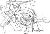
фиг.2 представляет собой вертикальный вид сбоку дозатора семян пневматической сеялки, показанной на фиг.1;figure 2 is a vertical side view of the seed meter of the pneumatic seeder shown in figure 1;
фиг.3 представляет собой вертикальный вид сбоку части фиг.2 в круге 3, иллюстрирующей шток исполнительного механизма во втянутом положении;figure 3 is a vertical side view of part of figure 2 in a
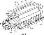
фиг.4 представляет собой вид в перспективе дозатора семян, показанного на фиг.2;FIG. 4 is a perspective view of the seed meter shown in FIG. 2;
фиг.4а представляет собой вид в перспективе, показывающий исполнительный механизм, способный закрывать две заслонки;figa is a perspective view showing an actuator capable of closing two shutters;
фиг.5 представляет собой вид в перспективе с пространственным разнесением элементов картриджа дозатора, иллюстрирующий один корпус дозатора и один барабанный сегмент, отделенные от картриджа;5 is an exploded perspective view of a dispenser cartridge, illustrating one dispenser housing and one drum segment separated from the cartridge;
фиг.6 представляет собой вид в перспективе кожуха дозатора семян, иллюстрирующий заслонку в закрытом положении;Fig.6 is a perspective view of the casing of the seed meter, illustrating the shutter in the closed position;
фиг.7 представляет собой вид в перспективе корпуса дозатора семян, показанного на фиг.6, иллюстрирующий заслонку в открытом положении;Fig.7 is a perspective view of the housing of the seed meter shown in Fig.6, illustrating the damper in the open position;
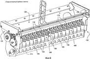
фиг.8 представляет собой вид в перспективе объемного дозатора согласно уровню техники перед добавлением еще одного варианта осуществления секционного механизма перекрывания дозатора согласно настоящему изобретению;FIG. 8 is a perspective view of a volume dispenser according to the prior art before adding yet another embodiment of a sectional mechanism for shutting down a dispenser according to the present invention;
фиг.9 представляет собой вид сбоку в разрезе дозатора, показанного на фиг.8, с добавлением секционного механизма перекрывания дозатора согласно настоящему изобретению, иллюстрирующий заслонку механизма перекрывания в открытом положении;Fig.9 is a side view in section of the dispenser shown in Fig.8, with the addition of a sectional mechanism for closing the dispenser according to the present invention, illustrating the shutter of the shutter mechanism in the open position;
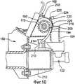
фиг.10 представляет собой вид сбоку в разрезе дозатора, показанного на фиг.9, иллюстрирующий заслонку в закрытом положении;figure 10 is a side view in section of the dispenser shown in figure 9, illustrating the shutter in the closed position;
фиг.11 представляет собой вид в перспективе снизу корпуса высевающего аппарата и секционного механизма перекрывания, показанного на фиг.9 и 10; и11 is a perspective view from below of the housing of the metering apparatus and the sectional overlap mechanism shown in figures 9 and 10; and
фиг.12 представляет собой вид сбоку дозатора, показанного на фиг.9, показывающий соединительный рычаг механизма перекрывания в высвобожденном положении для обеспечения извлечения барабана дозатора.FIG. 12 is a side view of the dispenser shown in FIG. 9, showing the connecting lever of the overlap mechanism in the released position to allow for removal of the dispenser drum.
Описание предпочтительного варианта осуществления изобретенияDescription of a preferred embodiment of the invention
На чертежах показана пневматическая сеялка, выполненная согласно предпочтительному варианту осуществления настоящего изобретения. Со ссылкой на фиг.1 показана пневматическая сеялка, состоящая из прицепа 10 для семян, буксируемого между трактором (не показан) и почвообрабатывающим орудием 12. Прицеп 10 для семян имеет раму 14, к которой прикреплены бункеры 16 и колеса 18. Каждый бункер 16 имеет связанную с ним систему 20 дозирования на нижней своей стороне для регулируемой подачи продукта в пневматическую распределительную систему 22 на основном распределительном коллекторе 24. Почвообрабатывающее орудие 12, буксируемое позади прицепа 10 для семян, в общем состоит из рамы 30, к которой прикреплены культиваторы 32. Также во многих вариантах применения желательно включение заделывающего оборудования для семян в ряду, такого как заделывающие колеса 34.The drawings show a pneumatic seeder made in accordance with a preferred embodiment of the present invention. With reference to FIG. 1, a pneumatic seeder is shown, consisting of a
Пневматическая распределительная система 22 включает в себя центробежный вентилятор 36, соединенный с полостью 38, которая, в свою очередь, соединена с одним или более основными распределительными коллекторами 24, каждый из которых соединен с бункером 16. Каждый отдельный канал в основном распределительном коллекторе 24 соединен посредством высевающего трубопровода 40 с вертикальной трубой (показана только одна). Каждая вертикальная труба 42, в свою очередь, соединена с дополнительным распределительным устройством 44. Распределительные трубопроводы 46 соединяют дополнительное распределительное устройство 44 с сошниками, установленными на культиваторах 50 для доставки продукта, семян или удобрения и т.д. в борозду, образованную культиваторами 32. Дополнительные подробности пневматической сеялки можно найти в патенте США 5,878,679, включенном сюда посредством ссылки. Несмотря на то что пневматическая сеялка, показанная на фиг.1, показана в виде отдельного пневматического прицепа, соединенного с почвообрабатывающим орудием, бункеры 16, система 20 дозирования и распределительная система 22 могут быть установлены на ту же раму, что и культиваторы 32.The
Далее со ссылкой на фиг.2-5 будет описана более подробно система 20 дозирования. Система 20 дозирования включает в себя кожух 50, имеющий верхний конец 52, который прикреплен к бункеру 16. Кожух 50 также имеет нижний конец 54, который прикреплен к основному коллектору 24 пневматической распределительной системы. Кожух 50 образует впускной канал 56, через который продукт поступает в кожух, и выпускной канал 58, через который дозированный продукт поступает в распределительную систему. Вращающийся отсечной клапан 60 расположен во впускном канале 56 и может поворачиваться, как показано стрелкой 62, из открытого положения, показанного на фиг.2, в положение для очистки, в котором продукт выгружают из кожуха 50, чтобы обеспечить опорожнение бункера 16 без прохождения продукта в распределительную систему через дозатор.Next, with reference to FIGS. 2-5, a
Впускной канал 56 проходит в картридж 70 дозатора, который вмещает барабан 72 дозатора. Картридж 70 можно извлекать из кожуха 50 дозатора, как показано на фиг.4, где картридж 70 показан частично вынутым из кожуха 50. Картридж состоит из множества корпусов 74 дозатора, расположенных рядом друг с другом и скрепленных вместе удлиненными болтами 84 (фиг.5), проходящими через отверстия 76 в корпусах дозатора. Барабан 72 дозатора выполнен из множества барабанных сегментов 78, расположенных в продольном направлении вдоль приводного вала 80. В показанном варианте осуществления приводной вал 80 является шестигранным для сопряжения с шестигранным отверстием 92 в барабанных сегментах 78. Дополнительное крепежное оборудование показано и описано в вышеуказанном патенте США 5,878,679.The
Каждый барабанный сегмент 78 расположен внутри отдельного корпуса 74 дозатора. Каждый корпус 74 дозатора имеет радиальную стенку 86 вдоль одного осевого конца корпуса, которая отделяет расположенные рядом сегменты барабана друг от друга в продольном направлении вдоль вала 80. Каждый корпус 74 образует впуск 88, сообщающийся с впускным каналом 56 кожуха дозатора для приема продукта из него. Так как барабан 72 дозатора вращается, как показано стрелкой 90 на фиг.2, продукт перемещается зубьями и желобками 92 барабанов через выступ 94 к выпускному отверстию 96 в корпусе дозатора. Оттуда продукт поступает в выпускной канал 58 в кожухе дозатора и в коллектор 24 распределительной системы. Для каждого корпуса дозатора предусмотрена заслонка 100 для избирательного перекрывания потока семян из данной барабанной секции дозатора. Заслонка показана на фиг.2 в закрытом положении, предотвращая прохождение продукта через выступ 94. Заслонка шарнирно прикреплена к корпусу дозатора на шарнире 102 около ближнего конца заслонки. Шарнирный стержень 108 (см. фиг.5) проходит в осевом направлении через картридж для шарнирной установки заслонок 100. Каждая заслонка 100 удерживается в закрытом положении плунжером 104, который перемещается со скольжением внутри втулки 106 в корпусе дозатора. Исполнительные механизмы 110 устанавливают в кожух 50 дозатора, при этом большая часть корпуса исполнительных механизмов 110 выступает наружу из кожуха, как показано на фиг.2 и 4. Исполнительные механизмы имеют выдвижной шток 112, который выдвигается во втулку 106 и упирается в плунжер 104, как показано на фиг.2, когда исполнительный механизм находится во включенном состоянии. Предпочтительно, шток исполнительного механизма подпружинен во втянутое положение таким образом, чтобы шток оставался втянутым, когда исполнительный механизм находится в выключенном состоянии. Термины включенный и выключенный означают, что приводящая в действие энергия подается или не подается, и может быть электрической, пневматической, гидравлической и т.д. Во втянутом состоянии концы штоков 112 находятся внутри кожуха 50, как показано на фиг.3, полностью извлеченными из корпуса дозатора. Это позволяет извлечь картридж дозатора 70 из кожуха 50, как показано на фиг.4. Плунжеры 104 и втулки 106 заключены внутри соответствующих корпусов дозатора так, чтобы не взаимодействовать с кожухом 50 в процессе введения или извлечения картриджа 70 в кожух 50 и из него.Each
Корпус дозатора и заслонка более подробно показаны на фиг.6 и 7. На фиг.6 заслонка 100 показана в закрытом положении, в котором дальний конец 103 заслонки упирается или примыкает к выступу 64 для предотвращения прохождения продукта через выступ. На фиг.7 заслонка показана в открытом положении и расположенная на расстоянии от выступа 94, позволяя продукту проходить через выступ к выпуску 96. Заслонка 100 выполнена за одно целое с пружинным язычком 114, проходящим вверх от шарнира 102, как показано на фиг.6 и 7. Пружинный язычок упирается во внутреннюю поверхность элемента 74 корпуса в открытом положении, показанном на фиг.7. Когда заслонка передвигается в закрытое положение, пружинный язычок 114 отклоняется, как показано на фиг.6. Когда шток 112 исполнительного механизма 110 втягивается, пружинный язычок обеспечивает смещающее усилие для передвижения заслонки 100 в открытое положение. Вместо единого пружинного язычка 114 между заслонкой и элементом корпуса можно использовать отдельные пружинные элементы для смещения заслонки в открытое положение. Они могли бы включать в себя пружину натяжения между заслонкой и корпусом около дальнего конца 103 заслонки или цилиндрическую пружину на шарнире 102.The dispenser body and the shutter are shown in more detail in FIGS. 6 and 7. In FIG. 6, the
Исполнительные механизмы 110 могут быть электронными, пневматическими, гидравлическими или любыми другими исполнительными механизмами, которые обеспечивают требуемое движение, и, предпочтительно, имеют электронное управление. Исполнительные механизмы 110 могут управляться избирательно оператором через панель управления в кабине трактора или, предпочтительно, исполнительными механизмами управляют посредством программного обеспечения картирования поля в сочетании с GPS или другой системой позиционирования транспортного средства. С использованием полевых карт и позиционирования транспортного средства исполнительные механизмы будут приводиться в действие для перекрывания потока продукта от дозатора и, таким образом, остановки потока продукта в одном или более распределительных трубопроводов 40, которые подают продукт в один или более рядов почвообрабатывающих орудий 12, когда почвообрабатывающее орудие проходит площадь, которая уже была засеяна или которую не нужно засеивать.
Как показано на фиг.4а, исполнительный механизм 110 может иметь шток 112, присоединенный к поперечной планке 113, которая, в свою очередь, поддерживает два выступа 112' штока. Подобное приспособление позволяет исполнительному механизму при необходимости управлять двумя или более заслонками. Несмотря на то что наличие одного исполнительного механизма на заслонку может быть предпочтительным вариантом осуществления, это может реально обеспечить более точное управление, чем доступно с помощью программного обеспечения картирования поля и системы позиционирования транспортного средства. Таким образом, закрытие двух или более заслонок одновременно может обеспечить максимальную выгоду, возможную в условиях сниженной производственной себестоимости.As shown in FIG. 4 a, the
На фиг.8-12 показано альтернативное исполнение изобретения. Здесь поворотные заслонки механизма перекрывания встроены в различные дозаторы, причем в данном случае дозатор представляет собой дозатор John Deere 1990CCS No-Till Air Drill. Система 120 дозирования показана на фиг.8 без секционного механизма перекрывания согласно настоящему изобретению для обеспечения контекста изобретения. Система 120 дозирования включает в себя узел 150 отсека дозаторов, на котором установлен бункер (не показан), и подает продукт в открытую внутреннюю часть 148 узла отсека дозаторов. Приводной вал 180 системы дозирования опирается на узел отсека дозаторов и несет барабан дозатора, имеющий множество барабанных сегментов 178. Барабанные сегменты 178 разнесены в продольном направлении друг от друга по длине приводного вала 180. Каждый барабанный сегмент окружен корпусом 168 высевающего аппарата, который открыт в сторону внутренней части 148 узла отсека дозаторов для получения продукта из него. Каждый корпус 168 высевающего аппарата также образует выпускную трубку 169 для направления продукта в поток воздуха распределительной системы 122 продукта, показанной на фиг.9, 10 и 12.8-12 show an alternative embodiment of the invention. Here, the rotary shutters of the shut-off mechanism are integrated in various dispensers, in which case the dispenser is a John Deere 1990CCS No-Till Air Drill dispenser. A
В процессе работы вращение барабанных сегментов против часовой стрелки, как показано на фиг.9 и 10, вызывает прохождение продукта через выступ 194 корпуса высевающего аппарата и в трубку 169. Заслонку 200 шарнирно устанавливают в каждый корпус высевающего аппарата на шарнире 202 на верхнем конце как заслонки, так и корпуса высевающего аппарата. Исполнительные механизмы 210 устанавливают в воздушный коллектор 212, образованный в виде части узла отсека дозаторов, при этом один исполнительный механизм расположен под каждым корпусом высевающего аппарата. Каждый исполнительный механизм имеет выдвижной шток 213 (фиг.11), прикрепленный к скобе 214. Соединительный рычаг 216 прикреплен к скобе и проходит вверх вокруг внешней части корпуса высевающего аппарата к заслонке 200. В показанном предпочтительном варианте осуществления соединительный рычаг является U-образным, имеет пару опор 218, по одной с каждой стороны корпуса высевающего аппарата. Опоры изогнуты для поддержания зазора с подшипниковыми узлами (не показано) на приводном валу 180. На верхних концах соединительного рычага опоры 218 соединены друг с другом посредством поперечной пластины 220. Как показано, соединительный рычаг выполнен из единого формованного полимерного элемента, образующего опоры 218 и поперечную пластину 220. Поперечная пластина также является U-образной для огибания заслонки 200. Соединительный рычаг можно выполнить из металла вместо формованной пластмассы. Поворотный стержень 222 также проходит между двумя опорами 218 соединительного рычага около поперечной пластины 220. Соединительный рычаг прикреплен к заслонке 200 с возможностью отсоединения посредством вставки поворотного стержня 222 в захват 224, образованный в заслонке 200. Пружинный держатель 226, прикрепленный заклепками или иным образом к заслонке, упирается в поворотный стержень 222 для удержания поворотного стержня вставленным в захват 224.During operation, the rotation of the drum segments counterclockwise, as shown in FIGS. 9 and 10, causes the product to pass through the
Исполнительные механизмы 210 представляют собой пневматические цилиндры обратного действия. Шток 213 обычно выдвигается с помощью внутренней пружины. Когда исполнительные механизмы приводят в действие сжатым воздухом, шток исполнительного механизма втягивается. В выключенном состоянии шток выдвигается, как показано на фиг.9. Это удерживает заслонку 200 в открытом положении, позволяя продукту проходить через корпуса высевающего аппарата, когда барабанные сегменты дозатора вращаются. Когда исполнительный механизм приведен в действие, а шток втянут, заслонка перемещается в закрытое положение, показанное на фиг.10, предотвращая прохождение продукта. Подходящим пневматическим цилиндром является модель «Flat I» пневматического цилиндра, поставляемая Bimba Manufacturing of University Park, Illinois. Данный цилиндр представляет собой цилиндр обратного действия с нормально выдвигаемым штоком. Вместо показанного пневматического цилиндра могут быть использованы электрические или гидравлические или другие исполнительные механизмы. Соединительный рычаг может высвобождаться от заслонки посредством отжатия пружинного держателя 226 для извлечения поворотного стержня 222 из захвата 224 на заслонке. Это позволяет поворачивать соединительный рычаг вокруг корпуса высевающего аппарата в положение с зазором, показанное на фиг.12, для того чтобы позволить извлечь барабанные сегменты 178 и приводной вал 180 через открытый верхний конец корпусов высевающего аппарата. Это обеспечивает возможность использования различных размеров и форм барабанных сегментов в дозаторе семян. По-разному подобранные формы заслонок 200 могут также быть использованы с различными барабанными сегментами 178 в зависимости от размера барабанных сегментов. Заслонки можно заменять посредством удаления поворотных стержней 202, прикрепляющих заслонки к соответствующим корпусам высевающего аппарата.
В варианте осуществления, показанном на фиг.9-12, исполнительные механизмы для заслонок расположены под барабанными сегментами и соединены с соответствующими заслонками посредством соединительных рычагов, которые проходят вокруг корпуса высевающего аппарата. Соединительный рычаг может проходить вокруг обеих сторон корпуса высевающего аппарата, как показано, или иметь только одну опору, проходящую вокруг одной стороны корпуса высевающего аппарата. Каждый исполнительный механизм может быть прикреплен более чем к одной заслонке посредством подходящего соединительного элемента, прикрепленного к соединительным рычагам по причинам, описанным выше. В качестве альтернативы, исполнительные механизмы могут быть установлены над барабанными сегментами и иметь штоки, которые проходят вниз и соединены непосредственно с заслонками. Данная конфигурация не может обеспечить большой доступ к барабанным сегментам для замены сегментов.In the embodiment shown in FIGS. 9-12, actuators for the shutters are located under the drum segments and are connected to the respective shutters by means of connecting levers that extend around the meter body. The connecting lever may extend around both sides of the metering unit housing, as shown, or have only one support extending around one side of the metering unit body. Each actuator may be attached to more than one valve by means of a suitable connecting element attached to the connecting levers for the reasons described above. Alternatively, actuators may be mounted above the drum segments and have rods that extend downward and are connected directly to the dampers. This configuration cannot provide much access to drum segments to replace segments.
Несмотря на то что изобретение было показано и описано с поворотной заслонкой, могут быть использованы другие типы движения для перемещения заслонки между открытым и закрытым положениями, например скользящая заслонка, которая показана в патентной публикации, на которую была сделана ссылка выше.Although the invention has been shown and described with a rotary shutter, other types of movement can be used to move the shutter between the open and closed positions, for example, the sliding shutter, which is shown in the patent publication referenced above.
Заслонка для объемного дозатора согласно настоящему изобретению, расположенная после барабана дозатора, но перед тем, как продукт попадает в воздушную струю, решает сложные задачи, описанные выше. Долгая задержка между перекрыванием и прекращением подачи продукта в рядок уменьшается, поскольку дозатор не нуждается в опорожнении перед тем, как прекратится поток продукта. Поскольку продукт останавливается перед тем, как продукт входит в воздушную струю, нет необходимости в направлении продукта назад в бункер. Это устраняет необходимость разделения смешанных продуктов и устраняет трудность возврата продукта в находящийся под давлением бункер. Несмотря на то что изобретение было показано и описано в контексте пневматической сеялки, специалистам в данной области техники необходимо понимать, что изобретение может быть использовано любым объемным дозатором, например в зерновой сеялке, использующей силу тяжести для высева семян из дозатора в землю.The damper for the volumetric metering device according to the present invention, located after the metering drum, but before the product enters the air stream, solves the complex tasks described above. The long delay between closing and stopping the flow of the product in the row is reduced, since the dispenser does not need to be emptied before the flow of the product stops. Since the product stops before the product enters the air stream, there is no need to direct the product back into the hopper. This eliminates the need to separate mixed products and eliminates the difficulty of returning the product to the pressurized hopper. Although the invention has been shown and described in the context of a pneumatic seeder, it will be appreciated by those skilled in the art that the invention can be used with any volumetric metering device, such as a grain seeder that uses gravity to plant seeds from a metering device into the ground.
После описания предпочтительного варианта осуществления становится понятно, что могут быть выполнены различные изменения, не выходящие за рамки объема изобретения, определенного в приложенной формуле изобретения.After describing a preferred embodiment, it becomes clear that various changes can be made without departing from the scope of the invention defined in the appended claims.
Claims (21)
Translated fromRussianбарабан дозатора, имеющий множество барабанных сегментов, выровненных вдоль оси барабана для дозирования продукта из бункера в распределительную систему;
множество заслонок, расположенных в осевом направлении вдоль барабана дозатора между барабаном дозатора и распределительной системой и выполненных с возможностью перемещения между открытым положением, в котором обеспечивается прохождение продукта из барабана дозатора в распределительную систему, и закрытым положением, в котором предотвращается прохождение продукта из барабана дозатора в распределительную систему; и
множество исполнительных механизмов, каждый из которых установлен с возможностью избирательного перемещения одной или более заслонок из открытого в закрытое положение.1. A volumetric dosing system for dispensing a product in a sowing machine having a product bin and a distribution system for dispensing a metered product having a plurality of individual product channels, comprising:
a dispenser drum having a plurality of drum segments aligned along the axis of the drum for dispensing a product from a hopper into a distribution system;
a plurality of dampers located axially along the dispenser drum between the dispenser drum and the distribution system and arranged to move between an open position in which the product passes from the dispenser drum to the distribution system and a closed position in which the product is prevented from passing from the dispenser drum to distribution system; and
many actuators, each of which is installed with the possibility of selective movement of one or more dampers from open to closed position.
Applications Claiming Priority (2)
| Application Number | Priority Date | Filing Date | Title |
|---|---|---|---|
| US12/481,254US8132521B2 (en) | 2009-06-09 | 2009-06-09 | Volumetric metering system with sectional shut-off |
| US12/481,254 | 2009-06-09 |
Publications (2)
| Publication Number | Publication Date |
|---|---|
| RU2010123395A RU2010123395A (en) | 2011-12-20 |
| RU2530994C2true RU2530994C2 (en) | 2014-10-20 |
Family
ID=42827321
Family Applications (1)
| Application Number | Title | Priority Date | Filing Date |
|---|---|---|---|
| RU2010123395/13ARU2530994C2 (en) | 2009-06-09 | 2010-06-08 | System of volumetric dosing with sectional valve |
Country Status (11)
| Country | Link |
|---|---|
| US (1) | US8132521B2 (en) |
| EP (1) | EP2260689B2 (en) |
| AR (1) | AR077029A1 (en) |
| AU (1) | AU2010202169B2 (en) |
| BR (1) | BRPI1002303B1 (en) |
| CA (1) | CA2704887C (en) |
| ES (1) | ES2415933T3 (en) |
| MX (1) | MX2010006140A (en) |
| PL (1) | PL2260689T3 (en) |
| RU (1) | RU2530994C2 (en) |
| UA (1) | UA106198C2 (en) |
Cited By (3)
| Publication number | Priority date | Publication date | Assignee | Title |
|---|---|---|---|---|
| RU2759322C1 (en)* | 2021-01-11 | 2021-11-11 | Федеральное государственное бюджетное образовательное учреждение высшего образования "Кубанский государственный аграрный университет имени И.Т. Трубилина" | Sowing device with simultaneous application of the main fertilizer |
| RU2766011C2 (en)* | 2017-06-30 | 2022-02-07 | Интеллиджент Эгрикалчарал Солюшнз Ллк | Sectional control device |
| RU212348U1 (en)* | 2022-02-09 | 2022-07-18 | Общество с ограниченной ответственностью "ЛВ-Сервис" | Sowing unit for seeder |
Families Citing this family (40)
| Publication number | Priority date | Publication date | Assignee | Title |
|---|---|---|---|---|
| US8678347B2 (en)* | 2010-09-20 | 2014-03-25 | Deere & Company | Manifold actuator assembly |
| US8671857B2 (en) | 2011-03-10 | 2014-03-18 | Cnh Canada, Ltd. | Variable geometry meter roller |
| US20140076218A1 (en) | 2012-09-14 | 2014-03-20 | James Z. Liu | Product distribution device with flow rate and section control monitoring |
| US9265188B2 (en) | 2012-12-07 | 2016-02-23 | Cnh Industrial Canada, Ltd. | Sectioned meter box assembly |
| US9591799B2 (en)* | 2013-01-25 | 2017-03-14 | Cnh Industrial Canada, Ltd. | Metering of product in an air cart on hilly terrain |
| US9420738B2 (en)* | 2013-06-12 | 2016-08-23 | Agco Corporation | Low rate metering wheel for coarse granules |
| ES2564235T3 (en) | 2013-10-16 | 2016-03-21 | Kverneland As | Dosing device for dosing bulk materials |
| US9635803B2 (en) | 2014-03-31 | 2017-05-02 | Salford Group Inc. | Metering apparatuses for sectional control |
| CA2905014C (en) | 2014-11-04 | 2020-03-10 | Cnh Industrial Canada, Ltd. | Flow control assembly for an agricultural metering system |
| CN105659999A (en)* | 2014-11-19 | 2016-06-15 | 现代农装科技股份有限公司 | Air-suction vegetable seedling-raising and precision seeding roller |
| DE102015101572A1 (en) | 2015-02-04 | 2016-08-04 | Horsch Maschinen Gmbh | Pneumatic seed drill |
| US20160330901A1 (en)* | 2015-05-14 | 2016-11-17 | Deere & Company | Product distribution device with section control monitoring |
| US9861030B2 (en) | 2015-09-23 | 2018-01-09 | Deere & Company | Biased guide to reduce variation in a volumetric meter |
| US9814173B2 (en) | 2015-09-30 | 2017-11-14 | Deere & Company | Seeding system |
| US20170086351A1 (en) | 2015-09-30 | 2017-03-30 | Deere & Company | Seed metering system and method of operating the same |
| US9949427B2 (en) | 2015-09-30 | 2018-04-24 | Deere & Company | System and method of distributing seeds and agricultural particles |
| US10492359B2 (en) | 2015-09-30 | 2019-12-03 | Deere & Company | Seeding system |
| US10085375B2 (en) | 2016-06-28 | 2018-10-02 | Cnh Industrial Canada, Ltd. | Sectional control system for delivery of agricultural product according to location |
| DE102016112058A1 (en)* | 2016-07-01 | 2018-01-04 | Amazonen-Werke H. Dreyer Gmbh & Co. Kg | Agricultural distributor with cover |
| CA2977467A1 (en) | 2016-10-11 | 2018-04-11 | Deere & Company | Seeding system |
| US10575457B2 (en) | 2017-09-21 | 2020-03-03 | Deere & Company | Commodity metering system with speed compensation based on machine tilt and methods for operating the same |
| US11191207B2 (en) | 2017-09-21 | 2021-12-07 | Deere & Company | Commodity metering system for work vehicle and calibration method for same |
| US10609858B2 (en) | 2017-09-21 | 2020-04-07 | Deere & Company | Commodity metering system for work vehicle and calibration method for same |
| US10942053B2 (en) | 2018-05-14 | 2021-03-09 | Deere & Company | Seeding system |
| US11140811B2 (en) | 2018-06-13 | 2021-10-12 | Deere & Company | Commodity metering system for work vehicle with rollers in staggered arrangement |
| CN109005801A (en)* | 2018-06-28 | 2018-12-18 | 安徽灵杨农机制造有限公司 | A kind of pea seeder |
| IT201800007355A1 (en)* | 2018-07-19 | 2020-01-19 | Adjustable distributor group for granulated materials and the like | |
| DE102018006660A1 (en)* | 2018-08-23 | 2020-02-27 | Rauch Landmaschinenfabrik Gmbh | Dosing unit for powder or particulate material to be distributed and distribution machine with such a dosing unit |
| US10986773B2 (en) | 2019-02-19 | 2021-04-27 | Cnh Industrial Canada, Ltd. | Look-ahead functionality tuning for independent sections |
| CA3097708A1 (en) | 2019-11-14 | 2021-05-14 | Cnh Industrial Canada, Ltd. | Particulate material metering system for an agricultural implement |
| US11765991B2 (en) | 2019-11-14 | 2023-09-26 | Cnh Industrial Canada, Ltd. | Particulate material metering system for an agricultural implement |
| US11770996B2 (en)* | 2020-02-03 | 2023-10-03 | Cnh Industrial America Llc | Housing for a modular meter assembly of a dry product applicator |
| US11555726B2 (en) | 2020-03-05 | 2023-01-17 | Cnh Industrial Canada, Ltd. | Metering system for distributing particulate material |
| DE102020002762A1 (en) | 2020-05-08 | 2021-11-11 | Lemken Gmbh & Co. Kg | Dosing device for an agricultural machine |
| US12250897B2 (en)* | 2020-10-30 | 2025-03-18 | Deere & Company | Removable roller with rotation indicator |
| US12349614B2 (en) | 2021-11-10 | 2025-07-08 | Deere & Company | Air seeding turn compensation using yaw rate from sensor on towing vehicle |
| CN114271073B (en)* | 2022-01-04 | 2023-05-23 | 许昌市农业技术推广站 | Wheat seed manure suppression all-in-one seeder |
| DE102022112265A1 (en) | 2022-05-17 | 2023-11-23 | Amazonen-Werke H. Dreyer SE & Co. KG | Machine for spreading seeds |
| PL447596A1 (en)* | 2024-01-25 | 2025-07-28 | Radosław Pietrzkowski | Dosing device for bulk materials |
| CN118275433B (en)* | 2024-05-31 | 2024-07-30 | 西北农林科技大学 | A quarantine weed seed detection device and method |
Citations (5)
| Publication number | Priority date | Publication date | Assignee | Title |
|---|---|---|---|---|
| SU927682A1 (en)* | 1980-03-12 | 1982-05-15 | Башкирский сельскохозяйственный институт | Metering-out feeder of pneumatic transport installation |
| RU2089057C1 (en)* | 1995-02-27 | 1997-09-10 | Всероссийский научно-исследовательский институт орошаемого земледелия | Drill |
| CA2566248A1 (en)* | 2006-03-06 | 2007-09-06 | Patrick Audette | Multi configuration distribution system for a drill or the like |
| US20090079624A1 (en)* | 2007-09-21 | 2009-03-26 | Dean Brian F | Sectional meter shut-off and agricultural implement having sectional meter shut-off |
| RU2356208C2 (en)* | 2007-05-10 | 2009-05-27 | Анистрад Григорьевич Васильев | Method of green manure crop seeding and device for its implementation |
Family Cites Families (7)
| Publication number | Priority date | Publication date | Assignee | Title |
|---|---|---|---|---|
| US4023707A (en)* | 1973-03-08 | 1977-05-17 | Johnson Leroy E | Seeder with seed flow modification for marking seeded fields |
| DK353279A (en)* | 1979-08-24 | 1981-02-25 | Nordsten As P | MACHINE FOR SPREADING CORN MATERIAL |
| AT383720B (en)* | 1985-02-05 | 1987-08-10 | Groemer Hubert | Seed drill designed as a tractor-mounted appliance |
| US5878679A (en)* | 1997-08-18 | 1999-03-09 | Deere & Company | Product disconnect for metering device |
| US5826523A (en)* | 1997-08-18 | 1998-10-27 | Deere & Company | Brush for air seeder metering system |
| CA2311698C (en)* | 2000-06-15 | 2003-05-06 | Bourgault Industries Ltd. | Seeder calibration apparatus and method |
| EP2022309B1 (en) | 2007-08-08 | 2012-06-27 | Amazonen-Werke H. Dreyer GmbH & Co. KG | Pneumatic sowing machine |
- 2009
- 2009-06-09USUS12/481,254patent/US8132521B2/enactiveActive
- 2010
- 2010-05-21CACA2704887Apatent/CA2704887C/enactiveActive
- 2010-05-27AUAU2010202169Apatent/AU2010202169B2/enactiveActive
- 2010-06-02EPEP10164716.2Apatent/EP2260689B2/enactiveActive
- 2010-06-02ESES10164716Tpatent/ES2415933T3/enactiveActive
- 2010-06-02PLPL10164716Tpatent/PL2260689T3/enunknown
- 2010-06-04MXMX2010006140Apatent/MX2010006140A/enactiveIP Right Grant
- 2010-06-08RURU2010123395/13Apatent/RU2530994C2/ennot_activeIP Right Cessation
- 2010-06-08BRBRPI1002303-8Apatent/BRPI1002303B1/enactiveIP Right Grant
- 2010-06-09UAUAA201007122Apatent/UA106198C2/enunknown
- 2010-06-09ARARP100102019Apatent/AR077029A1/enunknown
Patent Citations (5)
| Publication number | Priority date | Publication date | Assignee | Title |
|---|---|---|---|---|
| SU927682A1 (en)* | 1980-03-12 | 1982-05-15 | Башкирский сельскохозяйственный институт | Metering-out feeder of pneumatic transport installation |
| RU2089057C1 (en)* | 1995-02-27 | 1997-09-10 | Всероссийский научно-исследовательский институт орошаемого земледелия | Drill |
| CA2566248A1 (en)* | 2006-03-06 | 2007-09-06 | Patrick Audette | Multi configuration distribution system for a drill or the like |
| RU2356208C2 (en)* | 2007-05-10 | 2009-05-27 | Анистрад Григорьевич Васильев | Method of green manure crop seeding and device for its implementation |
| US20090079624A1 (en)* | 2007-09-21 | 2009-03-26 | Dean Brian F | Sectional meter shut-off and agricultural implement having sectional meter shut-off |
Cited By (5)
| Publication number | Priority date | Publication date | Assignee | Title |
|---|---|---|---|---|
| RU2766011C2 (en)* | 2017-06-30 | 2022-02-07 | Интеллиджент Эгрикалчарал Солюшнз Ллк | Sectional control device |
| US11419258B2 (en) | 2017-06-30 | 2022-08-23 | Ias | Sectional control device |
| RU2808237C1 (en)* | 2020-05-08 | 2023-11-28 | Лемкен Гмбх Унд Ко Кг | Dosing device for agricultural machinery |
| RU2759322C1 (en)* | 2021-01-11 | 2021-11-11 | Федеральное государственное бюджетное образовательное учреждение высшего образования "Кубанский государственный аграрный университет имени И.Т. Трубилина" | Sowing device with simultaneous application of the main fertilizer |
| RU212348U1 (en)* | 2022-02-09 | 2022-07-18 | Общество с ограниченной ответственностью "ЛВ-Сервис" | Sowing unit for seeder |
Also Published As
| Publication number | Publication date |
|---|---|
| EP2260689B1 (en) | 2013-03-27 |
| ES2415933T3 (en) | 2013-07-29 |
| CA2704887A1 (en) | 2010-12-09 |
| EP2260689A1 (en) | 2010-12-15 |
| AU2010202169B2 (en) | 2016-05-19 |
| CA2704887C (en) | 2017-09-26 |
| US20100307394A1 (en) | 2010-12-09 |
| RU2010123395A (en) | 2011-12-20 |
| UA106198C2 (en) | 2014-08-11 |
| PL2260689T3 (en) | 2013-08-30 |
| BRPI1002303B1 (en) | 2023-01-24 |
| AR077029A1 (en) | 2011-07-27 |
| AU2010202169A1 (en) | 2010-12-23 |
| MX2010006140A (en) | 2010-12-13 |
| US8132521B2 (en) | 2012-03-13 |
| EP2260689B2 (en) | 2020-02-12 |
| BRPI1002303A2 (en) | 2012-02-07 |
Similar Documents
| Publication | Publication Date | Title |
|---|---|---|
| RU2530994C2 (en) | System of volumetric dosing with sectional valve | |
| RU2544968C2 (en) | System of volumetric dosing with section flap | |
| RU2547720C2 (en) | System of volumetric dosing with sectional mechanism of overlapping with clutch | |
| RU2642118C1 (en) | Seeding machine with seeds feeding device | |
| RU2582767C2 (en) | Actuator assembly of pipeline | |
| RU2550424C1 (en) | Proportioner drum with variable geometry | |
| US20150216109A1 (en) | Metering assembly with individually driven metering sections | |
| US11662240B2 (en) | Variable rate air metering system |
Legal Events
| Date | Code | Title | Description |
|---|---|---|---|
| MM4A | The patent is invalid due to non-payment of fees | Effective date:20170609 |