RU2529537C2 - Systems for treatment of underground bed with circulating heat transfer fluid - Google Patents
Systems for treatment of underground bed with circulating heat transfer fluidDownload PDFInfo
- Publication number
- RU2529537C2 RU2529537C2RU2011119095/03ARU2011119095ARU2529537C2RU 2529537 C2RU2529537 C2RU 2529537C2RU 2011119095/03 ARU2011119095/03 ARU 2011119095/03ARU 2011119095 ARU2011119095 ARU 2011119095ARU 2529537 C2RU2529537 C2RU 2529537C2
- Authority
- RU
- Russia
- Prior art keywords
- heater
- formation
- heat transfer
- transfer fluid
- heat
- Prior art date
Links
- 239000013529heat transfer fluidSubstances0.000titleclaimsdescription231
- 238000011282treatmentMethods0.000titledescription24
- 239000012530fluidSubstances0.000claimsabstractdescription153
- 238000010438heat treatmentMethods0.000claimsabstractdescription97
- 238000000034methodMethods0.000claimsabstractdescription51
- 230000015572biosynthetic processEffects0.000claimsdescription284
- 230000008859changeEffects0.000claimsdescription10
- 239000000126substanceSubstances0.000abstractdescription6
- 238000000605extractionMethods0.000abstractdescription5
- 238000005755formation reactionMethods0.000description264
- 150000002430hydrocarbonsChemical class0.000description115
- 229930195733hydrocarbonNatural products0.000description114
- 239000007788liquidSubstances0.000description55
- 239000004215Carbon black (E152)Substances0.000description53
- 238000009413insulationMethods0.000description48
- 150000003839saltsChemical class0.000description46
- 238000004519manufacturing processMethods0.000description45
- 239000010410layerSubstances0.000description42
- 238000000197pyrolysisMethods0.000description32
- 238000011065in-situ storageMethods0.000description29
- XLYOFNOQVPJJNP-UHFFFAOYSA-NwaterSubstancesOXLYOFNOQVPJJNP-UHFFFAOYSA-N0.000description29
- 238000012546transferMethods0.000description28
- 238000003860storageMethods0.000description26
- 239000004020conductorSubstances0.000description23
- 229910001868waterInorganic materials0.000description23
- 239000007789gasSubstances0.000description21
- 239000000463materialSubstances0.000description20
- 230000008569processEffects0.000description19
- CURLTUGMZLYLDI-UHFFFAOYSA-NCarbon dioxideChemical compoundO=C=OCURLTUGMZLYLDI-UHFFFAOYSA-N0.000description18
- 239000004568cementSubstances0.000description18
- 230000001965increasing effectEffects0.000description16
- 238000012545processingMethods0.000description15
- 239000000203mixtureSubstances0.000description14
- 238000006243chemical reactionMethods0.000description12
- 239000011247coating layerSubstances0.000description12
- 230000007246mechanismEffects0.000description12
- 230000035699permeabilityEffects0.000description12
- 229910052751metalInorganic materials0.000description10
- 239000001569carbon dioxideSubstances0.000description9
- 229910002092carbon dioxideInorganic materials0.000description9
- 239000000446fuelSubstances0.000description9
- 239000002184metalSubstances0.000description9
- 239000007864aqueous solutionSubstances0.000description8
- 230000004888barrier functionEffects0.000description8
- 150000001875compoundsChemical class0.000description8
- 230000007423decreaseEffects0.000description8
- 230000005855radiationEffects0.000description8
- IJGRMHOSHXDMSA-UHFFFAOYSA-NAtomic nitrogenChemical compoundN#NIJGRMHOSHXDMSA-UHFFFAOYSA-N0.000description7
- 239000008186active pharmaceutical agentSubstances0.000description7
- 125000004432carbon atomChemical groupC*0.000description7
- 238000002485combustion reactionMethods0.000description7
- 238000003786synthesis reactionMethods0.000description7
- 238000001704evaporationMethods0.000description6
- 239000001257hydrogenSubstances0.000description6
- 229910052739hydrogenInorganic materials0.000description6
- 238000009434installationMethods0.000description6
- 239000011810insulating materialSubstances0.000description6
- 230000008018meltingEffects0.000description6
- 238000002844meltingMethods0.000description6
- 239000000243solutionSubstances0.000description6
- 238000001816coolingMethods0.000description5
- 230000006378damageEffects0.000description5
- 230000005611electricityEffects0.000description5
- 230000008020evaporationEffects0.000description5
- 239000011261inert gasSubstances0.000description5
- 239000011833salt mixtureSubstances0.000description5
- 241000196324EmbryophytaSpecies0.000description4
- VYPSYNLAJGMNEJ-UHFFFAOYSA-NSilicium dioxideChemical compoundO=[Si]=OVYPSYNLAJGMNEJ-UHFFFAOYSA-N0.000description4
- 229910000831SteelInorganic materials0.000description4
- 238000009835boilingMethods0.000description4
- 238000010586diagramMethods0.000description4
- 238000005553drillingMethods0.000description4
- 229910052500inorganic mineralInorganic materials0.000description4
- 239000011707mineralSubstances0.000description4
- 239000012184mineral waxSubstances0.000description4
- 239000003921oilSubstances0.000description4
- -1pyrobitumenSubstances0.000description4
- 239000010959steelSubstances0.000description4
- BVKZGUZCCUSVTD-UHFFFAOYSA-LCarbonateChemical compound[O-]C([O-])=OBVKZGUZCCUSVTD-UHFFFAOYSA-L0.000description3
- UFHFLCQGNIYNRP-UHFFFAOYSA-NHydrogenChemical compound[H][H]UFHFLCQGNIYNRP-UHFFFAOYSA-N0.000description3
- GRYLNZFGIOXLOG-UHFFFAOYSA-NNitric acidChemical classO[N+]([O-])=OGRYLNZFGIOXLOG-UHFFFAOYSA-N0.000description3
- FAPWRFPIFSIZLT-UHFFFAOYSA-MSodium chlorideChemical compound[Na+].[Cl-]FAPWRFPIFSIZLT-UHFFFAOYSA-M0.000description3
- 238000005452bendingMethods0.000description3
- 230000008901benefitEffects0.000description3
- 230000006835compressionEffects0.000description3
- 238000007906compressionMethods0.000description3
- 230000008602contractionEffects0.000description3
- 230000007797corrosionEffects0.000description3
- 238000005260corrosionMethods0.000description3
- 238000005485electric heatingMethods0.000description3
- 239000011888foilSubstances0.000description3
- 150000002431hydrogenChemical class0.000description3
- 238000002347injectionMethods0.000description3
- 239000007924injectionSubstances0.000description3
- 238000012986modificationMethods0.000description3
- 230000004048modificationEffects0.000description3
- 229910052757nitrogenInorganic materials0.000description3
- 239000007800oxidant agentSubstances0.000description3
- 238000005086pumpingMethods0.000description3
- 239000011435rockSubstances0.000description3
- 239000007787solidSubstances0.000description3
- QGZKDVFQNNGYKY-UHFFFAOYSA-NAmmoniaChemical compoundNQGZKDVFQNNGYKY-UHFFFAOYSA-N0.000description2
- OKTJSMMVPCPJKN-UHFFFAOYSA-NCarbonChemical compound[C]OKTJSMMVPCPJKN-UHFFFAOYSA-N0.000description2
- 229910013553LiNOInorganic materials0.000description2
- NINIDFKCEFEMDL-UHFFFAOYSA-NSulfurChemical compound[S]NINIDFKCEFEMDL-UHFFFAOYSA-N0.000description2
- 125000003118aryl groupChemical group0.000description2
- 239000010426asphaltSubstances0.000description2
- QVGXLLKOCUKJST-UHFFFAOYSA-Natomic oxygenChemical compound[O]QVGXLLKOCUKJST-UHFFFAOYSA-N0.000description2
- 229910052799carbonInorganic materials0.000description2
- 239000003818cinderSubstances0.000description2
- 238000009833condensationMethods0.000description2
- 230000005494condensationEffects0.000description2
- 230000003111delayed effectEffects0.000description2
- 238000011161developmentMethods0.000description2
- 230000002500effect on skinEffects0.000description2
- 230000005496eutecticsEffects0.000description2
- 239000003302ferromagnetic materialSubstances0.000description2
- 239000006260foamSubstances0.000description2
- 239000000295fuel oilSubstances0.000description2
- 210000004907glandAnatomy0.000description2
- 239000012774insulation materialSubstances0.000description2
- 239000007791liquid phaseSubstances0.000description2
- 150000002739metalsChemical class0.000description2
- VNWKTOKETHGBQD-UHFFFAOYSA-NmethaneChemical compoundCVNWKTOKETHGBQD-UHFFFAOYSA-N0.000description2
- 229910052760oxygenInorganic materials0.000description2
- 239000001301oxygenSubstances0.000description2
- 239000002245particleSubstances0.000description2
- 229920000642polymerPolymers0.000description2
- 239000002994raw materialSubstances0.000description2
- 238000011084recoveryMethods0.000description2
- 229920005989resinPolymers0.000description2
- 239000011347resinSubstances0.000description2
- 239000012266salt solutionSubstances0.000description2
- 239000004576sandSubstances0.000description2
- 238000000926separation methodMethods0.000description2
- 125000006850spacer groupChemical group0.000description2
- 239000011593sulfurSubstances0.000description2
- 229910052717sulfurInorganic materials0.000description2
- 210000003462veinAnatomy0.000description2
- 229910052902vermiculiteInorganic materials0.000description2
- 239000010455vermiculiteSubstances0.000description2
- 235000019354vermiculiteNutrition0.000description2
- MHCVCKDNQYMGEX-UHFFFAOYSA-N1,1'-biphenyl;phenoxybenzeneChemical compoundC1=CC=CC=C1C1=CC=CC=C1.C=1C=CC=CC=1OC1=CC=CC=C1MHCVCKDNQYMGEX-UHFFFAOYSA-N0.000description1
- 239000002028BiomassSubstances0.000description1
- UGFAIRIUMAVXCW-UHFFFAOYSA-NCarbon monoxideChemical compound[O+]#[C-]UGFAIRIUMAVXCW-UHFFFAOYSA-N0.000description1
- 229910000975Carbon steelInorganic materials0.000description1
- RWSOTUBLDIXVET-UHFFFAOYSA-NDihydrogen sulfideChemical compoundSRWSOTUBLDIXVET-UHFFFAOYSA-N0.000description1
- 229910001374InvarInorganic materials0.000description1
- 239000004642PolyimideSubstances0.000description1
- 241000183024Populus tremulaSpecies0.000description1
- 229910001347StelliteInorganic materials0.000description1
- 239000004964aerogelSubstances0.000description1
- 150000001336alkenesChemical class0.000description1
- 229910045601alloyInorganic materials0.000description1
- 239000000956alloySubstances0.000description1
- 229910021529ammoniaInorganic materials0.000description1
- 238000013459approachMethods0.000description1
- 239000012267brineSubstances0.000description1
- 150000001720carbohydratesChemical class0.000description1
- 229910002091carbon monoxideInorganic materials0.000description1
- 239000010962carbon steelSubstances0.000description1
- 150000004649carbonic acid derivativesChemical class0.000description1
- 239000000919ceramicSubstances0.000description1
- AHICWQREWHDHHF-UHFFFAOYSA-Nchromium;cobalt;iron;manganese;methane;molybdenum;nickel;silicon;tungstenChemical compoundC.[Si].[Cr].[Mn].[Fe].[Co].[Ni].[Mo].[W]AHICWQREWHDHHF-UHFFFAOYSA-N0.000description1
- 238000000576coating methodMethods0.000description1
- 238000004939cokingMethods0.000description1
- 239000002131composite materialSubstances0.000description1
- 239000002826coolantSubstances0.000description1
- 238000005336crackingMethods0.000description1
- 125000000753cycloalkyl groupChemical group0.000description1
- 238000004090dissolutionMethods0.000description1
- 238000009826distributionMethods0.000description1
- 230000005489elastic deformationEffects0.000description1
- 230000003028elevating effectEffects0.000description1
- 239000000839emulsionSubstances0.000description1
- 239000011152fibreglassSubstances0.000description1
- JEGUKCSWCFPDGT-UHFFFAOYSA-Nh2o hydrateChemical compoundO.OJEGUKCSWCFPDGT-UHFFFAOYSA-N0.000description1
- 229910052736halogenInorganic materials0.000description1
- 150000002367halogensChemical class0.000description1
- 125000004435hydrogen atomChemical group[H]*0.000description1
- 229910000037hydrogen sulfideInorganic materials0.000description1
- 230000002706hydrostatic effectEffects0.000description1
- 230000006872improvementEffects0.000description1
- 238000007689inspectionMethods0.000description1
- 150000002605large moleculesChemical class0.000description1
- 239000000314lubricantSubstances0.000description1
- 229920002521macromoleculePolymers0.000description1
- 239000011159matrix materialSubstances0.000description1
- 229910001092metal group alloyInorganic materials0.000description1
- 238000005065miningMethods0.000description1
- 238000003032molecular dockingMethods0.000description1
- 238000012544monitoring processMethods0.000description1
- 150000002823nitratesChemical class0.000description1
- JCXJVPUVTGWSNB-UHFFFAOYSA-Nnitrogen dioxideInorganic materialsO=[N]=OJCXJVPUVTGWSNB-UHFFFAOYSA-N0.000description1
- JRZJOMJEPLMPRA-UHFFFAOYSA-NolefinNatural productsCCCCCCCC=CJRZJOMJEPLMPRA-UHFFFAOYSA-N0.000description1
- 238000013021overheatingMethods0.000description1
- 238000007254oxidation reactionMethods0.000description1
- 239000003208petroleumSubstances0.000description1
- 239000012071phaseSubstances0.000description1
- JTJMJGYZQZDUJJ-UHFFFAOYSA-NphencyclidineChemical compoundC1CCCCN1C1(C=2C=CC=CC=2)CCCCC1JTJMJGYZQZDUJJ-UHFFFAOYSA-N0.000description1
- 230000000704physical effectEffects0.000description1
- 239000004033plasticSubstances0.000description1
- 229920001721polyimidePolymers0.000description1
- 239000000843powderSubstances0.000description1
- 230000009467reductionEffects0.000description1
- 238000007670refiningMethods0.000description1
- 238000010992refluxMethods0.000description1
- 230000000630rising effectEffects0.000description1
- 239000002760rocket fuelSubstances0.000description1
- 239000000377silicon dioxideSubstances0.000description1
- 239000011780sodium chlorideSubstances0.000description1
- HPALAKNZSZLMCH-UHFFFAOYSA-Msodium;chloride;hydrateChemical compoundO.[Na+].[Cl-]HPALAKNZSZLMCH-UHFFFAOYSA-M0.000description1
- 239000002689soilSubstances0.000description1
- 238000007711solidificationMethods0.000description1
- 230000008023solidificationEffects0.000description1
- 239000000725suspensionSubstances0.000description1
- 230000008719thickeningEffects0.000description1
- 239000012808vapor phaseSubstances0.000description1
Images


Classifications
- E—FIXED CONSTRUCTIONS
- E21—EARTH OR ROCK DRILLING; MINING
- E21B—EARTH OR ROCK DRILLING; OBTAINING OIL, GAS, WATER, SOLUBLE OR MELTABLE MATERIALS OR A SLURRY OF MINERALS FROM WELLS
- E21B43/00—Methods or apparatus for obtaining oil, gas, water, soluble or meltable materials or a slurry of minerals from wells
- E21B43/16—Enhanced recovery methods for obtaining hydrocarbons
- E21B43/24—Enhanced recovery methods for obtaining hydrocarbons using heat, e.g. steam injection
- E21B43/2401—Enhanced recovery methods for obtaining hydrocarbons using heat, e.g. steam injection by means of electricity
- E—FIXED CONSTRUCTIONS
- E21—EARTH OR ROCK DRILLING; MINING
- E21B—EARTH OR ROCK DRILLING; OBTAINING OIL, GAS, WATER, SOLUBLE OR MELTABLE MATERIALS OR A SLURRY OF MINERALS FROM WELLS
- E21B44/00—Automatic control systems specially adapted for drilling operations, i.e. self-operating systems which function to carry out or modify a drilling operation without intervention of a human operator, e.g. computer-controlled drilling systems; Systems specially adapted for monitoring a plurality of drilling variables or conditions
- E21B44/02—Automatic control of the tool feed
- H—ELECTRICITY
- H01—ELECTRIC ELEMENTS
- H01C—RESISTORS
- H01C3/00—Non-adjustable metal resistors made of wire or ribbon, e.g. coiled, woven or formed as grids
- H—ELECTRICITY
- H05—ELECTRIC TECHNIQUES NOT OTHERWISE PROVIDED FOR
- H05B—ELECTRIC HEATING; ELECTRIC LIGHT SOURCES NOT OTHERWISE PROVIDED FOR; CIRCUIT ARRANGEMENTS FOR ELECTRIC LIGHT SOURCES, IN GENERAL
- H05B3/00—Ohmic-resistance heating
- H05B3/40—Heating elements having the shape of rods or tubes
- H05B3/42—Heating elements having the shape of rods or tubes non-flexible
- H05B3/48—Heating elements having the shape of rods or tubes non-flexible heating conductor embedded in insulating material
- E—FIXED CONSTRUCTIONS
- E21—EARTH OR ROCK DRILLING; MINING
- E21B—EARTH OR ROCK DRILLING; OBTAINING OIL, GAS, WATER, SOLUBLE OR MELTABLE MATERIALS OR A SLURRY OF MINERALS FROM WELLS
- E21B43/00—Methods or apparatus for obtaining oil, gas, water, soluble or meltable materials or a slurry of minerals from wells
- E21B43/16—Enhanced recovery methods for obtaining hydrocarbons
- E21B43/24—Enhanced recovery methods for obtaining hydrocarbons using heat, e.g. steam injection
- E21B43/2405—Enhanced recovery methods for obtaining hydrocarbons using heat, e.g. steam injection in association with fracturing or crevice forming processes
- H—ELECTRICITY
- H05—ELECTRIC TECHNIQUES NOT OTHERWISE PROVIDED FOR
- H05B—ELECTRIC HEATING; ELECTRIC LIGHT SOURCES NOT OTHERWISE PROVIDED FOR; CIRCUIT ARRANGEMENTS FOR ELECTRIC LIGHT SOURCES, IN GENERAL
- H05B2214/00—Aspects relating to resistive heating, induction heating and heating using microwaves, covered by groups H05B3/00, H05B6/00
- H05B2214/03—Heating of hydrocarbons
- Y—GENERAL TAGGING OF NEW TECHNOLOGICAL DEVELOPMENTS; GENERAL TAGGING OF CROSS-SECTIONAL TECHNOLOGIES SPANNING OVER SEVERAL SECTIONS OF THE IPC; TECHNICAL SUBJECTS COVERED BY FORMER USPC CROSS-REFERENCE ART COLLECTIONS [XRACs] AND DIGESTS
- Y10—TECHNICAL SUBJECTS COVERED BY FORMER USPC
- Y10T—TECHNICAL SUBJECTS COVERED BY FORMER US CLASSIFICATION
- Y10T29/00—Metal working
- Y10T29/49—Method of mechanical manufacture
- Y10T29/49002—Electrical device making
- Y10T29/49082—Resistor making
- Y10T29/49083—Heater type
Landscapes
- Engineering & Computer Science (AREA)
- Geology (AREA)
- Life Sciences & Earth Sciences (AREA)
- Mining & Mineral Resources (AREA)
- Geochemistry & Mineralogy (AREA)
- Environmental & Geological Engineering (AREA)
- General Life Sciences & Earth Sciences (AREA)
- Physics & Mathematics (AREA)
- Fluid Mechanics (AREA)
- Microelectronics & Electronic Packaging (AREA)
- Production Of Liquid Hydrocarbon Mixture For Refining Petroleum (AREA)
- Earth Drilling (AREA)
- Physical Or Chemical Processes And Apparatus (AREA)
- Pipe Accessories (AREA)
- Investigation Of Foundation Soil And Reinforcement Of Foundation Soil By Compacting Or Drainage (AREA)
- Road Paving Structures (AREA)
- Treatment Of Sludge (AREA)
- Monitoring And Testing Of Nuclear Reactors (AREA)
Abstract
Description
Translated fromRussianОбласть техники, к которой относится изобретениеFIELD OF THE INVENTION
Настоящее изобретение относится в целом к способам и системам для добычи углеводородов, водорода и/или других продуктов из различных подземных пластов, таких как углеводородсодержащие пласты. В частности, некоторые варианты осуществления относятся к использованию циркуляционной системы с замкнутым контуром для нагрева части пласта в процессе конверсии in situ (внутри пласта).The present invention relates generally to methods and systems for producing hydrocarbons, hydrogen and / or other products from various subterranean formations, such as hydrocarbon containing formations. In particular, some embodiments relate to the use of a closed loop circulation system for heating part of the formation during in situ conversion (within the formation).
Уровень техникиState of the art
Углеводороды, получаемые из подземных пластов, часто используют в качестве энергетических ресурсов, в качестве разного рода сырья и в качестве потребительских продуктов. Озабоченность по поводу истощения существующих углеводородных ресурсов и озабоченность по поводу снижения в целом качества добываемых углеводородов привели к разработке способов для более эффективных добычи, переработки и/или применения имеющихся углеводородных ресурсов. Для извлечения углеводородных материалов из подземных пластов могут использоваться процессы in situ (внутри пласта). С целью обеспечения более легкого вывода углеводородного материала из подземного пласта может потребоваться изменение химических и/или физических свойств углеводородного материала в подземном пласте. Химические и физические изменения могут включать в себя реакции in situ, результатом которых становится образование извлекаемых флюидов, изменения состава, изменения растворимости, изменения плотности, фазовые изменения и/или изменения вязкости углеводородного материала в пласте. Флюидом могут быть (но без ограничения ими) газ, жидкость, эмульсия, суспензия и/или поток твердых частиц, который имеет характеристики текучести, подобные характеристикам текучести потока жидкости.Hydrocarbons obtained from underground formations are often used as energy resources, as various kinds of raw materials and as consumer products. Concerns about the depletion of existing hydrocarbon resources and concerns about the overall decline in the quality of produced hydrocarbons have led to the development of methods for more efficient production, processing and / or use of existing hydrocarbon resources. In situ processes (within the formation) can be used to extract hydrocarbon materials from underground formations. In order to provide easier removal of the hydrocarbon material from the subterranean formation, a change in the chemical and / or physical properties of the hydrocarbon material in the subterranean formation may be required. Chemical and physical changes can include in situ reactions that result in the formation of recoverable fluids, changes in composition, changes in solubility, changes in density, phase changes and / or changes in the viscosity of the hydrocarbon material in the formation. A fluid may be (but not limited to) a gas, liquid, emulsion, suspension and / or solid particle stream that has flow characteristics similar to those of a fluid stream.
Для обработки углеводородсодержащего пласта с использованием способа тепловой обработки in situ может быть использовано множество различных типов скважин и стволов скважин. В некоторых вариантах осуществления для обработки пласта используются вертикальные и/или по существу вертикальные скважины. В некоторых вариантах осуществления для обработки пласта используются горизонтальные или по существу горизонтальные скважины (такие как J-образные и/или L-образные скважины) и/или u-образные скважины. В некоторых вариантах осуществления для обработки пласта используются комбинации горизонтальных скважин, вертикальных скважин и/или какие-либо другие комбинации. В определенных вариантах осуществления скважины проходят через покрывающий слой пласта к углеводородсодержащему слою пласта. В некоторых ситуациях тепло в скважинах теряется на нагрев покрывающего слоя. В некоторых ситуациях инфраструктура на поверхности и в покрывающем слое, используемая для поддерживания нагревателей и/или добывающего оборудования в горизонтальных стволах и u-образных стволах скважины, имеет большие размеры и/или содержит много компонентов.For processing a hydrocarbon containing formation using an in situ heat treatment method, many different types of wells and wellbores can be used. In some embodiments, vertical and / or substantially vertical wells are used to treat the formation. In some embodiments, horizontal or substantially horizontal wells (such as J-shaped and / or L-shaped wells) and / or u-shaped wells are used to treat the formation. In some embodiments, a combination of horizontal wells, vertical wells, and / or any other combination is used to treat the formation. In certain embodiments, the wells pass through the overburden to the hydrocarbon containing layer of the reservoir. In some situations, heat in the wells is lost by heating the overburden. In some situations, the infrastructure on the surface and in the overburden used to support heaters and / or production equipment in horizontal boreholes and u-shaped boreholes is large and / or contains many components.
В патенте США №7575052 (Sandberg et al.) описан процесс тепловой обработки in situ, в котором для нагрева одного или более обрабатываемых участков используется циркуляционная система. В этой циркуляционной системе может использоваться нагретая жидкая теплопереносящая среда, которая для переноса тепла к пласту проходит через сеть труб в пласте.US Pat. No. 7,557,052 (Sandberg et al.) Describes an in situ heat treatment process in which a circulation system is used to heat one or more treatment sites. This circulating system can use a heated liquid heat transfer medium that passes through a network of pipes in the formation to transfer heat to the formation.
В публикации патентной заявки США №2008-0135254 (Vinegar et al.) описаны системы и способы для процесса обработки in situ, в которых использована циркуляционная система для нагрева одного или более обрабатываемых участков. В циркуляционной системе используется нагреваемая жидкая теплопереносящая среда, которая для переноса тепла к пласту проходит по трубам в пласте. В некоторых вариантах осуществления трубы расположены по меньшей мере в двух стволах скважин.U.S. Patent Application Publication No. 2008-0135254 (Vinegar et al.) Describes systems and methods for an in situ treatment process that utilize a circulation system to heat one or more treatment sites. The circulating system uses a heated liquid heat transfer medium that passes through pipes in the formation to transfer heat to the formation. In some embodiments, the pipes are located in at least two wellbores.
В публикации патентной заявки США №2009-0095476 (Nguyen et al.) описана нагревательная система, которая включает в себя трубопровод, расположенный в отверстии в подземном пласте. В трубопроводе находится изолированный проводник. В трубопроводе между частью изолированного проводника и частью трубопровода находится некоторый материал. Этим материалом может быть соль. При рабочей температуре нагревательной системы материал является текучей средой. Тепло переносится от изолированного проводника к текучей среде, от текучей среды к трубопроводу и от трубопровода к подземному пласту.U.S. Patent Application Publication No. 2009-0095476 (Nguyen et al.) Describes a heating system that includes a pipe located in a hole in a subterranean formation. An insulated conductor is located in the pipeline. In the pipeline between the part of the insulated conductor and the part of the pipeline is some material. This material may be salt. At the operating temperature of the heating system, the material is a fluid. Heat is transferred from an insulated conductor to a fluid, from a fluid to a pipeline, and from a pipeline to an underground formation.
Для разработки способов и систем для экономичной добычи углеводородов, водорода и/или других продуктов из углеводородсодержащих пластов были приложены значительные усилия. Однако в настоящее время все еще существует много углеводородсодержащих пластов, из которых углеводороды, водород и/или другие продукты экономично добыты быть не могут. В связи с этим существует потребность в улучшенных способах и системах, которые бы снизили энергетические затраты на обработку пласта, понизили выбросы в процессе обработки, облегчили установку нагревательной системы и/или снизили потери тепла на нагрев покрывающего слоя по сравнению со способами добычи углеводородов, в которых используется наземная аппаратура.Considerable effort has been put into developing methods and systems for the economical production of hydrocarbons, hydrogen and / or other products from hydrocarbon-containing formations. However, at present, there are still many hydrocarbon-containing formations from which hydrocarbons, hydrogen and / or other products cannot be economically produced. In this regard, there is a need for improved methods and systems that would reduce the energy costs of processing a formation, reduce emissions during processing, facilitate the installation of a heating system, and / or reduce heat loss for heating a coating layer in comparison with hydrocarbon production methods in which ground equipment is used.
Раскрытие изобретенияDisclosure of invention
Описанные в заявке варианты осуществления относятся в целом к системам и способам для нагрева подземного пласта.The embodiments described in the application relate generally to systems and methods for heating an underground formation.
В некоторых вариантах осуществления изобретения способ нагрева подземного пласта включает: подачу в пласт тепла от множества нагревателей и обеспечение возможности для части одного или более нагревателей выдвигаться из устьев скважин, оборудованных скользящими уплотнениями, чтобы скомпенсировать тепловое расширение нагревателей.In some embodiments, a method for heating an underground formation includes: supplying heat from a plurality of heaters to the formation and allowing part of one or more heaters to extend from wellheads equipped with sliding seals to compensate for the thermal expansion of the heaters.
В некоторых вариантах осуществления изобретения предлагается способ нагрева подземного пласта, включающий: подачу в пласт тепла от множества нагревателей и обеспечение возможности для части одного или более нагревателей выдвигаться из устьев скважин с использованием одного или более телескопических соединений.In some embodiments of the invention, there is provided a method of heating an underground formation, comprising: supplying heat from a plurality of heaters to the formation and allowing part of one or more heaters to extend from wellheads using one or more telescopic joints.
В некоторых вариантах осуществления изобретения предлагается способ компенсации теплового расширения нагревателя в пласте, включающий нагрев нагревателя в пласте и подъем части нагревателя из пласта для компенсации теплового расширения нагревателя.In some embodiments of the invention, there is provided a method of compensating for thermal expansion of a heater in a formation, comprising heating a heater in the formation and raising a portion of the heater from the formation to compensate for the thermal expansion of the heater.
В некоторых вариантах осуществления изобретения предлагается система для нагрева подземного пласта, включающая: множество расположенных в пласте нагревателей, сконфигурированных для подачи тепла к пласту; и по меньшей мере один подъемник, соединенный с частью нагревателя, сконфигурированный для подъема частей нагревателя из пласта с целью компенсации теплового расширения нагревателя.In some embodiments of the invention, there is provided a system for heating an underground formation, comprising: a plurality of heaters located in the formation, configured to supply heat to the formation; and at least one elevator connected to a part of the heater configured to lift parts of the heater from the formation to compensate for the thermal expansion of the heater.
В дополнительных вариантах осуществления признаки из отдельных вариантов осуществления могут быть объединены с признаками из других вариантов осуществления. Например, признаки из одного варианта осуществления могут быть объединены с признаками из любых других вариантов осуществления. В дополнительных вариантах осуществления обработка подземного пласта проводится с использованием любых описанных в заявке способов и систем. В дополнительных вариантах осуществления к отдельным описанным вариантам осуществления могут добавляться дополнительные признаки.In further embodiments, features from individual embodiments may be combined with features from other embodiments. For example, features from one embodiment may be combined with features from any other embodiments. In additional embodiments, the subterranean formation is treated using any of the methods and systems described in the application. In further embodiments, additional features may be added to the individual described embodiments.
Краткое описание чертежейBrief Description of the Drawings
Преимущества настоящего изобретения могут стать очевидными специалистам благодаря приведенному ниже детальному описанию со ссылками на прилагаемые чертежи, на которых:The advantages of the present invention may become apparent to those skilled in the art through the following detailed description with reference to the accompanying drawings, in which:
фиг.1 - схематический вид одного из вариантов осуществления одной из частей системы тепловой обработки in situ для обработки углеводородсодержащего пласта;figure 1 is a schematic view of one of the embodiments of one of the parts of the heat treatment system in situ for processing a hydrocarbon containing formation;
фиг.2 - схематическое представление одного из вариантов осуществления системы циркуляции теплопереносящей текучей среды для нагрева части пласта;FIG. 2 is a schematic representation of one embodiment of a heat transfer fluid circulation system for heating a portion of a formation; FIG.
фиг.3 - схематическое представление одного из вариантов осуществления L-образного нагревателя для его применения с системой циркуляции теплопереносящей текучей среды для нагрева части пласта;figure 3 is a schematic representation of one embodiment of an L-shaped heater for use with a heat transfer fluid circulation system for heating a portion of a formation;
фиг.4 - схематическое представление одного из вариантов осуществления вертикального нагревателя для применения с системой циркуляции теплопереносящей текучей среды для нагрева части пласта, где тепловое расширение нагревателя компенсируется под поверхностью;4 is a schematic representation of one embodiment of a vertical heater for use with a heat transfer fluid circulation system for heating a portion of a formation where thermal expansion of a heater is compensated below the surface;
фиг.5 - схематическое представление другого варианта осуществления вертикального нагревателя для применения с системой циркуляции теплопереносящей текучей среды для нагрева части пласта, где тепловое расширение нагревателя компенсируется над и под поверхностью;5 is a schematic diagram of another embodiment of a vertical heater for use with a heat transfer fluid circulation system for heating a portion of a formation, where the thermal expansion of the heater is compensated above and below the surface;
фиг.6 - вид в поперечном сечении одного из вариантов осуществления изоляции покрывающего слоя, в которой использован изоляционный цемент;6 is a view in cross section of one of the embodiments of the insulation of the coating layer, which used insulating cement;
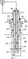
фиг.7 - вид в поперечном сечении варианта осуществления изоляции покрывающего слоя, в которой использован изоляционный рукав;Fig. 7 is a cross-sectional view of an embodiment of insulation of a coating layer in which an insulation sleeve is used;
фиг.8 - вид в поперечном сечении варианта осуществления изоляции покрывающего слоя, в которой использованы изоляционный рукав и вакуум;Fig. 8 is a cross-sectional view of an embodiment of insulation of a coating layer in which an insulation sleeve and vacuum are used;
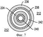
фиг.9 - представление варианта осуществления мехов, используемых для компенсации теплового расширения;Fig.9 is a representation of an embodiment of bellows used to compensate for thermal expansion;
фиг.10А - представление варианта осуществления сети труб с петлевым трубным компенсатором для компенсации теплового расширения;10A is a view of an embodiment of a pipe network with a loop pipe compensator to compensate for thermal expansion;
фиг.10В - представление варианта осуществления трубы со змеевиками или буферной трубчаткой для компенсации теплового расширения;10B is a view of an embodiment of a pipe with coils or a buffer tube to compensate for thermal expansion;
фиг.10С - представление варианта осуществления трубы с змеевиком или буферной трубчаткой для компенсации теплового расширения в изолированном объеме;figs - representation of an embodiment of a pipe with a coil or a buffer tube to compensate for thermal expansion in an isolated volume;
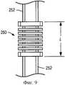
фиг.11 - представление варианта осуществления изолированной трубы в расположенной в покрывающем слое обсадной трубе большого диаметра;11 is a representation of an embodiment of an insulated pipe in a large diameter casing located in the overburden;
фиг.12 - представление варианта осуществления изолированной трубы в расположенной в покрывающем слое обсадной трубе большого диаметра для создания пространства для теплового расширения;12 is a representation of an embodiment of an insulated pipe in a large diameter casing located in the overburden to create a space for thermal expansion;
фиг.13 - представление варианта осуществления устья скважины со скользящим уплотнением, сальником или другим удерживающим давление оборудованием, которое обеспечивает перемещение частей нагревателя относительно устья скважины;FIG. 13 is a view of an embodiment of a wellhead with a sliding seal, gland, or other pressure holding equipment that moves parts of the heater relative to the wellhead; FIG.
фиг.14 - представление варианта осуществления устья скважины с телескопическим соединением, которое находится в контакте с фиксированным трубопроводом над устьем скважины;FIG. 14 is a view of an embodiment of a wellhead with a telescopic joint that is in contact with a fixed pipeline above the wellhead; FIG.
фиг.15 - представление варианта осуществления устья скважины с телескопическим соединением, которое находится в контакте с фиксированным трубопроводом, соединенным с устьем скважины;15 is a view of an embodiment of a wellhead with a telescopic joint that is in contact with a fixed pipeline connected to the wellhead;
фиг.16 - схематическое представление варианта осуществления системы циркуляции теплопереносящей текучей среды с уплотнениями;16 is a schematic representation of an embodiment of a heat transfer fluid circulating system with seals;
фиг.17 - схематическое представление другого варианта осуществления системы циркуляции теплопереносящей текучей среды с уплотнениями;17 is a schematic representation of another embodiment of a heat transfer fluid circulating system with seals;
фиг.18 - схематическое представление варианта осуществления системы циркуляции теплопереносящей текучей среды с запорными механизмами и уплотнениями;FIG. 18 is a schematic representation of an embodiment of a heat transfer fluid circulation system with locking mechanisms and seals; FIG.
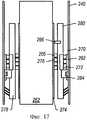
фиг.19 - представление u-образного ствола скважины с расположенным в стволе скважины нагревателем системы циркуляции горячей теплопереносящей текучей среды;Fig. 19 is a view of a u-shaped wellbore with a heater of the hot heat transfer fluid circulation system located in the wellbore;
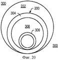
фиг.20 - вид с торца варианта осуществления нагревателя типа «труба в трубе» для системы циркуляции теплопереносящей текучей среды, примыкающей к обрабатываемому участку;FIG. 20 is an end view of an embodiment of a “pipe in pipe” type heater for a heat transfer fluid circulation system adjacent to a treatment site;
фиг.21 - представление варианта нагрева разных частей нагревателя для повторного пуска потока теплопереносящей текучей среды в нагревателе;Fig - representation of a variant of heating different parts of the heater for restarting the flow of heat transfer fluid in the heater;
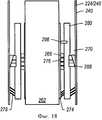
фиг.22 - схема варианта осуществления нагревателей типа «труба в трубе», расположенной в пласте системы циркуляции теплопереносящей текучей среды;Fig is a diagram of a variant of implementation of the heaters of the type "pipe in pipe" located in the reservoir of the circulation system of the heat transfer fluid;
фиг.23 - вид в поперечном сечении варианта осуществления нагревателя типа «труба в трубе», примыкающего к покрывающему слою;23 is a cross-sectional view of an embodiment of a pipe-in-pipe heater adjacent to the coating layer;
фиг.24 - схематическое представление варианта осуществления системы циркуляции теплопереносящей текучей среды в случае жидкой теплопереносящей текучей среды.24 is a schematic representation of an embodiment of a heat transfer fluid circulation system in the case of a liquid heat transfer fluid.
Хотя изобретение может иметь различные модификации и альтернативные формы, в виде примера на чертежах показаны конкретные варианты его осуществления, и они описаны подробно. Чертежи не обязательно масштабированы. Следует, однако, иметь в виду, что чертежи и их подробное описание не предназначены для ограничения изобретения конкретной раскрытой формой, а, наоборот, предполагается, что изобретение охватывает все модификации, эквиваленты и альтернативы, попадающие в объем настоящего изобретения, определенного прилагаемой формулой изобретения.Although the invention may have various modifications and alternative forms, as an example, the drawings show specific options for its implementation, and they are described in detail. Drawings are not necessarily scaled. However, it should be borne in mind that the drawings and their detailed description are not intended to limit the invention to the particular disclosed form, but rather, it is intended that the invention covers all modifications, equivalents, and alternatives falling within the scope of the present invention defined by the appended claims.
Осуществление изобретенияThe implementation of the invention
Следующее описание в целом относится к системам и способам обработки углеводородов в пласте. Такие пласты могут подвергаться обработке с целью получения углеводородных продуктов, водорода и других продуктов.The following description generally relates to systems and methods for treating hydrocarbons in a formation. Such formations may be treated to produce hydrocarbon products, hydrogen, and other products.
«Плотность в градусах АНИ» означает плотность в градусах АНИ (Американский нефтяной институт) при 15,5°С (60°F), определяемую согласно методу ASTM Method D6822 или ASTM Method D1298."Density in degrees ANI" means the density in degrees ANI (American Petroleum Institute) at 15.5 ° C (60 ° F), determined according to ASTM Method D6822 or ASTM Method D1298.
«Давление флюида» означает давление, создаваемое флюидом в пласте. «Литостатическим давлением» (иногда называемым «литостатическим напряжением») называется давление в пласте, равное весу на единицу площади вышележащей массы породы. «Гидростатическим давлением» является давление в пласте, создаваемое столбом воды."Fluid pressure" means the pressure created by the fluid in the formation. “Lithostatic pressure” (sometimes called “lithostatic stress”) is the pressure in the formation equal to the weight per unit area of the overlying rock mass. "Hydrostatic pressure" is the pressure in the reservoir created by a column of water.
Выражение «пласт» включает в себя один или более углеводородсодержащих слоев, один или более неуглеводородных слоев, покрывающий слой и/или подстилающий слой. Выражение «углеводородные слои» относится к слоям в пласте, которые содержат углеводороды. Углеводородные слои могут содержать неуглеводородный материал и углеводородный материал. Выражения «покрывающий слой» и/или «подстилающий слой» включают в себя один или более разных типов непроницаемых материалов. Например, покрывающий слой и/или подстилающий слой могут включать скальную породу, сланец, аргиллит или влажный/плотный карбонат. В некоторых вариантах осуществления тепловой обработки in situ покрывающий слой и/или подстилающий слой могут включать в себя углеводородсодержащий слой или углеводородсодержащие слои, которые относительно непроницаемы и не подвергаются действию температур во время проведения тепловой обработки in situ, результатом чего являются значительные изменения характеристик углеводородсодержащих слоев покрывающего слоя и/или подстилающего слоя. Например, подстилающий слой может содержать сланец или аргиллит, но подстилающий слой нельзя нагревать до температур пиролиза в процессе тепловой обработки in situ. В некоторых случаях покрывающий слой и/или подстилающий слой могут быть до некоторой степени проницаемыми.The expression “formation” includes one or more hydrocarbon-containing layers, one or more non-hydrocarbon layers, a covering layer and / or an underlying layer. The term “hydrocarbon layers” refers to layers in a formation that contain hydrocarbons. The hydrocarbon layers may contain non-hydrocarbon material and hydrocarbon material. The terms “overburden” and / or “underburden” include one or more different types of impermeable materials. For example, the overburden and / or underburden may include rock, shale, mudstone, or wet / dense carbonate. In some in situ heat treatments, the overburden and / or the underburden may include a hydrocarbon-containing layer or hydrocarbon-containing layers that are relatively impermeable and not exposed to temperature during in-situ heat-treatment, resulting in significant changes in the performance of the hydrocarbon-containing coating layers layer and / or underlying layer. For example, the underlying layer may contain shale or mudstone, but the underlying layer cannot be heated to pyrolysis temperatures during in situ heat treatment. In some cases, the overburden and / or the underburden may be somewhat permeable.
Под "пластовыми флюидами" подразумеваются флюиды (текучие среды), которые присутствуют в пласте и могут включать в себя пиролизный флюид, синтез-газ, мобилизованные углеводороды и воду (водяной пар). Пластовые флюиды могут включать в себя как углеводородные флюиды, так и неуглеводородные флюиды. Выражение "мобилизованный флюид" относится к флюидам в углеводородсодержащем пласте, которые приобрели текучесть в результате тепловой обработки пласта. Под "добытыми флюидами" подразумеваются флюиды, извлеченные из пласта.By “formation fluids” is meant fluids (fluids) that are present in the formation and may include pyrolysis fluid, synthesis gas, mobilized hydrocarbons and water (water vapor). Formation fluids may include both hydrocarbon fluids and non-hydrocarbon fluids. The term “mobilized fluid” refers to fluids in a hydrocarbon containing formation that have gained fluidity as a result of heat treatment of the formation. By "produced fluids" is meant fluids recovered from the formation.
"Источником тепла" является любая система для подачи тепла по крайней мере в часть пласта в основном путем контактного и/или радиационного теплопереноса. Источником тепла могут быть, например, электропроводящие материалы и/или электронагреватели типа изолированного проводника, удлиненного элемента и/или проводника, расположенного в кабелепроводе. Нагревателем могут также быть системы, которые генерируют тепло за счет сжигания топлива вне пласта или в пласте. Этими системами могут быть наземные горелки, скважинные газовые горелки, беспламенные рассредоточенные камеры сгорания и природные рассредоточенные камеры сгорания. В некоторых вариантах осуществления тепло, подаваемое или произведенное в одном или более источниках тепла, может быть получено от других источников энергии. Другие источники энергии могут нагревать пласт непосредственно либо же их энергия может передаваться теплоносителю, который непосредственно или опосредованно нагревает пласт. Следует иметь в виду, что в одном или более источниках тепла, которые доставляют тепло в пласт, могут использоваться различные источники энергии. Так, например, для данного пласта некоторые источники тепла могут подавать тепло от электропроводящих материалов, от электронагревателей сопротивления, некоторые источники тепла могут подавать тепло сгорания, а некоторые источники тепла могут подавать тепло от одного или более других источников энергии (например, химических реакций, солнечной энергии, энергии ветра, биомассы или других источников возобновляемой энергии). Химической реакцией может быть экзотермическая реакция (например, реакция окисления). Источник тепла может также включать в себя электропроводящий материал или нагреватель, который подает тепло в зону вблизи и/или окружающую место нагрева, например в нагревательную скважину.A “heat source" is any system for supplying heat to at least a portion of a formation, primarily by contact and / or radiation heat transfer. The heat source can be, for example, electrically conductive materials and / or electric heaters such as an insulated conductor, an elongated element and / or a conductor located in the conduit. The heater may also be systems that generate heat by burning fuel off the formation or in the formation. These systems may include ground burners, downhole gas burners, flameless dispersed combustion chambers, and natural dispersed combustion chambers. In some embodiments, heat supplied or generated in one or more heat sources can be obtained from other energy sources. Other energy sources can heat the formation directly, or their energy can be transferred to a coolant that directly or indirectly heats the formation. It should be borne in mind that in one or more heat sources that deliver heat to the formation, various energy sources can be used. For example, for a given formation, some heat sources can supply heat from electrically conductive materials, from resistance electric heaters, some heat sources can supply combustion heat, and some heat sources can supply heat from one or more other energy sources (for example, chemical reactions, solar energy, wind energy, biomass or other sources of renewable energy). The chemical reaction may be an exothermic reaction (e.g., an oxidation reaction). The heat source may also include an electrically conductive material or heater that delivers heat to an area close to and / or to the surrounding heating location, for example, to a heating well.
"Нагреватель" представляет собой любую систему или источник тепла, генерирующие тепло в скважине или в области, примыкающей к стволу скважины. Нагревателями могут быть, но не ограничиваясь ими, электронагреватели, горелки, камеры сгорания, которые реагируют с материалом в пласте или материалом, полученным из пласта, и/или их комбинации.A “heater” is any system or heat source that generates heat in a well or in an area adjacent to a wellbore. Heaters may include, but are not limited to, electric heaters, burners, combustion chambers that react with material in the formation or material obtained from the formation, and / or a combination thereof.
«Тяжелые углеводороды» представляют собой вязкие углеводородные флюиды. Тяжелые углеводороды могут включать в себя высоковязкие углеводородные флюиды, такие как тяжелое масло, смола и/или асфальт. Тяжелые углеводороды могут включать в себя как углерод и водород, так и в меньших концентрациях серу, кислород и азот. В следовых количествах в тяжелых углеводородах могут присутствовать и другие элементы. Тяжелые углеводороды могут быть классифицированы на основании плотности в градусах АНИ. Как правило, тяжелые углеводороды имеют плотность в градусах АНИ ниже примерно 20°. Тяжелое масло, например, обычно имеет плотность в градусах АНИ, равную примерно 10-20°, в то время как смола обычно имеет плотность в градусах АНИ ниже примерно 20°. Как правило, вязкость тяжелых углеводородов выше примерно 100 сП при 15°С. Тяжелые углеводороды могут включать в себя ароматические и другие сложные циклические углеводороды.“Heavy hydrocarbons” are viscous hydrocarbon fluids. Heavy hydrocarbons may include high viscosity hydrocarbon fluids, such as heavy oil, tar and / or asphalt. Heavy hydrocarbons can include both carbon and hydrogen, and in lower concentrations of sulfur, oxygen and nitrogen. In trace amounts, other elements may be present in heavy hydrocarbons. Heavy hydrocarbons can be classified based on density in degrees of API. As a rule, heavy hydrocarbons have a density in degrees of API below about 20 °. A heavy oil, for example, typically has a density in degrees of API equal to about 10-20 °, while a resin usually has a density in degrees of API below about 20 °. Typically, the viscosity of heavy hydrocarbons is above about 100 cP at 15 ° C. Heavy hydrocarbons may include aromatic and other complex cyclic hydrocarbons.
Тяжелые углеводороды могут находиться в относительно проницаемых пластах. Относительно проницаемый пласт может содержать тяжелые углеводороды, увлеченные, например, в песок или карбонат. «Относительно проницаемый» в отношении пластов или их частей определяется как имеющий среднюю проницаемость, равную или превышающую 10 миллидарси (например, 10 или 100 миллидарси). «Относительно низкая проницаемость» в отношении пластов или их частей определяется как имеющий среднюю проницаемость меньше примерно 10 миллидарси. Один дарси равен приблизительно 0,99 мкм2. Непроницаемый слой обычно имеет проницаемость, меньшую примерно 0,1 миллидарси.Heavy hydrocarbons may be located in relatively permeable formations. The relatively permeable formation may contain heavy hydrocarbons entrained, for example, in sand or carbonate. "Relatively permeable" in relation to formations or parts thereof is defined as having an average permeability equal to or greater than 10 millidarsi (for example, 10 or 100 millidarsi). “Relatively low permeability” in relation to formations or parts thereof is defined as having an average permeability of less than about 10 millidarcy. One darcy is approximately 0.99 μm2 . The impermeable layer typically has a permeability less than about 0.1 millidarcy.
Некоторые типы пластов, которые содержат тяжелые углеводороды, могут также содержать (но не ограничиваясь ими) природные минеральные воски или природные асфальтиты. «Природные минеральные воски» встречаются, как правило, по существу трубчатых жилах, которые могут иметь несколько метров в ширину, несколько километров в длину и сотни метров в глубину. «Природные асфальтиты» включают в себя твердые углеводороды ароматического состава и обычно встречаются в больших жилах. Извлечение из пластов in situ углеводородов, таких как минеральные воски и природные асфальтиты, может включать плавление с образованием жидких углеводородов и/или добычу углеводородов из пластов растворением.Some types of formations that contain heavy hydrocarbons may also contain (but not limited to) natural mineral waxes or natural asphalts. "Natural mineral waxes" are found, as a rule, in essentially tubular veins, which can have several meters in width, several kilometers in length and hundreds of meters in depth. "Natural asphalts" include aromatic solid hydrocarbons and are usually found in large veins. In situ recovery of hydrocarbons, such as mineral waxes and natural asphaltites, may include melting to form liquid hydrocarbons and / or producing hydrocarbons from the reservoirs by dissolution.
«Углеводороды» определяются в общем случае как молекулы, образованные преимущественно атомами углерода и водорода. Углеводороды могут также включать в себя и другие элементы, например (но не ограничиваясь ими) галогены, металлические элементы, азот, кислород и/или серу. Углеводородами могут быть (но не ограничиваясь ими) кероген, битум, пиробитум, нефти, природные минеральные воски и асфальтиты. Углеводороды могут находиться внутри минеральных матриц в земле или непосредственно вблизи них. Матрицами могут быть (но не ограничиваясь ими) осадочная порода, пески, силицилиты, карбонаты, диатомиты и другие пористые среды. "Углеводородные флюиды" представляют собой флюиды, которые содержат углеводороды. Углеводородные флюиды могут включать, захватывать или быть захваченными неуглеводородными флюидами, например водородом, азотом, оксидом углерода, диоксидом углерода, сероводородом, водой и аммиаком.“Hydrocarbons” are generally defined as molecules formed primarily by carbon and hydrogen atoms. Hydrocarbons may also include other elements, for example (but not limited to) halogens, metal elements, nitrogen, oxygen and / or sulfur. Hydrocarbons may include, but are not limited to, kerogen, bitumen, pyrobitumen, oils, natural mineral waxes, and asphaltites. Hydrocarbons may be located inside the mineral matrix or in the immediate vicinity of them. Matrices may include, but are not limited to, sedimentary rock, sands, silicites, carbonates, diatomites, and other porous media. "Hydrocarbon fluids" are fluids that contain hydrocarbons. Hydrocarbon fluids may include, trap, or be trapped by non-hydrocarbon fluids, for example, hydrogen, nitrogen, carbon monoxide, carbon dioxide, hydrogen sulfide, water, and ammonia.
«Процесс конверсии in situ» представляет собой процесс нагрева углеводородсодержащего пласта от источников тепла с целью повышения температуры по меньшей мере части пласта выше температуры пиролиза, в результате чего в пласте образуется пиролизный флюид.An “in situ conversion process” is a process of heating a hydrocarbon containing formation from heat sources to increase the temperature of at least a portion of the formation above the pyrolysis temperature, resulting in pyrolysis fluid being generated in the formation.
«Процесс тепловой обработки in situ» представляет собой процесс нагрева углеводородсодержащего пласта источниками тепла с целью повышения температуры по крайней мере части пласта выше некоторой температуры, в результате чего образуется мобилизованный флюид и происходит висбрекинг и/или пиролиз углеводородсодержащего материала, приводящие к образованию в пласте мобилизованных флюидов, флюидов висбрекинга и/или флюидов пиролиза.An “in situ heat treatment process” is a process of heating a hydrocarbon containing formation with heat sources to raise the temperature of at least a portion of the formation above a certain temperature, resulting in mobilized fluid and visbreaking and / or pyrolysis of the hydrocarbon containing material, leading to the formation of mobilized fluids, visbreaking fluids and / or pyrolysis fluids.
Выражение «изолированный проводник» относится к любому удлиненному материалу, который способен проводить электричество и целиком или частично покрыт электроизоляционным материалом.The term "insulated conductor" refers to any elongated material that is capable of conducting electricity and is wholly or partially coated with electrical insulating material.
«Пиролиз» представляет собой разрыв химических связей в результате теплового воздействия. Например, пиролиз может включать в себя превращение какого-либо соединения в одно или более других веществ только за счет тепла. Чтобы инициировать пиролиз, тепло может подаваться в участок пласта."Pyrolysis" is a rupture of chemical bonds as a result of thermal exposure. For example, pyrolysis may include the conversion of any compound into one or more other substances only due to heat. To initiate pyrolysis, heat may be supplied to a portion of the formation.
Выражение «пиролизные флюиды» или «продукты пиролиза» относится к флюиду, образующемуся главным образом в процессе пиролиза углеводородов. Образующийся в результате пиролизных реакций флюид может смешиваться с другими флюидами в пласте. Такая смесь рассматривается как пиролизный флюид или пиролизный продукт. Используемое в настоящем описании выражение «зона пиролиза» относится к объему пласта (например, относительно проницаемого пласта, такого как пласт битуминозных песков), в котором проведена или проходит реакция с образованием пиролизного флюида.The expression “pyrolysis fluids” or “pyrolysis products” refers to a fluid that is formed mainly during the pyrolysis of hydrocarbons. The fluid resulting from pyrolysis reactions can mix with other fluids in the formation. Such a mixture is regarded as a pyrolysis fluid or a pyrolysis product. Used in the present description, the expression "pyrolysis zone" refers to the volume of the formation (for example, relative to a permeable formation, such as tar sands), in which the reaction is carried out or is undergoing with the formation of a pyrolysis fluid.
"Суперпозиция тепла" означает подвод тепла от двух или более источников тепла к выбранному участку пласта таким образом, чтобы источники тепла влияли на температуру пласта по меньшей мере в одном месте между источниками тепла."Superposition of heat" means the supply of heat from two or more heat sources to a selected area of the formation so that heat sources affect the temperature of the formation at least in one place between the heat sources.
«Пласт битуминозных песков» представляет собой пласт, в котором углеводороды присутствуют преимущественно в виде тяжелых углеводородов и/или смолы, захваченных в минеральный зернистый каркас или другую хозяйскую литологию (например, песок или карбонат). Примеры пластов битуминозных песков включают такие пласты, как пласты в Атабаске, Гросмонте и на Пис-Ривер (все три в штате Альберта, Канада) и пласт Фаха в поясе Ориноко, Венесуэла.A “tar sands bed” is a bed in which hydrocarbons are present predominantly in the form of heavy hydrocarbons and / or resins trapped in a mineral granular framework or other host lithology (eg, sand or carbonate). Examples of tar sands strata include those at Athabasca, Grosmont, and Peace River (all three in Alberta, Canada) and the Faha formation in the Orinoco belt, Venezuela.
Выражение «нагреватель с ограничением температуры» обычно относится к нагревателю, в котором регулируется выход тепла (например, снижается выход тепла) выше заданной температуры без использования внешнего контроля, такого как температурные контроллеры, регуляторы мощности, выпрямители и другие приборы. Нагреватели с ограничением температуры могут быть переменно-токовыми или запитываемыми модулируемым (например, прерывистым) постоянным током электронагревателями сопротивления.The term “temperature limited heater” usually refers to a heater in which the heat output (for example, the heat output is reduced) is controlled above a predetermined temperature without the use of external controls such as temperature controllers, power controllers, rectifiers and other devices. Temperature limited heaters can be alternating current or modulated (for example, intermittent) direct current electric resistance heaters.
Выражение «толщина» слоя относится к толщине поперечного сечения слоя, которое (поперечное сечение) перпендикулярно лицевой поверхности слоя.The expression “thickness” of a layer refers to the thickness of the cross section of the layer, which (cross section) is perpendicular to the front surface of the layer.
Выражение «u-образный ствол скважины» относится к стволу скважины, который проходит от первого отверстия в пласте через по крайней мере часть пласта и наружу через второе отверстие в пласте. В настоящем контексте ствол скважины может быть лишь грубо v- или u-образным в предположении, что для пласта, который рассматривается как «u-образный», «ножки» и не обязательно должны быть параллельными одна другой или перпендикулярными «основанию» u.The expression “u-shaped wellbore” refers to a wellbore that extends from a first hole in a formation through at least a portion of the formation and outward through a second hole in the formation. In the present context, a wellbore can only be roughly v- or u-shaped under the assumption that for a formation that is considered to be “u-shaped”, “legs” and need not be parallel to one another or perpendicular to the “base” u.
«Облагораживание» подразумевает повышение качества углеводородов. Например, облагораживание тяжелых углеводородов может привести к увеличению плотности в градусах АНИ тяжелых углеводородов.“Improvement” means improving the quality of hydrocarbons. For example, upgrading heavy hydrocarbons can lead to an increase in density in degrees of API of heavy hydrocarbons.
Выражение «висбрекинг» относится к распутыванию молекул во флюиде в процессе тепловой обработки и/или к разрыву больших молекул на меньшие молекулы при тепловой обработке, что приводит к снижению вязкости флюида.The expression "visbreaking" refers to the unraveling of molecules in a fluid during heat treatment and / or to the breaking of large molecules into smaller molecules during heat treatment, which reduces the viscosity of the fluid.
Выражение «вязкость», если не оговорено иное, относится к кинематической вязкости при 40°С. Вязкость определяется согласно методу ASTM Method D445.The expression "viscosity", unless otherwise specified, refers to the kinematic viscosity at 40 ° C. Viscosity is determined according to ASTM Method D445.
Выражение «ствол скважины» относится к отверстию в пласте, выполненному бурением или внедрением в пласт трубопровода. Ствол скважины может иметь в существенной степени круглое поперечное сечение или поперечное сечение какой-либо иной формы. В соответствии с представлениями настоящей заявки, выражения «скважина» или «отверстие», относящиеся к отверстию в пласте, могут использоваться взаимозаменяемым образом по отношению к выражению «ствол скважины».The expression “wellbore” refers to a hole in a formation made by drilling or incorporating a pipeline into the formation. The wellbore may have a substantially circular cross section or a cross section of some other shape. In accordance with the present application, the expression “well” or “hole”, referring to a hole in the formation, can be used interchangeably with respect to the expression “wellbore”.
С целью получения множества разных продуктов пласт может обрабатываться различными способами. Для обработки пласта в процессе его тепловой обработки in situ могут быть использованы разные стадии или операции. В некоторых вариантах осуществления один или более участков пласта разрабатывают с использованием раствора, удаляя из этих участков растворимые минералы. Извлечение минералов в виде раствора может проводиться до, во время и/или после проведения операции тепловой обработки in situ. В некоторых вариантах осуществления средняя температура одного или более участков, в которых осуществляют разработку с использованием раствора, может поддерживаться ниже примерно 120°С.In order to obtain many different products, the formation can be processed in various ways. For processing the formation during its in situ heat treatment, various stages or operations can be used. In some embodiments, one or more portions of the formation are developed using a solution by removing soluble minerals from these portions. Extraction of minerals in the form of a solution can be carried out before, during and / or after the in situ heat treatment operation. In some embodiments, the average temperature of one or more sites in which development using the solution may be maintained is below about 120 ° C.
В некоторых вариантах осуществления один или более участков пласта нагревают с целью удаления воды из этих участков и/или для удаления из этих участков метана и других летучих углеводородов. В некоторых вариантах осуществления во время удаления воды и летучих углеводородов средняя температура может быть повышена от температуры окружающей среды до температуры ниже примерно 220°С.In some embodiments, one or more sections of the formation is heated to remove water from these sections and / or to remove methane and other volatile hydrocarbons from these sections. In some embodiments, during the removal of water and volatile hydrocarbons, the average temperature may be raised from ambient temperature to a temperature below about 220 ° C.
В некоторых вариантах осуществления один или более участков пласта нагревают до температур, которые обеспечивают движение и/или висбрекинг углеводородов в пласте. В некоторых вариантах осуществления среднюю температуру одного или более участков пласта повышают до температур мобилизации углеводородов в участках (например, до температуры в пределах от 100 до 250°С, от 120 до 240°С или от 150 до 230°С).In some embodiments, one or more portions of the formation is heated to temperatures that allow movement and / or visbreaking of hydrocarbons in the formation. In some embodiments, the average temperature of one or more sections of the formation is increased to the temperatures of mobilization of hydrocarbons in the areas (for example, to temperatures ranging from 100 to 250 ° C, from 120 to 240 ° C, or from 150 to 230 ° C).
В некоторых вариантах осуществления один или более участков пласта нагревают до температур, которые обеспечивают протекание в пласте пиролизных реакций. В некоторых вариантах осуществления средняя температура одного или более участков пласта может быть повышена до температур пиролиза углеводородов в участках (например, до температуры в пределах от 230 до 900°С, от 240 до 400°С или от 250 до 350°С).In some embodiments, one or more portions of the formation is heated to temperatures that allow pyrolysis reactions to occur in the formation. In some embodiments, the average temperature of one or more sections of the formation may be raised to the pyrolysis temperatures of the hydrocarbons in the areas (for example, to temperatures ranging from 230 to 900 ° C, from 240 to 400 ° C, or from 250 to 350 ° C).
Нагрев углеводородсодержащего пласта с помощью множества источников тепла может привести к установлению вокруг источников тепла тепловых градиентов, которые повышают температуру углеводородов в пласте до заданных значений при заданных скоростях нагрева. Скорость повышения температуры в диапазоне температур мобилизации и/или в диапазоне температур пиролиза для целевых продуктов может повлиять на качество и количество пластовых флюидов, добываемых из углеводородсодержащего пласта. Медленное повышение температуры пласта в диапазоне температур мобилизации и/или в диапазоне температур пиролиза может обеспечить добычу из пласта высококачественных, обладающих высокой плотностью в градусах АНИ углеводородов. Медленное повышение температуры пласта в диапазоне температур мобилизации и/или в диапазоне температур пиролиза может обеспечить извлечение в качестве углеводородного продукта большого количества находящихся в пласте углеводородов.Heating a hydrocarbon containing formation using a variety of heat sources can lead to the establishment of thermal gradients around the heat sources that increase the temperature of hydrocarbons in the formation to predetermined values at given heating rates. The rate of temperature increase in the range of mobilization temperatures and / or in the range of pyrolysis temperatures for the target products may affect the quality and quantity of reservoir fluids produced from a hydrocarbon containing formation. A slow increase in the temperature of the formation in the range of mobilization temperatures and / or in the range of pyrolysis temperatures can ensure the production of high-quality, high-density, in degrees ANI hydrocarbons from the formation. A slow increase in the temperature of the formation in the range of mobilization temperatures and / or in the range of pyrolysis temperatures can ensure the extraction of a large number of hydrocarbons in the formation as a hydrocarbon product.
В некоторых вариантах осуществления тепловой обработки in situ вместо медленного повышения температуры в температурном диапазоне одну из частей пласта нагревают до заданной температуры. В некоторых вариантах осуществления заданная температура равна 300, 325 или 350°С. В качестве заданной температуры могут быть выбраны и другие температуры.In some embodiments, in situ heat treatment, instead of slowly increasing the temperature in the temperature range, one part of the formation is heated to a predetermined temperature. In some embodiments, the predetermined temperature is 300, 325, or 350 ° C. Other temperatures can also be selected as the set temperature.
Суперпозиция тепла от источников тепла позволяет относительно быстро и эффективно устанавливать в пласте заданную температуру. Чтобы поддерживать температуру в пласте на близком к заданному уровне, можно осуществлять регулирование поступления в пласт энергии от источников тепла.Superposition of heat from heat sources makes it possible to relatively quickly and efficiently set the desired temperature in the formation. To maintain the temperature in the formation at a close to a predetermined level, it is possible to control the flow of energy from the heat sources into the formation.
Продукты мобилизации и/или пиролиза могут добываться из пласта через добывающие скважины. В некоторых вариантах осуществления среднюю температуру одного или более участков поднимают до температур мобилизации и добывают углеводороды через добывающие скважины. После того как обусловленная мобилизацией добыча снизится ниже установленного значения, средняя температура одного или более участков может быть повышена до температур пиролиза. В некоторых вариантах осуществления температуру одного или более участков повышают до температур пиролиза без проведения при этом добычи в значительном объеме до тех пор, пока не будут достигнуты температуры пиролиза. Пластовые флюиды, включая продукты пиролиза, могут добываться через добывающие скважины.Mobilization and / or pyrolysis products may be produced from the formation through production wells. In some embodiments, the average temperature of one or more sections is raised to mobilization temperatures and hydrocarbons are produced through production wells. After the production caused by mobilization decreases below the set value, the average temperature of one or more sites can be raised to pyrolysis temperatures. In some embodiments, the temperature of one or more sections is raised to pyrolysis temperatures without significant production being taken until pyrolysis temperatures are reached. Formation fluids, including pyrolysis products, can be produced through production wells.
В некоторых вариантах осуществления средняя температура одного или более участков может быть повышена до температур, достаточных для того, чтобы обеспечить добычу синтез-газа после мобилизации и/или пиролиза. В некоторых вариантах осуществления температура углеводородов может быть повышена в достаточной степени для того, чтобы обеспечить образование синтез-газа без проведения при этом добычи в значительном объеме до тех пор, пока не будут достигнуты температуры, достаточные для обеспечения образования синтез-газа. Например, синтез-газ может образовываться в пределах температур от примерно 400 до примерно 1200°С, от примерно 500 до примерно 1100°С или от примерно 550 до примерно 1000°С. Образующий синтез-газ флюид (например, водяной пар и/или воду) можно вводить в участки пласта для генерирования там синтез-газа. Добыча синтез-газа может осуществляться через добывающие скважины.In some embodiments, the average temperature of one or more sites may be raised to temperatures sufficient to allow production of synthesis gas after mobilization and / or pyrolysis. In some embodiments, the temperature of the hydrocarbons may be raised sufficiently to ensure that syngas is generated without having to produce a significant amount of production until temperatures are sufficient to ensure the formation of synthesis gas. For example, synthesis gas can be formed in the range of temperatures from about 400 to about 1200 ° C, from about 500 to about 1100 ° C, or from about 550 to about 1000 ° C. A synthesis gas-generating fluid (e.g., water vapor and / or water) can be introduced into the formation to generate synthesis gas there. Syngas can be produced through production wells.
Добыча с помощью раствора, извлечение летучих углеводородов и воды, мобилизация углеводородов, пиролиз углеводородов, генерирование синтез-газа и/или другие операции могут проводиться во время процесса тепловой обработки in situ. В некоторых вариантах осуществления некоторые операции могут проводиться после процесса тепловой обработки in situ. В число таких операций могут входить (но не ограничиваясь ими) рекуперация тепла из обработанных участков, хранение флюидов (например, воды и/или углеводородов) в предварительно обработанных участках и/или связывание диоксида углерода в предварительно обработанных участках.Solution extraction, volatile hydrocarbon and water recovery, hydrocarbon mobilization, hydrocarbon pyrolysis, synthesis gas generation and / or other operations can be carried out during the in situ heat treatment process. In some embodiments, some operations may be performed after the in situ heat treatment process. Such operations may include, but are not limited to, recovering heat from treated areas, storing fluids (e.g., water and / or hydrocarbons) in pretreated areas, and / or binding carbon dioxide to pretreated areas.
На фиг.1 приведен схематический вид одного из вариантов осуществления части системы тепловой обработки in situ для обработки углеводородсодержащего пласта. Система тепловой обработки in situ может включать в себя барьерные скважины 100. Барьерные скважины используются для создания барьера вокруг обрабатываемого участка. Барьер препятствует потоку флюидов к обрабатываемому участку и/или из него. Барьерными скважинами могут быть (но не ограничиваются ими) водопонижающие скважины, вакуумные скважины, захватывающие скважины, нагнетательные скважины, растворные скважины, замораживающие скважины или их комбинации. В некоторых вариантах осуществления барьерными скважинами 100 являются водопонижающие скважины. Водопонижающие скважины могут удалять жидкую воду и/или препятствовать поступлению жидкой воды в часть предназначенного для нагрева пласта или в нагреваемый пласт. В приведенном на фиг.1 варианте осуществления барьерные скважины 100 показаны проходящими только вдоль одной стороны источников 102 тепла, но, как правило, барьерные скважины опоясывают все используемые или предназначенные для использования источники 102 тепла для нагрева обрабатываемого участка пласта.Figure 1 is a schematic view of one embodiment of a portion of an in situ heat treatment system for treating a hydrocarbon containing formation. An in situ heat treatment system may include
Источники 102 тепла помещают в по крайней мере часть пласта. Источниками 102 тепла могут быть электропроводящие материалы. В некоторых вариантах осуществления нагревателями являются изолированные проводники, нагреватели типа проводников в каналах, наземные горелки, беспламенные рассредоточенные камеры сгорания и/или природные рассредоточенные камеры сгорания. Источниками 102 тепла могут быть и другие типы нагревателей. Для нагрева углеводородов в пласте источники 102 тепла подают тепло по крайней мере к части пласта. Энергия может подводиться к источникам 102 тепла по подводящим линиям 104. Подводящие линии 104 могут быть структурно различными в зависимости от типа используемого для нагревания пласта источника тепла или источников тепла. Подводящие линии 104 для источников тепла могут пропускать электричество для электропроводящих материалов или электронагревателей, могут транспортировать топливо для камер сгорания либо могут переносить циркулирующую в пласте теплообменивающую текучую среду. В некоторых вариантах осуществления электричество для операции тепловой обработки in situ может подаваться от атомной электростанции или от атомных электростанций. Использование энергии атомных электростанций позволяет снизить или исключить выбросы диоксида углерода в процессе тепловой обработки in situ. Нагревание пласта может приводить к некоторому увеличению проницаемости и/или пористости пласта. Увеличение проницаемости и/или пористости может быть обусловлено уменьшением массы в пласте в результате испарения и удаления воды, удаления углеводородов и/или образования трещин. Благодаря повышенной проницаемости и/или пористости пласта течение флюида в нагретой части пласта облегчается. Благодаря повышенной проницаемости и/или пористости флюид в нагретой части пласта может перемещаться через пласт на значительное расстояние. Это значительное расстояние может превышать 1000 м в зависимости от различных факторов, таких как проницаемость пласта, свойства флюида, температура пласта и перепад давления, обеспечивающий перемещение флюида. Способность флюида перемещаться на значительное расстояние в пласте позволяет располагать добывающие скважины 106 в пласте на относительно большом расстоянии одна от другой.
Добывающие скважины 106 используются для вывода из пласта пластового флюида. В некоторых вариантах осуществления добывающая скважина 106 включает в себя какой-либо источник тепла. Источник тепла в добывающей скважине может нагревать одну или более частей пласта в добывающей скважине или вблизи нее. В некоторых вариантах осуществления процесса обработки in situ количество тепла, подаваемого в пласт от добывающей скважины с одного метра добывающей скважины, меньше количества тепла, подаваемого в пласт источником тепла, который нагревает пласт, в расчете на один метр источника тепла. Воздействующее на пласт тепло из добывающей скважины может повысить проницаемость пласта вблизи добывающей скважины в результате испарения и удаления жидкофазного флюида вблизи добывающей скважины и/или повысить проницаемость пласта вблизи добывающей скважины в результате образования макро- и/или микротрещин.
В некоторых вариантах осуществления источник тепла в добывающей скважине 106 позволяет удалять из пласта паровую фазу пластовых флюидов. Обеспечение нагрева в добывающей скважине или через нее может: (1) препятствовать конденсации и/или возврату флегмы добываемого флюида, когда этот добываемый флюид движется в добывающей скважине вблизи покрывающего слоя; (2) увеличивать поступление тепла в пласт; (3) повышать скорость добычи из добывающей скважины по сравнению с добывающей скважиной без источника тепла; (4) препятствовать конденсации соединений с большим числом атомов углерода (углеводородов С6 и выше) в добывающей скважине и/или (5) повышать проницаемость пласта в добывающей скважине или вблизи нее.In some embodiments, the heat source in the
Подземное давление в пласте может соответствовать создаваемому в пласте давлению флюида. При повышении температур в нагретой части пласта давление в нагретой части может возрастать в результате теплового расширения флюидов, повышенного образования флюидов и испарения воды. Регулирование скорости вывода флюидов из пласта может позволить контролировать давление в пласте. Давление в пласте может определяться в нескольких разных участках, вблизи или в самих добывающих скважинах, вблизи или в самих источниках тепла или в мониторинговых скважинах.The subsurface pressure in the formation may correspond to the fluid pressure generated in the formation. With increasing temperatures in the heated part of the formation, the pressure in the heated part may increase as a result of thermal expansion of the fluids, increased formation of fluids and evaporation of water. Adjusting the rate of fluid removal from the formation may allow control of the pressure in the formation. The pressure in the formation can be determined in several different areas, near or in the producing wells themselves, near or in the heat sources themselves, or in monitoring wells.
В некоторых углеводородсодержащих пластах добычу углеводородов из пласта задерживают до тех пор, пока по крайней мере некоторая часть углеводородов в пласте не окажется мобилизованной и/или не подвергнется пиролизу. Пластовый флюид можно добывать из пласта тогда, когда пластовый флюид обладает заданным качеством. В некоторых вариантах осуществления заданное качество включает плотность в градусах АНИ, равную по меньшей мере примерно 20, 30 или 40°. Задержка добычи до тех пор, пока по крайней мере некоторая часть углеводородов не окажется мобилизованной и/или не подвергнется пиролизу, может повысить превращение тяжелых углеводородов в легкие углеводороды. Задержка начала добычи может минимизировать добычу из пласта тяжелых углеводородов. Добыча значительных количеств тяжелых углеводородов могла бы потребовать дорогостоящего оборудования и/или уменьшить срок службы добывающего оборудования.In some hydrocarbon containing formations, hydrocarbon production from the formation is delayed until at least some of the hydrocarbons in the formation are mobilized and / or pyrolyzed. Formation fluid can be produced from the formation when the formation fluid has a predetermined quality. In some embodiments, the desired quality includes a density in degrees of API that is at least about 20, 30, or 40 °. Delayed production until at least some of the hydrocarbons are mobilized and / or pyrolyzed can increase the conversion of heavy hydrocarbons to light hydrocarbons. Delaying the start of production can minimize production from the reservoir of heavy hydrocarbons. Extraction of significant amounts of heavy hydrocarbons could require expensive equipment and / or reduce the life of the production equipment.
В некоторых вариантах осуществления допускается повышение давления, возникающего в результате расширения мобилизованных флюидов, пиролизных флюидов или других образовавшихся в пласте флюидов, хотя открытый путь к добывающим скважинам 106 или к другому сбрасывающему давлению участку в пласте может еще не существовать. Можно допустить повышение давления до уровня литостатического давления. Трещины в углеводородсодержащем пласте могут образоваться тогда, когда давление флюида приближается к литостатическому давлению. Трещины могут образоваться, например, в направлении от источников 102 тепла в нагреваемой части пласта к добывающим скважинам 106. Возникновение трещин в нагретой части может частично снижать давление в этой части. Чтобы помешать нежелательной добыче, растрескиванию покрывающего слоя или подстилающего слоя и/или коксованию углеводородов в пласте, может оказаться необходимым поддерживать давление в пласте ниже заданного уровня.In some embodiments, an increase in pressure resulting from expansion of mobilized fluids, pyrolysis fluids, or other fluids generated in the formation is allowed, although the open path to
После достижения температур мобилизации и/или пиролиза и начала добычи из пласта давление в пласте можно менять с целью изменения и/или регулирования состава добываемого пластового флюида, регулирования содержания конденсируемого флюида по отношению к неконденсируемому флюиду в пластовом флюиде и/или регулирования плотности в градусах АНИ добываемого пластового флюида. Например, снижение давления может повлечь за собой добычу большего количества конденсируемого компонента флюида. Конденсируемый компонент флюида может иметь более высокое содержание олефинов.After reaching the temperatures of mobilization and / or pyrolysis and the beginning of production from the reservoir, the pressure in the reservoir can be changed in order to change and / or regulate the composition of the produced reservoir fluid, to regulate the content of the condensed fluid in relation to the non-condensable fluid in the reservoir fluid and / or to regulate the density in degrees ANI produced reservoir fluid. For example, a decrease in pressure may result in production of a larger amount of a condensable fluid component. The condensable fluid component may have a higher olefin content.
В некоторых вариантах осуществления процесса тепловой обработки in situ давление в пласте можно поддерживать достаточно высоким, чтобы стимулировать добычу пластового флюида с плотностью в градусах АНИ выше 20°. Поддержание повышенного давления в пласте может препятствовать оседанию пласта во время тепловой обработки in situ. Поддержание повышенного давления может уменьшить или исключить необходимость сжатия пластовых флюидов на поверхности для транспортировки флюидов по коллекторным трубопроводам к обрабатывающему оборудованию.In some embodiments of the in situ heat treatment process, the pressure in the formation can be kept high enough to stimulate production of formation fluid with a density in degrees of API above 20 °. Maintaining increased pressure in the formation may interfere with subsidence of the formation during in situ heat treatment. Maintaining elevated pressure can reduce or eliminate the need to compress formation fluids on the surface to transport fluids through manifold pipelines to processing equipment.
Неожиданным образом оказалось, что поддержание повышенного давления в нагретой части пласта может позволить добывать большие количества углеводородов повышенного качества с относительно низким молекулярным весом. Можно поддерживать такое давление, при котором добываемый пластовый флюид имел бы минимальное количество соединений с числом атомов углерода, большим заданного. Заданное число атомов углерода может быть в пределах до 25, до 20, до 12 или до 8. Некоторое количество соединений с большим числом атомов углерода может быть захвачено паром в пласте и вынесено с паром из пласта. Поддержание повышенного давления в пласте может препятствовать вынесению паром соединений с большим числом атомов углерода и/или многоядерных углеводородных соединений. Соединения с большим числом атомов углерода и/или многоядерные углеводородные соединения могут оставаться в жидкой фазе в пласте в течение значительных периодов времени. Эти значительные периоды времени могут обеспечить соединениям достаточно времени для того, чтобы они были подвергнуты пиролизу с образованием соединений с меньшим числом атомов углерода.Unexpectedly, it turned out that maintaining high pressure in the heated portion of the formation may allow the production of large quantities of high quality hydrocarbons with a relatively low molecular weight. You can maintain a pressure at which the produced reservoir fluid would have a minimum number of compounds with a greater number of carbon atoms. A predetermined number of carbon atoms can be in the range of up to 25, up to 20, up to 12, or up to 8. A certain number of compounds with a large number of carbon atoms can be captured by steam in the formation and taken out with steam from the formation. Maintaining increased pressure in the formation may prevent steam from releasing compounds with a large number of carbon atoms and / or multi-core hydrocarbon compounds. Compounds with a large number of carbon atoms and / or multicore hydrocarbon compounds can remain in the liquid phase in the formation for significant periods of time. These significant periods of time can provide the compounds with sufficient time to undergo pyrolysis to form compounds with fewer carbon atoms.
Пластовый флюид, добываемый из добывающих скважин 106, может транспортироваться по сборному трубопроводу 108 к обрабатывающим устройствам 110. Пластовые флюиды могут также выводиться из источников 102 тепла. Например, флюид может выводиться из источников 102 тепла с целью регулирования давления в пласте вблизи источников тепла. Флюид, выводимый из источников 102 тепла, может транспортироваться по трубопроводу или системе труб непосредственно к обрабатывающим устройствам 110. В число обрабатывающих устройств 110 могут входить разделительные установки, реакционные установки, облагораживающие установки, топливные элементы, турбины, резервуары-хранилища и/или другие системы и установки для переработки добываемых пластовых флюидов. На обрабатывающих устройствах может производиться моторное топливо по крайней мере из части добываемых из пласта углеводородов. В некоторых вариантах осуществления моторным топливом может быть ракетное топливо типа JP-8.Formation fluid produced from
В некоторых вариантах осуществления источники тепла, источники энергии для источников тепла, добывающее оборудование, подающие линии и/или другую вспомогательную аппаратуру для источников тепла или добычи помещают в туннелях, чтобы иметь возможность использовать для обработки пласта меньшие по размерам источники тепла и/или меньшую по размерам аппаратуру. Помещение этой аппаратуры и/или конструкций в туннелях может при этом снизить энергетические расходы для обработки пласта, снижать выбросы в процессе обработки, облегчить установку нагревательной системы и/или снизить потери тепла на нагрев покрывающего слоя по сравнению со способами добычи углеводородов, в которых используется наземная аппаратура. Туннели могут, например, быть по существу горизонтальными туннелями и/или наклонными туннелями.In some embodiments, heat sources, energy sources for heat sources, mining equipment, supply lines and / or other auxiliary equipment for heat sources or production are placed in tunnels to be able to use smaller heat sources and / or smaller sources for processing the formation the size of the equipment. The placement of this equipment and / or structures in tunnels can at the same time reduce energy costs for processing the formation, reduce emissions during processing, facilitate the installation of a heating system and / or reduce heat loss for heating the coating layer in comparison with hydrocarbon production methods that use ground equipment. The tunnels may, for example, be essentially horizontal tunnels and / or inclined tunnels.
В некоторых вариантах осуществления процесса обработки in situ для нагрева пласта используется циркуляционная система. Использование циркуляционной системы для тепловой обработки углеводородсодержащего пласта in situ может снизить расходы на энергию для обработки пласта, уменьшить выбросы от процесса обработки и или облегчить установку нагревательной системы. В некоторых вариантах осуществления циркуляционная система представляет собой циркуляционную систему типа замкнутого контура. На фиг.2 дается схематическое представление системы для нагрева пласта с использованием циркуляционной системы. Система может использоваться для нагрева углеводородов, которые залегают относительно глубоко в грунте и которые находятся в относительно больших по протяженности пластах. В некоторых вариантах осуществления углеводороды могут находиться на глубине в 100, 200, 300 м или более от поверхности. Циркуляционная система может также использоваться для нагрева углеводородов, которые залегают в грунте не столь глубоко. Углеводороды могут находиться в пластах, протяженность которых достигает 1000 м, 3000 м, 5000 м или более. Нагреватели циркуляционной системы могут быть расположены относительно соседних с ними нагревателей таким образом, чтобы суперпозиция тепла между нагревателями циркуляционной системы обеспечивала подъем температуры пласта по меньшей мере выше температуры кипения водного пластового флюида в пласте.In some embodiments of the in situ treatment process, a circulation system is used to heat the formation. Using a circulating system for in situ heat treatment of a hydrocarbon containing formation can reduce energy costs for treating the formation, reduce emissions from the treatment process, and or facilitate the installation of a heating system. In some embodiments, the circulation system is a closed loop type circulation system. Figure 2 is a schematic representation of a system for heating a formation using a circulation system. The system can be used to heat hydrocarbons that lie relatively deep in the soil and that are located in relatively large formations. In some embodiments, the hydrocarbons may be at a depth of 100, 200, 300 m or more from the surface. The circulation system can also be used to heat hydrocarbons that are not so deep in the ground. Hydrocarbons may be in formations with a length of 1000 m, 3000 m, 5000 m or more. Circulation system heaters can be positioned relative to their adjacent heaters so that a superposition of heat between the circulation system heaters ensures that the formation temperature rises at least above the boiling point of the aqueous formation fluid in the formation.
В некоторых вариантах осуществления нагреватели 200 могут быть образованы в пласте путем пробуривания первого ствола скважины с последующим пробуриванием второго ствола скважины, соединенного с первым стволом. В u-образный ствол могут быть помещены трубы, в результате чего образуется u-образный нагреватель. Нагреватели 200 соединены с системой 202 циркуляции теплопереносящей текучей среды с помощью системы труб. В некоторых вариантах осуществления используются другие правильные или неправильные схемы. Добывающие скважины и/или нагнетательные скважины могут иметь длинные по существу горизонтальные участки, подобные нагревающим частям нагревателей 200, или добывающие скважины и/или нагнетательные скважины могут быть ориентированы иным образом (например, скважины могут быть вертикально ориентированными скважинами или скважинами, включающими один или более наклонных участков).In some embodiments,
Как следует из фиг.2, система 202 циркуляции теплопереносящей текучей среды включает в себя теплогенератор 204, первый теплообменник 206, второй теплообменник 208 и движущие текучую среду устройства 210. Теплогенератор 204 нагревает теплопереносящую текучую среду до высокой температуры. Теплогенератор 204 может быть печью, солнечным коллектором, химическим реактором, ядерным реактором, топливным элементом и/или другим источником высокой температуры, способным передавать тепло теплопереносящей текучей среде. Если теплопереносящей текучей средой является газ, движущими текучую среду устройствами 210 могут быть компрессоры. Если теплопереносящей текучей средой является жидкость, движущими текучую среду устройствами 210 могут быть насосы.As follows from FIG. 2, the heat transfer
После выхода из пласта 212 теплопереносящая текучая среда проходит через первый теплообменник 206 и второй теплообменник 208 к движущим текучую среду устройствам 210. Первый теплообменник 206 переносит тепло между теплопереносящей текучей средой, выходящей из пласта 212, и теплопереносящей текучей средой, выходящей из движущих текучую среду устройств 210, в результате чего происходит повышение температуры теплопереносящей текучей среды, поступающей в теплогенератор 204, и снижение температуры теплопереносящей текучей среды, выходящей из пласта 212. Второй теплообменник 208 дополнительно понижает температуру текучей среды. В некоторых вариантах осуществления второй теплообменник 208 включает в себя или сам является резервуаром-хранилищем для теплопереносящей текучей среды.After exiting the
Теплопереносящая текучая среда поступает из второго теплообменника 208 в движущие текучую среду устройства 210. Движущие текучую среду устройства 210 могут быть расположены перед теплогенератором 204, благодаря чему нет необходимости в том, чтобы движущие текучую среду устройства работали при высокой температуре.The heat transfer fluid enters from the
В одном из вариантов осуществления теплопереносящей текучей средой является диоксид углерода. Теплогенератором 204 является печь, которая нагревает текучую среду до температуры в пределах от примерно 700 до примерно 920°С, от примерно 770 до примерно 870°С или от примерно 800 до примерно 850°С. В одном из вариантов осуществления теплогенератор 204 нагревает текучую среду до температуры примерно 820°С. Теплопереносящая текучая среда поступает из теплогенератора 204 в нагреватели 200. Тепло переносится от нагревателей 200 в прилегающий к нагревателям пласт 212. Температура выходящей из пласта 212 теплопереносящей текучей среды может быть в пределах от примерно 350 до примерно 580°С, от примерно 400 до примерно 530°С или от примерно 450 до примерно 500°С. В одном из вариантов осуществления температура выходящей из пласта 212 теплопереносящей текучей среды равна примерно 480°С. Можно использовать разный состав металлов труб, используемых для образования системы 220 циркуляции теплопереносящей текучей среды, что может значительно снизить стоимость труб. От теплогенератора 204 до точки, где температура значительно ниже, можно использовать высокотемпературную сталь, а от названной точки до первого теплообменника 206 может быть использована менее дорогая сталь. Для образования системы 220 циркуляции теплопереносящей текучей среды может быть использовано несколько марок стали.In one embodiment, the heat transfer fluid is carbon dioxide.
В некоторых вариантах осуществления в качестве теплопереносящей текучей среды в системе циркуляции текучей среды используется садочная соль, полученная естественным испарением воды (например, соль, содержащая 60 вес.% NaNO3 и 40 вес %.KNO3). Садочная соль может иметь температуру плавления примерно 230°С и верхний предел рабочих температур примерно 565°С. В некоторых вариантах осуществления к садочной соли может добавляться LiNO3 (например, от примерно 10 до примерно 30 вес.% LiNO3), в результате чего получают тройные солевые смеси с более широкими пределами рабочих температур и более низкими температурами плавления при лишь небольшом снижении максимальной рабочей температуры по сравнению с садочной солью. Более низкая температура плавления тройных солевых смесей может ослабить требования, которые предъявляет предварительный нагрев, и позволить использование для предварительного нагрева системы труб циркуляционной системы находящуюся под давлением воду или находящийся под давлением рассол. Скорость коррозии металла нагревателей, обусловленной композициями тройных солей при 550°С, сопоставимы со скоростью коррозии металла нагревателей, обусловленной садочной солью при 5б5°С. В таблице 1 приведены температуры плавления и верхние пределы для садочной соли и тройных солевых смесей. Водные растворы тройных солевых смесей могут переходить в расплавленную соль при удалении воды без затвердевания, что позволяет получать и/или хранить расплавленные соли в виде водных растворов.In some embodiments, the heat transfer fluid used in the fluid circulation system is a salt obtained by naturally evaporating water (for example, a salt containing 60 wt.% NaNO3 and 40 wt.% .KNO3 ). Salt salt can have a melting point of about 230 ° C and an upper limit of operating temperatures of about 565 ° C. In some embodiments, LiNO3 (e.g., from about 10 to about 30 wt.% LiNO3 ) can be added to the salt, resulting in ternary salt mixtures with wider operating temperature limits and lower melting points with only a slight decrease in maximum operating temperature compared to cinder salt. The lower melting temperature of the triple salt mixtures may weaken the preheating requirements and allow the use of pressurized water or pressurized brine for preheating the circulating pipe system. The corrosion rate of the metal of the heaters due to the triple salt compositions at 550 ° C is comparable to the corrosion rate of the metal of the heaters due to cinder salt at 5–5 ° C. Table 1 shows the melting points and upper limits for cage salt and triple salt mixtures. Aqueous solutions of ternary salt mixtures can pass into the molten salt when water is removed without solidification, which allows one to obtain and / or store molten salts in the form of aqueous solutions.
Теплогенератором 204 может быть печь, нагревающая теплопереносящую текучую среду до температуры примерно 560°С. Возвратная температура теплопереносящей текучей среды может быть в пределах от примерно 350 до примерно 450°С. Трубы, входящие в систему 202 циркуляции теплопереносящей текучей среды, могут быть изолированы и/или снабжены оперативным подогревом с целью облегчения пуска и течения текучей среды.The
В некоторых вариантах осуществления вместо u-образных стволов скважин могут использоваться вертикальные, наклонные или L-образные нагревательные стволы скважин (например, стволы, имеющие вход в первом месте, а выход - во втором месте). На фиг.3 изображен L-образный нагреватель 200. Нагреватель 200 может быть соединен с системой 202 циркуляции теплопереносящей текучей среды и может включать в себя подводящий трубопровод 214 и отводящий трубопровод 216. Система 202 циркуляции теплопереносящей текучей среды может подавать теплопереносящую текучую среду во множество нагревателей. Теплопереносящая текучая среда из системы 202 циркуляции теплопереносящей текучей среды может течь вниз по подводящему трубопроводу 214 и обратно вверх по отводящему трубопроводу 216. Подводящий трубопровод 214 и отводящий трубопровод 216 могут быть изолированы на участке покрывающего слоя 218. В некоторых вариантах осуществления подводящий трубопровод 214 может быть изолирован на участке покрывающего слоя 218 и углеводородсодержащего слоя 220 с целью уменьшения нежелательного теплопереноса между входящей и выходящей теплопереносящей текучей средой.In some embodiments, instead of u-shaped wellbores, vertical, inclined, or L-shaped heating wellbores may be used (for example, shafts having an entrance in first place and an exit in second place). 3 depicts an L-shaped
В некоторых вариантах осуществления примыкающие к покрывающему слою 218 части ствола скважины 222 являются большими по размеру, чем части ствола скважины, примыкающие к углеводородсодержащему слою 220. Наличие большего отверстия вблизи покрывающего слоя может позволить вводить изоляцию для ее использования в целях изолирования подводящего трубопровода 214 и/или отводящего трубопровода 216. Некоторые потери тепла в покрывающем слое от возвратного потока могут не влиять в заметной степени на эффективность, в особенности когда тепдопереносящей текучей средой является расплавленная соль или какая-либо другая текучая среда, которую необходимо нагревать, чтобы она оставалась жидкостью. Нагретая покрывающий слой вблизи нагревателя 200 может поддерживать теплопереносящую текучую среду в состоянии жидкости в течение достаточного времени в случае остановки циркуляции теплопереносящей текучей среды. Наличие определенного допуска на некоторый перенос тепла к покрывающему слою 218 может устранить необходимость в дорогостоящих изоляционных системах между отводящим трубопроводом 216 и покрывающим слоем. В некоторых вариантах осуществления между покрывающим слоем 218 и отводящим трубопроводом 216 используется изоляционный цемент.In some embodiments, portions of the
В случае вертикальных, наклонных или L-образных нагревателей стволы шахт могут буриться на большую длину, чем это необходимо для размещения нагревателей без подвода энергии (например, установленных, но бездействующих нагревателей). Тепловое расширение нагревателей после подачи энергии может стать причиной перемещения частей нагревателей за пределы длины стволов скважин, рассчитанных на создание в них пространства для теплового расширения нагревателей. В случае L-образных нагревателей остаточный буровой раствор и/или пластовый флюид в стволе скважины могут облегчить перемещение нагревателя вглубь ствола скважины по мере расширения нагревателя во время предварительного нагрева и/или нагрева теплопереносящей текучей средой.In the case of vertical, inclined, or L-shaped heaters, mine shafts can be drilled longer than necessary to accommodate heaters without supplying energy (for example, installed but inactive heaters). Thermal expansion of heaters after energy is supplied can cause parts of the heaters to move beyond the length of the wellbores, designed to create a space for thermal expansion of the heaters in them. In the case of L-shaped heaters, the residual drilling fluid and / or formation fluid in the wellbore can facilitate the movement of the heater deep into the wellbore as the heater expands during preheating and / or heating with a heat transfer fluid.
В случае вертикальных или наклонных стволов скважин последние могут пробуриваться глубже, чем необходимо для размещения нагревателей без подвода энергии. Когда нагреватель предварительно нагревается и/или нагревается теплопереносящей текучей средой, он может расширяться за пределы глубины ствола скважины. В некоторых вариантах осуществления у конца нагревателя может быть прикреплен расширительный рукав, чтобы предоставить пространство для теплового расширения в случае неустойчивых стволов скважин.In the case of vertical or deviated wellbores, the latter can be drilled deeper than necessary to accommodate heaters without supplying energy. When the heater is preheated and / or heated by heat transfer fluid, it can expand beyond the depth of the wellbore. In some embodiments, an expansion sleeve may be attached at the end of the heater to provide room for thermal expansion in the case of unstable wellbores.
На фиг.4 дается схематическое представление одного из вариантов осуществления части вертикального нагревателя 200. Система 202 циркуляции теплопереносящей текучей среды может подавать теплопереносящую текучую среду к подводящему трубопроводу 214 нагревателя 200. Система 202 циркуляции теплопереносящей текучей среды может получать теплопереносящую текучую среду из отводящего трубопровода 216. Подводящий трубопровод 214 может быть прикреплен к отводящему трубопроводу 216 с помощью сварных швов 228. Подводящий трубопровод 214 может включать в себя изоляционный рукав 224. Изоляционный рукав 224 может быть выполнен из нескольких секций. Каждая секция изоляционного рукава 224 для подводящего трубопровода 214 способна создавать пространство для теплового расширения, обусловленного температурной разницей между температурой подводящего трубопровода и температурой снаружи изоляционного рукава. Изменение длины подводящего трубопровода 214 и изоляционного рукава 224, обусловленное тепловым расширением, компенсируется в отводящем трубопроводе 216.4 is a schematic representation of one embodiment of a portion of a
Отводящий трубопровод 216 может содержать в себе изоляционный рукав 224'. Изоляционный рукав 224' может заканчиваться вблизи границы между покрывающим слоем 218 и углевод сродным слоем 220. В некоторых вариантах осуществления изоляционный рукав 224' устанавливается с использованием колтюбинговой установки. Верхняя первая часть изоляционного рукава 224' может быть прикреплена к отводящему трубопроводу 216 над или вблизи устья 226 скважины с помощью сварного шва 228. Нагреватель 200 может поддерживаться в устье скважины благодаря сочленению между наружным поддерживающим элементом изоляционного рукава 224' и устьем скважины. Наружный поддерживающий элемент изоляционного рукава 224' может обладать достаточной прочностью, чтобы удерживать нагреватель 200.The
В некоторых вариантах осуществления изоляционный рукав 224' включает в себя вторую часть (изоляционный рукав 224''), которая является отдельной и находится ниже первой части изоляционного рукава 224'. Часть 224'' изоляционного рукава может быть прикреплена к отводящему трубопроводу 224 с помощью сварных швов 228 или с помощью других типов уплотнений, которые могут выдерживать высокие температуры, под пакером 230. Сварные швы 228 между частью 224'' изоляционного рукава и отводящим трубопроводом 216 могут создавать препятствие для прохождения пластовых флюидов между изоляционным рукавом и отводящим трубопроводом. Во время нагрева дифференциальное тепловое расширение между более холодной наружной поверхностью и более горячей внутренней поверхностью изоляционного рукава 224' может привести к разъединению между первой частью изоляционного рукава и второй частью изоляционного рукава (изоляционного рукава 224''). Это разъединение может произойти вблизи вскрышной части нагревателя 200 над пакером 230. Изоляционный цемент между обсадной трубой 238 и пластом может дополнительно препятствовать потерям тепла на пласт и повысить энергоэффективность системы.In some embodiments, the insulating
Пакер 230 может представлять собой полированное приемное гнездо. Пакер 230 может быть прикреплен к обсадной трубе 238 ствола 222 скважины. В некоторых вариантах осуществления пакер 230 расположен в 1000 м или более ниже поверхности. При желании пакер 230 может быть расположен на глубине более 1000 м. Пакер 230 может препятствовать протеканию пластового флюида от нагретой части пласта вверх по стволу скважины до устья 226 скважины. Пакер 230 допускает перемещение части 224" изоляционного рукава вниз для создания пространства для теплового расширения нагревателя 200.
В некоторых вариантах осуществления в устье 226 скважины имеется неподвижное уплотнение 232. Неподвижным уплотнением 232 может быть второе уплотнение, которое не дает пластовому флюиду попадать на поверхность через ствол 222 скважины нагревателя 200.In some embodiments, a
На фиг.5 приводится схематическое представление другого варианта осуществления части вертикального нагревателя 200 в стволе 222 скважины. Приведенный на фиг.5 вариант осуществления подобен варианту осуществления, приведенному на фиг.4, но отличается тем, что неподвижное уплотнение 232 расположено вблизи покрывающего слоя 218, а скользящее уплотнение 234 расположено в устье 226 скважины. Часть изоляционного рукава 224' от неподвижного уплотнения 232 до устья 226 скважины может расширяться вверх из устья скважины, компенсируя тем самым тепловое расширение. Часть нагревателя, расположенная ниже неподвижного уплотнения 232, может расширяться вдоль избыточной длины ствола 222 скважины, компенсируя тем самым тепловое расширение.5 is a schematic representation of another embodiment of a portion of a
В некоторых вариантах осуществления нагреватель включает в себя переключатель потока. Переключатель потока может разрешать теплопереносящей текучей среде из циркуляционной системы течь вниз через покрывающий слой в подводящем трубопроводе нагревателя. Возвратный поток из нагревателя может течь вверх через кольцевое пространство между отводящим трубопроводом и подводящим трубопроводом. Переключатель потока может также перенаправлять вверх поток от подводящего трубопровода к кольцевому трубопроводу. Использование переключателя потока может дать возможность нагревателю работать вблизи обрабатываемого участка при более высокой температуре без повышения начальной температуры, подаваемой к нагревателям теплопереносящей текучей среды.In some embodiments, the heater includes a flow switch. The flow switch may allow heat transfer fluid from the circulation system to flow down through the overburden in the heater inlet pipe. The return flow from the heater may flow upward through the annular space between the discharge pipe and the supply pipe. The flow switch can also redirect upward flow from the supply pipe to the ring pipe. The use of a flow switch may enable the heater to operate close to the treatment area at a higher temperature without increasing the initial temperature supplied to the heat transfer fluid heaters.
В случае вертикальных, наклонных или L-образных нагревателей, когда поток теплопереносящей текучей среды направлен вниз по подводящему трубопроводу и возвращается по кольцевому пространству между подводящим трубопроводом и отводящим трубопроводом, в нагревателе может создаваться перепад температур, причем наиболее горячая часть расположена у дальнего торца нагревателя. В случае L-образных нагревателей горизонтальные части ряда первых нагревателей может чередоваться с вертикальными частями второго ряда нагревателей. Наиболее горячие используемые для нагрева пласта части первого ряда нагревателей могут находиться в непосредственной близи с наиболее холодными используемыми для нагрева пласта частями второго ряда нагревателей, в то время как наиболее горячие используемые для нагрева пласта части второго ряда нагревателей находятся в непосредственной близи с наиболее холодными используемыми для нагрева пласта частями первого ряда нагревателей. В случае вертикальных и наклонных нагревателей переключатели потоков могут позволить размещать нагреватели так, чтобы наиболее горячие используемые для нагрева пласта части первых нагревателей находились в непосредственной близи с наиболее холодными используемыми для нагрева пласта частями вторых нагревателей. Возможность того, что наиболее горячие используемые для нагрева пласта части первого ряда нагревателей находятся в непосредственной близи с наиболее холодными используемыми для нагрева пласта частями второго ряда нагревателей, обеспечивает более равномерный нагрев пласта.In the case of vertical, inclined, or L-shaped heaters, when the heat transfer fluid flows down the supply pipe and returns through the annular space between the supply pipe and the discharge pipe, a temperature difference can occur in the heater, the hottest part being located at the far end of the heater. In the case of L-shaped heaters, the horizontal parts of the row of the first heaters can alternate with the vertical parts of the second row of heaters. The hottest parts of the first row of heaters used to heat the formation can be in close proximity to the coldest parts of the second row of heaters used to heat the formation, while the hottest parts of the second row of heaters used to heat the formation are in close proximity to the coldest ones heating the formation with parts of the first row of heaters. In the case of vertical and inclined heaters, flow switches can allow the heaters to be positioned so that the hottest parts of the first heaters used to heat the formation are in close proximity to the coldest parts of the second heaters used to heat the formation. The possibility that the hottest parts of the first row of heaters used to heat the formation are in close proximity to the coldest parts of the second row of heaters used to heat the formation, which ensures more uniform heating of the formation.
В некоторых вариантах осуществления диаметр трубопровода, по которому теплопереносящая текучая среда течет через покрывающий слой 218, может быть меньше диаметра трубопровода через обрабатываемый участок. Например, диаметр трубы в покрывающем слое может быть равен примерно 3 дюймам (примерно 7,6 см), а диаметр трубы вблизи обрабатываемого участка может быть равен примерно 5 дюймам (примерно 12,7 см). Меньший диаметр трубы через покрывающий слой 218 может уменьшить теплопотери от теплопереносящей текучей среды на покрывающий слой. Снижение теплопотерь на покрывающем слое 218 уменьшает охлаждение теплопереносящей текучей среды, подаваемой в трубопровод, примыкающий к углеводородному слою 220. В некоторых вариантах осуществления любые повышенные потери тепла в трубе меньшего диаметра, обусловленные увеличенной скоростью теплопереносящей текучей среды по трубе меньшего диаметра, компенсируются меньшей площадью поверхности трубы меньшего диаметра и уменьшением времени пребывания теплопереносящей текучей среды в трубе меньшего диаметра.In some embodiments, the diameter of the conduit through which the heat transfer fluid flows through the
Теплопереносящая текучая среда из теплогенератора 204 системы 202 циркуляции теплопереносящей текучей среды проходит через покрывающий слой 218 пласта 212 к углеводородному слою 220. В некоторых вариантах осуществления части нагревателей 200, проходящие через покрывающий слой 218, являются изолированными. В некоторых вариантах осуществления изоляция или часть изоляции состоит из полиимидного изоляционного материала. В некоторых вариантах осуществления входные части нагревателей 200 в углеводородном слое 220 имеют сужающуюся в одну сторону изоляцию, целью чего является уменьшение перегрева углеводородного слоя вблизи входа нагревателя в углеводородный слой.The heat transfer fluid from the
Вскрышная секция нагревателей 200 может быть изолирована в целях предотвращения или уменьшения теплопотерь в не содержащие углеводородов зоны пласта. В некоторых вариантах осуществления теплоизоляцию выполняют по типу «труба в трубе». Теплопереносящая текучая среда течет по внутреннему трубопроводу. Изоляция заполняет пространство между внутренним трубопроводом и внешним трубопроводом. Эффективной изоляцией может быть комбинация металлической фольги, теплопотери с радиацией и микропористым кремнеземным порошком, уменьшающим кондуктивные теплопотери. Снижение давления в пространстве между внутренним трубопроводом и внешним трубопроводом путем вакуумирования отсасыванием во время сборки и/или создания вакуума помощью газопоглотителей может дополнительно снизить потери тепла в случае использования трубопровода типа «труба в трубе». Из-за разного теплового расширения внутреннего трубопровода и внешнего трубопровода внутреннему трубопроводу может быть сообщено предварительное механическое напряжение или он может быть выполнен из материала с низким тепловым расширением (например, из инварных сплавов). Изолированная система типа «труба в трубе» может устанавливаться непрерывным образом по типу установки гибкой трубы. Изолированные системы типа «труба в трубе» могут быть приобретены от Industrial Thermo Polymers Limited (Онтарио, Канада) и Oil Tech Services, Inc. (Хустон, Техас, США). В число других изоляционных материалов входят (но без ограничения ими) керамические одеяла, пеноцементы, цементы с низкопроводящими заполнителями (такими как вермикулит), изоляция Izoflex™ и композиты аэрогель/стекловолокно, такие как предлагаемые фирмой Aspen Aerogels, Inc. (Норсборо, Массачусетс, США).The overhead section of the
На фиг.6 приведен вид в поперечном сечении одного из вариантов осуществления изоляции покрывающего слоя. Между обсадной трубой 238 и пластом 212 может быть помещен изоляционный цемент 236. Изоляционный цемент 236 может быть также помещен между трубопроводом 240 для теплопереносящей текучей среды и обсадной трубой 238.Figure 6 shows a view in cross section of one of the embodiments of the insulation of the covering layer. Insulating
На фиг.7 приведен вид в поперечном сечении одного из альтернативных вариантов вскрышной изоляции, которая состоит из изоляционного рукава 224 вокруг трубопровода 240 для теплопереносящей текучей среды. Изоляционный рукав 224 может включать в себя, например, аэрогель. Между изоляционным рукавом 224 и обсадной трубой 238 может иметься зазор 242. Излучаемости изоляционного рукава 224 и обсадной трубы 238 могут быть низкими, чтобы уменьшать перенос радиационного тепла в газ 242. В зазор 242 между изоляционным рукавом 224 и обсадной трубой 238 может быть введен инертный газ. Газ в зазоре 242 может уменьшать кондуктивный теплоперенос между изоляционным рукавом 224 и обсадной трубой 238. В некоторых вариантах осуществления в зазоре с помощью отсасывания может быть создан и поддерживаться вакуум. Между обсадной трубой 238 и пластом 212 может быть помещен изоляционный цемент. В некоторых вариантах осуществления изоляционный рукав 224 имеет значительно более низкое значение теплопроводности по сравнению со значением теплопроводности изоляционного цемента. В некоторых вариантах осуществления изоляция, образуемая изоляцией, показанной на фиг.7, может быть лучше, чем изоляция, образуемая изоляцией, показанной на фиг.6.FIG. 7 is a cross-sectional view of one alternative overburden insulation that consists of an
На фиг.8 приведен вид в поперечном сечении одного из альтернативных вариантов вскрышной изоляции с изоляционным рукавом 224 вокруг трубопровода 240 для теплопереносящей текучей среды, вакуумным зазором 244 между изоляционным рукавом и трубопроводом 246 и зазором 242 между трубопроводом и обсадной трубой 238. Между обсадной трубой 238 и пластом 212 может быть помещен изоляционный цемент 236. В зазор 242 между трубопроводом 246 и обсадной трубой 238 может быть введен инертный газ. В некоторых вариантах осуществления в зазоре 242 с помощью отсасывания может быть создан. С помощью отсасывания может быть создан и поддерживаться вакуум в вакуумном зазоре 244 между изоляционным рукавом 224 и трубопроводом 246. Изоляционный рукав 224 может содержать в себе слои изоляционного материала, разделенные фольгой 248. Изоляционным материалом может быть, например, аэрогель. Слои изоляционного материала, разделенные фольгой 248, могут обеспечить значительную изоляцию вокруг трубопровода 240 теплопереносящей текучей среды. Вакуумный зазор может препятствовать радиационному, конвекционному и/или кондуктивному теплопереносу между изоляционным рукавом 224 и трубопроводом 246. В зазор 242 может быть введен какой-либо инертный газ. Излучаемости трубопровода 246 и обсадной трубы 238 могут быть низкими, чтобы уменьшить теплоперенос между трубопроводом и обсадной трубой. В некоторых вариантах осуществления изоляция, создаваемая изоляцией, показанной на фиг.8, может быть лучше, чем изоляция, создаваемая изоляцией, показанной на фиг.7.FIG. 8 is a cross-sectional view of one alternative overburden insulation with an insulating
Когда теплопереносящая текучая среда циркулирует через систему труб в пласте для нагрева пласта, тепло от теплопереносящей текучей среды может стать причиной изменений в системе труб. Тепло в трубах может уменьшить прочность труб, поскольку модуль Юнга и другие прочностные характеристики с температурой меняются. Высокие температуры в системе труб могут создать проблему ползучести, создать условия для продольного изгиба и перевести систему труб из области упругой деформации в область пластической деформации.When the heat transfer fluid circulates through the pipe system in the formation to heat the formation, heat from the heat transfer fluid can cause changes in the pipe system. Heat in pipes can reduce pipe strength because Young's modulus and other strength characteristics change with temperature. High temperatures in the pipe system can create a creep problem, create conditions for longitudinal bending, and transfer the pipe system from the region of elastic deformation to the region of plastic deformation.
Нагрев труб может стать причиной теплового расширения системы труб. В случае длинномерных нагревателей, помещенных в ствол скважины, система труб может расширяться на 2 м или более. В некоторых вариантах осуществления горизонтальная часть системы труб зацементирована в пласте с помощью теплопроводящего цемента с целью создания помехи для расширения системы труб в зазоры и возможного повреждения. Тепловое расширение системы труб может приводить к короблению труб и/или увеличению толщины стенок трубы.Heating pipes can cause thermal expansion of the pipe system. In the case of long heaters placed in the wellbore, the pipe system can expand by 2 m or more. In some embodiments, the horizontal portion of the pipe system is cemented into the formation using heat-conducting cement to interfere with the expansion of the pipe system into gaps and possible damage. Thermal expansion of the pipe system can lead to warping of the pipes and / or an increase in the wall thickness of the pipe.
В случае длинномерных нагревателей с равномерными радиусами изгиба (например, примерно 10° изгиба на 30 м) тепловое расширение системы труб может быть скомпенсировано в покрывающем слое или у поверхности пласта. После завершения теплового расширения положение нагревателей относительно устий скважин может стать фиксированным. После же окончания нагрева и охлаждения пласта положение нагревателей может стать нефиксированным, благодаря чему тепловое сжатие нагревателей не приведет к их разрушению.In the case of long heaters with uniform bending radii (for example, approximately 10 ° bending per 30 m), the thermal expansion of the pipe system can be compensated in the overburden or at the surface of the formation. After completion of thermal expansion, the position of the heaters relative to the wellheads may become fixed. After the end of heating and cooling the formation, the position of the heaters may become unfixed, so that the thermal compression of the heaters will not lead to their destruction.
На фиг.9-19 даются схематические представления различных способов компенсации теплового расширения. В некоторых вариантах осуществления обусловленное тепловым расширением изменение длины нагревателя может быть скомпенсировано над устьем скважины. После прекращения значительных изменений длины нагревателя, обусловленных тепловым расширением, положение нагревателя относительно устья скважины может быть фиксированным. Положение нагревателя относительно устья скважины может оставаться фиксированным до окончания нагрева пласта. После окончания нагрева положение нагревателя относительно устья скважины может стать свободным (не фиксированным), что будет компенсировать тепловое сжатие нагревателя во время его охлаждения.9-19 are schematic diagrams of various methods of compensating for thermal expansion. In some embodiments, due to thermal expansion, a change in the length of the heater may be compensated over the wellhead. After the cessation of significant changes in the length of the heater due to thermal expansion, the position of the heater relative to the wellhead can be fixed. The position of the heater relative to the wellhead may remain fixed until the formation is heated. After heating, the position of the heater relative to the wellhead may become free (not fixed), which will compensate for the thermal contraction of the heater while it is cooling.
На фиг.9 дается представление мехов 250. Длина мехов 250 может меняться, компенсируя тепловое расширение и/или тепловое сжатие системы труб 252. Меха 250 могут быть расположены под поверхностью или над поверхностью. В некоторых вариантах осуществления меха 250 содержат в себе какую-либо текучую среду, которая отводит тепло от устья скважины.Figure 9 gives a view of
На фиг.10А дается представление системы труб 252 с расширительной петлей 254 над устьем 225 скважины для компенсации теплового расширения. Скользящие уплотнения 226, сальники или какая-либо другая удерживающая давление аппаратура устья скважины позволяет системе труб 252 перемещаться относительно обсадной трубы 238. Расширение системы труб 252 компенсируется в расширительной петле 254. В некоторых вариантах осуществления для компенсации расширения системы труб 252 используются две или более расширительных петель 254.On figa gives a view of the
На фиг.10В дается представление системы труб 252 со спирально свернутой или смотанной трубчаткой 256 над устьем 226 скважины для компенсации теплового расширения. Скользящие уплотнения в устье 226 скважины, сальники или какая-либо другая удерживающая давление аппаратура позволяет системе труб 252 перемещаться относительно обсадной трубы 238. Расширение системы труб 252 компенсируется в спирально свернутой трубчатке 256. В некоторых вариантах осуществления расширение компенсируется путем свертывания в спираль выступающей из пласта части нагревателя на катушку с использованием колтюбинговой установки.FIG. 10B is a view of a
В некоторых вариантах осуществления спирально свернутая трубчатка 256 может быть заключена в изолированный объем 258, как это показано на фиг.10С.Заключение спирально свернутой трубчатки 256 в изолированный объем 258 может снизить потери тепла из спирально свернутой трубчатки и текучей среды внутри спирально свернутой трубчатки. В некоторых вариантах осуществления спирально свернутая трубчатка 256 имеет диаметр от 2' (примерно 0,6 м) до 4' (примерно 1,2 м) для компенсации расширения трубчатки 252 до примерно 30' (примерно 9,1 м).In some embodiments, the
На фиг.11 дается изображение части системы труб 252 в покрывающем слое 218 после того, как произошло расширение системы труб. Обсадная труба 238 имеет большой диаметр, чтобы обеспечить пространство для коробления труб 252. Между покрывающим слоем 218 и обсадной трубой 238 может находиться изоляционный цемент. Тепловое расширение системы труб 252 является причиной спирального или синусоидального коробления труб. Спиральное или синусоидальное коробление труб компенсирует тепловое расширение системы труб, включая горизонтальные трубы, примыкающие к обрабатываемому участку, который подвергается нагреву. Как следует из фиг.12, системой труб 252 может быть более чем один трубопровод, расположенный в обсадной трубе 238 большого диаметра. Наличие системы труб 252 в виде множества трубопроводов позволяет компенсировать тепловое расширение всей системы труб в пласте без увеличения падения давления текучей среды, текущей через систему труб в покрывающем слое 218.11 shows an image of a portion of the
В некоторых вариантах осуществления тепловое расширение подземной системы труб передается вверх к устью скважины. Расширение может быть скомпенсировано одним или более скользящими уплотнениями у устья скважины. Уплотнениями могут быть прокладки Grafbil®, прокладки Stellite® и/или прокладки Nitronic®. В некоторых вариантах осуществления уплотнениями могут быть уплотнения, предлагаемые фирмой BST Lift Systems, Inc. (Вентура, Калифорния, США).In some embodiments, the thermal expansion of the underground pipe system is transmitted upward to the wellhead. The extension may be offset by one or more sliding seals at the wellhead. Seals can be Grafbil® gaskets, Stellite® gaskets and / or Nitronic® gaskets. In some embodiments, the seals may be seals offered by BST Lift Systems, Inc. (Ventura, California, USA).
На фиг.13 дается представление устья 226 скважины со скользящим уплотнением 234. Устье 226 скважины включает в себя сальник и/или какое-либо другое удерживающее давление оборудование. Циркулируемая текучая среда может проходить через трубопровод 240. Трубопровод 240 может по крайней мере частично быть заключен в изолированный трубопровод 224. Использование изолированного трубопровода 224 может устранить необходимость в высокотемпературном скользящем уплотнении и необходимость в уплотнении для теплопереносящей текучей среды. Расширение трубопровода 240 может приниматься на поверхности с помощью расширительных петель, мехов, спирально свернутой или смотанной трубы и/или телескопических соединений. В некоторых вариантах осуществления ствол скважины изолирован от пластового давления с помощью пакеров 260 между изолированным трубопроводом 224 и обсадной трубой 238, которые содержат в себе газ для дополнительной изоляции. Пакерами 260 могут быть надувные пакеры и/или полированные приемные гнезда. В некоторых вариантах осуществления пакеры 260 выдерживают рабочие температуры до приблизительно 600°С. В некоторых вариантах осуществления в пакерах 260 имеются уплотнения от BST Lift Systems, Inc. (Вентура, Калифорния, США).13 is a view of the
В некоторых вариантах осуществления тепловое расширение подземной сети труб принимается на поверхности с помощью телескопического соединения, которое, чтобы скомпенсировать тепловое расширение, позволяет трубопроводу для теплопереносящей текучей среды расширяться за пределы пласта. Горячая теплопереносящая текучая среда может поступать из неподвижного трубопровода в трубопровод для теплопереносящей текучей среды в пласте. Возвратная теплопереносящая текучая среда из пласта может поступать из трубопровода для теплопереносящей текучей среды в неподвижный трубопровод. Скользящее уплотнение между неподвижным трубопроводом и системой труб в пласте и скользящее уплотнение между устьем скважины и системой труб в пласте могут компенсировать расширение трубопровода для теплопереносящей текучей среды наподобие телескопического соединения.In some embodiments, the thermal expansion of the underground pipe network is received at the surface using a telescopic connection that, to compensate for the thermal expansion, allows the heat transfer fluid conduit to expand beyond the formation. Hot heat transfer fluid may flow from a stationary pipeline into a heat transfer fluid conduit in the formation. The return heat transfer fluid from the formation may flow from the heat transfer fluid conduit to a fixed pipeline. A sliding seal between the stationary pipe and the pipe system in the formation and a sliding seal between the wellhead and the pipe system in the formation can compensate for the expansion of the heat transfer fluid pipe like a telescopic joint.
На фиг.14 дается представление системы, где теплопереносящая текучая среда в трубопроводе 240 переносится к или от неподвижного трубопровода 262. Трубопровод 240 может быть заключен в изоляционный рукав 224. Между изолированным рукавом 224 и устьем 226 скважины может находиться скользящее уплотнение 234. Ствол скважины может быть изолирован от пластового давления с помощью пакеров 260 между изоляционным рукавом 224 и обсадной трубой 238. Между частью неподвижного трубопровода 262 и трубопроводом 240 могут быть помещены уплотнения 264 от теплопереносящей текучей среды. Уплотнения 264 от теплопереносящей текучей среды могут быть прикреплены к неподвижному трубопроводу 262. Полученное в результате телескопическое соединение позволяет изоляционному рукаву 224 и трубопроводу 240 перемещаться относительно устья 226 скважины, чтобы компенсировать тепловое расширение помещенной в пласт системы труб. Трубопровод 240, чтобы скомпенсировать тепловое расширение, способен также перемещаться относительно неподвижного трубопровода 262. Уплотнения 264 для теплопереносящей текучей среды могут быть неизолированными и пространственно отделенными от текущей теплопереносящей текучей среды, благодаря чему температура уплотнений 264 для теплопереносящей текучей среды поддерживаются на относительно низком уровне.FIG. 14 is a representation of a system where heat transfer fluid in a
В некоторых вариантах осуществления тепловое расширение принимается на поверхности телескопическим соединением, где трубопровод для теплопереносящей текучей среды свободно перемещается, а неподвижный трубопровод является частью устья скважины. На фиг.15 дается представление системы, в которой неподвижный трубопровод 262 прикреплен к устью 226 скважины. Неподвижный трубопровод 262 может содержать в себе изоляционный рукав 224. Уплотнения 264 для теплопереносящей текучей среды могут быть неизолированными и пространственно отделенными от текущей теплопереносящей текучей среды, благодаря чему температура уплотнений 264 для теплопереносящей текучей среды поддерживается на относительно низком уровне. Трубопровод 240 способен перемещаться относительно неподвижного трубопровода 262 без необходимости в скользящем уплотнении в устье 226 скважины.In some embodiments, thermal expansion is received at the surface by a telescopic joint where the heat transfer fluid conduit moves freely and the fixed conduit is part of the wellhead. 15 is a view of a system in which a
На фиг.16 изображен один из вариантов осуществления уплотнений 264. Уплотнения 264 могут включать в себя стопку 266 прокладок, прикрепленную к корпусу 268 пакера. Корпус 268 пакера может быть сочленен с трубопроводом 240 с помощью установочных клиньев 270 пакера и изоляционного уплотнения 272 пакера Стопка 266 прокладок может контактировать с полированной частью 274 трубопровода 262. В некоторых вариантах осуществления в качестве опоры для стопки 266 прокладок используются кулачковые ролики 276. Например, в том случае, когда боковые нагрузки для стопки прокладок чрезмерно велики. В некоторых вариантах осуществления с корпусом 268 пакера сочленены подвижные контакты 278. Подвижные контакты 278 могут использоваться для очистки полированной части 274, когда трубопровод 262 вводится через уплотнение 264. При необходимости подвижные контакты 278 могут быть помещены на верхнюю сторону уплотнений 264. В некоторых вариантах осуществления стопка 266 прокладок нагружается с целью улучшения контакта с использованием рессоры или какого-либо другого предварительно нагруженного средства для усиления сжатия прокладок.FIG. 16 illustrates one embodiment of
В некоторых вариантах осуществления уплотнения 264 и трубопровод 262 заходят совместно в трубопровод 240. Для закрепления на месте уплотнений и трубопроводов используются запорные механизмы типа мандрелей. На фиг.17 изображен один из вариантов осуществления уплотнений 264, трубопровода 240 и трубопровода 263, закрепленных на месте запорными механизмами 280. Запорные механизмы 280 включают в себя изоляционные уплотнения 282 и запорные плашки 284. Запорные механизмы 280 могут активизироваться, когда уплотнения 264 и трубопровод 262 заходят в трубопровод 240.In some embodiments, seals 264 and
Как только механизмы 280 входят в зацепление с выбранной частью трубопровода 240, пружины в запорном механизме активизируются и открывают уплотнения 282, вводя их в контакт с поверхностью трубопровода 240 непосредственно над запорными плашками 284. Запорные механизмы 280 позволяют изоляционным уплотнениям 282 втягиваться, когда агрегат перемещается в трубопровод 240. Изоляционные уплотнения открываются и входят в контакт, когда профиль трубопровода 240 активизирует запорные механизмы.As soon as
Штифты 286 закрепляют на месте запорные механизмы 280, уплотнения 264, трубопровод 240 и трубопровод 262. В некоторых вариантах осуществления штифты освобождают агрегат после выбранной температуры, делая возможным перемещение трубопроводов. Штифты 286 могут быть выполнены, например, из материалов, которые разрушаются (например, плавятся) под действием тепла при температуре выше заданной.The
В некоторых вариантах осуществления запорные механизмы 280 устанавливаются на месте с использованием уплотнений из мягких металлов (например, фрикционных уплотнений из мягких металлов, которые обычно используют для наладки вставных штанговых насосов в тепловых скважинах). На фиг.18 изображен один из вариантов осуществления с запорными механизмами 280, установленными на месте с использованием уплотнений 288 из мягких металлов. Уплотнения 288 из мягких металлов работают методом сплющивания, обусловленного уменьшением внутреннего диаметра трубопровода 240. Использование металлических уплотнений увеличивает срок службы агрегата по сравнению с использованием эластомерных уплотнений.In some embodiments,
В некоторых вариантах осуществления к системе труб нагревателя, которая выступает из пласта, присоединены подъемные системы. Подъемные системы могут поднимать из пласта части нагревателя для компенсации теплового расширения. На фиг.19 дается представление u-образного ствола 222 скважины с расположенным в стволе скважины нагревателем 200. Ствол 200 скважины может включать в себя обсадные трубы 238 и нижние уплотнения 290. Нагреватель 200 может включать в себя изолированные части 292 с частью 294 нагревателя, примыкающей к обрабатываемому участку 300. К верхней части нагревателя 200 могут быть присоединены подвижные уплотнения 264. К изолированным частям 292 выше устий 226 скважины присоединены подъемные системы 296. С целью помешать подъему газообразного пластового флюида к устью 226 скважины и созданию изолирующей газовой подушки в подповерхностное кольцевое пространство между обсадными трубами 238 и изолированными частями 292 может быть введен какой-либо инертный газ (например, азот и/или диоксид углерода). Изолированные части 292 могут быть выполнены по типу «труба в трубе», через внутренний трубопровод которых течет теплопереносящая текучая среда циркуляционной системы. Внешний трубопровод каждой изолированной части 292 может иметь значительно более низкую температуру, чем внутренний трубопровод. Более низкая температура внешнего трубопровода позволяет использовать внешние трубопроводы в качестве нагруженных элементов для подъема нагревателя 200. Дифференциальное расширение между внешним трубопроводом и внутренним трубопроводом может сглаживаться с помощью внутренних мехов и/или скользящих уплотнений.In some embodiments, lifting systems are connected to a heater pipe system that projects from the formation. Lifting systems can lift heater parts out of the formation to compensate for thermal expansion. 19 is a view of a
Подъемные системы 296 могут включать в себя гидравлические подъемники, колтюбинговые установки с силовым приводом и/или противовесные системы, способные поддерживать нагреватель 200 и перемещать изолированные части 292 в или из пласта. Если подъемные системы 296 включают в себя гидравлические подъемники, внешние трубопроводы изолированных частей 292 могут сохраняться холодными на гидравлических подъемниках с помощью специальных скользящих промежуточных соединений. Гидравлические подъемники могут иметь два ряда скользящих направляющих. Первый ряд направляющих может быть соединен с нагревателем. Гидравлические подъемники могут поддерживать постоянное давление в отношении нагревателя по всему ходу гидравлического цилиндра. Второй ряд направляющих может периодически устанавливаться на внешний трубопровод, когда гидравлический цилиндр возвращается в исходное положение. Подъемные системы 296 могут также иметь тензометрические датчики и системы управления. Тензометрические датчики могут быть прикреплены к внешнему трубопроводу изолированных частей 292 либо же тензометрические датчики могут быть прикреплены к внутренним трубопроводам неизолированных частей ниже изоляции. Прикрепление тензометрических датчиков к внешнему трубопроводу может быть легче выполнимым, и стыковка присоединения может быть более надежной.Lifting systems 296 may include hydraulic lifts, power driven coiled tubing units and / or counterbalanced systems capable of supporting
Перед началом нагрева контрольные значения для систем управления могут быть установлены с использованием подъемных систем 296 с целью поднять нагреватель 200 настолько, чтобы части нагревателя контактировали с обсадной трубой в местах изгиба ствола 222 скважины. Механическое напряжение при подъеме нагревателя 200 может быть принято в качестве установочного значения для системы управления. В других вариантах осуществления установочное значение выбирается иным способом. В начале нагрева часть 294 нагревателя будет расширяться, и некоторая часть секции нагревателя будет совершать движение по горизонтали. Если расширение прижимает части нагревателя 200 к обсадной трубе 238, вес нагревателя будет удерживаться в точках контакта изолированных частей 292 и обсадной трубы. Измеряемое с помощью подъемной системы 296 механическое напряжение будет сдвигаться к нулю. Дополнительное тепловое расширение может привести к короблению и порче нагревателя 200. Вместо того чтобы допускать прижимание нагревателя 200 к обсадной трубе 238, гидравлические подъемники подъемных систем 296 могут сдвигать секции изолированных частей 292 вверх и наружу из пласта, чтобы поддерживать нагреватель с упором о верх обсадной трубы. Системы управления подъемных систем 296 могут поднимать нагреватель 200 для поддержания механического напряжения, измеряемого тензометрическими датчиками, близкого к установленному значению. Подъемная система 296 может быть также использована для повторного введения изолированных частей 292 в пласт во время охлаждения пласта, чтобы избежать повреждения нагревателя 200 при тепловом сжатии.Before starting heating, control values for control systems can be set using lifting systems 296 to raise the
В некоторых вариантах осуществления тепловое расширение нагревателя завершается в течение относительно коротких промежутков времени. В некоторых вариантах осуществления положение нагревателя после завершения теплового расширения фиксируется относительно ствола скважины. Подъемные системы могут быть удалены с нагревателей и использоваться на других нагревателях, которые еще не были нагреты. Подъемные системы могут быть повторно присоединены к нагревателям при охлаждении пласта, чтобы скомпенсировать тепловое сжатие нагревателей.In some embodiments, thermal expansion of the heater is completed within relatively short periods of time. In some embodiments, the position of the heater after completion of thermal expansion is fixed relative to the wellbore. Lifting systems can be removed from heaters and used on other heaters that have not yet been heated. Lifting systems can be reattached to the heaters while cooling the formation to compensate for the thermal contraction of the heaters.
В некоторых вариантах осуществления подъемные системы регулируются по гидравлическому давлению подъемников. Изменения в механическом напряжении трубы могут происходить в результате изменения гидравлического давления. Управляющая система может поддерживать гидравлическое давление в существенной степени на уровне установленного гидравлического давления в целях обеспечения компенсации теплового расширения нагревателя в пласте.In some embodiments, the lifting systems are controlled by the hydraulic pressure of the lifts. Changes in the mechanical stress of a pipe can occur as a result of a change in hydraulic pressure. The control system can maintain the hydraulic pressure substantially at the set hydraulic pressure in order to compensate for the thermal expansion of the heater in the formation.
В некоторых вариантах осуществления в циркуляционной системе для нагрева пласта используется жидкость. Использование жидкой теплопереносящей текучей среды может обеспечить системе высокую общую энергоэффективность по сравнению с электронагревом или газовыми нагревателями благодаря высокой энергоэффективности теплогенераторов, используемых для нагрева жидкой теплопереносящей текучей среды. Если для нагрева жидкой теплопереносящей текучей среды используются печи, выбросы диоксида углерода в процессе могут быть снижены по сравнению с электронагревом или газовыми горелками, установленными в стволах скважин, благодаря эффективности печей. Если для нагрева жидкой теплопереносящей текучей среды используется атомная энергия, выбросы диоксида углерода в процессе могут быть значительно снижены или даже исключены. Наземные установки для нагревательной системы могут быть образованы из обычной имеющейся в наличии промышленной аппаратуры в несложных компоновках. Обычная имеющаяся в наличии аппаратура в несложных компоновках может повысить надежность системы в целом.In some embodiments, a fluid is used in the circulation system to heat the formation. The use of a liquid heat transfer fluid can provide the system with high overall energy efficiency compared to electric heating or gas heaters due to the high energy efficiency of the heat generators used to heat the liquid heat transfer fluid. If furnaces are used to heat a heat-transferring liquid fluid, carbon dioxide emissions in the process can be reduced compared to electric heating or gas burners installed in wellbores due to the efficiency of the furnaces. If atomic energy is used to heat a heat-transferring liquid fluid, carbon dioxide emissions in the process can be significantly reduced or even eliminated. Ground installations for the heating system can be formed from conventional industrial equipment available in simple layouts. Conventional equipment available in simple layouts can increase the reliability of the system as a whole.
В некоторых вариантах осуществления жидкой теплопереносящей текучей средой является расплавленная соль или какая-либо другая жидкая текучая среда, обладающая способностью затвердевать, если температура ниже некоторой заданной температуры. Для гарантии того, чтобы теплопереносящая текучая среда оставалась в жидкой форме и чтобы теплопереносящая текучая среда имела температуру, которая бы позволяла теплопереносящей текучей среде течь через нагреватели из циркуляционной системы, может потребоваться вторичная нагревательная система. В некоторых вариантах осуществления вторичная нагревательная система нагревает нагреватель и/или теплопереносящую текучую среду до температуры, которая достаточна для того, чтобы расплавлять и обеспечивать текучесть теплопереносящей текучей среды, вместо того, чтобы производить нагрев до более высокой температуры. Вторичная нагревательная система может потребоваться лишь на короткий период времени при пуске и/или повторном пуске системы циркуляции текучей среды. В некоторых вариантах осуществления вторичную нагревательную систему можно удалять из нагревателя. В некоторых вариантах осуществления вторичная нагревательная система не обязательно обладает ожидаемым сроком службы порядка срока службы нагревателя.In some embodiments, the liquid heat transfer fluid is a molten salt or some other liquid fluid that has the ability to solidify if the temperature is below a predetermined temperature. To ensure that the heat transfer fluid remains in liquid form and that the heat transfer fluid has a temperature that allows the heat transfer fluid to flow through the heaters from the circulation system, a secondary heating system may be required. In some embodiments, the secondary heating system heats the heater and / or heat transfer fluid to a temperature sufficient to melt and fluidize the heat transfer fluid, rather than heating to a higher temperature. A secondary heating system may be required only for a short period of time when starting and / or restarting the fluid circulation system. In some embodiments, the secondary heating system may be removed from the heater. In some embodiments, the secondary heating system does not necessarily have an expected life of the order of the life of the heater.
В некоторых вариантах осуществления в качестве теплопереносящей текучей среды используется расплавленная соль. Расплавленная соль из пласта попадает в изолированные возвратные резервуары-хранилища. Температуры в этих возвратных резервуарах-хранилищах могут быть, например, порядка приблизительно 350°С. Расплавленная соль из возвратных резервуаров-хранилищ может транспортироваться в печи с помощью насосов. Может возникать потребность в том, чтобы каждый насос перемещал от 4 до 30 кг/сек расплавленной соли. Каждая из печей может обеспечивать тепло для расплавленной соли. Температуры на выходе расплавленной соли из печей могут быть равными примерно 550°С. Расплавленная соль может поступать из печей по системе труб к изолированным сырьевым резервуарам. Каждый сырьевой резервуар может подавать расплавленную соль, например, на 50 или более заглубленных в пласт систем труб. Расплавленная соль течет через пласт в направлении к возвратным резервуарам-хранилищам. В некоторых вариантах осуществления печи имеют кпд 90% или выше. В некоторых вариантах осуществления потери тепла в покрывающем слое составляют 8% или менее.In some embodiments, molten salt is used as the heat transfer fluid. The molten salt from the formation enters the isolated return storage tanks. The temperatures in these return storage tanks may, for example, be on the order of approximately 350 ° C. The molten salt from the return storage tanks can be transported in the furnace using pumps. There may be a need for each pump to transport 4 to 30 kg / s of molten salt. Each of the furnaces can provide heat for the molten salt. The temperatures at the outlet of the molten salt from the furnaces may be approximately 550 ° C. The molten salt can flow from the furnaces through a pipe system to isolated raw material tanks. Each feed tank may supply molten salt to, for example, 50 or more pipe systems buried in the formation. The molten salt flows through the formation towards the return storage tanks. In some embodiments, the furnaces have an efficiency of 90% or higher. In some embodiments, the heat loss in the coating layer is 8% or less.
В некоторых вариантах осуществления нагреватели для циркуляционных систем включают в себя изоляцию по длине нагревателей, включая части нагревателей, которые используются для нагрева обрабатываемого участка. Изоляция может облегчить ввод нагревателей в пласт. Изоляция, примыкающая к частям, используемым для нагрева обрабатываемого участка, может быть достаточной для обеспечения изоляции во время предварительного нагрева, но может разрушаться при температурах, создаваемых при циркуляции теплопереносящей текучей среды в стационарном режиме. В некоторых вариантах осуществления изоляционный слой меняет излучаемость нагревателя, что уменьшает радиационный перенос тепла от нагревателя. После разрушения изоляции излучаемость нагревателя может усиливать радиационный перенос тепла к обрабатываемому участку. Изоляция может уменьшать время, необходимое для подъема температуры нагревателей и/или теплопереносящей текучей среды в нагревателях до температур, достаточных для обеспечения расплавления и текучести теплопереносящей текучей среды. В некоторых вариантах осуществления изоляция, примыкающая к частям нагревателей, которые должны нагревать обрабатываемый участок, может включать полимерные покрытия. В некоторых вариантах осуществления изоляция частей нагревателей, примыкающих к покрывающему слою, отлична от изоляции нагревателей, примыкающей к частям нагревателей, используемых для нагрева обрабатываемого участка. Изоляция нагревателей, примыкающих к покрывающему слою, может иметь ожидаемый срок службы, равный или больший срока службы нагревателей.In some embodiments, heaters for circulation systems include insulation along the length of the heaters, including parts of the heaters that are used to heat the treatment area. Insulation can facilitate the entry of heaters into the formation. Insulation adjacent to the parts used to heat the treatment area may be sufficient to provide insulation during preheating, but may be destroyed at temperatures created by the circulation of the heat transfer fluid in a stationary mode. In some embodiments, the insulating layer changes the emissivity of the heater, which reduces the radiative heat transfer from the heater. After the destruction of the insulation, the emissivity of the heater can enhance the radiation heat transfer to the treated area. Insulation can reduce the time required to raise the temperature of the heaters and / or heat transfer fluid in the heaters to temperatures sufficient to allow the heat transfer fluid to melt and flow. In some embodiments, the insulation adjacent to the parts of the heaters that should heat the treatment area may include polymer coatings. In some embodiments, the insulation of the parts of the heaters adjacent to the coating layer is different from the insulation of the heaters adjacent to the parts of the heaters used to heat the treatment area. The insulation of the heaters adjacent to the coating layer may have an expected service life equal to or greater than the life of the heaters.
В некоторых вариантах осуществления в ствол скважины после или во время помещения туда нагревателя может быть введен нестойкий изоляционный материал (например, полимерная пена). Нестойкая изоляция может образовывать изоляцию на частях нагревателей, используемых для нагрева обрабатываемого участка во время предварительного нагрева. Используемая для нагрева обрабатываемого участка жидкая теплопереносящая текучая среда может повышать температуру нагревателя в достаточной степени для того, чтобы разрушить или удалить изоляционный слой.In some embodiments, unstable insulation material (e.g., polymeric foam) may be introduced into the wellbore after or during the placement of the heater there. Unstable insulation can form insulation on parts of the heaters used to heat the treated area during preheating. The liquid heat transfer fluid used to heat the treatment area can increase the temperature of the heater sufficiently to destroy or remove the insulating layer.
В некоторых вариантах осуществления циркуляционные системы, в которых в качестве теплопереносящей текучей среды используется расплавленная соль или какая-либо другая жидкость, нагревателем может быть одиночный трубопровод в пласте. Этот трубопровод может быть предварительно нагрет до температуры, достаточной для обеспечения текучести теплопереносящей текучей среды. В некоторых вариантах осуществления вторичная теплопереносящая текучая среда циркулирует через трубопровод для предварительного нагрева трубопровода и примыкающего к трубопроводу пласта. После достижения достаточно высокой температуры трубопровода и/или примыкающего к трубопроводу пласта вторичная текучая среда может быть вытеснена из трубопровода, и по трубе может осуществляться циркуляция теплопереносящей текучей среды.In some embodiments, circulating systems in which molten salt or some other fluid is used as the heat transfer fluid, the heater may be a single conduit in a formation. This conduit may be preheated to a temperature sufficient to ensure fluidity of the heat transfer fluid. In some embodiments, the secondary heat transfer fluid is circulated through the conduit to preheat the conduit and the formation adjacent to the conduit. After a sufficiently high temperature of the pipeline and / or adjacent to the pipeline formation has been reached, the secondary fluid may be expelled from the pipeline, and heat transfer fluid may be circulated through the pipe.
В некоторых вариантах осуществления для предварительного нагрева трубопровода могут использоваться водные растворы солевой композиции (например, Li:Na:K:NO3), которая предназначена для использования в качестве теплопереносящей текучей среды. Температура вторичной теплопереносящей текучей среды может быть ниже или равной температуре подповерхностного выхода устья скважины.In some embodiments, aqueous solutions of a salt composition (e.g., Li: Na: K: NO3 ), which is intended to be used as a heat transfer fluid, may be used to preheat the pipeline. The temperature of the secondary heat transfer fluid may be lower than or equal to the temperature of the subsurface outlet of the wellhead.
В некоторых вариантах осуществления вторичная теплопереносящая текучая среда (например, вода) нагревается до температуры в пределах от 0 до примерно 95°С или до температуры кипения вторичной теплопереносящей текучей среды. Солевую композицию можно добавлять к вторичной теплопереносящей текучей среде, когда она находится в резервуаре-хранилище циркуляционных систем. Состав соли и/или давление системы могут быть отрегулированы так, чтобы предотвратить закипание водного раствора при повышении температуры. После того как трубопровод нагреется до температуры, достаточной для обеспечения текучести расплавленной соли, остающаяся вода может быть удалена из водного раствора, в результате чего останется только расплавленная соль. Воду можно удалять с помощью упаривания, когда солевой раствор находится в резервуаре-хранилище циркуляционной системы. В некоторых вариантах осуществления температуру раствора расплавленной соли повышают до примерно 100°С. После предварительного нагрева трубопровода до температуры, достаточной для обеспечения текучести расплавленной соли, из солевого раствора может быть удалено значительное или все количество остающейся вторичной теплопереносящей текучей среды (например, воды), в результате чего останется только расплавленная соль. В некоторых вариантах осуществления температура раствора расплавленной соли в процессе упаривания составляет от 100 до 250°С.In some embodiments, the implementation of the secondary heat transfer fluid (eg, water) is heated to a temperature in the range from 0 to about 95 ° C or to the boiling point of the secondary heat transfer fluid. The salt composition can be added to the secondary heat transfer fluid when it is in the storage tank of the circulation systems. The salt composition and / or pressure of the system can be adjusted so as to prevent boiling of the aqueous solution with increasing temperature. After the pipeline is heated to a temperature sufficient to ensure the fluidity of the molten salt, the remaining water can be removed from the aqueous solution, leaving only the molten salt. Water can be removed by evaporation when the saline solution is in the storage tank of the circulation system. In some embodiments, the temperature of the molten salt solution is raised to about 100 ° C. After pre-heating the pipeline to a temperature sufficient to ensure the fluidity of the molten salt, a significant or all of the remaining secondary heat-transfer fluid (e.g. water) can be removed from the salt solution, leaving only the molten salt. In some embodiments, the implementation of the temperature of the solution of molten salt during the evaporation process is from 100 to 250 ° C.
После завершения операции тепловой обработки in situ расплавленная соль может быть охлаждена и к соли добавлена вода с образованием нового водного раствора. Водный раствор может быть оттранспортирован к другому подлежащему обработке участку, и процесс будет продолжен. Использование тройных расплавленных солей в виде водных растворов облегчает транспортирование раствора и позволяет обрабатывать с помощью одной и той же соли более одного участка пласта.After the in situ heat treatment operation is completed, the molten salt can be cooled and water added to the salt to form a new aqueous solution. The aqueous solution can be transported to another treatment site and the process will continue. The use of triple molten salts in the form of aqueous solutions facilitates the transportation of the solution and allows you to process with the same salt more than one section of the reservoir.
В некоторых вариантах осуществления циркуляционных систем, в которых в качестве теплопереносящей текучей среды используется расплавленная соль или какая-либо другая жидкость, нагреватель может иметь конфигурацию типа «труба в трубе». Используемая для нагрева пласта жидкая теплопереносящая текучая среда может течь через первый канал нагревателя. Через второй канал нагревателя типа «труба в трубе» может течь вторичная теплопереносящая текучая среда, обеспечивающая предварительный нагрев и/или надежность течения жидкой теплопереносящей текучей среды. После повышения температуры в нагревателе, которое достаточно, чтобы обеспечить непрерывное течение теплопереносящей текучей среды через нагреватель, в канале для вторичной теплопереносящей текучей среды может быть создан вакуум, чтобы ослабить теплоперенос от первого канала ко второму каналу. В некоторых вариантах осуществления канал для вторичной теплопереносящей текучей среды заполняется изоляционным материалом и/или блокируется каким-либо иным способом. Каналы в трубопроводе нагревателя типа «труба в трубе» могут содержать в себе внутренний трубопровод и кольцевое пространство между внутренним трубопроводом и внешним трубопроводом. В некоторых вариантах осуществления для перенаправления потока в нагревателе типа «труба в трубе» от внутреннего трубопровода к кольцевому пространству и/или наоборот могут быть использованы один или более переключателей потока.In some embodiments of circulating systems in which molten salt or some other liquid is used as the heat transfer fluid, the heater may be a pipe-in-pipe configuration. The liquid heat transfer fluid used to heat the formation may flow through the first heater channel. Secondary heat transfer fluid may flow through the second channel of the tube-in-tube heater, providing pre-heating and / or flow reliability of the liquid heat transfer fluid. After increasing the temperature in the heater, which is sufficient to provide a continuous flow of heat transfer fluid through the heater, a vacuum can be created in the channel for the secondary heat transfer fluid to weaken the heat transfer from the first channel to the second channel. In some embodiments, the channel for the secondary heat transfer fluid is filled with insulating material and / or blocked in some other way. The channels in the pipe-to-pipe heater may include an internal pipe and an annular space between the internal pipe and the external pipe. In some embodiments, one or more flow switches may be used to redirect the flow in the pipe-in-pipe heater from the inner pipe to the annular space and / or vice versa.
На фиг.20 изображен вид в поперечном сечении одного из вариантов осуществления нагревателя 200 типа «труба в трубе» для нагревательной системы с циркуляцией теплопереносящей текучей среды, примыкающей к обрабатываемому участку 300. Нагреватель 200 может быть помещен в ствол 222 скважины. Нагреватель 200 может включать в себя внешний трубопровод 304 и внутренний трубопровод 306. Во время работы нагревателя 200 в основном режиме жидкая теплопереносящая текучая среда может протекать через кольцевое пространство 308 между внешним трубопроводом 304 и внутренним трубопроводом 306. Во время работы в основном режиме поток текучей среды через внутренний трубопровод 306 может быть излишним.FIG. 20 is a cross-sectional view of one embodiment of a pipe-in-
Во время предварительного нагрева и/или обеспечения текучести вторичная теплопереносящая текучая среда может течь через внутренний трубопровод 306. Вторичной текучей средой может быть (но не ограничиваясь этим) воздух, диоксид углерода, выхлопной газ и/или природное или синтетическое масло (например, DowTherm A, Syltherm или Therminol 59), расплавленные при комнатной температуре соли (например, NaCl2-SrCl2, VCl4, SnCl4 или TiCl4), жидкая вода под высоким давлением, водяной пар или расплавленные при комнатной температуре металлические сплавы (например, эвтектика K-Na или эвтектика Ga-In-Sn). В некоторых вариантах осуществления внешний трубопровод 304 перед вводом в него используемой для нагрева пласта теплопереносящей текучей среды нагревается вторичной теплопереносящей текучей средой, проходящей через кольцевое пространство 308 (например, диоксидом углерода или выхлопным газом). Если используется выхлопной газ или какая-либо другая высокотемпературная текучая среда, для снижения температуры ниже верхнего предела рабочей температуры жидкой теплопереносящей текучей среды через нагреватель может пропускаться какая-либо другая теплопереносящая текучая среда (например, вода или водяной пар). Когда в нагреватель вводится жидкая теплопереносящая текучая среда, вторичная теплопереносящая текучая среда может быть вытеснена из кольцевого пространства. Вторичной теплопереносящей текучей средой во внутреннем трубопроводе 306 может быть та же текучая среда, что и вторичная теплопереносящая текучая среда, используемая для предварительного нагрева внешнего трубопровода 304 во время предварительного нагрева, или отличная от нее текучая среда. Использование двух разных вторичных теплопереносящих текучих сред может помочь в выявлении проблем с целостностью нагревателя 200. Любые проблемы с целостностью могут быть установлены и исправлены перед началом использования расплавленной соли.During preheating and / or fluidity, the secondary heat transfer fluid may flow through the
В некоторых вариантах осуществления вторичной теплопереносящей текучей средой, которая течет через кольцевое пространство 308 во время предварительного нагрева, является водная смесь соли, предназначенной для использования во время работы в основном режиме. Для повышения температуры, оставаясь в пределах до температуры кипения водной смеси, можно периодически повышать концентрацию соли. Для повышения температуры внешнего трубопровода 304 до температуры, достаточной для обеспечения возможности протекания расплавленной соли в кольцевом пространстве 308, можно использовать водную смесь. После достижения этой температуры остающуюся в водной смеси воду можно упарить из смеси, оставив расплавленную соль. Расплавленная соль может быть использована для тепловой обработки участка 300.In some embodiments, the secondary heat transfer fluid that flows through the
В некоторых вариантах осуществления внутренний трубопровод 306 может быть выполнен из относительно недорогого материала типа углеродистой стали. В некоторых вариантах осуществления внутренний трубопровод 306 выполнен из материала, остающегося неизменным на начальной ранней стадии процесса тепловой обработки. Внешний трубопровод 304 может быть выполнен из материала, стойкого к коррозии от расплавленной соли и пластового флюида (например, из стали Р91).In some embodiments, the
Для данной массовой скорости потока жидкой теплопереносящей текучей среды нагрев обрабатываемого участка с помощью жидкой теплопереносящей текучей среды, проходящей через кольцевое пространство 308 между внешним трубопроводом 304 и внутренним трубопроводом 306, может иметь определенные преимущества перед пропусканием жидкой теплопереносящей текучей среды через одиночный трубопровод. Протекание вторичной теплопереносящей текучей среды через внутренний трубопровод 306 может предварительно нагревать нагреватель 200 и обеспечивать течение, когда вначале используется жидкая теплопереносящая текучая среда и/или когда нужно возобновить поток после остановки циркуляции. Большая площадь наружной поверхности внешнего трубопровода 304 обеспечивает большую площадь поверхности для переноса тепла к пласту, в то время как количество необходимой для циркуляционной системы жидкой теплопереносящей текучей среды уменьшено из-за наличия внутреннего трубопровода 306. Циркулируемая жидкая теплопереносящая текучая среда может обеспечивать лучшее распределение расхода мощности по обрабатываемому участку благодаря повышенной скорости жидкой теплопереносящей текучей среды при одной и той массовой скорости потока. При этом может быть также повышена надежность нагревателя.For a given mass flow rate of a liquid heat transfer fluid, heating the treatment area with a liquid heat transfer fluid passing through an
В некоторых вариантах осуществления теплопереносящая текучая среда (расплавленная соль) может загустевать, в результате чего течение теплопереносящей текучей среды через внешний трубопровод 304 и/или внутренний трубопровод 306 будет замедляться и/или нарушаться. Избирательный нагрев разных частей внутреннего трубопровода 304 может обеспечивать достаточно тепла для разных частей нагревателя 200, чтобы усилить поток теплопереносящей текучей среды через нагреватель. Чтобы иметь возможность пропускать через выбранные части нагревателя 200 электроток, эти части нагревателя могут включать в себя ферромагнитный материал, например изолированные проводники. Нагрев сопротивлением внутреннего трубопровода 306 переносит достаточно тепла к загущенной теплопереносящей текучей среде во внешнем трубопроводе 304 и/или внутреннем трубопроводе 306, чтобы понизить вязкость теплопереносящей текучей среды в трубопроводах в достаточной степени для получения потока, усиленного по сравнению с потоком до нагрева расплавленной соли. Использование меняющегося во времени потока позволяет пропускать поток вдоль внутреннего трубопровода, не пропуская через теплопереносящую текучую среду электроток.In some embodiments, the heat transfer fluid (molten salt) may thicken, as a result of which the flow of heat transfer fluid through the
На фиг.21 приводится схема для нагрева разных частей нагревателя 200 с целью возобновления потока загущенной или иммобилизованной теплопереносящей текучей среды (например, расплавленной соли) в нагревателе. В некоторых вариантах осуществления части внутреннего трубопровода 306 и/или внешнего трубопровода 304 включают в себя ферромагнитные материалы, заключенные в термоизоляцию. Таким образом, эти части внутреннего трубопровода 306 и/или внешнего трубопровода 304 могут быть изолированными проводниками 302. Изолированные проводники 302 могут работать как ограниченные по температуре нагреватели, или нагреватели со скин-эффектом. Благодаря скин-эффекту изолированных проводников 302 подаваемый на изолированные проводники электроток остается ограниченным внутренним трубопроводом 306 и/или внешним трубопроводом 304 и не протекает через находящуюся в трубопроводах теплопереносящую текучую среду.21 is a diagram for heating different parts of the
В некоторых вариантах осуществления изолированные проводники 302 расположены вдоль выбранного участка внутреннего трубопровода 306 (например, вдоль всей длины внутреннего трубопровода или только вдоль вскрышной части внутреннего трубопровода). Подача электричества на внутренний трубопровод 306 генерирует тепло в изолированных проводниках 302. Генерируемое тепло может нагревать загущенную или иммобилизованную теплопереносящую текучую среду вдоль выбранного участка внутреннего трубопровода. Генерируемое тепло может нагревать теплопереносящую текучую среду как внутри внутреннего трубопровода, так и в кольцевом пространстве между внутренним трубопроводом и внешним трубопроводом 304. В некоторых вариантах осуществления внутренний трубопровод 306 включает в себя только изолированные проводники 302, расположенные во вскрышной части внутреннего трубопровода. Эти изолированные проводники избирательно генерируют тепло во вскрышных частях внутреннего трубопровода 304. Избирательный нагрев вскрышной части внутреннего трубопровода 306 может переносить тепло к загущенной теплопереносящей текучей среде и возобновлять поток во вскрышной части внутреннего трубопровода. Такой избирательный нагрев может удлинить срок службы нагревателя и минимизировать расходы на электронагрев за счет концентрирования тепла в области с наибольшей вероятностью загущения или иммобилизации теплопереносящей текучей среды.In some embodiments,
В некоторых вариантах осуществления изолированные проводники 302 расположены вдоль выбранного участка внешнего трубопровода 304 (например, вдоль вскрышной части внешнего трубопровода). Подача электричества на внешний трубопровод 304 генерирует тепло в изолированных проводниках 302. Генерируемое тепло может выборочно нагревать вскрышные части кольцевого пространства между внутренним трубопроводом 306 и внешним трубопроводом 304. От внешнего трубопровода 304 может быть перенесено достаточно тепла, чтобы снизить вязкость загущенной теплопереносящей текучей среды и обеспечить нормальное течение расплавленной соли в кольцевом пространстве.In some embodiments,
В некоторых вариантах осуществления наличие конфигурации нагревателя типа «труба в трубе» позволяет использовать переключатели потоков, перенаправляющие поток теплопереносящей текучей среды в нагревателе от течения через кольцевое пространство между внешним трубопроводом и внутренним трубопроводом, когда поток находится вблизи обрабатываемого участка, на течение через внутренний трубопровод, когда поток находится вблизи покрывающего слоя. На фиг.22 дается схематическое представление нагревателей 200 типа «труба в трубе», которые используются с циркуляционными системами 202, 202' для нагрева обрабатываемого участка 300. В некоторых вариантах осуществления нагреватели 200 включают в себя внешний трубопровод 304, внутренний трубопровод 306 и переключатели 310 потоков. Системы 202, 202' циркуляции текучей среды подают нагреваемую жидкую теплопереносящую текучую среду к устьям 226 скважин. Направление потока жидкой теплопереносящей текучей среды указано стрелками 312.In some embodiments, having a pipe-in-pipe heater configuration allows the use of flow switches that redirect the flow of heat transfer fluid in the heater from flowing through the annular space between the external pipe and the internal pipe, when the stream is close to the treatment area, for flowing through the internal pipe, when the stream is near the overburden. FIG. 22 is a schematic representation of pipe-in-
Теплопереносящая текучая среда из системы 202 циркуляции текучей среды проходит через устье 226 скважины к внутреннему трубопроводу 306. Теплопереносящая текучая среда проходит через переключатель 310 потока, который перенаправляет поток от внутреннего трубопровода 304 к кольцевому пространству между внешним трубопроводом 304 и внутренним трубопроводом. После этого теплопереносящая текучая среда течет через нагреватель 200 в обрабатываемом участке 300. Теплоперенос от теплопереносящей текучей среды подает тепло к обрабатываемому участку 300. Теплопереносящая текучая среда проходит затем через второй переключатель 310' потока, который перенаправляет поток от кольцевого пространства обратно во внутренний трубопровод 306. Теплопереносящая текучая среда выводится из пласта через второе устье 226' скважины и подается в систему 202' циркуляции текучей среды. Нагретая теплопереносящая текучая среда из системы 202' циркуляции текучей среды поступает через нагреватель 200' обратно в систему 202 циркуляции текучей среды.The heat transfer fluid from the
Использование переключателей 310 для пропускания текучей среды через кольцевое пространство, когда текучая среда находится вблизи обрабатываемого участка 300, способствует повышенному переносу тепла к обрабатываемому участку частично благодаря большой площади теплопереноса внешнего трубопровода 304. Использование переключателей 310 потока для пропускания текучей среды через внутренний трубопровод, когда она находится вблизи покрывающего слоя 218, может снижать тепловые потери в покрывающем слое. Кроме того, нагреватели 200 могут быть изолированными вблизи покрывающего слоя 218 с целью снижения тепловых потерь в пласт.The use of
На фиг.22 показан вид в поперечном сечении одного из вариантов осуществления нагревателя 200 типа «труба в трубе», примыкающего к покрывающему слою 218. Между внешним трубопроводом 304 и внутренним трубопроводом 306 может быть помещена изоляция 314. Жидкая теплопереносящая текучая среда может протекать через центр внутреннего трубопровода 306. Изоляция 314 может быть высокопористым изоляционным слоем, который препятствует радиации при высоких температурах (например, при температурах выше 500°С) и делает возможным поток вторичной теплопереносящей текучей среды на стадиях предварительного нагрева и/или нагрева для обеспечения текучести. Во время работы в основном режиме поток текучей среды через кольцевое пространство между внешним трубопроводом 304 и внутренним трубопроводом 306 вблизи покрывающего слоя 218 может быть остановлен или ослаблен.FIG. 22 is a cross-sectional view of one embodiment of a pipe-in-
Внешний трубопровод 302 может быть заключен в изоляционный рукав 315. Изоляционные рукава 315 на каждой стороне u-образного нагревателя могут быть прочно соединены с внешним трубопроводом 304 на большом протяжении, когда система не нагревается, благодаря чему изоляционные рукава на каждой стороне u-образного ствола скважины способны удерживать вес нагревателя. Изоляционный рукав 224 может включать в себя наружный элемент, представляющий собой конструкционный элемент, обеспечивающий подъем нагревателя 200, чтобы скомпенсировать тепловое расширение нагревателя. Изоляционный рукав 224 может быть заключен в обсадную трубу 238. Обсадная труба 238 может быть сочленена с покрывающим слоем 218 с помощью изоляционного цемента 236. Изоляционным цементом 236 может быть цемент, обладающий низкой теплопроводностью и тем самым уменьшающий кондуктивные теплопотери. Изоляционным цементом 319 может, например, быть вермикулит/заполнитель цемента. Чтобы помешать подъему пластового флюида в стволе скважины и/или создать изолирующую газовую подушку, в зазор 242 между изоляционным рукавом 224 и обсадной трубой 238 может вводиться инертный газ.
На фиг.24 дается схематическое представление одного из вариантов осуществления циркуляционной системы 202, которая подает жидкую теплопереносящую текучую среду в расположенные в пласте нагреватели типа «труба в трубе» (например, нагреватели, изображенные на фиг.22). Циркуляционная система 202 может включать в себя теплогенератор 204, компрессор 316, теплообменник 318, выхлопную систему 320, резервуар-хранилище 322 для жидкости, движущие текучую среду устройства 210 (например, насосы), подающий коллектор 324, возвратный коллектор 326 и систему 328 циркуляции вторичной теплопереносящей текучей среды. В некоторых вариантах осуществления теплогенератором 204 является печь. Топливо для теплогенератора 204 может подаваться по топливной линии 330. Количество топлива, подаваемому в теплогенератор 204, может регулироваться с помощью регулирующего клапана 332 в зависимости от температуры горячей теплопереносящей текучей среды, измеряемой с помощью температурного монитора 334.On Fig is a schematic representation of one of the embodiments of the
Окислитель для теплогенератора 204 может подаваться по линии 336 окислителя. Выхлоп из теплогенератора 204 может проходить через теплообменник 318 к выхлопной системе 320. Окислитель из компрессора 316 может проходить через теплообменник 318 с целью нагрева его выхлопом из теплогенератора 204.The oxidizing agent for the
В некоторых вариантах осуществления для подачи нагревающей текучей среды в систему 328 циркуляции вторичной теплопереносящей текучей среды во время предварительного нагрева и/или пуска циркуляции текучей среды клапан 338 может быть открыт в сторону нагревателей. В некоторых вариантах осуществления выхлопной газ циркулирует через нагреватели с помощью системы 228 циркуляции вторичной теплопереносящей текучей среды. В некоторых вариантах осуществления выхлопной газ проходит через один или более теплообменников системы 328 циркуляции вторичной теплопереносящей текучей среды для нагрева циркулирующей через нагреватели текучей среды.In some embodiments, for supplying a heating fluid to the secondary heat transfer
Во время предварительного нагрева система 228 циркуляции вторичной теплопереносящей текучей среды может подавать вторичную теплопереносящую текучую среду во внутренний трубопровод нагревателей и/или в кольцевое пространство между внутренним трубопроводом и внешним трубопроводом. Линия 340 может подавать вторичную теплопереносящую текучую среду на часть подающего коллектора 324, которая подает текучую среду во внутренние трубопроводы нагревателей. Линия 342 может подавать вторичную теплопереносящую текучую среду на часть подающего коллектора 324, которая подает текучую среду в кольцевые пространства между внутренними трубопроводами и внешними трубопроводами нагревателей. Линия 344 может возвращать вторичную теплопереносящую текучую среду из части возвратного коллектора 326, которая возвращает текучую среду из внутренних трубопроводов нагревателей. Линия 346 может возвращать вторичную теплопереносящую текучую среду из части возвратного коллектора 326, которая возвращает текучую среду из кольцевых пространств нагревателей. Клапаны 348 системы 328 циркуляции вторичной теплопереносящей текучей среды могут разрешать или останавливать вторичный теплопереносящий поток к или от подающего коллектора 324 и/или возвратного коллектора 326. Во время предварительного нагрева все клапаны 348 могут быть открыты. На стадии нагрева для обеспечения текучести клапаны 348 для линии 340 и для линии 344 могут быть закрыты, а клапаны 348 для линии 342 и линии 346 могут быть открыты. Жидкая теплопереносящая текучая среда из теплогенератора 204 может подаваться к части подающего коллектора 324, которая подает текучую среду во внутренние трубопроводы нагревателей на стадии нагрева для обеспечения текучести. Жидкая теплопереносящая текучая среда может возвращаться в резервуар-хранилище 322 из части возвратного коллектора 326, которая возвращает текучую среду из внутренних трубопроводов нагревателей. Во время работы в основном режиме все клапаны 348 могут быть закрыты.During preheating, the secondary heat transfer
В некоторых вариантах осуществления система 328 циркуляции вторичной теплопереносящей текучей среды является мобильной системой. Как только устанавливается рабочий поток теплопереносящей текучей среды через нагреватели, мобильная система 328 циркуляции вторичной теплопереносящей текучей среды может быть перемещена и соединена с другой циркуляционной системой, которая еще не была запущена в работу.In some embodiments, the secondary heat transfer
Во время работы в основном режиме жидкая теплопереносящая текучая среда из возвратного коллектора 326 может поступать в резервуар-хранилище 322 для жидкости. Резервуар-хранилище 322 для жидкости может быть изолирован и снабжен оперативным подогревом. Оперативный подогрев может включать в себя систему 350 циркуляции водяного пара, которая заставляет водяной пар циркулировать через змеевики в резервуаре-хранилище 322 для жидкости. Пропускаемый через змеевики пар поддерживает заданную температуру или заданный диапазон температур теплопереносящей текучей среды в резервуаре-хранилище 322 для жидкости.During operation in the main mode, liquid heat transfer fluid from the
Движущие текучую среду устройства 210 могут перемещать жидкую теплопереносящую текучую среду из резервуара-хранилища 322 для жидкости к теплогенератору 204. В некоторых вариантах осуществления движущими текучую среду устройствами 210 являются погруженные насосы, которые помещаются в резервуаре-хранилище 322 для жидкости. Присутствие движущих текучую среду устройств 210 в резервуарах-хранилищах может надежно поддерживать температуру насосов в пределах их рабочих температур. При этом теплопереносящая текучая среда может выполнять функцию смазки для этих насосов. В резервуаре-хранилище 322 для жидкости может помещаться одна или более резервных насосных систем. Резервная насосная система используется в случае отказа первичной насосной системы или в случае необходимости в ее техническом осмотре.The fluid moving
В период пуска теплогенератора 204 клапаны 352 могут направлять жидкую теплопереносящую текучую среду в резервуар-хранилище для жидкости. После завершения предварительного нагрева нагревателя в пласте клапаны 352 могут быть переконфигурированы на направление жидкой теплопереносящей текучей среды к части подающего коллектора 324, которая подает жидкую теплопереносящую текучую среду во внутренний трубопровод предварительно нагретого нагревателя. Возвратная жидкая теплопереносящая текучая среда из внутреннего трубопровода предварительно нагретого возвратного трубопровода может проходить через часть возвратного коллектора 326, в которую поступает прошедшая через пласт теплопереносящая текучая среда, после чего теплопереносящая текучая среда направляется в резервуар-хранилище 322 для жидкости.During the start-up period of the
Чтобы начать использовать циркуляционную систему 202, резервуар-хранилище 322 для жидкости может быть нагрет с использованием системы 350 циркуляции водяного пара. Теплопереносящая текучая среда может вводиться в резервуар-хранилище 322 для жидкости. Теплопереносящая текучая среда может загружаться в виде твердых частиц, которые плавятся в резервуаре-хранилище 322 для жидкости, либо же в резервуар-хранилище 322 для жидкости может загружаться жидкая теплопереносящая текучая среда. Для циркуляции теплопереносящей текучей среды из резервуара-хранилища 322 для жидкости к теплогенератору и обратно может быть запущен теплогенератор 204 и использованы движущие текучую среду устройства 210. Для нагрева нагревателей в пласте, которые соединены с подающими коллекторами 324 и возвратными коллекторами 326, может быть использована система 328 вторичной теплопереносящей текучей среды. Подача вторичной теплопереносящей текучей среды к части подающего коллектора 324, которая запитывает внутренние трубопроводы нагревателей, может быть остановлена. Возврат вторичной теплопереносящей текучей среды из части возвратного коллектора, куда поступает теплопереносящая текучая среда из внутренних трубопроводов нагревателей, также может быть остановлен. Теплопереносящая текучая среда из теплогенератора 204 может после этого направляться во внутренний трубопровод нагревателей.In order to start using the
Теплопереносящая текучая среда может течь через внутренние трубопроводы нагревателей до переключателей потока, которые перенаправляют поток теплопереносящей текучей среды от внутренних трубопроводов к кольцевым пространствам между внутренними трубопроводами и внешними трубопроводами. После этого теплопереносящая текучая среда может проходить через переключатели потока, которые перенаправляют поток обратно к внутренним трубопроводам. Присоединенные к нагревателям клапаны могут разрешать теплопереносящей текучей среде течь к отдельным нагревателям с целью их последовательного пуска вместо того, чтобы иметь систему циркуляции теплопереносящей текучей среды, которая бы подавала теплопереносящую текучую среду сразу на все нагреватели.Heat transfer fluid can flow through the internal pipelines of the heaters to flow switches that redirect the flow of heat transfer fluid from the internal pipelines to the annular spaces between the internal pipelines and the external pipelines. After that, the heat transfer fluid can pass through the flow switches, which redirect the flow back to the internal piping. Valves attached to the heaters can allow the heat transfer fluid to flow to the individual heaters for sequential start-up instead of having a heat transfer fluid circulation system that delivers the heat transfer fluid to all the heaters at once.
В возвратный коллектор 326 поступает теплопереносящая текучая среда, прошедшая через нагреватели в пласте, которые запитываются от второй системы циркуляции теплопереносящей текучей среды. Из возвратного коллектора 326 теплопереносящая текучая среда может направляться обратно в резервуар-хранилище 322 для жидкости.Heat transfer fluid enters the
Во время начального нагрева система 328 циркуляции вторичной теплопереносящей текучей среды может продолжать осуществлять циркуляцию вторичной теплопереносящуюей текучей среды через часть нагревателя, в которую не поступает теплопереносящая текучая среда, поступающая из теплогенератора 204. В некоторых вариантах осуществления система 328 циркуляции вторичной теплопереносящей текучей среды направляет вторичную теплопереносящую текучую среду в том же направлении, что и направление потока теплопереносящей текучей среды, поступающей из теплогенератора 204. В некоторых вариантах осуществления система 328 циркуляции вторичной теплопереносящей текучей среды направляет вторичную теплопереносящую текучую среду в направлении, противоположном потоку теплопереносящей текучей среды, поступающей из теплогенератора 204. Вторичная теплопереносящая текучая среда может обеспечивать постоянный поток теплопереносящей текучей среды, поступающей из теплогенератора 204. Поток вторичной теплопереносящей текучей среды может быть остановлен, если выходящая из пласта вторичная теплопереносящая текучая среда горячее вторичной теплопереносящей текучей среды, подаваемой в пласт, из-за теплопереноса с теплопереносящей текучей средой, поступающей из теплогенератора 204. В некоторых вариантах осуществления поток вторичной теплопереносящей текучей среды может быть остановлен, если через определенный период времени возникнут другие условия.During initial heating, the secondary heat transfer
На основании настоящего описания специалисту в данной области станут очевидны дополнительные модификации и альтернативные варианты осуществления разных аспектов изобретения. Соответственным образом, это описание следует рассматривать лишь как иллюстративное, целью которого является показать специалистам общее направление выполнения изобретения. Следует иметь в виду, что показанные и описанные в заявке формы изобретения следует рассматривать как предпочтительные в настоящий момент варианты осуществления. Описанные в заявке элементы и материалы могут быть заменены другими, порядок частей и операций может быть изменен на обратный, а некоторые признаки изобретения могут быть использованы независимым образом и при этом все из них, как это должно быть очевидным специалистам, содержат в себе выгоду от описания настоящего изобретения. Описанные в заявке элементы могут быть изменены в рамках сути и объема изобретения в том виде, в каком оно описано в приведенной ниже формуле изобретения. Наконец, следует иметь в виду, что описанные в заявке независимым образом признаки в некоторых вариантах осуществления могут быть объединены.Based on the present description, further modifications and alternative embodiments of various aspects of the invention will become apparent to those skilled in the art. Accordingly, this description should be considered only as illustrative, the purpose of which is to show specialists the general direction of the invention. It should be borne in mind that the forms of the invention shown and described in the application should be considered as currently preferred embodiments. The elements and materials described in the application can be replaced by others, the order of parts and operations can be reversed, and some features of the invention can be used independently, and all of them, as it should be obvious to specialists, contain the benefit of the description of the present invention. The elements described in the application may be changed within the essence and scope of the invention in the form in which it is described in the claims below. Finally, it should be borne in mind that the features described in the application independently can in some embodiments be combined.
Claims (19)
Translated fromRussianподводят тепло от множества нагревателей по меньшей мере к одному участку подземного пласта путем циркуляции теплопереносящей текучей среды через по меньшей мере один трубопровод по меньшей мере в одном из указанных нагревателей; и
обеспечивают возможность для части по меньшей мере одного из указанных трубопроводов по меньшей мере одного из нагревателей перемещаться относительно устья скважины с соответствующим нагревателем с использованием одного или более скользящих уплотнений в указанном устье скважины с тем, чтобы скомпенсировать тепловое расширение трубопровода.1. A method of heating an underground formation, characterized in that:
heat is supplied from the plurality of heaters to at least one portion of the subterranean formation by circulating the heat transfer fluid through at least one conduit in at least one of said heaters; and
provide the opportunity for part of at least one of these pipelines of at least one of the heaters to move relative to the wellhead with the corresponding heater using one or more sliding seals in the specified wellhead in order to compensate for the thermal expansion of the pipeline.
подводят тепло в пласт от множества нагревателей путем циркуляции теплопереносящей текучей среды через по меньшей мере один трубопровод по меньшей мере в одном из указанных нагревателей, при этом теплопереносящую текучую среду подают в или удаляют из указанного трубопровода, используя неподвижную трубу, связанную по текучей среде с указанным трубопроводом; и
обеспечивают возможность для части по меньшей мере одного из указанных трубопроводов по меньшей мере одного из нагревателей перемещаться относительно указанной неподвижной трубы с использованием одного или более телескопических соединений, расположенных между трубопроводом и неподвижной трубой, с тем чтобы скомпенсировать тепловое расширение трубопровода.6. A method of heating an underground formation, characterized in that:
heat is supplied to the formation from a plurality of heaters by circulating the heat transfer fluid through at least one conduit in at least one of said heaters, wherein the heat transfer fluid is supplied to or removed from said conduit using a fixed pipe connected in fluid with said pipeline; and
enable a portion of at least one of said pipelines of at least one of the heaters to move relative to said fixed pipe using one or more telescopic joints located between the pipe and the fixed pipe so as to compensate for the thermal expansion of the pipe.
подают тепло к части подземного пласта с использованием нагретого нагревателя в указанном пласте; и
поднимают часть нагревателя из пласта с тем, чтобы скомпенсировать тепловое расширение нагревателя.11. A method of compensating for thermal expansion of a heater in a formation, characterized in that:
supplying heat to a portion of the subterranean formation using a heated heater in said formation; and
lift a portion of the heater from the formation so as to compensate for the thermal expansion of the heater.
множество расположенных в пласте нагревателей, выполненных с возможностью подвода тепла к по меньшей мере части пласта; и
по меньшей мере один гидравлический подъемник, соединенный с частью нагревателя, причем гидравлический подъемник выполнен с возможностью поднимать одну или более частей нагревателя из пласта, с тем чтобы скомпенсировать тепловое расширение нагревателя путем поддержания гидравлического давления во время теплового расширения нагревателя приблизительно таким же, как гидравлическое давление до теплового расширения нагревателя.15. A system for heating an underground formation, comprising:
a plurality of heaters located in the formation, configured to supply heat to at least a portion of the formation; and
at least one hydraulic lift connected to a part of the heater, the hydraulic lift being configured to lift one or more parts of the heater from the formation so as to compensate for the thermal expansion of the heater by maintaining the hydraulic pressure during thermal expansion of the heater approximately the same as hydraulic pressure to the thermal expansion of the heater.
Applications Claiming Priority (5)
| Application Number | Priority Date | Filing Date | Title |
|---|---|---|---|
| US10497408P | 2008-10-13 | 2008-10-13 | |
| US61/104,974 | 2008-10-13 | ||
| US16849809P | 2009-04-10 | 2009-04-10 | |
| US61/168,498 | 2009-04-10 | ||
| PCT/US2009/060092WO2010045098A1 (en) | 2008-10-13 | 2009-10-09 | Circulated heated transfer fluid systems used to treat a subsurface formation |
Publications (2)
| Publication Number | Publication Date |
|---|---|
| RU2011119095A RU2011119095A (en) | 2012-11-20 |
| RU2529537C2true RU2529537C2 (en) | 2014-09-27 |
Family
ID=42097829
Family Applications (6)
| Application Number | Title | Priority Date | Filing Date |
|---|---|---|---|
| RU2011119086/03ARU2518649C2 (en) | 2008-10-13 | 2009-10-09 | Using self-regulating nuclear reactors in treating subsurface formation |
| RU2011119081/03ARU2530729C2 (en) | 2008-10-13 | 2009-10-09 | Systems and methods for formation of subsurface well bores |
| RU2011119093/03ARU2524584C2 (en) | 2008-10-13 | 2009-10-09 | Systems and methods for underground seam processing with help of electric conductors |
| RU2011119084/03ARU2518700C2 (en) | 2008-10-13 | 2009-10-09 | Using self-regulating nuclear reactors in treating subsurface formation |
| RU2011119096/03ARU2537712C2 (en) | 2008-10-13 | 2009-10-09 | Heating of underground hydrocarbon formations by circulating heat-transfer fluid |
| RU2011119095/03ARU2529537C2 (en) | 2008-10-13 | 2009-10-09 | Systems for treatment of underground bed with circulating heat transfer fluid |
Family Applications Before (5)
| Application Number | Title | Priority Date | Filing Date |
|---|---|---|---|
| RU2011119086/03ARU2518649C2 (en) | 2008-10-13 | 2009-10-09 | Using self-regulating nuclear reactors in treating subsurface formation |
| RU2011119081/03ARU2530729C2 (en) | 2008-10-13 | 2009-10-09 | Systems and methods for formation of subsurface well bores |
| RU2011119093/03ARU2524584C2 (en) | 2008-10-13 | 2009-10-09 | Systems and methods for underground seam processing with help of electric conductors |
| RU2011119084/03ARU2518700C2 (en) | 2008-10-13 | 2009-10-09 | Using self-regulating nuclear reactors in treating subsurface formation |
| RU2011119096/03ARU2537712C2 (en) | 2008-10-13 | 2009-10-09 | Heating of underground hydrocarbon formations by circulating heat-transfer fluid |
Country Status (10)
| Country | Link |
|---|---|
| US (14) | US8256512B2 (en) |
| EP (6) | EP2361343A1 (en) |
| JP (6) | JP5611962B2 (en) |
| CN (5) | CN102187054B (en) |
| AU (6) | AU2009303608B2 (en) |
| BR (2) | BRPI0919775A2 (en) |
| CA (6) | CA2739086A1 (en) |
| IL (5) | IL211950A (en) |
| RU (6) | RU2518649C2 (en) |
| WO (7) | WO2010045099A1 (en) |
Cited By (2)
| Publication number | Priority date | Publication date | Assignee | Title |
|---|---|---|---|---|
| RU2753290C1 (en)* | 2021-02-10 | 2021-08-12 | Общество с ограниченной ответственностью «АСДМ-Инжиниринг» | Method and system for combating asphalt-resin-paraffin and/or gas hydrate deposits in oil and gas wells |
| RU2836197C1 (en)* | 2023-08-01 | 2025-03-11 | СиДжиДжи СЕРВИСЕС САС | System and method of extracting heat for extreme media |
Families Citing this family (249)
| Publication number | Priority date | Publication date | Assignee | Title |
|---|---|---|---|---|
| AU5836701A (en) | 2000-04-24 | 2001-11-07 | Shell Int Research | In situ recovery of hydrocarbons from a kerogen-containing formation |
| US6929067B2 (en) | 2001-04-24 | 2005-08-16 | Shell Oil Company | Heat sources with conductive material for in situ thermal processing of an oil shale formation |
| AU2002360301B2 (en) | 2001-10-24 | 2007-11-29 | Shell Internationale Research Maatschappij B.V. | In situ thermal processing and upgrading of produced hydrocarbons |
| US8161998B2 (en) | 2007-06-04 | 2012-04-24 | Matos Jeffrey A | Frozen/chilled fluid for pipelines and for storage facilities |
| WO2004097159A2 (en) | 2003-04-24 | 2004-11-11 | Shell Internationale Research Maatschappij B.V. | Thermal processes for subsurface formations |
| ATE392534T1 (en) | 2004-04-23 | 2008-05-15 | Shell Int Research | PREVENTION OF RETURN IN A HEATED COUNTER OF AN IN-SITU CONVERSION SYSTEM |
| US10047280B2 (en) | 2013-09-20 | 2018-08-14 | Baker Hughes, A Ge Company, Llc | Organophosphorus containing composites for use in well treatment operations |
| US7987613B2 (en)* | 2004-10-12 | 2011-08-02 | Great River Energy | Control system for particulate material drying apparatus and process |
| US7500528B2 (en) | 2005-04-22 | 2009-03-10 | Shell Oil Company | Low temperature barrier wellbores formed using water flushing |
| EP2010755A4 (en) | 2006-04-21 | 2016-02-24 | Shell Int Research | HEATING SEQUENCE OF MULTIPLE LAYERS IN A FORMATION CONTAINING HYDROCARBONS |
| US8159825B1 (en) | 2006-08-25 | 2012-04-17 | Hypres Inc. | Method for fabrication of electrical contacts to superconducting circuits |
| US20080083566A1 (en)* | 2006-10-04 | 2008-04-10 | George Alexander Burnett | Reclamation of components of wellbore cuttings material |
| GB2461362A (en) | 2006-10-20 | 2010-01-06 | Shell Int Research | Systems and processes for use in treating subsurface formations |
| EP2115368A1 (en)* | 2007-02-02 | 2009-11-11 | Steve D. Shivvers | High efficiency drier with multi stage heating and drying zones |
| CN101688442B (en) | 2007-04-20 | 2014-07-09 | 国际壳牌研究有限公司 | Molten salt as a heat transfer fluid for heating a subsurface formation |
| JP5063195B2 (en)* | 2007-05-31 | 2012-10-31 | ラピスセミコンダクタ株式会社 | Data processing device |
| RU2496067C2 (en) | 2007-10-19 | 2013-10-20 | Шелл Интернэшнл Рисерч Маатсхаппий Б.В. | Cryogenic treatment of gas |
| US8318131B2 (en) | 2008-01-07 | 2012-11-27 | Mcalister Technologies, Llc | Chemical processes and reactors for efficiently producing hydrogen fuels and structural materials, and associated systems and methods |
| US9188086B2 (en) | 2008-01-07 | 2015-11-17 | Mcalister Technologies, Llc | Coupled thermochemical reactors and engines, and associated systems and methods |
| AT10660U1 (en)* | 2008-03-19 | 2009-07-15 | Binder Co Ag | DRYER WITH COOLING MEDIUM |
| US20090260823A1 (en) | 2008-04-18 | 2009-10-22 | Robert George Prince-Wright | Mines and tunnels for use in treating subsurface hydrocarbon containing formations |
| US8430168B2 (en)* | 2008-05-21 | 2013-04-30 | Valkyrie Commissioning Services, Inc. | Apparatus and methods for subsea control system testing |
| EP2361343A1 (en) | 2008-10-13 | 2011-08-31 | Shell Oil Company | Using self-regulating nuclear reactors in treating a subsurface formation |
| US8441361B2 (en) | 2010-02-13 | 2013-05-14 | Mcallister Technologies, Llc | Methods and apparatuses for detection of properties of fluid conveyance systems |
| US20110203776A1 (en)* | 2009-02-17 | 2011-08-25 | Mcalister Technologies, Llc | Thermal transfer device and associated systems and methods |
| WO2010118315A1 (en) | 2009-04-10 | 2010-10-14 | Shell Oil Company | Treatment methodologies for subsurface hydrocarbon containing formations |
| US7792250B1 (en)* | 2009-04-30 | 2010-09-07 | Halliburton Energy Services Inc. | Method of selecting a wellbore cement having desirable characteristics |
| GB2474249B (en)* | 2009-10-07 | 2015-11-04 | Mark Collins | An apparatus for generating heat |
| US8356935B2 (en) | 2009-10-09 | 2013-01-22 | Shell Oil Company | Methods for assessing a temperature in a subsurface formation |
| CA2776521C (en)* | 2009-10-09 | 2018-01-02 | Shell Internationale Research Maatschappij B.V. | Methods for assessing a temperature in a subsurface formation |
| US8257112B2 (en) | 2009-10-09 | 2012-09-04 | Shell Oil Company | Press-fit coupling joint for joining insulated conductors |
| US9466896B2 (en) | 2009-10-09 | 2016-10-11 | Shell Oil Company | Parallelogram coupling joint for coupling insulated conductors |
| US9310245B2 (en)* | 2009-10-28 | 2016-04-12 | Csir | Integrated sensing device for assessing integrity of a rock mass and corresponding method |
| US8386221B2 (en)* | 2009-12-07 | 2013-02-26 | Nuovo Pignone S.P.A. | Method for subsea equipment subject to hydrogen induced stress cracking |
| US8602658B2 (en)* | 2010-02-05 | 2013-12-10 | Baker Hughes Incorporated | Spoolable signal conduction and connection line and method |
| AU2011216244A1 (en) | 2010-02-13 | 2012-09-06 | Mcalister Technologies, Llc | Reactor vessels with transmissive surfaces for producing hydrogen-based fuels and structural elements, and associated systems and methods |
| JP5726912B2 (en)* | 2010-02-13 | 2015-06-03 | マクアリスター テクノロジーズ エルエルシー | Chemical reactor with re-radiating surface and related systems and methods |
| US8397828B2 (en)* | 2010-03-25 | 2013-03-19 | Baker Hughes Incorporated | Spoolable downhole control system and method |
| US8967259B2 (en) | 2010-04-09 | 2015-03-03 | Shell Oil Company | Helical winding of insulated conductor heaters for installation |
| US8939207B2 (en) | 2010-04-09 | 2015-01-27 | Shell Oil Company | Insulated conductor heaters with semiconductor layers |
| US8631866B2 (en) | 2010-04-09 | 2014-01-21 | Shell Oil Company | Leak detection in circulated fluid systems for heating subsurface formations |
| US9033042B2 (en) | 2010-04-09 | 2015-05-19 | Shell Oil Company | Forming bitumen barriers in subsurface hydrocarbon formations |
| US8701768B2 (en) | 2010-04-09 | 2014-04-22 | Shell Oil Company | Methods for treating hydrocarbon formations |
| US8820406B2 (en) | 2010-04-09 | 2014-09-02 | Shell Oil Company | Electrodes for electrical current flow heating of subsurface formations with conductive material in wellbore |
| US20110277992A1 (en)* | 2010-05-14 | 2011-11-17 | Paul Grimes | Systems and methods for enhanced recovery of hydrocarbonaceous fluids |
| CN110220254A (en) | 2010-05-25 | 2019-09-10 | 7Ac技术公司 | The method and system of air conditioning and other processing is carried out using liquid drier |
| US8943686B2 (en) | 2010-10-08 | 2015-02-03 | Shell Oil Company | Compaction of electrical insulation for joining insulated conductors |
| US8586866B2 (en) | 2010-10-08 | 2013-11-19 | Shell Oil Company | Hydroformed splice for insulated conductors |
| US8857051B2 (en) | 2010-10-08 | 2014-10-14 | Shell Oil Company | System and method for coupling lead-in conductor to insulated conductor |
| WO2012048191A1 (en)* | 2010-10-08 | 2012-04-12 | Shell Oil Company | Methods for joining insulated conductors |
| CA2811795A1 (en)* | 2010-10-08 | 2012-04-12 | Renfeng Richard Cao | Methods of heating a subsurface formation using electrically conductive particles |
| WO2012091816A2 (en)* | 2010-12-28 | 2012-07-05 | Hansen Energy Services Llc | Liquid lift pumps for gas wells |
| US9139316B2 (en) | 2010-12-29 | 2015-09-22 | Cardinal Health 414, Llc | Closed vial fill system for aseptic dispensing |
| US20120228286A1 (en)* | 2011-03-09 | 2012-09-13 | Central Garden And Pet Company | Inductive Heating Device for Aquarium Tanks |
| JP5399436B2 (en)* | 2011-03-30 | 2014-01-29 | 公益財団法人地球環境産業技術研究機構 | Storage substance storage device and storage method |
| AU2012254060B2 (en)* | 2011-04-08 | 2015-07-09 | Shell Internationale Research Maatschappij B.V. | Compaction of electrical insulation for joining insulated conductors |
| CA2832295C (en) | 2011-04-08 | 2019-05-21 | Shell Internationale Research Maatschappij B.V. | Systems for joining insulated conductors |
| US9016370B2 (en) | 2011-04-08 | 2015-04-28 | Shell Oil Company | Partial solution mining of hydrocarbon containing layers prior to in situ heat treatment |
| US8978769B2 (en)* | 2011-05-12 | 2015-03-17 | Richard John Moore | Offshore hydrocarbon cooling system |
| CN102200004A (en)* | 2011-05-12 | 2011-09-28 | 刘锋 | Special energy-saving matching device for beam pumping unit and pumping unit thereof |
| US8887806B2 (en) | 2011-05-26 | 2014-11-18 | Halliburton Energy Services, Inc. | Method for quantifying cement blend components |
| US9417332B2 (en) | 2011-07-15 | 2016-08-16 | Cardinal Health 414, Llc | Radiopharmaceutical CZT sensor and apparatus |
| US20130102772A1 (en) | 2011-07-15 | 2013-04-25 | Cardinal Health 414, Llc | Systems, methods and devices for producing, manufacturing and control of radiopharmaceuticals-full |
| US20130020727A1 (en) | 2011-07-15 | 2013-01-24 | Cardinal Health 414, Llc. | Modular cassette synthesis unit |
| US9102529B2 (en) | 2011-07-25 | 2015-08-11 | H2 Catalyst, Llc | Methods and systems for producing hydrogen |
| EP2742207A4 (en) | 2011-08-12 | 2016-06-29 | Mcalister Technologies Llc | Systems and methods for extracting and processing gases from submerged sources |
| WO2013025640A2 (en)* | 2011-08-12 | 2013-02-21 | Mcalister Technologies, Llc | Geothermal energization of a non-combustion chemical reactor and associated systems and methods |
| US8734546B2 (en) | 2011-08-12 | 2014-05-27 | Mcalister Technologies, Llc | Geothermal energization of a non-combustion chemical reactor and associated systems and methods |
| US8826657B2 (en) | 2011-08-12 | 2014-09-09 | Mcallister Technologies, Llc | Systems and methods for providing supplemental aqueous thermal energy |
| WO2013025659A1 (en) | 2011-08-12 | 2013-02-21 | Mcalister Technologies, Llc | Reducing and/or harvesting drag energy from transport vehicles, includings for chemical reactors, and associated systems and methods |
| US8911703B2 (en) | 2011-08-12 | 2014-12-16 | Mcalister Technologies, Llc | Reducing and/or harvesting drag energy from transport vehicles, including for chemical reactors, and associated systems and methods |
| WO2013025655A2 (en) | 2011-08-12 | 2013-02-21 | Mcalister Technologies, Llc | Systems and methods for providing supplemental aqueous thermal energy |
| US9302681B2 (en) | 2011-08-12 | 2016-04-05 | Mcalister Technologies, Llc | Mobile transport platforms for producing hydrogen and structural materials, and associated systems and methods |
| US8888408B2 (en) | 2011-08-12 | 2014-11-18 | Mcalister Technologies, Llc | Systems and methods for collecting and processing permafrost gases, and for cooling permafrost |
| WO2013025647A2 (en) | 2011-08-12 | 2013-02-21 | Mcalister Technologies, Llc | Fuel-cell systems operable in multiple modes for variable processing of feedstock materials and associated devices, systems, and methods |
| US8669014B2 (en) | 2011-08-12 | 2014-03-11 | Mcalister Technologies, Llc | Fuel-cell systems operable in multiple modes for variable processing of feedstock materials and associated devices, systems, and methods |
| JO3139B1 (en) | 2011-10-07 | 2017-09-20 | Shell Int Research | Forming insulated conductors using a final reduction step after heat treating |
| JO3141B1 (en) | 2011-10-07 | 2017-09-20 | Shell Int Research | Integral splice for insulated conductors |
| CA2850741A1 (en) | 2011-10-07 | 2013-04-11 | Manuel Alberto GONZALEZ | Thermal expansion accommodation for circulated fluid systems used to heat subsurface formations |
| CN104011327B (en) | 2011-10-07 | 2016-12-14 | 国际壳牌研究有限公司 | Using the dielectric properties of insulated wires in subterranean formations to determine the performance of insulated wires |
| US9243482B2 (en) | 2011-11-01 | 2016-01-26 | Nem Energy B.V. | Steam supply for enhanced oil recovery |
| EP2776664A4 (en) | 2011-11-07 | 2016-10-05 | Oklahoma Safety Equipment Company Inc | Pressure relief device, system, and method |
| CN102436856A (en)* | 2011-12-13 | 2012-05-02 | 匡仲平 | Method for avoiding nuclear radiation pollution caused by nuclear leakage accident |
| RU2485300C1 (en)* | 2011-12-14 | 2013-06-20 | Открытое акционерное общество "Татнефть" имени В.Д. Шашина | Development method of oil deposit in fractured reservoirs |
| EP2610570B1 (en)* | 2011-12-29 | 2016-11-23 | Ipsen, Inc. | Heating element arrangement for a vacuum heat treating furnace |
| EP2612983B1 (en)* | 2012-01-03 | 2014-05-21 | Quantum Technologie GmbH | Apparatus and method for oil sand exploitation |
| US10047594B2 (en) | 2012-01-23 | 2018-08-14 | Genie Ip B.V. | Heater pattern for in situ thermal processing of a subsurface hydrocarbon containing formation |
| AU2012367826A1 (en) | 2012-01-23 | 2014-08-28 | Genie Ip B.V. | Heater pattern for in situ thermal processing of a subsurface hydrocarbon containing formation |
| CN104302870B (en)* | 2012-02-18 | 2018-04-20 | 吉尼Ip公司 | For heating the method and system of hydrocarbonaceous sill |
| CA2811666C (en) | 2012-04-05 | 2021-06-29 | Shell Internationale Research Maatschappij B.V. | Compaction of electrical insulation for joining insulated conductors |
| US9303487B2 (en) | 2012-04-30 | 2016-04-05 | Baker Hughes Incorporated | Heat treatment for removal of bauschinger effect or to accelerate cement curing |
| AU2012379048B2 (en)* | 2012-05-04 | 2015-09-10 | Landmark Graphics Corporation | Systems and methods for optimal spacing of horizontal wells |
| US10210961B2 (en)* | 2012-05-11 | 2019-02-19 | Ge-Hitachi Nuclear Energy Americas, Llc | System and method for a commercial spent nuclear fuel repository turning heat and gamma radiation into value |
| US9181497B2 (en)* | 2012-05-16 | 2015-11-10 | Chevon U.S.A. Inc. | Process, method, and system for removing mercury from fluids |
| US9447675B2 (en)* | 2012-05-16 | 2016-09-20 | Chevron U.S.A. Inc. | In-situ method and system for removing heavy metals from produced fluids |
| JP2013249605A (en)* | 2012-05-31 | 2013-12-12 | Ihi Corp | Gas-hydrate collecting system |
| CN104508417B (en) | 2012-06-11 | 2017-03-29 | 7Ac技术公司 | For the method and system of the corrosion resistant heat exchanger of turbulence type |
| US10076001B2 (en)* | 2012-07-05 | 2018-09-11 | Nvent Services Gmbh | Mineral insulated cable having reduced sheath temperature |
| US8424784B1 (en) | 2012-07-27 | 2013-04-23 | MBJ Water Partners | Fracture water treatment method and system |
| US9896918B2 (en) | 2012-07-27 | 2018-02-20 | Mbl Water Partners, Llc | Use of ionized water in hydraulic fracturing |
| JP6255020B2 (en)* | 2012-08-13 | 2017-12-27 | シェブロン ユー.エス.エー. インコーポレイテッド | Improved production of clathrate by using thermosyphon |
| EP3348783B1 (en)* | 2012-09-20 | 2020-07-15 | nVent Services GmbH | Downhole wellbore heating system |
| WO2014058777A1 (en) | 2012-10-09 | 2014-04-17 | Shell Oil Company | Method for heating a subterranean formation penetrated by a wellbore |
| CA2899141A1 (en)* | 2012-10-16 | 2014-04-24 | Genie Ip B.V. | System and method for thermally treating a subsurface formation by a heated molten salt mixture |
| US10443315B2 (en)* | 2012-11-28 | 2019-10-15 | Nextstream Wired Pipe, Llc | Transmission line for wired pipe |
| WO2014089164A1 (en) | 2012-12-04 | 2014-06-12 | 7Ac Technologies, Inc. | Methods and systems for cooling buildings with large heat loads using desiccant chillers |
| RU2549654C2 (en)* | 2012-12-04 | 2015-04-27 | Общество с ограниченной ответственностью "Краснодарский Компрессорный Завод" | Nitrogen compressor plant to increase bed production rate (versions) |
| WO2014086594A1 (en) | 2012-12-06 | 2014-06-12 | Siemens Aktiengesellschaft | Arrangement and method for introducing heat into a geological formation by means of electromagnetic induction |
| GB201223055D0 (en)* | 2012-12-20 | 2013-02-06 | Carragher Paul | Method and apparatus for use in well abandonment |
| US9631848B2 (en) | 2013-03-01 | 2017-04-25 | 7Ac Technologies, Inc. | Desiccant air conditioning systems with conditioner and regenerator heat transfer fluid loops |
| US20140251596A1 (en)* | 2013-03-05 | 2014-09-11 | Cenovus Energy Inc. | Single vertical or inclined well thermal recovery process |
| US20140251608A1 (en)* | 2013-03-05 | 2014-09-11 | Cenovus Energy Inc. | Single vertical or inclined well thermal recovery process |
| KR102099693B1 (en) | 2013-03-14 | 2020-05-15 | 7에이씨 테크놀로지스, 아이엔씨. | Methods and systems for mini-split liquid desiccant air conditioning |
| WO2014160301A1 (en) | 2013-03-14 | 2014-10-02 | Mcalister Technologies, Llc | Method and apparatus for generating hydrogen from metal |
| CN105121966B (en) | 2013-03-14 | 2018-06-01 | 7Ac技术公司 | For the method and system of liquid drier air handling system transformation |
| CA2847980C (en) | 2013-04-04 | 2021-03-30 | Christopher Kelvin Harris | Temperature assessment using dielectric properties of an insulated conductor heater with selected electrical insulation |
| DE102013104643B3 (en)* | 2013-05-06 | 2014-06-18 | Borgwarner Beru Systems Gmbh | Corona ignition device, has housing tube providing support layer and conductive layer, where support layer is made of material with higher electrical conductivity than material of support layer |
| WO2014189491A1 (en)* | 2013-05-21 | 2014-11-27 | Halliburton Energy Serviices, Inc. | High-voltage drilling methods and systems using hybrid drillstring conveyance |
| EP3008396B1 (en) | 2013-06-12 | 2019-10-23 | 7AC Technologies, Inc. | Liquid desiccant air conditioning system |
| US9382785B2 (en) | 2013-06-17 | 2016-07-05 | Baker Hughes Incorporated | Shaped memory devices and method for using same in wellbores |
| CN105555908B (en) | 2013-09-20 | 2019-10-08 | 贝克休斯公司 | Use the method for surface modification of metals inorganic agent processing subsurface formations |
| RU2670802C9 (en) | 2013-09-20 | 2018-11-26 | Бейкер Хьюз Инкорпорейтед | Composites for use in stimulation of oil production and sand control operations |
| CA2920687C (en) | 2013-09-20 | 2018-08-21 | Baker Hughes Incorporated | Method of using surface modifying treatment agents to treat subterranean formations |
| NZ751779A (en) | 2013-09-20 | 2020-08-28 | Baker Hughes Inc | Method of inhibiting fouling on a metallic surface using a surface modifying treatment agent |
| US9701892B2 (en) | 2014-04-17 | 2017-07-11 | Baker Hughes Incorporated | Method of pumping aqueous fluid containing surface modifying treatment agent into a well |
| DE102013018210A1 (en)* | 2013-10-30 | 2015-04-30 | Linde Aktiengesellschaft | Method for producing a coherent ice body in a ground icing |
| GB2538392B (en)* | 2013-12-30 | 2020-08-19 | Halliburton Energy Services Inc | Ranging using current profiling |
| CA2877367C (en)* | 2014-01-13 | 2020-12-22 | Conocophillips Company | Anti-retention agent in steam-solvent oil recovery |
| US20160312598A1 (en)* | 2014-01-24 | 2016-10-27 | Halliburton Energy Services, Inc. | Method and Criteria for Trajectory Control |
| WO2015176172A1 (en) | 2014-02-18 | 2015-11-26 | Athabasca Oil Corporation | Cable-based well heater |
| US20170211849A1 (en)* | 2014-03-07 | 2017-07-27 | Greenfire Energy Inc | Process and method of producing geothermal power |
| US9637996B2 (en) | 2014-03-18 | 2017-05-02 | Baker Hughes Incorporated | Downhole uses of nanospring filled elastomers |
| KR102391093B1 (en) | 2014-03-20 | 2022-04-27 | 에머슨 클리메이트 테크놀로지즈 인코퍼레이티드 | Rooftop liquid desiccant systems and methods |
| US9618435B2 (en)* | 2014-03-31 | 2017-04-11 | Dmar Engineering, Inc. | Umbilical bend-testing |
| CA2942717C (en) | 2014-04-04 | 2022-06-21 | Dhruv Arora | Insulated conductors formed using a final reduction step after heat treating |
| US10078154B2 (en) | 2014-06-19 | 2018-09-18 | Evolution Engineering Inc. | Downhole system with integrated backup sensors |
| GB2527847A (en)* | 2014-07-04 | 2016-01-06 | Compactgtl Ltd | Catalytic reactors |
| RU2559250C1 (en)* | 2014-08-01 | 2015-08-10 | Олег Васильевич Коломийченко | Bottomhole catalytic assembly for thermal impact on formations containing hydrocarbons and solid organic substances |
| US9451792B1 (en)* | 2014-09-05 | 2016-09-27 | Atmos Nation, LLC | Systems and methods for vaporizing assembly |
| US9939421B2 (en)* | 2014-09-10 | 2018-04-10 | Saudi Arabian Oil Company | Evaluating effectiveness of ceramic materials for hydrocarbons recovery |
| JP2017533058A (en) | 2014-09-17 | 2017-11-09 | ギャリソン デンタル ソリューションズ,リミティド ライアビリティ カンパニー | Dental curing light |
| RU2569375C1 (en)* | 2014-10-21 | 2015-11-27 | Николай Борисович Болотин | Method and device for heating producing oil-bearing formation |
| DE102014223621A1 (en)* | 2014-11-19 | 2016-05-19 | Siemens Aktiengesellschaft | deposit Heating |
| CN107110525B (en) | 2014-11-21 | 2020-02-11 | 7Ac技术公司 | Method and system for micro-fluidic desiccant air conditioning |
| AR103391A1 (en) | 2015-01-13 | 2017-05-03 | Bp Corp North America Inc | METHODS AND SYSTEMS TO PRODUCE HYDROCARBONS FROM ROCA HYDROCARBON PRODUCER THROUGH THE COMBINED TREATMENT OF THE ROCK AND INJECTION OF BACK WATER |
| RU2591860C1 (en)* | 2015-02-05 | 2016-07-20 | Федеральное государственное бюджетное образовательное учреждение высшего профессионального образования "Южно-Уральский государственный университет" (национальный исследовательский университет) (ФГБОУ ВПО "ЮУрГУ" (НИУ)) | Method of extracting heavy oil from production reservoir and device for its implementation |
| FR3032564B1 (en)* | 2015-02-11 | 2017-03-03 | Saipem Sa | METHOD FOR CONNECTING CABLES WITH A UNIT DRIVING SECTION FOR VERTICALLY ASSEMBLING AN UNDERWATER FLUID TRANSPORT DRIVE |
| AU2016244116B2 (en) | 2015-04-03 | 2021-05-20 | Rama Rau YELUNDUR | Apparatus and method of focused in-situ electrical heating of hydrocarbon bearing formations |
| EP3298379A1 (en)* | 2015-05-20 | 2018-03-28 | Saudi Arabian Oil Company | Sampling techniques to detect hydrocarbon seepage |
| GB2539045A (en)* | 2015-06-05 | 2016-12-07 | Statoil Asa | Subsurface heater configuration for in situ hydrocarbon production |
| WO2017040753A1 (en)* | 2015-09-01 | 2017-03-09 | Exotex, Inc. | Construction products and systems for providing geothermal heat |
| US9556719B1 (en) | 2015-09-10 | 2017-01-31 | Don P. Griffin | Methods for recovering hydrocarbons from shale using thermally-induced microfractures |
| CA3003887C (en) | 2015-11-06 | 2024-06-25 | Oklahoma Safety Equipment Company, Inc. | Rupture disc device and method of assembly thereof |
| US10304591B1 (en)* | 2015-11-18 | 2019-05-28 | Real Power Licensing Corp. | Reel cooling method |
| WO2017100195A1 (en)* | 2015-12-09 | 2017-06-15 | Truva Inc. | Environment-aware cross-layer communication protocol in underground oil reservoirs |
| CN106917616B (en)* | 2015-12-28 | 2019-11-08 | 中国石油天然气股份有限公司 | Preheating device and method for heavy oil reservoir |
| GB2547672B (en)* | 2016-02-25 | 2018-02-21 | Rejuvetech Ltd | System and method |
| US10067201B2 (en)* | 2016-04-14 | 2018-09-04 | Texas Instruments Incorporated | Wiring layout to reduce magnetic field |
| WO2017189397A1 (en) | 2016-04-26 | 2017-11-02 | Shell Oil Company | Roller injector for deploying insulated conductor heaters |
| GB2550849B (en)* | 2016-05-23 | 2020-06-17 | Equinor Energy As | Interface and integration method for external control of the drilling control system |
| US10125588B2 (en) | 2016-06-30 | 2018-11-13 | Must Holding Llc | Systems and methods for recovering bitumen from subterranean formations |
| NO343262B1 (en)* | 2016-07-22 | 2019-01-14 | Norges Miljoe Og Biovitenskapelige Univ Nmbu | Solar thermal collecting and storage |
| CN106168119B (en)* | 2016-08-15 | 2018-07-13 | 中国石油天然气股份有限公司 | Tubular column structure of underground electric heating horizontal production well |
| CN106292277B (en)* | 2016-08-15 | 2020-01-07 | 上海交通大学 | Coordinated control method of subcritical thermal power unit based on global sliding mode control |
| WO2018067713A1 (en) | 2016-10-06 | 2018-04-12 | Shell Oil Company | Subsurface electrical connections for high voltage, low current mineral insulated cable heaters |
| WO2018067715A1 (en) | 2016-10-06 | 2018-04-12 | Shell Oil Company | High voltage, low current mineral insulated cable heater |
| CN106595113A (en)* | 2016-12-12 | 2017-04-26 | 吉林省联冠石油科技有限公司 | Heat exchange device and method for superconductive heating |
| EP3337290B1 (en)* | 2016-12-13 | 2019-11-27 | Nexans | Subsea direct electric heating system |
| WO2018144313A2 (en) | 2017-01-31 | 2018-08-09 | Saudi Arabian Oil Company | In-situ hic growth monitoring probe |
| US10041163B1 (en) | 2017-02-03 | 2018-08-07 | Ge-Hitachi Nuclear Energy Americas Llc | Plasma spray coating for sealing a defect area in a workpiece |
| US20180292133A1 (en)* | 2017-04-05 | 2018-10-11 | Rex Materials Group | Heat treating furnace |
| EP3389088A1 (en)* | 2017-04-12 | 2018-10-17 | ABB Schweiz AG | Heat exchanging arrangement and subsea electronic system |
| CN107387180B (en)* | 2017-07-17 | 2019-08-20 | 浙江陆特能源科技股份有限公司 | The method of stratum coal slurrying heating system and stratum coal slurrying power generation and heat supply on the spot on the spot |
| US10724341B2 (en) | 2017-08-14 | 2020-07-28 | Schlumberger Technology Corporation | Electrical power transmission for well construction apparatus |
| US10745975B2 (en) | 2017-08-14 | 2020-08-18 | Schlumberger Technology Corporation | Electrical power transmission for well construction apparatus |
| US10760348B2 (en) | 2017-08-14 | 2020-09-01 | Schlumberger Technology Corporation | Electrical power transmission for well construction apparatus |
| US10649427B2 (en) | 2017-08-14 | 2020-05-12 | Schlumberger Technology Corporation | Electrical power transmission for well construction apparatus |
| US10697275B2 (en) | 2017-08-14 | 2020-06-30 | Schlumberger Technology Corporation | Electrical power transmission for well construction apparatus |
| US10699822B2 (en)* | 2017-08-14 | 2020-06-30 | Schlumberger Technology Corporation | Electrical power transmission for well construction apparatus |
| RU2652909C1 (en)* | 2017-08-28 | 2018-05-03 | Общество с ограниченной ответственностью "Научно-техническая и торгово-промышленная фирма "ТЕХНОПОДЗЕМЭНЕРГО" (ООО "Техноподземэнерго") | Well gas-turbine-nuclear oil-and-gas producing complex (plant) |
| US10662709B2 (en) | 2017-09-06 | 2020-05-26 | Schlumberger Technology Corporation | Local electrical room module for well construction apparatus |
| US10472953B2 (en) | 2017-09-06 | 2019-11-12 | Schlumberger Technology Corporation | Local electrical room module for well construction apparatus |
| US10655292B2 (en) | 2017-09-06 | 2020-05-19 | Schlumberger Technology Corporation | Local electrical room module for well construction apparatus |
| US11198806B2 (en)* | 2017-09-12 | 2021-12-14 | Politecnico Di Milano | CO2-based mixtures as working fluid in thermodynamic cycles |
| CA3075856A1 (en) | 2017-09-13 | 2019-03-21 | Chevron Phillips Chemical Company Lp | Pvdf pipe and methods of making and using same |
| US10704371B2 (en)* | 2017-10-13 | 2020-07-07 | Chevron U.S.A. Inc. | Low dielectric zone for hydrocarbon recovery by dielectric heating |
| US10921001B2 (en) | 2017-11-01 | 2021-02-16 | 7Ac Technologies, Inc. | Methods and apparatus for uniform distribution of liquid desiccant in membrane modules in liquid desiccant air-conditioning systems |
| EP3704415A4 (en) | 2017-11-01 | 2021-11-03 | 7AC Technologies, Inc. | TANK SYSTEM FOR AN AIR CONDITIONING SYSTEM WITH LIQUID DRYING AGENTS |
| WO2019090345A1 (en)* | 2017-11-06 | 2019-05-09 | Concept Group Llc | Thermally-insulated modules and related methods |
| EP3711069A4 (en)* | 2017-11-13 | 2021-08-25 | Essex Furukawa Magnet Wire USA LLC | Winding wire articles having internal cavities |
| US11274856B2 (en)* | 2017-11-16 | 2022-03-15 | Ari Peter Berman | Method of deploying a heat exchanger pipe |
| RU2669647C1 (en)* | 2017-11-29 | 2018-10-12 | Публичное акционерное общество "Татнефть" имени В.Д. Шашина | Method of mining deposit of high viscous and super viscous oil by thermal methods at late stage of mining |
| US10399895B2 (en)* | 2017-12-13 | 2019-09-03 | Pike Technologies Of Wisconsin, Inc. | Bismuth-indium alloy for liquid-tight bonding of optical windows |
| US10201042B1 (en)* | 2018-01-19 | 2019-02-05 | Trs Group, Inc. | Flexible helical heater |
| CN107991158B (en)* | 2018-01-29 | 2021-11-12 | 山东交通学院 | Bituminous mixture Marshall compaction instrument capable of controlling compaction temperature and test method |
| US10822942B2 (en)* | 2018-02-13 | 2020-11-03 | Baker Hughes, A Ge Company, Llc | Telemetry system including a super conductor for a resource exploration and recovery system |
| HRP20230758T1 (en)* | 2018-02-21 | 2023-10-13 | Me Well Services Petrol Ve Saha Hizmetleri San. Tic. Ltd. Sti. | A gas injection system |
| US10137486B1 (en)* | 2018-02-27 | 2018-11-27 | Chevron U.S.A. Inc. | Systems and methods for thermal treatment of contaminated material |
| US11149538B2 (en)* | 2018-03-01 | 2021-10-19 | Baker Hughes, A Ge Company, Llc | Systems and methods for determining bending of a drilling tool, the drilling tool having electrical conduit |
| US10837248B2 (en) | 2018-04-25 | 2020-11-17 | Skye Buck Technology, LLC. | Method and apparatus for a chemical capsule joint |
| US11022330B2 (en) | 2018-05-18 | 2021-06-01 | Emerson Climate Technologies, Inc. | Three-way heat exchangers for liquid desiccant air-conditioning systems and methods of manufacture |
| US11555473B2 (en) | 2018-05-29 | 2023-01-17 | Kontak LLC | Dual bladder fuel tank |
| US11638331B2 (en) | 2018-05-29 | 2023-04-25 | Kontak LLC | Multi-frequency controllers for inductive heating and associated systems and methods |
| US11053775B2 (en)* | 2018-11-16 | 2021-07-06 | Leonid Kovalev | Downhole induction heater |
| US12345152B2 (en) | 2019-01-25 | 2025-07-01 | Precise Downhole Services Ltd. | Polymer insulated thermocouple bundles |
| CN109779625B (en)* | 2019-01-25 | 2022-09-09 | 华北科技学院 | A method and device for outburst prediction based on size distribution of drilled coal cuttings |
| CN112180815A (en)* | 2019-07-01 | 2021-01-05 | 苏州五蕴明泰科技有限公司 | Method for controlling carbon dioxide emission in waste combustion process |
| US11835675B2 (en) | 2019-08-07 | 2023-12-05 | Saudi Arabian Oil Company | Determination of geologic permeability correlative with magnetic permeability measured in-situ |
| CN110705110B (en)* | 2019-10-09 | 2023-04-14 | 浙江强盛压缩机制造有限公司 | Stress and strain calculation method for high-pressure packing box of large reciprocating compressor |
| US12253424B2 (en) | 2019-12-03 | 2025-03-18 | Precise Downhole Services Ltd. | High density thermistor cable |
| CN110954676B (en)* | 2019-12-03 | 2021-06-29 | 同济大学 | Visualization test device for simulating the construction of shield tunnels under existing tunnels |
| US11559847B2 (en) | 2020-01-08 | 2023-01-24 | General Electric Company | Superalloy part and method of processing |
| US11979950B2 (en) | 2020-02-18 | 2024-05-07 | Trs Group, Inc. | Heater for contaminant remediation |
| CN111271038A (en)* | 2020-03-12 | 2020-06-12 | 内蒙古科技大学 | Novel coalbed methane yield increasing method for low-permeability coal body |
| US10912154B1 (en) | 2020-08-06 | 2021-02-02 | Michael E. Brown | Concrete heating system |
| CN112096294A (en)* | 2020-09-13 | 2020-12-18 | 江苏刘一刀精密机械有限公司 | Novel diamond bit of high guidance quality |
| CN112252121B (en)* | 2020-11-11 | 2021-11-16 | 浙江八咏新型材料有限责任公司 | Pitch heating melting device is used in town road construction |
| US11851996B2 (en) | 2020-12-18 | 2023-12-26 | Jack McIntyre | Oil production system and method |
| CN112324409B (en)* | 2020-12-31 | 2021-07-06 | 西南石油大学 | A method for producing heavy oil in situ by producing solvent in oil layer |
| RU2756155C1 (en)* | 2021-03-04 | 2021-09-28 | Акционерное общество «Зарубежнефть» | Well ring heater |
| RU2756152C1 (en)* | 2021-03-04 | 2021-09-28 | Акционерное общество «Зарубежнефть» | Well beam heater |
| US11642709B1 (en) | 2021-03-04 | 2023-05-09 | Trs Group, Inc. | Optimized flux ERH electrode |
| US11214450B1 (en)* | 2021-03-11 | 2022-01-04 | Cciip Llc | Method of proofing an innerduct/microduct and proofing manifold |
| CN113051725B (en)* | 2021-03-12 | 2022-09-09 | 哈尔滨工程大学 | An Analysis Method of Dynamic Characteristics of DET and RELAP5 Coupling Based on Universal Auxiliary Variable Method |
| GB202104638D0 (en)* | 2021-03-31 | 2021-05-12 | Head Philip | Bismuth metal to metal encapsulated electrical power cable system for ESP |
| US12123295B2 (en)* | 2021-05-07 | 2024-10-22 | Halliburton Energy Services, Inc. | Slide-rotate ratio mode optimization for mud motor trajectory control |
| US11713651B2 (en)* | 2021-05-11 | 2023-08-01 | Saudi Arabian Oil Company | Heating a formation of the earth while drilling a wellbore |
| SE544793C2 (en)* | 2021-05-12 | 2022-11-15 | Jakob Isaksson | An arrangement and a method for storing thermal energy in the ground |
| US11619097B2 (en) | 2021-05-24 | 2023-04-04 | Saudi Arabian Oil Company | System and method for laser downhole extended sensing |
| US11725504B2 (en) | 2021-05-24 | 2023-08-15 | Saudi Arabian Oil Company | Contactless real-time 3D mapping of surface equipment |
| CN113153250B (en)* | 2021-06-11 | 2021-11-19 | 盐城瑞德石化机械有限公司 | Stable type underground injection allocation device with limiting mechanism |
| CN113266327A (en)* | 2021-07-05 | 2021-08-17 | 西南石油大学 | Oil gas underground multifunctional eddy heating device and method |
| US11879328B2 (en) | 2021-08-05 | 2024-01-23 | Saudi Arabian Oil Company | Semi-permanent downhole sensor tool |
| US12181186B2 (en) | 2021-10-26 | 2024-12-31 | Jack McIntyre | Fracturing hot rock |
| US11860077B2 (en) | 2021-12-14 | 2024-01-02 | Saudi Arabian Oil Company | Fluid flow sensor using driver and reference electromechanical resonators |
| CN114300213B (en)* | 2022-01-24 | 2024-01-26 | 中国科学院电工研究所 | High-thermal-conductivity niobium three-tin superconducting coil and manufacturing method thereof |
| CN114508336B (en)* | 2022-01-30 | 2022-09-30 | 中国矿业大学 | An integrated device and method for drilling, unlocking and fracturing of soft coal seams |
| US11867049B1 (en) | 2022-07-19 | 2024-01-09 | Saudi Arabian Oil Company | Downhole logging tool |
| US12338714B2 (en) | 2022-07-29 | 2025-06-24 | Saudi Arabian Oil Company | Hot water injection/stimulation with enablers |
| CN115050529B (en)* | 2022-08-15 | 2022-10-21 | 中国工程物理研究院流体物理研究所 | Novel water resistance of high security |
| CN115340241A (en)* | 2022-08-27 | 2022-11-15 | 辽宁大学 | A recycling mine water treatment device |
| US11913329B1 (en) | 2022-09-21 | 2024-02-27 | Saudi Arabian Oil Company | Untethered logging devices and related methods of logging a wellbore |
| WO2024112086A1 (en)* | 2022-11-22 | 2024-05-30 | 한국원자력연구원 | Light water reactor for oil sand mining having mid-loop applied thereto |
| US12378901B2 (en)* | 2022-12-05 | 2025-08-05 | Dale Allen Shepherd | OLIVIA cycle: SMR reactor coupling with UCG hydrogen production for zero emission power generation in solid oxide fuel cells |
| CN115898582B (en)* | 2022-12-06 | 2025-01-28 | 中国地质科学院 | A carbon dioxide storage and energy storage system and method based on well pattern mode |
| US12326301B2 (en)* | 2023-04-11 | 2025-06-10 | Noventa Energy Partners Inc. | Ground-based thermal storage and heat exchange system |
| CN116498282A (en)* | 2023-05-05 | 2023-07-28 | 西南石油大学 | Method for in-situ gasification of thick oil based on miniature nuclear reactor |
| WO2025151283A1 (en)* | 2024-01-08 | 2025-07-17 | Circul8 Energy & Environment Inc. | Hydrothermal destabilization of spent slurries and recovery of stable emulsified slurries |
| CN119434923A (en)* | 2025-01-07 | 2025-02-14 | 东北石油大学三亚海洋油气研究院 | Method and device for mining tight oil and shale oil |
Citations (6)
| Publication number | Priority date | Publication date | Assignee | Title |
|---|---|---|---|---|
| US3703929A (en)* | 1970-11-06 | 1972-11-28 | Union Oil Co | Well for transporting hot fluids through a permafrost zone |
| US4022280A (en)* | 1976-05-17 | 1977-05-10 | Stoddard Xerxes T | Thermal recovery of hydrocarbons by washing an underground sand |
| RU2133335C1 (en)* | 1996-09-11 | 1999-07-20 | Юрий Алексеевич Трутнев | Method and device for development of oil deposits and processing of oil |
| RU2223397C2 (en)* | 2001-07-19 | 2004-02-10 | Хайрединов Нил Шахиджанович | Process of development of oil field |
| RU2004115602A (en)* | 2001-10-24 | 2005-10-27 | Шелл Интернэшнл Рисерч Маатсхаппий Б.В. (NL) | METHODS AND DEVICES FOR HEATING INSIDE THE FORMATION CONTAINING A HYDROCARBON, WITH OPENING, CONTACTING THE EARTH'S SURFACE IN TWO LOCATIONS |
| RU2007109016A (en)* | 2007-03-12 | 2008-09-20 | Открытое Акционерное Общество "Татнефть" им. В.Д.Шашина (RU) | METHOD FOR STRUCTURING AND OPERATING A STEAM PRESSURE WELL |
Family Cites Families (1043)
| Publication number | Priority date | Publication date | Assignee | Title |
|---|---|---|---|---|
| US326439A (en) | 1885-09-15 | Protecting wells | ||
| US94813A (en) | 1869-09-14 | Improvement in torpedoes for oil-wells | ||
| US2732195A (en) | 1956-01-24 | Ljungstrom | ||
| US48994A (en) | 1865-07-25 | Improvement in devices for oil-wells | ||
| SE123136C1 (en) | 1948-01-01 | |||
| US345586A (en) | 1886-07-13 | Oil from wells | ||
| SE123138C1 (en) | 1948-01-01 | |||
| CA899987A (en) | 1972-05-09 | Chisso Corporation | Method for controlling heat generation locally in a heat-generating pipe utilizing skin effect current | |
| US2734579A (en)* | 1956-02-14 | Production from bituminous sands | ||
| US1457690A (en)* | 1923-06-05 | Percival iv brine | ||
| SE126674C1 (en) | 1949-01-01 | |||
| US760304A (en) | 1903-10-24 | 1904-05-17 | Frank S Gilbert | Heater for oil-wells. |
| US1342741A (en) | 1918-01-17 | 1920-06-08 | David T Day | Process for extracting oils and hydrocarbon material from shale and similar bituminous rocks |
| US1269747A (en) | 1918-04-06 | 1918-06-18 | Lebbeus H Rogers | Method of and apparatus for treating oil-shale. |
| GB156396A (en) | 1919-12-10 | 1921-01-13 | Wilson Woods Hoover | An improved method of treating shale and recovering oil therefrom |
| US1457479A (en)* | 1920-01-12 | 1923-06-05 | Edson R Wolcott | Method of increasing the yield of oil wells |
| US1477802A (en) | 1921-02-28 | 1923-12-18 | Cutler Hammer Mfg Co | Oil-well heater |
| US1510655A (en) | 1922-11-21 | 1924-10-07 | Clark Cornelius | Process of subterranean distillation of volatile mineral substances |
| US1634236A (en) | 1925-03-10 | 1927-06-28 | Standard Dev Co | Method of and apparatus for recovering oil |
| US1646599A (en) | 1925-04-30 | 1927-10-25 | George A Schaefer | Apparatus for removing fluid from wells |
| US1811560A (en)* | 1926-04-08 | 1931-06-23 | Standard Oil Dev Co | Method of and apparatus for recovering oil |
| US1666488A (en)* | 1927-02-05 | 1928-04-17 | Crawshaw Richard | Apparatus for extracting oil from shale |
| US1681523A (en) | 1927-03-26 | 1928-08-21 | Patrick V Downey | Apparatus for heating oil wells |
| US2011710A (en) | 1928-08-18 | 1935-08-20 | Nat Aniline & Chem Co Inc | Apparatus for measuring temperature |
| US1913395A (en) | 1929-11-14 | 1933-06-13 | Lewis C Karrick | Underground gasification of carbonaceous material-bearing substances |
| US2013838A (en) | 1932-12-27 | 1935-09-10 | Rowland O Pickin | Roller core drilling bit |
| US2288857A (en)* | 1937-10-18 | 1942-07-07 | Union Oil Co | Process for the removal of bitumen from bituminous deposits |
| US2244255A (en) | 1939-01-18 | 1941-06-03 | Electrical Treating Company | Well clearing system |
| US2208087A (en) | 1939-11-06 | 1940-07-16 | Carlton J Somers | Electric heater |
| US2244256A (en) | 1939-12-16 | 1941-06-03 | Electrical Treating Company | Apparatus for clearing wells |
| US2249926A (en) | 1940-05-13 | 1941-07-22 | John A Zublin | Nontracking roller bit |
| US2319702A (en) | 1941-04-04 | 1943-05-18 | Socony Vacuum Oil Co Inc | Method and apparatus for producing oil wells |
| US2365591A (en) | 1942-08-15 | 1944-12-19 | Ranney Leo | Method for producing oil from viscous deposits |
| US2423674A (en) | 1942-08-24 | 1947-07-08 | Johnson & Co A | Process of catalytic cracking of petroleum hydrocarbons |
| US2381256A (en) | 1942-10-06 | 1945-08-07 | Texas Co | Process for treating hydrocarbon fractions |
| US2390770A (en) | 1942-10-10 | 1945-12-11 | Sun Oil Co | Method of producing petroleum |
| US2484063A (en) | 1944-08-19 | 1949-10-11 | Thermactor Corp | Electric heater for subsurface materials |
| US2472445A (en)* | 1945-02-02 | 1949-06-07 | Thermactor Company | Apparatus for treating oil and gas bearing strata |
| US2595728A (en)* | 1945-03-09 | 1952-05-06 | Westinghouse Electric Corp | Polysiloxanes containing allyl radicals |
| US2481051A (en) | 1945-12-15 | 1949-09-06 | Texaco Development Corp | Process and apparatus for the recovery of volatilizable constituents from underground carbonaceous formations |
| US2444755A (en) | 1946-01-04 | 1948-07-06 | Ralph M Steffen | Apparatus for oil sand heating |
| US2634961A (en) | 1946-01-07 | 1953-04-14 | Svensk Skifferolje Aktiebolage | Method of electrothermal production of shale oil |
| US2466945A (en) | 1946-02-21 | 1949-04-12 | In Situ Gases Inc | Generation of synthesis gas |
| US2500305A (en) | 1946-05-28 | 1950-03-14 | Thermactor Corp | Electric oil well heater |
| US2497868A (en)* | 1946-10-10 | 1950-02-21 | Dalin David | Underground exploitation of fuel deposits |
| US2939689A (en) | 1947-06-24 | 1960-06-07 | Svenska Skifferolje Ab | Electrical heater for treating oilshale and the like |
| US2786660A (en) | 1948-01-05 | 1957-03-26 | Phillips Petroleum Co | Apparatus for gasifying coal |
| US2548360A (en)* | 1948-03-29 | 1951-04-10 | Stanley A Germain | Electric oil well heater |
| US2685930A (en)* | 1948-08-12 | 1954-08-10 | Union Oil Co | Oil well production process |
| US2630307A (en) | 1948-12-09 | 1953-03-03 | Carbonic Products Inc | Method of recovering oil from oil shale |
| US2595979A (en) | 1949-01-25 | 1952-05-06 | Texas Co | Underground liquefaction of coal |
| US2642943A (en) | 1949-05-20 | 1953-06-23 | Sinclair Oil & Gas Co | Oil recovery process |
| US2593477A (en) | 1949-06-10 | 1952-04-22 | Us Interior | Process of underground gasification of coal |
| GB674082A (en) | 1949-06-15 | 1952-06-18 | Nat Res Dev | Improvements in or relating to the underground gasification of coal |
| GB676543A (en) | 1949-11-14 | 1952-07-30 | Telegraph Constr & Maintenance | Improvements in the moulding and jointing of thermoplastic materials for example in the jointing of electric cables |
| US2670802A (en)* | 1949-12-16 | 1954-03-02 | Thermactor Company | Reviving or increasing the production of clogged or congested oil wells |
| US2623596A (en)* | 1950-05-16 | 1952-12-30 | Atlantic Refining Co | Method for producing oil by means of carbon dioxide |
| US2647196A (en)* | 1950-11-06 | 1953-07-28 | Union Oil Co | Apparatus for heating oil wells |
| US2714930A (en) | 1950-12-08 | 1955-08-09 | Union Oil Co | Apparatus for preventing paraffin deposition |
| US2695163A (en)* | 1950-12-09 | 1954-11-23 | Stanolind Oil & Gas Co | Method for gasification of subterranean carbonaceous deposits |
| US2647306A (en) | 1951-04-14 | 1953-08-04 | John C Hockery | Can opener |
| US2630306A (en) | 1952-01-03 | 1953-03-03 | Socony Vacuum Oil Co Inc | Subterranean retorting of shales |
| US2757739A (en)* | 1952-01-07 | 1956-08-07 | Parelex Corp | Heating apparatus |
| US2780450A (en) | 1952-03-07 | 1957-02-05 | Svenska Skifferolje Ab | Method of recovering oil and gases from non-consolidated bituminous geological formations by a heating treatment in situ |
| US2777679A (en)* | 1952-03-07 | 1957-01-15 | Svenska Skifferolje Ab | Recovering sub-surface bituminous deposits by creating a frozen barrier and heating in situ |
| US2759877A (en) | 1952-03-18 | 1956-08-21 | Sinclair Refining Co | Process and separation apparatus for use in the conversions of hydrocarbons |
| US2789805A (en) | 1952-05-27 | 1957-04-23 | Svenska Skifferolje Ab | Device for recovering fuel from subterraneous fuel-carrying deposits by heating in their natural location using a chain heat transfer member |
| US2761663A (en) | 1952-09-05 | 1956-09-04 | Louis F Gerdetz | Process of underground gasification of coal |
| US2780449A (en) | 1952-12-26 | 1957-02-05 | Sinclair Oil & Gas Co | Thermal process for in-situ decomposition of oil shale |
| US2825408A (en) | 1953-03-09 | 1958-03-04 | Sinclair Oil & Gas Company | Oil recovery by subsurface thermal processing |
| US2771954A (en)* | 1953-04-29 | 1956-11-27 | Exxon Research Engineering Co | Treatment of petroleum production wells |
| US2703621A (en)* | 1953-05-04 | 1955-03-08 | George W Ford | Oil well bottom hole flow increasing unit |
| US2743906A (en) | 1953-05-08 | 1956-05-01 | William E Coyle | Hydraulic underreamer |
| US2803305A (en) | 1953-05-14 | 1957-08-20 | Pan American Petroleum Corp | Oil recovery by underground combustion |
| US2914309A (en) | 1953-05-25 | 1959-11-24 | Svenska Skifferolje Ab | Oil and gas recovery from tar sands |
| US2902270A (en) | 1953-07-17 | 1959-09-01 | Svenska Skifferolje Ab | Method of and means in heating of subsurface fuel-containing deposits "in situ" |
| US2890754A (en) | 1953-10-30 | 1959-06-16 | Svenska Skifferolje Ab | Apparatus for recovering combustible substances from subterraneous deposits in situ |
| US2890755A (en) | 1953-12-19 | 1959-06-16 | Svenska Skifferolje Ab | Apparatus for recovering combustible substances from subterraneous deposits in situ |
| US2841375A (en) | 1954-03-03 | 1958-07-01 | Svenska Skifferolje Ab | Method for in-situ utilization of fuels by combustion |
| US2794504A (en)* | 1954-05-10 | 1957-06-04 | Union Oil Co | Well heater |
| US2793696A (en) | 1954-07-22 | 1957-05-28 | Pan American Petroleum Corp | Oil recovery by underground combustion |
| US2781851A (en) | 1954-10-11 | 1957-02-19 | Shell Dev | Well tubing heater system |
| US2801699A (en) | 1954-12-24 | 1957-08-06 | Pure Oil Co | Process for temporarily and selectively sealing a well |
| US2787325A (en) | 1954-12-24 | 1957-04-02 | Pure Oil Co | Selective treatment of geological formations |
| US2923535A (en) | 1955-02-11 | 1960-02-02 | Svenska Skifferolje Ab | Situ recovery from carbonaceous deposits |
| US2799341A (en)* | 1955-03-04 | 1957-07-16 | Union Oil Co | Selective plugging in oil wells |
| US2801089A (en) | 1955-03-14 | 1957-07-30 | California Research Corp | Underground shale retorting process |
| US2818118A (en)* | 1955-12-19 | 1957-12-31 | Phillips Petroleum Co | Production of oil by in situ combustion |
| US2862558A (en) | 1955-12-28 | 1958-12-02 | Phillips Petroleum Co | Recovering oils from formations |
| US2819761A (en) | 1956-01-19 | 1958-01-14 | Continental Oil Co | Process of removing viscous oil from a well bore |
| US2857002A (en) | 1956-03-19 | 1958-10-21 | Texas Co | Recovery of viscous crude oil |
| US2906340A (en)* | 1956-04-05 | 1959-09-29 | Texaco Inc | Method of treating a petroleum producing formation |
| US2991046A (en) | 1956-04-16 | 1961-07-04 | Parsons Lional Ashley | Combined winch and bollard device |
| US2889882A (en)* | 1956-06-06 | 1959-06-09 | Phillips Petroleum Co | Oil recovery by in situ combustion |
| US3120264A (en) | 1956-07-09 | 1964-02-04 | Texaco Development Corp | Recovery of oil by in situ combustion |
| US3016053A (en)* | 1956-08-02 | 1962-01-09 | George J Medovick | Underwater breathing apparatus |
| US2997105A (en) | 1956-10-08 | 1961-08-22 | Pan American Petroleum Corp | Burner apparatus |
| US2932352A (en)* | 1956-10-25 | 1960-04-12 | Union Oil Co | Liquid filled well heater |
| US2804149A (en)* | 1956-12-12 | 1957-08-27 | John R Donaldson | Oil well heater and reviver |
| US3127936A (en) | 1957-07-26 | 1964-04-07 | Svenska Skifferolje Ab | Method of in situ heating of subsurface preferably fuel containing deposits |
| US2942223A (en) | 1957-08-09 | 1960-06-21 | Gen Electric | Electrical resistance heater |
| US2906337A (en) | 1957-08-16 | 1959-09-29 | Pure Oil Co | Method of recovering bitumen |
| US3080918A (en)* | 1957-08-29 | 1963-03-12 | Richfield Oil Corp | Petroleum recovery from subsurface oil bearing formation |
| US3007521A (en)* | 1957-10-28 | 1961-11-07 | Phillips Petroleum Co | Recovery of oil by in situ combustion |
| US3010516A (en)* | 1957-11-18 | 1961-11-28 | Phillips Petroleum Co | Burner and process for in situ combustion |
| US2954826A (en) | 1957-12-02 | 1960-10-04 | William E Sievers | Heated well production string |
| GB876401A (en)* | 1957-12-23 | 1961-08-30 | Exxon Research Engineering Co | Moving bed nuclear reactor for process irradiation |
| US3085957A (en)* | 1957-12-26 | 1963-04-16 | Richfield Oil Corp | Nuclear reactor for heating a subsurface stratum |
| US2994376A (en)* | 1957-12-27 | 1961-08-01 | Phillips Petroleum Co | In situ combustion process |
| US3061009A (en) | 1958-01-17 | 1962-10-30 | Svenska Skifferolje Ab | Method of recovery from fossil fuel bearing strata |
| US3062282A (en) | 1958-01-24 | 1962-11-06 | Phillips Petroleum Co | Initiation of in situ combustion in a carbonaceous stratum |
| US3051235A (en) | 1958-02-24 | 1962-08-28 | Jersey Prod Res Co | Recovery of petroleum crude oil, by in situ combustion and in situ hydrogenation |
| US3004603A (en) | 1958-03-07 | 1961-10-17 | Phillips Petroleum Co | Heater |
| US3032102A (en) | 1958-03-17 | 1962-05-01 | Phillips Petroleum Co | In situ combustion method |
| US3079995A (en)* | 1958-04-16 | 1963-03-05 | Richfield Oil Corp | Petroleum recovery from subsurface oil-bearing formation |
| US3004601A (en) | 1958-05-09 | 1961-10-17 | Albert G Bodine | Method and apparatus for augmenting oil recovery from wells by refrigeration |
| US3048221A (en) | 1958-05-12 | 1962-08-07 | Phillips Petroleum Co | Hydrocarbon recovery by thermal drive |
| US3026940A (en) | 1958-05-19 | 1962-03-27 | Electronic Oil Well Heater Inc | Oil well temperature indicator and control |
| US3010513A (en)* | 1958-06-12 | 1961-11-28 | Phillips Petroleum Co | Initiation of in situ combustion in carbonaceous stratum |
| US2958519A (en) | 1958-06-23 | 1960-11-01 | Phillips Petroleum Co | In situ combustion process |
| US3044545A (en) | 1958-10-02 | 1962-07-17 | Phillips Petroleum Co | In situ combustion process |
| US3050123A (en) | 1958-10-07 | 1962-08-21 | Cities Service Res & Dev Co | Gas fired oil-well burner |
| US2950240A (en) | 1958-10-10 | 1960-08-23 | Socony Mobil Oil Co Inc | Selective cracking of aliphatic hydrocarbons |
| US2974937A (en) | 1958-11-03 | 1961-03-14 | Jersey Prod Res Co | Petroleum recovery from carbonaceous formations |
| US2998457A (en) | 1958-11-19 | 1961-08-29 | Ashland Oil Inc | Production of phenols |
| US2970826A (en) | 1958-11-21 | 1961-02-07 | Texaco Inc | Recovery of oil from oil shale |
| US3097690A (en) | 1958-12-24 | 1963-07-16 | Gulf Research Development Co | Process for heating a subsurface formation |
| US3036632A (en) | 1958-12-24 | 1962-05-29 | Socony Mobil Oil Co Inc | Recovery of hydrocarbon materials from earth formations by application of heat |
| US2937228A (en) | 1958-12-29 | 1960-05-17 | Robinson Machine Works Inc | Coaxial cable splice |
| US2969226A (en) | 1959-01-19 | 1961-01-24 | Pyrochem Corp | Pendant parting petro pyrolysis process |
| US3017168A (en) | 1959-01-26 | 1962-01-16 | Phillips Petroleum Co | In situ retorting of oil shale |
| US3110345A (en) | 1959-02-26 | 1963-11-12 | Gulf Research Development Co | Low temperature reverse combustion process |
| US3113619A (en) | 1959-03-30 | 1963-12-10 | Phillips Petroleum Co | Line drive counterflow in situ combustion process |
| US3113620A (en) | 1959-07-06 | 1963-12-10 | Exxon Research Engineering Co | Process for producing viscous oil |
| US3181613A (en) | 1959-07-20 | 1965-05-04 | Union Oil Co | Method and apparatus for subterranean heating |
| US3113623A (en) | 1959-07-20 | 1963-12-10 | Union Oil Co | Apparatus for underground retorting |
| US3116792A (en)* | 1959-07-27 | 1964-01-07 | Phillips Petroleum Co | In situ combustion process |
| US3132692A (en)* | 1959-07-27 | 1964-05-12 | Phillips Petroleum Co | Use of formation heat from in situ combustion |
| US3150715A (en) | 1959-09-30 | 1964-09-29 | Shell Oil Co | Oil recovery by in situ combustion with water injection |
| US3095031A (en) | 1959-12-09 | 1963-06-25 | Eurenius Malte Oscar | Burners for use in bore holes in the ground |
| US3131763A (en) | 1959-12-30 | 1964-05-05 | Texaco Inc | Electrical borehole heater |
| US3220479A (en) | 1960-02-08 | 1965-11-30 | Exxon Production Research Co | Formation stabilization system |
| US3163745A (en) | 1960-02-29 | 1964-12-29 | Socony Mobil Oil Co Inc | Heating of an earth formation penetrated by a well borehole |
| US3127935A (en) | 1960-04-08 | 1964-04-07 | Marathon Oil Co | In situ combustion for oil recovery in tar sands, oil shales and conventional petroleum reservoirs |
| US3137347A (en) | 1960-05-09 | 1964-06-16 | Phillips Petroleum Co | In situ electrolinking of oil shale |
| US3139928A (en) | 1960-05-24 | 1964-07-07 | Shell Oil Co | Thermal process for in situ decomposition of oil shale |
| US3106244A (en) | 1960-06-20 | 1963-10-08 | Phillips Petroleum Co | Process for producing oil shale in situ by electrocarbonization |
| US3142336A (en) | 1960-07-18 | 1964-07-28 | Shell Oil Co | Method and apparatus for injecting steam into subsurface formations |
| US3105545A (en) | 1960-11-21 | 1963-10-01 | Shell Oil Co | Method of heating underground formations |
| US3164207A (en) | 1961-01-17 | 1965-01-05 | Wayne H Thessen | Method for recovering oil |
| US3138203A (en) | 1961-03-06 | 1964-06-23 | Jersey Prod Res Co | Method of underground burning |
| US3191679A (en) | 1961-04-13 | 1965-06-29 | Wendell S Miller | Melting process for recovering bitumens from the earth |
| US3207220A (en) | 1961-06-26 | 1965-09-21 | Chester I Williams | Electric well heater |
| US3114417A (en) | 1961-08-14 | 1963-12-17 | Ernest T Saftig | Electric oil well heater apparatus |
| US3246695A (en) | 1961-08-21 | 1966-04-19 | Charles L Robinson | Method for heating minerals in situ with radioactive materials |
| US3057404A (en) | 1961-09-29 | 1962-10-09 | Socony Mobil Oil Co Inc | Method and system for producing oil tenaciously held in porous formations |
| US3183675A (en) | 1961-11-02 | 1965-05-18 | Conch Int Methane Ltd | Method of freezing an earth formation |
| US3170842A (en)* | 1961-11-06 | 1965-02-23 | Phillips Petroleum Co | Subcritical borehole nuclear reactor and process |
| US3209825A (en) | 1962-02-14 | 1965-10-05 | Continental Oil Co | Low temperature in-situ combustion |
| US3205946A (en) | 1962-03-12 | 1965-09-14 | Shell Oil Co | Consolidation by silica coalescence |
| US3141924A (en) | 1962-03-16 | 1964-07-21 | Amp Inc | Coaxial cable shield braid terminators |
| US3165154A (en) | 1962-03-23 | 1965-01-12 | Phillips Petroleum Co | Oil recovery by in situ combustion |
| US3149670A (en) | 1962-03-27 | 1964-09-22 | Smclair Res Inc | In-situ heating process |
| US3149672A (en) | 1962-05-04 | 1964-09-22 | Jersey Prod Res Co | Method and apparatus for electrical heating of oil-bearing formations |
| US3208531A (en) | 1962-08-21 | 1965-09-28 | Otis Eng Co | Inserting tool for locating and anchoring a device in tubing |
| US3182721A (en) | 1962-11-02 | 1965-05-11 | Sun Oil Co | Method of petroleum production by forward in situ combustion |
| US3288648A (en) | 1963-02-04 | 1966-11-29 | Pan American Petroleum Corp | Process for producing electrical energy from geological liquid hydrocarbon formation |
| US3205942A (en) | 1963-02-07 | 1965-09-14 | Socony Mobil Oil Co Inc | Method for recovery of hydrocarbons by in situ heating of oil shale |
| US3221505A (en) | 1963-02-20 | 1965-12-07 | Gulf Research Development Co | Grouting method |
| US3221811A (en) | 1963-03-11 | 1965-12-07 | Shell Oil Co | Mobile in-situ heating of formations |
| US3250327A (en) | 1963-04-02 | 1966-05-10 | Socony Mobil Oil Co Inc | Recovering nonflowing hydrocarbons |
| US3241611A (en) | 1963-04-10 | 1966-03-22 | Equity Oil Company | Recovery of petroleum products from oil shale |
| GB959945A (en) | 1963-04-18 | 1964-06-03 | Conch Int Methane Ltd | Constructing a frozen wall within the ground |
| US3237689A (en) | 1963-04-29 | 1966-03-01 | Clarence I Justheim | Distillation of underground deposits of solid carbonaceous materials in situ |
| US3205944A (en) | 1963-06-14 | 1965-09-14 | Socony Mobil Oil Co Inc | Recovery of hydrocarbons from a subterranean reservoir by heating |
| US3233668A (en) | 1963-11-15 | 1966-02-08 | Exxon Production Research Co | Recovery of shale oil |
| US3285335A (en) | 1963-12-11 | 1966-11-15 | Exxon Research Engineering Co | In situ pyrolysis of oil shale formations |
| US3273640A (en) | 1963-12-13 | 1966-09-20 | Pyrochem Corp | Pressure pulsing perpendicular permeability process for winning stabilized primary volatiles from oil shale in situ |
| US3272261A (en) | 1963-12-13 | 1966-09-13 | Gulf Research Development Co | Process for recovery of oil |
| US3303883A (en) | 1964-01-06 | 1967-02-14 | Mobil Oil Corp | Thermal notching technique |
| US3275076A (en) | 1964-01-13 | 1966-09-27 | Mobil Oil Corp | Recovery of asphaltic-type petroleum from a subterranean reservoir |
| US3342258A (en) | 1964-03-06 | 1967-09-19 | Shell Oil Co | Underground oil recovery from solid oil-bearing deposits |
| US3294167A (en) | 1964-04-13 | 1966-12-27 | Shell Oil Co | Thermal oil recovery |
| US3284281A (en) | 1964-08-31 | 1966-11-08 | Phillips Petroleum Co | Production of oil from oil shale through fractures |
| US3302707A (en) | 1964-09-30 | 1967-02-07 | Mobil Oil Corp | Method for improving fluid recoveries from earthen formations |
| US3310109A (en) | 1964-11-06 | 1967-03-21 | Phillips Petroleum Co | Process and apparatus for combination upgrading of oil in situ and refining thereof |
| US3380913A (en) | 1964-12-28 | 1968-04-30 | Phillips Petroleum Co | Refining of effluent from in situ combustion operation |
| US3262500A (en)* | 1965-03-01 | 1966-07-26 | Beehler Vernon D | Hot water flood system for oil wells |
| US3332480A (en) | 1965-03-04 | 1967-07-25 | Pan American Petroleum Corp | Recovery of hydrocarbons by thermal methods |
| US3338306A (en) | 1965-03-09 | 1967-08-29 | Mobil Oil Corp | Recovery of heavy oil from oil sands |
| US3358756A (en) | 1965-03-12 | 1967-12-19 | Shell Oil Co | Method for in situ recovery of solid or semi-solid petroleum deposits |
| US3299202A (en) | 1965-04-02 | 1967-01-17 | Okonite Co | Oil well cable |
| DE1242535B (en) | 1965-04-13 | 1967-06-22 | Deutsche Erdoel Ag | Process for the removal of residual oil from oil deposits |
| US3316344A (en) | 1965-04-26 | 1967-04-25 | Central Electr Generat Board | Prevention of icing of electrical conductors |
| US3342267A (en) | 1965-04-29 | 1967-09-19 | Gerald S Cotter | Turbo-generator heater for oil and gas wells and pipe lines |
| US3352355A (en) | 1965-06-23 | 1967-11-14 | Dow Chemical Co | Method of recovery of hydrocarbons from solid hydrocarbonaceous formations |
| US3346044A (en) | 1965-09-08 | 1967-10-10 | Mobil Oil Corp | Method and structure for retorting oil shale in situ by cycling fluid flows |
| US3349845A (en) | 1965-10-22 | 1967-10-31 | Sinclair Oil & Gas Company | Method of establishing communication between wells |
| US3386515A (en)* | 1965-12-03 | 1968-06-04 | Dresser Ind | Well completion apparatus |
| US3379248A (en) | 1965-12-10 | 1968-04-23 | Mobil Oil Corp | In situ combustion process utilizing waste heat |
| US3386508A (en) | 1966-02-21 | 1968-06-04 | Exxon Production Research Co | Process and system for the recovery of viscous oil |
| US3362751A (en) | 1966-02-28 | 1968-01-09 | Tinlin William | Method and system for recovering shale oil and gas |
| US3595082A (en) | 1966-03-04 | 1971-07-27 | Gulf Oil Corp | Temperature measuring apparatus |
| US3410977A (en) | 1966-03-28 | 1968-11-12 | Ando Masao | Method of and apparatus for heating the surface part of various construction materials |
| DE1615192B1 (en) | 1966-04-01 | 1970-08-20 | Chisso Corp | Inductively heated heating pipe |
| US3410796A (en) | 1966-04-04 | 1968-11-12 | Gas Processors Inc | Process for treatment of saline waters |
| US3513913A (en) | 1966-04-19 | 1970-05-26 | Shell Oil Co | Oil recovery from oil shales by transverse combustion |
| US3372754A (en) | 1966-05-31 | 1968-03-12 | Mobil Oil Corp | Well assembly for heating a subterranean formation |
| US3399623A (en) | 1966-07-14 | 1968-09-03 | James R. Creed | Apparatus for and method of producing viscid oil |
| US3428125A (en)* | 1966-07-25 | 1969-02-18 | Phillips Petroleum Co | Hydro-electropyrolysis of oil shale in situ |
| US3412011A (en) | 1966-09-02 | 1968-11-19 | Phillips Petroleum Co | Catalytic cracking and in situ combustion process for producing hydrocarbons |
| NL153755C (en) | 1966-10-20 | 1977-11-15 | Stichting Reactor Centrum | METHOD FOR MANUFACTURING AN ELECTRIC HEATING ELEMENT, AS WELL AS HEATING ELEMENT MANUFACTURED USING THIS METHOD. |
| US3465819A (en) | 1967-02-13 | 1969-09-09 | American Oil Shale Corp | Use of nuclear detonations in producing hydrocarbons from an underground formation |
| US3389975A (en) | 1967-03-10 | 1968-06-25 | Sinclair Research Inc | Process for the recovery of aluminum values from retorted shale and conversion of sodium aluminate to sodium aluminum carbonate hydroxide |
| NL6803827A (en) | 1967-03-22 | 1968-09-23 | ||
| US3515213A (en) | 1967-04-19 | 1970-06-02 | Shell Oil Co | Shale oil recovery process using heated oil-miscible fluids |
| US3598182A (en)* | 1967-04-25 | 1971-08-10 | Justheim Petroleum Co | Method and apparatus for in situ distillation and hydrogenation of carbonaceous materials |
| US3474863A (en)* | 1967-07-28 | 1969-10-28 | Shell Oil Co | Shale oil extraction process |
| US3528501A (en) | 1967-08-04 | 1970-09-15 | Phillips Petroleum Co | Recovery of oil from oil shale |
| US3480082A (en) | 1967-09-25 | 1969-11-25 | Continental Oil Co | In situ retorting of oil shale using co2 as heat carrier |
| US3434541A (en) | 1967-10-11 | 1969-03-25 | Mobil Oil Corp | In situ combustion process |
| NL154577B (en)* | 1967-11-15 | 1977-09-15 | Shell Int Research | PROCEDURE FOR THE WINNING OF HYDROCARBONS FROM A PERMEABLE UNDERGROUND FORMATION. |
| US3485300A (en) | 1967-12-20 | 1969-12-23 | Phillips Petroleum Co | Method and apparatus for defoaming crude oil down hole |
| US3477058A (en) | 1968-02-01 | 1969-11-04 | Gen Electric | Magnesia insulated heating elements and methods of production |
| US3580987A (en) | 1968-03-26 | 1971-05-25 | Pirelli | Electric cable |
| US3487753A (en)* | 1968-04-10 | 1970-01-06 | Dresser Ind | Well swab cup |
| US3455383A (en) | 1968-04-24 | 1969-07-15 | Shell Oil Co | Method of producing fluidized material from a subterranean formation |
| US3578080A (en) | 1968-06-10 | 1971-05-11 | Shell Oil Co | Method of producing shale oil from an oil shale formation |
| US3529682A (en) | 1968-10-03 | 1970-09-22 | Bell Telephone Labor Inc | Location detection and guidance systems for burrowing device |
| US3537528A (en) | 1968-10-14 | 1970-11-03 | Shell Oil Co | Method for producing shale oil from an exfoliated oil shale formation |
| US3593789A (en) | 1968-10-18 | 1971-07-20 | Shell Oil Co | Method for producing shale oil from an oil shale formation |
| US3502372A (en) | 1968-10-23 | 1970-03-24 | Shell Oil Co | Process of recovering oil and dawsonite from oil shale |
| US3565171A (en) | 1968-10-23 | 1971-02-23 | Shell Oil Co | Method for producing shale oil from a subterranean oil shale formation |
| US3554285A (en) | 1968-10-24 | 1971-01-12 | Phillips Petroleum Co | Production and upgrading of heavy viscous oils |
| US3629551A (en) | 1968-10-29 | 1971-12-21 | Chisso Corp | Controlling heat generation locally in a heat-generating pipe utilizing skin-effect current |
| US3501201A (en) | 1968-10-30 | 1970-03-17 | Shell Oil Co | Method of producing shale oil from a subterranean oil shale formation |
| US3617471A (en) | 1968-12-26 | 1971-11-02 | Texaco Inc | Hydrotorting of shale to produce shale oil |
| US3614986A (en) | 1969-03-03 | 1971-10-26 | Electrothermic Co | Method for injecting heated fluids into mineral bearing formations |
| US3562401A (en) | 1969-03-03 | 1971-02-09 | Union Carbide Corp | Low temperature electric transmission systems |
| US3542131A (en) | 1969-04-01 | 1970-11-24 | Mobil Oil Corp | Method of recovering hydrocarbons from oil shale |
| US3547192A (en) | 1969-04-04 | 1970-12-15 | Shell Oil Co | Method of metal coating and electrically heating a subterranean earth formation |
| US3618663A (en) | 1969-05-01 | 1971-11-09 | Phillips Petroleum Co | Shale oil production |
| US3605890A (en)* | 1969-06-04 | 1971-09-20 | Chevron Res | Hydrogen production from a kerogen-depleted shale formation |
| US3526095A (en) | 1969-07-24 | 1970-09-01 | Ralph E Peck | Liquid gas storage system |
| DE1939402B2 (en) | 1969-08-02 | 1970-12-03 | Felten & Guilleaume Kabelwerk | Method and device for corrugating pipe walls |
| US3599714A (en) | 1969-09-08 | 1971-08-17 | Roger L Messman | Method of recovering hydrocarbons by in situ combustion |
| US3547193A (en) | 1969-10-08 | 1970-12-15 | Electrothermic Co | Method and apparatus for recovery of minerals from sub-surface formations using electricity |
| US3661423A (en) | 1970-02-12 | 1972-05-09 | Occidental Petroleum Corp | In situ process for recovery of carbonaceous materials from subterranean deposits |
| US3943160A (en) | 1970-03-09 | 1976-03-09 | Shell Oil Company | Heat-stable calcium-compatible waterflood surfactant |
| US3647358A (en) | 1970-07-23 | 1972-03-07 | Anti Pollution Systems | Method of catalytically inducing oxidation of carbonaceous materials by the use of molten salts |
| US3657520A (en) | 1970-08-20 | 1972-04-18 | Michel A Ragault | Heating cable with cold outlets |
| US3759574A (en) | 1970-09-24 | 1973-09-18 | Shell Oil Co | Method of producing hydrocarbons from an oil shale formation |
| US4305463A (en) | 1979-10-31 | 1981-12-15 | Oil Trieval Corporation | Oil recovery method and apparatus |
| US3679812A (en) | 1970-11-13 | 1972-07-25 | Schlumberger Technology Corp | Electrical suspension cable for well tools |
| US3680633A (en) | 1970-12-28 | 1972-08-01 | Sun Oil Co Delaware | Situ combustion initiation process |
| US3675715A (en) | 1970-12-30 | 1972-07-11 | Forrester A Clark | Processes for secondarily recovering oil |
| US3700280A (en) | 1971-04-28 | 1972-10-24 | Shell Oil Co | Method of producing oil from an oil shale formation containing nahcolite and dawsonite |
| US3770398A (en) | 1971-09-17 | 1973-11-06 | Cities Service Oil Co | In situ coal gasification process |
| US3743854A (en) | 1971-09-29 | 1973-07-03 | Gen Electric | System and apparatus for dual transmission of petrochemical fluids and unidirectional electric current |
| US3812913A (en) | 1971-10-18 | 1974-05-28 | Sun Oil Co | Method of formation consolidation |
| US3782465A (en)* | 1971-11-09 | 1974-01-01 | Electro Petroleum | Electro-thermal process for promoting oil recovery |
| US3893918A (en) | 1971-11-22 | 1975-07-08 | Engineering Specialties Inc | Method for separating material leaving a well |
| US3844352A (en) | 1971-12-17 | 1974-10-29 | Brown Oil Tools | Method for modifying a well to provide gas lift production |
| US3766982A (en) | 1971-12-27 | 1973-10-23 | Justheim Petrol Co | Method for the in-situ treatment of hydrocarbonaceous materials |
| US3759328A (en) | 1972-05-11 | 1973-09-18 | Shell Oil Co | Laterally expanding oil shale permeabilization |
| US3794116A (en) | 1972-05-30 | 1974-02-26 | Atomic Energy Commission | Situ coal bed gasification |
| US3779602A (en) | 1972-08-07 | 1973-12-18 | Shell Oil Co | Process for solution mining nahcolite |
| US3757860A (en)* | 1972-08-07 | 1973-09-11 | Atlantic Richfield Co | Well heating |
| US3761599A (en) | 1972-09-05 | 1973-09-25 | Gen Electric | Means for reducing eddy current heating of a tank in electric apparatus |
| US3809159A (en) | 1972-10-02 | 1974-05-07 | Continental Oil Co | Process for simultaneously increasing recovery and upgrading oil in a reservoir |
| US3804172A (en) | 1972-10-11 | 1974-04-16 | Shell Oil Co | Method for the recovery of oil from oil shale |
| US3794113A (en) | 1972-11-13 | 1974-02-26 | Mobil Oil Corp | Combination in situ combustion displacement and steam stimulation of producing wells |
| US3804169A (en) | 1973-02-07 | 1974-04-16 | Shell Oil Co | Spreading-fluid recovery of subterranean oil |
| US3896260A (en) | 1973-04-03 | 1975-07-22 | Walter A Plummer | Powder filled cable splice assembly |
| US3947683A (en)* | 1973-06-05 | 1976-03-30 | Texaco Inc. | Combination of epithermal and inelastic neutron scattering methods to locate coal and oil shale zones |
| US3859503A (en)* | 1973-06-12 | 1975-01-07 | Richard D Palone | Electric heated sucker rod |
| US4076761A (en) | 1973-08-09 | 1978-02-28 | Mobil Oil Corporation | Process for the manufacture of gasoline |
| US3881551A (en) | 1973-10-12 | 1975-05-06 | Ruel C Terry | Method of extracting immobile hydrocarbons |
| US3907045A (en) | 1973-11-30 | 1975-09-23 | Continental Oil Co | Guidance system for a horizontal drilling apparatus |
| US3853185A (en) | 1973-11-30 | 1974-12-10 | Continental Oil Co | Guidance system for a horizontal drilling apparatus |
| US3882941A (en) | 1973-12-17 | 1975-05-13 | Cities Service Res & Dev Co | In situ production of bitumen from oil shale |
| US3946812A (en) | 1974-01-02 | 1976-03-30 | Exxon Production Research Company | Use of materials as waterflood additives |
| US4037655A (en) | 1974-04-19 | 1977-07-26 | Electroflood Company | Method for secondary recovery of oil |
| US4199025A (en) | 1974-04-19 | 1980-04-22 | Electroflood Company | Method and apparatus for tertiary recovery of oil |
| US3922148A (en) | 1974-05-16 | 1975-11-25 | Texaco Development Corp | Production of methane-rich gas |
| US3948755A (en) | 1974-05-31 | 1976-04-06 | Standard Oil Company | Process for recovering and upgrading hydrocarbons from oil shale and tar sands |
| ZA753184B (en) | 1974-05-31 | 1976-04-28 | Standard Oil Co | Process for recovering upgraded hydrocarbon products |
| US3892270A (en) | 1974-06-06 | 1975-07-01 | Chevron Res | Production of hydrocarbons from underground formations |
| US3894769A (en) | 1974-06-06 | 1975-07-15 | Shell Oil Co | Recovering oil from a subterranean carbonaceous formation |
| GB1507675A (en) | 1974-06-21 | 1978-04-19 | Pyrotenax Of Ca Ltd | Heating cables and manufacture thereof |
| US4006778A (en) | 1974-06-21 | 1977-02-08 | Texaco Exploration Canada Ltd. | Thermal recovery of hydrocarbon from tar sands |
| US4026357A (en) | 1974-06-26 | 1977-05-31 | Texaco Exploration Canada Ltd. | In situ gasification of solid hydrocarbon materials in a subterranean formation |
| US3935911A (en) | 1974-06-28 | 1976-02-03 | Dresser Industries, Inc. | Earth boring bit with means for conducting heat from the bit's bearings |
| US4029360A (en) | 1974-07-26 | 1977-06-14 | Occidental Oil Shale, Inc. | Method of recovering oil and water from in situ oil shale retort flue gas |
| US4014575A (en) | 1974-07-26 | 1977-03-29 | Occidental Petroleum Corporation | System for fuel and products of oil shale retort |
| US4005752A (en) | 1974-07-26 | 1977-02-01 | Occidental Petroleum Corporation | Method of igniting in situ oil shale retort with fuel rich flue gas |
| US3941421A (en) | 1974-08-13 | 1976-03-02 | Occidental Petroleum Corporation | Apparatus for obtaining uniform gas flow through an in situ oil shale retort |
| GB1454324A (en) | 1974-08-14 | 1976-11-03 | Iniex | Recovering combustible gases from underground deposits of coal or bituminous shale |
| US3948319A (en) | 1974-10-16 | 1976-04-06 | Atlantic Richfield Company | Method and apparatus for producing fluid by varying current flow through subterranean source formation |
| AR205595A1 (en) | 1974-11-06 | 1976-05-14 | Haldor Topsoe As | PROCEDURE FOR PREPARING GASES RICH IN METHANE |
| US3933447A (en) | 1974-11-08 | 1976-01-20 | The United States Of America As Represented By The United States Energy Research And Development Administration | Underground gasification of coal |
| US4138442A (en) | 1974-12-05 | 1979-02-06 | Mobil Oil Corporation | Process for the manufacture of gasoline |
| US3952802A (en) | 1974-12-11 | 1976-04-27 | In Situ Technology, Inc. | Method and apparatus for in situ gasification of coal and the commercial products derived therefrom |
| US3986556A (en) | 1975-01-06 | 1976-10-19 | Haynes Charles A | Hydrocarbon recovery from earth strata |
| US3958636A (en) | 1975-01-23 | 1976-05-25 | Atlantic Richfield Company | Production of bitumen from a tar sand formation |
| US4042026A (en) | 1975-02-08 | 1977-08-16 | Deutsche Texaco Aktiengesellschaft | Method for initiating an in-situ recovery process by the introduction of oxygen |
| US3972372A (en) | 1975-03-10 | 1976-08-03 | Fisher Sidney T | Exraction of hydrocarbons in situ from underground hydrocarbon deposits |
| US4096163A (en) | 1975-04-08 | 1978-06-20 | Mobil Oil Corporation | Conversion of synthesis gas to hydrocarbon mixtures |
| US3924680A (en) | 1975-04-23 | 1975-12-09 | In Situ Technology Inc | Method of pyrolysis of coal in situ |
| US3973628A (en) | 1975-04-30 | 1976-08-10 | New Mexico Tech Research Foundation | In situ solution mining of coal |
| US4016239A (en) | 1975-05-22 | 1977-04-05 | Union Oil Company Of California | Recarbonation of spent oil shale |
| US3987851A (en) | 1975-06-02 | 1976-10-26 | Shell Oil Company | Serially burning and pyrolyzing to produce shale oil from a subterranean oil shale |
| US3986557A (en) | 1975-06-06 | 1976-10-19 | Atlantic Richfield Company | Production of bitumen from tar sands |
| US3950029A (en) | 1975-06-12 | 1976-04-13 | Mobil Oil Corporation | In situ retorting of oil shale |
| US3993132A (en) | 1975-06-18 | 1976-11-23 | Texaco Exploration Canada Ltd. | Thermal recovery of hydrocarbons from tar sands |
| US4069868A (en) | 1975-07-14 | 1978-01-24 | In Situ Technology, Inc. | Methods of fluidized production of coal in situ |
| US4199024A (en) | 1975-08-07 | 1980-04-22 | World Energy Systems | Multistage gas generator |
| US3954140A (en) | 1975-08-13 | 1976-05-04 | Hendrick Robert P | Recovery of hydrocarbons by in situ thermal extraction |
| US3986349A (en) | 1975-09-15 | 1976-10-19 | Chevron Research Company | Method of power generation via coal gasification and liquid hydrocarbon synthesis |
| US3994341A (en)* | 1975-10-30 | 1976-11-30 | Chevron Research Company | Recovering viscous petroleum from thick tar sand |
| US4037658A (en) | 1975-10-30 | 1977-07-26 | Chevron Research Company | Method of recovering viscous petroleum from an underground formation |
| US3994340A (en) | 1975-10-30 | 1976-11-30 | Chevron Research Company | Method of recovering viscous petroleum from tar sand |
| US4087130A (en) | 1975-11-03 | 1978-05-02 | Occidental Petroleum Corporation | Process for the gasification of coal in situ |
| US4018279A (en) | 1975-11-12 | 1977-04-19 | Reynolds Merrill J | In situ coal combustion heat recovery method |
| US4018280A (en) | 1975-12-10 | 1977-04-19 | Mobil Oil Corporation | Process for in situ retorting of oil shale |
| US3992474A (en) | 1975-12-15 | 1976-11-16 | Uop Inc. | Motor fuel production with fluid catalytic cracking of high-boiling alkylate |
| US4019575A (en)* | 1975-12-22 | 1977-04-26 | Chevron Research Company | System for recovering viscous petroleum from thick tar sand |
| US3999607A (en) | 1976-01-22 | 1976-12-28 | Exxon Research And Engineering Company | Recovery of hydrocarbons from coal |
| US4031956A (en) | 1976-02-12 | 1977-06-28 | In Situ Technology, Inc. | Method of recovering energy from subsurface petroleum reservoirs |
| US4008762A (en) | 1976-02-26 | 1977-02-22 | Fisher Sidney T | Extraction of hydrocarbons in situ from underground hydrocarbon deposits |
| US4010800A (en) | 1976-03-08 | 1977-03-08 | In Situ Technology, Inc. | Producing thin seams of coal in situ |
| US4048637A (en) | 1976-03-23 | 1977-09-13 | Westinghouse Electric Corporation | Radar system for detecting slowly moving targets |
| DE2615874B2 (en) | 1976-04-10 | 1978-10-19 | Deutsche Texaco Ag, 2000 Hamburg | Application of a method for extracting crude oil and bitumen from underground deposits by means of a combustion front in deposits of any content of intermediate hydrocarbons in the crude oil or bitumen |
| GB1544245A (en) | 1976-05-21 | 1979-04-19 | British Gas Corp | Production of substitute natural gas |
| US4049053A (en)* | 1976-06-10 | 1977-09-20 | Fisher Sidney T | Recovery of hydrocarbons from partially exhausted oil wells by mechanical wave heating |
| US4487257A (en) | 1976-06-17 | 1984-12-11 | Raytheon Company | Apparatus and method for production of organic products from kerogen |
| US4193451A (en) | 1976-06-17 | 1980-03-18 | The Badger Company, Inc. | Method for production of organic products from kerogen |
| US4067390A (en) | 1976-07-06 | 1978-01-10 | Technology Application Services Corporation | Apparatus and method for the recovery of fuel products from subterranean deposits of carbonaceous matter using a plasma arc |
| US4057293A (en) | 1976-07-12 | 1977-11-08 | Garrett Donald E | Process for in situ conversion of coal or the like into oil and gas |
| US4043393A (en) | 1976-07-29 | 1977-08-23 | Fisher Sidney T | Extraction from underground coal deposits |
| US4091869A (en) | 1976-09-07 | 1978-05-30 | Exxon Production Research Company | In situ process for recovery of carbonaceous materials from subterranean deposits |
| US4083604A (en) | 1976-11-15 | 1978-04-11 | Trw Inc. | Thermomechanical fracture for recovery system in oil shale deposits |
| US4059308A (en) | 1976-11-15 | 1977-11-22 | Trw Inc. | Pressure swing recovery system for oil shale deposits |
| US4065183A (en) | 1976-11-15 | 1977-12-27 | Trw Inc. | Recovery system for oil shale deposits |
| US4077471A (en) | 1976-12-01 | 1978-03-07 | Texaco Inc. | Surfactant oil recovery process usable in high temperature, high salinity formations |
| US4064943A (en) | 1976-12-06 | 1977-12-27 | Shell Oil Co | Plugging permeable earth formation with wax |
| US4089374A (en)* | 1976-12-16 | 1978-05-16 | In Situ Technology, Inc. | Producing methane from coal in situ |
| US4084637A (en) | 1976-12-16 | 1978-04-18 | Petro Canada Exploration Inc. | Method of producing viscous materials from subterranean formations |
| US4093026A (en) | 1977-01-17 | 1978-06-06 | Occidental Oil Shale, Inc. | Removal of sulfur dioxide from process gas using treated oil shale and water |
| US4102418A (en) | 1977-01-24 | 1978-07-25 | Bakerdrill Inc. | Borehole drilling apparatus |
| US4277416A (en) | 1977-02-17 | 1981-07-07 | Aminoil, Usa, Inc. | Process for producing methanol |
| US4085803A (en) | 1977-03-14 | 1978-04-25 | Exxon Production Research Company | Method for oil recovery using a horizontal well with indirect heating |
| US4151877A (en) | 1977-05-13 | 1979-05-01 | Occidental Oil Shale, Inc. | Determining the locus of a processing zone in a retort through channels |
| US4099567A (en) | 1977-05-27 | 1978-07-11 | In Situ Technology, Inc. | Generating medium BTU gas from coal in situ |
| US4169506A (en) | 1977-07-15 | 1979-10-02 | Standard Oil Company (Indiana) | In situ retorting of oil shale and energy recovery |
| US4140180A (en)* | 1977-08-29 | 1979-02-20 | Iit Research Institute | Method for in situ heat processing of hydrocarbonaceous formations |
| US4144935A (en) | 1977-08-29 | 1979-03-20 | Iit Research Institute | Apparatus and method for in situ heat processing of hydrocarbonaceous formations |
| NL181941C (en) | 1977-09-16 | 1987-12-01 | Ir Arnold Willem Josephus Grup | METHOD FOR UNDERGROUND GASULATION OF COAL OR BROWN. |
| US4125159A (en) | 1977-10-17 | 1978-11-14 | Vann Roy Randell | Method and apparatus for isolating and treating subsurface stratas |
| SU915451A1 (en) | 1977-10-21 | 1988-08-23 | Vnii Ispolzovania | Method of underground gasification of fuel |
| US4119349A (en) | 1977-10-25 | 1978-10-10 | Gulf Oil Corporation | Method and apparatus for recovery of fluids produced in in-situ retorting of oil shale |
| US4114688A (en) | 1977-12-05 | 1978-09-19 | In Situ Technology Inc. | Minimizing environmental effects in production and use of coal |
| US4158467A (en) | 1977-12-30 | 1979-06-19 | Gulf Oil Corporation | Process for recovering shale oil |
| US4196914A (en)* | 1978-01-13 | 1980-04-08 | Dresser Industries, Inc. | Chuck for an earth boring machine |
| US4148359A (en) | 1978-01-30 | 1979-04-10 | Shell Oil Company | Pressure-balanced oil recovery process for water productive oil shale |
| DE2812490A1 (en) | 1978-03-22 | 1979-09-27 | Texaco Ag | PROCEDURE FOR DETERMINING THE SPATIAL EXTENSION OF SUBSEQUENT REACTIONS |
| US4162707A (en) | 1978-04-20 | 1979-07-31 | Mobil Oil Corporation | Method of treating formation to remove ammonium ions |
| US4197911A (en) | 1978-05-09 | 1980-04-15 | Ramcor, Inc. | Process for in situ coal gasification |
| US4228853A (en) | 1978-06-21 | 1980-10-21 | Harvey A Herbert | Petroleum production method |
| US4186801A (en) | 1978-12-18 | 1980-02-05 | Gulf Research And Development Company | In situ combustion process for the recovery of liquid carbonaceous fuels from subterranean formations |
| US4185692A (en) | 1978-07-14 | 1980-01-29 | In Situ Technology, Inc. | Underground linkage of wells for production of coal in situ |
| US4184548A (en) | 1978-07-17 | 1980-01-22 | Standard Oil Company (Indiana) | Method for determining the position and inclination of a flame front during in situ combustion of an oil shale retort |
| US4257650A (en)* | 1978-09-07 | 1981-03-24 | Barber Heavy Oil Process, Inc. | Method for recovering subsurface earth substances |
| US4183405A (en) | 1978-10-02 | 1980-01-15 | Magnie Robert L | Enhanced recoveries of petroleum and hydrogen from underground reservoirs |
| US4446917A (en) | 1978-10-04 | 1984-05-08 | Todd John C | Method and apparatus for producing viscous or waxy crude oils |
| US4299086A (en) | 1978-12-07 | 1981-11-10 | Gulf Research & Development Company | Utilization of energy obtained by substoichiometric combustion of low heating value gases |
| US4457365A (en) | 1978-12-07 | 1984-07-03 | Raytheon Company | In situ radio frequency selective heating system |
| US4265307A (en) | 1978-12-20 | 1981-05-05 | Standard Oil Company | Shale oil recovery |
| US4194562A (en) | 1978-12-21 | 1980-03-25 | Texaco Inc. | Method for preconditioning a subterranean oil-bearing formation prior to in-situ combustion |
| US4258955A (en) | 1978-12-26 | 1981-03-31 | Mobil Oil Corporation | Process for in-situ leaching of uranium |
| US4274487A (en) | 1979-01-11 | 1981-06-23 | Standard Oil Company (Indiana) | Indirect thermal stimulation of production wells |
| US4260192A (en) | 1979-02-21 | 1981-04-07 | Occidental Research Corporation | Recovery of magnesia from oil shale |
| US4324292A (en) | 1979-02-21 | 1982-04-13 | University Of Utah | Process for recovering products from oil shale |
| US4243511A (en) | 1979-03-26 | 1981-01-06 | Marathon Oil Company | Process for suppressing carbonate decomposition in vapor phase water retorting |
| US4248306A (en) | 1979-04-02 | 1981-02-03 | Huisen Allan T Van | Geothermal petroleum refining |
| US4282587A (en) | 1979-05-21 | 1981-08-04 | Daniel Silverman | Method for monitoring the recovery of minerals from shallow geological formations |
| US4216079A (en) | 1979-07-09 | 1980-08-05 | Cities Service Company | Emulsion breaking with surfactant recovery |
| US4234230A (en) | 1979-07-11 | 1980-11-18 | The Superior Oil Company | In situ processing of mined oil shale |
| US4228854A (en) | 1979-08-13 | 1980-10-21 | Alberta Research Council | Enhanced oil recovery using electrical means |
| US4701587A (en)* | 1979-08-31 | 1987-10-20 | Metcal, Inc. | Shielded heating element having intrinsic temperature control |
| US4256945A (en) | 1979-08-31 | 1981-03-17 | Iris Associates | Alternating current electrically resistive heating element having intrinsic temperature control |
| US4327805A (en) | 1979-09-18 | 1982-05-04 | Carmel Energy, Inc. | Method for producing viscous hydrocarbons |
| US4549396A (en) | 1979-10-01 | 1985-10-29 | Mobil Oil Corporation | Conversion of coal to electricity |
| US4370518A (en) | 1979-12-03 | 1983-01-25 | Hughes Tool Company | Splice for lead-coated and insulated conductors |
| US4250230A (en) | 1979-12-10 | 1981-02-10 | In Situ Technology, Inc. | Generating electricity from coal in situ |
| US4250962A (en) | 1979-12-14 | 1981-02-17 | Gulf Research & Development Company | In situ combustion process for the recovery of liquid carbonaceous fuels from subterranean formations |
| US4359687A (en) | 1980-01-25 | 1982-11-16 | Shell Oil Company | Method and apparatus for determining shaliness and oil saturations in earth formations using induced polarization in the frequency domain |
| US4398151A (en) | 1980-01-25 | 1983-08-09 | Shell Oil Company | Method for correcting an electrical log for the presence of shale in a formation |
| US4285547A (en) | 1980-02-01 | 1981-08-25 | Multi Mineral Corporation | Integrated in situ shale oil and mineral recovery process |
| USRE30738E (en) | 1980-02-06 | 1981-09-08 | Iit Research Institute | Apparatus and method for in situ heat processing of hydrocarbonaceous formations |
| US4303126A (en) | 1980-02-27 | 1981-12-01 | Chevron Research Company | Arrangement of wells for producing subsurface viscous petroleum |
| US4477376A (en) | 1980-03-10 | 1984-10-16 | Gold Marvin H | Castable mixture for insulating spliced high voltage cable |
| US4445574A (en) | 1980-03-24 | 1984-05-01 | Geo Vann, Inc. | Continuous borehole formed horizontally through a hydrocarbon producing formation |
| US4417782A (en) | 1980-03-31 | 1983-11-29 | Raychem Corporation | Fiber optic temperature sensing |
| JPS56146588A (en)* | 1980-04-14 | 1981-11-14 | Mitsubishi Electric Corp | Electric heating electrode device for hydrocarbon based underground resources |
| CA1168283A (en) | 1980-04-14 | 1984-05-29 | Hiroshi Teratani | Electrode device for electrically heating underground deposits of hydrocarbons |
| US4273188A (en) | 1980-04-30 | 1981-06-16 | Gulf Research & Development Company | In situ combustion process for the recovery of liquid carbonaceous fuels from subterranean formations |
| US4306621A (en) | 1980-05-23 | 1981-12-22 | Boyd R Michael | Method for in situ coal gasification operations |
| US4317485A (en)* | 1980-05-23 | 1982-03-02 | Baker International Corporation | Pump catcher apparatus |
| US4409090A (en) | 1980-06-02 | 1983-10-11 | University Of Utah | Process for recovering products from tar sand |
| JPS6015109B2 (en)* | 1980-06-03 | 1985-04-17 | 三菱電機株式会社 | Electrode device for electrical heating of hydrocarbon underground resources |
| CA1165361A (en) | 1980-06-03 | 1984-04-10 | Toshiyuki Kobayashi | Electrode unit for electrically heating underground hydrocarbon deposits |
| US4381641A (en) | 1980-06-23 | 1983-05-03 | Gulf Research & Development Company | Substoichiometric combustion of low heating value gases |
| US4401099A (en) | 1980-07-11 | 1983-08-30 | W.B. Combustion, Inc. | Single-ended recuperative radiant tube assembly and method |
| US4299285A (en) | 1980-07-21 | 1981-11-10 | Gulf Research & Development Company | Underground gasification of bituminous coal |
| DE3030110C2 (en) | 1980-08-08 | 1983-04-21 | Vsesojuznyj neftegazovyj naučno-issledovatel'skij institut, Moskva | Process for the extraction of petroleum by mining and by supplying heat |
| US4396062A (en) | 1980-10-06 | 1983-08-02 | University Of Utah Research Foundation | Apparatus and method for time-domain tracking of high-speed chemical reactions |
| US4353418A (en) | 1980-10-20 | 1982-10-12 | Standard Oil Company (Indiana) | In situ retorting of oil shale |
| US4384613A (en) | 1980-10-24 | 1983-05-24 | Terra Tek, Inc. | Method of in-situ retorting of carbonaceous material for recovery of organic liquids and gases |
| US4366864A (en) | 1980-11-24 | 1983-01-04 | Exxon Research And Engineering Co. | Method for recovery of hydrocarbons from oil-bearing limestone or dolomite |
| US4401163A (en) | 1980-12-29 | 1983-08-30 | The Standard Oil Company | Modified in situ retorting of oil shale |
| JPS57116891A (en)* | 1980-12-30 | 1982-07-21 | Kobe Steel Ltd | Method of and apparatus for generating steam on shaft bottom |
| US4385661A (en) | 1981-01-07 | 1983-05-31 | The United States Of America As Represented By The United States Department Of Energy | Downhole steam generator with improved preheating, combustion and protection features |
| US4448251A (en) | 1981-01-08 | 1984-05-15 | Uop Inc. | In situ conversion of hydrocarbonaceous oil |
| JPS57116891U (en) | 1981-01-12 | 1982-07-20 | ||
| US4423311A (en) | 1981-01-19 | 1983-12-27 | Varney Sr Paul | Electric heating apparatus for de-icing pipes |
| US4333764A (en) | 1981-01-21 | 1982-06-08 | Shell Oil Company | Nitrogen-gas-stabilized cement and a process for making and using it |
| US4366668A (en) | 1981-02-25 | 1983-01-04 | Gulf Research & Development Company | Substoichiometric combustion of low heating value gases |
| US4382469A (en) | 1981-03-10 | 1983-05-10 | Electro-Petroleum, Inc. | Method of in situ gasification |
| US4363361A (en) | 1981-03-19 | 1982-12-14 | Gulf Research & Development Company | Substoichiometric combustion of low heating value gases |
| US4390067A (en) | 1981-04-06 | 1983-06-28 | Exxon Production Research Co. | Method of treating reservoirs containing very viscous crude oil or bitumen |
| US4399866A (en) | 1981-04-10 | 1983-08-23 | Atlantic Richfield Company | Method for controlling the flow of subterranean water into a selected zone in a permeable subterranean carbonaceous deposit |
| US4444255A (en) | 1981-04-20 | 1984-04-24 | Lloyd Geoffrey | Apparatus and process for the recovery of oil |
| US4380930A (en) | 1981-05-01 | 1983-04-26 | Mobil Oil Corporation | System for transmitting ultrasonic energy through core samples |
| US4429745A (en) | 1981-05-08 | 1984-02-07 | Mobil Oil Corporation | Oil recovery method |
| US4378048A (en) | 1981-05-08 | 1983-03-29 | Gulf Research & Development Company | Substoichiometric combustion of low heating value gases using different platinum catalysts |
| US4384614A (en) | 1981-05-11 | 1983-05-24 | Justheim Pertroleum Company | Method of retorting oil shale by velocity flow of super-heated air |
| US4403110A (en) | 1981-05-15 | 1983-09-06 | Walter Kidde And Company, Inc. | Electrical cable splice |
| US4437519A (en) | 1981-06-03 | 1984-03-20 | Occidental Oil Shale, Inc. | Reduction of shale oil pour point |
| US4368452A (en) | 1981-06-22 | 1983-01-11 | Kerr Jr Robert L | Thermal protection of aluminum conductor junctions |
| US4428700A (en) | 1981-08-03 | 1984-01-31 | E. R. Johnson Associates, Inc. | Method for disposing of waste materials |
| US4456065A (en) | 1981-08-20 | 1984-06-26 | Elektra Energie A.G. | Heavy oil recovering |
| US4344483A (en) | 1981-09-08 | 1982-08-17 | Fisher Charles B | Multiple-site underground magnetic heating of hydrocarbons |
| US4452491A (en) | 1981-09-25 | 1984-06-05 | Intercontinental Econergy Associates, Inc. | Recovery of hydrocarbons from deep underground deposits of tar sands |
| US4425967A (en) | 1981-10-07 | 1984-01-17 | Standard Oil Company (Indiana) | Ignition procedure and process for in situ retorting of oil shale |
| US4605680A (en) | 1981-10-13 | 1986-08-12 | Chevron Research Company | Conversion of synthesis gas to diesel fuel and gasoline |
| US4401162A (en) | 1981-10-13 | 1983-08-30 | Synfuel (An Indiana Limited Partnership) | In situ oil shale process |
| US4410042A (en) | 1981-11-02 | 1983-10-18 | Mobil Oil Corporation | In-situ combustion method for recovery of heavy oil utilizing oxygen and carbon dioxide as initial oxidant |
| US4549073A (en) | 1981-11-06 | 1985-10-22 | Oximetrix, Inc. | Current controller for resistive heating element |
| US4444258A (en) | 1981-11-10 | 1984-04-24 | Nicholas Kalmar | In situ recovery of oil from oil shale |
| US4418752A (en) | 1982-01-07 | 1983-12-06 | Conoco Inc. | Thermal oil recovery with solvent recirculation |
| FR2519688A1 (en) | 1982-01-08 | 1983-07-18 | Elf Aquitaine | SEALING SYSTEM FOR DRILLING WELLS IN WHICH CIRCULATES A HOT FLUID |
| US4397732A (en) | 1982-02-11 | 1983-08-09 | International Coal Refining Company | Process for coal liquefaction employing selective coal feed |
| GB2117030B (en) | 1982-03-17 | 1985-09-11 | Cameron Iron Works Inc | Method and apparatus for remote installations of dual tubing strings in a subsea well |
| US4530401A (en) | 1982-04-05 | 1985-07-23 | Mobil Oil Corporation | Method for maximum in-situ visbreaking of heavy oil |
| CA1196594A (en) | 1982-04-08 | 1985-11-12 | Guy Savard | Recovery of oil from tar sands |
| US4537252A (en) | 1982-04-23 | 1985-08-27 | Standard Oil Company (Indiana) | Method of underground conversion of coal |
| US4491179A (en) | 1982-04-26 | 1985-01-01 | Pirson Sylvain J | Method for oil recovery by in situ exfoliation drive |
| US4455215A (en) | 1982-04-29 | 1984-06-19 | Jarrott David M | Process for the geoconversion of coal into oil |
| US4415034A (en) | 1982-05-03 | 1983-11-15 | Cities Service Company | Electrode well completion |
| US4412585A (en) | 1982-05-03 | 1983-11-01 | Cities Service Company | Electrothermal process for recovering hydrocarbons |
| US4524826A (en) | 1982-06-14 | 1985-06-25 | Texaco Inc. | Method of heating an oil shale formation |
| US4457374A (en) | 1982-06-29 | 1984-07-03 | Standard Oil Company | Transient response process for detecting in situ retorting conditions |
| US4442896A (en) | 1982-07-21 | 1984-04-17 | Reale Lucio V | Treatment of underground beds |
| US4407973A (en) | 1982-07-28 | 1983-10-04 | The M. W. Kellogg Company | Methanol from coal and natural gas |
| US4449594A (en) | 1982-07-30 | 1984-05-22 | Allied Corporation | Method for obtaining pressurized core samples from underpressurized reservoirs |
| US4479541A (en) | 1982-08-23 | 1984-10-30 | Wang Fun Den | Method and apparatus for recovery of oil, gas and mineral deposits by panel opening |
| US4460044A (en) | 1982-08-31 | 1984-07-17 | Chevron Research Company | Advancing heated annulus steam drive |
| US4544478A (en) | 1982-09-03 | 1985-10-01 | Chevron Research Company | Process for pyrolyzing hydrocarbonaceous solids to recover volatile hydrocarbons |
| US4463988A (en) | 1982-09-07 | 1984-08-07 | Cities Service Co. | Horizontal heated plane process |
| US4458767A (en) | 1982-09-28 | 1984-07-10 | Mobil Oil Corporation | Method for directionally drilling a first well to intersect a second well |
| US4485868A (en) | 1982-09-29 | 1984-12-04 | Iit Research Institute | Method for recovery of viscous hydrocarbons by electromagnetic heating in situ |
| US4927857A (en) | 1982-09-30 | 1990-05-22 | Engelhard Corporation | Method of methanol production |
| CA1214815A (en) | 1982-09-30 | 1986-12-02 | John F. Krumme | Autoregulating electrically shielded heater |
| US4695713A (en) | 1982-09-30 | 1987-09-22 | Metcal, Inc. | Autoregulating, electrically shielded heater |
| US4498531A (en) | 1982-10-01 | 1985-02-12 | Rockwell International Corporation | Emission controller for indirect fired downhole steam generators |
| US4485869A (en) | 1982-10-22 | 1984-12-04 | Iit Research Institute | Recovery of liquid hydrocarbons from oil shale by electromagnetic heating in situ |
| EP0110449B1 (en) | 1982-11-22 | 1986-08-13 | Shell Internationale Researchmaatschappij B.V. | Process for the preparation of a fischer-tropsch catalyst, a catalyst so prepared and use of this catalyst in the preparation of hydrocarbons |
| US4474238A (en) | 1982-11-30 | 1984-10-02 | Phillips Petroleum Company | Method and apparatus for treatment of subsurface formations |
| US4498535A (en) | 1982-11-30 | 1985-02-12 | Iit Research Institute | Apparatus and method for in situ controlled heat processing of hydrocarbonaceous formations with a controlled parameter line |
| US4752673A (en) | 1982-12-01 | 1988-06-21 | Metcal, Inc. | Autoregulating heater |
| US4520229A (en) | 1983-01-03 | 1985-05-28 | Amerace Corporation | Splice connector housing and assembly of cables employing same |
| US4501326A (en) | 1983-01-17 | 1985-02-26 | Gulf Canada Limited | In-situ recovery of viscous hydrocarbonaceous crude oil |
| US4609041A (en) | 1983-02-10 | 1986-09-02 | Magda Richard M | Well hot oil system |
| US4886118A (en) | 1983-03-21 | 1989-12-12 | Shell Oil Company | Conductively heating a subterranean oil shale to create permeability and subsequently produce oil |
| US4640352A (en) | 1983-03-21 | 1987-02-03 | Shell Oil Company | In-situ steam drive oil recovery process |
| US4458757A (en) | 1983-04-25 | 1984-07-10 | Exxon Research And Engineering Co. | In situ shale-oil recovery process |
| US4545435A (en) | 1983-04-29 | 1985-10-08 | Iit Research Institute | Conduction heating of hydrocarbonaceous formations |
| US4524827A (en) | 1983-04-29 | 1985-06-25 | Iit Research Institute | Single well stimulation for the recovery of liquid hydrocarbons from subsurface formations |
| US4518548A (en) | 1983-05-02 | 1985-05-21 | Sulcon, Inc. | Method of overlaying sulphur concrete on horizontal and vertical surfaces |
| US4470459A (en) | 1983-05-09 | 1984-09-11 | Halliburton Company | Apparatus and method for controlled temperature heating of volumes of hydrocarbonaceous materials in earth formations |
| EP0130671A3 (en) | 1983-05-26 | 1986-12-17 | Metcal Inc. | Multiple temperature autoregulating heater |
| US5073625A (en) | 1983-05-26 | 1991-12-17 | Metcal, Inc. | Self-regulating porous heating device |
| US4794226A (en) | 1983-05-26 | 1988-12-27 | Metcal, Inc. | Self-regulating porous heater device |
| DE3319732A1 (en) | 1983-05-31 | 1984-12-06 | Kraftwerk Union AG, 4330 Mülheim | MEDIUM-POWER PLANT WITH INTEGRATED COAL GASIFICATION SYSTEM FOR GENERATING ELECTRICITY AND METHANOL |
| US4658215A (en) | 1983-06-20 | 1987-04-14 | Shell Oil Company | Method for induced polarization logging |
| US4583046A (en) | 1983-06-20 | 1986-04-15 | Shell Oil Company | Apparatus for focused electrode induced polarization logging |
| US4717814A (en) | 1983-06-27 | 1988-01-05 | Metcal, Inc. | Slotted autoregulating heater |
| US4439307A (en) | 1983-07-01 | 1984-03-27 | Dravo Corporation | Heating process gas for indirect shale oil retorting through the combustion of residual carbon in oil depleted shale |
| US4985313A (en) | 1985-01-14 | 1991-01-15 | Raychem Limited | Wire and cable |
| US5209987A (en) | 1983-07-08 | 1993-05-11 | Raychem Limited | Wire and cable |
| US4598392A (en) | 1983-07-26 | 1986-07-01 | Mobil Oil Corporation | Vibratory signal sweep seismic prospecting method and apparatus |
| US4501445A (en) | 1983-08-01 | 1985-02-26 | Cities Service Company | Method of in-situ hydrogenation of carbonaceous material |
| US4538682A (en) | 1983-09-08 | 1985-09-03 | Mcmanus James W | Method and apparatus for removing oil well paraffin |
| US4573530A (en) | 1983-11-07 | 1986-03-04 | Mobil Oil Corporation | In-situ gasification of tar sands utilizing a combustible gas |
| US4698149A (en) | 1983-11-07 | 1987-10-06 | Mobil Oil Corporation | Enhanced recovery of hydrocarbonaceous fluids oil shale |
| US4489782A (en) | 1983-12-12 | 1984-12-25 | Atlantic Richfield Company | Viscous oil production using electrical current heating and lateral drain holes |
| US4598772A (en) | 1983-12-28 | 1986-07-08 | Mobil Oil Corporation | Method for operating a production well in an oxygen driven in-situ combustion oil recovery process |
| US4583242A (en) | 1983-12-29 | 1986-04-15 | Shell Oil Company | Apparatus for positioning a sample in a computerized axial tomographic scanner |
| US4540882A (en) | 1983-12-29 | 1985-09-10 | Shell Oil Company | Method of determining drilling fluid invasion |
| US4571491A (en) | 1983-12-29 | 1986-02-18 | Shell Oil Company | Method of imaging the atomic number of a sample |
| US4635197A (en) | 1983-12-29 | 1987-01-06 | Shell Oil Company | High resolution tomographic imaging method |
| US4542648A (en) | 1983-12-29 | 1985-09-24 | Shell Oil Company | Method of correlating a core sample with its original position in a borehole |
| US4613754A (en) | 1983-12-29 | 1986-09-23 | Shell Oil Company | Tomographic calibration apparatus |
| US4662439A (en) | 1984-01-20 | 1987-05-05 | Amoco Corporation | Method of underground conversion of coal |
| US4623401A (en) | 1984-03-06 | 1986-11-18 | Metcal, Inc. | Heat treatment with an autoregulating heater |
| US4644283A (en) | 1984-03-19 | 1987-02-17 | Shell Oil Company | In-situ method for determining pore size distribution, capillary pressure and permeability |
| US4552214A (en) | 1984-03-22 | 1985-11-12 | Standard Oil Company (Indiana) | Pulsed in situ retorting in an array of oil shale retorts |
| US4637464A (en) | 1984-03-22 | 1987-01-20 | Amoco Corporation | In situ retorting of oil shale with pulsed water purge |
| US4570715A (en) | 1984-04-06 | 1986-02-18 | Shell Oil Company | Formation-tailored method and apparatus for uniformly heating long subterranean intervals at high temperature |
| US4577690A (en) | 1984-04-18 | 1986-03-25 | Mobil Oil Corporation | Method of using seismic data to monitor firefloods |
| US4592423A (en)* | 1984-05-14 | 1986-06-03 | Texaco Inc. | Hydrocarbon stratum retorting means and method |
| US4597441A (en) | 1984-05-25 | 1986-07-01 | World Energy Systems, Inc. | Recovery of oil by in situ hydrogenation |
| US4620592A (en)* | 1984-06-11 | 1986-11-04 | Atlantic Richfield Company | Progressive sequence for viscous oil recovery |
| US4663711A (en) | 1984-06-22 | 1987-05-05 | Shell Oil Company | Method of analyzing fluid saturation using computerized axial tomography |
| US4577503A (en) | 1984-09-04 | 1986-03-25 | International Business Machines Corporation | Method and device for detecting a specific acoustic spectral feature |
| US4577691A (en) | 1984-09-10 | 1986-03-25 | Texaco Inc. | Method and apparatus for producing viscous hydrocarbons from a subterranean formation |
| US4576231A (en) | 1984-09-13 | 1986-03-18 | Texaco Inc. | Method and apparatus for combating encroachment by in situ treated formations |
| US4597444A (en) | 1984-09-21 | 1986-07-01 | Atlantic Richfield Company | Method for excavating a large diameter shaft into the earth and at least partially through an oil-bearing formation |
| US4691771A (en) | 1984-09-25 | 1987-09-08 | Worldenergy Systems, Inc. | Recovery of oil by in-situ combustion followed by in-situ hydrogenation |
| JPS6177795A (en)* | 1984-09-26 | 1986-04-21 | 株式会社東芝 | Control rod for nuclear reactor |
| US4616705A (en) | 1984-10-05 | 1986-10-14 | Shell Oil Company | Mini-well temperature profiling process |
| JPS61102990A (en)* | 1984-10-24 | 1986-05-21 | 近畿イシコ株式会社 | Lift apparatus of machine for doundation construction |
| US4598770A (en) | 1984-10-25 | 1986-07-08 | Mobil Oil Corporation | Thermal recovery method for viscous oil |
| US4572299A (en) | 1984-10-30 | 1986-02-25 | Shell Oil Company | Heater cable installation |
| JPS61118692A (en)* | 1984-11-13 | 1986-06-05 | ウエスチングハウス エレクトリック コ−ポレ−ション | Method of operating generation system of pressurized water type reactor |
| US4634187A (en) | 1984-11-21 | 1987-01-06 | Isl Ventures, Inc. | Method of in-situ leaching of ores |
| US4669542A (en) | 1984-11-21 | 1987-06-02 | Mobil Oil Corporation | Simultaneous recovery of crude from multiple zones in a reservoir |
| US4585066A (en) | 1984-11-30 | 1986-04-29 | Shell Oil Company | Well treating process for installing a cable bundle containing strands of changing diameter |
| US4704514A (en) | 1985-01-11 | 1987-11-03 | Egmond Cor F Van | Heating rate variant elongated electrical resistance heater |
| US4614392A (en) | 1985-01-15 | 1986-09-30 | Moore Boyd B | Well bore electric pump power cable connector for multiple individual, insulated conductors of a pump power cable |
| US4645906A (en) | 1985-03-04 | 1987-02-24 | Thermon Manufacturing Company | Reduced resistance skin effect heat generating system |
| US4643256A (en) | 1985-03-18 | 1987-02-17 | Shell Oil Company | Steam-foaming surfactant mixtures which are tolerant of divalent ions |
| US4785163A (en) | 1985-03-26 | 1988-11-15 | Raychem Corporation | Method for monitoring a heater |
| US4698583A (en) | 1985-03-26 | 1987-10-06 | Raychem Corporation | Method of monitoring a heater for faults |
| US4670634A (en) | 1985-04-05 | 1987-06-02 | Iit Research Institute | In situ decontamination of spills and landfills by radio frequency heating |
| FI861646A7 (en) | 1985-04-19 | 1986-10-20 | Raychem Gmbh | Heating device. |
| US4601333A (en)* | 1985-04-29 | 1986-07-22 | Hughes Tool Company | Thermal slide joint |
| JPS61282594A (en)* | 1985-06-05 | 1986-12-12 | 日本海洋掘削株式会社 | Method of measuring strings |
| US4671102A (en) | 1985-06-18 | 1987-06-09 | Shell Oil Company | Method and apparatus for determining distribution of fluids |
| US4626665A (en) | 1985-06-24 | 1986-12-02 | Shell Oil Company | Metal oversheathed electrical resistance heater |
| US4623444A (en) | 1985-06-27 | 1986-11-18 | Occidental Oil Shale, Inc. | Upgrading shale oil by a combination process |
| US4605489A (en) | 1985-06-27 | 1986-08-12 | Occidental Oil Shale, Inc. | Upgrading shale oil by a combination process |
| US4662438A (en)* | 1985-07-19 | 1987-05-05 | Uentech Corporation | Method and apparatus for enhancing liquid hydrocarbon production from a single borehole in a slowly producing formation by non-uniform heating through optimized electrode arrays surrounding the borehole |
| US4719423A (en) | 1985-08-13 | 1988-01-12 | Shell Oil Company | NMR imaging of materials for transport properties |
| US4728892A (en) | 1985-08-13 | 1988-03-01 | Shell Oil Company | NMR imaging of materials |
| NO853394L (en)* | 1985-08-29 | 1987-03-02 | You Yi Tu | DEVICE FOR AA BLOCKING A DRILL HOLE BY DRILLING AFTER OIL SOURCES E.L. |
| US4778586A (en) | 1985-08-30 | 1988-10-18 | Resource Technology Associates | Viscosity reduction processing at elevated pressure |
| US4662437A (en) | 1985-11-14 | 1987-05-05 | Atlantic Richfield Company | Electrically stimulated well production system with flexible tubing conductor |
| CA1253555A (en) | 1985-11-21 | 1989-05-02 | Cornelis F.H. Van Egmond | Heating rate variant elongated electrical resistance heater |
| US4662443A (en) | 1985-12-05 | 1987-05-05 | Amoco Corporation | Combination air-blown and oxygen-blown underground coal gasification process |
| US4849611A (en) | 1985-12-16 | 1989-07-18 | Raychem Corporation | Self-regulating heater employing reactive components |
| US4730162A (en) | 1985-12-31 | 1988-03-08 | Shell Oil Company | Time-domain induced polarization logging method and apparatus with gated amplification level |
| US4706751A (en) | 1986-01-31 | 1987-11-17 | S-Cal Research Corp. | Heavy oil recovery process |
| US4694907A (en) | 1986-02-21 | 1987-09-22 | Carbotek, Inc. | Thermally-enhanced oil recovery method and apparatus |
| US4640353A (en)* | 1986-03-21 | 1987-02-03 | Atlantic Richfield Company | Electrode well and method of completion |
| US4734115A (en) | 1986-03-24 | 1988-03-29 | Air Products And Chemicals, Inc. | Low pressure process for C3+ liquids recovery from process product gas |
| US4793421A (en)* | 1986-04-08 | 1988-12-27 | Becor Western Inc. | Programmed automatic drill control |
| GB2190162A (en)* | 1986-05-09 | 1987-11-11 | Kawasaki Thermal Systems Inc | Thermally insulated telescopic pipe coupling |
| US4651825A (en) | 1986-05-09 | 1987-03-24 | Atlantic Richfield Company | Enhanced well production |
| US4814587A (en) | 1986-06-10 | 1989-03-21 | Metcal, Inc. | High power self-regulating heater |
| US4682652A (en) | 1986-06-30 | 1987-07-28 | Texaco Inc. | Producing hydrocarbons through successively perforated intervals of a horizontal well between two vertical wells |
| US4769602A (en) | 1986-07-02 | 1988-09-06 | Shell Oil Company | Determining multiphase saturations by NMR imaging of multiple nuclides |
| US4893504A (en) | 1986-07-02 | 1990-01-16 | Shell Oil Company | Method for determining capillary pressure and relative permeability by imaging |
| US4716960A (en) | 1986-07-14 | 1988-01-05 | Production Technologies International, Inc. | Method and system for introducing electric current into a well |
| US4818370A (en) | 1986-07-23 | 1989-04-04 | Cities Service Oil And Gas Corporation | Process for converting heavy crudes, tars, and bitumens to lighter products in the presence of brine at supercritical conditions |
| US4772634A (en) | 1986-07-31 | 1988-09-20 | Energy Research Corporation | Apparatus and method for methanol production using a fuel cell to regulate the gas composition entering the methanol synthesizer |
| US4744245A (en) | 1986-08-12 | 1988-05-17 | Atlantic Richfield Company | Acoustic measurements in rock formations for determining fracture orientation |
| US4696345A (en) | 1986-08-21 | 1987-09-29 | Chevron Research Company | Hasdrive with multiple offset producers |
| US4769606A (en) | 1986-09-30 | 1988-09-06 | Shell Oil Company | Induced polarization method and apparatus for distinguishing dispersed and laminated clay in earth formations |
| US5043668A (en)* | 1987-08-26 | 1991-08-27 | Paramagnetic Logging Inc. | Methods and apparatus for measurement of electronic properties of geological formations through borehole casing |
| US4983319A (en) | 1986-11-24 | 1991-01-08 | Canadian Occidental Petroleum Ltd. | Preparation of low-viscosity improved stable crude oil transport emulsions |
| US5316664A (en) | 1986-11-24 | 1994-05-31 | Canadian Occidental Petroleum, Ltd. | Process for recovery of hydrocarbons and rejection of sand |
| US5340467A (en) | 1986-11-24 | 1994-08-23 | Canadian Occidental Petroleum Ltd. | Process for recovery of hydrocarbons and rejection of sand |
| CA1288043C (en) | 1986-12-15 | 1991-08-27 | Peter Van Meurs | Conductively heating a subterranean oil shale to create permeabilityand subsequently produce oil |
| US4766958A (en) | 1987-01-12 | 1988-08-30 | Mobil Oil Corporation | Method of recovering viscous oil from reservoirs with multiple horizontal zones |
| US4756367A (en) | 1987-04-28 | 1988-07-12 | Amoco Corporation | Method for producing natural gas from a coal seam |
| US4817711A (en) | 1987-05-27 | 1989-04-04 | Jeambey Calhoun G | System for recovery of petroleum from petroleum impregnated media |
| US4818371A (en) | 1987-06-05 | 1989-04-04 | Resource Technology Associates | Viscosity reduction by direct oxidative heating |
| US4787452A (en) | 1987-06-08 | 1988-11-29 | Mobil Oil Corporation | Disposal of produced formation fines during oil recovery |
| US4821798A (en) | 1987-06-09 | 1989-04-18 | Ors Development Corporation | Heating system for rathole oil well |
| US4793409A (en) | 1987-06-18 | 1988-12-27 | Ors Development Corporation | Method and apparatus for forming an insulated oil well casing |
| US4827761A (en) | 1987-06-25 | 1989-05-09 | Shell Oil Company | Sample holder |
| US4856341A (en) | 1987-06-25 | 1989-08-15 | Shell Oil Company | Apparatus for analysis of failure of material |
| US4884455A (en) | 1987-06-25 | 1989-12-05 | Shell Oil Company | Method for analysis of failure of material employing imaging |
| US4776638A (en) | 1987-07-13 | 1988-10-11 | University Of Kentucky Research Foundation | Method and apparatus for conversion of coal in situ |
| US4848924A (en) | 1987-08-19 | 1989-07-18 | The Babcock & Wilcox Company | Acoustic pyrometer |
| US4828031A (en) | 1987-10-13 | 1989-05-09 | Chevron Research Company | In situ chemical stimulation of diatomite formations |
| US4762425A (en) | 1987-10-15 | 1988-08-09 | Parthasarathy Shakkottai | System for temperature profile measurement in large furnances and kilns and method therefor |
| US4815791A (en) | 1987-10-22 | 1989-03-28 | The United States Of America As Represented By The Secretary Of The Interior | Bedded mineral extraction process |
| US5306640A (en) | 1987-10-28 | 1994-04-26 | Shell Oil Company | Method for determining preselected properties of a crude oil |
| US4987368A (en) | 1987-11-05 | 1991-01-22 | Shell Oil Company | Nuclear magnetism logging tool using high-temperature superconducting squid detectors |
| US4842448A (en) | 1987-11-12 | 1989-06-27 | Drexel University | Method of removing contaminants from contaminated soil in situ |
| US4808925A (en) | 1987-11-19 | 1989-02-28 | Halliburton Company | Three magnet casing collar locator |
| US4823890A (en) | 1988-02-23 | 1989-04-25 | Longyear Company | Reverse circulation bit apparatus |
| US4883582A (en) | 1988-03-07 | 1989-11-28 | Mccants Malcolm T | Vis-breaking heavy crude oils for pumpability |
| US4866983A (en) | 1988-04-14 | 1989-09-19 | Shell Oil Company | Analytical methods and apparatus for measuring the oil content of sponge core |
| US4885080A (en) | 1988-05-25 | 1989-12-05 | Phillips Petroleum Company | Process for demetallizing and desulfurizing heavy crude oil |
| US5046560A (en) | 1988-06-10 | 1991-09-10 | Exxon Production Research Company | Oil recovery process using arkyl aryl polyalkoxyol sulfonate surfactants as mobility control agents |
| US4884635A (en)* | 1988-08-24 | 1989-12-05 | Texaco Canada Resources | Enhanced oil recovery with a mixture of water and aromatic hydrocarbons |
| US4842070A (en) | 1988-09-15 | 1989-06-27 | Amoco Corporation | Procedure for improving reservoir sweep efficiency using paraffinic or asphaltic hydrocarbons |
| US4928765A (en) | 1988-09-27 | 1990-05-29 | Ramex Syn-Fuels International | Method and apparatus for shale gas recovery |
| GB8824111D0 (en) | 1988-10-14 | 1988-11-23 | Nashcliffe Ltd | Shaft excavation system |
| US4856587A (en) | 1988-10-27 | 1989-08-15 | Nielson Jay P | Recovery of oil from oil-bearing formation by continually flowing pressurized heated gas through channel alongside matrix |
| US5064006A (en) | 1988-10-28 | 1991-11-12 | Magrange, Inc | Downhole combination tool |
| US4848460A (en) | 1988-11-04 | 1989-07-18 | Western Research Institute | Contained recovery of oily waste |
| US5065501A (en) | 1988-11-29 | 1991-11-19 | Amp Incorporated | Generating electromagnetic fields in a self regulating temperature heater by positioning of a current return bus |
| US4859200A (en) | 1988-12-05 | 1989-08-22 | Baker Hughes Incorporated | Downhole electrical connector for submersible pump |
| US4860544A (en) | 1988-12-08 | 1989-08-29 | Concept R.K.K. Limited | Closed cryogenic barrier for containment of hazardous material migration in the earth |
| US4974425A (en) | 1988-12-08 | 1990-12-04 | Concept Rkk, Limited | Closed cryogenic barrier for containment of hazardous material migration in the earth |
| US4933640A (en) | 1988-12-30 | 1990-06-12 | Vector Magnetics | Apparatus for locating an elongated conductive body by electromagnetic measurement while drilling |
| US4940095A (en) | 1989-01-27 | 1990-07-10 | Dowell Schlumberger Incorporated | Deployment/retrieval method and apparatus for well tools used with coiled tubing |
| US5103920A (en) | 1989-03-01 | 1992-04-14 | Patton Consulting Inc. | Surveying system and method for locating target subterranean bodies |
| BR9007219A (en)* | 1989-03-13 | 1992-02-18 | Univ Utah | METHOD AND APPARATUS FOR ENERGY GENERATION |
| CA2015318C (en) | 1990-04-24 | 1994-02-08 | Jack E. Bridges | Power sources for downhole electrical heating |
| US4895206A (en) | 1989-03-16 | 1990-01-23 | Price Ernest H | Pulsed in situ exothermic shock wave and retorting process for hydrocarbon recovery and detoxification of selected wastes |
| US4913065A (en) | 1989-03-27 | 1990-04-03 | Indugas, Inc. | In situ thermal waste disposal system |
| US4947672A (en) | 1989-04-03 | 1990-08-14 | Burndy Corporation | Hydraulic compression tool having an improved relief and release valve |
| NL8901138A (en) | 1989-05-03 | 1990-12-03 | Nkf Kabel Bv | PLUG-IN CONNECTION FOR HIGH-VOLTAGE PLASTIC CABLES. |
| US4959193A (en)* | 1989-05-11 | 1990-09-25 | General Electric Company | Indirect passive cooling system for liquid metal cooled nuclear reactors |
| DE3918265A1 (en) | 1989-06-05 | 1991-01-03 | Henkel Kgaa | PROCESS FOR THE PREPARATION OF ETHANE SULPHONATE BASE TENSID MIXTURES AND THEIR USE |
| US5059303A (en) | 1989-06-16 | 1991-10-22 | Amoco Corporation | Oil stabilization |
| US5041210A (en) | 1989-06-30 | 1991-08-20 | Marathon Oil Company | Oil shale retorting with steam and produced gas |
| DE3922612C2 (en) | 1989-07-10 | 1998-07-02 | Krupp Koppers Gmbh | Process for the production of methanol synthesis gas |
| US4982786A (en) | 1989-07-14 | 1991-01-08 | Mobil Oil Corporation | Use of CO2 /steam to enhance floods in horizontal wellbores |
| US5050386A (en) | 1989-08-16 | 1991-09-24 | Rkk, Limited | Method and apparatus for containment of hazardous material migration in the earth |
| US5097903A (en) | 1989-09-22 | 1992-03-24 | Jack C. Sloan | Method for recovering intractable petroleum from subterranean formations |
| US5305239A (en) | 1989-10-04 | 1994-04-19 | The Texas A&M University System | Ultrasonic non-destructive evaluation of thin specimens |
| US4926941A (en) | 1989-10-10 | 1990-05-22 | Shell Oil Company | Method of producing tar sand deposits containing conductive layers |
| US5656239A (en) | 1989-10-27 | 1997-08-12 | Shell Oil Company | Method for recovering contaminants from soil utilizing electrical heating |
| US4984594A (en) | 1989-10-27 | 1991-01-15 | Shell Oil Company | Vacuum method for removing soil contamination utilizing surface electrical heating |
| US4986375A (en) | 1989-12-04 | 1991-01-22 | Maher Thomas P | Device for facilitating drill bit retrieval |
| US5336851A (en)* | 1989-12-27 | 1994-08-09 | Sumitomo Electric Industries, Ltd. | Insulated electrical conductor wire having a high operating temperature |
| US5082055A (en) | 1990-01-24 | 1992-01-21 | Indugas, Inc. | Gas fired radiant tube heater |
| US5020596A (en) | 1990-01-24 | 1991-06-04 | Indugas, Inc. | Enhanced oil recovery system with a radiant tube heater |
| US5011329A (en) | 1990-02-05 | 1991-04-30 | Hrubetz Exploration Company | In situ soil decontamination method and apparatus |
| CA2009782A1 (en) | 1990-02-12 | 1991-08-12 | Anoosh I. Kiamanesh | In-situ tuned microwave oil extraction process |
| TW215446B (en) | 1990-02-23 | 1993-11-01 | Furukawa Electric Co Ltd | |
| US5152341A (en) | 1990-03-09 | 1992-10-06 | Raymond S. Kasevich | Electromagnetic method and apparatus for the decontamination of hazardous material-containing volumes |
| US5027896A (en) | 1990-03-21 | 1991-07-02 | Anderson Leonard M | Method for in-situ recovery of energy raw material by the introduction of a water/oxygen slurry |
| GB9007147D0 (en) | 1990-03-30 | 1990-05-30 | Framo Dev Ltd | Thermal mineral extraction system |
| CA2015460C (en) | 1990-04-26 | 1993-12-14 | Kenneth Edwin Kisman | Process for confining steam injected into a heavy oil reservoir |
| US5126037A (en) | 1990-05-04 | 1992-06-30 | Union Oil Company Of California | Geopreater heating method and apparatus |
| US5032042A (en) | 1990-06-26 | 1991-07-16 | New Jersey Institute Of Technology | Method and apparatus for eliminating non-naturally occurring subsurface, liquid toxic contaminants from soil |
| US5201219A (en) | 1990-06-29 | 1993-04-13 | Amoco Corporation | Method and apparatus for measuring free hydrocarbons and hydrocarbons potential from whole core |
| US5054551A (en) | 1990-08-03 | 1991-10-08 | Chevron Research And Technology Company | In-situ heated annulus refining process |
| US5109928A (en) | 1990-08-17 | 1992-05-05 | Mccants Malcolm T | Method for production of hydrocarbon diluent from heavy crude oil |
| US5046559A (en) | 1990-08-23 | 1991-09-10 | Shell Oil Company | Method and apparatus for producing hydrocarbon bearing deposits in formations having shale layers |
| US5042579A (en) | 1990-08-23 | 1991-08-27 | Shell Oil Company | Method and apparatus for producing tar sand deposits containing conductive layers |
| US5060726A (en) | 1990-08-23 | 1991-10-29 | Shell Oil Company | Method and apparatus for producing tar sand deposits containing conductive layers having little or no vertical communication |
| BR9004240A (en)* | 1990-08-28 | 1992-03-24 | Petroleo Brasileiro Sa | ELECTRIC PIPE HEATING PROCESS |
| US5085276A (en) | 1990-08-29 | 1992-02-04 | Chevron Research And Technology Company | Production of oil from low permeability formations by sequential steam fracturing |
| US5245161A (en) | 1990-08-31 | 1993-09-14 | Tokyo Kogyo Boyeki Shokai, Ltd. | Electric heater |
| US5207273A (en) | 1990-09-17 | 1993-05-04 | Production Technologies International Inc. | Method and apparatus for pumping wells |
| US5066852A (en) | 1990-09-17 | 1991-11-19 | Teledyne Ind. Inc. | Thermoplastic end seal for electric heating elements |
| US5182427A (en) | 1990-09-20 | 1993-01-26 | Metcal, Inc. | Self-regulating heater utilizing ferrite-type body |
| JPH04272680A (en) | 1990-09-20 | 1992-09-29 | Thermon Mfg Co | Switch-controlled-zone type heating cable and assembling method thereof |
| US5400430A (en) | 1990-10-01 | 1995-03-21 | Nenniger; John E. | Method for injection well stimulation |
| US5517593A (en) | 1990-10-01 | 1996-05-14 | John Nenniger | Control system for well stimulation apparatus with response time temperature rise used in determining heater control temperature setpoint |
| JPH0827387B2 (en)* | 1990-10-05 | 1996-03-21 | 動力炉・核燃料開発事業団 | Heat-resistant fast neutron shielding material |
| US5408047A (en) | 1990-10-25 | 1995-04-18 | Minnesota Mining And Manufacturing Company | Transition joint for oil-filled cables |
| US5070533A (en) | 1990-11-07 | 1991-12-03 | Uentech Corporation | Robust electrical heating systems for mineral wells |
| FR2669077B2 (en) | 1990-11-09 | 1995-02-03 | Institut Francais Petrole | METHOD AND DEVICE FOR PERFORMING INTERVENTIONS IN WELLS OR HIGH TEMPERATURES. |
| US5060287A (en) | 1990-12-04 | 1991-10-22 | Shell Oil Company | Heater utilizing copper-nickel alloy core |
| US5217076A (en) | 1990-12-04 | 1993-06-08 | Masek John A | Method and apparatus for improved recovery of oil from porous, subsurface deposits (targevcir oricess) |
| US5065818A (en) | 1991-01-07 | 1991-11-19 | Shell Oil Company | Subterranean heaters |
| US5190405A (en) | 1990-12-14 | 1993-03-02 | Shell Oil Company | Vacuum method for removing soil contaminants utilizing thermal conduction heating |
| SU1836876A3 (en) | 1990-12-29 | 1994-12-30 | Смешанное научно-техническое товарищество по разработке техники и технологии для подземной электроэнергетики | Process of development of coal seams and complex of equipment for its implementation |
| US5667008A (en) | 1991-02-06 | 1997-09-16 | Quick Connectors, Inc. | Seal electrical conductor arrangement for use with a well bore in hazardous areas |
| US5289882A (en) | 1991-02-06 | 1994-03-01 | Boyd B. Moore | Sealed electrical conductor method and arrangement for use with a well bore in hazardous areas |
| US5103909A (en) | 1991-02-19 | 1992-04-14 | Shell Oil Company | Profile control in enhanced oil recovery |
| US5261490A (en) | 1991-03-18 | 1993-11-16 | Nkk Corporation | Method for dumping and disposing of carbon dioxide gas and apparatus therefor |
| US5204270A (en) | 1991-04-29 | 1993-04-20 | Lacount Robert B | Multiple sample characterization of coals and other substances by controlled-atmosphere programmed temperature oxidation |
| US5246273A (en) | 1991-05-13 | 1993-09-21 | Rosar Edward C | Method and apparatus for solution mining |
| CA2043092A1 (en) | 1991-05-23 | 1992-11-24 | Bruce C. W. Mcgee | Electrical heating of oil reservoir |
| US5117912A (en) | 1991-05-24 | 1992-06-02 | Marathon Oil Company | Method of positioning tubing within a horizontal well |
| ES2095474T3 (en) | 1991-06-17 | 1997-02-16 | Electric Power Res Inst | THERMOELECTRIC POWER PLANT USING COMPRESSED AIR ENERGY ACCUMULATION AND SATURATION. |
| EP0519573B1 (en) | 1991-06-21 | 1995-04-12 | Shell Internationale Researchmaatschappij B.V. | Hydrogenation catalyst and process |
| IT1248535B (en) | 1991-06-24 | 1995-01-19 | Cise Spa | SYSTEM TO MEASURE THE TRANSFER TIME OF A SOUND WAVE |
| US5133406A (en) | 1991-07-05 | 1992-07-28 | Amoco Corporation | Generating oxygen-depleted air useful for increasing methane production |
| US5189283A (en) | 1991-08-28 | 1993-02-23 | Shell Oil Company | Current to power crossover heater control |
| US5168927A (en) | 1991-09-10 | 1992-12-08 | Shell Oil Company | Method utilizing spot tracer injection and production induced transport for measurement of residual oil saturation |
| US5193618A (en) | 1991-09-12 | 1993-03-16 | Chevron Research And Technology Company | Multivalent ion tolerant steam-foaming surfactant composition for use in enhanced oil recovery operations |
| US5347070A (en) | 1991-11-13 | 1994-09-13 | Battelle Pacific Northwest Labs | Treating of solid earthen material and a method for measuring moisture content and resistivity of solid earthen material |
| US5349859A (en) | 1991-11-15 | 1994-09-27 | Scientific Engineering Instruments, Inc. | Method and apparatus for measuring acoustic wave velocity using impulse response |
| DE69209466T2 (en) | 1991-12-16 | 1996-08-14 | Inst Francais Du Petrol | Active or passive monitoring arrangement for underground deposit by means of fixed stations |
| CA2058255C (en) | 1991-12-20 | 1997-02-11 | Roland P. Leaute | Recovery and upgrading of hydrocarbons utilizing in situ combustion and horizontal wells |
| US5246071A (en) | 1992-01-31 | 1993-09-21 | Texaco Inc. | Steamflooding with alternating injection and production cycles |
| US5420402A (en) | 1992-02-05 | 1995-05-30 | Iit Research Institute | Methods and apparatus to confine earth currents for recovery of subsurface volatiles and semi-volatiles |
| US5211230A (en) | 1992-02-21 | 1993-05-18 | Mobil Oil Corporation | Method for enhanced oil recovery through a horizontal production well in a subsurface formation by in-situ combustion |
| GB9207174D0 (en) | 1992-04-01 | 1992-05-13 | Raychem Sa Nv | Method of forming an electrical connection |
| FI92441C (en) | 1992-04-01 | 1994-11-10 | Vaisala Oy | Electronic impedance sensor for measuring physical quantities, in particular temperature, and method of manufacturing that sensor |
| US5255740A (en) | 1992-04-13 | 1993-10-26 | Rrkt Company | Secondary recovery process |
| US5332036A (en) | 1992-05-15 | 1994-07-26 | The Boc Group, Inc. | Method of recovery of natural gases from underground coal formations |
| MY108830A (en) | 1992-06-09 | 1996-11-30 | Shell Int Research | Method of completing an uncased section of a borehole |
| US5297626A (en) | 1992-06-12 | 1994-03-29 | Shell Oil Company | Oil recovery process |
| US5392854A (en) | 1992-06-12 | 1995-02-28 | Shell Oil Company | Oil recovery process |
| US5226961A (en) | 1992-06-12 | 1993-07-13 | Shell Oil Company | High temperature wellbore cement slurry |
| US5255742A (en) | 1992-06-12 | 1993-10-26 | Shell Oil Company | Heat injection process |
| US5236039A (en) | 1992-06-17 | 1993-08-17 | General Electric Company | Balanced-line RF electrode system for use in RF ground heating to recover oil from oil shale |
| US5295763A (en) | 1992-06-30 | 1994-03-22 | Chambers Development Co., Inc. | Method for controlling gas migration from a landfill |
| JP3276407B2 (en)* | 1992-07-03 | 2002-04-22 | 東京瓦斯株式会社 | How to collect underground hydrocarbon hydrates |
| US5315065A (en) | 1992-08-21 | 1994-05-24 | Donovan James P O | Versatile electrically insulating waterproof connectors |
| US5305829A (en) | 1992-09-25 | 1994-04-26 | Chevron Research And Technology Company | Oil production from diatomite formations by fracture steamdrive |
| US5229583A (en) | 1992-09-28 | 1993-07-20 | Shell Oil Company | Surface heating blanket for soil remediation |
| US5276720A (en)* | 1992-11-02 | 1994-01-04 | General Electric Company | Emergency cooling system and method |
| US5339904A (en) | 1992-12-10 | 1994-08-23 | Mobil Oil Corporation | Oil recovery optimization using a well having both horizontal and vertical sections |
| US5358045A (en) | 1993-02-12 | 1994-10-25 | Chevron Research And Technology Company, A Division Of Chevron U.S.A. Inc. | Enhanced oil recovery method employing a high temperature brine tolerant foam-forming composition |
| CA2096034C (en) | 1993-05-07 | 1996-07-02 | Kenneth Edwin Kisman | Horizontal well gravity drainage combustion process for oil recovery |
| US5360067A (en) | 1993-05-17 | 1994-11-01 | Meo Iii Dominic | Vapor-extraction system for removing hydrocarbons from soil |
| US5384430A (en)* | 1993-05-18 | 1995-01-24 | Baker Hughes Incorporated | Double armor cable with auxiliary line |
| SE503278C2 (en) | 1993-06-07 | 1996-05-13 | Kabeldon Ab | Method of jointing two cable parts, as well as joint body and mounting tool for use in the process |
| US5325918A (en) | 1993-08-02 | 1994-07-05 | The United States Of America As Represented By The United States Department Of Energy | Optimal joule heating of the subsurface |
| WO1995006093A1 (en) | 1993-08-20 | 1995-03-02 | Technological Resources Pty. Ltd. | Enhanced hydrocarbon recovery method |
| US5377556A (en)* | 1993-09-27 | 1995-01-03 | Teleflex Incorporated | Core element tension mechanism having length adjust |
| US5358058A (en) | 1993-09-27 | 1994-10-25 | Reedrill, Inc. | Drill automation control system |
| US5377756A (en) | 1993-10-28 | 1995-01-03 | Mobil Oil Corporation | Method for producing low permeability reservoirs using a single well |
| US5388645A (en) | 1993-11-03 | 1995-02-14 | Amoco Corporation | Method for producing methane-containing gaseous mixtures |
| US5388640A (en) | 1993-11-03 | 1995-02-14 | Amoco Corporation | Method for producing methane-containing gaseous mixtures |
| US5388641A (en) | 1993-11-03 | 1995-02-14 | Amoco Corporation | Method for reducing the inert gas fraction in methane-containing gaseous mixtures obtained from underground formations |
| US5566755A (en) | 1993-11-03 | 1996-10-22 | Amoco Corporation | Method for recovering methane from a solid carbonaceous subterranean formation |
| US5388643A (en) | 1993-11-03 | 1995-02-14 | Amoco Corporation | Coalbed methane recovery using pressure swing adsorption separation |
| US5388642A (en) | 1993-11-03 | 1995-02-14 | Amoco Corporation | Coalbed methane recovery using membrane separation of oxygen from air |
| US5589775A (en) | 1993-11-22 | 1996-12-31 | Vector Magnetics, Inc. | Rotating magnet for distance and direction measurements from a first borehole to a second borehole |
| US5411086A (en) | 1993-12-09 | 1995-05-02 | Mobil Oil Corporation | Oil recovery by enhanced imbitition in low permeability reservoirs |
| US5435666A (en) | 1993-12-14 | 1995-07-25 | Environmental Resources Management, Inc. | Methods for isolating a water table and for soil remediation |
| US5404952A (en) | 1993-12-20 | 1995-04-11 | Shell Oil Company | Heat injection process and apparatus |
| US5411089A (en) | 1993-12-20 | 1995-05-02 | Shell Oil Company | Heat injection process |
| US5433271A (en) | 1993-12-20 | 1995-07-18 | Shell Oil Company | Heat injection process |
| US5634984A (en) | 1993-12-22 | 1997-06-03 | Union Oil Company Of California | Method for cleaning an oil-coated substrate |
| US5541517A (en) | 1994-01-13 | 1996-07-30 | Shell Oil Company | Method for drilling a borehole from one cased borehole to another cased borehole |
| US5453599A (en) | 1994-02-14 | 1995-09-26 | Hoskins Manufacturing Company | Tubular heating element with insulating core |
| US5411104A (en) | 1994-02-16 | 1995-05-02 | Conoco Inc. | Coalbed methane drilling |
| CA2144597C (en) | 1994-03-18 | 1999-08-10 | Paul J. Latimer | Improved emat probe and technique for weld inspection |
| US5415231A (en) | 1994-03-21 | 1995-05-16 | Mobil Oil Corporation | Method for producing low permeability reservoirs using steam |
| US5439054A (en) | 1994-04-01 | 1995-08-08 | Amoco Corporation | Method for treating a mixture of gaseous fluids within a solid carbonaceous subterranean formation |
| US5553478A (en) | 1994-04-08 | 1996-09-10 | Burndy Corporation | Hand-held compression tool |
| US5431224A (en) | 1994-04-19 | 1995-07-11 | Mobil Oil Corporation | Method of thermal stimulation for recovery of hydrocarbons |
| US5484020A (en) | 1994-04-25 | 1996-01-16 | Shell Oil Company | Remedial wellbore sealing with unsaturated monomer system |
| US5429194A (en)* | 1994-04-29 | 1995-07-04 | Western Atlas International, Inc. | Method for inserting a wireline inside coiled tubing |
| US5409071A (en) | 1994-05-23 | 1995-04-25 | Shell Oil Company | Method to cement a wellbore |
| US5503226A (en) | 1994-06-22 | 1996-04-02 | Wadleigh; Eugene E. | Process for recovering hydrocarbons by thermally assisted gravity segregation |
| WO1996002831A1 (en) | 1994-07-18 | 1996-02-01 | The Babcock & Wilcox Company | Sensor transport system for flash butt welder |
| US5632336A (en) | 1994-07-28 | 1997-05-27 | Texaco Inc. | Method for improving injectivity of fluids in oil reservoirs |
| US5747750A (en) | 1994-08-31 | 1998-05-05 | Exxon Production Research Company | Single well system for mapping sources of acoustic energy |
| US5449047A (en)* | 1994-09-07 | 1995-09-12 | Ingersoll-Rand Company | Automatic control of drilling system |
| US5525322A (en) | 1994-10-12 | 1996-06-11 | The Regents Of The University Of California | Method for simultaneous recovery of hydrogen from water and from hydrocarbons |
| US5553189A (en) | 1994-10-18 | 1996-09-03 | Shell Oil Company | Radiant plate heater for treatment of contaminated surfaces |
| US5497087A (en) | 1994-10-20 | 1996-03-05 | Shell Oil Company | NMR logging of natural gas reservoirs |
| US5498960A (en) | 1994-10-20 | 1996-03-12 | Shell Oil Company | NMR logging of natural gas in reservoirs |
| US5624188A (en) | 1994-10-20 | 1997-04-29 | West; David A. | Acoustic thermometer |
| MY115387A (en) | 1994-12-21 | 2003-05-31 | Shell Int Research | Steerable drilling with downhole motor |
| US5554453A (en) | 1995-01-04 | 1996-09-10 | Energy Research Corporation | Carbonate fuel cell system with thermally integrated gasification |
| AU4700496A (en) | 1995-01-12 | 1996-07-31 | Baker Hughes Incorporated | A measurement-while-drilling acoustic system employing multiple, segmented transmitters and receivers |
| US6088294A (en) | 1995-01-12 | 2000-07-11 | Baker Hughes Incorporated | Drilling system with an acoustic measurement-while-driving system for determining parameters of interest and controlling the drilling direction |
| US6065538A (en) | 1995-02-09 | 2000-05-23 | Baker Hughes Corporation | Method of obtaining improved geophysical information about earth formations |
| DE19505517A1 (en) | 1995-02-10 | 1996-08-14 | Siegfried Schwert | Procedure for extracting a pipe laid in the ground |
| US5594211A (en) | 1995-02-22 | 1997-01-14 | Burndy Corporation | Electrical solder splice connector |
| US5621844A (en) | 1995-03-01 | 1997-04-15 | Uentech Corporation | Electrical heating of mineral well deposits using downhole impedance transformation networks |
| CA2152521C (en)* | 1995-03-01 | 2000-06-20 | Jack E. Bridges | Low flux leakage cables and cable terminations for a.c. electrical heating of oil deposits |
| US5935421A (en) | 1995-05-02 | 1999-08-10 | Exxon Research And Engineering Company | Continuous in-situ combination process for upgrading heavy oil |
| US5569845A (en) | 1995-05-16 | 1996-10-29 | Selee Corporation | Apparatus and method for detecting molten salt in molten metal |
| US5911898A (en) | 1995-05-25 | 1999-06-15 | Electric Power Research Institute | Method and apparatus for providing multiple autoregulated temperatures |
| US5571403A (en) | 1995-06-06 | 1996-11-05 | Texaco Inc. | Process for extracting hydrocarbons from diatomite |
| AU3721295A (en) | 1995-06-20 | 1997-01-22 | Elan Energy | Insulated and/or concentric coiled tubing |
| AUPN469395A0 (en) | 1995-08-08 | 1995-08-31 | Gearhart United Pty Ltd | Borehole drill bit stabiliser |
| US5669275A (en) | 1995-08-18 | 1997-09-23 | Mills; Edward Otis | Conductor insulation remover |
| US5801332A (en) | 1995-08-31 | 1998-09-01 | Minnesota Mining And Manufacturing Company | Elastically recoverable silicone splice cover |
| JPH0972738A (en)* | 1995-09-05 | 1997-03-18 | Fujii Kiso Sekkei Jimusho:Kk | Method and equipment for inspecting properties of wall surface of bore hole |
| US5899958A (en) | 1995-09-11 | 1999-05-04 | Halliburton Energy Services, Inc. | Logging while drilling borehole imaging and dipmeter device |
| DE19536378A1 (en) | 1995-09-29 | 1997-04-03 | Bayer Ag | Heterocyclic aryl, alkyl and cycloalkyl acetic acid amides |
| US5700161A (en) | 1995-10-13 | 1997-12-23 | Baker Hughes Incorporated | Two-piece lead seal pothead connector |
| US5759022A (en) | 1995-10-16 | 1998-06-02 | Gas Research Institute | Method and system for reducing NOx and fuel emissions in a furnace |
| GB9521944D0 (en) | 1995-10-26 | 1996-01-03 | Camco Drilling Group Ltd | A drilling assembly for use in drilling holes in subsurface formations |
| RU2102587C1 (en)* | 1995-11-10 | 1998-01-20 | Линецкий Александр Петрович | Method for development and increased recovery of oil, gas and other minerals from ground |
| US5738178A (en) | 1995-11-17 | 1998-04-14 | Baker Hughes Incorporated | Method and apparatus for navigational drilling with a downhole motor employing independent drill string and bottomhole assembly rotary orientation and rotation |
| US5890840A (en) | 1995-12-08 | 1999-04-06 | Carter, Jr.; Ernest E. | In situ construction of containment vault under a radioactive or hazardous waste site |
| US5619611A (en) | 1995-12-12 | 1997-04-08 | Tub Tauch-Und Baggertechnik Gmbh | Device for removing downhole deposits utilizing tubular housing and passing electric current through fluid heating medium contained therein |
| GB9526120D0 (en) | 1995-12-21 | 1996-02-21 | Raychem Sa Nv | Electrical connector |
| TR199900452T2 (en) | 1995-12-27 | 1999-07-21 | Shell Internationale Research Maatschappij B.V. | Heat without flame. |
| IE960011A1 (en) | 1996-01-10 | 1997-07-16 | Padraig Mcalister | Structural ice composites, processes for their construction¹and their use as artificial islands and other fixed and¹floating structures |
| US5751895A (en) | 1996-02-13 | 1998-05-12 | Eor International, Inc. | Selective excitation of heating electrodes for oil wells |
| US5784530A (en) | 1996-02-13 | 1998-07-21 | Eor International, Inc. | Iterated electrodes for oil wells |
| US5826655A (en) | 1996-04-25 | 1998-10-27 | Texaco Inc | Method for enhanced recovery of viscous oil deposits |
| NO302493B1 (en)* | 1996-05-13 | 1998-03-09 | Maritime Hydraulics As | the sliding |
| US5652389A (en) | 1996-05-22 | 1997-07-29 | The United States Of America As Represented By The Secretary Of Commerce | Non-contact method and apparatus for inspection of inertia welds |
| US6022834A (en) | 1996-05-24 | 2000-02-08 | Oil Chem Technologies, Inc. | Alkaline surfactant polymer flooding composition and process |
| US5769569A (en) | 1996-06-18 | 1998-06-23 | Southern California Gas Company | In-situ thermal desorption of heavy hydrocarbons in vadose zone |
| US5828797A (en) | 1996-06-19 | 1998-10-27 | Meggitt Avionics, Inc. | Fiber optic linked flame sensor |
| AU740616B2 (en) | 1996-06-21 | 2001-11-08 | Syntroleum Corporation | Synthesis gas production system and method |
| US5788376A (en) | 1996-07-01 | 1998-08-04 | General Motors Corporation | Temperature sensor |
| PE17599A1 (en) | 1996-07-09 | 1999-02-22 | Syntroleum Corp | PROCEDURE TO CONVERT GASES TO LIQUIDS |
| US6806233B2 (en)* | 1996-08-02 | 2004-10-19 | M-I Llc | Methods of using reversible phase oil based drilling fluid |
| US5826653A (en) | 1996-08-02 | 1998-10-27 | Scientific Applications & Research Associates, Inc. | Phased array approach to retrieve gases, liquids, or solids from subaqueous geologic or man-made formations |
| US6116357A (en) | 1996-09-09 | 2000-09-12 | Smith International, Inc. | Rock drill bit with back-reaming protection |
| SE507262C2 (en) | 1996-10-03 | 1998-05-04 | Per Karlsson | Strain relief and tools for application thereof |
| US5782301A (en)* | 1996-10-09 | 1998-07-21 | Baker Hughes Incorporated | Oil well heater cable |
| US5875283A (en) | 1996-10-11 | 1999-02-23 | Lufran Incorporated | Purged grounded immersion heater |
| US6056057A (en) | 1996-10-15 | 2000-05-02 | Shell Oil Company | Heater well method and apparatus |
| US6079499A (en) | 1996-10-15 | 2000-06-27 | Shell Oil Company | Heater well method and apparatus |
| US5861137A (en) | 1996-10-30 | 1999-01-19 | Edlund; David J. | Steam reformer with internal hydrogen purification |
| US5816325A (en) | 1996-11-27 | 1998-10-06 | Future Energy, Llc | Methods and apparatus for enhanced recovery of viscous deposits by thermal stimulation |
| US7426961B2 (en) | 2002-09-03 | 2008-09-23 | Bj Services Company | Method of treating subterranean formations with porous particulate materials |
| US5862858A (en) | 1996-12-26 | 1999-01-26 | Shell Oil Company | Flameless combustor |
| US6427124B1 (en) | 1997-01-24 | 2002-07-30 | Baker Hughes Incorporated | Semblance processing for an acoustic measurement-while-drilling system for imaging of formation boundaries |
| SE510452C2 (en) | 1997-02-03 | 1999-05-25 | Asea Brown Boveri | Transformer with voltage regulator |
| US5821414A (en)* | 1997-02-07 | 1998-10-13 | Noy; Koen | Survey apparatus and methods for directional wellbore wireline surveying |
| US6631563B2 (en)* | 1997-02-07 | 2003-10-14 | James Brosnahan | Survey apparatus and methods for directional wellbore surveying |
| US6039121A (en) | 1997-02-20 | 2000-03-21 | Rangewest Technologies Ltd. | Enhanced lift method and apparatus for the production of hydrocarbons |
| GB9704181D0 (en) | 1997-02-28 | 1997-04-16 | Thompson James | Apparatus and method for installation of ducts |
| US5923170A (en) | 1997-04-04 | 1999-07-13 | Vector Magnetics, Inc. | Method for near field electromagnetic proximity determination for guidance of a borehole drill |
| US5926437A (en) | 1997-04-08 | 1999-07-20 | Halliburton Energy Services, Inc. | Method and apparatus for seismic exploration |
| US5984578A (en) | 1997-04-11 | 1999-11-16 | New Jersey Institute Of Technology | Apparatus and method for in situ removal of contaminants using sonic energy |
| GB2362463B (en) | 1997-05-02 | 2002-01-23 | Baker Hughes Inc | A system for determining an acoustic property of a subsurface formation |
| US5802870A (en) | 1997-05-02 | 1998-09-08 | Uop Llc | Sorption cooling process and system |
| WO1998050179A1 (en) | 1997-05-07 | 1998-11-12 | Shell Internationale Research Maatschappij B.V. | Remediation method |
| US6023554A (en) | 1997-05-20 | 2000-02-08 | Shell Oil Company | Electrical heater |
| US5927408A (en)* | 1997-05-22 | 1999-07-27 | Bucyrus International, Inc. | Head brake release with memory and method of controlling a drill head |
| JP4399033B2 (en) | 1997-06-05 | 2010-01-13 | シエル・インターナシヨネイル・リサーチ・マーチヤツピイ・ベー・ウイ | Repair method |
| US6102122A (en) | 1997-06-11 | 2000-08-15 | Shell Oil Company | Control of heat injection based on temperature and in-situ stress measurement |
| US6050348A (en) | 1997-06-17 | 2000-04-18 | Canrig Drilling Technology Ltd. | Drilling method and apparatus |
| US6112808A (en) | 1997-09-19 | 2000-09-05 | Isted; Robert Edward | Method and apparatus for subterranean thermal conditioning |
| EP0990238B1 (en)* | 1997-06-19 | 2006-05-17 | European Organization for Nuclear Research | Neutron-driven element transmutation |
| US5984010A (en) | 1997-06-23 | 1999-11-16 | Elias; Ramon | Hydrocarbon recovery systems and methods |
| CA2208767A1 (en) | 1997-06-26 | 1998-12-26 | Reginald D. Humphreys | Tar sands extraction process |
| WO1999001640A1 (en) | 1997-07-01 | 1999-01-14 | Alexandr Petrovich Linetsky | Method for exploiting gas and oil fields and for increasing gas and crude oil output |
| US5992522A (en) | 1997-08-12 | 1999-11-30 | Steelhead Reclamation Ltd. | Process and seal for minimizing interzonal migration in boreholes |
| US6321862B1 (en) | 1997-09-08 | 2001-11-27 | Baker Hughes Incorporated | Rotary drill bits for directional drilling employing tandem gage pad arrangement with cutting elements and up-drill capability |
| US5868202A (en) | 1997-09-22 | 1999-02-09 | Tarim Associates For Scientific Mineral And Oil Exploration Ag | Hydrologic cells for recovery of hydrocarbons or thermal energy from coal, oil-shale, tar-sands and oil-bearing formations |
| US6149344A (en) | 1997-10-04 | 2000-11-21 | Master Corporation | Acid gas disposal |
| US6354373B1 (en) | 1997-11-26 | 2002-03-12 | Schlumberger Technology Corporation | Expandable tubing for a well bore hole and method of expanding |
| FR2772137B1 (en) | 1997-12-08 | 1999-12-31 | Inst Francais Du Petrole | SEISMIC MONITORING METHOD OF AN UNDERGROUND ZONE DURING OPERATION ALLOWING BETTER IDENTIFICATION OF SIGNIFICANT EVENTS |
| WO1999030002A1 (en) | 1997-12-11 | 1999-06-17 | Petroleum Recovery Institute | Oilfield in situ hydrocarbon upgrading process |
| US6152987A (en) | 1997-12-15 | 2000-11-28 | Worcester Polytechnic Institute | Hydrogen gas-extraction module and method of fabrication |
| US6094048A (en) | 1997-12-18 | 2000-07-25 | Shell Oil Company | NMR logging of natural gas reservoirs |
| NO305720B1 (en) | 1997-12-22 | 1999-07-12 | Eureka Oil Asa | Procedure for increasing oil production from an oil reservoir |
| US6026914A (en) | 1998-01-28 | 2000-02-22 | Alberta Oil Sands Technology And Research Authority | Wellbore profiling system |
| US6269876B1 (en) | 1998-03-06 | 2001-08-07 | Shell Oil Company | Electrical heater |
| US6247542B1 (en) | 1998-03-06 | 2001-06-19 | Baker Hughes Incorporated | Non-rotating sensor assembly for measurement-while-drilling applications |
| US6540018B1 (en) | 1998-03-06 | 2003-04-01 | Shell Oil Company | Method and apparatus for heating a wellbore |
| MA24902A1 (en) | 1998-03-06 | 2000-04-01 | Shell Int Research | ELECTRIC HEATER |
| US6035701A (en) | 1998-04-15 | 2000-03-14 | Lowry; William E. | Method and system to locate leaks in subsurface containment structures using tracer gases |
| WO1999059002A2 (en) | 1998-05-12 | 1999-11-18 | Lockheed Martin Corporation | System and process for optimizing gravity gradiometer measurements |
| US6016867A (en) | 1998-06-24 | 2000-01-25 | World Energy Systems, Incorporated | Upgrading and recovery of heavy crude oils and natural bitumens by in situ hydrovisbreaking |
| US6016868A (en) | 1998-06-24 | 2000-01-25 | World Energy Systems, Incorporated | Production of synthetic crude oil from heavy hydrocarbons recovered by in situ hydrovisbreaking |
| US5958365A (en) | 1998-06-25 | 1999-09-28 | Atlantic Richfield Company | Method of producing hydrogen from heavy crude oil using solvent deasphalting and partial oxidation methods |
| US6388947B1 (en) | 1998-09-14 | 2002-05-14 | Tomoseis, Inc. | Multi-crosswell profile 3D imaging and method |
| NO984235L (en) | 1998-09-14 | 2000-03-15 | Cit Alcatel | Heating system for metal pipes for crude oil transport |
| AU761606B2 (en) | 1998-09-25 | 2003-06-05 | Errol A. Sonnier | System, apparatus, and method for installing control lines in a well |
| US6591916B1 (en) | 1998-10-14 | 2003-07-15 | Coupler Developments Limited | Drilling method |
| US6138753A (en) | 1998-10-30 | 2000-10-31 | Mohaupt Family Trust | Technique for treating hydrocarbon wells |
| US6192748B1 (en)* | 1998-10-30 | 2001-02-27 | Computalog Limited | Dynamic orienting reference system for directional drilling |
| US5968349A (en) | 1998-11-16 | 1999-10-19 | Bhp Minerals International Inc. | Extraction of bitumen from bitumen froth and biotreatment of bitumen froth tailings generated from tar sands |
| US6280000B1 (en)* | 1998-11-20 | 2001-08-28 | Joseph A. Zupanick | Method for production of gas from a coal seam using intersecting well bores |
| US20040035582A1 (en) | 2002-08-22 | 2004-02-26 | Zupanick Joseph A. | System and method for subterranean access |
| WO2000037775A1 (en) | 1998-12-22 | 2000-06-29 | Chevron U.S.A. Inc. | Oil recovery method for waxy crude oil using alkylaryl sulfonate surfactants derived from alpha-olefins |
| CN2357124Y (en)* | 1999-01-15 | 2000-01-05 | 辽河石油勘探局曙光采油厂 | Telescopic thermal recovery packer |
| US6078868A (en) | 1999-01-21 | 2000-06-20 | Baker Hughes Incorporated | Reference signal encoding for seismic while drilling measurement |
| US6739409B2 (en) | 1999-02-09 | 2004-05-25 | Baker Hughes Incorporated | Method and apparatus for a downhole NMR MWD tool configuration |
| GB2369630B (en) | 1999-02-09 | 2003-09-03 | Schlumberger Technology Corp | Completion equipment having a plurality of fluid paths for use in a well |
| US6429784B1 (en) | 1999-02-19 | 2002-08-06 | Dresser Industries, Inc. | Casing mounted sensors, actuators and generators |
| US6283230B1 (en) | 1999-03-01 | 2001-09-04 | Jasper N. Peters | Method and apparatus for lateral well drilling utilizing a rotating nozzle |
| US7591304B2 (en)* | 1999-03-05 | 2009-09-22 | Varco I/P, Inc. | Pipe running tool having wireless telemetry |
| US6155117A (en) | 1999-03-18 | 2000-12-05 | Mcdermott Technology, Inc. | Edge detection and seam tracking with EMATs |
| US6561269B1 (en) | 1999-04-30 | 2003-05-13 | The Regents Of The University Of California | Canister, sealing method and composition for sealing a borehole |
| US6110358A (en) | 1999-05-21 | 2000-08-29 | Exxon Research And Engineering Company | Process for manufacturing improved process oils using extraction of hydrotreated distillates |
| EG22117A (en)* | 1999-06-03 | 2002-08-30 | Exxonmobil Upstream Res Co | Method and apparatus for controlling pressure and detecting well control problems during drilling of an offshore well using a gas-lifted riser |
| US6519308B1 (en)* | 1999-06-11 | 2003-02-11 | General Electric Company | Corrosion mitigation system for liquid metal nuclear reactors with passive decay heat removal systems |
| US6257334B1 (en) | 1999-07-22 | 2001-07-10 | Alberta Oil Sands Technology And Research Authority | Steam-assisted gravity drainage heavy oil recovery process |
| US6269310B1 (en) | 1999-08-25 | 2001-07-31 | Tomoseis Corporation | System for eliminating headwaves in a tomographic process |
| US6446737B1 (en) | 1999-09-14 | 2002-09-10 | Deep Vision Llc | Apparatus and method for rotating a portion of a drill string |
| US6196350B1 (en) | 1999-10-06 | 2001-03-06 | Tomoseis Corporation | Apparatus and method for attenuating tube waves in a borehole |
| US6193010B1 (en) | 1999-10-06 | 2001-02-27 | Tomoseis Corporation | System for generating a seismic signal in a borehole |
| DE19948819C2 (en)* | 1999-10-09 | 2002-01-24 | Airbus Gmbh | Heating conductor with a connection element and / or a termination element and a method for producing the same |
| US6288372B1 (en) | 1999-11-03 | 2001-09-11 | Tyco Electronics Corporation | Electric cable having braidless polymeric ground plane providing fault detection |
| US6353706B1 (en) | 1999-11-18 | 2002-03-05 | Uentech International Corporation | Optimum oil-well casing heating |
| US6422318B1 (en) | 1999-12-17 | 2002-07-23 | Scioto County Regional Water District #1 | Horizontal well system |
| US6427783B2 (en) | 2000-01-12 | 2002-08-06 | Baker Hughes Incorporated | Steerable modular drilling assembly |
| US6452105B2 (en) | 2000-01-12 | 2002-09-17 | Meggitt Safety Systems, Inc. | Coaxial cable assembly with a discontinuous outer jacket |
| US6633236B2 (en) | 2000-01-24 | 2003-10-14 | Shell Oil Company | Permanent downhole, wireless, two-way telemetry backbone using redundant repeaters |
| US7259688B2 (en) | 2000-01-24 | 2007-08-21 | Shell Oil Company | Wireless reservoir production control |
| US6679332B2 (en) | 2000-01-24 | 2004-01-20 | Shell Oil Company | Petroleum well having downhole sensors, communication and power |
| US6715550B2 (en) | 2000-01-24 | 2004-04-06 | Shell Oil Company | Controllable gas-lift well and valve |
| RU2258805C2 (en) | 2000-03-02 | 2005-08-20 | Шелл Интернэшнл Рисерч Маатсхаппий Б.В. | System for chemical injection into well, oil well for oil product extraction (variants) and oil well operation method |
| EG22420A (en) | 2000-03-02 | 2003-01-29 | Shell Int Research | Use of downhole high pressure gas in a gas - lift well |
| US7170424B2 (en) | 2000-03-02 | 2007-01-30 | Shell Oil Company | Oil well casting electrical power pick-off points |
| SE514931C2 (en) | 2000-03-02 | 2001-05-21 | Sandvik Ab | Rock drill bit and process for its manufacture |
| US6357526B1 (en) | 2000-03-16 | 2002-03-19 | Kellogg Brown & Root, Inc. | Field upgrading of heavy oil and bitumen |
| US6485232B1 (en) | 2000-04-14 | 2002-11-26 | Board Of Regents, The University Of Texas System | Low cost, self regulating heater for use in an in situ thermal desorption soil remediation system |
| US6918444B2 (en) | 2000-04-19 | 2005-07-19 | Exxonmobil Upstream Research Company | Method for production of hydrocarbons from organic-rich rock |
| GB0009662D0 (en) | 2000-04-20 | 2000-06-07 | Scotoil Group Plc | Gas and oil production |
| US6698515B2 (en) | 2000-04-24 | 2004-03-02 | Shell Oil Company | In situ thermal processing of a coal formation using a relatively slow heating rate |
| US20030066642A1 (en) | 2000-04-24 | 2003-04-10 | Wellington Scott Lee | In situ thermal processing of a coal formation producing a mixture with oxygenated hydrocarbons |
| US6715548B2 (en) | 2000-04-24 | 2004-04-06 | Shell Oil Company | In situ thermal processing of a hydrocarbon containing formation to produce nitrogen containing formation fluids |
| US7096953B2 (en) | 2000-04-24 | 2006-08-29 | Shell Oil Company | In situ thermal processing of a coal formation using a movable heating element |
| AU5836701A (en) | 2000-04-24 | 2001-11-07 | Shell Int Research | In situ recovery of hydrocarbons from a kerogen-containing formation |
| US20030085034A1 (en) | 2000-04-24 | 2003-05-08 | Wellington Scott Lee | In situ thermal processing of a coal formation to produce pyrolsis products |
| US7011154B2 (en) | 2000-04-24 | 2006-03-14 | Shell Oil Company | In situ recovery from a kerogen and liquid hydrocarbon containing formation |
| US6588504B2 (en) | 2000-04-24 | 2003-07-08 | Shell Oil Company | In situ thermal processing of a coal formation to produce nitrogen and/or sulfur containing formation fluids |
| US6715546B2 (en) | 2000-04-24 | 2004-04-06 | Shell Oil Company | In situ production of synthesis gas from a hydrocarbon containing formation through a heat source wellbore |
| US6584406B1 (en) | 2000-06-15 | 2003-06-24 | Geo-X Systems, Ltd. | Downhole process control method utilizing seismic communication |
| AU2002246492A1 (en) | 2000-06-29 | 2002-07-30 | Paulo S. Tubel | Method and system for monitoring smart structures utilizing distributed optical sensors |
| US6585046B2 (en) | 2000-08-28 | 2003-07-01 | Baker Hughes Incorporated | Live well heater cable |
| US6412559B1 (en) | 2000-11-24 | 2002-07-02 | Alberta Research Council Inc. | Process for recovering methane and/or sequestering fluids |
| FR2817172B1 (en)* | 2000-11-29 | 2003-09-26 | Inst Francais Du Petrole | CHEMICAL CONVERSION REACTOR OF A LOAD WITH HEAT SUPPLIES AND CROSS CIRCULATION OF THE LOAD AND A CATALYST |
| US20020110476A1 (en) | 2000-12-14 | 2002-08-15 | Maziasz Philip J. | Heat and corrosion resistant cast stainless steels with improved high temperature strength and ductility |
| US20020112987A1 (en) | 2000-12-15 | 2002-08-22 | Zhiguo Hou | Slurry hydroprocessing for heavy oil upgrading using supported slurry catalysts |
| US6554075B2 (en)* | 2000-12-15 | 2003-04-29 | Halliburton Energy Services, Inc. | CT drilling rig |
| US20020112890A1 (en) | 2001-01-22 | 2002-08-22 | Wentworth Steven W. | Conduit pulling apparatus and method for use in horizontal drilling |
| US6516891B1 (en) | 2001-02-08 | 2003-02-11 | L. Murray Dallas | Dual string coil tubing injector assembly |
| US20020153141A1 (en) | 2001-04-19 | 2002-10-24 | Hartman Michael G. | Method for pumping fluids |
| US7096942B1 (en) | 2001-04-24 | 2006-08-29 | Shell Oil Company | In situ thermal processing of a relatively permeable formation while controlling pressure |
| US6929067B2 (en) | 2001-04-24 | 2005-08-16 | Shell Oil Company | Heat sources with conductive material for in situ thermal processing of an oil shale formation |
| US20030079877A1 (en) | 2001-04-24 | 2003-05-01 | Wellington Scott Lee | In situ thermal processing of a relatively impermeable formation in a reducing environment |
| EA009350B1 (en) | 2001-04-24 | 2007-12-28 | Шелл Интернэшнл Рисерч Маатсхаппий Б.В. | Method for in situ recovery from a tar sands formation and a blending agent |
| US6571888B2 (en) | 2001-05-14 | 2003-06-03 | Precision Drilling Technology Services Group, Inc. | Apparatus and method for directional drilling with coiled tubing |
| WO2003007313A2 (en) | 2001-07-03 | 2003-01-23 | Cci Thermal Technologies, Inc. | Corrugated metal ribbon heating element |
| US20030029617A1 (en) | 2001-08-09 | 2003-02-13 | Anadarko Petroleum Company | Apparatus, method and system for single well solution-mining |
| US6591908B2 (en)* | 2001-08-22 | 2003-07-15 | Alberta Science And Research Authority | Hydrocarbon production process with decreasing steam and/or water/solvent ratio |
| US6695062B2 (en)* | 2001-08-27 | 2004-02-24 | Baker Hughes Incorporated | Heater cable and method for manufacturing |
| MY129091A (en) | 2001-09-07 | 2007-03-30 | Exxonmobil Upstream Res Co | Acid gas disposal method |
| US6755251B2 (en) | 2001-09-07 | 2004-06-29 | Exxonmobil Upstream Research Company | Downhole gas separation method and system |
| US6470977B1 (en) | 2001-09-18 | 2002-10-29 | Halliburton Energy Services, Inc. | Steerable underreaming bottom hole assembly and method |
| US6886638B2 (en) | 2001-10-03 | 2005-05-03 | Schlumbergr Technology Corporation | Field weldable connections |
| US7104319B2 (en) | 2001-10-24 | 2006-09-12 | Shell Oil Company | In situ thermal processing of a heavy oil diatomite formation |
| US7077199B2 (en) | 2001-10-24 | 2006-07-18 | Shell Oil Company | In situ thermal processing of an oil reservoir formation |
| DK1438462T3 (en) | 2001-10-24 | 2008-08-25 | Shell Int Research | Isolation of soil with a frozen barrier prior to heat conduction treatment of the soil |
| AU2002360301B2 (en) | 2001-10-24 | 2007-11-29 | Shell Internationale Research Maatschappij B.V. | In situ thermal processing and upgrading of produced hydrocarbons |
| US7090013B2 (en) | 2001-10-24 | 2006-08-15 | Shell Oil Company | In situ thermal processing of a hydrocarbon containing formation to produce heated fluids |
| US6969123B2 (en) | 2001-10-24 | 2005-11-29 | Shell Oil Company | Upgrading and mining of coal |
| US7165615B2 (en) | 2001-10-24 | 2007-01-23 | Shell Oil Company | In situ recovery from a hydrocarbon containing formation using conductor-in-conduit heat sources with an electrically conductive material in the overburden |
| US6736222B2 (en) | 2001-11-05 | 2004-05-18 | Vector Magnetics, Llc | Relative drill bit direction measurement |
| US6679326B2 (en) | 2002-01-15 | 2004-01-20 | Bohdan Zakiewicz | Pro-ecological mining system |
| US6684948B1 (en) | 2002-01-15 | 2004-02-03 | Marshall T. Savage | Apparatus and method for heating subterranean formations using fuel cells |
| US7032809B1 (en) | 2002-01-18 | 2006-04-25 | Steel Ventures, L.L.C. | Seam-welded metal pipe and method of making the same without seam anneal |
| US6854534B2 (en) | 2002-01-22 | 2005-02-15 | James I. Livingstone | Two string drilling system using coil tubing |
| US6958195B2 (en) | 2002-02-19 | 2005-10-25 | Utc Fuel Cells, Llc | Steam generator for a PEM fuel cell power plant |
| US7513318B2 (en) | 2002-02-19 | 2009-04-07 | Smith International, Inc. | Steerable underreamer/stabilizer assembly and method |
| US6715553B2 (en) | 2002-05-31 | 2004-04-06 | Halliburton Energy Services, Inc. | Methods of generating gas in well fluids |
| US6942037B1 (en) | 2002-08-15 | 2005-09-13 | Clariant Finance (Bvi) Limited | Process for mitigation of wellbore contaminants |
| WO2004018827A1 (en) | 2002-08-21 | 2004-03-04 | Presssol Ltd. | Reverse circulation directional and horizontal drilling using concentric drill string |
| US20080069289A1 (en)* | 2002-09-16 | 2008-03-20 | Peterson Otis G | Self-regulating nuclear power module |
| US20040062340A1 (en)* | 2002-09-16 | 2004-04-01 | Peterson Otis G. | Self-regulating nuclear power module |
| JP2004111620A (en) | 2002-09-18 | 2004-04-08 | Murata Mfg Co Ltd | Igniter transformer |
| CN100359128C (en)* | 2002-10-24 | 2008-01-02 | 国际壳牌研究有限公司 | Method for preventing wellbore deformation during in situ thermal treatment of hydrocarbon containing formations |
| AU2003285008B2 (en) | 2002-10-24 | 2007-12-13 | Shell Internationale Research Maatschappij B.V. | Inhibiting wellbore deformation during in situ thermal processing of a hydrocarbon containing formation |
| AU2003283104A1 (en) | 2002-11-06 | 2004-06-07 | Canitron Systems, Inc. | Down hole induction heating tool and method of operating and manufacturing same |
| WO2004048892A1 (en)* | 2002-11-22 | 2004-06-10 | Reduct | Method for determining a track of a geographical trajectory |
| US7048051B2 (en) | 2003-02-03 | 2006-05-23 | Gen Syn Fuels | Recovery of products from oil shale |
| US7055602B2 (en) | 2003-03-11 | 2006-06-06 | Shell Oil Company | Method and composition for enhanced hydrocarbons recovery |
| FR2853904B1 (en) | 2003-04-15 | 2007-11-16 | Air Liquide | PROCESS FOR THE PRODUCTION OF HYDROCARBON LIQUIDS USING A FISCHER-TROPSCH PROCESS |
| WO2004097159A2 (en) | 2003-04-24 | 2004-11-11 | Shell Internationale Research Maatschappij B.V. | Thermal processes for subsurface formations |
| US6951250B2 (en) | 2003-05-13 | 2005-10-04 | Halliburton Energy Services, Inc. | Sealant compositions and methods of using the same to isolate a subterranean zone from a disposal well |
| WO2005010320A1 (en) | 2003-06-24 | 2005-02-03 | Exxonmobil Upstream Research Company | Methods of treating a subterranean formation to convert organic matter into producible hydrocarbons |
| US20080087420A1 (en) | 2006-10-13 | 2008-04-17 | Kaminsky Robert D | Optimized well spacing for in situ shale oil development |
| US6881897B2 (en) | 2003-07-10 | 2005-04-19 | Yazaki Corporation | Shielding structure of shielding electric wire |
| US7073577B2 (en) | 2003-08-29 | 2006-07-11 | Applied Geotech, Inc. | Array of wells with connected permeable zones for hydrocarbon recovery |
| US7114880B2 (en) | 2003-09-26 | 2006-10-03 | Carter Jr Ernest E | Process for the excavation of buried waste |
| US7147057B2 (en) | 2003-10-06 | 2006-12-12 | Halliburton Energy Services, Inc. | Loop systems and methods of using the same for conveying and distributing thermal energy into a wellbore |
| WO2005045192A1 (en) | 2003-11-03 | 2005-05-19 | Exxonmobil Upstream Research Company | Hydrocarbon recovery from impermeable oil shales |
| US6978837B2 (en)* | 2003-11-13 | 2005-12-27 | Yemington Charles R | Production of natural gas from hydrates |
| JP3914994B2 (en)* | 2004-01-28 | 2007-05-16 | 独立行政法人産業技術総合研究所 | Integrated facilities with natural gas production facilities and power generation facilities from methane hydrate sediments |
| GB2412389A (en)* | 2004-03-27 | 2005-09-28 | Cleansorb Ltd | Process for treating underground formations |
| ATE392534T1 (en) | 2004-04-23 | 2008-05-15 | Shell Int Research | PREVENTION OF RETURN IN A HEATED COUNTER OF AN IN-SITU CONVERSION SYSTEM |
| US7652395B2 (en) | 2004-09-03 | 2010-01-26 | Watlow Electric Manufacturing Company | Integrally coupled power control system having a solid state relay |
| US7398823B2 (en) | 2005-01-10 | 2008-07-15 | Conocophillips Company | Selective electromagnetic production tool |
| US7500528B2 (en) | 2005-04-22 | 2009-03-10 | Shell Oil Company | Low temperature barrier wellbores formed using water flushing |
| DE602006013437D1 (en) | 2005-04-22 | 2010-05-20 | Shell Int Research | A TEMPERATURE-LIMITED HEATING DEVICE USING A NON-FERROMAGNETIC LADDER |
| US7600585B2 (en) | 2005-05-19 | 2009-10-13 | Schlumberger Technology Corporation | Coiled tubing drilling rig |
| US20070044957A1 (en) | 2005-05-27 | 2007-03-01 | Oil Sands Underground Mining, Inc. | Method for underground recovery of hydrocarbons |
| US7849934B2 (en) | 2005-06-07 | 2010-12-14 | Baker Hughes Incorporated | Method and apparatus for collecting drill bit performance data |
| US7441597B2 (en) | 2005-06-20 | 2008-10-28 | Ksn Energies, Llc | Method and apparatus for in-situ radiofrequency assisted gravity drainage of oil (RAGD) |
| CA2626186C (en) | 2005-10-03 | 2014-09-09 | Wirescan As | System and method for monitoring of electrical cables |
| US7303007B2 (en) | 2005-10-07 | 2007-12-04 | Weatherford Canada Partnership | Method and apparatus for transmitting sensor response data and power through a mud motor |
| KR101434259B1 (en) | 2005-10-24 | 2014-08-27 | 쉘 인터내셔날 리써취 마트샤피지 비.브이. | Cogeneration systems and processes for treating hydrocarbon containing formations |
| US7647967B2 (en)* | 2006-01-12 | 2010-01-19 | Jimni Development LLC | Drilling and opening reservoir using an oriented fissure to enhance hydrocarbon flow and method of making |
| US7743826B2 (en) | 2006-01-20 | 2010-06-29 | American Shale Oil, Llc | In situ method and system for extraction of oil from shale |
| JP4298709B2 (en) | 2006-01-26 | 2009-07-22 | 矢崎総業株式会社 | Terminal processing method and terminal processing apparatus for shielded wire |
| US7445041B2 (en)* | 2006-02-06 | 2008-11-04 | Shale And Sands Oil Recovery Llc | Method and system for extraction of hydrocarbons from oil shale |
| WO2007098370A2 (en) | 2006-02-16 | 2007-08-30 | Chevron U.S.A. Inc. | Kerogen extraction from subterranean oil shale resources |
| US8127865B2 (en) | 2006-04-21 | 2012-03-06 | Osum Oil Sands Corp. | Method of drilling from a shaft for underground recovery of hydrocarbons |
| US7644993B2 (en) | 2006-04-21 | 2010-01-12 | Exxonmobil Upstream Research Company | In situ co-development of oil shale with mineral recovery |
| EP2010755A4 (en) | 2006-04-21 | 2016-02-24 | Shell Int Research | HEATING SEQUENCE OF MULTIPLE LAYERS IN A FORMATION CONTAINING HYDROCARBONS |
| US7461705B2 (en)* | 2006-05-05 | 2008-12-09 | Varco I/P, Inc. | Directional drilling control |
| CN101131886A (en)* | 2006-08-21 | 2008-02-27 | 吕应中 | Inherently safe, nuclear proliferation-proof and low-cost nuclear energy production method and device |
| US7705607B2 (en) | 2006-08-25 | 2010-04-27 | Instrument Manufacturing Company | Diagnostic methods for electrical cables utilizing axial tomography |
| ITMI20061648A1 (en) | 2006-08-29 | 2008-02-29 | Star Progetti Tecnologie Applicate Spa | HEAT IRRADIATION DEVICE THROUGH INFRARED |
| US8528636B2 (en) | 2006-09-13 | 2013-09-10 | Baker Hughes Incorporated | Instantaneous measurement of drillstring orientation |
| CA2870889C (en) | 2006-09-14 | 2016-11-01 | Ernest E. Carter, Jr. | Method of forming subterranean barriers with molten wax |
| GB0618108D0 (en)* | 2006-09-14 | 2006-10-25 | Technip France Sa | Subsea umbilical |
| US7622677B2 (en) | 2006-09-26 | 2009-11-24 | Accutru International Corporation | Mineral insulated metal sheathed cable connector and method of forming the connector |
| US7665524B2 (en) | 2006-09-29 | 2010-02-23 | Ut-Battelle, Llc | Liquid metal heat exchanger for efficient heating of soils and geologic formations |
| US20080078552A1 (en) | 2006-09-29 | 2008-04-03 | Osum Oil Sands Corp. | Method of heating hydrocarbons |
| CA2858464A1 (en) | 2006-10-13 | 2008-04-24 | Exxonmobil Upstream Research Company | Improved method of developing a subsurface freeze zone using formation fractures |
| BRPI0719858A2 (en) | 2006-10-13 | 2015-05-26 | Exxonmobil Upstream Res Co | Hydrocarbon fluid, and method for producing hydrocarbon fluids. |
| GB2461362A (en)* | 2006-10-20 | 2010-01-06 | Shell Int Research | Systems and processes for use in treating subsurface formations |
| US7823655B2 (en) | 2007-09-21 | 2010-11-02 | Canrig Drilling Technology Ltd. | Directional drilling control |
| US7730936B2 (en) | 2007-02-07 | 2010-06-08 | Schlumberger Technology Corporation | Active cable for wellbore heating and distributed temperature sensing |
| DE102007040606B3 (en) | 2007-08-27 | 2009-02-26 | Siemens Ag | Method and device for the in situ production of bitumen or heavy oil |
| CA2675780C (en) | 2007-03-22 | 2015-05-26 | Exxonmobil Upstream Research Company | Granular electrical connections for in situ formation heating |
| JP5396268B2 (en) | 2007-03-28 | 2014-01-22 | ルネサスエレクトロニクス株式会社 | Semiconductor device |
| CN101688442B (en) | 2007-04-20 | 2014-07-09 | 国际壳牌研究有限公司 | Molten salt as a heat transfer fluid for heating a subsurface formation |
| US7788967B2 (en) | 2007-05-02 | 2010-09-07 | Praxair Technology, Inc. | Method and apparatus for leak detection |
| AU2008253749B2 (en) | 2007-05-15 | 2014-03-20 | Exxonmobil Upstream Research Company | Downhole burner wells for in situ conversion of organic-rich rock formations |
| JP5300842B2 (en) | 2007-05-31 | 2013-09-25 | カーター,アーネスト・イー,ジユニア | Method for constructing an underground barrier |
| CN201106404Y (en)* | 2007-10-10 | 2008-08-27 | 中国石油天然气集团公司 | Reaming machine special for casing tube welldrilling |
| RU2496067C2 (en) | 2007-10-19 | 2013-10-20 | Шелл Интернэшнл Рисерч Маатсхаппий Б.В. | Cryogenic treatment of gas |
| CN101861444B (en) | 2007-11-19 | 2013-11-06 | 国际壳牌研究有限公司 | Systems and methods for producing oil and/or gas |
| WO2009073727A1 (en) | 2007-12-03 | 2009-06-11 | Osum Oil Sands Corp. | Method of recovering bitumen from a tunnel or shaft with heating elements and recovery wells |
| US9102862B2 (en) | 2008-02-07 | 2015-08-11 | Shell Oil Company | Method and composition for enhanced hydrocarbons recovery |
| CA2714106A1 (en) | 2008-02-07 | 2009-08-13 | Shell Internationale Research Maatschappij B.V. | Method and composition for enhanced hydrocarbons recovery |
| US7888933B2 (en) | 2008-02-15 | 2011-02-15 | Schlumberger Technology Corporation | Method for estimating formation hydrocarbon saturation using nuclear magnetic resonance measurements |
| US20090207041A1 (en) | 2008-02-19 | 2009-08-20 | Baker Hughes Incorporated | Downhole measurement while drilling system and method |
| US20090260823A1 (en) | 2008-04-18 | 2009-10-22 | Robert George Prince-Wright | Mines and tunnels for use in treating subsurface hydrocarbon containing formations |
| US8277642B2 (en) | 2008-06-02 | 2012-10-02 | Korea Technology Industries, Co., Ltd. | System for separating bitumen from oil sands |
| EP2361343A1 (en) | 2008-10-13 | 2011-08-31 | Shell Oil Company | Using self-regulating nuclear reactors in treating a subsurface formation |
| US7909093B2 (en) | 2009-01-15 | 2011-03-22 | Conocophillips Company | In situ combustion as adjacent formation heat source |
| US8812069B2 (en) | 2009-01-29 | 2014-08-19 | Hyper Tech Research, Inc | Low loss joint for superconducting wire |
| CN102379154A (en) | 2009-04-02 | 2012-03-14 | 泰科热控有限责任公司 | Mineral insulated skin effect heating cable |
| WO2010118315A1 (en) | 2009-04-10 | 2010-10-14 | Shell Oil Company | Treatment methodologies for subsurface hydrocarbon containing formations |
| CN102428252B (en) | 2009-05-15 | 2015-07-15 | 美国页岩油有限责任公司 | In situ method and system for extraction of oil from shale |
| US8257112B2 (en) | 2009-10-09 | 2012-09-04 | Shell Oil Company | Press-fit coupling joint for joining insulated conductors |
| US8356935B2 (en) | 2009-10-09 | 2013-01-22 | Shell Oil Company | Methods for assessing a temperature in a subsurface formation |
| US8701768B2 (en) | 2010-04-09 | 2014-04-22 | Shell Oil Company | Methods for treating hydrocarbon formations |
| US8820406B2 (en) | 2010-04-09 | 2014-09-02 | Shell Oil Company | Electrodes for electrical current flow heating of subsurface formations with conductive material in wellbore |
| US8939207B2 (en) | 2010-04-09 | 2015-01-27 | Shell Oil Company | Insulated conductor heaters with semiconductor layers |
| US8631866B2 (en) | 2010-04-09 | 2014-01-21 | Shell Oil Company | Leak detection in circulated fluid systems for heating subsurface formations |
| US8967259B2 (en) | 2010-04-09 | 2015-03-03 | Shell Oil Company | Helical winding of insulated conductor heaters for installation |
| US9033042B2 (en) | 2010-04-09 | 2015-05-19 | Shell Oil Company | Forming bitumen barriers in subsurface hydrocarbon formations |
| CA2811795A1 (en) | 2010-10-08 | 2012-04-12 | Renfeng Richard Cao | Methods of heating a subsurface formation using electrically conductive particles |
| CA2832295C (en) | 2011-04-08 | 2019-05-21 | Shell Internationale Research Maatschappij B.V. | Systems for joining insulated conductors |
| CN104011327B (en) | 2011-10-07 | 2016-12-14 | 国际壳牌研究有限公司 | Using the dielectric properties of insulated wires in subterranean formations to determine the performance of insulated wires |
| US20130087551A1 (en) | 2011-10-07 | 2013-04-11 | Shell Oil Company | Insulated conductors with dielectric screens |
- 2009
- 2009-10-09EPEP09821046Apatent/EP2361343A1/ennot_activeWithdrawn
- 2009-10-09USUS12/576,763patent/US8256512B2/ennot_activeExpired - Fee Related
- 2009-10-09CNCN200980140452.7Apatent/CN102187054B/ennot_activeExpired - Fee Related
- 2009-10-09EPEP09821044Apatent/EP2361342A1/ennot_activeWithdrawn
- 2009-10-09JPJP2011531190Apatent/JP5611962B2/ennot_activeExpired - Fee Related
- 2009-10-09USUS12/576,732patent/US8220539B2/ennot_activeExpired - Fee Related
- 2009-10-09AUAU2009303608Apatent/AU2009303608B2/ennot_activeCeased
- 2009-10-09EPEP09821048Apatent/EP2361344A1/ennot_activeWithdrawn
- 2009-10-09USUS12/576,722patent/US20100101783A1/ennot_activeAbandoned
- 2009-10-09EPEP09821050Apatent/EP2334901A1/ennot_activeWithdrawn
- 2009-10-09USUS12/576,790patent/US8267170B2/ennot_activeExpired - Fee Related
- 2009-10-09CACA2739086Apatent/CA2739086A1/ennot_activeAbandoned
- 2009-10-09USUS12/576,800patent/US8261832B2/ennot_activeExpired - Fee Related
- 2009-10-09USUS12/576,697patent/US8281861B2/ennot_activeExpired - Fee Related
- 2009-10-09CACA2738805Apatent/CA2738805A1/ennot_activeAbandoned
- 2009-10-09CNCN2009801436706Apatent/CN102203377A/enactivePending
- 2009-10-09USUS12/576,815patent/US9051829B2/ennot_activeExpired - Fee Related
- 2009-10-09WOPCT/US2009/060093patent/WO2010045099A1/enactiveApplication Filing
- 2009-10-09WOPCT/US2009/060092patent/WO2010045098A1/enactiveApplication Filing
- 2009-10-09RURU2011119086/03Apatent/RU2518649C2/ennot_activeIP Right Cessation
- 2009-10-09JPJP2011531195Apatent/JP5611963B2/ennot_activeExpired - Fee Related
- 2009-10-09USUS12/576,772patent/US9022118B2/ennot_activeExpired - Fee Related
- 2009-10-09RURU2011119081/03Apatent/RU2530729C2/ennot_activeIP Right Cessation
- 2009-10-09BRBRPI0919775Apatent/BRPI0919775A2/ennot_activeIP Right Cessation
- 2009-10-09JPJP2011531193Apatent/JP2012509417A/ennot_activeCeased
- 2009-10-09WOPCT/US2009/060090patent/WO2010045097A1/enactiveApplication Filing
- 2009-10-09JPJP2011531194Apatent/JP2012509418A/enactivePending
- 2009-10-09WOPCT/US2009/060099patent/WO2010045102A1/enactiveApplication Filing
- 2009-10-09CACA2738939Apatent/CA2738939A1/ennot_activeAbandoned
- 2009-10-09RURU2011119093/03Apatent/RU2524584C2/ennot_activeIP Right Cessation
- 2009-10-09EPEP09821045Apatent/EP2334900A1/ennot_activeWithdrawn
- 2009-10-09RURU2011119084/03Apatent/RU2518700C2/ennot_activeIP Right Cessation
- 2009-10-09BRBRPI0920141Apatent/BRPI0920141A2/ennot_activeIP Right Cessation
- 2009-10-09WOPCT/US2009/060100patent/WO2010045103A1/enactiveApplication Filing
- 2009-10-09AUAU2009303609Apatent/AU2009303609B2/ennot_activeCeased
- 2009-10-09CACA2738804Apatent/CA2738804A1/ennot_activeAbandoned
- 2009-10-09CACA2739088Apatent/CA2739088A1/ennot_activeAbandoned
- 2009-10-09AUAU2009303610Apatent/AU2009303610A1/ennot_activeAbandoned
- 2009-10-09RURU2011119096/03Apatent/RU2537712C2/ennot_activeIP Right Cessation
- 2009-10-09USUS12/576,782patent/US8353347B2/ennot_activeExpired - Fee Related
- 2009-10-09CNCN200980140450.8Apatent/CN102187052B/enactiveActive
- 2009-10-09CACA2739039Apatent/CA2739039C/enactiveActive
- 2009-10-09EPEP09821049Apatent/EP2334894A1/ennot_activeWithdrawn
- 2009-10-09USUS12/576,751patent/US9129728B2/ennot_activeExpired - Fee Related
- 2009-10-09WOPCT/US2009/060097patent/WO2010045101A1/enactiveApplication Filing
- 2009-10-09RURU2011119095/03Apatent/RU2529537C2/ennot_activeIP Right Cessation
- 2009-10-09USUS12/576,845patent/US20100155070A1/ennot_activeAbandoned
- 2009-10-09USUS12/576,707patent/US8267185B2/ennot_activeExpired - Fee Related
- 2009-10-09CNCN2009801404495Apatent/CN102187053A/enactivePending
- 2009-10-09USUS12/576,825patent/US8881806B2/enactiveActive
- 2009-10-09WOPCT/US2009/060162patent/WO2010045115A2/enactiveApplication Filing
- 2009-10-09AUAU2009303605Apatent/AU2009303605B2/ennot_activeCeased
- 2009-10-09JPJP2011531191Apatent/JP2012508838A/ennot_activeCeased
- 2009-10-09CNCN200980140451.2Apatent/CN102187055B/ennot_activeExpired - Fee Related
- 2009-10-09JPJP2011531189Apatent/JP5611961B2/ennot_activeExpired - Fee Related
- 2009-10-09AUAU2009303604Apatent/AU2009303604B2/ennot_activeCeased
- 2009-10-09AUAU2009303606Apatent/AU2009303606B2/ennot_activeCeased
- 2011
- 2011-03-27ILIL211950Apatent/IL211950A/ennot_activeIP Right Cessation
- 2011-03-27ILIL211951Apatent/IL211951A/ennot_activeIP Right Cessation
- 2011-03-29ILIL211991Apatent/IL211991A/ennot_activeIP Right Cessation
- 2011-03-29ILIL211990Apatent/IL211990A/ennot_activeIP Right Cessation
- 2011-03-29ILIL211989Apatent/IL211989A/ennot_activeIP Right Cessation
- 2016
- 2016-03-30USUS15/085,561patent/US20160281482A1/ennot_activeAbandoned
Patent Citations (6)
| Publication number | Priority date | Publication date | Assignee | Title |
|---|---|---|---|---|
| US3703929A (en)* | 1970-11-06 | 1972-11-28 | Union Oil Co | Well for transporting hot fluids through a permafrost zone |
| US4022280A (en)* | 1976-05-17 | 1977-05-10 | Stoddard Xerxes T | Thermal recovery of hydrocarbons by washing an underground sand |
| RU2133335C1 (en)* | 1996-09-11 | 1999-07-20 | Юрий Алексеевич Трутнев | Method and device for development of oil deposits and processing of oil |
| RU2223397C2 (en)* | 2001-07-19 | 2004-02-10 | Хайрединов Нил Шахиджанович | Process of development of oil field |
| RU2004115602A (en)* | 2001-10-24 | 2005-10-27 | Шелл Интернэшнл Рисерч Маатсхаппий Б.В. (NL) | METHODS AND DEVICES FOR HEATING INSIDE THE FORMATION CONTAINING A HYDROCARBON, WITH OPENING, CONTACTING THE EARTH'S SURFACE IN TWO LOCATIONS |
| RU2007109016A (en)* | 2007-03-12 | 2008-09-20 | Открытое Акционерное Общество "Татнефть" им. В.Д.Шашина (RU) | METHOD FOR STRUCTURING AND OPERATING A STEAM PRESSURE WELL |
Cited By (2)
| Publication number | Priority date | Publication date | Assignee | Title |
|---|---|---|---|---|
| RU2753290C1 (en)* | 2021-02-10 | 2021-08-12 | Общество с ограниченной ответственностью «АСДМ-Инжиниринг» | Method and system for combating asphalt-resin-paraffin and/or gas hydrate deposits in oil and gas wells |
| RU2836197C1 (en)* | 2023-08-01 | 2025-03-11 | СиДжиДжи СЕРВИСЕС САС | System and method of extracting heat for extreme media |
Also Published As
Similar Documents
| Publication | Publication Date | Title |
|---|---|---|
| RU2529537C2 (en) | Systems for treatment of underground bed with circulating heat transfer fluid | |
| US9399905B2 (en) | Leak detection in circulated fluid systems for heating subsurface formations | |
| CN102007266B (en) | Systems and methods for treating subterranean hydrocarbon-bearing formations | |
| RU2460871C2 (en) | METHOD FOR THERMAL TREATMENT in situ WITH USE OF CLOSED-LOOP HEATING SYSTEM | |
| CN102947539B (en) | conduction convection reflux retort method | |
| RU2608384C2 (en) | Formation of insulated conductors using final reduction stage after heat treatment | |
| RU2610459C2 (en) | One-piece joint for insulated conductors | |
| RU2324049C2 (en) | Installation and utilisation of replaceable heaters in carbohydrate pool | |
| RU2612774C2 (en) | Thermal expansion accommodation for systems with circulating fluid medium, used for rocks thickness heating | |
| JP2013524465A (en) | Installation method for insulation block and insulated conductor heater | |
| AU2011237624B2 (en) | Leak detection in circulated fluid systems for heating subsurface formations | |
| JP5938347B2 (en) | Press-fit connection joint for joining insulated conductors |
Legal Events
| Date | Code | Title | Description |
|---|---|---|---|
| MM4A | The patent is invalid due to non-payment of fees | Effective date:20171010 |