RU2526255C2 - Surgical suturing instrument with articulation joint - Google Patents
Surgical suturing instrument with articulation jointDownload PDFInfo
- Publication number
- RU2526255C2 RU2526255C2RU2011136722/14ARU2011136722ARU2526255C2RU 2526255 C2RU2526255 C2RU 2526255C2RU 2011136722/14 ARU2011136722/14 ARU 2011136722/14ARU 2011136722 ARU2011136722 ARU 2011136722ARU 2526255 C2RU2526255 C2RU 2526255C2
- Authority
- RU
- Russia
- Prior art keywords
- articulation
- end clamp
- electromagnets
- magnetic
- electromagnet
- Prior art date
Links
Images


Classifications
- A—HUMAN NECESSITIES
- A61—MEDICAL OR VETERINARY SCIENCE; HYGIENE
- A61B—DIAGNOSIS; SURGERY; IDENTIFICATION
- A61B17/00—Surgical instruments, devices or methods
- A61B17/068—Surgical staplers, e.g. containing multiple staples or clamps
- A61B17/072—Surgical staplers, e.g. containing multiple staples or clamps for applying a row of staples in a single action, e.g. the staples being applied simultaneously
- A61B17/07207—Surgical staplers, e.g. containing multiple staples or clamps for applying a row of staples in a single action, e.g. the staples being applied simultaneously the staples being applied sequentially
- A—HUMAN NECESSITIES
- A61—MEDICAL OR VETERINARY SCIENCE; HYGIENE
- A61B—DIAGNOSIS; SURGERY; IDENTIFICATION
- A61B17/00—Surgical instruments, devices or methods
- A61B17/00234—Surgical instruments, devices or methods for minimally invasive surgery
- A61B2017/00292—Surgical instruments, devices or methods for minimally invasive surgery mounted on or guided by flexible, e.g. catheter-like, means
- A61B2017/003—Steerable
- A—HUMAN NECESSITIES
- A61—MEDICAL OR VETERINARY SCIENCE; HYGIENE
- A61B—DIAGNOSIS; SURGERY; IDENTIFICATION
- A61B17/00—Surgical instruments, devices or methods
- A61B2017/00367—Details of actuation of instruments, e.g. relations between pushing buttons, or the like, and activation of the tool, working tip, or the like
- A61B2017/00398—Details of actuation of instruments, e.g. relations between pushing buttons, or the like, and activation of the tool, working tip, or the like using powered actuators, e.g. stepper motors, solenoids
- A—HUMAN NECESSITIES
- A61—MEDICAL OR VETERINARY SCIENCE; HYGIENE
- A61B—DIAGNOSIS; SURGERY; IDENTIFICATION
- A61B17/00—Surgical instruments, devices or methods
- A61B17/28—Surgical forceps
- A61B17/29—Forceps for use in minimally invasive surgery
- A61B2017/2926—Details of heads or jaws
- A61B2017/2927—Details of heads or jaws the angular position of the head being adjustable with respect to the shaft
- A61B2017/2929—Details of heads or jaws the angular position of the head being adjustable with respect to the shaft with a head rotatable about the longitudinal axis of the shaft
Landscapes
- Health & Medical Sciences (AREA)
- Life Sciences & Earth Sciences (AREA)
- Surgery (AREA)
- Heart & Thoracic Surgery (AREA)
- Engineering & Computer Science (AREA)
- Biomedical Technology (AREA)
- Nuclear Medicine, Radiotherapy & Molecular Imaging (AREA)
- Medical Informatics (AREA)
- Molecular Biology (AREA)
- Animal Behavior & Ethology (AREA)
- General Health & Medical Sciences (AREA)
- Public Health (AREA)
- Veterinary Medicine (AREA)
- Surgical Instruments (AREA)
Abstract
Description
Translated fromRussianПРЕДПОСЫЛКИ СОЗДАНИЯ ИЗОБРЕТЕНИЯBACKGROUND OF THE INVENTION
i. Техническая областьi. Technical area
Данное изобретение относится, в целом, к хирургическим инструментам и, в частности, к хирургическим сшивающим инструментам.This invention relates, in General, to surgical instruments and, in particular, to surgical stapling instruments.
ii. Описание известного уровня техникиii. Description of the prior art
Хирургические сшивающие инструменты используются для одновременного произведения разреза ткани и наложения шовных скобок на противоположные стороны разреза. Такие инструменты обычно имеют пару взаимодействующих рукояток, которые, если инструмент предназначен для эндоскопического или лапароскопического применения, могут проходить через канал канюли. В различных вариантах осуществления одна из рукояток может иметь картридж для скобок, имеющий по меньшей мере два латерально разделенных ряда скобок. Другая рукоятка может представлять собой упорную пластину, имеющую скобкоформующие углубления, соответствующие рядам скобок картриджа. Инструмент также может иметь множество клиньев, или салазок для скобок, которые, совершая возвратно-поступательные движения наружу, проходят через отверстия в картридже скобок и направляющих, поддерживающих скобки для продвижения скобок в сторону упорной пластины. Одновременное рассечение ткани при формировании рядов скобок на каждой стороне разреза может уменьшить кровотечение и упростить различные хирургические процедуры. При некоторых условиях, однако, для формирования скобок и разрезания ткани может требоваться значительное усилие.Surgical stapling instruments are used to simultaneously incise a tissue incision and impose suture brackets on opposite sides of the incision. Such instruments usually have a pair of interacting handles, which, if the instrument is intended for endoscopic or laparoscopic use, can pass through the cannula channel. In various embodiments, one of the handles may have a bracket cartridge having at least two laterally spaced rows of brackets. The other handle may be a thrust plate having bracketing recesses corresponding to the rows of brackets of the cartridge. The tool can also have many wedges, or slides for brackets, which, making reciprocating movements outward, pass through the holes in the cartridge of brackets and guides supporting the brackets to move the brackets towards the thrust plate. Simultaneous dissection of the tissue during the formation of rows of brackets on each side of the incision can reduce bleeding and simplify various surgical procedures. Under some conditions, however, considerable force may be required to form the braces and cut the fabric.
Существующие хирургические сшивающие инструменты имеют рукоятку, удлиненный вал, выступающий из рукоятки, и концевой зажим, подвижно закрепленный на удлиненном валу, при этом концевой зажим может двигаться относительно удлиненного вала. Зачастую хирургу требуется использовать обе руки для управления движением концевого зажима относительно вала, т.е. хирургу часто требуется использовать одну руку, например, для удержания рукоятки хирургического инструмента, а другую - например, для управления рычагом, приводящим в действие концевой зажим. Хотя такие хирургические инструменты могут быть пригодными для использования во многих условиях, руки хирурга могут быть заняты, что не позволяет ему осуществлять другие действия, необходимые в ходе хирургической операции. Пояснения выше приводятся исключительно для раскрытия некоторых недостатков, обнаруживаемых в настоящее время в области техники, к которой относится изобретение, и не ограничивают объем изобретения.Existing surgical stapling instruments have a handle, an elongated shaft protruding from the handle, and an end clip movably mounted on the elongated shaft, wherein the end clamp can move relative to the elongated shaft. Often, the surgeon needs to use both hands to control the movement of the end clamp relative to the shaft, i.e. the surgeon often needs to use one hand, for example, to hold the handle of a surgical instrument, and the other, for example, to control the lever that actuates the end clamp. Although such surgical instruments may be suitable for use in many conditions, the surgeon's hands may be busy, which does not allow him to carry out other actions necessary during the surgical operation. The explanations above are provided solely to reveal some of the disadvantages currently found in the technical field to which the invention relates, and do not limit the scope of the invention.
КРАТКОЕ ОПИСАНИЕSHORT DESCRIPTION
В одном общем аспекте хирургический инструмент может включать в себя множество магнитных элементов, выполненных с возможностью артикуляции концевого зажима хирургического инструмента. Хирургический инструмент может включать в себя по меньшей мере один электромагнит, который может избирательно активироваться или поляризироваться для создания магнитного поля, достаточного для приведения в движение по меньшей мере одного второго магнитного элемента, такого как постоянный магнит и (или), например, железный сердечник, установленный в концевом зажиме. В различных вариантах осуществления изобретения хирургический инструмент может включать в себя первый электромагнит, выполненный с возможностью создания первого магнитного поля и вращения концевого зажима в одном направлении, и дополнительно второй электромагнит, выполненный с возможностью создания второго магнитного поля и вращения концевого зажима в другом направлении. В некоторых вариантах осуществления изобретения хирургический инструмент может включать в себя по меньшей мере один соленоид, который может быть выполнен с возможностью поворота концевого зажима хирургического инструмента вокруг оси.In one general aspect, the surgical instrument may include a plurality of magnetic elements configured to articulate the end clamp of the surgical instrument. A surgical instrument may include at least one electromagnet that can be selectively activated or polarized to create a magnetic field sufficient to drive at least one second magnetic element, such as a permanent magnet and / or, for example, an iron core, mounted in end clamp. In various embodiments, the surgical instrument may include a first electromagnet configured to create a first magnetic field and rotate the end clamp in one direction, and further a second electromagnet configured to create a second magnetic field and rotate the end clamp in the other direction. In some embodiments, the surgical instrument may include at least one solenoid, which may be configured to rotate the end clamp of the surgical instrument around an axis.
В одном общем аспекте хирургический инструмент может включать в себя двигатель, который может быть выполнен с возможностью поворота концевого зажима хирургического инструмента вокруг оси. В некоторых вариантах осуществления изобретения двигатель может иметь обмотку, на которую может избирательно подаваться энергия для вращения железного сердечника. По меньшей мере в одном варианте осуществления изобретения двигатель может включать в себя по меньшей мере один электромагнит, который может быть выполнен с возможностью вращения вала, имеющего по меньшей мере один встроенный магнитный элемент. В различных вариантах осуществления изобретения хирургический инструмент может также включать в себя замок или тормоз, выполненный с возможностью предотвращения или по меньшей мере сдерживания движения концевого зажима хирургического инструмента. В некоторых вариантах осуществления изобретения замок может включать в себя по меньшей мере один соленоид, двигатель и (или) электромагнит, который может быть выполнен с возможностью передвижения блокирующего элемента между открытым и закрытым положениями с целью замыкания или размыкания блокирующим элементом концевого зажима.In one general aspect, the surgical instrument may include an engine that can be configured to rotate the end clamp of the surgical instrument around an axis. In some embodiments of the invention, the motor may have a winding onto which energy can be selectively supplied to rotate the iron core. In at least one embodiment of the invention, the engine may include at least one electromagnet, which may be configured to rotate a shaft having at least one built-in magnetic element. In various embodiments of the invention, the surgical instrument may also include a lock or brake configured to prevent or at least restrain the movement of the end clamp of the surgical instrument. In some embodiments of the invention, the lock may include at least one solenoid, motor, and / or electromagnet, which may be configured to move the blocking element between open and closed positions to close or open the end clip by the blocking element.
В одном общем аспекте хирургический инструмент может включать в себя множество магнитных элементов, выполненных с возможностью открывания и закрывания концевого зажима хирургического инструмента. В некоторых вариантах осуществления изобретения хирургический инструмент может включать в себя по меньшей мере один электромагнит, который может быть избирательно активирован или поляризирован для создания магнитного поля, достаточного для приведения в движение по меньшей мере одного второго магнитного элемента, такого как постоянный магнит и (или) железный сердечник, например, встроенный в упорную пластину или концевой зажим. В другом общем аспекте хирургический сшивающий инструмент может включать в себя множество магнитных элементов, выполненных с возможностью продвижения вперед или назад выталкивателя, рассекающего элемента и (или) салазок для скобок хирургического инструмента с целью разрезания и (или) сшивания ткани, расположенной на концевом зажиме хирургического инструмента. В некоторых вариантах осуществления изобретения рассекающий элемент может включать в себя по меньшей мере один встроенный электромагнит, который может быть выполнен с возможностью создания магнитного поля, взаимодействующего с одним или несколькими постоянными магнитами, например, установленными на концевом зажиме.In one general aspect, a surgical instrument may include a plurality of magnetic elements configured to open and close the end clamp of the surgical instrument. In some embodiments, the surgical instrument may include at least one electromagnet that can be selectively activated or polarized to create a magnetic field sufficient to drive at least one second magnetic element, such as a permanent magnet and / or an iron core, for example, integrated in a thrust plate or end clamp. In another general aspect, a surgical stapling instrument may include a plurality of magnetic elements configured to advance forward or back a pusher, a dissecting element, and / or a slide for brackets of a surgical instrument to cut and / or staple tissue located at an end clamp of a surgical tool. In some embodiments of the invention, the dissecting element may include at least one built-in electromagnet, which may be configured to create a magnetic field that interacts with one or more permanent magnets, for example, mounted on an end clip.
Настоящее краткое описание изобретения предназначено для краткого обзора определенных вариантов осуществления изобретения, являющегося предметом настоящей заявки. Необходимо понимать, что предмет настоящей заявки не ограничивается вариантами осуществления, раскрытыми в настоящем описании изобретения, и охватывает все модификации в рамках принципов и объема изобретения, определяемых в приложенной формуле изобретения. Необходимо также понимать, что настоящее описание не следует интерпретировать или толковать таким образом, чтобы оно ограничивало объем формулы изобретения.This brief description of the invention is intended to provide a brief overview of certain embodiments of the invention that is the subject of this application. You must understand that the subject of this application is not limited to the embodiments disclosed in the present description of the invention, and covers all modifications within the principles and scope of the invention defined in the attached claims. You must also understand that the present description should not be interpreted or interpreted in such a way as to limit the scope of the claims.
КРАТКОЕ ОПИСАНИЕ ФИГУРBRIEF DESCRIPTION OF THE FIGURES
Перечисленные выше и иные особенности и преимущества настоящего изобретения и способы их осуществления будут очевидны, а суть изобретения будет более понятной после ознакомления с описанием вариантов осуществления изобретения с сопроводительными фигурами.The above and other features and advantages of the present invention and methods for their implementation will be obvious, and the essence of the invention will be more clear after reading the description of embodiments of the invention with the accompanying figures.
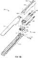
Фиг. 1A представляет собой перспективное изображение хирургического сшивающего инструмента, включающего в себя рукоятку, удлиненный вал, выступающий из рукоятки, и шарнирный концевой зажим, выходящий из удлиненного вала.FIG. 1A is a perspective view of a surgical stapling instrument including a handle, an elongated shaft protruding from the handle, and an articulated end clip extending from the elongated shaft.
Фиг. 1B представляет собой изображение концевого зажима хирургического инструмента, представленного на фиг. 1, в разобранном виде.FIG. 1B is an end clamp image of the surgical instrument of FIG. 1, unassembled.
Фиг. 2 представляет собой перспективное изображение артикуляционного сочленения концевого зажима и удлиненного вала хирургического инструмента в соответствии с по меньшей мере одним из вариантов осуществления настоящего изобретения; для демонстрации артикуляционного сочленения некоторые компоненты удалены.FIG. 2 is a perspective view of an articulation joint of an end clamp and an elongated shaft of a surgical instrument in accordance with at least one embodiment of the present invention; some components have been removed to demonstrate articulation articulation.
Фиг. 3 представляет собой поперечное сечение концевого зажима, представленного на фиг. 2, демонстрирующее соленоид, расположенный внутри удлиненного вала хирургического инструмента, при этом соленоид выполнен с возможностью приведения в движение концевого зажима.FIG. 3 is a cross-sectional view of the end clamp of FIG. 2, showing a solenoid located inside an elongated shaft of a surgical instrument, wherein the solenoid is configured to drive the end clamp.
Фиг. 4 представляет собой частичное перспективное изображение концевого зажима, артикуляционного сочленения и удлиненного вала, представленного на фиг. 2, некоторые компоненты удалены.FIG. 4 is a partial perspective view of the end clamp, articulation joint and elongated shaft of FIG. 2, some components are removed.
Фиг. 5 представляет собой поперечное сечение (вид сбоку) артикуляционного сочленения концевого зажима и удлиненного вала хирургического инструмента в соответствии с по меньшей мере одним из вариантов осуществления настоящего изобретения.FIG. 5 is a cross-section (side view) of an articulation joint of an end clamp and an elongated shaft of a surgical instrument in accordance with at least one embodiment of the present invention.
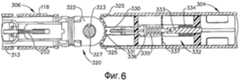
Фиг. 6 представляет собой поперечное сечение (вид снизу) хирургического инструмента, представленного на фиг. 5, проведенное по оси 6-6 на фиг. 5, показывающее управляемый соленоидом замок артикуляционного сочленения.FIG. 6 is a cross-section (bottom view) of the surgical instrument of FIG. 5 drawn along axis 6-6 in FIG. 5 showing a solenoid-driven articulation lock.
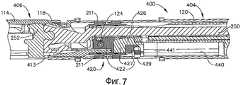
Фиг. 7 представляет собой поперечное сечение артикуляционного сочленения, служащего для сочленения концевого зажима и удлиненного вала хирургического инструмента, в соответствии с по меньшей мере одним из вариантов осуществления настоящего изобретения.FIG. 7 is a cross-sectional view of an articulation joint for jointing an end clamp and an elongated shaft of a surgical instrument, in accordance with at least one embodiment of the present invention.
Фиг. 8 представляет собой укрупненное изображение артикуляционного сочленения, представленного на фиг. 7, показывающее двигатель, выполненный с возможностью приведения в движение концевого зажима.FIG. 8 is an enlarged view of the articulation joint shown in FIG. 7, showing an engine configured to drive the end clamp.
Фиг. 9 представляет собой поперечное сечение артикуляционного сочленения, служащего для сочленения концевого зажима и удлиненного вала хирургического инструмента, в соответствии с по меньшей мере одним из вариантов осуществления настоящего изобретения.FIG. 9 is a cross-sectional view of an articulation joint used to joint an end clip and an elongated shaft of a surgical instrument, in accordance with at least one embodiment of the present invention.
Фиг. 10 представляет собой частичное перспективное изображение концевого зажима, артикуляционного сочленения и удлиненного вала, представленных на фиг. 9, показывающее двигатель, сочлененный с червячной передачей, выполненной с возможностью приведения в движение концевого зажима.FIG. 10 is a partial perspective view of the end clamp, articulation joint and elongated shaft shown in FIG. 9, showing an engine articulated with a worm gear configured to drive an end clamp.
Фиг. 11 представляет собой другую часть перспективного изображения концевого зажима, артикуляционного сочленения и удлиненного вала, представленных на фиг. 9, некоторые компоненты удалены.FIG. 11 is another part of a perspective view of the end clamp, articulation joint and elongated shaft shown in FIG. 9, some components are removed.
Фиг. 12 представляет собой частичное перспективное изображение артикуляционного сочленения, служащего для сочленения концевого зажима и удлиненного вала хирургического инструмента, в соответствии с по меньшей мере одним из вариантов осуществления настоящего изобретения.FIG. 12 is a partial perspective view of an articulation joint used to joint an end clamp and an elongated shaft of a surgical instrument, in accordance with at least one embodiment of the present invention.
Фиг. 13 представляет собой поперечное сечение концевого зажима, артикуляционного сочленения и удлиненного вала, представленных на фиг. 12, демонстрирующее управляемую двигателем трубку, выполненную с возможностью приведения в движение концевого зажима.FIG. 13 is a cross-sectional view of an end clamp, articulation joint and elongated shaft shown in FIG. 12, showing an engine-driven tube configured to drive an end clamp.
Фиг. 14 представляет собой другое частичное перспективное изображение концевого зажима, артикуляционного сочленения и удлиненного вала, представленных на фиг. 12, некоторые компоненты удалены, другие показаны линиями воображаемого контура.FIG. 14 is another partial perspective view of the end clamp, articulation joint and elongated shaft shown in FIG. 12, some components are removed, others are shown by imaginary contour lines.
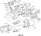
Фиг. 15 представляет собой изображение артикуляционного сочленения, показанного на фиг. 12, в разобранном виде.FIG. 15 is a depiction of the articulation articulation shown in FIG. 12, unassembled.
Фиг. 16 представляет собой перспективное изображение хирургического инструмента, имеющего кнопку для приведения в движение концевого зажима хирургического инструмента и кнопку вращения для вращения концевого зажима.FIG. 16 is a perspective view of a surgical instrument having a button for driving an end clamp of a surgical instrument and a rotation button for rotating an end clamp.
Фиг. 17 представляет собой поперечное сечение (вид сбоку) рукояточной части хирургического инструмента, показанного на фиг. 16.FIG. 17 is a cross-section (side view) of the handle portion of the surgical instrument shown in FIG. 16.
Фиг. 18 представляет собой перспективное изображение рукояточной части, показанной на фиг. 17, в поперечном сечении.FIG. 18 is a perspective view of the handle portion shown in FIG. 17, in cross section.
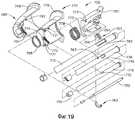
Фиг. 19 представляет собой изображение рукояточной части, показанной на фиг. 17, в разобранном виде.FIG. 19 is an image of the handle portion shown in FIG. 17, unassembled.
Фиг. 20 представляет собой перспективное изображение хирургического инструмента, в соответствии с по меньшей мере одним из вариантов осуществления настоящего изобретения, включающего в себя переключатель для управления движением и переключатель для управления вращением концевого зажима.FIG. 20 is a perspective view of a surgical instrument in accordance with at least one embodiment of the present invention, including a switch for controlling movement and a switch for controlling rotation of the end clamp.
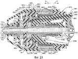
Фиг. 21 представляет собой поперечное сечение рукояточной части хирургического инструмента, показанного на фиг. 20.FIG. 21 is a cross section of the handle portion of the surgical instrument shown in FIG. twenty.
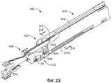
Фиг. 22 представляет собой перспективное изображение артикуляционного сочленения, служащего для сочленения концевого зажима и удлиненного вала хирургического инструмента, в соответствии с по меньшей мере одним из вариантов осуществления настоящего изобретения, некоторые компоненты удалены.FIG. 22 is a perspective view of an articulation articulation used to articulate an end clamp and an elongated shaft of a surgical instrument, in accordance with at least one embodiment of the present invention, some components are removed.
Фиг. 23 представляет собой схематическое изображение электромагнитов, расположенных в удлиненном вале, показанном на фиг. 22, выполненных с возможностью приложения магнитной силы к постоянным магнитам, установленным в концевом зажиме, показанном на фиг. 22.FIG. 23 is a schematic representation of electromagnets located in the elongated shaft shown in FIG. 22, configured to apply magnetic force to permanent magnets mounted in the end clamp shown in FIG. 22.
Фиг. 24 представляет собой поперечное сечение удлиненного вала, показанного на фиг. 22.FIG. 24 is a cross section of the elongated shaft shown in FIG. 22.
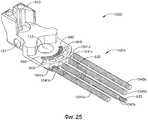
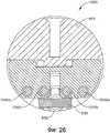
Фиг. 25 представляет собой перспективное изображение артикуляционного сочленения, выполненного с возможностью сочленения концевого зажима и удлиненного вала хирургического инструмента, в соответствии с по меньшей мере одним из вариантов осуществления настоящего изобретения, некоторые компоненты удалены.FIG. 25 is a perspective view of an articulation joint configured to joint an end clip and an elongated shaft of a surgical instrument, in accordance with at least one embodiment of the present invention, some components are removed.
Фиг. 26 представляет собой поперечное сечение концевого зажима, показанного на фиг. 25, демонстрирующее наличие нескольких электромагнитов.FIG. 26 is a cross-sectional view of the end clamp shown in FIG. 25, showing the presence of several electromagnets.
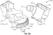
Фиг. 27 представляет собой перспективное изображение артикуляционного сочленения, выполненного с возможностью соединения концевого зажима и удлиненного вала хирургического инструмента, в соответствии с по меньшей мере одним из вариантов осуществления настоящего изобретения, некоторые компоненты удалены.FIG. 27 is a perspective view of an articulation joint configured to connect an end clamp and an elongated shaft of a surgical instrument, in accordance with at least one embodiment of the present invention, some components are removed.
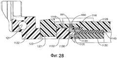
Фиг. 28 представляет собой поперечное сечение артикуляционного сочленения, показанного на фиг. 27, демонстрирующее систему постоянных магнитов и электромагнитов, выполненную с возможностью приведения в движение концевого зажима хирургического инструмента, и другую систему постоянных магнитов и электромагнитов, выполненную с возможностью закрепления концевого зажима в неподвижном положении относительно удлиненного вала хирургического инструмента.FIG. 28 is a cross section of the articulation joint shown in FIG. 27, showing a system of permanent magnets and electromagnets configured to actuate an end clamp of a surgical instrument, and another system of permanent magnets and electromagnets configured to fix an end clamp in a fixed position relative to an elongated shaft of a surgical instrument.
Фиг. 29 представляет собой изображение артикуляционного сочленения, показанного на фиг. 27, в демонтированном виде, некоторые компоненты удалены.FIG. 29 is a depiction of the articulation articulation shown in FIG. 27, dismantled, some components removed.
Фиг. 30 представляет собой изображение артикуляционного сочленения, показанного на фиг. 27, в разобранном виде.FIG. 30 is a depiction of the articulation articulation shown in FIG. 27, unassembled.
Фиг. 31 представляет собой поперечное сечение артикуляционного сочленения, показанного на фиг. 27, демонстрирующее систему постоянных магнитов и электромагнитов, выполненную с возможностью приведения в движение концевого зажима хирургического инструмента.FIG. 31 is a cross section of the articulation joint shown in FIG. 27, showing a system of permanent magnets and electromagnets configured to move the end clamp of a surgical instrument.
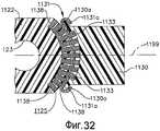
Фиг. 32 представляет собой поперечное сечение артикуляционного сочленения, показанного на фиг. 27, демонстрирующее систему постоянных магнитов и электромагнитов, выполненную с возможностью закрепления концевого зажима в неподвижном положении.FIG. 32 is a cross section of the articulation joint shown in FIG. 27, showing a system of permanent magnets and electromagnets configured to fix the end clamp in a fixed position.
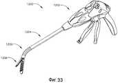
Фиг. 33 представляет собой перспективное изображение хирургического инструмента, включающего в себя рукоятку, удлиненный вал и концевой зажим, подвижно соединенный с удлиненным валом, в соответствии с по меньшей мере одним из вариантов осуществления настоящего изобретения.FIG. 33 is a perspective view of a surgical instrument including a handle, an elongated shaft, and an end clamp movably connected to the elongated shaft, in accordance with at least one embodiment of the present invention.
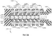
Фиг. 34 представляет собой поперечное сечение артикуляционного сочленения, выполненного с возможностью соединения удлиненного вала и концевого зажима, показанных на фиг. 33, на котором подвижное сочленение имеет несколько дисков.FIG. 34 is a cross-sectional view of an articulation joint configured to couple an elongated shaft and an end clamp shown in FIG. 33, on which the movable joint has several disks.
Фиг. 35 представляет собой поперечное сечение артикуляционного сочленения, показанного на фиг. 34, демонстрирующее сочленение в отогнутом положении.FIG. 35 is a cross section of the articulation joint shown in FIG. 34 showing the articulation in a bent position.
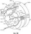
Фиг. 36 представляет собой перспективное изображение в поперечном сечении диска артикуляционного сочленения, показанного на фиг. 34, демонстрирующее электромагниты, расположенные в первой серии отверстий, и провода, проходящие через вторую серию отверстий, провода обеспечивают передачу электрической энергии от источника энергии к электромагнитам.FIG. 36 is a perspective cross-sectional view of the articulation joint disk shown in FIG. 34, showing electromagnets located in the first series of holes, and wires passing through the second series of holes, the wires transmit electrical energy from the energy source to the electromagnets.
Фиг. 37 представляет собой другое перспективное изображение в поперечном сечении диска, показанного на фиг. 36.FIG. 37 is another cross-sectional perspective view of the disk of FIG. 36.
Фиг. 38 представляет собой изображение смонтированной конструкции, состоящей из диска, показанного на фиг. 36, и второго диска, расположенного рядом с первым, при этом второй диск включает в себя несколько постоянных магнитов, расположенных в первой серии отверстий, а вторая серия отверстий в этом диске выполнена с возможностью прохождения проводов, показанных на фиг. 36.FIG. 38 is an image of a mounted structure consisting of the disk shown in FIG. 36, and a second disk adjacent to the first, the second disk including several permanent magnets located in the first series of holes, and the second series of holes in this disk is configured to pass the wires shown in FIG. 36.
Фиг. 39 представляет собой изображение диска, показанного на фиг. 36, в разобранном виде.FIG. 39 is an image of the disc shown in FIG. 36, unassembled.
Фиг. 40 представляет собой электрическую схему соединения постоянных магнитов и электромагнитов в подвижном сочленении, показанном на фиг. 34.FIG. 40 is a circuit diagram for connecting permanent magnets and electromagnets in the movable joint shown in FIG. 34.
Фиг. 41 представляет собой частичное перспективное изображение артикуляционного сочленения хирургического инструмента, в соответствии с по меньшей мере одним альтернативным вариантом осуществления настоящего изобретения, некоторые компоненты удалены, а другие показаны в поперечном сечении.FIG. 41 is a partial perspective view of the articulation of a surgical instrument in accordance with at least one alternative embodiment of the present invention, some components are removed and others are shown in cross section.
Фиг. 42 представляет собой поперечное сечение артикуляционного сочленения, показанного на фиг. 41, демонстрирующее попеременное расположение первых и вторых дисков в подвижном сочленении.FIG. 42 is a cross section of the articulation joint shown in FIG. 41, showing the alternate arrangement of the first and second disks in a movable joint.
Фиг. 43 представляет собой поперечное сечение артикуляционного сочленения, показанного на фиг. 41, в отогнутом положении.FIG. 43 is a cross section of the articulation joint shown in FIG. 41, in the bent position.
Фиг. 44 представляет собой вид с торца артикуляционного сочленения, показанного на фиг. 41.FIG. 44 is an end view of the articulation joint shown in FIG. 41.
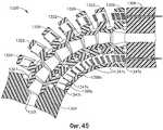
Фиг. 45 представляет собой другое поперечное сечение артикуляционного сочленения, показанного на фиг. 41, демонстрирующее выдвинутое и втянутое положение проводов электромагнитов, расположенных в дисках артикуляционного сочленения.FIG. 45 is another cross section of the articulation joint shown in FIG. 41, showing the extended and retracted position of the wires of the electromagnets located in the discs of the articulation joint.
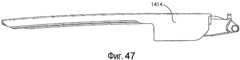
Фиг. 46 представляет собой поперечное сечение концевого зажима хирургического инструмента, в соответствии с по меньшей мере одним из вариантов осуществления настоящего изобретения, демонстрирующее наличие нескольких постоянных магнитов, расположенных в упорной пластине и концевом зажиме.FIG. 46 is a cross-sectional view of an end clamp of a surgical instrument, in accordance with at least one embodiment of the present invention, showing the presence of several permanent magnets located in the abutment plate and end clamp.
Фиг. 47 представляет собой изображение упорной пластины, показанной на фиг. 46, в вертикальной проекции.FIG. 47 is an image of a thrust plate shown in FIG. 46, in vertical projection.
Фиг. 48 представляет собой вертикальную проекцию рассекающего элемента концевого зажима, показанного на фиг. 46, включающего в себя несколько электромагнитов, выполненных с возможностью работы в сочетании с постоянными магнитами, расположенными в концевом зажиме хирургического инструмента, с целью выдвижения или втягивания рассекающего элемента концевого зажима.FIG. 48 is a vertical projection of the cutting element of the end clamp shown in FIG. 46, including several electromagnets configured to work in conjunction with permanent magnets located in the end clamp of a surgical instrument to extend or retract the dissecting element of the end clamp.
Фиг. 49 представляет собой перспективное изображение рассекающего элемента, показанного на фиг. 48.FIG. 49 is a perspective view of the dissecting element shown in FIG. 48.
Фиг. 50 представляет собой другое поперечное сечение концевого зажима, показанного на фиг. 46.FIG. 50 is another cross-sectional view of the end clamp shown in FIG. 46.
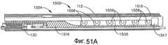
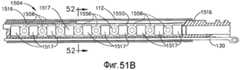
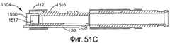
Фиг. 51A-51C демонстрируют дистальную, среднюю и проксимальную части удлиненного вала хирургического инструмента и подвижный выталкиватель, расположенный в удлиненном вале, в соответствии с по меньшей мере одним из вариантов осуществления настоящего изобретения.FIG. 51A-51C show the distal, middle, and proximal portions of an elongated shaft of a surgical instrument and a movable ejector located in an elongated shaft, in accordance with at least one embodiment of the present invention.
Фиг. 51A представляет собой поперечное сечение дистальной части удлиненного вала и подвижного выталкивателя, демонстрирующее ряд электромагнитов, расположенных в удлиненном вале.FIG. 51A is a cross-sectional view of a distal portion of an elongated shaft and a movable ejector, showing a series of electromagnets located in an elongated shaft.
Фиг. 51B представляет собой поперечное сечение средней части удлиненного вала и подвижного выталкивателя, показанных на фиг. 51A, демонстрирующее постоянные магниты, установленные на выталкивателе, и электромагниты, установленные в вале.FIG. 51B is a cross section of the middle portion of the elongated shaft and the movable ejector shown in FIG. 51A showing permanent magnets mounted on an ejector and electromagnets mounted in a shaft.
Фиг. 51C представляет собой поперечное сечение проксимальной части удлиненного вала и подвижного выталкивателя, показанных на фиг. 51A.FIG. 51C is a cross section of the proximal portion of the elongated shaft and the movable ejector shown in FIG. 51A.
Фиг. 52 представляет собой поперечное сечение удлиненного вала и подвижного выталкивателя, показанных на фиг. 51A-C.FIG. 52 is a cross section of an elongated shaft and a movable ejector shown in FIG. 51A-C.
Фиг. 53 представляет собой другое поперечное сечение дистальной части удлиненного вала и подвижного выталкивателя, показанных на фиг. 51A, демонстрирующее выталкиватель в выдвинутом положении.FIG. 53 is another cross-sectional view of the distal portion of the elongated shaft and the movable ejector shown in FIG. 51A showing an ejector in an extended position.
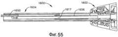
Фиг. 54 представляет собой поперечное сечение удлиненного вала хирургического инструмента в соответствии с по меньшей мере одним из вариантов осуществления настоящего изобретения, демонстрирующее выталкиватель в невыдвинутом положении.FIG. 54 is a cross-sectional view of an elongated shaft of a surgical instrument in accordance with at least one embodiment of the present invention, showing an ejector in an unextended position.
Фиг. 55 представляет собой поперечное сечение хирургического инструмента, показанного на фиг. 54, демонстрирующее выталкиватель, выдвинутый в рабочее положение посредством электромагнитной катушки.FIG. 55 is a cross-sectional view of the surgical instrument shown in FIG. 54, showing a pusher extended into position by means of an electromagnetic coil.
Для указания аналогичных элементов на разных изображениях используются аналогичные цифровые обозначения. Иллюстрации, прилагаемые к настоящей заявке, предназначены исключительно для демонстрации предпочтительных вариантов осуществления изобретения и не ограничивают объем настоящего изобретения.To indicate similar elements in different images, similar numeric notations are used. The illustrations appended to this application are intended solely to demonstrate preferred embodiments of the invention and do not limit the scope of the present invention.
ПОДРОБНОЕ ОПИСАНИЕDETAILED DESCRIPTION
Для более полного понимания конструкции, принципов работы, производства и использования устройств и способов, описанных в настоящем документе, приводится описание отдельных примеров осуществления. Один или несколько примеров вариантов осуществления представлены на сопроводительных иллюстрациях. Специалистам в данной области будет понятно, что устройства и способы, подробно описанные в настоящем документе и представленные на сопроводительных иллюстрациях, являются неограничивающими примерами вариантов осуществления, и объем различных вариантов осуществления настоящего изобретения определяется только формулой изобретения. Особенности, проиллюстрированные или описанные применительно к одному варианту осуществления, могут сочетаться с особенностями других вариантов осуществления. Предполагается, что объем настоящего изобретения охватывает все модификации и изменения.For a more complete understanding of the design, principles of operation, production and use of the devices and methods described herein, a description of individual embodiments is provided. One or more examples of embodiments are shown in the accompanying illustrations. Those skilled in the art will understand that the devices and methods described in detail herein and shown in the accompanying illustrations are non-limiting examples of embodiments, and the scope of various embodiments of the present invention is defined only by the claims. Features illustrated or described with respect to one embodiment may be combined with features of other embodiments. It is intended that the scope of the present invention covers all modifications and changes.
Раскрытие следующих одновременно поданных заявок на получение патента США, принадлежащих одному правообладателю, включено в настоящий документ в виде ссылок:Disclosure of the following concurrently filed US patent applications belonging to one copyright holder is incorporated herein by reference:
(1) Заявка на получение патента США № _______, под заголовком «ХИРУРГИЧЕСКИЙ СШИВАЮЩИЙ ИНСТРУМЕНТ», номер документа у патентного поверенного END6570USNP/090046; и(1) Application for U.S. Patent No. _______, under the heading “SURGICAL BINDING TOOL,” document number of the patent attorney END6570USNP / 090046; and
(2) Заявка на получение патента США № _______, под заголовком «ХИРУРГИЧЕСКИЙ СШИВАЮЩИЙ ИНСТРУМЕНТ, ВКЛЮЧАЮЩИЙ ПРИВОД С МАГНИТНЫМ ЭЛЕМЕНТОМ», номер документа у патентного поверенного END6569USNP/090045.(2) Application for US Patent No. _______, under the heading “SURGICAL STAPLING INSTRUMENT, INCLUDING A MAGNETIC ELEMENT DRIVE”, document number of the patent attorney END6569USNP / 090045.
В различных вариантах осуществления изобретения, показанных на фиг. 1A и 1B, хирургический инструмент, такой, например, как хирургический инструмент 100, может включать в себя рукоятку 102, удлиненный вал 104, выходящий из рукоятки 102, и концевой зажим 106, который можно приводить в движение или отгибать относительно удлиненного вала 104, как подробно описано ниже. По меньшей мере в одном из вариантов осуществления изобретения рукоятка 102 может включать замыкающую ручку 108, которая может быть выполнена с возможностью открывания и закрывания концевого зажима 106. В частности, концевой зажим 106 может включать в себя упорную пластину 114, и, кроме того, удлиненный вал 104 может включать в себя замыкающую трубку 112, при этом нажатие на закрывающий спусковой крючок 108 может приводить к продольному смещению замыкающей трубки 112 с целью вращения упорной пластины 114 между открытым и закрытым положением относительно канала картриджа скобок 113 и картриджа скобок 115. По меньшей мере в одном из вариантов осуществления изобретения замыкающая трубка 112 может скользить относительно стационарной части удлиненного вала 104, например, подобно центральной оси 116 (фиг. 1B). В некоторых вариантах осуществления изобретения концевой зажим 106 может дополнительно включать в себя трубчатую часть, такую как, например, дистальная трубчатая часть 118, которая может перемещаться под действием замыкающей трубки 112 с целью открывания и (или) закрывания упорной пластины 114. По меньшей мере в одном из вариантов осуществления изобретения хирургический инструмент 100 может дополнительно включать в себя одно или несколько шарнирных соединений 211 (фиг. 2 и 3), которые могут быть выполнены с возможностью соединения замыкающей трубки 112 с дистальной трубчатой частью 118, что позволяет дистальной трубчатой части 118 двигаться относительно замыкающей трубки 112 при движении концевого зажима 106 относительно удлиненного вала 104. Во всех случаях, когда упорная пластина 114 закрыта, пусковой крючок выталкивателя 110, находящийся в рукояточной части 112, может быть активирован для передвижения рассекающего и (или) скрепляющего скобками элемента через концевой зажим 106 с целью рассекания и (или) сшивания скобками ткани, захваченной концевым зажимом 106. После завершения рассекания и (или) сшивания закрывающий спусковой крючок 108 может быть отпущен для передвижения замыкающей трубки 112 в противоположную сторону в продольном направлении и открывания упорной пластины 114. Другие хирургические инструменты раскрываются с патенте США № 7441685, под заголовком «ХИРУРГИЧЕСКИЙ СШИВАЮЩИЙ ИНСТРУМЕНТ С ВОЗВРАТНЫМ МЕХАНИЗМОМ», выданном 28 октября 2008 г., полное раскрытие приводится в настоящем документе в виде ссылки. Дополнительные хирургические инструменты раскрываются в заявке на патент США № 12/008303, под заголовком «ХИРУРГИЧЕСКИЙ СШИВАЮЩИЙ ИНСТРУМЕНТ С ЗУБЧАТЫМ ВОЗВРАТНЫМ МЕХАНИЗМОМ», поданной 10 января 2008 г., и заявке на патент США № 12/008266, под заголовком «ХИРУРГИЧЕСКИЙ СШИВАЮЩИЙ ИНСТРУМЕНТ С ВОЗВРАТНЫМ МЕХАНИЗМОМ ВЫТАЛКИВАЮЩЕГО ЭЛЕМЕНТА», поданной 10 января 2008 г., полное раскрытие приводится в настоящем документе в виде ссылки.In the various embodiments shown in FIG. 1A and 1B, a surgical instrument, such as, for example, a
В различных вариантах осуществления изобретения, также соответствующих фиг. 1A и 1B, хирургический инструмент может дополнительно включать гибкое сочленение, такое как, например, гибкое сочленение 120, которое может быть выполнено с возможностью обеспечения подвижности концевого зажима 106 относительно удлиненного вала 104. По меньшей мере в одном из вариантов осуществления изобретения концевой зажим 106 может дополнительно включать в себя поворотную пластину 122, которая может удерживаться в канале картриджа скобок 113 канальным штырьком 124. Как показано на фиг. 1B, канальный штырек 124 может быть вставлен, закреплен прессовым соединением и (или) защелкой в и (или) через отверстия 111 в канале картриджа 113 и отверстие 121 в поворотной пластине 122 с целью закрепления поворотной пластины 122 в канале картриджа 113. В некоторых вариантах осуществления изобретения поворотная пластина 122 может быть неподвижно закреплена в канале картриджа скобок 113. Помимо вышеуказанного, удлиненный вал 104 может дополнительно включать планку вставки штырька 126, которая может быть закреплена посредством стержня 116, при этом по меньшей мере в одном из вариантов осуществления изобретения планка вставки штырька 126 может неподвижно удерживаться внутри удлиненного вала 104. В первую очередь, на фиг. 1B видно, что поворотная пластина 122 может дополнительно включать отверстие для штырька 123, которое может быть выполнено с возможностью принятия подвижного штырька 127, выступающего из планки вставки штырька 126. В различных вариантах осуществления изобретения штырек 127 и отверстие для штырька 123 могут быть подобраны по размеру таким образом, чтобы определять оси, такие как, например, ось 128, вокруг которых канал картриджа скобок 113 и поворотная пластина 122 могут вращаться относительно планки вставки штырька 126. В результате вышесказанного концевой зажим 106 может сгибаться относительно удлиненного вала 104 с целью, например, достижения подходящего положения концевого зажима 106 в месте хирургического вмешательства. После достижения надлежащего положения конечный зажим 106 может быть неподвижно закреплен относительно вала 104. В некоторых вариантах осуществления изобретения удлиненный вал 104 может дополнительно включать в себя замок или тормоз, такой, например, как замок 130, который может быть выполнен с возможностью, например, избирательного захвата поворотной пластины 122 и удержания ее в неподвижном положении относительно планки вставки штырька 126. По меньшей мере в одном варианте осуществления изобретения поворотная пластина 122 может иметь один или несколько зубцов 125, которые могут захватываться или зацепляться одной или несколькими выемками 131 на дистальном конце замка 130, таким образом предотвращая или по меньшей мере ограничивая относительное передвижение зубцов 125 и выемок 131.In various embodiments, also corresponding to FIG. 1A and 1B, the surgical instrument may further include a flexible joint, such as, for example, flexible joint 120, which may be configured to provide mobility to the
При использовании замок 130 может быть отсоединен от поворотной пластины 122 таким образом, чтобы концевой зажим 106 мог вращаться относительно удлиненного вала 104. При отсоединении замка 130 от поворотной пластины 122 по меньшей мере в одном из вариантов осуществления изобретения концевой зажим 106 может быть расположен напротив стенки полости в месте хирургического вмешательства, например такой как стенка брюшной полости, и к валу 104 может быть приложена сила в продольном направлении посредством рукоятки 102 с целью вращения концевого зажима 106 относительно удлиненного вала 104. При некоторых условиях такое артикуляционное движение может рассматриваться как пассивная артикуляция. Каждый раз при достижении подходящего положения концевого зажима 106 замок 130 может быть вновь замкнут с поворотной пластиной 122, а замыкающая трубка 112 может быть продвинута в продольном направлении посредством ручки 108 с целью закрытия упорной пластины 114, как описано выше. Как может видеть читатель, при передвижении концевого зажима 106 между прямым положением, т.е. положением, когда он расположен сонаправленно или по меньшей мере по существу сонаправленно с удлиненным валом 104 и согнутым положением дистальная трубчатая часть 118 может изменять свое положение между первым углом относительно замыкающей трубки 112 и вторым или отличающимся, углом относительно замыкающей трубки 112. Для согласованности такого относительного движения (см. фиг. 2 и 3) шарнирные соединения 211 могу быть подвижно присоединены к дистальной трубчатой части 118 и замыкающей трубке 112 посредством штырьковых выступов 109, выступающих из шарнирных соединений 211, через отверстия 107 в трубчатой части 118 и замыкающей трубке 112. Штырьковые выступы 109 и отверстия под штырьки 107 могут быть устроены таким образом, чтобы шарнирные соединения 211 могли обеспечить по меньшей мере одну степень свободы движения между дистальной трубчатой частью 118 и замыкающей трубкой 112. В таких вариантах осуществления изобретения шарнирные соединения 211 могут обеспечивать движение дистальной трубчатой части 118 относительно замыкающей трубки 112, даже если по меньшей мере часть замыкающей трубки 112 была выдвинута в дистальном направлении за пределы артикуляционного сочленения 120. Во всех случаях, когда упорная пластина 114 закрыта, пусковой крючок выталкивателя 110, находящийся в рукояточной части 112, может быть активирован для передвижения выталкивателя в дистальном направлении в концевой зажим 106. Хотя выталкиватель не показан на фиг. 1A и 1B, хирургический инструмент 200, согласно фиг. 2-4, включает в себя соответствующий выталкиватель 250 и рассекающий элемент 252, которые могут быть выполнены с возможностью продвижения в и (или) внутри концевого зажима 106. По меньшей мере в одном из вариантов осуществления изобретения удлиненный вал и (или) концевой зажим хирургического инструмента 100, например, могут включать в себя одну или несколько прорезей, выполненных с возможностью принятия и (или) направления выталкивателя 250 и (или) рассекающего элемента 252 при выдвижении и (или) оттягивании их внутри вала и (или) концевого зажима хирургического инструмента 100.In use, the
В различных вариантах осуществления изобретения (см. фиг. 2-4) хирургический инструмент, такой как хирургический инструмент 200, например, может включать в себя удлиненный вал 204 и концевой зажим 206, при этом концевой зажим 206 может быть выполнен с возможностью артикуляционного движения относительно удлиненного вала 204 благодаря артикуляционному сочленению 220. Аналогично хирургическому инструменту 100 концевой зажим 206 может включать в себя поворотную пластину 222, удерживаемую внутри канала картриджа скобок 213, при этом поворотная пластина 222 может иметь отверстие для штырька 223, выполненное с возможностью приема артикуляционного штырька 227, выступающего из планки вставки штырька 226. В различных вариантах осуществления изобретения, в первую очередь показанных на фиг. 4, удлиненный вал 204 может дополнительно включать один или несколько механизмов, которые могут быть выполнены с возможностью вращения, или поворота вокруг оси, концевого зажима 206 относительно вала 204. По меньшей мере в одном из вариантов осуществления изобретения удлиненный вал 204 может дополнительно включать в себя первый соленоид 240 и второй соленоид 242, установленные внутри него, которые могут соединяться с поворотной пластиной 222 таким образом, что активация первого соленоида 240 и (или) второго соленоида 242 может приводить, например, к вращению поворотной пластины 222 вокруг оси. В некоторых вариантах осуществления изобретения первый соленоид 240 может включать в себя поршень и (или) стержень 241, прикрепленный к поворотной пластине 222 таким образом, что поворотная пластина 222 может проталкиваться в дистальном направлении и (или) оттягиваться в проксимальном направлении посредством первого соленоида 240 с целью вращения концевого зажима 206 в направлении по часовой стрелке (CW) и (или) против часовой стрелки (CCW). В некоторых вариантах осуществления изобретения такое артикуляционное движение может рассматриваться как активная артикуляция.In various embodiments of the invention (see FIGS. 2-4), a surgical instrument, such as a
В различных вариантах осуществления изобретения, в дополнение к вышесказанному, стержень 241 может быть выдвинут дистально в направлении, указанном стрелкой «D», с целью вращения концевого зажима 206 по часовой стрелке в направлении, указанном стрелкой «CW». С целью вращения концевого зажима 206 против часовой стрелки, в направлении, указанном стрелкой «CCW», стержень 241 может быть оттянут проксимально в направлении, указанном стрелкой «P». В некоторых вариантах осуществления изобретения стержень 241 может иметь дистальный конец 245, который может быть расположен в отверстии 246 поворотной пластины 222 таким образом, что стержень 241 может поворачиваться относительно поворотной пластины 222. По меньшей мере в одном из вариантов осуществления изобретения стержень 241 может быть достаточно гибким для приспособления к относительному движению между поворотной пластиной 222 и соленоидом 240. В некоторых вариантах осуществления изобретения соленоид 240 может иметь скользящее или вращающееся соединение с удлиненным валом 204, благодаря чему стержень 241 не подвергается ненадлежащему изгибу или зажатию при его выдвижении или оттягивании для управления движением поворотной пластины 222 по оси. В любом случае изображенный на фиг. 3 соленоид 240 может иметь обмотку 247, на которую может подаваться электрический ток и (или) напряжение с целью создания достаточного магнитного поля для передвижения стержня 241 в дистальном и (или) проксимальном направлении, в зависимости от направления течения тока и (или) полярности напряжения, подаваемого на обмотку. По меньшей мере в одном подобном варианте осуществления изобретения поршень и (или) стержень 241 может иметь, например, железный сердечник, который может быть выполнен с возможностью взаимодействия с магнитным полем, генерируемым обмоткой соленоида 247.In various embodiments of the invention, in addition to the foregoing, the
В некоторых вариантах осуществления изобретения, в дополнение к вышесказанному, удлиненный вал 204 может включать в себя по меньшей мере один дополнительный соленоид, такой, например, как соленоид 242, который может быть выполнен с возможностью вращения поворотной пластины 222 одновременно с и (или) независимо от соленоида 240. По меньшей мере в одном из вариантов осуществления изобретения соленоид 242 может включать в себя поршень и (или) стержень 243, который может продвигаться дистально и (или) проксимально с целью вращения концевого зажима 206 в направлении по или против часовой стрелки. В отличие от соленоида 240 стержень 243 может продвигаться дистально для вращения поворотной пластины 222 в направлении против часовой стрелки и (или) оттягиваться проксимально для вращения поворотной пластины 222 в направлении по часовой стрелке. Аналогично соленоиду 240 стержень 243 может иметь дистальный конец 245, который может быть вставлен в отверстие 246 поворотной пластины 222 с возможностью вращения. Также аналогично соленоиду 240 соленоид 242 может иметь скользящее и (или) вращающееся соединение с удлиненным валом 204 для добавления по меньшей мере одной степени свободы в систему соединений, включающую в себя поворотную пластину 222, планку вставки штырька 226, соленоид 24 и стержень 243, что обеспечивает артикуляционное движение между концевым зажимом 206 и валом 204.In some embodiments, in addition to the foregoing, the
Как было описано выше, концевой зажим хирургического инструмента может закрепляться в неподвижном положении после достижения необходимой артикуляции концевого зажима. В различных вариантах осуществления изобретения (см. фиг. 5 и 6) хирургический инструмент, такой как, например, хирургический инструмент 300, может включать в себя удлиненный вал 304 и концевой зажим 306, при этом концевой зажим 306 может быть выполнен с возможностью совершения артикуляционных движений относительно удлиненного вала 304 благодаря артикуляционному сочленению 320. Аналогично хирургическому инструменту 100 концевой зажим 306 может включать в себя поворотную пластину 322, удерживаемую внутри канала картриджа скобок 313, при этом поворотная пластина 322 может иметь отверстие для штырька 323, выполненное с возможностью вставки артикуляционного штырька 327, выступающего из планки вставки штырька 326, закрепленной внутри удлиненного вала 304. В некоторых вариантах осуществления изобретения удлиненный вал 304 может дополнительно иметь замок, или тормоз, и привод замка, который может быть выполнен с возможностью зацепления замком поворотной пластины 322 и, в результате, удержания поворотной пластины 322 в неподвижном положении относительно удлиненного вала 304. По меньшей мере в одном из вариантов осуществления изобретения удлиненный вал 304 может включать в себя привод замка 332, который может быть выполнен с возможностью продвижения замка 330 в дистальном направлении для зацепления замка 330 с пластиной 322 и (или) в проксимальном направлении для отсоединения замка 330 от пластины 322. По меньшей мере в одном из вариантов осуществления изобретения привод замка 332 может включать в себя соленоид, установленный внутри удлиненного вала 304, при этом соленоид может включать в себя поршень и (или) стержень 333, который может выдвигаться дистально и (или) оттягиваться проксимально посредством обмотки 334. В некоторых вариантах осуществления изобретения замок 330 может быть прикреплен к стержню 333 таким образом, чтобы изменение положения стержня 333 могло приводить к изменению положения замка 330 в направлении к или от поворотной пластины 322. Аналогично вышеописанному замок 330 может входить в контакт с поворотной пластиной 322 таким образом, чтобы выемка 331 на дистальном конце замка 330 могла зацеплять или захватывать выступ, или зубец, 325, выступающий из поворотной пластины 322. По меньшей мере в одном из вариантов осуществления изобретения привод замка 332 может дополнительно включать в себя смещающий элемент, такой, например, как пружина 335, который может быть выполнен с возможностью смещения замка 330 до зацепления с поворотной пластиной 322. По меньшей мере в одном из подобных вариантов осуществления изобретения соленоид привода замка 332 может преодолевать смещающую силу пружины 335 с целью отсоединения замка 330 от поворотной пластины 322. В некоторых вариантах осуществления изобретения пружина 335 может быть сжата между фланцем 336, выступающим из замка 330, и стационарным, или по меньшей мере обладающим существенной степенью стационарности, фланцем 337 удлиненного вала 306 таким образом, что пружина 335 может передавать смещающее усилие замку 330. По меньшей мере в одном из вариантов осуществления изобретения пружина 335 может включать в себя линейную пружину, для которой прилагаемая сила может быть пропорциональна длине пространства, в котором сжата пружина.As described above, the end clamp of the surgical instrument can be fixed in a fixed position after achieving the necessary articulation of the end clamp. In various embodiments of the invention (see FIGS. 5 and 6), a surgical instrument, such as, for example, a
В различных вариантах осуществления изобретения (см. фиг. 7 и 8) хирургический инструмент 400, например, может включать в себя один или несколько двигателей, выполненных с возможностью артикуляции концевого зажима хирургического инструмента. В таких вариантах осуществления изобретения двигатель может быть представлен, например, индукционным двигателем, бесщеточным двигателем постоянного тока, шаговым двигателем и (или) синхронным двигателем. В некоторых вариантах осуществления изобретения хирургический инструмент 400 может включать в себя удлиненный вал 404 и концевой зажим 406, при этом концевой зажим 406 может быть выполнен с возможностью совершения артикуляционных движений относительно удлиненного вала 404 благодаря артикуляционному сочленению 420. Аналогично хирургическому инструменту 100 концевой зажим 406 может включать в себя поворотную пластину 422, удерживаемую внутри канала картриджа скобок 413, при этом поворотная пластина 422 может иметь отверстие для штырька 423, выполненное с возможностью вставки артикуляционного штырька 427, выступающего из планки вставки штырька 426, закрепленной внутри удлиненного вала 404. По меньшей мере в одном из вариантов осуществления изобретения удлиненный вал 404 может дополнительно включать в себя двигатель, такой, например, как двигатель 440, установленный таким образом, чтобы он мог работать в зацеплении с поворотной пластиной 422 с целью вращения, или артикуляции, концевого зажима 406 относительно вала 404. В частности, по меньшей мере в одном подобном варианте осуществления изобретения двигатель 440 может быть выполнен с возможностью вращения шестерни, такой как, например, прямозубчатая шестерня 439, которая может зацепляться с одним или несколькими зубцами, такими, например, как зубцы 429, на поворотной пластине 422 таким образом, чтобы вращение прямозубчатой шестерни 439 могло передаваться поворотной пластине 422. По меньшей мере в одном подобном варианте осуществления изобретения зубцы 429 могут быть расположены, по меньшей мере частично, в кольцевой последовательности по периметру поворотной пластины 422. В различных вариантах осуществления изобретения удлиненный вал 404 может дополнительно включать в себя коробку передач, такую как, например, коробка передач 441, для уменьшения и (или) повышения передаточного числа между входным валом, приводимым в действие двигателем 440, и выходным валом, приводящим в действие прямозубчатую шестерню 439.In various embodiments of the invention (see FIGS. 7 and 8), a
Аналогично вышеописанному, хирургический инструмент 500, например, может включать в себя один или несколько двигателей, выполненных с возможностью артикуляции концевого зажима хирургического инструмента с использованием червячной передачи. В различных вариантах осуществления изобретения хирургический инструмент 500 может включать в себя удлиненный вал 504 и концевой зажим 506, при этом концевой зажим 506 может быть выполнен с возможностью совершения артикуляционных движений относительно удлиненного вала 504 благодаря артикуляционному сочленению 520. Аналогично хирургическому инструменту 400, концевой зажим 506 может включать в себя поворотную пластину 522, удерживаемую внутри канала картриджа скобок 513, при этом поворотная пластина 522 может иметь отверстие для штырька 523, выполненное с возможностью вставки артикуляционного штырька, выступающего из планки вставки штырька 526, закрепленной внутри удлиненного вала 504. По меньшей мере в одном из вариантов осуществления изобретения удлиненный вал 504 может дополнительно включать в себя двигатель, такой, например, как двигатель 540, установленный таким образом, чтобы он мог работать в зацеплении с поворотной пластиной 522 с целью вращения, или артикуляции, концевого зажима 506 относительно вала 504. В частности, по меньшей мере в одном подобном варианте осуществления изобретения двигатель 540 может быть выполнен с возможностью червячной передачи, такой, например, как червяк 539, который может зацепляться с червячной шестерней или вогнутой частью червячного колеса 529 на поворотной пластине 522 таким образом, что вращение червяка 539 может передаваться поворотной пластине 522. Блок червячной передачи, подобный, например, описанному выше, может обеспечить достижение очень высокого передаточного числа, благодаря чему не требуется использование коробки передач для снижения скорости двигателя, хотя коробка передач и может быть использована. В некоторых вариантах осуществления изобретения блок червячной передачи может быть самоблокирующимся. В частности, угол подъема спиральной резьбы на червяке 539 может быть таким, что концевой зажим 506 и червячная передача 529 не могут вращаться так, чтобы червяк 539 и двигатель 540 вращались в обратную сторону. Говоря другими словами, червячная передача 529 и червяк 539 могут быть выполнены таким образом, что их заклинивает между собой под действием сил трения в случае приложения вращательного усилия к концевому зажиму 506. В некоторых вариантах осуществления изобретения, в результате, артикуляция концевого зажима 506 относительно удлиненного вала 504 может контролироваться только путем избирательного вращения червяка 539 двигателем 540 в направлении по часовой стрелке и против часовой стрелки с целью вращения концевого зажима 506, например влево и вправо, благодаря артикуляционному сочленению 520. По меньшей мере в одном подобном варианте осуществления изобретения отдельный замок, препятствующий артикуляции, подобный, например, описанному выше, может не требоваться, хотя такой замок может быть использован.Similar to the above, a
В различных вариантах осуществления изобретения по меньшей мере часть удлиненного вала хирургического инструмента, такого как, например, хирургический инструмент 600, может включать в себя двигатель, выполненный с возможностью артикуляции концевого зажима хирургического инструмента. В различных вариантах осуществления изобретения (см. фиг. 12-15) хирургический инструмент 600 может включать в себя удлиненный вал 604 и концевой зажим 606, при этом концевой зажим 606 может быть выполнен с возможностью артикуляционного движения относительно удлиненного вала 604 благодаря артикуляционному сочленению 620. В различных вариантах осуществления изобретения концевой зажим 606 может также включать в себя поворотный элемент 622, установленный внутри него, при этом, по меньшей мере в некоторых вариантах осуществления изобретения, поворотный элемент 622 может быть неподвижно закреплен внутри концевого зажима 606. Кроме того, удлиненный вал 604 может включать в себя один или несколько двигателей, таких, например, как двигатель 640, которые могут быть выполнены с возможностью вращения поворотного элемента 622 вокруг оси, определяемой осями вращения 627a и 627b. По меньшей мере в одном из вариантов осуществления изобретения двигатель 640 может включать в себя вращающуюся часть 616, установленную внутри удлиненного вала 604, и дополнительно осевой элемент вращения 626, соединенный с вращающейся частью 616, при этом вращающаяся часть 616 и осевой элемент вращения 626 могут быть неподвижно закреплены внутри удлиненного вала 604. На фиг. 15 осевой элемент вращения 626 может включать в себя верхний и нижний выступы 626a и 626b, при этом оси вращения 627a и 627b могут выступать из выступов 626a и 626b, соответственно, и могут крепиться в отверстиях 627c в выступах 626a и 626b любым подходящим способом, например, путем прессового или адгезивного соединения. В различных вариантах осуществления изобретения поворотный элемент 622 может включать в себя одно или несколько отверстий, таких как, например, отверстие 623, выполненных с возможностью плотного закрепления осей вращения 627a и 627b таким образом, что поворотный элемент 622 и концевой зажим 606 могут вращаться или совершать артикуляционные движения относительно оси, как описано выше.In various embodiments, at least a portion of the elongated shaft of the surgical instrument, such as, for example,
В различных вариантах осуществления изобретения, дополнительно к вышеописанному, вращающаяся часть 616 и (или) осевой элемент вращения 626 могут включать в себя одно или несколько отверстий, или вырезов, таких как, например, отверстия 651, которые могут быть выполнены с возможностью вставки одного или нескольких электромагнитов, таких как, например, электромагниты 647. Хотя это не продемонстрировано на фигурах, хирургический инструмент 600 может также включать в себя один или несколько проводников, таких как, например, изолированные провода, которые могут быть выполнены с возможностью проведения электрического тока при подсоединении к ним источника тока и (или) источника напряжения, такого, например, как батарея. По меньшей мере в одном подобном варианте осуществления изобретения проводники могут проходить от рукояточной части хирургического инструмента, такой как, например, рукоятка 102, к дистальному концу удлиненного вала 606, при этом проводники могут формировать витки вокруг ферромагнитных сердечников, которые могут состоять, например, из железа и (или) кобальта, для создания электромагнитов 647a и 647b. По меньшей мере в одном подобном варианте осуществления изобретения хирургический инструмент может дополнительно включать в себя переключатель, или исполнительный механизм, который может быть задействован для избирательного соединения источника тока и (или) источника напряжения с проводниками. В некоторых вариантах осуществления изобретения, если через проводники не проходит электрический ток, электромагниты 647a, 647b не могут создавать магнитное поле, а если через проводники проходит достаточный электрический ток, он может создавать одно или несколько магнитных полей, которые могут использоваться для вращения привода 639. В первую очередь, по фиг. 15 видно, что привод 639 может включать в себя один или несколько магнитных элементов, которые, при воздействии магнитного поля, или полей, создаваемых электромагнитами 647, могут взаимодействовать с магнитным полем, или полями, и приводить во вращательное движение привод 639. По меньшей мере в одном подобном варианте осуществления изобретения привод 639 может включать в себя одно или несколько отверстий, или вырезов, таких как, например, отверстия 648, которые могут быть выполнены с возможностью вставки одного или нескольких постоянных магнитов 649.In various embodiments of the invention, in addition to the above, the rotating
В различных вариантах осуществления изобретения, в дополнение к вышеописанному, постоянные магниты 649 могут обладать магнитной полярностью независимо от того, находятся ли они в магнитном поле. По меньшей мере в одном из вариантов осуществления изобретения каждый из постоянных магнитов 649 может иметь положительный, или северный, полюс 649n и отрицательный, или южный, полюс 649s, при этом полюса 649n и 649s могут быть расположены таким образом, что при воздействии магнитного поля или полей, избирательно создаваемых электромагнитами 647a и 647b, такие магнитные поля могут взаимодействовать с магнитными полями, создаваемыми постоянными магнитами 649, и, в результате, приводить во вращательное движение привод 639. В различных вариантах осуществления изобретения привод 639 может быть плотно вставлен, с обеспечением возможности вращения, в отверстие 654 в элементе 616 таким образом, что привод 639 может вращаться вокруг оси, когда постоянные магниты 649 перемещаются в магнитном поле, создаваемом электромагнитами 647a, 647b. Как было отмечено выше, на электромагниты 647a и 647b можно избирательно подавать энергию для создания магнитных полей, которые, благодаря полярности постоянных магнитов 649, обуславливают перемещение постоянных магнитов 649 в магнитном поле (полях). В различных вариантах осуществления изобретения на электромагниты 647a и 647b может подаваться энергия таким образом, что электромагниты 647a будут иметь полярность, отличную от полярности электромагнитов 647b. По меньшей мере в одном из вариантов осуществления изобретения на электромагниты 647a и 647b может подаваться энергия таким образом, что они будут иметь противоположную полярность, или противоположно направленные положительные (северные) и отрицательные (южные) полюса, и таким образом, что полюса электромагнитов 647a и 647b будут расположены попеременно. В различных вариантах осуществления изобретения направление течения тока через проводники, обвитые вокруг сердечников электромагнитов 647a, 647b, может определять полярность магнитного поля (полей), создаваемого электромагнитами. При использовании направление течения тока через проводники, как описано выше, может многократно переключаться, или попеременно изменяться, в результате чего может происходить многократное изменение полярности одного или нескольких электромагнитов 647a и 647b, с целью притяжения или отталкивания постоянных магнитов 649 таким образом, чтобы привод 639 мог непрерывно вращаться в направлении по или против часовой стрелки.In various embodiments of the invention, in addition to the above, the
Как было описано выше, действие постоянных магнитов 647a, 647b может приводить в движение привод 639, заставляя его вращаться в направлении по или против часовой стрелки. В различных вариантах осуществления изобретения привод 639 может также включать в себя одну или несколько передаточных частей, или зубцов привода, которые могут быть выполнены с возможностью зацепления с соответствующей приводной частью, или зубцами привода, на поворотном элементе 622. В частности, по меньшей мере в одном из вариантов осуществления изобретения привод 639 может включать в себя первую выступающую зубчатую передаточную часть 639a, которая может быть выполнена с возможностью зацепления с первой зубчатой передаточной частью 629a, выступающей из поворотного элемента 622, таким образом, что при вращении привода 639, как описано выше, первая зубчатая передаточная часть 639a может приводить в движение передаточную часть 629a, заставляя поворотный элемент 622 и, соответственно, концевой зажим 606 совершать вращательное или артикуляционное движение относительно поворотных осей 627a и 627b. По меньшей мере в одном из подобных вариантов осуществления изобретения (см., в первую очередь, фиг. 14) привод 639 может вращаться в первом направлении, указанном стрелкой D1, с целью вращения концевого зажима 606 в направлении по часовой стрелке, указанном стрелкой CW, и, в дополнение к этому, привод 639 может вращаться во втором направлении, указанном стрелкой D2, с целью вращения концевого зажима 606 в направлении против часовой стрелки, указанном стрелкой CCW. По меньшей мере в одном из вариантов осуществления изобретения в результате этого привод 639 может вращаться вокруг первой оси, а концевой зажим 606 может вращаться вокруг второй оси, при этом первая и вторая оси могут быть перпендикулярными или по меньшей мере по существу перпендикулярными относительно друг друга. В других вариантах осуществления изобретения первая и вторая оси могут быть непараллельными, пересекающимися и (или) расположенными под углом относительно друг друга. В различных вариантах осуществления изобретения (см. фиг. 14) привод 639 может дополнительно включать в себя вторую передаточную часть 639b, которая может зацепляться в рабочем положении со второй передаточной частью 629b поворотного элемента 622 через передаточный механизм 653. По меньшей мере в одном подобном варианте осуществления изобретения передаточный механизм 653 может быть установлен на осевом элементе вращения 626 с помощью оси, такой как, например, ось 655, с возможностью вращения таким образом, что при вращении привода 639 в направлении D1, как описано выше, вторая передаточная часть 639b может действовать совместно с первой передаточной частью 639a для обеспечения вращения поворотного механизма 622, например, в направлении по часовой стрелке CW.As described above, the action of the
Как было отмечено выше, хирургический инструмент может включать в себя рукояточную часть, выполненную с возможностью управления хирургическим инструментом. В различных вариантах осуществления изобретения (см. фиг. 16 и 17) хирургический инструмент, такой как, например, хирургический инструмент 700, может включать в себя рамку 701, замыкающую ручку 108, подвижно закрепленную на рамке 701, и дополнительно ручку выталкивателя 110, также подвижно закрепленную на рамке 701. Аналогично хирургическому инструменту 100, активация замыкающей ручки 108 и связанного с ней замыкающего привода может приводить к перемещению замыкающей трубки 712 в продольном направлении вдоль удлиненного вала 704 с целью открытия и закрытия упорной пластины 114. В некоторых вариантах осуществления изобретения (см. фиг. 17) замыкающий привод может включать в себя удерживающий заплечик 108b, который может скользить внутри рамки 701, и, в дополнение к этому, замыкающий соединитель 108a, подвижно соединенный с удерживающим заплечиком 108b и ручкой 108. По меньшей мере в одном подобном варианте осуществления изобретения по меньшей мере часть замыкающей трубки 712 может удерживаться удерживающим заплечиком 108b таким образом, что прижатие закрывающего спускового крючка 108 в направлении пистолетной рукоятки 103 может смещать замыкающий соединитель 108a, удерживающий заплечик 108b, и замыкающую трубку 712 в дистальном направлении, т.е. в направлении, указанном стрелкой D.As noted above, the surgical instrument may include a grip portion configured to control the surgical instrument. In various embodiments of the invention (see FIGS. 16 and 17), a surgical instrument, such as, for example, a
В дополнение к замыкающему приводу, описанному выше, рукояточная часть 702 может также включать в себя артикуляционную систему, выполненную с возможностью вращения привода, такого, например, как привод 739, с целью приведения концевого зажима 706 в артикуляционное движение относительно удлиненного вала 704. По меньшей мере в одном подобном варианте осуществления изобретения рукояточная часть 702 может также включать в себя ручку артикуляции 760, которая может двигаться между заблокированным и незаблокированным положением, при этом в некоторых вариантах осуществления изобретения (см., в первую очередь, фиг. 17) ручка артикуляции 760 может скользить между первым, или дистальным, положением, которое соответствует блокировке ручки вращения 770, и вторым, или проксимальным, положением, которое соответствует разблокированному состоянию ручки вращения 770. В первую очередь, по фиг. 19 видно, что ручка артикуляции 760 может включать в себя один или несколько замыкающих зубцов, или выступов, 761, которые могут быть выполнены с возможностью зацепления с одним или несколькими замыкающими зубцами, или выступами, 771 на вращающемся кольце 770, таким образом, что артикуляционная головка 760 не может вращаться относительно вращающегося кольца 770, когда артикуляционная головка 760 находится в блокирующем, или дистальном, положении. По меньшей мере в одном подобном варианте осуществления изобретения в результате ручка артикуляции 760 не может использоваться для вращения привода 739 и артикуляционного концевого зажима 706, если ручка артикуляции 760 находится в блокирующем положении.In addition to the locking drive described above, the
В дополнение к вышесказанному, если ручка артикуляции 760 передвигается в незаблокированное, или проксимальное, положение, блокирующие зубцы 761 достаточно отходят от блокирующих зубцов 771 таким образом, что ручка артикуляции 760 может вращаться относительно ручки вращения 770. По меньшей мере в одном подобном варианте осуществления изобретения (см. фиг. 16) ручка артикуляции 760 может вращаться, например, в первом направлении, указанном стрелкой D1, с целью вращения концевого зажима 706 в направлении по часовой стрелке, указанном стрелкой CW, и, соответственно, ручка артикуляции 760 может вращаться во втором направлении, указанном стрелкой D2, с целью вращения концевого зажима 706 в направлении против часовой стрелки, указанном стрелкой CCW. В первую очередь, на фиг. 18 видно, что ручка артикуляции 760 может зацепляться в рабочем положении со шлицевым кольцом 763 таким образом, что при вращении ручки артикуляции 760 шлицевое кольцо 763 может вращаться под действием ручки артикуляции 760. По меньшей мере в одном подобном варианте осуществления изобретения (см. фиг. 18) шлицевое кольцо 763 может включать в себя одну или несколько канавок 764, которые могут быть выполнены с возможностью обеспечения скольжения ручки артикуляции 760 между заблокированным и незаблокированным положениями, при передаче вращательного движения шлицевому кольцу 763. В различных вариантах осуществления изобретения (см. фиг. 19) шлицевое кольцо 763 может включать в себя две или несколько частей, которые могут соединяться друг с другом таким образом, что шлицевое кольцо 763 охватывает по меньшей мере часть замыкающей трубки 712. По меньшей мере в одном подобном варианте осуществления изобретения замыкающая трубка 712 может включать в себя отверстие, или окошечко, 765, которое может быть выполнено с возможностью прохождения по меньшей мере части шлицевого кольца 763 через замыкающую трубку 712 и присоединенный в рабочем положении привод 739. В частности, шлицевое кольцо 763 может также включать в себя один или несколько выступов, или ключей, 766, которые могут входить в одно или несколько отверстий 767 на приводе 739 таким образом, что при вращении шлицевого кольца 763 под действием ручки артикуляции 760 шлицевое кольцо 763 может вращать привод 739. В различных вариантах осуществления изобретения в результате этого ручка артикуляции 760 и привод 739 могут вращаться относительно замыкающей трубки 712 и вращательного элемента 716, когда ручка артикуляции 760 находится в незаблокированном положении.In addition to the above, if the
При использовании, как было указано выше, ручка артикуляции 760 может быть оттянута в проксимальное положение для отведения блокирующих зубцов 761 от блокирующих зубцов 771 ручки вращения 770. В различных вариантах осуществления изобретения (см., в первую очередь, фиг. 16) ручка артикуляции 760 может также включать в себя выступающую кромку 769, по меньшей мере в одном из вариантов осуществления изобретения выступающая кромка 769 может быть выполнена с возможностью для хирурга захватывать выступающую кромку 769 одним или несколькими пальцами и тянуть ручку артикуляции 760 в проксимальном направлении. В таком случае (см. фиг. 17) ручка артикуляции 760 может сжать смещающий элемент, такой, например, как пружина 768, расположенный между ручкой артикуляции 760 и ручкой вращения 770. В некоторых вариантах осуществления изобретения ручка артикуляции 760, привод 739 и концевой зажим 706 могут быть выполнены таким образом, что при повороте ручки артикуляции 760 на величину 10 градусов, например, в направлении D1 концевой зажим 706 может быть повернут на величину 10 градусов в направлении CW. Такие варианты осуществления изобретения могут быть охарактеризованы как имеющие передаточное соотношение 1:1, однако можно представить и другие варианты осуществления изобретения, для которых характерно меньшее или большее передаточное соотношение. В случае если концевой зажим 706 был достаточно артикулирован, хирург может высвободить ручку артикуляции 760 таким образом, чтобы пружина 768 могла переместить ручку артикуляции 760 из незаблокированного положения обратно в заблокированное. Как видно из фиг. 19, замыкающие зубцы 761 и (или) замыкающие зубцы 771 могут включать в себя ряд зубцов, которые могут быть выполнены таким образом, что по меньшей мере некоторые из замыкающих зубцов 761 и 771 могут заходить друг в друга или замыкаться, независимо от степени поворота ручки артикуляции 760 относительно ручки вращения 770. В варианте осуществления изобретения, показанном на фигуре, зубцы 761 и зубцы 771 расположены в круговом или по меньшей мере по существу круговом и концентрическом или по меньшей мере по существу концентрическом порядке.In use, as mentioned above, the articulation handle 760 can be pulled to the proximal position to retract the locking
В различных вариантах осуществления изобретения, в дополнение к вышеописанному, ручка вращения 770 может быть выполнена с возможностью вращения концевого зажима 706 вокруг продольной оси, такой как, например, продольная ось 799. По меньшей мере в одном подобном варианте осуществления изобретения (см., в первую очередь, фиг. 17) ручка вращения 770 может перемещаться между заблокированным, дистальным, положением, в котором ручка заблокирована относительно рамки 701, и незаблокированным, проксимальным, положением, в котором ручка не заблокирована относительно рамки 701. В различных вариантах осуществления изобретения (см. фиг. 17) ручка вращения 770 может также включать в себя выступающую кромку 779, по меньшей мере в одном из вариантов осуществления изобретения выступающая кромка 779 может быть выполнена с возможностью для хирурга захватить выступающую кромку 779 одним или несколькими пальцами и потянуть ручку вращения 770 в проксимальном направлении. Аналогично приведенному выше описанию (см., в первую очередь, фиг. 19), ручка вращения 770 может включать в себя один или несколько блокирующих зубцов, или выступов 772, которые могут быть выполнены с возможностью зацепления с одним или несколькими блокирующими зубцами 773, или выступами, на рамке 701 таким образом, чтобы ручка вращения 770 не могла вращаться относительно рамки 701 при расположении ручки вращения 770 в блокированном, или дистальном, положении. Однако, если ручка вращения 770 переходит в незаблокированное относительно рамки 701 положение, ручка вращения 770 может вращаться относительно рамки 701 с целью вращения концевого зажима 706 вокруг продольной оси 799. В частности, по меньшей мере в одном из вариантов осуществления изобретения ручка вращения 770 может дополнительно включать в себя одну или несколько приводных частей, таких как, например, плоскостные приводные части 774, которые могут быть выполнены с возможностью передачи вращения от ручки вращения 770 к вращающейся части 716 через соответствующие плоскостные части 775 на вращающейся части 716. По меньшей мере в одном подобном варианте осуществления изобретения (см., в первую очередь, фиг. 19) плоскостные приводные части 774 могут быть выполнены с возможностью прохождения через окошко 765 в замыкающей трубке 712 и, в дополнение к этому, через окошко 776 на приводе 739 таким образом, чтобы плоскостные приводные части 774 могли напрямую соединиться с плоскостными частями 775 на оси 716.In various embodiments of the invention, in addition to the above, the rotation handle 770 may be configured to rotate the
В дополнение к вышесказанному (см. фиг. 17) ручка вращения 770 может быть устроена таким образом, что при оттягивании ее в проксимальном направлении в разблокированное положение, как было описано выше, замыкающие зубцы 771 могли передавать вращение от ручки вращения 770 ручке артикуляции 760 через замыкающие зубцы 761. По меньшей мере в одном подобном варианте осуществления изобретения в результате ручка вращения 760 может поворачиваться синхронно с ручкой вращения 770 таким образом, что поворотный элемент 716 может поворачиваться синхронно с приводом 739, когда ручка вращения 770 находится в незаблокированном положении. По меньшей мере в одном из вариантов осуществления изобретения благодаря синхронному вращению поворотного элемента 716 и привода 739 концевой зажим 706 может не совершать артикуляционного движения относительно удлиненного вала 704, когда ручка вращения 770 вращается относительно рамки рукояточной части 701. Другими словами, так как ручка вращения 770 не вращается относительно ручки артикуляции 760 и привод 739 не вращается относительно оси 716, привод 739 не может приводить концевой зажим 706 в артикуляционное движение относительно оси 704. В случае, когда концевой зажим 706 надлежащим образом повернут вокруг оси 799, ручка вращения 770 может быть высвобождена с целью зацепления замыкающих зубцов 772 ручки вращения 770 и замыкающих зубцов 773 рамки рукоятки 701. По меньшей мере в одном из вариантов осуществления изобретения (см. фиг. 17-19) рукояточная часть 702 может дополнительно включать в себя смещающий элемент, такой, например, как пружина 778, расположенный между ручкой вращения 770 и рамкой 701, при этом пружина 778 может быть сжата между ручкой вращения 770 и рамкой 701 при передвижении ручки вращения 770 из заблокированного, дистального, положения в незаблокированное, проксимальное, положение, и при высвобождении ручки вращения 770, как описано выше, пружина 778 может вмещать ручку вращения 770 в направлении от рамки 701 таким образом, что замыкающие зубцы 772 зацепляются с замыкающими зубцами 773. Как показано на фиг. 19, замыкающие зубцы 772 и (или) замыкающие зубцы 773 могут включать в себя ряд зубцов, которые могут быть выполнены таким образом, что по меньшей мере некоторые из замыкающих зубцов 772 и 773 могут заходить друг в друга, или замыкаться, независимо от степени поворота ручки вращения 770 относительно рамки 701. В варианте осуществления изобретения, показанном на фигуре, зубцы 772 и зубцы 773 расположены в круговом или по меньшей мере по существу круговом и концентрическом или по меньшей мере по существу концентрическом порядке.In addition to the above (see Fig. 17), the rotation handle 770 can be arranged in such a way that when pulling it in the proximal direction to the unlocked position, as described above, the locking
В различных вариантах осуществления изобретения, в дополнение к вышеописанному, хирург может удерживать рукоятку 702 в одной руке, например в правой, при использовании хирургического инструмента 700. По меньшей мере в одном из вариантов осуществления изобретения, как указано выше, хирург может прижимать крючок 108 и ручки 110 в направлении пистолетной рукоятки 103, например, поместив большой палец на проксимальную сторону пистолетной рукоятки 103 и один или несколько пальцев той же руки на дистальную сторону крючка 108 и ручки 110 с целью приложения к ним усилия и нажатия на них в направлении пистолетной рукоятки 103. Кроме того, как указано выше, хирург может вытянуть один или несколько пальцев той же руки в дистальном направлении с целью захвата выступающей кромки 769 ручки артикуляции 760 и (или) выступающей кромки 779 ручки вращения 770 и потянуть их в проксимальном направлении. Другими словами, хирург может открывать и закрывать упорный элемент 114 с помощью закрывающего спускового крючка 108, разрезать и сшивать ткани с помощью ручки выталкивателя 110, выполнять артикуляцию концевого зажима 706 относительно удлиненного вала 704 благодаря артикуляционному сочленению 720 и, в дополнение к вышесказанному, вращать концевой зажим 706 вокруг продольной оси 799, при этом все перечисленные операции выполняются одной рукой. В результате хирург может располагать другой свободной рукой для выполнения других операций в ходе хирургического вмешательства. В различных условиях, однако, управление вращающимися ручками 760 и 770 и нажимными ручками 108 и 110 может потребовать использования двух рук для применения хирургического инструмента, особенно если руки хирурга слишком малы либо он по другой причине не имеет возможности выполнять перечисленные выше операции одной рукой, таким образом лишаясь одного или нескольких возможных преимуществ. В различных альтернативных вариантах осуществления изобретения (см. фиг. 20 и 21) хирургический инструмент, такой как, например, хирургический инструмент 800, может включать в себя систему магнитных элементов для артикуляции концевого зажима 706 относительно удлиненного вала 704 и, в дополнение к этому, систему магнитных элементов для вращения концевого зажима 706 вокруг продольной оси 799. В различных вариантах осуществления изобретения хирургический инструмент 800 может также включать в себя дополнительные системы магнитных элементов для передвижения ручки артикуляции 760 и ручки вращения 770 между заблокированным и незаблокированным положениями. В любом случае хирургический инструмент 800 может быть сходен с хирургическим инструментом 700 во многих отношениях, однако между ними существуют и различные отличия, подробно рассмотренные ниже.In various embodiments of the invention, in addition to the above, the surgeon can hold the
Аналогично ручке артикуляции 760 хирургического инструмента 700, ручка артикуляции 860 хирургического инструмента 800 (см. фиг. 20) может передвигаться между заблокированным, дистальным, и незаблокированным, проксимальным, положениями. Также аналогично ручке артикуляции 760 ручка артикуляции 860 (см. фиг. 20) может включать в себя замыкающие зубцы 761, которые могут зацепляться и выходить из зацепления с замыкающими зубцами 762 на ручке вращения 870 при передвижении ручки артикуляции 860 между заблокированным и незаблокированным положениями, соответственно. В различных вариантах осуществления изобретения ручка артикуляции 860 может быть оттянута назад, или проксимально, например, с помощью системы электромагнитов 881 и магнитных элементов 882. По меньшей мере в одном из вариантов осуществления изобретения (см. фиг. 21) электромагниты 881 могут быть присоединены к ручке вращения 870 в циркулярном или по меньшей мере по существу циркулярном порядке, который может быть концентрическим или по меньшей мере по существу концентрическим, с циркулярным или по меньшей мере по существу циркулярным расположением магнитных элементов 882, присоединенных к ручке артикуляции 860. В различных вариантах осуществления изобретения хирург может, например, задействовать переключатель на рукояточной части 802, с целью подсоединения источника тока и (или) источника напряжения к электромагнитам 881, таким образом, электромагниты 881 могут быть в достаточной степени заряжены, или поляризованы, для притяжения магнитных элементов 882 к электромагнитам 881 и, соответственно, передвижения ручки артикуляции 860 в проксимальном направлении. По меньшей мере в одном подобном варианте осуществления изобретения электромагниты 881 могут прилагать достаточную магнитодвижущую силу (МДС) к магнитным элементам 882 с целью существенного смещения ручки артикуляции 860 и расцепления замыкающих зубцов 761 и замыкающих зубцов 762, благодаря чему ручка артикуляции 860 приобретает возможность вращения относительно ручки вращения 870, как подробно описано ниже. В различных вариантах осуществления изобретения, аналогично описанному выше, между ручкой артикуляции 860 и ручкой вращения 870 может располагаться смещающий элемент, такой, например, как пружина 768, таким образом, что пружина 768 сжимается, когда ручка артикуляции 860 передвигается в проксимальное, незаблокированное положение и удерживается в нем посредством электромагнитов 881. После достаточной разрядки или деполяризации электромагнитов 881 пружина 768 может распрямиться с целью смещения ручки артикуляции 860 обратно в заблокированное, дистальное положение. В различных вариантах осуществления изобретения, в дополнение к вышеописанному, магнитные элементы 882 могут состоять, например, из железа и (или) любого подходящего ферромагнитного материала, который может взаимодействовать с магнитным полем. По меньшей мере в некоторых вариантах осуществления изобретения магнитные элементы 882 могут включать в себя постоянные магниты, такие как, например, неодимовые магниты, самарий-кобальтовые и (или) любые подходящие редкоземельные магниты. По меньшей мере в одном подобном варианте осуществления изобретения магнитные элементы 882 могут быть упорядочены так, чтобы притягивать, или отталкивать, по меньшей мере часть электромагнитов 881 таким образом, чтобы МДС, приложенная к электромагнитам 881, могла сжать пружину 768 и (или) представлять собой силу, противодействующую проксимальному движению ручки артикуляции 860.Similar to the
После достаточной разблокировки ручки артикуляции 860, как описано выше, ручка артикуляции 860 может вращаться относительно ручки вращения 870 с целью артикуляции концевого зажима 706 относительно удлиненного вала 704. В различных вариантах осуществления изобретения ручка артикуляции 860 может включать в себя один или несколько магнитных элементов 849, которые могут быть выполнены с возможностью взаимодействия с магнитным полем, или полями, генерируемыми одним или несколькими электромагнитами 847, присоединенными к ручке вращения 870. По меньшей мере в одном подобном варианте осуществления изобретения магнитные элементы 849 могут состоять, например, из железа и (или) любого подходящего ферромагнитного материла и могут быть встроены в ручку артикуляции 860 или соединены с ней другим подходящим способом. В различных вариантах осуществления изобретения электромагниты 847 могут прилагать достаточную магнитодвижущую силу (МДС) к магнитным элементам 849 с целью смещения магнитных элементов 849 и ручки артикуляции 860 относительно электромагнитов 847 и ручки вращения 870. По меньшей мере в одном из вариантов осуществления изобретения полярность электромагнитов 847 может переключаться между первым и вторым вариантом полярности с целью передвижения ручки артикуляции 860 в первом направлении, указанном стрелкой D1 (фиг. 20), и (или) во втором направлении, указанном стрелкой D2. При использовании (см. фиг. 20) хирург может задействовать переключатель 869 с целью подсоединения источника тока и (или) источника напряжения к электромагнитам 847, чтобы электромагниты 847 могли создать магнитное поле, достаточное для смещения ручки артикуляции 860 относительно ручки вращения 870 в необходимом направлении, и, соответственно, артикуляции концевого зажима 706 относительно удлиненного вала 704 способом, аналогичным или по меньшей мере сходным с приведенным выше описанием, например, для хирургического инструмента 700.After the articulation handle 860 is sufficiently unlocked, as described above, the articulation handle 860 can rotate relative to the rotation handle 870 to articulate the
Аналогично ручке вращения 770 хирургического инструмента 700 ручка вращения 870 хирургического инструмента 800 может передвигаться между дистальным положением, в котором она заблокирована относительно рамки 801, и проксимальным положением, в котором она не заблокирована относительно рамки 801. В различных вариантах осуществления изобретения, в дополнение к вышеописанному, система электромагнитов и магнитных элементов, например, может использоваться для передвижения ручки вращения 870 между заблокированным и незаблокированным положениями. По меньшей мере в одном подобном варианте осуществления изобретения (см. фиг. 21) рамка 801 может включать в себя несколько электромагнитов 886, установленных в циркулярном или по меньшей мере по существу циркулярном порядке, при этом электромагниты 886 могут быть выполнены с возможностью создания магнитного поля или полей, необходимых для притяжения и (или) отталкивания магнитных элементов 887, установленных в ручке вращения 870. Аналогично описанному выше, электромагниты 886 могут быть в достаточной степени заряжены, или поляризованы, с целью оттягивания магнитных элементов 887 и ручки вращения 870 в направлении электромагнитов 886 с целью отсоединения замыкающих зубцов 772 от замыкающих зубцов на рамке 701. При пребывании ручки вращения 870 в незаблокированном положении ручка вращения 870 может вращаться относительно рамки 801 с помощью другой системы электромагнитов и магнитных элементов. По меньшей мере в одном подобном варианте осуществления изобретения (см. фиг. 21) рамка 801 может включать в себя несколько магнитных элементов 880, которые могут быть выполнены с возможностью взаимодействия с магнитным полем или полями, создаваемыми электромагнитами 847. Аналогично описанному выше, хирург может задействовать переключатель 879 (см. фиг. 20) для избирательной подачи энергии, или поляризации, магнитных элементов 847 с целью создания первого магнитного поля для вращения ручки вращения 870 и второго магнитного поля для вращения ручки вращения 870 во втором направлении. В таких вариантах осуществления изобретения, при вращении ручки вращения 870, ручка вращения 870 может вращать концевой зажим 706 вокруг продольной оси 799 способом, аналогичным или по меньшей мере сходным с приведенным выше описанием, например, для хирургического инструмента 700.Similar to the rotation handle 770 of the
Хотя это не продемонстрировано на фигурах, читатель может понять, что электромагниты хирургического инструмента 800 могут снабжаться энергией от обычных распространенных источников, таких как, например, батареи и (или) различные источники энергии. Как показано на фиг. 21, хирургический инструмент 800 может дополнительно включать в себя один или несколько проводников, или проводов, для соединения источника, или источников, энергии, с электромагнитами хирургического инструмента 800. В различных вариантах осуществления изобретения рукояточная часть 802 может также включать в себя один или несколько проводников, или проводов, 883, которые могут подавать электрический ток и (или) напряжение на электромагниты 847. В некоторых вариантах осуществления изобретения, хотя это не продемонстрировано на фигурах, проводники 883 могут обладать достаточной гибкостью и (или) слабиной для приспособления к относительному движению ручки вращения 870 и рамки 801. В других вариантах осуществления изобретения (см. фиг. 21) рукояточная часть 802 может включать в себя одну или несколько щеток 888, расположенных между рамкой 801 и ручкой вращения 870, щетки могут быть выполнены с возможностью проведения тока от источника энергии к электромагнитам 847 независимо от того, движется ли ручка вращения 870 относительно рамки 801 и (или) независимо от угла поворота между ручкой вращения 870 и рамкой 801. По меньшей мере в одном подобном варианте осуществления изобретения щетки 888 могут быть расположены в круговом или по меньшей мере по существу круговом порядке вокруг рамки 801 и ручки вращения 870. В различных вариантах осуществления изобретения щетки 888 могут быть представлены волокнистыми щетками, такими как, например, оплетенные медные щетки, угольными щетками и (или) любыми другими подходящими щетками. По меньшей мере в одном из вариантов осуществления изобретения «щетка» может включать в себя один или несколько блоков материала, таких как, например, угольные блоки, которые могут быть выполнены с возможностью проведения тока и создания относительного скользящего контакта щетки с поверхностью. В некоторых вариантах осуществления изобретения «щетка» может быть представлена любым подходящим элементом. Во всех случаях щетки 888 могут быть достаточно упругими, чтобы они могли сгибаться или сжиматься при оттягивании ручки вращения 870 в дистальном направлении и вновь расправляться при возврате ручки вращения 870 в заблокированное положение.Although not shown in the figures, the reader may understand that the electromagnets of the
В различных вариантах осуществления изобретения, аналогично описанному выше, рукояточная часть 802 может также включать в себя один или несколько проводников, или проводов, 884, которые могут подавать электрический ток и (или) напряжение на электромагниты 881. В некоторых вариантах осуществления изобретения, хотя это не продемонстрировано на фигурах, проводники 884 могут обладать достаточной гибкостью и (или) слабиной для приспособления к относительному движению ручки вращения 870 и рамки 801. В других вариантах осуществления изобретения, аналогично описанному выше, рукояточная часть 802 может включать в себя одну или несколько щеток 885, расположенных между ручкой вращения 870 и рамкой 801, щетки могут быть выполнены с возможностью передачи электрического тока от источника энергии к электромагнитам 881 независимо от того, движется ли ручка вращения 870 относительно рамки 801 и (или) независимо от угла поворота между ручкой вращения 870 и рамкой 801. Аналогично описанному выше, щетки 885 могут быть представлены волокнистыми щетками, такими как, например, оплетенные медные щетки, угольными щетками и (или) любыми другими подходящими щетками, которые могут быть достаточно упругими, чтобы они могли сгибаться или сжиматься при оттягивании ручки вращения 870 в дистальном направлении и вновь расправляться при возврате ручки вращения 870 в заблокированное положение. В дополнение к описанному выше, щетки 885 и (или) щетки 888 могут допускать относительное скользящее движение между двумя половинами щетки. В частности, по меньшей мере в одном из вариантов осуществления изобретения щетка 885, например, может включать в себя первую половину, установленную на ручке вращения 870 и имеющую отходящие щетинки, при этом вторая половина щетки 885 может включать в себя контактную пластину или пластины, установленные на рамке 801 напротив щетинок, которые могут контактировать с пластиной и скользить относительно нее. В различных других вариантах осуществления изобретения щетка 885, например, может включать в себя первую и вторую половины, имеющие отходящие щетинки, при этом первая и вторая половины установлены на ручке вращения 870 и на рамке 801, они могут контактировать друг с другом и скользить относительно друг друга. Во всех случаях щетки 885 могут быть расположены в круговом или по существу круговом порядке вокруг рамки 801 и ручки вращения 870. В различных вариантах осуществления изобретения (см. фиг. 21) рукояточная часть 802 может включать в себя один или несколько проводников, или проводов, 889, которые могут подавать электрический ток и (или) напряжение на электромагниты 886.In various embodiments of the invention, similar to that described above, the
В различных вариантах осуществления изобретения хирургический инструмент может включать в себя один или несколько электромагнитов, расположенных вдоль удлиненного вала, при этом электромагниты могут быть выполнены с возможностью артикуляции концевого зажима хирургического инструмента относительно удлиненного вала. По меньшей мере в одном из вариантов осуществления изобретения (см. фиг. 22-24) хирургический инструмент 900 может включать в себя удлиненный вал 904 и концевой зажим 906 (показан на фигуре с некоторыми удаленными частями), при этом концевой зажим 906 может подвижно соединяться с удлиненным валом 904 с помощью артикуляционного сочленения 920. Аналогично описанному выше, концевой зажим 906 может включать в себя поворотную пластину 922, и, в дополнение к этому, удлиненный вал 904 может включать в себя планку вставки штырька 926, которая может крепиться к удлиненному валу 904 с помощью оси 916. Также, аналогично описанному выше, планка вставки штырька 926 может включать в себя выступающий штырек, который может быть выполнен с возможностью плотной вставки в отверстие для штырька 123 на поворотной пластине 922. В некоторых вариантах осуществления изобретения (см., в первую очередь, фиг. 23) удлиненный вал 904 может дополнительно включать в себя встроенные электромагниты 940a и 940b, и, в дополнение к этому, поворотная пластина 922 может также включать в себя встроенные магнитные элементы 949, при этом электромагниты 940a, 940b могут быть выполнены с возможностью создания магнитного поля, или полей, которые могут быть выполнены с возможностью взаимодействия с магнитными элементами 949 и вращения поворотной пластины 922 и концевого зажима 906 вокруг оси, определяемой планкой вставки штырька 926. В различных вариантах осуществления изобретения магнитные элементы 949 могут представлять собой магниты, такие как, например, редкоземельные магниты, которые могут быть расположены и упорядочены на поворотной пластине 922 таким образом, что полюса магнитов расположены в определенной заданной ориентации. По меньшей мере в одном из вариантов осуществления изобретения магнитные элементы 949 могут быть расположены таким образом, чтобы полюса каждого магнита были упорядочены в конфигурации «конец к концу», например, так, чтобы положительный, или северный, полюс каждого магнита располагался рядом с отрицательным, или южным, полюсом соседнего магнита. Можно представить другие варианты осуществления изобретения, в которых положительные полюса магнитов 949, например, расположены радиально, в направлении наружу от отрицательных полюсов.In various embodiments of the invention, the surgical instrument may include one or more electromagnets located along the elongated shaft, wherein the electromagnets can be configured to articulate the end clamp of the surgical instrument relative to the elongated shaft. In at least one embodiment of the invention (see FIGS. 22-24), the
При использовании по меньшей мере в одном из вариантов осуществления изобретения электромагнит 940b, например, может быть заряжен, или поляризован, таким образом, чтобы дистальный конец электромагнита 940b соответствовал положительному, или северному, магнитному полюсу магнитного поля. В таких условиях положительные полюса магнитных элементов 949 могут отталкиваться от электромагнита 940b, а отрицательные полюса магнитных элементов 949 притягиваться к электромагниту 940b. В различных вариантах осуществления изобретения в результате магнитное поле, создаваемое электромагнитом 940b, например, может быть достаточным для смещения, или вращения, поворотной пластины 922 и концевого зажима 906, например, в направлении против часовой стрелки, указанном стрелкой CCW. По меньшей мере в одном подобном варианте осуществления изобретения (см. фиг. 23) интенсивность магнитного поля, создаваемого электромагнитом 940b, можно контролировать с помощью контроля силы подаваемого через проводник 947b электрического тока, при этом более сильный ток приводит к генерации магнитного поля большей интенсивности, а более слабый ток - магнитного поля меньшей интенсивности. В некоторых вариантах осуществления изобретения, аналогично описанному выше, направление, в котором пропускается ток, или полярность, с которой подается напряжение по проводнику 947b, дает возможность управлять полярностью магнитного полюса, создающегося на дистальном конце электромагнита 940b. В частности, если ток протекает через проводник 947b в первом направлении, ток может создать положительный полюс на дистальном конце сердечника 941b, тогда как если ток протекает через проводник 947b в противоположном направлении, ток может создать отрицательный полюс на дистальном конце сердечника 941b. В различных вариантах осуществления изобретения в результате направление течения тока через проводник 947b может избирательно изменяться с целью избирательного изменения полярности магнитного поля, создаваемого, например, электромагнитом 940b. По меньшей мере в одном подобном варианте осуществления изобретения начальная полярность дистального конца электромагнита 940b может быть, например, положительной для отталкивания первого магнита 949, при этом полярность дистального конца электромагнита 940b может быть изменена с положительной на отрицательную для притяжения соседнего постоянного магнита 949 к электромагниту 940b с целью продолжения вращения поворотной пластины 922 и концевого зажима 906. После достижения вторым постоянным магнитом 949 необходимого положения полярность электромагнита 940b снова может быть изменена, т.е. превращена из отрицательной в положительную, в результате чего произойдет отталкивание второго магнита 949 от электромагнита 940b и продолжение вращения поворотной пластины 922 и концевого зажима 906.When used in at least one embodiment, the
В различных вариантах осуществления изобретения может быть желательно ограничить диапазон, в котором концевой зажим 906 может вращаться относительно удлиненного вала 904. В определенных вариантах осуществления изобретения, хотя это не продемонстрировано на фигурах, удлиненный вал 904 может включать в себя один или несколько ограничителей, которые могут быть выполнены с возможностью ограничения вращения концевого зажима 906 при его движении в направлении по часовой стрелке или против часовой стрелки. По меньшей мере в одном подобном варианте осуществления изобретения ограничители могут ограничивать максимальное вращение концевого зажима 906 в направлении по часовой стрелке и (или) против часовой стрелки. В некоторых вариантах осуществления изобретения (см. фиг. 23) хирургический инструмент может дополнительно включать в себя средства определения положения, или относительного угла, между концевым рабочим элементом 906 и удлиненным валом 904 и, кроме того, средства ограничения вращения концевого зажима 906 при существенном смещении концевого зажима 906. По меньшей мере в одном подобном варианте осуществления изобретения удлиненный вал 904 может дополнительно включать в себя один или несколько сенсорных датчиков, которые могут быть выполнены с возможностью выявления одной или нескольких меток на концевом зажиме 906 с целью определения величины или степени поворота концевого зажима 906 относительно оси 904. В частности, по меньшей мере в одном варианте осуществления изобретения удлиненный вал 904 может дополнительно включать в себя по меньшей мере один фотодатчик, такой как, например, фотодатчик 991, который может быть выполнен с возможностью выявления меток энкодера 990 при их прохождении под фотодатчиком 991 во время вращения концевого зажима 906. В различных вариантах осуществления изобретения фотодатчик 991 может дополнительно включать в себя светоиспускающий элемент и, кроме того, метки энкодера 990 могут включать в себя по меньшей мере частично отражающие поверхности на поворотной пластине 922, которые могут быть выполнены с возможностью отражения света, испускаемого светоиспускающим элементом, с целью обеспечения возможности определения положения меток энкодера 990. В определенных вариантах осуществления изобретения метки энкодера 990 могут быть награвированы на поверхности поворотной пластины 922. По меньшей мере в одном варианте осуществления изобретения, хотя это не продемонстрировано на фигурах, концевой зажим 906 может иметь несколько прорезей, или отверстий, упорядоченных аналогично расположению кодовых меток 990, при этом отверстия могут быть выполнены с возможностью прохождения через них света от источника света, расположенного на противоположной, или нижней, стороне поворотной пластины 922. По меньшей мере в одном подобном варианте осуществления изобретения источник света может включать в себя один или несколько светодиодов. В некоторых других вариантах осуществления изобретения, хотя это не продемонстрировано на фигурах, концевой зажим и удлиненный вал могут включать в себя механический энкодер, фиксирующий вращение концевого зажима.In various embodiments, it may be desirable to limit the range in which the
В различных вариантах осуществления изобретения (см., в первую очередь, фиг. 23) фотодатчик 991, например, может передавать сигнал к устройству управления, такому, например, как устройство управления 992, в результате чего данные, касающиеся количества меток энкодера 990, прошедших под фотодатчиком 991, могут передаваться в устройство управления 992. В частности, по меньшей мере в одном варианте осуществления изобретения устройство управления 992 может включать в себя по меньшей мере один процессор цифровой обработки сигналов, такой, например, как ПЦОС 993, который может быть выполнен с возможностью приема сигнальных импульсов от фотодатчика 991, соответствующих прохождению меток энкодера 990 под фотодатчиком 991. Например, если под датчиком 991 проходит пять меток 990, датчик 991 может передать пять сигнальных импульсов на ПЦОС 993 по проводнику 994, хотя такая связь может быть и беспроводной, через беспроводной передатчик (не показан на фигурах). В любом случае ПЦОС 993 может быть выполнен с возможностью обработки таких сигнальных импульсов, вычисления величины поворота концевого зажима 906 относительно удлиненного вала 904 и выдачи этой информации хирургу. По меньшей мере в одном варианте осуществления изобретения, в дополнение к вышеописанному, фиксация прохождения одной метки энкодера 990 может соответствовать одному уровню артикуляции концевого зажима 906, при этом ПЦОС 993 может использоваться для передачи информации о степени поворота концевого зажима 906 на ЖК-дисплей на рукояточной части хирургического инструмента. В различных вариантах осуществления изобретения ЖК-дисплей может включать в себя экран, на котором данные могут отображаться в виде цифр, текста и (или) в графической форме, например, в виде повышающейся или понижающейся линейной шкалы. В различных вариантах осуществления изобретения, в дополнение к вышеописанному, устройство управления 992 может дополнительно включать в себя широтно-импульсный модулятор (ШИМ), который может быть выполнен с возможностью модификации и управления выходными сигналами или энергией, подаваемой на электромагниты 940a и 940b.In various embodiments of the invention (see, primarily, FIG. 23), the
Как было описано выше, удлиненный вал 904 может включать в себя два электромагнита, т.е. электромагниты 940a и 940b, которые могут быть выполнены с возможностью создания магнитных полей, которые могут взаимодействовать с магнитными элементами 949. Как показано на фиг. 23, поворотная пластина 922 включает в себя пять встроенных магнитных элементов 949; однако в других вариантах осуществления изобретения может быть менее пяти магнитных элементов 949 или более пяти магнитных элементов. Аналогично, другие хирургические инструменты могут включать в себя любое подходящее количество электромагнитов. По меньшей мере в одном варианте осуществления изобретения (см. фиг. 25) удлиненный вал 1004 хирургического инструмента 1000 может включать в себя четыре электромагнита, т.е. электромагниты 1040a, 1040b, 1040c и 1040d, каждый из которых может быть выполнен с возможностью независимого генерирования магнитного поля и полярности на дистальных концах сердечников 1041a-1041d, соответственно. Аналогично описанному выше, сила и полярность магнитных полей, создаваемых электромагнитами 1040a-1040d, может определяться направлением и величиной тока, проходящего через проводники, или провода, 1041a-1041d, соответственно. В любом случае, при достижении концевым зажимом 906 достаточной степени артикуляции, аналогично описанному выше, концевой зажим 106 может быть закреплен в неподвижном положении. В различных вариантах осуществления изобретения (см. фиг. 23) удлиненный вал 904 может дополнительно включать в себя замок 930, который может передвигаться между проксимальным, незаблокированным положением, и дистальным, заблокированным положением, в котором замок 930 может зацепляться с зубцами 925 на поворотной пластине 922. По меньшей мере в одном варианте осуществления изобретения замок 930 может включать в себя несколько вырезов 931, которые могут быть выполнены с возможностью вхождения одного или нескольких зубцов 925 таким образом, чтобы препятствовать или по меньшей мере ограничивать движение поворотной пластины 922 относительно замка 930 и, соответственно, удлиненного вала 904. Аналогично, замок 930 может включать в себя несколько зубцов, расположенных между вырезами 931, которые могут быть выполнены с возможностью вхождения в вырезы, расположенные, например, между зубцами 925 на поворотной пластине 922. В различных вариантах осуществления изобретения, также аналогично описанному выше, удлиненный вал 904 может дополнительно включать в себя исполнительный механизм замка 932, который может быть выполнен с возможностью передвижения замка 930 между заблокированным и незаблокированным положениями. По меньшей мере в одном подобном варианте осуществления изобретения исполнительный механизм замка 932 может включать в себя, например, соленоид.As described above, the
В различных вариантах осуществления изобретения (см. фиг. 27-32) хирургический инструмент, такой, например, как хирургический инструмент 1100, может включать в себя удлиненный вал 1104 и концевой зажим 1106, при этом концевой зажим 1106 может быть выполнен с возможностью артикуляционного движения относительно удлиненного вала 1104 благодаря артикуляционному сочленению 1120. По меньшей мере в одном варианте осуществления изобретения, аналогично описанному выше, концевой зажим 1106 может включать в себя встроенную поворотную пластину 1122, и, кроме того, удлиненный вал 1104 может включать в себя встроенную планку вставки штырька 1126, при этом штырек 127, выступающий из планки вставки штырька 1126, может быть выполнен с возможностью плотной вставки в отверстие для штырька 123 на поворотной пластине 1122 с целью создания оси, с помощью которой поворотная пластина 1122 и концевой зажим 1106 могут совершать артикуляционные движения относительно удлиненного вала 1104. Также, аналогично описанному выше, удлиненный вал 1104 может дополнительно включать в себя один или несколько электромагнитов, которые могут быть выполнены с возможностью создания магнитного поля, или полей, которые могут быть выполнены с возможностью взаимодействия с одним или несколькими магнитными элементами, установленными на концевом зажиме 1106. По меньшей мере в одном подобном варианте осуществления изобретения (см., в первую очередь, фиг. 28-31) поворотная пластина 1122 концевого зажима 1106 может иметь несколько встроенных постоянных магнитов 1149, при этом по меньшей мере в одном варианте осуществления изобретения постоянные магниты 1149 могут быть вставлены в одну или несколько выемок в поворотной пластине 1122. В определенных вариантах осуществления изобретения, аналогично описанному выше, постоянные магниты 1149 могут иметь положительные и отрицательные полюса, которые могут быть расположены соответствующим образом, так чтобы при достаточном энергоснабжении, или поляризации, электромагнитов 1141, установленных в удлиненного вала 1104, постоянные магниты 1149 могли взаимодействовать с магнитным полем или полями, создаваемыми электромагнитами 1141. По меньшей мере в одном подобном варианте осуществления изобретения положительные полюса постоянных магнитов 1149 могут быть расположены таким образом, что их положительные полюса располагаются радиально относительно отрицательных полюсов. Другими словами, по меньшей мере в одном варианте осуществления изобретения положительные полюса постоянных магнитов 1149 могут быть расположены вблизи поверхности 1125, тогда как отрицательные полюса магнитов 1149 могут быть расположены дистально или по меньшей мере по существу дистально, относительно положительных полюсов. В некоторых других вариантах осуществления изобретения постоянные магниты 1141 могут быть расположены таким образом, чтобы их полюса чередовались. Например, постоянные магниты 1141 могут быть расположены таким образом, чтобы радиально направленный наружный конец первого магнита 1141 был, например, положительным, а радиально направленный наружный конец второго магнита 1141 - отрицательным, радиально направленный наружный конец третьего магнита - положительным, и так далее.In various embodiments of the invention (see FIGS. 27-32), a surgical instrument, such as, for example, a
В различных вариантах осуществления изобретения, в дополнение к вышеописанному, электромагниты 1141 могут избирательно снабжаться энергией, или поляризоваться, с целью притягивания или отталкивания постоянных магнитов 1149 и вращения концевого зажима 1106 в необходимом направлении. В определенных вариантах осуществления изобретения (см. фиг. 28 и 30) электромагниты 1141 могут быть встроены в или расположены в одной или нескольких выемках в исполнительном механизме 1140. По меньшей мере в одном варианте осуществления изобретения первая группа электромагнитов 1141 может быть заряжена или поляризована таким образом, чтобы их дистальные концы, т.е. концы, расположенные вблизи постоянных магнитов 1149, создавали, например, отрицательные полюса, тогда как вторая группа электромагнитов 1141 может оставаться незаряженной, или неполяризованной, или по меньшей мере по существу незаряженной, или неполяризованной. По меньшей мере в одном подобном варианте осуществления изобретения в результате несущие на себе отрицательные полюса дистальные концы электромагнитов 1141 могут притягивать положительные полюса постоянных магнитов 1149 и приводить постоянные магниты 1149 в движение в направлении отрицательных полюсов электромагнитов 1141. В различных условиях избирательная подача энергии, или поляризация, первой группы электромагнитов 1141 может приводить к смещению постоянных магнитов 1149 таким образом, чтобы концевой зажим 1106 вращался, например, в направлении против часовой стрелки. При определенных условиях первая группа электромагнитов 1141 может после этого быть разряжена, или деполяризована, или по меньшей мере по существу разряжена или деполяризована, а вторая группа электромагнитов 1141 может быть заряжена или поляризована таким образом, чтобы их дистальные концы создавали отрицательные полюса, которые, аналогично описанному выше, могли притягивать положительные полюса постоянных магнитов 1149 с целью продолжения вращения концевого зажима 1106, например, в направлении против часовой стрелки. В некоторых других вариантах осуществления изобретения первая группа электромагнитов 1141 может быть заряжена таким образом, чтобы их дистальные концы создавали, например, отрицательную полярность, тогда как вторая группа электромагнитов 1141 может быть заряжена таким образом, чтобы их дистальные концы создавали, например, положительную полярность. В различных вариантах осуществления изобретения первая и вторая группы могут быть заряжены таким образом, чтобы они одновременно имели отличающуюся полярность или создавали подходящую попеременную последовательность.In various embodiments of the invention, in addition to the above, the
При достижении концевым зажимом 1106 достаточной степени артикуляции, аналогично описанному выше, концевой зажим 1106 может быть закреплен в неподвижном положении. В различных вариантах осуществления изобретения (см. фиг. 28-30 и 32) удлиненный вал 1104 может дополнительно включать в себя замок 1130, при этом по меньшей мере часть замка 1130 может передвигаться между дистальным, незаблокированным положением, в котором осуществляется зацепление, например, с поворотной пластиной 1122, и проксимальным, незаблокированным положением, в котором замок в достаточной степени отсоединен от поворотной пластины 1122, чтобы обеспечить концевому зажиму 1106 возможность вращаться вокруг оси, определяемой отверстием для штырька 123 и штырьком 127. По меньшей мере в одном варианте осуществления изобретения замок 1130 может включать в себя подвижный тормозной башмак, такой, например, как тормозной башмак 1131, который может передвигаться между проксимальным и дистальным положениями. В частности, по меньшей мере в одном варианте осуществления изобретения поворотная пластина 1122 может включать в себя один или несколько встроенных постоянных магнитов 1138, при этом постоянные магниты 1138 могут быть расположены таким образом, чтобы, например, их положительные, или северные, полюса были расположены наружно, в радиальном направлении, относительно их отрицательных, или южных, полюсов, и при этом постоянные магниты 1138 могут быть выполнены с возможностью притягивания тормозного башмака 1131 к поворотной пластине 1122 таким образом, чтобы тормозной башмак 1131 контактировал с тормозной поверхностью 1125. В различных вариантах осуществления изобретения тормозной башмак 1131 может включать в себя один или несколько встроенных магнитных элементов 1133, которые могут взаимодействовать с магнитным полем или полями, создаваемыми постоянными магнитами 1138, при этом магнитное поле или поля могут прилагать достаточную магнитодвижущую силу (МДС) к магнитным элементам 1133 таким образом, чтобы тормозное усилие между тормозным башмаком 1131 и тормозной поверхностью 1125 было достаточным для предотвращения или по меньшей мере подавления относительного движения между поворотной пластиной 1122 и поворотным штырьком 1126.When the
Для разделения тормозного башмака 1131 и поворотной пластины 1122 в различных вариантах осуществления изобретения магнитные элементы 1133 могут включать в себя электромагниты, на которые может избирательно подаваться энергия с целью создания магнитного поля, или полей, которые могут отодвигать тормозной башмак 1131 от поворотной пластины 1122. По меньшей мере в одном случае на электромагниты 1133 может быть подана энергия с целью создания положительных полюсов на их дистальных концах, т.е. на концах, ближайших к поворотной пластине 122, таким образом, чтобы положительные полюса, создаваемые электромагнитами 1133, отталкивались положительными полюсами постоянных магнитов 1138. В различных вариантах осуществления изобретения электромагниты 1133 могут быть установлены на тормозном башмаке 1131 таким образом, чтобы при создании достаточной магнитодвижущей силы тормозной башмак 1131 мог смещаться проксимально. Тормозной башмак 1131 может смещаться проксимально таким образом, чтобы тормозной башмак 1131 выходил из соединения с тормозной поверхностью 1125 и (или) чтобы тормозной башмак 1131 другим способом терял возможность прилагать достаточное тормозное усилие к поворотной пластине 1122 с целью удержания концевого зажима 1106 в неподвижном положении. В некоторых других вариантах осуществления изобретения отрицательные полюса постоянных магнитов 1138 могут быть расположены радиально и наружно таким образом, чтобы при подаче энергии на электромагниты 1133 отрицательные полюса, создающиеся на дистальных концах электромагнитов 1133, могли отталкиваться отрицательными полюсами постоянных магнитов 1138. По меньшей мере в одном варианте осуществления изобретения (см., в первую очередь, фиг. 29 и 32) замок 1130 может включать в себя один или несколько элементов для ограничения смещения тормозного башмака 1131 таким образом, чтоб тормозной башмак 1131 двигался по определенному заданному пути, например, такому как ось 1199. По меньшей мере в одном подобном варианте осуществления изобретения замок 1130 может дополнительно включать в себя один или несколько выступов, или ограничителей движения 1130a, и тормозной башмак 1131 может дополнительно включать в себя стопорные плечики 1131a, при этом ограничители движения 1130a и стопорные плечики 1131a могут быть выполнены с возможностью предотвращения или по меньшей мере подавления относительного движения между тормозным башмаком 1131 и замком 1130 в направлении, поперечном оси 1199.To separate the
В различных вариантах осуществления изобретения, в дополнение к вышеописанному, артикуляционное сочленение может включать в себя первую и вторую части, которые могут быть выполнены с возможностью артикуляции относительно друг друга. В различных других вариантах осуществления изобретения артикуляционное сочленение может включать в себя более двух частей, способных к артикуляции относительно друг друга. По меньшей мере в одном подобном варианте осуществления изобретения (см. фиг. 33-40) хирургический инструмент, такой, например, как хирургический инструмент 1200, может включать в себя рукояточную часть 1202, удлиненный вал 1204 и концевой зажим 1206, при этом артикуляционное сочленение 1220 может быть выполнено с возможностью обеспечения вращения концевого зажима 1206 относительно удлиненного вала 1204, и при этом артикуляционное сочленение 1220 может включать в себя, например, несколько первых элементов сочленения 1222 и несколько вторых элементов сочленения 1226. В определенных вариантах осуществления изобретения (см., в первую очередь, фиг. 34 и 35) первые элементы сочленения 1222 и вторые элементы сочленения 1226 могут располагаться попеременно, при этом по меньшей мере в одном варианте осуществления изобретения каждый первый элемент сочленения 1222 может включать в себя один или несколько встроенных постоянных магнитов, а каждый второй элемент сочленения 1226 может включать один или несколько встроенных электромагнитов. Согласно фиг. 38 и 40 каждый первый элемент сочленения 1222 может включать в себя первый постоянный магнит 1249a, расположенный в отверстии, таком как, например, отверстие 1248, и, в дополнение к этому, второй постоянный магнит 1249b, расположенный в другом отверстии 1248 на противоположной или по меньшей мере по существу противоположной стороне первого элемента сочленения 1222. Аналогично (см. фиг. 36-40) каждый второй элемент сочленения 1226 может включать в себя первый электромагнит 1240a, расположенный в отверстии, таком как, например, отверстие 1251, и, в дополнение к этому, второй электромагнит 1240b, расположенный в другом отверстии 1251 на противоположной или по меньшей мере по существу противоположной стороне второго элемента сочленения 1226. В различных вариантах осуществления изобретения (см. фиг. 34 и 35) элементы сочленения 1222 и 1226 могут быть расположены таким образом, что постоянные магниты 1249a по расположению соответствовали, или по меньшей мере по существу соответствовали, электромагнитам 1240a и, в дополнении к этому, постоянные магниты 1249b по расположению соответствовали, или по меньшей мере по существу соответствовали, электромагнитам 1240b.In various embodiments of the invention, in addition to the above, the articulation articulation may include first and second parts that can be articulated relative to each other. In various other embodiments, the articulation articulation may include more than two parts capable of articulation with respect to each other. In at least one such embodiment of the invention (see FIGS. 33-40), a surgical instrument, such as, for example, a
В различных вариантах осуществления изобретения, в дополнение к вышеописанному, каждый электромагнит 1240a может включать в себя сердечник, такой, например, как сердечник 1241a, и проводник, такой, например, как проводник 1247a, при этом проводники 1247a могут быть выполнены с возможностью проведения тока при подсоединении источника тока и (или) источника напряжения к проводникам 1247a, и при этом по меньшей мере часть проводников 1247a может образовывать витки вокруг сердечников 1241a с целью создания магнитного поля, обладающего полярностью. Как было указано выше, полярность таких магнитных полей может зависеть от направления течения тока по проводникам 1247a. Аналогично описанному выше, каждый постоянный магнит 1240b может включать в себя сердечник, такой, например, как сердечник 1241b, и проводник, такой, например, как проводник 1247b, при этом проводники 1247b могут быть выполнены с возможностью проведения тока при подсоединении источника тока и (или) источника напряжения к проводникам 1247b. При использовании по меньшей мере в одном варианте осуществления изобретения концевой зажим 1206 может совершать артикуляционное движение, например, вправо или в направлении по часовой стрелке, как показано на фиг. 35, при подаче тока и (или) приложении напряжения к проводникам 1247a таким образом, чтобы ток протекал через проводники 1247a в первом направлении. В частности, (см. фиг. 40) электромагниты 1240a могут быть заряжены, или поляризованы, таким образом, чтобы отрицательные, или южные, полюса постоянных магнитов 1249a, отмеченные буквой «S», притягивались к положительным, или северным, полюсам, создаваемым электромагнитами 1240a, и, в дополнение к этому, положительные полюса постоянных магнитов 1249a, отмеченные буквой «N», притягивались к отрицательным полюсам, создаваемым электромагнитами 1240a. В таких условиях (см. фиг. 35) магнитодвижущие силы (МДС), создающиеся между электромагнитами 1240a и постоянными магнитами 1249a, могут быть достаточными для приведения первых элементов сочленения 1222 и вторых элементов сочленения 1226 в артикуляционное движение относительно друг друга. В определенных вариантах осуществления изобретения элементы сочленения 1222 и 1226 могут артикуляционно двигаться относительно друг друга до момента, когда они упрутся друг в друга. В определенных вариантах осуществления изобретения концевой зажим 1206 может совершать артикуляционное движение, например, влево или в направлении против часовой стрелки, как показано на фиг. 33, при подаче тока и (или) приложении напряжения к проводникам 1247a таким образом, чтобы ток протекал через проводники 1247a во втором, противоположном, направлении. В таких вариантах осуществления изобретения (см. фиг. 40) электромагниты 1240a могут быть заряжены, или поляризованы, таким образом, чтобы отрицательные полюса постоянных магнитов 1249 отталкивались отрицательными полюсами, создаваемыми электромагнитами 1240a, и, в дополнение к этому, положительные полюса постоянных магнитов 1249a отталкивались полюсами, создаваемыми электромагнитами 1240a.In various embodiments of the invention, in addition to the above, each electromagnet 1240a may include a core, such as, for example,
В различных вариантах осуществления изобретения, аналогично описанному выше, концевой зажим 1206 может совершать артикуляционное движение, например, влево, или в направлении против часовой стрелки, при подаче тока и (или) приложении напряжения к проводникам 1247b таким образом, чтобы ток протекал через проводники 1247b в первом направлении. В частности (см. фиг. 40), электромагниты 1240b могут быть заряжены, или поляризованы, таким образом, чтобы отрицательные, или южные, полюса постоянных магнитов 1249b, отмеченные буквой «S», притягивались к положительным, или северным, полюсам, создаваемым электромагнитами 1240b, и, в дополнение к этому, положительные полюса постоянных магнитов 1249b, отмеченные буквой «N», притягивались к отрицательным полюсам, создаваемым электромагнитами 1240b. В таких условиях (см. фиг. 33) магнитодвижущие силы (МДС), создающиеся между электромагнитами 1240b и постоянными магнитами 1249b, могут быть достаточными для приведения первых элементов сочленения 1222 и вторых элементов сочленения 1226 в артикуляционное движение относительно друг друга. В определенных вариантах осуществления изобретения элементы сочленения 1222 и 1226 могут артикуляционно двигаться относительно друг друга до момента, когда они упрутся друг в друга. Кроме того, аналогично описанному выше, концевой зажим 1206 может совершать артикуляционное движение, например, вправо, или в направлении по часовой стрелке, как показано на фиг. 35, при подаче тока и (или) приложении напряжения к проводникам 1247b таким образом, чтобы ток протекал через проводники 1247b во втором, или противоположном, направлении. В таких вариантах осуществления изобретения (см. фиг. 40) электромагниты 1240b могут быть заряжены, или поляризованы, таким образом, чтобы отрицательные полюса постоянных магнитов 1249b отталкивались отрицательными полюсами, создаваемыми электромагнитами 1240b, и, в дополнение к этому, положительные полюса постоянных магнитов 1249b отталкивались положительными полюсами, создаваемыми электромагнитами 1240b. В различных вариантах осуществления изобретения, в дополнение к вышеописанному, концевой зажим 1206 и (или) удлиненный вал 1204 могут включать в себя один или несколько постоянных магнитов и (или) электромагнитов, которые могут быть выполнены с возможностью артикуляции одного или нескольких элементов сочленения 1222 и (или) 1226.In various embodiments of the invention, similar to that described above, the
В различных вариантах осуществления изобретения также, в дополнение к вышеописанному, на все электромагниты 1240a в артикуляционном сочленении 1220 может одновременно быть подана энергия с целью достижения, например, максимальной правосторонней артикуляции концевого зажима 1206. Аналогично, на все электромагниты 1240b может одновременно быть подана энергия с целью достижения, например, максимальной левосторонней артикуляции концевого зажима 1206. По меньшей мере в одном варианте осуществления изобретения (см. фиг. 35) артикуляционное соединение 1220 может включать в себя, например, первые элементы сочленения, способные двигаться в трех плоскостях 1222, и вторые элементы сочленения, способные двигаться в трех плоскостях 1226. По меньшей мере в одном подобном варианте осуществления изобретения каждый из шести элементов сочленения, например, может быть выполнен с возможностью артикуляции приблизительно на 10 градусов относительно соседнего элемента сочленения, что в сумме дает общую артикуляцию приблизительно на 70 градусов. В определенных вариантах осуществления изобретения, хотя это не продемонстрировано на фигурах, для подачи энергии или поляризации каждого из электромагнитов 1240a может использоваться одиночный проводник, и, в дополнение к этому, для подачи энергии или поляризации каждого из электромагнитов 1240b также может использоваться одиночный проводник. Фактически, электромагниты 1240a могут быть расположены в ряд друг за другом, и, аналогичным образом, электромагниты 1240b также могут быть расположены в ряд друг за другом. В некоторых других вариантах осуществления изобретения (см. фиг. 40), например, каждый электромагнит 1240a может активироваться независимо от других электромагнитов 1240a, и, аналогично, каждый электромагнит 1240b может активироваться независимо от других электромагнитов 1240b. По меньшей мере в одном подобном варианте осуществления изобретения электромагниты 1240a, 1240b могут быть избирательно активированы таким образом, чтобы концевой зажим 1206 мог совершать артикуляционные движения, меньшие его максимально возможной артикуляции. Например, заряженным, или поляризованным, может быть только один электромагнит 1240a с целью артикуляции концевого зажима 1206 приблизительно на 20 градусов; при снабжении энергией, или поляризации, двух электромагнитов 1240a может быть произведена артикуляция концевого зажима 1206 приблизительно на 40 градусов; при снабжении энергией, или поляризации, трех электромагнитов 1240a может быть произведена артикуляция концевого зажима 1206 приблизительно на 70 градусов. В определенных вариантах осуществления изобретения концевой зажим 1206 и (или) удлиненный вал 1204 могут включать в себя один или несколько электромагнитов, которые могут приводиться в действие с целью артикуляции концевого зажима 1206 более чем на 70 градусов, например приблизительно на 80 градусов или менее чем на 20 градусов.In various embodiments of the invention, also, in addition to the above, all
Как было описано выше, каждый электромагнит 1240a, 1240b может включать в себя проводник 1247a и 1247b соответственно, который может быть выполнен с возможностью проведения тока. В различных вариантах осуществления изобретения проводники 1247a и 1247b могут включать в себя, например, провода, которые могут быть достаточно гибкими для приспособления к относительному движению между первыми элементами сочленения 1222 и вторыми элементами сочленения 1226. По меньшей мере в одном варианте осуществления изобретения проводники 1247a и 1247b могут проходить через одно или несколько сквозных отверстий 1298 в элементах сочленения 1222 и 1226, при этом проводники 1247a и 1247b могут иметь достаточную слабину, чтобы они не повреждались при артикуляции концевого зажима 1206. По меньшей мере в некоторых вариантах осуществления изобретения (см. фиг. 36) первые элементы сочленения 1222 и (или) вторые элементы сочленения 1226 могут дополнительно включать в себя один или несколько желобов 1296, например, которые могут быть выполнены с возможностью вхождения в них одного или нескольких проводников 1247a и (или) 1247b таким образом, чтобы проводники могли находиться вровень и (или) ниже уровня граней элементов сочленения 1222 и 1226. В различных вариантах осуществления изобретения один или несколько проводников, таких, например, как проводники 1247a и 1247b, могут проходить через желоба в 1250 элементах сочленения 1222 и 1226. По меньшей мере в одном подобном варианте осуществления изобретения каналы 1250 могут быть расположены вдоль нейтральной оси артикуляционного сочленения таким образом, чтобы минимизировать нагрузки и напряжения, испытываемые проводниками 1247a и 1247b. Другими словами, по меньшей мере в одном варианте осуществления изобретения путь, пролегающий внутри каналов 1250, может определить длину канала для проводников внутри артикуляционного сочленения, при этом длина его не изменяется или по меньшей мере по существу не изменяется, при артикуляции концевого зажима, благодаря чему проводники не подвергаются значительным деформациям.As described above, each electromagnet 1240a, 1240b may include a
В различных вариантах осуществления изобретения, как было описано выше, первые элементы сочленения 1222 могут быть выполнены с возможностью артикуляции относительно вторых элементов сочленения 1226, и, соответственно, вторые элементы сочленения 1226 могут быть выполнены с возможностью артикуляции относительно первых элементов сочленения 1222. По меньшей мере в одном варианте осуществления изобретения (см. фиг. 36-39) элементы сочленения 1222 и 1226 могут быть соединены друг с другом одним или несколькими соединителями типа «шарик и гнездо» или сочленениями. В частности, каждый первый элемент сочленения 1222 может включать в себя шариковый элемент 1227, который может быть выполнен с возможностью вхождения в гнездо 1223 на соседнем втором элементе сочленения 1226. Аналогично каждый второй элемент сочленения 1226 также может включать в себя шариковый элемент 1227, который может быть выполнен с возможностью вхождения в гнездо 1223 на соседнем первом элементе сочленения 1222. По меньшей мере в одном подобном варианте осуществления изобретения шариковые элементы 1227 могут быть сферическими, или по меньшей мере по существу сферическими, а гнезда 1223 могут представлять собой полусферические, или по меньшей мере по существу сферические, углубления. В различных вариантах осуществления изобретения сочленения типа «шарик и гнездо» могут быть выполнены с возможностью обеспечения движения первых и вторых элементов сочленения 1222 и 1226 в направлении из стороны в сторону, в направлении вверх и вниз и (или) в других необходимых направлениях. В различных вариантах осуществления изобретения шариковые элементы 1227 и гнезда 1223 могут формировать канал 1254, который может быть выполнен с возможностью скользящего вхождения выталкивателя 1250 (фиг. 35) и может определять путь движения выталкивателя 1250, особенно при артикулированном положении концевого зажима 1206. В определенных вариантах осуществления изобретения одно или несколько сочленений типа «шарик и гнездо» могут быть выполнены с возможностью ограничения относительного движения элементов сочленения 1222 и 1226. По меньшей мере в одном подобном варианте осуществления изобретения одно или несколько сочленений типа «шарик и гнездо» могут быть выполнены с возможностью ограничения относительного движения между первыми и вторыми элементами сочленения таким образом, чтобы элементы сочленения могли двигаться относительно друг друга, например, только в одной плоскости. Как показано на фиг. 36, шаровые компоненты 1227 могут включать в себя, например, один или несколько выступающих установочных фланцев 1224, которые (см. фиг. 37 и 38) могут быть выполнены с возможностью вхождения, например, в установочные выемки 1221, расположенные в гнездах 1223. По меньшей мере в одном подобном варианте осуществления изобретения установочные выступы 1224 и установочные выемки 1221 могут быть таким образом подобраны по форме и размеру, чтобы ограничивать относительное движение между первыми элементами сочленения 1222 и вторыми элементами сочленения 1226, например, направлением вдоль плоскости, определяемой установочными фланцами 1224.In various embodiments of the invention, as described above, the
В любом случае, в дополнение к вышеописанному, один или несколько первых элементов сочленения 1222 и один или несколько вторых элементов сочленения 1226 могут быть возвращены к осевому положению после того, как они были сдвинуты, или артикулированы, относительно друг друга. По меньшей мере в одном варианте осуществления изобретения электромагниты 1240a и 1240b, например, могут быть снабжены энергией с целью выпрямления артикулированного сочленения 1220 и, в дополнение к этому, с целью установления концевого зажима 1206 на одной оси с валом 1204. В частности, по меньшей мере в одном варианте осуществления изобретения электромагниты 1240a и электромагниты 1240b могут быть снабжены энергией одновременно таким образом, что первые элементы сочленения 1222 и вторые элементы сочленения 1226 располагаются вдоль центральной оси, определяемой валом 1204. В определенных вариантах осуществления изобретения величина тока и (или) мощность, подаваемая на электромагниты 1240a и 1240b, может быть различной по меньшей мере вначале, с целью передвижения элементов сочленения 1222 и 1226 в определенное положение относительно друг друга, при этом впоследствии величина тока и (или) мощность, подаваемая на электромагниты 1240a и 1240b, может быть уравнена, или по меньшей мере по существу уравнена, таким образом, чтобы достичь более точного расположения элементов сочленения 1222 и 1226. В определенных вариантах осуществления изобретения величина тока и (или) мощность, подаваемая на электромагниты 1240a и 1240b, может быть одинаковой, или по меньшей мере по существу одинаковой, вначале, особенно, если концевой зажим 1206 не был в существенной степени артикулирован.In any case, in addition to the above, one or more of the
В различных вариантах осуществления изобретения, в дополнение к вышеописанному, концевой зажим хирургического инструмента может быть артикулирован более чем в одной плоскости. По меньшей мере в одном варианте осуществления изобретения (см. фиг. 41-45) хирургический инструмент 1300 может включать в себя удлиненный вал 1304, концевой зажим 1306 и артикуляционное сочленение 1320, которые могут быть выполнены с возможностью обеспечения артикуляции концевого зажима 1306 относительно оси 1304. Аналогично артикуляционному сочленению 1220 артикуляционное сочленение 1320 может включать в себя несколько первых элементов сочленения 1322 и несколько вторых элементов сочленения 1326, которые могут быть выполнены с возможностью артикуляции относительно друг друга. В отличие от элементов сочленения 1222 и 1226 элементы сочленения 1322 и 1326 не имеют установочных элементов 1221 и 1224, которые ограничивают их относительное движение. По меньшей мере в одном варианте осуществления изобретения в результате этого концевой зажим 1306 может быть артикулирован в различных направлениях и (или) плоскостях. В определенных вариантах осуществления изобретения (см., в первую очередь, фиг. 41) каждый второй элемент сочленения 1326 может включать в себя четыре электромагнита, таких, например, как электромагниты 1340a, 1340b, 1340c и 1340d, которые могут быть установлены во втором элементе сочленения 1326 в отверстиях во втором элементе сочленения 1326. По меньшей мере в одном подобном варианте осуществления изобретения электромагниты 1340a-1340d могут располагаться на одинаковом расстоянии относительно друг друга в отношении центра элемента сочленения 1326. Соответственно, каждый первый элемент сочленения 1322 может включать в себя четыре постоянных магнита, включая (см. фиг. 42) постоянные магниты 1349a, 1349b, 1349c (фиг. 41), и четыре не показанных на фигурах постоянных магнита, при этом каждый постоянный магнит 1349a может быть установлен соосно с одним или несколькими электромагнитами 1340a; каждый постоянный магнит 1349b может быть установлен соосно с одним или несколькими электромагнитами 1340b; каждый постоянный магнит 1349c может быть установлен соосно с одним или несколькими электромагнитами 1340c, и при этом каждый четвертый постоянный магнит может быть установлен соосно с одним или несколькими электромагнитами 1340d.In various embodiments of the invention, in addition to the above, the end clamp of a surgical instrument may be articulated in more than one plane. In at least one embodiment of the invention (see FIGS. 41-45), a
При использовании, аналогично описанному выше и как показано на фиг. 43, электромагниты 1340a и (или) электромагниты 1340b могут быть избирательно активированы с целью артикуляции концевого зажима 1306 относительно удлиненного вала 1304 в правом и левом направлениях. Другими словами (см. фиг. 44), концевой зажим 1306 может быть артикулирован влево и вправо относительно оси 1395v, при этом в некоторых вариантах осуществления изобретения ось 1395v может проходить через электромагниты 1340c и 1340d и может пересекать или проходить поперек продольной оси 1399. В дополнение к вышесказанному, электромагниты 1340c и (или) электромагниты 1340d могут быть избирательно активированы с целью артикуляции концевого зажима 1306 относительно удлиненного вала 1304 в верхнем и нижнем направлениях. Другими словами, концевой зажим 1306 может быть артикулирован вверх и вниз относительно оси 1395h, при этом в некоторых вариантах осуществления изобретения ось 1395h может проходить через электромагниты 1340a и 1340b и может пересекать или проходить поперек продольной оси 1399. В различных вариантах осуществления изобретения любая подходящая комбинация электромагнитов 1390a, 1390b, 1390c, и 1390d может быть избирательно активирована с целью артикуляции концевого зажима 1306 относительно удлиненного вала 1304 в любом необходимом направлении. Например (см. фиг. 44), электромагниты 1340b и 1340c могут быть активированы с целью артикуляции концевого зажима 1306 в направлении вдоль оси 1395n. В подобном варианте осуществления изобретения величина тока, протекающего по проводникам 1347b, может быть равной, или по меньшей мере по существу равной, величине тока, протекающего по проводникам 1347c, благодаря чему показатели интенсивности магнитных полей, создаваемых электромагнитами 1340b и 1340c, могут быть одинаковыми, или по меньшей мере по существу одинаковыми, в результате чего они обуславливают приложение равных, или по меньшей мере по существу равных, магнитодвижущих сил к соответствующим образом ориентированным постоянным магнитам. Электромагниты 1340a и 1340d могут быть активированы с целью артикуляции концевого зажима 1306 в противоположном направлении вдоль оси 1395n. Аналогично электромагниты 1340a и 1340c могут быть активированы с целью артикуляции концевого зажима 1306 в направлении вдоль оси 1395p, и, в дополнение к этому, электромагниты 1340b и 1340d могут быть активированы с целью артикуляции концевого зажима 1306 в противоположном направлении вдоль оси 1395p.In use, as described above and as shown in FIG. 43, the
В различных вариантах осуществления изобретения, как было указано выше, электромагниты 1340b и 1340c могут быть активированы с целью артикуляции концевого зажима 1306, например, в направлении вдоль оси 1395n. По меньшей мере в одном подобном варианте осуществления изобретения электромагниты 1340b и 1340c могут быть активированы с целью притяжения постоянных магнитов 1349b и 1349c соответственно. В то же время, в некоторых вариантах осуществления изобретения, электромагниты 1340a и 1340d могут быть активированы с целью отталкивания постоянных магнитов 1349a и 1349d соответственно с целью способствования артикуляции концевого зажима 1306. В различных вариантах осуществления изобретения, в свете вышесказанного, любая подходящая комбинация электромагнитов может быть активирована таким образом, чтобы они могли притягивать и (или) отталкивать различные связанные с ними постоянные магниты, например, в одно и то же время и (или) в любом необходимом порядке.In various embodiments of the invention, as indicated above, the
Как было указано выше, различные комбинации электромагнитов 1340a, 1340b, 1340c и 1340d могут быть активированы с целью артикуляции концевого зажима 1306, при этом в некоторых вариантах осуществления изобретения на активируемые электромагниты может быть подана одинаковая величина тока с целью артикуляции концевого зажима 1306 вдоль осей 1395n и 1395p, т.е., например, приблизительно на угол 45 градусов относительно осей 1395v и 1395h. В других вариантах осуществления изобретения на различные электромагниты может быть подана различная величина тока таким образом, чтобы концевой зажим 1306 мог быть артикулирован в различных направлениях. Например, на проводники 1347c электромагнитов 1340c может быть подан ток, величина которого приблизительно в два раза превышает величину тока, подаваемого на проводники 1347b электромагнитов 1340b, с целью артикуляции концевого зажима 1306 в направлении, промежуточном между осями 1395n и 1395v. В любом случае электромагниты 1340a, 1340b, 1340c и 1340d могут быть активированы одновременно с целью, например, выпрямления артикуляционного сочленения 1320 вдоль продольной оси 1399. В определенных вариантах осуществления изобретения (см. фиг. 41 и 43) артикуляционное соединение 1320 может дополнительно включать в себя один или несколько выпрямляющих и выравнивающих стержней, таких, например, как стержни 1343, которые могут быть выполнены с возможностью выпрямления артикуляционного сочленения 1320. По меньшей мере в одном подобном варианте осуществления изобретения проксимальные концы стержней 1343 могут быть присоединены к удлиненному валу 1304, при этом стержни 1343 могут проходить через отверстия 1346 в элементах сочленения 1322 и 1326 и через отверстия 1397 в концевом зажиме 1306. Если концевой зажим 1306 подвергается артикуляции, как описано выше, стержни 1343 могут быть достаточно гибкими для обеспечения такой артикуляции, однако могут быть достаточно упругими для возвращения исходной формы после прекращения подачи энергии на электромагниты 1340a, 1340b, 1340c и 1340d. По меньшей мере в одном варианте осуществления изобретения стержни 1343 могут скользить в отверстиях 1346 и отверстиях 1397 с целью приспособления к различным конфигурациям артикуляционного сочленения 1320. Аналогично описанному выше (см. фиг. 41 и 45), элементы сочленения 1322 и 1326 могут включать в себя одно или несколько сквозных отверстий 1398a-1398d, которые могут быть приспособлены для скользящего вхождения проводников 1347a-1347d, при этом проводники 1347a-1347d также могут быть достаточно гибкими для приспособления к различным конфигурациям артикуляционного сочленения 1320.As indicated above, different combinations of electromagnets 1340a, 1340b, 1340c, and 1340d can be activated to articulate the
Как было описано выше, система постоянных магнитов и электромагнитов может использоваться для артикуляции концевого зажима относительно удлиненного вала хирургического инструмента. В различных вариантах осуществления изобретения хирургический инструмент может включать в себя систему постоянных магнитов и электромагнитов, выполненную с возможностью управления режущим элементом и (или) приводом сшивающего устройства через концевой рабочий элемент хирургического инструмента. По меньшей мере в одном из вариантов осуществления изобретения (см. фиг. 46-50) хирургический инструмент, такой, например, как хирургический инструмент 1400, может включать в себя концевой зажим 1406, удлиненный вал 1404 и рассекающий элемент 1452, выполненный с возможностью выдвижения вперед или оттягивания назад внутри концевого зажима 1406. Как показано на фиг. 46 и 50, концевой зажим 1406 может включать в себя желоб картриджа скобок 1413, выполненный с возможностью крепления и (или) размещения картриджа скобок 115. Концевой зажим 1406 может также включать в себя упорную пластину 1414, которая может быть подвижно прикреплена к желобу картриджа скобок 1413 таким образом, чтобы упорная пластина 1414 могла вращаться между открытым и закрытым положениями. Как хорошо видно на фиг. 46, упорная пластина 1414 может дополнительно включать в себя несколько встроенных постоянных магнитов 1417, при этом, если упорная пластина 1414 находится, например, в закрытом положении, постоянные магниты 1417 могут быть выполнены с возможностью выдвижения или оттягивания рассекающего элемента 1452. В частности, по меньшей мере в одном из вариантов осуществления изобретения, рассекающий элемент 1452 может включать в себя один или несколько электромагнитов 1456 (фиг. 48-50), которые могут снабжаться энергией, или поляризоваться, с целью создания магнитного поля, или полей, которые могут взаимодействовать с постоянными магнитами 1417 с созданием между ними магнитодвижущей силы. В различных вариантах осуществления изобретения подобные силы могут смещать рассекающий элемент 1452 проксимально и (или) дистально в пределах концевого зажима 1406. По меньшей мере в одном из вариантов осуществления изобретения постоянные магниты 1417 могут быть закреплены в расположенных на равных, или по существу равных, расстояниях отверстиях в упорной пластине 1414, и, кроме того, электромагниты 1456 могут быть вмонтированы в верхний башмак 1458. В различных вариантах осуществления изобретения (см. фиг. 50) верхний башмак 1458 может быть выполнен с возможностью вхождения в желоб 1405a в упорной пластине 1414 таким образом, чтобы, когда рассекающий элемент 1452 пересекает упорную пластину 1414, верхний башмак 1458 мог смещать упорную пластину 1414 вниз, например, для зажимания ткани, расположенной между упорной пластиной 1414 и картриджем скобок 115.As described above, a system of permanent magnets and electromagnets can be used to articulate the end clamp relative to the elongated shaft of the surgical instrument. In various embodiments of the invention, the surgical instrument may include a system of permanent magnets and electromagnets configured to control the cutting element and / or the drive of the stapler through the end working element of the surgical instrument. In at least one embodiment of the invention (see FIGS. 46-50), a surgical instrument, such as, for example,
В различных вариантах осуществления изобретения, аналогично описанному выше, желоб картриджа скобок 1413 может дополнительно включать в себя несколько встроенных постоянных магнитов 1419, при этом постоянные магниты 1419 могут быть выполнены с возможностью выдвижения или оттягивания рассекающего элемента 1452. В частности, по меньшей мере в одном из вариантов осуществления изобретения, рассекающий элемент 1452 может включать в себя один или несколько электромагнитов 1457, которые могут снабжаться энергией, или поляризоваться, с целью создания магнитного поля, или полей, которые могут взаимодействовать с постоянными магнитами 1419 с созданием между ними магнитодвижущей силы. В различных вариантах осуществления изобретения подобные силы могут смещать рассекающий элемент 1452 проксимально и (или) дистально в пределах концевого зажима 1406. По меньшей мере в одном из вариантов осуществления изобретения постоянные магниты 1419 могут быть закреплены в расположенных на равных, или по существу равных, расстояниях отверстиях в желобе картриджа скобок 1413, и дополнительно электромагниты 1457 могут быть вмонтированы в нижний башмак 1459. В различных вариантах осуществления изобретения (см. фиг. 50) нижний башмак 1459 может быть выполнен с возможностью вхождения в желоб 1405b в картридже скобок 115 таким образом, чтобы, когда рассекающий элемент 1452 пересекает картридж скобок 115, нижний башмак 1459 мог действовать совместно с верхним башмаком 1458, например, для зажимания ткани, расположенной между упорной пластиной 1414 и картриджем скобок 115. В определенных вариантах осуществления изобретения различные части картриджа скобок 115, желоба картриджа скобок 1413 и (или) упорного элемента 1414 могут быть изготовлены из непроводящих материалов или материалов, которые могут обладать достаточной диэлектрической прочностью для предотвращения протекания тока между электромагнитами и (или) между электромагнитами и постоянными магнитами, однако при этом являются достаточно проницаемыми для магнитных полей. В любом случае, аналогично описанному выше, хирургический инструмент 1400 может также включать в себя один или несколько проводников, например, таких как провода 1484, которые могут быть выполнены с возможностью снабжения электромагнитов 1456 и (или) 1457 током с целью избирательной поляризации электромагнитов 1456 и 1457. По меньшей мере в одном подобном варианте осуществления изобретения, также аналогично описанному выше, направление течения тока через проводники 1484 может избирательно изменяться с целью контроля расположения полюсов, создаваемых электромагнитами 1456 и (или) 1457. В различных вариантах осуществления изобретения по меньшей мере часть проводников 1484 может проходить внутри выталкивателя 1450. В определенных вариантах осуществления изобретения выталкиватель 1450 может включать в себя два или несколько расположенных стопкой слоев, при этом, хотя это не продемонстрировано на фигурах, по меньшей мере часть проводников 1484 может быть расположена между слоями, при этом слои могут быть выполнены с возможностью защиты и (или) электрической изоляции проводников 1484 от случайного замыкания друг с другом или с любой другой частью хирургического инструмента 1400. В различных вариантах осуществления изобретения, хотя это не продемонстрировано на фигурах, проводники 1484 могут включать в себя гибкий ленточный кабель, который может включать в себя несколько проводников 1484, расположенных параллельно и изолированных друг от друга. В любом случае системы постоянных магнитов и электромагнитов в концевом рабочем элементе 1406 может быть достаточно для выдвижения или оттягивания рассекающего элемента 1452 без приложения дополнительной выталкивающей силы к рассекающему элементу 1452 посредством выталкивателя 1450, хотя выталкиватель 1450 может быть выполнен с возможностью приложения дополнительного выталкивающего усилия к рассекающему элементу 1452.In various embodiments of the invention, similar to that described above, the gutter of the
В различных вариантах осуществления изобретения, как было указано выше, электромагниты могут быть расположены на и (или) внутри рассекающего элемента, передвигающегося внутри концевого зажима. При использовании электромагниты могут быть активированы, или снабжены энергией, таким образом, чтобы они могли генерировать поляризованное магнитное поле. По меньшей мере в одном подобном варианте осуществления изобретения каждый электромагнит может включать в себя по меньшей мере один проводник, образующий витки, при этом при пропускании тока через проводник может создаваться поле, имеющее положительный и отрицательный полюса. В определенных вариантах осуществления изобретения, как также указано выше, железные сердечники, обвитые проводником, могут усиливать магнитное поле, создаваемое при пропускании тока. Хотя электромагниты полностью подходят для использования в различных вариантах осуществления изобретения, помимо них может использоваться любое устройство, способное к избирательному созданию одного или нескольких магнитных полей. По меньшей мере в одном из вариантов осуществления изобретения поляризующееся устройство может быть представлено, например, кольцевым, или тороидальным, постоянным магнитом и (или) железным сердечником, и проводник может проходить через его отверстие, при этом магнитное поле, создаваемое током, проходящим по проводнику, может усиливаться кольцевым железным сердечником, окружающим проводник. В различных условиях магнитное поле, создаваемое подобным устройством, может быть достаточным для создания пригодной для использования в соответствии с приведенными в настоящем документе описаниями магнитодвижущей силы. В определенных вариантах осуществления изобретения для передвижения, например, рассекающего элемента внутри концевого зажима могут использоваться поля, создаваемые устройствами, работающими на эффекте Холла.In various embodiments of the invention, as indicated above, the electromagnets can be located on and / or inside the dissecting element moving inside the end clamp. In use, electromagnets can be activated, or supplied with energy, so that they can generate a polarized magnetic field. In at least one such embodiment of the invention, each electromagnet may include at least one conductor forming coils, while passing a current through the conductor, a field having a positive and a negative pole can be created. In certain embodiments of the invention, as also indicated above, iron cores entwined with a conductor can enhance the magnetic field generated by passing current. Although electromagnets are fully suitable for use in various embodiments of the invention, in addition to them, any device capable of selectively generating one or more magnetic fields can be used. In at least one embodiment, the polarizing device may be, for example, an annular, or toroidal, permanent magnet and / or an iron core, and the conductor may pass through its opening, with the magnetic field generated by the current passing through the conductor can be amplified by an annular iron core surrounding the conductor. Under various conditions, the magnetic field generated by such a device may be sufficient to create suitable for use in accordance with the descriptions of the magnetomotive force given in this document. In certain embodiments of the invention, fields created by Hall effect devices can be used to move, for example, a dissecting element within the end clamp.
В различных вариантах осуществления изобретения, как в дополнение к вышеописанному, так и в качестве варианта замены, хирургический инструмент может включать в себя систему постоянных магнитов и электромагнитов, выполненную с возможностью выдвижения и (или) оттягивания выталкивателя внутри удлиненного вала хирургического инструмента. Как показано на фиг. 51A-51C и 53, хирургический инструмент 1500 может включать в себя удлиненный вал 1504 и выталкиватель 1550, при этом выталкиватель 1550 может выдвигаться дистально (фиг. 53) и (или) оттягиваться проксимально (фиг. 51A-51C) с целью передвижения, например, рассекающего элемента и (или) привода сшивающего устройства 1452 внутри концевого зажима с целью, например, разрезания ткани и (или) наложения на нее скобок. В определенных вариантах осуществления изобретения вал 1504 может включать в себя трубчатый канал 1516, который может включать в себя одну или несколько щелевидных прорезей, выполненных с возможностью обеспечения скольжения выталкивателя 1550. По меньшей мере в одном подобном варианте осуществления изобретения удлиненный вал 1504 может также включать в себя один или несколько электромагнитов 1556, встроенных в трубчатый канал 1516, которые могут быть выполнены с возможностью избирательного создания одного или нескольких магнитных полей. Аналогично описанному выше, такие магнитные поля могут взаимодействовать с постоянными магнитами 1517, встроенными в выталкиватель 1550 таким образом, что магнитодвижущая сила, возникающая между электромагнитами 1556 и постоянными магнитами 1517, может приводить в движение постоянные магниты 1517 и выталкиватель 1550 относительно электромагнитов 1556 и трубчатого канала 1516. По меньшей мере в одном из вариантов осуществления изобретения (см. фиг. 52) удлиненный вал 1504 может включать в себя первый набор электромагнитов 1556, расположенный на одной стороне выталкивателя 1550, и второй набор электромагнитов 1556, расположенный на противоположной стороне выталкивателя 1550. Соответственно, первый набор постоянных магнитов 1517 может быть расположен на первой стороне выталкивателя 1550, а второй набор постоянных магнитов 1517 может быть расположен на противоположной стороне выталкивателя 1550. Кроме того, аналогично описанному выше, ток, подаваемый на электромагниты 1556, может подаваться избирательно с целью создания положительных полюсов, отрицательных полюсов и (или) полярности на электромагнитах 1556, в зависимости от необходимости, с целью достаточного притяжения и отталкивания положительных и отрицательных полюсов постоянных магнитов 1517. В определенных вариантах осуществления изобретения (см. фиг. 52) удлиненный вал 1504 может также включать в себя один или несколько проводников 1584, которые могут быть выполнены с возможностью подачи тока к электромагнитам 1556. В определенных вариантах осуществления изобретения проводники 1584 могут включать в себя ленточный кабель, расположенный между трубчатым каналом 1516 и электромагнитами 1556, при этом трубчатый канал 1516 может, например, состоять из неэлектропроводного материала.In various embodiments of the invention, both in addition to the above, and as a replacement option, the surgical instrument may include a system of permanent magnets and electromagnets configured to extend and / or extend the ejector inside the elongated shaft of the surgical instrument. As shown in FIG. 51A-51C and 53, the
В различных вариантах осуществления изобретения, в дополнение к вышеописанному, хирургический инструмент может включать в себя систему магнитных элементов, таких как, например, железные сердечники и (или) постоянные магниты, и избирательно активируемые электромагниты, при этом система может включать в себя линейный двигатель, выполненный с возможностью передвижения выталкивателя и (или) рассекающего элемента вдоль заданного пути, при этом путь может включать в себя линейные и (или) искривленные участки, проходящие в одном или нескольких направлениях. В различных вариантах осуществления изобретения хирургический инструмент может также включать в себя компьютер, или процессор, который может быть выполнен с возможностью вычисления необходимой величины, длительности и (или) направления электрического тока, подаваемого на электромагниты. В определенных вариантах осуществления изобретения хирургический инструмент может также включать в себя один или несколько переключателей, которые могут управляться компьютером с целью избирательной подачи тока на один или несколько электромагнитов. В определенных вариантах осуществления изобретения, хотя это не показано на фигурах, хирургический инструмент может включать в себя рукоятку, удлиненный вал, выходящий из рукоятки, и концевой зажим, присоединенный к валу, при этом вал может включать в себя один или несколько проводников, образующих витки вокруг оси или заданного пути внутри удлиненного вала. По меньшей мере в одном подобном варианте осуществления изобретения выталкиватель, или стержень, содержащий, например, железо, может быть расположен в отверстии, образованном витками проводников таким образом, что при прохождении тока по проводникам магнитное поле или поля, создаваемые проходящим током, могут двигать железный выталкиватель вдоль определенного пути. По меньшей мере в одном из вариантов осуществления изобретения, аналогично описанному выше, ток, проходящий по проводникам в первом направлении, может продвигать выталкиватель, например, дистально внутри вала, и, в дополнение к этому, ток, проходящий по проводникам во втором направлении, может продвигать выталкиватель, например, в противоположном, или проксимальном, направлении.In various embodiments of the invention, in addition to the above, the surgical instrument may include a system of magnetic elements, such as, for example, iron cores and / or permanent magnets, and selectively activated electromagnets, the system may include a linear motor, made with the possibility of moving the ejector and (or) dissecting element along a given path, while the path may include linear and (or) curved sections passing in one or more directions. In various embodiments of the invention, the surgical instrument may also include a computer, or a processor, which may be configured to calculate the required magnitude, duration, and / or direction of the electric current supplied to the electromagnets. In certain embodiments of the invention, the surgical instrument may also include one or more switches that can be controlled by a computer to selectively supply current to one or more electromagnets. In certain embodiments of the invention, although not shown in the figures, a surgical instrument may include a handle, an elongated shaft extending from the handle, and an end clip attached to the shaft, the shaft may include one or more coils forming turns around an axis or a given path inside an elongated shaft. In at least one such embodiment of the invention, the ejector, or rod containing, for example, iron, can be located in the hole formed by turns of conductors so that when the current passes through the conductors, the magnetic field or fields created by the passing current can move the iron ejector along a certain path. In at least one embodiment of the invention, similar to the one described above, the current passing through the conductors in the first direction can advance the ejector, for example, distally inside the shaft, and, in addition, the current passing through the conductors in the second direction can push the ejector, for example, in the opposite or proximal direction.
В различных вариантах осуществления изобретения удлиненный вал хирургического инструмента может включать в себя соленоид, выполненный с возможностью выдвижения и (или) оттягивания выталкивателя, рассекающего элемента и (или) привода сшивателя. По меньшей мере в одном из вариантов осуществления изобретения (см. фиг. 54 и 55) хирургический инструмент 1600 может включать в себя рукояточную часть 1602, удлиненный вал 1604 и выталкиватель 1650. Аналогично рукояточной части 102, рукояточная часть 1602 может также включать в себя пусковое устройство (не показана), выполненное с возможностью выдвижения и (или) оттягивания выталкивателя 1650. По меньшей мере в одном из вариантов осуществления изобретения пусковое устройство рукояточной части 1602 может быть выполнено с возможностью замыкания цепи, при этом замкнутая цепь может быть выполнена с возможностью подачи тока на соленоид, присоединенный к выталкивателю 1650. В определенных вариантах осуществления изобретения, хотя это не продемонстрировано на фигурах, рукояточная часть 1602, например, может включать в себя одну или несколько встроенных батарей, при этом батареи, в комплекте с одним или несколькими проводниками, могут быть выполнены с возможностью подачи тока на соленоид. По меньшей мере в одном из вариантов осуществления изобретения соленоид может включать в себя обмотку 1656, которая может снабжаться током с целью создания поляризованного магнитного поля. Аналогично описанному выше, соленоид может также включать в себя магнитный элемент 1617, который может состоять, например, из железа, и быть выполнен с возможностью взаимодействия с магнитным полем. При использовании ток через обмотку 1656 может пропускаться в первом направлении таким образом, что магнитное поле, создаваемое обмоткой 1656, может продвигать магнитный элемент 1617 и привод выталкивателя 1650, дистально внутри удлиненного вала 1604, как показано на фиг. 55. В определенных вариантах осуществления изобретения пусковое устройство может отпускаться с целью прекращения подачи тока на обмотку 1656 и прекращения выдвижения выталкивателя 1650. По меньшей мере в одном подобном варианте осуществления изобретения рукояточная часть 1602 и (или) удлиненный вал 1604 может включать в себя одну или несколько пружин (не показаны), которые могут быть выполнены с возможностью смещения магнитного элемента 1617 и выталкивателя 1650 обратно в исходное положение, показанное на фиг. 54. В других вариантах осуществления изобретения ток, проходящий через обмотку 1656 при отпускании ручки выталкивателя, может обращаться в другую сторону таким образом, что полярность магнитного поля, создаваемого обмоткой 1656, меняется на противоположную, и магнитный элемент 1617 оттягивается назад. В других вариантах осуществления изобретения пусковое устройство в рукояточной части 1602 может быть нажато еще раз с целью пропускания тока через обмотку 1656 в обратном направлении и оттягивания магнитного элемента 1617.In various embodiments of the invention, the elongated shaft of the surgical instrument may include a solenoid configured to extend and / or extend the ejector, dissecting element and / or stapler drive. In at least one embodiment (see FIGS. 54 and 55), a
В различных вариантах осуществления изобретения, хотя это не показано на фигурах, хирургический инструмент может включать в себя рукоятку, вал, выходящий из рукоятки, и концевой зажим, присоединенный к валу, при этом вал может включать в себя вращающийся приводной вал, при этом хирургический инструмент может дополнительно включать в себя двигатель, выполненный с возможностью приведения в движение вращающегося приводного вала. Различные хирургические инструменты, включающие в себя двигатель и вращающийся приводной вал, раскрываются в патенте США № 7422139, владелец Shelton, IV, et al., под заголовком «ХИРУРГИЧЕСКИЙ ИНСТРУМЕНТ ДЛЯ РАССЕЧЕНИЯ И СШИВАНИЯ С ПРИВОДОМ ОТ ДВИГАТЕЛЯ, С ТАКТИЛЬНОЙ ОБРАТНОЙ СВЯЗЬЮ ПО ПОЛОЖЕНИЮ», выданном 09 сентября 2008 г.; и патенте США № 7416101, владелец Shelton, IV, et al., под заголовком «ХИРУРГИЧЕСКИЙ ИНСТРУМЕНТ ДЛЯ РАССЕЧЕНИЯ И СШИВАНИЯ С ПРИВОДОМ ОТ ДВИГАТЕЛЯ, С ОБРАТНОЙ СВЯЗЬЮ ПО УСИЛИЮ», выданном 28 августа 2008 г., полное раскрытие которых включено в настоящий документ в виде ссылок. По меньшей мере в одном из вариантов осуществления изобретения двигатель хирургического инструмента может включать в себя шаговый двигатель, выполненный с возможностью вращения приводного вала в заданном диапазоне вращения. По меньшей мере в одном из вариантов осуществления изобретения один или несколько магнитных элементов, таких, например, как железные сердечники, могут быть размещены на или внутри приводного вала, при этом магнитные элементы могут контролироваться одним или несколькими датчиками, например, расположенными внутри вала. В определенных вариантах осуществления изобретения такие датчики могут быть представлены датчиками на эффекте Холла, или катушками, которые могут быть выполнены с возможностью выявления разрывов в одном или нескольких магнитных полях, т.е. разрывов, обуславливаемых магнитными элементами.In various embodiments of the invention, although not shown in the figures, the surgical instrument may include a handle, a shaft extending from the handle, and an end clip attached to the shaft, the shaft may include a rotatable drive shaft, wherein the surgical instrument may further include an engine configured to drive a rotating drive shaft. Various surgical instruments, including an engine and a rotary drive shaft, are disclosed in US Pat. No. 7,422,139, owner of Shelton, IV, et al., Under the head, “SURGICAL MOTOR DRIVING AND STAPLING TOOL, WITH A TACTICAL FEEDBACK” issued September 9, 2008; and US Patent No. 7,416,101, owner of Shelton, IV, et al., under the heading “SURGERY DRIVEN-DRIVEN SURGERY TOOL AND STRESSING TOOL” issued August 28, 2008, the entire disclosures of which are incorporated herein. in the form of links. In at least one embodiment, the surgical instrument motor may include a stepper motor configured to rotate the drive shaft in a predetermined rotation range. In at least one embodiment, one or more magnetic elements, such as, for example, iron cores, can be placed on or inside the drive shaft, wherein the magnetic elements can be monitored by one or more sensors, for example, located inside the shaft. In certain embodiments of the invention, such sensors may be Hall effect sensors, or coils that may be configured to detect gaps in one or more magnetic fields, i.e. discontinuities caused by magnetic elements.
В различных вариантах осуществления изобретения, хотя это не показано на фигурах, хирургический инструмент может включать в себя систему электромагнитов и магнитных элементов, которая может быть выполнена с возможностью закрывания и (или) открывания концевого зажима хирургического инструмента. По меньшей мере в одном подобном варианте осуществления изобретения, аналогично описанному выше, концевой зажим может включать в себя желоб картриджа скобок, выполненный с возможностью вхождения картриджа скобок, и, в дополнение к этому, упорную пластину, подвижно соединенную с желобом картриджа скобок. В определенных вариантах осуществления изобретения в желобе картриджа скобок могут быть расположены один или несколько электромагнитов и, в дополнение, на упорной пластине могут быть расположены один или несколько магнитных элементов, при этом при снабжении энергией, или поляризации, электромагниты могут создавать магнитное поле, которое может передвигать магнитные элементы в направлении электромагнитов и, в результате, передвигать упорную пластину между открытым и закрытым положениями. В некоторых подобных вариантах осуществления изобретения полярность электромагнитов может быть изменена на противоположную с целью отталкивания магнитных элементов, установленных на упорной пластине, и, в результате, передвижения упорной пластины между открытым и закрытым положениями. В других вариантах осуществления изобретения ток, подаваемый на электромагниты, может быть существенно уменьшен или отключен таким образом, что электромагниты лишаются способности создавать достаточное магнитное поле для удержания упорной пластины в закрытом положении. По меньшей мере в одном подобном варианте осуществления изобретения концевой зажим может дополнительно включать в себя пружину, которая может быть выполнена с возможностью смещения упорной пластины в открытое положение таким образом, что при отключении питания от электромагнитов, как описано выше, пружина может передвинуть упорную пластину в открытое положение. В различных альтернативных вариантах осуществления изобретения электромагниты могут быть приспособлены для смещения упорной пластины в открытое положение, а пружина - для смещения упорной пластины в закрытое положение.In various embodiments of the invention, although not shown in the figures, the surgical instrument may include a system of electromagnets and magnetic elements, which may be configured to close and / or open the end clamp of the surgical instrument. In at least one similar embodiment of the invention, similar to the one described above, the end clamp may include a bracket cartridge groove configured to fit the bracket cartridge, and, in addition, a thrust plate movably connected to the bracket cartridge groove. In certain embodiments of the invention, one or more electromagnets may be located in the groove of the bracket cartridge and, in addition, one or more magnetic elements may be located on the thrust plate, while supplying energy or polarization, the electromagnets may create a magnetic field that may move the magnetic elements in the direction of the electromagnets and, as a result, move the thrust plate between the open and closed positions. In some such embodiments, the polarity of the electromagnets can be reversed in order to repel the magnetic elements mounted on the thrust plate and, as a result, move the thrust plate between the open and closed positions. In other embodiments of the invention, the current supplied to the electromagnets can be significantly reduced or turned off so that the electromagnets are unable to create a sufficient magnetic field to hold the thrust plate in the closed position. In at least one such embodiment, the end clamp may further include a spring, which may be configured to bias the thrust plate to the open position so that when the power is disconnected from the electromagnets, as described above, the spring may move the thrust plate into open position. In various alternative embodiments of the invention, the electromagnets can be adapted to bias the thrust plate to the open position, and the spring to bias the thrust plate to the closed position.
Хотя настоящее изобретение было проиллюстрировано путем описания нескольких вариантов его осуществления, и хотя иллюстративные варианты осуществления изобретения были описаны в подробностях и деталях, в намерения заявителя не входит какое-либо ограничение объема прилагаемой формулы изобретения указанными деталями. Дополнительные преимущества и модификации могут быть очевидными для специалистов в данной области. Кроме того, хотя варианты изобретения, раскрываемые в настоящем документе, были описаны применительно к инструменту для эндоскопического рассекания и сшивания, можно представить и другие варианты осуществления настоящего изобретения, применимые для любого соответствующего медицинского устройства. Поскольку в описании настоящего изобретения представлены примеры конструкций, настоящее изобретение может быть модифицировано в рамках принципов и объема настоящего описания. Настоящая заявка охватывает все возможные вариации, способы применения или модификации изобретения, соответствующие его основным принципам. Кроме того, настоящая заявка охватывает такие отклонения от настоящего описания, которые подпадают под известную или общепринятую практику в области техники, к которой принадлежит настоящее изобретение.Although the present invention has been illustrated by describing several embodiments thereof, and although illustrative embodiments of the invention have been described in detail and in detail, the applicant does not intend to limit the scope of the appended claims to these details. Additional benefits and modifications may be apparent to those skilled in the art. In addition, although the embodiments of the invention disclosed herein have been described with respect to an endoscopic dissection and stapling instrument, other embodiments of the present invention that are applicable to any appropriate medical device may be presented. Since examples of constructions are provided in the description of the present invention, the present invention can be modified within the principles and scope of the present description. This application covers all possible variations, methods of application or modification of the invention, consistent with its basic principles. In addition, this application covers such deviations from the present description that fall under the well-known or generally accepted practice in the field of technology to which the present invention belongs.
В дополнение к вышесказанному, выше были описаны различные варианты осуществления изобретения применительно к хирургическим инструментам рассекающего типа. Однако следует отметить, что в других вариантах осуществления изобретения хирургический инструмент, раскрываемый в настоящем изобретении, не обязательно должен быть хирургическим инструментом рассекающего типа. Например, это может быть эндоскопический инструмент, не предназначенный для разрезания, зажим, сшивающий инструмент, инструмент для наложения зажимов, устройство для доступа, устройство доставки лекарственной/генной терапии, энергетическое устройство, работающее с использованием ультразвука, РЧ-излучения, лазера и т.д. Хотя настоящее изобретение описано в настоящем документе применительно к определенным раскрываемым вариантам осуществления изобретения, к описанным вариантам могут быть применены различные вариации и модификации. Например, можно использовать различные рабочие инструменты. Кроме того, для изготовления конкретных компонентов, материал которых был указан в описании, могут быть использованы другие материалы. Представленное выше описание и приложенная формула изобретения охватывают все указанные изменения и дополнения.In addition to the foregoing, various embodiments of the invention have been described above with respect to dissecting type surgical instruments. However, it should be noted that in other embodiments of the invention, the surgical instrument disclosed in the present invention does not have to be a cutting type surgical instrument. For example, it can be an endoscopic instrument not intended for cutting, a clamp, a stapling instrument, a clamping tool, an access device, a drug / gene therapy delivery device, an energy device using ultrasound, RF radiation, a laser, etc. d. Although the present invention is described herein with respect to certain disclosed embodiments of the invention, various variations and modifications may be applied to the described options. For example, you can use various work tools. In addition, for the manufacture of specific components, the material of which was indicated in the description, other materials can be used. The above description and the attached claims cover all these changes and additions.
В дополнение к вышесказанному, различные картриджи скобок, раскрываемые в настоящем изобретении, могут быть одноразовыми. По меньшей мере в одном из вариантов осуществления изобретения израсходованный или по меньшей мере частично израсходованный картридж скобок может быть удален из хирургического сшивающего инструмента и заменен другим картриджем скобок. В различных других вариантах осуществления изобретения картридж скобок может не иметь возможности удаления и (или) замены в ходе обычного использования хирургического инструмента, однако, при некоторых условиях, может быть заменяемым во время и (или) после ремонта и обслуживания хирургического инструмента, как подробнее описано ниже. В различных вариантах осуществления изобретения картридж скобок может быть составной частью одноразового загрузочного блока либо концевого зажима, который может дополнительно включать носитель картриджа скобок, упорную пластину, рассекающий элемент и (или) привод сшивающего элемента. По меньшей мере в одном подобном варианте осуществления изобретения одноразовый загрузочный блок или концевой зажим может целиком или по меньшей мере частично отсоединяться от хирургического инструмента и заменяться на новый.In addition to the foregoing, the various bracket cartridges disclosed in the present invention may be disposable. In at least one embodiment, the expended or at least partially expended staple cartridge can be removed from the surgical stapler and replaced with another staple cartridge. In various other embodiments, the bracket cartridge may not be able to be removed and / or replaced during normal use of the surgical instrument, however, under certain conditions, it may be replaced during and / or after repair and maintenance of the surgical instrument, as described in more detail below. In various embodiments, the bracket cartridge may be an integral part of a disposable loading unit or end clip, which may further include a bracket cartridge carrier, a thrust plate, a dissecting element, and / or a drive for the stapling element. In at least one such embodiment, the disposable loading unit or end clamp may be wholly or at least partially detached from the surgical instrument and replaced with a new one.
Раскрываемые в настоящем документе устройства могут иметь конструкцию, предполагающую утилизацию после разового использования, или же их конструкция может предусматривать многоразовое использование. Однако в обоих случаях после по меньшей мере одного использования устройство после соответствующей обработки и восстановления может использоваться повторно. Восстановление может включать любую комбинацию следующих этапов: разборку устройства, за которой следует очистка или замена отдельных элементов, и последующую сборку. В частности, устройство может быть разобрано, и любое количество определенных частей или компонентов устройства может быть выборочно заменено или удалено в любой комбинации. После очистки и (или) замены отдельных частей устройство можно собрать заново для последующего использования в центрах реабилитации или в операционном блоке непосредственно перед операцией. Специалистам в данной области будет очевидно, что при восстановлении устройства могут использоваться различные способы разборки, очистки (замены) и повторной сборки. Применение таких методов, а также получаемое в результате восстановленное устройство, входят в объем настоящего изобретения.The devices disclosed herein may be designed to be disposed of after a single use, or their design may be reusable. However, in both cases, after at least one use, the device after appropriate processing and recovery can be reused. Recovery can include any combination of the following steps: disassembling the device, followed by cleaning or replacing individual items, and subsequent assembly. In particular, the device can be disassembled, and any number of certain parts or components of the device can be selectively replaced or removed in any combination. After cleaning and (or) replacing individual parts, the device can be reassembled for subsequent use in rehabilitation centers or in the operating unit immediately before the operation. It will be apparent to those skilled in the art that various methods of disassembling, cleaning (replacing), and reassembling can be used when restoring the device. The use of such methods, as well as the resulting reconditioned device, are included in the scope of the present invention.
Предпочтительно, чтобы изобретение, описанное в настоящем документе, прошло соответствующую обработку перед использованием в хирургической операции. Во-первых, новый или уже использованный инструмент должен быть получен и при необходимости очищен. Затем инструмент может быть стерилизован. В одном способе стерилизации инструмент помещается в закрытый и герметичный контейнер, такой как пластиковый пакет или пакет Тайвек (TYVEK). Упомянутый контейнер с инструментом затем помещается в поле действия излучения, способного проникнуть внутрь контейнера, такого как гамма-излучение, рентгеновское излучение или пучок быстрых электронов. Упомянутое облучение уничтожает бактерии на инструменте и в контейнере. Стерилизованный таким образом инструмент может затем храниться в своем стерильном контейнере. Запечатанный контейнер сохраняет инструмент стерильным до момента его открытия в медицинском учреждении.Preferably, the invention described herein undergoes appropriate processing before use in a surgical operation. First, a new or used tool must be obtained and cleaned if necessary. Then the instrument can be sterilized. In one sterilization method, the instrument is placed in a closed and sealed container, such as a plastic bag or Tyvek bag (TYVEK). Said tool container is then placed in the field of radiation capable of penetrating into the container, such as gamma radiation, x-rays or a beam of fast electrons. Mentioned irradiation destroys the bacteria on the instrument and in the container. The instrument thus sterilized can then be stored in its sterile container. A sealed container keeps the instrument sterile until it is opened in a medical facility.
Любой патент, публикация или другая информация, которые полностью или частично включены в данный документ посредством ссылки, являются составной частью данного документа в той степени, в которой они не противоречат определениям, положениям и другой информации, представленной в настоящем документе. В связи с этим описание, представленное в настоящем документе в той мере, в которой это необходимо, превалирует над любой информацией, противоречащей положениям настоящего документа, которая была включена в указанный документ путем ссылки.Any patent, publication or other information that is fully or partially incorporated herein by reference is an integral part of this document to the extent that they do not contradict the definitions, provisions and other information presented in this document. In this regard, the description provided in this document, to the extent necessary, prevails over any information contrary to the provisions of this document, which was incorporated into this document by reference.
Claims (16)
Translated fromRussianвал;
артикуляционное сочленение, содержащее первый элемент сочленения и второй элемент сочленения, причем один из указанных первого элемента сочленения и второго элемента сочленения содержит шариковый элемент, а другой из указанных первого элемента сочленения и второго элемента сочленения содержит гнездо, при этом указанный шариковый элемент выполнен с возможностью движения в указанном гнезде для обеспечения артикуляции указанного второго элемента сочленения относительно указанного первого элемента сочленения;
первый магнитный элемент, установленный на указанном первом элементе сочленения;
второй магнитный элемент, установленный на указанном втором элементе сочленения; и
концевой зажим, при этом указанный концевой зажим подвижно соединен с указанным валом посредством указанного артикуляционного сочленения, причем указанный концевой зажим содержит:
желоб картриджа скобок, выполненный с возможностью вхождения картриджа скобок; и
упорную пластину, подвижно соединенную с указанным желобом картриджа скобок, при этом один из указанного первого магнитного элемента и указанного второго магнитного элемента выполнен с возможностью приложения магнитной силы к другому из указанного первого магнитного элемента и указанного второго магнитного элемента, и при этом указанная магнитная сила является достаточной для артикуляции указанного концевого зажима относительно указанного вала.1. A surgical stapling instrument containing:
shaft;
an articulation joint containing a first articulation element and a second articulation element, wherein one of said first articulation element and a second articulation element comprises a ball element, and the other of said first articulation element and a second articulation element comprises a socket, wherein said ball element is movable in the specified socket to provide articulation of the specified second articulation element relative to the specified first articulation element;
a first magnetic element mounted on said first articulation element;
a second magnetic element mounted on said second articulation element; and
an end clamp, wherein said end clamp is movably connected to said shaft by said articulation joint, said end clamp comprising:
a bracket cartridge groove configured to enter a bracket cartridge; and
an abutment plate movably connected to said trough of the cartridge of brackets, wherein one of said first magnetic element and said second magnetic element is configured to apply magnetic force to another of said first magnetic element and said second magnetic element, and wherein said magnetic force is sufficient to articulate the specified end clamp relative to the specified shaft.
второй магнитный элемент, установленный на указанном втором элементе сочленения, содержит первый магнитный элемент и второй магнитный элемент, причем указанный второй элемент сочленения способен к артикуляции относительно указанного первого элемента сочленения; при этом указанный первый электромагнит выполнен с возможностью избирательного создания первого магнитного поля, выполненного с возможностью передвижения указанного первого магнитного элемента относительно указанного первого электромагнита и артикуляции указанного концевого зажима в первом направлении, и при этом указанный второй электромагнит выполнен с возможностью избирательного создания второго магнитного поля, выполненного с возможностью передвижения указанного второго магнитного элемента относительно указанного второго электромагнита и артикуляции указанного концевого зажима во втором направлении.13. The surgical stapling instrument of claim 1, wherein said first magnetic element mounted on said first articulation element comprises a first electromagnet and a second electromagnet, and
a second magnetic element mounted on said second articulation element comprises a first magnetic element and a second magnetic element, said second articulation element being capable of articulation with respect to said first articulation element; wherein said first electromagnet is configured to selectively create a first magnetic field configured to move said first magnetic element relative to said first electromagnet and articulate said end clamp in a first direction, and said second electromagnet is configured to selectively create a second magnetic field, configured to move said second magnetic element relative to said second electromagnet and articulation of the specified end clamp in the second direction.
Applications Claiming Priority (3)
| Application Number | Priority Date | Filing Date | Title |
|---|---|---|---|
| US12/366,514 | 2009-02-05 | ||
| US12/366,514US8485413B2 (en) | 2009-02-05 | 2009-02-05 | Surgical stapling instrument comprising an articulation joint |
| PCT/US2010/022328WO2010090934A1 (en) | 2009-02-05 | 2010-01-28 | Surgical stapling instrument comprising an articulation joint |
Publications (2)
| Publication Number | Publication Date |
|---|---|
| RU2011136722A RU2011136722A (en) | 2013-03-10 |
| RU2526255C2true RU2526255C2 (en) | 2014-08-20 |
Family
ID=42133369
Family Applications (1)
| Application Number | Title | Priority Date | Filing Date |
|---|---|---|---|
| RU2011136722/14ARU2526255C2 (en) | 2009-02-05 | 2010-01-28 | Surgical suturing instrument with articulation joint |
Country Status (10)
| Country | Link |
|---|---|
| US (1) | US8485413B2 (en) |
| EP (3) | EP3542735B1 (en) |
| JP (1) | JP5752607B2 (en) |
| CN (1) | CN102368960B (en) |
| AU (1) | AU2010210789B2 (en) |
| BR (1) | BRPI1008732B8 (en) |
| CA (1) | CA2751377C (en) |
| PL (1) | PL2393427T3 (en) |
| RU (1) | RU2526255C2 (en) |
| WO (1) | WO2010090934A1 (en) |
Families Citing this family (802)
| Publication number | Priority date | Publication date | Assignee | Title |
|---|---|---|---|---|
| US11229472B2 (en) | 2001-06-12 | 2022-01-25 | Cilag Gmbh International | Modular battery powered handheld surgical instrument with multiple magnetic position sensors |
| US9060770B2 (en) | 2003-05-20 | 2015-06-23 | Ethicon Endo-Surgery, Inc. | Robotically-driven surgical instrument with E-beam driver |
| US20070084897A1 (en) | 2003-05-20 | 2007-04-19 | Shelton Frederick E Iv | Articulating surgical stapling instrument incorporating a two-piece e-beam firing mechanism |
| US8182501B2 (en) | 2004-02-27 | 2012-05-22 | Ethicon Endo-Surgery, Inc. | Ultrasonic surgical shears and method for sealing a blood vessel using same |
| US8905977B2 (en) | 2004-07-28 | 2014-12-09 | Ethicon Endo-Surgery, Inc. | Surgical stapling instrument having an electroactive polymer actuated medical substance dispenser |
| US8215531B2 (en) | 2004-07-28 | 2012-07-10 | Ethicon Endo-Surgery, Inc. | Surgical stapling instrument having a medical substance dispenser |
| US9072535B2 (en) | 2011-05-27 | 2015-07-07 | Ethicon Endo-Surgery, Inc. | Surgical stapling instruments with rotatable staple deployment arrangements |
| US11998198B2 (en) | 2004-07-28 | 2024-06-04 | Cilag Gmbh International | Surgical stapling instrument incorporating a two-piece E-beam firing mechanism |
| US11890012B2 (en) | 2004-07-28 | 2024-02-06 | Cilag Gmbh International | Staple cartridge comprising cartridge body and attached support |
| US20060079879A1 (en) | 2004-10-08 | 2006-04-13 | Faller Craig N | Actuation mechanism for use with an ultrasonic surgical instrument |
| US8800838B2 (en) | 2005-08-31 | 2014-08-12 | Ethicon Endo-Surgery, Inc. | Robotically-controlled cable-based surgical end effectors |
| US9237891B2 (en) | 2005-08-31 | 2016-01-19 | Ethicon Endo-Surgery, Inc. | Robotically-controlled surgical stapling devices that produce formed staples having different lengths |
| US10159482B2 (en) | 2005-08-31 | 2018-12-25 | Ethicon Llc | Fastener cartridge assembly comprising a fixed anvil and different staple heights |
| US7934630B2 (en) | 2005-08-31 | 2011-05-03 | Ethicon Endo-Surgery, Inc. | Staple cartridges for forming staples having differing formed staple heights |
| US11484312B2 (en) | 2005-08-31 | 2022-11-01 | Cilag Gmbh International | Staple cartridge comprising a staple driver arrangement |
| US7673781B2 (en) | 2005-08-31 | 2010-03-09 | Ethicon Endo-Surgery, Inc. | Surgical stapling device with staple driver that supports multiple wire diameter staples |
| US11246590B2 (en) | 2005-08-31 | 2022-02-15 | Cilag Gmbh International | Staple cartridge including staple drivers having different unfired heights |
| US7669746B2 (en) | 2005-08-31 | 2010-03-02 | Ethicon Endo-Surgery, Inc. | Staple cartridges for forming staples having differing formed staple heights |
| US20070191713A1 (en) | 2005-10-14 | 2007-08-16 | Eichmann Stephen E | Ultrasonic device for cutting and coagulating |
| US20070106317A1 (en) | 2005-11-09 | 2007-05-10 | Shelton Frederick E Iv | Hydraulically and electrically actuated articulation joints for surgical instruments |
| US7621930B2 (en) | 2006-01-20 | 2009-11-24 | Ethicon Endo-Surgery, Inc. | Ultrasound medical instrument having a medical ultrasonic blade |
| US7753904B2 (en) | 2006-01-31 | 2010-07-13 | Ethicon Endo-Surgery, Inc. | Endoscopic surgical instrument with a handle that can articulate with respect to the shaft |
| US8820603B2 (en) | 2006-01-31 | 2014-09-02 | Ethicon Endo-Surgery, Inc. | Accessing data stored in a memory of a surgical instrument |
| US11224427B2 (en) | 2006-01-31 | 2022-01-18 | Cilag Gmbh International | Surgical stapling system including a console and retraction assembly |
| US8186555B2 (en) | 2006-01-31 | 2012-05-29 | Ethicon Endo-Surgery, Inc. | Motor-driven surgical cutting and fastening instrument with mechanical closure system |
| US20110295295A1 (en) | 2006-01-31 | 2011-12-01 | Ethicon Endo-Surgery, Inc. | Robotically-controlled surgical instrument having recording capabilities |
| US20120292367A1 (en) | 2006-01-31 | 2012-11-22 | Ethicon Endo-Surgery, Inc. | Robotically-controlled end effector |
| US11793518B2 (en) | 2006-01-31 | 2023-10-24 | Cilag Gmbh International | Powered surgical instruments with firing system lockout arrangements |
| US11278279B2 (en) | 2006-01-31 | 2022-03-22 | Cilag Gmbh International | Surgical instrument assembly |
| US8763879B2 (en) | 2006-01-31 | 2014-07-01 | Ethicon Endo-Surgery, Inc. | Accessing data stored in a memory of surgical instrument |
| US8708213B2 (en) | 2006-01-31 | 2014-04-29 | Ethicon Endo-Surgery, Inc. | Surgical instrument having a feedback system |
| US20110024477A1 (en) | 2009-02-06 | 2011-02-03 | Hall Steven G | Driven Surgical Stapler Improvements |
| US7845537B2 (en) | 2006-01-31 | 2010-12-07 | Ethicon Endo-Surgery, Inc. | Surgical instrument having recording capabilities |
| US9861359B2 (en) | 2006-01-31 | 2018-01-09 | Ethicon Llc | Powered surgical instruments with firing system lockout arrangements |
| US8161977B2 (en) | 2006-01-31 | 2012-04-24 | Ethicon Endo-Surgery, Inc. | Accessing data stored in a memory of a surgical instrument |
| US8236010B2 (en) | 2006-03-23 | 2012-08-07 | Ethicon Endo-Surgery, Inc. | Surgical fastener and cutter with mimicking end effector |
| US8992422B2 (en) | 2006-03-23 | 2015-03-31 | Ethicon Endo-Surgery, Inc. | Robotically-controlled endoscopic accessory channel |
| US8322455B2 (en) | 2006-06-27 | 2012-12-04 | Ethicon Endo-Surgery, Inc. | Manually driven surgical cutting and fastening instrument |
| US7740159B2 (en) | 2006-08-02 | 2010-06-22 | Ethicon Endo-Surgery, Inc. | Pneumatically powered surgical cutting and fastening instrument with a variable control of the actuating rate of firing with mechanical power assist |
| US20110087276A1 (en) | 2009-10-09 | 2011-04-14 | Ethicon Endo-Surgery, Inc. | Method for forming a staple |
| US10568652B2 (en) | 2006-09-29 | 2020-02-25 | Ethicon Llc | Surgical staples having attached drivers of different heights and stapling instruments for deploying the same |
| US7506791B2 (en) | 2006-09-29 | 2009-03-24 | Ethicon Endo-Surgery, Inc. | Surgical stapling instrument with mechanical mechanism for limiting maximum tissue compression |
| US10130359B2 (en) | 2006-09-29 | 2018-11-20 | Ethicon Llc | Method for forming a staple |
| US11980366B2 (en) | 2006-10-03 | 2024-05-14 | Cilag Gmbh International | Surgical instrument |
| US7954682B2 (en) | 2007-01-10 | 2011-06-07 | Ethicon Endo-Surgery, Inc. | Surgical instrument with elements to communicate between control unit and end effector |
| US8652120B2 (en) | 2007-01-10 | 2014-02-18 | Ethicon Endo-Surgery, Inc. | Surgical instrument with wireless communication between control unit and sensor transponders |
| US8459520B2 (en) | 2007-01-10 | 2013-06-11 | Ethicon Endo-Surgery, Inc. | Surgical instrument with wireless communication between control unit and remote sensor |
| US8684253B2 (en) | 2007-01-10 | 2014-04-01 | Ethicon Endo-Surgery, Inc. | Surgical instrument with wireless communication between a control unit of a robotic system and remote sensor |
| US11291441B2 (en) | 2007-01-10 | 2022-04-05 | Cilag Gmbh International | Surgical instrument with wireless communication between control unit and remote sensor |
| US8632535B2 (en) | 2007-01-10 | 2014-01-21 | Ethicon Endo-Surgery, Inc. | Interlock and surgical instrument including same |
| US7900805B2 (en) | 2007-01-10 | 2011-03-08 | Ethicon Endo-Surgery, Inc. | Surgical instrument with enhanced battery performance |
| US20080169333A1 (en) | 2007-01-11 | 2008-07-17 | Shelton Frederick E | Surgical stapler end effector with tapered distal end |
| US11039836B2 (en) | 2007-01-11 | 2021-06-22 | Cilag Gmbh International | Staple cartridge for use with a surgical stapling instrument |
| US7673782B2 (en) | 2007-03-15 | 2010-03-09 | Ethicon Endo-Surgery, Inc. | Surgical stapling instrument having a releasable buttress material |
| US8057498B2 (en) | 2007-11-30 | 2011-11-15 | Ethicon Endo-Surgery, Inc. | Ultrasonic surgical instrument blades |
| US8911460B2 (en) | 2007-03-22 | 2014-12-16 | Ethicon Endo-Surgery, Inc. | Ultrasonic surgical instruments |
| US8142461B2 (en) | 2007-03-22 | 2012-03-27 | Ethicon Endo-Surgery, Inc. | Surgical instruments |
| US20080234709A1 (en) | 2007-03-22 | 2008-09-25 | Houser Kevin L | Ultrasonic surgical instrument and cartilage and bone shaping blades therefor |
| US8226675B2 (en) | 2007-03-22 | 2012-07-24 | Ethicon Endo-Surgery, Inc. | Surgical instruments |
| US8893946B2 (en) | 2007-03-28 | 2014-11-25 | Ethicon Endo-Surgery, Inc. | Laparoscopic tissue thickness and clamp load measuring devices |
| US8157145B2 (en) | 2007-05-31 | 2012-04-17 | Ethicon Endo-Surgery, Inc. | Pneumatically powered surgical cutting and fastening instrument with electrical feedback |
| US7832408B2 (en) | 2007-06-04 | 2010-11-16 | Ethicon Endo-Surgery, Inc. | Surgical instrument having a directional switching mechanism |
| US8931682B2 (en) | 2007-06-04 | 2015-01-13 | Ethicon Endo-Surgery, Inc. | Robotically-controlled shaft based rotary drive systems for surgical instruments |
| US7905380B2 (en) | 2007-06-04 | 2011-03-15 | Ethicon Endo-Surgery, Inc. | Surgical instrument having a multiple rate directional switching mechanism |
| US11564682B2 (en) | 2007-06-04 | 2023-01-31 | Cilag Gmbh International | Surgical stapler device |
| US8534528B2 (en) | 2007-06-04 | 2013-09-17 | Ethicon Endo-Surgery, Inc. | Surgical instrument having a multiple rate directional switching mechanism |
| US8408439B2 (en) | 2007-06-22 | 2013-04-02 | Ethicon Endo-Surgery, Inc. | Surgical stapling instrument with an articulatable end effector |
| US7753245B2 (en) | 2007-06-22 | 2010-07-13 | Ethicon Endo-Surgery, Inc. | Surgical stapling instruments |
| US11849941B2 (en) | 2007-06-29 | 2023-12-26 | Cilag Gmbh International | Staple cartridge having staple cavities extending at a transverse angle relative to a longitudinal cartridge axis |
| US8808319B2 (en) | 2007-07-27 | 2014-08-19 | Ethicon Endo-Surgery, Inc. | Surgical instruments |
| US8523889B2 (en) | 2007-07-27 | 2013-09-03 | Ethicon Endo-Surgery, Inc. | Ultrasonic end effectors with increased active length |
| US8882791B2 (en) | 2007-07-27 | 2014-11-11 | Ethicon Endo-Surgery, Inc. | Ultrasonic surgical instruments |
| US8430898B2 (en) | 2007-07-31 | 2013-04-30 | Ethicon Endo-Surgery, Inc. | Ultrasonic surgical instruments |
| US8512365B2 (en) | 2007-07-31 | 2013-08-20 | Ethicon Endo-Surgery, Inc. | Surgical instruments |
| US8252012B2 (en) | 2007-07-31 | 2012-08-28 | Ethicon Endo-Surgery, Inc. | Ultrasonic surgical instrument with modulator |
| US9044261B2 (en) | 2007-07-31 | 2015-06-02 | Ethicon Endo-Surgery, Inc. | Temperature controlled ultrasonic surgical instruments |
| EP2217157A2 (en) | 2007-10-05 | 2010-08-18 | Ethicon Endo-Surgery, Inc. | Ergonomic surgical instruments |
| US10010339B2 (en) | 2007-11-30 | 2018-07-03 | Ethicon Llc | Ultrasonic surgical blades |
| US8453908B2 (en) | 2008-02-13 | 2013-06-04 | Ethicon Endo-Surgery, Inc. | Surgical stapling instrument with improved firing trigger arrangement |
| US8561870B2 (en) | 2008-02-13 | 2013-10-22 | Ethicon Endo-Surgery, Inc. | Surgical stapling instrument |
| US8540133B2 (en) | 2008-09-19 | 2013-09-24 | Ethicon Endo-Surgery, Inc. | Staple cartridge |
| US7766209B2 (en) | 2008-02-13 | 2010-08-03 | Ethicon Endo-Surgery, Inc. | Surgical stapling instrument with improved firing trigger arrangement |
| US8752749B2 (en) | 2008-02-14 | 2014-06-17 | Ethicon Endo-Surgery, Inc. | Robotically-controlled disposable motor-driven loading unit |
| US8636736B2 (en) | 2008-02-14 | 2014-01-28 | Ethicon Endo-Surgery, Inc. | Motorized surgical cutting and fastening instrument |
| US11986183B2 (en) | 2008-02-14 | 2024-05-21 | Cilag Gmbh International | Surgical cutting and fastening instrument comprising a plurality of sensors to measure an electrical parameter |
| US8584919B2 (en) | 2008-02-14 | 2013-11-19 | Ethicon Endo-Sugery, Inc. | Surgical stapling apparatus with load-sensitive firing mechanism |
| US7819298B2 (en) | 2008-02-14 | 2010-10-26 | Ethicon Endo-Surgery, Inc. | Surgical stapling apparatus with control features operable with one hand |
| US8657174B2 (en) | 2008-02-14 | 2014-02-25 | Ethicon Endo-Surgery, Inc. | Motorized surgical cutting and fastening instrument having handle based power source |
| US8622274B2 (en) | 2008-02-14 | 2014-01-07 | Ethicon Endo-Surgery, Inc. | Motorized cutting and fastening instrument having control circuit for optimizing battery usage |
| US7866527B2 (en) | 2008-02-14 | 2011-01-11 | Ethicon Endo-Surgery, Inc. | Surgical stapling apparatus with interlockable firing system |
| US8758391B2 (en) | 2008-02-14 | 2014-06-24 | Ethicon Endo-Surgery, Inc. | Interchangeable tools for surgical instruments |
| JP5410110B2 (en) | 2008-02-14 | 2014-02-05 | エシコン・エンド−サージェリィ・インコーポレイテッド | Surgical cutting / fixing instrument with RF electrode |
| US9179912B2 (en) | 2008-02-14 | 2015-11-10 | Ethicon Endo-Surgery, Inc. | Robotically-controlled motorized surgical cutting and fastening instrument |
| US7793812B2 (en) | 2008-02-14 | 2010-09-14 | Ethicon Endo-Surgery, Inc. | Disposable motor-driven loading unit for use with a surgical cutting and stapling apparatus |
| US8459525B2 (en) | 2008-02-14 | 2013-06-11 | Ethicon Endo-Sugery, Inc. | Motorized surgical cutting and fastening instrument having a magnetic drive train torque limiting device |
| US7913891B2 (en) | 2008-02-14 | 2011-03-29 | Ethicon Endo-Surgery, Inc. | Disposable loading unit with user feedback features and surgical instrument for use therewith |
| US8573465B2 (en) | 2008-02-14 | 2013-11-05 | Ethicon Endo-Surgery, Inc. | Robotically-controlled surgical end effector system with rotary actuated closure systems |
| US7861906B2 (en) | 2008-02-14 | 2011-01-04 | Ethicon Endo-Surgery, Inc. | Surgical stapling apparatus with articulatable components |
| US7857185B2 (en) | 2008-02-14 | 2010-12-28 | Ethicon Endo-Surgery, Inc. | Disposable loading unit for surgical stapling apparatus |
| US7980443B2 (en) | 2008-02-15 | 2011-07-19 | Ethicon Endo-Surgery, Inc. | End effectors for a surgical cutting and stapling instrument |
| US8608044B2 (en) | 2008-02-15 | 2013-12-17 | Ethicon Endo-Surgery, Inc. | Feedback and lockout mechanism for surgical instrument |
| US7959051B2 (en) | 2008-02-15 | 2011-06-14 | Ethicon Endo-Surgery, Inc. | Closure systems for a surgical cutting and stapling instrument |
| US20090206141A1 (en) | 2008-02-15 | 2009-08-20 | Ethicon Endo-Surgery, Inc. | Buttress material having an activatable adhesive |
| US9585657B2 (en) | 2008-02-15 | 2017-03-07 | Ethicon Endo-Surgery, Llc | Actuator for releasing a layer of material from a surgical end effector |
| US11272927B2 (en) | 2008-02-15 | 2022-03-15 | Cilag Gmbh International | Layer arrangements for surgical staple cartridges |
| US20090206131A1 (en) | 2008-02-15 | 2009-08-20 | Ethicon Endo-Surgery, Inc. | End effector coupling arrangements for a surgical cutting and stapling instrument |
| US7922061B2 (en) | 2008-05-21 | 2011-04-12 | Ethicon Endo-Surgery, Inc. | Surgical instrument with automatically reconfigurable articulating end effector |
| US8058771B2 (en) | 2008-08-06 | 2011-11-15 | Ethicon Endo-Surgery, Inc. | Ultrasonic device for cutting and coagulating with stepped output |
| US9089360B2 (en) | 2008-08-06 | 2015-07-28 | Ethicon Endo-Surgery, Inc. | Devices and techniques for cutting and coagulating tissue |
| US8083120B2 (en) | 2008-09-18 | 2011-12-27 | Ethicon Endo-Surgery, Inc. | End effector for use with a surgical cutting and stapling instrument |
| US7954686B2 (en) | 2008-09-19 | 2011-06-07 | Ethicon Endo-Surgery, Inc. | Surgical stapler with apparatus for adjusting staple height |
| PL3476312T3 (en) | 2008-09-19 | 2024-03-11 | Ethicon Llc | Surgical stapler with apparatus for adjusting staple height |
| US9005230B2 (en) | 2008-09-23 | 2015-04-14 | Ethicon Endo-Surgery, Inc. | Motorized surgical instrument |
| US11648005B2 (en) | 2008-09-23 | 2023-05-16 | Cilag Gmbh International | Robotically-controlled motorized surgical instrument with an end effector |
| US9386983B2 (en) | 2008-09-23 | 2016-07-12 | Ethicon Endo-Surgery, Llc | Robotically-controlled motorized surgical instrument |
| US9050083B2 (en) | 2008-09-23 | 2015-06-09 | Ethicon Endo-Surgery, Inc. | Motorized surgical instrument |
| US8210411B2 (en) | 2008-09-23 | 2012-07-03 | Ethicon Endo-Surgery, Inc. | Motor-driven surgical cutting instrument |
| US8608045B2 (en) | 2008-10-10 | 2013-12-17 | Ethicon Endo-Sugery, Inc. | Powered surgical cutting and stapling apparatus with manually retractable firing system |
| US8020743B2 (en) | 2008-10-15 | 2011-09-20 | Ethicon Endo-Surgery, Inc. | Powered articulatable surgical cutting and fastening instrument with flexible drive member |
| US8517239B2 (en) | 2009-02-05 | 2013-08-27 | Ethicon Endo-Surgery, Inc. | Surgical stapling instrument comprising a magnetic element driver |
| US8397971B2 (en) | 2009-02-05 | 2013-03-19 | Ethicon Endo-Surgery, Inc. | Sterilizable surgical instrument |
| US8414577B2 (en) | 2009-02-05 | 2013-04-09 | Ethicon Endo-Surgery, Inc. | Surgical instruments and components for use in sterile environments |
| US8444036B2 (en) | 2009-02-06 | 2013-05-21 | Ethicon Endo-Surgery, Inc. | Motor driven surgical fastener device with mechanisms for adjusting a tissue gap within the end effector |
| US8453907B2 (en) | 2009-02-06 | 2013-06-04 | Ethicon Endo-Surgery, Inc. | Motor driven surgical fastener device with cutting member reversing mechanism |
| RU2525225C2 (en) | 2009-02-06 | 2014-08-10 | Этикон Эндо-Серджери, Инк. | Improvement of drive surgical suturing instrument |
| US8066167B2 (en) | 2009-03-23 | 2011-11-29 | Ethicon Endo-Surgery, Inc. | Circular surgical stapling instrument with anvil locking system |
| US9700339B2 (en) | 2009-05-20 | 2017-07-11 | Ethicon Endo-Surgery, Inc. | Coupling arrangements and methods for attaching tools to ultrasonic surgical instruments |
| US8650728B2 (en) | 2009-06-24 | 2014-02-18 | Ethicon Endo-Surgery, Inc. | Method of assembling a transducer for a surgical instrument |
| US9017326B2 (en) | 2009-07-15 | 2015-04-28 | Ethicon Endo-Surgery, Inc. | Impedance monitoring apparatus, system, and method for ultrasonic surgical instruments |
| US8663220B2 (en) | 2009-07-15 | 2014-03-04 | Ethicon Endo-Surgery, Inc. | Ultrasonic surgical instruments |
| US8461744B2 (en) | 2009-07-15 | 2013-06-11 | Ethicon Endo-Surgery, Inc. | Rotating transducer mount for ultrasonic surgical instruments |
| US8733612B2 (en)* | 2009-08-17 | 2014-05-27 | Covidien Lp | Safety method for powered surgical instruments |
| US10441345B2 (en) | 2009-10-09 | 2019-10-15 | Ethicon Llc | Surgical generator for ultrasonic and electrosurgical devices |
| US9168054B2 (en) | 2009-10-09 | 2015-10-27 | Ethicon Endo-Surgery, Inc. | Surgical generator for ultrasonic and electrosurgical devices |
| US10172669B2 (en) | 2009-10-09 | 2019-01-08 | Ethicon Llc | Surgical instrument comprising an energy trigger lockout |
| US9050093B2 (en) | 2009-10-09 | 2015-06-09 | Ethicon Endo-Surgery, Inc. | Surgical generator for ultrasonic and electrosurgical devices |
| US11090104B2 (en) | 2009-10-09 | 2021-08-17 | Cilag Gmbh International | Surgical generator for ultrasonic and electrosurgical devices |
| USRE47996E1 (en) | 2009-10-09 | 2020-05-19 | Ethicon Llc | Surgical generator for ultrasonic and electrosurgical devices |
| US20110114697A1 (en) | 2009-11-19 | 2011-05-19 | Ethicon Endo-Surgery, Inc. | Circular stapler introducer with multi-lumen sheath |
| US8136712B2 (en) | 2009-12-10 | 2012-03-20 | Ethicon Endo-Surgery, Inc. | Surgical stapler with discrete staple height adjustment and tactile feedback |
| US8220688B2 (en) | 2009-12-24 | 2012-07-17 | Ethicon Endo-Surgery, Inc. | Motor-driven surgical cutting instrument with electric actuator directional control assembly |
| JP5557522B2 (en)* | 2009-12-24 | 2014-07-23 | Ntn株式会社 | Remote control type actuator |
| US8851354B2 (en) | 2009-12-24 | 2014-10-07 | Ethicon Endo-Surgery, Inc. | Surgical cutting instrument that analyzes tissue thickness |
| US8267300B2 (en) | 2009-12-30 | 2012-09-18 | Ethicon Endo-Surgery, Inc. | Dampening device for endoscopic surgical stapler |
| US8608046B2 (en) | 2010-01-07 | 2013-12-17 | Ethicon Endo-Surgery, Inc. | Test device for a surgical tool |
| US8951272B2 (en) | 2010-02-11 | 2015-02-10 | Ethicon Endo-Surgery, Inc. | Seal arrangements for ultrasonically powered surgical instruments |
| US8469981B2 (en) | 2010-02-11 | 2013-06-25 | Ethicon Endo-Surgery, Inc. | Rotatable cutting implement arrangements for ultrasonic surgical instruments |
| US8531064B2 (en) | 2010-02-11 | 2013-09-10 | Ethicon Endo-Surgery, Inc. | Ultrasonically powered surgical instruments with rotating cutting implement |
| US8579928B2 (en) | 2010-02-11 | 2013-11-12 | Ethicon Endo-Surgery, Inc. | Outer sheath and blade arrangements for ultrasonic surgical instruments |
| US8382782B2 (en) | 2010-02-11 | 2013-02-26 | Ethicon Endo-Surgery, Inc. | Ultrasonic surgical instruments with partially rotating blade and fixed pad arrangement |
| US8961547B2 (en) | 2010-02-11 | 2015-02-24 | Ethicon Endo-Surgery, Inc. | Ultrasonic surgical instruments with moving cutting implement |
| US8419759B2 (en) | 2010-02-11 | 2013-04-16 | Ethicon Endo-Surgery, Inc. | Ultrasonic surgical instrument with comb-like tissue trimming device |
| US9259234B2 (en) | 2010-02-11 | 2016-02-16 | Ethicon Endo-Surgery, Llc | Ultrasonic surgical instruments with rotatable blade and hollow sheath arrangements |
| US8486096B2 (en) | 2010-02-11 | 2013-07-16 | Ethicon Endo-Surgery, Inc. | Dual purpose surgical instrument for cutting and coagulating tissue |
| US8834518B2 (en) | 2010-04-12 | 2014-09-16 | Ethicon Endo-Surgery, Inc. | Electrosurgical cutting and sealing instruments with cam-actuated jaws |
| GB2480498A (en) | 2010-05-21 | 2011-11-23 | Ethicon Endo Surgery Inc | Medical device comprising RF circuitry |
| US8795327B2 (en) | 2010-07-22 | 2014-08-05 | Ethicon Endo-Surgery, Inc. | Electrosurgical instrument with separate closure and cutting members |
| US9192431B2 (en) | 2010-07-23 | 2015-11-24 | Ethicon Endo-Surgery, Inc. | Electrosurgical cutting and sealing instrument |
| US8789740B2 (en) | 2010-07-30 | 2014-07-29 | Ethicon Endo-Surgery, Inc. | Linear cutting and stapling device with selectively disengageable cutting member |
| US8801734B2 (en) | 2010-07-30 | 2014-08-12 | Ethicon Endo-Surgery, Inc. | Circular stapling instruments with secondary cutting arrangements and methods of using same |
| US8783543B2 (en) | 2010-07-30 | 2014-07-22 | Ethicon Endo-Surgery, Inc. | Tissue acquisition arrangements and methods for surgical stapling devices |
| US8360296B2 (en) | 2010-09-09 | 2013-01-29 | Ethicon Endo-Surgery, Inc. | Surgical stapling head assembly with firing lockout for a surgical stapler |
| US8632525B2 (en) | 2010-09-17 | 2014-01-21 | Ethicon Endo-Surgery, Inc. | Power control arrangements for surgical instruments and batteries |
| US9289212B2 (en) | 2010-09-17 | 2016-03-22 | Ethicon Endo-Surgery, Inc. | Surgical instruments and batteries for surgical instruments |
| US20120078244A1 (en) | 2010-09-24 | 2012-03-29 | Worrell Barry C | Control features for articulating surgical device |
| US8733613B2 (en) | 2010-09-29 | 2014-05-27 | Ethicon Endo-Surgery, Inc. | Staple cartridge |
| US9301753B2 (en) | 2010-09-30 | 2016-04-05 | Ethicon Endo-Surgery, Llc | Expandable tissue thickness compensator |
| US9386988B2 (en) | 2010-09-30 | 2016-07-12 | Ethicon End-Surgery, LLC | Retainer assembly including a tissue thickness compensator |
| US11812965B2 (en) | 2010-09-30 | 2023-11-14 | Cilag Gmbh International | Layer of material for a surgical end effector |
| US9277919B2 (en) | 2010-09-30 | 2016-03-08 | Ethicon Endo-Surgery, Llc | Tissue thickness compensator comprising fibers to produce a resilient load |
| US8893949B2 (en) | 2010-09-30 | 2014-11-25 | Ethicon Endo-Surgery, Inc. | Surgical stapler with floating anvil |
| US9055941B2 (en) | 2011-09-23 | 2015-06-16 | Ethicon Endo-Surgery, Inc. | Staple cartridge including collapsible deck |
| US9351730B2 (en) | 2011-04-29 | 2016-05-31 | Ethicon Endo-Surgery, Llc | Tissue thickness compensator comprising channels |
| US9301752B2 (en) | 2010-09-30 | 2016-04-05 | Ethicon Endo-Surgery, Llc | Tissue thickness compensator comprising a plurality of capsules |
| RU2013119928A (en) | 2010-09-30 | 2014-11-10 | Этикон Эндо-Серджери, Инк. | A STAPLING SYSTEM CONTAINING A RETAINING MATRIX AND A LEVELING MATRIX |
| US10945731B2 (en) | 2010-09-30 | 2021-03-16 | Ethicon Llc | Tissue thickness compensator comprising controlled release and expansion |
| US9307989B2 (en) | 2012-03-28 | 2016-04-12 | Ethicon Endo-Surgery, Llc | Tissue stapler having a thickness compensator incorportating a hydrophobic agent |
| US9113862B2 (en) | 2010-09-30 | 2015-08-25 | Ethicon Endo-Surgery, Inc. | Surgical stapling instrument with a variable staple forming system |
| US9788834B2 (en) | 2010-09-30 | 2017-10-17 | Ethicon Llc | Layer comprising deployable attachment members |
| US9364233B2 (en) | 2010-09-30 | 2016-06-14 | Ethicon Endo-Surgery, Llc | Tissue thickness compensators for circular surgical staplers |
| US11298125B2 (en) | 2010-09-30 | 2022-04-12 | Cilag Gmbh International | Tissue stapler having a thickness compensator |
| US9232941B2 (en) | 2010-09-30 | 2016-01-12 | Ethicon Endo-Surgery, Inc. | Tissue thickness compensator comprising a reservoir |
| US9332974B2 (en) | 2010-09-30 | 2016-05-10 | Ethicon Endo-Surgery, Llc | Layered tissue thickness compensator |
| US9220501B2 (en) | 2010-09-30 | 2015-12-29 | Ethicon Endo-Surgery, Inc. | Tissue thickness compensators |
| US9314246B2 (en) | 2010-09-30 | 2016-04-19 | Ethicon Endo-Surgery, Llc | Tissue stapler having a thickness compensator incorporating an anti-inflammatory agent |
| US9016542B2 (en) | 2010-09-30 | 2015-04-28 | Ethicon Endo-Surgery, Inc. | Staple cartridge comprising compressible distortion resistant components |
| US12213666B2 (en) | 2010-09-30 | 2025-02-04 | Cilag Gmbh International | Tissue thickness compensator comprising layers |
| US11925354B2 (en) | 2010-09-30 | 2024-03-12 | Cilag Gmbh International | Staple cartridge comprising staples positioned within a compressible portion thereof |
| US9629814B2 (en) | 2010-09-30 | 2017-04-25 | Ethicon Endo-Surgery, Llc | Tissue thickness compensator configured to redistribute compressive forces |
| US8979890B2 (en) | 2010-10-01 | 2015-03-17 | Ethicon Endo-Surgery, Inc. | Surgical instrument with jaw member |
| US8695866B2 (en) | 2010-10-01 | 2014-04-15 | Ethicon Endo-Surgery, Inc. | Surgical instrument having a power control circuit |
| USD650074S1 (en) | 2010-10-01 | 2011-12-06 | Ethicon Endo-Surgery, Inc. | Surgical instrument |
| GB201017968D0 (en) | 2010-10-23 | 2010-12-08 | Sra Dev Ltd | Ergonomic handpiece for laparoscopic and open surgery |
| US8702142B2 (en) | 2011-01-05 | 2014-04-22 | Electro Scientific Industries, Inc. | Apparatus and method for handling a substrate |
| US8986287B2 (en) | 2011-02-14 | 2015-03-24 | Adrian E. Park | Adjustable laparoscopic instrument handle |
| US9211122B2 (en) | 2011-03-14 | 2015-12-15 | Ethicon Endo-Surgery, Inc. | Surgical access devices with anvil introduction and specimen retrieval structures |
| US8926598B2 (en) | 2011-03-15 | 2015-01-06 | Ethicon Endo-Surgery, Inc. | Surgical instruments with articulatable and rotatable end effector |
| US9044229B2 (en) | 2011-03-15 | 2015-06-02 | Ethicon Endo-Surgery, Inc. | Surgical fastener instruments |
| US8800841B2 (en) | 2011-03-15 | 2014-08-12 | Ethicon Endo-Surgery, Inc. | Surgical staple cartridges |
| US8857693B2 (en) | 2011-03-15 | 2014-10-14 | Ethicon Endo-Surgery, Inc. | Surgical instruments with lockable articulating end effector |
| US8540131B2 (en) | 2011-03-15 | 2013-09-24 | Ethicon Endo-Surgery, Inc. | Surgical staple cartridges with tissue tethers for manipulating divided tissue and methods of using same |
| RU2605147C2 (en) | 2011-04-01 | 2016-12-20 | Зинтес Гмбх | System for posterior spinal fixation with plate |
| AU2012250197B2 (en) | 2011-04-29 | 2017-08-10 | Ethicon Endo-Surgery, Inc. | Staple cartridge comprising staples positioned within a compressible portion thereof |
| US11207064B2 (en) | 2011-05-27 | 2021-12-28 | Cilag Gmbh International | Automated end effector component reloading system for use with a robotic system |
| US9259265B2 (en) | 2011-07-22 | 2016-02-16 | Ethicon Endo-Surgery, Llc | Surgical instruments for tensioning tissue |
| US9044243B2 (en) | 2011-08-30 | 2015-06-02 | Ethcon Endo-Surgery, Inc. | Surgical cutting and fastening device with descendible second trigger arrangement |
| US8833632B2 (en) | 2011-09-06 | 2014-09-16 | Ethicon Endo-Surgery, Inc. | Firing member displacement system for a stapling instrument |
| US9050084B2 (en) | 2011-09-23 | 2015-06-09 | Ethicon Endo-Surgery, Inc. | Staple cartridge including collapsible deck arrangement |
| US9333025B2 (en) | 2011-10-24 | 2016-05-10 | Ethicon Endo-Surgery, Llc | Battery initialization clip |
| WO2013119545A1 (en) | 2012-02-10 | 2013-08-15 | Ethicon-Endo Surgery, Inc. | Robotically controlled surgical instrument |
| US9044230B2 (en) | 2012-02-13 | 2015-06-02 | Ethicon Endo-Surgery, Inc. | Surgical cutting and fastening instrument with apparatus for determining cartridge and firing motion status |
| US9078653B2 (en) | 2012-03-26 | 2015-07-14 | Ethicon Endo-Surgery, Inc. | Surgical stapling device with lockout system for preventing actuation in the absence of an installed staple cartridge |
| MX358135B (en) | 2012-03-28 | 2018-08-06 | Ethicon Endo Surgery Inc | Tissue thickness compensator comprising a plurality of layers. |
| BR112014024098B1 (en) | 2012-03-28 | 2021-05-25 | Ethicon Endo-Surgery, Inc. | staple cartridge |
| US9198662B2 (en) | 2012-03-28 | 2015-12-01 | Ethicon Endo-Surgery, Inc. | Tissue thickness compensator having improved visibility |
| JP6224070B2 (en) | 2012-03-28 | 2017-11-01 | エシコン・エンド−サージェリィ・インコーポレイテッドEthicon Endo−Surgery,Inc. | Retainer assembly including tissue thickness compensator |
| US9241731B2 (en) | 2012-04-09 | 2016-01-26 | Ethicon Endo-Surgery, Inc. | Rotatable electrical connection for ultrasonic surgical instruments |
| US9226766B2 (en) | 2012-04-09 | 2016-01-05 | Ethicon Endo-Surgery, Inc. | Serial communication protocol for medical device |
| US9237921B2 (en) | 2012-04-09 | 2016-01-19 | Ethicon Endo-Surgery, Inc. | Devices and techniques for cutting and coagulating tissue |
| US9724118B2 (en) | 2012-04-09 | 2017-08-08 | Ethicon Endo-Surgery, Llc | Techniques for cutting and coagulating tissue for ultrasonic surgical instruments |
| US9439668B2 (en) | 2012-04-09 | 2016-09-13 | Ethicon Endo-Surgery, Llc | Switch arrangements for ultrasonic surgical instruments |
| USD741485S1 (en) | 2012-06-07 | 2015-10-20 | Southern Implants (Pty) Ltd | Bone distractor |
| EP2858583B1 (en)* | 2012-06-07 | 2016-08-03 | Southern Implants (Pty) Ltd. | Flexible drive assembly and bone distraction apparatus in which the drive assembly is used |
| US9101358B2 (en) | 2012-06-15 | 2015-08-11 | Ethicon Endo-Surgery, Inc. | Articulatable surgical instrument comprising a firing drive |
| US11278284B2 (en) | 2012-06-28 | 2022-03-22 | Cilag Gmbh International | Rotary drive arrangements for surgical instruments |
| US9282974B2 (en) | 2012-06-28 | 2016-03-15 | Ethicon Endo-Surgery, Llc | Empty clip cartridge lockout |
| US12383267B2 (en) | 2012-06-28 | 2025-08-12 | Cilag Gmbh International | Robotically powered surgical device with manually-actuatable reversing system |
| US20140005705A1 (en) | 2012-06-29 | 2014-01-02 | Ethicon Endo-Surgery, Inc. | Surgical instruments with articulating shafts |
| US9125662B2 (en)* | 2012-06-28 | 2015-09-08 | Ethicon Endo-Surgery, Inc. | Multi-axis articulating and rotating surgical tools |
| US20140001231A1 (en) | 2012-06-28 | 2014-01-02 | Ethicon Endo-Surgery, Inc. | Firing system lockout arrangements for surgical instruments |
| US9289256B2 (en) | 2012-06-28 | 2016-03-22 | Ethicon Endo-Surgery, Llc | Surgical end effectors having angled tissue-contacting surfaces |
| US20140005718A1 (en) | 2012-06-28 | 2014-01-02 | Ethicon Endo-Surgery, Inc. | Multi-functional powered surgical device with external dissection features |
| BR112014032776B1 (en) | 2012-06-28 | 2021-09-08 | Ethicon Endo-Surgery, Inc | SURGICAL INSTRUMENT SYSTEM AND SURGICAL KIT FOR USE WITH A SURGICAL INSTRUMENT SYSTEM |
| JP6290201B2 (en) | 2012-06-28 | 2018-03-07 | エシコン・エンド−サージェリィ・インコーポレイテッドEthicon Endo−Surgery,Inc. | Lockout for empty clip cartridge |
| US8747238B2 (en) | 2012-06-28 | 2014-06-10 | Ethicon Endo-Surgery, Inc. | Rotary drive shaft assemblies for surgical instruments with articulatable end effectors |
| US9561038B2 (en) | 2012-06-28 | 2017-02-07 | Ethicon Endo-Surgery, Llc | Interchangeable clip applier |
| US9119657B2 (en) | 2012-06-28 | 2015-09-01 | Ethicon Endo-Surgery, Inc. | Rotary actuatable closure arrangement for surgical end effector |
| US9408606B2 (en) | 2012-06-28 | 2016-08-09 | Ethicon Endo-Surgery, Llc | Robotically powered surgical device with manually-actuatable reversing system |
| US9101385B2 (en) | 2012-06-28 | 2015-08-11 | Ethicon Endo-Surgery, Inc. | Electrode connections for rotary driven surgical tools |
| US9072536B2 (en) | 2012-06-28 | 2015-07-07 | Ethicon Endo-Surgery, Inc. | Differential locking arrangements for rotary powered surgical instruments |
| US9028494B2 (en) | 2012-06-28 | 2015-05-12 | Ethicon Endo-Surgery, Inc. | Interchangeable end effector coupling arrangement |
| US9820768B2 (en) | 2012-06-29 | 2017-11-21 | Ethicon Llc | Ultrasonic surgical instruments with control mechanisms |
| US9393037B2 (en) | 2012-06-29 | 2016-07-19 | Ethicon Endo-Surgery, Llc | Surgical instruments with articulating shafts |
| US9351754B2 (en) | 2012-06-29 | 2016-05-31 | Ethicon Endo-Surgery, Llc | Ultrasonic surgical instruments with distally positioned jaw assemblies |
| US9326788B2 (en) | 2012-06-29 | 2016-05-03 | Ethicon Endo-Surgery, Llc | Lockout mechanism for use with robotic electrosurgical device |
| US9226767B2 (en) | 2012-06-29 | 2016-01-05 | Ethicon Endo-Surgery, Inc. | Closed feedback control for electrosurgical device |
| US9283045B2 (en) | 2012-06-29 | 2016-03-15 | Ethicon Endo-Surgery, Llc | Surgical instruments with fluid management system |
| US20140005702A1 (en) | 2012-06-29 | 2014-01-02 | Ethicon Endo-Surgery, Inc. | Ultrasonic surgical instruments with distally positioned transducers |
| US9198714B2 (en) | 2012-06-29 | 2015-12-01 | Ethicon Endo-Surgery, Inc. | Haptic feedback devices for surgical robot |
| US9408622B2 (en) | 2012-06-29 | 2016-08-09 | Ethicon Endo-Surgery, Llc | Surgical instruments with articulating shafts |
| EP2900158B1 (en) | 2012-09-28 | 2020-04-15 | Ethicon LLC | Multi-function bi-polar forceps |
| US9386985B2 (en) | 2012-10-15 | 2016-07-12 | Ethicon Endo-Surgery, Llc | Surgical cutting instrument |
| US9095367B2 (en) | 2012-10-22 | 2015-08-04 | Ethicon Endo-Surgery, Inc. | Flexible harmonic waveguides/blades for surgical instruments |
| US10201365B2 (en) | 2012-10-22 | 2019-02-12 | Ethicon Llc | Surgeon feedback sensing and display methods |
| JP6058810B2 (en) | 2012-11-09 | 2017-01-11 | ジャイラス・エーシーエムアイ・インコーポレーテッド | Forceps with rotating assembly |
| US20140135804A1 (en) | 2012-11-15 | 2014-05-15 | Ethicon Endo-Surgery, Inc. | Ultrasonic and electrosurgical devices |
| US8517240B1 (en)* | 2013-01-03 | 2013-08-27 | Just Right Surgical, Llc | Medical device and method of use |
| US9750497B2 (en) | 2013-01-03 | 2017-09-05 | Just Right Surgical, Llc | Device for use in laparoscopic surgery and method of use |
| US9386984B2 (en) | 2013-02-08 | 2016-07-12 | Ethicon Endo-Surgery, Llc | Staple cartridge comprising a releasable cover |
| US10092292B2 (en) | 2013-02-28 | 2018-10-09 | Ethicon Llc | Staple forming features for surgical stapling instrument |
| US9717497B2 (en) | 2013-02-28 | 2017-08-01 | Ethicon Llc | Lockout feature for movable cutting member of surgical instrument |
| RU2672520C2 (en) | 2013-03-01 | 2018-11-15 | Этикон Эндо-Серджери, Инк. | Hingedly turnable surgical instruments with conducting ways for signal transfer |
| RU2650201C2 (en)* | 2013-03-01 | 2018-04-11 | Этикон Эндо-Серджери, Инк. | Rotary powered articulation joint for surgical instruments |
| US9468438B2 (en) | 2013-03-01 | 2016-10-18 | Eticon Endo-Surgery, LLC | Sensor straightened end effector during removal through trocar |
| BR112015021082B1 (en) | 2013-03-01 | 2022-05-10 | Ethicon Endo-Surgery, Inc | surgical instrument |
| US9345481B2 (en) | 2013-03-13 | 2016-05-24 | Ethicon Endo-Surgery, Llc | Staple cartridge tissue thickness sensor system |
| US9254170B2 (en)* | 2013-03-13 | 2016-02-09 | Ethicon Endo-Surgery, Inc. | Electrosurgical device with disposable shaft having modular subassembly |
| US10226273B2 (en) | 2013-03-14 | 2019-03-12 | Ethicon Llc | Mechanical fasteners for use with surgical energy devices |
| US9808244B2 (en) | 2013-03-14 | 2017-11-07 | Ethicon Llc | Sensor arrangements for absolute positioning system for surgical instruments |
| US9629629B2 (en) | 2013-03-14 | 2017-04-25 | Ethicon Endo-Surgey, LLC | Control systems for surgical instruments |
| WO2014143472A1 (en) | 2013-03-15 | 2014-09-18 | GYRUS ACMI, INC. (d/b/a OLYMPUS SURGICAL TECHNOLOGIES AMERICA) | Electrosurgical instrument |
| JP6141506B2 (en) | 2013-03-15 | 2017-06-07 | ジャイラス エーシーエムアイ インク | Combined electrosurgical device |
| JP6153654B2 (en) | 2013-03-15 | 2017-06-28 | ジャイラス エーシーエムアイ インク | Combined electrosurgical device |
| CN105380711B (en) | 2013-03-15 | 2018-01-02 | 捷锐士阿希迈公司(以奥林巴斯美国外科技术名义) | Combine electrosurgery device |
| CN105142556B (en) | 2013-03-15 | 2019-01-08 | 捷锐士阿希迈公司(以奥林巴斯美国外科技术名义) | Bias surgical clamp |
| US9241728B2 (en) | 2013-03-15 | 2016-01-26 | Ethicon Endo-Surgery, Inc. | Surgical instrument with multiple clamping mechanisms |
| US9572577B2 (en) | 2013-03-27 | 2017-02-21 | Ethicon Endo-Surgery, Llc | Fastener cartridge comprising a tissue thickness compensator including openings therein |
| US9795384B2 (en) | 2013-03-27 | 2017-10-24 | Ethicon Llc | Fastener cartridge comprising a tissue thickness compensator and a gap setting element |
| US9332984B2 (en) | 2013-03-27 | 2016-05-10 | Ethicon Endo-Surgery, Llc | Fastener cartridge assemblies |
| US9826976B2 (en) | 2013-04-16 | 2017-11-28 | Ethicon Llc | Motor driven surgical instruments with lockable dual drive shafts |
| BR112015026109B1 (en) | 2013-04-16 | 2022-02-22 | Ethicon Endo-Surgery, Inc | surgical instrument |
| US9574644B2 (en) | 2013-05-30 | 2017-02-21 | Ethicon Endo-Surgery, Llc | Power module for use with a surgical instrument |
| US9775609B2 (en) | 2013-08-23 | 2017-10-03 | Ethicon Llc | Tamper proof circuit for surgical instrument battery pack |
| MX369362B (en) | 2013-08-23 | 2019-11-06 | Ethicon Endo Surgery Llc | Firing member retraction devices for powered surgical instruments. |
| US9814514B2 (en) | 2013-09-13 | 2017-11-14 | Ethicon Llc | Electrosurgical (RF) medical instruments for cutting and coagulating tissue |
| US20140171986A1 (en) | 2013-09-13 | 2014-06-19 | Ethicon Endo-Surgery, Inc. | Surgical Clip Having Comliant Portion |
| US9265926B2 (en) | 2013-11-08 | 2016-02-23 | Ethicon Endo-Surgery, Llc | Electrosurgical devices |
| GB2521229A (en) | 2013-12-16 | 2015-06-17 | Ethicon Endo Surgery Inc | Medical device |
| GB2521228A (en) | 2013-12-16 | 2015-06-17 | Ethicon Endo Surgery Inc | Medical device |
| US9839428B2 (en) | 2013-12-23 | 2017-12-12 | Ethicon Llc | Surgical cutting and stapling instruments with independent jaw control features |
| US9724092B2 (en) | 2013-12-23 | 2017-08-08 | Ethicon Llc | Modular surgical instruments |
| US9681870B2 (en) | 2013-12-23 | 2017-06-20 | Ethicon Llc | Articulatable surgical instruments with separate and distinct closing and firing systems |
| US9642620B2 (en) | 2013-12-23 | 2017-05-09 | Ethicon Endo-Surgery, Llc | Surgical cutting and stapling instruments with articulatable end effectors |
| US20150173756A1 (en) | 2013-12-23 | 2015-06-25 | Ethicon Endo-Surgery, Inc. | Surgical cutting and stapling methods |
| US20150173749A1 (en) | 2013-12-23 | 2015-06-25 | Ethicon Endo-Surgery, Inc. | Surgical staples and staple cartridges |
| US9795436B2 (en) | 2014-01-07 | 2017-10-24 | Ethicon Llc | Harvesting energy from a surgical generator |
| US9962161B2 (en) | 2014-02-12 | 2018-05-08 | Ethicon Llc | Deliverable surgical instrument |
| JP6462004B2 (en) | 2014-02-24 | 2019-01-30 | エシコン エルエルシー | Fastening system with launcher lockout |
| US20140166724A1 (en) | 2014-02-24 | 2014-06-19 | Ethicon Endo-Surgery, Inc. | Staple cartridge including a barbed staple |
| US9554854B2 (en) | 2014-03-18 | 2017-01-31 | Ethicon Endo-Surgery, Llc | Detecting short circuits in electrosurgical medical devices |
| US20150272580A1 (en) | 2014-03-26 | 2015-10-01 | Ethicon Endo-Surgery, Inc. | Verification of number of battery exchanges/procedure count |
| US10004497B2 (en) | 2014-03-26 | 2018-06-26 | Ethicon Llc | Interface systems for use with surgical instruments |
| US9913642B2 (en) | 2014-03-26 | 2018-03-13 | Ethicon Llc | Surgical instrument comprising a sensor system |
| BR112016021943B1 (en) | 2014-03-26 | 2022-06-14 | Ethicon Endo-Surgery, Llc | SURGICAL INSTRUMENT FOR USE BY AN OPERATOR IN A SURGICAL PROCEDURE |
| US12232723B2 (en) | 2014-03-26 | 2025-02-25 | Cilag Gmbh International | Systems and methods for controlling a segmented circuit |
| US10013049B2 (en) | 2014-03-26 | 2018-07-03 | Ethicon Llc | Power management through sleep options of segmented circuit and wake up control |
| US10463421B2 (en) | 2014-03-27 | 2019-11-05 | Ethicon Llc | Two stage trigger, clamp and cut bipolar vessel sealer |
| US10092310B2 (en) | 2014-03-27 | 2018-10-09 | Ethicon Llc | Electrosurgical devices |
| US10524852B1 (en) | 2014-03-28 | 2020-01-07 | Ethicon Llc | Distal sealing end effector with spacers |
| US9737355B2 (en) | 2014-03-31 | 2017-08-22 | Ethicon Llc | Controlling impedance rise in electrosurgical medical devices |
| US9913680B2 (en) | 2014-04-15 | 2018-03-13 | Ethicon Llc | Software algorithms for electrosurgical instruments |
| BR112016023825B1 (en) | 2014-04-16 | 2022-08-02 | Ethicon Endo-Surgery, Llc | STAPLE CARTRIDGE FOR USE WITH A SURGICAL STAPLER AND STAPLE CARTRIDGE FOR USE WITH A SURGICAL INSTRUMENT |
| US10327764B2 (en) | 2014-09-26 | 2019-06-25 | Ethicon Llc | Method for creating a flexible staple line |
| US20150297225A1 (en) | 2014-04-16 | 2015-10-22 | Ethicon Endo-Surgery, Inc. | Fastener cartridges including extensions having different configurations |
| CN106456176B (en) | 2014-04-16 | 2019-06-28 | 伊西康内外科有限责任公司 | Fastener Cartridge Including Extensions With Different Configurations |
| CN106456159B (en) | 2014-04-16 | 2019-03-08 | 伊西康内外科有限责任公司 | Fastener Cartridge Assembly and Nail Retainer Cover Arrangement |
| US10470768B2 (en) | 2014-04-16 | 2019-11-12 | Ethicon Llc | Fastener cartridge including a layer attached thereto |
| US9757186B2 (en) | 2014-04-17 | 2017-09-12 | Ethicon Llc | Device status feedback for bipolar tissue spacer |
| US12256926B2 (en) | 2014-05-12 | 2025-03-25 | Bolder Surgical, Llc | Device for use in laparoscopic surgery and method of use |
| US9901341B2 (en)* | 2014-05-16 | 2018-02-27 | Covidien Lp | Surgical instrument |
| US10045781B2 (en) | 2014-06-13 | 2018-08-14 | Ethicon Llc | Closure lockout systems for surgical instruments |
| US9693774B2 (en)* | 2014-06-25 | 2017-07-04 | Ethicon Llc | Pivotable articulation joint unlocking feature for surgical stapler |
| US9700333B2 (en) | 2014-06-30 | 2017-07-11 | Ethicon Llc | Surgical instrument with variable tissue compression |
| US10285724B2 (en) | 2014-07-31 | 2019-05-14 | Ethicon Llc | Actuation mechanisms and load adjustment assemblies for surgical instruments |
| WO2016028835A1 (en) | 2014-08-20 | 2016-02-25 | GYRUS ACMI, INC. (d/b/a OLYMPUS SURGICAL TECHNOLOGIES AMERICA) | Surgical forceps and latching system |
| US10194976B2 (en) | 2014-08-25 | 2019-02-05 | Ethicon Llc | Lockout disabling mechanism |
| US9877776B2 (en) | 2014-08-25 | 2018-01-30 | Ethicon Llc | Simultaneous I-beam and spring driven cam jaw closure mechanism |
| US10194972B2 (en) | 2014-08-26 | 2019-02-05 | Ethicon Llc | Managing tissue treatment |
| US11311294B2 (en) | 2014-09-05 | 2022-04-26 | Cilag Gmbh International | Powered medical device including measurement of closure state of jaws |
| BR112017004361B1 (en) | 2014-09-05 | 2023-04-11 | Ethicon Llc | ELECTRONIC SYSTEM FOR A SURGICAL INSTRUMENT |
| US10135242B2 (en) | 2014-09-05 | 2018-11-20 | Ethicon Llc | Smart cartridge wake up operation and data retention |
| US10105142B2 (en) | 2014-09-18 | 2018-10-23 | Ethicon Llc | Surgical stapler with plurality of cutting elements |
| CN107427300B (en) | 2014-09-26 | 2020-12-04 | 伊西康有限责任公司 | Surgical suture buttresses and auxiliary materials |
| US11523821B2 (en) | 2014-09-26 | 2022-12-13 | Cilag Gmbh International | Method for creating a flexible staple line |
| US10076325B2 (en) | 2014-10-13 | 2018-09-18 | Ethicon Llc | Surgical stapling apparatus comprising a tissue stop |
| US9924944B2 (en) | 2014-10-16 | 2018-03-27 | Ethicon Llc | Staple cartridge comprising an adjunct material |
| US10517594B2 (en) | 2014-10-29 | 2019-12-31 | Ethicon Llc | Cartridge assemblies for surgical staplers |
| US11141153B2 (en) | 2014-10-29 | 2021-10-12 | Cilag Gmbh International | Staple cartridges comprising driver arrangements |
| US9844376B2 (en) | 2014-11-06 | 2017-12-19 | Ethicon Llc | Staple cartridge comprising a releasable adjunct material |
| US10639092B2 (en) | 2014-12-08 | 2020-05-05 | Ethicon Llc | Electrode configurations for surgical instruments |
| US10736636B2 (en) | 2014-12-10 | 2020-08-11 | Ethicon Llc | Articulatable surgical instrument system |
| US9987000B2 (en) | 2014-12-18 | 2018-06-05 | Ethicon Llc | Surgical instrument assembly comprising a flexible articulation system |
| US9844374B2 (en) | 2014-12-18 | 2017-12-19 | Ethicon Llc | Surgical instrument systems comprising an articulatable end effector and means for adjusting the firing stroke of a firing member |
| US10085748B2 (en) | 2014-12-18 | 2018-10-02 | Ethicon Llc | Locking arrangements for detachable shaft assemblies with articulatable surgical end effectors |
| US10188385B2 (en) | 2014-12-18 | 2019-01-29 | Ethicon Llc | Surgical instrument system comprising lockable systems |
| US10117649B2 (en)* | 2014-12-18 | 2018-11-06 | Ethicon Llc | Surgical instrument assembly comprising a lockable articulation system |
| US9943309B2 (en) | 2014-12-18 | 2018-04-17 | Ethicon Llc | Surgical instruments with articulatable end effectors and movable firing beam support arrangements |
| US9844375B2 (en) | 2014-12-18 | 2017-12-19 | Ethicon Llc | Drive arrangements for articulatable surgical instruments |
| MX389118B (en) | 2014-12-18 | 2025-03-20 | Ethicon Llc | SURGICAL INSTRUMENT WITH AN ANVIL THAT CAN BE SELECTIVELY MOVED ON A DISCRETE, NON-MOBILE AXIS RELATIVE TO A STAPLE CARTRIDGE. |
| US10159524B2 (en) | 2014-12-22 | 2018-12-25 | Ethicon Llc | High power battery powered RF amplifier topology |
| US10092348B2 (en) | 2014-12-22 | 2018-10-09 | Ethicon Llc | RF tissue sealer, shear grip, trigger lock mechanism and energy activation |
| US9848937B2 (en) | 2014-12-22 | 2017-12-26 | Ethicon Llc | End effector with detectable configurations |
| US10111699B2 (en) | 2014-12-22 | 2018-10-30 | Ethicon Llc | RF tissue sealer, shear grip, trigger lock mechanism and energy activation |
| US10245095B2 (en) | 2015-02-06 | 2019-04-02 | Ethicon Llc | Electrosurgical instrument with rotation and articulation mechanisms |
| US11154301B2 (en) | 2015-02-27 | 2021-10-26 | Cilag Gmbh International | Modular stapling assembly |
| US10159483B2 (en) | 2015-02-27 | 2018-12-25 | Ethicon Llc | Surgical apparatus configured to track an end-of-life parameter |
| US10180463B2 (en) | 2015-02-27 | 2019-01-15 | Ethicon Llc | Surgical apparatus configured to assess whether a performance parameter of the surgical apparatus is within an acceptable performance band |
| US9993258B2 (en) | 2015-02-27 | 2018-06-12 | Ethicon Llc | Adaptable surgical instrument handle |
| US10045776B2 (en) | 2015-03-06 | 2018-08-14 | Ethicon Llc | Control techniques and sub-processor contained within modular shaft with select control processing from handle |
| US10441279B2 (en) | 2015-03-06 | 2019-10-15 | Ethicon Llc | Multiple level thresholds to modify operation of powered surgical instruments |
| US9924961B2 (en) | 2015-03-06 | 2018-03-27 | Ethicon Endo-Surgery, Llc | Interactive feedback system for powered surgical instruments |
| US9901342B2 (en) | 2015-03-06 | 2018-02-27 | Ethicon Endo-Surgery, Llc | Signal and power communication system positioned on a rotatable shaft |
| US9895148B2 (en) | 2015-03-06 | 2018-02-20 | Ethicon Endo-Surgery, Llc | Monitoring speed control and precision incrementing of motor for powered surgical instruments |
| US9808246B2 (en) | 2015-03-06 | 2017-11-07 | Ethicon Endo-Surgery, Llc | Method of operating a powered surgical instrument |
| US10245033B2 (en) | 2015-03-06 | 2019-04-02 | Ethicon Llc | Surgical instrument comprising a lockable battery housing |
| US10687806B2 (en) | 2015-03-06 | 2020-06-23 | Ethicon Llc | Adaptive tissue compression techniques to adjust closure rates for multiple tissue types |
| US10548504B2 (en) | 2015-03-06 | 2020-02-04 | Ethicon Llc | Overlaid multi sensor radio frequency (RF) electrode system to measure tissue compression |
| US10617412B2 (en) | 2015-03-06 | 2020-04-14 | Ethicon Llc | System for detecting the mis-insertion of a staple cartridge into a surgical stapler |
| US9993248B2 (en) | 2015-03-06 | 2018-06-12 | Ethicon Endo-Surgery, Llc | Smart sensors with local signal processing |
| JP2020121162A (en) | 2015-03-06 | 2020-08-13 | エシコン エルエルシーEthicon LLC | Time dependent evaluation of sensor data to determine stability element, creep element and viscoelastic element of measurement |
| US10342602B2 (en) | 2015-03-17 | 2019-07-09 | Ethicon Llc | Managing tissue treatment |
| US10321950B2 (en) | 2015-03-17 | 2019-06-18 | Ethicon Llc | Managing tissue treatment |
| EP3581133A1 (en) | 2015-03-23 | 2019-12-18 | Gyrus ACMI, Inc. (D.B.A. Olympus Surgical Technologies America) | Medical forceps with vessel transection capability |
| US10595929B2 (en) | 2015-03-24 | 2020-03-24 | Ethicon Llc | Surgical instruments with firing system overload protection mechanisms |
| US10433844B2 (en) | 2015-03-31 | 2019-10-08 | Ethicon Llc | Surgical instrument with selectively disengageable threaded drive systems |
| US10314638B2 (en) | 2015-04-07 | 2019-06-11 | Ethicon Llc | Articulating radio frequency (RF) tissue seal with articulating state sensing |
| US10117702B2 (en) | 2015-04-10 | 2018-11-06 | Ethicon Llc | Surgical generator systems and related methods |
| US10130410B2 (en) | 2015-04-17 | 2018-11-20 | Ethicon Llc | Electrosurgical instrument including a cutting member decouplable from a cutting member trigger |
| US9872725B2 (en) | 2015-04-29 | 2018-01-23 | Ethicon Llc | RF tissue sealer with mode selection |
| US10034684B2 (en) | 2015-06-15 | 2018-07-31 | Ethicon Llc | Apparatus and method for dissecting and coagulating tissue |
| US11020140B2 (en) | 2015-06-17 | 2021-06-01 | Cilag Gmbh International | Ultrasonic surgical blade for use with ultrasonic surgical instruments |
| US10154841B2 (en) | 2015-06-18 | 2018-12-18 | Ethicon Llc | Surgical stapling instruments with lockout arrangements for preventing firing system actuation when a cartridge is spent or missing |
| CN107771060B (en) | 2015-06-18 | 2021-06-04 | 伊西康有限责任公司 | Dual-articulation drive system structure for articulating surgical instruments |
| US11129669B2 (en) | 2015-06-30 | 2021-09-28 | Cilag Gmbh International | Surgical system with user adaptable techniques based on tissue type |
| US11141213B2 (en) | 2015-06-30 | 2021-10-12 | Cilag Gmbh International | Surgical instrument with user adaptable techniques |
| US10357303B2 (en) | 2015-06-30 | 2019-07-23 | Ethicon Llc | Translatable outer tube for sealing using shielded lap chole dissector |
| US11051873B2 (en) | 2015-06-30 | 2021-07-06 | Cilag Gmbh International | Surgical system with user adaptable techniques employing multiple energy modalities based on tissue parameters |
| US10034704B2 (en) | 2015-06-30 | 2018-07-31 | Ethicon Llc | Surgical instrument with user adaptable algorithms |
| US10898256B2 (en) | 2015-06-30 | 2021-01-26 | Ethicon Llc | Surgical system with user adaptable techniques based on tissue impedance |
| US10154852B2 (en) | 2015-07-01 | 2018-12-18 | Ethicon Llc | Ultrasonic surgical blade with improved cutting and coagulation features |
| US10835249B2 (en) | 2015-08-17 | 2020-11-17 | Ethicon Llc | Implantable layers for a surgical instrument |
| RU2725081C2 (en) | 2015-08-26 | 2020-06-29 | ЭТИКОН ЭлЭлСи | Strips with surgical staples allowing the presence of staples with variable properties and providing simple loading of the cartridge |
| US10980538B2 (en) | 2015-08-26 | 2021-04-20 | Ethicon Llc | Surgical stapling configurations for curved and circular stapling instruments |
| MX2018002392A (en) | 2015-08-26 | 2018-08-01 | Ethicon Llc | Staple cartridge assembly comprising various tissue compression gaps and staple forming gaps. |
| MX2022009705A (en) | 2015-08-26 | 2022-11-07 | Ethicon Llc | Surgical staples comprising hardness variations for improved fastening of tissue. |
| MX2022006189A (en) | 2015-09-02 | 2022-06-16 | Ethicon Llc | Surgical staple configurations with camming surfaces located between portions supporting surgical staples. |
| US10238390B2 (en) | 2015-09-02 | 2019-03-26 | Ethicon Llc | Surgical staple cartridges with driver arrangements for establishing herringbone staple patterns |
| US10363036B2 (en) | 2015-09-23 | 2019-07-30 | Ethicon Llc | Surgical stapler having force-based motor control |
| US10327769B2 (en) | 2015-09-23 | 2019-06-25 | Ethicon Llc | Surgical stapler having motor control based on a drive system component |
| US10085751B2 (en) | 2015-09-23 | 2018-10-02 | Ethicon Llc | Surgical stapler having temperature-based motor control |
| US10238386B2 (en) | 2015-09-23 | 2019-03-26 | Ethicon Llc | Surgical stapler having motor control based on an electrical parameter related to a motor current |
| US10105139B2 (en) | 2015-09-23 | 2018-10-23 | Ethicon Llc | Surgical stapler having downstream current-based motor control |
| US10076326B2 (en) | 2015-09-23 | 2018-09-18 | Ethicon Llc | Surgical stapler having current mirror-based motor control |
| US10299878B2 (en) | 2015-09-25 | 2019-05-28 | Ethicon Llc | Implantable adjunct systems for determining adjunct skew |
| US10433846B2 (en) | 2015-09-30 | 2019-10-08 | Ethicon Llc | Compressible adjunct with crossing spacer fibers |
| US10194973B2 (en) | 2015-09-30 | 2019-02-05 | Ethicon Llc | Generator for digitally generating electrical signal waveforms for electrosurgical and ultrasonic surgical instruments |
| US10478188B2 (en) | 2015-09-30 | 2019-11-19 | Ethicon Llc | Implantable layer comprising a constricted configuration |
| US11890015B2 (en) | 2015-09-30 | 2024-02-06 | Cilag Gmbh International | Compressible adjunct with crossing spacer fibers |
| US10980539B2 (en) | 2015-09-30 | 2021-04-20 | Ethicon Llc | Implantable adjunct comprising bonded layers |
| US10265069B2 (en)* | 2015-10-15 | 2019-04-23 | Ethicon Llc | Surgical staple cartridge with varying staple crown width along a curve |
| US10595930B2 (en) | 2015-10-16 | 2020-03-24 | Ethicon Llc | Electrode wiping surgical device |
| US10548655B2 (en) | 2015-10-16 | 2020-02-04 | Ethicon Llc | Control and electrical connections for electrode endocutter device |
| US10959771B2 (en) | 2015-10-16 | 2021-03-30 | Ethicon Llc | Suction and irrigation sealing grasper |
| US10335129B2 (en)* | 2015-11-17 | 2019-07-02 | Ethicon Llc | Methods and devices for auto return of articulated end effectors |
| CN105496512B (en)* | 2015-12-14 | 2017-12-19 | 李强 | Refer to directly control more and turn wrist surgical forceps for abdominoscope |
| US10959806B2 (en) | 2015-12-30 | 2021-03-30 | Ethicon Llc | Energized medical device with reusable handle |
| US10368865B2 (en) | 2015-12-30 | 2019-08-06 | Ethicon Llc | Mechanisms for compensating for drivetrain failure in powered surgical instruments |
| US10292704B2 (en) | 2015-12-30 | 2019-05-21 | Ethicon Llc | Mechanisms for compensating for battery pack failure in powered surgical instruments |
| US10179022B2 (en) | 2015-12-30 | 2019-01-15 | Ethicon Llc | Jaw position impedance limiter for electrosurgical instrument |
| US10265068B2 (en) | 2015-12-30 | 2019-04-23 | Ethicon Llc | Surgical instruments with separable motors and motor control circuits |
| US10575892B2 (en) | 2015-12-31 | 2020-03-03 | Ethicon Llc | Adapter for electrical surgical instruments |
| GB201600546D0 (en)* | 2016-01-12 | 2016-02-24 | Gyrus Medical Ltd | Electrosurgical device |
| GB201600550D0 (en)* | 2016-01-12 | 2016-02-24 | Gyrus Medical Ltd | Electrosurgical device |
| US11051840B2 (en) | 2016-01-15 | 2021-07-06 | Ethicon Llc | Modular battery powered handheld surgical instrument with reusable asymmetric handle housing |
| US11229471B2 (en) | 2016-01-15 | 2022-01-25 | Cilag Gmbh International | Modular battery powered handheld surgical instrument with selective application of energy based on tissue characterization |
| US11129670B2 (en) | 2016-01-15 | 2021-09-28 | Cilag Gmbh International | Modular battery powered handheld surgical instrument with selective application of energy based on button displacement, intensity, or local tissue characterization |
| US10716615B2 (en) | 2016-01-15 | 2020-07-21 | Ethicon Llc | Modular battery powered handheld surgical instrument with curved end effectors having asymmetric engagement between jaw and blade |
| US12193698B2 (en) | 2016-01-15 | 2025-01-14 | Cilag Gmbh International | Method for self-diagnosing operation of a control switch in a surgical instrument system |
| US10413291B2 (en) | 2016-02-09 | 2019-09-17 | Ethicon Llc | Surgical instrument articulation mechanism with slotted secondary constraint |
| BR112018016098B1 (en) | 2016-02-09 | 2023-02-23 | Ethicon Llc | SURGICAL INSTRUMENT |
| US11213293B2 (en) | 2016-02-09 | 2022-01-04 | Cilag Gmbh International | Articulatable surgical instruments with single articulation link arrangements |
| US10349937B2 (en)* | 2016-02-10 | 2019-07-16 | Covidien Lp | Surgical stapler with articulation locking mechanism |
| US10448948B2 (en) | 2016-02-12 | 2019-10-22 | Ethicon Llc | Mechanisms for compensating for drivetrain failure in powered surgical instruments |
| US11224426B2 (en) | 2016-02-12 | 2022-01-18 | Cilag Gmbh International | Mechanisms for compensating for drivetrain failure in powered surgical instruments |
| US10258331B2 (en) | 2016-02-12 | 2019-04-16 | Ethicon Llc | Mechanisms for compensating for drivetrain failure in powered surgical instruments |
| US10555769B2 (en) | 2016-02-22 | 2020-02-11 | Ethicon Llc | Flexible circuits for electrosurgical instrument |
| US11284890B2 (en) | 2016-04-01 | 2022-03-29 | Cilag Gmbh International | Circular stapling system comprising an incisable tissue support |
| US10413297B2 (en) | 2016-04-01 | 2019-09-17 | Ethicon Llc | Surgical stapling system configured to apply annular rows of staples having different heights |
| US10420552B2 (en) | 2016-04-01 | 2019-09-24 | Ethicon Llc | Surgical stapling system configured to provide selective cutting of tissue |
| US10617413B2 (en) | 2016-04-01 | 2020-04-14 | Ethicon Llc | Closure system arrangements for surgical cutting and stapling devices with separate and distinct firing shafts |
| US10531874B2 (en) | 2016-04-01 | 2020-01-14 | Ethicon Llc | Surgical cutting and stapling end effector with anvil concentric drive member |
| JP7010838B2 (en) | 2016-04-01 | 2022-01-26 | エシコン エルエルシー | Surgical staple fasteners |
| US11607239B2 (en) | 2016-04-15 | 2023-03-21 | Cilag Gmbh International | Systems and methods for controlling a surgical stapling and cutting instrument |
| US10426467B2 (en) | 2016-04-15 | 2019-10-01 | Ethicon Llc | Surgical instrument with detection sensors |
| US10357247B2 (en) | 2016-04-15 | 2019-07-23 | Ethicon Llc | Surgical instrument with multiple program responses during a firing motion |
| US11179150B2 (en) | 2016-04-15 | 2021-11-23 | Cilag Gmbh International | Systems and methods for controlling a surgical stapling and cutting instrument |
| US10405859B2 (en) | 2016-04-15 | 2019-09-10 | Ethicon Llc | Surgical instrument with adjustable stop/start control during a firing motion |
| US10828028B2 (en) | 2016-04-15 | 2020-11-10 | Ethicon Llc | Surgical instrument with multiple program responses during a firing motion |
| US10456137B2 (en) | 2016-04-15 | 2019-10-29 | Ethicon Llc | Staple formation detection mechanisms |
| US10492783B2 (en) | 2016-04-15 | 2019-12-03 | Ethicon, Llc | Surgical instrument with improved stop/start control during a firing motion |
| US10335145B2 (en) | 2016-04-15 | 2019-07-02 | Ethicon Llc | Modular surgical instrument with configurable operating mode |
| US11317917B2 (en) | 2016-04-18 | 2022-05-03 | Cilag Gmbh International | Surgical stapling system comprising a lockable firing assembly |
| US20170296173A1 (en) | 2016-04-18 | 2017-10-19 | Ethicon Endo-Surgery, Llc | Method for operating a surgical instrument |
| US10363037B2 (en) | 2016-04-18 | 2019-07-30 | Ethicon Llc | Surgical instrument system comprising a magnetic lockout |
| US10856934B2 (en) | 2016-04-29 | 2020-12-08 | Ethicon Llc | Electrosurgical instrument with electrically conductive gap setting and tissue engaging members |
| US10702329B2 (en) | 2016-04-29 | 2020-07-07 | Ethicon Llc | Jaw structure with distal post for electrosurgical instruments |
| US10485607B2 (en) | 2016-04-29 | 2019-11-26 | Ethicon Llc | Jaw structure with distal closure for electrosurgical instruments |
| US10646269B2 (en) | 2016-04-29 | 2020-05-12 | Ethicon Llc | Non-linear jaw gap for electrosurgical instruments |
| US10987156B2 (en) | 2016-04-29 | 2021-04-27 | Ethicon Llc | Electrosurgical instrument with electrically conductive gap setting member and electrically insulative tissue engaging members |
| US10456193B2 (en) | 2016-05-03 | 2019-10-29 | Ethicon Llc | Medical device with a bilateral jaw configuration for nerve stimulation |
| USD826405S1 (en) | 2016-06-24 | 2018-08-21 | Ethicon Llc | Surgical fastener |
| USD822206S1 (en) | 2016-06-24 | 2018-07-03 | Ethicon Llc | Surgical fastener |
| US10893863B2 (en) | 2016-06-24 | 2021-01-19 | Ethicon Llc | Staple cartridge comprising offset longitudinal staple rows |
| JP6957532B2 (en) | 2016-06-24 | 2021-11-02 | エシコン エルエルシーEthicon LLC | Staple cartridges including wire staples and punched staples |
| JP6980705B2 (en) | 2016-06-24 | 2021-12-15 | エシコン エルエルシーEthicon LLC | Stapling system for use with wire staples and punched staples |
| USD847989S1 (en) | 2016-06-24 | 2019-05-07 | Ethicon Llc | Surgical fastener cartridge |
| USD850617S1 (en) | 2016-06-24 | 2019-06-04 | Ethicon Llc | Surgical fastener cartridge |
| US10245064B2 (en) | 2016-07-12 | 2019-04-02 | Ethicon Llc | Ultrasonic surgical instrument with piezoelectric central lumen transducer |
| US10893883B2 (en) | 2016-07-13 | 2021-01-19 | Ethicon Llc | Ultrasonic assembly for use with ultrasonic surgical instruments |
| US10842522B2 (en) | 2016-07-15 | 2020-11-24 | Ethicon Llc | Ultrasonic surgical instruments having offset blades |
| US10376305B2 (en) | 2016-08-05 | 2019-08-13 | Ethicon Llc | Methods and systems for advanced harmonic energy |
| US10285723B2 (en) | 2016-08-09 | 2019-05-14 | Ethicon Llc | Ultrasonic surgical blade with improved heel portion |
| USD847990S1 (en) | 2016-08-16 | 2019-05-07 | Ethicon Llc | Surgical instrument |
| US10500000B2 (en) | 2016-08-16 | 2019-12-10 | Ethicon Llc | Surgical tool with manual control of end effector jaws |
| US10736649B2 (en) | 2016-08-25 | 2020-08-11 | Ethicon Llc | Electrical and thermal connections for ultrasonic transducer |
| US10952759B2 (en) | 2016-08-25 | 2021-03-23 | Ethicon Llc | Tissue loading of a surgical instrument |
| US10751117B2 (en) | 2016-09-23 | 2020-08-25 | Ethicon Llc | Electrosurgical instrument with fluid diverter |
| US10603064B2 (en) | 2016-11-28 | 2020-03-31 | Ethicon Llc | Ultrasonic transducer |
| US11266430B2 (en) | 2016-11-29 | 2022-03-08 | Cilag Gmbh International | End effector control and calibration |
| US20180168625A1 (en) | 2016-12-21 | 2018-06-21 | Ethicon Endo-Surgery, Llc | Surgical stapling instruments with smart staple cartridges |
| US10485543B2 (en) | 2016-12-21 | 2019-11-26 | Ethicon Llc | Anvil having a knife slot width |
| US20180168648A1 (en) | 2016-12-21 | 2018-06-21 | Ethicon Endo-Surgery, Llc | Durability features for end effectors and firing assemblies of surgical stapling instruments |
| MX2019007295A (en) | 2016-12-21 | 2019-10-15 | Ethicon Llc | Surgical instrument system comprising an end effector lockout and a firing assembly lockout. |
| US10993715B2 (en) | 2016-12-21 | 2021-05-04 | Ethicon Llc | Staple cartridge comprising staples with different clamping breadths |
| US10695055B2 (en) | 2016-12-21 | 2020-06-30 | Ethicon Llc | Firing assembly comprising a lockout |
| JP6983893B2 (en) | 2016-12-21 | 2021-12-17 | エシコン エルエルシーEthicon LLC | Lockout configuration for surgical end effectors and replaceable tool assemblies |
| US10426471B2 (en) | 2016-12-21 | 2019-10-01 | Ethicon Llc | Surgical instrument with multiple failure response modes |
| US10687810B2 (en) | 2016-12-21 | 2020-06-23 | Ethicon Llc | Stepped staple cartridge with tissue retention and gap setting features |
| US10758229B2 (en) | 2016-12-21 | 2020-09-01 | Ethicon Llc | Surgical instrument comprising improved jaw control |
| US10980536B2 (en) | 2016-12-21 | 2021-04-20 | Ethicon Llc | No-cartridge and spent cartridge lockout arrangements for surgical staplers |
| US10973516B2 (en) | 2016-12-21 | 2021-04-13 | Ethicon Llc | Surgical end effectors and adaptable firing members therefor |
| US10582928B2 (en) | 2016-12-21 | 2020-03-10 | Ethicon Llc | Articulation lock arrangements for locking an end effector in an articulated position in response to actuation of a jaw closure system |
| JP7010957B2 (en) | 2016-12-21 | 2022-01-26 | エシコン エルエルシー | Shaft assembly with lockout |
| CN110087565A (en) | 2016-12-21 | 2019-08-02 | 爱惜康有限责任公司 | Surgical stapling system |
| US11419606B2 (en) | 2016-12-21 | 2022-08-23 | Cilag Gmbh International | Shaft assembly comprising a clutch configured to adapt the output of a rotary firing member to two different systems |
| US10813638B2 (en) | 2016-12-21 | 2020-10-27 | Ethicon Llc | Surgical end effectors with expandable tissue stop arrangements |
| US11684367B2 (en) | 2016-12-21 | 2023-06-27 | Cilag Gmbh International | Stepped assembly having and end-of-life indicator |
| US10542982B2 (en) | 2016-12-21 | 2020-01-28 | Ethicon Llc | Shaft assembly comprising first and second articulation lockouts |
| US10945727B2 (en) | 2016-12-21 | 2021-03-16 | Ethicon Llc | Staple cartridge with deformable driver retention features |
| JP7010956B2 (en) | 2016-12-21 | 2022-01-26 | エシコン エルエルシー | How to staple tissue |
| US10898186B2 (en) | 2016-12-21 | 2021-01-26 | Ethicon Llc | Staple forming pocket arrangements comprising primary sidewalls and pocket sidewalls |
| US11134942B2 (en) | 2016-12-21 | 2021-10-05 | Cilag Gmbh International | Surgical stapling instruments and staple-forming anvils |
| JP2020501815A (en) | 2016-12-21 | 2020-01-23 | エシコン エルエルシーEthicon LLC | Surgical stapling system |
| US20180168615A1 (en) | 2016-12-21 | 2018-06-21 | Ethicon Endo-Surgery, Llc | Method of deforming staples from two different types of staple cartridges with the same surgical stapling instrument |
| US11090048B2 (en) | 2016-12-21 | 2021-08-17 | Cilag Gmbh International | Method for resetting a fuse of a surgical instrument shaft |
| US10568625B2 (en) | 2016-12-21 | 2020-02-25 | Ethicon Llc | Staple cartridges and arrangements of staples and staple cavities therein |
| US11033325B2 (en) | 2017-02-16 | 2021-06-15 | Cilag Gmbh International | Electrosurgical instrument with telescoping suction port and debris cleaner |
| US10799284B2 (en) | 2017-03-15 | 2020-10-13 | Ethicon Llc | Electrosurgical instrument with textured jaws |
| US11497546B2 (en) | 2017-03-31 | 2022-11-15 | Cilag Gmbh International | Area ratios of patterned coatings on RF electrodes to reduce sticking |
| US10327767B2 (en) | 2017-06-20 | 2019-06-25 | Ethicon Llc | Control of motor velocity of a surgical stapling and cutting instrument based on angle of articulation |
| US10368864B2 (en) | 2017-06-20 | 2019-08-06 | Ethicon Llc | Systems and methods for controlling displaying motor velocity for a surgical instrument |
| US10624633B2 (en) | 2017-06-20 | 2020-04-21 | Ethicon Llc | Systems and methods for controlling motor velocity of a surgical stapling and cutting instrument |
| US11517325B2 (en) | 2017-06-20 | 2022-12-06 | Cilag Gmbh International | Closed loop feedback control of motor velocity of a surgical stapling and cutting instrument based on measured displacement distance traveled over a specified time interval |
| US10646220B2 (en) | 2017-06-20 | 2020-05-12 | Ethicon Llc | Systems and methods for controlling displacement member velocity for a surgical instrument |
| US10813639B2 (en) | 2017-06-20 | 2020-10-27 | Ethicon Llc | Closed loop feedback control of motor velocity of a surgical stapling and cutting instrument based on system conditions |
| USD890784S1 (en) | 2017-06-20 | 2020-07-21 | Ethicon Llc | Display panel with changeable graphical user interface |
| USD879809S1 (en) | 2017-06-20 | 2020-03-31 | Ethicon Llc | Display panel with changeable graphical user interface |
| US10881396B2 (en) | 2017-06-20 | 2021-01-05 | Ethicon Llc | Surgical instrument with variable duration trigger arrangement |
| US10390841B2 (en) | 2017-06-20 | 2019-08-27 | Ethicon Llc | Control of motor velocity of a surgical stapling and cutting instrument based on angle of articulation |
| US10307170B2 (en) | 2017-06-20 | 2019-06-04 | Ethicon Llc | Method for closed loop control of motor velocity of a surgical stapling and cutting instrument |
| US11653914B2 (en) | 2017-06-20 | 2023-05-23 | Cilag Gmbh International | Systems and methods for controlling motor velocity of a surgical stapling and cutting instrument according to articulation angle of end effector |
| US10779820B2 (en) | 2017-06-20 | 2020-09-22 | Ethicon Llc | Systems and methods for controlling motor speed according to user input for a surgical instrument |
| US11382638B2 (en) | 2017-06-20 | 2022-07-12 | Cilag Gmbh International | Closed loop feedback control of motor velocity of a surgical stapling and cutting instrument based on measured time over a specified displacement distance |
| USD879808S1 (en) | 2017-06-20 | 2020-03-31 | Ethicon Llc | Display panel with graphical user interface |
| US10980537B2 (en) | 2017-06-20 | 2021-04-20 | Ethicon Llc | Closed loop feedback control of motor velocity of a surgical stapling and cutting instrument based on measured time over a specified number of shaft rotations |
| US11071554B2 (en) | 2017-06-20 | 2021-07-27 | Cilag Gmbh International | Closed loop feedback control of motor velocity of a surgical stapling and cutting instrument based on magnitude of velocity error measurements |
| US10881399B2 (en) | 2017-06-20 | 2021-01-05 | Ethicon Llc | Techniques for adaptive control of motor velocity of a surgical stapling and cutting instrument |
| US11090046B2 (en) | 2017-06-20 | 2021-08-17 | Cilag Gmbh International | Systems and methods for controlling displacement member motion of a surgical stapling and cutting instrument |
| US10888321B2 (en) | 2017-06-20 | 2021-01-12 | Ethicon Llc | Systems and methods for controlling velocity of a displacement member of a surgical stapling and cutting instrument |
| US10772629B2 (en) | 2017-06-27 | 2020-09-15 | Ethicon Llc | Surgical anvil arrangements |
| US10856869B2 (en) | 2017-06-27 | 2020-12-08 | Ethicon Llc | Surgical anvil arrangements |
| US10993716B2 (en) | 2017-06-27 | 2021-05-04 | Ethicon Llc | Surgical anvil arrangements |
| US11090049B2 (en) | 2017-06-27 | 2021-08-17 | Cilag Gmbh International | Staple forming pocket arrangements |
| US11324503B2 (en) | 2017-06-27 | 2022-05-10 | Cilag Gmbh International | Surgical firing member arrangements |
| US11266405B2 (en) | 2017-06-27 | 2022-03-08 | Cilag Gmbh International | Surgical anvil manufacturing methods |
| US11298128B2 (en) | 2017-06-28 | 2022-04-12 | Cilag Gmbh International | Surgical system couplable with staple cartridge and radio frequency cartridge, and method of using same |
| US11065048B2 (en)* | 2017-06-28 | 2021-07-20 | Cilag Gmbh International | Flexible circuit arrangement for surgical fastening instruments |
| USD906355S1 (en) | 2017-06-28 | 2020-12-29 | Ethicon Llc | Display screen or portion thereof with a graphical user interface for a surgical instrument |
| US11103301B2 (en) | 2017-06-28 | 2021-08-31 | Cilag Gmbh International | Surgical system coupleable with staple cartridge and radio frequency cartridge, and having a plurality of radio-frequency energy return paths |
| US10888369B2 (en) | 2017-06-28 | 2021-01-12 | Ethicon Llc | Systems and methods for controlling control circuits for independent energy delivery over segmented sections |
| US11013552B2 (en) | 2017-06-28 | 2021-05-25 | Cilag Gmbh International | Electrosurgical cartridge for use in thin profile surgical cutting and stapling instrument |
| USD869655S1 (en) | 2017-06-28 | 2019-12-10 | Ethicon Llc | Surgical fastener cartridge |
| US10211586B2 (en) | 2017-06-28 | 2019-02-19 | Ethicon Llc | Surgical shaft assemblies with watertight housings |
| US11272976B2 (en) | 2017-06-28 | 2022-03-15 | Cilag Gmbh International | Surgical end effector for applying electrosurgical energy to different electrodes on different time periods |
| EP3420947B1 (en) | 2017-06-28 | 2022-05-25 | Cilag GmbH International | Surgical instrument comprising selectively actuatable rotatable couplers |
| US11564686B2 (en) | 2017-06-28 | 2023-01-31 | Cilag Gmbh International | Surgical shaft assemblies with flexible interfaces |
| US10765427B2 (en) | 2017-06-28 | 2020-09-08 | Ethicon Llc | Method for articulating a surgical instrument |
| US11278346B2 (en) | 2017-06-28 | 2022-03-22 | Cilag Gmbh International | Systems and methods of displaying surgical instrument status |
| USD854151S1 (en) | 2017-06-28 | 2019-07-16 | Ethicon Llc | Surgical instrument shaft |
| US10903685B2 (en) | 2017-06-28 | 2021-01-26 | Ethicon Llc | Surgical shaft assemblies with slip ring assemblies forming capacitive channels |
| US11129666B2 (en) | 2017-06-28 | 2021-09-28 | Cilag Gmbh International | Shaft module circuitry arrangements |
| US11246592B2 (en) | 2017-06-28 | 2022-02-15 | Cilag Gmbh International | Surgical instrument comprising an articulation system lockable to a frame |
| US11058477B2 (en) | 2017-06-28 | 2021-07-13 | Cilag Gmbh International | Surgical cutting and fastening instruments with dual power sources |
| US11160604B2 (en) | 2017-06-28 | 2021-11-02 | Cilag Gmbh International | Surgical end effector to adjust jaw compression |
| US10603117B2 (en) | 2017-06-28 | 2020-03-31 | Ethicon Llc | Articulation state detection mechanisms |
| US10758232B2 (en) | 2017-06-28 | 2020-09-01 | Ethicon Llc | Surgical instrument with positive jaw opening features |
| US10888325B2 (en) | 2017-06-28 | 2021-01-12 | Ethicon Llc | Cartridge arrangements for surgical cutting and fastening instruments with lockout disablement features |
| USD865175S1 (en) | 2017-06-28 | 2019-10-29 | Ethicon Llc | Staple cartridge for surgical instrument |
| US10813640B2 (en)* | 2017-06-28 | 2020-10-27 | Ethicon Llc | Method of coating slip rings |
| USD893717S1 (en) | 2017-06-28 | 2020-08-18 | Ethicon Llc | Staple cartridge for surgical instrument |
| USD851762S1 (en) | 2017-06-28 | 2019-06-18 | Ethicon Llc | Anvil |
| USD908216S1 (en)* | 2017-06-28 | 2021-01-19 | Ethicon Llc | Surgical instrument |
| US10716614B2 (en) | 2017-06-28 | 2020-07-21 | Ethicon Llc | Surgical shaft assemblies with slip ring assemblies with increased contact pressure |
| US11484310B2 (en) | 2017-06-28 | 2022-11-01 | Cilag Gmbh International | Surgical instrument comprising a shaft including a closure tube profile |
| US11259805B2 (en) | 2017-06-28 | 2022-03-01 | Cilag Gmbh International | Surgical instrument comprising firing member supports |
| US10898183B2 (en) | 2017-06-29 | 2021-01-26 | Ethicon Llc | Robotic surgical instrument with closed loop feedback techniques for advancement of closure member during firing |
| US10932772B2 (en) | 2017-06-29 | 2021-03-02 | Ethicon Llc | Methods for closed loop velocity control for robotic surgical instrument |
| US10398434B2 (en) | 2017-06-29 | 2019-09-03 | Ethicon Llc | Closed loop velocity control of closure member for robotic surgical instrument |
| US10258418B2 (en) | 2017-06-29 | 2019-04-16 | Ethicon Llc | System for controlling articulation forces |
| US11007022B2 (en) | 2017-06-29 | 2021-05-18 | Ethicon Llc | Closed loop velocity control techniques based on sensed tissue parameters for robotic surgical instrument |
| US10820920B2 (en) | 2017-07-05 | 2020-11-03 | Ethicon Llc | Reusable ultrasonic medical devices and methods of their use |
| CN107212923A (en)* | 2017-07-13 | 2017-09-29 | 上海逸思医疗科技有限公司 | A kind of surgical operating instrument that there is electricity to drive clamping device |
| US11471155B2 (en) | 2017-08-03 | 2022-10-18 | Cilag Gmbh International | Surgical system bailout |
| US11304695B2 (en) | 2017-08-03 | 2022-04-19 | Cilag Gmbh International | Surgical system shaft interconnection |
| US11944300B2 (en) | 2017-08-03 | 2024-04-02 | Cilag Gmbh International | Method for operating a surgical system bailout |
| US11974742B2 (en) | 2017-08-03 | 2024-05-07 | Cilag Gmbh International | Surgical system comprising an articulation bailout |
| USD907648S1 (en) | 2017-09-29 | 2021-01-12 | Ethicon Llc | Display screen or portion thereof with animated graphical user interface |
| US10743872B2 (en) | 2017-09-29 | 2020-08-18 | Ethicon Llc | System and methods for controlling a display of a surgical instrument |
| US11490951B2 (en) | 2017-09-29 | 2022-11-08 | Cilag Gmbh International | Saline contact with electrodes |
| US11399829B2 (en) | 2017-09-29 | 2022-08-02 | Cilag Gmbh International | Systems and methods of initiating a power shutdown mode for a surgical instrument |
| USD917500S1 (en) | 2017-09-29 | 2021-04-27 | Ethicon Llc | Display screen or portion thereof with graphical user interface |
| USD907647S1 (en) | 2017-09-29 | 2021-01-12 | Ethicon Llc | Display screen or portion thereof with animated graphical user interface |
| US11484358B2 (en) | 2017-09-29 | 2022-11-01 | Cilag Gmbh International | Flexible electrosurgical instrument |
| US10729501B2 (en) | 2017-09-29 | 2020-08-04 | Ethicon Llc | Systems and methods for language selection of a surgical instrument |
| US10796471B2 (en) | 2017-09-29 | 2020-10-06 | Ethicon Llc | Systems and methods of displaying a knife position for a surgical instrument |
| US10765429B2 (en) | 2017-09-29 | 2020-09-08 | Ethicon Llc | Systems and methods for providing alerts according to the operational state of a surgical instrument |
| US11033323B2 (en) | 2017-09-29 | 2021-06-15 | Cilag Gmbh International | Systems and methods for managing fluid and suction in electrosurgical systems |
| US11129634B2 (en)* | 2017-10-30 | 2021-09-28 | Cilag Gmbh International | Surgical instrument with rotary drive selectively actuating multiple end effector functions |
| US10736616B2 (en) | 2017-10-30 | 2020-08-11 | Ethicon Llc | Surgical instrument with remote release |
| US11134944B2 (en) | 2017-10-30 | 2021-10-05 | Cilag Gmbh International | Surgical stapler knife motion controls |
| US10932804B2 (en) | 2017-10-30 | 2021-03-02 | Ethicon Llc | Surgical instrument with sensor and/or control systems |
| US11090075B2 (en) | 2017-10-30 | 2021-08-17 | Cilag Gmbh International | Articulation features for surgical end effector |
| US10842490B2 (en) | 2017-10-31 | 2020-11-24 | Ethicon Llc | Cartridge body design with force reduction based on firing completion |
| US10779903B2 (en) | 2017-10-31 | 2020-09-22 | Ethicon Llc | Positive shaft rotation lock activated by jaw closure |
| US10667834B2 (en) | 2017-11-02 | 2020-06-02 | Gyrus Acmi, Inc. | Bias device for biasing a gripping device with a shuttle on a central body |
| US11298801B2 (en) | 2017-11-02 | 2022-04-12 | Gyrus Acmi, Inc. | Bias device for biasing a gripping device including a central body and shuttles on the working arms |
| US11383373B2 (en) | 2017-11-02 | 2022-07-12 | Gyms Acmi, Inc. | Bias device for biasing a gripping device by biasing working arms apart |
| US10925603B2 (en)* | 2017-11-14 | 2021-02-23 | Covidien Lp | Reload with articulation stabilization system |
| US10966718B2 (en) | 2017-12-15 | 2021-04-06 | Ethicon Llc | Dynamic clamping assemblies with improved wear characteristics for use in connection with electromechanical surgical instruments |
| US10743874B2 (en) | 2017-12-15 | 2020-08-18 | Ethicon Llc | Sealed adapters for use with electromechanical surgical instruments |
| US10828033B2 (en) | 2017-12-15 | 2020-11-10 | Ethicon Llc | Handheld electromechanical surgical instruments with improved motor control arrangements for positioning components of an adapter coupled thereto |
| US11033267B2 (en) | 2017-12-15 | 2021-06-15 | Ethicon Llc | Systems and methods of controlling a clamping member firing rate of a surgical instrument |
| US11071543B2 (en) | 2017-12-15 | 2021-07-27 | Cilag Gmbh International | Surgical end effectors with clamping assemblies configured to increase jaw aperture ranges |
| US10869666B2 (en) | 2017-12-15 | 2020-12-22 | Ethicon Llc | Adapters with control systems for controlling multiple motors of an electromechanical surgical instrument |
| US10743875B2 (en) | 2017-12-15 | 2020-08-18 | Ethicon Llc | Surgical end effectors with jaw stiffener arrangements configured to permit monitoring of firing member |
| US11197670B2 (en) | 2017-12-15 | 2021-12-14 | Cilag Gmbh International | Surgical end effectors with pivotal jaws configured to touch at their respective distal ends when fully closed |
| US11006955B2 (en) | 2017-12-15 | 2021-05-18 | Ethicon Llc | End effectors with positive jaw opening features for use with adapters for electromechanical surgical instruments |
| US10779825B2 (en) | 2017-12-15 | 2020-09-22 | Ethicon Llc | Adapters with end effector position sensing and control arrangements for use in connection with electromechanical surgical instruments |
| US10779826B2 (en) | 2017-12-15 | 2020-09-22 | Ethicon Llc | Methods of operating surgical end effectors |
| US10687813B2 (en) | 2017-12-15 | 2020-06-23 | Ethicon Llc | Adapters with firing stroke sensing arrangements for use in connection with electromechanical surgical instruments |
| US10716565B2 (en) | 2017-12-19 | 2020-07-21 | Ethicon Llc | Surgical instruments with dual articulation drivers |
| US10729509B2 (en) | 2017-12-19 | 2020-08-04 | Ethicon Llc | Surgical instrument comprising closure and firing locking mechanism |
| US11045270B2 (en) | 2017-12-19 | 2021-06-29 | Cilag Gmbh International | Robotic attachment comprising exterior drive actuator |
| US11020112B2 (en) | 2017-12-19 | 2021-06-01 | Ethicon Llc | Surgical tools configured for interchangeable use with different controller interfaces |
| US10835330B2 (en) | 2017-12-19 | 2020-11-17 | Ethicon Llc | Method for determining the position of a rotatable jaw of a surgical instrument attachment assembly |
| USD910847S1 (en) | 2017-12-19 | 2021-02-16 | Ethicon Llc | Surgical instrument assembly |
| US11129680B2 (en) | 2017-12-21 | 2021-09-28 | Cilag Gmbh International | Surgical instrument comprising a projector |
| US11311290B2 (en) | 2017-12-21 | 2022-04-26 | Cilag Gmbh International | Surgical instrument comprising an end effector dampener |
| US12336705B2 (en) | 2017-12-21 | 2025-06-24 | Cilag Gmbh International | Continuous use self-propelled stapling instrument |
| US11076853B2 (en) | 2017-12-21 | 2021-08-03 | Cilag Gmbh International | Systems and methods of displaying a knife position during transection for a surgical instrument |
| US11179151B2 (en) | 2017-12-21 | 2021-11-23 | Cilag Gmbh International | Surgical instrument comprising a display |
| US11253256B2 (en) | 2018-08-20 | 2022-02-22 | Cilag Gmbh International | Articulatable motor powered surgical instruments with dedicated articulation motor arrangements |
| US11291440B2 (en) | 2018-08-20 | 2022-04-05 | Cilag Gmbh International | Method for operating a powered articulatable surgical instrument |
| US10856870B2 (en) | 2018-08-20 | 2020-12-08 | Ethicon Llc | Switching arrangements for motor powered articulatable surgical instruments |
| US10779821B2 (en) | 2018-08-20 | 2020-09-22 | Ethicon Llc | Surgical stapler anvils with tissue stop features configured to avoid tissue pinch |
| US10912559B2 (en) | 2018-08-20 | 2021-02-09 | Ethicon Llc | Reinforced deformable anvil tip for surgical stapler anvil |
| US20200054321A1 (en) | 2018-08-20 | 2020-02-20 | Ethicon Llc | Surgical instruments with progressive jaw closure arrangements |
| US11039834B2 (en) | 2018-08-20 | 2021-06-22 | Cilag Gmbh International | Surgical stapler anvils with staple directing protrusions and tissue stability features |
| US10842492B2 (en) | 2018-08-20 | 2020-11-24 | Ethicon Llc | Powered articulatable surgical instruments with clutching and locking arrangements for linking an articulation drive system to a firing drive system |
| US11045192B2 (en) | 2018-08-20 | 2021-06-29 | Cilag Gmbh International | Fabricating techniques for surgical stapler anvils |
| US11324501B2 (en) | 2018-08-20 | 2022-05-10 | Cilag Gmbh International | Surgical stapling devices with improved closure members |
| USD914878S1 (en) | 2018-08-20 | 2021-03-30 | Ethicon Llc | Surgical instrument anvil |
| US11083458B2 (en) | 2018-08-20 | 2021-08-10 | Cilag Gmbh International | Powered surgical instruments with clutching arrangements to convert linear drive motions to rotary drive motions |
| US11207065B2 (en) | 2018-08-20 | 2021-12-28 | Cilag Gmbh International | Method for fabricating surgical stapler anvils |
| CN108814668A (en)* | 2018-09-04 | 2018-11-16 | 苏州法兰克曼医疗器械有限公司 | A kind of articulated joint locking mechanism on surgical instruments |
| US11172929B2 (en) | 2019-03-25 | 2021-11-16 | Cilag Gmbh International | Articulation drive arrangements for surgical systems |
| US11147551B2 (en) | 2019-03-25 | 2021-10-19 | Cilag Gmbh International | Firing drive arrangements for surgical systems |
| US11147553B2 (en) | 2019-03-25 | 2021-10-19 | Cilag Gmbh International | Firing drive arrangements for surgical systems |
| US11696761B2 (en) | 2019-03-25 | 2023-07-11 | Cilag Gmbh International | Firing drive arrangements for surgical systems |
| USD938029S1 (en) | 2019-04-26 | 2021-12-07 | Cilag Gmbh International | Staple retainer for surgical stapler cartridge |
| US11266403B2 (en) | 2019-04-26 | 2022-03-08 | Cilag Gmbh International | Tissue cutting washer for right angle surgical stapler |
| US11166721B2 (en) | 2019-04-26 | 2021-11-09 | Cilag Gmbh International | Staple retainer for surgical stapler cartridge |
| US11324504B2 (en) | 2019-04-26 | 2022-05-10 | Cilag Gmbh International | Cartridge based lockout mechanism for right angle surgical stapler |
| US11202629B2 (en) | 2019-04-26 | 2021-12-21 | Cilag Gmbh International | Clamping based lockout mechanism for right angle surgical stapler |
| US11648009B2 (en) | 2019-04-30 | 2023-05-16 | Cilag Gmbh International | Rotatable jaw tip for a surgical instrument |
| US11471157B2 (en) | 2019-04-30 | 2022-10-18 | Cilag Gmbh International | Articulation control mapping for a surgical instrument |
| US11452528B2 (en) | 2019-04-30 | 2022-09-27 | Cilag Gmbh International | Articulation actuators for a surgical instrument |
| US11903581B2 (en) | 2019-04-30 | 2024-02-20 | Cilag Gmbh International | Methods for stapling tissue using a surgical instrument |
| US11426251B2 (en) | 2019-04-30 | 2022-08-30 | Cilag Gmbh International | Articulation directional lights on a surgical instrument |
| US11253254B2 (en) | 2019-04-30 | 2022-02-22 | Cilag Gmbh International | Shaft rotation actuator on a surgical instrument |
| US11432816B2 (en) | 2019-04-30 | 2022-09-06 | Cilag Gmbh International | Articulation pin for a surgical instrument |
| US11246678B2 (en) | 2019-06-28 | 2022-02-15 | Cilag Gmbh International | Surgical stapling system having a frangible RFID tag |
| US11660163B2 (en) | 2019-06-28 | 2023-05-30 | Cilag Gmbh International | Surgical system with RFID tags for updating motor assembly parameters |
| US11638587B2 (en) | 2019-06-28 | 2023-05-02 | Cilag Gmbh International | RFID identification systems for surgical instruments |
| US11771419B2 (en) | 2019-06-28 | 2023-10-03 | Cilag Gmbh International | Packaging for a replaceable component of a surgical stapling system |
| US11627959B2 (en) | 2019-06-28 | 2023-04-18 | Cilag Gmbh International | Surgical instruments including manual and powered system lockouts |
| US11478241B2 (en) | 2019-06-28 | 2022-10-25 | Cilag Gmbh International | Staple cartridge including projections |
| US11051807B2 (en) | 2019-06-28 | 2021-07-06 | Cilag Gmbh International | Packaging assembly including a particulate trap |
| US11298127B2 (en) | 2019-06-28 | 2022-04-12 | Cilag GmbH Interational | Surgical stapling system having a lockout mechanism for an incompatible cartridge |
| US11291451B2 (en) | 2019-06-28 | 2022-04-05 | Cilag Gmbh International | Surgical instrument with battery compatibility verification functionality |
| US11553971B2 (en) | 2019-06-28 | 2023-01-17 | Cilag Gmbh International | Surgical RFID assemblies for display and communication |
| US11399837B2 (en) | 2019-06-28 | 2022-08-02 | Cilag Gmbh International | Mechanisms for motor control adjustments of a motorized surgical instrument |
| US12004740B2 (en) | 2019-06-28 | 2024-06-11 | Cilag Gmbh International | Surgical stapling system having an information decryption protocol |
| US11426167B2 (en) | 2019-06-28 | 2022-08-30 | Cilag Gmbh International | Mechanisms for proper anvil attachment surgical stapling head assembly |
| US11298132B2 (en) | 2019-06-28 | 2022-04-12 | Cilag GmbH Inlernational | Staple cartridge including a honeycomb extension |
| US11241235B2 (en) | 2019-06-28 | 2022-02-08 | Cilag Gmbh International | Method of using multiple RFID chips with a surgical assembly |
| US11684434B2 (en) | 2019-06-28 | 2023-06-27 | Cilag Gmbh International | Surgical RFID assemblies for instrument operational setting control |
| US11259803B2 (en) | 2019-06-28 | 2022-03-01 | Cilag Gmbh International | Surgical stapling system having an information encryption protocol |
| US11224497B2 (en) | 2019-06-28 | 2022-01-18 | Cilag Gmbh International | Surgical systems with multiple RFID tags |
| US11376098B2 (en) | 2019-06-28 | 2022-07-05 | Cilag Gmbh International | Surgical instrument system comprising an RFID system |
| US11523822B2 (en) | 2019-06-28 | 2022-12-13 | Cilag Gmbh International | Battery pack including a circuit interrupter |
| US11464601B2 (en) | 2019-06-28 | 2022-10-11 | Cilag Gmbh International | Surgical instrument comprising an RFID system for tracking a movable component |
| US11497492B2 (en) | 2019-06-28 | 2022-11-15 | Cilag Gmbh International | Surgical instrument including an articulation lock |
| US11219455B2 (en) | 2019-06-28 | 2022-01-11 | Cilag Gmbh International | Surgical instrument including a lockout key |
| DE102019118869B4 (en)* | 2019-07-11 | 2021-01-21 | Aesculap Ag | Device for recording the operating cycles of a hand-operated instrument |
| US11389209B2 (en) | 2019-07-19 | 2022-07-19 | Medos International Sarl | Surgical plating systems, devices, and related methods |
| CN110403562B (en)* | 2019-07-24 | 2021-10-12 | 青岛大学附属医院 | Straight-bar inseparable hard tube endoscope with infinite visual angle |
| US11559304B2 (en) | 2019-12-19 | 2023-01-24 | Cilag Gmbh International | Surgical instrument comprising a rapid closure mechanism |
| US11607219B2 (en) | 2019-12-19 | 2023-03-21 | Cilag Gmbh International | Staple cartridge comprising a detachable tissue cutting knife |
| US11464512B2 (en) | 2019-12-19 | 2022-10-11 | Cilag Gmbh International | Staple cartridge comprising a curved deck surface |
| US11446029B2 (en) | 2019-12-19 | 2022-09-20 | Cilag Gmbh International | Staple cartridge comprising projections extending from a curved deck surface |
| US11529137B2 (en) | 2019-12-19 | 2022-12-20 | Cilag Gmbh International | Staple cartridge comprising driver retention members |
| US11911032B2 (en) | 2019-12-19 | 2024-02-27 | Cilag Gmbh International | Staple cartridge comprising a seating cam |
| US11576672B2 (en) | 2019-12-19 | 2023-02-14 | Cilag Gmbh International | Surgical instrument comprising a closure system including a closure member and an opening member driven by a drive screw |
| US11234698B2 (en) | 2019-12-19 | 2022-02-01 | Cilag Gmbh International | Stapling system comprising a clamp lockout and a firing lockout |
| US12035913B2 (en) | 2019-12-19 | 2024-07-16 | Cilag Gmbh International | Staple cartridge comprising a deployable knife |
| US11701111B2 (en) | 2019-12-19 | 2023-07-18 | Cilag Gmbh International | Method for operating a surgical stapling instrument |
| US11304696B2 (en) | 2019-12-19 | 2022-04-19 | Cilag Gmbh International | Surgical instrument comprising a powered articulation system |
| US11844520B2 (en) | 2019-12-19 | 2023-12-19 | Cilag Gmbh International | Staple cartridge comprising driver retention members |
| US11529139B2 (en) | 2019-12-19 | 2022-12-20 | Cilag Gmbh International | Motor driven surgical instrument |
| US11504122B2 (en) | 2019-12-19 | 2022-11-22 | Cilag Gmbh International | Surgical instrument comprising a nested firing member |
| US11291447B2 (en) | 2019-12-19 | 2022-04-05 | Cilag Gmbh International | Stapling instrument comprising independent jaw closing and staple firing systems |
| US11931033B2 (en) | 2019-12-19 | 2024-03-19 | Cilag Gmbh International | Staple cartridge comprising a latch lockout |
| US12053224B2 (en) | 2019-12-30 | 2024-08-06 | Cilag Gmbh International | Variation in electrode parameters and deflectable electrode to modify energy density and tissue interaction |
| US12336747B2 (en) | 2019-12-30 | 2025-06-24 | Cilag Gmbh International | Method of operating a combination ultrasonic / bipolar RF surgical device with a combination energy modality end-effector |
| US20210196362A1 (en) | 2019-12-30 | 2021-07-01 | Ethicon Llc | Electrosurgical end effectors with thermally insulative and thermally conductive portions |
| US12076006B2 (en) | 2019-12-30 | 2024-09-03 | Cilag Gmbh International | Surgical instrument comprising an orientation detection system |
| US12114912B2 (en) | 2019-12-30 | 2024-10-15 | Cilag Gmbh International | Non-biased deflectable electrode to minimize contact between ultrasonic blade and electrode |
| US11812957B2 (en) | 2019-12-30 | 2023-11-14 | Cilag Gmbh International | Surgical instrument comprising a signal interference resolution system |
| US11786291B2 (en) | 2019-12-30 | 2023-10-17 | Cilag Gmbh International | Deflectable support of RF energy electrode with respect to opposing ultrasonic blade |
| US11937866B2 (en) | 2019-12-30 | 2024-03-26 | Cilag Gmbh International | Method for an electrosurgical procedure |
| US11950797B2 (en) | 2019-12-30 | 2024-04-09 | Cilag Gmbh International | Deflectable electrode with higher distal bias relative to proximal bias |
| US11684412B2 (en) | 2019-12-30 | 2023-06-27 | Cilag Gmbh International | Surgical instrument with rotatable and articulatable surgical end effector |
| US11786294B2 (en) | 2019-12-30 | 2023-10-17 | Cilag Gmbh International | Control program for modular combination energy device |
| US12343063B2 (en) | 2019-12-30 | 2025-07-01 | Cilag Gmbh International | Multi-layer clamp arm pad for enhanced versatility and performance of a surgical device |
| US11779387B2 (en) | 2019-12-30 | 2023-10-10 | Cilag Gmbh International | Clamp arm jaw to minimize tissue sticking and improve tissue control |
| US11660089B2 (en) | 2019-12-30 | 2023-05-30 | Cilag Gmbh International | Surgical instrument comprising a sensing system |
| US12023086B2 (en) | 2019-12-30 | 2024-07-02 | Cilag Gmbh International | Electrosurgical instrument for delivering blended energy modalities to tissue |
| US12064109B2 (en) | 2019-12-30 | 2024-08-20 | Cilag Gmbh International | Surgical instrument comprising a feedback control circuit |
| US20210196357A1 (en) | 2019-12-30 | 2021-07-01 | Ethicon Llc | Electrosurgical instrument with asynchronous energizing electrodes |
| US11944366B2 (en) | 2019-12-30 | 2024-04-02 | Cilag Gmbh International | Asymmetric segmented ultrasonic support pad for cooperative engagement with a movable RF electrode |
| US11452525B2 (en) | 2019-12-30 | 2022-09-27 | Cilag Gmbh International | Surgical instrument comprising an adjustment system |
| US12262937B2 (en) | 2019-12-30 | 2025-04-01 | Cilag Gmbh International | User interface for surgical instrument with combination energy modality end-effector |
| US11937863B2 (en) | 2019-12-30 | 2024-03-26 | Cilag Gmbh International | Deflectable electrode with variable compression bias along the length of the deflectable electrode |
| US11779329B2 (en) | 2019-12-30 | 2023-10-10 | Cilag Gmbh International | Surgical instrument comprising a flex circuit including a sensor system |
| US11986201B2 (en) | 2019-12-30 | 2024-05-21 | Cilag Gmbh International | Method for operating a surgical instrument |
| US11696776B2 (en) | 2019-12-30 | 2023-07-11 | Cilag Gmbh International | Articulatable surgical instrument |
| US11911063B2 (en) | 2019-12-30 | 2024-02-27 | Cilag Gmbh International | Techniques for detecting ultrasonic blade to electrode contact and reducing power to ultrasonic blade |
| US12082808B2 (en) | 2019-12-30 | 2024-09-10 | Cilag Gmbh International | Surgical instrument comprising a control system responsive to software configurations |
| KR102408449B1 (en)* | 2020-04-29 | 2022-06-16 | 재단법인 아산사회복지재단 | Multi-joint bending apparatus using electromagnet, and control system |
| US11653921B2 (en) | 2020-05-04 | 2023-05-23 | Bolder Surgical, Llc | Anti-buckling actuation members for a surgical instrument |
| USD975851S1 (en) | 2020-06-02 | 2023-01-17 | Cilag Gmbh International | Staple cartridge |
| USD975278S1 (en) | 2020-06-02 | 2023-01-10 | Cilag Gmbh International | Staple cartridge |
| USD967421S1 (en) | 2020-06-02 | 2022-10-18 | Cilag Gmbh International | Staple cartridge |
| USD975850S1 (en) | 2020-06-02 | 2023-01-17 | Cilag Gmbh International | Staple cartridge |
| USD966512S1 (en) | 2020-06-02 | 2022-10-11 | Cilag Gmbh International | Staple cartridge |
| USD974560S1 (en) | 2020-06-02 | 2023-01-03 | Cilag Gmbh International | Staple cartridge |
| USD976401S1 (en) | 2020-06-02 | 2023-01-24 | Cilag Gmbh International | Staple cartridge |
| US11871925B2 (en) | 2020-07-28 | 2024-01-16 | Cilag Gmbh International | Surgical instruments with dual spherical articulation joint arrangements |
| US11844518B2 (en) | 2020-10-29 | 2023-12-19 | Cilag Gmbh International | Method for operating a surgical instrument |
| USD980425S1 (en) | 2020-10-29 | 2023-03-07 | Cilag Gmbh International | Surgical instrument assembly |
| US11779330B2 (en) | 2020-10-29 | 2023-10-10 | Cilag Gmbh International | Surgical instrument comprising a jaw alignment system |
| US11896217B2 (en) | 2020-10-29 | 2024-02-13 | Cilag Gmbh International | Surgical instrument comprising an articulation lock |
| US11717289B2 (en) | 2020-10-29 | 2023-08-08 | Cilag Gmbh International | Surgical instrument comprising an indicator which indicates that an articulation drive is actuatable |
| US11517390B2 (en) | 2020-10-29 | 2022-12-06 | Cilag Gmbh International | Surgical instrument comprising a limited travel switch |
| US11452526B2 (en) | 2020-10-29 | 2022-09-27 | Cilag Gmbh International | Surgical instrument comprising a staged voltage regulation start-up system |
| US11617577B2 (en) | 2020-10-29 | 2023-04-04 | Cilag Gmbh International | Surgical instrument comprising a sensor configured to sense whether an articulation drive of the surgical instrument is actuatable |
| US11534259B2 (en) | 2020-10-29 | 2022-12-27 | Cilag Gmbh International | Surgical instrument comprising an articulation indicator |
| US11931025B2 (en) | 2020-10-29 | 2024-03-19 | Cilag Gmbh International | Surgical instrument comprising a releasable closure drive lock |
| US12053175B2 (en) | 2020-10-29 | 2024-08-06 | Cilag Gmbh International | Surgical instrument comprising a stowed closure actuator stop |
| USD1013170S1 (en) | 2020-10-29 | 2024-01-30 | Cilag Gmbh International | Surgical instrument assembly |
| US11744581B2 (en) | 2020-12-02 | 2023-09-05 | Cilag Gmbh International | Powered surgical instruments with multi-phase tissue treatment |
| US11890010B2 (en) | 2020-12-02 | 2024-02-06 | Cllag GmbH International | Dual-sided reinforced reload for surgical instruments |
| US11737751B2 (en) | 2020-12-02 | 2023-08-29 | Cilag Gmbh International | Devices and methods of managing energy dissipated within sterile barriers of surgical instrument housings |
| US11849943B2 (en) | 2020-12-02 | 2023-12-26 | Cilag Gmbh International | Surgical instrument with cartridge release mechanisms |
| US11653920B2 (en) | 2020-12-02 | 2023-05-23 | Cilag Gmbh International | Powered surgical instruments with communication interfaces through sterile barrier |
| US11678882B2 (en) | 2020-12-02 | 2023-06-20 | Cilag Gmbh International | Surgical instruments with interactive features to remedy incidental sled movements |
| US11627960B2 (en) | 2020-12-02 | 2023-04-18 | Cilag Gmbh International | Powered surgical instruments with smart reload with separately attachable exteriorly mounted wiring connections |
| US11653915B2 (en) | 2020-12-02 | 2023-05-23 | Cilag Gmbh International | Surgical instruments with sled location detection and adjustment features |
| US11944296B2 (en) | 2020-12-02 | 2024-04-02 | Cilag Gmbh International | Powered surgical instruments with external connectors |
| US11980362B2 (en) | 2021-02-26 | 2024-05-14 | Cilag Gmbh International | Surgical instrument system comprising a power transfer coil |
| US11925349B2 (en) | 2021-02-26 | 2024-03-12 | Cilag Gmbh International | Adjustment to transfer parameters to improve available power |
| US11696757B2 (en) | 2021-02-26 | 2023-07-11 | Cilag Gmbh International | Monitoring of internal systems to detect and track cartridge motion status |
| US11751869B2 (en) | 2021-02-26 | 2023-09-12 | Cilag Gmbh International | Monitoring of multiple sensors over time to detect moving characteristics of tissue |
| US11793514B2 (en) | 2021-02-26 | 2023-10-24 | Cilag Gmbh International | Staple cartridge comprising sensor array which may be embedded in cartridge body |
| US11744583B2 (en) | 2021-02-26 | 2023-09-05 | Cilag Gmbh International | Distal communication array to tune frequency of RF systems |
| US12324580B2 (en) | 2021-02-26 | 2025-06-10 | Cilag Gmbh International | Method of powering and communicating with a staple cartridge |
| US11701113B2 (en) | 2021-02-26 | 2023-07-18 | Cilag Gmbh International | Stapling instrument comprising a separate power antenna and a data transfer antenna |
| US11950777B2 (en) | 2021-02-26 | 2024-04-09 | Cilag Gmbh International | Staple cartridge comprising an information access control system |
| US11749877B2 (en) | 2021-02-26 | 2023-09-05 | Cilag Gmbh International | Stapling instrument comprising a signal antenna |
| US11812964B2 (en) | 2021-02-26 | 2023-11-14 | Cilag Gmbh International | Staple cartridge comprising a power management circuit |
| US11723657B2 (en) | 2021-02-26 | 2023-08-15 | Cilag Gmbh International | Adjustable communication based on available bandwidth and power capacity |
| US11730473B2 (en) | 2021-02-26 | 2023-08-22 | Cilag Gmbh International | Monitoring of manufacturing life-cycle |
| US11950779B2 (en) | 2021-02-26 | 2024-04-09 | Cilag Gmbh International | Method of powering and communicating with a staple cartridge |
| US12108951B2 (en) | 2021-02-26 | 2024-10-08 | Cilag Gmbh International | Staple cartridge comprising a sensing array and a temperature control system |
| US11826042B2 (en) | 2021-03-22 | 2023-11-28 | Cilag Gmbh International | Surgical instrument comprising a firing drive including a selectable leverage mechanism |
| US11717291B2 (en) | 2021-03-22 | 2023-08-08 | Cilag Gmbh International | Staple cartridge comprising staples configured to apply different tissue compression |
| US11806011B2 (en) | 2021-03-22 | 2023-11-07 | Cilag Gmbh International | Stapling instrument comprising tissue compression systems |
| US11759202B2 (en) | 2021-03-22 | 2023-09-19 | Cilag Gmbh International | Staple cartridge comprising an implantable layer |
| US11737749B2 (en) | 2021-03-22 | 2023-08-29 | Cilag Gmbh International | Surgical stapling instrument comprising a retraction system |
| US11723658B2 (en) | 2021-03-22 | 2023-08-15 | Cilag Gmbh International | Staple cartridge comprising a firing lockout |
| US11826012B2 (en) | 2021-03-22 | 2023-11-28 | Cilag Gmbh International | Stapling instrument comprising a pulsed motor-driven firing rack |
| US11832816B2 (en) | 2021-03-24 | 2023-12-05 | Cilag Gmbh International | Surgical stapling assembly comprising nonplanar staples and planar staples |
| US11849944B2 (en) | 2021-03-24 | 2023-12-26 | Cilag Gmbh International | Drivers for fastener cartridge assemblies having rotary drive screws |
| US11896219B2 (en) | 2021-03-24 | 2024-02-13 | Cilag Gmbh International | Mating features between drivers and underside of a cartridge deck |
| US11944336B2 (en) | 2021-03-24 | 2024-04-02 | Cilag Gmbh International | Joint arrangements for multi-planar alignment and support of operational drive shafts in articulatable surgical instruments |
| US11903582B2 (en) | 2021-03-24 | 2024-02-20 | Cilag Gmbh International | Leveraging surfaces for cartridge installation |
| US11849945B2 (en) | 2021-03-24 | 2023-12-26 | Cilag Gmbh International | Rotary-driven surgical stapling assembly comprising eccentrically driven firing member |
| US11786239B2 (en) | 2021-03-24 | 2023-10-17 | Cilag Gmbh International | Surgical instrument articulation joint arrangements comprising multiple moving linkage features |
| US11786243B2 (en) | 2021-03-24 | 2023-10-17 | Cilag Gmbh International | Firing members having flexible portions for adapting to a load during a surgical firing stroke |
| US11793516B2 (en) | 2021-03-24 | 2023-10-24 | Cilag Gmbh International | Surgical staple cartridge comprising longitudinal support beam |
| US12102323B2 (en) | 2021-03-24 | 2024-10-01 | Cilag Gmbh International | Rotary-driven surgical stapling assembly comprising a floatable component |
| US11857183B2 (en) | 2021-03-24 | 2024-01-02 | Cilag Gmbh International | Stapling assembly components having metal substrates and plastic bodies |
| US11744603B2 (en) | 2021-03-24 | 2023-09-05 | Cilag Gmbh International | Multi-axis pivot joints for surgical instruments and methods for manufacturing same |
| US11896218B2 (en) | 2021-03-24 | 2024-02-13 | Cilag Gmbh International | Method of using a powered stapling device |
| US11931035B2 (en) | 2021-04-30 | 2024-03-19 | Cilag Gmbh International | Articulation system for surgical instrument |
| US11826043B2 (en) | 2021-04-30 | 2023-11-28 | Cilag Gmbh International | Staple cartridge comprising formation support features |
| US11857184B2 (en) | 2021-04-30 | 2024-01-02 | Cilag Gmbh International | Surgical instrument comprising a rotation-driven and translation-driven tissue cutting knife |
| US11944295B2 (en) | 2021-04-30 | 2024-04-02 | Cilag Gmbh International | Surgical instrument comprising end effector with longitudinal sealing step |
| US12232796B2 (en) | 2021-04-30 | 2025-02-25 | Cilag Gmbh International | Electrosurgical techniques for sealing, short circuit detection, and system determination of power level |
| US11918275B2 (en) | 2021-04-30 | 2024-03-05 | Cilag Gmbh International | Electrosurgical adaptation techniques of energy modality for combination electrosurgical instruments based on shorting or tissue impedance irregularity |
| US11826047B2 (en) | 2021-05-28 | 2023-11-28 | Cilag Gmbh International | Stapling instrument comprising jaw mounts |
| US11957337B2 (en) | 2021-10-18 | 2024-04-16 | Cilag Gmbh International | Surgical stapling assembly with offset ramped drive surfaces |
| US12279845B2 (en) | 2021-10-18 | 2025-04-22 | Cilag Gmbh International | Cable-driven actuation system for robotic surgical tool attachment |
| US12239317B2 (en) | 2021-10-18 | 2025-03-04 | Cilag Gmbh International | Anvil comprising an arrangement of forming pockets proximal to tissue stop |
| US11980363B2 (en) | 2021-10-18 | 2024-05-14 | Cilag Gmbh International | Row-to-row staple array variations |
| US11877745B2 (en) | 2021-10-18 | 2024-01-23 | Cilag Gmbh International | Surgical stapling assembly having longitudinally-repeating staple leg clusters |
| US12251105B2 (en) | 2021-10-20 | 2025-03-18 | Cilag Gmbh International | Lockout arrangements for surgical instruments |
| US12432790B2 (en) | 2021-10-28 | 2025-09-30 | Cilag Gmbh International | Method and device for transmitting UART communications over a security short range wireless communication |
| US11937816B2 (en) | 2021-10-28 | 2024-03-26 | Cilag Gmbh International | Electrical lead arrangements for surgical instruments |
| US12089841B2 (en) | 2021-10-28 | 2024-09-17 | Cilag CmbH International | Staple cartridge identification systems |
| US11957342B2 (en) | 2021-11-01 | 2024-04-16 | Cilag Gmbh International | Devices, systems, and methods for detecting tissue and foreign objects during a surgical operation |
Citations (3)
| Publication number | Priority date | Publication date | Assignee | Title |
|---|---|---|---|---|
| EP1693008A1 (en)* | 2005-02-18 | 2006-08-23 | Ethicon Endo-Surgery, Inc. | Surgical stapling instrument incorporating a fluid transfer controlled articulation mechanism |
| US20060259073A1 (en)* | 2004-03-10 | 2006-11-16 | Manabu Miyamoto | Surgical instrument |
| EP1745748A1 (en)* | 2005-07-19 | 2007-01-24 | Ethicon Endo-Surgery, Inc. | Surgical instrument with laterally moved shaft actuator coupled to pivoting articulation joint |
Family Cites Families (796)
| Publication number | Priority date | Publication date | Assignee | Title |
|---|---|---|---|---|
| DE273689C (en) | 1913-08-07 | 1914-05-08 | ||
| US826608A (en) | 1905-08-03 | 1906-07-24 | Joshua Pusey | Cast-off for suspenders and the like. |
| US830308A (en) | 1906-01-05 | 1906-09-04 | Paul A Dietz | Combined measure and weighing device. |
| FR999646A (en) | 1949-11-16 | 1952-02-04 | Cable clamp device | |
| FR1112936A (en) | 1954-10-20 | 1956-03-20 | Electric motor and three-speed control enclosed in a sheath | |
| US2853074A (en) | 1956-06-15 | 1958-09-23 | Edward A Olson | Stapling instrument for surgical purposes |
| DE1775926U (en) | 1958-06-11 | 1958-10-16 | Rudolf W Dipl Ing Ihmig | BALLPOINT REFILL. |
| GB939929A (en) | 1959-10-30 | 1963-10-16 | Vasilii Fedotovich Goodov | Instrument for stitching blood vessels, intestines, bronchi and other soft tissues |
| US3490675A (en) | 1966-10-10 | 1970-01-20 | United States Surgical Corp | Instrument for placing lateral gastrointestinal anastomoses |
| GB1210522A (en) | 1966-10-10 | 1970-10-28 | United States Surgical Corp | Instrument for placing lateral gastro-intestinal anastomoses |
| GB1217159A (en) | 1967-12-05 | 1970-12-31 | Coventry Gauge & Tool Co Ltd | Torque limiting device |
| US3551987A (en) | 1968-09-12 | 1971-01-05 | Jack E Wilkinson | Stapling clamp for gastrointestinal surgery |
| US3643851A (en) | 1969-08-25 | 1972-02-22 | United States Surgical Corp | Skin stapler |
| US3662939A (en) | 1970-02-26 | 1972-05-16 | United States Surgical Corp | Surgical stapler for skin and fascia |
| US3717294A (en) | 1970-12-14 | 1973-02-20 | Surgical Corp | Cartridge and powering instrument for stapling skin and fascia |
| US3851196A (en) | 1971-09-08 | 1974-11-26 | Xynetics Inc | Plural axis linear motor structure |
| GB1339394A (en) | 1972-04-06 | 1973-12-05 | Vnii Khirurgicheskoi Apparatur | Dies for surgical stapling instruments |
| US3819100A (en) | 1972-09-29 | 1974-06-25 | United States Surgical Corp | Surgical stapling instrument |
| USRE28932E (en) | 1972-09-29 | 1976-08-17 | United States Surgical Corporation | Surgical stapling instrument |
| US4169990A (en) | 1974-06-24 | 1979-10-02 | General Electric Company | Electronically commutated motor |
| SE419421B (en) | 1979-03-16 | 1981-08-03 | Ove Larson | RESIDENTIAL ARM IN SPECIAL ROBOT ARM |
| SU886900A1 (en) | 1979-03-26 | 1981-12-07 | Всесоюзный научно-исследовательский и испытательный институт медицинской техники | Surgical apparatus for applying line sutures |
| AU534210B2 (en) | 1980-02-05 | 1984-01-12 | United States Surgical Corporation | Surgical staples |
| US4429695A (en) | 1980-02-05 | 1984-02-07 | United States Surgical Corporation | Surgical instruments |
| US4396139A (en) | 1980-02-15 | 1983-08-02 | Technalytics, Inc. | Surgical stapling system, apparatus and staple |
| US4331277A (en) | 1980-05-23 | 1982-05-25 | United States Surgical Corporation | Self-contained gas powered surgical stapler |
| DE3036217C2 (en) | 1980-09-25 | 1986-12-18 | Siemens AG, 1000 Berlin und 8000 München | Remote-controlled medical device |
| AU542936B2 (en) | 1980-10-17 | 1985-03-28 | United States Surgical Corporation | Self centering staple |
| US4500024A (en) | 1980-11-19 | 1985-02-19 | Ethicon, Inc. | Multiple clip applier |
| SU1009439A1 (en) | 1981-03-24 | 1983-04-07 | Предприятие П/Я Р-6094 | Surgical suturing device for application of anastomosis on digestive tract |
| US4383634A (en) | 1981-05-26 | 1983-05-17 | United States Surgical Corporation | Surgical stapler apparatus with pivotally mounted actuator assemblies |
| FR2509490B1 (en) | 1981-07-09 | 1985-02-22 | Tractel Sa | RELEASE MECHANISM FOR TRACTION EQUIPMENT ACTING ON A CABLE THROUGH IT |
| US4475679A (en) | 1981-08-07 | 1984-10-09 | Fleury Jr George J | Multi-staple cartridge for surgical staplers |
| US4632290A (en) | 1981-08-17 | 1986-12-30 | United States Surgical Corporation | Surgical stapler apparatus |
| JPS5844033A (en) | 1981-09-11 | 1983-03-14 | 富士写真光機株式会社 | Adaptor type treating tool introducing apparatus for endoscope |
| US4402445A (en) | 1981-10-09 | 1983-09-06 | United States Surgical Corporation | Surgical fastener and means for applying same |
| US4809695A (en) | 1981-10-21 | 1989-03-07 | Owen M. Gwathmey | Suturing assembly and method |
| US4415112A (en) | 1981-10-27 | 1983-11-15 | United States Surgical Corporation | Surgical stapling assembly having resiliently mounted anvil |
| DE3204532C2 (en) | 1982-02-10 | 1983-12-08 | B. Braun Melsungen Ag, 3508 Melsungen | Surgical skin staple |
| DE3210466A1 (en) | 1982-03-22 | 1983-09-29 | Peter Dipl.-Kfm. Dr. 6230 Frankfurt Gschaider | Method and device for carrying out handling processes |
| US4664305A (en) | 1982-05-04 | 1987-05-12 | Blake Joseph W Iii | Surgical stapler |
| US4473077A (en)* | 1982-05-28 | 1984-09-25 | United States Surgical Corporation | Surgical stapler apparatus with flexible shaft |
| JPS59168848A (en) | 1983-03-11 | 1984-09-22 | エチコン・インコ−ポレ−テツド | Antiseptic surgical apparatus made of nonmetal having affinity to organism |
| US4506671A (en) | 1983-03-30 | 1985-03-26 | United States Surgical Corporation | Apparatus for applying two-part surgical fasteners |
| US4522327A (en) | 1983-05-18 | 1985-06-11 | United States Surgical Corporation | Surgical fastener applying apparatus |
| SU1175891A1 (en) | 1983-08-16 | 1985-08-30 | Предприятие П/Я А-7840 | Device for moulding articles |
| US4944443A (en) | 1988-04-22 | 1990-07-31 | Innovative Surgical Devices, Inc. | Surgical suturing instrument and method |
| US4530453A (en) | 1983-10-04 | 1985-07-23 | United States Surgical Corporation | Surgical fastener applying apparatus |
| US4505414A (en) | 1983-10-12 | 1985-03-19 | Filipi Charles J | Expandable anvil surgical stapler |
| US4610383A (en) | 1983-10-14 | 1986-09-09 | Senmed, Inc. | Disposable linear surgical stapler |
| US4571213A (en)* | 1983-11-17 | 1986-02-18 | Nikko Co., Ltd. | Direction-converting device for a toy car |
| US5002553A (en) | 1984-05-14 | 1991-03-26 | Surgical Systems & Instruments, Inc. | Atherectomy system with a clutch |
| GB8417562D0 (en) | 1984-07-10 | 1984-08-15 | Surgical Design Services | Fasteners |
| US4655222A (en) | 1984-07-30 | 1987-04-07 | Ethicon, Inc. | Coated surgical staple |
| US4754909A (en) | 1984-08-09 | 1988-07-05 | Barker John M | Flexible stapler |
| US4671445A (en) | 1984-08-09 | 1987-06-09 | Baxter Travenol Laboratories, Inc. | Flexible surgical stapler assembly |
| US4566620A (en) | 1984-10-19 | 1986-01-28 | United States Surgical Corporation | Articulated surgical fastener applying apparatus |
| US4767044A (en) | 1984-10-19 | 1988-08-30 | United States Surgical Corporation | Surgical fastener applying apparatus |
| US4573622A (en) | 1984-10-19 | 1986-03-04 | United States Surgical Corporation | Surgical fastener applying apparatus with variable fastener arrays |
| US4580712A (en) | 1984-10-19 | 1986-04-08 | United States Surgical Corporation | Surgical fastener applying apparatus with progressive application of fastener |
| US4750902A (en) | 1985-08-28 | 1988-06-14 | Sonomed Technology, Inc. | Endoscopic ultrasonic aspirators |
| US4728020A (en) | 1985-08-30 | 1988-03-01 | United States Surgical Corporation | Articulated surgical fastener applying apparatus |
| SU1377053A1 (en) | 1985-10-02 | 1988-02-28 | В. Г. Сахаутдинов, Р. А. Талипов, Р. М. Халиков и 3. X. Гарифуллин | Surgical suturing apparatus |
| US4715520A (en) | 1985-10-10 | 1987-12-29 | United States Surgical Corporation | Surgical fastener applying apparatus with tissue edge control |
| SU1333319A2 (en) | 1985-12-10 | 1987-08-30 | Петрозаводский государственный университет им.О.В.Куусинена | Suture appliance for hollow organs |
| US4634419A (en) | 1985-12-13 | 1987-01-06 | Cooper Lasersonics, Inc. | Angulated ultrasonic surgical handpieces and method for their production |
| US4827911A (en) | 1986-04-02 | 1989-05-09 | Cooper Lasersonics, Inc. | Method and apparatus for ultrasonic surgical fragmentation and removal of tissue |
| US4747820A (en) | 1986-04-09 | 1988-05-31 | Cooper Lasersonics, Inc. | Irrigation/aspiration manifold and fittings for ultrasonic surgical aspiration system |
| US4817847A (en) | 1986-04-21 | 1989-04-04 | Finanzaktiengesellschaft Globe Control | Instrument and a procedure for performing an anastomosis |
| SU1561964A1 (en) | 1986-04-24 | 1990-05-07 | Благовещенский государственный медицинский институт | Surgical suturing apparatus |
| US4743214A (en)* | 1986-09-03 | 1988-05-10 | Tai Cheng Yang | Steering control for toy electric vehicles |
| US4752024A (en) | 1986-10-17 | 1988-06-21 | Green David T | Surgical fastener and surgical stapling apparatus |
| US4865030A (en) | 1987-01-21 | 1989-09-12 | American Medical Systems, Inc. | Apparatus for removal of objects from body passages |
| US4941623A (en) | 1987-05-12 | 1990-07-17 | United States Surgical Corporation | Stapling process and device for use on the mesentery of the abdomen |
| US4844068A (en) | 1987-06-05 | 1989-07-04 | Ethicon, Inc. | Bariatric surgical instrument |
| US4821939A (en) | 1987-09-02 | 1989-04-18 | United States Surgical Corporation | Staple cartridge and an anvilless surgical stapler |
| US5158567A (en) | 1987-09-02 | 1992-10-27 | United States Surgical Corporation | One-piece surgical staple |
| US4931047A (en) | 1987-09-30 | 1990-06-05 | Cavitron, Inc. | Method and apparatus for providing enhanced tissue fragmentation and/or hemostasis |
| US5015227A (en) | 1987-09-30 | 1991-05-14 | Valleylab Inc. | Apparatus for providing enhanced tissue fragmentation and/or hemostasis |
| US4819853A (en) | 1987-12-31 | 1989-04-11 | United States Surgical Corporation | Surgical fastener cartridge |
| GB8800909D0 (en) | 1988-01-15 | 1988-02-17 | Ethicon Inc | Gas powered surgical stapler |
| US4805823A (en) | 1988-03-18 | 1989-02-21 | Ethicon, Inc. | Pocket configuration for internal organ staplers |
| US4869415A (en) | 1988-09-26 | 1989-09-26 | Ethicon, Inc. | Energy storage means for a surgical stapler |
| CA1308782C (en) | 1988-10-13 | 1992-10-13 | Gyrus Medical Limited | Screening and monitoring instrument |
| DE68924692T2 (en) | 1988-11-11 | 1996-04-25 | United States Surgical Corp | Surgical instrument. |
| US4986808A (en) | 1988-12-20 | 1991-01-22 | Valleylab, Inc. | Magnetostrictive transducer |
| US4978333A (en) | 1988-12-20 | 1990-12-18 | Valleylab, Inc. | Resonator for surgical handpiece |
| US5104397A (en) | 1989-04-14 | 1992-04-14 | Codman & Shurtleff, Inc. | Multi-position latching mechanism for forceps |
| US5040715B1 (en) | 1989-05-26 | 1994-04-05 | United States Surgical Corp | Apparatus and method for placing staples in laparoscopic or endoscopic procedures |
| US5505363A (en) | 1989-05-26 | 1996-04-09 | United States Surgical Corporation | Surgical staples with plated anvils |
| CH677728A5 (en) | 1989-10-17 | 1991-06-28 | Bieffe Medital Sa | |
| US5088997A (en) | 1990-03-15 | 1992-02-18 | Valleylab, Inc. | Gas coagulation device |
| SU1722476A1 (en) | 1990-04-02 | 1992-03-30 | Свердловский Филиал Научно-Производственного Объединения "Фтизиопульмонология" | Appliance for temporary occlusion of tubular organs |
| US5342395A (en) | 1990-07-06 | 1994-08-30 | American Cyanamid Co. | Absorbable surgical repair devices |
| RU2008830C1 (en) | 1990-07-13 | 1994-03-15 | Константин Алексеевич Додонов | Electrosurgical apparatus |
| US5156315A (en) | 1990-09-17 | 1992-10-20 | United States Surgical Corporation | Arcuate apparatus for applying two-part surgical fasteners |
| US5653373A (en) | 1990-09-17 | 1997-08-05 | United States Surgical Corporation | Arcuate apparatus for applying two-part surgical fasteners |
| EP0484677B2 (en) | 1990-10-05 | 2000-07-05 | United States Surgical Corporation | Apparatus for placing staples in laparoscopic or endoscopic procedures |
| US5129570A (en) | 1990-11-30 | 1992-07-14 | Ethicon, Inc. | Surgical stapler |
| CA2061885A1 (en) | 1991-03-14 | 1992-09-15 | David T. Green | Approximating apparatus for surgical jaw structure |
| US5065929A (en) | 1991-04-01 | 1991-11-19 | Ethicon, Inc. | Surgical stapler with locking means |
| US5257713A (en) | 1991-05-07 | 1993-11-02 | United States Surgical Corporation | Surgical fastening device |
| US5137198A (en) | 1991-05-16 | 1992-08-11 | Ethicon, Inc. | Fast closure device for linear surgical stapling instrument |
| FI93607C (en) | 1991-05-24 | 1995-05-10 | John Koivukangas | Cutting Remedy |
| US5190517A (en) | 1991-06-06 | 1993-03-02 | Valleylab Inc. | Electrosurgical and ultrasonic surgical system |
| US5221036A (en) | 1991-06-11 | 1993-06-22 | Haruo Takase | Surgical stapler |
| US5282829A (en) | 1991-08-15 | 1994-02-01 | United States Surgical Corporation | Hollow body implants |
| US5350104A (en) | 1991-08-23 | 1994-09-27 | Ethicon, Inc. | Sealing means for endoscopic surgical anastomosis stapling instrument |
| US5142932A (en) | 1991-09-04 | 1992-09-01 | The United States Of America As Represented By The Administrator Of The National Aeronautics And Space Administration | Flexible robotic arm |
| CA2075141C (en) | 1991-10-17 | 1998-06-30 | Donald A. Morin | Anvil for surgical staplers |
| US6250532B1 (en) | 1991-10-18 | 2001-06-26 | United States Surgical Corporation | Surgical stapling apparatus |
| US5307976A (en) | 1991-10-18 | 1994-05-03 | Ethicon, Inc. | Linear stapling mechanism with cutting means |
| US5289963A (en) | 1991-10-18 | 1994-03-01 | United States Surgical Corporation | Apparatus and method for applying surgical staples to attach an object to body tissue |
| CA2079756A1 (en) | 1991-10-18 | 1993-04-19 | David T. Green | Apparatus for applying surgical fasteners |
| US5326013A (en) | 1991-10-18 | 1994-07-05 | United States Surgical Corporation | Self contained gas powered surgical apparatus |
| US5478003A (en) | 1991-10-18 | 1995-12-26 | United States Surgical Corporation | Surgical apparatus |
| US5497933A (en) | 1991-10-18 | 1996-03-12 | United States Surgical Corporation | Apparatus and method for applying surgical staples to attach an object to body tissue |
| US5312023A (en) | 1991-10-18 | 1994-05-17 | United States Surgical Corporation | Self contained gas powered surgical apparatus |
| US5443198A (en) | 1991-10-18 | 1995-08-22 | United States Surgical Corporation | Surgical fastener applying apparatus |
| CA2078794C (en) | 1991-10-18 | 1998-10-06 | Frank J. Viola | Locking device for an apparatus for applying surgical fasteners |
| US5711472A (en) | 1991-10-18 | 1998-01-27 | United States Surgical Corporation | Self contained gas powered surgical apparatus |
| AU657364B2 (en) | 1991-10-18 | 1995-03-09 | United States Surgical Corporation | Self contained gas powered surgical apparatus |
| US5364001A (en) | 1991-10-18 | 1994-11-15 | United States Surgical Corporation | Self contained gas powered surgical apparatus |
| US5350400A (en) | 1991-10-30 | 1994-09-27 | American Cyanamid Company | Malleable, bioabsorbable, plastic staple; and method and apparatus for deforming such staple |
| US5395034A (en) | 1991-11-07 | 1995-03-07 | American Cyanamid Co. | Linear surgical stapling instrument |
| CA2106410C (en) | 1991-11-08 | 2004-07-06 | Stuart D. Edwards | Ablation electrode with insulated temperature sensing elements |
| US5383880A (en) | 1992-01-17 | 1995-01-24 | Ethicon, Inc. | Endoscopic surgical system with sensing means |
| US5433721A (en) | 1992-01-17 | 1995-07-18 | Ethicon, Inc. | Endoscopic instrument having a torsionally stiff drive shaft for applying fasteners to tissue |
| DE9290164U1 (en) | 1992-01-21 | 1994-09-15 | Valleylab, Inc., Boulder, Col. | Electrosurgical control for a trocar |
| US5284128A (en) | 1992-01-24 | 1994-02-08 | Applied Medical Resources Corporation | Surgical manipulator |
| US5271543A (en) | 1992-02-07 | 1993-12-21 | Ethicon, Inc. | Surgical anastomosis stapling instrument with flexible support shaft and anvil adjusting mechanism |
| WO1993015648A1 (en) | 1992-02-07 | 1993-08-19 | Wilk Peter J | Endoscope with disposable insertion member |
| DE9290173U1 (en) | 1992-02-07 | 1994-10-27 | Valleylab, Inc., Boulder, Col. | Ultrasonic surgical device |
| US5484095A (en) | 1992-03-31 | 1996-01-16 | United States Surgical Corporation | Apparatus for endoscopically applying staples individually to body tissue |
| US5281216A (en) | 1992-03-31 | 1994-01-25 | Valleylab, Inc. | Electrosurgical bipolar treating apparatus |
| US5236440A (en) | 1992-04-14 | 1993-08-17 | American Cyanamid Company | Surgical fastener |
| US5344059A (en) | 1992-05-19 | 1994-09-06 | United States Surgical Corporation | Surgical apparatus and anvil delivery system therefor |
| US5258012A (en) | 1992-06-30 | 1993-11-02 | Ethicon, Inc. | Surgical fasteners |
| US5221281A (en) | 1992-06-30 | 1993-06-22 | Valleylab Inc. | Electrosurgical tubular trocar |
| US5258009A (en) | 1992-06-30 | 1993-11-02 | American Cyanamid Company | Malleable, bioabsorbable,plastic staple having a knotted configuration; and method and apparatus for deforming such staple |
| US5222975A (en) | 1992-07-13 | 1993-06-29 | Lawrence Crainich | Surgical staples |
| US5368215A (en) | 1992-09-08 | 1994-11-29 | United States Surgical Corporation | Surgical apparatus and detachable anvil rod therefor |
| US5485952A (en) | 1992-09-23 | 1996-01-23 | United States Surgical Corporation | Apparatus for applying surgical fasteners |
| US5423471A (en) | 1992-10-02 | 1995-06-13 | United States Surgical Corporation | Apparatus for applying two-part surgical fasteners in laparoscopic or endoscopic procedures |
| US5601224A (en) | 1992-10-09 | 1997-02-11 | Ethicon, Inc. | Surgical instrument |
| US5381943A (en) | 1992-10-09 | 1995-01-17 | Ethicon, Inc. | Endoscopic surgical stapling instrument with pivotable and rotatable staple cartridge |
| US5431323A (en) | 1992-10-09 | 1995-07-11 | Ethicon, Inc. | Endoscopic surgical instrument with pivotable and rotatable staple cartridge |
| GB2272159A (en) | 1992-11-10 | 1994-05-11 | Andreas G Constantinides | Surgical/diagnostic aid |
| US5441483A (en) | 1992-11-16 | 1995-08-15 | Avitall; Boaz | Catheter deflection control |
| US5346504A (en) | 1992-11-19 | 1994-09-13 | Ethicon, Inc. | Intraluminal manipulator with a head having articulating links |
| AU672227B2 (en) | 1992-11-30 | 1996-09-26 | Sherwood Services Ag | An ultrasonic surgical handpiece and an energy initiator to maintain the vibration and linear dynamics |
| US5807393A (en) | 1992-12-22 | 1998-09-15 | Ethicon Endo-Surgery, Inc. | Surgical tissue treating device with locking mechanism |
| FR2699806B1 (en) | 1992-12-30 | 1995-03-24 | Duthoit Francois | Instrument, intended in particular to allow the extraction of pathological venous sections such as varicose veins. |
| US5304204A (en) | 1993-02-09 | 1994-04-19 | Ethicon, Inc. | Receiverless surgical fasteners |
| JPH08502438A (en) | 1993-02-22 | 1996-03-19 | ヴァリーラブ・インコーポレーテッド | Laparoscopic distraction tension retractor device and method |
| US5342396A (en) | 1993-03-02 | 1994-08-30 | Cook Melvin S | Staples |
| US5312329A (en) | 1993-04-07 | 1994-05-17 | Valleylab Inc. | Piezo ultrasonic and electrosurgical handpiece |
| US5370645A (en) | 1993-04-19 | 1994-12-06 | Valleylab Inc. | Electrosurgical processor and method of use |
| DE69406845T2 (en) | 1993-04-20 | 1998-04-09 | United States Surgical Corp | Surgical stapling instrument |
| US5540375A (en) | 1993-04-20 | 1996-07-30 | United States Surgical Corporation | Endoscopic stapler |
| GB9309142D0 (en) | 1993-05-04 | 1993-06-16 | Gyrus Medical Ltd | Laparoscopic instrument |
| US5415334A (en) | 1993-05-05 | 1995-05-16 | Ethicon Endo-Surgery | Surgical stapler and staple cartridge |
| US5364003A (en) | 1993-05-05 | 1994-11-15 | Ethicon Endo-Surgery | Staple cartridge for a surgical stapler |
| CA2124109A1 (en) | 1993-05-24 | 1994-11-25 | Mark T. Byrne | Endoscopic surgical instrument with electromagnetic sensor |
| GB9314391D0 (en) | 1993-07-12 | 1993-08-25 | Gyrus Medical Ltd | A radio frequency oscillator and an electrosurgical generator incorporating such an oscillator |
| US5478354A (en) | 1993-07-14 | 1995-12-26 | United States Surgical Corporation | Wound closing apparatus and method |
| US5372596A (en) | 1993-07-27 | 1994-12-13 | Valleylab Inc. | Apparatus for leakage control and method for its use |
| US5503320A (en) | 1993-08-19 | 1996-04-02 | United States Surgical Corporation | Surgical apparatus with indicator |
| US5447417A (en) | 1993-08-31 | 1995-09-05 | Valleylab Inc. | Self-adjusting pump head and safety manifold cartridge for a peristaltic pump |
| CA2133159A1 (en) | 1993-09-30 | 1995-03-31 | Eric J. Butterfield | Surgical instrument having improved manipulating means |
| US5405344A (en) | 1993-09-30 | 1995-04-11 | Ethicon, Inc. | Articulable socket joint assembly for an endoscopic instrument for surgical fastner track therefor |
| US5542594A (en) | 1993-10-06 | 1996-08-06 | United States Surgical Corporation | Surgical stapling apparatus with biocompatible surgical fabric |
| US5496312A (en) | 1993-10-07 | 1996-03-05 | Valleylab Inc. | Impedance and temperature generator control |
| CA2132917C (en) | 1993-10-07 | 2004-12-14 | John Charles Robertson | Circular anastomosis device |
| US6210403B1 (en) | 1993-10-07 | 2001-04-03 | Sherwood Services Ag | Automatic control for energy from an electrosurgical generator |
| US5560532A (en) | 1993-10-08 | 1996-10-01 | United States Surgical Corporation | Apparatus and method for applying surgical staples to body tissue |
| US5487499A (en) | 1993-10-08 | 1996-01-30 | United States Surgical Corporation | Surgical apparatus for applying surgical fasteners including a counter |
| US5725554A (en) | 1993-10-08 | 1998-03-10 | Richard-Allan Medical Industries, Inc. | Surgical staple and stapler |
| GB9322464D0 (en) | 1993-11-01 | 1993-12-22 | Gyrus Medical Ltd | Electrosurgical apparatus |
| US5449355A (en) | 1993-11-24 | 1995-09-12 | Valleylab Inc. | Retrograde tissue splitter and method |
| DE4340707C2 (en) | 1993-11-30 | 1997-03-27 | Wolf Gmbh Richard | manipulator |
| US5465894A (en) | 1993-12-06 | 1995-11-14 | Ethicon, Inc. | Surgical stapling instrument with articulated stapling head assembly on rotatable and flexible support shaft |
| US5743456A (en) | 1993-12-16 | 1998-04-28 | Stryker Corporation | Hand actuable surgical handpiece |
| US5422567A (en) | 1993-12-27 | 1995-06-06 | Valleylab Inc. | High frequency power measurement |
| WO1995017855A1 (en) | 1993-12-30 | 1995-07-06 | Valleylab, Inc. | Bipolar ultrasonic surgery |
| US5782397A (en) | 1994-01-04 | 1998-07-21 | Alpha Surgical Technologies, Inc. | Stapling device |
| US5382247A (en) | 1994-01-21 | 1995-01-17 | Valleylab Inc. | Technique for electrosurgical tips and method of manufacture and use |
| JP2925036B2 (en) | 1994-01-31 | 1999-07-26 | ヴァリーラブ・インコーポレーテッド | Telescopic telescopic bipolar electrode for non-invasive therapy |
| US5487500A (en) | 1994-02-03 | 1996-01-30 | Ethicon Endo-Surgery, Inc. | Surgical stapler instrument |
| US5465895A (en) | 1994-02-03 | 1995-11-14 | Ethicon Endo-Surgery, Inc. | Surgical stapler instrument |
| US5503638A (en) | 1994-02-10 | 1996-04-02 | Bio-Vascular, Inc. | Soft tissue stapling buttress |
| JPH0833642A (en) | 1994-02-25 | 1996-02-06 | Ethicon Endo Surgery Inc | Improved anvil receiving port for surgical stapler |
| WO1995023557A1 (en) | 1994-03-01 | 1995-09-08 | United States Surgical Corporation | Surgical stapler with anvil sensor and lockout |
| US5484398A (en) | 1994-03-17 | 1996-01-16 | Valleylab Inc. | Methods of making and using ultrasonic handpiece |
| US5472442A (en) | 1994-03-23 | 1995-12-05 | Valleylab Inc. | Moveable switchable electrosurgical handpiece |
| US5541376A (en) | 1994-03-28 | 1996-07-30 | Valleylab Inc | Switch and connector |
| CA2145723A1 (en) | 1994-03-30 | 1995-10-01 | Steven W. Hamblin | Surgical stapling instrument with remotely articulated stapling head assembly on rotatable support shaft |
| US5715987A (en) | 1994-04-05 | 1998-02-10 | Tracor Incorporated | Constant width, adjustable grip, staple apparatus and method |
| CA2144818C (en) | 1994-04-07 | 2006-07-11 | Henry Bolanos | Graduated anvil for surgical stapling instruments |
| US5529235A (en) | 1994-04-28 | 1996-06-25 | Ethicon Endo-Surgery, Inc. | Identification device for surgical instrument |
| US5470007A (en) | 1994-05-02 | 1995-11-28 | Minnesota Mining And Manufacturing Company | Laparoscopic stapler with overload sensor and interlock |
| US5489058A (en) | 1994-05-02 | 1996-02-06 | Minnesota Mining And Manufacturing Company | Surgical stapler with mechanisms for reducing the firing force |
| CA2148667A1 (en) | 1994-05-05 | 1995-11-06 | Carlo A. Mililli | Self-contained powered surgical apparatus |
| US5474566A (en) | 1994-05-05 | 1995-12-12 | United States Surgical Corporation | Self-contained powered surgical apparatus |
| US5628446A (en) | 1994-05-05 | 1997-05-13 | United States Surgical Corporation | Self-contained powered surgical apparatus |
| US5843021A (en) | 1994-05-09 | 1998-12-01 | Somnus Medical Technologies, Inc. | Cell necrosis apparatus |
| US5732872A (en) | 1994-06-17 | 1998-03-31 | Heartport, Inc. | Surgical stapling instrument |
| GB9413070D0 (en) | 1994-06-29 | 1994-08-17 | Gyrus Medical Ltd | Electrosurgical apparatus |
| US5833695A (en) | 1994-07-13 | 1998-11-10 | Yoon; Inbae | Surgical stapling system and method of applying staples from multiple staple cartridges |
| US5551622A (en) | 1994-07-13 | 1996-09-03 | Yoon; Inbae | Surgical stapler |
| DE9412228U1 (en) | 1994-07-28 | 1994-09-22 | Loctite Europa E.E.I.G. (E.W.I.V.), 85748 Garching | Peristaltic pump for precise dosing of small amounts of liquid |
| US5779130A (en) | 1994-08-05 | 1998-07-14 | United States Surgical Corporation | Self-contained powered surgical apparatus |
| US5507426A (en) | 1994-08-05 | 1996-04-16 | United States Surgical Corporation | Apparatus for applying surgical fasteners |
| EP0699418A1 (en) | 1994-08-05 | 1996-03-06 | United States Surgical Corporation | Self-contained powered surgical apparatus |
| US5509916A (en) | 1994-08-12 | 1996-04-23 | Valleylab Inc. | Laser-assisted electrosurgery system |
| US5480089A (en) | 1994-08-19 | 1996-01-02 | United States Surgical Corporation | Surgical stapler apparatus with improved staple pockets |
| CA2146508C (en) | 1994-08-25 | 2006-11-14 | Robert H. Schnut | Anvil for circular stapler |
| US5609601A (en) | 1994-09-23 | 1997-03-11 | United States Surgical Corporation | Endoscopic surgical apparatus with rotation lock |
| US5685474A (en) | 1994-10-04 | 1997-11-11 | United States Surgical Corporation | Tactile indicator for surgical instrument |
| US5901895A (en) | 1994-10-05 | 1999-05-11 | United States Surgical Corporation | Articulating apparatus for applying surgical fasteners to body tissue |
| US5797538A (en) | 1994-10-05 | 1998-08-25 | United States Surgical Corporation | Articulating apparatus for applying surgical fasteners to body tissue |
| EP0705571A1 (en) | 1994-10-07 | 1996-04-10 | United States Surgical Corporation | Self-contained powered surgical apparatus |
| US5868760A (en) | 1994-12-07 | 1999-02-09 | Mcguckin, Jr.; James F. | Method and apparatus for endolumenally resectioning tissue |
| US5713505A (en) | 1996-05-13 | 1998-02-03 | Ethicon Endo-Surgery, Inc. | Articulation transmission mechanism for surgical instruments |
| US5704534A (en) | 1994-12-19 | 1998-01-06 | Ethicon Endo-Surgery, Inc. | Articulation assembly for surgical instruments |
| US5632432A (en) | 1994-12-19 | 1997-05-27 | Ethicon Endo-Surgery, Inc. | Surgical instrument |
| US5613966A (en) | 1994-12-21 | 1997-03-25 | Valleylab Inc | System and method for accessory rate control |
| GB9425781D0 (en) | 1994-12-21 | 1995-02-22 | Gyrus Medical Ltd | Electrosurgical instrument |
| US5628743A (en) | 1994-12-21 | 1997-05-13 | Valleylab Inc. | Dual mode ultrasonic surgical apparatus |
| AU701320B2 (en) | 1994-12-22 | 1999-01-28 | Ethicon Endo-Surgery, Inc. | Impedance feedback monitor with query electrode for electrosurgical instrument |
| US5695494A (en) | 1994-12-22 | 1997-12-09 | Valleylab Inc | Rem output stage topology |
| US5466020A (en) | 1994-12-30 | 1995-11-14 | Valleylab Inc. | Bayonet connector for surgical handpiece |
| US5713895A (en) | 1994-12-30 | 1998-02-03 | Valleylab Inc | Partially coated electrodes |
| CA2210517A1 (en) | 1995-02-03 | 1996-08-08 | Valleylab, Inc. | Electrosurgical aspirator combined with a pencil |
| US5669907A (en) | 1995-02-10 | 1997-09-23 | Valleylab Inc. | Plasma enhanced bipolar electrosurgical system |
| US6213999B1 (en) | 1995-03-07 | 2001-04-10 | Sherwood Services Ag | Surgical gas plasma ignition apparatus and method |
| US5669904A (en) | 1995-03-07 | 1997-09-23 | Valleylab Inc. | Surgical gas plasma ignition apparatus and method |
| DE19509116C2 (en) | 1995-03-16 | 2000-01-05 | Deutsch Zentr Luft & Raumfahrt | Flexible structure |
| JP3147706B2 (en)* | 1995-03-22 | 2001-03-19 | 富士写真光機株式会社 | Endoscopic device inserted percutaneously |
| US5619992A (en) | 1995-04-06 | 1997-04-15 | Guthrie; Robert B. | Methods and apparatus for inhibiting contamination of reusable pulse oximetry sensors |
| US5553765A (en) | 1995-04-28 | 1996-09-10 | Ethicon Endo-Surgery, Inc. | Surgical stapler with improved operating lever mounting arrangement |
| AU5741296A (en) | 1995-05-12 | 1996-11-29 | Rodney C. Perkins | Translumenal circumferential injector |
| US5630540A (en) | 1995-05-24 | 1997-05-20 | United States Surgical Corporation | Surgical staple and staple drive member |
| US5628745A (en) | 1995-06-06 | 1997-05-13 | Bek; Robin B. | Exit spark control for an electrosurgical generator |
| US5720744A (en) | 1995-06-06 | 1998-02-24 | Valleylab Inc | Control system for neurosurgery |
| WO1996039086A1 (en) | 1995-06-06 | 1996-12-12 | Valleylab Inc. | Power control for an electrosurgical generator |
| JPH10506564A (en) | 1995-06-06 | 1998-06-30 | ヴァリーラブ・インコーポレーテッド | Digital waveform generation for electrosurgical generators |
| US5599344A (en) | 1995-06-06 | 1997-02-04 | Valleylab Inc. | Control apparatus for electrosurgical generator power output |
| US6015406A (en) | 1996-01-09 | 2000-01-18 | Gyrus Medical Limited | Electrosurgical instrument |
| GB9604770D0 (en) | 1995-06-23 | 1996-05-08 | Gyrus Medical Ltd | An electrosurgical generator and system |
| KR19990028365A (en) | 1995-06-23 | 1999-04-15 | 니겔 마크 고블 | Electrosurgical surgical instruments |
| GB9600377D0 (en) | 1996-01-09 | 1996-03-13 | Gyrus Medical Ltd | Electrosurgical instrument |
| US6293942B1 (en) | 1995-06-23 | 2001-09-25 | Gyrus Medical Limited | Electrosurgical generator method |
| EP1025807B1 (en) | 1995-06-23 | 2004-12-08 | Gyrus Medical Limited | An electrosurgical instrument |
| US5752644A (en) | 1995-07-11 | 1998-05-19 | United States Surgical Corporation | Disposable loading unit for surgical stapler |
| USRE38708E1 (en) | 1995-07-11 | 2005-03-01 | United States Surgical Corporation | Disposable loading unit for surgical stapler |
| US5611709A (en) | 1995-08-10 | 1997-03-18 | Valleylab Inc | Method and assembly of member and terminal |
| US5839639A (en) | 1995-08-17 | 1998-11-24 | Lasersurge, Inc. | Collapsible anvil assembly and applicator instrument |
| US6032849A (en) | 1995-08-28 | 2000-03-07 | United States Surgical | Surgical stapler |
| US5762256A (en) | 1995-08-28 | 1998-06-09 | United States Surgical Corporation | Surgical stapler |
| US5782396A (en) | 1995-08-28 | 1998-07-21 | United States Surgical Corporation | Surgical stapler |
| US5827271A (en) | 1995-09-19 | 1998-10-27 | Valleylab | Energy delivery system for vessel sealing |
| US5814055A (en) | 1995-09-19 | 1998-09-29 | Ethicon Endo-Surgery, Inc. | Surgical clamping mechanism |
| US5776130A (en) | 1995-09-19 | 1998-07-07 | Valleylab, Inc. | Vascular tissue sealing pressure control |
| US5772659A (en) | 1995-09-26 | 1998-06-30 | Valleylab Inc. | Electrosurgical generator power control circuit and method |
| US5702387A (en) | 1995-09-27 | 1997-12-30 | Valleylab Inc | Coated electrosurgical electrode |
| US5697542A (en) | 1995-10-19 | 1997-12-16 | Ethicon Endo-Surgery, Inc. | Endoscopic surgical stapler with compact profile |
| GB9521772D0 (en) | 1995-10-24 | 1996-01-03 | Gyrus Medical Ltd | An electrosurgical instrument |
| US5651491A (en) | 1995-10-27 | 1997-07-29 | United States Surgical Corporation | Surgical stapler having interchangeable loading units |
| US5941442A (en) | 1995-10-27 | 1999-08-24 | United States Surgical | Surgical stapler |
| CA2188738A1 (en) | 1995-10-27 | 1997-04-28 | Lisa W. Heaton | Surgical stapler having interchangeable loading units |
| BR9612395A (en) | 1995-12-29 | 1999-07-13 | Gyrus Medical Ltd | Electrosurgical instrument and an electrosurgical electrode set |
| GB9600354D0 (en) | 1996-01-09 | 1996-03-13 | Gyrus Medical Ltd | Electrosurgical instrument |
| US6013076A (en) | 1996-01-09 | 2000-01-11 | Gyrus Medical Limited | Electrosurgical instrument |
| WO1997029680A1 (en) | 1996-02-13 | 1997-08-21 | Imagyn Medical, Inc. | Surgical access device and method of constructing same |
| US6010054A (en) | 1996-02-20 | 2000-01-04 | Imagyn Medical Technologies | Linear stapling instrument with improved staple cartridge |
| US5820009A (en) | 1996-02-20 | 1998-10-13 | Richard-Allan Medical Industries, Inc. | Articulated surgical instrument with improved jaw closure mechanism |
| US5797537A (en) | 1996-02-20 | 1998-08-25 | Richard-Allan Medical Industries, Inc. | Articulated surgical instrument with improved firing mechanism |
| US5800379A (en) | 1996-02-23 | 1998-09-01 | Sommus Medical Technologies, Inc. | Method for ablating interior sections of the tongue |
| US5697543A (en) | 1996-03-12 | 1997-12-16 | Ethicon Endo-Surgery, Inc. | Linear stapler with improved firing stroke |
| IL117607A0 (en) | 1996-03-21 | 1996-07-23 | Dev Of Advanced Medical Produc | Surgical stapler and method of surgical fastening |
| US5785232A (en) | 1996-04-17 | 1998-07-28 | Vir Engineering | Surgical stapler |
| US5836503A (en) | 1996-04-22 | 1998-11-17 | United States Surgical Corporation | Insertion device for surgical apparatus |
| US6149660A (en) | 1996-04-22 | 2000-11-21 | Vnus Medical Technologies, Inc. | Method and apparatus for delivery of an appliance in a vessel |
| US6119913A (en) | 1996-06-14 | 2000-09-19 | Boston Scientific Corporation | Endoscopic stapler |
| GB2314274A (en) | 1996-06-20 | 1997-12-24 | Gyrus Medical Ltd | Electrode construction for an electrosurgical instrument |
| US5735874A (en) | 1996-06-21 | 1998-04-07 | Ethicon Endo-Surgery, Inc. | Variable position handle locking mechanism |
| US5730758A (en) | 1996-09-12 | 1998-03-24 | Allgeyer; Dean O. | Staple and staple applicator for use in skin fixation of catheters |
| US5752965A (en) | 1996-10-21 | 1998-05-19 | Bio-Vascular, Inc. | Apparatus and method for producing a reinforced surgical fastener suture line |
| GB9626512D0 (en) | 1996-12-20 | 1997-02-05 | Gyrus Medical Ltd | An improved electrosurgical generator and system |
| US6074401A (en) | 1997-01-09 | 2000-06-13 | Coalescent Surgical, Inc. | Pinned retainer surgical fasteners, instruments and methods for minimally invasive vascular and endoscopic surgery |
| US5908402A (en) | 1997-02-03 | 1999-06-01 | Valleylab | Method and apparatus for detecting tube occlusion in argon electrosurgery system |
| US6033399A (en) | 1997-04-09 | 2000-03-07 | Valleylab, Inc. | Electrosurgical generator with adaptive power control |
| GB9708268D0 (en) | 1997-04-24 | 1997-06-18 | Gyrus Medical Ltd | An electrosurgical instrument |
| USH2037H1 (en) | 1997-05-14 | 2002-07-02 | David C. Yates | Electrosurgical hemostatic device including an anvil |
| DE19721076A1 (en) | 1997-05-20 | 1998-11-26 | Trw Repa Gmbh | Method for producing a rope section with a fastening element for a vehicle occupant restraint system, and rope section produced with this method |
| US5951552A (en) | 1997-06-30 | 1999-09-14 | Ethicon Endo-Surgery, Inc. | Capacitively coupled cordless electrosurgical instrument |
| FR2765794B1 (en) | 1997-07-11 | 1999-09-03 | Joel Bardeau | DRAINAGE DEVICE, PARTICULARLY FOR COVERING |
| WO1999003409A1 (en) | 1997-07-18 | 1999-01-28 | Gyrus Medical Limited | An electrosurgical instrument |
| US5937951A (en) | 1997-07-18 | 1999-08-17 | Ethicon Endo-Surgery, Inc. | Skin stapler with rack and pinion staple feed mechanism |
| WO1999003408A1 (en) | 1997-07-18 | 1999-01-28 | Gyrus Medical Limited | An electrosurgical instrument |
| AU731398B2 (en) | 1997-07-18 | 2001-03-29 | Gyrus Medical Limited | An electrosurgical instrument |
| GB9900964D0 (en) | 1999-01-15 | 1999-03-10 | Gyrus Medical Ltd | An electrosurgical system |
| US6267761B1 (en) | 1997-09-09 | 2001-07-31 | Sherwood Services Ag | Apparatus and method for sealing and cutting tissue |
| WO1999012488A1 (en) | 1997-09-10 | 1999-03-18 | Sherwood Services Ag | Bipolar instrument for vessel fusion |
| AU9478498A (en) | 1997-09-11 | 1999-03-29 | Genzyme Corporation | Articulating endoscopic implant rotator surgical apparatus and method for using same |
| US5865361A (en) | 1997-09-23 | 1999-02-02 | United States Surgical Corporation | Surgical stapling apparatus |
| US5947984A (en) | 1997-10-10 | 1999-09-07 | Ethicon Endo-Surger, Inc. | Ultrasonic clamp coagulator apparatus having force limiting clamping mechanism |
| US6187003B1 (en) | 1997-11-12 | 2001-02-13 | Sherwood Services Ag | Bipolar electrosurgical instrument for sealing vessels |
| US6050996A (en) | 1997-11-12 | 2000-04-18 | Sherwood Services Ag | Bipolar electrosurgical instrument with replaceable electrodes |
| US6228083B1 (en) | 1997-11-14 | 2001-05-08 | Sherwood Services Ag | Laparoscopic bipolar electrosurgical instrument |
| US6068627A (en) | 1997-12-10 | 2000-05-30 | Valleylab, Inc. | Smart recognition apparatus and method |
| US6171330B1 (en) | 1997-12-15 | 2001-01-09 | Sofradim Production | Pneumatic surgical instrument for the distribution and placement of connecting or fastening means |
| US6472784B2 (en) | 1997-12-16 | 2002-10-29 | Fred N. Miekka | Methods and apparatus for increasing power of permanent magnet motors |
| EP0923907A1 (en) | 1997-12-19 | 1999-06-23 | Gyrus Medical Limited | An electrosurgical instrument |
| US6156056A (en) | 1998-01-09 | 2000-12-05 | Ethicon, Inc. | Suture buttress |
| GB2336214A (en) | 1998-01-16 | 1999-10-13 | David William Taylor | Preventionof multiple use of limited use devices |
| US6099551A (en) | 1998-03-12 | 2000-08-08 | Shelhigh, Inc. | Pericardial strip and stapler assembly for dividing and sealing visceral tissues and method of use thereof |
| AU3157599A (en) | 1998-03-26 | 1999-10-18 | Gyrus Medical Limited | An electrosurgical instrument |
| GB9807303D0 (en) | 1998-04-03 | 1998-06-03 | Gyrus Medical Ltd | An electrode assembly for an electrosurgical instrument |
| GB2335858A (en) | 1998-04-03 | 1999-10-06 | Gyrus Medical Ltd | Resectoscope having pivoting electrode assembly |
| US6629630B2 (en) | 1998-06-19 | 2003-10-07 | Scimed Life Systems, Inc. | Non-circular resection device and endoscope |
| US6126058A (en) | 1998-06-19 | 2000-10-03 | Scimed Life Systems, Inc. | Method and device for full thickness resectioning of an organ |
| US6585144B2 (en) | 1998-06-19 | 2003-07-01 | Acimed Life Systems, Inc. | Integrated surgical staple retainer for a full thickness resectioning device |
| US6601749B2 (en) | 1998-06-19 | 2003-08-05 | Scimed Life Systems, Inc. | Multi fire full thickness resectioning device |
| JP3806518B2 (en) | 1998-07-17 | 2006-08-09 | オリンパス株式会社 | Endoscopic treatment device |
| AU756626B2 (en) | 1998-10-23 | 2003-01-16 | Covidien Ag | Open vessel sealing forceps with disposable electrodes |
| WO2000024322A1 (en) | 1998-10-23 | 2000-05-04 | Applied Medical Resources Corporation | Surgical grasper with inserts and method of using same |
| DE19851291A1 (en) | 1998-11-06 | 2000-01-05 | Siemens Ag | Data input unit suitable for use in operating theatre |
| US6102271A (en) | 1998-11-23 | 2000-08-15 | Ethicon Endo-Surgery, Inc. | Circular stapler for hemorrhoidal surgery |
| JP2000171730A (en) | 1998-12-08 | 2000-06-23 | Olympus Optical Co Ltd | Battery type portable endoscopic device |
| US6387113B1 (en) | 1999-02-02 | 2002-05-14 | Biomet, Inc. | Method and apparatus for repairing a torn meniscus |
| DE19906191A1 (en) | 1999-02-15 | 2000-08-17 | Ingo F Herrmann | Mouldable endoscope for transmitting light and images with supplementary device has non-round cross section along longitudinal section for inserting in human or animal body opening |
| US6083242A (en) | 1999-02-17 | 2000-07-04 | Holobeam, Inc. | Surgical staples with deformation zones of non-uniform cross section |
| GB9905209D0 (en) | 1999-03-05 | 1999-04-28 | Gyrus Medical Ltd | Electrosurgery system |
| GB9905210D0 (en) | 1999-03-05 | 1999-04-28 | Gyrus Medical Ltd | Electrosurgical system |
| GB9905211D0 (en) | 1999-03-05 | 1999-04-28 | Gyrus Medical Ltd | Electrosurgery system and instrument |
| US6179776B1 (en) | 1999-03-12 | 2001-01-30 | Scimed Life Systems, Inc. | Controllable endoscopic sheath apparatus and related method of use |
| AU4187800A (en) | 1999-03-31 | 2000-10-16 | Peter L. Rosenblatt | Systems and methods for soft tissue reconstruction |
| JP2000287987A (en) | 1999-04-01 | 2000-10-17 | Olympus Optical Co Ltd | Chargeable battery type medical treatment apparatus |
| US6325805B1 (en) | 1999-04-23 | 2001-12-04 | Sdgi Holdings, Inc. | Shape memory alloy staple |
| JP4503725B2 (en) | 1999-05-17 | 2010-07-14 | オリンパス株式会社 | Endoscopic treatment device |
| GB9911954D0 (en) | 1999-05-21 | 1999-07-21 | Gyrus Medical Ltd | Electrosurgery system and instrument |
| GB9911956D0 (en) | 1999-05-21 | 1999-07-21 | Gyrus Medical Ltd | Electrosurgery system and method |
| DE19924311A1 (en) | 1999-05-27 | 2000-11-30 | Walter A Rau | Clip cutting device to cut body tissue and place staple on at least one side of cut line; has clamp head with staples and pressure plate part, with collagen and fibrin fleece underlay covering staples |
| GB9912625D0 (en) | 1999-05-28 | 1999-07-28 | Gyrus Medical Ltd | An electrosurgical generator and system |
| GB9912627D0 (en) | 1999-05-28 | 1999-07-28 | Gyrus Medical Ltd | An electrosurgical instrument |
| US6443973B1 (en) | 1999-06-02 | 2002-09-03 | Power Medical Interventions, Inc. | Electromechanical driver device for use with anastomosing, stapling, and resecting instruments |
| US7032798B2 (en) | 1999-06-02 | 2006-04-25 | Power Medical Interventions, Inc. | Electro-mechanical surgical device |
| US6491201B1 (en) | 2000-02-22 | 2002-12-10 | Power Medical Interventions, Inc. | Fluid delivery mechanism for use with anastomosing, stapling, and resecting instruments |
| US6315184B1 (en) | 1999-06-02 | 2001-11-13 | Powermed, Inc. | Stapling device for use with an electromechanical driver device for use with anastomosing, stapling, and resecting instruments |
| US7951071B2 (en) | 1999-06-02 | 2011-05-31 | Tyco Healthcare Group Lp | Moisture-detecting shaft for use with an electro-mechanical surgical device |
| US7695485B2 (en) | 2001-11-30 | 2010-04-13 | Power Medical Interventions, Llc | Surgical device |
| US6716233B1 (en) | 1999-06-02 | 2004-04-06 | Power Medical Interventions, Inc. | Electromechanical driver and remote surgical instrument attachment having computer assisted control capabilities |
| US6264087B1 (en) | 1999-07-12 | 2001-07-24 | Powermed, Inc. | Expanding parallel jaw device for use with an electromechanical driver device |
| US6517565B1 (en) | 1999-06-02 | 2003-02-11 | Power Medical Interventions, Inc. | Carriage assembly for controlling a steering wire steering mechanism within a flexible shaft |
| US8241322B2 (en) | 2005-07-27 | 2012-08-14 | Tyco Healthcare Group Lp | Surgical device |
| US8025199B2 (en) | 2004-02-23 | 2011-09-27 | Tyco Healthcare Group Lp | Surgical cutting and stapling device |
| US6793652B1 (en) | 1999-06-02 | 2004-09-21 | Power Medical Interventions, Inc. | Electro-mechanical surgical device |
| GB9913652D0 (en) | 1999-06-11 | 1999-08-11 | Gyrus Medical Ltd | An electrosurgical generator |
| US6325810B1 (en) | 1999-06-30 | 2001-12-04 | Ethicon, Inc. | Foam buttress for stapling apparatus |
| US6488196B1 (en) | 1999-06-30 | 2002-12-03 | Axya Medical, Inc. | Surgical stapler and method of applying plastic staples to body tissue |
| JP3293802B2 (en) | 1999-07-07 | 2002-06-17 | エスエムシー株式会社 | Chuck with position detection function |
| JP2001035827A (en) | 1999-07-16 | 2001-02-09 | Memc Kk | High concentration ozone water, preparation method thereof and cleaning method using the same |
| AU6519100A (en) | 1999-08-05 | 2001-03-05 | Biocardia, Inc. | A system and method for delivering thermally sensitive and reverse-thermal gelation matrials |
| US6358224B1 (en) | 1999-09-24 | 2002-03-19 | Tyco Healthcare Group Lp | Irrigation system for endoscopic surgery |
| CA2322061A1 (en) | 1999-10-05 | 2001-04-05 | Anil K. Nalagatla | Stapling instrument having two staple forming surfaces |
| US6749560B1 (en) | 1999-10-26 | 2004-06-15 | Circon Corporation | Endoscope shaft with slotted tube |
| EP1095627A1 (en) | 1999-10-27 | 2001-05-02 | Everest Medical Corporation | Electrosurgical probe for surface treatment |
| GB9927338D0 (en) | 1999-11-18 | 2000-01-12 | Gyrus Medical Ltd | Electrosurgical system |
| HU225908B1 (en) | 2000-01-24 | 2007-12-28 | Ethicon Endo Surgery Europe | Surgical circular stapling head |
| US6193129B1 (en) | 2000-01-24 | 2001-02-27 | Ethicon Endo-Surgery, Inc. | Cutting blade for a surgical anastomosis stapling instrument |
| US6429611B1 (en) | 2000-01-28 | 2002-08-06 | Hui Li | Rotary and linear motor |
| GB0223348D0 (en) | 2002-10-08 | 2002-11-13 | Gyrus Medical Ltd | A surgical instrument |
| GB0002849D0 (en) | 2000-02-08 | 2000-03-29 | Gyrus Medical Ltd | An electrosurgical instrument and an electosurgery system including such an instrument |
| US7770773B2 (en) | 2005-07-27 | 2010-08-10 | Power Medical Interventions, Llc | Surgical device |
| US6488197B1 (en) | 2000-02-22 | 2002-12-03 | Power Medical Interventions, Inc. | Fluid delivery device for use with anastomosing resecting and stapling instruments |
| US6533157B1 (en) | 2000-02-22 | 2003-03-18 | Power Medical Interventions, Inc. | Tissue stapling attachment for use with an electromechanical driver device |
| JP4447196B2 (en) | 2000-02-22 | 2010-04-07 | パワー メディカル インターベンションズ, エルエルシー | Telesurgical instrument attachment with electromechanical driver and computer control capability |
| GB0004179D0 (en) | 2000-02-22 | 2000-04-12 | Gyrus Medical Ltd | Tissue resurfacing |
| US8016855B2 (en) | 2002-01-08 | 2011-09-13 | Tyco Healthcare Group Lp | Surgical device |
| US6273897B1 (en) | 2000-02-29 | 2001-08-14 | Ethicon, Inc. | Surgical bettress and surgical stapling apparatus |
| JP4477280B2 (en) | 2000-03-16 | 2010-06-09 | メディガス リミテッド | Gastric fistula wall forming device |
| US6858005B2 (en) | 2000-04-03 | 2005-02-22 | Neo Guide Systems, Inc. | Tendon-driven endoscope and methods of insertion |
| US6517528B1 (en) | 2000-04-13 | 2003-02-11 | Scimed Life Systems, Inc. | Magnetic catheter drive shaft clutch |
| RU2187249C2 (en) | 2000-04-27 | 2002-08-20 | Общество с ограниченной ответственностью "ЭНДОМЕДИУМ+" | Surgical instrument |
| DE10026683C2 (en) | 2000-05-30 | 2003-07-10 | Ethicon Endo Surgery Europe | Surgical stapling device |
| US6805273B2 (en) | 2002-11-04 | 2004-10-19 | Federico Bilotti | Surgical stapling instrument |
| JP2002000556A (en)* | 2000-06-26 | 2002-01-08 | Nonomura Tomosuke | Endoscope |
| EP2005914B1 (en) | 2000-07-20 | 2012-04-04 | CareFusion 2200, Inc. | Hand-actuated articulating surgical tool |
| EP1303222A1 (en) | 2000-07-21 | 2003-04-23 | Atropos Limited | A cannula |
| AU2001288462A1 (en) | 2000-08-30 | 2002-03-13 | Cerebral Vascular Applications Inc. | Medical instrument |
| GB0021799D0 (en) | 2000-09-05 | 2000-10-18 | Gyrus Medical Ltd | Electrosurgery system |
| DE60144328D1 (en) | 2000-09-08 | 2011-05-12 | Abbott Vascular Inc | Surgical clamp |
| US6817508B1 (en) | 2000-10-13 | 2004-11-16 | Tyco Healthcare Group, Lp | Surgical stapling device |
| US7334717B2 (en) | 2001-10-05 | 2008-02-26 | Tyco Healthcare Group Lp | Surgical fastener applying apparatus |
| WO2003079909A2 (en) | 2002-03-19 | 2003-10-02 | Tyco Healthcare Group, Lp | Surgical fastener applying apparatus |
| US7055730B2 (en) | 2000-10-13 | 2006-06-06 | Tyco Healthcare Group Lp | Surgical fastener applying apparatus |
| US20040267310A1 (en) | 2000-10-20 | 2004-12-30 | Racenet David C | Directionally biased staple and anvil assembly for forming the staple |
| US6793661B2 (en) | 2000-10-30 | 2004-09-21 | Vision Sciences, Inc. | Endoscopic sheath assemblies having longitudinal expansion inhibiting mechanisms |
| GB0026586D0 (en) | 2000-10-31 | 2000-12-13 | Gyrus Medical Ltd | An electrosurgical system |
| JP2002143078A (en) | 2000-11-08 | 2002-05-21 | Olympus Optical Co Ltd | Outside tube for endoscope |
| US6569085B2 (en) | 2001-08-16 | 2003-05-27 | Syntheon, Llc | Methods and apparatus for delivering a medical instrument over an endoscope while the endoscope is in a body lumen |
| EP1357844B1 (en) | 2001-01-24 | 2008-06-25 | Tyco Healthcare Group Lp | Anastomosis instrument and method for performing same |
| US6626834B2 (en)* | 2001-01-25 | 2003-09-30 | Shane Dunne | Spiral scanner with electronic control |
| US6835199B2 (en) | 2001-01-31 | 2004-12-28 | Rex Medical, L.P. | Apparatus and method for resectioning gastro-esophageal tissue |
| US8313496B2 (en) | 2001-02-02 | 2012-11-20 | Lsi Solutions, Inc. | System for endoscopic suturing |
| DE60224990T2 (en) | 2001-02-27 | 2009-02-05 | Tyco Healthcare Group Lp, Norwalk | EXTERNAL MIXING ARRANGEMENT |
| US20030181900A1 (en) | 2002-03-25 | 2003-09-25 | Long Gary L. | Endoscopic ablation system with a plurality of electrodes |
| US7097644B2 (en) | 2001-03-30 | 2006-08-29 | Ethicon Endo-Surgery, Inc. | Medical device with improved wall construction |
| US6769590B2 (en) | 2001-04-02 | 2004-08-03 | Susan E. Vresh | Luminal anastomotic device and method |
| EP2397080B1 (en) | 2001-04-03 | 2018-08-01 | Covidien LP | Surgical stapling device |
| US6656193B2 (en) | 2001-05-07 | 2003-12-02 | Ethicon Endo-Surgery, Inc. | Device for attachment of buttress material to a surgical fastening device |
| IES20010547A2 (en) | 2001-06-07 | 2002-12-11 | Christy Cummins | Surgical Staple |
| DE20121753U1 (en) | 2001-06-15 | 2003-04-17 | BEMA GmbH + Co. KG Endochirurgische Instrumente, 78576 Emmingen-Liptingen | Handle for a surgical instrument comprises a locking device having a sliding element attached to one handle part and axially moving in a clamping housing attached to the other handle part |
| AU2002315397A1 (en) | 2001-06-20 | 2003-01-08 | Power Medical Interventions, Inc. | A method and system for integrated medical tracking |
| DE20112837U1 (en) | 2001-08-02 | 2001-10-04 | Aesculap AG & Co. KG, 78532 Tuttlingen | Forceps or tweezers shaped surgical instrument |
| DE10139153A1 (en) | 2001-08-09 | 2003-02-27 | Ingo F Herrmann | Disposable endoscope sheath |
| IES20010748A2 (en) | 2001-08-09 | 2003-02-19 | Christy Cummins | Surgical Stapling Device and Method |
| WO2004078051A2 (en) | 2001-08-27 | 2004-09-16 | Gyrus Medial Limited | Electrosurgical system |
| US7282048B2 (en) | 2001-08-27 | 2007-10-16 | Gyrus Medical Limited | Electrosurgical generator and system |
| GB0425051D0 (en) | 2004-11-12 | 2004-12-15 | Gyrus Medical Ltd | Electrosurgical generator and system |
| EP1287788B1 (en) | 2001-08-27 | 2011-04-20 | Gyrus Medical Limited | Electrosurgical system |
| US6629988B2 (en) | 2001-08-28 | 2003-10-07 | Ethicon, Inc. | Composite staple for completing an anastomosis |
| US6755338B2 (en) | 2001-08-29 | 2004-06-29 | Cerebral Vascular Applications, Inc. | Medical instrument |
| NL1018874C2 (en) | 2001-09-03 | 2003-03-05 | Michel Petronella Hub Vleugels | Surgical instrument. |
| GB2379878B (en) | 2001-09-21 | 2004-11-10 | Gyrus Medical Ltd | Electrosurgical system and method |
| US6578751B2 (en) | 2001-09-26 | 2003-06-17 | Scimed Life Systems, Inc. | Method of sequentially firing staples using springs and a rotary or linear shutter |
| EP1432358B1 (en) | 2001-10-05 | 2015-08-12 | Covidien LP | Surgical stapling device |
| JP4245480B2 (en) | 2001-10-05 | 2009-03-25 | タイコ ヘルスケア グループ エルピー | Surgical stapling apparatus and method |
| US7464847B2 (en) | 2005-06-03 | 2008-12-16 | Tyco Healthcare Group Lp | Surgical stapler with timer and feedback display |
| FR2831417B1 (en) | 2001-10-30 | 2004-08-06 | Eurosurgical | SURGICAL INSTRUMENT |
| DE10158246C1 (en) | 2001-11-28 | 2003-08-21 | Ethicon Endo Surgery Europe | Surgical stapling instrument |
| US7331968B2 (en) | 2004-06-14 | 2008-02-19 | Ethicon Endo-Surgery, Inc. | Endoscopic clip applier with threaded clip |
| US6711330B1 (en)* | 2001-12-07 | 2004-03-23 | Corning Incorporated | Optical transmission link with low bending loss |
| RU2225170C2 (en) | 2001-12-25 | 2004-03-10 | Дубровский Аркадий Вениаминович | Instrument having rotation device |
| JP4313205B2 (en) | 2001-12-27 | 2009-08-12 | ジラス メディカル リミティド | Surgical instruments |
| US6602252B2 (en) | 2002-01-03 | 2003-08-05 | Starion Instruments Corporation | Combined dissecting, cauterizing, and stapling device |
| DE60335080D1 (en) | 2002-01-16 | 2011-01-05 | Toyota Motor Co Ltd | TESTING PROCEDURE, STORAGE MEDIUM, PROGRAM, DRIVE |
| EP1478263B1 (en) | 2002-01-30 | 2011-03-09 | Tyco Healthcare Group LP | Surgical imaging device |
| US7427607B2 (en) | 2002-02-20 | 2008-09-23 | Next21 K.K. | Drug administration method |
| US7247161B2 (en) | 2002-03-22 | 2007-07-24 | Gyrus Ent L.L.C. | Powered surgical apparatus, method of manufacturing powered surgical apparatus, and method of using powered surgical apparatus |
| US7137981B2 (en) | 2002-03-25 | 2006-11-21 | Ethicon Endo-Surgery, Inc. | Endoscopic ablation system with a distally mounted image sensor |
| US7128748B2 (en) | 2002-03-26 | 2006-10-31 | Synovis Life Technologies, Inc. | Circular stapler buttress combination |
| US7070083B2 (en) | 2002-04-11 | 2006-07-04 | Tyco Healthcare Group Lp | Surgical stapling apparatus including an anvil and cartridge each having cooperating mating surfaces |
| EP2298187B1 (en) | 2002-04-16 | 2017-06-07 | Covidien LP | Surgical stapler and method |
| WO2003090630A2 (en) | 2002-04-25 | 2003-11-06 | Tyco Healthcare Group, Lp | Surgical instruments including micro-electromechanical systems (mems) |
| AU2003230359B2 (en) | 2002-05-10 | 2008-11-13 | Covidien Lp | Electrosurgical stapling apparatus |
| JP4316491B2 (en) | 2002-05-10 | 2009-08-19 | タイコ ヘルスケア グループ エルピー | Wound closure material applicator and stapler |
| EP2292151B1 (en) | 2002-05-10 | 2014-08-27 | Covidien LP | Surgical stapling apparatus having a wound closure material applicator assembly |
| AU2003234551A1 (en) | 2002-05-13 | 2003-11-11 | Tyco Healthcare Group, Lp | Surgical stapler and disposable loading unit having different size staples |
| US7967839B2 (en) | 2002-05-20 | 2011-06-28 | Rocky Mountain Biosystems, Inc. | Electromagnetic treatment of tissues and cells |
| US7056330B2 (en) | 2002-05-31 | 2006-06-06 | Ethicon Endo-Surgery, Inc. | Method for applying tissue fastener |
| US6769594B2 (en) | 2002-05-31 | 2004-08-03 | Tyco Healthcare Group, Lp | End-to-end anastomosis instrument and method for performing same |
| CA2489727C (en) | 2002-06-14 | 2011-04-26 | Power Medical Interventions, Inc. | Surgical device |
| JP4037693B2 (en)* | 2002-06-17 | 2008-01-23 | オリンパス株式会社 | Medical device and treatment tool |
| EP1515645B1 (en) | 2002-06-17 | 2006-08-16 | Tyco Healthcare Group Lp | Annular support structures |
| GB2390024B (en) | 2002-06-27 | 2005-09-21 | Gyrus Medical Ltd | Electrosurgical system |
| US7699856B2 (en) | 2002-06-27 | 2010-04-20 | Van Wyk Robert A | Method, apparatus, and kit for thermal suture cutting |
| US20060089535A1 (en) | 2002-07-11 | 2006-04-27 | Dan Raz | Piston-actuated endoscopic steering system |
| US7223230B2 (en) | 2002-09-06 | 2007-05-29 | C. R. Bard, Inc. | External endoscopic accessory control system |
| US7001408B2 (en) | 2002-09-20 | 2006-02-21 | Ethicon Endo-Surgery,Inc. | Surgical device with expandable member |
| WO2004028585A2 (en) | 2002-09-30 | 2004-04-08 | Sightline Technologies Ltd. | Piston-actuated endoscopic tool |
| US7326203B2 (en) | 2002-09-30 | 2008-02-05 | Depuy Acromed, Inc. | Device for advancing a functional element through tissue |
| JP4422027B2 (en) | 2002-10-04 | 2010-02-24 | タイコ ヘルスケア グループ エルピー | Surgical stapling device |
| ES2730694T3 (en) | 2002-10-04 | 2019-11-12 | Covidien Lp | Surgical stapler with universal joint and prior tissue support |
| AU2003279854B2 (en) | 2002-10-04 | 2008-12-18 | Covidien Lp | Tool assembly for a surgical stapling device |
| CA2500785C (en) | 2002-10-04 | 2011-04-26 | Philip C. Roy | Pneumatic powered surgical stapling device |
| ES2289334T3 (en) | 2002-10-04 | 2008-02-01 | Tyco Healthcare Group Lp | TOOL ASSEMBLY FOR SURGICAL STAPLING DEVICE. |
| US6958035B2 (en) | 2002-10-15 | 2005-10-25 | Dusa Pharmaceuticals, Inc | Medical device sheath apparatus and method of making and using same |
| US20090149871A9 (en) | 2002-11-01 | 2009-06-11 | Jonathan Kagan | Devices and methods for treating morbid obesity |
| CN1486667A (en) | 2002-11-22 | 2004-04-07 | Endoscope system with disposable sheath | |
| DE10257760A1 (en) | 2002-11-26 | 2004-06-17 | Stefan Koscher | Surgical instrument |
| US20040102783A1 (en) | 2002-11-27 | 2004-05-27 | Sutterlin Chester E. | Powered Kerrison-like Rongeur system |
| US20040147909A1 (en) | 2002-12-20 | 2004-07-29 | Gyrus Ent L.L.C. | Surgical instrument |
| GB0230055D0 (en) | 2002-12-23 | 2003-01-29 | Gyrus Medical Ltd | Electrosurgical method and apparatus |
| GB0426648D0 (en) | 2004-12-03 | 2005-01-05 | Gyrus Medical Ltd | An electrosurgical generator |
| CN1323649C (en) | 2003-01-09 | 2007-07-04 | 盖拉斯医疗有限公司 | electrosurgical generator |
| US20040225186A1 (en) | 2003-01-29 | 2004-11-11 | Horne Guy E. | Composite flexible endoscope insertion shaft with tubular substructure |
| DE602004015729D1 (en) | 2003-02-11 | 2008-09-25 | Olympus Corp | ABOUT TUBE |
| US20040167572A1 (en) | 2003-02-20 | 2004-08-26 | Roth Noah M. | Coated medical devices |
| AU2004216886B9 (en) | 2003-03-05 | 2010-02-25 | Gyrus Medical Limited | Electrosurgical generator and system |
| IL154814A0 (en) | 2003-03-09 | 2003-10-31 | Edward G Shifrin | Sternal closure system, method and apparatus therefor |
| US7559449B2 (en) | 2003-03-26 | 2009-07-14 | Tyco Healthcare Group Lp | Energy stored in spring with controlled release |
| DE10314072B4 (en) | 2003-03-28 | 2009-01-15 | Aesculap Ag | Surgical instrument |
| DE10324844A1 (en) | 2003-04-01 | 2004-12-23 | Tuebingen Scientific Surgical Products Gmbh | Surgical instrument with instrument handle and zero point adjustment |
| CA2523270A1 (en) | 2003-04-25 | 2004-11-11 | Applied Medical Resources Corporation | Steerable kink-resistant sheath |
| US20040243151A1 (en) | 2003-04-29 | 2004-12-02 | Demmy Todd L. | Surgical stapling device with dissecting tip |
| AU2003243219B2 (en) | 2003-05-09 | 2009-10-29 | Covidien Lp | Anastomotic staple with fluid dispensing capillary |
| US7380696B2 (en) | 2003-05-20 | 2008-06-03 | Ethicon Endo-Surgery, Inc. | Articulating surgical stapling instrument incorporating a two-piece E-beam firing mechanism |
| US20070084897A1 (en) | 2003-05-20 | 2007-04-19 | Shelton Frederick E Iv | Articulating surgical stapling instrument incorporating a two-piece e-beam firing mechanism |
| US7143923B2 (en) | 2003-05-20 | 2006-12-05 | Ethicon Endo-Surgery, Inc. | Surgical stapling instrument having a firing lockout for an unclosed anvil |
| US9060770B2 (en) | 2003-05-20 | 2015-06-23 | Ethicon Endo-Surgery, Inc. | Robotically-driven surgical instrument with E-beam driver |
| US7380695B2 (en) | 2003-05-20 | 2008-06-03 | Ethicon Endo-Surgery, Inc. | Surgical stapling instrument having a single lockout mechanism for prevention of firing |
| US6988649B2 (en) | 2003-05-20 | 2006-01-24 | Ethicon Endo-Surgery, Inc. | Surgical stapling instrument having a spent cartridge lockout |
| US6978921B2 (en) | 2003-05-20 | 2005-12-27 | Ethicon Endo-Surgery, Inc. | Surgical stapling instrument incorporating an E-beam firing mechanism |
| US7044352B2 (en) | 2003-05-20 | 2006-05-16 | Ethicon Endo-Surgery, Inc. | Surgical stapling instrument having a single lockout mechanism for prevention of firing |
| JP3521910B1 (en) | 2003-05-29 | 2004-04-26 | 清輝 司馬 | External forceps channel device for endoscope |
| US20060052825A1 (en) | 2003-06-16 | 2006-03-09 | Ransick Mark H | Surgical implant alloy |
| US7905902B2 (en) | 2003-06-16 | 2011-03-15 | Ethicon Endo-Surgery, Inc. | Surgical implant with preferential corrosion zone |
| EP2474272B1 (en) | 2003-06-17 | 2020-11-04 | Covidien LP | Surgical stapling device |
| US7494039B2 (en) | 2003-06-17 | 2009-02-24 | Tyco Healthcare Group Lp | Surgical stapling device |
| EP1635712B1 (en) | 2003-06-20 | 2015-09-30 | Covidien LP | Surgical stapling device |
| WO2004112652A2 (en) | 2003-06-20 | 2004-12-29 | Medtronic Vascular, Inc. | Device, system, and method for contracting tissue in a mammalian body |
| US6786382B1 (en) | 2003-07-09 | 2004-09-07 | Ethicon Endo-Surgery, Inc. | Surgical stapling instrument incorporating an articulation joint for a firing bar track |
| US7111769B2 (en) | 2003-07-09 | 2006-09-26 | Ethicon Endo-Surgery, Inc. | Surgical instrument incorporating an articulation mechanism having rotation about the longitudinal axis |
| US7213736B2 (en) | 2003-07-09 | 2007-05-08 | Ethicon Endo-Surgery, Inc. | Surgical stapling instrument incorporating an electroactive polymer actuated firing bar track through an articulation joint |
| US6981628B2 (en) | 2003-07-09 | 2006-01-03 | Ethicon Endo-Surgery, Inc. | Surgical instrument with a lateral-moving articulation control |
| US7055731B2 (en) | 2003-07-09 | 2006-06-06 | Ethicon Endo-Surgery Inc. | Surgical stapling instrument incorporating a tapered firing bar for increased flexibility around the articulation joint |
| US6964363B2 (en) | 2003-07-09 | 2005-11-15 | Ethicon Endo-Surgery, Inc. | Surgical stapling instrument having articulation joint support plates for supporting a firing bar |
| US7547312B2 (en) | 2003-09-17 | 2009-06-16 | Gore Enterprise Holdings, Inc. | Circular stapler buttress |
| US20050059997A1 (en) | 2003-09-17 | 2005-03-17 | Bauman Ann M. | Circular stapler buttress |
| US7083075B2 (en) | 2003-09-29 | 2006-08-01 | Ethicon Endo-Surgery, Inc. | Multi-stroke mechanism with automatic end of stroke retraction |
| US7364061B2 (en) | 2003-09-29 | 2008-04-29 | Ethicon Endo-Surgery, Inc. | Surgical stapling instrument incorporating a multistroke firing position indicator and retraction mechanism |
| US7303108B2 (en) | 2003-09-29 | 2007-12-04 | Ethicon Endo-Surgery, Inc. | Surgical stapling instrument incorporating a multi-stroke firing mechanism with a flexible rack |
| US6959852B2 (en) | 2003-09-29 | 2005-11-01 | Ethicon Endo-Surgery, Inc. | Surgical stapling instrument with multistroke firing incorporating an anti-backup mechanism |
| US6905057B2 (en) | 2003-09-29 | 2005-06-14 | Ethicon Endo-Surgery, Inc. | Surgical stapling instrument incorporating a firing mechanism having a linked rack transmission |
| US7000819B2 (en) | 2003-09-29 | 2006-02-21 | Ethicon Endo-Surgery, Inc. | Surgical stapling instrument having multistroke firing incorporating a traction-biased ratcheting mechanism |
| US20050070929A1 (en) | 2003-09-30 | 2005-03-31 | Dalessandro David A. | Apparatus and method for attaching a surgical buttress to a stapling apparatus |
| US20050075561A1 (en)* | 2003-10-01 | 2005-04-07 | Lucent Medical Systems, Inc. | Method and apparatus for indicating an encountered obstacle during insertion of a medical device |
| EP1680028B1 (en) | 2003-10-17 | 2012-01-25 | Tyco Healthcare Group LP | Surgical stapling device |
| US20090090763A1 (en) | 2007-10-05 | 2009-04-09 | Tyco Healthcare Group Lp | Powered surgical stapling device |
| US8770459B2 (en) | 2003-10-17 | 2014-07-08 | Covidien Lp | Surgical stapling device with independent tip rotation |
| US7296722B2 (en) | 2003-10-17 | 2007-11-20 | Tyco Healthcare Group Lp | Surgical fastener applying apparatus with controlled beam deflection |
| US9113880B2 (en) | 2007-10-05 | 2015-08-25 | Covidien Lp | Internal backbone structural chassis for a surgical device |
| US7842028B2 (en) | 2005-04-14 | 2010-11-30 | Cambridge Endoscopic Devices, Inc. | Surgical instrument guide device |
| US7147650B2 (en) | 2003-10-30 | 2006-12-12 | Woojin Lee | Surgical instrument |
| JP2005131211A (en) | 2003-10-31 | 2005-05-26 | Olympus Corp | Externally mounted channel for endoscope |
| JP2005131212A (en) | 2003-10-31 | 2005-05-26 | Olympus Corp | External channel for endoscope and endoscope device |
| JP2005131173A (en) | 2003-10-31 | 2005-05-26 | Olympus Corp | Externally mounted channel for endoscope |
| JP2005131164A (en) | 2003-10-31 | 2005-05-26 | Olympus Corp | External channel for endoscope |
| JP2005131163A (en) | 2003-10-31 | 2005-05-26 | Olympus Corp | External channel for endoscope |
| US20050096683A1 (en) | 2003-11-01 | 2005-05-05 | Medtronic, Inc. | Using thinner laminations to reduce operating temperature in a high speed hand-held surgical power tool |
| JP2005137423A (en) | 2003-11-04 | 2005-06-02 | Olympus Corp | External channel for endoscope and branch member for external channel |
| JP4594612B2 (en) | 2003-11-27 | 2010-12-08 | オリンパス株式会社 | Insertion aid |
| GB2408936B (en) | 2003-12-09 | 2007-07-18 | Gyrus Group Plc | A surgical instrument |
| US8221424B2 (en)* | 2004-12-20 | 2012-07-17 | Spinascope, Inc. | Surgical instrument for orthopedic surgery |
| US8590764B2 (en) | 2003-12-24 | 2013-11-26 | Boston Scientific Scimed, Inc. | Circumferential full thickness resectioning device |
| US7147139B2 (en) | 2003-12-30 | 2006-12-12 | Ethicon Endo-Surgery, Inc | Closure plate lockout for a curved cutter stapler |
| US7207472B2 (en) | 2003-12-30 | 2007-04-24 | Ethicon Endo-Surgery, Inc. | Cartridge with locking knife for a curved cutter stapler |
| US20050143759A1 (en) | 2003-12-30 | 2005-06-30 | Kelly William D. | Curved cutter stapler shaped for male pelvis |
| US6988650B2 (en) | 2003-12-30 | 2006-01-24 | Ethicon Endo-Surgery, Inc. | Retaining pin lever advancement mechanism for a curved cutter stapler |
| US7204835B2 (en) | 2004-02-02 | 2007-04-17 | Gyrus Medical, Inc. | Surgical instrument |
| GB0403020D0 (en) | 2004-02-11 | 2004-03-17 | Pa Consulting Services | Portable charging device |
| US6953138B1 (en) | 2004-02-18 | 2005-10-11 | Frank W. Dworak | Surgical stapler anvil with nested staple forming pockets |
| US20050187545A1 (en)* | 2004-02-20 | 2005-08-25 | Hooven Michael D. | Magnetic catheter ablation device and method |
| US8046049B2 (en) | 2004-02-23 | 2011-10-25 | Biosense Webster, Inc. | Robotically guided catheter |
| JP2005279253A (en) | 2004-03-02 | 2005-10-13 | Olympus Corp | Endoscope |
| US20060100610A1 (en) | 2004-03-05 | 2006-05-11 | Wallace Daniel T | Methods using a robotic catheter system |
| ES2400050T3 (en) | 2004-03-19 | 2013-04-05 | Covidien Lp | Anvil set with improved cutting ring |
| US7758612B2 (en) | 2004-04-27 | 2010-07-20 | Tyco Healthcare Group Lp | Surgery delivery device and mesh anchor |
| US8333764B2 (en) | 2004-05-12 | 2012-12-18 | Medtronic, Inc. | Device and method for determining tissue thickness and creating cardiac ablation lesions |
| GB2414185A (en) | 2004-05-20 | 2005-11-23 | Gyrus Medical Ltd | Morcellating device using cutting electrodes on end-face of tube |
| IES20040368A2 (en) | 2004-05-25 | 2005-11-30 | James E Coleman | Surgical stapler |
| GB2415140A (en) | 2004-06-18 | 2005-12-21 | Gyrus Medical Ltd | A surgical instrument |
| US7506790B2 (en) | 2004-07-28 | 2009-03-24 | Ethicon Endo-Surgery, Inc. | Surgical instrument incorporating an electrically actuated articulation mechanism |
| US7410086B2 (en) | 2004-07-28 | 2008-08-12 | Ethicon Endo-Surgery, Inc. | Electroactive polymer-based actuation mechanism for circular stapler |
| US8215531B2 (en) | 2004-07-28 | 2012-07-10 | Ethicon Endo-Surgery, Inc. | Surgical stapling instrument having a medical substance dispenser |
| US7147138B2 (en) | 2004-07-28 | 2006-12-12 | Ethicon Endo-Surgery, Inc. | Surgical stapling instrument having an electroactive polymer actuated buttress deployment mechanism |
| US8905977B2 (en) | 2004-07-28 | 2014-12-09 | Ethicon Endo-Surgery, Inc. | Surgical stapling instrument having an electroactive polymer actuated medical substance dispenser |
| US20060025812A1 (en) | 2004-07-28 | 2006-02-02 | Ethicon Endo-Surgery, Inc. | Surgical instrument incorporating an electrically actuated pivoting articulation mechanism |
| US7879070B2 (en) | 2004-07-28 | 2011-02-01 | Ethicon Endo-Surgery, Inc. | Electroactive polymer-based actuation mechanism for grasper |
| US7407077B2 (en) | 2004-07-28 | 2008-08-05 | Ethicon Endo-Surgery, Inc. | Electroactive polymer-based actuation mechanism for linear surgical stapler |
| US7143926B2 (en) | 2005-02-07 | 2006-12-05 | Ethicon Endo-Surgery, Inc. | Surgical stapling instrument incorporating a multi-stroke firing mechanism with return spring rotary manual retraction system |
| US7354447B2 (en) | 2005-11-10 | 2008-04-08 | Ethicon Endo-Surgery, Inc. | Disposable loading unit and surgical instruments including same |
| US7210609B2 (en) | 2004-07-30 | 2007-05-01 | Tools For Surgery, Llc | Stapling apparatus having a curved anvil and driver |
| AU2005277448B2 (en) | 2004-08-17 | 2011-04-21 | Covidien Lp | Stapling support structures |
| US7182239B1 (en) | 2004-08-27 | 2007-02-27 | Myers Stephan R | Segmented introducer device for a circular surgical stapler |
| US7128254B2 (en) | 2004-09-07 | 2006-10-31 | Ethicon Endo-Surgery, Inc. | Surgical stapling instrument incorporating a multistroke firing mechanism having a rotary slip-clutch transmission |
| CA2579606C (en) | 2004-09-10 | 2012-04-17 | Ethicon Endo-Surgery, Inc. | Surgical stapling instrument |
| WO2006044581A2 (en) | 2004-10-13 | 2006-04-27 | Medtronic, Inc. | Single-use transurethral needle ablation device |
| US7922743B2 (en) | 2004-10-18 | 2011-04-12 | Tyco Healthcare Group Lp | Structure for applying sprayable wound treatment material |
| US7717313B2 (en) | 2004-10-18 | 2010-05-18 | Tyco Healthcare Group Lp | Surgical apparatus and structure for applying sprayable wound treatment material |
| US7823592B2 (en) | 2004-10-18 | 2010-11-02 | Tyco Healthcare Group Lp | Annular adhesive structure |
| US7455682B2 (en) | 2004-10-18 | 2008-11-25 | Tyco Healthcare Group Lp | Structure containing wound treatment material |
| ES2748926T3 (en) | 2004-10-18 | 2020-03-18 | Covidien Lp | Surgical fixings coated with wound treatment materials |
| US7328829B2 (en) | 2004-12-13 | 2008-02-12 | Niti Medical Technologies Ltd. | Palm size surgical stapler for single hand operation |
| US7121446B2 (en) | 2004-12-13 | 2006-10-17 | Niti Medical Technologies Ltd. | Palm-size surgical stapler for single hand operation |
| US20060161185A1 (en) | 2005-01-14 | 2006-07-20 | Usgi Medical Inc. | Methods and apparatus for transmitting force to an end effector over an elongate member |
| US20060173470A1 (en) | 2005-01-31 | 2006-08-03 | Oray B N | Surgical fastener buttress material |
| US7654431B2 (en) | 2005-02-18 | 2010-02-02 | Ethicon Endo-Surgery, Inc. | Surgical instrument with guided laterally moving articulation member |
| US7559452B2 (en) | 2005-02-18 | 2009-07-14 | Ethicon Endo-Surgery, Inc. | Surgical instrument having fluid actuated opposing jaws |
| US7784662B2 (en) | 2005-02-18 | 2010-08-31 | Ethicon Endo-Surgery, Inc. | Surgical instrument with articulating shaft with single pivot closure and double pivot frame ground |
| US20060289602A1 (en) | 2005-06-23 | 2006-12-28 | Ethicon Endo-Surgery, Inc. | Surgical instrument with articulating shaft with double pivot closure and single pivot frame ground |
| US7674263B2 (en) | 2005-03-04 | 2010-03-09 | Gyrus Ent, L.L.C. | Surgical instrument and method |
| US7699846B2 (en) | 2005-03-04 | 2010-04-20 | Gyrus Ent L.L.C. | Surgical instrument and method |
| US7942890B2 (en) | 2005-03-15 | 2011-05-17 | Tyco Healthcare Group Lp | Anastomosis composite gasket |
| US7784663B2 (en) | 2005-03-17 | 2010-08-31 | Ethicon Endo-Surgery, Inc. | Surgical stapling instrument having load sensing control circuitry |
| JP4857585B2 (en) | 2005-04-04 | 2012-01-18 | 日立工機株式会社 | Cordless power tool |
| US7837694B2 (en) | 2005-04-28 | 2010-11-23 | Warsaw Orthopedic, Inc. | Method and apparatus for surgical instrument identification |
| DE102005020377B4 (en) | 2005-05-02 | 2021-08-12 | Robert Bosch Gmbh | Method for operating an electric machine tool |
| EP1883358B1 (en) | 2005-05-25 | 2009-12-02 | Gyrus Medical, Inc. | A surgical instrument |
| US20060291981A1 (en) | 2005-06-02 | 2006-12-28 | Viola Frank J | Expandable backspan staple |
| US7717312B2 (en) | 2005-06-03 | 2010-05-18 | Tyco Healthcare Group Lp | Surgical instruments employing sensors |
| CA2609970C (en) | 2005-06-03 | 2014-08-12 | Tyco Healthcare Group Lp | Battery powered surgical instrument |
| AU2006344427B2 (en) | 2005-06-03 | 2012-03-01 | Covidien Lp | Surgical stapler with timer and feedback display |
| EP2241270B1 (en) | 2005-06-28 | 2012-10-10 | Stryker Corporation | Control assembly for a motorized surgical tool that contains a sensor that monitors the state of the motor rotor |
| US7959050B2 (en) | 2005-07-26 | 2011-06-14 | Ethicon Endo-Surgery, Inc | Electrically self-powered surgical instrument with manual release |
| US8579176B2 (en) | 2005-07-26 | 2013-11-12 | Ethicon Endo-Surgery, Inc. | Surgical stapling and cutting device and method for using the device |
| US20070027468A1 (en) | 2005-08-01 | 2007-02-01 | Wales Kenneth S | Surgical instrument with an articulating shaft locking mechanism |
| US7641092B2 (en) | 2005-08-05 | 2010-01-05 | Ethicon Endo - Surgery, Inc. | Swing gate for device lockout in a curved cutter stapler |
| US7398908B2 (en) | 2005-08-15 | 2008-07-15 | Tyco Healthcare Group Lp | Surgical stapling instruments including a cartridge having multiple staple sizes |
| US7407075B2 (en) | 2005-08-15 | 2008-08-05 | Tyco Healthcare Group Lp | Staple cartridge having multiple staple sizes for a surgical stapling instrument |
| US7669746B2 (en) | 2005-08-31 | 2010-03-02 | Ethicon Endo-Surgery, Inc. | Staple cartridges for forming staples having differing formed staple heights |
| US9237891B2 (en) | 2005-08-31 | 2016-01-19 | Ethicon Endo-Surgery, Inc. | Robotically-controlled surgical stapling devices that produce formed staples having different lengths |
| US7673781B2 (en) | 2005-08-31 | 2010-03-09 | Ethicon Endo-Surgery, Inc. | Surgical stapling device with staple driver that supports multiple wire diameter staples |
| US7934630B2 (en) | 2005-08-31 | 2011-05-03 | Ethicon Endo-Surgery, Inc. | Staple cartridges for forming staples having differing formed staple heights |
| US7500979B2 (en) | 2005-08-31 | 2009-03-10 | Ethicon Endo-Surgery, Inc. | Surgical stapling device with multiple stacked actuator wedge cams for driving staple drivers |
| US20070051375A1 (en) | 2005-09-06 | 2007-03-08 | Milliman Keith L | Instrument introducer |
| JP2009507617A (en)* | 2005-09-14 | 2009-02-26 | ネオガイド システムズ, インコーポレイテッド | Method and apparatus for performing transluminal and other operations |
| US7467740B2 (en) | 2005-09-21 | 2008-12-23 | Ethicon Endo-Surgery, Inc. | Surgical stapling instruments having flexible channel and anvil features for adjustable staple heights |
| US7407078B2 (en) | 2005-09-21 | 2008-08-05 | Ehthicon Endo-Surgery, Inc. | Surgical stapling instrument having force controlled spacing end effector |
| EP1767163A1 (en) | 2005-09-22 | 2007-03-28 | Sherwood Services AG | Bipolar forceps with multiple electrode array end effector assembly |
| AU2006222753B2 (en) | 2005-09-30 | 2012-09-27 | Ethicon Endo-Surgery, Inc. | Electroactive polymer-based actuation mechanism for linear surgical stapler |
| US20070102472A1 (en) | 2005-11-04 | 2007-05-10 | Ethicon Endo-Surgery, Inc. | Electrosurgical stapling instrument with disposable severing / stapling unit |
| US7328828B2 (en) | 2005-11-04 | 2008-02-12 | Ethicon Endo-Surgery, Inc, | Lockout mechanisms and surgical instruments including same |
| US7607557B2 (en) | 2005-11-04 | 2009-10-27 | Ethicon Endo-Surgery, Inc. | Surgical stapling instruments structured for pump-assisted delivery of medical agents |
| US7673783B2 (en) | 2005-11-04 | 2010-03-09 | Ethicon Endo-Surgery, Inc. | Surgical stapling instruments structured for delivery of medical agents |
| US7799039B2 (en) | 2005-11-09 | 2010-09-21 | Ethicon Endo-Surgery, Inc. | Surgical instrument having a hydraulically actuated end effector |
| US7673780B2 (en) | 2005-11-09 | 2010-03-09 | Ethicon Endo-Surgery, Inc. | Articulation joint with improved moment arm extension for articulating an end effector of a surgical instrument |
| US20070106317A1 (en) | 2005-11-09 | 2007-05-10 | Shelton Frederick E Iv | Hydraulically and electrically actuated articulation joints for surgical instruments |
| US7651017B2 (en) | 2005-11-23 | 2010-01-26 | Ethicon Endo-Surgery, Inc. | Surgical stapler with a bendable end effector |
| US7246734B2 (en) | 2005-12-05 | 2007-07-24 | Ethicon Endo-Surgery, Inc. | Rotary hydraulic pump actuated multi-stroke surgical instrument |
| US7670334B2 (en) | 2006-01-10 | 2010-03-02 | Ethicon Endo-Surgery, Inc. | Surgical instrument having an articulating end effector |
| US20070175955A1 (en) | 2006-01-31 | 2007-08-02 | Shelton Frederick E Iv | Surgical cutting and fastening instrument with closure trigger locking mechanism |
| US7753904B2 (en) | 2006-01-31 | 2010-07-13 | Ethicon Endo-Surgery, Inc. | Endoscopic surgical instrument with a handle that can articulate with respect to the shaft |
| US20070175951A1 (en) | 2006-01-31 | 2007-08-02 | Shelton Frederick E Iv | Gearing selector for a powered surgical cutting and fastening instrument |
| US7575144B2 (en) | 2006-01-31 | 2009-08-18 | Ethicon Endo-Surgery, Inc. | Surgical fastener and cutter with single cable actuator |
| US20070175950A1 (en) | 2006-01-31 | 2007-08-02 | Shelton Frederick E Iv | Disposable staple cartridge having an anvil with tissue locator for use with a surgical cutting and fastening instrument and modular end effector system therefor |
| US7766210B2 (en) | 2006-01-31 | 2010-08-03 | Ethicon Endo-Surgery, Inc. | Motor-driven surgical cutting and fastening instrument with user feedback system |
| US7416101B2 (en) | 2006-01-31 | 2008-08-26 | Ethicon Endo-Surgery, Inc. | Motor-driven surgical cutting and fastening instrument with loading force feedback |
| US7845537B2 (en) | 2006-01-31 | 2010-12-07 | Ethicon Endo-Surgery, Inc. | Surgical instrument having recording capabilities |
| US7568603B2 (en) | 2006-01-31 | 2009-08-04 | Ethicon Endo-Surgery, Inc. | Motor-driven surgical cutting and fastening instrument with articulatable end effector |
| US8186555B2 (en) | 2006-01-31 | 2012-05-29 | Ethicon Endo-Surgery, Inc. | Motor-driven surgical cutting and fastening instrument with mechanical closure system |
| US7464846B2 (en) | 2006-01-31 | 2008-12-16 | Ethicon Endo-Surgery, Inc. | Surgical instrument having a removable battery |
| US8161977B2 (en) | 2006-01-31 | 2012-04-24 | Ethicon Endo-Surgery, Inc. | Accessing data stored in a memory of a surgical instrument |
| US8708213B2 (en) | 2006-01-31 | 2014-04-29 | Ethicon Endo-Surgery, Inc. | Surgical instrument having a feedback system |
| US7422139B2 (en) | 2006-01-31 | 2008-09-09 | Ethicon Endo-Surgery, Inc. | Motor-driven surgical cutting fastening instrument with tactile position feedback |
| US7464849B2 (en) | 2006-01-31 | 2008-12-16 | Ethicon Endo-Surgery, Inc. | Electro-mechanical surgical instrument with closure system and anvil alignment components |
| US7770775B2 (en) | 2006-01-31 | 2010-08-10 | Ethicon Endo-Surgery, Inc. | Motor-driven surgical cutting and fastening instrument with adaptive user feedback |
| US20110295295A1 (en) | 2006-01-31 | 2011-12-01 | Ethicon Endo-Surgery, Inc. | Robotically-controlled surgical instrument having recording capabilities |
| US20110024477A1 (en) | 2009-02-06 | 2011-02-03 | Hall Steven G | Driven Surgical Stapler Improvements |
| US7644848B2 (en) | 2006-01-31 | 2010-01-12 | Ethicon Endo-Surgery, Inc. | Electronic lockouts and surgical instrument including same |
| CN201263101Y (en) | 2006-02-20 | 2009-06-24 | 布莱克和戴克公司 | DC motor with double commutator strip set and selectable series/parallel connection adjacent coil |
| US8236010B2 (en)* | 2006-03-23 | 2012-08-07 | Ethicon Endo-Surgery, Inc. | Surgical fastener and cutter with mimicking end effector |
| US8721630B2 (en) | 2006-03-23 | 2014-05-13 | Ethicon Endo-Surgery, Inc. | Methods and devices for controlling articulation |
| US8992422B2 (en) | 2006-03-23 | 2015-03-31 | Ethicon Endo-Surgery, Inc. | Robotically-controlled endoscopic accessory channel |
| EP2007466A4 (en)* | 2006-03-31 | 2012-01-18 | Automated Medical Instr Inc | System and method for advancing, orienting, and immobilizing on internal body tissue a catheter or other therapeutic device |
| US20070246505A1 (en) | 2006-04-24 | 2007-10-25 | Medical Ventures Inc. | Surgical buttress assemblies and methods of uses thereof |
| US7278563B1 (en) | 2006-04-25 | 2007-10-09 | Green David T | Surgical instrument for progressively stapling and incising tissue |
| EP2486862B1 (en) | 2006-05-19 | 2019-03-27 | Ethicon Endo-Surgery, Inc. | Electrical surgical instrument |
| US8105350B2 (en) | 2006-05-23 | 2012-01-31 | Cambridge Endoscopic Devices, Inc. | Surgical instrument |
| DE202007003114U1 (en) | 2006-06-13 | 2007-06-21 | Olympus Winter & Ibe Gmbh | Medical forceps has a removable tool that fits into a retaining sleeve that has a snap action element that prevents rotation |
| US8322455B2 (en) | 2006-06-27 | 2012-12-04 | Ethicon Endo-Surgery, Inc. | Manually driven surgical cutting and fastening instrument |
| CA2592221C (en) | 2006-07-11 | 2014-10-07 | Tyco Healthcare Group Lp | Skin staples with thermal properties |
| US7740159B2 (en) | 2006-08-02 | 2010-06-22 | Ethicon Endo-Surgery, Inc. | Pneumatically powered surgical cutting and fastening instrument with a variable control of the actuating rate of firing with mechanical power assist |
| US7431189B2 (en) | 2006-08-02 | 2008-10-07 | Ethicon Endo-Surgery, Inc. | Pneumatically powered surgical cutting and fastening instrument with mechanical linkage coupling end effector and trigger motion |
| US20080029574A1 (en) | 2006-08-02 | 2008-02-07 | Shelton Frederick E | Pneumatically powered surgical cutting and fastening instrument with actuator at distal end |
| WO2008021969A2 (en) | 2006-08-09 | 2008-02-21 | Coherex Medical, Inc. | Methods, systems and devices for reducing the size of an internal tissue opening |
| US8794496B2 (en) | 2006-09-11 | 2014-08-05 | Covidien Lp | Rotating knob locking mechanism for surgical stapling device |
| US20110087276A1 (en) | 2009-10-09 | 2011-04-14 | Ethicon Endo-Surgery, Inc. | Method for forming a staple |
| US20100133317A1 (en) | 2006-09-29 | 2010-06-03 | Shelton Iv Frederick E | Motor-Driven Surgical Cutting And Fastening Instrument with Tactile Position Feedback |
| US7506791B2 (en) | 2006-09-29 | 2009-03-24 | Ethicon Endo-Surgery, Inc. | Surgical stapling instrument with mechanical mechanism for limiting maximum tissue compression |
| US8708210B2 (en) | 2006-10-05 | 2014-04-29 | Covidien Lp | Method and force-limiting handle mechanism for a surgical instrument |
| US8584921B2 (en) | 2006-10-06 | 2013-11-19 | Covidien Lp | Surgical instrument with articulating tool assembly |
| RU2009119425A (en)* | 2006-10-24 | 2010-11-27 | Конинклейке Филипс Электроникс Н.В. (Nl) | SYSTEM FOR OBJECT IMAGE FORMATION |
| US7845533B2 (en) | 2007-06-22 | 2010-12-07 | Tyco Healthcare Group Lp | Detachable buttress material retention systems for use with a surgical stapling device |
| US7721930B2 (en) | 2006-11-10 | 2010-05-25 | Thicon Endo-Surgery, Inc. | Disposable cartridge with adhesive for use with a stapling device |
| US7954682B2 (en) | 2007-01-10 | 2011-06-07 | Ethicon Endo-Surgery, Inc. | Surgical instrument with elements to communicate between control unit and end effector |
| US8652120B2 (en) | 2007-01-10 | 2014-02-18 | Ethicon Endo-Surgery, Inc. | Surgical instrument with wireless communication between control unit and sensor transponders |
| US8632535B2 (en) | 2007-01-10 | 2014-01-21 | Ethicon Endo-Surgery, Inc. | Interlock and surgical instrument including same |
| US8684253B2 (en) | 2007-01-10 | 2014-04-01 | Ethicon Endo-Surgery, Inc. | Surgical instrument with wireless communication between a control unit of a robotic system and remote sensor |
| US7900805B2 (en) | 2007-01-10 | 2011-03-08 | Ethicon Endo-Surgery, Inc. | Surgical instrument with enhanced battery performance |
| US7721931B2 (en) | 2007-01-10 | 2010-05-25 | Ethicon Endo-Surgery, Inc. | Prevention of cartridge reuse in a surgical instrument |
| US8459520B2 (en) | 2007-01-10 | 2013-06-11 | Ethicon Endo-Surgery, Inc. | Surgical instrument with wireless communication between control unit and remote sensor |
| US7738971B2 (en) | 2007-01-10 | 2010-06-15 | Ethicon Endo-Surgery, Inc. | Post-sterilization programming of surgical instruments |
| US7721936B2 (en) | 2007-01-10 | 2010-05-25 | Ethicon Endo-Surgery, Inc. | Interlock and surgical instrument including same |
| US20080169333A1 (en) | 2007-01-11 | 2008-07-17 | Shelton Frederick E | Surgical stapler end effector with tapered distal end |
| US20080169328A1 (en) | 2007-01-11 | 2008-07-17 | Shelton Frederick E | Buttress material for use with a surgical stapler |
| EP3087929B1 (en) | 2007-03-06 | 2020-04-29 | Covidien LP | Surgical stapling apparatus |
| US8011550B2 (en) | 2009-03-31 | 2011-09-06 | Tyco Healthcare Group Lp | Surgical stapling apparatus |
| US7431188B1 (en) | 2007-03-15 | 2008-10-07 | Tyco Healthcare Group Lp | Surgical stapling apparatus with powered articulation |
| US7422136B1 (en) | 2007-03-15 | 2008-09-09 | Tyco Healthcare Group Lp | Powered surgical stapling device |
| US7673782B2 (en) | 2007-03-15 | 2010-03-09 | Ethicon Endo-Surgery, Inc. | Surgical stapling instrument having a releasable buttress material |
| US7490749B2 (en) | 2007-03-28 | 2009-02-17 | Ethicon Endo-Surgery, Inc. | Surgical stapling and cutting instrument with manually retractable firing member |
| US8056787B2 (en) | 2007-03-28 | 2011-11-15 | Ethicon Endo-Surgery, Inc. | Surgical stapling and cutting instrument with travel-indicating retraction member |
| US8893946B2 (en) | 2007-03-28 | 2014-11-25 | Ethicon Endo-Surgery, Inc. | Laparoscopic tissue thickness and clamp load measuring devices |
| US7950560B2 (en) | 2007-04-13 | 2011-05-31 | Tyco Healthcare Group Lp | Powered surgical instrument |
| US7931660B2 (en) | 2007-05-10 | 2011-04-26 | Tyco Healthcare Group Lp | Powered tacker instrument |
| US7832611B2 (en) | 2007-05-16 | 2010-11-16 | The Invention Science Fund I, Llc | Steerable surgical stapler |
| US7810691B2 (en) | 2007-05-16 | 2010-10-12 | The Invention Science Fund I, Llc | Gentle touch surgical stapler |
| US7823761B2 (en) | 2007-05-16 | 2010-11-02 | The Invention Science Fund I, Llc | Maneuverable surgical stapler |
| US8038045B2 (en) | 2007-05-25 | 2011-10-18 | Tyco Healthcare Group Lp | Staple buttress retention system |
| US7810693B2 (en) | 2007-05-30 | 2010-10-12 | Ethicon Endo-Surgery, Inc. | Surgical stapling and cutting instrument with articulatable end effector |
| US7798386B2 (en) | 2007-05-30 | 2010-09-21 | Ethicon Endo-Surgery, Inc. | Surgical instrument articulation joint cover |
| US20080297287A1 (en) | 2007-05-30 | 2008-12-04 | Magnetecs, Inc. | Magnetic linear actuator for deployable catheter tools |
| US7549564B2 (en) | 2007-06-22 | 2009-06-23 | Ethicon Endo-Surgery, Inc. | Surgical stapling instrument with an articulating end effector |
| US20080296346A1 (en) | 2007-05-31 | 2008-12-04 | Shelton Iv Frederick E | Pneumatically powered surgical cutting and fastening instrument with electrical control and recording mechanisms |
| US8157145B2 (en) | 2007-05-31 | 2012-04-17 | Ethicon Endo-Surgery, Inc. | Pneumatically powered surgical cutting and fastening instrument with electrical feedback |
| US8931682B2 (en) | 2007-06-04 | 2015-01-13 | Ethicon Endo-Surgery, Inc. | Robotically-controlled shaft based rotary drive systems for surgical instruments |
| US7905380B2 (en) | 2007-06-04 | 2011-03-15 | Ethicon Endo-Surgery, Inc. | Surgical instrument having a multiple rate directional switching mechanism |
| US7832408B2 (en) | 2007-06-04 | 2010-11-16 | Ethicon Endo-Surgery, Inc. | Surgical instrument having a directional switching mechanism |
| US7819299B2 (en) | 2007-06-04 | 2010-10-26 | Ethicon Endo-Surgery, Inc. | Surgical instrument having a common trigger for actuating an end effector closing system and a staple firing system |
| US7731072B2 (en) | 2007-06-18 | 2010-06-08 | Ethicon Endo-Surgery, Inc. | Surgical stapling and cutting instrument with improved anvil opening features |
| US7950561B2 (en) | 2007-06-18 | 2011-05-31 | Tyco Healthcare Group Lp | Structure for attachment of buttress material to anvils and cartridges of surgical staplers |
| US7665646B2 (en) | 2007-06-18 | 2010-02-23 | Tyco Healthcare Group Lp | Interlocking buttress material retention system |
| US8408439B2 (en) | 2007-06-22 | 2013-04-02 | Ethicon Endo-Surgery, Inc. | Surgical stapling instrument with an articulatable end effector |
| US7604150B2 (en) | 2007-06-22 | 2009-10-20 | Ethicon Endo-Surgery, Inc. | Surgical stapling instrument with an anti-back up mechanism |
| US7753245B2 (en) | 2007-06-22 | 2010-07-13 | Ethicon Endo-Surgery, Inc. | Surgical stapling instruments |
| US7597229B2 (en) | 2007-06-22 | 2009-10-06 | Ethicon Endo-Surgery, Inc. | End effector closure system for a surgical stapling instrument |
| US7441685B1 (en) | 2007-06-22 | 2008-10-28 | Ethicon Endo-Surgery, Inc. | Surgical stapling instrument with a return mechanism |
| US7658311B2 (en) | 2007-06-22 | 2010-02-09 | Ethicon Endo-Surgery, Inc. | Surgical stapling instrument with a geared return mechanism |
| US8062330B2 (en) | 2007-06-27 | 2011-11-22 | Tyco Healthcare Group Lp | Buttress and surgical stapling apparatus |
| US7624902B2 (en) | 2007-08-31 | 2009-12-01 | Tyco Healthcare Group Lp | Surgical stapling apparatus |
| US7922063B2 (en) | 2007-10-31 | 2011-04-12 | Tyco Healthcare Group, Lp | Powered surgical instrument |
| US7954687B2 (en) | 2007-11-06 | 2011-06-07 | Tyco Healthcare Group Lp | Coated surgical staples and an illuminated staple cartridge for a surgical stapling instrument |
| US7766209B2 (en) | 2008-02-13 | 2010-08-03 | Ethicon Endo-Surgery, Inc. | Surgical stapling instrument with improved firing trigger arrangement |
| US8561870B2 (en) | 2008-02-13 | 2013-10-22 | Ethicon Endo-Surgery, Inc. | Surgical stapling instrument |
| US8453908B2 (en) | 2008-02-13 | 2013-06-04 | Ethicon Endo-Surgery, Inc. | Surgical stapling instrument with improved firing trigger arrangement |
| US8540133B2 (en) | 2008-09-19 | 2013-09-24 | Ethicon Endo-Surgery, Inc. | Staple cartridge |
| US8758391B2 (en) | 2008-02-14 | 2014-06-24 | Ethicon Endo-Surgery, Inc. | Interchangeable tools for surgical instruments |
| US8636736B2 (en) | 2008-02-14 | 2014-01-28 | Ethicon Endo-Surgery, Inc. | Motorized surgical cutting and fastening instrument |
| US7857185B2 (en) | 2008-02-14 | 2010-12-28 | Ethicon Endo-Surgery, Inc. | Disposable loading unit for surgical stapling apparatus |
| US7819297B2 (en) | 2008-02-14 | 2010-10-26 | Ethicon Endo-Surgery, Inc. | Surgical stapling apparatus with reprocessible handle assembly |
| US7793812B2 (en) | 2008-02-14 | 2010-09-14 | Ethicon Endo-Surgery, Inc. | Disposable motor-driven loading unit for use with a surgical cutting and stapling apparatus |
| US7913891B2 (en) | 2008-02-14 | 2011-03-29 | Ethicon Endo-Surgery, Inc. | Disposable loading unit with user feedback features and surgical instrument for use therewith |
| US7819298B2 (en) | 2008-02-14 | 2010-10-26 | Ethicon Endo-Surgery, Inc. | Surgical stapling apparatus with control features operable with one hand |
| US7861906B2 (en) | 2008-02-14 | 2011-01-04 | Ethicon Endo-Surgery, Inc. | Surgical stapling apparatus with articulatable components |
| US7810692B2 (en) | 2008-02-14 | 2010-10-12 | Ethicon Endo-Surgery, Inc. | Disposable loading unit with firing indicator |
| US8752749B2 (en) | 2008-02-14 | 2014-06-17 | Ethicon Endo-Surgery, Inc. | Robotically-controlled disposable motor-driven loading unit |
| US7866527B2 (en) | 2008-02-14 | 2011-01-11 | Ethicon Endo-Surgery, Inc. | Surgical stapling apparatus with interlockable firing system |
| US8657174B2 (en) | 2008-02-14 | 2014-02-25 | Ethicon Endo-Surgery, Inc. | Motorized surgical cutting and fastening instrument having handle based power source |
| US9179912B2 (en) | 2008-02-14 | 2015-11-10 | Ethicon Endo-Surgery, Inc. | Robotically-controlled motorized surgical cutting and fastening instrument |
| US7819296B2 (en) | 2008-02-14 | 2010-10-26 | Ethicon Endo-Surgery, Inc. | Surgical stapling apparatus with retractable firing systems |
| US20090206133A1 (en) | 2008-02-14 | 2009-08-20 | Ethicon Endo-Surgery, Inc. | Articulatable loading units for surgical stapling and cutting instruments |
| US7959051B2 (en) | 2008-02-15 | 2011-06-14 | Ethicon Endo-Surgery, Inc. | Closure systems for a surgical cutting and stapling instrument |
| US20090206137A1 (en) | 2008-02-15 | 2009-08-20 | Ethicon Endo-Surgery, Inc. | Disposable loading units for a surgical cutting and stapling instrument |
| US8608044B2 (en) | 2008-02-15 | 2013-12-17 | Ethicon Endo-Surgery, Inc. | Feedback and lockout mechanism for surgical instrument |
| US20090206131A1 (en) | 2008-02-15 | 2009-08-20 | Ethicon Endo-Surgery, Inc. | End effector coupling arrangements for a surgical cutting and stapling instrument |
| US7980443B2 (en) | 2008-02-15 | 2011-07-19 | Ethicon Endo-Surgery, Inc. | End effectors for a surgical cutting and stapling instrument |
| US20090206141A1 (en) | 2008-02-15 | 2009-08-20 | Ethicon Endo-Surgery, Inc. | Buttress material having an activatable adhesive |
| US20090242610A1 (en) | 2008-03-26 | 2009-10-01 | Shelton Iv Frederick E | Disposable loading unit and surgical instruments including same |
| US20090255974A1 (en) | 2008-04-14 | 2009-10-15 | Tyco Healthcare Group Lp | Single loop surgical fastener apparatus for applying variable compression |
| US8231040B2 (en) | 2008-04-14 | 2012-07-31 | Tyco Healthcare Group Lp | Variable compression surgical fastener cartridge |
| US8100310B2 (en) | 2008-04-14 | 2012-01-24 | Tyco Healthcare Group Lp | Variable compression surgical fastener apparatus |
| US8231041B2 (en) | 2008-04-14 | 2012-07-31 | Tyco Healthcare Group Lp | Variable compression surgical fastener cartridge |
| US7926691B2 (en) | 2008-04-14 | 2011-04-19 | Tyco Healthcare Group, L.P. | Variable compression surgical fastener cartridge |
| US7922061B2 (en) | 2008-05-21 | 2011-04-12 | Ethicon Endo-Surgery, Inc. | Surgical instrument with automatically reconfigurable articulating end effector |
| US8011551B2 (en) | 2008-07-01 | 2011-09-06 | Tyco Healthcare Group Lp | Retraction mechanism with clutch-less drive for use with a surgical apparatus |
| US20100069942A1 (en) | 2008-09-18 | 2010-03-18 | Ethicon Endo-Surgery, Inc. | Surgical instrument with apparatus for measuring elapsed time between actions |
| US8083120B2 (en) | 2008-09-18 | 2011-12-27 | Ethicon Endo-Surgery, Inc. | End effector for use with a surgical cutting and stapling instrument |
| US7837080B2 (en) | 2008-09-18 | 2010-11-23 | Ethicon Endo-Surgery, Inc. | Surgical stapling instrument with device for indicating when the instrument has cut through tissue |
| US7954686B2 (en) | 2008-09-19 | 2011-06-07 | Ethicon Endo-Surgery, Inc. | Surgical stapler with apparatus for adjusting staple height |
| US8210411B2 (en) | 2008-09-23 | 2012-07-03 | Ethicon Endo-Surgery, Inc. | Motor-driven surgical cutting instrument |
| US9386983B2 (en) | 2008-09-23 | 2016-07-12 | Ethicon Endo-Surgery, Llc | Robotically-controlled motorized surgical instrument |
| US9050083B2 (en) | 2008-09-23 | 2015-06-09 | Ethicon Endo-Surgery, Inc. | Motorized surgical instrument |
| US8608045B2 (en) | 2008-10-10 | 2013-12-17 | Ethicon Endo-Sugery, Inc. | Powered surgical cutting and stapling apparatus with manually retractable firing system |
| US8020743B2 (en) | 2008-10-15 | 2011-09-20 | Ethicon Endo-Surgery, Inc. | Powered articulatable surgical cutting and fastening instrument with flexible drive member |
| US7918377B2 (en) | 2008-10-16 | 2011-04-05 | Ethicon Endo-Surgery, Inc. | Surgical stapling instrument with apparatus for providing anvil position feedback |
| US8231042B2 (en) | 2008-11-06 | 2012-07-31 | Tyco Healthcare Group Lp | Surgical stapler |
| GB0822110D0 (en) | 2008-12-03 | 2009-01-07 | Angiomed Ag | Catheter sheath for implant delivery |
| US8770460B2 (en) | 2008-12-23 | 2014-07-08 | George E. Belzer | Shield for surgical stapler and method of use |
| US8397971B2 (en) | 2009-02-05 | 2013-03-19 | Ethicon Endo-Surgery, Inc. | Sterilizable surgical instrument |
| US8517239B2 (en) | 2009-02-05 | 2013-08-27 | Ethicon Endo-Surgery, Inc. | Surgical stapling instrument comprising a magnetic element driver |
| US20100193566A1 (en) | 2009-02-05 | 2010-08-05 | Ethicon Endo-Surgery, Inc. | Surgical stapling instrument |
| US8414577B2 (en) | 2009-02-05 | 2013-04-09 | Ethicon Endo-Surgery, Inc. | Surgical instruments and components for use in sterile environments |
| US8453907B2 (en) | 2009-02-06 | 2013-06-04 | Ethicon Endo-Surgery, Inc. | Motor driven surgical fastener device with cutting member reversing mechanism |
| US8444036B2 (en) | 2009-02-06 | 2013-05-21 | Ethicon Endo-Surgery, Inc. | Motor driven surgical fastener device with mechanisms for adjusting a tissue gap within the end effector |
| US8245899B2 (en) | 2009-02-06 | 2012-08-21 | Ethicon Endo-Surgery, Inc. | Driven surgical stapler improvements |
| US20110024478A1 (en) | 2009-02-06 | 2011-02-03 | Shelton Iv Frederick E | Driven Surgical Stapler Improvements |
| US8066167B2 (en) | 2009-03-23 | 2011-11-29 | Ethicon Endo-Surgery, Inc. | Circular surgical stapling instrument with anvil locking system |
| US8016178B2 (en) | 2009-03-31 | 2011-09-13 | Tyco Healthcare Group Lp | Surgical stapling apparatus |
| US8444549B2 (en)* | 2009-04-16 | 2013-05-21 | Covidien Lp | Self-steering endoscopic device |
| CN101940844A (en)* | 2009-07-03 | 2011-01-12 | 林翠琼 | Analog dog tail oscillator |
| US8360299B2 (en) | 2009-08-11 | 2013-01-29 | Covidien Lp | Surgical stapling apparatus |
| US8152041B2 (en) | 2009-10-14 | 2012-04-10 | Tyco Healthcare Group Lp | Varying tissue compression aided by elastic members |
| US20110114697A1 (en) | 2009-11-19 | 2011-05-19 | Ethicon Endo-Surgery, Inc. | Circular stapler introducer with multi-lumen sheath |
| US8136712B2 (en) | 2009-12-10 | 2012-03-20 | Ethicon Endo-Surgery, Inc. | Surgical stapler with discrete staple height adjustment and tactile feedback |
| US8851354B2 (en) | 2009-12-24 | 2014-10-07 | Ethicon Endo-Surgery, Inc. | Surgical cutting instrument that analyzes tissue thickness |
| US8220688B2 (en) | 2009-12-24 | 2012-07-17 | Ethicon Endo-Surgery, Inc. | Motor-driven surgical cutting instrument with electric actuator directional control assembly |
| US8267300B2 (en) | 2009-12-30 | 2012-09-18 | Ethicon Endo-Surgery, Inc. | Dampening device for endoscopic surgical stapler |
| US8608046B2 (en) | 2010-01-07 | 2013-12-17 | Ethicon Endo-Surgery, Inc. | Test device for a surgical tool |
| US8801734B2 (en) | 2010-07-30 | 2014-08-12 | Ethicon Endo-Surgery, Inc. | Circular stapling instruments with secondary cutting arrangements and methods of using same |
| US8783543B2 (en) | 2010-07-30 | 2014-07-22 | Ethicon Endo-Surgery, Inc. | Tissue acquisition arrangements and methods for surgical stapling devices |
| US8789740B2 (en) | 2010-07-30 | 2014-07-29 | Ethicon Endo-Surgery, Inc. | Linear cutting and stapling device with selectively disengageable cutting member |
| US8360296B2 (en) | 2010-09-09 | 2013-01-29 | Ethicon Endo-Surgery, Inc. | Surgical stapling head assembly with firing lockout for a surgical stapler |
| US8632525B2 (en) | 2010-09-17 | 2014-01-21 | Ethicon Endo-Surgery, Inc. | Power control arrangements for surgical instruments and batteries |
| US9289212B2 (en) | 2010-09-17 | 2016-03-22 | Ethicon Endo-Surgery, Inc. | Surgical instruments and batteries for surgical instruments |
| US20120078244A1 (en) | 2010-09-24 | 2012-03-29 | Worrell Barry C | Control features for articulating surgical device |
| US8733613B2 (en) | 2010-09-29 | 2014-05-27 | Ethicon Endo-Surgery, Inc. | Staple cartridge |
| US9113862B2 (en) | 2010-09-30 | 2015-08-25 | Ethicon Endo-Surgery, Inc. | Surgical stapling instrument with a variable staple forming system |
| US9016542B2 (en) | 2010-09-30 | 2015-04-28 | Ethicon Endo-Surgery, Inc. | Staple cartridge comprising compressible distortion resistant components |
| US8893949B2 (en) | 2010-09-30 | 2014-11-25 | Ethicon Endo-Surgery, Inc. | Surgical stapler with floating anvil |
| US9055941B2 (en) | 2011-09-23 | 2015-06-16 | Ethicon Endo-Surgery, Inc. | Staple cartridge including collapsible deck |
| USD650074S1 (en) | 2010-10-01 | 2011-12-06 | Ethicon Endo-Surgery, Inc. | Surgical instrument |
| US8695866B2 (en) | 2010-10-01 | 2014-04-15 | Ethicon Endo-Surgery, Inc. | Surgical instrument having a power control circuit |
- 2009
- 2009-02-05USUS12/366,514patent/US8485413B2/ennot_activeExpired - Fee Related
- 2010
- 2010-01-28WOPCT/US2010/022328patent/WO2010090934A1/enactiveApplication Filing
- 2010-01-28EPEP19174452.3Apatent/EP3542735B1/enactiveActive
- 2010-01-28CNCN201080014660.5Apatent/CN102368960B/ennot_activeExpired - Fee Related
- 2010-01-28PLPL10702203Tpatent/PL2393427T3/enunknown
- 2010-01-28AUAU2010210789Apatent/AU2010210789B2/ennot_activeCeased
- 2010-01-28EPEP17196212.9Apatent/EP3292826B1/enactiveActive
- 2010-01-28BRBRPI1008732Apatent/BRPI1008732B8/ennot_activeIP Right Cessation
- 2010-01-28EPEP10702203.0Apatent/EP2393427B1/ennot_activeNot-in-force
- 2010-01-28CACA2751377Apatent/CA2751377C/ennot_activeExpired - Fee Related
- 2010-01-28JPJP2011549190Apatent/JP5752607B2/enactiveActive
- 2010-01-28RURU2011136722/14Apatent/RU2526255C2/ennot_activeIP Right Cessation
Patent Citations (3)
| Publication number | Priority date | Publication date | Assignee | Title |
|---|---|---|---|---|
| US20060259073A1 (en)* | 2004-03-10 | 2006-11-16 | Manabu Miyamoto | Surgical instrument |
| EP1693008A1 (en)* | 2005-02-18 | 2006-08-23 | Ethicon Endo-Surgery, Inc. | Surgical stapling instrument incorporating a fluid transfer controlled articulation mechanism |
| EP1745748A1 (en)* | 2005-07-19 | 2007-01-24 | Ethicon Endo-Surgery, Inc. | Surgical instrument with laterally moved shaft actuator coupled to pivoting articulation joint |
Also Published As
| Publication number | Publication date |
|---|---|
| BRPI1008732A2 (en) | 2016-03-08 |
| CN102368960B (en) | 2014-08-27 |
| CA2751377C (en) | 2017-06-13 |
| PL2393427T3 (en) | 2018-05-30 |
| CA2751377A1 (en) | 2010-08-12 |
| WO2010090934A1 (en) | 2010-08-12 |
| JP2012516752A (en) | 2012-07-26 |
| AU2010210789A1 (en) | 2011-08-25 |
| US8485413B2 (en) | 2013-07-16 |
| EP3542735A1 (en) | 2019-09-25 |
| EP3292826A1 (en) | 2018-03-14 |
| BRPI1008732B8 (en) | 2021-06-22 |
| EP3292826B1 (en) | 2019-05-15 |
| EP2393427A1 (en) | 2011-12-14 |
| US20100193567A1 (en) | 2010-08-05 |
| EP2393427B1 (en) | 2017-12-27 |
| RU2011136722A (en) | 2013-03-10 |
| CN102368960A (en) | 2012-03-07 |
| AU2010210789B2 (en) | 2013-09-12 |
| JP5752607B2 (en) | 2015-07-22 |
| EP3542735B1 (en) | 2022-03-16 |
| BRPI1008732B1 (en) | 2020-02-11 |
Similar Documents
| Publication | Publication Date | Title |
|---|---|---|
| RU2526255C2 (en) | Surgical suturing instrument with articulation joint | |
| RU2526463C2 (en) | Surgical suturing instrument comprising actuator with magnetic elements | |
| RU2525740C2 (en) | Surgical suturing instrument |
Legal Events
| Date | Code | Title | Description |
|---|---|---|---|
| MM4A | The patent is invalid due to non-payment of fees | Effective date:20210129 |