RU2513819C1 - Diamond bore bit - Google Patents
Diamond bore bitDownload PDFInfo
- Publication number
- RU2513819C1 RU2513819C1RU2013103906/03ARU2013103906ARU2513819C1RU 2513819 C1RU2513819 C1RU 2513819C1RU 2013103906/03 ARU2013103906/03 ARU 2013103906/03ARU 2013103906 ARU2013103906 ARU 2013103906ARU 2513819 C1RU2513819 C1RU 2513819C1
- Authority
- RU
- Russia
- Prior art keywords
- matrix
- sectors
- abrasive material
- bushings
- grooves
- Prior art date
Links
- 239000010432diamondSubstances0.000titleclaimsabstractdescription18
- 229910003460diamondInorganic materials0.000titleclaimsabstractdescription15
- 239000011159matrix materialSubstances0.000claimsabstractdescription34
- 239000003082abrasive agentSubstances0.000claimsabstractdescription21
- 238000005406washingMethods0.000claimsabstractdescription6
- 238000005065miningMethods0.000abstract1
- 239000000126substanceSubstances0.000abstract1
- 239000011435rockSubstances0.000description10
- 238000005553drillingMethods0.000description5
- 238000005498polishingMethods0.000description5
- 238000000034methodMethods0.000description3
- 230000006378damageEffects0.000description2
- 230000007423decreaseEffects0.000description2
- 239000006004Quartz sandSubstances0.000description1
- VYPSYNLAJGMNEJ-UHFFFAOYSA-NSilicium dioxideChemical compoundO=[Si]=OVYPSYNLAJGMNEJ-UHFFFAOYSA-N0.000description1
- 230000002159abnormal effectEffects0.000description1
- 238000011010flushing procedureMethods0.000description1
- 238000003466weldingMethods0.000description1
Images

Landscapes
- Earth Drilling (AREA)
Abstract
Description
Translated fromRussianИзобретение относится к области породоразрушающего инструмента, а именно к буровым коронкам с алмазным вооружением для бурения скважин с отбором керна.The invention relates to the field of rock cutting tools, namely to drill bits with diamond weapons for drilling wells with coring.
Известна буровая коронка, включающая корпус, алмазосодержащую матрицу, соединенную с корпусом приварочным слоем и разделенную промывочными пазами на отдельные секторы (см. авт. св. СССР №594291, кл. Е21В 10/48, 1975 г.).A drill bit is known, including a housing, a diamond-containing matrix, connected to the housing by a welding layer and divided by washing grooves into separate sectors (see ed. St. USSR No. 594291, class E21B 10/48, 1975).
Недостатком этой коронки является малая механическая скорость бурения, особенно при бурении по малоабразивным породам вследствие быстрого заполирования алмазов.The disadvantage of this crown is the low mechanical drilling speed, especially when drilling on low abrasive rocks due to the rapid polishing of diamonds.
Известна также алмазная буровая коронка, включающая корпус с присоединительной резьбой и алмазосодержащую матрицу, разделенную промывочными пазами на секторы и содержащую абразивный материал (см. авт. св. СССР №1402659, кл. Е21В 10/48, 1988 г.).A diamond drill bit is also known, including a body with a connecting thread and a diamond-containing matrix, divided by washing grooves into sectors and containing abrasive material (see ed. St. USSR No. 1402659, class E21B 10/48, 1988).
Данная коронка, благодаря использованию абразивного материала, позволяет избежать заполирования алмазов. Однако она не обеспечивает надежного соединения матрицы с корпусом особенно при значительной высоте матрицы и наличии вибрации бурового инструмента. Все это снижает эффективность работы известной коронки.This crown, thanks to the use of abrasive material, avoids polishing diamonds. However, it does not provide a reliable connection of the matrix with the body, especially with a significant height of the matrix and the presence of vibration of the drilling tool. All this reduces the efficiency of the known crown.
Наиболее близкой к предложенной по технической сущности и достигаемому результату является алмазная буровая коронка, включающая корпус с присоединительной резьбой и матрицу, разделенную промывочными пазами на секторы и содержащую абразивный материал, размещенный в емкостях, имеющих со стороны резьбы коническую форму, верхняя часть которых снабжена штифтом для жесткого соединения с корпусом; причем емкости расположены внутри матрицы и выполнены с втулкой для выпуска абразивного материала, выходная часть которой в исходном положении перекрыта матричным материалом (см. патент РФ 2468178, кл. Е21В 10/48, 2011 г.).The closest to the proposed technical essence and the achieved result is a diamond drill bit, comprising a body with a connecting thread and a matrix divided by washing grooves into sectors and containing abrasive material placed in containers having a conical shape on the thread side, the upper part of which is equipped with a pin for hard connection to the case; moreover, the containers are located inside the matrix and are made with a sleeve for the release of abrasive material, the output part of which is blocked by the matrix material in its initial position (see RF patent 2468178, CL ЕВВ 10/48, 2011).
К недостаткам данной коронки следует отнести сравнительно высокую энергоемкость процесса разрушения породы. Это связано с неравномерным распределением абразивного материала под торцом коронки, приводящим в ряде случаев, особенно при бурении наклонных скважин, к аномальному износу матрицы.The disadvantages of this crown include the relatively high energy intensity of the process of rock destruction. This is due to the uneven distribution of abrasive material under the end face of the crown, leading in some cases, especially when drilling deviated wells, to abnormal wear of the matrix.
В связи с изложенным техническим результатом изобретения является повышение эффективности работы коронки путем снижения энергоемкости процесса разрушения породы.In connection with the stated technical result of the invention is to increase the efficiency of the crown by reducing the energy intensity of the process of rock destruction.
Указанный технический результат достигается тем, что в алмазной буровой коронке, включающей корпус с присоединительной резьбой и алмазосодержащую матрицу, разделенную промывочными пазами на секторы и содержащую абразивный материал, размещенный в емкостях, имеющих со стороны резьбы коническую форму, верхняя часть которых снабжена штифтом для жесткого соединения с корпусом; причем емкости расположены внутри матрицы и выполнены с втулкой для выпуска абразивного материала, выходная часть которой в исходном положении перекрыта матричным материалом, согласно изобретению рабочий торец секторов выполнен с несколькими соосно расположенными канавками, а емкости для абразивного материала выполнены с несколькими втулками, выходная часть которых расположена на торцах выступов, образованных между соосными канавками.The specified technical result is achieved in that in a diamond drill bit including a body with a connecting thread and a diamond-containing matrix, divided by washing grooves into sectors and containing abrasive material placed in containers having a conical shape on the thread side, the upper part of which is equipped with a pin for rigid connection with housing; moreover, the containers are located inside the matrix and are made with a sleeve for the release of abrasive material, the output part of which is blocked by the matrix material in the initial position, according to the invention, the working end face of the sectors is made with several coaxially spaced grooves, and the containers for abrasive material are made with several bushings, the output part of which is located at the ends of the protrusions formed between the coaxial grooves.
Достижению поставленного технического результата способствует также и то, что:The achievement of the technical result also contributes to the fact that:
- выходные торцы втулок расположены в передней по ходу вращения части торца выступов между соосными канавками;- the output ends of the bushings are located in the front along the rotation part of the end face of the protrusions between the coaxial grooves;
- выходная часть втулок на разных секторах расположена на разном расстоянии от торца матрицы.- the output part of the bushings on different sectors is located at different distances from the end of the matrix.
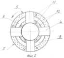
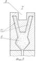
Изобретение поясняется чертежами, где на фиг.1 изображен общий вид коронки в продольном разрезе; на фиг.2 - вид со стороны рабочего торца; на фиг.3 - узел 1 на фиг.1 в увеличенном масштабе.The invention is illustrated by drawings, where in Fig.1 shows a General view of the crown in longitudinal section; figure 2 is a view from the side of the working end; figure 3 -
Предложенная буровая коронка содержит корпус 1 с присоединительной резьбой 2 и матрицу 3, разделенную промывочными пазами 4 на рабочие секторы 5 и содержащую абразивный материал 6. Абразивный материал 6, например кварцевый песок, размещен в емкостях 7, расположенных внутри матрицы 3. имеющих со стороны резьбы 2 коническую форму, верхняя часть которых снабжена штифтами 9 для жесткого соединения с корпусом 1. Рабочие торцы секторов 5 выполнены с несколькими соосно расположенными канавками 8, которые могут располагаться как концентрично, так и с эксцентриситетом относительно оси коронки. При этом емкости 7 для абразивного материала 6 выполнены с несколькими втулками 11, число которых соответствует числу кольцевых выступов 10, образованных соосными канавками 8. Выходная часть втулок 11 расположена в передней по ходу вращения рабочей части торца выступов 10, что обеспечивает гарантированную подачу абразивного материала 6 под всю рабочую площадку выступов 10. Выходная часть каждой втулки 11 в исходном положении перекрыта матричным материалом и удалена от плоскости забоя на определенную высоту, величина которой определяется физико-механическими свойствами разбуриваемых пород. Эта высота от h1 до h2 уменьшается и увеличивается соответственно по мере уменьшения и увеличения абразивности разбуриваемых пород. Чем менее абразивные породы и быстрее происходит заполирование алмазов, тем меньше должно быть расстояние от торца втулки 11 до торца матрицы 3, и наоборот, чем абразивнее породы, тем выше от торца матрицы 3 располагается торец втулки 11. Кроме того, этим расстоянием можно регулировать количество подаваемого абразивного материала путем смещения торцов втулок 11 от торца выступов 10 на разных секторах 5. При этом наружную поверхность емкости 7 для абразивного материала 6 предпочтительно выполнять биконической формы. Размещение биконической емкости 7 в матрице 3 повышает надежность их сцепления и обеспечивает высокую надежность крепления матрицы 3 с корпусом 1 благодаря созданию замкового соединения между верхним конусом биконической емкости 7 с матрицей 3.The proposed drill bit contains a
Принцип работы алмазной коронки заключается в следующем. Под действием осевой нагрузки и крутящего момента режущие элементы матрицы 3 внедряются в породу и разрушают ее. Разрушенная порода через пазы 4 удаляется на дневную поверхность. В процессе работы происходит износ матрицы 3 и при износе ее на заданную величину обнажаются выходные торцы втулок 11 и абразивный материал 6 из емкостей 7, равномерно расположенных по всей окружности матрицы 3, начинает поступать под торец коронки, способствуя самозатачиванию режущих элементов матрицы 3 и уменьшению их заполирования. При этом благодаря расположению выходных торцов втулок 11 на разном расстоянии от забоя можно обеспечить дозированную подачу абразивного материала 6 под торец коронки.The principle of operation of the diamond crown is as follows. Under the action of axial load and torque, the cutting elements of the matrix 3 are embedded in the rock and destroy it. The destroyed rock through the
Таким образом, предложенная конструкция коронки позволяет повысить эффективность работы коронки путем обеспечения надежного соединения матрицы с корпусом и предохранения режущих элементов матрицы от заполирования в процессе всего времени работы коронки.Thus, the proposed design of the crown allows you to increase the efficiency of the crown by providing a reliable connection of the matrix with the housing and protecting the cutting elements of the matrix from polishing during the entire operation time of the crown.
Claims (3)
Translated fromRussianPriority Applications (1)
| Application Number | Priority Date | Filing Date | Title |
|---|---|---|---|
| RU2013103906/03ARU2513819C1 (en) | 2013-01-30 | 2013-01-30 | Diamond bore bit |
Applications Claiming Priority (1)
| Application Number | Priority Date | Filing Date | Title |
|---|---|---|---|
| RU2013103906/03ARU2513819C1 (en) | 2013-01-30 | 2013-01-30 | Diamond bore bit |
Publications (1)
| Publication Number | Publication Date |
|---|---|
| RU2513819C1true RU2513819C1 (en) | 2014-04-20 |
Family
ID=50481084
Family Applications (1)
| Application Number | Title | Priority Date | Filing Date |
|---|---|---|---|
| RU2013103906/03ARU2513819C1 (en) | 2013-01-30 | 2013-01-30 | Diamond bore bit |
Country Status (1)
| Country | Link |
|---|---|
| RU (1) | RU2513819C1 (en) |
Citations (5)
| Publication number | Priority date | Publication date | Assignee | Title |
|---|---|---|---|---|
| US4128136A (en)* | 1977-12-09 | 1978-12-05 | Lamage Limited | Drill bit |
| SU1402659A1 (en)* | 1986-10-04 | 1988-06-15 | Всесоюзный Научно-Исследовательский Институт Экономики Минерального Сырья И Геологоразведочных Работ | Diamond drilling bit |
| RU2007542C1 (en)* | 1991-06-05 | 1994-02-15 | Чихоткин Виктор Федорович | Diamond drill bit |
| RU2418938C1 (en)* | 2010-02-26 | 2011-05-20 | Николай Митрофанович Панин | Diamond drill bit |
| RU2468178C1 (en)* | 2011-07-14 | 2012-11-27 | Николай Митрофанович Панин | Diamond crown bit |
- 2013
- 2013-01-30RURU2013103906/03Apatent/RU2513819C1/enactive
Patent Citations (5)
| Publication number | Priority date | Publication date | Assignee | Title |
|---|---|---|---|---|
| US4128136A (en)* | 1977-12-09 | 1978-12-05 | Lamage Limited | Drill bit |
| SU1402659A1 (en)* | 1986-10-04 | 1988-06-15 | Всесоюзный Научно-Исследовательский Институт Экономики Минерального Сырья И Геологоразведочных Работ | Diamond drilling bit |
| RU2007542C1 (en)* | 1991-06-05 | 1994-02-15 | Чихоткин Виктор Федорович | Diamond drill bit |
| RU2418938C1 (en)* | 2010-02-26 | 2011-05-20 | Николай Митрофанович Панин | Diamond drill bit |
| RU2468178C1 (en)* | 2011-07-14 | 2012-11-27 | Николай Митрофанович Панин | Diamond crown bit |
Similar Documents
| Publication | Publication Date | Title |
|---|---|---|
| ES2710550T3 (en) | Drill bits with axially narrow waterways | |
| USRE32036E (en) | Drill bit | |
| RU2721914C2 (en) | Cutting element with multiple beveled surfaces and cutting end of definite shape, and drilling cutting tools containing such cutting elements | |
| US4323130A (en) | Drill bit | |
| US3692127A (en) | Rotary diamond core bit | |
| CA2910607A1 (en) | Percussive rock drill bit | |
| RU2468178C1 (en) | Diamond crown bit | |
| RU2418938C1 (en) | Diamond drill bit | |
| RU160827U1 (en) | DIAMOND CROWN FOR DRILLING | |
| CN105765152A (en) | Drill bits having blind-hole flushing and systems for using same | |
| CN106103879B (en) | Impact drill with multiple sets of front cutting inserts | |
| RU2513819C1 (en) | Diamond bore bit | |
| AU2015244141B2 (en) | Single-waterway drill bits and systems for using same | |
| CN104499948A (en) | Double-cutting impregnated diamond segment | |
| RU2353748C1 (en) | Bore bit | |
| CN104295240B (en) | Novel diamond bit | |
| RU170442U1 (en) | Drill head for horizontal directional drilling | |
| RU2473773C1 (en) | Diamond crown bit | |
| RU2549653C1 (en) | Blade drilling bit (versions) | |
| RU2373370C2 (en) | Diamond drill bit | |
| CN103867132A (en) | Diamond-impregnated geological prospecting coring bit with plowing and breaking functions | |
| RU2513822C1 (en) | Diamond bore bit | |
| RU2513049C1 (en) | Impregnated diamond crown bit | |
| RU2693082C1 (en) | Rock cutting tool | |
| RU2471957C1 (en) | Diamond crown bit |