RU2513815C2 - Barrier sealing and unit with this barrier sealing - Google Patents
Barrier sealing and unit with this barrier sealingDownload PDFInfo
- Publication number
- RU2513815C2 RU2513815C2RU2011134661/03ARU2011134661ARU2513815C2RU 2513815 C2RU2513815 C2RU 2513815C2RU 2011134661/03 ARU2011134661/03 ARU 2011134661/03ARU 2011134661 ARU2011134661 ARU 2011134661ARU 2513815 C2RU2513815 C2RU 2513815C2
- Authority
- RU
- Russia
- Prior art keywords
- sealing profile
- sealing
- pipe
- barrier seal
- barrier
- Prior art date
Links
- 238000007789sealingMethods0.000titleclaimsabstractdescription78
- 230000004888barrier functionEffects0.000titleclaimsabstractdescription77
- 238000005192partitionMethods0.000claimsabstractdescription11
- 239000012530fluidSubstances0.000abstractdescription9
- 230000000694effectsEffects0.000abstractdescription3
- 238000013508migrationMethods0.000abstractdescription2
- 230000005012migrationEffects0.000abstractdescription2
- 239000000126substanceSubstances0.000abstract1
- 230000008901benefitEffects0.000description5
- 238000012360testing methodMethods0.000description4
- 238000012986modificationMethods0.000description3
- 230000004048modificationEffects0.000description3
- 238000011161developmentMethods0.000description2
- 238000009434installationMethods0.000description2
- 238000003825pressingMethods0.000description2
- 230000003014reinforcing effectEffects0.000description2
- 206010004950Birth markDiseases0.000description1
- 238000004519manufacturing processMethods0.000description1
- 238000000034methodMethods0.000description1
- 230000003287optical effectEffects0.000description1
- 230000001105regulatory effectEffects0.000description1
Images

Classifications
- E—FIXED CONSTRUCTIONS
- E21—EARTH OR ROCK DRILLING; MINING
- E21B—EARTH OR ROCK DRILLING; OBTAINING OIL, GAS, WATER, SOLUBLE OR MELTABLE MATERIALS OR A SLURRY OF MINERALS FROM WELLS
- E21B33/00—Sealing or packing boreholes or wells
- E21B33/02—Surface sealing or packing
- E21B33/03—Well heads; Setting-up thereof
- E21B33/068—Well heads; Setting-up thereof having provision for introducing objects or fluids into, or removing objects from, wells
- E21B33/072—Well heads; Setting-up thereof having provision for introducing objects or fluids into, or removing objects from, wells for cable-operated tools
- F—MECHANICAL ENGINEERING; LIGHTING; HEATING; WEAPONS; BLASTING
- F16—ENGINEERING ELEMENTS AND UNITS; GENERAL MEASURES FOR PRODUCING AND MAINTAINING EFFECTIVE FUNCTIONING OF MACHINES OR INSTALLATIONS; THERMAL INSULATION IN GENERAL
- F16J—PISTONS; CYLINDERS; SEALINGS
- F16J15/00—Sealings
- F16J15/02—Sealings between relatively-stationary surfaces
- F16J15/06—Sealings between relatively-stationary surfaces with solid packing compressed between sealing surfaces
- F16J15/062—Sealings between relatively-stationary surfaces with solid packing compressed between sealing surfaces characterised by the geometry of the seat
- F—MECHANICAL ENGINEERING; LIGHTING; HEATING; WEAPONS; BLASTING
- F16—ENGINEERING ELEMENTS AND UNITS; GENERAL MEASURES FOR PRODUCING AND MAINTAINING EFFECTIVE FUNCTIONING OF MACHINES OR INSTALLATIONS; THERMAL INSULATION IN GENERAL
- F16J—PISTONS; CYLINDERS; SEALINGS
- F16J15/00—Sealings
- F16J15/02—Sealings between relatively-stationary surfaces
- F16J15/06—Sealings between relatively-stationary surfaces with solid packing compressed between sealing surfaces
- F16J15/064—Sealings between relatively-stationary surfaces with solid packing compressed between sealing surfaces the packing combining the sealing function with other functions
- F—MECHANICAL ENGINEERING; LIGHTING; HEATING; WEAPONS; BLASTING
- F16—ENGINEERING ELEMENTS AND UNITS; GENERAL MEASURES FOR PRODUCING AND MAINTAINING EFFECTIVE FUNCTIONING OF MACHINES OR INSTALLATIONS; THERMAL INSULATION IN GENERAL
- F16L—PIPES; JOINTS OR FITTINGS FOR PIPES; SUPPORTS FOR PIPES, CABLES OR PROTECTIVE TUBING; MEANS FOR THERMAL INSULATION IN GENERAL
- F16L7/00—Supporting pipes or cables inside other pipes or sleeves, e.g. for enabling pipes or cables to be inserted or withdrawn from under roads or railways without interruption of traffic
- F16L7/02—Supporting pipes or cables inside other pipes or sleeves, e.g. for enabling pipes or cables to be inserted or withdrawn from under roads or railways without interruption of traffic and sealing the pipes or cables inside the other pipes, cables or sleeves
Landscapes
- Engineering & Computer Science (AREA)
- General Engineering & Computer Science (AREA)
- Geology (AREA)
- Life Sciences & Earth Sciences (AREA)
- Mining & Mineral Resources (AREA)
- Mechanical Engineering (AREA)
- Physics & Mathematics (AREA)
- Fluid Mechanics (AREA)
- Environmental & Geological Engineering (AREA)
- General Life Sciences & Earth Sciences (AREA)
- Geochemistry & Mineralogy (AREA)
- Geometry (AREA)
- Gasket Seals (AREA)
- Joints With Pressure Members (AREA)
Abstract
Description
Translated fromRussianУРОВЕНЬ ТЕХНИКИ ИЗОБРЕТЕНИЯBACKGROUND OF THE INVENTION
Область техники, к которой относится изобретениеFIELD OF THE INVENTION
Настоящее изобретение относится к барьерному уплотнению и узлу, включающему данное барьерное уплотнение.The present invention relates to a barrier seal and an assembly including the barrier seal.
ОПИСАНИЕ ПРЕДШЕСТВУЮЩЕГО УРОВНЯ ТЕХНИКИDESCRIPTION OF THE PRIOR ART
Эффективные производственные операции на нефтяных месторождениях зависят от информации, касающейся продуктивных горизонтов скважин. Подобная информация является особенно важной при эксплуатации нефтяных месторождений с горизонтальными скважинами, где толщина и геологическое строение нефтеносного пласта может значительно варьироваться на протяжении длины горизонтального участка. Для сбора профилей давления, температуры и других профилей скважины используют колонну, оснащенную контрольно-измерительным оборудованием, ведущую от одного или более скважинных датчиков. Колонну, оснащенную контрольно-измерительным оборудованием, как правило, устанавливают внутри обсадной трубы скважины в непосредственном контакте со скважинными текучими средами. Вследствие проблем техники безопасности и нормативно-правового регулирования, с целью предотвращения миграции скважинных текучих сред поверхности на колоннах, оснащенных контрольно-измерительным оборудованием, должны быть расположены средства управления.Effective production operations in oil fields depend on information regarding the productive horizons of the wells. Such information is especially important when operating oil fields with horizontal wells, where the thickness and geological structure of the oil reservoir can vary significantly over the length of the horizontal section. To collect pressure, temperature, and other well profiles, a string is used that is equipped with test equipment leading from one or more downhole sensors. A column equipped with control and measuring equipment, as a rule, is installed inside the casing of the well in direct contact with the borehole fluids. Due to safety and regulatory issues, controls should be located on columns equipped with test equipment to prevent the migration of borehole surface fluids.
Подобные колонны, оснащенные контрольно-измерительным оборудованием, как правило, соединяются с системами сбора данных на поверхности для сбора, сохранения и/или передачи данных температуры, давления и других данных. Вследствие этого существует необходимость доступа к колонне, оснащенной контрольно-измерительным оборудованием, в оборудовании устья скважины и подобный доступ, как правило, осуществляют, обеспечивая возможность выхода колонны, оснащенной контрольно-измерительным оборудованием, из оборудования устья скважины через вспомогательный порт, например выпускную трубу оборудования устья скважины для колонны, оснащенной контрольно-измерительным оборудованием. Подобные выпускные трубы представляют собой заключительную преграду, которая изолирует скважинные текучие среды от поверхности.Such columns equipped with instrumentation are typically connected to surface data acquisition systems for collecting, storing and / or transmitting temperature, pressure and other data. As a result of this, there is a need for access to the column equipped with control and measuring equipment in the wellhead equipment and such access is usually carried out, making it possible for the column equipped with control and measuring equipment to exit the wellhead equipment through an auxiliary port, for example, an equipment outlet pipe wellhead for a string equipped with instrumentation. Such exhaust pipes constitute a final barrier that isolates the borehole fluids from the surface.
Главной проблемой хорошего управления колонной, оснащенной контрольно-измерительным оборудованием, является монтаж выпускной трубы оборудования устья скважины для такой колонны на оборудовании устья скважины. Соединение и герметизация различных линий в колонне, оснащенной контрольно-измерительным оборудованием, с выпускной трубой оборудования устья скважины и соединение линий с поверхностной системой сбора данных, как правило, связаны с затратами времени и труда вследствие чувствительной природы и размера линий. Размер и ограниченный объем выпускной трубы оборудования устья скважины для колонны, оснащенной контрольно-измерительным оборудованием, также может затруднять задачу герметизации и соединения линий. Чем больше выполнять манипуляций с линиями, тем больше вероятность того, что одна или несколько линий могут быть повреждены вследствие их хрупкой природы. Вследствие этого необходимо уменьшение времени, требующегося для монтажа выпускной трубы оборудования устья скважины для колонны, оснащенной контрольно-измерительным оборудованием, и за счет этого уменьшение манипулирования линиями.The main problem of good control of the string, equipped with control and measuring equipment, is the installation of the outlet pipe of the wellhead equipment for such a string on the wellhead equipment. The connection and sealing of various lines in a column equipped with control and measuring equipment with the outlet pipe of the wellhead equipment and the connection of lines with a surface data acquisition system are usually associated with time and labor costs due to the sensitive nature and size of the lines. The size and limited volume of the outlet pipe of the wellhead equipment for the column equipped with control and measuring equipment can also complicate the task of sealing and connecting the lines. The more you manipulate the lines, the greater the likelihood that one or more lines may be damaged due to their fragile nature. As a result of this, it is necessary to reduce the time required to install the outlet pipe of the wellhead equipment for the column equipped with control and measuring equipment, and thereby reduce the manipulation of the lines.
Существует множество способов предотвращения достижения скважинными текучими средами поверхности, хорошо известных в данной области, однако остаются значительные недостатки.There are many ways to prevent well fluids from reaching surfaces that are well known in the art, but there are significant disadvantages.
КРАТКАЯ СУЩНОСТЬ ИЗОБРЕТЕНИЯSUMMARY OF THE INVENTION
В одном аспекте настоящее изобретение обеспечивает оборудование устья скважины, содержащее выпускную трубу оснащенной контрольно-измерительным оборудованием колонны, содержащую первый патрубок, образующий уплотняющий профиль, второй патрубок, образующий уплотняющий профиль, и барьерное уплотнение, расположенное между первым патрубком и вторым патрубком и содержащее перегородку, имеющую первый конец, второй конец и поверхность, проходящую между первым концом и вторым концом, и ребро, проходящее радиально наружу от поверхности перегородки и образующее первый уплотняющий профиль, проходящий от первой стороны ребра, и второй уплотняющий профиль, проходящий от второй стороны ребра, причем ребро образует множество расположенных на одной линии отверстий, и хомут, находящийся в зацеплении с первым патрубком и вторым патрубком для отклонения первого уплотняющего профиля в уплотненное зацепление с уплотняющим профилем первого патрубка и для отклонения второго уплотняющего профиля в уплотненное зацепление с уплотняющим профилем второго патрубка.In one aspect, the present invention provides wellhead equipment comprising an outlet pipe of a string equipped with test equipment comprising a first nozzle forming a sealing profile, a second nozzle forming a sealing profile, and a barrier seal located between the first nozzle and the second nozzle and containing a baffle, having a first end, a second end and a surface extending between the first end and the second end, and a rib extending radially outward from the surface of the birthmarks and forming a first sealing profile extending from the first side of the rib, and a second sealing profile extending from the second side of the rib, the rib forming a plurality of holes located on the same line, and a collar engaged with the first nozzle and the second nozzle to deflect the first sealing profile in a sealed mesh with the sealing profile of the first pipe and for deflecting the second sealing profile in a sealed mesh with the sealing profile of the second pipe.
Настоящее изобретение предоставляет значительные преимущества, включающие в себя создание средства для более эффективного монтажа оборудования устьев скважин, а в частности выпускных труб для колонн, оснащенных контрольно-измерительным оборудованием, и создание выпускной трубы колонны, оснащенной контрольно-измерительным оборудованием, которая может быть смонтирована с меньшими манипуляциями колонной.The present invention provides significant advantages, including the creation of means for more efficient installation of wellhead equipment, and in particular, outlet pipes for columns equipped with control and measuring equipment, and the creation of a discharge pipe of a column equipped with control and measuring equipment, which can be mounted with less manipulation of the column.
Дополнительные цели, признаки и преимущества станут ясны из подробного описания, приведенного ниже.Additional objectives, features and benefits will become apparent from the detailed description below.
КРАТКОЕ ОПИСАНИЕ ЧЕРТЕЖЕЙBRIEF DESCRIPTION OF THE DRAWINGS
Новые признаки, характеризующие изобретение, изложены в приложенной формуле изобретения. Однако изобретение, предпочтительный вариант применения и его дополнительные цели и преимущества будут лучше понятны из следующего подробного описания со ссылками на приложенные чертежи, на которых крайняя левая значащая цифра в ссылочных номерах обозначает первую фигуру, на которой появляются соответствующие ссылочные номера, при этом на чертежах показано следующее:New features characterizing the invention are set forth in the appended claims. However, the invention, the preferred application and its additional objectives and advantages will be better understood from the following detailed description with reference to the attached drawings, in which the leftmost significant digit in the reference numbers denotes the first figure in which the corresponding reference numbers appear, while the drawings show following:
Фиг.1 представляет собой перспективный вид иллюстративного варианта осуществления барьерного уплотнения;Figure 1 is a perspective view of an illustrative embodiment of a barrier seal;
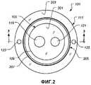
Фиг.2 представляет собой вид снизу в плане барьерного уплотнения фиг.1;Figure 2 is a bottom plan view of the barrier seal of Figure 1;
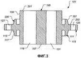
Фиг.3 представляет собой вид поперечного сечения барьерного уплотнения фиг.1 по линии 3-3 на фиг.2;FIG. 3 is a cross-sectional view of the barrier seal of FIG. 1 along line 3-3 of FIG. 2;
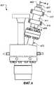
Фиг.4 представляет собой вид сбоку в вертикальном разрезе иллюстративного варианта осуществления оборудования устья скважины, включающего выпускную трубу для колонны, оснащенной контрольно-измерительным оборудованием;FIG. 4 is a side elevational view of an illustrative embodiment of a wellhead equipment including an exhaust pipe for a string equipped with instrumentation;
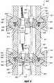
Фиг.5 представляет собой вид частичного поперечного сечения участка выпускной трубы колонны с фиг.4, оснащенной контрольно-измерительным оборудованием, выполненный по линии 5-5 на фиг.4;FIG. 5 is a partial cross-sectional view of a portion of the exhaust pipe of the column of FIG. 4 equipped with instrumentation taken along line 5-5 of FIG. 4;
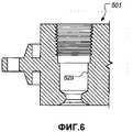
Фиг.6 представляет собой вид поперечного сечения участка иллюстративного варианта осуществления барьерного уплотнения, показывающий первую иллюстративную конфигурацию прохода для линии;FIG. 6 is a cross-sectional view of a portion of an illustrative embodiment of a barrier seal showing a first illustrative line passage configuration;
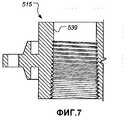
Фиг.7 представляет собой вид поперечного сечения участка иллюстративного варианта осуществления барьерного уплотнения, показывающий вторую иллюстративную конфигурацию прохода для линии.7 is a cross-sectional view of a portion of an illustrative embodiment of a barrier seal showing a second illustrative line passage configuration.
В то время как изобретение может быть подвергнуто различным модификациям и альтернативным формам, в данной заявке в качестве примера показаны на чертежах и подробно описаны специфичные варианты его осуществления. Однако необходимо понимать, что описание в данной заявке специфичных вариантов осуществления не предполагает ограничения изобретения конкретными раскрытыми формами, но наоборот изобретение должно охватывать все модификации, эквиваленты и альтернативы в пределах объема приложенной формулы изобретения.While the invention may be subjected to various modifications and alternative forms, this application is shown by way of example in the drawings and specific embodiments thereof are described in detail. However, it should be understood that the description of specific embodiments in this application does not imply limiting the invention to the particular forms disclosed, but rather, the invention should cover all modifications, equivalents, and alternatives within the scope of the attached claims.
ПОДРОБНОЕ ОПИСАНИЕ ИЗОБРЕТЕНИЯDETAILED DESCRIPTION OF THE INVENTION
Ниже описаны иллюстративные варианты осуществления изобретения. В интересах ясности в описании приведены не все признаки фактического осуществления. Конечно, следует понимать, что при разработке любого подобного фактического варианта осуществления, для достижения конкретных целей разработчика, необходимо принимать множество решений, связанных с конкретной реализацией, например, совместимых с ограничениями, связанными с проектом и деловой деятельностью, которые будут варьироваться от одного воплощения к другому. Более того, следует понимать, что подобные усилия на разработку могут быть сложными и затратными по времени, но тем не менее должны представлять собой рутинную деятельность для рядовых специалистов в данной области, получающих выгоду от данного раскрытия.Illustrative embodiments of the invention are described below. In the interest of clarity, the description does not show all the signs of actual implementation. Of course, it should be understood that in the development of any such actual implementation option, in order to achieve the specific goals of the developer, it is necessary to make many decisions related to the specific implementation, for example, compatible with the limitations associated with the project and business activities, which will vary from one embodiment to to another. Moreover, it should be understood that such development efforts can be complex and time-consuming, but nevertheless should be a routine activity for ordinary specialists in this field who benefit from this disclosure.
Настоящее изобретение представляет барьерное уплотнение и узел, включающий барьерное уплотнение. Барьерное уплотнение включает в себя перегородку, имеющую первый конец, второй конец и поверхность, проходящую между первым концом и вторым концом. Ребро проходит радиально наружу от поверхности перегородки и образует первый уплотняющий профиль на первой стороне ребра и второй уплотняющий профиль на второй стороне ребра. Узел, включающий барьерное уплотнение, включает в себя первый элемент, образующий уплотняющий профиль, второй элемент, образующий уплотняющий профиль, барьерное уплотнение, расположенное между первым элементом и вторым элементом, и хомут. Хомут находится в зацеплении с первым элементом и вторым элементом для отклонения первого уплотняющего профиля в уплотненное зацепление с уплотняющим профилем первого элемента и для отклонения второго уплотняющего профиля в уплотненное зацепление с уплотняющим профилем второго элемента. В одном варианте осуществления узел представляет собой оборудование устья скважины, включающее в себя выпускную трубу колонны, оснащенной контрольно-измерительным оборудованием.The present invention provides a barrier seal and an assembly including a barrier seal. The barrier seal includes a baffle having a first end, a second end, and a surface extending between the first end and the second end. The rib extends radially outward from the surface of the partition and forms a first sealing profile on the first side of the rib and a second sealing profile on the second side of the rib. The assembly including the barrier seal includes a first element forming a sealing profile, a second element forming a sealing profile, a barrier seal located between the first element and the second element, and a clamp. The clamp is engaged with the first element and the second element to deflect the first sealing profile into a sealed engagement with the sealing profile of the first element and to deflect the second sealing profile into the sealed engagement with the sealing profile of the second element. In one embodiment, the assembly is wellhead equipment, including an outlet pipe of a string equipped with instrumentation.
Фиг.1-3 предоставляют виды иллюстративного варианта осуществления барьерного уплотнения 101. Фиг.1 представляет собой перспективный вид барьерного уплотнения 101. Фиг.2 представляет собой вид снизу в плане барьерного уплотнения 101. Необходимо заметить, что фиг.2 изображает барьерное уплотнение 101, если, в общем, смотреть в направлении, соответствующем стрелке 103 на фиг.1. Фиг.3 представляет собой вид поперечного сечения барьерного уплотнения 101 по линии 3-3 на фиг.2. Барьерное уплотнение 101 включает в себя перегородку 105, имеющую первый конец 107, второй конец 201, показанный на фиг.2 и 3, и поверхность 109, проходящую между первым концом 107 и вторым концом 201. Ребро 111 проходит радиально наружу от поверхности 109 перегородки 105. Ребро 111 образует первую сторону 113 и вторую сторону 203, показанную на фиг.2 и 3. Ребро 111 включает в себя первый выступ 115, проходящий от первой стороны 113 ребра 111, и второй выступ 205, показанный на фиг.2 и 3, проходящий от второй стороны 203 ребра 111. Первый выступ 115 образует первый уплотняющий профиль 117, а второй выступ 205 образует второй уплотняющий профиль 207, который лучше всего показан на фиг.3. Таким образом, ребро 111 образует первый уплотняющий профиль 117, проходящий от первой его стороны 113, и второй уплотняющий профиль 207, проходящий от второй его стороны 203. Первый уплотняющий профиль 117 и второй уплотняющий профиль 207 стыкуются с уплотняющими профилями расположенных рядом элементов для герметичного соединения расположенных рядом элементов, как обсуждается более подробно в данном описании.1-3 show views of an illustrative embodiment of the
Как показано на фиг.1-3, перегородка 105 предпочтительно образует, по меньшей мере, один проход, в данном варианте - проходы 119 и 121, проходящие между первым концом 107 и вторым концом 201 перегородки 105. Проходы 119, 121 обеспечивают возможность прохождения линий, таких как контрольно-измерительные линии, линии управления и тому подобные линии, через барьерное уплотнение 101. Такие контрольно-измерительные линии и/или линии управления могут представлять собой электрические, оптические, пневматические или гидравлические линии и тому подобное. Проходы 119, 121 предпочтительно снабжаются фитингами, которые препятствуют прохождению текучих сред через проходы 119, 121 и обеспечивают в то же время возможность прохождения через них линий. Несмотря на то что перегородка 105 образует, по меньшей мере, один проход в проиллюстрированном варианте осуществления, объем настоящего изобретения этим не ограничен. Точнее, в некоторых вариантах осуществления перегородка 105 может не иметь подобных проходов или включать в себя другие признаки. Подобные варианты осуществления предусматриваются настоящим изобретением.As shown in figures 1-3, the
Фиг.4 изображает вид сбоку в вертикальном разрезе иллюстративного варианта осуществления узла, включающего одно или несколько барьерных уплотнений 101. В проиллюстрированном варианте осуществления узел представляет собой оборудование 401 устья скважины, которое включает в себя выпускную трубу 403 колонны, оснащенной контрольно-измерительным оборудованием, в которую встроены барьерные уплотнения 101. Выпускная труба 403 предотвращает прохождение через нее скважинных текучих сред к поверхности, обеспечивая в то же время возможность прохождения контрольно-измерительных линий из оборудования 401 устья скважины через каналы 405 и 407. Выпускная труба 403 включает в себя первый патрубок 409, второй патрубок 411 и третий патрубок 413. Второй патрубок 411 прикреплен к первому патрубку 409 с помощью первого хомута 415. Третий патрубок 413 прикреплен ко второму патрубку 411 с помощью второго хомута 417.FIG. 4 is a side elevational view of an illustrative embodiment of an assembly including one or
Фиг.5 представляет вид частичного поперечного сечения иллюстративного варианта осуществления участка выпускной трубы 403 колонны, оснащенной контрольно-измерительным оборудованием, по линии 5-5 на фиг.4. В проиллюстрированном варианте осуществления первое барьерное уплотнение 501 расположено между первым патрубком 409 и вторым патрубком 411. Первое барьерное уплотнение 501 соответствует барьерному уплотнению 101, показанному на фиг.1-3, за исключением того, что конфигурации проходов для прохождения линий отличаются от проходов 119 и 121 барьерного уплотнения 101. Первый патрубок 409 образует уплотняющий профиль 503, который стыкуется с первым уплотняющим профилем 505 первого барьерного уплотнения 501. Второй патрубок 411 образует первый уплотняющий профиль 507, который стыкуется со вторым уплотняющим профилем 509 первого барьерного уплотнения 501. Первый патрубок 409 образует выступ 511, при этом второй патрубок 411 образует первый выступ 513. Первый хомут 415 соединен с выступами 511 и 513, поджимая выступы 511 и 513 друг к другу, отклоняя за счет этого первый уплотняющий профиль 505 и второй уплотняющий профиль 509 первого барьерного уплотнения 501 в целом радиально внутрь и вводя в уплотненное зацепление первый уплотняющий профиль 505 с уплотняющим профилем 503 первого патрубка 409, и в уплотненное зацепление второй уплотняющий профиль 509 с первым уплотняющим профилем 507 второго патрубка 411. Давление внутри первого патрубка 409 или второго патрубка 411 поджимает первый уплотняющий профиль 505 и второй уплотняющий профиль 509 первого барьерного уплотнения 501 в целом радиально наружу, усиливая за счет этого уплотненное зацепление между первым барьерным уплотнением 501 и первым патрубком 409 и между первым барьерным уплотнением 501 и вторым патрубком 411.FIG. 5 is a partial cross-sectional view of an illustrative embodiment of a portion of an
Аналогичным образом, между вторым патрубком 411 и третьим патрубком 413 расположено второе барьерное уплотнение 515. Второе барьерное уплотнение 515 соответствует барьерному уплотнению 101, показано на фиг.1-3, за исключением того, что конфигурации проходов для прохождения линий отличаются от проходов 119 и 121 барьерного уплотнения 101. Второй патрубок 411 образует второй уплотняющий профиль 517, который стыкуется с первым уплотняющим профилем 519 второго барьерного уплотнения 515. Третий патрубок 413 образует уплотняющий профиль 521, который стыкуется со вторым уплотняющим профилем 523 второго барьерного уплотнения 515. Второй патрубок 411 образует второй выступ 525, а третий патрубок 413 образует выступ 527. Второй хомут 417 соединен с выступами 525 и 527, поджимая выступы 525 и 527 друг к другу, отклоняя за счет этого первый уплотняющий профиль 519 и второй уплотняющий профиль 523 второго барьерного уплотнения 515 в целом радиально внутрь и вводя в уплотненное зацепление первый уплотняющий профиль 519 со вторым уплотняющим профилем 517 второго патрубка 411 и вводя в уплотнение зацепление второй уплотняющий профиль 523 с уплотняющим профилем 521 третьего патрубка 413. Давление внутри второго патрубка 411 или третьего патрубка 413 поджимает первый уплотняющий профиль 519 и второй уплотняющий профиль 523 второго барьерного уплотнения 515 в целом радиально наружу, усиливая за счет этого уплотненное зацепление между вторым барьерным уплотнением 515 и вторым патрубком 411 и между вторым барьерным уплотнением 515 и третьим патрубком 413.Similarly, between the
Как раскрыто в данном описании, первое барьерное уплотнение 501 и второе барьерное уплотнение 515 соответствуют барьерному уплотнению 101, показанному на фиг.1-3, за исключением конфигурации проходов для прохождения линий через первое барьерное уплотнение 501 и второе барьерное уплотнение 515. Первое барьерное уплотнение 501 образует проходы 529 и 531, которые выполнены с возможностью приема манжет 533 и 535 и выполнены с возможностью навинчивания на резьбу контргаек 537. Необходимо заметить, что для лучшего понимания на фиг.5 манжеты 533 и 535 и контргайки 537 показаны не в поперечном сечении. На фиг.6 показана конфигурация прохода 529, которая также соответствует конфигурации прохода 531.As disclosed herein, the
Как показано на фиг.5, второе барьерное уплотнение 515 образует проход 539, который выполнен с возможностью навинчивания на резьбу соединителя 541. Второе барьерное уплотнение 515 дополнительно образует проход 543, который выполнен с возможностью размещения манжет 533 и 535 и с возможностью навинчивания на резьбу контргайки 537. Необходимо заметить, что соединитель 541, манжеты 533 и 535 и контргайка 537 для ясности показаны не в поперечном сечении. На фиг.7 показана конфигурация прохода 539. Конфигурация прохода 543 соответствует конфигурации прохода 529, показанной на фиг.6.As shown in FIG. 5, the
Необходимо заметить, что конкретные конфигурации проходов 529, 531, 539 и 543 представляют собой всего лишь примеры широкого разнообразия конфигураций, предусматриваемых настоящим изобретением. Подобные проходы могут быть выполнены, например, с возможностью работать с множеством различных типов герметизирующих линии элементов, таких как уплотнения с кольцами и контргайками, уплотнения с манжетами и контргайками, соединительные вставки и тому подобное. Более того, подобные проходы могут быть выполнены, например, с наличием уплотнительной резьбы, такой как трубная резьба, “автоклавная” резьба и тому подобное.It should be noted that the specific configurations of
Первая линия 545 и вторая линия 547 проходят из скважины через оборудование 401 устья скважины, показанное на фиг.4, и через выпускную трубу 403 колонны, оснащенной контрольно-измерительным оборудованием. Первая линия 545 проходит через проход 529 первого барьерного уплотнения 501, манжеты 535 и 533 и контргайку 537, функционально связанные с первым барьерным уплотнением 501. Первая линия 545 далее проходит через проход 539 и соединитель 541. Вторая линия 547 проходит через проход 531 первого барьерного уплотнения 501, манжеты 535 и 533 и контргайку 537, функционально связанные с первым барьерным уплотнением 501. Вторая линия 547 далее проходит через проход 543 второго барьерного уплотнения 515, через манжеты 535 и 533 и контргайку 537, функционально связанные со вторым барьерным уплотнением 515.The
Поверхности контакта между манжетами 533 и 535 и первым барьерным уплотнением 501 и поверхности контакта между манжетами 533 и 535, функционально связанными с первым барьерным уплотнением 501, и линиями 545 и 547, препятствуют протеканию текучих сред между первым патрубком 409 и вторым патрубком 411. Поверхность контакта между соединителем 541 и вторым барьерным уплотнением 515 и поверхности контакта между манжетами 533 и 535, функционально связанными со вторым барьерным уплотнением 515, и второй линией 547 препятствуют протеканию текучей среды между вторым патрубком 411 и третьим патрубком 413.The contact surfaces between the
Как показано на фиг.5, проиллюстрированные варианты осуществления первого барьерного уплотнения 501 и второго барьерного уплотнения 515 образуют множество расположенных на одной линии отверстий 549 и 551. Соответствующие отверстия 123 и 125 лучше показаны на фиг.1-3. Установочные штыри 553 и 555 проходят из первого патрубка 409 в установочные отверстия 549 и 551 соответственно первого барьерного уплотнения 501 для выравнивания первого барьерного уплотнения 501 на первом патрубке 409. Установочные штыри 553 и 555 также проходят из второго патрубка 411 в установочные отверстия 549 и 551 соответственно второго барьерного уплотнения 515 для выравнивания второго барьерного уплотнения 515 на втором патрубке 411. Настоящим изобретением предусматриваются и другие средства для выравнивания барьерных уплотнений на патрубках или других подобных элементах. Более того, настоящее изобретение предусматривает барьерные уплотнения, которые не включают установочные отверстия или другие подобные установочные средства.As shown in FIG. 5, illustrated embodiments of the
Необходимо заметить, что настоящее изобретение предусматривает любое количество барьерных уплотнений, таких как барьерные уплотнения 101, 501, 515 или аналогичные, встроенных в узел.It should be noted that the present invention provides for any number of barrier seals, such as barrier seals 101, 501, 515 or the like, integrated in the assembly.
Конкретные варианты осуществления, раскрытые выше, являются всего лишь иллюстративными, так как изобретение может быть модифицировано и использовано на практике в виде различных, но эквивалентных способов, очевидных квалифицированным специалистам в данной области. Кроме того, не предполагается ограничений деталей конструкции или внешнего вида, показанных в данном описании, за исключением описанных в формуле изобретения ниже. Вследствие этого, очевидно, что конкретные варианты осуществления, раскрытые выше, могут быть изменены или модифицированы, и все подобные варианты находятся в пределах объема правовых притязаний изобретения, определенных в формуле изобретения. Очевидно, что изобретение было описано и проиллюстрировано со значительными преимуществами. Несмотря на то что настоящее изобретение показано с ограниченным числом вариантов, оно не ограничено только данными формами, но может быть подвергнуто различным изменениям и модификациям.The specific embodiments disclosed above are merely illustrative, since the invention can be modified and practiced in the form of various, but equivalent, methods obvious to those skilled in the art. In addition, it is not intended to limit the structural details or appearance shown in this description, except as described in the claims below. Therefore, it is obvious that the specific embodiments disclosed above can be changed or modified, and all such variants are within the scope of the legal claims of the invention defined in the claims. Obviously, the invention has been described and illustrated with significant advantages. Although the present invention is shown with a limited number of options, it is not limited to these forms only, but can be subjected to various changes and modifications.
Claims (7)
Translated fromRussianApplications Claiming Priority (3)
| Application Number | Priority Date | Filing Date | Title |
|---|---|---|---|
| CA2650168ACA2650168C (en) | 2009-01-19 | 2009-01-19 | Barrier seal and assembly incorporating same |
| CA2,650,168 | 2009-01-19 | ||
| PCT/IB2010/050241WO2010082186A2 (en) | 2009-01-19 | 2010-01-19 | Barrier seal and assembly incorporating same |
Publications (2)
| Publication Number | Publication Date |
|---|---|
| RU2011134661A RU2011134661A (en) | 2013-02-27 |
| RU2513815C2true RU2513815C2 (en) | 2014-04-20 |
Family
ID=42340165
Family Applications (1)
| Application Number | Title | Priority Date | Filing Date |
|---|---|---|---|
| RU2011134661/03ARU2513815C2 (en) | 2009-01-19 | 2010-01-19 | Barrier sealing and unit with this barrier sealing |
Country Status (5)
| Country | Link |
|---|---|
| US (1) | US8444183B2 (en) |
| CA (1) | CA2650168C (en) |
| MX (1) | MX2011005331A (en) |
| RU (1) | RU2513815C2 (en) |
| WO (1) | WO2010082186A2 (en) |
Families Citing this family (2)
| Publication number | Priority date | Publication date | Assignee | Title |
|---|---|---|---|---|
| WO2017058195A1 (en)* | 2015-09-30 | 2017-04-06 | Hewlett-Packard Development Company, L.P. | Fluid seals |
| US12183597B2 (en)* | 2021-11-24 | 2024-12-31 | Ichor Systems, Inc. | Fluid delivery system |
Citations (6)
| Publication number | Priority date | Publication date | Assignee | Title |
|---|---|---|---|---|
| RU2107149C1 (en)* | 1996-03-05 | 1998-03-20 | Виктор Тимофеевич Кушин | Shaft collar equipment |
| US20030019163A1 (en)* | 2001-07-30 | 2003-01-30 | Claudio Dittel | Concrete manhole connector gasket |
| RU2217574C2 (en)* | 2001-12-13 | 2003-11-27 | Закрытое акционерное общество "Газтехнология" | Sealing unit for mouth |
| RU2280755C2 (en)* | 2003-12-26 | 2006-07-27 | Закрытое акционерное общество "Нефтемашвнедрение" | Combined cable entry |
| RU55854U1 (en)* | 2006-03-23 | 2006-08-27 | Закрытое акционерное общество "Научно-производственное предприятие "Сибтехноцентр" | SQUARE HOLE SEALER AND INSERT FOR SQUARE PIPES SQUARE SECTION |
| RU59698U1 (en)* | 2006-03-31 | 2006-12-27 | Закрытое акционерное общество "Научно-производственное предприятие "Сибтехноцентр" | WELL MOUNT SEALER AND INSERT FOR SEALING TUBE COMPANIES WITH A CABLE OR WITHOUT A CABLE |
Family Cites Families (26)
| Publication number | Priority date | Publication date | Assignee | Title |
|---|---|---|---|---|
| US2031849A (en)* | 1930-05-02 | 1936-02-25 | Atmospheric Nitrogen Corp | Pipe fitting |
| US2083090A (en)* | 1935-12-09 | 1937-06-08 | Laurence L Rector | Casing head |
| US2144227A (en)* | 1936-02-14 | 1939-01-17 | Arthur J Penick | Combination well head and hanger |
| US2794505A (en)* | 1955-11-04 | 1957-06-04 | Cameron Iron Works Inc | Pipe hanging apparatus |
| US2939727A (en)* | 1956-10-15 | 1960-06-07 | Cameron Iron Works Inc | Wellhead equipment |
| US3177013A (en)* | 1957-09-30 | 1965-04-06 | Laurence L Rector | Dual string suspension assembly |
| US3080181A (en)* | 1958-08-19 | 1963-03-05 | Gray Tool Co | Multiple tubing hanger and seal assembly |
| US3072420A (en)* | 1958-12-08 | 1963-01-08 | Fmc Corp | Tubing hanger assembly |
| US3071396A (en)* | 1959-03-26 | 1963-01-01 | Armco Steel Corp | Multiple string tubing hanger constructions |
| US3118690A (en)* | 1960-04-01 | 1964-01-21 | Gray Tool Co | Well completion equipment having rotatable hanger bushings |
| US3141685A (en)* | 1960-10-11 | 1964-07-21 | Gray Tool Co | Coupling with leak detecting means and sealing ring therefor |
| US3330355A (en)* | 1963-10-03 | 1967-07-11 | Fmc Corp | Method for installing a well |
| US3325176A (en) | 1963-10-14 | 1967-06-13 | Gray Tool Co | Seal rings |
| FR91871E (en)* | 1966-03-24 | 1968-08-23 | Citroen Sa Andre | Multiple coupling for fluid lines |
| US3680632A (en)* | 1970-07-15 | 1972-08-01 | Thomas A Myers | Pressure control well head for slanted bore holes |
| US3713334A (en)* | 1971-01-25 | 1973-01-30 | R Vann | Downhole recorder device for logging boreholes |
| US3873134A (en)* | 1973-01-04 | 1975-03-25 | Michael Sammaritano | Apparatus for joining preformed conduits |
| US3948315A (en)* | 1974-08-13 | 1976-04-06 | Brown Fintube Company | Closure for heat exchanger |
| US4570701A (en)* | 1983-11-14 | 1986-02-18 | Wf Roberts | Dual purpose closure for heat exchangers |
| USRE34332E (en)* | 1987-09-21 | 1993-08-03 | Assembly for connecting multi-duct conduits | |
| US5135265A (en)* | 1991-01-23 | 1992-08-04 | The Lamson & Sessions Co. | Multiple passage conduit assembly |
| CA2131803A1 (en)* | 1992-03-12 | 1993-09-16 | John Stobbart | Seal ring and joint |
| US5478970A (en)* | 1994-02-03 | 1995-12-26 | D. G. O'brien, Inc. | Apparatus for terminating and interconnecting rigid electrical cable and method |
| GB2443224A (en)* | 2006-10-26 | 2008-04-30 | Remote Marine Systems Ltd | Connector having removable conductor |
| US8033579B2 (en)* | 2007-10-05 | 2011-10-11 | Ckd Corporation | Fluid device connecting structure |
| US8191933B2 (en)* | 2008-07-16 | 2012-06-05 | General Electric Company | Extrusion resistant gasket face seal |
- 2009
- 2009-01-19CACA2650168Apatent/CA2650168C/ennot_activeExpired - Fee Related
- 2010
- 2010-01-19RURU2011134661/03Apatent/RU2513815C2/ennot_activeIP Right Cessation
- 2010-01-19MXMX2011005331Apatent/MX2011005331A/enactiveIP Right Grant
- 2010-01-19WOPCT/IB2010/050241patent/WO2010082186A2/enactiveApplication Filing
- 2010-01-19USUS13/131,573patent/US8444183B2/ennot_activeExpired - Fee Related
Patent Citations (6)
| Publication number | Priority date | Publication date | Assignee | Title |
|---|---|---|---|---|
| RU2107149C1 (en)* | 1996-03-05 | 1998-03-20 | Виктор Тимофеевич Кушин | Shaft collar equipment |
| US20030019163A1 (en)* | 2001-07-30 | 2003-01-30 | Claudio Dittel | Concrete manhole connector gasket |
| RU2217574C2 (en)* | 2001-12-13 | 2003-11-27 | Закрытое акционерное общество "Газтехнология" | Sealing unit for mouth |
| RU2280755C2 (en)* | 2003-12-26 | 2006-07-27 | Закрытое акционерное общество "Нефтемашвнедрение" | Combined cable entry |
| RU55854U1 (en)* | 2006-03-23 | 2006-08-27 | Закрытое акционерное общество "Научно-производственное предприятие "Сибтехноцентр" | SQUARE HOLE SEALER AND INSERT FOR SQUARE PIPES SQUARE SECTION |
| RU59698U1 (en)* | 2006-03-31 | 2006-12-27 | Закрытое акционерное общество "Научно-производственное предприятие "Сибтехноцентр" | WELL MOUNT SEALER AND INSERT FOR SEALING TUBE COMPANIES WITH A CABLE OR WITHOUT A CABLE |
Also Published As
| Publication number | Publication date |
|---|---|
| CA2650168A1 (en) | 2010-07-19 |
| WO2010082186A2 (en) | 2010-07-22 |
| CA2650168C (en) | 2011-02-22 |
| US20110260451A1 (en) | 2011-10-27 |
| RU2011134661A (en) | 2013-02-27 |
| US8444183B2 (en) | 2013-05-21 |
| WO2010082186A3 (en) | 2011-04-07 |
| MX2011005331A (en) | 2011-09-01 |
Similar Documents
| Publication | Publication Date | Title |
|---|---|---|
| US8011437B2 (en) | Wellbore method and apparatus for completion, production and injection | |
| US9169709B2 (en) | Spool module | |
| AU2014342687B2 (en) | Method and system for monitoring fluid flow in a conduit | |
| US6688386B2 (en) | Tubing hanger and adapter assembly | |
| CA2454857C (en) | Y-body christmas tree for use with coil tubing | |
| US20030079878A1 (en) | Completion system, apparatus, and method | |
| NO342809B1 (en) | Valve tree with internally located flowmeter | |
| US9945211B2 (en) | Leak-off assembly for gravel pack system | |
| US20130206394A1 (en) | Downhole Screen with Exterior Shunts and Manifolded Shunt Connections at Tubular Joints | |
| US11428091B2 (en) | Above packer gas separation | |
| US20120292034A1 (en) | Dual Barrier Side Pocket Mandrel | |
| RU2513815C2 (en) | Barrier sealing and unit with this barrier sealing | |
| NO325203B1 (en) | Cable protective rudder section, method for arranging at least ± n cable protective outer rudder section and use of a device for protecting the cable | |
| RU2141028C1 (en) | Well strainer with alternative ways of flow | |
| US12152483B2 (en) | Resin sealed sensor port | |
| US10533395B2 (en) | Production assembly with integrated flow meter | |
| US11408256B2 (en) | System and methodology to integrate m-tool nozzle with sand screen | |
| US11828140B2 (en) | System and methods of use for a blind plug | |
| BR112022001935B1 (en) | System and methods of use for a blind plug | |
| CA2934688A1 (en) | Vent pod encapsulating gas separator and relocating expelled gas to remote location | |
| CN108825201A (en) | A kind of oil gas sand separation metering skid complexes for oil and gas extraction wellhead equipment | |
| NO327168B1 (en) | Insulation assembly for use in a well |
Legal Events
| Date | Code | Title | Description |
|---|---|---|---|
| MM4A | The patent is invalid due to non-payment of fees | Effective date:20210120 |