RU2513346C1 - Vehicle running gear - Google Patents
Vehicle running gearDownload PDFInfo
- Publication number
- RU2513346C1 RU2513346C1RU2012156772/11ARU2012156772ARU2513346C1RU 2513346 C1RU2513346 C1RU 2513346C1RU 2012156772/11 ARU2012156772/11 ARU 2012156772/11ARU 2012156772 ARU2012156772 ARU 2012156772ARU 2513346 C1RU2513346 C1RU 2513346C1
- Authority
- RU
- Russia
- Prior art keywords
- wheels
- wheel
- vehicle
- axles
- axes
- Prior art date
Links
- 239000000126substanceSubstances0.000abstract1
- 230000009977dual effectEffects0.000description1
- 230000001360synchronised effectEffects0.000description1
Images
Landscapes
- Motorcycle And Bicycle Frame (AREA)
Abstract
Description
Translated fromRussianИзобретение относится к движителям транспортных средств, преимущественно внедорожных.The invention relates to propulsion vehicles, mainly off-road.
Известна ходовая часть транспортного средства / см. авт. свид. №1556992 (кл. B62D 55/04) от 23.06.1988/, содержащая установленное на оси центральное бортовое колесо, балансир, установленный на оси центрального колеса, посредством эксцентричной втулки, боковые колеса - опорные катки, осями вращения установленные на свободных равной длины концах двухплечего балансира. Имеется также замкнутая армированная эластичная лента, охватывающая центральное бортовое колесо и сдвоенные боковые колеса.Known chassis of the vehicle / see ed. testimonial. No. 1556992 (class B62D 55/04) dated 06/23/1988 /, containing a central wheel mounted on an axle, a balancer mounted on an axle of a central wheel, by means of an eccentric bushing, side wheels - track rollers mounted with axes of rotation mounted on free equal length ends two shoulders balancer. There is also a closed reinforced elastic band covering the center side wheel and dual side wheels.
Ходовые качества шасси движителя-прототипа ограничены малыми размерами боковых колес (в сравнении с центральным колесом), а также наличием замкнутой ленты, охватывающей центральное и пару сдвоенных боковых колес. При этом привод соответствующего борта конструктивно возможен только передачей крутящего момента на центральное колесо.The driving performance of the prototype propulsion chassis is limited by the small size of the side wheels (compared to the center wheel), as well as the presence of a closed belt covering the center and a pair of twin side wheels. In this case, the drive of the corresponding side is structurally possible only by transmitting torque to the central wheel.
С целью повышения ходовых качеств шасси движителя транспортного средства, содержащего установленное на оси центральное бортовое колесо, балансир, установленный на оси центрального колеса, боковые колеса, осями вращения установленные на свободных равной длины концах балансира, все три бортовых колеса транспортного средства имеют параллельные оси вращения, лежащие в общей горизонтальной плоскости, и кинематически связаны дополнительно в двух ободных точках колес общими осями, образующими с осями вращения колес четырехшарнирный антипараллелограмм.In order to improve the driving performance of the chassis of a vehicle propulsion device, comprising a central side wheel mounted on an axis, a balancer mounted on an axis of the central wheel, side wheels mounted on rotational axes at free equal length ends of the balancer, all three vehicle side wheels have parallel rotation axes, lying in a common horizontal plane, and kinematically connected additionally at two wheel rim points by common axes, forming a four-joint antipa with the axes of rotation of the wheels parallelogram.
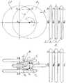
Предлагаемая техническим решением ходовая часть транспортного средства иллюстрируется чертежом.The proposed chassis of the vehicle is illustrated in the drawing.
Ходовая часть транспортного средства содержит три бортовых колеса (1, 2, 3) с центральным бортовым колесом 2, одноплечий балансир 4, установленный на оси (D2-D2) центрального колеса 2, соосные боковые колеса 1 и 3, осями вращения соответственно (A1-A1) и (А3-А3) установленные на свободных равной длины концах балансира 4. При этом все три бортовых колеса (1, 2, 3) ходовой части транспортного средства имеют параллельные оси вращения соответственно (A1-A1), (D2-D2), (А3-А3), лежащие в общей горизонтальной плоскости, и кинематически связаны дополнительно в двух ободных точках колес общими осями Вi и Сi (i=1, 2, 3), образующими с осями вращения колес (1, 2, 3) четырехшарнирный антипараллелограмм.The chassis of the vehicle contains three side wheels (1, 2, 3) with a
Передачей крутящего момента от привода (на чертеж не показан) на одно из колес ходовой части транспортного средства получаем синхронное вращение трехколесного бортового шасси предлагаемой конструкции.By transmitting torque from the drive (not shown in the drawing) to one of the wheels of the vehicle chassis, we obtain the synchronous rotation of the three-wheeled side chassis of the proposed design.
Таким образом, предлагаемое техническое решение, по мнению заявителя, является новым, имеет изобретательский уровень и промышленно применимо.Thus, the proposed technical solution, according to the applicant, is new, has an inventive step and is industrially applicable.
Claims (1)
Translated fromRussianPriority Applications (1)
| Application Number | Priority Date | Filing Date | Title |
|---|---|---|---|
| RU2012156772/11ARU2513346C1 (en) | 2012-12-25 | 2012-12-25 | Vehicle running gear |
Applications Claiming Priority (1)
| Application Number | Priority Date | Filing Date | Title |
|---|---|---|---|
| RU2012156772/11ARU2513346C1 (en) | 2012-12-25 | 2012-12-25 | Vehicle running gear |
Publications (1)
| Publication Number | Publication Date |
|---|---|
| RU2513346C1true RU2513346C1 (en) | 2014-04-20 |
Family
ID=50480814
Family Applications (1)
| Application Number | Title | Priority Date | Filing Date |
|---|---|---|---|
| RU2012156772/11ARU2513346C1 (en) | 2012-12-25 | 2012-12-25 | Vehicle running gear |
Country Status (1)
| Country | Link |
|---|---|
| RU (1) | RU2513346C1 (en) |
Citations (6)
| Publication number | Priority date | Publication date | Assignee | Title |
|---|---|---|---|---|
| SU1556992A1 (en)* | 1988-06-23 | 1990-04-15 | Белорусский Политехнический Институт | Vehicle undercarriage |
| NL9400193A (en)* | 1994-02-07 | 1995-09-01 | Heerenveen Ind Dev | Caterpillar-track device |
| RU3117U1 (en)* | 1995-06-16 | 1996-11-16 | Акционерное общество открытого типа "Всероссийский научно-исследовательский институт транспортного машиностроения" | TRACK VEHICLE VEHICLE |
| JPH09290786A (en)* | 1996-04-26 | 1997-11-11 | Atex Co Ltd | Electric motor driven tricycle |
| US6070898A (en)* | 1998-08-14 | 2000-06-06 | Sunrise Medical, Inc. | Suspension system for a wheelchair |
| RU2198107C2 (en)* | 1998-03-12 | 2003-02-10 | Открытое акционерное общество "Всероссийский научно-исследовательский институт транспортного машиностроения" | Two-wheel vehicle |
- 2012
- 2012-12-25RURU2012156772/11Apatent/RU2513346C1/enactive
Patent Citations (6)
| Publication number | Priority date | Publication date | Assignee | Title |
|---|---|---|---|---|
| SU1556992A1 (en)* | 1988-06-23 | 1990-04-15 | Белорусский Политехнический Институт | Vehicle undercarriage |
| NL9400193A (en)* | 1994-02-07 | 1995-09-01 | Heerenveen Ind Dev | Caterpillar-track device |
| RU3117U1 (en)* | 1995-06-16 | 1996-11-16 | Акционерное общество открытого типа "Всероссийский научно-исследовательский институт транспортного машиностроения" | TRACK VEHICLE VEHICLE |
| JPH09290786A (en)* | 1996-04-26 | 1997-11-11 | Atex Co Ltd | Electric motor driven tricycle |
| RU2198107C2 (en)* | 1998-03-12 | 2003-02-10 | Открытое акционерное общество "Всероссийский научно-исследовательский институт транспортного машиностроения" | Two-wheel vehicle |
| US6070898A (en)* | 1998-08-14 | 2000-06-06 | Sunrise Medical, Inc. | Suspension system for a wheelchair |
Similar Documents
| Publication | Publication Date | Title |
|---|---|---|
| CA2533517A1 (en) | Traction assembly for a vehicle | |
| CA2649151A1 (en) | Tire actuated generator for use on cars | |
| JP2018510811A (en) | Motor driven vehicles, especially two-wheeled vehicles | |
| WO2013009291A3 (en) | Lawn care vehicle with rear wheel steering assembly | |
| FI20115256L (en) | Balancing mechanism for a bogie | |
| FR2964638B1 (en) | REAR AXLE OF MOTOR VEHICLE WITH STEERING WHEELS | |
| JP2011126514A (en) | Front double-wheel type tricycle | |
| CN106142982B (en) | Track bearing hollow wheel hub and hollow wheel hub bicycle | |
| RU2513346C1 (en) | Vehicle running gear | |
| CA2676937A1 (en) | Amphibious all terrain vehicle with track assemblies | |
| CN201872806U (en) | Novel snowfield motorcycle wheels | |
| WO2014174140A9 (en) | Vehicle | |
| WO2017137927A3 (en) | Steering knuckle, steerable track system, and vehicle | |
| CN202053829U (en) | Elastic connecting rod stepping device | |
| GB2459607A (en) | Multi wheeled single track vehicle | |
| CN104002902B (en) | Three-wheeled electric road sweeper three-wheel linkage steering mechanism | |
| CN204310001U (en) | Electricity rubs car front-wheel mechanism | |
| CN207156871U (en) | Independent suspension wheel alignment machine turns torque arm device | |
| CN207328738U (en) | A kind of coaxial transmission system | |
| CN204820991U (en) | Full all terrain vehicle device of striking on water | |
| CN202756511U (en) | Connecting rod bushing device for car steering shock absorber | |
| CN203666246U (en) | Crawler wheel | |
| RU2011142907A (en) | VEHICLE | |
| RU2477239C1 (en) | All-wheel drive bicycle | |
| CN204250291U (en) | A kind of cart of bilateral driving |