RU2506930C2 - Intervertebral insert and coupled plate assembly - Google Patents
Intervertebral insert and coupled plate assemblyDownload PDFInfo
- Publication number
- RU2506930C2 RU2506930C2RU2011122797/14ARU2011122797ARU2506930C2RU 2506930 C2RU2506930 C2RU 2506930C2RU 2011122797/14 ARU2011122797/14 ARU 2011122797/14ARU 2011122797 ARU2011122797 ARU 2011122797ARU 2506930 C2RU2506930 C2RU 2506930C2
- Authority
- RU
- Russia
- Prior art keywords
- implant
- bone fixation
- plate
- bone fixing
- bones
- Prior art date
Links
Images


Classifications
- A—HUMAN NECESSITIES
- A61—MEDICAL OR VETERINARY SCIENCE; HYGIENE
- A61B—DIAGNOSIS; SURGERY; IDENTIFICATION
- A61B17/00—Surgical instruments, devices or methods
- A61B17/56—Surgical instruments or methods for treatment of bones or joints; Devices specially adapted therefor
- A61B17/58—Surgical instruments or methods for treatment of bones or joints; Devices specially adapted therefor for osteosynthesis, e.g. bone plates, screws or setting implements
- A61B17/68—Internal fixation devices, including fasteners and spinal fixators, even if a part thereof projects from the skin
- A61B17/80—Cortical plates, i.e. bone plates; Instruments for holding or positioning cortical plates, or for compressing bones attached to cortical plates
- A61B17/809—Cortical plates, i.e. bone plates; Instruments for holding or positioning cortical plates, or for compressing bones attached to cortical plates with bone-penetrating elements, e.g. blades or prongs
- A—HUMAN NECESSITIES
- A61—MEDICAL OR VETERINARY SCIENCE; HYGIENE
- A61F—FILTERS IMPLANTABLE INTO BLOOD VESSELS; PROSTHESES; DEVICES PROVIDING PATENCY TO, OR PREVENTING COLLAPSING OF, TUBULAR STRUCTURES OF THE BODY, e.g. STENTS; ORTHOPAEDIC, NURSING OR CONTRACEPTIVE DEVICES; FOMENTATION; TREATMENT OR PROTECTION OF EYES OR EARS; BANDAGES, DRESSINGS OR ABSORBENT PADS; FIRST-AID KITS
- A61F2/00—Filters implantable into blood vessels; Prostheses, i.e. artificial substitutes or replacements for parts of the body; Appliances for connecting them with the body; Devices providing patency to, or preventing collapsing of, tubular structures of the body, e.g. stents
- A61F2/02—Prostheses implantable into the body
- A61F2/30—Joints
- A61F2/44—Joints for the spine, e.g. vertebrae, spinal discs
- A61F2/4455—Joints for the spine, e.g. vertebrae, spinal discs for the fusion of spinal bodies, e.g. intervertebral fusion of adjacent spinal bodies, e.g. fusion cages
- A—HUMAN NECESSITIES
- A61—MEDICAL OR VETERINARY SCIENCE; HYGIENE
- A61B—DIAGNOSIS; SURGERY; IDENTIFICATION
- A61B17/00—Surgical instruments, devices or methods
- A61B17/16—Instruments for performing osteoclasis; Drills or chisels for bones; Trepans
- A61B17/17—Guides or aligning means for drills, mills, pins or wires
- A61B17/1728—Guides or aligning means for drills, mills, pins or wires for holes for bone plates or plate screws
- A—HUMAN NECESSITIES
- A61—MEDICAL OR VETERINARY SCIENCE; HYGIENE
- A61B—DIAGNOSIS; SURGERY; IDENTIFICATION
- A61B17/00—Surgical instruments, devices or methods
- A61B17/16—Instruments for performing osteoclasis; Drills or chisels for bones; Trepans
- A61B17/17—Guides or aligning means for drills, mills, pins or wires
- A61B17/1739—Guides or aligning means for drills, mills, pins or wires specially adapted for particular parts of the body
- A61B17/1757—Guides or aligning means for drills, mills, pins or wires specially adapted for particular parts of the body for the spine
- A—HUMAN NECESSITIES
- A61—MEDICAL OR VETERINARY SCIENCE; HYGIENE
- A61B—DIAGNOSIS; SURGERY; IDENTIFICATION
- A61B17/00—Surgical instruments, devices or methods
- A61B17/56—Surgical instruments or methods for treatment of bones or joints; Devices specially adapted therefor
- A61B17/58—Surgical instruments or methods for treatment of bones or joints; Devices specially adapted therefor for osteosynthesis, e.g. bone plates, screws or setting implements
- A61B17/68—Internal fixation devices, including fasteners and spinal fixators, even if a part thereof projects from the skin
- A61B17/70—Spinal positioners or stabilisers, e.g. stabilisers comprising fluid filler in an implant
- A61B17/7059—Cortical plates
- A—HUMAN NECESSITIES
- A61—MEDICAL OR VETERINARY SCIENCE; HYGIENE
- A61B—DIAGNOSIS; SURGERY; IDENTIFICATION
- A61B17/00—Surgical instruments, devices or methods
- A61B17/56—Surgical instruments or methods for treatment of bones or joints; Devices specially adapted therefor
- A61B17/58—Surgical instruments or methods for treatment of bones or joints; Devices specially adapted therefor for osteosynthesis, e.g. bone plates, screws or setting implements
- A61B17/68—Internal fixation devices, including fasteners and spinal fixators, even if a part thereof projects from the skin
- A61B17/80—Cortical plates, i.e. bone plates; Instruments for holding or positioning cortical plates, or for compressing bones attached to cortical plates
- A61B17/8033—Cortical plates, i.e. bone plates; Instruments for holding or positioning cortical plates, or for compressing bones attached to cortical plates having indirect contact with screw heads, or having contact with screw heads maintained with the aid of additional components, e.g. nuts, wedges or head covers
- A61B17/8042—Cortical plates, i.e. bone plates; Instruments for holding or positioning cortical plates, or for compressing bones attached to cortical plates having indirect contact with screw heads, or having contact with screw heads maintained with the aid of additional components, e.g. nuts, wedges or head covers the additional component being a cover over the screw head
- A—HUMAN NECESSITIES
- A61—MEDICAL OR VETERINARY SCIENCE; HYGIENE
- A61B—DIAGNOSIS; SURGERY; IDENTIFICATION
- A61B17/00—Surgical instruments, devices or methods
- A61B17/56—Surgical instruments or methods for treatment of bones or joints; Devices specially adapted therefor
- A61B17/58—Surgical instruments or methods for treatment of bones or joints; Devices specially adapted therefor for osteosynthesis, e.g. bone plates, screws or setting implements
- A61B17/68—Internal fixation devices, including fasteners and spinal fixators, even if a part thereof projects from the skin
- A61B17/80—Cortical plates, i.e. bone plates; Instruments for holding or positioning cortical plates, or for compressing bones attached to cortical plates
- A61B17/8052—Cortical plates, i.e. bone plates; Instruments for holding or positioning cortical plates, or for compressing bones attached to cortical plates immobilised relative to screws by interlocking form of the heads and plate holes, e.g. conical or threaded
- A61B17/8057—Cortical plates, i.e. bone plates; Instruments for holding or positioning cortical plates, or for compressing bones attached to cortical plates immobilised relative to screws by interlocking form of the heads and plate holes, e.g. conical or threaded the interlocking form comprising a thread
- A—HUMAN NECESSITIES
- A61—MEDICAL OR VETERINARY SCIENCE; HYGIENE
- A61B—DIAGNOSIS; SURGERY; IDENTIFICATION
- A61B17/00—Surgical instruments, devices or methods
- A61B17/56—Surgical instruments or methods for treatment of bones or joints; Devices specially adapted therefor
- A61B17/58—Surgical instruments or methods for treatment of bones or joints; Devices specially adapted therefor for osteosynthesis, e.g. bone plates, screws or setting implements
- A61B17/68—Internal fixation devices, including fasteners and spinal fixators, even if a part thereof projects from the skin
- A61B17/84—Fasteners therefor or fasteners being internal fixation devices
- A61B17/86—Pins or screws or threaded wires; nuts therefor
- A—HUMAN NECESSITIES
- A61—MEDICAL OR VETERINARY SCIENCE; HYGIENE
- A61B—DIAGNOSIS; SURGERY; IDENTIFICATION
- A61B17/00—Surgical instruments, devices or methods
- A61B17/56—Surgical instruments or methods for treatment of bones or joints; Devices specially adapted therefor
- A61B17/58—Surgical instruments or methods for treatment of bones or joints; Devices specially adapted therefor for osteosynthesis, e.g. bone plates, screws or setting implements
- A61B17/88—Osteosynthesis instruments; Methods or means for implanting or extracting internal or external fixation devices
- A—HUMAN NECESSITIES
- A61—MEDICAL OR VETERINARY SCIENCE; HYGIENE
- A61F—FILTERS IMPLANTABLE INTO BLOOD VESSELS; PROSTHESES; DEVICES PROVIDING PATENCY TO, OR PREVENTING COLLAPSING OF, TUBULAR STRUCTURES OF THE BODY, e.g. STENTS; ORTHOPAEDIC, NURSING OR CONTRACEPTIVE DEVICES; FOMENTATION; TREATMENT OR PROTECTION OF EYES OR EARS; BANDAGES, DRESSINGS OR ABSORBENT PADS; FIRST-AID KITS
- A61F2/00—Filters implantable into blood vessels; Prostheses, i.e. artificial substitutes or replacements for parts of the body; Appliances for connecting them with the body; Devices providing patency to, or preventing collapsing of, tubular structures of the body, e.g. stents
- A61F2/02—Prostheses implantable into the body
- A61F2/30—Joints
- A61F2/44—Joints for the spine, e.g. vertebrae, spinal discs
- A61F2/4455—Joints for the spine, e.g. vertebrae, spinal discs for the fusion of spinal bodies, e.g. intervertebral fusion of adjacent spinal bodies, e.g. fusion cages
- A61F2/4465—Joints for the spine, e.g. vertebrae, spinal discs for the fusion of spinal bodies, e.g. intervertebral fusion of adjacent spinal bodies, e.g. fusion cages having a circular or kidney shaped cross-section substantially perpendicular to the axis of the spine
- A—HUMAN NECESSITIES
- A61—MEDICAL OR VETERINARY SCIENCE; HYGIENE
- A61F—FILTERS IMPLANTABLE INTO BLOOD VESSELS; PROSTHESES; DEVICES PROVIDING PATENCY TO, OR PREVENTING COLLAPSING OF, TUBULAR STRUCTURES OF THE BODY, e.g. STENTS; ORTHOPAEDIC, NURSING OR CONTRACEPTIVE DEVICES; FOMENTATION; TREATMENT OR PROTECTION OF EYES OR EARS; BANDAGES, DRESSINGS OR ABSORBENT PADS; FIRST-AID KITS
- A61F2/00—Filters implantable into blood vessels; Prostheses, i.e. artificial substitutes or replacements for parts of the body; Appliances for connecting them with the body; Devices providing patency to, or preventing collapsing of, tubular structures of the body, e.g. stents
- A61F2/02—Prostheses implantable into the body
- A61F2/30—Joints
- A61F2/46—Special tools for implanting artificial joints
- A61F2/4603—Special tools for implanting artificial joints for insertion or extraction of endoprosthetic joints or of accessories thereof
- A61F2/4611—Special tools for implanting artificial joints for insertion or extraction of endoprosthetic joints or of accessories thereof of spinal prostheses
- A—HUMAN NECESSITIES
- A61—MEDICAL OR VETERINARY SCIENCE; HYGIENE
- A61F—FILTERS IMPLANTABLE INTO BLOOD VESSELS; PROSTHESES; DEVICES PROVIDING PATENCY TO, OR PREVENTING COLLAPSING OF, TUBULAR STRUCTURES OF THE BODY, e.g. STENTS; ORTHOPAEDIC, NURSING OR CONTRACEPTIVE DEVICES; FOMENTATION; TREATMENT OR PROTECTION OF EYES OR EARS; BANDAGES, DRESSINGS OR ABSORBENT PADS; FIRST-AID KITS
- A61F2/00—Filters implantable into blood vessels; Prostheses, i.e. artificial substitutes or replacements for parts of the body; Appliances for connecting them with the body; Devices providing patency to, or preventing collapsing of, tubular structures of the body, e.g. stents
- A61F2/02—Prostheses implantable into the body
- A61F2/30—Joints
- A61F2/3094—Designing or manufacturing processes
- A61F2/30965—Reinforcing the prosthesis by embedding particles or fibres during moulding or dipping
- A—HUMAN NECESSITIES
- A61—MEDICAL OR VETERINARY SCIENCE; HYGIENE
- A61F—FILTERS IMPLANTABLE INTO BLOOD VESSELS; PROSTHESES; DEVICES PROVIDING PATENCY TO, OR PREVENTING COLLAPSING OF, TUBULAR STRUCTURES OF THE BODY, e.g. STENTS; ORTHOPAEDIC, NURSING OR CONTRACEPTIVE DEVICES; FOMENTATION; TREATMENT OR PROTECTION OF EYES OR EARS; BANDAGES, DRESSINGS OR ABSORBENT PADS; FIRST-AID KITS
- A61F2/00—Filters implantable into blood vessels; Prostheses, i.e. artificial substitutes or replacements for parts of the body; Appliances for connecting them with the body; Devices providing patency to, or preventing collapsing of, tubular structures of the body, e.g. stents
- A61F2/02—Prostheses implantable into the body
- A61F2/30—Joints
- A61F2002/30001—Additional features of subject-matter classified in A61F2/28, A61F2/30 and subgroups thereof
- A61F2002/30316—The prosthesis having different structural features at different locations within the same prosthesis; Connections between prosthetic parts; Special structural features of bone or joint prostheses not otherwise provided for
- A61F2002/30329—Connections or couplings between prosthetic parts, e.g. between modular parts; Connecting elements
- A61F2002/30383—Connections or couplings between prosthetic parts, e.g. between modular parts; Connecting elements made by laterally inserting a protrusion, e.g. a rib into a complementarily-shaped groove
- A61F2002/30387—Dovetail connection
- A—HUMAN NECESSITIES
- A61—MEDICAL OR VETERINARY SCIENCE; HYGIENE
- A61F—FILTERS IMPLANTABLE INTO BLOOD VESSELS; PROSTHESES; DEVICES PROVIDING PATENCY TO, OR PREVENTING COLLAPSING OF, TUBULAR STRUCTURES OF THE BODY, e.g. STENTS; ORTHOPAEDIC, NURSING OR CONTRACEPTIVE DEVICES; FOMENTATION; TREATMENT OR PROTECTION OF EYES OR EARS; BANDAGES, DRESSINGS OR ABSORBENT PADS; FIRST-AID KITS
- A61F2/00—Filters implantable into blood vessels; Prostheses, i.e. artificial substitutes or replacements for parts of the body; Appliances for connecting them with the body; Devices providing patency to, or preventing collapsing of, tubular structures of the body, e.g. stents
- A61F2/02—Prostheses implantable into the body
- A61F2/30—Joints
- A61F2002/30001—Additional features of subject-matter classified in A61F2/28, A61F2/30 and subgroups thereof
- A61F2002/30316—The prosthesis having different structural features at different locations within the same prosthesis; Connections between prosthetic parts; Special structural features of bone or joint prostheses not otherwise provided for
- A61F2002/30329—Connections or couplings between prosthetic parts, e.g. between modular parts; Connecting elements
- A61F2002/30476—Connections or couplings between prosthetic parts, e.g. between modular parts; Connecting elements locked by an additional locking mechanism
- A61F2002/305—Snap connection
- A—HUMAN NECESSITIES
- A61—MEDICAL OR VETERINARY SCIENCE; HYGIENE
- A61F—FILTERS IMPLANTABLE INTO BLOOD VESSELS; PROSTHESES; DEVICES PROVIDING PATENCY TO, OR PREVENTING COLLAPSING OF, TUBULAR STRUCTURES OF THE BODY, e.g. STENTS; ORTHOPAEDIC, NURSING OR CONTRACEPTIVE DEVICES; FOMENTATION; TREATMENT OR PROTECTION OF EYES OR EARS; BANDAGES, DRESSINGS OR ABSORBENT PADS; FIRST-AID KITS
- A61F2/00—Filters implantable into blood vessels; Prostheses, i.e. artificial substitutes or replacements for parts of the body; Appliances for connecting them with the body; Devices providing patency to, or preventing collapsing of, tubular structures of the body, e.g. stents
- A61F2/02—Prostheses implantable into the body
- A61F2/30—Joints
- A61F2002/30001—Additional features of subject-matter classified in A61F2/28, A61F2/30 and subgroups thereof
- A61F2002/30316—The prosthesis having different structural features at different locations within the same prosthesis; Connections between prosthetic parts; Special structural features of bone or joint prostheses not otherwise provided for
- A61F2002/30329—Connections or couplings between prosthetic parts, e.g. between modular parts; Connecting elements
- A61F2002/30476—Connections or couplings between prosthetic parts, e.g. between modular parts; Connecting elements locked by an additional locking mechanism
- A61F2002/30505—Connections or couplings between prosthetic parts, e.g. between modular parts; Connecting elements locked by an additional locking mechanism spring biased
- A—HUMAN NECESSITIES
- A61—MEDICAL OR VETERINARY SCIENCE; HYGIENE
- A61F—FILTERS IMPLANTABLE INTO BLOOD VESSELS; PROSTHESES; DEVICES PROVIDING PATENCY TO, OR PREVENTING COLLAPSING OF, TUBULAR STRUCTURES OF THE BODY, e.g. STENTS; ORTHOPAEDIC, NURSING OR CONTRACEPTIVE DEVICES; FOMENTATION; TREATMENT OR PROTECTION OF EYES OR EARS; BANDAGES, DRESSINGS OR ABSORBENT PADS; FIRST-AID KITS
- A61F2/00—Filters implantable into blood vessels; Prostheses, i.e. artificial substitutes or replacements for parts of the body; Appliances for connecting them with the body; Devices providing patency to, or preventing collapsing of, tubular structures of the body, e.g. stents
- A61F2/02—Prostheses implantable into the body
- A61F2/30—Joints
- A61F2002/30001—Additional features of subject-matter classified in A61F2/28, A61F2/30 and subgroups thereof
- A61F2002/30316—The prosthesis having different structural features at different locations within the same prosthesis; Connections between prosthetic parts; Special structural features of bone or joint prostheses not otherwise provided for
- A61F2002/30329—Connections or couplings between prosthetic parts, e.g. between modular parts; Connecting elements
- A61F2002/30476—Connections or couplings between prosthetic parts, e.g. between modular parts; Connecting elements locked by an additional locking mechanism
- A61F2002/30507—Connections or couplings between prosthetic parts, e.g. between modular parts; Connecting elements locked by an additional locking mechanism using a threaded locking member, e.g. a locking screw or a set screw
- A—HUMAN NECESSITIES
- A61—MEDICAL OR VETERINARY SCIENCE; HYGIENE
- A61F—FILTERS IMPLANTABLE INTO BLOOD VESSELS; PROSTHESES; DEVICES PROVIDING PATENCY TO, OR PREVENTING COLLAPSING OF, TUBULAR STRUCTURES OF THE BODY, e.g. STENTS; ORTHOPAEDIC, NURSING OR CONTRACEPTIVE DEVICES; FOMENTATION; TREATMENT OR PROTECTION OF EYES OR EARS; BANDAGES, DRESSINGS OR ABSORBENT PADS; FIRST-AID KITS
- A61F2/00—Filters implantable into blood vessels; Prostheses, i.e. artificial substitutes or replacements for parts of the body; Appliances for connecting them with the body; Devices providing patency to, or preventing collapsing of, tubular structures of the body, e.g. stents
- A61F2/02—Prostheses implantable into the body
- A61F2/30—Joints
- A61F2002/30001—Additional features of subject-matter classified in A61F2/28, A61F2/30 and subgroups thereof
- A61F2002/30316—The prosthesis having different structural features at different locations within the same prosthesis; Connections between prosthetic parts; Special structural features of bone or joint prostheses not otherwise provided for
- A61F2002/30329—Connections or couplings between prosthetic parts, e.g. between modular parts; Connecting elements
- A61F2002/30476—Connections or couplings between prosthetic parts, e.g. between modular parts; Connecting elements locked by an additional locking mechanism
- A61F2002/30517—Connections or couplings between prosthetic parts, e.g. between modular parts; Connecting elements locked by an additional locking mechanism using a locking plate
- A—HUMAN NECESSITIES
- A61—MEDICAL OR VETERINARY SCIENCE; HYGIENE
- A61F—FILTERS IMPLANTABLE INTO BLOOD VESSELS; PROSTHESES; DEVICES PROVIDING PATENCY TO, OR PREVENTING COLLAPSING OF, TUBULAR STRUCTURES OF THE BODY, e.g. STENTS; ORTHOPAEDIC, NURSING OR CONTRACEPTIVE DEVICES; FOMENTATION; TREATMENT OR PROTECTION OF EYES OR EARS; BANDAGES, DRESSINGS OR ABSORBENT PADS; FIRST-AID KITS
- A61F2/00—Filters implantable into blood vessels; Prostheses, i.e. artificial substitutes or replacements for parts of the body; Appliances for connecting them with the body; Devices providing patency to, or preventing collapsing of, tubular structures of the body, e.g. stents
- A61F2/02—Prostheses implantable into the body
- A61F2/30—Joints
- A61F2002/30001—Additional features of subject-matter classified in A61F2/28, A61F2/30 and subgroups thereof
- A61F2002/30316—The prosthesis having different structural features at different locations within the same prosthesis; Connections between prosthetic parts; Special structural features of bone or joint prostheses not otherwise provided for
- A61F2002/30535—Special structural features of bone or joint prostheses not otherwise provided for
- A61F2002/30576—Special structural features of bone or joint prostheses not otherwise provided for with extending fixation tabs
- A—HUMAN NECESSITIES
- A61—MEDICAL OR VETERINARY SCIENCE; HYGIENE
- A61F—FILTERS IMPLANTABLE INTO BLOOD VESSELS; PROSTHESES; DEVICES PROVIDING PATENCY TO, OR PREVENTING COLLAPSING OF, TUBULAR STRUCTURES OF THE BODY, e.g. STENTS; ORTHOPAEDIC, NURSING OR CONTRACEPTIVE DEVICES; FOMENTATION; TREATMENT OR PROTECTION OF EYES OR EARS; BANDAGES, DRESSINGS OR ABSORBENT PADS; FIRST-AID KITS
- A61F2/00—Filters implantable into blood vessels; Prostheses, i.e. artificial substitutes or replacements for parts of the body; Appliances for connecting them with the body; Devices providing patency to, or preventing collapsing of, tubular structures of the body, e.g. stents
- A61F2/02—Prostheses implantable into the body
- A61F2/30—Joints
- A61F2002/30001—Additional features of subject-matter classified in A61F2/28, A61F2/30 and subgroups thereof
- A61F2002/30316—The prosthesis having different structural features at different locations within the same prosthesis; Connections between prosthetic parts; Special structural features of bone or joint prostheses not otherwise provided for
- A61F2002/30535—Special structural features of bone or joint prostheses not otherwise provided for
- A61F2002/30593—Special structural features of bone or joint prostheses not otherwise provided for hollow
- A—HUMAN NECESSITIES
- A61—MEDICAL OR VETERINARY SCIENCE; HYGIENE
- A61F—FILTERS IMPLANTABLE INTO BLOOD VESSELS; PROSTHESES; DEVICES PROVIDING PATENCY TO, OR PREVENTING COLLAPSING OF, TUBULAR STRUCTURES OF THE BODY, e.g. STENTS; ORTHOPAEDIC, NURSING OR CONTRACEPTIVE DEVICES; FOMENTATION; TREATMENT OR PROTECTION OF EYES OR EARS; BANDAGES, DRESSINGS OR ABSORBENT PADS; FIRST-AID KITS
- A61F2/00—Filters implantable into blood vessels; Prostheses, i.e. artificial substitutes or replacements for parts of the body; Appliances for connecting them with the body; Devices providing patency to, or preventing collapsing of, tubular structures of the body, e.g. stents
- A61F2/02—Prostheses implantable into the body
- A61F2/30—Joints
- A61F2002/30001—Additional features of subject-matter classified in A61F2/28, A61F2/30 and subgroups thereof
- A61F2002/30316—The prosthesis having different structural features at different locations within the same prosthesis; Connections between prosthetic parts; Special structural features of bone or joint prostheses not otherwise provided for
- A61F2002/30535—Special structural features of bone or joint prostheses not otherwise provided for
- A61F2002/30604—Special structural features of bone or joint prostheses not otherwise provided for modular
- A—HUMAN NECESSITIES
- A61—MEDICAL OR VETERINARY SCIENCE; HYGIENE
- A61F—FILTERS IMPLANTABLE INTO BLOOD VESSELS; PROSTHESES; DEVICES PROVIDING PATENCY TO, OR PREVENTING COLLAPSING OF, TUBULAR STRUCTURES OF THE BODY, e.g. STENTS; ORTHOPAEDIC, NURSING OR CONTRACEPTIVE DEVICES; FOMENTATION; TREATMENT OR PROTECTION OF EYES OR EARS; BANDAGES, DRESSINGS OR ABSORBENT PADS; FIRST-AID KITS
- A61F2/00—Filters implantable into blood vessels; Prostheses, i.e. artificial substitutes or replacements for parts of the body; Appliances for connecting them with the body; Devices providing patency to, or preventing collapsing of, tubular structures of the body, e.g. stents
- A61F2/02—Prostheses implantable into the body
- A61F2/30—Joints
- A61F2/30767—Special external or bone-contacting surface, e.g. coating for improving bone ingrowth
- A61F2/30771—Special external or bone-contacting surface, e.g. coating for improving bone ingrowth applied in original prostheses, e.g. holes or grooves
- A61F2002/30772—Apertures or holes, e.g. of circular cross section
- A61F2002/30784—Plurality of holes
- A61F2002/30787—Plurality of holes inclined obliquely with respect to each other
- A—HUMAN NECESSITIES
- A61—MEDICAL OR VETERINARY SCIENCE; HYGIENE
- A61F—FILTERS IMPLANTABLE INTO BLOOD VESSELS; PROSTHESES; DEVICES PROVIDING PATENCY TO, OR PREVENTING COLLAPSING OF, TUBULAR STRUCTURES OF THE BODY, e.g. STENTS; ORTHOPAEDIC, NURSING OR CONTRACEPTIVE DEVICES; FOMENTATION; TREATMENT OR PROTECTION OF EYES OR EARS; BANDAGES, DRESSINGS OR ABSORBENT PADS; FIRST-AID KITS
- A61F2/00—Filters implantable into blood vessels; Prostheses, i.e. artificial substitutes or replacements for parts of the body; Appliances for connecting them with the body; Devices providing patency to, or preventing collapsing of, tubular structures of the body, e.g. stents
- A61F2/02—Prostheses implantable into the body
- A61F2/30—Joints
- A61F2/30767—Special external or bone-contacting surface, e.g. coating for improving bone ingrowth
- A61F2/30771—Special external or bone-contacting surface, e.g. coating for improving bone ingrowth applied in original prostheses, e.g. holes or grooves
- A61F2002/30772—Apertures or holes, e.g. of circular cross section
- A61F2002/3079—Stepped or enlarged apertures, e.g. having discrete diameter changes
- A—HUMAN NECESSITIES
- A61—MEDICAL OR VETERINARY SCIENCE; HYGIENE
- A61F—FILTERS IMPLANTABLE INTO BLOOD VESSELS; PROSTHESES; DEVICES PROVIDING PATENCY TO, OR PREVENTING COLLAPSING OF, TUBULAR STRUCTURES OF THE BODY, e.g. STENTS; ORTHOPAEDIC, NURSING OR CONTRACEPTIVE DEVICES; FOMENTATION; TREATMENT OR PROTECTION OF EYES OR EARS; BANDAGES, DRESSINGS OR ABSORBENT PADS; FIRST-AID KITS
- A61F2/00—Filters implantable into blood vessels; Prostheses, i.e. artificial substitutes or replacements for parts of the body; Appliances for connecting them with the body; Devices providing patency to, or preventing collapsing of, tubular structures of the body, e.g. stents
- A61F2/02—Prostheses implantable into the body
- A61F2/30—Joints
- A61F2/30767—Special external or bone-contacting surface, e.g. coating for improving bone ingrowth
- A61F2/30771—Special external or bone-contacting surface, e.g. coating for improving bone ingrowth applied in original prostheses, e.g. holes or grooves
- A61F2002/30841—Sharp anchoring protrusions for impaction into the bone, e.g. sharp pins, spikes
- A—HUMAN NECESSITIES
- A61—MEDICAL OR VETERINARY SCIENCE; HYGIENE
- A61F—FILTERS IMPLANTABLE INTO BLOOD VESSELS; PROSTHESES; DEVICES PROVIDING PATENCY TO, OR PREVENTING COLLAPSING OF, TUBULAR STRUCTURES OF THE BODY, e.g. STENTS; ORTHOPAEDIC, NURSING OR CONTRACEPTIVE DEVICES; FOMENTATION; TREATMENT OR PROTECTION OF EYES OR EARS; BANDAGES, DRESSINGS OR ABSORBENT PADS; FIRST-AID KITS
- A61F2/00—Filters implantable into blood vessels; Prostheses, i.e. artificial substitutes or replacements for parts of the body; Appliances for connecting them with the body; Devices providing patency to, or preventing collapsing of, tubular structures of the body, e.g. stents
- A61F2/02—Prostheses implantable into the body
- A61F2/30—Joints
- A61F2/44—Joints for the spine, e.g. vertebrae, spinal discs
- A61F2002/448—Joints for the spine, e.g. vertebrae, spinal discs comprising multiple adjacent spinal implants within the same intervertebral space or within the same vertebra, e.g. comprising two adjacent spinal implants
- A—HUMAN NECESSITIES
- A61—MEDICAL OR VETERINARY SCIENCE; HYGIENE
- A61F—FILTERS IMPLANTABLE INTO BLOOD VESSELS; PROSTHESES; DEVICES PROVIDING PATENCY TO, OR PREVENTING COLLAPSING OF, TUBULAR STRUCTURES OF THE BODY, e.g. STENTS; ORTHOPAEDIC, NURSING OR CONTRACEPTIVE DEVICES; FOMENTATION; TREATMENT OR PROTECTION OF EYES OR EARS; BANDAGES, DRESSINGS OR ABSORBENT PADS; FIRST-AID KITS
- A61F2/00—Filters implantable into blood vessels; Prostheses, i.e. artificial substitutes or replacements for parts of the body; Appliances for connecting them with the body; Devices providing patency to, or preventing collapsing of, tubular structures of the body, e.g. stents
- A61F2/02—Prostheses implantable into the body
- A61F2/30—Joints
- A61F2/46—Special tools for implanting artificial joints
- A61F2/4603—Special tools for implanting artificial joints for insertion or extraction of endoprosthetic joints or of accessories thereof
- A61F2002/4615—Special tools for implanting artificial joints for insertion or extraction of endoprosthetic joints or of accessories thereof of spacers
- A—HUMAN NECESSITIES
- A61—MEDICAL OR VETERINARY SCIENCE; HYGIENE
- A61F—FILTERS IMPLANTABLE INTO BLOOD VESSELS; PROSTHESES; DEVICES PROVIDING PATENCY TO, OR PREVENTING COLLAPSING OF, TUBULAR STRUCTURES OF THE BODY, e.g. STENTS; ORTHOPAEDIC, NURSING OR CONTRACEPTIVE DEVICES; FOMENTATION; TREATMENT OR PROTECTION OF EYES OR EARS; BANDAGES, DRESSINGS OR ABSORBENT PADS; FIRST-AID KITS
- A61F2220/00—Fixations or connections for prostheses classified in groups A61F2/00 - A61F2/26 or A61F2/82 or A61F9/00 or A61F11/00 or subgroups thereof
- A61F2220/0008—Fixation appliances for connecting prostheses to the body
- A61F2220/0016—Fixation appliances for connecting prostheses to the body with sharp anchoring protrusions, e.g. barbs, pins, spikes
- A—HUMAN NECESSITIES
- A61—MEDICAL OR VETERINARY SCIENCE; HYGIENE
- A61F—FILTERS IMPLANTABLE INTO BLOOD VESSELS; PROSTHESES; DEVICES PROVIDING PATENCY TO, OR PREVENTING COLLAPSING OF, TUBULAR STRUCTURES OF THE BODY, e.g. STENTS; ORTHOPAEDIC, NURSING OR CONTRACEPTIVE DEVICES; FOMENTATION; TREATMENT OR PROTECTION OF EYES OR EARS; BANDAGES, DRESSINGS OR ABSORBENT PADS; FIRST-AID KITS
- A61F2220/00—Fixations or connections for prostheses classified in groups A61F2/00 - A61F2/26 or A61F2/82 or A61F9/00 or A61F11/00 or subgroups thereof
- A61F2220/0025—Connections or couplings between prosthetic parts, e.g. between modular parts; Connecting elements
- A—HUMAN NECESSITIES
- A61—MEDICAL OR VETERINARY SCIENCE; HYGIENE
- A61F—FILTERS IMPLANTABLE INTO BLOOD VESSELS; PROSTHESES; DEVICES PROVIDING PATENCY TO, OR PREVENTING COLLAPSING OF, TUBULAR STRUCTURES OF THE BODY, e.g. STENTS; ORTHOPAEDIC, NURSING OR CONTRACEPTIVE DEVICES; FOMENTATION; TREATMENT OR PROTECTION OF EYES OR EARS; BANDAGES, DRESSINGS OR ABSORBENT PADS; FIRST-AID KITS
- A61F2230/00—Geometry of prostheses classified in groups A61F2/00 - A61F2/26 or A61F2/82 or A61F9/00 or A61F11/00 or subgroups thereof
- A61F2230/0002—Two-dimensional shapes, e.g. cross-sections
- A61F2230/0028—Shapes in the form of latin or greek characters
- A61F2230/0034—D-shaped
- A—HUMAN NECESSITIES
- A61—MEDICAL OR VETERINARY SCIENCE; HYGIENE
- A61F—FILTERS IMPLANTABLE INTO BLOOD VESSELS; PROSTHESES; DEVICES PROVIDING PATENCY TO, OR PREVENTING COLLAPSING OF, TUBULAR STRUCTURES OF THE BODY, e.g. STENTS; ORTHOPAEDIC, NURSING OR CONTRACEPTIVE DEVICES; FOMENTATION; TREATMENT OR PROTECTION OF EYES OR EARS; BANDAGES, DRESSINGS OR ABSORBENT PADS; FIRST-AID KITS
- A61F2310/00—Prostheses classified in A61F2/28 or A61F2/30 - A61F2/44 being constructed from or coated with a particular material
- A61F2310/00005—The prosthesis being constructed from a particular material
- A61F2310/00011—Metals or alloys
- A61F2310/00017—Iron- or Fe-based alloys, e.g. stainless steel
- A—HUMAN NECESSITIES
- A61—MEDICAL OR VETERINARY SCIENCE; HYGIENE
- A61F—FILTERS IMPLANTABLE INTO BLOOD VESSELS; PROSTHESES; DEVICES PROVIDING PATENCY TO, OR PREVENTING COLLAPSING OF, TUBULAR STRUCTURES OF THE BODY, e.g. STENTS; ORTHOPAEDIC, NURSING OR CONTRACEPTIVE DEVICES; FOMENTATION; TREATMENT OR PROTECTION OF EYES OR EARS; BANDAGES, DRESSINGS OR ABSORBENT PADS; FIRST-AID KITS
- A61F2310/00—Prostheses classified in A61F2/28 or A61F2/30 - A61F2/44 being constructed from or coated with a particular material
- A61F2310/00005—The prosthesis being constructed from a particular material
- A61F2310/00011—Metals or alloys
- A61F2310/00023—Titanium or titanium-based alloys, e.g. Ti-Ni alloys
- A—HUMAN NECESSITIES
- A61—MEDICAL OR VETERINARY SCIENCE; HYGIENE
- A61F—FILTERS IMPLANTABLE INTO BLOOD VESSELS; PROSTHESES; DEVICES PROVIDING PATENCY TO, OR PREVENTING COLLAPSING OF, TUBULAR STRUCTURES OF THE BODY, e.g. STENTS; ORTHOPAEDIC, NURSING OR CONTRACEPTIVE DEVICES; FOMENTATION; TREATMENT OR PROTECTION OF EYES OR EARS; BANDAGES, DRESSINGS OR ABSORBENT PADS; FIRST-AID KITS
- A61F2310/00—Prostheses classified in A61F2/28 or A61F2/30 - A61F2/44 being constructed from or coated with a particular material
- A61F2310/00005—The prosthesis being constructed from a particular material
- A61F2310/00011—Metals or alloys
- A61F2310/00029—Cobalt-based alloys, e.g. Co-Cr alloys or Vitallium
- A—HUMAN NECESSITIES
- A61—MEDICAL OR VETERINARY SCIENCE; HYGIENE
- A61F—FILTERS IMPLANTABLE INTO BLOOD VESSELS; PROSTHESES; DEVICES PROVIDING PATENCY TO, OR PREVENTING COLLAPSING OF, TUBULAR STRUCTURES OF THE BODY, e.g. STENTS; ORTHOPAEDIC, NURSING OR CONTRACEPTIVE DEVICES; FOMENTATION; TREATMENT OR PROTECTION OF EYES OR EARS; BANDAGES, DRESSINGS OR ABSORBENT PADS; FIRST-AID KITS
- A61F2310/00—Prostheses classified in A61F2/28 or A61F2/30 - A61F2/44 being constructed from or coated with a particular material
- A61F2310/00005—The prosthesis being constructed from a particular material
- A61F2310/00011—Metals or alloys
- A61F2310/00035—Other metals or alloys
- A61F2310/00131—Tantalum or Ta-based alloys
- A—HUMAN NECESSITIES
- A61—MEDICAL OR VETERINARY SCIENCE; HYGIENE
- A61F—FILTERS IMPLANTABLE INTO BLOOD VESSELS; PROSTHESES; DEVICES PROVIDING PATENCY TO, OR PREVENTING COLLAPSING OF, TUBULAR STRUCTURES OF THE BODY, e.g. STENTS; ORTHOPAEDIC, NURSING OR CONTRACEPTIVE DEVICES; FOMENTATION; TREATMENT OR PROTECTION OF EYES OR EARS; BANDAGES, DRESSINGS OR ABSORBENT PADS; FIRST-AID KITS
- A61F2310/00—Prostheses classified in A61F2/28 or A61F2/30 - A61F2/44 being constructed from or coated with a particular material
- A61F2310/00389—The prosthesis being coated or covered with a particular material
- A61F2310/00395—Coating or prosthesis-covering structure made of metals or of alloys
- A61F2310/00407—Coating made of titanium or of Ti-based alloys
- A—HUMAN NECESSITIES
- A61—MEDICAL OR VETERINARY SCIENCE; HYGIENE
- A61F—FILTERS IMPLANTABLE INTO BLOOD VESSELS; PROSTHESES; DEVICES PROVIDING PATENCY TO, OR PREVENTING COLLAPSING OF, TUBULAR STRUCTURES OF THE BODY, e.g. STENTS; ORTHOPAEDIC, NURSING OR CONTRACEPTIVE DEVICES; FOMENTATION; TREATMENT OR PROTECTION OF EYES OR EARS; BANDAGES, DRESSINGS OR ABSORBENT PADS; FIRST-AID KITS
- A61F2310/00—Prostheses classified in A61F2/28 or A61F2/30 - A61F2/44 being constructed from or coated with a particular material
- A61F2310/00389—The prosthesis being coated or covered with a particular material
- A61F2310/00592—Coating or prosthesis-covering structure made of ceramics or of ceramic-like compounds
- A61F2310/00796—Coating or prosthesis-covering structure made of a phosphorus-containing compound, e.g. hydroxy(l)apatite
Landscapes
- Health & Medical Sciences (AREA)
- Orthopedic Medicine & Surgery (AREA)
- Life Sciences & Earth Sciences (AREA)
- Surgery (AREA)
- Engineering & Computer Science (AREA)
- Biomedical Technology (AREA)
- General Health & Medical Sciences (AREA)
- Veterinary Medicine (AREA)
- Heart & Thoracic Surgery (AREA)
- Public Health (AREA)
- Animal Behavior & Ethology (AREA)
- Neurology (AREA)
- Molecular Biology (AREA)
- Medical Informatics (AREA)
- Nuclear Medicine, Radiotherapy & Molecular Imaging (AREA)
- Oral & Maxillofacial Surgery (AREA)
- Transplantation (AREA)
- Cardiology (AREA)
- Vascular Medicine (AREA)
- Dentistry (AREA)
- Physical Education & Sports Medicine (AREA)
- Prostheses (AREA)
- Surgical Instruments (AREA)
Abstract
Description
Translated fromRussianУровень техникиState of the art
Межпозвонковые имплантаты, включая межпозвонковые вставки и механически сцепленные с ними пластины, известны в данной области техники и используются для восстановления высоты диска, позволяя осуществить сращивание тел соседних позвонков, обеспечивая устойчивую фиксацию в процессе заживления.Intervertebral implants, including intervertebral inserts and plates mechanically linked to them, are known in the art and are used to restore the height of the disc, allowing fusion of adjacent vertebral bodies, providing stable fixation during healing.
Желательно сконструировать имплантат с нулевым профилем, в котором элементы фиксации костей, которыми имплантат крепится к телам позвонков, заблокированы от обратного выдвижения (вывинчивания) из костей и/или из пластины.It is desirable to construct an implant with a zero profile, in which the elements of bone fixation, with which the implant is attached to the vertebral bodies, are blocked from backward extension (unscrewing) from the bones and / or from the plate.
Кроме того, желательно сконструировать имплантат с нулевым профилем, который включает в себя сцепления с использованием многоосных элементов для фиксации костей, а также средства, предотвращающие слишком глубокое внедрение имплантата в подготовленное межпозвоночное пространство. Как вывинчивание винта, так и слишком глубокое внедрение имплантата в подготовленное межпозвоночное пространство могут оказать негативное влияние на работу имплантата.In addition, it is desirable to construct an implant with a zero profile, which includes adhesions using multiaxial elements to fix the bones, as well as means that prevent the implant from penetrating too deep into the prepared intervertebral space. Both screw unscrewing and implant insertion into the prepared intervertebral space too deep can have a negative effect on the implant's operation.
Краткое изложение сущности изобретенияSummary of the invention
Настоящее изобретение относится, в общем, к спинальному имплантату. Более конкретно настоящее изобретение относится к сборочной единице с нулевым профилем, состоящей из межпозвонковой вставки и сцепленной с ней пластины для вставки в межпозвоночное пространство между телами позвонков, расположенных выше и ниже данного межпозвоночного пространства («верхним» и «нижним» позвонками). Имплантат предпочтительно включает в себя вставку (участок распорки), пластину, сцепленную с вставкой, множество элементов фиксации костей для зацепления с телами позвонков и удерживающий механизм для предотвращения выхода элементов фиксации костей из сцепления с имплантатом после операции.The present invention relates generally to a spinal implant. More specifically, the present invention relates to an assembly unit with a zero profile, consisting of an intervertebral insert and an interlinked plate for insertion into the intervertebral space between the vertebral bodies located above and below the intervertebral space (“upper” and “lower” vertebrae). The implant preferably includes an insert (spacer portion), a plate adhered to the insert, a plurality of bone fixation elements for engagement with vertebral bodies, and a retention mechanism for preventing bone fixation elements from engaging with the implant after surgery.
Согласно одному из примеров вариантов осуществления имплантат включает в себя первый и второй элементы фиксации костей, вставку, пластину, сцепленную с вставкой, а также первую и вторую подпружиненные защелки для предотвращения обратного выдвижения первого и второго элементов фиксации костей из отверстий для фиксации костей, выполненных в пластине (например, от выхода из сцепления с имплантатом после операции). Вставка предпочтительно включает в себя верхнюю поверхность для контакта с телом верхнего позвонка, нижнюю поверхность для контакта с телом нижнего позвонка, первую боковую поверхность, вторую боковую поверхность, переднюю поверхность и заднюю поверхности.According to one example embodiment, the implant includes first and second bone fixation elements, an insert, a plate engaged with the insert, and also first and second spring-loaded latches to prevent the first and second bone fixation elements from sliding back out of the bone fixation openings made in plate (for example, from disengagement from the implant after surgery). The insert preferably includes an upper surface for contact with the body of the upper vertebra, a lower surface for contact with the body of the lower vertebra, the first side surface, the second side surface, the front surface and the rear surface.
Пластина включает в себя верхнюю поверхность, нижнюю поверхность, первую боковую поверхность, вторую боковую поверхность, переднюю поверхность, заднюю поверхность, первое и второе отверстия для фиксации костей и первое и второе гнезда. Первое и второе отверстия для фиксации костей имеют размер и форму, подходящие для размещения первого и второго элементов фиксации костей соответственно. Первое отверстие для фиксации костей расположено под таким углом, что первый элемент фиксации костей зацепляется с телом верхнего позвонка, в то время как второе отверстие для фиксации костей расположено под таким углом, что второй элемент фиксации костей зацепляется с телом нижнего позвонка. Первое гнездо сообщается с первым отверстием для фиксации костей, а второе гнездо сообщается со вторым отверстием для фиксации костей.The plate includes an upper surface, a lower surface, a first side surface, a second side surface, a front surface, a rear surface, first and second openings for fixing bones, and first and second nests. The first and second bone fixation holes are of a size and shape suitable for accommodating the first and second bone fixation elements, respectively. The first bone fixation hole is positioned at such an angle that the first bone fixation element engages with the body of the upper vertebra, while the second bone fixation hole is positioned at such an angle that the second bone fixation element engages with the body of the lower vertebra. The first socket communicates with the first hole for fixing bones, and the second socket communicates with the second hole for fixing bones.
Первая и вторая подпружиненные защелки расположены в первом и втором гнездах соответственно. Первая и вторая подпружиненные защелки перемещаются из первого положения во второе положение. В первом положении, по меньшей мере, участки первой и второй защелок выступают в первое и второе отверстия для фиксации костей соответственно, так что как только первый и второй элементы фиксации костей вставлены в первое и второе отверстия для фиксации костей соответственно, первая и вторая защелки, по меньшей мере, частично закрывают первый и второй элементы фиксации костей соответственно, препятствуя их обратному выдвижению. Первая и вторая подпружиненные защелки предпочтительно смещаются пружиной в первое положение.The first and second spring-loaded latches are located in the first and second sockets, respectively. The first and second spring-loaded latches move from the first position to the second position. In the first position, at least portions of the first and second latches protrude into the first and second bone fixation holes, respectively, so that as soon as the first and second bone fixation elements are inserted into the first and second bone fixation holes, respectively, the first and second latches, at least partially cover the first and second elements of the fixation of the bones, respectively, preventing their reverse extension. The first and second spring-loaded latches are preferably biased by the spring into the first position.
Вставка первого и второго элементов фиксации костей предпочтительно вызывает введение головок первого и второго элементов фиксации костей в контакт с первой и второй подпружиненными защелками соответственно, заставляя первую и вторую подпружиненные защелки отскакивать из первого положения во второе положение. Затем дальнейшая вставка первого и второго элементов фиксации костей вызывает дистальное перемещение головок первого и второго элементов фиксации костей относительно первой и второй подпружиненных защелок, в результате чего первая и вторая подпружиненные защелки автоматически перемещаются из второго положения в первое положение.The insertion of the first and second bone fixation elements preferably causes the heads of the first and second bone fixation elements to come into contact with the first and second spring-loaded latches, respectively, causing the first and second spring-loaded latches to bounce from the first position to the second position. Then, the further insertion of the first and second bone fixation elements causes a distal movement of the heads of the first and second bone fixation elements relative to the first and second spring-loaded latches, as a result of which the first and second spring-loaded latches automatically move from the second position to the first position.
Имплантат предпочтительно также включает в себя первый и второй упоры для предотвращения излишнего внедрения имплантата во время имплантации, также помогающие зафиксировать положение имплантата во время вставки первого и второго элементов фиксации костей. Первый упор предпочтительно продолжается вверх относительно верхней поверхности пластины и контактирует с телом верхнего позвонка, в то время как второй упор продолжается вниз от нижней поверхности пластины и контактирует с телом нижнего позвонка. Первый и второй упоры предпочтительно выполнены как одно целое с пластиной.The implant preferably also includes first and second stops to prevent excessive implant insertion during implantation, also helping to fix the position of the implant during insertion of the first and second bone fixation elements. The first emphasis preferably extends upward relative to the upper surface of the plate and contacts the upper vertebral body, while the second emphasis extends downward from the lower surface of the plate and contacts the lower vertebral body. The first and second stops are preferably made integrally with the plate.
Согласно другому варианту осуществления имплантат предпочтительно включает в себя первый и второй элементы фиксации костей, вставку, пластину, сцепленную с вставкой, и вертушку для предотвращения обратного выдвижения первого и второго элементов фиксации костей из отверстий или чрезмерного внедрения пластины. Вставка включает в себя верхнюю поверхность для контакта с телом верхнего позвонка, нижнюю поверхность для контакта с телом нижнего позвонка, первую боковую поверхность, вторую боковую поверхность, переднюю поверхность и заднюю поверхность.According to another embodiment, the implant preferably includes first and second bone fixation elements, an insert, a plate engaged with the insert, and a pinwheel to prevent the first and second bone fixation elements from sliding back out of the holes or excessive insertion of the plate. The insert includes an upper surface for contact with the body of the upper vertebra, a lower surface for contact with the body of the lower vertebra, the first side surface, the second side surface, the front surface and the back surface.
Пластина включает в себя верхнюю поверхность, нижнюю поверхность, первую боковую поверхность, вторую боковую поверхность, переднюю поверхность, заднюю поверхность и первое и второе отверстия для фиксации костей. Первое и второе отверстия для фиксации костей имеют размер и форму, подходящие для размещения первого и второго элементов фиксации костей соответственно. Первое отверстие для фиксации костей расположено под таким углом, что первый элемент фиксации костей зацепляется с телом верхнего позвонка, в то время как второе отверстие для фиксации костей расположено под таким углом, что второй элемент фиксации костей зацепляется с телом нижнего позвонка.The plate includes an upper surface, a lower surface, a first side surface, a second side surface, a front surface, a rear surface, and first and second openings for fixing bones. The first and second bone fixation holes are of a size and shape suitable for accommodating the first and second bone fixation elements, respectively. The first bone fixation hole is positioned at such an angle that the first bone fixation element engages with the body of the upper vertebra, while the second bone fixation hole is positioned at such an angle that the second bone fixation element engages with the body of the lower vertebra.
Вертушка предпочтительно имеет продольную ось, продолжающуюся от первого конца до второго конца. Вертушка сцеплена с пластиной между первым и вторым отверстиями для фиксации костей. В процессе эксплуатации вертушка поворачивается между первым положением, в котором она не взаимодействует с первым и вторым отверстиями для фиксации костей, так что первый и второй элементы фиксации костей можно вставить в первое и второе отверстия для фиксации костей соответственно, и вторым положением, в котором первый конец вертушки, по меньшей мере, частично закрывает, по меньшей мере, участок первого отверстия для фиксации костей, а второй конец вертушки, по меньшей мере, частично закрывает, по меньшей мере, участок второго отверстия для фиксации костей, препятствуя обратному выдвижению (вывинчиванию) первого и второго элементов фиксации костей. Вертушка предпочтительно поворачивается из первого положения во второе положение в диапазоне приблизительно девяноста градусов (90°). Вертушка предпочтительно включает в себя резьбовой винт для зацепления с резьбовым отверстием, выполненным в пластине. В процессе эксплуатации, в первом положении, продольная ось вертушки предпочтительно ориентирована параллельно оси имплантата и параллельно продольной оси тел позвонков, так что первый конец вертушки продолжается над верхней поверхностью пластины, а второй конец вертушки продолжается под нижней поверхностью пластины, таким образом, что во время имплантации имплантата вертушка действует как упор, препятствуя чрезмерному внедрению имплантата, а также способствуя фиксации положения имплантата во время вставки первого и второго элементов фиксации костей.The spinner preferably has a longitudinal axis extending from the first end to the second end. The spinner is engaged with the plate between the first and second holes for fixing the bones. During operation, the spinner rotates between the first position in which it does not interact with the first and second bone fixation holes, so that the first and second bone fixation elements can be inserted into the first and second bone fixation holes, respectively, and the second position in which the first the end of the turntable at least partially covers at least a portion of the first hole for fixing bones, and the second end of the turntable at least partially closes at least a portion of the second hole for fixing bones, preventing the reverse extension (unscrewing) of the first and second elements of bone fixation. The spinner preferably rotates from a first position to a second position in a range of approximately ninety degrees (90 °). The pinwheel preferably includes a threaded screw for engagement with a threaded hole formed in the plate. During operation, in the first position, the longitudinal axis of the pinwheel is preferably oriented parallel to the axis of the implant and parallel to the longitudinal axis of the vertebral bodies, so that the first end of the pinwheel extends above the upper surface of the plate, and the second end of the pinwheel continues below the lower surface of the plate, so that during the implant implantation the pinwheel acts as a stop, preventing excessive implant implantation, and also contributing to the fixation of the implant position during insertion of the first and second element fixation of bones.
Согласно еще одному варианту осуществления имплантат имеет размер и конструкцию, подходящие для вставки в межпозвоночное пространство между телами верхнего и нижнего позвонков и включает в себя: (а) первый и второй элементы фиксации костей; (в) вставку, включающую в себя верхнюю поверхность для контакта с телом верхнего позвонка, нижнюю поверхность для контакта с телом нижнего позвонка, первую боковую поверхность, вторую боковую поверхность, переднюю поверхность и заднюю поверхность; и (с) пластину, сцепленную с вставкой. Вставка включает в себя верхнюю поверхность, нижнюю поверхность, первую боковую поверхность, вторую боковую поверхность, переднюю поверхность и заднюю поверхность. Пластина также включает в себя первое и второе отверстия для фиксации костей и первое и второе гнезда, причем первое и второе отверстия для фиксации костей имеют размер и форму, подходящие для размещения первого и второго элементов фиксации костей соответственно. Первое отверстие для фиксации костей расположено под таким углом, что первый элемент фиксации костей зацепляется с телом верхнего позвонка, в то время как второе отверстие для фиксации костей расположено под таким углом, что второй элемент фиксации костей зацепляется с телом нижнего позвонка. Первое гнездо сообщается с первым отверстием для фиксации костей, а второе гнездо сообщается со вторым отверстием для фиксации костей. Имплантат также включает в себя первую и вторую подпружиненные защелки, препятствующие обратному выдвижению первого и второго элементов фиксации костей соответственно. Первая подпружиненная защелка расположена в первом гнезде, а вторая подпружиненная защелка расположена во втором гнезде. Первая и вторая подпружиненные защелки перемещаются из первого положения во второе положение, и в первом положении, по меньшей мере, участки первой и второй защелок выступают в первое и второе отверстия для фиксации костей соответственно, так что как только первый и второй элементы фиксации костей вставляют в первое и второе отверстия для фиксации костей соответственно, первая и вторая защелки, по меньшей мере, частично закрывают первый и второй элементы фиксации костей соответственно, препятствуя их обратному выдвижению, при этом первая и вторая подпружиненные защелки сдвигаются в первое положение пружиной.According to yet another embodiment, the implant has a size and design suitable for insertion into the intervertebral space between the bodies of the upper and lower vertebrae and includes: (a) first and second bone fixation elements; (c) an insert including an upper surface for contact with the body of the upper vertebra, a lower surface for contact with the body of the lower vertebra, the first side surface, the second side surface, the front surface and the back surface; and (c) a plate engaged with the insert. The insert includes an upper surface, a lower surface, a first side surface, a second side surface, a front surface and a rear surface. The plate also includes first and second openings for fixing the bones and the first and second nests, the first and second openings for fixing the bones have a size and shape suitable for accommodating the first and second elements for fixing the bones, respectively. The first bone fixation hole is positioned at such an angle that the first bone fixation element engages with the body of the upper vertebra, while the second bone fixation hole is positioned at such an angle that the second bone fixation element engages with the body of the lower vertebra. The first socket communicates with the first hole for fixing bones, and the second socket communicates with the second hole for fixing bones. The implant also includes first and second spring-loaded latches, preventing the backward extension of the first and second bone fixation elements, respectively. The first spring-loaded latch is located in the first socket, and the second spring-loaded latch is located in the second socket. The first and second spring-loaded latches move from the first position to the second position, and in the first position, at least portions of the first and second latches protrude into the first and second bone fixation holes, respectively, so that as soon as the first and second bone fixation elements are inserted into the first and second holes for fixing the bones, respectively, the first and second latches, at least partially cover the first and second elements of the fixation of bones, respectively, preventing their reverse extension, while the first and second spring-loaded latch is shifted to the first position by a spring.
Высота пластины предпочтительно по существу равна высоте вставки, а ширина пластины предпочтительно по существу равна ширине вставки. Вставка предпочтительно включает в себя первую и вторую выемки, выполненные в первой и второй боковых поверхностях соответственно, а пластина включает в себя первый и второй выступы, продолжающиеся из пластины и зацепляющиеся с упомянутыми первой и второй выемками.The height of the plate is preferably substantially equal to the height of the insert, and the width of the plate is preferably substantially equal to the width of the insert. The insert preferably includes first and second recesses formed in the first and second side surfaces, respectively, and the plate includes first and second protrusions extending from the plate and engaged with said first and second recesses.
Каждая из подпружиненных защелок, первая и вторая, предпочтительно включает в себя пружину и защелкивающийся элемент. Защелкивающийся элемент предпочтительно включает в себя сужающийся первый конец, который выступает в первое и второе отверстия для фиксации костей с целью взаимодействия с первым и вторым элементом фиксации костей соответственно, и второй конец, взаимодействующий с пружиной. Первая и вторая подпружиненные защелки предпочтительно закреплены внутри первого и второго гнезд соответственно, посредством первого и второго штырей соответственно.Each of the spring-loaded latches, the first and second, preferably includes a spring and a snap element. The snap element preferably includes a tapering first end that projects into the first and second bone fixation holes for engaging with the first and second bone fixation element, respectively, and a second end cooperating with the spring. The first and second spring-loaded latches are preferably fixed inside the first and second sockets, respectively, by means of the first and second pins, respectively.
В процессе использования вставка первого и второго элементов фиксации костей предпочтительно вызывает перемещение первой и второй подпружиненных защелок из соответствующего первого положения в соответствующее второе положение. Вставка первого и второго элементов фиксации костей предпочтительно вызывает вступление головок первого и второго элементов фиксации костей в контакт с первой и второй подпружиненными защелками соответственно, заставляя первую и вторую подпружиненные защелки отскакивать из первого положения во второе положение. Дальнейшая вставка первого и второго элементов фиксации костей заставляет головки первого и второго элементов фиксации костей перемещаться в дистальном направлении относительно первой и второй подпружиненных защелок, в результате чего первая и вторая защелки автоматически перемещаются из второго положения в первое.In use, the insertion of the first and second bone fixation elements preferably causes the first and second spring-loaded latches to move from the corresponding first position to the corresponding second position. The insertion of the first and second bone fixation elements preferably causes the heads of the first and second bone fixation elements to come into contact with the first and second spring-loaded latches, respectively, causing the first and second spring-loaded latches to bounce from the first position to the second position. Further insertion of the first and second bone fixation elements causes the heads of the first and second bone fixation elements to move distally relative to the first and second spring-loaded latches, as a result of which the first and second latches automatically move from the second position to the first.
Имплантат предпочтительно также включает в себя первый и второй упоры для предотвращения чрезмерного внедрения имплантата во время имплантации, также помогающие зафиксировать положение имплантата во время вставки первого и второго элементов фиксации костей, причем первый упор выступает над верхней поверхностью пластины для контакта с телом верхнего позвонка, а второй упор выступает вниз из нижней поверхности пластины для контакта с телом нижнего позвонка. Первый и второй упоры предпочтительно выполнены как одно целое с пластиной.The implant preferably also includes first and second stops to prevent excessive implant implantation during implantation, which also helps to fix the position of the implant during insertion of the first and second bone fixation elements, the first stop protruding above the upper surface of the plate for contact with the upper vertebral body, and the second stop protrudes downward from the lower surface of the plate to contact the body of the lower vertebra. The first and second stops are preferably made integrally with the plate.
Согласно еще одному примеру осуществления имплантат имеет размер и конструкцию, подходящие для вставки в межпозвоночное пространство между телами верхнего и нижнего позвонков и включает в себя: (а) первый и второй элементы фиксации костей; (б) вставку, включающую в себя верхнюю поверхность для контакта с телом верхнего позвонка, нижнюю поверхность для контакта с телом нижнего позвонка, первую боковую поверхность, вторую боковую поверхность, переднюю поверхность и заднюю поверхность; и (в) пластину, сцепленную с вставкой. Пластина включает в себя верхнюю поверхность, нижнюю поверхность, первую боковую поверхность, вторую боковую поверхность, переднюю поверхность, заднюю поверхность и первое и второе отверстия для фиксации костей. Первое и второе отверстия для фиксации костей имеют размер и форму, подходящие для размещения первого и второго элементов фиксации костей соответственно. Первое отверстие для фиксации костей расположено под таким углом, что первый элемент фиксации костей зацепляется с телом верхнего позвонка, а второе отверстие для фиксации костей расположено под таким углом, что второй элемент фиксации костей зацепляется с телом нижнего позвонка. Имплантат также содержит: (г) вертушку, продольная ось которой продолжается от первого конца до второго конца. Вертушка сцеплена с пластиной между первым и вторым отверстиями для фиксации костей. Вертушка поворачивается между первым положением, в котором она не взаимодействует с первым и вторым отверстиями для фиксации костей, так что первый и второй элементы фиксации костей можно вставить в первое и второе отверстия для фиксации костей соответственно, и вторым положением, в котором первый конец вертушки хотя бы частично закрывает, по меньшей мере, участок первого отверстия для фиксации костей, а второй конец вертушки хотя бы частично закрывает, по меньшей мере, участок второго отверстия для фиксации костей, препятствуя обратному выдвижению первого и второго элементов фиксации костей после имплантации. В первом положении продольная ось вертушки предпочтительно ориентирована параллельно оси имплантата, так что первый конец вертушки продолжается над верхней поверхностью пластины, а второй конец вертушки продолжается под нижней поверхностью пластины таким образом, что во время имплантации имплантата вертушка действует как упор, препятствуя чрезмерному внедрению имплантата, а также способствуя фиксации положения имплантата во время вставки первого и второго элементов фиксации костей.According to another embodiment, the implant has a size and design suitable for insertion into the intervertebral space between the bodies of the upper and lower vertebrae and includes: (a) the first and second bone fixation elements; (b) an insert including an upper surface for contact with the body of the upper vertebra, a lower surface for contact with the body of the lower vertebra, the first side surface, the second side surface, the front surface and the back surface; and (c) a plate engaged with the insert. The plate includes an upper surface, a lower surface, a first side surface, a second side surface, a front surface, a rear surface, and first and second openings for fixing bones. The first and second bone fixation holes are of a size and shape suitable for accommodating the first and second bone fixation elements, respectively. The first bone fixation hole is located at such an angle that the first bone fixation element engages with the body of the upper vertebra, and the second bone fixation hole is located at such an angle that the second bone fixation element engages with the body of the lower vertebra. The implant also contains: (g) a spinner, the longitudinal axis of which extends from the first end to the second end. The spinner is engaged with the plate between the first and second holes for fixing the bones. The spinner rotates between the first position in which it does not interact with the first and second bone fixation holes, so that the first and second bone fixation elements can be inserted into the first and second bone fixation holes, respectively, and the second position, in which the first end of the turntable would partially cover at least a portion of the first hole for fixing bones, and the second end of the turntable would at least partially cover at least a portion of the second hole for fixing bones, preventing the reverse the extension of the first and second elements of bone fixation after implantation. In the first position, the longitudinal axis of the pinwheel is preferably oriented parallel to the axis of the implant, so that the first end of the pinwheel extends above the upper surface of the plate, and the second end of the pinwheel extends below the lower surface of the plate so that during the implantation of the implant the pinwheel acts as a stop, preventing excessive implant implantation, as well as helping to fix the position of the implant during insertion of the first and second bone fixation elements.
Вертушка предпочтительно поворачивается из первого положения во второе положение в диапазоне приблизительно девяносто градусов (90°). Вертушка предпочтительно включает в себя резьбовой винт для зацепления с резьбовым отверстием, выполненным в пластине. Задняя поверхность пластины предпочтительно включает в себя клиновидные выемки, образующие направляющие уклоны для первого и второго концов вертушки во время поворота вертушки из первого положения во второе положение, таким образом, что во втором положении вертушка расположена заподлицо с задней поверхностью пластины.The spinner preferably rotates from a first position to a second position in a range of approximately ninety degrees (90 °). The pinwheel preferably includes a threaded screw for engagement with a threaded hole formed in the plate. The rear surface of the plate preferably includes wedge-shaped recesses forming guiding slopes for the first and second ends of the turntable during rotation of the turntable from the first position to the second position, so that in the second position the turntable is flush with the rear surface of the plate.
Краткое описание нескольких чертежейA brief description of several drawings
Приведенное выше краткое изложение сущности изобретения, равно как и последующее подробное описание предпочтительных вариантов осуществления изобретения, станет более понятным при прочтении совместно с прилагаемыми чертежами. Из соображений иллюстрации имплантата, представленного в настоящей заявке, на чертежах представлены предпочтительные варианты осуществления. Однако следует понимать, что заявленное изобретение не ограничено представленными устройствами и средствами. На чертежах:The above summary of the invention, as well as the following detailed description of preferred embodiments of the invention, will become more apparent when read in conjunction with the accompanying drawings. For reasons of illustration of the implant presented in this application, the preferred embodiments are shown in the drawings. However, it should be understood that the claimed invention is not limited to the presented devices and means. In the drawings:
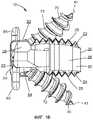
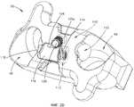
Фиг. 1А иллюстрирует вид спереди в перспективе имплантата по первому предпочтительному варианту осуществления настоящей заявки;FIG. 1A illustrates a front perspective view of an implant according to a first preferred embodiment of the present application;
Фиг. 1В иллюстрирует вертикальный вид сбоку имплантата, представленного на Фиг. 1А;FIG. 1B illustrates a vertical side view of the implant of FIG. 1A;
Фиг. 1С иллюстрирует вид сверху в плане имплантата, представленного на Фиг. 1А;FIG. 1C illustrates a top plan view of the implant of FIG. 1A;
Фиг. 1D иллюстрирует вертикальный вид спереди имплантата, представленного на Фиг. 1А;FIG. 1D illustrates a front elevational view of the implant of FIG. 1A;
Фиг. 1Е иллюстрирует вид имплантата, представленного на Фиг. 1А, в разрезе по линии 1Е-1Е на Фиг. 1С;FIG. 1E illustrates a view of the implant of FIG. 1A, in section along
Фиг. 1F иллюстрирует вид имплантата, представленного на Фиг. 1А, в разрезе по линии 1F-1F на Фиг. 1А;FIG. 1F illustrates a view of the implant of FIG. 1A, in section along the
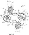
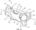
Фиг. 2А иллюстрирует вид спереди в перспективе пластины имплантата, представленного на Фиг. 1А;FIG. 2A illustrates a front perspective view of the implant plate of FIG. 1A;
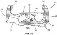
Фиг. 2B иллюстрирует вид пластины, представленной на Фиг. 2А, в разрезе по линии 2B-2B на Фиг. 2А;FIG. 2B illustrates a view of the plate of FIG. 2A, in section along line 2B-2B in FIG. 2A;
Фиг. 2C иллюстрирует увеличенный вид в разрезе удерживающего механизма, который используют вместе с имплантатом, представленным на Фиг. 1А;FIG. 2C illustrates an enlarged sectional view of a holding mechanism that is used with the implant of FIG. 1A;
Фиг. 2D иллюстрирует вид в перспективе удерживающего механизма, представленного на Фиг. 2С;FIG. 2D illustrates a perspective view of the holding mechanism of FIG. 2C;
Фиг. 2Е-2J иллюстрируют различные альтернативные виды имплантата, представленного на Фиг. 1А, включающего в себя различные альтернативные конструкции стопорного элемента, предназначенного, по меньшей мере, для частичного внедрения в тела позвонков во время установки;FIG. 2E-2J illustrate various alternative views of the implant of FIG. 1A, including various alternative designs of a retaining element intended to at least partially penetrate vertebral bodies during installation;
Фиг. 3А иллюстрирует вид сверху в плане примера инструмента для извлечения, который контактирует с удерживающим механизмом, представленным на Фиг. 2D, и отводит его, позволяя извлечь элементы для фиксации костей из имплантата;FIG. 3A illustrates a top plan view of an example extraction tool that is in contact with the holding mechanism of FIG. 2D, and removes it, allowing you to remove the elements for fixing the bones from the implant;
Фиг. 3B иллюстрирует увеличенный вид инструмента для извлечения, представленного на Фиг. 3А, в разрезе по линии 3B-3B на Фиг. 3А;FIG. 3B illustrates an enlarged view of the extraction tool of FIG. 3A, in section along the
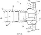
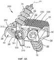
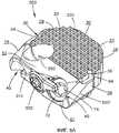
Фиг. 4А иллюстрирует вид спереди в перспективе имплантата по второму предпочтительному варианту осуществления настоящей заявки, причем удерживающий механизм находится в первом положении;FIG. 4A illustrates a front perspective view of an implant according to a second preferred embodiment of the present application, wherein the holding mechanism is in a first position;
Фиг. 4В иллюстрирует вертикальный вид сбоку имплантата, представленного на Фиг. 4А, причем удерживающий механизм находится в первом положении;FIG. 4B illustrates a vertical side view of the implant of FIG. 4A, wherein the holding mechanism is in a first position;
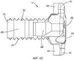
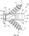
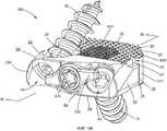
Фиг. 4С иллюстрирует вид спереди в перспективе имплантата, представленного на Фиг. 4А, причем удерживающий механизм находится во втором положении;FIG. 4C illustrates a front perspective view of the implant of FIG. 4A, wherein the holding mechanism is in a second position;
Фиг. 4D иллюстрирует вертикальный вид сбоку имплантата, представленного на Фиг. 4А, причем удерживающий механизм находится во втором положении;FIG. 4D illustrates a vertical side view of the implant of FIG. 4A, wherein the holding mechanism is in a second position;
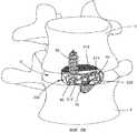
Фиг. 5А иллюстрирует вид спереди в перспективе имплантата, представленного на Фиг. 4А, вставленного в межпозвоночное пространство между телами соседних позвонков, причем удерживающий механизм находится в первом положении и действует как упор, предотвращающий чрезмерное внедрение имплантата в межпозвоночное пространство;FIG. 5A illustrates a front perspective view of the implant of FIG. 4A inserted into the intervertebral space between the bodies of adjacent vertebrae, the retaining mechanism being in the first position and acting as a stop, preventing excessive implant penetration into the intervertebral space;
Фиг. 5B иллюстрирует вид спереди в перспективе имплантата, представленного на Фиг. 4А, вставленного в межпозвоночное пространство между телами соседних позвонков, причем удерживающий механизм находится во втором положении;FIG. 5B illustrates a front perspective view of the implant of FIG. 4A inserted into the intervertebral space between the bodies of adjacent vertebrae, the retaining mechanism being in the second position;
Фиг. 6А иллюстрирует вид сверху в перспективе имплантата, представленного на Фиг. 4А, причем пластина включает в себя используемый по усмотрению механизм блокировки резьбы;FIG. 6A illustrates a top perspective view of the implant of FIG. 4A, wherein the plate includes a discretionary thread locking mechanism;
Фиг. 6B иллюстрирует альтернативный вид сверху в перспективе имплантата, представленного на Фиг. 6А, на котором используемый по усмотрению механизм блокировки резьбы контактирует с имплантированным элементом фиксации костей;FIG. 6B illustrates an alternative top perspective view of the implant of FIG. 6A, wherein a discretionary thread locking mechanism is in contact with an implanted bone fixation member;
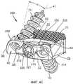
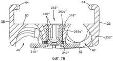
Фиг. 7А иллюстрирует альтернативный вид спереди в перспективе, с пространственным разделением деталей, пластины, используемой в соединении с имплантатом, представленным на Фиг. 4А, причем удерживающий механизм включает в себя второй пример механизма сцепления для зацепления с пластиной;FIG. 7A illustrates an alternative front perspective view, with a spatial separation of parts, of a plate used in conjunction with the implant of FIG. 4A, wherein the holding mechanism includes a second example of a clutch mechanism for engaging with a plate;
Фиг. 7B иллюстрирует вид пластины и удерживающего механизма, представленных на Фиг. 7А, в разрезе по линии 7B-7B на Фиг. 7А;FIG. 7B illustrates a view of the plate and the holding mechanism shown in FIG. 7A, in section along line 7B-7B in FIG. 7A;
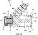
Фиг. 8 иллюстрирует местный вид в разрезе пластины, используемой в соединении с имплантатом, представленным на Фиг. 4А, причем удерживающий механизм включает в себя третий пример механизма сцепления для зацепления с пластиной;FIG. 8 illustrates a partial sectional view of a plate used in conjunction with the implant of FIG. 4A, wherein the holding mechanism includes a third example of a clutch mechanism for engaging with a plate;
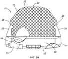
Фиг. 9А иллюстрирует вид спереди в перспективе имплантата, представленного на Фиг. 4А, причем имплантат включает в себя второй пример вставки;FIG. 9A illustrates a front perspective view of the implant of FIG. 4A, wherein the implant includes a second insertion example;
Фиг. 9В иллюстрирует вид сверху в перспективе имплантата, представленного на Фиг. 9А, в котором отсутствует используемый по усмотрению пористый участок из полиэфирэфиркетона;FIG. 9B illustrates a top perspective view of the implant of FIG. 9A, in which there is no optional porous polyetheretherketone portion;
Фиг. 9С иллюстрирует вид имплантата, представленного на Фиг. 9А, в разрезе по линии 9С-9С на Фиг. 9А, в котором отсутствует используемый по усмотрению пористый участок из полиэфирэфиркетона;FIG. 9C illustrates a view of the implant of FIG. 9A, in section along the
Фиг. 10А-10Е иллюстрируют различные виды примера инструмента для вставки и способа вставки имплантата, представленного на Фиг. 4А; иFIG. 10A-10E illustrate various views of an example insertion tool and the implant insertion method of FIG. 4A; and
Фиг. 11А-11С иллюстрируют различные виды примера инструмента для вставки и для направления сверла, предназначенного для вставки имплантата.FIG. 11A-11C illustrate various views of an example insertion tool and for guiding a drill for inserting an implant.
Подробное описание изобретенияDETAILED DESCRIPTION OF THE INVENTION
Определенная терминология используется в нижеследующем описании исключительно из соображений удобства, но не ограничения. Слова «левый», «правый», «нижний» и «верхний» обозначают направления на чертежах, на которые делается ссылка. Слова «внутрь» или «дистально», «наружу» или «проксимально» относятся к направлениям «к» и «от» геометрического центра имплантата и связанных с ним деталей соответственно. Слова «передний» («антериальный»), «задний» («постериальный»), «верхний», «нижний» и связанные с ними слова и/или фразы обозначают предпочтительные положения и ориентации в теле человека, на которые делается ссылка, но не носят ограничительного характера. Терминология включает вышеперечисленные слова, их производные и слова со сходными значениями.Certain terminology is used in the following description solely for convenience, but not limitation. The words “left,” “right,” “lower,” and “upper” indicate directions in the referenced drawings. The words “inward” or “distally”, “outward” or “proximal” refer to the directions “to” and “from” the geometric center of the implant and related parts, respectively. The words “anterior” (“anterial”), “posterior” (“posterior”), “upper”, “lower” and related words and / or phrases indicate preferred positions and orientations in the human body to which reference is made, but are not restrictive. The terminology includes the above words, their derivatives and words with similar meanings.
Одинаковые номера ссылочных позиций будут использованы на протяжении всей заявки для описания аналогичных или одинаковых элементов каждого из предпочтительных вариантов осуществления описанного в данном документе имплантата, и описания будут сосредоточены на конкретных признаках отдельных вариантов осуществления, которые отличают данный конкретный вариант осуществления от других.The same reference numerals will be used throughout the application to describe similar or identical elements to each of the preferred embodiments of the implant described herein, and the descriptions will focus on specific features of the individual embodiments that distinguish this particular embodiment from others.
Предпочтительные варианты осуществления настоящей заявки направлены на имплантат 10,200 («10-200»). Следует понимать, что, хотя различные варианты осуществления имплантата 10-200 будут описаны в связи со спинальной хирургией, специалисты в данной области техники поймут, что имплантат 10-200 и его элементы могут быть использованы для имплантации в другие части тела, включая, например, трубчатые кости или кости колена, бедра, плеча, а также для замены других суставов или для наращивания костей.Preferred embodiments of the present application are directed to an implant 10,200 ("10-200"). It should be understood that although various embodiments of the 10-200 implant will be described in connection with spinal surgery, those skilled in the art will understand that the 10-200 implant and its elements can be used for implantation in other parts of the body, including, for example, tubular bones or bones of the knee, hip, shoulder, as well as to replace other joints or to build bones.
Различные варианты осуществления имплантата 10-200 предпочтительно имеют размеры и геометрическую форму, позволяющие имплантировать их между телами соседних позвонков. Размер и геометрическая форма имплантата 10-200 могут быть такими, что позволяют заполнить все или почти все межпозвоночное пространство D между телами V соседних позвонков, заменяя межпозвоночный диск, или лишь часть межпозвоночного пространства D. В дополнение к этому, предпочтительный имплантат 10-200 может иметь конструкцию, позволяющую заменить все тело V позвонка и связанные с ним межпозвоночные пространства D или множество межпозвоночных пространств D в позвоночнике пациента, что станет очевидным для специалиста в данной области техники, имеющего среднюю квалификацию, после изучения настоящей заявки. Имплантат 10-200 может быть предназначен для использования при вставке в позвоночник антериальным, антериально-латеральным, непосредственно латеральным, экстрафораминальным, трансфораминальным и постериальным способами.Various embodiments of the implant 10-200 preferably have dimensions and geometric shapes that allow them to be implanted between the bodies of adjacent vertebrae. The size and geometrical shape of the 10-200 implant can be such that it allows you to fill all or almost all of the intervertebral space D between the bodies V of the adjacent vertebrae, replacing the intervertebral disc, or only part of the intervertebral space D. In addition, the preferred implant 10-200 can have a design that allows you to replace the entire body of the V vertebra and the associated intervertebral spaces D or many intervertebral spaces D in the patient’s spine, which will become obvious to a person skilled in the art Having an average qualification after studying the present application. The implant 10-200 can be intended for use when inserted into the spine by anterial, anterial-lateral, directly lateral, extraforaminal, transforaminal and posterior methods.
Имплантат 10-200 каждого из предпочтительных вариантов осуществления включает в себя межпозвонковую вставку 20, 220, 220' («20-220») и пластину 50, 250, 250', 250", 250"' («50-250»). Вставка 20-220 предпочтительно имеет размер и форму, подходящие для имплантации в межпозвоночное пространство D между телами V соседних позвонков. Вставка 20-200 каждого из предпочтительных вариантов осуществления включает в себя верхнюю поверхность 22, нижнюю поверхность 24, первую боковую поверхность 26, вторую боковую поверхность 28, переднюю поверхность 30 и заднюю поверхность 32. Верхняя и нижняя поверхности 22, 24 подходят для контакта и предназначены для крепления к замыкательным пластинкам тел V соседних позвонков. Вставка 20-220 предпочтительно имеет размер и геометрическую форму, позволяющие поддерживать и/или восстанавливать нужную высоту межпозвоночного диска между телами V соседних позвонков. Соответственно, верхняя и нижняя поверхности 22, 24 могут включать в себя ряд зубцов, гребней, шипов или других аналогичных выступов 25, содействующих креплению имплантата 10-200 к замыкательным пластинкам тел V соседних позвонков.The implant 10-200 of each of the preferred embodiments includes an
Верхняя и нижняя поверхности 22, 24 также могут включать в себя криволинейную или сужающуюся поверхность, помогающую обеспечить анатомическую форму для сопряжения с позвоночником пациента или желаемую ориентацию замыкательных пластинок тел V соседних позвонков. Конкретная площадь и кривизна поверхности, сужение или другая альтернативная особенность формы поверхности в антериально-постериальном направлении, а также конкретная площадь и кривизна поверхности, сужение или другая альтернативная особенность формы поверхности в медиально-латеральном направлении зависят от места, в которое должен быть имплантирован имплантат 10-200, и/или от решения хирурга, или от того, используется ли имплантат 10-200 в другой области тела.The upper and
Вставка 20-220 также может включать в себя одно или более гнезд, отверстий, окошек или каналов 34 для размещения трансплантируемой костной ткани. Например, имплантат 10-200 может включать в себя одно или более отверстие, окошко или канал, продолжающиеся через вставку 20-220 от верхней поверхности 22 до нижней поверхности 24, для вставки трансплантируемой костной ткани таким образом, что оказывается содействие росту костей через вертикальные отверстия, окошки или каналы 34 после имплантации имплантата 10-200. Наличие одного или более гнезд, отверстий, окошек или каналов 34 особенно предпочтительно, если вставка 20-200 выполнена из материала, не являющегося алогенным трансплантатом и не обеспечивающего рост костей, такого как полиэфирэфиркетон («PEEK»).The insert 20-220 may also include one or more nests, holes, windows or
Пластина 50-250 предпочтительно сцеплена с вставкой 20-220, чтобы обеспечить повышенную устойчивость имплантата во время заживления, а также оптимальным образом ориентировать траекторию элементов 70 фиксации костей во время имплантации.The plate 50-250 is preferably engaged with the insert 20-220 to provide increased stability of the implant during healing, as well as to optimally orient the trajectory of the
Пластина 50-250 каждого из предпочтительных вариантов осуществления включает в себя верхнюю поверхность 52, нижнюю поверхность 54, первую боковую поверхность 56, вторую боковую поверхность 58, переднюю поверхность 60 и заднюю поверхность 62. Пластина 50-250 предпочтительно контактирует с задней поверхностью 32 вставки 20-220 и предпочтительно не продолжается за пределы вертикального или латерального периметра вставки 20-220 и не создает его значительного увеличения. Таким образом, имплантат 10-200 имеет низкий профиль. Кроме того, пластину 50-250 предпочтительно полностью имплантируют внутрь межпозвоночного пространства D, между телами V соседних позвонков таким образом, что внешний профиль пластины 50-250 очень мал или отсутствует (например, пластина 50-250 не выступает вперед за пределы края межпозвоночного дискового пространства D). Таким образом, конструкция не выступает или очень мало выступает за пределы межпозвоночного пространства D или контура тел V позвонков, тем самым ограничивая дисфазию и уровень дискомфорта для пациента. В процессе использования пластина 50-250 может иметь такие размеры и геометрическую форму, что верхние и нижние поверхности 52, 54 пластины 50-250 контактируют с замыкательными пластинками тел V соседних позвонков. В качестве альтернативы пластина 50-250 может иметь такие размеры и геометрическую форму, что с телами V соседних позвонков контактирует только вставка 20-200. Например, высота пластины 50-250 может быть достаточно мала, чтобы она не контактировала с телами V соседних позвонков, будучи соединена с вставкой 20-220 в имплантированном состоянии.The plate 50-250 of each of the preferred embodiments includes an
Пластина 50-250 может быть сцеплена с вставкой 20-200 посредством любого механизма сцепления, который известен в настоящее время или будет известен впоследствии. Например, вставка 20-200 может включать в себя одну или более выемок 36, выполненных в боковых или задних поверхностях, для зацепления с одним или более выступами 64, продолжающимися из вставки 50-250. Вставка 20 предпочтительно включает в себя выемку 36, выполненную в каждой из ее боковых поверхностей 26, 28, для зацепления с выступами 64, выступающими из пластины 50-250. Выемки 36 могут иметь протяженность по всему участку от верхней поверхности 22 до нижней поверхности вставки 22, а могут продолжаться лишь частично от верхней или нижней поверхностей 20, 22. Другие механизмы сцепления для сцепления пластины 50-250 с вставкой 20-220 раскрыты в международной заявке № PCT/US2008/082473, поданной 5 ноября 2008 года и озаглавленной «Низкопрофильный межпозвонковый имплантат» («Low-profile Intervertebral Implant»), содержание которой полностью включено в данный документ посредством ссылки.The plate 50-250 may be coupled to the insert 20-200 by any clutch mechanism that is currently known or will be known subsequently. For example, insert 20-200 may include one or
Задняя поверхность 62 пластины 50-250 предпочтительно включает в себя элемент 80 для зацепления с инструментом, предназначенный для зацепления с одним или более инструментами для вставки. Элемент 80 для зацепления с инструментом может иметь любую форму, известную в настоящее время или впоследствии и подходящую для данной цели, включая одну или более выемок, выполненных в задней поверхности 62 пластины 50-250 и продолжающихся от верхней и нижней поверхностей 52, 54 соответственно, для зацепления с захватами инструмента для вставки. В качестве альтернативы элемент 80 для зацепления с инструментом может представлять собой резьбовое отверстие (не показано на чертеже), выполненное в задней поверхности 62 пластины 50-250, для зацепления с резьбовым стержнем, выступающим из инструмента для вставки, и т.д.The
Имплантат 10-200 предпочтительно включает в себя одно или более отверстий 40 для фиксации костей, в котором размещают один или более элементов 70 фиксации костей, предпочтительно костные винты таким образом, что в процессе эксплуатации, после вставки имплантата 10-200 в межпозвоночное пространство D между телами V соседних позвонков, имплантат 10-200 может быть прикреплен к телам V соседних позвонков. Элементы 70 фиксации костей предпочтительно включают в себя резьбовой стержень 72 и головку 74 частично сферической формы, в общем случае гладкую в том месте, где она контактирует с отверстием 40 для фиксации костей. Резьбовой стержень 72 может быть самонарезающим, т.е. не требующим сверления направляющих отверстий, но может быть и другим. Элементы 70 фиксации костей не ограничиваются костными винтами 70 и могут представлять собой винтовой гвоздь, дистально расширяющийся гвоздь или винт и т.д. Отверстия 40 для фиксации костей предпочтительно имеют такой размер и геометрическую форму, что головка 74 элемента 70 фиксации костей не выступает в проксимальном направлении за пределы задней поверхности 62 пластины 50, когда элементы 70 фиксации костей полностью имплантированы.The implant 10-200 preferably includes one or more bone fixation holes 40 in which one or more
Отверстия 40 для фиксации костей предпочтительно включают в себя криволинейную или в форме усеченной сферы поверхности для контакта с нижней стороной в общем случае гладкой или имеющей форму усеченной сферы поверхностью головки 74 элемента 70 фиксации костей, так что элементы 70 фиксации костей могут полиаксиально поворачиваться относительно пластины 50-250, и для элементов 70 фиксации костей может быть выбрано множество вариантов углов траектории в соответствии с предпочтениями или потребностями хирурга, а также с обеспечением возможности оседания имплантата 10-200 во время заживления.The bone fixation holes 40 preferably include a curved or truncated sphere surface for contacting the lower side with a generally smooth or truncated sphere surface of the
Пластина 50-250 предпочтительно включает в себя первое и второе отверстия 40 для фиксации костей, предназначенные для размещения первого и второго элементов 70 фиксации костей, при этом первый элемент 70 фиксации костей приподнят под углом вверх для зацепления с телом V верхнего позвонка, а второй элемент 70 фиксации костей отклонен вниз для зацепления с телом V нижнего позвонка. То есть отверстия 40 для фиксации костей предпочтительно имеют продольную ось 41, которая ориентирована под наклоном относительно имплантата 10-200 таким образом, что элементы 70 фиксации костей образуют крепящий уголок по отношению к верхней и нижней поверхностям 22, 24 вставки 20, при этом угол фиксации костей может составлять от двадцати градусов (20°) до шестидесяти градусов (60°), а более предпочтительно - от тридцати градусов (30°) до пятидесяти градусов (50°). Угол фиксации костей может быть одинаковым для всех отверстий 40, а может быть различным для каждого из отверстий 40. В дополнение к этому отверстия 40 для фиксации костей могут быть направлены внутрь, к центру имплантата 10-200, или наружу, от центра имплантата 10-200, предпочтительно под латеральным углом фиксации костей таким образом, что элементы 70 фиксации костей продолжаются латерально внутрь, к центральной плоскостей имплантата 10-200, или латерально наружу, от центральной плоскостей имплантата 10-200. Латеральный угол фиксации костей α может находиться в диапазоне от плюс шестидесяти градусов (60°) до минус шестидесяти градусов (-60°), предпочтительно от нуля градусов (0) до плюс или минус тридцати градусов (30°), а еще более предпочтительно составляет приблизительно плюс или минус пятнадцать градусов (15°). Латеральный угол фиксации оси может быть как одинаковым для всех отверстий 40, так и различным. Однако, как должно быть понятно специалисту в данной области техники, имеющему среднюю квалификацию, после прочтения данного описания, возможно множество потенциальных величин углов, так как элементы 70 фиксации костей полиаксиальны, как будет более подробно описано далее.The plate 50-250 preferably includes first and second bone fixation holes 40 for accommodating the first and second
Однако следует понимать, что имплантат 10-200 может включать в себя три, четыре, пять и более отверстий 40 для фиксации костей, предназначенных для размещения соответствующего количества элементов 70 фиксации костей, в любом количестве возможных конструкций. В дополнение к этому, количество элементов 70 фиксации костей, продолжающихся от верхней и нижней поверхностей 22, 24, может варьироваться, и количество элементов 70 фиксации костей, продолжающихся от верхней поверхности 22, не обязательно должно равняться числу элементов 70 фиксации костей, продолжающихся от нижней поверхности 24.However, it should be understood that the implant 10-200 may include three, four, five, or more holes for fixing the bones, designed to accommodate the appropriate number of
Выходные отверстия для отверстий 40 для фиксации костей предпочтительно выполнены, по меньшей мере частично, в верхней или нижней поверхности 52, 54 пластины 50-250. Выходные отверстия также могут быть выполнены, по меньшей мере, частично или полностью, в верхней или нижней поверхности 22, 24 вставки 20-220. Отверстия 40 для фиксации костей также могут включать в себя частично сферический внутренний объем для размещения частично сферической формы головки 74 элемента 70 фиксации костей, что позволяет выбирать из диапазона полиаксиальных ориентаций элементов 70 фиксации костей относительно тел V позвонков.The exit openings for the bone fixation holes 40 are preferably made at least partially in the upper or
Имплантат 10-200 также предпочтительно включает в себя удерживающий механизм для снижения вероятности того, что элементы 70 фиксации костей в послеоперационном периоде выйдут из сцепления с имплантатом 10-200 и переместятся из межпозвоночного пространства D. В процессе эксплуатации удерживающий механизм предпочтительно закрывает, по меньшей мере, участок отверстий 40 для фиксации костей и, следовательно, также элементы 70 фиксации костей, что позволяет предотвратить вывинчивание элементов 70 фиксации костей, как будет более подробно описано далее.The implant 10-200 also preferably includes a retention mechanism to reduce the likelihood that post-operative
Имплантат 10-200, включая вставку 20-220 и пластину 50-250, может быть выполнен из любого подходящего биосовместимого материала или сочетания материалов, включая следующие материалы: металлы, такие как титан, титановые сплавы, нержавеющую сталь, алюминий, алюминиевые сплавы, магний и т.д.; полимеры, такие как полиэфирэфиркетон, пористый полиэфирэфиркетон, полиэфирэфиркетон с углеродными волокнами, рассасываемые полимеры, полимолочная кислота и т.д., аллотрансплантат, синтетический заменитель аллотрансплантата, керамика в виде биостекла, тантал, Nitinol или альтернативные материалы для роста костей, какой-либо композиционный материал или сочетание данных материалов; но не ограничиваясь перечисленным.The 10-200 implant, including insert 20-220 and plate 50-250, may be made of any suitable biocompatible material or combination of materials, including the following materials: metals such as titanium, titanium alloys, stainless steel, aluminum, aluminum alloys, magnesium etc.; polymers such as polyetheretherketone, porous polyetheretherketone, carbon fiber polyetheretherketone, resorbable polymers, polylactic acid, etc., allograft, synthetic allograft substitute, bioglass ceramic, tantalum, Nitinol or alternative materials for growth a material or combination of these materials; but not limited to the above.
Вставка 20-200 может быть выполнена из материала, отличного от материала пластины 50-250. Например, пластина 50-250 может быть выполнена из металлического материала, такого как титан или титановый сплав, а вставка 20-220 может быть выполнена из неметаллического материала, например полимера, такого как полиэфирэфиркетон, аллотрансплантата, биорассасываемого материала, керамики и т. д. В качестве альтернативы пластина 50-250 и вставка 20-200 могут быть выполнены из одного и того же материала. Кроме того, пластина 50-250 и вставка 20-220 могут быть выполнены как единое целое, предварительно собраны или переданы хирургу по отдельности и собраны в операционной.The insert 20-200 may be made of a material different from the material of the plate 50-250. For example, a plate 50-250 may be made of a metal material, such as titanium or a titanium alloy, and an insert 20-220 may be made of a non-metallic material, for example a polymer, such as polyetheretherketone, allograft, bioabsorbable material, ceramic, etc. Alternatively, the plate 50-250 and the insert 20-200 can be made of the same material. In addition, the plate 50-250 and the insert 20-220 can be made as a whole, pre-assembled or transferred to the surgeon separately and assembled in the operating room.
Как должно быть понятно среднему специалисту в данной области техники, имплантат 10-200 или его части также могут быть покрыты различными компаундами для усиления нарастания или врастания костной ткани, для ускорения заживления или для обеспечения возможности коррекции имплантата 10-200, включая гидроксиапатит, титано-никелевый сплав, нанесение титана методом осаждения паровой фазы с нанесением при помощи плазменной струи или плазменную обработку с целью сделать поверхность гидрофильной.As should be understood by one of ordinary skill in the art, the 10-200 implant or parts thereof can also be coated with various compounds to enhance bone tissue growth or growth, to accelerate healing, or to allow correction of the 10-200 implant, including hydroxyapatite, titanium- nickel alloy, deposition of titanium by vapor deposition using a plasma jet or plasma treatment to make the surface hydrophilic.
На Фиг. 1А-2J представлен межпозвонковый имплантат 10 согласно первому предпочтительному варианту осуществления, который включает в себя вставку 20, пластину 50, первый и второй элементы 70 фиксации костей и удерживающий механизм. Согласно первому предпочтительному варианту осуществления удерживающий механизм представляет собой подпружиненную защелку 110. Более предпочтительно, чтобы пластина 50 включала в себя гнездо 112, сообщающееся с каждым из отверстий 40 для фиксации костей, для размещения пружины 114 и защелки 116. Гнездо 112 образует продольную ось, пересекающую продольную ось 41 отверстия 40 для фиксации костей и, следовательно, элемента 70 фиксации костей. Угол пересечения может быть поперечным, перпендикулярным или острым.In FIG. 1A-2J illustrate an
Защелка 116 предпочтительно включает в себя первый конец 118 для контакта или взаимодействия с головкой 74 элемента 70 фиксации костей и второй конец 120 для размещения пружины 114, контакта или взаимодействия с ней. Пружина 114 предпочтительно имеет размеры и форму, позволяющие смещать защелку 116 таким образом, чтобы защелка 116 выступала в отверстие 40 для фиксации костей, поверх головки 74 элемента 70 фиксации костей, сразу после вставки элемента 70 фиксации костей в отверстие 40 для фиксации костей, чтобы предотвратить его вывинчивание. Подпружиненная защелка 116 предпочтительно закреплена внутри гнезда 112 посредством штифта или установочного винта 125. То есть защелка 116 может включать в себя канавку или выемку 126, выполненную для сопряжения со штырем или установочным винтом 125, расположенным внутри отверстия 125а. Взаимодействие штыря или установочного винта 125 и канавки, или выемки 126 предотвращает выпадение защелки 116 из гнезда 112. Например, защелка 116 предпочтительно включает в себя профрезерованный паз 126, а штырь или установочный винт 125 может быть резьбовым и предпочтительно имеет соответствующую форму, такую, что установочный винт 125 может быть размещен и зафиксирован в пазу 126, выполненном в защелке 116. Также может быть использован другой механизм для крепления подпружиненной защелки 116 к пластине 50.The
Согласно первому предпочтительному варианту осуществления пластина 50 также включает в себя первый и второй упоры 65, при этом первый упор 65 выступает над верхней поверхностью 52 пластины 50 для контакта с телом V верхнего позвонка, а второй упор 65 выступает под нижней поверхностью 54 пластины 50 для контакта с телом V нижнего позвонка. Наличие большего или меньшего количества упоров 65 также предполагается. Наличие первого и второго упоров 65 облегчает полную посадку имплантата 10 относительно тел V соседних позвонков независимо от несимметричной анатомии позвоночника пациента, которая часто отличает наружные поверхности тел V позвонков. Упоры 65 предпочтительно выполнены как одно целое с пластиной 50.According to a first preferred embodiment, the
В процессе эксплуатации упоры 65 упираются в антериальные поверхности тел V позвонков во время имплантации, однако упоры 65 также могут упираться в латеральные или антериально-латеральные поверхности тел V позвонков, в зависимости от процедуры хирургической операции и используемого способа вставки. Упоры 65 помогают предотвратить излишнее внедрение имплантата 10 в процессе имплантации, а также помогают зафиксировать положение имплантата 10 во время вставки элементов 70 фиксации костей, как будет более подробно описано ниже. Отчасти благодаря расположению упоров 65 имплантат 10 в общем случае имеет нулевой профиль, не выходящий за пределы межпозвоночного пространства, по меньшей мере, вдоль срединной линии, проходящей от основания черепа до нижнего поясничного позвонка, так как задняя поверхность 62 пластины 50 может быть вогнутой, сопрягаясь с межпозвоночным пространством D. На Фиг. 2Е-2J показано, что дистальная поверхность 65а упоров 65 может иметь форму, позволяющую, по меньшей мере, частично встраиваться в тела V позвонков во время вставки, чтобы еще сильнее уменьшить часть профиля пластины 50, выходящую за пределы межпозвоночного пространства D, если это требуется. Например, как показано на Фиг. 2Е, дистальная поверхность 65а упоров 65 может включать в себя пирамидальный выступ, или зубец, 66, продолжающийся от данной поверхности, который, по меньшей мере, частично встраивается в тело V позвонка во время установки имплантата. В качестве альтернативы дистальная поверхность 65а упоров 65 может включать в себя множество выступов, или зубцов, 67 (Фиг. 2F), вертикальный выступ 68 типа лопатки (Фиг. 2G и 2Н) или поперечный выступ 69 типа лопатки (показанный на Фиг. 2I и 2J), продолжающиеся от данной поверхности, которые во время установки имплантата, по меньшей мере, частично внедряются в тела V позвонков.During operation, the
В процессе операции хирург подготавливает проход, или канал, к межпозвоночному пространству D, производит, по меньшей мере, частичную дискотомию и вставляет имплантат 10, включая вставку 20 и пластину 50, в межпозвоночное пространство D, пока упоры 65 не вступят в контакт с прилегающими телами V позвонков. После того как хирург выбрал нужный угол введения элементов 70 фиксации костей, он вводит первый и второй элементы 70 фиксации костей в отверстия 40 для фиксации костей и пропускает через них под выбранным углом, с предварительным формированием направляющих отверстий или без него. Введение элементов 70 фиксации костей в отверстия 40 для фиксации костей приводит головку 74 элемента 70 фиксации костей в контакт с внутренними сферическими участками отверстий 40 для фиксации костей, а также приводит к выравниванию тел V позвонков, но без избыточного внедрения имплантата 100, так как упоры 65 направляют движение тел V позвонков во время манипуляций, связанных с фиксацией костей. То есть, так как упоры 65 контактируют с прилегающими телами V позвонков и препятствуют слишком глубокому внедрению имплантата в межпозвоночное пространство D, введение элементов 70 фиксации костей приводит к стягиванию и/или репозиции тел V соседних позвонков, что способствует срастанию. Элементы 70 фиксации костей вводят, пока тела V позвонков не будут оптимальным образом выровнены, а затем вводят головки 74 элементов 70 фиксации костей в сферические участки отверстий 70 для фиксации костей.During the operation, the surgeon prepares the passage, or canal, to the intervertebral space D, performs at least partial disco-tomy and inserts the
По мере введения элементов 70 фиксации костей через отверстия 40 для фиксации костей нижняя сторона головки 74 элементов 70 фиксации костей контактирует с первым концом 118, а предпочтительно с сужающимся концевым участком 117, защелкивающихся элементов 116, выступающих в отверстия 40 для фиксации костей, побуждая тем самым защелки 116 отскакивать назад, нажимая на пружину 114, и отводя защелкивающиеся элементы 116 из отверстий 40 для фиксации костей, чтобы можно было имплантировать элементы 70 фиксации костей. Как только головки 74 элементов 70 фиксации костей проходят мимо сужающихся концевых участков 117 защелкивающихся элементов 116, пружина 114 выталкивает защелкивающиеся элементы 116 обратно, в исходное положение, в котором они выступают, по меньшей мере, частично, в отверстия 40 для фиксации костей. В этом положении первый конец 118 защелкивающегося элемента 116 должен закрыть, по меньшей мере, участок головки 74 элемента 70 фиксации костей, контактировать и/или взаимодействовать с ее верхней поверхностью, чтобы заблокировать головки 74 элементов 70 фиксации костей и ограничить возможность вывинчивания элементов 70 фиксации костей из отверстий 40 для фиксации костей. В частности, первый конец 118 защелки 110 предпочтительно входит в отверстие 40 для фиксации костей таким образом, что головка 74 элемента 70 фиксации костей не может выдвинуться из отверстия 40 для фиксации костей, не столкнувшись с первым концом 118.As the
После имплантации элементы 70 фиксации костей предпочтительно могут свободно покачиваться, что дает возможность осадки в процессе заживления после операции. Как показано на Фиг. 3А и 3В, если хирург решит, что размещение имплантата 10 не является оптимальным, можно провести регулирование посредством сжатия защелкивающихся элементов 116 тупым инструментом или втулкой, что позволяет извлечь элементы 70 фиксации костей. Например, инструмент 1000 для извлечения может включать в себя внутренний стержень 1010 для зацепления с элементом 70 фиксации костей и наружный стержень 1020 для контакта с защелкивающимся элементом 116 и его отталкивания, таким образом, что элемент 70 фиксации костей может быть извлечен из пластины 50.After implantation, the
На Фиг. 4А-5B показано, что межпозвонковый имплантат 200 согласно второму предпочтительному варианту осуществления включает в себя вставку 220, пластину 250, первый и второй элементы 70 фиксации костей и удерживающий механизм. Согласно второму предпочтительному варианту осуществления удерживающий механизм представляет собой подвижную вертушку 310, которая перемещается, а более предпочтительно - поворачивается между первым положением (проиллюстрировано на Фиг. 4А, 4B и 5А) и вторым положением (проиллюстрировано на Фиг. 4С, 4D и 5В). В первом положении вертушка 310 не взаимодействует с первым и вторым отверстиями 40 для фиксации костей, так что первый и второй элемент 70 фиксации костей можно вставить в тела V соседних позвонков. Во втором положении вертушка 310 блокирует или закрывает, по меньшей мере, участки отверстий 40 для фиксации костей и, следовательно, по меньшей мере, участки имплантированных элементов 70 фиксации костей, препятствуя вывинчиванию.In FIG. 4A-5B show that an
Вертушку 310 предпочтительно подвергают предварительной сборке или заранее крепят к пластине 250. Вертушка 310 может быть прикреплена к пластине 250 любым механизмом сцепления, известным в настоящее время или впоследствии в данной области техники, включая описанные ниже. Согласно второму предпочтительному варианту осуществления вертушка 310 предварительно собрана вместе с пластиной 250 посредством удерживающего винта 320, который взаимодействует с резьбовым отверстием (не показано на чертеже), расположенным между отверстиями 40 для фиксации костей, выполненными в пластине 250. Удерживающий винт 320 может продолжаться вглубь вставки 220 и быть сцеплен с ней резьбовым соединением, но данный вариант не носит ограничительного характера. В качестве альтернативы удерживающий винт 320 может быть прочно сцеплен с пластиной 250 стержнем с крестовиной (поперечным штифтом), заклепкой, винтовым клином, прикрепленным к стержню удерживающего винта 320 и т. д. Вертушка 310 включает в себя первый и второй концы 312, 314, образующие продольную ось, которая в общем случае расположена поперек продольной оси удерживающего винта 320.The
Вертушка 310 и удерживающий винт 320 предпочтительно поворачиваются из первого положения во второе положение в диапазоне приблизительно девяносто градусов (90°). В первом положении продольная ось вертушки 310 ориентирована, в общем случае, параллельно продольной оси имплантата 200 и параллельно оси позвоночника таким образом, что вертушка 310 не взаимодействует с отверстиями 40 для фиксации костей или элементами 70 фиксации костей, что позволяет вставлять элементы 70 фиксации костей в тела V соседних позвонков. Во втором положении продольная ось вертушки 310, в общем случае, ориентирована перпендикулярно оси позвоночника, таким образом, что вертушка 310 блокирует или перекрывает, по меньшей мере, участки отверстий 40 для фиксации костей и препятствует вывинчиванию элементов 70 фиксации костей. То есть во втором положении вертушка 310 закрывает, по меньшей мере, участки головок 74 элементов 70 фиксации костей, в то время как в первом положении вертушка 310 позволяет вставить элементы 70 фиксации костей в отверстия 40 для фиксации костей и в соответствующие тела V соседних позвонков.The
Удерживающий винт 320 предпочтительно включает в себя элемент зацепления 321 для зацепления с инструментом 500 для вставки, как будет более подробно описано далее, позволяющий поворачивать удерживающий винт 320 и вертушку 310 между первым и вторым положениями. Удерживающий винт 320 и вертушка 310 сцеплены друг с другом посредством двухточечной посадки с натягом между наружным диаметром удерживающего винта 320 и диаметром расточки (не показана на чертеже) в вертушке 310.The retaining
Пластина 250 предпочтительно включает в себя клиновидную выемку 330, которая образует направляющий уклон, так что во втором положении вертушка 310 предпочтительно расположена заподлицо с задней поверхностью 62 пластины 250 (как лучше всего видно на Фиг. 4D). Соответственно, в первом положении (Фиг. 4А и 4B) вертушка 310 выступает относительно задней поверхности 62 пластины 250, а втором положении (Фиг. 4С и 4D) передняя поверхность вертушки 310 расположена практически заподлицо или даже слегка утоплена относительно задней поверхности 62. Следовательно, в имплантированной конструкции, когда вертушка 310 находится во втором положении, весь имплантат 200, включая вертушку 310, расположен в пределах позвоночника пациента или позади относительно передней стороны позвонков V.The
В процессе операции хирург подготавливает проход, или канал, к межпозвоночному пространству D, производит, по меньшей мере, частичную дискотомию и вставляет имплантат 200, включая вставку 220 и пластину 250, в межпозвоночное пространство D, при этом вертушка 310 находится в первом положении. В первом положении размер вертушки 310 позволяет ей действовать в качестве упора во время имплантации имплантата 200, чтобы предотвратить чрезмерное внедрение имплантата 200, а также зафиксировать положение имплантата 200 во время вставки элементов 70 фиксации костей. В частности, концы 312, 314 вертушки 310 контактируют и/или зацепляются с примыкающими телами V позвонков, механически блокируя дальнейшее внедрение имплантата 200 в межпозвоночное пространство D (как лучше всего видно на Фиг. 5А).During the operation, the surgeon prepares the passage, or canal, to the intervertebral space D, performs at least partial disco- tomy and inserts the
После того как хирург выберет нужный угол введения для элементов 70 фиксации костей, он вводит первый и второй элементы 70 фиксации костей в отверстия 40 для фиксации костей и пропускает через них под выбранным углом, с предварительным формированием направляющих отверстий или без него. Внедрение элементов 70 фиксации костей в отверстия 40 для фиксации костей заставляет головки 74 элементов 70 фиксации костей контактировать с внутренними сферическими участками отверстий 40 для фиксации костей и приводит к выравниванию тел V позвонков, но не к чрезмерному внедрению имплантата 200, так как вертушка 310 предпочтительным образом направляет перемещение тел V позвонков во время манипуляций, связанных с фиксацией костей. Элементы 70 фиксации костей вводят, пока тела V позвонков не будут выровнены оптимальным образом, а затем вводят головки 74 элементов 70 фиксации костей в сферические участки отверстий 70 для фиксации костей. Затем удерживающий винт 320 и вертушка 310, направляемые выемками 330 в задней поверхности 62 пластины 250, поворачивают на девяносто градусов (90°), из первого положения во второе положение, при помощи сопряжения инструмента для вставки с выполненным на удерживающем винте 320 элементом 321 для зацепления с инструментом. По мере поворота удерживающего винта 320 из первого положения во второе положение удерживающий винт 320 предпочтительно продвигается в дистальном направлении в соответствии с шагом резьбы на его стержне, а вертушка 310 поворачивается, перемещаясь вниз по направляющему уклону, образованному выемками 330, и остается там, будучи расположена поверх головок 74 элементов 70 фиксации костей. Форма направляющего уклона, образованного выемками 330, предпочтительно удерживает вертушку 310 от избыточного поворота и выхода за пределы второго положения таким образом, что концы вертушки 310, по меньшей мере, частично покрывают головки 74 элементов 70 фиксации костей. По существу, это позволяет предотвратить вывинчивание элементов 70 фиксации костей из пластины 250 и вставки 220 с помощью вертушки 310.After the surgeon selects the desired insertion angle for the
После имплантации элементы 70 фиксации костей предпочтительно могут свободно покачиваться, что дает возможность осадки в процессе заживления после операции. Если хирург решит, что размещение имплантата 200 не является оптимальным, можно выполнить регулирование, повернув вертушку 310 обратно, в первое положение, разблокировав тем самым перемещение головок 74 элементов 70 фиксации костей и обеспечив возможность регулирования положения имплантата.After implantation, the
На Фиг. 6А и 6В проиллюстрирован второй предпочтительный вариант осуществления пластины 250', используемой в имплантате 200. Согласно второму предпочтительному варианту осуществления пластины 250' отверстия 40 для фиксации костей включают в себя выступающий механизм 350 блокировки резьбы, который расположен и устроен таким образом, чтобы давать возможность резьбового перемещения первого и второго элементов 70 фиксации костей относительно отверстия 40 для фиксации костей до тех пор, пока самый проксимальный виток резьбы 73, выполненный на стержне 72 элемента 70 фиксации костей, не пройдет в дистальном направлении мимо механизма 350 блокировки резьбы; в этом месте дистальная поверхность механизма блокировки резьбы 350 вступает в контакт с проксимальной стороной самого проксимального витка резьбы 73, предотвращая вывинчивание первого и второго элементов 70 фиксации костей из отверстий 40 для фиксации костей. Механизм блокировки резьбы 350 может принимать форму приподнятого гребня, неполного кольца или любого другого выступа, предназначенного для того, чтобы дать возможность самому проксимальному витку резьбы 73 элемента 70 фиксации костей переместиться до точки, в которой его перемещение в противоположном направлении будет задержано. В качестве альтернативы, механизм блокировки резьбы 350 может быть расположен внутри отверстий 40 для фиксации костей, чтобы блокировать проксимальную поверхность головок 74 элементов 70 фиксации костей, а не крайние в проксимальном направлении витки резьбы 73. В качестве альтернативы, механизм блокировки резьбы 350 может иметь конструкцию, позволяющую ему зацепляться с соответствующими углублениями (не показаны), выполненным в боковых сторонах головок 74 элементов 70 фиксации костей.In FIG. 6A and 6B illustrate a second preferred embodiment of the
Элементы 70 фиксации костей могут дополнительно включать в себя поднутрение 75 между самым проксимальным витком 73 резьбы и дистальным участком головки 74, что позволяет элементу 70 фиксации костей, по существу, свободно вращаться после полной установки в отверстии 40 для фиксации костей, что дает возможность отставания перемещения тел V позвонков относительно имплантата 200 в процессе имплантации.The
Во время операции имплантат 200 размещают между телами V соседних позвонков, а элементы 70 фиксации костей продвигают в отверстия 40 для фиксации костей до тех пор, пока самый проксимальный виток резьбы 73, выполненный на стержне 72 элемента 70 фиксации костей, не пройдет мимо выступающего механизма 350 блокировки резьбы. В этом положении элементы 70 фиксации резьбы полностью устанавливаются относительно пластины 250. Дистальная поверхность механизма блокировки резьбы 350 контактирует с проксимальной стороной самого проксимального витка резьбы 73, выполненного на стержнях 72 элементов 70 фиксации костей, ограничивая вывинчивание элементов 70 фиксации костей из отверстий 40 для фиксации костей. Элементы 70 фиксации костей в общем случае свободно вращаются после полной установки благодаря наличию поднутрений 75 между самым проксимальным витком 73 резьбы и дистальным участком головки 74 каждого элемента 70 фиксации костей, что дает возможность отставания перемещения тел V позвонков относительно имплантата 200 в процессе имплантации. Вертушка 310 может быть использована вместе с механизмом 350 блокировки резьбы для закрепления положения имплантата 200 во время вставки элементов 270 фиксации костей, а также для дополнительного предохранения от вывинчивания. В качестве альтернативы предусмотрено, что механизм блокировки резьбы 350 может быть встроен в имплантат 10 согласно первому предпочтительному варианту осуществления.During surgery, the
На Фиг. 7А и 7В проиллюстрирован третий предпочтительный вариант осуществления пластины 250", используемой в имплантате 200. Третий предпочтительный вариант осуществления пластины 250" включает в себя альтернативный механизм сцепления для сцепления вертушки 310" с пластиной 250". Согласно данному варианту осуществления вертушка 310" включает в себя множество пазов 317", продолжающихся от дистального конца 316" вертушки 310", таким образом, что вертушка 310" включает в себя множество пружиноподобных пальцев 315", ориентированных вдоль оси, продолжающейся в дистальном направлении, в общем случае перпендикулярно продольной оси концов 312", 314" вертушки 310". Пружинные пальцы 315" предпочтительно включают в себя продолжающиеся наружу фланцы 318" у дистального конца 316". Пластина 250" предпочтительно включает в себя безрезьбовое отверстие 263", расположенное между отверстиями 40 для фиксации костей. Безрезьбовое отверстие 263" предпочтительно включает в себя один или более уклонов 263а" и одну или более ступенек 263b" для взаимодействия с пружинными пальцами 315" с целью крепления вертушки 310" к пластине 250".In FIG. 7A and 7B illustrate a third preferred embodiment of the
Используемый по усмотрению удерживающий фиксатор 340", такой как вильчатый фиксатор, выполненный, например, из элгилоя, может быть установлен в отверстии 263", дополнительно содействуя креплению вертушки 310" к пластине 250", позволяя вставку вертушки 310" в отверстие 263" и одновременно с этим обеспечивая дополнительную защиту от обратного выдвижения вертушки 310" из отверстия 263".An optionally used retaining
Во время операции вертушку 310" скрепляют с пластиной 250" посредством вставки пружинных пальцев 315" в отверстие 263" до тех пор, пока вертушка 310" не защелкнется в гнезде 263", после чего вертушка 310" удерживается внутри отверстия. То есть по мере введения пружинных пальцев 315" в отверстие 263" скошенные фланцы 318", выполненные на дистальном конце 316" вертушки 310", и пружинные пальцы 315" сжимаются таким образом, что пальцы 315" проходят сквозь используемый по усмотрению удерживающий фиксатор 340", после чего пружинные пальцы 315" частично отпружинивают наружу. Удерживающий зажим 340" может дополнительно слегка отгибаться наружу при прохождении сквозь фланца 318", после чего удерживающий зажим 340" отпружинивает в исходное положение. По мере того как пружинные пальцы 315" продолжают продвигаться в отверстие 263", пальцы 315" проходят поверх ступеньки 263b", а затем отгибаются наружу, в не отклоненное состояние, примыкая к уклону 263а". Таким образом, обратное выдвижение вертушки 310" из гнезда 263" предотвращается посредством взаимодействия между фланцами 318" и ступенькой 263b".During the operation, the
На Фиг. 8 проиллюстрирован четвертый предпочтительный вариант осуществления пластины 250"', используемой в имплантате 200. Четвертый предпочтительный вариант осуществления пластины 250"' включает в себя третий альтернативный механизм сцепления для сцепления вертушки 310"' с пластиной 250"'. Согласно данному варианту осуществления безрезьбовое отверстие 263"' включает в себя первый уклон 263а"', первую ступеньку 263b"', второй предпочтительный винтовой уклон 263с"' и вторую ступеньку 263d"' по мере продвижения от задней поверхности 62 пластины 250"'. Конструкция вертушки 310"', по существу, идентична вертушке 310" второго примера механизма сцепления, описанного выше.In FIG. 8 illustrates a fourth preferred embodiment of the
Во время операции вертушку 310'" скрепляют с пластиной 250" посредством вставки пружинных пальцев 315"' в безрезьбовое отверстие 263"' до тех пор, пока вертушка 310'" не защелкнется в отверстии 263"', в результате чего вертушка 310" удерживается внутри него. По мере продвижения пружинных пальцев 315"' в отверстии 263"' пружинные пальцы 315"' сжимаются, когда скошенные фланцы 318"' проходят мимо первого уклона 263а"' и поверх первой ступеньки 263b"', а затем пружинные пальцы 315"' и фланцы 318"' частично отпружинивают наружу, закрепляя вертушку 310"' относительно пластины 250"'. Таким образом, обратное выдвижение вертушки 310"' из отверстия 263" предотвращается посредством взаимодействия между фланцами 318"' и первой ступенькой 263b"'. Кроме того, по мере перемещения вертушки 310"' из первого положения во второе положение пружинные пальцы 315"' продвигаются дальше в отверстие 263"', в котором фланец 318"' направляется предпочтительно имеющим винтовую форму вторым уклоном 263"' до тех пор, пока фланец 318"' не пройдет по второй ступеньке 263d"'. Пружинные пальцы 315"' и фланцы 318"' отгибаются наружу, в не отклоненное положение, блокируя выдвижение вертушки 310"' назад через отверстие 263"' посредством взаимодействия между фланцами 318"' и второй ступенькой 263d"'.During operation, the
На Фиг. 9А-9С представлен альтернативный вариант осуществления вставки 220', используемой в первом и втором вариантах осуществления межпозвоночного имплантата 10-200 (проиллюстрирован второй предпочтительный вариант осуществления), который включает в себя центральную область 422 из пористого полиэфирэфиркетона, концентрично окруженную участком 420 из обычного полиэфирэфиркетона.In FIG. 9A-9C show an alternative embodiment of an insert 220 'used in the first and second embodiments of an intervertebral implant 10-200 (a second preferred embodiment is illustrated), which includes a
Во время операции имплантат 200 имплантируют и закрепляют внутри межпозвоночного пространства D способом, аналогичным вышеописанному. Центральный участок 422 вставки 220', выполненный из пористого полиэфирэфиркетона, имеет пористость, обеспечивающую подходящий канал, через который может течь кровь, а кость может расти, что способствует сращиванию тел V соседних позвонков. Участок 422 из пористого полиэфирэфиркетона может продолжаться от верхней поверхности 22 до нижней поверхности 24 вставки 220'.During surgery, the
В качестве альтернативы, вставка 220' может включать в себя перемычку 424. Если вставка 220' включает в себя перемычку 424, то первое и второе глухие отверстия 426, 428 предпочтительно продолжаются от верхней и нижней поверхностей 22, 24 соответственно до перемычки 424. Глухие отверстия 426, 428 могут включать в себя скошенные боковые стенки 430, такие, что диаметр глухих отверстий 426, 428 увеличивается к центру вставки 220'. Перемычка 424 может быть выполнена из того же материала, что и остальная часть вставки 220', но предпочтительно выполнена из пористого полиэфирэфиркетона. В качестве альтернативы перемычка 424 может быть съемной, например, с возможностью вытаскивания из вставки 220', чтобы обеспечить сквозное осевое отверстие. Во время операции глухие отверстия 426, 428 предпочтительно заполняют костным трансплантатом или другим материалом, способствующим сращиванию, и имплантат 200' имплантируют в межпозвоночное пространство D между телами V соседних позвонков. Используемые по выбору скошенные стенки 430 глухих отверстий 426, 428 облегчают фиксацию имплантата 200' в нужном положении внутри межпозвоночного пространства в процессе врастания костей в глухие отверстия 426, 428.Alternatively, insert 220 'may include a
На Фиг. 10А-10Е представлен пример инструмента 500 для вставки и способа вставки имплантата 200, которые будут описаны далее. В связи с примером способа вертушка 310 будет описана и проиллюстирована открепленной от пластины 250. Однако данный иллюстративный способ может быть легко адаптирован к работе с вертушкой 310, предварительно прикрепленной к пластине 250, или с первым предпочтительным вариантом осуществления имплантата 10, что станет очевидным специалисту в данной области техники, имеющему среднюю квалификацию, после изучения данной заявки.In FIG. 10A-10E show an example of an
Инструмент для вставки 500 предназначен для сцепления с вертушкой 310, сцепления с пластиной 250, по меньшей мере, частичной вставки имплантата 200 в межпозвоночное пространство D для того, чтобы позволить вставку элементов 70 фиксации костей в отверстия 40 для фиксации костей, для крепления вертушки 310 к пластине 250, если это необходимо, и для поворота вертушки 310 из первого положения во второе положение, если необходимо.
Инструмент для вставки 500 предпочтительно включает в себя внутренний стержень 520 и наружный трубчатый элемент 530. Внутренний стержень 520 предпочтительно включает в себя дистальный элемент 525 зацепления, такой как звездчатый привод, для взаимодействия с элементом 321 зацепления, выполненным на удерживающем винте 320. Наружный трубчатый элемент 530 предпочтительно включает в себя дистальный элемент 535 зацепления для взаимодействия с соответствующим элементом зацепления (не показанным на чертеже), выполненным на пластине 250. Соответственно, инструмент 500 удерживает вертушку 310 посредством крепления элемента 525 зацепления, выполненного на внутреннем стержне 520 инструмента 500, к вертушке 310. Инструмент 500 удерживает имплантат 200 путем захвата пластины 250 с помощью элемента 525 зацепления, выполненного на наружном трубчатом элементе 530.The
Внутренний стержень 520 имеет конструкцию, позволяющую ему поступательно перемещаться внутри наружного трубчатого элемента 530 вдоль продольной оси 501 инструмента 500. Соответственно, внутренний стержень 520 и, следовательно, вертушка 310, могут быть поступательно перемещены в проксимальном направлении относительно наружного трубчатого элемента 530 и, следовательно, относительно имплантата 200. В вариантах осуществления, в которых вертушка 310 не прикреплена к пластине 250, и если пластина 250 не включает в себя ни одного упора, инструмент 500 может также включать в себя один или более упор (не показаны на чертежах) для предотвращения чрезмерного внедрения имплантата 200 в межпозвоночное пространство, а также для фиксации положения имплантата 200 относительно межпозвоночного пространства во время имплантации элементов 70 фиксации костей.The
Во время операции хирург вставляет имплантат 200 в межпозвоночное пространство D, используя инструмент 500 для продвижения имплантата в межпозвоночное пространство D между телами V соседних позвонков, пока упомянутые упоры, один или более (не показанные на чертежах), не упрутся в передние (или латеральные, или переднелатеральные) стороны тел V соседних позвонков. Затем элементы 70 фиксации костей вставляют через отверстия 40 для фиксации костей в тела V соседних позвонков, при этом сдвиг имплантата 200 ограничен взаимодействием упоров с телами V соседних позвонков.During surgery, the surgeon inserts the
Если вертушка 310 не прикреплена к инструменту, то затем вертушку 310 и удерживающий винт 320 можно продвинуть в соответствующее отверстие 263, выполненное в пластине 250, поступательно перемещая внутренний стержень 520 в дистальном направлении относительно наружного трубчатого элемента 530. Затем внутренний стержень 250 поворачивают таким образом, что вертушка 310 перемещается из первого положения во второе положение, предотвращая обратное выдвижение имплантированных элементов 70 фиксации костей. Затем инструмент 500 выводят из сцепления с вертушкой 310 и удерживающим винтом 320.If the
На Фиг. 11А-11С представлен используемый по усмотрению инструмент 600 для вставки и для направления сверла, который может быть использован для вставки любого из описанных выше имплантатов 10-200 и для выравнивания траектории шила, сверла, отвертки и т.д., с целью формирования направляющего отверстия и/или вставки элемента фиксации костей. Инструмент 600 для вставки и направления сверла включает в себя пару рычагов 610, 615, продолжающихся от пары рукояток 620, 625, сцепленных на оси поворота 630. Данные рычаги 610, 615 включают в себя наводящие цилиндры 612, 616, расположенные на их на дистальных концах, соответственно для выравнивания траектории шила, сверла, элементов фиксации костей и т.д. Цилиндры 612, 616 включают в себя направляющие ребра 613, 617 соответственно, расположенные на их наружных поверхностях, для взаимодействия с фиксатором 625 в отверстиях 40 для фиксации костей в имплантате 200. Взаимодействующие направляющие ребра 613, 617 и фиксаторы 625 предназначены для ограничения вращения имплантата 10-200 относительно инструмента 600; это свойство особенно предпочтительно для имплантатов 10-200, имеющих только два отверстия 40 для фиксации костей.In FIG. 11A-11C show a
В ходе операции рычаги инструмента 600 для вставки и для направления сверла открывают посредством сжатия рукояток 620, 625, и цилиндры 612, 616 вставляют в отверстия 40 для фиксации костей, выполненные в пластине 250, таким образом, что направляющие ребра 613, 617 взаимодействуют с фиксаторами 625. По достижении надежного захвата имплантата 10-200 рычаги 610, 615 фиксируют, и инструмент 600 можно использовать для вставки имплантата 10-200 в межпозвоночное пространство D между телами V соседних позвонков, которое, по меньшей мере, частично очищено. Затем цилиндры 612, 616 можно использовать для выравнивания траектории шила, сверла и т.д., чтобы образовать направляющие отверстия для элементов 70 фиксации костей или для выравнивания траектории элементов 70 фиксации костей в случае использования самонарезающих элементов 70 фиксации костей. После имплантации элементов 70 фиксации костей рычаги 610, 615 размыкают, и инструмент 600 для вставки и для направления сверла выводят из сцепления с имплантатом в сборе.During the operation, the levers of the
Хотя вышеизложенное описание и чертежи представляют предпочтительные варианты осуществления настоящего изобретения, следует понимать, что различные дополнения, модификации, сочетания и/или дополнения могут быть осуществления без отступления от сущности и объема настоящего изобретения, которые определены в прилагаемой формуле изобретения. В частности, специалисту в данной области техники должно быть ясно, что настоящее изобретение может быть осуществлено и в других конкретных формах, конструкциях, компоновках, пропорциях, с другими элементами, материалами и компонентами, без отступления от его сущности или существенных отличительных признаков. Специалист в данной области техники поймет, что изобретение может быть использовано с множеством модификаций конструкции, компоновки, пропорций, материалов, компонентов и т.д., используемых в практическом воплощении изобретения, которые особенно хорошо подходят для конкретной среды и конкретных условий операции, без отступления от принципов изобретения. Кроме того, признаки, описанные в данном документе, могут использоваться как по отдельности, так и в сочетании с другими признаками. Следовательно, раскрытые в настоящем документе варианты осуществления следует рассматривать во всех отношениях как иллюстративные и не носящие ограничительного характера, объем изобретения обозначен прилагаемой формулой изобретения и не ограничивается вышеизложенным описанием.Although the foregoing description and drawings represent preferred embodiments of the present invention, it should be understood that various additions, modifications, combinations and / or additions can be made without departing from the essence and scope of the present invention, which are defined in the attached claims. In particular, it should be clear to a person skilled in the art that the present invention may also be practiced in other specific forms, constructions, arrangements, proportions, with other elements, materials and components, without departing from its essence or essential distinguishing features. A person skilled in the art will understand that the invention can be used with many modifications of the design, layout, proportions, materials, components, etc. used in the practical embodiment of the invention, which are particularly well suited for a particular environment and specific operating conditions, without departure from the principles of the invention. In addition, the features described herein can be used both individually and in combination with other features. Therefore, the embodiments disclosed herein should be considered in all respects as illustrative and not restrictive, the scope of the invention is indicated by the appended claims and is not limited to the foregoing description.
Claims (14)
Translated fromRussianА) первый и второй элементы (70) фиксации костей;
В) вставку (20), включающую в себя верхнюю поверхность (22) для контакта с телом верхнего позвонка, нижнюю поверхность (24) для контакта с телом нижнего позвонка, первую боковую поверхность (26), вторую боковую поверхность (28), переднюю поверхность (30) и заднюю поверхность (32);
С) пластину (50), сцепленную с вставкой (20), при этом пластина включает в себя верхнюю поверхность (52), нижнюю поверхность (54), первую боковую поверхность (56), вторую боковую поверхность (58), переднюю поверхность (60) и заднюю поверхность (62), а также первое и второе отверстия (40) для фиксации костей и первое и второе гнезда (112), при этом первое и второе отверстия (40) для фиксации костей имеют размер, подходящий для размещения первого и второго элементов (70) фиксации костей соответственно, причем первое отверстие (40) для фиксации костей наклонено таким образом, что первый элемент (70) фиксации костей зацепляется с телом верхнего позвонка, второе отверстие (40) для фиксации костей наклонено таким образом, что второй элемент (70) фиксации костей зацепляется с телом нижнего позвонка, при этом первое гнездо (112) сообщается с первым отверстием (40) для фиксации костей, второе гнездо (112) сообщается со вторым отверстием (40) для фиксации костей;
при этом
D) упомянутый имплантат (10) дополнительно содержит первую и вторую подпружиненные защелки (110), препятствующие обратному выдвижению первого и второго элементов (70) фиксации костей соответственно, причем первая подпружиненная защелка (110) расположена в первом гнезде (112), вторая подпружиненная защелка (110) расположена во втором гнезде (112), причем первая и вторая подпружиненные защелки (110) выполнены с возможностью перемещения из первого положения во второе положение, и в первом положении, по меньшей мере, участки первой и второй защелок (110) выступают в первое и второе отверстия (40) для фиксации костей соответственно, так что как только первый и второй элемент (70) вставлены в первое и второе отверстия (40) для фиксации костей соответственно, первая и вторая защелки (110), по меньшей мере, частично закрывают первый и второй элементы (70) фиксации костей соответственно, препятствуя их обратному выдвижению, при этом первая и вторая подпружиненные защелки (110) сдвинуты пружиной в первое положение.1. The implant (10) for insertion into the intervertebral space between the vertebral bodies located above and below this intervertebral space, while the implant (10) contains:
A) the first and second elements (70) of bone fixation;
C) an insert (20), including the upper surface (22) for contact with the body of the upper vertebra, the lower surface (24) for contact with the body of the lower vertebra, the first side surface (26), the second side surface (28), the front surface (30) and the back surface (32);
C) a plate (50) engaged with the insert (20), the plate including an upper surface (52), a lower surface (54), a first side surface (56), a second side surface (58), and a front surface (60 ) and the rear surface (62), as well as the first and second holes (40) for fixing the bones and the first and second nests (112), while the first and second holes (40) for fixing the bones have a size suitable for accommodating the first and second bone fixation elements (70), respectively, wherein the first bone fixation hole (40) is inclined in such a manner once the first bone fixation element (70) engages with the upper vertebral body, the second bone fixation hole (40) is inclined so that the second bone fixation element (70) engages with the lower vertebral body, while the first socket (112) communicates with the first hole (40) for fixing the bones, the second socket (112) communicates with the second hole (40) for fixing the bones;
wherein
D) said implant (10) further comprises a first and second spring-loaded latch (110), preventing the backward extension of the first and second bone fixation elements (70), respectively, wherein the first spring-loaded latch (110) is located in the first socket (112), the second spring-loaded latch (110) is located in the second socket (112), wherein the first and second spring-loaded latches (110) are movable from the first position to the second position, and in the first position, at least portions of the first and second latches (110) protrude fall into the first and second holes (40) for fixing the bones, respectively, so that as soon as the first and second element (70) are inserted into the first and second holes (40) for fixing the bones, the first and second latches (110), at least partially close the first and second elements (70) for fixing the bones, respectively, preventing their reverse extension, while the first and second spring-loaded latches (110) are shifted by the spring to the first position.
а) первый и второй элементы (70) фиксации костей;
в) вставку (220), включающую в себя верхнюю поверхность (22) для контакта с телом верхнего позвонка, нижнюю поверхность (24) для контакта с телом нижнего позвонка, первую боковую поверхность (26), вторую боковую поверхность (28), переднюю поверхность (30) и заднюю поверхность (32);
с) пластину (250), сцепленную с вставкой (220), при этом пластина (250) включает в себя верхнюю поверхность (52), нижнюю поверхность (54), первую боковую поверхность (56), вторую боковую поверхность (58), переднюю поверхность (60) и заднюю поверхность (62), а также первое и второе отверстия (40) для фиксации костей, которые имеют размер и форму, подходящие для размещения первого и второго элементов (70) фиксации костей соответственно, причем первое отверстие (40) для фиксации костей наклонено таким образом, что первый элемент (70) фиксации костей зацепляется с телом верхнего позвонка, второе отверстие (40) для фиксации костей наклонено таким образом, что второй элемент (70) фиксации костей зацепляется с телом нижнего позвонка;
d) вертушку (310), продольная ось которой проходит от первого конца (312) до второго конца (314), причем вертушка (310) сцеплена с пластиной (250) между первыми и вторым отверстиями (40) для фиксации костей, при этом вертушка (310) выполнена с возможностью поворота между первым положением, в котором вертушка (310) не взаимодействует с первым и вторым отверстиями (40) для фиксации костей, так что первый и второй элементы (70) фиксации костей могут быть вставлены в первое и второе отверстия (40) для фиксации костей соответственно, и вторым положением, в котором первый конец (312) вертушки (310), по меньшей мере, частично закрывает, по меньшей мере, участок первого отверстия (40) для фиксации костей, а второй конец (314) вертушки (310), по меньшей мере, частично закрывает, по меньшей мере, участок второго отверстия (40) для фиксации костей, чтобы предотвратить обратное выдвижение первого и второго элементов (70) фиксации костей после имплантации;
при этом:
е) в первом положении продольная ось вертушки (310) ориентирована, в основном, параллельно оси имплантата (200), так что первый конец (312) вертушки (310) проходит выше верхней поверхности (52) пластины (250), а второй конец (314) вертушки (310) проходит ниже нижней поверхности (54) пластины (250), так что вертушка (310) действует как упор во время имплантации имплантата (200), препятствуя слишком глубокому внедрению имплантата (200) и помогая позиционировать имплантат (200) во время вставки первого и второго элементов (70) фиксации костей.11. The implant (200) for insertion into the intervertebral space between the vertebral bodies located above and below this intervertebral space, while the implant (200) contains:
a) the first and second elements (70) of fixation of bones;
c) insert (220), including the upper surface (22) for contact with the body of the upper vertebra, the lower surface (24) for contact with the body of the lower vertebra, the first side surface (26), the second side surface (28), the front surface (30) and the back surface (32);
c) a plate (250) engaged with the insert (220), the plate (250) including an upper surface (52), a lower surface (54), a first side surface (56), a second side surface (58), and a front the surface (60) and the rear surface (62), as well as the first and second holes (40) for fixing bones, which have a size and shape suitable for placing the first and second elements (70) for fixing bones, respectively, the first hole (40) for bone fixation is inclined so that the first bone fixation element (70) engages with the body erhnego vertebra, a second opening (40) for the fixation of bones is inclined so that the second element (70) engages the bone fixation of the lower vertebral body;
d) a spinner (310), the longitudinal axis of which extends from the first end (312) to the second end (314), and the spinner (310) is engaged with the plate (250) between the first and second holes (40) for fixing the bones, while the spinner (310) is rotatable between a first position in which the spinner (310) does not interact with the first and second holes (40) for fixing the bones, so that the first and second elements (70) for fixing the bones can be inserted into the first and second holes (40) for fixing the bones, respectively, and the second position in which the first the end (312) of the turntable (310) at least partially covers at least a portion of the first hole (40) for fixing the bones, and the second end (314) of the turntable (310) at least partially closes at least at least a portion of a second bone fixation hole (40) to prevent backward extension of the first and second bone fixation elements (70) after implantation;
wherein:
f) in the first position, the longitudinal axis of the turntable (310) is oriented mainly parallel to the axis of the implant (200), so that the first end (312) of the turntable (310) extends above the upper surface (52) of the plate (250), and the second end ( 314) the pinwheel (310) extends below the bottom surface (54) of the plate (250), so that the pinwheel (310) acts as a stop during implantation of the implant (200), preventing the implant from being inserted too deep (200) and helping to position the implant (200) during insertion of the first and second bone fixation elements (70).
Applications Claiming Priority (5)
| Application Number | Priority Date | Filing Date | Title |
|---|---|---|---|
| US11244108P | 2008-11-07 | 2008-11-07 | |
| US61/112,441 | 2008-11-07 | ||
| US13992008P | 2008-12-22 | 2008-12-22 | |
| US61/139,920 | 2008-12-22 | ||
| PCT/US2009/063529WO2010054181A1 (en) | 2008-11-07 | 2009-11-06 | Vertebral interbody spacer and coupled plate assembly |
Publications (2)
| Publication Number | Publication Date |
|---|---|
| RU2011122797A RU2011122797A (en) | 2012-12-20 |
| RU2506930C2true RU2506930C2 (en) | 2014-02-20 |
Family
ID=41622748
Family Applications (1)
| Application Number | Title | Priority Date | Filing Date |
|---|---|---|---|
| RU2011122797/14ARU2506930C2 (en) | 2008-11-07 | 2009-11-06 | Intervertebral insert and coupled plate assembly |
Country Status (10)
| Country | Link |
|---|---|
| US (9) | US20100145460A1 (en) |
| EP (4) | EP2352462B1 (en) |
| JP (2) | JP5681636B2 (en) |
| KR (1) | KR20110081351A (en) |
| CN (2) | CN102256570B (en) |
| BR (2) | BRPI0921485A2 (en) |
| CA (2) | CA2742812A1 (en) |
| CO (1) | CO6361875A2 (en) |
| RU (1) | RU2506930C2 (en) |
| WO (2) | WO2010054208A1 (en) |
Cited By (1)
| Publication number | Priority date | Publication date | Assignee | Title |
|---|---|---|---|---|
| RU2797127C1 (en)* | 2022-05-04 | 2023-05-31 | Общество с ограниченной ответственностью "КОНМЕТ" | Intervertebral disc replacement device |
Families Citing this family (232)
| Publication number | Priority date | Publication date | Assignee | Title |
|---|---|---|---|---|
| US6206922B1 (en)* | 1995-03-27 | 2001-03-27 | Sdgi Holdings, Inc. | Methods and instruments for interbody fusion |
| FR2897259B1 (en) | 2006-02-15 | 2008-05-09 | Ldr Medical Soc Par Actions Si | INTERSOMATIC TRANSFORAMINAL CAGE WITH INTERBREBAL FUSION GRAFT AND CAGE IMPLANTATION INSTRUMENT |
| FR2824261B1 (en) | 2001-05-04 | 2004-05-28 | Ldr Medical | INTERVERTEBRAL DISC PROSTHESIS AND IMPLEMENTATION METHOD AND TOOLS |
| FR2827156B1 (en) | 2001-07-13 | 2003-11-14 | Ldr Medical | VERTEBRAL CAGE DEVICE WITH MODULAR FASTENING |
| AR038680A1 (en) | 2002-02-19 | 2005-01-26 | Synthes Ag | INTERVERTEBRAL IMPLANT |
| FR2846550B1 (en) | 2002-11-05 | 2006-01-13 | Ldr Medical | INTERVERTEBRAL DISC PROSTHESIS |
| CA2515247C (en) | 2003-02-06 | 2010-10-05 | Synthes (U.S.A.) | Intervertebral implant |
| US20170020683A1 (en) | 2003-04-21 | 2017-01-26 | Rsb Spine Llc | Bone plate stabilization system and method for its use |
| US7985255B2 (en)* | 2003-04-21 | 2011-07-26 | Rsb Spine Llc | Implant subsidence control |
| FR2865629B1 (en) | 2004-02-04 | 2007-01-26 | Ldr Medical | INTERVERTEBRAL DISC PROSTHESIS |
| EP2113227B1 (en) | 2004-02-04 | 2015-07-29 | LDR Medical | Intervertebral disc prosthesis |
| FR2869528B1 (en) | 2004-04-28 | 2007-02-02 | Ldr Medical | INTERVERTEBRAL DISC PROSTHESIS |
| FR2879436B1 (en) | 2004-12-22 | 2007-03-09 | Ldr Medical | INTERVERTEBRAL DISC PROSTHESIS |
| US11903849B2 (en) | 2005-04-12 | 2024-02-20 | Moskowitz Family Llc | Intervertebral implant and tool assembly |
| US9532821B2 (en) | 2005-04-12 | 2017-01-03 | Nathan C. Moskowitz | Bi-directional fixating/locking transvertebral body screw/intervertebral cage stand-alone constructs with vertical hemi-bracket screw locking mechanism |
| US9744052B2 (en) | 2005-04-12 | 2017-08-29 | Nathan C. Moskowitz | Bi-directional fixating/locking transvertebral body screw/intervertebral cage stand-alone constructs |
| US9675385B2 (en) | 2005-04-12 | 2017-06-13 | Nathan C. Moskowitz | Spinous process staple with interdigitating-interlocking hemi-spacers for adjacent spinous process separation and distraction |
| US9888918B2 (en)* | 2005-04-12 | 2018-02-13 | Nathan C. Moskowitz | Horizontal-transvertebral curvilinear nail-screws with inter-locking rigid or jointed flexible rods for spinal fusion |
| US9814601B2 (en)* | 2005-04-12 | 2017-11-14 | Nathan C. Moskowitz | Bi-directional fixating/locking transvertebral body screw/intervertebral cage stand-alone constructs |
| US7972363B2 (en) | 2005-04-12 | 2011-07-05 | Moskowitz Ahmnon D | Bi-directional fixating/locking transvertebral body screw/intervertebral cage stand-alone constructs and posterior cervical and lumbar interarticulating joint stapling guns and devices for spinal fusion |
| US7846188B2 (en) | 2005-04-12 | 2010-12-07 | Moskowitz Nathan C | Bi-directional fixating transvertebral body screws, zero-profile horizontal intervertebral miniplates, total intervertebral body fusion devices, and posterior motion-calibrating interarticulating joint stapling device for spinal fusion |
| US7942903B2 (en) | 2005-04-12 | 2011-05-17 | Moskowitz Ahmnon D | Bi-directional fixating transvertebral body screws and posterior cervical and lumbar interarticulating joint calibrated stapling devices for spinal fusion |
| US7704279B2 (en) | 2005-04-12 | 2010-04-27 | Moskowitz Mosheh T | Bi-directional fixating transvertebral body screws, zero-profile horizontal intervertebral miniplates, expansile intervertebral body fusion devices, and posterior motion-calibrating interarticulating joint stapling device for spinal fusion |
| US9848993B2 (en) | 2005-04-12 | 2017-12-26 | Nathan C. Moskowitz | Zero-profile expandable intervertebral spacer devices for distraction and spinal fusion and a universal tool for their placement and expansion |
| FR2891135B1 (en) | 2005-09-23 | 2008-09-12 | Ldr Medical Sarl | INTERVERTEBRAL DISC PROSTHESIS |
| FR2893838B1 (en) | 2005-11-30 | 2008-08-08 | Ldr Medical Soc Par Actions Si | PROSTHESIS OF INTERVERTEBRAL DISC AND INSTRUMENTATION OF INSERTION OF THE PROSTHESIS BETWEEN VERTEBRATES |
| US7887595B1 (en) | 2005-12-05 | 2011-02-15 | Nuvasive, Inc. | Methods and apparatus for spinal fusion |
| AU2007206904B2 (en)* | 2006-01-20 | 2012-08-02 | Zimmer Gmbh | Humeral component |
| EP1988855A2 (en) | 2006-02-27 | 2008-11-12 | Synthes GmbH | Intervertebral implant with fixation geometry |
| US7854765B2 (en) | 2006-04-20 | 2010-12-21 | Moskowitz Mosheh T | Electronically controlled artificial intervertebral disc with motor assisted actuation systems |
| US8114162B1 (en) | 2006-08-09 | 2012-02-14 | Nuvasive, Inc. | Spinal fusion implant and related methods |
| WO2008070863A2 (en) | 2006-12-07 | 2008-06-12 | Interventional Spine, Inc. | Intervertebral implant |
| US9039768B2 (en) | 2006-12-22 | 2015-05-26 | Medos International Sarl | Composite vertebral spacers and instrument |
| US20080161929A1 (en) | 2006-12-29 | 2008-07-03 | Mccormack Bruce | Cervical distraction device |
| US8465546B2 (en) | 2007-02-16 | 2013-06-18 | Ldr Medical | Intervertebral disc prosthesis insertion assemblies |
| FR2916956B1 (en) | 2007-06-08 | 2012-12-14 | Ldr Medical | INTERSOMATIC CAGE, INTERVERTEBRAL PROSTHESIS, ANCHORING DEVICE AND IMPLANTATION INSTRUMENTATION |
| US12186201B2 (en) | 2007-07-02 | 2025-01-07 | Theken Spine, Llc | Spinal cage having deployable member |
| US10342674B2 (en)* | 2007-07-02 | 2019-07-09 | Theken Spine, Llc | Spinal cage having deployable member |
| JP2011502708A (en) | 2007-11-16 | 2011-01-27 | ジンテス ゲゼルシャフト ミット ベシュレンクテル ハフツング | Low profile intervertebral implant |
| WO2009089367A2 (en) | 2008-01-09 | 2009-07-16 | Providence Medical Technology, Inc. | Methods and apparatus for accessing and treating the facet joint |
| US20090248092A1 (en) | 2008-03-26 | 2009-10-01 | Jonathan Bellas | Posterior Intervertebral Disc Inserter and Expansion Techniques |
| US8333804B1 (en)* | 2008-03-27 | 2012-12-18 | Spinelogik, Inc. | Intervertebral fusion device and method of use |
| CA2725811A1 (en) | 2008-06-06 | 2009-12-10 | Providence Medical Technology, Inc. | Facet joint implants and delivery tools |
| US8361152B2 (en) | 2008-06-06 | 2013-01-29 | Providence Medical Technology, Inc. | Facet joint implants and delivery tools |
| US8267966B2 (en) | 2008-06-06 | 2012-09-18 | Providence Medical Technology, Inc. | Facet joint implants and delivery tools |
| US11224521B2 (en) | 2008-06-06 | 2022-01-18 | Providence Medical Technology, Inc. | Cervical distraction/implant delivery device |
| US9333086B2 (en) | 2008-06-06 | 2016-05-10 | Providence Medical Technology, Inc. | Spinal facet cage implant |
| US8328872B2 (en) | 2008-09-02 | 2012-12-11 | Globus Medical, Inc. | Intervertebral fusion implant |
| US8709083B2 (en)* | 2009-06-04 | 2014-04-29 | William E. Duffield | Intervertebral fusion implant |
| CN102256570B (en) | 2008-11-07 | 2015-09-02 | 斯恩蒂斯有限公司 | Spacer and connecting plate assembly between vertebral bodies |
| US8721723B2 (en) | 2009-01-12 | 2014-05-13 | Globus Medical, Inc. | Expandable vertebral prosthesis |
| WO2010096773A1 (en)* | 2009-02-20 | 2010-08-26 | Spartan Cage Holding, Llc | Interbody fusion system with intervertebral implant retention assembly |
| US9526620B2 (en) | 2009-03-30 | 2016-12-27 | DePuy Synthes Products, Inc. | Zero profile spinal fusion cage |
| US9408715B2 (en) | 2009-04-15 | 2016-08-09 | DePuy Synthes Products, Inc. | Arcuate fixation member |
| US8641766B2 (en) | 2009-04-15 | 2014-02-04 | DePuy Synthes Products, LLC | Arcuate fixation member |
| US10842642B2 (en) | 2009-04-16 | 2020-11-24 | Nuvasive, Inc. | Methods and apparatus of performing spine surgery |
| CN105326585B (en) | 2009-09-17 | 2018-12-11 | Ldr控股公司 | Intervertebral implant with extensible bone anchoring element |
| EP2498721B1 (en)* | 2009-11-09 | 2015-10-14 | Centinel Spine Inc. | Spinal implant with attachment system |
| US8840668B1 (en) | 2009-11-11 | 2014-09-23 | Nuvasive, Inc. | Spinal implants, instruments and related methods |
| US8740983B1 (en)* | 2009-11-11 | 2014-06-03 | Nuvasive, Inc. | Spinal fusion implants and related methods |
| US9393129B2 (en) | 2009-12-10 | 2016-07-19 | DePuy Synthes Products, Inc. | Bellows-like expandable interbody fusion cage |
| WO2011080535A1 (en) | 2009-12-31 | 2011-07-07 | Lrd Medical | Anchoring device, intervertebral implant and implantation instrument |
| US9155631B2 (en) | 2010-04-08 | 2015-10-13 | Globus Medical Inc. | Intervertbral implant |
| US8591585B2 (en) | 2010-04-12 | 2013-11-26 | Globus Medical, Inc. | Expandable vertebral implant |
| US11426287B2 (en) | 2010-04-12 | 2022-08-30 | Globus Medical Inc. | Expandable vertebral implant |
| US9301850B2 (en) | 2010-04-12 | 2016-04-05 | Globus Medical, Inc. | Expandable vertebral implant |
| US8870880B2 (en) | 2010-04-12 | 2014-10-28 | Globus Medical, Inc. | Angling inserter tool for expandable vertebral implant |
| US9579211B2 (en) | 2010-04-12 | 2017-02-28 | Globus Medical, Inc. | Expandable vertebral implant |
| US8460387B2 (en) | 2010-06-04 | 2013-06-11 | Spartan Cage, LLC | Intervertebral implant and face plate combination |
| US8920471B2 (en) | 2010-07-12 | 2014-12-30 | K2M, Inc. | Transverse connector |
| US20120065734A1 (en)* | 2010-09-15 | 2012-03-15 | Spinal USA LLC | Intervertebral plate system |
| US11529241B2 (en) | 2010-09-23 | 2022-12-20 | DePuy Synthes Products, Inc. | Fusion cage with in-line single piece fixation |
| US20120078373A1 (en)* | 2010-09-23 | 2012-03-29 | Thomas Gamache | Stand alone intervertebral fusion device |
| US20120078372A1 (en) | 2010-09-23 | 2012-03-29 | Thomas Gamache | Novel implant inserter having a laterally-extending dovetail engagement feature |
| US9241809B2 (en) | 2010-12-21 | 2016-01-26 | DePuy Synthes Products, Inc. | Intervertebral implants, systems, and methods of use |
| WO2012088238A2 (en) | 2010-12-21 | 2012-06-28 | Synthes Usa, Llc | Intervertebral implants, systems, and methods of use |
| US8852281B2 (en)* | 2011-01-18 | 2014-10-07 | Globus Medical, Inc. | Artificial spinal disk prosthesis |
| US20120197401A1 (en)* | 2011-01-27 | 2012-08-02 | Warsaw Orthopedic, Inc. | Interbody spinal implants with modular add-on devices |
| US8940030B1 (en) | 2011-01-28 | 2015-01-27 | Nuvasive, Inc. | Spinal fixation system and related methods |
| CA2829565A1 (en)* | 2011-03-10 | 2012-09-13 | DePuy Synthes Products, LLC | Awl screw fixation members and related systems |
| US20120245693A1 (en)* | 2011-03-25 | 2012-09-27 | Josef Gorek | Spinal fixation device |
| WO2012141715A1 (en)* | 2011-04-15 | 2012-10-18 | Synthes Usa, Llc | Fixation assembly |
| US8882775B2 (en) | 2011-04-15 | 2014-11-11 | DePuy Synthes Products, LLC | Fixation assembly |
| US9017409B2 (en)* | 2011-04-22 | 2015-04-28 | K2M, Inc. | Spinal interbody spacer with semi-constrained screws |
| WO2012148838A1 (en) | 2011-04-26 | 2012-11-01 | Alphatec Spine, Inc. | Stand alone interbody fixation system |
| US9017412B2 (en) | 2011-04-29 | 2015-04-28 | Life Spine, Inc. | Spinal interbody implant with bone screw retention |
| US9005292B2 (en)* | 2011-05-10 | 2015-04-14 | Hooman M. MELAMED | Vertebral spacer |
| US20120310351A1 (en)* | 2011-06-02 | 2012-12-06 | Farley Daniel K | Lordotic spacer |
| FR2978347B1 (en) | 2011-07-25 | 2013-08-23 | Medicrea International | MATERIAL OF VERTEBRAL OSTEOSYNTHESIS |
| US10881526B2 (en) | 2011-09-16 | 2021-01-05 | Globus Medical, Inc. | Low profile plate |
| US9681959B2 (en) | 2011-09-16 | 2017-06-20 | Globus Medical, Inc. | Low profile plate |
| US9848994B2 (en)* | 2011-09-16 | 2017-12-26 | Globus Medical, Inc. | Low profile plate |
| US10245155B2 (en) | 2011-09-16 | 2019-04-02 | Globus Medical, Inc. | Low profile plate |
| US9149365B2 (en) | 2013-03-05 | 2015-10-06 | Globus Medical, Inc. | Low profile plate |
| US9539109B2 (en) | 2011-09-16 | 2017-01-10 | Globus Medical, Inc. | Low profile plate |
| US9237957B2 (en) | 2011-09-16 | 2016-01-19 | Globus Medical, Inc. | Low profile plate |
| US10098760B2 (en) | 2011-09-16 | 2018-10-16 | Globus Medical, Inc. | Low profile plate |
| US9248028B2 (en) | 2011-09-16 | 2016-02-02 | DePuy Synthes Products, Inc. | Removable, bone-securing cover plate for intervertebral fusion cage |
| US20140058446A1 (en)* | 2011-09-28 | 2014-02-27 | Avi Bernstein | Spinal implant system |
| WO2013052654A1 (en)* | 2011-10-04 | 2013-04-11 | Beacon Biomedical, Llc | Spinal plate assembly |
| US9370435B2 (en)* | 2011-11-17 | 2016-06-21 | Zimmer Biomet Spine, Inc. | Modular anchor bone fusion cage |
| US9750616B2 (en) | 2012-02-17 | 2017-09-05 | Spinal Elements, Inc. | Interbody fusion device |
| FR2987256B1 (en) | 2012-02-24 | 2014-08-08 | Ldr Medical | ANCHORING DEVICE FOR INTERVERTEBRAL IMPLANT, INTERVERTEBRAL IMPLANT AND IMPLANTATION INSTRUMENTATION |
| US9271836B2 (en) | 2012-03-06 | 2016-03-01 | DePuy Synthes Products, Inc. | Nubbed plate |
| US9693876B1 (en) | 2012-03-30 | 2017-07-04 | Ali H. MESIWALA | Spinal fusion implant and related methods |
| US9615934B2 (en)* | 2012-04-06 | 2017-04-11 | Sanjay K. KHURANA | Protective cover for interbody fusion devices |
| US9173692B1 (en)* | 2012-06-15 | 2015-11-03 | Stc.Unm | Composite metal and bone orthopedic fixation devices |
| AU2013282268A1 (en)* | 2012-06-29 | 2015-01-22 | DePuy Synthes Products, LLC | Lateral insertion spinal implant |
| US8814912B2 (en)* | 2012-07-27 | 2014-08-26 | Zimmer Spine, Inc. | Bone stabilization member with bone screw retention mechanism |
| US9326861B2 (en) | 2012-08-03 | 2016-05-03 | Globus Medical, Inc. | Stabilizing joints |
| US9987142B2 (en) | 2012-08-31 | 2018-06-05 | Institute for Musculoskeletal Science and Education, Ltd. | Fixation devices for anterior lumbar or cervical interbody fusion |
| US9186257B2 (en)* | 2012-10-11 | 2015-11-17 | Rhausler, Inc. | Bone plate and fusion cage interface |
| USD732667S1 (en) | 2012-10-23 | 2015-06-23 | Providence Medical Technology, Inc. | Cage spinal implant |
| US10182921B2 (en)* | 2012-11-09 | 2019-01-22 | DePuy Synthes Products, Inc. | Interbody device with opening to allow packing graft and other biologics |
| US20150327894A1 (en)* | 2012-12-19 | 2015-11-19 | Mauricio TORO | Plate centering device for orthopedic surgery |
| EP2945574B1 (en)* | 2013-01-16 | 2019-12-18 | Retrospine Pty Ltd. | Spinal plate selection and positioning system |
| US9107767B2 (en) | 2013-01-16 | 2015-08-18 | DePuy Synthes Products, Inc. | Intervertebral cage with anterior fixation and stabilization |
| US10105239B2 (en)* | 2013-02-14 | 2018-10-23 | Globus Medical, Inc. | Devices and methods for correcting vertebral misalignment |
| US9402738B2 (en)* | 2013-02-14 | 2016-08-02 | Globus Medical, Inc. | Devices and methods for correcting vertebral misalignment |
| US9585765B2 (en)* | 2013-02-14 | 2017-03-07 | Globus Medical, Inc | Devices and methods for correcting vertebral misalignment |
| US10849667B2 (en)* | 2013-02-22 | 2020-12-01 | University of Pittsburgh—of the Commonwealth System of Higher Education | Biodegradable, magnesium-containing bone screws, methods for their preparation and medical applications therefor |
| US9717601B2 (en) | 2013-02-28 | 2017-08-01 | DePuy Synthes Products, Inc. | Expandable intervertebral implant, system, kit and method |
| WO2014138311A1 (en) | 2013-03-05 | 2014-09-12 | Globus Medical, Inc. | Low profile plate |
| US20140277478A1 (en)* | 2013-03-13 | 2014-09-18 | K2M, Inc. | Spinal implant and surgical method |
| US10327910B2 (en)* | 2013-03-14 | 2019-06-25 | X-Spine Systems, Inc. | Spinal implant and assembly |
| US10322006B2 (en)* | 2013-03-15 | 2019-06-18 | Globus Medical, Inc. | Interbody standalone intervertebral implant |
| FR3005569B1 (en) | 2013-05-16 | 2021-09-03 | Ldr Medical | VERTEBRAL IMPLANT, VERTEBRAL IMPLANT FIXATION DEVICE AND IMPLANTATION INSTRUMENTATION |
| US20160151171A1 (en)* | 2013-07-17 | 2016-06-02 | Spinal Usa, Inc. | Modular intervertebral cage system |
| JP6514697B2 (en)* | 2013-08-07 | 2019-05-15 | グローバス メディカル インコーポレイティッド | Extensible fixing device and installation method thereof |
| US9351847B2 (en)* | 2013-08-22 | 2016-05-31 | Globus Medical, Inc. | Interbody fusion devices with self-affixing mechanisms |
| EP3052036B1 (en)* | 2013-10-01 | 2020-01-01 | DeGen Medical, Inc. | Osteosynthesis system, assemblies and components |
| WO2015051080A1 (en)* | 2013-10-02 | 2015-04-09 | Renovis Surgical Technologies, Inc. | Surgical implant devices incorporating porous surfaces and a locking plate |
| US10863976B2 (en) | 2013-10-07 | 2020-12-15 | Warsaw Orthopedic, Inc. | Spinal implant system and method for lumbar and lumbosacral fusion |
| US9918848B2 (en)* | 2013-10-07 | 2018-03-20 | Warsaw Orthopedic, Inc. | Spinal implant system and method |
| WO2015054066A1 (en) | 2013-10-07 | 2015-04-16 | Warsaw Orthopedic, Inc. | Spinal implant system and method for lumbar and lumbosacral fusion |
| US9283091B2 (en)* | 2013-10-07 | 2016-03-15 | Warsaw Orthopedic, Inc. | Spinal implant system and method |
| USD745159S1 (en) | 2013-10-10 | 2015-12-08 | Nuvasive, Inc. | Intervertebral implant |
| US9968464B2 (en) | 2014-01-17 | 2018-05-15 | Spine Wave, Inc. | Spinal fusion system |
| FR3016793B1 (en) | 2014-01-30 | 2021-05-07 | Ldr Medical | ANCHORING DEVICE FOR SPINAL IMPLANT, SPINAL IMPLANT AND IMPLANTATION INSTRUMENTATION |
| US9877759B2 (en) | 2014-02-06 | 2018-01-30 | Life Spine, Inc. | Foot implant for bone fixation |
| US9889014B2 (en) | 2014-02-06 | 2018-02-13 | Life Spine, Inc. | Implant for bone fixation |
| CN106413607A (en)* | 2014-02-21 | 2017-02-15 | 悉尼儿童医院网络(兰德威克和韦斯米) | An implantable device |
| FR3020756B1 (en) | 2014-05-06 | 2022-03-11 | Ldr Medical | VERTEBRAL IMPLANT, VERTEBRAL IMPLANT FIXATION DEVICE AND IMPLANT INSTRUMENTATION |
| US9545320B2 (en) | 2014-05-15 | 2017-01-17 | Globus Medical, Inc. | Standalone interbody implants |
| US9968461B2 (en) | 2014-05-15 | 2018-05-15 | Globus Medical, Inc. | Standalone interbody implants |
| US11160666B2 (en) | 2014-05-15 | 2021-11-02 | Globus Medical, Inc. | Laterally insertable intervertebral spinal implant |
| US9486327B2 (en) | 2014-05-15 | 2016-11-08 | Globus Medical, Inc. | Standalone interbody implants |
| AU2015267055B2 (en) | 2014-05-27 | 2020-04-02 | Christopher U. Phan | Lateral mass fixation implant |
| JP2017520357A (en) | 2014-05-28 | 2017-07-27 | プロビデンス メディカル テクノロジー インコーポレイテッド | Outer mass fixing system |
| US20160151166A1 (en)* | 2014-07-01 | 2016-06-02 | Alliance Partners, Llc | Low profile standalone cervical interbody with screw locking clips and method of using same |
| US20160058563A1 (en)* | 2014-09-03 | 2016-03-03 | Globus Medical Inc. | Intervertebral Implants and Related Methods of Use |
| US10568672B2 (en)* | 2014-10-16 | 2020-02-25 | Arthrex, Inc. | Anatomic osteotomy wedge |
| US9867718B2 (en) | 2014-10-22 | 2018-01-16 | DePuy Synthes Products, Inc. | Intervertebral implants, systems, and methods of use |
| USD858769S1 (en) | 2014-11-20 | 2019-09-03 | Nuvasive, Inc. | Intervertebral implant |
| US10342678B2 (en) | 2015-02-02 | 2019-07-09 | Spinal Elements, Inc. | Interbody implant inserter |
| US10238502B2 (en) | 2015-03-13 | 2019-03-26 | Xenco Medical LLC | Devices, methods, systems, and kits for the surgical treatment of cervical disc disease |
| US9901461B2 (en)* | 2015-04-21 | 2018-02-27 | Warsaw Orthopedic, Inc. | Spinal implant system and method of use |
| US10039648B2 (en) | 2015-05-06 | 2018-08-07 | Choice Spine, Lp | Intervertebral implant device |
| US9820867B2 (en)* | 2015-05-13 | 2017-11-21 | Gil Tepper | Three column spinal fixation implants and associated surgical methods |
| CN108289689A (en) | 2015-10-13 | 2018-07-17 | 普罗维登斯医疗技术公司 | Joint of vertebral column implantation material conveying device and system |
| USD841165S1 (en) | 2015-10-13 | 2019-02-19 | Providence Medical Technology, Inc. | Cervical cage |
| US20170156882A1 (en)* | 2015-12-07 | 2017-06-08 | Ctl Medical Corporation | Plate and cage system with standalone effects and related methods |
| US10064741B2 (en) | 2015-12-28 | 2018-09-04 | Titan Spine, Inc. | Clamping device for affixing a stop plate to an interbody implant |
| US9962191B2 (en)* | 2016-01-19 | 2018-05-08 | K2M, Inc. | Spinal implant and methods of use thereof |
| US10842633B2 (en) | 2016-02-23 | 2020-11-24 | Life Spine, Inc. | Spinal interbody cage implant with flexible barbs |
| US20200000595A1 (en) | 2016-06-07 | 2020-01-02 | HD LifeSciences LLC | High X-Ray Lucency Lattice Structures |
| TW201806562A (en) | 2016-06-28 | 2018-03-01 | 普羅維登斯醫療科技公司 | Spinal implant and methods of using the same |
| USD887552S1 (en) | 2016-07-01 | 2020-06-16 | Providence Medical Technology, Inc. | Cervical cage |
| WO2018006429A1 (en)* | 2016-07-08 | 2018-01-11 | 北京爱康宜诚医疗器材有限公司 | Ilium repair device |
| US10500063B2 (en) | 2016-10-14 | 2019-12-10 | Spine Wave, Inc. | Modular interbody fusion device |
| US10307265B2 (en) | 2016-10-18 | 2019-06-04 | Institute for Musculoskeletal Science and Education, Ltd. | Implant with deployable blades |
| US10405992B2 (en) | 2016-10-25 | 2019-09-10 | Institute for Musculoskeletal Science and Education, Ltd. | Spinal fusion implant |
| US10449060B2 (en) | 2016-10-25 | 2019-10-22 | Institute for Musculoskeletal Science and Education, Ltd. | Spinal fusion implant |
| US11491025B2 (en) | 2016-10-25 | 2022-11-08 | Elevation Spine, Inc. | Intervertebral implant and method of use |
| US9937055B1 (en) | 2016-11-28 | 2018-04-10 | Spine Wave, Inc. | Scoring implant trial and implant inserter for spinal fusion system |
| CA3061043A1 (en) | 2017-02-14 | 2018-08-23 | HD LifeSciences LLC | High x-ray lucency lattice structures and variably x-ray lucent markers |
| CA3058365A1 (en) | 2017-04-01 | 2018-10-04 | HD LifeSciences LLC | Three-dimensional lattice structures for implants |
| EP3606473A4 (en) | 2017-04-01 | 2020-12-30 | HD Lifesciences LLC | FLUID INTERFACE SYSTEM FOR IMPLANTS |
| US10376385B2 (en) | 2017-04-05 | 2019-08-13 | Globus Medical, Inc. | Decoupled spacer and plate and method of installing the same |
| US11452608B2 (en) | 2017-04-05 | 2022-09-27 | Globus Medical, Inc. | Decoupled spacer and plate and method of installing the same |
| EP3612138A1 (en) | 2017-04-19 | 2020-02-26 | Life Spine, Inc. (a Delaware Corporation) | Stand-alone alif spine implants |
| US11672674B2 (en) | 2017-04-19 | 2023-06-13 | Life Spine Inc. | Implant with bone screw retention |
| US10980641B2 (en)* | 2017-05-04 | 2021-04-20 | Neurostructures, Inc. | Interbody spacer |
| KR101889365B1 (en)* | 2017-05-10 | 2018-08-17 | 안경기 | Structure of plate hybrid cage |
| US11871968B2 (en) | 2017-05-19 | 2024-01-16 | Providence Medical Technology, Inc. | Spinal fixation access and delivery system |
| RU176259U1 (en)* | 2017-05-31 | 2018-01-12 | Федеральное государственное бюджетное учреждение "Российский ордена Трудового Красного Знамени научно-исследовательский институт травматологии и ортопедии им. Р.Р. Вредена" Министерства здравоохранения Российской Федерации (ФГБУ "РНИИТО им. Р.Р. Вредена" Минздрава России) | Implant for anterior spinal fusion in the lumbar spine |
| US10758370B2 (en) | 2017-06-30 | 2020-09-01 | Elevation Spine, Inc. | Interbody spacer and bone plate assembly |
| US10940016B2 (en) | 2017-07-05 | 2021-03-09 | Medos International Sarl | Expandable intervertebral fusion cage |
| US10492912B2 (en) | 2017-08-18 | 2019-12-03 | Innovasis, Inc. | Interbody spinal fusion implant having locking elements with lateral displacement |
| US10555764B2 (en) | 2017-08-22 | 2020-02-11 | Innovasis, Inc. | Interbody spinal fusion implant having locking elements that outwardly displace for locking |
| US10888435B2 (en) | 2017-10-05 | 2021-01-12 | Spine Wave, Inc. | Modular inserter for anterior cervical cage |
| US11766339B1 (en)* | 2017-10-24 | 2023-09-26 | Omnia Medical, LLC | Multi-material multi-component spinal implant |
| US10736752B1 (en) | 2017-10-24 | 2020-08-11 | Omnia Medical, LLC | Multi-material multi-component spinal implant |
| US10973658B2 (en) | 2017-11-27 | 2021-04-13 | Titan Spine, Inc. | Rotating implant and associated instrumentation |
| CA3078902A1 (en)* | 2017-11-30 | 2019-06-06 | DePuy Synthes Products, Inc. | Bone fracture fixation clamp with bone remodeling adaptability |
| CN108969163B (en)* | 2017-12-28 | 2021-06-25 | 浙江德康医疗器械有限公司 | A zero-notch fusion device |
| US11648128B2 (en) | 2018-01-04 | 2023-05-16 | Providence Medical Technology, Inc. | Facet screw and delivery device |
| US11135070B2 (en) | 2018-02-14 | 2021-10-05 | Titan Spine, Inc. | Modular adjustable corpectomy cage |
| EP4108194A1 (en) | 2018-03-02 | 2022-12-28 | Stryker European Holdings I, LLC | Bone plates and associated screws |
| EP3826582A4 (en) | 2018-07-26 | 2022-05-25 | Nanohive Medical LLC | DYNAMIC IMPLANT FIXATION PLATE |
| US10849758B2 (en) | 2018-08-22 | 2020-12-01 | Institute for Musculoskeletal Science and Education, Ltd. | Spinal fusion implant |
| TW202008968A (en)* | 2018-08-23 | 2020-03-01 | 台灣微創醫療器材股份有限公司 | Vertebral implant and method for manufacturing the same |
| AU2019342137A1 (en) | 2018-09-20 | 2021-03-25 | Spinal Elements, Inc. | Spinal implant device |
| WO2020061464A1 (en) | 2018-09-21 | 2020-03-26 | Providence Medical Technology, Inc. | Vertebral joint access and decortication devices and methods of using |
| US11071629B2 (en)* | 2018-10-13 | 2021-07-27 | Neurostructures Inc. | Interbody spacer |
| US11779378B2 (en) | 2019-01-11 | 2023-10-10 | Medcom Advisors, Llc | Self-aligning plating system and method |
| US11497617B2 (en) | 2019-01-16 | 2022-11-15 | Nanohive Medical Llc | Variable depth implants |
| US11298244B2 (en) | 2019-01-31 | 2022-04-12 | K2M, Inc. | Interbody implants and instrumentation |
| CN109806034A (en)* | 2019-03-28 | 2019-05-28 | 西安市红会医院 | Posterior Lumbar Interbody Fusion System |
| USD933230S1 (en) | 2019-04-15 | 2021-10-12 | Providence Medical Technology, Inc. | Cervical cage |
| JP2022531020A (en) | 2019-05-07 | 2022-07-05 | スパイナル・エレメンツ・インコーポレーテッド | Neck plate and inserter |
| USD911525S1 (en) | 2019-06-21 | 2021-02-23 | Providence Medical Technology, Inc. | Spinal cage |
| WO2021030644A1 (en)* | 2019-08-15 | 2021-02-18 | Spineex, Inc. | Translating dual axis adjustable interbody fusion spinal system |
| US11534307B2 (en) | 2019-09-16 | 2022-12-27 | K2M, Inc. | 3D printed cervical standalone implant |
| CN110538014B (en)* | 2019-10-08 | 2024-05-14 | 宋兴华 | Fusion device and fusion device assembly for minimally invasive surgery |
| EP4044940A4 (en)* | 2019-10-18 | 2023-11-01 | Orthosoft ULC | PATIENT-SPECIFIC INSTRUMENTS AND PROCEDURES FOR ARTHROPLASTY OF THE ANKLE JOINT |
| US11278426B2 (en) | 2019-11-26 | 2022-03-22 | GetSet Surgical SA | Spinal surgery assemblies, systems, and methods |
| US11173042B2 (en)* | 2019-11-26 | 2021-11-16 | GetSet Surgical SA | Spinal surgery devices, systems, and methods |
| US11273057B2 (en)* | 2019-11-26 | 2022-03-15 | GetSet Surgical SA | Spinal surgery instruments, systems, and methods |
| USD925740S1 (en) | 2019-11-26 | 2021-07-20 | GetSet Surgical SA | Spinal fusion cage |
| EP4103084A4 (en)* | 2020-02-14 | 2024-03-13 | Kyocera Medical Technologies, Inc. | LATERAL LUMBAR PLATE SYSTEM WITH INTEGRATED ROTATION CONTROL MECHANISM FOR SCREW FIXATION |
| USD945621S1 (en) | 2020-02-27 | 2022-03-08 | Providence Medical Technology, Inc. | Spinal cage |
| US11382761B2 (en) | 2020-04-11 | 2022-07-12 | Neurostructures, Inc. | Expandable interbody spacer |
| US11304817B2 (en) | 2020-06-05 | 2022-04-19 | Neurostructures, Inc. | Expandable interbody spacer |
| EP4216876A2 (en) | 2020-09-24 | 2023-08-02 | Alphatec Spine, Inc. | Composite porous interbodies and methods of manufacture |
| US11911284B2 (en) | 2020-11-19 | 2024-02-27 | Spinal Elements, Inc. | Curved expandable interbody devices and deployment tools |
| US11717419B2 (en) | 2020-12-10 | 2023-08-08 | Neurostructures, Inc. | Expandable interbody spacer |
| WO2022133456A1 (en) | 2020-12-17 | 2022-06-23 | Spinal Elements, Inc. | Spinal implant device |
| CN112618117B (en)* | 2020-12-31 | 2024-08-13 | 北京市春立正达医疗器械股份有限公司 | Zero notch fusion device |
| CN113230003B (en)* | 2021-05-10 | 2022-06-14 | 北京爱康宜诚医疗器材有限公司 | acetabular prosthesis |
| US20230165690A1 (en)* | 2021-11-29 | 2023-06-01 | Spinal Elements, Inc. | Spinal implant device |
| US20250127626A1 (en)* | 2023-10-18 | 2025-04-24 | Lincotek Medical LLC | Interbody spacer and bone plate assembly |
Citations (8)
| Publication number | Priority date | Publication date | Assignee | Title |
|---|---|---|---|---|
| RU2229271C1 (en)* | 2002-09-09 | 2004-05-27 | Государственное федеральное учреждение науки Уральский научно-исследовательский институт травматологии и ортопедии им. В.Д. Чаклина | Method and device for treating the cases of retrospondylolisthesis |
| WO2004069106A1 (en)* | 2003-02-06 | 2004-08-19 | Synthes Ag Chur | Intervertebral implant |
| RU2244527C2 (en)* | 2003-01-21 | 2005-01-20 | Научно-исследовательский центр Татарстана "Восстановительная травматология и ортопедия" | Device for fixing the vertebral column and device for setting it |
| US20060079961A1 (en)* | 2001-01-23 | 2006-04-13 | Michelson Gary K | Implant with trailing end adapted to receive bone screws |
| WO2006138500A2 (en)* | 2005-06-16 | 2006-12-28 | Robinson James C | Bone screw retaining system |
| RU2307625C1 (en)* | 2006-01-10 | 2007-10-10 | Государственное образовательное учреждение дополнительного профессионального образования "Новокузнецкий государственный институт усовершенствования врачей Федерального агентства по здравоохранению и социальному развитию" | Arrangement for spondylosyndesis |
| US20080249575A1 (en)* | 2007-04-03 | 2008-10-09 | Warsaw Orthopedic, Inc. | Anchor Member Locking Features |
| US20080269806A1 (en)* | 2007-04-24 | 2008-10-30 | Jeffrey Zhang | Prostheses for locking an artificial disc in an intervertebral disc space |
Family Cites Families (593)
| Publication number | Priority date | Publication date | Assignee | Title |
|---|---|---|---|---|
| US424836A (en) | 1890-04-01 | Nut-lock | ||
| US438892A (en) | 1890-10-21 | Suspender-buckle | ||
| US1105105A (en) | 1912-02-10 | 1914-07-28 | William O'n Sherman | Surgical appliance. |
| US1200797A (en) | 1915-09-30 | 1916-10-10 | David Barbe | Nut-lock. |
| US1332464A (en)* | 1918-11-14 | 1920-03-02 | Duncan Electric Mfg Co | Electricity-meter |
| GB157668A (en) | 1920-04-14 | 1921-01-27 | John Horsfall | Improvements in and relating to nut locks |
| GB265592A (en) | 1926-02-05 | 1927-08-18 | Lorenz Hayd | Improvements in nut locks |
| US2151919A (en)* | 1935-03-25 | 1939-03-28 | Illinois Tool Works | Locking device |
| US2372888A (en)* | 1944-04-20 | 1945-04-03 | Duggan James Edward | Nut structure |
| US2621145A (en) | 1949-08-17 | 1952-12-09 | Machteld E Sano | Bone mat compositions |
| US2782827A (en)* | 1953-06-12 | 1957-02-26 | Rosan Joseph | Snap ring connection between threaded fastener and locking collar |
| US2906311A (en) | 1956-11-01 | 1959-09-29 | Illinois Tool Works | Stud carried locking detents with means to hold the detents in lock position |
| US2972367A (en)* | 1957-07-18 | 1961-02-21 | United Carr Fastener Corp | Fastening device |
| US3062253A (en) | 1958-08-26 | 1962-11-06 | Waldes Kohinoor Inc | Bolt and shear sleeve with shear sleeve retracting means |
| US3272249A (en) | 1963-09-09 | 1966-09-13 | Slater Steel Ind Ltd | Locking device for use on suspension clamps and the like |
| US3350103A (en) | 1965-08-02 | 1967-10-31 | Ventura Tool Company | Seal ring holding device |
| US3426364A (en) | 1966-08-25 | 1969-02-11 | Colorado State Univ Research F | Prosthetic appliance for replacing one or more natural vertebrae |
| US3579831A (en) | 1969-03-05 | 1971-05-25 | Irving J Stevens | Bone implant |
| CH509513A (en) | 1969-06-20 | 1971-06-30 | Pasbrig Max | Detachable connector device |
| US3561075A (en)* | 1969-07-15 | 1971-02-09 | Motorola Inc | Threaded fastener captivating device |
| SE391122B (en) | 1971-01-25 | 1977-02-07 | Cutter Lab | PROTESTS IN THE FORM OF A SPINE BONIC DISC AND PROCEDURES FOR MANUFACTURE THEREOF |
| US3707303A (en) | 1971-03-10 | 1972-12-26 | Petri Johnson Inc | Means for securing an insert to a base piece |
| US3899897A (en) | 1974-04-03 | 1975-08-19 | Ford Motor Co | By-pass suction throttling valve in a refrigeration system |
| US3945671A (en)* | 1974-10-23 | 1976-03-23 | Emhart Corporation | Seal lock and the like incorporating permanently secured single engagement |
| US4017946A (en)* | 1976-03-01 | 1977-04-19 | Alta Engineering, Inc. | Lock screw for rigging connector or the like |
| US4056301A (en) | 1976-03-11 | 1977-11-01 | Norden Alexander | Retained screw assembly |
| CH612341A5 (en)* | 1976-03-16 | 1979-07-31 | Max Bernhard Ulrich | |
| GB1493220A (en) | 1976-10-12 | 1977-11-30 | Pye Ltd | Screw or nut and a washer intended to be held captive thereon |
| US4285377A (en) | 1977-03-28 | 1981-08-25 | Hi-Shear Corporation | Safety bolt |
| JPS5424643A (en) | 1977-07-26 | 1979-02-24 | Canon Inc | Method and apparatus for liquid developing |
| DE2747994A1 (en) | 1977-10-26 | 1979-05-03 | Kraftwerk Union Ag | ANTI-ROTATION FOR CYLINDER-HEAD SCREWS WITH MULTI-SOCKET AND TOOL FOR PLASTIC DEFORMING FOR SUCH ANTI-ROTATION |
| CH628803A5 (en) | 1978-05-12 | 1982-03-31 | Sulzer Ag | Implant insertable between adjacent vertebrae |
| US4278120A (en) | 1978-10-05 | 1981-07-14 | Hi Shear Corporation | Safety bolt |
| US4512038A (en)* | 1979-04-27 | 1985-04-23 | University Of Medicine And Dentistry Of New Jersey | Bio-absorbable composite tissue scaffold |
| US4248936A (en)* | 1979-05-29 | 1981-02-03 | Owens-Corning Fiberglas Corporation | Asphalt-coated glass fibers |
| US4297063A (en) | 1979-06-11 | 1981-10-27 | Hi Shear Corporation | Telescoping self-retaining safety bolt assembly |
| US4288902A (en) | 1979-10-05 | 1981-09-15 | Franz Louis J | Method of forming a notched edge lock screw |
| EP0028466B1 (en)* | 1979-10-31 | 1983-10-12 | Colibri Lighters Limited | Smokers' lighter |
| GB2068734B (en) | 1980-02-06 | 1983-11-23 | Saratov Nii Travmatol I Ortope | Hip endoprosthesis |
| CH645264A5 (en) | 1980-05-28 | 1984-09-28 | Straumann Inst Ag | FITTING WITH A PLATE AND SCREWS THAT FIX IT TO A BONE. |
| CH648197A5 (en) | 1980-05-28 | 1985-03-15 | Synthes Ag | IMPLANT AND SCREW FASTENING ON ITS BONE. |
| CA1146301A (en) | 1980-06-13 | 1983-05-17 | J. David Kuntz | Intervertebral disc prosthesis |
| DE3042003A1 (en) | 1980-10-10 | 1982-07-15 | Hans Dr. 5609 Hückeswagen Reimer | Bone cement reinforcing component - comprises thread structure compatible with body tissue forming soft sponge |
| DE8105177U1 (en) | 1981-02-25 | 1984-01-12 | Schuett Und Grundei Gmbh Medizintechnische Fabrikation, 2400 Luebeck | Implant as a replacement for cancellous bones |
| DE3114136C2 (en)* | 1981-04-08 | 1986-02-06 | Aesculap-Werke Ag Vormals Jetter & Scheerer, 7200 Tuttlingen | Osteosynthesis plate |
| US4394370A (en) | 1981-09-21 | 1983-07-19 | Jefferies Steven R | Bone graft material for osseous defects and method of making same |
| US4450591A (en) | 1981-12-10 | 1984-05-29 | Rappaport Mark J | Internal anti-proratory plug assembly and process of installing the same |
| US4501269A (en)* | 1981-12-11 | 1985-02-26 | Washington State University Research Foundation, Inc. | Process for fusing bone joints |
| FR2519857A1 (en) | 1982-01-19 | 1983-07-22 | Butel Jean | DEVICE FOR OSTEOSYNTHESIS OF THE FRACTURES OF THE END OF THE FEMUR |
| US4553890A (en) | 1982-06-14 | 1985-11-19 | Bulent Gulistan | Captive panel screw |
| US4545374A (en) | 1982-09-03 | 1985-10-08 | Jacobson Robert E | Method and instruments for performing a percutaneous lumbar diskectomy |
| GB2148122B (en) | 1983-09-30 | 1986-10-22 | Gendler El | Process for stimulating induction of bone formation and stimulation of bone regeneration by artificially perforated bone matrix |
| US4932973A (en) | 1983-09-30 | 1990-06-12 | El Gendler | Cartilage and bone induction by artificially perforated organic bone matrix |
| DE8410539U1 (en)* | 1984-04-04 | 1985-05-02 | Marker Patentverwertungsgesellschaft mbH, Baar | Device on components that can be screwed onto an object |
| US4648768A (en)* | 1984-05-15 | 1987-03-10 | Hambric James C | Locknut assembly for high-speed rotary components |
| FR2570594B1 (en) | 1984-09-26 | 1989-02-24 | Kehr Pierre | VERTEBRAL PROSTHESIS, PARTICULARLY FOR CERVICAL VERTEBRES |
| US5096150A (en)* | 1984-11-29 | 1992-03-17 | Westwood Samuel M | Clamp device |
| US4678470A (en) | 1985-05-29 | 1987-07-07 | American Hospital Supply Corporation | Bone-grafting material |
| US4627853A (en) | 1985-05-29 | 1986-12-09 | American Hospital Supply Corporation | Method of producing prostheses for replacement of articular cartilage and prostheses so produced |
| US5053049A (en) | 1985-05-29 | 1991-10-01 | Baxter International | Flexible prostheses of predetermined shapes and process for making same |
| US4599086A (en) | 1985-06-07 | 1986-07-08 | Doty James R | Spine stabilization device and method |
| US4743256A (en) | 1985-10-04 | 1988-05-10 | Brantigan John W | Surgical prosthetic implant facilitating vertebral interbody fusion and method |
| CH671150A5 (en) | 1986-10-13 | 1989-08-15 | Jaquet Orthopedie | |
| CH668693A5 (en) | 1986-01-28 | 1989-01-31 | Sulzer Ag | MEDICAL AGRAFFE. |
| US4711760A (en) | 1986-02-27 | 1987-12-08 | Westinghouse Electric Corp. | Nuclear reactor incorporating locking device for threaded bolt connections |
| US4804290A (en)* | 1986-08-22 | 1989-02-14 | Peter J. Balsells | Latching and sealing device |
| US4717115A (en)* | 1986-10-14 | 1988-01-05 | The United States Of America As Represented By The Secretary Of The Army | Adjustable mold for fabricating bone replacements |
| FI80605C (en) | 1986-11-03 | 1990-07-10 | Biocon Oy | BENKIRURGISK BIOKOMPOSITMATERIAL. |
| US4708377A (en) | 1986-11-28 | 1987-11-24 | Aeroquip Corporation | Contractible coupling |
| US4834757A (en) | 1987-01-22 | 1989-05-30 | Brantigan John W | Prosthetic implant |
| US4714469A (en) | 1987-02-26 | 1987-12-22 | Pfizer Hospital Products Group, Inc. | Spinal implant |
| SU1465040A1 (en) | 1987-02-27 | 1989-03-15 | Ленинградский санитарно-гигиенический медицинский институт | Method of closing defects in case of osteomyelitis of tubular bones |
| FI78232C (en) | 1987-06-15 | 1989-07-10 | Trident Oy | IMPLANTS, SOM ERSAETTER EN TAND ELLER EN DEL AV BENVAEVNADEN MED SYNTETISKT MATERIAL. |
| CH672589A5 (en) | 1987-07-09 | 1989-12-15 | Sulzer Ag | |
| CH672588A5 (en) | 1987-07-09 | 1989-12-15 | Sulzer Ag | |
| US5108438A (en) | 1989-03-02 | 1992-04-28 | Regen Corporation | Prosthetic intervertebral disc |
| US5116374A (en) | 1989-03-02 | 1992-05-26 | Regen Corporation | Prosthetic meniscus |
| GB8718627D0 (en) | 1987-08-06 | 1987-09-09 | Showell A W Sugicraft Ltd | Spinal implants |
| US4812094A (en)* | 1987-09-24 | 1989-03-14 | Maclean-Fogg Company | Locking fastener assembly for threaded joint |
| US4829152A (en) | 1987-11-16 | 1989-05-09 | Rostoker, Inc. | Method of resistance welding a porous body to a substrate |
| JPH01136655A (en) | 1987-11-24 | 1989-05-29 | Asahi Optical Co Ltd | Movable type pyramid spacer |
| US5147404A (en) | 1987-12-07 | 1992-09-15 | Downey Ernest L | Vertebra prosthesis |
| US4976576A (en) | 1988-02-24 | 1990-12-11 | The Boeing Company | Captive self-locking mechanism |
| DE3809793A1 (en) | 1988-03-23 | 1989-10-05 | Link Waldemar Gmbh Co | SURGICAL INSTRUMENT SET |
| US4950296A (en) | 1988-04-07 | 1990-08-21 | Mcintyre Jonathan L | Bone grafting units |
| US5047058A (en) | 1988-04-08 | 1991-09-10 | Smith & Nephew Richards, Inc. | System of inserts for the tibial component of a knee prosthesis |
| US4858603A (en) | 1988-06-06 | 1989-08-22 | Johnson & Johnson Orthopaedics, Inc. | Bone pin |
| US5772661A (en) | 1988-06-13 | 1998-06-30 | Michelson; Gary Karlin | Methods and instrumentation for the surgical correction of human thoracic and lumbar spinal disease from the antero-lateral aspect of the spine |
| US5484437A (en) | 1988-06-13 | 1996-01-16 | Michelson; Gary K. | Apparatus and method of inserting spinal implants |
| CA1333209C (en) | 1988-06-28 | 1994-11-29 | Gary Karlin Michelson | Artificial spinal fusion implants |
| US5609635A (en)* | 1988-06-28 | 1997-03-11 | Michelson; Gary K. | Lordotic interbody spinal fusion implants |
| US4936851A (en) | 1988-08-26 | 1990-06-26 | Colin Electronics Co., Ltd. | Analytic bone implant |
| US4961740B1 (en) | 1988-10-17 | 1997-01-14 | Surgical Dynamics Inc | V-thread fusion cage and method of fusing a bone joint |
| US4872452A (en) | 1989-01-09 | 1989-10-10 | Minnesota Mining And Manufacturing Company | Bone rasp |
| CA1318469C (en) | 1989-02-15 | 1993-06-01 | Acromed Corporation | Artificial disc |
| US5020949A (en) | 1989-03-08 | 1991-06-04 | Davidson Eugene P | Controlled-torque fastener |
| US5281226A (en)* | 1989-03-31 | 1994-01-25 | Davydov Anatoly B | Missing portion of a tubular bone |
| US4994084A (en)* | 1989-06-23 | 1991-02-19 | Brennan H George | Reconstructive surgery method and implant |
| US5458638A (en)* | 1989-07-06 | 1995-10-17 | Spine-Tech, Inc. | Non-threaded spinal implant |
| US5017069A (en) | 1989-08-30 | 1991-05-21 | Northrop Corporation | Sleeve bolt |
| US5290558A (en)* | 1989-09-21 | 1994-03-01 | Osteotech, Inc. | Flowable demineralized bone powder composition and its use in bone repair |
| DE3933459A1 (en) | 1989-10-06 | 1991-04-18 | Karsten Dipl Ing Reumann | Biomedical implant production equipment - uses computer tomographic image to generate implant profile for component mfr. |
| US5006120A (en) | 1989-10-10 | 1991-04-09 | Carter Peter R | Distal radial fracture set and method for repairing distal radial fractures |
| DE8912648U1 (en) | 1989-10-23 | 1990-11-22 | Mecron Medizinische Produkte Gmbh, 1000 Berlin | Vertebral body implant |
| US5235034A (en) | 1989-11-06 | 1993-08-10 | Phillips Petroleum Company | Treatment of polyarylene sulfide/sulfone polymers with zinc compound and acidic solution |
| US5112354A (en) | 1989-11-16 | 1992-05-12 | Northwestern University | Bone allograft material and method |
| GB8926319D0 (en) | 1989-11-21 | 1990-01-10 | Mcdonald John M | Scaffolding |
| US5062850A (en) | 1990-01-16 | 1991-11-05 | University Of Florida | Axially-fixed vertebral body prosthesis and method of fixation |
| US5295994A (en) | 1991-11-15 | 1994-03-22 | Bonutti Peter M | Active cannulas |
| US5954739A (en) | 1990-03-02 | 1999-09-21 | General Surgical Innovations, Inc. | Method of dissecting tissue layers |
| US5163949A (en) | 1990-03-02 | 1992-11-17 | Bonutti Peter M | Fluid operated retractors |
| US5345927A (en) | 1990-03-02 | 1994-09-13 | Bonutti Peter M | Arthroscopic retractors |
| US5454365A (en) | 1990-11-05 | 1995-10-03 | Bonutti; Peter M. | Mechanically expandable arthroscopic retractors |
| US5514153A (en) | 1990-03-02 | 1996-05-07 | General Surgical Innovations, Inc. | Method of dissecting tissue layers |
| US5197971A (en) | 1990-03-02 | 1993-03-30 | Bonutti Peter M | Arthroscopic retractor and method of using the same |
| US6277136B1 (en) | 1990-03-02 | 2001-08-21 | General Surgical Innovations, Inc. | Method for developing an anatomic space |
| US5331975A (en) | 1990-03-02 | 1994-07-26 | Bonutti Peter M | Fluid operated retractors |
| FR2659226B1 (en) | 1990-03-07 | 1992-05-29 | Jbs Sa | PROSTHESIS FOR INTERVERTEBRAL DISCS AND ITS IMPLEMENTATION INSTRUMENTS. |
| US5030220A (en) | 1990-03-29 | 1991-07-09 | Advanced Spine Fixation Systems Incorporated | Spine fixation system |
| US5593425A (en) | 1990-06-28 | 1997-01-14 | Peter M. Bonutti | Surgical devices assembled using heat bonable materials |
| US5269785A (en) | 1990-06-28 | 1993-12-14 | Bonutti Peter M | Apparatus and method for tissue removal |
| US7208013B1 (en) | 1990-06-28 | 2007-04-24 | Bonutti Ip, Llc | Composite surgical devices |
| US6464713B2 (en) | 1990-06-28 | 2002-10-15 | Peter M. Bonutti | Body tissue fastening |
| US6203565B1 (en) | 1990-06-28 | 2001-03-20 | Peter M. Bonutti | Surgical devices assembled using heat bondable materials |
| US5163960A (en) | 1990-06-28 | 1992-11-17 | Bonutti Peter M | Surgical devices assembled using heat bondable materials |
| US6990982B1 (en) | 1990-06-28 | 2006-01-31 | Bonutti Ip, Llc | Method for harvesting and processing cells from tissue fragments |
| US5010783A (en)* | 1990-07-02 | 1991-04-30 | Caterpillar Inc. | Tappet retainer assembly |
| AT394307B (en) | 1990-07-24 | 1992-03-10 | Mohamed Ibrahim Dr Rasheed | SPINE PROSTHESIS |
| EP0475077B1 (en) | 1990-09-10 | 1996-06-12 | Synthes AG, Chur | Bone regeneration membrane |
| DE69109658T2 (en) | 1990-10-04 | 1995-09-07 | Canadian Space Agency, Montreal, Quebec | INTERFACE FOR ORBITAL EXCHANGE UNITS. |
| ES2076467T3 (en) | 1990-10-31 | 1995-11-01 | El Gendler | FLEXIBLE MEMBRANES PRODUCED WITH ORGANIC BONE MATTER FOR THE REPAIR AND RECONSTRUCTION OF PARTS OF THE SKELETON. |
| US5085660A (en)* | 1990-11-19 | 1992-02-04 | Lin Kwan C | Innovative locking plate system |
| US5348788A (en) | 1991-01-30 | 1994-09-20 | Interpore Orthopaedics, Inc. | Mesh sheet with microscopic projections and holes |
| US5118235A (en) | 1991-02-11 | 1992-06-02 | Illinois Tool Works Inc. | Washer with integral flap and fastening assembly combining fastener with such washer |
| ES2085604T3 (en) | 1991-03-07 | 1996-06-01 | Sulzer Medizinaltechnik Ag | NUT FOR THREADED UNION FOR IMPLANTS. |
| US5192327A (en)* | 1991-03-22 | 1993-03-09 | Brantigan John W | Surgical prosthetic implant for vertebrae |
| JP3007903B2 (en) | 1991-03-29 | 2000-02-14 | 京セラ株式会社 | Artificial disc |
| DE4215137A1 (en) | 1991-06-04 | 1992-12-10 | Man Ceramics Gmbh | IMPLANT FOR SPINE PILLARS |
| DE4121524C2 (en) | 1991-06-28 | 1994-07-14 | Deutsche Aerospace Airbus | Screw connection |
| US5306307A (en) | 1991-07-22 | 1994-04-26 | Calcitek, Inc. | Spinal disk implant |
| US5329846A (en) | 1991-08-12 | 1994-07-19 | Bonutti Peter M | Tissue press and system |
| US6503277B2 (en) | 1991-08-12 | 2003-01-07 | Peter M. Bonutti | Method of transplanting human body tissue |
| FR2680461B1 (en)* | 1991-08-19 | 1993-11-26 | Fabrication Mat Orthopedique | IMPLANT FOR OSTEOSYNTHESIS DEVICE, ESPECIALLY OF THE RACHIS, AND CORRESPONDING DEVICE FOR ITS PLACEMENT. |
| US5275601A (en)* | 1991-09-03 | 1994-01-04 | Synthes (U.S.A) | Self-locking resorbable screws and plates for internal fixation of bone fractures and tendon-to-bone attachment |
| US5290312A (en) | 1991-09-03 | 1994-03-01 | Alphatec | Artificial vertebral body |
| US5180381A (en)* | 1991-09-24 | 1993-01-19 | Aust Gilbert M | Anterior lumbar/cervical bicortical compression plate |
| GB9120908D0 (en)* | 1991-10-02 | 1991-11-13 | British Aerospace | Thread locking assembly |
| US5258031A (en) | 1992-01-06 | 1993-11-02 | Danek Medical | Intervertebral disk arthroplasty |
| US5201736A (en) | 1992-01-13 | 1993-04-13 | Strauss Sorrell I | Maxillofacial bone clamp |
| US5211664A (en) | 1992-01-14 | 1993-05-18 | Forschungsinstitut, Davos Laboratorium Fur Experimentelle Chirugie | Shell structure for bone replacement |
| US5534031A (en) | 1992-01-28 | 1996-07-09 | Asahi Kogaku Kogyo Kabushiki Kaisha | Prosthesis for spanning a space formed upon removal of an intervertebral disk |
| US5314476A (en) | 1992-02-04 | 1994-05-24 | Osteotech, Inc. | Demineralized bone particles and flowable osteogenic composition containing same |
| AU667877B2 (en)* | 1992-02-14 | 1996-04-18 | Board Of Regents, The University Of Texas System | Multi-phase bioerodible implant/carrier and method of manufacturing and using same |
| US5876452A (en)* | 1992-02-14 | 1999-03-02 | Board Of Regents, University Of Texas System | Biodegradable implant |
| US6013853A (en)* | 1992-02-14 | 2000-01-11 | The University Of Texas System | Continuous release polymeric implant carrier |
| US5366507A (en) | 1992-03-06 | 1994-11-22 | Sottosanti John S | Method for use in bone tissue regeneration |
| US5282861A (en) | 1992-03-11 | 1994-02-01 | Ultramet | Open cell tantalum structures for cancellous bone implants and cell and tissue receptors |
| US5766251A (en) | 1992-03-13 | 1998-06-16 | Tomihisa Koshino | Wedge-shaped spacer for correction of deformed extremities |
| DE4208115A1 (en) | 1992-03-13 | 1993-09-16 | Link Waldemar Gmbh Co | DISC ENDOPROTHESIS |
| GB2266246B (en) | 1992-03-27 | 1996-08-07 | Jesse Shirley & Son Limited | Fracture fixation device |
| US5306309A (en) | 1992-05-04 | 1994-04-26 | Calcitek, Inc. | Spinal disk implant and implantation kit |
| DE4220218C2 (en) | 1992-06-20 | 1994-09-22 | S & G Implants Gmbh | Implant with an open-cell or open-pore metal structure |
| US5368593A (en) | 1992-07-07 | 1994-11-29 | Stark; John G. | Devices and methods for attachment of spine fixation devices |
| FR2697996B1 (en) | 1992-11-17 | 1995-01-06 | Medinov Sa | Modular set for hip prosthesis. |
| DE69320593T2 (en)* | 1992-11-25 | 1999-03-04 | Codman & Shurtleff, Inc., Randolph, Mass. | Bone plate system |
| DE4242889A1 (en) | 1992-12-18 | 1994-06-23 | Merck Patent Gmbh | Hollow endoprostheses with filling that promotes bone growth |
| CA2103200A1 (en) | 1992-12-28 | 1994-06-29 | Robert S. Howland | Cervical spine rod fixation system |
| US5238342A (en) | 1993-01-06 | 1993-08-24 | Monogram Aerospace Industries, Inc. | Blind fastener with mechanical thread lock |
| US6001099A (en) | 1998-06-08 | 1999-12-14 | Huebner; Randall J. | Bone plate with varying rigidity |
| FR2700947B1 (en) | 1993-02-03 | 1995-03-17 | Daniel Noyer | Prosthetic femoral implant for dysplastic hip. |
| EP0610837B1 (en) | 1993-02-09 | 2001-09-05 | Acromed Corporation | Spine disc |
| US6066175A (en) | 1993-02-16 | 2000-05-23 | Henderson; Fraser C. | Fusion stabilization chamber |
| US5405391A (en) | 1993-02-16 | 1995-04-11 | Hednerson; Fraser C. | Fusion stabilization chamber |
| FR2703580B1 (en) | 1993-03-03 | 1997-10-17 | Gilles Robert | Cervical interbody fusion cage. |
| US5601554A (en)* | 1993-03-04 | 1997-02-11 | Advanced Spine Fixation Systems, Inc. | Branch connector for spinal fixation systems |
| US5487744A (en)* | 1993-04-08 | 1996-01-30 | Advanced Spine Fixation Systems, Inc. | Closed connector for spinal fixation systems |
| US5441538A (en) | 1993-04-12 | 1995-08-15 | Bonutti; Peter M. | Bone implant and method of securing |
| US5845645A (en) | 1993-05-14 | 1998-12-08 | Bonutti; Peter M. | Method of anchoring a suture |
| US5464426A (en) | 1993-05-14 | 1995-11-07 | Bonutti; Peter M. | Method of closing discontinuity in tissue |
| US5549630A (en) | 1993-05-14 | 1996-08-27 | Bonutti; Peter M. | Method and apparatus for anchoring a suture |
| US5403348A (en) | 1993-05-14 | 1995-04-04 | Bonutti; Peter M. | Suture anchor |
| US5380323A (en)* | 1993-06-16 | 1995-01-10 | Advanced Spine Fixation Systems, Inc. | Clamps for spinal fixation systems |
| US5534027A (en) | 1993-06-21 | 1996-07-09 | Zimmer, Inc. | Method for providing a barrier to the advancement of wear debris in an orthopaedic implant assembly |
| US5645596A (en) | 1993-07-07 | 1997-07-08 | Asahi Kogaku Kogyo Kabushiki Kaisha | Ceramic vertebrae prosthesis |
| DE4323034C1 (en)* | 1993-07-09 | 1994-07-28 | Lutz Biedermann | Placeholders, especially for an intervertebral disc |
| US5423817A (en) | 1993-07-29 | 1995-06-13 | Lin; Chih-I | Intervertebral fusing device |
| FR2708461B1 (en) | 1993-08-06 | 1995-09-29 | Advanced Technical Fabrication | Interbody implant for spine. |
| DE4328062A1 (en) | 1993-08-20 | 1995-02-23 | Heinrich Ulrich | Implant to replace vertebral bodies and / or to stabilize and fix the spine |
| DE4328690B4 (en) | 1993-08-26 | 2006-08-17 | SDGI Holdings, Inc., Wilmington | Intervertebral implant for vertebral body blocking and implantation instrument for positioning the intervertebral implant |
| US5458641A (en) | 1993-09-08 | 1995-10-17 | Ramirez Jimenez; Juan J. | Vertebral body prosthesis |
| US5425772A (en) | 1993-09-20 | 1995-06-20 | Brantigan; John W. | Prosthetic implant for intervertebral spinal fusion |
| BE1007549A3 (en)* | 1993-09-21 | 1995-08-01 | Beckers Louis Francois Charles | Implant. |
| US5443514A (en) | 1993-10-01 | 1995-08-22 | Acromed Corporation | Method for using spinal implants |
| US5397364A (en)* | 1993-10-12 | 1995-03-14 | Danek Medical, Inc. | Anterior interbody fusion device |
| US5545842A (en) | 1993-10-26 | 1996-08-13 | Bal Seal Engineering Company, Inc. | Radially mounted spring to connect, lock and unlock, and for snap-on fastening, and for mechanical, electromagnetic shielding, electrical conductivity, and thermal dissipation with environmental sealing |
| US5411348A (en) | 1993-10-26 | 1995-05-02 | Bal Seal Engineering Company, Inc. | Spring mechanism to connect, lock and unlock, members |
| US5514180A (en) | 1994-01-14 | 1996-05-07 | Heggeness; Michael H. | Prosthetic intervertebral devices |
| FR2715293B1 (en) | 1994-01-26 | 1996-03-22 | Biomat | Vertebral interbody fusion cage. |
| US5443515A (en) | 1994-01-26 | 1995-08-22 | Implex Corporation | Vertebral body prosthetic implant with slidably positionable stabilizing member |
| DE4403509A1 (en) | 1994-02-04 | 1995-08-10 | Draenert Klaus | Material and process for its manufacture |
| EP0666068B1 (en) | 1994-02-07 | 1999-09-08 | Sulzer Orthopädie AG | Outer shell a hip joint prosthesis acetabular cup having at least two shells and hip joint prosthesis with such an outer shell |
| US5431658A (en) | 1994-02-14 | 1995-07-11 | Moskovich; Ronald | Facilitator for vertebrae grafts and prostheses |
| DE4409392A1 (en) | 1994-03-18 | 1995-09-21 | Biedermann Motech Gmbh | Adjustable vertebral body |
| PT1197181E (en) | 1994-03-28 | 2005-02-28 | Michelson Gary K | VERTEBRAL FIXING APPARATUS |
| CA2551185C (en) | 1994-03-28 | 2007-10-30 | Sdgi Holdings, Inc. | Apparatus and method for anterior spinal stabilization |
| US5571189A (en) | 1994-05-20 | 1996-11-05 | Kuslich; Stephen D. | Expandable fabric implant for stabilizing the spinal motion segment |
| JP3509103B2 (en)* | 1994-05-23 | 2004-03-22 | スルザー スパイン−テック インコーポレイテッド | Intervertebral fusion implant |
| US5906827A (en) | 1994-06-03 | 1999-05-25 | Creative Biomolecules, Inc. | Matrix for the manufacture of autogenous replacement body parts |
| SE9402130D0 (en) | 1994-06-17 | 1994-06-17 | Sven Olerud | Device and method for plate fixation of legs |
| US5478342A (en) | 1994-06-30 | 1995-12-26 | Spinetech, Inc. | Reversible bone screw lock |
| US5507818A (en) | 1994-06-30 | 1996-04-16 | Mclaughlin; John A. | Multipolar joint endoprosthesis |
| DE4423257C2 (en) | 1994-07-02 | 2001-07-12 | Ulrich Heinrich | Implant to be inserted between the vertebral body of the spine as a placeholder |
| US5980522A (en) | 1994-07-22 | 1999-11-09 | Koros; Tibor | Expandable spinal implants |
| ATE185884T1 (en) | 1994-08-09 | 1999-11-15 | Salice Arturo Spa | FASTENING ELEMENT |
| AU3207895A (en) | 1994-08-23 | 1996-03-14 | Spine-Tech, Inc. | Cervical spine stabilization system |
| US6033405A (en)* | 1994-09-15 | 2000-03-07 | Surgical Dynamics, Inc. | Apparatus and method for implant insertion |
| DE69526094T2 (en) | 1994-09-15 | 2002-11-21 | Surgical Dynamics, Inc. | CONICAL FUSION CAGE |
| US5681311A (en) | 1994-09-15 | 1997-10-28 | Smith & Nephew, Inc. | Osteosynthesis apparatus |
| US5885299A (en)* | 1994-09-15 | 1999-03-23 | Surgical Dynamics, Inc. | Apparatus and method for implant insertion |
| US5570983A (en) | 1994-09-27 | 1996-11-05 | Hollander; Andrew A. | Reduced-friction screw |
| US5601553A (en)* | 1994-10-03 | 1997-02-11 | Synthes (U.S.A.) | Locking plate and bone screw |
| US5674296A (en) | 1994-11-14 | 1997-10-07 | Spinal Dynamics Corporation | Human spinal disc prosthesis |
| FR2727003B1 (en) | 1994-11-18 | 1997-04-18 | Euros Sa | ANTERIOR STABILIZATION DEVICE OF THE LOMBO-SACRE SPINE |
| US7141665B1 (en) | 1998-04-29 | 2006-11-28 | The Scripps Research Institute | Enzymatic DNA molecules |
| ES2259169T3 (en) | 1994-12-09 | 2006-09-16 | Sdgi Holdings, Inc. | REPLACEMENT OF ADJUSTABLE VERTEBRAL BODY. |
| TW316844B (en) | 1994-12-09 | 1997-10-01 | Sofamor Danek Group Inc | |
| US5766252A (en) | 1995-01-24 | 1998-06-16 | Osteonics Corp. | Interbody spinal prosthetic implant and method |
| US5683216A (en) | 1995-02-02 | 1997-11-04 | General Electric Company | Spring latching mechanisms for preventing relative movement of assembled components |
| US5550172A (en) | 1995-02-07 | 1996-08-27 | Ethicon, Inc. | Utilization of biocompatible adhesive/sealant materials for securing surgical devices |
| DE19504867C1 (en) | 1995-02-14 | 1996-02-29 | Harms Juergen | Position retainer for spine |
| CN1134810A (en) | 1995-02-17 | 1996-11-06 | 索发默达纳集团股份有限公司 | Improved interbody spinal fusion implants |
| US5976141A (en) | 1995-02-23 | 1999-11-02 | Synthes (U.S.A.) | Threaded insert for bone plate screw hole |
| US5860973A (en) | 1995-02-27 | 1999-01-19 | Michelson; Gary Karlin | Translateral spinal implant |
| US5620448A (en) | 1995-03-24 | 1997-04-15 | Arthrex, Inc. | Bone plate system for opening wedge proximal tibial osteotomy |
| US6206922B1 (en) | 1995-03-27 | 2001-03-27 | Sdgi Holdings, Inc. | Methods and instruments for interbody fusion |
| AU705930B2 (en) | 1995-03-27 | 1999-06-03 | Warsaw Orthopedic, Inc. | Interbody fusion device and method for restoration of normal spinal anatomy |
| US5782919A (en) | 1995-03-27 | 1998-07-21 | Sdgi Holdings, Inc. | Interbody fusion device and method for restoration of normal spinal anatomy |
| JP3501542B2 (en)* | 1995-04-07 | 2004-03-02 | 富久 腰野 | Medical hard tissue replacements and artificial joints |
| US5520690A (en)* | 1995-04-13 | 1996-05-28 | Errico; Joseph P. | Anterior spinal polyaxial locking screw plate assembly |
| US5735905A (en) | 1995-04-27 | 1998-04-07 | Southwest Research Institute | Shock absorbing element for a load bearing prosthesis |
| FR2733413B1 (en)* | 1995-04-27 | 1997-10-17 | Jbs Sa | CERVICAL CAGE DEVICE FOR PERFORMING INTERSOMATIC ARTHRODESIS |
| US5607428A (en)* | 1995-05-01 | 1997-03-04 | Lin; Kwan C. | Orthopedic fixation device having a double-threaded screw |
| US20040138690A1 (en) | 1995-06-05 | 2004-07-15 | Bonutti Peter M. | Fluid operated retractors |
| WO1996039988A2 (en) | 1995-06-07 | 1996-12-19 | Michelson Gary K | Translateral spinal implant |
| US5865849A (en)* | 1995-06-07 | 1999-02-02 | Crosscart, Inc. | Meniscal heterografts |
| US5702449A (en) | 1995-06-07 | 1997-12-30 | Danek Medical, Inc. | Reinforced porous spinal implants |
| US6039762A (en) | 1995-06-07 | 2000-03-21 | Sdgi Holdings, Inc. | Reinforced bone graft substitutes |
| US5578034A (en) | 1995-06-07 | 1996-11-26 | Danek Medical, Inc. | Apparatus for preventing screw backout in a bone plate fixation system |
| EP0749733B1 (en) | 1995-06-21 | 2002-05-29 | Sulzer Orthopädie AG | Tibialplatform for a knee-joint prosthesis and knee-joint prosthesis with such a tibialplatform |
| US5597278A (en)* | 1995-07-24 | 1997-01-28 | Maclean-Fogg Company | Locking fastener assembly for threaded joint |
| US5782915A (en) | 1995-09-15 | 1998-07-21 | Stone; Kevin R. | Articular cartilage heterografts |
| US5944755A (en) | 1995-09-15 | 1999-08-31 | Crosscart, Inc. | Articular cartilage xenografts |
| US5902338A (en) | 1995-09-15 | 1999-05-11 | Crosscart, Inc. | Anterior cruciate ligament heterograft |
| US5683394A (en) | 1995-09-29 | 1997-11-04 | Advanced Spine Fixation Systems, Inc. | Fusion mass constrainer |
| US5888222A (en)* | 1995-10-16 | 1999-03-30 | Sdgi Holding, Inc. | Intervertebral spacers |
| US5989289A (en) | 1995-10-16 | 1999-11-23 | Sdgi Holdings, Inc. | Bone grafts |
| KR100415064B1 (en)* | 1995-10-20 | 2005-04-06 | 신테스 아게 츄어 | Intervertebral implant |
| DE19541114A1 (en) | 1995-10-26 | 1997-04-30 | Artos Med Produkte | Intervertebral implant |
| US5778804A (en) | 1995-11-17 | 1998-07-14 | Read; Donald E. | Fastening apparatus |
| CA2242645A1 (en) | 1995-12-08 | 1997-06-12 | Robert S. Bray, Jr. | Anterior stabilization device |
| FR2742653B1 (en) | 1995-12-21 | 1998-02-27 | Colorado | INTERSOMATIC VERTEBRAL CAGE |
| US5725531A (en) | 1995-12-27 | 1998-03-10 | Shapiro; Jules S. | Reaming device |
| US5814084A (en) | 1996-01-16 | 1998-09-29 | University Of Florida Tissue Bank, Inc. | Diaphysial cortical dowel |
| US5766253A (en) | 1996-01-16 | 1998-06-16 | Surgical Dynamics, Inc. | Spinal fusion device |
| ES2260783T3 (en) | 1996-01-17 | 2006-11-01 | Osteotech, Inc. | PROCEDURE TO PRODUCE FLEXIBLE SHEETS FROM LONG AND DEMINERALIZED OSE PARTICLES. |
| JPH09280219A (en) | 1996-02-14 | 1997-10-28 | Sekisui Chem Co Ltd | Easy release joint |
| US5865845A (en)* | 1996-03-05 | 1999-02-02 | Thalgott; John S. | Prosthetic intervertebral disc |
| US5824078A (en) | 1996-03-11 | 1998-10-20 | The Board Of Trustees Of The University Of Arkansas | Composite allograft, press, and methods |
| FR2747034B1 (en) | 1996-04-03 | 1998-06-19 | Scient X | INTERSOMATIC CONTAINMENT AND MERGER SYSTEM |
| US5776194A (en) | 1996-04-25 | 1998-07-07 | Nuvana Medical Innovations, Llc | Intermedullary rod apparatus and methods of repairing proximal humerus fractures |
| US5713900A (en)* | 1996-05-31 | 1998-02-03 | Acromed Corporation | Apparatus for retaining bone portions in a desired spatial relationship |
| US5800433A (en) | 1996-05-31 | 1998-09-01 | Acromed Corporation | Spinal column retaining apparatus |
| US5755796A (en) | 1996-06-06 | 1998-05-26 | Ibo; Ivo | Prosthesis of the cervical intervertebralis disk |
| US5702455A (en) | 1996-07-03 | 1997-12-30 | Saggar; Rahul | Expandable prosthesis for spinal fusion |
| US5964807A (en) | 1996-08-08 | 1999-10-12 | Trustees Of The University Of Pennsylvania | Compositions and methods for intervertebral disc reformation |
| US5895426A (en) | 1996-09-06 | 1999-04-20 | Osteotech, Inc. | Fusion implant device and method of use |
| FR2753368B1 (en) | 1996-09-13 | 1999-01-08 | Chauvin Jean Luc | EXPANSIONAL OSTEOSYNTHESIS CAGE |
| WO1998017208A2 (en) | 1996-10-22 | 1998-04-30 | Surgical Dynamics, Inc. | Apparatus for fusing adjacent bone structures |
| US5968098A (en) | 1996-10-22 | 1999-10-19 | Surgical Dynamics, Inc. | Apparatus for fusing adjacent bone structures |
| WO1998017209A2 (en) | 1996-10-23 | 1998-04-30 | Sdgi Holdings, Inc. | Spinal spacer |
| US5920312A (en) | 1996-10-31 | 1999-07-06 | Ncr Corporation | System and method for building testing and integrating a graphical dynakey user interface |
| US5872915A (en) | 1996-12-23 | 1999-02-16 | International Business Machines Corporation | Computer apparatus and method for providing security checking for software applications accessed via the World-Wide Web |
| US5728159A (en)* | 1997-01-02 | 1998-03-17 | Musculoskeletal Transplant Foundation | Serrated bone graft |
| US5836948A (en) | 1997-01-02 | 1998-11-17 | Saint Francis Medical Technologies, Llc | Spine distraction implant and method |
| US5749916A (en) | 1997-01-21 | 1998-05-12 | Spinal Innovations | Fusion implant |
| DE19702201C1 (en) | 1997-01-23 | 1998-08-06 | Aesculap Ag & Co Kg | Pin-shaped holding component for orthopaedic retention system |
| US5931838A (en) | 1997-01-28 | 1999-08-03 | Vito; Raymond P. | Fixation assembly for orthopedic applications |
| CA2533695C (en) | 1997-02-11 | 2007-06-19 | Gary Karlin Michelson | Anterior cervical plating system with a multi-lock having a threaded shaft |
| ES2297092T3 (en)* | 1997-02-11 | 2008-05-01 | Warsaw Orthopedic, Inc. | PREVIOUS CERVICAL PLATE OF UNIQUE BLOCK. |
| US6139550A (en)* | 1997-02-11 | 2000-10-31 | Michelson; Gary K. | Skeletal plating system |
| US5861041A (en) | 1997-04-07 | 1999-01-19 | Arthit Sitiso | Intervertebral disk prosthesis and method of making the same |
| AU744371B2 (en)* | 1997-04-25 | 2002-02-21 | Stryker European Holdings I, Llc | Two-part intersomatic implant |
| US6045579A (en) | 1997-05-01 | 2000-04-04 | Spinal Concepts, Inc. | Adjustable height fusion device |
| US6017345A (en)* | 1997-05-09 | 2000-01-25 | Spinal Innovations, L.L.C. | Spinal fixation plate |
| US6033438A (en)* | 1997-06-03 | 2000-03-07 | Sdgi Holdings, Inc. | Open intervertebral spacer |
| US5972368A (en) | 1997-06-11 | 1999-10-26 | Sdgi Holdings, Inc. | Bone graft composites and spacers |
| US5910315A (en) | 1997-07-18 | 1999-06-08 | Stevenson; Sharon | Allograft tissue material for filling spinal fusion cages or related surgical spaces |
| US5904719A (en) | 1997-07-24 | 1999-05-18 | Techsys Medical, Llc | Interbody fusion device having partial circular section cross-sectional segments |
| US5954722A (en) | 1997-07-29 | 1999-09-21 | Depuy Acromed, Inc. | Polyaxial locking plate |
| US20050216059A1 (en) | 2002-09-05 | 2005-09-29 | Bonutti Peter M | Method and apparatus for securing a suture |
| US6475230B1 (en) | 1997-08-01 | 2002-11-05 | Peter M. Bonutti | Method and apparatus for securing a suture |
| US6159234A (en) | 1997-08-01 | 2000-12-12 | Peter M. Bonutti | Method and apparatus for securing a suture |
| US6010525A (en) | 1997-08-01 | 2000-01-04 | Peter M. Bonutti | Method and apparatus for securing a suture |
| US6146421A (en) | 1997-08-04 | 2000-11-14 | Gordon, Maya, Roberts And Thomas, Number 1, Llc | Multiple axis intervertebral prosthesis |
| WO1999009914A1 (en) | 1997-08-27 | 1999-03-04 | University Of Florida Tissue Bank, Inc. | Cortical bone cervical smith-robinson fusion implant |
| WO1999009903A1 (en) | 1997-08-27 | 1999-03-04 | Synthes Ag Chur | Locking ring with bayonet for plate osteosynthesis |
| US20010031254A1 (en) | 1998-11-13 | 2001-10-18 | Bianchi John R. | Assembled implant |
| US6086595A (en) | 1997-08-29 | 2000-07-11 | Sulzer Spine-Tech Inc. | Apparatus and method for spinal stabilization |
| ATE247442T1 (en)* | 1997-09-30 | 2003-09-15 | Ct Pulse Orthopedics Ltd | TUBULAR SUPPORT BODY FOR BRIDGING TWO VERTEBRATES |
| US6511509B1 (en) | 1997-10-20 | 2003-01-28 | Lifenet | Textured bone allograft, method of making and using same |
| CA2311803A1 (en) | 1997-10-24 | 1999-05-06 | Robert S. Bray, Jr. | Bone plate and bone screw guide mechanism |
| US6090998A (en) | 1997-10-27 | 2000-07-18 | University Of Florida | Segmentally demineralized bone implant |
| ES2226186T3 (en) | 1997-11-29 | 2005-03-16 | Surgicraft Limited | SURGICAL IMPLANT AND SURGICAL FIXING SCREW. |
| US6146420A (en) | 1997-12-10 | 2000-11-14 | Sdgi Holdings, Inc. | Osteogenic fusion device |
| US20010001129A1 (en) | 1997-12-10 | 2001-05-10 | Mckay William F. | Osteogenic fusion device |
| US6159215A (en) | 1997-12-19 | 2000-12-12 | Depuy Acromed, Inc. | Insertion instruments and method for delivering a vertebral body spacer |
| US6086613A (en) | 1997-12-23 | 2000-07-11 | Depuy Acromed, Inc. | Spacer assembly for use in spinal surgeries |
| US5899939A (en) | 1998-01-21 | 1999-05-04 | Osteotech, Inc. | Bone-derived implant for load-supporting applications |
| US6086614A (en) | 1998-01-23 | 2000-07-11 | Sulzer Orthopedics Inc. | Orthopedic prosthesis having anti-backout screw |
| US6482233B1 (en) | 1998-01-29 | 2002-11-19 | Synthes(U.S.A.) | Prosthetic interbody spacer |
| US6143033A (en) | 1998-01-30 | 2000-11-07 | Synthes (Usa) | Allogenic intervertebral implant |
| US7087082B2 (en)* | 1998-08-03 | 2006-08-08 | Synthes (Usa) | Bone implants with central chambers |
| US6986788B2 (en) | 1998-01-30 | 2006-01-17 | Synthes (U.S.A.) | Intervertebral allograft spacer |
| US6123731A (en) | 1998-02-06 | 2000-09-26 | Osteotech, Inc. | Osteoimplant and method for its manufacture |
| US6008433A (en) | 1998-04-23 | 1999-12-28 | Stone; Kevin R. | Osteotomy wedge device, kit and methods for realignment of a varus angulated knee |
| US5951558A (en)* | 1998-04-22 | 1999-09-14 | Fiz; Daniel | Bone fixation device |
| DE19818143A1 (en) | 1998-04-23 | 1999-10-28 | Medinorm Ag | Device for connecting vertebrae of the spine |
| FR2778088B1 (en) | 1998-04-30 | 2000-09-08 | Materiel Orthopedique En Abreg | ANTERIOR IMPLANT, PARTICULARLY FOR THE CERVICAL RACHIS |
| US6241769B1 (en) | 1998-05-06 | 2001-06-05 | Cortek, Inc. | Implant for spinal fusion |
| US6800093B2 (en) | 1998-05-06 | 2004-10-05 | Cortek, Inc. | Device for spinal fusion |
| US6258089B1 (en) | 1998-05-19 | 2001-07-10 | Alphatec Manufacturing, Inc. | Anterior cervical plate and fixation system |
| US6682561B2 (en) | 1998-06-18 | 2004-01-27 | Pioneer Laboratories, Inc. | Spinal fixation system |
| GB2338652A (en) | 1998-06-23 | 1999-12-29 | Biomet Merck Ltd | Vertebral body replacement |
| GR1003160B (en) | 1998-06-29 | 1999-06-21 | Plate-cylinder system of vertebral prosthesis | |
| US6086593A (en) | 1998-06-30 | 2000-07-11 | Bonutti; Peter M. | Method and apparatus for use in operating on a bone |
| US5904683A (en) | 1998-07-10 | 1999-05-18 | Sulzer Spine-Tech Inc. | Anterior cervical vertebral stabilizing device |
| WO2000004851A1 (en) | 1998-07-22 | 2000-02-03 | Spinal Dynamics Corporation | Threaded cylindrical multidiscoid single or multiple array disc prosthesis |
| DE29813139U1 (en) | 1998-07-23 | 1998-12-03 | Howmedica GmbH, 24232 Schönkirchen | Vertebral body reconstruction system |
| DK1100417T3 (en) | 1998-08-03 | 2004-08-02 | Synthes Ag | Intervertebral allograft spacer |
| JP4156197B2 (en) | 1998-08-06 | 2008-09-24 | ウォーソー・オーソペディック・インコーポレーテッド | Composite intervertebral spacer |
| US6241731B1 (en) | 1998-08-11 | 2001-06-05 | Daniel Fiz | Plate and screw assembly for fixing bones |
| US6099531A (en) | 1998-08-20 | 2000-08-08 | Bonutti; Peter M. | Changing relationship between bones |
| FR2784570B1 (en) | 1998-10-19 | 2001-02-16 | Scient X | INTERVERTEBRAL CONNECTION DEVICE HAVING ANTI-EXTRACTION MEANS FOR ANCHORAGE SCREWS |
| US6113637A (en) | 1998-10-22 | 2000-09-05 | Sofamor Danek Holdings, Inc. | Artificial intervertebral joint permitting translational and rotational motion |
| US6371986B1 (en) | 1998-10-27 | 2002-04-16 | George W. Bagby | Spinal fusion device, bone joining implant, and vertebral fusion implant |
| US6193757B1 (en) | 1998-10-29 | 2001-02-27 | Sdgi Holdings, Inc. | Expandable intervertebral spacers |
| US6025538A (en) | 1998-11-20 | 2000-02-15 | Musculoskeletal Transplant Foundation | Compound bone structure fabricated from allograft tissue |
| DE19858889B4 (en) | 1998-12-19 | 2008-08-07 | Wolter, Dietmar, Prof. Dr.Med. | Fixation system for bones |
| US6200347B1 (en) | 1999-01-05 | 2001-03-13 | Lifenet | Composite bone graft, method of making and using same |
| US6206923B1 (en) | 1999-01-08 | 2001-03-27 | Sdgi Holdings, Inc. | Flexible implant using partially demineralized bone |
| DE60022620T2 (en) | 1999-01-11 | 2006-06-22 | SDGI Holdings, Inc., Wilmington | INTERMEDIATE SPACER WITH ACCESSIBLE INTERIOR THROUGH SIDE WALLS |
| JP3505416B2 (en) | 1999-01-25 | 2004-03-08 | 古河電気工業株式会社 | Optical cable winding and laying method on overhead line |
| US6245108B1 (en)* | 1999-02-25 | 2001-06-12 | Spineco | Spinal fusion implant |
| US6113638A (en) | 1999-02-26 | 2000-09-05 | Williams; Lytton A. | Method and apparatus for intervertebral implant anchorage |
| US6056749A (en) | 1999-03-15 | 2000-05-02 | Spineology, Inc. | Method and device for fixing and correcting spondylolisthesis anteriorly |
| US6156070A (en) | 1999-03-26 | 2000-12-05 | Howmedica Osteonics Corp. | Allograft prosthetic joints and method |
| US6143030A (en) | 1999-03-26 | 2000-11-07 | Bristol-Myers Squibb Co. | Impaction allograft form and method of orthopaedic surgery using same |
| US6602291B1 (en) | 1999-04-05 | 2003-08-05 | Raymedica, Inc. | Prosthetic spinal disc nucleus having a shape change characteristic |
| AU4246000A (en)* | 1999-04-16 | 2000-11-02 | Nuvasive, Inc. | Articulation systems for positioning minimally invasive surgical tools |
| US6342074B1 (en)* | 1999-04-30 | 2002-01-29 | Nathan S. Simpson | Anterior lumbar interbody fusion implant and method for fusing adjacent vertebrae |
| EP1198208B1 (en) | 1999-05-05 | 2013-07-10 | Warsaw Orthopedic, Inc. | Nested interbody spinal fusion implants |
| AU4988700A (en) | 1999-05-05 | 2000-11-17 | Gary K. Michelson | Spinal fusion implants with opposed locking screws |
| US7094239B1 (en)* | 1999-05-05 | 2006-08-22 | Sdgi Holdings, Inc. | Screws of cortical bone and method of manufacture thereof |
| AU5327900A (en) | 1999-06-08 | 2000-12-28 | Osteotech, Inc. | Keyed intervertebral dowel |
| US6770096B2 (en) | 1999-07-01 | 2004-08-03 | Spinevision S.A. | Interbody spinal stabilization cage and spinal stabilization method |
| US6261291B1 (en) | 1999-07-08 | 2001-07-17 | David J. Talaber | Orthopedic implant assembly |
| FR2795945B1 (en) | 1999-07-09 | 2001-10-26 | Scient X | ANATOMICAL INTERSOMATIC IMPLANT AND GRIPPER FOR SUCH AN IMPLANT |
| DE29913200U1 (en) | 1999-07-28 | 1999-09-23 | Tutogen Medical GmbH, 91077 Neunkirchen | Bone material implant |
| US6368343B1 (en) | 2000-03-13 | 2002-04-09 | Peter M. Bonutti | Method of using ultrasonic vibration to secure body tissue |
| US6592609B1 (en) | 1999-08-09 | 2003-07-15 | Bonutti 2003 Trust-A | Method and apparatus for securing tissue |
| US6447516B1 (en) | 1999-08-09 | 2002-09-10 | Peter M. Bonutti | Method of securing tissue |
| US6080158A (en) | 1999-08-23 | 2000-06-27 | Lin; Chih-I | Intervertebral fusion device |
| US6231610B1 (en) | 1999-08-25 | 2001-05-15 | Allegiance Corporation | Anterior cervical column support device |
| AU7118100A (en) | 1999-09-03 | 2001-04-10 | Daniel J. Cook | Temporary spine fixation device and method |
| CN1172634C (en) | 1999-09-13 | 2004-10-27 | 库尔斯恩蒂斯股份公司 | Bone plating system |
| US6264695B1 (en) | 1999-09-30 | 2001-07-24 | Replication Medical, Inc. | Spinal nucleus implant |
| US6224602B1 (en) | 1999-10-11 | 2001-05-01 | Interpore Cross International | Bone stabilization plate with a secured-locking mechanism for cervical fixation |
| DE19951760B4 (en) | 1999-10-27 | 2005-06-09 | Sepitec Foundation | Implant for osteosynthesis |
| US6461359B1 (en) | 1999-11-10 | 2002-10-08 | Clifford Tribus | Spine stabilization device |
| US6432106B1 (en) | 1999-11-24 | 2002-08-13 | Depuy Acromed, Inc. | Anterior lumbar interbody fusion cage with locking plate |
| US6592624B1 (en) | 1999-11-24 | 2003-07-15 | Depuy Acromed, Inc. | Prosthetic implant element |
| US6331179B1 (en) | 2000-01-06 | 2001-12-18 | Spinal Concepts, Inc. | System and method for stabilizing the human spine with a bone plate |
| US6447512B1 (en)* | 2000-01-06 | 2002-09-10 | Spinal Concepts, Inc. | Instrument and method for implanting an interbody fusion device |
| US7635390B1 (en) | 2000-01-14 | 2009-12-22 | Marctec, Llc | Joint replacement component having a modular articulating surface |
| US6635073B2 (en) | 2000-05-03 | 2003-10-21 | Peter M. Bonutti | Method of securing body tissue |
| US6770078B2 (en) | 2000-01-14 | 2004-08-03 | Peter M. Bonutti | Movable knee implant and methods therefor |
| US6702821B2 (en) | 2000-01-14 | 2004-03-09 | The Bonutti 2003 Trust A | Instrumentation for minimally invasive joint replacement and methods for using same |
| US7104996B2 (en) | 2000-01-14 | 2006-09-12 | Marctec. Llc | Method of performing surgery |
| US6402781B1 (en)* | 2000-01-31 | 2002-06-11 | Mitralife | Percutaneous mitral annuloplasty and cardiac reinforcement |
| DE60110375T2 (en) | 2000-02-04 | 2006-03-02 | Michelson, Gary Karlin, Los Angeles | EXPANDABLE INTERSPINAL FUSION IMPLANT |
| EP1645248B8 (en) | 2000-02-04 | 2010-06-16 | Warsaw Orthopedic, Inc. | Expandable interbody spinal fusion implant having pivotally attached blocker |
| US6814756B1 (en)* | 2000-02-04 | 2004-11-09 | Gary K. Michelson | Expandable threaded arcuate interbody spinal fusion implant with lordotic configuration during insertion |
| US6500205B1 (en) | 2000-04-19 | 2002-12-31 | Gary K. Michelson | Expandable threaded arcuate interbody spinal fusion implant with cylindrical configuration during insertion |
| WO2001078798A1 (en) | 2000-02-10 | 2001-10-25 | Regeneration Technologies, Inc. | Assembled implant |
| FR2805457B1 (en) | 2000-02-24 | 2002-10-11 | Stryker Spine Sa | INTERVERTEBRAL IMPLANT WITH BODY AND SUPPORT SIDE |
| JP2001246470A (en) | 2000-03-01 | 2001-09-11 | Yaskawa Electric Corp | High-speed carbon dioxide welding method |
| WO2001066048A1 (en) | 2000-03-09 | 2001-09-13 | Osteotech, Inc. | Anterior lumbar spacer |
| US20140025111A1 (en) | 2000-03-10 | 2014-01-23 | Bonutti Skeletal Innovations Llc | Anchor for securing a suture |
| US7094251B2 (en) | 2002-08-27 | 2006-08-22 | Marctec, Llc. | Apparatus and method for securing a suture |
| US7329263B2 (en) | 2000-03-13 | 2008-02-12 | Marctec, Llc | Method and device for securing body tissue |
| US9138222B2 (en) | 2000-03-13 | 2015-09-22 | P Tech, Llc | Method and device for securing body tissue |
| AR027685A1 (en) | 2000-03-22 | 2003-04-09 | Synthes Ag | METHOD AND METHOD FOR CARRYING OUT |
| US6235033B1 (en) | 2000-04-19 | 2001-05-22 | Synthes (Usa) | Bone fixation assembly |
| AU774360B2 (en) | 2000-04-20 | 2004-06-24 | Synthes Gmbh | Device for fixing implants on or in a bone |
| FR2808673B1 (en) | 2000-05-11 | 2002-12-06 | Scient X | INTERSOMATIC IMPLANT FORE LUMBAR |
| FR2808995B1 (en) | 2000-05-18 | 2003-02-21 | Aesculap Sa | INTERSOMATIC CAGE WITH UNIFIED GRAFT |
| IL136571A0 (en) | 2000-06-05 | 2001-06-14 | Sudakov Boris | Multifunctional medical tool |
| US20020111680A1 (en)* | 2000-06-13 | 2002-08-15 | Michelson Gary K. | Ratcheted bone dowel |
| AU2001274821A1 (en) | 2000-06-13 | 2001-12-24 | Gary K. Michelson | Manufactured major long bone ring implant shaped to conform to a prepared intervertebral implantation space |
| US7018416B2 (en) | 2000-07-06 | 2006-03-28 | Zimmer Spine, Inc. | Bone implants and methods |
| US6808537B2 (en)* | 2000-07-07 | 2004-10-26 | Gary Karlin Michelson | Expandable implant with interlocking walls |
| US6730127B2 (en) | 2000-07-10 | 2004-05-04 | Gary K. Michelson | Flanged interbody spinal fusion implants |
| US6638310B2 (en) | 2000-07-26 | 2003-10-28 | Osteotech, Inc. | Intervertebral spacer and implant insertion instrumentation |
| US6447546B1 (en) | 2000-08-11 | 2002-09-10 | Dale G. Bramlet | Apparatus and method for fusing opposing spinal vertebrae |
| US6629998B1 (en)* | 2000-08-23 | 2003-10-07 | Chih-I Lin | Intervertebral retrieval device |
| US6443987B1 (en) | 2000-09-15 | 2002-09-03 | Donald W. Bryan | Spinal vertebral implant |
| US6761738B1 (en) | 2000-09-19 | 2004-07-13 | Sdgi Holdings, Inc. | Reinforced molded implant formed of cortical bone |
| ATE334644T1 (en) | 2000-10-11 | 2006-08-15 | Michael D Mason | INTEGRATED FUSION DEVICE |
| US6605090B1 (en) | 2000-10-25 | 2003-08-12 | Sdgi Holdings, Inc. | Non-metallic implant devices and intra-operative methods for assembly and fixation |
| US6810353B2 (en) | 2000-10-26 | 2004-10-26 | The United States Of America As Represented By The Secretary Of The Department Of Health And Human Services, Centers For Disease Control | Non-directional magnet field based proximity receiver with multiple warning and machine shutdown capability |
| AU2002225831A1 (en) | 2000-11-03 | 2002-05-15 | Osteotech, Inc. | Spinal intervertebral implant and method of making |
| AUPR157600A0 (en) | 2000-11-20 | 2000-12-14 | Silverbrook Research Pty. Ltd. | An apparatus and method (bin04) |
| US6656181B2 (en) | 2000-11-22 | 2003-12-02 | Robert A Dixon | Method and device utilizing tapered screw shanks for spinal stabilization |
| US6503250B2 (en)* | 2000-11-28 | 2003-01-07 | Kamaljit S. Paul | Bone support assembly |
| US6565605B2 (en) | 2000-12-13 | 2003-05-20 | Medicinelodge, Inc. | Multiple facet joint replacement |
| US6413259B1 (en) | 2000-12-14 | 2002-07-02 | Blackstone Medical, Inc | Bone plate assembly including a screw retaining member |
| US6743257B2 (en) | 2000-12-19 | 2004-06-01 | Cortek, Inc. | Dynamic implanted intervertebral spacer |
| US6468311B2 (en) | 2001-01-22 | 2002-10-22 | Sdgi Holdings, Inc. | Modular interbody fusion implant |
| US6558387B2 (en) | 2001-01-30 | 2003-05-06 | Fastemetix, Llc | Porous interbody fusion device having integrated polyaxial locking interference screws |
| DK1355593T3 (en) | 2001-01-30 | 2006-07-31 | Synthes Ag | Bone implant, especially intervertebral implant |
| DE60224850T2 (en) | 2001-02-04 | 2009-01-22 | Warsaw Orthopedic, Inc., Warsaw | Instrumentation for introducing and positioning an expandable intervertebral fusion implant |
| US6562073B2 (en) | 2001-02-06 | 2003-05-13 | Sdgi Holding, Inc. | Spinal bone implant |
| US6576017B2 (en) | 2001-02-06 | 2003-06-10 | Sdgi Holdings, Inc. | Spinal implant with attached ligament and methods |
| US6673113B2 (en) | 2001-10-18 | 2004-01-06 | Spinecore, Inc. | Intervertebral spacer device having arch shaped spring elements |
| US6849093B2 (en)* | 2001-03-09 | 2005-02-01 | Gary K. Michelson | Expansion constraining member adapted for use with an expandable interbody spinal fusion implant and method for use thereof |
| DE10116412C1 (en) | 2001-04-02 | 2003-01-16 | Ulrich Gmbh & Co Kg | Implant to be inserted between the vertebral body of the spine |
| FR2822674B1 (en)* | 2001-04-03 | 2003-06-27 | Scient X | STABILIZED INTERSOMATIC MELTING SYSTEM FOR VERTEBERS |
| FR2823096B1 (en) | 2001-04-06 | 2004-03-19 | Materiel Orthopedique En Abreg | PLATE FOR LTE AND LTE VERTEBRATE OSTEOSYNTHESIS DEVICE, OSTEOSYNTHESIS DEVICE INCLUDING SUCH A PLATE, AND INSTRUMENT FOR LAYING SUCH A PLATE |
| JP3629557B2 (en) | 2001-04-28 | 2005-03-16 | 李 春澤 | Spinal fusion transfer |
| US6558424B2 (en) | 2001-06-28 | 2003-05-06 | Depuy Acromed | Modular anatomic fusion device |
| US7833245B2 (en) | 2001-07-12 | 2010-11-16 | Osteotech, Inc. | Intervertebral implant with movement resistant structure |
| FR2827156B1 (en) | 2001-07-13 | 2003-11-14 | Ldr Medical | VERTEBRAL CAGE DEVICE WITH MODULAR FASTENING |
| US7018412B2 (en) | 2001-08-20 | 2006-03-28 | Ebi, L.P. | Allograft spinal implant |
| DE50114038D1 (en) | 2001-08-24 | 2008-07-31 | Zimmer Gmbh | Artificial disc |
| US7114500B2 (en) | 2001-08-28 | 2006-10-03 | Marctec, Llc | Surgical draping system |
| US7708741B1 (en) | 2001-08-28 | 2010-05-04 | Marctec, Llc | Method of preparing bones for knee replacement surgery |
| US6569201B2 (en) | 2001-09-28 | 2003-05-27 | Depuy Acromed, Inc. | Hybrid composite interbody fusion device |
| US20060142765A9 (en) | 2001-10-15 | 2006-06-29 | Dixon Robert A | Vertebral implant for bone fixation or interbody use |
| US6648917B2 (en) | 2001-10-17 | 2003-11-18 | Medicinelodge, Inc. | Adjustable bone fusion implant and method |
| US7025787B2 (en) | 2001-11-26 | 2006-04-11 | Sdgi Holdings, Inc. | Implantable joint prosthesis and associated instrumentation |
| US6855167B2 (en) | 2001-12-05 | 2005-02-15 | Osteotech, Inc. | Spinal intervertebral implant, interconnections for such implant and processes for making |
| US7238203B2 (en) | 2001-12-12 | 2007-07-03 | Vita Special Purpose Corporation | Bioactive spinal implants and method of manufacture thereof |
| US6736850B2 (en) | 2001-12-28 | 2004-05-18 | Spinal Concepts, Inc. | Vertebral pseudo arthrosis device and method |
| US6923830B2 (en) | 2002-02-02 | 2005-08-02 | Gary K. Michelson | Spinal fusion implant having deployable bone engaging projections |
| US7077864B2 (en) | 2002-02-12 | 2006-07-18 | Cross Medical Products, Inc. | Vertebral interbody cage with translatable locking screw |
| AR038680A1 (en) | 2002-02-19 | 2005-01-26 | Synthes Ag | INTERVERTEBRAL IMPLANT |
| US6682563B2 (en)* | 2002-03-04 | 2004-01-27 | Michael S. Scharf | Spinal fixation device |
| US6695846B2 (en)* | 2002-03-12 | 2004-02-24 | Spinal Innovations, Llc | Bone plate and screw retaining mechanism |
| RU2303422C2 (en) | 2002-03-12 | 2007-07-27 | Сервитек Инк. | Intervertebral prosthesis and system of intervertebral prostheses, in peculiar case, for cervical department of vertebral column |
| FR2841124B1 (en) | 2002-06-25 | 2007-04-13 | Eurosurgical | REVERSIBLE INTERSOMATIC CAGE AND DEVICE FOR PLACING IT BETWEEN THE VERTEBRAL BODY OF A VERTEBRAL COLUMN |
| EP1534194A2 (en) | 2002-06-26 | 2005-06-01 | Nuvasive, Inc. | Total disc replacement system and related methods |
| JP4088495B2 (en) | 2002-08-20 | 2008-05-21 | 昭和医科工業株式会社 | Intervertebral cage |
| US20040078081A1 (en) | 2002-09-09 | 2004-04-22 | Ferree Bret A. | Bioresorbable components and methods for spinal arthroplasty |
| US6837905B1 (en)* | 2002-09-26 | 2005-01-04 | Daniel M. Lieberman | Spinal vertebral fusion implant and method |
| US20040092929A1 (en) | 2002-09-27 | 2004-05-13 | Zindrick Michael R. | Spinal plate with means to secure a graft |
| US6899735B2 (en) | 2002-10-02 | 2005-05-31 | Sdgi Holdings, Inc. | Modular intervertebral prosthesis system |
| US7323011B2 (en) | 2002-10-18 | 2008-01-29 | Musculoskeletal Transplant Foundation | Cortical and cancellous allograft cervical fusion block |
| AU2003286531A1 (en) | 2002-10-21 | 2004-05-13 | 3Hbfm, Llc | Intervertebral disk prosthesis |
| US7232463B2 (en) | 2002-10-23 | 2007-06-19 | U.S. Spinal Technologies, Llc | Intervertebral cage designs |
| US7497859B2 (en) | 2002-10-29 | 2009-03-03 | Kyphon Sarl | Tools for implanting an artificial vertebral disk |
| US20040133278A1 (en) | 2002-10-31 | 2004-07-08 | Marino James F. | Spinal disc implant |
| US6723126B1 (en) | 2002-11-01 | 2004-04-20 | Sdgi Holdings, Inc. | Laterally expandable cage |
| FR2846876B1 (en) | 2002-11-12 | 2005-07-29 | Hassan Razian | INTERVENIAL CAGE WITH MEDIAN ANCHOR BLADE |
| US7320708B1 (en) | 2002-11-13 | 2008-01-22 | Sdgi Holdings, Inc. | Cervical interbody device |
| US6761739B2 (en) | 2002-11-25 | 2004-07-13 | Musculoskeletal Transplant Foundation | Cortical and cancellous allograft spacer |
| US20040210310A1 (en) | 2002-12-10 | 2004-10-21 | Trieu Hai H. | Implant system and method for intervertebral disc augmentation |
| US6974479B2 (en) | 2002-12-10 | 2005-12-13 | Sdgi Holdings, Inc. | System and method for blocking and/or retaining a prosthetic spinal implant |
| JP4276625B2 (en) | 2002-12-17 | 2009-06-10 | ジンテーズ ゲゼルシャフト ミト ベシュレンクテル ハフツング | Intervertebral implants with joints arranged in a cardan fashion |
| US20040158254A1 (en) | 2003-02-12 | 2004-08-12 | Sdgi Holdings, Inc. | Instrument and method for milling a path into bone |
| US20040176853A1 (en) | 2003-03-05 | 2004-09-09 | Sennett Andrew R. | Apparatus and method for spinal fusion using posteriorly implanted devices |
| US6908484B2 (en) | 2003-03-06 | 2005-06-21 | Spinecore, Inc. | Cervical disc replacement |
| US7112222B2 (en) | 2003-03-31 | 2006-09-26 | Depuy Spine, Inc. | Anterior lumbar interbody fusion cage with locking plate |
| US7060097B2 (en) | 2003-03-31 | 2006-06-13 | Depuy Spine, Inc. | Method and apparatus for implant stability |
| US7819903B2 (en) | 2003-03-31 | 2010-10-26 | Depuy Spine, Inc. | Spinal fixation plate |
| BRPI0409091A (en) | 2003-04-07 | 2006-04-11 | Cervitech Inc | intervertebral joint prosthesis for the cervical spine |
| US7047092B2 (en) | 2003-04-08 | 2006-05-16 | Coraccess Systems | Home automation contextual user interface |
| US8100976B2 (en) | 2003-04-21 | 2012-01-24 | Rsb Spine Llc | Implant subsidence control |
| US7985255B2 (en)* | 2003-04-21 | 2011-07-26 | Rsb Spine Llc | Implant subsidence control |
| US9278009B2 (en)* | 2003-04-21 | 2016-03-08 | Rsb Spine Llc | Spine implants |
| US8613772B2 (en) | 2003-04-21 | 2013-12-24 | Rsb Spine Llc | Lateral mount implant device |
| US6984234B2 (en)* | 2003-04-21 | 2006-01-10 | Rsb Spine Llc | Bone plate stabilization system and method for its use |
| US7776067B2 (en) | 2005-05-27 | 2010-08-17 | Jackson Roger P | Polyaxial bone screw with shank articulation pressure insert and method |
| US7803162B2 (en) | 2003-07-21 | 2010-09-28 | Spine Solutions, Inc. | Instruments and method for inserting an intervertebral implant |
| EP1646336B1 (en) | 2003-07-22 | 2009-07-08 | Synthes GmbH | Intervertebral implant comprising dome-shaped joint surfaces |
| US7722673B2 (en)* | 2003-07-22 | 2010-05-25 | Cervitech, Inc. | Intervertebral disc prosthesis |
| DE10340150A1 (en) | 2003-08-26 | 2005-03-31 | Aesculap Ag & Co. Kg | Implant for closing an opening of the annulus fibrosus |
| US7226482B2 (en) | 2003-09-02 | 2007-06-05 | Synthes (U.S.A.) | Multipiece allograft implant |
| US7857839B2 (en)* | 2003-09-03 | 2010-12-28 | Synthes Usa, Llc | Bone plate with captive clips |
| US20050049595A1 (en) | 2003-09-03 | 2005-03-03 | Suh Sean S. | Track-plate carriage system |
| US7794465B2 (en) | 2003-09-10 | 2010-09-14 | Warsaw Orthopedic, Inc. | Artificial spinal discs and associated implantation instruments and methods |
| US7766914B2 (en) | 2003-09-10 | 2010-08-03 | Warsaw Orthopedic, Inc. | Adjustable drill guide |
| US20050065605A1 (en) | 2003-09-18 | 2005-03-24 | Jackson Roger P. | Threaded center line cage with funnel shaped profile |
| US20050065607A1 (en) | 2003-09-24 | 2005-03-24 | Gross Jeffrey M. | Assembled fusion implant |
| US7641701B2 (en)* | 2003-09-30 | 2010-01-05 | X-Spine Systems, Inc. | Spinal fusion system and method for fusing spinal bones |
| GB0325421D0 (en) | 2003-10-30 | 2003-12-03 | Gill Steven S | An intervertebral prosthesis |
| US7837732B2 (en) | 2003-11-20 | 2010-11-23 | Warsaw Orthopedic, Inc. | Intervertebral body fusion cage with keels and implantation methods |
| WO2005065397A2 (en) | 2003-12-30 | 2005-07-21 | Depuy Spine Sarl | Bone anchor assemblies |
| US7621938B2 (en) | 2004-01-15 | 2009-11-24 | Warsaw Orthopedic, Inc. | Spinal implant construct and method for implantation |
| US7485145B2 (en) | 2004-02-23 | 2009-02-03 | Alphatec Spine, Incorporated | Artificial intervertebral disc assembly |
| US20080039873A1 (en) | 2004-03-09 | 2008-02-14 | Marctec, Llc. | Method and device for securing body tissue |
| US7119999B2 (en) | 2004-03-20 | 2006-10-10 | Texas Instruments Incorporated | Pre-regulator with reverse current blocking |
| NZ550331A (en) | 2004-03-26 | 2009-09-25 | Synthes Usa | Allograft implant |
| US20050222683A1 (en) | 2004-03-31 | 2005-10-06 | Sdgi Holdings | Shape memory alloy disc replacement device |
| US7833271B2 (en) | 2004-05-04 | 2010-11-16 | Zimmer Spine, Inc. | Spinal implants with body and insert |
| US7398623B2 (en) | 2004-05-12 | 2008-07-15 | Tiger Claw, Inc. | Deck board fastener with concave prongs |
| US8535379B2 (en) | 2006-04-04 | 2013-09-17 | Nathan C. Moskowitz | Artificial cervical and lumbar discs, disc plate insertion gun for performing sequential single plate intervertebral implantation enabling symmetric bi-disc plate alignment for interplate mobile core placement |
| US8172904B2 (en) | 2004-06-30 | 2012-05-08 | Synergy Disc Replacement, Inc. | Artificial spinal disc |
| MXPA06014714A (en) | 2004-06-30 | 2007-06-22 | Synergy Disc Replacement Inc | Artificial spinal disc. |
| US20060020342A1 (en) | 2004-07-21 | 2006-01-26 | Ferree Bret A | Facet-preserving artificial disc replacements |
| US7625380B2 (en) | 2004-07-21 | 2009-12-01 | Warsaw Orthopedic, Inc. | Dual distractor inserter |
| US20060085076A1 (en) | 2004-10-15 | 2006-04-20 | Manoj Krishna | Posterior spinal arthroplasty-development of a new posteriorly inserted artificial disc and an artificial facet joint |
| US20060129240A1 (en) | 2004-12-10 | 2006-06-15 | Joe Lessar | Implants based on engineered composite materials having enhanced imaging and wear resistance |
| FR2879436B1 (en) | 2004-12-22 | 2007-03-09 | Ldr Medical | INTERVERTEBRAL DISC PROSTHESIS |
| DE202004020209U1 (en) | 2004-12-30 | 2006-05-04 | Mathys Medizinaltechnik Ag | Aiming device for surgical drills and introduction of bone fixing means has aiming body comprising positioning device arranged at front surfaces which are insertable in hole on an implant |
| WO2006102443A2 (en) | 2005-03-22 | 2006-09-28 | Archus Orthopedics, Inc. | Minimally invasive spine restoration systems, devices, methods and kits |
| US7704279B2 (en) | 2005-04-12 | 2010-04-27 | Moskowitz Mosheh T | Bi-directional fixating transvertebral body screws, zero-profile horizontal intervertebral miniplates, expansile intervertebral body fusion devices, and posterior motion-calibrating interarticulating joint stapling device for spinal fusion |
| US7942903B2 (en) | 2005-04-12 | 2011-05-17 | Moskowitz Ahmnon D | Bi-directional fixating transvertebral body screws and posterior cervical and lumbar interarticulating joint calibrated stapling devices for spinal fusion |
| US7846188B2 (en) | 2005-04-12 | 2010-12-07 | Moskowitz Nathan C | Bi-directional fixating transvertebral body screws, zero-profile horizontal intervertebral miniplates, total intervertebral body fusion devices, and posterior motion-calibrating interarticulating joint stapling device for spinal fusion |
| US7972363B2 (en) | 2005-04-12 | 2011-07-05 | Moskowitz Ahmnon D | Bi-directional fixating/locking transvertebral body screw/intervertebral cage stand-alone constructs and posterior cervical and lumbar interarticulating joint stapling guns and devices for spinal fusion |
| GB0508678D0 (en) | 2005-04-28 | 2005-06-08 | Cope Aiden | Motion segment intervertebral disc prosthesis |
| US7955358B2 (en) | 2005-09-19 | 2011-06-07 | Albert Todd J | Bone screw apparatus, system and method |
| US7699880B2 (en)* | 2005-10-24 | 2010-04-20 | Depuy Products, Inc. | Bone fixation system and bone screws having anti-back out feature |
| US20070123987A1 (en) | 2005-11-02 | 2007-05-31 | Bernstein Avi J | Curvilinear cervical interbody device |
| FR2893838B1 (en) | 2005-11-30 | 2008-08-08 | Ldr Medical Soc Par Actions Si | PROSTHESIS OF INTERVERTEBRAL DISC AND INSTRUMENTATION OF INSERTION OF THE PROSTHESIS BETWEEN VERTEBRATES |
| US7594932B2 (en) | 2005-12-29 | 2009-09-29 | International Spinal Innovations, Llc | Apparatus for anterior intervertebral spinal fixation and fusion |
| US7815680B2 (en) | 2006-01-13 | 2010-10-19 | Nabil L. Muhanna | Flexible vertebral implant |
| US7688368B2 (en) | 2006-01-27 | 2010-03-30 | Eastman Kodak Company | Image sensor with improved light sensitivity |
| EP1988855A2 (en) | 2006-02-27 | 2008-11-12 | Synthes GmbH | Intervertebral implant with fixation geometry |
| US20070225806A1 (en) | 2006-03-24 | 2007-09-27 | Sdgi Holdings, Inc. | Arthroplasty device |
| US20070270961A1 (en) | 2006-04-25 | 2007-11-22 | Sdgi Holdings, Inc. | Spinal implant with deployable and retractable barbs |
| EP3628244A1 (en) | 2006-07-24 | 2020-04-01 | Centinel Spine Schweiz GmbH | Intervertebral implant with keel |
| US8100975B2 (en) | 2006-08-11 | 2012-01-24 | Warsaw Orthopedic, Inc. | Intervertebral implants with attachable flanges and methods of use |
| US8062303B2 (en) | 2006-08-16 | 2011-11-22 | K2M, Inc. | Apparatus and methods for inserting an implant |
| US8128700B2 (en) | 2006-09-13 | 2012-03-06 | Synthes Usa, Llc | Allograft intervertebral implant and method of manufacturing the same |
| US9381098B2 (en) | 2006-09-28 | 2016-07-05 | Spinal Kinetics, Inc. | Tool systems for implanting prosthetic intervertebral discs |
| US7850731B2 (en) | 2006-10-04 | 2010-12-14 | Seaspine, Inc. | Articulating spinal implant |
| US20140081406A1 (en) | 2006-11-07 | 2014-03-20 | Biomedflex, Llc | Prosthetic joint with alignment feature |
| US7997039B2 (en) | 2006-12-29 | 2011-08-16 | Boral Stone Products, LLC | Veneer panel |
| US20080234822A1 (en) | 2007-01-26 | 2008-09-25 | Tutogen Medical, U.S., Inc. | Method and Apparatus for Stabilization and Fusion of Adjacent Bone Segments |
| USD580551S1 (en) | 2007-02-01 | 2008-11-11 | Zimmer Spine, Inc. | Spinal implant |
| US8465546B2 (en) | 2007-02-16 | 2013-06-18 | Ldr Medical | Intervertebral disc prosthesis insertion assemblies |
| WO2008102174A2 (en)* | 2007-02-21 | 2008-08-28 | Surgicraft Limited | Orthopaedic implants and prostheses |
| WO2008106625A2 (en)* | 2007-02-28 | 2008-09-04 | University Of Notre Dame Du Lac | Porous composite biomaterials and related methods |
| US8268000B2 (en)* | 2007-04-03 | 2012-09-18 | Warsaw Orthopedic, Inc. | Composite interbody spacer |
| US20080249569A1 (en)* | 2007-04-03 | 2008-10-09 | Warsaw Orthopedic, Inc. | Implant Face Plates |
| US8163026B2 (en) | 2007-04-05 | 2012-04-24 | Zimmer Spine, Inc. | Interbody implant |
| US8273127B2 (en)* | 2007-06-06 | 2012-09-25 | Spinesmith Partners, L.P. | Interbody fusion device and associated methods |
| US20080312742A1 (en)* | 2007-06-12 | 2008-12-18 | Dennis Lee Abernathie | Anterior Spinal Fusion and Fixation Cage with Integrated Plate and Method of Use |
| US8545562B1 (en) | 2007-07-02 | 2013-10-01 | Theken Spine, Llc | Deployable member for use with an intervertebral cage |
| US8685099B2 (en) | 2007-08-14 | 2014-04-01 | Warsaw Orthopedic, Inc. | Multiple component osteoimplant |
| US20090076608A1 (en) | 2007-09-17 | 2009-03-19 | Vermillion Technologies, Llc | Intervertebral disc replacement prosthesis |
| US8852280B2 (en) | 2007-09-27 | 2014-10-07 | Warsaw Orthopedic, Inc. | Intervertebral implant |
| US8167950B2 (en) | 2007-10-11 | 2012-05-01 | International Spinal Innovations, Llc | Minimally invasive lateral intervertbral fixation system, device and method |
| JP2011502708A (en) | 2007-11-16 | 2011-01-27 | ジンテス ゲゼルシャフト ミット ベシュレンクテル ハフツング | Low profile intervertebral implant |
| US8377132B2 (en) | 2008-01-16 | 2013-02-19 | Aesculap Implant Systems, Llc | Standalone dynamic interbody |
| US20090210062A1 (en) | 2008-02-20 | 2009-08-20 | John Thalgott | Orthopaedic Implants and Prostheses |
| US8425514B2 (en) | 2008-06-25 | 2013-04-23 | Westmark Medical, Llc. | Spinal fixation device |
| US8328872B2 (en) | 2008-09-02 | 2012-12-11 | Globus Medical, Inc. | Intervertebral fusion implant |
| CA2735001A1 (en)* | 2008-09-02 | 2010-03-11 | Synthes Usa, Llc | Implant with spiral anchor |
| CN102256570B (en) | 2008-11-07 | 2015-09-02 | 斯恩蒂斯有限公司 | Spacer and connecting plate assembly between vertebral bodies |
| US8545567B1 (en) | 2008-11-14 | 2013-10-01 | David Krueger | Spinal fusion device |
| EP2355751A4 (en) | 2008-11-14 | 2013-07-10 | David Krueger | Spinal fusion device |
| WO2010096773A1 (en)* | 2009-02-20 | 2010-08-26 | Spartan Cage Holding, Llc | Interbody fusion system with intervertebral implant retention assembly |
| US8641766B2 (en) | 2009-04-15 | 2014-02-04 | DePuy Synthes Products, LLC | Arcuate fixation member |
| US20110137417A1 (en) | 2009-12-04 | 2011-06-09 | Transplant Technologies of Texas | Multiple wafer cortical bone and cancellous bone allograft with cortical pins |
| US9241809B2 (en) | 2010-12-21 | 2016-01-26 | DePuy Synthes Products, Inc. | Intervertebral implants, systems, and methods of use |
| WO2012088238A2 (en) | 2010-12-21 | 2012-06-28 | Synthes Usa, Llc | Intervertebral implants, systems, and methods of use |
| US20120197401A1 (en) | 2011-01-27 | 2012-08-02 | Warsaw Orthopedic, Inc. | Interbody spinal implants with modular add-on devices |
| WO2012148838A1 (en) | 2011-04-26 | 2012-11-01 | Alphatec Spine, Inc. | Stand alone interbody fixation system |
| US9204975B2 (en) | 2011-09-16 | 2015-12-08 | Globus Medical, Inc. | Multi-piece intervertebral implants |
| US10245155B2 (en) | 2011-09-16 | 2019-04-02 | Globus Medical, Inc. | Low profile plate |
| US9398960B2 (en) | 2011-09-16 | 2016-07-26 | Globus Medical, Inc. | Multi-piece intervertebral implants |
| US9149365B2 (en) | 2013-03-05 | 2015-10-06 | Globus Medical, Inc. | Low profile plate |
| US9237957B2 (en) | 2011-09-16 | 2016-01-19 | Globus Medical, Inc. | Low profile plate |
| US9770340B2 (en) | 2011-09-16 | 2017-09-26 | Globus Medical, Inc. | Multi-piece intervertebral implants |
| US8961606B2 (en) | 2011-09-16 | 2015-02-24 | Globus Medical, Inc. | Multi-piece intervertebral implants |
| US9848994B2 (en) | 2011-09-16 | 2017-12-26 | Globus Medical, Inc. | Low profile plate |
| US8900310B2 (en) | 2012-04-05 | 2014-12-02 | Zimmer Spine, Inc. | Interbody spacer |
| US9572680B2 (en) | 2013-01-25 | 2017-02-21 | K2M, Inc. | Spinal implants, spinal implant kits, and surgical methods |
| US10327910B2 (en) | 2013-03-14 | 2019-06-25 | X-Spine Systems, Inc. | Spinal implant and assembly |
| US9198774B2 (en) | 2013-11-21 | 2015-12-01 | Perumala Corporation | Intervertebral disk cage and stabilizer |
| US9566169B2 (en) | 2014-03-13 | 2017-02-14 | DePuy Synthes Products, Inc. | ACIS allograft designs |
| US9867718B2 (en) | 2014-10-22 | 2018-01-16 | DePuy Synthes Products, Inc. | Intervertebral implants, systems, and methods of use |
- 2009
- 2009-11-06CNCN200980150740.0Apatent/CN102256570B/enactiveActive
- 2009-11-06USUS12/614,082patent/US20100145460A1/ennot_activeAbandoned
- 2009-11-06RURU2011122797/14Apatent/RU2506930C2/ennot_activeIP Right Cessation
- 2009-11-06BRBRPI0921485Apatent/BRPI0921485A2/ennot_activeApplication Discontinuation
- 2009-11-06CACA2742812Apatent/CA2742812A1/ennot_activeAbandoned
- 2009-11-06EPEP09752630.5Apatent/EP2352462B1/enactiveActive
- 2009-11-06EPEP20155633.9Apatent/EP3788973B1/enactiveActive
- 2009-11-06JPJP2011534926Apatent/JP5681636B2/enactiveActive
- 2009-11-06KRKR1020117012835Apatent/KR20110081351A/ennot_activeAbandoned
- 2009-11-06EPEP09752623.0Apatent/EP2352461B1/enactiveActive
- 2009-11-06WOPCT/US2009/063570patent/WO2010054208A1/enactiveApplication Filing
- 2009-11-06CNCN201510377908.9Apatent/CN105055054B/enactiveActive
- 2009-11-06WOPCT/US2009/063529patent/WO2010054181A1/enactiveApplication Filing
- 2009-11-06CACA2743247Apatent/CA2743247A1/ennot_activeAbandoned
- 2009-11-06USUS12/613,866patent/US9192419B2/enactiveActive
- 2009-11-06JPJP2011534928Apatent/JP2012508044A/enactivePending
- 2009-11-06EPEP17165834.7Apatent/EP3219293B1/enactiveActive
- 2009-11-06BRBRPI0921486Apatent/BRPI0921486A2/ennot_activeIP Right Cessation
- 2011
- 2011-06-07COCO11070179Apatent/CO6361875A2/ennot_activeApplication Discontinuation
- 2013
- 2013-05-23USUS13/901,002patent/US9402735B2/enactiveActive
- 2015
- 2015-04-17USUS14/689,614patent/US9414935B2/enactiveActive
- 2016
- 2016-07-08USUS15/205,173patent/US10531960B2/ennot_activeExpired - Fee Related
- 2016-07-22USUS15/217,198patent/US10433976B2/enactiveActive
- 2019
- 2019-09-03USUS16/558,670patent/US11612492B2/enactiveActive
- 2020
- 2020-01-08USUS16/737,676patent/US11517444B2/enactiveActive
- 2023
- 2023-03-27USUS18/190,215patent/US12263096B2/enactiveActive
Patent Citations (8)
| Publication number | Priority date | Publication date | Assignee | Title |
|---|---|---|---|---|
| US20060079961A1 (en)* | 2001-01-23 | 2006-04-13 | Michelson Gary K | Implant with trailing end adapted to receive bone screws |
| RU2229271C1 (en)* | 2002-09-09 | 2004-05-27 | Государственное федеральное учреждение науки Уральский научно-исследовательский институт травматологии и ортопедии им. В.Д. Чаклина | Method and device for treating the cases of retrospondylolisthesis |
| RU2244527C2 (en)* | 2003-01-21 | 2005-01-20 | Научно-исследовательский центр Татарстана "Восстановительная травматология и ортопедия" | Device for fixing the vertebral column and device for setting it |
| WO2004069106A1 (en)* | 2003-02-06 | 2004-08-19 | Synthes Ag Chur | Intervertebral implant |
| WO2006138500A2 (en)* | 2005-06-16 | 2006-12-28 | Robinson James C | Bone screw retaining system |
| RU2307625C1 (en)* | 2006-01-10 | 2007-10-10 | Государственное образовательное учреждение дополнительного профессионального образования "Новокузнецкий государственный институт усовершенствования врачей Федерального агентства по здравоохранению и социальному развитию" | Arrangement for spondylosyndesis |
| US20080249575A1 (en)* | 2007-04-03 | 2008-10-09 | Warsaw Orthopedic, Inc. | Anchor Member Locking Features |
| US20080269806A1 (en)* | 2007-04-24 | 2008-10-30 | Jeffrey Zhang | Prostheses for locking an artificial disc in an intervertebral disc space |
Cited By (1)
| Publication number | Priority date | Publication date | Assignee | Title |
|---|---|---|---|---|
| RU2797127C1 (en)* | 2022-05-04 | 2023-05-31 | Общество с ограниченной ответственностью "КОНМЕТ" | Intervertebral disc replacement device |
Also Published As
Similar Documents
| Publication | Publication Date | Title |
|---|---|---|
| RU2506930C2 (en) | Intervertebral insert and coupled plate assembly | |
| US11678996B2 (en) | Stand alone intervertebral fusion device | |
| US10080670B2 (en) | Apparatus and method for stabilizing adjacent bone portions | |
| US12318123B2 (en) | Cervical plate and inserter | |
| EP3338720A1 (en) | Implant for treating the spine | |
| US20150272641A1 (en) | Surgical Plate System and Method |
Legal Events
| Date | Code | Title | Description |
|---|---|---|---|
| MM4A | The patent is invalid due to non-payment of fees | Effective date:20161107 |