RU2500360C2 - Surgical apparatus for application of staples with reusable components - Google Patents
Surgical apparatus for application of staples with reusable componentsDownload PDFInfo
- Publication number
- RU2500360C2 RU2500360C2RU2011100173/14ARU2011100173ARU2500360C2RU 2500360 C2RU2500360 C2RU 2500360C2RU 2011100173/14 ARU2011100173/14 ARU 2011100173/14ARU 2011100173 ARU2011100173 ARU 2011100173ARU 2500360 C2RU2500360 C2RU 2500360C2
- Authority
- RU
- Russia
- Prior art keywords
- brackets
- cartridge
- specified
- locking mechanism
- applying
- Prior art date
Links
Images


Landscapes
- Surgical Instruments (AREA)
Abstract
Description
Translated fromRussianОБЛАСТЬ ИЗОБРЕТЕНИЯFIELD OF THE INVENTION
Изобретение относится к хирургическому инструментарию для сшивания тканей, более конкретно к хирургическому аппарату для наложения скобок, который может быть разобран, а его части подвергнуты обработке и стерилизации с целью повторного использования в ходе последующих хирургических вмешательств, который содержит съемный пусковой модуль и который может повторно использоваться в комплекте с несколькими картриджами на протяжении одного оперативного вмешательства.The invention relates to surgical instruments for stitching tissues, and more particularly to a surgical apparatus for applying brackets, which can be disassembled, and its parts are subjected to processing and sterilization for reuse in subsequent surgical interventions, which contains a removable trigger module and which can be reused complete with several cartridges during one surgical intervention.
ПРЕДПОСЫЛКИ СОЗДАНИЯ ИЗОБРЕТЕНИЯBACKGROUND OF THE INVENTION
До введения в практику хирургических аппаратов для наложения скобок процесс сшивания тканей у пациентов занимал у хирургов много времени. Данная операция являлась самым долгим этапом любого хирургического вмешательства. Использование хирургических аппаратов для наложения скобок значительно снизило временные затраты на сшивание тканей. Подобные хирургические аппараты для наложения скобок описываются в следующих патентах США, включенных в настоящий документ путем ссылки: № 4633861, выданной Chow и др.; № 4633874, выданной Chow и др.; № 5129570, выданной Schulze и др.Prior to the introduction of surgical brace instruments, the process of tissue stitching in patients took surgeons a lot of time. This operation was the longest stage of any surgical intervention. The use of surgical devices for applying brackets significantly reduced the time spent on tissue stitching. Such surgical bracing devices are described in the following US patents, incorporated herein by reference: No. 4633861 issued by Chow et al .; No. 4,633,874 to Chow et al .; No. 5129570 issued by Schulze et al.
Одной из сложностей в применении хирургических аппаратов для наложения скобок является необходимость обеспечения их стерильности во время операции. Аппарат для наложения скобок многоразового применения, как правило, является достаточно сложным инструментом, стерилизация которого после применения затруднена. Таким образом, неоднократно высказывались пожелания по созданию хирургических аппаратов для наложения скобок одноразового применения. Поскольку во время хирургического вмешательства может возникать потребность более чем в одном хирургическом аппарате для наложения скобок, то, исходя из соображений экономии, были разработаны аппараты для наложения скобок с перезаряжаемыми картриджами. Конструкция таких перезаряжаемых картриджей предусматривает наличие хирургических скобок и механизма, выталкивающего их из картриджа. Обычно в составе исполнительного механизма также имеется режущий инструмент. Таким образом, каждый раз при перезагрузке картриджа осуществляется замена исполнительного механизма и ножа. Как правило, в ходе одного хирургического вмешательства для пациента используется несколько картриджей, вследствие чего необходима серия замен ножей и исполнительного механизма для одного и того же пациента. Поскольку за время использования одного картриджа нож обычно не успевает изнашиваться, то нож и исполнительный механизм могут быть использованы повторно при работе с другими картриджами при оперировании одного пациента. Повторное использование исполнительного механизма у одного и того же пациента не требует дополнительной стерилизации и позволит снизить затраты, связанные с оперативным вмешательством. Также высказывались пожелания по разработке аппарата для наложения скобок, части которого могут использоваться повторно, то есть аппарата для наложения скобок, состоящего из частей, которые могут использоваться как однократно, так и многократно. Повторное использование частей аппарата для наложения скобок позволяет снизить стоимость хирургического вмешательства, а также уменьшить расход хирургических материалов.One of the difficulties in using surgical apparatus for braces is the need to ensure their sterility during surgery. The apparatus for reusable brackets, as a rule, is a rather complicated instrument, the sterilization of which is difficult after use. Thus, repeatedly expressed wishes for the creation of surgical devices for imposing brackets for single use. Since during surgery a need may arise for more than one surgical apparatus for applying brackets, for reasons of economy, devices for applying brackets with rechargeable cartridges have been developed. The design of such rechargeable cartridges provides for the presence of surgical braces and a mechanism that pushes them out of the cartridge. Typically, the actuator also has a cutting tool. Thus, each time the cartridge is reloaded, the actuator and knife are replaced. As a rule, during one surgical intervention, several cartridges are used for a patient, as a result of which a series of replacements of knives and an actuator is necessary for the same patient. Since the knife usually does not have time to wear out during the use of one cartridge, the knife and actuator can be reused when working with other cartridges when operating one patient. Reuse of the actuator in the same patient does not require additional sterilization and will reduce the costs associated with surgical intervention. Also, wishes were expressed for the development of an apparatus for applying brackets, parts of which can be reused, that is, an apparatus for applying brackets, consisting of parts that can be used both once and repeatedly. Reuse of parts of the apparatus for applying brackets reduces the cost of surgical intervention, as well as reduce the consumption of surgical materials.
Таким образом, в целях снижения себестоимости хирургических вмешательств существует необходимость разработки разборного хирургического аппарата для наложения скобок, части которого могут подвергаться обработке для дальнейшего использования. В частности, существует потребность в хирургическом аппарате для наложения скобок, который позволяет повторно использовать исполнительный и режущий механизмы в сочетании с возможностью использования нескольких картриджей во время операции над одним и тем же пациентом, в целях снижения затрат на шовные материалы, применяемые в таком аппарате для наложения скобок. Также существует потребность в хирургическом аппарате для наложения скобок, который можно легко разбирать и собирать для обработки и повторного использования его частей. Кроме того, существует потребность в аппарате для наложения скобок, содержащем части, пригодные для многоразового использования, которое включает исполнительный механизм одноразового использования, позволяющий осуществлять быструю замену в промежутках между хирургическими вмешательствами на более сложные режущие и сшивающие компоненты. Кроме того, существует потребность в аппарате для наложения скобок, содержащем части, пригодные для многоразового использования, в котором такие части имеют простую цельную конструкцию, облегчающую их эффективную обработку в перерыве между операциями. В рамках настоящего изобретения предлагается аппарат для наложения скобок с частями, пригодными для многоразового применения, который отвечает данным требованиям.Thus, in order to reduce the cost of surgical interventions, there is a need to develop a collapsible surgical apparatus for applying brackets, parts of which can be processed for further use. In particular, there is a need for a surgical apparatus for applying brackets, which allows you to reuse the actuator and cutting mechanisms in combination with the ability to use multiple cartridges during surgery on the same patient, in order to reduce the cost of suture materials used in such an apparatus for overlay brackets. There is also a need for a surgical apparatus for applying brackets that can be easily disassembled and assembled for processing and reuse of its parts. In addition, there is a need for an apparatus for applying brackets containing parts suitable for reusable use, which includes a disposable actuator that allows for quick replacement in the intervals between surgical interventions for more complex cutting and stapling components. In addition, there is a need for an apparatus for applying brackets containing parts suitable for reusable use, in which such parts have a simple integral design that facilitates their efficient processing in between operations. In the framework of the present invention, there is provided an apparatus for applying brackets with parts suitable for reusable use that meets these requirements.
КРАТКОЕ ОПИСАНИЕ ИЗОБРЕТЕНИЯSUMMARY OF THE INVENTION
В соответствии с положениями настоящего изобретения разработан аппарат для наложения скобок с частями, пригодными для многоразового применения, предназначенный для установки хирургических скобок в тканях. Аппарат для наложения скобок представляет собой корпус, имеющий дистальный конец, проксимальный конец и продольную ось, расположенную вдоль корпуса. На проксимальном конце расположена рукоятка аппарата для наложения скобок, а на дистальном конце расположен картридж со скобками и противолежащая упорная пластина. Аппарат для наложения скобок имеет также пусковой модуль, предназначенный для установки скобок. Пусковой модуль состоит из по меньшей мере одного продольно направленного элемента, предназначенного для последовательной подачи скобок в направлении упорной пластины. Пусковой модуль может легко отсоединяться от корпуса аппарата для наложения скобок и заменяться другим.In accordance with the provisions of the present invention, an apparatus for applying brackets with parts suitable for reusable use, designed to install surgical braces in tissues. The apparatus for applying brackets is a body having a distal end, a proximal end and a longitudinal axis located along the body. At the proximal end is the handle of the apparatus for applying brackets, and at the distal end is a cartridge with brackets and an opposing thrust plate. The apparatus for applying brackets also has a trigger module designed to set brackets. The launch module consists of at least one longitudinally directed element designed for sequential supply of brackets in the direction of the thrust plate. The launcher module can easily be disconnected from the body of the apparatus for imposing brackets and replaced by another.
В другом варианте осуществления в рамках настоящего изобретения предлагается аппарат для наложения скобок с компонентами, предназначенными для многоразового применения, имеющий верхнюю губку с рычагом на проксимальном конце и упором на дистальном конце. Нижняя губка, имеющая проксимальную рамку в форме желоба и дистальный желоб картриджа, выровнена по линии с верхней губкой. Пусковой модуль, включающий по меньшей мере один продольно движущийся элемент для последовательного выталкивания скобок в направлении упорной пластины, может легко отсоединяться от нижней губки и заменяться другим. Картридж, содержащий множество хирургических скобок, свободно расположен внутри желоба для картриджа аппарата для наложения скобок. Механизм, соединяющий верхнюю и нижнюю губки вместе, расположен в промежуточном положении вдоль продольной оси аппарата для наложения скобок. Механизм может перемещаться относительно верхней и нижней губок, фиксируя аппарат для наложения скобок в различных положениях. Различные фиксированные положения аппарата для наложения скобок также включают положение для присоединения и отсоединения механизма от губок, а также закрытое фиксированное положение, в котором механизм соединен с губками.In another embodiment, within the framework of the present invention, there is provided a bracketing apparatus with reusable components having an upper jaw with a lever at the proximal end and a stop at the distal end. The lower jaw having a proximal gutter-shaped frame and a distal cartridge gutter is aligned with the upper jaw. The trigger module, including at least one longitudinally moving element for successively pushing the brackets in the direction of the thrust plate, can be easily detached from the lower jaw and replaced with another. A cartridge containing a plurality of surgical braces is freely positioned inside the groove for the cartridge of the bracemaker. The mechanism connecting the upper and lower jaws together is located in an intermediate position along the longitudinal axis of the apparatus for applying brackets. The mechanism can move relative to the upper and lower jaws, fixing the apparatus for imposing brackets in various positions. Various fixed positions of the apparatus for applying brackets also include a position for attaching and detaching the mechanism from the jaws, as well as a closed fixed position in which the mechanism is connected to the jaws.
КРАТКОЕ ОПИСАНИЕ ЧЕРТЕЖЕЙBRIEF DESCRIPTION OF THE DRAWINGS
На фиг. 1 представлено изометрическое изображение модели хирургического аппарата для наложения скобок в закрытом фиксированном положении.In FIG. 1 is an isometric view of a model of a surgical apparatus for applying brackets in a closed, fixed position.
На фиг. 2 представлен вид спереди аппарата для наложения скобок в исходном открытом положении.In FIG. 2 shows a front view of the apparatus for applying brackets in the initial open position.
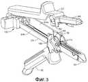
На фиг. 3 представлено изометрическое изображение аппарата для наложения скобок в исходном открытом положении.In FIG. 3 is an isometric view of an apparatus for applying brackets in the initial open position.
На фиг. 4 представлено изометрическое изображение вида снизу верхней губки многоразового применения аппарата для наложения скобок.In FIG. 4 is an isometric view of a bottom view of a reusable upper lip of the apparatus for applying brackets.
На фиг. 5 представлено изометрическое изображение вида сверху верхней губки аппарата для наложения скобок.In FIG. 5 is an isometric view of a top view of the upper lip of the apparatus for applying brackets.
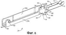
На фиг. 6 представлено изометрическое изображение нижней губки многоразового применения аппарата для наложения скобок, включающей желоб для картриджа со скобками.In FIG. 6 is an isometric view of a lower reusable sponge apparatus for applying brackets, including a cartridge groove with brackets.
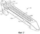
На фиг. 7 представлено изометрическое изображение картриджа одноразового использования аппарата для наложения скобок.In FIG. 7 is an isometric view of a disposable cartridge for brackets.
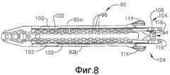
На фиг. 8 представлено изометрическое изображение вида снизу картриджа одноразового использования аппарата для наложения скобок.In FIG. 8 is an isometric view of a bottom view of a disposable cartridge of a bracketing apparatus.
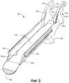
На фиг. 9 представлено изометрическое изображение фиксирующего механизма многоразового применения.In FIG. 9 is an isometric view of a reusable locking mechanism.
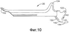
На фиг. 10 представлен вид спереди фиксирующего механизма многоразового применения.In FIG. 10 is a front view of a reusable locking mechanism.
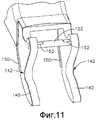
На фиг. 11 представлено детальное изометрическое изображение дистального конца фиксирующего механизма.In FIG. 11 is a detailed isometric view of the distal end of the locking mechanism.
На фиг. 12 представлен фрагмент вида спереди аппарата для наложения скобок, демонстрирующий фиксирующий механизм в готовом для сборки виде.In FIG. 12 is a fragment of a front view of the apparatus for applying brackets, showing the locking mechanism in a ready-to-assemble form.
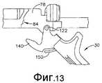
На фиг. 13 представлен фрагмент вида спереди аппарата для наложения скобок, демонстрирующий фиксирующий механизм в частично собранном положении.In FIG. 13 is a fragment of a front view of the apparatus for applying brackets, showing the locking mechanism in a partially assembled position.
На фиг. 14 представлен фрагмент вида спереди аппарата для наложения скобок, демонстрирующий фиксирующий механизм в повернутом и частично закрытом фиксированном положении.In FIG. 14 is a fragment of a front view of the apparatus for applying brackets, showing the locking mechanism in a rotated and partially closed fixed position.
На фиг. 15 представлен фрагмент вида спереди аппарата для наложения скобок, демонстрирующий взаимное расположение фиксирующего механизма и верхней губки в позиции, предшествующей закрытому фиксированному положению.In FIG. 15 is a fragment of a front view of the apparatus for applying brackets, showing the relative position of the locking mechanism and the upper jaw in the position preceding the closed fixed position.
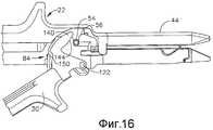
На фиг. 16 представлен фрагмент вида спереди аппарата для наложения скобок, демонстрирующий взаимное расположение фиксирующего механизма и верхней губки в исходном открытом положении в процессе использования.In FIG. 16 is a fragment of a front view of the apparatus for applying brackets, showing the relative position of the locking mechanism and the upper jaw in its original open position during use.
На фиг. 17 представлено изометрическое изображение пускового модуля одноразового использования.In FIG. 17 is an isometric view of a disposable launcher.
На фиг. 18 представлено другое изометрическое изображение пускового модуля одноразового использования, вид спереди, в направлении от проксимального к дистальному концу.In FIG. 18 is another perspective view of a disposable launch module, front view, in the direction from the proximal to the distal end.
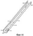
На фиг. 19 представлено изометрическое изображение поддона пускового модуля.In FIG. 19 is an isometric view of a tray of a launch module.
На фиг. 20 представлено детальное изометрическое изображение проксимального конца пускового модуля.In FIG. 20 is a detailed isometric view of the proximal end of the launch module.
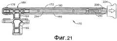
На фиг. 21 представлен вид сверху пускового модуля.In FIG. 21 is a top view of a launch module.
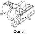
На фиг. 22 представлено изометрическое изображение пусковой рукоятки.In FIG. 22 is an isometric view of the trigger handle.
На фиг. 23 представлено изометрическое изображение направляющего блока.In FIG. 23 is an isometric view of a guide block.
На фиг. 24 представлено изометрическое изображение исполнительного механизма.In FIG. 24 is an isometric view of an actuator.
На фиг. 25 представлено изометрическое изображение опорной планки ножа.In FIG. 25 is an isometric view of a knife support bar.
На фиг. 26 представлено приближенное изометрическое изображение дистального конца пускового модуля, демонстрирующее предохранительную насадку.In FIG. 26 is an approximate isometric view of the distal end of the launch module, showing a safety nozzle.
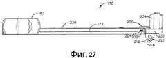
На фиг. 27 представлен вид спереди пускового модуля.In FIG. 27 is a front view of a launch module.
На фиг. 28 представлен вид проксимального конца пускового модуля в разрезе, демонстрирующий взаимное расположение пусковой рукоятки и стопорной пружины в крайнем заднем положении.In FIG. 28 is a cross-sectional view of the proximal end of the launch module, showing the relative position of the launch handle and the lock spring in the rearmost position.
На фиг. 29 представлен вид проксимального конца пускового модуля в разрезе, демонстрирующий положение пусковой рукоятки, выдвинутой вперед в процессе выталкивания скобки.In FIG. 29 is a sectional view of the proximal end of the launch module, showing the position of the trigger handle extended forward in the process of ejecting the bracket.
ПОДРОБНОЕ ОПИСАНИЕ ИЗОБРЕТЕНИЯDETAILED DESCRIPTION OF THE INVENTION
Обратимся теперь к сопровождающим заявку чертежам, на которых сходные элементы имеют сходные цифровые обозначения. На фиг. 1-3 схематически изображен первый образец хирургического аппарата для наложения скобок 20, разработанного в соответствии с настоящим изобретением. Корпус аппарата для наложения скобок 20 содержит верхнюю губку 22, нижнюю губку 24 и фиксирующий механизм 30. Соединяющий механизм 30 может поворачиваться относительно верхней и нижней губок 22, 24, как показано на фиг. 2-3. Соединяющий механизм 30 может поворачиваться, принимая серию положений с целью фиксации аппарата для наложения скобок в закрытом фиксированном положении или в различных видах исходных открытых положений, позволяющих изменять положение ткани внутри аппарата для наложения скобок, осуществлять замену картриджа или разборку аппарата для наложения скобок. По завершении хирургического вмешательства, фиксирующий механизм 30 может быть повернут до положения полного открытия, позволяющего выполнить разборку аппарата для наложения скобок 20 для его подготовки к повторной стерилизации и повторному использованию его частей.We now turn to the accompanying drawings, in which similar elements have similar numeric designations. In FIG. 1-3, a first example of a surgical apparatus for applying
Как показано на фиг. 4 и 5, верхняя губка 22 выполнена в виде цельной конструкции с желобом и противолежащими боковыми стенками 32a, 32b, соединенными между собой с помощью верхней стенки 36. На наружной поверхности верхней стенке 36 придана соответствующая форма, которая способствует удобному захвату рукой, и включает верхний выступ рукоятки 40, облегчающей удержание и работу хирурга с аппаратом для наложения скобок. Дистальный конец верхней губки 22 имеет пару направленных вовнутрь бортов 42, формирующих упорную пластину 44 аппарата для наложения скобок. Борта 42 разделены центральной продольной прорезью 46, которая расположена вдоль упорной пластины 44. Внутренняя поверхность каждого из бортов 42 имеет два продольных ряда равномерно распределенных карманов 50, предназначенных для формирования скобок. Карманы 50 необходимы для придания B-образной формы U-образным скобкам в момент их выталкивания в направлении бортов упорной пластины при срабатывании. Упорная пластина 44 имеет конический наконечник на дистальном конце, облегчающий введение аппарата для наложения скобок в полые органы пациента. Пара тканевых стопоров 52 расположена на противоположных сторонах относительно упорной пластины 44 вблизи проксимального конца формирующих скобки карманов 50. Тканевые стопоры 52 расположены сбоку в одном направлении с проксимальным концом формирующих скобки карманов 50, что предотвращает попадание тканей за пределы упорной пластины 44 аппарата для наложения скобок. Блокирование ткани у проксимального конца упорной пластины 44 предотвращает защемление или разрезание несшитых участков ткани.As shown in FIG. 4 and 5, the
Цилиндрические штифты 54 отходят от противоположных сторон верхней губки 22 за пределы тканевых стопоров 52. Штифты 54 входят в вертикальные прорези, расположенные на нижней губке 24, и служат для соединения верхней и нижней губок. Верхняя губка 22 также имеет пару изогнутых бороздок 60, расположенных вблизи проксимального конца боковых стенок желоба 32a, 32b. Бороздки 60 взаимодействуют с выступами 62 на нижней губке 24, как показано на фиг. 2, обеспечивая быстрое выравнивание губок при работе аппарата для наложения скобок. Верхняя губка 22 должна предпочтительно изготавливаться из цельного куска биосовместимого металла, например, из нержавеющей стали. Использование цельного куска материала для изготовления верхней губки 22 увеличивает конструкционную целостность аппарата для наложения скобок. В качестве альтернативного варианта верхняя губка 22 может состоять из двух или трех частей, которые соединяются вместе в процессе изготовления при помощи известных методов соединения, например, при помощи сварки.The cylindrical pins 54 extend from opposite sides of the
Как показано на фиг. 6, нижняя губка 24 выполнена из цельного куска материала в виде удлиненной рамки U-образной формы, имеющей пару боковых стенок 64a и 64b, соединенных с помощью нижней стенки 66. На дистальном конце нижней губки 24 боковые стенки 64a и 64b уменьшаются и образуют желоб для картриджа 70, предназначенный для размещения картриджа одноразового использования в аппарате для наложения скобок. Бороздки 72 размещаются на боковых стенках 64a и 64b вблизи дистального конца желоба для картриджа 70. Бороздки 72 взаимодействуют с боковыми выступами на картридже, что необходимо для удержания картриджа внутри желоба. Прорези для выравнивания по вертикали 56 располагаются проксимально от желоба для картриджа 70 у верхнего края боковых стенок 64a и 64b. Как было сказано ранее, штифты 54 на верхней губке 22 взаимодействуют с прорезями для выравнивания 56 для достижения взаимного выравнивания и соединения зажимов аппарата для наложения скобок. Расстояние между боковыми стенками 32a и 32b верхней губки несколько больше, чем расстояние между боковыми стенками 64a и 64b нижней губки, что позволяет верхней губке располагаться поверх нижней, когда штифты 54 вставляются в выравнивающие прорези 56, а выступы 62 - в бороздки 60. Вырезы 74 расположены на наружной поверхности боковых стенок 64a и 64b дистальнее выравнивающих прорезей 56. Вырезы 74 облегчают присоединение исполнительного механизма к нижней губке 24, как подробно описано ниже.As shown in FIG. 6, the
Просвет 76 образуется в нижней стенке 66 в средней части нижней губки 24. Боковые стенки 64a и 64b продлены по направлению вниз по противоположным сторонам просвета 76 с образованием наклоненных в дистальном направлении выступов 80. Направленные вдоль дистальных краевых выступов 80 боковые стенки 64a и 64b образуют прямоугольный вырез 82, имеющий закругленный конец 88. Диаметр закругленного конца 88 несколько превышает ширину прорези 82. Проксимальнее выступов 80 на наружных поверхностях боковых стенок 64a и 64b расположено приспособление для позиционирования стопорного элемента. Как показано на фиг. 6, такое приспособление может включать несколько стопорных выступов 84 либо иных неровностей, нанесенных на поверхности боковых стенок 64a и 64b машинным способом. Несмотря на то, что на фиг. 6 изображено лишь приспособление, расположенное на передней стороне нижней губки 24, необходимо понимать, что задняя сторона нижней губки имеет аналогичный профиль, поэтому стопорный элемент 30 может фиксироваться в нескольких положениях с помощью обеих сторон нижней губки, как описано ниже. Удерживающий элемент 86 расположен на проксимальном конце нижней губки 24 в месте соединения боковых стенок 64a и 64b и нижней стенки 66. Удерживающий элемент 86 может содержать участки продолжающихся во внутреннем направлении боковых стенок 64a и 64b, которые способствуют защелкиванию исполнительного модуля в процессе сборки аппарата для наложения скобок 20.A
На фиг. 7 и 8 показан пример съемного картриджа 90, используемого в аппарате для наложения скобок 20, разработанном в соответствии с положениями настоящего изобретения. Картридж 90 приспособлен для размещения хирургических скобок, сгруппированных в по меньшей мере два продольных ряда, размещенных рядом друг с другом. Картридж 90 имеет корпус, который имеет противолежащие боковые стенки 92a, 92b, а также имеет конфигурацию, обеспечивающую его скольжение по желобу нижней губки 70. Картридж 90 разделен в продольном направлении центральной продольной прорезью 94, которая расположена от проксимального конца картриджа до дистального конца. Отверстия 96 в корпусе картриджа распределены вдоль продольной прорези 94. В показанном варианте реализации отверстия для скобок выполнены в виде двух расположенных рядом перемежающихся рядов, в которых каждая пара рядов размещается на противоположных от центральной продольной прорези 94 сторонах. Отверстия для скобок в соседних рядах перемежаются, что обеспечивает более эффективное сшивание тканей при работе аппарата для наложения скобок. Как показано на фиг. 8, картридж 90 имеет пару продольных прорезей 100, расположенных на противоположных сторонах от центральной продольной прорези 94, между перемежающимися рядами отверстий 96. Каждая из продольных прорезей 100 расположена в направлении от проксимального конца картриджа 90 к дистальному концу. Направляющие для скобок (не показаны) вставлены в отверстия для скобок 96 для выталкивания скобок, заряженных в картридж 90. Каждая направляющая для скобок выполнена таким образом, что она одновременно способна выталкивать две скобки, расположенные в смежных рядах картриджа 90. Таким образом, первый комплект направляющих для скобок предназначен для выталкивания скобок из перемежающихся рядов, расположенных на одной стороне от центральной продольной прорези 94, а второй комплект направляющих для скобок предназначен для выталкивания скобок из пары смежных рядов, расположенных на другой стороне от центральной продольной прорези.In FIG. 7 and 8 show an example of a
На дистальном конце картриджа 90 имеется конический наконечник, облегчающий введение нижней губки 24 аппарата для наложения скобок в полые трубчатые органы пациента. Проксимальнее конического наконечника в картридже 90 размещена пара выступающих наружу частей 102. Пара отстоящих параллельных бортов 104 проходит в заднем направлении от противоположных сторон картриджа 90. Ножки 110 являются продолжением бортов 104, идущих вниз, на проксимальном конце картриджа аппарата для наложения скобок. Каждая из ножек 110 имеет закругленный паз 112, расположенный наружной стороной вниз. При вставке картриджа 90 в нижнюю губку 24 выступающие части 102 свободно входят в бороздки 72 боковых стенок нижней губки, а ножки 110 проходят через прорези 76 в нижней стенке нижней губки 66 аппарата для наложения скобок. Пазы ножек 112 взаимодействуют со штифтами на фиксирующем механизме 30, как описано ниже, для удержания картриджа в желобе нижней губки 70. Пара створок 114 расположена по направлению вверх и наружу относительно боковых стенок 92a и 92b на проксимальном конце картриджа 90. Створки 114 служат для захвата аппарата для наложения скобок рукой, облегчая установку картриджа 90 вручную и его извлечение из нижней губки 24. При помощи створок 114 картридж 90 может быть извлечен из просвета 76 и бороздок 72 и вынут из нижней губки 24 аппарата для наложения скобок после использования. Кроме того, створки 114 взаимодействуют с боковыми стенками нижней губки 64a и 64b на проксимальном конце желоба для картриджа 70, как показано на фиг. 3, для фиксирования картриджа на нижней губке 24. Короткий расширенный участок 116 расположен позади картриджа 90, между выступающими в заднем направлении ножками 110. Центральная прорезь для ножа 94 расположена продольно, проходя через расширенный участок 116, и может снабжаться с противоположных сторон наклоненными вовнутрь направляющими поверхностями на проксимальном конце прорези. Запирающий штифт 106 соединен с одного конца с расширенным участком 116 и может вращаться вокруг точки соединения. Изначально, когда картридж 90 устанавливается в аппарат для наложения скобок 20, запирающий штифт 106 расположен поперек центральной прорези для ножа 94.At the distal end of the
Как было сказано выше, аппарат для наложения скобок 20 имеет фиксирующий механизм 30, предназначенный для соединения верхней и нижней губок в средней части длины аппарата для наложения скобок. Предпочтительно, чтобы губки 22 и 24 соединялись в точке, прилегающей к проксимальному концу упорной пластины 44 и картриджа 90 аппарата для наложения скобок. В предпочтительном варианте реализации, изображенном на фиг. 9, фиксирующий механизм 30 представляет собой цельную конструкцию. Рамка в форме желоба имеет противоположные боковые стенки 124a и 124b, соединенные верхней стенкой 130. Соединяющий механизм 30 также содержит затворный штифт 122 для шарнирного соединения механизма с нижней губкой 24. Предпочтительно, чтобы фиксирующий механизм состоял из цельного куска нержавеющей стали или другого биосовместимого металла. Расстояние между противоположными боковыми стенками 124a и 124b фиксирующего механизма превышает расстояние между боковыми стенками 64a и 64b нижней губки 24 аппарата для наложения скобок. Боковые стенки 124a и 124b имеют направленные наружу удлиненные выступы 132, предназначенные для захвата рукой и поворота рукоятки фиксирующего механизма 120 для переключения положений аппарата. Наружная поверхность рукоятки фиксирующего механизма 120 имеет расширенную часть 134. При соединении с нижней губкой 24 расширенная часть 134 скрепляется с верхней губкой 40, формируя рукоятку, позволяющую хирургу осуществлять манипуляции с аппаратом для наложения скобок.As mentioned above, the apparatus for applying
Каждая из боковых стенок 124a и 124b фиксирующего механизма 30 включает удлиненный в дистальном направлении C-образный крючок 140, имеющий обращенный вперед вырез 142, предназначенный для взаимодействия со штифтом верхней губки 54. Как показано на фиг. 9 и 10, крючки 140 имеют внутреннюю поверхность 144, направленную назад от кончика крючка до прорези 142. Когда фиксирующий механизм 30 перемещается в закрытое фиксированное положение, прорези 142 вступают во взаимодействие со штифтами верхней губки 54, что обеспечивает удержание фиксирующего механизма в закрытом фиксированном положении. Ниже прорезей 142 каждый из крючков 140 расположен в дистальном направлении вниз за пределы верхней стенки 130. Затворный штифт 122 расположен между нижними загнутыми концами крючков 140, как показано на фиг. 11, поперек конца фиксирующего механизма 30. Затворный штифт 122 имеет цилиндрическую форму с плоскими поверхностями 152, прилегающими друг к другу. Диаметр затворного штифта 122 больше диаметра узкого отверстия прорези нижней губки 82. Затворный элемент 30 свободно подсоединяется к нижней губке 24 при помощи штифта 122, вставляемого в прорезь нижней губки 82. Затворный штифт 122 вставляется в прорезь 82 путем ориентирования фиксирующего механизма 30 таким образом, что плоские концы 152 становятся параллельными прямым сторонам прорези. В таком положении затворный штифт 122 может вставляться в прорезь 82 даже несмотря на то, что диаметр штифта превышает ширину прорези. При выравнивании плоских концов 152 относительно линейных сторон прорези 82 затворный штифт 122 вставляется в прорезь, как показано на фиг. 12, до тех пор, пока штифт не займет положение в округлом конце прорези 88, как показано на фиг. 13.Each of the
Аппарат для наложения скобок 20 также имеет другие средства удержания фиксирующего механизма при изменении его положений. Как показано на фиг. 9 и 10, другие средства включают пружинный рычаг 150, расположенный от верхнего края каждой из боковых стенок рукояток фиксирующего механизма 124a и 124b. Пружинный рычаг 150 изгибается вверх в дистальном направлении, повторяя верхний профиль крючка 140, и имеет конец в форме луковицы. С затворным штифтом 122, установленным в прорезь 82 и отклоненным в дистальном положении фиксирующим механизмом 30, как показано на фиг. 13, аппарат для наложения скобок 20 находится в исходном открытом положении. Для того чтобы закрыть аппарат для наложения скобок 20, защелкивающийся фиксирующий механизм 30 поворачивается в направлении проксимального конца аппарата для наложения скобок для приведения затворного элемента в положение, ближайшее к телу нижней губки 24. При отклонении плоского конца 152 от линии выравнивания со сторонами прорези 82 зазор по ширине между штифтом 122 и прорезью 82 предотвращает выскальзывание штифта из прорези 88. Таким образом, штифт 122 фиксируется в прорези 88, прикрепляя защелкивающийся фиксирующий механизм 30 к нижней губке 24.The apparatus for applying
При повороте защелкивающегося фиксирующего механизма 30 крючки 140 располагаются вдоль сторон нижней губки 24. При перемещении крючков 140 вдоль боковых стенок нижней губки 64a и 64b концы пружинных рычагов 150 в виде луковиц приходят в соприкосновение со стопорными выступами 84 на боковых стенках. Для продвижения пружинных рычагов 150 между стопорными выступами к защелкивающемуся фиксирующему механизму прикладывается дополнительное усилие, что вызывает сгибание пружинных рычагов в направлении крючков 140, чтобы концы пружинных рычагов могли продвигаться, минуя выступы. Когда пружинные рычаги 150 располагаются между стопорными выступами 84, как показано на фиг. 14, защелкивающийся фиксирующий механизм 30 оказывается в частично закрытом фиксированном положении. В частично закрытом фиксированном положении механизм 30 присоединен к нижней губке 24, и выравнивающие прорези 56 располагаются на расстоянии от кончиков крючков 140. Штифты верхней губки 54 могут свободно вставляться или извлекаться из прорезей 56 нижней губки, обеспечивая, соответственно, соединение или разъединение верхней и нижней губок аппарата для наложения скобок.When the
Если затворный штифт 122 продолжает вращение в прорези 88, подводя защелкивающийся фиксирующий механизм 30 ближе к нижней губке 24, внутренние поверхности крючков 144 поворачиваются, перекрывая просвет выравнивающих прорезей 56, блокируя прорези и штифты верхней губки 54 внутри прорезей. Пружинные рычаги 150 также движутся вдоль стопорных выступов 84, соприкасаясь с вогнутым наружным краем верхнего выступа. В таком предварительно замкнутом положении, изображенном на фиг. 15, фиксирующий механизм 30 и верхняя и нижняя губки 22 и 24 соединяются, образуя тело аппарата для наложения скобок 20, при этом штифты верхней губки 54 могут скользить внутри прорезей 56, между дном прорези и наклоненной поверхностью 144, обеспечивая перемещение губок относительно друг друга. Защелкивающийся фиксирующий механизм 30 поддерживает губки в неплотно замкнутом положении, обеспечивая взаимные перемещения картриджа и упорной пластины. Относительные перемещения дистальных концов губок 22 и 24 дают возможность осуществлять подгонку аппарата при захватывании ткани без необходимости отсоединения губок друг от друга.If the
Когда защелкивающийся фиксирующий механизм 30 находится в закрытом рабочем положении (показано на фиг. 1), механизм обхватывает нижнюю губку 24, при этом штифты 54 на верхней губке 22 находятся в прорезях 142. Пружинные рычаги 150 продвигаются вверх в дистальном направлении, вдоль сторон нижней губки 24, минуя стопорные выступы 84. В этом положении верхняя и нижняя губки смыкаются, сжимая ткань поверхностями упорной пластины и картриджа, а аппарат для наложения скобок готов к сшиванию и отрезанию ткани. В закрытом фиксированном положении между упорной пластиной и поверхностью картриджа сохраняется минимальное расстояние, что достигается за счет наличия штифта 160. Для корректировки положения ткани между поверхностями упорной пластины и картриджа фиксирующий механизм 30 можно вернуть назад в предварительно замкнутое положение, как показано на фиг. 16, с целью извлечения штифтов 54 из прорезей крючка 142. При вращении затворного элемента 30 в обратном направлении пружинные рычаги 150 вновь вступают в контакт со стопорными бугорками 84 с целью удержания соединительного механизма на соответствующем месте. Возвращение в положение, непосредственно предшествующее закрытому фиксированному положению аппарата для наложения скобок, ослабляет соединение крючков 140 и штифтов 52, что позволяет штифтам скользить внутри прорезей 56 без необходимости отсоединения губок друг от друга.When the
Для разборки аппарата для наложения скобок 20 соединительный механизм 30 поворачивается в сторону, противоположную нижней губки 24, а штифты верхней губки 54 вынимаются из прорезей крючков 142. Соединительный механизм 30 может быть повернут в сторону, противоположную верхней и нижней губкам 22 и 24 путем оттягивания кончиков губки фиксирующего механизма 162. Так как на рукоятку фиксирующего механизма 120 продолжает действовать усилие, препятствующее ее вращению, пружинные рычаги 150 проходят через стопорные выступы 84, позволяя крючкам 140 отклоняться вперед, перемещаясь между боковыми стенками нижней губки 64a и 64b. Соединяющий механизм 30 поворачивается в направлении картриджа 90 до тех пор, пока фиксирующий механизм 30 не оказывается в исходном открытом положении, показанном на фиг. 13. При переводе фиксирующего механизма 30 в открытое положение плоские концы 152 затворного штифта 122 вновь оказываются параллельными прямым краям прорези 82, давая возможность извлечения затворного штифта через прорезь 82 и отсоединения соединительного механизма от нижней губки 24. При отсоединении соединительного механизма 30 аппарат для наложения скобок 20 может быть разобран на три цельных компонента: верхнюю губку 22, нижнюю губку 24 и соединительный механизм 30. Цельная конструкция этих компонентов многоразового применения (с желобами) обеспечивает возможность легкой тщательной обработки и стерилизации этих компонентов в промежутках между использованием.To disassemble the apparatus for applying
Обратимся теперь к фиг. 17 и 18, на которых изображен исполнительный модуль 170, предназначенный для сшивания и разрезания ткани, зажатой между верхней и нижней губками 22 и 24. Исполнительный модуль 170 содержит U-образный продолговатый поддон 172, обеспечивающий поддержку компонентов исполнительного модуля. Поддон модуля 172 имеет пару боковых стенок 174, соединенных при помощи нижней стенки 176 (фиг. 19). Расстояние между стенками 174 поддона модуля меньше расстояния между боковыми стенками 64a и 64b нижней губки аппарата, что позволяет поддону модуля входить и закрепляться в проксимальном желобе нижней губке 24. Как показано на фиг. 19 и 20, проксимальный конец поддона модуля 170 включает один или несколько стопорных выступов 178, расположенных на наружной поверхности боковых стенок 174. При перемещении исполнительного модуля 170 в дистальном направлении в желобе нижней губки, стопорные выступы 178 взаимодействуют с удерживающими элементами 86 на внутренней поверхности желоба нижней губки 24. Взаимодействие стопорных выступов 178 с удерживающими элементами 86 позволяет захватить и удерживать исполнительный модуль внутри нижней губки 24.Turning now to FIG. 17 and 18, depicting an
Как показано на фиг. 21, внутри поддона пускового модуля 172 расположено несколько двигающихся исполнительных механизмов, что предназначено для осуществления продольных движений внутри поддона по отношению к верхней и нижней губкам 22 и 24. Исполнительные элементы включают блок толкателя 180, расположенный внутри поддона модуля 172 и обеспечивающий возвратно-поступательные движения вдоль поддона. Блок толкателя 180 присоединен к рукоятке исполнительного механизма 182 с помощью бокового фланца 184. Если исполнительный модуль 170 установлен внутри нижней губки 24, как показано на фиг. 3, фланец 184 проходит через удлиненный направляющий паз 186, сформированный в боковой стенке 64 нижней губки аппарата для наложения скобок. Фланец 184 позволяет разместить рукоятку исполнительного механизма 182 на внешней стороне губок 22 и 24, упрощая доступ к ней хирурга. На фиг. 3 показано, что рукоятка 182 проходит через направляющий паз по боковой стенке 186 нижней губки 64b. Направляющий паз может также располагаться на противоположной боковой стенке нижней губке 64a, в этом случае рукоятка исполнительного механизма 182 выступает с противоположной стороны аппарата для наложения скобок 20. Когда хирург двигает рукоятку 182 по наружным поверхностям губок 22 и 24, фланец 184 проходит через направляющий паз 186.As shown in FIG. 21, several moving actuators are located inside the pallet of the
Обратимся к фиг. 21. Исполнительный модуль 170 также содержит пару толкателей 190, расположенных по длине параллельно друг другу. Проксимальные концы толкателей 190 закреплены в боковых прорезях толкателя 192 (как показано на фиг. 22), что позволяет им перемещаться в продольном направлении вместе с блоком толкателя 180 внутри поддона модуля 172. Толкатели 190 расположены на расстоянии от блока толкателя 180 и во время перемещения заходят в продольные пазы 194, размещенные в направляющем блоке 200, как показано на фиг. 23. Как показано на фиг. 18, направляющий блок 200 закреплен на дистальном конце поддона модуля 172. Верхние края боковых стенок поддона модуля 174 загнуты вовнутрь. Они нависают над боковыми краями направляющего блока 200, что удерживает направляющий блок внутри поддона модуля. Кроме того, петли 202, отходящие от направляющего блока 200 по сторонам через отверстия 204 на боковых стенках модуля 174, закрепляют направляющий блок в поддоне. Дистальный конец направляющего блока 200 находится за пределами поддона модуля 172, между задними фланцами 104 картриджа 90 аппарата для наложения скобок. Боковые прорези 194 направляющего блока 200 выравнивают толкатели 190 с продольными прорезями 100 направляющих для скобок картриджа аппарата для наложения скобок 90. Дистальные концы толкателей 190 находятся впереди направляющих пазов 194 и имеют заостренный скошенный конец 206, как показано на фиг. 24, образующую наклоненную поверхность, предназначенную для захвата направляющих для скобок внутри картриджа 90 в процессе движения толкателей через картридж в дистальном направлении. Продольные движения концов толкателей 206 приводят в действие направляющие для скобок и, следовательно, вызывают выталкивание скобок из картриджа.Turning to FIG. 21. The
Обратимся к фиг. 23. Направляющий блок 200 включает центральную секцию 210, проходящую через отверстие 76 вниз в нижней стенке нижней губки 66. Центральная секция 210 включает наклоненную с дистального конца прямую прорезь 212, имеющую закругленный конец 218. Когда аппарат для наложения скобок 20 собран, прорезь направляющего блока 212 выровнена по длине с прорезью 82 в боковых стенках 64a и 64b нижней губки аппарата для наложения скобок, что позволяет стопорному штифту 122 взаимодействовать как с нижней губкой 24, так и с направляющим блоком 200, если фиксирующий механизм 30 установлен в аппарат для наложения скобок. При введении затворного штифта 122 в прорезь 82 и конец прорези 88 штифт также проходит через прорезь направляющего блока 212 и размещается в прорези закругленного конца 218, фиксируя исполнительный модуль 170 и нижнюю губку 24 друг с другом.Turning to FIG. 23. The
Как показано на фиг. 18 и 21, исполнительный модуль 170 также включает опорную планку ножа 214, расположенную между толкателями 190. Опорная планка ножа 214 и толкатели 190 предпочтительно должны быть изготовлены из листового металла. Проксимальный конец опорной планки ножа 214 закрепляется внутри центральной прорези 216 блока толкателя 180 (фиг. 22) для присоединения опорной планки ножа к блоку толкателя с целью обеспечения возможности приведения в движение с помощью рукоятки исполнительного механизма 182. На дистальном конце блока толкателя 180 опорная планка ножа 214 входит в центральную прорезь 220 направляющего блока 200 (как показано на фиг. 23) с целью выравнивания опорной планки ножа с продольной центральной прорезью 94 картриджа. Как показано на фиг. 25, наклоненное лезвие ножа 222, имеющего скошенную режущую кромку, расположено у переднего конца опорной планки ножа 214. Скошенная режущая кромка лезвия ножа 222 ориентирована под углом к губкам 22 и 24 и вставлена в центральную продольную прорезь 220 направляющего блока 200. На проксимальном конце лезвия ножа 222 опорная планка ножа 214 имеет вырез для фиксирования его на картридже 228, а также секцию предохранителя 224, которая является частью защитного запорного механизма, как описано ниже. Проксимальный конец опорной планки ножа 214 имеет ступенчатое сечение, показанное под номером 226. Ступенчатое сечение ножа 226 формируется за счет вырезания участка опорной планки ножа 214 на проксимальном конце с образованием выступающих точек 230 и 232 опорной планки.As shown in FIG. 18 and 21, the
Как показано на фиг. 26 и 27, предохранительная насадка 234 прикрывает дистальный конец направляющего блока 200. Центральная секция 236 насадки 234 окружает лезвие ножа 222 и клиновидные концы 206 толкателей 190. Направленный внутрь край 240 расположен вдоль нижней кромки насадки. В процессе сборки для фиксации дистального конца исполнительного модуля внутри желоба нижней губки необходимо давить на предохранительную насадку 234. При надавливании на предохранительную насадку 234 край 240 входит в углубления 74 на наружной поверхности нижней губки 24.As shown in FIG. 26 and 27, the
Пластинчатая пружина 250, показанная на фиг. 19, является частью нижней стенки поддона модуля 176 и расположена снизу направляющего блока 200. Пружина 250 является частью предохранительного механизма, предотвращающего выталкивание скоб из использованного картриджа, что достигается путем поднятия предохранителя опорной планки ножа 224 в упор к направляющему блоку 200. Вторая пружина 252 является частью нижней стенки поддона модуля 176 и расположена вблизи проксимального конца поддона. Вторая пружина 252 является стопорной пружиной, взаимодействующей с вырезом на исполнительном блоке 180 и предотвращающей движение рукоятки исполнительного модуля 182 во время транспортировки, а также дающей возможность на слух и тактильно определять момент, когда пусковая рукоятка возвращается в наиболее проксимальное положение внутри поддона после выталкивания скобки. На фиг. 28 и 29 более подробно иллюстрируется работа стопорной пружины 252. На фиг. 28 пружина 252 показана во взаимодействии с вырезом 254 на исполнительном блоке 180 с целью предотвращения нежелательного движения исполнительного блока в дистальном направлении. На фиг. 29 показана стопорная пружина 252, вышедшая из выреза 254 после приложения направленного усилия к рукоятке исполнительного блока 182. Толкатели 190 и опорная планка ножа 214 продвигаются в дистальном направлении после приложения усилия к пусковой рукоятке 182, достаточного для преодоления силы сопротивления пружины 252, оказываемого на вырез 254. После отсоединения пружины 252 от выреза 254 исполнительный блок 180 может продвигаться в дистальном направлении по поддону 172, сначала продвигая толкатели 190, а затем опорную планку ножа 214 из направляющего блока 200 в картридж 90.The
В начальном положении срабатывания, показанном на фиг. 28, направленный вниз край исполнительного блока 180 входит в контакт с опорной планкой ножа 214 в проксимальной конечной точке 232 ступенчатого выреза 226. Рукоятка пускового механизма 182 оттягивается в крайнее положение направляющего паза 186, размещая, таким образом, толкатели 190 и лезвие ножа 222 в прорезях 194 и 220 в направляющем блоке 200. В момент приложения к рукоятке пускового механизма 182 дистально направленного усилия пружина 252 отсоединяется от выреза 254, позволяя блоку пускового механизма 180 двигаться вдоль поддона модуля 172. При движении исполнительного блока 180, он смещает толкатели 190 в дистальном направлении, заставляя клиновидные концы толкателей входить в продольные прорези 100 направляющих для скобок картриджа. При начальных движениях исполнительного блока 180 дистальный край блока продвигается сквозь ступенчатый вырез опорной планки ножа 226, как показано на фиг. 29, при этом непосредственного контакта с самой опорной планкой не происходит. Таким образом, опорная планка ножа 214 остается неподвижной при начальном дистальном продвижении толкателей 190 и блока 180.In the initial actuation position shown in FIG. 28, the downward-facing edge of the
После того как исполнительный блок 180 минует ступенчатый вырез опорной планки ножа 226, дистальный край блока вступает в контакт с дистальной конечной точкой 230 опорной планки ножа 214. Такой контакт между исполнительным блоком 180 и опорной планкой ножа 214 заставляет опорную планку ножа двигаться вместе с исполнительным блоком и толкателями 190 по мере того, как продвигается рукоятка 182. По мере продвижения опорной планки ножа 214 лезвие ножа 222 направляется по центральной прорези 220 и задней расширенной части картриджа 116 в центральную продольную прорезь 94 картриджа 90 и центральную продольную прорезь 46 упорной пластины 44. По мере продвижения лезвия ножа 222 через расширенную часть картриджа 116 лезвие отклоняет запирающий штифт 106, освобождая путь для двигающейся опорной планки ножа. Лезвие ножа 222 и концы толкателей 206 одновременно движутся через картридж аппарата для наложения скобок 90, выталкивая скобки из отверстий 96 и разрезая ткань. Лезвие ножа 222 продвигается в картридж 90, располагаясь несколько позади толкателей 190, а скобки проникают в ткань, зажатую между упорной пластиной и картриджем до того, как лезвие ножа приблизится и отрежет ткань между рядами скобок.After the
После того, как с помощью рукоятки 182 нож и толкатели были продвинуты до упора (или до необходимого положения), исполнительный блок 180 отводится в поддоне модуля 172 в исходное положение за счет отведения рукоятки исполнительного механизма назад в проксимальном направлении через направляющий паз нижней губки 186. Изначально, в то время как исполнительный блок 180 и толкатели 190 оттягиваются в проксимальном направлении, опорная планка ножа 214, благодаря наличию ступенчатого выреза 226 опорной планки, остается неподвижной в дистальном положении. Как только дистальный край исполнительного блока снова вступает в контакт с проксимальной конечной точкой 232 ступенчатого выреза, опорная планка ножа 214 начинает возвращаться в проксимальном положении вместе с исполнительным блоком и толкателями. По мере осуществления обратного движения опорной планки ножа 214 в направляющем блоке 200, она поднимается вверх при помощи пластинчатой пружины 250, входя в контакт с направляющим блоком до тех пор, пока предохранитель 224 не захватит центральную подпорку 256 (фиг. 23) направляющего блока. Как только предохранитель 224 захватывает центральную подпорку направляющего блока 256, опорная планка ножа 214 уже не может осуществлять движений относительно исполнительного блока 180. В предпочтительном варианте осуществления опорная планка ножа 214 захватывает предохранитель 224 тогда, когда исполнительный блок 180 и толкатели 190 достигают крайнего проксимального положения.After using the
После полного возвращения рукоятки исполнительного механизма 182 в исходное положение, как показано на фиг. 28, фиксирующий механизм 30 поворачивается относительно губок 22 и 24, разъединяя их, как описано выше. После разъединения рукояток картридж 90 можно извлечь и вставить новый. Использованный картридж извлекается путем вытягивания за крылышки картриджа 114 и извлечения ножки картриджа 110 из просвета нижней губки 76. При извлечении проксимального конца картриджа из просвета нижней губки 76 вырезы ножек картриджа 112 (фиг. 7) выходят из контакта c затворным штифтом 122. После извлечения проксимального конца картриджа 90, можно извлечь его дистальный конец из желоба для картриджа 70 и утилизировать картридж.After the handle of the
Новый картридж 90 может быть загружен в нижнюю губку 24 путем проталкивания дистального конца картриджа с выступами в дистальном направлении желоба нижней губки 70, а также путем проталкивания нижних ножек 110 через просвет нижней губки 76 и нажатия на крылышки 114. Ножки картриджа 110 проталкиваются через просвет нижней губки 76 до тех пор, пока вырезы ножек 112 не защелкиваются, сцепляясь с затворным штифтом 122. При надавливании на проксимальный конец картриджа 90 блокирующий штифт 106 на картридже давит на опорную планку ножа 214 в районе фиксирующей прорези 228, противодействуя усилию пластинчатой пружины 250. Усилие, оказываемое на блокирующий штифт 106, толкает вырез опорной планки ножа 224 вниз, нарушая ее сцепление с центральной подпоркой направляющего блока 256. При надавливании на опорную планку ножа 214, она вновь выравнивается с центральной прорезью направляющего блока 220, что позволяет опорной планке продвинуться в дистальном направлении через прорезь и вовнутрь нового картриджа. Таким образом, в процессе перезагрузки нового картриджа происходит возврат предохранительного механизма в исходное положение. После загрузки нового картриджа аппарат для наложения скобок можно собрать вновь, при этом верхняя губка 22 размещается над нижней губкой 24, а штифты верхней губки 54 возвращаются в выравнивающие прорези 56. Блокирующие крючки 140 отводятся назад над прорезями 56 до тех пор, пока штифты 54 не войдут в прорези 142. При блокировании штифтов 54 в прорезях крючков 142 и повороте фиксирующего механизма 30 в положение вблизи нижней губки 24 аппарат для наложения скобок находится в закрытом фиксированном положении и готов к выталкиванию скобок из нового картриджа.The
Верхняя и нижняя губки и фиксирующий механизм многоразового использования, описанные выше, поставляются в нестерильной упаковке. До начала сборки аппарата для наложения скобок 20 эти компоненты должны быть очищены с помощью ферментных чистящих средств с нейтральным pH, а затем простерилизованы паром в автоклаве. Такая обработки также должна проводиться перед каждым последующим использованием аппарата для наложения скобок. Исполнительный модуль 170, в связи с наличием большого количества движущихся частей, предназначен для однократного использования у одного пациента с целью предотвращения сложной процедуры очистки модуля. Исполнительный модуль поставляется в стерильной упаковке, которую необходимо вскрывать в стерильных условиях. Картридж 90 также поставляется в стерильной упаковке, которую необходимо вскрывать в стерильных условиях.The upper and lower jaws and the reusable locking mechanism described above are supplied in non-sterile packaging. Before assembling the
Для сборки аппарата для наложения скобок 20 исполнительный модуль 170 вынимается из упаковки, и его проксимальный конец сначала вставляется в проксимальный желоб нижней губки 24. Исполнительный модуль 170 фиксируется взаимодействием проксимальных стопорных выступов 178 с удерживающими элементами 86 нижней губки. Затем дистальный конец исполнительного модуля поворачивается вниз и попадает в рамку нижней губки 24, имеющей форму желоба. Как только исполнительный модуль 170 оказывается в желобе нижней губки, предохранительная насадка 234 с усилием входит своими краями 240 в прорези 74 на боковых стенках нижней губки 64a и 64b. Давление на предохранительную насадку 234 толкает центральную секцию направляющего блока 212 через просвет 76 нижней губки, совмещая прорезь направляющего блока 212 с прорезью нижней губки 82 и блокируя исполнительный модуль внутри нижней губки 24. При загрузке исполнительного модуля 170 в нижнюю губку 24 фиксирующий механизм 30 присоединяется к нижней губке за счет введения затворного штифта 122 в прорези 82 и 212, как описано выше. Соединяющий механизм 30 поворачивается относительно нижней губки 24 в частично закрытое фиксированное положение, как показано на фиг. 14. В этом положении фиксирующий механизм 30 оказывается присоединенным к нижней губке 24, но при этом верхняя губка 22 находится отдельно от нижней. Предохранительная насадка 234 снимается с исполнительного модуля 170 движением в дистальном направлении, показанном стрелкой на насадке, как изображено на рисунках.To assemble the apparatus for applying
Затем новый картридж 90 вставляется в желоб для картриджа нижней губки 70 по инструкции, описанной выше. После того как картридж вставлен, верхняя губка 22 помещается поверх нижней губки 24, при этом штифты 54 вставляются в выравнивающие прорези 56. Соединяющий механизм 30 поворачивается относительно верхней и нижней губок 22 и 24, приводя аппарат для наложения скобок в предварительно замкнутое положение (как показано на фиг. 15), в котором внутренняя поверхность крючков 144 перекрывает просвет выравнивающих прорезей 56, блокируя штифты 54 внутри прорезей. Ткань, которую необходимо отсечь, помещается между упорной пластиной 44 и картриджем 90 и выравнивается в необходимое положение. Тканевые стопоры 52 предотвращают чрезмерно глубокое попадание тканей в механизм аппарата для наложения скобок. После должной корректировки положения ткани аппарат для наложения скобок закрывается, чтобы подготовить его к выталкиванию скобок. Перевод аппарата в закрытое фиксированное положение осуществляется путем поворота фиксирующего механизма 30 и приведения его в контакт с нижней губкой 24, чтобы разместить крючки 140 над просветами прорезей 56, а также заблокировать штифты 54 в прорезях крючков 142. В таком положении ткань оказывается зажатой внутри аппарата. Если необходима дальнейшая корректировка положения ткани, аппарат для наложения скобок может быть возвращен в предварительно замкнутое положение, как показано на фиг. 16, в котором дистальные концы верхней и нижней губок могут немного двигаться относительно друг друга, что обычно достаточно для изменения положения ткани. После того как ткань должным образом зафиксирована между губками аппарата для наложения скобок, а фиксирующий механизм 30 повернут в рабочее закрытое положение, аппарат для наложения скобок можно активировать, нажав на рукоятку исполнительного механизма 182 и отведя ее вперед по направляющему пазу 186 до конца. По мере продвижения рукоятки зажатая ткань сшивается скобами и отрезается. После того как рукоятка исполнительного механизма 182 останавливается, достигая крайнего дистального положения, необходимо отвести ее назад, в проксимальном направлении, по направляющему пазу 186. У проксимального конца пути движения рукоятки взаимодействие стопорной пружины 252 с вырезом 254 на исполнительном блоке дает возможность тактильно и на слух определять момент, когда рукоятка возвращается, сигнализируя о том, что исполнительные компоненты вышли из картриджа 90 обратно в поддон модуля 172.Then, a
В случае когда для завершения процедуры требуется дополнительное сшивание и отрезание ткани, фиксирующий механизм 30 поворачивается обратно в частично закрытое фиксированное положение так, что верхняя губка 22 может быть извлечена. При этом использованный картридж извлекается и заменяется новым. После установки нового картриджа фиксирующий механизм 30 может быть повернут назад, при этом необходимо также пройти предварительно замкнутое и закрытое фиксированное состояния, чтобы снова иметь возможность размещать, зажимать и сшивать ткань, используя новый картридж. После того как необходимый участок ткани отсечен, фиксирующий механизм 30 извлекается путем поворота его в исходное открытое положение (показано на фиг. 13) и извлечения затворного штифта 122 из прорезей 82 и 212. Затем исполнительный модуль 170 и картридж 90 могут быть извлечены из нижней губки 24 и удалены. Остальные компоненты (верхняя губка, нижняя губка и фиксирующий механизм) могут быть по отдельности очищены и простерилизованы при подготовке к повторному использованию.In the case where additional stitching and cutting of the fabric is required to complete the procedure, the
В соответствии с положениями настоящего изобретения исполнительный модуль 170 является отдельным от картриджа 90 компонентом, что позволяет осуществлять замену использованных картриджей во время операции над одним пациентом без замены исполнительного модуля. Соответственно, исполнительный модуль может использоваться у одного пациента многократно вместе с несколькими картриджами однократного применения. Использование цельного поддона модуля 172 в качестве структуры, поддерживающей компоненты исполнительного модуля, позволяет выполнить быструю установку и отсоединение исполнительного модуля от желоба нижней губки. Компоненты многоразового использования аппарата для наложения скобок имеют простую цельную конструкцию, облегчающую их многократную обработку и повторное использование. Разборная конструкция фиксирующего механизма облегчает сборку и разборку частей многократного применения аппарата для наложения скобок. Кроме того, после того как аппарат для наложения скобок был собран, блокирующие и удерживающие функции фиксирующего механизма и нижней губки предотвращают возможность непреднамеренной разборки аппарата для наложения скобок во время оперативного вмешательства.In accordance with the provisions of the present invention, the
Последующее описание предпочтительного варианта осуществления настоящего изобретения приводится в иллюстративных и описательных целях. Оно не призвано быть исчерпывающим или ограничить изобретение конкретными изложенными формами. В свете вышеприведенного изложения возможны многие очевидные изменения или модификации настоящего изобретения. Данный вариант осуществления был выбран и описан для того, чтобы наилучшим образом проиллюстрировать принципы настоящего изобретения и его возможное практическое применение, чтобы, таким образом, дать возможность специалисту использовать данное изобретение наилучшим образом в различных вариантах и разнообразных модификациях, которые подходят конкретным требуемым обстоятельствам его применения. Область действия настоящего изобретения определяется приведенными ниже пунктами формулы изобретения.The following description of a preferred embodiment of the present invention is provided for illustrative and descriptive purposes. It is not intended to be exhaustive or to limit the invention to the specific forms set forth. In light of the foregoing, many obvious changes or modifications to the present invention are possible. This embodiment has been selected and described in order to best illustrate the principles of the present invention and its possible practical application, so as to enable a person skilled in the art to use the invention in the best possible way in various variants and various modifications that suit the particular required circumstances of its use . The scope of the present invention is defined by the following claims.
Claims (6)
Translated fromRussianа. корпус с дистальным концом, проксимальным концом и продольной осью, расположенной по длине между ними, при этом на проксимальном конце расположена рукоятка, а на дистальном конце расположена нижняя губка, содержащая желоб для картриджа со скобками и противоположная верхняя губка содержит упорную пластину, причем верхняя губка содержит биосовместимый материал; и
b. исполнительный модуль, предназначенный для установки скобок, при этом указанный исполнительный модуль содержит, по меньшей мере, один двигающийся в продольном направлении элемент, предназначенный для последовательной подачи скобок в направлении упорной пластины; причем указанный исполнительный модуль можно легко отсоединять от корпуса аппарата и заменять другим;
при этом указанный корпус содержит фиксирующий механизм для соединения указанных верхней и нижней губок вместе в промежуточном положении вдоль продольной оси указанного аппарата,
причем указанный фиксирующий механизм может перемещаться относительно упомянутых верхней и нижней губок и приводить аппарат в различные фиксированные положения, включая состояние сборки, в котором указанный фиксирующий механизм может быть присоединен к указанным губкам, и отсоединен от них, а также закрытое фиксированное положение, в котором фиксирующий механизм прикреплен к губкам;
причем указанный фиксирующий механизм дополнительно содержит затворный штифт, при этом указанный затворный штифт может вставляться и извлекаться из прорези на корпусе указанного аппарата для присоединения и отсоединения фиксирующего механизма с аппаратом для наложения скобок.1. A surgical apparatus for applying brackets, designed to install surgical braces in tissue, including:
but. a housing with a distal end, a proximal end and a longitudinal axis located along the length between them, with a handle at the proximal end and a lower lip located at the distal end containing a cartridge groove with brackets and the opposite upper lip containing a thrust plate, the upper lip contains biocompatible material; and
b. an actuator module for mounting brackets, wherein said actuator module comprises at least one longitudinally moving element for sequentially supplying brackets in the direction of the thrust plate; moreover, the specified Executive module can be easily disconnected from the body of the device and replaced by another;
wherein said housing comprises a locking mechanism for connecting said upper and lower jaws together in an intermediate position along the longitudinal axis of said apparatus,
moreover, the specified locking mechanism can move relative to the aforementioned upper and lower jaws and bring the device into various fixed positions, including the state of the assembly in which the specified locking mechanism can be attached to and disconnected from these jaws, as well as a closed fixed position in which the locking the mechanism is attached to the jaws;
moreover, the specified locking mechanism further comprises a bolt pin, while the specified bolt pin can be inserted and removed from the slot on the housing of the specified apparatus for attaching and disconnecting the locking mechanism with the apparatus for applying brackets.
Applications Claiming Priority (3)
| Application Number | Priority Date | Filing Date | Title |
|---|---|---|---|
| US12/137,571US20090308907A1 (en) | 2008-06-12 | 2008-06-12 | Partially reusable surgical stapler |
| US12/137,571 | 2008-06-12 | ||
| PCT/US2009/047009WO2009152307A1 (en) | 2008-06-12 | 2009-06-11 | A partially reusable surgical stapler |
Publications (2)
| Publication Number | Publication Date |
|---|---|
| RU2011100173A RU2011100173A (en) | 2012-07-20 |
| RU2500360C2true RU2500360C2 (en) | 2013-12-10 |
Family
ID=44693540
Family Applications (1)
| Application Number | Title | Priority Date | Filing Date |
|---|---|---|---|
| RU2011100173/14ARU2500360C2 (en) | 2008-06-12 | 2009-06-11 | Surgical apparatus for application of staples with reusable components |
Country Status (3)
| Country | Link |
|---|---|
| JP (1) | JP5512663B2 (en) |
| BR (1) | BRPI0915375B8 (en) |
| RU (1) | RU2500360C2 (en) |
Families Citing this family (470)
| Publication number | Priority date | Publication date | Assignee | Title |
|---|---|---|---|---|
| US20070084897A1 (en) | 2003-05-20 | 2007-04-19 | Shelton Frederick E Iv | Articulating surgical stapling instrument incorporating a two-piece e-beam firing mechanism |
| US9060770B2 (en) | 2003-05-20 | 2015-06-23 | Ethicon Endo-Surgery, Inc. | Robotically-driven surgical instrument with E-beam driver |
| US8215531B2 (en) | 2004-07-28 | 2012-07-10 | Ethicon Endo-Surgery, Inc. | Surgical stapling instrument having a medical substance dispenser |
| US11890012B2 (en) | 2004-07-28 | 2024-02-06 | Cilag Gmbh International | Staple cartridge comprising cartridge body and attached support |
| US9072535B2 (en) | 2011-05-27 | 2015-07-07 | Ethicon Endo-Surgery, Inc. | Surgical stapling instruments with rotatable staple deployment arrangements |
| US11998198B2 (en) | 2004-07-28 | 2024-06-04 | Cilag Gmbh International | Surgical stapling instrument incorporating a two-piece E-beam firing mechanism |
| US7934630B2 (en) | 2005-08-31 | 2011-05-03 | Ethicon Endo-Surgery, Inc. | Staple cartridges for forming staples having differing formed staple heights |
| US7669746B2 (en) | 2005-08-31 | 2010-03-02 | Ethicon Endo-Surgery, Inc. | Staple cartridges for forming staples having differing formed staple heights |
| US11246590B2 (en) | 2005-08-31 | 2022-02-15 | Cilag Gmbh International | Staple cartridge including staple drivers having different unfired heights |
| US10159482B2 (en) | 2005-08-31 | 2018-12-25 | Ethicon Llc | Fastener cartridge assembly comprising a fixed anvil and different staple heights |
| US9237891B2 (en) | 2005-08-31 | 2016-01-19 | Ethicon Endo-Surgery, Inc. | Robotically-controlled surgical stapling devices that produce formed staples having different lengths |
| US11484312B2 (en) | 2005-08-31 | 2022-11-01 | Cilag Gmbh International | Staple cartridge comprising a staple driver arrangement |
| US20070106317A1 (en) | 2005-11-09 | 2007-05-10 | Shelton Frederick E Iv | Hydraulically and electrically actuated articulation joints for surgical instruments |
| US11793518B2 (en) | 2006-01-31 | 2023-10-24 | Cilag Gmbh International | Powered surgical instruments with firing system lockout arrangements |
| US8708213B2 (en) | 2006-01-31 | 2014-04-29 | Ethicon Endo-Surgery, Inc. | Surgical instrument having a feedback system |
| US7845537B2 (en) | 2006-01-31 | 2010-12-07 | Ethicon Endo-Surgery, Inc. | Surgical instrument having recording capabilities |
| US7753904B2 (en) | 2006-01-31 | 2010-07-13 | Ethicon Endo-Surgery, Inc. | Endoscopic surgical instrument with a handle that can articulate with respect to the shaft |
| US8186555B2 (en) | 2006-01-31 | 2012-05-29 | Ethicon Endo-Surgery, Inc. | Motor-driven surgical cutting and fastening instrument with mechanical closure system |
| US20110295295A1 (en) | 2006-01-31 | 2011-12-01 | Ethicon Endo-Surgery, Inc. | Robotically-controlled surgical instrument having recording capabilities |
| US11278279B2 (en) | 2006-01-31 | 2022-03-22 | Cilag Gmbh International | Surgical instrument assembly |
| US20120292367A1 (en) | 2006-01-31 | 2012-11-22 | Ethicon Endo-Surgery, Inc. | Robotically-controlled end effector |
| US8820603B2 (en) | 2006-01-31 | 2014-09-02 | Ethicon Endo-Surgery, Inc. | Accessing data stored in a memory of a surgical instrument |
| US11224427B2 (en) | 2006-01-31 | 2022-01-18 | Cilag Gmbh International | Surgical stapling system including a console and retraction assembly |
| US20110024477A1 (en) | 2009-02-06 | 2011-02-03 | Hall Steven G | Driven Surgical Stapler Improvements |
| US8236010B2 (en) | 2006-03-23 | 2012-08-07 | Ethicon Endo-Surgery, Inc. | Surgical fastener and cutter with mimicking end effector |
| US8992422B2 (en) | 2006-03-23 | 2015-03-31 | Ethicon Endo-Surgery, Inc. | Robotically-controlled endoscopic accessory channel |
| US8322455B2 (en) | 2006-06-27 | 2012-12-04 | Ethicon Endo-Surgery, Inc. | Manually driven surgical cutting and fastening instrument |
| US10130359B2 (en) | 2006-09-29 | 2018-11-20 | Ethicon Llc | Method for forming a staple |
| US10568652B2 (en) | 2006-09-29 | 2020-02-25 | Ethicon Llc | Surgical staples having attached drivers of different heights and stapling instruments for deploying the same |
| US7506791B2 (en) | 2006-09-29 | 2009-03-24 | Ethicon Endo-Surgery, Inc. | Surgical stapling instrument with mechanical mechanism for limiting maximum tissue compression |
| US11980366B2 (en) | 2006-10-03 | 2024-05-14 | Cilag Gmbh International | Surgical instrument |
| US8684253B2 (en) | 2007-01-10 | 2014-04-01 | Ethicon Endo-Surgery, Inc. | Surgical instrument with wireless communication between a control unit of a robotic system and remote sensor |
| US8632535B2 (en) | 2007-01-10 | 2014-01-21 | Ethicon Endo-Surgery, Inc. | Interlock and surgical instrument including same |
| US8652120B2 (en) | 2007-01-10 | 2014-02-18 | Ethicon Endo-Surgery, Inc. | Surgical instrument with wireless communication between control unit and sensor transponders |
| US11291441B2 (en) | 2007-01-10 | 2022-04-05 | Cilag Gmbh International | Surgical instrument with wireless communication between control unit and remote sensor |
| US11039836B2 (en) | 2007-01-11 | 2021-06-22 | Cilag Gmbh International | Staple cartridge for use with a surgical stapling instrument |
| US20080169333A1 (en) | 2007-01-11 | 2008-07-17 | Shelton Frederick E | Surgical stapler end effector with tapered distal end |
| US7673782B2 (en) | 2007-03-15 | 2010-03-09 | Ethicon Endo-Surgery, Inc. | Surgical stapling instrument having a releasable buttress material |
| US8893946B2 (en) | 2007-03-28 | 2014-11-25 | Ethicon Endo-Surgery, Inc. | Laparoscopic tissue thickness and clamp load measuring devices |
| US8931682B2 (en) | 2007-06-04 | 2015-01-13 | Ethicon Endo-Surgery, Inc. | Robotically-controlled shaft based rotary drive systems for surgical instruments |
| US11564682B2 (en) | 2007-06-04 | 2023-01-31 | Cilag Gmbh International | Surgical stapler device |
| US7753245B2 (en) | 2007-06-22 | 2010-07-13 | Ethicon Endo-Surgery, Inc. | Surgical stapling instruments |
| US11849941B2 (en) | 2007-06-29 | 2023-12-26 | Cilag Gmbh International | Staple cartridge having staple cavities extending at a transverse angle relative to a longitudinal cartridge axis |
| US8561870B2 (en) | 2008-02-13 | 2013-10-22 | Ethicon Endo-Surgery, Inc. | Surgical stapling instrument |
| US8540133B2 (en)* | 2008-09-19 | 2013-09-24 | Ethicon Endo-Surgery, Inc. | Staple cartridge |
| US7819298B2 (en) | 2008-02-14 | 2010-10-26 | Ethicon Endo-Surgery, Inc. | Surgical stapling apparatus with control features operable with one hand |
| JP5410110B2 (en) | 2008-02-14 | 2014-02-05 | エシコン・エンド−サージェリィ・インコーポレイテッド | Surgical cutting / fixing instrument with RF electrode |
| US9179912B2 (en) | 2008-02-14 | 2015-11-10 | Ethicon Endo-Surgery, Inc. | Robotically-controlled motorized surgical cutting and fastening instrument |
| US7866527B2 (en) | 2008-02-14 | 2011-01-11 | Ethicon Endo-Surgery, Inc. | Surgical stapling apparatus with interlockable firing system |
| US11986183B2 (en) | 2008-02-14 | 2024-05-21 | Cilag Gmbh International | Surgical cutting and fastening instrument comprising a plurality of sensors to measure an electrical parameter |
| US8758391B2 (en) | 2008-02-14 | 2014-06-24 | Ethicon Endo-Surgery, Inc. | Interchangeable tools for surgical instruments |
| US8573465B2 (en) | 2008-02-14 | 2013-11-05 | Ethicon Endo-Surgery, Inc. | Robotically-controlled surgical end effector system with rotary actuated closure systems |
| US8636736B2 (en) | 2008-02-14 | 2014-01-28 | Ethicon Endo-Surgery, Inc. | Motorized surgical cutting and fastening instrument |
| US11272927B2 (en) | 2008-02-15 | 2022-03-15 | Cilag Gmbh International | Layer arrangements for surgical staple cartridges |
| US9585657B2 (en) | 2008-02-15 | 2017-03-07 | Ethicon Endo-Surgery, Llc | Actuator for releasing a layer of material from a surgical end effector |
| PL3476312T3 (en) | 2008-09-19 | 2024-03-11 | Ethicon Llc | Surgical stapler with apparatus for adjusting staple height |
| US7954686B2 (en) | 2008-09-19 | 2011-06-07 | Ethicon Endo-Surgery, Inc. | Surgical stapler with apparatus for adjusting staple height |
| US11648005B2 (en) | 2008-09-23 | 2023-05-16 | Cilag Gmbh International | Robotically-controlled motorized surgical instrument with an end effector |
| US9386983B2 (en) | 2008-09-23 | 2016-07-12 | Ethicon Endo-Surgery, Llc | Robotically-controlled motorized surgical instrument |
| US9005230B2 (en) | 2008-09-23 | 2015-04-14 | Ethicon Endo-Surgery, Inc. | Motorized surgical instrument |
| US8210411B2 (en) | 2008-09-23 | 2012-07-03 | Ethicon Endo-Surgery, Inc. | Motor-driven surgical cutting instrument |
| US8608045B2 (en) | 2008-10-10 | 2013-12-17 | Ethicon Endo-Sugery, Inc. | Powered surgical cutting and stapling apparatus with manually retractable firing system |
| US8517239B2 (en) | 2009-02-05 | 2013-08-27 | Ethicon Endo-Surgery, Inc. | Surgical stapling instrument comprising a magnetic element driver |
| RU2525225C2 (en) | 2009-02-06 | 2014-08-10 | Этикон Эндо-Серджери, Инк. | Improvement of drive surgical suturing instrument |
| US8444036B2 (en) | 2009-02-06 | 2013-05-21 | Ethicon Endo-Surgery, Inc. | Motor driven surgical fastener device with mechanisms for adjusting a tissue gap within the end effector |
| US8220688B2 (en) | 2009-12-24 | 2012-07-17 | Ethicon Endo-Surgery, Inc. | Motor-driven surgical cutting instrument with electric actuator directional control assembly |
| US8851354B2 (en) | 2009-12-24 | 2014-10-07 | Ethicon Endo-Surgery, Inc. | Surgical cutting instrument that analyzes tissue thickness |
| US8608046B2 (en) | 2010-01-07 | 2013-12-17 | Ethicon Endo-Surgery, Inc. | Test device for a surgical tool |
| US8783543B2 (en) | 2010-07-30 | 2014-07-22 | Ethicon Endo-Surgery, Inc. | Tissue acquisition arrangements and methods for surgical stapling devices |
| US9289212B2 (en) | 2010-09-17 | 2016-03-22 | Ethicon Endo-Surgery, Inc. | Surgical instruments and batteries for surgical instruments |
| US8632525B2 (en) | 2010-09-17 | 2014-01-21 | Ethicon Endo-Surgery, Inc. | Power control arrangements for surgical instruments and batteries |
| US9351730B2 (en) | 2011-04-29 | 2016-05-31 | Ethicon Endo-Surgery, Llc | Tissue thickness compensator comprising channels |
| US10945731B2 (en) | 2010-09-30 | 2021-03-16 | Ethicon Llc | Tissue thickness compensator comprising controlled release and expansion |
| US9277919B2 (en) | 2010-09-30 | 2016-03-08 | Ethicon Endo-Surgery, Llc | Tissue thickness compensator comprising fibers to produce a resilient load |
| US12213666B2 (en) | 2010-09-30 | 2025-02-04 | Cilag Gmbh International | Tissue thickness compensator comprising layers |
| US9386988B2 (en) | 2010-09-30 | 2016-07-12 | Ethicon End-Surgery, LLC | Retainer assembly including a tissue thickness compensator |
| US9788834B2 (en) | 2010-09-30 | 2017-10-17 | Ethicon Llc | Layer comprising deployable attachment members |
| US9629814B2 (en) | 2010-09-30 | 2017-04-25 | Ethicon Endo-Surgery, Llc | Tissue thickness compensator configured to redistribute compressive forces |
| US11925354B2 (en) | 2010-09-30 | 2024-03-12 | Cilag Gmbh International | Staple cartridge comprising staples positioned within a compressible portion thereof |
| US9364233B2 (en) | 2010-09-30 | 2016-06-14 | Ethicon Endo-Surgery, Llc | Tissue thickness compensators for circular surgical staplers |
| US9016542B2 (en) | 2010-09-30 | 2015-04-28 | Ethicon Endo-Surgery, Inc. | Staple cartridge comprising compressible distortion resistant components |
| US11298125B2 (en) | 2010-09-30 | 2022-04-12 | Cilag Gmbh International | Tissue stapler having a thickness compensator |
| RU2013119928A (en) | 2010-09-30 | 2014-11-10 | Этикон Эндо-Серджери, Инк. | A STAPLING SYSTEM CONTAINING A RETAINING MATRIX AND A LEVELING MATRIX |
| US11812965B2 (en) | 2010-09-30 | 2023-11-14 | Cilag Gmbh International | Layer of material for a surgical end effector |
| US9232941B2 (en) | 2010-09-30 | 2016-01-12 | Ethicon Endo-Surgery, Inc. | Tissue thickness compensator comprising a reservoir |
| US9301753B2 (en) | 2010-09-30 | 2016-04-05 | Ethicon Endo-Surgery, Llc | Expandable tissue thickness compensator |
| US9055941B2 (en) | 2011-09-23 | 2015-06-16 | Ethicon Endo-Surgery, Inc. | Staple cartridge including collapsible deck |
| US9220501B2 (en) | 2010-09-30 | 2015-12-29 | Ethicon Endo-Surgery, Inc. | Tissue thickness compensators |
| US8695866B2 (en) | 2010-10-01 | 2014-04-15 | Ethicon Endo-Surgery, Inc. | Surgical instrument having a power control circuit |
| AU2012250197B2 (en) | 2011-04-29 | 2017-08-10 | Ethicon Endo-Surgery, Inc. | Staple cartridge comprising staples positioned within a compressible portion thereof |
| US11207064B2 (en) | 2011-05-27 | 2021-12-28 | Cilag Gmbh International | Automated end effector component reloading system for use with a robotic system |
| US9050084B2 (en) | 2011-09-23 | 2015-06-09 | Ethicon Endo-Surgery, Inc. | Staple cartridge including collapsible deck arrangement |
| US9044230B2 (en) | 2012-02-13 | 2015-06-02 | Ethicon Endo-Surgery, Inc. | Surgical cutting and fastening instrument with apparatus for determining cartridge and firing motion status |
| MX358135B (en) | 2012-03-28 | 2018-08-06 | Ethicon Endo Surgery Inc | Tissue thickness compensator comprising a plurality of layers. |
| JP6224070B2 (en) | 2012-03-28 | 2017-11-01 | エシコン・エンド−サージェリィ・インコーポレイテッドEthicon Endo−Surgery,Inc. | Retainer assembly including tissue thickness compensator |
| BR112014024098B1 (en) | 2012-03-28 | 2021-05-25 | Ethicon Endo-Surgery, Inc. | staple cartridge |
| US9101358B2 (en) | 2012-06-15 | 2015-08-11 | Ethicon Endo-Surgery, Inc. | Articulatable surgical instrument comprising a firing drive |
| US20140005718A1 (en) | 2012-06-28 | 2014-01-02 | Ethicon Endo-Surgery, Inc. | Multi-functional powered surgical device with external dissection features |
| US9289256B2 (en) | 2012-06-28 | 2016-03-22 | Ethicon Endo-Surgery, Llc | Surgical end effectors having angled tissue-contacting surfaces |
| US11278284B2 (en) | 2012-06-28 | 2022-03-22 | Cilag Gmbh International | Rotary drive arrangements for surgical instruments |
| US12383267B2 (en) | 2012-06-28 | 2025-08-12 | Cilag Gmbh International | Robotically powered surgical device with manually-actuatable reversing system |
| US9408606B2 (en) | 2012-06-28 | 2016-08-09 | Ethicon Endo-Surgery, Llc | Robotically powered surgical device with manually-actuatable reversing system |
| JP6290201B2 (en) | 2012-06-28 | 2018-03-07 | エシコン・エンド−サージェリィ・インコーポレイテッドEthicon Endo−Surgery,Inc. | Lockout for empty clip cartridge |
| BR112014032776B1 (en) | 2012-06-28 | 2021-09-08 | Ethicon Endo-Surgery, Inc | SURGICAL INSTRUMENT SYSTEM AND SURGICAL KIT FOR USE WITH A SURGICAL INSTRUMENT SYSTEM |
| US20140001231A1 (en) | 2012-06-28 | 2014-01-02 | Ethicon Endo-Surgery, Inc. | Firing system lockout arrangements for surgical instruments |
| US9282974B2 (en) | 2012-06-28 | 2016-03-15 | Ethicon Endo-Surgery, Llc | Empty clip cartridge lockout |
| RU2672520C2 (en) | 2013-03-01 | 2018-11-15 | Этикон Эндо-Серджери, Инк. | Hingedly turnable surgical instruments with conducting ways for signal transfer |
| BR112015021082B1 (en) | 2013-03-01 | 2022-05-10 | Ethicon Endo-Surgery, Inc | surgical instrument |
| US9629629B2 (en) | 2013-03-14 | 2017-04-25 | Ethicon Endo-Surgey, LLC | Control systems for surgical instruments |
| US9808244B2 (en) | 2013-03-14 | 2017-11-07 | Ethicon Llc | Sensor arrangements for absolute positioning system for surgical instruments |
| BR112015026109B1 (en) | 2013-04-16 | 2022-02-22 | Ethicon Endo-Surgery, Inc | surgical instrument |
| US9826976B2 (en) | 2013-04-16 | 2017-11-28 | Ethicon Llc | Motor driven surgical instruments with lockable dual drive shafts |
| MX369362B (en) | 2013-08-23 | 2019-11-06 | Ethicon Endo Surgery Llc | Firing member retraction devices for powered surgical instruments. |
| US9775609B2 (en) | 2013-08-23 | 2017-10-03 | Ethicon Llc | Tamper proof circuit for surgical instrument battery pack |
| US9839428B2 (en) | 2013-12-23 | 2017-12-12 | Ethicon Llc | Surgical cutting and stapling instruments with independent jaw control features |
| US20150173749A1 (en) | 2013-12-23 | 2015-06-25 | Ethicon Endo-Surgery, Inc. | Surgical staples and staple cartridges |
| US20150173756A1 (en) | 2013-12-23 | 2015-06-25 | Ethicon Endo-Surgery, Inc. | Surgical cutting and stapling methods |
| US9724092B2 (en) | 2013-12-23 | 2017-08-08 | Ethicon Llc | Modular surgical instruments |
| US9642620B2 (en) | 2013-12-23 | 2017-05-09 | Ethicon Endo-Surgery, Llc | Surgical cutting and stapling instruments with articulatable end effectors |
| US9962161B2 (en) | 2014-02-12 | 2018-05-08 | Ethicon Llc | Deliverable surgical instrument |
| JP6462004B2 (en) | 2014-02-24 | 2019-01-30 | エシコン エルエルシー | Fastening system with launcher lockout |
| US20140166724A1 (en) | 2014-02-24 | 2014-06-19 | Ethicon Endo-Surgery, Inc. | Staple cartridge including a barbed staple |
| US9913642B2 (en) | 2014-03-26 | 2018-03-13 | Ethicon Llc | Surgical instrument comprising a sensor system |
| US12232723B2 (en) | 2014-03-26 | 2025-02-25 | Cilag Gmbh International | Systems and methods for controlling a segmented circuit |
| US10004497B2 (en) | 2014-03-26 | 2018-06-26 | Ethicon Llc | Interface systems for use with surgical instruments |
| US20150272580A1 (en) | 2014-03-26 | 2015-10-01 | Ethicon Endo-Surgery, Inc. | Verification of number of battery exchanges/procedure count |
| US10013049B2 (en) | 2014-03-26 | 2018-07-03 | Ethicon Llc | Power management through sleep options of segmented circuit and wake up control |
| BR112016021943B1 (en) | 2014-03-26 | 2022-06-14 | Ethicon Endo-Surgery, Llc | SURGICAL INSTRUMENT FOR USE BY AN OPERATOR IN A SURGICAL PROCEDURE |
| US10327764B2 (en) | 2014-09-26 | 2019-06-25 | Ethicon Llc | Method for creating a flexible staple line |
| BR112016023825B1 (en) | 2014-04-16 | 2022-08-02 | Ethicon Endo-Surgery, Llc | STAPLE CARTRIDGE FOR USE WITH A SURGICAL STAPLER AND STAPLE CARTRIDGE FOR USE WITH A SURGICAL INSTRUMENT |
| CN106456159B (en) | 2014-04-16 | 2019-03-08 | 伊西康内外科有限责任公司 | Fastener Cartridge Assembly and Nail Retainer Cover Arrangement |
| CN106456176B (en) | 2014-04-16 | 2019-06-28 | 伊西康内外科有限责任公司 | Fastener Cartridge Including Extensions With Different Configurations |
| US20150297225A1 (en) | 2014-04-16 | 2015-10-22 | Ethicon Endo-Surgery, Inc. | Fastener cartridges including extensions having different configurations |
| US10470768B2 (en) | 2014-04-16 | 2019-11-12 | Ethicon Llc | Fastener cartridge including a layer attached thereto |
| US10045781B2 (en) | 2014-06-13 | 2018-08-14 | Ethicon Llc | Closure lockout systems for surgical instruments |
| US10135242B2 (en) | 2014-09-05 | 2018-11-20 | Ethicon Llc | Smart cartridge wake up operation and data retention |
| BR112017004361B1 (en) | 2014-09-05 | 2023-04-11 | Ethicon Llc | ELECTRONIC SYSTEM FOR A SURGICAL INSTRUMENT |
| US11311294B2 (en) | 2014-09-05 | 2022-04-26 | Cilag Gmbh International | Powered medical device including measurement of closure state of jaws |
| US10105142B2 (en) | 2014-09-18 | 2018-10-23 | Ethicon Llc | Surgical stapler with plurality of cutting elements |
| CN107427300B (en) | 2014-09-26 | 2020-12-04 | 伊西康有限责任公司 | Surgical suture buttresses and auxiliary materials |
| US11523821B2 (en) | 2014-09-26 | 2022-12-13 | Cilag Gmbh International | Method for creating a flexible staple line |
| US10076325B2 (en) | 2014-10-13 | 2018-09-18 | Ethicon Llc | Surgical stapling apparatus comprising a tissue stop |
| US9924944B2 (en) | 2014-10-16 | 2018-03-27 | Ethicon Llc | Staple cartridge comprising an adjunct material |
| US11141153B2 (en) | 2014-10-29 | 2021-10-12 | Cilag Gmbh International | Staple cartridges comprising driver arrangements |
| US10517594B2 (en) | 2014-10-29 | 2019-12-31 | Ethicon Llc | Cartridge assemblies for surgical staplers |
| US9844376B2 (en) | 2014-11-06 | 2017-12-19 | Ethicon Llc | Staple cartridge comprising a releasable adjunct material |
| US10736636B2 (en) | 2014-12-10 | 2020-08-11 | Ethicon Llc | Articulatable surgical instrument system |
| US9943309B2 (en) | 2014-12-18 | 2018-04-17 | Ethicon Llc | Surgical instruments with articulatable end effectors and movable firing beam support arrangements |
| US9844375B2 (en) | 2014-12-18 | 2017-12-19 | Ethicon Llc | Drive arrangements for articulatable surgical instruments |
| MX389118B (en) | 2014-12-18 | 2025-03-20 | Ethicon Llc | SURGICAL INSTRUMENT WITH AN ANVIL THAT CAN BE SELECTIVELY MOVED ON A DISCRETE, NON-MOBILE AXIS RELATIVE TO A STAPLE CARTRIDGE. |
| US10117649B2 (en) | 2014-12-18 | 2018-11-06 | Ethicon Llc | Surgical instrument assembly comprising a lockable articulation system |
| US9987000B2 (en) | 2014-12-18 | 2018-06-05 | Ethicon Llc | Surgical instrument assembly comprising a flexible articulation system |
| US9844374B2 (en) | 2014-12-18 | 2017-12-19 | Ethicon Llc | Surgical instrument systems comprising an articulatable end effector and means for adjusting the firing stroke of a firing member |
| US10085748B2 (en) | 2014-12-18 | 2018-10-02 | Ethicon Llc | Locking arrangements for detachable shaft assemblies with articulatable surgical end effectors |
| US10188385B2 (en) | 2014-12-18 | 2019-01-29 | Ethicon Llc | Surgical instrument system comprising lockable systems |
| US9993258B2 (en) | 2015-02-27 | 2018-06-12 | Ethicon Llc | Adaptable surgical instrument handle |
| US11154301B2 (en) | 2015-02-27 | 2021-10-26 | Cilag Gmbh International | Modular stapling assembly |
| US10180463B2 (en) | 2015-02-27 | 2019-01-15 | Ethicon Llc | Surgical apparatus configured to assess whether a performance parameter of the surgical apparatus is within an acceptable performance band |
| US10159483B2 (en) | 2015-02-27 | 2018-12-25 | Ethicon Llc | Surgical apparatus configured to track an end-of-life parameter |
| JP2020121162A (en) | 2015-03-06 | 2020-08-13 | エシコン エルエルシーEthicon LLC | Time dependent evaluation of sensor data to determine stability element, creep element and viscoelastic element of measurement |
| US10687806B2 (en) | 2015-03-06 | 2020-06-23 | Ethicon Llc | Adaptive tissue compression techniques to adjust closure rates for multiple tissue types |
| US9993248B2 (en) | 2015-03-06 | 2018-06-12 | Ethicon Endo-Surgery, Llc | Smart sensors with local signal processing |
| US10441279B2 (en) | 2015-03-06 | 2019-10-15 | Ethicon Llc | Multiple level thresholds to modify operation of powered surgical instruments |
| US10045776B2 (en) | 2015-03-06 | 2018-08-14 | Ethicon Llc | Control techniques and sub-processor contained within modular shaft with select control processing from handle |
| US9924961B2 (en) | 2015-03-06 | 2018-03-27 | Ethicon Endo-Surgery, Llc | Interactive feedback system for powered surgical instruments |
| US10245033B2 (en) | 2015-03-06 | 2019-04-02 | Ethicon Llc | Surgical instrument comprising a lockable battery housing |
| US9901342B2 (en) | 2015-03-06 | 2018-02-27 | Ethicon Endo-Surgery, Llc | Signal and power communication system positioned on a rotatable shaft |
| US10617412B2 (en) | 2015-03-06 | 2020-04-14 | Ethicon Llc | System for detecting the mis-insertion of a staple cartridge into a surgical stapler |
| US9808246B2 (en) | 2015-03-06 | 2017-11-07 | Ethicon Endo-Surgery, Llc | Method of operating a powered surgical instrument |
| US9895148B2 (en) | 2015-03-06 | 2018-02-20 | Ethicon Endo-Surgery, Llc | Monitoring speed control and precision incrementing of motor for powered surgical instruments |
| US10548504B2 (en) | 2015-03-06 | 2020-02-04 | Ethicon Llc | Overlaid multi sensor radio frequency (RF) electrode system to measure tissue compression |
| US10433844B2 (en) | 2015-03-31 | 2019-10-08 | Ethicon Llc | Surgical instrument with selectively disengageable threaded drive systems |
| US10154841B2 (en) | 2015-06-18 | 2018-12-18 | Ethicon Llc | Surgical stapling instruments with lockout arrangements for preventing firing system actuation when a cartridge is spent or missing |
| US10835249B2 (en) | 2015-08-17 | 2020-11-17 | Ethicon Llc | Implantable layers for a surgical instrument |
| MX2022009705A (en) | 2015-08-26 | 2022-11-07 | Ethicon Llc | Surgical staples comprising hardness variations for improved fastening of tissue. |
| MX2018002392A (en) | 2015-08-26 | 2018-08-01 | Ethicon Llc | Staple cartridge assembly comprising various tissue compression gaps and staple forming gaps. |
| US10980538B2 (en) | 2015-08-26 | 2021-04-20 | Ethicon Llc | Surgical stapling configurations for curved and circular stapling instruments |
| RU2725081C2 (en) | 2015-08-26 | 2020-06-29 | ЭТИКОН ЭлЭлСи | Strips with surgical staples allowing the presence of staples with variable properties and providing simple loading of the cartridge |
| MX2022006189A (en) | 2015-09-02 | 2022-06-16 | Ethicon Llc | Surgical staple configurations with camming surfaces located between portions supporting surgical staples. |
| US10238390B2 (en) | 2015-09-02 | 2019-03-26 | Ethicon Llc | Surgical staple cartridges with driver arrangements for establishing herringbone staple patterns |
| US10238386B2 (en) | 2015-09-23 | 2019-03-26 | Ethicon Llc | Surgical stapler having motor control based on an electrical parameter related to a motor current |
| US10085751B2 (en) | 2015-09-23 | 2018-10-02 | Ethicon Llc | Surgical stapler having temperature-based motor control |
| US10105139B2 (en) | 2015-09-23 | 2018-10-23 | Ethicon Llc | Surgical stapler having downstream current-based motor control |
| US10076326B2 (en) | 2015-09-23 | 2018-09-18 | Ethicon Llc | Surgical stapler having current mirror-based motor control |
| US10363036B2 (en) | 2015-09-23 | 2019-07-30 | Ethicon Llc | Surgical stapler having force-based motor control |
| US10327769B2 (en) | 2015-09-23 | 2019-06-25 | Ethicon Llc | Surgical stapler having motor control based on a drive system component |
| US10299878B2 (en) | 2015-09-25 | 2019-05-28 | Ethicon Llc | Implantable adjunct systems for determining adjunct skew |
| US10433846B2 (en) | 2015-09-30 | 2019-10-08 | Ethicon Llc | Compressible adjunct with crossing spacer fibers |
| US11890015B2 (en) | 2015-09-30 | 2024-02-06 | Cilag Gmbh International | Compressible adjunct with crossing spacer fibers |
| US10980539B2 (en) | 2015-09-30 | 2021-04-20 | Ethicon Llc | Implantable adjunct comprising bonded layers |
| US10478188B2 (en) | 2015-09-30 | 2019-11-19 | Ethicon Llc | Implantable layer comprising a constricted configuration |
| US10368865B2 (en) | 2015-12-30 | 2019-08-06 | Ethicon Llc | Mechanisms for compensating for drivetrain failure in powered surgical instruments |
| US10292704B2 (en) | 2015-12-30 | 2019-05-21 | Ethicon Llc | Mechanisms for compensating for battery pack failure in powered surgical instruments |
| US10265068B2 (en) | 2015-12-30 | 2019-04-23 | Ethicon Llc | Surgical instruments with separable motors and motor control circuits |
| BR112018016098B1 (en) | 2016-02-09 | 2023-02-23 | Ethicon Llc | SURGICAL INSTRUMENT |
| US10413291B2 (en) | 2016-02-09 | 2019-09-17 | Ethicon Llc | Surgical instrument articulation mechanism with slotted secondary constraint |
| US11213293B2 (en) | 2016-02-09 | 2022-01-04 | Cilag Gmbh International | Articulatable surgical instruments with single articulation link arrangements |
| US10258331B2 (en) | 2016-02-12 | 2019-04-16 | Ethicon Llc | Mechanisms for compensating for drivetrain failure in powered surgical instruments |
| US11224426B2 (en) | 2016-02-12 | 2022-01-18 | Cilag Gmbh International | Mechanisms for compensating for drivetrain failure in powered surgical instruments |
| US10448948B2 (en) | 2016-02-12 | 2019-10-22 | Ethicon Llc | Mechanisms for compensating for drivetrain failure in powered surgical instruments |
| US10413297B2 (en) | 2016-04-01 | 2019-09-17 | Ethicon Llc | Surgical stapling system configured to apply annular rows of staples having different heights |
| US10617413B2 (en) | 2016-04-01 | 2020-04-14 | Ethicon Llc | Closure system arrangements for surgical cutting and stapling devices with separate and distinct firing shafts |
| US11607239B2 (en) | 2016-04-15 | 2023-03-21 | Cilag Gmbh International | Systems and methods for controlling a surgical stapling and cutting instrument |
| US10492783B2 (en) | 2016-04-15 | 2019-12-03 | Ethicon, Llc | Surgical instrument with improved stop/start control during a firing motion |
| US10405859B2 (en) | 2016-04-15 | 2019-09-10 | Ethicon Llc | Surgical instrument with adjustable stop/start control during a firing motion |
| US10335145B2 (en) | 2016-04-15 | 2019-07-02 | Ethicon Llc | Modular surgical instrument with configurable operating mode |
| US11179150B2 (en) | 2016-04-15 | 2021-11-23 | Cilag Gmbh International | Systems and methods for controlling a surgical stapling and cutting instrument |
| US10357247B2 (en) | 2016-04-15 | 2019-07-23 | Ethicon Llc | Surgical instrument with multiple program responses during a firing motion |
| US10426467B2 (en) | 2016-04-15 | 2019-10-01 | Ethicon Llc | Surgical instrument with detection sensors |
| US10828028B2 (en) | 2016-04-15 | 2020-11-10 | Ethicon Llc | Surgical instrument with multiple program responses during a firing motion |
| US10456137B2 (en) | 2016-04-15 | 2019-10-29 | Ethicon Llc | Staple formation detection mechanisms |
| US10363037B2 (en) | 2016-04-18 | 2019-07-30 | Ethicon Llc | Surgical instrument system comprising a magnetic lockout |
| US20170296173A1 (en) | 2016-04-18 | 2017-10-19 | Ethicon Endo-Surgery, Llc | Method for operating a surgical instrument |
| US11317917B2 (en) | 2016-04-18 | 2022-05-03 | Cilag Gmbh International | Surgical stapling system comprising a lockable firing assembly |
| JP6957532B2 (en) | 2016-06-24 | 2021-11-02 | エシコン エルエルシーEthicon LLC | Staple cartridges including wire staples and punched staples |
| JP6980705B2 (en) | 2016-06-24 | 2021-12-15 | エシコン エルエルシーEthicon LLC | Stapling system for use with wire staples and punched staples |
| USD850617S1 (en) | 2016-06-24 | 2019-06-04 | Ethicon Llc | Surgical fastener cartridge |
| USD847989S1 (en) | 2016-06-24 | 2019-05-07 | Ethicon Llc | Surgical fastener cartridge |
| USD826405S1 (en) | 2016-06-24 | 2018-08-21 | Ethicon Llc | Surgical fastener |
| US10893863B2 (en) | 2016-06-24 | 2021-01-19 | Ethicon Llc | Staple cartridge comprising offset longitudinal staple rows |
| US10500000B2 (en) | 2016-08-16 | 2019-12-10 | Ethicon Llc | Surgical tool with manual control of end effector jaws |
| US10682137B2 (en)* | 2016-08-29 | 2020-06-16 | Ethicon Llc | Surgical stapler |
| JP7010956B2 (en) | 2016-12-21 | 2022-01-26 | エシコン エルエルシー | How to staple tissue |
| JP7010957B2 (en) | 2016-12-21 | 2022-01-26 | エシコン エルエルシー | Shaft assembly with lockout |
| US10687810B2 (en) | 2016-12-21 | 2020-06-23 | Ethicon Llc | Stepped staple cartridge with tissue retention and gap setting features |
| US11684367B2 (en) | 2016-12-21 | 2023-06-27 | Cilag Gmbh International | Stepped assembly having and end-of-life indicator |
| US11090048B2 (en) | 2016-12-21 | 2021-08-17 | Cilag Gmbh International | Method for resetting a fuse of a surgical instrument shaft |
| US10568625B2 (en) | 2016-12-21 | 2020-02-25 | Ethicon Llc | Staple cartridges and arrangements of staples and staple cavities therein |
| US10945727B2 (en) | 2016-12-21 | 2021-03-16 | Ethicon Llc | Staple cartridge with deformable driver retention features |
| US11419606B2 (en) | 2016-12-21 | 2022-08-23 | Cilag Gmbh International | Shaft assembly comprising a clutch configured to adapt the output of a rotary firing member to two different systems |
| US20180168625A1 (en) | 2016-12-21 | 2018-06-21 | Ethicon Endo-Surgery, Llc | Surgical stapling instruments with smart staple cartridges |
| US10980536B2 (en) | 2016-12-21 | 2021-04-20 | Ethicon Llc | No-cartridge and spent cartridge lockout arrangements for surgical staplers |
| US20180168648A1 (en) | 2016-12-21 | 2018-06-21 | Ethicon Endo-Surgery, Llc | Durability features for end effectors and firing assemblies of surgical stapling instruments |
| MX2019007295A (en) | 2016-12-21 | 2019-10-15 | Ethicon Llc | Surgical instrument system comprising an end effector lockout and a firing assembly lockout. |
| US10993715B2 (en) | 2016-12-21 | 2021-05-04 | Ethicon Llc | Staple cartridge comprising staples with different clamping breadths |
| US10485543B2 (en) | 2016-12-21 | 2019-11-26 | Ethicon Llc | Anvil having a knife slot width |
| JP6983893B2 (en) | 2016-12-21 | 2021-12-17 | エシコン エルエルシーEthicon LLC | Lockout configuration for surgical end effectors and replaceable tool assemblies |
| US10898186B2 (en) | 2016-12-21 | 2021-01-26 | Ethicon Llc | Staple forming pocket arrangements comprising primary sidewalls and pocket sidewalls |
| US11134942B2 (en) | 2016-12-21 | 2021-10-05 | Cilag Gmbh International | Surgical stapling instruments and staple-forming anvils |
| US10426471B2 (en) | 2016-12-21 | 2019-10-01 | Ethicon Llc | Surgical instrument with multiple failure response modes |
| US10813638B2 (en) | 2016-12-21 | 2020-10-27 | Ethicon Llc | Surgical end effectors with expandable tissue stop arrangements |
| JP2020501815A (en) | 2016-12-21 | 2020-01-23 | エシコン エルエルシーEthicon LLC | Surgical stapling system |
| US10758229B2 (en) | 2016-12-21 | 2020-09-01 | Ethicon Llc | Surgical instrument comprising improved jaw control |
| US10973516B2 (en) | 2016-12-21 | 2021-04-13 | Ethicon Llc | Surgical end effectors and adaptable firing members therefor |
| US10695055B2 (en) | 2016-12-21 | 2020-06-30 | Ethicon Llc | Firing assembly comprising a lockout |
| CN110087565A (en) | 2016-12-21 | 2019-08-02 | 爱惜康有限责任公司 | Surgical stapling system |
| US10582928B2 (en) | 2016-12-21 | 2020-03-10 | Ethicon Llc | Articulation lock arrangements for locking an end effector in an articulated position in response to actuation of a jaw closure system |
| US10542982B2 (en) | 2016-12-21 | 2020-01-28 | Ethicon Llc | Shaft assembly comprising first and second articulation lockouts |
| US20180168615A1 (en) | 2016-12-21 | 2018-06-21 | Ethicon Endo-Surgery, Llc | Method of deforming staples from two different types of staple cartridges with the same surgical stapling instrument |
| US10806451B2 (en)* | 2017-02-17 | 2020-10-20 | Ethicon Llc | Surgical stapler with cooperating distal tip features on anvil and staple cartridge |
| US10368864B2 (en) | 2017-06-20 | 2019-08-06 | Ethicon Llc | Systems and methods for controlling displaying motor velocity for a surgical instrument |
| US10779820B2 (en) | 2017-06-20 | 2020-09-22 | Ethicon Llc | Systems and methods for controlling motor speed according to user input for a surgical instrument |
| US10881396B2 (en) | 2017-06-20 | 2021-01-05 | Ethicon Llc | Surgical instrument with variable duration trigger arrangement |
| US11071554B2 (en) | 2017-06-20 | 2021-07-27 | Cilag Gmbh International | Closed loop feedback control of motor velocity of a surgical stapling and cutting instrument based on magnitude of velocity error measurements |
| US10881399B2 (en) | 2017-06-20 | 2021-01-05 | Ethicon Llc | Techniques for adaptive control of motor velocity of a surgical stapling and cutting instrument |
| US10327767B2 (en) | 2017-06-20 | 2019-06-25 | Ethicon Llc | Control of motor velocity of a surgical stapling and cutting instrument based on angle of articulation |
| US10307170B2 (en) | 2017-06-20 | 2019-06-04 | Ethicon Llc | Method for closed loop control of motor velocity of a surgical stapling and cutting instrument |
| US10888321B2 (en) | 2017-06-20 | 2021-01-12 | Ethicon Llc | Systems and methods for controlling velocity of a displacement member of a surgical stapling and cutting instrument |
| USD879808S1 (en) | 2017-06-20 | 2020-03-31 | Ethicon Llc | Display panel with graphical user interface |
| US10980537B2 (en) | 2017-06-20 | 2021-04-20 | Ethicon Llc | Closed loop feedback control of motor velocity of a surgical stapling and cutting instrument based on measured time over a specified number of shaft rotations |
| US10390841B2 (en) | 2017-06-20 | 2019-08-27 | Ethicon Llc | Control of motor velocity of a surgical stapling and cutting instrument based on angle of articulation |
| US11517325B2 (en) | 2017-06-20 | 2022-12-06 | Cilag Gmbh International | Closed loop feedback control of motor velocity of a surgical stapling and cutting instrument based on measured displacement distance traveled over a specified time interval |
| USD879809S1 (en) | 2017-06-20 | 2020-03-31 | Ethicon Llc | Display panel with changeable graphical user interface |
| USD890784S1 (en) | 2017-06-20 | 2020-07-21 | Ethicon Llc | Display panel with changeable graphical user interface |
| US11382638B2 (en) | 2017-06-20 | 2022-07-12 | Cilag Gmbh International | Closed loop feedback control of motor velocity of a surgical stapling and cutting instrument based on measured time over a specified displacement distance |
| US10624633B2 (en) | 2017-06-20 | 2020-04-21 | Ethicon Llc | Systems and methods for controlling motor velocity of a surgical stapling and cutting instrument |
| US11090046B2 (en) | 2017-06-20 | 2021-08-17 | Cilag Gmbh International | Systems and methods for controlling displacement member motion of a surgical stapling and cutting instrument |
| US10646220B2 (en) | 2017-06-20 | 2020-05-12 | Ethicon Llc | Systems and methods for controlling displacement member velocity for a surgical instrument |
| US10813639B2 (en) | 2017-06-20 | 2020-10-27 | Ethicon Llc | Closed loop feedback control of motor velocity of a surgical stapling and cutting instrument based on system conditions |
| US11653914B2 (en) | 2017-06-20 | 2023-05-23 | Cilag Gmbh International | Systems and methods for controlling motor velocity of a surgical stapling and cutting instrument according to articulation angle of end effector |
| US11324503B2 (en) | 2017-06-27 | 2022-05-10 | Cilag Gmbh International | Surgical firing member arrangements |
| US10856869B2 (en) | 2017-06-27 | 2020-12-08 | Ethicon Llc | Surgical anvil arrangements |
| US10993716B2 (en) | 2017-06-27 | 2021-05-04 | Ethicon Llc | Surgical anvil arrangements |
| US11266405B2 (en) | 2017-06-27 | 2022-03-08 | Cilag Gmbh International | Surgical anvil manufacturing methods |
| US11090049B2 (en) | 2017-06-27 | 2021-08-17 | Cilag Gmbh International | Staple forming pocket arrangements |
| US10772629B2 (en) | 2017-06-27 | 2020-09-15 | Ethicon Llc | Surgical anvil arrangements |
| USD854151S1 (en) | 2017-06-28 | 2019-07-16 | Ethicon Llc | Surgical instrument shaft |
| US11246592B2 (en) | 2017-06-28 | 2022-02-15 | Cilag Gmbh International | Surgical instrument comprising an articulation system lockable to a frame |
| USD906355S1 (en) | 2017-06-28 | 2020-12-29 | Ethicon Llc | Display screen or portion thereof with a graphical user interface for a surgical instrument |
| US11484310B2 (en) | 2017-06-28 | 2022-11-01 | Cilag Gmbh International | Surgical instrument comprising a shaft including a closure tube profile |
| US10211586B2 (en) | 2017-06-28 | 2019-02-19 | Ethicon Llc | Surgical shaft assemblies with watertight housings |
| EP3420947B1 (en) | 2017-06-28 | 2022-05-25 | Cilag GmbH International | Surgical instrument comprising selectively actuatable rotatable couplers |
| US11259805B2 (en) | 2017-06-28 | 2022-03-01 | Cilag Gmbh International | Surgical instrument comprising firing member supports |
| US10765427B2 (en) | 2017-06-28 | 2020-09-08 | Ethicon Llc | Method for articulating a surgical instrument |
| US10716614B2 (en) | 2017-06-28 | 2020-07-21 | Ethicon Llc | Surgical shaft assemblies with slip ring assemblies with increased contact pressure |
| US10903685B2 (en) | 2017-06-28 | 2021-01-26 | Ethicon Llc | Surgical shaft assemblies with slip ring assemblies forming capacitive channels |
| US10758232B2 (en) | 2017-06-28 | 2020-09-01 | Ethicon Llc | Surgical instrument with positive jaw opening features |
| US11564686B2 (en) | 2017-06-28 | 2023-01-31 | Cilag Gmbh International | Surgical shaft assemblies with flexible interfaces |
| USD851762S1 (en) | 2017-06-28 | 2019-06-18 | Ethicon Llc | Anvil |
| US11007022B2 (en) | 2017-06-29 | 2021-05-18 | Ethicon Llc | Closed loop velocity control techniques based on sensed tissue parameters for robotic surgical instrument |
| US10398434B2 (en) | 2017-06-29 | 2019-09-03 | Ethicon Llc | Closed loop velocity control of closure member for robotic surgical instrument |
| US10898183B2 (en) | 2017-06-29 | 2021-01-26 | Ethicon Llc | Robotic surgical instrument with closed loop feedback techniques for advancement of closure member during firing |
| US10258418B2 (en) | 2017-06-29 | 2019-04-16 | Ethicon Llc | System for controlling articulation forces |
| US10932772B2 (en) | 2017-06-29 | 2021-03-02 | Ethicon Llc | Methods for closed loop velocity control for robotic surgical instrument |
| US11974742B2 (en) | 2017-08-03 | 2024-05-07 | Cilag Gmbh International | Surgical system comprising an articulation bailout |
| US11304695B2 (en) | 2017-08-03 | 2022-04-19 | Cilag Gmbh International | Surgical system shaft interconnection |
| US11944300B2 (en) | 2017-08-03 | 2024-04-02 | Cilag Gmbh International | Method for operating a surgical system bailout |
| US11471155B2 (en) | 2017-08-03 | 2022-10-18 | Cilag Gmbh International | Surgical system bailout |
| USD907648S1 (en) | 2017-09-29 | 2021-01-12 | Ethicon Llc | Display screen or portion thereof with animated graphical user interface |
| USD907647S1 (en) | 2017-09-29 | 2021-01-12 | Ethicon Llc | Display screen or portion thereof with animated graphical user interface |
| US10729501B2 (en) | 2017-09-29 | 2020-08-04 | Ethicon Llc | Systems and methods for language selection of a surgical instrument |
| US10765429B2 (en) | 2017-09-29 | 2020-09-08 | Ethicon Llc | Systems and methods for providing alerts according to the operational state of a surgical instrument |
| US10796471B2 (en) | 2017-09-29 | 2020-10-06 | Ethicon Llc | Systems and methods of displaying a knife position for a surgical instrument |
| US10743872B2 (en) | 2017-09-29 | 2020-08-18 | Ethicon Llc | System and methods for controlling a display of a surgical instrument |
| US11399829B2 (en) | 2017-09-29 | 2022-08-02 | Cilag Gmbh International | Systems and methods of initiating a power shutdown mode for a surgical instrument |
| USD917500S1 (en) | 2017-09-29 | 2021-04-27 | Ethicon Llc | Display screen or portion thereof with graphical user interface |
| US11090075B2 (en) | 2017-10-30 | 2021-08-17 | Cilag Gmbh International | Articulation features for surgical end effector |
| US11134944B2 (en) | 2017-10-30 | 2021-10-05 | Cilag Gmbh International | Surgical stapler knife motion controls |
| US10779903B2 (en) | 2017-10-31 | 2020-09-22 | Ethicon Llc | Positive shaft rotation lock activated by jaw closure |
| US10842490B2 (en) | 2017-10-31 | 2020-11-24 | Ethicon Llc | Cartridge body design with force reduction based on firing completion |
| US10687813B2 (en) | 2017-12-15 | 2020-06-23 | Ethicon Llc | Adapters with firing stroke sensing arrangements for use in connection with electromechanical surgical instruments |
| US10743874B2 (en) | 2017-12-15 | 2020-08-18 | Ethicon Llc | Sealed adapters for use with electromechanical surgical instruments |
| US10966718B2 (en) | 2017-12-15 | 2021-04-06 | Ethicon Llc | Dynamic clamping assemblies with improved wear characteristics for use in connection with electromechanical surgical instruments |
| US11006955B2 (en) | 2017-12-15 | 2021-05-18 | Ethicon Llc | End effectors with positive jaw opening features for use with adapters for electromechanical surgical instruments |
| US10743875B2 (en) | 2017-12-15 | 2020-08-18 | Ethicon Llc | Surgical end effectors with jaw stiffener arrangements configured to permit monitoring of firing member |
| US11033267B2 (en) | 2017-12-15 | 2021-06-15 | Ethicon Llc | Systems and methods of controlling a clamping member firing rate of a surgical instrument |
| US11197670B2 (en) | 2017-12-15 | 2021-12-14 | Cilag Gmbh International | Surgical end effectors with pivotal jaws configured to touch at their respective distal ends when fully closed |
| US11071543B2 (en) | 2017-12-15 | 2021-07-27 | Cilag Gmbh International | Surgical end effectors with clamping assemblies configured to increase jaw aperture ranges |
| US10828033B2 (en) | 2017-12-15 | 2020-11-10 | Ethicon Llc | Handheld electromechanical surgical instruments with improved motor control arrangements for positioning components of an adapter coupled thereto |
| US10869666B2 (en) | 2017-12-15 | 2020-12-22 | Ethicon Llc | Adapters with control systems for controlling multiple motors of an electromechanical surgical instrument |
| US10779825B2 (en) | 2017-12-15 | 2020-09-22 | Ethicon Llc | Adapters with end effector position sensing and control arrangements for use in connection with electromechanical surgical instruments |
| US10779826B2 (en) | 2017-12-15 | 2020-09-22 | Ethicon Llc | Methods of operating surgical end effectors |
| USD910847S1 (en) | 2017-12-19 | 2021-02-16 | Ethicon Llc | Surgical instrument assembly |
| US11020112B2 (en) | 2017-12-19 | 2021-06-01 | Ethicon Llc | Surgical tools configured for interchangeable use with different controller interfaces |
| US10716565B2 (en) | 2017-12-19 | 2020-07-21 | Ethicon Llc | Surgical instruments with dual articulation drivers |
| US11045270B2 (en) | 2017-12-19 | 2021-06-29 | Cilag Gmbh International | Robotic attachment comprising exterior drive actuator |
| US10729509B2 (en) | 2017-12-19 | 2020-08-04 | Ethicon Llc | Surgical instrument comprising closure and firing locking mechanism |
| US10835330B2 (en) | 2017-12-19 | 2020-11-17 | Ethicon Llc | Method for determining the position of a rotatable jaw of a surgical instrument attachment assembly |
| US11179151B2 (en) | 2017-12-21 | 2021-11-23 | Cilag Gmbh International | Surgical instrument comprising a display |
| US11129680B2 (en) | 2017-12-21 | 2021-09-28 | Cilag Gmbh International | Surgical instrument comprising a projector |
| US11076853B2 (en) | 2017-12-21 | 2021-08-03 | Cilag Gmbh International | Systems and methods of displaying a knife position during transection for a surgical instrument |
| US11311290B2 (en) | 2017-12-21 | 2022-04-26 | Cilag Gmbh International | Surgical instrument comprising an end effector dampener |
| US12336705B2 (en) | 2017-12-21 | 2025-06-24 | Cilag Gmbh International | Continuous use self-propelled stapling instrument |
| US10667818B2 (en)* | 2018-02-06 | 2020-06-02 | Ethicon Llc | Lockout assembly for linear surgical stapler |
| US10842492B2 (en) | 2018-08-20 | 2020-11-24 | Ethicon Llc | Powered articulatable surgical instruments with clutching and locking arrangements for linking an articulation drive system to a firing drive system |
| US11324501B2 (en) | 2018-08-20 | 2022-05-10 | Cilag Gmbh International | Surgical stapling devices with improved closure members |
| USD914878S1 (en) | 2018-08-20 | 2021-03-30 | Ethicon Llc | Surgical instrument anvil |
| US11083458B2 (en) | 2018-08-20 | 2021-08-10 | Cilag Gmbh International | Powered surgical instruments with clutching arrangements to convert linear drive motions to rotary drive motions |
| US10912559B2 (en) | 2018-08-20 | 2021-02-09 | Ethicon Llc | Reinforced deformable anvil tip for surgical stapler anvil |
| US11039834B2 (en) | 2018-08-20 | 2021-06-22 | Cilag Gmbh International | Surgical stapler anvils with staple directing protrusions and tissue stability features |
| US11207065B2 (en) | 2018-08-20 | 2021-12-28 | Cilag Gmbh International | Method for fabricating surgical stapler anvils |
| US11045192B2 (en) | 2018-08-20 | 2021-06-29 | Cilag Gmbh International | Fabricating techniques for surgical stapler anvils |
| US11253256B2 (en) | 2018-08-20 | 2022-02-22 | Cilag Gmbh International | Articulatable motor powered surgical instruments with dedicated articulation motor arrangements |
| US10779821B2 (en) | 2018-08-20 | 2020-09-22 | Ethicon Llc | Surgical stapler anvils with tissue stop features configured to avoid tissue pinch |
| US11291440B2 (en) | 2018-08-20 | 2022-04-05 | Cilag Gmbh International | Method for operating a powered articulatable surgical instrument |
| US20200054321A1 (en) | 2018-08-20 | 2020-02-20 | Ethicon Llc | Surgical instruments with progressive jaw closure arrangements |
| US10856870B2 (en) | 2018-08-20 | 2020-12-08 | Ethicon Llc | Switching arrangements for motor powered articulatable surgical instruments |
| US11147551B2 (en) | 2019-03-25 | 2021-10-19 | Cilag Gmbh International | Firing drive arrangements for surgical systems |
| US11172929B2 (en) | 2019-03-25 | 2021-11-16 | Cilag Gmbh International | Articulation drive arrangements for surgical systems |
| US11696761B2 (en) | 2019-03-25 | 2023-07-11 | Cilag Gmbh International | Firing drive arrangements for surgical systems |
| US11147553B2 (en) | 2019-03-25 | 2021-10-19 | Cilag Gmbh International | Firing drive arrangements for surgical systems |
| US11648009B2 (en) | 2019-04-30 | 2023-05-16 | Cilag Gmbh International | Rotatable jaw tip for a surgical instrument |
| US11426251B2 (en) | 2019-04-30 | 2022-08-30 | Cilag Gmbh International | Articulation directional lights on a surgical instrument |
| US11432816B2 (en) | 2019-04-30 | 2022-09-06 | Cilag Gmbh International | Articulation pin for a surgical instrument |
| US11903581B2 (en) | 2019-04-30 | 2024-02-20 | Cilag Gmbh International | Methods for stapling tissue using a surgical instrument |
| US11253254B2 (en) | 2019-04-30 | 2022-02-22 | Cilag Gmbh International | Shaft rotation actuator on a surgical instrument |
| US11471157B2 (en) | 2019-04-30 | 2022-10-18 | Cilag Gmbh International | Articulation control mapping for a surgical instrument |
| US11452528B2 (en) | 2019-04-30 | 2022-09-27 | Cilag Gmbh International | Articulation actuators for a surgical instrument |
| US11259803B2 (en) | 2019-06-28 | 2022-03-01 | Cilag Gmbh International | Surgical stapling system having an information encryption protocol |
| US11246678B2 (en) | 2019-06-28 | 2022-02-15 | Cilag Gmbh International | Surgical stapling system having a frangible RFID tag |
| US11771419B2 (en) | 2019-06-28 | 2023-10-03 | Cilag Gmbh International | Packaging for a replaceable component of a surgical stapling system |
| US11627959B2 (en) | 2019-06-28 | 2023-04-18 | Cilag Gmbh International | Surgical instruments including manual and powered system lockouts |
| US11376098B2 (en) | 2019-06-28 | 2022-07-05 | Cilag Gmbh International | Surgical instrument system comprising an RFID system |
| US11051807B2 (en) | 2019-06-28 | 2021-07-06 | Cilag Gmbh International | Packaging assembly including a particulate trap |
| US11219455B2 (en) | 2019-06-28 | 2022-01-11 | Cilag Gmbh International | Surgical instrument including a lockout key |
| US11298132B2 (en) | 2019-06-28 | 2022-04-12 | Cilag GmbH Inlernational | Staple cartridge including a honeycomb extension |
| US11298127B2 (en) | 2019-06-28 | 2022-04-12 | Cilag GmbH Interational | Surgical stapling system having a lockout mechanism for an incompatible cartridge |
| US12004740B2 (en) | 2019-06-28 | 2024-06-11 | Cilag Gmbh International | Surgical stapling system having an information decryption protocol |
| US11684434B2 (en) | 2019-06-28 | 2023-06-27 | Cilag Gmbh International | Surgical RFID assemblies for instrument operational setting control |
| US11523822B2 (en) | 2019-06-28 | 2022-12-13 | Cilag Gmbh International | Battery pack including a circuit interrupter |
| US11426167B2 (en) | 2019-06-28 | 2022-08-30 | Cilag Gmbh International | Mechanisms for proper anvil attachment surgical stapling head assembly |
| US11553971B2 (en) | 2019-06-28 | 2023-01-17 | Cilag Gmbh International | Surgical RFID assemblies for display and communication |
| US11224497B2 (en) | 2019-06-28 | 2022-01-18 | Cilag Gmbh International | Surgical systems with multiple RFID tags |
| US11399837B2 (en) | 2019-06-28 | 2022-08-02 | Cilag Gmbh International | Mechanisms for motor control adjustments of a motorized surgical instrument |
| US11464601B2 (en) | 2019-06-28 | 2022-10-11 | Cilag Gmbh International | Surgical instrument comprising an RFID system for tracking a movable component |
| US11497492B2 (en) | 2019-06-28 | 2022-11-15 | Cilag Gmbh International | Surgical instrument including an articulation lock |
| US11241235B2 (en) | 2019-06-28 | 2022-02-08 | Cilag Gmbh International | Method of using multiple RFID chips with a surgical assembly |
| US11291451B2 (en) | 2019-06-28 | 2022-04-05 | Cilag Gmbh International | Surgical instrument with battery compatibility verification functionality |
| US11478241B2 (en) | 2019-06-28 | 2022-10-25 | Cilag Gmbh International | Staple cartridge including projections |
| US11638587B2 (en) | 2019-06-28 | 2023-05-02 | Cilag Gmbh International | RFID identification systems for surgical instruments |
| US11660163B2 (en) | 2019-06-28 | 2023-05-30 | Cilag Gmbh International | Surgical system with RFID tags for updating motor assembly parameters |
| US11607219B2 (en) | 2019-12-19 | 2023-03-21 | Cilag Gmbh International | Staple cartridge comprising a detachable tissue cutting knife |
| US11911032B2 (en) | 2019-12-19 | 2024-02-27 | Cilag Gmbh International | Staple cartridge comprising a seating cam |
| US11464512B2 (en) | 2019-12-19 | 2022-10-11 | Cilag Gmbh International | Staple cartridge comprising a curved deck surface |
| US11931033B2 (en) | 2019-12-19 | 2024-03-19 | Cilag Gmbh International | Staple cartridge comprising a latch lockout |
| US11559304B2 (en) | 2019-12-19 | 2023-01-24 | Cilag Gmbh International | Surgical instrument comprising a rapid closure mechanism |
| US11234698B2 (en) | 2019-12-19 | 2022-02-01 | Cilag Gmbh International | Stapling system comprising a clamp lockout and a firing lockout |
| US11291447B2 (en) | 2019-12-19 | 2022-04-05 | Cilag Gmbh International | Stapling instrument comprising independent jaw closing and staple firing systems |
| US11529137B2 (en) | 2019-12-19 | 2022-12-20 | Cilag Gmbh International | Staple cartridge comprising driver retention members |
| US11504122B2 (en) | 2019-12-19 | 2022-11-22 | Cilag Gmbh International | Surgical instrument comprising a nested firing member |
| RU2726346C1 (en)* | 2019-12-19 | 2020-07-14 | Частное учреждение образовательная организация высшего образования "Медицинский университет "Реавиз" | Side-to-side enteroenteroanastomosis protection and reinforcement method when using a linear suturing device |
| US11576672B2 (en) | 2019-12-19 | 2023-02-14 | Cilag Gmbh International | Surgical instrument comprising a closure system including a closure member and an opening member driven by a drive screw |
| US11844520B2 (en) | 2019-12-19 | 2023-12-19 | Cilag Gmbh International | Staple cartridge comprising driver retention members |
| US11529139B2 (en) | 2019-12-19 | 2022-12-20 | Cilag Gmbh International | Motor driven surgical instrument |
| US11701111B2 (en) | 2019-12-19 | 2023-07-18 | Cilag Gmbh International | Method for operating a surgical stapling instrument |
| US11304696B2 (en) | 2019-12-19 | 2022-04-19 | Cilag Gmbh International | Surgical instrument comprising a powered articulation system |
| US12035913B2 (en) | 2019-12-19 | 2024-07-16 | Cilag Gmbh International | Staple cartridge comprising a deployable knife |
| US11446029B2 (en) | 2019-12-19 | 2022-09-20 | Cilag Gmbh International | Staple cartridge comprising projections extending from a curved deck surface |
| USD976401S1 (en) | 2020-06-02 | 2023-01-24 | Cilag Gmbh International | Staple cartridge |
| USD975850S1 (en) | 2020-06-02 | 2023-01-17 | Cilag Gmbh International | Staple cartridge |
| USD975851S1 (en) | 2020-06-02 | 2023-01-17 | Cilag Gmbh International | Staple cartridge |
| USD966512S1 (en) | 2020-06-02 | 2022-10-11 | Cilag Gmbh International | Staple cartridge |
| USD974560S1 (en) | 2020-06-02 | 2023-01-03 | Cilag Gmbh International | Staple cartridge |
| USD967421S1 (en) | 2020-06-02 | 2022-10-18 | Cilag Gmbh International | Staple cartridge |
| USD975278S1 (en) | 2020-06-02 | 2023-01-10 | Cilag Gmbh International | Staple cartridge |
| US11871925B2 (en) | 2020-07-28 | 2024-01-16 | Cilag Gmbh International | Surgical instruments with dual spherical articulation joint arrangements |
| US11452526B2 (en) | 2020-10-29 | 2022-09-27 | Cilag Gmbh International | Surgical instrument comprising a staged voltage regulation start-up system |
| US11931025B2 (en) | 2020-10-29 | 2024-03-19 | Cilag Gmbh International | Surgical instrument comprising a releasable closure drive lock |
| US11617577B2 (en) | 2020-10-29 | 2023-04-04 | Cilag Gmbh International | Surgical instrument comprising a sensor configured to sense whether an articulation drive of the surgical instrument is actuatable |
| US11717289B2 (en) | 2020-10-29 | 2023-08-08 | Cilag Gmbh International | Surgical instrument comprising an indicator which indicates that an articulation drive is actuatable |
| US12053175B2 (en) | 2020-10-29 | 2024-08-06 | Cilag Gmbh International | Surgical instrument comprising a stowed closure actuator stop |
| US11896217B2 (en) | 2020-10-29 | 2024-02-13 | Cilag Gmbh International | Surgical instrument comprising an articulation lock |
| US11517390B2 (en) | 2020-10-29 | 2022-12-06 | Cilag Gmbh International | Surgical instrument comprising a limited travel switch |
| USD980425S1 (en) | 2020-10-29 | 2023-03-07 | Cilag Gmbh International | Surgical instrument assembly |
| US11844518B2 (en) | 2020-10-29 | 2023-12-19 | Cilag Gmbh International | Method for operating a surgical instrument |
| US11534259B2 (en) | 2020-10-29 | 2022-12-27 | Cilag Gmbh International | Surgical instrument comprising an articulation indicator |
| US11779330B2 (en) | 2020-10-29 | 2023-10-10 | Cilag Gmbh International | Surgical instrument comprising a jaw alignment system |
| US11744581B2 (en) | 2020-12-02 | 2023-09-05 | Cilag Gmbh International | Powered surgical instruments with multi-phase tissue treatment |
| US11737751B2 (en) | 2020-12-02 | 2023-08-29 | Cilag Gmbh International | Devices and methods of managing energy dissipated within sterile barriers of surgical instrument housings |
| US11653915B2 (en) | 2020-12-02 | 2023-05-23 | Cilag Gmbh International | Surgical instruments with sled location detection and adjustment features |
| US11678882B2 (en) | 2020-12-02 | 2023-06-20 | Cilag Gmbh International | Surgical instruments with interactive features to remedy incidental sled movements |
| US11849943B2 (en) | 2020-12-02 | 2023-12-26 | Cilag Gmbh International | Surgical instrument with cartridge release mechanisms |
| US11890010B2 (en) | 2020-12-02 | 2024-02-06 | Cllag GmbH International | Dual-sided reinforced reload for surgical instruments |
| US11627960B2 (en) | 2020-12-02 | 2023-04-18 | Cilag Gmbh International | Powered surgical instruments with smart reload with separately attachable exteriorly mounted wiring connections |
| US11653920B2 (en) | 2020-12-02 | 2023-05-23 | Cilag Gmbh International | Powered surgical instruments with communication interfaces through sterile barrier |
| US11944296B2 (en) | 2020-12-02 | 2024-04-02 | Cilag Gmbh International | Powered surgical instruments with external connectors |
| US11744583B2 (en) | 2021-02-26 | 2023-09-05 | Cilag Gmbh International | Distal communication array to tune frequency of RF systems |
| US11696757B2 (en) | 2021-02-26 | 2023-07-11 | Cilag Gmbh International | Monitoring of internal systems to detect and track cartridge motion status |
| US11793514B2 (en) | 2021-02-26 | 2023-10-24 | Cilag Gmbh International | Staple cartridge comprising sensor array which may be embedded in cartridge body |
| US11925349B2 (en) | 2021-02-26 | 2024-03-12 | Cilag Gmbh International | Adjustment to transfer parameters to improve available power |
| US12108951B2 (en) | 2021-02-26 | 2024-10-08 | Cilag Gmbh International | Staple cartridge comprising a sensing array and a temperature control system |
| US12324580B2 (en) | 2021-02-26 | 2025-06-10 | Cilag Gmbh International | Method of powering and communicating with a staple cartridge |
| US11730473B2 (en) | 2021-02-26 | 2023-08-22 | Cilag Gmbh International | Monitoring of manufacturing life-cycle |
| US11950779B2 (en) | 2021-02-26 | 2024-04-09 | Cilag Gmbh International | Method of powering and communicating with a staple cartridge |
| US11749877B2 (en) | 2021-02-26 | 2023-09-05 | Cilag Gmbh International | Stapling instrument comprising a signal antenna |
| US11751869B2 (en) | 2021-02-26 | 2023-09-12 | Cilag Gmbh International | Monitoring of multiple sensors over time to detect moving characteristics of tissue |
| US11812964B2 (en) | 2021-02-26 | 2023-11-14 | Cilag Gmbh International | Staple cartridge comprising a power management circuit |
| US11701113B2 (en) | 2021-02-26 | 2023-07-18 | Cilag Gmbh International | Stapling instrument comprising a separate power antenna and a data transfer antenna |
| US11723657B2 (en) | 2021-02-26 | 2023-08-15 | Cilag Gmbh International | Adjustable communication based on available bandwidth and power capacity |
| US11980362B2 (en) | 2021-02-26 | 2024-05-14 | Cilag Gmbh International | Surgical instrument system comprising a power transfer coil |
| US11950777B2 (en) | 2021-02-26 | 2024-04-09 | Cilag Gmbh International | Staple cartridge comprising an information access control system |
| US11723658B2 (en) | 2021-03-22 | 2023-08-15 | Cilag Gmbh International | Staple cartridge comprising a firing lockout |
| US11759202B2 (en) | 2021-03-22 | 2023-09-19 | Cilag Gmbh International | Staple cartridge comprising an implantable layer |
| US11737749B2 (en) | 2021-03-22 | 2023-08-29 | Cilag Gmbh International | Surgical stapling instrument comprising a retraction system |
| US11826042B2 (en) | 2021-03-22 | 2023-11-28 | Cilag Gmbh International | Surgical instrument comprising a firing drive including a selectable leverage mechanism |
| US11806011B2 (en) | 2021-03-22 | 2023-11-07 | Cilag Gmbh International | Stapling instrument comprising tissue compression systems |
| US11717291B2 (en) | 2021-03-22 | 2023-08-08 | Cilag Gmbh International | Staple cartridge comprising staples configured to apply different tissue compression |
| US11826012B2 (en) | 2021-03-22 | 2023-11-28 | Cilag Gmbh International | Stapling instrument comprising a pulsed motor-driven firing rack |
| US11944336B2 (en) | 2021-03-24 | 2024-04-02 | Cilag Gmbh International | Joint arrangements for multi-planar alignment and support of operational drive shafts in articulatable surgical instruments |
| US11832816B2 (en) | 2021-03-24 | 2023-12-05 | Cilag Gmbh International | Surgical stapling assembly comprising nonplanar staples and planar staples |
| US11786243B2 (en) | 2021-03-24 | 2023-10-17 | Cilag Gmbh International | Firing members having flexible portions for adapting to a load during a surgical firing stroke |
| US11786239B2 (en) | 2021-03-24 | 2023-10-17 | Cilag Gmbh International | Surgical instrument articulation joint arrangements comprising multiple moving linkage features |
| US11744603B2 (en) | 2021-03-24 | 2023-09-05 | Cilag Gmbh International | Multi-axis pivot joints for surgical instruments and methods for manufacturing same |
| US11849945B2 (en) | 2021-03-24 | 2023-12-26 | Cilag Gmbh International | Rotary-driven surgical stapling assembly comprising eccentrically driven firing member |
| US11896219B2 (en) | 2021-03-24 | 2024-02-13 | Cilag Gmbh International | Mating features between drivers and underside of a cartridge deck |
| US11857183B2 (en) | 2021-03-24 | 2024-01-02 | Cilag Gmbh International | Stapling assembly components having metal substrates and plastic bodies |
| US12102323B2 (en) | 2021-03-24 | 2024-10-01 | Cilag Gmbh International | Rotary-driven surgical stapling assembly comprising a floatable component |
| US11849944B2 (en) | 2021-03-24 | 2023-12-26 | Cilag Gmbh International | Drivers for fastener cartridge assemblies having rotary drive screws |
| US11793516B2 (en) | 2021-03-24 | 2023-10-24 | Cilag Gmbh International | Surgical staple cartridge comprising longitudinal support beam |
| US11903582B2 (en) | 2021-03-24 | 2024-02-20 | Cilag Gmbh International | Leveraging surfaces for cartridge installation |
| US11896218B2 (en) | 2021-03-24 | 2024-02-13 | Cilag Gmbh International | Method of using a powered stapling device |
| US11826047B2 (en) | 2021-05-28 | 2023-11-28 | Cilag Gmbh International | Stapling instrument comprising jaw mounts |
| US11957337B2 (en) | 2021-10-18 | 2024-04-16 | Cilag Gmbh International | Surgical stapling assembly with offset ramped drive surfaces |
| US11980363B2 (en) | 2021-10-18 | 2024-05-14 | Cilag Gmbh International | Row-to-row staple array variations |
| US12239317B2 (en) | 2021-10-18 | 2025-03-04 | Cilag Gmbh International | Anvil comprising an arrangement of forming pockets proximal to tissue stop |
| US11877745B2 (en) | 2021-10-18 | 2024-01-23 | Cilag Gmbh International | Surgical stapling assembly having longitudinally-repeating staple leg clusters |
| US11937816B2 (en) | 2021-10-28 | 2024-03-26 | Cilag Gmbh International | Electrical lead arrangements for surgical instruments |
| US12432790B2 (en) | 2021-10-28 | 2025-09-30 | Cilag Gmbh International | Method and device for transmitting UART communications over a security short range wireless communication |
| US12089841B2 (en) | 2021-10-28 | 2024-09-17 | Cilag CmbH International | Staple cartridge identification systems |
| CN116395229B (en)* | 2023-05-26 | 2025-04-25 | 江苏乐聚医药科技有限公司 | Puncturing device |
Citations (5)
| Publication number | Priority date | Publication date | Assignee | Title |
|---|---|---|---|---|
| US4633861A (en)* | 1984-10-19 | 1987-01-06 | Senmed, Inc. | Surgical stapling instrument with jaw clamping mechanism |
| DE3731613C1 (en)* | 1987-09-19 | 1989-03-16 | Aesculap Werke Ag | Device for filling C-shaped scalp clips into the magazine of a scalp clip application instrument |
| US4892244A (en)* | 1988-11-07 | 1990-01-09 | Ethicon, Inc. | Surgical stapler cartridge lockout device |
| US5129570A (en)* | 1990-11-30 | 1992-07-14 | Ethicon, Inc. | Surgical stapler |
| US5636779A (en)* | 1994-12-13 | 1997-06-10 | United States Surgical Corporation | Apparatus for applying surgical fasteners |
Family Cites Families (4)
| Publication number | Priority date | Publication date | Assignee | Title |
|---|---|---|---|---|
| US5395034A (en)* | 1991-11-07 | 1995-03-07 | American Cyanamid Co. | Linear surgical stapling instrument |
| US5542594A (en)* | 1993-10-06 | 1996-08-06 | United States Surgical Corporation | Surgical stapling apparatus with biocompatible surgical fabric |
| US5941442A (en)* | 1995-10-27 | 1999-08-24 | United States Surgical | Surgical stapler |
| US7055730B2 (en)* | 2000-10-13 | 2006-06-06 | Tyco Healthcare Group Lp | Surgical fastener applying apparatus |
- 2009
- 2009-06-11BRBRPI0915375Apatent/BRPI0915375B8/enactiveIP Right Grant
- 2009-06-11RURU2011100173/14Apatent/RU2500360C2/ennot_activeIP Right Cessation
- 2009-06-11JPJP2011513683Apatent/JP5512663B2/enactiveActive
Patent Citations (6)
| Publication number | Priority date | Publication date | Assignee | Title |
|---|---|---|---|---|
| US4633861A (en)* | 1984-10-19 | 1987-01-06 | Senmed, Inc. | Surgical stapling instrument with jaw clamping mechanism |
| DE3731613C1 (en)* | 1987-09-19 | 1989-03-16 | Aesculap Werke Ag | Device for filling C-shaped scalp clips into the magazine of a scalp clip application instrument |
| US4892244A (en)* | 1988-11-07 | 1990-01-09 | Ethicon, Inc. | Surgical stapler cartridge lockout device |
| US4892244B1 (en)* | 1988-11-07 | 1991-08-27 | Ethicon Inc | |
| US5129570A (en)* | 1990-11-30 | 1992-07-14 | Ethicon, Inc. | Surgical stapler |
| US5636779A (en)* | 1994-12-13 | 1997-06-10 | United States Surgical Corporation | Apparatus for applying surgical fasteners |
Also Published As
| Publication number | Publication date |
|---|---|
| RU2011100173A (en) | 2012-07-20 |
| BRPI0915375B8 (en) | 2021-06-22 |
| BRPI0915375A2 (en) | 2015-11-03 |
| JP2011524199A (en) | 2011-09-01 |
| JP5512663B2 (en) | 2014-06-04 |
| BRPI0915375B1 (en) | 2019-09-10 |
Similar Documents
| Publication | Publication Date | Title |
|---|---|---|
| RU2500360C2 (en) | Surgical apparatus for application of staples with reusable components | |
| EP2299914B1 (en) | A partially reusable surgical stapler | |
| EP3673824B1 (en) | Surgical stapler with tissue engagement features around tissue containment pin | |
| RU2508913C2 (en) | Block structure for surgical stapling apparatus | |
| RU2508914C2 (en) | Surgical stapling apparatus having intermediate closing position | |
| RU2509536C2 (en) | Surgical stapling apparatus with cutter appliance | |
| EP0178942B1 (en) | Surgical stapling instrument with jaw latching mechanism and disposable staple cartridge | |
| JP6882301B2 (en) | Surgical stapler with lockable translational pins | |
| RU2492818C2 (en) | Disposable load modules for surgical cutting and fastening instrument | |
| RU2497465C2 (en) | Surgical suturing instrument with improved construction of sewing/cutting lever | |
| RU2599869C2 (en) | Removable surgical staple cartridges | |
| JP5596304B2 (en) | Mountable clamp for surgical stapler | |
| CA2806437C (en) | Linear cutting and stapling device with selectively disengageable cutting member | |
| RU2497464C2 (en) | Working organs for surgical cutting and fastening instrument | |
| US20120267418A1 (en) | Locking Shipping Wedge | |
| CN110063762A (en) | Surgical fasteners bringing device | |
| AU2013210063A1 (en) | Surgical fastener applying apparatus | |
| RU2513598C2 (en) | Surgical stapler with disposable components |
Legal Events
| Date | Code | Title | Description |
|---|---|---|---|
| MM4A | The patent is invalid due to non-payment of fees | Effective date:20200612 |