RU2500326C2 - Elementary bearing structure of stand for placement of object, comprising articulated polyhedral cell - Google Patents
Elementary bearing structure of stand for placement of object, comprising articulated polyhedral cellDownload PDFInfo
- Publication number
- RU2500326C2 RU2500326C2RU2009107284/12ARU2009107284ARU2500326C2RU 2500326 C2RU2500326 C2RU 2500326C2RU 2009107284/12 ARU2009107284/12 ARU 2009107284/12ARU 2009107284 ARU2009107284 ARU 2009107284ARU 2500326 C2RU2500326 C2RU 2500326C2
- Authority
- RU
- Russia
- Prior art keywords
- cell
- supporting
- folding
- wall
- ribs
- Prior art date
Links
Images


Classifications
- A—HUMAN NECESSITIES
- A47—FURNITURE; DOMESTIC ARTICLES OR APPLIANCES; COFFEE MILLS; SPICE MILLS; SUCTION CLEANERS IN GENERAL
- A47F—SPECIAL FURNITURE, FITTINGS, OR ACCESSORIES FOR SHOPS, STOREHOUSES, BARS, RESTAURANTS OR THE LIKE; PAYING COUNTERS
- A47F5/00—Show stands, hangers, or shelves characterised by their constructional features
- A47F5/10—Adjustable or foldable or dismountable display stands
- G—PHYSICS
- G06—COMPUTING OR CALCULATING; COUNTING
- G06F—ELECTRIC DIGITAL DATA PROCESSING
- G06F1/00—Details not covered by groups G06F3/00 - G06F13/00 and G06F21/00
- G06F1/16—Constructional details or arrangements
- G—PHYSICS
- G09—EDUCATION; CRYPTOGRAPHY; DISPLAY; ADVERTISING; SEALS
- G09F—DISPLAYING; ADVERTISING; SIGNS; LABELS OR NAME-PLATES; SEALS
- G09F1/00—Cardboard or like show-cards of foldable or flexible material
- G09F1/04—Folded cards
- G09F1/06—Folded cards to be erected in three dimensions
- A—HUMAN NECESSITIES
- A47—FURNITURE; DOMESTIC ARTICLES OR APPLIANCES; COFFEE MILLS; SPICE MILLS; SUCTION CLEANERS IN GENERAL
- A47F—SPECIAL FURNITURE, FITTINGS, OR ACCESSORIES FOR SHOPS, STOREHOUSES, BARS, RESTAURANTS OR THE LIKE; PAYING COUNTERS
- A47F3/00—Show cases or show cabinets
- A47F3/14—Display trays or containers
- A—HUMAN NECESSITIES
- A47—FURNITURE; DOMESTIC ARTICLES OR APPLIANCES; COFFEE MILLS; SPICE MILLS; SUCTION CLEANERS IN GENERAL
- A47F—SPECIAL FURNITURE, FITTINGS, OR ACCESSORIES FOR SHOPS, STOREHOUSES, BARS, RESTAURANTS OR THE LIKE; PAYING COUNTERS
- A47F5/00—Show stands, hangers, or shelves characterised by their constructional features
- A47F5/10—Adjustable or foldable or dismountable display stands
- A47F5/11—Adjustable or foldable or dismountable display stands made of cardboard, paper or the like
- A47F5/112—Adjustable or foldable or dismountable display stands made of cardboard, paper or the like hand-folded from sheet material
- G—PHYSICS
- G06—COMPUTING OR CALCULATING; COUNTING
- G06F—ELECTRIC DIGITAL DATA PROCESSING
- G06F1/00—Details not covered by groups G06F3/00 - G06F13/00 and G06F21/00
- G06F1/16—Constructional details or arrangements
- G06F1/1601—Constructional details related to the housing of computer displays, e.g. of CRT monitors, of flat displays
- G—PHYSICS
- G09—EDUCATION; CRYPTOGRAPHY; DISPLAY; ADVERTISING; SEALS
- G09F—DISPLAYING; ADVERTISING; SIGNS; LABELS OR NAME-PLATES; SEALS
- G09F15/00—Boards, hoardings, pillars, or like structures for notices, placards, posters, or the like
- G09F15/0006—Boards, hoardings, pillars, or like structures for notices, placards, posters, or the like planar structures comprising one or more panels
- G09F15/0056—Boards, hoardings, pillars, or like structures for notices, placards, posters, or the like planar structures comprising one or more panels portable display standards
- G09F15/0062—Boards, hoardings, pillars, or like structures for notices, placards, posters, or the like planar structures comprising one or more panels portable display standards collapsible
Landscapes
- Engineering & Computer Science (AREA)
- Theoretical Computer Science (AREA)
- General Physics & Mathematics (AREA)
- Physics & Mathematics (AREA)
- General Engineering & Computer Science (AREA)
- Human Computer Interaction (AREA)
- Computer Hardware Design (AREA)
- Display Racks (AREA)
- Cartons (AREA)
- Toys (AREA)
- Purses, Travelling Bags, Baskets, Or Suitcases (AREA)
- Devices For Indicating Variable Information By Combining Individual Elements (AREA)
- Pivots And Pivotal Connections (AREA)
- Mirrors, Picture Frames, Photograph Stands, And Related Fastening Devices (AREA)
- Rigid Containers With Two Or More Constituent Elements (AREA)
- Supports Or Holders For Household Use (AREA)
- Details Of Rigid Or Semi-Rigid Containers (AREA)
- Chair Legs, Seat Parts, And Backrests (AREA)
- Road Signs Or Road Markings (AREA)
- Packaging Of Annular Or Rod-Shaped Articles, Wearing Apparel, Cassettes, Or The Like (AREA)
- Packages (AREA)
- Refuse Receptacles (AREA)
- Casings For Electric Apparatus (AREA)
- Photovoltaic Devices (AREA)
- Special Chairs (AREA)
Abstract
Description
Translated fromRussianОбластью изобретения являются складывающиеся или практически автоматически раскладывающиеся стенды, преимущество которых состоит в том, что они, с одной стороны, при транспортировке и складировании обеспечивают превосходные условия и, с другой стороны, могут быстро монтироваться на месте назначения.The field of invention is folding or almost automatically folding stands, the advantage of which is that, on the one hand, they provide excellent conditions for transportation and storage and, on the other hand, can be quickly mounted at their destination.
В сложенном положении несущей конструкции необходимо только приступить к ее развертыванию и под действием упругих возвратных элементов она полностью автоматически раскладывается.In the folded position of the supporting structure, it is only necessary to proceed with its deployment and under the action of the elastic return elements, it is completely automatically displayed.
Естественно при обратной последовательности действий сложение несущей конструкции сопровождается преодолением усилия возвратных элементов.Naturally, in the reverse sequence of actions, the addition of the supporting structure is accompanied by overcoming the efforts of the return elements.
Заявителем разрабатываются такие стенды на протяжении длительного времени.The applicant has been developing such stands for a long time.
Первоначальные стенды были информационными. Эти стенды служат для размещения сообщений или визуальных реклам в местах торговли, обозначаемых аббревиатурой PLV, и имеют вид стоек. Такие стенды раскрыты в источнике FR 2824946.The original stands were informational. These stands are used to place messages or visual advertisements in trading places designated by the abbreviation PLV, and have the form of racks. Such stands are disclosed in FR 2824946.
Затем заявителем были предложены несущие стенды, внутреннее пространство которых в развернутом положении сохраняется свободным для размещения в нем предмета или несущей конструкции вокруг предмета, который может выступать или не выходить за ее пределы. Такие стенды раскрыты в заявке на патент Франции №0702817, 18.04.2007.Then, the applicant proposed load-bearing stands, the internal space of which in the unfolded position is kept free to place an object or a supporting structure around it, which may or may not extend beyond its limits. Such stands are disclosed in French patent application No. 0702817, 04/18/2007.
Ранее заявителем уже предлагались стойки для размещения информации для использования в торговых точках, которые также позволяют размещать предметы подобно стойкам, описанным в источнике FR 2847062.Previously, the applicant has already proposed racks for posting information for use in retail outlets, which also allow you to place items like racks described in the source FR 2847062.
Настоящим изобретением заявитель предлагает стенды, основанные на схожем принципе, но предназначенные, прежде всего, для размещения или показа предметов и дополнительно для размещения информации.The present invention, the applicant offers stands based on a similar principle, but intended primarily for the placement or display of items and additionally for the placement of information.
Из источника WO 2005/004677 известна элементарная несущая конструкция для стенда для размещения предмета, содержащая сочлененную многогранную ячейку, способную совершать движение между плоским сложенным положением и разложенным рабочим положением, в котором она открыта для размещения предмета, складные средства для поддержания ячейки в разложенном открытом положении и упругие элементы для приведения средств поддержания в разложенное положении поддержки, при этом приведение ячейки в плоское положение достигается складыванием поддерживающих средств с преодолением действия упругих элементов.From the source WO 2005/004677 there is known an elementary supporting structure for a stand for placing an object, comprising an articulated polyhedral cell capable of moving between a flat folded position and an unfolded working position in which it is open to accommodate an object, folding means for supporting the cell in the unfolded open position and elastic elements for bringing the support means in the unfolded support position, while bringing the cell into a flat position is achieved by folding General means with overcoming the action of elastic elements.
Следует напомнить, что многогранник - это тело с плоскими гранями.It should be recalled that a polyhedron is a body with flat faces.
Однако ячейка, описанная в упомянутом выше источнике, не позволяет размещать в ней предмет или объект значительного веса.However, the cell described in the source mentioned above does not allow placing an object or object of significant weight in it.
Следовательно, изобретение согласно настоящей заявке относится прежде всего к элементарной несущей конструкции охарактеризованного выше типа, отличающейся тем, что ячейка содержит многогранный корпус с ребрами сочленения и, по меньшей мере, одну складную, поворотную поддерживающую стенку, при этом ребра сочленения ограничивают основание и потолочную поверхность ячейки, а складная поворотная поддерживающая стенка выполнена так, что она обеспечивает распор между основанием и потолочной поверхностью.Therefore, the invention according to the present application relates primarily to an elementary supporting structure of the type described above, characterized in that the cell comprises a multi-faceted housing with articulation ribs and at least one folding, rotatable supporting wall, wherein the articulation ribs define the base and ceiling surface cell, and a folding rotary supporting wall is made so that it provides a spacer between the base and the ceiling surface.
Поддерживающая стенка является складной распорной стенкой.The supporting wall is a folding spacer wall.
При таких условиях потолочная поверхность ячейки может легко выдержать предмет или объект значительного веса, даже другую элементарную несущую конструкцию или даже множество таких несущих конструкций.Under such conditions, the ceiling surface of the cell can easily withstand an object or object of considerable weight, even another elementary load-bearing structure, or even a plurality of such load-bearing structures.
Следовательно, в разложенном и открытом положении ячейки потолочная поверхность и распорная стенка образуют силовой стояк, проходящий до самого основания.Therefore, in the unfolded and open position of the cell, the ceiling surface and the spacer wall form a power riser, extending to the very bottom.
Согласно первому варианту выполнения поддерживающая стенка установлена с возможностью поворота вокруг ребра, проходящего под прямым углом к наружным ребрам сочленения многогранного корпуса.According to a first embodiment, the supporting wall is rotatably mounted around a rib extending at right angles to the outer ribs of the joint of the polyhedral body.
В других вариантах выполнения поддерживающая стенка установлена с возможностью поворота вокруг внутреннего ребра корпуса.In other embodiments, the supporting wall is pivotally mounted around an inner rib of the housing.
Согласно первому варианту выполнения несущая ячейка содержит только одно отделение, в других вариантах выполнения она может состоять из двух отделений.According to the first embodiment, the carrier cell contains only one compartment; in other embodiments, it may consist of two compartments.
Согласно отдельному варианту выполнения поддерживающая стенка установлена с возможностью поворота вокруг ребра, параллельного ребрам сочленения.According to a separate embodiment, the supporting wall is pivotally mounted around a rib parallel to the articulation ribs.
В этом случае поддерживающая стенка может иметь выемки, которые подобны выемкам на поверхностях ячейки, которые параллельны ей в сложенном и разложенном положениях ячейки.In this case, the supporting wall may have recesses that are similar to recesses on the cell surfaces that are parallel to it in the folded and unfolded positions of the cell.
В таком случае всегда можно предусмотреть наличие вторичных поддерживающих стенок, установленных с возможностью свободного поворота вокруг наружных ребер многогранного корпуса.In this case, it is always possible to provide for the presence of secondary supporting walls installed with the possibility of free rotation around the outer ribs of the polyhedral body.
Также изобретение относится к комплексу из нескольких элементарных несущих конструкций, охарактеризованных выше.The invention also relates to a complex of several elementary load-bearing structures described above.
Ниже изобретение подробнее поясняется описанием нескольких вариантов выполнения элементарной несущей конструкции и комплекса из нескольких элементарных несущих конструкций согласно изобретению со ссылкой на приложенный чертеж, на котором изображено:Below the invention is explained in more detail by describing several embodiments of an elementary load-bearing structure and a complex of several elementary load-bearing structures according to the invention with reference to the attached drawing, which shows:
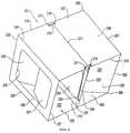
фиг.1 - вид спереди в перспективе на элементарную несущую конструкцию стенда согласно первому варианту выполнения;figure 1 is a front view in perspective of an elementary supporting structure of the stand according to the first embodiment;
фиг.2 - вид сзади в перспективе на несущую конструкцию на фиг.1;figure 2 is a rear view in perspective of a supporting structure in figure 1;
фиг.3 - вид спереди в перспективе на комплекс из двух элементарных несущих конструкций стенда согласно второму варианту выполнения;figure 3 is a front view in perspective of a complex of two elementary load-bearing structures of the stand according to the second embodiment;
фиг.4 - вид в перспективе на элементарную несущую конструкцию стенда по изобретению согласно третьему варианту выполнения.4 is a perspective view of an elementary supporting structure of the stand according to the invention according to the third embodiment.
Ниже описывается со ссылкой на фиг.1 и 2 первый вариант выполнения элементарной несущей конструкции стенда согласно изобретению. Многогранная ячейка 1, в данном случае в виде параллелепипеда, содержит корпус 2 с четырьмя поверхностями 3-6, связанными их общими ребрами 7-10, образующими ребра сочленения.Below is described with reference to figures 1 and 2, the first embodiment of the elementary supporting structure of the stand according to the invention. The polyhedral cell 1, in this case in the form of a parallelepiped, contains a casing 2 with four surfaces 3-6 connected by their common ribs 7-10, forming the junction ribs.
С одной стороны корпус 2 практически открыт и содержит только две небольших створки 11, 12, сочлененных с двумя ребрами 13, 14 обеих противоположных поверхностей 6, 4 ячейки 1, при этом ребра 13, 14 проходят перпендикулярно и под прямым углом к ребрам 7-10 сочленения. С другой стороны корпус 2 может быть закрыт двумя складывающимися створками 15, 16, служащими для поддержания ячейки в разложенном открытом положении, как это будет подробнее пояснено ниже.On the one hand, the housing 2 is practically open and contains only two
Обе поддерживающие створки 15, 16 установлены с возможностью поворота вокруг обоих ребер 17, 18 поверхностей 6, 4, противоположных ребрам 13, 14 сочленения обеих малых передних створок 11, 12. Сумма их ширины практически равна ширине корпуса 2 в открытом положении, т.е. основания 5 и потолочной поверхности 6 корпуса 2.Both supporting
От трех свободных краев 19, 20, 21 и 22, 23, 24 обеих поддерживающих створок 15, 16, а также от двух задних краев 25, 26 поверхностей 3, 5 выполнены вырезы, оканчивающиеся глазками для пропуска в них упругого возвратного элемента 27. Упругий элемент 27 пропускают через пару глазков 28 на гране 3 возле края 25, пару глазков 29 на створке 15 возле ее края 20, пару глазков 30 на гране 5 возле края 26 и пару глазков 31 на створке 16 возле ее края 23.From three
Таким образом, ячейка 1 является подвижной между своим плоским сложенным положением и рабочим разложенным положением, в котором она открыта для размещения предмета в ее единственном отделении. В плоском положении поверхности 3, 4 и 5, 6 корпуса 2 располагаются попарно друг на друге после поворота вокруг четырех ребер 7-10 сочленения. В открытом положении корпус поддерживается посредством поддерживающих створок 15, 16, являющихся поворотными вокруг наружных ребер 17, 18, проходящих под прямым углом к ребрам сочленения, под действием упругого элемента 27, содержащего четыре пары глазков 28-31 практически в одной плоскости для уменьшения его натяжения, при этом края 19, 21 и 22, 24 обеих створок 15, 16 располагаются практически в плоскости обоих краев 25, 26, обеспечивая опору для поверхностей 3, 5. Следовательно, обе створки находятся в поддерживающем, разложенном положении и выполняют функцию распорки между основанием 5 и потолочной поверхностью 3.Thus, cell 1 is movable between its flat folded position and the working unfolded position, in which it is open to accommodate an item in its only compartment. In the flat position of the
Приведение в плоское положение ячейки 1 (корпуса 2) производится складыванием створок 15, 16, т.е. их поворотом вокруг ребер 17, 18 с преодолением усилия упругого возвратного элемента 27 и укладкой на внутреннюю сторону поверхностей 6, 4.Bringing the cell 1 (housing 2) into a flat position is done by folding the
Само собой разумеется, что множество описанных ячеек 1 может быть размещено друг на друге или друг возле друга с использованием любого средства соединения, например, склеивания.It goes without saying that the plurality of described cells 1 can be placed on top of each other or next to each other using any means of bonding, for example, gluing.
Ниже со ссылкой на фиг.3 описывается второй вариант выполнения, предусматривающий комплекс из двух элементарных несущих конструкций стенда согласно изобретению. Элемент 100, расположенный над вторым элементом 150 на фиг.3, причем эти оба элемента отличаются между собой только способом крепления возвратного упругого элемента, представляет собой также ячейку 101 в виде параллелепипеда, содержащую корпус 102 с четырьмя поверхностями 103-106, связанными общими ребрами 107-110 сочленения.Below, with reference to FIG. 3, a second embodiment is described, comprising a complex of two elementary load-bearing structures of the stand according to the invention. The
Складная поддерживающая стенка 115 расположена с возможностью поворота вокруг центральной линии 116 поверхности 105, проходящей под прямым углом к ребрам сочленения ячейки почти на одинаковом расстоянии от передних 111, 112 и задних 113, 114 краев ячейки, причем эти края расположены перпендикулярно к ребрам сочленения ячейки и относятся к ее верхней 103 и нижней 105 поверхностям. Поддерживающая стенка выполнена прямоугольной и соответствует сечению отверстия корпуса 102, ее ширина равна длине краев 111-114, а высота - длине ребер 117-120, связывающих ребра 107-110 сочленения.The
От переднего края 111 поверхности 103 ячейки и от свободного конца 121 поддерживающей стенки 115, расположенной напротив края 116 для поворота, выполнены вырезы, которые оканчиваются глазками для пропуска в них упругого возвратного элемента 127.From the
Следовательно, упругий элемент пропускается через пару глазков 128 на поверхности 103 возле края 111 и через пару глазков 129 на поддерживающей стенке 115 возле ее свободного края 121. В этом месте упругий элемент проходит непосредственно от одной из обеих пар глазков 128, 129 к другой.Therefore, the elastic element is passed through a pair of
Таким образом, ячейка 100 является подвижной между плоским сложенным положением и рабочим разложенным положением, в котором она открыта для размещения одного или нескольких предметов. В рабочем положении ячейка содержит два отделения 130, 131, по одному с каждой стороны поддерживающей стенки 115.Thus, the
В плоском положении поверхности 103, 104 и 105, 106 несущей конструкции 102 располагаются попарно друг на друге после поворота вокруг четырех ребер 107-110 сочленения.In the flat position, the
Корпус удерживается в открытом положении посредством поддерживающей стенки 115, выполненной поворотной вокруг ребра 116 и расположенной под прямым углом к ребрам сочленения, под действием упругого элемента 127, обеспечивающего сближение между собой двух пар глазков 128, 129, при этом поддерживающая стенка лежит практически в плоскости, перпендикулярной к четырем поверхностям 103-106 корпуса 102 ячейки 100, для которых она служит опорой. Таким образом, стенка 115 находится в разложенном положении для поддержки ячейки 100 в открытом положении.The housing is held in open position by means of a supporting
Приведение в плоское положение ячейки 101 корпуса 102 производится складыванием стенки 115, т.е. ее поворотом вокруг ребра 116 сочленения, нажатием и укладкой на нижнюю поверхность 105, сближая при этом ее свободный край 121 с задним краем 114 нижней поверхности 105.Bringing the
Другой элемент 150 соединен с элементом 100, в данном случае, с помощью клея. Он отличается от связанного с ним элемента 100 способом крепления упругого возвратного элемента 157 и обратным направлением поворота поддерживающей стенки. Нижняя поверхность 155 корпуса ячейки 150, как, впрочем, и верхняя поверхность 103 ячейки 100, содержит центральное отверстие 158. Вместо натяжения упругого элемента 157 между парой глазков 159 на свободном конце 161 складной поддерживающей стенки 160, с одной стороны, и парой глазков на заднем нижнем конце нижней поверхности 155, с другой стороны, внутри ячейки, как было описано выше, здесь упругий элемент 157 пропущен снаружи ячейки через центральное отверстие 158.Another
Следует отметить, что ребра, вокруг которых поворачиваются обе стенки 115 и 160 обеих ячеек 100 и 150, имеют противоположное расположение, одно внизу на нижней поверхности 105, фиг.3, другое - вверху на верхней поверхности ячейки 150, которая в данном случае совмещается с нижней поверхностью связанной ячейки.It should be noted that the ribs around which both
Также следует указать, что, как показано на фиг.3, в том случае, когда усилие упругого элемента 127 не достаточно для надлежащего поворота поддерживающей стенки 115, т.е. для ее приведения в плоскость, перпендикулярную к поверхностям 103, 105, то поддерживающая стенка 115 не сможет обеспечить функцию распорки между основанием и потолочной поверхностью. Поэтому предпочтительно применять ячейку 100 и, следовательно, ячейку 150, в положении, повернутом на 90° по отношению к положению на фиг.3, для того, чтобы поддерживающая стенка 115, даже если она не полностью повернулась, выполняла тем не менее функцию распорки не между поверхностями 103, 105, а между поверхностями 104 и 106, перпендикулярными к поверхностям 103 и 105. В этом случае поддерживающая стенка 115, находящаяся в разложенном положении, будет постоянно образовывать с поверхностями 104, 106 силовой стояк в качестве опоры для тяжеловесного предмета.It should also be pointed out that, as shown in FIG. 3, in the case where the force of the
Как показано на фиг.4, элементарная несущая конструкция также содержит многогранную ячейку 201 в формы параллелепипеда с корпусом 202, содержащим четыре поверхности 203-206, связанные четырьмя наружными ребрами 207-210 сочленения.As shown in FIG. 4, the elementary load-bearing structure also comprises a
Верхняя 203 и нижняя 205 поверхности могут складываться вдвое вдоль двух внутренних ребер 211, 212, служащих для сгиба, сочленения и поворота и расположенных параллельно наружным ребрам сочленения.The upper 203 and lower 205 surfaces can be folded in half along the two
Складная стенка 221, размеры которой практически равны размерам боковых поверхностей 204, 206 корпуса 202, установлена с возможностью поворота вокруг нижнего ребра 212 вращения на нижней поверхности 205 корпуса 202.A
На верхней поверхности 203 корпуса 202, с обеих сторон от линии сгиба 211 на поверхности 203 корпуса 202, и от краев 213, 214 поверхности 203, перпендикулярных к ребрам 207, 210, выполнены вырезы, оканчивающиеся глазками 215-218 для пропуска в них упругих возвратных элементов 219, 220. Также вырезы предусмотрены в складной стенке 221 от ее обоих краев 222, проходящих под прямым углом к ребрам 207-210 сочленения вблизи ребра 212 вращения, при этом вырезы оканчиваются глазками 223 для пропуска в них упругих возвратных элементов 219-220.On the
В варианте выполнения на фиг.4 складная стенка 221, так же, как и боковые поверхности 204, 206 корпуса 202, содержит выемки 224, 225.In the embodiment of FIG. 4, the
Предусмотрены четыре других складных стенки 230-232, установленных с возможностью поворота вокруг четырех наружных ребер 226-229 корпуса 222, проходящих под прямым углом к ребрам 207-210 сочленения.Four other collapsible walls 230-232 are provided, rotatably mounted around four outer ribs 226-229 of the
Таким образом ячейка 201 выполнена подвижной между плоским сложенным положением и рабочим разложенным положением, в котором она открыта для размещения нескольких предметов.Thus, the
В рабочем положении (фиг.4) ячейка содержит два отделения 233, 234, по одному с каждой стороны складной стенки 221, находящейся в разложенном и приподнятом положении для поддержания верхней 203 и нижней 205 поверхностей по линиям 211, 212, с которыми складная стенка образует силовой стояк, служащий опорой для тяжеловесного предмета.In the operating position (figure 4), the cell contains two
Такое приподнятое положение средней стенки 221 достигается посредством упругих возвратных элементов 219, 220. Для придания большей устойчивости корпусу 202 в форме параллелепипеда вторичные поддерживающие стенки 230-232 поворачивают вокруг их ребер вращения от их положения прижатия к боковым поверхностям 206, 204 в положение, в котором они поддерживают верхнюю 203 и нижнюю 205 поверхности, лежащие практически под прямым углом к поверхностям 203-206 корпуса 202.Such a raised position of the
Приведение в плоское положение ячейки 201 производится отводом назад вторичных поддерживающих стенок 230-232 на боковые поверхности корпуса с преодолением действия упругих возвратных элементов 219-220 и поворотом средней поддерживающей стенки 221 вокруг ее ребра 212 вращения. Во время приведения в плоское положение обе поверхности 203, 205 складываются вдвое по линиям 211, 212, при этом обе боковых поверхности 204, 206 сближаются и заключают между собой верхнюю свободную часть средней поддерживающей стенки 221.The flattening of the
Claims (10)
Translated fromRussianApplications Claiming Priority (2)
| Application Number | Priority Date | Filing Date | Title |
|---|---|---|---|
| FR0801347 | 2008-03-12 | ||
| FR0801347AFR2928528B1 (en) | 2008-03-12 | 2008-03-12 | ELEMENTARY OBJECT DISPENSER SUPPORT COMPRISING AN ARTICULATED POLYEDRIQUE CASE. |
Publications (2)
| Publication Number | Publication Date |
|---|---|
| RU2009107284A RU2009107284A (en) | 2010-09-10 |
| RU2500326C2true RU2500326C2 (en) | 2013-12-10 |
Family
ID=39831862
Family Applications (1)
| Application Number | Title | Priority Date | Filing Date |
|---|---|---|---|
| RU2009107284/12ARU2500326C2 (en) | 2008-03-12 | 2009-03-02 | Elementary bearing structure of stand for placement of object, comprising articulated polyhedral cell |
Country Status (37)
| Country | Link |
|---|---|
| US (1) | US8348360B2 (en) |
| EP (1) | EP2100541B1 (en) |
| JP (1) | JP5339596B2 (en) |
| KR (1) | KR101352202B1 (en) |
| CN (1) | CN101530275B (en) |
| AP (1) | AP2566A (en) |
| AR (1) | AR071746A1 (en) |
| AT (1) | AT506442B1 (en) |
| AU (1) | AU2009200790B2 (en) |
| BE (1) | BE1018920A3 (en) |
| BR (1) | BRPI0900651B1 (en) |
| CA (1) | CA2655597C (en) |
| CH (1) | CH698631B1 (en) |
| CL (1) | CL2009000520A1 (en) |
| CO (1) | CO6200100A1 (en) |
| DE (1) | DE102009001060A1 (en) |
| EG (1) | EG26486A (en) |
| ES (2) | ES2353511B8 (en) |
| FR (1) | FR2928528B1 (en) |
| GB (1) | GB2458343B (en) |
| GR (1) | GR1008222B (en) |
| IS (1) | IS2953B (en) |
| IT (1) | IT1393435B1 (en) |
| LU (1) | LU91536B1 (en) |
| MA (1) | MA30851B1 (en) |
| ME (1) | ME00605B (en) |
| MX (1) | MX2009002755A (en) |
| NZ (1) | NZ575230A (en) |
| PE (1) | PE20100043A1 (en) |
| PL (1) | PL2100541T3 (en) |
| PT (1) | PT104422B (en) |
| RO (1) | RO125741B1 (en) |
| RU (1) | RU2500326C2 (en) |
| SG (1) | SG155855A1 (en) |
| TW (1) | TWI562637B (en) |
| UA (1) | UA95491C2 (en) |
| ZA (1) | ZA200901472B (en) |
Families Citing this family (6)
| Publication number | Priority date | Publication date | Assignee | Title |
|---|---|---|---|---|
| FR2955472B1 (en) | 2010-01-27 | 2012-01-20 | Hotel Francois L | OBJECT PRESENTATION BRACKET |
| KR101213494B1 (en)* | 2010-05-12 | 2012-12-20 | 삼성디스플레이 주식회사 | A solid display apparatus, a flexible display apparatus, and a method for manufacturing the display apparatuses |
| ES2537350B1 (en) | 2013-07-04 | 2016-03-15 | Ferrán Mestres Armengol | Self-expanding folding hollow body for exhibitor and self-expanding folding hollow structural assembly for exhibitor |
| CN107301823A (en)* | 2017-06-15 | 2017-10-27 | 洪海光电集团有限公司 | Lift multimedia presentation device |
| CN107140282B (en)* | 2017-06-26 | 2020-03-27 | 上海鸿研物流技术有限公司 | Logistics appliance and empty and full state identification method thereof |
| CN111627356A (en)* | 2020-06-17 | 2020-09-04 | 龙岩市康庆科技有限公司 | Environmental protection and energy saving technique is with show board |
Citations (10)
| Publication number | Priority date | Publication date | Assignee | Title |
|---|---|---|---|---|
| GB467854A (en)* | 1936-01-24 | 1937-06-24 | William Augustus May | Improvements in or relating to advertising circulars, showcards or the like |
| FR1254983A (en)* | 1960-01-16 | 1961-03-03 | Thibaud & Cie G | Foldable display |
| US3300166A (en)* | 1965-06-14 | 1967-01-24 | Container Corp | Collapsible automatically set up display container |
| US4854060A (en)* | 1987-02-27 | 1989-08-08 | Manco Inc. | Self-erecting photo display |
| WO2001078040A1 (en)* | 2000-07-11 | 2001-10-18 | Hotel Francois L | Folding structure for displaying information |
| WO2005004677A1 (en)* | 2003-07-10 | 2005-01-20 | Geoffrey Alan Moss | Display stand with foldable self erecting supporting base |
| JP2005132407A (en)* | 2003-10-30 | 2005-05-26 | Kyocera Mita Corp | Carton box |
| JP2005343478A (en)* | 2004-05-31 | 2005-12-15 | Sharp Corp | Packaging box |
| RU54904U1 (en)* | 2005-09-19 | 2006-07-27 | Общество с ограниченной ответственностью "Конкорд-М" | SURPRISE PACKAGING |
| US20080053942A1 (en)* | 2003-07-31 | 2008-03-06 | Marc Cox | Display Device |
Family Cites Families (30)
| Publication number | Priority date | Publication date | Assignee | Title |
|---|---|---|---|---|
| US1216071A (en)* | 1916-08-09 | 1917-02-13 | Alfred H Carstensen | Hat-box. |
| FR702817A (en) | 1929-11-01 | 1931-04-17 | Kali Forschungsanstalt Gmbh | Improvements to processes for obtaining calcium or magnesium orthophosphates |
| US1871706A (en)* | 1931-04-03 | 1932-08-16 | William R Krebs | Foldable paper box |
| US3010246A (en)* | 1959-04-20 | 1961-11-28 | England Press Inc | Self-forming device |
| US3385424A (en)* | 1966-04-11 | 1968-05-28 | Robertshaw Controls Co | Carton and insert |
| US3391848A (en)* | 1967-01-13 | 1968-07-09 | Martin L. Schmidt | Pop-open box |
| US3576354A (en)* | 1969-05-08 | 1971-04-27 | Roseth Corp | Knockdown closets |
| DE6936641U (en)* | 1969-09-17 | 1970-01-02 | Stabernack Gmbh Gustav | SALES DISPLAY |
| GB1381135A (en)* | 1972-09-29 | 1975-01-22 | Tonhaeuser H L | Display device |
| CA975961A (en)* | 1972-12-18 | 1975-10-14 | David C. Jenkins | Self-erecting devices |
| US3933300A (en)* | 1975-01-20 | 1976-01-20 | Hoerner Waldorf Corporation | Loin box with locking cover |
| US3987957A (en)* | 1975-10-31 | 1976-10-26 | Container Corporation Of America | One piece simplex carton |
| US4335830A (en)* | 1980-11-17 | 1982-06-22 | Industrial Packaging Co., Inc. | Solution container |
| US4619426A (en)* | 1985-05-22 | 1986-10-28 | Drueck Jr Fred | Self-erecting hollow structure |
| IL77611A (en)* | 1986-01-15 | 1988-11-15 | Abraham Schnapp | Toy comprising an expandable cube |
| US4723664A (en)* | 1987-03-26 | 1988-02-09 | Arrow Art Finishers Co. | Reinforced display stand for supporting heavy loads |
| JP2511770Y2 (en)* | 1990-06-07 | 1996-09-25 | レンゴー株式会社 | Display stand |
| DE4102082A1 (en)* | 1991-01-24 | 1992-07-30 | Horst Gmbh & Co Kg | Goods-carrier of carton form or formed of cardboard paper - has foot with dies joined by elastic tension pieces, and fold lines |
| JP3662328B2 (en)* | 1996-01-29 | 2005-06-22 | 株式会社Tana−X | Structure that lifts and holds the inner box |
| US5887782A (en)* | 1997-09-24 | 1999-03-30 | Mueller; Charles J. | High stacking strength automatic corrugated box |
| CN2364771Y (en)* | 1998-01-26 | 2000-02-23 | 汤玛士·贝尔斯 | Photo link and picture display frame |
| JP2002308349A (en)* | 2001-04-11 | 2002-10-23 | Shinsei:Kk | Thermal insulating box |
| FR2824946B1 (en)* | 2001-05-18 | 2003-10-03 | Hotel Francois L | INFORMATION DISPLAY HOLDER HAVING AT LEAST ONE FACE OF PRESENTATION |
| JP4049623B2 (en)* | 2002-06-26 | 2008-02-20 | レンゴー株式会社 | Two-stage display stand |
| US20040111930A1 (en)* | 2002-09-17 | 2004-06-17 | Ossmann Francis J. | Advertising/promotional display system with integral sound generating means |
| FR2847062B1 (en) | 2002-11-12 | 2005-01-07 | Hotel Francois L | INFORMATION HOLDER HOLDER HOLDER |
| FR2876827B1 (en)* | 2004-10-06 | 2007-04-27 | L'hotel Francois | INSERT HOLDER HOLDER WITH DISCRETE ACTION INSERTS |
| JP3993191B2 (en)* | 2004-10-19 | 2007-10-17 | 日本通運株式会社 | Foldable container |
| WO2006086597A1 (en)* | 2005-02-11 | 2006-08-17 | Graphic Packaging International, Inc. | Carton with interlocking divider |
| FR2915305B1 (en)* | 2007-04-18 | 2009-06-05 | Hotel Francois L | INVISIBLE FIXING MOUNT DISPLAY STAND |
- 2008
- 2008-03-12FRFR0801347Apatent/FR2928528B1/enactiveActive
- 2009
- 2009-02-20DEDE102009001060Apatent/DE102009001060A1/ennot_activeCeased
- 2009-02-23CACA2655597Apatent/CA2655597C/enactiveActive
- 2009-02-23CHCH00267/09Apatent/CH698631B1/ennot_activeIP Right Cessation
- 2009-02-26GRGR20090100116Apatent/GR1008222B/enactiveIP Right Grant
- 2009-02-27NZNZ575230Apatent/NZ575230A/ennot_activeIP Right Cessation
- 2009-02-27AUAU2009200790Apatent/AU2009200790B2/ennot_activeCeased
- 2009-03-01EGEG2009030280Apatent/EG26486A/enactive
- 2009-03-02ZAZA2009/01472Apatent/ZA200901472B/enunknown
- 2009-03-02ROROA200900193Apatent/RO125741B1/enunknown
- 2009-03-02RURU2009107284/12Apatent/RU2500326C2/enactive
- 2009-03-03TWTW098106778Apatent/TWI562637B/ennot_activeIP Right Cessation
- 2009-03-03PTPT104422Apatent/PT104422B/enactiveIP Right Grant
- 2009-03-04GBGB0903735Apatent/GB2458343B/enactiveActive
- 2009-03-05CLCL2009000520Apatent/CL2009000520A1/enunknown
- 2009-03-05MAMA31688Apatent/MA30851B1/enunknown
- 2009-03-06LULU91536Apatent/LU91536B1/enactive
- 2009-03-06APAP2009004797Apatent/AP2566A/enactive
- 2009-03-06JPJP2009053511Apatent/JP5339596B2/ennot_activeExpired - Fee Related
- 2009-03-06ESES200900626Apatent/ES2353511B8/ennot_activeExpired - Fee Related
- 2009-03-06ARARP090100821Apatent/AR071746A1/enactiveIP Right Grant
- 2009-03-09MEMEP-2009-87Apatent/ME00605B/enunknown
- 2009-03-09COCO09023942Apatent/CO6200100A1/enactiveIP Right Grant
- 2009-03-09ISIS8805Apatent/IS2953B/enunknown
- 2009-03-10SGSG200901812-8Apatent/SG155855A1/enunknown
- 2009-03-10BRBRPI0900651-6patent/BRPI0900651B1/ennot_activeIP Right Cessation
- 2009-03-10ATATA387/2009Apatent/AT506442B1/ennot_activeIP Right Cessation
- 2009-03-10PEPE2009000350Apatent/PE20100043A1/enactiveIP Right Grant
- 2009-03-10ITITTO2009A000175Apatent/IT1393435B1/enactive
- 2009-03-11PLPL09290173Tpatent/PL2100541T3/enunknown
- 2009-03-11ESES09290173.5Tpatent/ES2544487T3/enactiveActive
- 2009-03-11KRKR1020090020549Apatent/KR101352202B1/ennot_activeExpired - Fee Related
- 2009-03-11UAUAA200902137Apatent/UA95491C2/enunknown
- 2009-03-11EPEP20090290173patent/EP2100541B1/enactiveActive
- 2009-03-12BEBE2009/0144Apatent/BE1018920A3/ennot_activeIP Right Cessation
- 2009-03-12USUS12/402,654patent/US8348360B2/ennot_activeExpired - Fee Related
- 2009-03-12CNCN200910130784.9Apatent/CN101530275B/ennot_activeExpired - Fee Related
- 2009-03-12MXMX2009002755Apatent/MX2009002755A/enactiveIP Right Grant
Patent Citations (10)
| Publication number | Priority date | Publication date | Assignee | Title |
|---|---|---|---|---|
| GB467854A (en)* | 1936-01-24 | 1937-06-24 | William Augustus May | Improvements in or relating to advertising circulars, showcards or the like |
| FR1254983A (en)* | 1960-01-16 | 1961-03-03 | Thibaud & Cie G | Foldable display |
| US3300166A (en)* | 1965-06-14 | 1967-01-24 | Container Corp | Collapsible automatically set up display container |
| US4854060A (en)* | 1987-02-27 | 1989-08-08 | Manco Inc. | Self-erecting photo display |
| WO2001078040A1 (en)* | 2000-07-11 | 2001-10-18 | Hotel Francois L | Folding structure for displaying information |
| WO2005004677A1 (en)* | 2003-07-10 | 2005-01-20 | Geoffrey Alan Moss | Display stand with foldable self erecting supporting base |
| US20080053942A1 (en)* | 2003-07-31 | 2008-03-06 | Marc Cox | Display Device |
| JP2005132407A (en)* | 2003-10-30 | 2005-05-26 | Kyocera Mita Corp | Carton box |
| JP2005343478A (en)* | 2004-05-31 | 2005-12-15 | Sharp Corp | Packaging box |
| RU54904U1 (en)* | 2005-09-19 | 2006-07-27 | Общество с ограниченной ответственностью "Конкорд-М" | SURPRISE PACKAGING |
Also Published As
Similar Documents
| Publication | Publication Date | Title |
|---|---|---|
| RU2500326C2 (en) | Elementary bearing structure of stand for placement of object, comprising articulated polyhedral cell | |
| KR20120132621A (en) | Item display stand | |
| BRPI0716000A2 (en) | folding display module | |
| BRPI1004589A2 (en) | hinged fractal structure | |
| JP2008276218A (en) | Display stand having invisible securing flap | |
| WO2008096266A1 (en) | Portable and foldable module for exhibition and sale of articles | |
| US8210358B2 (en) | Collapsible display | |
| CN107822385A (en) | A kind of quick showcase stored and deployed | |
| JP2008250271A (en) | Display board | |
| CN212233901U (en) | A foldable sculpture booth | |
| CN109043973A (en) | A kind of showing stand facilitating storage, transport | |
| JP3233088U (en) | Portable partition | |
| JP3196576U (en) | Product display | |
| JP6086946B2 (en) | Display shelf | |
| JPS6034197Y2 (en) | foldable support device | |
| CN221193723U (en) | Combined floor unit structure of paper binding process room | |
| JP3018314U (en) | Exhibition box | |
| CN213097116U (en) | Portable cardboard bed | |
| GB2443449A (en) | Collapsible display unit | |
| JP3062663U (en) | Assembled display box | |
| KR200360866Y1 (en) | Collapsible of desk | |
| US20130193821A1 (en) | Modular articulate support | |
| IE85974B1 (en) | Elementary support for object display comprising a hinge polyhedral compartment | |
| CA2827361A1 (en) | Collapsible display folder | |
| FR2957055A1 (en) | Assembly for arranging e.g. goods in displaying and transporting box, has subunits articulated around folding lines between position in extension of one another and deployed position in which subunits are juxtaposed against one another |
Legal Events
| Date | Code | Title | Description |
|---|---|---|---|
| PD4A | Correction of name of patent owner | ||
| PC41 | Official registration of the transfer of exclusive right | Effective date:20170821 | |
| QB4A | Licence on use of patent | Free format text:LICENCE Effective date:20170822 | |
| QB4A | Licence on use of patent | Free format text:SUB-LICENCE Effective date:20170925 |