RU2496658C1 - Cooling system for vehicle hv parts - Google Patents
Cooling system for vehicle hv partsDownload PDFInfo
- Publication number
- RU2496658C1 RU2496658C1RU2012108122/11ARU2012108122ARU2496658C1RU 2496658 C1RU2496658 C1RU 2496658C1RU 2012108122/11 ARU2012108122/11 ARU 2012108122/11ARU 2012108122 ARU2012108122 ARU 2012108122ARU 2496658 C1RU2496658 C1RU 2496658C1
- Authority
- RU
- Russia
- Prior art keywords
- air
- air inlet
- seat
- cooling
- hole
- Prior art date
Links
- 238000001816coolingMethods0.000titleclaimsabstractdescription46
- 239000011248coating agentSubstances0.000claimsdescription10
- 238000000576coating methodMethods0.000claimsdescription10
- 239000000463materialSubstances0.000claimsdescription9
- 230000000977initiatory effectEffects0.000claims2
- 239000000126substanceSubstances0.000abstractdescription3
- 239000011358absorbing materialSubstances0.000abstract1
- XLYOFNOQVPJJNP-UHFFFAOYSA-NwaterSubstancesOXLYOFNOQVPJJNP-UHFFFAOYSA-N0.000description6
- 239000000428dustSubstances0.000description4
- 239000004744fabricSubstances0.000description2
- 230000002093peripheral effectEffects0.000description2
- 238000011144upstream manufacturingMethods0.000description2
- 239000000470constituentSubstances0.000description1
- 238000007599dischargingMethods0.000description1
- 230000006870functionEffects0.000description1
- 239000010985leatherSubstances0.000description1
- 230000035515penetrationEffects0.000description1
- 230000008447perceptionEffects0.000description1
- 229920003023plasticPolymers0.000description1
- 239000004033plasticSubstances0.000description1
- 229920005749polyurethane resinPolymers0.000description1
- 230000001172regenerating effectEffects0.000description1
- 229920003002synthetic resinPolymers0.000description1
- 239000000057synthetic resinSubstances0.000description1
Images


Classifications
- B—PERFORMING OPERATIONS; TRANSPORTING
- B60—VEHICLES IN GENERAL
- B60K—ARRANGEMENT OR MOUNTING OF PROPULSION UNITS OR OF TRANSMISSIONS IN VEHICLES; ARRANGEMENT OR MOUNTING OF PLURAL DIVERSE PRIME-MOVERS IN VEHICLES; AUXILIARY DRIVES FOR VEHICLES; INSTRUMENTATION OR DASHBOARDS FOR VEHICLES; ARRANGEMENTS IN CONNECTION WITH COOLING, AIR INTAKE, GAS EXHAUST OR FUEL SUPPLY OF PROPULSION UNITS IN VEHICLES
- B60K1/00—Arrangement or mounting of electrical propulsion units
- B60K1/04—Arrangement or mounting of electrical propulsion units of the electric storage means for propulsion
- B—PERFORMING OPERATIONS; TRANSPORTING
- B60—VEHICLES IN GENERAL
- B60K—ARRANGEMENT OR MOUNTING OF PROPULSION UNITS OR OF TRANSMISSIONS IN VEHICLES; ARRANGEMENT OR MOUNTING OF PLURAL DIVERSE PRIME-MOVERS IN VEHICLES; AUXILIARY DRIVES FOR VEHICLES; INSTRUMENTATION OR DASHBOARDS FOR VEHICLES; ARRANGEMENTS IN CONNECTION WITH COOLING, AIR INTAKE, GAS EXHAUST OR FUEL SUPPLY OF PROPULSION UNITS IN VEHICLES
- B60K11/00—Arrangement in connection with cooling of propulsion units
- B60K11/06—Arrangement in connection with cooling of propulsion units with air cooling
- B—PERFORMING OPERATIONS; TRANSPORTING
- B60—VEHICLES IN GENERAL
- B60K—ARRANGEMENT OR MOUNTING OF PROPULSION UNITS OR OF TRANSMISSIONS IN VEHICLES; ARRANGEMENT OR MOUNTING OF PLURAL DIVERSE PRIME-MOVERS IN VEHICLES; AUXILIARY DRIVES FOR VEHICLES; INSTRUMENTATION OR DASHBOARDS FOR VEHICLES; ARRANGEMENTS IN CONNECTION WITH COOLING, AIR INTAKE, GAS EXHAUST OR FUEL SUPPLY OF PROPULSION UNITS IN VEHICLES
- B60K11/00—Arrangement in connection with cooling of propulsion units
- B60K11/08—Air inlets for cooling; Shutters or blinds therefor
- B—PERFORMING OPERATIONS; TRANSPORTING
- B60—VEHICLES IN GENERAL
- B60L—PROPULSION OF ELECTRICALLY-PROPELLED VEHICLES; SUPPLYING ELECTRIC POWER FOR AUXILIARY EQUIPMENT OF ELECTRICALLY-PROPELLED VEHICLES; ELECTRODYNAMIC BRAKE SYSTEMS FOR VEHICLES IN GENERAL; MAGNETIC SUSPENSION OR LEVITATION FOR VEHICLES; MONITORING OPERATING VARIABLES OF ELECTRICALLY-PROPELLED VEHICLES; ELECTRIC SAFETY DEVICES FOR ELECTRICALLY-PROPELLED VEHICLES
- B60L50/00—Electric propulsion with power supplied within the vehicle
- B60L50/50—Electric propulsion with power supplied within the vehicle using propulsion power supplied by batteries or fuel cells
- B60L50/60—Electric propulsion with power supplied within the vehicle using propulsion power supplied by batteries or fuel cells using power supplied by batteries
- B60L50/66—Arrangements of batteries
- B—PERFORMING OPERATIONS; TRANSPORTING
- B60—VEHICLES IN GENERAL
- B60L—PROPULSION OF ELECTRICALLY-PROPELLED VEHICLES; SUPPLYING ELECTRIC POWER FOR AUXILIARY EQUIPMENT OF ELECTRICALLY-PROPELLED VEHICLES; ELECTRODYNAMIC BRAKE SYSTEMS FOR VEHICLES IN GENERAL; MAGNETIC SUSPENSION OR LEVITATION FOR VEHICLES; MONITORING OPERATING VARIABLES OF ELECTRICALLY-PROPELLED VEHICLES; ELECTRIC SAFETY DEVICES FOR ELECTRICALLY-PROPELLED VEHICLES
- B60L58/00—Methods or circuit arrangements for monitoring or controlling batteries or fuel cells, specially adapted for electric vehicles
- B60L58/10—Methods or circuit arrangements for monitoring or controlling batteries or fuel cells, specially adapted for electric vehicles for monitoring or controlling batteries
- B60L58/24—Methods or circuit arrangements for monitoring or controlling batteries or fuel cells, specially adapted for electric vehicles for monitoring or controlling batteries for controlling the temperature of batteries
- B60L58/26—Methods or circuit arrangements for monitoring or controlling batteries or fuel cells, specially adapted for electric vehicles for monitoring or controlling batteries for controlling the temperature of batteries by cooling
- B—PERFORMING OPERATIONS; TRANSPORTING
- B60—VEHICLES IN GENERAL
- B60N—SEATS SPECIALLY ADAPTED FOR VEHICLES; VEHICLE PASSENGER ACCOMMODATION NOT OTHERWISE PROVIDED FOR
- B60N2/00—Seats specially adapted for vehicles; Arrangement or mounting of seats in vehicles
- B60N2/56—Heating or ventilating devices
- B60N2/5607—Heating or ventilating devices characterised by convection
- B60N2/5621—Heating or ventilating devices characterised by convection by air
- B—PERFORMING OPERATIONS; TRANSPORTING
- B60—VEHICLES IN GENERAL
- B60N—SEATS SPECIALLY ADAPTED FOR VEHICLES; VEHICLE PASSENGER ACCOMMODATION NOT OTHERWISE PROVIDED FOR
- B60N2/00—Seats specially adapted for vehicles; Arrangement or mounting of seats in vehicles
- B60N2/58—Seat coverings
- B—PERFORMING OPERATIONS; TRANSPORTING
- B60—VEHICLES IN GENERAL
- B60N—SEATS SPECIALLY ADAPTED FOR VEHICLES; VEHICLE PASSENGER ACCOMMODATION NOT OTHERWISE PROVIDED FOR
- B60N2/00—Seats specially adapted for vehicles; Arrangement or mounting of seats in vehicles
- B60N2/90—Details or parts not otherwise provided for
- B60N2/986—Side-rests
- H—ELECTRICITY
- H01—ELECTRIC ELEMENTS
- H01M—PROCESSES OR MEANS, e.g. BATTERIES, FOR THE DIRECT CONVERSION OF CHEMICAL ENERGY INTO ELECTRICAL ENERGY
- H01M10/00—Secondary cells; Manufacture thereof
- H01M10/60—Heating or cooling; Temperature control
- H01M10/61—Types of temperature control
- H01M10/613—Cooling or keeping cold
- H—ELECTRICITY
- H01—ELECTRIC ELEMENTS
- H01M—PROCESSES OR MEANS, e.g. BATTERIES, FOR THE DIRECT CONVERSION OF CHEMICAL ENERGY INTO ELECTRICAL ENERGY
- H01M10/00—Secondary cells; Manufacture thereof
- H01M10/60—Heating or cooling; Temperature control
- H01M10/62—Heating or cooling; Temperature control specially adapted for specific applications
- H01M10/625—Vehicles
- H—ELECTRICITY
- H01—ELECTRIC ELEMENTS
- H01M—PROCESSES OR MEANS, e.g. BATTERIES, FOR THE DIRECT CONVERSION OF CHEMICAL ENERGY INTO ELECTRICAL ENERGY
- H01M10/00—Secondary cells; Manufacture thereof
- H01M10/60—Heating or cooling; Temperature control
- H01M10/65—Means for temperature control structurally associated with the cells
- H01M10/655—Solid structures for heat exchange or heat conduction
- H01M10/6556—Solid parts with flow channel passages or pipes for heat exchange
- H—ELECTRICITY
- H01—ELECTRIC ELEMENTS
- H01M—PROCESSES OR MEANS, e.g. BATTERIES, FOR THE DIRECT CONVERSION OF CHEMICAL ENERGY INTO ELECTRICAL ENERGY
- H01M10/00—Secondary cells; Manufacture thereof
- H01M10/60—Heating or cooling; Temperature control
- H01M10/65—Means for temperature control structurally associated with the cells
- H01M10/656—Means for temperature control structurally associated with the cells characterised by the type of heat-exchange fluid
- H01M10/6561—Gases
- H01M10/6563—Gases with forced flow, e.g. by blowers
- H—ELECTRICITY
- H01—ELECTRIC ELEMENTS
- H01M—PROCESSES OR MEANS, e.g. BATTERIES, FOR THE DIRECT CONVERSION OF CHEMICAL ENERGY INTO ELECTRICAL ENERGY
- H01M10/00—Secondary cells; Manufacture thereof
- H01M10/60—Heating or cooling; Temperature control
- H01M10/66—Heat-exchange relationships between the cells and other systems, e.g. central heating systems or fuel cells
- H01M10/663—Heat-exchange relationships between the cells and other systems, e.g. central heating systems or fuel cells the system being an air-conditioner or an engine
- B—PERFORMING OPERATIONS; TRANSPORTING
- B60—VEHICLES IN GENERAL
- B60K—ARRANGEMENT OR MOUNTING OF PROPULSION UNITS OR OF TRANSMISSIONS IN VEHICLES; ARRANGEMENT OR MOUNTING OF PLURAL DIVERSE PRIME-MOVERS IN VEHICLES; AUXILIARY DRIVES FOR VEHICLES; INSTRUMENTATION OR DASHBOARDS FOR VEHICLES; ARRANGEMENTS IN CONNECTION WITH COOLING, AIR INTAKE, GAS EXHAUST OR FUEL SUPPLY OF PROPULSION UNITS IN VEHICLES
- B60K1/00—Arrangement or mounting of electrical propulsion units
- B60K2001/003—Arrangement or mounting of electrical propulsion units with means for cooling the electrical propulsion units
- B60K2001/005—Arrangement or mounting of electrical propulsion units with means for cooling the electrical propulsion units the electric storage means
- B—PERFORMING OPERATIONS; TRANSPORTING
- B60—VEHICLES IN GENERAL
- B60K—ARRANGEMENT OR MOUNTING OF PROPULSION UNITS OR OF TRANSMISSIONS IN VEHICLES; ARRANGEMENT OR MOUNTING OF PLURAL DIVERSE PRIME-MOVERS IN VEHICLES; AUXILIARY DRIVES FOR VEHICLES; INSTRUMENTATION OR DASHBOARDS FOR VEHICLES; ARRANGEMENTS IN CONNECTION WITH COOLING, AIR INTAKE, GAS EXHAUST OR FUEL SUPPLY OF PROPULSION UNITS IN VEHICLES
- B60K1/00—Arrangement or mounting of electrical propulsion units
- B60K1/04—Arrangement or mounting of electrical propulsion units of the electric storage means for propulsion
- B60K2001/0405—Arrangement or mounting of electrical propulsion units of the electric storage means for propulsion characterised by their position
- B60K2001/0416—Arrangement in the rear part of the vehicle
- B—PERFORMING OPERATIONS; TRANSPORTING
- B60—VEHICLES IN GENERAL
- B60L—PROPULSION OF ELECTRICALLY-PROPELLED VEHICLES; SUPPLYING ELECTRIC POWER FOR AUXILIARY EQUIPMENT OF ELECTRICALLY-PROPELLED VEHICLES; ELECTRODYNAMIC BRAKE SYSTEMS FOR VEHICLES IN GENERAL; MAGNETIC SUSPENSION OR LEVITATION FOR VEHICLES; MONITORING OPERATING VARIABLES OF ELECTRICALLY-PROPELLED VEHICLES; ELECTRIC SAFETY DEVICES FOR ELECTRICALLY-PROPELLED VEHICLES
- B60L2200/00—Type of vehicles
- B60L2200/26—Rail vehicles
- B—PERFORMING OPERATIONS; TRANSPORTING
- B60—VEHICLES IN GENERAL
- B60L—PROPULSION OF ELECTRICALLY-PROPELLED VEHICLES; SUPPLYING ELECTRIC POWER FOR AUXILIARY EQUIPMENT OF ELECTRICALLY-PROPELLED VEHICLES; ELECTRODYNAMIC BRAKE SYSTEMS FOR VEHICLES IN GENERAL; MAGNETIC SUSPENSION OR LEVITATION FOR VEHICLES; MONITORING OPERATING VARIABLES OF ELECTRICALLY-PROPELLED VEHICLES; ELECTRIC SAFETY DEVICES FOR ELECTRICALLY-PROPELLED VEHICLES
- B60L2210/00—Converter types
- B60L2210/10—DC to DC converters
- Y—GENERAL TAGGING OF NEW TECHNOLOGICAL DEVELOPMENTS; GENERAL TAGGING OF CROSS-SECTIONAL TECHNOLOGIES SPANNING OVER SEVERAL SECTIONS OF THE IPC; TECHNICAL SUBJECTS COVERED BY FORMER USPC CROSS-REFERENCE ART COLLECTIONS [XRACs] AND DIGESTS
- Y02—TECHNOLOGIES OR APPLICATIONS FOR MITIGATION OR ADAPTATION AGAINST CLIMATE CHANGE
- Y02E—REDUCTION OF GREENHOUSE GAS [GHG] EMISSIONS, RELATED TO ENERGY GENERATION, TRANSMISSION OR DISTRIBUTION
- Y02E60/00—Enabling technologies; Technologies with a potential or indirect contribution to GHG emissions mitigation
- Y02E60/10—Energy storage using batteries
- Y—GENERAL TAGGING OF NEW TECHNOLOGICAL DEVELOPMENTS; GENERAL TAGGING OF CROSS-SECTIONAL TECHNOLOGIES SPANNING OVER SEVERAL SECTIONS OF THE IPC; TECHNICAL SUBJECTS COVERED BY FORMER USPC CROSS-REFERENCE ART COLLECTIONS [XRACs] AND DIGESTS
- Y02—TECHNOLOGIES OR APPLICATIONS FOR MITIGATION OR ADAPTATION AGAINST CLIMATE CHANGE
- Y02T—CLIMATE CHANGE MITIGATION TECHNOLOGIES RELATED TO TRANSPORTATION
- Y02T10/00—Road transport of goods or passengers
- Y02T10/60—Other road transportation technologies with climate change mitigation effect
- Y02T10/70—Energy storage systems for electromobility, e.g. batteries
- Y—GENERAL TAGGING OF NEW TECHNOLOGICAL DEVELOPMENTS; GENERAL TAGGING OF CROSS-SECTIONAL TECHNOLOGIES SPANNING OVER SEVERAL SECTIONS OF THE IPC; TECHNICAL SUBJECTS COVERED BY FORMER USPC CROSS-REFERENCE ART COLLECTIONS [XRACs] AND DIGESTS
- Y02—TECHNOLOGIES OR APPLICATIONS FOR MITIGATION OR ADAPTATION AGAINST CLIMATE CHANGE
- Y02T—CLIMATE CHANGE MITIGATION TECHNOLOGIES RELATED TO TRANSPORTATION
- Y02T10/00—Road transport of goods or passengers
- Y02T10/60—Other road transportation technologies with climate change mitigation effect
- Y02T10/72—Electric energy management in electromobility
Landscapes
- Engineering & Computer Science (AREA)
- Chemical & Material Sciences (AREA)
- Transportation (AREA)
- Mechanical Engineering (AREA)
- Manufacturing & Machinery (AREA)
- Chemical Kinetics & Catalysis (AREA)
- Electrochemistry (AREA)
- General Chemical & Material Sciences (AREA)
- Combustion & Propulsion (AREA)
- Aviation & Aerospace Engineering (AREA)
- Power Engineering (AREA)
- Sustainable Energy (AREA)
- Sustainable Development (AREA)
- Life Sciences & Earth Sciences (AREA)
- Cooling, Air Intake And Gas Exhaust, And Fuel Tank Arrangements In Propulsion Units (AREA)
- Electric Propulsion And Braking For Vehicles (AREA)
- Seats For Vehicles (AREA)
- Arrangement Or Mounting Of Propulsion Units For Vehicles (AREA)
- Secondary Cells (AREA)
Abstract
Description
Translated fromRussianНастоящее изобретение относится к охлаждающей структуре для высоковольтных электрических частей транспортного средства, которая является эффективной при заборе охлаждающего воздуха для охлаждения высоковольтных электрических частей, используемых в электрическом транспортном средстве или гибридном транспортном средстве.The present invention relates to a cooling structure for high voltage electrical parts of a vehicle, which is effective in drawing cooling air for cooling high voltage electrical parts used in an electric vehicle or a hybrid vehicle.
Например, в гибридном транспортном средстве высоковольтные электрические части устанавливаются за спинкой заднего сиденья, внутри багажного отделения, или ниже багажного отделения. Эти высоковольтные электрические части содержат аккумуляторную батарею в качестве источника энергии для приведения в движение транспортного средства. Поскольку батарея является частью, генерирующей тепло, которая производит тепло при зарядке или разрядке, для батареи требуется охлаждение, чтобы поддерживать ее рабочие характеристики. Желательно, чтобы батарея эффективно охлаждалась за счет подачи забранного охлаждающего воздуха к батарее с маленьким сопротивлением для прохода воздуха. Традиционно, например, воздух внутри пассажирского отделения гибридного транспортного средства забирается из положения, находящегося рядом с задним сиденьем и поблизости от батареи, с помощью охлаждающего вентилятора, и подается к батарее как охлаждающий воздух, например, как описано в документе JP-4114478-В.For example, in a hybrid vehicle, high voltage electrical parts are installed behind the back of the rear seat, inside the luggage compartment, or below the luggage compartment. These high voltage electrical parts comprise a battery as an energy source for driving a vehicle. Because the battery is a heat-generating part that produces heat when charging or discharging, the battery needs cooling to maintain its performance. It is desirable that the battery is effectively cooled by supplying the taken cooling air to a battery with a small resistance for air passage. Traditionally, for example, air inside the passenger compartment of a hybrid vehicle is taken from a position near the rear seat and close to the battery using a cooling fan, and is supplied to the battery as cooling air, for example, as described in JP-4114478-B.
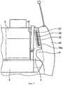
Фиг.12 является видом в перспективе, показывающим впускное отверстие для воздуха системы охлаждения аккумуляторной батареи в соответствии с документом JP-4114478-В. В этой структуре выполнены боковой канал впуска воздуха отверстия и канал выпуска воздуха, соответственно, на стороне выше по ходу потока и стороне ниже по ходу потока в канале охлаждающего воздуха для блока аккумуляторной батареи, установленного в багажном отделении за задним сиденьем 101 таким образом, чтобы подавать воздух изнутри пассажирского отделения к блоку аккумуляторной батареи как охлаждающий воздух. Охлаждающий вентилятор обеспечивается на промежуточном участке вдоль длины бокового канала впуска воздуха. Воздушное впускное отверстие 13 бокового канала впуска воздуха открывается на верхнем участке боковой отделки 104 сиденья, расположенного в боковой части спинки 102 сиденья заднего сиденья 101 таким образом, что воздух, находящийся внутри пассажирского отделения, забирается из воздушного впускного отверстия 103.12 is a perspective view showing an air inlet for a battery cooling system in accordance with JP-4114478-B. In this structure, there are a side air inlet channel and air outlet channel, respectively, on the side upstream and side downstream in the cooling air channel for the battery pack installed in the luggage compartment behind the
В охлаждающей структуре аккумуляторной батареи, описанной в JP-4114478-B, воздушное впускное отверстие 103 располагается в боковой отделке 104 сиденья, которая обеспечивается в боковой части заднего сиденья 101. Поэтому ширина заднего сиденья 101 может быть уменьшена за счет боковой отделки 104 сиденья. Кроме того, в таком транспортном средстве, как малогабаритный автомобиль, не имеющем боковой отделки сиденья, воздушное впускное отверстие 103 не могло бы располагаться, и следовательно, оно может быть дополнительно улучшено.In the battery cooling structure described in JP-4114478-B, the
Изобретение было сделано с учетом описанных выше обстоятельств, и поэтому его задачей является обеспечение охлаждающей структуры для высоковольтных электрических частей транспортного средства, которая позволяет расположить в заднем сиденье участок отверстия, из которого воздух внутри пассажирского отделения забирается в канал впуска воздуха. Такая компоновка не только гарантирует достаточное количество впускаемого воздуха, но также позволяет избежать контакта с пассажиром, который садится на заднее сиденье и освобождает его, даже в транспортном средстве такого типа, в котором нет боковой отделки сиденья.The invention was made taking into account the circumstances described above, and therefore its task is to provide a cooling structure for high-voltage electrical parts of the vehicle, which allows you to place in the back seat a portion of the hole from which air inside the passenger compartment is drawn into the air intake channel. This arrangement not only guarantees a sufficient amount of intake air, but also avoids contact with a passenger who sits in the back seat and frees him, even in a vehicle of this type in which there is no side trim for the seat.
Согласно техническому решению, охарактеризованному признаками пункта 1 формулы изобретения, предусмотрена охлаждающая структура для высоковольтных электрических частей транспортного средства (например, модуль 21 аккумуляторной батареи, модуль 22 обратного преобразователя, и модуль 23 преобразователя постоянного тока в постоянный DC-DC), которая располагается за задним сиденьем (например, задним сиденьем 7 в варианте выполнения изобретения), и содержит:According to the technical solution characterized by the features of
- канал впуска воздуха (например, канал 26 впуска воздуха в варианте выполнения изобретения), имеющий воздушное впускное отверстие (например, воздушное впускное отверстие 32 в варианте выполнения изобретения), которое располагается выше, чем подушка сиденья (например, подушка 6 сиденья в варианте выполнения изобретения) заднего сиденья и соединяется с высоковольтными электрическими частями таким образом, чтобы подавать воздух изнутри пассажирского отделения (например, пассажирского отделения 9 в варианте выполнения изобретения) к высоковольтным электрическим частям, как охлаждающий воздух; иan air inlet channel (for example, an
- охлаждающий вентилятор (например, охлаждающий вентилятор 30 в варианте выполнения изобретения), который вызывает протекание охлаждающего воздуха через канал впуска воздуха,a cooling fan (e.g.,
при этом участок отверстия (например, участок 35 отверстия в варианте выполнения изобретения) для забора воздуха изнутри пассажирского отделения в канал впуска воздуха формируется в боковой части спинки сиденья (например, боковая часть спинки 4 сиденья в варианте выполнения изобретения), которая располагается наружу в поперечном направлении от главной спинки сиденья (например, главная спинка 5 сиденья в варианте выполнения изобретения) заднего сиденья.wherein a hole portion (for example, a
Пункт 2 формулы изобретения, основанный на п.1, предусматривает структуру, в которой участок отверстия располагается в поперечном направлении наружу, в большей степени, чем центральное положение в поперечном направлении боковой части спинки сиденья.
Пункт 3 формулы изобретения, основанный на п.1 или 2, предусматривает структуру, в которой нижний конечный участок (например, нижний конечный участок 35а в варианте выполнения изобретения) участка отверстия располагается выше на 30 мм или более чем подлокотник (например, подлокотник 41 в варианте выполнения изобретения), который обеспечивается на обшивке двери (например, обшивке 40 двери).
Пункт 4 формулы изобретения, основанный на п.1 или 2, предусматривает структуру, в которой участок отверстия располагается таким образом, что, по меньшей мере, часть его скрывается подлокотником, если смотреть на него с передней стороны.
Пункт 5 формулы изобретения, основанный на любом из п.1-4, предусматривает структуру, в которой участок отверстия защищен покрытием (например, покрытием 34 в варианте выполнения изобретения) боковой части спинки сиденья, которое является воздухопроницаемым.
Пункт 6 формулы изобретения, основанный на любом из п.1-4, предусматривает структуру, в которой участок отверстия покрывается решеткой впуска воздуха отверстия (например, решеткой 37 впуска воздуха в варианте выполнения изобретения), имеющей множество прорезей впуска воздуха (например, прорезей 39 впуска воздуха в варианте выполнения изобретения).
Пункт 7 формулы изобретения, основанный на любом из п.1-6, предусматривает структуру, в которой боковая часть спинки сиденья имеет материал подушки сиденья (например, материал 52 подушки сиденья в варианте выполнения изобретения), для того чтобы шум воздушного впускного отверстия от воздуха, который забирается через участок отверстия, поглощался материалом подушки сиденья.
Пункт 8 формулы изобретения, основанный на любом из п.1-7, предусматривает структуру, в которой участок пространства (например, участок 53 дополнительного пространства в варианте выполнения изобретения) обеспечивается между каналом впуска воздуха и воздушным впускным отверстием.
В соответствии с п.1 формулы изобретения, участок отверстия, через который воздух изнутри пассажирского отделения вводится в канал впуска воздуха, может быть выполнен в боковой части спинки заднего сиденья, которая располагается поблизости от аккумуляторной батареи, при этом не должна обеспечиваться отделка боковой части сиденья. Таким образом, ширина заднего сиденья может быть увеличена, и воздух из пассажирского отделения может забираться в достаточной степени, в то же время получая комфортабельное пространство внутри пассажирского отделения, которое предоставляет превосходное качество для вождения. Такая конфигурация является эффективной, в частности, для малогабаритного автомобиля, в котором трудно гарантировать пространство, чтобы обеспечить отделку боковой части сиденья. Кроме того, можно избежать контакта пассажира с участком отверстия, когда он или она садится в автомобиль или выходит из него, за счет формирования участка отверстия в боковой части спинки сиденья.In accordance with
В соответствии с п.2 формулы изобретения, участок отверстия не закрывается рукой или плечом пассажира или непристегнутого ремня безопасности. Это гарантирует, что воздух изнутри пассажирского отделения может беспрепятственно забираться, чтобы охлаждать высоковольтные электрические части.In accordance with
В соответствии с п.3 формулы изобретения, локоть пассажира не прилегает к участку отверстия, а также участок отверстия не закрывается локтем пассажира. Таким образом, воздух, находящийся внутри пассажирского отделения может гарантированно забираться.In accordance with
В соответствии с п.4 формулы изобретения, может быть предотвращено не только проникновение пыли из участка отверстия, но также участок отверстия может быть выполнен незаметным за счет подлокотника, даже в том случае, когда площадь участка отверстия увеличивается, для того чтобы уменьшить шум от впуска воздуха таким образом повышая качество конструкции внутри пассажирского отделения.According to
В соответствии с п.5 формулы изобретения, боковая часть спинки сиденья покрывается тем же самым покрытием, как и все сиденье в целом, за счет чего может быть обеспечено восприятие целостности. Таким образом, качество продукта повышается. Кроме того, шум от впуска воздуха может быть уменьшен с помощью воздухопроницаемого покрытия, таким образом получается бесшумное пассажирское отделение.According to
В соответствии с п.6 формулы изобретения, проникновение пыли из участка отверстия может быть предотвращено.According to
В соответствии с п.7 формулы изобретения, шум от впуска воздуха может быть уменьшен с помощью материала подушки сиденья боковой части спинки сиденья, таким образом получается бесшумное пассажирское отделение.According to
В соответствии с п.8 формулы изобретения, капельки воды, которая конденсируется внутри канала впуска воздуха могут быть сброшены в участке дополнительного пространства, таким образом предотвращая прилипание воды к высоковольтным электрическим частям, для того чтобы защитить высоковольтные электрические части, которые могут быть серьезно повреждены из-за наличия воды. За счет применения участка дополнительного пространства в таком участке, где трудно сформировать канал впуска воздуха, способный обеспечить ввод достаточного количества воздуха, линия впуска воздуха может быть расположена внутри пассажирского отделения, которое является компактным по своему размеру.According to
Настоящее изобретение поясняется чертежами, на которых представлено следующее:The present invention is illustrated by drawings, which represent the following:
фиг.1 - боковой вид гибридного транспортного средства, в соответствии с первым вариантом выполнения изобретения;figure 1 is a side view of a hybrid vehicle, in accordance with the first embodiment of the invention;
фиг.2 - детальный вид в перспективе в разобранном состоянии, показывающий заднюю часть гибридного транспортного средства по фиг.1;figure 2 is a detailed perspective view in an exploded state, showing the rear of the hybrid vehicle of figure 1;
фиг.3 - разрез охлаждающей структуры для высоковольтных электрических частей по фиг.2;figure 3 - section of the cooling structure for high-voltage electrical parts of figure 2;
фиг.4 - вид в перспективе боковой части спинки сиденья, в которой участок отверстия сдвинут дальше в направлении вверх относительно подушки заднего сиденья;FIG. 4 is a perspective view of a side portion of a seatback in which a portion of an opening is shifted further upward relative to a rear seat cushion;
фиг.5 - вид сверху, показывающий позиционное соотношение между пассажиром, сидящим на заднем сиденье, и каналом впуска воздуха;5 is a plan view showing a positional relationship between a passenger sitting in the back seat and an air inlet channel;
фиг.6А - вид в перспективе решетки впуска воздуха, которая установлена на участок отверстия, а фиг.6В - разрез вдоль линии VI-VI по фиг.6А;FIG. 6A is a perspective view of an air intake grill that is mounted on a portion of an opening, and FIG. 6B is a section along line VI-VI of FIG. 6A;
фиг.7 - вид спереди заднего сиденья, в котором участок отверстия расположен дальше по направлению вверх, чем подлокотник;7 is a front view of the rear seat, in which the portion of the hole is located farther upward than the armrest;
фиг.8А - вид в перспективе боковой части спинки сиденья, в которой решетка воздушного впускного отверстия установлена с задней стороны заднего сиденья, а фиг.8В - разрез вдоль линии VIII-VIII на фиг.8А;figa is a perspective view of the side of the backrest, in which the grille of the air inlet is installed on the rear side of the rear seat, and figv is a section along the line VIII-VIII in figa;
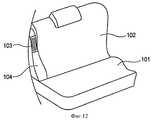
фиг.9 - вид в перспективе боковой части спинки сиденья, в соответствии с третьим вариантом выполнения изобретения, в котором участок отверстия покрыт воздухопроницаемым покрытием;FIG. 9 is a perspective view of a side portion of a seatback, in accordance with a third embodiment of the invention, in which a portion of the opening is coated with a breathable coating;
фиг.10 - вид спереди четвертого варианта выполнения изобретения, при этом участок отверстия расположен так, что он перекрывается подлокотником;figure 10 is a front view of a fourth embodiment of the invention, while the portion of the hole is located so that it overlaps the armrest;
фиг.11 - вид сбоку гибридного транспортного средства, в соответствии с усовершенствованным вариантом выполнения изобретения;11 is a side view of a hybrid vehicle in accordance with an improved embodiment of the invention;
фиг.12 - частичный вид в перспективе заднего сиденья автомобиля, в соответствии с известным примером, если смотреть на сиденье из пассажирского отделения.Fig is a partial perspective view of the rear seat of the car, in accordance with a known example, if you look at the seat from the passenger compartment.
В дальнейшем варианты выполнения изобретения будут описываться подробно, со ссылками на прилагаемые чертежи. Чертежи показываются в направлении, в котором ссылочные позиции, приведенные здесь, выглядят обычными.In the following, embodiments of the invention will be described in detail with reference to the accompanying drawings. The drawings are shown in the direction in which the reference numbers shown here look normal.
Первый вариант выполнения изобретенияFirst Embodiment
Как показано на фиг.1, транспортное средство 1 является гибридным транспортным средством, которое содержит силовой агрегат 2, включающий в себя двигатель и мотор-генератор, которые обеспечиваются последовательно. Приводу двигателя содействует мотор-генератор, а когда транспортное средство замедляется, электрическая мощность, получаемая от мотор-генератора, регенерируется. Мотор-генератор является трехфазным двигателем переменного тока. Движущая сила от двигателя и мотор-генератора передается к передним колесам 3, которые являются приводными колесами.As shown in FIG. 1,
В транспортном средстве 1 заднее сиденье 7 содержит боковую часть 4 спинки сиденья, главную часть 5 спинки сиденья и подушку 6 сиденья, а коробка 20 электрических частей располагается за главной частью 5 спинки сиденья. Электрические части в коробке 20 электрических частей присоединяются к силовому агрегату 2 через электрический кабель 8.In the
Как показано на фиг.2 и 3, коробка 20 электрических частей содержит модуль 21 аккумуляторной батареи, модуль 22 обратного преобразователя, и модуль 23 преобразователя постоянного тока в постоянный DC-DC, как высоковольтные электрические части. Когда мотор-генератор запитывается от модуля 21 аккумуляторной батареи, который является источником питания постоянным током, постоянный ток преобразуется в переменный ток модулем 22 обратного преобразователя.As shown in FIGS. 2 and 3, the
Когда выход от двигателя или кинетическая энергия транспортного средства 1 преобразуется в электрическую энергию, которая должна сохраняться в модуле 21 аккумуляторной батареи во время замедления транспортного средства, мотор-генератор функционирует как генератор, чтобы генерировать так называемую регенеративную тормозную силу. Затем переменный ток преобразуется в постоянный ток модулем 22 обратного преобразователя для сохранения в модуле 21 аккумуляторной батареи. Поскольку напряжение постоянного тока, который преобразуется модулем 22 обратного преобразователя, является высоким, то его часть уменьшается модулем 23 преобразователя постоянного тока в постоянный DC-DC.When the engine output or kinetic energy of the
Канал 26 впуска воздуха сообщается с коробкой 20 электрических частей, которая содержит модуль 21 аккумуляторной батареи, модуль 22 обратного преобразователя, и модуль 23 преобразователя постоянного тока в постоянный (DC-DC), для того чтобы внутренняя часть коробки 20 электрических частей охлаждалась с помощью забираемого из пассажирского отделения 9 транспортного средства 1 охлаждающего воздуха.The
Коробка 20 электрических частей является корпусом 24 для размещения"элементов, имеющим, по существу, прямоугольную форму коробки в виде параллелепипеда, которая имеет открытую сторону, при этом модуль 21 аккумуляторной батареи, модуль 22 обратного преобразователя, и модуль 23 преобразователя постоянного тока в постоянный (DC-DC) размещаются в корпусе 24 для размещения элементов. Коробка 20 электрических частей располагается за главной частью 5 спинки заднего сиденья 7 в состоянии, когда крышка 25 привинчивается к корпусу 24 для размещения элементов, чтобы закрыть его открытую сторону.The
Канал 26 впуска воздуха сформирован как целая часть на участке левой стороны (правосторонний участок на фиг.2) крышки 25. Канал 27 впуска воздуха формируется в правосторонней стенке 28 корпуса 24 для размещения элементов таким образом, чтобы соединить его с внутренней частью корпуса 24 для размещения элементов. Охлаждающий вентилятор 30 для принудительного выхода воздуха из корпуса 24 для размещения элементов устанавливается в отверстии 29 воздушного выпускного отверстия, которое составляет конечный участок канала 27 выпуска воздуха. Если более точно, то канал 26 воздушного впускного отверстия соединяется со стороной канала для охлаждающего воздуха коробки 20 электрических частей, расположенной выше по ходу потока, а канал 27 выпуска воздуха соединяется со стороной канала для охлаждающего воздуха коробки 20 электрических частей, расположенных ниже по ходу потока.The
Как показано на фиг.4 и 5, канал 26 впуска воздуха является пустотелым элементом, имеющим, по существу, прямоугольное сечение, сформированным, например, из синтетической смолы, и изогнутым, по существу, в S-образную форму. Канал 26 впуска воздуха расположен внутри боковой части 4 спинки сиденья.As shown in FIGS. 4 and 5, the
Боковая часть 4 спинки сиденья выполнена в виде вытянутых в вертикальном направлении участков подушки сиденья, которые размещаются на обеих внешних сторонах главной части 5 спинки сиденья. Если смотреть на боковую часть 4 спинки сиденья сверху, то участок боковой части 4 спинки сиденья, который лежит дальше в направлении внутрь, чем его поперечная промежуточная позиция М, изогнутая таким образом, что она постепенно выступает к передней части транспортного средства 1, поскольку она уходит в направлении от главной части 5 спинки сиденья, в то время как участок, который лежит дальше в направлении наружу, чем его поперечная промежуточная позиция М, формируется, по существу, линейно. Как показано на фиг.6 В, боковая часть 4 спинки сиденья получается, например, из главного корпуса 33 боковой части спинки сиденья, который формируется из пластика и, например, покрытия 34, которое выполнено из куска ткани (имеющей свойство воздухопроницаемости), или кожи.The
Открытый конечный участок 31 канала 26 впуска воздуха располагается дальше в направлении вверх по отношению к подушке 6 сиденья и выступает вверх настолько, насколько участок 35 отверстия обеспечивается в главном корпусе 33 боковой части спинки сиденья. Воздушное впускное отверстие 32, которое открывается к открытому конечному участку 31, располагается таким образом, чтобы размещаться напротив участка 35 отверстия. Участок 35 отверстия формируется в практически линейном участке боковой части 4 спинки сиденья, которая лежит дальше в направлении наружу, чем его поперечная промежуточная позиция М, таким образом чтобы не располагаться близко к руке или плечу 46 пассажира 45 заднего сиденья, когда он или она наклоняется напротив боковой части 4 спинки сиденья, или близко к непристегнутому ремню 47 безопасности, который подвешивается на боковой части 4 спинки сиденья. Нижний конечный участок 35а участка 35 отверстия располагается выше на 30 мм или более чем подлокотник 41, обеспеченный на обшивке 40 двери (см. фиг.7), и постепенно наклоняется в направлении вверх, поскольку он проходит в поперечном направлении внутрь.The
Участок 35 отверстия главного корпуса 33 боковой части спинки сиденья покрывается решеткой 37 воздушного впускного отверстия, имеющем множество прорезей 39 воздушного впускного отверстия для забора воздуха из пассажирского отделения 9. Как показано на фиг.6А, множество установочных отверстий 36 формируется на периферийном участке края участка 35 отверстия главного корпуса 33 боковой части спинки сиденья, в то время как множество установочных ножек 38, имеющих, по существу, защелкивающиеся участки 38а L-образной формы, формируются на решетке 37 воздушного впускного отверстия. Решетка 37 воздушного впускного отверстия прикрепляется к главному корпусу 33 боковой части спинки сиденья за счет вставления установочных ножек 38 в установочные отверстия 36 в главном корпусе 33 боковой части спинки сиденья, для того чтобы защелкивающиеся участки 38а вошли в зацепление с установочными отверстиями 36.The opening
В упомянутой выше охлаждающей структуре, когда охлаждающий вентилятор 30 приводится во вращение, охлаждающий воздух, забирается из пассажирского отделения 9 через решетку 37 воздушного впускного отверстия, а затем посылается от участка 35 отверстия в боковую часть 4 спинки сиденья и к коробке 20 электрических частей через канал 26 впуска воздуха. Затем забираемый таким образом охлаждающий воздух охлаждает модуль 21 аккумуляторной батареи, модуль 22 обратного преобразователя, и модуль 23 преобразователя постоянного тока в постоянный (DC-DC), и в дальнейшем выпускается через канал 27 впуска воздуха.In the above-mentioned cooling structure, when the cooling
В соответствии с этим вариантом выполнения изобретения, участок 35 отверстия, который забирает воздух из пассажирского отделения 9 в канал 26 впуска воздуха, формируется в боковой части 4 спинки сиденья, которая располагается на внешней стороне в поперечном направлении главной части 5 спинки сиденья заднего сиденья 7. Таким образом, нет необходимости обеспечивать отделку боковой части сиденья, и следовательно, ширина заднего сиденья 7 может быть увеличена. Таким образом воздух может в достаточной степени забираться из пассажирского отделения, в то же время позволяя получить пространство внутри пассажирского отделения, которое может обеспечить превосходное качество для вождения. Эта конфигурация является эффективной, в частности, для малогабаритного автомобиля, в котором трудно гарантировать пространство для отделки боковой части сиденья. Кроме того, предотвращается контакт пассажира заднего сиденья с участком 35 отверстия, когда он или она садятся или выходят из транспортного средства 1, за счет обеспечения участка 35 отверстия в боковой части 4 спинки сиденья, таким образом пассажир заднего сиденья может комфортабельно производить посадку и высадку из транспортного средства 1.According to this embodiment of the invention, an opening
Участок 35 отверстия располагается в поперечном направлении наружу по отношению к промежуточному в поперечном направлении положению боковой части 4 спинки сиденья, таким образом он не может быть закрыт рукой или плечом пассажира 45, или непристегнутым ремнем 47 безопасности. Таким образом, воздух может надежно забираться из пассажирского отделения 9, чтобы затем подаваться в коробку 20 электрических частей как охлаждающий воздух, для того чтобы охлаждать модуль 21 аккумуляторной батареи, модуль 22 обратного преобразователя, и модуль 23 преобразователя постоянного тока в постоянный (DC-DC).The
Нижний конечный участок 35а участка 35 отверстия располагается выше на 30 мм или более чем подлокотник 41, обеспеченный на облицовке 40 двери. Поэтому локоть пассажира 45 не прилегает к участку 35 отверстия, таким образом комфортабельное пространство внутри пассажирского отделения не ухудшается. Поскольку участок 35 отверстия не закрывается локтем, воздух может гарантированно забираться из пассажирского отделения 9.The
Поскольку участок 35 отверстия покрыт решеткой 37 впуска воздуха, имеющей множество прорезей 39, то может быть предотвращено попадание посторонних веществ, таких как пыль, из участка 35 отверстия.Since the opening
Второй вариант выполнения изобретенияSecond Embodiment
На фиг.8А и 8В показана охлаждающая структура для высоковольтных электрических частей транспортного средства, в соответствии со вторым вариантом выполнения изобретения. Как показано на фиг.8А и 8В, решетка 37 впуска воздуха этого варианта выполнения изобретения устанавливается с задней стороны боковой части 4 спинки сиденья. Если более точно, то материал 52 подушки сиденья, например такой, как формованная полиуретановая смола, заполняет внутреннее пространство боковой части 4 спинки сиденья, а кронштейн 51 прикрепляется к пруткам 50, которые располагаются в материале 52 подушки сиденья. Участок 35 отверстия формируется в кронштейне 51, а множество установочных отверстий 36 формируются в периферийной части края участка 35 отверстия. Решетка 37 впуска воздуха прикрепляется к кронштейну 51 за счет вставления установочных ножек 38 в установочные отверстия 36 кронштейна 51 с задней стороны боковой части 4 спинки сиденья через отверстие 52а, сформированное в материале 52 подушки сиденья, которое обеспечивается, по меньшей мере, за кронштейном 51 таким образом, чтобы защелкивающиеся участки 38а вошли в зацепление с установочными отверстиями 36.On figa and 8B shows a cooling structure for high voltage electrical parts of the vehicle, in accordance with the second embodiment of the invention. As shown in FIGS. 8A and 8B, the
Воздушное впускное отверстие 32 канала 26 впуска воздуха разнесено с участком 35 отверстия, а участок 53 дополнительного пространства обеспечивается между ними.The
В соответствии с этим вариантом выполнения изобретения, боковая часть 4 спинки сиденья имеет внутри материал 52 подушки сиденья, который поглощает шум, возникающий при заборе воздуха, который создается воздухом, забираемым из участка 35 отверстия. Поэтому шум, возникающий при заборе воздуха, может быть уменьшен, для того чтобы получить бесшумное пассажирское отделение 9.According to this embodiment of the invention, the
Поскольку между участком 35 отверстия и впускным отверстием 32 канала 26 впуска воздуха сформирован участок 53 дополнительного пространства, то капельки воды, сконденсировавшиеся внутри канала 26 впуска воздуха, могут быть сброшены в участке 53 дополнительного пространства, таким образом предотвращая прилипание воды к модулю 21 аккумуляторной батареи, модулю 22 обратного преобразователя, и модулю 23 преобразователя постоянного тока в постоянный DC-DC, которые размещаются в коробке 20 электрических частей. Таким образом может быть предотвращено серьезное повреждение водой этих модулей 21, 22 и 23. За счет использования участка 53 дополнительного пространства с участком, где трудно обеспечить сформировать канал 26 впуска воздуха способный обеспечить введение достаточного количества воздуха, воздушная впускная линия гарантирует, что требуемое количество впускаемого воздуха может быть обеспечено в транспортном средстве 1, когда оно является малогабаритным.Since an
В этом варианте выполнения изобретения воздушное впускное отверстие 32 может быть расположено близко к участку 35 отверстия, как в первом варианте выполнения изобретения, но без обеспечения участка 53 дополнительного пространства между впускным отверстием 32 и участком 35 отверстия. Таким образом конфигурация может быть изменена в зависимости от требований к пространству, где могут быть расположены составляющие элементы.In this embodiment, the
Третий вариант выполнения изобретенияThird Embodiment
Фиг.9 показывает охлаждающую структуру для высоковольтных электрических частей транспортного средства, в соответствии с третьим вариантом выполнения изобретения. В этом варианте выполнения изобретения боковая часть 4 спинки сиденья не включает в себя решетку впуска воздуха. Вся поверхность боковой части 4 спинки сиденья, которая включает в себя участок 35 отверстия, равномерно покрывается воздухопроницаемым покрытием 34, таким как ткань. Таким образом, вся поверхность боковой части 4 спинки сиденья покрывается тем же самым покрытием 34, посредством этого создавая видимость целостности боковой части 4 спинки сиденья и увеличивая качество продукта. Кроме того, за счет воздухопроницаемого покрытия 34 может быть уменьшен шум, производимый воздушным впускным отверстием, таким образом получается бесшумное пассажирское отделение.Fig. 9 shows a cooling structure for high voltage electrical parts of a vehicle in accordance with a third embodiment of the invention. In this embodiment, the
Участок 35 отверстия может иметь конфигурацию в виде решетки, так что покрытие 34 в значительной степени не ослабляется, когда пассажир 45 заднего сиденья контактирует с участком 35 отверстия через покрытие 34. Таким образом, решетка 37 впуска воздуха может быть установлена внутри покрытия 34.The opening
Четвертый вариант выполнения изобретенияFourth Embodiment
На фиг.10 показана охлаждающая структура для высоковольтных электрических частей транспортного средства, в соответствии с четвертым вариантом выполнения изобретения. Как показано на фиг.10, участок 35 отверстия (решетка 37 впуска воздуха) располагается таким образом, что, по меньшей мере, часть ее скрывается подлокотником 41, обеспеченным на обшивке 40 двери, если смотреть на него с передней стороны. Таким образом, может быть предотвращено попадание посторонних веществ, таких как пыль, из участка 35 отверстия. Поскольку участок 35 отверстия выполнен незаметным за счет подлокотника 41, качество конструкции внутренней части салона может быть повышено. Поскольку участок 35 отверстия не будет закрываться пассажиром 45 заднего сиденья, то может быть гарантировано достаточное количество впускаемого воздуха, для того чтобы эффективно охлаждать высоковольтные электрические части.10 shows a cooling structure for high voltage electrical parts of a vehicle in accordance with a fourth embodiment of the invention. As shown in FIG. 10, the opening portion 35 (air intake grille 37) is positioned so that at least part of it is hidden by an armrest 41 provided on the
Изобретение не ограничивается вышеописанными вариантами выполнения изобретения, но может быть изменено, модифицировано или улучшено, если требуется. Варианты выполнения изобретения могут комбинироваться в зависимости от требований, не выходя за рамки сущности и объема изобретения. В то время как гибридное транспортное средство иллюстрируется в вариантах выполнения изобретения, это не ограничивает изобретение. Например, изобретение может быть применено к электрическому транспортному средству, которое использует двигатель или двигатели в качестве источника приведения в движение.The invention is not limited to the above described embodiments of the invention, but may be modified, modified, or improved if necessary. Embodiments of the invention may be combined depending on requirements, without going beyond the essence and scope of the invention. While a hybrid vehicle is illustrated in embodiments of the invention, this does not limit the invention. For example, the invention can be applied to an electric vehicle that uses an engine or motors as a source of propulsion.
В вариантах выполнения изобретения, в то время как коробка 20 электрических частей описывается таким образом, что она располагается за главной частью 5 спинки заднего сиденья 7, как показано на фиг.11, коробка 20 электрических частей может располагаться под полом багажного отделения 10, сформированного за задним сиденьем 7. В этом случае могут быть причины для того, чтобы канал 26 впуска воздуха проходил в направлении вниз, для того чтобы он соединялся с высоковольтными электрическими частями (коробкой 20 электрических частей);In embodiments of the invention, while the
Изобретение основывается на заявке на патент Японии №2009-180967 (поданной 3 августа 2009 г.), содержание которой включено в данное описание в качестве ссылки.The invention is based on Japanese Patent Application No. 2009-180967 (filed August 3, 2009), the contents of which are incorporated herein by reference.
Claims (12)
Translated fromRussian- канал впуска воздуха, имеющий воздушное впускное отверстие, которое расположено выше, чем подушка заднего сиденья, и соединенный с высоковольтными электрическими частями для подачи воздуха изнутри пассажирского отделения к высоковольтным электрическим частям, в качестве охлаждающего воздуха; и
- охлаждающий вентилятор, инициирующий протекание охлаждающего воздуха через канал впуска воздуха,
при этом участок отверстия для забора воздуха изнутри пассажирского отделения в канал впуска воздуха формируется в боковой части спинки сиденья, которая простирается наружу в поперечном направлении от главной части спинки заднего сиденья, причем нижняя конечная часть участка отверстия расположена выше на 30 мм или более чем подлокотник, который расположен на обшивке двери.1. The cooling structure for the high voltage electrical parts of the vehicle, located behind the rear seat, containing:
- an air inlet channel having an air inlet that is higher than the rear seat cushion and connected to the high voltage electrical parts for supplying air from the inside of the passenger compartment to the high voltage electrical parts as cooling air; and
- a cooling fan initiating the flow of cooling air through the air inlet channel,
wherein the portion of the hole for intake of air from the inside of the passenger compartment into the air inlet channel is formed in the side of the seat back, which extends outward in the transverse direction from the main part of the back of the rear seat, the lower end portion of the hole being located 30 mm higher or more than the armrest, which is located on the door trim.
- канал впуска воздуха, имеющий воздушное впускное отверстие, которое расположено выше, чем подушка заднего сиденья, и соединенный с высоковольтными электрическими частями для подачи воздуха изнутри пассажирского отделения к высоковольтным электрическим частям, в качестве охлаждающего воздуха; и
- охлаждающий вентилятор, инициирующий протекание охлаждающего воздуха через канал впуска воздуха,
при этом участок отверстия для забора воздуха изнутри пассажирского отделения в канал впуска воздуха формируется в боковой части спинки сиденья, которая простирается наружу в поперечном направлении от главной части спинки заднего сиденья, причем боковая часть спинки сиденья имеет материал подушки сиденья, для поглощения материалом подушки шума от воздушного впускного отверстия, создаваемого воздухом, который забирается через участок отверстия.7. A cooling structure for the high voltage electrical parts of the vehicle, located behind the rear seat, comprising:
- an air inlet channel having an air inlet that is higher than the rear seat cushion and connected to the high voltage electrical parts for supplying air from the inside of the passenger compartment to the high voltage electrical parts as cooling air; and
- a cooling fan initiating the flow of cooling air through the air inlet channel,
wherein the portion of the air intake opening from inside the passenger compartment to the air inlet channel is formed in the side of the seat back, which extends outward in the transverse direction from the main part of the rear seat back, and the side part of the seat back has a seat cushion material to absorb noise from an air inlet created by air that is drawn through a portion of the opening.
Applications Claiming Priority (3)
| Application Number | Priority Date | Filing Date | Title |
|---|---|---|---|
| JP2009-180967 | 2009-08-03 | ||
| JP2009180967 | 2009-08-03 | ||
| PCT/JP2010/059480WO2011016284A1 (en) | 2009-08-03 | 2010-06-03 | Cooling structure for high-voltage electrical component for vehicle |
Publications (2)
| Publication Number | Publication Date |
|---|---|
| RU2012108122A RU2012108122A (en) | 2013-09-20 |
| RU2496658C1true RU2496658C1 (en) | 2013-10-27 |
Family
ID=43544186
Family Applications (1)
| Application Number | Title | Priority Date | Filing Date |
|---|---|---|---|
| RU2012108122/11ARU2496658C1 (en) | 2009-08-03 | 2010-06-03 | Cooling system for vehicle hv parts |
Country Status (7)
| Country | Link |
|---|---|
| US (2) | US10414301B2 (en) |
| JP (3) | JP5518073B2 (en) |
| CN (2) | CN102481837B (en) |
| BR (1) | BR112012002588B1 (en) |
| DE (1) | DE112010003241B4 (en) |
| RU (1) | RU2496658C1 (en) |
| WO (1) | WO2011016284A1 (en) |
Cited By (1)
| Publication number | Priority date | Publication date | Assignee | Title |
|---|---|---|---|---|
| RU2745399C1 (en)* | 2017-11-27 | 2021-03-24 | Сименс Акциенгезелльшафт | Cooling system with parallel cooling channels |
Families Citing this family (102)
| Publication number | Priority date | Publication date | Assignee | Title |
|---|---|---|---|---|
| GB2476648A (en)* | 2009-12-29 | 2011-07-06 | Valtra Oy Ab | Utility vehicle cab ventilation system |
| JP5632299B2 (en)* | 2011-01-14 | 2014-11-26 | 本田技研工業株式会社 | Vehicle soundproof structure |
| JP2012210878A (en)* | 2011-03-31 | 2012-11-01 | Nissan Motor Co Ltd | Cooling structure for vehicle heating component |
| JP5708192B2 (en)* | 2011-04-19 | 2015-04-30 | トヨタ紡織株式会社 | Battery cooling air intake structure |
| US8733834B2 (en)* | 2011-04-29 | 2014-05-27 | Lear Corporation | Trim assembly |
| US20130168168A1 (en)* | 2011-12-28 | 2013-07-04 | Kawasaki Jukogyo Kabushiki Kaisha | Hybrid Vehicle |
| JP6035916B2 (en)* | 2012-07-05 | 2016-11-30 | スズキ株式会社 | Car body rear structure |
| US9399418B2 (en) | 2013-01-24 | 2016-07-26 | Ford Global Technologies, Llc | Independent cushion extension and thigh support |
| US9096157B2 (en) | 2013-01-24 | 2015-08-04 | Ford Global Technologies, Llc | Seating assembly with air distribution system |
| US9016783B2 (en) | 2013-01-24 | 2015-04-28 | Ford Global Technologies, Llc | Thin seat flex rest composite cushion extension |
| US9415713B2 (en) | 2013-01-24 | 2016-08-16 | Ford Global Technologies, Llc | Flexible seatback system |
| US9126508B2 (en) | 2013-01-24 | 2015-09-08 | Ford Global Technologies, Llc | Upper seatback pivot system |
| US9016784B2 (en) | 2013-01-24 | 2015-04-28 | Ford Global Technologies, Llc | Thin seat leg support system and suspension |
| US9216677B2 (en) | 2013-01-24 | 2015-12-22 | Ford Global Technologies, Llc | Quick-connect trim carrier attachment |
| US9902293B2 (en) | 2013-01-24 | 2018-02-27 | Ford Global Technologies, Llc | Independent cushion extension with optimized leg-splay angle |
| US8727374B1 (en) | 2013-01-24 | 2014-05-20 | Ford Global Technologies, Llc | Vehicle seatback with side airbag deployment |
| US9409504B2 (en) | 2013-01-24 | 2016-08-09 | Ford Global Technologies, Llc | Flexible seatback system |
| US9061616B2 (en) | 2013-01-24 | 2015-06-23 | Ford Global Technologies, Llc | Articulating headrest assembly |
| US9126504B2 (en) | 2013-01-24 | 2015-09-08 | Ford Global Technologies, Llc | Integrated thin flex composite headrest assembly |
| JP2014184852A (en)* | 2013-03-22 | 2014-10-02 | Toyota Motor Corp | Vehicular side airbag device |
| US9193284B2 (en) | 2013-06-11 | 2015-11-24 | Ford Global Technologies, Llc | Articulating cushion bolster for ingress/egress |
| JP2015022840A (en)* | 2013-07-17 | 2015-02-02 | 矢崎総業株式会社 | Battery abnormality alarm device |
| US9540788B2 (en) | 2013-08-09 | 2017-01-10 | Komatsu Ltd. | Work vehicle |
| JP6052099B2 (en)* | 2013-08-22 | 2016-12-27 | 株式会社デンソー | Vehicle seat air conditioner |
| US9527418B2 (en) | 2013-09-12 | 2016-12-27 | Ford Global Technologies, Llc | Semi rigid push/pull vented envelope system |
| US8905431B1 (en) | 2013-09-24 | 2014-12-09 | Ford Global Technologies, Llc | Side airbag assembly for a vehicle seat |
| US9187019B2 (en) | 2013-10-17 | 2015-11-17 | Ford Global Technologies, Llc | Thigh support for customer accommodation seat |
| US9505322B2 (en) | 2013-10-25 | 2016-11-29 | Ford Global Technologies, Llc | Manual lumbar pump assembly |
| US9566884B2 (en) | 2013-11-11 | 2017-02-14 | Ford Global Technologies, Llc | Powered head restraint electrical connector |
| US9315130B2 (en) | 2013-11-11 | 2016-04-19 | Ford Global Technologies, Llc | Articulating head restraint |
| US9365143B2 (en) | 2013-12-12 | 2016-06-14 | Ford Global Technologies, Llc | Rear seat modular cushion |
| JP6131862B2 (en)* | 2014-01-17 | 2017-05-24 | トヨタ紡織株式会社 | Vehicle seat |
| US9315131B2 (en) | 2014-01-23 | 2016-04-19 | Ford Global Technologies, Llc | Suspension seat back and cushion system having an inner suspension panel |
| US9649963B2 (en) | 2014-03-04 | 2017-05-16 | Ford Global Technologies, Pllc | Trim and foam assembly for a vehicle seat |
| US9527419B2 (en) | 2014-03-31 | 2016-12-27 | Ford Global Technologies, Llc | Vehicle seating assembly with manual cushion tilt |
| US9302643B2 (en)* | 2014-04-02 | 2016-04-05 | Ford Global Technologies, Llc | Vehicle seating assembly with side airbag deployment |
| US9421894B2 (en) | 2014-04-02 | 2016-08-23 | Ford Global Technologies, Llc | Vehicle seating assembly with manual independent thigh supports |
| CN103909849B (en)* | 2014-04-14 | 2017-01-25 | 广东亿纬赛恩斯新能源系统有限公司 | Seat component with battery cooling system and battery cooling method |
| JP6199826B2 (en)* | 2014-08-06 | 2017-09-20 | テイ・エス テック株式会社 | Vehicle seat |
| US9694741B2 (en) | 2014-08-25 | 2017-07-04 | Ford Global Technologies, Llc | Ambient functional lighting of a seat |
| US10471874B2 (en) | 2014-09-02 | 2019-11-12 | Ford Global Technologies, Llc | Massage bladder matrix |
| US9789790B2 (en) | 2014-10-03 | 2017-10-17 | Ford Global Technologies, Llc | Tuned flexible support member and flexible suspension features for comfort carriers |
| US9333882B2 (en) | 2014-10-03 | 2016-05-10 | Ford Global Technologies, Llc | Manual upper seatback support |
| US9776533B2 (en) | 2014-10-03 | 2017-10-03 | Ford Global Technologies, Llc | Torsion bar upper seatback support assembly |
| US9771003B2 (en) | 2014-10-29 | 2017-09-26 | Ford Global Technologies, Llc | Apparatus for customizing a vehicle seat for an occupant |
| US9340131B1 (en) | 2014-11-06 | 2016-05-17 | Ford Global Technologies, Llc | Head restraint with a multi-cell bladder assembly |
| US9517777B2 (en) | 2014-11-06 | 2016-12-13 | Ford Global Technologies, Llc | Lane departure feedback system |
| JP6439407B2 (en)* | 2014-11-26 | 2018-12-19 | 三菱自動車工業株式会社 | Vehicle seat |
| US10065570B2 (en) | 2014-12-10 | 2018-09-04 | Ford Global Technologies, Llc | Electronic device holder for a vehicle seat |
| US9809127B2 (en)* | 2014-12-18 | 2017-11-07 | Fca Us Llc | Compact integrated battery packs for hybrid vehicles |
| US9593642B2 (en) | 2014-12-19 | 2017-03-14 | Ford Global Technologies, Llc | Composite cam carrier |
| US9663000B2 (en) | 2015-01-16 | 2017-05-30 | Ford Global Technologies, Llc | Vehicle seat configured to improve access |
| US9365142B1 (en) | 2015-01-20 | 2016-06-14 | Ford Global Technologies, Llc | Manual independent thigh extensions |
| US9707877B2 (en) | 2015-01-20 | 2017-07-18 | Ford Global Technologies, Llc | Independent thigh extension and support trim carrier |
| JP2016153279A (en)* | 2015-02-20 | 2016-08-25 | トヨタ自動車株式会社 | Cooling unit of vehicular battery pack |
| US9566930B2 (en) | 2015-03-02 | 2017-02-14 | Ford Global Technologies, Llc | Vehicle seat assembly with side-impact airbag deployment mechanism |
| JP6439976B2 (en)* | 2015-04-23 | 2018-12-19 | トヨタ自動車株式会社 | Non-contact power supply battery device |
| US9802535B2 (en) | 2015-04-27 | 2017-10-31 | Ford Global Technologies, Llc | Seat having ambient lighting |
| KR101655209B1 (en) | 2015-06-15 | 2016-09-07 | 현대자동차 주식회사 | Cooling structure of seat and electronic module |
| US10046682B2 (en) | 2015-08-03 | 2018-08-14 | Ford Global Technologies, Llc | Back cushion module for a vehicle seating assembly |
| US9718387B2 (en) | 2015-08-03 | 2017-08-01 | Ford Global Technologies, Llc | Seat cushion module for a vehicle seating assembly |
| US9688174B2 (en) | 2015-08-07 | 2017-06-27 | Ford Global Technologies, Llc | Multi-cell seat cushion assembly |
| US9573528B1 (en) | 2015-08-25 | 2017-02-21 | Ford Global Technologies, Llc | Integrated seatback storage |
| US9616776B1 (en) | 2015-11-16 | 2017-04-11 | Ford Global Technologies, Llc | Integrated power thigh extender |
| US9809131B2 (en) | 2015-12-04 | 2017-11-07 | Ford Global Technologies, Llc | Anthropomorphic pivotable upper seatback support |
| US9931999B2 (en) | 2015-12-17 | 2018-04-03 | Ford Global Technologies, Llc | Back panel lower clip anchorage features for dynamic events |
| US10093214B2 (en) | 2016-01-14 | 2018-10-09 | Ford Global Technologies, Llc | Mechanical manual leg tilt |
| US9914421B2 (en) | 2016-01-15 | 2018-03-13 | Ford Global Technologies, Llc | Seatback flexible slip plane joint for side air bag deployment |
| US9756408B2 (en) | 2016-01-25 | 2017-09-05 | Ford Global Technologies, Llc | Integrated sound system |
| US10035442B2 (en) | 2016-01-25 | 2018-07-31 | Ford Global Technologies, Llc | Adjustable upper seatback module |
| US10052990B2 (en) | 2016-01-25 | 2018-08-21 | Ford Global Technologies, Llc | Extended seatback module head restraint attachment |
| US9776543B2 (en) | 2016-01-25 | 2017-10-03 | Ford Global Technologies, Llc | Integrated independent thigh supports |
| US9849817B2 (en) | 2016-03-16 | 2017-12-26 | Ford Global Technologies, Llc | Composite seat structure |
| US10046681B2 (en) | 2016-04-12 | 2018-08-14 | Ford Global Technologies, Llc | Articulating mechanical thigh extension composite trim payout linkage system |
| US10286818B2 (en) | 2016-03-16 | 2019-05-14 | Ford Global Technologies, Llc | Dual suspension seating assembly |
| US9994135B2 (en) | 2016-03-30 | 2018-06-12 | Ford Global Technologies, Llc | Independent cushion thigh support |
| US10220737B2 (en) | 2016-04-01 | 2019-03-05 | Ford Global Technologies, Llc | Kinematic back panel |
| US9889773B2 (en) | 2016-04-04 | 2018-02-13 | Ford Global Technologies, Llc | Anthropomorphic upper seatback |
| US10081279B2 (en) | 2016-04-12 | 2018-09-25 | Ford Global Technologies, Llc | Articulating thigh extension trim tensioning slider mechanism |
| US9802512B1 (en) | 2016-04-12 | 2017-10-31 | Ford Global Technologies, Llc | Torsion spring bushing |
| US10625646B2 (en) | 2016-04-12 | 2020-04-21 | Ford Global Technologies, Llc | Articulating mechanical thigh extension composite trim payout linkage system |
| US9845029B1 (en) | 2016-06-06 | 2017-12-19 | Ford Global Technologies, Llc | Passive conformal seat with hybrid air/liquid cells |
| US9849856B1 (en) | 2016-06-07 | 2017-12-26 | Ford Global Technologies, Llc | Side airbag energy management system |
| US9834166B1 (en) | 2016-06-07 | 2017-12-05 | Ford Global Technologies, Llc | Side airbag energy management system |
| US10166895B2 (en) | 2016-06-09 | 2019-01-01 | Ford Global Technologies, Llc | Seatback comfort carrier |
| US10377279B2 (en) | 2016-06-09 | 2019-08-13 | Ford Global Technologies, Llc | Integrated decking arm support feature |
| US10286824B2 (en) | 2016-08-24 | 2019-05-14 | Ford Global Technologies, Llc | Spreader plate load distribution |
| US10279714B2 (en) | 2016-08-26 | 2019-05-07 | Ford Global Technologies, Llc | Seating assembly with climate control features |
| US10391910B2 (en) | 2016-09-02 | 2019-08-27 | Ford Global Technologies, Llc | Modular assembly cross-tube attachment tab designs and functions |
| US10239431B2 (en) | 2016-09-02 | 2019-03-26 | Ford Global Technologies, Llc | Cross-tube attachment hook features for modular assembly and support |
| US9914378B1 (en) | 2016-12-16 | 2018-03-13 | Ford Global Technologies, Llc | Decorative and functional upper seatback closeout assembly |
| US10596936B2 (en) | 2017-05-04 | 2020-03-24 | Ford Global Technologies, Llc | Self-retaining elastic strap for vent blower attachment to a back carrier |
| CN110831801B (en)* | 2017-07-06 | 2023-01-13 | 本田技研工业株式会社 | Vehicle with a steering wheel |
| JP6933939B2 (en)* | 2017-09-19 | 2021-09-08 | 河西工業株式会社 | Interior parts for vehicles and vehicles |
| US10479243B2 (en) | 2017-12-05 | 2019-11-19 | Ford Global Technologies, Llc | Air channel thermocomfort foam pad |
| JP7020131B2 (en)* | 2018-01-18 | 2022-02-16 | トヨタ自動車株式会社 | vehicle |
| DE102018210010A1 (en)* | 2018-06-20 | 2019-12-24 | Robert Bosch Gmbh | Cooling an accumulator of a motor vehicle |
| JP7151508B2 (en)* | 2019-01-25 | 2022-10-12 | トヨタ自動車株式会社 | vehicle |
| JP6817362B2 (en)* | 2019-03-15 | 2021-01-20 | 本田技研工業株式会社 | Exhaust structure for vehicles |
| US10960794B1 (en)* | 2019-11-05 | 2021-03-30 | GM Global Technology Operations LLC | Seat assembly |
| KR102730544B1 (en)* | 2019-11-14 | 2024-11-13 | 현대자동차주식회사 | Inlet duct structure for vehicle battery system |
| US11312273B1 (en)* | 2021-03-25 | 2022-04-26 | Faurecia Automotive Seating, Llc | Method and apparatus for mat retention in a seat assembly |
Citations (4)
| Publication number | Priority date | Publication date | Assignee | Title |
|---|---|---|---|---|
| JP2004001683A (en)* | 2002-04-12 | 2004-01-08 | Toyota Motor Corp | Automotive battery cooling structure, automotive battery system and automobile |
| RU70483U1 (en)* | 2007-08-24 | 2008-01-27 | Закрытое акционерное общество Инженерно-производственная фирма КРИОТЕРМ | CHAIR WITH THERMAL REGULATION SYSTEM |
| EP1932707A1 (en)* | 2005-10-06 | 2008-06-18 | Toyota Jidosha Kabushiki Kaisha | Cooling device for on-vehicle machinery |
| EP2062769A1 (en)* | 2006-09-06 | 2009-05-27 | Toyota Jidosha Kabushiki Kaisha | Structure for air-cooling vehicle-mounted object |
Family Cites Families (21)
| Publication number | Priority date | Publication date | Assignee | Title |
|---|---|---|---|---|
| JPS59162054U (en) | 1983-04-15 | 1984-10-30 | 三菱自動車工業株式会社 | Vehicle air conditioning seat |
| JPS61159209U (en) | 1985-03-27 | 1986-10-02 | ||
| US5921605A (en)* | 1995-11-27 | 1999-07-13 | Lear Corporation | Interlocking rear seat and package tray assembly |
| CN2269126Y (en)* | 1996-08-14 | 1997-12-03 | 蓝涌芳 | Ventilation soft chair |
| AU702397B2 (en)* | 1996-10-07 | 1999-02-18 | Jc Associates Co., Ltd. | Vehicle seat |
| JP3337021B2 (en)* | 2000-02-21 | 2002-10-21 | トヨタ車体株式会社 | High-pressure battery cooling air intake structure |
| JP2004345451A (en)* | 2003-05-21 | 2004-12-09 | Honda Motor Co Ltd | Cooling structure for high-voltage components |
| JP2005071759A (en)* | 2003-08-22 | 2005-03-17 | Toyota Motor Corp | Battery cooling structure |
| JP4551184B2 (en)* | 2004-11-02 | 2010-09-22 | 株式会社イノアックコーポレーション | Air intake duct |
| JP2006188182A (en) | 2005-01-07 | 2006-07-20 | Toyota Motor Corp | Cooling device for power storage mechanism |
| JP4602164B2 (en)* | 2005-06-02 | 2010-12-22 | 本田技研工業株式会社 | vehicle |
| JP5253711B2 (en)* | 2005-06-02 | 2013-07-31 | 本田技研工業株式会社 | Battery cooling structure |
| US7341277B2 (en)* | 2005-07-13 | 2008-03-11 | Honda Motor Co., Ltd. | Occupant safety device |
| CN2863545Y (en)* | 2006-02-14 | 2007-01-31 | 胡平正 | Automobile seat capable of changing width |
| JP2007331689A (en)* | 2006-06-19 | 2007-12-27 | Nissan Motor Co Ltd | Battery cooling device for vehicle |
| JP4715708B2 (en) | 2006-10-03 | 2011-07-06 | トヨタ自動車株式会社 | Electric vehicle and vehicle charging system |
| US20080297136A1 (en)* | 2007-05-30 | 2008-12-04 | Ford Global Technologies, Llc | System and method to detect, in a vehicle, blockage of an airflow passage to a power storage unit |
| US9126477B2 (en)* | 2007-05-30 | 2015-09-08 | Ford Global Technologies, Llc | Ductless cooling system for a vehicle power storage unit |
| JP4283326B1 (en) | 2007-12-25 | 2009-06-24 | 本田技研工業株式会社 | Battery cooling air intake structure |
| JP2009180967A (en) | 2008-01-31 | 2009-08-13 | Seiko Epson Corp | Image forming apparatus |
| CN201205876Y (en)* | 2008-04-30 | 2009-03-11 | 吴建中 | Seat structure at middle of vehicle front row |
- 2010
- 2010-06-03RURU2012108122/11Apatent/RU2496658C1/ennot_activeIP Right Cessation
- 2010-06-03JPJP2011525825Apatent/JP5518073B2/ennot_activeExpired - Fee Related
- 2010-06-03BRBR112012002588-0Apatent/BR112012002588B1/ennot_activeIP Right Cessation
- 2010-06-03USUS13/388,905patent/US10414301B2/ennot_activeExpired - Fee Related
- 2010-06-03CNCN201080034373.0Apatent/CN102481837B/ennot_activeExpired - Fee Related
- 2010-06-03CNCN201410359546.6Apatent/CN104085293B/ennot_activeExpired - Fee Related
- 2010-06-03DEDE112010003241.6Tpatent/DE112010003241B4/ennot_activeExpired - Fee Related
- 2010-06-03WOPCT/JP2010/059480patent/WO2011016284A1/enactiveApplication Filing
- 2014
- 2014-03-31JPJP2014072201Apatent/JP5736486B2/ennot_activeExpired - Fee Related
- 2014-03-31JPJP2014072200Apatent/JP5736485B2/ennot_activeExpired - Fee Related
- 2014-06-19USUS14/309,175patent/US20140302763A1/ennot_activeAbandoned
Patent Citations (4)
| Publication number | Priority date | Publication date | Assignee | Title |
|---|---|---|---|---|
| JP2004001683A (en)* | 2002-04-12 | 2004-01-08 | Toyota Motor Corp | Automotive battery cooling structure, automotive battery system and automobile |
| EP1932707A1 (en)* | 2005-10-06 | 2008-06-18 | Toyota Jidosha Kabushiki Kaisha | Cooling device for on-vehicle machinery |
| EP2062769A1 (en)* | 2006-09-06 | 2009-05-27 | Toyota Jidosha Kabushiki Kaisha | Structure for air-cooling vehicle-mounted object |
| RU70483U1 (en)* | 2007-08-24 | 2008-01-27 | Закрытое акционерное общество Инженерно-производственная фирма КРИОТЕРМ | CHAIR WITH THERMAL REGULATION SYSTEM |
Cited By (2)
| Publication number | Priority date | Publication date | Assignee | Title |
|---|---|---|---|---|
| RU2745399C1 (en)* | 2017-11-27 | 2021-03-24 | Сименс Акциенгезелльшафт | Cooling system with parallel cooling channels |
| US11178798B2 (en) | 2017-11-27 | 2021-11-16 | Siemens Aktiengesellschaft | Cooling system with parallel cooling channels, temperature sensor, and movable flaps |
Also Published As
| Publication number | Publication date |
|---|---|
| US20140302763A1 (en) | 2014-10-09 |
| CN104085293B (en) | 2016-11-23 |
| US10414301B2 (en) | 2019-09-17 |
| JP5736485B2 (en) | 2015-06-17 |
| JPWO2011016284A1 (en) | 2013-01-10 |
| JP5518073B2 (en) | 2014-06-11 |
| JP5736486B2 (en) | 2015-06-17 |
| WO2011016284A1 (en) | 2011-02-10 |
| JP2014196100A (en) | 2014-10-16 |
| CN102481837B (en) | 2014-12-03 |
| BR112012002588A2 (en) | 2020-08-18 |
| JP2014177274A (en) | 2014-09-25 |
| CN104085293A (en) | 2014-10-08 |
| RU2012108122A (en) | 2013-09-20 |
| DE112010003241B4 (en) | 2019-08-22 |
| US20120129440A1 (en) | 2012-05-24 |
| BR112012002588B1 (en) | 2021-11-03 |
| DE112010003241T5 (en) | 2012-09-06 |
| CN102481837A (en) | 2012-05-30 |
Similar Documents
| Publication | Publication Date | Title |
|---|---|---|
| RU2496658C1 (en) | Cooling system for vehicle hv parts | |
| KR101523481B1 (en) | Wiring protective cover structure for electric vehicle | |
| JP4283326B1 (en) | Battery cooling air intake structure | |
| CN107791813B (en) | Housing structure of power equipment unit | |
| US10583714B2 (en) | Vehicle | |
| JP4637504B2 (en) | Arrangement structure of high piezoelectric case | |
| JP4503345B2 (en) | Cooling structure for vehicle battery or high-voltage components | |
| JP5430276B2 (en) | Cooling structure for vehicle battery | |
| JP4050168B2 (en) | Car | |
| JP5557856B2 (en) | Cooling structure for vehicle battery unit | |
| JP6123226B2 (en) | Cooling device for vehicle battery pack | |
| JP6036051B2 (en) | Storage device cooling structure | |
| JP7228001B2 (en) | car body structure | |
| JP2004345451A (en) | Cooling structure for high-voltage components | |
| CN215284472U (en) | Electric vehicle | |
| CN115179743B (en) | Cooling device for vehicle | |
| JP7036855B2 (en) | Cooling structure of power storage device | |
| JP2014198491A (en) | Ventilation structure for vehicle |
Legal Events
| Date | Code | Title | Description |
|---|---|---|---|
| MM4A | The patent is invalid due to non-payment of fees | Effective date:20160604 |