RU2494770C1 - Assembled grip for infusion cartridge - Google Patents
Assembled grip for infusion cartridgeDownload PDFInfo
- Publication number
- RU2494770C1 RU2494770C1RU2012102377/14ARU2012102377ARU2494770C1RU 2494770 C1RU2494770 C1RU 2494770C1RU 2012102377/14 ARU2012102377/14 ARU 2012102377/14ARU 2012102377 ARU2012102377 ARU 2012102377ARU 2494770 C1RU2494770 C1RU 2494770C1
- Authority
- RU
- Russia
- Prior art keywords
- clamp assembly
- gripping clamp
- connector
- pump
- clamping element
- Prior art date
Links
- 238000001802infusionMethods0.000titleclaimsabstractdescription76
- 235000016709nutritionNutrition0.000claimsabstractdescription43
- 230000035764nutritionEffects0.000claimsabstractdescription43
- 229920001296polysiloxanePolymers0.000claimsabstractdescription35
- 239000003814drugSubstances0.000claimsabstractdescription30
- 235000015097nutrientsNutrition0.000claimsabstractdescription8
- 239000008155medical solutionSubstances0.000claimsabstractdescription6
- 229940079593drugDrugs0.000claimsdescription27
- 238000005086pumpingMethods0.000claimsdescription25
- 238000001990intravenous administrationMethods0.000claimsdescription16
- 230000000903blocking effectEffects0.000claimsdescription13
- 238000005452bendingMethods0.000claimsdescription12
- 239000000463materialSubstances0.000claimsdescription6
- 239000012530fluidSubstances0.000claimsdescription4
- 239000004033plasticSubstances0.000claimsdescription4
- 229920003023plasticPolymers0.000claimsdescription4
- 229920001169thermoplasticPolymers0.000claimsdescription3
- 239000004416thermosoftening plasticSubstances0.000claimsdescription3
- 230000003993interactionEffects0.000claimsdescription2
- 238000003825pressingMethods0.000claimsdescription2
- 241001079251EuodiaSpecies0.000claims1
- 230000006835compressionEffects0.000claims1
- 238000007906compressionMethods0.000claims1
- 238000000034methodMethods0.000abstractdescription5
- 238000002360preparation methodMethods0.000abstractdescription3
- 238000002347injectionMethods0.000abstractdescription2
- 239000007924injectionSubstances0.000abstractdescription2
- 238000004064recyclingMethods0.000abstract1
- 239000000126substanceSubstances0.000abstract1
- 239000000243solutionSubstances0.000description14
- 230000007246mechanismEffects0.000description13
- 239000000203mixtureSubstances0.000description8
- 238000012377drug deliveryMethods0.000description4
- 239000012190activatorSubstances0.000description3
- 238000009434installationMethods0.000description3
- 230000007774longtermEffects0.000description3
- 230000002572peristaltic effectEffects0.000description2
- -1polypropylenePolymers0.000description2
- 239000004800polyvinyl chlorideSubstances0.000description2
- 229920000915polyvinyl chloridePolymers0.000description2
- 239000004698PolyethyleneSubstances0.000description1
- 239000004743PolypropyleneSubstances0.000description1
- 239000004793PolystyreneSubstances0.000description1
- 108091027981Response elementProteins0.000description1
- NIXOWILDQLNWCW-UHFFFAOYSA-Nacrylic acid groupChemical groupC(C=C)(=O)ONIXOWILDQLNWCW-UHFFFAOYSA-N0.000description1
- 230000003466anti-cipated effectEffects0.000description1
- MTAZNLWOLGHBHU-UHFFFAOYSA-Nbutadiene-styrene rubberChemical compoundC=CC=C.C=CC1=CC=CC=C1MTAZNLWOLGHBHU-UHFFFAOYSA-N0.000description1
- 230000008859changeEffects0.000description1
- 230000006378damageEffects0.000description1
- 230000001419dependent effectEffects0.000description1
- 230000005484gravityEffects0.000description1
- 229910052500inorganic mineralInorganic materials0.000description1
- 230000002452interceptive effectEffects0.000description1
- 238000002483medicationMethods0.000description1
- 239000002184metalSubstances0.000description1
- 239000011707mineralSubstances0.000description1
- 150000002825nitrilesChemical class0.000description1
- 229920000573polyethylenePolymers0.000description1
- 229920001155polypropylenePolymers0.000description1
- 229920002223polystyrenePolymers0.000description1
- 230000003389potentiating effectEffects0.000description1
- 230000008569processEffects0.000description1
- 230000001105regulatory effectEffects0.000description1
- 238000000926separation methodMethods0.000description1
- 239000002904solventSubstances0.000description1
- 239000012815thermoplastic materialSubstances0.000description1
- 230000007704transitionEffects0.000description1
Images


Classifications
- A—HUMAN NECESSITIES
- A61—MEDICAL OR VETERINARY SCIENCE; HYGIENE
- A61M—DEVICES FOR INTRODUCING MEDIA INTO, OR ONTO, THE BODY; DEVICES FOR TRANSDUCING BODY MEDIA OR FOR TAKING MEDIA FROM THE BODY; DEVICES FOR PRODUCING OR ENDING SLEEP OR STUPOR
- A61M39/00—Tubes, tube connectors, tube couplings, valves, access sites or the like, specially adapted for medical use
- A61M39/22—Valves or arrangement of valves
- A61M39/28—Clamping means for squeezing flexible tubes, e.g. roller clamps
- A61M39/281—Automatic tube cut-off devices, e.g. squeezing tube on detection of air
- A—HUMAN NECESSITIES
- A61—MEDICAL OR VETERINARY SCIENCE; HYGIENE
- A61M—DEVICES FOR INTRODUCING MEDIA INTO, OR ONTO, THE BODY; DEVICES FOR TRANSDUCING BODY MEDIA OR FOR TAKING MEDIA FROM THE BODY; DEVICES FOR PRODUCING OR ENDING SLEEP OR STUPOR
- A61M39/00—Tubes, tube connectors, tube couplings, valves, access sites or the like, specially adapted for medical use
- A61M39/22—Valves or arrangement of valves
- A61M39/28—Clamping means for squeezing flexible tubes, e.g. roller clamps
- A61M39/284—Lever clamps
- A—HUMAN NECESSITIES
- A61—MEDICAL OR VETERINARY SCIENCE; HYGIENE
- A61M—DEVICES FOR INTRODUCING MEDIA INTO, OR ONTO, THE BODY; DEVICES FOR TRANSDUCING BODY MEDIA OR FOR TAKING MEDIA FROM THE BODY; DEVICES FOR PRODUCING OR ENDING SLEEP OR STUPOR
- A61M2205/00—General characteristics of the apparatus
- A61M2205/12—General characteristics of the apparatus with interchangeable cassettes forming partially or totally the fluid circuit
- A61M2205/128—General characteristics of the apparatus with interchangeable cassettes forming partially or totally the fluid circuit with incorporated valves
- A—HUMAN NECESSITIES
- A61—MEDICAL OR VETERINARY SCIENCE; HYGIENE
- A61M—DEVICES FOR INTRODUCING MEDIA INTO, OR ONTO, THE BODY; DEVICES FOR TRANSDUCING BODY MEDIA OR FOR TAKING MEDIA FROM THE BODY; DEVICES FOR PRODUCING OR ENDING SLEEP OR STUPOR
- A61M5/00—Devices for bringing media into the body in a subcutaneous, intra-vascular or intramuscular way; Accessories therefor, e.g. filling or cleaning devices, arm-rests
- A61M5/14—Infusion devices, e.g. infusing by gravity; Blood infusion; Accessories therefor
- A61M5/142—Pressure infusion, e.g. using pumps
- A61M5/14212—Pumping with an aspiration and an expulsion action
- A61M5/14228—Pumping with an aspiration and an expulsion action with linear peristaltic action, i.e. comprising at least three pressurising members or a helical member
- A—HUMAN NECESSITIES
- A61—MEDICAL OR VETERINARY SCIENCE; HYGIENE
- A61M—DEVICES FOR INTRODUCING MEDIA INTO, OR ONTO, THE BODY; DEVICES FOR TRANSDUCING BODY MEDIA OR FOR TAKING MEDIA FROM THE BODY; DEVICES FOR PRODUCING OR ENDING SLEEP OR STUPOR
- A61M5/00—Devices for bringing media into the body in a subcutaneous, intra-vascular or intramuscular way; Accessories therefor, e.g. filling or cleaning devices, arm-rests
- A61M5/14—Infusion devices, e.g. infusing by gravity; Blood infusion; Accessories therefor
- A61M5/142—Pressure infusion, e.g. using pumps
- A61M5/14212—Pumping with an aspiration and an expulsion action
- A61M5/14232—Roller pumps
Landscapes
- Health & Medical Sciences (AREA)
- Heart & Thoracic Surgery (AREA)
- Pulmonology (AREA)
- Engineering & Computer Science (AREA)
- Anesthesiology (AREA)
- Biomedical Technology (AREA)
- Hematology (AREA)
- Life Sciences & Earth Sciences (AREA)
- Animal Behavior & Ethology (AREA)
- General Health & Medical Sciences (AREA)
- Public Health (AREA)
- Veterinary Medicine (AREA)
- Infusion, Injection, And Reservoir Apparatuses (AREA)
- Medical Preparation Storing Or Oral Administration Devices (AREA)
Abstract
Description
Translated fromRussianОбласть техники, к которой относится изобретениеFIELD OF THE INVENTION
Настоящее изобретение относится к захватному зажиму в сборе для соединения трубки с насосом для энтерального питания, предназначенным для подачи питательных препаратов, или с инфузионным насосом, предназначенным для вливания медицинских растворов пациенту. В частности, настоящее изобретение относится к захватному зажиму в сборе в виде кассеты с зажимным элементом для использования в комплектах энтерального питания или инфузионных комплектах и т.п., при этом зажимной элемент препятствует свободному протеканию энтеральной смеси через комплект для энтерального питания или растворов через инфузионный комплект, если кассета и зажимной элемент не установлены надлежащим образом в корпусе или какой-либо другой конструкции насоса для энтерального питания или инфузионного насоса.The present invention relates to a gripping clamp assembly for connecting a tube to an enteral nutrition pump for feeding nutrients or to an infusion pump for infusing medical solutions to a patient. In particular, the present invention relates to a gripping clamp assembly in the form of a cartridge with a clamping element for use in enteral nutrition kits or infusion kits and the like, wherein the clamping element prevents the enteral mixture from flowing freely through the enteral nutrition kit or solutions through the infusion kit if the cartridge and clamping element are not properly installed in the housing or any other design of the enteral nutrition pump or infusion pump.
Уровень техникиState of the art
Использование инфузионных комплектов и комплектов для энтерального питания для ввода растворов и питания в организм пациента хорошо известно в медицине. Инфузионные комплекты и комплекты для энтерального питания используются как для энтерального, так и для парентерального применения, соответственно. В целях гигиены инфузионные комплекты и комплекты для энтерального питания, являющиеся устройствами одноразового применения, должны незамедлительно уничтожаться после использования и впоследствии могут быть утилизированы. Насосы для энтерального питания используются для ввода в организм пациента питательных веществ и медикаментов (смесей), когда пациент, в силу различных причин, не может принимать пищу нормальным образом. Парентеральные (внутривенные) растворы вводятся в организм пациентов для соответствующего восполнения потери жидкости и для обеспечения пациентов питательными веществами, минералами и лекарственными средствами. Инфузионные комплекты и комплекты для энтерального питания часто размещаются на отдельно стоящей конструкции, где лекарственная смесь или раствор под действием собственного веса поступает в организм пациента. Скорость, с которой раствор поступает в организм пациента, может приблизительно контролироваться с помощью различных зажимов, таких как роликовые зажимы, которые в настоящее время имеются в продаже.The use of infusion kits and enteral nutrition kits for introducing solutions and nutrition into the patient's body is well known in medicine. Infusion and enteral feeding kits are used for both enteral and parenteral use, respectively. For hygiene purposes, infusion sets and enteral nutrition kits, which are disposable devices, must be destroyed immediately after use and subsequently disposed of. Enteral nutrition pumps are used to introduce nutrients and medications (mixtures) into the patient's body when the patient, for various reasons, cannot eat food normally. Parenteral (intravenous) solutions are injected into the body of patients to adequately replenish fluid loss and to provide patients with nutrients, minerals and drugs. Infusion sets and sets for enteral nutrition are often placed on a separate structure, where the drug mixture or solution under the influence of its own weight enters the patient's body. The rate at which the solution enters the patient can be approximately controlled using various clamps, such as roller clamps, which are currently commercially available.
Во многих применениях имеется необходимость точно контролировать количество раствора или смеси, которое вводится в организм пациента. Когда это имеет место, в инфузионный комплект устанавливается регулирующее устройство, такое как инфузионный насос, для регулирования скорости, с которой раствор подается в организм пациента. В применении, где используется насос и т.д., зажимы, применяемые для регулирования протекания, обычно полностью открыты с целью предотвращения препятствования зажима надлежащему функционированию насоса. Зажим открывается с таким расчетом, что насос для энтерального питания или инфузионный насос будет контролировать протекание жидкости через инфузионный комплект или комплект для энтерального питания. Однако экстренные случаи или невнимательность могут помешать медицинскому персоналу правильно установить комплект для энтерального питания или инфузионный комплект в насос для энтерального питания или инфузионный насос. Кроме того, комплект для энтерального питания или инфузионный комплект по неосторожности могут быть удалены из насоса во время работы насоса.In many applications, there is a need to precisely control the amount of solution or mixture that is administered to the patient. When this happens, a regulating device, such as an infusion pump, is installed in the infusion kit to control the speed at which the solution is delivered to the patient. In applications where a pump, etc. is used, the clamps used to control the flow are usually fully open to prevent the clamp from interfering with the proper functioning of the pump. The clamp opens in such a way that the enteral nutrition pump or infusion pump will control the flow of fluid through the infusion set or enteral nutrition kit. However, emergency cases or inattention may prevent medical personnel from properly installing the enteral nutrition kit or infusion kit in the enteral nutrition pump or infusion pump. In addition, the enteral nutrition kit or the infusion kit may be inadvertently removed from the pump while the pump is operating.
Если комплект для энтерального питания или инфузионный комплект установлен в насос ненадлежащим образом и зажим был открыт, часто возникает ситуация, известная как свободное протекание. Сила тяжести взывает свободное протекание раствора или смеси в организм пациента, которое не контролируется насосом или другим регулирующим устройством. В условиях свободного протекания раствор или смесь в количестве, во много раз превышающем требуемую дозу, может быть введена в организм пациента за относительно короткий период времени. Это может представлять особую опасность, если раствор содержит сильнодействующее лекарственное средство или организм пациента недостаточно сильный, чтобы регулировать большое поступление раствора или смеси. Таким образом, имеется необходимость в устройстве, которое предотвращает условия свободного протекания, если комплект для энтерального питания или инфузионный комплект установлен ненадлежащим образом в насос или другое регулирующее средство. Кроме того, важно, чтобы устройство было защищено от несанкционированного использования в отношении создания условий свободного протекания. Другим требованием к таким комплектам для энтерального питания или инфузионным комплектам является период длительного хранения, который может доходить до несколько лет. Следовательно, должны быть исключены слипание и непрерывная деформация силиконовой трубки, которые могут привести к отклонению обычных свойств протекания препарата при использовании трубки.If the enteral feeding kit or infusion kit is not properly installed in the pump and the clamp has been opened, a situation often known as free flow occurs. Gravity causes the free flow of the solution or mixture into the patient's body, which is not controlled by a pump or other control device. Under conditions of free flow, a solution or mixture in an amount many times higher than the required dose can be introduced into the patient’s body in a relatively short period of time. This can be especially dangerous if the solution contains a potent drug or the patient’s body is not strong enough to regulate the large flow of the solution or mixture. Thus, there is a need for a device that prevents free flow conditions if the enteral nutrition kit or infusion kit is not properly installed in the pump or other control means. In addition, it is important that the device is protected against unauthorized use in relation to the creation of free flow conditions. Another requirement for such enteral nutrition kits or infusion kits is a long-term storage period, which can last up to several years. Therefore, the sticking and continuous deformation of the silicone tube, which can lead to a deviation of the normal flow properties of the drug when using the tube, should be excluded.
Для исключения вышеуказанных условий свободного протекания были использованы различные принципы, один из которых описан в WO 96/030679 А1. Здесь в обтюраторе с захватным зажимом используется зажимной механизм, по меньшей мере, с одним плечом, вставленным, по меньшей мере, частично, в корпус, который служит в качестве регулировочного механизма за счет перемещения плеча между положением, в котором плечо перекрывает протекание препарата через инфузионный комплект, и положением, в котором он обеспечивает свободное протекание препарата через инфузионный комплект. В этом случае проблема состоит в том, что имеется возможность манипулирования обтюратором с захватным зажимом таким образом, что усилию пружины могут противодействовать другие наружные элементы, такие как сжимающий элемент, крепежный элемент и т.п. Кроме того, металлическая пружина внутри обтюратора с захватным зажимом по WO 96/030679 А1 не изготавливается из пластика, что препятствует возможности ее утилизации вместе с другими элементами из пластика. Это делает процесс утилизации инфузионного комплекта более трудоемким и, тем самым, более дорогостоящим. Другим недостатком вышеуказанного инфузионного комплекта, включающего в себя обтюратор с захватным зажимом, является то, что его крепление к инфузионному насосу или насосу для энтерального питания является довольно сложным, т.е. силиконовая трубка должна быть расположена точно в образованных выемках и обернута вокруг узла ротора и.т.д. Кроме того, основным недостатком этого известного обтюратора с захватным зажимом является то, что когда колпачок с соответствующим элементом остается внутри обтюратора с захватным зажимом для открывания трубки, возникает состояние свободного протекания препарата, даже если инфузионный комплект не соединен с насосом.To eliminate the above free flow conditions, various principles have been used, one of which is described in WO 96/030679 A1. Here, in the shutter with a gripping clamp, a clamping mechanism is used with at least one shoulder inserted at least partially into the housing, which serves as an adjustment mechanism by moving the shoulder between the position in which the shoulder blocks the flow of the drug through the infusion kit, and the position in which it ensures the free flow of the drug through the infusion kit. In this case, the problem is that it is possible to manipulate the obturator with a gripping clamp in such a way that other external elements, such as a compressing element, a fastening element, and the like, can counteract the spring force. In addition, the metal spring inside the obturator with a gripping clamp according to WO 96/030679 A1 is not made of plastic, which prevents the possibility of its disposal along with other elements from plastic. This makes the disposal process of the infusion set more time consuming and, therefore, more expensive. Another disadvantage of the above infusion kit, including a trap with a gripping clamp, is that its attachment to an infusion pump or enteral nutrition pump is rather complicated, i.e. the silicone tube must be located exactly in the formed recesses and wrapped around the rotor assembly, etc. In addition, the main disadvantage of this prior art sealer with a gripping clamp is that when the cap with the corresponding element remains inside the sealer with a gripping clamp for opening the tube, a free flow of the drug occurs even if the infusion set is not connected to the pump.
В документе US 4,689,043 описан активатор трубки для внутривенного вливания для использования в перистальтическом насосе для внутривенного вливания, содержащий средства, которые требуют закрывания зажима, связанного с трубкой, после соединения трубки для внутривенного вливания с насосом и после последующего отсоединения трубки для внутривенного вливания от насоса. Этот активатор трубки для внутривенного вливания также представляет собой довольно сложную конструкцию и не решает проблему хранения зажимаемой силиконовой трубки перед ее использованием в инфузионном насосе. Кроме того, установка инфузионного комплекта с активатором трубки для внутривенного вливания является трудоемкой, при этом не исключаются ошибки из-за наличия множества элементов.US 4,689,043 describes an activator of an intravenous infusion tube for use in a peristaltic intravenous infusion pump, comprising means that require closing the clamp associated with the tube after connecting the intravenous infusion tube to the pump and after disconnecting the intravenous infusion tube from the pump. This activator of an intravenous infusion tube is also a rather complicated design and does not solve the problem of storing a clampable silicone tube before using it in an infusion pump. In addition, the installation of an infusion kit with an activator of the tube for intravenous infusion is time-consuming, while errors due to the presence of many elements are not excluded.
Раскрытие изобретенияDisclosure of invention
Таким образом, задача настоящего изобретения состоит в создании захватного зажима в сборе для соединения трубки с насосом для энтерального питания или с инфузионным насосом, предназначенным для подачи питательных препаратов или вливания медицинских растворов пациенту, при этом захватный зажим в сборе содержит относительно простую конструкцию, образует механизм, препятствующий свободному протеканию препарата и работающий при любых условиях, обеспечивает долговременное хранение силиконовой трубки, изготавливается из однотипных материалов с целью облегчения утилизации и может использоваться с рядом насосов для энтерального питания или с инфузионными насосами.Thus, it is an object of the present invention to provide a gripping clamp assembly for connecting a tube to an enteral nutrition pump or to an infusion pump for supplying nutrients or infusing medical solutions to a patient, wherein the gripping clamp assembly contains a relatively simple structure that forms a mechanism , which prevents the free flow of the drug and works under any conditions, provides long-term storage of the silicone tube, is made of the same type of material rials in order to facilitate disposal and can be used with a number of enteral nutrition pumps or with infusion pumps.
Указанная задача решена с помощью отличительных характеристик по п.1 формулы изобретения. Преимущественнее варианты осуществления изобретения представлены в зависимых пунктах формулы изобретения.This problem is solved using the distinctive characteristics according to
По изобретению захватный зажим в сборе для соединения трубки с насосом для энтерального питания или с инфузионным насосом, предназначенным для подачи питательных препаратов или вливания медицинских растворов пациенту, содержит следующие элементы: основание, содержащее удерживающие средства для удерживания трубки в рабочем положении на основании и опорную поверхность для поддерживания соединителя, зажимной элемент, имеющий поверхности, контактирующие с перекачивающей секцией, и перемещающийся между открытым положением, обеспечивающим протекание жидкости через перекачивающую секцию, и закрытым положением, при котором перекачивающая секция перекрывается зажимным элементом, и стопорные средства, приспособленные для зацепления друг с другом в закрытом положении и приспособленные для взаимодействия с освобождающим средством, внешним относительно захватного зажима в сборе, для перевода зажимного элемента из закрытого положения в открытое положение, соединитель для соединения трубки с портом пациента, при этом соединитель может извлекаться из захватного зажима в сборе. Отличительными характеристиками захватного зажима в сборе является то, что зажимной элемент также содержит удерживающий рычаг, при этом в открытом положении зажимного элемента соединитель удерживается удерживающим рычагом, и зажимной элемент приспособлен для зацепления с освобождающим средством с целью перевода зажимного элемента в открытое положение, когда захватный зажим в сборе крепится к насосу для энтерального питания или к инфузионному насосу и извлекается соединитель.According to the invention, the gripping clamp assembly for connecting the tube to an enteral nutrition pump or to an infusion pump for supplying nutrients or infusion of medical solutions to a patient, comprises the following elements: a base containing holding means for holding the tube in a working position on the base and a supporting surface to maintain the connector, a clamping element having surfaces in contact with the pumping section and moving between the open position, provides fluid flowing through the pumping section, and a closed position in which the pumping section is blocked by the clamping element, and locking means adapted to engage with each other in the closed position and adapted to interact with the release means external to the gripping clamp assembly to translate the clamping element from the closed position to the open position, a connector for connecting the tube to the patient port, while the connector can be removed from the gripping clamp in yelling. A distinctive feature of the gripping clamp assembly is that the clamping member also includes a holding arm, while in the open position of the clamping member, the connector is held by the holding arm, and the clamping member is adapted to engage the releasing means to move the clamping member to the open position when the gripping clamp the assembly is attached to the enteral feeding pump or to the infusion pump and the connector is removed.
Таким образом, предотвращается состояние свободного протекания, когда захватный зажим в сборе находится в положении подачи препарата, поскольку соединитель, который должен быть соединен с портом пациента, все еще является частью захватного зажима в сборе и не может быть извлечен, если зажимной элемент не находится в закрытом положении. Прежде чем пользователь сможет извлечь соединитель из сборочной единицы, зажимной элемент должен быть переведен в закрытое положение, предотвращающее любое протекание препарата через перекачивающую секцию силиконовой трубки. Таким образом, возникновение состояния свободного протекания препарата снова предотвращается, когда соответствующие соединители соединяются с портом на одном конце и с контейнером с раствором или смесью на другом конце. В этом состоянии, т.е., после закрывания зажимного элемента и извлечения соединителя, захватный зажим в сборе может быть вставлен в насос для энтерального питания или инфузионный насос. При вставлении в насос зажимной элемент открывается в результате взаимодействия освобождающих элементов с зажимным элементом. Однако никакого состояния свободного протекания не возникает, поскольку перекачивающая секция силиконовой трубки так плотно намотана вокруг перекачивающего механизма (узел ротора) насоса для энтерального питания или инфузионного насоса, что протекание раствора через силиконовую трубку предотвращается. Таким образом, состояние свободного протекания препарата в инфузионном комплекте, содержащим захватный зажим в сборе по настоящему изобретению, предотвращается при любых условиях, в частности перед первым использованием.In this way, a free flow state is prevented when the grip clamp assembly is in the drug delivery position, since the connector to be connected to the patient port is still part of the grip clamp assembly and cannot be removed if the clamping element is not in closed position. Before the user can remove the connector from the assembly unit, the clamping element must be moved to the closed position to prevent any flow of the drug through the pumping section of the silicone tube. Thus, the occurrence of a free flow state of the drug is again prevented when the corresponding connectors are connected to a port at one end and to a container with a solution or mixture at the other end. In this state, i.e., after closing the clamping element and removing the connector, the gripping clamp assembly can be inserted into the enteral feeding pump or the infusion pump. When inserted into the pump, the clamping element opens as a result of the interaction of the releasing elements with the clamping element. However, no free flow state occurs because the pumping section of the silicone tube is so tightly wound around the pumping mechanism (rotor assembly) of the enteral nutrition pump or infusion pump that the flow of the solution through the silicone tube is prevented. Thus, the state of the free flow of the drug in the infusion set containing the gripping clamp assembly of the present invention is prevented under any conditions, in particular before the first use.
К другим преимуществам захватного зажима в сборе по изобретению относится то, что сборочная единица может храниться в течение длительного времени, например, пять лет, в состоянии подачи препарата, поскольку зажимной элемент находится в открытом положении, и силиконовая трубка не сжимается или не зажимается, что предотвращает разрушение или слипание материала. Кроме того, механизм, препятствующий свободному протеканию препарата, является неотъемлемой частью захватного зажима в сборе, позволяя не использовать какие-либо другие элементы.Other advantages of the grip clamp assembly according to the invention include that the assembly unit can be stored for a long time, for example, five years, in a state of drug delivery, since the clamping element is in the open position and the silicone tube does not compress or not clamp, which prevents the destruction or sticking of the material. In addition, the mechanism that prevents the free flow of the drug is an integral part of the gripping clamp assembly, allowing you to not use any other elements.
Следует отметить, что для перевода захватного зажима в сборе в состояние подачи препарата, которое обычно соответствует положению, при котором весь инфузионный комплект или комплект для энтерального питания свернут в отдельный пакет из полиматериала или в блистерную упаковку, отдельные элементы захватного зажима в сборе должны быть собраны соответствующим образом, тем самым, переводя зажимной элемент в закрытое положение и перекрывая силиконовую трубку. Однако период времени, когда протекание препарата перекрывается, будет лишь минимальным, поскольку устройство освобождения незамедлительно будет воздействовать на стопорные средства зажимного элемента, тем самым, переводя его в открытое положение.It should be noted that in order to transfer the capture clamp assembly to the drug delivery state, which usually corresponds to the situation in which the entire infusion set or enteral nutrition kit is folded into a separate package from a polymeric material or in a blister pack, the individual elements of the capture clamp assembly must be assembled accordingly, thereby translating the clamping element to the closed position and blocking the silicone tube. However, the time period when the flow of the drug is blocked will be only minimal, since the release device will immediately act on the locking means of the clamping element, thereby translating it into the open position.
Захватный зажим в сборе по настоящему изобретению также защищен от несанкционированного использования, поскольку обычный пользователь не сможет открыть зажимной элемент руками, когда зажимной элемент прижат в закрытом положении и удален соединитель. Намерение разобрать без необходимости сборочную единицу, используя пригодные инструменты (которые обычно недоступны медицинскому персоналу, настраивающему комплекты для энтерального питания или инфузионные комплекты), позволит открыть зажимной элемент, что повлечет за собой риск нарушения функционирования всей сборочной единицы.The grip clamp assembly of the present invention is also protected against unauthorized use, as a general user will not be able to open the clamping element by hand when the clamping element is pressed in the closed position and the connector has been removed. The intention to disassemble the assembly unit without the need, using suitable tools (which are usually not available to medical personnel setting up enteral nutrition kits or infusion sets), will allow the clamping element to be opened, which will entail the risk of disruption of the functioning of the entire assembly unit.
Предпочтительно, основание и зажимной элемент образованы как одно целое. Это позволяет получить компактный захватный зажим в сборе и уменьшить количество элементов, используемых при сборке.Preferably, the base and the clamping member are integrally formed. This allows you to get a compact gripping clamp Assembly and reduce the number of elements used in the Assembly.
В преимущественном варианте осуществления изобретения соединитель представляет собой энтеральный элемент, элемент для внутривенного вливания, переходник для энтерального питания, переходник с люэровским наконечником для внутривенного вливания или другой энтеральный элемент или элемент для внутривенного вливания. Могут быть использованы все соединители, известные в области энтерального питания или инфузии.In an advantageous embodiment of the invention, the connector is an enteric element, an intravenous infusion element, an enteral nutrition adapter, an Luer lug adapter for intravenous infusion, or another enteric element or element for intravenous infusion. All connectors known in the field of enteral nutrition or infusion may be used.
В предпочтительном варианте осуществления изобретения основание образовано в виде кассеты, так чтобы захватный зажим в сборе мог быть целиком прикреплен к насосу для энтерального питания или к инфузионному насосу. Кассета имеет плоскую компактную конструкцию.In a preferred embodiment of the invention, the base is formed in the form of a cassette so that the complete gripping clamp can be wholly attached to the enteral feeding pump or to the infusion pump. The cassette has a flat compact design.
В предпочтительном варианте осуществления изобретения захватный зажим в сборе изготовлен из пригодного для повторного использования пластического материала, такого как термопласт, и перекачивающая секция трубки изготовлена из силикона или заменителя силикона. Это обеспечивает простую процедуру утилизации устройств одноразового использования и позволяет избежать трудоемких процедур сортировки.In a preferred embodiment, the grip assembly is made of recyclable plastic material, such as thermoplastic, and the pumping section of the tube is made of silicone or a silicone substitute. This provides a simple disposal procedure for disposable devices and avoids laborious sorting procedures.
В предпочтительном варианте осуществления изобретения зажимной элемент содержит первую ножку с участком блокировки трубки, вторую ножку с плоской поверхностью, изгибающийся участок, действующий как упругий элемент, первое стопорное средство на свободном конце первой ножки и второе стопорное средство на свободном конце второй ножки и удерживающий рычаг рядом с первой ножкой и изгибающимся участком, при этом участок блокировки трубки и плоская поверхность могут прижиматься друг к другу и сжимать между собой трубку, и первое и второе стопорные средства могут входить в зацепление друг с другом в открытом положении или в закрытом положении.In a preferred embodiment of the invention, the clamping element comprises a first leg with a tube blocking portion, a second leg with a flat surface, a bending portion acting as an elastic element, a first locking means at the free end of the first leg and a second locking means at the free end of the second leg and a holding arm adjacent with the first leg and the bending section, while the blocking section of the tube and a flat surface can be pressed against each other and squeeze the tube together, and the first and second hundred the porous means may mesh with each other in the open position or in the closed position.
В предпочтительном варианте осуществления изобретения зажимные поверхности являются шероховатыми, рифлеными или оребренными. В зависимости от конкретных требований к силиконовой трубке могут использоваться различные конфигурации зажимных поверхностей. Также имеется возможность изменения функции первой ножки и второй ножки.In a preferred embodiment of the invention, the clamping surfaces are rough, grooved or ribbed. Various clamping surface configurations can be used depending on the specific requirements of the silicone tube. It is also possible to change the function of the first leg and second leg.
Предпочтительно, в открытом положении зажимного элемента удерживающий рычаг прикладывает усилие к соединителю, так чтобы соединитель не мог быть извлечен из захватного зажима в сборе. Предпочтительно, соединитель может быть извлечен из захватного зажима в сборе, только когда зажимной элемент находится в закрытом положении. Это предотвращает состояние свободного протекания препарата, когда медицинский персонал устанавливает инфузионный комплект или комплект для энтерального питания, содержащий захватный зажим в сборе по изобретению, в инфузионный насос или насос для энтерального питания.Preferably, in the open position of the clamping member, the holding arm exerts a force on the connector so that the connector cannot be removed from the gripper clamp assembly. Preferably, the connector can be removed from the gripper clamp assembly only when the clamp member is in the closed position. This prevents the drug from flowing freely when medical personnel install an infusion kit or enteral nutrition kit containing the grip assembly of the invention into an infusion pump or enteral nutrition pump.
Предпочтительно, опорные средства содержат первую выемку для размещения соединителя и вторую выемку для размещения трубки, связанной с соединителем. Таким образом, соединитель и связанная с ним трубка могут плотно удерживаться в сборочной единице (или кассете). Это позволяет получить аккуратную и компактную конструкцию сборочной единицы, которая облегчает медицинскому персоналу использование инфузионного комплекта.Preferably, the support means comprise a first recess for receiving the connector and a second recess for receiving the tube associated with the connector. Thus, the connector and its associated tube can be held tightly in the assembly unit (or cassette). This allows you to get a neat and compact design of the assembly unit, which facilitates the use of an infusion set for medical personnel.
По другому варианту осуществления настоящего изобретения насос для энтерального питания или инфузионный насос содержит захватный зажим в сборе, упомянутый выше, при этом насос содержит средство освобождения, предназначенное для зацепления с зажимным элементом с целью освобождения зажимного элемента из закрытого положения в открытое положение.According to another embodiment of the present invention, the enteral feeding pump or infusion pump comprises the gripping clamp assembly mentioned above, wherein the pump comprises release means for engaging with the clamp member in order to release the clamp member from the closed position to the open position.
Предпочтительно, протекание препарата через перекачивающую секцию обеспечивается только в случае, когда установлен захватный зажим в сборе. Это обеспечивает, что механизм, препятствующий свободному протеканию препарата, отключается только в случае, когда захватный зажим в сборе полностью прикреплен к инфузионному насосу.Preferably, the flow of the drug through the pumping section is only ensured when the gripping clip assembly is installed. This ensures that the mechanism that prevents the free flow of the drug is disabled only when the gripping clamp assembly is fully attached to the infusion pump.
Краткое описание чертежейBrief Description of the Drawings
Вышеуказанные задача, отличительные характеристики и преимущества настоящего изобретения станут понятными после изучения приведенного ниже подробного описания со ссылкой на приложенные чертежи.The above object, distinguishing characteristics and advantages of the present invention will become apparent after studying the following detailed description with reference to the attached drawings.
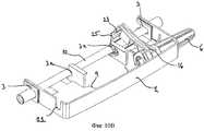
На фиг.1 показана кассета по предпочтительному варианту выполнения захватного зажима в сборе по изобретению, вид в перспективе;Figure 1 shows a cartridge according to a preferred embodiment of the gripping clamp assembly according to the invention, a perspective view;
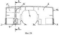
на фиг.2А, 2В, 2С - кассета, показанная на фиг.1, вид спереди, вид сверху и вид сзади, соответственно;on figa, 2B, 2C - cassette shown in figure 1, front view, top view and rear view, respectively;
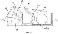
на фиг.2D, 2Е - виды в разрезе по линии А-А из фиг.2В, где зажимной элемент показан в закрытом и открытом положении, соответственно;on fig.2D, 2E - views in section along the line aa of figv, where the clamping element is shown in the closed and open position, respectively;
на фиг.3А, 3В - трубчатый переходник для предпочтительного варианта выполнения захватного зажима в сборе по изобретению, виды в перспективе;on figa, 3B - tube adapter for a preferred embodiment of the gripping clamp Assembly according to the invention, perspective views;
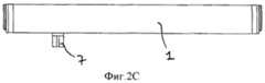
на фиг.4 - силиконовая трубка по предпочтительному варианту выполнения захватного зажима в сборе по изобретению;figure 4 - silicone tube in a preferred embodiment of the gripping clamp Assembly according to the invention;
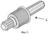
на фиг.5 - энтеральный универсальный элемент с крышкой, представляющий собой часть предпочтительного варианта выполнения захватного зажима в сборе по изобретению, вид в перспективе;figure 5 - enteric universal element with a lid, which is part of a preferred embodiment of the gripping clamp Assembly according to the invention, a perspective view;
на фиг.6 - энтеральный адаптер с крышкой по другому варианту выполнения захватного зажима в сборе по изобретению;6 is an enteral adapter with a cover according to another embodiment of the gripping clamp assembly according to the invention;
на фиг.7 - предпочтительный вариант выполнения захватного зажима в сборе по изобретению в первом состоянии сборки, вид в перспективе;7 is a preferred embodiment of the gripping clamp assembly according to the invention in a first assembly state, perspective view;
на фиг.8 - предпочтительный вариант выполнения захватного зажима в сборе по изобретению во втором состоянии сборки, вид в перспективе;on Fig - a preferred embodiment of the gripping clamp Assembly according to the invention in the second state of the Assembly, a perspective view;
на фиг.9А, 9В - два предпочтительных варианта выполнения захватного зажима в сборе по изобретению в третьем состоянии сборки, виды в перспективе;on figa, 9B - two preferred embodiments of the gripping clamp Assembly according to the invention in a third state of Assembly, perspective views;
на фиг.10А, 10В - два предпочтительных варианта выполнения захватного зажима в сборе по изобретению в состоянии подачи препарата, виды в перспективе.on figa, 10B - two preferred options for the execution of the gripping clamp Assembly according to the invention in the state of supply of the drug, perspective views.
Осуществление изобретенияThe implementation of the invention
На фиг.1 показан вид в перспективе основного элемента предпочтительного варианта выполнения захватного зажима в сборе по изобретению, который содержит кассету 1, образующую основание устройства. Кассета 1, в общем, является прямоугольной и относительно плоской конструкцией. На своих противолежащих сторонах кассета 1 содержит удерживающие средства 3 для поддержки перекачивающей секции силиконовой трубки (не показана на фигуре). Другие удерживающие средства За для вмещения силиконовой трубки расположены в направлении центра вблизи продольного края кассеты 1. Опорные средства 5 предусмотрены для поддержки соединителя, который будет подробно описан ниже. Главным элементом захватного зажима в сборе по изобретению является зажимной элемент 7, который в показанном варианте осуществления изобретения составляет одно целое с кассетой 1. Конструктивные особенности зажимного элемента 7 будут описаны со ссылкой на фиг.2D и фиг.2Е. В боковой стенке, противолежащей опорному средству 5, имеется выемка 11 для трубки, предназначенная для поддержки трубки, связанной с соединителем. Во избежание усложнения фигур элементами, которые не являются существенными для изобретения, в этом месте трубка не изображена. Нижний участок кассеты 1 имеет выемку 9 для узла ротора, которая, по существу, имеет форму прямоугольника с внутренними закругленными углами. При креплении захватного зажима по изобретению к насосу для энтерального питания или к инфузионному насосу ролики узла перистальтического ротора вставляются в пространство, образуемое выемкой 9 для узла ротора. Удерживающие средства За образованы в параллельных боковых стенках, которые расположены на краю выемки 9 и, по существу, перпендикулярны направлению трубки с целью повышения устойчивости во время вышеуказанной процедуры крепления.Figure 1 shows a perspective view of the main element of a preferred embodiment of the gripping clamp assembly according to the invention, which contains a
На фиг.2А, 2В и 2С показаны вид спереди, вид сверху и вид сзади элементов захватного зажима в сборе из фиг.1, при этом одни и те же элементы обозначены одинаковыми ссылочными номерами.On figa, 2B and 2C shows a front view, a top view and a rear view of the elements of the gripping clamp Assembly of figure 1, while the same elements are indicated by the same reference numbers.
На фиг.2D и 2Е показан увеличенный вид сбоку в разрезе кассеты 1 из фиг.1, при этом зажимной элемент 7 находится в закрытом положении (фиг.2D) и в открытом положении (фиг.2Е). Зажимной элемент 7, в общем, состоит из первой ножки 15 с участком 17 блокировки трубки в виде, по существу, прямоугольной пластины, которая крепится к первой ножке 15, по существу, под прямым углом. На дальнем конце по отношению к участку 17 блокировки трубки первая ножка 15 содержит удерживающий рычаг 16. В показанном варианте осуществления изобретения вторая ножка 19 зажимного элемента 7 образована за одно целое с установочной пластиной кассеты 1. Соединительным элементом между первой ножкой 15 и второй ножкой 19 зажимного элемента 7 является изгибающийся участок 21, который действует в качестве упругого элемента, так чтобы зажимной элемент 7 мог перемещаться из открытого положения в закрытое положение. Удерживающий рычаг 16 образован в переходной области между первой ножкой 15 и изгибающимся участком 21 и продолжается, по меньшей мере, частично в пространство над круглым опорным средством 5, предпочтительно, под углом 5-30°. Для надежного функционирования удерживающего рычага 16 на верхней поверхности первой ножки 15 и удерживающего рычага 16 образован тавровый профиль, что наиболее наглядно показано на фиг.1.On fig.2D and 2E shows an enlarged side view in section of the
На свободном конце первой ножки 15 имеется первое стопорное средство 23, которое продолжается, по существу, под прямым углом к нижней пластине кассеты 1. Тавровый профиль продолжается, по существу, от нижнего конца первого стопорного средства 23 до дальнего конца удерживающего рычага 16. Первое стопорное средство 23 содержит выступ, выступающий, в общем, в сторону от изгибающегося участка 21. Ответным элементом первого стопорного средства 23 является второе стопорное средство 25, расположенное на свободном конце второй ножки 19. В предпочтительном варианте осуществления настоящего изобретения второе стопорное средство 25 имеет горизонтальную прорезь, длина которой обеспечивает зацепление крючкообразного первого стопорного средства 23 и прорези второго стопорного средства 25 в закрытом положении зажимного элемента 7 (показано на фиг.2D). Таким образом, второе стопорное средство 25 в этом варианте осуществления изобретения имеет большую ширину, чем первое стопорное средство 23, как можно видеть на фиг.2А. В предпочтительном варианте осуществления изобретения в открытом положении зажимного элемента 7 зацепление между первым и вторым стопорными средствами (показано на фиг.2Е) отсутствует. Следует отметить, что для обеспечения стопорной функции зажимного элемента 7 в первом и втором стопорном средствах 23, 25 могут быть использованы любые другие элементы зацепления.At the free end of the
Перемещение зажимного элемента 7 из открытого положения в закрытое положение осуществляется достаточно просто: при нажатии на верхнюю поверхность первой ножки 15 первое стопорное средство 23 перемещается вниз и, в конечном счете, входит в зацепление своим крючкообразным выступом с прорезью, образованной во втором стопорном средстве 25, преодолевая упругую силу изгибающегося участка 21, что обеспечивает устойчивое закрытое состояние зажимного элемента 7. За счет кратковременного разъединения первого стопорного средства 23 и второго стопорного средства 25 зажимной элемент 7 может быть переведен из закрытого положения в открытое положение. Это может быть выполнено за счет изгибания второго стопорного средства 25 в сторону от первого стопорного средства 23 в направлении от изгибающегося участка 21, т.е., по существу, параллельно плоскости второй ножки 19. Как вариант, можно нажать на первое стопорное средство 23 через прорезь во втором стопорном средстве 25, по существу, параллельно плоскости второй ножки 19. Поскольку доступ с наружной стороны ко второму стопорному средству 25 перекрывается первым стопорным средством 23, то для разъединения первого и второго стопорных средств 23, 25 должны использоваться специальные инструменты, такие как очень маленькая шпилька или отвертка.The movement of the
Следует отметить, что в зажимном элементе 7 могут использоваться стопорные средства других типов, такие как механизм, используемый в накладке кабеля/соединительной накладке, механизм с магнитным затвором или крепление на липучке. В альтернативных вариантах осуществления изобретения (не показаны) могут использоваться два или более крючкообразных выступов первого стопорного средства 23, предназначенные для зацепления с соответствующим множеством прорезей во втором стопорном средстве 25. Для разъединения таких стопорных средств должны использоваться специальные инструменты.It should be noted that other types of locking means may be used in the
Как можно видеть на фиг.2D и 2Е, участок 17 блокировки трубки в закрытом положении почти касается внутренней поверхности второй ножки 19, таким образом, сжимая перекачивающую секцию силиконовой трубки (не показано) и перекрывая протекание препарата по трубке. В показанном варианте осуществления изобретения зажимные поверхности участка 17 блокировки трубки и второй ножки 19 являются гладкими. Однако зажимные поверхности могут быть шероховатыми, рифлеными или оребренными с целью облегчения сжимающей функции зажимного элемента 7 в зависимости от характеристик силиконовой трубки.As can be seen in FIGS. 2D and 2E, the
На фиг.3А и 3В показаны виды в перспективе трубчатого переходника 39, предназначенного для удерживания силиконовой трубки и ее вставления в удерживающие средства 3, предусмотренные в кассете 1 захватного зажима в сборе (см. фиг.1). Для обеспечения надлежащего крепления трубчатые переходники содержат фланец 40, который предназначен для контакта с выемками, образованными в удерживающих средствах 3 кассеты 1.FIGS. 3A and 3B show perspective views of a
На фиг.4 показана перекачивающая секция силиконовой трубки 10, которая расположена в захватном зажиме в сборе по изобретению между зажимными поверхностями первой ножки 15 и второй ножки 19 и которая с обоих концов плотно соединена с соответствующими концами трубчатых переходников 39. Следует отметить, что обычно из силикона изготавливается только перекачивающая секция трубчатого участка всего инфузионного комплекта, в то время как остальные участки трубки выполняются из ПВХ (поливинилхлорида).Figure 4 shows the pumping section of the
На фиг.5 и 6 показаны два предпочтительных варианта соединителя 6, представляющего собой часть захватного зажима в сборе по изобретению. На фиг.5 показан универсальный элемент, который может быть использован в ряде устройств для энтерального питания, а на фиг.6 показан энтеральный переходник, который на одном конце содержит охватывающий люэровский наконечник или конусный элемент. Следует отметить, что на фиг.5 универсальный элемент на более короткой стороне непосредственно соединен с трубкой, например, посредством склеивания с применением растворителя.Figures 5 and 6 show two preferred embodiments of
Функция захватного зажима в сборе по настоящему изобретению будет подробно описана ниже со ссылкой на фиг.7, 8, 9А, 9В, 10А и 10В.The function of the gripping clamp assembly of the present invention will be described in detail below with reference to FIGS. 7, 8, 9A, 9B, 10A and 10B.
На фиг.7 показан вид в перспективе первого этапа сборки предпочтительного варианта выполнения захватного зажима в сборе по изобретению. Предполагается, что кассета 1 будет изготавливаться литьем под давлением из термопластичного материала, например, из полипропилена, полистирола, полиэтилена или акрил-нитрил-бутадиен-стирола (ABS), а также любого другого пригодного термопластика. Перекачивающая секция 10 силиконовой трубки уже соединена с двумя трубчатыми переходниками 39 и теперь устанавливается в кассету 1. Перед вставлением трубчатых переходников 39 в удерживающие средства 3 и 3а кассеты 1 силиконовая трубка 10 должна быть расположена между зажимными поверхностями первой ножки 15 и второй ножки 19 зажимного элемента 7. С этой целью первое стопорное средство 23 и второе стопорное средство 25 разъединяются, и первая ножка 15 может быть широко раскрыта для приема силиконовой трубки 10. Как вариант, зажимной элемент 7 может удерживаться в нормальном открытом положении, и силиконовая трубка 10 может перемещаться со скольжением между зажимными поверхностями зажимного элемента 7, и затем соединяться с трубчатым переходником 39, который далее входит в зацепление с удерживающими средствами 3 и За. Очевидно, что в таком состоянии после вставления силиконовой трубки 10 в кассету 1 перекачивающая секция не перекрывается. Однако следует отметить, что это состояние является лишь промежуточным состоянием при сборке захватного зажима в сборе по изобретению.FIG. 7 is a perspective view of a first assembly step of a preferred embodiment of the gripping clamp assembly of the invention. It is anticipated that
На фиг.8 показан следующий этап сборки, где соединитель 6 изображен в двух различных формах: в виде универсального элемента из фиг.5 и энтерального переходника из фиг.6. Три стрелки указывают активное перемещение относительно различных элементов захватного зажима в сборе: прежде всего зажимной элемент 7 перемещается в закрытое положение посредством нажатия на наружную поверхность первой ножки 15, предпочтительно, по существу, над участком 17 блокировки трубки, тем самым, перекрывая перекачивающую секцию силиконовой трубки 10. Второе перемещение указывает на позиционирование соединителя 6 в опорном средстве 5 кассеты 1. Следует отметить, что в показанном варианте осуществления изобретения сложно установить соединитель 6 в опорное средство 5 кассеты 1, когда зажимной элемент 7 находится в открытом положении. Причина состоит в том, что этому препятствует удерживающий рычаг 16, который в открытом положении зажимного элемента 7 продолжается, по существу, параллельно нижней пластине кассеты 1. Однако по изобретению эта функция препятствования установке соединителя 6 в опорное средство 5 кассеты 1 не является существенной, как будет объяснено ниже.On Fig shows the next stage of the assembly, where the
Состояние, показанное на фиг.8, также является промежуточным состоянием во время сборки захватного зажима в сборе по изобретению. Оно является необходимым для следующего этапа сборки, который представляет собой крепление соединителя 6 к существующим элементам захватного зажима в сборе за счет его вставления в опорное средство 5, когда зажимной элемент 7 находится в закрытом положении. Следует отметить, что, несмотря на то, что на фиг.8 показаны два варианта выполнения соединителя 6, только один соединитель 6 может входить в зацепление с опорным средством 5. Зацепление соединителя 6 с опорным средством 5 не позволяет соединителю 6 перемещаться вдоль его оси в продольном направлении.The state shown in FIG. 8 is also an intermediate state during assembly of the gripping clip assembly of the invention. It is necessary for the next assembly step, which is the fastening of the
На фиг.9А и 9В показаны виды в перспективе двух предпочтительных вариантов выполнения захватного зажима в сборе по изобретению на следующем этапе после того, как соединитель 6 был прикреплен к сборочной единице, как указано выше. В этом промежуточном состоянии зажимной элемент 7 удерживает перекачивающую секцию 10 силиконовой трубки. Кроме того, существует некоторое свободное пространство между верхней поверхностью соединителя 6 и нижней поверхностью удерживающего рычага 16 зажимного элемента 7.FIGS. 9A and 9B show perspective views of two preferred embodiments of the gripping clamp assembly of the invention in the next step after
На фиг.10А и 10В показаны виды в перспективе двух предпочтительных вариантов выполнения захватного зажима в сборе по изобретению в окончательном состоянии подачи препарата после перевода зажимного элемента 7 в открытое положение. Открывание зажимного элемента 7 достигается за счет разъединения первого стопорного средства 23 и второго стопорного средства 25 зажимного элемента 7 с целью открыть зону между зажимными поверхностями и, следовательно, позволить силиконовой трубке 10 вернуться в состояние, в котором она имеет исходное поперечное сечение. Важно отметить, что в этом состоянии подачи препарата захватного зажима в сборе по изобретению перекачивающая секция силиконовой трубки 10, по существу, не деформируется в том смысле, что во время хранения захватного зажима в сборе предотвращается прилипание внутренних поверхностей. Однако в этом состоянии подачи препарата в захватном зажиме в сборе по изобретению не возникает никакого свободного протекания препарата, поскольку соединитель 6 плотно крепится внутри сборочной единицы, так как удерживающий рычаг 16 зажимного элемента 7 прикладывает усилие к соединителю 6, так чтобы он не мог быть удален из сборочной единицы без закрывания зажимного элемента 7. Следовательно, медицинский персонал не может присоединить соединитель 6 к порту пациента, что привело бы к состоянию свободного протекания препарата. Ключевым принципом настоящего изобретения является то, что когда удерживающий рычаг 16, который действует как стопор, прикладывает усилие к соединителю 6 в открытом положении зажимного элемента 7, отсутствует возможность возникновения свободного протекания препарата, поскольку соединитель 6 плотно удерживается в сборочной единице, и извлечение соединителя 6 из сборочной единицы возможно только после перевода зажимного элемента 7 в закрытое положение. Таким образом, протекание препарата через перекачивающую секцию силиконовой трубки 10 всегда перекрывается перед вставлением захватного зажима в сборе в насос.10A and 10B show perspective views of two preferred embodiments of the gripping clamp assembly of the invention in the final state of drug delivery after moving the
Перевод захватного зажима в сборе по изобретению из состояния, показанного на фиг.9А и 9В, в состояние, показанное на фиг.10А и 10В, требует разъединения первого стопорного средства 23 и второго стопорного средства 25. Это может быть достигнуто с помощью наружного инструмента, являющегося частью процесса сборки захватного зажима в сборе по изобретению; этот специальный инструмент толкает второй стопорный элемент 25 в направлении участка 21 зажимного элемента 7, так чтобы вывести стопорные элементы из крюкообразного зацепления, как показано стрелками на фиг.9А и 9В. Очевидно, что это освобождение зажимного элемента 7 не может быть выполнено легко, например, только с помощью пальцев. На фиг.10А и 10В также показано, что удерживающий рычаг 16 зажимного элемента 7 плотно установлен поверх соединителя 6. Кроме того, удерживающий рычаг 16 продолжается на большей части поверхности соединителя 6, что не позволяет извлечь соединитель 6 из сборочной единицы в этом состоянии. Как указано выше, продольному перемещению препятствует опорное средство 5.The transfer of the gripping clamp assembly according to the invention from the state shown in FIGS. 9A and 9B to the state shown in FIGS. 10A and 10B requires the first locking means 23 and the second locking means 25 to be disconnected. This can be achieved using an external tool, as part of the assembly of the gripping clamp assembly according to the invention; this special tool pushes the
Следует отметить, что захватный зажим в сборе, показанный на фиг.10А и 10В, не может быть присоединен к насосу для энтерального питания или к инфузионному насосу. Перед установкой должен быть извлечен соединитель 6. Это возможно только после перевода зажимного элемента 7 в закрытое положение. Понятно, что перевод зажимного элемента 7 в закрытое положение также открывает доступ к соединителю 6, который может быть извлечен из сборочной единицы и присоединен к порту для настройки комплекта для энтерального питания или инфузионного комплекта. Во время крепления захаватного зажима в сборе с удаленным соединителем 6 к насосу для энтерального питания или к инфузионному насосу зажимной элемент 7 все еще находится в закрытом положении, тем самым, перекрывая протекание жидкости через перекачивающую секцию силиконовой трубки 10. Таким образом, исключается состояние свободного протекания препарата. Однако состояние, при котором перекрыта перекачивающая секция силиконовой трубки 10, должно быть устранено, как только кассета 1 с другими элементами захватного зажима в сборе будет установлена в насос для энтерального питания или инфузионный насос. Форма кассеты, которую имеет основание захватного зажима в сборе, облегчает манипулирование сборочной единицей и ее установку в насос.It should be noted that the complete gripper clamp shown in FIGS. 10A and 10B cannot be connected to an enteral feeding pump or to an infusion pump. Before installation, the
В вышеописанном предпочтительном варианте осуществления изобретения был представлен стопорно-освобождающий механизм. Следует отметить, что могут использоваться другие стопорно-освобождающие механизмы, например, магнитный механизм или механизм с крепежными средствами. Однако все альтернативные технические решения должны удовлетворять основному требованию, состоящему в том, что они должны быть защищены от несанкционированного использования, так чтобы зажимной элемент 7 нельзя было легко открыть вручную или с помощью инструментов, легкодоступных медицинскому персоналу.In the above described preferred embodiment, a locking release mechanism has been provided. It should be noted that other locking and releasing mechanisms may be used, for example, a magnetic mechanism or a mechanism with fixing means. However, all alternative technical solutions must satisfy the basic requirement that they must be protected from unauthorized use, so that the clamping
В качестве объекта настоящего изобретения предлагается захватный зажим в сборе для соединения трубки с насосом для энтерального питания или с инфузионным насосом, который приспособлен для подачи питательных препаратов или вливания медицинских растворов пациенту, содержит относительно простую конструкцию, образует механизм, препятствующий свободному протеканию препарата и работающий при любых условиях, обеспечивает долговременное хранение силиконовой трубки, изготавливается из однотипных материалов с целью облегчения утилизации и может использоваться с рядом насосов для энтерального питания или с инфузионными насосами.As an object of the present invention, there is provided a gripping clamp assembly for connecting a tube to an enteral nutrition pump or to an infusion pump, which is adapted to supply nutrient preparations or to infuse medical solutions to a patient, contains a relatively simple structure, forms a mechanism that prevents the drug from flowing freely, and works when any conditions, provides long-term storage of a silicone tube, is made of the same materials in order to facilitate disposal It can be used with a number of pumps for enteral feeding pump or infusion.
Claims (25)
Translated fromRussianApplications Claiming Priority (3)
| Application Number | Priority Date | Filing Date | Title |
|---|---|---|---|
| EPPCT/EP2009/004601 | 2009-06-25 | ||
| PCT/EP2009/004601WO2010149187A1 (en) | 2009-06-25 | 2009-06-25 | Pinch clamp assembly for an infusion cassette |
| PCT/EP2009/060556WO2010149231A1 (en) | 2009-06-25 | 2009-08-14 | Pinch clamp assembly |
Publications (2)
| Publication Number | Publication Date |
|---|---|
| RU2012102377A RU2012102377A (en) | 2013-07-27 |
| RU2494770C1true RU2494770C1 (en) | 2013-10-10 |
Family
ID=41723103
Family Applications (3)
| Application Number | Title | Priority Date | Filing Date |
|---|---|---|---|
| RU2012102384/14ARU2012102384A (en) | 2009-06-25 | 2009-06-25 | CAPTURE CLAMP ASSEMBLY FOR INFUSION CASSETTE |
| RU2012102377/14ARU2494770C1 (en) | 2009-06-25 | 2009-08-14 | Assembled grip for infusion cartridge |
| RU2012102375/14ARU2012102375A (en) | 2009-06-25 | 2009-09-22 | CAPTURE CLAMP ASSEMBLY FOR INFUSION CASSETTE |
Family Applications Before (1)
| Application Number | Title | Priority Date | Filing Date |
|---|---|---|---|
| RU2012102384/14ARU2012102384A (en) | 2009-06-25 | 2009-06-25 | CAPTURE CLAMP ASSEMBLY FOR INFUSION CASSETTE |
Family Applications After (1)
| Application Number | Title | Priority Date | Filing Date |
|---|---|---|---|
| RU2012102375/14ARU2012102375A (en) | 2009-06-25 | 2009-09-22 | CAPTURE CLAMP ASSEMBLY FOR INFUSION CASSETTE |
Country Status (14)
| Country | Link |
|---|---|
| US (3) | US8545458B2 (en) |
| EP (2) | EP2445573B1 (en) |
| JP (3) | JP5314800B2 (en) |
| CN (3) | CN102481447B (en) |
| AU (3) | AU2009348770B2 (en) |
| BR (1) | BRPI0925301A8 (en) |
| CA (3) | CA2765880C (en) |
| ES (3) | ES2456352T3 (en) |
| MX (3) | MX2011014000A (en) |
| RU (3) | RU2012102384A (en) |
| SG (3) | SG177295A1 (en) |
| TW (3) | TWI403340B (en) |
| WO (3) | WO2010149187A1 (en) |
| ZA (2) | ZA201200598B (en) |
Cited By (1)
| Publication number | Priority date | Publication date | Assignee | Title |
|---|---|---|---|---|
| RU2841598C1 (en)* | 2021-01-13 | 2025-06-10 | Фрезениус Каби (Наньчан) Ко., Лтд. | Infusion device |
Families Citing this family (41)
| Publication number | Priority date | Publication date | Assignee | Title |
|---|---|---|---|---|
| US8308457B2 (en) | 2004-11-24 | 2012-11-13 | Q-Core Medical Ltd. | Peristaltic infusion pump with locking mechanism |
| IL165365A0 (en) | 2004-11-24 | 2006-01-15 | Q Core Ltd | Finger-type peristaltic pump |
| IL179231A0 (en) | 2006-11-13 | 2007-03-08 | Q Core Ltd | A finger-type peristaltic pump comprising a ribbed anvil |
| US8535025B2 (en) | 2006-11-13 | 2013-09-17 | Q-Core Medical Ltd. | Magnetically balanced finger-type peristaltic pump |
| IL179234A0 (en) | 2006-11-13 | 2007-03-08 | Q Core Ltd | An anti-free flow mechanism |
| RU2012104810A (en)* | 2009-07-13 | 2013-08-20 | Нестек С.А. | CARTRIDGES AND METHOD OF USE |
| US9457158B2 (en) | 2010-04-12 | 2016-10-04 | Q-Core Medical Ltd. | Air trap for intravenous pump |
| US9017297B2 (en)* | 2010-08-06 | 2015-04-28 | WalkMed Infusion LLC | Infusion pump and method which inhibits unintended tubing withdrawal |
| USD672458S1 (en)* | 2010-08-31 | 2012-12-11 | The University Of Vermont And State Agriculture College | Infusion pump electrical connector cover |
| US9674811B2 (en) | 2011-01-16 | 2017-06-06 | Q-Core Medical Ltd. | Methods, apparatus and systems for medical device communication, control and localization |
| US8469933B2 (en) | 2011-03-18 | 2013-06-25 | Zyno Medical Llc | Pump activated pinch clamp |
| US9726167B2 (en) | 2011-06-27 | 2017-08-08 | Q-Core Medical Ltd. | Methods, circuits, devices, apparatuses, encasements and systems for identifying if a medical infusion system is decalibrated |
| WO2013010580A1 (en) | 2011-07-18 | 2013-01-24 | Cedic S.R.L. | Anti free flow valve |
| EP2583716B1 (en)* | 2011-10-18 | 2015-07-29 | B. Braun Melsungen AG | Infusion hose clamp for a infusionpump and method for use of the same |
| WO2013145060A1 (en)* | 2012-03-26 | 2013-10-03 | テルモ株式会社 | Infusion pump |
| EP2921188B1 (en)* | 2012-11-14 | 2018-01-31 | Namiki Seimitsu Houseki Kabushiki Kaisha | Tube clamp structure of tubing pump |
| US9855110B2 (en) | 2013-02-05 | 2018-01-02 | Q-Core Medical Ltd. | Methods, apparatus and systems for operating a medical device including an accelerometer |
| US20140378901A1 (en)* | 2013-06-23 | 2014-12-25 | Q-Core Medical Ltd. | Mechanical pump to tube interfaces, systems including the interfaces and methods for producing same |
| CN104941031B (en)* | 2015-07-07 | 2018-06-01 | 苏州麦德迅医疗科技有限公司 | Infusion pump and method with rotation lock |
| US20180221643A1 (en)* | 2015-07-31 | 2018-08-09 | Smiths Medical Asd, Inc. | Infusion line clamp systems for infusion pumps |
| US10792432B2 (en) | 2016-06-09 | 2020-10-06 | Becton, Dickinson And Company | Drive assembly and spacer for drug delivery system |
| US10751476B2 (en) | 2016-06-09 | 2020-08-25 | Becton, Dickinson And Company | Actuator assembly for drug delivery system |
| US10603445B2 (en) | 2016-06-09 | 2020-03-31 | Becton, Dickinson And Company | Needle actuator assembly for drug delivery system |
| US10549044B2 (en) | 2016-06-09 | 2020-02-04 | Becton, Dickinson And Company | Spacer assembly for drug delivery system |
| CN109414545B (en)* | 2016-06-16 | 2021-07-27 | 史密斯医疗Asd公司 | Assembly and method for infusion pump system administration set |
| CA3048976A1 (en) | 2016-12-30 | 2018-07-05 | Baxter International Inc. | Infusion pump door seal for vertical intravenous tubes |
| EP3838311B1 (en) | 2016-12-30 | 2025-05-07 | Baxter International Inc. | Anti-occlusion intravenous tube port |
| US11517734B2 (en)* | 2017-06-21 | 2022-12-06 | Kristin Rossodivito | System and method for detecting air embolisms in lines for hemodynamic monitoring |
| CA3069538A1 (en) | 2017-07-19 | 2019-01-24 | Smiths Medical Asd, Inc. | Housing arrangements for infusion pumps |
| USD870263S1 (en) | 2017-07-26 | 2019-12-17 | Smiths Medical Asd, Inc. | Infusion set |
| DE102017212883A1 (en)* | 2017-07-26 | 2019-01-31 | B. Braun Melsungen Ag | Hose clamp for clamping a medical hose |
| DE102017122647A1 (en)* | 2017-09-28 | 2019-03-28 | B. Braun Melsungen Ag | Hose clamp and volumetric pump with hose clamp |
| JP7111809B2 (en) | 2017-10-16 | 2022-08-02 | ベクトン・ディキンソン・アンド・カンパニー | Spacer assembly for drug delivery device |
| ES2927716T3 (en)* | 2017-10-31 | 2022-11-10 | Cme America Llc | Cartridge for tubing placement in a peristaltic infusion pump |
| AU2018388965B2 (en)* | 2017-12-19 | 2024-11-21 | Smiths Medical Asd, Inc. | Infusion pump systems and methods for administration sets |
| US11213460B2 (en) | 2018-09-19 | 2022-01-04 | Vesco Medical Llc | Connectors for infusion pump feeding sets |
| HUE068931T2 (en)* | 2019-01-22 | 2025-02-28 | Adventia Pharma S L | Feeding cap, drive head, and drive system |
| US20220362461A1 (en)* | 2019-06-14 | 2022-11-17 | Inventec Appliances (Pudong) Corporation | Infusion device |
| WO2021015281A1 (en)* | 2019-07-22 | 2021-01-28 | ニプロ株式会社 | Drug solution injection controller |
| US11426515B2 (en) | 2019-07-25 | 2022-08-30 | Zevex, Inc. | Infusion pump cassette having integrated pinch clip occluder |
| ES2933693T3 (en) | 2019-11-18 | 2023-02-13 | Eitan Medical Ltd | Rapid test for medical pump |
Citations (8)
| Publication number | Priority date | Publication date | Assignee | Title |
|---|---|---|---|---|
| US4944485A (en)* | 1989-08-28 | 1990-07-31 | Ivac Corporation | Clamp for flexible tubing |
| SU1720504A3 (en)* | 1987-03-06 | 1992-03-15 | Польска Акадэмия Наук Заклад Досьвядчальны "Медипан" Центрум Медицины Досьвядчальнэй И Клиничнэй (Инопредприятие) | Device for control of liquid flow rate in flow-through pipeline |
| US5401256A (en)* | 1994-01-14 | 1995-03-28 | Minnesota Mining And Manufacturing Company | Flexible clamp for use in IV tubing set |
| RU2111018C1 (en)* | 1995-05-06 | 1998-05-20 | Центральный научно-исследовательский институт точного машиностроения | Peristaltic apparatus with continuously adjustable medication feeding system |
| US5954485A (en)* | 1996-08-14 | 1999-09-21 | Sims Deltec, Inc. | Free-flow protection devices and methods |
| WO2003011377A1 (en)* | 2001-07-31 | 2003-02-13 | Scott Laboratories, Inc. | Apparatuses and methods for providing iv infusion administration |
| US20070265559A1 (en)* | 2004-12-20 | 2007-11-15 | Jms Co., Ltd. | Transfusion Safety Device |
| RU2339408C2 (en)* | 2004-07-16 | 2008-11-27 | Мейнтэк Ко., Лтд. | Device for resetting of injected volume of liquid medicine |
Family Cites Families (21)
| Publication number | Priority date | Publication date | Assignee | Title |
|---|---|---|---|---|
| US4944854A (en)* | 1983-11-08 | 1990-07-31 | Celanese Corporation | Electret process and products |
| US4635092A (en)* | 1984-06-04 | 1987-01-06 | General Electric Company | Tape automated manufacture of power semiconductor devices |
| JPH0236520Y2 (en)* | 1986-03-17 | 1990-10-04 | ||
| US4689043A (en) | 1986-03-19 | 1987-08-25 | Imed Corporation | IV tube activator |
| US4950255A (en)* | 1988-04-07 | 1990-08-21 | I-Flow Corporation | Catheter connector and clamp |
| CA2064134A1 (en)* | 1991-04-23 | 1992-10-24 | Gary A. Thill | Free flow prevention system for infusion pump |
| DE4118732A1 (en) | 1991-06-07 | 1992-12-10 | Joka Kathetertechnik Gmbh | HOSE CLAMP FOR MEDICAL PURPOSES |
| US5482438A (en)* | 1994-03-09 | 1996-01-09 | Anderson; Robert L. | Magnetic detent and position detector for fluid pump motor |
| US5482446A (en)* | 1994-03-09 | 1996-01-09 | Baxter International Inc. | Ambulatory infusion pump |
| AU5527596A (en) | 1995-03-27 | 1996-10-16 | Zevex, Inc. | Pinch clip occluder for infusion sets |
| US6210361B1 (en)* | 1997-08-22 | 2001-04-03 | Deka Products Limited Partnership | System for delivering intravenous drugs |
| US6659976B2 (en)* | 2001-04-16 | 2003-12-09 | Zevek, Inc. | Feeding set adaptor |
| CN1668358A (en)* | 2002-05-16 | 2005-09-14 | 斯科特实验室公司 | Medical supply kits for sedation and pain relief |
| JP3885018B2 (en)* | 2002-10-24 | 2007-02-21 | 株式会社トップ | Infusion pump cassette |
| US7124996B2 (en) | 2004-07-16 | 2006-10-24 | Cardinal Health 303, Inc. | Automatic clamp apparatus for IV infusion sets used in pump devices |
| US20060042631A1 (en)* | 2004-08-31 | 2006-03-02 | Martin James F | Apparatus to deliver oxygen to a patient |
| TWI381861B (en) | 2004-10-19 | 2013-01-11 | Terumo Corp | Infusion apparatus and clamp |
| JP4949700B2 (en) | 2006-03-08 | 2012-06-13 | テルモ株式会社 | Infusion tube loading aid and infusion device |
| CN2925508Y (en) | 2006-07-25 | 2007-07-25 | 张丽霞 | Pressed fixer of drainage tube |
| JP3133453U (en)* | 2007-04-27 | 2007-07-12 | 株式会社メテク | Tube cassette for infusion pump |
| US8062008B2 (en)* | 2007-09-27 | 2011-11-22 | Curlin Medical Inc. | Peristaltic pump and removable cassette therefor |
- 2009
- 2009-06-25CACA2765880Apatent/CA2765880C/ennot_activeExpired - Fee Related
- 2009-06-25AUAU2009348770Apatent/AU2009348770B2/ennot_activeCeased
- 2009-06-25WOPCT/EP2009/004601patent/WO2010149187A1/enactiveApplication Filing
- 2009-06-25CNCN200980161101.4Apatent/CN102481447B/ennot_activeExpired - Fee Related
- 2009-06-25MXMX2011014000Apatent/MX2011014000A/enunknown
- 2009-06-25RURU2012102384/14Apatent/RU2012102384A/ennot_activeApplication Discontinuation
- 2009-06-25USUS13/379,195patent/US8545458B2/ennot_activeExpired - Fee Related
- 2009-06-25SGSG2011094372Apatent/SG177295A1/enunknown
- 2009-06-25ESES09776838.6Tpatent/ES2456352T3/enactiveActive
- 2009-06-25JPJP2012516518Apatent/JP5314800B2/ennot_activeExpired - Fee Related
- 2009-06-25EPEP09776838.6Apatent/EP2445573B1/ennot_activeNot-in-force
- 2009-08-14WOPCT/EP2009/060556patent/WO2010149231A1/enactiveApplication Filing
- 2009-08-14RURU2012102377/14Apatent/RU2494770C1/ennot_activeIP Right Cessation
- 2009-08-14SGSG2011094398Apatent/SG177297A1/enunknown
- 2009-08-14CACA2765967Apatent/CA2765967C/enactiveActive
- 2009-08-14JPJP2012516526Apatent/JP5308575B2/ennot_activeExpired - Fee Related
- 2009-08-14AUAU2009348754Apatent/AU2009348754B2/ennot_activeCeased
- 2009-08-14USUS13/379,203patent/US8551057B2/ennot_activeExpired - Fee Related
- 2009-08-14MXMX2011013998Apatent/MX2011013998A/enunknown
- 2009-08-14ESES09781858.7Tpatent/ES2451516T3/enactiveActive
- 2009-08-14CNCN200980161100XApatent/CN102481446B/ennot_activeExpired - Fee Related
- 2009-09-22ESES09783304.0Tpatent/ES2456298T3/enactiveActive
- 2009-09-22JPJP2012516527Apatent/JP5526228B2/ennot_activeExpired - Fee Related
- 2009-09-22WOPCT/EP2009/062292patent/WO2010149232A1/enactiveApplication Filing
- 2009-09-22EPEP09783304.0Apatent/EP2445575B1/ennot_activeNot-in-force
- 2009-09-22USUS13/379,199patent/US8551056B2/ennot_activeExpired - Fee Related
- 2009-09-22SGSG2011094414Apatent/SG176930A1/enunknown
- 2009-09-22AUAU2009348755Apatent/AU2009348755B2/ennot_activeCeased
- 2009-09-22CACA2765968Apatent/CA2765968C/ennot_activeExpired - Fee Related
- 2009-09-22CNCN200980161103.3Apatent/CN102481448B/ennot_activeExpired - Fee Related
- 2009-09-22BRBRPI0925301Apatent/BRPI0925301A8/ennot_activeApplication Discontinuation
- 2009-09-22MXMX2011014001Apatent/MX2011014001A/enunknown
- 2009-09-22RURU2012102375/14Apatent/RU2012102375A/ennot_activeApplication Discontinuation
- 2010
- 2010-06-25TWTW099120963Apatent/TWI403340B/ennot_activeIP Right Cessation
- 2010-06-25TWTW099120965Apatent/TWI400102B/ennot_activeIP Right Cessation
- 2010-06-25TWTW099120964Apatent/TWI403339B/ennot_activeIP Right Cessation
- 2012
- 2012-01-24ZAZA2012/00598Apatent/ZA201200598B/enunknown
- 2012-01-24ZAZA2012/00596Apatent/ZA201200596B/enunknown
Patent Citations (8)
| Publication number | Priority date | Publication date | Assignee | Title |
|---|---|---|---|---|
| SU1720504A3 (en)* | 1987-03-06 | 1992-03-15 | Польска Акадэмия Наук Заклад Досьвядчальны "Медипан" Центрум Медицины Досьвядчальнэй И Клиничнэй (Инопредприятие) | Device for control of liquid flow rate in flow-through pipeline |
| US4944485A (en)* | 1989-08-28 | 1990-07-31 | Ivac Corporation | Clamp for flexible tubing |
| US5401256A (en)* | 1994-01-14 | 1995-03-28 | Minnesota Mining And Manufacturing Company | Flexible clamp for use in IV tubing set |
| RU2111018C1 (en)* | 1995-05-06 | 1998-05-20 | Центральный научно-исследовательский институт точного машиностроения | Peristaltic apparatus with continuously adjustable medication feeding system |
| US5954485A (en)* | 1996-08-14 | 1999-09-21 | Sims Deltec, Inc. | Free-flow protection devices and methods |
| WO2003011377A1 (en)* | 2001-07-31 | 2003-02-13 | Scott Laboratories, Inc. | Apparatuses and methods for providing iv infusion administration |
| RU2339408C2 (en)* | 2004-07-16 | 2008-11-27 | Мейнтэк Ко., Лтд. | Device for resetting of injected volume of liquid medicine |
| US20070265559A1 (en)* | 2004-12-20 | 2007-11-15 | Jms Co., Ltd. | Transfusion Safety Device |
Cited By (1)
| Publication number | Priority date | Publication date | Assignee | Title |
|---|---|---|---|---|
| RU2841598C1 (en)* | 2021-01-13 | 2025-06-10 | Фрезениус Каби (Наньчан) Ко., Лтд. | Infusion device |
Also Published As
Similar Documents
| Publication | Publication Date | Title |
|---|---|---|
| RU2494770C1 (en) | Assembled grip for infusion cartridge | |
| EP2445574B1 (en) | Pinch clamp assembly for an infusion cassette | |
| HK1169063B (en) | Pinch clamp assembly for an infusion cassette | |
| HK1169062B (en) | Pinch clamp assembly for an infusion cassette | |
| HK1169064B (en) | Pinch clamp assembly for an infusion cassette |
Legal Events
| Date | Code | Title | Description |
|---|---|---|---|
| MM4A | The patent is invalid due to non-payment of fees | Effective date:20140815 |