RU2491502C2 - Method and device for gap gaging and leveling between parts fitted on assembly unit in absence of one of said parts - Google Patents
Method and device for gap gaging and leveling between parts fitted on assembly unit in absence of one of said partsDownload PDFInfo
- Publication number
- RU2491502C2 RU2491502C2RU2010120564/28ARU2010120564ARU2491502C2RU 2491502 C2RU2491502 C2RU 2491502C2RU 2010120564/28 ARU2010120564/28 ARU 2010120564/28ARU 2010120564 ARU2010120564 ARU 2010120564ARU 2491502 C2RU2491502 C2RU 2491502C2
- Authority
- RU
- Russia
- Prior art keywords
- measurement
- node
- alignment
- image
- clearance
- Prior art date
Links
- 238000000034methodMethods0.000titleclaimsabstractdescription41
- 238000005259measurementMethods0.000claimsabstractdescription85
- 238000005286illuminationMethods0.000claimsabstractdescription3
- 230000003287optical effectEffects0.000claimsdescription5
- 230000005855radiationEffects0.000claimsdescription5
- 238000000691measurement methodMethods0.000claimsdescription3
- 238000004364calculation methodMethods0.000claimsdescription2
- 238000013500data storageMethods0.000claims1
- 239000000126substanceSubstances0.000abstract1
- 238000009434installationMethods0.000description5
- 239000011521glassSubstances0.000description4
- 238000004519manufacturing processMethods0.000description4
- 238000003860storageMethods0.000description4
- 238000004026adhesive bondingMethods0.000description1
- 230000002950deficientEffects0.000description1
- 238000005516engineering processMethods0.000description1
- 239000012467final productSubstances0.000description1
- 239000005357flat glassSubstances0.000description1
- 230000005484gravityEffects0.000description1
- 238000011326mechanical measurementMethods0.000description1
- 229910052702rheniumInorganic materials0.000description1
- WUAPFZMCVAUBPE-UHFFFAOYSA-Nrhenium atomChemical compound[Re]WUAPFZMCVAUBPE-UHFFFAOYSA-N0.000description1
- 239000000523sampleSubstances0.000description1
- 230000001360synchronised effectEffects0.000description1
Images


Classifications
- B—PERFORMING OPERATIONS; TRANSPORTING
- B62—LAND VEHICLES FOR TRAVELLING OTHERWISE THAN ON RAILS
- B62D—MOTOR VEHICLES; TRAILERS
- B62D65/00—Designing, manufacturing, e.g. assembling, facilitating disassembly, or structurally modifying motor vehicles or trailers, not otherwise provided for
- B62D65/005—Inspection and final control devices
- G—PHYSICS
- G01—MEASURING; TESTING
- G01B—MEASURING LENGTH, THICKNESS OR SIMILAR LINEAR DIMENSIONS; MEASURING ANGLES; MEASURING AREAS; MEASURING IRREGULARITIES OF SURFACES OR CONTOURS
- G01B11/00—Measuring arrangements characterised by the use of optical techniques
- G01B11/14—Measuring arrangements characterised by the use of optical techniques for measuring distance or clearance between spaced objects or spaced apertures
Landscapes
- Engineering & Computer Science (AREA)
- Physics & Mathematics (AREA)
- General Physics & Mathematics (AREA)
- Manufacturing & Machinery (AREA)
- Chemical & Material Sciences (AREA)
- Combustion & Propulsion (AREA)
- Transportation (AREA)
- Mechanical Engineering (AREA)
- Length Measuring Devices By Optical Means (AREA)
Abstract
Description
Translated fromRussianНастоящее изобретение касается, в общем, способа и устройства измерения зазора и выравнивания между деталями, закрепленными на узле в случае отсутствия этой детали.The present invention relates, in General, to a method and device for measuring the clearance and alignment between parts attached to the node in the absence of this part.
Более точно, но исключительно, настоящее изобретение касается способа соответствующего измерения зазора и выравнивания между деталями, предназначенными для закрепления на автомобильном транспортном средстве при отсутствии одной из них в процессе проведения измерения, в частности, для дверей, крыльев, капота, стекол или крыши автомобильного транспортного средства.More precisely, but exclusively, the present invention relates to a method for adequately measuring the clearance and alignment between parts intended to be mounted on a motor vehicle in the absence of one of them during the measurement process, in particular for doors, fenders, bonnet, glass or roof of a motor vehicle facilities.
В этой области, как и во многих других, соответствие зазоров и выравнивания является важной задачей, так как эти характеристики гарантируют механическое функционирование узла, герметичность и эстетику узла, оказывающих значительное влияние на оценку качества изготовления конечного изделия.In this area, as in many others, matching gaps and alignment is an important task, since these characteristics guarantee the mechanical functioning of the assembly, the tightness and aesthetics of the assembly, which have a significant impact on the assessment of the quality of manufacturing of the final product.
Эти измерения могут быть легко осуществлены, когда измеряемые детали установлены на месте одна относительно другой, например, посредством контактного измерения щупами или калиброванными пластинками, следствием чего может явиться риск повреждения деталей, подвергаемых измерению, в частности, появления царапин на последних.These measurements can be easily carried out when the measured parts are mounted in place one relative to the other, for example, by contact measurement with probes or calibrated plates, which may result in the risk of damage to the parts being measured, in particular, scratches on the latter.
Однако существует много случаев, когда одна из деталей отсутствует при измерении зазора и выравнивания между двумя деталями. Это, например, случай, но не исключительный, касающийся переднего оконного стекла, которое будет вклеено в переднюю часть передней двери автомобиля при монтаже, тогда как измерения зазора и выравнивания между этим окном и передней частью соответствующей передней двери будут выполнены предварительно перед этим монтажом.However, there are many cases where one of the parts is missing when measuring the clearance and alignment between the two parts. This, for example, is a case, but not exceptional, regarding the front window glass that will be glued to the front of the front door of the car during installation, while the clearance and alignment measurements between this window and the front of the corresponding front door will be made before this installation.
Было предложено разместить ложное окно для обеспечения возможности измерения зазора и выравнивания между передней дверью и этим ложным окном в процессе предварительного этапа измерения. Такое решение имеет, однако многочисленные недостатки, а именно необходимость вложения средств для изготовления двух комплектов, левого и правого, ложных окон, необходимость осуществления их позиционирования на каждом автомобиле перед станцией измерения зазора и выравнивания, необходимость осуществлять их съем на выходе этой станции со связанными с этим рисками забыть или разбить их, и, наконец, необходимость перемещать ложные окна с позиции снятия на позицию установки. Это приводит к многочисленным манипуляциям, осуществляемым с ложными окнами, и, кроме того, к повышению стоимости изготовления.It was suggested that a false window be placed to allow measurement of the clearance and alignment between the front door and this false window during the preliminary measurement step. Such a solution, however, has numerous drawbacks, namely, the need to invest in the manufacture of two sets, left and right, false windows, the need to position them on each vehicle in front of the clearance and alignment station, and to remove them at the outlet of this station with associated forget about these risks or break them, and, finally, the need to move false windows from the removal position to the installation position. This leads to numerous manipulations carried out with false windows, and, in addition, to an increase in manufacturing costs.
При таком решении измерение собственно зазора и выравнивания может осуществляться при анализе изображений, полученных с помощью двухмерных датчиков, называемых 2D, что предоставляет многочисленные преимущества, по сравнению с механическим измерением, в частности, в том, что касается риска повреждения деталей. При этом оптическом измерении каждый датчик излучает полосу лазерного света, проецируемую радиально измеряемой стыковке. В изображении, полученной этим способом, горизонтальные расхождения, видимые между сегментами прямых, дают представление о зазоре, а вертикальные расхождения, видимые между сегментами прямой, дают представление о выравнивании. При алгоритме обработки изображений, возможно количественно измерять вертикальные и горизонтальные расхождения между сегментами для того, чтобы сделать вывод о зазоре и выравнивании.With this solution, the measurement of the gap itself and alignment can be carried out when analyzing images obtained using two-dimensional sensors, called 2D, which provides numerous advantages compared to mechanical measurement, in particular with regard to the risk of damage to parts. In this optical measurement, each sensor emits a band of laser light projected onto a radially measured interface. In the image obtained in this way, the horizontal discrepancies visible between the line segments give an idea of the clearance, and the vertical discrepancies visible between the line segments give an idea of alignment. With the image processing algorithm, it is possible to quantitatively measure the vertical and horizontal discrepancies between the segments in order to make a conclusion about the clearance and alignment.
Документы FR-A-2756626 и US-A-5129010 касаются оптических трехмерных датчиков, называемых 3D, используемых для определения зазоров и выравнивании между деталями и могущих использоваться в вышеупомянутом способе. Однако в этих документах не уточнена возможность измерения между краем детали и элементом крепления другой детали в отсутствие последней на ее опорном узле.The documents FR-A-2756626 and US-A-5129010 relate to optical three-dimensional sensors, called 3D, used to determine gaps and alignment between parts and which can be used in the aforementioned method. However, these documents do not clarify the possibility of measuring between the edge of the part and the fastening element of another part in the absence of the latter on its supporting unit.
Целью настоящего изобретения является возможность обеспечения точного и быстрого измерения зазора и выравнивания между двумя деталями, предназначенными для установки на узле, при этом одна из этих деталей отсутствует в процессе проведения измерений.The aim of the present invention is the ability to provide accurate and quick measurements of the clearance and alignment between two parts intended for installation on the site, while one of these parts is missing during the measurement process.
Изобретение касается способа измерения зазора и выравнивания между краями, предназначенными находиться напротив, первой и второй детали, закрепленных на узле, при этом вторая деталь должна быть позиционирована на этом узле, относительно, по меньшей мере, одной точки маркировки, неподвижной и отмечаемой на этом узле, причем в процессе проведения измерений вторая деталь отсутствует на узле, отличающегося следующими этапами:The invention relates to a method for measuring the clearance and alignment between the edges intended to be opposite, the first and second parts mounted on the node, while the second part should be positioned on this node, relative to at least one marking point, fixed and marked on this node moreover, in the process of taking the measurements, the second part is absent on the unit, characterized by the following steps:
- позиционирование, по меньшей мере, одного датчика в положение, которое позволяет ему иметь зону измерения, включающую в себя край первой детали, и точку маркировки на опорном узле для второй отсутствующей детали,- positioning of at least one sensor in a position that allows it to have a measurement zone including the edge of the first part, and a marking point on the reference node for the second missing part,
- излучение лазерной полосы для образования первого изображения зоны измерения,- radiation of the laser strip to form the first image of the measurement zone,
- получение первого изображения датчиком,- obtaining the first image by the sensor,
- излучение дополнительного освещения для образования второго изображения этой зоны измерения, в котором точка маркировки на узле появится в виде китайской тени,- radiation of additional lighting to form a second image of this measurement zone, in which the marking point on the node appears in the form of a Chinese shadow,
- получение этим датчиком второго изображения,- obtaining by this sensor a second image,
- обработка данных полученных изображений и определение алгоритмом измерения зазора и выравнивания между первой и второй деталями.- processing the data of the obtained images and determining by the algorithm for measuring the clearance and alignment between the first and second parts.
Преимущественно, обработка изображений и определение алгоритмом измерений зазора и выравнивания между первой и второй деталями осуществляется посредством:Mostly, image processing and determination by the measurement algorithm of the clearance and alignment between the first and second parts is carried out by:
- определения положения края первой детали, а также точки маркировки из полученных изображений, дающих также соответственно измерение глубины для первого изображения и измерение расстояния для второго изображения,- determining the position of the edge of the first part, as well as the marking point from the obtained images, which also give, respectively, a depth measurement for the first image and a distance measurement for the second image,
- коррекции этим алгоритмом измерения глубины путем вычитания величины теоретического размера толщины второй детали для получения выравнивания, и- correction by this algorithm for measuring depth by subtracting the theoretical thickness of the second part to obtain alignment, and
- коррекции этим алгоритмом измерения расстояния посредством вычитания величины теоретического размера между точкой маркировки и краем второй детали для получения зазора.- correction by this algorithm for measuring the distance by subtracting the theoretical size between the marking point and the edge of the second part to obtain a gap.
В соответствии с другими дополнительными характеристиками способа:In accordance with other additional characteristics of the method:
- первое изображение получают посредством излучения лазерной полосы, формирующей светящуюся плоскость, проецируемую на первую деталь и узел таким образом, чтобы создать, по меньшей мере, одну линию, проходящую поперек краям, предназначенным находиться напротив, двух деталей,- the first image is obtained by emitting a laser strip forming a luminous plane projected onto the first part and assembly in such a way as to create at least one line extending across the edges intended to be opposite, two parts,
- второе изображение получают проекцией пучка рассеянного света,- the second image is obtained by the projection of a beam of scattered light,
- в случае, когда вторая деталь имеет несколько точек маркировки на опорном узле, способ включает в себя подобные этапы соответствующего измерения расстояния и глубины для каждой точки маркировки для получения соответственно измерения зазора или выравнивания, при этом с каждой точкой маркировки связан конкретный датчик,- in the case where the second part has several marking points on the reference node, the method includes similar steps of correspondingly measuring the distance and depth for each marking point to obtain respectively a clearance or alignment measurement, and a specific sensor is associated with each marking point,
- этап взаимного сравнения полученного измерения зазора и выравнивания с измерением другого эталонного способа измерения, осуществляют посредством рассчитанной компенсации для возможной коррекции этих измерений и повторной калибровки используемого алгоритма в случае необходимости,- the stage of mutual comparison of the obtained measurement of the gap and alignment with the measurement of another reference measurement method, carried out by means of calculated compensation for the possible correction of these measurements and recalibration of the algorithm used, if necessary,
- измерения осуществляют либо в процессе продвижения опорного узла перед одним или несколькими датчиками, либо когда опорный узел неподвижен перед одним или несколькими датчиками для проведения измерений.- measurements are carried out either in the process of moving the support unit in front of one or more sensors, or when the support unit is stationary in front of one or more sensors for measurements.
Изобретение касается также устройства для измерения зазора и выравнивания между краями, предназначенными находиться напротив первой и второй детали, закрепленных к узлу, при этом вторая деталь должна быть позиционирована на этом узле (V) относительно, по меньшей мере, одной точки маркировки (i1 или i2), неподвижной и отмечаемой на этом узле (V), причем вторая деталь не находится на этом узле в процессе проведения измерений, отличающегося тем, что оно содержит, по меньшей мере, один трехмерный датчик, имеющий соответствующую совместимую зону измерения между краем, который должен находиться напротив первой детали и точки маркировки второй на опорной части узла, при этом первый и второй источники света с оптическими средствами, связанными с ними для соответствующего излучения лазерной полосы для получения первого изображения и рассеянного освещения для получения второго изображения с точкой маркировки, появляющейся в виде китайской тени на этом втором изображении, при этом устройство содержит, кроме того, блок обработки получаемых изображений для расчета соответствующего измерения глубины и расстояния, блок хранения данных, относящихся к двум деталям, для расчета соответствующего измерения зазора и выравнивания после коррекции в соответствии с данными, записанными в блоке хранения.The invention also relates to a device for measuring the clearance and alignment between the edges, intended to be opposite the first and second parts attached to the node, while the second part should be positioned on this node (V) relative to at least one marking point (i1 or i2 ), fixed and marked on this node (V), and the second part is not located on this node during the measurement process, characterized in that it contains at least one three-dimensional sensor having a corresponding compatible measurement zone grafting between the edge, which should be opposite the first part and the marking point of the second on the supporting part of the assembly, while the first and second light sources with optical means associated with them for the corresponding radiation of the laser strip to obtain the first image and diffuse lighting to obtain a second image with the marking point appearing in the form of a Chinese shadow on this second image, while the device also contains a processing unit for the received images to calculate the corresponding change rhenium depth and distance, the storage unit for data related to two parts, for calculating the corresponding measurement of the gap and alignment after correction in accordance with the data recorded in the storage unit.
В соответствии с другими дополнительными характеристиками устройства:In accordance with other additional characteristics of the device:
- первый источник является лазерным диодом, а второй источник - светодиодной панелью,- the first source is a laser diode, and the second source is an LED panel,
- по меньшей мере, один трехмерный датчик интегрирован с первым источником света, образующим, таким образом, видеодатчик, этот датчик, выполнен, предпочтительно, в виде камеры,- at least one three-dimensional sensor is integrated with the first light source, thus forming a video sensor, this sensor is preferably made in the form of a camera,
- один или несколько трехмерных датчиков размещены сбоку от узла и не мешают ему, когда узел продвигается в процессе проведения измерений.- one or more three-dimensional sensors are placed on the side of the node and do not interfere with it when the node moves forward during the measurement process.
Изобретение касается также узла, содержащего, по меньшей мере, первую и вторую детали, отличающегося тем, что измерение зазора и выравнивания этих двух деталей одной относительно другой осуществляется или таким способом, или таким устройством.The invention also relates to a unit containing at least the first and second parts, characterized in that the clearance and alignment of these two parts from one to the other is carried out either in this way or in such a device.
Предпочтительно, узел содержит другие элементы, предназначенные находиться напротив и в отсутствие одного из этих элементов, соответствующее измерение зазора и выравнивания которого осуществляется подобным образом и одновременно с первой и второй деталью.Preferably, the assembly contains other elements intended to be opposite and in the absence of one of these elements, the corresponding measurement of the clearance and alignment of which is carried out in a similar manner and simultaneously with the first and second part.
Этот узел может являться автомобильным транспортным средством.This assembly may be a motor vehicle.
В этом автомобильном транспортном средстве первая деталь может являться дверью автомобиля, а вторая деталь - окном, связанным с этой дверью и устанавливаемым в автомобиле после осуществления измерений зазора и выравнивания.In this automobile vehicle, the first part may be a car door, and the second part may be a window connected to this door and installed in the car after the clearance and alignment measurements have been taken.
Технический результат, достигаемый настоящим изобретением, заключается в возможности вместо измерения выравнивания и зазора, принимая в качестве ориентира края напротив деталей, осуществить соответствующее измерение глубины для определения выравнивания и расстояния между краем одной из деталей и положением точки крепления или неподвижным репером для другой детали на узле, это измерение расстояния после коррекции позволяет установить зазор между двумя деталями.The technical result achieved by the present invention consists in the possibility, instead of measuring alignment and clearance, taking as an orientation the edges opposite the parts, to carry out an appropriate depth measurement to determine the alignment and the distance between the edge of one of the parts and the position of the attachment point or a fixed benchmark for another part on the assembly , this measurement of the distance after correction allows you to set the gap between the two parts.
Измерение между краем одной детали или точкой крепления или репера другой на узле заменено на измерение край в край промежутка между деталями, при этом измерение искомого зазора получается при вычитании из измеренного расстояния теоретического размера края первой детали и точки крепления второй, также как измерение выравнивания получается при вычитании из измеренной глубины теоретического размера толщины второй детали.The measurement between the edge of one part or the attachment point or the reference point of another on the assembly is replaced by the measurement of the edge to the edge of the gap between the parts, while the measurement of the desired clearance is obtained by subtracting from the measured distance the theoretical size of the edge of the first part and the attachment point of the second, as well as the alignment measurement subtracting from the measured depth the theoretical size of the thickness of the second part.
В дальнейшем изобретение поясняется нижеследующим описанием, не являющимся ограничительным, со ссылками на сопровождающие чертежи, на которых:The invention is further explained in the following description, which is not restrictive, with reference to the accompanying drawings, in which:
- Фиг.1 схематично изображает вид сбоку кузова автомобильного транспортного средства, представляющий возможные примеры измерений зазора и выравнивания,- Figure 1 schematically depicts a side view of the car body of a vehicle, representing possible examples of measurements of clearance and alignment,
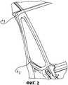
- Фиг.2 схематично изображает вид в аксонометрии окна, размещенного в кузове автомобильного транспортного средства,- Figure 2 schematically depicts a perspective view of a window located in the back of a motor vehicle,
- Фиг.3 схематично изображает устройство для измерений зазора и выравнивания по изобретению,- Figure 3 schematically depicts a device for measuring clearance and alignment according to the invention,
- Фиг.4 изображает кривую, относящуюся к получению первого изображения, представляющего видимое горизонтальное расхождение, касающееся выравнивания,- Figure 4 depicts a curve related to obtaining a first image representing a visible horizontal divergence regarding alignment,
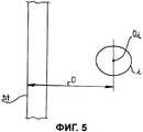
- Фиг.5 схематично представляет второе изображение, полученное способом по настоящему изобретению, позволяющее измерить расстояние между внешним краем передней двери и отверстием маркировки окна, при этом последнее отсутствует при измерении.- Figure 5 schematically represents a second image obtained by the method of the present invention, which allows you to measure the distance between the outer edge of the front door and the hole marking the window, while the latter is absent in the measurement.
Фиг.1 представляет различные измерения зазора и выравнивания между различными элементами автомобильного транспортного средства, которым подвергается кузов автомобильного транспортного средства. Не ограничивающим образом эти измерения могут также касаться соединений между крылом и дверью, впереди и сзади автомобиля, дверей между собой, сверху и снизу последних, стекла и двери, стекла и крыши, крыши и двери, а также капота с его элементами. На специальной станции, называемой измерительной станцией, может быть осуществлено более тридцати измерений.Figure 1 presents various measurements of the clearance and alignment between the various elements of a motor vehicle to which the body of a motor vehicle is subjected. In a non-limiting way, these measurements can also relate to connections between the wing and the door, front and rear of the car, doors to each other, above and below the latter, glass and doors, glass and roof, roof and door, as well as the hood with its elements. At a special station, called a measuring station, more than thirty measurements can be made.
В дальнейшем пример измерения зазора и выравнивания будет касаться соединения переднего окна с передней дверью транспортного средства, но этот пример не является ограничивающим, и способ, как и устройство в соответствии с настоящим изобретением, могут использоваться для других элементов транспортного средства, например, стекол, по отношению к другому элементу транспортного средства, когда эти стекла еще не установлены в процессе проведения измерений. Более того, настоящее изобретение не ограничивается элементами автомобильного транспортного средства, и может также использоваться для измерения пространственных зазоров между деталями, удерживаемыми любым узлом или деталью, закрепленной на другой детали, при этом последняя играет роль опорного узла.In the following, an example of measuring the clearance and alignment will relate to the connection of the front window with the front door of the vehicle, but this example is not limiting, and the method, as well as the device in accordance with the present invention, can be used for other elements of the vehicle, for example, windows, relative to another element of the vehicle when these glasses are not yet installed during the measurement process. Moreover, the present invention is not limited to elements of an automobile vehicle, and can also be used to measure the spatial clearances between parts held by any assembly or part fixed to another component, the latter playing the role of a reference assembly.
Фиг.2 показывает проблематику, специфическую для переднего окна, предназначенного для установки край в край спереди передней двери автомобильного транспортного средства. Как ранее было указано во вступительной части настоящего изобретения, это окно монтируется вклеиванием на сборочном участке, тогда как измерительный участок находится перед сборочным участком.Figure 2 shows the specifics of the front window, designed to install edge to edge in front of the front door of a motor vehicle. As previously indicated in the introductory part of the present invention, this window is mounted by gluing on the assembly section, while the measuring section is located in front of the assembly section.
Окно имеет две точки маркировки, i1 и i2, видные на опорной части этого окна, когда оно еще не установлено на место, и которые могут служить реперными точками для проведения измерений зазора и выравнивания, осуществляемых в отсутствие этого окна.The window has two marking points, i1 and i2, visible on the supporting part of this window when it is not already in place, and which can serve as reference points for measuring clearance and alignment in the absence of this window.
В случае окна и передней двери транспортного средства способ измерения зазора и выравнивания между краями, предназначенными находиться напротив, первой и второй деталей, то есть передней двери и окна, закрепленных на транспортном средстве, при этом окно удерживается на транспортном средстве двумя точками маркировки, позволяющими осуществить разметку положения окна на транспортном средстве, причем окно не находится на месте при проведении измерений, включает следующие этапы:In the case of the window and the front door of the vehicle, the method of measuring the clearance and alignment between the edges intended to be opposite the first and second parts, that is, the front door and the window mounted on the vehicle, while the window is held on the vehicle by two marking points, allowing marking the position of the window on the vehicle, and the window is not in place during measurements, includes the following steps:
- позиционирование двух датчиков для каждой точки маркировки в положении, позволяющем каждому датчику иметь зону измерения, включающую в себя край передней двери и соответствующую точку маркировки отсутствующего окна,- the positioning of two sensors for each marking point in a position that allows each sensor to have a measurement zone including the edge of the front door and the corresponding marking point of the missing window,
- одновременное излучение лазерной полосы для каждой точки маркировки для формирования первого изображения в зоне измерения,- simultaneous emission of a laser strip for each marking point to form a first image in the measurement zone,
- получение первого изображения каждым из датчиков,- obtaining the first image by each of the sensors,
- одновременное излучение дополнительного освещения для каждой точки маркировки для формирования второго изображения этой зоны измерения, в котором точка маркировки, связанная с окном, появится в виде китайской тени,- simultaneous emission of additional illumination for each marking point to form a second image of this measurement zone, in which the marking point associated with the window appears in the form of a Chinese shadow,
- получение второго изображения каждым из датчиков для измерения глубины между краем напротив передней двери и части, предназначенной для того, чтобы позднее удержать окно, а также измерение расстояния между краем напротив передней двери и соответствующей точкой маркировки на части опорного кузова окна,- obtaining a second image by each of the sensors for measuring the depth between the edge opposite the front door and the part intended to hold the window later, as well as measuring the distance between the edge opposite the front door and the corresponding marking point on the window supporting body part,
- обработка и определение посредством алгоритма положения края передней двери, а также точки маркировки на основе полученных изображений, дающих соответственно измерение глубины для первого изображения и измерение расстояния для второго изображения,- processing and determination by the algorithm of the position of the edge of the front door, as well as the marking points based on the obtained images, respectively giving a depth measurement for the first image and a distance measurement for the second image,
- коррекция этим алгоритмом измерения глубины посредством вычитания значения теоретического размера толщины окна для получения выравнивания,- correction by this algorithm for measuring depth by subtracting the value of the theoretical size of the window thickness to obtain alignment,
- коррекция этим алгоритмом измерения расстояния посредством вычитания значения теоретического размера между точкой маркировки на опорной части окна и краем окна для получения этого зазора.- correction by this algorithm of distance measurement by subtracting the value of the theoretical size between the marking point on the supporting part of the window and the edge of the window to obtain this gap.
Предпочтительно, первое изображение получают путем излучения лазерной полосы, образующей светящуюся плоскость, проецируемую на переднюю дверь транспортного средства таким образом, чтобы создать, по меньшей мере, одну линию, проходящую поперек краев, предназначенных находиться напротив, этой передней двери и окна.Preferably, the first image is obtained by emitting a laser strip forming a luminous plane projected onto the front door of the vehicle so as to create at least one line extending across the edges intended to be opposite to that front door and window.
Предпочтительно, второе изображение получают проекцией пучка рассеянного света.Preferably, the second image is obtained by the projection of a scattered light beam.
Так как окно имеет две точки маркировки i1 и i2, подобные этапы измерения расстояния и глубины для каждой точки крепления осуществляются для того, чтобы получить измерения зазора или выравнивания, при этом конкретный датчик предназначен для каждой точки маркировки. Преимущественно, имеются, таким образом, два датчика для каждой боковой стороны транспортного средства соответственно с правым и левым окном. Эти этапы могут быть синхронизированы, но не обязательно.Since the window has two marking points i1 and i2, similar steps of measuring distance and depth for each attachment point are carried out in order to obtain clearance or alignment measurements, and a specific sensor is designed for each marking point. Advantageously, there are thus two sensors for each side of the vehicle with a right and left window, respectively. These steps can be synchronized, but not necessary.
Преимущественно, этап взаимного сравнения полученного измерения зазора и выравнивания с измерением другим эталонным способом измерения, осуществляется рассчитанной компенсацией для возможной коррекции этих измерений и повторной калибровки используемого алгоритма. В качестве другого способа измерения зазора и выравнивания можно назвать способ с применением переносимого оператором, использующий технологию лазерной триангуляции, причем устройство для осуществления способа может быть легко повторно калибровано. Это измерение взаимного сравнения получается, например, путем сравнения средней величины трех измерений по одному из способов со средней величиной, полученной по другому способу для повторной калибровки устройства для измерения зазора и выравнивания.Advantageously, the step of comparing the obtained measurement of the clearance and alignment with the measurement by another standard measurement method is carried out by the calculated compensation for the possible correction of these measurements and recalibration of the algorithm used. As another method for measuring clearance and alignment, a method using an operator-portable method using laser triangulation technology can be mentioned, and the device for implementing the method can be easily re-calibrated. This measurement of mutual comparison is obtained, for example, by comparing the average value of three measurements in one of the methods with the average value obtained by another method for recalibrating the device for measuring the clearance and alignment.
Фиг.3 схематично изображает устройство для измерения зазора и выравнивания по изобретению.Figure 3 schematically depicts a device for measuring the clearance and alignment according to the invention.
Предпочтительно соответствующие измерения зазора и выравнивания осуществляются в процессе продвижения транспортного средства V перед одним или несколькими датчиками. Правая и левая стороны транспортного средства могут одновременно подвергаться измерениям зазора и выравнивания.Preferably, appropriate clearance and alignment measurements are carried out during the advancement of the vehicle V in front of one or more sensors. The right and left sides of the vehicle can be simultaneously measured by clearance and alignment.
Таким образом, в соответствии с настоящим изобретением устройство для измерения зазора и выравнивания между краями, предназначенными находиться напротив передней двери и окна имеет, по меньшей мере, один трехмерный датчик 3D, обозначенный позицией 1, в случае окна, предпочтительно два датчика, позиционированные соответственно первой точки маркировки 11 и второй точки маркировки 12, видимые на фиг.2, имеющие соответствующую совместимую зону измерения между краем передней двери и соответствующей точкой маркировки i1 или i2 на части опорного кузова окна. Это устройство имеет также первый 1 или второй 2 источники света со связанными с ними оптическими средствами для излучения соответственно лазерной полосы Е1 для получения первого изображения и рассеянного освещения для получения второго изображения с точкой маркировки, появляющейся в виде китайской тени на втором изображении. Наконец, это устройство содержит блок хранения данных, относящихся к передней двери и окну, и блок обработки полученных изображений для соответствующего расчета измерения глубины и расстояния и последующего расчета измерения зазора и выравнивания по данным, записанным в блоке хранения, причем оба блока не представлены на чертежах.Thus, in accordance with the present invention, the device for measuring the clearance and alignment between the edges intended to be opposite the front door and the window has at least one three-dimensional 3D sensor, indicated by 1, in the case of a window, preferably two sensors positioned respectively according to the first marking points 11 and second marking points 12, visible in FIG. 2, having a corresponding compatible measuring area between the edge of the front door and the corresponding marking point i1 or i2 on the part of the support Peninsula window. This device also has first 1 or second 2 light sources with associated optical means for emitting respectively the E1 laser strip to obtain a first image and diffuse lighting to obtain a second image with a marking point appearing as a Chinese shadow in the second image. Finally, this device comprises a storage unit for data relating to the front door and window, and an image processing unit for appropriately calculating a measurement of depth and distance and then calculating a clearance and alignment measurement from data recorded in the storage unit, both of which are not shown in the drawings .
Преимущественно, первый источник 1 является лазерным диодом, а второй источник 2 - светодиодной панелью.Advantageously, the first source 1 is a laser diode, and the second source 2 is an LED panel.
Как изображено на Фиг.3, по меньшей мере, один из двух трехмерных датчиков 3D может быть связан с лазерным диодом для образования, таким образом, видеодатчика 1. Преимущественно, этот датчик может быть также выполнен в виде камеры.As shown in FIG. 3, at least one of the two three-dimensional 3D sensors can be connected to a laser diode to form, thus, a video sensor 1. Advantageously, this sensor can also be made in the form of a camera.
В процессе осуществления способа вышеописанным устройством транспортное средство V проходит, без того, чтобы это было ограничивающим, продвигаясь перед датчиками 1, находясь на сборочной линии. Другие измерения зазора и выравнивания на других элементах транспортного средства, таких как крыша, стекла, капот, двери, крылья, багажник, и все это на обеих сторонах транспортного средства, осуществляются одновременно и синхронно, чтобы не увеличивать время проведения измерений. Устройство может также работать, когда опорный узел неподвижен перед датчиками.In the process of implementing the method of the above-described device, the vehicle V passes, without being restrictive, advancing in front of the sensors 1, being on the assembly line. Other clearance and alignment measurements on other elements of the vehicle, such as the roof, windows, hood, doors, wings, trunk, and all this on both sides of the vehicle, are carried out simultaneously and synchronously so as not to increase the measurement time. The device can also work when the support node is stationary in front of the sensors.
В том, что касается измерения зазора и выравнивания передней двери с окном с двумя точками маркировки на каждой боковой стороне транспортного средства, предпочтительно, два трехмерных датчика размещаются сбоку от транспортного средства на его сборочной линии и не мешают ему, когда оно продвигается в процессе проведения измерения.With regard to measuring the clearance and alignment of the front door with a window with two marking points on each side of the vehicle, preferably two three-dimensional sensors are located on the side of the vehicle on its assembly line and do not interfere with it when it advances during the measurement .
Обычно, когда зона измерения является протяженной, для того, чтобы не ухудшать качество получения изображений, следует взять датчик с более высокой разрешающей способностью, например, камеру.Usually, when the measurement zone is extended, in order not to affect the quality of image acquisition, you should take a sensor with a higher resolution, for example, a camera.
Фиг.4 изображает вертикальное расхождение между наружным краем bt передней двери t и опорной поверхностью s кузова для опоры окна с осью Ai отверстия маркировки i1 или 12, это вертикальное расхождение дает глубину Р между наружной поверхностью t передней части передней двери и опорной поверхностью s для опоры окна, служащее для расчета величины выравнивания после коррекции вычитанием теоретического размера толщины окна.Figure 4 shows a vertical divergence between the outer edge bt of the front door t and the abutment surface s of the body for supporting the window with the axis Ai of the marking hole i1 or 12, this vertical divergence gives the depth P between the outer surface t of the front of the front door and the abutment surface s for the abutment window, used to calculate the amount of alignment after correction by subtracting the theoretical size of the window thickness.
Фиг.5 схематично представляет второе изображение, получаемое способом в соответствии с настоящим изобретением, позволяющим измерить расстояние D между наружным краем bt передней двери и отверстием маркировки i окна, при этом последнее отсутствует в процессе измерения. Точнее говоря, D является расстоянием между краем t передней части передней двери и центром oi тяжести отверстия маркировки i окна, при этом отверстие i является одним из отверстий i1 или i2, видимых на Фиг.2.5 schematically represents a second image obtained by the method in accordance with the present invention, which allows to measure the distance D between the outer edge bt of the front door and the hole marking i of the window, while the latter is absent in the measurement process. More specifically, D is the distance between the edge t of the front of the front door and the center of gravity oi of the window marking hole i, wherein hole i is one of the holes i1 or i2 visible in FIG. 2.
Алгоритмы настоящего изобретения содержат, таким образом, два больших этапа: расчет соответствующей необработанной величины расстояния D и глубины Р между деталями, и коррекционный расчет для определения соответствующей величины зазора и выравнивания между двумя расположенными напротив деталями.The algorithms of the present invention thus comprise two large steps: calculating the corresponding raw value of the distance D and the depth P between the parts, and a correction calculation to determine the appropriate amount of clearance and alignment between the two opposite parts.
Настоящее изобретение не ограничивается описанным выше вариантом осуществления.The present invention is not limited to the embodiment described above.
Способ и устройство по изобретению находят использование для измерения зазора и выравнивания между двумя деталями, закрепленными к узлу, при этом одна деталь должна быть позиционирована на этом узле посредством, по меньшей мере, одной точки маркировки, отмечаемой на этом узле, при этом эта деталь не находится на этом узле в процессе проведения измерений. Под точкой маркировки понимается любой реперный знак или любая точка крепления, отмечаемая на узле для позиционирования детали. Эта точка маркировки может быть выполнена в любой форме, например, метка или точечное изменение узла, и не ограничена отверстием маркировки, как в случае с окном.The method and device according to the invention are used to measure the clearance and alignment between two parts attached to a node, while one part must be positioned on this node by at least one marking point marked on this node, while this part is not located on this node during the measurement process. The marking point means any reference mark or any fastening point marked on the assembly for positioning the part. This marking point can be made in any form, for example, a mark or a point change of the assembly, and is not limited to the marking hole, as is the case with a window.
Настоящее изобретение по сравнению с известным уровнем техники предоставляет возможность не использовать больше заменяющую деталь, когда одна из деталей еще не установлена, что позволяет не прибегать к операциям установки, операциям съема, а также операциям по изготовлению и повторному использованию заменяющих деталей, что дает большую экономию по стоимости.The present invention, in comparison with the prior art, makes it possible not to use the replacement part anymore when one of the parts has not yet been installed, which eliminates the need for installation operations, removal operations, as well as the manufacturing and reuse of replacement parts, which gives great savings at cost.
Кроме того, настоящее изобретение позволяет улучшить качество и надежность измерений. Отсутствует риск ложного измерения, связанного с бракованными, плохо позиционированными или недостающими заменяющими деталями.In addition, the present invention improves the quality and reliability of measurements. There is no risk of false measurement associated with defective, poorly positioned or missing replacement parts.
Claims (13)
Translated fromRussian- позиционирование, по меньшей мере, одного датчика (1) в положении, позволяющем ему иметь зону измерения, включающую в себя край (bt) первой детали и точку маркировки (i1 или i2) на опорном узле (V) для второй отсутствующей детали,
- излучение лазерной полосы для образования первого изображения зоны измерения, при этом лазерная полоса образует светящуюся плоскость, проецируемую на первую деталь и узел (V) таким образом, чтобы создать, по меньшей мере, одну линию, проходящую поперечно краям (bt), предназначенным находиться напротив, двух деталей,
- получение этим датчиком первого изображения,
- излучение дополнительного освещения для образования второго изображения этой зоны измерения, в котором точка маркировки (i1 или i2) на узле (V) появится в виде китайской тени,
- получение этим датчиком (1) второго изображения,
- обработка данных полученных изображений и определение алгоритмом измерения зазора и выравнивания между первой и второй деталями,
причем эти два этапа осуществляют посредством:
- определения положения края (bt) первой детали, а также точки маркировки (i1 или i2), исходя из полученных изображений, дающих, таким образом, соответственно измерение глубины (Р) для первого изображения и измерение расстояния (D) для второго изображения,
- коррекции этим алгоритмом измерения глубины (Р) путем вычитания значения теоретического размера толщины второй детали для получения выравнивания, и
- коррекции этим алгоритмом измерения расстояния (D) путем вычитания значения теоретического размера между точкой маркировки (i1 или i2) и краем (bt) второй детали для получения зазора.1. The method of measuring the clearance and alignment between the edges (bt), intended to be opposite, the first and second parts mounted on the node (V), while the second part should be positioned on this node (V) relative to at least one point marking (i1 or i2), fixed and marked on this node (V), and the second part is missing on the node (V) during the measurement process, characterized in the following steps:
- positioning of at least one sensor (1) in a position allowing it to have a measurement zone including the edge (bt) of the first part and a marking point (i1 or i2) on the support node (V) for the second missing part,
- radiation of the laser strip to form the first image of the measurement zone, while the laser strip forms a luminous plane projected onto the first part and node (V) in such a way as to create at least one line extending transversely to the edges (bt), intended to be on the contrary, two parts,
- obtaining by this sensor a first image,
- radiation of additional illumination to form a second image of this measurement zone, in which the marking point (i1 or i2) on the node (V) appears in the form of a Chinese shadow,
- obtaining by this sensor (1) a second image,
- processing the data of the obtained images and determining by the algorithm for measuring the clearance and alignment between the first and second parts,
moreover, these two stages are carried out by:
- determining the position of the edge (bt) of the first part, as well as the marking point (i1 or i2), based on the images obtained, thus giving, respectively, a depth measurement (P) for the first image and a distance measurement (D) for the second image,
- correction by this algorithm for measuring depth (P) by subtracting the value of the theoretical size of the thickness of the second part to obtain alignment, and
- correction by this algorithm of measuring the distance (D) by subtracting the value of the theoretical size between the marking point (i1 or i2) and the edge (bt) of the second part to obtain a clearance.
Applications Claiming Priority (3)
| Application Number | Priority Date | Filing Date | Title |
|---|---|---|---|
| FR0758525AFR2922639B1 (en) | 2007-10-23 | 2007-10-23 | METHOD AND DEVICE FOR MEASURING GAMING AND FLASHING BETWEEN PARTS FIXED ON AN ASSEMBLY IN THE ABSENCE OF ONE OF THEM |
| FR0758525 | 2007-10-23 | ||
| PCT/FR2008/051884WO2009053660A1 (en) | 2007-10-23 | 2008-10-20 | Method and device for measuring clearances and flush-fitting between components fixed to an assembly in the absence of one of these components |
Publications (2)
| Publication Number | Publication Date |
|---|---|
| RU2010120564A RU2010120564A (en) | 2011-11-27 |
| RU2491502C2true RU2491502C2 (en) | 2013-08-27 |
Family
ID=39431139
Family Applications (1)
| Application Number | Title | Priority Date | Filing Date |
|---|---|---|---|
| RU2010120564/28ARU2491502C2 (en) | 2007-10-23 | 2008-10-20 | Method and device for gap gaging and leveling between parts fitted on assembly unit in absence of one of said parts |
Country Status (7)
| Country | Link |
|---|---|
| EP (1) | EP2203712B1 (en) |
| CN (1) | CN101836074B (en) |
| AR (1) | AR068999A1 (en) |
| BR (1) | BRPI0815439B1 (en) |
| FR (1) | FR2922639B1 (en) |
| RU (1) | RU2491502C2 (en) |
| WO (1) | WO2009053660A1 (en) |
Families Citing this family (6)
| Publication number | Priority date | Publication date | Assignee | Title |
|---|---|---|---|---|
| FR2960508B1 (en)* | 2010-05-27 | 2015-05-29 | Peugeot Citroen Automobiles Sa | METHOD FOR CONTROLLING THE BODY OF A CARRIAGE-LIKE VEHICLE AND TEMPLATE FOR CARRYING OUT SAID METHOD |
| ES2409269T3 (en)* | 2010-08-31 | 2013-06-26 | Siemens Aktiengesellschaft | Method for determining the cleavage measurement and / or leveling marks of body parts of a motor vehicle and control program |
| CN104424601B (en)* | 2013-08-28 | 2020-01-31 | 深圳市智信精密仪器有限公司 | Centering assembly method and device for special-shaped body assembly parts |
| FR3057535B1 (en)* | 2016-10-19 | 2018-10-19 | Peugeot Citroen Automobiles Sa | METHOD FOR SIMULATING A POSITIONING OF A GLASS PLACED IN AN OPENING OF A MOTOR VEHICLE |
| ES2821104B2 (en)* | 2019-10-23 | 2021-08-23 | Eines Systems S L | MEASUREMENT METHOD OF ENRASE AND SEPARATION OF PARTS OF A VEHICLE AND MEASURING TUNNEL |
| CN112705926B (en)* | 2021-01-29 | 2024-04-26 | 中国工程物理研究院机械制造工艺研究所 | Full-closed loop control device and method for assembly gap |
Citations (4)
| Publication number | Priority date | Publication date | Assignee | Title |
|---|---|---|---|---|
| SU160593A1 (en)* | ||||
| US4498776A (en)* | 1982-08-23 | 1985-02-12 | General Motors Corporation | Electro-optical method and apparatus for measuring the fit of adjacent surfaces |
| US4654949A (en)* | 1982-02-16 | 1987-04-07 | Diffracto Ltd. | Method for automatically handling, assembling and working on objects |
| GB2284258A (en)* | 1993-11-18 | 1995-05-31 | Honda Motor Co Ltd | Measuring position of edge of workpiece |
Family Cites Families (10)
| Publication number | Priority date | Publication date | Assignee | Title |
|---|---|---|---|---|
| US4666303A (en)* | 1983-07-11 | 1987-05-19 | Diffracto Ltd. | Electro-optical gap and flushness sensors |
| US5129010A (en)* | 1989-12-15 | 1992-07-07 | Kabushiki Kaisha Toyoto Chuo Kenkyusho | System for measuring shapes and dimensions of gaps and flushnesses on three dimensional surfaces of objects |
| JP2667762B2 (en)* | 1992-04-20 | 1997-10-27 | 日立建機株式会社 | Segment assembly positioning method |
| JP3442140B2 (en)* | 1994-04-20 | 2003-09-02 | ファナック株式会社 | Position measurement device and position deviation correction device using three-dimensional visual sensor |
| FR2756626B1 (en) | 1996-12-02 | 1999-02-19 | Espace Ind Controle Sa | SYSTEM FOR MEASURING GAMES AND FLOORS BETWEEN OPPOSITE PARTS |
| US6454949B1 (en) | 2000-09-19 | 2002-09-24 | Baffin, Inc. | Highly accelerated process for removing contaminants from liquids |
| US7024032B2 (en)* | 2002-10-31 | 2006-04-04 | Perceptron, Inc. | Method for assessing fit and alignment of a manufactured part |
| CN1506655A (en)* | 2002-12-11 | 2004-06-23 | 上海科鸣机械设备有限公司 | Piano key arrangement smoothness measurer |
| ITBO20030536A1 (en)* | 2003-09-16 | 2005-03-17 | Marposs Spa | METHOD AND SYSTEM TO CHECK THE POSITION OF A MECHANICAL PART |
| CN100561121C (en)* | 2007-02-02 | 2009-11-18 | 西安交通大学 | Flatness Detection Method Based on Image Processing and Image Recognition |
- 2007
- 2007-10-23FRFR0758525Apatent/FR2922639B1/ennot_activeExpired - Fee Related
- 2008
- 2008-10-20EPEP08842791Apatent/EP2203712B1/ennot_activeNot-in-force
- 2008-10-20RURU2010120564/28Apatent/RU2491502C2/ennot_activeIP Right Cessation
- 2008-10-20BRBRPI0815439-2Apatent/BRPI0815439B1/ennot_activeIP Right Cessation
- 2008-10-20CNCN2008801130912Apatent/CN101836074B/ennot_activeExpired - Fee Related
- 2008-10-20WOPCT/FR2008/051884patent/WO2009053660A1/enactiveApplication Filing
- 2008-10-22ARARP080104612Apatent/AR068999A1/enactiveIP Right Grant
Patent Citations (4)
| Publication number | Priority date | Publication date | Assignee | Title |
|---|---|---|---|---|
| SU160593A1 (en)* | ||||
| US4654949A (en)* | 1982-02-16 | 1987-04-07 | Diffracto Ltd. | Method for automatically handling, assembling and working on objects |
| US4498776A (en)* | 1982-08-23 | 1985-02-12 | General Motors Corporation | Electro-optical method and apparatus for measuring the fit of adjacent surfaces |
| GB2284258A (en)* | 1993-11-18 | 1995-05-31 | Honda Motor Co Ltd | Measuring position of edge of workpiece |
Also Published As
| Publication number | Publication date |
|---|---|
| FR2922639A1 (en) | 2009-04-24 |
| FR2922639B1 (en) | 2009-12-11 |
| CN101836074A (en) | 2010-09-15 |
| AR068999A1 (en) | 2009-12-23 |
| BRPI0815439A2 (en) | 2015-08-25 |
| WO2009053660A1 (en) | 2009-04-30 |
| BRPI0815439B1 (en) | 2019-07-09 |
| EP2203712B1 (en) | 2013-03-20 |
| RU2010120564A (en) | 2011-11-27 |
| EP2203712A1 (en) | 2010-07-07 |
| CN101836074B (en) | 2012-05-23 |
Similar Documents
| Publication | Publication Date | Title |
|---|---|---|
| RU2491502C2 (en) | Method and device for gap gaging and leveling between parts fitted on assembly unit in absence of one of said parts | |
| US9869064B2 (en) | Device for inspecting shape of road travel surface | |
| JP6765728B2 (en) | Tire condition analysis | |
| US9188439B2 (en) | Method and device for determining distances on a vehicle | |
| MY151009A (en) | Method and system for identifying moving object, and method and system for inspecting moving object by radiation imaging | |
| CN102388290A (en) | Method and apparatus for determining the tread depth of a vehicle tire | |
| CN105849524A (en) | Method and device for tire condition analysis | |
| JP6348592B2 (en) | Method, control / evaluation unit, and computer program for adjusting irradiation area directivity of headlamp | |
| KR20220054809A (en) | Assembly for fault detection of motor vehicle bodywork | |
| US9970751B2 (en) | Optical axis angle inspection device | |
| CN104321614B (en) | Method and apparatus for carrying out the process for the orientation of at least one rail that determines measuring station | |
| JP3819859B2 (en) | Headlight optical axis adjustment method | |
| TW200607984A (en) | System and method for simultaneous 3D height measurements on multiple sides of an object | |
| CN105091795B (en) | A kind of detection device and method for detecting outer inclination angle of vehicle tyre and toe-in angle | |
| US12249061B1 (en) | Detection and estimation of defects in vehicle's exterior | |
| US12031812B2 (en) | Method and system for determining a three-dimensional definition of an object by reflectometry | |
| EP2208963B1 (en) | Method for measuring gaps and flushes | |
| CN114993201B (en) | Tire pattern detection device and method | |
| US10414453B2 (en) | System and method for aiming a vehicular headlamp | |
| US20200205633A1 (en) | Arrangement and Method for Contactless Distance Determination of the Type of the Light Intersection Method | |
| CN105556241B (en) | The measurement of walking mechanism under ambient light | |
| JPH03186706A (en) | 3D shape and dimension measuring device | |
| CN109238136A (en) | A kind of headstock headlight measurement method | |
| CN116718132B (en) | A three-dimensional road surface measurement method and system | |
| CN214251482U (en) | Whole car light measurement system |
Legal Events
| Date | Code | Title | Description |
|---|---|---|---|
| MM4A | The patent is invalid due to non-payment of fees | Effective date:20201021 |