RU2489100C2 - Surgical suturing apparatus with hinged-turning components - Google Patents
Surgical suturing apparatus with hinged-turning componentsDownload PDFInfo
- Publication number
- RU2489100C2 RU2489100C2RU2009105142/14ARU2009105142ARU2489100C2RU 2489100 C2RU2489100 C2RU 2489100C2RU 2009105142/14 ARU2009105142/14 ARU 2009105142/14ARU 2009105142 ARU2009105142 ARU 2009105142ARU 2489100 C2RU2489100 C2RU 2489100C2
- Authority
- RU
- Russia
- Prior art keywords
- articulated
- segment
- handle
- distal
- assembly
- Prior art date
Links
Images


Classifications
- A—HUMAN NECESSITIES
- A61—MEDICAL OR VETERINARY SCIENCE; HYGIENE
- A61B—DIAGNOSIS; SURGERY; IDENTIFICATION
- A61B17/00—Surgical instruments, devices or methods
- A61B17/068—Surgical staplers, e.g. containing multiple staples or clamps
- A61B17/072—Surgical staplers, e.g. containing multiple staples or clamps for applying a row of staples in a single action, e.g. the staples being applied simultaneously
- A61B17/07207—Surgical staplers, e.g. containing multiple staples or clamps for applying a row of staples in a single action, e.g. the staples being applied simultaneously the staples being applied sequentially
- A—HUMAN NECESSITIES
- A61—MEDICAL OR VETERINARY SCIENCE; HYGIENE
- A61B—DIAGNOSIS; SURGERY; IDENTIFICATION
- A61B17/00—Surgical instruments, devices or methods
- A61B2017/0046—Surgical instruments, devices or methods with a releasable handle; with handle and operating part separable
- A61B2017/00473—Distal part, e.g. tip or head
- A—HUMAN NECESSITIES
- A61—MEDICAL OR VETERINARY SCIENCE; HYGIENE
- A61B—DIAGNOSIS; SURGERY; IDENTIFICATION
- A61B17/00—Surgical instruments, devices or methods
- A61B17/28—Surgical forceps
- A61B17/29—Forceps for use in minimally invasive surgery
- A61B2017/2901—Details of shaft
- A—HUMAN NECESSITIES
- A61—MEDICAL OR VETERINARY SCIENCE; HYGIENE
- A61B—DIAGNOSIS; SURGERY; IDENTIFICATION
- A61B17/00—Surgical instruments, devices or methods
- A61B17/28—Surgical forceps
- A61B17/29—Forceps for use in minimally invasive surgery
- A61B2017/2901—Details of shaft
- A61B2017/2905—Details of shaft flexible
- A—HUMAN NECESSITIES
- A61—MEDICAL OR VETERINARY SCIENCE; HYGIENE
- A61B—DIAGNOSIS; SURGERY; IDENTIFICATION
- A61B17/00—Surgical instruments, devices or methods
- A61B17/28—Surgical forceps
- A61B17/29—Forceps for use in minimally invasive surgery
- A61B2017/2901—Details of shaft
- A61B2017/2906—Multiple forceps
- A—HUMAN NECESSITIES
- A61—MEDICAL OR VETERINARY SCIENCE; HYGIENE
- A61B—DIAGNOSIS; SURGERY; IDENTIFICATION
- A61B17/00—Surgical instruments, devices or methods
- A61B17/28—Surgical forceps
- A61B17/29—Forceps for use in minimally invasive surgery
- A61B17/2909—Handles
- A61B2017/291—Handles the position of the handle being adjustable with respect to the shaft
- A—HUMAN NECESSITIES
- A61—MEDICAL OR VETERINARY SCIENCE; HYGIENE
- A61B—DIAGNOSIS; SURGERY; IDENTIFICATION
- A61B17/00—Surgical instruments, devices or methods
- A61B17/28—Surgical forceps
- A61B17/29—Forceps for use in minimally invasive surgery
- A61B17/2909—Handles
- A61B2017/2912—Handles transmission of forces to actuating rod or piston
- A61B2017/2923—Toothed members, e.g. rack and pinion
- A—HUMAN NECESSITIES
- A61—MEDICAL OR VETERINARY SCIENCE; HYGIENE
- A61B—DIAGNOSIS; SURGERY; IDENTIFICATION
- A61B17/00—Surgical instruments, devices or methods
- A61B17/28—Surgical forceps
- A61B17/29—Forceps for use in minimally invasive surgery
- A61B17/2909—Handles
- A61B2017/2925—Pistol grips
- A—HUMAN NECESSITIES
- A61—MEDICAL OR VETERINARY SCIENCE; HYGIENE
- A61B—DIAGNOSIS; SURGERY; IDENTIFICATION
- A61B17/00—Surgical instruments, devices or methods
- A61B17/28—Surgical forceps
- A61B17/29—Forceps for use in minimally invasive surgery
- A61B2017/2926—Details of heads or jaws
- A61B2017/2927—Details of heads or jaws the angular position of the head being adjustable with respect to the shaft
- A—HUMAN NECESSITIES
- A61—MEDICAL OR VETERINARY SCIENCE; HYGIENE
- A61B—DIAGNOSIS; SURGERY; IDENTIFICATION
- A61B90/00—Instruments, implements or accessories specially adapted for surgery or diagnosis and not covered by any of the groups A61B1/00 - A61B50/00, e.g. for luxation treatment or for protecting wound edges
- A61B90/70—Cleaning devices specially adapted for surgical instruments
Landscapes
- Health & Medical Sciences (AREA)
- Life Sciences & Earth Sciences (AREA)
- Surgery (AREA)
- Heart & Thoracic Surgery (AREA)
- Engineering & Computer Science (AREA)
- Biomedical Technology (AREA)
- Nuclear Medicine, Radiotherapy & Molecular Imaging (AREA)
- Medical Informatics (AREA)
- Molecular Biology (AREA)
- Animal Behavior & Ethology (AREA)
- General Health & Medical Sciences (AREA)
- Public Health (AREA)
- Veterinary Medicine (AREA)
- Surgical Instruments (AREA)
Abstract
Description
Translated fromRussianОБЛАСТЬ ТЕХНИКИFIELD OF TECHNOLOGY
Настоящее изобретение относится, в общем, к эндоскопическим хирургическим инструментам, содержащим, но без ограничения, хирургические сшивающие скобками инструменты, которые выполнены для применения с одноразовыми загрузочными модулями, которые способны накладывать ряды скобок на ткань, при одновременном отрезании ткани между упомянутыми рядами скобок и, в частности, к усовершенствованиям, относящимся к упомянутым инструментам.The present invention relates, in General, to endoscopic surgical instruments containing, but without limitation, surgical stapling instruments that are designed for use with disposable loading modules that are able to overlap the rows of brackets on the fabric, while cutting off the tissue between the said rows of brackets and, in particular, improvements related to said tools.
УРОВЕНЬ ТЕХНИКИBACKGROUND
Нижеприведенные заявки на патенты США, которые включены в настоящее описание путем отсылки, вместе с настоящей заявкой, принадлежат правоприемнику данной заявки.The following US patent applications, which are incorporated herein by reference, together with this application, belong to the assignee of this application.
(1) Заявка на патент США, Surgical Stapling Apparatus With Load-Sensitive Firing Mechanism, Geoffrey С Hueil et al., Docket No. END6215USNP/070332;(1) U.S. Patent Application, Surgical Stapling Apparatus With Load-Sensitive Firing Mechanism, Geoffrey C Hueil et al., Docket No. END6215USNP / 070332;
(2) Заявка на патент США, Surgical Stapling Apparatus With Interlockable Firing System, Steven G. Hall et al., Docket No. END6217USNP/070334;(2) U.S. Patent Application, Surgical Stapling Apparatus With Interlockable Firing System, Steven G. Hall et al., Docket No. END6217USNP / 070334;
(3) Заявка на патент США, Articulatable Loading Units For Surgical Stapling and Cutting Instruments, Jerome R. Morgan et al., Docket No. END6218USNP/070335;(3) U.S. Patent Application, Articulatable Loading Units For Surgical Stapling and Cutting Instruments, Jerome R. Morgan et al., Docket No. END6218USNP / 070335;
(4) Заявка на патент США, Surgical Stapling Apparatus With Reprocessible Handle Assembly, Kevin R. Doll et al., Docket No. END6220USNP/070337;(4) U.S. Patent Application, Surgical Stapling Apparatus With Reprocessible Handle Assembly, Kevin R. Doll et al., Docket No. END6220USNP / 070337;
(5) Заявка на патент США, Surgical Stapling Apparatus With Control Features Operable With One Hand, Steven G. Hall et al., Docket No. END6226USNP/070343;(5) U.S. Patent Application, Surgical Stapling Apparatus With Control Features Operable With One Hand, Steven G. Hall et al., Docket No. END6226USNP / 070343;
(6) Заявка на патент США, Surgical Stapling Apparatus With Retractable Firing Systems, Geoffrey С Hueil et al., Docket No. END6227USNP/070344.(6) U.S. Patent Application, Surgical Stapling Apparatus With Retractable Firing Systems, Geoffrey C Hueil et al., Docket No. END6227USNP / 070344.
Эндоскопическим хирургическим инструментам часто отдают предпочтение перед традиционными открытыми хирургическими устройствами, поскольку при меньшем рассечении обычно меньше время послеоперационного восстановления и риск осложнений. Поэтому выполнены важные разработки в области эндоскопических хирургических инструментов, которые пригодны для точного размещения дистального концевого эффектора в искомом операционном поле через канюлю или троакар. Такие дистальные концевые эффекторы (например, эндоскопический режущий инструмент (типа endocutter), захват, режущее приспособление, сшивающие скобками аппараты, приспособление для наложения скрепок, устройство доступа, устройство для доставки лекарства генной терапии к месту действия и энергетическое устройство, использующее ультразвук, высокую частоту (RF), лазер и т.д.) захватывают ткань множеством способов для получения диагностического или терапевтического результата.Endoscopic surgical instruments are often preferred over traditional open surgical devices, since with a smaller incision, postoperative recovery time and risk of complications are usually less. Therefore, important developments have been made in the field of endoscopic surgical instruments, which are suitable for the precise placement of the distal end effector in the desired surgical field through a cannula or trocar. Such distal end effectors (e.g., an endoscopic cutting tool (such as an endocutter), a gripper, a cutting device, stapling devices, a stapling device, an access device, a device for delivering gene therapy drugs to the site of action and an energy device using ultrasound, high frequency (RF), laser, etc.) capture tissue in a variety of ways to obtain a diagnostic or therapeutic result.
Известные хирургические сшивающие скобками аппараты содержат концевой эффектор, который одновременно выполняет продольное рассечение в ткани и накладывает ряды скобок на противоположные стороны рассечения. Концевой эффектор содержит пару согласованно действующих зажимных элементов, которые, если инструмент предназначен для эндоскопического или лапароскопического применения, способны проходить по проходному каналу канюли. Один из зажимных элементов вмещает кассету для скобок, содержащую, по меньшей мере, два поперечно разнесенных ряда скобок. Другой зажимной элемент образует наковальню, содержащую скобкоформирующие углубления, совмещенные с рядами скобок в кассете. Инструмент обычно содержит множество возвратно-поступательно перемещающихся клиньев, которые, при приведении в движение в дистальном направлении, проходят сквозь отверстия в кассете для скобок и входят в контакт с поводками, служащими опорой для скобок, для выполнения выталкивания скобок к наковальне.Known surgical staple-stitching apparatuses contain an end effector that simultaneously performs longitudinal dissection in the tissue and superimposes rows of brackets on opposite sides of the dissection. The end effector contains a pair of coordinated acting clamping elements, which, if the tool is intended for endoscopic or laparoscopic use, are able to pass through the cannula passage channel. One of the clamping elements accommodates a cassette for brackets containing at least two transverse spaced rows of brackets. Another clamping element forms an anvil containing bracket-forming recesses combined with rows of brackets in the cassette. The tool usually contains a plurality of reciprocating wedges, which, when driven distally, pass through the holes in the cassette for the brackets and come in contact with the leashes serving as a support for the brackets to push the brackets to the anvil.
Известны разные типы хирургических сшивающих скобками аппаратов, пригодных для эндоскопического применения. Например, в хирургическом сшивающем скобками аппарате одного типа применяется кассета для скобок. Кассета для скобок обычно несет множество скобок, ориентированных по обе стороны продольно продолжающегося паза в корпусе кассеты, который выполнен с возможностью вмещения режущего элемента, который приводится в движение вдоль паза. Когда режущий элемент перемещается по пазу кассеты, скобки выталкиваются вверх в участок наковальни инструмента. Режущий элемент может опираться на приводимый элемент, который содержит участок инструмента, отдельный от кассеты. Примеры устройств данных типов описаны в патенте США № 6,905,057, Surgical Stapling Instrument Incorporating a Firing Mechanism Having a Linked Rack Transmission, Jeffrey S. Swayze and Frederick E. Shelton, IV (Джеффри С. Свейзи и Фредерик Э. Шелтон IV), и в патенте США №7,083,075, Multi-Stroke Mechanism With Automatic End of Stroke Retraction, Jeffery S. Swayze, Frederick E. Shelton, IV, Kevin Ross Doll, and Douglas B. Hoffman (Джеффри С. Свейзи, Фредерик Э. Шелтон IV, Кевин Росс Долл и Дуглас Б. Хоффман), описания которых целиком включены в настоящее описание путем отсылки.There are various types of surgical stapling devices suitable for endoscopic use. For example, in one type of surgical staple stapler, a cassette for staples is used. A cassette for brackets usually carries a plurality of brackets oriented on both sides of a longitudinally extending groove in the cassette body, which is configured to accommodate a cutting element that is driven along the groove. When the cutting element moves along the groove of the cartridge, the brackets are pushed up into the section of the anvil of the tool. The cutting element can be supported by a driven element that contains a portion of the tool separate from the cartridge. Examples of these types of devices are described in US Pat. No. 6,905,057, Surgical Stapling Instrument Incorporating a Firing Mechanism Having a Linked Rack Transmission, Jeffrey S. Swayze and Frederick E. Shelton, IV (Jeffrey S. Swayze and Frederick E. Shelton IV), and in U.S. Patent 7,083,075, Multi-Stroke Mechanism With Automatic End of Stroke Retraction, Jeffery S. Swayze, Frederick E. Shelton, IV, Kevin Ross Doll, and Douglas B. Hoffman (Jeffrey S. Swayze, Frederick E. Shelton IV, Kevin Ross Doll and Douglas B. Hoffman), descriptions of which are incorporated herein by reference in their entirety.
Хирургические сшивающие скобками инструменты других типов выполнены с возможностью работы с одноразовыми загрузочными модулями (DLU), которые конструктивно выполнены с возможностью выполнения функции опоры для установленного в них кассетно-ножевого узла. Такие устройства, которые предназначены для работы с DLU, обеспечивают преимущество применения «чистого» ножевого лезвия в каждом случае работы инструментом. Пример подобного хирургического сшивающего скобками инструмента и конструкции DLU описан в патенте США №5,865,361, выданном Миллимэну с соавторами (Milliman et al.), описание которого целиком включено в настоящее описание путем отсылки.Surgical stapling instruments of other types are made with the possibility of working with disposable loading modules (DLU), which are structurally made with the ability to perform the support function for the cartridge-knife assembly installed in them. Such devices, which are designed to work with DLU, provide the advantage of using a “clean” knife blade in each case of working with a tool. An example of such a surgical stapling instrument and DLU construct is described in US Pat. No. 5,865,361 to Milliman et al., The entire disclosure of which is incorporated herein by reference.
В зависимости от характера операции, часто желательно ориентировать DLU или концевой эффектор под углом относительно продольной оси стержня инструмента. Обычно, поперечное или неосевое перемещение DLU или концевого эффектора относительно стержня инструмента часто называют «шарнирным поворотом». Упомянутое шарнирно-поворотное позиционирование позволяет врачу удобнее захватывать ткань в некоторых случаях, например, позади органа. Кроме того, шарнирно-поворотное позиционирование дает полезную возможность позиционирования DLU или эндоскопа позади концевого эффектора, без блокировки стержня инструмента.Depending on the nature of the operation, it is often desirable to orient the DLU or end effector at an angle relative to the longitudinal axis of the tool shaft. Typically, lateral or non-axial movement of a DLU or end effector relative to a tool shaft is often referred to as “articulated rotation”. The articulated swivel positioning allows the doctor to more conveniently grab tissue in some cases, for example, behind the organ. In addition, pivot-swivel positioning provides the useful ability to position a DLU or endoscope behind an end effector without locking the tool shaft.
Способы шарнирного поворота хирургического сшивающего скобками аппарата обычно усложняются объединением управления шарнирным поворотом с управлением смыканием концевого эффектора для зажима ткани и приведением в действие концевого эффектора (т.е. сшиванием скобками и отрезанием) в пространстве, ограниченном небольшим диаметром эндоскопического инструмента. Как правило, все три управляющих движения передаются по стержню в виде продольных поступательных перемещений. Например, в патенте США №5,673,840, выданном Шульцу с соавторами (Schulze et al.), описание которого включено в настоящую заявку путем отсылки, предлагается гармошкообразный шарнирно-поворотный механизм («с гибким участком рамы»), который шарнирно поворачивают селективным оттягиванием одного из двух соединительных штоков по стержню рабочего оборудования, при этом, каждый из штоков соответственно смещен на противоположные стороны от центральной оси стержня. Соединительные штоки перемещаются храповым механизмом между дискретными положениями в ряду данных положений.Techniques for pivoting a surgical stapler apparatus are typically complicated by combining pivoting controls with controlling the closing of the end effector to clamp the tissue and activating the end effector (i.e., stapling with staples and cutting) in a space bounded by the small diameter of the endoscopic instrument. As a rule, all three control movements are transmitted along the rod in the form of longitudinal translational movements. For example, US Pat. No. 5,673,840 to Schulze et al., The disclosure of which is incorporated herein by reference, provides an accordion-like swivel mechanism (“with a flexible portion of the frame”) that is articulated by selectively pulling one of two connecting rods along the rod of the working equipment, while each of the rods is respectively offset on opposite sides from the central axis of the rod. The connecting rods are moved by ratchet between discrete positions in the series of these positions.
Другой пример продольного управления механизмом шарнирного поворота содержится в патенте США №5,865,361, в котором предлагается передаточное звено шарнирного поворота, смещенное с эксцентрикового шарнира так, что толкающее или вытягивающее продольное поступательное перемещение передаточного звена шарнирного поворота вызывает шарнирный поворот в соответствующую сторону. Аналогично, в патенте США №5,797,537 предлагается аналогичный шток, проходящий по стержню для осуществления шарнирного поворота. Другие примеры шарнирно-поворачиваемых хирургических сшивающих скобками устройств описаны в патентах США №6,250,532 и 6,664,532.Another example of the longitudinal control of the articulated rotation mechanism is contained in US Pat. No. 5,865,361, which proposes a articulated articulated transmission link displaced from an eccentric articulation such that a pushing or pulling longitudinal translational movement of the articulated articulated transmission mechanism causes articulated rotation in the corresponding direction. Similarly, US Pat. No. 5,797,537 proposes a similar rod extending along a shaft for pivoting. Other examples of articulated surgical stapling devices are described in US Pat. Nos. 6,250,532 and 6,664,532.
Из-за типов систем прошивки/отрезания, обычно применяемых в сочетании с DLU, конструкции приводов для шарнирного поворота DLU часто должны развивать значительные крутящие моменты для сгибания прошивной/отрезной конструкции. Данная проблема осложняется отсутствием доступного пространства для размещения приводящих устройств, которые являются достаточно крупными для развития упомянутых требуемых усилий.Due to the types of firmware / cutting systems commonly used in conjunction with DLUs, DLU articulated drive designs often need to develop significant torques to bend the firmware / cutoff structure. This problem is complicated by the lack of available space for accommodating drive devices that are large enough to develop the required efforts.
Для решения упомянутых проблем разработаны «пассивные шарнирно-поворотные сочленения». Например, в патентной публикации США №2007/0027469 A1 авторов Кевина У. Смита, Мэттью А. Полмера, Корея Роберта Клайна и Дерека Ди Девилла (Kevin W. Smith, Matthew A. Palmer, Korey Robert Kline and Derek Dee Deville), описание которого включено в настоящую заявку путем отсылки, предлагается медицинское устройство, в котором применяется пассивное шарнирно-поворотное сочленение. При приведении в действие, шарнирно-поворотное сочленение отпускается в свободное шарнирно-поворотное состояние, чтобы допускать свободный шарнирный поворот концевого эффектора относительно управляющей рукоятки, в зависимости от внешних усилий, действующих на концевой эффектор.To solve the aforementioned problems, “passive articulated-swivel joints” have been developed. For example, U.S. Patent Publication No. 2007/0027469 A1 to Kevin W. Smith, Matthew A. Palmer, Korey Robert Kline and Derek Dee Deville, by Kevin W. Smith, Matthew A. Polmer, Korea, Korea which is incorporated into this application by reference, a medical device is proposed in which a passive articulated-swivel joint is used. When actuated, the articulated-swivel joint is released into a free articulated-swivel state to allow a free articulated rotation of the end effector relative to the control handle, depending on the external forces acting on the end effector.
Хотя вышеупомянутые устройства с пассивной шарнирно-поворотной конструкцией эффективно решают различные проблемы, возникающие в связи с активными шарнирно-поворотными конструкциями, тем не менее, все еще существует потребность в хирургическом отрезающем и сшивающем скобками инструменте, который выполнен с возможностью работы с DLU, которые имеют усовершенствованные конструкции пассивных шарнирно-поворотных сочленений.Although the aforementioned devices with a passive swivel design effectively solve various problems arising from active swivel structures, there is still a need for a surgical cutting and stapling instrument that is capable of working with DLUs that have advanced designs of passive swivel joints.
Следовательно, существует еще одна потребность в хирургическом отрезающем и сшивающем скобками инструменте, который выполнен с возможностью работы с DLU и обладает улучшенными возможностями активного шарнирного поворота.Therefore, there is another need for a surgical cutting and stapling instrument that is DLU capable and has enhanced active swivel capabilities.
СУЩНОСТЬ ИЗОБРЕТЕНИЯSUMMARY OF THE INVENTION
В соответствии с одним аспектом изобретения предлагается хирургический сшивающий скобками аппарат, который может содержать узел рукоятки, который может содержать подвижную рукоятку и неподвижный корпус рукоятки. Подвижную рукоятку можно перемещать путем выполнения рабочих ходов относительно неподвижного корпуса рукоятки. Приводящий стержень может быть установлен, по меньшей мере, частично в корпус рукоятки и смонтирован с возможностью создания приводящих движений в ответ на манипулирование подвижной рукояткой. Различные варианты осуществления хирургического сшивающего скобками аппарата могут дополнительно содержать узел удлиненного корпуса, который может содержать проксимальный сегмент корпуса, который выступает из узла рукоятки и сопрягается с приводящим стержнем. Дистальный сегмент корпуса может быть выполнен с возможностью рабочего соединения с одноразовым загрузочным модулем. Промежуточное шарнирно-поворотное сочленение может соединять дистальный сегмент корпуса с проксимальным сегментом корпуса так, что проксимальный сегмент корпуса и дистальный сегмент корпуса задают продольную ось. Промежуточное шарнирно-поворотное сочленение может допускать селективный поворот дистального сегмента корпуса вокруг промежуточной оси шарнирного поворота, которая, по существу, поперечна продольной оси. Узел удлиненного корпуса может быть также выполнен с возможностью передачи приводящих движений от приводящего стержня в одноразовый загрузочный модуль.In accordance with one aspect of the invention, there is provided a surgical stapling apparatus that may comprise a handle assembly, which may comprise a movable handle and a fixed handle housing. The movable handle can be moved by performing strokes relative to the stationary housing of the handle. The driving rod may be installed at least partially in the handle housing and mounted with the possibility of creating driving movements in response to manipulation of the movable handle. Various embodiments of a surgical stapling apparatus may further comprise an elongated body assembly, which may comprise a proximal body segment that protrudes from the handle assembly and mates with the driving shaft. The distal segment of the housing can be made with the possibility of working connection with a disposable boot module. An intermediate swivel joint may connect the distal segment of the body to the proximal segment of the body so that the proximal segment of the body and the distal segment of the body define a longitudinal axis. The intermediate articulation-swivel joint can allow selective rotation of the distal segment of the housing about an intermediate axis of articulation, which is essentially transverse to the longitudinal axis. The elongated body assembly may also be configured to transmit driving motions from the driving rod to the disposable loading module.
В соответствии с другим общим аспектом различных вариантов осуществления настоящего изобретения предлагается хирургический сшивающий скобками аппарат, который может содержать узел рукоятки, который содержит подвижную рукоятку и неподвижный корпус рукоятки. Подвижную рукоятку можно перемещать путем выполнения рабочих ходов относительно неподвижного корпуса рукоятки. Приводящий стержень может быть установлен, по меньшей мере, частично в корпус рукоятки и смонтирован с возможностью создания приводящих движений в ответ на манипулирование подвижной рукояткой. Хирургический сшивающий скобками аппарат может дополнительно содержать узел удлиненного корпуса, который имеет, по меньшей мере, проксимальный конец, который соединен с возможностью перемещения с узлом рукоятки посредством шарового шарнира. Узел удлиненного корпуса может быть выполнен с возможностью передачи приводящих движений от приводящего стержня в одноразовый загрузочный модуль, соединенный с возможностью функционирования с дистальным концом удлиненного корпуса.In accordance with another general aspect of various embodiments of the present invention, there is provided a surgical stapling apparatus that may comprise a handle assembly that includes a movable handle and a fixed handle body. The movable handle can be moved by performing strokes relative to the stationary housing of the handle. The driving rod may be installed at least partially in the handle housing and mounted with the possibility of creating driving movements in response to manipulation of the movable handle. The surgical stapling apparatus may further comprise an elongated body assembly that has at least a proximal end that is movably connected to the handle assembly via a ball joint. The elongated body assembly may be configured to transmit driving motions from the driving rod to a disposable loading module, operably connected to the distal end of the elongated body.
В соответствии с еще одним общим аспектом различных вариантов осуществления настоящего изобретения предлагается хирургический сшивающий скобками аппарат, который может содержать узел рукоятки, который содержит подвижную рукоятку и неподвижный корпус рукоятки. Подвижную рукоятку можно перемещать путем выполнения рабочих ходов относительно неподвижного корпуса рукоятки. Приводящий стержень может быть установлен, по меньшей мере, частично в корпус рукоятки и смонтирован с возможностью создания приводящих движений в ответ на манипулирование подвижной рукояткой. Различные варианты осуществления могут дополнительно содержать узел удлиненного корпуса, который может содержать проксимальный сегмент корпуса, который выступает из узла рукоятки и сопрягается с приводящим стержнем. Проксимальный сегмент корпуса может содержать шаровой сегмент, сформированный на его дистальном конце. Узел удлиненного корпуса может дополнительно содержать дистальный сегмент корпуса, который имеет дистальный конец, который выполнен с возможностью рабочего соединения с одноразовым загрузочным модулем. Дистальный сегмент корпуса может дополнительно содержать гнездо, сформированное на его проксимальном конце, которое выполнено в размер для вмещения в него с возможностью поворота шарового сегмента. Система шарнирного поворота может быть установлена, по меньшей мере, частично на узле рукоятки и выполнена с возможностью сопряжения с дистальным сегментом корпуса узла удлиненного корпуса для селективной передачи, по меньшей мере, одного шарнирно-поворотного движения дистальному сегменту корпуса, чтобы вынуждать дистальный сегмент корпуса шарнирно поворачиваться в первой плоскости. Система шарнирного поворота может быть дополнительно выполнена с возможностью селективной передачи, по меньшей мере, одного другого шарнирно-поворотного движения дистальному сегменту корпуса, чтобы вынуждать дистальный участок шарнирно поворачиваться во второй плоскости, которая, по существу, ортогональна первой плоскости.In accordance with yet another general aspect of various embodiments of the present invention, there is provided a surgical stapling apparatus that may comprise a handle assembly that includes a movable handle and a fixed handle body. The movable handle can be moved by performing strokes relative to the stationary housing of the handle. The driving rod may be installed at least partially in the handle housing and mounted with the possibility of creating driving movements in response to manipulation of the movable handle. Various embodiments may further comprise an elongated housing assembly, which may comprise a proximal housing segment that projects from the handle assembly and mates with a driving rod. The proximal segment of the body may comprise a spherical segment formed at its distal end. The elongated body assembly may further comprise a distal body segment that has a distal end that is operatively connected to a disposable loading module. The distal segment of the housing may further comprise a socket formed at its proximal end, which is made in size to fit in with the possibility of rotation of the ball segment. The articulated rotation system can be installed at least partially on the handle assembly and is adapted to interface with the distal segment of the housing of the elongated housing assembly for selectively transmitting at least one articulated-rotational movement to the distal housing segment to force the distal housing segment articulated rotate in the first plane. The articulated rotation system may further be configured to selectively transmit at least one other articulated-rotational movement to the distal segment of the housing to force the distal region to pivotally rotate in a second plane that is substantially orthogonal to the first plane.
КРАТКОЕ ОПИСАНИЕ ЧЕРТЕЖЕЙBRIEF DESCRIPTION OF THE DRAWINGS
Прилагаемые чертежи, которые включены в настоящее описание и являются его составной частью, иллюстрируют варианты осуществления изобретения и, вместе с вышеприведенным общим описанием различных вариантов осуществления изобретения и нижеприведенным подробным описанием вариантов осуществления, служат для пояснения различных принципов настоящего изобретения.The accompanying drawings, which are incorporated in and constitute a part of the present description, illustrate embodiments of the invention and, together with the above general description of various embodiments of the invention and the following detailed description of embodiments, serve to explain various principles of the present invention.
Фиг.1 - вид в перспективе различных вариантов осуществления хирургического сшивающего скобками аппарата многократного использования в соответствии с настоящим изобретением, с присоединенным к аппарату шарнирно-поворачиваемым одноразовым загрузочным модулем.Figure 1 is a perspective view of various embodiments of a surgical stapling reusable apparatus in accordance with the present invention, with a pivotally rotatable disposable loading module attached to the apparatus.
Фиг.2 - вид в перспективе различных вариантов осуществления хирургического сшивающего скобками аппарата многократного использования в соответствии с настоящим изобретением, с присоединенным к аппарату нешарнирным одноразовым загрузочным модулем.Figure 2 is a perspective view of various embodiments of a surgical stapling reusable apparatus in accordance with the present invention, with a non-articulated disposable loading module attached to the apparatus.
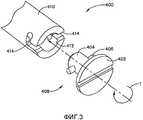
Фиг.3 - местный вид в перспективе с разделением деталей варианта осуществления быстроразъемного крепежного средства в соответствии с настоящим изобретением.FIG. 3 is a partial exploded perspective view of an embodiment of a quick coupler fastener in accordance with the present invention.
Фиг.4 - вид в сборе с пространственным разделением деталей различных вариантов осуществления хирургического сшивающего скобками аппарата многократного использования в соответствии с настоящим изобретением.4 is a view with a spatial separation of parts of various embodiments of a surgical stapling staple reusable apparatus in accordance with the present invention.
Фиг.5 - другой вид в сборе с пространственным разделением деталей хирургического сшивающего скобками аппарата многократного использования, показанного на фиг.4.FIG. 5 is another exploded view of the details of the surgical stapling staple reusable apparatus shown in FIG. 4.
Фиг.6 - вид в сборе с пространственным разделением деталей участка узла рукоятки варианта осуществления хирургического сшивающего скобками аппарата многократного использования, показанного на фиг.4 и 5.Fig.6 is a view of a complete with a spatial separation of the parts of the site of the handle of the embodiment of the surgical stapling staple reusable apparatus shown in Fig.4 and 5.
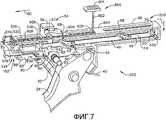
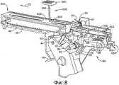
Фиг.7 - местный вид справа в перспективе варианта осуществления приводного узла прошивки/отрезания в соответствии с настоящим изобретением.FIG. 7 is a partial right perspective view of an embodiment of a firmware / cutting drive assembly in accordance with the present invention.
Фиг.8 - местный вид слева в перспективе варианта осуществления приводного узла прошивки/отрезания, показанного на фиг.7.FIG. 8 is a partial left perspective view of an embodiment of a firmware / cutting drive assembly shown in FIG. 7.
Фиг.9 - вид слева варианта осуществления приводного узла прошивки/отрезания, показанного на фиг.7 и 8.Fig.9 is a left view of a variant of implementation of the drive unit firmware / cutting, shown in Fig.7 and 8.
Фиг.10 - вид в сборе с пространственным разделением деталей варианта осуществления узла штока управления из различных вариантов осуществления в соответствии с настоящим изобретением.FIG. 10 is an exploded view of an embodiment of a control rod assembly of various embodiments in accordance with the present invention. FIG.
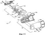
Фиг.11 - вид в сборе с пространственным разделением деталей варианта осуществления узла поворотной головки и механизма шарнирного поворота в соответствии с настоящим изобретением.11 is an exploded view of an embodiment of a pivoting head assembly and an articulated rotation mechanism in accordance with the present invention.
Фиг.12 - вид в перспективе загрязненного хирургического сшивающего скобками аппарата многократного использования, показанного на фиг.1 и 2, с отсоединенным от него одноразовым загрузочным модулем.FIG. 12 is a perspective view of a contaminated surgical staple reusable apparatus shown in FIGS. 1 and 2, with a disposable loading module detached from it.
Фиг.13 - вид в перспективе загрязненного хирургического сшивающего скобками аппарата многократного использования, показанного на фиг.12, со штоком управления, выдвинутым из дистального конца удлиненного корпуса.FIG. 13 is a perspective view of a contaminated surgical stapling reusable apparatus shown in FIG. 12 with a control rod extended from a distal end of an elongated body.
Фиг.14 - блок-схема последовательности этапов варианта осуществления способа очистки в соответствии с настоящим изобретением.14 is a flowchart of an embodiment of a cleaning method in accordance with the present invention.
Фиг.15 - вид в перспективе выдвинутого штока управления, погруженного в раствор для очистки.15 is a perspective view of an extended control rod immersed in a cleaning solution.
Фиг.16 - другая блок-схема последовательности других этапов варианта осуществления способа очистки в соответствии с настоящим изобретением.16 is another flowchart of other steps of an embodiment of a cleaning method in accordance with the present invention.
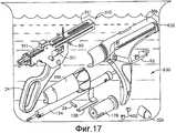
Фиг.17 - вид в перспективе погружения в раствор для очистки различных компонентов варианта осуществления в соответствии с настоящим изобретением.17 is a perspective view of immersion in a solution for cleaning various components of an embodiment in accordance with the present invention.
Фиг.18 - вид сбоку варианта осуществления приводного узла прошивки/отрезания из различных вариантов осуществления в соответствии с настоящим изобретением.FIG. 18 is a side view of an embodiment of a firmware / cutting drive assembly from various embodiments in accordance with the present invention.
Фиг.19 - блок-схема последовательности этапов варианта осуществления способа повторной сборки в соответствии с настоящим изобретением.Fig. 19 is a flowchart of an embodiment of a reassembly method in accordance with the present invention.
Фиг.20 - вид с пространственным разделением, показывающий применение варианта осуществления монтажного лотка в соответствии с настоящим изобретением.FIG. 20 is an exploded view showing an embodiment of an mounting tray in accordance with the present invention.
Фиг.21 - вид в перспективе другого варианта осуществления хирургического сшивающего скобками аппарата многократного использования в соответствии с настоящим изобретением, соединенного с нешарнирным одноразовым загрузочным модулем.FIG. 21 is a perspective view of another embodiment of a surgical staple reusable apparatus in accordance with the present invention coupled to a non-articulated disposable loading module.
Фиг.22 - вид в сборе с пространственным разделением деталей узла рукоятки хирургического сшивающего скобками аппарата, показанного на фиг.21.Fig. 22 is an exploded view of the parts of the handle assembly of the surgical stapling apparatus shown in Fig. 21.
Фиг.23 - вид в сборе с пространственным разделением деталей другого варианта осуществления механизма определения одноразового загрузочного модуля из различных вариантов осуществления в соответствии с настоящим изобретением.FIG. 23 is an exploded view of another embodiment of a mechanism for determining a disposable loading module from various embodiments in accordance with the present invention.
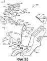
Фиг.24 - вид в сборе с пространственным разделением деталей другого варианта осуществления узла поворотной головки и механизма шарнирного поворота в соответствии с настоящим изобретением.24 is an exploded perspective view of another embodiment of a rotary head assembly and an articulated rotation mechanism in accordance with the present invention.
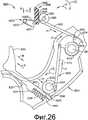
Фиг.25 - вид в сборе с пространственным разделением деталей варианта осуществления узла курка деблокировки прошивки/отрезания в соответствии с настоящим изобретением.FIG. 25 is an exploded view of an embodiment of a trigger release unit for firmware / cutting trigger assembly in accordance with the present invention. FIG.
Фиг.26 - местный вид в сборе узла курка деблокировки прошивки/отрезания, показанного на фиг.25.FIG. 26 is an exploded perspective view of the assembly of the trigger for releasing the firmware / cutting trigger shown in FIG. 25.
Фиг.27 - вид в сборе варианта осуществления узла рукоятки в соответствии с настоящим изобретением.27 is an assembled view of an embodiment of a handle assembly in accordance with the present invention.
Фиг.28 - другой вид в сборе варианта осуществления узла рукоятки в соответствии с настоящим изобретением, с подвижной рукояткой данного узла, подтянутой к неподвижному участку рукоятки для смыкания наковальни на одноразовом загрузочном модуле.FIG. 28 is another assembly view of an embodiment of a handle assembly in accordance with the present invention, with a movable handle of that assembly pulled to a fixed portion of the handle to close the anvil on a disposable loading module.
Фиг.29 - другой вид в сборе варианта осуществления узла рукоятки в соответствии с настоящим изобретением, с подвижной рукояткой, возвращенной в исходное положение после смыкания наковальни.29 is another assembly view of an embodiment of a handle assembly in accordance with the present invention, with a movable handle returned to its original position after the closure of the anvil.
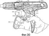
Фиг.30 - другой вид в сборе варианта осуществления узла рукоятки в соответствии с настоящим изобретением перед приведением в действие курка деблокировки прошивки/отрезания.FIG. 30 is another assembled view of an embodiment of a handle assembly in accordance with the present invention before actuating a firmware release / cutting trigger.
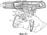
Фиг.31 - другой вид в сборе варианта осуществления узла рукоятки в соответствии с настоящим изобретением, с приведенным в действие курком деблокировки прошивки/отрезания.FIG. 31 is another assembly view of an embodiment of a handle assembly in accordance with the present invention, with a trigger for releasing firmware / cutting trigger.
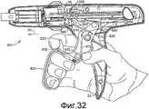
Фиг.32 - другой вид в сборе варианта осуществления узла рукоятки в соответствии с настоящим изобретением, с приведенным в действие курком деблокировки прошивки/отрезания и подвижной рукояткой в начале ее приведения в действие.Fig. 32 is another assembly view of an embodiment of a handle assembly in accordance with the present invention, with a trigger for releasing firmware / cutting trigger and a movable handle at the start of its activation.
Фиг.33 - другой вид в сборе варианта осуществления узла рукоятки в соответствии с настоящим изобретением, с приведенным в действие курком деблокировки прошивки/отрезания и подвижной рукояткой данного узла, подтянутой к неподвижному участку рукоятки.Fig. 33 is another assembly view of an embodiment of a handle assembly in accordance with the present invention, with a trigger for releasing firmware / cutting trigger and a movable handle of this assembly pulled to a fixed portion of the handle.
Фиг.34 - местный вид в сборе другого варианта осуществления курка деблокировки прошивки/отрезания в соответствии с настоящим изобретением.Fig. 34 is an assembled partial view of another embodiment of a firmware unlock / cut trigger in accordance with the present invention.
Фиг.35 - вид в перспективе другого варианта осуществления хирургического сшивающего скобками аппарата в соответствии с настоящим изобретением.Fig. 35 is a perspective view of another embodiment of a surgical stapling apparatus in accordance with the present invention.
Фиг.36 - местный вид в сборе с пространственным разделением деталей участка узла рукоятки и поворотного кожуха хирургического сшивающего скобками аппарата, показанного на фиг.35.FIG. 36 is a partial exploded view of a portion of a portion of a handle assembly and a rotatable casing of a surgical stapling apparatus shown in FIG. 35.
Фиг.37 - вид в перспективе участка варианта осуществления хирургического сшивающего скобками аппарата, показанного на фиг.35 и 36, с участком корпуса рукоятки, снятым для демонстрации различных находящихся в нем компонентов в режиме поворота.Fig. 37 is a perspective view of a portion of an embodiment of the surgical stapling apparatus shown in Figs. 35 and 36, with a portion of the handle body removed to demonstrate the various components contained therein in a rotation mode.
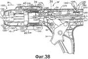
Фиг.38 - вид сбоку участка варианта осуществления хирургического сшивающего скобками аппарата, показанного на фиг.36, с его селекторным переключателем в дистальном незафиксированном положении.Fig. 38 is a side view of a portion of an embodiment of a surgical stapling apparatus shown in Fig. 36 with its selector switch in a distal non-locked position.
Фиг.39 - увеличенный вид задвижки, выведенной из зацепления с кольцом блокировки поворота, когда аппарат находится в режиме поворота.Fig. 39 is an enlarged view of a valve disengaged from a rotation lock ring when the apparatus is in a rotation mode.
Фиг.40 - вид в разрезе хирургического сшивающего скобками аппарата по линии 40-40 на фиг.38.Fig. 40 is a cross-sectional view of a surgical stapling apparatus along line 40-40 of Fig. 38.
Фиг.41 - местный вид сверху хирургического сшивающего скобками аппарата, показанного на фиг.35-40, с участком захвата, показанным в разрезе.Fig - local top view of the surgical stapling brackets of the apparatus shown in Fig.35-40, with the capture section shown in section.
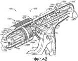
Фиг.42 - вид в перспективе участка варианта осуществления хирургического сшивающего скобками аппарата, показанного на фиг.35-41, с участком корпуса рукоятки, снятым для демонстрации различных находящихся в нем компонентов в режиме шарнирного поворота.Fig. 42 is a perspective view of a portion of an embodiment of a surgical stapling apparatus shown in Figs. 35-41, with a portion of the handle body removed to demonstrate the various components therein in articulated rotation mode.
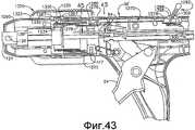
Фиг.43 - вид сбоку участка варианта осуществления хирургического сшивающего скобками аппарата, показанного на фиг.36, с его селекторным переключателем в проксимальном зафиксированном положении.Fig. 43 is a side view of a portion of an embodiment of a surgical stapling apparatus shown in Fig. 36 with its selector switch in a proximal locked position.
Фиг.44 - увеличенный вид задвижки, находящейся в зацеплении с кольцом блокировки поворота для фиксации аппарата находится в режиме шарнирного поворота.Fig. 44 is an enlarged view of a valve that is meshed with a rotation lock ring for fixing the apparatus is in articulated rotation mode.
Фиг.45 - местный вид в разрезе хирургического сшивающего скобками аппарата, показанного на фиг.43, по линии 45-45 на фиг.43.Fig. 45 is a fragmentary sectional view of the surgical stapling apparatus shown in Fig. 43 along line 45-45 in Fig. 43.
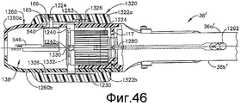
Фиг.46 - местный вид в разрезе узла рукоятки хирургического сшивающего скобками аппарата в соответствии с настоящим изобретением, в котором применяется альтернативный сдвигаемый элемент.Fig. 46 is a partial sectional view of the handle assembly of a surgical stapling apparatus in accordance with the present invention in which an alternate movable member is used.
Фиг.47 - вид в перспективе другого варианта осуществления хирургического сшивающего скобками аппарата в соответствии с настоящим изобретением.Fig. 47 is a perspective view of another embodiment of a surgical stapling apparatus in accordance with the present invention.
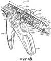
Фиг.48 - увеличенный вид в перспективе участка узла рукоятки хирургического сшивающего скобками аппарата, показанного на фиг.47, с участком корпуса рукоятки, снятым для наглядности.Fig. 48 is an enlarged perspective view of a portion of a handle assembly of a surgical stapling apparatus shown in Fig. 47 with a portion of a handle body removed for illustrative purposes.
Фиг.49 - местный вид сбоку узла рукоятки, показанного на фиг.49, с участком корпуса рукоятки, снятым для наглядности.Fig. 49 is a partial side view of the handle assembly shown in Fig. 49, with a portion of the handle body taken for clarity.
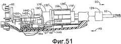
Фиг.50 - местный вид сверху узла рукоятки, показанного на фиг.49, с некоторыми компонентами, показанными в разрезе, и с системой шарнирного поворота данного узла в заблокированном положении.Fig. 50 is a partial top view of the handle assembly shown in Fig. 49, with some components shown in section, and with a hinge system of the assembly in the locked position.
Фиг.51 - местный вид сверху узла рукоятки, показанного на фиг.49 и 50, с некоторыми компонентами, показанными в разрезе, и с системой шарнирного поворота данного узла в незаблокированном положении.Fig. 51 is a local top view of the handle assembly shown in Figs. 49 and 50, with some components shown in section, and with a hinge rotation system of the assembly in the unlocked position.
Фиг.52 - вид в перспективе другого варианта осуществления хирургического сшивающего скобками аппарата в соответствии с настоящим изобретением.Fig. 52 is a perspective view of another embodiment of a surgical stapling apparatus in accordance with the present invention.
Фиг.53 - вид в сборе в перспективе участка узла рукоятки хирургического сшивающего скобками аппарата, показанного на фиг.52, с участком корпуса рукоятки и цилиндром чувствительного механизма, снятыми для наглядности.Fig. 53 is an assembled perspective view of a portion of a handle assembly of a surgical stapling apparatus shown in Fig. 52, with a portion of the handle body and a cylinder of the sensing mechanism, taken for clarity.
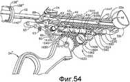
Фиг.54 - вид слева в сборе в перспективе узла рукоятки хирургического сшивающего скобками аппарата, показанного на фиг.52 и 53, с корпусом, снятым для наглядности.Fig. 54 is a left perspective view of the assembly of the handle assembly of the surgical stapling apparatus shown in Figs. 52 and 53, with the body removed for illustrative purposes.
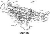
Фиг.55 - вид справа в сборе в перспективе узла рукоятки хирургического сшивающего скобками аппарата, показанного на фиг.52-54, с корпусом, снятым для наглядности.Fig. 55 is a right-hand view of the assembly in perspective of the handle assembly of the surgical stapling apparatus shown in Figs. 52-54, with the body removed for illustrative purposes.
Фиг.56 - вид сбоку участка вариантов осуществления системы шарнирного поворота, зубчатых передач и селекторного переключателя шарнирного поворота, с переключателем шарнирного поворота в нейтральном положении.56 is a side view of a portion of an embodiment of the articulated rotation system, gears, and articulated rotation selector switch, with the articulated rotation switch in the neutral position.
Фиг.57 - другой вид сбоку вариантов осуществления системы шарнирного поворота, зубчатых передач и селекторного переключателя шарнирного поворота, с переключателем шарнирного поворота в положении шарнирного поворота влево.Fig. 57 is another side view of embodiments of an articulated rotation system, gears and an articulated rotation selector switch, with an articulated rotation switch in an articulated left rotation position.
Фиг.58 - другой вид сбоку вариантов осуществления системы шарнирного поворота, зубчатых передач и селекторного переключателя шарнирного поворота, с переключателем шарнирного поворота в положении шарнирного поворота вправо.58 is another side view of embodiments of an articulated rotation system, gears, and an articulated rotation selector switch, with an articulated rotation switch in an articulated rotation position to the right.
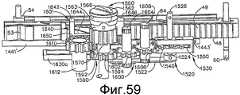
Фиг.59 - вид снизу селекторного переключателя зубчатых передач, узла зубчатого привода, зубчатой передачи шарнирного поворота и тяги шарнирного поворота в варианте осуществления в соответствии с настоящим изобретением, с селекторным переключателем зубчатых передач в положении шарнирного поворота.Fig. 59 is a bottom view of a gear selector switch, a gear drive assembly, an articulated gear and the articulated traction in an embodiment of the present invention, with a gear selector in the articulated position.
Фиг.60 - вид снизу селекторного переключателя зубчатых передач, узла зубчатого привода, зубчатой передачи шарнирного поворота и тяги шарнирного поворота в варианте осуществления в соответствии с настоящим изобретением, с селекторным переключателем зубчатых передач в положении прошивки/отрезания.60 is a bottom view of the gear selector switch, the gear drive assembly, the articulated gear and the articulated traction in the embodiment of the present invention, with the gear selector in the firmware / cut position.
Фиг.61 - увеличенный вид варианта осуществления селекторного переключателя зубчатых передач в положении шарнирного поворота.Fig. 61 is an enlarged view of an embodiment of a gear selector switch in an articulated position.
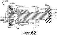
Фиг.62 - вид в разрезе варианта осуществления селекторного переключателя зубчатых передач в положении прошивки/отрезания.Fig. 62 is a sectional view of an embodiment of a gear selector switch in the firmware / cut position.
Фиг.63 - вид с торца различных компонентов хирургического сшивающего скобками аппарата в режиме шарнирного поворота.Fig. 63 is an end view of various components of a surgical stapling apparatus in articulated rotation mode.
Фиг.64 - другой вид с торца компонентов, показанных на фиг.63, в режиме прошивки/отрезания.Fig.64 is another end view of the components shown in Fig.63, in the firmware / cutting mode.
Фиг.65 - местный вид в разрезе и в перспективе альтернативного варианта осуществления механизма шарнирного поворота в соответствии с настоящим изобретением.Fig is a partial view in section and in perspective of an alternative embodiment of the articulated rotation mechanism in accordance with the present invention.
Фиг.66 - местный вид сверху в разрезе механизма шарнирного поворота, показанного на фиг.65.Fig.66 is a partial top view in section of the articulated rotation mechanism shown in Fig.65.
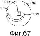
Фиг.67 - изображение положения кулачкового диска и штифта шарнирного поворота в варианте осуществления механизма шарнирного поворота, показанном на фиг.65 и 66, в положении шарнирного поворота влево.Fig. 67 is an image of the position of the cam disc and the pivot pin in the embodiment of the pivot mechanism shown in Figs. 65 and 66 in the pivoting position to the left.
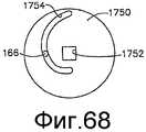
Фиг.68 - изображение положения кулачкового диска и штифта шарнирного поворота в варианте осуществления механизма шарнирного поворота, показанном на фиг.65 и 66, в прямом положении (в отсутствие шарнирного поворота).Fig. 68 is a view of the position of the cam disc and the articulated pivot pin in the embodiment of the articulated rotation mechanism shown in Figs. 65 and 66 in the upright position (in the absence of articulated rotation).
Фиг.69 - изображение положения кулачкового диска и штифта шарнирного поворота в варианте осуществления механизма шарнирного поворота, показанном на фиг.65 и 66, в положении шарнирного поворота вправо.FIG. 69 is a view of the position of the cam disk and the pivot pin in the embodiment of the pivot mechanism shown in FIGS. 65 and 66 in the pivot position to the right.
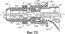
Фиг.70 - вид в плане в разрезе участка другого варианта осуществления механизма шарнирного поворота в соответствии с настоящим изобретением.70 is a plan view in section of a portion of another embodiment of an articulated rotation mechanism in accordance with the present invention.
Фиг.71 - местный вид в разрезе участка варианта осуществления механизма шарнирного поворота, показанного на фиг.70.Fig. 71 is a partial sectional view of a portion of an embodiment of the articulated rotation mechanism shown in Fig. 70.
Фиг.72 - вид сбоку другого варианта осуществления механизма шарнирного поворота в соответствии с настоящим изобретением, с некоторыми из компонентов данного механизма, показанными в разрезе.72 is a side view of another embodiment of an articulated rotation mechanism in accordance with the present invention, with some of the components of this mechanism shown in section.
Фиг.73 - вид в разрезе варианта осуществления механизма шарнирного поворота, показанного на фиг.72, по линии 73-73 на фиг.72.Fig. 73 is a sectional view of an embodiment of the articulated rotation mechanism shown in Fig. 72, taken along line 73-73 in Fig. 72.
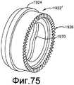
Фиг.74 - вид сбоку другого варианта осуществления механизма шарнирного поворота в соответствии с настоящим изобретением, с некоторыми из компонентов данного механизма, показанными в разрезе.Fig. 74 is a side view of another embodiment of an articulated rotation mechanism in accordance with the present invention, with some of the components of this mechanism shown in section.
Фиг.75 - вид в перспективе варианта осуществления внешнего кольца шарнирного поворота в механизме шарнирного поворота, показанном на фиг.74.Fig. 75 is a perspective view of an embodiment of an outer pivot ring in the pivot mechanism shown in Fig. 74.
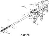
Фиг.76 - вид слева в перспективе другого варианта осуществления хирургического сшивающего скобками аппарата в соответствии с настоящим изобретением.Fig. 76 is a left perspective view of another embodiment of a surgical stapling apparatus in accordance with the present invention.
Фиг.77 - вид справа в перспективе варианта осуществления хирургического сшивающего скобками аппарата, показанного на фиг.76.Fig.77 is a right side perspective view of an embodiment of a surgical stapling apparatus shown in Fig.76.
Фиг.78 - вид в сборе с пространственным разделением деталей правого сегмента корпуса узла рукоятки, со съемной крышкой, отсоединенной от сегмента корпуса.Fig. 78 is an exploded view of the parts of the right segment of the housing of the handle assembly, with a removable cover detached from the segment of the housing.
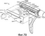
Фиг.79 - другой вид правого сегмента корпуса узла рукоятки, со съемной крышкой, отсоединенной от сегмента корпуса.Fig - another view of the right segment of the housing unit of the handle, with a removable cover, disconnected from the segment of the housing.
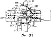
Фиг.80 - вид справа сбоку узла рукоятки хирургического сшивающего скобками аппарата, показанного на фиг.76-78.Fig. 80 is a right side view of the handle assembly of the surgical stapling apparatus shown in Figs. 76-78.
Фиг.81 - вид в разрезе узла корпуса по линии 81-81 на фиг.80.Fig. 81 is a sectional view of the housing assembly along line 81-81 in Fig. 80.
Фиг.82 - вид в разрезе узла корпуса по линии 82-82 на фиг.80.Fig. 82 is a sectional view of the body assembly along line 82-82 of Fig. 80.
Фиг.83 - вид в разрезе участка узла корпуса и ручки взведения по линии 83-83 на фиг.80.Fig. 83 is a sectional view of a portion of the body assembly and cocking handle along line 83-83 in Fig. 80.
Фиг.84 - вид справа сбоку узла рукоятки хирургического сшивающего скобками аппарата, показанного на фиг.76-83, со съемной крышкой, снятой для того, чтобы показать головку отведения и ручку взведения в положении «перед прошивкой/отрезанием».Fig. 84 is a right side view of the handle assembly of the surgical stapling apparatus shown in Figs. 76-83, with a removable cover removed to show the lead head and cocking handle in the “before flashing / cutting” position.
Фиг.85 - другой вид справа сбоку узла рукоятки, показанного на фиг.84, с ручкой взведения во взведенном положении.Fig. 85 is another right side view of the handle assembly shown in Fig. 84 with the cocked handle in the cocked position.
Фиг.86 - другой вид справа сбоку узла рукоятки, показанного на фиг.84 и 85, с изображением положения головки отведения и ручки взведения перед достижением полностью отработанного положения.Fig. 86 is another right side view of the handle assembly shown in Figs. 84 and 85 depicting the position of the lead head and cocking handle before reaching the fully worked out position.
Фиг.87 - местный вид в разрезе узла рукоятки и ручки взведения, с ручкой взведения, поджатой в направлении по часовой стрелке для высвобождения стопорного элемента.Fig. 87 is a fragmentary sectional view of the handle assembly and cocking handle assembly, with the cocking handle pressed in a clockwise direction to release the locking member.
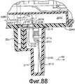
Фиг.88 - другой местный вид в разрезе узла рукоятки, ручки взведения и головки отведения, при этом, головка отведения высвободила стопорный элемент для предоставления возможности автоматического отведения приводящего стержня.Fig - another local view in section of the node of the handle, cocking handle and the head of the lead, while the lead head released the locking element to enable automatic removal of the drive rod.
Фиг.89 - местный вид в перспективе участка различных вариантов осуществления одноразового загрузочного модуля в соответствии с настоящим изобретением.89 is a partial perspective view of a portion of various embodiments of a disposable loading module in accordance with the present invention.
Фиг.90 - вид в перспективе варианта осуществления собачки из различных вариантов осуществления в соответствии с настоящим изобретением.Fig. 90 is a perspective view of an embodiment of a dog of various embodiments in accordance with the present invention.
Фиг.91 - вид в перспективе другого варианта осуществления собачки из различных вариантов осуществления в соответствии с настоящим изобретением.Fig. 91 is a perspective view of another embodiment of a dog from various embodiments in accordance with the present invention.
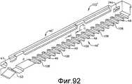
Фиг.92 - вид снизу в перспективе варианта осуществления приводящего стержня из различных вариантов осуществления в соответствии с настоящим изобретением.Fig. 92 is a bottom perspective view of an embodiment of a driving rod of various embodiments in accordance with the present invention.
Фиг.93 - вид снизу в перспективе другого варианта осуществления приводящего стержня из различных вариантов осуществления в соответствии с настоящим изобретением.FIG. 93 is a bottom perspective view of another embodiment of a driving rod from various embodiments in accordance with the present invention.
Фиг.93A - вид сбоку участка варианта осуществления системы прошивки/отрезания в соответствии с настоящим изобретением, применяемой в соединении с хирургическим сшивающим скобками инструментом такого типа, который описан в заявке на патент США №11/821,277, с зубом, находящимся в приводящем зацеплении с прошивным/отрезным элементом.93A is a side view of a portion of an embodiment of a firmware / cutting system in accordance with the present invention used in conjunction with a surgical stapling staple instrument of the type described in US Patent Application No. 11 / 821,277 with a tooth engaged with piercing / cutting element.
Фиг.93B - другой вид сбоку варианта осуществления системы прошивки/отрезания, показанного на фиг.93A, с зубом в расцепленном положении.FIG. 93B is another side view of an embodiment of the firmware / cutting system shown in FIG. 93A with the tooth in the disengaged position.
Фиг.94 - вид в перспективе варианта осуществления хирургического сшивающего скобками аппарата и одноразового загрузочного модуля в соответствии с настоящим изобретением.Fig. 94 is a perspective view of an embodiment of a surgical stapling apparatus and a disposable loading module in accordance with the present invention.
Фиг.95 - вид в перспективе варианта осуществления одноразового загрузочного модуля, показанного на фиг.94.Fig. 95 is a perspective view of an embodiment of the disposable loading module shown in Fig. 94.
Фиг.96 - вид в сборе с пространственным разделением деталей варианта осуществления одноразового загрузочного модуля, показанного на фиг.95.Fig. 96 is an exploded view of an embodiment of the disposable loading module shown in Fig. 95.
Фиг.97 - вид в перспективе одноразового загрузочного модуля, показанного на фиг.95 и 96, шарнирно поворачиваемого хирургическим захватом.Fig.97 is a perspective view of a disposable loading module, shown in Fig.95 and 96, pivotally rotated by a surgical grip.
Фиг.98 - вид в перспективе другого варианта осуществления одноразового загрузочного модуля в соответствии с настоящим изобретением.Fig. 98 is a perspective view of another embodiment of a disposable loading module in accordance with the present invention.
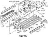
Фиг.99 - вид в сборе с пространственным разделением деталей варианта осуществления одноразового загрузочного модуля, показанного на фиг.98.Fig. 99 is an exploded view of an embodiment of the disposable loading module shown in Fig. 98.
Фиг.100 - вид в перспективе одноразового загрузочного модуля, показанного на фиг.98 и 99, шарнирно поворачиваемого хирургическим захватом.FIG. 100 is a perspective view of the disposable loading module shown in FIGS. 98 and 99, pivotally rotatable with a surgical grip.
Фиг.101 - вид в перспективе одноразового загрузочного модуля, показанного на фиг.98-100, с изображением его пассивного шарнирно-поворотного перемещения и активного шарнирно-поворотного перемещения.Fig. 101 is a perspective view of the disposable loading module shown in Figs. 98-100, with an image of its passive articulated-rotary movement and active articulated-rotary movement.
Фиг.102 - вид в перспективе другого варианта осуществления одноразового загрузочного модуля в соответствии с настоящим изобретением.102 is a perspective view of another embodiment of a disposable loading module in accordance with the present invention.
Фиг.103 - вид в сборе с пространственным разделением деталей варианта осуществления одноразового загрузочного модуля, показанного на фиг.102.FIG. 103 is an exploded view of an embodiment of the disposable loading module shown in FIG.
Фиг.104 - вид в сборе с пространственным разделением деталей другого механизма определения одноразового загрузочного модуля и варианта осуществления узла штока управления из различных вариантов осуществления настоящего изобретения.Fig. 104 is an exploded view of another mechanism for determining a one-time loading module and an embodiment of a control rod assembly from various embodiments of the present invention.
Фиг.105 - вид в перспективе другого варианта осуществления одноразового загрузочного модуля в соответствии с настоящим изобретением, с изображением его пассивного шарнирно-поворотного перемещения и активного шарнирно-поворотного перемещения.FIG. 105 is a perspective view of another embodiment of a disposable loading module in accordance with the present invention, with an image of its passive articulated-rotary movement and active articulated-rotary movement.
Фиг.106 - вид в сборе с пространственным разделением деталей одноразового загрузочного модуля, показанного на фиг.105.Fig. 106 is an exploded view of the parts of the disposable loading module shown in Fig. 105.
Фиг.107 - вид с проксимального торца одноразового загрузочного модуля, показанного на фиг.105 и 106, взятый в направлении, показанном стрелками 107-107 на фиг.105.Fig. 107 is a proximal end view of the disposable loading module shown in Figs. 105 and 106, taken in the direction shown by arrows 107-107 in Fig. 105.
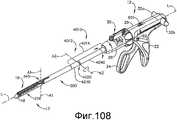
Фиг.108 - вид в перспективе другого варианта осуществления хирургического сшивающего скобками аппарата в соответствии с настоящим изобретением.108 is a perspective view of another embodiment of a surgical stapling apparatus in accordance with the present invention.
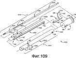
Фиг.109 - вид в сборе с пространственным разделением деталей варианта осуществления системы шарнирного поворота в соответствии с настоящим изобретением, применяемой в хирургическом сшивающем скобками аппарате, показанном на фиг.108.FIG. 109 is an exploded perspective view of an embodiment of an articulated rotation system in accordance with the present invention used in the surgical stapling apparatus shown in FIG.
Фиг.110 - вид в сборе с пространственным разделением деталей участков промежуточного шарнирно-поворотного сочленения системы шарнирного поворота, показанной на фиг.109.FIG. 110 is an exploded view of parts of sections of an intermediate articulated-articulated joint of the articulated rotation system shown in FIG.
Фиг.111 - вид в перспективе хирургического сшивающего скобками аппарата, показанного на фиг.108, применяемого при открытой хирургической операции.FIG. 111 is a perspective view of a surgical stapling apparatus shown in FIG. 108 used in open surgery.
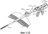
Фиг.112 - вид в перспективе другого варианта осуществления хирургического сшивающего скобками аппарата в соответствии с настоящим изобретением, применяемого в сочетании с обычным троакаром для выполнения эндоскопической хирургической операции.FIG. 112 is a perspective view of another embodiment of a surgical stapling apparatus in accordance with the present invention used in combination with a conventional trocar to perform an endoscopic surgery.
Фиг.113 - вид в перспективе другого варианта осуществления системы шарнирного поворота в соответствии с настоящим изобретением.113 is a perspective view of another embodiment of an articulated rotation system in accordance with the present invention.
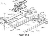
Фиг.114 - местный вид в сборе с пространственным разделением деталей системы шарнирного поворота, показанной на фиг.113.FIG. 114 is a partial exploded view of the parts of the articulated rotation system shown in FIG.
Фиг.115 - вид в сборе сбоку системы шарнирного поворота, показанной на фиг.113 и 114.Fig. 115 is an assembled side view of the articulated rotation system shown in Figs. 113 and 114.
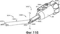
Фиг.116 - вид в перспективе другого варианта осуществления системы шарнирного поворота в соответствии с настоящим изобретением.FIG. 116 is a perspective view of another embodiment of an articulated rotation system in accordance with the present invention.
Фиг.117 - вид в перспективе другого варианта осуществления системы шарнирного поворота в соответствии с настоящим изобретением.FIG. 117 is a perspective view of another embodiment of an articulated rotation system in accordance with the present invention.
Фиг.118 - вид в сборе с пространственным разделением деталей системы шарнирного поворота, показанной на фиг.117.Fig is a view of the Assembly with a spatial separation of the parts of the articulated rotation system shown in Fig.
Фиг.119 - вид в сборе сбоку участка системы шарнирного поворота, показанной на фиг.117 и 118, с его некоторыми компонентами, показанными в разрезе для наглядности.Fig. 19 is an assembly side view of a portion of the articulated rotation system shown in Figs. 117 and 118, with some of its components shown in section for clarity.
Фиг.120 - местный вид в сборе в перспективе различных вариантов осуществления тяг и штифтов шарнирного поворота в соответствии с настоящим изобретением.FIG. 120 is an exploded perspective view of various embodiments of rods and pivot pins in accordance with the present invention.
Фиг.121 - вид в разрезе вариантов осуществления тяг и штифтов шарнирного поворота, показанных на фиг.120.Fig. 121 is a cross-sectional view of embodiments of rods and pivot pins shown in Fig. 120.
Фиг.122 - вид в перспективе другого варианта осуществления хирургического сшивающего скобками аппарата в соответствии с настоящим изобретением, применяемого в сочетании с обычным троакаром для выполнения эндоскопической хирургической операции.FIG. 122 is a perspective view of another embodiment of a surgical stapling apparatus in accordance with the present invention used in combination with a conventional trocar to perform an endoscopic surgical operation.
Фиг.123 - местный вид в сборе с пространственным разделением деталей варианта осуществления системы шарнирного поворота хирургического сшивающего скобками аппарата, показанного на фиг.122.FIG. 123 is an exploded perspective view of an embodiment of an articulated rotation system of a surgical stapling apparatus shown in FIG.
ПОДРОБНОЕ ОПИСАНИЕDETAILED DESCRIPTION
Как видно из чертежей, на которых одинаковыми цифровыми позициями обозначены сходные компоненты на нескольких видах, на фиг.1 изображен хирургический инструмент многократного использования, который, в наглядных вариантах представляет собой, в частности, хирургический сшивающий скобками инструмент 10, допускающий практическое использование особых преимуществ различных вариантов осуществления настоящего изобретения. Хирургический сшивающий скобками инструмент 10 может содержать узел 12 рукоятки и удлиненный корпус 14. На фиг.1 изображен хирургический сшивающий скобками инструмент 10 с шарнирно-поворачиваемым одноразовым загрузочным модулем 16, присоединенным к данному инструменту. На фиг.2 изображен хирургический сшивающий скобками инструмент 10 с нешарнирным одноразовым загрузочным модулем 16', присоединенным к данному инструменту. Одноразовые загрузочные модули 16, 16' могут содержать инструментальный узел 17, который содержит кассетный узел 18, который вмещает множество хирургических скобок. Инструментальный узел 17 может дополнительно содержать скобкоформирующую наковальню 20. Упомянутые одноразовые загрузочные модули 16, 16' могут выполнять хирургические операции, например, отрезания ткани и наложения скобок с каждой стороны разреза. Различные варианты осуществления настоящего изобретения можно применять в соединении с одноразовыми загрузочными модулями, описанными в патенте США №5,865,361 изобретателя Миллимэна с соавторами (Milliman et al.), описание которого целиком включено в настоящее описание путем отсылки.As can be seen from the drawings, in which similar components in several views are denoted by the same reference numerals, Fig. 1 shows a reusable surgical instrument, which, in illustrative embodiments, is, in particular, a
Следует понимать, что в настоящем описании термины «проксимальный» и «дистальный» применяют для обозначения положения относительно захвата практикующим врачом узла рукоятки инструмента. Следовательно, инструментальный узел 17 является дистальным относительно более проксимального узла 12 рукоятки. Далее, следует понимать, что, для удобства и ясности, специальные термины, обозначающие пространственное положение, например, «вертикальный», «горизонтальный», «вверх», «вниз», «правый» и «левый» использованы в настоящем описании применительно к чертежам. Однако, существует множество пространственно-угловых положений применения хирургических инструментов, и упомянутые термины не предполагают ограничительного и абсолютного значения.It should be understood that in the present description, the terms "proximal" and "distal" are used to indicate the position regarding the capture by the practitioner of the node of the handle of the tool. Therefore, the
Как пояснялось выше, известные хирургические сшивающие скобками аппараты, например, аппараты, описанные в патенте США №5,865,361, слабо пригодны для многократной обработки (например, многократной стерилизации), обеспечивающей возможность многократного применения инструментов, так как их нелегко разбирать. Хирургический сшивающий скобками аппарат 10, показанный на фиг.1-20, выполнен с возможностью удобной многократной обработки и может применяться в соединении с шарнирно-поворачиваемым одноразовым загрузочным модулем 16 (фиг.1) и нешарнирными одноразовыми загрузочными модулями 16' (фиг.2), как подробно дополнительно описано ниже. В различных вариантах осуществления хирургического сшивающего скобками аппарата 10 может применяться узел 12 рукоятки, который конструктивно выполнен для облегчения очистки и стерилизации различных компонентов, заключенных в упомянутой рукоятке. Например, узел 12 рукоятки может содержать неподвижный участок 22 рукоятки, подвижную рукоятку 24 и цилиндрический участок 26. Поворотная головка 28 может быть установлена на переднем конце цилиндрического участка 26 для поддержки поворота удлиненного корпуса 14 относительно узла 12 рукоятки вокруг продольной оси «L-L» сшивающего скобками аппарата 10. Как дополнительно подробно поясняется ниже, некоторые варианты осуществления узла рукоятки могут также содержать рычаг 30 шарнирного поворота, который установлен на переднем конце цилиндрического участка 26 около поворотной головки 28. Возможна разработка других вариантов осуществления для применения в соединении с нешарнирными одноразовыми загрузочными модулями, и, следовательно, узел 12 рукоятки может не содержать подобных компонентов управления шарнирным поворотом. Узел 12 рукоятки может дополнительно содержать корпус 36 рукоятки, который может быть сформирован из первого сегмента 36a корпуса и второго сегмента 36b корпуса, которые, при их соединении, образуют корпус 36 рукоятки. Для облегчения разборки узла 12 рукоятки, сегменты 36a, 36b корпуса можно соединять, по меньшей мере, одним и, предпочтительно, тремя быстроразъемными крепежными средствами 400.As explained above, well-known surgical stapling devices, for example, the devices described in US Pat. The
Как показано на фиг.3, быстроразъемное крепежное средство 400 может содержать байонетное крепежное средство, которое содержит участок 402 головки винта, который содержит цилиндрический участок 404 или участок корпуса, который выступает из него и выполнен в размер для вмещения в отверстие 412 в соответствующем распорном элементе 410 жесткости, сформированном в сегменте 36a корпуса. Стержень или поперечный элемент 406 установлен в участке 404 корпуса для формирования, по существу, T-образного соединительного участка 408, выполненного в размер для вмещения в сегменты 414 прорези с каждой стороны отверстия 412. Сегменты 414 прорези выполнены так, что, когда T-образный соединительный участок вставляют в отверстие 412 и сегменты 414 прорези поворачивают, как показано стрелкой «T» на фиг.3, стержень 406 фиксирует с возможностью разъема соединительный участок 408 в заданном положении. В различных вариантах осуществления участок 404 корпуса быстроразъемного крепежного средства 400 может продолжаться через соответствующее отверстие в сегменте 36b корпуса и затем замыкаться фиксироваться стержнем или поперечным элементом 406 к данному сегменту так, что быстроразъемное крепежное средство 400 оказывается неразъемно связанным со вторым сегментом 36b корпуса, чтобы, когда сегмент 36b корпуса отсоединяют от первого сегмента 36a корпуса, быстроразъемные крепежные средства 400 не терялись и оставались на втором сегменте 36b корпуса при очистке/стерилизации.As shown in FIG. 3, the quick-
Как показано на фиг.4-8, подвижная рукоятка 24 может быть соединена с возможностью поворота с приводным узлом 500 прошивки/отрезания, который можно демонтировать с корпуса 36 рукоятки для очистки/стерилизации. В различных вариантах осуществления приводного узла 500 прошивки/отрезания может содержать внутренний рамный узел 510, который служит рабочей опорой для подвижной рукоятки 24. Как можно видеть на упомянутых фигурах, подвижная рукоятка 24 может быть шарнирно соединена с внутренним рамным узлом 510 шарнирным пальцем 38. Поджимной элемент 40, который может содержать торсионную пружину, отжимает подвижную рукоятку 24 от неподвижного участка 22 рукоятки. Смотри фиг.6-8. Приводящий стержень 46 может быть установлен внутри внутреннего рамного узла 510 и может содержать зубчатую рейку 48. Приводящая собачка 42, на которой имеется зуб 43 зацепления рейки, установлена с возможностью поворота на шарнирном пальце 44 на одном конце подвижной рукоятки 24. Смотри фиг.8. Поджимной элемент 50, который может содержать торсионную пружину, расположен с возможностью поджима приводящей собачки 42 к зубчатой рейке 48 приводящего стержня 46. Смотри фиг.7. Подвижную рукоятку 24 можно поворачивать, чтобы перемещать зуб 43 зацепления рейки приводящей собачки 42 в контакт с зубчатой рейкой 48 приводящего стержня 46 для линейной подачи приводящего стержня 46 в дистальном направлении «DD». Дистальный конец приводящего стержня 46 может содержать полость 47, сформированную в данном стержне, для вмещения проксимального конца 49 штока 52 управления (фиг.4) таким образом, что линейная подача приводящего стержня 46 вызывает соответствующую линейную подачу штока 52 управления.As shown in FIGS. 4-8, the
Внутренний рамный узел 510 может дополнительно содержать запорную собачку 54, которая содержит фиксирующий выступ 55, выполненный на данной собачке, соединена с рамным узлом 510 с возможностью поворота на шарнирном пальце 57 и поджата в полость 512 в приводящем стержне 46 поджимным элементом 56, который может содержать торсионную пружину. Фиксирующий выступ 55 запорной собачки 54 может перемещаться в зацепление с полостью 512 для удерживания приводящего стержня 46 в продольно фиксированном положении, когда одноразовый загрузочный модуль не присоединен к удлиненному корпусу 14, как дополнительно подробно поясняется ниже.The
Внутренний рамный узел 510 может также вмещать с возможностью функционирования механизм 58 отведения, который может содержать правую головку 32a отведения и левую головку 32b отведения, которые соединены с проксимальным концом приводящего стержня 46 соединительным стержнем 60. Смотри фиг.6. Соединительный стержень 60 может содержать правый и левый участки 62a и 62b зацепления для вмещения головок 32a и 32b отведения, соответственно, и центральный участок 62c, который выполнен в размер и по форме для поступательного перемещения внутри пары продольных прорезей 514 во внутреннем рамном узле 510 и прорезей 34a, сформированных в приводящем стержне 46 вблизи его проксимального конца. Каждая из головок 32a, 32b отведения может содержать полость в данной головке, чтобы головки можно было устанавливать по прессовой посадке на соответствующие участки 62a, 62b зацепления, соответственно. В различных вариантах осуществления настоящего изобретения соединительный стержень 60 может быть выполнен так, чтобы, когда с данного штыря снимают головки 32a, 32b отведения с целью разборки, соединительный стержень 60 оставался установленным в заданном положении согласованно с внутренним рамный узлом 510. Смотри фиг.7, 8 и 17. Как показано на фиг.6, центральный участок 62C может быть снабжен вырезом 63, который предназначен для зацепления с удерживанием фиксирующей лапкой (не показанной), сформированной на проксимальном конце фиксатора 520, который вмещается с возможностью сдвига в полость 522 в приводящем стержне 46. Отводящая пружина 524 закреплена между поперечной стойкой 526 в приводящем стержне 46 и фиксатором 520 для оттягивания фиксатора 520 в дистальном направлении, чтобы фиксирующая лапка, сформированная на его проксимальном конце, зацеплялась с возможностью удерживания за вырез 63 в соединительном стержне 60. Специалистам со средним уровнем компетентности в данной области техники должно быть понятно, что, когда головки 32a и 32b отведения отсоединяют от соединительного стержня 60, соединительный стержень 60 остается соединенным с внутренним рамным узлом 510 лапкой на фиксаторе 520.The
Расцепляющая планка 64 может быть соединена с возможностью функционирования с приводящим стержнем 46 и установлена для перемещения относительно упомянутого стержня при манипулировании головками 32a, 32b отведения. Пара пространственно разнесенных штифтов 66 может продолжаться наружу от боковой поверхности приводящего стержня 46 для сцепления с парой соответствующих наклонных кулачковых прорезей 68, сформированных в расцепляющей планке 64. После перемещения головок 32a, 32b отведения в проксимальном направлении «PD», штифты 66 могут отводить расцепляющую планку 64 вниз относительно приводящего стержня 46 и относительно зубчатой рейки 48 так, чтобы нижний участок расцепляющей планки 64 продолжался ниже зубчатой рейки 48 для отцепления зуба 43 зацепления рейки приводящей собачки 42 от зубчатой рейки 48. Поперечная прорезь 70 сформирована на проксимальном конце расцепляющей планки 64 для вмещения центрального участка 62c соединительного стержня 60, и удлиненные прорези 34 (фиг.1) образованы в цилиндрической секции 26 узла 12 рукоятки для обеспечения продольного поступательного перемещения соединительного стержня 60 в то время, когда головки 32a, 32b отведения оттягивают в проксимальном направлении «PD» для отведения приводящего стержня 46 и, следовательно, отведения штока 52 управления в проксимальном направлении «PD».The
В различных вариантах осуществления внутренний рамный узел 510 может также служить рабочей опорой для узла 80 блокировки прошивки/отрезания, который может содержать стопорный штифт 82 и поворотный фиксаторный элемент 83. Смотри фиг.7 и 8. Стопорный штифт 82 поджимается в центральное положение поджимными пружинами 84 и содержит кольцевые конусообразные кулачковые поверхности 85. Каждый конец стопорного штифта 82 продолжается через корпус 36 рукоятки вблизи верхнего края неподвижного участка 22 рукоятки. Поворотный фиксаторный элемент 83 может быть закреплен на его дистальном конце с возможностью поворота на шарнирном пальце 86 и может содержать запирающий затвор 88 и проксимальную выступающую часть 90, содержащую прорезь 89, сформированную в ней. Смотри фиг.7 и 8. Поворотный фиксаторный элемент 83 может поджиматься пружиной 93 (фиг.9), чтобы вынуждать запирающий затвор 88, закрепленный на данном элементе, входить в упорный фиксатор 53 внизу приводящего стержня 46 для предотвращения выдвижения приводящего стержня 46 и следующего за этим прошивного/отрезного срабатывания сшивающего скобками аппарата 10. Кольцевая конусообразная кулачковая поверхность 85 на стопорном штифте 82 расположена так, чтобы продолжаться в клиновидную прорезь 89 в проксимальной выступающей части 90. Поперечное перемещение стопорного штифта 82 в любом направлении против поджимного усилия каждой пружины 84 перемещает конусообразную кулачковую поверхность 85 в зацепление с боковыми стенками клиновидной прорези 89 в проксимальной выступающей части 90 и, тем самым, приводит к повороту поворотного фиксаторного элемента 83 на шарнирном пальце 86 с выходом запирающего затвора 88 из упорного фиксатора 53, что делает возможным продвижение вперед приводящего стержня 46.In various embodiments, the
Как дополнительно показано на фиг.6-9, передаточное звено 182 чувствительного механизма может быть установлено с возможностью функционирования на внутреннем рамном узле 510. Как можно видеть на данных фигурах, передаточное звено 182 чувствительного механизма может быть присоединено с возможностью сдвига к внутреннему рамному узлу 510 штифтом или винтом 530, который продолжается сквозь прорезь 532 в передаточном звене 182 чувствительного механизма, так что передаточное звено 182 чувствительного механизма может продольно сдвигаться относительно внутреннего рамного узла 510. Дистальный конец пружины 531 может быть закреплен к винту 530, и проксимальный конец пружины 531 может быть зацеплен за скобку 533 на передаточном звене 182 чувствительного механизма. Смотри фиг.6. Пружина 531 служит для оттягивания передаточного звена 182 чувствительного механизма в дистальном направлении «DD». Передаточное звено 182 чувствительного механизма может дополнительно содержать проксимальный фиксирующий рычаг 535, который содержит выступающий внутрь проксимальный конец 537, выполненный с возможностью взаимодействия с запорной собачкой 54. В частности, когда к сшивающему скобками аппарату 10 не присоединен одноразовый загрузочный модуль 16, 16', передаточное звено 182 чувствительного механизма оттянуто в дистальном направлении пружиной 531. В данном «ненагруженном» положении, проксимальный конец 537 проксимального фиксирующего рычага 535 не зацепляет запорную собачку 54 для удерживания запорной собачки 54 в положении фиксации, в котором фиксирующий выступ 55 вмещен в полость 512 и удерживает приводящий стержень 46 в продольно зафиксированном положении. Таким образом, если к сшивающему скобками аппарату 10 не присоединен одноразовый загрузочный модуль 16, 16', то сшивающий скобками аппарат 10 нельзя нормально привести в действие.As further shown in FIGS. 6-9, the
Передаточное звено 182 чувствительного механизма может дополнительно содержать продолжающуюся вниз дистальную лапку 534, сформированную на данном звене, для контакта с фланцем 179, сформированном на цилиндре 178 чувствительного механизма. Смотри фиг.4 и 5. Как дополнительно подробно поясняется ниже, трубка 176 чувствительного механизма ориентирована для сопряжения с цилиндром 178 чувствительного механизма. Смотри фиг.10. Передаточное звено 182 чувствительного механизма может дополнительно содержать пружинную консоль 536 с продолжающимся вниз концом 538, который входит в зацепление с кулачковой поверхностью 83a на поворотном фиксаторном элементе 83. Смотри фиг.7. Когда одноразовый загрузочный модуль 16, 16' присоединяют к дистальному концу удлиненного корпуса 14, одноразовый загрузочный модуль 16, 16' приходит в зацепление с дистальным концом трубки 176 чувствительного механизма и, тем самым, передвигает трубку 176 чувствительного механизма в проксимальном направлении, и, в результате, передвигает цилиндр 178 чувствительного механизма и передаточное звено 182 чувствительного механизма в проксимальном направлении. Перемещение передаточного звена 182 чувствительного механизма в проксимальном направлении вынуждает конец 538 пружинной консоли 536 перемещаться в проксимальном направлении от кулачковой поверхности 83a, что позволяет фиксаторному элементу 83 поворачиваться под действием пружины 92 из положения, допускающего срабатывание сшивающего скобками аппарата 10 (т.е. допускающего приведение в действие приводящего стержня 46) в блокирующее положение, в котором запирающий затвор 88 вмещен в упорный фиксатор 53 в приводящем стержне 46 и предотвращает срабатывание сшивающего скобками аппарата 10. Передаточное звено 182 чувствительного механизма предотвращает срабатывание, когда одноразовый загрузочный модуль 16 отсутствует. Фиксаторный элемент 83 предотвращает срабатывание при смыкании и размыкании узла 20 наковальни. Кроме того, когда передаточное звено 182 чувствительного механизма перемещается в проксимальном направлении, проксимальный конец 537 проксимального фиксирующего рычага 535 выполняет функцию поворота запорной собачки 54 таким образом, что фиксирующий выступ 55 выходит из полости 512 и, тем самым, позволяет привести в действие приводящий стержень 46. Смотри фиг.8.The
Как показано на фиг.4, корпус 36 рукоятки может содержать кольцевой паз 117, выполненный с возможностью вмещения кольцевого пояска 118, сформированного на проксимальном конце поворотной головки 28, которая предпочтительно образована из отформованных полусекций 28a и 28b, который могут соединяться между собой винтами 29. Кольцевой паз 117 и поясок 118 допускают поворот поворотной головки 28 относительно корпуса 36 рукоятки. Как показано на фиг.4, удлиненный корпус 14 может содержать наружную обойму 124, которая выполнена в размер, чтобы служить опорой для трубки 176 чувствительного механизма (показанной на фиг.10), и передаточное звено 123 шарнирного поворота. Данная сборка из компонентов 123, 124, 176 и 52 иногда называется в настоящем описании «узлом 125 штока управления» и может содержать другие компоненты, шарнирно установленные на штоке 52 управления. Проксимальный конец обоймы 124 содержит диаметрально противоположные отверстия 128, которые выполнены в размер для вмещения радиальных выступов 132, сформированных на дистальном конце поворотной головки 28. Смотри фиг.4 и 5. Выступы 132 и отверстия 128 жестко фиксируют поворотную головку 28 и удлиненный корпус 14 как от продольного, так и от поворотного перемещения друг относительно друга. Следовательно, поворот поворотной головки 28 относительно узла 12 рукоятки приводит к соответствующему повороту удлиненного корпуса 14 вокруг продольной оси L-L относительно узла 12 рукоятки. Следует также понимать, что, так как к дистальному концу удлиненного корпуса 14 присоединен одноразовый загрузочный модуль 16, 16', то поворот удлиненного корпуса 14 приводит также к повороту одноразового загрузочного модуля 16, 16'.As shown in FIG. 4, the
В различных вариантах осуществления механизм 120 шарнирного поворота может быть установлен на поворотной головке 28 и может содержать рычаг 30 шарнирного поворота и кулачковый элемент 136. Смотри фиг.11. Рычаг 30 шарнирного поворота может быть установлен с возможностью поворота на шарнирном пальце 140, который можно закрепить на резьбе в поворотной головке 28. Подвижный штифт 142 может вмещаться в гнездо 131 в нижней части рычага 30 шарнирного поворота и продолжаться вниз от данного рычага для зацепления с кулачковым элементом 136. Кулачковый элемент 136 может содержать корпус 144, который содержит удлиненную прорезь 146, продолжающуюся через одну стороны данного корпуса. Пару кулачковых пластин 136a, 136b можно соединять с корпусом 144 парой заклепок 145 или другими подходящими крепежными средствами для формирования узла 137 кулачковых пластин. В других вариантах осуществления узел 137 кулачковых пластин может быть сформирован в одно целое с корпусом 144. Кулачковые пластины 136a и 136b могут содержать ступенчатую кулачковую поверхность 148a, 148b, соответственно, которая формирует ступенчатую кулачковую поверхность 148. Каждая ступенька ступенчатой поверхности 148 соответствует конкретной степени шарнирного поворота сшивающего скобками аппарата 10. Удлиненная прорезь 146 выполнена с возможностью вмещения подвижного штифта 142, выступающего из рычага 30 шарнирного поворота. Узел 137 кулачковых пластин прикреплен к корпусу 144 таким образом, чтобы формировать дистальный ступенчатый участок 150 и проксимальный ступенчатый участок 152. Проксимальный ступенчатый участок 152 содержит выемку 154.In various embodiments, the
Как можно видеть на фиг.4, механизм 120 шарнирного поворота может дополнительно содержать сдвигаемый элемент 138, который содержит выступающий вверх консольный участок 540, который содержит вырез 542, который сформирован в данном участке в размер для вмещения лапки 544, сформированной на цилиндре 178 чувствительного механизма. Дистальный конец сдвигаемого элемента 138 может содержать консоль 546, которая содержит отверстие 548, выполненное с возможностью вмещения пальца 164, продолжающегося из проксимального конца передаточного звена 123 шарнирного поворота. Смотри фиг.4 и 10. К сдвигаемому элементу 138 прикреплен штифт 166, который может быть изготовлен из неабразивного материала, например, тефлона®, и в размер для вмещения в ступенчатую кулачковую поверхность 148. В собранном состоянии дистальный и проксимальный ступенчатые участки 150 и 152 кулачкового элемента 136 расположены под фланцами 170 и 172, сформированными на поворотной головке 28 для ограничения перемещения кулачкового элемента 136 поперечным движением относительно продольной оси «L-L» сшивающего скобками аппарата 10. Когда рычаг 30 шарнирного поворота поворачивают вокруг шарнирного пальца 140, кулачковый элемент 136 поперечно перемещается на поворотной головке 28 и перемещает, при этом, ступенчатую кулачковую поверхность 148 в поперечном направлении относительно штифта 166, и, тем самым, вынуждает штифт 166 перемещаться в проксимальном или дистальном направлении по ступенчатой кулачковой поверхности 148. Поскольку штифт 166 жестко прикреплен к сдвигаемому элементу 138, то сдвигаемый элемент 138 перемещается в проксимальном или дистальном направлении и вызывает соответствующее проксимальное или дистальное перемещение передаточного звена 123 шарнирного поворота.As can be seen in FIG. 4, the
Цилиндр 178 чувствительного механизма может содержать выступающий участок 544, выполненный с возможностью вмещения в выемку 154 в узле 137 кулачковых пластин. Когда к дистальному концу удлиненного корпуса 14 сшивающего скобками аппарата 10 прикреплен рабочим соединением шарнирно-поворотный одноразовый загрузочный модуль 16, выступ 544 перемещается проксимально от выемки 154 в кулачковом элементе 136. При расположении выступа 544 проксимально от выемки 154, кулачковый элемент 136 может свободно перемещаться в поперечном направлении и, тем самым, осуществлять шарнирный поворот сшивающего скобками аппарата 10. Как поясняется в патенте США №5,865,361, нешарнирный одноразовый загрузочный модуль 16' не содержит удлиненного вставного наконечника. По существу, когда в удлиненный корпус 14 вставляют нешарнирный одноразовый загрузочный модуль 16', цилиндр 178 чувствительного механизма не перемещается в проксимальном направлении на расстояние, достаточное для вывода выступа 544 из выемки 154. Следовательно, кулачковый элемент 136 заблокирован от поперечного перемещения выступом 544, который находится в выемке 154, и рычаг 30 шарнирного поворота застопорен в его центральном положении.The
Как можно видеть на фиг.4-9, данный вариант осуществления может также содержать узел 600 отключения блокировки прошивки/отрезания, который содержит кнопку 601 отключения блокировки, к которой прикреплена проволока 602 отключения блокировки. Проволока 602 отключения блокировки может быть уложена с возможностью сдвига между лапками 606 фиксации формы проволоки, сформированными на верхней поверхности 604 внутреннего рамного узла 510. Дистальный конец 610 проволоки 602 отключения блокировки закреплен в отверстии 539 в дистальном конце передаточного звена 182 чувствительного механизма. Когда кнопку 601 отключения блокировки перемещают в проксимальном направлении «PD», проволока 602 отключения блокировки оттягивает в проксимальном направлении передаточное звено 182 чувствительного механизма, которое отжимает запорную собачку 54 из стопорного зацепления с приводящим стержнем 46, а также вынуждает конец 538 пружинной консоли 536 отойти в проксимальном направлении от кулачковой поверхности 83a, чтобы позволить фиксаторному элементу 83 повернуться под действием пружины 92 из положения, допускающего срабатывание сшивающего скобками аппарата 10 (т.е. допускающего приведение в действие приводящего стержня 46) в блокирующее положение, в котором запирающий затвор 88 вмещен в упорный фиксатор 53 в приводящем стержне 46 и предотвращает срабатывание сшивающего скобками аппарата 10, пока не нажат стопорный штифт 82.As can be seen in FIGS. 4-9, this embodiment may also include a firmware / cut-off lock disable
Как показано на фиг.1, 2, 9 и 10, чтобы применить сшивающий скобками аппарат 10, сначала к дистальному концу удлиненного корпуса 14 прикрепляют одноразовый загрузочный модуль 16, 16'. Сшивающий скобками аппарат 10 можно использовать с шарнирно-поворачиваемыми одноразовыми загрузочными модулями 16 и нешарнирными одноразовыми загрузочными модулями 16', каждый из которых содержит, например, линейные ряды скобок от приблизительно 30 мм до приблизительно 60 мм. Способ присоединения одноразового загрузочного модуля 16, 16' к удлиненному корпусу 14 описан в патенте США №5,865,361. Когда вставной наконечник одноразового загрузочного модуля 16, 16' сцепляется с дистальным концом трубки 176 чувствительного механизма, то приводится в действие механизм обнаружения одноразового загрузочного модуля. Когда вставной наконечник входит в зацепление с трубкой 176 чувствительного механизма и перемещает ее в проксимальном направлении, трубка 176 чувствительного механизма вызывает проксимальное перемещение цилиндра 178 чувствительного механизма и передаточного звена 182 чувствительного механизма в проксимальном направлении «PD», чтобы повернуть фиксаторный элемент 83 против часовой стрелки, из неблокирующего положения в положение, в котором затвор 88 блокирует перемещение приводящего стержня 46.As shown in FIGS. 1, 2, 9 and 10, in order to use the
Когда одноразовый загрузочный модуль 16, 16' присоединен к сшивающему скобками аппарату 10, инструментальный узел 17 можно расположить около намеченной ткани. Чтобы зажать намеченную ткань между скобкоформирующей наковальней 20 и кассетным узлом 18, подвижную рукоятку 24 поворачивают к неподвижному участку 22 рукоятки против усилия торсионной пружины 40 для перемещения приводящей собачки 42 в зацепление с выступом 322 на приводящем стержне 46. Зацепление между выступом 322 и приводящей собачкой 42 приводит к дистальной подаче приводящего стержня 46 и, следовательно, дистальной подаче штока 52 управления. Шток 52 управления соединен на его дистальном конце с узлом привода аксиальной подачи в одноразовом загрузочном модуле 16, 16', содержащем приводную поперечину, чтобы дистальное перемещение штока 52 управления вызывало дистальное перемещение приводной поперечины в дистальном направлении и, тем самым, вынуждало скобкоформирующую наковальню 20 поворачиваться в сомкнутое положение таким образом, как описано в патенте США №5,865,361. В различных вариантах осуществления один полный ход подвижной рукоятки 24 может подать приводящий стержень 46 на приблизительно 15 мм, что может быть достаточным для зажима ткани во время первого хода, но не для прошивания скобками. Приводящий стержень 46 удерживается в его продольном положении после того, как подвижная рукоятка 24 отпущена, запирающим затвором 88, который поджат в фиксатор 53 в нижней части приводящего стержня 46. После отпускания подвижной рукоятки 24, приводящая собачка 42 проходит через рейку 48 в то время, как торсионная пружина 40 возвращает рукоятку 24 в положение на расстоянии от неподвижной рукоятки 22. В упомянутом положении приводящая собачка 42 поджимается в зацепление с зубчатой рейкой 48, чтобы дополнительно поддерживать приводящий стержень 46 в его продольно зафиксированном положении.When the
Чтобы «выполнить прошивку» скобками, установленными в кассетном узле 18 (т.е., вдавить скобки в скобкоформирующую наковальню 20), подвижную рукоятку 24 снова приводят в действие. В различных вариантах осуществления сшивающий скобками аппарат 10 может быть способен к работе с одноразовыми загрузочными модулями 16, 16', содержащими линейные ряды скобок от приблизительно 30 мм до приблизительно 60 мм. В данных конструктивных схемах сшивающий скобками аппарат 10 может быть выполнен так, чтобы каждый ход подвижной рукоятки 24 подавал приводящий стержень 46 на 15 мм. Так как один ход требуется для зажима ткани, то подвижной рукояткой 24 следует делать (n+1) ходов для прошивки скобками, где n равно частному от деления длины линейных рядов скобок в одноразовом загрузочном модуле, прикрепленном к сшивающему скобками аппарату 10, на 15 мм.In order to “perform the firmware” with the brackets installed in the cassette assembly 18 (ie, press the brackets into the bracket-forming anvil 20), the
Прежде, чем можно будет произвести прошивку скобками, следует выполнить действие узлом 80 блокировки прошивки/отрезания, чтобы переместить запирающий затвор 88 из его блокирующего положения в неблокирующее положение. Указанный результат можно получить воздействием на стопорный штифт 82, чтобы привести кулачковую поверхность 85 в зацепление с боковыми стенками прорезями 89 фиксаторного элемента 83 и, тем самым, повернуть фиксаторный элемент 83 в направлении против часовой стрелки на фиг.9. После этого, можно выполнить соответствующее число ходов подвижной рукояткой 24, чтобы подать приводящий стержень 46 и, тем самым, шток 52 управления и приводную поперечину в дистальном направлении «DD», чтобы известным способом отработать одноразовым загрузочным модулем 16, 16'. Для отведения приводящего стержня 46 и, следовательно, штока 52 управления и элемента привода одноразового загрузочного модуля 16, 16' после сшивания скобками, головки 32a, 32b отведения можно оттянуть в проксимальном направлении, что вынуждает штифты 66 переместить расцепляющую планку 64 в направлении, указанном стрелкой «J» на фиг.7, через зубья 49 для вывода приводящей собачки 42 из зацепления с зубьями 49 зубчатой рейки 48.Before the brackets can be flashed, the action of the flashing / cutting
Специалистам со средним уровнем компетентности в данной области техники должно быть очевидно, что одноразовые загрузочные модули 16, 16' стерилизуются и упаковываются в стерильные упаковочные материалы перед использованием. Аналогично, сшивающий скобками аппарат 10 также стерилизуется перед использованием. После использования, одноразовый загрузочный модуль 16, 16' выбрасывают. Предполагается, что сшивающий скобками аппарат 10 можно также многократно стерилизовать для дополнительного использования, однако, известные инструменты, например, инструменты, описанные в вышеупомянутом патенте США №5,865,361, и другие известные инструменты, предназначенные для применения с одноразовыми загрузочными модулями, мало пригодны для простой разборки с целью удобной стерилизации различных внутренних компонентов. Следовательно, данные устройства часто отправляют в отходы после единственного применения. Как дополнительно подробно поясняется ниже, сшивающий скобками аппарат 10 конструктивно выполнен с возможностью удобной разборки, чтобы допускать многократную обработку (т.е. многократную стерилизацию) сшивающего скобками аппарата 10.Professionals with an average level of competence in the art should understand that
На фиг.12 показан сшивающий скобками аппарат 10 после того, как им воспользовались, и одноразовый загрузочный модуль (не показанный) отсоединили от аппарата (этап 700 на фиг.14). Пунктирная штриховка 620, 622 обозначает примерные зоны загрязнения на удлиненном корпусе 14 и узле 12 рукоятки, соответственно. Чтобы начать повторную обработку сшивающего скобками аппарата 10, пользователь перемещает кнопку 601 отключения блокировки срабатывания в проксимальном направлении и удерживает кнопку 601 отключения блокировки срабатывания в данном проксимальном положении (этап 702). Данный этап состоит в перемещении передаточного звена 182 чувствительного механизма в проксимальном направлении вышеописанным образом и дает пользователю возможность приводить в действие приводящий стержень 46. Кроме того, пользователь перемещает стопорный штифт 82, чтобы можно было периодически двигать подвижную рукоятку 24 для приведения в действие приводящего стержня 46. Затем пользователь многократно периодически двигает подвижную рукоятку 24 (по стрелке «R» на фиг.13), чтобы выдвинуть шток 52 управления так, что загрязненный участок 624 штока 52 управления продолжается из обоймы 124 (этап 704). Смотри фиг.13. Затем пользователь может вставить открытый загрязненный участок 624 штока 52 управления и дистальный конец обоймы 124 в соответствующий очищающий или стерилизующий материал 630, например, оксид, пероксид этилена и т.п. (этап 706). Смотри фиг.15.FIG. 12 shows a
Для стерилизации узла 12 рукоятки, узел 12 рукоятки можно легко разобрать (этап 708). Как показано на фиг.5, пользователь может разделить сегменты 28a и 28b поворотной головки снятием винтов или крепежных средств 29 (этап 710). Сегменты 28a и 28b поворотной головки, а также сдвигаемый элемент 138 снимают и откладывают (этап 712). Затем правую и левую головки 32a, 32b отведения стягивают с соединительного стержня 60 (этап 714). После этого, с левого участка 36b корпуса можно снять три быстроразъемных крепежных средства 400, если крепежные средства 400 не имеют свободного соединения с упомянутым участком (этап 716). Затем сегмент 36b корпуса рукоятки можно отложить (этап 718). После этого пользователь может взять приводной узел 500 прошивки/отрезания из сегмента 36a корпуса и положить его на плоскую поверхность (этап 720). Затем пользователь может захватить дистальный конец штока 52 управления и повернуть его вертикально (по стрелке «V» на фиг.5 - этап 722). После этого, шток 52 управления можно вытянуть из полости 47 в приводящем стержне 46, как показано на фиг.4 (этап 724). Затем пользователь может отсоединить цилиндр 178 чувствительного механизма от проксимального конца трубки 176 чувствительного механизма (этап 726). Таким образом, сшивающий скобками аппарат 10 можно разделить на части, показанные на фиг.4. После того, пользователь может выбрать желательный цикл очистки/стерилизации (этап 730). Смотри фиг.16. В частности, пользователь может выбирать между «мокрым» циклом очистки, при котором компоненты погружают в соответствующий очистной раствор 630 (фиг.17) или «сухим» циклом очистки, при котором применяют облучение, или можно применить сочетание обоих циклов. Специалистам со средним уровнем компетентности в данной области техники должно быть очевидно, что на фиг.17 показаны только некоторые из компонентов узла рукоятки, погружаемых в очищающий материал 630. Следует понимать, что предполагается погружение всех компонентов узла рукоятки либо одновременно (если контейнер является достаточно большим), либо по одному за раз, либо мелкими группами, пока все не произведена очистка всех компонентов (этап 732). Однако, следует понимать, что те компоненты, которые износились или получили повреждения, можно заменять новыми стерилизованными компонентами для выполнения сборки. Резервуар 632, содержащий очищающий материал 630, можно встряхивать, или очищающий материал можно перемешивать или иначе взбалтывать с использованием обычных способов для обеспечения прохода очищающего материала 630 через отверстия 511 во внутреннем рамном узле 510 в контакт со всеми компонентами, содержащимися внутри данного узла (этап 734). После того, как все компоненты подверглись действию очищающего материала 630 в течение требуемого времени, компоненты можно извлечь из очищающего материала 630 и затем высушить на воздухе или высушить с использованием других обычных способов (этап 736).To sterilize the
После того, как компоненты очищены очищающим материалом (этапы 732-736), пользователь может также выбрать способ облучения компонентов (этапы 740, 742), или пользователь может отказаться от облучения компонентов (этап 744), после чего пользователь может смазать некоторые компоненты (этап 746), как дополнительно подробно описано ниже. Если пользователь выбирает облучение разобранных компонентов либо после мокрой очистки компонентов, либо вместо мокрой очистки, то пользователь выложить все составные части на соответствующий лоток или другой объект (не показанный). Затем на компоненты можно направить излучение с использованием обычных методов облучения. Например, можно применить излучение электронного пучка. Возможно также использование других видов веществ для паровой стерилизации, например, паров этиленоксида, паров пероксида.After the components are cleaned with a cleaning material (steps 732-736), the user can also choose the method of irradiating the components (
После того, как компоненты стерилизованы, некоторые компоненты можно смазать (этап 746). Как можно видеть на фиг.18, на различных компонентах инструкции 770 по смазке могут быть обеспечены рельефным или иным способом на внутреннем рамном узле 510. Как показано на фиг.18, на различные компоненты можно наносить стерильный смазочный материал, например, стеарат натрия.After the components are sterilized, some components can be lubricated (step 746). As can be seen in FIG. 18, on various components of the
Затем компоненты можно снова собрать в порядке, показанном на фиг.19. Для поддержки сборки компонентов можно воспользоваться стерильным монтажным элементом или лотком 790, который содержит ряд сопрягающихся полостей 792, 794. Смотри фиг.20. Один способ повторной сборки содержит этап 750, который заключается в укладке сегмента 28a поворотной головки в сопрягающуюся профилированную полость 792 в монтажном лотке 790. Головку 32a отведения можно уложить в сопрягающуюся полость 794 (этап 752). Первый сегмент 36a корпуса можно уложить в сопрягающуюся полость 796 (этап 754). Сдвигаемый элемент 138 можно уложить в правый сегмент 28a поворотной головки, при этом, штифт 166, прикрепленный к упомянутому элементу, вставлен в ступенчатую кулачковую прорезь 148 в кулачковом элементе 136, который установлен под фланцы 170, 172 в правом сегменте 28a поворотной головки (этап 756). Цилиндр 178 чувствительного механизма можно посадить на проксимальный конец штока 52 управления (этап 758). Узел 125 штока управления ориентирован вертикально, с направленным вверх дистальным концом. Цилиндр 178 чувствительного механизма удерживают на штоке 52 управления (этап 760). Проксимальный конец штока 52 управления вставляют в полость 47 в приводящем стержне 46 (этап 762). Затем узел 125 штока управления поворачивают вниз влево, чтобы выполнить соединение с приводящим стержнем 46 (этап 764). Цилиндр 178 чувствительного механизма поворачивают, пока лапка 544 не оказывается направленной вниз (этап 766). Соединенные приводной узел 500 прошивки/отрезания и узел 125 штока управления вставляют в правый сегмент 36a корпуса рукоятки и правый сегмент 28a поворотной головки в соответствующих полостях 798, 792, 796 в монтажном лотке 790. Фиксирующую лапку 544 на цилиндре 178 чувствительного механизма вставляют в вырез 542 в сдвигаемом элементе 138 (этап 768). Соединительный стержень 60 можно выставить для вставки в отверстие (не показанное) в правой головке 32a отведения (этап 770). Затем второй сегмент 36b корпуса рукоятки укладывают поверх собранного узла и выравнивают, чтобы быстроразъемные крепежные средства 400 могли соединить сегменты 36a, 36b корпуса рукоятки (этап 772). Сегмент 28b поворотной головки можно ориентировать так, чтобы состыковать с сегментом 28a поворотной головки и соединить с ним винтами 29 (этап 774). После этого левую головку 32b отведения можно запрессовать на стержень 60 отведения для выполнения сборки (этап 776).The components can then be reassembled in the order shown in FIG. 19. To support component assembly, you can use the sterile mounting element or
Вышеописанный узел 80 блокировки прошивки/отрезания, а также узел блокировки прошивки/отрезания, описанный в вышеупомянутом патенте США №5,865,361, может представлять сложность для использования, так как врач должен прижать стопорный штифт 82, чтобы можно было приводить в действие приводящий стержень 46 периодическими действиями подвижной рукояткой 24. Данная конструкция обычно требует, чтобы врач пользовался обеими руками (одной рукой для удерживания узла рукоятки и работы подвижной рукояткой и другой рукой для прижатия стопорного штифта 82). Желательно располагать хирургическим сшивающим скобками аппаратом, который содержит более экономичную конструкцию рычага блокировки прошивки/отрезания, который не требует, чтобы врач пользовался обеими руками для приведения инструмента в действие. На фиг.21-33 изображен сшивающий скобками аппарат 810, который, по существу, аналогичен вышеописанному сшивающему скобками аппарату 10 или, возможно, по существу, аналогичен сшивающему скобками аппарату, описанному в патенте США №5,865,361, или другому известному хирургическому инструменту, который использует узел блокировки стопорным штифтом, за исключением того, сшивающий скобками аппарат 810 использует систему 880 блокировки прошивки/отрезания, которая намного удобнее в применении и не требует участия обеих рук для приведения инструмента в действие.The above firmware / cutting
Как показано на фиг.21 и 22, узел 12 рукоятки содержит корпус 36 рукоятки, который предпочтительно сформирован из отформованных сегментов 36a и 36b корпуса рукоятки, которые совместно формируют неподвижный элемент 22 рукоятки и цилиндрический участок 26 узла 12 рукоятки. Подвижная рукоятка 824 может быть установлена с возможностью поворота между сегментами 36a и 36b корпуса рукоятки на шарнирном пальце 38. Смотри фиг.22. Поджимной элемент 40, который может содержать торсионную пружину, отжимает подвижную рукоятку 824 от неподвижной рукоятки 22. Приводящий стержень 46 может быть установлен внутри цилиндрического участка 26 корпуса 36 рукоятки и содержит рейку 48 с зубьями 49. Приводящая собачка 42, на которой имеется зуб 43 зацепления рейки, может быть установлена с возможностью поворота на шарнирном пальце 44 на одном конце подвижной рукоятки. Для поджима приводящей собачки 42 к рейке 48 на приводящем стержне можно применить поджимной элемент 50, который может содержать торсионную пружину. Когда подвижную рукоятку 824 приводят в действие (например, поворачивают), данная рукоятка перемещает приводящую собачку 42 так, что зуб 43 зацепления рейки зацепляет с возможностью привода зубчатую рейку 48 приводящего стержня 46 для линейной подачи приводящего стержня 46 в дистальном направлении «DD». Передний конец приводящего стержня 46 содержит полость 47, сформированную в данном стержне, для вмещения проксимального конца 53 штока 52 управления (фиг.23) таким образом, что линейная подача приводящего стержня 46 вызывает соответствующую линейную подачу штока 52 управления.As shown in FIGS. 21 and 22, the
Сшивающий скобками аппарат 810 может дополнительно содержать запорную собачку 54, которая содержит фиксирующий рейку элемент 55, может быть установлена с возможностью поворота на шарнирном пальце 57 внутри корпуса 36 рукоятки и поджата к зубчатой рейке 48 поджимным элементом 56, который также предпочтительно является торсионной пружиной. Фиксирующий рейку выступ 55 запорной собачки 54 ориентирован для перемещения в полость 512 в приводящем стержне 46 таким образом, что, когда фиксирующий рейку выступ 55 находится в полости 512, приводящий стержень 46 удерживается в продольно фиксированном положении, если одноразовый загрузочный модуль не присоединен к сшивающему скобками аппарату 810.The stapler-
Различные варианты осуществления могут также содержать механизм 58 отведения, который может содержать правую головку 32a отведения и левую головку 32b отведения, которые соединены с проксимальным концом приводящего стержня 46 соединительным стержнем 60. Смотри фиг.22. Соединительный стержень 60 может содержать правый и левый участки 62a и 62b зацепления для вмещения головок 32a и 32b отведения и центральный участок 62c, который выполнен в размер и по форме для поступательного перемещения внутри пары продольных прорезей 34a, соответственно сформированных в приводящем стержне 46 вблизи его проксимального конца. Расцепляющая планка 64 может быть соединена с возможностью функционирования с приводящим стержнем 46 и установлена для перемещения относительно упомянутого стержня при манипулировании головками 32a, 32b отведения. Пара пространственно разнесенных штифтов 66 может продолжаться наружу от боковой поверхности приводящего стержня 46 для сцепления с парой соответствующих наклонных кулачковых прорезей 68, сформированных в расцепляющей планке 64. После перемещения головок 32a, 32b отведения в проксимальном направлении «PD», штифты 66 могут отводить расцепляющую планку 64 вниз относительно приводящего стержня 46 и относительно зубчатой рейки 48 так, чтобы нижний участок расцепляющей планки 64 продолжался ниже зубчатой рейки 48 для отцепления зуба 43 зацепления рейки приводящей собачки 42 от зубчатой рейки 48. Прорезь 70 может быть сформирована на проксимальном конце расцепляющей планки 64 для вмещения центрального участка 62c соединительного стержня 60, и удлиненные прорези 34 образованы в цилиндрической секции 26 узла 12 рукоятки для обеспечения продольного поступательного перемещения соединительного стержня 60 в то время, когда головки 32a, 32b отведения оттягивают в проксимальном направлении «PD» для отведения приводящего стержня 46 и, следовательно, отведения назад штока 52 управления.Various embodiments may also include a
Сшивающий скобками аппарат 810 может дополнительно содержать передаточное звено 882 чувствительного механизма, которое может быть соединено с возможностью сдвига с сегментом 36a корпуса рукоятки штифтом или винтом 530, который продолжается сквозь прорезь 532 в передаточном звене 882 чувствительного механизма, так что передаточное звено 882 чувствительного механизма может продольно сдвигаться относительно корпуса 36 рукоятки. Дистальный конец пружины 531 может быть закреплен к винту 530, и проксимальный конец пружины 531 может быть зацеплен за скобку 533 на передаточном звене 882 чувствительного механизма. Смотри фиг.22. Пружина 531 служит для оттягивания передаточного звена 882 чувствительного механизма в дистальном направлении «DD». Передаточное звено 882 чувствительного механизма дополнительно содержит проксимальный фиксирующий рычаг 535, который содержит выступающий внутрь проксимальный конец 537, выполненный с возможностью взаимодействия с запорной собачкой 54. В частности, когда к инструменту 810 не присоединен одноразовый загрузочный модуль 16, 16', передаточное звено 882 чувствительного механизма оттянуто в дистальном направлении пружиной 531. В данном «ненагруженном» положении, проксимальный конец 537 проксимального фиксирующего рычага 535 не зацепляет запорную собачку 54 для удерживания запорной собачки 54 в положении фиксации, в котором фиксирующий выступ 55 вмещен в полость 512 и удерживает приводящий стержень 46 в продольно зафиксированном положении. Таким образом, если к инструменту 810 не присоединен одноразовый загрузочный модуль 16, 16', то инструмент 10 нельзя привести в действие.The
Как показано на фиг.23, механизм обнаружения одноразового загрузочного модуля может продолжаться внутри сшивающего скобками аппарата 810 из удлиненного корпуса 14 в узел 12 рукоятки. Механизм обнаружения может содержать трубку 176 чувствительного механизма, которая установлена с возможностью сдвига в наружную обойму 124. Дистальный конец трубки 176 чувствительного механизма расположен по направлению к дистальному концу удлиненного корпуса 14, и проксимальный конец трубки 176 чувствительного механизма закреплен в дистальном конце цилиндра 178' чувствительного механизма парой выступов 180'. Дистальный конец передаточного звена 882 чувствительного механизма ориентирован в положение упора во фланец проксимального конца 190' цилиндра 178' чувствительного механизма.As shown in FIG. 23, the mechanism for detecting the disposable loading module can continue inside the
Передаточное звено 882 чувствительного механизма может дополнительно содержать продолжающуюся вниз дистальную лапку 534, сформированную на данном звене, для контакта с фланцем 179, сформированном на цилиндре 178' чувствительного механизма. Смотри фиг.22 и 23. Как дополнительно подробно поясняется ниже, трубка 176 чувствительного механизма ориентирована для сопряжения с цилиндром 178' чувствительного механизма. Смотри фиг.23. Когда одноразовый загрузочный модуль 16, 16' присоединяют к дистальному концу удлиненного корпуса 14, одноразовый загрузочный модуль 16, 16' приходит в зацепление с дистальным концом трубки 176 чувствительного механизма и, тем самым, передвигает трубку 176 чувствительного механизма в проксимальном направлении, и, в результате, передвигает цилиндр 178 чувствительного механизма и передаточное звено 882 чувствительного механизма в проксимальном направлении. Когда передаточное звено 882 чувствительного механизма перемещается в проксимальном направлении, проксимальный конец 537 проксимального фиксирующего рычага 535 выполняет функцию поворота запорной собачки 54 таким образом, что фиксирующий выступ 55 выходит из полости 512 и, тем самым, позволяет привести в действие приводящий стержень.The
В сшивающем скобками аппарате 810 может также применяться механизм 120 шарнирного поворота, тип и конструкция которого подробно описаны выше, со следующими обращающими внимание отличиями. В различных вариантах осуществления механизм 120 шарнирного поворота может быть установлен на поворотной головке 28 и содержать рычаг 30 шарнирного поворота, кулачковый элемент 136 и сдвигаемый элемент 138'. В различных вариантах осуществления сдвигаемый элемент 138' может содержать множество ребер 156, которые выполнены для вмещения с возможностью сдвига в канавки (не показанные), сформированные вдоль внутренних стенок поворотной головки 28. Сцепление между ребрами 156 и данными канавками не допускает поворота поворотной головки 28 и сдвигаемого элемента 138' друг относительного друга, при допуске их относительного линейного перемещения. Дистальный конец сдвигаемого элемента 138' может содержать консоль 160, которая содержит отверстие 162, выполненное с возможностью вмещения пальца 164, продолжающегося от проксимального конца передаточного звена 123 шарнирного поворота. Смотри фиг.23.The
В собранном состоянии, проксимальный и дистальный ступенчатый участки 150 и 152 кулачкового элемента 136 расположены под фланцами 170 и 172, сформированными на поворотной головке 28, для ограничения перемещения кулачкового элемента 136 поперечным движением относительно продольной оси «L-L» сшивающего скобками аппарата 810. Когда рычаг 30 шарнирного поворота поворачивают вокруг шарнирного пальца 140, кулачковый элемент 136 поперечно перемещается на поворотной головке 28 и перемещает, при этом, ступенчатую кулачковую поверхность 148 (смотри фиг.11) поперечно штифту 166, и, тем самым, вынуждает штифт 166 перемещаться в проксимальном или дистальном направлении по ступенчатой кулачковой поверхности 148. Поскольку штифт 166 жестко прикреплен к сдвигаемому элементу 138', то сдвигаемый элемент 138' перемещается в проксимальном или дистальном направлении и вызывает соответствующее проксимальное или дистальное перемещение первого передаточного звена 123 шарнирного поворота. Смотри фиг.23 и 24.In the assembled state, the proximal and distal stepped
Как также видно из фиг.24, кулачковый элемент 136 может содержать выемку 154. Стопорное кольцо 184, содержащее выступающий участок 186, выполненный с возможностью вмещения в выемку 154, расположено вокруг цилиндра 178' чувствительного механизма между участком 188' управляющего выступа и проксимальным фланцевым участком 190'. Смотри фиг.23. Пружина 192', расположенная между фланцевым участком 190' и стопорным кольцом 184, поджимает стопорное кольцо 184 в дистальном направлении на цилиндре 178 чувствительного механизма. Когда шарнирно-поворотный одноразовый загрузочный модуль 16, содержащий удлиненный концевой участок, вставляют в дистальный конец удлиненного корпуса 14 сшивающего скобками аппарата 810, вставной наконечник заставляет участок 188' управляющего выступа перемещаться в проксимальном направлении в зацепление со стопорным кольцом 184 и, тем самым, отодвигать стопорное кольцо 184 и выступающий участок 186 проксимально от выемки 154 в кулачковом элементе 136. При расположении выступающего участка 186 проксимально от выемки 154, кулачковый элемент 136 может свободно перемещаться в поперечном направлении и, тем самым, осуществлять шарнирный поворот сшивающего скобками аппарата 810. Другие нешарнирные одноразовые загрузочные модули могут быть без удлиненного вставного наконечника. По существу, когда к удлиненному корпусу 14 присоединяют нешарнирный одноразовый загрузочный модуль 16, цилиндр 178' чувствительного механизма не отводится в проксимальном направлении на расстояние, достаточное для вывода выступающего участка 186 из выемки 154. Следовательно, кулачковый элемент 136 заблокирован от поперечного перемещения выступающим участком 186 стопорного кольца 184, который расположен в выемке 154, и рычаг 30 шарнирного поворота застопорен в его центральном положении.As can also be seen from FIG. 24, the
Как показано на фиг.23, дистальный конец удлиненного корпуса 14 может содержать механизм 900 блокировки штока управления, который может быть приведен в действие во время присоединения одноразового загрузочного модуля 16, 16' с дистальным концом удлиненного корпуса 14. Механизм 900 блокировки штока управления может содержать запирающую планку 902, которая поджимается в дистальном направлении пружиной 904 и содержит проксимальный палец 906, имеющий наклонную кулачковую поверхность 908. В различных вариантах осуществления возможно использование фиксатора 910 прошивного стержня, который содержит фиксирующую лапку 912, выступающую из него. Фиксирующая лапка 912 может быть выполнена с возможностью селективного зацепления за вырез 914 в штоке 52 управления. Фиксатор 910 прошивного стержня может быть снабжен поджимным элементом в форме пластинчатой пружины (не показанной) или чем-то подобным и содержать стопорный палец 916, продолжающийся из него. Пластинчатая пружина служит для поджима фиксатора 910 прошивного стержня наружу, когда проксимальный конец запирающей планки 902 выдвигается вперед в дистальное положение. Запирающая планка 902 может перемещаться из дистального положения, находящегося на расстоянии от фиксирующей лапки 912, в проксимальное положение, расположенное позади фиксирующей лапки 912. В проксимальном положении запирающая планка 902 вынуждает фиксирующую лапку 912 продолжаться сквозь прорезь 918 в трубке 176 чувствительного механизма в зацепление с вырезом 914 в штоке 52 управления.As shown in FIG. 23, the distal end of the
Во время вставки одноразового загрузочного модуля 16, 16' в дистальный конец удлиненного корпуса 14, как дополнительно подробно поясняется ниже, кулачковая поверхность 908 запирающей планки 902 зацепляется выступом на одноразовом загрузочном модуле 16, 16', когда одноразовый загрузочный модуль 16, 16' поворачивают в зацепление с удлиненным корпусом 14, для перевода планки 902 в проксимальное положение. Фиксирующая лапка 912, которая расположена внутри выреза 914, удерживается в нем запирающей планкой 902 в то время, как выступ находится в зацеплении с кулачковой поверхностью 908 для предотвращения продольного перемещения штока 52 управления во время сборки. Когда одноразовый загрузочный модуль 16, 16' располагают относительно удлиненного корпуса 14 надлежащим образом, выступ на проксимальном конце одноразового загрузочного модуля 16, 16' сходит с кулачковой поверхности 908, что дает возможность пружине 904 вернуть запирающую планку 902 в ее дистальное положение и, тем самым, допускает последующее продольное перемещение штока 52 управления. Следует отметить, что, когда выступ одноразового загрузочного модуля сходит с кулачковой поверхности 908, может быть произведен ощутимый на слух щелчок или звук, указывающий, что одноразовый загрузочный модуль 16, 16' правильно закрепился к удлиненному корпусу 14.During insertion of the
Как видно из фиг.22, 25 и 26, в сшивающем скобками аппарате 810 можно применить усовершенствованный узел 880 блокировки прошивки/отрезания. В данном варианте осуществления подвижную рукоятку 824 можно снабдить полостью 930, выполненную в размер для вмещения проксимального участка курка 932 деблокировки прошивки/отрезания. Как можно видеть на данных фигурах, курок 932 деблокировки прошивки/отрезания может содержать выступ 934, сформированный на данном курке, и отпускающая пружина 936 может продолжаться между дном полости 930 и выступом 934 для приложения поджимного усилия к курку 932 деблокировки прошивки/отрезания в направлении «A». Как более подробно показано на фиг.26, курок 932 деблокировки прошивки/отрезания может иметь проксимальный задний участок 940, который выполнен в размер для продолжения с возможностью сдвига в прорезь 825, сформированную в подвижной рукоятке 824, когда курок деблокировки прошивки/отрезания нажимают в направлении «B». Усовершенствованный узел 880 блокировки прошивки/отрезания может дополнительно содержать зубчато-рычажный узел 950. В различных вариантах осуществления зубчато-рычажный узел 950 может содержать первое зубчатое колесо 952, которое установлено с возможностью поворота на оси 954 первого зубчатого колеса, которая закреплена на подвижной рукоятке 824. Первое зубчатое колесо 952 может содержать первый зубчатый сегмент 956, который предназначен для зубчатого зацепления с зубчатой рейкой 960 курка деблокировки, сформированной на заднем участке 940 курка 932 деблокировки прошивки/отрезания. Первое зубчатое колесо 952 может быть связано с собачкой 970 деблокировки первым соединительным звеном 972, которое соединено шарнирным пальцем или иным образом с возможностью поворота с первым зубчатым колесом 952 и собачкой 970 деблокировки. Как можно видеть на фиг.22 и 25, собачка 970 деблокировки может быть установлена с возможностью поворота на пальце 38.As can be seen from Fig.22, 25 and 26, in the
В различных вариантах осуществления собачка 970 деблокировки может содержать участок 974 зацепления, который выполнен с возможностью зацепления за разъединительный палец 980, который прикреплен ко второму соединительному звену 982 и принуждается к движению только в дуговой прорези 826, сформированной в подвижной рукоятке 824. Из последующего текста настоящего подробного описания станет очевидно, что прорезь 826 предотвращает перемещение второго соединительного звена 982, при приведении в действие подвижной рукоятки 824. Второе соединительное звено 982 также может быть связано шарнирным пальцем или соединено с возможностью поворота с зубчатым колесом 990 затвора, которое установлено с возможностью поворота на ось 992 зубчатого колеса, которая установлена в сегментах 36a, 36b корпуса рукоятки. На зубчатом колесе 990 затвора содержится сегмент с зубьями 994 зубчатого колеса, ориентированный для зубчатого зацепления с зубчатой рейкой 998 затвора, сформированной на запирающем затворе 996. В запирающем затворе 996 может быть выполнена прорезь 997 для вмещения участка 1002 пружины 1000 затвора, которая опирается на штифт 1004 затвора, который продолжается между сегментами 36a, 36b корпуса рукоятки. Пружина 1000 затвора служит для поджима запирающего затвора 996 в направлении «C». Смотри фиг.26.In various embodiments, the
Ниже, со ссылками на фиг.27-30, приведено описание работы системы 880 блокировки прошивки/отрезания. На фиг.27 показан сшивающий скобками аппарат 810 до зажима ткани в одноразовом загрузочном модуле (не показанном). Как можно видеть на данной фигуре, на данном этапе работы участок 974 зацепления собачки 970 деблокировки не находится в контакте с разъединительным пальцем 980. Как также можно видеть, верхний конец запирающего затвора 996 находится на дистальном конце приводящего стержня 46. На фиг.28 показано первое приведение в действие подвижной рукоятки 824, чтобы привести скобкоформирующую наковальню одноразового загрузочного модуля к смыканию вышеописанным образом. Врач еще не нажимал курок 932 деблокировки прошивки/отрезания и удобно расположил свой указательный палец позади приводящего участка 933 курка 932 деблокировки прошивки/отрезания. При приведении подвижной рукоятки 824 в действие, приводящий стержень 46 перемещается в дистальном направлении «DD» приводящей собачкой 42 вышеописанным образом. Как можно видеть из фиг.28, приводящий стержень 46 переместился в положение, в котором конец запирающего затвора 996 вошел в упорный фиксатор 53 в приводящем стержне 46 и соответствующий упорный фиксатор 53' в расцепляющей планке 64. Как более понятно из рассмотрения фиг.25, верхний конец запирающего затвора 996 содержит сформированный на нем скошенный или сужающийся участок 999, который сходится с вертикально продолжающейся проксимальной стороной 1005 запирающего затвора 996. Как также можно видеть на фиг.25, упорный фиксатор 53 в приводящем стержне 46 содержит наклонные поверхности 1006, 1007, а также участок 1008 вертикального уступа. Когда верхний конец запирающего затвора 996 полностью поджат в упорный фиксатор 53 пружиной 1000 затвора, проксимальная сторона 1005 запирающего затвора 996 расположена напротив вертикального уступа 1008 в приводящем стержне 46 для предотвращения, тем самым, перемещения приводящего стержня 46. Однако, когда запирающий затвор 996 оттягивается в направлении «D», наклонные поверхности 1006, 1007, а также скошенная поверхность 999 на запирающем затворе 996, дают возможность приводящему стержню 46 продольно продвинуться за запирающий затвор 996, без полного отжимания запирающего затвора 996 из контакта с приводящим стержнем 46.Below, with reference to Fig.27-30, a description of the operation of the
Как показано на фиг.28, в описанном положении, прорезь 826 в подвижной рукоятке 824 допускала подтягивание подвижной рукоятки к неподвижному участку 22 рукоятки, без принуждения разъединительного пальца 980 к перемещению второго соединительного звена 982, которое, в свою очередь, приводило бы в действие запирающий затвор 996. Как можно видеть на фиг.28, пружина 1000 поджала запирающий затвор 996 в положение блокировки, в котором запирающий затвор 996 вмещен в упорные фиксаторы 53, 53', и проксимальная поверхность 998 затвора находится напротив вертикального уступа 1008 в приводящем стержне 46. После того, как подвижная рукоятка 824 была оттянута в первое положение, показанное на фиг.28, для смыкания скобкоформирующей наковальни, врач дает подвижной рукоятке 824 переместиться в положение, показанное на фиг.29, под действием поджимного усилия пружины 40 запирания рукоятки. На данном этапе, головки 32a, 32b отведения можно оттянуть в проксимальном направлении, чтобы заставить скобкоформирующую наковальню разжать ткань в том случае, если врач намерен выполнить повторную манипуляцию инструментом 17, или врач может начать цикл прошивки/отрезания захватом своим указательным пальцем приводящего участка 933 курка 932 деблокировки прошивки/отрезания, как показано на фиг.30.As shown in FIG. 28, in the described position, the
На фиг.31 показано, что врач нажал курок 932 деблокировки прошивки/отрезания. Данное действие приводит зубчатую рейку 960 курка деблокировки на заднем участке 940 курка деблокировки в зацепление с первым зубчатым сегментом 956 на первом зубчатом колесе 952 и, тем самым, вынуждает первое зубчатое колесо 952 поворачиваться в направлении против часовой стрелки «CCW». Когда первое зубчатое колесо 952 поворачивается в направлении против часовой стрелки, оно толкает первое соединительное звено 972 в направлении «E», вынуждает собачку 970 деблокировки поворачиваться в направлении по часовой стрелки «C». Когда собачка 970 деблокировки поворачивается в направлении «C», поверхность 974 зацепления контактирует с разъединительным пальцем 980 и перемещает второе соединительное звено 982 в направлении «F». Когда второе соединительное звено 982 перемещается в направлении «F», оно вынуждает зубчатое колесо 990 затвора поворачиваться в направлении против часовой стрелки «CCW». Зубья 994 зубчатого колеса на зубчатом колесе 990 затвора находятся в зацеплении с зубчатой рейкой 998 затвора и перемещают запирающий затвор 996 в направлении «D» из запирающего зацепления с упорными фиксаторами 53, 53'.On Fig shows that the doctor pulled the
На фиг.32 показано положение запирающего затвора 996 относительно приводящего стержня 46, когда приводящий стержень 46 начинает перемещаться в дистальном направлении «DD» при приведении в действие подвижной рукоятки 824. Как можно видеть на данной фигуре, верхний скошенный участок 999 запирающего затвора 996 находится, при этом, в контакте с вертикальной кромкой 1005 в приводящем стержне 46 и дает возможность приводящему стержню 46 перемещаться в дистальном направлении. На фиг.33 показано окончание первого прошивного/отрезного хода подвижной рукоятки 824. Как можно видеть на данной фигуре, верхний конец запирающего затвора 996 скользит по низу приводящего стержня 46 и пластины 64, когда приводящий стержень 46 подается в дистальном направлении «DD». Проксимальный конец звена 982 переместился к проксимальному концу прорези 826 во время данного хода.32 shows the position of the locking
На фиг.34 показан альтернативный вариант осуществления сшивающего скобками аппарата 810', в котором применяется альтернативный узел 880' блокировки прошивки/отрезания, который может быть, по существу, аналогичен вышеописанному узлу 880 блокировки прошивки/отрезания, за исключением отмеченных ниже отличий. В частности, в узле 880' блокировки прошивки/отрезания применяется гибкая планка 1020, которая заключена для перемещения в змеевидном проходе 828, сформированном в подвижной рукоятке 824'. Гибкая планка 1020 заменяет первое зубчатое колесо 952, первое соединительное звено 972 и собачку 970 деблокировки. Один конец гибкой планки 1020 соединен с курком 932 деблокировки прошивки/отрезания, и другой конец гибкой планки 1020 принуждается к контакту с разъединительным пальцем 980, который также вынужден перемещаться только в прорези 828. Следовательно, когда нажимают курок 932 деблокировки прошивки/отрезания, гибкая планка 1020 толкает разъединительный палец 980, который заставляет второе соединительное звено 982 перемещаться в направлении «F». Когда второе соединительное звено 982 перемещается в направлении «F», зубчатое колесо 990 затвора перемещается в направлении против часовой стрелки «CCW» и перемещает запирающий затвор 996 в направлении «D». Когда врач отпускает курок 932 деблокировки прошивки/отрезания, отпускающая пружина 936 перемещает курок 932 деблокировки прошивки/отрезания в направлении «A», с оттягиванием, тем самым, гибкой планки 1020 от разъединительного пальца 980, что дает возможность разъединительному пальцу 980 свободно перемещаться в прорези 828. Когда разъединительный палец 980 освобождается, пружина 1000 затвора может поджимать запирающий затвор 996 в направлении «C». Когда запирающий затвор 996 поджат в направлении «C», зубчатое колесо 990 затвора свободно перемещается в направлении по часовой стрелке «C». Специалистам со средним уровнем компетентности в данной области техники должно быть очевидно, что вышеописанные конструкции систем 880, 880' блокировки прошивки/отрезания позволяют врачу манипулировать инструментами одной рукой. Данное решение является значительным усовершенствованием по сравнению с системами блокировки прошивки/отрезания, описанными в патенте США №5,865,361 и другими известными сшивающими скобками аппаратами, выполненными для работы с одноразовыми загрузочными модулями.FIG. 34 shows an alternative embodiment of the
На фиг.35-46 показан хирургический сшивающий скобками аппарат 1210, который предназначен для решения, по меньшей мере, некоторых из вышеупомянутых проблем, связанных с известными хирургическими сшивающими скобками аппаратами, которые предназначены для работы с шарнирно-поворачиваемыми одноразовыми загрузочными модулями. В частности, и как показано на фиг.35, хирургический сшивающий скобками аппарат 1210 может быть, по существу, аналогичен по конструкции различным вышеописанным инструментам, за исключением селективно фиксируемой системы 1220 поворота и системы 1320 шарнирного поворота (фиг.36), как подробнее поясняется ниже. Компоненты, которые идентичны компонентам, применяемым в вышеупомянутых вариантах осуществления, обозначаются ниже идентичными позициями элементов, и специалисты со средним уровнем компетентности в данной области техники могут обращаться к вышеприведенным разделам настоящего описания, которые поясняют конструкцию и работу упомянутых компонентов.Figures 35-46 show a
В одном варианте осуществления хирургический сшивающий скобками аппарат 1210 может содержать узел 12 рукоятки, который содержит удлиненный корпус 14, который соединен с возможностью функционирования с упомянутым узлом и дистально выступает из него. Дистальный конец удлиненного корпуса 14 может соединяться с шарнирно-поворачиваемым одноразовым загрузочным модулем 16. Одноразовый загрузочный модуль 16 может содержать инструментальный узел 17, который допускает его селективный шарнирный поворот вокруг оси «A1-A1» шарнирно-поворотными движениями, передаваемыми известным образом в данный узел посредством удлиненного корпуса 14. Смотри фиг.35. В различных вариантах осуществления настоящего изобретения проксимальный конец удлиненного корпуса 14 может быть присоединен к поворотному кожуху 1260, который соединен с корпусом 36' рукоятки. Как можно видеть на фиг.36, 44 и 45, корпус 36' рукоятки может содержать кольцевой паз 117, выполненный с возможностью вмещения кольцевого пояска 1262, сформированного на проксимальном конце поворотного кожуха 1260, который предпочтительно сформирован из отформованных сегментов 1260a и 1260b кожуха. Кольцевой паз 117 и поясок 1262 создают возможность поворота кожуха 1260 относительно корпуса 36' рукоятки. Поворот поворотного кожуха 1260 вынуждает удлиненный корпус 14 и одноразовый загрузочный модуль, закрепленный к нему, поворачиваться вокруг продольной оси «L-L», определяемой удлиненным корпусом 14. Различные варианты осуществления хирургического сшивающего скобками аппарата 1210 могут содержать селективно фиксируемую систему 1220 поворота, чтобы селективно фиксировать поворотный кожух 1260 для предотвращения его поворота (а также поворота удлиненного корпуса 14 и одноразового загрузочного модуля 16) относительно узла 12 рукоятки вокруг продольной оси «L-L».In one embodiment, the
В различных вариантах осуществления фиксируемая система 1220 поворота может содержать цилиндрическую дистальную крышку 1222, сформированную или иначе обеспеченную на дистальном конце корпуса 36' рукоятки. На фиг.36 изображен сегмент 36a' корпуса для корпуса 36' рукоятки, который содержит один сегмент 1222a крышки, сформированный на упомянутом сегменте. Специалистам со средним уровнем компетентности в данной области техники должно быть очевидно, что сегмент 36b' корпуса для корпуса 36' рукоятки содержит ответный сегмент 1222b крышки, сформированный на упомянутом сегменте, который взаимодействует с сегментом 1222a крышки для формирования дистальной крышки 1222. Смотри фиг.40.In various embodiments, the
Фиксируемая система 1220 поворота может дополнительно содержать тормозную систему 1229. В частности, сегмент 1222a крышки может содержать внутреннюю шлицевую секцию 1224a, и сегмент 1222b крышки может содержать внутреннюю шлицевую секцию 1224b. Внутренние шлицевые секции 1224a, 1224b совместно формируют внутреннюю шлицевую секцию 1224, которая выполнена с возможностью поддержки тормозной трубки 1230 тормозной системы 1229. В различных вариантах осуществления тормозная трубка 1230 содержит внешние шлицы 1232, которые сформированы на данной трубке в размер для вмещения во внутренние шлицы 1224 в дистальной крышке 1222 таким образом, что тормозная трубка 1230 может перемещаться аксиально относительно дистальной крышки 1222, но закреплена от поворота относительно нее. Тормозная система 1229 может дополнительно содержать тормозной бандаж 1240, который взаимодействует со штифтом 1250 тормозного рычага, который установлен с возможностью функционирования в поворотный кожух 1260. Дополнительное подробное описание работы штифта 1250 тормозного рычага и тормозного бандажа 1240 приведено ниже.The
Тормозная трубка 1230 может перемещаться аксиально относительно цилиндрической дистальной крышки 1222 посредством переключающей планки 1270, которая имеет рабочее соединение с узлом 1290 селекторного переключателя. Как можно видеть на фиг.36, переключающая планка 1270 содержит проксимальный конец 1272 и дистальный конец 1276. Проксимальный конец 1272 может иметь отверстие 1274 для вмещения стержневого участка 1294 селекторного переключателя 1292. Стержневой участок 1294 продолжается сквозь отверстие 1274 в переключающей планке 1270 и закрепляется к данной планке поперечным штифтом 1296. Кроме того, селекторный переключатель 1292 может содержать крепежный штифт 1298, который соединяет с возможностью поворота стержневой участок 1294 к корпусу 36'. Для фиксации селекторного переключателя 1292 в заданном положении можно воспользоваться фиксирующей пружиной 1300. Фиксирующая пружина 1300 может содержать выпуклый участок 1302, который выполнен с возможностью зацепления поперечным штифтом 1296, когда селекторный переключатель 1292 поворачивают в дистальном и проксимальном направлениях вокруг оси «SA-SA», образованной крепежным штифтом 1298. Смотри фиг.36. Следовательно, когда селекторный переключатель 1292 поворачивают в проксимальное положение (фиг.42, 43 и 46), и когда селекторный переключатель 1292 поворачивают в дистальное положение (фиг.37, 38, 41 и 45), выпуклый участок 1302 пружины 1300 удерживает селекторный переключатель 1292 и переключающую планку 1270 в заданном положении.The
Как показано на фиг.36, дистальный конец 1276 переключающей планки 1270 может содержать выступающий из него соединительный штифт 1278, который выполнен с возможностью присоединения переключающей планки 1270 к тормозной трубке 1230. Смотри фиг.38. Таким образом, линейное перемещение переключающей планки в проксимальном направлении «PD» и дистальном направлении «DD» вынуждает тормозную трубку 1230 также перемещаться в данных направлениях внутри участка 1222 цилиндрической дистальной крышки. Как также можно видеть на фиг.36-39 и 41-46, дистальный конец 1276 переключающей планки 1270 может дополнительно содержать задвижку 1280, сформированную на данной планке или прикрепленную к ней. Задвижка 1280 выполнена с возможностью селективного сцепления с кольцом 1264 блокировки поворота, которое содержит ряд зубьев 1266, сформированных или иначе обеспеченных на кольцевом пояске 1262. Как можно видеть на фиг.36, кольцевой паз 117 в цилиндрической дистальной крышке 1222 сформирован продолжающимся внутрь фланцем 1226, который содержит проходящую сквозь него канавку 1228 для вмещения через нее дистального конца 1276 переключающей планки 1270. Таким образом, как дополнительно в подробностях поясняется ниже, когда переключающую планку 1270 перемещают в дистальном направлении «DD», задвижку 1280 можно привести в зацепление с зубьями 1266 кольца 1264 блокировки поворота кожуха 1260 для предотвращения, тем самым, поворота кожуха 1260 относительно крышки 1222 и корпуса 36. Смотри фиг.44.As shown in FIG. 36, the
Различные варианты осуществления хирургического сшивающего скобками аппарата 1210 могут дополнительно содержать оригинальную новую систему 1320 шарнирного поворота, которая, как поясняется ниже, сопрягается с компонентами, формирующими удлиненный корпус 14, чтобы селективно подавать в упомянутую систему шарнирно-поворотные движения для передачи в одноразовый загрузочный модуль 16. Система 1320 шарнирного поворота может содержать сдвигаемый элемент 138'. Например, сдвигаемый элемент 138' может содержать ребра 156, который выполнения для вмещения с возможностью сдвига в канавки 1261, сформированные вдоль внутренних стенок кожуха 1260. Сцепление между ребрами 156 и данными канавками 1261 (фиг.36 и 37) не допускает поворота сдвигаемого элемента 138' относительно кожуха 1260, но, при этом, допускает относительное линейное перемещение данных компонентов. Дистальный конец сдвигаемого элемента 138' может содержать консоль 160, которая содержит отверстие 162, выполненное с возможностью вмещения пальца 164, продолжающегося от проксимального конца передаточного звена 123 шарнирного поворота. Смотри фиг.37. Кроме того, в данном варианте осуществления сдвигаемый элемент 138' содержит выступающий из него штифт 166 шарнирного поворота, который продолжается через прорезь 1265 шарнирного поворота в кожух 1260 шарнирного поворота. Штифт 166 шарнирного поворота вмещен в отверстие 1324 (фиг.36), сформированное в захвате системы 1320 линейного шарнирного поворота и вращения, который посажен на кожух 1260. Система шарнирного поворота может дополнительно содержать захват 1322 для линейного шарнирного поворота и вращения, который может быть из двух сегментов 1322a, 1322b захвата, которые соединяются вокруг кожуха 1260. Отверстия 1324 могут быть обеспечены в сегменте 1322a захвата, как показано на фиг.36. Следовательно, когда врач перемещает захват 1322 аксиально в проксимальном направлении «PD» и дистальном направлении «DD», сдвигаемый элемент 138', а также передаточное звено 123 шарнирного поворота перемещаются в данных направлениях с приведением, тем самым, в исполнение шарнирного поворота шарнирно-поворачиваемого одноразового загрузочного модуля.Various embodiments of a
Кроме того, в данном варианте осуществления тормозная система 1229 может быть выполнена с возможностью предотвращения приведения в действие системы 1320 шарнирного поворота. Например, как также показано на фиг.36, тормозной бандаж 1240 может быть выполнен с возможностью вмещения между разнесенными упорными фланцами 1267, сформированными на внешней стороне кожуха 1260 для формирования канавки 1269 под тормозной бандаж. Как можно видеть на фиг.36, тормозной бандаж 1240 не образует сплошного кольца; концы 1242 тормозного бандажа 1240 расположены с разнесением один против другого, с образованием между ними вмещающего кулачок отверстия 1244. Тормозной бандаж 1240 установлен внутри канавки 1269 под тормозной бандаж так, чтобы кулачковое отверстие 1242 было ориентировано для вмещения в него тормозного кулачка 1330. К тормозному кулачку 1330 прикреплен штифт 1332 перемещения тормозного рычага, который продолжается сквозь отверстие 1334 тормозного кулачка в кожухе 1260. Как можно видеть на фиг.37, штифт 1332 перемещения тормозного рычага выполнен с возможностью вмещения в канавку 1234 перемещения, сформированную в дистальном конце тормозной трубки 1230. В захвате 1322 для линейного шарнирного поворота и вращения, который содержит участок системы 1320 шарнирного поворота, содержится поднутренная зона 1326, чтобы захват 1320 мог перемещаться аксиально относительно кожуха 1260. В различных вариантах осуществления сегмент 1322a захвата может быть снабжен рядом стопоров 1328, которые выполнены с возможностью зацепления индикаторного пальца 1263 (фиг.41), выступающего из кожуха 1260, чтобы, когда захват 1320 аксиально перемещают по кожуху 1260, индикаторный палец 1263 производил ощутимый на слух щелчок или звук, когда индикаторный палец входит в зацепление со стопором 1328. На приведенной фигуре изображены пять стопоров 1328; возможно также использование другого числа стопоров 1328.In addition, in this embodiment, the
Ниже, со ссылками на фиг.37-39, 41 и 42-44, приведено описание работы хирургического сшивающего скобками аппарата 1210. На фиг.37-39 изображен сшивающий скобками аппарат 1210 в режиме «поворота», в котором наружную обойму 124 можно селективно поворачивать вокруг продольной оси «L-L». Как можно видеть на фиг.37 и 38, селекторный переключатель 1292 повернут в дистальное положение, в котором переключающая планка 1270 вытянута в проксимальном направлении «PD». Когда переключающая планка 1270 вытянута в проксимальном направлении, задвижка 1280 поворота расцеплена с кольцом 1264 блокировки поворота (фиг.39) и, тем самым, допускает поворот кожуха 1260 вокруг продольной оси «L-L». Как изложено выше, проксимальный конец обоймы 124 содержит диаметрально противоположные отверстия 128, которые выполнены в размер для вмещения радиальных выступов 132, сформированных внутри дистального конца кожуха 1260. Смотри фиг.36 и 38. Выступы 132 и отверстия 128 жестко фиксируют кожух 1260 и удлиненный корпус 14 один к другому, как от продольного, так и от поворотного перемещения. Следовательно, поворот кожуха 1260 относительно узла 12 рукоятки приводит к соответствующему повороту удлиненного корпуса 14 вокруг продольной оси L-L относительно узла 12 рукоятки. Кроме того, так как переключающая планка 1270 соединена с тормозной трубкой 1230 соединительным штифтом 1278, когда переключающую планку 1270 перемещают в проксимальном направлении «PD», тормозная трубка 1230 также перемещается в проксимальном направлении внутри цилиндрической дистальной крышки 1222. Как пояснялось выше, штифт 1332 перемещения тормозного кулачка 1330 вмещается в канавку 1234 перемещения в тормозной трубке 1230. Когда тормозная трубка 1230 перемещается в проксимальном направлении, штифт 1332 перемещения, который является дистальным конструктивным элементом радиального рычага, который, в свою очередь, жестко прикреплен к штифту 1250, поворачивает тормозной кулачок 1330 так, что он разжимает концы 1242 тормозного бандажа 1240 радиально наружу, чтобы фиксировать захват 1322 для линейного шарнирного поворота и вращения к кожуху 1260. Тормозной бандаж 1240 препятствует аксиальному перемещению захвата 1322 на кожухе 1260; однако, поворот захвата 1322 вызывает поворот кожуха 1260 вокруг оси «L-L». Таким образом, когда селекторный переключатель 1292 повернут в дистальном направлении, удлиненный корпус 14 и присоединенный к нему одноразовый загрузочный модуль можно повернуть вокруг продольной оси «L-L» путем поворота захвата 1320.Below, with reference to Figs. 37-39, 41 and 42-44, a description is given of the operation of the
Когда врач намерен шарнирно повернуть одноразовый загрузочный модуль, селекторный переключатель 1292 поворачивают в проксимальном направлении «PD», показанном на фиг.42, 43 и 46. Как можно видеть на фиг.42, 43 и 46, когда селекторный переключатель 1292 поворачивают в проксимальном направлении, переключающая планка 1270 подается аксиально в дистальном направлении «D-D», с приведением задвижки 1280 поворота в стопорное зацепление с кольцом 1264 блокировки поворота. Когда задвижка 1280 поворота находится в зацеплении с кольцом 1264 блокировки поворота, кожух 1260 (и удлиненный корпус 14 и обойма 124) не могут поворачиваться относительно узла 12 рукоятки вокруг продольной оси «L-L». Когда переключающая планка 1270 перемещается в дистальном направлении, тормозная трубка 1230 также перемещается в дистальном направлении «D-D», так как переключающая планка 1270 прикреплена к упомянутой трубке. Когда тормозная трубка 1230 перемещается в проксимальном направлении, штифт 1332 перемещения 1332 приводится в поворотное движение и поворачивает тормозной кулачок 1330 так, что он позволяет концам 1242 тормозного бандажа 1240 сдвигаться внутрь друг к другу, чтобы, тем самым, дать возможность захвату 1320 перемещаться относительно кожуха 1260. Смотри фиг.46. В различных вариантах осуществления штифт 166 шарнирного поворота продолжается из сдвигаемого элемента 138' сквозь прорезь 1265 в сегмент 1260a кожуха и вмещается в отверстие 1324 в сегменте 1322a захвата. Смотри фиг.36 и 37. Таким образом, когда врач перемещает захват 1322 поворота аксиально в проксимальном направлении «PD» и дистальном направлении «DD», сдвигаемый элемент 138', а также передаточное звено 123 шарнирного поворота, которое прикреплено к нему консолью 160, также перемещаются. Таким образом, когда врач перемещает захват 1322 поворота аксиально в проксимальном направлении «PD» и дистальном направлении «DD», сдвигаемый элемент 138', а также передаточное звено 123 шарнирного поворота также перемещаются в упомянутых направлениях для осуществления шарнирного поворота шарнирно-поворачиваемого одноразового загрузочного модуля. Кроме того, когда захват 1322 аксиально перемещают на кожухе 1260, индикаторный палец 1263 производит ощутимый на слух щелчок или звук, когда он входит в зацепление со стопорами 1328 для снабжения врача звуковым указанием о совершении шарнирно-поворотного движения.When the doctor intends to swivel the disposable loading module, the
На фиг.46 показано применение сдвигаемого элемента 138, который содержит выступающий вверх консольный участок 540 и консоль 546, который содержит отверстие 548, выполненное с возможностью вмещения пальца (не показанного), продолжающегося из проксимального конца передаточного звена 123 шарнирного поворота (не показанного). Смотри фиг.4 и 11. Штифт 166 прикреплен к сдвигаемому элементу 138 и выполнен в размер для продолжения сквозь прорезь 1265 в кожухе и в отверстие 1324 в захвате 1322. В другом отношении настоящий вариант осуществления работает аналогично вариантам осуществления, показанным на фиг.37 и 38. Специалистам со средним уровнем компетентности в данной области техники должно быть очевидно, что вышеописанный вариант осуществления представляет значительное усовершенствование по сравнению с известными инструментами, предназначенными для применения с такими одноразовыми загрузочными модулями, которые описаны в патенте США №5,865,361. В частности, в вышеописанных вариантах осуществления врач может поворачивать одноразовый загрузочный модуль в требуемое положение и затем фиксировать кожух 1260 для предотвращения дополнительного поворота кожуха 1260. Затем врач может шарнирно поворачивать одноразовый загрузочный модуль, пока кожух 1260 остается зафиксировать в заданном положении. В известных модулях поворотная головка могла свободно поворачиваться в то время, как врач производил шарнирный поворот одноразового загрузочного модуля. Таким образом, для предотвращения поворота одноразового загрузочного модуля, врач должен быть манипулировать рычагом шарнирного поворота с осторожностью, чтобы не сообщить поворотное движение поворотной головке. Вышеописанные варианты осуществления решают данную проблему.On Fig shows the use of a
На фиг.47-51 показан другой хирургический сшивающий скобками аппарат 1410 в соответствии с настоящим изобретением, конструктивно предназначенный для применения с одноразовым загрузочным модулем (не показанным), который позволяет врачу шарнирно поворачивать одноразовый загрузочный модуль и выполнять им прошивку/отрезание одной рукой. В частности, и со ссылкой на фиг.47, хирургический инструмент 1410, по существу, аналогичен по конструкции различным вышеописанным инструментам, за исключением системы 1420 шарнирного поворота, как подробно поясняется ниже. Компоненты, которые идентичны компонентам, применяемым в вышеупомянутых вариантах осуществления, обозначаются ниже идентичными позициями, и специалисты со средним уровнем компетентности в данной области техники могут обращаться к вышеприведенным разделам настоящего описания, которые поясняют конструкцию и работу упомянутых компонентов.Figures 47-51 show another
В одном варианте осуществления хирургический сшивающий скобками аппарат 1410 может содержать узел 12 рукоятки, который содержит удлиненный корпус 14, который соединен с возможностью функционирования с узлом 12 рукоятки и дистально выступает из него. Дистальный конец удлиненного корпуса 14 может соединяться с шарнирно-поворачиваемым одноразовым загрузочным модулем 16. Одноразовый загрузочный модуль может содержать инструментальный узел 17, который допускает его селективный шарнирный поворот вокруг оси «AA-AA» шарнирного поворота шарнирно-поворотными движениями, передаваемыми известным образом в упомянутый узел посредством удлиненного корпуса 14.In one embodiment, the
Узел 12 рукоятки может содержать корпус 36 рукоятки и содержать подвижную рукоятку 24, которая соединена с возможностью функционирования с упомянутым корпусом и может совершать движения в виде рабочих ходов относительно корпуса 36 рукоятки. Как в вышеописанных вариантах осуществления, приведение в действие подвижной рукоятки 24 может вызывать продольные приводные движения приводящего стержня 46, который соединен с возможностью функционирования со штоком 52 управления, который содержит участок удлиненного корпуса 14. Как можно видеть из фиг.48-51, система 1420 шарнирного поворота может содержать рычаг 1422 шарнирного поворота, который может быть выполнен по форме и ориентирован относительно неподвижного участка 22 корпуса 36 рукоятки и подвижной рукоятки 24 так, чтобы врач мог приводить упомянутый рычаг в действие своим указательным пальцем руки, которая захватывает узел 12 рукоятки, и которая приводит в действие подвижную рукоятку 24. Рычаг 1422 шарнирного поворота может содержать соединенный с ним участок 1424 приводной штанги, который содержит вертикальный участок 1426, который шарнирно соединен с корпусом 36 рукоятки на шарнирном пальце 1428 так, что рычаг 1422 шарнирного поворота можно селективно поворачивать в направлениях «G» и «H» на шарнирном пальце 1428. Смотри фиг.49. Участок 1424 приводной штанги может дополнительно содержать приводной участок 1430, в котором содержится прорезь 1432, выполненная с возможностью вмещения приводного штифта 1434, закрепленного на тяге 1440 шарнирного поворота. Как можно видеть на фиг.49, тяга 1440 шарнирного поворота может быть снабжена парой удлиненных прорезей 1442, 1444, которые выполнены с возможностью вмещения участков винтов 1450, 1452, соответственно. Винты 1450, 1452 продолжаются сквозь удлиненные прорези 1442, 1444, соответственно, и прикреплены сегменту 36a корпуса рукоятки так, что тяга 1440 шарнирного поворота принуждается к продольному перемещению внутри корпуса 36 рукоятки в проксимальном направлении «PD» и дистальном направлении «DD». Дистальный конец тяги 1440 шарнирного поворота может содержать штифт 1446 шарнирного поворота, который выполнен с возможностью продолжению в кольцевую канавку 139'', обеспеченную в проксимальном конце сдвигаемого элемента 138'', который в других отношениях может быть идентичным по конструкции и принципу действия сдвигаемому элементу 138', подробно описанному выше. То есть, сдвигаемый элемент 138'' может содержать множество ребер 156, которые выполнены для вмещения с возможностью сдвига в канавки, сформированные вдоль внутренних стенок поворотной головки 28''. Сцепление между ребрами 156 и данными канавками не допускает поворота сдвигаемого элемента 138'' и поворотной головки 28'' друг относительного друга, при допуске относительного линейного перемещения между данными компонентами. Дистальный конец сдвигаемого элемента 138'' может содержать консоль 160, которая содержит отверстие 162, выполненное с возможностью вмещения пальца 164, продолжающегося из проксимального конца передаточного звена 123 шарнирного поворота. Смотри фиг.48 и 49. Следовательно, когда врач приводит в действие рычаг 1422 шарнирного поворота в направлении «G», приводной участок 1430 оттягивает тягу 1440 шарнирного поворота в проксимальном направлении «PD», которая оттягивает сдвигаемый элемент 138'' и передаточное звено 123 шарнирного поворота, прикрепленное к нему, в проксимальном направлении «PD», которое может, тем самым, принудить одноразовый загрузочный модуль, соединенный с упомянутым звеном, шарнирно повернуться в направлении вправо таким образом, как изложено выше и поясняется в дальнейшем. Когда врач подтягивает рычаг 1422 шарнирного поворота в направлении «H», приводной участок 1430 толкает тягу 1440 шарнирного поворота в дистальном направлении «DD», которая также толкает сдвигаемый элемент 138'' и передаточное звено 123 шарнирного поворота, прикрепленное к нему, в дистальном направлении «DD», которое может, тем самым, принудить одноразовый загрузочный модуль, соединенный с упомянутым звеном, шарнирно повернуться в направлении влево.The
Как указано выше, данный вариант осуществления может содержать цилиндр 178' чувствительного механизма, который сопрягается с трубкой 176 чувствительного механизма и передаточным звеном 182 чувствительного механизма, как пояснялось выше, чтобы обнаруживать, присоединен ли одноразовый загрузочный модуль к штоку 52 управления и не допускать приведения в действие механизма 1420 шарнирного поворота, когда одноразовый загрузочный модуль не присоединен. Однако, в данном варианте осуществления фланец 190' цилиндра 178' чувствительного механизма выполнен с возможностью взаимодействия с выступом 1448 блокировки по «отсутствию загрузки», сформированным на тяге 1440 шарнирного поворота. Смотри фиг.50 и 51. Когда одноразовый загрузочный модуль не присоединен к удлиненному корпусу 14 и штоку 52 управления, цилиндр 178' чувствительного механизма поджат в положение, показанное на фиг.50. Как можно видеть на данной фигуре, выступ 1448 блокировки по отсутствию загрузки на тяге 1440 шарнирного поворота вводится в зацепление с фланцем 190' на цилиндре 178' чувствительного механизма так, что тяга 1440 шарнирного поворота поджимается вбок наружу в направлении «I». Как также можно видеть на данной фигуре, продолжающийся внутрь упорный фиксатор 37 сформирован на сегменте 36a корпуса рукоятки и выполнен с возможностью вмещения в фиксирующий вырез 1445 в тяге 1440 шарнирного поворота, когда фланец 190' входит в зацепление с выступом 1448 блокировки по отсутствию загрузки для поджима тяги 1440 шарнирного поворота в направлении «I». Когда фиксатор 37 вмещен в фиксирующий вырез 1445, тягу 1440 шарнирного поворота нельзя привести в действие. Следовательно, когда одноразовый загрузочный модуль не присоединен к инструменту 1410, рычаг 1422 шарнирного поворота нельзя привести в действие. Когда одноразовый загрузочный модуль присоединяют к удлиненному корпусу 14 и штоку 52 управления, и тяге 176 чувствительного механизма, цилиндр 178' чувствительного механизма поджимается в проксимальном направлении «PD», что приводит к расцеплению фланца 190' с выступом 1448 блокировки по отсутствию загрузки, как показано на фиг.51, и, тем самым, допускает перемещение тяги 1440 шарнирного поворота. Таким образом, рычаг 1422 шарнирного поворота можно приводить в действие, когда одноразовый загрузочный модуль присоединен к сшивающему скобками аппарату 1410.As indicated above, this embodiment may comprise a
Специалистам со средним уровнем компетентности в данной области техники должно быть понятно, что вышеописанный механизм 1420 шарнирного поворота позволяет врачу манипулировать инструментом одной рукой. Данное решение является значительным усовершенствованием по сравнению с механизмами шарнирного поворота, описанными в патенте США №5,865,361 и другими известными сшивающими скобками аппаратами, выполненными для работы с одноразовыми загрузочными модулями.Professionals with an average level of competence in the art should understand that the above articulated
На фиг.52-64 показан другой хирургический сшивающий скобками аппарат 1510 в соответствии с настоящим изобретением, конструктивно предназначенный для применения с шарнирно-поворачиваемым одноразовым загрузочным модулем (не показанным), который позволяет врачу шарнирно поворачивать одноразовый загрузочный модуль и выполнять им прошивку/отрезание при манипулировании подвижной рукояткой 24''. В одном варианте осуществления хирургический сшивающий скобками аппарат 1510 может содержать узел 12 рукоятки, который содержит удлиненный корпус 14, который соединен с возможностью функционирования с узлом 12 рукоятки и дистально выступает из него. Дистальный конец удлиненного корпуса 14 может соединяться с шарнирно-поворачиваемым одноразовым загрузочным модулем 16. Одноразовый загрузочный модуль может содержать инструментальный узел 17, который допускает его селективный шарнирный поворот вокруг оси «A1-A1» шарнирного поворота шарнирно-поворотными движениями, передаваемыми в упомянутый узел посредством удлиненного корпуса 14 известным образом. Как подробно поясняется ниже, хирургический сшивающий скобками аппарат 1510 может применять оригинальное новое переключательное устройство 1512, которое сопрягается с подвижной рукояткой 24'', приводящим стержнем 46 и системой 1520 шарнирного поворота. Когда переключательное устройство 1512 ориентировано в положение «прошивки/отрезания», манипулирование подвижной рукояткой 24'' путем выполнения рабочих ходов сообщает прошивное/отрезное движение приводящему стержню 46, и когда переключательное устройство 1512 ориентировано в положение «шарнирного поворота», манипулирование подвижной рукояткой 24'' путем выполнения рабочих ходов приводит в действие систему 1520 шарнирного поворота. Компоненты, которые идентичны компонентам, применяемым в вышеупомянутых вариантах осуществления, обозначаются ниже идентичными позициями, и специалисты со средним уровнем компетентности в данной области техники могут обращаться к вышеприведенным разделам настоящего описания, которые поясняют конструкцию и работу упомянутых компонентов.On Fig-64 shows another
Как можно видеть на фиг.52 и 53, переключательное устройство 1512 может содержать селекторный переключатель 1522 шарнирного поворота, который расположен снаружи корпуса 36 рукоятки для обеспечения доступа к нему. Селекторный переключатель 1522 шарнирного поворота может быть соединен с осью 1524 селекторного переключателя шарнирного поворота, которая продолжается сквозь сегмент 36b корпуса рукоятки и закреплена к качающейся опоре 1530, которая составляет участок системы 1520 шарнирного поворота. Вторая ось 1526 селекторного переключателя шарнирного поворота выступает наружу из другой стороны качающейся опоры 1530 и продолжается сквозь сегмент 36a корпуса рукоятки для соединения с селекторным переключателем 1522a так, что качающаяся опора 1530 может поворачиваться вокруг оси «RA» качания, определяемой осями 1524, 1526. Смотри фиг.60. Как можно видеть на фиг.56-58, система 1520 шарнирного поворота дополнительно содержит первое зубчатое колесо 1540 шарнирного поворота и второе зубчатое колесо 1550 шарнирного поворота, каждое из которых может свободно поворачиваться внутри качающейся опоры 1530. Первое и второе зубчатые колеса 1540 и 1550 шарнирного поворота ориентированы для селективного зацепления за надставку 1441' тяги шарнирного поворота, которая содержит участок тяги 1440' шарнирного поворота, которая в других отношения аналогична вышеописанной тяге 1440 шарнирного поворота. Как можно видеть на фиг.55, в надставке 1441' тяги шарнирного поворота содержится ряд отверстий 1443', выполненных с возможностью зацепления первым и вторым зубчатыми колесами 1540, 1550 шарнирного поворота, в зависимости от ориентации качающейся опоры 1530.As can be seen in FIGS. 52 and 53, the
Переключательное устройство 1512 может дополнительно содержать оригинальный новый узел 1560 селективного переключения передач для сопряжения между зубчатым колесом 1610 прошивки/отрезания и зубчатой передачей 1600 шарнирного поворота, которая содержит участок системы шарнирного поворота. В различных вариантах осуществления зубчатая передача 1600 шарнирного поворота может содержать первое передаточное зубчатое колесо 1602, которое установлено на оси 1604 первого передаточного зубчатого колеса, которая установлена с возможностью вращения в гнезда-опоры (не показанные) в сегментах 36a, 36b рукоятки, и второе передаточное зубчатое колесо 1606, которое установлено на оси 1608 второго передаточного зубчатого колеса, которая установлена с возможностью вращения в гнезда-опоры (не показанные) в сегментах 36a, 36b рукоятки. В различных вариантах осуществления узел 1560 селективного переключения передач может содержать переключатель 1562 выбора функции, который содержит пару штифтов 1563, выступающих из него, которые продолжаются сквозь соответствующие дуговидные прорези 1564 в сегменте 36b корпуса рукоятки и закреплены к приводному диску 1566. Смотри фиг.61 и 62. Как можно видеть на данных фигурах, в приводном диске 1566 может содержаться ряд вмещающих зубья углублений 1568, которые выполнены с возможностью селективного зацепления с соответствующими зубьями 1571 диска в подвижном диске 1570. Подвижный диск 1570 может быть закреплен от поворота на неподвижной оси 1574. Как можно видеть на фиг.61 и 62, конец 1575 неподвижной оси 1574 может вмещаться в углубление 1577 и заштифтован в данном углублении стопорным штифтом 1578. Например, в различных вариантах осуществления конец 1575 может быть отформован в сегменте 36a корпуса рукоятки так, чтобы неподвижная ось 1574 не могла поворачиваться относительно упомянутого сегмента. Как также можно видеть на фиг.62, подвижный диск 1570 может быть заштифтован от поворота на неподвижной оси 1574 подвижным штифтом 1580, который продолжается сквозь поперечный паз 1576 в неподвижной оси 1574, чтобы подвижный диск 1570 перемещался аксиально (и без возможности поворота) на неподвижной оси 1574.The
Как можно видеть на фиг.61 и 62, узел 1560 селективного переключения передач может дополнительно содержать узел 1590 зубчатого привода, который содержит участок 1592 зубчатого привода и участок 1594 зубчатого привода шарнирного поворота. Узел 1590 зубчатого привода выполнен с возможностью аксиального перемещения на неподвижной оси 1574 и поджат в направлении «J» пружиной 1596, которая надета на неподвижную ось 1574.As can be seen in FIGS. 61 and 62, the selective
Ниже, со ссылками на фиг.57 и 58, приведено описание работы системы 1520 шарнирного поворота. Чтобы начать процесс шарнирного поворота, врач приводит в действие один из селекторных переключателей 1522a, 1522b шарнирного поворота. Например, в одном варианте осуществления, если врач намерен шарнирно повернуть одноразовый загрузочный модуль вправо, врач поворачивает селекторные переключатели 1522a, 1522b шарнирного поворота вниз (по стрелке «L» на фиг.52). При повороте селекторных переключателей 1522 вниз, качающаяся опора 1530 поворачивается в направлении против часовой стрелки «CCW» на фиг.58 для приведения второго зубчатого колеса 1550 шарнирного поворота в зубчатое зацепление с отверстиями 1443' в надставке 1441' тяги шарнирного поворота. В режиме шарнирного поворота узел 1560 селективного переключения передач может оставаться в незадействованном положении, показанном на фиг.59 и 63. В данном положении узел 1590 зубчатого привода расположен так, что зубчатое колесо 1620 рукоятки, закрепленное или, в ином случае, отформованное на подвижной рукоятке 24, находится в зубчатом зацеплении с участком 1592 зубчатого привода узла 1590 зубчатого привода. Кроме того, участок 1594 зубчатого привода шарнирного поворота узла 1590 зубчатого привода находится в зубчатом зацеплении с первым передаточным зубчатым колесом 1602. Как можно видеть на фиг.59, когда узел 1590 зубчатого привода расположен упомянутым образом, зубчатое колесо 1610 прошивки/отрезания, которое установлено с возможностью вращения на ось 1612 зубчатого колеса прошивки/отрезания, не находится в зацеплении с узлом 1590 зубчатого привода. Таким образом, приведение в действие подвижной рукоятки 24 не повлияет на зубчатое колесо 1610 прошивки/отрезания.Below, with reference to FIGS. 57 and 58, a description is given of the operation of the articulated
Когда селекторные переключатели 1522a, 1522b, 1562 находятся в положении в соответствии с непосредственно предшествующим описанием, врач может шарнирно повернуть одноразовый загрузочный модуль, присоединенный к сшивающему скобками аппарату 1510, приведением в действие (с применением храпового механизма или поворотом) подвижной рукоятки 24. Когда подвижную рукоятку 24 приводят в действие, зубчатое колесо 1620 рукоятки поворачивается в направлении против часовой стрелки «CCW» и, в свою очередь, вынуждает поворачиваться в направлении по часовой стрелке «CW» приводное зубчатое колесо 1592, которое, в свою очередь, вынуждает поворачиваться в направлении против часовой стрелки «CCW» первое передаточное зубчатое колесо 1602, которое, в свою очередь, вынуждает поворачиваться в направлении по часовой стрелке «CW» второе передаточное зубчатое колесо 1606, которое, в свою очередь, вынуждает поворачиваться в направлении против часовой стрелки «CCW» первое зубчатое колесо 1540 шарнирного поворота, которое, в свою очередь, вынуждает поворачиваться в направлении по часовой стрелке «CW» второе зубчатое колесо 1550 шарнирного поворота, которое, в свою очередь, перемещает надставку 1441' тяги шарнирного поворота в проксимальном направлении «PD». Смотри фиг.58. Когда надставка 1441' тяги шарнирного поворота приводится в движение в проксимальном направлении «PD», тяга 1440' шарнирного поворота приводит в движение в проксимальном направлении «PD» сдвигаемый элемент 138” и прикрепленное к нему передаточное звено 123 шарнирного поворота, которое, тем самым, может вынуждать одноразовый загрузочный модуль, связанный с данным звеном, шарнирно поворачиваться в направлении вправо таким образом, как изложено выше и поясняется в дальнейшем. Для шарнирного поворота одноразового загрузочного модуля влево, врач поворачивает селекторные переключатели 1522a, 1522b шарнирного поворота в направлении вверх (направление «M» на фиг.52). Когда селекторные переключатели 1522a, 1522b поворачивают в данном направлении, качающаяся опора 1530 поворачивается в направлении по часовой стрелке «CW» вокруг оси «RA» качания и, тем самым, приводит первое зубчатое колесо 1540 шарнирного поворота в зубчатое зацепление с надставкой 1441' тяги шарнирного поворота. Так как первое зубчатое колесо 1540 шарнирного поворота поворачивается в направлении по часовой стрелке «CW», первое зубчатое колесо 1540 шарнирного поворота приводит надставку 1441' тяги шарнирного поворота в движение в дистальном направлении «DD», когда приводят в действие подвижную рукоятку. Когда надставку 1441' тяги шарнирного поворота приводят в движение в дистальном направлении «DD», тяга 1440' шарнирного поворота приводит в движение в дистальном направлении «DD» сдвигаемый элемент 138'' и прикрепленное к нему передаточное звено 123 шарнирного поворота, которое, тем самым, может вынуждать одноразовый загрузочный модуль, связанный с данным звеном, шарнирно поворачиваться в направлении влево. Кроме того, в данном варианте осуществления тяга 1440' шарнирного поворота может использовать блокировочное устройство, описанное выше применительно к тяге 1440 шарнирного поворота, для предотвращения перемещения тяги 1440' шарнирного поворота, когда к сшивающему скобками аппарату 1510 не присоединен одноразовый загрузочный модуль. Таким образом, в данном варианте осуществления шарнирно-поворотные движения производят приведением в действие подвижной рукоятки 24.When the
Данный вариант осуществления может также использовать оригинальную новую систему прошивки/отрезания, обозначенную, в общем, позицией 1601, в состав которой входит зубчатое колесо 1610 прошивки/отрезания. В частности, и как показано на фиг.55-60, система 1601 прошивки/отрезания может также содержать ползун 1640 собачки, который установлен с возможностью перемещения в правой реечной направляющей 1630a, сформированной в правом сегменте 36a корпуса рукоятки, и левой реечной направляющей 1630b, сформированной в левом сегменте 36b корпуса рукоятки, как показано на фиг.54 (сегменты 36a, 36b корпуса не показаны для наглядности на фиг.54). В различных вариантах осуществления ползун 1640 собачки, в общем, может иметь форму заглавной буквы «I» с дистальным поперечным участком 1642, центральным пластинчатым участком 1644 и проксимальным поперечным участком 1646. Поперечные участки 1642, 1646 служат для установки ползуна 1640 собачки с возможностью сдвига в реечных направляющих 1630a, 1630b так, что ползун 1640 собачки может аксиально перемещаться в проксимальном направлении «PD» и дистальном направлении «DD». Кроме того, в данном варианте осуществления может присутствовать приводная рейка 1650, сформированная на нижней поверхности или иначе прикрепленная к нижней поверхности центрального пластинчатого участка 1644 ползуна 1640 собачки. Рейка 1650 прошивки/отрезания ориентирована для зубчатого зацепления с зубчатым колесом 1610 прошивки/отрезания, как дополнительно подробнее поясняется ниже. Кроме того, к центральному пластинчатому участку 1644 прикреплена собачка 42, которая содержит участок 43 зацепления с рейкой для приводного зацепления рейки 48 на приводящем стержне 46. Как показано на фиг.55 и 64, собачка 42 в различных вариантах осуществления может быть штампованной из металла и иметь, по существу, U-образную форму, так что собачку 42 можно установить с возможностью поворота на шарнирном пальце 44' на центральном пластинчатом участке 1644. Пружину 50' собачки можно установить в отверстие 1645 в центральном пластинчатом участке 1644 для поджима собачки 42 в зубчатое зацепление с рейкой 48 на приводящем стержне 46. Смотри фиг.64.This embodiment may also use the original new firmware / cutting system, indicated generally by 1601, which includes a gear /
Ниже, со ссылкой на фиг.60 и 64, приведено описание работы системы 1601 прошивки/отрезания. Чтобы начать процесс прошивки/отрезания, врач поворачивает узел 1560 селективного переключения передач в положение, показанное на фиг.64, чтобы узел 1590 зубчатого привода был поджат в направлении «K» так, что зубчатое колесо 1620 рукоятки остается в зубчатом зацеплении с ведущим зубчатым колесом 1592, и зубчатое колесо 1594 шарнирного поворота в узле 1590 зубчатого привода не находится в зацеплении с первым передаточным зубчатым колесом 1602 шарнирного поворота. Кроме того, приводное зубчатое колесо 1592 находится в зубчатом зацеплении с зубчатым колесом 1610 прошивки/отрезания, которое, как описано выше, находится в зубчатом зацеплении с рейкой 1650 прошивки/отрезания. Так как ведущее зубчатое колесо 1594 шарнирного поворота не находится в зацеплении с первым передаточным зубчатым колесом 1602 шарнирного поворота, то приведение в действие подвижной рукоятки 24'' не создаст, в результате, никаких шарнирно-поворотных движений.Below, with reference to FIGS. 60 and 64, a description is given of the operation of the firmware /
Когда селекторный переключатель 1562 устанавливают в соответствии с непосредственно предшествующим описанием, врач может привести в действие приводящий стержень 46, который, в свою очередь, передает прошивное/отрезное движения штоку 52 управления, соединенному с приводящим стержнем 46, который, в свою очередь, передает прошивное/отрезное движения одноразовому загрузочному модулю, соединенному со штоком таким образом, как описано в патенте США №5,865,361. Как показано на фиг.56, приводящий стержень 46 в соответствии с данным оригинальным новым вариантом осуществления приводят в действие (или перемещают в дистальном направлении «DD») путем приведения в действие (с применением храпового механизма или поворотом) подвижной рукоятки 24. Когда подвижную рукоятку 24 приводят в действие, зубчатое колесо 1620 рукоятки поворачивается в направлении против часовой стрелки «CCW» и, в свою очередь, вынуждает поворачиваться в направлении по часовой стрелке «CW» приводное зубчатое колесо 1592, которое, в свою очередь, вынуждает поворачиваться в направлении против часовой стрелки «CCW» зубчатое колесо 1610 прошивки/отрезания и приводить в движение рейку 1650 прошивки/отрезания и соединенную с ней собачку 42 в дистальном направлении «DD». Участок 43 зацепления с рейкой собачки 42 находится в зацеплении с зубьями 49 рейки 48 на приводящем стержне 46 и, тем самым, приводит в движение приводящий стержень 46 в дистальном направлении «DD». В других отношениях, данный вариант осуществления работает, как описано выше. В частности, врач продолжает приводить в действие подвижную рукоятку 24'' с помощью храпового механизма, пока не завершится последовательность прошивки/отрезания. Когда подвижную рукоятку 24'' поворачивают в положение около участка 22 неподвижной рукоятки, врач отпускает подвижную рукоятку 24'' и подвижная рукоятка 24'' поворачивается в исходное положение пружиной 40 (описанной выше), и затем подвижную рукоятку 24'' можно снова повернуть для выполнения другого хода по подаче собачки 42 и приводящего стержня 46. Когда подвижную рукоятку 24'' отпускают, зуб 43 зацепления рейки на собачке 42 сдвигается по зубьям 49 на зубчатой рейке 48 приводящего стержня в то время, как собачка перемещается в проксимальном направлении «PD», и затем повторно зацепляет зубья 49, когда подвижную рукоятку 24'' поворачивают для приведения приводящего стержня в движение в дистальном направлении «DD».When the
Специалистам со средним уровнем компетентности в данной области техники должно быть понятно, что сшивающий скобками аппарат 1510 оснащен подвижной рукояткой 24'', которую можно использовать для приведения в действие инструмента, а также для приведения в действие закрепленного на нем одноразового загрузочного модуля. Из дальнейшего будет понятно, что данные варианты осуществления способны развивать более высокие усилия шарнирного поворота, чем другие известные устройства, например, устройства, описанные в патенте США №5,865,361.Professionals with an average level of competence in the art should understand that the
На фиг.65-69 изображен альтернативный механизм 1720 шарнирного поворота для аксиальной подачи сдвигаемого элемента 138, чтобы добиться, в конечном счете, продольного срабатывания передаточного звена шарнирного поворота (не показанного на фиг.65). Как можно видеть на фиг.65 и 66, механизм 1720 шарнирного поворота можно использовать в соединении с поворотной головкой 28', которая может быть, по существу, идентичной вышеописанной поворотной головке 28, за исключением того, что поворотная головка 28' выполнена с возможностью установки на ней головки 1730 шарнирного поворота, как показано. Как можно видеть на фиг.66, головка 1730 шарнирного поворота может содержать лапку 1732 для захвата пальцами, которая закреплена на шарнирном пальце 1734, который продолжается сквозь отверстие 1736 в сегменте 28a' поворотной головки. Шарнирный палец 1734 может содержать квадратный участок 1735, который выполнен с возможностью неповоротного размещения в соответствующем квадратном отверстии 1752 в кулачковом диске 1750. Сдвигаемый элемент 138 может содержать выступающий вверх консольный участок 540, в котором содержится вырез 542, который выполнен в размер для вмещения лапки (не показанной), сформированной на (непоказанном) цилиндре чувствительного механизма, как пояснялось выше. Дистальный конец сдвигаемого элемента 138 может содержать консоль 546, которая содержит отверстие 548, выполненное с возможностью вмещения пальца 164 (не показанного на фиг.65 и 66), продолжающегося из проксимального конца передаточного звена 123 шарнирного поворота (не показанного на фиг.65 и 66), как пояснялось выше. Смотри фиг.4 и 11. К сдвигаемому элементу 138 прикреплен штифт 166, который может быть изготовлен из неабразивного материала, например, тефлона® или металла, который покрыт тефлоном®, и в размер для вмещения в дуговидную кулачковую прорезь 1754. Следовательно, когда головку 1730 шарнирного поворота поворачивают, штифт 166 приводится в продольное движение либо в проксимальном направлении «PD» или в дистальном направлении «DD», в зависимости от направления, в котором поворачивают головку 1730 шарнирного поворота. Продольное смещение штифта 166 показано на последовательности фиг.67-69. Например, на фиг.67 показано положение кулачкового диска 1750 и штифта 166, когда одноразовый загрузочный модуль шарнирно повернут влево. На фиг.68 показано положение кулачкового диска 17650 и штифта 166 шарнирного поворота, когда одноразовый загрузочный модуль не повернут (например, расположен соосно с удлиненным корпусом), и на фиг.69 показано положение кулачкового диска 17650 и штифта 166 шарнирного поворота, когда одноразовый загрузочный модуль шарнирно повернут вправо. В некоторых вариантах осуществления дуговидная кулачковая прорезь 1754 может иметь такую форму, что ее угол подъема относительно штифта 166 на протяжении всей последовательности приведения в действие является относительно малым (меньше 15 градусов), что может приводить к эффективной фиксации шарнирного поворота.65-69 depict an alternative articulated
На фиг.70 и 71 изображен другой оригинальный новый механизм 1820 шарнирного поворота и оригинальная новая система 1850 поворота с фиксацией, которые можно применять в соединении с сшивающим скобками аппаратом 1810, в котором может применяться одноразовый загрузочный модуль. Механизм 1820 шарнирного поворота конструктивно предназначен для аксиальной подачи сдвигаемого элемента 138 для приведения, в конечном счете, в продольное движение передаточного звена 123 шарнирного поворота (не показанного на фиг.70 и 71), которое соединено со сдвигаемым элементом 138. Как можно видеть на фиг.70 и 71, механизм 1820 шарнирного поворота можно применять в связи с корпусом 36'' рукоятки, который сформирован из сегментов рукоятки (на фиг.70 и 71 показан сегмент 36a'' рукоятки, но следует понимать, что, для формирования корпуса 38” рукоятки, применяется еще один сегмент рукоятки, сопрягающийся по форме с сегментом 36a'' рукоятки). В различных вариантах осуществления механизм 1820 шарнирного поворота установлен на поворотном кожухе 1830, который содержит снабженный фланцем проксимальный конец 1832, который выполнен с возможностью вмещения в кольцевую канавку 1834, сформированную в корпусе 36'' рукоятки таким образом, что поворотный кожух 1830 можно селективно поворачивать вокруг оси «L-L» относительно кожуха 36'' рукоятки, как дополнительно подробно поясняется ниже. Хотя на фиг.70 и 71 и не показано, удлиненный элемент 14 и обойма 124, описанные выше в связи с другими вариантами осуществления, можно закреплять к поворотному кожуху 1830 радиальными выступами 132, сформированными на дистальном конце поворотного кожуха 1830. Смотри фиг.70. Выступы 132 и отверстия 128 в обойме 124 жестко фиксируют поворотный кожух 1830 и удлиненный корпус 14 как от продольного, так и от поворотного перемещения друг относительно друга. Следовательно, поворот поворотного кожуха 1830 относительно корпуса 36'' рукоятки приводит к соответствующему повороту удлиненного корпуса 14 относительно корпуса 36'' рукоятки.On Fig and 71 shows another original
Как можно видеть на фиг.70 и 71, механизм 1820 может содержать кольцо 1822 шарнирного поворота, которое соединено на резьбе с группой резьбовых витков 1836, обеспеченных на поворотном кожухе 1830. Сдвигаемый элемент 138 может содержать выступающий вверх консольный участок 540, который содержит вырез 542, который сформирован в данном участке в размер для вмещения лапки (не показанной), сформированной на цилиндре чувствительного механизма (не показанном), как поясняется выше. Дистальный конец сдвигаемого элемента 138 может содержать консоль 546, которая содержит отверстие 548, выполненное с возможностью вмещения пальца 164 (не показанного на фиг.70 и 71), продолжающегося из проксимального конца передаточного звена 123 шарнирного поворота (не показанного на фиг.70 и 71), как поясняется выше. Смотри фиг.4 и 11. К сдвигаемому элементу 138 прикреплен штифт 166, который может быть изготовлен из неабразивного материала, например, тефлона® или металла, который покрыт тефлоном®, и в размер для вмещения в кольцевую прорезь 1825, сформированную в кольце 1822 шарнирного поворота. Следовательно, когда кольцо 1822 шарнирного поворота подается по резьбе на поворотном кожухе 1830 в проксимальном направлении «PD», штифт 166 также приводит в движение сдвигаемый элемент 138 (и передаточное звено 123 шарнирного поворота) в проксимальном направлении «PD», что вызывает шарнирный поворот одноразового загрузочного модуля в направлении вправо. Аналогично, когда кольцо 1822 шарнирного поворота подается по резьбе на поворотном кожухе 1830 в дистальном направлении «DD», штифт 166 также приводит в движение сдвигаемый элемент 138 (и передаточное звено 123 шарнирного поворота) в дистальном направлении «DD», что вызывает шарнирный поворот одноразового загрузочного модуля в направлении влево.As can be seen in FIGS. 70 and 71, the
Вариант осуществления, показанный на фиг.70 и 71 содержит также оригинальную новую систему 1850 поворота с фиксацией, которая может содержать блокируемую головку 1852, которая состоит из двух сегментов 1852a головки, которые соединены между собой винтами, клеем, защелкивающимися элементами, стойками и т.п. над дистальным концом корпуса 36” рукоятки так, что блокируемая головка 1852 установлена с возможностью поворота и аксиального сдвига на дистальном конце узла 36” рукоятки. Как также можно видеть на фиг.70 и 71, дистальный конец корпуса 36” рукоятки содержит первый стопорный фланец 1860 с первым набором сформированных на нем радиальных зубьев 1862 зубчатого колеса. Блокируемая головка 1852 может также содержать продолжающийся внутрь второй стопорный фланец 1854, который содержит второй набор сформированных на нем радиальных зубьев 1856 зубчатого колеса. Второй набор радиальных зубьев 1856 зубчатого колеса расположен напротив первого набора радиальных зубьев 1862 зубчатого колеса на первом стопорном фланце 1860 так, что вторые радиальные зубья 1856 зубчатого колеса могут селективно сцепляться с первыми радиальными зубьями 1862 зубчатого колеса. Чтобы поджимать блокируемую головку 1852 в дистальном направлении «DD» для приведения второго набора радиальных зубьев 1862 зубчатого колеса в зубчатое зацепление с первым набором радиальных зубьев 1862 зубчатого колеса, можно применить фиксирующую пружину 1870. Как также можно видеть на фиг.70 и 71, проксимальный конец 1831 поворотного кожуха 1830 содержит поворотный шлиц 1837, сформированный на нем с возможностью зацепления с продолжающимся внутрь зубчатым фланцем 1858, сформированным на дистальном конце блокируемой головки 1852. Специалистам со средним уровнем компетентности в данной области техники должно быть понятно, что поворотный шлиц 1837 и зубчатый фланец 1858 служат для фиксации от поворота блокируемой головки 1852 к поворотному кожуху 1830, но с допуском аксиального перемещения блокируемой головки 1852 относительно поворотного кожуха 1830. Следовательно, для поворота поворотного кожуха 1830 (и удлиненного корпуса 14 и одноразового загрузочного модуля, прикрепленного к нему), врач отжимает блокируемую головку 1852 в проксимальном направлении «PD», чтобы отцепить второй набор радиальных зубьев 1856 зубчатого колеса от первого набора радиальных зубьев 1862 зубчатого колеса, что позволяет блокируемой головке 1852 поворачиваться вокруг продольной оси «L-L» относительно корпуса 36'' рукоятки. Когда блокируемую головку 1852 поворачивают, поворотный кожух 1830 также поворачивается вместе с блокируемой головкой 1852 благодаря зацеплению между зубчатым фланцем 1858 и поворотным шлицом 1837. После того, как врач повернет поворотный кожух 1830 в требуемое положение, врач освобождает блокируемую головку 1852. Когда блокируемую головку 1852 отпускают, пружина 1870 поджимает второй набор радиальных зубьев 1856 зубчатого колеса в зубчатое зацепление с первым набором радиальных зубьев 1862 зубчатого колеса для удерживания поворотного кожуха 1830 в данном положении. Следовательно, описанные оригинальные новые конструкции решают проблемы, связанные с поворотными головками и механизмами шарнирного поворота, применяемыми в прежних хирургических инструментах, которые применяются в связи с одноразовыми загрузочными модулями. В частности, после того, как одноразовый загрузочный модуль и удлиненный корпус вставлены в пациента, врач может поворачивать одноразовый загрузочный модуль вокруг продольной оси «L-L» относительно узла 12'' рукоятки до требуемой ориентации и затем блокировать его в данном положении. Затем, врач может шарнирно повернуть одноразовый загрузочный модуль влево или вправо от продольной оси. В вариантах осуществления в соответствии с непосредственно предшествующим описанием, резьбовое зацепление между кольцом шарнирного поворота и поворотной головкой служит для фиксации одноразового загрузочного модуля в требуемом шарнирно повернутом положении. Как указано выше, в прежних хирургических инструментах, в которых применяется поворотная головка, которая содержит фиксируемую к ней головку шарнирного поворота, поворотная головка может перемещаться, когда врач приводит в действие рычаг шарнирного поворота, что затрудняет точное позиционирование одноразового загрузочного модуля.The embodiment shown in FIGS. 70 and 71 also contains an original new
На фиг.72 и 73 изображен другой оригинальный новый механизм 1920 шарнирного поворота, установленный внутри поворотной головки 28'' такого типа, конструкция и работа которого описаны выше. В данном варианте осуществления механизм 1920 шарнирного поворота может содержать внешнее кольцо 1922 шарнирного поворота, которое содержит упорный фланец 1924, сформированный на кольце с возможностью вмещения в кольцевую канавку 1930, сформированную в поворотной головке 28'', для посадки с возможностью поворота внешнего кольца 1922 шарнирного поворота в поворотную головку 28'' таким образом, что внешнее кольцо 1922 шарнирного поворота может свободно поворачиваться относительно поворотной головки 28'', не может аксиально перемещаться относительно упомянутой головки. В различных вариантах осуществления проксимальный конец 1923 внешнего кольца 1922 шарнирного поворота может содержать сформированные на нем радиальные зубья 1926 зубчатого колеса для зубчатого зацепления с цилиндрическим зубчатым колесом 1940, которое закреплено на головке 1942 шарнирного поворота. Как можно видеть на фиг.73, головка 1942 шарнирного поворота содержит закрепленную в ней ось 1944, которая вмещается с возможностью поворота в сквозное отверстие 1943 в поворотной головке 28'' и жестко соединена с цилиндрическим зубчатым колесом 1940 так, что поворот головки 1942 шарнирного поворота вызывает поворот цилиндрического зубчатого колеса 1940. Когда цилиндрическое зубчатое колесо 1940 поворачивается, внешнее кольцо 1922 шарнирного поворота также поворачивается вокруг продольной оси «L-L». Специалистам со средним уровнем компетентности в данной области техники будет понятно, что внешнее кольцо 1922 шарнирного поворота можно селективно поворачивать в направлениях по часовой стрелке «CW» или против часовой стрелки «CCW» вокруг продольной оси L-L, в зависимости от направления поворота головки 1942 шарнирного поворота.72 and 73 show another original new articulated
Как также можно видеть на фиг.72, внешнее кольцо 1922 шарнирного поворота содержит сформированную в нем внутреннюю резьбу 1928 для резьбового зацепления с внутренним кольцом 1950 шарнирного поворота. В данном варианте осуществления сдвигаемый элемент содержит металлическое звено 1960, которое закреплено или заштифтовано к внутреннему кольцу 1950 шарнирного поворота штифтом 1952 или другими средствами крепления. Металлическое звено 1960 может перемещаться только аксиально в проксимальном направлении «PD» и дистальном направлении «DD», так как данное звено вмещается в аксиальную канавку 1962, сформированную в поворотной головке 28''. Дистальный конец металлического звена 1960 содержит отверстие 1964, выполненное с возможностью вмещения пальца 164, продолжающегося из проксимального конца передаточного звена 123 шарнирного поворота. Следовательно, поворот головки 1942 шарнирного поворота будет приводить к аксиальному перемещению передаточного звена 123 шарнирного поворота в проксимальном направлении «PD» или дистальном направлении «DD», в зависимости от направления поворота головки 1942 шарнирного поворота. Когда передаточное звено 123 шарнирного поворота подается в дистальном направлении «DD», одноразовый загрузочный модуль будет, в результате, шарнирно поворачиваться влево, и, передаточное звено шарнирного поворота оттягивается в проксимальном направлении «PD», одноразовый загрузочный модуль будет, в результате, шарнирно поворачиваться вправо, как поясняется выше. Специалистам со средним уровнем компетентности в данной области техники должно быть очевидно, что резьбовое зацепление между внутренним кольцом 1950 шарнирного поворота и внешним кольцом 1922 шарнирного поворота будет служить для удерживания передаточного звена шарнирного поворота (и, в конечном счете, одноразового загрузочного модуля) в требуемом положении шарнирного поворота, пока головку шарнирного поворота снова не поворачивают. Кроме того, следует понимать, что требуемый поворот головки можно задавать передаточным отношением зубчатой передачи и шагом резьбы.As can also be seen in FIG. 72, the
На фиг.74 и 75 показан другой альтернативный механизм 1920' шарнирного поворота, в котором применяется внутреннее кольцо 1922' шарнирного поворота, которое идентично вышеописанному кольцу 1922 шарнирного поворота, за исключением того, что в кольце 1922' шарнирного поворота содержится кулачковый паз 1970 вместо внутренней резьбы 1928. Как можно видеть на фиг.74 и 75, металлическое звено 1960 содержит закрепленный на нем штифт 1966 шарнирного поворота, который движется в кулачковом пазу 1970 во внутреннем кольце 1922' шарнирного поворота. Следовательно, когда внутреннее кольцо 1922' шарнирного поворота поворачивают головкой 1942 шарнирного поворота, как пояснялось выше, кулачковый паз 1970 и вмещенный в него штифт 1966 шарнирного поворота приводят в движение металлическое звено 1960 в проксимальном направлении «PD» и дистальном направлении «DD», что приводит к аксиальному перемещению передаточного звена 123 шарнирного поворота в таких направлениях, о которых упоминалось выше.FIGS. 74 and 75 show another
При использовании ранее известных хирургических сшивающих скобками устройств, которые приспособлены для применения с одноразовыми загрузочными модулями, шток управления часто случайно выдвигается из конца обоймы удлиненного корпуса до присоединения одноразового загрузочного модуля. Когда такое случается, и к аппарату присоединяют одноразовый загрузочный модуль, загрузочный модуль невозможно привести в действие. Вместо этого врач должен сначала отвести шток управления перед присоединением загрузочного модуля. Данное состояние может породить путаницу и приводит к ненужным потерям времени во время операции. Кроме того, во время последовательности исполнения прошивки/отрезания, прошивная планка может оказаться защемленной и потребовать от врача отведения прошивной планки, что может быть иногда сложной задачей, в зависимости от характера защемления. Вариант осуществления хирургического сшивающего скобками аппарата 2010 в соответствии с настоящим изобретением предназначен для устранения данных проблем.When using previously known surgical stapling devices that are suitable for use with disposable loading modules, the control rod often accidentally extends from the end of the sleeve of the elongated housing before attaching the disposable loading module. When this happens, and a one-time boot module is attached to the machine, the boot module cannot be activated. Instead, the physician should first retract the control rod before attaching the loading module. This condition can cause confusion and leads to unnecessary loss of time during surgery. In addition, during the sequence of executing the firmware / cutting, the firmware strip may be pinched and require the doctor to retract the firmware strip, which can sometimes be a difficult task, depending on the nature of the pinching. An embodiment of a
В частности, и как показано на фиг.76, хирургический сшивающий скобками аппарат 2010 может быть, по существу, конструктивно аналогичен различным вышеописанным инструментам, за исключением оригинальной новой отводящей системы 2020, которая подробно описана ниже. Компоненты, которые аналогичны компонентам, применяемым в вышеупомянутых вариантах осуществления, будут обозначены такими же цифровыми позициями, и специалисты со средним уровнем компетентности в данной области техники могут обращаться к вышеприведенным разделам настоящего описания, в которых поясняется конструкция и работа данных компонентов.In particular, and as shown in FIG. 76, the
В одном варианте осуществления хирургический сшивающий скобками аппарат 2010 может содержать узел 2012 рукоятки, который содержит удлиненный корпус 14, который соединен с возможностью функционирования с узлом 2012 рукоятки и дистально выступает из него. Дистальный конец удлиненного корпуса 14 может соединяться с шарнирно-поворачиваемым одноразовым загрузочным модулем 16 (или нешарнирным одноразовым загрузочным модулем). Одноразовый загрузочный модуль 16 может содержать инструментальный узел 17, который допускает его селективный шарнирный поворот вокруг оси «A1-A1» шарнирного поворота шарнирно-поворотными движениями, передаваемыми известным образом в данный узел посредством удлиненного корпуса 14. Смотри фиг.76. В различных вариантах осуществления проксимальный конец удлиненного корпуса 14 присоединен к поворотной головке 28, которая соединена с корпусом 2036 рукоятки. Как можно видеть на фиг.76 и 77, корпус 2036 рукоятки может быть сформирован из правого сегмента 2036a корпуса и левого сегмента 2036b корпуса, которые соединены один с другим.In one embodiment, the
Как показано на фиг.76-78, правый сегмент 2036a корпуса может содержать съемную крышку 2040, которая присоединена к правому сегменту 2036a корпуса защелками, винтами, штифтовыми вставками или съемным фиксирующим столбиком, вставляемым в бобышку. Как дополнительно подробно описано ниже, в данном варианте осуществления применяется также расцепляющая планка 64 (фиг.81) вышеописанных типа и конструкции, которая содержит соединенный с ней соединительный стержень 60. Соединительный стержень 60 продолжается сквозь удлиненную прорезь 34b для отведения в левом сегменте 2036b корпуса (фиг.76), а также сквозь удлиненную прорезь 34a для отведения в съемной крышке 2040 (фиг.77) для закрепления на нем головок 32a, 32b отведения, как описано выше. Правый сегмент 2036a корпуса дополнительно содержит сформированную в нем прорезь 34a' для отведения, которая соответствует прорези для отведения 34a в съемной крышке 2040, когда съемная крышка 2040 закреплена на данном сегменте защелкивающимися элементами, адгезивом, винтами и т.п. В данном варианте осуществления правый элемент 2036a корпуса может содержать пару сформированных на нем, пространственно разнесенных удлиненных направляющих выступов 2050, которые служат для ограничения удлиненного прохода 2052 для отведения между ними. Кроме того, в различных вариантах осуществления на соединительный стержень 60 может быть посажен отводящий скользящий элемент 2060, который принуждается только к аксиальному перемещению в дистальном направлении «DD» и проксимальном направлении «PD» в пределах удлиненного прохода 2052 для отведения. Отводящая система 2020 может дополнительно содержать ползун 2070 тросика, перемещение которого ограничено только продольным перемещением в пределах прохода 2052 для отведения, как можно видеть на фиг.79 и 84-86. В проксимальном конце 2072 ползуна 2070 тросика может содержаться вырез 2074, чтобы проксимальный конец 2082 отводящего тросика 2080 можно было заштифтовать или иначе закрепить к данному ползуну. Дистальный конец 2084 отводящего тросика 2080 можно закреплять к проксимальному концу 2092 отводящей пружины 2090. Дистальный конец 2094 отводящей пружины 2090 можно закреплять к стойке 2096 для отводящей пружины, сформированной на правом сегменте 2036a корпуса. Смотри фиг.78 и 83-85. Отводящий тросик 2080 может быть надет на отводящий шкив 2100, который установлен с возможностью вращения на стойку 2102 шкива, сформированную на правом сегменте 2036a корпуса.As shown in FIGS. 76-78, the
В различных вариантах осуществления отводящая система 2020 может быть выполнена с возможностью автоматического отведения, а при желании, ручного отведения штока 52 управления в конце последовательности прошивки/отрезания. Например, как можно видеть на фиг.83, ручка 2110 взведения может содержать выполненную в нем полость 2111 и крепиться к ползуну 2070 тросика вилкообразным креплением 2112 выступа и штифтом 2114, который вмещается в полость 2111. Как можно видеть на фиг.83, ручка 2110 взведения может дополнительно содержать внутренний торцевой участок 2116, который выполнен с возможностью примыкания к съемной крышке 2040, а также содержит затылованную область или выемку 2118, сформированную в нем. Пружина 2120 выступа, сформированная как показано на фиг.78 и 83, может быть установлена на штифте 2114 для поджима ручки 2110 взведения на штифте 2114 в направлении против часовой стрелки «CCW», как показано на фиг.83. Отводящая система 2020 может дополнительно содержать узел 2130 предохранительного фиксатора.In various embodiments, the
Узел 2130 предохранительного фиксатора может содержать стопорный элемент 2132, который шарнирно соединен со съемной крышкой 2040 штифтом 2134 фиксатора. Фиксирующая пружина 2140, выполненная как показано на фиг.82 и 83, может быть смонтирована на штифте фиксатора 2134 и прикреплена к крышке 2040 винтом 2142 или другим подходящим крепежным средством так, что фиксирующая пружина 2140 поджата в направлении против часовой стрелки «CCW» на фиг.83. Как можно дополнительно видеть на фиг.83, стопорный элемент 2132 выполнен так, что выступает сквозь окно 2044 в крышке 2040 и содержит вырезанный проксимальный конец 2136, выполненный с возможностью зацепления выреза 2046 в крышке 2040. Смотри фиг.83. Стопорный элемент 2132 может иметь дистальный конец 2138, который выполнен с возможностью фиксирующего зацепления выреза 2076 в проксимальном конце 2072 ползуна 2070 тросика.The
Ниже приведено описание работы хирургического сшивающего скобками аппарата 2010 со ссылкой на фиг.84-88. На фиг.84 изображен хирургический сшивающий скобками аппарат 2010 в исходном положении «перед прошивкой/отрезанием», головка 32a отведения и ручка 2110 взведения (фиг.80) находятся в положении «перед прошивкой/отрезанием» на проксимальном конце корпуса 2036 рукоятки. Перед началом последовательности прошивки/отрезания, врач может продвинуть ручку 2110 взведения в дистальном направлении «DD» во взведенное положение, показанное на фиг.85. Как можно видеть на данной фигуре, когда ручка 2110 взведения находится во взведенном положении, отводящая пружина 2090 натянута и служит для аккумулирования в ней энергии отведения. После того, как ручка 2110 взведения передвинута во взведенное положение, врач может нажать кнопку 82 прошивки/отрезания (как пояснялось выше) и затем начать последовательность прошивки/отрезания посредством приведения в действие подвижной рукоятки 24 с использованием храпового механизма. Когда врач подает приводящий стержень 46 в дистальном направлении «DD» посредством приведения в действие подвижной рукоятки 24 с использованием храпового механизма, головки 32a, 32b отведения перемещаются в дистальном направлении вместе приводящим стержнем 46, пока не достигнут положения, показанного на фиг.86, которое находится перед концом прошивного/отрезного хода (т.е. шток 52 управления подан на расстояние, на которое он может продвинуться в дистальном направлении, чтобы обеспечить полное срабатывание одноразового загрузочного модуля). Если врач пожелает отвести вручную шток 52 управления до окончания прошивного/отрезного хода (в любой момент времени во время последовательности прошивки/отрезания), врач просто прижимает ручки 2110 взведения в направлении по часовой стрелке «CW», показанном на фиг.87, что вынуждает ручку 2110 взведения прижать стопорный элемент 2132 в направлении по часовой стрелке «CW" для принудительного выведения, тем самым, дистального конца 2138 из фиксирующего выреза 2076 в ползуне 2070 тросика, чтобы, тем самым, дать возможность ползуну 2070 тросика переместиться в проксимальном направлении «PD» под действием усилия отводящей пружины 2090 и, тем самым, принудить отводящий скользящий элемент 2060 к перемещению в проксимальном направлении «PD». Так как стержень 60 отведения продолжается сквозь ползун 2060 отведения и прикреплен к планке 64 отведения, то стержень 60 отведения вынуждает планку 64 отведения отводить приводящий стержень 46 (и шток 52 управления) благодаря его закреплению к приводящему стержню 46.The following is a description of the operation of the
Если врач не желает вручную приводить в действие отводящую систему 2020, врач может продолжать двигать подвижной рукояткой 24 с использованием храпового механизма, пока последовательность прошивки/отрезания не завершится. Когда приводящий стержень 46 подан дистально в его крайнее дистальное положение в конце последовательности прошивки/отрезания (фиг.88), ползун 2060 отведения поджимает стопорный элемент 2132 в положение, показанное на фиг.88 так, что дистальный конец 2138 выведен из фиксирующего зацепления выреза 2076 в ползуне 2070 тросика, что позволяет ползуну 2070 тросика перемещаться в крайнее проксимальное отведенное положение под действием усилия отводящей пружины 2090. Следовательно, когда головка 32a отведения достигает положение полного срабатывания, она заставляет отводящую систему 2020 автоматически отвести приводящий стержень 46 и шток 52 управления.If the doctor does not want to manually operate the
Специалистам со средним уровнем компетентности в данной области техники несложно понять, что данные варианты осуществления служат для решения проблемы неполного отведения штока 52 управления в положение, в котором к сшивающему скобками аппарату можно присоединить другой одноразовый загрузочный модуль. Кроме того, отводящая пружина служит для поддержки отведения штока управления врачом, если данное отведение потребуется во время последовательности прошивки/отрезания.Professionals with an average level of competence in the art can easily understand that these embodiments serve to solve the problem of incomplete retraction of the
На фиг.89 изображен альтернативный одноразовый загрузочный модуль 2216, который содержит удлиненный корпусной участок 250', который может содержать верхнюю корпусную половину (не показанную) и нижнюю корпусную половину 252'. Дистальный конец корпуса 250' соединен с инструментальным узлом 17 (фиг.76) и может разъемно крепиться к удлиненному корпусу 14. Корпусные половины образуют канал 253' для вмещения в нем с возможностью сдвига узла 212 привода аксиальной подачи. Как дополнительно поясняется ниже, узел 212 привода подачи содержит удлиненную приводную поперечину 266, содержащую дистальный рабочий наконечник 268 и проксимальную секцию 270 сцепления. Приводная поперечина 266 может быть изготовлена из одного листа материала или, предпочтительно, из нескольких сложенных листов. Секция 270 сцепления может содержать пару пальцев 270a и 270b сцепления, которые могут быть выполнены в размер и по конфигурации для установочного сцепления с парой соответствующих фиксирующих пазов 272a, сформированных в элементе 272 привода. Элемент 272 привода может содержать проксимальное отверстие 274, выполненное с возможностью вмещения дистального конца штока 52 управления, когда проксимальный конец одноразового загрузочного модуля 2216 введен в сцепление с удлиненным корпусом 14 хирургического сшивающего скобками аппарата 10. В данном варианте осуществления в корпусе 250' установлен, по меньшей мере, один аккумулирующий энергию элемент 2220, а, предпочтительно, пара таких элементов, как показано. Аккумулирующие энергию элементы 2220 могут содержать пружины 2222 сжатия. Когда шток 52 управления подается аксиально в дистальном направлении «DD», элемент 272 привода и приводная поперечина 266 приводятся в движение в данном направлении со сжатием пружин 2222 (т.е. с накоплением в них энергии для отведения). После того, как последовательность прошивки/отрезания завершена, или если во время последовательности прошивки/отрезания возникает потребность в отведении приводной поперечины 266, сжатые пружины 2222 будут высвобождать накопленную энергию отведения и служить для поддержки процессов отведения посредством высвобождения аккумулированной в них энергии, чтобы поджимать приводную поперечину 266 и элемент 272 привода в проксимальном направлении «PD».On Fig depicts an alternative
Ранее известные инструменты, например, инструменты, описанные в патенте США №5,865,361, обладают таким недостатком, как неспособность срабатывать в толстой ткани (например, в тканях с толщинами больше, чем 3,5 мм) из-за повышенных нагрузок, действующих на систему прошивки/отрезания. Упомянутые повышенные нагрузки могут, например, повышать вероятность того, что система прошивки/отрезания выйдет из строя, когда нож все еще находится в наковальне, и поэтому может потребоваться, чтобы концевой эффектор вырезали из ткани. Данный вид отказа отказ может иметь следствием тяжелые травмы пациента. Различные варианты осуществления настоящего изобретения относятся к усовершенствованным передаточным механизмам или узлам привода, которые конструктивно выполнены с возможностью выполнения функция отказоустойчивого «предохранителя» или устройства, которое предотвращало бы подачу приводящего стержня 46 (например, предотвращало бы передачу приводящих движений в одноразовый загрузочный модуль), когда нагрузка прошивки/отрезания, обусловленная толстой тканью, превышает предварительно заданную величину.Previously known tools, for example, the tools described in US patent No. 5,865,361, have such a disadvantage as the inability to work in thick tissue (for example, in fabrics with thicknesses greater than 3.5 mm) due to the increased loads acting on the firmware system / cutting off. Mentioned increased loads may, for example, increase the likelihood that the firmware / cutting system will fail when the knife is still in the anvil, and therefore it may be necessary for the end effector to be cut out of the fabric. This type of failure can result in severe injuries to the patient. Various embodiments of the present invention relate to improved transmission mechanisms or drive units that are structurally configured to perform the function of a fail-safe “fuse” or device that would prevent the
На фиг.90 показан один передаточный узел 100 привода, который содержит приводящую собачку 42', которая содержит участок 102 корпуса собачки, на котором имеется элемент или зуб 43 зацепления рейки, который закреплен или сформирован на участке 102 корпуса собачки в соединительной зоне, обозначенной, в общем, позицией 104. В варианте осуществления, показанном на фиг.90, поднутренная или ослабленная зона 45 сформирована вдоль, по меньшей мере, участка соединительной зоны 104. Характеристики поднутренной или ослабленной зоны 45 можно назначать так, чтобы зуб 43 срезался с приводящей собачки 42' или иначе приходил в неприводящее положение, когда нагрузка прошивки/отрезания достигает предварительно заданной максимальной величины, чтобы, тем самым, предотвращать подачу приводящего стержня 46, даже если приводимый от руки элемент 24 рукоятки продолжают приводить в действие. В различных вариантах осуществления предварительно заданную максимальную величину можно выбирать так, чтобы зуб 43 срезался или иначе приходил в неприводящее положение до того, как какие-либо компоненты поломались или иначе вышли из строя из-за сопротивления, испытываемого приводной поперечиной вследствие заедания или другого препятствия.FIG. 90 shows one
Другая конструкция собачки показана на фиг.91. Как можно видеть на данной фигуре, собачка 42'' содержит корпус 106 собачки шириной «W», и зуб 43 зацепления имеет ширину «W'», которая меньше, чем «W», так что зуб 43 зацепления будет срезаться или иначе отламываться, когда нагрузка прошивки/отрезания превышает предварительно заданную величину, для предотвращения дальнейшей подачи приводящего стержня 46, даже если приводимый от руки элемент 24 рукоятки продолжают приводить в действие. В различных вариантах осуществления собачки 42', 42'' можно изготавливать (формовать, механически обрабатывать и т.п.) из одного материала. В других вариантах осуществления зуб 43 зацепления можно формировать отдельно от корпуса 106 собачки и можно соединять с корпусом срезным штифтом (не показанным) или другим средством, например, клеем, чтобы закреплять зуб 43 зацепления в положении для приводящего зацепления с приводящим стержнем 46 при нормальных нагрузках, но срезаться для представления зубу 43 возможности повернуться в несцепленное положение, когда нагрузка прошивки/отрезания превосходит предварительно заданную величину.Another dog design is shown in FIG. As can be seen in this figure, the
На фиг.92 изображен другой передаточный узел 100' привода, который содержит приводящий стержень 46', который выполнен с возможностью поломки, когда нагрузка прошивки/отрезания превосходит предварительно заданную величину. В данном варианте осуществления поднутренная зона 108 обеспечена между соседними зубьями 49 и выполнена в размер для формирования зоны срезания длиной «SL», которая будет облегчать срезание зуба 49 или иначе допускать выход зуба 49 из приводящего зацепления с зубом 43, или позволять зубу 43 на собачке 42 перескакивать через зуб 49 на рейке 48', когда нагрузка прошивки/отрезания достигает вышеупомянутой предварительно заданной величины или превышает ее. В альтернативном варианте осуществления, показанном на фиг.93, приводящий стержень 46'' имеет ширину «WB», и каждый зуб 49 имеет ширину «WT», который может быть меньше, чем ширина «WB». Ширину «WT» можно назначать так, чтобы зубья 49 могли срезаться с приводящего стержня 46'' или иначе разрушаться или выходить из приводящего зацепления с зубом 43 на собачке 42, когда нагрузка прошивки/отрезания достигает вышеупомянутой предварительно заданной величины или превышает ее, как описано выше. Кроме того, передаточный узел может быть выполнен в размер для деформирования или прогибания под соответствующей нагрузкой, чтобы расцеплять зубья с собачкой при предварительно заданной нагрузке. Зубья на собачке и рейке в различных вариантах осуществления могут быть рассчитаны на минимальные разрушающие нагрузки, изменяющиеся в очень широком диапазоне, в зависимости от требуемой степени безопасности. Упомянутые минимальные разрушающие нагрузки можно получать изменением геометрии, конструкции и/или материалов, из которых изготавливают зубья, клей, срезные штифты и т.п.92 shows another
Специалистам со средним уровнем компетентности в данной области техники будет понятно, что вышеописанные конструкции передаточных узлов привода в соответствии с настоящим изобретением представляют значительное усовершенствование по сравнению с ранее известными хирургическими инструментами, которые предназначены для приведения в действие одноразовых загрузочных модулей. В частности, данные передаточные узлы привода в соответствии с настоящим изобретением не допустят, чтобы врач подавал отрезные и сшивающие компоненты в загрузочном модуле, когда загрузочный модуль сталкивается с прошивными/отрезными усилиями, которые могут привести к защемлению и/или срыву полной подачи отрезных и сшивающих компонентов сквозь ткань, зажатую в модуле. При использовании ранее известных модулей, врач мог не подозревать, что толщина ткани, зажатой в модуле, была слишком большой для выполнения операции, и невольно мог продолжать подачу отрезных и сшивающих компонентов в модуль приведением в действие рукоятки, пока узел рукоятки не разрывался или не выходил из строя иначе, с лишением способности к отведению ножа. Если компоненты застревали, врач мог быть лишен возможности отвести компоненты и поэтому должен был вырезать модуль из ткани. Различные вышеописанные конструкции в соответствии с настоящим изобретением направлены на устранение упомянутых проблем.Professionals with an average level of competence in the art will understand that the above-described designs of the drive transmission units in accordance with the present invention represent a significant improvement over previously known surgical instruments that are designed to drive disposable loading modules. In particular, these drive transmission assemblies in accordance with the present invention will not allow the physician to provide cutting and stapling components to the loading module when the loading module is faced with piercing / cutting forces that could cause jamming and / or interruption of the full feed of the cutting and stitching components through the fabric sandwiched in the module. When using previously known modules, the doctor could not suspect that the thickness of the tissue clamped in the module was too large to carry out the operation, and could unwittingly continue supplying cut-off and stapling components to the module by actuating the handle until the handle assembly was torn or pulled out otherwise, with the deprivation of the ability to abduct the knife. If the components got stuck, the doctor might be unable to remove the components and therefore had to cut out the module from the tissue. The various constructions described above in accordance with the present invention address the above problems.
Упомянутые оригинальные новые признаки можно также эффективно применить с другими хирургическими отрезными и сшивающими скобками аппаратами, в которых применяется конструкция приводящей собачки. Например, на фиг.93A и 93B показана конструкция 2000 собачки из двух частей, которую можно эффективно использовать с хирургическими инструментами, описанными в заявке на патент США №11/821,277, Surgical Stapling Instruments, изобретателей Чэд П. Бодри и Джеффри С. Свейзи (Chad P. Boudreaux and Jeffrey S. Swayze), поданной 22 июня 2007 г., описание которой целиком включено в настоящую заявку путем отсылки. В частности, узел 2000 собачки из двух частей может содержать корпус 2010 собачки, который может быть выполнен и, в других отношениях, действовать так, как описано в вышеупомянутой патентной заявке за исключением того, что в данном варианте осуществления участок 2020 зуба соединен с возможностью поворота или иного перемещения с корпусом 2010 собачки. Участок 2020 зуба в нормальном состоянии может поддерживаться в приводящей ориентации (фиг.93A) срезным штифтом 2030 или другой подходящей конструкцией, например, клеевой и т.п., которая выбрана для срезания или иного разрушения, когда прошивной/отрезной элемент 2040 наталкивается на нагрузку или сопротивление прошивки/отрезания предварительно заданной величины. На фиг.93A показан зуб 2020 в приводящем зацеплении с прошивным/отрезным элементом 2040. На фиг.93B показано положение после того, как прошивной/отрезной элемент 2040 натолкнулся на сопротивление, которое превосходит предварительно заданную нагрузку прошивки/отрезания, что, тем самым, вызвало срезание срезного штифта 2030 и позволило зубу 2020 повернуться в несцепленное положение. Следовательно, в несцепленном положении прошивной/отрезной элемент 2040 невозможно подать в дистальном направлении, даже если продолжается приведение в действие прошивного/отрезного рычага.The mentioned original new features can also be effectively applied with other surgical cutting and stapling brackets, which use the design of the lead dog. For example, FIGS. 93A and 93B show a two-
На фиг.94-97 показан оригинальный новый шарнирно-поворачиваемый одноразовый загрузочный модуль 3016, который можно применить с хирургическим сшивающим скобками аппаратом 10 или любыми другими различными хирургическими сшивающими скобками аппаратами, описанными выше. Как показано на фиг.96, одноразовый загрузочный модуль 3016 может содержать инструментальный узел 17, который содержит узел 20 наковальни и кассетный узел 18. Узел 20 наковальни может содержать участок 204 наковальни, который может содержать множество скобкоформирующих выемок (не показанных), сформированных в нижней поверхности упомянутого участка. К верней поверхности участка 204 наковальни можно крепиться покрывная планка 208 для образования между ними полости. Полость может иметь размер для вмещения дистального конца узла 212 привода аксиальной подачи. Продольная прорезь 214 продолжается вдоль участка 204 наковальни, чтобы способствовать проходу удерживающего выступа 284 узла 212 привода аксиальной подачи в полость наковальни. Кулачковая поверхность 209, сформированная на участке 204 наковальни может располагаться так, чтобы входить в зацепление с узлом 212 привода аксиальной подачи для облегчения зажима ткани между узлом 20 наковальни и кассетой 18. Пара шарнирных элементов 211, сформированных на участке 204 наковальни, может находиться внутри прорезей 213, сформированных в держателе 216 для направления движения участка 204 наковальни между разомкнутым и замкнутым положениями.On Fig -97 shows the original new articulated swivel
В различных вариантах осуществления кассетный узел 18 может содержать держатель 216, который образует удлиненный опорный желоб 218. Смотри фиг.96. Удлиненный опорный желоб 218 может иметь размер и конфигурацию для вмещения кассеты 220 для скобок. Соответствующие лапки 222 и прорези 224, сформированные вдоль кассеты 220 для скобок и удлиненного опорного желоба 218, могут выполнять функцию удерживания кассеты 220 для скобок внутри опорного желоба 218. На кассете 220 для скобок может быть выполнена пара опорных распорок, чтобы они располагались с опорой на боковые стенки держателя 216 для дополнительной устойчивости кассеты 220 для скобок в опорном желобе 218.In various embodiments, the
Кассета 220 для скобок может дополнительно содержать фиксирующие пазы 225 для вмещения множества скреп и толкателей известным образом. Множество пространственно разнесенных продольных пазов 230 продолжается сквозь кассету 220 для скобок для вмещения выступающих вверх кулачковых клиньев 232 приводящего блока 234. Центральный продольный паз 282 продолжается по длине кассеты 220 для скобок для облегчения прохождения ножевого лезвия 280. Во время работы хирургического аппарата 10 для наложения скобок, приводящий блок 234 поступательно движется по продольным пазам 230 кассеты 220 для скобок, чтобы подавать кулачковые клинья 232 последовательно в контакт с толкателями, установленными для выполнения их функции в пазы 225, и чтобы, тем самым вынуждать толкатели (не показанные) к поступательному движению в вертикальном направлении в пазах 225 и выталкиванию скреп, соответствующих толкателям (не показанным), из пазов 225 в деформирующие скрепы выемки узла 20 наковальни.The
Различные варианты осуществления могут содержать опорный узел 202, который может содержать верхний и нижний опорные участки 236 и 238. В одном варианте осуществления верхний опорный участок 236 может быть снабжен парой осей 237 качания, которые выполнены для вмещения с возможностью поворота в отверстия 219 в боковых стенках держателя 216. Пара пружин 241, препятствующих продольному изгибу, может быть установлена в соответствующие выемки в опорном узле 202 для обеспечения опоры для многослойного ножевого узла внутри опорного узла 202. Проксимальный участок опорного узла 202 можно устанавливать с исключением возможности поворота в дистальную переходную муфту 243 корпуса, как показано на фиг.96.Various embodiments may comprise a
Корпусной участок 200 одноразового загрузочного модуля 3016 может содержать верхнюю корпусную половину 250 и нижнюю корпусную половину 252. Проксимальный конец корпусной половины 250 может содержать выступы 254 сцепления для разъемного сцепления с удлиненным корпусом 14 (фиг.94) и вставной наконечник 193. Выступы 254 формируют байонетное сочленение с дистальным концом корпуса 14, описанное в патенте США №5,865,361.The
Как также можно видеть на фиг.96, узел 212 привода аксиальной подачи может содержать удлиненную приводную поперечину 266, содержащую дистальный рабочий наконечник 268 и проксимальную секцию 270 сцепления. Приводная поперечина 266 может быть изготовлена из одного листа материала или, предпочтительно, из нескольких сложенных листов. Секция 270 сцепления может содержать пару пальцев 270a и 270b сцепления, которые могут быть выполнены в размер и по конфигурации для установочного сцепления с парой соответствующих фиксирующих пазов 272a, сформированных в элементе 272 привода. Элемент 272 привода может содержать проксимальное отверстие (не показанное), выполненное с возможностью вмещения дистального конца 276 штока 52 управления (описанного выше), когда проксимальный конец одноразового загрузочного модуля 3016 введен в сцепление с удлиненным корпусом 14 хирургического сшивающего скобками аппарата 10.As can also be seen in FIG. 96, the axial
Дистальный конец приводной поперечины 266 может быть образован вертикальной опорной распоркой 278, которая служит опорой для ножевого лезвия 280, и поверхностью 283 примыкания, которая входит в зацепление с центральным участком приводящего блока 234 во время операции сшивания скобками. Поверхность 285 при основании поверхности 283 может быть выполнена с возможностью вмещения опорного элемента 287, расположенного с возможностью скольжения вдоль дна держателя 216. Ножевое лезвие 280 может располагаться так, чтобы поступательно двигаться немного сзади приводящего блока 234 по центральному продольному пазу 282 в кассете 220 для скобок и, при этом, формировать разрез между рядами сшитой скобками ткани тела. Чтобы обеспечивать опору для приводной поперечины 266 в корпусе 200 в то время, как приводная поперечина 266 подается в аксиальном направлении, внутри корпуса 200 можно установить элемент 290 стабилизации ножа.The distal end of the
Удерживающий выступ 284 может выступать в дистальном направлении от вертикальной распорки 278 и может служить опорой для пары цилиндрических кулачковых роликов 286 на его дистальном конце. Кулачковые ролики 286 могут содержать запрессованные или приваренные штифты и могут быть выполнены в размер и по конфигурации с возможностью зацепления с кулачковой поверхностью 209 на корпусе 204 наковальни для прижима участка 204 наковальни к ткани тела. Между проксимальным концом участка 204 наковальни и верхним опорным участком 236 может быть обеспечена пара пружин 207 для поджима узла 20 наковальни в нормально разомкнутое положение.The retaining
В загрузочном модуле 3016, показанном на фиг.94-97, применяется «пассивная» конструкция шарнирного поворота. Как можно видеть на данных фигурах, загрузочный модуль 3016 содержит гибкий шарнирно-поворотный элемент 300, который соединен с корпусным узлом 200, например, проксимальной присоединительной корпусной втулкой 301. Гибкий шарнирно-поворотный элемент 300 содержит участок 301 корпуса, который может быть изготовлен, например, из полиэтилена, полипропилена или других подходящих материалов и может содержать множество разрезов 302, разделенных ребрами 304. В различных вариантах осуществления разрезы 302 и ребра 304 могут располагаться с равными промежутками вдоль гибкого шарнирно-поворотного элемента 300, что способствует формированию непрерывного радиуса изгиба, когда гибкий шарнирно-поворотный элемент поворачивают. Гибкий шарнирно-поворотный элемент 300, имеющий несколько радиусов изгиба можно получить обеспечением неравных промежутков между разрезами 302 и ребрами 304. Например, данную конструкцию можно обеспечить сокращением промежутка между ребрами 304 на одном конце и увеличением промежутка на другом конце. Специалистам со средним уровнем компетентности в данной области техники должно быть очевидно, что увеличение промежутков между разрезами 302 и/или ребрами 304 уменьшает радиус изгиба секции с увеличенными промежутками и, тем самым, точнее аппроксимирует соединение с изгибом в точке поворота. Напротив, уменьшение промежутков между разрезами 302 и/или ребрами приводит к более плавному изгибу, с большим радиусом изгиба. В альтернативном варианте гибкий шарнирно-поворотный элемент 300 можно изготовить из комбинации материалов, внешней частью которой может быть снабженная прорезями нержавеющая сталь, которая будет действовать аналогично вышеупомянутым пластикам и полимерным материалам.In the
В варианте осуществления, показанном на фиг.94-97, разрезы 302 содержат кольцевые канавки, которые продолжаются, по меньшей мере, частично по периметру гибкого шарнирно-поворотного элемента 300. Однако, разрезы 302 предпочтительно содержат полукольцевые канавки, которые разделены центральной продольной основой 306, проходящей вдоль продольной оси L-L гибкого шарнирно-поворотного элемента 300 так, что первое множество ребер сформировано на одной боковой стороне основы 306, и второе множество ребер сформировано на другой боковой стороне основы 306. Данная основа 306 помогает обеспечить жесткость гибкого шарнирно-поворотного элемента 300 и оставляет место сквозному пазу 310 для вмещения хирургических инструментов, например, узла 212 привода. Продольная основа 306 может проходить вдоль всей продольной протяженности гибкого шарнирно-поворотного элемента 300. Гибкий шарнирно-поворотный элемент 300 может также содержать пару боковых пазов 314, проходящих сквозь каждое ребро 304 с каждой боковой стороны, для вмещения соответствующей шарнирно-поворотной планки 320. Смотри фиг.96. Упомянутые шарнирно-поворотные планки 320 можно изготавливать из материала, который является относительно неупругим. То есть, планки 320 можно изготавливать из материала, который сохраняет свое положение после изгиба. Шарнирно-поворотные планки 320 можно изготавливать из таких материалов, как, например, свинец, медь, нержавеющая сталь, титан и т.п.In the embodiment shown in FIGS. 94-97, the
Одноразовый загрузочный модуль 3016 выполнен в размер для введения, в шарнирно неповернутом состоянии, показанном на фиг.94 и 95, по проходу канюли троакара, в хирургическое поле внутри пациента (не показанного) для выполнения хирургической операции. Например, одноразовый загрузочный модуль 3016 может быть выполнен в размер для введения через гастроскоп или колоноскоп. После того, как участок инструментального узла 17 одноразового загрузочного модуля 3016 введен по проходу канюли троакара, врач может переместить инструментальный узел 17 для получения требуемой ориентации шарнирного поворота «пассивным» приведением инструментального узла 17 в контакт с органом или другим участком тела или другим медицинским инструментом 330 (например, захватами, как показано на фиг.97), чтобы приложить внешнее усилие к инструментальному узлу 17 для принуждения его к шарнирному повороту в плоскости относительно корпусного участка 200 одноразового загрузочного модуля 3016. Специалисту со средним уровнем компетентности в данной области техники должно быть очевидно, что, после того, как инструментальный узел 17 шарнирно повернут в требуемое положение, шарнирно-поворотные планки 320 служат для удерживания инструментального узла 17 в данной конфигурации. Инструментальный узел 17 можно шарнирно повернуть на угол «PA», как показано на фиг.97.The
На фиг.98-101 показан другой вариант осуществления загрузочного модуля 3016' в соответствии с настоящим изобретением. Загрузочный модуль 3016', по существу, идентичен загрузочному модулю 16, за исключением того, что загрузочный модуль 3016' выполнен с возможностью пассивного шарнирного поворота, а также активного шарнирного поворота. Как можно видеть на фиг.98 и 99, загрузочный модуль 3016' содержит первое шарнирно-поворотное сочленение 340, которое сформировано из опорного узла 202', который содержит дистальный участок 206 и проксимальный участок 226, который шарнирно соединен с дистальным участком. В различных вариантах осуществления дистальный участок 206 содержит верхний опорный участок 208 и нижний опорный участок 210. На каждом из опорных участков 206', 208' может быть сформирован шарнирный палец 244, чтобы задать ось «A1», которая может быть, по существу, перпендикулярной продольной оси «L-L» одноразового загрузочного модуля 3016'. Проксимальный участок 226 опорного узла 202' может содержать верхний опорный участок 236' и нижний опорный участок 238'. Дистальный участок 206 опорного элемента 202' и проксимальный участок 226 опорного элемента 202' могут шарнирно соединяться между собой парой соединительных элементов 246. Каждый соединительный элемент 246 содержит проходящее сквозь него отверстие 247 для вмещения в него соответствующего пальца 244. Проксимальный конец 248 каждого соединительного элемента 246 выполнен для вмещения с возможностью сцепления в соответствующую канавку 251, сформированную в верхнем опорном участке 236' и нижнем опорном участке 238'. Проксимальный участок 226 опорного узла 202' можно устанавливать с исключением возможности поворота в дистальную переходную муфту 243 корпуса, как показано на фиг.99. Корпусной участок 200 одноразового загрузочного модуля 3016' может содержать верхнюю корпусную половину 250 и нижнюю корпусную половину 252. Проксимальный конец корпусной половины 250 может содержать выступы 254 сцепления для разъемного сцепления с удлиненным корпусом 14 (не показанном на фиг.99) и вставной наконечник 193. Выступы 254 формируют байонетное сочленение с дистальным концом корпуса 14, которое дополнительно подробно описано ниже. Корпусные половины 250 и 252 образуют канал 253 для вмещения в нем с возможностью сдвига узла 212 привода аксиальной подачи. Между проксимальным концом участка 204 наковальни и верхним опорным участком может быть обеспечена пара пружин 207 для поджима узла 20 наковальни в нормально разомкнутое положение.Figs. 98-101 show another embodiment of a boot module 3016 'in accordance with the present invention. The boot module 3016 'is substantially identical to the
В данном варианте осуществления может также применяться гибкий шарнирно-поворотный элемент 300', который может быть, по существу, аналогичным вышеописанному гибкому шарнирно-поворотному элементу 300, за исключением нижеотмеченных отличий. Дистальный конец гибкого шарнирно-поворотного элемента 300' можно закреплять с исключением возможности поворота к дистальной переходной муфте 243 корпуса, и проксимальный конец гибкого шарнирно-поворотного элемента 300' можно закреплять с исключением возможности поворота к проксимальной присоединительной корпусной втулке 301, которая присоединена к корпусному участку 200. В данном варианте осуществления можно применять передаточное звено 256' шарнирного поворота, чтобы предоставлять также пользователю возможность активно шарнирно поворачивать инструментальный узел 17. Передаточное звено 256' шарнирного поворота может содержать удлиненный гибкий проволочный участок 450, который заканчивается дистальным крючковым участком 452. Проволочный участок 450 может вмещаться в просвет 420 в гибком шарнирно-поворотном элементе 300'. Крючковой конец 452 может быть закреплен между дистальным участком 206 и нижним опорным участком 210 штифтом, закрепленным между ними. Смотри фиг.99. Гибкий проволочный участок 450 может быть соединен с участком 451 штока, который содержит петлевой или другой крючковой участок 258', который выполнен для зацепления крючком с дистальным крючком 165, сформированным на дистальном конце первого передаточного звена 123 шарнирного поворота известным способом, описанным в патенте США №5,865,361. Смотри фиг.10. Загрузочный модуль 3016' данной конструкции допускает пассивный шарнирный поворот с помощью гибкого шарнирно-поворотного элемента 300' на угол «PA» описанным выше способом в диапазоне перемещений «PA» или, по желанию, врач может активно шарнирно поворачивать инструментальный узел 17 модуля вокруг первой оси «A1-A1» шарнирного поворота в диапазоне перемещений «AA» посредством приведения в действие рычага 30 шарнирного поворота так, как описано в патенте США №5,865,361. Смотри фиг.101.In this embodiment, a
На фиг.102-104 показан другой вариант осуществления загрузочного модуля 3016'' в соответствии с настоящим изобретением. Загрузочный модуль 3016'' может быть, по существу, идентичным загрузочному модулю 3016', за исключением того, что загрузочный модуль 3016'' конструктивно выполнен с двумя активными передаточными звеньями 256R, 256L шарнирного поворота, которые позволяют активно натягивать шарнирно-поворотный элемент 300 с одной стороны, при одновременном активном отталкивании с противоположной стороны. Как можно видеть на фиг.103 передаточные звенья 256R, 256L шарнирного поворота могут иметь дистальный пластинчатый участок 430, который выполнен в размер для продолжения через соответствующий боковой паз 314 в шарнирно-поворотном элементе 300. На дистальном конце каждого дистального пластинчатого участка 430 может быть выполнен упорный крепежный конструктивный элемент 432 для удерживания дистального пластинчатого участка 430 внутри соответствующего ему бокового паза 314. В альтернативных вариантах осуществления упорный конструктивный элемент может быть отформован в шарнирно-поворотном элементе 300, или можно применить другие крепежные конструкции. Передаточные звенья 256R, 256L шарнирного поворота могут дополнительно иметь удлиненный промежуточный участок 334R, 334L, который заканчивается крючковым участком 336R, 336L, соответственно. В различных вариантах осуществления передаточные звенья 256R, 256L шарнирного поворота могут быть изготовлены из металла или набора многослойных или наборных пластин.102-104, another embodiment of a
На фиг.104 показан узел 125' штока управления, который может быть, по существу, аналогичен узлу 125 штока управления, описанному выше, за исключением того, что узел 125' штока управления содержит правое передаточное звено 123R шарнирного поворота и левое передаточное звено 123L шарнирного поворота. Правое передаточное звено 123R шарнирного поворота может содержать сформированный на нем дистальный крючок 165R для разъемного сцепления с крючковым участком 336R передаточного звена 256R шарнирного поворота в одноразовом загрузочном модуле 3016''. Смотри фиг.103. Аналогично, левое передаточное звено 123L шарнирного поворота может содержать сформированный на нем дистальный крючковой участок 165L для разъемного сцепления с крючковым участком 336L передаточного звена 256L шарнирного поворота в одноразовом загрузочном модуле 3016''. Правое передаточное звено 123R шарнирного поворота может содержать палец 164R, выступающий из его проксимального конца, и левое передаточное звено 123L шарнирного поворота может содержать палец 164L, выступающий из его проксимального конца. Хотя на фиг.103 специально не показано, однако, можно применять рычажную связь, зубчатую связь и т.п., чтобы соединять с возможностью перемещения пальцы 164R, 164L с консолью 160, соединенной со сдвигаемым элементом 138' таким образом, что, когда сдвигаемый элемент 138' аксиально подается в дистальном направлении «DD», как подробно описано выше, правые передаточные звенья 123R и 256R шарнирного поворота подаются в дистальном направлении «DD», и левые передаточные звенья 123L и 256L оттягиваются в проксимальном направлении «PD», чтобы, тем самым, вынуждать инструментальный узел 17 поворачиваться вокруг первой оси «A1-A1» поворота вправо от продольной оси L-L, как показано на фиг.101 или наоборот. Аналогично, в различных вариантах осуществления, когда сдвигаемый элемент 138' подается в проксимальном направлении «PD», правые передаточные звенья 123R и 256R шарнирного поворота оттягиваются в проксимальном направлении «PD», и левые передаточные звенья 123L и 256L подаются в дистальном направлении «DD», чтобы, тем самым, вынуждать инструментальный узел 17 поворачиваться влево от продольной оси L-L или наоборот. Специалисты со средним уровнем компетентности в данной области техники должны понимать, что подобное «нажимное» и «вытяжное»» действие приводит к снижению напряжений, действующих на одно передаточное звено шарнирного поворота, по сравнению с такими ранее известными шарнирно-поворотными конструкциями, в которых применяется единственное передаточное звено шарнирного поворота. Гибкий шарнирно-поворотный элемент 300' может нуждаться в большем усилии для сгибания или деформации по сравнению с конструкцией на основе шарнирного пальца, подобной конструкции участка 206.104 shows a
На фиг.105-107 показан другой вариант осуществления загрузочного модуля 3016''' в соответствии с настоящим изобретением. Загрузочный модуль 3016''' представляет собой, по существу, комбинацию загрузочных модулей 3016 и 3016', так как в загрузочном модуле 3016''' применяется передаточное звено 256' шарнирного поворота и передаточные звенья 256R, 256L шарнирного поворота, которые позволяют шарнирно поворачивать шарнирно-поворотный элемент 300' в пассивном режиме в диапазоне перемещений «PA» и в активном режиме в дополнительном диапазоне перемещений «AA».FIGS. 105-107 show another embodiment of a
На фиг.108-111 показан другой хирургический сшивающий скобками аппарат 4010 в соответствии с настоящим изобретением, который конструктивно предназначен для применения с одноразовым загрузочным модулем. На фиг.108 показан одноразовый загрузочный модуль 16, который первое шарнирно-поворотное сочленение 340, тип и конструкция которого описаны выше, и которое позволяет инструментальному узлу 17 поворачиваться вокруг первой оси A1-A1 поворота относительно корпуса 200 одноразового загрузочного модуля, который прикреплен хирургическому сшивающему скобками аппарату 4010. Хирургический сшивающий скобками аппарат 4010 может обладать особенностями и компонентами, которые, по существу, аналогичны особенностям и компонентам различных вышеописанных вариантов осуществления хирургических сшивающих скобками аппаратов, за исключением оригинальной новой системы 4012 шарнирного поворота, различные конфигурации которой подробно описаны ниже. Компоненты, которые идентичны компонентам, применяемым в вышеупомянутых вариантах осуществления хирургического сшивающего скобками аппарата, обозначаются ниже идентичными позициями, и специалисты со средним уровнем компетентности в данной области техники могут обращаться к вышеприведенным разделам настоящего описания, которые поясняют конструкцию и работу упомянутых компонентов. Как можно видеть на фиг.108, система 4012 шарнирного поворота может содержать промежуточное шарнирно-поворотное сочленение 4020, которое находится в узле 4014 удлиненного корпуса между одноразовым загрузочным модулем 16 и узлом 12 рукоятки, так что одноразовый загрузочный модуль 16 можно селективно поворачивать относительно узла 12 рукоятки вокруг второй оси A2-A2 шарнирного поворота. Как показано на фиг.108, вторая ось A2-A2 шарнирного поворота, по существу, поперечна продольной оси L-L и первой оси A1-A1 шарнирного поворота.FIGS. 108-111 show another
Как можно видеть на фиг.108 и 109, узел 4014 удлиненного корпуса может содержать дистальный сегмент 4030 корпуса и проксимальный сегмент 4040 корпуса, которые соединены между собой в промежуточном шарнирно-поворотном сочленении 4020. Система 4012 шарнирного поворота может дополнительно содержать сдвигаемый элемент 138, который содержит выступающий вверх консольный участок 540, который содержит вырез 542, который сформирован в данном участке в размер для вмещения лапки 544, сформированной на цилиндре 178 чувствительного механизма. Дистальный конец сдвигаемого элемента 138 может содержать консоль 546, которая содержит отверстие 548, выполненное с возможностью вмещения пальца 164, продолжающегося из проксимального конца передаточного звена 4050 шарнирного поворота. К сдвигаемому элементу 138 прикреплен штифт 166, который может быть изготовлен из неабразивного материала, например, тефлона® или металла, покрытого тефлоном®, и в размер для вмещения в ступенчатую кулачковую поверхность 148 (показанную на фиг.11). Работа данных компонентов описана выше.As can be seen in FIGS. 108 and 109, the
На фиг.110 показан вариант осуществления промежуточного шарнирно-поворотного сочленения 4020 в соответствии с настоящим изобретением. Как можно видеть на данной фигуре, дистальный сегмент 4030 корпуса является полым и имеет проксимальный конец 4031, который содержит две проксимально выступающих лапки 4032, сформированных на нем. Каждая лапка 4032 может содержать выступающий из нее палец 4034 и, по меньшей мере, одно сформированное на ней фиксирующее ребро 4036. Проксимальный сегмент 4040 корпуса является полым и, как можно видеть на фиг.109, имеет проксимальный конец 4041, который содержит отверстие 128 для вмещения соответствующего радиального выступа 132 (показанного на фиг.10), сформированного на поворотной головке 28, описанной выше. Как можно видеть на фиг.110, дистальный конец 4042 проксимального сегмента 4040 корпуса может содержать пару дистально выступающих лапок 4044, каждая из которых содержит вмещающее палец отверстие 4046, проходящее сквозь нее, для вмещения соответствующего пальца 4034 дистального сегмента 4030 корпуса, чтобы дистальный сегмент 4030 корпуса мог поворачиваться относительно проксимального сегмента 4040 корпуса. Каждая лапка 4044 может содержать группу сформированных на ней радиальных канавок 4048 для сцепления с соответствующими противостоящими фиксирующими ребрами 4036 на лапках 4032. Следовательно, при сборке, пальцы 4034 и отверстия 4046 служат для определения второй оси A2-A2 шарнирного поворота и устанавливаются по посадке с зазором, чтобы дистальный сегмент 4030 корпуса мог поворачиваться в требуемое положение относительно проксимального сегмента 4040 корпуса при приложении усилия к дистальному сегменту 4030 корпуса, с одновременным удерживанием проксимального сегмента 4040 корпуса в неподвижном состоянии или наоборот. Взаимодействие между фиксирующими ребрами 4036 и канавками 4048 служит для удерживания дистального сегмента 4030 корпуса в требуемом положении относительно проксимального сегмента 4040 корпуса после прекращения действия усилия шарнирного поворота. В альтернативных вариантах осуществления фиксирующие ребра 4036 можно формировать на дистально выступающих лапках 4044, и радиальные канавки 4048 можно формировать на проксимально выступающих лапках 4032. В еще одних вариантах осуществления, по меньшей мере, один фиксирующий выступ 4036 может быть сформирован на лапке 4032, и радиальные канавки 4048 можно обеспечить на соединяемой с ней лапке 4044, и, по меньшей мере, один фиксирующий выступ 4036 можно обеспечить на другой лапке 4044, и канавки 4048 можно обеспечить на лапке 4032, соединяемой с данной лапкой 4044. При соединении промежуточным шарнирно-поворотным сочленением 4020, дистальный сегмент корпуса 4030 и проксимальный сегмент 4040 узла 414 удлиненного корпуса задают продольную ось L-L.FIG. 110 shows an embodiment of an intermediate articulated
Как указано выше, система 4012 шарнирного поворота может дополнительно содержать передаточное звено 4050 шарнирного поворота, которое содержит проксимальный участок 4052, который содержит выступающий из него палец 164, который выполнен с возможностью вмещения в отверстие 548 в консоли 546 сдвигаемого элемента 138. Смотри фиг.109. Передаточное звено 4050 шарнирного поворота может дополнительно содержать дистальный участок 4054, который соединен на штифте с возможностью поворота с проксимальным участком 4052 так, что дистальный участок 4054 может поворачиваться относительно проксимального участка 4052 вокруг оси A2'-A2' шарнирного поворота. Дистальный конец дистального участка 4054 снабжен сформированным на нем дистальным крючком 165 для разъемного сцепления с крючковым участком передаточного звена шарнирного поворота в одноразовом загрузочном модуле 16 известным образом. Как также можно видеть на фиг.109, данный вариант осуществления может содержать пустотелую трубку 4060 чувствительного механизма, которая содержит дистальный участок 4062, которая соединена с возможностью поворота с проксимальным участком 4064 для поворотного перемещения относительно дистального участка вокруг оси A2''-A2'' шарнирного поворота. Дистальный участок 4062 и проксимальный участок 4064 трубки 4060 чувствительного механизма можно соединять свободно, чтобы трубка 4060 чувствительного механизма могла допускать некоторые отклонения осей компонентов. Например, в различных вариантах осуществления участки 4062 и 4064 трубки чувствительного механизма можно соединять так, чтобы допускать аксиальное перемещение ±0,125'' данных компонентов одного относительно другого. Трубка 4060 чувствительного механизма может выполнять свою функцию таким же образом, как описано выше для трубки 176 чувствительного механизма, и может содержать соединенный с ней механизм блокировки штока управления (непоказанный) такого типа, который описан выше.As indicated above, the
Как также можно видеть на фиг.109, система 4012 шарнирного поворота может содержать узел 4070 штока управления, который работает аналогично вышеописанному штоку 52 управления, за исключением сегмента 4074 шарнирного поворота, который соединяет между собой дистальный участок 4072 и проксимальный участок 4076. Сегмент 4074 шарнирного поворота может содержать набор сложенных послойно металлических полосок, который допускают изгибание узла 4070 штока управления в то время, как узел 4014 удлиненного корпуса шарнирно поворачивается в промежуточном шарнирно-поворотном сочленении 4042, но, при этом, остается достаточно жестким для аксиальной передачи усилий прошивки/отрезания из узла 12 рукоятки в одноразовый загрузочный модуль 16. Возможно также применение других конструкций гибкого сочленения. Кроме того, между проксимальным участком 4076 узла 4070 штока управления и трубкой 4060 чувствительного механизма можно обеспечить кольцо 4080, чтобы обеспечить дополнительную опору для узла 4070 штока управления в данной трубке. Специалистам со средним уровнем компетентности в данной области техники будет очевидно, что, в собранном состоянии, передаточное звено 4050 шарнирного поворота и трубка 4060 чувствительного механизма установлены внутри узла 4014 удлиненного корпуса так, что оси A2''-A2'' и A2'-A2', по существу, совпадают со второй осью A2-A2 шарнирного поворота. Аналогично, узел 4070 штока управления установлен внутри узла 4014 удлиненного корпуса так, что сегмент 4074 шарнирного поворота перекрывает промежуточное шарнирно-поворотное сочленение 4020.As can also be seen in FIG. 109, the articulated
На фиг.111 показано применение хирургического сшивающего скобками аппарата 4010 при «открытой» хирургической операции, когда одноразовый загрузочный модуль 16 и узел 4014 удлиненного корпуса введены в пациента через открытый разрез в ткани «T». Как очевидно из рассмотрения данной фигуры, инструментальный узел 17 можно селективно шарнирно повернуть вокруг первой оси A1-A1 шарнирного поворота путем управления рычагом 30 шарнирного поворота, как пояснялось выше. Одноразовый загрузочный модуль 16 можно также повернуть вокруг второй оси A2-А2 шарнирного поворота относительно проксимального сегмента 4040 корпуса узла 4014 удлиненного корпуса и узла 12 рукоятки путем «пассивного» приведения инструментального узла 17 в контакт с органом или другим участком тела или путем зажима одноразового загрузочного модуля 16 другим хирургическим инструментом, например, захватом (не показанным), для приложения внешнего усилия к инструментальному узлу 17, чтобы принудить его к шарнирному повороту вокруг второй оси A2-A2 шарнирного поворота. Специалисту со средним уровнем компетентности в данной области техники будет очевидно, что, после шарнирного поворота инструментального узла 17 в требуемое положение вокруг второй оси A2-A2 шарнирного поворота, данный узел удерживается в данном положении благодаря сцеплению между вышеописанными фиксирующими ребрами 4036 и радиальными канавками 4048. Для создания возможности эндоскопического применения сшивающего скобками аппарата 4010 через обычный троакар 4000, как показано на фиг.112, промежуточное шарнирно-поворотное сочленение 4020 можно обеспечить вблизи поворотной головки 28 так, чтобы шарнирно-поворотное сочленение 4020 могло оставаться снаружи троакара 4000, и, тем самым, узел 12 рукоятки можно было поворачивать вокруг второй оси A2-A2 шарнирного поворота, относительно участка хирургического сшивающего скобками аппарата 4010, выступающего в пациента через троакар 4000.Figure 111 shows the use of a
На фиг.113-115 показана система 5012 шарнирного поворота, которую можно применять с различными хирургическими сшивающими скобками аппаратами в соответствии с настоящим изобретением. Компоненты, которые идентичны компонентам, применяемым в вышеупомянутых вариантах осуществления, обозначаются ниже идентичными позициями элементов, и специалисты со средним уровнем компетентности в данной области техники могут обращаться к вышеприведенным разделам настоящего описания, которые поясняют конструкцию и работу упомянутых компонентов. Система 5012 шарнирного поворота может содержать промежуточное шарнирно-поворотное сочленение 5020 в узле 5014 удлиненного корпуса, которое облегчает поворотное движение одноразового загрузочного модуля 16 относительно узла 12 рукоятки вокруг второй оси A2-A2 шарнирного поворота, которая, по существу, поперечна продольной оси L-L и первой оси A1-A1 шарнирного поворота. Узел 5014 удлиненного корпуса может содержать дистальный сегмент 5030 корпуса и проксимальный сегмент 5040 корпуса, которые соединены между собой в промежуточном шарнирно-поворотном сочленении 5020. Как показано на фиг.114, система 5012 шарнирного поворота может дополнительно содержать сдвигаемый элемент 138, который содержит выступающий вверх консольный участок 540, который содержит вырез 542, который сформирован в данном участке в размер для вмещения лапки 544, сформированной на цилиндре 178 чувствительного механизма. Дистальный конец сдвигаемого элемента 138 может содержать консоль 546, которая содержит отверстие 548, выполненное с возможностью вмещения пальца 164, продолжающегося из проксимального конца передаточного звена 4050 шарнирного поворота. К сдвигаемому элементу 138 прикреплен штифт 166, который может быть изготовлен из неабразивного материала, например, тефлона® или металла, покрытого тефлоном®, и в размер для вмещения в ступенчатую кулачковую поверхность 148 (показанную на фиг.11). Работа данных компонентов описана выше.FIGS. 113-115 show an articulated
Как дополнительно показано на фиг.114, дистальный сегмент 5030 корпуса является полым и имеет проксимальный конец 5031, который содержит две проксимально выступающих лапки 5032. Каждая лапка 5032 содержит выступающий из нее палец 5034. Проксимальный сегмент 5040 корпуса является полым и содержит отверстие 128 для вмещения соответствующего радиального выступа 132, сформированного на поворотной головке 28, описанной выше. Смотри фиг.114 и 115. Дистальный конец 5042 проксимального сегмента 5040 корпуса может содержать пару дистально выступающих лапок 5044, каждая из которых содержит вмещающее палец отверстие (не показанное), проходящее сквозь нее, для вмещения соответствующего пальца 5034 дистального сегмента 5030 корпуса, чтобы дистальный сегмент 5030 корпуса мог поворачиваться относительно проксимального сегмента 5040 корпуса. В различных вариантах осуществления промежуточное шарнирно-поворотное сочленение 5020 может быть сформировано с радиальными канавками 4048 и фиксирующими ребрами 4036, как пояснялось выше. Промежуточное шарнирно-поворотное сочленение 5020 в других вариантах осуществления может быть выполнено без упомянутых радиальных канавок и фиксирующих ребер.As further shown in FIG. 114, the
Система 5012 шарнирного поворота, показанная на фиг.113-115, является «активной» системой шарнирного поворота и может содержать тягу 5050 шарнирного поворота, которая имеет дистальный конец 5052, который шарнирным или иным способом прикреплен к дистальному сегменту 5030 корпуса посредством штифта 5054. Как показано на фиг.114, тяга 5050 шарнирного поворота может двигаться в удлиненном пазу 5043 под тягу, обеспеченном в проксимальном сегменте 5040 корпуса узла 5014 удлиненного корпуса. Для обеспечения дополнительной опоры для тяги 5050 шарнирного поворота, сверху на проксимальный сегмент 5040 корпуса можно надевать кожух 5080. Смотри фиг.113 и 115. Тяга 5050 шарнирного поворота может иметь проксимальный конец 5056, который сформирован в одно целое или иным образом неподвижно соединен со стабилизирующей втулкой 5060. Стабилизирующая втулка 5060 может быть выполнена в размер для посадки на проксимальный сегмент 5040 корпуса и содержит соединенный с ней базовый участок 5062, который скреплен или сформирован с кнопочной стойкой 5064, которая заканчивается кнопкой 5066 шарнирного поворота. Как можно видеть на фиг.114 и 115, базовый участок 5062 может быть сформирован с двумя выступающими вверх упорными фиксаторами 5068, которые выполнены для сцепления с возможностью удерживания с фиксирующими рейками 5072, сформированными на двух фиксирующих пластинах 5070, которые неподвижно установлены в поворотную головку 28. Как показано на фиг.114 и 115, можно применить две фиксирующие пластины 5070, по одной с каждой стороны кнопочной стойки 5064.The
Как показано на фиг.113, для шарнирного поворота дистального сегмента 5030 корпуса, а также дистального участка 4072 узла 4070 штока управления (и присоединенного к нему одноразового загрузочного модуля) в направлении вправо «RD» вокруг второй оси A2-A2 шарнирного поворота, врач просто сдвигает кнопку 5066 шарнирного поворота в дистальном направлении «D-D». Чтобы шарнирно повернуть дистальный сегмент 5030 корпуса, дистальный участок 4072 узла 4070 штока управления и одноразовый загрузочный модуль в левом направлении «LD», врач сдвигает кнопку 5066 шарнирного поворота в проксимальном направлении «PD». Специалистам со средним уровнем компетентности в данной области техники должно быть понятно, что систему 5020 шарнирного поворота можно эффективно применять с хирургическими сшивающими скобками аппаратами, которые выполнены с возможностью вмещения шарнирно-поворачиваемых и нешарнирных одноразовых загрузочных модулей. Система 5020 шарнирного поворота, показанная на фиг.113-115, выполнена с возможностью эффективного применения для открытых хирургических операций. Система 5012' шарнирного поворота, показанная на фиг.116, может быть более пригодна для эндоскопических операций. Как можно видеть на данной фигуре, шарнирно-поворотное сочленение 5020 находится ближе к поворотной головке 28, так что, при применении, шарнирно-поворотное сочленение 5020 находится снаружи троакара, через который продолжается дистальный сегмент 5030 корпуса узла 5014 удлиненного корпуса.As shown in FIG. 113, for pivoting the
На фиг.117-121 показана оригинальная новая «активная» система 6012 шарнирного поворота, которую можно применять в соединении с различными хирургическими сшивающими скобками аппаратами, выполненными с возможностью применения с одноразовыми загрузочными модулями. Компоненты системы 6012 шарнирного поворота, которые идентичны компонентам, применяемым в вышеупомянутых вариантах осуществления, обозначаются ниже идентичными позициями, и специалисты со средним уровнем компетентности в данной области техники могут обращаться к вышеприведенным разделам настоящего описания, которые поясняют конструкцию и работу упомянутых компонентов. В различных вариантах осуществления система 6012 шарнирного поворота содержит узел 6028 поворотной головки, который, за исключением отмеченных ниже отличий, аналогичен вышеописанной поворотной головке 28. Как можно видеть на фиг.118, поворотная головка 6028 содержит шарнирно-поворотный насадок 6030 кожуха, который содержит сформированную на нем дистальную шаровую опору 6032 шарнирного поворота. В различных вариантах осуществления узел 6028 поворотной головки может быть сформирован из двух сегментов 6028a и 6028b, которые отформованы из пластика или другого подходящего материала, и которые могут быть соединены между собой, например, защелкивающимися элементами, винтами, клеем и т.п. Смотри фиг.117. На дистальную шаровую опору 6032 шарнирного поворота посажен, с возможностью поворота, дистальный сегмент 6040 корпуса с проксимальным сегментом 6042, который формирует гнездо 6044 шарнирного поворота, которое может быть сформировано из охватывающих сегментов 6040a и 6040b, которые могут быть соединены между собой, например, защелкивающимися элементами, винтами, клеем и т.п. Как показано на фиг.118, система 6012 шарнирного поворота может также содержать сдвиговый элемент, тип и конструкция которого описаны выше, и который выполнен с возможностью вмещения пальца 164, продолжающегося из проксимального конца передаточного звена 4050' шарнирного поворота. Передаточное звено 4050' шарнирного поворота аналогично вышеописанному передаточному звену 4050 шарнирного поворота, за исключением того, что передаточное звено 4050' шарнирного поворота содержит сформированный в нем гибкий соединительный участок (цилиндрическую пружину и т.п.) 6025.In Fig.11-121 shows the original new "active"
Как можно видеть на фиг.118, система 6012 шарнирного поворота может дополнительно содержать полую трубку 6060 чувствительного механизма, которая имеет дистальный концевой участок 6062, который соединен с проксимальным участком 6064 гибким соединителем (цилиндрической пружиной и т.п.) 6066. Трубка 6060 чувствительного механизма может работать таким способом, который описан выше для трубки 123 чувствительного механизма, и может содержать присоединенный к ней механизм блокировки штока управления (не показанный) такого типа, который описан выше. Как также можно видеть на фиг.118, система 6012 шарнирного поворота может содержать узел 6070 штока управления, который работает аналогично вышеописанному штоку 52 управления, исключая гибкий соединительный сегмент 6074, который соединяет между собой дистальный участок 6072 и проксимальный участок 6076. Гибкий соединительный сегмент 6074 может содержать цилиндрическую пружину и т.п., которая позволит изгибать узел 6070 штока управления во время шарнирного поворота, но является достаточно жестким для аксиальной передачи усилий прошивки/отрезания из узла 12 рукоятки в одноразовый загрузочный модуль 16. Как можно видеть на фиг.118 и 119, узел 6070 штока управления продолжается через трубку 6060 чувствительного механизма, и проксимальный концевой участок 6076 устанавливается в упомянутую трубку кольцом 6068. Чтобы обеспечить дополнительную осевую опору для проксимального участка 6076 узла 6070 штока управления и гибкого соединительного сегмента 6074, можно применить проксимальную трубку 6080 прошивного штока. Смотри фиг.118 и 119. Специалистам со средним уровнем компетентности в данной области техники должно быть очевидно, что, в собранном состоянии, гибкий соединительный участок 6025 передаточного звена 4050' шарнирного поворота, гибкий соединительный участок 6066 трубки 6060 чувствительного механизма и гибкий соединительный сегмент 6074 установлены в шаровой опоре 6032 шарнирного поворота, как показано на фиг.119.As can be seen in FIG. 118, the
Как можно видеть на фиг.118 и 119, система 6012 шарнирного поворота дополнительно содержит кольцо 6090 шарнирного поворота, которое установлено с возможностью перемещения на дистальном конце 6034 насадка 6030 кожуха. В различных вариантах осуществления кольцо 6090 шарнирного поворота может быть сформировано из двух дуговидных сегментов 6090a и 6090b, которые соединены между собой, например, винтами 6091 или другими подходящими крепежными конструкциями. Кольцо 6090 шарнирного поворота соединено с двумя диаметрально противоположными лентами 6100 горизонтального шарнирного поворота и двумя диаметрально противоположными лентами 6110 вертикального шарнирного поворота. Смотри фиг.118. Как показано на фиг.120 и 121, в различных вариантах осуществления проксимальный конец 6102 каждой ленты 6100 горизонтального шарнирного поворота может быть шарнирно соединен со штифтом 6104 горизонтального шарнирного поворота. Аналогично, проксимальный конец 6112 каждой ленты 6110 вертикального шарнирного поворота может быть шарнирно соединен со штифтом 6114 вертикального шарнирного поворота. На фиг.120 и 121 показана одна форма крепления проксимального конца 6102 ленты 6100 горизонтального шарнирного поворота к штифту 6104 горизонтального шарнирного поворота, а также крепления проксимального конца 6112 ленты 6110 вертикального шарнирного поворота к штифту 6114 вертикального шарнирного поворота. Как можно видеть на данных фигурах, шаровой шарнир 6120 может быть соединен с дистальными концами 6102, 6112 и вмещен с возможностью поворота в соответствующее гнездо 6108, 6118 в штифтах 6104, 6114, соответственно, горизонтального и вертикального шарнирного поворота. Штифты 6104 горизонтального шарнирного поворота могут продолжаться сквозь диаметрально противоположные горизонтальные прорези 6036 (фиг.118) в проксимальном концевом участке 6034 насадки 6030 кожуха для вмещения в отверстия 6092 в кольце 6090 шарнирного поворота. Аналогично, штифты 6114 вертикального шарнирного поворота продолжаются сквозь вертикальные прорези 6038, сформированные в проксимальном концевом участке 6034 насадки 6030 кожуха для вмещения в отверстия 6094 в кольце 6090 шарнирного поворота.As can be seen in FIGS. 118 and 119, the
В различных вариантах осуществления ленты 6100 горизонтального шарнирного поворота и ленты 6110 вертикального шарнирного поворота могут содержать металлические ленты, которые будут изгибаться или деформироваться по их оси ослабленного сопротивления (т.е. оси, которая продолжается поперечно их длине), но не будут изгибаться или деформироваться по их оси высокого сопротивления (т.е. их длинной оси, продолжающейся вдоль их длины). Для обеспечения опоры для лент 6100, 6110 шарнирного поворота вдоль их соответствующих длин, ленты 6100 горизонтального шарнирного поворота могут быть установлены с возможностью перемещения в удлиненные горизонтальные пазы 6033, сформированные в удлиненный кожух 6030. Дистальный конец 6106 каждой ленты 6100 горизонтального шарнирного поворота может содержать выступающий из него дистальный штифт 6109 шарнирного поворота, который продолжается сквозь соответствующую горизонтальную прорезь 6037 в шаровом опорном участке 6032 удлиненного кожуха 6030, для соединения с дистальным сегментом 6040 корпуса. В различных вариантах осуществления дистальный штифт 6109 шарнирного поворота продолжается сквозь отверстие в соответствующем дистальном конце 6106 ленты 6100 горизонтального шарнирного поворота, чтобы позволить дистальному концу 6106 данной ленты поворачиваться вокруг данного штифта. Аналогично, дистальный конец 6116 каждой ленты 6110 вертикального шарнирного поворота может содержать выступающий из него дистальный штифт 6119 шарнирного поворота, который продолжается сквозь соответствующую вертикальную прорезь 6039 в шаровом опорном участке 6032 удлиненного кожуха 6030, для соединения с дистальным сегментом 6040 корпуса. Смотри фиг.119. Дистальные штифты 6119 шарнирного поворота могут продолжаться сквозь отверстие в дистальном конце 6116 соответствующей ленты 6110 вертикального шарнирного поворота, чтобы позволить дистальному концу 6116 поворачиваться вокруг данного штифта.In various embodiments,
Хотя на фиг.117-118 и не показано специально, среднему специалисту в данной области техники будет очевидно, что дистальный сегмент 6040 корпуса может быть выполнен для рабочего соединения с шарнирно-поворачиваемым одноразовым загрузочным модулем или нешарнирным одноразовым загрузочным модулем с использованием способа, описанного выше или известного в технике. Однако, в настоящем варианте осуществления врач может селективно шарнирно поворачивать дистальный сегмент 6040 корпуса и прикрепленный к нему одноразовый загрузочный модуль посредством селективного поворота кольца 6090 шарнирного поворота на проксимальном конце 6034 надставки 6030 кожуха. Например, на фиг.119 показано кольцо 6090 шарнирного поворота, повернутое в положение, в котором дистальный сегмент 6040 корпуса повернут в вертикальном направлении «VD». Чтобы повернуть дистальный сегмент 6040 корпуса в горизонтальном направлении (в направлении, перпендикулярном направлению VD, показанном на фиг.119), врач сначала приводит кольцо шарнирного поворота обратно в нейтральное вертикальное положение (в котором дистальный сегмент 6040 корпуса является соосным надставке 6030 кожуха), и затем врач поворачивает кольцо шарнирного поворота так, чтобы на одной стороне участок кольца 6090 перемещался в дистальном направлении, а другая сторона перемещалась в проксимальном направлении (обозначенными стрелками «DD» и «PD» на фиг.117). Подобный активный шарнирный поворот содержит, по существу, шарнирные повороты в двух плоскостях. То есть, дистальный сегмент 6040 корпуса и соединенный с ним одноразовый загрузочный модуль можно селективно шарнирно поворачивать только в вертикально продолжающейся плоскости или только в горизонтально продолжающейся плоскости, которая, по существу, ортогональна вертикально продолжающейся плоскости. Дистальный сегмент 6040 корпуса и одноразовый загрузочный модуль невозможно шарнирно повернуть одновременно в вертикальном и горизонтальном направлениях. Однако, специалистам со средним уровнем компетентности в данной области техники будет очевидно, что поворотная головка 6028, благодаря ее присоединению с возможностью поворота к узлу рукоятки, облегчает селективный поворот дистального сегмента 6040 корпуса и соединенного с ним одноразового загрузочного модуля вокруг продольной оси L-L.Although not shown specifically in FIGS. 117-118, it will be apparent to one of ordinary skill in the art that the
На фиг.122 и 123 представлен другой вариант осуществления хирургического сшивающего скобками аппарата 7010 в соответствии с настоящим изобретением, в котором применяется пассивная система 7012 шарнирного поворота. Как можно видеть на данных фигурах, пассивная система 7012 шарнирного поворота может содержать поворотную головку 7028, которая отчасти аналогична вышеописанной поворотной головке 28, за исключением нижеописанных отличий. Компоненты хирургического сшивающего скобками аппарата 7010, которые идентичны компонентам, применяемым в вышеупомянутых вариантах осуществления, обозначаются ниже идентичными позициями элементов, и специалисты со средним уровнем компетентности в данной области техники могут обращаться к вышеприведенным разделам настоящего описания, которые поясняют конструкцию и работу упомянутых компонентов. Как можно видеть на фиг.123, поворотная головка 7028 содержит сформированное в ней гнездо 7030 шарнирного поворота, которое выполнено в размер для вмещения с возможностью поворота шаровой опоры 7016, сформированной на узле 7014 удлиненного корпуса. В альтернативных вариантах осуществления гнездо 7030 может быть сформировано в сегменте обоймы, который неповоротно установлен в поворотной головке 7028. Дистальный конец 7015 узла 7014 удлиненного корпуса выполнен для рабочего соединения известным способом с шарнирно-поворачиваемым или нешарнирным одноразовым загрузочным модулем. Как также можно видеть на фиг.123, система 7012 шарнирного поворота может дополнительно содержать сдвигаемый элемент 138, который содержит выступающий вверх консольный участок 540, который содержит вырез 542, который сформирован в данном участке в размер для вмещения лапки (не показанной), сформированной на цилиндре чувствительного механизма (не показанном) вышеописанным способом. Дистальный конец сдвигаемого элемента 138 может содержать консоль 546, которая содержит отверстие 548, выполненное с возможностью вмещения пальца 164, продолжающегося из проксимального конца 7052 передаточного звена 7050 шарнирного поворота. Дистальный конец 7054 передаточного звена 7050 шарнирного поворота содержит сформированный на нем дистальный крючок 165, который может сцепляться крючком с лапкой или крючком шарнирного поворота, сформированной(ым) на передаточном звене шарнирного поворота, установленным в одноразовый загрузочный модуль. К сдвигаемому элементу 138 прикреплен штифт 166, который может быть изготовлен из неабразивного материала, например, тефлона® или металла, который покрыт тефлоном®, и в размер для вмещения в ступенчатую кулачковую поверхность 148 (смотри фиг.11). Как можно видеть на фиг.123, в передаточном звене 7050 шарнирного поворота, вблизи его проксимального конца 7052, может быть обеспечен гибкий элемент 7055 в форме цилиндрической пружины или чего-то подобного.On Fig and 123 presents another embodiment of a
Пассивная система 7012 шарнирного поворота может дополнительно содержать полую трубку 7060 чувствительного механизма, которая имеет дистальный концевой участок 7062, который соединен с проксимальным участком 7064 гибким соединителем (цилиндрической пружиной и т.п.) 7066. Трубка 7060 чувствительного механизма может работать таким способом, который описан выше для трубки 123 чувствительного механизма, и может содержать присоединенный к ней механизм блокировки штока управления (не показанный) такого типа, который описан выше. Как также можно видеть на фиг.123, система 7012 шарнирного поворота может содержать узел 7070 штока управления, который работает аналогично вышеописанному штоку 52 управления, исключая гибкий соединительный сегмент 7074, который соединяет между собой дистальный участок 7072 и проксимальный участок 7076. Гибкий соединительный сегмент 7074 может содержать цилиндрическую пружину и т.п., которая позволит изгибать узел 7070 штока управления во время шарнирного поворота, но является достаточно жестким для аксиальной передачи усилий прошивки/отрезания из узла 12 рукоятки в одноразовый загрузочный модуль 16. Узел 7070 штока управления прошивкой/отрезанием продолжается сквозь трубку 7060 чувствительного механизма, и дистальный конец 7072 устанавливается в данную трубку кольцом 7068. Специалистам со средним уровнем компетентности в данной области техники должно быть очевидно, что, в собранном состоянии, гибкий соединительный участок 7055 передаточного звена 7050 шарнирного поворота, гибкий соединительный участок 7066 трубки 7060 чувствительного механизма и гибкий соединительный сегмент 7074 узла 7070 штока направления, по меньшей мере, частично установлены в шаровой опоре 7016 шарнирного поворота и гнезде 7030.The
На фиг.122 показано применение хирургического сшивающего скобками аппарата 7010 в соответствии с настоящим изобретением с обычным троакаром 4000. Как можно видеть на данной фигуре, одноразовый загрузочный модуль 16 присоединен к узлу 7014 удлиненного корпуса. Хотя на фигуре показан шарнирно-поворачиваемый одноразовый загрузочный модуль 16, специалисту со средним уровнем компетентности в данной области техники будет понятно, что аппарат 7012 можно эффективно использовать с нешарнирными одноразовыми загрузочными модулями. После того, как троакар 4000 вставлен сквозь ткань «T» с использованием известных методов, врач может ввести одноразовый загрузочный модуль 16 сквозь троакар в пациента. Если применяется шарнирно-поворачиваемый одноразовый загрузочный модуль 16, врач должен ориентировать одноразовый загрузочный модуль в шарнирно неповернутое состояние для его введения по троакару. После того, как одноразовый загрузочный модуль 16 введен в пациента и приведен в действие для сжатия на намеченной ткани вышеописанным образом, врач может шарнирно повернуть рукоятку простым поворотом узла 12 рукоятки в шаровом шарнирно-поворотном сочленении 7020. Шаровой участок 7016 может иметь такой размер относительно гнезда 7030, чтобы величина силы трения покоя между компонентами была достаточной для удерживания данных компонентов в заданном положении, но не настолько большой, чтобы не допускать манипулирования данными компонентами для их перемещения друг относительно друга. В других вариантах осуществления можно обеспечить упоры в компонентах шарового шарнирного сочленения для удерживания сочленения в различных положениях. Врач может также манипулировать узлом 12 рукоятки относительно узла 7014 удлиненного корпуса перед сжатием на намеченной ткани посредством захвата проксимального конца узла удлиненного корпуса, выступающего из троакара 4000 и последующего манипулирования узлом 12 рукоятки относительно него.On Fig shows the use of a
Выше описано несколько вариантов осуществления изобретения, однако, должно быть очевидно, что специалисты со средним уровнем компетентности в данной области техники смогут создать различные модификации, изменения и доработки к данным вариантам осуществления с получением некоторых или всех преимуществ изобретения. Например, в соответствии с различными вариантами осуществления, для выполнения заданной функции или функций, единственный компонент можно заменять несколькими компонентами, и несколько компонентов можно заменять одним компонентом. Поэтому настоящее предположение предполагает охват всех подобных модификаций, изменений и доработок, не выходящих за пределы объема и существа описанного изобретения, заданных прилагаемой формулой изобретения.Several embodiments of the invention have been described above, however, it should be obvious that those of ordinary skill in the art will be able to create various modifications, changes, and improvements to these embodiments with some or all of the advantages of the invention. For example, in accordance with various embodiments, to perform a given function or functions, a single component can be replaced by several components, and several components can be replaced by a single component. Therefore, this assumption assumes the coverage of all such modifications, changes and modifications that do not go beyond the scope and essence of the described invention defined by the attached claims.
Устройства, описанные в настоящей заявке, могут быть предназначены для удаления в отходы после однократного использования, или устройства могут быть предназначены для многократного использования. Однако, в каждом случае, устройство можно восстанавливать для повторного использования после, по меньшей мере, одного использования. Восстановление может содержать любую комбинацию этапов разборки устройства, затем чистки или замены конкретных деталей, и последующей повторной сборки. В частности, устройство можно разбирать, и любое число конкретных деталей или частей устройства можно селективно заменять или демонтировать в любой комбинации. После чистки и/или замены конкретных частей, устройство можно повторно собирать для последующего использования либо в ремонтном учреждении, либо группой хирургов непосредственно перед хирургической операцией. Специалистам со средним уровнем компетентности в данной области техники будет очевидно, что восстановление устройства можно выполнять множеством разных методов разборки, чистки/замены и повторной сборки. Применение данных методов и полученного восстановленного устройства находится в пределах объема настоящей заявки.The devices described in this application may be designed to be disposed of after a single use, or the devices may be designed for repeated use. However, in each case, the device can be restored for reuse after at least one use. Recovery may include any combination of the steps of disassembling the device, then cleaning or replacing specific parts, and then reassembling. In particular, the device can be disassembled, and any number of specific parts or parts of the device can be selectively replaced or disassembled in any combination. After cleaning and / or replacing specific parts, the device can be reassembled for later use either in a repair facility or by a group of surgeons immediately before a surgical operation. Professionals with an average level of competence in the art will appreciate that restoration of the device can be accomplished by many different methods of disassembling, cleaning / replacing and reassembling. The use of these methods and the resulting reconditioned device is within the scope of this application.
Изобретение, описанное в настоящей заявке, будет проходить обработку перед хирургической операцией. Сначала получают и, при необходимости, чистят новый или использованный инструмент. Затем инструмент можно стерилизовать. Согласно одному методу стерилизации, инструмент помещают в закрытый или герметично закрытый контейнер, например, пакет из пластика или материала TYVEK®. Затем контейнер и инструмент помещают в поле излучения, которое может проникать сквозь контейнер, например, гамма-излучения, рентгеновского излучения или высокоэнергетических электронов. Излучение убивает бактерии на инструменте и в контейнере. Затем стерилизованный инструмент можно хранить в стерильном контейнере. Герметично закрытый контейнер сохраняет инструмент в стерильном состоянии, пока контейнер не открывают в медицинском учреждении.The invention described in this application will undergo processing before surgery. First receive and, if necessary, clean a new or used tool. Then the instrument can be sterilized. According to one sterilization method, the instrument is placed in a closed or hermetically sealed container, for example, a bag of plastic or TYVEK® material. Then the container and the instrument are placed in a radiation field that can penetrate through the container, for example, gamma radiation, X-rays or high-energy electrons. Radiation kills bacteria on the instrument and in the container. The sterilized instrument can then be stored in a sterile container. A hermetically sealed container keeps the instrument in a sterile state until the container is opened in a medical facility.
Любые патент, публикация или другие данные описания, в целом или частично, которые упомянуты как включенные в настоящее описание путем отсылки, включены в настоящее описание только в таких пределах, в которых включенные данные не противоречат существующим определениям, формулировкам или другим данным, представленным в настоящем описании. По существу, и в необходимых пределах, сведения, приведенные в явном виде в настоящем описании, заменяют собой любые противоречащие данные, включенные в настоящее описание путем отсылки. Любые данные, или их часть, которые упомянуты как включенные в настоящее описание путем отсылки, но которые противоречат существующим определениям, формулировкам или другим данным, представленным в настоящем описании, будут включаться только в таких пределах, в которых не возникает противоречия между упомянутыми включенными данными и существующими данными изобретения.Any patent, publication, or other description data, in whole or in part, that are mentioned as being incorporated into this description by reference, is included in this description only to the extent that the included data does not contradict the existing definitions, formulations or other data presented in this description. Essentially, and to the extent necessary, the information provided explicitly in the present description supersedes any conflicting data included in the present description by reference. Any data, or part thereof, which is mentioned as being included in the present description by reference, but which contradicts the existing definitions, formulations or other data presented in the present description, will be included only to the extent that there is no conflict between the data included and existing data of the invention.
Изобретение, которое предполагается к охране, нельзя толковать как ограниченное конкретными описанными вариантами осуществления. Поэтому варианты осуществления следует считать наглядными, а не ограничивающими. Другими специалистами могут быть созданы варианты и внесены изменения, не выходящие за пределы существа настоящего изобретения. Соответственно, прямо предполагается, что настоящим документом должны охватываться все подобные эквиваленты, варианты и изменения, которые находятся в пределах существа и объема настоящего изобретения, определенных формулой изобретения.The invention, which is intended to be protected, cannot be construed as limited to the specific described embodiments. Therefore, embodiments should be considered illustrative, and not limiting. Other specialists can create options and make changes that do not go beyond the essence of the present invention. Accordingly, it is expressly intended that all such equivalents, variations, and changes that fall within the spirit and scope of the present invention defined by the claims should be covered by this document.
Claims (19)
Translated fromRussianузел рукоятки, содержащий подвижную рукоятку и неподвижный корпус рукоятки, при этом подвижную рукоятку можно перемещать путем выполнения рабочих ходов относительно неподвижного корпуса рукоятки;
приводящий стержень, установленный, по меньшей мере, частично в корпус рукоятки и смонтированный с возможностью создания приводящих движений в ответ на манипулирование подвижной рукояткой; и
узел удлиненного корпуса, содержащий
проксимальный сегмент корпуса, выступающий из узла рукоятки и сопрягающийся с приводящим стержнем;
дистальный сегмент корпуса, выполненный с возможностью рабочего соединения с одноразовым загрузочным модулем; и
промежуточное шарнирно-поворотное сочленение, соединяющее дистальный сегмент корпуса с проксимальным сегментом корпуса так, что проксимальный сегмент корпуса и дистальный сегмент корпуса задают продольную ось, и при этом промежуточное шарнирно-поворотное сочленение допускает селективный поворот дистального сегмента корпуса вокруг промежуточной оси шарнирного поворота, которая, по существу, поперечна упомянутой продольной оси, и при этом узел удлиненного корпуса выполнен с возможностью передачи приводящих движений от приводящего стержня в одноразовый загрузочный модуль.1. Surgical stapling brackets apparatus containing:
a handle assembly comprising a movable handle and a fixed handle body, wherein the movable handle can be moved by performing strokes relative to the fixed handle body;
a driving rod installed at least partially in the handle housing and mounted with the possibility of creating driving movements in response to manipulation of the movable handle; and
an elongated body assembly comprising
the proximal segment of the body protruding from the handle assembly and mating with the driving rod;
a distal segment of the housing, made with the possibility of working connection with a disposable loading module; and
an intermediate articulated-swivel joint connecting the distal segment of the body to the proximal segment of the body so that the proximal segment of the body and the distal segment of the body define a longitudinal axis, and the intermediate articulated-swivel allows selective rotation of the distal segment of the body about an intermediate axis of articulation, which, substantially transverse to said longitudinal axis, and wherein the elongated body assembly is adapted to transmit driving motions from the driving pull into a disposable loading module.
по меньшей мере, одно фиксирующее ребро, сформированное на, по меньшей мере, одной из проксимально выступающих лапок; и
множество радиальных канавок, сформированных на, по меньшей мере, одной из дистально выступающих лапок и расположенных для селективного сцепления с упомянутым, по меньшей мере, одним фиксирующим ребром.5. The surgical staple-stapling apparatus according to claim 4, further comprising:
at least one fixing rib formed on at least one of the proximal protruding legs; and
a plurality of radial grooves formed on at least one of the distally protruding legs and arranged to selectively engage with said at least one locking rib.
по меньшей мере, одно фиксирующее ребро, сформированное на, по меньшей мере, одной из дистально выступающих лапок; и
множество радиальных канавок, сформированных на, по меньшей мере, одной из проксимально выступающих лапок и расположенных для селективного сцепления с упомянутым, по меньшей мере, одним фиксирующим ребром.6. The surgical staple-stapling apparatus according to claim 4, further comprising:
at least one fixing rib formed on at least one of the distally protruding legs; and
a plurality of radial grooves formed on at least one of the proximal protruding legs and arranged to selectively engage with said at least one locking rib.
кнопку шарнирного поворота, установленную с возможностью функционирования на узле рукоятки; и
тягу шарнирного поворота, сопрягающуюся с возможностью функционирования с кнопкой шарнирного поворота и дистальным сегментом корпуса.8. The surgical stapling apparatus according to claim 7, wherein said articulated rotation system comprises:
a swivel button mounted with the ability to function on the handle assembly; and
articulated rotation traction, mating with the possibility of functioning with the articulated rotation button and the distal body segment.
рукоятку шарнирного поворота, установленную с возможностью функционирования на узле рукоятки;
по меньшей мере, одну тягу горизонтального шарнирного поворота, сопрягающуюся с рукояткой шарнирного поворота и шаровым шарниром; и
по меньшей мере, одну тягу вертикального шарнирного поворота, сопрягающуюся с рукояткой шарнирного поворота и шаровым шарниром.13. The surgical stapling apparatus according to claim 11, wherein said articulated rotation system comprises:
a hinged rotation handle mounted to operate on a handle assembly;
at least one horizontal swivel link rod mating with the swivel crank and ball joint; and
at least one rod of vertical articulated rotation, mating with the articulated rotation handle and ball joint.
узел рукоятки, содержащий подвижную рукоятку и неподвижный корпус рукоятки, при этом подвижную рукоятку можно перемещать путем выполнения рабочих ходов относительно неподвижного корпуса рукоятки;
приводящий стержень, установленный, по меньшей мере, частично в корпус рукоятки и смонтированный с возможностью создания приводящих движений в ответ на манипулирование подвижной рукояткой; и
узел удлиненного корпуса, содержащий:
проксимальный сегмент корпуса, выступающий из узла рукоятки и сопрягающийся с приводящим стержнем, причем проксимальный сегмент корпуса содержит шаровой сегмент, сформированный на его дистальном конце; и
дистальный сегмент корпуса, имеющий дистальный конец, выполненный с возможностью рабочего соединения с одноразовым, загрузочным модулем, причем дистальный сегмент корпуса дополнительно содержит гнездо, сформированное на его проксимальном конце, причем упомянутое гнездо выполнено в размер для вмещения в него с возможностью поворота шарового сегмента; и
систему шарнирного поворота, по меньшей мере, частично установленную на узле рукоятки и сопрягающуюся с дистальным сегментом корпуса узла удлиненного корпуса для селективной передачи, по меньшей мере, одного шарнирно-поворотного движения дистальному сегменту корпуса, чтобы вынуждать дистальный сегмент корпуса шарнирно поворачиваться в первой плоскости, причем система шарнирного поворота дополнительно выполнена с возможностью селективной передачи, по меньшей мере, одного другого шарнирно-поворотного движения дистальному сегменту корпуса, чтобы вынуждать дистальный участок шарнирно поворачиваться во второй плоскости, которая, по существу, ортогональна первой плоскости.14. A surgical stapling apparatus comprising:
a handle assembly comprising a movable handle and a fixed handle body, wherein the movable handle can be moved by performing strokes relative to the fixed handle body;
a driving rod installed at least partially in the handle housing and mounted with the possibility of creating driving movements in response to manipulation of the movable handle; and
an elongated body assembly comprising:
a proximal body segment protruding from the handle assembly and mating with a driving rod, the proximal body segment comprising a spherical segment formed at its distal end; and
a distal housing segment having a distal end configured to be operatively connected to a disposable loading module, the distal housing segment further comprising a socket formed at its proximal end, said socket being sized to fit into it with a possibility to rotate the ball segment; and
an articulated rotation system at least partially mounted on the handle assembly and mating with the distal segment of the housing of the elongated housing assembly for selectively transmitting at least one articulated-swivel movement to the distal housing segment to force the distal housing segment to pivotally rotate in the first plane, moreover, the articulated rotation system is additionally configured to selectively transmit at least one other articulated-rotational movement to the distal segment to rpusa forcing the distal portion is pivotally rotated in a second plane which is substantially orthogonal to the first plane.
рукоятку шарнирного поворота, установленную с возможностью функционирования на узле рукоятки;
по меньшей мере, одну тягу горизонтального шарнирного поворота, сопрягающуюся с рукояткой шарнирного поворота и гнездом; и
по меньшей мере, одну тягу вертикального шарнирного поворота, сопрягающуюся с рукояткой шарнирного поворота и гнездом.15. The surgical stapling machine according to claim 14, wherein said articulated rotation system comprises:
a hinged rotation handle mounted to operate on a handle assembly;
at least one horizontal swivel link rod mating with the swivel crank and socket; and
at least one vertical articulated pivot rod mating with the articulated pivot arm and socket.
одноразовый загрузочный модуль;
узел рукоятки, содержащий подвижную рукоятку и неподвижный корпус рукоятки, при этом подвижную рукоятку можно перемещать путем выполнения рабочих ходов относительно неподвижного корпуса рукоятки;
приводящий стержень, установленный, по меньшей мере, частично в корпус рукоятки и смонтированный с возможностью создания приводящих движений в ответ на манипулирование подвижной рукояткой; и
узел удлиненного корпуса, содержащий:
проксимальный сегмент корпуса, выступающий из узла рукоятки и сопрягающийся с приводящим стержнем;
дистальный сегмент корпуса, присоединенный к одноразовому загрузочному модулю; и
промежуточное шарнирно-поворотное сочленение, соединяющее дистальный сегмент корпуса с проксимальным сегментом корпуса так, что проксимальный сегмент корпуса и дистальный сегмент корпуса задают продольную ось, и при этом промежуточное шарнирно-поворотное сочленение допускает селективный поворот дистального сегмента корпуса вокруг промежуточной оси шарнирного поворота, которая, по существу, поперечна упомянутой продольной оси, и при этом узел удлиненного корпуса выполнен с возможностью передачи приводящих движений от приводящего стержня в одноразовый загрузочный модуль.17. Surgical stapling brackets apparatus containing:
one-time boot module;
a handle assembly comprising a movable handle and a fixed handle body, wherein the movable handle can be moved by performing strokes relative to the fixed handle body;
a driving rod installed at least partially in the handle housing and mounted with the possibility of creating driving movements in response to manipulation of the movable handle; and
an elongated body assembly comprising:
the proximal segment of the body protruding from the handle assembly and mating with the driving rod;
a distal housing segment connected to a disposable loading module; and
an intermediate articulated-swivel joint connecting the distal segment of the body to the proximal segment of the body so that the proximal segment of the body and the distal segment of the body define a longitudinal axis, and the intermediate articulated-swivel allows selective rotation of the distal segment of the body about an intermediate axis of articulation, which, substantially transverse to said longitudinal axis, and wherein the elongated body assembly is adapted to transmit driving motions from the driving pull into a disposable loading module.
одноразовый загрузочный модуль;
узел рукоятки, содержащий курок;
приводящий стержень, соединенный с корпусом рукоятки и смонтированный с возможностью создания приводящих движений в ответ на манипулирование указанным курком; и
узел удлиненного корпуса, содержащий:
проксимальный сегмент корпуса, выступающий из узла рукоятки и сопрягающийся с приводящим стержнем;
дистальный сегмент корпуса, присоединенный к одноразовому загрузочному модулю; и
промежуточное шарнирно-поворотное сочленение, соединяющее дистальный сегмент корпуса с проксимальным сегментом корпуса так, что проксимальный сегмент корпуса и дистальный сегмент корпуса задают продольную ось, и при этом промежуточное шарнирно-поворотное сочленение допускает селективный поворот дистального сегмента корпуса вокруг промежуточной оси шарнирного поворота, которая, по существу, поперечна упомянутой продольной оси, и при этом узел удлиненного корпуса выполнен с возможностью передачи приводящих движений от приводящего стержня в одноразовый загрузочный модуль.18. A surgical stapling apparatus comprising:
one-time boot module;
handle assembly comprising a trigger;
a driving rod connected to the handle body and mounted with the possibility of creating driving movements in response to manipulating said trigger; and
an elongated body assembly comprising:
the proximal segment of the body protruding from the handle assembly and mating with the driving rod;
a distal housing segment connected to a disposable loading module; and
an intermediate articulated-swivel joint connecting the distal segment of the body to the proximal segment of the body so that the proximal segment of the body and the distal segment of the body define a longitudinal axis, and the intermediate articulated-swivel allows selective rotation of the distal segment of the body about an intermediate axis of articulation, which, substantially transverse to said longitudinal axis, and wherein the elongated body assembly is adapted to transmit driving motions from the driving pull into a disposable loading module.
одноразовый загрузочный модуль;
узел рукоятки, содержащий подвижную рукоятку и неподвижный корпус рукоятки, при этом подвижную рукоятку можно перемещать путем выполнения рабочих ходов относительно неподвижного корпуса рукоятки;
приводящий стержень, установленный, по меньшей мере, частично в корпус рукоятки и смонтированный с возможностью создания приводящих движений в ответ на манипулирование подвижной рукояткой; и
узел удлиненного корпуса, содержащий:
проксимальный сегмент корпуса, выступающий из узла рукоятки и сопрягающийся с приводящим стержнем, причем проксимальный сегмент корпуса содержит шаровой сегмент, сформированный на его дистальном конце; и
дистальный сегмент корпуса, имеющий дистальный конец, присоединенный к одноразовому загрузочному модулю, причем дистальный сегмент корпуса дополнительно содержит гнездо, сформированное на его проксимальном конце, причем упомянутое гнездо выполнено в размер для вмещения в него с возможностью поворота шарового сегмента; и
систему шарнирного поворота, по меньшей мере, частично установленную на узле рукоятки и сопрягающуюся с дистальным сегментом корпуса узла удлиненного корпуса для селективной передачи, по меньшей мере, одного шарнирно-поворотного движения дистальному сегменту корпуса, чтобы вынуждать дистальный сегмент корпуса шарнирно поворачиваться в первой плоскости, причем система шарнирного поворота дополнительно выполнена с возможностью селективной передачи, по меньшей мере, одного другого шарнирно-поворотного движения дистальному сегменту корпуса, чтобы вынуждать дистальный участок шарнирно поворачиваться во второй плоскости, которая, по существу, ортогональна первой плоскости.19. A surgical staple stapler apparatus comprising:
one-time boot module;
a handle assembly comprising a movable handle and a fixed handle body, wherein the movable handle can be moved by performing strokes relative to the fixed handle body;
a driving rod installed at least partially in the handle housing and mounted with the possibility of creating driving movements in response to manipulation of the movable handle; and
an elongated body assembly comprising:
a proximal body segment protruding from the handle assembly and mating with a driving rod, the proximal body segment comprising a spherical segment formed at its distal end; and
a distal housing segment having a distal end connected to a disposable loading module, the distal housing segment further comprising a socket formed at its proximal end, said socket being sized to fit into it so that the ball segment can be rotated; and
an articulated rotation system at least partially mounted on the handle assembly and mating with the distal segment of the housing of the elongated housing assembly for selectively transmitting at least one articulated-swivel movement to the distal housing segment to force the distal housing segment to pivotally rotate in the first plane, moreover, the articulated rotation system is additionally configured to selectively transmit at least one other articulated-rotational movement to the distal segment to rpusa forcing the distal portion is pivotally rotated in a second plane which is substantially orthogonal to the first plane.
Applications Claiming Priority (2)
| Application Number | Priority Date | Filing Date | Title |
|---|---|---|---|
| US12/031,066US7861906B2 (en) | 2008-02-14 | 2008-02-14 | Surgical stapling apparatus with articulatable components |
| US12/031,066 | 2008-02-14 |
Publications (2)
| Publication Number | Publication Date |
|---|---|
| RU2009105142A RU2009105142A (en) | 2010-08-20 |
| RU2489100C2true RU2489100C2 (en) | 2013-08-10 |
Family
ID=40788896
Family Applications (1)
| Application Number | Title | Priority Date | Filing Date |
|---|---|---|---|
| RU2009105142/14ARU2489100C2 (en) | 2008-02-14 | 2009-02-13 | Surgical suturing apparatus with hinged-turning components |
Country Status (6)
| Country | Link |
|---|---|
| US (1) | US7861906B2 (en) |
| EP (1) | EP2092897B1 (en) |
| JP (1) | JP5329255B2 (en) |
| CN (1) | CN101507629B (en) |
| BR (1) | BRPI0901725B8 (en) |
| RU (1) | RU2489100C2 (en) |
Families Citing this family (1043)
| Publication number | Priority date | Publication date | Assignee | Title |
|---|---|---|---|---|
| US5865361A (en) | 1997-09-23 | 1999-02-02 | United States Surgical Corporation | Surgical stapling apparatus |
| US11229472B2 (en) | 2001-06-12 | 2022-01-25 | Cilag Gmbh International | Modular battery powered handheld surgical instrument with multiple magnetic position sensors |
| US20070084897A1 (en) | 2003-05-20 | 2007-04-19 | Shelton Frederick E Iv | Articulating surgical stapling instrument incorporating a two-piece e-beam firing mechanism |
| US9060770B2 (en) | 2003-05-20 | 2015-06-23 | Ethicon Endo-Surgery, Inc. | Robotically-driven surgical instrument with E-beam driver |
| US9113880B2 (en)* | 2007-10-05 | 2015-08-25 | Covidien Lp | Internal backbone structural chassis for a surgical device |
| US10041822B2 (en) | 2007-10-05 | 2018-08-07 | Covidien Lp | Methods to shorten calibration times for powered devices |
| US8182501B2 (en) | 2004-02-27 | 2012-05-22 | Ethicon Endo-Surgery, Inc. | Ultrasonic surgical shears and method for sealing a blood vessel using same |
| US11890012B2 (en) | 2004-07-28 | 2024-02-06 | Cilag Gmbh International | Staple cartridge comprising cartridge body and attached support |
| US11998198B2 (en) | 2004-07-28 | 2024-06-04 | Cilag Gmbh International | Surgical stapling instrument incorporating a two-piece E-beam firing mechanism |
| US9072535B2 (en) | 2011-05-27 | 2015-07-07 | Ethicon Endo-Surgery, Inc. | Surgical stapling instruments with rotatable staple deployment arrangements |
| US8215531B2 (en) | 2004-07-28 | 2012-07-10 | Ethicon Endo-Surgery, Inc. | Surgical stapling instrument having a medical substance dispenser |
| US8905977B2 (en) | 2004-07-28 | 2014-12-09 | Ethicon Endo-Surgery, Inc. | Surgical stapling instrument having an electroactive polymer actuated medical substance dispenser |
| US20060079879A1 (en) | 2004-10-08 | 2006-04-13 | Faller Craig N | Actuation mechanism for use with an ultrasonic surgical instrument |
| US11484312B2 (en) | 2005-08-31 | 2022-11-01 | Cilag Gmbh International | Staple cartridge comprising a staple driver arrangement |
| US10159482B2 (en) | 2005-08-31 | 2018-12-25 | Ethicon Llc | Fastener cartridge assembly comprising a fixed anvil and different staple heights |
| US7673781B2 (en)* | 2005-08-31 | 2010-03-09 | Ethicon Endo-Surgery, Inc. | Surgical stapling device with staple driver that supports multiple wire diameter staples |
| US9237891B2 (en) | 2005-08-31 | 2016-01-19 | Ethicon Endo-Surgery, Inc. | Robotically-controlled surgical stapling devices that produce formed staples having different lengths |
| US11246590B2 (en) | 2005-08-31 | 2022-02-15 | Cilag Gmbh International | Staple cartridge including staple drivers having different unfired heights |
| US7934630B2 (en) | 2005-08-31 | 2011-05-03 | Ethicon Endo-Surgery, Inc. | Staple cartridges for forming staples having differing formed staple heights |
| US7669746B2 (en) | 2005-08-31 | 2010-03-02 | Ethicon Endo-Surgery, Inc. | Staple cartridges for forming staples having differing formed staple heights |
| US8800838B2 (en) | 2005-08-31 | 2014-08-12 | Ethicon Endo-Surgery, Inc. | Robotically-controlled cable-based surgical end effectors |
| US20070191713A1 (en) | 2005-10-14 | 2007-08-16 | Eichmann Stephen E | Ultrasonic device for cutting and coagulating |
| US20070106317A1 (en)* | 2005-11-09 | 2007-05-10 | Shelton Frederick E Iv | Hydraulically and electrically actuated articulation joints for surgical instruments |
| US7799039B2 (en) | 2005-11-09 | 2010-09-21 | Ethicon Endo-Surgery, Inc. | Surgical instrument having a hydraulically actuated end effector |
| US7673780B2 (en) | 2005-11-09 | 2010-03-09 | Ethicon Endo-Surgery, Inc. | Articulation joint with improved moment arm extension for articulating an end effector of a surgical instrument |
| US7621930B2 (en) | 2006-01-20 | 2009-11-24 | Ethicon Endo-Surgery, Inc. | Ultrasound medical instrument having a medical ultrasonic blade |
| US7568603B2 (en) | 2006-01-31 | 2009-08-04 | Ethicon Endo-Surgery, Inc. | Motor-driven surgical cutting and fastening instrument with articulatable end effector |
| US11224427B2 (en) | 2006-01-31 | 2022-01-18 | Cilag Gmbh International | Surgical stapling system including a console and retraction assembly |
| US7766210B2 (en) | 2006-01-31 | 2010-08-03 | Ethicon Endo-Surgery, Inc. | Motor-driven surgical cutting and fastening instrument with user feedback system |
| US9861359B2 (en) | 2006-01-31 | 2018-01-09 | Ethicon Llc | Powered surgical instruments with firing system lockout arrangements |
| US8820603B2 (en) | 2006-01-31 | 2014-09-02 | Ethicon Endo-Surgery, Inc. | Accessing data stored in a memory of a surgical instrument |
| US20120292367A1 (en) | 2006-01-31 | 2012-11-22 | Ethicon Endo-Surgery, Inc. | Robotically-controlled end effector |
| US8161977B2 (en) | 2006-01-31 | 2012-04-24 | Ethicon Endo-Surgery, Inc. | Accessing data stored in a memory of a surgical instrument |
| US7845537B2 (en) | 2006-01-31 | 2010-12-07 | Ethicon Endo-Surgery, Inc. | Surgical instrument having recording capabilities |
| US20110024477A1 (en) | 2009-02-06 | 2011-02-03 | Hall Steven G | Driven Surgical Stapler Improvements |
| US20110295295A1 (en) | 2006-01-31 | 2011-12-01 | Ethicon Endo-Surgery, Inc. | Robotically-controlled surgical instrument having recording capabilities |
| US8186555B2 (en) | 2006-01-31 | 2012-05-29 | Ethicon Endo-Surgery, Inc. | Motor-driven surgical cutting and fastening instrument with mechanical closure system |
| US11278279B2 (en) | 2006-01-31 | 2022-03-22 | Cilag Gmbh International | Surgical instrument assembly |
| US8708213B2 (en) | 2006-01-31 | 2014-04-29 | Ethicon Endo-Surgery, Inc. | Surgical instrument having a feedback system |
| US7753904B2 (en) | 2006-01-31 | 2010-07-13 | Ethicon Endo-Surgery, Inc. | Endoscopic surgical instrument with a handle that can articulate with respect to the shaft |
| US7770775B2 (en) | 2006-01-31 | 2010-08-10 | Ethicon Endo-Surgery, Inc. | Motor-driven surgical cutting and fastening instrument with adaptive user feedback |
| US11793518B2 (en) | 2006-01-31 | 2023-10-24 | Cilag Gmbh International | Powered surgical instruments with firing system lockout arrangements |
| US8763879B2 (en) | 2006-01-31 | 2014-07-01 | Ethicon Endo-Surgery, Inc. | Accessing data stored in a memory of surgical instrument |
| US8236010B2 (en) | 2006-03-23 | 2012-08-07 | Ethicon Endo-Surgery, Inc. | Surgical fastener and cutter with mimicking end effector |
| US8992422B2 (en) | 2006-03-23 | 2015-03-31 | Ethicon Endo-Surgery, Inc. | Robotically-controlled endoscopic accessory channel |
| EP2018248B1 (en) | 2006-05-19 | 2015-11-04 | Applied Medical Resources Corporation | Surgical stapler |
| US8322455B2 (en) | 2006-06-27 | 2012-12-04 | Ethicon Endo-Surgery, Inc. | Manually driven surgical cutting and fastening instrument |
| US7740159B2 (en) | 2006-08-02 | 2010-06-22 | Ethicon Endo-Surgery, Inc. | Pneumatically powered surgical cutting and fastening instrument with a variable control of the actuating rate of firing with mechanical power assist |
| US20110087276A1 (en) | 2009-10-09 | 2011-04-14 | Ethicon Endo-Surgery, Inc. | Method for forming a staple |
| US10568652B2 (en) | 2006-09-29 | 2020-02-25 | Ethicon Llc | Surgical staples having attached drivers of different heights and stapling instruments for deploying the same |
| US7506791B2 (en) | 2006-09-29 | 2009-03-24 | Ethicon Endo-Surgery, Inc. | Surgical stapling instrument with mechanical mechanism for limiting maximum tissue compression |
| US10130359B2 (en) | 2006-09-29 | 2018-11-20 | Ethicon Llc | Method for forming a staple |
| US11980366B2 (en) | 2006-10-03 | 2024-05-14 | Cilag Gmbh International | Surgical instrument |
| US8584921B2 (en) | 2006-10-06 | 2013-11-19 | Covidien Lp | Surgical instrument with articulating tool assembly |
| US8632535B2 (en) | 2007-01-10 | 2014-01-21 | Ethicon Endo-Surgery, Inc. | Interlock and surgical instrument including same |
| US8652120B2 (en) | 2007-01-10 | 2014-02-18 | Ethicon Endo-Surgery, Inc. | Surgical instrument with wireless communication between control unit and sensor transponders |
| US8684253B2 (en) | 2007-01-10 | 2014-04-01 | Ethicon Endo-Surgery, Inc. | Surgical instrument with wireless communication between a control unit of a robotic system and remote sensor |
| US11291441B2 (en) | 2007-01-10 | 2022-04-05 | Cilag Gmbh International | Surgical instrument with wireless communication between control unit and remote sensor |
| US7721936B2 (en) | 2007-01-10 | 2010-05-25 | Ethicon Endo-Surgery, Inc. | Interlock and surgical instrument including same |
| US7721931B2 (en) | 2007-01-10 | 2010-05-25 | Ethicon Endo-Surgery, Inc. | Prevention of cartridge reuse in a surgical instrument |
| US8459520B2 (en) | 2007-01-10 | 2013-06-11 | Ethicon Endo-Surgery, Inc. | Surgical instrument with wireless communication between control unit and remote sensor |
| US7954682B2 (en) | 2007-01-10 | 2011-06-07 | Ethicon Endo-Surgery, Inc. | Surgical instrument with elements to communicate between control unit and end effector |
| US7900805B2 (en) | 2007-01-10 | 2011-03-08 | Ethicon Endo-Surgery, Inc. | Surgical instrument with enhanced battery performance |
| US7738971B2 (en) | 2007-01-10 | 2010-06-15 | Ethicon Endo-Surgery, Inc. | Post-sterilization programming of surgical instruments |
| US20080169333A1 (en) | 2007-01-11 | 2008-07-17 | Shelton Frederick E | Surgical stapler end effector with tapered distal end |
| US11039836B2 (en) | 2007-01-11 | 2021-06-22 | Cilag Gmbh International | Staple cartridge for use with a surgical stapling instrument |
| US7673782B2 (en) | 2007-03-15 | 2010-03-09 | Ethicon Endo-Surgery, Inc. | Surgical stapling instrument having a releasable buttress material |
| US20080234709A1 (en) | 2007-03-22 | 2008-09-25 | Houser Kevin L | Ultrasonic surgical instrument and cartilage and bone shaping blades therefor |
| US8911460B2 (en) | 2007-03-22 | 2014-12-16 | Ethicon Endo-Surgery, Inc. | Ultrasonic surgical instruments |
| US8142461B2 (en) | 2007-03-22 | 2012-03-27 | Ethicon Endo-Surgery, Inc. | Surgical instruments |
| US8057498B2 (en) | 2007-11-30 | 2011-11-15 | Ethicon Endo-Surgery, Inc. | Ultrasonic surgical instrument blades |
| US8226675B2 (en) | 2007-03-22 | 2012-07-24 | Ethicon Endo-Surgery, Inc. | Surgical instruments |
| US8056787B2 (en)* | 2007-03-28 | 2011-11-15 | Ethicon Endo-Surgery, Inc. | Surgical stapling and cutting instrument with travel-indicating retraction member |
| US8893946B2 (en) | 2007-03-28 | 2014-11-25 | Ethicon Endo-Surgery, Inc. | Laparoscopic tissue thickness and clamp load measuring devices |
| US7810693B2 (en) | 2007-05-30 | 2010-10-12 | Ethicon Endo-Surgery, Inc. | Surgical stapling and cutting instrument with articulatable end effector |
| US7798386B2 (en) | 2007-05-30 | 2010-09-21 | Ethicon Endo-Surgery, Inc. | Surgical instrument articulation joint cover |
| US8157145B2 (en) | 2007-05-31 | 2012-04-17 | Ethicon Endo-Surgery, Inc. | Pneumatically powered surgical cutting and fastening instrument with electrical feedback |
| US8931682B2 (en) | 2007-06-04 | 2015-01-13 | Ethicon Endo-Surgery, Inc. | Robotically-controlled shaft based rotary drive systems for surgical instruments |
| US7819299B2 (en) | 2007-06-04 | 2010-10-26 | Ethicon Endo-Surgery, Inc. | Surgical instrument having a common trigger for actuating an end effector closing system and a staple firing system |
| US7832408B2 (en)* | 2007-06-04 | 2010-11-16 | Ethicon Endo-Surgery, Inc. | Surgical instrument having a directional switching mechanism |
| US8534528B2 (en) | 2007-06-04 | 2013-09-17 | Ethicon Endo-Surgery, Inc. | Surgical instrument having a multiple rate directional switching mechanism |
| US7905380B2 (en) | 2007-06-04 | 2011-03-15 | Ethicon Endo-Surgery, Inc. | Surgical instrument having a multiple rate directional switching mechanism |
| US11564682B2 (en) | 2007-06-04 | 2023-01-31 | Cilag Gmbh International | Surgical stapler device |
| US7731072B2 (en) | 2007-06-18 | 2010-06-08 | Ethicon Endo-Surgery, Inc. | Surgical stapling and cutting instrument with improved anvil opening features |
| US7658311B2 (en) | 2007-06-22 | 2010-02-09 | Ethicon Endo-Surgery, Inc. | Surgical stapling instrument with a geared return mechanism |
| US8408439B2 (en) | 2007-06-22 | 2013-04-02 | Ethicon Endo-Surgery, Inc. | Surgical stapling instrument with an articulatable end effector |
| US7753245B2 (en)* | 2007-06-22 | 2010-07-13 | Ethicon Endo-Surgery, Inc. | Surgical stapling instruments |
| US11849941B2 (en) | 2007-06-29 | 2023-12-26 | Cilag Gmbh International | Staple cartridge having staple cavities extending at a transverse angle relative to a longitudinal cartridge axis |
| US8523889B2 (en) | 2007-07-27 | 2013-09-03 | Ethicon Endo-Surgery, Inc. | Ultrasonic end effectors with increased active length |
| US8808319B2 (en) | 2007-07-27 | 2014-08-19 | Ethicon Endo-Surgery, Inc. | Surgical instruments |
| US8882791B2 (en) | 2007-07-27 | 2014-11-11 | Ethicon Endo-Surgery, Inc. | Ultrasonic surgical instruments |
| US8252012B2 (en) | 2007-07-31 | 2012-08-28 | Ethicon Endo-Surgery, Inc. | Ultrasonic surgical instrument with modulator |
| US8430898B2 (en) | 2007-07-31 | 2013-04-30 | Ethicon Endo-Surgery, Inc. | Ultrasonic surgical instruments |
| US9044261B2 (en) | 2007-07-31 | 2015-06-02 | Ethicon Endo-Surgery, Inc. | Temperature controlled ultrasonic surgical instruments |
| US8512365B2 (en) | 2007-07-31 | 2013-08-20 | Ethicon Endo-Surgery, Inc. | Surgical instruments |
| US8061576B2 (en) | 2007-08-31 | 2011-11-22 | Tyco Healthcare Group Lp | Surgical instrument |
| EP2217157A2 (en) | 2007-10-05 | 2010-08-18 | Ethicon Endo-Surgery, Inc. | Ergonomic surgical instruments |
| US20110022032A1 (en)* | 2007-10-05 | 2011-01-27 | Tyco Healthcare Group Lp | Battery ejection design for a surgical device |
| US10010339B2 (en) | 2007-11-30 | 2018-07-03 | Ethicon Llc | Ultrasonic surgical blades |
| US8453908B2 (en)* | 2008-02-13 | 2013-06-04 | Ethicon Endo-Surgery, Inc. | Surgical stapling instrument with improved firing trigger arrangement |
| US8540133B2 (en)* | 2008-09-19 | 2013-09-24 | Ethicon Endo-Surgery, Inc. | Staple cartridge |
| US8561870B2 (en) | 2008-02-13 | 2013-10-22 | Ethicon Endo-Surgery, Inc. | Surgical stapling instrument |
| US7766209B2 (en) | 2008-02-13 | 2010-08-03 | Ethicon Endo-Surgery, Inc. | Surgical stapling instrument with improved firing trigger arrangement |
| US8636736B2 (en) | 2008-02-14 | 2014-01-28 | Ethicon Endo-Surgery, Inc. | Motorized surgical cutting and fastening instrument |
| US7819297B2 (en) | 2008-02-14 | 2010-10-26 | Ethicon Endo-Surgery, Inc. | Surgical stapling apparatus with reprocessible handle assembly |
| US8657174B2 (en) | 2008-02-14 | 2014-02-25 | Ethicon Endo-Surgery, Inc. | Motorized surgical cutting and fastening instrument having handle based power source |
| US8752749B2 (en) | 2008-02-14 | 2014-06-17 | Ethicon Endo-Surgery, Inc. | Robotically-controlled disposable motor-driven loading unit |
| US7866527B2 (en) | 2008-02-14 | 2011-01-11 | Ethicon Endo-Surgery, Inc. | Surgical stapling apparatus with interlockable firing system |
| US8459525B2 (en) | 2008-02-14 | 2013-06-11 | Ethicon Endo-Sugery, Inc. | Motorized surgical cutting and fastening instrument having a magnetic drive train torque limiting device |
| US7857185B2 (en) | 2008-02-14 | 2010-12-28 | Ethicon Endo-Surgery, Inc. | Disposable loading unit for surgical stapling apparatus |
| US7793812B2 (en) | 2008-02-14 | 2010-09-14 | Ethicon Endo-Surgery, Inc. | Disposable motor-driven loading unit for use with a surgical cutting and stapling apparatus |
| US9179912B2 (en) | 2008-02-14 | 2015-11-10 | Ethicon Endo-Surgery, Inc. | Robotically-controlled motorized surgical cutting and fastening instrument |
| US11986183B2 (en) | 2008-02-14 | 2024-05-21 | Cilag Gmbh International | Surgical cutting and fastening instrument comprising a plurality of sensors to measure an electrical parameter |
| US8584919B2 (en) | 2008-02-14 | 2013-11-19 | Ethicon Endo-Sugery, Inc. | Surgical stapling apparatus with load-sensitive firing mechanism |
| US7819298B2 (en) | 2008-02-14 | 2010-10-26 | Ethicon Endo-Surgery, Inc. | Surgical stapling apparatus with control features operable with one hand |
| US8622274B2 (en) | 2008-02-14 | 2014-01-07 | Ethicon Endo-Surgery, Inc. | Motorized cutting and fastening instrument having control circuit for optimizing battery usage |
| US7819296B2 (en) | 2008-02-14 | 2010-10-26 | Ethicon Endo-Surgery, Inc. | Surgical stapling apparatus with retractable firing systems |
| US7810692B2 (en) | 2008-02-14 | 2010-10-12 | Ethicon Endo-Surgery, Inc. | Disposable loading unit with firing indicator |
| JP5410110B2 (en) | 2008-02-14 | 2014-02-05 | エシコン・エンド−サージェリィ・インコーポレイテッド | Surgical cutting / fixing instrument with RF electrode |
| US8758391B2 (en) | 2008-02-14 | 2014-06-24 | Ethicon Endo-Surgery, Inc. | Interchangeable tools for surgical instruments |
| US8573465B2 (en) | 2008-02-14 | 2013-11-05 | Ethicon Endo-Surgery, Inc. | Robotically-controlled surgical end effector system with rotary actuated closure systems |
| US7913891B2 (en) | 2008-02-14 | 2011-03-29 | Ethicon Endo-Surgery, Inc. | Disposable loading unit with user feedback features and surgical instrument for use therewith |
| US7980443B2 (en) | 2008-02-15 | 2011-07-19 | Ethicon Endo-Surgery, Inc. | End effectors for a surgical cutting and stapling instrument |
| US7959051B2 (en) | 2008-02-15 | 2011-06-14 | Ethicon Endo-Surgery, Inc. | Closure systems for a surgical cutting and stapling instrument |
| US9585657B2 (en) | 2008-02-15 | 2017-03-07 | Ethicon Endo-Surgery, Llc | Actuator for releasing a layer of material from a surgical end effector |
| US20090206131A1 (en) | 2008-02-15 | 2009-08-20 | Ethicon Endo-Surgery, Inc. | End effector coupling arrangements for a surgical cutting and stapling instrument |
| US20090206141A1 (en) | 2008-02-15 | 2009-08-20 | Ethicon Endo-Surgery, Inc. | Buttress material having an activatable adhesive |
| US11272927B2 (en) | 2008-02-15 | 2022-03-15 | Cilag Gmbh International | Layer arrangements for surgical staple cartridges |
| US8608044B2 (en) | 2008-02-15 | 2013-12-17 | Ethicon Endo-Surgery, Inc. | Feedback and lockout mechanism for surgical instrument |
| US8733611B2 (en) | 2008-03-12 | 2014-05-27 | Covidien Lp | Ratcheting mechanism for surgical stapling device |
| US7922061B2 (en) | 2008-05-21 | 2011-04-12 | Ethicon Endo-Surgery, Inc. | Surgical instrument with automatically reconfigurable articulating end effector |
| US9089360B2 (en)* | 2008-08-06 | 2015-07-28 | Ethicon Endo-Surgery, Inc. | Devices and techniques for cutting and coagulating tissue |
| US8058771B2 (en) | 2008-08-06 | 2011-11-15 | Ethicon Endo-Surgery, Inc. | Ultrasonic device for cutting and coagulating with stepped output |
| US7837080B2 (en) | 2008-09-18 | 2010-11-23 | Ethicon Endo-Surgery, Inc. | Surgical stapling instrument with device for indicating when the instrument has cut through tissue |
| US8083120B2 (en) | 2008-09-18 | 2011-12-27 | Ethicon Endo-Surgery, Inc. | End effector for use with a surgical cutting and stapling instrument |
| US7954686B2 (en) | 2008-09-19 | 2011-06-07 | Ethicon Endo-Surgery, Inc. | Surgical stapler with apparatus for adjusting staple height |
| PL3476312T3 (en) | 2008-09-19 | 2024-03-11 | Ethicon Llc | Surgical stapler with apparatus for adjusting staple height |
| US9050083B2 (en) | 2008-09-23 | 2015-06-09 | Ethicon Endo-Surgery, Inc. | Motorized surgical instrument |
| US9005230B2 (en) | 2008-09-23 | 2015-04-14 | Ethicon Endo-Surgery, Inc. | Motorized surgical instrument |
| US8628544B2 (en) | 2008-09-23 | 2014-01-14 | Covidien Lp | Knife bar for surgical instrument |
| US7988028B2 (en) | 2008-09-23 | 2011-08-02 | Tyco Healthcare Group Lp | Surgical instrument having an asymmetric dynamic clamping member |
| US9386983B2 (en) | 2008-09-23 | 2016-07-12 | Ethicon Endo-Surgery, Llc | Robotically-controlled motorized surgical instrument |
| US11648005B2 (en) | 2008-09-23 | 2023-05-16 | Cilag Gmbh International | Robotically-controlled motorized surgical instrument with an end effector |
| US8210411B2 (en) | 2008-09-23 | 2012-07-03 | Ethicon Endo-Surgery, Inc. | Motor-driven surgical cutting instrument |
| US7896214B2 (en) | 2008-09-23 | 2011-03-01 | Tyco Healthcare Group Lp | Tissue stop for surgical instrument |
| US8279242B2 (en)* | 2008-09-26 | 2012-10-02 | Microsoft Corporation | Compensating for anticipated movement of a device |
| US8608045B2 (en) | 2008-10-10 | 2013-12-17 | Ethicon Endo-Sugery, Inc. | Powered surgical cutting and stapling apparatus with manually retractable firing system |
| US8020743B2 (en) | 2008-10-15 | 2011-09-20 | Ethicon Endo-Surgery, Inc. | Powered articulatable surgical cutting and fastening instrument with flexible drive member |
| US7918377B2 (en) | 2008-10-16 | 2011-04-05 | Ethicon Endo-Surgery, Inc. | Surgical stapling instrument with apparatus for providing anvil position feedback |
| US8397971B2 (en)* | 2009-02-05 | 2013-03-19 | Ethicon Endo-Surgery, Inc. | Sterilizable surgical instrument |
| US8517239B2 (en) | 2009-02-05 | 2013-08-27 | Ethicon Endo-Surgery, Inc. | Surgical stapling instrument comprising a magnetic element driver |
| US8485413B2 (en)* | 2009-02-05 | 2013-07-16 | Ethicon Endo-Surgery, Inc. | Surgical stapling instrument comprising an articulation joint |
| US8414577B2 (en) | 2009-02-05 | 2013-04-09 | Ethicon Endo-Surgery, Inc. | Surgical instruments and components for use in sterile environments |
| US8444036B2 (en) | 2009-02-06 | 2013-05-21 | Ethicon Endo-Surgery, Inc. | Motor driven surgical fastener device with mechanisms for adjusting a tissue gap within the end effector |
| RU2525225C2 (en) | 2009-02-06 | 2014-08-10 | Этикон Эндо-Серджери, Инк. | Improvement of drive surgical suturing instrument |
| US8453907B2 (en) | 2009-02-06 | 2013-06-04 | Ethicon Endo-Surgery, Inc. | Motor driven surgical fastener device with cutting member reversing mechanism |
| US9737334B2 (en) | 2009-03-06 | 2017-08-22 | Ethicon Llc | Methods and devices for accessing a body cavity |
| US8066167B2 (en)* | 2009-03-23 | 2011-11-29 | Ethicon Endo-Surgery, Inc. | Circular surgical stapling instrument with anvil locking system |
| US8292154B2 (en) | 2009-04-16 | 2012-10-23 | Tyco Healthcare Group Lp | Surgical apparatus for applying tissue fasteners |
| US9700339B2 (en)* | 2009-05-20 | 2017-07-11 | Ethicon Endo-Surgery, Inc. | Coupling arrangements and methods for attaching tools to ultrasonic surgical instruments |
| US8132706B2 (en)* | 2009-06-05 | 2012-03-13 | Tyco Healthcare Group Lp | Surgical stapling apparatus having articulation mechanism |
| US8827134B2 (en) | 2009-06-19 | 2014-09-09 | Covidien Lp | Flexible surgical stapler with motor in the head |
| US8650728B2 (en) | 2009-06-24 | 2014-02-18 | Ethicon Endo-Surgery, Inc. | Method of assembling a transducer for a surgical instrument |
| US9017326B2 (en)* | 2009-07-15 | 2015-04-28 | Ethicon Endo-Surgery, Inc. | Impedance monitoring apparatus, system, and method for ultrasonic surgical instruments |
| US8461744B2 (en) | 2009-07-15 | 2013-06-11 | Ethicon Endo-Surgery, Inc. | Rotating transducer mount for ultrasonic surgical instruments |
| US8663220B2 (en) | 2009-07-15 | 2014-03-04 | Ethicon Endo-Surgery, Inc. | Ultrasonic surgical instruments |
| US9474540B2 (en) | 2009-10-08 | 2016-10-25 | Ethicon-Endo-Surgery, Inc. | Laparoscopic device with compound angulation |
| US9168054B2 (en) | 2009-10-09 | 2015-10-27 | Ethicon Endo-Surgery, Inc. | Surgical generator for ultrasonic and electrosurgical devices |
| USRE47996E1 (en) | 2009-10-09 | 2020-05-19 | Ethicon Llc | Surgical generator for ultrasonic and electrosurgical devices |
| US9050093B2 (en) | 2009-10-09 | 2015-06-09 | Ethicon Endo-Surgery, Inc. | Surgical generator for ultrasonic and electrosurgical devices |
| US11090104B2 (en) | 2009-10-09 | 2021-08-17 | Cilag Gmbh International | Surgical generator for ultrasonic and electrosurgical devices |
| US10172669B2 (en) | 2009-10-09 | 2019-01-08 | Ethicon Llc | Surgical instrument comprising an energy trigger lockout |
| US10441345B2 (en) | 2009-10-09 | 2019-10-15 | Ethicon Llc | Surgical generator for ultrasonic and electrosurgical devices |
| US20110114697A1 (en) | 2009-11-19 | 2011-05-19 | Ethicon Endo-Surgery, Inc. | Circular stapler introducer with multi-lumen sheath |
| US8136712B2 (en) | 2009-12-10 | 2012-03-20 | Ethicon Endo-Surgery, Inc. | Surgical stapler with discrete staple height adjustment and tactile feedback |
| US8220688B2 (en) | 2009-12-24 | 2012-07-17 | Ethicon Endo-Surgery, Inc. | Motor-driven surgical cutting instrument with electric actuator directional control assembly |
| US8851354B2 (en) | 2009-12-24 | 2014-10-07 | Ethicon Endo-Surgery, Inc. | Surgical cutting instrument that analyzes tissue thickness |
| US8267300B2 (en)* | 2009-12-30 | 2012-09-18 | Ethicon Endo-Surgery, Inc. | Dampening device for endoscopic surgical stapler |
| US8608046B2 (en) | 2010-01-07 | 2013-12-17 | Ethicon Endo-Surgery, Inc. | Test device for a surgical tool |
| US8382782B2 (en)* | 2010-02-11 | 2013-02-26 | Ethicon Endo-Surgery, Inc. | Ultrasonic surgical instruments with partially rotating blade and fixed pad arrangement |
| US8961547B2 (en)* | 2010-02-11 | 2015-02-24 | Ethicon Endo-Surgery, Inc. | Ultrasonic surgical instruments with moving cutting implement |
| US8469981B2 (en) | 2010-02-11 | 2013-06-25 | Ethicon Endo-Surgery, Inc. | Rotatable cutting implement arrangements for ultrasonic surgical instruments |
| US8951272B2 (en) | 2010-02-11 | 2015-02-10 | Ethicon Endo-Surgery, Inc. | Seal arrangements for ultrasonically powered surgical instruments |
| US8579928B2 (en) | 2010-02-11 | 2013-11-12 | Ethicon Endo-Surgery, Inc. | Outer sheath and blade arrangements for ultrasonic surgical instruments |
| US8531064B2 (en) | 2010-02-11 | 2013-09-10 | Ethicon Endo-Surgery, Inc. | Ultrasonically powered surgical instruments with rotating cutting implement |
| US8419759B2 (en)* | 2010-02-11 | 2013-04-16 | Ethicon Endo-Surgery, Inc. | Ultrasonic surgical instrument with comb-like tissue trimming device |
| US9259234B2 (en) | 2010-02-11 | 2016-02-16 | Ethicon Endo-Surgery, Llc | Ultrasonic surgical instruments with rotatable blade and hollow sheath arrangements |
| US8486096B2 (en) | 2010-02-11 | 2013-07-16 | Ethicon Endo-Surgery, Inc. | Dual purpose surgical instrument for cutting and coagulating tissue |
| US8834518B2 (en) | 2010-04-12 | 2014-09-16 | Ethicon Endo-Surgery, Inc. | Electrosurgical cutting and sealing instruments with cam-actuated jaws |
| US9226760B2 (en) | 2010-05-07 | 2016-01-05 | Ethicon Endo-Surgery, Inc. | Laparoscopic devices with flexible actuation mechanisms |
| US8562592B2 (en) | 2010-05-07 | 2013-10-22 | Ethicon Endo-Surgery, Inc. | Compound angle laparoscopic methods and devices |
| GB2480498A (en) | 2010-05-21 | 2011-11-23 | Ethicon Endo Surgery Inc | Medical device comprising RF circuitry |
| US8460337B2 (en) | 2010-06-09 | 2013-06-11 | Ethicon Endo-Surgery, Inc. | Selectable handle biasing |
| US8795327B2 (en) | 2010-07-22 | 2014-08-05 | Ethicon Endo-Surgery, Inc. | Electrosurgical instrument with separate closure and cutting members |
| US9192431B2 (en) | 2010-07-23 | 2015-11-24 | Ethicon Endo-Surgery, Inc. | Electrosurgical cutting and sealing instrument |
| US8783543B2 (en) | 2010-07-30 | 2014-07-22 | Ethicon Endo-Surgery, Inc. | Tissue acquisition arrangements and methods for surgical stapling devices |
| US8789740B2 (en) | 2010-07-30 | 2014-07-29 | Ethicon Endo-Surgery, Inc. | Linear cutting and stapling device with selectively disengageable cutting member |
| US8801734B2 (en) | 2010-07-30 | 2014-08-12 | Ethicon Endo-Surgery, Inc. | Circular stapling instruments with secondary cutting arrangements and methods of using same |
| US8360296B2 (en) | 2010-09-09 | 2013-01-29 | Ethicon Endo-Surgery, Inc. | Surgical stapling head assembly with firing lockout for a surgical stapler |
| US8632525B2 (en) | 2010-09-17 | 2014-01-21 | Ethicon Endo-Surgery, Inc. | Power control arrangements for surgical instruments and batteries |
| US9289212B2 (en) | 2010-09-17 | 2016-03-22 | Ethicon Endo-Surgery, Inc. | Surgical instruments and batteries for surgical instruments |
| US20120078244A1 (en) | 2010-09-24 | 2012-03-29 | Worrell Barry C | Control features for articulating surgical device |
| US8733613B2 (en) | 2010-09-29 | 2014-05-27 | Ethicon Endo-Surgery, Inc. | Staple cartridge |
| US9113862B2 (en) | 2010-09-30 | 2015-08-25 | Ethicon Endo-Surgery, Inc. | Surgical stapling instrument with a variable staple forming system |
| US11812965B2 (en) | 2010-09-30 | 2023-11-14 | Cilag Gmbh International | Layer of material for a surgical end effector |
| US12213666B2 (en) | 2010-09-30 | 2025-02-04 | Cilag Gmbh International | Tissue thickness compensator comprising layers |
| US9277919B2 (en) | 2010-09-30 | 2016-03-08 | Ethicon Endo-Surgery, Llc | Tissue thickness compensator comprising fibers to produce a resilient load |
| US11298125B2 (en) | 2010-09-30 | 2022-04-12 | Cilag Gmbh International | Tissue stapler having a thickness compensator |
| US9220501B2 (en) | 2010-09-30 | 2015-12-29 | Ethicon Endo-Surgery, Inc. | Tissue thickness compensators |
| US9332974B2 (en) | 2010-09-30 | 2016-05-10 | Ethicon Endo-Surgery, Llc | Layered tissue thickness compensator |
| US10945731B2 (en) | 2010-09-30 | 2021-03-16 | Ethicon Llc | Tissue thickness compensator comprising controlled release and expansion |
| US11925354B2 (en) | 2010-09-30 | 2024-03-12 | Cilag Gmbh International | Staple cartridge comprising staples positioned within a compressible portion thereof |
| US9307989B2 (en) | 2012-03-28 | 2016-04-12 | Ethicon Endo-Surgery, Llc | Tissue stapler having a thickness compensator incorportating a hydrophobic agent |
| US9301752B2 (en) | 2010-09-30 | 2016-04-05 | Ethicon Endo-Surgery, Llc | Tissue thickness compensator comprising a plurality of capsules |
| US9386988B2 (en) | 2010-09-30 | 2016-07-12 | Ethicon End-Surgery, LLC | Retainer assembly including a tissue thickness compensator |
| US9314246B2 (en) | 2010-09-30 | 2016-04-19 | Ethicon Endo-Surgery, Llc | Tissue stapler having a thickness compensator incorporating an anti-inflammatory agent |
| US9629814B2 (en) | 2010-09-30 | 2017-04-25 | Ethicon Endo-Surgery, Llc | Tissue thickness compensator configured to redistribute compressive forces |
| US9055941B2 (en) | 2011-09-23 | 2015-06-16 | Ethicon Endo-Surgery, Inc. | Staple cartridge including collapsible deck |
| RU2013119928A (en) | 2010-09-30 | 2014-11-10 | Этикон Эндо-Серджери, Инк. | A STAPLING SYSTEM CONTAINING A RETAINING MATRIX AND A LEVELING MATRIX |
| US9351730B2 (en) | 2011-04-29 | 2016-05-31 | Ethicon Endo-Surgery, Llc | Tissue thickness compensator comprising channels |
| US9788834B2 (en) | 2010-09-30 | 2017-10-17 | Ethicon Llc | Layer comprising deployable attachment members |
| US9016542B2 (en) | 2010-09-30 | 2015-04-28 | Ethicon Endo-Surgery, Inc. | Staple cartridge comprising compressible distortion resistant components |
| US9364233B2 (en) | 2010-09-30 | 2016-06-14 | Ethicon Endo-Surgery, Llc | Tissue thickness compensators for circular surgical staplers |
| US9232941B2 (en) | 2010-09-30 | 2016-01-12 | Ethicon Endo-Surgery, Inc. | Tissue thickness compensator comprising a reservoir |
| US8893949B2 (en) | 2010-09-30 | 2014-11-25 | Ethicon Endo-Surgery, Inc. | Surgical stapler with floating anvil |
| US9301753B2 (en) | 2010-09-30 | 2016-04-05 | Ethicon Endo-Surgery, Llc | Expandable tissue thickness compensator |
| US8899461B2 (en) | 2010-10-01 | 2014-12-02 | Covidien Lp | Tissue stop for surgical instrument |
| US8979890B2 (en) | 2010-10-01 | 2015-03-17 | Ethicon Endo-Surgery, Inc. | Surgical instrument with jaw member |
| US8695866B2 (en) | 2010-10-01 | 2014-04-15 | Ethicon Endo-Surgery, Inc. | Surgical instrument having a power control circuit |
| USD650074S1 (en) | 2010-10-01 | 2011-12-06 | Ethicon Endo-Surgery, Inc. | Surgical instrument |
| US8336754B2 (en) | 2011-02-04 | 2012-12-25 | Covidien Lp | Locking articulation mechanism for surgical stapler |
| US8986287B2 (en) | 2011-02-14 | 2015-03-24 | Adrian E. Park | Adjustable laparoscopic instrument handle |
| JP6518403B2 (en) | 2011-02-18 | 2019-05-22 | インテュイティブ サージカル オペレーションズ, インコーポレイテッド | Fusion and cutting surgical instruments and related methods |
| US9211122B2 (en) | 2011-03-14 | 2015-12-15 | Ethicon Endo-Surgery, Inc. | Surgical access devices with anvil introduction and specimen retrieval structures |
| US8540131B2 (en) | 2011-03-15 | 2013-09-24 | Ethicon Endo-Surgery, Inc. | Surgical staple cartridges with tissue tethers for manipulating divided tissue and methods of using same |
| US8926598B2 (en) | 2011-03-15 | 2015-01-06 | Ethicon Endo-Surgery, Inc. | Surgical instruments with articulatable and rotatable end effector |
| US9044229B2 (en) | 2011-03-15 | 2015-06-02 | Ethicon Endo-Surgery, Inc. | Surgical fastener instruments |
| US8800841B2 (en) | 2011-03-15 | 2014-08-12 | Ethicon Endo-Surgery, Inc. | Surgical staple cartridges |
| US8857693B2 (en) | 2011-03-15 | 2014-10-14 | Ethicon Endo-Surgery, Inc. | Surgical instruments with lockable articulating end effector |
| CN102185833B (en)* | 2011-03-30 | 2014-03-12 | 无锡众志和达数据计算股份有限公司 | Fiber channel (FC) input/output (I/O) parallel processing method based on field programmable gate array (FPGA) |
| US8573463B2 (en) | 2011-03-31 | 2013-11-05 | Covidien Lp | Locking articulation mechanism |
| US9474527B1 (en)* | 2011-04-26 | 2016-10-25 | Bryan D. Knodel | Surgical instrument with discrete articulation |
| US9566048B1 (en)* | 2011-04-26 | 2017-02-14 | Cardica, Inc. | Surgical instrument with discrete cammed articulation |
| AU2012250197B2 (en) | 2011-04-29 | 2017-08-10 | Ethicon Endo-Surgery, Inc. | Staple cartridge comprising staples positioned within a compressible portion thereof |
| US11207064B2 (en) | 2011-05-27 | 2021-12-28 | Cilag Gmbh International | Automated end effector component reloading system for use with a robotic system |
| US9451959B2 (en) | 2011-06-09 | 2016-09-27 | Covidien Lp | Surgical fastener applying apparatus |
| US9289209B2 (en) | 2011-06-09 | 2016-03-22 | Covidien Lp | Surgical fastener applying apparatus |
| US9271728B2 (en) | 2011-06-09 | 2016-03-01 | Covidien Lp | Surgical fastener applying apparatus |
| US8763876B2 (en) | 2011-06-30 | 2014-07-01 | Covidien Lp | Surgical instrument and cartridge for use therewith |
| US20130012958A1 (en) | 2011-07-08 | 2013-01-10 | Stanislaw Marczyk | Surgical Device with Articulation and Wrist Rotation |
| US8568390B2 (en) | 2011-07-20 | 2013-10-29 | Covidien Lp | Articulating surgical apparatus |
| US9028478B2 (en) | 2011-07-20 | 2015-05-12 | Covidien Lp | Articulating surgical apparatus |
| US8574263B2 (en) | 2011-07-20 | 2013-11-05 | Covidien Lp | Coaxial coil lock |
| US8603135B2 (en) | 2011-07-20 | 2013-12-10 | Covidien Lp | Articulating surgical apparatus |
| US9259265B2 (en) | 2011-07-22 | 2016-02-16 | Ethicon Endo-Surgery, Llc | Surgical instruments for tensioning tissue |
| US9539007B2 (en) | 2011-08-08 | 2017-01-10 | Covidien Lp | Surgical fastener applying aparatus |
| US9155537B2 (en) | 2011-08-08 | 2015-10-13 | Covidien Lp | Surgical fastener applying apparatus |
| US9724095B2 (en) | 2011-08-08 | 2017-08-08 | Covidien Lp | Surgical fastener applying apparatus |
| US9044243B2 (en) | 2011-08-30 | 2015-06-02 | Ethcon Endo-Surgery, Inc. | Surgical cutting and fastening device with descendible second trigger arrangement |
| US8833632B2 (en) | 2011-09-06 | 2014-09-16 | Ethicon Endo-Surgery, Inc. | Firing member displacement system for a stapling instrument |
| US9050084B2 (en) | 2011-09-23 | 2015-06-09 | Ethicon Endo-Surgery, Inc. | Staple cartridge including collapsible deck arrangement |
| US9333025B2 (en) | 2011-10-24 | 2016-05-10 | Ethicon Endo-Surgery, Llc | Battery initialization clip |
| US9016539B2 (en) | 2011-10-25 | 2015-04-28 | Covidien Lp | Multi-use loading unit |
| US8740036B2 (en) | 2011-12-01 | 2014-06-03 | Covidien Lp | Surgical instrument with actuator spring arm |
| CN103156654B (en)* | 2011-12-19 | 2015-07-15 | 苏州天臣国际医疗科技有限公司 | Pivot structure of hand shank |
| US10299815B2 (en) | 2012-01-19 | 2019-05-28 | Covidien Lp | Surgical instrument with clam releases mechanism |
| US8864010B2 (en) | 2012-01-20 | 2014-10-21 | Covidien Lp | Curved guide member for articulating instruments |
| WO2013119545A1 (en) | 2012-02-10 | 2013-08-15 | Ethicon-Endo Surgery, Inc. | Robotically controlled surgical instrument |
| US9044230B2 (en) | 2012-02-13 | 2015-06-02 | Ethicon Endo-Surgery, Inc. | Surgical cutting and fastening instrument with apparatus for determining cartridge and firing motion status |
| US8979827B2 (en) | 2012-03-14 | 2015-03-17 | Covidien Lp | Surgical instrument with articulation mechanism |
| US9078653B2 (en) | 2012-03-26 | 2015-07-14 | Ethicon Endo-Surgery, Inc. | Surgical stapling device with lockout system for preventing actuation in the absence of an installed staple cartridge |
| JP6224070B2 (en) | 2012-03-28 | 2017-11-01 | エシコン・エンド−サージェリィ・インコーポレイテッドEthicon Endo−Surgery,Inc. | Retainer assembly including tissue thickness compensator |
| MX358135B (en) | 2012-03-28 | 2018-08-06 | Ethicon Endo Surgery Inc | Tissue thickness compensator comprising a plurality of layers. |
| BR112014024098B1 (en) | 2012-03-28 | 2021-05-25 | Ethicon Endo-Surgery, Inc. | staple cartridge |
| US9198662B2 (en) | 2012-03-28 | 2015-12-01 | Ethicon Endo-Surgery, Inc. | Tissue thickness compensator having improved visibility |
| US9237921B2 (en) | 2012-04-09 | 2016-01-19 | Ethicon Endo-Surgery, Inc. | Devices and techniques for cutting and coagulating tissue |
| US9241731B2 (en) | 2012-04-09 | 2016-01-26 | Ethicon Endo-Surgery, Inc. | Rotatable electrical connection for ultrasonic surgical instruments |
| US9724118B2 (en) | 2012-04-09 | 2017-08-08 | Ethicon Endo-Surgery, Llc | Techniques for cutting and coagulating tissue for ultrasonic surgical instruments |
| US9144456B2 (en) | 2012-04-09 | 2015-09-29 | Intuitive Surgical Operations, Inc. | Surgical instrument control |
| US9226766B2 (en) | 2012-04-09 | 2016-01-05 | Ethicon Endo-Surgery, Inc. | Serial communication protocol for medical device |
| US9439668B2 (en) | 2012-04-09 | 2016-09-13 | Ethicon Endo-Surgery, Llc | Switch arrangements for ultrasonic surgical instruments |
| US9526497B2 (en) | 2012-05-07 | 2016-12-27 | Covidien Lp | Surgical instrument with articulation mechanism |
| US9101358B2 (en) | 2012-06-15 | 2015-08-11 | Ethicon Endo-Surgery, Inc. | Articulatable surgical instrument comprising a firing drive |
| US9072536B2 (en) | 2012-06-28 | 2015-07-07 | Ethicon Endo-Surgery, Inc. | Differential locking arrangements for rotary powered surgical instruments |
| US8747238B2 (en) | 2012-06-28 | 2014-06-10 | Ethicon Endo-Surgery, Inc. | Rotary drive shaft assemblies for surgical instruments with articulatable end effectors |
| US9289256B2 (en) | 2012-06-28 | 2016-03-22 | Ethicon Endo-Surgery, Llc | Surgical end effectors having angled tissue-contacting surfaces |
| US11278284B2 (en) | 2012-06-28 | 2022-03-22 | Cilag Gmbh International | Rotary drive arrangements for surgical instruments |
| US20140005718A1 (en) | 2012-06-28 | 2014-01-02 | Ethicon Endo-Surgery, Inc. | Multi-functional powered surgical device with external dissection features |
| US9408606B2 (en) | 2012-06-28 | 2016-08-09 | Ethicon Endo-Surgery, Llc | Robotically powered surgical device with manually-actuatable reversing system |
| US9028494B2 (en) | 2012-06-28 | 2015-05-12 | Ethicon Endo-Surgery, Inc. | Interchangeable end effector coupling arrangement |
| BR112014032776B1 (en) | 2012-06-28 | 2021-09-08 | Ethicon Endo-Surgery, Inc | SURGICAL INSTRUMENT SYSTEM AND SURGICAL KIT FOR USE WITH A SURGICAL INSTRUMENT SYSTEM |
| US20140005705A1 (en) | 2012-06-29 | 2014-01-02 | Ethicon Endo-Surgery, Inc. | Surgical instruments with articulating shafts |
| US9101385B2 (en) | 2012-06-28 | 2015-08-11 | Ethicon Endo-Surgery, Inc. | Electrode connections for rotary driven surgical tools |
| JP6290201B2 (en) | 2012-06-28 | 2018-03-07 | エシコン・エンド−サージェリィ・インコーポレイテッドEthicon Endo−Surgery,Inc. | Lockout for empty clip cartridge |
| US9282974B2 (en) | 2012-06-28 | 2016-03-15 | Ethicon Endo-Surgery, Llc | Empty clip cartridge lockout |
| US20140001231A1 (en) | 2012-06-28 | 2014-01-02 | Ethicon Endo-Surgery, Inc. | Firing system lockout arrangements for surgical instruments |
| US12383267B2 (en) | 2012-06-28 | 2025-08-12 | Cilag Gmbh International | Robotically powered surgical device with manually-actuatable reversing system |
| US9561038B2 (en) | 2012-06-28 | 2017-02-07 | Ethicon Endo-Surgery, Llc | Interchangeable clip applier |
| US9119657B2 (en) | 2012-06-28 | 2015-09-01 | Ethicon Endo-Surgery, Inc. | Rotary actuatable closure arrangement for surgical end effector |
| US9125662B2 (en) | 2012-06-28 | 2015-09-08 | Ethicon Endo-Surgery, Inc. | Multi-axis articulating and rotating surgical tools |
| US9820768B2 (en) | 2012-06-29 | 2017-11-21 | Ethicon Llc | Ultrasonic surgical instruments with control mechanisms |
| US9198714B2 (en) | 2012-06-29 | 2015-12-01 | Ethicon Endo-Surgery, Inc. | Haptic feedback devices for surgical robot |
| US9226767B2 (en) | 2012-06-29 | 2016-01-05 | Ethicon Endo-Surgery, Inc. | Closed feedback control for electrosurgical device |
| US9283045B2 (en) | 2012-06-29 | 2016-03-15 | Ethicon Endo-Surgery, Llc | Surgical instruments with fluid management system |
| US20140005702A1 (en) | 2012-06-29 | 2014-01-02 | Ethicon Endo-Surgery, Inc. | Ultrasonic surgical instruments with distally positioned transducers |
| US9326788B2 (en) | 2012-06-29 | 2016-05-03 | Ethicon Endo-Surgery, Llc | Lockout mechanism for use with robotic electrosurgical device |
| US9468439B2 (en) | 2012-06-29 | 2016-10-18 | Covidien Lp | Surgical instrument and bushing |
| US9408622B2 (en) | 2012-06-29 | 2016-08-09 | Ethicon Endo-Surgery, Llc | Surgical instruments with articulating shafts |
| US9351754B2 (en) | 2012-06-29 | 2016-05-31 | Ethicon Endo-Surgery, Llc | Ultrasonic surgical instruments with distally positioned jaw assemblies |
| US9393037B2 (en) | 2012-06-29 | 2016-07-19 | Ethicon Endo-Surgery, Llc | Surgical instruments with articulating shafts |
| US9232944B2 (en) | 2012-06-29 | 2016-01-12 | Covidien Lp | Surgical instrument and bushing |
| US10492814B2 (en)* | 2012-07-09 | 2019-12-03 | Covidien Lp | Apparatus for endoscopic procedures |
| US9821448B2 (en)* | 2012-09-25 | 2017-11-21 | The United States Of America As Represented By The Secretary Of The Navy | Ergonomic thermoluminescent dosimeter adapter |
| CN102865792A (en)* | 2012-09-26 | 2013-01-09 | 常州市武进凤市通信设备有限公司 | Novel check device |
| EP2900158B1 (en) | 2012-09-28 | 2020-04-15 | Ethicon LLC | Multi-function bi-polar forceps |
| US9386985B2 (en) | 2012-10-15 | 2016-07-12 | Ethicon Endo-Surgery, Llc | Surgical cutting instrument |
| US9364217B2 (en) | 2012-10-16 | 2016-06-14 | Covidien Lp | In-situ loaded stapler |
| US9095367B2 (en) | 2012-10-22 | 2015-08-04 | Ethicon Endo-Surgery, Inc. | Flexible harmonic waveguides/blades for surgical instruments |
| US10201365B2 (en) | 2012-10-22 | 2019-02-12 | Ethicon Llc | Surgeon feedback sensing and display methods |
| US20140135804A1 (en) | 2012-11-15 | 2014-05-15 | Ethicon Endo-Surgery, Inc. | Ultrasonic and electrosurgical devices |
| US9345480B2 (en) | 2013-01-18 | 2016-05-24 | Covidien Lp | Surgical instrument and cartridge members for use therewith |
| US9386984B2 (en) | 2013-02-08 | 2016-07-12 | Ethicon Endo-Surgery, Llc | Staple cartridge comprising a releasable cover |
| US10092292B2 (en) | 2013-02-28 | 2018-10-09 | Ethicon Llc | Staple forming features for surgical stapling instrument |
| US9468438B2 (en) | 2013-03-01 | 2016-10-18 | Eticon Endo-Surgery, LLC | Sensor straightened end effector during removal through trocar |
| RU2672520C2 (en) | 2013-03-01 | 2018-11-15 | Этикон Эндо-Серджери, Инк. | Hingedly turnable surgical instruments with conducting ways for signal transfer |
| BR112015021082B1 (en) | 2013-03-01 | 2022-05-10 | Ethicon Endo-Surgery, Inc | surgical instrument |
| US10561432B2 (en) | 2013-03-05 | 2020-02-18 | Covidien Lp | Pivoting screw for use with a pair of jaw members of a surgical instrument |
| US12161322B2 (en) | 2013-03-13 | 2024-12-10 | Covidien Lp | Surgical stapling apparatus |
| US9345481B2 (en) | 2013-03-13 | 2016-05-24 | Ethicon Endo-Surgery, Llc | Staple cartridge tissue thickness sensor system |
| US9814463B2 (en) | 2013-03-13 | 2017-11-14 | Covidien Lp | Surgical stapling apparatus |
| US9629628B2 (en) | 2013-03-13 | 2017-04-25 | Covidien Lp | Surgical stapling apparatus |
| US9717498B2 (en) | 2013-03-13 | 2017-08-01 | Covidien Lp | Surgical stapling apparatus |
| US9668729B2 (en) | 2013-03-13 | 2017-06-06 | Covidien Lp | Surgical stapling apparatus |
| US9629629B2 (en) | 2013-03-14 | 2017-04-25 | Ethicon Endo-Surgey, LLC | Control systems for surgical instruments |
| EP2967564B1 (en) | 2013-03-14 | 2018-09-12 | Applied Medical Resources Corporation | Surgical stapler with partial pockets |
| US9808244B2 (en) | 2013-03-14 | 2017-11-07 | Ethicon Llc | Sensor arrangements for absolute positioning system for surgical instruments |
| US10226273B2 (en) | 2013-03-14 | 2019-03-12 | Ethicon Llc | Mechanical fasteners for use with surgical energy devices |
| US9241728B2 (en) | 2013-03-15 | 2016-01-26 | Ethicon Endo-Surgery, Inc. | Surgical instrument with multiple clamping mechanisms |
| US9820742B2 (en) | 2013-03-15 | 2017-11-21 | Applied Medical Resources Corporation | Surgical stapler with expandable jaw |
| KR102526549B1 (en) | 2013-03-15 | 2023-04-27 | 어플라이드 메디컬 리소시스 코포레이션 | Surgical stapler having actuation mechanism with rotatable shaft |
| US9510827B2 (en) | 2013-03-25 | 2016-12-06 | Covidien Lp | Micro surgical instrument and loading unit for use therewith |
| US9572577B2 (en) | 2013-03-27 | 2017-02-21 | Ethicon Endo-Surgery, Llc | Fastener cartridge comprising a tissue thickness compensator including openings therein |
| US9795384B2 (en) | 2013-03-27 | 2017-10-24 | Ethicon Llc | Fastener cartridge comprising a tissue thickness compensator and a gap setting element |
| US9332984B2 (en) | 2013-03-27 | 2016-05-10 | Ethicon Endo-Surgery, Llc | Fastener cartridge assemblies |
| US9826976B2 (en) | 2013-04-16 | 2017-11-28 | Ethicon Llc | Motor driven surgical instruments with lockable dual drive shafts |
| BR112015026109B1 (en) | 2013-04-16 | 2022-02-22 | Ethicon Endo-Surgery, Inc | surgical instrument |
| US9574644B2 (en) | 2013-05-30 | 2017-02-21 | Ethicon Endo-Surgery, Llc | Power module for use with a surgical instrument |
| US9445810B2 (en) | 2013-06-12 | 2016-09-20 | Covidien Lp | Stapling device with grasping jaw mechanism |
| US10271843B2 (en) | 2013-06-17 | 2019-04-30 | Covidien Lp | Surgical instrument with lockout mechanism |
| US9775609B2 (en) | 2013-08-23 | 2017-10-03 | Ethicon Llc | Tamper proof circuit for surgical instrument battery pack |
| MX369362B (en) | 2013-08-23 | 2019-11-06 | Ethicon Endo Surgery Llc | Firing member retraction devices for powered surgical instruments. |
| US9662108B2 (en) | 2013-08-30 | 2017-05-30 | Covidien Lp | Surgical stapling apparatus |
| US20140171986A1 (en) | 2013-09-13 | 2014-06-19 | Ethicon Endo-Surgery, Inc. | Surgical Clip Having Comliant Portion |
| US9814514B2 (en) | 2013-09-13 | 2017-11-14 | Ethicon Llc | Electrosurgical (RF) medical instruments for cutting and coagulating tissue |
| US20140014704A1 (en)* | 2013-09-16 | 2014-01-16 | Ethicon Endo-Surgery, Inc. | Medical Device Having An Improved Coating |
| US20140014707A1 (en)* | 2013-09-16 | 2014-01-16 | Ethicon Endo-Surgery, Inc. | Surgical Stapling Instrument Having An Improved Coating |
| CN105682567B (en) | 2013-11-04 | 2021-09-10 | 柯惠Lp公司 | Surgical fastener applying apparatus |
| JP6366708B2 (en) | 2013-11-04 | 2018-08-01 | コヴィディエン リミテッド パートナーシップ | Surgical fastener application device |
| CN105682568B (en) | 2013-11-04 | 2018-10-23 | 柯惠Lp公司 | Surgical fasteners bringing device |
| US9265926B2 (en) | 2013-11-08 | 2016-02-23 | Ethicon Endo-Surgery, Llc | Electrosurgical devices |
| GB2521229A (en) | 2013-12-16 | 2015-06-17 | Ethicon Endo Surgery Inc | Medical device |
| GB2521228A (en) | 2013-12-16 | 2015-06-17 | Ethicon Endo Surgery Inc | Medical device |
| US9867613B2 (en) | 2013-12-19 | 2018-01-16 | Covidien Lp | Surgical staples and end effectors for deploying the same |
| US9681870B2 (en) | 2013-12-23 | 2017-06-20 | Ethicon Llc | Articulatable surgical instruments with separate and distinct closing and firing systems |
| US20150173789A1 (en)* | 2013-12-23 | 2015-06-25 | Ethicon Endo-Surgery, Inc. | Surgical instruments with articulatable shaft arrangements |
| US9642620B2 (en) | 2013-12-23 | 2017-05-09 | Ethicon Endo-Surgery, Llc | Surgical cutting and stapling instruments with articulatable end effectors |
| US20150173749A1 (en) | 2013-12-23 | 2015-06-25 | Ethicon Endo-Surgery, Inc. | Surgical staples and staple cartridges |
| US20150173756A1 (en) | 2013-12-23 | 2015-06-25 | Ethicon Endo-Surgery, Inc. | Surgical cutting and stapling methods |
| US9839428B2 (en) | 2013-12-23 | 2017-12-12 | Ethicon Llc | Surgical cutting and stapling instruments with independent jaw control features |
| US9724092B2 (en)* | 2013-12-23 | 2017-08-08 | Ethicon Llc | Modular surgical instruments |
| US9795436B2 (en) | 2014-01-07 | 2017-10-24 | Ethicon Llc | Harvesting energy from a surgical generator |
| US9962161B2 (en) | 2014-02-12 | 2018-05-08 | Ethicon Llc | Deliverable surgical instrument |
| US9848874B2 (en) | 2014-02-14 | 2017-12-26 | Covidien Lp | Small diameter endoscopic stapler |
| US20140166724A1 (en) | 2014-02-24 | 2014-06-19 | Ethicon Endo-Surgery, Inc. | Staple cartridge including a barbed staple |
| JP6462004B2 (en) | 2014-02-24 | 2019-01-30 | エシコン エルエルシー | Fastening system with launcher lockout |
| US10499908B2 (en) | 2014-03-04 | 2019-12-10 | Maquet Cardiovascular Llc | Surgical implant and method and instrument for installing the same |
| WO2015134682A1 (en) | 2014-03-04 | 2015-09-11 | Maquet Cardiovascular Llc | Surgical implant and method and instrument for installing the same |
| US9554854B2 (en) | 2014-03-18 | 2017-01-31 | Ethicon Endo-Surgery, Llc | Detecting short circuits in electrosurgical medical devices |
| US20150272580A1 (en) | 2014-03-26 | 2015-10-01 | Ethicon Endo-Surgery, Inc. | Verification of number of battery exchanges/procedure count |
| US10004497B2 (en) | 2014-03-26 | 2018-06-26 | Ethicon Llc | Interface systems for use with surgical instruments |
| US10013049B2 (en) | 2014-03-26 | 2018-07-03 | Ethicon Llc | Power management through sleep options of segmented circuit and wake up control |
| BR112016021943B1 (en) | 2014-03-26 | 2022-06-14 | Ethicon Endo-Surgery, Llc | SURGICAL INSTRUMENT FOR USE BY AN OPERATOR IN A SURGICAL PROCEDURE |
| US12232723B2 (en) | 2014-03-26 | 2025-02-25 | Cilag Gmbh International | Systems and methods for controlling a segmented circuit |
| US9913642B2 (en) | 2014-03-26 | 2018-03-13 | Ethicon Llc | Surgical instrument comprising a sensor system |
| US10092310B2 (en) | 2014-03-27 | 2018-10-09 | Ethicon Llc | Electrosurgical devices |
| US10463421B2 (en) | 2014-03-27 | 2019-11-05 | Ethicon Llc | Two stage trigger, clamp and cut bipolar vessel sealer |
| US10524852B1 (en) | 2014-03-28 | 2020-01-07 | Ethicon Llc | Distal sealing end effector with spacers |
| US9737355B2 (en) | 2014-03-31 | 2017-08-22 | Ethicon Llc | Controlling impedance rise in electrosurgical medical devices |
| US9757126B2 (en) | 2014-03-31 | 2017-09-12 | Covidien Lp | Surgical stapling apparatus with firing lockout mechanism |
| US9913680B2 (en) | 2014-04-15 | 2018-03-13 | Ethicon Llc | Software algorithms for electrosurgical instruments |
| US10327764B2 (en) | 2014-09-26 | 2019-06-25 | Ethicon Llc | Method for creating a flexible staple line |
| CN106456159B (en) | 2014-04-16 | 2019-03-08 | 伊西康内外科有限责任公司 | Fastener Cartridge Assembly and Nail Retainer Cover Arrangement |
| US20150297225A1 (en) | 2014-04-16 | 2015-10-22 | Ethicon Endo-Surgery, Inc. | Fastener cartridges including extensions having different configurations |
| BR112016023825B1 (en) | 2014-04-16 | 2022-08-02 | Ethicon Endo-Surgery, Llc | STAPLE CARTRIDGE FOR USE WITH A SURGICAL STAPLER AND STAPLE CARTRIDGE FOR USE WITH A SURGICAL INSTRUMENT |
| US10470768B2 (en) | 2014-04-16 | 2019-11-12 | Ethicon Llc | Fastener cartridge including a layer attached thereto |
| CN106456176B (en) | 2014-04-16 | 2019-06-28 | 伊西康内外科有限责任公司 | Fastener Cartridge Including Extensions With Different Configurations |
| US9757186B2 (en) | 2014-04-17 | 2017-09-12 | Ethicon Llc | Device status feedback for bipolar tissue spacer |
| US9668733B2 (en) | 2014-04-21 | 2017-06-06 | Covidien Lp | Stapling device with features to prevent inadvertent firing of staples |
| US9861366B2 (en) | 2014-05-06 | 2018-01-09 | Covidien Lp | Ejecting assembly for a surgical stapler |
| EP3142569B1 (en) | 2014-05-15 | 2023-12-27 | Covidien LP | Surgical fastener applying apparatus |
| ES2861258T3 (en) | 2014-06-11 | 2021-10-06 | Applied Med Resources | Circumferential Shot Surgical Stapler |
| US10045781B2 (en) | 2014-06-13 | 2018-08-14 | Ethicon Llc | Closure lockout systems for surgical instruments |
| US9700333B2 (en) | 2014-06-30 | 2017-07-11 | Ethicon Llc | Surgical instrument with variable tissue compression |
| US10285724B2 (en) | 2014-07-31 | 2019-05-14 | Ethicon Llc | Actuation mechanisms and load adjustment assemblies for surgical instruments |
| US10194976B2 (en) | 2014-08-25 | 2019-02-05 | Ethicon Llc | Lockout disabling mechanism |
| US9877776B2 (en) | 2014-08-25 | 2018-01-30 | Ethicon Llc | Simultaneous I-beam and spring driven cam jaw closure mechanism |
| US10194972B2 (en) | 2014-08-26 | 2019-02-05 | Ethicon Llc | Managing tissue treatment |
| US10135242B2 (en) | 2014-09-05 | 2018-11-20 | Ethicon Llc | Smart cartridge wake up operation and data retention |
| BR112017004361B1 (en) | 2014-09-05 | 2023-04-11 | Ethicon Llc | ELECTRONIC SYSTEM FOR A SURGICAL INSTRUMENT |
| US11311294B2 (en) | 2014-09-05 | 2022-04-26 | Cilag Gmbh International | Powered medical device including measurement of closure state of jaws |
| KR102773368B1 (en) | 2014-09-15 | 2025-02-27 | 어플라이드 메디컬 리소시스 코포레이션 | Surgical stapler with self-adjusting staple height |
| US10105142B2 (en) | 2014-09-18 | 2018-10-23 | Ethicon Llc | Surgical stapler with plurality of cutting elements |
| CN107427300B (en) | 2014-09-26 | 2020-12-04 | 伊西康有限责任公司 | Surgical suture buttresses and auxiliary materials |
| US11523821B2 (en) | 2014-09-26 | 2022-12-13 | Cilag Gmbh International | Method for creating a flexible staple line |
| US10076325B2 (en) | 2014-10-13 | 2018-09-18 | Ethicon Llc | Surgical stapling apparatus comprising a tissue stop |
| US9924944B2 (en) | 2014-10-16 | 2018-03-27 | Ethicon Llc | Staple cartridge comprising an adjunct material |
| US11141153B2 (en) | 2014-10-29 | 2021-10-12 | Cilag Gmbh International | Staple cartridges comprising driver arrangements |
| US10517594B2 (en) | 2014-10-29 | 2019-12-31 | Ethicon Llc | Cartridge assemblies for surgical staplers |
| US9844376B2 (en) | 2014-11-06 | 2017-12-19 | Ethicon Llc | Staple cartridge comprising a releasable adjunct material |
| US10639092B2 (en) | 2014-12-08 | 2020-05-05 | Ethicon Llc | Electrode configurations for surgical instruments |
| US10736636B2 (en) | 2014-12-10 | 2020-08-11 | Ethicon Llc | Articulatable surgical instrument system |
| US10117649B2 (en) | 2014-12-18 | 2018-11-06 | Ethicon Llc | Surgical instrument assembly comprising a lockable articulation system |
| US9943309B2 (en) | 2014-12-18 | 2018-04-17 | Ethicon Llc | Surgical instruments with articulatable end effectors and movable firing beam support arrangements |
| US9844374B2 (en) | 2014-12-18 | 2017-12-19 | Ethicon Llc | Surgical instrument systems comprising an articulatable end effector and means for adjusting the firing stroke of a firing member |
| US10188385B2 (en) | 2014-12-18 | 2019-01-29 | Ethicon Llc | Surgical instrument system comprising lockable systems |
| US9987000B2 (en) | 2014-12-18 | 2018-06-05 | Ethicon Llc | Surgical instrument assembly comprising a flexible articulation system |
| US10085748B2 (en) | 2014-12-18 | 2018-10-02 | Ethicon Llc | Locking arrangements for detachable shaft assemblies with articulatable surgical end effectors |
| MX389118B (en) | 2014-12-18 | 2025-03-20 | Ethicon Llc | SURGICAL INSTRUMENT WITH AN ANVIL THAT CAN BE SELECTIVELY MOVED ON A DISCRETE, NON-MOBILE AXIS RELATIVE TO A STAPLE CARTRIDGE. |
| US9844375B2 (en) | 2014-12-18 | 2017-12-19 | Ethicon Llc | Drive arrangements for articulatable surgical instruments |
| US10111699B2 (en) | 2014-12-22 | 2018-10-30 | Ethicon Llc | RF tissue sealer, shear grip, trigger lock mechanism and energy activation |
| US9848937B2 (en) | 2014-12-22 | 2017-12-26 | Ethicon Llc | End effector with detectable configurations |
| US10092348B2 (en) | 2014-12-22 | 2018-10-09 | Ethicon Llc | RF tissue sealer, shear grip, trigger lock mechanism and energy activation |
| US10159524B2 (en) | 2014-12-22 | 2018-12-25 | Ethicon Llc | High power battery powered RF amplifier topology |
| US10245095B2 (en) | 2015-02-06 | 2019-04-02 | Ethicon Llc | Electrosurgical instrument with rotation and articulation mechanisms |
| US10039545B2 (en) | 2015-02-23 | 2018-08-07 | Covidien Lp | Double fire stapling |
| US10085749B2 (en) | 2015-02-26 | 2018-10-02 | Covidien Lp | Surgical apparatus with conductor strain relief |
| US10285698B2 (en) | 2015-02-26 | 2019-05-14 | Covidien Lp | Surgical apparatus |
| US10180463B2 (en) | 2015-02-27 | 2019-01-15 | Ethicon Llc | Surgical apparatus configured to assess whether a performance parameter of the surgical apparatus is within an acceptable performance band |
| US9993258B2 (en) | 2015-02-27 | 2018-06-12 | Ethicon Llc | Adaptable surgical instrument handle |
| US10159483B2 (en) | 2015-02-27 | 2018-12-25 | Ethicon Llc | Surgical apparatus configured to track an end-of-life parameter |
| US11154301B2 (en) | 2015-02-27 | 2021-10-26 | Cilag Gmbh International | Modular stapling assembly |
| JP2020121162A (en) | 2015-03-06 | 2020-08-13 | エシコン エルエルシーEthicon LLC | Time dependent evaluation of sensor data to determine stability element, creep element and viscoelastic element of measurement |
| US10548504B2 (en) | 2015-03-06 | 2020-02-04 | Ethicon Llc | Overlaid multi sensor radio frequency (RF) electrode system to measure tissue compression |
| US10045776B2 (en) | 2015-03-06 | 2018-08-14 | Ethicon Llc | Control techniques and sub-processor contained within modular shaft with select control processing from handle |
| US9924961B2 (en) | 2015-03-06 | 2018-03-27 | Ethicon Endo-Surgery, Llc | Interactive feedback system for powered surgical instruments |
| US10617412B2 (en) | 2015-03-06 | 2020-04-14 | Ethicon Llc | System for detecting the mis-insertion of a staple cartridge into a surgical stapler |
| US10441279B2 (en) | 2015-03-06 | 2019-10-15 | Ethicon Llc | Multiple level thresholds to modify operation of powered surgical instruments |
| US9901342B2 (en) | 2015-03-06 | 2018-02-27 | Ethicon Endo-Surgery, Llc | Signal and power communication system positioned on a rotatable shaft |
| US10245033B2 (en) | 2015-03-06 | 2019-04-02 | Ethicon Llc | Surgical instrument comprising a lockable battery housing |
| US9808246B2 (en) | 2015-03-06 | 2017-11-07 | Ethicon Endo-Surgery, Llc | Method of operating a powered surgical instrument |
| US10687806B2 (en) | 2015-03-06 | 2020-06-23 | Ethicon Llc | Adaptive tissue compression techniques to adjust closure rates for multiple tissue types |
| US9993248B2 (en) | 2015-03-06 | 2018-06-12 | Ethicon Endo-Surgery, Llc | Smart sensors with local signal processing |
| US9895148B2 (en) | 2015-03-06 | 2018-02-20 | Ethicon Endo-Surgery, Llc | Monitoring speed control and precision incrementing of motor for powered surgical instruments |
| US10321950B2 (en) | 2015-03-17 | 2019-06-18 | Ethicon Llc | Managing tissue treatment |
| US10342602B2 (en) | 2015-03-17 | 2019-07-09 | Ethicon Llc | Managing tissue treatment |
| US9918717B2 (en) | 2015-03-18 | 2018-03-20 | Covidien Lp | Pivot mechanism for surgical device |
| US10595929B2 (en) | 2015-03-24 | 2020-03-24 | Ethicon Llc | Surgical instruments with firing system overload protection mechanisms |
| US10433844B2 (en) | 2015-03-31 | 2019-10-08 | Ethicon Llc | Surgical instrument with selectively disengageable threaded drive systems |
| US10314638B2 (en) | 2015-04-07 | 2019-06-11 | Ethicon Llc | Articulating radio frequency (RF) tissue seal with articulating state sensing |
| US10463368B2 (en) | 2015-04-10 | 2019-11-05 | Covidien Lp | Endoscopic stapler |
| US10117702B2 (en) | 2015-04-10 | 2018-11-06 | Ethicon Llc | Surgical generator systems and related methods |
| US10130410B2 (en) | 2015-04-17 | 2018-11-20 | Ethicon Llc | Electrosurgical instrument including a cutting member decouplable from a cutting member trigger |
| US9872725B2 (en) | 2015-04-29 | 2018-01-23 | Ethicon Llc | RF tissue sealer with mode selection |
| US10299789B2 (en) | 2015-05-05 | 2019-05-28 | Covidie LP | Adapter assembly for surgical stapling devices |
| US10117650B2 (en) | 2015-05-05 | 2018-11-06 | Covidien Lp | Adapter assembly and loading units for surgical stapling devices |
| US10039532B2 (en) | 2015-05-06 | 2018-08-07 | Covidien Lp | Surgical instrument with articulation assembly |
| EP4245227A3 (en) | 2015-05-08 | 2024-01-17 | Bolder Surgical, LLC | Surgical stapler |
| CN107635481B (en) | 2015-05-25 | 2021-01-05 | 柯惠有限合伙公司 | Minor diameter surgical suturing device |
| US10349941B2 (en) | 2015-05-27 | 2019-07-16 | Covidien Lp | Multi-fire lead screw stapling device |
| US10172615B2 (en) | 2015-05-27 | 2019-01-08 | Covidien Lp | Multi-fire push rod stapling device |
| US10034684B2 (en) | 2015-06-15 | 2018-07-31 | Ethicon Llc | Apparatus and method for dissecting and coagulating tissue |
| US11020140B2 (en) | 2015-06-17 | 2021-06-01 | Cilag Gmbh International | Ultrasonic surgical blade for use with ultrasonic surgical instruments |
| US10154841B2 (en) | 2015-06-18 | 2018-12-18 | Ethicon Llc | Surgical stapling instruments with lockout arrangements for preventing firing system actuation when a cartridge is spent or missing |
| US10898256B2 (en) | 2015-06-30 | 2021-01-26 | Ethicon Llc | Surgical system with user adaptable techniques based on tissue impedance |
| US11129669B2 (en) | 2015-06-30 | 2021-09-28 | Cilag Gmbh International | Surgical system with user adaptable techniques based on tissue type |
| US11051873B2 (en) | 2015-06-30 | 2021-07-06 | Cilag Gmbh International | Surgical system with user adaptable techniques employing multiple energy modalities based on tissue parameters |
| US10357303B2 (en) | 2015-06-30 | 2019-07-23 | Ethicon Llc | Translatable outer tube for sealing using shielded lap chole dissector |
| US11141213B2 (en) | 2015-06-30 | 2021-10-12 | Cilag Gmbh International | Surgical instrument with user adaptable techniques |
| US10034704B2 (en) | 2015-06-30 | 2018-07-31 | Ethicon Llc | Surgical instrument with user adaptable algorithms |
| US10154852B2 (en) | 2015-07-01 | 2018-12-18 | Ethicon Llc | Ultrasonic surgical blade with improved cutting and coagulation features |
| US10548599B2 (en) | 2015-07-20 | 2020-02-04 | Covidien Lp | Endoscopic stapler and staple |
| US9987012B2 (en) | 2015-07-21 | 2018-06-05 | Covidien Lp | Small diameter cartridge design for a surgical stapling instrument |
| US10064622B2 (en) | 2015-07-29 | 2018-09-04 | Covidien Lp | Surgical stapling loading unit with stroke counter and lockout |
| US10045782B2 (en) | 2015-07-30 | 2018-08-14 | Covidien Lp | Surgical stapling loading unit with stroke counter and lockout |
| EP3331455B1 (en) | 2015-08-06 | 2019-10-09 | Applied Medical Resources Corporation | Surgical stapler having locking articulation joint |
| US10835249B2 (en) | 2015-08-17 | 2020-11-17 | Ethicon Llc | Implantable layers for a surgical instrument |
| US10980538B2 (en) | 2015-08-26 | 2021-04-20 | Ethicon Llc | Surgical stapling configurations for curved and circular stapling instruments |
| RU2725081C2 (en) | 2015-08-26 | 2020-06-29 | ЭТИКОН ЭлЭлСи | Strips with surgical staples allowing the presence of staples with variable properties and providing simple loading of the cartridge |
| MX2022009705A (en) | 2015-08-26 | 2022-11-07 | Ethicon Llc | Surgical staples comprising hardness variations for improved fastening of tissue. |
| MX2018002392A (en) | 2015-08-26 | 2018-08-01 | Ethicon Llc | Staple cartridge assembly comprising various tissue compression gaps and staple forming gaps. |
| US10238390B2 (en) | 2015-09-02 | 2019-03-26 | Ethicon Llc | Surgical staple cartridges with driver arrangements for establishing herringbone staple patterns |
| MX2022006189A (en) | 2015-09-02 | 2022-06-16 | Ethicon Llc | Surgical staple configurations with camming surfaces located between portions supporting surgical staples. |
| US10105139B2 (en) | 2015-09-23 | 2018-10-23 | Ethicon Llc | Surgical stapler having downstream current-based motor control |
| US10363036B2 (en) | 2015-09-23 | 2019-07-30 | Ethicon Llc | Surgical stapler having force-based motor control |
| US10085751B2 (en) | 2015-09-23 | 2018-10-02 | Ethicon Llc | Surgical stapler having temperature-based motor control |
| US10238386B2 (en) | 2015-09-23 | 2019-03-26 | Ethicon Llc | Surgical stapler having motor control based on an electrical parameter related to a motor current |
| US10327769B2 (en) | 2015-09-23 | 2019-06-25 | Ethicon Llc | Surgical stapler having motor control based on a drive system component |
| US10076326B2 (en) | 2015-09-23 | 2018-09-18 | Ethicon Llc | Surgical stapler having current mirror-based motor control |
| US10299878B2 (en) | 2015-09-25 | 2019-05-28 | Ethicon Llc | Implantable adjunct systems for determining adjunct skew |
| US10478188B2 (en) | 2015-09-30 | 2019-11-19 | Ethicon Llc | Implantable layer comprising a constricted configuration |
| US10433846B2 (en) | 2015-09-30 | 2019-10-08 | Ethicon Llc | Compressible adjunct with crossing spacer fibers |
| US10980539B2 (en) | 2015-09-30 | 2021-04-20 | Ethicon Llc | Implantable adjunct comprising bonded layers |
| US10194973B2 (en) | 2015-09-30 | 2019-02-05 | Ethicon Llc | Generator for digitally generating electrical signal waveforms for electrosurgical and ultrasonic surgical instruments |
| US11890015B2 (en) | 2015-09-30 | 2024-02-06 | Cilag Gmbh International | Compressible adjunct with crossing spacer fibers |
| US10213204B2 (en) | 2015-10-02 | 2019-02-26 | Covidien Lp | Micro surgical instrument and loading unit for use therewith |
| US10595930B2 (en) | 2015-10-16 | 2020-03-24 | Ethicon Llc | Electrode wiping surgical device |
| US10548655B2 (en) | 2015-10-16 | 2020-02-04 | Ethicon Llc | Control and electrical connections for electrode endocutter device |
| US10959771B2 (en) | 2015-10-16 | 2021-03-30 | Ethicon Llc | Suction and irrigation sealing grasper |
| US10772632B2 (en) | 2015-10-28 | 2020-09-15 | Covidien Lp | Surgical stapling device with triple leg staples |
| US10595864B2 (en) | 2015-11-24 | 2020-03-24 | Covidien Lp | Adapter assembly for interconnecting electromechanical surgical devices and surgical loading units, and surgical systems thereof |
| US10111660B2 (en) | 2015-12-03 | 2018-10-30 | Covidien Lp | Surgical stapler flexible distal tip |
| US10265068B2 (en) | 2015-12-30 | 2019-04-23 | Ethicon Llc | Surgical instruments with separable motors and motor control circuits |
| US10292704B2 (en) | 2015-12-30 | 2019-05-21 | Ethicon Llc | Mechanisms for compensating for battery pack failure in powered surgical instruments |
| US10179022B2 (en) | 2015-12-30 | 2019-01-15 | Ethicon Llc | Jaw position impedance limiter for electrosurgical instrument |
| US10368865B2 (en) | 2015-12-30 | 2019-08-06 | Ethicon Llc | Mechanisms for compensating for drivetrain failure in powered surgical instruments |
| US10959806B2 (en) | 2015-12-30 | 2021-03-30 | Ethicon Llc | Energized medical device with reusable handle |
| US10575892B2 (en) | 2015-12-31 | 2020-03-03 | Ethicon Llc | Adapter for electrical surgical instruments |
| US10966717B2 (en) | 2016-01-07 | 2021-04-06 | Covidien Lp | Surgical fastener apparatus |
| US11229471B2 (en) | 2016-01-15 | 2022-01-25 | Cilag Gmbh International | Modular battery powered handheld surgical instrument with selective application of energy based on tissue characterization |
| US11051840B2 (en) | 2016-01-15 | 2021-07-06 | Ethicon Llc | Modular battery powered handheld surgical instrument with reusable asymmetric handle housing |
| US10660623B2 (en) | 2016-01-15 | 2020-05-26 | Covidien Lp | Centering mechanism for articulation joint |
| US12193698B2 (en) | 2016-01-15 | 2025-01-14 | Cilag Gmbh International | Method for self-diagnosing operation of a control switch in a surgical instrument system |
| US11129670B2 (en) | 2016-01-15 | 2021-09-28 | Cilag Gmbh International | Modular battery powered handheld surgical instrument with selective application of energy based on button displacement, intensity, or local tissue characterization |
| US10716615B2 (en) | 2016-01-15 | 2020-07-21 | Ethicon Llc | Modular battery powered handheld surgical instrument with curved end effectors having asymmetric engagement between jaw and blade |
| BR112018016098B1 (en) | 2016-02-09 | 2023-02-23 | Ethicon Llc | SURGICAL INSTRUMENT |
| US11213293B2 (en) | 2016-02-09 | 2022-01-04 | Cilag Gmbh International | Articulatable surgical instruments with single articulation link arrangements |
| US10413291B2 (en) | 2016-02-09 | 2019-09-17 | Ethicon Llc | Surgical instrument articulation mechanism with slotted secondary constraint |
| US10349937B2 (en) | 2016-02-10 | 2019-07-16 | Covidien Lp | Surgical stapler with articulation locking mechanism |
| US10420559B2 (en) | 2016-02-11 | 2019-09-24 | Covidien Lp | Surgical stapler with small diameter endoscopic portion |
| US10448948B2 (en) | 2016-02-12 | 2019-10-22 | Ethicon Llc | Mechanisms for compensating for drivetrain failure in powered surgical instruments |
| US10258331B2 (en) | 2016-02-12 | 2019-04-16 | Ethicon Llc | Mechanisms for compensating for drivetrain failure in powered surgical instruments |
| US11224426B2 (en) | 2016-02-12 | 2022-01-18 | Cilag Gmbh International | Mechanisms for compensating for drivetrain failure in powered surgical instruments |
| US10555769B2 (en) | 2016-02-22 | 2020-02-11 | Ethicon Llc | Flexible circuits for electrosurgical instrument |
| US10617413B2 (en) | 2016-04-01 | 2020-04-14 | Ethicon Llc | Closure system arrangements for surgical cutting and stapling devices with separate and distinct firing shafts |
| US10420552B2 (en) | 2016-04-01 | 2019-09-24 | Ethicon Llc | Surgical stapling system configured to provide selective cutting of tissue |
| US11284890B2 (en) | 2016-04-01 | 2022-03-29 | Cilag Gmbh International | Circular stapling system comprising an incisable tissue support |
| US10531874B2 (en) | 2016-04-01 | 2020-01-14 | Ethicon Llc | Surgical cutting and stapling end effector with anvil concentric drive member |
| US10413297B2 (en) | 2016-04-01 | 2019-09-17 | Ethicon Llc | Surgical stapling system configured to apply annular rows of staples having different heights |
| JP7010838B2 (en) | 2016-04-01 | 2022-01-26 | エシコン エルエルシー | Surgical staple fasteners |
| AU2017250206B2 (en) | 2016-04-12 | 2022-03-24 | Applied Medical Resources Corporation | Surgical stapler having a powered handle |
| KR102388183B1 (en) | 2016-04-12 | 2022-04-19 | 어플라이드 메디컬 리소시스 코포레이션 | Reload Shaft Assembly for Surgical Stapler |
| WO2017180706A1 (en) | 2016-04-12 | 2017-10-19 | Applied Medical Resources Corporation | Surgical stapler having articulation mechanism |
| US10828028B2 (en) | 2016-04-15 | 2020-11-10 | Ethicon Llc | Surgical instrument with multiple program responses during a firing motion |
| US10405859B2 (en) | 2016-04-15 | 2019-09-10 | Ethicon Llc | Surgical instrument with adjustable stop/start control during a firing motion |
| US10456137B2 (en) | 2016-04-15 | 2019-10-29 | Ethicon Llc | Staple formation detection mechanisms |
| US10357247B2 (en) | 2016-04-15 | 2019-07-23 | Ethicon Llc | Surgical instrument with multiple program responses during a firing motion |
| US10492783B2 (en) | 2016-04-15 | 2019-12-03 | Ethicon, Llc | Surgical instrument with improved stop/start control during a firing motion |
| US11607239B2 (en) | 2016-04-15 | 2023-03-21 | Cilag Gmbh International | Systems and methods for controlling a surgical stapling and cutting instrument |
| US11179150B2 (en) | 2016-04-15 | 2021-11-23 | Cilag Gmbh International | Systems and methods for controlling a surgical stapling and cutting instrument |
| US10335145B2 (en) | 2016-04-15 | 2019-07-02 | Ethicon Llc | Modular surgical instrument with configurable operating mode |
| US10426467B2 (en) | 2016-04-15 | 2019-10-01 | Ethicon Llc | Surgical instrument with detection sensors |
| US11317917B2 (en) | 2016-04-18 | 2022-05-03 | Cilag Gmbh International | Surgical stapling system comprising a lockable firing assembly |
| US10363037B2 (en) | 2016-04-18 | 2019-07-30 | Ethicon Llc | Surgical instrument system comprising a magnetic lockout |
| US20170296173A1 (en) | 2016-04-18 | 2017-10-19 | Ethicon Endo-Surgery, Llc | Method for operating a surgical instrument |
| US10987156B2 (en) | 2016-04-29 | 2021-04-27 | Ethicon Llc | Electrosurgical instrument with electrically conductive gap setting member and electrically insulative tissue engaging members |
| US10646269B2 (en) | 2016-04-29 | 2020-05-12 | Ethicon Llc | Non-linear jaw gap for electrosurgical instruments |
| US10485607B2 (en) | 2016-04-29 | 2019-11-26 | Ethicon Llc | Jaw structure with distal closure for electrosurgical instruments |
| US10856934B2 (en) | 2016-04-29 | 2020-12-08 | Ethicon Llc | Electrosurgical instrument with electrically conductive gap setting and tissue engaging members |
| US10702329B2 (en) | 2016-04-29 | 2020-07-07 | Ethicon Llc | Jaw structure with distal post for electrosurgical instruments |
| US10456193B2 (en) | 2016-05-03 | 2019-10-29 | Ethicon Llc | Medical device with a bilateral jaw configuration for nerve stimulation |
| US10561419B2 (en) | 2016-05-04 | 2020-02-18 | Covidien Lp | Powered end effector assembly with pivotable channel |
| US11065022B2 (en) | 2016-05-17 | 2021-07-20 | Covidien Lp | Cutting member for a surgical instrument |
| CN105962981B (en)* | 2016-06-08 | 2018-10-02 | 宁波维尔凯迪医疗器械有限公司 | A kind of articulation structure and the stapler with the structure |
| USD847989S1 (en) | 2016-06-24 | 2019-05-07 | Ethicon Llc | Surgical fastener cartridge |
| USD822206S1 (en) | 2016-06-24 | 2018-07-03 | Ethicon Llc | Surgical fastener |
| US10893863B2 (en) | 2016-06-24 | 2021-01-19 | Ethicon Llc | Staple cartridge comprising offset longitudinal staple rows |
| USD850617S1 (en) | 2016-06-24 | 2019-06-04 | Ethicon Llc | Surgical fastener cartridge |
| JP6980705B2 (en) | 2016-06-24 | 2021-12-15 | エシコン エルエルシーEthicon LLC | Stapling system for use with wire staples and punched staples |
| JP6957532B2 (en) | 2016-06-24 | 2021-11-02 | エシコン エルエルシーEthicon LLC | Staple cartridges including wire staples and punched staples |
| USD826405S1 (en) | 2016-06-24 | 2018-08-21 | Ethicon Llc | Surgical fastener |
| US10245064B2 (en) | 2016-07-12 | 2019-04-02 | Ethicon Llc | Ultrasonic surgical instrument with piezoelectric central lumen transducer |
| US10893883B2 (en) | 2016-07-13 | 2021-01-19 | Ethicon Llc | Ultrasonic assembly for use with ultrasonic surgical instruments |
| US10842522B2 (en) | 2016-07-15 | 2020-11-24 | Ethicon Llc | Ultrasonic surgical instruments having offset blades |
| US10376305B2 (en) | 2016-08-05 | 2019-08-13 | Ethicon Llc | Methods and systems for advanced harmonic energy |
| US10285723B2 (en) | 2016-08-09 | 2019-05-14 | Ethicon Llc | Ultrasonic surgical blade with improved heel portion |
| US10500000B2 (en) | 2016-08-16 | 2019-12-10 | Ethicon Llc | Surgical tool with manual control of end effector jaws |
| USD847990S1 (en) | 2016-08-16 | 2019-05-07 | Ethicon Llc | Surgical instrument |
| US10952759B2 (en) | 2016-08-25 | 2021-03-23 | Ethicon Llc | Tissue loading of a surgical instrument |
| US10736649B2 (en) | 2016-08-25 | 2020-08-11 | Ethicon Llc | Electrical and thermal connections for ultrasonic transducer |
| US10751117B2 (en) | 2016-09-23 | 2020-08-25 | Ethicon Llc | Electrosurgical instrument with fluid diverter |
| US11642126B2 (en) | 2016-11-04 | 2023-05-09 | Covidien Lp | Surgical stapling apparatus with tissue pockets |
| US10631857B2 (en) | 2016-11-04 | 2020-04-28 | Covidien Lp | Loading unit for surgical instruments with low profile pushers |
| US10492784B2 (en) | 2016-11-08 | 2019-12-03 | Covidien Lp | Surgical tool assembly with compact firing assembly |
| US10603064B2 (en) | 2016-11-28 | 2020-03-31 | Ethicon Llc | Ultrasonic transducer |
| US11266430B2 (en) | 2016-11-29 | 2022-03-08 | Cilag Gmbh International | End effector control and calibration |
| US10463371B2 (en) | 2016-11-29 | 2019-11-05 | Covidien Lp | Reload assembly with spent reload indicator |
| US10568625B2 (en) | 2016-12-21 | 2020-02-25 | Ethicon Llc | Staple cartridges and arrangements of staples and staple cavities therein |
| JP6983893B2 (en) | 2016-12-21 | 2021-12-17 | エシコン エルエルシーEthicon LLC | Lockout configuration for surgical end effectors and replaceable tool assemblies |
| JP7010956B2 (en) | 2016-12-21 | 2022-01-26 | エシコン エルエルシー | How to staple tissue |
| MX2019007295A (en) | 2016-12-21 | 2019-10-15 | Ethicon Llc | Surgical instrument system comprising an end effector lockout and a firing assembly lockout. |
| US11684367B2 (en) | 2016-12-21 | 2023-06-27 | Cilag Gmbh International | Stepped assembly having and end-of-life indicator |
| US20180168648A1 (en) | 2016-12-21 | 2018-06-21 | Ethicon Endo-Surgery, Llc | Durability features for end effectors and firing assemblies of surgical stapling instruments |
| US10813638B2 (en) | 2016-12-21 | 2020-10-27 | Ethicon Llc | Surgical end effectors with expandable tissue stop arrangements |
| US20180168625A1 (en) | 2016-12-21 | 2018-06-21 | Ethicon Endo-Surgery, Llc | Surgical stapling instruments with smart staple cartridges |
| US10687810B2 (en) | 2016-12-21 | 2020-06-23 | Ethicon Llc | Stepped staple cartridge with tissue retention and gap setting features |
| US10898186B2 (en) | 2016-12-21 | 2021-01-26 | Ethicon Llc | Staple forming pocket arrangements comprising primary sidewalls and pocket sidewalls |
| JP2020501815A (en) | 2016-12-21 | 2020-01-23 | エシコン エルエルシーEthicon LLC | Surgical stapling system |
| US11134942B2 (en) | 2016-12-21 | 2021-10-05 | Cilag Gmbh International | Surgical stapling instruments and staple-forming anvils |
| US10485543B2 (en) | 2016-12-21 | 2019-11-26 | Ethicon Llc | Anvil having a knife slot width |
| JP7010957B2 (en) | 2016-12-21 | 2022-01-26 | エシコン エルエルシー | Shaft assembly with lockout |
| CN110087565A (en) | 2016-12-21 | 2019-08-02 | 爱惜康有限责任公司 | Surgical stapling system |
| US10980536B2 (en) | 2016-12-21 | 2021-04-20 | Ethicon Llc | No-cartridge and spent cartridge lockout arrangements for surgical staplers |
| US20180168615A1 (en) | 2016-12-21 | 2018-06-21 | Ethicon Endo-Surgery, Llc | Method of deforming staples from two different types of staple cartridges with the same surgical stapling instrument |
| US10993715B2 (en) | 2016-12-21 | 2021-05-04 | Ethicon Llc | Staple cartridge comprising staples with different clamping breadths |
| US10542982B2 (en) | 2016-12-21 | 2020-01-28 | Ethicon Llc | Shaft assembly comprising first and second articulation lockouts |
| US11419606B2 (en) | 2016-12-21 | 2022-08-23 | Cilag Gmbh International | Shaft assembly comprising a clutch configured to adapt the output of a rotary firing member to two different systems |
| US10945727B2 (en) | 2016-12-21 | 2021-03-16 | Ethicon Llc | Staple cartridge with deformable driver retention features |
| US10426471B2 (en) | 2016-12-21 | 2019-10-01 | Ethicon Llc | Surgical instrument with multiple failure response modes |
| US10582928B2 (en) | 2016-12-21 | 2020-03-10 | Ethicon Llc | Articulation lock arrangements for locking an end effector in an articulated position in response to actuation of a jaw closure system |
| US10758229B2 (en) | 2016-12-21 | 2020-09-01 | Ethicon Llc | Surgical instrument comprising improved jaw control |
| US10695055B2 (en) | 2016-12-21 | 2020-06-30 | Ethicon Llc | Firing assembly comprising a lockout |
| US11090048B2 (en) | 2016-12-21 | 2021-08-17 | Cilag Gmbh International | Method for resetting a fuse of a surgical instrument shaft |
| US10973516B2 (en) | 2016-12-21 | 2021-04-13 | Ethicon Llc | Surgical end effectors and adaptable firing members therefor |
| CN106691526A (en)* | 2016-12-29 | 2017-05-24 | 江苏风和医疗器材股份有限公司 | Surgical instrument and rod component for same |
| US10709901B2 (en) | 2017-01-05 | 2020-07-14 | Covidien Lp | Implantable fasteners, applicators, and methods for brachytherapy |
| US11116514B2 (en) | 2017-02-06 | 2021-09-14 | Covidien Lp | Surgical clip applier with user feedback feature |
| US10952767B2 (en) | 2017-02-06 | 2021-03-23 | Covidien Lp | Connector clip for securing an introducer to a surgical fastener applying apparatus |
| US11033325B2 (en) | 2017-02-16 | 2021-06-15 | Cilag Gmbh International | Electrosurgical instrument with telescoping suction port and debris cleaner |
| US20180235618A1 (en) | 2017-02-22 | 2018-08-23 | Covidien Lp | Loading unit for surgical instruments with low profile pushers |
| US11350915B2 (en) | 2017-02-23 | 2022-06-07 | Covidien Lp | Surgical stapler with small diameter endoscopic portion |
| US10849621B2 (en) | 2017-02-23 | 2020-12-01 | Covidien Lp | Surgical stapler with small diameter endoscopic portion |
| US10299790B2 (en) | 2017-03-03 | 2019-05-28 | Covidien Lp | Adapter with centering mechanism for articulation joint |
| US10799284B2 (en) | 2017-03-15 | 2020-10-13 | Ethicon Llc | Electrosurgical instrument with textured jaws |
| US10660641B2 (en) | 2017-03-16 | 2020-05-26 | Covidien Lp | Adapter with centering mechanism for articulation joint |
| US11497546B2 (en) | 2017-03-31 | 2022-11-15 | Cilag Gmbh International | Area ratios of patterned coatings on RF electrodes to reduce sticking |
| US11324502B2 (en) | 2017-05-02 | 2022-05-10 | Covidien Lp | Surgical loading unit including an articulating end effector |
| US10603035B2 (en) | 2017-05-02 | 2020-03-31 | Covidien Lp | Surgical loading unit including an articulating end effector |
| US10524784B2 (en) | 2017-05-05 | 2020-01-07 | Covidien Lp | Surgical staples with expandable backspan |
| US10390826B2 (en) | 2017-05-08 | 2019-08-27 | Covidien Lp | Surgical stapling device with elongated tool assembly and methods of use |
| US10420551B2 (en) | 2017-05-30 | 2019-09-24 | Covidien Lp | Authentication and information system for reusable surgical instruments |
| US10478185B2 (en) | 2017-06-02 | 2019-11-19 | Covidien Lp | Tool assembly with minimal dead space |
| US10779820B2 (en) | 2017-06-20 | 2020-09-22 | Ethicon Llc | Systems and methods for controlling motor speed according to user input for a surgical instrument |
| US10307170B2 (en) | 2017-06-20 | 2019-06-04 | Ethicon Llc | Method for closed loop control of motor velocity of a surgical stapling and cutting instrument |
| US10646220B2 (en) | 2017-06-20 | 2020-05-12 | Ethicon Llc | Systems and methods for controlling displacement member velocity for a surgical instrument |
| US11071554B2 (en) | 2017-06-20 | 2021-07-27 | Cilag Gmbh International | Closed loop feedback control of motor velocity of a surgical stapling and cutting instrument based on magnitude of velocity error measurements |
| US10881396B2 (en) | 2017-06-20 | 2021-01-05 | Ethicon Llc | Surgical instrument with variable duration trigger arrangement |
| US10624633B2 (en) | 2017-06-20 | 2020-04-21 | Ethicon Llc | Systems and methods for controlling motor velocity of a surgical stapling and cutting instrument |
| US10327767B2 (en) | 2017-06-20 | 2019-06-25 | Ethicon Llc | Control of motor velocity of a surgical stapling and cutting instrument based on angle of articulation |
| US11653914B2 (en) | 2017-06-20 | 2023-05-23 | Cilag Gmbh International | Systems and methods for controlling motor velocity of a surgical stapling and cutting instrument according to articulation angle of end effector |
| US10980537B2 (en) | 2017-06-20 | 2021-04-20 | Ethicon Llc | Closed loop feedback control of motor velocity of a surgical stapling and cutting instrument based on measured time over a specified number of shaft rotations |
| USD890784S1 (en) | 2017-06-20 | 2020-07-21 | Ethicon Llc | Display panel with changeable graphical user interface |
| US10390841B2 (en) | 2017-06-20 | 2019-08-27 | Ethicon Llc | Control of motor velocity of a surgical stapling and cutting instrument based on angle of articulation |
| US10881399B2 (en) | 2017-06-20 | 2021-01-05 | Ethicon Llc | Techniques for adaptive control of motor velocity of a surgical stapling and cutting instrument |
| US10888321B2 (en) | 2017-06-20 | 2021-01-12 | Ethicon Llc | Systems and methods for controlling velocity of a displacement member of a surgical stapling and cutting instrument |
| USD879809S1 (en) | 2017-06-20 | 2020-03-31 | Ethicon Llc | Display panel with changeable graphical user interface |
| US10813639B2 (en) | 2017-06-20 | 2020-10-27 | Ethicon Llc | Closed loop feedback control of motor velocity of a surgical stapling and cutting instrument based on system conditions |
| US10368864B2 (en) | 2017-06-20 | 2019-08-06 | Ethicon Llc | Systems and methods for controlling displaying motor velocity for a surgical instrument |
| US11517325B2 (en) | 2017-06-20 | 2022-12-06 | Cilag Gmbh International | Closed loop feedback control of motor velocity of a surgical stapling and cutting instrument based on measured displacement distance traveled over a specified time interval |
| US11382638B2 (en) | 2017-06-20 | 2022-07-12 | Cilag Gmbh International | Closed loop feedback control of motor velocity of a surgical stapling and cutting instrument based on measured time over a specified displacement distance |
| USD879808S1 (en) | 2017-06-20 | 2020-03-31 | Ethicon Llc | Display panel with graphical user interface |
| US11090046B2 (en) | 2017-06-20 | 2021-08-17 | Cilag Gmbh International | Systems and methods for controlling displacement member motion of a surgical stapling and cutting instrument |
| US10856869B2 (en) | 2017-06-27 | 2020-12-08 | Ethicon Llc | Surgical anvil arrangements |
| US10993716B2 (en) | 2017-06-27 | 2021-05-04 | Ethicon Llc | Surgical anvil arrangements |
| US11090049B2 (en) | 2017-06-27 | 2021-08-17 | Cilag Gmbh International | Staple forming pocket arrangements |
| US10772629B2 (en) | 2017-06-27 | 2020-09-15 | Ethicon Llc | Surgical anvil arrangements |
| US11324503B2 (en) | 2017-06-27 | 2022-05-10 | Cilag Gmbh International | Surgical firing member arrangements |
| US11266405B2 (en) | 2017-06-27 | 2022-03-08 | Cilag Gmbh International | Surgical anvil manufacturing methods |
| US10888369B2 (en) | 2017-06-28 | 2021-01-12 | Ethicon Llc | Systems and methods for controlling control circuits for independent energy delivery over segmented sections |
| USD908216S1 (en) | 2017-06-28 | 2021-01-19 | Ethicon Llc | Surgical instrument |
| US11065048B2 (en) | 2017-06-28 | 2021-07-20 | Cilag Gmbh International | Flexible circuit arrangement for surgical fastening instruments |
| US11278346B2 (en) | 2017-06-28 | 2022-03-22 | Cilag Gmbh International | Systems and methods of displaying surgical instrument status |
| USD869655S1 (en) | 2017-06-28 | 2019-12-10 | Ethicon Llc | Surgical fastener cartridge |
| EP3420947B1 (en) | 2017-06-28 | 2022-05-25 | Cilag GmbH International | Surgical instrument comprising selectively actuatable rotatable couplers |
| US11129666B2 (en) | 2017-06-28 | 2021-09-28 | Cilag Gmbh International | Shaft module circuitry arrangements |
| USD906355S1 (en) | 2017-06-28 | 2020-12-29 | Ethicon Llc | Display screen or portion thereof with a graphical user interface for a surgical instrument |
| US10716614B2 (en) | 2017-06-28 | 2020-07-21 | Ethicon Llc | Surgical shaft assemblies with slip ring assemblies with increased contact pressure |
| US11272976B2 (en) | 2017-06-28 | 2022-03-15 | Cilag Gmbh International | Surgical end effector for applying electrosurgical energy to different electrodes on different time periods |
| USD893717S1 (en)* | 2017-06-28 | 2020-08-18 | Ethicon Llc | Staple cartridge for surgical instrument |
| US10813640B2 (en) | 2017-06-28 | 2020-10-27 | Ethicon Llc | Method of coating slip rings |
| US10765427B2 (en) | 2017-06-28 | 2020-09-08 | Ethicon Llc | Method for articulating a surgical instrument |
| US11160604B2 (en) | 2017-06-28 | 2021-11-02 | Cilag Gmbh International | Surgical end effector to adjust jaw compression |
| US11246592B2 (en) | 2017-06-28 | 2022-02-15 | Cilag Gmbh International | Surgical instrument comprising an articulation system lockable to a frame |
| US11013552B2 (en) | 2017-06-28 | 2021-05-25 | Cilag Gmbh International | Electrosurgical cartridge for use in thin profile surgical cutting and stapling instrument |
| US10758232B2 (en) | 2017-06-28 | 2020-09-01 | Ethicon Llc | Surgical instrument with positive jaw opening features |
| USD865175S1 (en) | 2017-06-28 | 2019-10-29 | Ethicon Llc | Staple cartridge for surgical instrument |
| US11298128B2 (en) | 2017-06-28 | 2022-04-12 | Cilag Gmbh International | Surgical system couplable with staple cartridge and radio frequency cartridge, and method of using same |
| US11259805B2 (en) | 2017-06-28 | 2022-03-01 | Cilag Gmbh International | Surgical instrument comprising firing member supports |
| US11564686B2 (en) | 2017-06-28 | 2023-01-31 | Cilag Gmbh International | Surgical shaft assemblies with flexible interfaces |
| US11058477B2 (en) | 2017-06-28 | 2021-07-13 | Cilag Gmbh International | Surgical cutting and fastening instruments with dual power sources |
| US10888325B2 (en) | 2017-06-28 | 2021-01-12 | Ethicon Llc | Cartridge arrangements for surgical cutting and fastening instruments with lockout disablement features |
| US11484310B2 (en) | 2017-06-28 | 2022-11-01 | Cilag Gmbh International | Surgical instrument comprising a shaft including a closure tube profile |
| US10211586B2 (en) | 2017-06-28 | 2019-02-19 | Ethicon Llc | Surgical shaft assemblies with watertight housings |
| US10903685B2 (en) | 2017-06-28 | 2021-01-26 | Ethicon Llc | Surgical shaft assemblies with slip ring assemblies forming capacitive channels |
| US11103301B2 (en) | 2017-06-28 | 2021-08-31 | Cilag Gmbh International | Surgical system coupleable with staple cartridge and radio frequency cartridge, and having a plurality of radio-frequency energy return paths |
| USD851762S1 (en) | 2017-06-28 | 2019-06-18 | Ethicon Llc | Anvil |
| USD854151S1 (en) | 2017-06-28 | 2019-07-16 | Ethicon Llc | Surgical instrument shaft |
| US10603117B2 (en) | 2017-06-28 | 2020-03-31 | Ethicon Llc | Articulation state detection mechanisms |
| US10258418B2 (en) | 2017-06-29 | 2019-04-16 | Ethicon Llc | System for controlling articulation forces |
| US10898183B2 (en) | 2017-06-29 | 2021-01-26 | Ethicon Llc | Robotic surgical instrument with closed loop feedback techniques for advancement of closure member during firing |
| US10932772B2 (en) | 2017-06-29 | 2021-03-02 | Ethicon Llc | Methods for closed loop velocity control for robotic surgical instrument |
| US10398434B2 (en) | 2017-06-29 | 2019-09-03 | Ethicon Llc | Closed loop velocity control of closure member for robotic surgical instrument |
| US11007022B2 (en) | 2017-06-29 | 2021-05-18 | Ethicon Llc | Closed loop velocity control techniques based on sensed tissue parameters for robotic surgical instrument |
| US10820920B2 (en) | 2017-07-05 | 2020-11-03 | Ethicon Llc | Reusable ultrasonic medical devices and methods of their use |
| US11304695B2 (en) | 2017-08-03 | 2022-04-19 | Cilag Gmbh International | Surgical system shaft interconnection |
| US11974742B2 (en) | 2017-08-03 | 2024-05-07 | Cilag Gmbh International | Surgical system comprising an articulation bailout |
| US11471155B2 (en) | 2017-08-03 | 2022-10-18 | Cilag Gmbh International | Surgical system bailout |
| US11944300B2 (en) | 2017-08-03 | 2024-04-02 | Cilag Gmbh International | Method for operating a surgical system bailout |
| US10624636B2 (en) | 2017-08-23 | 2020-04-21 | Covidien Lp | Surgical stapling device with floating staple cartridge |
| US10806452B2 (en) | 2017-08-24 | 2020-10-20 | Covidien Lp | Loading unit for a surgical stapling instrument |
| USD907647S1 (en) | 2017-09-29 | 2021-01-12 | Ethicon Llc | Display screen or portion thereof with animated graphical user interface |
| US11490951B2 (en) | 2017-09-29 | 2022-11-08 | Cilag Gmbh International | Saline contact with electrodes |
| US10765429B2 (en) | 2017-09-29 | 2020-09-08 | Ethicon Llc | Systems and methods for providing alerts according to the operational state of a surgical instrument |
| US11399829B2 (en) | 2017-09-29 | 2022-08-02 | Cilag Gmbh International | Systems and methods of initiating a power shutdown mode for a surgical instrument |
| USD917500S1 (en) | 2017-09-29 | 2021-04-27 | Ethicon Llc | Display screen or portion thereof with graphical user interface |
| US11484358B2 (en) | 2017-09-29 | 2022-11-01 | Cilag Gmbh International | Flexible electrosurgical instrument |
| USD907648S1 (en) | 2017-09-29 | 2021-01-12 | Ethicon Llc | Display screen or portion thereof with animated graphical user interface |
| US10743872B2 (en) | 2017-09-29 | 2020-08-18 | Ethicon Llc | System and methods for controlling a display of a surgical instrument |
| US11033323B2 (en) | 2017-09-29 | 2021-06-15 | Cilag Gmbh International | Systems and methods for managing fluid and suction in electrosurgical systems |
| US10796471B2 (en) | 2017-09-29 | 2020-10-06 | Ethicon Llc | Systems and methods of displaying a knife position for a surgical instrument |
| US10729501B2 (en) | 2017-09-29 | 2020-08-04 | Ethicon Llc | Systems and methods for language selection of a surgical instrument |
| US11090075B2 (en) | 2017-10-30 | 2021-08-17 | Cilag Gmbh International | Articulation features for surgical end effector |
| US11134944B2 (en) | 2017-10-30 | 2021-10-05 | Cilag Gmbh International | Surgical stapler knife motion controls |
| US10779903B2 (en) | 2017-10-31 | 2020-09-22 | Ethicon Llc | Positive shaft rotation lock activated by jaw closure |
| US10842490B2 (en) | 2017-10-31 | 2020-11-24 | Ethicon Llc | Cartridge body design with force reduction based on firing completion |
| US10925603B2 (en) | 2017-11-14 | 2021-02-23 | Covidien Lp | Reload with articulation stabilization system |
| US10863987B2 (en) | 2017-11-16 | 2020-12-15 | Covidien Lp | Surgical instrument with imaging device |
| US10779826B2 (en) | 2017-12-15 | 2020-09-22 | Ethicon Llc | Methods of operating surgical end effectors |
| US10966718B2 (en) | 2017-12-15 | 2021-04-06 | Ethicon Llc | Dynamic clamping assemblies with improved wear characteristics for use in connection with electromechanical surgical instruments |
| US10869666B2 (en) | 2017-12-15 | 2020-12-22 | Ethicon Llc | Adapters with control systems for controlling multiple motors of an electromechanical surgical instrument |
| US10687813B2 (en) | 2017-12-15 | 2020-06-23 | Ethicon Llc | Adapters with firing stroke sensing arrangements for use in connection with electromechanical surgical instruments |
| US11071543B2 (en) | 2017-12-15 | 2021-07-27 | Cilag Gmbh International | Surgical end effectors with clamping assemblies configured to increase jaw aperture ranges |
| US11006955B2 (en) | 2017-12-15 | 2021-05-18 | Ethicon Llc | End effectors with positive jaw opening features for use with adapters for electromechanical surgical instruments |
| US10779825B2 (en) | 2017-12-15 | 2020-09-22 | Ethicon Llc | Adapters with end effector position sensing and control arrangements for use in connection with electromechanical surgical instruments |
| US10743874B2 (en) | 2017-12-15 | 2020-08-18 | Ethicon Llc | Sealed adapters for use with electromechanical surgical instruments |
| US10743875B2 (en) | 2017-12-15 | 2020-08-18 | Ethicon Llc | Surgical end effectors with jaw stiffener arrangements configured to permit monitoring of firing member |
| US11197670B2 (en) | 2017-12-15 | 2021-12-14 | Cilag Gmbh International | Surgical end effectors with pivotal jaws configured to touch at their respective distal ends when fully closed |
| US10828033B2 (en) | 2017-12-15 | 2020-11-10 | Ethicon Llc | Handheld electromechanical surgical instruments with improved motor control arrangements for positioning components of an adapter coupled thereto |
| US11033267B2 (en) | 2017-12-15 | 2021-06-15 | Ethicon Llc | Systems and methods of controlling a clamping member firing rate of a surgical instrument |
| US10716565B2 (en) | 2017-12-19 | 2020-07-21 | Ethicon Llc | Surgical instruments with dual articulation drivers |
| US11045270B2 (en) | 2017-12-19 | 2021-06-29 | Cilag Gmbh International | Robotic attachment comprising exterior drive actuator |
| US10729509B2 (en) | 2017-12-19 | 2020-08-04 | Ethicon Llc | Surgical instrument comprising closure and firing locking mechanism |
| US10835330B2 (en) | 2017-12-19 | 2020-11-17 | Ethicon Llc | Method for determining the position of a rotatable jaw of a surgical instrument attachment assembly |
| USD910847S1 (en) | 2017-12-19 | 2021-02-16 | Ethicon Llc | Surgical instrument assembly |
| US11020112B2 (en) | 2017-12-19 | 2021-06-01 | Ethicon Llc | Surgical tools configured for interchangeable use with different controller interfaces |
| US12336705B2 (en) | 2017-12-21 | 2025-06-24 | Cilag Gmbh International | Continuous use self-propelled stapling instrument |
| US11076853B2 (en) | 2017-12-21 | 2021-08-03 | Cilag Gmbh International | Systems and methods of displaying a knife position during transection for a surgical instrument |
| US11179151B2 (en) | 2017-12-21 | 2021-11-23 | Cilag Gmbh International | Surgical instrument comprising a display |
| US11129680B2 (en) | 2017-12-21 | 2021-09-28 | Cilag Gmbh International | Surgical instrument comprising a projector |
| US11311290B2 (en) | 2017-12-21 | 2022-04-26 | Cilag Gmbh International | Surgical instrument comprising an end effector dampener |
| US10945732B2 (en) | 2018-01-17 | 2021-03-16 | Covidien Lp | Surgical stapler with self-returning assembly |
| KR20250038836A (en) | 2018-02-27 | 2025-03-19 | 어플라이드 메디컬 리소시스 코포레이션 | Surgical stapler having a powered handle |
| CA3090020A1 (en) | 2018-03-02 | 2019-09-06 | Covidien Lp | Surgical stapling instrument |
| CN108618820A (en)* | 2018-05-04 | 2018-10-09 | 无锡市宝玛精密部件有限公司 | General scope linear cutting anastomat transfer |
| US10849622B2 (en) | 2018-06-21 | 2020-12-01 | Covidien Lp | Articulated stapling with fire lock |
| US10736631B2 (en) | 2018-08-07 | 2020-08-11 | Covidien Lp | End effector with staple cartridge ejector |
| US20200054321A1 (en) | 2018-08-20 | 2020-02-20 | Ethicon Llc | Surgical instruments with progressive jaw closure arrangements |
| US11045192B2 (en) | 2018-08-20 | 2021-06-29 | Cilag Gmbh International | Fabricating techniques for surgical stapler anvils |
| US11253256B2 (en) | 2018-08-20 | 2022-02-22 | Cilag Gmbh International | Articulatable motor powered surgical instruments with dedicated articulation motor arrangements |
| US11207065B2 (en) | 2018-08-20 | 2021-12-28 | Cilag Gmbh International | Method for fabricating surgical stapler anvils |
| US10856870B2 (en) | 2018-08-20 | 2020-12-08 | Ethicon Llc | Switching arrangements for motor powered articulatable surgical instruments |
| US11324501B2 (en) | 2018-08-20 | 2022-05-10 | Cilag Gmbh International | Surgical stapling devices with improved closure members |
| US11039834B2 (en) | 2018-08-20 | 2021-06-22 | Cilag Gmbh International | Surgical stapler anvils with staple directing protrusions and tissue stability features |
| US10779821B2 (en) | 2018-08-20 | 2020-09-22 | Ethicon Llc | Surgical stapler anvils with tissue stop features configured to avoid tissue pinch |
| US11291440B2 (en) | 2018-08-20 | 2022-04-05 | Cilag Gmbh International | Method for operating a powered articulatable surgical instrument |
| US10842492B2 (en) | 2018-08-20 | 2020-11-24 | Ethicon Llc | Powered articulatable surgical instruments with clutching and locking arrangements for linking an articulation drive system to a firing drive system |
| USD914878S1 (en) | 2018-08-20 | 2021-03-30 | Ethicon Llc | Surgical instrument anvil |
| US11083458B2 (en) | 2018-08-20 | 2021-08-10 | Cilag Gmbh International | Powered surgical instruments with clutching arrangements to convert linear drive motions to rotary drive motions |
| US10912559B2 (en) | 2018-08-20 | 2021-02-09 | Ethicon Llc | Reinforced deformable anvil tip for surgical stapler anvil |
| US10849620B2 (en) | 2018-09-14 | 2020-12-01 | Covidien Lp | Connector mechanisms for surgical stapling instruments |
| US11510669B2 (en) | 2020-09-29 | 2022-11-29 | Covidien Lp | Hand-held surgical instruments |
| US11090051B2 (en) | 2018-10-23 | 2021-08-17 | Covidien Lp | Surgical stapling device with floating staple cartridge |
| US11197673B2 (en) | 2018-10-30 | 2021-12-14 | Covidien Lp | Surgical stapling instruments and end effector assemblies thereof |
| FR3088114B1 (en)* | 2018-11-06 | 2020-10-16 | Sc2N Sa | PRESSURE SENSOR WITH HOLDING MEDIA |
| US10912563B2 (en) | 2019-01-02 | 2021-02-09 | Covidien Lp | Stapling device including tool assembly stabilizing member |
| US11179206B2 (en) | 2019-01-29 | 2021-11-23 | Covidien Lp | Geared actuation mechanisms for surgical instruments such as for use in robotic surgical systems |
| US11717355B2 (en) | 2019-01-29 | 2023-08-08 | Covidien Lp | Drive mechanisms for surgical instruments such as for use in robotic surgical systems |
| US10945797B2 (en) | 2019-01-29 | 2021-03-16 | Covidien Lp | Geared actuation mechanisms for surgical instruments such as for use in robotic surgical systems |
| US10898285B2 (en) | 2019-02-15 | 2021-01-26 | Covidien Lp | Articulation mechanisms for surgical instruments such as for use in robotic surgical systems |
| US10888387B2 (en) | 2019-02-15 | 2021-01-12 | Covidien Lp | Articulation mechanisms for surgical instruments such as for use in robotic surgical systems |
| US11484372B2 (en) | 2019-02-15 | 2022-11-01 | Covidien Lp | Articulation mechanisms for surgical instruments such as for use in robotic surgical systems |
| EP3930588B1 (en) | 2019-02-27 | 2025-09-03 | Applied Medical Resources Corporation | Surgical stapling instrument having a two-position lockout mechanism |
| US11344297B2 (en) | 2019-02-28 | 2022-05-31 | Covidien Lp | Surgical stapling device with independently movable jaws |
| US11259808B2 (en) | 2019-03-13 | 2022-03-01 | Covidien Lp | Tool assemblies with a gap locking member |
| US11696761B2 (en) | 2019-03-25 | 2023-07-11 | Cilag Gmbh International | Firing drive arrangements for surgical systems |
| US11147553B2 (en) | 2019-03-25 | 2021-10-19 | Cilag Gmbh International | Firing drive arrangements for surgical systems |
| US11172929B2 (en) | 2019-03-25 | 2021-11-16 | Cilag Gmbh International | Articulation drive arrangements for surgical systems |
| US11147551B2 (en) | 2019-03-25 | 2021-10-19 | Cilag Gmbh International | Firing drive arrangements for surgical systems |
| KR20210145248A (en) | 2019-03-29 | 2021-12-01 | 어플라이드 메디컬 리소시스 코포레이션 | Reload cover for surgical stapling system |
| US11284892B2 (en) | 2019-04-02 | 2022-03-29 | Covidien Lp | Loading unit and adapter with modified coupling assembly |
| US11284893B2 (en) | 2019-04-02 | 2022-03-29 | Covidien Lp | Stapling device with articulating tool assembly |
| US11241228B2 (en) | 2019-04-05 | 2022-02-08 | Covidien Lp | Surgical instrument including an adapter assembly and an articulating surgical loading unit |
| KR102223560B1 (en)* | 2019-04-19 | 2021-03-05 | 중앙대학교 산학협력단 | Linear stapler for laparoscopic surgery |
| US10952800B2 (en) | 2019-04-26 | 2021-03-23 | Covidien Lp | Articulation assembly for a surgical instrument such as for use in a robotic surgical system and methods of assembling the same |
| US11253254B2 (en) | 2019-04-30 | 2022-02-22 | Cilag Gmbh International | Shaft rotation actuator on a surgical instrument |
| US11471157B2 (en) | 2019-04-30 | 2022-10-18 | Cilag Gmbh International | Articulation control mapping for a surgical instrument |
| US11452528B2 (en) | 2019-04-30 | 2022-09-27 | Cilag Gmbh International | Articulation actuators for a surgical instrument |
| US11903581B2 (en) | 2019-04-30 | 2024-02-20 | Cilag Gmbh International | Methods for stapling tissue using a surgical instrument |
| US11648009B2 (en) | 2019-04-30 | 2023-05-16 | Cilag Gmbh International | Rotatable jaw tip for a surgical instrument |
| US11426251B2 (en) | 2019-04-30 | 2022-08-30 | Cilag Gmbh International | Articulation directional lights on a surgical instrument |
| US11432816B2 (en) | 2019-04-30 | 2022-09-06 | Cilag Gmbh International | Articulation pin for a surgical instrument |
| US11553971B2 (en) | 2019-06-28 | 2023-01-17 | Cilag Gmbh International | Surgical RFID assemblies for display and communication |
| US11627959B2 (en) | 2019-06-28 | 2023-04-18 | Cilag Gmbh International | Surgical instruments including manual and powered system lockouts |
| US12004740B2 (en) | 2019-06-28 | 2024-06-11 | Cilag Gmbh International | Surgical stapling system having an information decryption protocol |
| US11241235B2 (en) | 2019-06-28 | 2022-02-08 | Cilag Gmbh International | Method of using multiple RFID chips with a surgical assembly |
| US11376098B2 (en) | 2019-06-28 | 2022-07-05 | Cilag Gmbh International | Surgical instrument system comprising an RFID system |
| US11259803B2 (en) | 2019-06-28 | 2022-03-01 | Cilag Gmbh International | Surgical stapling system having an information encryption protocol |
| US11051807B2 (en) | 2019-06-28 | 2021-07-06 | Cilag Gmbh International | Packaging assembly including a particulate trap |
| US11684434B2 (en) | 2019-06-28 | 2023-06-27 | Cilag Gmbh International | Surgical RFID assemblies for instrument operational setting control |
| US11523822B2 (en) | 2019-06-28 | 2022-12-13 | Cilag Gmbh International | Battery pack including a circuit interrupter |
| US11660163B2 (en) | 2019-06-28 | 2023-05-30 | Cilag Gmbh International | Surgical system with RFID tags for updating motor assembly parameters |
| US11219455B2 (en) | 2019-06-28 | 2022-01-11 | Cilag Gmbh International | Surgical instrument including a lockout key |
| US11464601B2 (en) | 2019-06-28 | 2022-10-11 | Cilag Gmbh International | Surgical instrument comprising an RFID system for tracking a movable component |
| US11399837B2 (en) | 2019-06-28 | 2022-08-02 | Cilag Gmbh International | Mechanisms for motor control adjustments of a motorized surgical instrument |
| US11291451B2 (en) | 2019-06-28 | 2022-04-05 | Cilag Gmbh International | Surgical instrument with battery compatibility verification functionality |
| US11426167B2 (en) | 2019-06-28 | 2022-08-30 | Cilag Gmbh International | Mechanisms for proper anvil attachment surgical stapling head assembly |
| US11246678B2 (en) | 2019-06-28 | 2022-02-15 | Cilag Gmbh International | Surgical stapling system having a frangible RFID tag |
| US11497492B2 (en) | 2019-06-28 | 2022-11-15 | Cilag Gmbh International | Surgical instrument including an articulation lock |
| US11298127B2 (en) | 2019-06-28 | 2022-04-12 | Cilag GmbH Interational | Surgical stapling system having a lockout mechanism for an incompatible cartridge |
| US11298132B2 (en) | 2019-06-28 | 2022-04-12 | Cilag GmbH Inlernational | Staple cartridge including a honeycomb extension |
| US11638587B2 (en) | 2019-06-28 | 2023-05-02 | Cilag Gmbh International | RFID identification systems for surgical instruments |
| US11224497B2 (en) | 2019-06-28 | 2022-01-18 | Cilag Gmbh International | Surgical systems with multiple RFID tags |
| US11771419B2 (en) | 2019-06-28 | 2023-10-03 | Cilag Gmbh International | Packaging for a replaceable component of a surgical stapling system |
| US11478241B2 (en) | 2019-06-28 | 2022-10-25 | Cilag Gmbh International | Staple cartridge including projections |
| US11224424B2 (en) | 2019-08-02 | 2022-01-18 | Covidien Lp | Linear stapling device with vertically movable knife |
| US11406385B2 (en) | 2019-10-11 | 2022-08-09 | Covidien Lp | Stapling device with a gap locking member |
| US11123068B2 (en) | 2019-11-08 | 2021-09-21 | Covidien Lp | Surgical staple cartridge |
| US11534163B2 (en) | 2019-11-21 | 2022-12-27 | Covidien Lp | Surgical stapling instruments |
| US11974743B2 (en) | 2019-12-02 | 2024-05-07 | Covidien Lp | Linear stapling device with a gap locking member |
| US11707274B2 (en) | 2019-12-06 | 2023-07-25 | Covidien Lp | Articulating mechanism for surgical instrument |
| US11109862B2 (en) | 2019-12-12 | 2021-09-07 | Covidien Lp | Surgical stapling device with flexible shaft |
| US12383260B2 (en) | 2019-12-13 | 2025-08-12 | Covidien Lp | Surgical stapler with universal tip reload |
| US11737747B2 (en) | 2019-12-17 | 2023-08-29 | Covidien Lp | Hand-held surgical instruments |
| US11446029B2 (en) | 2019-12-19 | 2022-09-20 | Cilag Gmbh International | Staple cartridge comprising projections extending from a curved deck surface |
| US11701111B2 (en) | 2019-12-19 | 2023-07-18 | Cilag Gmbh International | Method for operating a surgical stapling instrument |
| US12035913B2 (en) | 2019-12-19 | 2024-07-16 | Cilag Gmbh International | Staple cartridge comprising a deployable knife |
| US11931033B2 (en) | 2019-12-19 | 2024-03-19 | Cilag Gmbh International | Staple cartridge comprising a latch lockout |
| US11576672B2 (en) | 2019-12-19 | 2023-02-14 | Cilag Gmbh International | Surgical instrument comprising a closure system including a closure member and an opening member driven by a drive screw |
| US11559304B2 (en) | 2019-12-19 | 2023-01-24 | Cilag Gmbh International | Surgical instrument comprising a rapid closure mechanism |
| US11304696B2 (en) | 2019-12-19 | 2022-04-19 | Cilag Gmbh International | Surgical instrument comprising a powered articulation system |
| US11529139B2 (en) | 2019-12-19 | 2022-12-20 | Cilag Gmbh International | Motor driven surgical instrument |
| US11607219B2 (en) | 2019-12-19 | 2023-03-21 | Cilag Gmbh International | Staple cartridge comprising a detachable tissue cutting knife |
| US11529137B2 (en) | 2019-12-19 | 2022-12-20 | Cilag Gmbh International | Staple cartridge comprising driver retention members |
| US11234698B2 (en) | 2019-12-19 | 2022-02-01 | Cilag Gmbh International | Stapling system comprising a clamp lockout and a firing lockout |
| US11911032B2 (en) | 2019-12-19 | 2024-02-27 | Cilag Gmbh International | Staple cartridge comprising a seating cam |
| US11291447B2 (en) | 2019-12-19 | 2022-04-05 | Cilag Gmbh International | Stapling instrument comprising independent jaw closing and staple firing systems |
| US11504122B2 (en) | 2019-12-19 | 2022-11-22 | Cilag Gmbh International | Surgical instrument comprising a nested firing member |
| US11844520B2 (en) | 2019-12-19 | 2023-12-19 | Cilag Gmbh International | Staple cartridge comprising driver retention members |
| US11464512B2 (en) | 2019-12-19 | 2022-10-11 | Cilag Gmbh International | Staple cartridge comprising a curved deck surface |
| US11812957B2 (en) | 2019-12-30 | 2023-11-14 | Cilag Gmbh International | Surgical instrument comprising a signal interference resolution system |
| US12053224B2 (en) | 2019-12-30 | 2024-08-06 | Cilag Gmbh International | Variation in electrode parameters and deflectable electrode to modify energy density and tissue interaction |
| US11911063B2 (en) | 2019-12-30 | 2024-02-27 | Cilag Gmbh International | Techniques for detecting ultrasonic blade to electrode contact and reducing power to ultrasonic blade |
| US12076006B2 (en) | 2019-12-30 | 2024-09-03 | Cilag Gmbh International | Surgical instrument comprising an orientation detection system |
| US11696776B2 (en) | 2019-12-30 | 2023-07-11 | Cilag Gmbh International | Articulatable surgical instrument |
| US20210196362A1 (en) | 2019-12-30 | 2021-07-01 | Ethicon Llc | Electrosurgical end effectors with thermally insulative and thermally conductive portions |
| US12114912B2 (en) | 2019-12-30 | 2024-10-15 | Cilag Gmbh International | Non-biased deflectable electrode to minimize contact between ultrasonic blade and electrode |
| US12262937B2 (en) | 2019-12-30 | 2025-04-01 | Cilag Gmbh International | User interface for surgical instrument with combination energy modality end-effector |
| US11786291B2 (en) | 2019-12-30 | 2023-10-17 | Cilag Gmbh International | Deflectable support of RF energy electrode with respect to opposing ultrasonic blade |
| US12336747B2 (en) | 2019-12-30 | 2025-06-24 | Cilag Gmbh International | Method of operating a combination ultrasonic / bipolar RF surgical device with a combination energy modality end-effector |
| US12023086B2 (en) | 2019-12-30 | 2024-07-02 | Cilag Gmbh International | Electrosurgical instrument for delivering blended energy modalities to tissue |
| US12082808B2 (en) | 2019-12-30 | 2024-09-10 | Cilag Gmbh International | Surgical instrument comprising a control system responsive to software configurations |
| US20210196357A1 (en) | 2019-12-30 | 2021-07-01 | Ethicon Llc | Electrosurgical instrument with asynchronous energizing electrodes |
| US11779329B2 (en) | 2019-12-30 | 2023-10-10 | Cilag Gmbh International | Surgical instrument comprising a flex circuit including a sensor system |
| US11944366B2 (en) | 2019-12-30 | 2024-04-02 | Cilag Gmbh International | Asymmetric segmented ultrasonic support pad for cooperative engagement with a movable RF electrode |
| US11937866B2 (en) | 2019-12-30 | 2024-03-26 | Cilag Gmbh International | Method for an electrosurgical procedure |
| US12343063B2 (en) | 2019-12-30 | 2025-07-01 | Cilag Gmbh International | Multi-layer clamp arm pad for enhanced versatility and performance of a surgical device |
| US11950797B2 (en) | 2019-12-30 | 2024-04-09 | Cilag Gmbh International | Deflectable electrode with higher distal bias relative to proximal bias |
| US11937863B2 (en) | 2019-12-30 | 2024-03-26 | Cilag Gmbh International | Deflectable electrode with variable compression bias along the length of the deflectable electrode |
| US12064109B2 (en) | 2019-12-30 | 2024-08-20 | Cilag Gmbh International | Surgical instrument comprising a feedback control circuit |
| US11786294B2 (en) | 2019-12-30 | 2023-10-17 | Cilag Gmbh International | Control program for modular combination energy device |
| US11452525B2 (en) | 2019-12-30 | 2022-09-27 | Cilag Gmbh International | Surgical instrument comprising an adjustment system |
| US11684412B2 (en) | 2019-12-30 | 2023-06-27 | Cilag Gmbh International | Surgical instrument with rotatable and articulatable surgical end effector |
| US11986201B2 (en) | 2019-12-30 | 2024-05-21 | Cilag Gmbh International | Method for operating a surgical instrument |
| US11779387B2 (en) | 2019-12-30 | 2023-10-10 | Cilag Gmbh International | Clamp arm jaw to minimize tissue sticking and improve tissue control |
| US11660089B2 (en) | 2019-12-30 | 2023-05-30 | Cilag Gmbh International | Surgical instrument comprising a sensing system |
| US11963711B2 (en) | 2019-12-31 | 2024-04-23 | Applied Medical Resources Corporation | Electrosurgical system with tissue and maximum current identification |
| US11602365B2 (en) | 2020-01-21 | 2023-03-14 | Covidien Lp | Cam driver for surgical instruments |
| US11331113B2 (en) | 2020-01-22 | 2022-05-17 | Covidien Lp | Drive and articulation mechanisms for surgical instruments for use in robotic surgical systems |
| US11278282B2 (en) | 2020-01-31 | 2022-03-22 | Covidien Lp | Stapling device with selective cutting |
| US11452524B2 (en) | 2020-01-31 | 2022-09-27 | Covidien Lp | Surgical stapling device with lockout |
| US12156651B2 (en) | 2020-02-03 | 2024-12-03 | Covidien Lp | Surgical stapling device |
| US11648023B2 (en) | 2020-02-10 | 2023-05-16 | Covidien Lp | Drive mechanisms for surgical instruments |
| JP2023523507A (en) | 2020-02-14 | 2023-06-06 | コヴィディエン リミテッド パートナーシップ | A cartridge holder for surgical staples and having ridges on the peripheral wall for gripping tissue |
| CN115103642A (en) | 2020-02-14 | 2022-09-23 | 柯惠有限合伙公司 | surgical stapler |
| US11344301B2 (en) | 2020-03-02 | 2022-05-31 | Covidien Lp | Surgical stapling device with replaceable reload assembly |
| US11344302B2 (en) | 2020-03-05 | 2022-05-31 | Covidien Lp | Articulation mechanism for surgical stapling device |
| US11707278B2 (en) | 2020-03-06 | 2023-07-25 | Covidien Lp | Surgical stapler tool assembly to minimize bleeding |
| US11246593B2 (en) | 2020-03-06 | 2022-02-15 | Covidien Lp | Staple cartridge |
| US11357505B2 (en) | 2020-03-10 | 2022-06-14 | Covidien Lp | Surgical stapling apparatus with firing lockout mechanism |
| US11317911B2 (en) | 2020-03-10 | 2022-05-03 | Covidien Lp | Tool assembly with replaceable cartridge assembly |
| US11406383B2 (en) | 2020-03-17 | 2022-08-09 | Covidien Lp | Fire assisted powered EGIA handle |
| US12108953B2 (en) | 2020-03-24 | 2024-10-08 | Covidien Lp | Surgical stapling device with replaceable staple cartridge |
| US11426159B2 (en) | 2020-04-01 | 2022-08-30 | Covidien Lp | Sled detection device |
| US11331098B2 (en) | 2020-04-01 | 2022-05-17 | Covidien Lp | Sled detection device |
| US11504117B2 (en) | 2020-04-02 | 2022-11-22 | Covidien Lp | Hand-held surgical instruments |
| US11937794B2 (en) | 2020-05-11 | 2024-03-26 | Covidien Lp | Powered handle assembly for surgical devices |
| US11406387B2 (en) | 2020-05-12 | 2022-08-09 | Covidien Lp | Surgical stapling device with replaceable staple cartridge |
| US11191537B1 (en) | 2020-05-12 | 2021-12-07 | Covidien Lp | Stapling device with continuously parallel jaws |
| US12030195B2 (en) | 2020-05-27 | 2024-07-09 | Covidien Lp | Tensioning mechanisms and methods for articulating surgical instruments such as for use in robotic surgical systems |
| US11534167B2 (en) | 2020-05-28 | 2022-12-27 | Covidien Lp | Electrotaxis-conducive stapling |
| USD975278S1 (en) | 2020-06-02 | 2023-01-10 | Cilag Gmbh International | Staple cartridge |
| USD976401S1 (en) | 2020-06-02 | 2023-01-24 | Cilag Gmbh International | Staple cartridge |
| USD974560S1 (en) | 2020-06-02 | 2023-01-03 | Cilag Gmbh International | Staple cartridge |
| USD975851S1 (en) | 2020-06-02 | 2023-01-17 | Cilag Gmbh International | Staple cartridge |
| USD967421S1 (en) | 2020-06-02 | 2022-10-18 | Cilag Gmbh International | Staple cartridge |
| USD975850S1 (en) | 2020-06-02 | 2023-01-17 | Cilag Gmbh International | Staple cartridge |
| USD966512S1 (en) | 2020-06-02 | 2022-10-11 | Cilag Gmbh International | Staple cartridge |
| US11191538B1 (en) | 2020-06-08 | 2021-12-07 | Covidien Lp | Surgical stapling device with parallel jaw closure |
| US11844517B2 (en) | 2020-06-25 | 2023-12-19 | Covidien Lp | Linear stapling device with continuously parallel jaws |
| US12059195B2 (en) | 2020-06-29 | 2024-08-13 | Covidien Lp | Seal configurations for surgical instruments such as for use in robotic surgical systems |
| US12220186B2 (en) | 2020-06-29 | 2025-02-11 | Covidien Lp | Seal configurations for surgical instruments such as for use in robotic surgical systems |
| US11324500B2 (en) | 2020-06-30 | 2022-05-10 | Covidien Lp | Surgical stapling device |
| US12023027B2 (en) | 2020-07-02 | 2024-07-02 | Covidien Lp | Surgical stapling device with compressible staple cartridge |
| US11446028B2 (en) | 2020-07-09 | 2022-09-20 | Covidien Lp | Tool assembly with pivotable clamping beam |
| US12349902B2 (en) | 2020-07-09 | 2025-07-08 | Covidien Lp | Powered handle assembly for surgical devices |
| US11517305B2 (en) | 2020-07-09 | 2022-12-06 | Covidien Lp | Contoured staple pusher |
| EP4185215A4 (en) | 2020-07-21 | 2024-04-03 | Covidien LP | Shipping cover for staple cartridge |
| US11871925B2 (en) | 2020-07-28 | 2024-01-16 | Cilag Gmbh International | Surgical instruments with dual spherical articulation joint arrangements |
| US11266402B2 (en) | 2020-07-30 | 2022-03-08 | Covidien Lp | Sensing curved tip for surgical stapling instruments |
| US11439392B2 (en) | 2020-08-03 | 2022-09-13 | Covidien Lp | Surgical stapling device and fastener for pathological exam |
| US11395654B2 (en) | 2020-08-07 | 2022-07-26 | Covidien Lp | Surgical stapling device with articulation braking assembly |
| US11925428B2 (en) | 2020-08-07 | 2024-03-12 | Covidien Lp | Manual end effector activation for robotic surgical systems |
| US11737844B2 (en) | 2020-08-19 | 2023-08-29 | Covidien Lp | End effector assembly for use in a robotic surgical instrument |
| US11896333B2 (en) | 2020-08-19 | 2024-02-13 | Covidien Lp | Robotic surgical instrument |
| US12357372B2 (en) | 2020-08-20 | 2025-07-15 | Covidien Lp | End effector assembly for use in a robotic surgical instrument |
| US11602342B2 (en) | 2020-08-27 | 2023-03-14 | Covidien Lp | Surgical stapling device with laser probe |
| US12185964B2 (en) | 2020-09-10 | 2025-01-07 | Covidien Lp | End effector assemblies for surgical instruments such as for use in robotic surgical systems |
| US12161386B2 (en) | 2020-09-11 | 2024-12-10 | Covidien Lp | Surgical instruments having an articulating section such as for use in robotic surgical systems |
| US11925406B2 (en) | 2020-09-14 | 2024-03-12 | Covidien Lp | End effector assemblies for surgical instruments |
| US11678878B2 (en) | 2020-09-16 | 2023-06-20 | Covidien Lp | Articulation mechanism for surgical stapling device |
| WO2022056774A1 (en)* | 2020-09-17 | 2022-03-24 | Covidien Lp | Surgical fastener applying apparatus with lockout assembly |
| US11660092B2 (en) | 2020-09-29 | 2023-05-30 | Covidien Lp | Adapter for securing loading units to handle assemblies of surgical stapling instruments |
| US11406384B2 (en) | 2020-10-05 | 2022-08-09 | Covidien Lp | Stapling device with drive assembly stop member |
| US11576674B2 (en) | 2020-10-06 | 2023-02-14 | Covidien Lp | Surgical stapling device with articulation lock assembly |
| US11957422B2 (en) | 2020-10-15 | 2024-04-16 | Covidien Lp | Surgical instruments for use in robotic surgical systems and methods relating to the same |
| CN112276865B (en)* | 2020-10-19 | 2024-06-04 | 南京腾亚精工科技股份有限公司 | Percussion device of axial nail gun |
| US11779330B2 (en) | 2020-10-29 | 2023-10-10 | Cilag Gmbh International | Surgical instrument comprising a jaw alignment system |
| US11534259B2 (en) | 2020-10-29 | 2022-12-27 | Cilag Gmbh International | Surgical instrument comprising an articulation indicator |
| US11452526B2 (en) | 2020-10-29 | 2022-09-27 | Cilag Gmbh International | Surgical instrument comprising a staged voltage regulation start-up system |
| USD1013170S1 (en) | 2020-10-29 | 2024-01-30 | Cilag Gmbh International | Surgical instrument assembly |
| US11617577B2 (en) | 2020-10-29 | 2023-04-04 | Cilag Gmbh International | Surgical instrument comprising a sensor configured to sense whether an articulation drive of the surgical instrument is actuatable |
| US11844518B2 (en) | 2020-10-29 | 2023-12-19 | Cilag Gmbh International | Method for operating a surgical instrument |
| US11931025B2 (en) | 2020-10-29 | 2024-03-19 | Cilag Gmbh International | Surgical instrument comprising a releasable closure drive lock |
| US11730475B2 (en) | 2020-10-29 | 2023-08-22 | Applied Medical Resources Corporation | Surgical stapler having a powered handle |
| US11717289B2 (en) | 2020-10-29 | 2023-08-08 | Cilag Gmbh International | Surgical instrument comprising an indicator which indicates that an articulation drive is actuatable |
| US12053175B2 (en) | 2020-10-29 | 2024-08-06 | Cilag Gmbh International | Surgical instrument comprising a stowed closure actuator stop |
| KR20230096077A (en) | 2020-10-29 | 2023-06-29 | 어플라이드 메디컬 리소시스 코포레이션 | Working Shaft Retaining Mechanism for Surgical Stapler |
| US11517390B2 (en) | 2020-10-29 | 2022-12-06 | Cilag Gmbh International | Surgical instrument comprising a limited travel switch |
| EP4236819A1 (en) | 2020-10-29 | 2023-09-06 | Applied Medical Resources Corporation | Material combinations and processing methods for a surgical instrument |
| USD980425S1 (en) | 2020-10-29 | 2023-03-07 | Cilag Gmbh International | Surgical instrument assembly |
| US11896217B2 (en) | 2020-10-29 | 2024-02-13 | Cilag Gmbh International | Surgical instrument comprising an articulation lock |
| US11890007B2 (en) | 2020-11-18 | 2024-02-06 | Covidien Lp | Stapling device with flex cable and tensioning mechanism |
| US11627960B2 (en) | 2020-12-02 | 2023-04-18 | Cilag Gmbh International | Powered surgical instruments with smart reload with separately attachable exteriorly mounted wiring connections |
| US11744581B2 (en) | 2020-12-02 | 2023-09-05 | Cilag Gmbh International | Powered surgical instruments with multi-phase tissue treatment |
| US11944296B2 (en) | 2020-12-02 | 2024-04-02 | Cilag Gmbh International | Powered surgical instruments with external connectors |
| US11849943B2 (en) | 2020-12-02 | 2023-12-26 | Cilag Gmbh International | Surgical instrument with cartridge release mechanisms |
| US11653915B2 (en) | 2020-12-02 | 2023-05-23 | Cilag Gmbh International | Surgical instruments with sled location detection and adjustment features |
| US11737751B2 (en) | 2020-12-02 | 2023-08-29 | Cilag Gmbh International | Devices and methods of managing energy dissipated within sterile barriers of surgical instrument housings |
| US11678882B2 (en) | 2020-12-02 | 2023-06-20 | Cilag Gmbh International | Surgical instruments with interactive features to remedy incidental sled movements |
| US11890010B2 (en) | 2020-12-02 | 2024-02-06 | Cllag GmbH International | Dual-sided reinforced reload for surgical instruments |
| US11653920B2 (en) | 2020-12-02 | 2023-05-23 | Cilag Gmbh International | Powered surgical instruments with communication interfaces through sterile barrier |
| US11737774B2 (en) | 2020-12-04 | 2023-08-29 | Covidien Lp | Surgical instrument with articulation assembly |
| US11819200B2 (en) | 2020-12-15 | 2023-11-21 | Covidien Lp | Surgical instrument with articulation assembly |
| US11553914B2 (en) | 2020-12-22 | 2023-01-17 | Covidien Lp | Surgical stapling device with parallel jaw closure |
| WO2022140080A1 (en) | 2020-12-23 | 2022-06-30 | Covidien Lp | Surgical instrument including a decoupling mechanism |
| US11759206B2 (en) | 2021-01-05 | 2023-09-19 | Covidien Lp | Surgical stapling device with firing lockout mechanism |
| US11744582B2 (en) | 2021-01-05 | 2023-09-05 | Covidien Lp | Surgical stapling device with firing lockout mechanism |
| US12279767B2 (en) | 2021-01-14 | 2025-04-22 | Applied Medical Resources Corporation | Surgical stapler having shaft recognition mechanism |
| US11517313B2 (en) | 2021-01-27 | 2022-12-06 | Covidien Lp | Surgical stapling device with laminated drive member |
| US11759207B2 (en) | 2021-01-27 | 2023-09-19 | Covidien Lp | Surgical stapling apparatus with adjustable height clamping member |
| US12108951B2 (en) | 2021-02-26 | 2024-10-08 | Cilag Gmbh International | Staple cartridge comprising a sensing array and a temperature control system |
| US11751869B2 (en) | 2021-02-26 | 2023-09-12 | Cilag Gmbh International | Monitoring of multiple sensors over time to detect moving characteristics of tissue |
| US11749877B2 (en) | 2021-02-26 | 2023-09-05 | Cilag Gmbh International | Stapling instrument comprising a signal antenna |
| US11696757B2 (en) | 2021-02-26 | 2023-07-11 | Cilag Gmbh International | Monitoring of internal systems to detect and track cartridge motion status |
| US11950779B2 (en) | 2021-02-26 | 2024-04-09 | Cilag Gmbh International | Method of powering and communicating with a staple cartridge |
| US11730473B2 (en) | 2021-02-26 | 2023-08-22 | Cilag Gmbh International | Monitoring of manufacturing life-cycle |
| US11744583B2 (en) | 2021-02-26 | 2023-09-05 | Cilag Gmbh International | Distal communication array to tune frequency of RF systems |
| US11793514B2 (en) | 2021-02-26 | 2023-10-24 | Cilag Gmbh International | Staple cartridge comprising sensor array which may be embedded in cartridge body |
| US11925349B2 (en) | 2021-02-26 | 2024-03-12 | Cilag Gmbh International | Adjustment to transfer parameters to improve available power |
| US11723657B2 (en) | 2021-02-26 | 2023-08-15 | Cilag Gmbh International | Adjustable communication based on available bandwidth and power capacity |
| US11980362B2 (en) | 2021-02-26 | 2024-05-14 | Cilag Gmbh International | Surgical instrument system comprising a power transfer coil |
| US11812964B2 (en) | 2021-02-26 | 2023-11-14 | Cilag Gmbh International | Staple cartridge comprising a power management circuit |
| US11950777B2 (en) | 2021-02-26 | 2024-04-09 | Cilag Gmbh International | Staple cartridge comprising an information access control system |
| US11701113B2 (en) | 2021-02-26 | 2023-07-18 | Cilag Gmbh International | Stapling instrument comprising a separate power antenna and a data transfer antenna |
| US12324580B2 (en) | 2021-02-26 | 2025-06-10 | Cilag Gmbh International | Method of powering and communicating with a staple cartridge |
| US11717300B2 (en) | 2021-03-11 | 2023-08-08 | Covidien Lp | Surgical stapling apparatus with integrated visualization |
| US11826012B2 (en) | 2021-03-22 | 2023-11-28 | Cilag Gmbh International | Stapling instrument comprising a pulsed motor-driven firing rack |
| US11737749B2 (en) | 2021-03-22 | 2023-08-29 | Cilag Gmbh International | Surgical stapling instrument comprising a retraction system |
| US11826042B2 (en) | 2021-03-22 | 2023-11-28 | Cilag Gmbh International | Surgical instrument comprising a firing drive including a selectable leverage mechanism |
| US11806011B2 (en) | 2021-03-22 | 2023-11-07 | Cilag Gmbh International | Stapling instrument comprising tissue compression systems |
| US11717291B2 (en) | 2021-03-22 | 2023-08-08 | Cilag Gmbh International | Staple cartridge comprising staples configured to apply different tissue compression |
| US11759202B2 (en) | 2021-03-22 | 2023-09-19 | Cilag Gmbh International | Staple cartridge comprising an implantable layer |
| US11723658B2 (en) | 2021-03-22 | 2023-08-15 | Cilag Gmbh International | Staple cartridge comprising a firing lockout |
| US11744603B2 (en) | 2021-03-24 | 2023-09-05 | Cilag Gmbh International | Multi-axis pivot joints for surgical instruments and methods for manufacturing same |
| US11786239B2 (en) | 2021-03-24 | 2023-10-17 | Cilag Gmbh International | Surgical instrument articulation joint arrangements comprising multiple moving linkage features |
| US11793516B2 (en) | 2021-03-24 | 2023-10-24 | Cilag Gmbh International | Surgical staple cartridge comprising longitudinal support beam |
| US11896218B2 (en) | 2021-03-24 | 2024-02-13 | Cilag Gmbh International | Method of using a powered stapling device |
| US11849945B2 (en) | 2021-03-24 | 2023-12-26 | Cilag Gmbh International | Rotary-driven surgical stapling assembly comprising eccentrically driven firing member |
| US11896219B2 (en) | 2021-03-24 | 2024-02-13 | Cilag Gmbh International | Mating features between drivers and underside of a cartridge deck |
| US11786243B2 (en) | 2021-03-24 | 2023-10-17 | Cilag Gmbh International | Firing members having flexible portions for adapting to a load during a surgical firing stroke |
| US11849944B2 (en) | 2021-03-24 | 2023-12-26 | Cilag Gmbh International | Drivers for fastener cartridge assemblies having rotary drive screws |
| US12102323B2 (en) | 2021-03-24 | 2024-10-01 | Cilag Gmbh International | Rotary-driven surgical stapling assembly comprising a floatable component |
| US11857183B2 (en) | 2021-03-24 | 2024-01-02 | Cilag Gmbh International | Stapling assembly components having metal substrates and plastic bodies |
| US11903582B2 (en) | 2021-03-24 | 2024-02-20 | Cilag Gmbh International | Leveraging surfaces for cartridge installation |
| US11832816B2 (en) | 2021-03-24 | 2023-12-05 | Cilag Gmbh International | Surgical stapling assembly comprising nonplanar staples and planar staples |
| US11944336B2 (en) | 2021-03-24 | 2024-04-02 | Cilag Gmbh International | Joint arrangements for multi-planar alignment and support of operational drive shafts in articulatable surgical instruments |
| US11974750B2 (en) | 2021-03-26 | 2024-05-07 | Covidien Lp | Surgical staple cartridge |
| US11497495B2 (en) | 2021-03-31 | 2022-11-15 | Covidien Lp | Continuous stapler strip for use with a surgical stapling device |
| US11666330B2 (en) | 2021-04-05 | 2023-06-06 | Covidien Lp | Surgical stapling device with lockout mechanism |
| US11857184B2 (en) | 2021-04-30 | 2024-01-02 | Cilag Gmbh International | Surgical instrument comprising a rotation-driven and translation-driven tissue cutting knife |
| US11826043B2 (en) | 2021-04-30 | 2023-11-28 | Cilag Gmbh International | Staple cartridge comprising formation support features |
| US11918275B2 (en) | 2021-04-30 | 2024-03-05 | Cilag Gmbh International | Electrosurgical adaptation techniques of energy modality for combination electrosurgical instruments based on shorting or tissue impedance irregularity |
| US11931035B2 (en) | 2021-04-30 | 2024-03-19 | Cilag Gmbh International | Articulation system for surgical instrument |
| US12232796B2 (en) | 2021-04-30 | 2025-02-25 | Cilag Gmbh International | Electrosurgical techniques for sealing, short circuit detection, and system determination of power level |
| US11944295B2 (en) | 2021-04-30 | 2024-04-02 | Cilag Gmbh International | Surgical instrument comprising end effector with longitudinal sealing step |
| WO2022235625A1 (en) | 2021-05-03 | 2022-11-10 | Covidien Lp | Motor position control and methods for robotic assisted sealing instrument |
| US11576670B2 (en) | 2021-05-06 | 2023-02-14 | Covidien Lp | Surgical stapling device with optimized drive assembly |
| US11812956B2 (en) | 2021-05-18 | 2023-11-14 | Covidien Lp | Dual firing radial stapling device |
| US11696755B2 (en) | 2021-05-19 | 2023-07-11 | Covidien Lp | Surgical stapling device with reload assembly removal lockout |
| CN117337154A (en) | 2021-05-21 | 2024-01-02 | 柯惠有限合伙公司 | Articulated assemblies for surgical devices |
| US11510673B1 (en) | 2021-05-25 | 2022-11-29 | Covidien Lp | Powered stapling device with manual retraction |
| US11771423B2 (en) | 2021-05-25 | 2023-10-03 | Covidien Lp | Powered stapling device with manual retraction |
| US11701119B2 (en) | 2021-05-26 | 2023-07-18 | Covidien Lp | Powered stapling device with rack release |
| US11826047B2 (en) | 2021-05-28 | 2023-11-28 | Cilag Gmbh International | Stapling instrument comprising jaw mounts |
| US11576675B2 (en) | 2021-06-07 | 2023-02-14 | Covidien Lp | Staple cartridge with knife |
| US11707275B2 (en) | 2021-06-29 | 2023-07-25 | Covidien Lp | Asymmetrical surgical stapling device |
| US11617579B2 (en) | 2021-06-29 | 2023-04-04 | Covidien Lp | Ultra low profile surgical stapling instrument for tissue resections |
| US11602344B2 (en) | 2021-06-30 | 2023-03-14 | Covidien Lp | Surgical stapling apparatus with firing lockout assembly |
| US11540831B1 (en) | 2021-08-12 | 2023-01-03 | Covidien Lp | Staple cartridge with actuation sled detection |
| US11779334B2 (en) | 2021-08-19 | 2023-10-10 | Covidien Lp | Surgical stapling device including a manual retraction assembly |
| US11576671B1 (en) | 2021-08-20 | 2023-02-14 | Covidien Lp | Small diameter linear surgical stapling apparatus |
| US12023028B2 (en) | 2021-08-20 | 2024-07-02 | Covidien Lp | Articulating surgical stapling apparatus with pivotable knife bar guide assembly |
| US11707277B2 (en) | 2021-08-20 | 2023-07-25 | Covidien Lp | Articulating surgical stapling apparatus with pivotable knife bar guide assembly |
| CN115990047A (en)* | 2021-09-06 | 2023-04-21 | 麦德莱(苏州)医疗科技有限公司 | A kind of medical double-joint compression forceps |
| US11864761B2 (en) | 2021-09-14 | 2024-01-09 | Covidien Lp | Surgical instrument with illumination mechanism |
| US11660094B2 (en) | 2021-09-29 | 2023-05-30 | Covidien Lp | Surgical fastening instrument with two-part surgical fasteners |
| US11653922B2 (en) | 2021-09-29 | 2023-05-23 | Covidien Lp | Surgical stapling device with firing lockout mechanism |
| US11849949B2 (en) | 2021-09-30 | 2023-12-26 | Covidien Lp | Surgical stapling device with firing lockout member |
| US12035909B2 (en) | 2021-10-13 | 2024-07-16 | Covidien Lp | Surgical stapling device with firing lockout mechanism |
| US12279845B2 (en) | 2021-10-18 | 2025-04-22 | Cilag Gmbh International | Cable-driven actuation system for robotic surgical tool attachment |
| US12239317B2 (en) | 2021-10-18 | 2025-03-04 | Cilag Gmbh International | Anvil comprising an arrangement of forming pockets proximal to tissue stop |
| US11877745B2 (en) | 2021-10-18 | 2024-01-23 | Cilag Gmbh International | Surgical stapling assembly having longitudinally-repeating staple leg clusters |
| US11957337B2 (en) | 2021-10-18 | 2024-04-16 | Cilag Gmbh International | Surgical stapling assembly with offset ramped drive surfaces |
| US11980363B2 (en) | 2021-10-18 | 2024-05-14 | Cilag Gmbh International | Row-to-row staple array variations |
| US12251105B2 (en) | 2021-10-20 | 2025-03-18 | Cilag Gmbh International | Lockout arrangements for surgical instruments |
| US11937816B2 (en) | 2021-10-28 | 2024-03-26 | Cilag Gmbh International | Electrical lead arrangements for surgical instruments |
| US12089841B2 (en) | 2021-10-28 | 2024-09-17 | Cilag CmbH International | Staple cartridge identification systems |
| US12432790B2 (en) | 2021-10-28 | 2025-09-30 | Cilag Gmbh International | Method and device for transmitting UART communications over a security short range wireless communication |
| US11957342B2 (en) | 2021-11-01 | 2024-04-16 | Cilag Gmbh International | Devices, systems, and methods for detecting tissue and foreign objects during a surgical operation |
| US12268389B2 (en) | 2021-11-12 | 2025-04-08 | Covidien Lp | Surgical stapling device with firing lockout |
| US12433626B2 (en) | 2021-11-19 | 2025-10-07 | Covidien Lp | Drive mechanisms for surgical instruments |
| US12419705B2 (en) | 2022-02-25 | 2025-09-23 | Covidien Lp | Articulation assembly for robotic device |
| US12137905B2 (en) | 2022-05-16 | 2024-11-12 | Covidien Lp | Gas-powered continuous feed surgical fastening device |
| US12193666B2 (en) | 2022-05-27 | 2025-01-14 | Covidien Lp | Replaceable staple cartridge with retractable knife |
Citations (4)
| Publication number | Priority date | Publication date | Assignee | Title |
|---|---|---|---|---|
| US4566620A (en)* | 1984-10-19 | 1986-01-28 | United States Surgical Corporation | Articulated surgical fastener applying apparatus |
| US20040093029A1 (en)* | 2002-04-15 | 2004-05-13 | Cook Biotech, Incorporated | Apparatus and method for producing a reinforced surgical staple line |
| RU2244516C1 (en)* | 2003-08-04 | 2005-01-20 | Общество с ограниченной ответственностью "Научно-производственное объединение "Томский медицинский инструмент" | Surgical stapler for placing cylindrical spiral-shaped clamp |
| EP1884206A1 (en)* | 2006-08-02 | 2008-02-06 | Ethicon Endo-Surgery, Inc. | Surgical cutting and fastening instrument with distally mounted pneumatically powered rotary drive member |
Family Cites Families (634)
| Publication number | Priority date | Publication date | Assignee | Title |
|---|---|---|---|---|
| DE273689C (en) | 1913-08-07 | 1914-05-08 | ||
| FR999646A (en) | 1949-11-16 | 1952-02-04 | Cable clamp device | |
| US2804848A (en) | 1954-09-30 | 1957-09-03 | Chicago Pneumatic Tool Co | Drilling apparatus |
| FR1112936A (en) | 1954-10-20 | 1956-03-20 | Electric motor and three-speed control enclosed in a sheath | |
| US2853074A (en) | 1956-06-15 | 1958-09-23 | Edward A Olson | Stapling instrument for surgical purposes |
| DE1775926U (en) | 1958-06-11 | 1958-10-16 | Rudolf W Dipl Ing Ihmig | BALLPOINT REFILL. |
| GB939929A (en) | 1959-10-30 | 1963-10-16 | Vasilii Fedotovich Goodov | Instrument for stitching blood vessels, intestines, bronchi and other soft tissues |
| US3490675A (en) | 1966-10-10 | 1970-01-20 | United States Surgical Corp | Instrument for placing lateral gastrointestinal anastomoses |
| GB1210522A (en) | 1966-10-10 | 1970-10-28 | United States Surgical Corp | Instrument for placing lateral gastro-intestinal anastomoses |
| US3551987A (en) | 1968-09-12 | 1971-01-05 | Jack E Wilkinson | Stapling clamp for gastrointestinal surgery |
| US3643851A (en) | 1969-08-25 | 1972-02-22 | United States Surgical Corp | Skin stapler |
| US3662939A (en) | 1970-02-26 | 1972-05-16 | United States Surgical Corp | Surgical stapler for skin and fascia |
| US3717294A (en) | 1970-12-14 | 1973-02-20 | Surgical Corp | Cartridge and powering instrument for stapling skin and fascia |
| US3819100A (en) | 1972-09-29 | 1974-06-25 | United States Surgical Corp | Surgical stapling instrument |
| AU534210B2 (en) | 1980-02-05 | 1984-01-12 | United States Surgical Corporation | Surgical staples |
| US4429695A (en) | 1980-02-05 | 1984-02-07 | United States Surgical Corporation | Surgical instruments |
| US4396139A (en) | 1980-02-15 | 1983-08-02 | Technalytics, Inc. | Surgical stapling system, apparatus and staple |
| US4331277A (en) | 1980-05-23 | 1982-05-25 | United States Surgical Corporation | Self-contained gas powered surgical stapler |
| AU542936B2 (en) | 1980-10-17 | 1985-03-28 | United States Surgical Corporation | Self centering staple |
| US4500024A (en) | 1980-11-19 | 1985-02-19 | Ethicon, Inc. | Multiple clip applier |
| US4383634A (en) | 1981-05-26 | 1983-05-17 | United States Surgical Corporation | Surgical stapler apparatus with pivotally mounted actuator assemblies |
| FR2509490B1 (en) | 1981-07-09 | 1985-02-22 | Tractel Sa | RELEASE MECHANISM FOR TRACTION EQUIPMENT ACTING ON A CABLE THROUGH IT |
| US4475679A (en) | 1981-08-07 | 1984-10-09 | Fleury Jr George J | Multi-staple cartridge for surgical staplers |
| US4576167A (en) | 1981-09-03 | 1986-03-18 | United States Surgical Corporation | Surgical stapler apparatus with curved shaft |
| US4402445A (en) | 1981-10-09 | 1983-09-06 | United States Surgical Corporation | Surgical fastener and means for applying same |
| US4809695A (en) | 1981-10-21 | 1989-03-07 | Owen M. Gwathmey | Suturing assembly and method |
| US4415112A (en) | 1981-10-27 | 1983-11-15 | United States Surgical Corporation | Surgical stapling assembly having resiliently mounted anvil |
| DE3204532C2 (en) | 1982-02-10 | 1983-12-08 | B. Braun Melsungen Ag, 3508 Melsungen | Surgical skin staple |
| US4664305A (en) | 1982-05-04 | 1987-05-12 | Blake Joseph W Iii | Surgical stapler |
| JPS59168848A (en) | 1983-03-11 | 1984-09-22 | エチコン・インコ−ポレ−テツド | Antiseptic surgical apparatus made of nonmetal having affinity to organism |
| US4506671A (en) | 1983-03-30 | 1985-03-26 | United States Surgical Corporation | Apparatus for applying two-part surgical fasteners |
| US4522327A (en) | 1983-05-18 | 1985-06-11 | United States Surgical Corporation | Surgical fastener applying apparatus |
| SU1175891A1 (en) | 1983-08-16 | 1985-08-30 | Предприятие П/Я А-7840 | Device for moulding articles |
| US4944443A (en) | 1988-04-22 | 1990-07-31 | Innovative Surgical Devices, Inc. | Surgical suturing instrument and method |
| US4530453A (en) | 1983-10-04 | 1985-07-23 | United States Surgical Corporation | Surgical fastener applying apparatus |
| US4667674A (en) | 1983-10-04 | 1987-05-26 | United States Surgical Corporation | Surgical fastener exhibiting improved hemostasis |
| US4505414A (en) | 1983-10-12 | 1985-03-19 | Filipi Charles J | Expandable anvil surgical stapler |
| US4610383A (en) | 1983-10-14 | 1986-09-09 | Senmed, Inc. | Disposable linear surgical stapler |
| GB8417562D0 (en) | 1984-07-10 | 1984-08-15 | Surgical Design Services | Fasteners |
| US4655222A (en) | 1984-07-30 | 1987-04-07 | Ethicon, Inc. | Coated surgical staple |
| US4754909A (en) | 1984-08-09 | 1988-07-05 | Barker John M | Flexible stapler |
| US4671445A (en) | 1984-08-09 | 1987-06-09 | Baxter Travenol Laboratories, Inc. | Flexible surgical stapler assembly |
| US4580712A (en) | 1984-10-19 | 1986-04-08 | United States Surgical Corporation | Surgical fastener applying apparatus with progressive application of fastener |
| US4767044A (en) | 1984-10-19 | 1988-08-30 | United States Surgical Corporation | Surgical fastener applying apparatus |
| US4573622A (en) | 1984-10-19 | 1986-03-04 | United States Surgical Corporation | Surgical fastener applying apparatus with variable fastener arrays |
| US4728020A (en) | 1985-08-30 | 1988-03-01 | United States Surgical Corporation | Articulated surgical fastener applying apparatus |
| SU1377053A1 (en) | 1985-10-02 | 1988-02-28 | В. Г. Сахаутдинов, Р. А. Талипов, Р. М. Халиков и 3. X. Гарифуллин | Surgical suturing apparatus |
| US4610250A (en) | 1985-10-08 | 1986-09-09 | United States Surgical Corporation | Two-part surgical fastener for fascia wound approximation |
| US4715520A (en) | 1985-10-10 | 1987-12-29 | United States Surgical Corporation | Surgical fastener applying apparatus with tissue edge control |
| US4817847A (en) | 1986-04-21 | 1989-04-04 | Finanzaktiengesellschaft Globe Control | Instrument and a procedure for performing an anastomosis |
| SU1561964A1 (en) | 1986-04-24 | 1990-05-07 | Благовещенский государственный медицинский институт | Surgical suturing apparatus |
| US4752024A (en) | 1986-10-17 | 1988-06-21 | Green David T | Surgical fastener and surgical stapling apparatus |
| US4865030A (en) | 1987-01-21 | 1989-09-12 | American Medical Systems, Inc. | Apparatus for removal of objects from body passages |
| CA1322314C (en) | 1987-02-10 | 1993-09-21 | Paul Mulhauser | Venous cuff applicator |
| US4941623A (en) | 1987-05-12 | 1990-07-17 | United States Surgical Corporation | Stapling process and device for use on the mesentery of the abdomen |
| US4821939A (en) | 1987-09-02 | 1989-04-18 | United States Surgical Corporation | Staple cartridge and an anvilless surgical stapler |
| US5158567A (en) | 1987-09-02 | 1992-10-27 | United States Surgical Corporation | One-piece surgical staple |
| US4819853A (en) | 1987-12-31 | 1989-04-11 | United States Surgical Corporation | Surgical fastener cartridge |
| US5084057A (en) | 1989-07-18 | 1992-01-28 | United States Surgical Corporation | Apparatus and method for applying surgical clips in laparoscopic or endoscopic procedures |
| GB8800909D0 (en) | 1988-01-15 | 1988-02-17 | Ethicon Inc | Gas powered surgical stapler |
| US4805823A (en) | 1988-03-18 | 1989-02-21 | Ethicon, Inc. | Pocket configuration for internal organ staplers |
| US4880015A (en) | 1988-06-03 | 1989-11-14 | Nierman David M | Biopsy forceps |
| US4869415A (en) | 1988-09-26 | 1989-09-26 | Ethicon, Inc. | Energy storage means for a surgical stapler |
| DE68924692T2 (en) | 1988-11-11 | 1996-04-25 | United States Surgical Corp | Surgical instrument. |
| US5104397A (en) | 1989-04-14 | 1992-04-14 | Codman & Shurtleff, Inc. | Multi-position latching mechanism for forceps |
| US5040715B1 (en) | 1989-05-26 | 1994-04-05 | United States Surgical Corp | Apparatus and method for placing staples in laparoscopic or endoscopic procedures |
| US4955959A (en) | 1989-05-26 | 1990-09-11 | United States Surgical Corporation | Locking mechanism for a surgical fastening apparatus |
| CH677728A5 (en) | 1989-10-17 | 1991-06-28 | Bieffe Medital Sa | |
| US5014899A (en) | 1990-03-30 | 1991-05-14 | United States Surgical Corporation | Surgical stapling apparatus |
| SU1722476A1 (en) | 1990-04-02 | 1992-03-30 | Свердловский Филиал Научно-Производственного Объединения "Фтизиопульмонология" | Appliance for temporary occlusion of tubular organs |
| US5116349A (en) | 1990-05-23 | 1992-05-26 | United States Surgical Corporation | Surgical fastener apparatus |
| US5342395A (en) | 1990-07-06 | 1994-08-30 | American Cyanamid Co. | Absorbable surgical repair devices |
| US5156614A (en) | 1990-09-17 | 1992-10-20 | United States Surgical Corporation | Apparatus for applying two-part surgical fasteners |
| US5653373A (en) | 1990-09-17 | 1997-08-05 | United States Surgical Corporation | Arcuate apparatus for applying two-part surgical fasteners |
| US5156315A (en) | 1990-09-17 | 1992-10-20 | United States Surgical Corporation | Arcuate apparatus for applying two-part surgical fasteners |
| EP0484677B2 (en) | 1990-10-05 | 2000-07-05 | United States Surgical Corporation | Apparatus for placing staples in laparoscopic or endoscopic procedures |
| US5042707A (en) | 1990-10-16 | 1991-08-27 | Taheri Syde A | Intravascular stapler, and method of operating same |
| FR2668361A1 (en) | 1990-10-30 | 1992-04-30 | Mai Christian | OSTEOSYNTHESIS CLIP AND PLATE WITH SELF-RETENTIVE DYNAMIC COMPRESSION. |
| US5129570A (en) | 1990-11-30 | 1992-07-14 | Ethicon, Inc. | Surgical stapler |
| US5209747A (en) | 1990-12-13 | 1993-05-11 | Knoepfler Dennis J | Adjustable angle medical forceps |
| BR9107241A (en) | 1990-12-18 | 1994-02-16 | Minnesota Mining & Mfg | CLAMP CARTRIDGE SET ADAPTED FOR USE IN A SURGICAL STAPLER |
| US5354303A (en) | 1991-01-09 | 1994-10-11 | Endomedix Corporation | Devices for enclosing, manipulating, debulking and removing tissue through minimal incisions |
| CA2061885A1 (en) | 1991-03-14 | 1992-09-15 | David T. Green | Approximating apparatus for surgical jaw structure |
| US5065929A (en) | 1991-04-01 | 1991-11-19 | Ethicon, Inc. | Surgical stapler with locking means |
| US5171249A (en) | 1991-04-04 | 1992-12-15 | Ethicon, Inc. | Endoscopic multiple ligating clip applier |
| US5171247A (en) | 1991-04-04 | 1992-12-15 | Ethicon, Inc. | Endoscopic multiple ligating clip applier with rotating shaft |
| US5257713A (en) | 1991-05-07 | 1993-11-02 | United States Surgical Corporation | Surgical fastening device |
| US5137198A (en) | 1991-05-16 | 1992-08-11 | Ethicon, Inc. | Fast closure device for linear surgical stapling instrument |
| US5221036A (en) | 1991-06-11 | 1993-06-22 | Haruo Takase | Surgical stapler |
| US5383888A (en) | 1992-02-12 | 1995-01-24 | United States Surgical Corporation | Articulating endoscopic surgical apparatus |
| US5282829A (en) | 1991-08-15 | 1994-02-01 | United States Surgical Corporation | Hollow body implants |
| US5478003A (en) | 1991-10-18 | 1995-12-26 | United States Surgical Corporation | Surgical apparatus |
| AU657364B2 (en) | 1991-10-18 | 1995-03-09 | United States Surgical Corporation | Self contained gas powered surgical apparatus |
| US5711472A (en) | 1991-10-18 | 1998-01-27 | United States Surgical Corporation | Self contained gas powered surgical apparatus |
| US5312023A (en) | 1991-10-18 | 1994-05-17 | United States Surgical Corporation | Self contained gas powered surgical apparatus |
| US5497933A (en) | 1991-10-18 | 1996-03-12 | United States Surgical Corporation | Apparatus and method for applying surgical staples to attach an object to body tissue |
| US5364001A (en) | 1991-10-18 | 1994-11-15 | United States Surgical Corporation | Self contained gas powered surgical apparatus |
| US6250532B1 (en) | 1991-10-18 | 2001-06-26 | United States Surgical Corporation | Surgical stapling apparatus |
| US5289963A (en) | 1991-10-18 | 1994-03-01 | United States Surgical Corporation | Apparatus and method for applying surgical staples to attach an object to body tissue |
| US5443198A (en) | 1991-10-18 | 1995-08-22 | United States Surgical Corporation | Surgical fastener applying apparatus |
| US5307976A (en) | 1991-10-18 | 1994-05-03 | Ethicon, Inc. | Linear stapling mechanism with cutting means |
| CA2079756A1 (en) | 1991-10-18 | 1993-04-19 | David T. Green | Apparatus for applying surgical fasteners |
| CA2078794C (en) | 1991-10-18 | 1998-10-06 | Frank J. Viola | Locking device for an apparatus for applying surgical fasteners |
| AU660712B2 (en) | 1991-10-18 | 1995-07-06 | United States Surgical Corporation | Apparatus for applying surgical fasteners |
| US5326013A (en) | 1991-10-18 | 1994-07-05 | United States Surgical Corporation | Self contained gas powered surgical apparatus |
| US5397046A (en) | 1991-10-18 | 1995-03-14 | United States Surgical Corporation | Lockout mechanism for surgical apparatus |
| US5579978A (en) | 1991-10-18 | 1996-12-03 | United States Surgical Corporation | Apparatus for applying surgical fasteners |
| US5350400A (en) | 1991-10-30 | 1994-09-27 | American Cyanamid Company | Malleable, bioabsorbable, plastic staple; and method and apparatus for deforming such staple |
| CA2106410C (en) | 1991-11-08 | 2004-07-06 | Stuart D. Edwards | Ablation electrode with insulated temperature sensing elements |
| US5383880A (en) | 1992-01-17 | 1995-01-24 | Ethicon, Inc. | Endoscopic surgical system with sensing means |
| US5433721A (en) | 1992-01-17 | 1995-07-18 | Ethicon, Inc. | Endoscopic instrument having a torsionally stiff drive shaft for applying fasteners to tissue |
| US5271543A (en) | 1992-02-07 | 1993-12-21 | Ethicon, Inc. | Surgical anastomosis stapling instrument with flexible support shaft and anvil adjusting mechanism |
| US5282806A (en) | 1992-08-21 | 1994-02-01 | Habley Medical Technology Corporation | Endoscopic surgical instrument having a removable, rotatable, end effector assembly |
| US5352235A (en)* | 1992-03-16 | 1994-10-04 | Tibor Koros | Laparoscopic grasper and cutter |
| US5484095A (en) | 1992-03-31 | 1996-01-16 | United States Surgical Corporation | Apparatus for endoscopically applying staples individually to body tissue |
| US5314424A (en) | 1992-04-06 | 1994-05-24 | United States Surgical Corporation | Surgical instrument locking mechanism |
| US5484451A (en) | 1992-05-08 | 1996-01-16 | Ethicon, Inc. | Endoscopic surgical instrument and staples for applying purse string sutures |
| US5389098A (en) | 1992-05-19 | 1995-02-14 | Olympus Optical Co., Ltd. | Surgical device for stapling and/or fastening body tissues |
| US5658300A (en) | 1992-06-04 | 1997-08-19 | Olympus Optical Co., Ltd. | Tissue fixing surgical instrument, tissue-fixing device, and method of fixing tissues |
| US5906625A (en) | 1992-06-04 | 1999-05-25 | Olympus Optical Co., Ltd. | Tissue-fixing surgical instrument, tissue-fixing device, and method of fixing tissue |
| CN2125378U (en)* | 1992-06-19 | 1992-12-23 | 汪沧洲 | Close type disinfection pot for medical appliances |
| US5258012A (en) | 1992-06-30 | 1993-11-02 | Ethicon, Inc. | Surgical fasteners |
| US5258009A (en) | 1992-06-30 | 1993-11-02 | American Cyanamid Company | Malleable, bioabsorbable,plastic staple having a knotted configuration; and method and apparatus for deforming such staple |
| US5222975A (en) | 1992-07-13 | 1993-06-29 | Lawrence Crainich | Surgical staples |
| US5762458A (en) | 1996-02-20 | 1998-06-09 | Computer Motion, Inc. | Method and apparatus for performing minimally invasive cardiac procedures |
| CA2104345A1 (en) | 1992-09-02 | 1994-03-03 | David T. Green | Surgical clamp apparatus |
| US5368215A (en) | 1992-09-08 | 1994-11-29 | United States Surgical Corporation | Surgical apparatus and detachable anvil rod therefor |
| US5485952A (en) | 1992-09-23 | 1996-01-23 | United States Surgical Corporation | Apparatus for applying surgical fasteners |
| US5423471A (en) | 1992-10-02 | 1995-06-13 | United States Surgical Corporation | Apparatus for applying two-part surgical fasteners in laparoscopic or endoscopic procedures |
| US5381943A (en) | 1992-10-09 | 1995-01-17 | Ethicon, Inc. | Endoscopic surgical stapling instrument with pivotable and rotatable staple cartridge |
| US5431323A (en) | 1992-10-09 | 1995-07-11 | Ethicon, Inc. | Endoscopic surgical instrument with pivotable and rotatable staple cartridge |
| US5374277A (en) | 1992-10-09 | 1994-12-20 | Ethicon, Inc. | Surgical instrument |
| US5601224A (en) | 1992-10-09 | 1997-02-11 | Ethicon, Inc. | Surgical instrument |
| US5333422A (en) | 1992-12-02 | 1994-08-02 | The United States Of America As Represented By The United States Department Of Energy | Lightweight extendable and retractable pole |
| US5403312A (en) | 1993-07-22 | 1995-04-04 | Ethicon, Inc. | Electrosurgical hemostatic device |
| US5807393A (en) | 1992-12-22 | 1998-09-15 | Ethicon Endo-Surgery, Inc. | Surgical tissue treating device with locking mechanism |
| FR2699806B1 (en) | 1992-12-30 | 1995-03-24 | Duthoit Francois | Instrument, intended in particular to allow the extraction of pathological venous sections such as varicose veins. |
| US5358510A (en) | 1993-01-26 | 1994-10-25 | Ethicon, Inc. | Two part surgical fastener |
| US5304204A (en) | 1993-02-09 | 1994-04-19 | Ethicon, Inc. | Receiverless surgical fasteners |
| US5383895A (en)* | 1993-02-10 | 1995-01-24 | Unisurge, Inc. | Endoscopic surgical grasper and method |
| US5342396A (en) | 1993-03-02 | 1994-08-30 | Cook Melvin S | Staples |
| US5397324A (en) | 1993-03-10 | 1995-03-14 | Carroll; Brendan J. | Surgical stapler instrument and method for vascular hemostasis |
| DE69406845T2 (en) | 1993-04-20 | 1998-04-09 | United States Surgical Corp | Surgical stapling instrument |
| US5540375A (en) | 1993-04-20 | 1996-07-30 | United States Surgical Corporation | Endoscopic stapler |
| US5415334A (en) | 1993-05-05 | 1995-05-16 | Ethicon Endo-Surgery | Surgical stapler and staple cartridge |
| US5364003A (en) | 1993-05-05 | 1994-11-15 | Ethicon Endo-Surgery | Staple cartridge for a surgical stapler |
| CA2124109A1 (en) | 1993-05-24 | 1994-11-25 | Mark T. Byrne | Endoscopic surgical instrument with electromagnetic sensor |
| US5341724A (en) | 1993-06-28 | 1994-08-30 | Bronislav Vatel | Pneumatic telescoping cylinder and method |
| US5478354A (en) | 1993-07-14 | 1995-12-26 | United States Surgical Corporation | Wound closing apparatus and method |
| ATE209875T1 (en) | 1993-07-21 | 2001-12-15 | Charles H Klieman | SURGICAL INSTRUMENT FOR ENDOSCOPIC AND GENERAL OPERATIONS |
| US5693051A (en) | 1993-07-22 | 1997-12-02 | Ethicon Endo-Surgery, Inc. | Electrosurgical hemostatic device with adaptive electrodes |
| US5688270A (en) | 1993-07-22 | 1997-11-18 | Ethicon Endo-Surgery,Inc. | Electrosurgical hemostatic device with recessed and/or offset electrodes |
| US5503320A (en) | 1993-08-19 | 1996-04-02 | United States Surgical Corporation | Surgical apparatus with indicator |
| CA2133159A1 (en) | 1993-09-30 | 1995-03-31 | Eric J. Butterfield | Surgical instrument having improved manipulating means |
| US5405344A (en)* | 1993-09-30 | 1995-04-11 | Ethicon, Inc. | Articulable socket joint assembly for an endoscopic instrument for surgical fastner track therefor |
| US5542594A (en) | 1993-10-06 | 1996-08-06 | United States Surgical Corporation | Surgical stapling apparatus with biocompatible surgical fabric |
| CA2132917C (en) | 1993-10-07 | 2004-12-14 | John Charles Robertson | Circular anastomosis device |
| US5487499A (en) | 1993-10-08 | 1996-01-30 | United States Surgical Corporation | Surgical apparatus for applying surgical fasteners including a counter |
| US5562682A (en) | 1993-10-08 | 1996-10-08 | Richard-Allan Medical Industries, Inc. | Surgical Instrument with adjustable arms |
| US5560532A (en) | 1993-10-08 | 1996-10-01 | United States Surgical Corporation | Apparatus and method for applying surgical staples to body tissue |
| US5725554A (en) | 1993-10-08 | 1998-03-10 | Richard-Allan Medical Industries, Inc. | Surgical staple and stapler |
| US5465894A (en) | 1993-12-06 | 1995-11-14 | Ethicon, Inc. | Surgical stapling instrument with articulated stapling head assembly on rotatable and flexible support shaft |
| US5743456A (en) | 1993-12-16 | 1998-04-28 | Stryker Corporation | Hand actuable surgical handpiece |
| US5782397A (en) | 1994-01-04 | 1998-07-21 | Alpha Surgical Technologies, Inc. | Stapling device |
| US5487500A (en) | 1994-02-03 | 1996-01-30 | Ethicon Endo-Surgery, Inc. | Surgical stapler instrument |
| US5465895A (en) | 1994-02-03 | 1995-11-14 | Ethicon Endo-Surgery, Inc. | Surgical stapler instrument |
| US5597107A (en) | 1994-02-03 | 1997-01-28 | Ethicon Endo-Surgery, Inc. | Surgical stapler instrument |
| US5503638A (en) | 1994-02-10 | 1996-04-02 | Bio-Vascular, Inc. | Soft tissue stapling buttress |
| US5507773A (en) | 1994-02-18 | 1996-04-16 | Ethicon Endo-Surgery | Cable-actuated jaw assembly for surgical instruments |
| JPH0833642A (en) | 1994-02-25 | 1996-02-06 | Ethicon Endo Surgery Inc | Improved anvil receiving port for surgical stapler |
| WO1995023557A1 (en) | 1994-03-01 | 1995-09-08 | United States Surgical Corporation | Surgical stapler with anvil sensor and lockout |
| CA2145723A1 (en) | 1994-03-30 | 1995-10-01 | Steven W. Hamblin | Surgical stapling instrument with remotely articulated stapling head assembly on rotatable support shaft |
| US5715987A (en) | 1994-04-05 | 1998-02-10 | Tracor Incorporated | Constant width, adjustable grip, staple apparatus and method |
| CA2144818C (en) | 1994-04-07 | 2006-07-11 | Henry Bolanos | Graduated anvil for surgical stapling instruments |
| US5529235A (en) | 1994-04-28 | 1996-06-25 | Ethicon Endo-Surgery, Inc. | Identification device for surgical instrument |
| US5470007A (en) | 1994-05-02 | 1995-11-28 | Minnesota Mining And Manufacturing Company | Laparoscopic stapler with overload sensor and interlock |
| US5489058A (en) | 1994-05-02 | 1996-02-06 | Minnesota Mining And Manufacturing Company | Surgical stapler with mechanisms for reducing the firing force |
| US5474566A (en) | 1994-05-05 | 1995-12-12 | United States Surgical Corporation | Self-contained powered surgical apparatus |
| CA2148667A1 (en) | 1994-05-05 | 1995-11-06 | Carlo A. Mililli | Self-contained powered surgical apparatus |
| US5628446A (en) | 1994-05-05 | 1997-05-13 | United States Surgical Corporation | Self-contained powered surgical apparatus |
| US5732872A (en) | 1994-06-17 | 1998-03-31 | Heartport, Inc. | Surgical stapling instrument |
| US5558665A (en) | 1994-06-24 | 1996-09-24 | Archimedes Surgical, Inc. | Surgical instrument and method for intraluminal retraction of an anatomic structure |
| US5833695A (en) | 1994-07-13 | 1998-11-10 | Yoon; Inbae | Surgical stapling system and method of applying staples from multiple staple cartridges |
| US5551622A (en) | 1994-07-13 | 1996-09-03 | Yoon; Inbae | Surgical stapler |
| US5533521A (en) | 1994-07-15 | 1996-07-09 | United States Surgical Corporation | Interchangeable tissue measuring device |
| DE9412228U1 (en) | 1994-07-28 | 1994-09-22 | Loctite Europa E.E.I.G. (E.W.I.V.), 85748 Garching | Peristaltic pump for precise dosing of small amounts of liquid |
| US5779130A (en) | 1994-08-05 | 1998-07-14 | United States Surgical Corporation | Self-contained powered surgical apparatus |
| EP0699418A1 (en) | 1994-08-05 | 1996-03-06 | United States Surgical Corporation | Self-contained powered surgical apparatus |
| US5507426A (en) | 1994-08-05 | 1996-04-16 | United States Surgical Corporation | Apparatus for applying surgical fasteners |
| US5480089A (en) | 1994-08-19 | 1996-01-02 | United States Surgical Corporation | Surgical stapler apparatus with improved staple pockets |
| CA2146508C (en) | 1994-08-25 | 2006-11-14 | Robert H. Schnut | Anvil for circular stapler |
| US5609601A (en) | 1994-09-23 | 1997-03-11 | United States Surgical Corporation | Endoscopic surgical apparatus with rotation lock |
| US5571116A (en) | 1994-10-02 | 1996-11-05 | United States Surgical Corporation | Non-invasive treatment of gastroesophageal reflux disease |
| US5685474A (en) | 1994-10-04 | 1997-11-11 | United States Surgical Corporation | Tactile indicator for surgical instrument |
| US5901895A (en) | 1994-10-05 | 1999-05-11 | United States Surgical Corporation | Articulating apparatus for applying surgical fasteners to body tissue |
| US5797538A (en) | 1994-10-05 | 1998-08-25 | United States Surgical Corporation | Articulating apparatus for applying surgical fasteners to body tissue |
| EP0705571A1 (en) | 1994-10-07 | 1996-04-10 | United States Surgical Corporation | Self-contained powered surgical apparatus |
| US5549637A (en) | 1994-11-10 | 1996-08-27 | Crainich; Lawrence | Articulated medical instrument |
| US5868760A (en) | 1994-12-07 | 1999-02-09 | Mcguckin, Jr.; James F. | Method and apparatus for endolumenally resectioning tissue |
| US7235089B1 (en) | 1994-12-07 | 2007-06-26 | Boston Scientific Corporation | Surgical apparatus and method |
| US5636779A (en) | 1994-12-13 | 1997-06-10 | United States Surgical Corporation | Apparatus for applying surgical fasteners |
| US5988479A (en) | 1994-12-13 | 1999-11-23 | United States Surgical Corporation | Apparatus for applying surgical fasteners |
| US5713505A (en) | 1996-05-13 | 1998-02-03 | Ethicon Endo-Surgery, Inc. | Articulation transmission mechanism for surgical instruments |
| US5704534A (en) | 1994-12-19 | 1998-01-06 | Ethicon Endo-Surgery, Inc. | Articulation assembly for surgical instruments |
| US5632432A (en) | 1994-12-19 | 1997-05-27 | Ethicon Endo-Surgery, Inc. | Surgical instrument |
| AU701320B2 (en) | 1994-12-22 | 1999-01-28 | Ethicon Endo-Surgery, Inc. | Impedance feedback monitor with query electrode for electrosurgical instrument |
| US5735445A (en) | 1995-03-07 | 1998-04-07 | United States Surgical Corporation | Surgical stapler |
| CN2231104Y (en)* | 1995-03-08 | 1996-07-17 | 汪沧洲 | Automatic quick sterilizing box for medical apparatus and instruments |
| US5575799A (en) | 1995-03-30 | 1996-11-19 | United States Surgical Corporation | Articulating surgical apparatus |
| US5624452A (en) | 1995-04-07 | 1997-04-29 | Ethicon Endo-Surgery, Inc. | Hemostatic surgical cutting or stapling instrument |
| US5553765A (en) | 1995-04-28 | 1996-09-10 | Ethicon Endo-Surgery, Inc. | Surgical stapler with improved operating lever mounting arrangement |
| AU5741296A (en) | 1995-05-12 | 1996-11-29 | Rodney C. Perkins | Translumenal circumferential injector |
| US5678748A (en) | 1995-05-24 | 1997-10-21 | Vir Engineering | Surgical stapler with improved safety mechanism |
| US5630540A (en) | 1995-05-24 | 1997-05-20 | United States Surgical Corporation | Surgical staple and staple drive member |
| US5752644A (en) | 1995-07-11 | 1998-05-19 | United States Surgical Corporation | Disposable loading unit for surgical stapler |
| USRE38708E1 (en) | 1995-07-11 | 2005-03-01 | United States Surgical Corporation | Disposable loading unit for surgical stapler |
| US5706998A (en) | 1995-07-17 | 1998-01-13 | United States Surgical Corporation | Surgical stapler with alignment pin locking mechanism |
| US5718359A (en) | 1995-08-14 | 1998-02-17 | United States Of America Surgical Corporation | Surgical stapler with lockout mechanism |
| US5715988A (en) | 1995-08-14 | 1998-02-10 | United States Surgical Corporation | Surgical stapler with lockout mechanism |
| US5839639A (en) | 1995-08-17 | 1998-11-24 | Lasersurge, Inc. | Collapsible anvil assembly and applicator instrument |
| US5782396A (en) | 1995-08-28 | 1998-07-21 | United States Surgical Corporation | Surgical stapler |
| US5762256A (en) | 1995-08-28 | 1998-06-09 | United States Surgical Corporation | Surgical stapler |
| US6032849A (en) | 1995-08-28 | 2000-03-07 | United States Surgical | Surgical stapler |
| US5814055A (en) | 1995-09-19 | 1998-09-29 | Ethicon Endo-Surgery, Inc. | Surgical clamping mechanism |
| US5776130A (en) | 1995-09-19 | 1998-07-07 | Valleylab, Inc. | Vascular tissue sealing pressure control |
| US5797959A (en) | 1995-09-21 | 1998-08-25 | United States Surgical Corporation | Surgical apparatus with articulating jaw structure |
| US5707392A (en) | 1995-09-29 | 1998-01-13 | Symbiosis Corporation | Hermaphroditic stamped forceps jaw for disposable endoscopic biopsy forceps and method of making the same |
| US5697542A (en) | 1995-10-19 | 1997-12-16 | Ethicon Endo-Surgery, Inc. | Endoscopic surgical stapler with compact profile |
| US5700270A (en) | 1995-10-20 | 1997-12-23 | United States Surgical Corporation | Surgical clip applier |
| US5651491A (en) | 1995-10-27 | 1997-07-29 | United States Surgical Corporation | Surgical stapler having interchangeable loading units |
| US5941442A (en) | 1995-10-27 | 1999-08-24 | United States Surgical | Surgical stapler |
| CA2188738A1 (en) | 1995-10-27 | 1997-04-28 | Lisa W. Heaton | Surgical stapler having interchangeable loading units |
| US5762255A (en) | 1996-02-20 | 1998-06-09 | Richard-Allan Medical Industries, Inc. | Surgical instrument with improvement safety lockout mechanisms |
| US5725536A (en) | 1996-02-20 | 1998-03-10 | Richard-Allen Medical Industries, Inc. | Articulated surgical instrument with improved articulation control mechanism |
| US6436107B1 (en) | 1996-02-20 | 2002-08-20 | Computer Motion, Inc. | Method and apparatus for performing minimally invasive surgical procedures |
| US5797537A (en)* | 1996-02-20 | 1998-08-25 | Richard-Allan Medical Industries, Inc. | Articulated surgical instrument with improved firing mechanism |
| US6010054A (en) | 1996-02-20 | 2000-01-04 | Imagyn Medical Technologies | Linear stapling instrument with improved staple cartridge |
| US5820009A (en) | 1996-02-20 | 1998-10-13 | Richard-Allan Medical Industries, Inc. | Articulated surgical instrument with improved jaw closure mechanism |
| US5673842A (en) | 1996-03-05 | 1997-10-07 | Ethicon Endo-Surgery | Surgical stapler with locking mechanism |
| US5605272A (en) | 1996-03-12 | 1997-02-25 | Ethicon Endo-Surgery, Inc. | Trigger mechanism for surgical instruments |
| US5697543A (en) | 1996-03-12 | 1997-12-16 | Ethicon Endo-Surgery, Inc. | Linear stapler with improved firing stroke |
| IL117607A0 (en) | 1996-03-21 | 1996-07-23 | Dev Of Advanced Medical Produc | Surgical stapler and method of surgical fastening |
| US5728121A (en)* | 1996-04-17 | 1998-03-17 | Teleflex Medical, Inc. | Surgical grasper devices |
| US5785232A (en) | 1996-04-17 | 1998-07-28 | Vir Engineering | Surgical stapler |
| US5836503A (en) | 1996-04-22 | 1998-11-17 | United States Surgical Corporation | Insertion device for surgical apparatus |
| US6149660A (en) | 1996-04-22 | 2000-11-21 | Vnus Medical Technologies, Inc. | Method and apparatus for delivery of an appliance in a vessel |
| US6050472A (en) | 1996-04-26 | 2000-04-18 | Olympus Optical Co., Ltd. | Surgical anastomosis stapler |
| US5823066A (en)* | 1996-05-13 | 1998-10-20 | Ethicon Endo-Surgery, Inc. | Articulation transmission mechanism for surgical instruments |
| US6119913A (en) | 1996-06-14 | 2000-09-19 | Boston Scientific Corporation | Endoscopic stapler |
| US5735874A (en) | 1996-06-21 | 1998-04-07 | Ethicon Endo-Surgery, Inc. | Variable position handle locking mechanism |
| US5702408A (en) | 1996-07-17 | 1997-12-30 | Ethicon Endo-Surgery, Inc. | Articulating surgical instrument |
| US5730758A (en) | 1996-09-12 | 1998-03-24 | Allgeyer; Dean O. | Staple and staple applicator for use in skin fixation of catheters |
| US6109500A (en) | 1996-10-04 | 2000-08-29 | United States Surgical Corporation | Lockout mechanism for a surgical stapler |
| US5752965A (en) | 1996-10-21 | 1998-05-19 | Bio-Vascular, Inc. | Apparatus and method for producing a reinforced surgical fastener suture line |
| US6074401A (en) | 1997-01-09 | 2000-06-13 | Coalescent Surgical, Inc. | Pinned retainer surgical fasteners, instruments and methods for minimally invasive vascular and endoscopic surgery |
| US5919198A (en) | 1997-04-17 | 1999-07-06 | Ethicon Endo-Surgery, Inc. | Disposable cartridge with drivers |
| USH2037H1 (en) | 1997-05-14 | 2002-07-02 | David C. Yates | Electrosurgical hemostatic device including an anvil |
| DE19721076A1 (en) | 1997-05-20 | 1998-11-26 | Trw Repa Gmbh | Method for producing a rope section with a fastening element for a vehicle occupant restraint system, and rope section produced with this method |
| US5951552A (en) | 1997-06-30 | 1999-09-14 | Ethicon Endo-Surgery, Inc. | Capacitively coupled cordless electrosurgical instrument |
| FR2765794B1 (en) | 1997-07-11 | 1999-09-03 | Joel Bardeau | DRAINAGE DEVICE, PARTICULARLY FOR COVERING |
| US5878938A (en) | 1997-08-11 | 1999-03-09 | Ethicon Endo-Surgery, Inc. | Surgical stapler with improved locking mechanism |
| AU9478498A (en) | 1997-09-11 | 1999-03-29 | Genzyme Corporation | Articulating endoscopic implant rotator surgical apparatus and method for using same |
| EP2362286B1 (en) | 1997-09-19 | 2015-09-02 | Massachusetts Institute Of Technology | Robotic apparatus |
| US5865361A (en) | 1997-09-23 | 1999-02-02 | United States Surgical Corporation | Surgical stapling apparatus |
| JP3191092B2 (en)* | 1997-09-26 | 2001-07-23 | 技術研究組合医療福祉機器研究所 | Guide manipulator and work support device |
| US5947984A (en) | 1997-10-10 | 1999-09-07 | Ethicon Endo-Surger, Inc. | Ultrasonic clamp coagulator apparatus having force limiting clamping mechanism |
| US6241723B1 (en) | 1997-10-15 | 2001-06-05 | Team Medical Llc | Electrosurgical system |
| US6086600A (en) | 1997-11-03 | 2000-07-11 | Symbiosis Corporation | Flexible endoscopic surgical instrument for invagination and fundoplication |
| US6171330B1 (en) | 1997-12-15 | 2001-01-09 | Sofradim Production | Pneumatic surgical instrument for the distribution and placement of connecting or fastening means |
| US6033427A (en) | 1998-01-07 | 2000-03-07 | Lee; Benjamin I. | Method and device for percutaneous sealing of internal puncture sites |
| US6156056A (en) | 1998-01-09 | 2000-12-05 | Ethicon, Inc. | Suture buttress |
| US6620166B1 (en) | 1998-01-09 | 2003-09-16 | Ethicon, Inc. | Suture buttress system |
| US6245081B1 (en) | 1998-01-09 | 2001-06-12 | Steven M. Bowman | Suture buttress |
| GB2336214A (en) | 1998-01-16 | 1999-10-13 | David William Taylor | Preventionof multiple use of limited use devices |
| US6099551A (en) | 1998-03-12 | 2000-08-08 | Shelhigh, Inc. | Pericardial strip and stapler assembly for dividing and sealing visceral tissues and method of use thereof |
| US6126058A (en) | 1998-06-19 | 2000-10-03 | Scimed Life Systems, Inc. | Method and device for full thickness resectioning of an organ |
| US6601749B2 (en) | 1998-06-19 | 2003-08-05 | Scimed Life Systems, Inc. | Multi fire full thickness resectioning device |
| US6585144B2 (en) | 1998-06-19 | 2003-07-01 | Acimed Life Systems, Inc. | Integrated surgical staple retainer for a full thickness resectioning device |
| JP4164235B2 (en) | 1998-10-23 | 2008-10-15 | コビディエン アクチェンゲゼルシャフト | Endoscopic bipolar electrosurgical forceps |
| WO2000024322A1 (en) | 1998-10-23 | 2000-05-04 | Applied Medical Resources Corporation | Surgical grasper with inserts and method of using same |
| US5951574A (en)* | 1998-10-23 | 1999-09-14 | Ethicon Endo-Surgery, Inc. | Multiple clip applier having a split feeding mechanism |
| US6102271A (en) | 1998-11-23 | 2000-08-15 | Ethicon Endo-Surgery, Inc. | Circular stapler for hemorrhoidal surgery |
| US6387113B1 (en) | 1999-02-02 | 2002-05-14 | Biomet, Inc. | Method and apparatus for repairing a torn meniscus |
| US6083242A (en) | 1999-02-17 | 2000-07-04 | Holobeam, Inc. | Surgical staples with deformation zones of non-uniform cross section |
| AU4187800A (en) | 1999-03-31 | 2000-10-16 | Peter L. Rosenblatt | Systems and methods for soft tissue reconstruction |
| JP2000287987A (en) | 1999-04-01 | 2000-10-17 | Olympus Optical Co Ltd | Chargeable battery type medical treatment apparatus |
| US6228084B1 (en) | 1999-04-06 | 2001-05-08 | Kirwan Surgical Products, Inc. | Electro-surgical forceps having recessed irrigation channel |
| US6308089B1 (en) | 1999-04-14 | 2001-10-23 | O.B. Scientific, Inc. | Limited use medical probe |
| US6325805B1 (en) | 1999-04-23 | 2001-12-04 | Sdgi Holdings, Inc. | Shape memory alloy staple |
| US6454781B1 (en) | 1999-05-26 | 2002-09-24 | Ethicon Endo-Surgery, Inc. | Feedback control in an ultrasonic surgical instrument for improved tissue effects |
| DE19924311A1 (en) | 1999-05-27 | 2000-11-30 | Walter A Rau | Clip cutting device to cut body tissue and place staple on at least one side of cut line; has clamp head with staples and pressure plate part, with collagen and fibrin fleece underlay covering staples |
| US6793652B1 (en) | 1999-06-02 | 2004-09-21 | Power Medical Interventions, Inc. | Electro-mechanical surgical device |
| US6517565B1 (en) | 1999-06-02 | 2003-02-11 | Power Medical Interventions, Inc. | Carriage assembly for controlling a steering wire steering mechanism within a flexible shaft |
| US8025199B2 (en) | 2004-02-23 | 2011-09-27 | Tyco Healthcare Group Lp | Surgical cutting and stapling device |
| US7032798B2 (en) | 1999-06-02 | 2006-04-25 | Power Medical Interventions, Inc. | Electro-mechanical surgical device |
| US7951071B2 (en) | 1999-06-02 | 2011-05-31 | Tyco Healthcare Group Lp | Moisture-detecting shaft for use with an electro-mechanical surgical device |
| US6443973B1 (en) | 1999-06-02 | 2002-09-03 | Power Medical Interventions, Inc. | Electromechanical driver device for use with anastomosing, stapling, and resecting instruments |
| US6315184B1 (en) | 1999-06-02 | 2001-11-13 | Powermed, Inc. | Stapling device for use with an electromechanical driver device for use with anastomosing, stapling, and resecting instruments |
| US8241322B2 (en) | 2005-07-27 | 2012-08-14 | Tyco Healthcare Group Lp | Surgical device |
| US6264087B1 (en) | 1999-07-12 | 2001-07-24 | Powermed, Inc. | Expanding parallel jaw device for use with an electromechanical driver device |
| US6491201B1 (en) | 2000-02-22 | 2002-12-10 | Power Medical Interventions, Inc. | Fluid delivery mechanism for use with anastomosing, stapling, and resecting instruments |
| US7695485B2 (en) | 2001-11-30 | 2010-04-13 | Power Medical Interventions, Llc | Surgical device |
| US6716233B1 (en) | 1999-06-02 | 2004-04-06 | Power Medical Interventions, Inc. | Electromechanical driver and remote surgical instrument attachment having computer assisted control capabilities |
| US6325810B1 (en) | 1999-06-30 | 2001-12-04 | Ethicon, Inc. | Foam buttress for stapling apparatus |
| US6117158A (en) | 1999-07-07 | 2000-09-12 | Ethicon Endo-Surgery, Inc. | Ratchet release mechanism for hand held instruments |
| US6168605B1 (en)* | 1999-07-08 | 2001-01-02 | Ethicon Endo-Surgery, Inc. | Curved laparoscopic scissor having arcs of curvature |
| JP2001035827A (en) | 1999-07-16 | 2001-02-09 | Memc Kk | High concentration ozone water, preparation method thereof and cleaning method using the same |
| AU6519100A (en) | 1999-08-05 | 2001-03-05 | Biocardia, Inc. | A system and method for delivering thermally sensitive and reverse-thermal gelation matrials |
| US6358224B1 (en) | 1999-09-24 | 2002-03-19 | Tyco Healthcare Group Lp | Irrigation system for endoscopic surgery |
| CA2322061A1 (en) | 1999-10-05 | 2001-04-05 | Anil K. Nalagatla | Stapling instrument having two staple forming surfaces |
| US6494896B1 (en) | 1999-11-30 | 2002-12-17 | Closure Medical Corporation | Applicator for laparoscopic or endoscopic surgery |
| US6428487B1 (en) | 1999-12-17 | 2002-08-06 | Ethicon Endo-Surgery, Inc. | Surgical biopsy system with remote control for selecting an operational mode |
| US6197042B1 (en) | 2000-01-05 | 2001-03-06 | Medical Technology Group, Inc. | Vascular sheath with puncture site closure apparatus and methods of use |
| HU225908B1 (en) | 2000-01-24 | 2007-12-28 | Ethicon Endo Surgery Europe | Surgical circular stapling head |
| US6569171B2 (en) | 2001-02-28 | 2003-05-27 | Microline, Inc. | Safety locking mechanism for a medical clip device |
| US7770773B2 (en) | 2005-07-27 | 2010-08-10 | Power Medical Interventions, Llc | Surgical device |
| US8016855B2 (en) | 2002-01-08 | 2011-09-13 | Tyco Healthcare Group Lp | Surgical device |
| JP4447196B2 (en) | 2000-02-22 | 2010-04-07 | パワー メディカル インターベンションズ, エルエルシー | Telesurgical instrument attachment with electromechanical driver and computer control capability |
| US6488197B1 (en) | 2000-02-22 | 2002-12-03 | Power Medical Interventions, Inc. | Fluid delivery device for use with anastomosing resecting and stapling instruments |
| US6273897B1 (en) | 2000-02-29 | 2001-08-14 | Ethicon, Inc. | Surgical bettress and surgical stapling apparatus |
| RU2187249C2 (en) | 2000-04-27 | 2002-08-20 | Общество с ограниченной ответственностью "ЭНДОМЕДИУМ+" | Surgical instrument |
| US6387114B2 (en) | 2000-04-28 | 2002-05-14 | Scimed Life Systems, Inc. | Gastrointestinal compression clips |
| US6805273B2 (en) | 2002-11-04 | 2004-10-19 | Federico Bilotti | Surgical stapling instrument |
| DE10026683C2 (en) | 2000-05-30 | 2003-07-10 | Ethicon Endo Surgery Europe | Surgical stapling device |
| EP2005914B1 (en) | 2000-07-20 | 2012-04-04 | CareFusion 2200, Inc. | Hand-actuated articulating surgical tool |
| EP1303222A1 (en) | 2000-07-21 | 2003-04-23 | Atropos Limited | A cannula |
| AU2001288462A1 (en) | 2000-08-30 | 2002-03-13 | Cerebral Vascular Applications Inc. | Medical instrument |
| US6767356B2 (en) | 2000-09-01 | 2004-07-27 | Angiolink Corporation | Advanced wound site management systems and methods |
| DE60144328D1 (en) | 2000-09-08 | 2011-05-12 | Abbott Vascular Inc | Surgical clamp |
| BR0017336B1 (en) | 2000-10-04 | 2008-11-18 | device for supplying electric power to an electric pen, electric pen for use with such a device as well as device with such an electric pen. | |
| US6817508B1 (en) | 2000-10-13 | 2004-11-16 | Tyco Healthcare Group, Lp | Surgical stapling device |
| US7334717B2 (en) | 2001-10-05 | 2008-02-26 | Tyco Healthcare Group Lp | Surgical fastener applying apparatus |
| US7055730B2 (en) | 2000-10-13 | 2006-06-06 | Tyco Healthcare Group Lp | Surgical fastener applying apparatus |
| WO2003079909A2 (en) | 2002-03-19 | 2003-10-02 | Tyco Healthcare Group, Lp | Surgical fastener applying apparatus |
| US6773438B1 (en) | 2000-10-19 | 2004-08-10 | Ethicon Endo-Surgery | Surgical instrument having a rotary lockout mechanism |
| US20040267310A1 (en) | 2000-10-20 | 2004-12-30 | Racenet David C | Directionally biased staple and anvil assembly for forming the staple |
| US8286845B2 (en) | 2000-11-27 | 2012-10-16 | Boston Scientific Scimed, Inc. | Full thickness resection device control handle |
| US7081114B2 (en) | 2000-11-29 | 2006-07-25 | St. Jude Medical, Atrial Fibrillation Division, Inc. | Electrophysiology/ablation catheter having lariat configuration of variable radius |
| US6406440B1 (en)* | 2000-12-21 | 2002-06-18 | Ethicon Endo-Surgery, Inc. | Specimen retrieval bag |
| US6482200B2 (en) | 2001-01-03 | 2002-11-19 | Ronald D. Shippert | Cautery apparatus and method |
| EP1357844B1 (en) | 2001-01-24 | 2008-06-25 | Tyco Healthcare Group Lp | Anastomosis instrument and method for performing same |
| US6835199B2 (en) | 2001-01-31 | 2004-12-28 | Rex Medical, L.P. | Apparatus and method for resectioning gastro-esophageal tissue |
| US8313496B2 (en) | 2001-02-02 | 2012-11-20 | Lsi Solutions, Inc. | System for endoscopic suturing |
| DE60224990T2 (en) | 2001-02-27 | 2009-02-05 | Tyco Healthcare Group Lp, Norwalk | EXTERNAL MIXING ARRANGEMENT |
| US6769590B2 (en) | 2001-04-02 | 2004-08-03 | Susan E. Vresh | Luminal anastomotic device and method |
| EP2397080B1 (en) | 2001-04-03 | 2018-08-01 | Covidien LP | Surgical stapling device |
| US7090673B2 (en) | 2001-04-06 | 2006-08-15 | Sherwood Services Ag | Vessel sealer and divider |
| ES2262639T3 (en) | 2001-04-06 | 2006-12-01 | Sherwood Services Ag | SHUTTER AND DIVIDER OF GLASSES WITH BUMPER MEMBERS N OCONDUCTIVES. |
| ATE551955T1 (en) | 2001-04-20 | 2012-04-15 | Tyco Healthcare | SURGICAL DEVICE HAVING BIPOLAR OR ULTRASONIC FEATURES |
| US6503257B2 (en) | 2001-05-07 | 2003-01-07 | Ethicon Endo-Surgery, Inc. | Method for releasing buttress material attached to a surgical fastening device |
| US6656193B2 (en) | 2001-05-07 | 2003-12-02 | Ethicon Endo-Surgery, Inc. | Device for attachment of buttress material to a surgical fastening device |
| IES20010547A2 (en) | 2001-06-07 | 2002-12-11 | Christy Cummins | Surgical Staple |
| DE20121753U1 (en) | 2001-06-15 | 2003-04-17 | BEMA GmbH + Co. KG Endochirurgische Instrumente, 78576 Emmingen-Liptingen | Handle for a surgical instrument comprises a locking device having a sliding element attached to one handle part and axially moving in a clamping housing attached to the other handle part |
| AU2002315397A1 (en) | 2001-06-20 | 2003-01-08 | Power Medical Interventions, Inc. | A method and system for integrated medical tracking |
| DE20112837U1 (en) | 2001-08-02 | 2001-10-04 | Aesculap AG & Co. KG, 78532 Tuttlingen | Forceps or tweezers shaped surgical instrument |
| US6592608B2 (en) | 2001-12-07 | 2003-07-15 | Biopsy Sciences, Llc | Bioabsorbable sealant |
| IES20010748A2 (en) | 2001-08-09 | 2003-02-19 | Christy Cummins | Surgical Stapling Device and Method |
| US6629988B2 (en) | 2001-08-28 | 2003-10-07 | Ethicon, Inc. | Composite staple for completing an anastomosis |
| US6755338B2 (en) | 2001-08-29 | 2004-06-29 | Cerebral Vascular Applications, Inc. | Medical instrument |
| NL1018874C2 (en) | 2001-09-03 | 2003-03-05 | Michel Petronella Hub Vleugels | Surgical instrument. |
| US6578751B2 (en) | 2001-09-26 | 2003-06-17 | Scimed Life Systems, Inc. | Method of sequentially firing staples using springs and a rotary or linear shutter |
| JP4245480B2 (en) | 2001-10-05 | 2009-03-25 | タイコ ヘルスケア グループ エルピー | Surgical stapling apparatus and method |
| EP1432358B1 (en) | 2001-10-05 | 2015-08-12 | Covidien LP | Surgical stapling device |
| US7464847B2 (en) | 2005-06-03 | 2008-12-16 | Tyco Healthcare Group Lp | Surgical stapler with timer and feedback display |
| FR2831417B1 (en) | 2001-10-30 | 2004-08-06 | Eurosurgical | SURGICAL INSTRUMENT |
| DE10158246C1 (en) | 2001-11-28 | 2003-08-21 | Ethicon Endo Surgery Europe | Surgical stapling instrument |
| DE60238362D1 (en) | 2001-11-29 | 2010-12-30 | Max Co Ltd | Electric stapler |
| US6723087B2 (en) | 2001-12-14 | 2004-04-20 | Medtronic, Inc. | Apparatus and method for performing surgery on a patient |
| US7122028B2 (en) | 2001-12-19 | 2006-10-17 | Allegiance Corporation | Reconfiguration surgical apparatus |
| RU2225170C2 (en) | 2001-12-25 | 2004-03-10 | Дубровский Аркадий Вениаминович | Instrument having rotation device |
| US6602252B2 (en) | 2002-01-03 | 2003-08-05 | Starion Instruments Corporation | Combined dissecting, cauterizing, and stapling device |
| EP1478263B1 (en) | 2002-01-30 | 2011-03-09 | Tyco Healthcare Group LP | Surgical imaging device |
| US7427607B2 (en) | 2002-02-20 | 2008-09-23 | Next21 K.K. | Drug administration method |
| US7128748B2 (en) | 2002-03-26 | 2006-10-31 | Synovis Life Technologies, Inc. | Circular stapler buttress combination |
| US7070083B2 (en) | 2002-04-11 | 2006-07-04 | Tyco Healthcare Group Lp | Surgical stapling apparatus including an anvil and cartridge each having cooperating mating surfaces |
| EP2298187B1 (en) | 2002-04-16 | 2017-06-07 | Covidien LP | Surgical stapler and method |
| WO2003090630A2 (en) | 2002-04-25 | 2003-11-06 | Tyco Healthcare Group, Lp | Surgical instruments including micro-electromechanical systems (mems) |
| JP4316491B2 (en) | 2002-05-10 | 2009-08-19 | タイコ ヘルスケア グループ エルピー | Wound closure material applicator and stapler |
| EP2292151B1 (en) | 2002-05-10 | 2014-08-27 | Covidien LP | Surgical stapling apparatus having a wound closure material applicator assembly |
| AU2003230359B2 (en) | 2002-05-10 | 2008-11-13 | Covidien Lp | Electrosurgical stapling apparatus |
| AU2003234551A1 (en) | 2002-05-13 | 2003-11-11 | Tyco Healthcare Group, Lp | Surgical stapler and disposable loading unit having different size staples |
| US7967839B2 (en) | 2002-05-20 | 2011-06-28 | Rocky Mountain Biosystems, Inc. | Electromagnetic treatment of tissues and cells |
| US7056330B2 (en) | 2002-05-31 | 2006-06-06 | Ethicon Endo-Surgery, Inc. | Method for applying tissue fastener |
| US6769594B2 (en) | 2002-05-31 | 2004-08-03 | Tyco Healthcare Group, Lp | End-to-end anastomosis instrument and method for performing same |
| CA2489727C (en) | 2002-06-14 | 2011-04-26 | Power Medical Interventions, Inc. | Surgical device |
| EP1515645B1 (en) | 2002-06-17 | 2006-08-16 | Tyco Healthcare Group Lp | Annular support structures |
| US7112214B2 (en) | 2002-06-25 | 2006-09-26 | Incisive Surgical, Inc. | Dynamic bioabsorbable fastener for use in wound closure |
| US20060089535A1 (en) | 2002-07-11 | 2006-04-27 | Dan Raz | Piston-actuated endoscopic steering system |
| US20040044364A1 (en) | 2002-08-29 | 2004-03-04 | Devries Robert | Tissue fasteners and related deployment systems and methods |
| US7001408B2 (en) | 2002-09-20 | 2006-02-21 | Ethicon Endo-Surgery,Inc. | Surgical device with expandable member |
| WO2004028585A2 (en) | 2002-09-30 | 2004-04-08 | Sightline Technologies Ltd. | Piston-actuated endoscopic tool |
| US7326203B2 (en) | 2002-09-30 | 2008-02-05 | Depuy Acromed, Inc. | Device for advancing a functional element through tissue |
| JP4422027B2 (en) | 2002-10-04 | 2010-02-24 | タイコ ヘルスケア グループ エルピー | Surgical stapling device |
| ES2730694T3 (en) | 2002-10-04 | 2019-11-12 | Covidien Lp | Surgical stapler with universal joint and prior tissue support |
| AU2003279854B2 (en) | 2002-10-04 | 2008-12-18 | Covidien Lp | Tool assembly for a surgical stapling device |
| ES2289334T3 (en) | 2002-10-04 | 2008-02-01 | Tyco Healthcare Group Lp | TOOL ASSEMBLY FOR SURGICAL STAPLING DEVICE. |
| CA2500785C (en) | 2002-10-04 | 2011-04-26 | Philip C. Roy | Pneumatic powered surgical stapling device |
| DE10257760A1 (en) | 2002-11-26 | 2004-06-17 | Stefan Koscher | Surgical instrument |
| US20040102783A1 (en) | 2002-11-27 | 2004-05-27 | Sutterlin Chester E. | Powered Kerrison-like Rongeur system |
| US7343920B2 (en) | 2002-12-20 | 2008-03-18 | Toby E Bruce | Connective tissue repair system |
| US20040167572A1 (en) | 2003-02-20 | 2004-08-26 | Roth Noah M. | Coated medical devices |
| US7559449B2 (en) | 2003-03-26 | 2009-07-14 | Tyco Healthcare Group Lp | Energy stored in spring with controlled release |
| DE10314072B4 (en) | 2003-03-28 | 2009-01-15 | Aesculap Ag | Surgical instrument |
| DE10330604A1 (en) | 2003-04-01 | 2004-10-28 | Tuebingen Scientific Surgical Products Gmbh | Surgical instrument |
| DE10324844A1 (en) | 2003-04-01 | 2004-12-23 | Tuebingen Scientific Surgical Products Gmbh | Surgical instrument with instrument handle and zero point adjustment |
| US8714429B2 (en) | 2003-04-29 | 2014-05-06 | Covidien Lp | Dissecting tip for surgical stapler |
| US20040243151A1 (en) | 2003-04-29 | 2004-12-02 | Demmy Todd L. | Surgical stapling device with dissecting tip |
| US7160299B2 (en) | 2003-05-01 | 2007-01-09 | Sherwood Services Ag | Method of fusing biomaterials with radiofrequency energy |
| AU2003243219B2 (en) | 2003-05-09 | 2009-10-29 | Covidien Lp | Anastomotic staple with fluid dispensing capillary |
| US6978921B2 (en) | 2003-05-20 | 2005-12-27 | Ethicon Endo-Surgery, Inc. | Surgical stapling instrument incorporating an E-beam firing mechanism |
| US6988649B2 (en) | 2003-05-20 | 2006-01-24 | Ethicon Endo-Surgery, Inc. | Surgical stapling instrument having a spent cartridge lockout |
| US7143923B2 (en) | 2003-05-20 | 2006-12-05 | Ethicon Endo-Surgery, Inc. | Surgical stapling instrument having a firing lockout for an unclosed anvil |
| US7380695B2 (en) | 2003-05-20 | 2008-06-03 | Ethicon Endo-Surgery, Inc. | Surgical stapling instrument having a single lockout mechanism for prevention of firing |
| US7044352B2 (en) | 2003-05-20 | 2006-05-16 | Ethicon Endo-Surgery, Inc. | Surgical stapling instrument having a single lockout mechanism for prevention of firing |
| US20070084897A1 (en) | 2003-05-20 | 2007-04-19 | Shelton Frederick E Iv | Articulating surgical stapling instrument incorporating a two-piece e-beam firing mechanism |
| US7380696B2 (en) | 2003-05-20 | 2008-06-03 | Ethicon Endo-Surgery, Inc. | Articulating surgical stapling instrument incorporating a two-piece E-beam firing mechanism |
| US7140528B2 (en) | 2003-05-20 | 2006-11-28 | Ethicon Endo-Surgery, Inc. | Surgical stapling instrument having an electroactive polymer actuated single lockout mechanism for prevention of firing |
| US7905902B2 (en) | 2003-06-16 | 2011-03-15 | Ethicon Endo-Surgery, Inc. | Surgical implant with preferential corrosion zone |
| US20060052825A1 (en) | 2003-06-16 | 2006-03-09 | Ransick Mark H | Surgical implant alloy |
| EP2474272B1 (en) | 2003-06-17 | 2020-11-04 | Covidien LP | Surgical stapling device |
| US7494039B2 (en) | 2003-06-17 | 2009-02-24 | Tyco Healthcare Group Lp | Surgical stapling device |
| EP1635712B1 (en) | 2003-06-20 | 2015-09-30 | Covidien LP | Surgical stapling device |
| WO2004112652A2 (en) | 2003-06-20 | 2004-12-29 | Medtronic Vascular, Inc. | Device, system, and method for contracting tissue in a mammalian body |
| US6964363B2 (en) | 2003-07-09 | 2005-11-15 | Ethicon Endo-Surgery, Inc. | Surgical stapling instrument having articulation joint support plates for supporting a firing bar |
| US7213736B2 (en) | 2003-07-09 | 2007-05-08 | Ethicon Endo-Surgery, Inc. | Surgical stapling instrument incorporating an electroactive polymer actuated firing bar track through an articulation joint |
| US7055731B2 (en) | 2003-07-09 | 2006-06-06 | Ethicon Endo-Surgery Inc. | Surgical stapling instrument incorporating a tapered firing bar for increased flexibility around the articulation joint |
| US6981628B2 (en) | 2003-07-09 | 2006-01-03 | Ethicon Endo-Surgery, Inc. | Surgical instrument with a lateral-moving articulation control |
| US7111769B2 (en) | 2003-07-09 | 2006-09-26 | Ethicon Endo-Surgery, Inc. | Surgical instrument incorporating an articulation mechanism having rotation about the longitudinal axis |
| US6786382B1 (en) | 2003-07-09 | 2004-09-07 | Ethicon Endo-Surgery, Inc. | Surgical stapling instrument incorporating an articulation joint for a firing bar track |
| CA2439536A1 (en) | 2003-09-04 | 2005-03-04 | Jacek Krzyzanowski | Variations of biopsy jaw and clevis and method of manufacture |
| US7547312B2 (en) | 2003-09-17 | 2009-06-16 | Gore Enterprise Holdings, Inc. | Circular stapler buttress |
| US20050059997A1 (en) | 2003-09-17 | 2005-03-17 | Bauman Ann M. | Circular stapler buttress |
| US7434715B2 (en) | 2003-09-29 | 2008-10-14 | Ethicon Endo-Surgery, Inc. | Surgical stapling instrument having multistroke firing with opening lockout |
| US6905057B2 (en) | 2003-09-29 | 2005-06-14 | Ethicon Endo-Surgery, Inc. | Surgical stapling instrument incorporating a firing mechanism having a linked rack transmission |
| US7364061B2 (en) | 2003-09-29 | 2008-04-29 | Ethicon Endo-Surgery, Inc. | Surgical stapling instrument incorporating a multistroke firing position indicator and retraction mechanism |
| US7303108B2 (en) | 2003-09-29 | 2007-12-04 | Ethicon Endo-Surgery, Inc. | Surgical stapling instrument incorporating a multi-stroke firing mechanism with a flexible rack |
| US6959852B2 (en) | 2003-09-29 | 2005-11-01 | Ethicon Endo-Surgery, Inc. | Surgical stapling instrument with multistroke firing incorporating an anti-backup mechanism |
| US7083075B2 (en)* | 2003-09-29 | 2006-08-01 | Ethicon Endo-Surgery, Inc. | Multi-stroke mechanism with automatic end of stroke retraction |
| US7000819B2 (en) | 2003-09-29 | 2006-02-21 | Ethicon Endo-Surgery, Inc. | Surgical stapling instrument having multistroke firing incorporating a traction-biased ratcheting mechanism |
| US20050070929A1 (en) | 2003-09-30 | 2005-03-31 | Dalessandro David A. | Apparatus and method for attaching a surgical buttress to a stapling apparatus |
| US7556647B2 (en) | 2003-10-08 | 2009-07-07 | Arbor Surgical Technologies, Inc. | Attachment device and methods of using the same |
| US8770459B2 (en) | 2003-10-17 | 2014-07-08 | Covidien Lp | Surgical stapling device with independent tip rotation |
| US20090090763A1 (en) | 2007-10-05 | 2009-04-09 | Tyco Healthcare Group Lp | Powered surgical stapling device |
| US7842028B2 (en) | 2005-04-14 | 2010-11-30 | Cambridge Endoscopic Devices, Inc. | Surgical instrument guide device |
| US20050131457A1 (en) | 2003-12-15 | 2005-06-16 | Ethicon, Inc. | Variable stiffness shaft |
| US20050143759A1 (en) | 2003-12-30 | 2005-06-30 | Kelly William D. | Curved cutter stapler shaped for male pelvis |
| US7207472B2 (en) | 2003-12-30 | 2007-04-24 | Ethicon Endo-Surgery, Inc. | Cartridge with locking knife for a curved cutter stapler |
| US6988650B2 (en) | 2003-12-30 | 2006-01-24 | Ethicon Endo-Surgery, Inc. | Retaining pin lever advancement mechanism for a curved cutter stapler |
| US20050171522A1 (en) | 2004-01-30 | 2005-08-04 | Christopherson Mark A. | Transurethral needle ablation system with needle position indicator |
| GB0403020D0 (en) | 2004-02-11 | 2004-03-17 | Pa Consulting Services | Portable charging device |
| US7097089B2 (en) | 2004-02-17 | 2006-08-29 | Tyco Healthcare Group Lp | Surgical stapling apparatus with locking mechanism |
| ES2285587T3 (en) | 2004-02-17 | 2007-11-16 | Tyco Healthcare Group Lp | SURGICAL ENGRAVING DEVICE WITH LOCKING MECHANISM. |
| DE602005001328T2 (en) | 2004-02-17 | 2008-02-14 | Tyco Healthcare Group Lp, Norwalk | Surgical stapler |
| US6953138B1 (en) | 2004-02-18 | 2005-10-11 | Frank W. Dworak | Surgical stapler anvil with nested staple forming pockets |
| US7066944B2 (en) | 2004-03-11 | 2006-06-27 | Laufer Michael D | Surgical fastening system |
| ES2400050T3 (en) | 2004-03-19 | 2013-04-05 | Covidien Lp | Anvil set with improved cutting ring |
| US7758612B2 (en) | 2004-04-27 | 2010-07-20 | Tyco Healthcare Group Lp | Surgery delivery device and mesh anchor |
| US8333764B2 (en) | 2004-05-12 | 2012-12-18 | Medtronic, Inc. | Device and method for determining tissue thickness and creating cardiac ablation lesions |
| IES20040368A2 (en) | 2004-05-25 | 2005-11-30 | James E Coleman | Surgical stapler |
| US7059508B2 (en) | 2004-06-30 | 2006-06-13 | Ethicon Endo-Surgery, Inc. | Surgical stapling instrument incorporating an uneven multistroke firing mechanism having a rotary transmission |
| US7410086B2 (en) | 2004-07-28 | 2008-08-12 | Ethicon Endo-Surgery, Inc. | Electroactive polymer-based actuation mechanism for circular stapler |
| US8215531B2 (en) | 2004-07-28 | 2012-07-10 | Ethicon Endo-Surgery, Inc. | Surgical stapling instrument having a medical substance dispenser |
| US8905977B2 (en) | 2004-07-28 | 2014-12-09 | Ethicon Endo-Surgery, Inc. | Surgical stapling instrument having an electroactive polymer actuated medical substance dispenser |
| US7513408B2 (en) | 2004-07-28 | 2009-04-07 | Ethicon Endo-Surgery, Inc. | Multiple firing stroke surgical instrument incorporating electroactive polymer anti-backup mechanism |
| US7407077B2 (en) | 2004-07-28 | 2008-08-05 | Ethicon Endo-Surgery, Inc. | Electroactive polymer-based actuation mechanism for linear surgical stapler |
| US7147138B2 (en) | 2004-07-28 | 2006-12-12 | Ethicon Endo-Surgery, Inc. | Surgical stapling instrument having an electroactive polymer actuated buttress deployment mechanism |
| US7354447B2 (en) | 2005-11-10 | 2008-04-08 | Ethicon Endo-Surgery, Inc. | Disposable loading unit and surgical instruments including same |
| US7879070B2 (en) | 2004-07-28 | 2011-02-01 | Ethicon Endo-Surgery, Inc. | Electroactive polymer-based actuation mechanism for grasper |
| US7143926B2 (en) | 2005-02-07 | 2006-12-05 | Ethicon Endo-Surgery, Inc. | Surgical stapling instrument incorporating a multi-stroke firing mechanism with return spring rotary manual retraction system |
| US7506790B2 (en) | 2004-07-28 | 2009-03-24 | Ethicon Endo-Surgery, Inc. | Surgical instrument incorporating an electrically actuated articulation mechanism |
| US7143925B2 (en) | 2004-07-28 | 2006-12-05 | Ethicon Endo-Surgery, Inc. | Surgical instrument incorporating EAP blocking lockout mechanism |
| US7210609B2 (en) | 2004-07-30 | 2007-05-01 | Tools For Surgery, Llc | Stapling apparatus having a curved anvil and driver |
| AU2005277448B2 (en) | 2004-08-17 | 2011-04-21 | Covidien Lp | Stapling support structures |
| US7128254B2 (en) | 2004-09-07 | 2006-10-31 | Ethicon Endo-Surgery, Inc. | Surgical stapling instrument incorporating a multistroke firing mechanism having a rotary slip-clutch transmission |
| FR2876020B1 (en) | 2004-10-06 | 2007-03-09 | Sofradim Production Sa | APPARATUS FOR STORAGE, DISTRIBUTION AND INSTALLATION OF SURGICAL ATTACHES |
| WO2006044581A2 (en) | 2004-10-13 | 2006-04-27 | Medtronic, Inc. | Single-use transurethral needle ablation device |
| US7823592B2 (en) | 2004-10-18 | 2010-11-02 | Tyco Healthcare Group Lp | Annular adhesive structure |
| US7922743B2 (en) | 2004-10-18 | 2011-04-12 | Tyco Healthcare Group Lp | Structure for applying sprayable wound treatment material |
| WO2006044799A2 (en) | 2004-10-18 | 2006-04-27 | Tyco Healthcare Group, Lp | Extraluminal sealant applicator and method |
| US7717313B2 (en) | 2004-10-18 | 2010-05-18 | Tyco Healthcare Group Lp | Surgical apparatus and structure for applying sprayable wound treatment material |
| ES2748926T3 (en) | 2004-10-18 | 2020-03-18 | Covidien Lp | Surgical fixings coated with wound treatment materials |
| EP1838223A2 (en)* | 2004-11-23 | 2007-10-03 | Novare Surgical Systems, Inc. | Articulating mechanisms and link systems with torque transmission in remote manipulation of instruments and tools |
| US7121446B2 (en) | 2004-12-13 | 2006-10-17 | Niti Medical Technologies Ltd. | Palm-size surgical stapler for single hand operation |
| US7328829B2 (en) | 2004-12-13 | 2008-02-12 | Niti Medical Technologies Ltd. | Palm size surgical stapler for single hand operation |
| US7611474B2 (en) | 2004-12-29 | 2009-11-03 | Ethicon Endo-Surgery, Inc. | Core sampling biopsy device with short coupled MRI-compatible driver |
| US20060173470A1 (en) | 2005-01-31 | 2006-08-03 | Oray B N | Surgical fastener buttress material |
| US7559450B2 (en) | 2005-02-18 | 2009-07-14 | Ethicon Endo-Surgery, Inc. | Surgical instrument incorporating a fluid transfer controlled articulation mechanism |
| US7654431B2 (en) | 2005-02-18 | 2010-02-02 | Ethicon Endo-Surgery, Inc. | Surgical instrument with guided laterally moving articulation member |
| US20060289602A1 (en) | 2005-06-23 | 2006-12-28 | Ethicon Endo-Surgery, Inc. | Surgical instrument with articulating shaft with double pivot closure and single pivot frame ground |
| US20060217729A1 (en) | 2005-03-09 | 2006-09-28 | Brasseler Usa Medical Llc | Surgical apparatus and tools for same |
| US7784663B2 (en) | 2005-03-17 | 2010-08-31 | Ethicon Endo-Surgery, Inc. | Surgical stapling instrument having load sensing control circuitry |
| US7297149B2 (en) | 2005-04-14 | 2007-11-20 | Ethicon Endo-Surgery, Inc. | Surgical clip applier methods |
| US7837694B2 (en) | 2005-04-28 | 2010-11-23 | Warsaw Orthopedic, Inc. | Method and apparatus for surgical instrument identification |
| US20060291981A1 (en) | 2005-06-02 | 2006-12-28 | Viola Frank J | Expandable backspan staple |
| US7717312B2 (en) | 2005-06-03 | 2010-05-18 | Tyco Healthcare Group Lp | Surgical instruments employing sensors |
| AU2006344427B2 (en) | 2005-06-03 | 2012-03-01 | Covidien Lp | Surgical stapler with timer and feedback display |
| CA2609970C (en) | 2005-06-03 | 2014-08-12 | Tyco Healthcare Group Lp | Battery powered surgical instrument |
| EP2241270B1 (en) | 2005-06-28 | 2012-10-10 | Stryker Corporation | Control assembly for a motorized surgical tool that contains a sensor that monitors the state of the motor rotor |
| US8579176B2 (en) | 2005-07-26 | 2013-11-12 | Ethicon Endo-Surgery, Inc. | Surgical stapling and cutting device and method for using the device |
| CN101495046B (en) | 2005-07-27 | 2012-12-12 | Tyco医疗健康集团 | e.g. shafts for electromechanical surgical equipment |
| US20070027468A1 (en)* | 2005-08-01 | 2007-02-01 | Wales Kenneth S | Surgical instrument with an articulating shaft locking mechanism |
| US7641092B2 (en) | 2005-08-05 | 2010-01-05 | Ethicon Endo - Surgery, Inc. | Swing gate for device lockout in a curved cutter stapler |
| US7398908B2 (en) | 2005-08-15 | 2008-07-15 | Tyco Healthcare Group Lp | Surgical stapling instruments including a cartridge having multiple staple sizes |
| US7407075B2 (en) | 2005-08-15 | 2008-08-05 | Tyco Healthcare Group Lp | Staple cartridge having multiple staple sizes for a surgical stapling instrument |
| US7500979B2 (en) | 2005-08-31 | 2009-03-10 | Ethicon Endo-Surgery, Inc. | Surgical stapling device with multiple stacked actuator wedge cams for driving staple drivers |
| US7673781B2 (en) | 2005-08-31 | 2010-03-09 | Ethicon Endo-Surgery, Inc. | Surgical stapling device with staple driver that supports multiple wire diameter staples |
| US7669746B2 (en) | 2005-08-31 | 2010-03-02 | Ethicon Endo-Surgery, Inc. | Staple cartridges for forming staples having differing formed staple heights |
| US7934630B2 (en) | 2005-08-31 | 2011-05-03 | Ethicon Endo-Surgery, Inc. | Staple cartridges for forming staples having differing formed staple heights |
| US20070051375A1 (en) | 2005-09-06 | 2007-03-08 | Milliman Keith L | Instrument introducer |
| US7407078B2 (en) | 2005-09-21 | 2008-08-05 | Ehthicon Endo-Surgery, Inc. | Surgical stapling instrument having force controlled spacing end effector |
| US7467740B2 (en) | 2005-09-21 | 2008-12-23 | Ethicon Endo-Surgery, Inc. | Surgical stapling instruments having flexible channel and anvil features for adjustable staple heights |
| US20070072466A1 (en)* | 2005-09-27 | 2007-03-29 | Manabu Miyamoto | Instrument for endoscope |
| US7357287B2 (en)* | 2005-09-29 | 2008-04-15 | Ethicon Endo-Surgery, Inc. | Surgical stapling instrument having preloaded firing assistance mechanism |
| CA2563147C (en)* | 2005-10-14 | 2014-09-23 | Tyco Healthcare Group Lp | Surgical stapling device |
| US20070102472A1 (en) | 2005-11-04 | 2007-05-10 | Ethicon Endo-Surgery, Inc. | Electrosurgical stapling instrument with disposable severing / stapling unit |
| US7328828B2 (en) | 2005-11-04 | 2008-02-12 | Ethicon Endo-Surgery, Inc, | Lockout mechanisms and surgical instruments including same |
| US7673783B2 (en) | 2005-11-04 | 2010-03-09 | Ethicon Endo-Surgery, Inc. | Surgical stapling instruments structured for delivery of medical agents |
| US7607557B2 (en) | 2005-11-04 | 2009-10-27 | Ethicon Endo-Surgery, Inc. | Surgical stapling instruments structured for pump-assisted delivery of medical agents |
| US7799039B2 (en) | 2005-11-09 | 2010-09-21 | Ethicon Endo-Surgery, Inc. | Surgical instrument having a hydraulically actuated end effector |
| US7673780B2 (en) | 2005-11-09 | 2010-03-09 | Ethicon Endo-Surgery, Inc. | Articulation joint with improved moment arm extension for articulating an end effector of a surgical instrument |
| US20070106317A1 (en) | 2005-11-09 | 2007-05-10 | Shelton Frederick E Iv | Hydraulically and electrically actuated articulation joints for surgical instruments |
| US7651017B2 (en) | 2005-11-23 | 2010-01-26 | Ethicon Endo-Surgery, Inc. | Surgical stapler with a bendable end effector |
| US7246734B2 (en) | 2005-12-05 | 2007-07-24 | Ethicon Endo-Surgery, Inc. | Rotary hydraulic pump actuated multi-stroke surgical instrument |
| US7670334B2 (en) | 2006-01-10 | 2010-03-02 | Ethicon Endo-Surgery, Inc. | Surgical instrument having an articulating end effector |
| CA2574934C (en) | 2006-01-24 | 2015-12-29 | Sherwood Services Ag | System and method for closed loop monitoring of monopolar electrosurgical apparatus |
| US20070173813A1 (en) | 2006-01-24 | 2007-07-26 | Sherwood Services Ag | System and method for tissue sealing |
| US7644848B2 (en) | 2006-01-31 | 2010-01-12 | Ethicon Endo-Surgery, Inc. | Electronic lockouts and surgical instrument including same |
| US7753904B2 (en) | 2006-01-31 | 2010-07-13 | Ethicon Endo-Surgery, Inc. | Endoscopic surgical instrument with a handle that can articulate with respect to the shaft |
| US7422139B2 (en) | 2006-01-31 | 2008-09-09 | Ethicon Endo-Surgery, Inc. | Motor-driven surgical cutting fastening instrument with tactile position feedback |
| US7416101B2 (en) | 2006-01-31 | 2008-08-26 | Ethicon Endo-Surgery, Inc. | Motor-driven surgical cutting and fastening instrument with loading force feedback |
| US8161977B2 (en) | 2006-01-31 | 2012-04-24 | Ethicon Endo-Surgery, Inc. | Accessing data stored in a memory of a surgical instrument |
| US20070175955A1 (en) | 2006-01-31 | 2007-08-02 | Shelton Frederick E Iv | Surgical cutting and fastening instrument with closure trigger locking mechanism |
| US7568603B2 (en) | 2006-01-31 | 2009-08-04 | Ethicon Endo-Surgery, Inc. | Motor-driven surgical cutting and fastening instrument with articulatable end effector |
| US20070175950A1 (en) | 2006-01-31 | 2007-08-02 | Shelton Frederick E Iv | Disposable staple cartridge having an anvil with tissue locator for use with a surgical cutting and fastening instrument and modular end effector system therefor |
| US8186555B2 (en) | 2006-01-31 | 2012-05-29 | Ethicon Endo-Surgery, Inc. | Motor-driven surgical cutting and fastening instrument with mechanical closure system |
| US20070175951A1 (en) | 2006-01-31 | 2007-08-02 | Shelton Frederick E Iv | Gearing selector for a powered surgical cutting and fastening instrument |
| US7766210B2 (en) | 2006-01-31 | 2010-08-03 | Ethicon Endo-Surgery, Inc. | Motor-driven surgical cutting and fastening instrument with user feedback system |
| US7464846B2 (en) | 2006-01-31 | 2008-12-16 | Ethicon Endo-Surgery, Inc. | Surgical instrument having a removable battery |
| US8708213B2 (en) | 2006-01-31 | 2014-04-29 | Ethicon Endo-Surgery, Inc. | Surgical instrument having a feedback system |
| US7845537B2 (en) | 2006-01-31 | 2010-12-07 | Ethicon Endo-Surgery, Inc. | Surgical instrument having recording capabilities |
| US7770775B2 (en) | 2006-01-31 | 2010-08-10 | Ethicon Endo-Surgery, Inc. | Motor-driven surgical cutting and fastening instrument with adaptive user feedback |
| US7464849B2 (en) | 2006-01-31 | 2008-12-16 | Ethicon Endo-Surgery, Inc. | Electro-mechanical surgical instrument with closure system and anvil alignment components |
| CN201263101Y (en) | 2006-02-20 | 2009-06-24 | 布莱克和戴克公司 | DC motor with double commutator strip set and selectable series/parallel connection adjacent coil |
| US20070246505A1 (en) | 2006-04-24 | 2007-10-25 | Medical Ventures Inc. | Surgical buttress assemblies and methods of uses thereof |
| US7278563B1 (en) | 2006-04-25 | 2007-10-09 | Green David T | Surgical instrument for progressively stapling and incising tissue |
| JP4829005B2 (en) | 2006-05-12 | 2011-11-30 | テルモ株式会社 | manipulator |
| EP2486862B1 (en) | 2006-05-19 | 2019-03-27 | Ethicon Endo-Surgery, Inc. | Electrical surgical instrument |
| EP2018248B1 (en) | 2006-05-19 | 2015-11-04 | Applied Medical Resources Corporation | Surgical stapler |
| US8105350B2 (en) | 2006-05-23 | 2012-01-31 | Cambridge Endoscopic Devices, Inc. | Surgical instrument |
| US20070276409A1 (en)* | 2006-05-25 | 2007-11-29 | Ethicon Endo-Surgery, Inc. | Endoscopic gastric restriction methods and devices |
| US8322455B2 (en) | 2006-06-27 | 2012-12-04 | Ethicon Endo-Surgery, Inc. | Manually driven surgical cutting and fastening instrument |
| US7740159B2 (en) | 2006-08-02 | 2010-06-22 | Ethicon Endo-Surgery, Inc. | Pneumatically powered surgical cutting and fastening instrument with a variable control of the actuating rate of firing with mechanical power assist |
| US20080029574A1 (en) | 2006-08-02 | 2008-02-07 | Shelton Frederick E | Pneumatically powered surgical cutting and fastening instrument with actuator at distal end |
| US8794496B2 (en) | 2006-09-11 | 2014-08-05 | Covidien Lp | Rotating knob locking mechanism for surgical stapling device |
| US20100133317A1 (en) | 2006-09-29 | 2010-06-03 | Shelton Iv Frederick E | Motor-Driven Surgical Cutting And Fastening Instrument with Tactile Position Feedback |
| US7506791B2 (en) | 2006-09-29 | 2009-03-24 | Ethicon Endo-Surgery, Inc. | Surgical stapling instrument with mechanical mechanism for limiting maximum tissue compression |
| US8708210B2 (en) | 2006-10-05 | 2014-04-29 | Covidien Lp | Method and force-limiting handle mechanism for a surgical instrument |
| US8584921B2 (en) | 2006-10-06 | 2013-11-19 | Covidien Lp | Surgical instrument with articulating tool assembly |
| US7845533B2 (en) | 2007-06-22 | 2010-12-07 | Tyco Healthcare Group Lp | Detachable buttress material retention systems for use with a surgical stapling device |
| US7900805B2 (en) | 2007-01-10 | 2011-03-08 | Ethicon Endo-Surgery, Inc. | Surgical instrument with enhanced battery performance |
| US7954682B2 (en) | 2007-01-10 | 2011-06-07 | Ethicon Endo-Surgery, Inc. | Surgical instrument with elements to communicate between control unit and end effector |
| US8459520B2 (en) | 2007-01-10 | 2013-06-11 | Ethicon Endo-Surgery, Inc. | Surgical instrument with wireless communication between control unit and remote sensor |
| US8652120B2 (en) | 2007-01-10 | 2014-02-18 | Ethicon Endo-Surgery, Inc. | Surgical instrument with wireless communication between control unit and sensor transponders |
| US7738971B2 (en) | 2007-01-10 | 2010-06-15 | Ethicon Endo-Surgery, Inc. | Post-sterilization programming of surgical instruments |
| US7721931B2 (en) | 2007-01-10 | 2010-05-25 | Ethicon Endo-Surgery, Inc. | Prevention of cartridge reuse in a surgical instrument |
| US7721936B2 (en) | 2007-01-10 | 2010-05-25 | Ethicon Endo-Surgery, Inc. | Interlock and surgical instrument including same |
| US20080169333A1 (en) | 2007-01-11 | 2008-07-17 | Shelton Frederick E | Surgical stapler end effector with tapered distal end |
| US20080169328A1 (en) | 2007-01-11 | 2008-07-17 | Shelton Frederick E | Buttress material for use with a surgical stapler |
| US7422136B1 (en) | 2007-03-15 | 2008-09-09 | Tyco Healthcare Group Lp | Powered surgical stapling device |
| US7673782B2 (en) | 2007-03-15 | 2010-03-09 | Ethicon Endo-Surgery, Inc. | Surgical stapling instrument having a releasable buttress material |
| US7431188B1 (en) | 2007-03-15 | 2008-10-07 | Tyco Healthcare Group Lp | Surgical stapling apparatus with powered articulation |
| US7490749B2 (en) | 2007-03-28 | 2009-02-17 | Ethicon Endo-Surgery, Inc. | Surgical stapling and cutting instrument with manually retractable firing member |
| US8893946B2 (en) | 2007-03-28 | 2014-11-25 | Ethicon Endo-Surgery, Inc. | Laparoscopic tissue thickness and clamp load measuring devices |
| US8056787B2 (en) | 2007-03-28 | 2011-11-15 | Ethicon Endo-Surgery, Inc. | Surgical stapling and cutting instrument with travel-indicating retraction member |
| US7950560B2 (en) | 2007-04-13 | 2011-05-31 | Tyco Healthcare Group Lp | Powered surgical instrument |
| US7810691B2 (en) | 2007-05-16 | 2010-10-12 | The Invention Science Fund I, Llc | Gentle touch surgical stapler |
| US8038045B2 (en) | 2007-05-25 | 2011-10-18 | Tyco Healthcare Group Lp | Staple buttress retention system |
| US7810693B2 (en) | 2007-05-30 | 2010-10-12 | Ethicon Endo-Surgery, Inc. | Surgical stapling and cutting instrument with articulatable end effector |
| US7798386B2 (en) | 2007-05-30 | 2010-09-21 | Ethicon Endo-Surgery, Inc. | Surgical instrument articulation joint cover |
| US7549564B2 (en) | 2007-06-22 | 2009-06-23 | Ethicon Endo-Surgery, Inc. | Surgical stapling instrument with an articulating end effector |
| US20080296346A1 (en) | 2007-05-31 | 2008-12-04 | Shelton Iv Frederick E | Pneumatically powered surgical cutting and fastening instrument with electrical control and recording mechanisms |
| US8157145B2 (en) | 2007-05-31 | 2012-04-17 | Ethicon Endo-Surgery, Inc. | Pneumatically powered surgical cutting and fastening instrument with electrical feedback |
| US7905380B2 (en) | 2007-06-04 | 2011-03-15 | Ethicon Endo-Surgery, Inc. | Surgical instrument having a multiple rate directional switching mechanism |
| US7832408B2 (en) | 2007-06-04 | 2010-11-16 | Ethicon Endo-Surgery, Inc. | Surgical instrument having a directional switching mechanism |
| US7819299B2 (en) | 2007-06-04 | 2010-10-26 | Ethicon Endo-Surgery, Inc. | Surgical instrument having a common trigger for actuating an end effector closing system and a staple firing system |
| US7950561B2 (en) | 2007-06-18 | 2011-05-31 | Tyco Healthcare Group Lp | Structure for attachment of buttress material to anvils and cartridges of surgical staplers |
| US7665646B2 (en) | 2007-06-18 | 2010-02-23 | Tyco Healthcare Group Lp | Interlocking buttress material retention system |
| US7731072B2 (en) | 2007-06-18 | 2010-06-08 | Ethicon Endo-Surgery, Inc. | Surgical stapling and cutting instrument with improved anvil opening features |
| US7753245B2 (en) | 2007-06-22 | 2010-07-13 | Ethicon Endo-Surgery, Inc. | Surgical stapling instruments |
| US7597229B2 (en) | 2007-06-22 | 2009-10-06 | Ethicon Endo-Surgery, Inc. | End effector closure system for a surgical stapling instrument |
| US7441685B1 (en) | 2007-06-22 | 2008-10-28 | Ethicon Endo-Surgery, Inc. | Surgical stapling instrument with a return mechanism |
| US7604150B2 (en) | 2007-06-22 | 2009-10-20 | Ethicon Endo-Surgery, Inc. | Surgical stapling instrument with an anti-back up mechanism |
| US7658311B2 (en) | 2007-06-22 | 2010-02-09 | Ethicon Endo-Surgery, Inc. | Surgical stapling instrument with a geared return mechanism |
| US8062330B2 (en) | 2007-06-27 | 2011-11-22 | Tyco Healthcare Group Lp | Buttress and surgical stapling apparatus |
| US7766209B2 (en) | 2008-02-13 | 2010-08-03 | Ethicon Endo-Surgery, Inc. | Surgical stapling instrument with improved firing trigger arrangement |
| US8540133B2 (en) | 2008-09-19 | 2013-09-24 | Ethicon Endo-Surgery, Inc. | Staple cartridge |
| US7793812B2 (en) | 2008-02-14 | 2010-09-14 | Ethicon Endo-Surgery, Inc. | Disposable motor-driven loading unit for use with a surgical cutting and stapling apparatus |
| US7819296B2 (en) | 2008-02-14 | 2010-10-26 | Ethicon Endo-Surgery, Inc. | Surgical stapling apparatus with retractable firing systems |
| US8758391B2 (en) | 2008-02-14 | 2014-06-24 | Ethicon Endo-Surgery, Inc. | Interchangeable tools for surgical instruments |
| US7819298B2 (en) | 2008-02-14 | 2010-10-26 | Ethicon Endo-Surgery, Inc. | Surgical stapling apparatus with control features operable with one hand |
| US7866527B2 (en) | 2008-02-14 | 2011-01-11 | Ethicon Endo-Surgery, Inc. | Surgical stapling apparatus with interlockable firing system |
| US7913891B2 (en) | 2008-02-14 | 2011-03-29 | Ethicon Endo-Surgery, Inc. | Disposable loading unit with user feedback features and surgical instrument for use therewith |
| US7810692B2 (en) | 2008-02-14 | 2010-10-12 | Ethicon Endo-Surgery, Inc. | Disposable loading unit with firing indicator |
| US7857185B2 (en) | 2008-02-14 | 2010-12-28 | Ethicon Endo-Surgery, Inc. | Disposable loading unit for surgical stapling apparatus |
| US7819297B2 (en) | 2008-02-14 | 2010-10-26 | Ethicon Endo-Surgery, Inc. | Surgical stapling apparatus with reprocessible handle assembly |
| US20090206133A1 (en) | 2008-02-14 | 2009-08-20 | Ethicon Endo-Surgery, Inc. | Articulatable loading units for surgical stapling and cutting instruments |
| US8636736B2 (en) | 2008-02-14 | 2014-01-28 | Ethicon Endo-Surgery, Inc. | Motorized surgical cutting and fastening instrument |
| US20090206131A1 (en) | 2008-02-15 | 2009-08-20 | Ethicon Endo-Surgery, Inc. | End effector coupling arrangements for a surgical cutting and stapling instrument |
| US8608044B2 (en) | 2008-02-15 | 2013-12-17 | Ethicon Endo-Surgery, Inc. | Feedback and lockout mechanism for surgical instrument |
| US7959051B2 (en) | 2008-02-15 | 2011-06-14 | Ethicon Endo-Surgery, Inc. | Closure systems for a surgical cutting and stapling instrument |
| US7980443B2 (en) | 2008-02-15 | 2011-07-19 | Ethicon Endo-Surgery, Inc. | End effectors for a surgical cutting and stapling instrument |
| US20090206141A1 (en) | 2008-02-15 | 2009-08-20 | Ethicon Endo-Surgery, Inc. | Buttress material having an activatable adhesive |
| US20090206137A1 (en) | 2008-02-15 | 2009-08-20 | Ethicon Endo-Surgery, Inc. | Disposable loading units for a surgical cutting and stapling instrument |
| US20090242610A1 (en) | 2008-03-26 | 2009-10-01 | Shelton Iv Frederick E | Disposable loading unit and surgical instruments including same |
| US8231040B2 (en) | 2008-04-14 | 2012-07-31 | Tyco Healthcare Group Lp | Variable compression surgical fastener cartridge |
| US7926691B2 (en) | 2008-04-14 | 2011-04-19 | Tyco Healthcare Group, L.P. | Variable compression surgical fastener cartridge |
| US20090255974A1 (en) | 2008-04-14 | 2009-10-15 | Tyco Healthcare Group Lp | Single loop surgical fastener apparatus for applying variable compression |
| US8231041B2 (en) | 2008-04-14 | 2012-07-31 | Tyco Healthcare Group Lp | Variable compression surgical fastener cartridge |
| US8100310B2 (en) | 2008-04-14 | 2012-01-24 | Tyco Healthcare Group Lp | Variable compression surgical fastener apparatus |
| US7922061B2 (en) | 2008-05-21 | 2011-04-12 | Ethicon Endo-Surgery, Inc. | Surgical instrument with automatically reconfigurable articulating end effector |
| US8083120B2 (en) | 2008-09-18 | 2011-12-27 | Ethicon Endo-Surgery, Inc. | End effector for use with a surgical cutting and stapling instrument |
| US20100069942A1 (en) | 2008-09-18 | 2010-03-18 | Ethicon Endo-Surgery, Inc. | Surgical instrument with apparatus for measuring elapsed time between actions |
| US7837080B2 (en) | 2008-09-18 | 2010-11-23 | Ethicon Endo-Surgery, Inc. | Surgical stapling instrument with device for indicating when the instrument has cut through tissue |
| US7954686B2 (en) | 2008-09-19 | 2011-06-07 | Ethicon Endo-Surgery, Inc. | Surgical stapler with apparatus for adjusting staple height |
| US9050083B2 (en) | 2008-09-23 | 2015-06-09 | Ethicon Endo-Surgery, Inc. | Motorized surgical instrument |
| US8210411B2 (en) | 2008-09-23 | 2012-07-03 | Ethicon Endo-Surgery, Inc. | Motor-driven surgical cutting instrument |
| US8608045B2 (en) | 2008-10-10 | 2013-12-17 | Ethicon Endo-Sugery, Inc. | Powered surgical cutting and stapling apparatus with manually retractable firing system |
| US8020743B2 (en) | 2008-10-15 | 2011-09-20 | Ethicon Endo-Surgery, Inc. | Powered articulatable surgical cutting and fastening instrument with flexible drive member |
| US7918377B2 (en) | 2008-10-16 | 2011-04-05 | Ethicon Endo-Surgery, Inc. | Surgical stapling instrument with apparatus for providing anvil position feedback |
| US8414577B2 (en) | 2009-02-05 | 2013-04-09 | Ethicon Endo-Surgery, Inc. | Surgical instruments and components for use in sterile environments |
| US8397971B2 (en) | 2009-02-05 | 2013-03-19 | Ethicon Endo-Surgery, Inc. | Sterilizable surgical instrument |
| US20100193566A1 (en) | 2009-02-05 | 2010-08-05 | Ethicon Endo-Surgery, Inc. | Surgical stapling instrument |
| US8517239B2 (en) | 2009-02-05 | 2013-08-27 | Ethicon Endo-Surgery, Inc. | Surgical stapling instrument comprising a magnetic element driver |
| US8485413B2 (en) | 2009-02-05 | 2013-07-16 | Ethicon Endo-Surgery, Inc. | Surgical stapling instrument comprising an articulation joint |
- 2008
- 2008-02-14USUS12/031,066patent/US7861906B2/enactiveActive
- 2009
- 2009-02-13BRBRPI0901725Apatent/BRPI0901725B8/enactiveIP Right Grant
- 2009-02-13RURU2009105142/14Apatent/RU2489100C2/ennot_activeIP Right Cessation
- 2009-02-13EPEP09250392.9Apatent/EP2092897B1/enactiveActive
- 2009-02-13JPJP2009031166Apatent/JP5329255B2/enactiveActive
- 2009-02-16CNCN2009100078359Apatent/CN101507629B/enactiveActive
Patent Citations (6)
| Publication number | Priority date | Publication date | Assignee | Title |
|---|---|---|---|---|
| US4566620A (en)* | 1984-10-19 | 1986-01-28 | United States Surgical Corporation | Articulated surgical fastener applying apparatus |
| US20040093029A1 (en)* | 2002-04-15 | 2004-05-13 | Cook Biotech, Incorporated | Apparatus and method for producing a reinforced surgical staple line |
| RU2244516C1 (en)* | 2003-08-04 | 2005-01-20 | Общество с ограниченной ответственностью "Научно-производственное объединение "Томский медицинский инструмент" | Surgical stapler for placing cylindrical spiral-shaped clamp |
| EP1884206A1 (en)* | 2006-08-02 | 2008-02-06 | Ethicon Endo-Surgery, Inc. | Surgical cutting and fastening instrument with distally mounted pneumatically powered rotary drive member |
| EP1884204A2 (en)* | 2006-08-02 | 2008-02-06 | Ethicon Endo-Surgery, Inc. | Pneumatically powered surgical cutting and fastening instrument with manually operated retraction apparatus |
| US20080029575A1 (en)* | 2006-08-02 | 2008-02-07 | Shelton Frederick E | Surgical cutting and fastening instrument with distally mounted pneumatically powered rotary drive member |
Also Published As
| Publication number | Publication date |
|---|---|
| CN101507629A (en) | 2009-08-19 |
| BRPI0901725B1 (en) | 2019-08-13 |
| EP2092897B1 (en) | 2019-05-01 |
| BRPI0901725B8 (en) | 2021-06-22 |
| US7861906B2 (en) | 2011-01-04 |
| EP2092897A3 (en) | 2014-01-08 |
| JP2009189829A (en) | 2009-08-27 |
| JP5329255B2 (en) | 2013-10-30 |
| CN101507629B (en) | 2012-11-14 |
| RU2009105142A (en) | 2010-08-20 |
| EP2092897A2 (en) | 2009-08-26 |
| BRPI0901725A2 (en) | 2010-01-26 |
| US20090206129A1 (en) | 2009-08-20 |
Similar Documents
| Publication | Publication Date | Title |
|---|---|---|
| RU2489100C2 (en) | Surgical suturing apparatus with hinged-turning components | |
| RU2491027C2 (en) | Pivotal-rotary load modules for surgical staple sewing and cutting instruments | |
| RU2489099C2 (en) | Surgical suturing apparatus with elements of control, suitable for work with one hand | |
| RU2499567C2 (en) | Surgical suturing apparatus with mechanism of launching, sensitive to loading | |
| RU2488358C2 (en) | Surgical suturing reusable apparatus (versions) and method of its processing (versions) | |
| RU2493789C2 (en) | Surgical sewing apparatus with diverting shooting | |
| RU2492820C2 (en) | Surgical suturing apparatus with lockable system of shooting | |
| HK1135875A (en) | Surgical stapling apparatus with articulatable components | |
| HK1135879B (en) | Surgical stapling apparatus with load-sensitive firing mechanism | |
| HK1135584B (en) | Articulatable loading units for surgical stapling and cutting instruments | |
| HK1135005A (en) | Surgical stapling apparatus with control features operable with one hand | |
| HK1136761B (en) | Surgical stapling apparatus with interlockable firing system | |
| HK1135875B (en) | Surgical stapling apparatus with articulatable components |
Legal Events
| Date | Code | Title | Description |
|---|---|---|---|
| MM4A | The patent is invalid due to non-payment of fees | Effective date:20150214 |