RU2481592C2 - Systems and methods of monitoring safety for magnetic resonance - Google Patents
Systems and methods of monitoring safety for magnetic resonanceDownload PDFInfo
- Publication number
- RU2481592C2 RU2481592C2RU2010130465/28ARU2010130465ARU2481592C2RU 2481592 C2RU2481592 C2RU 2481592C2RU 2010130465/28 ARU2010130465/28 ARU 2010130465/28ARU 2010130465 ARU2010130465 ARU 2010130465ARU 2481592 C2RU2481592 C2RU 2481592C2
- Authority
- RU
- Russia
- Prior art keywords
- magnetic resonance
- excitation
- radio frequency
- signal
- coil
- Prior art date
Links
- 230000005291magnetic effectEffects0.000titleclaimsabstractdescription167
- 238000000034methodMethods0.000titleclaimsabstractdescription40
- 238000012544monitoring processMethods0.000titleclaimsabstractdescription10
- 230000005284excitationEffects0.000claimsabstractdescription81
- 238000001356surgical procedureMethods0.000claimsabstractdescription25
- 230000004044responseEffects0.000claimsabstractdescription7
- 238000011156evaluationMethods0.000claimsabstract2
- 238000012937correctionMethods0.000claimsdescription14
- 230000003068static effectEffects0.000claimsdescription6
- 238000004891communicationMethods0.000claimsdescription4
- 238000004611spectroscopical analysisMethods0.000claimsdescription4
- 238000000605extractionMethods0.000claimsdescription3
- 238000005259measurementMethods0.000claimsdescription2
- 238000004590computer programMethods0.000claims2
- 230000000694effectsEffects0.000abstractdescription6
- 231100001261hazardousToxicity0.000abstractdescription5
- 238000011835investigationMethods0.000abstractdescription3
- 239000000126substanceSubstances0.000abstract1
- 238000002595magnetic resonance imagingMethods0.000description10
- 238000003780insertionMethods0.000description8
- 230000037431insertionEffects0.000description8
- 230000007423decreaseEffects0.000description7
- 241001465754MetazoaSpecies0.000description6
- 230000008901benefitEffects0.000description6
- 238000013480data collectionMethods0.000description6
- 230000005540biological transmissionEffects0.000description5
- 238000001574biopsyMethods0.000description4
- 230000008859changeEffects0.000description4
- 238000002474experimental methodMethods0.000description4
- 238000003384imaging methodMethods0.000description4
- 238000009529body temperature measurementMethods0.000description3
- 239000002184metalSubstances0.000description3
- 230000035945sensitivityEffects0.000description3
- 206010028980NeoplasmDiseases0.000description2
- 239000004020conductorSubstances0.000description2
- 238000005516engineering processMethods0.000description2
- 230000004907fluxEffects0.000description2
- 238000010438heat treatmentMethods0.000description2
- 239000007943implantSubstances0.000description2
- 230000003993interactionEffects0.000description2
- 239000011159matrix materialSubstances0.000description2
- 238000012986modificationMethods0.000description2
- 230000004048modificationEffects0.000description2
- 230000000737periodic effectEffects0.000description2
- 230000009467reductionEffects0.000description2
- 230000000007visual effectEffects0.000description2
- 208000031481Pathologic ConstrictionDiseases0.000description1
- 206010057469Vascular stenosisDiseases0.000description1
- 238000002399angioplastyMethods0.000description1
- 238000003491arrayMethods0.000description1
- 238000006243chemical reactionMethods0.000description1
- 150000001875compoundsChemical class0.000description1
- 238000010276constructionMethods0.000description1
- 230000008878couplingEffects0.000description1
- 238000010168coupling processMethods0.000description1
- 238000005859coupling reactionMethods0.000description1
- 230000001419dependent effectEffects0.000description1
- 230000001066destructive effectEffects0.000description1
- 238000001514detection methodMethods0.000description1
- 230000005672electromagnetic fieldEffects0.000description1
- 210000003414extremityAnatomy0.000description1
- 230000002349favourable effectEffects0.000description1
- 230000005294ferromagnetic effectEffects0.000description1
- 210000000245forearmAnatomy0.000description1
- 230000001939inductive effectEffects0.000description1
- 230000007246mechanismEffects0.000description1
- 230000003278mimic effectEffects0.000description1
- 239000000203mixtureSubstances0.000description1
- 210000000056organAnatomy0.000description1
- 230000000399orthopedic effectEffects0.000description1
- 230000001151other effectEffects0.000description1
- 238000013021overheatingMethods0.000description1
- 230000008569processEffects0.000description1
- 238000012545processingMethods0.000description1
- 238000011160researchMethods0.000description1
- 230000029058respiratory gaseous exchangeEffects0.000description1
- 238000010183spectrum analysisMethods0.000description1
- 230000036262stenosisEffects0.000description1
- 208000037804stenosisDiseases0.000description1
- 230000001629suppressionEffects0.000description1
- 230000009885systemic effectEffects0.000description1
- 238000004861thermometryMethods0.000description1
Images


Classifications
- G—PHYSICS
- G01—MEASURING; TESTING
- G01R—MEASURING ELECTRIC VARIABLES; MEASURING MAGNETIC VARIABLES
- G01R33/00—Arrangements or instruments for measuring magnetic variables
- G01R33/20—Arrangements or instruments for measuring magnetic variables involving magnetic resonance
- G01R33/28—Details of apparatus provided for in groups G01R33/44 - G01R33/64
- G01R33/285—Invasive instruments, e.g. catheters or biopsy needles, specially adapted for tracking, guiding or visualization by NMR
- G—PHYSICS
- G01—MEASURING; TESTING
- G01R—MEASURING ELECTRIC VARIABLES; MEASURING MAGNETIC VARIABLES
- G01R33/00—Arrangements or instruments for measuring magnetic variables
- G01R33/20—Arrangements or instruments for measuring magnetic variables involving magnetic resonance
- G01R33/28—Details of apparatus provided for in groups G01R33/44 - G01R33/64
- G01R33/288—Provisions within MR facilities for enhancing safety during MR, e.g. reduction of the specific absorption rate [SAR], detection of ferromagnetic objects in the scanner room
Landscapes
- Physics & Mathematics (AREA)
- Health & Medical Sciences (AREA)
- General Health & Medical Sciences (AREA)
- Pathology (AREA)
- Condensed Matter Physics & Semiconductors (AREA)
- General Physics & Mathematics (AREA)
- Magnetic Resonance Imaging Apparatus (AREA)
Abstract
Description
Translated fromRussianОбласть техники, к которой относится изобретениеFIELD OF THE INVENTION
Изобретение относится к области техники, связанной с магнитным резонансом. Для примера, оно находит применение при получении изображений с использованием магнитного резонанса и спектроскопии и описано с конкретной ссылкой на них. Однако сказанное ниже будет также находить применение в других областях использования магнитного резонанса.The invention relates to the field of technology related to magnetic resonance. For example, it finds application in obtaining images using magnetic resonance and spectroscopy and is described with specific reference to them. However, the foregoing will also find application in other fields of use of magnetic resonance.
Уровень техникиState of the art
Получение изображений с использованием магнитного резонанса и спектроскопия являются известными способами диагностики, контроля, исследования или иного описания различных типов состояний людей, животных (например, домашние животные или объекты клинических исследований), трупов, археологических объектов и т.д. В таких случаях объект обычно имеет существенное значение и способы с использованием магнитного резонанса предпочтительны, поскольку они, как считается, вряд ли наносят ущерб или вызывают повреждение объекта.Magnetic resonance imaging and spectroscopy are well-known methods for diagnosing, monitoring, examining or otherwise describing various types of conditions of people, animals (e.g., domestic animals or objects of clinical research), corpses, archaeological objects, etc. In such cases, the object is usually of significant importance and methods using magnetic resonance are preferred because they are considered to be unlikely to cause damage or cause damage to the object.
Хотя магнитный резонанс действительно, в целом, является безопасным и неразрушительным способом, проблемы могут возникать, если объект содержит или связан с электропроводящим объектом, компонентом или другим элементом. В таком случае высокочастотное возбуждение, используемое при магнитном резонансе, может взаимодействовать с электропроводящим элементом, вызывая нагревание, локальный электрический разряд или другой отрицательный эффект, способный нанести ущерб или повредить объект. Например, при магнитном резонансе, используемом во время хирургических операций, катетер или другой хирургический инструмент вставляется в человека или животное. Если хирургический инструмент содержит металлические провода или другие проводящие компоненты, они могут взаимодействовать с сигналом радиочастотного возбуждения с выхода передающей катушки во время возбуждения магнитного резонанса. Аналогично, введенные провода кардиостимулятора, ортопедические имплантанты, датчики или другие токопроводящие инородные объекты, расположенные внутри или на человеке, или животном, могут вызвать проблемы. В судебно-медицинской экспертизе, использующей магнитный резонанс на трупе, археологическом артефакте или тому подобном, состав объекта до исследования может быть не известен, и неожиданный электропроводящий компонент, скрытый в трупе, египетской мумии или тому подобном, может вызвать существенное повреждение за счет нагревания или других эффектов взаимодействия с высокочастотным сигналом.Although magnetic resonance is, in general, a safe and non-destructive method, problems can arise if an object contains or is associated with an electrically conductive object, component or other element. In this case, the high-frequency excitation used in magnetic resonance can interact with the electrically conductive element, causing heat, local electric discharge or other negative effect that can cause damage or damage the object. For example, with magnetic resonance used during surgical operations, a catheter or other surgical instrument is inserted into a person or animal. If the surgical instrument contains metal wires or other conductive components, they can interact with the RF excitation signal from the output of the transmitting coil during magnetic resonance excitation. Likewise, inserted pacemaker wires, orthopedic implants, sensors or other conductive foreign objects located inside or on a person or animal can cause problems. In a forensic examination using magnetic resonance on a corpse, an archaeological artifact, or the like, the composition of the object may not be known prior to investigation, and an unexpected electrically conductive component hidden in the corpse, an Egyptian mummy or the like can cause significant damage due to heating or other effects of interaction with a high-frequency signal.
Вероятность повреждения резко возрастает, если токопроводящий элемент имеет частоту собственного резонанса, совпадающую или близкую к частоте магнитного резонанса. В таких случаях взаимодействие электропроводящего элемента с радиочастотным сигналом, используемым при возбуждении магнитного резонанса, резко увеличивается за счет собственного резонанса. Частота собственного резонанса элемента может зависеть от широкого круга факторов. Например, частота собственного резонанса хирургического инструмента может изменяться в ответ на то, как врач держит инструмент, или в результате контакта между прибором и объектом по мере того, как хирургический инструмент вводится и движется внутри объекта или чего-либо другого. В итоге существуют многочисленные ситуации, в которых известный или неизвестный электропроводящий объект может неожиданно взаимодействовать с возбуждением магнитного резонанса, возможно, посредством собственного резонанса, чтобы приводить к перегреву или другому повреждению объекта.The probability of damage increases sharply if the conductive element has a natural resonance frequency that matches or is close to the magnetic resonance frequency. In such cases, the interaction of the electrically conductive element with the radio frequency signal used in exciting magnetic resonance increases dramatically due to intrinsic resonance. The frequency of the intrinsic resonance of an element may depend on a wide range of factors. For example, the intrinsic resonance frequency of a surgical instrument may change in response to how the doctor holds the instrument, or as a result of contact between the instrument and the object as the surgical instrument is inserted and moves inside the object or something else. As a result, there are numerous situations in which a known or unknown electrically conductive object can unexpectedly interact with the excitation of magnetic resonance, possibly through intrinsic resonance, to lead to overheating or other damage to the object.
Статья «Permanent Non-invasive Device Safety Monitoring for Clinical MRI», практика ISMRM 2007, стр.1086, относится к проблеме ограничения SAR во время сканирования MR с системой параллельной передачи. Обсуждается эффект ошибок фазы и амплитуды в РЧ цепи или неудача каналов РЧ передачи в системах параллельной РЧ передачи. Так как это может привести к увеличению локального SAR и нарушению существующих пределов SAR, для обеспечения безопасности пациента, для обнаружения нарушения РЧ требования и немедленного прекращения сканирования представляются модуль управления SAR и модуль остановки усиления. Эти механизмы обеспечивают пациенту безопасность в системах параллельной РЧ передачи.The article “Permanent Non-invasive Device Safety Monitoring for Clinical MRI”, ISMRM 2007 Practice, p. 1086, addresses the issue of SAR limitation during MR scans with a parallel transmission system. The effect of phase and amplitude errors in the RF circuit or the failure of the RF transmission channels in parallel RF transmission systems is discussed. Since this can lead to an increase in local SAR and violation of existing SAR limits, a SAR control module and a gain stop module are introduced to ensure patient safety, to detect an RF violation and to immediately stop scanning. These mechanisms provide patient safety in parallel RF transmission systems.
Сущность изобретенияSUMMARY OF THE INVENTION
В соответствии с одним аспектом способа и устройства, описанными здесь, раскрывается способ обеспечения безопасности магнитного резонанса, содержащий этапы, на которых: принимают радиочастотный сигнал во время возбуждения магнитного резонанса; извлекают радиочастотный параметр из принятого радиочастотного сигнала; оценивают безопасность объекта, основываясь на извлеченном радиочастотном параметре; и вносят поправку в возбуждение магнитного резонанса, влияющего на оценку, указывающую потенциально опасное состояние.In accordance with one aspect of the method and device described herein, a method for ensuring the safety of magnetic resonance is disclosed, comprising the steps of: receiving an RF signal during magnetic resonance excitation; extracting the radio frequency parameter from the received radio frequency signal; assessing facility safety based on the extracted RF parameter; and amending the excitation of magnetic resonance, affecting an estimate indicating a potentially dangerous condition.
В соответствии с другим аспектом способа и устройства, описанными здесь, раскрывается считываемый компьютером носитель с запрограммированной программой, управляющей процессором для выполнения способа, изложенного в предыдущем абзаце.In accordance with another aspect of the method and device described herein, a computer-readable medium with a programmed program controlling a processor for performing the method described in the previous paragraph is disclosed.
В соответствии с другим аспектом способа и устройства, описанными здесь, раскрывается монитор безопасности магнитного резонанса, содержащий: анализатор, выполненный с возможностью (i) приема радиочастотного сигнала во время возбуждения магнитного резонанса, (ii) извлечения параметра радиочастотного сигнала из принятого радиочастотного сигнала и (iii) оценки безопасности объекта, основываясь на извлеченном радиочастотном параметре; и модуль внесения поправок, выполненный с возможностью внесения поправок в возбуждение магнитного резонанса, в зависимости от оценки (iii), указывающей на потенциально опасное состояние.In accordance with another aspect of the method and device described herein, a magnetic resonance safety monitor is disclosed, comprising: an analyzer configured to (i) receive an RF signal during magnetic resonance excitation, (ii) extract an RF parameter from the received RF signal, and ( iii) object safety assessments based on the extracted radio frequency parameter; and an amendment module configured to amend magnetic resonance excitation, depending on the assessment (iii) indicating a potentially dangerous condition.
В соответствии с другим аспектом способа и устройства, описанными здесь, раскрывается магнитный резонансный сканер, содержащий: магнит, создающий статическое (B0) магнитное поле; систему градиентов магнитного поля, выполненную с возможностью наложения выбранных градиентов магнитного поля на статическое магнитное поле; радиочастотную систему, выполненную с возможностью возбуждения и обнаружения магнитного резонанса; и монитор безопасности магнитного резонанса, как изложено здесь в непосредственно предшествующем абзаце.In accordance with another aspect of the method and device described herein, a magnetic resonance scanner is disclosed, comprising: a magnet generating a static (B0 ) magnetic field; a system of magnetic field gradients configured to superimpose selected magnetic field gradients on a static magnetic field; a radio frequency system configured to excite and detect magnetic resonance; and a magnetic resonance safety monitor, as set forth here in the immediately preceding paragraph.
Одно преимущество заключается в повышенной безопасности во время хирургических процедур, контролируемых посредством получения изображений с использованием магнитного резонанса.One advantage is increased safety during surgical procedures controlled by magnetic resonance imaging.
Другое преимущество заключается в постоянной повышенной безопасности во время процедур с использованием магнитного резонанса.Another advantage is the constant increased safety during magnetic resonance procedures.
Другое преимущество заключается в постоянном снижении риска повреждения артефактов, исследуемых с помощью процедуры, использующей магнитный резонанс.Another advantage is the continuous reduction in the risk of damage to artifacts examined using a procedure using magnetic resonance.
Другие дополнительные преимущества настоящего изобретения должны быть оценены специалистами в этой области техники после прочтения и понимания последующего подробного описания.Other additional advantages of the present invention should be appreciated by those skilled in the art after reading and understanding the following detailed description.
Краткое описание чертежейBrief Description of the Drawings
Эти и другие аспекты здесь далее будут описаны подробно посредством примера, на основе следующих вариантов осуществления со ссылкой на сопроводительные чертежи, на которых:These and other aspects will hereinafter be described in detail by way of example, based on the following embodiments with reference to the accompanying drawings, in which:
фиг. 1 - схематическое изображение системы сканера с использованием магнитного резонанса, пригодной для выполнения хирургической процедуры, контролируемой путем получения изображений с использованием магнитного резонанса и содержащей монитор безопасности для обнаружения потенциально опасного состояния, вызванного связью радиочастотного возбуждения с объектами или элементами в области исследования;FIG. 1 is a schematic representation of a scanner system using magnetic resonance, suitable for performing a surgical procedure controlled by imaging using magnetic resonance, and comprising a safety monitor for detecting a potentially dangerous condition caused by the association of radio frequency excitation with objects or elements in the study area;
фиг. 2 - схематическое представление аспектов выбора времени хирургической процедуры с использованием магнитного резонанса, выполняемой с системой, показанной на фиг. 1;FIG. 2 is a schematic representation of aspects of the timing of a surgical procedure using magnetic resonance performed with the system shown in FIG. one;
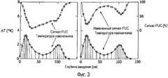
фиг. 3 - графики результатов изучения фантомов, доказывающие эффективность монитора безопасности, показанного на фиг. 1. Левый график показывает корреляцию результатов измерений температуры наконечника устройства катетера с мощностью радиочастотного сигнала, контролируемого внутренней катушкой датчика (PUC). На правом графике показаны данные левого графика после коррекции, учитывающей типичное отражение мощности за счет отстройки частоты радиочастотной передающей катушки; иFIG. 3 is a graph of phantom study results proving the effectiveness of the safety monitor shown in FIG. 1. The left graph shows the correlation of the temperature measurements of the tip of the catheter device with the power of the radio frequency signal controlled by the internal sensor coil (PUC). The right graph shows the data of the left graph after correction, taking into account the typical reflection of power due to the tuning of the frequency of the radio frequency transmitting coil; and
фиг. 4 - графики результатов исследования добровольца, доказывающие эффективность монитора безопасности, показанного на фиг. 1. Левый график показывает связь радиочастотного сигнала, используемого для возбуждения магнитного резонанса в безопасном катетере и в незащищенном катетере, как функцию глубины введения в объект добровольца. Правый график показывает настройку и отстройку незащищенного устройства катетера в области, отмеченной как "D" на левом графике, вызванную периодическим касанием ручки незащищенного устройства катетера.FIG. 4 is a graph of volunteer study results proving the effectiveness of the safety monitor shown in FIG. 1. The left graph shows the relationship of the radio frequency signal used to excite magnetic resonance in a safe catheter and in an unprotected catheter as a function of the depth of insertion into a volunteer. The right graph shows the setup and detuning of the unprotected catheter device in the area marked as “D” in the left graph, caused by the periodic touch of the handle of the unprotected catheter device.
Подробное описание вариантов осуществленияDetailed Description of Embodiments
Со ссылкой на фиг. 1, сканер 10 с использованием магнитного резонанса содержит основной магнит 12, создающий статическое магнитное поле (B0) в области 14 исследования, в которой помещен объект, такой как показанный на чертеже человеческий объект 16, для получения изображений, спектрального анализа или другой процедуры с использованием магнитного резонанса. Представленный на чертеже сканер 10 с использованием магнитного резонанса является горизонтальным сканером трубчатого типа, показанным в поперечном разрезе для демонстрации выбранных компонент; однако, могут применяться и другие типы сканеров с использованием магнитного резонанса.With reference to FIG. 1, the
Сканер 10 с использованием магнитного резонанса также содержит систему 18 градиентов магнитного поля, которая может, например, содержать катушки градиентов магнитного поля, выполненные с возможностью наложения выбранных градиентов магнитного поля на статическое (B0) магнитное поле для выполнения различных задач, таких как пространственное ограничение возбуждения магнитного резонанса, пространственное кодирование частоты и/или фазы магнитного резонанса, подавление магнитного резонанса или тому подобное. Как вариант, сканер с использованием магнитного резонанса может содержать другие элементы, не показанные на фиг. 1, такие как облицовка канала, активная катушка или пассивные ферромагнитные прокладки или тому подобное. Объект 16 соответственно подготавливается к процедуре с использованием магнитного резонанса, помещаясь на подвижное ложе 20 объекта, которое затем вставляется вместе с находящимся на нем объектом в показанное на чертеже положение для выполнения процедуры с использованием магнитного резонанса. Например, ложе 20 объекта может быть носилками или столом, который первоначально расположен на платформе 22, соседствующей со сканером 10 с использованием магнитного резонанса, объект помещается на ложе 20 и затем скольжением перемещается с платформы 22 в канал сканера 10 с использованием магнитного резонанса.The
Сканер с использованием магнитного резонанса дополнительно содержит радиочастотную передающую катушку 24, которая используется для передачи радиочастотного сигнала на частоте магнитного резонанса, чтобы выполнить возбуждение магнитного резонанса. Показанная на чертеже радиочастотная передающая катушка 24 является цельной катушкой в форме квадратной птичьей клетки; однако, могут использоваться и другие типы радиочастотной передающей катушки, такие как цельная катушка с поперечным электромагнитным полем (TEM) или локальная радиочастотная передающая катушка, такая как головная катушка и т.д. Та же самая радиочастотная передающая катушка 24 или другая приемная катушка 26 магнитного резонанса используется для измерения сигнала магнитного резонанса, созданного приложенным радиочастотным возбуждением в объекте в области 14 исследования. Показанная на чертеже приемная катушка 26 магнитного резонанса является плоской контурной катушкой (видна на краю на фиг. 1); однако могут использоваться другие типы приемных катушек, такие как матрица плоских катушек, катушки конечностей, катушки головы и так далее. Показанный на чертеже сканер 10 с использованием магнитного резонанса также содержит две иллюстративные контрольные контурные катушки 28, 30. Контурная катушка 28 устанавливается на, или рядом с каналом устройства 10 для использования в выборочных или контрольных задачах. Контрольная контурная катушка 30 является контурной катушкой, расположенной на или около объекта 16 с его контуром, пересекающим контур приемной контурной катушки 26. Хотя катушки 28, 30 контроля являются контурными катушками, но подразумевается также использование радиочастотных катушек других типов.The magnetic resonance scanner further comprises a radio frequency transmitting coil 24, which is used to transmit the radio frequency signal at a magnetic resonance frequency in order to perform magnetic resonance excitation. The radio frequency transmitting coil 24 shown in the drawing is a single square bird-shaped coil; however, other types of radio frequency transmitting coils may be used, such as a transverse electromagnetic field integral (TEM) coil or a local radio frequency transmitting coil such as a head coil, etc. The same radio frequency transmitting coil 24 or other magnetic resonance receiving coil 26 is used to measure the magnetic resonance signal generated by the applied radio frequency excitation in the object in the study area 14. The magnetic resonance receiving coil 26 shown in the drawing is a planar loop coil (visible at the edge of FIG. 1); however, other types of receiving coils may be used, such as a matrix of flat coils, limb coils, head coils and so on. The
Следует понимать, что термин "катушка", как он используется здесь, предназначен охватывать массивы катушки, катушки SENSE и другие многочисленные элементы приемника, используемые для возбуждения или измерения магнитного резонанса. Различные радиочастотные катушки 24, 26, 28, 30 управляются радиочастотным контроллером 32 магнитного резонанса, который может содержать, например, одноканальный, квадратурный или многоканальный радиочастотный передатчик, одноканальный или многоканальный цифровой приемник, соответствующую схему радиочастотной коммутации для выполнения таких операций, как отстройка частоты приемной катушки 26 магнитного резонанса во время возбуждения магнитного резонанса, мультиплексирование соединений с различными катушками 24, 26, 28, 30 или тому подобное.It should be understood that the term “coil,” as used here, is intended to encompass coil arrays, SENSE coils, and numerous other receiver elements used to excite or measure magnetic resonance. The
Во время иллюстративной хирургической процедуры с использованием магнитного резонанса радиочастотный контроллер 32 магнитного резонанса подает электропитание на радиочастотную передающую катушку 24, чтобы создавать радиочастотный сигнал на частоте магнитного резонанса, который возбуждает магнитный резонанс в объекте или в части объекта, выбранной соответствующим приложением пространственно выборочного градиента магнитного поля системой 18 градиентов магнитного поля. Как вариант, другие градиенты магнитного поля прикладываются системой 18 градиентов во время или после возбуждения магнитного резонанса, чтобы пространственно кодировать или как-либо иначе манипулировать магнитным резонансом. Если обеспечивается показанная на чертеже катушка 26 магнитного резонанса, она обычно отстраивается от частоты магнитного резонанса во время возбуждения магнитного резонанса, чтобы избежать перегрузки приемной катушки 26. На этапе приема радиочастотная передающая катушка 24 или специализированная приемная катушка 26 магнитного резонанса настраивается, чтобы измерять сигнал магнитного резонанса. Измеренный сигнал магнитного резонанса запоминается, обрабатывается (например, с помощью алгоритма реконструкции изображения в случае процедуры получения изображений с использованием магнитного резонанса), и изображение или другие результаты отображаются, запоминаются или используются как-либо иначе. В демонстрационном примере, показанном на фиг. 1, компьютер 34 запрограммирован или выполнен как-либо иначе с возможностью выполнения таких задач обработки, запоминания и отображения данных. Во время хирургической процедуры хирургический инструмент 36 вводится в объект 16 для выполнения желаемой хирургической операции, такой как взятие биопсии, установка катетера, основываясь на временном кардиостимуляторе, установка протезного устройства, выполнение ангиопластической процедуры или тому подобного.During an illustrative surgical procedure using magnetic resonance, the radio frequency magnetic resonance controller 32 supplies power to the radio frequency transmitting coil 24 to generate a radio frequency signal at a magnetic resonance frequency that excites magnetic resonance in an object or in a part of an object selected by a suitable application of a spatially selective magnetic field gradient a system of 18 magnetic field gradients. Alternatively, other magnetic field gradients are applied by a system of 18 gradients during or after magnetic resonance excitation to spatially encode or otherwise manipulate magnetic resonance. If the magnetic resonance coil 26 shown in the drawing is provided, it is usually detuned from the magnetic resonance frequency during magnetic resonance excitation to avoid overloading the receiving coil 26. At the receiving stage, the radio frequency transmitting coil 24 or the specialized magnetic resonance receiving coil 26 is tuned to measure the magnetic signal resonance. The measured magnetic resonance signal is stored, processed (for example, using an image reconstruction algorithm in the case of a magnetic resonance image acquisition procedure), and the image or other results are displayed, stored or otherwise used. In the demo shown in FIG. 1, the computer 34 is programmed or otherwise executed with the ability to perform such tasks of processing, storing and displaying data. During the surgical procedure, the surgical instrument 36 is inserted into the object 16 to perform the desired surgical operation, such as taking a biopsy, installing a catheter based on a temporary pacemaker, installing a prosthetic device, performing an angioplastic procedure or the like.
Применение радиочастотного возбуждения предоставляет возможность компромисса с безопасностью объекта (в случае объекта, являющегося человеком или животным) или возможностью повреждения объекта (в случае археологического артефакта или другого неживого объекта). Это может происходить, если радиочастотное возбуждение связывается с электропроводящим объектом в области 14 исследования. Например, если радиочастотное возбуждение связывается с хирургическим инструментом 36, то тогда электрический ток будет проходить на частоте возбуждения через хирургический инструмент 36. Такой наведенный электрический ток может вызвать местное нагревание, электростатический разряд или другие нежелательные эффекты, способные нанести ущерб или вызвать повреждение объекта. В вариантах осуществления, в которых хирургический инструмент 36 содержит один или более проводов или других удлиненных проводников, вероятно, такой электрический ток будет проходить, по существу, параллельно или вдоль удлиненных проводников. Для показанного на чертеже хирургического инструмента 36 такой электрический ток создает круговые петли Bcouple магнитного поля, окружающие хирургический инструмент 36, как схематически показано на фиг. 1. Следует отметить, что показанная на чертеже контрольная контурная катушка 30 расположена так, чтобы принимать существенный поток Bcoupleот петель магнитного поля, так чтобы контрольная контурная катушка 30 была индуктивно хорошо связана с петлями Bcoupleмагнитного поля. В других процедурах радиочастотное возбуждение может небезопасно связываться с другим проводящим элементом или объектом в области 14 исследования, таким как электронный кардиостимулятор, металлический протезный имплантант или тому подобное.The use of radio frequency excitation provides a compromise with the safety of the object (in the case of an object that is a human or animal) or the possibility of damage to the object (in the case of an archaeological artifact or other non-living object). This may occur if the radio frequency excitation is associated with an electrically conductive object in the study area 14. For example, if radiofrequency excitation is associated with a surgical instrument 36, then an electric current will pass at a frequency of excitation through the surgical instrument 36. Such induced electric current can cause local heating, electrostatic discharge or other undesirable effects that can cause damage or damage to the object. In embodiments where the surgical instrument 36 comprises one or more wires or other elongated conductors, it is likely that such an electric current will flow substantially parallel to or along the elongated conductors. For the surgical instrument 36 shown in the drawing, such an electric current creates circular loops Bcouple of magnetic field surrounding the surgical instrument 36, as schematically shown in FIG. 1. It should be noted that the
Чтобы обнаружить такое потенциально опасное состояние, обеспечивается монитор 40 безопасности, чтобы контролировать возбуждение магнитного резонанса. Монитор 40 безопасности может контролировать различные радиочастотные параметры приложенного радиочастотного возбуждения. Например, контрольная контурная катушка 28, установленная в канале, или контрольная контурная катушка 30, установленная на объекте или около него, может использоваться как катушка датчика, чтобы обнаруживать сигнал, являющийся входным для анализатора 42 мощности, чтобы создавать сигнал, индуцирующий мгновенную радиочастотную мощность, созданную радиочастотной передающей катушкой 24 во время радиочастотного возбуждения. Вместо того чтобы быть связанным с одной из специализированных контрольных катушек 28, 30, анализатор 42 мощности может быть соединен с приемной катушкой 26 магнитного резонанса. В этой последней схеме построения приемная катушка 26 магнитного резонанса обычно отстраивается по частоте от частоты магнитного резонанса во время приложения радиочастотного возбуждения; однако даже в отстроенном состоянии приемная катушка 26 магнитного резонанса обычно обнаруживает остаточный радиочастотный сигнал, реагируя на радиочастотное возбуждение.To detect such a potentially dangerous condition, a security monitor 40 is provided to control magnetic resonance excitation. The security monitor 40 may monitor various radio frequency parameters of the applied RF excitation. For example, a control loop coil 28 installed in the channel, or a
Дополнительно или альтернативно, монитор 40 безопасности может содержать или объединять в себе анализатор 44 цепей, оперативно соединенный с радиочастотной передающей катушкой 24, чтобы определять отражение, передачу или другие характеристики радиочастотного возбуждения. В некоторых вариантах осуществления анализатор 44 цепей выводит один или более s-параметров, характеризующих радиочастотное возбуждение, таких как отраженная мощность, например, параметр S11, проходящая мощность, например, параметр S21, или тому подобное. Анализатор 46 s-параметров обрабатывает s-параметры, чтобы определить желаемую информацию о радиочастотном возбуждении. Например, анализатор 44 цепей, как вариант, измеряет параметр S11 и анализатор 46 s-параметров определяет частоту сигнала радиочастотного возбуждения, основываясь на параметре S11. Как другой пример, анализатор 44 цепей, как вариант, измеряет параметр S21 и анализатор 46 s-параметров определяют фазу сигнала радиочастотного возбуждения, основываясь на параметре S21.Additionally or alternatively, the security monitor 40 may comprise or integrate a network analyzer 44 operatively coupled to the radio frequency transmitting coil 24 to determine reflection, transmission or other characteristics of the radio frequency excitation. In some embodiments, the network analyzer 44 outputs one or more s-parameters characterizing RF excitation, such as reflected power, for example, parameter S11, transmitted power, for example, parameter S21, or the like. An s-parameter analyzer 46 processes the s-parameters to determine the desired RF excitation information. For example, the network analyzer 44 optionally measures the parameter S11 and the s-parameter analyzer 46 determines the frequency of the RF excitation signal based on the parameter S11. As another example, the network analyzer 44 optionally measures parameter S21 and the s-parameter analyzer 46 determines the phase of the RF excitation signal based on parameter S21.
Контролируемые радиочастотные параметры сравниваются с критерием безопасности с помощью компаратора 50. Например, быстрое уменьшение мощности связи, указываемое анализатором 42 мощности, может быть признаком потери мощности в резонансном контуре внутри области 14 исследования, таком как резонансный контур, образуемый хирургическим инструментом 36. Резкий скачок частоты или фазы радиочастотного возбуждения также может указывать на опасную связь с резонансным контуром в области 14 исследования. Как вариант, критерием безопасности является критерий безопасности, относящийся к конкретному объекту, определяемый на основе калибровки 52 объекта. Если компаратор 50 идентифицирует опасное состояние, основываясь на сравнении, он должным образом активирует модуль 54 введения поправки, который выполняет соответствующее введение поправки, такое как завершение процедуры магнитного резонанса, в том числе любого возбуждения магнитного резонанса, или регулирует возбуждение магнитного резонанса, чтобы подавить или устранить опасное состояние или тому подобное. Например, если введение поправки содержит прерывание процедуры магнитного резонанса, то модуль 54 введения поправки может соответственно содержать генератор сигнала, дающий на выходе сигнал "прерывания", подаваемый на радиочастотный контроллер 32 магнитного резонанса, заставляющий радиочастотный контроллер 32 магнитного резонанса прекратить радиочастотное возбуждение.The monitored radio frequency parameters are compared with the safety criterion using a
Продолжая ссылку на фиг. 1 и с дальнейшей ссылкой на фиг. 2, описано использование монитора 40 безопасности и сканера 10 с использованием магнитного резонанса, чтобы контролировать иллюстрируемую хирургическую процедуру. Вся процедура инициируется на этапе 60 загрузки объекта, во время которой объект 16 загружается в область 14 исследования сканера 10 с использованием магнитного резонанса. Это сопровождается этапом 62 планирования сканирования, во время которого планируется хирургическая процедура. Планирование сканирований обычно влечет за собой протонные изображения объекта до введения хирургического инструмента 36. Врач или другой медицинский персонал отображают полученные планируемые изображения на компьютере 34 и определяют соответствующие параметры, признаки или другие аспекты, такие как целевая опухоль для биопсии, местоположение сосудистого стеноза, который должен быть подвергнут процедуре ангиопластической операции, местоположение критичных соседних органов, которых нужно избегать во время операционной процедуры, и т.д. Планируемые изображения могут также использоваться для оптимизации параметров создания изображений с использованием магнитного резонанса для объекта хирургической процедуры, чтобы гарантировать хорошую контрастность изображения и другие благоприятные характеристики получения изображений.Continuing with reference to FIG. 1 and with further reference to FIG. 2, the use of a safety monitor 40 and a
Одновременно с этапом 62 планирования сканирований, как вариант, выполняется этап 64 сбора данных для калибровки контроля безопасности, чтобы создать калибровку 52 объекта. Этап 64 сбора данных для калибровки может, например, определить среднее значение и среднеквадратичное отклонение или другой вариационный параметр, описывающий мощность, обнаруженную анализатором 42 мощности в отсутствии введения хирургического инструмента 36. Это обеспечивает отсчетный уровень мощности для сравнения с уровнями мощности, обнаруженными для радиочастотных возбуждений, выполняемых во время хирургической процедуры. Точно также, этап 64 сбора данных для калибровки может определить значения частоты и фазы и девиации или изменения, описывающие частоту и фазу радиочастотного возбуждения, чтобы обеспечить точку отсчета для сравнения частоты и фазы во время хирургической процедуры. Предпочтительно, этап 64 сбора данных для калибровки, как вариант, выполняется в сочетании с планированием получения изображений, то есть, радиочастотные возбуждения, используемые при получении планируемых изображений, могут рассматриваться как калибровочные радиочастотные возбуждения для монитора 40 безопасности и эталонный радиочастотный параметр или параметры, созданные при калибровочных радиочастотных возбуждениях, могут быть измерены и проанализированы монитором 40 безопасности, чтобы создать калибровку 52 объекта.Simultaneously with the
Когда этапы 62, 64 планирования хирургической процедуры и сбора данных для калибровки контроля закончены, начинается хирургическая процедура и этап 66 получения изображений с помощью магнитного резонанса, во время которого выполняется хирургическая процедура и в то же время сканером 10 с использованием магнитного резонанса выполняется контроль посредством получения изображений с использованием магнитного резонанса. Например, хирургическая процедура может повлечь за собой введение хирургического инструмента 36 в объект 16 вдоль траектории введения, определенной заранее, используя планирование изображений. Одновременное получение изображений с использованием магнитного резонанса обеспечивает врача или другой медицинский персонал визуальной обратной связью по точному положению хирургического инструмента 36 в объекте 16. Таким образом, врач или другой медицинский персонал, используя изображения, полученные с использованием магнитного резонанса, могут "видеть", когда наконечник хирургического инструмента 36 входит в опухоль для взятия биопсии, или могут "видеть", когда наконечник достигает стеноза, который должен быть расширен посредством ангиопластики, или тому подобное. Когда взятие образца биопсии, ангиопластика или другая хирургическая задача закончены, врач или другой медицинский персонал могут извлечь хирургический инструмент 36 из объекта, снова применяя получение изображений с использованием магнитного резонанса, чтобы контролировать извлечение.When the surgical procedure planning and data collection steps 62, 64 for calibration control are completed, the surgical procedure and magnetic
Одновременно с хирургической процедурой и этапом 66 получения изображений с использованием магнитного резонанса монитором 40 безопасности выполняется этап 68 контроля безопасности. Это влечет за собой контроль радиочастотного параметра или параметров (например, обнаружение мощности, частоты и/или фазы) во время каждого применения радиочастотного возбуждения в области 14 исследования и оценку безопасности объекта на основе контроля. Если монитор 40 безопасности обнаруживает потенциально небезопасное состояние, он посылает сигнал 70 введения поправки в хирургическую процедуру и этап 66 получения изображений с использованием магнитного резонанса. В некоторых вариантах осуществления сигнал 70 введения поправки направляется на радиочастотный контроллер 32 магнитного резонанса, чтобы вызвать резкое прекращение операций радиочастотного возбуждения. Альтернативно, сигнал 70 введения поправки может заставить радиочастотный контроллер 32 магнитного резонанса 32 регулировать радиочастотные возбуждения, снижая мощность, регулируя частоту или фазу или как-либо иначе регулируя радиочастотные возбуждения, чтобы подавить или исключить потенциально опасное состояние. В качестве еще одной дополнительной или альтернативной реакции сигнал 70 введения поправки может быть направлен на компьютер 34 или другое устройство отображения, чтобы обеспечить подачу визуальной тревоги врачу или другому медицинскому персоналу, указывая на потенциально опасное состояние. Такая тревога, как вариант, также сопровождается звуковой тревогой, вспышкой света или другим сигналом привлечения внимания.Simultaneously with the surgical procedure and the
Когда хирургическая процедура и этап 66 получения изображений с использованием магнитного резонанса закончены, объект должным образом выгружается из сканера 10 с использованием магнитного резонанса на этапе 72 выгрузки объекта.When the surgical procedure and the magnetic
Со ссылкой на фиг. 3 и 4, описаны некоторые иллюстративные эксперименты, подтверждающие эффективность раскрытых систем способов контроля безопасности. На фиг. 3 показаны графики изучения фантома. Слева показана корреляция результатов измерения температуры наконечника устройства катетера с мощностью радиочастотного сигнала, контролируемого внутренней катушкой датчика (PUC). На графике справа показаны данные левого графика после коррекции, учитывающей типичное отражение мощности за счет отстройки частоты радиочастотной передающей катушки. На фиг. 4 показан график результатов исследования на добровольце. На левом графике показана связь радиочастотного сигнала, используемого при возбуждении магнитного резонанса, для безопасного катетера и небезопасного катетера как функция глубины введения в объект добровольца. На правом графике показана настройка и отстройка частоты устройства небезопасного катетера в области, маркированной как "D" на левом графике, вызванные периодическим касанием ручки устройства небезопасного катетера.With reference to FIG. 3 and 4, some illustrative experiments are described that confirm the effectiveness of the disclosed systems of safety control methods. In FIG. Figure 3 shows the phantom study graphs. On the left, the correlation of the results of measuring the temperature of the tip of the catheter device with the power of the radio frequency signal controlled by the internal sensor coil (PUC) is shown. The graph on the right shows the data of the left graph after correction, taking into account the typical reflection of power due to the tuning of the frequency of the radio frequency transmitting coil. In FIG. 4 shows a graph of the results of a study on a volunteer. The left graph shows the relationship of the radio frequency signal used to excite magnetic resonance for a safe catheter and an unsafe catheter as a function of the depth of insertion into a volunteer. The right graph shows the tuning and tuning of the frequency of the device of an unsafe catheter in the area marked as "D" in the left graph, caused by the periodic touch of the handle of the device of an unsafe catheter.
Данные, показанные на фиг. 3 и 4, были получены, применяя сканер с использованием магнитного резонанса 3 Tesla Philips Achieva (предлагаемый компанией Philips Medical Systems, Бест, Нидерланды). Безопасный катетер и небезопасный катетер использовались, чтобы продемонстрировать способность монитора 40 безопасности автоматически обнаруживать опасную радиочастотную связь между радиочастотным возбуждением и небезопасным катетером во время получения изображений. В эксперименте с фантомом, представленном на фиг. 3, катетеры продвигались в фантом трубчатого сосуда во время получения изображений в реальном времени (декартовы SSFP, TR=9 мс, TE=3,5 мс, α=65о, матрица 172x172, SAR всего тела <0,9 Вт/кг). Катушка датчика, установленная около стенки канала (подобно, например, контрольной катушке 28 на фиг. 1), создавала сигналы, помеченные как "сигнал PUC [%]", масштабированные на правом графике на фиг. 3. Были получены одновременные результаты оптоволоконных измерений температуры, используя систему термометрии от компании LumaSense Technologies, Санта-Клара, штат Калифорния, США. Температура и сигналы PUC были зарегистрированы для 22 различных позиций, как показано на графике на фиг. 3.The data shown in FIG. 3 and 4 were obtained using a Tesla Philips Achieva 3 magnetic resonance scanner (available from Philips Medical Systems, Best, The Netherlands). A safe catheter and an unsafe catheter were used to demonstrate the ability of the security monitor 40 to automatically detect a dangerous radio frequency link between the radio frequency excitation and the unsafe catheter during image acquisition. In the phantom experiment shown in FIG. 3, the catheter is advanced into the tubular vessel phantom during real-time obtaining images (Cartesian SSFP, TR = 9 ms, TE = 3,5 ms, α =65 °, matrix 172x172, SAR whole body <0.9 W / kg) . A sensor coil mounted near the channel wall (like, for example, control coil 28 in FIG. 1) created signals labeled “PUC signal [%]” scaled on the right graph in FIG. 3. Simultaneous results of fiber-optic temperature measurements were obtained using a thermometry system from LumaSense Technologies, Santa Clara, California, USA. Temperature and PUC signals were recorded for 22 different positions, as shown in the graph in FIG. 3.
В эксперименте на добровольце, результаты которого представлены на фиг. 4, доброволец помещался внутрь сканера и фантом сосуда помещался вдоль предплечий и на вершине грудной клетки добровольца. Безопасные и небезопасные катетеры продвигались вместе с получением изображений добровольца. От добровольца требовалось нормально дышать и минимально двигаться, чтобы имитировать нормальный уровень соответствия.In a volunteer experiment, the results of which are presented in FIG. 4, the volunteer was placed inside the scanner and the phantom of the vessel was placed along the forearms and on top of the volunteer's chest. Safe and unsafe catheters advanced along with volunteer imaging. The volunteer was required to breathe normally and move minimally to mimic a normal level of compliance.
Со ссылкой на фиг. 3, наблюдалась существенная корреляция между результатами измерения температуры и сигналами PUC в выбранных положениях катетера. На левом графике отражения мощности за счет отстройки частоты радиочастотной передающей катушки 24 не учитывались. Изменения сигнала PUC являлись результатом как рассеяния мощности в небезопасном катетере, так и отражений мощности. Соответственно, заметное на фиг. 3 уменьшение мощности сигнала с увеличением введения катетера является консервативным критерием потенциальной радиочастотной связи. Правый график представляет те же самые данные, что и на графике на левой стороне, за исключением того, что учитывалось предполагаемое типичное поведение отражения мощности. Корреляция, как видно, должна быть еще более сильной, чем когда поведение отражения мощности учитывается приблизительно.With reference to FIG. 3, there was a significant correlation between the temperature measurement results and the PUC signals at the selected catheter positions. On the left graph of power reflection due to the tuning of the frequency of the radio frequency transmitting coil 24 were not taken into account. Changes in the PUC signal were the result of both power dissipation in an unsafe catheter and power reflections. Accordingly, noticeable in FIG. 3, a decrease in signal power with an increase in catheter insertion is a conservative criterion for potential RF communication. The right graph represents the same data as the graph on the left side, except that the assumed typical power reflection behavior was taken into account. The correlation, as can be seen, should be even stronger than when the behavior of power reflection is taken into account approximately.
Со ссылкой на фиг. 4, левый график, измерения были выполнены с загрузкой тела добровольца в катушку. Однозначно обнаружена опасная ситуация за счет использования небезопасного катетера. Изменение сигналов PUC благодаря дыханию составило 3,6% (не показано) по сравнению с 95%-ным уменьшением сигнала PUC за счет радиочастотной связи между радиочастотным возбуждением и небезопасным катетером. С другой стороны, безопасный катетер точно показывает отсутствие существенного уменьшения сигнала PUC. На мониторе 40 безопасности анализатор 42 мощности соответственно определяет "100%-ный" уровень для данного объекта во время этапа 64 сбора данных для контроля безопасности и после этого сравнивает мощность, указанную анализатором 42 мощности с этим "100%-ным" уровнем. Потенциально опасное состояние соответственно определяется выбранным уменьшением процента мощности сигнала относительно "100%-ного" уровня. Например, если уровень мощности уменьшается ниже 80% от "100%-ного" уровня, это может расцениваться как индикация потенциально опасного состояния, заставляя, таким образом, монитор 40 безопасности активировать модуль 54 введения поправки.With reference to FIG. 4, the left graph, measurements were made with loading the body of a volunteer into a coil. A dangerous situation has been unequivocally detected through the use of an unsafe catheter. The change in PUC signals due to respiration was 3.6% (not shown) compared to a 95% decrease in PUC signal due to the RF coupling between RF excitation and an unsafe catheter. On the other hand, a safe catheter accurately shows the absence of a significant reduction in the PUC signal. On the security monitor 40, the power analyzer 42 accordingly determines a “100%” level for a given object during the
На правом графике на фиг. 4 показано влияние на сигнал PUC повторного касания наконечника опасного катетера в то время, когда катетер находится в положении "D", указанном на левом графике, то есть вставлен на глубину введения приблизительно 62 см, где сигнал PUC составляет приблизительно 40% от "100%-ного" уровня. Эффект касания заключается в изменении собственной резонансной частоты опасного катетера, и это изменение резонансной частоты однозначно заметно на правом графике фиг. 4 как модуляция порядка 20-30% от "100%-ного" уровня сигнала PUC. Способность обнаружить эту отстройку частоты за счет физического обращения с небезопасным катетером имеет значение, потому что во время хирургической процедуры хирургический инструмент может быть настроен очень далеко от частоты магнитного резонанса до тех пор, пока с хирургическим инструментом не начнут работать, не введут его в объект или не будут как-либо иначе манипулировать или использовать способом, который изменяет собственную резонансную частоту хирургического инструмента, приводя ее к значению, совпадающему с частотой магнитного резонанса.In the right graph of FIG. Figure 4 shows the effect on the PUC signal of re-touching the tip of a dangerous catheter while the catheter is in the “D” position shown on the left graph, that is, inserted at a depth of insertion of approximately 62 cm, where the PUC signal is approximately 40% of “100% -th "level. The touch effect is a change in the intrinsic resonance frequency of the hazardous catheter, and this change in the resonance frequency is clearly visible in the right graph of FIG. 4 as modulation of the order of 20-30% of the "100%" level of the PUC signal. The ability to detect this frequency offset due to physical handling of an unsafe catheter is important because during the surgical procedure, the surgical instrument can be tuned very far from the magnetic resonance frequency until it is started to work with the surgical instrument, or inserted into the object or will not be otherwise manipulated or used in a way that changes the natural resonant frequency of the surgical instrument, leading it to a value that matches the frequency of the magnesian full resonance.
Результаты, показанные на фиг. 3 и 4, были получены, используя катушку датчика, установленную на стенке канала, подобно показанной на фиг. 1 иллюстративной контурной катушке 28 контроля. Способность такой относительно удаленной катушки обнаруживать опасное состояние катетера, как показано на фиг. 3 и 4, демонстрирует общую эффективность раскрытого контроля безопасности. Однако, чтобы обеспечить более высокую чувствительность к опасному состоянию, предполагается расположить катушку датчика так, чтобы она была в относительно лучшем положении для связи с изменениями магнитного поля, наведенного при опасном состоянии. Как показано на фиг. 1, например, катушка 30 датчика устанавливается так, чтобы ее плоскость пересекала петли магнитного потока поля Bcouple, которые, как ожидается, должны создаваться любым опасным индуцированным током, протекающим вдоль направления длины хирургического инструмента 36. Соответственно, ожидается, что катушка 30 датчика может быть более чувствительной к опасному состоянию связи, относящемуся к хирургическому инструменту 36, по сравнению с установленной на стенке канала контрольной катушкой 20. В некоторых вариантах осуществления монитор 40 безопасности может контролировать множество катушек, когда одной катушки, обнаруживающей потенциально опасное состояние, будет достаточно для компаратора 50, чтобы включить модуль 54 введения поправки.The results shown in FIG. 3 and 4 were obtained using a sensor coil mounted on a channel wall, similar to that shown in FIG. 1 illustrative contour coil 28 of the control. The ability of such a relatively remote coil to detect an unsafe catheter condition, as shown in FIG. 3 and 4, demonstrates the overall effectiveness of the disclosed security control. However, in order to provide higher sensitivity to the hazardous state, it is proposed to position the sensor coil so that it is in a relatively better position to communicate with changes in the magnetic field induced in the hazardous state. As shown in FIG. 1, for example, the
С другой стороны, с точки зрения высокой чувствительности к опасному состоянию, указанному экспериментами, представленными на фиг. 3 и 4, также предполагается использовать приемную катушку 26, использующую магнитный резонанс, в качестве катушки датчика (или в качестве одной из катушек датчика) для монитора 40 безопасности. Приемная катушка, использующая магнитный резонанс, обычно отстраивается по частоте во время этапа радиочастотного возбуждения получения изображений с использованием магнитного резонанса или другой процедуры с использованием магнитного резонанса. Однако, поскольку радиочастотное возбуждение обычно имеет порядки величины, более высокие, чем сигнал магнитного резонанса, который должен быть обнаружен, и дополнительно с точки зрения высокой чувствительности, указанной на фиг. 3 и 4, предполагается, что приемная катушка 26 магнитного резонанса, даже в расстроенном состоянии, будет обеспечивать достаточный остаточный сигнал, чтобы позволить обнаружение уменьшения мощности по время радиочастотного возбуждения, указывающего на потенциально опасное состояние. Преимущество использования приемной катушки 26 магнитного резонанса для контроля безопасности состоит в том, что приемная катушка 26 магнитного резонанса уже доступна и обычно расположена вблизи хирургического инструмента во время хирургической процедуры.On the other hand, from the point of view of high sensitivity to the dangerous state indicated by the experiments shown in FIG. 3 and 4, it is also contemplated to use a magnetic resonance receiving coil 26 as a sensor coil (or as one of the sensor coils) for the security monitor 40. A receiver coil using magnetic resonance is typically tuned in frequency during the RF excitation step of acquiring images using magnetic resonance or another procedure using magnetic resonance. However, since the RF excitation usually has orders of magnitude higher than the magnetic resonance signal to be detected, and further from the point of view of high sensitivity indicated in FIG. 3 and 4, it is assumed that the magnetic resonance receiving coil 26, even in the detuned state, will provide sufficient residual signal to allow detection of a decrease in power during RF excitation, indicating a potentially dangerous condition. An advantage of using a magnetic resonance pickup coil 26 for safety monitoring is that the magnetic resonance pickup coil 26 is already available and is usually located near the surgical instrument during a surgical procedure.
Хотя представленное здесь описание сделано с некоторой иллюстративной ссылкой на получение изображений с использованием магнитного резонанса при хирургических операциях, хирургические процедуры, использующие хирургические инструменты, устройства и способы контроля безопасности, раскрытые здесь, с легкостью применимы к другим процедурам с использованием магнитного резонанса и к нечеловеческим, животным или неодушевленным объектам. Во время получения изображений археологического артефакта, например, монитор 40 безопасности может обнаружить снижение мощности радиочастотного возбуждения или смещение по частоте или фазе радиочастотного возбуждения, которое может быть индикацией потенциально опасного состояния, в котором радиочастотное возбуждение связано с металлическим или другим электропроводящим объектом, элементом или признаком археологического артефакта. Прежде чем произойдет повреждение археологического артефакта, монитор 40 безопасности может заставить модуль 54 введения поправки прервать процедуру магнитного резонанса.Although the description presented here is made with some illustrative reference to magnetic resonance imaging in surgical operations, surgical procedures using the surgical instruments, devices and safety monitoring methods disclosed herein are easily applicable to other procedures using magnetic resonance and non-human, animal or inanimate objects. During imaging of an archaeological artifact, for example, the security monitor 40 may detect a decrease in RF excitation power or a shift in the frequency or phase of the RF excitation, which may be an indication of a potentially dangerous condition in which the RF excitation is associated with a metal or other electrically conductive object, element or feature archaeological artifact. Before damage to the archaeological artifact occurs, the security monitor 40 may cause the correction module 54 to interrupt the magnetic resonance procedure.
Изобретение было описано со ссылкой на предпочтительные варианты осуществления. Модификации и изменения могут произойти и в другом варианте после прочтения и понимания предшествующего подробного описания. Подразумевается, что изобретение истолковывается как содержащее все такие модификации и изменения настолько, насколько они попадают в пределы объема пунктов приложенной формулы изобретения или их эквивалентов. В формуле изобретения любые ссылочные знаки, помещенные между круглыми скобками, не должны рассматриваться как ограничение формулы изобретения. Слово "содержащий" не исключает присутствия элементов или этапов, отличных от перечисленных в формуле изобретения. Неопределенный или определенный артикль, предшествующий элементу, не исключает присутствия множества таких элементов. Раскрытый способ может быть осуществлен посредством аппаратурных средств, содержащих несколько различных элементов, и посредством соответственно запрограммированного компьютера. В системной формуле изобретения, перечисляющей несколько средств, некоторые из этих средств могут быть осуществлены одной и той же позицией считываемого компьютером программного обеспечения или аппаратурного обеспечения. Простой факт, что некоторые критерии повторяются во взаимно различных зависимых пунктах формулы изобретения, не указывает, что комбинация этих критериев не может использоваться для достижения преимущества.The invention has been described with reference to preferred embodiments. Modifications and changes may occur in another embodiment after reading and understanding the previous detailed description. It is intended that the invention be construed as containing all such modifications and changes to the extent that they fall within the scope of the appended claims or their equivalents. In the claims, any reference characters placed between parentheses should not be construed as limiting the claims. The word “comprising” does not exclude the presence of elements or steps other than those listed in the claims. The indefinite or definite article preceding an element does not exclude the presence of many such elements. The disclosed method can be implemented by means of hardware containing several different elements, and by means of a suitably programmed computer. In a systemic claims listing several tools, some of these tools can be implemented with the same position as computer-readable software or hardware. The simple fact that some criteria are repeated in mutually different dependent claims does not indicate that a combination of these criteria cannot be used to achieve an advantage.
Claims (15)
Translated fromRussianпринимают радиочастотный сигнал от области исследования во время возбуждения магнитного резонанса;
извлекают мгновенное значение параметра из принятого радиочастотного сигнала; оценивают безопасность объекта, основываясь на извлеченных значениях;
вносят поправку в возбуждение магнитного резонанса в ответ на оценку, указывающую на состояние, потенциально небезопасное для объекта;
отличающийся тем, что
оценка содержит оценку потенциально небезопасного состояния, вызванного возбуждением магнитного резонанса, связанного с объектом в области исследования.1. A method of obtaining an image using magnetic resonance or spectroscopy of an object, comprising stages in which
receive a radio frequency signal from the study area during magnetic resonance excitation;
extracting the instantaneous value of the parameter from the received RF signal; evaluate the safety of the object based on the extracted values;
amend the magnetic resonance excitation in response to an estimate indicating a condition that is potentially unsafe for the object;
characterized in that
the assessment contains an assessment of a potentially unsafe condition caused by the excitation of magnetic resonance associated with an object in the field of study.
выполняют хирургическую процедуру, используя хирургический инструмент, выполняют возбуждение магнитного резонанса и измерения повторяются во время хирургической процедуры, чтобы отслеживать хирургический инструмент.4. The method using magnetic resonance according to claim 3, further comprising stages, which have a surgical instrument (36) in the field (14) of the study; and
performing a surgical procedure using a surgical instrument; performing magnetic resonance excitation; and measurements are repeated during the surgical procedure to track the surgical instrument.
приема радиочастотного сигнала от области исследования во время возбуждения магнитного резонанса, (ii) извлечения мгновенного значения из принятого радиочастотного сигнала, и (iii) оценки безопасности объекта, основываясь на извлеченных значениях; и
модуль (54) введения поправки, выполненный с возможностью введения поправки возбуждения магнитного резонанса в ответ на оценку (iii), указывающую состояние, потенциально опасное для объекта, отличающийся тем, что
модуль анализатора выполнен с возможностью оценки потенциально небезопасного состояния, вызванного радиочастотной связью с объектом в области исследования.10. A magnetic resonance safety monitor (40) comprising an analyzer module (42, 44, 46, 50) configured to (i)
receiving an RF signal from the study area during magnetic resonance excitation, (ii) extracting the instantaneous value from the received RF signal, and (iii) assessing the safety of the object based on the extracted values; and
an amendment introducing module (54) configured to introduce a correction of magnetic resonance excitation in response to an estimate (iii) indicating a condition that is potentially dangerous for the object, characterized in that
the analyzer module is capable of evaluating a potentially unsafe condition caused by radio frequency communication with an object in the field of study.
магнит (12), создающий статическое (В0) магнитное поле;
систему (18) градиентов магнитного поля, выполненную с возможностью наложения выбранных градиентов магнитного поля на статическое магнитное поле;
радиочастотную систему (24, 26, 32), выполненную с возможностью возбуждения и обнаружения магнитного резонанса; и
монитор (40) безопасности магнитного резонанса по п.10.14. A scanner using magnetic resonance resonance, comprising
a magnet (12) creating a static (B0 ) magnetic field;
a system (18) of magnetic field gradients configured to superimpose selected magnetic field gradients on a static magnetic field;
a radio frequency system (24, 26, 32) configured to excite and detect magnetic resonance; and
magnetic resonance safety monitor (40) according to claim 10.
Applications Claiming Priority (3)
| Application Number | Priority Date | Filing Date | Title |
|---|---|---|---|
| EP07123950 | 2007-12-21 | ||
| EP07123950.3 | 2007-12-21 | ||
| PCT/IB2008/055482WO2009081379A2 (en) | 2007-12-21 | 2008-12-22 | Magnetic resonance safety monitoring systems and methods |
Publications (2)
| Publication Number | Publication Date |
|---|---|
| RU2010130465A RU2010130465A (en) | 2012-01-27 |
| RU2481592C2true RU2481592C2 (en) | 2013-05-10 |
Family
ID=40637867
Family Applications (1)
| Application Number | Title | Priority Date | Filing Date |
|---|---|---|---|
| RU2010130465/28ARU2481592C2 (en) | 2007-12-21 | 2008-12-22 | Systems and methods of monitoring safety for magnetic resonance |
Country Status (7)
| Country | Link |
|---|---|
| US (1) | US9952296B2 (en) |
| EP (1) | EP2225574A2 (en) |
| JP (1) | JP5455926B2 (en) |
| CN (1) | CN101903788B (en) |
| DE (1) | DE202008018452U1 (en) |
| RU (1) | RU2481592C2 (en) |
| WO (1) | WO2009081379A2 (en) |
Families Citing this family (20)
| Publication number | Priority date | Publication date | Assignee | Title |
|---|---|---|---|---|
| JP5518403B2 (en)* | 2008-09-09 | 2014-06-11 | 株式会社東芝 | Magnetic resonance imaging apparatus and magnetic resonance imaging method |
| CN102369450A (en)* | 2009-04-01 | 2012-03-07 | 皇家飞利浦电子股份有限公司 | Magnetic resonance system and method for comprehensive implantable device safety testing and patient safety monitoring |
| BR112012029855A8 (en)* | 2010-05-27 | 2016-09-13 | Koninklijke Philips Electronics Nv | MAGNETIC RESONANCE EXAMINATION SYSTEM FOR THE EXAMINATION OF AN OBJECT, METHOD AND COMPUTER PROGRAM |
| DE102010029463B4 (en)* | 2010-05-28 | 2014-07-24 | Siemens Aktiengesellschaft | Monitoring method for monitoring and / or protection of components, in particular a high-frequency antenna of a magnetic resonance system, as well as a monitoring device and a magnetic resonance system with a monitoring device for this purpose |
| DE102011085975A1 (en)* | 2011-11-09 | 2013-05-16 | Siemens Aktiengesellschaft | A method for securing implanted medical devices in an electromagnetic radiation emitting diagnostic device |
| DE102012203452B4 (en) | 2012-03-05 | 2019-01-03 | Siemens Healthcare Gmbh | Output of high frequency pulses in a magnetic resonance imaging system |
| DE102012203782B4 (en)* | 2012-03-12 | 2022-08-11 | Siemens Healthcare Gmbh | Method for performing a combined magnetic resonance positron emission tomography |
| WO2016142174A1 (en)* | 2015-03-09 | 2016-09-15 | Koninklijke Philips N.V. | Method and safety module for an automatic or semi-automatic detection whether an mr examination of a person is approved with a predetermined mr system |
| KR101697359B1 (en)* | 2016-03-14 | 2017-01-18 | 한국표준과학연구원 | Rf dosimeter for measuring sar level and human torso phantom having thereof |
| DE102016206398B4 (en)* | 2016-04-15 | 2025-01-09 | Siemens Healthineers Ag | Operation of a magnetic resonance device taking into account implant wearers, a safety unit, safety system and a magnetic resonance device |
| CN105975731B (en)* | 2016-06-20 | 2019-01-25 | 中国科学院深圳先进技术研究院 | Magnetic resonance radio frequency coil simulation method and device |
| DE102016115216A1 (en)* | 2016-08-16 | 2018-02-22 | Mr Comp Gmbh | Device and method for testing the MR safety of implants |
| KR102006666B1 (en)* | 2017-08-24 | 2019-08-02 | 한국표준과학연구원 | Method for acquiring specific absorption rate during MRI scans |
| CN109419508B (en)* | 2017-09-01 | 2022-08-09 | 西门子(深圳)磁共振有限公司 | System, device and method for realizing safe implant scanning under magnetic resonance condition |
| US10823797B2 (en)* | 2018-03-26 | 2020-11-03 | Siemens Healthcare Gmbh | Apparatus and method for spatial encoding using a radio frequency signal in magnetic resonance tomography |
| CN112336332B (en)* | 2019-08-09 | 2024-11-29 | 通用电气精准医疗有限责任公司 | Magnetic resonance imaging scanning method and magnetic resonance imaging system |
| CN110658233A (en)* | 2019-10-09 | 2020-01-07 | 清华大学 | RF excitation response measurement equipment and transfer function measurement system |
| CN113900055B (en)* | 2020-06-22 | 2025-03-25 | 通用电气精准医疗有限责任公司 | Magnetic resonance imaging system and implant positioning method thereof |
| CN113203968B (en)* | 2021-04-27 | 2024-02-02 | 上海辰光医疗科技股份有限公司 | Magnetic resonance transmitting coil structure with high transmitting efficiency |
| CN114415097B (en)* | 2021-12-31 | 2023-06-30 | 江苏美时医疗技术有限公司 | Magnetic resonance phased array coil performance rapid detection device and detection method thereof |
Citations (6)
| Publication number | Priority date | Publication date | Assignee | Title |
|---|---|---|---|---|
| SU1125520A1 (en)* | 1983-07-18 | 1984-11-23 | Казанский Физико-Технический Институт Казанского Филиала Ан Ссср | Device for adjusting temperature of resonator of magnetic resonance radio spectrometer |
| RU2247405C2 (en)* | 1999-09-13 | 2005-02-27 | Фоксборо Нмр Лтд. | Nuclear magnetic resonance probe |
| WO2005103748A1 (en)* | 2004-04-23 | 2005-11-03 | Koninklijke Philips Electronics N.V. | Magnetic resonance imaging system provided with an electrical accessory device |
| US20050283168A1 (en)* | 2003-08-25 | 2005-12-22 | Biophan Technologies, Inc. | Medical device with an electrically conductive anti-antenna member |
| US20050288750A1 (en)* | 2003-08-25 | 2005-12-29 | Biophan Technologies, Inc. | Medical device with an electrically conductive anti-antenna member |
| US20060118319A1 (en)* | 2002-01-22 | 2006-06-08 | Xingwu Wang | Magnetic resonance imaging coated assembly |
Family Cites Families (35)
| Publication number | Priority date | Publication date | Assignee | Title |
|---|---|---|---|---|
| JPH05237072A (en) | 1992-02-28 | 1993-09-17 | Shimadzu Corp | Nuclear magnetic resonance tomography |
| JPH05237078A (en)* | 1992-02-29 | 1993-09-17 | Shimadzu Corp | Excitation power monitor for mr apparatus |
| US6898454B2 (en)* | 1996-04-25 | 2005-05-24 | The Johns Hopkins University | Systems and methods for evaluating the urethra and the periurethral tissues |
| DE10157039A1 (en) | 2001-11-21 | 2003-06-05 | Philips Intellectual Property | RF coil arrangement for magnetic resonance imaging device |
| AU4169497A (en)* | 1996-08-29 | 1998-04-14 | David T. Borup | Apparatus and method for imaging with wavefields using inverse scattering techniques |
| US5730134A (en) | 1996-09-09 | 1998-03-24 | General Electric Company | System to monitor temperature near an invasive device during magnetic resonance procedures |
| US6272370B1 (en)* | 1998-08-07 | 2001-08-07 | The Regents Of University Of Minnesota | MR-visible medical device for neurological interventions using nonlinear magnetic stereotaxis and a method imaging |
| WO1998052465A1 (en)* | 1997-05-23 | 1998-11-26 | Transurgical, Inc. | Mri-guided therapeutic unit and methods |
| US7848788B2 (en)* | 1999-04-15 | 2010-12-07 | The Johns Hopkins University | Magnetic resonance imaging probe |
| EP1147430A1 (en)* | 1999-10-01 | 2001-10-24 | Koninklijke Philips Electronics N.V. | Magnetic resonance imaging method |
| AU2001238012A1 (en)* | 2000-02-01 | 2001-08-14 | Surgi-Vision, Inc. | Magnetic resonance imaging transseptal needle antenna |
| US6426623B1 (en)* | 2000-09-27 | 2002-07-30 | Mayo Foundation For Medical Education And Research | MRI RF power monitor |
| US7123010B2 (en)* | 2001-06-26 | 2006-10-17 | Siemens Aktiengesellschaft | Magnetic resonance apparatus and operation method for hyperthermic treatment |
| GB0117715D0 (en)* | 2001-07-19 | 2001-09-12 | Mrbp Res Ltd | Microwave biochemical analysis |
| US6957098B1 (en)* | 2002-06-27 | 2005-10-18 | Advanced Cardiovascular Systems, Inc. | Markers for interventional devices in magnetic resonant image (MRI) systems |
| DE10249239A1 (en) | 2002-10-23 | 2004-05-06 | Philips Intellectual Property & Standards Gmbh | Magnetic resonance imaging device with additional electrical equipment |
| DE10254660B4 (en)* | 2002-11-22 | 2006-04-27 | Siemens Ag | Method for correcting the B 1 field in MR measurements and magnetic resonance measuring device |
| EP1585990A1 (en)* | 2003-01-07 | 2005-10-19 | Philips Intellectual Property & Standards GmbH | High-frequency system for an mr apparatus with multiple transmit channels |
| US20040199069A1 (en)* | 2003-04-02 | 2004-10-07 | Connelly Patrick R. | Device and method for preventing magnetic resonance imaging induced damage |
| WO2004104989A2 (en) | 2003-05-16 | 2004-12-02 | The Boc Group, Inc. | Nmr measuring system |
| US7242981B2 (en)* | 2003-06-30 | 2007-07-10 | Codman Neuro Sciences Sárl | System and method for controlling an implantable medical device subject to magnetic field or radio frequency exposure |
| JP2007526783A (en) | 2003-06-30 | 2007-09-20 | コーニンクレッカ フィリップス エレクトロニクス エヌ ヴィ | Apparatus and method for controlling specific absorption rate (SAR) in MRI |
| JP4838131B2 (en)* | 2003-09-09 | 2011-12-14 | コーニンクレッカ フィリップス エレクトロニクス エヌ ヴィ | Tracking of catheter tip for interventional procedures monitored by magnetic resonance imaging |
| US7970452B2 (en)* | 2003-09-30 | 2011-06-28 | Hologic, Inc. | Open architecture imaging apparatus and coil system for magnetic resonance imaging |
| US7403004B2 (en)* | 2003-10-31 | 2008-07-22 | Koninklijke Philips Electronics N.V. | B1 field control in magnetic resonance imaging |
| US7508205B2 (en)* | 2004-04-29 | 2009-03-24 | Koninklijke Philips Electronics N.V. | Magnetic resonance imaging system, a method of magnetic resonance imaging and a computer program |
| EP1629773B8 (en)* | 2004-08-30 | 2012-06-20 | Kabushiki Kaisha Toshiba | Magnetic resonance diagnostic apparatus |
| US20060173285A1 (en)* | 2004-12-20 | 2006-08-03 | General Electric Company | Methods and systems for reducing RF-induced heating in magnetic resonance imaging |
| WO2006114749A1 (en)* | 2005-04-28 | 2006-11-02 | Koninklijke Philips Electronics N.V. | Method and circuit arrangement for operating multi-channel transmit/receive antenna devices |
| US8099059B2 (en)* | 2005-04-29 | 2012-01-17 | Koninklijke Philips Electronics N.V. | Method and circuit arrangement for operating multi-channel transmit/recieve antenna devices |
| US20070106148A1 (en)* | 2005-10-28 | 2007-05-10 | Dumoulin Charles L | Electronic circuits to improve the sensitivity of magnetic resonance tracking catheters and intraluminal RF coils |
| US7945308B2 (en)* | 2005-12-27 | 2011-05-17 | General Electric Company | Systems, methods and apparatus for an endo-rectal receive-only probe |
| US7511492B2 (en)* | 2006-02-21 | 2009-03-31 | Beth Israel Deaconess Medical Center, Inc. | Magnetic resonance imaging and radio frequency impedance mapping methods and apparatus |
| DE102006009040B4 (en)* | 2006-02-27 | 2011-08-18 | Siemens AG, 80333 | Coaxial cable assembly and test method for a coaxial cable assembly |
| JP5237072B2 (en) | 2008-12-12 | 2013-07-17 | 極東開発工業株式会社 | Vehicle loading platform lifting device |
- 2008
- 2008-12-22JPJP2010539034Apatent/JP5455926B2/ennot_activeExpired - Fee Related
- 2008-12-22USUS12/808,404patent/US9952296B2/enactiveActive
- 2008-12-22WOPCT/IB2008/055482patent/WO2009081379A2/enactiveApplication Filing
- 2008-12-22EPEP08864036Apatent/EP2225574A2/ennot_activeCeased
- 2008-12-22CNCN200880122270.2Apatent/CN101903788B/ennot_activeExpired - Fee Related
- 2008-12-22DEDE202008018452.5Upatent/DE202008018452U1/ennot_activeExpired - Lifetime
- 2008-12-22RURU2010130465/28Apatent/RU2481592C2/ennot_activeIP Right Cessation
Patent Citations (6)
| Publication number | Priority date | Publication date | Assignee | Title |
|---|---|---|---|---|
| SU1125520A1 (en)* | 1983-07-18 | 1984-11-23 | Казанский Физико-Технический Институт Казанского Филиала Ан Ссср | Device for adjusting temperature of resonator of magnetic resonance radio spectrometer |
| RU2247405C2 (en)* | 1999-09-13 | 2005-02-27 | Фоксборо Нмр Лтд. | Nuclear magnetic resonance probe |
| US20060118319A1 (en)* | 2002-01-22 | 2006-06-08 | Xingwu Wang | Magnetic resonance imaging coated assembly |
| US20050283168A1 (en)* | 2003-08-25 | 2005-12-22 | Biophan Technologies, Inc. | Medical device with an electrically conductive anti-antenna member |
| US20050288750A1 (en)* | 2003-08-25 | 2005-12-29 | Biophan Technologies, Inc. | Medical device with an electrically conductive anti-antenna member |
| WO2005103748A1 (en)* | 2004-04-23 | 2005-11-03 | Koninklijke Philips Electronics N.V. | Magnetic resonance imaging system provided with an electrical accessory device |
Also Published As
| Publication number | Publication date |
|---|---|
| WO2009081379A3 (en) | 2009-08-27 |
| CN101903788A (en) | 2010-12-01 |
| RU2010130465A (en) | 2012-01-27 |
| US20100312091A1 (en) | 2010-12-09 |
| WO2009081379A2 (en) | 2009-07-02 |
| DE202008018452U1 (en) | 2014-06-02 |
| CN101903788B (en) | 2015-01-28 |
| JP2011507589A (en) | 2011-03-10 |
| JP5455926B2 (en) | 2014-03-26 |
| US9952296B2 (en) | 2018-04-24 |
| EP2225574A2 (en) | 2010-09-08 |
Similar Documents
| Publication | Publication Date | Title |
|---|---|---|
| RU2481592C2 (en) | Systems and methods of monitoring safety for magnetic resonance | |
| EP2920602B1 (en) | Mri involving a distributed sensor to monitor the temperature of coil cables and traps | |
| US20110046475A1 (en) | Techniques for correcting temperature measurement in magnetic resonance thermometry | |
| US20120086449A1 (en) | Magnetic resonance system and method for comprehensive implantable device safety tests and patient safety monitoring | |
| CN106896334B (en) | The method and MRI system of active implantation material surrounding tissue temperature under MR are assessed in advance | |
| US9784807B2 (en) | Method and magnetic resonance apparatus to acquire magnetic resonance data of a target region including a metal object | |
| WO2001017428A1 (en) | Magnetic resonance imaging device and method therefor | |
| CN104736050B (en) | Magnetic resonance imaging device and SAR prediction method | |
| US10203382B2 (en) | Wirelessly powered magnetic resonance imaging signal amplification system for ingestible devices having L-C mesh circuit | |
| US20050070784A1 (en) | Magnetic resonance imaging apparatus and magnetic resonance imaging method | |
| US10551466B2 (en) | Correction of a magnetic resonance transmission signal | |
| CN112336332B (en) | Magnetic resonance imaging scanning method and magnetic resonance imaging system | |
| WO2018113518A1 (en) | Method for monitoring temperature of tissues surrounding active implant, and magnetic resonance imaging system | |
| RU2559562C2 (en) | Magnetic resonance analysis for tool detection | |
| US9151812B2 (en) | Method to operate an image-generating medical modality to avoid patient injury by a modality-generated electromagnetic field | |
| US9268003B2 (en) | System and method for measuring induced radio frequency current using phase contrast magnetic resonance imaging | |
| US10267885B2 (en) | Method and apparatus for magnetic resonance imaging | |
| CN107788986A (en) | The method that the implant information of patient is determined by magnetic resonance measurement | |
| US7474877B2 (en) | Method for monitoring an RF power amplifier, and an RF device, a monitoring device, and an MR system corresponding thereto | |
| US10620284B2 (en) | Method and apparatus determining a fat content of a liver of a patient using measured spectral magnetic resonance data | |
| JP4179576B2 (en) | Magnetic resonance imaging apparatus and imaging parameter calculation method | |
| JP3346800B2 (en) | Magnetic resonance diagnostic equipment | |
| CA2805580C (en) | System and method for measuring induced radio frequency current using phase contrast magnetic resonance imaging |
Legal Events
| Date | Code | Title | Description |
|---|---|---|---|
| MM4A | The patent is invalid due to non-payment of fees | Effective date:20201223 |