RU2481073C1 - Device of sliding clamp elements and their positional location inside spherical case of multifunctional diagnostic-surgical robotic system with possibility of information and computer control named after yirusanov - Google Patents
Device of sliding clamp elements and their positional location inside spherical case of multifunctional diagnostic-surgical robotic system with possibility of information and computer control named after yirusanovDownload PDFInfo
- Publication number
- RU2481073C1 RU2481073C1RU2011151801/12ARU2011151801ARU2481073C1RU 2481073 C1RU2481073 C1RU 2481073C1RU 2011151801/12 ARU2011151801/12 ARU 2011151801/12ARU 2011151801 ARU2011151801 ARU 2011151801ARU 2481073 C1RU2481073 C1RU 2481073C1
- Authority
- RU
- Russia
- Prior art keywords
- clamp
- elements
- robotic system
- housing
- vertical plane
- Prior art date
Links
- 238000000034methodMethods0.000abstractdescription5
- 239000003814drugSubstances0.000abstract1
- 230000000694effectsEffects0.000abstract1
- 239000000126substanceSubstances0.000abstract1
- 238000006073displacement reactionMethods0.000description4
- 238000001356surgical procedureMethods0.000description4
- 230000036512infertilityEffects0.000description3
- 239000003638chemical reducing agentSubstances0.000description1
- 238000002405diagnostic procedureMethods0.000description1
Images

Landscapes
- Endoscopes (AREA)
- Manipulator (AREA)
Abstract
Description
Translated fromRussianИзобретение относится к медицинской технике и может быть использовано в робототехнической системе при выполнении различных медицинских процедур.The invention relates to medical equipment and can be used in a robotic system when performing various medical procedures.
Известно устройство зажима (см. патент RU №2371305), которое включает обойму, выполненную с возможностью поступательного перемещения, упругие элементы, выполненные в виде упругой ленты с перегибами и прикрепленные к обойме, приводной элемент со штоком и несущий стержень. Захват снабжен жесткой планкой, имеющей в средней части шарнир, при этом упругие элементы прикреплены к обойме одним концом, а другим, в виде внутренних перегибов упругих элементов, - к жесткой планке. При этом несущий стержень скреплен с шарниром жесткой планкой (прототип).A clamping device is known (see patent RU No. 2371305), which includes a clip made with the possibility of translational movement, elastic elements made in the form of an elastic tape with kinks and attached to the clip, a drive element with a rod and a supporting rod. The grip is equipped with a rigid bar having a hinge in the middle part, while the elastic elements are attached to the ferrule with one end and the other, in the form of internal bends of the elastic elements, to the rigid bar. In this case, the supporting rod is fastened with a hinge to a rigid bar (prototype).
Недостатком известного устройства зажима является ограничение его функциональных возможностей, поскольку он предназначен для решения конкретной задачи и не может быть применен в робототехнической системе с компьютерным управлением для ориентированного приема хирургических инструментов и диагностических устройств с последующим возвратно-поступательным двойным разворотом для проведения как хирургических, так и диагностики процедур.A disadvantage of the known clamping device is the limitation of its functionality, since it is designed to solve a specific problem and cannot be used in a computer-controlled robotic system for oriented reception of surgical instruments and diagnostic devices with subsequent reciprocating double-turn for carrying out both surgical and diagnostic procedures.
Техническим результатом предложенного изобретения является усовершенствование известного устройства захвата для ориентированного приема и двойного возвратно-поступательного разворота хирургических инструментов и диагностических устройств, функционально связанных с операционным столом с компьютерным управлением.The technical result of the proposed invention is the improvement of the known capture device for oriented reception and double reciprocating reversal of surgical instruments and diagnostic devices functionally connected to a computer-controlled operating table.
Указанный технический результат достигается следующим устройством.The specified technical result is achieved by the following device.
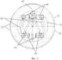
Устройство выдвижных элементов зажима и их позиционное расположение внутри сферического корпуса многофункциональной дагностико-хиругической робототехнической системы с возможностью информационно-компьютерного управления, включающее корпус робототехнической системы и выдвижные элементы зажима, которые включают устройство зажима операционных элементов с возможностью двух разворотов и соединенного с устройством промежуточного разворота посредством первого привода, выполняющего функцию шарнира, который посредством второго привода, выполняющего также функцию шарнира, соединен с дополнительным устройство осевого разворота зажима, который соединен с корпусом роторной часть привода, закрепленного на выдвижной части линейного привода, при этом корпус робототехнической системы выполнен с внешней сферической поверхностью и с боковым отверстием круглой формы, напротив которого с внутренней стороны сферического корпуса последовательно по кругу расположены и закреплены пять корпусов линейного привода выдвижных элементов зажима, один из вторых расположен в верхней части сферического корпуса, и его выдвижные элементы зажима расположены в вертикальной плоскости сферического корпуса в зоне отверстия круглой формы, по обе стороны вертикальной плоскости сферического корпуса друг над другом расположены по два линейных привода, при этом выдвижные элементы зажима расположены в зоне отверстия круглой формы сферического корпуса, при этом выдвижные элементы зажима верхних линейных приводов позиционно ориентированы от вертикальной плоскости сферического корпуса, а выдвижные элементы зажима нижних линейных приводов позиционно ориентированы к вертикальной плоскости сферического корпуса.The device of the retractable clamp elements and their positional location inside the spherical body of the multifunctional diagnostic and surgical robotic system with the possibility of computer-information control, including the robotic system housing and retractable clamp elements, which include a clamp device for operating elements with the possibility of two turns and connected to the intermediate turn device the first drive that acts as a hinge, which through the second drive yes, also performing the function of a hinge, it is connected to an additional device of axial rotation of the clamp, which is connected to the housing of the rotor part of the drive mounted on the sliding part of the linear drive, while the housing of the robotic system is made with an external spherical surface and with a lateral round hole, opposite which on the inside of the spherical body, five cases of a linear drive of the retractable clamp elements are arranged and fixed sequentially in a circle, one of the second is located at parts of the spherical body, and its sliding clamp elements are located in the vertical plane of the spherical body in the area of the round hole, two linear actuators are arranged on each side of the vertical plane of the spherical body, the sliding elements of the clamp are located in the zone of the round shape of the spherical body while the sliding elements of the clamp of the upper linear actuators are positionally oriented from the vertical plane of the spherical body, and the sliding elements of the clamp of the lower linear actuators are positionally oriented to the vertical plane of the spherical body.
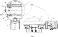
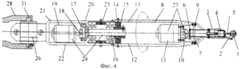
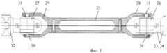
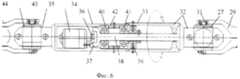
На фиг.1 и 2 изображено устройство выдвижных элементов зажима и их позиционное расположение внутри сферического корпуса многофункциональной дагностико-хиругической робототехнической системы с возможностью информационно-компьютерного управления. На фиг.3 изображено позиционное положение корпуса сферической операционной системы относительно хирургического и инструментального стола. На фиг.4 изображено устройство первого осевого разворота зажима операционных элементов. На фиг.5 изображено устройство промежуточного разворота зажима хирургических элементов. На фиг.6 изображено устройство второго разворота зажима. На фиг.7 изображено устройство линейного сдвига зажима робототехнической системы.Figures 1 and 2 show the device of the retractable clamping elements and their positional location inside the spherical body of the multifunctional diagnostic-surgical robotic system with the possibility of information-computer control. Figure 3 shows the positional position of the housing of the spherical operating system relative to the surgical and instrumental table. Figure 4 shows the device of the first axial turn of the clamp operating elements. Figure 5 shows a device for intermediate reversal of clamping of surgical elements. Figure 6 shows the device of the second turn of the clamp. 7 depicts a linear shear clamp device of a robotic system.
Устройство выдвижных элементов зажима и их позиционное расположение внутри сферического корпуса многофункциональной дагностико-хиругической робототехнической системы с возможностью информационно-компьютерного управления содержит (фиг.4) устройство зажима 1 медицинского инструмента 2, реализованного с возможностью возвратно-поступательного смещения в корпусе зажима 3 привода 4 с фиксирующим стержнем 5. При этом корпус 3 с зажимом 1 хирургического элемента 2 с противоположной стороны 6 расположения зажима 1 зафиксирован па конической шестеренке 7 для возвратно-поступательного смещения в осевой плоскости первой части корпуса смещения 8 зажима 1 и шарнирно соединен с верхней частью осевого стержня 9 конической шестеренки 7, которая функционально связана с конической шестеренкой 10 привода 11 возвратно-поступательного разворота корпуса 3 с зажимом 1 хирургического элемента 2. При этом привод 11 возвратно-поступательного разворота корпуса 3 с зажимом 1 зафиксирован на первой 12 и второй 13 половинах первой части корпуса 8 смещения зажима 1, которые совместно образуют корпус цилиндрической формы и с противоположной стороны 14 расположения зажима 1 зафиксированы между собой посредством ограничителя 15, который зафиксирован на одном конце осевого стержневого элемента 16 первого осевого разворота зажима 1. При этом второй конец осевого стержневою элемента 16 выполнен с конической шестеренкой 17, которая функционально связана с конической шестеренкой 18 привода 19 первого осевого разворота, который зафиксирован внутри второй части корпуса 20, который также выполнен в виде двух половин 21 и 22, соединенных посредством шайбы 23. В результате описанная конструкция представляет собой устройство разворота зажима 1 операционных элементов 2 и устройство первого осевого разворота операционных элементов 2 и является устройством с возможностью двух разворотов. При этом устройство зажима операционных элементов (фиг.4) с возможностью двух разворотов включает также дополнительный корпус 25 (фиг.5) устройства промежуточного разворота с первым 26 и вторым 27 приводами с редуктором, которые позиционно расположены на одном 28 и другом 29 его конце, при этом внешняя редукторная часть первого 26 и второго 27 приводов соединена с первой половиной конечной части 30 корпуса 25 промежуточного разворота зажима, а противоположная статорная часть 31 приводов шарнирно соединена со второй половиной конечной части 28 корпуса промежуточного разворота 25, при этом на корпусе статора первого привода 26 закреплена с возможностью совместного разворота крайняя часть корпуса 23, 24 устройства зажима операционных элементов с возможностью двойного разворота зажима, а на корпусе статора второго привода 27 закреплена крайняя часть 32 дополнительного устройства второго осевого разворота зажима. При этом устройство дополнительного осевого разворота захвата (фиг.6), корпус которого выполнен из двух частей 33 и 34 цилиндрической формы, одна 34 из которых включает зафиксированный внутри привод 35 с конической шестеренкой 36, функционально связанной с конической шестеренкой 37 осевого стержневого элемента 38 разворота второй части корпуса 33, внутри которого он зафиксирован в центральной части ограничителя 39, а верхняя часть ограничителя 39 зафиксирована внутри второй части 33 корпуса разворота. При этом на осевом стержневом элементе 38 между его конической шестеренкой 37 и ограничителем 39 расположены два разнесенных подшипника 40 и 41 с шайбой 42 между ними, которая зафиксирована с первой и второй частями корпуса 34 осевого дополнительного разворота устройства зажима 1. При этом первая 33 и вторая 34 части корпуса устройства дополнительного осевого разворота зажима противоположными сторонами 43 и 32 зафиксированы на статорной части привода 44 устройства разворота выдвижной части и на статорной части второго привода 27 устройства промежуточного разворота соответственно. При этом введен линейный привод 45 (фиг.7), корпус 46 которого закреплен в сферическом корпусе робототехнической системы, а на выдвижной части 47 линейного привода 45 посредством двух планок 48 и 49 закреплен привод с редуктором 44, в котором внешняя часть 50 редуктора закреплена с планкой 49, а статорная часть привода 44 с редуктором посредством осевого стержня 51 соединена с возможностью вращения со второй планкой 48, при этом корпус статора привода 44 соединен с устройством дополнительного второго осевого разворота зажима. При этом корпус 52 робототехнической системы (фиг.1 и 2) выполнен с внешней сферической поверхностью и с боковым отверстием 53 с крышкой 54 круглой формы и включает верхнюю 55 и нижнюю 56 части, которые выполнены с возможностью их совместного крепления, при этом внутри верхней части 55 корпуса 52 посредством первой крепежной планки 57 закреплены три корпуса линейного привода 45 выдвижных элементов зажима, а внутри нижней части 56 корпуса закреплены посредством второй крепежной планки 58 два корпуса линейного привода 45 выдвижных элементов зажима, при этом крепежные планки 57 и 58 соединены как между собой и закреплены внутри верхней 55 и нижней 56 частей корпуса соответственно. При этом (фиг.1) верхняя 59 часть крышки 54 соединена со стержнем 60 внутри верхней части 55 корпуса 52 с возможностью разворота, а нижняя часть крышки 56 соединена с внешней частью редуктора привода 62, корпус которого закреплен внутри нижней части 56 корпуса 52. Робототехническая система (фиг.3) включает хирургический стол 63 и инструментальный стол 64. При этом выдвижные элементы зажима 65 и 66 (фиг.4-7) на фиг.1 расположены в зоне отверстия 53 круглой формы сферического корпуса 52, при этом выдвижные элементы зажима 65 верхних линейных приводов 44 позиционно ориентированы от вертикальной плоскости (67) сферического корпуса 52, а выдвижные элементы зажима 66 нижних линейных приводов позиционно ориентированы к вертикальной плоскости 67 сферического корпуса 52, что позволяет выполнять выдвижение выдвижных элементов зажима 65 и 66 (фиг.4-7) в зону операционного и инструментального стола для выполнения хирургических процедур. А также позволяет обеспечить стерильность выдвижных элементов зажима 65 и 66 (фиг.4-7) путем их введения во внутрь сферического корпуса 52.The device of the retractable clamp elements and their positional location inside the spherical body of the multifunctional diagnostic-surgical robotic system with the possibility of information-computer control contains (Fig. 4) the
Устройство выдвижных элементов зажима и их позиционное расположение внутри сферического корпуса многофункциональной дагностико-хиругической робототехнической системе с возможностью информационно-компьютерного управления в данном исполнении может быть использовано для ориентированного приема (фиг.1 и 2) хирургических инструментов и диагностических устройств с инструментального стола 64, функционально связанного с операционным столом 63. А реализуют эту процедуру (фиг.3) посредством устройства зажима 1, который включает фиксирующий стержень 5, функционально связанный с приводом 4 с возможностью возвратно-поступательного смещения внутри корпуса 3 зажима 1. При этом корпус 3 зажима 1 в позиции 6 зафиксирован с конической шестеренкой 7 и шарнирно связан с верхней частью осевою стержня 9 конической шестеренки 7 и осуществляет совместный разворот посредством конической шестеренки 10 и привода 11, который зафиксирован внутри корпуса смещения 8 зажима, состоящего из первой 12 и второй 13 его частей. С другой стороны корпуса 8 смещения зажима первая 12 и вторая 13 его части зафиксированы между собой посредством ограничителя 15, который расположен на осевом стержневом элементе 16 разворота корпуса 8 для разворота зажима 1 после приема инструмента 2. При этом корпус 20 осевого разворота зажима выполнен из двух частей 21 и 22 цилиндрической формы, одна часть 22 включает зафиксированный внутри привод 19 с конической шестеренкой 18, функционально связанной с конической шестеренкой 17 осевого стержневого элемента 16 разворота второй части корпуса 8, внутри которого он зафиксирован в центральной части ограничителя 15, а верхняя часть ограничителя 15 зафиксирована внутри второй части корпуса 8 разворота. При этом на осевом стержневом элементе 16 между его конической шестеренкой 17 и ограничителем 15 расположены два разнесенных подшипника с шайбой 23 между ними, которая зафиксирована с первой 21 и второй частями 22 корпуса осевого разворота. При этом функциональное назначение устройства промежуточного разворота (Фиг.3) предназначено для расширения функциональных возможностей перемещения зажима 1 как над операционным столом 63 (Фиг.2), так и для перемещения зажима в зону расположения инструментального стола 64. И эту процедуру выполняют (фиг.4) первый 26 и второй 27 приводы. И если второй привод 27 выполняет функцию возвратно-поступательного разворота дополнительного корпуса 25 промежуточного разворота зажима 1 на более чем 180°, то первый привод 26 выполняет функцию возвратно-поступательного разворота устройства 23, 24 (фиг.3) возвратно-поступательного двойного разворота зажима 1. При этом следует отметить, что разворот осуществляет статорная часть привода 26 и 27. А устройство второго осевого разворота зажима (фиг.5) позволяет расширить функциональные возможности позиционного положения как в корпусе робототехнической системы 52 (фиг.1), так и зоне операции над хирургическим столом 63 и инструментальным столом 64. При этом посредством линейного привода 45 (фиг.1, 7) осуществляют дополнительное выдвижение зажима 1, а посредством привода 44 помимо корректировки позиционного положения зажима выполняют ввод предварительно собранных устройств зажима 1 во внутрь сферического корпуса 52 робототехнической системы. При этом робототехническая система (фиг.3) включает хирургический стол 63 и инструментальный стол 64 для совместного проведения хирургических процедур, в котором корпус 52 робототехнической системы (фиг.1 и 2) выполнен с внешней сферической поверхностью и с боковым отверстием 53 с крышкой 54 круглой формы и включает верхнюю 55 и нижнюю 56 части, выполненные с возможностью их совместного крепления. При этом внутри верхней части 55 корпуса 52 посредством первой крепежной планки 57 закреплены три корпуса линейного привода 45 выдвижных элементов зажима, а внутри нижней части 56 корпуса закреплены посредством второй крепежной планки 58 два корпуса линейного привода 45 выдвижных элементов зажима, при этом крепежные планки 57 и 58 соединены как между собой и закреплены внутри верхней 55 и нижней 56 частей корпуса соответственно. При этом для обеспечения стерильности выполняемых процедур (фиг.1) верхняя 59 часть крышки 54 соединена со стержнем 60 внутри верхней части корпуса 55 с возможностью разворота, а нижняя часть крышки 56 соединена с внешней частью редуктора привода 62, корпус которого закреплен внутри нижней части корпуса 56. При этом выдвижные элементы зажима 65 и 66 (фиг.4-7) на фиг.1 расположены в зоне отверстия 53 круглой формы сферического корпуса 52, при этом выдвижные элементы зажима 65 верхних линейных приводов 44 позиционно ориентированы от вертикальной плоскости (67) сферического корпуса 52, а выдвижные элементы зажима 66 нижних линейных приводов позиционно ориентированы к вертикальной плоскости 67 сферического корпуса 52, что позволяет выполнять выдвижение выдвижных элементов зажима 65 и 66 (фиг.4-7) в зону операционного и инструментального стола для выполнения хирургических процедур. А также позволяет обеспечить стерильность выдвижных элементов зажима 65 и 66 (фиг.4-7) путем их введения во внутрь сферического корпуса 52.The device of the retractable clamp elements and their positional location inside the spherical body of the multifunctional diagnostic-surgical robotic system with the possibility of information-computer control in this design can be used for oriented reception (figures 1 and 2) of surgical instruments and diagnostic devices from the tool table 64, functionally associated with the operating table 63. And implement this procedure (figure 3) by means of a
Использование предложенного технического решения позволяет расширить функциональные возможности устройства захвата хирургических инструментов и диагностических устройств в дагностико-хиругический системах операционного стола с возможностью информационно-компьютерного управления.Using the proposed technical solution allows you to expand the functionality of the capture device of surgical instruments and diagnostic devices in the diagnostic and surgical systems of the operating table with the possibility of information-computer control.
Claims (1)
Translated fromRussianPriority Applications (1)
| Application Number | Priority Date | Filing Date | Title |
|---|---|---|---|
| RU2011151801/12ARU2481073C1 (en) | 2011-12-20 | 2011-12-20 | Device of sliding clamp elements and their positional location inside spherical case of multifunctional diagnostic-surgical robotic system with possibility of information and computer control named after yirusanov |
Applications Claiming Priority (1)
| Application Number | Priority Date | Filing Date | Title |
|---|---|---|---|
| RU2011151801/12ARU2481073C1 (en) | 2011-12-20 | 2011-12-20 | Device of sliding clamp elements and their positional location inside spherical case of multifunctional diagnostic-surgical robotic system with possibility of information and computer control named after yirusanov |
Publications (1)
| Publication Number | Publication Date |
|---|---|
| RU2481073C1true RU2481073C1 (en) | 2013-05-10 |
Family
ID=48789348
Family Applications (1)
| Application Number | Title | Priority Date | Filing Date |
|---|---|---|---|
| RU2011151801/12ARU2481073C1 (en) | 2011-12-20 | 2011-12-20 | Device of sliding clamp elements and their positional location inside spherical case of multifunctional diagnostic-surgical robotic system with possibility of information and computer control named after yirusanov |
Country Status (1)
| Country | Link |
|---|---|
| RU (1) | RU2481073C1 (en) |
Citations (4)
| Publication number | Priority date | Publication date | Assignee | Title |
|---|---|---|---|---|
| WO1996008346A1 (en)* | 1994-09-15 | 1996-03-21 | Dennis Gemmell | Dual head attachment for a robotic arm |
| RU2233626C2 (en)* | 1996-02-20 | 2004-08-10 | Компьютер Моушн, Инк. | Method and apparatus for performing minimum invasive heart operations |
| EP2014252A2 (en)* | 2007-06-18 | 2009-01-14 | Hitachi Ltd. | Manipulator and manipulation device equipped with it |
| RU2412800C2 (en)* | 2006-02-03 | 2011-02-27 | ДЗЕ ЮРОПИАН АТОМИК ЭНЕРДЖИ КОММЬЮНИТИ (ЕВРАТОМ) Под представительством Дзе Юропиан Коммишион | Robotised surgical system for minimal invasions |
- 2011
- 2011-12-20RURU2011151801/12Apatent/RU2481073C1/enactive
Patent Citations (4)
| Publication number | Priority date | Publication date | Assignee | Title |
|---|---|---|---|---|
| WO1996008346A1 (en)* | 1994-09-15 | 1996-03-21 | Dennis Gemmell | Dual head attachment for a robotic arm |
| RU2233626C2 (en)* | 1996-02-20 | 2004-08-10 | Компьютер Моушн, Инк. | Method and apparatus for performing minimum invasive heart operations |
| RU2412800C2 (en)* | 2006-02-03 | 2011-02-27 | ДЗЕ ЮРОПИАН АТОМИК ЭНЕРДЖИ КОММЬЮНИТИ (ЕВРАТОМ) Под представительством Дзе Юропиан Коммишион | Robotised surgical system for minimal invasions |
| EP2014252A2 (en)* | 2007-06-18 | 2009-01-14 | Hitachi Ltd. | Manipulator and manipulation device equipped with it |
Similar Documents
| Publication | Publication Date | Title |
|---|---|---|
| KR101724227B1 (en) | Medical robot | |
| CN106344160B (en) | A surgical robot with arc-shaped moving joint | |
| US20170265951A1 (en) | Robotic surgical systems and instrument drive units | |
| WO2019023390A3 (en) | Medical device handle | |
| EP2100569A3 (en) | Telescopic support for a surgical instrument | |
| WO2014121262A3 (en) | Hybrid control surgical robotic system | |
| EP4418669A3 (en) | Surgical system instrument mounting | |
| Zhang et al. | Modeling, design and experiment of a remote-center-of-motion parallel manipulator for needle insertion | |
| CN113876432B (en) | Redundant parallel femoral fracture reduction robot | |
| KR20150022414A (en) | Laparoscopic surgical robot | |
| US10610323B2 (en) | Telescoping control mechanism for controlling a medical instrument | |
| US20200352667A1 (en) | Surgical robotic arms and pulley assemblies thereof | |
| CN106584499B (en) | Flexible manipulator, massage robot and mechanical massage system | |
| RU2481073C1 (en) | Device of sliding clamp elements and their positional location inside spherical case of multifunctional diagnostic-surgical robotic system with possibility of information and computer control named after yirusanov | |
| RU2470594C1 (en) | Device of sliding element of clamp of j.i. rusanov's multifunctional diagnostic-surgical robotic system with possibility of information-computer control | |
| RU2481064C1 (en) | Device for closing sliding clamp elements inside spherical case of multifunctional diagnostic-surgical robotic system with possibility of information and computer control named after yirusanov | |
| RU2479264C1 (en) | Yu i rusanov clamp extended element system and its positional arrangement inside the spherical body of multifunctional diagnostic surgical robotic system with possibility of computerised control | |
| RU2470595C1 (en) | Device for fixation of linear drives of clamp operational elements in spherical case of multifunctional diagnostic-surgical robotic system for j.i. rusanov's operation table with possibility of information-computer control | |
| RU2481065C1 (en) | Device of preliminary turn of operational elements of multifunctional diagnostic-surgical robotic system of operation table with possibility of information and computer control named after yirusanov | |
| RU2481069C1 (en) | Device of intermediate turn of operational elements of multifunctional diagnostic-surgical robotic system of operation table with possibility of information-computer control named after yirusanov | |
| CN116350350A (en) | Multi-axis mechanical arm | |
| KR101158424B1 (en) | Surgical instrument with multi-degree of the freedoms | |
| RU2484761C1 (en) | Yi rusanov's device for horizontal rotation of use apparatus functional element of multifunctional diagnostic-surgical robotic system for spherical case projecting device with possibility of information-computer control | |
| RU2484946C1 (en) | Yu rusanov computer-aided device for back-and-force turn of surgical elements of multifunctional robotics system for patient table | |
| RU2481072C1 (en) | Device for axial reciprocal turning of actuating element of receiving and holding surgical elements in multifunctional diagnostic and surgical robotic system for operation table with possibility of information and computer control named after yirusanov |