RU2478348C2 - Pneumatically driven surgical cutting and fixing apparatus with smooth regulation of rate of bringing sewing/cutting into action with mechanical support - Google Patents
Pneumatically driven surgical cutting and fixing apparatus with smooth regulation of rate of bringing sewing/cutting into action with mechanical supportDownload PDFInfo
- Publication number
- RU2478348C2 RU2478348C2RU2007129538/14ARU2007129538ARU2478348C2RU 2478348 C2RU2478348 C2RU 2478348C2RU 2007129538/14 ARU2007129538/14 ARU 2007129538/14ARU 2007129538 ARU2007129538 ARU 2007129538ARU 2478348 C2RU2478348 C2RU 2478348C2
- Authority
- RU
- Russia
- Prior art keywords
- assembly
- pneumatic
- piercing
- drive
- proximal
- Prior art date
Links
- 238000005520cutting processMethods0.000titleclaimsdescription101
- 230000009471actionEffects0.000titledescription2
- 238000009958sewingMethods0.000title1
- 230000033001locomotionEffects0.000claimsabstractdescription103
- 230000005540biological transmissionEffects0.000claimsabstractdescription8
- 239000012636effectorSubstances0.000claimsdescription100
- 230000007246mechanismEffects0.000claimsdescription63
- 238000000034methodMethods0.000claimsdescription11
- 230000001960triggered effectEffects0.000claimsdescription11
- 238000004891communicationMethods0.000claimsdescription8
- 230000004044responseEffects0.000claimsdescription6
- 238000009434installationMethods0.000claimsdescription5
- 238000010079rubber tappingMethods0.000claimsdescription4
- 230000001954sterilising effectEffects0.000claimsdescription2
- 230000000694effectsEffects0.000abstractdescription2
- 239000003814drugSubstances0.000abstract2
- 239000000126substanceSubstances0.000abstract1
- 239000007789gasSubstances0.000description160
- 238000013461designMethods0.000description53
- 230000008878couplingEffects0.000description31
- 238000010168coupling processMethods0.000description31
- 238000005859coupling reactionMethods0.000description31
- 239000012528membraneSubstances0.000description30
- 239000000463materialSubstances0.000description17
- 238000009826distributionMethods0.000description14
- 239000012530fluidSubstances0.000description13
- 230000002441reversible effectEffects0.000description12
- 239000011344liquid materialSubstances0.000description10
- 238000003825pressingMethods0.000description10
- 230000008901benefitEffects0.000description9
- 230000000903blocking effectEffects0.000description9
- MWUXSHHQAYIFBG-UHFFFAOYSA-Nnitrogen oxideInorganic materialsO=[N]MWUXSHHQAYIFBG-UHFFFAOYSA-N0.000description9
- CURLTUGMZLYLDI-UHFFFAOYSA-NCarbon dioxideChemical compoundO=C=OCURLTUGMZLYLDI-UHFFFAOYSA-N0.000description8
- ATUOYWHBWRKTHZ-UHFFFAOYSA-NPropaneChemical compoundCCCATUOYWHBWRKTHZ-UHFFFAOYSA-N0.000description8
- 239000003292glueSubstances0.000description7
- 230000000007visual effectEffects0.000description7
- YFMFNYKEUDLDTL-UHFFFAOYSA-N1,1,1,2,3,3,3-heptafluoropropaneChemical compoundFC(F)(F)C(F)C(F)(F)FYFMFNYKEUDLDTL-UHFFFAOYSA-N0.000description6
- 150000005828hydrofluoroalkanesChemical class0.000description6
- NNPPMTNAJDCUHE-UHFFFAOYSA-NisobutaneChemical compoundCC(C)CNNPPMTNAJDCUHE-UHFFFAOYSA-N0.000description6
- 239000012071phaseSubstances0.000description6
- 230000005236sound signalEffects0.000description6
- 238000010276constructionMethods0.000description5
- 230000006870functionEffects0.000description5
- 238000012544monitoring processMethods0.000description5
- XKRFYHLGVUSROY-UHFFFAOYSA-NArgonChemical compound[Ar]XKRFYHLGVUSROY-UHFFFAOYSA-N0.000description4
- IJGRMHOSHXDMSA-UHFFFAOYSA-NAtomic nitrogenChemical compoundN#NIJGRMHOSHXDMSA-UHFFFAOYSA-N0.000description4
- LCGLNKUTAGEVQW-UHFFFAOYSA-NDimethyl etherChemical compoundCOCLCGLNKUTAGEVQW-UHFFFAOYSA-N0.000description4
- 239000001273butaneSubstances0.000description4
- 229910002092carbon dioxideInorganic materials0.000description4
- 239000001569carbon dioxideSubstances0.000description4
- 239000004744fabricSubstances0.000description4
- 230000006872improvementEffects0.000description4
- 230000036512infertilityEffects0.000description4
- 239000007788liquidSubstances0.000description4
- IJDNQMDRQITEOD-UHFFFAOYSA-Nn-butaneChemical compoundCCCCIJDNQMDRQITEOD-UHFFFAOYSA-N0.000description4
- OFBQJSOFQDEBGM-UHFFFAOYSA-Nn-pentaneNatural productsCCCCCOFBQJSOFQDEBGM-UHFFFAOYSA-N0.000description4
- 229920000642polymerPolymers0.000description4
- 239000001294propaneSubstances0.000description4
- 230000005855radiationEffects0.000description4
- LVGUZGTVOIAKKC-UHFFFAOYSA-N1,1,1,2-tetrafluoroethaneChemical compoundFCC(F)(F)FLVGUZGTVOIAKKC-UHFFFAOYSA-N0.000description3
- XOBKSJJDNFUZPF-UHFFFAOYSA-NMethoxyethaneChemical compoundCCOCXOBKSJJDNFUZPF-UHFFFAOYSA-N0.000description3
- KEAYESYHFKHZAL-UHFFFAOYSA-NSodiumChemical compound[Na]KEAYESYHFKHZAL-UHFFFAOYSA-N0.000description3
- 230000008859changeEffects0.000description3
- -1chlorofluorocarbonsChemical compound0.000description3
- 238000004140cleaningMethods0.000description3
- 230000007423decreaseEffects0.000description3
- 230000008713feedback mechanismEffects0.000description3
- 239000007792gaseous phaseSubstances0.000description3
- 239000001282iso-butaneSubstances0.000description3
- 239000000203mixtureSubstances0.000description3
- 230000004048modificationEffects0.000description3
- 238000012986modificationMethods0.000description3
- 239000004033plasticSubstances0.000description3
- 239000012312sodium hydrideSubstances0.000description3
- 229910000104sodium hydrideInorganic materials0.000description3
- 238000001356surgical procedureMethods0.000description3
- 229910052786argonInorganic materials0.000description2
- QVGXLLKOCUKJST-UHFFFAOYSA-Natomic oxygenChemical compound[O]QVGXLLKOCUKJST-UHFFFAOYSA-N0.000description2
- 238000005452bendingMethods0.000description2
- 238000009472formulationMethods0.000description2
- 239000001307heliumSubstances0.000description2
- 229910052734heliumInorganic materials0.000description2
- SWQJXJOGLNCZEY-UHFFFAOYSA-Nhelium atomChemical compound[He]SWQJXJOGLNCZEY-UHFFFAOYSA-N0.000description2
- 238000005304joiningMethods0.000description2
- 229910052757nitrogenInorganic materials0.000description2
- 239000001301oxygenSubstances0.000description2
- 229910052760oxygenInorganic materials0.000description2
- 230000008569processEffects0.000description2
- 238000007789sealingMethods0.000description2
- 230000011664signalingEffects0.000description2
- 239000007790solid phaseSubstances0.000description2
- 238000004659sterilization and disinfectionMethods0.000description2
- 238000003860storageMethods0.000description2
- 238000012546transferMethods0.000description2
- 230000007704transitionEffects0.000description2
- 238000003466weldingMethods0.000description2
- WXGNWUVNYMJENI-UHFFFAOYSA-N1,1,2,2-tetrafluoroethaneChemical compoundFC(F)C(F)FWXGNWUVNYMJENI-UHFFFAOYSA-N0.000description1
- 241000894006BacteriaSpecies0.000description1
- 241000193317Lindra <fungus>Species0.000description1
- 229910000831SteelInorganic materials0.000description1
- 239000004775TyvekSubstances0.000description1
- 229920000690TyvekPolymers0.000description1
- 230000001154acute effectEffects0.000description1
- 230000003044adaptive effectEffects0.000description1
- XAGFODPZIPBFFR-UHFFFAOYSA-NaluminiumChemical compound[Al]XAGFODPZIPBFFR-UHFFFAOYSA-N0.000description1
- 229910052782aluminiumInorganic materials0.000description1
- 238000007906compressionMethods0.000description1
- 230000006835compressionEffects0.000description1
- AQEFLFZSWDEAIP-UHFFFAOYSA-Ndi-tert-butyl etherChemical compoundCC(C)(C)OC(C)(C)CAQEFLFZSWDEAIP-UHFFFAOYSA-N0.000description1
- 238000010586diagramMethods0.000description1
- 238000007599dischargingMethods0.000description1
- 238000006073displacement reactionMethods0.000description1
- 238000005516engineering processMethods0.000description1
- 238000001704evaporationMethods0.000description1
- 230000008020evaporationEffects0.000description1
- 230000007717exclusionEffects0.000description1
- 239000003546flue gasSubstances0.000description1
- 230000000977initiatory effectEffects0.000description1
- 238000003780insertionMethods0.000description1
- 230000037431insertionEffects0.000description1
- 239000007791liquid phaseSubstances0.000description1
- 230000013011matingEffects0.000description1
- 239000002991molded plasticSubstances0.000description1
- 238000003032molecular dockingMethods0.000description1
- 230000007935neutral effectEffects0.000description1
- 239000012188paraffin waxSubstances0.000description1
- 239000003209petroleum derivativeSubstances0.000description1
- 230000036316preloadEffects0.000description1
- 230000008439repair processEffects0.000description1
- 238000000926separation methodMethods0.000description1
- 239000010959steelSubstances0.000description1
- 230000032258transportEffects0.000description1
Images


Classifications
- A—HUMAN NECESSITIES
- A61—MEDICAL OR VETERINARY SCIENCE; HYGIENE
- A61B—DIAGNOSIS; SURGERY; IDENTIFICATION
- A61B17/00—Surgical instruments, devices or methods
- A—HUMAN NECESSITIES
- A61—MEDICAL OR VETERINARY SCIENCE; HYGIENE
- A61B—DIAGNOSIS; SURGERY; IDENTIFICATION
- A61B17/00—Surgical instruments, devices or methods
- A61B17/068—Surgical staplers, e.g. containing multiple staples or clamps
- A61B17/072—Surgical staplers, e.g. containing multiple staples or clamps for applying a row of staples in a single action, e.g. the staples being applied simultaneously
- A61B17/07207—Surgical staplers, e.g. containing multiple staples or clamps for applying a row of staples in a single action, e.g. the staples being applied simultaneously the staples being applied sequentially
- A—HUMAN NECESSITIES
- A61—MEDICAL OR VETERINARY SCIENCE; HYGIENE
- A61B—DIAGNOSIS; SURGERY; IDENTIFICATION
- A61B17/00—Surgical instruments, devices or methods
- A61B17/068—Surgical staplers, e.g. containing multiple staples or clamps
- A—HUMAN NECESSITIES
- A61—MEDICAL OR VETERINARY SCIENCE; HYGIENE
- A61B—DIAGNOSIS; SURGERY; IDENTIFICATION
- A61B17/00—Surgical instruments, devices or methods
- A61B17/12—Surgical instruments, devices or methods for ligaturing or otherwise compressing tubular parts of the body, e.g. blood vessels or umbilical cord
- A61B17/122—Clamps or clips, e.g. for the umbilical cord
- A—HUMAN NECESSITIES
- A61—MEDICAL OR VETERINARY SCIENCE; HYGIENE
- A61B—DIAGNOSIS; SURGERY; IDENTIFICATION
- A61B17/00—Surgical instruments, devices or methods
- A61B2017/00535—Surgical instruments, devices or methods pneumatically or hydraulically operated
- A61B2017/00544—Surgical instruments, devices or methods pneumatically or hydraulically operated pneumatically
- A—HUMAN NECESSITIES
- A61—MEDICAL OR VETERINARY SCIENCE; HYGIENE
- A61B—DIAGNOSIS; SURGERY; IDENTIFICATION
- A61B17/00—Surgical instruments, devices or methods
- A61B17/28—Surgical forceps
- A61B17/29—Forceps for use in minimally invasive surgery
- A61B2017/2926—Details of heads or jaws
- A61B2017/2927—Details of heads or jaws the angular position of the head being adjustable with respect to the shaft
- A61B2017/2929—Details of heads or jaws the angular position of the head being adjustable with respect to the shaft with a head rotatable about the longitudinal axis of the shaft
Landscapes
- Health & Medical Sciences (AREA)
- Life Sciences & Earth Sciences (AREA)
- Surgery (AREA)
- Molecular Biology (AREA)
- Engineering & Computer Science (AREA)
- Biomedical Technology (AREA)
- Heart & Thoracic Surgery (AREA)
- Medical Informatics (AREA)
- Nuclear Medicine, Radiotherapy & Molecular Imaging (AREA)
- Animal Behavior & Ethology (AREA)
- General Health & Medical Sciences (AREA)
- Public Health (AREA)
- Veterinary Medicine (AREA)
- Reproductive Health (AREA)
- Vascular Medicine (AREA)
- Surgical Instruments (AREA)
Abstract
Description
Translated fromRussianПЕРЕКРЕСТНАЯ ССЫЛКА НА РОДСТВЕННЫЕ ЗАЯВКИCROSS REFERENCE TO RELATED APPLICATIONS
Настоящая заявка связана с нижеперечисленными, одновременно поданными заявками на патенты США, которые включены в настоящую заявку путем отсылки:This application is related to the following, at the same time, filed applications for US patents, which are incorporated into this application by reference:
(1) PNEUMATICALLY POWERED SURGICAL CUTTING AND FASTENING INSTRUMENT WITH MECHANICAL LINKAGE COUPLING END EFFECTOR AND TRIGGER MOTION; Изобретатели: Frederick E. Shelton, IV, Jerome R. Morgan, Eugene L. Timperman, and Leslie M. Fugikawa (K&LNG 060346/END5912USNP);(1) PNEUMATICALLY POWERED SURGICAL CUTTING AND FASTENING INSTRUMENT WITH MECHANICAL LINKAGE COUPLING END EFFECTOR AND TRIGGER MOTION; Inventors: Frederick E. Shelton, IV, Jerome R. Morgan, Eugene L. Timperman, and Leslie M. Fugikawa (K & LNG 060346 / END5912USNP);
(2) PNEUMATICALLY POWERED SURGICAL CUTTING AND FASTENING INSTRUMENT WITH ACTUATOR AT DISTAL END; Изобретатели: Frederick E. Shelton, IV, Jerome R. Morgan, Eugene L. Timperman, and Leslie M. Fugikawa (K&LNG 060344/END5911USNP);(2) PNEUMATICALLY POWERED SURGICAL CUTTING AND FASTENING INSTRUMENT WITH ACTUATOR AT DISTAL END; Inventors: Frederick E. Shelton, IV, Jerome R. Morgan, Eugene L. Timperman, and Leslie M. Fugikawa (K & LNG 060344 / END5911USNP);
(3) PNEUMATICALLY POWERED SURGICAL CUTTING AND FASTENING INSTRUMENT WITH AUDIBLE AND VISUAL FEEDBACK FEATURES; Изобретатели: Frederick E. Shelton, IV, Jerome R. Morgan, Eugene L. Timperman, and Leslie M. Fugikawa (K&LNG 060345/END5914USNP);(3) PNEUMATICALLY POWERED SURGICAL CUTTING AND FASTENING INSTRUMENT WITH AUDIBLE AND VISUAL FEEDBACK FEATURES; Inventors: Frederick E. Shelton, IV, Jerome R. Morgan, Eugene L. Timperman, and Leslie M. Fugikawa (K & LNG 060345 / END5914USNP);
(4) PNEUMATICALLY POWERED SURGICAL CUTTING AND FASTENING INSTRUMENT WITH REPLACEABLE POWER SOURCES; Изобретатели: Frederick E. Shelton, IV, Jerome R. Morgan, Eugene L. Timperman, and Leslie M. Fugikawa (K&LNG 060326/END5955USNP);(4) PNEUMATICALLY POWERED SURGICAL CUTTING AND FASTENING INSTRUMENT WITH REPLACEABLE POWER SOURCES; Inventors: Frederick E. Shelton, IV, Jerome R. Morgan, Eugene L. Timperman, and Leslie M. Fugikawa (K & LNG 060326 / END5955USNP);
(5) PNEUMATICALLY POWERED SURGICAL CUTTING AND FASTENING INSTRUMENT WITH IMPROVED VOLUME STORAGE; Изобретатели: Frederick E. Shelton, IV and Jerome R. Morgan; (K&LNG 060327/END5956USNP);(5) PNEUMATICALLY POWERED SURGICAL CUTTING AND FASTENING INSTRUMENT WITH IMPROVED VOLUME STORAGE; Inventors: Frederick E. Shelton, IV and Jerome R. Morgan; (K & LNG 060327 / END5956USNP);
(6) PNEUMATICALLY POWERED SURGICAL CUTTING AND FASTENING INSTRUMENT WITH MANUALLY OPERATED RETRACTION APPARATUS; Изобретатели: Frederick E. Shelton, IV, Jerome R. Morgan, Eugene L. Timperman, and Leslie M. Fugikawa (K&LNG 060328/END5957USNP); и(6) PNEUMATICALLY POWERED SURGICAL CUTTING AND FASTENING INSTRUMENT WITH MANUALLY OPERATED RETRACTION APPARATUS; Inventors: Frederick E. Shelton, IV, Jerome R. Morgan, Eugene L. Timperman, and Leslie M. Fugikawa (K & LNG 060328 / END5957USNP); and
(7) SURGICAL CUTTING AND FASTENING INSTRUMENT WITH DISTALLY MOUNTED PNUEMATICALLY POWERED ROTARY DRIVE MEMBER; Изобретатели: Frederick E. Shelton, IV, Jerome R. Morgan, Eugene L. Timperman, and Leslie M. Fugikawa (K&LNG 060329/END5958USNP).(7) SURGICAL CUTTING AND FASTENING INSTRUMENT WITH DISTALLY MOUNTED PNUEMATICALLY POWERED ROTARY DRIVE MEMBER; Inventors: Frederick E. Shelton, IV, Jerome R. Morgan, Eugene L. Timperman, and Leslie M. Fugikawa (K & LNG 060329 / END5958USNP).
УРОВЕНЬ ТЕХНИКИBACKGROUND
Настоящее изобретение относится, в общем, к хирургическим аппаратам и, в частности, - к пневмоприводным хирургическим отрезным и фиксирующим аппаратам. Настоящее изобретение может быть применимо в традиционном инструментарии для эндоскопической и открытой хирургии, а также применимо в хирургии с применением робототехники.The present invention relates, in General, to surgical devices and, in particular, to pneumatic surgical cutting and fixing devices. The present invention can be applied in traditional instruments for endoscopic and open surgery, as well as applicable in surgery using robotics.
Хирургические отрезные и фиксирующие аппараты (сшивающие аппараты) применялись прежде для одновременного выполнения продольного разреза в ткани и наложения рядов скобок на противоположные стороны разреза. Такие аппараты обычно содержат пару согласованно действующих зажимных элементов, которые, если аппарат предназначен для эндоскопического или лапароскопического применений, способны проходить по проходному каналу канюли. Один из зажимных элементов вмещает кассету для скобок, содержащую, по меньшей мере, два поперечно разнесенных ряда скобок. Другой зажимной элемент образует упор, содержащий скобкоформирующие углубления, совмещенные с рядами скобок в кассете. Аппарат содержит множество возвратно-поступательно перемещающихся клиньев, которые, при приведении в движение в дистальном направлении, проходят сквозь отверстия в кассете для скобок и входят в контакт с поводками, служащими опорой для скобок, для выполнения выталкивания скобок к упору.Surgical detachable and fixing devices (staplers) were previously used to simultaneously perform a longitudinal incision in the tissue and superimpose rows of brackets on opposite sides of the incision. Such devices usually contain a pair of coordinated acting clamping elements, which, if the device is intended for endoscopic or laparoscopic applications, are able to pass through the cannula passage channel. One of the clamping elements accommodates a cassette for brackets containing at least two transverse spaced rows of brackets. Another clamping element forms a stop containing bracket-forming recesses aligned with rows of brackets in the cassette. The apparatus contains a plurality of reciprocating wedges that, when driven in the distal direction, pass through the holes in the cassette for the brackets and come in contact with the leashes serving as a support for the brackets to push the brackets to the stop.
С годами разработано множество разнообразных способов приведения в действие отрезных и скобкоустанавливающих компонентов. Например, в патенте США № 6978921 изобретателей Шелтона, IV, с соавторами (Shelton, IV et al.) описан хирургический сшивающий скобками аппарат, в котором применяются тканерассекающие и скобкоустанавливающие компоненты, которые приводятся в движение ручным приведением в действие различных рычажно-спусковых механизмов на рукоятке. Созданы другие хирургические сшивающие скобками аппараты, в которых применяются электродвигатели, работающие от аккумуляторов. Подобное устройство описано в патенте США № 5954259 изобретателя Виолы с соавторами (Viola et al.).Over the years, many diverse methods have been developed for actuating detachable and bracketing components. For example, US Pat. No. 6,978,921 to the inventors of Shelton, IV, et al. (Shelton, IV et al.) Describe a surgical stapling apparatus that utilizes tissue-dissecting and staple-mounted components that are driven by manually actuating various trigger mechanisms on handle. Other surgical stapling devices have been created that use battery-powered electric motors. A similar device is described in US Pat. No. 5,954,259 to the inventor of Viola et al. (Viola et al.).
Другие хирургические сшивающие скобками аппараты приводятся в действие источником сжатого газа. Например, в патенте США № 6619529 изобретателя Грина с соавторами (Green et al.) описан хирургический сшивающий скобками аппарат, в котором применяется источник сжатого газа в рукоятке, который служит для приведения в действие цилиндра, который также расположен в рукоятке. Цилиндр вмещает поршневой узел, который приводится в движение при пропускании сжатого газа в цилиндр. Поршень выполнен с возможностью взаимодействия с компонентами, расположенными в удлиненном трубчатом участке и элементе рукоятки, для осуществления установки скобок и движения хирургического ножа в дистально установленном концевом эффекторе. Однако подобная конструкция использует сложную совокупность компонентов для передачи движения поршня, установленного в рукоятке, компонентам, расположенным на участке концевого эффектора устройства. Кроме того, при использовании подобного устройства, существует риск, что источник энергии истощится во время хирургической операции из-за отсутствия способа контроля количества газа, остающегося в газовом баллончике. Если это происходит в ходе циклов прошивки/отрезания или отведения, данные устройства не содержат средства для простой замены отработанного контейнера новым контейнером или вспомогательным источником энергии.Other surgical stapling devices are powered by a compressed gas source. For example, U.S. Patent No. 6,619,529 to inventor Green et al. (Green et al.) Describes a surgical stapling apparatus that uses a source of compressed gas in a handle that serves to drive a cylinder that is also located in the handle. The cylinder accommodates the piston assembly, which is driven by passing compressed gas into the cylinder. The piston is configured to interact with components located in the elongated tubular portion and the handle element to install the brackets and move the surgical knife in a distal end effector. However, such a design uses a complex set of components to transmit the movement of the piston installed in the handle to components located on the end effector portion of the device. In addition, when using such a device, there is a risk that the energy source will be depleted during the surgical operation due to the lack of a way to control the amount of gas remaining in the gas cartridge. If this occurs during flashing / cutting or retraction cycles, these devices do not contain the means to simply replace the used container with a new container or auxiliary energy source.
Другое пневмоприводное хирургическое сшивающее скобками устройство описано в патентной публикации США № US 2006/0151567 изобретателя Роя (Roy). В данном устройстве применяется система с пневматическим двигателем или цилиндром, установленная в рукоятке устройства для произведения движения, которое служит для приведения в действие концевого эффектора. Данное устройство может получать энергию от сменных баллончиков или от внешнего источника энергии, например, существующей в больнице сети сжатого воздуха или газа.Another pneumatic actuated surgical stapling device is described in US Patent Publication No. US 2006/0151567 to Roy inventor. This device uses a system with a pneumatic engine or cylinder installed in the handle of the device for producing movement, which serves to drive the end effector. This device can receive energy from removable cartridges or from an external energy source, for example, a compressed air or gas network existing in the hospital.
Манипулирование такими пневмоприводными устройствами, в которых используют баллончики или контейнеры в участке рукоятки устройства, затрудняется также из-за размера газового баллона, необходимого для хранения сжатого газа в объеме, достаточном для поддержки срабатывания устройства искомое число раз при минимальном применимом давлении. В прошлом, в устройствах, предназначенных для большого числа применений/операций, требовалось применять большой баллон или, если применялись баллоны меньшего размера, требовалось, чтобы данные баллоны были под нежелательно высокими давлениями. Кроме того, устройства, в которых применялись сменные баллончики, которые можно применять неограниченное число раз, должны проходить повторную обработку и повторную стерилизацию. Подобные конструкции могут резко изменять рабочие характеристики и потому могут быть менее желательными.The manipulation of such pneumatic actuating devices that use cartridges or containers in the handle portion of the device is also hindered by the size of the gas cylinder needed to store the compressed gas in an amount sufficient to support the operation of the device the required number of times at the minimum applicable pressure. In the past, devices intended for a large number of applications / operations required the use of a large cylinder or, if smaller cylinders were used, these cylinders were required to be at undesirably high pressures. In addition, devices that used replaceable cartridges that can be used an unlimited number of times must undergo re-treatment and re-sterilization. Such designs can dramatically change performance and therefore may be less desirable.
Другие проблемы имеют место с ранее известными пневмоприводными эндоскопическими режущими инструментами типа endocutter. Например, после того как хирург приводит аппарат в действие одним переключателем или рычагом включения, аппарат продвигается через весь или, по меньшей мере, делает попытку продвинуться через весь цикл прошивки/отрезания. Затем, компоненты прошивки/отрезания могут быть отведены приводной системой. Хирург, применяющий устройство, описанное в патентной публикации США № 2006/0151567, может прервать цикл прошивки/отрезания и/или настроить поток газа в устройство через узел рычага, однако средство контроля продвижения устройства отсутствует. Кроме того, данные ранее известные устройства не содержат средства для ручного отведения механизма ножа и прошивной планки, если рабочее давление исчезает или прерывается во время операции. Кроме того, данное устройство не содержит средства для представления врачу возможности приложения вручную дополнительного усилия к приводной системе, чтобы поддерживать выдвижение прошивного/отрезного механизма или замедлять такое выдвижение.Other problems occur with previously known endocutter pneumatic endoscopic cutting tools. For example, after the surgeon actuates the device with one switch or switch lever, the device moves through the whole or, at least, makes an attempt to advance through the entire firmware / cutting cycle. Then, the firmware / cutting components can be retracted by the drive system. A surgeon using the device described in US Patent Publication No. 2006/0151567 can interrupt the flashing / cutting cycle and / or adjust the gas flow to the device through the lever assembly, however, there is no means to control the progress of the device. In addition, these previously known devices do not contain means for manually retracting the knife mechanism and the piercing bar if the operating pressure disappears or is interrupted during the operation. In addition, this device does not contain a means for presenting to the doctor the possibility of manually applying additional force to the drive system in order to support the extension of the piercing / cutting mechanism or to slow down such extension.
Следовательно, существует потребность в пневмоприводном хирургическом сшивающем скобками устройстве, которое не требует применения широкой группы компонентов для передачи пневматически вызванных движений сшивания скобками и отрезания компонентам концевого эффектора.Therefore, there is a need for a pneumatic actuated surgical stapling device that does not require the use of a wide group of components for transmitting pneumatically induced stapling movements with staples and cutting off the components of the end effector.
Существует другая потребность в пневмоприводном хирургическом сшивающем скобками устройстве, которое обеспечивает хирургу средство для управления и контроля продвижения устройства по мере того, как данное устройство перемещается в ходе цикла прошивки/отрезания и отведения.There is another need for a pneumatic actuated surgical stapling device that provides the surgeon with a means to control and monitor the progress of the device as the device moves during the flashing / cutting and retraction cycle.
Существует еще одна потребность в пневмоприводном хирургическом сшивающем скобками устройстве, которое обеспечивает хирургу тактильную и другую обратную связь по усилиям, встречающимся во время прошивки/отрезания, а также сообщение о том, когда устройство достигло своего сработавшего положения и готово к отведению.There is another need for a pneumatic actuated surgical stapling device that provides the surgeon with tactile and other feedback on the forces encountered during flashing / cutting, as well as a message about when the device has reached its triggered position and is ready to retract.
Существует потребность в пневмоприводном хирургическом сшивающем скобками устройстве, которое экономично и обладает способностью к легкой смене источников энергии, при ограничении числа допустимых замен данных источников.There is a need for a pneumatic actuated surgical stapling device that is economical and has the ability to easily change energy sources, while limiting the number of allowable replacements for these sources.
Существует другая потребность в способах и устройствах для более эффективного хранения газа в баллонах, используемых для снабжения энергией хирургических сшивающих скобками устройств, чтобы от одного баллона можно было получать энергию большее число раз.There is another need for methods and devices for more efficiently storing gas in cylinders, used to supply energy to surgical stapling devices so that more energy can be generated from a single cylinder.
Существует еще одна потребность в пневмоприводном хирургическом сшивающем скобками устройстве, которое содержит средство для ручного отведения узла ножа и прошивной планки, если рабочее давление исчезает или прерывается.There is another need for a pneumatic actuated surgical stapling device that includes means for manually retracting the knife assembly and the piercing bar if the operating pressure disappears or is interrupted.
Существует еще одна потребность в устройствах, которые содержат, по меньшей мере, одну из вышеупомянутых возможностей, и которые также содержат концевой эффектор, который можно селективно шарнирно поворачивать относительно узла рукоятки и/или участка узла удлиненного стержня, с которым он соединен.There is another need for devices that contain at least one of the above possibilities, and which also contain an end effector that can be selectively pivotally rotated relative to the handle assembly and / or the portion of the elongated shaft assembly to which it is connected.
Существует еще одна потребность в устройствах, которые содержат, по меньшей мере, одну из вышеупомянутых возможностей, и которые могут также вмещать разъемно присоединяемые концевые эффекторы для облегчения применения устройства в связи с концевыми эффекторами одноразовой конструкции.There is yet another need for devices that comprise at least one of the aforementioned features, and which can also accommodate detachable terminal end effectors to facilitate use of the device in connection with end effectors of a disposable design.
СУЩНОСТЬ ИЗОБРЕТЕНИЯSUMMARY OF THE INVENTION
В соответствии с одним общим аспектом, целью настоящего изобретения является хирургический аппарат, содержащий узел рукоятки и дистальный элемент, который дистально соединен с узлом рукоятки и выполнен с возможностью установки в нем с возможностью функционирования пневмоприводного инструмента. Может быть обеспечен также пневматический элемент привода, который выполнен с возможностью создания, по меньшей мере, одного приводящего движения при получении, по меньшей мере, одного пневматического сигнала из источника пневматической энергии, пневмогидравлически связанного с ним. Аппарат может дополнительно содержать узел ведущего валика, который сообщается с пневматическим элементом привода и пневмоприводным инструментом для передачи приводящих движений пневмоприводному инструменту. Аппарат может дополнительно содержать рычаг механической поддержки, который установлен с возможностью функционирования на узле рукоятки и связан с узлом ведущего валика так, что, при ручном приведении в действие рычага механической поддержки, узлу ведущего валика придается дополнительное приводящее движение.In accordance with one general aspect, an object of the present invention is a surgical apparatus comprising a handle assembly and a distal member that is distally connected to a handle assembly and configured to fit a pneumatic actuating tool therein. A pneumatic drive element may also be provided, which is configured to generate at least one driving motion upon receipt of at least one pneumatic signal from a pneumatic energy source, pneumohydraulically coupled to it. The apparatus may further comprise a drive roller assembly that communicates with the pneumatic drive element and the pneumatic drive tool for transmitting driving motions to the pneumatic drive tool. The apparatus may further comprise a mechanical support lever, which is mounted to operate on the handle assembly and connected to the drive roller assembly so that, when manually actuating the mechanical support lever, the drive drive assembly is given additional driving movement.
В соответствии с другим общим аспектом, целью настоящего изобретения является хирургический аппарат, который может содержать узел рукоятки и смыкающий привод, который установлен на узле рукоятки и выполнен с возможностью создания замыкающего движения и размыкающего движения. Аппарат может дополнительно содержать приводную систему, которая установлена на узле рукоятки и выполнена с возможностью селективного создания, по меньшей мере, какого-то одного из прошивного/отрезного движения и отводящего движения. Узел удлиненного стержня может быть соединен с узлом рукоятки так, что он сообщается со смыкающим приводом для передачи размыкающего и замыкающего движений. Узел удлиненного стержня может дополнительно сообщаться с приводной системой для передачи прошивного/отрезного и отводящего движений. Концевой эффектор может быть связан с упомянутым узлом удлиненного стержня и содержать удлиненный желоб, который выполнен с размером для установки в него кассеты для скобок. Концевой эффектор может дополнительно содержать упор, который соединен с возможностью поворота с удлиненным желобом так, что данный упор реагирует поворотом на размыкающее и замыкающее движения от узла удлиненного стержня. Кроме того, концевой эффектор может содержать прошивной/отрезной механизм, который установлен с возможностью функционирования во что-то одно из удлиненного желоба и кассеты для скобок так, что данный механизм способен перемещаться из незадействованного положения в сработавшее положение в ответ на придание прошивного/отрезного движения от узла удлиненного стержня. Прошивной/отрезной механизм может также перемещаться из сработавшего положения в незадействованное положение в ответ на другое придание отводящего движения от узла удлиненного стержня. Хирургический аппарат может дополнительно содержать рычаг механической поддержки, который установлен с возможностью перемещения на узле рукоятки и связан с узлом удлиненного стержня так, что, при ручном приведении в действие рычага механической поддержки, узлу удлиненного стержня придается дополнительное прошивное/отрезное движение для передачи прошивному/отрезному механизму.In accordance with another general aspect, an object of the present invention is a surgical apparatus, which may comprise a handle assembly and a closing drive that is mounted on the handle assembly and configured to create a closing movement and a breaking movement. The apparatus may further comprise a drive system that is mounted on the handle assembly and is configured to selectively create at least one of the piercing / cutting-off movement and the retracting movement. The node of the elongated rod can be connected to the node of the handle so that it communicates with the closing drive to transmit the opening and closing movements. The elongated shaft assembly may additionally communicate with the drive system for transmitting piercing / cutting and tapping movements. The end effector may be connected to the said node of the elongated rod and contain an elongated groove, which is made with a size for installation in it of a cartridge for brackets. The end effector may further comprise a stop, which is rotatably connected to the elongated groove so that this stop responds by turning to the opening and closing movements from the elongated rod assembly. In addition, the end effector may include a piercing / cutting mechanism, which is installed with the possibility of functioning in one of the elongated grooves and cassettes for brackets so that this mechanism is able to move from an unused position to a triggered position in response to imparting a piercing / cutting movement from the node of the elongated shaft. The piercing / detachable mechanism can also be moved from a triggered position to an idle position in response to another imparting a retracting movement from an elongated shaft assembly. The surgical apparatus may further comprise a mechanical support lever that is mounted to move on the handle assembly and is connected to the elongated shaft assembly so that, when manually actuating the mechanical support lever, the extended shaft assembly is provided with additional piercing / cutting movement for transmission to piercing / cutting to the mechanism.
ЧЕРТЕЖИBLUEPRINTS
В настоящей заявке представлены для примера описания различных вариантов осуществления настоящего изобретения в сочетании со следующими чертежами, на которых одинаковые позиции применяются для обозначения одинаковых частей, и на которых:The present application provides, for example, descriptions of various embodiments of the present invention in combination with the following drawings, in which like numbers are used to mean like parts, and in which:
Фиг. 1 - вид в перспективе варианта осуществления хирургического отрезного и фиксирующего аппарата в соответствии с настоящим изобретением;FIG. 1 is a perspective view of an embodiment of a surgical cutting and fixing apparatus in accordance with the present invention;
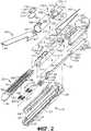
Фиг. 2 - общий вид с пространственным разделением деталей конструкции концевого эффектора, который можно применять в сочетании с различными вариантами осуществления настоящего изобретения;FIG. 2 is an exploded perspective view of an end effector structure that can be used in combination with various embodiments of the present invention;
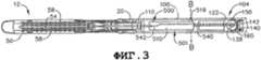
Фиг. 3 - вид сверху концевого эффектора, показанного на фиг. 1 и 2, с участком упора, снятым с него, и узлом замыкающей трубки, показанным пунктирными линиями;FIG. 3 is a top view of the end effector shown in FIG. 1 and 2, with a stop portion removed from it and an end pipe assembly shown by dashed lines;
Фиг. 4 - вид сбоку в разрезе конструкции концевого эффектора, показанного на фиг. 3, с участком упора, соединенным с ним и показанным в разомкнутом положении;FIG. 4 is a sectional side view of the end effector structure shown in FIG. 3, with a stop portion connected to it and shown in the open position;
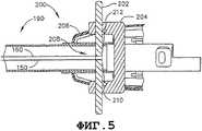
Фиг. 5 - вид сверху в разрезе участка устройства управления шарнирным поворотом, который можно применять с различными вариантами осуществления настоящего изобретения;FIG. 5 is a top sectional view of a portion of an articulated steering control device that can be used with various embodiments of the present invention;
Фиг. 6 - вид сверху в разрезе, изображающий шарнирный поворот концевого эффектора, показанного на фиг. 1;FIG. 6 is a sectional top view showing the articulated rotation of the end effector shown in FIG. one;
Фиг. 7 - общий вид с пространственным разделением деталей, иллюстрирующий вариант осуществления узла замыкающей трубки и конструкции возвратно-поступательной муфты, установленной в узле рукоятки с другими компонентами, вмещенными в корпусной узел, исключенными для ясности;FIG. 7 is a perspective view with a spatial separation of parts, illustrating an embodiment of a closure tube assembly and a reciprocating coupling assembly installed in a handle assembly with other components housed in a housing assembly excluded for clarity;
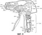
Фиг. 8 - вид в разрезе конструкции корпусного узла различных вариантов осуществления настоящего изобретения;FIG. 8 is a sectional view of a structure of a housing assembly of various embodiments of the present invention;
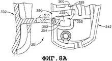
Фиг. 8A - местный вид в разрезе участка системы блокировки замыкающего рычага, которую можно применить в связи с различными вариантами осуществления настоящего изобретения;FIG. 8A is a partial cross-sectional view of a portion of a locking lever locking system that may be used in connection with various embodiments of the present invention;
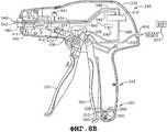
Фиг. 8B - вид в разрезе другого варианта осуществления узла рукоятки по настоящему изобретению, в котором источник сжатого газа является внешним относительно узла рукоятки;FIG. 8B is a cross-sectional view of another embodiment of a handle assembly of the present invention, in which a source of compressed gas is external to the handle assembly;
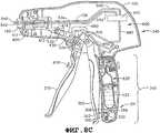
Фиг. 8C - вид в разрезе другого варианта осуществления узла рукоятки по настоящему изобретению;FIG. 8C is a sectional view of another embodiment of a handle assembly of the present invention;
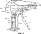
Фиг. 9 - другой вид в разрезе узла рукоятки, показанного на фиг. 8;FIG. 9 is another sectional view of the handle assembly shown in FIG. 8;
Фиг. 10 - вид сбоку конструкции ножевой планки и элемента привода прошивки/отрезания, который содержит узел двухступенчатого цилиндра в соответствии с различными вариантами осуществления настоящего изобретения, с узлом цилиндра, показанным в разрезе;FIG. 10 is a side view of the structure of a knife bar and a firmware / cutting drive member that comprises a two-stage cylinder assembly in accordance with various embodiments of the present invention, with a cylinder assembly shown in section;
Фиг. 11 - другой вид сбоку конструкций ножевой планки и двухступенчатого цилиндра, показанных на фиг. 10, с ножевой планкой в выдвинутом положении;FIG. 11 is another side view of the structures of the knife bar and the two-stage cylinder shown in FIG. 10, with the knife bar in the extended position;
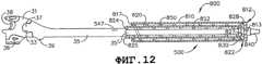
Фиг. 12 - вид сбоку другой конструкции ножевой планки и элемента привода прошивки/отрезания в соответствии с настоящим изобретением с ножевой планкой, отведенной в узел цилиндра, показанный в разрезе;FIG. 12 is a side view of another design of a knife bar and a firmware / cutting drive element in accordance with the present invention with a knife bar allotted to the cylinder assembly shown in section;
Фиг. 13 - другой вид сбоку конструкций ножевой планки и цилиндра, показанных на фиг. 12, с ножевой планкой в выдвинутом положении;FIG. 13 is another side view of the structures of the knife bar and cylinder shown in FIG. 12, with the knife bar in the extended position;
Фиг. 14 - вид сверху конструкции концевого эффектора и несущего узла, вмещающего конструкции цилиндра и ножевой планки, показанных на фиг. 12 и 13;FIG. 14 is a plan view of the structure of the end effector and the bearing assembly accommodating the cylinder and knife blade structures shown in FIG. 12 and 13;
Фиг. 15 - вид сбоку в разрезе конструкции концевого эффектора и несущего узла, показанных на фиг. 14, с соединенным с ней участком упора в разомкнутом положении;FIG. 15 is a cross-sectional side view of the structure of the end effector and the support assembly shown in FIG. 14, with the stop portion connected to it in the open position;
Фиг. 16 - вид в разрезе узла рукоятки, который можно применять в связи с вариантом осуществления, показанном на фиг. 12-15;FIG. 16 is a sectional view of a handle assembly that can be used in connection with the embodiment shown in FIG. 12-15;
Фиг. 16A - вид в разрезе другого узла рукоятки, который можно применять в связи с вариантом осуществления, показанном на фиг. 12-15, причем источник сжатого газа является внешним относительно узла рукоятки;FIG. 16A is a cross-sectional view of another handle assembly that can be used in connection with the embodiment shown in FIG. 12-15, wherein the source of compressed gas is external to the handle assembly;
Фиг. 16B - вид в разрезе другого варианта осуществления узла рукоятки в соответствии с настоящим изобретением;FIG. 16B is a sectional view of another embodiment of a handle assembly in accordance with the present invention;
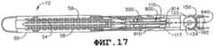
Фиг. 17 - вид сверху другой конструкции ножевой планки и несущего узла, который служит опорой для другого элемента прошивного/отрезного привода в форме мембранной коробки, в соответствии с другим вариантом осуществления настоящего изобретения;FIG. 17 is a plan view of another design of a knife bar and a carrier assembly that supports another element of a piercing / cutting drive in the form of a membrane box, in accordance with another embodiment of the present invention;
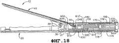
Фиг. 18 - вид сбоку в разрезе конструкций концевого эффектора и несущего узла в варианте осуществления, показанном на фиг. 17;FIG. 18 is a cross-sectional side view of the structures of the end effector and the support assembly in the embodiment shown in FIG. 17;
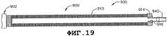
Фиг. 19 - сборочный вид с местным разрезом мембранной коробки в соответствии с вариантами осуществления, показанными на фиг. 17 и 18;FIG. 19 is a partial cutaway view of a membrane box in accordance with the embodiments shown in FIG. 17 and 18;
Фиг. 20 - увеличенный вид участка мембранной коробки, показанной на фиг. 19;FIG. 20 is an enlarged view of a portion of the membrane box shown in FIG. 19;
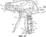
Фиг. 21 - вид в разрезе варианта осуществления узла рукоятки, который можно применить с вариантами осуществления, показанными на фиг. 17-20;FIG. 21 is a sectional view of an embodiment of a handle assembly that can be applied with the embodiments shown in FIG. 17-20;
Фиг. 21A - вид в разрезе другого варианта осуществления узла рукоятки, который можно применить в связи с вариантами осуществления, показанными на фиг. 17-20, причем источник сжатого газа является внешним относительно узла рукоятки;FIG. 21A is a cross-sectional view of another embodiment of a handle assembly that can be applied in connection with the embodiments shown in FIG. 17-20, the compressed gas source being external to the handle assembly;
Фиг. 21B - вид в разрезе другого варианта осуществления узла рукоятки в соответствии с настоящим изобретением;FIG. 21B is a sectional view of another embodiment of a handle assembly in accordance with the present invention;
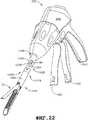
Фиг. 22 - вид в перспективе другого хирургического отрезного и фиксирующего аппарата в соответствии с другими вариантами осуществления настоящего изобретения;FIG. 22 is a perspective view of another surgical cutting and fixing apparatus in accordance with other embodiments of the present invention;
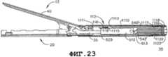
Фиг. 23 - вид сбоку в разрезе концевого эффектора и несущего узла в варианте изобретения, показанном на фиг. 22;FIG. 23 is a cross-sectional side view of an end effector and a carrier assembly in the embodiment of the invention shown in FIG. 22;
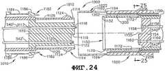
Фиг. 24 - вид в разрезе конструкции быстроразъемного сочленения в варианте осуществления, показанном на фиг. 22 и 23, перед соединением дистального узла стержня с проксимальным узлом стержня;FIG. 24 is a cross-sectional view of a quick coupling structure in the embodiment shown in FIG. 22 and 23, before connecting the distal shaft assembly to the proximal shaft assembly;
Фиг. 25 - вид в разрезе проксимального узла стержня по линии 25-25 на фиг. 24;FIG. 25 is a sectional view of the proximal node of the rod along line 25-25 of FIG. 24;
Фиг. 26 - местный вид в перспективе дистального узла стержня, соединенного с проксимальным узлом стержня, причем участок дистального узла стержня не показан для ясности;FIG. 26 is a fragmentary perspective view of a distal shaft assembly connected to a proximal shaft assembly, a portion of the distal shaft assembly not shown for clarity;
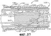
Фиг. 27 - вид сбоку в разрезе узла сочленения в вариантах осуществления, показанных на фиг. 24-26, с дистальным узлом стержня, соединенным с проксимальным узлом стержня;FIG. 27 is a sectional side view of the articulation assembly in the embodiments shown in FIG. 24-26, with a distal shaft assembly connected to the proximal shaft assembly;
Фиг. 28 - вид в перспективе участка дистального узла стержня до соединения с участком проксимального узла стержня;FIG. 28 is a perspective view of a portion of a distal shaft assembly before connecting to a shaft of a proximal shaft assembly;
Фиг. 29 - местный вид в разрезе другой конструкции быстроразъемного сочленения в варианте осуществления, которую можно применить с вариантом осуществления, показанном на фиг. 12-16A;FIG. 29 is a fragmentary sectional view of another quick-connect joint structure in an embodiment that can be applied with the embodiment shown in FIG. 12-16A;
Фиг. 30 - вид в разрезе проксимального узла стержня по линии 30-30 на фиг. 29;FIG. 30 is a sectional view of the proximal node of the rod along line 30-30 of FIG. 29;
Фиг. 31 - вид в перспективе участка проксимального узла стержня, который можно применить в связи с вариантами осуществления, показанными на фиг. 22-30;FIG. 31 is a perspective view of a portion of a proximal node of a shaft that can be used in connection with the embodiments shown in FIG. 22-30;
Фиг. 32 - вид в перспективе другого хирургического отрезного и фиксирующего аппарата в соответствии с настоящим изобретением, в котором применяется пневмоприводное шарнирно-поворотное сочленение в соответствии с различными вариантами осуществления настоящего изобретения;FIG. 32 is a perspective view of another surgical cutting and fixing apparatus in accordance with the present invention, in which a pneumatic actuated articulated-swivel joint is used in accordance with various embodiments of the present invention;
Фиг. 33 - местный вид в перспективе участка шарнирно-поворотного сочленения, соединяющего дистальный несущий сегмент с проксимальным несущим сегментом в варианте осуществления, показанном на фиг. 32;FIG. 33 is a partial perspective view of a portion of a pivotally articulating joint connecting the distal bearing segment to the proximal bearing segment in the embodiment shown in FIG. 32;
Фиг. 34 - другой вид в перспективе конструкции шарнирно-поворотного сочленения, показанного на фиг. 33, со снятой с него крышкой, где изображен дистальный несущий сегмент, шарнирно повернутый относительно проксимального несущего сегмента;FIG. 34 is another perspective view of the articulation design shown in FIG. 33, with the cover removed from it, which depicts a distal bearing segment pivotally rotated relative to the proximal bearing segment;
Фиг. 35 - общий вид с пространственным разделением деталей конструкции шарнирно-поворотного сочленения, показанного на фиг. 33 и 34;FIG. 35 is an exploded perspective view of the pivot articulated structure shown in FIG. 33 and 34;
Фиг. 36 - вид сбоку в разрезе узла сочленения, показанного на фиг. 33-35;FIG. 36 is a side sectional view of the articulation assembly shown in FIG. 33-35;
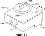
Фиг. 37 - вид в перспективе варианта осуществления переключающего узла в соответствии с настоящим изобретением;FIG. 37 is a perspective view of an embodiment of a switching unit in accordance with the present invention;
Фиг. 38 - вид сбоку переключающего узла, показанного на фиг. 37;FIG. 38 is a side view of the switching assembly shown in FIG. 37;
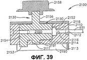
Фиг. 39 - вид в разрезе переключающего узла, показанного на фиг. 37 и 38, взятом по линии 39-39 на фиг. 37;FIG. 39 is a sectional view of the switching unit shown in FIG. 37 and 38 taken along lines 39-39 of FIG. 37;
Фиг. 40 - вид в разрезе переключающего узла в выключенном положении, взятом по линии 40-40 на фиг. 38;FIG. 40 is a sectional view of the switching unit in the off position taken along line 40-40 of FIG. 38;
Фиг. 41 - другой вид в разрезе переключающего узла, показанного на фиг. 37-40, во включенном положении;FIG. 41 is another cross-sectional view of the switching assembly shown in FIG. 37-40, in the on position;
Фиг. 42 - вид в разрезе переключающего узла, показанного на фиг. 41, взятом по линии 42-42 на фиг. 41;FIG. 42 is a cross-sectional view of the switching assembly shown in FIG. 41 taken along line 42-42 of FIG. 41;
Фиг. 43 - вид снизу переключающего узла, показанного на фиг. 37-42;FIG. 43 is a bottom view of the switching assembly shown in FIG. 37-42;
Фиг. 44 - вид в разрезе узла рукоятки, который содержит в себе переключающий узел, показанный на фиг. 37-43, и вмещает источник сжатого газа;FIG. 44 is a sectional view of a handle assembly that includes a switching assembly shown in FIG. 37-43, and contains a source of compressed gas;
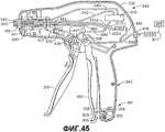
Фиг. 45 - вид в разрезе узла рукоятки, который содержит в себе переключающий узел, показанный на фиг. 37-43, и в котором источник сжатого газа является внешним относительно узла рукоятки;FIG. 45 is a sectional view of a handle assembly that includes a switching assembly shown in FIG. 37-43, and in which the source of compressed gas is external to the handle assembly;
Фиг. 46 - вид в перспективе другого хирургического отрезного и фиксирующего аппарата в соответствии с настоящим изобретением, в котором применяются варианты осуществления шарнирно-поворотного сочленения, показанные на фиг. 33-36, и варианты осуществления быстроразъемного сочленения, показанные на фиг. 23-31;FIG. 46 is a perspective view of another surgical cutting and fixing apparatus in accordance with the present invention, in which the pivot articulated embodiments shown in FIG. 33-36, and quick coupler embodiments shown in FIG. 23-31;
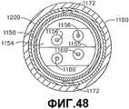
Фиг. 47 - вид в разрезе конструкции быстроразъемного сочленения в варианте осуществления, показанном на фиг. 46, перед соединением дистального узла стержня с проксимальным узлом стержня;FIG. 47 is a cross-sectional view of a quick coupler structure in the embodiment shown in FIG. 46, before connecting the distal shaft assembly to the proximal shaft assembly;
Фиг. 48 - вид в разрезе узла сочленения в вариантах осуществления, показанных на фиг. 47, взятом по линии 48-48 на фиг. 47;FIG. 48 is a sectional view of the articulation assembly in the embodiments shown in FIG. 47 taken along lines 48-48 of FIG. 47;
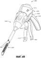
Фиг. 49 - вид в перспективе другого варианта осуществления хирургического отрезного и фиксирующего аппарата в соответствии с настоящим изобретением;FIG. 49 is a perspective view of another embodiment of a surgical cutting and fixing apparatus in accordance with the present invention;
Фиг. 50 - общий вид с пространственным разделением деталей конструкции концевого эффектора, которую можно применить в связи с вариантом осуществления, показанным на фиг. 49;FIG. 50 is an exploded perspective view of an end effector structure that can be applied in connection with the embodiment shown in FIG. 49;
Фиг. 51 - общий вид с пространственным разделением деталей конструкции концевого эффектора, несущего узла и узла замыкающей трубки, которые можно применить в связи с вариантом осуществления, показанным на фиг. 49;FIG. 51 is an exploded perspective view of an end effector, a carrier assembly, and a closure tube assembly that can be used in connection with the embodiment shown in FIG. 49;
Фиг. 52 - вид сбоку в разрезе концевого эффектора, несущего узла и узла замыкающей трубки, показанных на фиг. 51, с участком упора, не показанным для ясности;FIG. 52 is a cross-sectional side view of an end effector, a carrier assembly, and a closure tube assembly shown in FIG. 51, with a stop portion not shown for clarity;
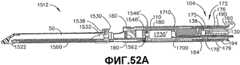
Фиг. 52A - вид сбоку в разрезе концевого эффектора, несущего узла и узла замыкающей трубки в соответствии с другим неограничивающим вариантом осуществления настоящего изобретения, в котором пневматический двигатель установлен дистально от узла рукоятки;FIG. 52A is a cross-sectional side view of an end effector, a carrier assembly, and a closure tube assembly in accordance with another non-limiting embodiment of the present invention, in which the air motor is mounted distally from the handle assembly;
Фиг. 52B - вид сбоку в разрезе концевого эффектора, несущего узла и узла замыкающей трубки в соответствии с другим неограничивающим вариантом осуществления настоящего изобретения, в котором пневматический двигатель установлен дистально от узла рукоятки;FIG. 52B is a cross-sectional side view of an end effector, a carrier assembly, and a closure tube assembly in accordance with another non-limiting embodiment of the present invention, in which the air motor is mounted distally from the handle assembly;
Фиг. 53 - вид в разрезе узла рукоятки, который можно применить в связи с вариантом осуществления, показанным на фиг. 49;FIG. 53 is a sectional view of a handle assembly that can be applied in connection with the embodiment shown in FIG. 49;
Фиг. 53A - вид в разрезе другого узла рукоятки, который можно применить в связи с вариантом осуществления, показанным на фиг. 49, в котором источник сжатого газа является внешним относительно узла рукоятки;FIG. 53A is a sectional view of another handle assembly that can be used in connection with the embodiment shown in FIG. 49, wherein the source of compressed gas is external to the handle assembly;
Фиг. 54 - еще один вид в разрезе узла рукоятки, показанного на фиг. 53;FIG. 54 is another sectional view of the handle assembly shown in FIG. 53;
Фиг. 55 - вид сбоку относительного расположения конструкции прошивного/отрезного рычага в соответствии с различными вариантами осуществления настоящего изобретения;FIG. 55 is a side view of a relative arrangement of a piercing / cutting arm structure in accordance with various embodiments of the present invention;
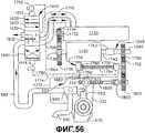
Фиг. 56 - схематическое изображение варианта осуществления системы управления в соответствии с настоящим изобретением, который можно применить в связи с различными вариантами осуществления настоящего изобретения;FIG. 56 is a schematic diagram of an embodiment of a control system in accordance with the present invention that can be applied in connection with various embodiments of the present invention;
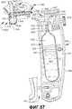
Фиг. 57 - вид в сечении участка съемной ручки, отсоединенного от основного соединительного участка различных вариантов осуществления узла рукоятки в соответствии с настоящим изобретением;FIG. 57 is a sectional view of a portion of a removable handle detached from a main connecting portion of various embodiments of a handle assembly in accordance with the present invention;
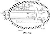
Фиг. 58 - местный вид в разрезе, изображающий участок съемной ручки, присоединенный к основному соединительному участку узла рукоятки в соответствии с различными вариантами осуществления настоящего изобретения;FIG. 58 is a partial cross-sectional view illustrating a portion of a removable handle attached to a main connecting portion of a handle assembly in accordance with various embodiments of the present invention;
Фиг. 59 - местный вид в разрезе участка съемной ручки и основного соединительного участка, показанных на фиг. 58, причем распределители и компоненты, относящиеся к цилиндру, не показаны для ясности;FIG. 59 is a partial cross-sectional view of a portion of a removable handle and a main connecting portion shown in FIG. 58, with valves and components related to the cylinder not shown for clarity;
Фиг. 60 - вид в разрезе участка съемной ручки и основного соединительного участка, показанных на фиг. 58 и 59, взятом по линии 60-60 на фиг. 59;FIG. 60 is a sectional view of a portion of a removable handle and a main connecting portion shown in FIG. 58 and 59 taken along line 60-60 of FIG. 59;
Фиг. 61 - вид в разрезе участка съемной ручки и основного соединительного участка, показанных на фиг. 58, 59 и 60, взятом по линии 61-61 на фиг. 59;FIG. 61 is a sectional view of a portion of a removable handle and a main connection portion shown in FIG. 58, 59 and 60 taken along line 61-61 of FIG. 59;
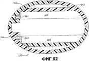
Фиг. 62 - вид в разрезе участка съемной ручки и основного соединительного участка, показанных на фиг. 58-61, взятом по линии 62-62 на фиг. 59;FIG. 62 is a sectional view of a portion of a removable handle and a main connecting portion shown in FIG. 58-61 taken along line 62-62 of FIG. 59;
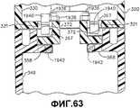
Фиг. 63 - другой местный вид в разрезе участка съемной ручки и основного соединительного участка, показанных на фиг. 58-62, взятом по линии 63-63 на фиг. 59;FIG. 63 is another partial cross-sectional view of a portion of a removable handle and a main connecting portion shown in FIG. 58-62 taken along line 63-63 of FIG. 59;
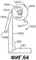
Фиг. 64 - схематичное изображение варианта осуществления блокировочной системы в соответствии с настоящим изобретением в исходном положении;FIG. 64 is a schematic illustration of an embodiment of a locking system in accordance with the present invention in a rest position;
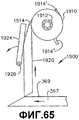
Фиг. 65 - другое схематичное изображение блокировочной системы, показанной на фиг. 64, изображающее ее срабатывание, когда участок ручки первоначально соединяют с основным соединительным участком узла рукоятки;FIG. 65 is another schematic illustration of the interlock system shown in FIG. 64 depicting its actuation when the handle portion is initially connected to the main connecting portion of the handle assembly;
Фиг. 66 - другое схематичное изображение блокировочной системы, показанной на фиг. 64 и 65, до второго отсоединения участка ручки от основного соединительного участка узла рукоятки;FIG. 66 is another schematic illustration of the interlock system shown in FIG. 64 and 65, until the second disconnection of the handle portion from the main connecting portion of the handle assembly;
Фиг. 67 - другое схематичное изображение блокировочной системы, показанной на фиг. 64-66, на котором изображены положения компонентов системы, когда участок ручки соединен с основным соединительным участком;FIG. 67 is another schematic representation of the interlock system shown in FIG. 64-66, which shows the positions of the components of the system when the handle section is connected to the main connecting section;
Фиг. 68 - другое схематичное изображение блокировочной системы, показанной на фиг. 64-67, на котором изображены положения компонентов системы во время второго соединения участка ручки с основным соединительным участком;FIG. 68 is another schematic illustration of the interlock system shown in FIG. 64-67, which depicts the position of the components of the system during the second connection of the handle section with the main connecting section;
Фиг. 69 - другое схематичное изображение, представляющее блокировочную систему после того, как участок ручки соединяют с основным соединительным участком во второй и последний раз;FIG. 69 is another schematic view showing an interlock system after a handle portion is connected to the main connecting portion for a second and last time;
Фиг. 70 - вид в перспективе другого варианта осуществления хирургического отрезного и фиксирующего аппарата в соответствии с настоящим изобретением;FIG. 70 is a perspective view of another embodiment of a surgical cutting and fixing apparatus in accordance with the present invention;
Фиг. 71 - вид в разрезе варианта осуществления узла рукоятки, который можно применить в связи с аппаратом, показанным на фиг. 70;FIG. 71 is a sectional view of an embodiment of a handle assembly that can be used in conjunction with the apparatus shown in FIG. 70;
Фиг. 72 - общий вид с пространственным разделением деталей возвратно-поступательной муфты и узла отводящего штока в соответствии с различными вариантами осуществления настоящего изобретения;FIG. 72 is an exploded perspective view of a reciprocating clutch and an outlet rod assembly in accordance with various embodiments of the present invention;
Фиг. 72A - общий вид с пространственным разделением деталей возвратно-поступательной муфты и узла отводящего штока в соответствии с другими вариантами осуществления настоящего изобретения;FIG. 72A is an exploded perspective view of a reciprocating coupling and an outlet stem assembly in accordance with other embodiments of the present invention;
Фиг. 73 - вид в сборе компонентов, показанных на фиг. 72, с их узлом цилиндра в полностью выдвинутом положении;FIG. 73 is an assembly view of the components shown in FIG. 72, with their cylinder assembly in the fully extended position;
Фиг. 74 - вид сзади в вертикальной проекции варианта осуществления узла возвратно-поступательной муфты в соответствии с настоящим изобретением;FIG. 74 is a rear elevational view of an embodiment of a reciprocating coupling assembly in accordance with the present invention;
Фиг. 75 - другой вид сзади в вертикальной проекции узла возвратно-поступательной муфты, показанного на фиг. 74, с отводящим штоком и толкающим стержнем, продолжающимся в отверстие толкающего стержня, и с толкающим стержнем, соединенным с соединительным элементом;FIG. 75 is another rear elevational view of the reciprocating coupling assembly shown in FIG. 74, with a discharge rod and a push rod extending into the hole of the push rod, and with a push rod connected to the connecting element;
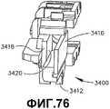
Фиг. 76 - вид сзади в перспективе левостороннего участка узла возвратно-поступательной муфты;FIG. 76 is a rear perspective view of a left-side portion of a reciprocating coupling assembly;
Фиг. 77 - другой вид сзади в перспективе левостороннего участка узла возвратно-поступательной муфты;FIG. 77 is another perspective view of a left-side portion of a reciprocating coupling assembly;
Фиг. 78 - схематичное изображение конструкции системы управления, которую можно применять с вариантами осуществления, показанными на фиг. 70-77;FIG. 78 is a schematic illustration of a control system structure that can be applied with the embodiments shown in FIG. 70-77;
Фиг. 79 - вид сверху в разрезе конструкции узла рукоятки в вариантах осуществления, показанных на фиг. 70-78, с узлом цилиндра в выдвинутом положении;FIG. 79 is a top sectional view of the structure of the handle assembly in the embodiments shown in FIG. 70-78, with the cylinder assembly in the extended position;
Фиг. 80 - другой вид сверху в разрезе конструкции узла рукоятки в вариантах осуществления, показанных на фиг. 70-79, с узлом цилиндра в отведенном положении;FIG. 80 is another cross-sectional top view of a handle assembly in the embodiments shown in FIG. 70-79, with the cylinder assembly in the retracted position;
Фиг. 81 - вид в разрезе узла рукоятки в вариантах осуществления, показанных на фиг. 70-80;FIG. 81 is a sectional view of the handle assembly in the embodiments shown in FIG. 70-80;
Фиг. 81A - вид в разрезе варианта осуществления узла рукоятки, который можно применить с вариантом осуществления, показанным на фиг. 70-80, причем источник сжатого газа является внешним относительно узла рукоятки;FIG. 81A is a sectional view of an embodiment of a handle assembly that can be applied with the embodiment shown in FIG. 70-80, and the source of compressed gas is external relative to the node handle;
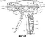
Фиг. 82 - другой вид в разрезе узла рукоятки, показанного на фиг. 81, причем узел цилиндра выдвинут;FIG. 82 is another cross-sectional view of the handle assembly shown in FIG. 81, wherein the cylinder assembly is extended;
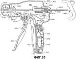
Фиг. 83 - другой вид в разрезе узла рукоятки, показанного на фиг. 81, причем узел цилиндра отведен; иFIG. 83 is another cross-sectional view of the handle assembly shown in FIG. 81, wherein the cylinder assembly is allotted; and
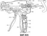
Фиг. 83A - вид в разрезе узла рукоятки в варианте осуществления, показанном на фиг. 72B, причем узел цилиндра отведен и прошивной/отрезной шток находится в его крайнем проксимальном положении.FIG. 83A is a sectional view of the handle assembly in the embodiment shown in FIG. 72B, wherein the cylinder assembly is retracted and the piercing / cutting rod is in its extreme proximal position.
ПОДРОБНОЕ ОПИСАНИЕDETAILED DESCRIPTION
При рассмотрении чертежей, на которых одинаковыми числовыми позициями обозначены аналогичные компоненты на нескольких видах, на фиг. 1 представлен хирургический сшивающий скобками и отрезной аппарат 10, который допускает применение некоторых особых преимуществ настоящего изобретения. Вариант осуществления, показанный на фиг. 1, содержит узел 300 рукоятки, узел 100 удлиненного стержня и концевой эффектор 12, который присоединен к узлу 100 удлиненного стержня. Различные варианты осуществления настоящего изобретения могут содержать концевой эффектор, который присоединен с возможностью поворота к узлу 100 удлиненного стержня и приводится в поворотное движение изгибающимися тросами или лентами, например, такими, которые описаны в заявке на патент США № 11/329020, «SURGICAL INSTRUMENT HAVING AN ARTICULATING END EFFECTOR», поданной 10 января 2006 г., описание которой включено в настоящую заявку путем отсылки. Однако из настоящего подробного описания специалистам со средним уровнем компетентности в данной области техники будет очевидно, что различные варианты осуществления настоящего изобретения можно успешно реализовать в сочетании с конструкциями концевых эффекторов, которые используют отличающиеся поворотные механизмы и элементы управления, и, как дополнительно подробно поясняется ниже, могут быть даже успешно применены с нешарнирными конструкциями концевых эффекторов.When considering the drawings, in which the same numeric reference numerals denote similar components in several views, in FIG. 1 illustrates a surgical staple stapler and a
Как можно видеть на фиг. 1, узел 300 рукоятки аппарата 10 может содержать замыкающий рычаг 302 и рычаг 310 прошивки. Очевидно, что аппараты, содержащие концевые эффекторы, предназначенные для разных хирургических задач, могут содержать разные количества или типы рычагов, или других подходящих элементов управления для приведения в действие концевого эффектора. Концевой эффектор 12 показан разделенным с узлом 300 рукоятки, предпочтительно удлиненным узлом 100 стержня. Врач может шарнирно поворачивать концевой эффектор 12 относительно узла 100 стержня с помощью устройства 200 управления шарнирным поворотом.As can be seen in FIG. 1, the
Следует понимать, что термины, обозначающие пространственное положение, например, вертикальный, горизонтальный, правый, левый и т.п., приведены в настоящем описании со ссылкой на чертежи в предположении, что продольная ось хирургического аппарата 10 соосна с центральной осью узла 100 удлиненного стержня, причем рычаги 302, 310 продолжаются вниз под острым углом из нижней части узла 300 рукоятки. В реальной практике, однако, хирургический аппарат 10 можно ориентировать под различными углами, и, по существу, данные термины, обозначающие пространственное положение, применяются по отношению к самому хирургическому аппарату 10. Кроме того, «проксимальный» применяется для обозначения перспективы со стороны врача, который находится позади узла 300 рукоятки и который устанавливает концевой эффектор 12 в дистальном направлении или удаленным от себя.It should be understood that the terms indicating the spatial position, for example, vertical, horizontal, right, left, etc., are given in the present description with reference to the drawings under the assumption that the longitudinal axis of the
Для целей настоящего описания термин «сжатый газ» относится к любому газу, подходящему для применения в пневмоприводных системах, используемых в стерильных условиях. Неограничивающие примеры таких сред включают в себя сжатый воздух, диоксид углерода (CO2), азот, кислород, аргон, гелий, гидрид натрия, пропан, изобутан, бутан, хлорфторуглероды, диметиловый эфир, метилэтиловый эфир, оксиды азота, гидрофторалканы (HFA) - либо, например, HFA 134a (1,1,1,2,-тетрафторэтан), либо HFA 227 (1,1,1,2,3,3,3-гептафторпропан).For the purposes of the present description, the term "compressed gas" refers to any gas suitable for use in pneumatic drive systems used under sterile conditions. Non-limiting examples of such media include compressed air, carbon dioxide (CO2 ), nitrogen, oxygen, argon, helium, sodium hydride, propane, isobutane, butane, chlorofluorocarbons, dimethyl ether, methyl ethyl ether, nitrogen oxides, hydrofluoroalkanes (HFA) - either, for example, HFA 134a (1,1,1,2,2-tetrafluoroethane), or HFA 227 (1,1,1,2,3,3,3-heptafluoropropane).
Для целей настоящего описания термин «пневмогидравлически связанный» означает, что элементы связаны между собой соответствующей линией или другим средством, допускающим проход сжатого газа между ними. Для целей настоящего описания термин «линия», используемый в сочетаниях «подводящая линия» или «обратная линия», относится к соответствующему проходу, сформированному из жестких или гибких трубки, патрубка, трубопроводов и т.п., для транспортировки сжатого газа от одного компонента к другому.For the purposes of the present description, the term "pneumohydraulically connected" means that the elements are interconnected by an appropriate line or other means allowing the passage of compressed gas between them. For the purposes of the present description, the term "line" used in the combinations "supply line" or "return line" refers to the corresponding passage formed from rigid or flexible tubes, pipes, pipelines, etc., for transporting compressed gas from one component to another.
Для целей настоящего описания термин «пневматический сигнал» или «пневматический приводной сигнал» относится к потоку газа от источника сжатого газа к, по меньшей мере, одному компоненту, который пневмогидравлически связан с источником сжатого газа, или потоку газа между компонентами, которые пневмогидравлически связаны между собой.For the purposes of the present description, the term “pneumatic signal” or “pneumatic drive signal” refers to a gas stream from a compressed gas source to at least one component that is pneumohydraulically coupled to a compressed gas source, or a gas flow between components that are pneumohydraulically connected between by myself.
Для целей настоящего описания фраза «по существу, поперечно продольной оси», где «продольная ось» является осью стержня, относится к направлению, которое почти перпендикулярно продольной оси. Однако, очевидно, что направления, которые несколько отклоняются от перпендикулярного продольной оси, также, по существу, поперечны продольной оси.For the purposes of the present description, the phrase "substantially transverse to the longitudinal axis", where "the longitudinal axis" is the axis of the rod, refers to a direction that is almost perpendicular to the longitudinal axis. However, it is obvious that directions that deviate somewhat from the perpendicular longitudinal axis are also substantially transverse to the longitudinal axis.
На фиг. 2 представлен общий вид с пространственным разделением деталей одного типа узла пневмоприводного инструмента или концевого эффектора, который можно применять в различных вариантах осуществления настоящего изобретения. Узел 12 пневмоприводного инструмента, показанный на фиг. 1-4, выполнен с возможностью функционирования в качестве эндоскопического режущего инструмента типа endocutter. Однако ниже из настоящего подробного описания очевидно, что можно также предположить применение различных оригинальных и новаторских приводных конструкций в соответствии с вариантами осуществления настоящего изобретения для приведения в действие других концевых эффекторов, выполненных с возможностью исполнения других хирургических задач и, следовательно, требующих исключения, модификации или добавления компонентов из тех или к тем, которые показаны на чертежах. Кроме того, очевидно, что концевые эффекторы 12, показанные на фиг. 1-4, можно выполнять для специальных хирургических применений.In FIG. 2 is an exploded perspective view of one type of pneumatic tool assembly or end effector assembly that can be used in various embodiments of the present invention. The
Один тип концевого эффектора, который можно применять с различными вариантами осуществления настоящего изобретения, изображен на фиг. 2. Как можно видеть на данном чертеже, в концевом эффекторе 12 применяется прошивной/отрезной механизм 30 с Е-образной поперечиной («узел ножа»), который, кроме отрезания ткани и выталкивания скобок, расположенных в цилиндре для скобок, установленном в упомянутый концевой эффектор, предпочтительно регулирует зазор участка упора концевого эффектора 12 относительно цилиндра для скобок. Разнообразные аспекты прошивных/отрезных механизмов с Е-образной поперечиной описаны в патенте США № 6978921, «Surgical Stapling Instrument Incorporating An E-Beam Firing Mechanism», изобретателей Шелтона IV с соавторами (Shelton, IV. et al.), соответствующие разделы которых включены в настоящее описание путем отсылки. Однако ниже из настоящего подробного описания специалистам со средним уровнем компетентности в данной области техники должно быть очевидно, что возможно эффективное применение других конфигураций ножевых и прошивных/отрезных механизмов без выхода за пределы существа и объема настоящего изобретения.One type of end effector that can be used with various embodiments of the present invention is depicted in FIG. 2. As can be seen in this drawing, in the
Для целей настоящего описания термин «прошивной/отрезной механизм» относится к участку или участкам пневмоприводного инструмента и/или концевого эффектора, который перемещается из незадействованного положения, в котором прошивной/отрезной механизм может быть, по существу, неподвижным, в сработавшее или конечное положение, в котором участок или участки перемещены или переставлены в конечное положение, при этом такое его перемещение приводит к исполнению инструментом, по меньшей мере, одного действия в ответ на передачу ему, по меньшей мере, одного прошивного/отрезного движения. Прошивной/отрезной механизм может содержать, например: (i) компоненты, которые полностью установлены на пневмоприводном инструменте и сопрягаются с компонентами в хирургическом устройстве; (ii) комбинацию компонентов, которые расположены на пневмоприводном инструменте и в хирургическом устройстве; или (iii) компоненты, которые установлены на хирургическом устройстве и могут перемещаться в пневмоприводной инструмент и из него. Для целей настоящего описания термин «прошивной ход» относится к фактическому перемещению прошивного/отрезного механизма из незадействованного положения в сработавшее положение. Термин «отводящий ход» относится к возвратному перемещению прошивного/отрезного механизма из сработавшего положения в незадействованное положение.For the purposes of the present description, the term “piercing / cutting-off mechanism” refers to a portion or portions of a pneumatic actuating tool and / or end effector that moves from an unused position, in which the piercing / cutting-off mechanism may be substantially stationary, to the actuated or final position, in which the section or sections are moved or rearranged to the final position, while such a movement leads to the execution of the tool, at least one action in response to the transfer to him at least EPE, a piercing / cutting movement. The piercing / detachable mechanism may contain, for example: (i) components that are fully mounted on a pneumatic drive tool and mate with components in a surgical device; (ii) a combination of components that are located on the pneumatic instrument and in the surgical device; or (iii) components that are mounted on the surgical device and can be moved into and out of the pneumatic instrument. For the purposes of the present description, the term “piercing move” refers to the actual movement of the piercing / cutting mechanism from an unused position to a triggered position. The term "retracting stroke" refers to the return movement of the piercing / cutting mechanism from the triggered position to the idle position.
Как можно видеть на фиг. 2, концевой эффектор 12 содержит дистальный элемент, который, в различных неограничивающих вариантах осуществления, содержит удлиненный желоб 20, который содержит соединенный с ним упор 40 с поворотно-поступательным перемещением. Удлиненный желоб 20 выполнен с возможностью размещения и установки кассеты 50 для скобок, которая реагирует на узел 30 ножа выталкиванием скобок 70 в формирующий контакт с упором 40. Следует понимать, что, хотя в настоящей заявке представлено описание предпочтительно быстросменной кассеты для скобок, кассета для скобок, согласующаяся с аспектами настоящего изобретения, может быть постоянно закрепленной в удлиненном желобе 20 или неразъемной с ним.As can be seen in FIG. 2, the
В различных вариантах осуществления прошивной/отрезной механизм или узел 30 ножа содержит вертикально разнесенные пальцы, которые регулируют зазор концевого эффектора 12 во время прошивки. В частности, верхние пальцы 32 установлены с возможностью входа в выемку 42 упора вблизи шарнира между упором 40 и удлиненным желобом 20. Смотри фиг. 4. Во время прошивки/отрезания при сомкнутом упоре 40 верхние пальцы 32 выдвигаются в дистальном направлении внутри продольного паза 44 упора, продолжающегося в дистальном направлении через упор 40. Любое незначительное отклонение вверх в упоре 40 преодолевается направленным вниз усилием, оказываемым верхними пальцами 32.In various embodiments, the piercing / cutting mechanism or
Узел 30 ножа содержит также головку 34 ножевой планки, которая зацепляет вверх желобковый паз 23 (фиг. 2), сформированный в удлиненном желобе 20 и, тем самым, взаимодействует с верхними пальцами 32 для стягивания упора 40 и удлиненного желоба 20 немного ближе между собой в случае зажима между ними лишней ткани. В различных вариантах осуществления узел 30 ножа предпочтительно может содержать средние пальцы 36, которые проходят по прорези привода прошивки/отрезания (не показанной), сформированной в нижней поверхности кассеты 50 и направленной вверх поверхности удлиненного желоба 20, и, тем самым, приводят в движение находящиеся в нем скобки 70, как описано ниже. Средние пальцы 36, при скольжении относительно удлиненного желоба 20, эффективно препятствуют любой тенденции к защемлению концевого эффектора 12 в сомкнутом состоянии на его дистальном конце. Однако, при применении других конструкций узла ножа, возможно достижение оригинальных и новаторских аспектов в различных вариантах осуществления настоящего изобретения.The
Как показано на фиг. 2, дистально направленная режущая кромка 38 между верхними и средними пальцами 32, 36 на узле 30 ножа проходит по проксимально открытой вертикальной прорези 54 в кассете 50 для отрезания зажатой ткани. Жесткое позиционирование узла 30 ножа относительно удлиненного желоба 20 и упора 40 обеспечивает эффективное выполнение разреза. В различных вариантах осуществления нижняя поверхность упора 40 может быть снабжена множеством расположенных в нем скобкоформирующих углублений (не показанных), которые расположены соответственно напротив множества вырезов 58 под скобки в верхней 56 поверхности кассеты 50 для скобок, когда кассета 50 для скобок установлена внутри удлиненного желоба. В различных вариантах осуществления кассету 50 для скобок можно устанавливать с самофиксацией в удлиненный желоб 20. В частности, удлиненные элементы 60, 62 кассеты 50 для скобок входят во фрикционное и разъемное зацепление с выемками 24, 26, соответственно, удлиненного желоба 20.As shown in FIG. 2, a distally directed cutting
Как также можно видеть на фиг. 2, кассета 50 для скобок содержит корпус 51 кассеты, клиновидный скользящий блок 64, поводки 66 скобок, скобки 70 и кассетный лоток 68. В собранном состоянии кассетный лоток 68 вмещает клиновидный скользящий блок 64, поводки 66 скобок и скобки 70 внутри корпуса 51 кассеты. Удлиненный желоб 20 связан с узлом 300 рукоятки узлом 100 удлиненного стержня, который содержит дистальную несущую или рамную секцию 110 и проксимальную несущую или рамную секцию 130. Удлиненный желоб 20 содержит проксимально расположенные крепежные гнезда 22, каждое из которых вмещает соответствующий элемент 114 крепления желоба, сформированный на дистальном конце дистальной несущей секции 110. Удлиненный желоб 20 содержит также криволинейные пазы 28 под упор, в которых установлен с возможностью поворота соответствующий палец 43 упора на упоре 40. Узел 170 замыкающей втулки установлен поверх несущего узла 102 и содержит дистальный сегмент 180 замыкающей трубки и проксимальный сегмент 190 замыкающей трубки. Как поясняется ниже, аксиальное перемещение узла 170 замыкающей втулки относительно несущего узла 102 вынуждает упор 40 поворачиваться относительно удлиненного желоба 20.As can also be seen in FIG. 2, the
Как можно видеть на фиг. 2, фиксирующая пружина 112 установлена в дистальном несущем сегменте 110 в качестве блокировки для узла 30 ножа. Дистальный и проксимальный квадратные вырезы 111, 113 сформированы наверху дистального несущего сегмента 110 для образования зажимной перекладины 115 между ними, которая вмещает верхний рычаг 116 фиксирующей пружины 112, чей нижний, дистально продолжающийся рычаг 118 оказывает направленное вниз усилие на дистальный конец узла 501 цилиндра, служащий опорой для участка 35 планки поршня, выступающей из узла 30 ножа, как подробно поясняется ниже. Следует понимать, что различные варианты осуществления могут содержать другие типы блокировок или совсем не содержать блокировок.As can be seen in FIG. 2, a retaining
В варианте осуществления, представленном на фиг. 1-6, концевой эффектор 12 можно шарнирно поворачивать относительно проксимального сегмента 190 замыкающей трубки (и узла 300 рукоятки) посредством совокупности тросов или лент, которые изгибаются для натягивания концевого эффектора 12 вокруг шарнира 104 сочленения. Специалистам со средним уровнем компетентности в данной области техники должно быть понятно, что данная конструкция представляет всего одну из множества шарнирно-поворотных конструкций, которые можно применить в связи с устройствами данного типа. В данном варианте осуществления проксимальный конец дистального несущего сегмента 110 содержит на себе выступ 122. Дистальный конец проксимального несущего сегмента 130 снабжен лапкой 134, в которой имеется сквозной вырез 136. Проксимальный несущий сегмент 130 расположен относительно дистального несущего сегмента 110 так, что вырез 136 коаксиально совмещен с вырезом 124 в выступе 122, чтобы ось 138 поворота продолжалась сквозь него. Смотри фиг. 4. Данная конструкция в сборе позволяет концевому эффектору 12 поворачиваться относительно проксимального несущего сегмента 130 вокруг оси A-A поворота.In the embodiment of FIG. 1-6, the
Как указано выше, в данном варианте осуществления применяются ленты для шарнирного поворота концевого эффектора 12. В частности, ленты 150, 160 могут продолжаться в дистальном направлении к шарниру 104 сочленения, как показано на фиг. 2 и 3. Лента 150 может продолжаться через проксимальный сегмент 190 замыкающей трубки вдоль его левой стороны, где она может быть проложена вокруг ленточного элемента 160 и поперек к правой стороне проксимального сегмента 190 замыкающей трубки. Здесь лента 150 может быть механически соединена с выступом 122, например, в точке 123 соединения. Аналогично, лента 160 может продолжаться через проксимальный сегмент 190 замыкающей трубки вдоль его правой стороны, где она может быть проложена вокруг ленточного элемента 150 и поперек к левой стороне проксимального сегмента 190 замыкающей трубки. Здесь лента 160 может быть механически соединена с выступом 122 в точке 125 соединения.As indicated above, in this embodiment, tapes are used to articulate the
На фиг. 3 представлен вид сверху концевого эффектора и несущего узла 102 с узлом 100 замыкающей трубки, показанным пунктирными линиями. На фиг. 4 представлен местный вид сбоку в разрезе того же самого участка аппарата 10. Как можно видеть на фиг. 4, ленты 150 и 160 показаны смещенными одна от другой для предотвращения помех перемещению согласно одному неограничивающему варианту осуществления. Например, лента 150 показана в положении ниже ленты 160. В другом неограничивающем варианте осуществления вертикальное расположение лент 150 и 160 можно обратить. Как также видно из фиг. 2 и 3, ленточный элемент 150 продолжается вокруг штифта 140 в участке 134 лапки проксимального рамного сегмента 130. Аналогично, лента 160 продолжается вокруг штифта 142 в участке 134 лапки проксимального рамного сегмента 130. Смотри также фиг. 2.In FIG. 3 is a plan view of an end effector and a
Ленточные участки 150 и 160 могут продолжаться от выступа 122 и вдоль проксимального сегмента 190 замыкающей трубки к устройству 200 управления шарнирным поворотом, показанным на фиг. 5. Устройство 200 управления шарнирным поворотом может содержать ползун 202 шарнирного поворота, рамку 204 и кожух 206. Ленточные участки 150, 160 могут проходить сквозь ползун 202 шарнирного поворота по пазу 208 или другому вырезу, хотя очевидно, что ленточные участки 150, 160 можно соединять с ползуном 202 любым подходящим средством. Ползун 202 шарнирного поворота может представлять собой одну целую деталь, как показано на фиг. 5, или, в одном неограничивающем варианте осуществления, может содержать две детали с сопряжением между двумя деталями, ограничивающим паз 208. В одном неограничивающем варианте осуществления ползун 202 шарнирного поворота может содержать несколько пазов, где, например, каждый паз соответствует одному из ленточных участков 150, 160. Кожух 206 может закрывать различные компоненты устройства 200 управления для предотвращения попадания мусора.The
В различных вариантах осуществления ленточные участки 150, 160 могут быть закреплены к рамке 204 в точках 210, 212 соединения, расположенных проксимально от паза 208. В неограничивающем варианте осуществления, показанном на фиг. 5, показано, что ленточные участки 150, 160 предварительно отогнуты от точек 210, 212 соединения к пазу 208, расположенному вблизи продольной оси проксимального сегмента 190 замыкающей трубки. Следует понимать, что ленточные участки 150, 160 могут быть закреплены в любом другом месте в аппарате 10, расположенном проксимально относительно паза 208, включая узел 300 рукоятки.In various embodiments, the
Во время применения вариант осуществления, показанный на фиг. 2, может находиться в неповернутом положении, показанном на фиг. 3. Устройство 200 управления шарнирным поворотом и ленты 150, 160 показаны в центральном положении, приблизительно, на продольной оси узла 100 стержня. Соответственно, концевой эффектор 12 находится в нейтральном или неповернутом положении. На фиг. 6 устройство 200 управления шарнирным поворотом показано с ползуном 202 шарнирного поворота, передвинутым в рамке шарнирного поворота в правую сторону от узла 100 стержня. Соответственно, ленты 150, 160 изогнуты к правой стороне узла 100 стержня. Можно видеть, что изгиб ленты 150 вправо оказывает поперечно направленное усилие на выступ 122, который смещается от точки поворота выступа 122. Данное смещающее усилие вынуждает выступ 122 поворачиваться вокруг шарнира 104 сочленения, что, в свою очередь, вынуждает концевой эффектор 12 поворачиваться вправо, как показано. Следует понимать, что сдвиг ползуна 202 шарнирного поворота в левую сторону узла 100 стержня может оказывать поперечно направленное усилие на ленты 150, 160 и, тем самым, изгибать обе ленты 150, 160 к левой стороне узла 100 стержня. Тогда изгиб ленты 160 оказывает поперечно направленное усилие на выступ 122, который, как указано выше, смещается от точки поворота выступа 122. Это, в свою очередь, вынуждает выступ 122 поворачиваться вокруг шарнира 104 сочленения, что вынуждает концевой эффектор 12 поворачиваться влево.During use, the embodiment shown in FIG. 2 may be in the non-rotated position shown in FIG. 3. The articulated
В различных вариантах осуществления узел 100 стержня содержит узел 170 замыкающей трубки, который размещен на несущем узле 102. Смотри фиг. 2. Узел 170 замыкающей трубки содержит дистальный сегмент 180 замыкающей трубки и проксимальный сегмент 190 замыкающей трубки. Дистальный сегмент 180 замыкающей трубки и проксимальный сегмент 190 замыкающей трубки могут быть выполнены из полимера или другого подходящего материала. Проксимальный сегмент 190 замыкающей трубки является полым и содержит аксиальный проход 191, продолжающийся через данный сегмент, который выполнен с размером для установки в него участка несущего узла 102.In various embodiments, the
В варианте осуществления, показанном на фиг. 2 и 4, применено двухшарнирное замыкающее соединение 172. Следует понимать, что изобретение не ограничено конструкцией двухшарнирного замыкающего соединения и может содержать любую подходящую замыкающую трубку или втулку, или совсем не содержать замыкающей трубки или втулки. Как конкретно показано на фиг. 4, дистальный сегмент 180 замыкающей трубки содержит верхнюю и нижнюю проксимально выступающие лапки 182, 184. Дистальный сегмент 180 замыкающей трубки дополнительно содержит подковообразный вырез 185 и лапку 186 для зацепления размыкающей/смыкающей лапки 46 упора на упоре 40, чтобы вынуждать упор 40 поворачиваться между разомкнутым и сомкнутым положениями, как дополнительно подробно поясняется ниже. Смотри фиг. 2.In the embodiment shown in FIG. 2 and 4, a double-hinged
Проксимальный сегмент 190 замыкающей трубки аналогично снабжен дистально продолжающейся верхней лапкой 192 и дистально продолжающейся нижней лапкой 194. Верхнее двухшарнирное соединительное звено 174 содержит выступающие вверх дистальную и проксимальную оси 175, 176 поворота, которые находятся в зацеплении, соответственно, с верхним дистальным отверстием 183 под ось поворота в верхней проксимально выступающей лапке 182 и верхним проксимальным отверстием 193 под ось поворота в верхней дистально выступающей лапке 192. Конструкция сочленения дополнительно содержит нижнее двухшарнирное соединительное звено 177, которое содержит выступающие вниз дистальную и проксимальную оси 178, 179 поворота (не показанные на фиг. 2, однако показанные на фиг. 4), которые находятся в зацеплении, соответственно, с нижним дистальным отверстием 187 под ось поворота в нижней проксимально выступающей лапке 184 и нижним проксимальным отверстием 195 под ось поворота в нижней дистально выступающей лапке 194.The proximal
Во время применения узел 170 замыкающей трубки поступательно перемещают в дистальном направлении для смыкания упора 40, например, в ответ на приведение в действие замыкающего рычага 310. Упор 40 смыкают поступательным перемещением в дистальном направлении узла 170 замыкающей трубки на несущем узле 102, что вынуждает заднюю сторону подковообразного выступа 185 наталкиваться на размыкающую/смыкающую лапку 46 на упоре 40 и вызывает его поворот в сомкнутое положение. Чтобы разомкнуть упор 40, узел 170 замыкающей трубки аксиально перемещают в проксимальном направлении на несущем узле 102, что вынуждает лапку 186 приходить в контакт и нажимать на размыкающую/смыкающую лапку 46 с поворотом упора 40 в разомкнутое положение.During use, the
На фиг. 7 представлен общий вид с пространственным разделением деталей неограничивающего узла 300 рукоятки в соответствии с различными вариантами осуществления настоящего изобретения. В варианте осуществления, показанном на фигуре 7, узел рукоятки имеет конфигурацию «ручки пистолетного типа» и сформирован из правого корпусного элемента 320 и левого корпусного элемента 330, которые отформованы или иначе изготовлены из полимера или другого подходящего материала и предназначены для состыковки. Данные корпусные элементы 320 и 330 можно соединять между собой с помощью защелкивающихся элементов, шпеньков и гнезд, отформованных или иначе сформированных в данных элементах и/или на клею, винтах, болтах, зажимах и т.п. Верхний участок 322 правого корпусного элемента 320 состыковывается с соответствующим верхним участком 323 левого корпусного элемента 330 с формированием основного корпусного участка, обозначенного позицией 340. Аналогично, нижний участок 324 ручки правого корпусного элемента 320 состыковывается с нижним участком 334 ручки левого корпусного элемента 330 с формированием участка ручки, обозначенного, в общем, позицией 342. В варианте осуществления, показанном на фиг. 7, участок 342 ручки в целом является неразъемным с основным корпусным участком 340. Данная конструкция может быть, в частности, пригодной для применений, когда источник сжатого газа постоянно установлен в участке 342 ручки. Данная конструкция пригодна также для применения с источниками сжатого газа, которые являются внешними относительно узла 300 рукоятки и подключаются к компонентам управления, вмещенным в него, посредством проходного отверстия или проходных отверстий в корпусном узле. В других вариантах осуществления, как дополнительно подробно поясняется ниже, участок 342 ручки является разъемным с основным корпусным участком 340. Как должно быть очевидно ниже из настоящего подробного описания, данная конструкция дает множество преимуществ и выгод. Однако специалистам со средним уровнем компетентности в данной области техники должно быть совершенно очевидно, что узел 300 рукоятки может иметь множество разных форм и размеров.In FIG. 7 is an exploded perspective view of a
Для ясности на фиг. 7 представлены только компоненты, применяемые для управления аксиальным перемещением узла 170 замыкающей трубки, которые, в конечном счете, управляют размыканием и смыканием упора 40. Как можно видеть на данном чертеже, замыкающая возвратно-поступательная муфта 400, которая соединена с замыкающим рычагом 302 узлом 430 рычажной передачи, установлена внутри основного корпусного участка 340. Замыкающая возвратно-поступательная муфта 400 может быть также изготовлена из двух деталей 402, 404, которые отформованы или иначе изготовлены из полимера или другого подходящего материала и предназначены для состыковки. Например, в варианте осуществления, показанном на фиг. 7, правый участок 402 может быть снабжен крепежными столбиками 403, которые предназначены для вмещения в соответствующие гнезда (не показанные) в левом участке 404. Правый и левый участки 402, 404 могут удерживаться совместно иным способом, защелкивающими элементами и/или клеем, и/или болтами, винтами, зажимами и т.п. Как можно видеть на данном чертеже, в проксимальном конце проксимального сегмента 190 замыкающей трубки выполнена удерживающая канавка 196. Правый участок 402 замыкающей возвратно-поступательной муфты 400 содержит правый удерживающий фланцевый сегмент 405, который выполнен с возможностью взаимодействия с левым удерживающим фланцевым сегментом (не показанным) на левом участке 404 замыкающей возвратно-поступательной муфты 400 для формирования удерживающего фланцевого узла, который продолжается в удерживающую канавку 196 в проксимальном сегменте 190 замыкающей трубки.For clarity, FIG. 7, only components used to control the axial movement of the
Как также можно видеть на фиг. 7, правый удерживающий шпенек 326 несущего узла выступает внутрь из правого корпусного элемента 320. Данный шпенек 326 выступает в удлиненный паз или окно 406 в правом участке 402 замыкающей возвратно-поступательной муфты 400. Сходный удерживающий шпенек (не показанный) замыкающей возвратно-поступательной муфты выступает внутрь из левого корпусного элемента 330 для вмещения в другое окно или паз 408, выполненный в левом участке 404 замыкающей возвратно-поступательной муфты 400. Удерживающие шпеньки служат для неподвижной фиксации проксимального конца 133 проксимального несущего сегмента 130 (не показанного на фиг. 7) к узлу 300 рукоятки и одновременно допускают аксиальное перемещение замыкающей возвратно-поступательной муфты 400 относительно него. Удерживающие шпеньки могут быть механически закреплены к проксимальному концу проксимального несущего сегмента 130 посредством, например, болтов, винтов, клея, защелкивающихся элементов и т.п. Кроме того, замыкающая возвратно-поступательная муфта 400 снабжена продолжающимися вбок направляющими ребрами 410, 411. Ребро 410 установлено с возможностью скольжения в направляющую 328 ребра в правом корпусном элементе 320, и ребро 411 установлено с возможностью скольжения в направляющую ребра (не показанную) в левом корпусном элементе 330.As can also be seen in FIG. 7, the
Аксиальное перемещение замыкающей возвратно-поступательной муфты 400 и узла 170 замыкающей трубки в дистальном направлении (по стрелке «C») создается перемещением замыкающего рычага 302 к участку 342 ручки узла 300 рукоятки, и аксиальное перемещение замыкающей возвратно-поступательной муфты 400 в проксимальном направлении (по стрелке «D») создается перемещением замыкающего рычага 302 от участка 342 ручки. В различных вариантах осуществления замыкающая возвратно-поступательная муфта 400 снабжена соединительной лапкой 412, которая облегчает прикрепление к ней узла 430 замыкающей рычажной передачи. Смотри фиг. 8 и 9. Узел 430 замыкающей рычажной передачи содержит вильчатый участок 432, который шарнирно, с возможностью поворота, присоединен к соединительной лапке 412 штифтом 414. Узел 430 замыкающей рычажной передачи дополнительно содержит замыкающее плечо 434, которое шарнирно, с возможностью поворота, присоединено к узлу 304 вилки, сформированному на замыкающем рычаге 302, замыкающим штифтом 436, как показано на фиг. 7. Замыкающий рычаг 302 установлен с возможностью поворота в узле 300 рукоятки на шарнирном пальце 306, который продолжается между правым корпусным элементом 320 и левым корпусным элементом 330.The axial movement of the
Когда врачу требуется сомкнуть упор 40 для зажима ткани в концевом эффекторе 12, врач притягивает замыкающий рычаг 302 к участку 342 ручки. Когда врач подтягивает замыкающий рычаг 302 к участку 342 ручки, узел 430 замыкающей рычажной передачи перемещает замыкающую возвратно-поступательную муфту 400 в дистальном направлении «C», пока узел 430 замыкающей рычажной передачи не переместится в положение фиксации, показанное на фиг. 8. В данном положении узел 430 рычажной передачи будет стремиться удерживать замыкающую возвратно-поступательную муфту 400 в данном положении фиксации. Когда замыкающую возвратно-поступательную муфту 400 перемещают в положение фиксации, узел 170 замыкающей трубки перемещается в дистальном направлении по несущему узлу 102 и, тем самым, приводит размыкающую/смыкающую лапку 46 на упоре 40 в контакт с проксимальным концом подковообразного выреза 185 в дистальном сегменте 180 замыкающей трубки и, тем самым, поворачивает упор 40 в сомкнутое (сжатое) положение.When the doctor needs to close the
В различных вариантах осуществления, для дополнительного удерживания замыкающей возвратно-поступательной муфты 400 в сомкнутом положении, замыкающий рычаг 302 может быть снабжен расцепляемым механизмом 301 фиксации, который выполнен с возможностью зацепления за участок 342 рукоятки и удерживания с возможностью отпускания замыкающего рычага 302 в положении фиксации. Можно также применить другие фиксирующие устройства для удерживания с возможностью освобождения замыкающей возвратно-поступательной муфты 400 в положении фиксации. В варианте осуществления, показанном на фиг. 8, 8A, 8B и 9, замыкающий рычаг 302 содержит гибкую продольную консоль 303, которая содержит боковой палец 305, продолжающийся из нее. Консоль 303 и палец 305 могут быть выполнены, например, из формованного пластика. Участок 342 ручки пистолетного типа в узле 300 рукоятки содержит отверстие 350 с поперечно продолжающимся клином 352, расположенным в нем. Когда замыкающий рычаг 302 отводят, палец 305 входит в зацепление с клином 352, и палец 305 прижимается вниз (т.е. консоль 303 поворачивается по часовой стрелке) нижней поверхностью 354 клина 352. Когда палец 305 полностью проходит нижнюю поверхность 354, усилие, действующее по часовой стрелке на консоль 303, снимается, и палец 305 поворачивается против часовой стрелки так, что палец 305 приходит в упор в вырез 356 за клином 352 и, тем самым, фиксирует замыкающий рычаг 302. Палец 305 дополнительно удерживается на месте в положении фиксации гибким упором 358, продолжающимся из клина 352.In various embodiments, to further hold the closure of the
Для деблокирования замыкающего рычага 302 оператор может дополнительно прижать замыкающий рычаг 302, что приводит палец 305 в зацепление с наклонной задней стенкой 359 отверстия 350 и, тем самым, отжиму пальца 305 вверх за гибкий упор 358. Затем палец 305 высвобождается для выхода по верхнему проходу в отверстии 360 так, что замыкающий рычаг 302 больше не зафиксирован к участку 342 ручки пистолетного типа. Дополнительные сведения о подобной конструкции приведены в заявке на патент США № 11/344020, «Surgical Instrument Having A Removable Battery», выданной 31 января 2006 г. изобретателю Шелтону IV с соавторами (Shelton, IV et al.), соответствующие разделы которой включены в настоящую заявку путем отсылки. Возможно также применение других расцепляемых фиксирующих конструкций.To release the locking
В различных вариантах осуществления настоящего изобретения узел 30 ножа может содержать, по существу, жесткий участок 35 планки поршня, выступающий из него или иначе прикрепленный к нему, который входит в состав элемента 500 привода, который установлен с возможностью функционирования на дистальном несущем сегменте 110 и выполнен с возможностью передачи, по меньшей мере, двух приводящих движений (например, прошивного/отрезного движения и отводящего движения) узлу 30 ножа. В вариантах осуществления, показанных на фиг. 3, 4, 10 и 11, элемент 500 привода содержит узел 501 двухступенчатого пневмоприводного цилиндра. Узел 30 ножа может содержать цельный компонент или может быть выполнен из нескольких деталей для облегчения сборки аппарата 10. Например, как показано на фиг. 10 и 11, узел 30 ножевой планки содержит дистальный участок 31, который содержит верхние пальцы 32, головку 34, средние пальцы 36 и нож 38. Дистальный участок 31 может быть снабжен вырезом 33, выполненным в нем в размер для вмещения выступа 37, обеспеченного на дистальном конце участка 35 планки поршня. Выступ 37 может вмещаться на трении в вырез 33 и/или фиксироваться в нем клеем, сваркой и т.п.In various embodiments, implementation of the present invention, the
Узел 501 цилиндра содержит первый кожух 510 цилиндра, который имеет первый закрытый проксимальный конец 512 и первый открытый дистальный конец 514, который открыт в первый аксиальный проход 516 в первом 510 кожухе цилиндра. Узел 501 цилиндра содержит также второй кожух 520 цилиндра, который имеет второй проксимальный конец 522 и второй открытый дистальный конец 524, который открыт во второй аксиальный проход 526. Второй закрытый проксимальный конец 522 имеет первую поршневую головку 528, сформированную на нем, которая выполнена в такой размер относительно первого аксиального прохода 516, чтобы создавать, по существу, воздухонепроницаемое скользящее уплотнение к первой стенке 511 первого кожуха 510 цилиндра для образования первой области 515 цилиндра между дистальной стороной первого проксимального конца 512 и проксимальной стороной первой поршневой головки 528. Первый дистальный конец 514 первого кожуха 510 цилиндра дополнительно содержит продолжающийся внутрь первый фланец 517, сформированный на нем для создания, по существу, воздухонепроницаемого скользящего уплотнения к внешней поверхности стенки второго кожуха 520 цилиндра и, тем самым, образования второй области 518 цилиндра между проксимальной стороной первого фланца 517 и дистальной стороной первой поршневой головки 528.The
Сквозь первую поршневую головку 528 обеспечен первый проход 527. Как также можно видеть на фиг. 10 и 11, проксимальный конец планки 35 поршня продолжается через второй открытый дистальный конец 524 второго кожуха 520 цилиндра и во второй аксиальный проход 526. Вторая поршневая головка 530 сформирована на проксимальном конце планки 35 поршня или иначе - прикреплена к ней. Вторая поршневая головка 530 выполнена в такой размер относительно второго аксиального прохода 526, чтобы создавать, по существу, воздухонепроницаемое скользящее уплотнение ко второй стенке 521 второго кожуха 520 цилиндра для образования третьей области 532 цилиндра. Второй дистальный конец 524 второго кожуха 520 цилиндра дополнительно содержит продолжающийся внутрь второй фланец 525, сформированный на нем для создания, по существу, воздухонепроницаемого скользящего уплотнения к планке 35 поршня и, тем самым, образования четвертой области 534 цилиндра между проксимальной стороной второго фланца 525 и дистальной стороной второй поршневой головки 530.A
Как можно видеть на фиг. 3 и 4, узел 501 цилиндра установлен внутри дистального несущего сегмента 110. В различных вариантах осуществления пара качающихся опор 519 выполнена на проксимальном конце первого кожуха 510 цилиндра. Качающиеся опоры 519 вмещены в отверстия 119 под качающиеся опоры в дистальном несущем сегменте 110, чтобы узел 501 цилиндра мог поворачиваться в дистальном несущем сегменте 110 вокруг оси B-B поворота. Смотри фиг. 3. Первая подводящая линия или подводящая трубка 540 продолжается от направляющего распределителя 610 в узле 300 рукоятки (фиг. 8 и 9) через проксимальный сегмент 190 замыкающей трубки для подсоединения к первому проксимальному концу 512 первого кожуха 510 цилиндра, чтобы подводить сжатый газ через первое подводящее проходное отверстие 513 или отверстие в первом проксимальном конце 512 первого кожуха 510 цилиндра. Смотри фиг. 10 и 11. Кроме того, вторая подводящая линия 542 продолжается от направляющего распределителя 610 через проксимальный сегмент 190 замыкающей трубки и подсоединяется к первому кожуху 510 цилиндра вблизи его дистального конца 514 для подведения сжатого газа во вторую область 518 цилиндра через второе проходное отверстие 529.As can be seen in FIG. 3 and 4, a
Ниже, со ссылками на фиг. 8-11, поясняется выдвижение и отведение прошивного/отрезного механизма или узла 30 ножа. Как можно видеть на фиг. 8 и 9, подводящие линии 540 и 542 подсоединены к обычному направляющему распределителю 610, который является частью системы 600 силового привода, вмещенной в корпусе 300 рукоятки. В различных вариантах осуществления направляющий распределитель 610 можно сдвигать вручную между положениями, соответствующими ходу вперед (выдвижение) и ходу назад (отведение), селекторным переключателем 612 или нажимными кнопками, которые доступны через корпус 300 рукоятки. Смотри фиг. 1. В варианте осуществления, показанном на фиг. 8 и 9, применяется сменный источник 620 сжатого газа. Как дополнительно подробно поясняется ниже, данный источник сжатого газа содержит баллон 622, который может быть перезаряжаемым предпочтительным сжатым газом. Однако специалисты со средним уровнем компетентности в данной области техники должны понимать, что возможно также эффективное применение несменных/перезаряжаемых источников (баллонов) со сжатым газом. В других вариантах осуществления узел 300 рукоятки может быть снабжен проходным отверстием 616 для подведения сжатого газа из внешнего источника 618 сжатого газа. Например, аппарат 10 может быть подсоединен к больничной сети 618 сжатого воздуха посредством гибкой подводящей линии 617. Смотри фиг. 8B.Below, with reference to FIG. 8-11, the extension and retraction of the piercing / detachable mechanism or
Ниже дополнительно подробно поясняются оригинальные и новаторские аспекты сменного/перезаряжаемого баллона 622. Однако с целью объяснения выдвижения и отведения планки 35 поршня и узла 30 ножа показано, что сжатый газ протекает из баллона 622 (или внешнего источника 618 давления) по подводящей линии 650 в привод с регулируемым усилием, который может содержать обычный регулятор 660 расхода. Как, в частности, можно видеть на фиг. 9 и 55, регулятор 660 расхода связан с соединительной тягой 662 питания, которая соединена с рычагом 670 включения. Для целей настоящего описания термин «узел привода с регулируемым усилием» содержит, по меньшей мере, регулятор расхода 660 и рычаг 670 включения и соответствующие эквивалентные конструкции. В различных вариантах осуществления рычаг 670 включения установлен смежно с рычагом 310 прошивки, который соединен с возможностью поворота с узлом 300 рукоятки шарнирным пальцем 370, который продолжается между правым корпусным элементом 320 и левым корпусным элементом 330. Нажим на рычаг 670 включения внутрь к рычагу 310 прошивки вынуждает регулятор 660 расхода увеличивать расход сжатого газа, протекающего из баллона 622 в подводящую линию 680, соединенную с направляющим распределителем 610. В зависимости от положения направляющего распределителя 610 сжатый газ будет протекать в одну из подводящих линий 540 или 542. Например, когда направляющий распределитель 610 включается врачом для приведения в действие узла 30 ножа, сжатый газ получает возможность протекать по подводящей линии 540 в первую область 515 цилиндра через первое отверстие 527 в первой поршневой головке 528 и в третью область 532 цилиндра, после приведения в действие рычага 670 включения. Когда сжатый газ поступает в третью область 532 цилиндра, вторая поршневая головка 530 толкает планку 35 поршня в дистальном направлении. Газ, находящийся в четвертой области цилиндра, выпускается из нее через выпускное отверстие 523 во втором кожухе 520 цилиндра. Аналогично, газ, содержащийся во второй области 518 цилиндра, получает возможность отведения из нее через второе отверстие 529 во вторую подводящую линию 542. Вторая подводящая линия 542 транспортирует выпущенный газ в направляющий распределитель 610, из которого он, в конечном счете, выпускается. Непрерывная подача сжатого газа в первую область 515 цилиндра и третью область 532 цилиндра вынуждает узел 30 ножа полностью выдвинуться через концевой эффектор 12. Когда узел 30 ножа проходит по концевому эффектору 12, он отрезает зажатую в нем ткань и выталкивает скобки 70 из кассеты 50 для скобок (выталкивает скобки в формирующий контакт с нижней поверхностью упора 40). После того как узел 30 ножа выдвинут в его конечное дистальное положение в концевом эффекторе 12, врач прекращает подачу сжатого газа отпусканием рычага 670 включения.Original and innovative aspects of the replaceable /
Для отведения прошивного/отрезного механизма или узла 30 ножа врач вручную перемещает селекторный переключатель 612 или соответствующую кнопку для регулировки направляющего распределителя 610 в положение для отведения и начинает нажимать на рычаг 670 включения, что приводит к протеканию сжатого газа во вторую подводящую линию 542. Газ, протекающий по второй подводящей линии 542, поступает во вторую область 518 цилиндра, что вызывает отведение второго кожуха 520 цилиндра в проксимальном направлении в первый кожух 510 цилиндра. Газ в первой области 515 цилиндра имеет возможность выпуска через первое подводящее отверстие 513 в первую подводящую линию 540. Газ, проходящий по первой подводящей линии 540, входит в направляющий распределитель 610, из которого он выпускается. После того как сжатый газ, поступающий во вторую область 518 цилиндра, вызовет отведение второго кожуха 520 цилиндра в первый кожух 510 цилиндра, как показано на фиг. 10, газ, проходящий через второе отверстие 529, может пройти через выпускное отверстие 523 в первом кожухе 510 цилиндра и в четвертую область 534 цилиндра. Когда сжатый газ поступает в четвертую область 534 цилиндра, вторая поршневая головка 530 подтягивает планку 35 поршня в проксимальном направлении во второй кожух 520 цилиндра. Газ в третьей области 532 цилиндра проходит через первое отверстие 527 в первую область 515 цилиндра, из которой он выпускается вышеописанным образом.To divert the piercing / detachable mechanism or
В приводе с регулируемым усилием в форме регулятора 660 расхода согласно различным вариантам осуществления настоящего изобретения могут применяться пружины или другие поджимные средства (не показанные) для поджима регулятора 660 расхода в невключенное положение. В невключенном положении регулятор 660 расхода может находиться в конфигурации, предотвращающей любой поток газа от источников газа 620 или 618 через дроссельное отверстие (не показанное) в регуляторе 660. Следовательно, когда рычаг 670 включения находится в невключенном положении, устройство, по существу, выключено.In a variable-force actuator in the form of a
В вышеописанных вариантах осуществления регулятор 660 расхода может быть механически связан с рычагом 670 включения через соединительную тягу 662 питания так, что, когда врач нажимает на рычаг 670 включения внутрь к рычагу 310 прошивки, соединительная тяга 662 вынуждает регулятор 660 расхода пропускать больший поток газа через регулятор 660. Следовательно, быстрое нажатие на рычаг 670 включения может вызвать увеличение скорости прошивки/отрезания устройством и замедление скорости, с которой нажимают на рычаг 670 включения, замедляет скорость прошивки/отрезания. Следовательно, величина газового потока, пропускаемого через регулятор 660 расхода, может быть, по существу, пропорциональной величине усилия, прилагаемого рукой к рычагу 670 включения.In the above embodiments, the
В других вариантах осуществления регулятор 660 расхода может работать с электронным управлением так, что, при включении рычага включения, регулятор 660 расхода дискретно выпускает струю газа. Регулятор 660 расхода импульсно выпускает небольшое количество газа, и чем сильнее нажатие на рычаг 670 включения, тем чаще будут следовать импульсы. Данная конструкция служит для селективного регулирования объема газа, используемого для приведения в действие устройства.In other embodiments, the
Кроме того, в других отличающихся вариантах осуществления приводной механизм может содержать механизм иного типа, который не установлен с возможностью поворота относительно узла рукоятки, как установлен рычаг 670 включения. Например, рычаг включения может содержать пружинный ползунковый переключатель и т.п. Соответственно, защита, допускаемая в данных вариантах осуществления настоящего изобретения, не должна ограничиваться только вариантами осуществления, использующими поворотно включаемый рычаг.In addition, in other different embodiments, the implementation of the drive mechanism may include a mechanism of a different type, which is not installed with the possibility of rotation relative to the node of the handle, as the mounted
Кроме того, в различных вариантах осуществления, к подводящей линии 540 может быть пневмогидравлически подсоединен датчик 541 давления, как показано на фиг. 8 и 8A. В соответствующем участке узла 300 рукоятки можно обеспечить окно 543, чтобы врач мог наблюдать датчик 541, или могут быть применены другие конструкции для предоставления врачу возможности наблюдения датчика 541 во время применения. Смотри фиг. 7. В различных вариантах осуществления датчик 541 давления может содержать электронный индикатор или шкальный индикатор. В данных неограничивающих вариантах осуществления датчик 541 обеспечивает средство для обеспечения обратной связи по встречным силам во время прошивного/отрезного хода. Специалисты со средним уровнем компетентности в данной области техники должны понимать, что, в некоторых неограничивающих вариантах осуществления, усилие, необходимое для приведения в движение прошивного/отрезного механизма, прямопропорционально давлению в узле 501 цилиндра. Если данные усилия малы, то узел 501 цилиндра не потребует больших давлений для приведения в действие. С другой стороны, если усилия, необходимые для приведения в действие узла 501 цилиндра, значительны, то в узел 501 цилиндра потребуется выпускать больше газа, чтобы повысить в нем давление для полного срабатывания прошивного/отрезного механизма. Датчик 541 давления служит для снабжения врача показаниями, пропорциональными усилиям, испытываемым концевым эффектором.Furthermore, in various embodiments, a
В других различных вариантах осуществления в подводящей линии 540 может быть обеспечено выпускное отверстие 545 для звуковой сигнализации, как показано на фиг. 8C. Данное выпускное отверстие для звуковой сигнализации дает выход небольшому количеству газа из подводящей линии 540. Тон издаваемого свистка, вызываемого истечением данного газа, должен повышаться по мере увеличения сил давления. Тогда врач может соотносить тон свистка с усилиями, испытываемыми прошивным/отрезным механизмом. Следовательно, данная конструкция обеспечивает врача звуковым механизмом обратной связи для контроля прошивных/отрезных усилий, испытываемых системой 500 привода и, в конечном счете, прошивным/отрезным механизмом.In other various embodiments, an
Различные неограничивающие варианты осуществления можно также снабдить средством для автоматического извещения врача о том, когда прошивной/отрезной механизм достигает конца прошивного хода. Например, как показано на фиг. 4, в дистальном несущем сегменте 110 можно оборудовать концевой переключатель 546 для обнаружения включающего элемента 547, встроенного в прошивной шток 35 или иначе соединенного с ним, как показано на фиг. 11. Включающий элемент 547 расположен также таким образом, чтобы, когда прошивная планка 35 и прошивной/отрезной механизм достигают конца прошивного хода, включающий элемент 547 обнаруживался концевым переключателем 546, который может электрически соединяться с направляющим распределителем 610 для передачи в него соответствующего сигнала. Направляющий распределитель 610 может быть выполнен с возможностью автоматического переключения, после получения такого сигнала, в положение для отведения и допускает отведение прошивного/отрезного механизма. Кроме того, концевой переключатель 546 может быть связан с индикаторным элементом, обозначенным, в общем, позицией 549 на фиг. 8. В различных вариантах осуществления индикаторный элемент может давать врачу звуковой сигнал, визуальный сигнал или комбинацию звукового и визуального сигналов для указания, что прошивной/отрезной механизм достиг конца прошивного хода. Например, индикаторный элемент может содержать звукогенерирующее устройство, светоизлучающий диод, виброгенерирующее устройство и т.п. или комбинацию таких устройств. Концевой переключатель и соответствующие управляющие компоненты могут работать от аккумуляторной батареи (не показанной), установленной в корпусном узле 300, или могут получать электропитание от внешнего источника электропитания. Следовательно, различные неограничивающие варианты осуществления настоящего изобретения могут быть снабжены средством для предоставления врачу визуального и/или звукового сигнала, указывающего, что прошивной/отрезной механизм достиг конца прошивного хода, и/или средством для автоматического пневматического отведения прошивного/отрезного механизма в незадействованное положение.Various non-limiting embodiments may also be provided with means for automatically notifying the physician when the piercing / cutting mechanism reaches the end of the piercing stroke. For example, as shown in FIG. 4, in the
Как можно видеть на фиг. 4, 10 и 11, на нижней стороне планки 35 поршня может быть сформирован фиксирующий выступ 39. Когда узел 30 ножа находится в полностью отведенном положении, как показано на фиг. 4, рычаг 118 фиксирующей пружины 112 прилагает поджимное усилие к дистальному концу узла 501 цилиндра. Поскольку узел 501 цилиндра установлен с возможностью поворота в дистальном несущем сегменте 110 на качающихся опорах 519, то дистальный конец узла 501 цилиндра поворачивается вниз внутри дистального несущего сегмента 110 и дополнительно вынуждает фиксирующий выступ 39 на планке 35 поршня опускаться в фиксирующее отверстие 21 в удлиненном желобе 20. Данная конструкция служит для фиксации узла 30 ножа в отведенном положении за счет фрикционного сцепления фиксирующего выступа 39 с участками удлиненного желоба 20, образующими в нем фиксирующее отверстие. Как можно видеть на фиг. 10 и 11, фиксирующий выступ 39 имеет проксимальную наклонную поверхность 39' и дистальную наклонную поверхность 39” для обеспечения легкого входа и выхода фиксирующего выступа в/из фиксирующего отверстия в удлиненном желобе 20. Специалистам со средним уровнем компетентности в данной области техники должно быть очевидно, что возможно успешное применение других конструкций для фиксации ножевой планки без выхода за пределы существа и объема настоящего изобретения.As can be seen in FIG. 4, 10 and 11, a locking
На фиг. 12-16A представлен другой вариант осуществления настоящего изобретения, в котором приводной элемент 500 содержит узел 800 цилиндра, который аналогичен по конструкции вышеописанному узлу 501 цилиндра, за исключением нижеописанных различий. Например, в данном варианте осуществления применяются пружины 850, 852 для отведения планки 35 поршня. Как можно видеть на фигурах 12 и 13, узел 800 цилиндра содержит первый кожух 810 цилиндра, который имеет первый закрытый конец 812, и первое подводящее проходное отверстие 813 сквозь него. Первая подводящая линия 840 присоединена к первому закрытому концу 812 для подачи сжатого газа через первое подводящее проходное отверстие 813. В настоящем варианте осуществления первый кожух 810 цилиндра не содержит второго отверстия 529, которое описано в связи с различными вышеописанными вариантами осуществления. Второй кожух 820 цилиндра вмещен с возможностью скольжения в первый кожух 810 цилиндра и имеет второй закрытый проксимальный конец 822, который содержит сформированную на нем первую поршневую головку 828. Первая область 815 цилиндра образована между первым закрытым концом 812 и первой поршневой головкой 828. Первая отводящая пружина 850 обеспечена между первой поршневой головкой 828 и первым фланцем 817, сформированным на дистальном конце первого кожуха 810 цилиндра. Первая отводящая пружина 850 служит для поджима второго кожуха 820 цилиндра в положение отведения в первом кожухе 810 цилиндра, как показано на фиг. 12. Планка 35 поршня имеет ступенчатый конец 35', который выполнен в размер для входа во второй дистальный конец 824 второго кожуха 820 цилиндра. На втором дистальном конце 824 сформирован второй фланец 825 для обеспечения, по существу, скользящего уплотнения к ступенчатому участку 35' планки 35 поршня. На проксимальном конце ступенчатой секции 35' планки поршня обеспечена вторая поршневая головка 830 для образования третьей области 832 цилиндра между второй поршневой головкой 830 и первой поршневой головкой 828. Сквозь первую поршневую головку 828 обеспечено первое отверстие 827, чтобы воздух мог проходить между первой областью 815 цилиндра и третьей областью 832 цилиндра. Между вторым фланцем 825 и второй поршневой головкой 830 обеспечена вторая отводящая пружина 852, как показано на фиг. 12, для поджима второй поршневой головки 830 и ступенчатой планки 35' поршня в полностью отведенное положение во втором кожухе 820 цилиндра, как видно на фиг. 12.In FIG. 12-16A, another embodiment of the present invention is presented in which the
Данный вариант осуществления настоящего изобретения можно приводить в действие следующим образом. Как можно видеть на фиг. 16, узел 300 рукоятки снабжен сменным источником 620 сжатого газа, как описано выше. Однако специалистам со средним уровнем компетентности в данной области техники должно быть очевидно, что возможно также эффективное применение несменных источников (баллонов) сжатого газа. Кроме того, в других вариантах осуществления узел 300 рукоятки может быть снабжен проходным отверстием 616 для облегчения присоединения направляющего распределителя 610 и соответствующих компонентов к внешнему источнику сжатого газа 618. Смотри фиг. 16A. Например, аппарат 10 можно подсоединять к больничной магистрали сжатого воздуха по гибкой подводящей линии 617.This embodiment of the present invention can be actuated as follows. As can be seen in FIG. 16, the
Для приведения аппарата в действие врач перемещает селекторный переключатель 612 направляющего распределителя (фиг. 1) или нажимные кнопки в положение для хода вперед (выдвижения) и начинает нажимать на рычаг 670 включения, что позволяет сжатому газу протекать из цилиндра 622 (или внешнего источника 618) по подводящей линии 680, через направляющий распределитель 610 и в подводящую линию 840. Сжатый газ протекает из первой подводящей линии 840 через первое подводящее проходное отверстие 813 в первую область 815 цилиндра, через первое отверстие 827 и в третью область 832 цилиндра. Газ, поступающий в третью область 832 цилиндра, вынуждает вторую поршневую головку 830 и ступенчатый участок 35' планки 35 поршня перемещаться в дистальном направлении. После того как вторая поршневая головка 830 переместится в полностью выдвинутое положение (фиг. 13), газ, продолжающий поступать в первую область 815 цилиндра, смещает второй кожух 820 в его полностью выдвинутое положение. Как только узел 30 ножа выдвинется в его крайнее дистальное положение в концевом эффекторе 12, врач прекращает подачу сжатого газа отпусканием рычага 670 включения.To actuate the device, the doctor moves the
Для отведения прошивного/отрезного механизма или узла 30 ножа врач переводит селекторный переключатель 612 направляющего распределителя в положение заднего хода (отведения), при этом первая подводящая линия 840 подсоединяется к выпускному отверстию в направляющем распределителе 610. Газ в третьей области 832 цилиндра и первой области 815 цилиндра получает возможность выхода через первое подводящее проходное отверстие 813 в подводящую линию 840 и, в конечном счете, выпускается через направляющий распределитель 610. По мере того как газ выходит из третьей области 832 цилиндра, вторая отводящая пружина 852 отводит ступенчатый участок 35' планки 35 поршня во второй кожух 820 цилиндра. Аналогично, по мере того как газ выходит из первой области 815 цилиндра, первая отводящая пружина 850 смещает второй кожух 520 цилиндра в первый кожух 810 цилиндра.To divert the piercing / detachable mechanism or
Кроме того, в настоящем варианте осуществления, с подводящей линией 840 может быть пневмогидравлически связан датчик 541 давления, как показано на фиг. 16 и 16A, который может действовать аналогично описанному выше случаю и служит для предоставления врачу пропорционального показания усилий, испытываемых концевым эффектором. В других различных вариантах осуществления в подводящей линии 840 может быть оборудовано выпускное отверстие 545 для звуковой сигнализации, как показано на фиг. 16B, которое может функционировать аналогично описанному выше случаю, чтобы обеспечивать врача звуковым механизмом обратной связи для контроля прошивных/отрезных усилий, испытываемых системой 500 привода и, в конечном счете, прошивным/отрезным механизмом. В других альтернативных вариантах осуществления в дистальном несущем сегменте 110 можно оборудовать концевой переключатель 546 (фиг. 15) для обнаружения включающего элемента 547 (фиг. 12 и 13), встроенного в прошивной шток 35 для автоматического управления направляющим распределителем 610 и/или предоставления визуальных и/или звуковых сигналов, указывающих, что прошивной/отрезной механизм достиг конца прошивного хода.In addition, in the present embodiment,
На фиг. 17-21A представлен еще один вариант осуществления настоящего изобретения, на котором элемент 500 привода содержит мембранную коробку 900. Мембранная коробка 900 может иметь дистальный конец 902, который соединен с дистальным участком 31 узла 30 ножевой планки. Дистальный конец 902 содержит сформированный на нем выступ 904, который выполнен в размер для вмещения в вырез 33 в участке 31. Выступ 904 может быть фрикционно установлен в вырезе 33 и/или фиксироваться в нем клеем, сваркой и т.п. Дистальный участок 31 может иметь конструкцию и конфигурацию, аналогичные тем, которые подробно описаны выше.In FIG. 17-21A illustrates yet another embodiment of the present invention in which the
Мембранная коробка 900 дополнительно содержит расширяемый/сжимаемый мембранный участок 910, который выполнен с размером для выдвижения и втягивания в мембранном проходе 117 в дистальном несущем сегменте, как показано на фиг. 18. Мембранный участок 910 может быть сформирован проволочными ограничивающими кольцами 912, как показано на фиг. 20, и соединен с опорным участком 914, который неподвижно прикреплен к дистальному несущему сегменту 110 или выполнен в виде неразъемного участка дистального несущего сегмента 110. Опорный участок 914 можно крепить к дистальному несущему сегменту 110 клеем, винтами и т.п. Подводящее проходное отверстие 916 выполнено насквозь через опору 914 мембраны, и подводящая линия 940 соединена с подводящим проходным отверстием 916. Подводящая линия 940 связана также с направляющим распределителем 610 в узле 300 рукоятки. Смотри фиг. 21, 21A. Направляющий распределитель 610 сообщается также с вакуумным проходным отверстием 620, оборудованным в узле 300 рукоятки, по вакуумной линии 922. Вакуумное проходное отверстие 620 можно подсоединять к источнику вакуума 630, например, гибкой линией 632. Источник вакуума может представлять собой больничную стационарную линию подведения вакуума. Чтобы врач мог свободно манипулировать аппаратом, гибкую вакуумную линию 632 можно подсоединить от проходного отверстия 620 до источника 630 вакуума.
Данный аппарат можно снабдить вышеописанными конструкциями узла 170 замыкающей трубки и замыкающего рычага 310. Следовательно, ткань можно зажимать в концевом эффекторе 12 описанным выше способом. После того как ткань зажата в концевом эффекторе 12, врач может следующим образом включить аппарат для прошивки. Врач переводит селекторный переключатель 612 (фиг. 1) или кнопки направляющего распределителя 610 в положение для хода вперед (выдвижения) и начинает нажимать на рычаг 670 включения. Когда нажимают рычаг 670 включения, клапан 660 расхода дает сжатому газу возможность протекать из источника 620 сжатого газа (фиг. 21) или 618 (фиг. 21A) к направляющему распределителю 610. Направляющий распределитель 610 дает сжатому газу возможность протекать по подводящей линии 940 в мембрану 910 и, тем самым, вызывает ее выдвижение в дистальном направлении. Когда мембрана 910 выдвигается в дистальном направлении, она приводит в движение узел 30 ножа через концевой эффектор 12 с отрезанием зажатой в нем ткани и выталкиванием скобок 70 из кассеты 50 для скобок в формообразующий контакт с нижней поверхностью упора 40. После перемещения узла 30 ножа в его крайнее дистальное положение в концевом эффекторе 12 врач отпускает рычаг 670 включения. Для отведения узла 30 ножа врач переводит селекторный переключатель 612 направляющего распределителя 610 в положение для отведения, чтобы, тем самым, обеспечить возможность подсоединения источника 630 вакуума к подводящей линии 940. Подача вакуума в подводящую линию 940 вынуждает мембрану 910 сократиться в ее отведенное положение, показанное на фиг. 18. После того как мембрана 910 полностью отведена, врач может перевести селекторный переключатель 612 или кнопки в положение, в котором направляющий распределитель прекращает подачу вакуума в подводящую линию 940. Однако вакуум, остающийся в подводящей линии 940, может служить для удерживания мембраны 910 в отведенном положении.This apparatus can be equipped with the above-described designs of the
В варианте осуществления, показанном на фиг. 21, применяется сменный источник 620 сжатого газа. Как дополнительно подробно поясняется ниже, данный источник сжатого газа содержит баллон 622, который может быть перезаряжаемым. Однако специалистам со средним уровнем компетентности в данной области техники должно быть очевидно, что возможно также эффективное применение несменных/перезаряжаемых источников (баллонов) со сжатым газом или сжатой текучей средой. В других вариантах осуществления узел 300 рукоятки может быть снабжен проходным отверстием 616 для подведения сжатого газа из внешнего источника 618 сжатого газа. Например, аппарат 10 может быть подсоединен к больничной магистрали 618 сжатого воздуха посредством гибкой подводящей линии 617. Смотри фиг. 21A.In the embodiment shown in FIG. 21, a replaceable compressed
Кроме того, в данном варианте осуществления, к подводящей линии 940 может быть пневмогидравлически подсоединен датчик 541 давления, как показано на фиг. 21 и 21A, который может функционировать, как описано выше, и служит для предоставления врачу показания, пропорционального усилиям, испытываемым концевым эффектором. В других различных вариантах осуществления в подводящей линии 940 может быть обеспечено выпускное отверстие 545 для звуковой сигнализации, как показано на фиг. 21B, которое может действовать, как описано выше, чтобы обеспечивать врача звуковым механизмом обратной связи для контроля прошивных/отрезных усилий, испытываемых системой 500 привода и, в конечном счете, прошивным/отрезным механизмом. В других альтернативных вариантах осуществления, в дистальном несущем сегменте 110 можно оборудовать концевой переключатель 546 (фиг. 18) для обнаружения включающего элемента 912' (фиг. 20) на мембранной коробке 900 и для автоматического управления направляющим распределителем 610 и/или выдачи визуального и/или звукового сигналов, указывающих, что прошивной/отрезной механизм или узел 30 ножа достиг конца прошивного хода.In addition, in this embodiment, a
На фиг. 22-27 изображен нешарнирный одноразовый концевой эффектор 12, в котором применены многие из оригинальных и новаторских признаков вышеописанного варианта осуществления. Как можно видеть на фиг. 23, в данном варианте осуществления может применяться концевой эффектор 12 и любой из элементов 500 привода, которые подробно описаны выше. Однако в данном варианте осуществления концевой эффектор 12 может быть одноразовым и прикрепленным к дистальному узлу 1010 стержня, который может соединяться с возможностью разъема с проксимальным узлом 1020 стержня посредством оригинального и новаторского сочленения быстроразъемного типа, обозначенного, в общем, позицией 1000. После использования концевого эффектора 12 концевой эффектор 12 и дистальный узел 1010 стержня, к которому он крепится, можно отсоединять от проксимального узла 1020 стержня и, при желании, выбрасывать. Затем новый стерильный концевой эффектор 12, в комплекте с его собственным дистальным узлом 1010 стержня и конструкцией цилиндра, можно крепить к проксимальному узлу 1020 стержня для выполнения другой хирургической операции. Как более подробно поясняется ниже, дистальный узел 1010 стержня содержит дистальный несущий сегмент 1110 и дистальный сегмент 1180 замыкающей трубки. Проксимальный узел 1020 стержня содержит проксимальный несущий сегмент 1150, проксимальный сегмент 1190 замыкающей трубки и расцепляющую втулку 1200.In FIG. 22 to 27, a non-articulated
Дистальный несущий сегмент 1110 и проксимальный несущий сегмент 1150 совместно формируют несущий узел 1030. В данном варианте осуществления дистальный несущий сегмент 1110 может быть, по существу, идентичным дистальному несущему сегменту 110, подробно описанному выше, за исключением того, что различаются их соответствующие проксимальные концы. Аналогично, проксимальный несущий сегмент 1150 может быть, по существу, идентичным проксимальному несущему сегменту 130, описанному выше, за исключением того, что различаются их соответствующие дистальные концы, чтобы дистальный несущий сегмент 1110 и проксимальный несущий сегмент 1150 можно было неповоротно соединять между собой. Кроме того, в данном варианте осуществления дистальный сегмент 1180 замыкающей трубки может быть, по существу, идентичным дистальному сегменту 180 замыкающей трубки, описанному выше, за исключением того, что различаются их проксимальные концы. Аналогично, проксимальный сегмент 1190 замыкающей трубки может быть, по существу, идентичным проксимальному сегменту 190 замыкающей трубки, за исключением того, что различаются их дистальные концы, чтобы дистальный сегмент 1180 замыкающей трубки и проксимальный сегмент 1190 замыкающей трубки можно было неповоротно соединять между собой.The
Как можно видеть на фиг. 23, в дистальном несущем сегменте 1110 установлена фиксирующая пружина 112 для блокировки планки 35 поршня. В верхней части дистальной несущей секции 1110 сформированы дистальный и проксимальный квадратные вырезы 1111, 1113 для образования между ними зажимной перекладины 1115, которая вмещает верхнее плечо 116 фиксирующей пружины 112, чье нижнее, дистально продолженное плечо 118 оказывает направленное вниз усилие на дистальный конец узла цилиндра, как пояснялось выше. Следует понимать, что различные варианты осуществления могут содержать блокировки других типов или быть совсем без блокировок.As can be seen in FIG. 23, a retaining
Проксимальный конец 1114 дистального несущего сегмента 1110 содержит сформированный в нем дистальный соединительный участок 1116. Смотри фиг. 24 и 27. Как можно видеть на фиг. 24, дистальный соединительный участок 1116 содержит первое дистальное подводящее проходное отверстие 1117, которое соединено с сегментом 540' первой подводящей линии. Второе дистальное подводящее проходное отверстие 1120 обеспечено в дистальном соединительном участке 1116 и соединено с сегментом 542' второй подводящей линии. Как можно видеть на фиг. 23, сегмент 540' первой подводящей линии соединен с первым подводящим проходным отверстием 513 в первом кожухе 510 цилиндра, и сегмент 542' второй подводящей линии соединен со вторым подводящим проходным отверстием 529 в дистальном конце первого кожуха 510. Первый участок 1118 подводящего штуцера выступает в проксимальном направлении из первого дистального подводящего проходного отверстия 1117, как показано. Второй участок 1122 подводящего штуцера выступает наружу в проксимальном направлении из второго дистального подводящего проходного отверстия 1120.The
Аналогично, дистальный конец 1152 проксимального несущего сегмента 1150 содержит второй соединительный участок 1154, который имеет первое проксимальное подводящее проходное отверстие 1156, которое соединено с другим сегментом 540” первой подводящей линии. Второй соединительный участок 1154 дополнительно содержит выполненное в нем второе проксимальное подводящее проходное отверстие 1160, которое соединено с другим сегментом 542” второй подводящей линии. Первое проксимальное подводящее проходное отверстие 1156 выполнено с возможностью разъемного вмещения в нем первого подводящего штуцера 1118 (фиг. 27), и второе проксимальное подводящее проходное отверстие 1160, выполненное с размером для съемного вмещения в нем второго подводящего штуцера 1122. Как можно видеть на фиг. 24 и 27, первое уплотнительное кольцо 1158 связано с первым проксимальным подводящим проходным отверстием 1156 для формирования, по существу, воздухонепроницаемого уплотнения (или непроницаемого для текучих сред) между сегментом 540' первой подводящей линии и другим сегментом 540” первой подводящей линии, когда первый штуцер 1118 вставлен в первое проксимальное подводящее проходное отверстие 1156. При соединении описанным образом сегменты 540' и 540” первой подводящей линии сочленены с формированием первой подводящей линии 540. Аналогично, второе уплотнительное кольцо 1162 связано со вторым проксимальным подводящим проходным отверстием 1160 для формирования другого, по существу, воздухонепроницаемого уплотнения (или непроницаемого для текучих сред) между сегментом 542' второй подводящей линии и другим сегментом 542” второй подводящей линии, когда второй подводящий штуцер 1122 вставлен во второе проксимальное подводящее проходное отверстие 1160. При соединении описанным образом сегменты 542' и 542” второй подводящей линии формируют вторую подводящую линию 542. Специалистам со средним уровнем компетентности в данной области техники должно быть понятно, что возможно применение других разъемных соединительных конструкций, быстроразъемных конструкций для разъемного соединения сегмента 540' первой подводящей линии с другим сегментом 540” первой подводящей линии и сегмента 542' второй подводящей линии с другим сегментом 542” второй подводящей линии без выхода за пределы существа и объема настоящего изобретения.Similarly, the
Дистальный соединительный участок 1116 и проксимальный соединительный участок 1154 могут быть выполнены так, что их можно соединять только при одной ориентации. Например, как показано на фиг. 24, дистальный соединительный участок 1116 может быть снабжен вырезанным участком 1119, который выполнен с возможностью стыковки с другим вырезанным участком 1155 в проксимальном соединительном участке 1154 для обеспечения входа первого штуцера 1118 в зацепление с первым проксимальным подводящим проходным отверстием 1156 и второго штуцера 1122 в зацепление со вторым проксимальным подводящим проходным отверстием 1160 во время монтажа. Описанная оригинальная и новаторская соединительная конструкция предотвращает случайное соединение первого штуцера 1118 со вторым проксимальным подводящим проходным отверстием 1160 и второго штуцера 112 с первым проксимальным подводящим проходным отверстием 1156. Возможно применение других конфигураций наподобие шпонок для обеспечения правильной ориентации при соединении дистального соединительного участка 1116 и проксимального соединительного участка 1154.The distal connecting
Как также можно видеть на фиг. 24 и 27, дистальный конец 1152 проксимального несущего сегмента 1150 содержит участок 1170 полой втулки, который выступает в дистальном направлении. Данный участок 1170 полой втулки выполнен в размер для вмещения в него проксимального конца 1114 дистального несущего сегмента 1110. Для разъемной фиксации дистального несущего сегмента 1110 к проксимальному несущему сегменту 1150 на проксимальном конце 1114 дистального несущего сегмента 1110 сформирована пара противостоящих фиксирующих элементов 1124. Фиксаторы 1124 расположены на гибких лапках 1126, вырезанных или иначе сформированных в дистальном несущем сегменте 1110, чтобы, когда проксимальный конец 1114 дистального несущего сегмента 1110 вставляют в участок 1170 полой втулки проксимального несущего сегмента 1150, и первый штуцер 1118 присоединяют с уплотнением к первому проксимальному подводящему проходному отверстию 1156, а второй штуцер 1122 присоединяют с уплотнением ко второму проксимальному подводящему проходному отверстию 1160, фиксирующие элементы 1124 вмещались в соответствующие отверстия 1172 в участке 1170 полой втулки. Смотри фиг. 24 и 27.As can also be seen in FIG. 24 and 27, the
Описание разъемного соединения дистального сегмента 1180 замыкающей трубки с проксимальным сегментом 1190 замыкающей трубки приведено ниже со ссылками на фиг. 24-27. Как можно видеть на данных чертежах, проксимальный конец 1182 дистального сегмента 1180 замыкающей трубки содержит, по меньшей мере, две фиксирующих лапки 1184 байонетного типа, выступающих из него в проксимальном направлении. Каждая фиксирующая лапка 1184 содержит сформированный на ней скошенный фиксирующий клин 1186, который выполнен в размер для вмещения в соответствующие фиксирующие отверстия 1194 в проксимальном сегменте 1190 замыкающей трубки. В положении, показанном на фиг. 26 и 27, дистальный несущий сегмент 1110 зафиксирован к проксимальному несущему сегменту 1150 с формированием несущего узла 1030, и дистальный сегмент 1180 замыкающей трубки зафиксирован к проксимальному сегменту 1190 замыкающей трубки с формированием узла 1178 замыкающей трубки. Данная конструкция допускает перемещение узла 1178 замыкающей трубки в проксимальном направлении и дистальном направлении на несущем узле 1030 для размыкания и смыкания упора 40 на концевом эффекторе 12 в соответствии с различными вышеописанными способами.A description of the detachable connection of the distal
Для присоединения дистального узла 1010 стержня к проксимальному узлу 1020 стержня пользователь совмещает проксимальный конец 1012 дистального узла 1010 стержня с дистальным концом 1022 проксимального узла 1020 стержня, как показано на фиг. 24, и затем вставляет дистальный конец 1012 в проксимальный конец 1022. Когда фиксаторы 1124 вмещены в фиксирующие отверстия 1172, и фиксирующие клинья 1186 вмещены в отверстия 1194, дистальный узел 1010 стержня зафиксирован к проксимальному узлу 1020 стержня. Упор 40 можно смыкать перемещением узла 1178 замыкающей трубки в дистальном направлении путем захвата замыкающего рычага 310 и его поворота к участку 342 ручки узла 300 рукоятки, как описано выше. Ножевую планку 30 можно приводить в движение приведением в действие рычага 670 включения, как описано выше.To connect the
Для создания возможности удобного отсоединения дистального узла 1010 стержня от проксимального узла 1020 стержня в различных вариантах осуществления применяют конструкцию расцепляющей втулки. В данных вариантах осуществления сегмент 1200 расцепляющей втулки установлен с возможностью скольжения поверх проксимального несущего сегмента 1150 между проксимальным несущим сегментом 1150 и проксимальным сегментом 1190 замыкающей трубки. В различных вариантах осуществления проксимальный конец расцепляющей втулки 1200 может быть снабжен деблокирующей кнопкой 1204, которая выступает сквозь соответствующую прорезь 1196 в проксимальном конце 1195 проксимального сегмента 1190 замыкающей трубки. Смотри фиг. 22 и 31. Данная конструкция допускает аксиальное перемещение расцепляющей втулки 1200 в дистальном и проксимальном направлениях на проксимальном несущем сегменте 1150 без помех для осевого движения проксимального сегмента 1190 замыкающей трубки по несущему узлу 1030.To enable convenient disconnection of the
Как, в частности, можно видеть на фиг. 27, дистальный конец 1202 расцепляющей втулки 1200 скошен внутрь и ориентирован так, что он находится рядом с двумя фиксирующими отверстиями 1194 замыкающей трубки в проксимальном сегменте 1190 замыкающей трубки. Для расцепления дистального узла 1010 стержня от проксимального узла 1020 стержня пользователь сдвигает деблокирующую кнопку в дистальном направлении в прорези 1196 для перемещения расцепляющей втулки 1200 в дистальном направлении. Когда скошенный дистальный конец 1204 расцепляющей втулки 1200 контактирует с фиксирующими клиньями 1186, фиксирующие клинья 1186 перемещаются внутрь из зацепления с фиксирующими отверстиями 1194 в проксимальном сегменте 1190 замыкающей трубки. Дальнейшее перемещение расцепляющей втулки 1200 в дистальном направлении приводит вторую скошенную внутреннюю кромку 1206 в расцепляющей втулке 1200 в контакт с запорными фиксаторами 1124 и, тем самым, смещает их внутрь из зацепления с отверстиями 1172 в проксимальном несущем сегменте 1150, что дает возможность отсоединить дистальный узел 1010 стержня от проксимального несущего узла 1020.As, in particular, can be seen in FIG. 27, the
Вариант осуществления, изображенный на фиг. 22-28, можно эффективно применять с узлом 501 цилиндра такого типа, который описан выше. Вариант осуществления, изображенный на фиг. 29 и 30, можно эффективно применять с узлом 800 цилиндра или мембранной коробкой 900, описанными выше. Как можно видеть на фиг. 29 и 30, дистальный соединительный участок 1116 содержит только одно сформированное в нем проходное отверстие 1300, которое соединено с сегментом 940' подводящей линии. Первый подводящий штуцер 1302 выступает в проксимальном направлении из первого дистального подводящего проходного отверстия 1300, как показано. Аналогично, соединительный участок 1154 содержит только одно проксимальное подводящее проходное отверстие 1306, которое соединено с другим сегментом 940” первой подводящей линии. Подводящее проходное отверстие 1306 выполнено с возможностью разъемного вмещения в нем первого подводящего штуцера 1302. Как можно видеть на фиг. 29 и 30, с проксимальным подводящим проходным отверстием связано уплотнительное кольцо 1308 для формирования, по существу, воздухонепроницаемого уплотнения (или непроницаемого для текучей среды) между сегментом 940' первой подводящей линии и другим сегментом 940” первой подводящей линии, когда подводящий штуцер 1302 вставлен в проксимальное подводящее проходное отверстие 1306. При соединении вышеописанным образом сегменты 940' и 940” первой подводящей линии соединяются с формированием первой подводящей линии 940. После этого подводящая линия 940 может подводить сжатый газ в узел 800 цилиндра или мембранную коробку 900 вышеописанными способами.The embodiment depicted in FIG. 22-28, can be effectively applied with the
На фиг. 32 изображен альтернативный шарнирно поворачиваемый хирургический отрезной и сшивающий скобками аппарат 2000, который содержит узел 2002 пневмоприводного шарнирно-поворотного сочленения, которое можно применять в связи с вышеописанными концевым эффектором 12 и узлом 170 замыкающей трубки. В данном варианте осуществления можно также применять вышеописанный узел 501 цилиндра. Как можно видеть на фиг. 33-35, узел 2002 сочленения содержит несущий узел 2004, который содержит дистальный несущий сегмент 2010, содержащий поворотный элемент 2014, выступающий из его проксимального конца 2012. Поворотный элемент 2014 содержит выступающий из него приводной гребень 2016. Как показано на фиг. 35, узел 501 цилиндра установлен с возможностью поворота в дистальном несущем сегменте 2010 на качающихся опорах 519.In FIG. 32 depicts an alternative pivotable surgical detachable and
Поворотный элемент 2014 вмещен с возможностью поворота в гнездо 2034 шарнира, сформированное на дистальном конце 2032 проксимального несущего сегмента 2030. Поворотный элемент 2014 может свободно поворачиваться относительно проксимального несущего элемента 2030 вокруг оси E-E поворота. Смотри фиг. 36. Как можно видеть на фиг. 35, дистальный конец 2032 проксимального несущего сегмента 2030 содержит канавку 2036, сформированную в нем для вмещения участка первой подводящей линии 540. Аналогично, в дистальном конце 2032 проксимального несущего сегмента 2030 обеспечена вторая канавка 2038 для вмещения в ней второй подводящей линии 542. Подводящие линии 540, 542 проходят вокруг гнезда 2034 шарнира и в проксимальный конец 2012 дистального несущего сегмента 2010, в котором они присоединены к узлу 501 цилиндра различными вышеописанными способами. Специалистам со средним уровнем компетентности в данной области техники должно быть очевидно, что в подводящих линиях 540 и 542 внутри полого проксимального несущего сегмента 2030 может быть обеспечена достаточная слабина, чтобы дистальный несущий сегмент 2010 мог свободно поворачиваться вокруг оси E-E поворота относительно проксимального несущего сегмента 2030. При установке подводящих линий 540, 542 в канавках 2036, 2038, соответственно, данные подводящие линии не будут мешать аксиальному перемещению узла 170 замыкающей трубки относительно несущего узла 2004.The
Как можно видеть также на фиг. 35, первый вертикальный подводящий канал 2040 выполнен сообщающимся с гнездом 2034 шарнира. Аналогично, второй вертикальный подводящий канал 2050 также выполнен сообщающимся с гнездом 2034 шарнира, как показано на фиг. 35. Третья подводящая линия 2042, продолжающаяся от переключающего узла 2100, установленного в узле 300 рукоятки, сообщается с первым вертикальным подводящим каналом 2040, и четвертая подводящая линия 2052, продолжающаяся от переключающего узла 2100, сообщается со вторым вертикальным каналом 2050. Для сборки узла 2002 сочленения поворотный элемент 2014 вставляют в гнездо 2034 шарнира, и крышку 2060 крепят к проксимальному несущему сегменту 2030, как показано, винтами 2062 или другими подходящими крепежными элементами. Следовательно, сжатый газ, поступающий в первый вертикальный подводящий канал 2040 из третьей подводящей линии 2042, будет вызывать поворот дистального несущего сегмента 2010 вокруг оси E-E поворота в направлении «F», и сжатый газ, поступающий во второй вертикальный подводящий канал 2050 из четвертой подводящей линии 2052, будет вызывать поворот дистального несущего сегмента 2010 относительно проксимального несущего сегмента 2030 вокруг оси E-E поворота в направлении «G». Смотри фиг. 34.As can also be seen in FIG. 35, the first
Ниже, со ссылкой на фиг. 37-45, поясняются конструкция и работа переключающего узла 2100 в различных вариантах осуществления. В различных неограничивающих вариантах осуществления переключающий узел 2100 содержит блок 2110 переключателя, в котором содержится подводящее проходное отверстие 2112. Подводящее проходное отверстие 2112 соединено с подводящей линией 651 для получения сжатого газа из источника сжатого газа 620 (фиг. 44) или 618 (фиг. 45). В частности, подводящая линия 651 может продолжаться от подводящей линии 650 к проходному отверстию 2112. В блоке 2110 переключателя обеспечена полость 2114 переключателя, выполненная в размер для вмещения с возможностью поворота в ней центрального участка 2150 корпуса узла 2130 элемента переключения. Шарнирный стержень 2151 выступает из нижней поверхности центрального участка 2150 корпуса для установки с возможностью поворота в шарнирное отверстие 2111 в блоке 2110 переключателя. Смотри фиг. 39. Данная конструкция позволяет узлу 2130 элемента переключения селективно поворачиваться вокруг оси H-H переключателя. Смотри фиг. 38. Пара уплотнительных колец 2152, 2154 или других подходящих уплотняющих элементов может быть обеспечена, как показано на фиг. 38 и 39, для создания, по существу, воздухонепроницаемого уплотнения между центральным участком 2150 корпуса узла 2130 элемента переключения и блоком 2110 переключателя. Шток 2156 выступает из центрального участка 2150 корпуса для вмещения головки 2158 переключения. Поворот головки 2158 переключения вынуждает центральный участок 2150 корпуса поворачиваться в полости 2114 переключателя. Как можно видеть на фиг. 39, подводящее проходное отверстие 2112 сообщается с подводящим каналом 2116 в блоке 2110 переключателя, который сообщается с областью 2118 распределения, также сформированной в блоке 2110 переключателя.Below, with reference to FIG. 37-45, the construction and operation of the
Центральный участок 2150 корпуса узла 2130 элемента переключения содержит проходящее сквозь него центральное подводящее проходное отверстие 2160, которое сообщается с областью 2118 распределения. В блоке 2110 переключателя обеспечен третий подводящий канал 2045. Смотри фиг. 40. Третий подводящий канал 2045 продолжается между полостью 2114 переключателя и третьим подводящим проходным отверстием 2044, к которому подсоединена третья подводящая линия 2042. Аналогично, в блоке 2110 переключателя обеспечен четвертый подводящий канал 2055, который продолжается между полостью 2114 переключателя и четвертым подводящим проходным отверстием 2054, к которому подсоединена четвертая подводящая линия 2052. Когда узел 2130 элемента переключения расположен, как показано на фиг. 40, сжатый газ, поступающий в блок 2110 переключателя через подводящее проходное отверстие 2112 в подводящий канал 2116, проходит в область 2118 распределения и может протекать в центральный подводящий канал 2160. Однако сжатый газ будет перекрываться в конце центрального подводящего канала 2160. Следовательно, на фиг. 40 переключатель показан в выключенном положении.The
Для поворота дистального несущего сегмента 2010 вправо (противоположно положению, показанному на фиг. 34) узел 2130 элемента переключения поворачивают в положение, показанное на фиг. 41. Как можно видеть на данном чертеже, сжатый газ, поступающий в блок 2110 переключателя через подводящее проходное отверстие 2112, через подводящий канал 2116 и в область 2118 распределения, пропускается через центральное подводящее проходное отверстие 2160 в третий подводящий канал 2045 и в третью подводящую линию 2042. Затем сжатый газ протекает в первый вертикальный подводящий канал 2040 и контактирует с приводным гребнем 2016 на поворотном элементе 2014 для проталкивания поворотного элемента 2014 в направлении «F». Сжатый газ на противоположной стороне приводного гребня 2016 поступает во второй вертикальный канал 2050 и протекает в четвертую подводящую линию 2052. Когда сжатый газ поступает в четвертое проходное отверстие 2054 в блоке 2110 переключателя, он протекает в четвертый подводящий канал 2055 и в четвертый выпускной канал 2170 в центральном участке 2150 корпуса. Четвертый выпускной канал 2170 сообщается с вырезанной выпускной областью 2155 в центральном участке 2150 корпуса узла 2130 элемента переключения. Смотри фиг. 43. Следовательно, сжатый газ из четвертой подводящей линии 2052 выпускается через четвертый выпускной канал 2170 и из переключателя через вырезанную выпускную область 2155.To rotate the
Для поворота дистального несущего сегмента 2010 в положение, показанное на фиг. 34, врач поворачивает узел 2130 элемента переключения так, чтобы центральный подводящий канал 2160 продолжался между областью 2118 распределения и четвертым подводящим каналом 2055. Следовательно, сжатый газ, протекающий из подводящей линии 651 в подводящий канал 2116 и в область 2118 распределения, протекает через центральный подводящий канал 2160 в четвертый подводящий канал 2055. Сжатый газ вытекает через четвертое подводящее проходное отверстие 2054 и в четвертую подводящую линию 2052. Четвертая подводящая линия 2052 пропускает сжатый газ во второй вертикальный подводящий канал 2050. Когда сжатый газ поступает во второй вертикальный подводящий канал 2050, приводной гребень 2016 поворачивает поворотный элемент 2014 в направлении «G». Смотри фиг. 34. Газ на противоположной стороне приводного гребня 2016 протекает через первый вертикальный подводящий канал 2040 и в третью подводящую линию 2042. Газ выходит из третьей подводящей линии 2042 в третий подводящий канал 2045 и протекает в третий выпускной канал 2180, выполненный в центральном участке 2150 корпуса. Третий выпускной канал 2180 ориентирован для выпуска газа через вырезанную выпускную область 2155.To rotate the
Другим оригинальным и новаторским признаком данного варианта осуществления является конструкция автоматического устройства промежуточного положения, которое дает врачу возможность фиксировать дистальный несущий участок 2010 (и концевой эффектор 12) в требуемом положении шарнирного поворота просто отпусканием головки 2158 селекторного переключателя. В частности, возвратная пружина 2190, выполненная показанным способом, установлена в блоке 2110 переключателя, как показано на фиг. 40, 41 и 43. Для удерживания пружины 2190 в блоке 2110 переключателя из нижней поверхности 2113 блока 2110 переключателя выступает пара противоположных выступов 2192, 2194. Пружина 2190 удерживается внутри пазов 2193, 2195 в выступах 2192, 2194, соответственно. Смотри фиг. 43. Как можно видеть на фиг. 43, из центрального участка 2150 корпуса узла 2130 элемента переключения выступает возвратный стержень 2153. Возвратный стержень 2153 вмещается между свободными концами 2196, 2198 возвратной пружины 2190. На фиг. 43 центральный участок 2150 корпуса показан в промежуточном или закрытом положении.Another original and innovative feature of this embodiment is the design of an automatic intermediate position device that allows the doctor to fix the distal bearing section 2010 (and end effector 12) in the desired articulated rotation position by simply releasing the
Следовательно, когда врач намерен шарнирно повернуть концевой эффектор 12, он поворачивает головку 2158 переключения для перемещения центрального участка 2150 корпуса узла 2130 элемента переключения в направлении поворота, соответствующем искомому шарнирно-поворотному ходу. Когда врач поворачивает центральный участок 2150 корпуса, он поворачивает его против усилия, развиваемого одним из свободных концов 2196, 2198 возвратной пружины 2190. После того как врач шарнирно повернет концевой эффектор 12 в искомое положение, он отпускает головку 2158 переключения и возвратная пружина 2190 перемещает центральный участок 2150 корпуса в закрытое положение, вследствие чего концевой эффектор 12 удерживается в данном положении. Если врач намерен отрегулировать положение шарнирного поворота концевого эффектора 12, он просто поворачивает головку 2158 переключения в искомое положение для достижения искомого положения и затем отпускает головку 2158 для удерживания концевого эффектора 12 в данном положении.Therefore, when the doctor intends to pivotally rotate the
На фиг. 44 представлена конструкция компонентов системы управления, применяемых в связи с переключателем 2100 для различных неограничивающих вариантов осуществления настоящего изобретения. Как можно видеть на данном чертеже, применяется сменный источник 620 сжатого газа. Газ, вытекающий из источника 620, протекает по подводящей линии 650 в регулятор 660 расхода и по подводящей линии 651 в проходное отверстие 2112 в переключающем узле 2100. В вариантах осуществления, показанных на фиг. 44, источник 620 содержит сменный/перезаряжаемый баллон 622, который установлен в участке 342 ручки корпусного узла 300. Баллон 622 может быть перезаряжаемым. Однако специалистам со средним уровнем компетентности в данной области техники должно быть очевидно, что возможно также эффективное применение несменных/перезаряжаемых источников (баллонов) сжатого газа. В других вариантах осуществления узел 300 рукоятки может быть снабжен проходным отверстием 616 для подведения сжатого газа от внешнего источника 618 сжатого газа. Например, аппарат можно подсоединять к больничной магистрали сжатого воздуха (не показанной) гибкой подводящей линией 617. Смотри фиг. 45.In FIG. 44 illustrates the construction of control system components used in connection with a
На фиг. 46-48 показано применение конструкции узла 2002 шарнирно-поворотного сочленения в связи с быстроразъемным соединением 1000' такого типа и с такой конструкцией, которые описаны выше. Однако в данной конструкции применено всего четыре проходных отверстия. Как можно видеть на фиг. 47, дистальный соединительный участок 1116 содержит первое дистальное подводящее проходное отверстие 1117, которое соединено с сегментом 540' первой подводящей линии. Второе дистальное подводящее проходное отверстие 1120 обеспечено в дистальном соединительном участке 1116 и соединено с сегментом 542' второй подводящей линии. Первый участок 1118 подводящего штуцера выступает в проксимальном направлении из первого дистального подводящего проходного отверстия 1117, как показано. Второй участок 1122 подводящего штуцера выступает наружу в проксимальном направлении из второго дистального подводящего проходного отверстия 1120.In FIG. 46-48 show the application of the design of the articulated-
Дистальный соединительный участок 1116 дополнительно содержит третье дистальное подводящее проходное отверстие 1117', которое соединено с сегментом 2042' третьей подводящей линии. Четвертое дистальное подводящее проходное отверстие 1120' обеспечено в дистальном соединительном участке 1116 и соединено с сегментом 2052' четвертой подводящей линии. Третий участок 1118' подводящего штуцера выступает в проксимальном направлении из третьего дистального подводящего проходного отверстия 1117', как показано. Четвертый участок 1122' подводящего штуцера выступает наружу в проксимальном направлении из четвертого подводящего проходного отверстия 1120'.The distal connecting
Аналогично, дистальный конец 1152 проксимального несущего сегмента 1150 содержит второй соединительный участок 1154, который имеет первое проксимальное подводящее проходное отверстие 1156, которое соединено с другим сегментом 540” первой подводящей линии. Второй соединительный участок 1154 дополнительно содержит выполненное в нем второе проксимальное подводящее проходное отверстие 1160, которое соединено с другим сегментом 542” второй подводящей линии. Первое проксимальное подводящее проходное отверстие 1156 выполнено с возможностью разъемного вмещения в нем первого подводящего штуцера 1118, и второе проксимальное подводящее проходное отверстие 1160, выполненное с размером для съемного вмещения в нем второго подводящего штуцера 1122. Как можно видеть на фиг. 47, первое уплотнительное кольцо 1158 связано с первым проксимальным подводящим проходным отверстием 1156 для формирования, по существу, воздухонепроницаемого уплотнения (или непроницаемого для текучих сред) между сегментом 540' первой подводящей линии и другим сегментом 540” первой подводящей линии, когда первый штуцер 1118 вставлен в первое проксимальное подводящее проходное отверстие 1156. При соединении описанным образом сегменты 540' и 540” первой подводящей линии сочленены с формированием первой подводящей линии 540. Аналогично, второе уплотнительное кольцо 1162 связано со вторым проксимальным подводящим проходным отверстием 1160 для формирования другого, по существу, воздухонепроницаемого уплотнения (или непроницаемого для текучих сред) между сегментом 542' второй подводящей линии и другим сегментом 542” второй подводящей линии, когда второй подводящий штуцер 1122 вставляют во второе проксимальное подводящее проходное отверстие 1160. При соединении описанным образом сегменты 542' и 542” второй подводящей линии формируют вторую подводящую линию 542.Similarly, the
Кроме того, дистальный конец 1152 проксимального несущего сегмента 1150 содержит второй соединительный участок 1154, который имеет третье проксимальное подводящее проходное отверстие 1156', которое соединено с другим сегментом 2042” третьей подводящей линии. Второй соединительный участок 1154 дополнительно содержит выполненное в нем четвертое проксимальное подводящее проходное отверстие 1160', которое соединено с другим сегментом 2052” четвертой подводящей линии. Третье проксимальное подводящее проходное отверстие 1156' выполнено с возможностью разъемного вмещения в нем третьего подводящего штуцера 1118', и четвертое проксимальное подводящее проходное отверстие 1160', выполненное с размером для съемного вмещения в нем четвертого подводящего штуцера 1122'. Как можно видеть на фиг. 47, третье уплотнительное кольцо 1158' связано с третьим проксимальным подводящим проходным отверстием 1156' для формирования, по существу, воздухонепроницаемого уплотнения (или непроницаемого для текучих сред) между сегментом 2042' третьей подводящей линии и другим сегментом 2042” третьей подводящей линии, когда третий штуцер 1118' вставлен в третье проксимальное подводящее проходное отверстие 1156'. При соединении описанным образом сегменты 2042' и 2042” третьей подводящей линии сочленены с формированием третьей подводящей линии 2042. Аналогично, четвертое уплотнительное кольцо 1162' связано с четвертым проксимальным подводящим проходным отверстием 1160' для формирования другого, по существу, воздухонепроницаемого уплотнения (или непроницаемого для текучих сред) между сегментом 2052' четвертой подводящей линии и другим сегментом 2052” четвертой подводящей линии, когда четвертый подводящий штуцер 1122' вставлен в четвертое проксимальное подводящее проходное отверстие 1160'. При соединении описанным образом сегменты 2052' и 2052” четвертой подводящей линии формируют четвертую подводящую линию 2052. Специалистам со средним уровнем компетентности в данной области техники должно быть понятно, что возможно применение других разъемных соединительных конструкций, быстроразъемных конструкций для разъемного соединения без выхода за пределы существа и объема настоящего изобретения.In addition, the
Как указано выше в разделе «Уровень техники» настоящего описания, по мере того как системы эндоскопических режущих инструментов типа endocutter становятся все меньше, потребность в разработке пневмоприводных систем, которые могли бы развивать необходимые приводные усилия, становится все настоятельнее. Данные проблемы было бы в какой-то степени легче решать с помощью электродвигателей для привода вращательных ведущих валиков. Вращательное движение можно легко передавать длинными гибкими или шарнирно-поворотными ведущими валиками. Несмотря на огромный прогресс в развитии возможностей электродвигателей в части их размеров и вращательных моментов, эффективность данных систем будет ограничиваться размером диаметра дистального удлиненного стержня и размером электродвигателя, который можно установить в данной области, так как электродвигатель должен быть как можно ближе к сшивающему скобками механизму. Во многих современных применениях требуемый размер диаметра стержня не допускает размещения электродвигателя на дистальном конце системы, несмотря на его способность обеспечивать достаточную мощность для приведения системы в действие.As indicated above in the “Background” section of the present description, as endocutter-type endoscopic cutting tool systems become smaller, the need to develop pneumatic drive systems that can develop the necessary drive forces becomes more urgent. These problems would be somewhat easier to solve with the help of electric motors for driving rotary drive rollers. Rotational movement can be easily transmitted by long flexible or pivotally swivel drive rollers. Despite the enormous progress in developing the capabilities of electric motors in terms of their sizes and torques, the effectiveness of these systems will be limited by the size of the diameter of the distal elongated shaft and the size of the electric motor that can be installed in this area, since the electric motor should be as close as possible to the stapling mechanism. In many modern applications, the required rod diameter does not allow the motor to be placed at the distal end of the system, despite its ability to provide sufficient power to drive the system.
Нижеследующие варианты осуществления направлены на устранение таких проблем и недостатков, которые связаны с применением электроприводных двигателей. Как поясняется ниже, данные варианты осуществления применяют пневмоприводной двигатель для передачи мощности вращения на эндоскопический режущий инструмент типа endocutter с вращательным приводом. Как правило, пневмоприводные двигатели развивают вращательные моменты и скорости вращения в числе оборотов в минуту, которые пропорциональны давлению и объему газа, направляемому в двигатель. В неограничивающих вариантах осуществления, показанных на фиг. 49-56, для передачи вращательного движения от пневмоприводного двигателя к концевому эффектору применен узел шарнирно-поворотного ведущего валика. Однако специалистам со средним уровнем компетентности в данной области техники должно быть очевидно, что оригинальные и новаторские аспекты данных вариантов осуществления настоящего изобретения можно также эффективно применять в связи с другими известными концевыми эффекторами с вращательным приводом и другими хирургическими аппаратами, в которых применяется конструкция гибкого ведущего валика для передачи вращательного приводного движения на эндоскопический режущий инструмент типа endocutter. Кроме того, оригинальные и новаторские аспекты данных вариантов осуществления настоящего изобретения можно эффективно применять в связи с конструкциями концевых эффекторов без шарнирного поворота.The following implementation options are aimed at eliminating such problems and disadvantages that are associated with the use of electric motors. As explained below, these embodiments use a pneumatic drive motor to transmit rotational power to an endoscutter with rotary drive type endocutter. As a rule, air-driven engines develop rotational moments and rotational speeds in the number of revolutions per minute, which are proportional to the pressure and volume of gas directed to the engine. In the non-limiting embodiments shown in FIG. 49-56, an articulated-rotary drive roller assembly was used to transmit rotational motion from the pneumatic drive motor to the end effector. However, it should be apparent to those of ordinary skill in the art that the original and innovative aspects of these embodiments of the present invention can also be effectively applied in connection with other known rotary drive end effectors and other surgical devices that utilize a flexible drive roller design. for transmitting rotary drive movement to an endoscopic cutting tool such as endocutter. In addition, the original and innovative aspects of these embodiments of the present invention can be effectively applied in connection with the design of the end effectors without articulating rotation.
На фиг. 49-56 представлен хирургический отрезной и сшивающий скобками аппарат 1500 в соответствии с настоящим изобретением, в котором применяется эндоскопический режущий инструмент 1512 типа endocutter с вращательным приводом. Существует множество разнообразных эндоскопических режущих инструментов 1512 типа endocutter с вращательным приводом и других хирургических аппаратов. Например, одна конструкция подобного вращательно-приводного эндоскопического режущего инструмента типа endocutter описана в заявке на патент США № 11/343,447, «Motor Driven Surgical Cutting and Fastening Instrument With Adaptive User Feedback», поданной 31 января 2006 г. изобретателями Шелтоном IV с соавторами (Shelton, IV et al.), соответствующие разделы которой включены в настоящее описание путем отсылки. Другие примеры описаны в заявке на патент США, «Manually Driven Surgical Cutting and Fastening Instrument», поданной 27 июня 2006 г. (KLNG No. 050704/END5779USNP) изобретателями Шелтоном IV с соавторами (Shelton, IV et al.), соответствующие разделы которой включены в настоящее описание путем отсылки.In FIG. 49-56 show a surgical detachable and
На фиг. 50 представлен вид с пространственным разделением деталей концевого эффектора 1512 в соответствии с различными неограничивающими вариантами осуществления. Как показано в представленном варианте осуществления, концевой эффектор 1512 может содержать удлиненный желоб 1520, который выполнен в размер для вмещения пневмоприводного инструмента. Пневмоприводной инструмент в различных неограничивающих вариантах осуществления содержит кассету 50 для скобок, в которой установлен с возможностью функционирования «прошивной/отрезной механизм». Данный вариант осуществления содержит узел 1530 клиновидного скользящего блока, на котором находится ножевой участок 1538. Узел 1530 клиновидного скользящего блока установлен на резьбе на винтовой шпиндель 1560. Подшипник 1522, расположенный на дистальном конце 1521 удлиненного желоба 1520, вмещает винтовой шпиндель 1560 и обеспечивает, тем самым, возможность свободного вращения винтового шпинделя 1560 относительно удлиненного желоба 1520. Винтовой шпиндель 1560 может сопрягаться с резьбовым отверстием (не показанным) в узле 1530 клиновидного скользящего блока так, что вращение шпинделя 1560 вынуждает узел 1530 клиновидного скользящего блока перемещаться в дистальном или проксимальном направлении (в зависимости от направления вращения) по удлиненному желобу 1520 между полностью выдвинутым или сработавшим положением, в котором скобки, установленные в кассету, вытолкнуты, и полностью отведенным положением или незадействованным положением. Соответственно, когда винтовой шпиндель 1560 вращается в одном направлении, узел 1530 клиновидного скользящего блока приводится в движение в дистальном направлении через кассету 50 с отрезанием ткани, зажатой в концевом эффекторе 1512, и выталкиванием скобок из кассеты 50 в формообразующий контакт с нижней поверхностью упора 40, которая соединена с возможностью поворота с удлиненным желобом 1520. Скользящий участок 1532 узла 1530 клиновидного скользящего блока может быть выполнен, например, из пластика и может иметь наклонные дистальные поверхности 1534. Когда узел 1530 клиновидного скользящего блока проходит через удлиненный желоб 1520, наклонные передние поверхности 1534 могут выжимать вверх или выталкивать скобки из кассеты 50 для скобок сквозь сжатую ткань к упору 40. Упор 40 загибает скобки и, тем самым, сшивает скобками разрезаемую ткань. Когда узел 1530 клиновидного скользящего блока отводят, ножевой участок 1538 и скользящий участок 1532 могут расцепляться, в результате чего скользящий участок 1532 остается на дистальном конце удлиненного желоба 1520. Специалистам со средним уровнем компетентности в данной области техники должно быть очевидно, что пневмоприводные инструменты можно применять с другими прошивными/отрезными механизмами.In FIG. 50 is an exploded view of
На фиг. 51 и 52 представлена одна конструкция ведущего валика для передачи вращательного движения винтовому шпинделю 1560 от пневмоприводного двигателя в узле 300 рукоятки. Как можно видеть из фиг. 51, в данном варианте осуществления можно применять узел 170 замыкающей трубки, который подробно описан выше. Узел 170 замыкающей трубки помещен с возможностью скольжения на несущем узле 1540, который содержит проксимальный несущий сегмент 1542, в который установлен с возможностью вращения главный вращательный (или проксимальный) ведущий валик 1544, который сообщается с промежуточным (или дистальным) ведущим валиком 1546 через коническую зубчатую передачу 1550, которая содержит шестерни 1552, 1554, 1556. Промежуточный ведущий валик 1546 соединен с ведущей шестерней 1548, которая находится в зацеплении с проксимальной ведущей шестерней 1562 винтового шпинделя 1560. Вертикальная коническая шестерня 1552 установлена с возможностью поворота в отверстии 1543 на дистальном конце проксимального несущего сегмента 1542. Дистальный несущий сегмент 1570 может служить для вмещения в него промежуточного ведущего валика 1546 и ведущих шестерен 1548, 1554. Главный ведущий валик 1544, промежуточный ведущий валик 1546 и узел шарнирного поворота (например, коническую зубчатую передачу 1550) совместно иногда именуются в настоящем описании как «узел главного ведущего валика».In FIG. 51 and 52 show one design of the drive roller for transmitting rotational movement to the
Как можно видеть на фиг. 53 и 54, различные варианты осуществления аппарата 1500 получают энергию от источника пневматической энергии в форме сжатого газа 620. В вариантах осуществления, показанных на данных чертежах, источник 620 содержит сменный/перезаряжаемый баллон 622, который установлен в участок 642 ручки корпусного узла 300. Баллон 622 может быть перезаряжаемым. Однако специалистам со средним уровнем компетентности в данной области техники должно быть очевидно, что возможно также эффективное применение несменных/перезаряжаемых источников (баллонов) сжатого газа. В других вариантах осуществления, узел 300 рукоятки может быть снабжен проходным отверстием 616 для подведения сжатого газа из внешнего источника 618 сжатого газа. Например, аппарат 1500 можно было бы подсоединять к больничной магистрали сжатого воздуха (не показанной) посредством гибкой подводящей линии 617. Смотри фиг. 53A.As can be seen in FIG. 53 and 54, various embodiments of
Оригинальные и новаторские аспекты сменного/перезаряжаемого баллона 622 более подробно поясняются ниже. Однако с целью объяснения системы привода для обеспечения вращательного движения в концевом эффекторе 1512 показано, что сжатый газ протекает под давлением из баллона 622 или внешнего источника 618 сжатого газа по подводящей линии 650 в обычный регулятор 660 расхода. Регулятор 660 расхода связан с соединительной тягой 662 питания, которая соединена с рычагом 670 включения. Смотри фиг. 53 и 58. В различных вариантах осуществления рычаг 670 включения установлен смежно с элементом контроля перемещения или условно позиционируемым рычагом 310' прошивки, который соединен с возможностью поворота с узлом 300 рукоятки шарнирным 370 пальцем, который продолжается между правым корпусным элементом 320 и левым корпусным элементом 330. Условно позиционируемый рычаг 310' может быть изготовлен из пластика или другого подходящего материала и имеет участок, по существу, U-образный в сечении, для вмещения, как показано, рычага 670 включения. Врач может взять рукой участок 352 ручки корпусного узла 300 так, чтобы три его нижних пальца находились на условно позиционируемом рычаге 310', и его указательный палец находился на рычаге 670 включения. Нажим на рычаг 670 включения внутрь к условно позиционируемому рычагу 310' вынуждает регулятор 660 расхода представлять проход через него для газа под давлением из источника 620 (или 618 на фиг. 53A) в подводящую линию 680 и в направляющий распределитель 1610.The original and innovative aspects of the replaceable /
Как можно видеть на фиг. 56, направляющий распределитель 1610 содержит секцию 1620 положения для хода вперед, секцию 1630 останова и секцию 1640 хода назад. Секции 1620, 1630, 1640 распределителя можно вручную переключать кнопками 1612 и 1614, которые выступают через корпус 300 рукоятки. Смотри фиг. 49 и 56. Две подводящие/выпускные линии 1700, 1710 продолжаются от направляющего распределителя 1610 в обычный пневмоприводной двигатель 1730. Следовательно, когда врач переключает направляющий распределитель 1610 в положение для хода вперед, канал 1622 хода вперед пропускает поток сжатого газа из подводящей линии 680 и в подводящую/выпускную линию 1700 и, тем самым, вынуждает пневмоприводной двигатель 1730 приводить ведущий валик 1732 двигателя в первом направлении, что, как более подробно описано ниже, приведет к передаче вращательного движения ведущему валику 1544, который будет приводить в движение узел 1532 клиновидного скользящего блока и ножевой участок 1538 в дистальном направлении через концевой эффектор 1512 в процессе хода прошивки. Газ, выходящий из пневмоприводного двигателя 1730 по подводящей линии 1710, выпускается через выпускное проходное отверстие 1632. Когда распределитель 1610 переключают в положение для хода назад, газ, проходящий по подводящей линии 680, получает возможность протекания по подводящей линии 1710 в пневмоприводной двигатель 1730. Газ, выходящий из пневмоприводного двигателя 1730 по подводящей/выпускной линии 1700, выпускается через выпускное проходное отверстие 1632. Когда распределитель находится в положении останова, подводящая линия 1680 и подводящая/выпускная линия 1710 закрыты, и подводящая линия 1700 соединена с выпускным проходным отверстием 1632. Смотри фиг. 56.As can be seen in FIG. 56, the
Как можно дополнительно видеть на фиг. 56, выводной валик 1732 пневмоприводного двигателя 1730 может нести первую ведущую шестерню 1734, которая находится в зубчатом зацеплении со второй ведущей шестерней 1736, которая установлена на входном валике 1738 планетарной зубчатой передачи 1740. Планетарная зубчатая передача 1740 содержит выводной валик 1742, который соединен с проксимальным концом 1545 ведущего валика 1544 посредством обычного муфтового элемента 1743 сцепления валов для передачи упомянутому ведущему валику вращательного движения. Следовательно, когда распределитель 1610 переключают в положение для хода вперед, выводной валик 1732 пневмоприводного двигателя 1730 придает вращательное движение ведущему валику 1544 через шестерни 1734, 1736 и планетарную зубчатую передачу 1740 и, тем самым, вынуждает узел 1530 клиновидного скользящего блока и ножевой участок 1538 продвинуться через кассету 50 с отрезанием ткани, зажатой в концевом эффекторе 1512, и выталкиванием скобок из кассеты 50 в формообразующий контакт с упором 40. Когда распределитель 1610 переключают в положение для хода назад, выводной валик 1732 пневмоприводного двигателя 1730 придает противоположное вращательное движение ведущему валику 1544 для отведения узла 1530 клиновидного скользящего блока и ножевого участка 1538 в проксимальном направлении обратно через кассету 50.As can be further seen in FIG. 56, the
Варианты осуществления, изображенные на фиг. 49-56, содержат также дополнительные оригинальные и новаторские особенности, которые повышают эксплуатационные качества аппарата и обеспечивают для врача различные формы обратной связи, чтобы врач мог контролировать положение узла 1530 клиновидного скользящего блока и ножевого участка 1538 в кассете 50 по мере того, как данный узел продвигается в кассете в дистальном направлении, а также отводится. Как также можно видеть на фиг. 56, на ведущем валике 1544 или на выводном валике 1742 планетарной зубчатой передачи 1740 обеспечена шестерня 1750 обратной связи. Шестерня 1750 обратной связи находится в зубчатом зацеплении с шестерней 1752 положения ножа, которая установлена на резьбовом валике 1754 положения ножа. Валик 1754 положения ножа может быть установлен на соответствующих подшипниковых конструкциях (не показанных), которые облегчают его свободное вращение. Проксимальный концевой переключатель 1760 относится к проксимальному концу 1756 валика 1754, и дистальный концевой переключатель 1770 относится к дистальному концу 1758 валика 1754. Индикатор 1780 ножа установлен на резьбе на валике 1754 положения ножа с возможностью движения по нему в дистальном и проксимальном направлениях. Когда ведущий валик 1544 вращается в направлении, которое вынуждает узел 1532 клиновидного скользящего блока и ножевой участок 1538 перемещаться в дистальном направлении через кассету 50, индикатор 1780 ножа также перемещается в проксимальном направлении к дистальному концевому переключателю 1770. Дистальный концевой переключатель 1770 ориентирован так, что, когда узел 1530 клиновидного скользящего блока и ножевой участок 1538 находятся в крайнем дистальном положении, индикатор 1789 ножа включает дистальный концевой переключатель 1770. В левом корпусном элементе 330 (или правом корпусном элементе 320, в зависимости от местоположения валика 1754 положения ножа в корпусном узле 300) обеспечено окно, чтобы врач мог наблюдать положение индикатора 1780 ножа для определения положения прошивного/отрезного механизма (узла 1530 клиновидного скользящего блока и ножевого участка 1538) в пределах его прошивного хода, а также чтобы снабдить врача средством для контроля положения узла 1530 клиновидного скользящего блока в процессе отводящего хода.The embodiments shown in FIG. 49-56, also contain additional original and innovative features that increase the operational performance of the device and provide various forms of feedback for the doctor so that the doctor can control the position of the
Кроме того, в различных вариантах осуществления может быть обеспечена дистальная управляющая линия 1772 от подводящей линии 650 к дистальному концевому переключателю 1770. Между дистальным концевым переключателем 1770 и направляющим распределителем 1610 может быть обеспечена линия 1774 дистального концевого переключателя. Следовательно, когда узел 1530 клиновидного скользящего блока и ножевого участка 1538 закончит прошивной ход, и индикатор 1780 ножа включит дистальный концевой переключатель 1770, дистальный концевой переключатель 1770 позволяет газу протекать под давлением от подводящей линии 650 в линию 1774 дистального концевого переключателя и в направляющий распределитель 1610, что, в различных вариантах осуществления, вызывает автоматическое переключение направляющего распределителя 1610 в положение для хода назад и, тем самым, вынуждает пневмоприводной двигатель 1730 реверсировать и, в конечном счете, сообщать реверсное вращательное движение ведущему валику 1544. Когда пневмоприводной двигатель 1730 реверсирует ведущий валик 1544, реверсное вращательное движение передается валику 1754 положения ножа для приведения, тем самым, индикатора 1780 положения ножа в обратное движение к проксимальному концевому переключателю 1760. Проксимальная управляющая линия 1662 может продолжаться также между проксимальным концевым переключателем 1660 и подводящей линией 650, чтобы, когда индикатор 1780 положения ножа включает проксимальный концевой переключатель 1660 (и указывает, тем самым, что узел 1530 клиновидного скользящего блока и ножевой участок 1538 переместился в его полностью отведенное положение), проксимальный концевой переключатель 1660 пропустил поток газа в линию 1664 проксимального концевого переключателя и в направляющий распределитель 1610 и, тем самым, вызвал автоматическое переключение направляющего распределителя 1610 в положение для останова.In addition, in various embodiments, a
В различных вариантах осуществления с линией 1774 дистального концевого переключателя (или дистальным концевым переключателем 1770) может сообщаться первый воздушный свисток 1790 или другое подходящее звукогенерирующее устройство, чтобы, когда дистальный концевой переключатель 1770 включается в конце прошивного хода, воздух, проходящий по линии 1774 дистального концевого переключателя, включал первый свисток 1790 для выдачи врачу звукового сигнала, указывающего, что клиновидный скользящий блок/нож достиг конца прошивного хода. Аналогично, с проксимальным концевым переключателем 1760 может сообщаться второй воздушный свисток 1792 или другое подходящее звукогенерирующее устройство, чтобы, когда проксимальный концевой переключатель 1760 включается в конце отводящего хода, воздух, проходящий по линии 1764 проксимального концевого переключателя, включал второй свисток 1792 для выдачи врачу другого звукового сигнала, указывающего, что клиновидный скользящий блок/нож достиг конца отводящего хода. В других вариантах осуществления, например, с дистальным и проксимальным концевыми переключателями 1770, 1760 могут быть связаны светоизлучающие диоды или другие сигнальные устройства с питанием от аккумуляторов, чтобы выдавать пользователю другое показание, когда клиновидный скользящий блок/нож достиг конца прошивного хода и/или отводящего хода. В альтернативных вариантах осуществления свистки 1790, 1792 можно заменять датчиками давления или манометрами для указания, когда устройство достигло конца прошивного хода и/или отводящего хода.In various embodiments, a first air whistle 1790 or other suitable sound generating device may be in communication with a distal end switch line 1774 (or distal end switch 1770) such that when the
В различных вариантах осуществления, изображенных на фиг. 49-56, пневмоприводной двигатель установлен в узел 300 рукоятки. В вариантах осуществления, изображенных на фиг. 52A и 52B, пневмоприводной двигатель 1730' расположен в дистальной несущей секции 110. Ведущий валик 1546' двигателя содержит насаженную на него ведущую шестерню 1548', которая находится в зубчатом зацеплении с проксимальной ведущей шестерней 1562 винтового шпинделя 1560. На фиг. 52A изображен подобный дистально установленный пневмоприводной двигатель в связи с шарнирно-поворотным сочленением 104, которое описано выше. Вариант осуществления, изображенный на фиг. 52B, использует пневмоприводной узел шарнирно-поворотного сочленения 2002, который описан выше. Подобные конструкции дистально установленных пневмоприводных двигателей можно также применять в связи с хирургическими аппаратами, в которых используют другие конструкции шарнирно-поворотных сочленений, или использовать в связи с аппаратами, в которых концевой эффектор не имеет шарнирного поворота относительно узла рукоятки или участка узла удлиненного стержня, к которому он прикреплен. Специалистам со средним уровнем компетентности в данной области техники должно быть понятно, что подобные конструкции дистально установленных пневмоприводных двигателей сводят к минимуму потери мощности, которые могли бы иметь место в удлиненных конструкциях ведущих валиков для вариантов осуществления, в которых двигатель установлен в узле рукоятки, и прошивное и отводящее движения должны передаваться через шарнирно-поворотное сочленение в концевой эффектор. Варианты осуществления, например, изображенные на фиг. 52A и 52B, нуждаются в проведении только двух линий 1710 и 1760 через шарнирно-поворотное сочленение для питания электродвигателя 1730'. Линии 1710 и 1760 могут содержать гибкие трубопроводы или что-то подобное и менее склонны налагать ограничения на шарнирно-поворотные сочленения в сравнении с другими конструкциями, которые нуждаются в прохождении через сочленение, по меньшей мере, одного элемента привода.In the various embodiments depicted in FIG. 49-56, a pneumatic drive motor is mounted in a
Кроме того, различные варианты осуществления настоящего изобретения могут быть конструктивно выполнены с возможностью обеспечения пользователя обратной связью в тактильной форме по относительному положению прошивных/отрезных компонентов аппарата. В некоторых вариантах осуществления этого добиваются связыванием элемента контроля перемещения или условно позиционируемого рычага 310' c движениями выдвижения и отведения, сообщаемыми ведущему валику или прошивному/отрезному механизму устройства. В частности, и как показано на фиг. 53-55, данный вариант осуществления может содержать узел 1800 рычажной передачи обратной связи, который, в различных неограничивающих вариантах осуществления, может содержать резьбовой валик 1801 ручной обратной связи, который соединен на резьбе с элементом-гайкой 334, которая установлена с возможностью поворота на участке 332 верхней крепежной пластины условно позиционируемого рычага 310'. Дистальный конец валика 1801 ручной обратной связи содержит участок 1802 универсального шарнира, который служит опорой для шестерни 1804 ручной обратной связи, которая находится в зубчатом зацеплении с шестерней 1752 положения ножа. Когда направляющий распределитель 1610 находится в положении для хода вперед, пневмоприводной двигатель 1730 приводит ведущий валик 1544 в движение так, что прошивной/отрезной механизм в форме клиновидного скользящего блока 1530 и ножевого участка 1538 приводятся в движение в дистальном направлении через кассету (прошивной ход). Шестерня 1750 обратной связи приводит в движение шестерню 1752 положения ножа, которая, в свою очередь, приводит в движение шестерню 1804 ручной обратной связи. Тогда шестерня 1804 ручной обратной связи вращает валик ручной обратной связи, который, благодаря его резьбовому зацеплению с гайкой 334, подтягивает условно позиционируемый рычаг 310' к участку 342 ручки узла 300 рукоятки и, тем самым, обеспечивает для врача «тактильную» индикацию продвижения вперед клиновидного скользящего блока 1530 и ножевого участка 1538. Специалистам со средним уровнем компетентности в данной области техники должно быть понятно, что если врач сделает попытку повернуть условно позиционируемый рычаг 310' к участку 342 ручки узла 300 рукоятки, то валик 1801 ручной обратной связи и гайка 334 воспрепятствуют любому его перемещению. Однако условно позиционируемый рычаг 310' будет автоматически поворачиваться в связи с продвижением и отведением клиновидного скользящего блока 1530 и ножевого участка 1538. Подобная конструкция обеспечивает врача автоматическим тактильным показанием продвижения вперед и отведения клиновидного скользящего блока 1530 и ножевого участка 1538 (прошивного/отрезного механизма) просто при захвате условно позиционируемого рычага 310' во время хирургической операции. Следовательно, врач не должен за чем-нибудь следить для получения такой обратной связи. Данная конструкция дает в одну руку врача невизуальную обратную связь с продвижением прошивного/отрезного механизма между незадействованным положением и сработавшим положением, а также когда прошивной/отрезной механизм двигают обратно из сработавшего положения в незадействованное положение.In addition, various embodiments of the present invention can be structurally configured to provide the user with tactile feedback on the relative position of the piercing / cut-off components of the apparatus. In some embodiments, this is accomplished by linking a movement control element or a conditionally positioned lever 310 'with extension and retraction movements communicated to the drive roller or the piercing / cutting mechanism of the device. In particular, and as shown in FIG. 53-55, this embodiment may comprise a
Различные варианты осуществления можно дополнительно снабдить другой конструкцией тактильной обратной связи, обозначенной, в общем, позицией 333. Например, как можно видеть на фиг. 53-56, участок 332 верхней крепежной пластины условно позиционируемого рычага 310' можно снабдить рядом вырезов 335, зубцов, канавок и т.п., которые предназначены для сопряжения с пружинным рычагом 337, установленным в узле 300 рукоятки, когда условно позиционируемый рычаг 310' поворачивается на пальце 370 во время прошивного и отводящего ходов. Когда участок 332 верхней крепежной пластины поворачивается с условно позиционируемым рычагом 310', конец пружинного рычага 337 опускается в каждый последовательный вырез 335 и служит для передачи (последовательно) усилия на участок 332 верхней крепежной пластины, которое может ощущаться врачом при захвате условно позиционируемого рычага 310'. Следовательно, по мере того как условно позиционируемый рычаг 310' будет продвигаться вперед, для врача будет обеспечена последовательность дополнительных движений тактильной обратной связи, соответствующих перемещению прошивного/отрезного механизма, для подтверждения, что условно позиционируемый рычаг 310' (и, в конечном счете, прошивной/отрезной механизм) либо выдвигается в ходе прошивки, либо отводится в ходе отведения, смотря по обстоятельствам. Кроме того, когда конец пружинного плеча 337 опускается в каждый последовательный вырез, он может издавать слышимый звук, щелчок и т.п. с предоставлением врачу звуковой обратной связи по перемещению прошивного/отрезного механизма в ходе прошивки и в ходе отведения. Таким образом, данный вариант осуществления обеспечивает последовательность (из, по меньшей мере, двух) слышимых звуков, которые связаны с перемещением прошивного/отрезного механизма между незадействованным и сработавшим положениями.Various embodiments may be further provided with a different tactile feedback design, indicated generally at 333. For example, as can be seen in FIG. 53-56, a
Специалистам со средним уровнем компетентности в данной области техники должно быть очевидно, что аппарат 1500 означает серьезное усовершенствование по сравнению с известными конструкциями пневмоприводных эндоскопических режущих инструментов типа endocutter. Например, различные варианты осуществления обеспечивают для врача средство контроля положения прошивного/отрезного механизма (клиновидного скользящего блока/ножа) по мере того, как данный механизм приводится в движение на протяжении его прошивного хода. В некоторых вариантах осуществления, когда клиновидный скользящий блок/нож достигает конца своего прошивного хода, он автоматически отводится. После вывода в полностью отведенное положение распределитель может автоматически переключаться в положение для останова и, тем самым, прекращать подачу воздуха из источника 618 или 620 в пневмоприводной двигатель 1730. Однако, если, в процессе приведения в действие, врач пожелает остановить продвижение клиновидного скользящего блока/ножа в дистальном направлении в кассете, врач может просто вручную переключить распределитель 1610 в положение для хода назад и продолжать задействовать рычаг включения 670 для подачи сжатого газа в пневмоприводной двигатель 1730, пока клиновидный скользящий блок/нож не переместится в заданное отведенное положение. Кроме того, оригинальный и новаторский, условно позиционируемый рычаг 310' обеспечивает для врача ручную или тактильную обратную связь, которую врач может ощущать во время захвата условно позиционируемого рычага 310'. Кроме того, врача можно обеспечить слышимым звуковым сигналом, когда клиновидный скользящий блок/нож достиг конца прошивного хода и/или полностью отведен.Professionals with an average level of competence in the art should understand that the
Специалисту в данной области техники должно быть также очевидно, что оригинальные и новаторские преимущества, предоставляемые устройством контроля перемещения, можно получить также при применении элементов 500, 800 привода или мембранной коробки 900, при таком соединении каждого из данных элементов привода с участком 332 верхней крепежной пластины или другим участком условно позиционируемого рычага 310' посредством гибкого троса (не показанного) механизма тянуще-толкающего типа или жестким элементом (для вариантов осуществления без шарнирного поворота), что продвижение вперед или отведение данных элементов привода прямо или косвенно связано с условно позиционируемым рычагом 310'. Данную оригинальную и новаторскую конструкцию можно также применять с вариантом осуществления, представленным на фигурах 70-83 и описанным ниже.It should also be obvious to a person skilled in the art that the original and innovative advantages provided by the motion control device can also be obtained by using
Как указано выше, узел 1800 рычажной передачи обратной связи не только автоматически перемещает условно позиционируемый рычаг 310' со скоростью, которая соответствует скорости перемещения прошивного/отрезного механизма для снабжения врача средством контроля продвижения прошивного/отрезного механизма, но в узле 1800 рычажной передачи обратной связи можно применить резьбы или другое средство, которое эффективно предотвращало бы или сильно ограничивало возможность врача вручную поворачивать условно позиционируемый рычаг 310'. В данных неограничивающих вариантах осуществления условно позиционируемый рычаг 310' перемещается только тогда, когда его перемещает узел 1800 рычажной передачи обратной связи. В других вариантах осуществления ручное перемещение условно позиционируемого рычага 310' может блокироваться двигателем (не показанным) или другим газовым цилиндром (не показанным), выполненным с возможностью блокирования любого поворотного перемещения условно позиционируемого рычага 310' при приведении в действие. Например, подача усилия на рычаг 670 включения включает выпуск газа, но пока прошивной/отрезной механизм не начал перемещаться, условно позиционируемый рычаг 310', по существу, не получит возможности перемещаться, и если прошивной/отрезной механизм прекращает перемещаться, то также прекращается движение условно позиционируемого рычага 310'.As indicated above, the
Однако в других различных вариантах осуществления узел 1800 рычажной передачи обратной связи можно конструктивно выполнять с возможностью поддержки врачом элемента привода в форме пневмоприводного двигателя 1740 в ходе прошивки, чтобы наращивать его усилие или замедлять выдвижение прошивного/отрезного механизма, если это необходимо врачу. В данных вариантах осуществления, например, валик 1801 обратной связи можно сформировать с резьбой трапецеидального типа или другой резьбовой конструкцией или конфигурацией, которая фактически позволила бы врачу прилагать давление к условно позиционируемому рычагу 310' и, тем самым, сообщать вращательное усилие валику 1801 благодаря его зацеплению с гайкой 334. При сообщении вращательного движения валику 1801 врач прилагает также вращательное усилие к шестерне 1804, которая находится в зубчатом зацеплении с шестерней 1750, которая смонтирована на ведущем валике 1544. Следовательно, если прошивной/отрезной механизм сталкивается с сопротивлением, то врач может подать механически развиваемую мощность на ведущий валик 1544 путем нажима на условно позиционируемый рычаг 310'. Если врач желает замедлить или затормозить перемещение прошивного/отрезного механизма, то врач может приложить усилие к условно позиционируемому рычагу 310', который, в свою очередь, будет оказывать сопротивление/замедлять вращение валика 1801 и шестерни 1804 и, в конечном счете, вращение ведущего валика 1544.However, in various other embodiments, the
Вышеописанные различные варианты осуществления пояснялись в связи с использованием элемента хранения материала в форме сменного баллона 622 для подведения газа под давлением, чтобы приводить устройство в действие. В различных вариантах осуществления сменный баллон 622 можно первоначально заполнять газом под давлением и перезаряжать. В других вариантах осуществления баллон может не допускать перезарядки. Например, баллон 622 может быть выполнен в виде обычного одноразового баллона, наполненного диоксидом углерода. После того как баллон выработается, пользователь снимает его с узла рукоятки и заменяет его свежим заполненным баллоном. Газами других типов, которые можно применять, являются, например, сжатый воздух, диоксид углерода (CO2), азот, кислород, аргон, гелий, гидрид натрия, пропан, изобутан, бутан, хлорфторуглероды, диметиловый эфир, метилэтиловый эфир, оксиды азота, гидрофторалканы (HFA): либо, например, HFA 134a (1,1,1,2,-тетрафторэтан), либо HFA 227 (1,1,1,2,3,3,3-гептафторпропан). Данная конструкция обеспечивает огромное улучшение по сравнению с известными конструкциями пневмоприводного хирургического аппарата. Однако количество раз возможного использования аппарата зависит от объема газа, который можно хранить в таких баллонах, и потребности эффективного обеспечения стерильности устройства.The various embodiments described above have been explained in connection with the use of a material storage member in the form of a
В других вариантах осуществления настоящего изобретения применяется баллон 622, который хранит материал в негазообразной, а жидкой фазе под давлением в баллоне, и затем, по меньшей мере, некоторое количество жидкости испаряется в газообразную фазу, когда оказывается под сниженным давлением после включения устройства. Примеры подобных жидкостей, которые могут применяться в данных вариантах осуществления, включают в себя оксиды азота, диметилэтиловый эфир, метилэтиловый эфир, гидрид натрия, пропан, изобутан, бутан, гидрофторалканы (HFA): либо, например, HFA 134a (1,1,1,2,-тетрафторэтан), либо HFA 227 (1,1,1,2,3,3,3-гептафторпропан) и диоксид углерода (CO2) под высокими давлениями.In other embodiments of the present invention, a
На фиг. 57 представлен один неограничивающий пример баллона 622, который содержит один из жидких материалов 624, упомянутых выше. Баллон 622 может быть изготовлен из стали, алюминия или другого материала, который совместим с жидкостью/парами, хранящимися в данном баллоне, и способен выдерживать развиваемые в нем внутренние давления. При применении данных хирургических аппаратов таких типов, которые описаны в настоящей заявке, врач часто поворачивает узел рукоятки 300 во множество различных положений, включая перевернутое верхом вниз для получения заданного положения концевого эффектора 12. Поэтому в данных вариантах осуществления, для предотвращения нежелательного вытекания жидкости из баллона 622 в систему управления во время подобного манипулирования, в баллоне 622 предусмотрена мембрана 626. Мембрана 626 может быть изготовлена из материала, который предотвращает прохождение сквозь нее жидкого материала, но допускает прохождение сквозь мембрану 626 пара, образующегося из жидкости. Следовательно, врач может свободно манипулировать узлом 300 рукоятки без риска прохождения жидкого материала 624 в направляющий распределитель 1610 и/или пневмоприводной двигатель 1730. Хотя баллон 622 изображен в виде одной цельной конструкции, баллон 622 может быть изготовлен из, по меньшей мере, двух деталей для облегчения помещения в него жидкого материала 624 и мембраны 626. Для создания уплотнений, непроницаемых для текучей среды, между различными участками баллона, в данном варианте осуществления можно применить соответствующий(ие) уплотнительный(ые) элемент(ы). Кроме того, для наполнения баллона 622 можно обеспечить наливное отверстие (не показанное).In FIG. 57 presents one non-limiting example of a
В варианте осуществления, показанном на фиг. 57, когда врач переключает направляющий распределитель 1610 в положение для хода вперед и включает регулятор 660 расхода, давление в баллоне 622 снижается. Такое снижение давления вызывает начало испарения жидкого материала 624, и пар 628 проходит сквозь мембрану 626 и служит для питания энергией разнообразных вышеописанных систем управления. Таким образом, при снижении давления в баллоне 622, жидкий материал 624 начинает испаряться, и пар 628 под давлением служит для питания устройства энергией.In the embodiment shown in FIG. 57, when the doctor switches the
В других вариантах осуществления возможно применение жидких материалов, которые требуется сжигать для превращения жидкого материала в газообразную фазу. Примерами подобных жидких материалов являются пропан, бутан и другие нефтяные продукты. Для поджига жидкого материала можно применить обычный кнопочный воспламенитель или другую систему зажигания. В подобных системах другие компоненты устройства следовало бы изготавливать из таких материалов и таким образом, чтобы безопасно отводить любые тепло/дымовые газы, образующиеся при этом. В еще одних вариантах осуществления возможно применение материалов с легким переходом из одной фазы в другую, которые предназначены, в частности, для превращения из твердой фазы в текучую фазу, твердой фазы в газовую фазу или из текучей фазы в газовую фазу при низком давлении и температуре, при подведении тепла. Примерами подобных материалов являются парафин и многочисленные смеси гидридов натрия. Данные материалы с легким переходом из одной фазы в другую могут сильно изменяться в объеме при подведении тепла в систему. Подобные устройства будут использовать средство, например горелку, для подведения требуемого тепла в материал. И вновь, компоненты данного устройства, которые могут подвергаться воздействию упомянутого тепла, следовало бы проектировать и изготавливать из материалов, предназначенных для безопасного отведения тепла и защиты врача во время применения.In other embodiments, it is possible to use liquid materials that need to be burned to convert the liquid material into a gaseous phase. Examples of such liquid materials are propane, butane and other petroleum products. To ignite a liquid material, a conventional button igniter or other ignition system can be used. In such systems, other components of the device should be made of such materials and in such a way as to safely remove any heat / flue gases generated in this case. In still other embodiments, it is possible to use materials with easy transitions from one phase to another, which are intended, in particular, to convert from a solid phase to a fluid phase, a solid phase to a gas phase or from a fluid phase to a gas phase at low pressure and temperature, when summing up heat. Examples of such materials are paraffin and numerous mixtures of sodium hydrides. These materials with an easy transition from one phase to another can vary greatly in volume when heat is introduced into the system. Such devices will use a means, such as a burner, to supply the required heat to the material. And again, the components of this device, which may be exposed to the mentioned heat, should be designed and manufactured from materials designed to safely remove heat and protect the doctor during use.
Вариант осуществления, показанный на фиг. 57, допускает применение с множеством вышеописанных баллонов различных типов и обеспечивает разнообразные преимущества над другими вариантами осуществления, в которых баллон постоянно установлен в узле 300 рукоятки. В частности, и, как показано на фиг. 57, баллон 622 может быть установлен в полости 671, сформированной в участке 342 ручки узла 300 рукоятки. Для обеспечения доступа в полость 671 участок 342 ручки может быть изготовлен из двух легкоразъемных деталей или снабжен съемной крышкой (не показанной), которая защелкивается или иначе - съемно крепится к данному участку ручки. В различных вариантах осуществления выпускной конец 630 баллона 622 ввинчивается в резьбовое проходное отверстие 634 в блоке 632 распределения. Резьбовое проходное отверстие 634 сообщается с подводящим каналом 636, который открывается и закрывается игольчатым клапаном 638. В частности, в различных вариантах осуществления, игольчатый клапан 638 ввинчивается в блок 632 распределения так, чтобы подводящий канал 636 можно было открывать и закрывать поворотом игольчатого клапана 638. Однако возможно применение других клапана или конструкций регулирования расхода.The embodiment shown in FIG. 57, can be used with many of the various types of cylinders described above and provides various advantages over other embodiments in which the cylinder is permanently installed in the
Для обеспечения для врача показаний давления в баллоне во время применения можно оборудовать датчик 640 давления с пневмогидравлическим сообщением с подводящим каналом 636. В участке 342 ручки можно обеспечить окно 642 датчика, чтобы пользователь мог наблюдать датчик 640 во время применения. Смотри фиг. 49.In order to provide the doctor with indications of pressure in the balloon during use, a
Как можно видеть на фиг. 57 и 58, баллон 622 может быть установлен в съемном участке 342 ручки, который съемно закреплен к основному соединительному участку 344, который выступает вниз из основного участка 340 рукоятки. Съемный участок 342 ручки может зацепляться с основным соединительным участком 344 посредством любой подходящей конструкции. Например, в соответствии с различными вариантами осуществления, сцепление съемного участка 342 ручки с основным соединительным участком 344 можно выполнить показанной конструкцией с прямолинейным скользящим сдвигом. Как показано, например, на фиг. 57-59 и 61, отцепляемый участок 342 ручки дополнительно содержит первую и вторую верхние направляющие 367 скольжения и первую и вторую нижние направляющие 368 скольжения. Как также можно видеть на данных чертежах, первая верхняя направляющая 367 скольжения образует уклон 369. Верхние направляющие 367 скольжения выполнены с возможностью вмещения в соответствующие области 384, образованные в основном участке 340 рукоятки панелями 380 и 382.As can be seen in FIG. 57 and 58,
Хирургический аппарат может дополнительно содержать блокировочную систему 1900. Блокировочная система 1900, показанная более подробно, например, на фигурах 59 и 64-69, конструктивно выполнена и расположена с возможностью блокировки соединения основного соединительного участка 344 к съемному участку 342 ручки после заданного числа отсоединений съемного участка 342 ручки от основного соединительного участка 344. Заданное число может быть любым числом раз. Подобная конструкция может быть особенно полезна для того, чтобы обеспечить эффективное содержание устройства в стерильности путем ограничения числа раз возможного применения устройства. Например, в соответствии с различными вариантами осуществления, блокировочная система 1900 может блокировать соединение основного соединительного участка 344 со съемным участком 342 ручки после того, как съемный участок 342 ручки отсоединяли от основного соединительного участка 344 два раза. Хотя блокировочная система 1900 показана находящейся, большей частью, внутри основного корпусного участка 340, следует понимать, что, согласно другим вариантам осуществления, блокировочная система 1900 может находиться, большей частью, внутри съемного участка 342 ручки.The surgical device may further comprise a
Как показано на фиг. 59, блокировочная система 1900 содержит счетчик 1902 и блокирующий узел 1904, соединенный со счетчиком 1902. Счетчик 1902 конструктивно выполнен и расположен с возможностью движения вперед, когда съемный участок 342 ручки отсоединяют от основного соединительного участка 344 узла 300 рукоятки. Как можно видеть на фиг. 59, счетчик 1902 соединен с осью 1906, которая установлена в выступе 1908, соединенном с правым корпусным элементом 320. Счетчик 1902 содержит шаговое колесо 1910, соединенное с осью 1906, и поджимной элемент 1912, соединенный с шаговым колесом 1910. Поджимной элемент может содержать 1912, например, торсионную пружину, выполненную с возможностью поджима шагового колеса 1910 в направлении против часовой стрелки. Смотри фиг. 59.As shown in FIG. 59, the
Шаговое колесо 1910 образует выступы 1914, 1914', 1914”, которые взаимодействуют с блокирующим узлом 1904 для ограничения движения вперед шагового колеса 1910. Один из выступов 1914” конструктивно выполнен и расположен с возможностью взаимодействия с блокирующим узлом 1904 для блокирования соединения съемного участка 342 ручки с основным соединительным элементом 344 после того, как участок 342 ручки отсоединяли от основного соединительного участка 344 заданное число раз. Хотя шаговое колесо 1910 показано с образованными на нем выступами 1914, 1914', 19141”, следует понимать, что, согласно другим вариантам осуществления, на шаговом колесе 1910 могут быть образованы впадины, которые взаимодействуют с блокирующим узлом 1904 для ограничения движения вперед шагового колеса 1910, и одна из впадин может взаимодействовать с блокирующим узлом 1904 для блокирования соединения съемного участка 342 ручки с основным соединительным элементом 344 после того, как участок 342 ручки отсоединяли от основного соединительного участка 344 заданное число раз.The
Ось 1906 конструктивно выполнена и расположена с возможностью допуска сброса шагового колеса 1910 в предыдущее положение. Например, ось 1906 может образовывать отверстие 1916 шестиугольной формы, и шестигранный инструмент можно вставлять через отверстие 1918 в левом корпусном элементе 330 (показанном на фиг. 60) и в отверстие 1916 шестиугольной формы и затем поворачивать по часовой стрелке для сброса шагового колеса 1910 в предыдущее положение.
Как показано на фиг. 59, блокирующий узел 1904 содержит блокирующий элемент 1920, направляющую 1922 блокирующего элемента, пропускной элемент 1924 и поджимной элемент 1926. Пропускной элемент 1924 находится в контакте с блокирующим элементом 1920, соединен с возможностью поворота с направляющей 1922 блокирующего элемента и взаимодействует с выступами 1914, 1914', 1914” для ограничения движения вперед шагового колеса 1910. Поджимной элемент 1926 соединен с пропускным элементом 1924. Поджимной элемент 1926 может содержать, например, торсионную пружину, выполненную с возможностью поджима пропускного элемента 1924 в направлении по часовой стрелке. Работа блокировочной системы 1900 более подробно описана ниже со ссылками на фиг. 64-69.As shown in FIG. 59, the locking
Как показано, например, на фиг. 59-63, узел 300 рукоятки дополнительно содержит систему 1930 разъединения, конструктивно выполненную и расположенную с возможностью инициирования отцепления съемного сегмента 342 ручки от основного соединительного участка 344. Система 1930 разъединения находится внутри основного соединительного участка 344 и содержит деблокирующую кнопку 1932, и первый и второй разъединительные элементы 1934, соединенные или выполненные одним целым с деблокирующей кнопкой 1932. Каждый из первого и второго разъединительных элементов 1934 образует деблокирующую наклонную поверхность 1936. Система 1930 разъединения дополнительно содержит первый и второй разъединительные пальцы 1938 в контакте с соответствующими деблокирующими наклонными поверхностями 1936, первую и вторую фиксирующие пружины 1940 в контакте с первым и вторым разъединительными пальцами 1938', и первую и вторую выталкивающие пружины 1942 в контакте с первой и второй нижними направляющими 368 скольжения. Смотри фиг. 62. Как можно видеть на фиг. 59, свободные концы 1941 пружин 1940 продолжаются через соответствующее отверстие 321 в правом корпусном элементе 320 и соответствующее отверстие 331 в левом корпусном элементе 330 в соответствующие отверстия 372 в верхних направляющих 367 скольжения для фиксации съемного участка 342 ручки в основном соединительном участке 344.As shown, for example, in FIG. 59-63, the
Для инициирования отцепления съемного участка 342 ручки от соединительного участка 344 ручки деблокирующую кнопку 1932 сдвигают и, тем самым, вынуждают первый и второй разъединительные элементы 1934 и соответствующие деблокирующие наклонные поверхности 1936 также сдвигаться вперед. По мере того как деблокирующие наклонные поверхности 1936 сдвигаются вперед, деблокирующие наклонные поверхности 1936 вынуждают первый и второй разъединительные пальцы 1938 изменять положение. Изменение соответствующих положений первого и второго разъединительных пальцев 1938 вынуждает первую и вторую фиксирующие пружины 1940 перемещаться вверх из отверстий 372 в верхних направляющих 367 скольжения на достаточное расстояние, чтобы первая и вторая верхние направляющие 367 скольжения выдвинулись из зацепления с ними. Когда съемный участок 342 ручки перемещается от основного соединительного участка 344 ручки, каждая из первой и второй выталкивающих пружин 1942 высвобождает накопленную энергию и, тем самым, воздействует усилием, соответственно, на каждую из первой и второй нижних направляющих 368 скольжения. Оказываемое усилие помогает отцеплению съемного участка 342 ручки от основного соединительного участка 344 ручки. Следует понимать, что, в соответствии с другими вариантами осуществления, система 1930 разъединения может содержать другие компоненты и/или конфигурации, подходящие для инициирования отсоединения съемного участка 342 ручки от основного соединительного участка 344 ручки.To initiate the disengagement of the handle
Как показано на фиг. 57 и 58, дистальный конец 637 подводящего канала 636 имеет точку 639, сформированную на нем для придания дистальному концу 637 способности протыкать насквозь стерильную уплотнительную мембрану 646, установленную внутри закрытой распределительной камеры 644, обеспеченной в основной соединительной секции 344. В частности, дистальный конец 637 подводящего канала 636 вставляют через проходное отверстие 645 в распределительную камеру 644. Стерильную мембрану 646 можно выполнять из любого подходящего, допускающего прокалывание материала, который допускает стерилизацию и может обеспечивать уплотнение, по существу, непроницаемое для текучей среды или воздуха, с дистальным концом 637 подводящего канала 636 при его вставке сквозь мембрану, и, при этом, сохранять стерильность области внутри распределительной камеры 644, когда конец 637 подводящего канала 636 извлекают из мембраны.As shown in FIG. 57 and 58, the
Как можно видеть также на фиг. 57 и 58, подводящая линия 650 имеет пневмогидравлическое соединение с распределительной камерой 644, так что сжатый газ, поступающий в распределительную камеру 644 из подводящей линии 636, протекает в подводящую линию 650. На фиг. 57 показан съемный участок 342 ручки перед присоединением к основному соединительному участку 344. На фиг. 58 показан съемный участок 342 ручки, присоединенный к основному соединительному участку 344. Как можно видеть на фиг. 58, дистальный конец 637 подводящего канала 636 проткнул насквозь стерильную мембрану 646. Для облегчения вставки дистального конца 637 подводящего канала 636 сквозь стерильную мембрану между стенкой съемного участка 342 ручки и блоком 632 распределения обеспечена пружина 649 сжатия. Данная конструкция обеспечивает некоторый «свободный сдвиг» для блока 632 распределения, когда дистальный конец 637 подводящего канала 636 вставляют сквозь мембрану 646.As can also be seen in FIG. 57 and 58, the
На фиг. 64-69 показаны относительные положения компонентов блокировочной системы 1900 в разные моменты в процессе соединения/разъединения. На фиг. 64 показаны относительные положения перед первым полным сцеплением участка 342 ручки с основным соединительным участком 344. Пропускной элемент 1924 находится в контакте с выступом 1914 и, тем самым, препятствует движению шагового колеса 1910 вперед.In FIG. 64-69 show the relative positions of the components of the
Участок 342 ручки крепят к соединительному участку 344 продвижением направляющих 637 скольжения в соответствующие каналы 384. Блокирующий элемент 1920 выступает в один из каналов 384 через отверстие 381 в панели 380. Смотри фиг. 59. Когда первая и вторая верхние направляющие 367 скольжения продвигаются, наклонная поверхность 369 на одной из первой и второй верхних направляющих 367 скольжения контактирует с блокирующим элементом 1920 и вынуждает его перемещаться вверх к шаговому колесу 1910. Когда блокирующий элемент 1920 двигается к шаговому колесу 1910, блокирующий элемент 1920 вынуждает пропускной элемент 1924 отодвинуться от шагового колеса 1910. Смотри фиг. 65. По мере того как первая верхняя направляющая 367 скольжения и наклонная поверхность 369 продолжают двигаться вперед, блокирующий элемент 1920 продолжает двигаться к шаговому колесу 1910. После того как участок 352 ручки полностью сцепится с основным участком 351, блокирующий элемент 1920 находится в контакте с выступом 1914, который сначала находился в контакте с пропускным элементом 1924, и, тем самым, препятствует движению вперед шагового колеса 1910, как показано на фигуре 66.The
После того как инициируется отцепление участка 342 ручки от основного соединительного участка 344, первая и вторая верхние направляющие 367 скольжения двигаются в противоположном направлении, наклонная поверхность 369, образованная первой верхней направляющей 367 скольжения, позволяет блокирующему элементу 1920 отодвигаться от шагового колеса 1910. Когда блокирующий элемент 1920 отодвигается от шагового колеса 1910, блокирующий элемент 1920 позволяет пропускному элементу 1924 двигаться к шаговому колесу 1910 и мимо выступа 1914, как показано на фигуре 67. Когда участок 342 ручки отсоединяется от основного соединительного элемента 344, блокирующий элемент 1920 отодвигается достаточно далеко от шагового колеса 1910 до потери контакта с выступом 1914 и позволяет шаговому колесу 1910 поворачиваться, пока второй выступ 1914' не приходит в контакт с пропускным элементом 1924, как показано на фигуре 68.After the detachment of the
В этот момент счетчик 1902 продвинут на одно положение, и участок 342 ручки можно повторно соединить с основным соединительным участком 344. Цикл соединения/разъединения можно повторить. На фиг. 68 показан второй процесс соединения. Когда участок 342 ручки полностью сцеплен с основным соединительным участком 344, блокирующий элемент 1920 находится в контакте с выступом 1914” и, тем самым, препятствует движению вперед шагового колеса 1910, как показано на фиг. 69. В конце второго цикла, когда участок 342 ручки разъединен с основным соединительным участком 344, пропускной элемент 1926 находится в контакте с третьим выступом 1914”, как показано на фиг. 69. Третий выступ 1914” конструктивно выполнен и расположен с возможностью блокирования отодвигания пропускного элемента 1926 от шагового колеса 1910 блокирующим элементом 1920 и, тем самым, блокирования повторного соединения основного соединительного участка 344 с участком 342 ручки (или его соединения со сменной секцией ручки). Поэтому, в соответствии с данными вариантами осуществления, хирургический аппарат фактически является аппаратом двухразового использования. Однако специалисту в данной области техники должно быть очевидно, что число использований можно увеличить, если на шаговом колесе 1910 образовать дополнительные выступы или впадины. Другие варианты осуществления настоящего изобретения не содержат блокировочной системы 1900, но выполнены так, чтобы панели 382 или другой участок или участки узла 300 ручки обламывались или иначе - выходили из строя для предотвращения следующего присоединения участка 342 ручки или другого участка ручки к узлу рукоятки.At this point, the
На фиг. 70-83 представлено другое оригинальное и новаторское пневмоприводное хирургическое отрезное и фиксирующее устройство 3010 в соответствии с настоящим изобретением, которое снабжает врача возможностью контролировать продвижение при прошивном ходе, а также обеспечивает возможность ручного отведения прошивных/отрезных компонентов данного устройства. Данный вариант осуществления можно применять в связи с вышеописанным концевым эффектором 12 или с другими конструкциями концевых эффекторов.In FIG. 70-83, another original and innovative pneumatic actuated surgical cutting and fixing
Удлиненный несущий узел 3102 в данном варианте осуществления может содержать проксимальный несущий сегмент 3104, который соединен с дистальным несущим сегментом 3106. В альтернативных вариантах осуществления удлиненный несущий узел 3102 может содержать единственный компонент. Удлиненный несущий узел 3102 является, по существу, полым и неподвижно соединенным с корпусным узлом 300. Как можно видеть на фиг. 79 и 80, проксимальный конец 3105 проксимального несущего сегмента может быть соединен с корпусным узлом правым крепежным шпеньком 3110, выступающим из правого корпусного элемента 320, и левым крепежным шпеньком 3112, выступающим из левого корпусного элемента 330. Дистальный конец удлиненного несущего элемента 3102 может быть соединен с удлиненным желобом 20 вышеописанным образом.The
Кроме того, в данном варианте осуществления, удлиненная замыкающая трубка 3190 продолжается из узла 300 рукоятки к концевому эффектору 12. Дистальный конец 3192 замыкающей трубки 3190 содержит подковообразный вырез 3194 и служит для взаимодействия с размыкающей/смыкающей лапкой 46 на упоре 40 описанным выше образом, когда замыкающая трубка 3190 перемещается аксиально на несущем сегменте 3102. Смотри фиг. 70.In addition, in this embodiment, the
Как можно видеть на фиг. 71, узел 3400 возвратно-поступательной муфты, который соединен с замыкающим рычагом 302 узлом 430 рычажной передачи, установлен внутри основного корпусного участка 340. Узел 3400 возвратно-поступательной муфты может быть также изготовлен из двух деталей 3402, 3404, которые отформованы или иначе - изготовлены из полимера или другого подходящего материала и предназначены для состыковки. Детали 3402, 3404 могут удерживаться совместно защелкивающими элементами и/или клеем, и/или болтами, винтами, зажимами и т.п. Правый участок 3402 узла 3400 возвратно-поступательной муфты содержит правый удерживающий фланцевый сегмент 3405, который выполнен с возможностью взаимодействия с левым удерживающим фланцевым сегментом (не показанным) на левом участке 3404 узла 3400 возвратно-поступательной муфты для формирования удерживающего фланцевого узла, который может продолжаться в удерживающую канавку (не показанную) в проксимальном конце 3196 удлиненной замыкающей трубки 3190 вышеописанным образом. Проксимальный конец 3104 удлиненного несущего элемента 3102 продолжается в отверстие 3403, сформированное в дистальном конце узла 3400 возвратно-поступательной муфты, и неподвижно соединен с правым корпусным элементом 320 правым удерживающим шпеньком 3110, который продолжается через отверстие 3406, и левым удерживающим шпеньком 3112, который продолжается через 3408 в правом участке 3402 и левом участке 3404, соответственно. Кроме того, узел 3400 возвратно-поступательной муфты снабжен продолжающимися вбок направляющими ребрами 3410, 3411. Ребро 3410 выполнено с возможностью вмещения с возможностью скольжения в соответствующую направляющую ребра в правом корпусном элементе 320, и ребро 3411 выполнено с возможностью вмещения с возможностью скольжения в соответствующую направляющую ребра в левом корпусном элементе 330. Следовательно, узел 3400 возвратно-поступательной муфты и замыкающая трубка 3190 могут аксиально перемещаться относительно несущего узла 3102, который соединен с узлом 300 рукоятки.As can be seen in FIG. 71, the reciprocating
Аксиальное перемещение узла 3400 возвратно-поступательной муфты и удлиненной замыкающей трубки 3190 в дистальном направлении (по стрелке «C») создается перемещением замыкающего рычага 302 к участку 342 ручки узла 300 рукоятки, и аксиальное перемещение узла 3400 возвратно-поступательной муфты в проксимальном направлении (по стрелке «D») создается перемещением замыкающего рычага 302 от участка 342 ручки. В различных вариантах осуществления узел 3400 возвратно-поступательной муфты снабжен соединительной лапкой 3412, которая облегчает прикрепление к ней узла 3430 замыкающей рычажной передачи. Смотри фиг. 71 и 72. Узел 3430 замыкающей рычажной передачи содержит вильчатый участок 3432, который шарнирно, с возможностью поворота, присоединен к соединительной лапке 3412 штифтом 3414. Узел 3430 замыкающей рычажной передачи дополнительно содержит замыкающее плечо 3434, которое шарнирно, с возможностью поворота, присоединено к узлу 304 вилки, сформированному на замыкающем рычаге 302, замыкающим штифтом 436, как показано на фиг. 71. Замыкающий рычаг 302 установлен с возможностью поворота в узле 300 рукоятки на шарнирном пальце 306, который продолжается между правым корпусным элементом 320 и левым корпусным элементом 330.The axial movement of the
Когда врачу требуется сомкнуть упор 40 и зажать ткань в концевом эффекторе 12, врач притягивает замыкающий рычаг 302 к участку 342 ручки. Когда врач подтягивает замыкающий рычаг 302 к участку 342 ручки, узел 3430 замыкающей рычажной передачи перемещает узел 3400 возвратно-поступательной муфты в дистальном направлении «C», пока узел 3430 замыкающей рычажной передачи не переместится в положение фиксации, показанное на фиг. 71. В данном положении узел 3430 рычажной передачи будет стремиться удерживать узел 3400 возвратно-поступательной муфты в данном положении фиксации. Когда узел 3400 возвратно-поступательной муфты перемещают в положение фиксации, замыкающая трубка 3190 перемещается в дистальном направлении по несущему узлу 3102 и, тем самым, приводит размыкающую/смыкающую лапку 46 на упоре 40 в контакт с проксимальным концом подковообразного выреза 3194 в дистальном конце 3192 сегмента 3190 замыкающей трубки и, тем самым, поворачивает упор 40 в сомкнутое (сжатое) положение. Для дополнительного удерживания узла 3400 возвратно-поступательной муфты в сомкнутом положении можно применить вышеописанный механизм 301 фиксации.When the doctor needs to close the
Как указано выше, в данных различных вариантах осуществления настоящего изобретения применяется оригинальный и новаторский узел 4000 отводящего штока, который дает врачу возможность контроля продвижения при прошивном и отводящем ходах, а также обеспечивает возможность ручного отведения прошивной планки 4030. Как можно видеть на фиг. 72, узел 4000 отводящего штока содержит отводящий шток 4010, который установлен на штифтах с возможностью скольжения на толкающий стержень 4020. В частности, отводящий шток 4010 содержит сквозной удлиненный паз 4012, который выполнен в размер для вмещения с возможностью скольжения двух штифтов 4014 для соединения отводящего штока 4010 с толкающим стержнем 4020. К проксимальному концу 4011 отводящего штока 4010 может быть прикреплена отводящая ручка 4016.As indicated above, in these various embodiments of the present invention, an original and innovative
Толкающий стержень 4020 имеет дистальный конец 4022, который выполнен с возможностью сопряжения с проксимальным концом удлиненной прошивной планки 4030. Как показано на фиг. 72, проксимальный конец 4032 прошивной планки 4030 имеет соединительный участок 4034, сформированный на нем, который выполнен с размером для сопряжения с соответственно сформированным соединительным вырезом 4024 в дистальном конце 4022 толкающего стержня 4020. Следовательно, толкающий стержень 4020 можно использовать для аксиального проталкивания прошивной планки 4030 в дистальном направлении для прошивного хода или вытягивания прошивной планки 4030 в проксимальном направлении для отводящего хода. Специалистам со средним уровнем компетентности в данной области техники должно быть очевидно, что прошивная планка 4030 продолжается через несущий узел 3102. В альтернативных вариантах осуществления прошивная планка 4030 может иметь прямоугольную, квадратную и т.п. форму в сечении и соединяться с дистальным концом 31 узла 30 ножа, как описано выше, или соединяться с ножевыми планками различных типов и другими компонентами концевого эффектора, которые требуют аксиального перемещения для приведения в действие концевого эффектора.The
На фиг. 72-77 представлены различные виды узла 3400 возвратно-поступательной муфты. Как можно видеть на данных чертежах, левый участок 3404 возвратно-поступательной муфты содержит две разнесенные вертикальные опорные стенки 3416 и 3418, которые образуют между собой проем 3420 под толкающий стержень. Дистальный конец 4022 толкающего стержня 4020 продолжается через проем 3420 под толкающий стержень для соединения с проксимальным концом 4032 прошивной планки 4030. Как можно видеть на фиг. 72, проксимальный конец 4026 толкающего стержня 4020 соединен с «Z»-образной соединительной деталью 4040. В частности, проксимальный конец 4026 толкающего стержня может содержать соединительный шпенек 4028, выступающий из него, который может вмещаться в отверстие 4049 в соединительной лапке 4042 на проксимальном конце 4041 Z-образной соединительной детали 4040. Смотри фиг. 72. Однако проксимальный конец 4026 толкающего стержня 4020 можно крепить к соединительной лапке 4042 винтом или другими подходящими крепежными деталями. Дистальный конец 4045 Z-образной соединительной детали 4040 содержит дистальную соединительную лапку 4046 на данном конце, которая выполнена с возможностью присоединения к поршневому цилиндру 5040, выступающему из узла 5000 пневмоприводного цилиндра.In FIG. 72-77 show various views of the
Как можно видеть на фиг. 79, узел 5000 цилиндров может содержать первый кожух 501 цилиндра, который имеет первый закрытый проксимальный конец 5012 и первый открытый дистальный конец 5014, который открыт в первый аксиальный проход 5016 в первом 5010 кожухе цилиндра. Узел 5000 цилиндра содержит также второй кожух 5020 цилиндра, который имеет второй проксимальный конец 5022 и второй открытый дистальный конец 5024, который открыт во второй аксиальный проход 5026. Второй проксимальный конец 5022 имеет первую поршневую головку 5028, сформированную на нем, которая выполнена в такой размер относительно первого аксиального прохода 5016, чтобы создавать, по существу, воздухонепроницаемое скользящее уплотнение к первой стенке 5011 первого кожуха 5010 цилиндра для образования первой области 5015 цилиндра между дистальной стороной первого проксимального конца 5012 и проксимальной стороной первой поршневой головки 5028. Первый дистальный конец 5014 первого кожуха 5010 цилиндра дополнительно содержит продолжающийся внутрь первый фланец 5017, сформированный на нем для создания, по существу, воздухонепроницаемого скользящего уплотнения к внешней поверхности стенки второго кожуха 5020 цилиндра и, тем самым, образования второй области 5018 цилиндра между проксимальной стороной первого фланца 5017 и дистальной стороной первой поршневой головки 5028.As can be seen in FIG. 79, the
Сквозь первую поршневую головку 5028 обеспечен первый проход 5027. Как также можно видеть на фиг. 79, поршневой цилиндр 5040 продолжается через второй открытый дистальный конец 5024 второго кожуха 5020 цилиндра и во второй аксиальный проход 5026. Поршневой цилиндр 5040 имеет проксимальный конец 5042 и закрытый дистальный конец 5044. Вторая поршневая головка 5046 сформирована на проксимальном конце 5042 поршневого цилиндра 5040. Вторая поршневая головка 5046 выполнена в такой размер относительно второго аксиального прохода 5026, чтобы создавать, по существу, воздухонепроницаемое скользящее уплотнение ко второй стенке 5021 второго кожуха 5020 цилиндра для образования третьей области 5032 цилиндра. Второй дистальный конец 5024 второго кожуха 5020 цилиндра дополнительно содержит продолжающийся внутрь второй фланец 5025, сформированный на нем для создания, по существу, воздухонепроницаемого скользящего уплотнения к поршневому цилиндру 5040 и, тем самым, образования четвертой области 5034 цилиндра между проксимальной стороной второго фланца 5025 и дистальной стороной второй поршневой головки 5030. Сквозь вторую поршневую головку 5046 обеспечено отверстие 5047 в проход 5048 в поршневом цилиндре 5040.A
Как можно видеть на фиг. 79 и 80, узел 5000 цилиндра установлен внутри корпусного узла 300. Первая подводящая линия или подводящая трубка 5050 продолжается от направляющего распределителя 610 в узле 300 рукоятки для подсоединения к первому проксимальному концу 5012 первого кожуха 5010 цилиндра, чтобы подводить сжатый газ через первое подводящее проходное отверстие 5013 или отверстие в первом проксимальном конце 5012 первого кожуха 5010 цилиндра. Кроме того, вторая подводящая линия или подводящая трубка 5052 продолжается от направляющего распределителя 610 к первому кожуху 5010 цилиндра вблизи его дистального конца 5014 для подведения сжатого газа во вторую область 5018 цилиндра через второе проходное отверстие 5029. Смотри фиг.78.As can be seen in FIG. 79 and 80, a
Ниже, со ссылками на фиг. 78 и 79, поясняется выдвижение и отведение прошивной планки 4030. Как можно видеть на фиг. 78, подводящие линии 5050 и 5052 подсоединены к обычному направляющему распределителю 1610, который является частью системы 1600 силового привода, установленной в корпусе 300 рукоятки. Направляющий распределитель 1610 содержит секцию 1620 положения для хода вперед, секцию 1630 останова и секцию 1640 хода назад. Секции 1620, 1630, 1640 распределителя можно переключать вручную нажимными кнопками 1612 и 1614, которые выступают через корпус 300 рукоятки. В различных вариантах осуществления применяется сменный источник 620 сжатого газа. Смотри фиг. 71 и 81-83. Однако специалисты со средним уровнем компетентности в данной области техники должны понимать, что возможно также эффективное применение несменных/перезаряжаемых источников (баллонов) со сжатым газом. В других вариантах осуществления узел 300 рукоятки может быть снабжен проходным отверстием 616 для подведения сжатого газа из внешнего источника 618 сжатого газа. Например, аппарат 3010 может быть подсоединен к больничной магистрали 618 сжатого воздуха посредством гибкой подводящей линии 617. Смотри фиг. 81A.Below, with reference to FIG. 78 and 79, the extension and retraction of the piercing
Сжатый газ протекает из баллона 622 (или внешнего источника 618 давления) по подводящей линии 650 в обычный регулятор 660 расхода. Как, в частности, можно видеть на фиг. 78, регулятор 660 расхода связан с соединительной тягой 662 питания, которая соединена с рычагом 670 включения. В различных вариантах осуществления рычаг 670 включения установлен смежно с рычагом 310 прошивки, который соединен с возможностью поворота с узлом 300 рукоятки шарнирным пальцем 370, который продолжается между правым корпусным элементом 320 и левым корпусным элементом 330. Нажим на рычаг 670 включения внутрь к рычагу 310 прошивки вынуждает регулятор 660 расхода пропускать больше сжатого газа, протекающего через него в подводящую линию 680, проведенную в направляющий распределитель 1610. В зависимости от положения направляющего распределителя 1610 сжатый газ будет протекать в одну из подводящих линий 5050 или 5052. Например, когда направляющий распределитель 1610 включается врачом для выдвижения прошивной планки 30, распределитель 1610 переключается в положение для хода вперед, так что канал 1622 хода вперед пропускает поток сжатого газа из подводящей линии 680 в подводящую линию 5050. Газ, протекающий по подводящей линии 5050, поступает в первую область 5015 цилиндра через первое подводящее проходное отверстие 5013 в закрытом конце 5012 и через отверстие 5027 в первой поршневой головке 5028 и в третью область 5032 цилиндра. Сжатый газ, поступающий в третью область 5032 цилиндра, проходит также через отверстие 5047 во второй поршневой головке 5046 в полый поршневой цилиндр 5040 и вытесняет поршневой цилиндр 5040 в дистальном направлении. Газ, находящийся в четвертой области 5034 цилиндра, выпускается из нее через выпускное отверстие 5023 во второй кожух 5020 цилиндра. Аналогично, газ, находящийся во второй области 5018 цилиндра, имеет возможность выходить из нее через второе отверстие 5029 во вторую подводящую линию 5052. Вторая подводящая линия 5052 транспортирует выпущенный газ в канал 1624 в направляющем распределителе 1610, откуда газ, в конечном счете, выпускается через выпускной канал 1632. Непрерывная подача сжатого газа в первую область 5015 цилиндра, третью область 5032 цилиндра и проход 5048 в поршневом цилиндре 5040 вынуждает поршневой цилиндр 5040 выдвигаться в дистальном направлении, как показано на фиг. 73 и 79. Когда поршневой цилиндр 5040 выдвигается в дистальном направлении, Z-образный соединитель 4040 также выдвигается в дистальном направлении вследствие его соединения с дистальным концом 5044 поршневого цилиндра 5040. Z-образный соединитель 4040 продвигает толкающий стержень 4020 в дистальном направлении, который продвигает также прошивную планку 4030 в дистальном направлении. Когда прошивная планка 4030 перемещается в дистальном направлении, прикрепленный к ней дистальный концевой участок 31 узла 30 ножа продвигается вперед через кассету 50 для отрезания ткани, зажатой в концевом эффекторе 12, и выталкивания скобок. Как только узел 30 ножа выдвинется в его крайнее дистальное положение в концевом эффекторе 12, врач прекращает подачу сжатого газа отпусканием рычага 670 включения.Compressed gas flows from a cylinder 622 (or an external pressure source 618) through a
Данный вариант осуществления также может быть снабжен средством для указания, когда узел 30 ножа достиг своего крайнего дистального положения в кассете 50. В частности, может быть обеспечена дистальная управляющая линия 1772 от подводящей линии 650 к дистальному концевому переключателю 1770. Между дистальным концевым переключателем 1770 и направляющим распределителем 1610 обеспечена линия 1774 дистального концевого переключателя. Следовательно, когда узел 30 ножа закончит прошивной ход, дистальный концевой переключатель 1770 ориентирован относительно участка узла 5000 цилиндра так, что он включается данным участком. Дистальный концевой переключатель 1770 позволяет воздуху протекать под давлением от подводящей линии 650 в линию 1774 дистального концевого переключателя и в направляющий распределитель 1610, что, в различных вариантах осуществления, вызывает автоматическое переключение направляющего распределителя 1610 в положение для хода назад, что, как поясняется ниже, вызывает отведение прошивной планки 4030. В различных вариантах осуществления с линией 1774 дистального концевого переключателя (или дистальным концевым переключателем 1770) может сообщаться первый воздушный свисток 1790 или другое подходящее звукогенерирующее устройство, чтобы, когда дистальный концевой переключатель 1770 включается в конце прошивного хода, воздух, проходящий по линии 1774 дистального концевого переключателя, включал первый свисток 1790 для выдачи врачу звукового сигнала, указывающего, что узел 30 ножа достиг конца прошивного хода. В альтернативных вариантах осуществления вместо свистка 1790 возможно применение реле давления, манометров и т.п. для снабжения врача указанием, когда узел 30 ножа достиг конца прошивного хода.This embodiment may also be provided with means for indicating when the
Для пневматического отведения прошивной планки 4030 врач может нажать кнопку 1612, чтобы переключить распределитель 1610 в положение для хода назад, и начинает нажимать на рычаг 670 включения, что приведет к протеканию сжатого газа во вторую подводящую линию 5052. Газ, протекающий по второй подводящей линии 5052, поступает во вторую область 5018 цилиндра, что вызывает отведение второго кожуха 5020 цилиндра в проксимальном направлении в первый кожух 5010 цилиндра. Газ в первой области 5015 цилиндра имеет возможность выпуска через первое подводящее отверстие 5013 в первую подводящую линию 5040. Газ, проходящий по первой подводящей линии 5040, входит в направляющий распределитель 1610, из которого он выпускается через выпускное отверстие 1632. После того как сжатый газ, поступающий во вторую область 5018 цилиндра, вызовет отведение второго кожуха 5020 цилиндра в первый кожух 5010 цилиндра, газ, проходящий через второе отверстие 5029, может пройти через выпускное отверстие 5023 в первом кожухе 5010 цилиндра и в четвертую область 5034 цилиндра. Когда сжатый газ поступает в четвертую область 5034 цилиндра, вторая поршневая головка 5046 подтягивает поршневой цилиндр 5040 в проксимальном направлении во второй кожух 5020 цилиндра. Газ в третьей области 5032 цилиндра проходит через первое отверстие 5027 в первую область 5015 цилиндра, из которой он выпускается вышеописанным образом. В то время как поршневой цилиндр 5040 отводится, Z-образный соединитель 4040 перемещается в проксимальном направлении и тянет за собой толкающий стержень 4020 и прошивную планку 4030, которая присоединена к нему.For pneumatic removal of the piercing
В различных вариантах осуществления проксимальная управляющая линия 1662 может продолжаться также между проксимальным концевым переключателем 1660 и подводящей линией 650. Проксимальный концевой переключатель 1660 ориентирован относительно узла цилиндра 5000 или соединителя 4040 так, чтобы, когда прошивная планка 4030 полностью отводится, проксимальный концевой переключатель 1760 включался и тогда давал ход воздуху в линию 1764 проксимального концевого переключателя и в направляющий распределитель 1610 и, тем самым, вызывал автоматическое переключение направляющего распределителя 1610 в положение для останова. В альтернативных вариантах осуществления с проксимальным концевым переключателем 1760 может сообщаться второй воздушный свисток 1792 или другое подходящее звукогенерирующее устройство, чтобы, когда проксимальный концевой переключатель 1760 включается в конце отводящего хода, газ, проходящий по линии 1764 проксимального концевого переключателя, включал второй свисток 1792 для выдачи врачу другого звукового сигнала, указывающего, что прошивная планка 4030 и ножевой участок 30 достигли конца отводящего хода. В других вариантах осуществления, например, с дистальным и проксимальным концевыми переключателями 1770, 1760 могут быть связаны светоизлучающие диоды или другие сигнальные устройства с питанием от аккумуляторов, чтобы выдавать пользователю другое показание, когда клиновидный скользящий блок/нож достиг конца прошивного хода и/или отводящего хода. Специалистам со средним уровнем компетентности в данной области техники должно быть ясно, что, если во время прошивного хода врачу потребуется остановить прошивной ход и отвести прошивную планку и нож, то все, что врач должен сделать, это переключить вручную распределитель 1610 в положение для хода назад.In various embodiments, the
В вышеописанных примерах врач не пользовался оригинальным и новаторским узлом 4000 отводящего штока данного варианта осуществления настоящего изобретения. Узел отводящего штока дает несколько преимуществ. Во-первых, если в течение прошивного или отводящего ходов пневматическая энергия неожиданно пропадает вследствие, возможно, опорожнения питающего баллона 620 или, в другом случае, вследствие случайного перерыва подачи сжатого газа, то врач может вручную отвести прошивную планку (и узел 30 ножа) просто ручным переключением распределителя 1610 в положение для хода назад и захватом отводящей ручки 4016, соединенной с проксимальным концом отводящего штока, и оттягиванием штока в проксимальном направлении, пока прошивная планка не оказывается полностью отведенной. Смотри фиг. 83. Переключение распределителя 1610 в положение для хода назад обеспечивает возможность выпуска газа из узла цилиндра в то время, когда отводят ножевую планку.In the above examples, the doctor did not use the original and
Другим преимуществом, предоставляемым данным вариантом осуществления настоящего изобретения, является возможность визуального контроля выполнения прошивки прошивной планкой и ножевым участком в то время, когда они перемещаются в дистальном направлении во время прошивного хода. Данное преимущество можно получить просто оттягиванием отводящего штока в крайнее проксимальное положение, показанное на фиг. 83, перед началом прошивного хода. При нахождении в данном положении, когда узел 5000 цилиндра выдвигает соединитель 4040, толкающий стержень 4020 и прошивную планку 4030 в дистальном направлении, толкающий стержень 4020 тянет отводящий шток 4010 за собой в дистальном направлении благодаря штифтовому соединению с ним. В различных вариантах осуществления обеспечивается такая длина отводящего штока 4010, чтобы, когда прошивная планка 4030 выдвинута полностью, никакой участок отводящего штока 4010 не выступал из узла 300 рукоятки. Следовательно, врач может определять продвижение прошивной планки 4030 и узла 30 ножа путем наблюдения участка отводящего штока 4010, выступающего из узла 300 рукоятки.Another advantage provided by this embodiment of the present invention is the ability to visually control the execution of the firmware with the piercing bar and the knife section while they are moving in the distal direction during the piercing stroke. This advantage can be obtained simply by pulling the outlet rod to the extreme proximal position shown in FIG. 83, before starting the firmware move. When in this position, when the
В альтернативных вариантах осуществления, показанных на фиг. 72A и 83A, отводящий шток 4010 может быть снабжен, по меньшей мере, одним, но, предпочтительно, по меньшей мере, двумя вырезами 4015 для вмещения в них штифтов 4014. Специалистам со средним уровнем компетентности в данной области техники должно быть очевидно, что данная конструкция обеспечит врачу возможность визуального контроля продвижения прошивной планки 4030 и узла 30 ножа во время отводящего хода. В частности, когда прошивная планка 4030 отводится, толкающий стержень 4020 вынуждает отводящий шток 4010 выдвигаться в проксимальном направлении из корпусного узла 300 благодаря зацеплению штифтов 4014 в вырезах 4015. Следовательно, врач может оценивать расстояние, на которое продвинулась прошивная планка 4030 во время отводящего хода, наблюдением расстояния, на которое отводящий шток 4010 выступает из узла 300 рукоятки. Однако, когда аппарат не применяется, отводящий шток 4010 можно вдвинуть в узел рукоятки в положение, показанное на фиг. 81.In the alternative embodiments shown in FIG. 72A and 83A, the
Выше приведено описание нескольких вариантов осуществления изобретения, однако очевидно, что специалистами в данной области техники могут быть внесены разнообразные модификации, изменения и усовершенствования в данные варианты осуществления при достижении некоторых или всех преимуществ изобретения. Например, в соответствии с различными вариантами осуществления, для выполнения данных функции или функций единственный компонент может быть заменен несколькими компонентами, и несколько компонентов может быть заменено единственным компонентом. Поэтому настоящая заявка предполагает охват всех подобных модификаций, изменений и усовершенствований, не выходящих за пределы объема и существа предложенного изобретения, определенных прилагаемой формулой изобретения.The above is a description of several embodiments of the invention, however, it is obvious that specialists in the art can make various modifications, changes and improvements to these embodiments, while achieving some or all of the advantages of the invention. For example, in accordance with various embodiments, to perform a given function or functions, a single component may be replaced by several components, and several components may be replaced by a single component. Therefore, the present application is intended to cover all such modifications, changes, and improvements that do not go beyond the scope and essence of the proposed invention defined by the attached claims.
Устройства, описанные в настоящей заявке, могут быть предназначены для выброса после единственного использования, или данные устройства могут быть предназначены для многократного использования. Однако, в каждом случае, устройство можно восстановить для повторного использования после, по меньшей мере, одного использования. Восстановление может включать в себя комбинацию этапов разборки устройства, последующую затем очистку или замену конкретных деталей и последующую повторную сборку. В частности, устройство можно разбирать, и любое число конкретных деталей или частей устройства можно селективно заменять или снимать в любой комбинации. После очистки и/или замены конкретных частей устройство может быть повторно собрано для последующего использования либо на ремонтном предприятии, либо хирургической бригадой непосредственно перед хирургической операцией. Специалистам со средним уровнем компетентности в данной области техники должно быть очевидно, что для восстановления устройства можно применять множество разных методов разборки, очистки/замены и повторной сборки. Как применение таких методов, так и получаемое восстановленное устройство находятся в пределах объема настоящей заявки.The devices described in this application may be intended to be discarded after a single use, or these devices may be designed to be reused. However, in each case, the device can be restored for reuse after at least one use. Reconditioning may include a combination of disassembling the device, then cleaning or replacing specific parts, and then reassembling it. In particular, the device can be disassembled, and any number of specific parts or parts of the device can be selectively replaced or removed in any combination. After cleaning and / or replacing specific parts, the device can be reassembled for subsequent use either at a repair facility or by a surgical team immediately before a surgical operation. Professionals with an average level of competence in the art should understand that many different methods of disassembling, cleaning / replacing, and reassembling can be used to reconstruct the device. Both the application of such methods and the resulting reconditioned device are within the scope of this application.
Изобретение, описанное в настоящей заявке, будет предпочтительно подвергать обработке перед хирургической операцией. Во-первых, получают новый или бывший в употреблении аппарат и, при необходимости, очищают. Затем аппарат можно стерилизовать. По одному из методов стерилизации аппарат помещают в закрытую и герметичную тару, например пакет из пластика или материала TYVEK®. Затем тару и аппарат помещают в поток излучения, которое может проникать сквозь тару, например гамма-излучение, рентгеновское излучение или поток высокоэнергетических электронов. Радиация убивает бактерий на аппарате и в таре. Затем стерилизованный аппарат можно хранить в стерильной таре. Герметичная тара сохраняет стерильность аппарата, пока ее не вскрывают в медицинском учреждении.The invention described in this application will preferably be processed before surgery. Firstly, they receive a new or used device and, if necessary, clean it. Then the device can be sterilized. According to one sterilization method, the device is placed in a closed and sealed container, for example, a bag made of plastic or TYVEK® material. Then the container and the apparatus are placed in a stream of radiation that can penetrate through the container, for example gamma radiation, x-ray radiation or a stream of high-energy electrons. Radiation kills bacteria on the device and in the container. Then the sterilized apparatus can be stored in a sterile container. Sealed containers maintain the sterility of the device until it is opened in a medical facility.
Любые патент, публикация или другие данные, целиком или частично, которые упомянуты как включенные в настоящее описание путем отсылки, включены в настоящее описание только в таких пределах, в которых включенные данные не противоречат существующим определениям, формулировкам или другим данным, представленным в настоящем описании. По существу, и в необходимых пределах, сведения, приведенные в явном виде в настоящем описании, заменяют собой любые противоречащие данные, включенные в настоящее описание путем отсылки. Любые данные, или их часть, которые упомянуты как включенные в настоящее описание путем отсылки, но которые противоречат существующим определениям, формулировкам или другим данным, представленным в настоящем описании, будут включаться только в таких пределах, в которых не возникает противоречия между упомянутыми включенными данными и существующими данными изобретения.Any patent, publication, or other data, in whole or in part, that is mentioned as being included in the present description by reference, is included in the present description only to such extent that the included data does not contradict the existing definitions, formulations or other data presented in the present description. Essentially, and to the extent necessary, the information provided explicitly in the present description supersedes any conflicting data included in the present description by reference. Any data, or part thereof, which is mentioned as being included in the present description by reference, but which contradicts the existing definitions, formulations or other data presented in the present description, will be included only to the extent that there is no conflict between the data included and existing data of the invention.
Изобретение, предполагаемое к охране, нельзя толковать как ограниченное конкретными описанными вариантами осуществления. Поэтому варианты осуществления следует считать наглядными, а не ограничивающими. Другими специалистами могут быть созданы варианты и внесены изменения без выхода за пределы существа настоящего изобретения. Соответственно, прямо предполагается, что настоящим документом должны охватываться все такие эквиваленты, варианты и изменения, которые находятся в пределах существа и объема настоящего изобретения, определенных формулой изобретения.The invention contemplated for protection cannot be construed as limited to the specific described embodiments. Therefore, embodiments should be considered illustrative, and not limiting. Other specialists can create options and make changes without going beyond the merits of the present invention. Accordingly, it is expressly intended that this document should cover all such equivalents, variations, and changes that fall within the spirit and scope of the present invention as defined by the claims.
Claims (19)
Translated fromRussianузел рукоятки;
дистальный элемент, дистально соединенный с упомянутым узлом рукоятки и выполненный с возможностью установки на нем пневмоприводного инструмента;
пневматический элемент привода, выполненный с возможностью создания, по меньшей мере, одного приводящего движения при получении, по меньшей мере, одного пневматического сигнала из источника пневматической энергии, пневмогидравлически связанного с упомянутым пневматическим элементом привода;
узел ведущего валика, сообщающийся с упомянутым пневматическим элементом привода и пневмоприводным инструментом для передачи, по меньшей мере, одного приводящего движения пневмоприводному инструменту; и
рычаг механической поддержки, установленный с возможностью функционирования на упомянутом узле рукоятки и связанный с упомянутым узлом ведущего валика так, что, при ручном приведении в действие упомянутого рычага механической поддержки, упомянутому узлу ведущего валика придается дополнительное приводящее движение,
при этом упомянутый пневмоприводной двигатель содержит выводной валик, соединенный с упомянутым узлом ведущего валика, и упомянутый рычаг механической поддержки механически связан с упомянутым выводным валиком узлом рычажной передачи, содержащим:
первую шестерню, закрепленную с возможностью функционирования на упомянутом выводном валике упомянутого пневмоприводного двигателя;
резьбовой валик, находящийся в таком резьбовом зацеплении с участком упомянутого рычага механической поддержки, что, когда упомянутый рычаг механической поддержки приводят вручную в действие, упомянутый резьбовой валик вращается; и
вторую шестерню, соединенную с возможностью функционирования с упомянутым резьбовым валиком и находящуюся в зубчатом зацеплении с упомянутой первой шестерней.1. A surgical apparatus comprising:
handle assembly;
a distal element distally connected to the said node of the handle and made with the possibility of installing on it a pneumatic drive tool;
a pneumatic actuator element configured to generate at least one driving motion upon receipt of at least one pneumatic signal from a pneumatic energy source pneumohydraulically coupled to said pneumatic actuator element;
a drive roller assembly in communication with said pneumatic drive element and a pneumatic drive tool for transmitting at least one driving motion to the pneumatic drive tool; and
a mechanical support lever installed with the possibility of functioning on the said node of the handle and connected with the said node of the drive roller so that, when manually actuating the said lever of mechanical support, the said node of the drive roller is given an additional driving movement,
wherein said pneumatic drive motor comprises an output roller connected to said drive roller assembly, and said mechanical support lever is mechanically connected to said output roller by a lever transmission assembly comprising:
a first gear fixed with the possibility of functioning on said output roller of said pneumatic drive motor;
a threaded roller in such a threaded engagement with a portion of said mechanical support lever such that when said mechanical support lever is manually actuated, said threaded roller rotates; and
a second gear coupled operably to said threaded roller and in gear engagement with said first gear.
получают упомянутый хирургический аппарат по п.1;
стерилизуют упомянутый хирургический аппарат; и
хранят упомянутый аппарат в стерильной таре.10. A method of processing an apparatus for a surgical operation, wherein said method comprises the following steps:
receive said surgical apparatus according to claim 1;
sterilizing said surgical apparatus; and
store said apparatus in a sterile container.
узел рукоятки;
средство для установки на нем с возможностью функционирования пневмоприводного инструмента, при этом упомянутое средство для установки с возможностью функционирования дистально соединено с упомянутым узлом рукоятки;
средство привода, установленное с возможностью функционирования на упомянутом узле рукоятки, для создания, по меньшей мере, одного приводящего движения при получении, по меньшей мере, одного пневматического сигнала из источника пневматической энергии, пневмогидравлически связанного с упомянутым средством привода;
средство для передачи упомянутого, по меньшей мере, одного приводящего движения от средства привода к пневмоприводному инструменту; и средство для создания и придания вручную дополнительного приводящего движения упомянутому средству для передачи.11. A surgical apparatus comprising:
handle assembly;
means for installation on it with the possibility of functioning of a pneumatic drive tool, while said means for installation with the possibility of functioning distally connected to the said node of the handle;
drive means mounted to operate on said handle assembly for generating at least one driving movement upon receipt of at least one pneumatic signal from a pneumatic energy source pneumohydraulically coupled to said drive means;
means for transmitting said at least one driving movement from the drive means to the pneumatic tool; and means for creating and giving manually additional driving movement to said transmission medium.
узел рукоятки;
смыкающий привод, установленный на упомянутом узле рукоятки и выполненный с возможностью создания замыкающего движения и размыкающего движения;
приводная система, установленная на упомянутом узле рукоятки и выполненная с возможностью селективного создания, по меньшей мере, какого-то одного из прошивного/отрезного движения и отводящего движения;
узел удлиненного стержня, соединенный с упомянутым узлом рукоятки и сообщающийся с упомянутым смыкающим приводом для передачи упомянутых размыкающего и замыкающего движений, и дополнительно сообщающийся с упомянутой приводной системой для передачи упомянутого прошивного/отрезного движения и упомянутого отводящего движения; и
концевой эффектор, связанный с упомянутым узлом удлиненного стержня, при этом упомянутый концевой эффектор содержит:
удлиненный желоб, выполненный с размером для установки в него кассеты для скобок;
упор, соединенный с возможностью поворота с упомянутым удлиненным желобом и реагирующий поворотом на упомянутые размыкающее и замыкающее движения от упомянутого узла удлиненного стержня; и
прошивной/отрезной механизм, установленный с возможностью функционирования во что-то одно из удлиненного желоба и кассеты для скобок, и способный к перемещению из незадействованного положения в сработавшее положение в ответ на придание упомянутого прошивного/отрезного движения от упомянутого узла удлиненного стержня, и способный к перемещению из упомянутого сработавшего положения в упомянутое незадействованное положение в ответ на другое придание упомянутого отводящего движения от упомянутого узла удлиненного стержня, и причем упомянутый хирургический аппарат дополнительно содержит:
рычаг механической поддержки, установленный с возможностью перемещения на упомянутом узле рукоятки и связанный с упомянутым узлом удлиненного стержня так, что, при ручном приведении в действие упомянутого рычага механической поддержки, упомянутому узлу удлиненного стержня придается дополнительное прошивное/отрезное движение для передачи упомянутому прошивному/отрезному механизму.13. A surgical apparatus comprising:
handle assembly;
a closing drive mounted on said handle assembly and configured to make a closing movement and a breaking movement;
a drive system mounted on the aforementioned node of the handle and configured to selectively create at least one of the piercing / cutting-off movement and the retracting movement;
an elongated rod assembly connected to said handle assembly and communicating with said locking drive for transmitting said opening and closing movements, and further communicating with said driving system for transmitting said piercing / cutting movement and said diverting movement; and
an end effector associated with said elongated rod assembly, said end effector comprising:
an elongated groove made with a size for installing a cassette for brackets;
an abutment pivotally coupled to said elongated trough and reacting by rotation to said opening and closing movements from said elongated rod assembly; and
a piercing / cutting-off mechanism, installed with the possibility of functioning in one of the elongated trough and cassette for brackets, and capable of moving from an unused position to a triggered position in response to giving the said piercing / cutting-off movement from the said node of the elongated shaft, and capable of moving from said triggered position to said idle position in response to another imparting said retracting movement from said elongated rod assembly, and wherein the wrinkled surgical apparatus further comprises:
a mechanical support lever mounted to be movable on said handle assembly and connected to said elongated shaft assembly such that when manually actuating said mechanical support lever, said extended crank assembly is provided with additional piercing / cutting movement for transmitting to said piercing / cutting mechanism .
первую шестерню, закрепленную с возможностью функционирования на упомянутом выводном валике упомянутого пневмоприводного двигателя;
резьбовой валик, находящийся в таком резьбовом зацеплении с участком упомянутого рычага механической поддержки, что, когда упомянутый рычаг механической поддержки приводят вручную в действие, упомянутый резьбовой валик вращается; и
вторую шестерню, соединенную с возможностью функционирования с упомянутым резьбовым валиком и находящуюся в зубчатом зацеплении с упомянутой первой шестерней.16. The surgical apparatus of claim 15, wherein said drive system further comprises a pneumatic drive motor comprising an output roller, and wherein said linkage assembly comprises:
a first gear fixed with the possibility of functioning on said output roller of said pneumatic drive motor;
a threaded roller in such a threaded engagement with a portion of said mechanical support lever such that when said mechanical support lever is manually actuated, said threaded roller rotates; and
a second gear coupled operably to said threaded roller and in gear engagement with said first gear.
Applications Claiming Priority (2)
| Application Number | Priority Date | Filing Date | Title |
|---|---|---|---|
| US11/497,898US7740159B2 (en) | 2006-08-02 | 2006-08-02 | Pneumatically powered surgical cutting and fastening instrument with a variable control of the actuating rate of firing with mechanical power assist |
| US11/497,898 | 2006-08-02 |
Publications (2)
| Publication Number | Publication Date |
|---|---|
| RU2007129538A RU2007129538A (en) | 2009-02-10 |
| RU2478348C2true RU2478348C2 (en) | 2013-04-10 |
Family
ID=38988208
Family Applications (1)
| Application Number | Title | Priority Date | Filing Date |
|---|---|---|---|
| RU2007129538/14ARU2478348C2 (en) | 2006-08-02 | 2007-08-01 | Pneumatically driven surgical cutting and fixing apparatus with smooth regulation of rate of bringing sewing/cutting into action with mechanical support |
Country Status (14)
| Country | Link |
|---|---|
| US (2) | US7740159B2 (en) |
| EP (1) | EP1915952B1 (en) |
| JP (1) | JP5236227B2 (en) |
| KR (1) | KR101497980B1 (en) |
| CN (1) | CN101116626B (en) |
| AT (1) | ATE525963T1 (en) |
| AU (1) | AU2007203194B2 (en) |
| BR (1) | BRPI0703284B8 (en) |
| CA (1) | CA2595434C (en) |
| IL (1) | IL184582A (en) |
| MX (1) | MX2007009308A (en) |
| RU (1) | RU2478348C2 (en) |
| SG (1) | SG139698A1 (en) |
| TW (1) | TWI481378B (en) |
Families Citing this family (1138)
| Publication number | Priority date | Publication date | Assignee | Title |
|---|---|---|---|---|
| US5865361A (en) | 1997-09-23 | 1999-02-02 | United States Surgical Corporation | Surgical stapling apparatus |
| US10285694B2 (en) | 2001-10-20 | 2019-05-14 | Covidien Lp | Surgical stapler with timer and feedback display |
| US7464847B2 (en) | 2005-06-03 | 2008-12-16 | Tyco Healthcare Group Lp | Surgical stapler with timer and feedback display |
| US9060770B2 (en) | 2003-05-20 | 2015-06-23 | Ethicon Endo-Surgery, Inc. | Robotically-driven surgical instrument with E-beam driver |
| US20070084897A1 (en) | 2003-05-20 | 2007-04-19 | Shelton Frederick E Iv | Articulating surgical stapling instrument incorporating a two-piece e-beam firing mechanism |
| US10041822B2 (en) | 2007-10-05 | 2018-08-07 | Covidien Lp | Methods to shorten calibration times for powered devices |
| US11311291B2 (en) | 2003-10-17 | 2022-04-26 | Covidien Lp | Surgical adapter assemblies for use between surgical handle assembly and surgical end effectors |
| US20090090763A1 (en)* | 2007-10-05 | 2009-04-09 | Tyco Healthcare Group Lp | Powered surgical stapling device |
| US10022123B2 (en) | 2012-07-09 | 2018-07-17 | Covidien Lp | Surgical adapter assemblies for use between surgical handle assembly and surgical end effectors |
| US20050177176A1 (en)* | 2004-02-05 | 2005-08-11 | Craig Gerbi | Single-fold system for tissue approximation and fixation |
| US8215531B2 (en) | 2004-07-28 | 2012-07-10 | Ethicon Endo-Surgery, Inc. | Surgical stapling instrument having a medical substance dispenser |
| US8905977B2 (en) | 2004-07-28 | 2014-12-09 | Ethicon Endo-Surgery, Inc. | Surgical stapling instrument having an electroactive polymer actuated medical substance dispenser |
| US11890012B2 (en) | 2004-07-28 | 2024-02-06 | Cilag Gmbh International | Staple cartridge comprising cartridge body and attached support |
| US7354447B2 (en)* | 2005-11-10 | 2008-04-08 | Ethicon Endo-Surgery, Inc. | Disposable loading unit and surgical instruments including same |
| US11998198B2 (en) | 2004-07-28 | 2024-06-04 | Cilag Gmbh International | Surgical stapling instrument incorporating a two-piece E-beam firing mechanism |
| US9072535B2 (en) | 2011-05-27 | 2015-07-07 | Ethicon Endo-Surgery, Inc. | Surgical stapling instruments with rotatable staple deployment arrangements |
| US7947034B2 (en) | 2004-07-30 | 2011-05-24 | Tyco Healthcare Group Lp | Flexible shaft extender and method of using same |
| CA2609970C (en) | 2005-06-03 | 2014-08-12 | Tyco Healthcare Group Lp | Battery powered surgical instrument |
| US11291443B2 (en) | 2005-06-03 | 2022-04-05 | Covidien Lp | Surgical stapler with timer and feedback display |
| US9237891B2 (en) | 2005-08-31 | 2016-01-19 | Ethicon Endo-Surgery, Inc. | Robotically-controlled surgical stapling devices that produce formed staples having different lengths |
| US7934630B2 (en) | 2005-08-31 | 2011-05-03 | Ethicon Endo-Surgery, Inc. | Staple cartridges for forming staples having differing formed staple heights |
| US8800838B2 (en) | 2005-08-31 | 2014-08-12 | Ethicon Endo-Surgery, Inc. | Robotically-controlled cable-based surgical end effectors |
| US10159482B2 (en) | 2005-08-31 | 2018-12-25 | Ethicon Llc | Fastener cartridge assembly comprising a fixed anvil and different staple heights |
| US7673781B2 (en)* | 2005-08-31 | 2010-03-09 | Ethicon Endo-Surgery, Inc. | Surgical stapling device with staple driver that supports multiple wire diameter staples |
| US11246590B2 (en) | 2005-08-31 | 2022-02-15 | Cilag Gmbh International | Staple cartridge including staple drivers having different unfired heights |
| US7669746B2 (en)* | 2005-08-31 | 2010-03-02 | Ethicon Endo-Surgery, Inc. | Staple cartridges for forming staples having differing formed staple heights |
| US11484312B2 (en) | 2005-08-31 | 2022-11-01 | Cilag Gmbh International | Staple cartridge comprising a staple driver arrangement |
| US7500979B2 (en) | 2005-08-31 | 2009-03-10 | Ethicon Endo-Surgery, Inc. | Surgical stapling device with multiple stacked actuator wedge cams for driving staple drivers |
| US7467740B2 (en)* | 2005-09-21 | 2008-12-23 | Ethicon Endo-Surgery, Inc. | Surgical stapling instruments having flexible channel and anvil features for adjustable staple heights |
| US20070102472A1 (en)* | 2005-11-04 | 2007-05-10 | Ethicon Endo-Surgery, Inc. | Electrosurgical stapling instrument with disposable severing / stapling unit |
| US7607557B2 (en)* | 2005-11-04 | 2009-10-27 | Ethicon Endo-Surgery, Inc. | Surgical stapling instruments structured for pump-assisted delivery of medical agents |
| US7673783B2 (en)* | 2005-11-04 | 2010-03-09 | Ethicon Endo-Surgery, Inc. | Surgical stapling instruments structured for delivery of medical agents |
| US20070106317A1 (en)* | 2005-11-09 | 2007-05-10 | Shelton Frederick E Iv | Hydraulically and electrically actuated articulation joints for surgical instruments |
| US7673780B2 (en)* | 2005-11-09 | 2010-03-09 | Ethicon Endo-Surgery, Inc. | Articulation joint with improved moment arm extension for articulating an end effector of a surgical instrument |
| US7799039B2 (en)* | 2005-11-09 | 2010-09-21 | Ethicon Endo-Surgery, Inc. | Surgical instrument having a hydraulically actuated end effector |
| US7670334B2 (en)* | 2006-01-10 | 2010-03-02 | Ethicon Endo-Surgery, Inc. | Surgical instrument having an articulating end effector |
| US8820603B2 (en) | 2006-01-31 | 2014-09-02 | Ethicon Endo-Surgery, Inc. | Accessing data stored in a memory of a surgical instrument |
| US7644848B2 (en) | 2006-01-31 | 2010-01-12 | Ethicon Endo-Surgery, Inc. | Electronic lockouts and surgical instrument including same |
| US7568603B2 (en) | 2006-01-31 | 2009-08-04 | Ethicon Endo-Surgery, Inc. | Motor-driven surgical cutting and fastening instrument with articulatable end effector |
| US8708213B2 (en)* | 2006-01-31 | 2014-04-29 | Ethicon Endo-Surgery, Inc. | Surgical instrument having a feedback system |
| US20070175950A1 (en)* | 2006-01-31 | 2007-08-02 | Shelton Frederick E Iv | Disposable staple cartridge having an anvil with tissue locator for use with a surgical cutting and fastening instrument and modular end effector system therefor |
| US20070175955A1 (en)* | 2006-01-31 | 2007-08-02 | Shelton Frederick E Iv | Surgical cutting and fastening instrument with closure trigger locking mechanism |
| US20110295295A1 (en) | 2006-01-31 | 2011-12-01 | Ethicon Endo-Surgery, Inc. | Robotically-controlled surgical instrument having recording capabilities |
| US7464846B2 (en)* | 2006-01-31 | 2008-12-16 | Ethicon Endo-Surgery, Inc. | Surgical instrument having a removable battery |
| US20110024477A1 (en) | 2009-02-06 | 2011-02-03 | Hall Steven G | Driven Surgical Stapler Improvements |
| US8763879B2 (en) | 2006-01-31 | 2014-07-01 | Ethicon Endo-Surgery, Inc. | Accessing data stored in a memory of surgical instrument |
| US7766210B2 (en) | 2006-01-31 | 2010-08-03 | Ethicon Endo-Surgery, Inc. | Motor-driven surgical cutting and fastening instrument with user feedback system |
| US7845537B2 (en) | 2006-01-31 | 2010-12-07 | Ethicon Endo-Surgery, Inc. | Surgical instrument having recording capabilities |
| US11278279B2 (en) | 2006-01-31 | 2022-03-22 | Cilag Gmbh International | Surgical instrument assembly |
| US7753904B2 (en)* | 2006-01-31 | 2010-07-13 | Ethicon Endo-Surgery, Inc. | Endoscopic surgical instrument with a handle that can articulate with respect to the shaft |
| US8161977B2 (en) | 2006-01-31 | 2012-04-24 | Ethicon Endo-Surgery, Inc. | Accessing data stored in a memory of a surgical instrument |
| US7464849B2 (en)* | 2006-01-31 | 2008-12-16 | Ethicon Endo-Surgery, Inc. | Electro-mechanical surgical instrument with closure system and anvil alignment components |
| US7770775B2 (en) | 2006-01-31 | 2010-08-10 | Ethicon Endo-Surgery, Inc. | Motor-driven surgical cutting and fastening instrument with adaptive user feedback |
| US11793518B2 (en) | 2006-01-31 | 2023-10-24 | Cilag Gmbh International | Powered surgical instruments with firing system lockout arrangements |
| US7575144B2 (en) | 2006-01-31 | 2009-08-18 | Ethicon Endo-Surgery, Inc. | Surgical fastener and cutter with single cable actuator |
| US8186555B2 (en) | 2006-01-31 | 2012-05-29 | Ethicon Endo-Surgery, Inc. | Motor-driven surgical cutting and fastening instrument with mechanical closure system |
| US11224427B2 (en) | 2006-01-31 | 2022-01-18 | Cilag Gmbh International | Surgical stapling system including a console and retraction assembly |
| US20120292367A1 (en) | 2006-01-31 | 2012-11-22 | Ethicon Endo-Surgery, Inc. | Robotically-controlled end effector |
| US9861359B2 (en) | 2006-01-31 | 2018-01-09 | Ethicon Llc | Powered surgical instruments with firing system lockout arrangements |
| US8236010B2 (en)* | 2006-03-23 | 2012-08-07 | Ethicon Endo-Surgery, Inc. | Surgical fastener and cutter with mimicking end effector |
| US8721630B2 (en) | 2006-03-23 | 2014-05-13 | Ethicon Endo-Surgery, Inc. | Methods and devices for controlling articulation |
| US8992422B2 (en) | 2006-03-23 | 2015-03-31 | Ethicon Endo-Surgery, Inc. | Robotically-controlled endoscopic accessory channel |
| EP2015681B1 (en) | 2006-05-03 | 2018-03-28 | Datascope Corp. | Tissue closure device |
| US8322455B2 (en) | 2006-06-27 | 2012-12-04 | Ethicon Endo-Surgery, Inc. | Manually driven surgical cutting and fastening instrument |
| US7431189B2 (en)* | 2006-08-02 | 2008-10-07 | Ethicon Endo-Surgery, Inc. | Pneumatically powered surgical cutting and fastening instrument with mechanical linkage coupling end effector and trigger motion |
| US7740159B2 (en) | 2006-08-02 | 2010-06-22 | Ethicon Endo-Surgery, Inc. | Pneumatically powered surgical cutting and fastening instrument with a variable control of the actuating rate of firing with mechanical power assist |
| US20080029574A1 (en)* | 2006-08-02 | 2008-02-07 | Shelton Frederick E | Pneumatically powered surgical cutting and fastening instrument with actuator at distal end |
| US20110087276A1 (en) | 2009-10-09 | 2011-04-14 | Ethicon Endo-Surgery, Inc. | Method for forming a staple |
| US10130359B2 (en) | 2006-09-29 | 2018-11-20 | Ethicon Llc | Method for forming a staple |
| US7506791B2 (en) | 2006-09-29 | 2009-03-24 | Ethicon Endo-Surgery, Inc. | Surgical stapling instrument with mechanical mechanism for limiting maximum tissue compression |
| US10568652B2 (en) | 2006-09-29 | 2020-02-25 | Ethicon Llc | Surgical staples having attached drivers of different heights and stapling instruments for deploying the same |
| US11980366B2 (en) | 2006-10-03 | 2024-05-14 | Cilag Gmbh International | Surgical instrument |
| US8584921B2 (en) | 2006-10-06 | 2013-11-19 | Covidien Lp | Surgical instrument with articulating tool assembly |
| US8733614B2 (en)* | 2006-10-06 | 2014-05-27 | Covidien Lp | End effector identification by mechanical features |
| US7721931B2 (en)* | 2007-01-10 | 2010-05-25 | Ethicon Endo-Surgery, Inc. | Prevention of cartridge reuse in a surgical instrument |
| US7738971B2 (en)* | 2007-01-10 | 2010-06-15 | Ethicon Endo-Surgery, Inc. | Post-sterilization programming of surgical instruments |
| US8632535B2 (en) | 2007-01-10 | 2014-01-21 | Ethicon Endo-Surgery, Inc. | Interlock and surgical instrument including same |
| US7900805B2 (en)* | 2007-01-10 | 2011-03-08 | Ethicon Endo-Surgery, Inc. | Surgical instrument with enhanced battery performance |
| US11291441B2 (en) | 2007-01-10 | 2022-04-05 | Cilag Gmbh International | Surgical instrument with wireless communication between control unit and remote sensor |
| US7954682B2 (en) | 2007-01-10 | 2011-06-07 | Ethicon Endo-Surgery, Inc. | Surgical instrument with elements to communicate between control unit and end effector |
| US8652120B2 (en) | 2007-01-10 | 2014-02-18 | Ethicon Endo-Surgery, Inc. | Surgical instrument with wireless communication between control unit and sensor transponders |
| US7721936B2 (en)* | 2007-01-10 | 2010-05-25 | Ethicon Endo-Surgery, Inc. | Interlock and surgical instrument including same |
| US8684253B2 (en) | 2007-01-10 | 2014-04-01 | Ethicon Endo-Surgery, Inc. | Surgical instrument with wireless communication between a control unit of a robotic system and remote sensor |
| US8459520B2 (en)* | 2007-01-10 | 2013-06-11 | Ethicon Endo-Surgery, Inc. | Surgical instrument with wireless communication between control unit and remote sensor |
| US11039836B2 (en) | 2007-01-11 | 2021-06-22 | Cilag Gmbh International | Staple cartridge for use with a surgical stapling instrument |
| US20080169333A1 (en) | 2007-01-11 | 2008-07-17 | Shelton Frederick E | Surgical stapler end effector with tapered distal end |
| US7673782B2 (en) | 2007-03-15 | 2010-03-09 | Ethicon Endo-Surgery, Inc. | Surgical stapling instrument having a releasable buttress material |
| US7431188B1 (en) | 2007-03-15 | 2008-10-07 | Tyco Healthcare Group Lp | Surgical stapling apparatus with powered articulation |
| US8056787B2 (en) | 2007-03-28 | 2011-11-15 | Ethicon Endo-Surgery, Inc. | Surgical stapling and cutting instrument with travel-indicating retraction member |
| US7490749B2 (en)* | 2007-03-28 | 2009-02-17 | Ethicon Endo-Surgery, Inc. | Surgical stapling and cutting instrument with manually retractable firing member |
| US8893946B2 (en) | 2007-03-28 | 2014-11-25 | Ethicon Endo-Surgery, Inc. | Laparoscopic tissue thickness and clamp load measuring devices |
| US7950560B2 (en) | 2007-04-13 | 2011-05-31 | Tyco Healthcare Group Lp | Powered surgical instrument |
| US8800837B2 (en) | 2007-04-13 | 2014-08-12 | Covidien Lp | Powered surgical instrument |
| US20080255413A1 (en) | 2007-04-13 | 2008-10-16 | Michael Zemlok | Powered surgical instrument |
| US11259801B2 (en) | 2007-04-13 | 2022-03-01 | Covidien Lp | Powered surgical instrument |
| US7823760B2 (en) | 2007-05-01 | 2010-11-02 | Tyco Healthcare Group Lp | Powered surgical stapling device platform |
| US7931660B2 (en) | 2007-05-10 | 2011-04-26 | Tyco Healthcare Group Lp | Powered tacker instrument |
| US7549564B2 (en)* | 2007-06-22 | 2009-06-23 | Ethicon Endo-Surgery, Inc. | Surgical stapling instrument with an articulating end effector |
| US7798386B2 (en) | 2007-05-30 | 2010-09-21 | Ethicon Endo-Surgery, Inc. | Surgical instrument articulation joint cover |
| US7810693B2 (en) | 2007-05-30 | 2010-10-12 | Ethicon Endo-Surgery, Inc. | Surgical stapling and cutting instrument with articulatable end effector |
| US20080296346A1 (en)* | 2007-05-31 | 2008-12-04 | Shelton Iv Frederick E | Pneumatically powered surgical cutting and fastening instrument with electrical control and recording mechanisms |
| US8157145B2 (en) | 2007-05-31 | 2012-04-17 | Ethicon Endo-Surgery, Inc. | Pneumatically powered surgical cutting and fastening instrument with electrical feedback |
| US7819299B2 (en)* | 2007-06-04 | 2010-10-26 | Ethicon Endo-Surgery, Inc. | Surgical instrument having a common trigger for actuating an end effector closing system and a staple firing system |
| US11564682B2 (en) | 2007-06-04 | 2023-01-31 | Cilag Gmbh International | Surgical stapler device |
| US7832408B2 (en) | 2007-06-04 | 2010-11-16 | Ethicon Endo-Surgery, Inc. | Surgical instrument having a directional switching mechanism |
| US7905380B2 (en) | 2007-06-04 | 2011-03-15 | Ethicon Endo-Surgery, Inc. | Surgical instrument having a multiple rate directional switching mechanism |
| US8931682B2 (en) | 2007-06-04 | 2015-01-13 | Ethicon Endo-Surgery, Inc. | Robotically-controlled shaft based rotary drive systems for surgical instruments |
| US8534528B2 (en) | 2007-06-04 | 2013-09-17 | Ethicon Endo-Surgery, Inc. | Surgical instrument having a multiple rate directional switching mechanism |
| US7731072B2 (en)* | 2007-06-18 | 2010-06-08 | Ethicon Endo-Surgery, Inc. | Surgical stapling and cutting instrument with improved anvil opening features |
| US8408439B2 (en) | 2007-06-22 | 2013-04-02 | Ethicon Endo-Surgery, Inc. | Surgical stapling instrument with an articulatable end effector |
| US7604150B2 (en)* | 2007-06-22 | 2009-10-20 | Ethicon Endo-Surgery, Inc. | Surgical stapling instrument with an anti-back up mechanism |
| US7658311B2 (en)* | 2007-06-22 | 2010-02-09 | Ethicon Endo-Surgery, Inc. | Surgical stapling instrument with a geared return mechanism |
| US7597229B2 (en)* | 2007-06-22 | 2009-10-06 | Ethicon Endo-Surgery, Inc. | End effector closure system for a surgical stapling instrument |
| US7753245B2 (en) | 2007-06-22 | 2010-07-13 | Ethicon Endo-Surgery, Inc. | Surgical stapling instruments |
| US7441685B1 (en) | 2007-06-22 | 2008-10-28 | Ethicon Endo-Surgery, Inc. | Surgical stapling instrument with a return mechanism |
| US11849941B2 (en) | 2007-06-29 | 2023-12-26 | Cilag Gmbh International | Staple cartridge having staple cavities extending at a transverse angle relative to a longitudinal cartridge axis |
| US8061576B2 (en) | 2007-08-31 | 2011-11-22 | Tyco Healthcare Group Lp | Surgical instrument |
| US7624902B2 (en) | 2007-08-31 | 2009-12-01 | Tyco Healthcare Group Lp | Surgical stapling apparatus |
| AU2008302043B2 (en) | 2007-09-21 | 2013-06-27 | Covidien Lp | Surgical device |
| US8960520B2 (en) | 2007-10-05 | 2015-02-24 | Covidien Lp | Method and apparatus for determining parameters of linear motion in a surgical instrument |
| US10498269B2 (en) | 2007-10-05 | 2019-12-03 | Covidien Lp | Powered surgical stapling device |
| US8517241B2 (en) | 2010-04-16 | 2013-08-27 | Covidien Lp | Hand-held surgical devices |
| US20110022032A1 (en)* | 2007-10-05 | 2011-01-27 | Tyco Healthcare Group Lp | Battery ejection design for a surgical device |
| US10779818B2 (en) | 2007-10-05 | 2020-09-22 | Covidien Lp | Powered surgical stapling device |
| US8967443B2 (en) | 2007-10-05 | 2015-03-03 | Covidien Lp | Method and apparatus for determining parameters of linear motion in a surgical instrument |
| US7922063B2 (en) | 2007-10-31 | 2011-04-12 | Tyco Healthcare Group, Lp | Powered surgical instrument |
| US7766209B2 (en) | 2008-02-13 | 2010-08-03 | Ethicon Endo-Surgery, Inc. | Surgical stapling instrument with improved firing trigger arrangement |
| US8453908B2 (en) | 2008-02-13 | 2013-06-04 | Ethicon Endo-Surgery, Inc. | Surgical stapling instrument with improved firing trigger arrangement |
| US8561870B2 (en) | 2008-02-13 | 2013-10-22 | Ethicon Endo-Surgery, Inc. | Surgical stapling instrument |
| US8540133B2 (en) | 2008-09-19 | 2013-09-24 | Ethicon Endo-Surgery, Inc. | Staple cartridge |
| US7819296B2 (en)* | 2008-02-14 | 2010-10-26 | Ethicon Endo-Surgery, Inc. | Surgical stapling apparatus with retractable firing systems |
| US8459525B2 (en) | 2008-02-14 | 2013-06-11 | Ethicon Endo-Sugery, Inc. | Motorized surgical cutting and fastening instrument having a magnetic drive train torque limiting device |
| US7819298B2 (en) | 2008-02-14 | 2010-10-26 | Ethicon Endo-Surgery, Inc. | Surgical stapling apparatus with control features operable with one hand |
| US7866527B2 (en) | 2008-02-14 | 2011-01-11 | Ethicon Endo-Surgery, Inc. | Surgical stapling apparatus with interlockable firing system |
| US8636736B2 (en) | 2008-02-14 | 2014-01-28 | Ethicon Endo-Surgery, Inc. | Motorized surgical cutting and fastening instrument |
| US7793812B2 (en) | 2008-02-14 | 2010-09-14 | Ethicon Endo-Surgery, Inc. | Disposable motor-driven loading unit for use with a surgical cutting and stapling apparatus |
| US8573465B2 (en) | 2008-02-14 | 2013-11-05 | Ethicon Endo-Surgery, Inc. | Robotically-controlled surgical end effector system with rotary actuated closure systems |
| US8584919B2 (en) | 2008-02-14 | 2013-11-19 | Ethicon Endo-Sugery, Inc. | Surgical stapling apparatus with load-sensitive firing mechanism |
| US20090206133A1 (en)* | 2008-02-14 | 2009-08-20 | Ethicon Endo-Surgery, Inc. | Articulatable loading units for surgical stapling and cutting instruments |
| JP5410110B2 (en) | 2008-02-14 | 2014-02-05 | エシコン・エンド−サージェリィ・インコーポレイテッド | Surgical cutting / fixing instrument with RF electrode |
| US8758391B2 (en) | 2008-02-14 | 2014-06-24 | Ethicon Endo-Surgery, Inc. | Interchangeable tools for surgical instruments |
| US11986183B2 (en) | 2008-02-14 | 2024-05-21 | Cilag Gmbh International | Surgical cutting and fastening instrument comprising a plurality of sensors to measure an electrical parameter |
| US9179912B2 (en) | 2008-02-14 | 2015-11-10 | Ethicon Endo-Surgery, Inc. | Robotically-controlled motorized surgical cutting and fastening instrument |
| US7810692B2 (en) | 2008-02-14 | 2010-10-12 | Ethicon Endo-Surgery, Inc. | Disposable loading unit with firing indicator |
| US7857185B2 (en)* | 2008-02-14 | 2010-12-28 | Ethicon Endo-Surgery, Inc. | Disposable loading unit for surgical stapling apparatus |
| US7861906B2 (en) | 2008-02-14 | 2011-01-04 | Ethicon Endo-Surgery, Inc. | Surgical stapling apparatus with articulatable components |
| US8657174B2 (en) | 2008-02-14 | 2014-02-25 | Ethicon Endo-Surgery, Inc. | Motorized surgical cutting and fastening instrument having handle based power source |
| US7913891B2 (en)* | 2008-02-14 | 2011-03-29 | Ethicon Endo-Surgery, Inc. | Disposable loading unit with user feedback features and surgical instrument for use therewith |
| US7819297B2 (en)* | 2008-02-14 | 2010-10-26 | Ethicon Endo-Surgery, Inc. | Surgical stapling apparatus with reprocessible handle assembly |
| US8622274B2 (en) | 2008-02-14 | 2014-01-07 | Ethicon Endo-Surgery, Inc. | Motorized cutting and fastening instrument having control circuit for optimizing battery usage |
| US8752749B2 (en) | 2008-02-14 | 2014-06-17 | Ethicon Endo-Surgery, Inc. | Robotically-controlled disposable motor-driven loading unit |
| US8608044B2 (en)* | 2008-02-15 | 2013-12-17 | Ethicon Endo-Surgery, Inc. | Feedback and lockout mechanism for surgical instrument |
| US20090206131A1 (en) | 2008-02-15 | 2009-08-20 | Ethicon Endo-Surgery, Inc. | End effector coupling arrangements for a surgical cutting and stapling instrument |
| US9585657B2 (en) | 2008-02-15 | 2017-03-07 | Ethicon Endo-Surgery, Llc | Actuator for releasing a layer of material from a surgical end effector |
| US7980443B2 (en)* | 2008-02-15 | 2011-07-19 | Ethicon Endo-Surgery, Inc. | End effectors for a surgical cutting and stapling instrument |
| US7959051B2 (en)* | 2008-02-15 | 2011-06-14 | Ethicon Endo-Surgery, Inc. | Closure systems for a surgical cutting and stapling instrument |
| US20090206141A1 (en)* | 2008-02-15 | 2009-08-20 | Ethicon Endo-Surgery, Inc. | Buttress material having an activatable adhesive |
| US11272927B2 (en) | 2008-02-15 | 2022-03-15 | Cilag Gmbh International | Layer arrangements for surgical staple cartridges |
| US8393062B2 (en)* | 2008-03-31 | 2013-03-12 | United Technologies Corp. | Systems and methods for positioning fairing sheaths of gas turbine engines |
| US7922061B2 (en)* | 2008-05-21 | 2011-04-12 | Ethicon Endo-Surgery, Inc. | Surgical instrument with automatically reconfigurable articulating end effector |
| US7942303B2 (en) | 2008-06-06 | 2011-05-17 | Tyco Healthcare Group Lp | Knife lockout mechanisms for surgical instrument |
| US7789283B2 (en) | 2008-06-06 | 2010-09-07 | Tyco Healthcare Group Lp | Knife/firing rod connection for surgical instrument |
| US8701959B2 (en) | 2008-06-06 | 2014-04-22 | Covidien Lp | Mechanically pivoting cartridge channel for surgical instrument |
| US8011551B2 (en) | 2008-07-01 | 2011-09-06 | Tyco Healthcare Group Lp | Retraction mechanism with clutch-less drive for use with a surgical apparatus |
| US8074858B2 (en) | 2008-07-17 | 2011-12-13 | Tyco Healthcare Group Lp | Surgical retraction mechanism |
| US20130006055A1 (en)* | 2008-07-30 | 2013-01-03 | Acclarent, Inc. | Swing prism endoscope |
| FR2935106B1 (en)* | 2008-08-22 | 2010-09-17 | Pellenc Sa | PORTABLE ELECTROPORTATIVE TOOL |
| US8083120B2 (en) | 2008-09-18 | 2011-12-27 | Ethicon Endo-Surgery, Inc. | End effector for use with a surgical cutting and stapling instrument |
| US7837080B2 (en)* | 2008-09-18 | 2010-11-23 | Ethicon Endo-Surgery, Inc. | Surgical stapling instrument with device for indicating when the instrument has cut through tissue |
| PL3476312T3 (en) | 2008-09-19 | 2024-03-11 | Ethicon Llc | Surgical stapler with apparatus for adjusting staple height |
| US7954686B2 (en) | 2008-09-19 | 2011-06-07 | Ethicon Endo-Surgery, Inc. | Surgical stapler with apparatus for adjusting staple height |
| US9386983B2 (en) | 2008-09-23 | 2016-07-12 | Ethicon Endo-Surgery, Llc | Robotically-controlled motorized surgical instrument |
| US9005230B2 (en) | 2008-09-23 | 2015-04-14 | Ethicon Endo-Surgery, Inc. | Motorized surgical instrument |
| US8215532B2 (en) | 2008-09-23 | 2012-07-10 | Tyco Healthcare Group Lp | Tissue stop for surgical instrument |
| US11648005B2 (en) | 2008-09-23 | 2023-05-16 | Cilag Gmbh International | Robotically-controlled motorized surgical instrument with an end effector |
| US7988028B2 (en) | 2008-09-23 | 2011-08-02 | Tyco Healthcare Group Lp | Surgical instrument having an asymmetric dynamic clamping member |
| US7896214B2 (en) | 2008-09-23 | 2011-03-01 | Tyco Healthcare Group Lp | Tissue stop for surgical instrument |
| US9050083B2 (en) | 2008-09-23 | 2015-06-09 | Ethicon Endo-Surgery, Inc. | Motorized surgical instrument |
| US8628544B2 (en) | 2008-09-23 | 2014-01-14 | Covidien Lp | Knife bar for surgical instrument |
| US8210411B2 (en) | 2008-09-23 | 2012-07-03 | Ethicon Endo-Surgery, Inc. | Motor-driven surgical cutting instrument |
| US8608045B2 (en) | 2008-10-10 | 2013-12-17 | Ethicon Endo-Sugery, Inc. | Powered surgical cutting and stapling apparatus with manually retractable firing system |
| US8020743B2 (en)* | 2008-10-15 | 2011-09-20 | Ethicon Endo-Surgery, Inc. | Powered articulatable surgical cutting and fastening instrument with flexible drive member |
| US7918377B2 (en)* | 2008-10-16 | 2011-04-05 | Ethicon Endo-Surgery, Inc. | Surgical stapling instrument with apparatus for providing anvil position feedback |
| US8517239B2 (en) | 2009-02-05 | 2013-08-27 | Ethicon Endo-Surgery, Inc. | Surgical stapling instrument comprising a magnetic element driver |
| US8397971B2 (en)* | 2009-02-05 | 2013-03-19 | Ethicon Endo-Surgery, Inc. | Sterilizable surgical instrument |
| US8485413B2 (en) | 2009-02-05 | 2013-07-16 | Ethicon Endo-Surgery, Inc. | Surgical stapling instrument comprising an articulation joint |
| US8414577B2 (en) | 2009-02-05 | 2013-04-09 | Ethicon Endo-Surgery, Inc. | Surgical instruments and components for use in sterile environments |
| US8444036B2 (en) | 2009-02-06 | 2013-05-21 | Ethicon Endo-Surgery, Inc. | Motor driven surgical fastener device with mechanisms for adjusting a tissue gap within the end effector |
| RU2525225C2 (en) | 2009-02-06 | 2014-08-10 | Этикон Эндо-Серджери, Инк. | Improvement of drive surgical suturing instrument |
| US8453907B2 (en) | 2009-02-06 | 2013-06-04 | Ethicon Endo-Surgery, Inc. | Motor driven surgical fastener device with cutting member reversing mechanism |
| US8066167B2 (en)* | 2009-03-23 | 2011-11-29 | Ethicon Endo-Surgery, Inc. | Circular surgical stapling instrument with anvil locking system |
| US8292154B2 (en) | 2009-04-16 | 2012-10-23 | Tyco Healthcare Group Lp | Surgical apparatus for applying tissue fasteners |
| US8127976B2 (en) | 2009-05-08 | 2012-03-06 | Tyco Healthcare Group Lp | Stapler cartridge and channel interlock |
| DE102009022692B8 (en)* | 2009-05-26 | 2013-09-12 | Joimax Gmbh | Apparatus and method for applying a medical lockable clip in a tissue area |
| US8132706B2 (en) | 2009-06-05 | 2012-03-13 | Tyco Healthcare Group Lp | Surgical stapling apparatus having articulation mechanism |
| US8821514B2 (en)* | 2009-06-08 | 2014-09-02 | Covidien Lp | Powered tack applier |
| US8827134B2 (en) | 2009-06-19 | 2014-09-09 | Covidien Lp | Flexible surgical stapler with motor in the head |
| US8342378B2 (en) | 2009-08-17 | 2013-01-01 | Covidien Lp | One handed stapler |
| US8733612B2 (en) | 2009-08-17 | 2014-05-27 | Covidien Lp | Safety method for powered surgical instruments |
| US8418907B2 (en) | 2009-11-05 | 2013-04-16 | Covidien Lp | Surgical stapler having cartridge with adjustable cam mechanism |
| KR101052519B1 (en)* | 2009-11-13 | 2011-07-29 | 삼성중공업 주식회사 | Cable joint type robot joint device and automated robot using the same |
| US20110114697A1 (en) | 2009-11-19 | 2011-05-19 | Ethicon Endo-Surgery, Inc. | Circular stapler introducer with multi-lumen sheath |
| US8136712B2 (en) | 2009-12-10 | 2012-03-20 | Ethicon Endo-Surgery, Inc. | Surgical stapler with discrete staple height adjustment and tactile feedback |
| US8220688B2 (en) | 2009-12-24 | 2012-07-17 | Ethicon Endo-Surgery, Inc. | Motor-driven surgical cutting instrument with electric actuator directional control assembly |
| US8851354B2 (en) | 2009-12-24 | 2014-10-07 | Ethicon Endo-Surgery, Inc. | Surgical cutting instrument that analyzes tissue thickness |
| US8267300B2 (en) | 2009-12-30 | 2012-09-18 | Ethicon Endo-Surgery, Inc. | Dampening device for endoscopic surgical stapler |
| US8608046B2 (en) | 2010-01-07 | 2013-12-17 | Ethicon Endo-Surgery, Inc. | Test device for a surgical tool |
| US8469254B2 (en)* | 2010-01-22 | 2013-06-25 | Covidien Lp | Surgical instrument having a drive assembly |
| US8348127B2 (en) | 2010-04-07 | 2013-01-08 | Covidien Lp | Surgical fastener applying apparatus |
| US8801734B2 (en) | 2010-07-30 | 2014-08-12 | Ethicon Endo-Surgery, Inc. | Circular stapling instruments with secondary cutting arrangements and methods of using same |
| US8789740B2 (en) | 2010-07-30 | 2014-07-29 | Ethicon Endo-Surgery, Inc. | Linear cutting and stapling device with selectively disengageable cutting member |
| US8783543B2 (en) | 2010-07-30 | 2014-07-22 | Ethicon Endo-Surgery, Inc. | Tissue acquisition arrangements and methods for surgical stapling devices |
| CN101912287B (en)* | 2010-08-13 | 2011-10-26 | 李东瑞 | Linear type anastomat |
| US8360296B2 (en) | 2010-09-09 | 2013-01-29 | Ethicon Endo-Surgery, Inc. | Surgical stapling head assembly with firing lockout for a surgical stapler |
| US8632525B2 (en) | 2010-09-17 | 2014-01-21 | Ethicon Endo-Surgery, Inc. | Power control arrangements for surgical instruments and batteries |
| US9289212B2 (en) | 2010-09-17 | 2016-03-22 | Ethicon Endo-Surgery, Inc. | Surgical instruments and batteries for surgical instruments |
| US20120078244A1 (en) | 2010-09-24 | 2012-03-29 | Worrell Barry C | Control features for articulating surgical device |
| US8733613B2 (en) | 2010-09-29 | 2014-05-27 | Ethicon Endo-Surgery, Inc. | Staple cartridge |
| US12213666B2 (en) | 2010-09-30 | 2025-02-04 | Cilag Gmbh International | Tissue thickness compensator comprising layers |
| US9629814B2 (en) | 2010-09-30 | 2017-04-25 | Ethicon Endo-Surgery, Llc | Tissue thickness compensator configured to redistribute compressive forces |
| US11298125B2 (en) | 2010-09-30 | 2022-04-12 | Cilag Gmbh International | Tissue stapler having a thickness compensator |
| US9364233B2 (en) | 2010-09-30 | 2016-06-14 | Ethicon Endo-Surgery, Llc | Tissue thickness compensators for circular surgical staplers |
| US9113862B2 (en) | 2010-09-30 | 2015-08-25 | Ethicon Endo-Surgery, Inc. | Surgical stapling instrument with a variable staple forming system |
| US9220501B2 (en) | 2010-09-30 | 2015-12-29 | Ethicon Endo-Surgery, Inc. | Tissue thickness compensators |
| US9016542B2 (en) | 2010-09-30 | 2015-04-28 | Ethicon Endo-Surgery, Inc. | Staple cartridge comprising compressible distortion resistant components |
| US9277919B2 (en) | 2010-09-30 | 2016-03-08 | Ethicon Endo-Surgery, Llc | Tissue thickness compensator comprising fibers to produce a resilient load |
| US9055941B2 (en) | 2011-09-23 | 2015-06-16 | Ethicon Endo-Surgery, Inc. | Staple cartridge including collapsible deck |
| US8893949B2 (en) | 2010-09-30 | 2014-11-25 | Ethicon Endo-Surgery, Inc. | Surgical stapler with floating anvil |
| US9386988B2 (en) | 2010-09-30 | 2016-07-12 | Ethicon End-Surgery, LLC | Retainer assembly including a tissue thickness compensator |
| US9314246B2 (en) | 2010-09-30 | 2016-04-19 | Ethicon Endo-Surgery, Llc | Tissue stapler having a thickness compensator incorporating an anti-inflammatory agent |
| US9351730B2 (en) | 2011-04-29 | 2016-05-31 | Ethicon Endo-Surgery, Llc | Tissue thickness compensator comprising channels |
| US9301752B2 (en) | 2010-09-30 | 2016-04-05 | Ethicon Endo-Surgery, Llc | Tissue thickness compensator comprising a plurality of capsules |
| RU2013119928A (en) | 2010-09-30 | 2014-11-10 | Этикон Эндо-Серджери, Инк. | A STAPLING SYSTEM CONTAINING A RETAINING MATRIX AND A LEVELING MATRIX |
| US11925354B2 (en) | 2010-09-30 | 2024-03-12 | Cilag Gmbh International | Staple cartridge comprising staples positioned within a compressible portion thereof |
| US9307989B2 (en) | 2012-03-28 | 2016-04-12 | Ethicon Endo-Surgery, Llc | Tissue stapler having a thickness compensator incorportating a hydrophobic agent |
| US9332974B2 (en) | 2010-09-30 | 2016-05-10 | Ethicon Endo-Surgery, Llc | Layered tissue thickness compensator |
| US9232941B2 (en) | 2010-09-30 | 2016-01-12 | Ethicon Endo-Surgery, Inc. | Tissue thickness compensator comprising a reservoir |
| US9301753B2 (en) | 2010-09-30 | 2016-04-05 | Ethicon Endo-Surgery, Llc | Expandable tissue thickness compensator |
| US11812965B2 (en) | 2010-09-30 | 2023-11-14 | Cilag Gmbh International | Layer of material for a surgical end effector |
| US9788834B2 (en) | 2010-09-30 | 2017-10-17 | Ethicon Llc | Layer comprising deployable attachment members |
| US10945731B2 (en) | 2010-09-30 | 2021-03-16 | Ethicon Llc | Tissue thickness compensator comprising controlled release and expansion |
| US8899461B2 (en) | 2010-10-01 | 2014-12-02 | Covidien Lp | Tissue stop for surgical instrument |
| USD650074S1 (en) | 2010-10-01 | 2011-12-06 | Ethicon Endo-Surgery, Inc. | Surgical instrument |
| US8695866B2 (en) | 2010-10-01 | 2014-04-15 | Ethicon Endo-Surgery, Inc. | Surgical instrument having a power control circuit |
| US8308041B2 (en) | 2010-11-10 | 2012-11-13 | Tyco Healthcare Group Lp | Staple formed over the wire wound closure procedure |
| US8986287B2 (en) | 2011-02-14 | 2015-03-24 | Adrian E. Park | Adjustable laparoscopic instrument handle |
| KR102143818B1 (en) | 2011-02-15 | 2020-08-13 | 인튜어티브 서지컬 오퍼레이션즈 인코포레이티드 | Indicator for knife location in a stapling or vessel sealing instrument |
| KR102359695B1 (en) | 2011-02-15 | 2022-02-09 | 인튜어티브 서지컬 오퍼레이션즈 인코포레이티드 | Systems for detecting clamping or firing failure |
| US9393017B2 (en) | 2011-02-15 | 2016-07-19 | Intuitive Surgical Operations, Inc. | Methods and systems for detecting staple cartridge misfire or failure |
| US9211122B2 (en) | 2011-03-14 | 2015-12-15 | Ethicon Endo-Surgery, Inc. | Surgical access devices with anvil introduction and specimen retrieval structures |
| US8857693B2 (en) | 2011-03-15 | 2014-10-14 | Ethicon Endo-Surgery, Inc. | Surgical instruments with lockable articulating end effector |
| US8800841B2 (en) | 2011-03-15 | 2014-08-12 | Ethicon Endo-Surgery, Inc. | Surgical staple cartridges |
| US9044229B2 (en) | 2011-03-15 | 2015-06-02 | Ethicon Endo-Surgery, Inc. | Surgical fastener instruments |
| US8540131B2 (en) | 2011-03-15 | 2013-09-24 | Ethicon Endo-Surgery, Inc. | Surgical staple cartridges with tissue tethers for manipulating divided tissue and methods of using same |
| US8926598B2 (en) | 2011-03-15 | 2015-01-06 | Ethicon Endo-Surgery, Inc. | Surgical instruments with articulatable and rotatable end effector |
| AU2012250197B2 (en) | 2011-04-29 | 2017-08-10 | Ethicon Endo-Surgery, Inc. | Staple cartridge comprising staples positioned within a compressible portion thereof |
| US11207064B2 (en) | 2011-05-27 | 2021-12-28 | Cilag Gmbh International | Automated end effector component reloading system for use with a robotic system |
| US9451959B2 (en) | 2011-06-09 | 2016-09-27 | Covidien Lp | Surgical fastener applying apparatus |
| US9289209B2 (en) | 2011-06-09 | 2016-03-22 | Covidien Lp | Surgical fastener applying apparatus |
| US9271728B2 (en) | 2011-06-09 | 2016-03-01 | Covidien Lp | Surgical fastener applying apparatus |
| US8763876B2 (en) | 2011-06-30 | 2014-07-01 | Covidien Lp | Surgical instrument and cartridge for use therewith |
| US20130012958A1 (en) | 2011-07-08 | 2013-01-10 | Stanislaw Marczyk | Surgical Device with Articulation and Wrist Rotation |
| US9539007B2 (en) | 2011-08-08 | 2017-01-10 | Covidien Lp | Surgical fastener applying aparatus |
| US9155537B2 (en) | 2011-08-08 | 2015-10-13 | Covidien Lp | Surgical fastener applying apparatus |
| US9724095B2 (en) | 2011-08-08 | 2017-08-08 | Covidien Lp | Surgical fastener applying apparatus |
| US8833632B2 (en) | 2011-09-06 | 2014-09-16 | Ethicon Endo-Surgery, Inc. | Firing member displacement system for a stapling instrument |
| US9050084B2 (en) | 2011-09-23 | 2015-06-09 | Ethicon Endo-Surgery, Inc. | Staple cartridge including collapsible deck arrangement |
| US11207089B2 (en) | 2011-10-25 | 2021-12-28 | Covidien Lp | Apparatus for endoscopic procedures |
| US8899462B2 (en) | 2011-10-25 | 2014-12-02 | Covidien Lp | Apparatus for endoscopic procedures |
| US9016539B2 (en) | 2011-10-25 | 2015-04-28 | Covidien Lp | Multi-use loading unit |
| US8657177B2 (en) | 2011-10-25 | 2014-02-25 | Covidien Lp | Surgical apparatus and method for endoscopic surgery |
| US8672206B2 (en) | 2011-10-25 | 2014-03-18 | Covidien Lp | Apparatus for endoscopic procedures |
| US9492146B2 (en) | 2011-10-25 | 2016-11-15 | Covidien Lp | Apparatus for endoscopic procedures |
| US9480492B2 (en) | 2011-10-25 | 2016-11-01 | Covidien Lp | Apparatus for endoscopic procedures |
| US9364231B2 (en) | 2011-10-27 | 2016-06-14 | Covidien Lp | System and method of using simulation reload to optimize staple formation |
| US8968312B2 (en) | 2011-11-16 | 2015-03-03 | Covidien Lp | Surgical device with powered articulation wrist rotation |
| US8740036B2 (en) | 2011-12-01 | 2014-06-03 | Covidien Lp | Surgical instrument with actuator spring arm |
| US10299815B2 (en) | 2012-01-19 | 2019-05-28 | Covidien Lp | Surgical instrument with clam releases mechanism |
| US8864010B2 (en) | 2012-01-20 | 2014-10-21 | Covidien Lp | Curved guide member for articulating instruments |
| US9044230B2 (en) | 2012-02-13 | 2015-06-02 | Ethicon Endo-Surgery, Inc. | Surgical cutting and fastening instrument with apparatus for determining cartridge and firing motion status |
| US8979827B2 (en) | 2012-03-14 | 2015-03-17 | Covidien Lp | Surgical instrument with articulation mechanism |
| US9078653B2 (en) | 2012-03-26 | 2015-07-14 | Ethicon Endo-Surgery, Inc. | Surgical stapling device with lockout system for preventing actuation in the absence of an installed staple cartridge |
| BR112014024098B1 (en) | 2012-03-28 | 2021-05-25 | Ethicon Endo-Surgery, Inc. | staple cartridge |
| JP6224070B2 (en) | 2012-03-28 | 2017-11-01 | エシコン・エンド−サージェリィ・インコーポレイテッドEthicon Endo−Surgery,Inc. | Retainer assembly including tissue thickness compensator |
| US9198662B2 (en) | 2012-03-28 | 2015-12-01 | Ethicon Endo-Surgery, Inc. | Tissue thickness compensator having improved visibility |
| MX358135B (en) | 2012-03-28 | 2018-08-06 | Ethicon Endo Surgery Inc | Tissue thickness compensator comprising a plurality of layers. |
| JP5997365B2 (en)* | 2012-04-18 | 2016-09-28 | カーディカ インコーポレイテッド | Safety lockout for surgical staplers |
| US9364278B2 (en)* | 2012-04-30 | 2016-06-14 | Covidien Lp | Limited reuse ablation needles and ablation devices for use therewith |
| US9526497B2 (en) | 2012-05-07 | 2016-12-27 | Covidien Lp | Surgical instrument with articulation mechanism |
| US11871901B2 (en) | 2012-05-20 | 2024-01-16 | Cilag Gmbh International | Method for situational awareness for surgical network or surgical network connected device capable of adjusting function based on a sensed situation or usage |
| US9597104B2 (en) | 2012-06-01 | 2017-03-21 | Covidien Lp | Handheld surgical handle assembly, surgical adapters for use between surgical handle assembly and surgical end effectors, and methods of use |
| US9868198B2 (en) | 2012-06-01 | 2018-01-16 | Covidien Lp | Hand held surgical handle assembly, surgical adapters for use between surgical handle assembly and surgical loading units, and methods of use |
| US10080563B2 (en) | 2012-06-01 | 2018-09-25 | Covidien Lp | Loading unit detection assembly and surgical device for use therewith |
| US9101358B2 (en) | 2012-06-15 | 2015-08-11 | Ethicon Endo-Surgery, Inc. | Articulatable surgical instrument comprising a firing drive |
| US9364220B2 (en) | 2012-06-19 | 2016-06-14 | Covidien Lp | Apparatus for endoscopic procedures |
| US20140005718A1 (en) | 2012-06-28 | 2014-01-02 | Ethicon Endo-Surgery, Inc. | Multi-functional powered surgical device with external dissection features |
| JP6290201B2 (en) | 2012-06-28 | 2018-03-07 | エシコン・エンド−サージェリィ・インコーポレイテッドEthicon Endo−Surgery,Inc. | Lockout for empty clip cartridge |
| US8747238B2 (en) | 2012-06-28 | 2014-06-10 | Ethicon Endo-Surgery, Inc. | Rotary drive shaft assemblies for surgical instruments with articulatable end effectors |
| US9072536B2 (en) | 2012-06-28 | 2015-07-07 | Ethicon Endo-Surgery, Inc. | Differential locking arrangements for rotary powered surgical instruments |
| US9561038B2 (en) | 2012-06-28 | 2017-02-07 | Ethicon Endo-Surgery, Llc | Interchangeable clip applier |
| US9119657B2 (en) | 2012-06-28 | 2015-09-01 | Ethicon Endo-Surgery, Inc. | Rotary actuatable closure arrangement for surgical end effector |
| US20140001231A1 (en) | 2012-06-28 | 2014-01-02 | Ethicon Endo-Surgery, Inc. | Firing system lockout arrangements for surgical instruments |
| US9125662B2 (en) | 2012-06-28 | 2015-09-08 | Ethicon Endo-Surgery, Inc. | Multi-axis articulating and rotating surgical tools |
| US9289256B2 (en) | 2012-06-28 | 2016-03-22 | Ethicon Endo-Surgery, Llc | Surgical end effectors having angled tissue-contacting surfaces |
| US9282974B2 (en) | 2012-06-28 | 2016-03-15 | Ethicon Endo-Surgery, Llc | Empty clip cartridge lockout |
| US9408606B2 (en) | 2012-06-28 | 2016-08-09 | Ethicon Endo-Surgery, Llc | Robotically powered surgical device with manually-actuatable reversing system |
| BR112014032776B1 (en) | 2012-06-28 | 2021-09-08 | Ethicon Endo-Surgery, Inc | SURGICAL INSTRUMENT SYSTEM AND SURGICAL KIT FOR USE WITH A SURGICAL INSTRUMENT SYSTEM |
| US11278284B2 (en) | 2012-06-28 | 2022-03-22 | Cilag Gmbh International | Rotary drive arrangements for surgical instruments |
| US9101385B2 (en) | 2012-06-28 | 2015-08-11 | Ethicon Endo-Surgery, Inc. | Electrode connections for rotary driven surgical tools |
| US12383267B2 (en) | 2012-06-28 | 2025-08-12 | Cilag Gmbh International | Robotically powered surgical device with manually-actuatable reversing system |
| US9028494B2 (en) | 2012-06-28 | 2015-05-12 | Ethicon Endo-Surgery, Inc. | Interchangeable end effector coupling arrangement |
| US9232944B2 (en) | 2012-06-29 | 2016-01-12 | Covidien Lp | Surgical instrument and bushing |
| US9839480B2 (en) | 2012-07-09 | 2017-12-12 | Covidien Lp | Surgical adapter assemblies for use between surgical handle assembly and surgical end effectors |
| US10492814B2 (en) | 2012-07-09 | 2019-12-03 | Covidien Lp | Apparatus for endoscopic procedures |
| US9955965B2 (en) | 2012-07-09 | 2018-05-01 | Covidien Lp | Switch block control assembly of a medical device |
| US9402604B2 (en) | 2012-07-20 | 2016-08-02 | Covidien Lp | Apparatus for endoscopic procedures |
| US9301757B2 (en) | 2012-07-27 | 2016-04-05 | Covidien Lp | Surgical fastener applying apparatus including fluid-activated firing mechanism |
| DE102012107292A1 (en)* | 2012-08-08 | 2014-02-13 | Aesculap Ag | Pneumatically operated surgical instrument |
| US9386985B2 (en) | 2012-10-15 | 2016-07-12 | Ethicon Endo-Surgery, Llc | Surgical cutting instrument |
| US9364217B2 (en) | 2012-10-16 | 2016-06-14 | Covidien Lp | In-situ loaded stapler |
| US9421014B2 (en) | 2012-10-18 | 2016-08-23 | Covidien Lp | Loading unit velocity and position feedback |
| US9445816B2 (en)* | 2012-12-17 | 2016-09-20 | Ethicon Endo-Surgery, Llc | Circular stapler with selectable motorized and manual control |
| US9345480B2 (en) | 2013-01-18 | 2016-05-24 | Covidien Lp | Surgical instrument and cartridge members for use therewith |
| US9782187B2 (en) | 2013-01-18 | 2017-10-10 | Covidien Lp | Adapter load button lockout |
| US10918364B2 (en) | 2013-01-24 | 2021-02-16 | Covidien Lp | Intelligent adapter assembly for use with an electromechanical surgical system |
| US9386984B2 (en) | 2013-02-08 | 2016-07-12 | Ethicon Endo-Surgery, Llc | Staple cartridge comprising a releasable cover |
| US9421003B2 (en) | 2013-02-18 | 2016-08-23 | Covidien Lp | Apparatus for endoscopic procedures |
| US9216013B2 (en) | 2013-02-18 | 2015-12-22 | Covidien Lp | Apparatus for endoscopic procedures |
| US10092292B2 (en) | 2013-02-28 | 2018-10-09 | Ethicon Llc | Staple forming features for surgical stapling instrument |
| US9468438B2 (en) | 2013-03-01 | 2016-10-18 | Eticon Endo-Surgery, LLC | Sensor straightened end effector during removal through trocar |
| BR112015021082B1 (en) | 2013-03-01 | 2022-05-10 | Ethicon Endo-Surgery, Inc | surgical instrument |
| RU2672520C2 (en) | 2013-03-01 | 2018-11-15 | Этикон Эндо-Серджери, Инк. | Hingedly turnable surgical instruments with conducting ways for signal transfer |
| US10561432B2 (en) | 2013-03-05 | 2020-02-18 | Covidien Lp | Pivoting screw for use with a pair of jaw members of a surgical instrument |
| US9668729B2 (en) | 2013-03-13 | 2017-06-06 | Covidien Lp | Surgical stapling apparatus |
| US9717498B2 (en) | 2013-03-13 | 2017-08-01 | Covidien Lp | Surgical stapling apparatus |
| US9629628B2 (en) | 2013-03-13 | 2017-04-25 | Covidien Lp | Surgical stapling apparatus |
| US9345481B2 (en) | 2013-03-13 | 2016-05-24 | Ethicon Endo-Surgery, Llc | Staple cartridge tissue thickness sensor system |
| US9492189B2 (en) | 2013-03-13 | 2016-11-15 | Covidien Lp | Apparatus for endoscopic procedures |
| US9814463B2 (en) | 2013-03-13 | 2017-11-14 | Covidien Lp | Surgical stapling apparatus |
| US12161322B2 (en) | 2013-03-13 | 2024-12-10 | Covidien Lp | Surgical stapling apparatus |
| US9808244B2 (en) | 2013-03-14 | 2017-11-07 | Ethicon Llc | Sensor arrangements for absolute positioning system for surgical instruments |
| US9364235B2 (en) | 2013-03-14 | 2016-06-14 | C.R. Bard, Inc. | Power assist device for a surgical instrument |
| US9629629B2 (en) | 2013-03-14 | 2017-04-25 | Ethicon Endo-Surgey, LLC | Control systems for surgical instruments |
| US9510827B2 (en) | 2013-03-25 | 2016-12-06 | Covidien Lp | Micro surgical instrument and loading unit for use therewith |
| US9332984B2 (en) | 2013-03-27 | 2016-05-10 | Ethicon Endo-Surgery, Llc | Fastener cartridge assemblies |
| US9572577B2 (en) | 2013-03-27 | 2017-02-21 | Ethicon Endo-Surgery, Llc | Fastener cartridge comprising a tissue thickness compensator including openings therein |
| US9795384B2 (en) | 2013-03-27 | 2017-10-24 | Ethicon Llc | Fastener cartridge comprising a tissue thickness compensator and a gap setting element |
| US9775610B2 (en) | 2013-04-09 | 2017-10-03 | Covidien Lp | Apparatus for endoscopic procedures |
| US9700318B2 (en) | 2013-04-09 | 2017-07-11 | Covidien Lp | Apparatus for endoscopic procedures |
| BR112015026109B1 (en) | 2013-04-16 | 2022-02-22 | Ethicon Endo-Surgery, Inc | surgical instrument |
| US9826976B2 (en) | 2013-04-16 | 2017-11-28 | Ethicon Llc | Motor driven surgical instruments with lockable dual drive shafts |
| US9574644B2 (en) | 2013-05-30 | 2017-02-21 | Ethicon Endo-Surgery, Llc | Power module for use with a surgical instrument |
| US9801646B2 (en) | 2013-05-30 | 2017-10-31 | Covidien Lp | Adapter load button decoupled from loading unit sensor |
| US9445810B2 (en) | 2013-06-12 | 2016-09-20 | Covidien Lp | Stapling device with grasping jaw mechanism |
| US9797486B2 (en) | 2013-06-20 | 2017-10-24 | Covidien Lp | Adapter direct drive with manual retraction, lockout and connection mechanisms |
| US10085746B2 (en) | 2013-06-28 | 2018-10-02 | Covidien Lp | Surgical instrument including rotating end effector and rotation-limiting structure |
| US9358004B2 (en) | 2013-06-28 | 2016-06-07 | Covidien Lp | Articulating apparatus for endoscopic procedures |
| US9757129B2 (en) | 2013-07-08 | 2017-09-12 | Covidien Lp | Coupling member configured for use with surgical devices |
| MX369362B (en)* | 2013-08-23 | 2019-11-06 | Ethicon Endo Surgery Llc | Firing member retraction devices for powered surgical instruments. |
| US9775609B2 (en) | 2013-08-23 | 2017-10-03 | Ethicon Llc | Tamper proof circuit for surgical instrument battery pack |
| US9662108B2 (en) | 2013-08-30 | 2017-05-30 | Covidien Lp | Surgical stapling apparatus |
| US20140171986A1 (en) | 2013-09-13 | 2014-06-19 | Ethicon Endo-Surgery, Inc. | Surgical Clip Having Comliant Portion |
| US9955966B2 (en) | 2013-09-17 | 2018-05-01 | Covidien Lp | Adapter direct drive with manual retraction, lockout, and connection mechanisms for improper use prevention |
| US9962157B2 (en) | 2013-09-18 | 2018-05-08 | Covidien Lp | Apparatus and method for differentiating between tissue and mechanical obstruction in a surgical instrument |
| US9974540B2 (en) | 2013-10-18 | 2018-05-22 | Covidien Lp | Adapter direct drive twist-lock retention mechanism |
| CN105682567B (en) | 2013-11-04 | 2021-09-10 | 柯惠Lp公司 | Surgical fastener applying apparatus |
| CN105682568B (en) | 2013-11-04 | 2018-10-23 | 柯惠Lp公司 | Surgical fasteners bringing device |
| JP6366708B2 (en) | 2013-11-04 | 2018-08-01 | コヴィディエン リミテッド パートナーシップ | Surgical fastener application device |
| US9295522B2 (en) | 2013-11-08 | 2016-03-29 | Covidien Lp | Medical device adapter with wrist mechanism |
| WO2015077356A1 (en) | 2013-11-19 | 2015-05-28 | Wheeler William K | Fastener applicator with interlock |
| US10236616B2 (en) | 2013-12-04 | 2019-03-19 | Covidien Lp | Adapter assembly for interconnecting surgical devices and surgical attachments, and surgical systems thereof |
| US9918713B2 (en) | 2013-12-09 | 2018-03-20 | Covidien Lp | Adapter assembly for interconnecting electromechanical surgical devices and surgical loading units, and surgical systems thereof |
| ES2755485T3 (en) | 2013-12-09 | 2020-04-22 | Covidien Lp | Adapter assembly for the interconnection of electromechanical surgical devices and surgical load units, and surgical systems thereof |
| CN105813582B (en) | 2013-12-11 | 2019-05-28 | 柯惠Lp公司 | Wrist and jaw assemblies for robotic surgical systems |
| CN110448377A (en) | 2013-12-12 | 2019-11-15 | 柯惠Lp公司 | Gear train for robotic surgical system |
| US9808245B2 (en) | 2013-12-13 | 2017-11-07 | Covidien Lp | Coupling assembly for interconnecting an adapter assembly and a surgical device, and surgical systems thereof |
| US9867613B2 (en) | 2013-12-19 | 2018-01-16 | Covidien Lp | Surgical staples and end effectors for deploying the same |
| US9681870B2 (en) | 2013-12-23 | 2017-06-20 | Ethicon Llc | Articulatable surgical instruments with separate and distinct closing and firing systems |
| US20150173756A1 (en) | 2013-12-23 | 2015-06-25 | Ethicon Endo-Surgery, Inc. | Surgical cutting and stapling methods |
| US9724092B2 (en) | 2013-12-23 | 2017-08-08 | Ethicon Llc | Modular surgical instruments |
| US9839428B2 (en) | 2013-12-23 | 2017-12-12 | Ethicon Llc | Surgical cutting and stapling instruments with independent jaw control features |
| US20150173749A1 (en) | 2013-12-23 | 2015-06-25 | Ethicon Endo-Surgery, Inc. | Surgical staples and staple cartridges |
| US9642620B2 (en) | 2013-12-23 | 2017-05-09 | Ethicon Endo-Surgery, Llc | Surgical cutting and stapling instruments with articulatable end effectors |
| US9839424B2 (en) | 2014-01-17 | 2017-12-12 | Covidien Lp | Electromechanical surgical assembly |
| US9655616B2 (en) | 2014-01-22 | 2017-05-23 | Covidien Lp | Apparatus for endoscopic procedures |
| US9962161B2 (en) | 2014-02-12 | 2018-05-08 | Ethicon Llc | Deliverable surgical instrument |
| US10219869B2 (en) | 2014-02-12 | 2019-03-05 | Covidien Lp | Surgical end effectors and pulley assemblies thereof |
| US9848874B2 (en) | 2014-02-14 | 2017-12-26 | Covidien Lp | Small diameter endoscopic stapler |
| US9301691B2 (en) | 2014-02-21 | 2016-04-05 | Covidien Lp | Instrument for optically detecting tissue attributes |
| US20140166724A1 (en) | 2014-02-24 | 2014-06-19 | Ethicon Endo-Surgery, Inc. | Staple cartridge including a barbed staple |
| JP6462004B2 (en) | 2014-02-24 | 2019-01-30 | エシコン エルエルシー | Fastening system with launcher lockout |
| US10004497B2 (en) | 2014-03-26 | 2018-06-26 | Ethicon Llc | Interface systems for use with surgical instruments |
| US9913642B2 (en) | 2014-03-26 | 2018-03-13 | Ethicon Llc | Surgical instrument comprising a sensor system |
| US12232723B2 (en) | 2014-03-26 | 2025-02-25 | Cilag Gmbh International | Systems and methods for controlling a segmented circuit |
| US10013049B2 (en) | 2014-03-26 | 2018-07-03 | Ethicon Llc | Power management through sleep options of segmented circuit and wake up control |
| BR112016021943B1 (en) | 2014-03-26 | 2022-06-14 | Ethicon Endo-Surgery, Llc | SURGICAL INSTRUMENT FOR USE BY AN OPERATOR IN A SURGICAL PROCEDURE |
| US20150272580A1 (en) | 2014-03-26 | 2015-10-01 | Ethicon Endo-Surgery, Inc. | Verification of number of battery exchanges/procedure count |
| US9757126B2 (en) | 2014-03-31 | 2017-09-12 | Covidien Lp | Surgical stapling apparatus with firing lockout mechanism |
| EP3125785B1 (en) | 2014-03-31 | 2020-03-04 | Covidien LP | Wrist and jaw assemblies for robotic surgical systems |
| CN106456159B (en) | 2014-04-16 | 2019-03-08 | 伊西康内外科有限责任公司 | Fastener Cartridge Assembly and Nail Retainer Cover Arrangement |
| US20150297225A1 (en) | 2014-04-16 | 2015-10-22 | Ethicon Endo-Surgery, Inc. | Fastener cartridges including extensions having different configurations |
| BR112016023825B1 (en) | 2014-04-16 | 2022-08-02 | Ethicon Endo-Surgery, Llc | STAPLE CARTRIDGE FOR USE WITH A SURGICAL STAPLER AND STAPLE CARTRIDGE FOR USE WITH A SURGICAL INSTRUMENT |
| US10327764B2 (en) | 2014-09-26 | 2019-06-25 | Ethicon Llc | Method for creating a flexible staple line |
| CN106456176B (en) | 2014-04-16 | 2019-06-28 | 伊西康内外科有限责任公司 | Fastener Cartridge Including Extensions With Different Configurations |
| US10470768B2 (en) | 2014-04-16 | 2019-11-12 | Ethicon Llc | Fastener cartridge including a layer attached thereto |
| US10164466B2 (en) | 2014-04-17 | 2018-12-25 | Covidien Lp | Non-contact surgical adapter electrical interface |
| US10080552B2 (en) | 2014-04-21 | 2018-09-25 | Covidien Lp | Adapter assembly with gimbal for interconnecting electromechanical surgical devices and surgical loading units, and surgical systems thereof |
| US9668733B2 (en) | 2014-04-21 | 2017-06-06 | Covidien Lp | Stapling device with features to prevent inadvertent firing of staples |
| US9861366B2 (en) | 2014-05-06 | 2018-01-09 | Covidien Lp | Ejecting assembly for a surgical stapler |
| EP3142569B1 (en) | 2014-05-15 | 2023-12-27 | Covidien LP | Surgical fastener applying apparatus |
| US9713466B2 (en) | 2014-05-16 | 2017-07-25 | Covidien Lp | Adaptor for surgical instrument for converting rotary input to linear output |
| US10045781B2 (en) | 2014-06-13 | 2018-08-14 | Ethicon Llc | Closure lockout systems for surgical instruments |
| US10335147B2 (en)* | 2014-06-25 | 2019-07-02 | Ethicon Llc | Method of using lockout features for surgical stapler cartridge |
| US9839425B2 (en) | 2014-06-26 | 2017-12-12 | Covidien Lp | Adapter assembly for interconnecting electromechanical surgical devices and surgical loading units, and surgical systems thereof |
| US10163589B2 (en) | 2014-06-26 | 2018-12-25 | Covidien Lp | Adapter assemblies for interconnecting surgical loading units and handle assemblies |
| US9763661B2 (en) | 2014-06-26 | 2017-09-19 | Covidien Lp | Adapter assembly for interconnecting electromechanical surgical devices and surgical loading units, and surgical systems thereof |
| US10561418B2 (en) | 2014-06-26 | 2020-02-18 | Covidien Lp | Adapter assemblies for interconnecting surgical loading units and handle assemblies |
| US9987095B2 (en) | 2014-06-26 | 2018-06-05 | Covidien Lp | Adapter assemblies for interconnecting electromechanical handle assemblies and surgical loading units |
| US9943214B2 (en) | 2014-07-02 | 2018-04-17 | Xenocor, Inc. | Medical borescopes and related methods and systems |
| CN110811499A (en)* | 2014-07-02 | 2020-02-21 | 西诺克公司 | Borescope and related methods and systems |
| US10702128B2 (en) | 2014-07-02 | 2020-07-07 | Xenocor, Inc. | Medical borescopes and related tip assemblies |
| US10135242B2 (en) | 2014-09-05 | 2018-11-20 | Ethicon Llc | Smart cartridge wake up operation and data retention |
| US11311294B2 (en) | 2014-09-05 | 2022-04-26 | Cilag Gmbh International | Powered medical device including measurement of closure state of jaws |
| BR112017004361B1 (en) | 2014-09-05 | 2023-04-11 | Ethicon Llc | ELECTRONIC SYSTEM FOR A SURGICAL INSTRUMENT |
| US10105142B2 (en) | 2014-09-18 | 2018-10-23 | Ethicon Llc | Surgical stapler with plurality of cutting elements |
| US11523821B2 (en) | 2014-09-26 | 2022-12-13 | Cilag Gmbh International | Method for creating a flexible staple line |
| CN107427300B (en) | 2014-09-26 | 2020-12-04 | 伊西康有限责任公司 | Surgical suture buttresses and auxiliary materials |
| US10603128B2 (en) | 2014-10-07 | 2020-03-31 | Covidien Lp | Handheld electromechanical surgical system |
| US10076325B2 (en) | 2014-10-13 | 2018-09-18 | Ethicon Llc | Surgical stapling apparatus comprising a tissue stop |
| US9924944B2 (en) | 2014-10-16 | 2018-03-27 | Ethicon Llc | Staple cartridge comprising an adjunct material |
| US10226254B2 (en) | 2014-10-21 | 2019-03-12 | Covidien Lp | Adapter, extension, and connector assemblies for surgical devices |
| US10729443B2 (en) | 2014-10-21 | 2020-08-04 | Covidien Lp | Adapter, extension, and connector assemblies for surgical devices |
| US10085750B2 (en) | 2014-10-22 | 2018-10-02 | Covidien Lp | Adapter with fire rod J-hook lockout |
| US9949737B2 (en) | 2014-10-22 | 2018-04-24 | Covidien Lp | Adapter assemblies for interconnecting surgical loading units and handle assemblies |
| US11141153B2 (en) | 2014-10-29 | 2021-10-12 | Cilag Gmbh International | Staple cartridges comprising driver arrangements |
| US10517594B2 (en) | 2014-10-29 | 2019-12-31 | Ethicon Llc | Cartridge assemblies for surgical staplers |
| US11504192B2 (en) | 2014-10-30 | 2022-11-22 | Cilag Gmbh International | Method of hub communication with surgical instrument systems |
| US9844376B2 (en) | 2014-11-06 | 2017-12-19 | Ethicon Llc | Staple cartridge comprising a releasable adjunct material |
| US10736636B2 (en) | 2014-12-10 | 2020-08-11 | Ethicon Llc | Articulatable surgical instrument system |
| US10085748B2 (en) | 2014-12-18 | 2018-10-02 | Ethicon Llc | Locking arrangements for detachable shaft assemblies with articulatable surgical end effectors |
| US9844375B2 (en) | 2014-12-18 | 2017-12-19 | Ethicon Llc | Drive arrangements for articulatable surgical instruments |
| US10117649B2 (en) | 2014-12-18 | 2018-11-06 | Ethicon Llc | Surgical instrument assembly comprising a lockable articulation system |
| US10188385B2 (en) | 2014-12-18 | 2019-01-29 | Ethicon Llc | Surgical instrument system comprising lockable systems |
| MX389118B (en) | 2014-12-18 | 2025-03-20 | Ethicon Llc | SURGICAL INSTRUMENT WITH AN ANVIL THAT CAN BE SELECTIVELY MOVED ON A DISCRETE, NON-MOBILE AXIS RELATIVE TO A STAPLE CARTRIDGE. |
| US9844374B2 (en) | 2014-12-18 | 2017-12-19 | Ethicon Llc | Surgical instrument systems comprising an articulatable end effector and means for adjusting the firing stroke of a firing member |
| US9987000B2 (en) | 2014-12-18 | 2018-06-05 | Ethicon Llc | Surgical instrument assembly comprising a flexible articulation system |
| US9943309B2 (en) | 2014-12-18 | 2018-04-17 | Ethicon Llc | Surgical instruments with articulatable end effectors and movable firing beam support arrangements |
| US10111665B2 (en) | 2015-02-19 | 2018-10-30 | Covidien Lp | Electromechanical surgical systems |
| US10039545B2 (en) | 2015-02-23 | 2018-08-07 | Covidien Lp | Double fire stapling |
| US10085749B2 (en) | 2015-02-26 | 2018-10-02 | Covidien Lp | Surgical apparatus with conductor strain relief |
| US10285698B2 (en) | 2015-02-26 | 2019-05-14 | Covidien Lp | Surgical apparatus |
| US9993258B2 (en) | 2015-02-27 | 2018-06-12 | Ethicon Llc | Adaptable surgical instrument handle |
| US11154301B2 (en) | 2015-02-27 | 2021-10-26 | Cilag Gmbh International | Modular stapling assembly |
| US10180463B2 (en) | 2015-02-27 | 2019-01-15 | Ethicon Llc | Surgical apparatus configured to assess whether a performance parameter of the surgical apparatus is within an acceptable performance band |
| US10159483B2 (en) | 2015-02-27 | 2018-12-25 | Ethicon Llc | Surgical apparatus configured to track an end-of-life parameter |
| US9993248B2 (en) | 2015-03-06 | 2018-06-12 | Ethicon Endo-Surgery, Llc | Smart sensors with local signal processing |
| US9924961B2 (en) | 2015-03-06 | 2018-03-27 | Ethicon Endo-Surgery, Llc | Interactive feedback system for powered surgical instruments |
| US9901342B2 (en) | 2015-03-06 | 2018-02-27 | Ethicon Endo-Surgery, Llc | Signal and power communication system positioned on a rotatable shaft |
| US10548504B2 (en) | 2015-03-06 | 2020-02-04 | Ethicon Llc | Overlaid multi sensor radio frequency (RF) electrode system to measure tissue compression |
| US10441279B2 (en) | 2015-03-06 | 2019-10-15 | Ethicon Llc | Multiple level thresholds to modify operation of powered surgical instruments |
| JP2020121162A (en) | 2015-03-06 | 2020-08-13 | エシコン エルエルシーEthicon LLC | Time dependent evaluation of sensor data to determine stability element, creep element and viscoelastic element of measurement |
| US10245033B2 (en) | 2015-03-06 | 2019-04-02 | Ethicon Llc | Surgical instrument comprising a lockable battery housing |
| US10687806B2 (en) | 2015-03-06 | 2020-06-23 | Ethicon Llc | Adaptive tissue compression techniques to adjust closure rates for multiple tissue types |
| US10045776B2 (en) | 2015-03-06 | 2018-08-14 | Ethicon Llc | Control techniques and sub-processor contained within modular shaft with select control processing from handle |
| US9808246B2 (en) | 2015-03-06 | 2017-11-07 | Ethicon Endo-Surgery, Llc | Method of operating a powered surgical instrument |
| US9895148B2 (en) | 2015-03-06 | 2018-02-20 | Ethicon Endo-Surgery, Llc | Monitoring speed control and precision incrementing of motor for powered surgical instruments |
| US10617412B2 (en) | 2015-03-06 | 2020-04-14 | Ethicon Llc | System for detecting the mis-insertion of a staple cartridge into a surgical stapler |
| US10190888B2 (en) | 2015-03-11 | 2019-01-29 | Covidien Lp | Surgical stapling instruments with linear position assembly |
| US9918717B2 (en) | 2015-03-18 | 2018-03-20 | Covidien Lp | Pivot mechanism for surgical device |
| US10433844B2 (en) | 2015-03-31 | 2019-10-08 | Ethicon Llc | Surgical instrument with selectively disengageable threaded drive systems |
| US10226239B2 (en) | 2015-04-10 | 2019-03-12 | Covidien Lp | Adapter assembly with gimbal for interconnecting electromechanical surgical devices and surgical loading units, and surgical systems thereof |
| US10463368B2 (en) | 2015-04-10 | 2019-11-05 | Covidien Lp | Endoscopic stapler |
| US10327779B2 (en) | 2015-04-10 | 2019-06-25 | Covidien Lp | Adapter, extension, and connector assemblies for surgical devices |
| US11432902B2 (en) | 2015-04-10 | 2022-09-06 | Covidien Lp | Surgical devices with moisture control |
| US11278286B2 (en) | 2015-04-22 | 2022-03-22 | Covidien Lp | Handheld electromechanical surgical system |
| EP3741309A1 (en) | 2015-04-22 | 2020-11-25 | Covidien LP | Handheld electromechanical surgical system |
| US10299789B2 (en) | 2015-05-05 | 2019-05-28 | Covidie LP | Adapter assembly for surgical stapling devices |
| US10117650B2 (en) | 2015-05-05 | 2018-11-06 | Covidien Lp | Adapter assembly and loading units for surgical stapling devices |
| US10039532B2 (en) | 2015-05-06 | 2018-08-07 | Covidien Lp | Surgical instrument with articulation assembly |
| EP4245227A3 (en) | 2015-05-08 | 2024-01-17 | Bolder Surgical, LLC | Surgical stapler |
| US10159471B2 (en)* | 2015-05-13 | 2018-12-25 | C.R. Bard, Inc. | Actuation lockout for a surgical instrument |
| CN107635481B (en) | 2015-05-25 | 2021-01-05 | 柯惠有限合伙公司 | Minor diameter surgical suturing device |
| US10172615B2 (en) | 2015-05-27 | 2019-01-08 | Covidien Lp | Multi-fire push rod stapling device |
| US10349941B2 (en) | 2015-05-27 | 2019-07-16 | Covidien Lp | Multi-fire lead screw stapling device |
| US10154841B2 (en) | 2015-06-18 | 2018-12-18 | Ethicon Llc | Surgical stapling instruments with lockout arrangements for preventing firing system actuation when a cartridge is spent or missing |
| US10548599B2 (en) | 2015-07-20 | 2020-02-04 | Covidien Lp | Endoscopic stapler and staple |
| US9987012B2 (en) | 2015-07-21 | 2018-06-05 | Covidien Lp | Small diameter cartridge design for a surgical stapling instrument |
| US10751058B2 (en) | 2015-07-28 | 2020-08-25 | Covidien Lp | Adapter assemblies for surgical devices |
| US10064622B2 (en) | 2015-07-29 | 2018-09-04 | Covidien Lp | Surgical stapling loading unit with stroke counter and lockout |
| US10045782B2 (en) | 2015-07-30 | 2018-08-14 | Covidien Lp | Surgical stapling loading unit with stroke counter and lockout |
| US10835249B2 (en) | 2015-08-17 | 2020-11-17 | Ethicon Llc | Implantable layers for a surgical instrument |
| MX2022009705A (en) | 2015-08-26 | 2022-11-07 | Ethicon Llc | Surgical staples comprising hardness variations for improved fastening of tissue. |
| US10980538B2 (en) | 2015-08-26 | 2021-04-20 | Ethicon Llc | Surgical stapling configurations for curved and circular stapling instruments |
| MX2018002392A (en) | 2015-08-26 | 2018-08-01 | Ethicon Llc | Staple cartridge assembly comprising various tissue compression gaps and staple forming gaps. |
| RU2725081C2 (en) | 2015-08-26 | 2020-06-29 | ЭТИКОН ЭлЭлСи | Strips with surgical staples allowing the presence of staples with variable properties and providing simple loading of the cartridge |
| MX2022006189A (en) | 2015-09-02 | 2022-06-16 | Ethicon Llc | Surgical staple configurations with camming surfaces located between portions supporting surgical staples. |
| US10238390B2 (en) | 2015-09-02 | 2019-03-26 | Ethicon Llc | Surgical staple cartridges with driver arrangements for establishing herringbone staple patterns |
| US10363036B2 (en) | 2015-09-23 | 2019-07-30 | Ethicon Llc | Surgical stapler having force-based motor control |
| US10085751B2 (en) | 2015-09-23 | 2018-10-02 | Ethicon Llc | Surgical stapler having temperature-based motor control |
| US10105139B2 (en) | 2015-09-23 | 2018-10-23 | Ethicon Llc | Surgical stapler having downstream current-based motor control |
| US10238386B2 (en) | 2015-09-23 | 2019-03-26 | Ethicon Llc | Surgical stapler having motor control based on an electrical parameter related to a motor current |
| US10076326B2 (en) | 2015-09-23 | 2018-09-18 | Ethicon Llc | Surgical stapler having current mirror-based motor control |
| US10327769B2 (en) | 2015-09-23 | 2019-06-25 | Ethicon Llc | Surgical stapler having motor control based on a drive system component |
| US10299878B2 (en) | 2015-09-25 | 2019-05-28 | Ethicon Llc | Implantable adjunct systems for determining adjunct skew |
| AU2016326371B2 (en) | 2015-09-25 | 2020-07-23 | Covidien Lp | Robotic surgical assemblies and instrument drive connectors thereof |
| US10980539B2 (en) | 2015-09-30 | 2021-04-20 | Ethicon Llc | Implantable adjunct comprising bonded layers |
| US10433846B2 (en) | 2015-09-30 | 2019-10-08 | Ethicon Llc | Compressible adjunct with crossing spacer fibers |
| US10478188B2 (en) | 2015-09-30 | 2019-11-19 | Ethicon Llc | Implantable layer comprising a constricted configuration |
| US11890015B2 (en) | 2015-09-30 | 2024-02-06 | Cilag Gmbh International | Compressible adjunct with crossing spacer fibers |
| US10213204B2 (en) | 2015-10-02 | 2019-02-26 | Covidien Lp | Micro surgical instrument and loading unit for use therewith |
| US10371238B2 (en) | 2015-10-09 | 2019-08-06 | Covidien Lp | Adapter assembly for surgical device |
| US10413298B2 (en) | 2015-10-14 | 2019-09-17 | Covidien Lp | Adapter assembly for surgical devices |
| US10772632B2 (en) | 2015-10-28 | 2020-09-15 | Covidien Lp | Surgical stapling device with triple leg staples |
| US10939952B2 (en) | 2015-11-06 | 2021-03-09 | Covidien Lp | Adapter, extension, and connector assemblies for surgical devices |
| US10729435B2 (en) | 2015-11-06 | 2020-08-04 | Covidien Lp | Adapter assemblies for interconnecting surgical loading units and handle assemblies |
| US10292705B2 (en) | 2015-11-06 | 2019-05-21 | Covidien Lp | Surgical apparatus |
| US10595864B2 (en) | 2015-11-24 | 2020-03-24 | Covidien Lp | Adapter assembly for interconnecting electromechanical surgical devices and surgical loading units, and surgical systems thereof |
| US10617411B2 (en) | 2015-12-01 | 2020-04-14 | Covidien Lp | Adapter assembly for surgical device |
| US10111660B2 (en) | 2015-12-03 | 2018-10-30 | Covidien Lp | Surgical stapler flexible distal tip |
| US10433841B2 (en) | 2015-12-10 | 2019-10-08 | Covidien Lp | Adapter assembly for surgical device |
| US10253847B2 (en) | 2015-12-22 | 2019-04-09 | Covidien Lp | Electromechanical surgical devices with single motor drives and adapter assemblies therfor |
| US10420554B2 (en) | 2015-12-22 | 2019-09-24 | Covidien Lp | Personalization of powered surgical devices |
| US10265068B2 (en) | 2015-12-30 | 2019-04-23 | Ethicon Llc | Surgical instruments with separable motors and motor control circuits |
| US10368865B2 (en) | 2015-12-30 | 2019-08-06 | Ethicon Llc | Mechanisms for compensating for drivetrain failure in powered surgical instruments |
| US10292704B2 (en) | 2015-12-30 | 2019-05-21 | Ethicon Llc | Mechanisms for compensating for battery pack failure in powered surgical instruments |
| US10966717B2 (en) | 2016-01-07 | 2021-04-06 | Covidien Lp | Surgical fastener apparatus |
| US10314579B2 (en) | 2016-01-07 | 2019-06-11 | Covidien Lp | Adapter assemblies for interconnecting surgical loading units and handle assemblies |
| US10524797B2 (en) | 2016-01-13 | 2020-01-07 | Covidien Lp | Adapter assembly including a removable trocar assembly |
| US10660623B2 (en) | 2016-01-15 | 2020-05-26 | Covidien Lp | Centering mechanism for articulation joint |
| US10508720B2 (en) | 2016-01-21 | 2019-12-17 | Covidien Lp | Adapter assembly with planetary gear drive for interconnecting electromechanical surgical devices and surgical loading units, and surgical systems thereof |
| BR112018016098B1 (en) | 2016-02-09 | 2023-02-23 | Ethicon Llc | SURGICAL INSTRUMENT |
| US10413291B2 (en) | 2016-02-09 | 2019-09-17 | Ethicon Llc | Surgical instrument articulation mechanism with slotted secondary constraint |
| US11213293B2 (en) | 2016-02-09 | 2022-01-04 | Cilag Gmbh International | Articulatable surgical instruments with single articulation link arrangements |
| US10398439B2 (en) | 2016-02-10 | 2019-09-03 | Covidien Lp | Adapter, extension, and connector assemblies for surgical devices |
| US10349937B2 (en) | 2016-02-10 | 2019-07-16 | Covidien Lp | Surgical stapler with articulation locking mechanism |
| US10420559B2 (en) | 2016-02-11 | 2019-09-24 | Covidien Lp | Surgical stapler with small diameter endoscopic portion |
| US11224426B2 (en) | 2016-02-12 | 2022-01-18 | Cilag Gmbh International | Mechanisms for compensating for drivetrain failure in powered surgical instruments |
| US10258331B2 (en) | 2016-02-12 | 2019-04-16 | Ethicon Llc | Mechanisms for compensating for drivetrain failure in powered surgical instruments |
| US10448948B2 (en) | 2016-02-12 | 2019-10-22 | Ethicon Llc | Mechanisms for compensating for drivetrain failure in powered surgical instruments |
| US11284890B2 (en) | 2016-04-01 | 2022-03-29 | Cilag Gmbh International | Circular stapling system comprising an incisable tissue support |
| US10413297B2 (en) | 2016-04-01 | 2019-09-17 | Ethicon Llc | Surgical stapling system configured to apply annular rows of staples having different heights |
| JP7010838B2 (en) | 2016-04-01 | 2022-01-26 | エシコン エルエルシー | Surgical staple fasteners |
| CN109219405B (en)* | 2016-04-01 | 2022-05-24 | 伊西康有限责任公司 | Surgical Suture System |
| US10617413B2 (en) | 2016-04-01 | 2020-04-14 | Ethicon Llc | Closure system arrangements for surgical cutting and stapling devices with separate and distinct firing shafts |
| US10420552B2 (en) | 2016-04-01 | 2019-09-24 | Ethicon Llc | Surgical stapling system configured to provide selective cutting of tissue |
| US10531874B2 (en) | 2016-04-01 | 2020-01-14 | Ethicon Llc | Surgical cutting and stapling end effector with anvil concentric drive member |
| US10405859B2 (en) | 2016-04-15 | 2019-09-10 | Ethicon Llc | Surgical instrument with adjustable stop/start control during a firing motion |
| US10335145B2 (en) | 2016-04-15 | 2019-07-02 | Ethicon Llc | Modular surgical instrument with configurable operating mode |
| US10828028B2 (en) | 2016-04-15 | 2020-11-10 | Ethicon Llc | Surgical instrument with multiple program responses during a firing motion |
| US11179150B2 (en) | 2016-04-15 | 2021-11-23 | Cilag Gmbh International | Systems and methods for controlling a surgical stapling and cutting instrument |
| US11607239B2 (en) | 2016-04-15 | 2023-03-21 | Cilag Gmbh International | Systems and methods for controlling a surgical stapling and cutting instrument |
| US10456137B2 (en) | 2016-04-15 | 2019-10-29 | Ethicon Llc | Staple formation detection mechanisms |
| US10357247B2 (en) | 2016-04-15 | 2019-07-23 | Ethicon Llc | Surgical instrument with multiple program responses during a firing motion |
| US10492783B2 (en) | 2016-04-15 | 2019-12-03 | Ethicon, Llc | Surgical instrument with improved stop/start control during a firing motion |
| US10426467B2 (en) | 2016-04-15 | 2019-10-01 | Ethicon Llc | Surgical instrument with detection sensors |
| US11317917B2 (en) | 2016-04-18 | 2022-05-03 | Cilag Gmbh International | Surgical stapling system comprising a lockable firing assembly |
| US20170296173A1 (en) | 2016-04-18 | 2017-10-19 | Ethicon Endo-Surgery, Llc | Method for operating a surgical instrument |
| US10363037B2 (en) | 2016-04-18 | 2019-07-30 | Ethicon Llc | Surgical instrument system comprising a magnetic lockout |
| US10561419B2 (en) | 2016-05-04 | 2020-02-18 | Covidien Lp | Powered end effector assembly with pivotable channel |
| US10799239B2 (en) | 2016-05-09 | 2020-10-13 | Covidien Lp | Adapter assembly with pulley system and worm gear drive for interconnecting electromechanical surgical devices and surgical end effectors |
| US10736637B2 (en) | 2016-05-10 | 2020-08-11 | Covidien Lp | Brake for adapter assemblies for surgical devices |
| US10588610B2 (en) | 2016-05-10 | 2020-03-17 | Covidien Lp | Adapter assemblies for surgical devices |
| US11065022B2 (en) | 2016-05-17 | 2021-07-20 | Covidien Lp | Cutting member for a surgical instrument |
| US10702302B2 (en) | 2016-05-17 | 2020-07-07 | Covidien Lp | Adapter assembly including a removable trocar assembly |
| US10463374B2 (en) | 2016-05-17 | 2019-11-05 | Covidien Lp | Adapter assembly for a flexible circular stapler |
| EP3463143A4 (en) | 2016-05-26 | 2020-01-22 | Covidien LP | ROBOTIC SURGICAL ARRANGEMENTS |
| CN106175863B (en)* | 2016-06-22 | 2019-02-01 | 屈秀峰 | Alimentary canal internal medicine anastomat device |
| USD822206S1 (en) | 2016-06-24 | 2018-07-03 | Ethicon Llc | Surgical fastener |
| US10893863B2 (en) | 2016-06-24 | 2021-01-19 | Ethicon Llc | Staple cartridge comprising offset longitudinal staple rows |
| USD826405S1 (en) | 2016-06-24 | 2018-08-21 | Ethicon Llc | Surgical fastener |
| USD850617S1 (en) | 2016-06-24 | 2019-06-04 | Ethicon Llc | Surgical fastener cartridge |
| USD847989S1 (en) | 2016-06-24 | 2019-05-07 | Ethicon Llc | Surgical fastener cartridge |
| JP6980705B2 (en) | 2016-06-24 | 2021-12-15 | エシコン エルエルシーEthicon LLC | Stapling system for use with wire staples and punched staples |
| JP6957532B2 (en) | 2016-06-24 | 2021-11-02 | エシコン エルエルシーEthicon LLC | Staple cartridges including wire staples and punched staples |
| US10653398B2 (en) | 2016-08-05 | 2020-05-19 | Covidien Lp | Adapter assemblies for surgical devices |
| US10500000B2 (en) | 2016-08-16 | 2019-12-10 | Ethicon Llc | Surgical tool with manual control of end effector jaws |
| US10743859B2 (en) | 2016-10-21 | 2020-08-18 | Covidien Lp | Surgical end effectors |
| US10617409B2 (en) | 2016-10-21 | 2020-04-14 | Covidien Lp | Surgical end effectors |
| US11298123B2 (en) | 2016-10-21 | 2022-04-12 | Covidien Lp | Surgical end effectors |
| US11642126B2 (en) | 2016-11-04 | 2023-05-09 | Covidien Lp | Surgical stapling apparatus with tissue pockets |
| US10631857B2 (en) | 2016-11-04 | 2020-04-28 | Covidien Lp | Loading unit for surgical instruments with low profile pushers |
| US11116594B2 (en) | 2016-11-08 | 2021-09-14 | Covidien Lp | Surgical systems including adapter assemblies for interconnecting electromechanical surgical devices and end effectors |
| US10492784B2 (en) | 2016-11-08 | 2019-12-03 | Covidien Lp | Surgical tool assembly with compact firing assembly |
| US10463371B2 (en) | 2016-11-29 | 2019-11-05 | Covidien Lp | Reload assembly with spent reload indicator |
| US10945727B2 (en) | 2016-12-21 | 2021-03-16 | Ethicon Llc | Staple cartridge with deformable driver retention features |
| US10426471B2 (en) | 2016-12-21 | 2019-10-01 | Ethicon Llc | Surgical instrument with multiple failure response modes |
| US10568625B2 (en) | 2016-12-21 | 2020-02-25 | Ethicon Llc | Staple cartridges and arrangements of staples and staple cavities therein |
| US20180168625A1 (en) | 2016-12-21 | 2018-06-21 | Ethicon Endo-Surgery, Llc | Surgical stapling instruments with smart staple cartridges |
| US10485543B2 (en) | 2016-12-21 | 2019-11-26 | Ethicon Llc | Anvil having a knife slot width |
| JP7010957B2 (en) | 2016-12-21 | 2022-01-26 | エシコン エルエルシー | Shaft assembly with lockout |
| US10813638B2 (en) | 2016-12-21 | 2020-10-27 | Ethicon Llc | Surgical end effectors with expandable tissue stop arrangements |
| CN110087565A (en) | 2016-12-21 | 2019-08-02 | 爱惜康有限责任公司 | Surgical stapling system |
| US10980536B2 (en) | 2016-12-21 | 2021-04-20 | Ethicon Llc | No-cartridge and spent cartridge lockout arrangements for surgical staplers |
| US10898186B2 (en) | 2016-12-21 | 2021-01-26 | Ethicon Llc | Staple forming pocket arrangements comprising primary sidewalls and pocket sidewalls |
| US10687810B2 (en) | 2016-12-21 | 2020-06-23 | Ethicon Llc | Stepped staple cartridge with tissue retention and gap setting features |
| JP7010956B2 (en) | 2016-12-21 | 2022-01-26 | エシコン エルエルシー | How to staple tissue |
| US10582928B2 (en) | 2016-12-21 | 2020-03-10 | Ethicon Llc | Articulation lock arrangements for locking an end effector in an articulated position in response to actuation of a jaw closure system |
| US11419606B2 (en) | 2016-12-21 | 2022-08-23 | Cilag Gmbh International | Shaft assembly comprising a clutch configured to adapt the output of a rotary firing member to two different systems |
| US11090048B2 (en) | 2016-12-21 | 2021-08-17 | Cilag Gmbh International | Method for resetting a fuse of a surgical instrument shaft |
| US10993715B2 (en) | 2016-12-21 | 2021-05-04 | Ethicon Llc | Staple cartridge comprising staples with different clamping breadths |
| JP2020501815A (en) | 2016-12-21 | 2020-01-23 | エシコン エルエルシーEthicon LLC | Surgical stapling system |
| US10542982B2 (en) | 2016-12-21 | 2020-01-28 | Ethicon Llc | Shaft assembly comprising first and second articulation lockouts |
| US20180168615A1 (en) | 2016-12-21 | 2018-06-21 | Ethicon Endo-Surgery, Llc | Method of deforming staples from two different types of staple cartridges with the same surgical stapling instrument |
| US10758229B2 (en) | 2016-12-21 | 2020-09-01 | Ethicon Llc | Surgical instrument comprising improved jaw control |
| MX2019007295A (en) | 2016-12-21 | 2019-10-15 | Ethicon Llc | Surgical instrument system comprising an end effector lockout and a firing assembly lockout. |
| US11684367B2 (en) | 2016-12-21 | 2023-06-27 | Cilag Gmbh International | Stepped assembly having and end-of-life indicator |
| JP6983893B2 (en) | 2016-12-21 | 2021-12-17 | エシコン エルエルシーEthicon LLC | Lockout configuration for surgical end effectors and replaceable tool assemblies |
| US10695055B2 (en) | 2016-12-21 | 2020-06-30 | Ethicon Llc | Firing assembly comprising a lockout |
| US20180168648A1 (en) | 2016-12-21 | 2018-06-21 | Ethicon Endo-Surgery, Llc | Durability features for end effectors and firing assemblies of surgical stapling instruments |
| US10973516B2 (en) | 2016-12-21 | 2021-04-13 | Ethicon Llc | Surgical end effectors and adaptable firing members therefor |
| US11134942B2 (en) | 2016-12-21 | 2021-10-05 | Cilag Gmbh International | Surgical stapling instruments and staple-forming anvils |
| US10709901B2 (en) | 2017-01-05 | 2020-07-14 | Covidien Lp | Implantable fasteners, applicators, and methods for brachytherapy |
| US10888309B2 (en) | 2017-01-31 | 2021-01-12 | Covidien Lp | Surgical fastener devices with geometric tubes |
| US10952767B2 (en) | 2017-02-06 | 2021-03-23 | Covidien Lp | Connector clip for securing an introducer to a surgical fastener applying apparatus |
| US20180235618A1 (en) | 2017-02-22 | 2018-08-23 | Covidien Lp | Loading unit for surgical instruments with low profile pushers |
| US11350915B2 (en) | 2017-02-23 | 2022-06-07 | Covidien Lp | Surgical stapler with small diameter endoscopic portion |
| US10849621B2 (en) | 2017-02-23 | 2020-12-01 | Covidien Lp | Surgical stapler with small diameter endoscopic portion |
| US10631945B2 (en) | 2017-02-28 | 2020-04-28 | Covidien Lp | Autoclavable load sensing device |
| US10299790B2 (en) | 2017-03-03 | 2019-05-28 | Covidien Lp | Adapter with centering mechanism for articulation joint |
| US11272929B2 (en) | 2017-03-03 | 2022-03-15 | Covidien Lp | Dynamically matching input and output shaft speeds of articulating adapter assemblies for surgical instruments |
| US10660641B2 (en) | 2017-03-16 | 2020-05-26 | Covidien Lp | Adapter with centering mechanism for articulation joint |
| US10603035B2 (en) | 2017-05-02 | 2020-03-31 | Covidien Lp | Surgical loading unit including an articulating end effector |
| US10390858B2 (en) | 2017-05-02 | 2019-08-27 | Covidien Lp | Powered surgical device with speed and current derivative motor shut off |
| US11324502B2 (en) | 2017-05-02 | 2022-05-10 | Covidien Lp | Surgical loading unit including an articulating end effector |
| US10524784B2 (en) | 2017-05-05 | 2020-01-07 | Covidien Lp | Surgical staples with expandable backspan |
| US10390826B2 (en) | 2017-05-08 | 2019-08-27 | Covidien Lp | Surgical stapling device with elongated tool assembly and methods of use |
| US11311295B2 (en) | 2017-05-15 | 2022-04-26 | Covidien Lp | Adaptive powered stapling algorithm with calibration factor |
| US10420551B2 (en) | 2017-05-30 | 2019-09-24 | Covidien Lp | Authentication and information system for reusable surgical instruments |
| US10478185B2 (en) | 2017-06-02 | 2019-11-19 | Covidien Lp | Tool assembly with minimal dead space |
| US11382638B2 (en) | 2017-06-20 | 2022-07-12 | Cilag Gmbh International | Closed loop feedback control of motor velocity of a surgical stapling and cutting instrument based on measured time over a specified displacement distance |
| US11071554B2 (en) | 2017-06-20 | 2021-07-27 | Cilag Gmbh International | Closed loop feedback control of motor velocity of a surgical stapling and cutting instrument based on magnitude of velocity error measurements |
| US10624633B2 (en) | 2017-06-20 | 2020-04-21 | Ethicon Llc | Systems and methods for controlling motor velocity of a surgical stapling and cutting instrument |
| USD879808S1 (en) | 2017-06-20 | 2020-03-31 | Ethicon Llc | Display panel with graphical user interface |
| US10646220B2 (en) | 2017-06-20 | 2020-05-12 | Ethicon Llc | Systems and methods for controlling displacement member velocity for a surgical instrument |
| US10888321B2 (en) | 2017-06-20 | 2021-01-12 | Ethicon Llc | Systems and methods for controlling velocity of a displacement member of a surgical stapling and cutting instrument |
| USD879809S1 (en) | 2017-06-20 | 2020-03-31 | Ethicon Llc | Display panel with changeable graphical user interface |
| US10368864B2 (en) | 2017-06-20 | 2019-08-06 | Ethicon Llc | Systems and methods for controlling displaying motor velocity for a surgical instrument |
| US11653914B2 (en) | 2017-06-20 | 2023-05-23 | Cilag Gmbh International | Systems and methods for controlling motor velocity of a surgical stapling and cutting instrument according to articulation angle of end effector |
| US10980537B2 (en) | 2017-06-20 | 2021-04-20 | Ethicon Llc | Closed loop feedback control of motor velocity of a surgical stapling and cutting instrument based on measured time over a specified number of shaft rotations |
| US10307170B2 (en) | 2017-06-20 | 2019-06-04 | Ethicon Llc | Method for closed loop control of motor velocity of a surgical stapling and cutting instrument |
| USD890784S1 (en) | 2017-06-20 | 2020-07-21 | Ethicon Llc | Display panel with changeable graphical user interface |
| US10881399B2 (en) | 2017-06-20 | 2021-01-05 | Ethicon Llc | Techniques for adaptive control of motor velocity of a surgical stapling and cutting instrument |
| US10881396B2 (en) | 2017-06-20 | 2021-01-05 | Ethicon Llc | Surgical instrument with variable duration trigger arrangement |
| US10390841B2 (en) | 2017-06-20 | 2019-08-27 | Ethicon Llc | Control of motor velocity of a surgical stapling and cutting instrument based on angle of articulation |
| US11517325B2 (en) | 2017-06-20 | 2022-12-06 | Cilag Gmbh International | Closed loop feedback control of motor velocity of a surgical stapling and cutting instrument based on measured displacement distance traveled over a specified time interval |
| US10779820B2 (en) | 2017-06-20 | 2020-09-22 | Ethicon Llc | Systems and methods for controlling motor speed according to user input for a surgical instrument |
| US11090046B2 (en) | 2017-06-20 | 2021-08-17 | Cilag Gmbh International | Systems and methods for controlling displacement member motion of a surgical stapling and cutting instrument |
| US10813639B2 (en) | 2017-06-20 | 2020-10-27 | Ethicon Llc | Closed loop feedback control of motor velocity of a surgical stapling and cutting instrument based on system conditions |
| US10327767B2 (en) | 2017-06-20 | 2019-06-25 | Ethicon Llc | Control of motor velocity of a surgical stapling and cutting instrument based on angle of articulation |
| US11324503B2 (en) | 2017-06-27 | 2022-05-10 | Cilag Gmbh International | Surgical firing member arrangements |
| US11266405B2 (en) | 2017-06-27 | 2022-03-08 | Cilag Gmbh International | Surgical anvil manufacturing methods |
| US10772629B2 (en) | 2017-06-27 | 2020-09-15 | Ethicon Llc | Surgical anvil arrangements |
| US10856869B2 (en) | 2017-06-27 | 2020-12-08 | Ethicon Llc | Surgical anvil arrangements |
| US10993716B2 (en) | 2017-06-27 | 2021-05-04 | Ethicon Llc | Surgical anvil arrangements |
| US11090049B2 (en) | 2017-06-27 | 2021-08-17 | Cilag Gmbh International | Staple forming pocket arrangements |
| US10716614B2 (en) | 2017-06-28 | 2020-07-21 | Ethicon Llc | Surgical shaft assemblies with slip ring assemblies with increased contact pressure |
| US10211586B2 (en) | 2017-06-28 | 2019-02-19 | Ethicon Llc | Surgical shaft assemblies with watertight housings |
| USD851762S1 (en) | 2017-06-28 | 2019-06-18 | Ethicon Llc | Anvil |
| EP3420947B1 (en) | 2017-06-28 | 2022-05-25 | Cilag GmbH International | Surgical instrument comprising selectively actuatable rotatable couplers |
| US11564686B2 (en) | 2017-06-28 | 2023-01-31 | Cilag Gmbh International | Surgical shaft assemblies with flexible interfaces |
| US11484310B2 (en) | 2017-06-28 | 2022-11-01 | Cilag Gmbh International | Surgical instrument comprising a shaft including a closure tube profile |
| US11259805B2 (en) | 2017-06-28 | 2022-03-01 | Cilag Gmbh International | Surgical instrument comprising firing member supports |
| USD854151S1 (en) | 2017-06-28 | 2019-07-16 | Ethicon Llc | Surgical instrument shaft |
| US10765427B2 (en) | 2017-06-28 | 2020-09-08 | Ethicon Llc | Method for articulating a surgical instrument |
| USD869655S1 (en) | 2017-06-28 | 2019-12-10 | Ethicon Llc | Surgical fastener cartridge |
| US11246592B2 (en) | 2017-06-28 | 2022-02-15 | Cilag Gmbh International | Surgical instrument comprising an articulation system lockable to a frame |
| US10903685B2 (en) | 2017-06-28 | 2021-01-26 | Ethicon Llc | Surgical shaft assemblies with slip ring assemblies forming capacitive channels |
| USD906355S1 (en) | 2017-06-28 | 2020-12-29 | Ethicon Llc | Display screen or portion thereof with a graphical user interface for a surgical instrument |
| US10758232B2 (en) | 2017-06-28 | 2020-09-01 | Ethicon Llc | Surgical instrument with positive jaw opening features |
| US10898183B2 (en) | 2017-06-29 | 2021-01-26 | Ethicon Llc | Robotic surgical instrument with closed loop feedback techniques for advancement of closure member during firing |
| US10258418B2 (en) | 2017-06-29 | 2019-04-16 | Ethicon Llc | System for controlling articulation forces |
| US10932772B2 (en) | 2017-06-29 | 2021-03-02 | Ethicon Llc | Methods for closed loop velocity control for robotic surgical instrument |
| US11007022B2 (en) | 2017-06-29 | 2021-05-18 | Ethicon Llc | Closed loop velocity control techniques based on sensed tissue parameters for robotic surgical instrument |
| US10398434B2 (en) | 2017-06-29 | 2019-09-03 | Ethicon Llc | Closed loop velocity control of closure member for robotic surgical instrument |
| US11974742B2 (en) | 2017-08-03 | 2024-05-07 | Cilag Gmbh International | Surgical system comprising an articulation bailout |
| US11944300B2 (en) | 2017-08-03 | 2024-04-02 | Cilag Gmbh International | Method for operating a surgical system bailout |
| US11304695B2 (en) | 2017-08-03 | 2022-04-19 | Cilag Gmbh International | Surgical system shaft interconnection |
| US11471155B2 (en) | 2017-08-03 | 2022-10-18 | Cilag Gmbh International | Surgical system bailout |
| US10772700B2 (en) | 2017-08-23 | 2020-09-15 | Covidien Lp | Contactless loading unit detection |
| US10624636B2 (en) | 2017-08-23 | 2020-04-21 | Covidien Lp | Surgical stapling device with floating staple cartridge |
| US10806452B2 (en) | 2017-08-24 | 2020-10-20 | Covidien Lp | Loading unit for a surgical stapling instrument |
| US11583358B2 (en) | 2017-09-06 | 2023-02-21 | Covidien Lp | Boundary scaling of surgical robots |
| EP3678579A4 (en) | 2017-09-08 | 2021-06-16 | Covidien LP | Energy disconnect for robotic surgical assemblies |
| USD917500S1 (en) | 2017-09-29 | 2021-04-27 | Ethicon Llc | Display screen or portion thereof with graphical user interface |
| US10743872B2 (en) | 2017-09-29 | 2020-08-18 | Ethicon Llc | System and methods for controlling a display of a surgical instrument |
| US10796471B2 (en) | 2017-09-29 | 2020-10-06 | Ethicon Llc | Systems and methods of displaying a knife position for a surgical instrument |
| US11399829B2 (en) | 2017-09-29 | 2022-08-02 | Cilag Gmbh International | Systems and methods of initiating a power shutdown mode for a surgical instrument |
| USD907647S1 (en) | 2017-09-29 | 2021-01-12 | Ethicon Llc | Display screen or portion thereof with animated graphical user interface |
| US10729501B2 (en) | 2017-09-29 | 2020-08-04 | Ethicon Llc | Systems and methods for language selection of a surgical instrument |
| USD907648S1 (en) | 2017-09-29 | 2021-01-12 | Ethicon Llc | Display screen or portion thereof with animated graphical user interface |
| US10765429B2 (en) | 2017-09-29 | 2020-09-08 | Ethicon Llc | Systems and methods for providing alerts according to the operational state of a surgical instrument |
| US11291510B2 (en) | 2017-10-30 | 2022-04-05 | Cilag Gmbh International | Method of hub communication with surgical instrument systems |
| US10987104B2 (en) | 2017-10-30 | 2021-04-27 | Covidien Lp | Apparatus for endoscopic procedures |
| US11510741B2 (en) | 2017-10-30 | 2022-11-29 | Cilag Gmbh International | Method for producing a surgical instrument comprising a smart electrical system |
| US12185949B2 (en) | 2017-10-30 | 2025-01-07 | Covidien Lp | Apparatus for endoscopic procedures |
| US11134944B2 (en) | 2017-10-30 | 2021-10-05 | Cilag Gmbh International | Surgical stapler knife motion controls |
| US11026687B2 (en) | 2017-10-30 | 2021-06-08 | Cilag Gmbh International | Clip applier comprising clip advancing systems |
| US11207066B2 (en) | 2017-10-30 | 2021-12-28 | Covidien Lp | Apparatus for endoscopic procedures |
| US11090075B2 (en) | 2017-10-30 | 2021-08-17 | Cilag Gmbh International | Articulation features for surgical end effector |
| US11317919B2 (en) | 2017-10-30 | 2022-05-03 | Cilag Gmbh International | Clip applier comprising a clip crimping system |
| US11311342B2 (en) | 2017-10-30 | 2022-04-26 | Cilag Gmbh International | Method for communicating with surgical instrument systems |
| US11229436B2 (en) | 2017-10-30 | 2022-01-25 | Cilag Gmbh International | Surgical system comprising a surgical tool and a surgical hub |
| US11911045B2 (en) | 2017-10-30 | 2024-02-27 | Cllag GmbH International | Method for operating a powered articulating multi-clip applier |
| US11801098B2 (en) | 2017-10-30 | 2023-10-31 | Cilag Gmbh International | Method of hub communication with surgical instrument systems |
| US11925373B2 (en) | 2017-10-30 | 2024-03-12 | Cilag Gmbh International | Surgical suturing instrument comprising a non-circular needle |
| US11564756B2 (en) | 2017-10-30 | 2023-01-31 | Cilag Gmbh International | Method of hub communication with surgical instrument systems |
| US10842490B2 (en) | 2017-10-31 | 2020-11-24 | Ethicon Llc | Cartridge body design with force reduction based on firing completion |
| US10779903B2 (en) | 2017-10-31 | 2020-09-22 | Ethicon Llc | Positive shaft rotation lock activated by jaw closure |
| US10925603B2 (en) | 2017-11-14 | 2021-02-23 | Covidien Lp | Reload with articulation stabilization system |
| US10863987B2 (en) | 2017-11-16 | 2020-12-15 | Covidien Lp | Surgical instrument with imaging device |
| US11071543B2 (en) | 2017-12-15 | 2021-07-27 | Cilag Gmbh International | Surgical end effectors with clamping assemblies configured to increase jaw aperture ranges |
| US10779826B2 (en) | 2017-12-15 | 2020-09-22 | Ethicon Llc | Methods of operating surgical end effectors |
| US10966718B2 (en) | 2017-12-15 | 2021-04-06 | Ethicon Llc | Dynamic clamping assemblies with improved wear characteristics for use in connection with electromechanical surgical instruments |
| US10743874B2 (en) | 2017-12-15 | 2020-08-18 | Ethicon Llc | Sealed adapters for use with electromechanical surgical instruments |
| US11006955B2 (en) | 2017-12-15 | 2021-05-18 | Ethicon Llc | End effectors with positive jaw opening features for use with adapters for electromechanical surgical instruments |
| US11197670B2 (en) | 2017-12-15 | 2021-12-14 | Cilag Gmbh International | Surgical end effectors with pivotal jaws configured to touch at their respective distal ends when fully closed |
| US10869666B2 (en) | 2017-12-15 | 2020-12-22 | Ethicon Llc | Adapters with control systems for controlling multiple motors of an electromechanical surgical instrument |
| US11033267B2 (en) | 2017-12-15 | 2021-06-15 | Ethicon Llc | Systems and methods of controlling a clamping member firing rate of a surgical instrument |
| US10743875B2 (en) | 2017-12-15 | 2020-08-18 | Ethicon Llc | Surgical end effectors with jaw stiffener arrangements configured to permit monitoring of firing member |
| US10687813B2 (en) | 2017-12-15 | 2020-06-23 | Ethicon Llc | Adapters with firing stroke sensing arrangements for use in connection with electromechanical surgical instruments |
| US10779825B2 (en) | 2017-12-15 | 2020-09-22 | Ethicon Llc | Adapters with end effector position sensing and control arrangements for use in connection with electromechanical surgical instruments |
| US10828033B2 (en) | 2017-12-15 | 2020-11-10 | Ethicon Llc | Handheld electromechanical surgical instruments with improved motor control arrangements for positioning components of an adapter coupled thereto |
| USD910847S1 (en) | 2017-12-19 | 2021-02-16 | Ethicon Llc | Surgical instrument assembly |
| US10835330B2 (en) | 2017-12-19 | 2020-11-17 | Ethicon Llc | Method for determining the position of a rotatable jaw of a surgical instrument attachment assembly |
| US11045270B2 (en) | 2017-12-19 | 2021-06-29 | Cilag Gmbh International | Robotic attachment comprising exterior drive actuator |
| US10716565B2 (en) | 2017-12-19 | 2020-07-21 | Ethicon Llc | Surgical instruments with dual articulation drivers |
| US11020112B2 (en) | 2017-12-19 | 2021-06-01 | Ethicon Llc | Surgical tools configured for interchangeable use with different controller interfaces |
| US10729509B2 (en) | 2017-12-19 | 2020-08-04 | Ethicon Llc | Surgical instrument comprising closure and firing locking mechanism |
| US11129680B2 (en) | 2017-12-21 | 2021-09-28 | Cilag Gmbh International | Surgical instrument comprising a projector |
| US11076853B2 (en) | 2017-12-21 | 2021-08-03 | Cilag Gmbh International | Systems and methods of displaying a knife position during transection for a surgical instrument |
| US11311290B2 (en) | 2017-12-21 | 2022-04-26 | Cilag Gmbh International | Surgical instrument comprising an end effector dampener |
| US12336705B2 (en) | 2017-12-21 | 2025-06-24 | Cilag Gmbh International | Continuous use self-propelled stapling instrument |
| US11179151B2 (en) | 2017-12-21 | 2021-11-23 | Cilag Gmbh International | Surgical instrument comprising a display |
| US11896443B2 (en) | 2017-12-28 | 2024-02-13 | Cilag Gmbh International | Control of a surgical system through a surgical barrier |
| US11160605B2 (en) | 2017-12-28 | 2021-11-02 | Cilag Gmbh International | Surgical evacuation sensing and motor control |
| US11324557B2 (en) | 2017-12-28 | 2022-05-10 | Cilag Gmbh International | Surgical instrument with a sensing array |
| US11666331B2 (en) | 2017-12-28 | 2023-06-06 | Cilag Gmbh International | Systems for detecting proximity of surgical end effector to cancerous tissue |
| US11423007B2 (en) | 2017-12-28 | 2022-08-23 | Cilag Gmbh International | Adjustment of device control programs based on stratified contextual data in addition to the data |
| US11056244B2 (en) | 2017-12-28 | 2021-07-06 | Cilag Gmbh International | Automated data scaling, alignment, and organizing based on predefined parameters within surgical networks |
| US11559308B2 (en) | 2017-12-28 | 2023-01-24 | Cilag Gmbh International | Method for smart energy device infrastructure |
| US11100631B2 (en) | 2017-12-28 | 2021-08-24 | Cilag Gmbh International | Use of laser light and red-green-blue coloration to determine properties of back scattered light |
| US11864728B2 (en) | 2017-12-28 | 2024-01-09 | Cilag Gmbh International | Characterization of tissue irregularities through the use of mono-chromatic light refractivity |
| US11589888B2 (en) | 2017-12-28 | 2023-02-28 | Cilag Gmbh International | Method for controlling smart energy devices |
| US11389164B2 (en) | 2017-12-28 | 2022-07-19 | Cilag Gmbh International | Method of using reinforced flexible circuits with multiple sensors to optimize performance of radio frequency devices |
| US11744604B2 (en) | 2017-12-28 | 2023-09-05 | Cilag Gmbh International | Surgical instrument with a hardware-only control circuit |
| US12127729B2 (en) | 2017-12-28 | 2024-10-29 | Cilag Gmbh International | Method for smoke evacuation for surgical hub |
| US11969216B2 (en) | 2017-12-28 | 2024-04-30 | Cilag Gmbh International | Surgical network recommendations from real time analysis of procedure variables against a baseline highlighting differences from the optimal solution |
| US11026751B2 (en) | 2017-12-28 | 2021-06-08 | Cilag Gmbh International | Display of alignment of staple cartridge to prior linear staple line |
| US11896322B2 (en) | 2017-12-28 | 2024-02-13 | Cilag Gmbh International | Sensing the patient position and contact utilizing the mono-polar return pad electrode to provide situational awareness to the hub |
| US11096693B2 (en) | 2017-12-28 | 2021-08-24 | Cilag Gmbh International | Adjustment of staple height of at least one row of staples based on the sensed tissue thickness or force in closing |
| US11576677B2 (en) | 2017-12-28 | 2023-02-14 | Cilag Gmbh International | Method of hub communication, processing, display, and cloud analytics |
| US11832840B2 (en) | 2017-12-28 | 2023-12-05 | Cilag Gmbh International | Surgical instrument having a flexible circuit |
| US11304763B2 (en) | 2017-12-28 | 2022-04-19 | Cilag Gmbh International | Image capturing of the areas outside the abdomen to improve placement and control of a surgical device in use |
| US11678881B2 (en) | 2017-12-28 | 2023-06-20 | Cilag Gmbh International | Spatial awareness of surgical hubs in operating rooms |
| US11659023B2 (en) | 2017-12-28 | 2023-05-23 | Cilag Gmbh International | Method of hub communication |
| US11202570B2 (en) | 2017-12-28 | 2021-12-21 | Cilag Gmbh International | Communication hub and storage device for storing parameters and status of a surgical device to be shared with cloud based analytics systems |
| US11013563B2 (en) | 2017-12-28 | 2021-05-25 | Ethicon Llc | Drive arrangements for robot-assisted surgical platforms |
| US11308075B2 (en) | 2017-12-28 | 2022-04-19 | Cilag Gmbh International | Surgical network, instrument, and cloud responses based on validation of received dataset and authentication of its source and integrity |
| US11786245B2 (en) | 2017-12-28 | 2023-10-17 | Cilag Gmbh International | Surgical systems with prioritized data transmission capabilities |
| US11132462B2 (en) | 2017-12-28 | 2021-09-28 | Cilag Gmbh International | Data stripping method to interrogate patient records and create anonymized record |
| US12376855B2 (en) | 2017-12-28 | 2025-08-05 | Cilag Gmbh International | Safety systems for smart powered surgical stapling |
| WO2019133144A1 (en) | 2017-12-28 | 2019-07-04 | Ethicon Llc | Detection and escalation of security responses of surgical instruments to increasing severity threats |
| US11571234B2 (en) | 2017-12-28 | 2023-02-07 | Cilag Gmbh International | Temperature control of ultrasonic end effector and control system therefor |
| US11304699B2 (en) | 2017-12-28 | 2022-04-19 | Cilag Gmbh International | Method for adaptive control schemes for surgical network control and interaction |
| US11273001B2 (en) | 2017-12-28 | 2022-03-15 | Cilag Gmbh International | Surgical hub and modular device response adjustment based on situational awareness |
| US12396806B2 (en) | 2017-12-28 | 2025-08-26 | Cilag Gmbh International | Adjustment of a surgical device function based on situational awareness |
| US11234756B2 (en) | 2017-12-28 | 2022-02-01 | Cilag Gmbh International | Powered surgical tool with predefined adjustable control algorithm for controlling end effector parameter |
| US12062442B2 (en) | 2017-12-28 | 2024-08-13 | Cilag Gmbh International | Method for operating surgical instrument systems |
| US20190201142A1 (en) | 2017-12-28 | 2019-07-04 | Ethicon Llc | Automatic tool adjustments for robot-assisted surgical platforms |
| US10758310B2 (en) | 2017-12-28 | 2020-09-01 | Ethicon Llc | Wireless pairing of a surgical device with another device within a sterile surgical field based on the usage and situational awareness of devices |
| US11937769B2 (en) | 2017-12-28 | 2024-03-26 | Cilag Gmbh International | Method of hub communication, processing, storage and display |
| US20190201112A1 (en) | 2017-12-28 | 2019-07-04 | Ethicon Llc | Computer implemented interactive surgical systems |
| US11364075B2 (en) | 2017-12-28 | 2022-06-21 | Cilag Gmbh International | Radio frequency energy device for delivering combined electrical signals |
| US11419630B2 (en) | 2017-12-28 | 2022-08-23 | Cilag Gmbh International | Surgical system distributed processing |
| US11284936B2 (en) | 2017-12-28 | 2022-03-29 | Cilag Gmbh International | Surgical instrument having a flexible electrode |
| US11540855B2 (en) | 2017-12-28 | 2023-01-03 | Cilag Gmbh International | Controlling activation of an ultrasonic surgical instrument according to the presence of tissue |
| US11266468B2 (en) | 2017-12-28 | 2022-03-08 | Cilag Gmbh International | Cooperative utilization of data derived from secondary sources by intelligent surgical hubs |
| US11179175B2 (en) | 2017-12-28 | 2021-11-23 | Cilag Gmbh International | Controlling an ultrasonic surgical instrument according to tissue location |
| US11903601B2 (en) | 2017-12-28 | 2024-02-20 | Cilag Gmbh International | Surgical instrument comprising a plurality of drive systems |
| US11832899B2 (en) | 2017-12-28 | 2023-12-05 | Cilag Gmbh International | Surgical systems with autonomously adjustable control programs |
| US11317937B2 (en) | 2018-03-08 | 2022-05-03 | Cilag Gmbh International | Determining the state of an ultrasonic end effector |
| US11147607B2 (en) | 2017-12-28 | 2021-10-19 | Cilag Gmbh International | Bipolar combination device that automatically adjusts pressure based on energy modality |
| US11291495B2 (en) | 2017-12-28 | 2022-04-05 | Cilag Gmbh International | Interruption of energy due to inadvertent capacitive coupling |
| US11559307B2 (en) | 2017-12-28 | 2023-01-24 | Cilag Gmbh International | Method of robotic hub communication, detection, and control |
| US11179208B2 (en) | 2017-12-28 | 2021-11-23 | Cilag Gmbh International | Cloud-based medical analytics for security and authentication trends and reactive measures |
| US11786251B2 (en) | 2017-12-28 | 2023-10-17 | Cilag Gmbh International | Method for adaptive control schemes for surgical network control and interaction |
| US11410259B2 (en) | 2017-12-28 | 2022-08-09 | Cilag Gmbh International | Adaptive control program updates for surgical devices |
| US11602393B2 (en) | 2017-12-28 | 2023-03-14 | Cilag Gmbh International | Surgical evacuation sensing and generator control |
| US10892995B2 (en) | 2017-12-28 | 2021-01-12 | Ethicon Llc | Surgical network determination of prioritization of communication, interaction, or processing based on system or device needs |
| US11278281B2 (en) | 2017-12-28 | 2022-03-22 | Cilag Gmbh International | Interactive surgical system |
| US11696760B2 (en) | 2017-12-28 | 2023-07-11 | Cilag Gmbh International | Safety systems for smart powered surgical stapling |
| US11612444B2 (en) | 2017-12-28 | 2023-03-28 | Cilag Gmbh International | Adjustment of a surgical device function based on situational awareness |
| US11857152B2 (en) | 2017-12-28 | 2024-01-02 | Cilag Gmbh International | Surgical hub spatial awareness to determine devices in operating theater |
| US11304745B2 (en) | 2017-12-28 | 2022-04-19 | Cilag Gmbh International | Surgical evacuation sensing and display |
| US11376002B2 (en) | 2017-12-28 | 2022-07-05 | Cilag Gmbh International | Surgical instrument cartridge sensor assemblies |
| US11818052B2 (en) | 2017-12-28 | 2023-11-14 | Cilag Gmbh International | Surgical network determination of prioritization of communication, interaction, or processing based on system or device needs |
| US11311306B2 (en) | 2017-12-28 | 2022-04-26 | Cilag Gmbh International | Surgical systems for detecting end effector tissue distribution irregularities |
| US10918310B2 (en) | 2018-01-03 | 2021-02-16 | Biosense Webster (Israel) Ltd. | Fast anatomical mapping (FAM) using volume filling |
| US11529187B2 (en) | 2017-12-28 | 2022-12-20 | Cilag Gmbh International | Surgical evacuation sensor arrangements |
| US11432885B2 (en) | 2017-12-28 | 2022-09-06 | Cilag Gmbh International | Sensing arrangements for robot-assisted surgical platforms |
| US11998193B2 (en) | 2017-12-28 | 2024-06-04 | Cilag Gmbh International | Method for usage of the shroud as an aspect of sensing or controlling a powered surgical device, and a control algorithm to adjust its default operation |
| US11419667B2 (en) | 2017-12-28 | 2022-08-23 | Cilag Gmbh International | Ultrasonic energy device which varies pressure applied by clamp arm to provide threshold control pressure at a cut progression location |
| US11166772B2 (en) | 2017-12-28 | 2021-11-09 | Cilag Gmbh International | Surgical hub coordination of control and communication of operating room devices |
| US20190206569A1 (en) | 2017-12-28 | 2019-07-04 | Ethicon Llc | Method of cloud based data analytics for use with the hub |
| US11464535B2 (en) | 2017-12-28 | 2022-10-11 | Cilag Gmbh International | Detection of end effector emersion in liquid |
| US11969142B2 (en) | 2017-12-28 | 2024-04-30 | Cilag Gmbh International | Method of compressing tissue within a stapling device and simultaneously displaying the location of the tissue within the jaws |
| US12096916B2 (en) | 2017-12-28 | 2024-09-24 | Cilag Gmbh International | Method of sensing particulate from smoke evacuated from a patient, adjusting the pump speed based on the sensed information, and communicating the functional parameters of the system to the hub |
| US11253315B2 (en) | 2017-12-28 | 2022-02-22 | Cilag Gmbh International | Increasing radio frequency to create pad-less monopolar loop |
| US11109866B2 (en) | 2017-12-28 | 2021-09-07 | Cilag Gmbh International | Method for circular stapler control algorithm adjustment based on situational awareness |
| US11633237B2 (en) | 2017-12-28 | 2023-04-25 | Cilag Gmbh International | Usage and technique analysis of surgeon / staff performance against a baseline to optimize device utilization and performance for both current and future procedures |
| US10898622B2 (en) | 2017-12-28 | 2021-01-26 | Ethicon Llc | Surgical evacuation system with a communication circuit for communication between a filter and a smoke evacuation device |
| US11304720B2 (en) | 2017-12-28 | 2022-04-19 | Cilag Gmbh International | Activation of energy devices |
| US11257589B2 (en) | 2017-12-28 | 2022-02-22 | Cilag Gmbh International | Real-time analysis of comprehensive cost of all instrumentation used in surgery utilizing data fluidity to track instruments through stocking and in-house processes |
| US20190201090A1 (en) | 2017-12-28 | 2019-07-04 | Ethicon Llc | Capacitive coupled return path pad with separable array elements |
| US20190201039A1 (en) | 2017-12-28 | 2019-07-04 | Ethicon Llc | Situational awareness of electrosurgical systems |
| US11446052B2 (en) | 2017-12-28 | 2022-09-20 | Cilag Gmbh International | Variation of radio frequency and ultrasonic power level in cooperation with varying clamp arm pressure to achieve predefined heat flux or power applied to tissue |
| US11424027B2 (en) | 2017-12-28 | 2022-08-23 | Cilag Gmbh International | Method for operating surgical instrument systems |
| US11051876B2 (en) | 2017-12-28 | 2021-07-06 | Cilag Gmbh International | Surgical evacuation flow paths |
| US11464559B2 (en) | 2017-12-28 | 2022-10-11 | Cilag Gmbh International | Estimating state of ultrasonic end effector and control system therefor |
| US11076921B2 (en) | 2017-12-28 | 2021-08-03 | Cilag Gmbh International | Adaptive control program updates for surgical hubs |
| WO2019136041A1 (en) | 2018-01-04 | 2019-07-11 | Covidien Lp | Robotic surgical instrument including high articulation wrist assembly with torque transmission and mechanical manipulation |
| EP3737328B1 (en) | 2018-01-09 | 2025-04-30 | Covidien LP | STERILE INTERFACE MODULE FOR ROBOTIC SURGICAL DEVICES |
| US10945732B2 (en) | 2018-01-17 | 2021-03-16 | Covidien Lp | Surgical stapler with self-returning assembly |
| CA3090020A1 (en) | 2018-03-02 | 2019-09-06 | Covidien Lp | Surgical stapling instrument |
| US11259830B2 (en) | 2018-03-08 | 2022-03-01 | Cilag Gmbh International | Methods for controlling temperature in ultrasonic device |
| US11986233B2 (en) | 2018-03-08 | 2024-05-21 | Cilag Gmbh International | Adjustment of complex impedance to compensate for lost power in an articulating ultrasonic device |
| US11534196B2 (en) | 2018-03-08 | 2022-12-27 | Cilag Gmbh International | Using spectroscopy to determine device use state in combo instrument |
| US12303159B2 (en) | 2018-03-08 | 2025-05-20 | Cilag Gmbh International | Methods for estimating and controlling state of ultrasonic end effector |
| JP7348199B2 (en) | 2018-03-28 | 2023-09-20 | データスコープ コーポレイション | Device for atrial appendage exclusion |
| US11219453B2 (en) | 2018-03-28 | 2022-01-11 | Cilag Gmbh International | Surgical stapling devices with cartridge compatible closure and firing lockout arrangements |
| US11207067B2 (en) | 2018-03-28 | 2021-12-28 | Cilag Gmbh International | Surgical stapling device with separate rotary driven closure and firing systems and firing member that engages both jaws while firing |
| US11278280B2 (en) | 2018-03-28 | 2022-03-22 | Cilag Gmbh International | Surgical instrument comprising a jaw closure lockout |
| US11096688B2 (en) | 2018-03-28 | 2021-08-24 | Cilag Gmbh International | Rotary driven firing members with different anvil and channel engagement features |
| US11589865B2 (en) | 2018-03-28 | 2023-02-28 | Cilag Gmbh International | Methods for controlling a powered surgical stapler that has separate rotary closure and firing systems |
| US11213294B2 (en) | 2018-03-28 | 2022-01-04 | Cilag Gmbh International | Surgical instrument comprising co-operating lockout features |
| US11090047B2 (en) | 2018-03-28 | 2021-08-17 | Cilag Gmbh International | Surgical instrument comprising an adaptive control system |
| US11471156B2 (en) | 2018-03-28 | 2022-10-18 | Cilag Gmbh International | Surgical stapling devices with improved rotary driven closure systems |
| WO2019191015A1 (en) | 2018-03-29 | 2019-10-03 | Covidien Lp | Robotic surgical systems and instrument drive assemblies |
| US11160556B2 (en) | 2018-04-23 | 2021-11-02 | Covidien Lp | Threaded trocar for adapter assemblies |
| US11298126B2 (en) | 2018-05-02 | 2022-04-12 | Covidien Lp | Shipping wedge for end effector installation onto surgical devices |
| US11534172B2 (en) | 2018-05-07 | 2022-12-27 | Covidien Lp | Electromechanical surgical stapler including trocar assembly release mechanism |
| US11896230B2 (en) | 2018-05-07 | 2024-02-13 | Covidien Lp | Handheld electromechanical surgical device including load sensor having spherical ball pivots |
| US11399839B2 (en) | 2018-05-07 | 2022-08-02 | Covidien Lp | Surgical devices including trocar lock and trocar connection indicator |
| US10849622B2 (en) | 2018-06-21 | 2020-12-01 | Covidien Lp | Articulated stapling with fire lock |
| US20190388091A1 (en) | 2018-06-21 | 2019-12-26 | Covidien Lp | Powered surgical devices including strain gauges incorporated into flex circuits |
| US11116500B2 (en) | 2018-06-28 | 2021-09-14 | Covidien Lp | Surgical fastener applying device, kits and methods for endoscopic procedures |
| US11497490B2 (en) | 2018-07-09 | 2022-11-15 | Covidien Lp | Powered surgical devices including predictive motor control |
| US11241233B2 (en) | 2018-07-10 | 2022-02-08 | Covidien Lp | Apparatus for ensuring strain gauge accuracy in medical reusable device |
| US12137902B2 (en) | 2018-07-25 | 2024-11-12 | Covidien Lp | Adaptive anti-twitch algorithm for powered surgical devices |
| US12029507B2 (en) | 2018-07-26 | 2024-07-09 | Covidien Lp | Surgical robotic systems |
| US10736631B2 (en) | 2018-08-07 | 2020-08-11 | Covidien Lp | End effector with staple cartridge ejector |
| US11596496B2 (en) | 2018-08-13 | 2023-03-07 | Covidien Lp | Surgical devices with moisture control |
| US11076858B2 (en) | 2018-08-14 | 2021-08-03 | Covidien Lp | Single use electronics for surgical devices |
| US11291440B2 (en) | 2018-08-20 | 2022-04-05 | Cilag Gmbh International | Method for operating a powered articulatable surgical instrument |
| US11324501B2 (en) | 2018-08-20 | 2022-05-10 | Cilag Gmbh International | Surgical stapling devices with improved closure members |
| US10842492B2 (en) | 2018-08-20 | 2020-11-24 | Ethicon Llc | Powered articulatable surgical instruments with clutching and locking arrangements for linking an articulation drive system to a firing drive system |
| US11253256B2 (en) | 2018-08-20 | 2022-02-22 | Cilag Gmbh International | Articulatable motor powered surgical instruments with dedicated articulation motor arrangements |
| US10779821B2 (en) | 2018-08-20 | 2020-09-22 | Ethicon Llc | Surgical stapler anvils with tissue stop features configured to avoid tissue pinch |
| US20200054321A1 (en) | 2018-08-20 | 2020-02-20 | Ethicon Llc | Surgical instruments with progressive jaw closure arrangements |
| US10912559B2 (en) | 2018-08-20 | 2021-02-09 | Ethicon Llc | Reinforced deformable anvil tip for surgical stapler anvil |
| US11083458B2 (en) | 2018-08-20 | 2021-08-10 | Cilag Gmbh International | Powered surgical instruments with clutching arrangements to convert linear drive motions to rotary drive motions |
| US10856870B2 (en) | 2018-08-20 | 2020-12-08 | Ethicon Llc | Switching arrangements for motor powered articulatable surgical instruments |
| US11039834B2 (en) | 2018-08-20 | 2021-06-22 | Cilag Gmbh International | Surgical stapler anvils with staple directing protrusions and tissue stability features |
| USD914878S1 (en) | 2018-08-20 | 2021-03-30 | Ethicon Llc | Surgical instrument anvil |
| US11045192B2 (en) | 2018-08-20 | 2021-06-29 | Cilag Gmbh International | Fabricating techniques for surgical stapler anvils |
| US11207065B2 (en) | 2018-08-20 | 2021-12-28 | Cilag Gmbh International | Method for fabricating surgical stapler anvils |
| US10849620B2 (en) | 2018-09-14 | 2020-12-01 | Covidien Lp | Connector mechanisms for surgical stapling instruments |
| US11510669B2 (en) | 2020-09-29 | 2022-11-29 | Covidien Lp | Hand-held surgical instruments |
| USD904611S1 (en) | 2018-10-10 | 2020-12-08 | Bolder Surgical, Llc | Jaw design for a surgical instrument |
| US11090051B2 (en) | 2018-10-23 | 2021-08-17 | Covidien Lp | Surgical stapling device with floating staple cartridge |
| US11197734B2 (en) | 2018-10-30 | 2021-12-14 | Covidien Lp | Load sensing devices for use in surgical instruments |
| US11197673B2 (en) | 2018-10-30 | 2021-12-14 | Covidien Lp | Surgical stapling instruments and end effector assemblies thereof |
| US11717276B2 (en) | 2018-10-30 | 2023-08-08 | Covidien Lp | Surgical devices including adapters and seals |
| US11369372B2 (en) | 2018-11-28 | 2022-06-28 | Covidien Lp | Surgical stapler adapter with flexible cable assembly, flexible fingers, and contact clips |
| US10912563B2 (en) | 2019-01-02 | 2021-02-09 | Covidien Lp | Stapling device including tool assembly stabilizing member |
| US11202635B2 (en) | 2019-02-04 | 2021-12-21 | Covidien Lp | Programmable distal tilt position of end effector for powered surgical devices |
| US11376006B2 (en) | 2019-02-06 | 2022-07-05 | Covidien Lp | End effector force measurement with digital drive circuit |
| US11331100B2 (en) | 2019-02-19 | 2022-05-17 | Cilag Gmbh International | Staple cartridge retainer system with authentication keys |
| US11464511B2 (en) | 2019-02-19 | 2022-10-11 | Cilag Gmbh International | Surgical staple cartridges with movable authentication key arrangements |
| US11317915B2 (en) | 2019-02-19 | 2022-05-03 | Cilag Gmbh International | Universal cartridge based key feature that unlocks multiple lockout arrangements in different surgical staplers |
| US11357503B2 (en) | 2019-02-19 | 2022-06-14 | Cilag Gmbh International | Staple cartridge retainers with frangible retention features and methods of using same |
| US11369377B2 (en) | 2019-02-19 | 2022-06-28 | Cilag Gmbh International | Surgical stapling assembly with cartridge based retainer configured to unlock a firing lockout |
| US11344297B2 (en) | 2019-02-28 | 2022-05-31 | Covidien Lp | Surgical stapling device with independently movable jaws |
| US11219461B2 (en) | 2019-03-08 | 2022-01-11 | Covidien Lp | Strain gauge stabilization in a surgical device |
| US11259808B2 (en) | 2019-03-13 | 2022-03-01 | Covidien Lp | Tool assemblies with a gap locking member |
| US11172929B2 (en) | 2019-03-25 | 2021-11-16 | Cilag Gmbh International | Articulation drive arrangements for surgical systems |
| US11696761B2 (en) | 2019-03-25 | 2023-07-11 | Cilag Gmbh International | Firing drive arrangements for surgical systems |
| US11147551B2 (en) | 2019-03-25 | 2021-10-19 | Cilag Gmbh International | Firing drive arrangements for surgical systems |
| US11147553B2 (en) | 2019-03-25 | 2021-10-19 | Cilag Gmbh International | Firing drive arrangements for surgical systems |
| US11284893B2 (en) | 2019-04-02 | 2022-03-29 | Covidien Lp | Stapling device with articulating tool assembly |
| US11284892B2 (en) | 2019-04-02 | 2022-03-29 | Covidien Lp | Loading unit and adapter with modified coupling assembly |
| US11241228B2 (en) | 2019-04-05 | 2022-02-08 | Covidien Lp | Surgical instrument including an adapter assembly and an articulating surgical loading unit |
| US11369378B2 (en) | 2019-04-18 | 2022-06-28 | Covidien Lp | Surgical instrument including an adapter assembly and an articulating surgical loading unit |
| US11648009B2 (en) | 2019-04-30 | 2023-05-16 | Cilag Gmbh International | Rotatable jaw tip for a surgical instrument |
| US11452528B2 (en) | 2019-04-30 | 2022-09-27 | Cilag Gmbh International | Articulation actuators for a surgical instrument |
| US11253254B2 (en) | 2019-04-30 | 2022-02-22 | Cilag Gmbh International | Shaft rotation actuator on a surgical instrument |
| US11903581B2 (en) | 2019-04-30 | 2024-02-20 | Cilag Gmbh International | Methods for stapling tissue using a surgical instrument |
| US11426251B2 (en) | 2019-04-30 | 2022-08-30 | Cilag Gmbh International | Articulation directional lights on a surgical instrument |
| US11471157B2 (en) | 2019-04-30 | 2022-10-18 | Cilag Gmbh International | Articulation control mapping for a surgical instrument |
| US11432816B2 (en) | 2019-04-30 | 2022-09-06 | Cilag Gmbh International | Articulation pin for a surgical instrument |
| US11058429B2 (en) | 2019-06-24 | 2021-07-13 | Covidien Lp | Load sensing assemblies and methods of manufacturing load sensing assemblies |
| US11123101B2 (en) | 2019-07-05 | 2021-09-21 | Covidien Lp | Retaining mechanisms for trocar assemblies |
| US11426168B2 (en) | 2019-07-05 | 2022-08-30 | Covidien Lp | Trocar coupling assemblies for a surgical stapler |
| US11446035B2 (en) | 2019-06-24 | 2022-09-20 | Covidien Lp | Retaining mechanisms for trocar assemblies |
| US11464541B2 (en) | 2019-06-24 | 2022-10-11 | Covidien Lp | Retaining mechanisms for trocar assembly |
| USD964564S1 (en) | 2019-06-25 | 2022-09-20 | Cilag Gmbh International | Surgical staple cartridge retainer with a closure system authentication key |
| USD950728S1 (en) | 2019-06-25 | 2022-05-03 | Cilag Gmbh International | Surgical staple cartridge |
| USD952144S1 (en) | 2019-06-25 | 2022-05-17 | Cilag Gmbh International | Surgical staple cartridge retainer with firing system authentication key |
| US11523817B2 (en) | 2019-06-27 | 2022-12-13 | Covidien Lp | Endoluminal pursestring device |
| US11523822B2 (en) | 2019-06-28 | 2022-12-13 | Cilag Gmbh International | Battery pack including a circuit interrupter |
| US11771419B2 (en) | 2019-06-28 | 2023-10-03 | Cilag Gmbh International | Packaging for a replaceable component of a surgical stapling system |
| US11224497B2 (en) | 2019-06-28 | 2022-01-18 | Cilag Gmbh International | Surgical systems with multiple RFID tags |
| US11219455B2 (en) | 2019-06-28 | 2022-01-11 | Cilag Gmbh International | Surgical instrument including a lockout key |
| US11246678B2 (en) | 2019-06-28 | 2022-02-15 | Cilag Gmbh International | Surgical stapling system having a frangible RFID tag |
| US11051807B2 (en) | 2019-06-28 | 2021-07-06 | Cilag Gmbh International | Packaging assembly including a particulate trap |
| US11684434B2 (en) | 2019-06-28 | 2023-06-27 | Cilag Gmbh International | Surgical RFID assemblies for instrument operational setting control |
| US11627959B2 (en) | 2019-06-28 | 2023-04-18 | Cilag Gmbh International | Surgical instruments including manual and powered system lockouts |
| US11298127B2 (en) | 2019-06-28 | 2022-04-12 | Cilag GmbH Interational | Surgical stapling system having a lockout mechanism for an incompatible cartridge |
| US11259803B2 (en) | 2019-06-28 | 2022-03-01 | Cilag Gmbh International | Surgical stapling system having an information encryption protocol |
| US11464601B2 (en) | 2019-06-28 | 2022-10-11 | Cilag Gmbh International | Surgical instrument comprising an RFID system for tracking a movable component |
| US11399837B2 (en) | 2019-06-28 | 2022-08-02 | Cilag Gmbh International | Mechanisms for motor control adjustments of a motorized surgical instrument |
| US11497492B2 (en) | 2019-06-28 | 2022-11-15 | Cilag Gmbh International | Surgical instrument including an articulation lock |
| US11291451B2 (en) | 2019-06-28 | 2022-04-05 | Cilag Gmbh International | Surgical instrument with battery compatibility verification functionality |
| US11553971B2 (en) | 2019-06-28 | 2023-01-17 | Cilag Gmbh International | Surgical RFID assemblies for display and communication |
| US11638587B2 (en) | 2019-06-28 | 2023-05-02 | Cilag Gmbh International | RFID identification systems for surgical instruments |
| US11660163B2 (en) | 2019-06-28 | 2023-05-30 | Cilag Gmbh International | Surgical system with RFID tags for updating motor assembly parameters |
| US11241235B2 (en) | 2019-06-28 | 2022-02-08 | Cilag Gmbh International | Method of using multiple RFID chips with a surgical assembly |
| US11376098B2 (en) | 2019-06-28 | 2022-07-05 | Cilag Gmbh International | Surgical instrument system comprising an RFID system |
| US12004740B2 (en) | 2019-06-28 | 2024-06-11 | Cilag Gmbh International | Surgical stapling system having an information decryption protocol |
| US11298132B2 (en) | 2019-06-28 | 2022-04-12 | Cilag GmbH Inlernational | Staple cartridge including a honeycomb extension |
| US11426167B2 (en) | 2019-06-28 | 2022-08-30 | Cilag Gmbh International | Mechanisms for proper anvil attachment surgical stapling head assembly |
| US11478241B2 (en) | 2019-06-28 | 2022-10-25 | Cilag Gmbh International | Staple cartridge including projections |
| US11224424B2 (en) | 2019-08-02 | 2022-01-18 | Covidien Lp | Linear stapling device with vertically movable knife |
| US11406385B2 (en) | 2019-10-11 | 2022-08-09 | Covidien Lp | Stapling device with a gap locking member |
| US11123068B2 (en) | 2019-11-08 | 2021-09-21 | Covidien Lp | Surgical staple cartridge |
| US11534163B2 (en) | 2019-11-21 | 2022-12-27 | Covidien Lp | Surgical stapling instruments |
| US11076850B2 (en) | 2019-11-26 | 2021-08-03 | Covidien Lp | Surgical instrument including an adapter assembly and an articulating surgical loading unit |
| US11974743B2 (en) | 2019-12-02 | 2024-05-07 | Covidien Lp | Linear stapling device with a gap locking member |
| US11707274B2 (en) | 2019-12-06 | 2023-07-25 | Covidien Lp | Articulating mechanism for surgical instrument |
| US11109862B2 (en) | 2019-12-12 | 2021-09-07 | Covidien Lp | Surgical stapling device with flexible shaft |
| US12383260B2 (en) | 2019-12-13 | 2025-08-12 | Covidien Lp | Surgical stapler with universal tip reload |
| US11737747B2 (en) | 2019-12-17 | 2023-08-29 | Covidien Lp | Hand-held surgical instruments |
| US11291446B2 (en) | 2019-12-18 | 2022-04-05 | Covidien Lp | Surgical instrument including an adapter assembly and an articulating surgical loading unit |
| US11576672B2 (en) | 2019-12-19 | 2023-02-14 | Cilag Gmbh International | Surgical instrument comprising a closure system including a closure member and an opening member driven by a drive screw |
| US12035913B2 (en) | 2019-12-19 | 2024-07-16 | Cilag Gmbh International | Staple cartridge comprising a deployable knife |
| US11504122B2 (en) | 2019-12-19 | 2022-11-22 | Cilag Gmbh International | Surgical instrument comprising a nested firing member |
| US11844520B2 (en) | 2019-12-19 | 2023-12-19 | Cilag Gmbh International | Staple cartridge comprising driver retention members |
| US11197675B2 (en) | 2019-12-19 | 2021-12-14 | Covidien Lp | Positioning guide for surgical instruments and surgical instrument systems |
| US11291447B2 (en) | 2019-12-19 | 2022-04-05 | Cilag Gmbh International | Stapling instrument comprising independent jaw closing and staple firing systems |
| USD944984S1 (en) | 2019-12-19 | 2022-03-01 | Covidien Lp | Tubular positioning guide |
| USD944985S1 (en) | 2019-12-19 | 2022-03-01 | Covidien Lp | Positioning guide cuff |
| US11931033B2 (en) | 2019-12-19 | 2024-03-19 | Cilag Gmbh International | Staple cartridge comprising a latch lockout |
| US11529137B2 (en) | 2019-12-19 | 2022-12-20 | Cilag Gmbh International | Staple cartridge comprising driver retention members |
| US11446029B2 (en) | 2019-12-19 | 2022-09-20 | Cilag Gmbh International | Staple cartridge comprising projections extending from a curved deck surface |
| US11234698B2 (en) | 2019-12-19 | 2022-02-01 | Cilag Gmbh International | Stapling system comprising a clamp lockout and a firing lockout |
| US11607219B2 (en) | 2019-12-19 | 2023-03-21 | Cilag Gmbh International | Staple cartridge comprising a detachable tissue cutting knife |
| US11559304B2 (en) | 2019-12-19 | 2023-01-24 | Cilag Gmbh International | Surgical instrument comprising a rapid closure mechanism |
| US11304696B2 (en) | 2019-12-19 | 2022-04-19 | Cilag Gmbh International | Surgical instrument comprising a powered articulation system |
| US11701111B2 (en) | 2019-12-19 | 2023-07-18 | Cilag Gmbh International | Method for operating a surgical stapling instrument |
| US11529139B2 (en) | 2019-12-19 | 2022-12-20 | Cilag Gmbh International | Motor driven surgical instrument |
| US11911032B2 (en) | 2019-12-19 | 2024-02-27 | Cilag Gmbh International | Staple cartridge comprising a seating cam |
| US11464512B2 (en) | 2019-12-19 | 2022-10-11 | Cilag Gmbh International | Staple cartridge comprising a curved deck surface |
| US11583275B2 (en) | 2019-12-27 | 2023-02-21 | Covidien Lp | Surgical instruments including sensor assembly |
| US12102305B2 (en) | 2020-01-15 | 2024-10-01 | Covidien Lp | Adapter assemblies and surgical loading units |
| US11278282B2 (en) | 2020-01-31 | 2022-03-22 | Covidien Lp | Stapling device with selective cutting |
| US11452524B2 (en) | 2020-01-31 | 2022-09-27 | Covidien Lp | Surgical stapling device with lockout |
| US12156651B2 (en) | 2020-02-03 | 2024-12-03 | Covidien Lp | Surgical stapling device |
| US11458244B2 (en) | 2020-02-07 | 2022-10-04 | Covidien Lp | Irrigating surgical apparatus with positive pressure fluid |
| US11553913B2 (en) | 2020-02-11 | 2023-01-17 | Covidien Lp | Electrically-determining tissue cut with surgical stapling apparatus |
| JP2023523507A (en)* | 2020-02-14 | 2023-06-06 | コヴィディエン リミテッド パートナーシップ | A cartridge holder for surgical staples and having ridges on the peripheral wall for gripping tissue |
| CN115103642A (en) | 2020-02-14 | 2022-09-23 | 柯惠有限合伙公司 | surgical stapler |
| US11344301B2 (en) | 2020-03-02 | 2022-05-31 | Covidien Lp | Surgical stapling device with replaceable reload assembly |
| US11344302B2 (en) | 2020-03-05 | 2022-05-31 | Covidien Lp | Articulation mechanism for surgical stapling device |
| US11246593B2 (en) | 2020-03-06 | 2022-02-15 | Covidien Lp | Staple cartridge |
| US11707278B2 (en) | 2020-03-06 | 2023-07-25 | Covidien Lp | Surgical stapler tool assembly to minimize bleeding |
| US11357505B2 (en) | 2020-03-10 | 2022-06-14 | Covidien Lp | Surgical stapling apparatus with firing lockout mechanism |
| US11317911B2 (en) | 2020-03-10 | 2022-05-03 | Covidien Lp | Tool assembly with replaceable cartridge assembly |
| US11406383B2 (en) | 2020-03-17 | 2022-08-09 | Covidien Lp | Fire assisted powered EGIA handle |
| US12108953B2 (en) | 2020-03-24 | 2024-10-08 | Covidien Lp | Surgical stapling device with replaceable staple cartridge |
| US11331098B2 (en) | 2020-04-01 | 2022-05-17 | Covidien Lp | Sled detection device |
| US11426159B2 (en) | 2020-04-01 | 2022-08-30 | Covidien Lp | Sled detection device |
| US11504117B2 (en) | 2020-04-02 | 2022-11-22 | Covidien Lp | Hand-held surgical instruments |
| US11937794B2 (en) | 2020-05-11 | 2024-03-26 | Covidien Lp | Powered handle assembly for surgical devices |
| US11191537B1 (en) | 2020-05-12 | 2021-12-07 | Covidien Lp | Stapling device with continuously parallel jaws |
| US11406387B2 (en) | 2020-05-12 | 2022-08-09 | Covidien Lp | Surgical stapling device with replaceable staple cartridge |
| US12029470B2 (en) | 2020-05-21 | 2024-07-09 | Covidien Lp | Simultaneous RF monopolar calibration using a shared return electrode |
| US11534167B2 (en) | 2020-05-28 | 2022-12-27 | Covidien Lp | Electrotaxis-conducive stapling |
| USD975851S1 (en) | 2020-06-02 | 2023-01-17 | Cilag Gmbh International | Staple cartridge |
| USD974560S1 (en) | 2020-06-02 | 2023-01-03 | Cilag Gmbh International | Staple cartridge |
| USD976401S1 (en) | 2020-06-02 | 2023-01-24 | Cilag Gmbh International | Staple cartridge |
| USD967421S1 (en) | 2020-06-02 | 2022-10-18 | Cilag Gmbh International | Staple cartridge |
| USD966512S1 (en) | 2020-06-02 | 2022-10-11 | Cilag Gmbh International | Staple cartridge |
| USD975278S1 (en) | 2020-06-02 | 2023-01-10 | Cilag Gmbh International | Staple cartridge |
| USD975850S1 (en) | 2020-06-02 | 2023-01-17 | Cilag Gmbh International | Staple cartridge |
| US11191538B1 (en) | 2020-06-08 | 2021-12-07 | Covidien Lp | Surgical stapling device with parallel jaw closure |
| US12016557B2 (en) | 2020-06-10 | 2024-06-25 | Covidien Lp | Sealed electrical connection between surgical loading unit and adapter |
| US11844517B2 (en) | 2020-06-25 | 2023-12-19 | Covidien Lp | Linear stapling device with continuously parallel jaws |
| US11324500B2 (en) | 2020-06-30 | 2022-05-10 | Covidien Lp | Surgical stapling device |
| US12023027B2 (en) | 2020-07-02 | 2024-07-02 | Covidien Lp | Surgical stapling device with compressible staple cartridge |
| US11446028B2 (en) | 2020-07-09 | 2022-09-20 | Covidien Lp | Tool assembly with pivotable clamping beam |
| US11517305B2 (en) | 2020-07-09 | 2022-12-06 | Covidien Lp | Contoured staple pusher |
| US12349902B2 (en) | 2020-07-09 | 2025-07-08 | Covidien Lp | Powered handle assembly for surgical devices |
| US11622768B2 (en) | 2020-07-13 | 2023-04-11 | Covidien Lp | Methods and structure for confirming proper assembly of powered surgical stapling systems |
| EP4185215A4 (en) | 2020-07-21 | 2024-04-03 | Covidien LP | Shipping cover for staple cartridge |
| US11871925B2 (en) | 2020-07-28 | 2024-01-16 | Cilag Gmbh International | Surgical instruments with dual spherical articulation joint arrangements |
| US11266402B2 (en) | 2020-07-30 | 2022-03-08 | Covidien Lp | Sensing curved tip for surgical stapling instruments |
| US11439392B2 (en) | 2020-08-03 | 2022-09-13 | Covidien Lp | Surgical stapling device and fastener for pathological exam |
| US11395654B2 (en) | 2020-08-07 | 2022-07-26 | Covidien Lp | Surgical stapling device with articulation braking assembly |
| US11602342B2 (en) | 2020-08-27 | 2023-03-14 | Covidien Lp | Surgical stapling device with laser probe |
| US11660091B2 (en) | 2020-09-08 | 2023-05-30 | Covidien Lp | Surgical device with seal assembly |
| USD934423S1 (en) | 2020-09-11 | 2021-10-26 | Bolder Surgical, Llc | End effector for a surgical device |
| US11678878B2 (en) | 2020-09-16 | 2023-06-20 | Covidien Lp | Articulation mechanism for surgical stapling device |
| US11571192B2 (en) | 2020-09-25 | 2023-02-07 | Covidien Lp | Adapter assembly for surgical devices |
| US11660092B2 (en) | 2020-09-29 | 2023-05-30 | Covidien Lp | Adapter for securing loading units to handle assemblies of surgical stapling instruments |
| US11406384B2 (en) | 2020-10-05 | 2022-08-09 | Covidien Lp | Stapling device with drive assembly stop member |
| US11576674B2 (en) | 2020-10-06 | 2023-02-14 | Covidien Lp | Surgical stapling device with articulation lock assembly |
| CN112155675B (en)* | 2020-10-14 | 2022-02-08 | 南通大学附属医院 | Minimally invasive surgical instrument and use method thereof |
| US11931025B2 (en) | 2020-10-29 | 2024-03-19 | Cilag Gmbh International | Surgical instrument comprising a releasable closure drive lock |
| US11452526B2 (en) | 2020-10-29 | 2022-09-27 | Cilag Gmbh International | Surgical instrument comprising a staged voltage regulation start-up system |
| USD980425S1 (en) | 2020-10-29 | 2023-03-07 | Cilag Gmbh International | Surgical instrument assembly |
| US11534259B2 (en) | 2020-10-29 | 2022-12-27 | Cilag Gmbh International | Surgical instrument comprising an articulation indicator |
| US11517390B2 (en) | 2020-10-29 | 2022-12-06 | Cilag Gmbh International | Surgical instrument comprising a limited travel switch |
| US11844518B2 (en) | 2020-10-29 | 2023-12-19 | Cilag Gmbh International | Method for operating a surgical instrument |
| US11779330B2 (en) | 2020-10-29 | 2023-10-10 | Cilag Gmbh International | Surgical instrument comprising a jaw alignment system |
| US11896217B2 (en) | 2020-10-29 | 2024-02-13 | Cilag Gmbh International | Surgical instrument comprising an articulation lock |
| US11717289B2 (en) | 2020-10-29 | 2023-08-08 | Cilag Gmbh International | Surgical instrument comprising an indicator which indicates that an articulation drive is actuatable |
| US11617577B2 (en) | 2020-10-29 | 2023-04-04 | Cilag Gmbh International | Surgical instrument comprising a sensor configured to sense whether an articulation drive of the surgical instrument is actuatable |
| US12053175B2 (en) | 2020-10-29 | 2024-08-06 | Cilag Gmbh International | Surgical instrument comprising a stowed closure actuator stop |
| USD1013170S1 (en) | 2020-10-29 | 2024-01-30 | Cilag Gmbh International | Surgical instrument assembly |
| US12193884B2 (en) | 2020-11-17 | 2025-01-14 | Covidien Lp | Contactless force measurement of motor torque in powered surgical device |
| US11890007B2 (en) | 2020-11-18 | 2024-02-06 | Covidien Lp | Stapling device with flex cable and tensioning mechanism |
| US11744580B2 (en) | 2020-11-24 | 2023-09-05 | Covidien Lp | Long stapler reloads with continuous cartridge |
| US11653919B2 (en) | 2020-11-24 | 2023-05-23 | Covidien Lp | Stapler line reinforcement continuity |
| KR102565978B1 (en)* | 2020-11-30 | 2023-08-09 | 이승원 | Surgical titanium clip applier |
| KR102534008B1 (en)* | 2020-11-30 | 2023-05-18 | 주식회사 화인메디 | Surgical clip applier |
| KR102549554B1 (en)* | 2020-11-30 | 2023-06-28 | 이승원 | Surgical polymer clip applier |
| US11653920B2 (en) | 2020-12-02 | 2023-05-23 | Cilag Gmbh International | Powered surgical instruments with communication interfaces through sterile barrier |
| US11737751B2 (en) | 2020-12-02 | 2023-08-29 | Cilag Gmbh International | Devices and methods of managing energy dissipated within sterile barriers of surgical instrument housings |
| US11944296B2 (en) | 2020-12-02 | 2024-04-02 | Cilag Gmbh International | Powered surgical instruments with external connectors |
| US11627960B2 (en) | 2020-12-02 | 2023-04-18 | Cilag Gmbh International | Powered surgical instruments with smart reload with separately attachable exteriorly mounted wiring connections |
| US11653915B2 (en) | 2020-12-02 | 2023-05-23 | Cilag Gmbh International | Surgical instruments with sled location detection and adjustment features |
| US11744581B2 (en) | 2020-12-02 | 2023-09-05 | Cilag Gmbh International | Powered surgical instruments with multi-phase tissue treatment |
| US11890010B2 (en) | 2020-12-02 | 2024-02-06 | Cllag GmbH International | Dual-sided reinforced reload for surgical instruments |
| US11678882B2 (en) | 2020-12-02 | 2023-06-20 | Cilag Gmbh International | Surgical instruments with interactive features to remedy incidental sled movements |
| US11849943B2 (en) | 2020-12-02 | 2023-12-26 | Cilag Gmbh International | Surgical instrument with cartridge release mechanisms |
| US11737774B2 (en) | 2020-12-04 | 2023-08-29 | Covidien Lp | Surgical instrument with articulation assembly |
| US11819200B2 (en) | 2020-12-15 | 2023-11-21 | Covidien Lp | Surgical instrument with articulation assembly |
| US11553914B2 (en) | 2020-12-22 | 2023-01-17 | Covidien Lp | Surgical stapling device with parallel jaw closure |
| WO2022140080A1 (en) | 2020-12-23 | 2022-06-30 | Covidien Lp | Surgical instrument including a decoupling mechanism |
| US11759206B2 (en) | 2021-01-05 | 2023-09-19 | Covidien Lp | Surgical stapling device with firing lockout mechanism |
| US11744582B2 (en) | 2021-01-05 | 2023-09-05 | Covidien Lp | Surgical stapling device with firing lockout mechanism |
| US11759207B2 (en) | 2021-01-27 | 2023-09-19 | Covidien Lp | Surgical stapling apparatus with adjustable height clamping member |
| US11517313B2 (en) | 2021-01-27 | 2022-12-06 | Covidien Lp | Surgical stapling device with laminated drive member |
| US11701113B2 (en) | 2021-02-26 | 2023-07-18 | Cilag Gmbh International | Stapling instrument comprising a separate power antenna and a data transfer antenna |
| US12324580B2 (en) | 2021-02-26 | 2025-06-10 | Cilag Gmbh International | Method of powering and communicating with a staple cartridge |
| US11793514B2 (en) | 2021-02-26 | 2023-10-24 | Cilag Gmbh International | Staple cartridge comprising sensor array which may be embedded in cartridge body |
| US11751869B2 (en) | 2021-02-26 | 2023-09-12 | Cilag Gmbh International | Monitoring of multiple sensors over time to detect moving characteristics of tissue |
| US11730473B2 (en) | 2021-02-26 | 2023-08-22 | Cilag Gmbh International | Monitoring of manufacturing life-cycle |
| US11696757B2 (en) | 2021-02-26 | 2023-07-11 | Cilag Gmbh International | Monitoring of internal systems to detect and track cartridge motion status |
| US12108951B2 (en) | 2021-02-26 | 2024-10-08 | Cilag Gmbh International | Staple cartridge comprising a sensing array and a temperature control system |
| US11744583B2 (en) | 2021-02-26 | 2023-09-05 | Cilag Gmbh International | Distal communication array to tune frequency of RF systems |
| US11925349B2 (en) | 2021-02-26 | 2024-03-12 | Cilag Gmbh International | Adjustment to transfer parameters to improve available power |
| US11812964B2 (en) | 2021-02-26 | 2023-11-14 | Cilag Gmbh International | Staple cartridge comprising a power management circuit |
| US11950779B2 (en) | 2021-02-26 | 2024-04-09 | Cilag Gmbh International | Method of powering and communicating with a staple cartridge |
| US11749877B2 (en) | 2021-02-26 | 2023-09-05 | Cilag Gmbh International | Stapling instrument comprising a signal antenna |
| US11980362B2 (en) | 2021-02-26 | 2024-05-14 | Cilag Gmbh International | Surgical instrument system comprising a power transfer coil |
| US11723657B2 (en) | 2021-02-26 | 2023-08-15 | Cilag Gmbh International | Adjustable communication based on available bandwidth and power capacity |
| US11950777B2 (en) | 2021-02-26 | 2024-04-09 | Cilag Gmbh International | Staple cartridge comprising an information access control system |
| US11717300B2 (en) | 2021-03-11 | 2023-08-08 | Covidien Lp | Surgical stapling apparatus with integrated visualization |
| US11737749B2 (en) | 2021-03-22 | 2023-08-29 | Cilag Gmbh International | Surgical stapling instrument comprising a retraction system |
| US11759202B2 (en) | 2021-03-22 | 2023-09-19 | Cilag Gmbh International | Staple cartridge comprising an implantable layer |
| US11723658B2 (en) | 2021-03-22 | 2023-08-15 | Cilag Gmbh International | Staple cartridge comprising a firing lockout |
| US11806011B2 (en) | 2021-03-22 | 2023-11-07 | Cilag Gmbh International | Stapling instrument comprising tissue compression systems |
| US11826012B2 (en) | 2021-03-22 | 2023-11-28 | Cilag Gmbh International | Stapling instrument comprising a pulsed motor-driven firing rack |
| US11717291B2 (en) | 2021-03-22 | 2023-08-08 | Cilag Gmbh International | Staple cartridge comprising staples configured to apply different tissue compression |
| US11826042B2 (en) | 2021-03-22 | 2023-11-28 | Cilag Gmbh International | Surgical instrument comprising a firing drive including a selectable leverage mechanism |
| US11832816B2 (en) | 2021-03-24 | 2023-12-05 | Cilag Gmbh International | Surgical stapling assembly comprising nonplanar staples and planar staples |
| US11793516B2 (en) | 2021-03-24 | 2023-10-24 | Cilag Gmbh International | Surgical staple cartridge comprising longitudinal support beam |
| US11896218B2 (en) | 2021-03-24 | 2024-02-13 | Cilag Gmbh International | Method of using a powered stapling device |
| US12102323B2 (en) | 2021-03-24 | 2024-10-01 | Cilag Gmbh International | Rotary-driven surgical stapling assembly comprising a floatable component |
| US11896219B2 (en) | 2021-03-24 | 2024-02-13 | Cilag Gmbh International | Mating features between drivers and underside of a cartridge deck |
| US11786243B2 (en) | 2021-03-24 | 2023-10-17 | Cilag Gmbh International | Firing members having flexible portions for adapting to a load during a surgical firing stroke |
| US11944336B2 (en) | 2021-03-24 | 2024-04-02 | Cilag Gmbh International | Joint arrangements for multi-planar alignment and support of operational drive shafts in articulatable surgical instruments |
| US11786239B2 (en) | 2021-03-24 | 2023-10-17 | Cilag Gmbh International | Surgical instrument articulation joint arrangements comprising multiple moving linkage features |
| US11849944B2 (en) | 2021-03-24 | 2023-12-26 | Cilag Gmbh International | Drivers for fastener cartridge assemblies having rotary drive screws |
| US11857183B2 (en) | 2021-03-24 | 2024-01-02 | Cilag Gmbh International | Stapling assembly components having metal substrates and plastic bodies |
| US11744603B2 (en) | 2021-03-24 | 2023-09-05 | Cilag Gmbh International | Multi-axis pivot joints for surgical instruments and methods for manufacturing same |
| US11849945B2 (en) | 2021-03-24 | 2023-12-26 | Cilag Gmbh International | Rotary-driven surgical stapling assembly comprising eccentrically driven firing member |
| US11903582B2 (en) | 2021-03-24 | 2024-02-20 | Cilag Gmbh International | Leveraging surfaces for cartridge installation |
| US11974750B2 (en) | 2021-03-26 | 2024-05-07 | Covidien Lp | Surgical staple cartridge |
| US11497495B2 (en) | 2021-03-31 | 2022-11-15 | Covidien Lp | Continuous stapler strip for use with a surgical stapling device |
| US11666330B2 (en) | 2021-04-05 | 2023-06-06 | Covidien Lp | Surgical stapling device with lockout mechanism |
| USD1046129S1 (en) | 2021-04-14 | 2024-10-08 | Bolder Surgical, Llc | End effector for a surgical instrument |
| US12016556B2 (en) | 2021-05-03 | 2024-06-25 | Covidien Lp | Handheld electromechanical surgical system |
| US11576670B2 (en) | 2021-05-06 | 2023-02-14 | Covidien Lp | Surgical stapling device with optimized drive assembly |
| US11812956B2 (en) | 2021-05-18 | 2023-11-14 | Covidien Lp | Dual firing radial stapling device |
| US11696755B2 (en) | 2021-05-19 | 2023-07-11 | Covidien Lp | Surgical stapling device with reload assembly removal lockout |
| CN117337154A (en) | 2021-05-21 | 2024-01-02 | 柯惠有限合伙公司 | Articulated assemblies for surgical devices |
| US11510673B1 (en) | 2021-05-25 | 2022-11-29 | Covidien Lp | Powered stapling device with manual retraction |
| US11771423B2 (en) | 2021-05-25 | 2023-10-03 | Covidien Lp | Powered stapling device with manual retraction |
| US11701119B2 (en) | 2021-05-26 | 2023-07-18 | Covidien Lp | Powered stapling device with rack release |
| US11826047B2 (en) | 2021-05-28 | 2023-11-28 | Cilag Gmbh International | Stapling instrument comprising jaw mounts |
| US11576675B2 (en) | 2021-06-07 | 2023-02-14 | Covidien Lp | Staple cartridge with knife |
| US11684362B2 (en) | 2021-06-07 | 2023-06-27 | Covidien Lp | Handheld electromechanical surgical system |
| US11707275B2 (en) | 2021-06-29 | 2023-07-25 | Covidien Lp | Asymmetrical surgical stapling device |
| US11617579B2 (en) | 2021-06-29 | 2023-04-04 | Covidien Lp | Ultra low profile surgical stapling instrument for tissue resections |
| US11771432B2 (en) | 2021-06-29 | 2023-10-03 | Covidien Lp | Stapling and cutting to default values in the event of strain gauge data integrity loss |
| US11602344B2 (en) | 2021-06-30 | 2023-03-14 | Covidien Lp | Surgical stapling apparatus with firing lockout assembly |
| US11786248B2 (en) | 2021-07-09 | 2023-10-17 | Covidien Lp | Surgical stapling device including a buttress retention assembly |
| US11819209B2 (en) | 2021-08-03 | 2023-11-21 | Covidien Lp | Hand-held surgical instruments |
| US11540831B1 (en) | 2021-08-12 | 2023-01-03 | Covidien Lp | Staple cartridge with actuation sled detection |
| US11862884B2 (en) | 2021-08-16 | 2024-01-02 | Covidien Lp | Surgical instrument with electrical connection |
| US11779334B2 (en) | 2021-08-19 | 2023-10-10 | Covidien Lp | Surgical stapling device including a manual retraction assembly |
| US11576671B1 (en) | 2021-08-20 | 2023-02-14 | Covidien Lp | Small diameter linear surgical stapling apparatus |
| US12023028B2 (en) | 2021-08-20 | 2024-07-02 | Covidien Lp | Articulating surgical stapling apparatus with pivotable knife bar guide assembly |
| US11707277B2 (en) | 2021-08-20 | 2023-07-25 | Covidien Lp | Articulating surgical stapling apparatus with pivotable knife bar guide assembly |
| US12161341B2 (en) | 2021-09-07 | 2024-12-10 | Covidien Lp | Slow speed staple and staple relaxation for stapling optimization |
| US11864761B2 (en) | 2021-09-14 | 2024-01-09 | Covidien Lp | Surgical instrument with illumination mechanism |
| US11653922B2 (en) | 2021-09-29 | 2023-05-23 | Covidien Lp | Surgical stapling device with firing lockout mechanism |
| US11660094B2 (en) | 2021-09-29 | 2023-05-30 | Covidien Lp | Surgical fastening instrument with two-part surgical fasteners |
| US11849949B2 (en) | 2021-09-30 | 2023-12-26 | Covidien Lp | Surgical stapling device with firing lockout member |
| US12035909B2 (en) | 2021-10-13 | 2024-07-16 | Covidien Lp | Surgical stapling device with firing lockout mechanism |
| US11877745B2 (en) | 2021-10-18 | 2024-01-23 | Cilag Gmbh International | Surgical stapling assembly having longitudinally-repeating staple leg clusters |
| US12239317B2 (en) | 2021-10-18 | 2025-03-04 | Cilag Gmbh International | Anvil comprising an arrangement of forming pockets proximal to tissue stop |
| US11957337B2 (en) | 2021-10-18 | 2024-04-16 | Cilag Gmbh International | Surgical stapling assembly with offset ramped drive surfaces |
| US12279845B2 (en) | 2021-10-18 | 2025-04-22 | Cilag Gmbh International | Cable-driven actuation system for robotic surgical tool attachment |
| US11980363B2 (en) | 2021-10-18 | 2024-05-14 | Cilag Gmbh International | Row-to-row staple array variations |
| US12251105B2 (en) | 2021-10-20 | 2025-03-18 | Cilag Gmbh International | Lockout arrangements for surgical instruments |
| US12089841B2 (en) | 2021-10-28 | 2024-09-17 | Cilag CmbH International | Staple cartridge identification systems |
| US11937816B2 (en) | 2021-10-28 | 2024-03-26 | Cilag Gmbh International | Electrical lead arrangements for surgical instruments |
| US12432790B2 (en) | 2021-10-28 | 2025-09-30 | Cilag Gmbh International | Method and device for transmitting UART communications over a security short range wireless communication |
| US12268389B2 (en) | 2021-11-12 | 2025-04-08 | Covidien Lp | Surgical stapling device with firing lockout |
| EP4450003A4 (en)* | 2021-12-14 | 2025-03-26 | Touchstone International Medical Science Co., Ltd. | Closing driving mechanism and medical anastomat |
| US11832823B2 (en) | 2022-02-08 | 2023-12-05 | Covidien Lp | Determination of anvil release during anastomosis |
| US12137905B2 (en) | 2022-05-16 | 2024-11-12 | Covidien Lp | Gas-powered continuous feed surgical fastening device |
| US12193666B2 (en) | 2022-05-27 | 2025-01-14 | Covidien Lp | Replaceable staple cartridge with retractable knife |
| CN116549041A (en)* | 2023-04-13 | 2023-08-08 | 江苏风和医疗器材股份有限公司 | Surgical instrument |
| US20250093054A1 (en)* | 2023-09-14 | 2025-03-20 | Dr. Susan Jo Medicine Professional Corporation | Energy storage systems utilizing compressed air and associated systems and methods |
Citations (6)
| Publication number | Priority date | Publication date | Assignee | Title |
|---|---|---|---|---|
| US4349028A (en)* | 1980-10-03 | 1982-09-14 | United States Surgical Corporation | Surgical stapling apparatus having self-contained pneumatic system for completing manually initiated motion sequence |
| DE3148619C2 (en)* | 1980-05-23 | 1985-09-19 | United States Surgical Corp., Norwalk, Conn. | Gas operated surgical stapling instrument |
| RU93032702A (en)* | 1993-06-23 | 1996-11-10 | Научно-внедренческое производственное предприятие "Пласт" | METHOD OF STERILIZATION OF MEDICAL INSTRUMENT |
| US5636780A (en)* | 1991-10-18 | 1997-06-10 | United States Surgical Corporation | Self contained gas powered surgical apparatus |
| RU2096045C1 (en)* | 1993-04-22 | 1997-11-20 | Центральная клиническая больница N 3 МПС РФ | Medical instrument sterilization method |
| US6171330B1 (en)* | 1997-12-15 | 2001-01-09 | Sofradim Production | Pneumatic surgical instrument for the distribution and placement of connecting or fastening means |
Family Cites Families (885)
| Publication number | Priority date | Publication date | Assignee | Title |
|---|---|---|---|---|
| DE273689C (en) | 1913-08-07 | 1914-05-08 | ||
| US2037727A (en) | 1934-12-27 | 1936-04-21 | United Shoe Machinery Corp | Fastening |
| FR999646A (en) | 1949-11-16 | 1952-02-04 | Cable clamp device | |
| US2804848A (en) | 1954-09-30 | 1957-09-03 | Chicago Pneumatic Tool Co | Drilling apparatus |
| FR1112936A (en) | 1954-10-20 | 1956-03-20 | Electric motor and three-speed control enclosed in a sheath | |
| US2959974A (en) | 1958-05-28 | 1960-11-15 | Melvin H Emrick | Forward and reverse friction drive tapping attachment |
| DE1775926U (en) | 1958-06-11 | 1958-10-16 | Rudolf W Dipl Ing Ihmig | BALLPOINT REFILL. |
| GB939929A (en) | 1959-10-30 | 1963-10-16 | Vasilii Fedotovich Goodov | Instrument for stitching blood vessels, intestines, bronchi and other soft tissues |
| GB1210522A (en) | 1966-10-10 | 1970-10-28 | United States Surgical Corp | Instrument for placing lateral gastro-intestinal anastomoses |
| US3490675A (en) | 1966-10-10 | 1970-01-20 | United States Surgical Corp | Instrument for placing lateral gastrointestinal anastomoses |
| GB1217159A (en) | 1967-12-05 | 1970-12-31 | Coventry Gauge & Tool Co Ltd | Torque limiting device |
| US3551987A (en) | 1968-09-12 | 1971-01-05 | Jack E Wilkinson | Stapling clamp for gastrointestinal surgery |
| US3643851A (en) | 1969-08-25 | 1972-02-22 | United States Surgical Corp | Skin stapler |
| US3662939A (en) | 1970-02-26 | 1972-05-16 | United States Surgical Corp | Surgical stapler for skin and fascia |
| US3717294A (en) | 1970-12-14 | 1973-02-20 | Surgical Corp | Cartridge and powering instrument for stapling skin and fascia |
| US3734207A (en) | 1971-12-27 | 1973-05-22 | M Fishbein | Battery powered orthopedic cutting tool |
| US3940844A (en) | 1972-02-22 | 1976-03-02 | Pci Group, Inc. | Method of installing an insulating sleeve on a staple |
| GB1339394A (en) | 1972-04-06 | 1973-12-05 | Vnii Khirurgicheskoi Apparatur | Dies for surgical stapling instruments |
| US3819100A (en) | 1972-09-29 | 1974-06-25 | United States Surgical Corp | Surgical stapling instrument |
| USRE28932E (en) | 1972-09-29 | 1976-08-17 | United States Surgical Corporation | Surgical stapling instrument |
| US3894174A (en) | 1974-07-03 | 1975-07-08 | Emhart Corp | Insulated staple and method of making the same |
| SU886900A1 (en) | 1979-03-26 | 1981-12-07 | Всесоюзный научно-исследовательский и испытательный институт медицинской техники | Surgical apparatus for applying line sutures |
| US4357940A (en) | 1979-12-13 | 1982-11-09 | Detroit Neurosurgical Foundation | Tissue pneumatic separator structure |
| AU534210B2 (en) | 1980-02-05 | 1984-01-12 | United States Surgical Corporation | Surgical staples |
| US4429695A (en) | 1980-02-05 | 1984-02-07 | United States Surgical Corporation | Surgical instruments |
| US4396139A (en) | 1980-02-15 | 1983-08-02 | Technalytics, Inc. | Surgical stapling system, apparatus and staple |
| US4606343A (en) | 1980-08-18 | 1986-08-19 | United States Surgical Corporation | Self-powered surgical fastening instrument |
| DE3036217C2 (en) | 1980-09-25 | 1986-12-18 | Siemens AG, 1000 Berlin und 8000 München | Remote-controlled medical device |
| AU542936B2 (en) | 1980-10-17 | 1985-03-28 | United States Surgical Corporation | Self centering staple |
| US4500024A (en) | 1980-11-19 | 1985-02-19 | Ethicon, Inc. | Multiple clip applier |
| SU1009439A1 (en) | 1981-03-24 | 1983-04-07 | Предприятие П/Я Р-6094 | Surgical suturing device for application of anastomosis on digestive tract |
| US4526174A (en) | 1981-03-27 | 1985-07-02 | Minnesota Mining And Manufacturing Company | Staple and cartridge for use in a tissue stapling device and a tissue closing method |
| US4383634A (en) | 1981-05-26 | 1983-05-17 | United States Surgical Corporation | Surgical stapler apparatus with pivotally mounted actuator assemblies |
| FR2509490B1 (en) | 1981-07-09 | 1985-02-22 | Tractel Sa | RELEASE MECHANISM FOR TRACTION EQUIPMENT ACTING ON A CABLE THROUGH IT |
| US4475679A (en) | 1981-08-07 | 1984-10-09 | Fleury Jr George J | Multi-staple cartridge for surgical staplers |
| US4632290A (en) | 1981-08-17 | 1986-12-30 | United States Surgical Corporation | Surgical stapler apparatus |
| US4461305A (en)* | 1981-09-04 | 1984-07-24 | Cibley Leonard J | Automated biopsy device |
| JPS5844033A (en) | 1981-09-11 | 1983-03-14 | 富士写真光機株式会社 | Adaptor type treating tool introducing apparatus for endoscope |
| US4402445A (en) | 1981-10-09 | 1983-09-06 | United States Surgical Corporation | Surgical fastener and means for applying same |
| US4809695A (en) | 1981-10-21 | 1989-03-07 | Owen M. Gwathmey | Suturing assembly and method |
| US4415112A (en) | 1981-10-27 | 1983-11-15 | United States Surgical Corporation | Surgical stapling assembly having resiliently mounted anvil |
| DE3204532C2 (en) | 1982-02-10 | 1983-12-08 | B. Braun Melsungen Ag, 3508 Melsungen | Surgical skin staple |
| DE3210466A1 (en) | 1982-03-22 | 1983-09-29 | Peter Dipl.-Kfm. Dr. 6230 Frankfurt Gschaider | Method and device for carrying out handling processes |
| US4664305A (en) | 1982-05-04 | 1987-05-12 | Blake Joseph W Iii | Surgical stapler |
| JPS59168848A (en) | 1983-03-11 | 1984-09-22 | エチコン・インコ−ポレ−テツド | Antiseptic surgical apparatus made of nonmetal having affinity to organism |
| US4522327A (en) | 1983-05-18 | 1985-06-11 | United States Surgical Corporation | Surgical fastener applying apparatus |
| SU1175891A1 (en) | 1983-08-16 | 1985-08-30 | Предприятие П/Я А-7840 | Device for moulding articles |
| US4944443A (en) | 1988-04-22 | 1990-07-31 | Innovative Surgical Devices, Inc. | Surgical suturing instrument and method |
| US4530453A (en) | 1983-10-04 | 1985-07-23 | United States Surgical Corporation | Surgical fastener applying apparatus |
| US4505414A (en) | 1983-10-12 | 1985-03-19 | Filipi Charles J | Expandable anvil surgical stapler |
| US4610383A (en) | 1983-10-14 | 1986-09-09 | Senmed, Inc. | Disposable linear surgical stapler |
| US4565109A (en) | 1983-12-27 | 1986-01-21 | Tsay Chi Chour | Instantaneous direction changing rotation mechanism |
| US5002553A (en) | 1984-05-14 | 1991-03-26 | Surgical Systems & Instruments, Inc. | Atherectomy system with a clutch |
| US4655222A (en) | 1984-07-30 | 1987-04-07 | Ethicon, Inc. | Coated surgical staple |
| US4754909A (en) | 1984-08-09 | 1988-07-05 | Barker John M | Flexible stapler |
| US4671445A (en) | 1984-08-09 | 1987-06-09 | Baxter Travenol Laboratories, Inc. | Flexible surgical stapler assembly |
| US4573622A (en) | 1984-10-19 | 1986-03-04 | United States Surgical Corporation | Surgical fastener applying apparatus with variable fastener arrays |
| US4580712A (en) | 1984-10-19 | 1986-04-08 | United States Surgical Corporation | Surgical fastener applying apparatus with progressive application of fastener |
| US4566620A (en) | 1984-10-19 | 1986-01-28 | United States Surgical Corporation | Articulated surgical fastener applying apparatus |
| US4767044A (en) | 1984-10-19 | 1988-08-30 | United States Surgical Corporation | Surgical fastener applying apparatus |
| US4750902A (en) | 1985-08-28 | 1988-06-14 | Sonomed Technology, Inc. | Endoscopic ultrasonic aspirators |
| US4728020A (en) | 1985-08-30 | 1988-03-01 | United States Surgical Corporation | Articulated surgical fastener applying apparatus |
| SU1377053A1 (en) | 1985-10-02 | 1988-02-28 | В. Г. Сахаутдинов, Р. А. Талипов, Р. М. Халиков и 3. X. Гарифуллин | Surgical suturing apparatus |
| US4715520A (en) | 1985-10-10 | 1987-12-29 | United States Surgical Corporation | Surgical fastener applying apparatus with tissue edge control |
| SU1333319A2 (en) | 1985-12-10 | 1987-08-30 | Петрозаводский государственный университет им.О.В.Куусинена | Suture appliance for hollow organs |
| US4634419A (en) | 1985-12-13 | 1987-01-06 | Cooper Lasersonics, Inc. | Angulated ultrasonic surgical handpieces and method for their production |
| US4827911A (en) | 1986-04-02 | 1989-05-09 | Cooper Lasersonics, Inc. | Method and apparatus for ultrasonic surgical fragmentation and removal of tissue |
| US4747820A (en) | 1986-04-09 | 1988-05-31 | Cooper Lasersonics, Inc. | Irrigation/aspiration manifold and fittings for ultrasonic surgical aspiration system |
| US4817847A (en) | 1986-04-21 | 1989-04-04 | Finanzaktiengesellschaft Globe Control | Instrument and a procedure for performing an anastomosis |
| SU1561964A1 (en) | 1986-04-24 | 1990-05-07 | Благовещенский государственный медицинский институт | Surgical suturing apparatus |
| US4709120A (en) | 1986-06-06 | 1987-11-24 | Pearson Dean C | Underground utility equipment vault |
| US4752024A (en) | 1986-10-17 | 1988-06-21 | Green David T | Surgical fastener and surgical stapling apparatus |
| US4865030A (en) | 1987-01-21 | 1989-09-12 | American Medical Systems, Inc. | Apparatus for removal of objects from body passages |
| CA1322314C (en) | 1987-02-10 | 1993-09-21 | Paul Mulhauser | Venous cuff applicator |
| US4941623A (en) | 1987-05-12 | 1990-07-17 | United States Surgical Corporation | Stapling process and device for use on the mesentery of the abdomen |
| US4844068A (en) | 1987-06-05 | 1989-07-04 | Ethicon, Inc. | Bariatric surgical instrument |
| US5027834A (en) | 1987-06-11 | 1991-07-02 | United States Surgical Corporation | Stapling process for use on the mesenteries of the abdomen |
| US4821939A (en) | 1987-09-02 | 1989-04-18 | United States Surgical Corporation | Staple cartridge and an anvilless surgical stapler |
| US5158567A (en) | 1987-09-02 | 1992-10-27 | United States Surgical Corporation | One-piece surgical staple |
| US4931047A (en) | 1987-09-30 | 1990-06-05 | Cavitron, Inc. | Method and apparatus for providing enhanced tissue fragmentation and/or hemostasis |
| US5015227A (en) | 1987-09-30 | 1991-05-14 | Valleylab Inc. | Apparatus for providing enhanced tissue fragmentation and/or hemostasis |
| US4819853A (en) | 1987-12-31 | 1989-04-11 | United States Surgical Corporation | Surgical fastener cartridge |
| GB8800909D0 (en)* | 1988-01-15 | 1988-02-17 | Ethicon Inc | Gas powered surgical stapler |
| JPH01182196A (en) | 1988-01-18 | 1989-07-20 | Sanshin Ind Co Ltd | Auxiliary shift device |
| US4805823A (en) | 1988-03-18 | 1989-02-21 | Ethicon, Inc. | Pocket configuration for internal organ staplers |
| US4869415A (en) | 1988-09-26 | 1989-09-26 | Ethicon, Inc. | Energy storage means for a surgical stapler |
| CA1308782C (en) | 1988-10-13 | 1992-10-13 | Gyrus Medical Limited | Screening and monitoring instrument |
| US4892244A (en) | 1988-11-07 | 1990-01-09 | Ethicon, Inc. | Surgical stapler cartridge lockout device |
| DE68924692T2 (en) | 1988-11-11 | 1996-04-25 | United States Surgical Corp | Surgical instrument. |
| US4978333A (en) | 1988-12-20 | 1990-12-18 | Valleylab, Inc. | Resonator for surgical handpiece |
| US4986808A (en) | 1988-12-20 | 1991-01-22 | Valleylab, Inc. | Magnetostrictive transducer |
| US5111987A (en) | 1989-01-23 | 1992-05-12 | Moeinzadeh Manssour H | Semi-disposable surgical stapler |
| US5061269A (en)* | 1989-02-07 | 1991-10-29 | Joseph J. Berke | Surgical rongeur power grip structure and method |
| US5522817A (en) | 1989-03-31 | 1996-06-04 | United States Surgical Corporation | Absorbable surgical fastener with bone penetrating elements |
| US5104397A (en) | 1989-04-14 | 1992-04-14 | Codman & Shurtleff, Inc. | Multi-position latching mechanism for forceps |
| US4955959A (en) | 1989-05-26 | 1990-09-11 | United States Surgical Corporation | Locking mechanism for a surgical fastening apparatus |
| US5413268A (en) | 1989-05-26 | 1995-05-09 | United States Surgical Corporation | Apparatus and method for placing stables in laparoscopic or endoscopic procedures |
| US5505363A (en) | 1989-05-26 | 1996-04-09 | United States Surgical Corporation | Surgical staples with plated anvils |
| US5031814A (en) | 1989-05-26 | 1991-07-16 | United States Surgical Corporation | Locking mechanism for surgical fastening apparatus |
| US5106008A (en) | 1989-05-26 | 1992-04-21 | United States Surgical Corporation | Locking mechanism for a surgical fastening apparatus |
| US5318221A (en) | 1989-05-26 | 1994-06-07 | United States Surgical Corporation | Apparatus and method for placing staples in laparoscopic or endoscopic procedures |
| US5040715B1 (en) | 1989-05-26 | 1994-04-05 | United States Surgical Corp | Apparatus and method for placing staples in laparoscopic or endoscopic procedures |
| US4946067A (en) | 1989-06-07 | 1990-08-07 | Wickes Manufacturing Company | Inflation valve with actuating lever interlock |
| CH677728A5 (en) | 1989-10-17 | 1991-06-28 | Bieffe Medital Sa | |
| US5088997A (en) | 1990-03-15 | 1992-02-18 | Valleylab, Inc. | Gas coagulation device |
| SU1722476A1 (en) | 1990-04-02 | 1992-03-30 | Свердловский Филиал Научно-Производственного Объединения "Фтизиопульмонология" | Appliance for temporary occlusion of tubular organs |
| US5005754A (en) | 1990-04-04 | 1991-04-09 | Ethicon, Inc. | Bladder and mandrel for use with surgical stapler |
| US5342395A (en) | 1990-07-06 | 1994-08-30 | American Cyanamid Co. | Absorbable surgical repair devices |
| RU2008830C1 (en) | 1990-07-13 | 1994-03-15 | Константин Алексеевич Додонов | Electrosurgical apparatus |
| US5156315A (en) | 1990-09-17 | 1992-10-20 | United States Surgical Corporation | Arcuate apparatus for applying two-part surgical fasteners |
| US5653373A (en) | 1990-09-17 | 1997-08-05 | United States Surgical Corporation | Arcuate apparatus for applying two-part surgical fasteners |
| US5253793A (en) | 1990-09-17 | 1993-10-19 | United States Surgical Corporation | Apparatus for applying two-part surgical fasteners |
| US5080556A (en) | 1990-09-28 | 1992-01-14 | General Electric Company | Thermal seal for a gas turbine spacer disc |
| EP0484677B2 (en) | 1990-10-05 | 2000-07-05 | United States Surgical Corporation | Apparatus for placing staples in laparoscopic or endoscopic procedures |
| US5129570A (en) | 1990-11-30 | 1992-07-14 | Ethicon, Inc. | Surgical stapler |
| CA2055943C (en) | 1990-12-06 | 2003-09-23 | Daniel P. Rodak | Surgical fastening apparatus with locking mechanism |
| BR9107241A (en) | 1990-12-18 | 1994-02-16 | Minnesota Mining & Mfg | CLAMP CARTRIDGE SET ADAPTED FOR USE IN A SURGICAL STAPLER |
| CA2061885A1 (en) | 1991-03-14 | 1992-09-15 | David T. Green | Approximating apparatus for surgical jaw structure |
| US5065929A (en) | 1991-04-01 | 1991-11-19 | Ethicon, Inc. | Surgical stapler with locking means |
| US5246156A (en) | 1991-09-12 | 1993-09-21 | Ethicon, Inc. | Multiple fire endoscopic stapling mechanism |
| US5257713A (en) | 1991-05-07 | 1993-11-02 | United States Surgical Corporation | Surgical fastening device |
| US5413267A (en) | 1991-05-14 | 1995-05-09 | United States Surgical Corporation | Surgical stapler with spent cartridge sensing and lockout means |
| US5137198A (en) | 1991-05-16 | 1992-08-11 | Ethicon, Inc. | Fast closure device for linear surgical stapling instrument |
| FI93607C (en) | 1991-05-24 | 1995-05-10 | John Koivukangas | Cutting Remedy |
| US5190517A (en) | 1991-06-06 | 1993-03-02 | Valleylab Inc. | Electrosurgical and ultrasonic surgical system |
| US5221036A (en) | 1991-06-11 | 1993-06-22 | Haruo Takase | Surgical stapler |
| US5207697A (en) | 1991-06-27 | 1993-05-04 | Stryker Corporation | Battery powered surgical handpiece |
| US5282829A (en) | 1991-08-15 | 1994-02-01 | United States Surgical Corporation | Hollow body implants |
| US5350104A (en) | 1991-08-23 | 1994-09-27 | Ethicon, Inc. | Sealing means for endoscopic surgical anastomosis stapling instrument |
| US5200280A (en) | 1991-09-05 | 1993-04-06 | Black & Decker Inc. | Terminal cover for a battery pack |
| CA2075141C (en) | 1991-10-17 | 1998-06-30 | Donald A. Morin | Anvil for surgical staplers |
| US6250532B1 (en) | 1991-10-18 | 2001-06-26 | United States Surgical Corporation | Surgical stapling apparatus |
| US5312023A (en) | 1991-10-18 | 1994-05-17 | United States Surgical Corporation | Self contained gas powered surgical apparatus |
| US5497933A (en) | 1991-10-18 | 1996-03-12 | United States Surgical Corporation | Apparatus and method for applying surgical staples to attach an object to body tissue |
| CA2079756A1 (en) | 1991-10-18 | 1993-04-19 | David T. Green | Apparatus for applying surgical fasteners |
| US5289963A (en) | 1991-10-18 | 1994-03-01 | United States Surgical Corporation | Apparatus and method for applying surgical staples to attach an object to body tissue |
| US5397046A (en) | 1991-10-18 | 1995-03-14 | United States Surgical Corporation | Lockout mechanism for surgical apparatus |
| US5443198A (en) | 1991-10-18 | 1995-08-22 | United States Surgical Corporation | Surgical fastener applying apparatus |
| US5431322A (en) | 1991-10-18 | 1995-07-11 | United States Surgical Corporation | Self contained gas powered surgical apparatus |
| CA2078794C (en) | 1991-10-18 | 1998-10-06 | Frank J. Viola | Locking device for an apparatus for applying surgical fasteners |
| AU660712B2 (en) | 1991-10-18 | 1995-07-06 | United States Surgical Corporation | Apparatus for applying surgical fasteners |
| US5711472A (en) | 1991-10-18 | 1998-01-27 | United States Surgical Corporation | Self contained gas powered surgical apparatus |
| US5364001A (en) | 1991-10-18 | 1994-11-15 | United States Surgical Corporation | Self contained gas powered surgical apparatus |
| US5478003A (en)* | 1991-10-18 | 1995-12-26 | United States Surgical Corporation | Surgical apparatus |
| US5307976A (en) | 1991-10-18 | 1994-05-03 | Ethicon, Inc. | Linear stapling mechanism with cutting means |
| US5326013A (en) | 1991-10-18 | 1994-07-05 | United States Surgical Corporation | Self contained gas powered surgical apparatus |
| US5350400A (en) | 1991-10-30 | 1994-09-27 | American Cyanamid Company | Malleable, bioabsorbable, plastic staple; and method and apparatus for deforming such staple |
| US5395034A (en) | 1991-11-07 | 1995-03-07 | American Cyanamid Co. | Linear surgical stapling instrument |
| CA2106410C (en) | 1991-11-08 | 2004-07-06 | Stuart D. Edwards | Ablation electrode with insulated temperature sensing elements |
| US5383880A (en) | 1992-01-17 | 1995-01-24 | Ethicon, Inc. | Endoscopic surgical system with sensing means |
| US5433721A (en) | 1992-01-17 | 1995-07-18 | Ethicon, Inc. | Endoscopic instrument having a torsionally stiff drive shaft for applying fasteners to tissue |
| DE9290164U1 (en) | 1992-01-21 | 1994-09-15 | Valleylab, Inc., Boulder, Col. | Electrosurgical control for a trocar |
| US5284128A (en) | 1992-01-24 | 1994-02-08 | Applied Medical Resources Corporation | Surgical manipulator |
| US5271543A (en) | 1992-02-07 | 1993-12-21 | Ethicon, Inc. | Surgical anastomosis stapling instrument with flexible support shaft and anvil adjusting mechanism |
| WO1993015648A1 (en) | 1992-02-07 | 1993-08-19 | Wilk Peter J | Endoscope with disposable insertion member |
| DE9290173U1 (en) | 1992-02-07 | 1994-10-27 | Valleylab, Inc., Boulder, Col. | Ultrasonic surgical device |
| US5282806A (en) | 1992-08-21 | 1994-02-01 | Habley Medical Technology Corporation | Endoscopic surgical instrument having a removable, rotatable, end effector assembly |
| US5281216A (en) | 1992-03-31 | 1994-01-25 | Valleylab, Inc. | Electrosurgical bipolar treating apparatus |
| US5236440A (en) | 1992-04-14 | 1993-08-17 | American Cyanamid Company | Surgical fastener |
| US5484451A (en) | 1992-05-08 | 1996-01-16 | Ethicon, Inc. | Endoscopic surgical instrument and staples for applying purse string sutures |
| US5344059A (en) | 1992-05-19 | 1994-09-06 | United States Surgical Corporation | Surgical apparatus and anvil delivery system therefor |
| US5658300A (en) | 1992-06-04 | 1997-08-19 | Olympus Optical Co., Ltd. | Tissue fixing surgical instrument, tissue-fixing device, and method of fixing tissues |
| US5258009A (en) | 1992-06-30 | 1993-11-02 | American Cyanamid Company | Malleable, bioabsorbable,plastic staple having a knotted configuration; and method and apparatus for deforming such staple |
| US5221281A (en) | 1992-06-30 | 1993-06-22 | Valleylab Inc. | Electrosurgical tubular trocar |
| US5258012A (en) | 1992-06-30 | 1993-11-02 | Ethicon, Inc. | Surgical fasteners |
| US5222975A (en) | 1992-07-13 | 1993-06-29 | Lawrence Crainich | Surgical staples |
| US5762458A (en) | 1996-02-20 | 1998-06-09 | Computer Motion, Inc. | Method and apparatus for performing minimally invasive cardiac procedures |
| US5368215A (en) | 1992-09-08 | 1994-11-29 | United States Surgical Corporation | Surgical apparatus and detachable anvil rod therefor |
| US5485952A (en) | 1992-09-23 | 1996-01-23 | United States Surgical Corporation | Apparatus for applying surgical fasteners |
| US5423471A (en) | 1992-10-02 | 1995-06-13 | United States Surgical Corporation | Apparatus for applying two-part surgical fasteners in laparoscopic or endoscopic procedures |
| US5601224A (en) | 1992-10-09 | 1997-02-11 | Ethicon, Inc. | Surgical instrument |
| US5381943A (en) | 1992-10-09 | 1995-01-17 | Ethicon, Inc. | Endoscopic surgical stapling instrument with pivotable and rotatable staple cartridge |
| US5431323A (en) | 1992-10-09 | 1995-07-11 | Ethicon, Inc. | Endoscopic surgical instrument with pivotable and rotatable staple cartridge |
| GB2272159A (en) | 1992-11-10 | 1994-05-11 | Andreas G Constantinides | Surgical/diagnostic aid |
| IL103737A (en) | 1992-11-13 | 1997-02-18 | Technion Res & Dev Foundation | Stapler device particularly useful in medical suturing |
| US5441483A (en) | 1992-11-16 | 1995-08-15 | Avitall; Boaz | Catheter deflection control |
| US5346504A (en) | 1992-11-19 | 1994-09-13 | Ethicon, Inc. | Intraluminal manipulator with a head having articulating links |
| AU672227B2 (en) | 1992-11-30 | 1996-09-26 | Sherwood Services Ag | An ultrasonic surgical handpiece and an energy initiator to maintain the vibration and linear dynamics |
| US5333422A (en) | 1992-12-02 | 1994-08-02 | The United States Of America As Represented By The United States Department Of Energy | Lightweight extendable and retractable pole |
| US5807393A (en) | 1992-12-22 | 1998-09-15 | Ethicon Endo-Surgery, Inc. | Surgical tissue treating device with locking mechanism |
| US5403312A (en) | 1993-07-22 | 1995-04-04 | Ethicon, Inc. | Electrosurgical hemostatic device |
| FR2699806B1 (en) | 1992-12-30 | 1995-03-24 | Duthoit Francois | Instrument, intended in particular to allow the extraction of pathological venous sections such as varicose veins. |
| US5304204A (en) | 1993-02-09 | 1994-04-19 | Ethicon, Inc. | Receiverless surgical fasteners |
| JPH08502438A (en) | 1993-02-22 | 1996-03-19 | ヴァリーラブ・インコーポレーテッド | Laparoscopic distraction tension retractor device and method |
| US5342396A (en) | 1993-03-02 | 1994-08-30 | Cook Melvin S | Staples |
| US5397324A (en) | 1993-03-10 | 1995-03-14 | Carroll; Brendan J. | Surgical stapler instrument and method for vascular hemostasis |
| US5312329A (en) | 1993-04-07 | 1994-05-17 | Valleylab Inc. | Piezo ultrasonic and electrosurgical handpiece |
| US5370645A (en) | 1993-04-19 | 1994-12-06 | Valleylab Inc. | Electrosurgical processor and method of use |
| DE69406845T2 (en) | 1993-04-20 | 1998-04-09 | United States Surgical Corp | Surgical stapling instrument |
| US5540375A (en) | 1993-04-20 | 1996-07-30 | United States Surgical Corporation | Endoscopic stapler |
| GB9309142D0 (en) | 1993-05-04 | 1993-06-16 | Gyrus Medical Ltd | Laparoscopic instrument |
| US5415334A (en) | 1993-05-05 | 1995-05-16 | Ethicon Endo-Surgery | Surgical stapler and staple cartridge |
| US5364003A (en) | 1993-05-05 | 1994-11-15 | Ethicon Endo-Surgery | Staple cartridge for a surgical stapler |
| US5509918A (en)* | 1993-05-11 | 1996-04-23 | David Romano | Method and apparatus for drilling a curved bore in an object |
| CA2124109A1 (en) | 1993-05-24 | 1994-11-25 | Mark T. Byrne | Endoscopic surgical instrument with electromagnetic sensor |
| RU2063771C1 (en)* | 1993-06-23 | 1996-07-20 | Научно-внедренческое производственное предприятие "Пласт" | Method of sterilization of medical instruments |
| US5341724A (en) | 1993-06-28 | 1994-08-30 | Bronislav Vatel | Pneumatic telescoping cylinder and method |
| GB9314391D0 (en) | 1993-07-12 | 1993-08-25 | Gyrus Medical Ltd | A radio frequency oscillator and an electrosurgical generator incorporating such an oscillator |
| US5478354A (en) | 1993-07-14 | 1995-12-26 | United States Surgical Corporation | Wound closing apparatus and method |
| US5688270A (en) | 1993-07-22 | 1997-11-18 | Ethicon Endo-Surgery,Inc. | Electrosurgical hemostatic device with recessed and/or offset electrodes |
| US5709680A (en) | 1993-07-22 | 1998-01-20 | Ethicon Endo-Surgery, Inc. | Electrosurgical hemostatic device |
| US5372596A (en) | 1993-07-27 | 1994-12-13 | Valleylab Inc. | Apparatus for leakage control and method for its use |
| US5503320A (en) | 1993-08-19 | 1996-04-02 | United States Surgical Corporation | Surgical apparatus with indicator |
| US5447417A (en) | 1993-08-31 | 1995-09-05 | Valleylab Inc. | Self-adjusting pump head and safety manifold cartridge for a peristaltic pump |
| US5405344A (en) | 1993-09-30 | 1995-04-11 | Ethicon, Inc. | Articulable socket joint assembly for an endoscopic instrument for surgical fastner track therefor |
| CA2133159A1 (en) | 1993-09-30 | 1995-03-31 | Eric J. Butterfield | Surgical instrument having improved manipulating means |
| US5542594A (en) | 1993-10-06 | 1996-08-06 | United States Surgical Corporation | Surgical stapling apparatus with biocompatible surgical fabric |
| CA2132917C (en) | 1993-10-07 | 2004-12-14 | John Charles Robertson | Circular anastomosis device |
| US5496312A (en) | 1993-10-07 | 1996-03-05 | Valleylab Inc. | Impedance and temperature generator control |
| US6210403B1 (en) | 1993-10-07 | 2001-04-03 | Sherwood Services Ag | Automatic control for energy from an electrosurgical generator |
| US5487499A (en) | 1993-10-08 | 1996-01-30 | United States Surgical Corporation | Surgical apparatus for applying surgical fasteners including a counter |
| US5725554A (en) | 1993-10-08 | 1998-03-10 | Richard-Allan Medical Industries, Inc. | Surgical staple and stapler |
| US5560532A (en) | 1993-10-08 | 1996-10-01 | United States Surgical Corporation | Apparatus and method for applying surgical staples to body tissue |
| US5562682A (en) | 1993-10-08 | 1996-10-08 | Richard-Allan Medical Industries, Inc. | Surgical Instrument with adjustable arms |
| GB9322464D0 (en) | 1993-11-01 | 1993-12-22 | Gyrus Medical Ltd | Electrosurgical apparatus |
| US5449355A (en) | 1993-11-24 | 1995-09-12 | Valleylab Inc. | Retrograde tissue splitter and method |
| DE4340707C2 (en) | 1993-11-30 | 1997-03-27 | Wolf Gmbh Richard | manipulator |
| US5465894A (en) | 1993-12-06 | 1995-11-14 | Ethicon, Inc. | Surgical stapling instrument with articulated stapling head assembly on rotatable and flexible support shaft |
| US5743456A (en) | 1993-12-16 | 1998-04-28 | Stryker Corporation | Hand actuable surgical handpiece |
| US5422567A (en) | 1993-12-27 | 1995-06-06 | Valleylab Inc. | High frequency power measurement |
| WO1995017855A1 (en) | 1993-12-30 | 1995-07-06 | Valleylab, Inc. | Bipolar ultrasonic surgery |
| US5782397A (en) | 1994-01-04 | 1998-07-21 | Alpha Surgical Technologies, Inc. | Stapling device |
| US5382247A (en) | 1994-01-21 | 1995-01-17 | Valleylab Inc. | Technique for electrosurgical tips and method of manufacture and use |
| JP2925036B2 (en) | 1994-01-31 | 1999-07-26 | ヴァリーラブ・インコーポレーテッド | Telescopic telescopic bipolar electrode for non-invasive therapy |
| US5597107A (en) | 1994-02-03 | 1997-01-28 | Ethicon Endo-Surgery, Inc. | Surgical stapler instrument |
| US5465895A (en) | 1994-02-03 | 1995-11-14 | Ethicon Endo-Surgery, Inc. | Surgical stapler instrument |
| US5487500A (en) | 1994-02-03 | 1996-01-30 | Ethicon Endo-Surgery, Inc. | Surgical stapler instrument |
| US5503638A (en) | 1994-02-10 | 1996-04-02 | Bio-Vascular, Inc. | Soft tissue stapling buttress |
| JPH0833642A (en) | 1994-02-25 | 1996-02-06 | Ethicon Endo Surgery Inc | Improved anvil receiving port for surgical stapler |
| WO1995023557A1 (en) | 1994-03-01 | 1995-09-08 | United States Surgical Corporation | Surgical stapler with anvil sensor and lockout |
| US5484398A (en) | 1994-03-17 | 1996-01-16 | Valleylab Inc. | Methods of making and using ultrasonic handpiece |
| US5472442A (en) | 1994-03-23 | 1995-12-05 | Valleylab Inc. | Moveable switchable electrosurgical handpiece |
| US5541376A (en) | 1994-03-28 | 1996-07-30 | Valleylab Inc | Switch and connector |
| CA2145723A1 (en) | 1994-03-30 | 1995-10-01 | Steven W. Hamblin | Surgical stapling instrument with remotely articulated stapling head assembly on rotatable support shaft |
| US5715987A (en) | 1994-04-05 | 1998-02-10 | Tracor Incorporated | Constant width, adjustable grip, staple apparatus and method |
| CA2144818C (en) | 1994-04-07 | 2006-07-11 | Henry Bolanos | Graduated anvil for surgical stapling instruments |
| US5415335A (en) | 1994-04-07 | 1995-05-16 | Ethicon Endo-Surgery | Surgical stapler cartridge containing lockout mechanism |
| US5529235A (en) | 1994-04-28 | 1996-06-25 | Ethicon Endo-Surgery, Inc. | Identification device for surgical instrument |
| US5470007A (en) | 1994-05-02 | 1995-11-28 | Minnesota Mining And Manufacturing Company | Laparoscopic stapler with overload sensor and interlock |
| US5489058A (en) | 1994-05-02 | 1996-02-06 | Minnesota Mining And Manufacturing Company | Surgical stapler with mechanisms for reducing the firing force |
| CA2148667A1 (en) | 1994-05-05 | 1995-11-06 | Carlo A. Mililli | Self-contained powered surgical apparatus |
| US5628446A (en) | 1994-05-05 | 1997-05-13 | United States Surgical Corporation | Self-contained powered surgical apparatus |
| US5474566A (en) | 1994-05-05 | 1995-12-12 | United States Surgical Corporation | Self-contained powered surgical apparatus |
| US5843021A (en) | 1994-05-09 | 1998-12-01 | Somnus Medical Technologies, Inc. | Cell necrosis apparatus |
| US5480409A (en)* | 1994-05-10 | 1996-01-02 | Riza; Erol D. | Laparoscopic surgical instrument |
| USRE38335E1 (en) | 1994-05-24 | 2003-11-25 | Endius Incorporated | Surgical instrument |
| US5553675A (en) | 1994-06-10 | 1996-09-10 | Minnesota Mining And Manufacturing Company | Orthopedic surgical device |
| US5732872A (en) | 1994-06-17 | 1998-03-31 | Heartport, Inc. | Surgical stapling instrument |
| GB9413070D0 (en) | 1994-06-29 | 1994-08-17 | Gyrus Medical Ltd | Electrosurgical apparatus |
| US5833695A (en) | 1994-07-13 | 1998-11-10 | Yoon; Inbae | Surgical stapling system and method of applying staples from multiple staple cartridges |
| US5551622A (en) | 1994-07-13 | 1996-09-03 | Yoon; Inbae | Surgical stapler |
| DE9412228U1 (en) | 1994-07-28 | 1994-09-22 | Loctite Europa E.E.I.G. (E.W.I.V.), 85748 Garching | Peristaltic pump for precise dosing of small amounts of liquid |
| US5779130A (en) | 1994-08-05 | 1998-07-14 | United States Surgical Corporation | Self-contained powered surgical apparatus |
| US5507426A (en) | 1994-08-05 | 1996-04-16 | United States Surgical Corporation | Apparatus for applying surgical fasteners |
| EP0699418A1 (en) | 1994-08-05 | 1996-03-06 | United States Surgical Corporation | Self-contained powered surgical apparatus |
| US5509916A (en) | 1994-08-12 | 1996-04-23 | Valleylab Inc. | Laser-assisted electrosurgery system |
| US5480089A (en) | 1994-08-19 | 1996-01-02 | United States Surgical Corporation | Surgical stapler apparatus with improved staple pockets |
| CA2146508C (en) | 1994-08-25 | 2006-11-14 | Robert H. Schnut | Anvil for circular stapler |
| US5609601A (en) | 1994-09-23 | 1997-03-11 | United States Surgical Corporation | Endoscopic surgical apparatus with rotation lock |
| US5571116A (en) | 1994-10-02 | 1996-11-05 | United States Surgical Corporation | Non-invasive treatment of gastroesophageal reflux disease |
| US5685474A (en) | 1994-10-04 | 1997-11-11 | United States Surgical Corporation | Tactile indicator for surgical instrument |
| US5797538A (en) | 1994-10-05 | 1998-08-25 | United States Surgical Corporation | Articulating apparatus for applying surgical fasteners to body tissue |
| US5901895A (en) | 1994-10-05 | 1999-05-11 | United States Surgical Corporation | Articulating apparatus for applying surgical fasteners to body tissue |
| EP0705571A1 (en) | 1994-10-07 | 1996-04-10 | United States Surgical Corporation | Self-contained powered surgical apparatus |
| US5868760A (en) | 1994-12-07 | 1999-02-09 | Mcguckin, Jr.; James F. | Method and apparatus for endolumenally resectioning tissue |
| US5636779A (en) | 1994-12-13 | 1997-06-10 | United States Surgical Corporation | Apparatus for applying surgical fasteners |
| US5988479A (en) | 1994-12-13 | 1999-11-23 | United States Surgical Corporation | Apparatus for applying surgical fasteners |
| US5704534A (en) | 1994-12-19 | 1998-01-06 | Ethicon Endo-Surgery, Inc. | Articulation assembly for surgical instruments |
| US5713505A (en) | 1996-05-13 | 1998-02-03 | Ethicon Endo-Surgery, Inc. | Articulation transmission mechanism for surgical instruments |
| US5632432A (en) | 1994-12-19 | 1997-05-27 | Ethicon Endo-Surgery, Inc. | Surgical instrument |
| US5628743A (en) | 1994-12-21 | 1997-05-13 | Valleylab Inc. | Dual mode ultrasonic surgical apparatus |
| GB9425781D0 (en) | 1994-12-21 | 1995-02-22 | Gyrus Medical Ltd | Electrosurgical instrument |
| US5613966A (en) | 1994-12-21 | 1997-03-25 | Valleylab Inc | System and method for accessory rate control |
| AU701320B2 (en) | 1994-12-22 | 1999-01-28 | Ethicon Endo-Surgery, Inc. | Impedance feedback monitor with query electrode for electrosurgical instrument |
| US5695494A (en) | 1994-12-22 | 1997-12-09 | Valleylab Inc | Rem output stage topology |
| US5466020A (en) | 1994-12-30 | 1995-11-14 | Valleylab Inc. | Bayonet connector for surgical handpiece |
| US5713895A (en) | 1994-12-30 | 1998-02-03 | Valleylab Inc | Partially coated electrodes |
| CA2210517A1 (en) | 1995-02-03 | 1996-08-08 | Valleylab, Inc. | Electrosurgical aspirator combined with a pencil |
| US5669907A (en) | 1995-02-10 | 1997-09-23 | Valleylab Inc. | Plasma enhanced bipolar electrosurgical system |
| US5669904A (en) | 1995-03-07 | 1997-09-23 | Valleylab Inc. | Surgical gas plasma ignition apparatus and method |
| US5735445A (en) | 1995-03-07 | 1998-04-07 | United States Surgical Corporation | Surgical stapler |
| US6213999B1 (en) | 1995-03-07 | 2001-04-10 | Sherwood Services Ag | Surgical gas plasma ignition apparatus and method |
| DE19509116C2 (en) | 1995-03-16 | 2000-01-05 | Deutsch Zentr Luft & Raumfahrt | Flexible structure |
| DE19509115C2 (en) | 1995-03-16 | 1997-11-27 | Deutsche Forsch Luft Raumfahrt | Surgical device for preparing an anastomosis using minimally invasive surgical techniques |
| US5575799A (en) | 1995-03-30 | 1996-11-19 | United States Surgical Corporation | Articulating surgical apparatus |
| US5619992A (en) | 1995-04-06 | 1997-04-15 | Guthrie; Robert B. | Methods and apparatus for inhibiting contamination of reusable pulse oximetry sensors |
| US5624452A (en) | 1995-04-07 | 1997-04-29 | Ethicon Endo-Surgery, Inc. | Hemostatic surgical cutting or stapling instrument |
| US5553765A (en) | 1995-04-28 | 1996-09-10 | Ethicon Endo-Surgery, Inc. | Surgical stapler with improved operating lever mounting arrangement |
| AU5741296A (en) | 1995-05-12 | 1996-11-29 | Rodney C. Perkins | Translumenal circumferential injector |
| US5678748A (en) | 1995-05-24 | 1997-10-21 | Vir Engineering | Surgical stapler with improved safety mechanism |
| US5630540A (en) | 1995-05-24 | 1997-05-20 | United States Surgical Corporation | Surgical staple and staple drive member |
| WO1996039086A1 (en) | 1995-06-06 | 1996-12-12 | Valleylab Inc. | Power control for an electrosurgical generator |
| US5720744A (en) | 1995-06-06 | 1998-02-24 | Valleylab Inc | Control system for neurosurgery |
| US5599344A (en) | 1995-06-06 | 1997-02-04 | Valleylab Inc. | Control apparatus for electrosurgical generator power output |
| JPH10506564A (en) | 1995-06-06 | 1998-06-30 | ヴァリーラブ・インコーポレーテッド | Digital waveform generation for electrosurgical generators |
| US5628745A (en) | 1995-06-06 | 1997-05-13 | Bek; Robin B. | Exit spark control for an electrosurgical generator |
| US6015406A (en) | 1996-01-09 | 2000-01-18 | Gyrus Medical Limited | Electrosurgical instrument |
| GB9604770D0 (en) | 1995-06-23 | 1996-05-08 | Gyrus Medical Ltd | An electrosurgical generator and system |
| GB9600377D0 (en) | 1996-01-09 | 1996-03-13 | Gyrus Medical Ltd | Electrosurgical instrument |
| KR19990028365A (en) | 1995-06-23 | 1999-04-15 | 니겔 마크 고블 | Electrosurgical surgical instruments |
| EP1025807B1 (en) | 1995-06-23 | 2004-12-08 | Gyrus Medical Limited | An electrosurgical instrument |
| US6293942B1 (en) | 1995-06-23 | 2001-09-25 | Gyrus Medical Limited | Electrosurgical generator method |
| USRE38708E1 (en) | 1995-07-11 | 2005-03-01 | United States Surgical Corporation | Disposable loading unit for surgical stapler |
| US5752644A (en) | 1995-07-11 | 1998-05-19 | United States Surgical Corporation | Disposable loading unit for surgical stapler |
| US5611709A (en) | 1995-08-10 | 1997-03-18 | Valleylab Inc | Method and assembly of member and terminal |
| US5715988A (en) | 1995-08-14 | 1998-02-10 | United States Surgical Corporation | Surgical stapler with lockout mechanism |
| US5718359A (en) | 1995-08-14 | 1998-02-17 | United States Of America Surgical Corporation | Surgical stapler with lockout mechanism |
| US5839639A (en) | 1995-08-17 | 1998-11-24 | Lasersurge, Inc. | Collapsible anvil assembly and applicator instrument |
| US5782396A (en) | 1995-08-28 | 1998-07-21 | United States Surgical Corporation | Surgical stapler |
| US5762256A (en) | 1995-08-28 | 1998-06-09 | United States Surgical Corporation | Surgical stapler |
| US6032849A (en) | 1995-08-28 | 2000-03-07 | United States Surgical | Surgical stapler |
| US5776130A (en) | 1995-09-19 | 1998-07-07 | Valleylab, Inc. | Vascular tissue sealing pressure control |
| US5827271A (en) | 1995-09-19 | 1998-10-27 | Valleylab | Energy delivery system for vessel sealing |
| US5814055A (en) | 1995-09-19 | 1998-09-29 | Ethicon Endo-Surgery, Inc. | Surgical clamping mechanism |
| US5772659A (en) | 1995-09-26 | 1998-06-30 | Valleylab Inc. | Electrosurgical generator power control circuit and method |
| US5702387A (en) | 1995-09-27 | 1997-12-30 | Valleylab Inc | Coated electrosurgical electrode |
| US5796188A (en) | 1995-10-05 | 1998-08-18 | Xomed Surgical Products, Inc. | Battery-powered medical instrument with power booster |
| US5697542A (en)* | 1995-10-19 | 1997-12-16 | Ethicon Endo-Surgery, Inc. | Endoscopic surgical stapler with compact profile |
| GB9521772D0 (en) | 1995-10-24 | 1996-01-03 | Gyrus Medical Ltd | An electrosurgical instrument |
| CA2188738A1 (en) | 1995-10-27 | 1997-04-28 | Lisa W. Heaton | Surgical stapler having interchangeable loading units |
| US5651491A (en) | 1995-10-27 | 1997-07-29 | United States Surgical Corporation | Surgical stapler having interchangeable loading units |
| US5941442A (en) | 1995-10-27 | 1999-08-24 | United States Surgical | Surgical stapler |
| BR9612395A (en) | 1995-12-29 | 1999-07-13 | Gyrus Medical Ltd | Electrosurgical instrument and an electrosurgical electrode set |
| GB9600354D0 (en) | 1996-01-09 | 1996-03-13 | Gyrus Medical Ltd | Electrosurgical instrument |
| US6013076A (en) | 1996-01-09 | 2000-01-11 | Gyrus Medical Limited | Electrosurgical instrument |
| WO1997029680A1 (en) | 1996-02-13 | 1997-08-21 | Imagyn Medical, Inc. | Surgical access device and method of constructing same |
| US5820009A (en) | 1996-02-20 | 1998-10-13 | Richard-Allan Medical Industries, Inc. | Articulated surgical instrument with improved jaw closure mechanism |
| US6010054A (en) | 1996-02-20 | 2000-01-04 | Imagyn Medical Technologies | Linear stapling instrument with improved staple cartridge |
| US5762255A (en) | 1996-02-20 | 1998-06-09 | Richard-Allan Medical Industries, Inc. | Surgical instrument with improvement safety lockout mechanisms |
| US5797537A (en) | 1996-02-20 | 1998-08-25 | Richard-Allan Medical Industries, Inc. | Articulated surgical instrument with improved firing mechanism |
| US5725536A (en) | 1996-02-20 | 1998-03-10 | Richard-Allen Medical Industries, Inc. | Articulated surgical instrument with improved articulation control mechanism |
| US6436107B1 (en) | 1996-02-20 | 2002-08-20 | Computer Motion, Inc. | Method and apparatus for performing minimally invasive surgical procedures |
| US5800379A (en) | 1996-02-23 | 1998-09-01 | Sommus Medical Technologies, Inc. | Method for ablating interior sections of the tongue |
| US5673842A (en) | 1996-03-05 | 1997-10-07 | Ethicon Endo-Surgery | Surgical stapler with locking mechanism |
| US5605272A (en) | 1996-03-12 | 1997-02-25 | Ethicon Endo-Surgery, Inc. | Trigger mechanism for surgical instruments |
| US5697543A (en) | 1996-03-12 | 1997-12-16 | Ethicon Endo-Surgery, Inc. | Linear stapler with improved firing stroke |
| IL117607A0 (en) | 1996-03-21 | 1996-07-23 | Dev Of Advanced Medical Produc | Surgical stapler and method of surgical fastening |
| US5747953A (en) | 1996-03-29 | 1998-05-05 | Stryker Corporation | Cordless, battery operated surical tool |
| US5785232A (en) | 1996-04-17 | 1998-07-28 | Vir Engineering | Surgical stapler |
| US6149660A (en) | 1996-04-22 | 2000-11-21 | Vnus Medical Technologies, Inc. | Method and apparatus for delivery of an appliance in a vessel |
| US5836503A (en) | 1996-04-22 | 1998-11-17 | United States Surgical Corporation | Insertion device for surgical apparatus |
| US6050472A (en) | 1996-04-26 | 2000-04-18 | Olympus Optical Co., Ltd. | Surgical anastomosis stapler |
| US5823066A (en) | 1996-05-13 | 1998-10-20 | Ethicon Endo-Surgery, Inc. | Articulation transmission mechanism for surgical instruments |
| US6119913A (en) | 1996-06-14 | 2000-09-19 | Boston Scientific Corporation | Endoscopic stapler |
| GB2314274A (en) | 1996-06-20 | 1997-12-24 | Gyrus Medical Ltd | Electrode construction for an electrosurgical instrument |
| US5735874A (en) | 1996-06-21 | 1998-04-07 | Ethicon Endo-Surgery, Inc. | Variable position handle locking mechanism |
| US5702408A (en) | 1996-07-17 | 1997-12-30 | Ethicon Endo-Surgery, Inc. | Articulating surgical instrument |
| US6083234A (en) | 1996-07-23 | 2000-07-04 | Surgical Dynamics, Inc. | Anastomosis instrument and method |
| US5730758A (en) | 1996-09-12 | 1998-03-24 | Allgeyer; Dean O. | Staple and staple applicator for use in skin fixation of catheters |
| US6109500A (en) | 1996-10-04 | 2000-08-29 | United States Surgical Corporation | Lockout mechanism for a surgical stapler |
| US5843132A (en) | 1996-10-07 | 1998-12-01 | Ilvento; Joseph P. | Self-contained, self-powered temporary intravenous pacing catheter assembly |
| US5752965A (en) | 1996-10-21 | 1998-05-19 | Bio-Vascular, Inc. | Apparatus and method for producing a reinforced surgical fastener suture line |
| GB9626512D0 (en) | 1996-12-20 | 1997-02-05 | Gyrus Medical Ltd | An improved electrosurgical generator and system |
| US6074401A (en) | 1997-01-09 | 2000-06-13 | Coalescent Surgical, Inc. | Pinned retainer surgical fasteners, instruments and methods for minimally invasive vascular and endoscopic surgery |
| US5908402A (en) | 1997-02-03 | 1999-06-01 | Valleylab | Method and apparatus for detecting tube occlusion in argon electrosurgery system |
| US5810821A (en) | 1997-03-28 | 1998-09-22 | Biomet Inc. | Bone fixation screw system |
| US6033399A (en) | 1997-04-09 | 2000-03-07 | Valleylab, Inc. | Electrosurgical generator with adaptive power control |
| US5919198A (en) | 1997-04-17 | 1999-07-06 | Ethicon Endo-Surgery, Inc. | Disposable cartridge with drivers |
| GB9708268D0 (en) | 1997-04-24 | 1997-06-18 | Gyrus Medical Ltd | An electrosurgical instrument |
| USH1904H (en) | 1997-05-14 | 2000-10-03 | Ethicon Endo-Surgery, Inc. | Electrosurgical hemostatic method and device |
| USH2037H1 (en) | 1997-05-14 | 2002-07-02 | David C. Yates | Electrosurgical hemostatic device including an anvil |
| DE19721076A1 (en) | 1997-05-20 | 1998-11-26 | Trw Repa Gmbh | Method for producing a rope section with a fastening element for a vehicle occupant restraint system, and rope section produced with this method |
| US5951552A (en) | 1997-06-30 | 1999-09-14 | Ethicon Endo-Surgery, Inc. | Capacitively coupled cordless electrosurgical instrument |
| FR2765794B1 (en) | 1997-07-11 | 1999-09-03 | Joel Bardeau | DRAINAGE DEVICE, PARTICULARLY FOR COVERING |
| WO1999003408A1 (en) | 1997-07-18 | 1999-01-28 | Gyrus Medical Limited | An electrosurgical instrument |
| WO1999003409A1 (en) | 1997-07-18 | 1999-01-28 | Gyrus Medical Limited | An electrosurgical instrument |
| GB9900964D0 (en) | 1999-01-15 | 1999-03-10 | Gyrus Medical Ltd | An electrosurgical system |
| AU731398B2 (en) | 1997-07-18 | 2001-03-29 | Gyrus Medical Limited | An electrosurgical instrument |
| US5937951A (en) | 1997-07-18 | 1999-08-17 | Ethicon Endo-Surgery, Inc. | Skin stapler with rack and pinion staple feed mechanism |
| US5878938A (en) | 1997-08-11 | 1999-03-09 | Ethicon Endo-Surgery, Inc. | Surgical stapler with improved locking mechanism |
| US6267761B1 (en) | 1997-09-09 | 2001-07-31 | Sherwood Services Ag | Apparatus and method for sealing and cutting tissue |
| WO1999012488A1 (en) | 1997-09-10 | 1999-03-18 | Sherwood Services Ag | Bipolar instrument for vessel fusion |
| AU9478498A (en) | 1997-09-11 | 1999-03-29 | Genzyme Corporation | Articulating endoscopic implant rotator surgical apparatus and method for using same |
| US6017356A (en) | 1997-09-19 | 2000-01-25 | Ethicon Endo-Surgery Inc. | Method for using a trocar for penetration and skin incision |
| US5865361A (en) | 1997-09-23 | 1999-02-02 | United States Surgical Corporation | Surgical stapling apparatus |
| US5947984A (en) | 1997-10-10 | 1999-09-07 | Ethicon Endo-Surger, Inc. | Ultrasonic clamp coagulator apparatus having force limiting clamping mechanism |
| US6086600A (en) | 1997-11-03 | 2000-07-11 | Symbiosis Corporation | Flexible endoscopic surgical instrument for invagination and fundoplication |
| US6187003B1 (en) | 1997-11-12 | 2001-02-13 | Sherwood Services Ag | Bipolar electrosurgical instrument for sealing vessels |
| US6050996A (en) | 1997-11-12 | 2000-04-18 | Sherwood Services Ag | Bipolar electrosurgical instrument with replaceable electrodes |
| US6228083B1 (en) | 1997-11-14 | 2001-05-08 | Sherwood Services Ag | Laparoscopic bipolar electrosurgical instrument |
| US6068627A (en) | 1997-12-10 | 2000-05-30 | Valleylab, Inc. | Smart recognition apparatus and method |
| EP0923907A1 (en) | 1997-12-19 | 1999-06-23 | Gyrus Medical Limited | An electrosurgical instrument |
| US6156056A (en) | 1998-01-09 | 2000-12-05 | Ethicon, Inc. | Suture buttress |
| GB2336214A (en) | 1998-01-16 | 1999-10-13 | David William Taylor | Preventionof multiple use of limited use devices |
| US6099551A (en) | 1998-03-12 | 2000-08-08 | Shelhigh, Inc. | Pericardial strip and stapler assembly for dividing and sealing visceral tissues and method of use thereof |
| GB9807303D0 (en) | 1998-04-03 | 1998-06-03 | Gyrus Medical Ltd | An electrode assembly for an electrosurgical instrument |
| AU3157599A (en) | 1998-03-26 | 1999-10-18 | Gyrus Medical Limited | An electrosurgical instrument |
| GB2335858A (en) | 1998-04-03 | 1999-10-06 | Gyrus Medical Ltd | Resectoscope having pivoting electrode assembly |
| US6062360A (en) | 1998-05-13 | 2000-05-16 | Brunswick Corporation | Synchronizer for a gear shift mechanism for a marine propulsion system |
| US6126058A (en) | 1998-06-19 | 2000-10-03 | Scimed Life Systems, Inc. | Method and device for full thickness resectioning of an organ |
| US6585144B2 (en) | 1998-06-19 | 2003-07-01 | Acimed Life Systems, Inc. | Integrated surgical staple retainer for a full thickness resectioning device |
| US6601749B2 (en) | 1998-06-19 | 2003-08-05 | Scimed Life Systems, Inc. | Multi fire full thickness resectioning device |
| US6629630B2 (en) | 1998-06-19 | 2003-10-07 | Scimed Life Systems, Inc. | Non-circular resection device and endoscope |
| JP3806518B2 (en) | 1998-07-17 | 2006-08-09 | オリンパス株式会社 | Endoscopic treatment device |
| AU756626B2 (en) | 1998-10-23 | 2003-01-16 | Covidien Ag | Open vessel sealing forceps with disposable electrodes |
| WO2000024322A1 (en) | 1998-10-23 | 2000-05-04 | Applied Medical Resources Corporation | Surgical grasper with inserts and method of using same |
| DE19851291A1 (en) | 1998-11-06 | 2000-01-05 | Siemens Ag | Data input unit suitable for use in operating theatre |
| US6102271A (en) | 1998-11-23 | 2000-08-15 | Ethicon Endo-Surgery, Inc. | Circular stapler for hemorrhoidal surgery |
| JP2000171730A (en) | 1998-12-08 | 2000-06-23 | Olympus Optical Co Ltd | Battery type portable endoscopic device |
| US6126670A (en) | 1998-12-16 | 2000-10-03 | Medtronic, Inc. | Cordless surgical handpiece with disposable battery; and method |
| DE19905085A1 (en) | 1999-01-29 | 2000-08-03 | Black & Decker Inc N D Ges D S | Battery operated, hand-held power tool |
| US6387113B1 (en) | 1999-02-02 | 2002-05-14 | Biomet, Inc. | Method and apparatus for repairing a torn meniscus |
| DE19906191A1 (en) | 1999-02-15 | 2000-08-17 | Ingo F Herrmann | Mouldable endoscope for transmitting light and images with supplementary device has non-round cross section along longitudinal section for inserting in human or animal body opening |
| US6083242A (en) | 1999-02-17 | 2000-07-04 | Holobeam, Inc. | Surgical staples with deformation zones of non-uniform cross section |
| GB9905211D0 (en) | 1999-03-05 | 1999-04-28 | Gyrus Medical Ltd | Electrosurgery system and instrument |
| GB9905209D0 (en) | 1999-03-05 | 1999-04-28 | Gyrus Medical Ltd | Electrosurgery system |
| GB9905210D0 (en) | 1999-03-05 | 1999-04-28 | Gyrus Medical Ltd | Electrosurgical system |
| US6179776B1 (en) | 1999-03-12 | 2001-01-30 | Scimed Life Systems, Inc. | Controllable endoscopic sheath apparatus and related method of use |
| US6416486B1 (en) | 1999-03-31 | 2002-07-09 | Ethicon Endo-Surgery, Inc. | Ultrasonic surgical device having an embedding surface and a coagulating surface |
| AU4187800A (en) | 1999-03-31 | 2000-10-16 | Peter L. Rosenblatt | Systems and methods for soft tissue reconstruction |
| JP2000287987A (en) | 1999-04-01 | 2000-10-17 | Olympus Optical Co Ltd | Chargeable battery type medical treatment apparatus |
| US6325805B1 (en) | 1999-04-23 | 2001-12-04 | Sdgi Holdings, Inc. | Shape memory alloy staple |
| JP4503725B2 (en) | 1999-05-17 | 2010-07-14 | オリンパス株式会社 | Endoscopic treatment device |
| GB9911954D0 (en) | 1999-05-21 | 1999-07-21 | Gyrus Medical Ltd | Electrosurgery system and instrument |
| GB9911956D0 (en) | 1999-05-21 | 1999-07-21 | Gyrus Medical Ltd | Electrosurgery system and method |
| DE19924311A1 (en) | 1999-05-27 | 2000-11-30 | Walter A Rau | Clip cutting device to cut body tissue and place staple on at least one side of cut line; has clamp head with staples and pressure plate part, with collagen and fibrin fleece underlay covering staples |
| GB9912625D0 (en) | 1999-05-28 | 1999-07-28 | Gyrus Medical Ltd | An electrosurgical generator and system |
| GB9912627D0 (en) | 1999-05-28 | 1999-07-28 | Gyrus Medical Ltd | An electrosurgical instrument |
| US7032798B2 (en) | 1999-06-02 | 2006-04-25 | Power Medical Interventions, Inc. | Electro-mechanical surgical device |
| US7951071B2 (en) | 1999-06-02 | 2011-05-31 | Tyco Healthcare Group Lp | Moisture-detecting shaft for use with an electro-mechanical surgical device |
| US8241322B2 (en) | 2005-07-27 | 2012-08-14 | Tyco Healthcare Group Lp | Surgical device |
| US6716233B1 (en) | 1999-06-02 | 2004-04-06 | Power Medical Interventions, Inc. | Electromechanical driver and remote surgical instrument attachment having computer assisted control capabilities |
| US6517565B1 (en) | 1999-06-02 | 2003-02-11 | Power Medical Interventions, Inc. | Carriage assembly for controlling a steering wire steering mechanism within a flexible shaft |
| US6315184B1 (en) | 1999-06-02 | 2001-11-13 | Powermed, Inc. | Stapling device for use with an electromechanical driver device for use with anastomosing, stapling, and resecting instruments |
| US6491201B1 (en) | 2000-02-22 | 2002-12-10 | Power Medical Interventions, Inc. | Fluid delivery mechanism for use with anastomosing, stapling, and resecting instruments |
| US6443973B1 (en) | 1999-06-02 | 2002-09-03 | Power Medical Interventions, Inc. | Electromechanical driver device for use with anastomosing, stapling, and resecting instruments |
| US6793652B1 (en) | 1999-06-02 | 2004-09-21 | Power Medical Interventions, Inc. | Electro-mechanical surgical device |
| US7695485B2 (en) | 2001-11-30 | 2010-04-13 | Power Medical Interventions, Llc | Surgical device |
| US6981941B2 (en) | 1999-06-02 | 2006-01-03 | Power Medical Interventions | Electro-mechanical surgical device |
| US8025199B2 (en) | 2004-02-23 | 2011-09-27 | Tyco Healthcare Group Lp | Surgical cutting and stapling device |
| US6264087B1 (en) | 1999-07-12 | 2001-07-24 | Powermed, Inc. | Expanding parallel jaw device for use with an electromechanical driver device |
| GB9913652D0 (en) | 1999-06-11 | 1999-08-11 | Gyrus Medical Ltd | An electrosurgical generator |
| US6325810B1 (en) | 1999-06-30 | 2001-12-04 | Ethicon, Inc. | Foam buttress for stapling apparatus |
| US6488196B1 (en) | 1999-06-30 | 2002-12-03 | Axya Medical, Inc. | Surgical stapler and method of applying plastic staples to body tissue |
| JP2001035827A (en) | 1999-07-16 | 2001-02-09 | Memc Kk | High concentration ozone water, preparation method thereof and cleaning method using the same |
| AU6519100A (en) | 1999-08-05 | 2001-03-05 | Biocardia, Inc. | A system and method for delivering thermally sensitive and reverse-thermal gelation matrials |
| US6358224B1 (en) | 1999-09-24 | 2002-03-19 | Tyco Healthcare Group Lp | Irrigation system for endoscopic surgery |
| CA2322061A1 (en) | 1999-10-05 | 2001-04-05 | Anil K. Nalagatla | Stapling instrument having two staple forming surfaces |
| US6320123B1 (en) | 1999-10-20 | 2001-11-20 | Steven S. Reimers | System and method for shielding electrical components from electromagnetic waves |
| US6749560B1 (en) | 1999-10-26 | 2004-06-15 | Circon Corporation | Endoscope shaft with slotted tube |
| EP1095627A1 (en) | 1999-10-27 | 2001-05-02 | Everest Medical Corporation | Electrosurgical probe for surface treatment |
| GB9927338D0 (en) | 1999-11-18 | 2000-01-12 | Gyrus Medical Ltd | Electrosurgical system |
| US6184655B1 (en) | 1999-12-10 | 2001-02-06 | Stryker Corporation | Battery charging system with internal power manager |
| US6193129B1 (en) | 2000-01-24 | 2001-02-27 | Ethicon Endo-Surgery, Inc. | Cutting blade for a surgical anastomosis stapling instrument |
| HU225908B1 (en) | 2000-01-24 | 2007-12-28 | Ethicon Endo Surgery Europe | Surgical circular stapling head |
| GB0223348D0 (en) | 2002-10-08 | 2002-11-13 | Gyrus Medical Ltd | A surgical instrument |
| GB0002849D0 (en) | 2000-02-08 | 2000-03-29 | Gyrus Medical Ltd | An electrosurgical instrument and an electosurgery system including such an instrument |
| US6488197B1 (en) | 2000-02-22 | 2002-12-03 | Power Medical Interventions, Inc. | Fluid delivery device for use with anastomosing resecting and stapling instruments |
| GB0004179D0 (en) | 2000-02-22 | 2000-04-12 | Gyrus Medical Ltd | Tissue resurfacing |
| US6533157B1 (en) | 2000-02-22 | 2003-03-18 | Power Medical Interventions, Inc. | Tissue stapling attachment for use with an electromechanical driver device |
| US7770773B2 (en) | 2005-07-27 | 2010-08-10 | Power Medical Interventions, Llc | Surgical device |
| US8016855B2 (en) | 2002-01-08 | 2011-09-13 | Tyco Healthcare Group Lp | Surgical device |
| JP4447196B2 (en) | 2000-02-22 | 2010-04-07 | パワー メディカル インターベンションズ, エルエルシー | Telesurgical instrument attachment with electromechanical driver and computer control capability |
| US6273897B1 (en) | 2000-02-29 | 2001-08-14 | Ethicon, Inc. | Surgical bettress and surgical stapling apparatus |
| JP4477280B2 (en) | 2000-03-16 | 2010-06-09 | メディガス リミテッド | Gastric fistula wall forming device |
| US6858005B2 (en) | 2000-04-03 | 2005-02-22 | Neo Guide Systems, Inc. | Tendon-driven endoscope and methods of insertion |
| US6517528B1 (en) | 2000-04-13 | 2003-02-11 | Scimed Life Systems, Inc. | Magnetic catheter drive shaft clutch |
| RU2187249C2 (en) | 2000-04-27 | 2002-08-20 | Общество с ограниченной ответственностью "ЭНДОМЕДИУМ+" | Surgical instrument |
| US6412639B1 (en) | 2000-04-28 | 2002-07-02 | Closure Medical Corporation | Medical procedure kit having medical adhesive |
| US6805273B2 (en) | 2002-11-04 | 2004-10-19 | Federico Bilotti | Surgical stapling instrument |
| DE10026683C2 (en) | 2000-05-30 | 2003-07-10 | Ethicon Endo Surgery Europe | Surgical stapling device |
| EP2005914B1 (en) | 2000-07-20 | 2012-04-04 | CareFusion 2200, Inc. | Hand-actuated articulating surgical tool |
| EP1303222A1 (en) | 2000-07-21 | 2003-04-23 | Atropos Limited | A cannula |
| AU2001288462A1 (en) | 2000-08-30 | 2002-03-13 | Cerebral Vascular Applications Inc. | Medical instrument |
| GB0021799D0 (en) | 2000-09-05 | 2000-10-18 | Gyrus Medical Ltd | Electrosurgery system |
| DE60144328D1 (en) | 2000-09-08 | 2011-05-12 | Abbott Vascular Inc | Surgical clamp |
| US6817508B1 (en) | 2000-10-13 | 2004-11-16 | Tyco Healthcare Group, Lp | Surgical stapling device |
| US7055730B2 (en) | 2000-10-13 | 2006-06-06 | Tyco Healthcare Group Lp | Surgical fastener applying apparatus |
| US7334717B2 (en) | 2001-10-05 | 2008-02-26 | Tyco Healthcare Group Lp | Surgical fastener applying apparatus |
| WO2003079909A2 (en) | 2002-03-19 | 2003-10-02 | Tyco Healthcare Group, Lp | Surgical fastener applying apparatus |
| US6773438B1 (en) | 2000-10-19 | 2004-08-10 | Ethicon Endo-Surgery | Surgical instrument having a rotary lockout mechanism |
| US20040267310A1 (en) | 2000-10-20 | 2004-12-30 | Racenet David C | Directionally biased staple and anvil assembly for forming the staple |
| US6793661B2 (en) | 2000-10-30 | 2004-09-21 | Vision Sciences, Inc. | Endoscopic sheath assemblies having longitudinal expansion inhibiting mechanisms |
| GB0026586D0 (en) | 2000-10-31 | 2000-12-13 | Gyrus Medical Ltd | An electrosurgical system |
| JP2002143078A (en) | 2000-11-08 | 2002-05-21 | Olympus Optical Co Ltd | Outside tube for endoscope |
| US8286845B2 (en) | 2000-11-27 | 2012-10-16 | Boston Scientific Scimed, Inc. | Full thickness resection device control handle |
| US7081114B2 (en) | 2000-11-29 | 2006-07-25 | St. Jude Medical, Atrial Fibrillation Division, Inc. | Electrophysiology/ablation catheter having lariat configuration of variable radius |
| US6439446B1 (en) | 2000-12-01 | 2002-08-27 | Stephen J. Perry | Safety lockout for actuator shaft |
| US6569085B2 (en) | 2001-08-16 | 2003-05-27 | Syntheon, Llc | Methods and apparatus for delivering a medical instrument over an endoscope while the endoscope is in a body lumen |
| EP1357844B1 (en) | 2001-01-24 | 2008-06-25 | Tyco Healthcare Group Lp | Anastomosis instrument and method for performing same |
| US6835199B2 (en) | 2001-01-31 | 2004-12-28 | Rex Medical, L.P. | Apparatus and method for resectioning gastro-esophageal tissue |
| US8313496B2 (en) | 2001-02-02 | 2012-11-20 | Lsi Solutions, Inc. | System for endoscopic suturing |
| US6997931B2 (en) | 2001-02-02 | 2006-02-14 | Lsi Solutions, Inc. | System for endoscopic suturing |
| DE60224990T2 (en) | 2001-02-27 | 2009-02-05 | Tyco Healthcare Group Lp, Norwalk | EXTERNAL MIXING ARRANGEMENT |
| US7097644B2 (en) | 2001-03-30 | 2006-08-29 | Ethicon Endo-Surgery, Inc. | Medical device with improved wall construction |
| US20030181900A1 (en) | 2002-03-25 | 2003-09-25 | Long Gary L. | Endoscopic ablation system with a plurality of electrodes |
| US6769590B2 (en) | 2001-04-02 | 2004-08-03 | Susan E. Vresh | Luminal anastomotic device and method |
| EP2397080B1 (en) | 2001-04-03 | 2018-08-01 | Covidien LP | Surgical stapling device |
| US6656193B2 (en) | 2001-05-07 | 2003-12-02 | Ethicon Endo-Surgery, Inc. | Device for attachment of buttress material to a surgical fastening device |
| IES20010547A2 (en) | 2001-06-07 | 2002-12-11 | Christy Cummins | Surgical Staple |
| DE20121753U1 (en) | 2001-06-15 | 2003-04-17 | BEMA GmbH + Co. KG Endochirurgische Instrumente, 78576 Emmingen-Liptingen | Handle for a surgical instrument comprises a locking device having a sliding element attached to one handle part and axially moving in a clamping housing attached to the other handle part |
| AU2002315397A1 (en) | 2001-06-20 | 2003-01-08 | Power Medical Interventions, Inc. | A method and system for integrated medical tracking |
| DE20112837U1 (en) | 2001-08-02 | 2001-10-04 | Aesculap AG & Co. KG, 78532 Tuttlingen | Forceps or tweezers shaped surgical instrument |
| IES20010748A2 (en) | 2001-08-09 | 2003-02-19 | Christy Cummins | Surgical Stapling Device and Method |
| DE10139153A1 (en) | 2001-08-09 | 2003-02-27 | Ingo F Herrmann | Disposable endoscope sheath |
| US6692507B2 (en) | 2001-08-23 | 2004-02-17 | Scimed Life Systems, Inc. | Impermanent biocompatible fastener |
| EP1287788B1 (en) | 2001-08-27 | 2011-04-20 | Gyrus Medical Limited | Electrosurgical system |
| WO2004078051A2 (en) | 2001-08-27 | 2004-09-16 | Gyrus Medial Limited | Electrosurgical system |
| US7282048B2 (en) | 2001-08-27 | 2007-10-16 | Gyrus Medical Limited | Electrosurgical generator and system |
| GB0425051D0 (en) | 2004-11-12 | 2004-12-15 | Gyrus Medical Ltd | Electrosurgical generator and system |
| US6629988B2 (en) | 2001-08-28 | 2003-10-07 | Ethicon, Inc. | Composite staple for completing an anastomosis |
| US6755338B2 (en) | 2001-08-29 | 2004-06-29 | Cerebral Vascular Applications, Inc. | Medical instrument |
| NL1018874C2 (en) | 2001-09-03 | 2003-03-05 | Michel Petronella Hub Vleugels | Surgical instrument. |
| GB2379878B (en) | 2001-09-21 | 2004-11-10 | Gyrus Medical Ltd | Electrosurgical system and method |
| US6578751B2 (en) | 2001-09-26 | 2003-06-17 | Scimed Life Systems, Inc. | Method of sequentially firing staples using springs and a rotary or linear shutter |
| EP1432358B1 (en) | 2001-10-05 | 2015-08-12 | Covidien LP | Surgical stapling device |
| JP4245480B2 (en) | 2001-10-05 | 2009-03-25 | タイコ ヘルスケア グループ エルピー | Surgical stapling apparatus and method |
| US7464847B2 (en) | 2005-06-03 | 2008-12-16 | Tyco Healthcare Group Lp | Surgical stapler with timer and feedback display |
| FR2831417B1 (en) | 2001-10-30 | 2004-08-06 | Eurosurgical | SURGICAL INSTRUMENT |
| AUPR865901A0 (en) | 2001-11-02 | 2002-01-24 | Poly Systems Pty Ltd | Projectile firing device |
| DE10158246C1 (en) | 2001-11-28 | 2003-08-21 | Ethicon Endo Surgery Europe | Surgical stapling instrument |
| US7331968B2 (en) | 2004-06-14 | 2008-02-19 | Ethicon Endo-Surgery, Inc. | Endoscopic clip applier with threaded clip |
| RU2225170C2 (en) | 2001-12-25 | 2004-03-10 | Дубровский Аркадий Вениаминович | Instrument having rotation device |
| JP4313205B2 (en) | 2001-12-27 | 2009-08-12 | ジラス メディカル リミティド | Surgical instruments |
| US6602252B2 (en) | 2002-01-03 | 2003-08-05 | Starion Instruments Corporation | Combined dissecting, cauterizing, and stapling device |
| DE60335080D1 (en) | 2002-01-16 | 2011-01-05 | Toyota Motor Co Ltd | TESTING PROCEDURE, STORAGE MEDIUM, PROGRAM, DRIVE |
| EP1478263B1 (en) | 2002-01-30 | 2011-03-09 | Tyco Healthcare Group LP | Surgical imaging device |
| US7427607B2 (en) | 2002-02-20 | 2008-09-23 | Next21 K.K. | Drug administration method |
| US7247161B2 (en) | 2002-03-22 | 2007-07-24 | Gyrus Ent L.L.C. | Powered surgical apparatus, method of manufacturing powered surgical apparatus, and method of using powered surgical apparatus |
| US7137981B2 (en) | 2002-03-25 | 2006-11-21 | Ethicon Endo-Surgery, Inc. | Endoscopic ablation system with a distally mounted image sensor |
| US7128748B2 (en) | 2002-03-26 | 2006-10-31 | Synovis Life Technologies, Inc. | Circular stapler buttress combination |
| US7070083B2 (en) | 2002-04-11 | 2006-07-04 | Tyco Healthcare Group Lp | Surgical stapling apparatus including an anvil and cartridge each having cooperating mating surfaces |
| EP2298187B1 (en) | 2002-04-16 | 2017-06-07 | Covidien LP | Surgical stapler and method |
| WO2003090630A2 (en) | 2002-04-25 | 2003-11-06 | Tyco Healthcare Group, Lp | Surgical instruments including micro-electromechanical systems (mems) |
| AU2003230359B2 (en) | 2002-05-10 | 2008-11-13 | Covidien Lp | Electrosurgical stapling apparatus |
| EP2292151B1 (en) | 2002-05-10 | 2014-08-27 | Covidien LP | Surgical stapling apparatus having a wound closure material applicator assembly |
| JP4316491B2 (en) | 2002-05-10 | 2009-08-19 | タイコ ヘルスケア グループ エルピー | Wound closure material applicator and stapler |
| AU2003234551A1 (en) | 2002-05-13 | 2003-11-11 | Tyco Healthcare Group, Lp | Surgical stapler and disposable loading unit having different size staples |
| US7967839B2 (en) | 2002-05-20 | 2011-06-28 | Rocky Mountain Biosystems, Inc. | Electromagnetic treatment of tissues and cells |
| US7056330B2 (en) | 2002-05-31 | 2006-06-06 | Ethicon Endo-Surgery, Inc. | Method for applying tissue fastener |
| US6769594B2 (en) | 2002-05-31 | 2004-08-03 | Tyco Healthcare Group, Lp | End-to-end anastomosis instrument and method for performing same |
| CA2489727C (en) | 2002-06-14 | 2011-04-26 | Power Medical Interventions, Inc. | Surgical device |
| EP1515645B1 (en) | 2002-06-17 | 2006-08-16 | Tyco Healthcare Group Lp | Annular support structures |
| GB2390024B (en) | 2002-06-27 | 2005-09-21 | Gyrus Medical Ltd | Electrosurgical system |
| US7699856B2 (en) | 2002-06-27 | 2010-04-20 | Van Wyk Robert A | Method, apparatus, and kit for thermal suture cutting |
| US8287561B2 (en) | 2002-06-28 | 2012-10-16 | Boston Scientific Scimed, Inc. | Balloon-type actuator for surgical applications |
| US20060089535A1 (en) | 2002-07-11 | 2006-04-27 | Dan Raz | Piston-actuated endoscopic steering system |
| US7223230B2 (en) | 2002-09-06 | 2007-05-29 | C. R. Bard, Inc. | External endoscopic accessory control system |
| US7001408B2 (en) | 2002-09-20 | 2006-02-21 | Ethicon Endo-Surgery,Inc. | Surgical device with expandable member |
| WO2004028585A2 (en) | 2002-09-30 | 2004-04-08 | Sightline Technologies Ltd. | Piston-actuated endoscopic tool |
| US7326203B2 (en) | 2002-09-30 | 2008-02-05 | Depuy Acromed, Inc. | Device for advancing a functional element through tissue |
| CA2500785C (en) | 2002-10-04 | 2011-04-26 | Philip C. Roy | Pneumatic powered surgical stapling device |
| ES2730694T3 (en) | 2002-10-04 | 2019-11-12 | Covidien Lp | Surgical stapler with universal joint and prior tissue support |
| AU2003279854B2 (en) | 2002-10-04 | 2008-12-18 | Covidien Lp | Tool assembly for a surgical stapling device |
| JP4422027B2 (en) | 2002-10-04 | 2010-02-24 | タイコ ヘルスケア グループ エルピー | Surgical stapling device |
| ES2289334T3 (en) | 2002-10-04 | 2008-02-01 | Tyco Healthcare Group Lp | TOOL ASSEMBLY FOR SURGICAL STAPLING DEVICE. |
| US6958035B2 (en) | 2002-10-15 | 2005-10-25 | Dusa Pharmaceuticals, Inc | Medical device sheath apparatus and method of making and using same |
| US20090149871A9 (en) | 2002-11-01 | 2009-06-11 | Jonathan Kagan | Devices and methods for treating morbid obesity |
| CN1486667A (en) | 2002-11-22 | 2004-04-07 | Endoscope system with disposable sheath | |
| DE10257760A1 (en) | 2002-11-26 | 2004-06-17 | Stefan Koscher | Surgical instrument |
| US20040102783A1 (en) | 2002-11-27 | 2004-05-27 | Sutterlin Chester E. | Powered Kerrison-like Rongeur system |
| US20040147909A1 (en) | 2002-12-20 | 2004-07-29 | Gyrus Ent L.L.C. | Surgical instrument |
| US7343920B2 (en) | 2002-12-20 | 2008-03-18 | Toby E Bruce | Connective tissue repair system |
| GB0230055D0 (en) | 2002-12-23 | 2003-01-29 | Gyrus Medical Ltd | Electrosurgical method and apparatus |
| CN1323649C (en) | 2003-01-09 | 2007-07-04 | 盖拉斯医疗有限公司 | electrosurgical generator |
| GB0426648D0 (en) | 2004-12-03 | 2005-01-05 | Gyrus Medical Ltd | An electrosurgical generator |
| US20040225186A1 (en) | 2003-01-29 | 2004-11-11 | Horne Guy E. | Composite flexible endoscope insertion shaft with tubular substructure |
| DE602004015729D1 (en) | 2003-02-11 | 2008-09-25 | Olympus Corp | ABOUT TUBE |
| US20040167572A1 (en) | 2003-02-20 | 2004-08-26 | Roth Noah M. | Coated medical devices |
| AU2004216886B9 (en) | 2003-03-05 | 2010-02-25 | Gyrus Medical Limited | Electrosurgical generator and system |
| US7559449B2 (en) | 2003-03-26 | 2009-07-14 | Tyco Healthcare Group Lp | Energy stored in spring with controlled release |
| DE10314072B4 (en) | 2003-03-28 | 2009-01-15 | Aesculap Ag | Surgical instrument |
| DE10324844A1 (en) | 2003-04-01 | 2004-12-23 | Tuebingen Scientific Surgical Products Gmbh | Surgical instrument with instrument handle and zero point adjustment |
| CA2523270A1 (en) | 2003-04-25 | 2004-11-11 | Applied Medical Resources Corporation | Steerable kink-resistant sheath |
| US20040243151A1 (en) | 2003-04-29 | 2004-12-02 | Demmy Todd L. | Surgical stapling device with dissecting tip |
| US8714429B2 (en) | 2003-04-29 | 2014-05-06 | Covidien Lp | Dissecting tip for surgical stapler |
| US7160299B2 (en) | 2003-05-01 | 2007-01-09 | Sherwood Services Ag | Method of fusing biomaterials with radiofrequency energy |
| AU2003243219B2 (en) | 2003-05-09 | 2009-10-29 | Covidien Lp | Anastomotic staple with fluid dispensing capillary |
| US6988649B2 (en) | 2003-05-20 | 2006-01-24 | Ethicon Endo-Surgery, Inc. | Surgical stapling instrument having a spent cartridge lockout |
| US9060770B2 (en) | 2003-05-20 | 2015-06-23 | Ethicon Endo-Surgery, Inc. | Robotically-driven surgical instrument with E-beam driver |
| US6978921B2 (en) | 2003-05-20 | 2005-12-27 | Ethicon Endo-Surgery, Inc. | Surgical stapling instrument incorporating an E-beam firing mechanism |
| US7044352B2 (en) | 2003-05-20 | 2006-05-16 | Ethicon Endo-Surgery, Inc. | Surgical stapling instrument having a single lockout mechanism for prevention of firing |
| US20070084897A1 (en) | 2003-05-20 | 2007-04-19 | Shelton Frederick E Iv | Articulating surgical stapling instrument incorporating a two-piece e-beam firing mechanism |
| US7380695B2 (en) | 2003-05-20 | 2008-06-03 | Ethicon Endo-Surgery, Inc. | Surgical stapling instrument having a single lockout mechanism for prevention of firing |
| US7140528B2 (en) | 2003-05-20 | 2006-11-28 | Ethicon Endo-Surgery, Inc. | Surgical stapling instrument having an electroactive polymer actuated single lockout mechanism for prevention of firing |
| US7380696B2 (en) | 2003-05-20 | 2008-06-03 | Ethicon Endo-Surgery, Inc. | Articulating surgical stapling instrument incorporating a two-piece E-beam firing mechanism |
| US7143923B2 (en) | 2003-05-20 | 2006-12-05 | Ethicon Endo-Surgery, Inc. | Surgical stapling instrument having a firing lockout for an unclosed anvil |
| JP3521910B1 (en) | 2003-05-29 | 2004-04-26 | 清輝 司馬 | External forceps channel device for endoscope |
| US7905902B2 (en) | 2003-06-16 | 2011-03-15 | Ethicon Endo-Surgery, Inc. | Surgical implant with preferential corrosion zone |
| US20060052825A1 (en) | 2003-06-16 | 2006-03-09 | Ransick Mark H | Surgical implant alloy |
| US7494039B2 (en) | 2003-06-17 | 2009-02-24 | Tyco Healthcare Group Lp | Surgical stapling device |
| EP2474272B1 (en) | 2003-06-17 | 2020-11-04 | Covidien LP | Surgical stapling device |
| WO2004112652A2 (en) | 2003-06-20 | 2004-12-29 | Medtronic Vascular, Inc. | Device, system, and method for contracting tissue in a mammalian body |
| EP1635712B1 (en) | 2003-06-20 | 2015-09-30 | Covidien LP | Surgical stapling device |
| US7213736B2 (en) | 2003-07-09 | 2007-05-08 | Ethicon Endo-Surgery, Inc. | Surgical stapling instrument incorporating an electroactive polymer actuated firing bar track through an articulation joint |
| US7055731B2 (en) | 2003-07-09 | 2006-06-06 | Ethicon Endo-Surgery Inc. | Surgical stapling instrument incorporating a tapered firing bar for increased flexibility around the articulation joint |
| US6964363B2 (en) | 2003-07-09 | 2005-11-15 | Ethicon Endo-Surgery, Inc. | Surgical stapling instrument having articulation joint support plates for supporting a firing bar |
| US6981628B2 (en) | 2003-07-09 | 2006-01-03 | Ethicon Endo-Surgery, Inc. | Surgical instrument with a lateral-moving articulation control |
| US6786382B1 (en) | 2003-07-09 | 2004-09-07 | Ethicon Endo-Surgery, Inc. | Surgical stapling instrument incorporating an articulation joint for a firing bar track |
| US7111769B2 (en) | 2003-07-09 | 2006-09-26 | Ethicon Endo-Surgery, Inc. | Surgical instrument incorporating an articulation mechanism having rotation about the longitudinal axis |
| CA2531909C (en) | 2003-07-16 | 2011-02-15 | Tyco Healthcare Group Lp | Surgical stapling device with tissue tensioner |
| US7547312B2 (en) | 2003-09-17 | 2009-06-16 | Gore Enterprise Holdings, Inc. | Circular stapler buttress |
| US20050059997A1 (en) | 2003-09-17 | 2005-03-17 | Bauman Ann M. | Circular stapler buttress |
| US7303108B2 (en) | 2003-09-29 | 2007-12-04 | Ethicon Endo-Surgery, Inc. | Surgical stapling instrument incorporating a multi-stroke firing mechanism with a flexible rack |
| US7083075B2 (en) | 2003-09-29 | 2006-08-01 | Ethicon Endo-Surgery, Inc. | Multi-stroke mechanism with automatic end of stroke retraction |
| US7364061B2 (en) | 2003-09-29 | 2008-04-29 | Ethicon Endo-Surgery, Inc. | Surgical stapling instrument incorporating a multistroke firing position indicator and retraction mechanism |
| US7000819B2 (en) | 2003-09-29 | 2006-02-21 | Ethicon Endo-Surgery, Inc. | Surgical stapling instrument having multistroke firing incorporating a traction-biased ratcheting mechanism |
| US7434715B2 (en) | 2003-09-29 | 2008-10-14 | Ethicon Endo-Surgery, Inc. | Surgical stapling instrument having multistroke firing with opening lockout |
| US6959852B2 (en) | 2003-09-29 | 2005-11-01 | Ethicon Endo-Surgery, Inc. | Surgical stapling instrument with multistroke firing incorporating an anti-backup mechanism |
| US6905057B2 (en) | 2003-09-29 | 2005-06-14 | Ethicon Endo-Surgery, Inc. | Surgical stapling instrument incorporating a firing mechanism having a linked rack transmission |
| US20050070929A1 (en) | 2003-09-30 | 2005-03-31 | Dalessandro David A. | Apparatus and method for attaching a surgical buttress to a stapling apparatus |
| US8770459B2 (en) | 2003-10-17 | 2014-07-08 | Covidien Lp | Surgical stapling device with independent tip rotation |
| EP1680028B1 (en) | 2003-10-17 | 2012-01-25 | Tyco Healthcare Group LP | Surgical stapling device |
| US7296722B2 (en) | 2003-10-17 | 2007-11-20 | Tyco Healthcare Group Lp | Surgical fastener applying apparatus with controlled beam deflection |
| US20090090763A1 (en) | 2007-10-05 | 2009-04-09 | Tyco Healthcare Group Lp | Powered surgical stapling device |
| US9113880B2 (en) | 2007-10-05 | 2015-08-25 | Covidien Lp | Internal backbone structural chassis for a surgical device |
| US7842028B2 (en) | 2005-04-14 | 2010-11-30 | Cambridge Endoscopic Devices, Inc. | Surgical instrument guide device |
| US7147650B2 (en) | 2003-10-30 | 2006-12-12 | Woojin Lee | Surgical instrument |
| JP2005131173A (en) | 2003-10-31 | 2005-05-26 | Olympus Corp | Externally mounted channel for endoscope |
| JP2005131211A (en) | 2003-10-31 | 2005-05-26 | Olympus Corp | Externally mounted channel for endoscope |
| JP2005131163A (en) | 2003-10-31 | 2005-05-26 | Olympus Corp | External channel for endoscope |
| JP2005131164A (en) | 2003-10-31 | 2005-05-26 | Olympus Corp | External channel for endoscope |
| JP2005131212A (en) | 2003-10-31 | 2005-05-26 | Olympus Corp | External channel for endoscope and endoscope device |
| JP2005137423A (en) | 2003-11-04 | 2005-06-02 | Olympus Corp | External channel for endoscope and branch member for external channel |
| JP4594612B2 (en) | 2003-11-27 | 2010-12-08 | オリンパス株式会社 | Insertion aid |
| GB2408936B (en) | 2003-12-09 | 2007-07-18 | Gyrus Group Plc | A surgical instrument |
| US8590764B2 (en) | 2003-12-24 | 2013-11-26 | Boston Scientific Scimed, Inc. | Circumferential full thickness resectioning device |
| US6988650B2 (en) | 2003-12-30 | 2006-01-24 | Ethicon Endo-Surgery, Inc. | Retaining pin lever advancement mechanism for a curved cutter stapler |
| US20050143759A1 (en) | 2003-12-30 | 2005-06-30 | Kelly William D. | Curved cutter stapler shaped for male pelvis |
| US7204835B2 (en) | 2004-02-02 | 2007-04-17 | Gyrus Medical, Inc. | Surgical instrument |
| GB0403020D0 (en) | 2004-02-11 | 2004-03-17 | Pa Consulting Services | Portable charging device |
| ES2285586T3 (en) | 2004-02-17 | 2007-11-16 | Tyco Healthcare Group Lp | SURGICAL ENGRAVING DEVICE WITH LOCKING MECHANISM. |
| DE602005001328T2 (en) | 2004-02-17 | 2008-02-14 | Tyco Healthcare Group Lp, Norwalk | Surgical stapler |
| ES2285587T3 (en) | 2004-02-17 | 2007-11-16 | Tyco Healthcare Group Lp | SURGICAL ENGRAVING DEVICE WITH LOCKING MECHANISM. |
| US7097089B2 (en) | 2004-02-17 | 2006-08-29 | Tyco Healthcare Group Lp | Surgical stapling apparatus with locking mechanism |
| US6953138B1 (en) | 2004-02-18 | 2005-10-11 | Frank W. Dworak | Surgical stapler anvil with nested staple forming pockets |
| US8046049B2 (en) | 2004-02-23 | 2011-10-25 | Biosense Webster, Inc. | Robotically guided catheter |
| JP2005279253A (en) | 2004-03-02 | 2005-10-13 | Olympus Corp | Endoscope |
| US7066944B2 (en) | 2004-03-11 | 2006-06-27 | Laufer Michael D | Surgical fastening system |
| ES2400050T3 (en) | 2004-03-19 | 2013-04-05 | Covidien Lp | Anvil set with improved cutting ring |
| US6960107B1 (en) | 2004-04-16 | 2005-11-01 | Brunswick Corporation | Marine transmission with a cone clutch used for direct transfer of torque |
| US7758612B2 (en) | 2004-04-27 | 2010-07-20 | Tyco Healthcare Group Lp | Surgery delivery device and mesh anchor |
| US8333764B2 (en) | 2004-05-12 | 2012-12-18 | Medtronic, Inc. | Device and method for determining tissue thickness and creating cardiac ablation lesions |
| GB2414185A (en) | 2004-05-20 | 2005-11-23 | Gyrus Medical Ltd | Morcellating device using cutting electrodes on end-face of tube |
| IES20040368A2 (en) | 2004-05-25 | 2005-11-30 | James E Coleman | Surgical stapler |
| GB2415140A (en) | 2004-06-18 | 2005-12-21 | Gyrus Medical Ltd | A surgical instrument |
| US7059508B2 (en) | 2004-06-30 | 2006-06-13 | Ethicon Endo-Surgery, Inc. | Surgical stapling instrument incorporating an uneven multistroke firing mechanism having a rotary transmission |
| US7506790B2 (en) | 2004-07-28 | 2009-03-24 | Ethicon Endo-Surgery, Inc. | Surgical instrument incorporating an electrically actuated articulation mechanism |
| US7513408B2 (en) | 2004-07-28 | 2009-04-07 | Ethicon Endo-Surgery, Inc. | Multiple firing stroke surgical instrument incorporating electroactive polymer anti-backup mechanism |
| US7143925B2 (en) | 2004-07-28 | 2006-12-05 | Ethicon Endo-Surgery, Inc. | Surgical instrument incorporating EAP blocking lockout mechanism |
| US8215531B2 (en) | 2004-07-28 | 2012-07-10 | Ethicon Endo-Surgery, Inc. | Surgical stapling instrument having a medical substance dispenser |
| US7407077B2 (en) | 2004-07-28 | 2008-08-05 | Ethicon Endo-Surgery, Inc. | Electroactive polymer-based actuation mechanism for linear surgical stapler |
| US8905977B2 (en) | 2004-07-28 | 2014-12-09 | Ethicon Endo-Surgery, Inc. | Surgical stapling instrument having an electroactive polymer actuated medical substance dispenser |
| US7410086B2 (en) | 2004-07-28 | 2008-08-12 | Ethicon Endo-Surgery, Inc. | Electroactive polymer-based actuation mechanism for circular stapler |
| US7354447B2 (en) | 2005-11-10 | 2008-04-08 | Ethicon Endo-Surgery, Inc. | Disposable loading unit and surgical instruments including same |
| US7147138B2 (en) | 2004-07-28 | 2006-12-12 | Ethicon Endo-Surgery, Inc. | Surgical stapling instrument having an electroactive polymer actuated buttress deployment mechanism |
| CA2512948C (en) | 2004-07-28 | 2013-10-01 | Ethicon Endo-Surgery, Inc. | Surgical stapling instrument having an electroactive polymer actuated medical substance dispenser |
| US7210609B2 (en) | 2004-07-30 | 2007-05-01 | Tools For Surgery, Llc | Stapling apparatus having a curved anvil and driver |
| AU2005277448B2 (en) | 2004-08-17 | 2011-04-21 | Covidien Lp | Stapling support structures |
| US7182239B1 (en) | 2004-08-27 | 2007-02-27 | Myers Stephan R | Segmented introducer device for a circular surgical stapler |
| US7128254B2 (en) | 2004-09-07 | 2006-10-31 | Ethicon Endo-Surgery, Inc. | Surgical stapling instrument incorporating a multistroke firing mechanism having a rotary slip-clutch transmission |
| CA2579606C (en) | 2004-09-10 | 2012-04-17 | Ethicon Endo-Surgery, Inc. | Surgical stapling instrument |
| FR2876020B1 (en) | 2004-10-06 | 2007-03-09 | Sofradim Production Sa | APPARATUS FOR STORAGE, DISTRIBUTION AND INSTALLATION OF SURGICAL ATTACHES |
| WO2006044581A2 (en) | 2004-10-13 | 2006-04-27 | Medtronic, Inc. | Single-use transurethral needle ablation device |
| US7455682B2 (en) | 2004-10-18 | 2008-11-25 | Tyco Healthcare Group Lp | Structure containing wound treatment material |
| ES2748926T3 (en) | 2004-10-18 | 2020-03-18 | Covidien Lp | Surgical fixings coated with wound treatment materials |
| US7717313B2 (en) | 2004-10-18 | 2010-05-18 | Tyco Healthcare Group Lp | Surgical apparatus and structure for applying sprayable wound treatment material |
| US7922743B2 (en) | 2004-10-18 | 2011-04-12 | Tyco Healthcare Group Lp | Structure for applying sprayable wound treatment material |
| US7823592B2 (en) | 2004-10-18 | 2010-11-02 | Tyco Healthcare Group Lp | Annular adhesive structure |
| AU2005295269B2 (en)* | 2004-10-19 | 2010-05-13 | Regeneron Pharmaceuticals, Inc. | Method for generating an animal homozygous for a genetic modification |
| US7328829B2 (en) | 2004-12-13 | 2008-02-12 | Niti Medical Technologies Ltd. | Palm size surgical stapler for single hand operation |
| US7121446B2 (en) | 2004-12-13 | 2006-10-17 | Niti Medical Technologies Ltd. | Palm-size surgical stapler for single hand operation |
| US7611474B2 (en) | 2004-12-29 | 2009-11-03 | Ethicon Endo-Surgery, Inc. | Core sampling biopsy device with short coupled MRI-compatible driver |
| US20060142772A1 (en) | 2004-12-29 | 2006-06-29 | Ralph James D | Surgical fasteners and related implant devices having bioabsorbable components |
| US20060173470A1 (en) | 2005-01-31 | 2006-08-03 | Oray B N | Surgical fastener buttress material |
| US20060289602A1 (en) | 2005-06-23 | 2006-12-28 | Ethicon Endo-Surgery, Inc. | Surgical instrument with articulating shaft with double pivot closure and single pivot frame ground |
| US7559452B2 (en) | 2005-02-18 | 2009-07-14 | Ethicon Endo-Surgery, Inc. | Surgical instrument having fluid actuated opposing jaws |
| US7559450B2 (en) | 2005-02-18 | 2009-07-14 | Ethicon Endo-Surgery, Inc. | Surgical instrument incorporating a fluid transfer controlled articulation mechanism |
| US7654431B2 (en) | 2005-02-18 | 2010-02-02 | Ethicon Endo-Surgery, Inc. | Surgical instrument with guided laterally moving articulation member |
| US7780054B2 (en) | 2005-02-18 | 2010-08-24 | Ethicon Endo-Surgery, Inc. | Surgical instrument with laterally moved shaft actuator coupled to pivoting articulation joint |
| US7784662B2 (en) | 2005-02-18 | 2010-08-31 | Ethicon Endo-Surgery, Inc. | Surgical instrument with articulating shaft with single pivot closure and double pivot frame ground |
| US7699846B2 (en) | 2005-03-04 | 2010-04-20 | Gyrus Ent L.L.C. | Surgical instrument and method |
| US7674263B2 (en) | 2005-03-04 | 2010-03-09 | Gyrus Ent, L.L.C. | Surgical instrument and method |
| US7942890B2 (en) | 2005-03-15 | 2011-05-17 | Tyco Healthcare Group Lp | Anastomosis composite gasket |
| US7784663B2 (en) | 2005-03-17 | 2010-08-31 | Ethicon Endo-Surgery, Inc. | Surgical stapling instrument having load sensing control circuitry |
| JP4857585B2 (en) | 2005-04-04 | 2012-01-18 | 日立工機株式会社 | Cordless power tool |
| US7780055B2 (en) | 2005-04-06 | 2010-08-24 | Tyco Healthcare Group Lp | Loading unit having drive assembly locking mechanism |
| US7837694B2 (en) | 2005-04-28 | 2010-11-23 | Warsaw Orthopedic, Inc. | Method and apparatus for surgical instrument identification |
| DE102005020377B4 (en) | 2005-05-02 | 2021-08-12 | Robert Bosch Gmbh | Method for operating an electric machine tool |
| EP1883358B1 (en) | 2005-05-25 | 2009-12-02 | Gyrus Medical, Inc. | A surgical instrument |
| US20060291981A1 (en) | 2005-06-02 | 2006-12-28 | Viola Frank J | Expandable backspan staple |
| CA2609970C (en) | 2005-06-03 | 2014-08-12 | Tyco Healthcare Group Lp | Battery powered surgical instrument |
| US7717312B2 (en) | 2005-06-03 | 2010-05-18 | Tyco Healthcare Group Lp | Surgical instruments employing sensors |
| AU2006344427B2 (en) | 2005-06-03 | 2012-03-01 | Covidien Lp | Surgical stapler with timer and feedback display |
| EP2241270B1 (en) | 2005-06-28 | 2012-10-10 | Stryker Corporation | Control assembly for a motorized surgical tool that contains a sensor that monitors the state of the motor rotor |
| US7959050B2 (en) | 2005-07-26 | 2011-06-14 | Ethicon Endo-Surgery, Inc | Electrically self-powered surgical instrument with manual release |
| US8579176B2 (en) | 2005-07-26 | 2013-11-12 | Ethicon Endo-Surgery, Inc. | Surgical stapling and cutting device and method for using the device |
| US7641092B2 (en) | 2005-08-05 | 2010-01-05 | Ethicon Endo - Surgery, Inc. | Swing gate for device lockout in a curved cutter stapler |
| US7398908B2 (en) | 2005-08-15 | 2008-07-15 | Tyco Healthcare Group Lp | Surgical stapling instruments including a cartridge having multiple staple sizes |
| US7407075B2 (en) | 2005-08-15 | 2008-08-05 | Tyco Healthcare Group Lp | Staple cartridge having multiple staple sizes for a surgical stapling instrument |
| US7673781B2 (en) | 2005-08-31 | 2010-03-09 | Ethicon Endo-Surgery, Inc. | Surgical stapling device with staple driver that supports multiple wire diameter staples |
| US9237891B2 (en) | 2005-08-31 | 2016-01-19 | Ethicon Endo-Surgery, Inc. | Robotically-controlled surgical stapling devices that produce formed staples having different lengths |
| US7934630B2 (en) | 2005-08-31 | 2011-05-03 | Ethicon Endo-Surgery, Inc. | Staple cartridges for forming staples having differing formed staple heights |
| US7669746B2 (en) | 2005-08-31 | 2010-03-02 | Ethicon Endo-Surgery, Inc. | Staple cartridges for forming staples having differing formed staple heights |
| US7500979B2 (en) | 2005-08-31 | 2009-03-10 | Ethicon Endo-Surgery, Inc. | Surgical stapling device with multiple stacked actuator wedge cams for driving staple drivers |
| US20070051375A1 (en) | 2005-09-06 | 2007-03-08 | Milliman Keith L | Instrument introducer |
| US7407078B2 (en) | 2005-09-21 | 2008-08-05 | Ehthicon Endo-Surgery, Inc. | Surgical stapling instrument having force controlled spacing end effector |
| US7467740B2 (en) | 2005-09-21 | 2008-12-23 | Ethicon Endo-Surgery, Inc. | Surgical stapling instruments having flexible channel and anvil features for adjustable staple heights |
| EP1767163A1 (en) | 2005-09-22 | 2007-03-28 | Sherwood Services AG | Bipolar forceps with multiple electrode array end effector assembly |
| AU2006222753B2 (en) | 2005-09-30 | 2012-09-27 | Ethicon Endo-Surgery, Inc. | Electroactive polymer-based actuation mechanism for linear surgical stapler |
| US20070102472A1 (en) | 2005-11-04 | 2007-05-10 | Ethicon Endo-Surgery, Inc. | Electrosurgical stapling instrument with disposable severing / stapling unit |
| US7607557B2 (en) | 2005-11-04 | 2009-10-27 | Ethicon Endo-Surgery, Inc. | Surgical stapling instruments structured for pump-assisted delivery of medical agents |
| US7328828B2 (en) | 2005-11-04 | 2008-02-12 | Ethicon Endo-Surgery, Inc, | Lockout mechanisms and surgical instruments including same |
| US7673783B2 (en) | 2005-11-04 | 2010-03-09 | Ethicon Endo-Surgery, Inc. | Surgical stapling instruments structured for delivery of medical agents |
| US7673780B2 (en) | 2005-11-09 | 2010-03-09 | Ethicon Endo-Surgery, Inc. | Articulation joint with improved moment arm extension for articulating an end effector of a surgical instrument |
| US7799039B2 (en) | 2005-11-09 | 2010-09-21 | Ethicon Endo-Surgery, Inc. | Surgical instrument having a hydraulically actuated end effector |
| US20070106317A1 (en) | 2005-11-09 | 2007-05-10 | Shelton Frederick E Iv | Hydraulically and electrically actuated articulation joints for surgical instruments |
| US7651017B2 (en) | 2005-11-23 | 2010-01-26 | Ethicon Endo-Surgery, Inc. | Surgical stapler with a bendable end effector |
| US7246734B2 (en) | 2005-12-05 | 2007-07-24 | Ethicon Endo-Surgery, Inc. | Rotary hydraulic pump actuated multi-stroke surgical instrument |
| US7670334B2 (en) | 2006-01-10 | 2010-03-02 | Ethicon Endo-Surgery, Inc. | Surgical instrument having an articulating end effector |
| US7464846B2 (en) | 2006-01-31 | 2008-12-16 | Ethicon Endo-Surgery, Inc. | Surgical instrument having a removable battery |
| US7568603B2 (en) | 2006-01-31 | 2009-08-04 | Ethicon Endo-Surgery, Inc. | Motor-driven surgical cutting and fastening instrument with articulatable end effector |
| US7770775B2 (en) | 2006-01-31 | 2010-08-10 | Ethicon Endo-Surgery, Inc. | Motor-driven surgical cutting and fastening instrument with adaptive user feedback |
| US20110024477A1 (en) | 2009-02-06 | 2011-02-03 | Hall Steven G | Driven Surgical Stapler Improvements |
| US7766210B2 (en) | 2006-01-31 | 2010-08-03 | Ethicon Endo-Surgery, Inc. | Motor-driven surgical cutting and fastening instrument with user feedback system |
| US8708213B2 (en) | 2006-01-31 | 2014-04-29 | Ethicon Endo-Surgery, Inc. | Surgical instrument having a feedback system |
| US8186555B2 (en) | 2006-01-31 | 2012-05-29 | Ethicon Endo-Surgery, Inc. | Motor-driven surgical cutting and fastening instrument with mechanical closure system |
| US7575144B2 (en) | 2006-01-31 | 2009-08-18 | Ethicon Endo-Surgery, Inc. | Surgical fastener and cutter with single cable actuator |
| US7416101B2 (en) | 2006-01-31 | 2008-08-26 | Ethicon Endo-Surgery, Inc. | Motor-driven surgical cutting and fastening instrument with loading force feedback |
| US20070175955A1 (en) | 2006-01-31 | 2007-08-02 | Shelton Frederick E Iv | Surgical cutting and fastening instrument with closure trigger locking mechanism |
| US20070175950A1 (en) | 2006-01-31 | 2007-08-02 | Shelton Frederick E Iv | Disposable staple cartridge having an anvil with tissue locator for use with a surgical cutting and fastening instrument and modular end effector system therefor |
| US7753904B2 (en) | 2006-01-31 | 2010-07-13 | Ethicon Endo-Surgery, Inc. | Endoscopic surgical instrument with a handle that can articulate with respect to the shaft |
| US8161977B2 (en) | 2006-01-31 | 2012-04-24 | Ethicon Endo-Surgery, Inc. | Accessing data stored in a memory of a surgical instrument |
| US7464849B2 (en) | 2006-01-31 | 2008-12-16 | Ethicon Endo-Surgery, Inc. | Electro-mechanical surgical instrument with closure system and anvil alignment components |
| US20110295295A1 (en) | 2006-01-31 | 2011-12-01 | Ethicon Endo-Surgery, Inc. | Robotically-controlled surgical instrument having recording capabilities |
| US20070175951A1 (en) | 2006-01-31 | 2007-08-02 | Shelton Frederick E Iv | Gearing selector for a powered surgical cutting and fastening instrument |
| US7644848B2 (en) | 2006-01-31 | 2010-01-12 | Ethicon Endo-Surgery, Inc. | Electronic lockouts and surgical instrument including same |
| US7845537B2 (en) | 2006-01-31 | 2010-12-07 | Ethicon Endo-Surgery, Inc. | Surgical instrument having recording capabilities |
| US7422139B2 (en) | 2006-01-31 | 2008-09-09 | Ethicon Endo-Surgery, Inc. | Motor-driven surgical cutting fastening instrument with tactile position feedback |
| CN201263101Y (en) | 2006-02-20 | 2009-06-24 | 布莱克和戴克公司 | DC motor with double commutator strip set and selectable series/parallel connection adjacent coil |
| US8721630B2 (en) | 2006-03-23 | 2014-05-13 | Ethicon Endo-Surgery, Inc. | Methods and devices for controlling articulation |
| US8992422B2 (en) | 2006-03-23 | 2015-03-31 | Ethicon Endo-Surgery, Inc. | Robotically-controlled endoscopic accessory channel |
| US8236010B2 (en) | 2006-03-23 | 2012-08-07 | Ethicon Endo-Surgery, Inc. | Surgical fastener and cutter with mimicking end effector |
| US20070246505A1 (en) | 2006-04-24 | 2007-10-25 | Medical Ventures Inc. | Surgical buttress assemblies and methods of uses thereof |
| US7278563B1 (en) | 2006-04-25 | 2007-10-09 | Green David T | Surgical instrument for progressively stapling and incising tissue |
| EP2486862B1 (en) | 2006-05-19 | 2019-03-27 | Ethicon Endo-Surgery, Inc. | Electrical surgical instrument |
| US8105350B2 (en) | 2006-05-23 | 2012-01-31 | Cambridge Endoscopic Devices, Inc. | Surgical instrument |
| DE202007003114U1 (en) | 2006-06-13 | 2007-06-21 | Olympus Winter & Ibe Gmbh | Medical forceps has a removable tool that fits into a retaining sleeve that has a snap action element that prevents rotation |
| US8322455B2 (en) | 2006-06-27 | 2012-12-04 | Ethicon Endo-Surgery, Inc. | Manually driven surgical cutting and fastening instrument |
| US7431189B2 (en) | 2006-08-02 | 2008-10-07 | Ethicon Endo-Surgery, Inc. | Pneumatically powered surgical cutting and fastening instrument with mechanical linkage coupling end effector and trigger motion |
| US20080029574A1 (en) | 2006-08-02 | 2008-02-07 | Shelton Frederick E | Pneumatically powered surgical cutting and fastening instrument with actuator at distal end |
| US7740159B2 (en) | 2006-08-02 | 2010-06-22 | Ethicon Endo-Surgery, Inc. | Pneumatically powered surgical cutting and fastening instrument with a variable control of the actuating rate of firing with mechanical power assist |
| WO2008021969A2 (en) | 2006-08-09 | 2008-02-21 | Coherex Medical, Inc. | Methods, systems and devices for reducing the size of an internal tissue opening |
| US8794496B2 (en) | 2006-09-11 | 2014-08-05 | Covidien Lp | Rotating knob locking mechanism for surgical stapling device |
| US20100133317A1 (en) | 2006-09-29 | 2010-06-03 | Shelton Iv Frederick E | Motor-Driven Surgical Cutting And Fastening Instrument with Tactile Position Feedback |
| US7506791B2 (en) | 2006-09-29 | 2009-03-24 | Ethicon Endo-Surgery, Inc. | Surgical stapling instrument with mechanical mechanism for limiting maximum tissue compression |
| US20110087276A1 (en) | 2009-10-09 | 2011-04-14 | Ethicon Endo-Surgery, Inc. | Method for forming a staple |
| US8708210B2 (en) | 2006-10-05 | 2014-04-29 | Covidien Lp | Method and force-limiting handle mechanism for a surgical instrument |
| US8584921B2 (en) | 2006-10-06 | 2013-11-19 | Covidien Lp | Surgical instrument with articulating tool assembly |
| RU2009119425A (en)* | 2006-10-24 | 2010-11-27 | Конинклейке Филипс Электроникс Н.В. (Nl) | SYSTEM FOR OBJECT IMAGE FORMATION |
| US7845533B2 (en) | 2007-06-22 | 2010-12-07 | Tyco Healthcare Group Lp | Detachable buttress material retention systems for use with a surgical stapling device |
| US7721930B2 (en) | 2006-11-10 | 2010-05-25 | Thicon Endo-Surgery, Inc. | Disposable cartridge with adhesive for use with a stapling device |
| US8459520B2 (en) | 2007-01-10 | 2013-06-11 | Ethicon Endo-Surgery, Inc. | Surgical instrument with wireless communication between control unit and remote sensor |
| US7721931B2 (en) | 2007-01-10 | 2010-05-25 | Ethicon Endo-Surgery, Inc. | Prevention of cartridge reuse in a surgical instrument |
| US8632535B2 (en) | 2007-01-10 | 2014-01-21 | Ethicon Endo-Surgery, Inc. | Interlock and surgical instrument including same |
| US8684253B2 (en) | 2007-01-10 | 2014-04-01 | Ethicon Endo-Surgery, Inc. | Surgical instrument with wireless communication between a control unit of a robotic system and remote sensor |
| US8652120B2 (en) | 2007-01-10 | 2014-02-18 | Ethicon Endo-Surgery, Inc. | Surgical instrument with wireless communication between control unit and sensor transponders |
| US7738971B2 (en) | 2007-01-10 | 2010-06-15 | Ethicon Endo-Surgery, Inc. | Post-sterilization programming of surgical instruments |
| US7954682B2 (en) | 2007-01-10 | 2011-06-07 | Ethicon Endo-Surgery, Inc. | Surgical instrument with elements to communicate between control unit and end effector |
| US7721936B2 (en) | 2007-01-10 | 2010-05-25 | Ethicon Endo-Surgery, Inc. | Interlock and surgical instrument including same |
| US7900805B2 (en) | 2007-01-10 | 2011-03-08 | Ethicon Endo-Surgery, Inc. | Surgical instrument with enhanced battery performance |
| US20080169333A1 (en) | 2007-01-11 | 2008-07-17 | Shelton Frederick E | Surgical stapler end effector with tapered distal end |
| US20080169328A1 (en) | 2007-01-11 | 2008-07-17 | Shelton Frederick E | Buttress material for use with a surgical stapler |
| WO2008089404A2 (en) | 2007-01-19 | 2008-07-24 | Synovis Life Technologies, Inc. | Circular stapler anvil introducer |
| EP3087929B1 (en) | 2007-03-06 | 2020-04-29 | Covidien LP | Surgical stapling apparatus |
| US8011550B2 (en) | 2009-03-31 | 2011-09-06 | Tyco Healthcare Group Lp | Surgical stapling apparatus |
| US7673782B2 (en) | 2007-03-15 | 2010-03-09 | Ethicon Endo-Surgery, Inc. | Surgical stapling instrument having a releasable buttress material |
| US7431188B1 (en) | 2007-03-15 | 2008-10-07 | Tyco Healthcare Group Lp | Surgical stapling apparatus with powered articulation |
| US7422136B1 (en) | 2007-03-15 | 2008-09-09 | Tyco Healthcare Group Lp | Powered surgical stapling device |
| US8893946B2 (en) | 2007-03-28 | 2014-11-25 | Ethicon Endo-Surgery, Inc. | Laparoscopic tissue thickness and clamp load measuring devices |
| US8056787B2 (en) | 2007-03-28 | 2011-11-15 | Ethicon Endo-Surgery, Inc. | Surgical stapling and cutting instrument with travel-indicating retraction member |
| US7490749B2 (en) | 2007-03-28 | 2009-02-17 | Ethicon Endo-Surgery, Inc. | Surgical stapling and cutting instrument with manually retractable firing member |
| US7950560B2 (en) | 2007-04-13 | 2011-05-31 | Tyco Healthcare Group Lp | Powered surgical instrument |
| US7931660B2 (en) | 2007-05-10 | 2011-04-26 | Tyco Healthcare Group Lp | Powered tacker instrument |
| US7810691B2 (en) | 2007-05-16 | 2010-10-12 | The Invention Science Fund I, Llc | Gentle touch surgical stapler |
| US7832611B2 (en) | 2007-05-16 | 2010-11-16 | The Invention Science Fund I, Llc | Steerable surgical stapler |
| US7823761B2 (en) | 2007-05-16 | 2010-11-02 | The Invention Science Fund I, Llc | Maneuverable surgical stapler |
| US8038045B2 (en) | 2007-05-25 | 2011-10-18 | Tyco Healthcare Group Lp | Staple buttress retention system |
| US7810693B2 (en) | 2007-05-30 | 2010-10-12 | Ethicon Endo-Surgery, Inc. | Surgical stapling and cutting instrument with articulatable end effector |
| US7798386B2 (en) | 2007-05-30 | 2010-09-21 | Ethicon Endo-Surgery, Inc. | Surgical instrument articulation joint cover |
| US7549564B2 (en) | 2007-06-22 | 2009-06-23 | Ethicon Endo-Surgery, Inc. | Surgical stapling instrument with an articulating end effector |
| US20080296346A1 (en) | 2007-05-31 | 2008-12-04 | Shelton Iv Frederick E | Pneumatically powered surgical cutting and fastening instrument with electrical control and recording mechanisms |
| US8157145B2 (en) | 2007-05-31 | 2012-04-17 | Ethicon Endo-Surgery, Inc. | Pneumatically powered surgical cutting and fastening instrument with electrical feedback |
| US8931682B2 (en) | 2007-06-04 | 2015-01-13 | Ethicon Endo-Surgery, Inc. | Robotically-controlled shaft based rotary drive systems for surgical instruments |
| US7832408B2 (en) | 2007-06-04 | 2010-11-16 | Ethicon Endo-Surgery, Inc. | Surgical instrument having a directional switching mechanism |
| US7819299B2 (en) | 2007-06-04 | 2010-10-26 | Ethicon Endo-Surgery, Inc. | Surgical instrument having a common trigger for actuating an end effector closing system and a staple firing system |
| US7905380B2 (en) | 2007-06-04 | 2011-03-15 | Ethicon Endo-Surgery, Inc. | Surgical instrument having a multiple rate directional switching mechanism |
| US7731072B2 (en) | 2007-06-18 | 2010-06-08 | Ethicon Endo-Surgery, Inc. | Surgical stapling and cutting instrument with improved anvil opening features |
| US7665646B2 (en) | 2007-06-18 | 2010-02-23 | Tyco Healthcare Group Lp | Interlocking buttress material retention system |
| US7950561B2 (en) | 2007-06-18 | 2011-05-31 | Tyco Healthcare Group Lp | Structure for attachment of buttress material to anvils and cartridges of surgical staplers |
| US7753245B2 (en) | 2007-06-22 | 2010-07-13 | Ethicon Endo-Surgery, Inc. | Surgical stapling instruments |
| US7604150B2 (en) | 2007-06-22 | 2009-10-20 | Ethicon Endo-Surgery, Inc. | Surgical stapling instrument with an anti-back up mechanism |
| US8408439B2 (en) | 2007-06-22 | 2013-04-02 | Ethicon Endo-Surgery, Inc. | Surgical stapling instrument with an articulatable end effector |
| US7441685B1 (en) | 2007-06-22 | 2008-10-28 | Ethicon Endo-Surgery, Inc. | Surgical stapling instrument with a return mechanism |
| US7658311B2 (en) | 2007-06-22 | 2010-02-09 | Ethicon Endo-Surgery, Inc. | Surgical stapling instrument with a geared return mechanism |
| US7597229B2 (en) | 2007-06-22 | 2009-10-06 | Ethicon Endo-Surgery, Inc. | End effector closure system for a surgical stapling instrument |
| US8062330B2 (en) | 2007-06-27 | 2011-11-22 | Tyco Healthcare Group Lp | Buttress and surgical stapling apparatus |
| US7600663B2 (en) | 2007-07-05 | 2009-10-13 | Green David T | Apparatus for stapling and incising tissue |
| US7624902B2 (en) | 2007-08-31 | 2009-12-01 | Tyco Healthcare Group Lp | Surgical stapling apparatus |
| US9597080B2 (en) | 2007-09-24 | 2017-03-21 | Covidien Lp | Insertion shroud for surgical instrument |
| US7922063B2 (en) | 2007-10-31 | 2011-04-12 | Tyco Healthcare Group, Lp | Powered surgical instrument |
| US7954687B2 (en) | 2007-11-06 | 2011-06-07 | Tyco Healthcare Group Lp | Coated surgical staples and an illuminated staple cartridge for a surgical stapling instrument |
| US7766209B2 (en) | 2008-02-13 | 2010-08-03 | Ethicon Endo-Surgery, Inc. | Surgical stapling instrument with improved firing trigger arrangement |
| US8540133B2 (en) | 2008-09-19 | 2013-09-24 | Ethicon Endo-Surgery, Inc. | Staple cartridge |
| US8561870B2 (en) | 2008-02-13 | 2013-10-22 | Ethicon Endo-Surgery, Inc. | Surgical stapling instrument |
| US8453908B2 (en) | 2008-02-13 | 2013-06-04 | Ethicon Endo-Surgery, Inc. | Surgical stapling instrument with improved firing trigger arrangement |
| US8758391B2 (en) | 2008-02-14 | 2014-06-24 | Ethicon Endo-Surgery, Inc. | Interchangeable tools for surgical instruments |
| US7861906B2 (en) | 2008-02-14 | 2011-01-04 | Ethicon Endo-Surgery, Inc. | Surgical stapling apparatus with articulatable components |
| US7913891B2 (en) | 2008-02-14 | 2011-03-29 | Ethicon Endo-Surgery, Inc. | Disposable loading unit with user feedback features and surgical instrument for use therewith |
| US8657174B2 (en) | 2008-02-14 | 2014-02-25 | Ethicon Endo-Surgery, Inc. | Motorized surgical cutting and fastening instrument having handle based power source |
| US20090206133A1 (en) | 2008-02-14 | 2009-08-20 | Ethicon Endo-Surgery, Inc. | Articulatable loading units for surgical stapling and cutting instruments |
| US7819296B2 (en) | 2008-02-14 | 2010-10-26 | Ethicon Endo-Surgery, Inc. | Surgical stapling apparatus with retractable firing systems |
| US7819297B2 (en) | 2008-02-14 | 2010-10-26 | Ethicon Endo-Surgery, Inc. | Surgical stapling apparatus with reprocessible handle assembly |
| US9179912B2 (en) | 2008-02-14 | 2015-11-10 | Ethicon Endo-Surgery, Inc. | Robotically-controlled motorized surgical cutting and fastening instrument |
| US7857185B2 (en) | 2008-02-14 | 2010-12-28 | Ethicon Endo-Surgery, Inc. | Disposable loading unit for surgical stapling apparatus |
| US7866527B2 (en) | 2008-02-14 | 2011-01-11 | Ethicon Endo-Surgery, Inc. | Surgical stapling apparatus with interlockable firing system |
| US8752749B2 (en) | 2008-02-14 | 2014-06-17 | Ethicon Endo-Surgery, Inc. | Robotically-controlled disposable motor-driven loading unit |
| US7793812B2 (en) | 2008-02-14 | 2010-09-14 | Ethicon Endo-Surgery, Inc. | Disposable motor-driven loading unit for use with a surgical cutting and stapling apparatus |
| US7810692B2 (en) | 2008-02-14 | 2010-10-12 | Ethicon Endo-Surgery, Inc. | Disposable loading unit with firing indicator |
| US8636736B2 (en) | 2008-02-14 | 2014-01-28 | Ethicon Endo-Surgery, Inc. | Motorized surgical cutting and fastening instrument |
| US7819298B2 (en) | 2008-02-14 | 2010-10-26 | Ethicon Endo-Surgery, Inc. | Surgical stapling apparatus with control features operable with one hand |
| US20090206141A1 (en) | 2008-02-15 | 2009-08-20 | Ethicon Endo-Surgery, Inc. | Buttress material having an activatable adhesive |
| US20090206131A1 (en) | 2008-02-15 | 2009-08-20 | Ethicon Endo-Surgery, Inc. | End effector coupling arrangements for a surgical cutting and stapling instrument |
| US7980443B2 (en) | 2008-02-15 | 2011-07-19 | Ethicon Endo-Surgery, Inc. | End effectors for a surgical cutting and stapling instrument |
| US8608044B2 (en) | 2008-02-15 | 2013-12-17 | Ethicon Endo-Surgery, Inc. | Feedback and lockout mechanism for surgical instrument |
| US20090206137A1 (en) | 2008-02-15 | 2009-08-20 | Ethicon Endo-Surgery, Inc. | Disposable loading units for a surgical cutting and stapling instrument |
| US7959051B2 (en) | 2008-02-15 | 2011-06-14 | Ethicon Endo-Surgery, Inc. | Closure systems for a surgical cutting and stapling instrument |
| US20090242610A1 (en) | 2008-03-26 | 2009-10-01 | Shelton Iv Frederick E | Disposable loading unit and surgical instruments including same |
| US8231040B2 (en) | 2008-04-14 | 2012-07-31 | Tyco Healthcare Group Lp | Variable compression surgical fastener cartridge |
| US20090255974A1 (en) | 2008-04-14 | 2009-10-15 | Tyco Healthcare Group Lp | Single loop surgical fastener apparatus for applying variable compression |
| US7926691B2 (en) | 2008-04-14 | 2011-04-19 | Tyco Healthcare Group, L.P. | Variable compression surgical fastener cartridge |
| US8100310B2 (en) | 2008-04-14 | 2012-01-24 | Tyco Healthcare Group Lp | Variable compression surgical fastener apparatus |
| US8231041B2 (en) | 2008-04-14 | 2012-07-31 | Tyco Healthcare Group Lp | Variable compression surgical fastener cartridge |
| DE102008020464A1 (en)* | 2008-04-23 | 2010-06-10 | Espera-Werke Gmbh | Device for conveying products |
| US7922061B2 (en) | 2008-05-21 | 2011-04-12 | Ethicon Endo-Surgery, Inc. | Surgical instrument with automatically reconfigurable articulating end effector |
| US7942303B2 (en) | 2008-06-06 | 2011-05-17 | Tyco Healthcare Group Lp | Knife lockout mechanisms for surgical instrument |
| US8007513B2 (en) | 2008-06-12 | 2011-08-30 | Ethicon Endo-Surgery, Inc. | Partially reusable surgical stapler |
| US8011551B2 (en) | 2008-07-01 | 2011-09-06 | Tyco Healthcare Group Lp | Retraction mechanism with clutch-less drive for use with a surgical apparatus |
| US8083120B2 (en) | 2008-09-18 | 2011-12-27 | Ethicon Endo-Surgery, Inc. | End effector for use with a surgical cutting and stapling instrument |
| US20100069942A1 (en) | 2008-09-18 | 2010-03-18 | Ethicon Endo-Surgery, Inc. | Surgical instrument with apparatus for measuring elapsed time between actions |
| US7837080B2 (en) | 2008-09-18 | 2010-11-23 | Ethicon Endo-Surgery, Inc. | Surgical stapling instrument with device for indicating when the instrument has cut through tissue |
| US7954686B2 (en) | 2008-09-19 | 2011-06-07 | Ethicon Endo-Surgery, Inc. | Surgical stapler with apparatus for adjusting staple height |
| US9050083B2 (en) | 2008-09-23 | 2015-06-09 | Ethicon Endo-Surgery, Inc. | Motorized surgical instrument |
| US8210411B2 (en) | 2008-09-23 | 2012-07-03 | Ethicon Endo-Surgery, Inc. | Motor-driven surgical cutting instrument |
| US9386983B2 (en) | 2008-09-23 | 2016-07-12 | Ethicon Endo-Surgery, Llc | Robotically-controlled motorized surgical instrument |
| US8608045B2 (en) | 2008-10-10 | 2013-12-17 | Ethicon Endo-Sugery, Inc. | Powered surgical cutting and stapling apparatus with manually retractable firing system |
| US8020743B2 (en) | 2008-10-15 | 2011-09-20 | Ethicon Endo-Surgery, Inc. | Powered articulatable surgical cutting and fastening instrument with flexible drive member |
| US7918377B2 (en) | 2008-10-16 | 2011-04-05 | Ethicon Endo-Surgery, Inc. | Surgical stapling instrument with apparatus for providing anvil position feedback |
| US8231042B2 (en) | 2008-11-06 | 2012-07-31 | Tyco Healthcare Group Lp | Surgical stapler |
| GB0822110D0 (en) | 2008-12-03 | 2009-01-07 | Angiomed Ag | Catheter sheath for implant delivery |
| US8517239B2 (en) | 2009-02-05 | 2013-08-27 | Ethicon Endo-Surgery, Inc. | Surgical stapling instrument comprising a magnetic element driver |
| US20100193566A1 (en) | 2009-02-05 | 2010-08-05 | Ethicon Endo-Surgery, Inc. | Surgical stapling instrument |
| US8397971B2 (en) | 2009-02-05 | 2013-03-19 | Ethicon Endo-Surgery, Inc. | Sterilizable surgical instrument |
| US8414577B2 (en) | 2009-02-05 | 2013-04-09 | Ethicon Endo-Surgery, Inc. | Surgical instruments and components for use in sterile environments |
| US8485413B2 (en) | 2009-02-05 | 2013-07-16 | Ethicon Endo-Surgery, Inc. | Surgical stapling instrument comprising an articulation joint |
| US20110024478A1 (en) | 2009-02-06 | 2011-02-03 | Shelton Iv Frederick E | Driven Surgical Stapler Improvements |
| US8245899B2 (en) | 2009-02-06 | 2012-08-21 | Ethicon Endo-Surgery, Inc. | Driven surgical stapler improvements |
| US8453907B2 (en) | 2009-02-06 | 2013-06-04 | Ethicon Endo-Surgery, Inc. | Motor driven surgical fastener device with cutting member reversing mechanism |
| US8444036B2 (en) | 2009-02-06 | 2013-05-21 | Ethicon Endo-Surgery, Inc. | Motor driven surgical fastener device with mechanisms for adjusting a tissue gap within the end effector |
| US8066167B2 (en) | 2009-03-23 | 2011-11-29 | Ethicon Endo-Surgery, Inc. | Circular surgical stapling instrument with anvil locking system |
| US8016178B2 (en) | 2009-03-31 | 2011-09-13 | Tyco Healthcare Group Lp | Surgical stapling apparatus |
| US8360299B2 (en) | 2009-08-11 | 2013-01-29 | Covidien Lp | Surgical stapling apparatus |
| US8152041B2 (en) | 2009-10-14 | 2012-04-10 | Tyco Healthcare Group Lp | Varying tissue compression aided by elastic members |
| US20110114697A1 (en) | 2009-11-19 | 2011-05-19 | Ethicon Endo-Surgery, Inc. | Circular stapler introducer with multi-lumen sheath |
| US8136712B2 (en) | 2009-12-10 | 2012-03-20 | Ethicon Endo-Surgery, Inc. | Surgical stapler with discrete staple height adjustment and tactile feedback |
| US8851354B2 (en) | 2009-12-24 | 2014-10-07 | Ethicon Endo-Surgery, Inc. | Surgical cutting instrument that analyzes tissue thickness |
| US8220688B2 (en) | 2009-12-24 | 2012-07-17 | Ethicon Endo-Surgery, Inc. | Motor-driven surgical cutting instrument with electric actuator directional control assembly |
| US8267300B2 (en) | 2009-12-30 | 2012-09-18 | Ethicon Endo-Surgery, Inc. | Dampening device for endoscopic surgical stapler |
| US8608046B2 (en) | 2010-01-07 | 2013-12-17 | Ethicon Endo-Surgery, Inc. | Test device for a surgical tool |
| US20110275901A1 (en) | 2010-05-07 | 2011-11-10 | Ethicon Endo-Surgery, Inc. | Laparoscopic devices with articulating end effectors |
| US20110276083A1 (en) | 2010-05-07 | 2011-11-10 | Ethicon Endo-Surgery, Inc. | Bendable shaft for handle positioning |
| US8783543B2 (en) | 2010-07-30 | 2014-07-22 | Ethicon Endo-Surgery, Inc. | Tissue acquisition arrangements and methods for surgical stapling devices |
| US8789740B2 (en) | 2010-07-30 | 2014-07-29 | Ethicon Endo-Surgery, Inc. | Linear cutting and stapling device with selectively disengageable cutting member |
| US8801734B2 (en) | 2010-07-30 | 2014-08-12 | Ethicon Endo-Surgery, Inc. | Circular stapling instruments with secondary cutting arrangements and methods of using same |
| US8360296B2 (en) | 2010-09-09 | 2013-01-29 | Ethicon Endo-Surgery, Inc. | Surgical stapling head assembly with firing lockout for a surgical stapler |
| US9289212B2 (en) | 2010-09-17 | 2016-03-22 | Ethicon Endo-Surgery, Inc. | Surgical instruments and batteries for surgical instruments |
| US8632525B2 (en) | 2010-09-17 | 2014-01-21 | Ethicon Endo-Surgery, Inc. | Power control arrangements for surgical instruments and batteries |
| US20120078244A1 (en) | 2010-09-24 | 2012-03-29 | Worrell Barry C | Control features for articulating surgical device |
| US8733613B2 (en) | 2010-09-29 | 2014-05-27 | Ethicon Endo-Surgery, Inc. | Staple cartridge |
| US9016542B2 (en) | 2010-09-30 | 2015-04-28 | Ethicon Endo-Surgery, Inc. | Staple cartridge comprising compressible distortion resistant components |
| US9113862B2 (en) | 2010-09-30 | 2015-08-25 | Ethicon Endo-Surgery, Inc. | Surgical stapling instrument with a variable staple forming system |
| US9055941B2 (en) | 2011-09-23 | 2015-06-16 | Ethicon Endo-Surgery, Inc. | Staple cartridge including collapsible deck |
| US8893949B2 (en) | 2010-09-30 | 2014-11-25 | Ethicon Endo-Surgery, Inc. | Surgical stapler with floating anvil |
| USD650074S1 (en) | 2010-10-01 | 2011-12-06 | Ethicon Endo-Surgery, Inc. | Surgical instrument |
| US8695866B2 (en) | 2010-10-01 | 2014-04-15 | Ethicon Endo-Surgery, Inc. | Surgical instrument having a power control circuit |
- 2006
- 2006-08-02USUS11/497,898patent/US7740159B2/ennot_activeExpired - Fee Related
- 2007
- 2007-07-09AUAU2007203194Apatent/AU2007203194B2/ennot_activeCeased
- 2007-07-12ILIL184582Apatent/IL184582A/enactiveIP Right Grant
- 2007-07-26SGSG200705469-5Apatent/SG139698A1/enunknown
- 2007-07-31KRKR1020070076814Apatent/KR101497980B1/ennot_activeExpired - Fee Related
- 2007-08-01JPJP2007201088Apatent/JP5236227B2/ennot_activeExpired - Fee Related
- 2007-08-01ATAT07253033Tpatent/ATE525963T1/ennot_activeIP Right Cessation
- 2007-08-01MXMX2007009308Apatent/MX2007009308A/enactiveIP Right Grant
- 2007-08-01CACA2595434Apatent/CA2595434C/ennot_activeExpired - Fee Related
- 2007-08-01CNCN2007101397988Apatent/CN101116626B/ennot_activeExpired - Fee Related
- 2007-08-01EPEP07253033Apatent/EP1915952B1/ennot_activeNot-in-force
- 2007-08-01RURU2007129538/14Apatent/RU2478348C2/ennot_activeIP Right Cessation
- 2007-08-01TWTW096128136Apatent/TWI481378B/ennot_activeIP Right Cessation
- 2007-08-02BRBRPI0703284Apatent/BRPI0703284B8/ennot_activeIP Right Cessation
- 2010
- 2010-05-17USUS12/781,575patent/US8631987B2/enactiveActive
Patent Citations (6)
| Publication number | Priority date | Publication date | Assignee | Title |
|---|---|---|---|---|
| DE3148619C2 (en)* | 1980-05-23 | 1985-09-19 | United States Surgical Corp., Norwalk, Conn. | Gas operated surgical stapling instrument |
| US4349028A (en)* | 1980-10-03 | 1982-09-14 | United States Surgical Corporation | Surgical stapling apparatus having self-contained pneumatic system for completing manually initiated motion sequence |
| US5636780A (en)* | 1991-10-18 | 1997-06-10 | United States Surgical Corporation | Self contained gas powered surgical apparatus |
| RU2096045C1 (en)* | 1993-04-22 | 1997-11-20 | Центральная клиническая больница N 3 МПС РФ | Medical instrument sterilization method |
| RU93032702A (en)* | 1993-06-23 | 1996-11-10 | Научно-внедренческое производственное предприятие "Пласт" | METHOD OF STERILIZATION OF MEDICAL INSTRUMENT |
| US6171330B1 (en)* | 1997-12-15 | 2001-01-09 | Sofradim Production | Pneumatic surgical instrument for the distribution and placement of connecting or fastening means |
Non-Patent Citations (1)
| Title |
|---|
| ФЕДОРОВ И.В. ХИРУРГИЧЕСКИЕ ИНСТРУМЕНТЫ. ФУНКЦИИ И НАЗНАЧЕНИЕ. - КАЗАНЬ: АКП «АДЕЛАИДА», 2001, с.171-177.* |
Also Published As
| Publication number | Publication date |
|---|---|
| CN101116626A (en) | 2008-02-06 |
| RU2007129538A (en) | 2009-02-10 |
| TW200808252A (en) | 2008-02-16 |
| US8631987B2 (en) | 2014-01-21 |
| CN101116626B (en) | 2011-10-26 |
| BRPI0703284B8 (en) | 2021-06-22 |
| JP5236227B2 (en) | 2013-07-17 |
| JP2008036426A (en) | 2008-02-21 |
| HK1116384A1 (en) | 2008-12-24 |
| EP1915952B1 (en) | 2011-09-28 |
| MX2007009308A (en) | 2009-01-29 |
| CA2595434A1 (en) | 2008-02-02 |
| EP1915952A3 (en) | 2008-05-07 |
| ATE525963T1 (en) | 2011-10-15 |
| US20100224669A1 (en) | 2010-09-09 |
| BRPI0703284A (en) | 2008-03-25 |
| BRPI0703284B1 (en) | 2019-09-03 |
| KR20080012213A (en) | 2008-02-11 |
| IL184582A0 (en) | 2008-01-20 |
| CA2595434C (en) | 2015-02-24 |
| AU2007203194B2 (en) | 2012-09-06 |
| KR101497980B1 (en) | 2015-03-03 |
| US20080029576A1 (en) | 2008-02-07 |
| SG139698A1 (en) | 2008-02-29 |
| AU2007203194A1 (en) | 2008-02-21 |
| TWI481378B (en) | 2015-04-21 |
| IL184582A (en) | 2014-11-30 |
| EP1915952A2 (en) | 2008-04-30 |
| US7740159B2 (en) | 2010-06-22 |
Similar Documents
| Publication | Publication Date | Title |
|---|---|---|
| RU2478348C2 (en) | Pneumatically driven surgical cutting and fixing apparatus with smooth regulation of rate of bringing sewing/cutting into action with mechanical support | |
| RU2478347C2 (en) | Pneumatically driven surgical cutting and fixing apparatus with executing device on distal end | |
| RU2469666C2 (en) | Pneumatic surgical cutoff and fixation apparatus with audio and video feedback functions | |
| HK1113731B (en) | Pneumatically powered surgical cutting and fastening instrument with manually operated retraction apparatus | |
| HK1116380A (en) | Pneumatically powered surgical cutting and fastening instrument with actuator at distal end | |
| HK1113732B (en) | Pneumatically powered surgical cutting and fastening instrument with audible and visual feedback features | |
| HK1113733B (en) | Pneumatically powered surgical cutting and fastening instrument with replaceable power sources | |
| HK1113732A1 (en) | Pneumatically powered surgical cutting and fastening instrument with audible and visual feedback features | |
| HK1113731A (en) | Pneumatically powered surgical cutting and fastening instrument with manually operated retraction apparatus |
Legal Events
| Date | Code | Title | Description |
|---|---|---|---|
| FA92 | Acknowledgement of application withdrawn (lack of supplementary materials submitted) | Effective date:20120326 | |
| FZ9A | Application not withdrawn (correction of the notice of withdrawal) | Effective date:20120820 | |
| MM4A | The patent is invalid due to non-payment of fees | Effective date:20200802 |