RU2476189C2 - Inserting devices for inserting intervertebral disc prosthesis - Google Patents
Inserting devices for inserting intervertebral disc prosthesisDownload PDFInfo
- Publication number
- RU2476189C2 RU2476189C2RU2009130810/14ARU2009130810ARU2476189C2RU 2476189 C2RU2476189 C2RU 2476189C2RU 2009130810/14 ARU2009130810/14 ARU 2009130810/14ARU 2009130810 ARU2009130810 ARU 2009130810ARU 2476189 C2RU2476189 C2RU 2476189C2
- Authority
- RU
- Russia
- Prior art keywords
- prosthesis
- intervertebral disc
- tool
- possibility
- parts
- Prior art date
Links
- 238000003780insertionMethods0.000claimsdescription121
- 230000037431insertionEffects0.000claimsdescription121
- 230000000295complement effectEffects0.000claimsdescription16
- 230000015572biosynthetic processEffects0.000claimsdescription4
- 230000003213activating effectEffects0.000claimsdescription2
- 238000001356surgical procedureMethods0.000abstractdescription15
- 239000003814drugSubstances0.000abstractdescription3
- 239000000126substanceSubstances0.000abstract1
- 238000000034methodMethods0.000description18
- 241000282472Canis lupus familiarisSpecies0.000description17
- 230000033001locomotionEffects0.000description16
- 238000002513implantationMethods0.000description10
- 238000013461designMethods0.000description9
- 206010023509KyphosisDiseases0.000description7
- 208000007623LordosisDiseases0.000description7
- 230000004927fusionEffects0.000description6
- 238000004806packaging method and processMethods0.000description6
- 239000011248coating agentSubstances0.000description5
- 238000000576coating methodMethods0.000description5
- 210000001520combAnatomy0.000description5
- 238000012937correctionMethods0.000description5
- 238000000605extractionMethods0.000description5
- 210000000988bone and boneAnatomy0.000description4
- 238000010276constructionMethods0.000description4
- 238000005516engineering processMethods0.000description4
- 230000036512infertilityEffects0.000description3
- 230000003993interactionEffects0.000description3
- 239000000463materialSubstances0.000description3
- 238000005259measurementMethods0.000description3
- 238000003860storageMethods0.000description3
- 238000011109contaminationMethods0.000description2
- 230000007850degenerationEffects0.000description2
- 201000010099diseaseDiseases0.000description2
- 208000037265diseases, disorders, signs and symptomsDiseases0.000description2
- 238000009826distributionMethods0.000description2
- 210000005069earsAnatomy0.000description2
- 239000007943implantSubstances0.000description2
- 230000014759maintenance of locationEffects0.000description2
- 238000007726management methodMethods0.000description2
- 230000007246mechanismEffects0.000description2
- 230000008569processEffects0.000description2
- 230000009467reductionEffects0.000description2
- 210000001519tissueAnatomy0.000description2
- 210000002105tongueAnatomy0.000description2
- 238000012546transferMethods0.000description2
- 238000011282treatmentMethods0.000description2
- VYZAMTAEIAYCRO-UHFFFAOYSA-NChromiumChemical compound[Cr]VYZAMTAEIAYCRO-UHFFFAOYSA-N0.000description1
- ZOKXTWBITQBERF-UHFFFAOYSA-NMolybdenumChemical compound[Mo]ZOKXTWBITQBERF-UHFFFAOYSA-N0.000description1
- 208000020307Spinal diseaseDiseases0.000description1
- RTAQQCXQSZGOHL-UHFFFAOYSA-NTitaniumChemical compound[Ti]RTAQQCXQSZGOHL-UHFFFAOYSA-N0.000description1
- 239000004699Ultra-high molecular weight polyethyleneSubstances0.000description1
- 238000010521absorption reactionMethods0.000description1
- 230000006978adaptationEffects0.000description1
- 230000002421anti-septic effectEffects0.000description1
- QVGXLLKOCUKJST-UHFFFAOYSA-Natomic oxygenChemical compound[O]QVGXLLKOCUKJST-UHFFFAOYSA-N0.000description1
- 238000005452bendingMethods0.000description1
- 230000000975bioactive effectEffects0.000description1
- 230000005540biological transmissionEffects0.000description1
- 230000008859changeEffects0.000description1
- 229910052804chromiumInorganic materials0.000description1
- 239000011651chromiumSubstances0.000description1
- 229910017052cobaltInorganic materials0.000description1
- 239000010941cobaltSubstances0.000description1
- GUTLYIVDDKVIGB-UHFFFAOYSA-Ncobalt atomChemical compound[Co]GUTLYIVDDKVIGB-UHFFFAOYSA-N0.000description1
- 238000004891communicationMethods0.000description1
- 230000008878couplingEffects0.000description1
- 238000010168coupling processMethods0.000description1
- 238000005859coupling reactionMethods0.000description1
- 230000003247decreasing effectEffects0.000description1
- 230000003412degenerative effectEffects0.000description1
- 230000001934delayEffects0.000description1
- 238000006073displacement reactionMethods0.000description1
- 229940079593drugDrugs0.000description1
- 238000011156evaluationMethods0.000description1
- 229910052588hydroxylapatiteInorganic materials0.000description1
- 208000015181infectious diseaseDiseases0.000description1
- 239000007924injectionSubstances0.000description1
- 238000002347injectionMethods0.000description1
- 238000007689inspectionMethods0.000description1
- 238000009434installationMethods0.000description1
- 238000004519manufacturing processMethods0.000description1
- 238000002483medicationMethods0.000description1
- 238000002156mixingMethods0.000description1
- 238000012986modificationMethods0.000description1
- 230000004048modificationEffects0.000description1
- 229910052750molybdenumInorganic materials0.000description1
- 239000011733molybdenumSubstances0.000description1
- 230000007935neutral effectEffects0.000description1
- 230000003287optical effectEffects0.000description1
- 230000011164ossificationEffects0.000description1
- 238000010525oxidative degradation reactionMethods0.000description1
- 229910052760oxygenInorganic materials0.000description1
- 239000001301oxygenSubstances0.000description1
- 210000004197pelvisAnatomy0.000description1
- 230000000149penetrating effectEffects0.000description1
- XYJRXVWERLGGKC-UHFFFAOYSA-Dpentacalcium;hydroxide;triphosphateChemical compound[OH-].[Ca+2].[Ca+2].[Ca+2].[Ca+2].[Ca+2].[O-]P([O-])([O-])=O.[O-]P([O-])([O-])=O.[O-]P([O-])([O-])=OXYJRXVWERLGGKC-UHFFFAOYSA-D0.000description1
- 238000000554physical therapyMethods0.000description1
- 238000007750plasma sprayingMethods0.000description1
- 239000004033plasticSubstances0.000description1
- 229920003023plasticPolymers0.000description1
- -1polyethylene corePolymers0.000description1
- 230000002980postoperative effectEffects0.000description1
- 238000003825pressingMethods0.000description1
- 238000009516primary packagingMethods0.000description1
- 230000005855radiationEffects0.000description1
- 230000002787reinforcementEffects0.000description1
- 238000009517secondary packagingMethods0.000description1
- 229920006300shrink filmPolymers0.000description1
- 230000001954sterilising effectEffects0.000description1
- 238000004659sterilization and disinfectionMethods0.000description1
- 238000012414sterilization procedureMethods0.000description1
- 238000006467substitution reactionMethods0.000description1
- 239000010936titaniumSubstances0.000description1
- 229910052719titaniumInorganic materials0.000description1
- 229920000785ultra high molecular weight polyethylenePolymers0.000description1
- 230000000007visual effectEffects0.000description1
Images


Classifications
- A—HUMAN NECESSITIES
- A61—MEDICAL OR VETERINARY SCIENCE; HYGIENE
- A61F—FILTERS IMPLANTABLE INTO BLOOD VESSELS; PROSTHESES; DEVICES PROVIDING PATENCY TO, OR PREVENTING COLLAPSING OF, TUBULAR STRUCTURES OF THE BODY, e.g. STENTS; ORTHOPAEDIC, NURSING OR CONTRACEPTIVE DEVICES; FOMENTATION; TREATMENT OR PROTECTION OF EYES OR EARS; BANDAGES, DRESSINGS OR ABSORBENT PADS; FIRST-AID KITS
- A61F2/00—Filters implantable into blood vessels; Prostheses, i.e. artificial substitutes or replacements for parts of the body; Appliances for connecting them with the body; Devices providing patency to, or preventing collapsing of, tubular structures of the body, e.g. stents
- A61F2/02—Prostheses implantable into the body
- A61F2/30—Joints
- A61F2/46—Special tools for implanting artificial joints
- A61F2/4603—Special tools for implanting artificial joints for insertion or extraction of endoprosthetic joints or of accessories thereof
- A61F2/4611—Special tools for implanting artificial joints for insertion or extraction of endoprosthetic joints or of accessories thereof of spinal prostheses
- A—HUMAN NECESSITIES
- A61—MEDICAL OR VETERINARY SCIENCE; HYGIENE
- A61F—FILTERS IMPLANTABLE INTO BLOOD VESSELS; PROSTHESES; DEVICES PROVIDING PATENCY TO, OR PREVENTING COLLAPSING OF, TUBULAR STRUCTURES OF THE BODY, e.g. STENTS; ORTHOPAEDIC, NURSING OR CONTRACEPTIVE DEVICES; FOMENTATION; TREATMENT OR PROTECTION OF EYES OR EARS; BANDAGES, DRESSINGS OR ABSORBENT PADS; FIRST-AID KITS
- A61F2/00—Filters implantable into blood vessels; Prostheses, i.e. artificial substitutes or replacements for parts of the body; Appliances for connecting them with the body; Devices providing patency to, or preventing collapsing of, tubular structures of the body, e.g. stents
- A61F2/02—Prostheses implantable into the body
- A61F2/30—Joints
- A61F2/46—Special tools for implanting artificial joints
- A—HUMAN NECESSITIES
- A61—MEDICAL OR VETERINARY SCIENCE; HYGIENE
- A61F—FILTERS IMPLANTABLE INTO BLOOD VESSELS; PROSTHESES; DEVICES PROVIDING PATENCY TO, OR PREVENTING COLLAPSING OF, TUBULAR STRUCTURES OF THE BODY, e.g. STENTS; ORTHOPAEDIC, NURSING OR CONTRACEPTIVE DEVICES; FOMENTATION; TREATMENT OR PROTECTION OF EYES OR EARS; BANDAGES, DRESSINGS OR ABSORBENT PADS; FIRST-AID KITS
- A61F2/00—Filters implantable into blood vessels; Prostheses, i.e. artificial substitutes or replacements for parts of the body; Appliances for connecting them with the body; Devices providing patency to, or preventing collapsing of, tubular structures of the body, e.g. stents
- A61F2/0095—Packages or dispensers for prostheses or other implants
- A—HUMAN NECESSITIES
- A61—MEDICAL OR VETERINARY SCIENCE; HYGIENE
- A61F—FILTERS IMPLANTABLE INTO BLOOD VESSELS; PROSTHESES; DEVICES PROVIDING PATENCY TO, OR PREVENTING COLLAPSING OF, TUBULAR STRUCTURES OF THE BODY, e.g. STENTS; ORTHOPAEDIC, NURSING OR CONTRACEPTIVE DEVICES; FOMENTATION; TREATMENT OR PROTECTION OF EYES OR EARS; BANDAGES, DRESSINGS OR ABSORBENT PADS; FIRST-AID KITS
- A61F2/00—Filters implantable into blood vessels; Prostheses, i.e. artificial substitutes or replacements for parts of the body; Appliances for connecting them with the body; Devices providing patency to, or preventing collapsing of, tubular structures of the body, e.g. stents
- A61F2/02—Prostheses implantable into the body
- A61F2/30—Joints
- A61F2/44—Joints for the spine, e.g. vertebrae, spinal discs
- A61F2/442—Intervertebral or spinal discs, e.g. resilient
- A61F2/4425—Intervertebral or spinal discs, e.g. resilient made of articulated components
- A—HUMAN NECESSITIES
- A61—MEDICAL OR VETERINARY SCIENCE; HYGIENE
- A61F—FILTERS IMPLANTABLE INTO BLOOD VESSELS; PROSTHESES; DEVICES PROVIDING PATENCY TO, OR PREVENTING COLLAPSING OF, TUBULAR STRUCTURES OF THE BODY, e.g. STENTS; ORTHOPAEDIC, NURSING OR CONTRACEPTIVE DEVICES; FOMENTATION; TREATMENT OR PROTECTION OF EYES OR EARS; BANDAGES, DRESSINGS OR ABSORBENT PADS; FIRST-AID KITS
- A61F2/00—Filters implantable into blood vessels; Prostheses, i.e. artificial substitutes or replacements for parts of the body; Appliances for connecting them with the body; Devices providing patency to, or preventing collapsing of, tubular structures of the body, e.g. stents
- A61F2/02—Prostheses implantable into the body
- A61F2/30—Joints
- A61F2/30767—Special external or bone-contacting surface, e.g. coating for improving bone ingrowth
- A—HUMAN NECESSITIES
- A61—MEDICAL OR VETERINARY SCIENCE; HYGIENE
- A61F—FILTERS IMPLANTABLE INTO BLOOD VESSELS; PROSTHESES; DEVICES PROVIDING PATENCY TO, OR PREVENTING COLLAPSING OF, TUBULAR STRUCTURES OF THE BODY, e.g. STENTS; ORTHOPAEDIC, NURSING OR CONTRACEPTIVE DEVICES; FOMENTATION; TREATMENT OR PROTECTION OF EYES OR EARS; BANDAGES, DRESSINGS OR ABSORBENT PADS; FIRST-AID KITS
- A61F2/00—Filters implantable into blood vessels; Prostheses, i.e. artificial substitutes or replacements for parts of the body; Appliances for connecting them with the body; Devices providing patency to, or preventing collapsing of, tubular structures of the body, e.g. stents
- A61F2/02—Prostheses implantable into the body
- A61F2/30—Joints
- A61F2002/30001—Additional features of subject-matter classified in A61F2/28, A61F2/30 and subgroups thereof
- A61F2002/30316—The prosthesis having different structural features at different locations within the same prosthesis; Connections between prosthetic parts; Special structural features of bone or joint prostheses not otherwise provided for
- A61F2002/30535—Special structural features of bone or joint prostheses not otherwise provided for
- A61F2002/30604—Special structural features of bone or joint prostheses not otherwise provided for modular
- A61F2002/30607—Kits of prosthetic parts to be assembled in various combinations for forming different prostheses
- A—HUMAN NECESSITIES
- A61—MEDICAL OR VETERINARY SCIENCE; HYGIENE
- A61F—FILTERS IMPLANTABLE INTO BLOOD VESSELS; PROSTHESES; DEVICES PROVIDING PATENCY TO, OR PREVENTING COLLAPSING OF, TUBULAR STRUCTURES OF THE BODY, e.g. STENTS; ORTHOPAEDIC, NURSING OR CONTRACEPTIVE DEVICES; FOMENTATION; TREATMENT OR PROTECTION OF EYES OR EARS; BANDAGES, DRESSINGS OR ABSORBENT PADS; FIRST-AID KITS
- A61F2/00—Filters implantable into blood vessels; Prostheses, i.e. artificial substitutes or replacements for parts of the body; Appliances for connecting them with the body; Devices providing patency to, or preventing collapsing of, tubular structures of the body, e.g. stents
- A61F2/02—Prostheses implantable into the body
- A61F2/30—Joints
- A61F2002/30001—Additional features of subject-matter classified in A61F2/28, A61F2/30 and subgroups thereof
- A61F2002/30316—The prosthesis having different structural features at different locations within the same prosthesis; Connections between prosthetic parts; Special structural features of bone or joint prostheses not otherwise provided for
- A61F2002/30535—Special structural features of bone or joint prostheses not otherwise provided for
- A61F2002/30604—Special structural features of bone or joint prostheses not otherwise provided for modular
- A61F2002/30616—Sets comprising a plurality of prosthetic parts of different sizes or orientations
- A—HUMAN NECESSITIES
- A61—MEDICAL OR VETERINARY SCIENCE; HYGIENE
- A61F—FILTERS IMPLANTABLE INTO BLOOD VESSELS; PROSTHESES; DEVICES PROVIDING PATENCY TO, OR PREVENTING COLLAPSING OF, TUBULAR STRUCTURES OF THE BODY, e.g. STENTS; ORTHOPAEDIC, NURSING OR CONTRACEPTIVE DEVICES; FOMENTATION; TREATMENT OR PROTECTION OF EYES OR EARS; BANDAGES, DRESSINGS OR ABSORBENT PADS; FIRST-AID KITS
- A61F2/00—Filters implantable into blood vessels; Prostheses, i.e. artificial substitutes or replacements for parts of the body; Appliances for connecting them with the body; Devices providing patency to, or preventing collapsing of, tubular structures of the body, e.g. stents
- A61F2/02—Prostheses implantable into the body
- A61F2/30—Joints
- A61F2002/30001—Additional features of subject-matter classified in A61F2/28, A61F2/30 and subgroups thereof
- A61F2002/30316—The prosthesis having different structural features at different locations within the same prosthesis; Connections between prosthetic parts; Special structural features of bone or joint prostheses not otherwise provided for
- A61F2002/30535—Special structural features of bone or joint prostheses not otherwise provided for
- A61F2002/30617—Visible markings for adjusting, locating or measuring
- A—HUMAN NECESSITIES
- A61—MEDICAL OR VETERINARY SCIENCE; HYGIENE
- A61F—FILTERS IMPLANTABLE INTO BLOOD VESSELS; PROSTHESES; DEVICES PROVIDING PATENCY TO, OR PREVENTING COLLAPSING OF, TUBULAR STRUCTURES OF THE BODY, e.g. STENTS; ORTHOPAEDIC, NURSING OR CONTRACEPTIVE DEVICES; FOMENTATION; TREATMENT OR PROTECTION OF EYES OR EARS; BANDAGES, DRESSINGS OR ABSORBENT PADS; FIRST-AID KITS
- A61F2/00—Filters implantable into blood vessels; Prostheses, i.e. artificial substitutes or replacements for parts of the body; Appliances for connecting them with the body; Devices providing patency to, or preventing collapsing of, tubular structures of the body, e.g. stents
- A61F2/02—Prostheses implantable into the body
- A61F2/30—Joints
- A61F2002/30001—Additional features of subject-matter classified in A61F2/28, A61F2/30 and subgroups thereof
- A61F2002/30621—Features concerning the anatomical functioning or articulation of the prosthetic joint
- A61F2002/30649—Ball-and-socket joints
- A61F2002/30662—Ball-and-socket joints with rotation-limiting means
- A—HUMAN NECESSITIES
- A61—MEDICAL OR VETERINARY SCIENCE; HYGIENE
- A61F—FILTERS IMPLANTABLE INTO BLOOD VESSELS; PROSTHESES; DEVICES PROVIDING PATENCY TO, OR PREVENTING COLLAPSING OF, TUBULAR STRUCTURES OF THE BODY, e.g. STENTS; ORTHOPAEDIC, NURSING OR CONTRACEPTIVE DEVICES; FOMENTATION; TREATMENT OR PROTECTION OF EYES OR EARS; BANDAGES, DRESSINGS OR ABSORBENT PADS; FIRST-AID KITS
- A61F2/00—Filters implantable into blood vessels; Prostheses, i.e. artificial substitutes or replacements for parts of the body; Appliances for connecting them with the body; Devices providing patency to, or preventing collapsing of, tubular structures of the body, e.g. stents
- A61F2/02—Prostheses implantable into the body
- A61F2/30—Joints
- A61F2002/30001—Additional features of subject-matter classified in A61F2/28, A61F2/30 and subgroups thereof
- A61F2002/30667—Features concerning an interaction with the environment or a particular use of the prosthesis
- A61F2002/3071—Identification means; Administration of patients
- A—HUMAN NECESSITIES
- A61—MEDICAL OR VETERINARY SCIENCE; HYGIENE
- A61F—FILTERS IMPLANTABLE INTO BLOOD VESSELS; PROSTHESES; DEVICES PROVIDING PATENCY TO, OR PREVENTING COLLAPSING OF, TUBULAR STRUCTURES OF THE BODY, e.g. STENTS; ORTHOPAEDIC, NURSING OR CONTRACEPTIVE DEVICES; FOMENTATION; TREATMENT OR PROTECTION OF EYES OR EARS; BANDAGES, DRESSINGS OR ABSORBENT PADS; FIRST-AID KITS
- A61F2/00—Filters implantable into blood vessels; Prostheses, i.e. artificial substitutes or replacements for parts of the body; Appliances for connecting them with the body; Devices providing patency to, or preventing collapsing of, tubular structures of the body, e.g. stents
- A61F2/02—Prostheses implantable into the body
- A61F2/30—Joints
- A61F2/30767—Special external or bone-contacting surface, e.g. coating for improving bone ingrowth
- A61F2/30771—Special external or bone-contacting surface, e.g. coating for improving bone ingrowth applied in original prostheses, e.g. holes or grooves
- A61F2002/30904—Special external or bone-contacting surface, e.g. coating for improving bone ingrowth applied in original prostheses, e.g. holes or grooves serrated profile, i.e. saw-toothed
- A—HUMAN NECESSITIES
- A61—MEDICAL OR VETERINARY SCIENCE; HYGIENE
- A61F—FILTERS IMPLANTABLE INTO BLOOD VESSELS; PROSTHESES; DEVICES PROVIDING PATENCY TO, OR PREVENTING COLLAPSING OF, TUBULAR STRUCTURES OF THE BODY, e.g. STENTS; ORTHOPAEDIC, NURSING OR CONTRACEPTIVE DEVICES; FOMENTATION; TREATMENT OR PROTECTION OF EYES OR EARS; BANDAGES, DRESSINGS OR ABSORBENT PADS; FIRST-AID KITS
- A61F2/00—Filters implantable into blood vessels; Prostheses, i.e. artificial substitutes or replacements for parts of the body; Appliances for connecting them with the body; Devices providing patency to, or preventing collapsing of, tubular structures of the body, e.g. stents
- A61F2/02—Prostheses implantable into the body
- A61F2/30—Joints
- A61F2/44—Joints for the spine, e.g. vertebrae, spinal discs
- A61F2/442—Intervertebral or spinal discs, e.g. resilient
- A61F2/4425—Intervertebral or spinal discs, e.g. resilient made of articulated components
- A61F2002/443—Intervertebral or spinal discs, e.g. resilient made of articulated components having two transversal endplates and at least one intermediate component
- A—HUMAN NECESSITIES
- A61—MEDICAL OR VETERINARY SCIENCE; HYGIENE
- A61F—FILTERS IMPLANTABLE INTO BLOOD VESSELS; PROSTHESES; DEVICES PROVIDING PATENCY TO, OR PREVENTING COLLAPSING OF, TUBULAR STRUCTURES OF THE BODY, e.g. STENTS; ORTHOPAEDIC, NURSING OR CONTRACEPTIVE DEVICES; FOMENTATION; TREATMENT OR PROTECTION OF EYES OR EARS; BANDAGES, DRESSINGS OR ABSORBENT PADS; FIRST-AID KITS
- A61F2/00—Filters implantable into blood vessels; Prostheses, i.e. artificial substitutes or replacements for parts of the body; Appliances for connecting them with the body; Devices providing patency to, or preventing collapsing of, tubular structures of the body, e.g. stents
- A61F2/02—Prostheses implantable into the body
- A61F2/30—Joints
- A61F2/46—Special tools for implanting artificial joints
- A61F2/4603—Special tools for implanting artificial joints for insertion or extraction of endoprosthetic joints or of accessories thereof
- A61F2002/4622—Special tools for implanting artificial joints for insertion or extraction of endoprosthetic joints or of accessories thereof having the shape of a forceps or a clamp
- A—HUMAN NECESSITIES
- A61—MEDICAL OR VETERINARY SCIENCE; HYGIENE
- A61F—FILTERS IMPLANTABLE INTO BLOOD VESSELS; PROSTHESES; DEVICES PROVIDING PATENCY TO, OR PREVENTING COLLAPSING OF, TUBULAR STRUCTURES OF THE BODY, e.g. STENTS; ORTHOPAEDIC, NURSING OR CONTRACEPTIVE DEVICES; FOMENTATION; TREATMENT OR PROTECTION OF EYES OR EARS; BANDAGES, DRESSINGS OR ABSORBENT PADS; FIRST-AID KITS
- A61F2/00—Filters implantable into blood vessels; Prostheses, i.e. artificial substitutes or replacements for parts of the body; Appliances for connecting them with the body; Devices providing patency to, or preventing collapsing of, tubular structures of the body, e.g. stents
- A61F2/02—Prostheses implantable into the body
- A61F2/30—Joints
- A61F2/46—Special tools for implanting artificial joints
- A61F2/4603—Special tools for implanting artificial joints for insertion or extraction of endoprosthetic joints or of accessories thereof
- A61F2002/4625—Special tools for implanting artificial joints for insertion or extraction of endoprosthetic joints or of accessories thereof with relative movement between parts of the instrument during use
- A61F2002/4627—Special tools for implanting artificial joints for insertion or extraction of endoprosthetic joints or of accessories thereof with relative movement between parts of the instrument during use with linear motion along or rotating motion about the instrument axis or the implantation direction, e.g. telescopic, along a guiding rod, screwing inside the instrument
- A—HUMAN NECESSITIES
- A61—MEDICAL OR VETERINARY SCIENCE; HYGIENE
- A61F—FILTERS IMPLANTABLE INTO BLOOD VESSELS; PROSTHESES; DEVICES PROVIDING PATENCY TO, OR PREVENTING COLLAPSING OF, TUBULAR STRUCTURES OF THE BODY, e.g. STENTS; ORTHOPAEDIC, NURSING OR CONTRACEPTIVE DEVICES; FOMENTATION; TREATMENT OR PROTECTION OF EYES OR EARS; BANDAGES, DRESSINGS OR ABSORBENT PADS; FIRST-AID KITS
- A61F2/00—Filters implantable into blood vessels; Prostheses, i.e. artificial substitutes or replacements for parts of the body; Appliances for connecting them with the body; Devices providing patency to, or preventing collapsing of, tubular structures of the body, e.g. stents
- A61F2/02—Prostheses implantable into the body
- A61F2/30—Joints
- A61F2/46—Special tools for implanting artificial joints
- A61F2/4603—Special tools for implanting artificial joints for insertion or extraction of endoprosthetic joints or of accessories thereof
- A61F2002/4625—Special tools for implanting artificial joints for insertion or extraction of endoprosthetic joints or of accessories thereof with relative movement between parts of the instrument during use
- A61F2002/4628—Special tools for implanting artificial joints for insertion or extraction of endoprosthetic joints or of accessories thereof with relative movement between parts of the instrument during use with linear motion along or rotating motion about an axis transverse to the instrument axis or to the implantation direction, e.g. clamping
- A—HUMAN NECESSITIES
- A61—MEDICAL OR VETERINARY SCIENCE; HYGIENE
- A61F—FILTERS IMPLANTABLE INTO BLOOD VESSELS; PROSTHESES; DEVICES PROVIDING PATENCY TO, OR PREVENTING COLLAPSING OF, TUBULAR STRUCTURES OF THE BODY, e.g. STENTS; ORTHOPAEDIC, NURSING OR CONTRACEPTIVE DEVICES; FOMENTATION; TREATMENT OR PROTECTION OF EYES OR EARS; BANDAGES, DRESSINGS OR ABSORBENT PADS; FIRST-AID KITS
- A61F2/00—Filters implantable into blood vessels; Prostheses, i.e. artificial substitutes or replacements for parts of the body; Appliances for connecting them with the body; Devices providing patency to, or preventing collapsing of, tubular structures of the body, e.g. stents
- A61F2/02—Prostheses implantable into the body
- A61F2/30—Joints
- A61F2/46—Special tools for implanting artificial joints
- A61F2002/4681—Special tools for implanting artificial joints by applying mechanical shocks, e.g. by hammering
- A—HUMAN NECESSITIES
- A61—MEDICAL OR VETERINARY SCIENCE; HYGIENE
- A61F—FILTERS IMPLANTABLE INTO BLOOD VESSELS; PROSTHESES; DEVICES PROVIDING PATENCY TO, OR PREVENTING COLLAPSING OF, TUBULAR STRUCTURES OF THE BODY, e.g. STENTS; ORTHOPAEDIC, NURSING OR CONTRACEPTIVE DEVICES; FOMENTATION; TREATMENT OR PROTECTION OF EYES OR EARS; BANDAGES, DRESSINGS OR ABSORBENT PADS; FIRST-AID KITS
- A61F2250/00—Special features of prostheses classified in groups A61F2/00 - A61F2/26 or A61F2/82 or A61F9/00 or A61F11/00 or subgroups thereof
- A61F2250/0058—Additional features; Implant or prostheses properties not otherwise provided for
- A61F2250/006—Additional features; Implant or prostheses properties not otherwise provided for modular
- A61F2250/0062—Kits of prosthetic parts to be assembled in various combinations for forming different prostheses
- A—HUMAN NECESSITIES
- A61—MEDICAL OR VETERINARY SCIENCE; HYGIENE
- A61F—FILTERS IMPLANTABLE INTO BLOOD VESSELS; PROSTHESES; DEVICES PROVIDING PATENCY TO, OR PREVENTING COLLAPSING OF, TUBULAR STRUCTURES OF THE BODY, e.g. STENTS; ORTHOPAEDIC, NURSING OR CONTRACEPTIVE DEVICES; FOMENTATION; TREATMENT OR PROTECTION OF EYES OR EARS; BANDAGES, DRESSINGS OR ABSORBENT PADS; FIRST-AID KITS
- A61F2250/00—Special features of prostheses classified in groups A61F2/00 - A61F2/26 or A61F2/82 or A61F9/00 or A61F11/00 or subgroups thereof
- A61F2250/0058—Additional features; Implant or prostheses properties not otherwise provided for
- A61F2250/0085—Identification means; Administration of patients
- A61F2250/0086—Identification means; Administration of patients with bar code
- A—HUMAN NECESSITIES
- A61—MEDICAL OR VETERINARY SCIENCE; HYGIENE
- A61F—FILTERS IMPLANTABLE INTO BLOOD VESSELS; PROSTHESES; DEVICES PROVIDING PATENCY TO, OR PREVENTING COLLAPSING OF, TUBULAR STRUCTURES OF THE BODY, e.g. STENTS; ORTHOPAEDIC, NURSING OR CONTRACEPTIVE DEVICES; FOMENTATION; TREATMENT OR PROTECTION OF EYES OR EARS; BANDAGES, DRESSINGS OR ABSORBENT PADS; FIRST-AID KITS
- A61F2250/00—Special features of prostheses classified in groups A61F2/00 - A61F2/26 or A61F2/82 or A61F9/00 or A61F11/00 or subgroups thereof
- A61F2250/0058—Additional features; Implant or prostheses properties not otherwise provided for
- A61F2250/0085—Identification means; Administration of patients
- A61F2250/0089—Identification means; Administration of patients coded with symbols, e.g. dots, numbers, letters, words
- A—HUMAN NECESSITIES
- A61—MEDICAL OR VETERINARY SCIENCE; HYGIENE
- A61F—FILTERS IMPLANTABLE INTO BLOOD VESSELS; PROSTHESES; DEVICES PROVIDING PATENCY TO, OR PREVENTING COLLAPSING OF, TUBULAR STRUCTURES OF THE BODY, e.g. STENTS; ORTHOPAEDIC, NURSING OR CONTRACEPTIVE DEVICES; FOMENTATION; TREATMENT OR PROTECTION OF EYES OR EARS; BANDAGES, DRESSINGS OR ABSORBENT PADS; FIRST-AID KITS
- A61F2250/00—Special features of prostheses classified in groups A61F2/00 - A61F2/26 or A61F2/82 or A61F9/00 or A61F11/00 or subgroups thereof
- A61F2250/0058—Additional features; Implant or prostheses properties not otherwise provided for
- A61F2250/0096—Markers and sensors for detecting a position or changes of a position of an implant, e.g. RF sensors, ultrasound markers
- A61F2250/0097—Visible markings, e.g. indicia
Landscapes
- Health & Medical Sciences (AREA)
- Biomedical Technology (AREA)
- Engineering & Computer Science (AREA)
- Orthopedic Medicine & Surgery (AREA)
- Transplantation (AREA)
- Life Sciences & Earth Sciences (AREA)
- Heart & Thoracic Surgery (AREA)
- Vascular Medicine (AREA)
- Oral & Maxillofacial Surgery (AREA)
- Animal Behavior & Ethology (AREA)
- General Health & Medical Sciences (AREA)
- Public Health (AREA)
- Veterinary Medicine (AREA)
- Cardiology (AREA)
- Neurology (AREA)
- Physical Education & Sports Medicine (AREA)
- Prostheses (AREA)
- Surgical Instruments (AREA)
Abstract
Description
Translated fromRussianОБЛАСТЬ ТЕХНИКИ, К КОТОРОЙ ОТНОСИТСЯ ИЗОБРЕТЕНИЕFIELD OF THE INVENTION
Изобретение относится к области протезов и в частности к протезу межпозвоночного диска для замены естественных межпозвоночных дисков.The invention relates to the field of prostheses and, in particular, to an intervertebral disc prosthesis for replacing natural intervertebral discs.
УРОВЕНЬ ТЕХНИКИBACKGROUND
Здоровый межпозвоночный диск достаточно гибок и обеспечивает движение между смежными позвонками или между позвонком и другим смежным элементом позвоночника, например копчиком, который является самой нижней частью позвоночного столба, образованной четырьмя сросшимися копчиковыми позвонками, и крестцом, который является треугольной костью, представляющей собой задний скелетный элемент, формирующий таз, и который содержит 5 сросшихся позвонков. Это движение обеспечивает изгиб позвоночника. Болезнь или дегенерация тканей естественного межпозвоночного диска часто приводят к сильной боли и уменьшению подвижности. Если дегенерация или болезнь естественного межпозвоночного диска прогрессирует до стадии, на которой консервативное лечение, например лекарства, инъекции и/или физиотерапия, неэффективны, может потребоваться хирургическое вмешательство.A healthy intervertebral disc is flexible enough to allow movement between adjacent vertebrae or between the vertebra and another adjacent element of the spine, such as the coccyx, which is the lowest part of the vertebral column formed by four fused coccygeal vertebrae, and the sacrum, which is a triangular bone, which is the posterior skeletal element forming the pelvis, and which contains 5 fused vertebrae. This movement provides bending of the spine. A disease or tissue degeneration of the natural intervertebral disc often leads to severe pain and decreased mobility. If degeneration or disease of the natural intervertebral disc progresses to the point where conservative treatments, such as medications, injections and / or physiotherapy, are ineffective, surgery may be required.
Обычная процедура лечения дегенеративных или больных межпозвоночных дисков включает удаление естественных тканей диска и сращение смежных позвонков. Сращение исключает подвижность между смежными позвонками, но также может передавать нагрузки и движения межпозвоночным дискам выше и/или ниже точки сращения.A common treatment for degenerative or diseased intervertebral discs involves the removal of natural disc tissue and the fusion of adjacent vertebrae. Fusion excludes mobility between adjacent vertebrae, but can also transfer loads and movements to the intervertebral discs above and / or below the fusion point.
Для решения некоторых проблем, вызванных межпозвоночным сращением, был разработан протез межпозвоночного диска. В частности, различные конструкции протеза межпозвоночного диска могут обеспечивать относительно нормальный диапазон движений смежного позвонка, и, следовательно, более нормальное распределение нагрузок и движений вдоль различных сегментов позвоночника. Протез межпозвоночного диска обычно выполнен с возможностью восстановления нормальной высоты диска и может уменьшать болезненность хирургического вмешательства и вероятность осложнения от применения послеоперационной иммобилизации, обычно присутствующие при процедуре сращения.To solve some problems caused by intervertebral fusion, an intervertebral disc prosthesis was developed. In particular, various intervertebral disc prosthesis designs can provide a relatively normal range of motion for the adjacent vertebra, and therefore a more normal distribution of loads and movements along different segments of the spine. An intervertebral disc prosthesis is typically configured to restore normal disc height and can reduce the pain of surgery and the likelihood of complications from the use of postoperative immobilization, usually present during the fusion procedure.
Патенты Франции №№2824261, 2846550 и 2865629, заявка на патент Франции №2893838, соответствующие заявкам WO 02/089701, WO 04/041129, WO 2005/074839 и WO 2007063398 и заявкам на патенты США №№10/476565, 10/533846, 11/051710, и 11/362253, которые переуступлены патентообладателю настоящей заявки и которые включены в настоящее описание посредством ссылок для всех целей, раскрывают различные конструкции протеза межпозвоночного диска. Протезы многих из этих конструкций могут иметь верхнюю пластину, поддерживающую верхний позвонок, нижнюю пластину, поддерживающую нижний позвонок, и подвижный сердечник или ядро, которое обеспечивает некоторый диапазон движения сочленения между верхней и нижней пластинами.French Patents Nos. 2824261, 2846550 and 2865629, French Patent Application No. 2893838, corresponding to WO 02/089701, WO 04/041129, WO 2005/074839 and WO 2007063398 and US Patent Applications Nos. 10/476565, 10/533846 , 11/051710, and 11/362253, which are assigned to the patentee of this application and which are incorporated herein by reference for all purposes, disclose various designs of the intervertebral disc prosthesis. The prostheses of many of these structures may have an upper plate supporting the upper vertebra, a lower plate supporting the lower vertebra, and a movable core or core that provides some range of movement of the joint between the upper and lower plates.
Перед хирургической процедурой имплантации часто измеряют пластины верхнего и нижнего позвонков для подтверждения целесообразности процедуры. После дискэктомии посредством различных оценочных процедур измеряют глубину и ширину межпозвоночного пространства и определяют соответствующее вертикальное разнесение смежных позвонков и размеры верхней и нижней пластин протеза диска, а также размеры сердечника.Before the surgical implantation procedure, plates of the upper and lower vertebrae are often measured to confirm the advisability of the procedure. After a discectomy, the depth and width of the intervertebral space are measured by various evaluation procedures and the corresponding vertical spacing of adjacent vertebrae and the dimensions of the upper and lower plates of the prosthetic disc, as well as the dimensions of the core, are determined.
Как правило, существует несколько вариантов выбора глубины и ширины пластин межпозвоночного протеза и высоты сердечника в зависимости от типа протеза межпозвоночного диска. Например, протез шейного диска LDR Medical Mobi-C(tm) в настоящее время может быть выполнен с любыми из 4 размеров пластин и 3 высот сердечника, а протез поясничного диска LDR Medical Mobidisc(tm) в настоящее время может быть выполнен с любыми из 18 размеров пластин и 6 высот сердечника. Кроме того, хирург может выправить или исправить лордоз или кифоз использованием по меньшей мере одной пластины, имеющей угловое смещение между осью позвонка, определяемой нормалью к контактной поверхности пластины и позвонка, и средней, или нейтральной, нормальной осью, определяемой контактной поверхностью пластины и сердечника. Таким образом, даже в пределах одной продуктовой линейки могут существовать различные комбинации отдельных компонентов протеза диска, позволяющие удовлетворять потребности конкретного пациента. В различных системах межпозвоночных протезных продуктов верхние пластины, нижние пластины и сердечники могут быть доставлены в стерильную зону операционной по отдельности. После определения нужной конфигурации верхней пластины, нижней пластины и сердечника, хирургический персонал обычно должен взять нужные верхнюю и нижнюю пластину и сердечник из запаса.As a rule, there are several options for choosing the depth and width of the plates of the intervertebral prosthesis and the height of the core, depending on the type of prosthesis of the intervertebral disc. For example, the LDR Medical Mobi-C (tm) cervical disc prosthesis can currently be made with any of 4 plate sizes and 3 core heights, and the LDR Medical Mobidisc (tm) lumbar disc prosthesis can now be made with any of 18 plate sizes and 6 core heights. In addition, the surgeon can correct or correct lordosis or kyphosis using at least one plate having an angular displacement between the axis of the vertebra defined by the normal to the contact surface of the plate and vertebra and the middle or neutral normal axis defined by the contact surface of the plate and core. Thus, even within the same product line, there may be various combinations of the individual components of the disc prosthesis, which can satisfy the needs of a particular patient. In various systems of intervertebral prosthetic products, the upper plates, lower plates and cores can be delivered individually to the sterile area of the operating room. After determining the desired configuration of the upper plate, lower plate and core, surgical personnel usually must take the desired upper and lower plate and core from stock.
Затем компоненты протеза обычно собирают с целью соединения со вставочным инструментом для вставки протеза или загрузки в этот инструмент или собирают непосредственно со вставочным инструментом. В некоторых системах для сборки компонентов протеза и загрузки собранного протеза во вставочный инструмент используют сборочный стенд или сборочное приспособление. Процесс выбора и сборки может быть трудоемким и неудобным, потенциально приводящим к задержкам во время хирургической процедуры. Манипулирование компонентами во время сборки может поставить под угрозу стерильность протеза, а использование дополнительного манипуляционного оборудования, такого как сборочный стенд или сборочное приспособление, может потребовать выполнения дополнительных процедур стерилизации, увеличить сложность процедуры и загромоздить операционную.Then, the components of the prosthesis are usually assembled to connect with the insertion tool for inserting the prosthesis or loading into this tool or assembled directly with the insertion tool. In some systems, an assembly stand or assembly fixture is used to assemble the prosthesis components and load the assembled prosthesis into the insertion tool. The selection and assembly process can be time consuming and inconvenient, potentially resulting in delays during the surgical procedure. Manipulating components during assembly can jeopardize the sterility of the prosthesis, and the use of additional handling equipment, such as an assembly stand or assembly device, may require additional sterilization procedures, increase the complexity of the procedure and clutter the operating room.
В некоторых системах каждый вставочный инструмент из подбора выполнен с возможностью использования с комбинациями различных компонентов протеза одних размеров или ограниченного диапазона размеров. Обычно требуемые размеры и конфигурация различных компонентов протеза неизвестны до начала хирургической процедуры. Таким образом, хирург во время процедуры должен выбрать подходящий вставочный инструмент после определения надлежащих размеров и конфигураций различных компонентов протеза. Таким образом, хирургический персонал вынужден дезинфицировать и стерилизовывать несколько вставочных инструментов, чтобы иметь под рукой во время процедуры полный выбор вставочных инструментов. Во время процедуры выбор подходящего инструмента и подтверждение выбора увеличивают продолжительность и сложность хирургической процедуры. Однако в различных конструкциях вставочных инструментов рабочие компоненты корпуса вставочного инструмента являются одинаковыми независимо от конфигурации протеза, и только вставочное приспособление инструмента, например головка, держатель или другой носитель собранного протеза, различно в разных вставочных инструментах. Нередко различие вставочных приспособлений определяется только различием размеров и конфигурации компонентов протеза.In some systems, each insertion tool from a selection is configured to be used with combinations of various prosthetic components of the same size or a limited range of sizes. Typically, the required dimensions and configuration of the various components of the prosthesis are not known prior to the start of the surgical procedure. Thus, the surgeon must select the appropriate insertion tool during the procedure after determining the appropriate sizes and configurations of the various components of the prosthesis. Thus, the surgical staff is forced to disinfect and sterilize several insertion instruments in order to have a complete selection of insertion instruments on hand during the procedure. During the procedure, selecting the appropriate instrument and confirming the choice increases the duration and complexity of the surgical procedure. However, in different designs of insertion tools, the working components of the insertion tool body are the same regardless of the configuration of the prosthesis, and only the insertion device of the tool, for example the head, holder or other carrier of the assembled prosthesis, is different in different insertion tools. Often, the difference in insertion devices is determined only by the difference in size and configuration of the components of the prosthesis.
РАСКРЫТИЕ ИЗОБРЕТЕНИЯSUMMARY OF THE INVENTION
В этом контексте одна из задач настоящего изобретения состоит в преодолении недостатков уровня техники посредством предложения вставочного устройства для вставки протеза межпозвоночного диска, которое просто в использовании и может быть обеспечено в вариантах, которые могут быть непосредственно использованы во время хирургических процедур.In this context, one of the objectives of the present invention is to overcome the disadvantages of the prior art by offering an insertion device for inserting an intervertebral disc prosthesis that is easy to use and can be provided in options that can be directly used during surgical procedures.
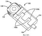
Эта задача настоящего изобретения решена посредством вставочного устройства для вставки протеза межпозвоночного диска, содержащего: соединитель (140) для соединения с отсоединяемым корпусом (130) вставочного инструмента, и протез (104) межпозвоночного диска, удерживаемый вставочным приспособлением (106) с возможностью отпускания, отличающегося тем, что вставочное приспособление (106) разделено по меньшей мере на две части (164), сжатые вокруг по меньшей мере части протеза с возможностью разжатия, так что протез (104) выполнен с возможностью высвобождения путем приведения в действие указанных по меньшей мере двух частей (164) вставочного приспособления (106).This object of the present invention is accomplished by means of an insertion device for inserting an intervertebral disc prosthesis, comprising: a connector (140) for connecting to a detachable insert tool body (130), and an intervertebral disc prosthesis (104) held by an insertion device (106) with a release possibility in that the insertion device (106) is divided into at least two parts (164), compressed around at least part of the prosthesis with the possibility of expansion, so that the prosthesis (104) is made with the possibility of release by activating said at least two parts (164) of the insertion device (106).
Еще в одном варианте выполнения две части (164) вставочного приспособления (106), сжатые вокруг по меньшей мере части протеза с возможностью разжатия, выполнены с возможностью высвобождения этого протеза (104) путем поворота одной из них по отношению к другой.In another embodiment, two parts (164) of the insertion device (106), compressed around at least part of the prosthesis with the possibility of expansion, are made with the possibility of releasing this prosthesis (104) by rotating one of them with respect to the other.
Еще в одном варианте выполнения вставочное приспособление (106) и протез (104) расположены в стерильной упаковке (103а, 103b) с формированием стерильного пакета (102, 202).In yet another embodiment, the insertion device (106) and the prosthesis (104) are located in a sterile package (103a, 103b) with the formation of a sterile package (102, 202).
Еще в одном варианте выполнения вставочное приспособление (106) имеет поверхность (116), взаимодополняющую по отношению к указанному протезу (104) и по существу пригнанную к нему.In yet another embodiment, the insertion device (106) has a surface (116) that is complementary with respect to said prosthesis (104) and substantially fits thereto.
Еще в одном варианте выполнения вставочное приспособление (106) содержит по меньшей мере один фиксатор, который входит в зацепление с выемкой (111, 122) и/или стержнем (124) протеза (104) межпозвоночного диска.In yet another embodiment, the insertion device (106) comprises at least one retainer that engages with a recess (111, 122) and / or the shaft (124) of the intervertebral disc prosthesis (104).
Еще в одном варианте выполнения фиксатор вставочного приспособления (106) представляет собой защелку (123), а выемка (111) расположена на краю (112) пластины (108, 109) протеза (104) межпозвоночного диска.In another embodiment, the latch of the insertion device (106) is a latch (123), and a recess (111) is located on the edge (112) of the plate (108, 109) of the intervertebral disc prosthesis (104).
Еще в одном варианте выполнения фиксатор вставочного приспособления (106) представляет собой собачку (120), а выемка (122) расположена вдоль сердечника (110) протеза (104) межпозвоночного диска.In another embodiment, the latch of the insertion device (106) is a dog (120), and a recess (122) is located along the core (110) of the prosthesis (104) of the intervertebral disc.
Еще в одном варианте выполнения собачка (120) имеет канал, по существу соответствующий краю (112) стержня (124) пластины (108, 109) протеза (104) межпозвоночного диска.In another embodiment, the dog (120) has a channel essentially corresponding to the edge (112) of the shaft (124) of the plate (108, 109) of the intervertebral disc prosthesis (104).
Еще в одном варианте выполнения вставочное устройство дополнительно содержит вставочный инструмент (131).In yet another embodiment, the insertion device further comprises an insertion tool (131).
Еще в одном варианте выполнения вставочный инструмент (131) вставочного устройства содержит отсоединяемый корпус (130), соединенный с соединителем (140) с возможностью отсоединения.In yet another embodiment, the insertion tool (131) of the insertion device comprises a detachable housing (130) that is detachably connected to the connector (140).
Еще в одном варианте выполнения корпус (130) вставочного инструмента (131) содержит вставочный привод (136).In another embodiment, the insert tool body (130) comprises an insert drive (136).
Еще в одном варианте выполнения корпус (130) вставочного инструмента (131) содержит ограничитель (144) вставки.In another embodiment, the insert tool body (130) comprises an insert limiter (144).
Еще в одном варианте выполнения корпус (130) вставочного инструмента (131) содержит фиксатор (146) ограничителя вставки.In yet another embodiment, the insert tool body (130) includes an insert stopper retainer (146).
Еще в одном варианте выполнения фиксатор (146) корпуса (130) вставочного инструмента (131) выполнен с возможностью регулировки.In another embodiment, the latch (146) of the housing (130) of the insert tool (131) is made with the possibility of adjustment.
Еще в одном варианте выполнения протез межпозвоночного диска содержит первую пластину (108), вторую пластину (109) и сердечник (110).In another embodiment, the intervertebral disc prosthesis comprises a first plate (108), a second plate (109) and a core (110).
Еще одна задача настоящего изобретения состоит в преодолении недостатков уровня техники посредством создания вставочных приспособлений для вставочного устройства для вставки протеза межпозвоночного диска, которые просты в использовании и могут быть непосредственно использованы во время хирургических процедур.Another objective of the present invention is to overcome the disadvantages of the prior art by creating insertion devices for an insertion device for inserting an intervertebral disc prosthesis that are easy to use and can be directly used during surgical procedures.
Эта задача решена благодаря созданию вставочного приспособления (106) для вставочного устройства для вставки протеза межпозвоночного диска, содержащего соединитель (140) для отсоединения с отсоединяемым корпусом (130) и протез (104) межпозвоночного диска, удерживаемый вставочным приспособлением (106) с возможностью отпускания, отличающегося тем, что вставочное приспособление (106) разделено по меньшей мере на две части (164), сжатые вокруг по меньшей мере части протеза с возможностью разжатия, так что протез (104) выполнен с возможностью разжатия путем приведения в действие указанных по меньшей мере двух частей (164) вставочного приспособления (106).This problem is solved by creating an insertion device (106) for an insertion device for inserting an intervertebral disc prosthesis containing a connector (140) for disconnecting with a detachable body (130) and an intervertebral disc prosthesis (104) held by the insertion device (106) with the possibility of releasing, characterized in that the insertion device (106) is divided into at least two parts (164), compressed around at least part of the prosthesis with the possibility of expansion, so that the prosthesis (104) is made with the possibility of opening path actuating said at least two parts (164), the insert means (106).
Протез межпозвоночного диска предложен в различных вариантах выполнения. Протез может быть снабжен вставочным приспособлением, например головкой, держателем или другим носителем протеза. Вставочное приспособление может быть выполнено с возможностью удержания протеза и взаимодействия с корпусом вставочного инструмента. В различных вариантах выполнения протез и вставочный держатель расположены в стерильном пакете, причем указанные компоненты и держатель стерилизованы и упакованы по меньшей мере в один слой стерильной упаковки по меньшей мере одного типа. В различных вариантах выполнения протез и вставочный инструмент расположены в стерильном пакете, причем компоненты протеза и вставочный держатель стерилизованы и упакованы по меньшей мере в один слой стерильной упаковки по меньшей мере одного типа. Также раскрыты вставочные устройства для вставки протеза межпозвоночного диска, вставочные системы для вставки протеза межпозвоночного диска, системы для доставки и вставки протеза межпозвоночного диска, способы вставки протеза межпозвоночного диска между смежными элементами позвоночника и способы доставки в стерильных условиях в стерильную зону вставочного устройства для вставки протеза межпозвоночного диска.An intervertebral disc prosthesis is proposed in various embodiments. The prosthesis may be provided with an insertion device, for example a head, holder or other carrier of the prosthesis. The insertion device may be configured to hold the prosthesis and interact with the insert tool body. In various embodiments, the prosthesis and insertion holder are located in a sterile package, wherein said components and holder are sterilized and packaged in at least one layer of a sterile package of at least one type. In various embodiments, the prosthesis and insertion tool are located in a sterile package, wherein the components of the prosthesis and insertion holder are sterilized and packaged in at least one layer of a sterile package of at least one type. Also disclosed are insertion devices for inserting an intervertebral disc prosthesis, insertion systems for inserting an intervertebral disc prosthesis, systems for delivering and inserting an intervertebral disc prosthesis, methods for inserting an intervertebral disc prosthesis between adjacent spinal elements, and methods for delivering under sterile conditions to a sterile area of an insertion device for inserting a prosthesis intervertebral disc.
КРАТКОЕ ОПИСАНИЕ ЧЕРТЕЖЕЙBRIEF DESCRIPTION OF THE DRAWINGS
Другие особенности и преимущества различных вариантов выполнения и различных аспектов настоящего изобретения станут более понятными для специалистов из нижеследующего описания, приведенного со ссылками на приложенные чертежи, на которых:Other features and advantages of various embodiments and various aspects of the present invention will become more apparent to those skilled in the art from the following description, given with reference to the attached drawings, in which:
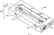
на фиг.1 изображен вариант выполнения стерильного пакета, содержащего вставочное устройство для вставки протеза;figure 1 shows an embodiment of a sterile package containing an insertion device for inserting a prosthesis;
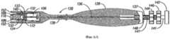
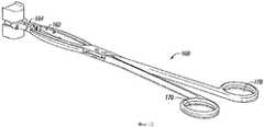
на фиг.2 изображен вариант выполнения вставочного устройства для вставки протеза;figure 2 shows an embodiment of an insertion device for inserting a prosthesis;
на фиг.3 изображены детали варианта выполнения вставочного устройства для вставки протеза;figure 3 shows the details of an embodiment of an insertion device for inserting a prosthesis;
на фиг.4 изображен вариант выполнения корпуса вставочного инструмента;figure 4 shows an embodiment of the housing of the insertion tool;
на фиг.5А и 5b изображены компоненты варианта выполнения корпуса вставочного инструмента и вставочного устройства для вставки протеза;5A and 5b show components of an embodiment of an insert tool body and an insert device for inserting a prosthesis;
на фиг.6А, 6В и 6С изображены различные виды варианта выполнения корпуса вставочного инструмента;6A, 6B and 6C show various views of an embodiment of an insert tool body;
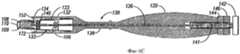
на фиг.7 изображен вариант выполнения вставочного устройства для вставки протеза и опоры корпуса вставочного инструмента;7 shows an embodiment of an insertion device for inserting a prosthesis and a support of an insertion tool body;
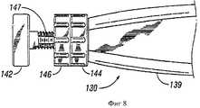
на фиг.8 изображены компоненты и часть варианта выполнения корпуса вставочного инструмента;Fig. 8 shows the components and part of an embodiment of the insert tool body;
на фиг.9 изображен вариант выполнения вставочного устройства для вставки протеза и опоры корпуса вставочного инструмента;Fig. 9 shows an embodiment of an insertion device for inserting a prosthesis and a support of an insertion tool body;
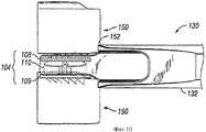
на фиг.10 изображен вариант выполнения вставочного устройства для вставки протеза и опоры корпуса вставочного инструмента;figure 10 shows an embodiment of the insertion device for inserting the prosthesis and the support of the body of the insertion tool;
на фиг.11 изображен вариант выполнения вставочного устройства для вставки протеза и опоры корпуса вставочного инструмента;11 shows an embodiment of an insertion device for inserting a prosthesis and a support of an insertion tool body;
на фиг.12 изображен вариант выполнения извлекающего инструмента;12 shows an embodiment of an extraction tool;
на фиг.13 изображен вариант выполнения вставочного устройства для вставки протеза и извлекающего инструмента;13 shows an embodiment of an insertion device for inserting a prosthesis and an extraction tool;
на фиг.14 изображен вариант выполнения протеза межпозвоночного диска, вставочного приспособления и извлекающего инструмента;on Fig shows an embodiment of the prosthesis of the intervertebral disc, insertion device and extraction tool;
на фиг.15 изображен вариант выполнения области для хранения запаса и места для хранения;on Fig shows an embodiment of the area for storing stock and storage space;
на фиг.16 изображен вариант выполнения места для хранения и информации о конфигурации;on Fig shows an embodiment of a storage space and configuration information;
на фиг.17 изображен вариант выполнения стерильного пакета, содержащего вставочное устройство для вставки протеза;on Fig shows an embodiment of a sterile package containing an insertion device for inserting a prosthesis;
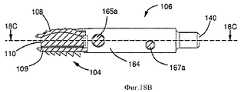
на фиг.18А, 18В и 18С изображены соответственно вид сверху, сечение плоскостью (18В-18В), показанной на фиг.18А, и сечение плоскостью (18С-18С), показанной на фиг.18В, варианта выполнения вставочного устройства для вставки протеза;on figa, 18B and 18C depict, respectively, a top view, a section of the plane (18B-18B) shown in figa, and a section of the plane (18C-18C) shown in figv, an embodiment of the insertion device for inserting the prosthesis;
на фиг.19А и 19В изображены перспективные виды варианта выполнения вставочного устройства для вставки протеза соответственно в собранном и разобранном видах;on figa and 19B depict perspective views of an embodiment of an insertion device for inserting a prosthesis, respectively, in assembled and disassembled views;
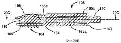
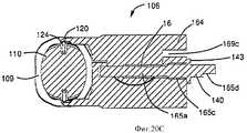
на фиг.20А, 20В и 20С изображены соответственно вид сверху, сечение плоскостью (20В-20В), показанной на фиг.20А, и сечение плоскостью (20С-20С), показанной на фиг.20В, варианта выполнения вставочного устройства для вставки протеза;on figa, 20B and 20C depict, respectively, a top view, a section by the plane (20B-20B) shown in figa, and a section by the plane (20C-20C) shown in fig.20B, an embodiment of an insertion device for inserting a prosthesis;
на фиг.21А и 21В изображены перспективные виды соответственно варианта выполнения вставочного устройства для вставки протеза в разобранном виде и варианта выполнения вставочного приспособления;on figa and 21B depict perspective views, respectively, of an embodiment of an insertion device for inserting a prosthesis in an unassembled form and an embodiment of an insertion device;
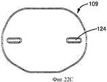
на фиг.22А, 22В и 22С изображены соответственно вид сверху первой пластины протеза межпозвоночного диска, вид сбоку второй пластины протеза межпозвоночного диска и вид сверху второй пластины протеза межпозвоночного диска согласно различным вариантам выполнения;on figa, 22B and 22C respectively shows a top view of the first plate of an intervertebral disc prosthesis, a side view of a second plate of an intervertebral disc prosthesis and a top view of a second plate of an intervertebral disc prosthesis according to various embodiments;
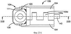
на фиг.23А, 23В и 23С изображены соответственно вид сверху, сечение плоскостью (23В-23В), показанной на фиг.23А, и сечение плоскостью (23С-23С), показанной на фиг.23В, варианта выполнения вставочного устройства для вставки протеза;on figa, 23B and 23C depict, respectively, a top view, a section by the plane (23B-23B) shown in figa, and a section by the plane (23C-23C) shown in fig.23B, an embodiment of an insertion device for inserting a prosthesis;
на фиг.24А и 24В изображены перспективные виды варианта выполнения вставочного устройства для вставки протеза соответственно в собранном и разобранном видах;on figa and 24B depict perspective views of an embodiment of an insertion device for inserting a prosthesis, respectively, in assembled and disassembled views;
на фиг.25А и 25В изображены перспективные виды варианта выполнения вставочного устройства для вставки протеза соответственно в собранном и разобранном видах;on figa and 25B depict perspective views of an embodiment of an insertion device for inserting a prosthesis, respectively, in assembled and disassembled views;
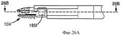
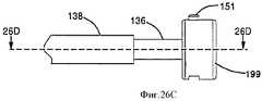
на фиг.26А и 26В изображены соответственно вид сбоку детали части вставочного устройства для вставки протеза, обозначенной номером позиции 26А на фиг.25А, и сечение плоскостью (26В-26В) вставочного устройства для вставки протеза, представленной на фиг.26А; на фиг.26С и 26D изображены соответственно вид сбоку детали части вставочного устройства для вставки протеза, обозначенной номером позиции 26С на фиг.25А, и сечение плоскостью (26D-26D) вставочного устройства для вставки протеза, представленной на фиг.26В.on figa and 26B respectively shows a side view of a detail of a part of the insertion device for inserting the prosthesis, indicated by the
ОСУЩЕСТВЛЕНИЕ ИЗОБРЕТЕНИЯDETAILED DESCRIPTION OF THE INVENTION
В нескольких вариантах выполнения настоящего изобретения вставочное устройство для вставки протеза расположено таким образом, что исключена возможность непосредственного касания протеза во время процедуры вставки. Такое размещение, в частности, предпочтительно тем, что оно ограничивает или предотвращает риск загрязнения протеза во время процедуры вставки. Для облегчения вставки протеза между смежными позвонками и для обеспечения возможности использования хирургом вставочного устройства для вставки протеза без непосредственного контакта с протезом предложены различные варианты выполнения стерильной упаковки или стерильного вставочного устройства для вставки протеза. На фиг.1 изображен один из возможных вариантов выполнения упакованного вставочного устройства (101) для вставки протеза межпозвоночного диска. В этом варианте выполнения стерильное вставочное приспособление (106) и стерильные компоненты протеза (104) межпозвоночного диска могут быть собраны с формированием стерильного вставочного устройства (100) для вставки протеза, показанной на фиг.2 и расположенной в первичной, или внутренней, стерильной упаковке (103а) и во вторичной, или внешней, стерильной упаковке (103b) с формированием стерильного пакета (102). Компоненты протеза (104) могут быть собраны с приспособлением (106) и доставлены в стерильную зону операционной, будучи предварительно сконфигурированы и готовы к использованию. Следует отметить, что конструкции упаковок (103а) и (103b), формирующих стерильные пакеты (102, 202), произвольны, и что настоящее изобретение может быть использовано с другими конструкциями упаковки, например стерильным пакетом (102, 202), содержащим только один слой, два слоя, как в вышеупомянутом примере, при допущении, что первичная и вторичная упаковки представляют собой слои, или более двух слоев, причем слои могут отличаться друг от друга. В такую упаковку могут быть упакованы различные компоненты, формирующие нижеописанные устройства в собранном или разобранном виде, причем предпочтительно по меньшей мере все компоненты протеза собраны, например соединены с приспособлением, например удерживаемы вставочным инструментом. Стерильный пакет с такими конструкциями доставляют в стерильную зону для имплантации пациенту без касания компонентов протеза во время вставки, таким образом ограничивая риск загрязнения.In several embodiments of the present invention, the insertion device for inserting the prosthesis is positioned so that it is not possible to directly touch the prosthesis during the insertion procedure. Such placement is particularly advantageous in that it limits or prevents the risk of contamination of the prosthesis during the insertion procedure. To facilitate insertion of the prosthesis between adjacent vertebrae and to allow the surgeon to use an insertion device to insert the prosthesis without direct contact with the prosthesis, various embodiments of sterile packaging or a sterile insertion device for inserting the prosthesis are proposed. Figure 1 shows one possible embodiment of a packaged insertion device (101) for inserting an intervertebral disc prosthesis. In this embodiment, a sterile insertion device (106) and sterile components of an intervertebral disc prosthesis (104) can be assembled to form a sterile insertion device (100) for inserting the prosthesis shown in FIG. 2 and located in a primary or internal sterile package ( 103a) and in a secondary, or external, sterile package (103b) with the formation of a sterile package (102). The components of the prosthesis (104) can be assembled with the device (106) and delivered to the sterile area of the operating room, being pre-configured and ready for use. It should be noted that the designs of the packages (103a) and (103b) forming the sterile bags (102, 202) are arbitrary, and that the present invention can be used with other packaging designs, for example, a sterile package (102, 202) containing only one layer , two layers, as in the above example, assuming that the primary and secondary packaging are layers, or more than two layers, the layers may be different from each other. Various components can be packed in such a package, forming the devices described below in assembled or disassembled form, preferably at least all components of the prosthesis are assembled, for example, connected to a device, for example, held by an insertion tool. A sterile bag with such designs is delivered to the sterile area for implantation to the patient without touching the prosthesis components during insertion, thereby limiting the risk of contamination.
На фиг.2 изображен один из потенциальных вариантов выполнения устройства (100). Различные варианты выполнения устройства (100) могут содержать протез (104) и приспособление (106), удерживающее протез (104) и соединенное, или связанное, или сцепленное другим способом со съемным или отсоединяемым корпусом (130) хирургического инструмента, который, например, проиллюстрирован на фиг.4 и который используют при имплантировании протеза (104). Протез (104) может быть типа, производимого LDR Medical и описанного здесь, или в патентах Франции №№2824261, 2846550, 2865629, 2869528, 2879436, соответствующих заявкам WO 02/089701, WO 04/041129, WO 2005/074839, WO 2005/104996 и WO 2006/120505 соответственно, или в заявках на патенты Франции №№2891135 и 2893838, соответствующих заявкам WO 2007/034310 и WO 2007/063398 соответственно, поданных Заявителем настоящей заявки или соответствующих заявок на патенты США, переуступленных патентообладателю настоящей заявки. Такой протез может содержать, например, по меньшей мере первую пластину, вторую пластину, подвижный сердечник, выполненный с возможностью вращения и/или поступательного движения по отношению по меньшей мере к одной из пластин, и средства взаимодействия сердечника по меньшей мере с одной из пластин для ограничения или предотвращения его перемещения по отношению по меньшей мере к одной из пластин. Настоящее изобретение также может содержать протез другого типа, например который известен из уровня техники и может включать различные средства, необходимые для его использования в устройстве, как описано ниже. В варианте выполнения, изображенном на фиг.4, зажим (126), например представленный на фиг.3, обеспечивает дополнительное крепление к компонентам протеза (104).Figure 2 shows one of the potential embodiments of the device (100). Various embodiments of the device (100) may include a prosthesis (104) and a device (106) holding the prosthesis (104) and connected, or connected, or otherwise engaged with a removable or detachable case (130) of a surgical instrument, which, for example, is illustrated figure 4 and which is used when implanting a prosthesis (104). The prosthesis (104) may be of the type manufactured by LDR Medical and described herein, or in French patents Nos. 2824261, 2846550, 2865629, 2869528, 2879436 corresponding to WO 02/089701, WO 04/041129, WO 2005/074839, WO 2005 / 104996 and WO 2006/120505, respectively, or in French patent applications Nos. 2891135 and 2893838, corresponding to WO 2007/034310 and WO 2007/063398, respectively, filed by the Applicant of this application or the corresponding applications for US patents assigned to the patent holder of this application. Such a prosthesis may comprise, for example, at least a first plate, a second plate, a movable core configured to rotate and / or translate with respect to at least one of the plates, and means for interacting the core with at least one of the plates for limiting or preventing its movement in relation to at least one of the plates. The present invention may also contain another type of prosthesis, for example, which is known in the art and may include various means necessary for its use in the device, as described below. In the embodiment shown in FIG. 4, a clamp (126), such as that shown in FIG. 3, provides additional attachment to the components of the prosthesis (104).
На фиг.3 изображен покомпонентный вид варианта выполнения протеза (104) и приспособления (106). Протез (104) в этом варианте выполнения содержит первую пластину, такую как верхняя пластина (108), вторую пластину, такую как нижняя пластина (109), и подвижный сердечник (110). Конструкции "верхней" и "нижней" пластин, как правило, взаимозаменяемы, и обозначение пластин как "первая пластина" и "вторая пластина" или как "верхняя пластина" и "нижняя пластина", разумеется, носит исключительно произвольный характер. Пластины (108, 109) предпочтительно могут быть выполнены из хрома, кобальта и молибдена, но также могут быть использованы другие материалы. В различных предпочтительных вариантах выполнения сердечник может быть выполнен из полиэтилена с ультравысоким молекулярным весом, но также могут быть использованы другие материалы. При необходимости на контактные поверхности пластин (108, 109) с позвонками могут быть нанесены титан и гидроксиапатитовое покрытие, нанесенное плазменным напылением для облегчения по меньшей мере частичного сращения со смежными позвонками посредством костного врастания или других форм связи. Протез (104) в различных вариантах выполнения может содержать другие признаки. Например, пластина (109) может быть снабжена ограничителями движения сердечника, например стержнями (124), которые показаны на чертеже и которые ограничивают поступательное и вращательное движение сердечника (110). В таких вариантах выполнения может быть обеспечен контакт между ограничителями (124) и выемками (122) вдоль периметра корпуса сердечника для ограничения поступательного и вращательного движения сердечника (110). При необходимости пластины (108, 109) могут иметь изогнутые под углом края (115), выполненные с возможностью взаимодополняющего контакта с необязательными изогнутыми под углом контактными поверхностями (116) приспособления (106), преимущества которого более подробно описаны ниже.Figure 3 shows an exploded view of an embodiment of the prosthesis (104) and device (106). The prosthesis (104) in this embodiment comprises a first plate, such as an upper plate (108), a second plate, such as a lower plate (109), and a movable core (110). The constructions of the “upper” and “lower” plates are generally interchangeable, and the designation of the plates as “first plate” and “second plate” or as “upper plate” and “lower plate” is, of course, exclusively arbitrary. The plates (108, 109) can preferably be made of chromium, cobalt and molybdenum, but other materials can also be used. In various preferred embodiments, the core may be made of ultra-high molecular weight polyethylene, but other materials may also be used. If necessary, titanium and a hydroxyapatite coating deposited by plasma spraying can be applied to the contact surfaces of the vertebral plates (108, 109) to facilitate at least partial adhesion to adjacent vertebrae by means of bone ingrowth or other forms of communication. The prosthesis (104) in various embodiments may contain other features. For example, the plate (109) can be equipped with limiters of movement of the core, for example, rods (124), which are shown in the drawing and which limit the translational and rotational movement of the core (110). In such embodiments, contact may be made between the stops (124) and the recesses (122) along the perimeter of the core body to limit the translational and rotational movement of the core (110). If necessary, the plates (108, 109) can have angled edges (115) configured to complement each other with optional angled contact surfaces (116) of the tool (106), the advantages of which are described in more detail below.
Дополнительные необязательные особенности протеза (104) могут облегчить его имплантацию и стабильность после имплантации. Например, по меньшей мере один край протеза (104), который входит в контакт с поверхностями позвонков (150) во время вставки протеза, может быть скошен, например края (112) пластин (108) и (109), в результате чего может быть уменьшено усилие, необходимое для вставки протеза (104). Другие варианты выполнения могут не содержать такого скоса или могут быть скошены только в нескольких ключевых местах по периметру пластин (108, 109). Различные варианты выполнения также могут содержать гребенки (114), которые, например, могут содержать насечки или зубцы, расположенные по меньшей мере на одной из пластин (108, 109) в области по меньшей мере одного края протеза (104), или по меньшей мере одна гребенка может быть расположена в другом месте вдоль по меньшей мере одной контактной поверхности пластин (108, 109) с позвонками. Гребенки (114) могут быть выполнены таким образом, что они минимизируют силу, необходимую при имплантации протеза (104), и предотвращают последующее движение протеза. После того как протез (104) имплантирован, гребенки (114) предпочтительно стабилизируют его и препятствуют его перемещению по отношению к позвонкам (150) различными способами. Например, гребенки (114) могут иметь зубцы, расположенные между протезом (104) и позвонками (150) и препятствующие перемещению прежде всего в направлении извлечения, таким образом способствуя удержанию протеза (104) на месте после имплантации и во время отвода приспособления (106). Поверхности пластин (108, 109) также могут иметь пористое биологически совместимое покрытие, например описанное выше, которое также обеспечивает связь с костной тканью и ее сращение с протезом. После связи костной ткани с пластинами (108, 109) и ее обрастания вокруг гребенок (114) между каждой из пластин (108, 109) протеза (104) и соответствующим смежным позвонком (150) может быть сформировано прочное соединение. В других вариантах выполнения пористое биологически совместимое покрытие может быть заменено или дополнено пористым биоактивным покрытием, которое может стимулировать формирование костной ткани, и/или антисептическим покрытием, которое может препятствовать или противодействовать инфекции на поверхности импланта.Additional optional features of the prosthesis (104) may facilitate its implantation and stability after implantation. For example, at least one edge of the prosthesis (104) that comes into contact with the surfaces of the vertebrae (150) during insertion of the prosthesis can be chamfered, for example, the edges (112) of the plates (108) and (109), which can result in reduced force required to insert the prosthesis (104). Other embodiments may not contain such a bevel or may be chamfered only in a few key places along the perimeter of the plates (108, 109). Various embodiments may also include combs (114), which, for example, may include notches or teeth located on at least one of the plates (108, 109) in the region of at least one edge of the prosthesis (104), or at least one comb may be located elsewhere along at least one contact surface of the vertebral plates (108, 109). The combs (114) can be made in such a way that they minimize the force required for implantation of the prosthesis (104) and prevent subsequent movement of the prosthesis. After the prosthesis (104) is implanted, the combs (114) preferably stabilize it and prevent it from moving in relation to the vertebrae (150) in various ways. For example, combs (114) may have teeth located between the prosthesis (104) and vertebrae (150) and preventing movement primarily in the direction of extraction, thereby helping to keep the prosthesis (104) in place after implantation and during retraction of the device (106) . The surfaces of the plates (108, 109) can also have a porous biocompatible coating, for example, described above, which also provides connection with the bone tissue and its fusion with the prosthesis. After bonding the bone tissue to the plates (108, 109) and its fouling around the combs (114), a strong joint can be formed between each of the plates (108, 109) of the prosthesis (104) and the corresponding adjacent vertebra (150). In other embodiments, the porous biocompatible coating can be replaced or supplemented with a porous bioactive coating that can stimulate bone formation and / or an antiseptic coating that can prevent or counteract infection on the surface of the implant.
После полной или частичной дискэктомии и дистракции смежных элементов позвоночника, например позвонков (150), хирургические процедуры по имплантации протеза могут включать измерения пространства для межпозвоночного диска. Эти измерения могут быть использованы для определения размеров и конфигурации верхней и нижней пластин (108) и (109) и подвижного сердечника (110), предназначенных для имплантации. В различных вариантах выполнения протез (104) обычно может быть выполнен с возможностью коррекции различных типов нарушений позвоночника, включая лордоз и кифоз. Коррекция лордоза или кифоза может включать установление угла, например от 0 до 15 градусов, между пластинами (108) и (109) в заднепереднем направлении. Пластина (108), пластина (109) или сердечник (110) могут быть сконфигурированы для установления такого угла, например, как описано в патенте Франции №2824261, переуступленном патентообладателю настоящей заявки. Такой угол может быть установлен между верхней пластиной и нижней пластиной благодаря сердечнику или ядру, верхняя и нижняя поверхности которого установлены под углом (одна поверхность сердечника наклонена по отношению к другой) или посредством того, что верхняя и нижняя поверхности по меньшей мере одной из пластин установлены под углом (одна поверхность по меньшей мере одной из пластин наклонена по отношению к другой поверхности этой пластины). Кроме того, пластины (108, 109) и сердечник (110) обычно имеют размеры и конфигурацию, выбранные для конкретного пациента, которому будет имплантирован протез (104). На практике размеры и конфигурация протеза (104) нередко неизвестны до проведения значительной части хирургической процедуры. Соответственно, в случае любого конкретного пациента хирургический персонал нуждается в наличии подбора конфигураций вставочных устройств для вставки протеза.After complete or partial discectomy and distraction of adjacent elements of the spine, such as vertebrae (150), surgical procedures for implanting a prosthesis may include space measurements for the intervertebral disc. These measurements can be used to determine the size and configuration of the upper and lower plates (108) and (109) and the movable core (110) intended for implantation. In various embodiments, the prosthesis (104) can usually be configured to correct various types of spinal disorders, including lordosis and kyphosis. Correction of lordosis or kyphosis may include setting the angle, for example, from 0 to 15 degrees, between the plates (108) and (109) in the rear-front direction. The plate (108), the plate (109) or the core (110) can be configured to establish such an angle, for example, as described in French patent No. 2824261, assigned to the patent holder of this application. Such an angle can be established between the upper plate and the lower plate due to the core or core, the upper and lower surfaces of which are installed at an angle (one surface of the core is inclined with respect to the other) or by means of the fact that the upper and lower surfaces of at least one of the plates are installed at an angle (one surface of at least one of the plates is inclined with respect to the other surface of this plate). In addition, the plates (108, 109) and the core (110) usually have the sizes and configurations selected for the particular patient to whom the prosthesis will be implanted (104). In practice, the dimensions and configuration of the prosthesis (104) are often unknown before a significant part of the surgical procedure. Accordingly, in the case of any particular patient, the surgical staff needs to have the configuration of insertion devices for inserting the prosthesis.
В различных вариантах выполнения пластины (108, 109) и сердечник (110) протеза (104) могут быть удерживаемы приспособлением (106) или соединены с ним с возможностью отсоединения. Приспособление (106) может быть выполнено различными способами, например в форме головки, держателя или другого носителя собранного протеза (104). При необходимости приспособление (106) может иметь зажимные губки (121), которые удерживают протез посредством захвата или зажима боковых краев верхней и нижней пластин протеза. Приспособление (106) также может содержать по меньшей мере один необязательный фиксатор, например собачку (120). Собачки (120) могут быть зацеплены за соответствующую выемку (122), расположенную в подвижном сердечнике (110), и входить в контакт с соответствующим стержнем (124), расположенным на пластине (109), или захватывать его. Собачки (120) могут иметь поверхности, по существу соответствующие зазору и/или конфигурации наружных поверхностей выемок (122). По меньшей мере одна собачка (120) может быть снабжена каналом, по существу соответствующим краю одного из соответственных стержней (124) для увеличения эффективности захвата на пластине (109). Кроме того, при необходимости приспособление (106) может содержать дополнительные фиксирующие, захватные или крепежные средства, например проиллюстрированные защелки (123), которые расположены на зажимных губках (121) и которые могут быть сцеплены с взаимодополняющими фиксирующими, захватными или крепежными средствами, например приемником, выемкой, насечкой и т.д., например выемками (111), расположенными вдоль противоположных боковых краев пластины (108). Например, на фиг.22А показан пример выемки (111), обеспечивающей удержание пластины (108) приспособлением (106, не показано на этом чертеже), например благодаря защелкам (123), а на фиг.22В показан пример стержня (124) (ствола, бруса, штыря или столбика) пластины (109), обеспечивающего удержание этой пластины и содержащего заплечик (12), предназначенный для взаимодействия с собачками (120) приспособления (106) для поддержки протеза и предотвращения выпадения протеза при его удержании приспособлением (106), например типа, подробно описанного ниже со ссылками на фиг.18 (А-С). При ознакомлении с настоящим описанием следует понимать, что могут быть предусмотрены различные варианты выполнения держателя и приспособления с дополнительным зажимом (126) для удержания протеза или без него.In various embodiments, the plates (108, 109) and the core (110) of the prosthesis (104) can be held by the device (106) or can be disconnected with it. The device (106) can be performed in various ways, for example, in the form of a head, holder or other carrier of an assembled prosthesis (104). If necessary, the device (106) may have clamping jaws (121) that hold the prosthesis by gripping or clamping the side edges of the upper and lower plates of the prosthesis. The device (106) may also contain at least one optional latch, for example a dog (120). Dogs (120) can be hooked to a corresponding recess (122) located in the movable core (110) and come into contact with or capture a corresponding rod (124) located on the plate (109). Dogs (120) may have surfaces substantially corresponding to the clearance and / or configuration of the outer surfaces of the recesses (122). At least one dog (120) may be provided with a channel essentially corresponding to the edge of one of the respective rods (124) to increase the capture efficiency on the plate (109). In addition, if necessary, the device (106) may include additional fixing, gripping or fixing means, for example illustrated latches (123), which are located on the clamping jaws (121) and which can be coupled with complementary fixing, gripping or fixing means, for example, a receiver a recess, a notch, etc., for example, recesses (111) located along opposite lateral edges of the plate (108). For example, FIG. 22A shows an example of a recess (111) for holding the plate (108) by a fixture (106, not shown), for example by means of latches (123), and FIG. 22B shows an example of a rod (124) (barrel) , a bar, a pin or a column) of a plate (109) that provides retention of this plate and contains a shoulder (12) designed to interact with the dogs (120) of the device (106) to support the prosthesis and prevent the prosthesis from falling out while holding it by the device (106), for example of the type described in detail below with reference to FIG. .18 (A-C). When reading the present description, it should be understood that various embodiments of the holder and the device may be provided with an additional clip (126) for holding the prosthesis or without it.
В различных вариантах выполнения приспособление (106) также может содержать изогнутые под углом контактные поверхности (116), выполненные с возможностью взаимодополняющего контакта с необязательными изогнутыми под углом краями (115) пластин (108, 109) протеза. Необязательный заплечик (118) может быть выполнен с возможностью взаимодополняющего контакта с периметром сердечника (110). Общая высота поверхностей (116) и заплечика (118) предпочтительно может быть по существу равной расстоянию между пластинами (108, 109) собранного протеза (104). Таким образом, в различных вариантах выполнения поверхности (116) и заплечик (118) могут быть объединены для образования поверхности приспособления (106), взаимодополняющей по отношению к протезу (104) и по существу пригнанной к нему, когда протез (104) собран с приспособлением (106), или соединен с ним, или прикреплен к нему. Взаимодополняющая пригонка между изогнутыми под углом конструкциями, такая как эта, может способствовать стабилизации протеза (104) и равномерному вжиманию его компонентов в пространство для межпозвоночного диска с предотвращением нежелательного вращательного или поступательного движения протеза (104) или его компонентов во время вставки.In various embodiments, the device (106) may also include angled contact surfaces (116) configured to complement each other with optional angled edges (115) of the prosthesis plates (108, 109). An optional shoulder (118) may be configured to complement each other with the core perimeter (110). The total height of the surfaces (116) and the shoulder (118) can preferably be substantially equal to the distance between the plates (108, 109) of the assembled prosthesis (104). Thus, in various embodiments, the surface (116) and the shoulder (118) can be combined to form the surface of the device (106), complementary to the prosthesis (104) and essentially fitted to it when the prosthesis (104) is assembled with the device (106), or connected to it, or attached to it. A complementary fit between angled constructions, such as this one, can help stabilize the prosthesis (104) and evenly squeeze its components into the intervertebral disc space while preventing unwanted rotational or translational movement of the prosthesis (104) or its components during insertion.
Различные варианты выполнения могут включать любые или все конструкции, описанные выше, но также могут содержать другие крепежные и опорные механизмы. Например, при необходимости некоторые варианты выполнения могут иметь дополнительные соединительные точки, например, в пластине (108), пластине (109) или в обеих пластинах. Другие варианты выполнения могут содержать фиксаторы, например штифты или зажимы, которые входят по меньшей мере в одну полость или выемку в различных компонентах протеза, или применять по меньшей мере один из множества других способов, которые могут быть использованы для захвата объектов и могут обеспечивать их удобное высвобождение, когда требуется.Various embodiments may include any or all of the structures described above, but may also include other mounting and support mechanisms. For example, if necessary, some embodiments may have additional connecting points, for example, in a plate (108), a plate (109), or in both plates. Other embodiments may include latches, for example pins or clamps, which fit into at least one cavity or recess in various components of the prosthesis, or use at least one of many other methods that can be used to capture objects and can provide them convenient release when required.
В различных вариантах выполнения приспособление (106) может иметь приводящие средства для высвобождения протеза (104). В различных вариантах выполнения привод может быть выполнен в виде подпружиненных рычагов, хвостовиков, стержней или других приводящих средств (164), выполненных с возможностью поворота вокруг поворотных средств, например шарнирного пальца (172). В другом случае приспособление (106) может содержать встроенную шарнирную часть, вокруг которой обеспечена возможность поворота рычагов, хвостовиков, стержней или других приводящих средств (164) и которая, например, содержит гибкий материал, такой как пластик или резина, или имеет признаки, обеспечивающие уменьшение напряжения и/или деформации, например вырезы или пустоты.In various embodiments, the device (106) may have a drive means for releasing the prosthesis (104). In various embodiments, the actuator can be made in the form of spring-loaded levers, shanks, rods, or other driving means (164), configured to rotate around rotary means, for example, a pivot pin (172). In another case, the device (106) may include an integrated hinge part around which it is possible to turn levers, shanks, rods or other driving means (164) and which, for example, contains flexible material, such as plastic or rubber, or has signs that provide reduction of stress and / or deformation, for example cutouts or voids.
В некоторых вариантах выполнения настоящего изобретения приспособление (106) может содержать корпус, разделенный по меньшей мере на две части (164), взаимодополняющие по отношению друг к другу и собранные таким образом, что они удерживают по меньшей мере часть протеза (104) по меньшей мере на конце приспособления (106), содержащего собачки (120) или защелки (123). Эти собачки или защелки (120, 123) в некоторых вариантах выполнения могут быть сформированы ответвлениями, продолжающими боковую поверхность каждой из частей (164) корпуса приспособления. Термин "собачки" не следует трактовать в ограничительном смысле, поскольку такое расположение может быть обеспечено ответвлениями, имеющими форму, приспособленную для удержания протеза на конце ответвления, как подробно описано ниже. Предпочтительно в этих вариантах выполнения приспособление (106) разделено вдоль своей продольной оси, то есть оси вставки протеза, таким образом, что 2 части его корпуса окружают протез и удерживают его за наружные боковые поверхности. Таким образом, в этих вариантах выполнения приводящие средства (164) приспособления (106) сформированы сборкой 2-х частей корпуса, например, с помощью штифта (165а), проникающего в канал (165е) или отверстие, например, просверленное и проходящее по меньшей мере частично через каждую часть (264) корпуса приспособления (106). На фиг.18 (А-С), 19 (А и В), 20 (А-С), 21 (А и В), 23 (А-С) и 24 (А и В) показаны несколько иллюстративных, но не ограничивающих примеров возможных вариантов выполнения, а на фиг.25 (А и В) и 26 (A-D) показаны примеры вариантов выполнения стерильного вставочного инструмента (131), в частности, подходящего для этих вариантов выполнения приспособления (106). В этих вариантах выполнения приведение в действие приспособления (106) для высвобождения протеза (104) осуществляют путем отвода штифта (165а) и разбора двух частей (164) корпуса приспособления (106), формирующих приводящие средства (164), как подробно описано ниже. Приспособление (106) согласно этим вариантам выполнения также может быть предварительно собрано с протезом (104) и расположено в стерильной упаковке с ним и далее со стерильным инструментом (131).In some embodiments of the present invention, the device (106) may include a body divided into at least two parts (164), complementary to each other and assembled so that they hold at least part of the prosthesis (104) at least at the end of the fixture (106) containing the dogs (120) or latches (123). These dogs or latches (120, 123) in some embodiments may be formed by branches extending the lateral surface of each of the parts (164) of the device body. The term “dogs” should not be construed in a limiting sense, since such an arrangement can be provided by branches having a shape adapted to hold the prosthesis at the end of the branch, as described in detail below. Preferably, in these embodiments, the device (106) is divided along its longitudinal axis, that is, the axis of insertion of the prosthesis, so that 2 parts of its body surround the prosthesis and hold it by the outer side surfaces. Thus, in these embodiments, the driving means (164) of the device (106) are formed by assembling 2 parts of the housing, for example, by means of a pin (165a) penetrating into the channel (165e) or a hole, for example, drilled and passing at least partially through each part (264) of the tool body (106). On Fig (A-C), 19 (A and B), 20 (A-C), 21 (A and B), 23 (A-C) and 24 (A and B) are shown several illustrative, but not limiting examples of possible embodiments, and FIGS. 25 (A and B) and 26 (AD) show examples of embodiments of a sterile insertion tool (131), in particular suitable for these embodiments of the device (106). In these embodiments, the actuation of the device (106) for releasing the prosthesis (104) is carried out by removing the pin (165a) and disassembling the two parts (164) of the body of the device (106) forming the driving means (164), as described in detail below. The device (106) according to these embodiments can also be pre-assembled with a prosthesis (104) and placed in a sterile package with it and then with a sterile instrument (131).
На фиг.18А показан вариант выполнения приспособления (106), удерживающего протез (104) в частности благодаря взаимодействию между защелками (123) приспособления и выемками (111) пластины (108) протеза (104), формирующими механизм для фиксирования протеза (104) на приспособлении (106). В этом примере, показанном на фиг.18 (А-С), две части (164) корпуса приспособления (106) имеют по существу форму параллелепипеда, за исключением конца, снабженного собачками и защелками для удержания протеза. Таким образом, две части (164) корпуса, разделенного вдоль своей продольной оси, собраны вокруг протеза и взаимодействуют в этом примере через по существу плоскую поверхность. Две части (164) корпуса приспособления (106) снабжены соединителем (140), обеспечивающим установку приспособления (106) на инструменте (131, например, фиг.25А и 25В). Следует отметить, что могут быть предусмотрены несколько вариантов выполнения приспособления, содержащего только один соединитель только на одной из двух частей своего корпуса. В показанном примере этот соединитель (140) содержит стержень, предназначенный для взаимодействия с приводом (136, фиг.25В), например стержень, снабженный резьбовым отверстием (134) для его навинчивания на соединитель (140). Следует отметить, что конструкция, содержащая стержень (резьбовой стержень) соединителя (140) и отверстие (134, фиг.26В) привода (136) инструмента (131), разумеется, может быть взаимообратной или может быть заменена другими средствами соединения, удержания, фиксирования приспособления (106) и инструмента (131). Таким образом, например, соединитель приспособления может содержать резьбовое отверстие (140), взаимодействующее с резьбовым концом (134) привода (136) вставочного инструмента. В других вариантах выполнения соединитель (140) может содержать стержень, имеющий срез (165d), предназначенный для взаимодействия с проходом, содержащим заплечик, на конце привода (136, фиг.25В). В других вариантах выполнения соединитель (140) может содержать стержень, имеющий резьбу и срез (165d), так что приспособлением (106) и/или штифтом (165а), в случае если он удерживает соединитель (140), как подробно описано ниже, можно манипулировать как с помощью инструмента, содержащего заплечик, взаимодействующий со срезом, так и с помощью инструмента, содержащего резьбовое отверстие. Кроме того, другие предусмотренные варианты выполнения содержат соединитель, имеющий резьбовое отверстие, в нижней части которого расположен заплечик, причем таким образом этот соединитель может взаимодействовать как с резьбовым концом (134) привода (136, фиг.25В), так и с инструментом, содержащим стержень со срезом на конце. На фиг.18В представлено сечение такого варианта выполнения с изогнутыми под углом краями (115) пластин (108, 109) протеза, упираемыми в изогнутые под углом поверхности или края приспособления (106). В некоторых вариантах выполнения (не показаны) приспособление (106) также содержит заплечик или поверхность для контакта с сердечником (110) для поддержания различных компонентов (108, 109, 110) протеза в положении, подходящем для их вставки между позвонками. Как, в частности, видно на фиг.18С, сборка двух частей (164) корпуса приспособления (106) выполнена в этом примере с помощью по меньшей мере одного штифта (165а), проходящего в поперечном направлении через приспособление (106), от одного бока до другого, в горизонтальной плоскости. В этом примере штифт (165а) снабжен резьбовым концом (165с), обеспечивающим его ввинчивание в резьбовое отверстие стяжки или любого другого средства сборки. Свинчивание штифта (165а) и стяжки (165b) обеспечивает удержание вместе двух частей (164) корпуса приспособления, которые удерживают (окружают) компоненты протеза, в частности, посредством собачек (120), взаимодействующих со стержнем (124) пластины (109) протеза и далее посредством защелок или собачек (123), взаимодействующих с выемками (111), упомянутыми выше. В примере, проиллюстрированном на фиг.18С, сборка двух частей (164) корпуса приспособления (106) усилена стержнем (167а), выступающим из одной части (164) и входящим в отверстие (167b, фиг.19b) в другой части. Однако, это усиление (167а, 167b) сборки не имеет решающего значения, и некоторые варианты выполнения содержат только штифт (165а). Как, в частности, видно на фиг.19В, штифт (165а) в некоторых вариантах выполнения может содержать ограничитель (165f), взаимодействующий с корпусом (165g) взаимодополняющей формы и расположенный в одной из двух частей (164) корпуса приспособления (106) таким образом, что он препятствует вращению штифта (165а) во время винчения стяжки (165b). Таким образом, сборка приспособления может быть выполнена простой вставкой штифта (165а) в отверстие (165е), проходящее через две части (164) корпуса, и навинчиванием резьбового отверстия (165с) стяжки (165b) на резьбовой конец (165с) штифта (165а). Следует отметить, что термин "стяжка" использован здесь для обозначения компонента, который может быть навинчен на резьбовой стержень, но может быть использована любая аналогичная конструкция, например показанная на фиг.19В и содержащая шлиц, обеспечивающий винчение отверткой. Кроме того, вместо стяжки может быть использовано резьбовое отверстие, расположенное непосредственно в одной из двух частей (164) и обеспечивающее винчение резьбового штифта (165а) без необходимости использования других конструкций. Аналогично резьбовая конструкция может быть взаимообратной или может быть заменена любым другим средством фиксации штифта. Следует отметить, что в примере, показанном на фиг.19В, собачки (123, 120), предназначенные для удержания пластин, снабжены заплечиком, формирующим горизонтальную поверхность, поддерживающую каждую пластину таким образом, что протез может быть удержан без необходимости оказания слишком сильного давления на выемки (111) и стержни (124) пластин.On figa shows an embodiment of the device (106) holding the prosthesis (104), in particular due to the interaction between the latches (123) of the device and the recesses (111) of the plate (108) of the prosthesis (104), forming a mechanism for fixing the prosthesis (104) on adaptation (106). In this example, shown in Fig. 18 (A-C), the two parts (164) of the body of the device (106) are essentially parallelepiped-shaped, with the exception of the end provided with pawls and latches for holding the prosthesis. Thus, the two parts (164) of the body, separated along its longitudinal axis, are assembled around the prosthesis and in this example interact through a substantially flat surface. Two parts (164) of the tool body (106) are equipped with a connector (140), which enables the device (106) to be installed on the tool (131, for example, FIGS. 25A and 25B). It should be noted that several embodiments of the device may be provided, containing only one connector on only one of the two parts of its housing. In the example shown, this connector (140) contains a rod designed to interact with the drive (136, Fig. 25B), for example, a rod provided with a threaded hole (134) for screwing onto the connector (140). It should be noted that the structure containing the rod (threaded rod) of the connector (140) and the hole (134, Fig.26B) of the drive (136) of the tool (131), of course, can be reciprocal or can be replaced by other means of connection, retention, fixing fixtures (106) and tools (131). Thus, for example, the fixture connector may comprise a threaded hole (140) cooperating with the threaded end (134) of the insert tool drive (136). In other embodiments, the connector (140) may include a rod having a slice (165d), designed to interact with the passage containing the shoulder, at the end of the drive (136, Fig.25B). In other embodiments, the connector (140) may include a rod having a thread and a shear (165d), so that the device (106) and / or the pin (165a), if it holds the connector (140), as described in detail below, can to manipulate both with the help of a tool containing a shoulder interacting with a slice, and with a tool containing a threaded hole. In addition, other embodiments provided include a connector having a threaded hole in the lower part of which is located a shoulder, and thus this connector can interact with both the threaded end (134) of the actuator (136, Fig. 25B), and with a tool containing rod with a cut at the end. On figv presents a cross-section of such an embodiment with curved at an angle edges (115) of the plates (108, 109) of the prosthesis, abutting against an angled surface or the edges of the device (106). In some embodiments (not shown), the device (106) also comprises a shoulder or surface for contact with the core (110) to maintain the various components (108, 109, 110) of the prosthesis in a position suitable for insertion between the vertebrae. As, in particular, it is seen in FIG. 18C, the assembly of two parts (164) of the housing of the device (106) is made in this example with at least one pin (165a) extending laterally through the device (106) from one side to another, in a horizontal plane. In this example, the pin (165a) is provided with a threaded end (165c), allowing it to be screwed into the threaded hole of the coupler or any other assembly means. The screwing of the pin (165a) and the coupler (165b) ensures that the two parts (164) of the device body that hold (surround) the prosthesis components are held together, in particular by means of dogs (120) interacting with the shaft (124) of the prosthesis plate (109) and further by means of latches or pawls (123) interacting with the recesses (111) mentioned above. In the example illustrated in FIG. 18C, the assembly of the two parts (164) of the fixture body (106) is reinforced with a rod (167a) protruding from one part (164) and entering the hole (167b, FIG. 19b) in the other part. However, this reinforcement (167a, 167b) of the assembly is not critical, and some embodiments contain only a pin (165a). As, in particular, it is seen in FIG. 19B, the pin (165a) in some embodiments may comprise a stop (165f) interacting with the housing (165g) of complementary shape and located in one of the two parts (164) of the device body (106) so so that it prevents the pin (165a) from rotating during the screwing of the coupler (165b). Thus, the assembly of the device can be accomplished by simply inserting the pin (165a) into the hole (165e) passing through the two parts (164) of the housing and screwing the threaded hole (165c) of the tie (165b) onto the threaded end (165c) of the pin (165a) . It should be noted that the term “coupler” is used here to refer to a component that can be screwed onto a threaded rod, but any similar construction can be used, such as shown in FIG. 19B, and containing a slot for screwing with a screwdriver. In addition, instead of a screed, a threaded hole located directly in one of the two parts (164) can be used to provide screwing of the threaded pin (165a) without the need for other designs. Similarly, the threaded structure may be reciprocal or may be replaced by any other means of fixing the pin. It should be noted that in the example shown in FIG. 19B, the dogs (123, 120) designed to hold the plates are provided with a shoulder that forms a horizontal surface supporting each plate so that the prosthesis can be held without having to exert too much pressure on recesses (111) and rods (124) of the plates.
В некоторых вариантах выполнения, пример которых представлен на фиг.20А, две части (164) корпуса приспособления (106) взаимодействуют между собой через изогнутые поверхности: одна часть содержит долю (169а), содержащую выпуклую поверхность, а другая часть содержит долю (169b), содержащую вогнутую поверхность, взаимодополняющую по отношению к указанной выпуклой поверхности. Таким образом, первая из двух частей (164) формирует охватывающую часть (169b), а вторая часть (164) формирует охватываемую часть (169а), содержащую долю, входящую в часть (169b). В примере, показанном на фиг.19А, приспособление (106) по меньшей мере частично пересечено проходом или каналом (165е), например просверленным, например выполненным на уровне долей (169а) и (169b) двух частей корпуса. Таким образом, штифт (165а), вставленный в этот проход (165е), обеспечивает сборку и удержание вместе двух частей (164) корпуса приспособления. В этих вариантах выполнения проход (165е) и штифт (165а) ориентированы вдоль продольной оси приспособления (106). Как, в частности, видно на фиг.20В и 20С, резьба (165с) по меньшей мере на части штифта (165а) может взаимодействовать с резьбой в проходе (165е). В этом примере штифт также содержит ограничитель, например кольцевой выступ или юбку (143), для ограничения винчения штифта. В некоторых вариантах выполнения, например показанных на фиг.20А-20С, доли (169а) и (169b) двух частей (164) корпуса расположены таким образом, что между двумя частями по меньшей мере на конце, противоположном концу, удерживающему протез, сохранен зазор (169с). Когда штифт (165а) отведен из прохода (165е), благодаря этому зазору давление, приложенное к боковым поверхностям двух частей (164) на уровне конца, противоположного концу, удерживающему протез, вызывает вращение двух частей по отношению друг к другу за счет взаимодополняемости их соответствующих изогнутых поверхностей и позволяет освободить протез способом, сходным со случаем зажима. Кроме того, проход (106е) может содержать увеличенную долю (16) для облегчения вставки и отвода штифта. Штифт (165а), как показано на фиг.20 (А-С), может содержать соединитель (140) для инструмента (131). В этом проиллюстрированном примере соединитель (140) содержит срез (165d), предназначенный для взаимодействия с отверстием, содержащим взаимодополняющий заплечик, выполненный на одном из концов привода (136, фиг.25В). Разумеется, могут быть предусмотрены и другие конструкции соединителя (140). Например, как, в частности, видно на фиг.21А, соединитель (140) может содержать штырь или стержень с резьбой (135) по меньшей мере на своей части, а штифт (165а) может содержать резьбу (165с), ввинчивание которой в приспособление ограничено ограничителем (143), например кольцевым выступом. В частности, в предпочтительном варианте этап резьбы (165с) штифта (165а) и этап резьбы (135) соединителя (140) являются взаимообратными, так что навинчивание инструмента (131) на соединитель (140) обеспечивает, при остановке инструмента на кольцевом выступе (143), вывинчивание штифта (165а) без необходимости изменения направления винчения хирургом. На фиг.21В показана деталь части (164) корпуса приспособления и, в частности, заплечик (120bis) на собачке (120), предназначенной для удержания пластины (109) протеза (104). Этот заплечик выполнен для эффективного удержания стержня (124) пластины (109), которая также содержит взаимодополняющий заплечик (12), как, в частности, видно на фиг.22В. Аналогично на фиг.21В показана собачка (123), содержащая заплечик или опорную поверхность для удержания пластины (108).In some embodiments, an example of which is shown in Fig. 20A, two parts (164) of the tool body (106) interact with each other through curved surfaces: one part contains a portion (169a) containing a convex surface, and the other part contains a share (169b) comprising a concave surface complementary to said convex surface. Thus, the first of the two parts (164) forms the female part (169b), and the second part (164) forms the male part (169a) containing the part included in the part (169b). In the example shown in FIG. 19A, the tool (106) is at least partially crossed by a passage or channel (165e), for example drilled, for example, made at the level of the parts (169a) and (169b) of the two parts of the body. Thus, a pin (165a) inserted into this passage (165e) provides for the assembly and holding together of two parts (164) of the fixture body. In these embodiments, the passage (165e) and the pin (165a) are oriented along the longitudinal axis of the tool (106). As, in particular, seen in FIGS. 20B and 20C, the thread (165c) on at least a portion of the pin (165a) can interact with the thread in the passage (165e). In this example, the pin also contains a stopper, such as an annular protrusion or skirt (143), to limit the screwing of the pin. In some embodiments, such as those shown in FIGS. 20A-20C, the fractions (169a) and (169b) of the two body parts (164) are arranged so that a gap is maintained between the two parts at least at the end opposite the end holding the prosthesis. (169s). When the pin (165a) is withdrawn from the passage (165e), due to this gap, the pressure applied to the side surfaces of the two parts (164) at the end opposite the end holding the prosthesis causes the two parts to rotate relative to each other due to the complementarity of their respective curved surfaces and allows you to release the prosthesis in a manner similar to the case of clamping. In addition, the passage (106e) may contain an increased proportion (16) to facilitate insertion and removal of the pin. The pin (165a), as shown in FIG. 20 (A-C), may include a tool connector (140) for the tool (131). In this illustrated example, the connector (140) contains a slice (165d) designed to interact with an opening containing a complementary shoulder made at one end of the drive (136, FIG. 25B). Of course, other connector designs (140) may also be provided. For example, as, in particular, seen in FIG. 21A, the connector (140) may comprise a pin or threaded rod (135) at least in its part, and the pin (165a) may comprise a thread (165c), which is screwed into the device limited by a stop (143), for example, an annular protrusion. In particular, in a preferred embodiment, the thread step (165c) of the pin (165a) and the thread step (135) of the connector (140) are reciprocal, so that the screwing of the tool (131) onto the connector (140) ensures, when the tool stops on the annular protrusion (143) ), unscrewing the pin (165a) without the need for the surgeon to change the direction of screwing. On figv shows a detail of part (164) of the body of the device and, in particular, the shoulder (120bis) on the dog (120), designed to hold the plate (109) of the prosthesis (104). This shoulder is designed to effectively hold the rod (124) of the plate (109), which also contains a complementary shoulder (12), as, in particular, is seen in figv. Similarly, FIG. 21B shows a dog (123) comprising a shoulder or abutment surface for holding the plate (108).
На фиг.23А, 23В и 23С показан еще один вариант выполнения приспособления (106), разделенного на две взаимодополняющие части (164). В вариантах выполнения этого типа первая из частей содержит по меньшей мере одну охватываемую долю (169а), а вторая часть содержит по меньшей мере одну охватывающую долю (169b), взаимодополняющую по отношению к охватываемой доли первой части. В этом показанном примере две охватываемых доли, имеющие по существу квадратное или прямоугольное сечение, взаимодействуют с двумя охватывающими долями, имеющими взаимодополняющую форму. Из раскрытия этого и предыдущего вариантов выполнения ясно, что изобретение обеспечивает несколько вариантов выполнения охватываемых и охватывающих долей и что их количество может меняться. На фиг.24А и 24В проиллюстрирована сборка и/или разборка приспособления (106) путем сравнения соответственно видов этих вариантов выполнения в собранном и разобранном состоянии. Сборка в этом примере выполнена сведением двух частей (164) корпуса и введением штифта (165а) в проход (165е). Аналогично разборка выполнена отводом штифта и разделением двух частей (164).On figa, 23B and 23C shows another embodiment of the device (106), divided into two complementary parts (164). In embodiments of this type, the first part contains at least one male share (169a), and the second part contains at least one female share (169b), complementary to the male share of the first part. In this shown example, two male lobes having a substantially square or rectangular cross-section interact with two female lobes having a complementary shape. From the disclosure of this and the previous embodiments, it is clear that the invention provides several embodiments of male and female shares and that their number may vary. On figa and 24B illustrates the Assembly and / or disassembly of the device (106) by comparing, respectively, the types of these embodiments in the assembled and disassembled state. The assembly in this example is made by mixing the two parts (164) of the housing and inserting the pin (165a) into the passage (165e). Similarly, disassembly is performed by retracting the pin and separating the two parts (164).
Специалистам после ознакомления с этим раскрытием очевидно, что для приспособления (106) могут быть разработаны различные другие конструкции для осуществления захвата протеза (104) и его высвобождения после его вставки в пространство для межпозвоночного диска.After reviewing this disclosure, it will be apparent to those skilled in the art that various other structures may be developed to accommodate (106) to capture the prosthesis (104) and release it after it is inserted into the intervertebral disc space.
Более того, различные варианты выполнения и примеры, проиллюстрированные здесь, могут быть объединены, если здесь явно не указано обратное или если они несовместимы.Moreover, the various embodiments and examples illustrated herein may be combined unless expressly stated otherwise or if they are incompatible.
Некоторые варианты выполнения устройства (100) при необходимости могут содержать зажим (126), который охватывает собранный протез (104) и прижимает пластины (108, 109) к сердечнику (110). Удерживающие средства, например зажим (126), увеличивают возможности приспособления (106) по поддержанию протеза (104) в собранном состоянии во время перемещения и/или во время соединения приспособления (106) с корпусом (130) установочного инструмента, их прикрепления друг к другу или сборки друг с другом. При необходимости зажим (126) может иметь по меньшей мере одни удаляющие средства для облегчения удаления зажима после того, как устройство (100) собрано с корпусом (130), соединено с ним или прикреплено к нему. Эти средства могут быть, например, ушками (127, 128) соответственно на верхней и нижней поверхностях зажима (126), как описано ниже.Some embodiments of the device (100), if necessary, may include a clamp (126), which covers the assembled prosthesis (104) and presses the plate (108, 109) to the core (110). Holding means, such as a clamp (126), increase the ability of the device (106) to maintain the prosthesis (104) in the assembled state during movement and / or during the connection of the device (106) with the housing (130) of the installation tool, their attachment to each other or assembly with each other. If necessary, the clip (126) may have at least one removal means to facilitate removal of the clip after the device (100) is assembled with the housing (130), connected to it or attached to it. These means can be, for example, ears (127, 128) respectively on the upper and lower surfaces of the clamp (126), as described below.
В некоторых предпочтительных вариантах выполнения компоненты протеза (104) и приспособление (106) могут быть стерилизованы с использованием гамма-излучения. После стерилизации указанные компоненты могут быть упакованы в первичную стерильную упаковку (103а) с формированием стерильного пакета (102), при этом компоненты протеза (104) и приспособление (106) собраны в виде устройства (100), хотя упаковка разобранных компонентов протеза (104) и приспособления (106) также находится в пределах объема настоящего изобретения. В различных предпочтительных вариантах выполнения компоненты протеза (104) и приспособление (106), которые упакованы в упаковку (103а) в собранном или разобранном состоянии, также могут быть упакованы в коробку или другой контейнер и заключены во вторичную стерильную упаковку (10b) с формированием стерильного пакета (102). Упаковка (103а, 103b) может включать воздушно-пузырьковую упаковку, упаковку типа "блистер", упаковку в усадочной пленке или другую известную конструкцию упаковки, подходящую для поддержания стерильности медицинского импланта. Упаковка (103а, 103b) в некоторых вариантах выполнения предпочтительно может содержать пакет для поглощения кислорода, например для уменьшения вероятности окислительной деградации полиэтиленового сердечника (110) или других компонентов. В предпочтительных вариантах выполнения пакет (102) предпочтительно может быть подготовлен для доставки или перемещения в стерильную зону операционной напрямую или через распределительные средства.In some preferred embodiments, prosthetic components (104) and device (106) can be sterilized using gamma radiation. After sterilization, these components can be packed in the primary sterile package (103a) with the formation of a sterile package (102), while the components of the prosthesis (104) and the device (106) are assembled in the form of a device (100), although the packaging of the disassembled components of the prosthesis (104) and devices (106) are also within the scope of the present invention. In various preferred embodiments, prosthesis components (104) and fixture (106), which are packaged in a pack (103a) in assembled or disassembled condition, can also be packaged in a box or other container and enclosed in a secondary sterile package (10b) to form a sterile package (102). The package (103a, 103b) may include an air bubble package, a blister package, a shrink film package, or other known package design suitable for maintaining sterility of a medical implant. The package (103a, 103b) in some embodiments, may preferably comprise an oxygen absorption bag, for example, to reduce the likelihood of oxidative degradation of the polyethylene core (110) or other components. In preferred embodiments, the bag (102) can preferably be prepared for delivery or transfer to the sterile area of the operating room directly or via distribution means.
Пакеты (102) устройств (100) предпочтительно содержат идентифицирующую информацию. Например, различные варианты выполнения при необходимости имеют упаковочную бирку (198) с идентифицирующей информацией (180). Идентифицирующая информация может включать дату, до которой допустимо использование, номер партии и номер для заказа или серийный номер устройства (100) или его компонентов, бирку с руководством по соблюдению стерильности и/или информацию о размере и конфигурации пластин (108, 109) и сердечника (110). Предпочтительно упаковочная бирка обеспечивает полную отслеживаемость сборки (100) от исходного изготовления до окончательной имплантации и использования в теле конкретного пациента. В некоторых вариантах выполнения стерильный пакет (102, 202) может содержать по меньшей мере прозрачную стенку (107), обеспечивающую видимость вставочного устройства (100, 101, 105) снаружи пакета (102, 202).Packages (102) of devices (100) preferably contain identifying information. For example, various embodiments, if necessary, have a packaging tag (198) with identifying information (180). Identifying information may include the date up to which use is permitted, the lot number and order number or serial number of the device (100) or its components, a tag with sterility guidelines and / or information about the size and configuration of the plates (108, 109) and the core (110). Preferably, the packaging tag provides complete traceability of the assembly (100) from the initial manufacture to the final implantation and use in the body of a particular patient. In some embodiments, a sterile bag (102, 202) may include at least a transparent wall (107) that allows the insertion device (100, 101, 105) to be visible outside the bag (102, 202).
Различные описанные здесь варианты выполнения предусматривают наличие хирургического персонала с подбором или другим запасом предварительно стерилизованных, сконфигурированных и собранных устройств (100). При необходимости упакованное вставочное устройство для вставки протеза межпозвоночного диска может быть снабжено разобранным протезом (104) и приспособлением (106), предварительно сконфигурированным для использования с протезом (104) после его сборки. В таких вариантах выполнения компоненты протеза (104) обычно собирают с приспособлением (106) с формированием устройства (100) в стерильной зоне.The various embodiments described herein include the presence of surgical personnel with the selection or other supply of pre-sterilized, configured, and assembled devices (100). If necessary, the packaged insertion device for inserting the intervertebral disc prosthesis may be provided with a disassembled prosthesis (104) and a device (106) pre-configured for use with the prosthesis (104) after its assembly. In such embodiments, components of the prosthesis (104) are usually assembled with a device (106) to form a device (100) in the sterile area.
Во время хирургической процедуры в различных вариантах выполнения хирург определяет требуемые размеры и конфигурацию протеза (104). Для такого определения могут быть использованы, например, измерения пространства для межпозвоночного диска. Предпочтительно хирургический персонал может получать требуемое устройство (100) в стерильной зоне операционной из запаса устройств (100).During the surgical procedure, in various embodiments, the surgeon determines the required dimensions and configuration of the prosthesis (104). For such a determination, for example, space measurements for the intervertebral disc can be used. Preferably, the surgical staff can obtain the desired device (100) in the sterile area of the operating room from the stock of devices (100).
В различных раскрытых здесь вариантах выполнения, таких как показан на фиг.4, в которых протез (104) собран или разобран, устройство (100) может быть выполнено с возможностью использования со съемным или отсоединяемым корпусом (130) инструмента, который может быть использован во время хирургической процедуры для имплантации протеза (104) в пространство для межпозвоночного диска. Устройство (100) и корпус (130) предпочтительно могут быть установлены или собраны для использования, например, путем прикрепления устройства (100) к корпусу (130) или соединения с ним в стерильной зоне операционной.In the various embodiments disclosed here, such as shown in FIG. 4, in which the prosthesis (104) is assembled or disassembled, the device (100) can be configured to use a tool that can be used in a removable or detachable case (130) the time of the surgical procedure for implanting the prosthesis (104) into the space for the intervertebral disc. The device (100) and the case (130) can preferably be installed or assembled for use, for example, by attaching the device (100) to the case (130) or connected to it in the sterile area of the operating room.
После извлечения из пакета (102) устройство (100) и съемный или отсоединяемый корпус (130) собирают. В вариантах выполнения, представленных на фиг.5А и 5В, устройство (100) может быть выровнено с опорой (132), например с проиллюстрированным корпусом, выполненной с возможностью приема и поддержки устройства (100) во время имплантации. Предпочтительно корпус (130) может быть выполнен с возможностью использования со всеми наличными протезами (104) различных размеров и конфигураций или по меньшей мере с большим их подбором. В некоторых вариантах выполнения систем для доставки и вставки протеза межпозвоночного диска высоты различных протезов (104) могут сильно различаться. Опора (132) при необходимости может быть снабжена по меньшей мере одним фиксатором, например проиллюстрированным язычком (133), для удержания компонентов протеза в устройстве. В других вариантах выполнения, которые содержат такие фиксаторы, могут быть использованы такие конструкции, как зажимы, зажимные кулачки, пружины или другие поддерживающие компоненты. Фиксаторы, такие как язычки (133), могут способствовать центрированию и поддержке опорой (132) протезов множества различных размеров и конфигураций.After removal from the bag (102), the device (100) and the removable or detachable case (130) are assembled. In the embodiments shown in FIGS. 5A and 5B, the device (100) may be aligned with a support (132), for example, an illustrated housing configured to receive and support the device (100) during implantation. Preferably, the housing (130) can be configured to be used with all available prostheses (104) of various sizes and configurations, or at least with a large selection thereof. In some embodiments of the systems for delivering and inserting an intervertebral disc prosthesis, the heights of various prostheses (104) can vary greatly. The support (132), if necessary, can be provided with at least one retainer, for example, an illustrated tongue (133), to hold the components of the prosthesis in the device. In other embodiments that include such retainers, structures such as clamps, jaws, springs, or other supporting components may be used. Retainers, such as tongues (133), can help center and support the prosthesis (132) in many different sizes and configurations.
После ознакомления с настоящим раскрытием специалисты легко найдут множество альтернативных средств для соединения, сборки, прикрепления или сцепления иным способом устройства (100) и корпуса (130). Например, корпус (130) может быть снабжен приводом (136), таким как стержень, ствол, трос или другая передаточная или управляющая конструкция, например как проиллюстрировано на фиг.6А, 6В и 6С. Привод (136) в различных вариантах выполнения может иметь средства взаимодействия, например проиллюстрированный резьбовой конец (134) стержня (136), для взаимодействия или соединения с соединителем (140), например с проиллюстрированным на фиг.3 резьбовым отверстием приспособления (106). Стержень (136), установленный во взаимодействии, как указано выше, может удерживать и толкать приспособление (106) во время имплантации.After reading this disclosure, those skilled in the art will easily find many alternative means for connecting, assembling, attaching or otherwise coupling the device (100) and the housing (130). For example, the housing (130) may be provided with a drive (136), such as a rod, barrel, cable or other transmission or control structure, for example as illustrated in FIGS. 6A, 6B and 6C. The actuator (136) in various embodiments may have interaction means, for example, the illustrated threaded end (134) of the shaft (136), for interaction or connection with a connector (140), for example, with the threaded hole of the device (106) illustrated in FIG. The rod (136), mounted in cooperation, as described above, can hold and push the device (106) during implantation.
Устройство (100) при необходимости может быть прикреплено к корпусу (130) или соединено с ним путем установки конца (134) в отверстии (140). Устройство (100) может быть вручную введено по меньшей мере частично в опору (132) по меньшей мере до точки, в которой устройство (100) входит во взаимодействие с концом (134). Устройство (100) также может быть вручную полностью введено в опору (132) с обеспечением утапливания конца (134) в компоненте (138) корпуса (130). При этом конец (134) можно вращать в отверстии (140) до достижения соответствующего резьбового зацепления и прочной фиксации устройства (100) в опоре (132). В другом случае конец (134) после начального ввода в отверстие (140) можно вращать в отверстии (140) до полного втягивания устройства (100) в опору (132) и фиксации в ней. Независимо от того, каким способом устройство (100) введено в опору (132), ушки (127, 128) на соответствующих верхней и нижней поверхностях зажима (126) могут быть выполнены с возможностью контакта с передними краями (152) опоры (132) соответственно задолго до посадки устройства (100) в опору (132) с обеспечением отделения зажима (126) от протеза (104) при дальнейшем перемещении устройства (100) в опору (132), например, как показано на фиг.5.The device (100), if necessary, can be attached to the housing (130) or connected to it by installing the end (134) in the hole (140). The device (100) can be manually inserted at least partially into the support (132) at least to the point at which the device (100) interacts with the end (134). The device (100) can also be manually fully inserted into the support (132) to ensure that the end (134) in the component (138) of the housing (130) is recessed. In this case, the end (134) can be rotated in the hole (140) until the corresponding threaded engagement and firm fixation of the device (100) in the support (132) are achieved. In another case, the end (134) after the initial insertion into the hole (140) can be rotated in the hole (140) until the device (100) is completely pulled into the support (132) and fixed in it. Regardless of how the device (100) is inserted into the support (132), the ears (127, 128) on the respective upper and lower surfaces of the clamp (126) can be made to contact the front edges (152) of the support (132), respectively long before the device (100) is seated in the support (132) to ensure that the clamp (126) is separated from the prosthesis (104) when the device (100) is further moved to the support (132), for example, as shown in FIG.
На фиг.25А показан перспективный вид примера некоторых вариантов выполнения вставочного инструмента (131), удерживающего приспособление (106), корпус которого разделен на две части (164), охватывающие (удерживающие) протез (104), например, как показано на одном из чертежей на фиг.18-24. Устройство, сформированное протезом (104), удерживаемым приспособлением (106), удерживаемым инструментом (131), может образовывать вставочное устройство согласно некоторым вариантам выполнения настоящего изобретения. В вариантах выполнения инструмента (131), проиллюстрированных на фиг.25 и 26, которые, в частности, подходят для вариантов выполнения приспособления (106), показанных на фиг.18-24, привод (136) может содержать по меньшей мере один штырь, имеющий конец, содержащий соединитель (134), например резьбовое отверстие, взаимодействующий с соединителем (соединителями) (140) приспособления, например по меньшей мере один резьбовой стержень в этом примере, для удержания протеза и обеспечения для хирурга возможности манипулирования другим концом, например благодаря управляющему средству (142), такому как ручка, обеспечивающему навинчивание привода (136) на соединитель приспособления. В показанных вариантах выполнения привод (приводы) (136) расположен (расположены) в корпусе (130) вставочного инструмента, содержащего компонент (138), например кожух или жесткую оболочку, которым можно манипулировать и в котором привод (приводы) (136) установлен (установлены) с обеспечением свободного вращения и поступательного движения таким образом, что приведение в действие ручки (142) обеспечивает фиксацию приспособления (106) на инструменте (131), и наоборот. Инструмент (131) также содержит опору (132), содержащую корпус, имеющий такие форму и размеры, что они обеспечивают прием приспособления (106), и край (152), формирующие ограничитель, предназначенный для расположения в контакте по меньшей мере с одним позвонком. Следует отметить, что в этих вариантах выполнения опора (132) инструмента не является необходимой и что край (152) выполняет функцию указания положения протеза по отношению к краям позвонков. Таким образом, в некоторых вариантах выполнения использована опора (132) такого типа, что она не охватывает приспособление или даже может отсутствовать, а инструмент (131) тогда содержит далее ограничитель, продолжающий компонент (138) для формирования края (152), предназначенного для контакта с краями позвонков. Как показано на фиг.25В, в некоторых вариантах выполнения опора (132) инструмента (131) содержит по меньшей мере на одной из своих боковых поверхностей по меньшей мере одну выемку (110), обеспечивающую свободный доступ по меньшей мере к наружным боковым поверхностям приспособления (106). Таким образом, как, в частности, показано на фиг.268, эти выемки (110) обеспечивают доступ к стяжке (165b) и/или штифту (165а) приспособления (106), например типа, который показан на фиг.18А, таким образом, что штифт может быть отведен, как только вставочный инструмент начинает удерживать приспособление, перед вставкой протеза (104) между позвонками. Таким образом, после вставки протеза между позвонками, приспособление (106) может быть легко разобрано при отсоединении от него инструмента (131), а вывинчивание штифта на этом этапе затруднительно. В других вариантах выполнения эти выемки не являются необходимыми, поскольку штифт (165а) ориентирован вдоль продольной оси приспособления (106) и может быть отведен после вставки протеза (104) между позвонками. Например, в вариантах выполнения, имеющих штифт (165а), ввинчиваемый в приспособление (106) посредством резьбы (165 с), взаимообратной по отношению к резьбе (135), на которую навинчен привод (136), винчение привода вызывает отвод штифта и способствует высвобождению протеза приспособлением. В некоторых вариантах выполнения инструмент (131) также содержит крышку (199), установленную на конце привода (136), содержащего управляющее средство (142) или ручку для обеспечения для хирурга возможности проталкивания устройства (105) и ударения по нему, например инструментом, для вставки протеза между позвонками. Как показано на фиг.26С и 26D, эта крышка (199) может содержать шарик или винт (151), обеспечивающий ее фиксацию на одном из концов привода (136). Как описано ниже для других вариантов выполнения, в некоторых вариантах выполнения, подобных показанным на фиг.25 и 26, инструмент (131) может содержать по меньшей мере один регулируемый ограничитель (144) для управления вставкой протеза (104) в межпозвоночное пространство и/или шкалу для указания положения протеза (104) и/или приспособления (106) по отношению к инструменту (131) и/или позвонкам, например посредством ограничителя (152).On figa shows a perspective view of an example of some embodiments of the insertion tool (131) holding the device (106), the body of which is divided into two parts (164), covering (holding) the prosthesis (104), for example, as shown in one of the drawings in Fig.18-24. A device formed by a prosthesis (104) held by a fixture (106) held by a tool (131) can form an insertion device according to some embodiments of the present invention. In embodiments of the tool (131) illustrated in FIGS. 25 and 26, which are particularly suitable for the embodiments of the tool (106) shown in FIGS. 18-24, the actuator (136) may comprise at least one pin, having an end containing a connector (134), for example, a threaded hole, interacting with the connector (s) (140) of the device, for example at least one threaded rod in this example, to hold the prosthesis and allow the surgeon to manipulate the other end, for example due to layers control means (142), such as a handle for screwing on the drive (136) of the connector device. In the shown embodiments, the drive (s) (136) is located (located) in the housing (130) of the insert tool containing the component (138), for example, a casing or a hard shell that can be manipulated and in which the drive (s) (136) is installed ( installed) with the provision of free rotation and translational motion in such a way that the actuation of the handle (142) ensures the fixation of the device (106) on the tool (131), and vice versa. The tool (131) also contains a support (132) containing a body having such a shape and dimensions that they allow receiving the device (106), and an edge (152) forming a stopper designed to be in contact with at least one vertebra. It should be noted that in these embodiments, the support (132) of the instrument is not necessary and that the edge (152) performs the function of indicating the position of the prosthesis with respect to the edges of the vertebrae. Thus, in some embodiments, a support (132) of such a type is used that it does not cover the device or may even be absent, and the tool (131) then contains a stopper extending the component (138) for forming the edge (152) intended for contact with the edges of the vertebrae. As shown in FIG. 25B, in some embodiments, the support (132) of the tool (131) comprises at least one recess (110) on at least one of its side surfaces, providing easy access to at least the outer side surfaces of the device ( 106). Thus, as shown in particular in FIG. 288, these recesses (110) provide access to the screed (165b) and / or pin (165a) of the tool (106), for example of the type shown in FIG. 18A, thus that the pin can be retracted as soon as the insertion tool begins to hold the device, before inserting the prosthesis (104) between the vertebrae. Thus, after inserting the prosthesis between the vertebrae, the device (106) can be easily disassembled when the tool (131) is disconnected from it, and unscrewing the pin at this stage is difficult. In other embodiments, these recesses are not necessary since the pin (165a) is oriented along the longitudinal axis of the device (106) and can be retracted after inserting the prosthesis (104) between the vertebrae. For example, in embodiments having a pin (165a) screwed into the fixture (106) by means of a thread (165 s) that is reciprocal with respect to the thread (135) onto which the drive is screwed (136), the drive is screwed in and the pin is pulled away and contributes to release denture fixture. In some embodiments, the tool (131) also includes a cover (199) mounted on the end of the actuator (136) containing control means (142) or a handle to allow the surgeon to push and hit the device (105), for example, with a tool, for insertion of the prosthesis between the vertebrae. As shown in FIGS. 26C and 26D, this cover (199) may include a ball or screw (151) to secure it to one end of the drive (136). As described below for other embodiments, in some embodiments similar to those shown in FIGS. 25 and 26, the tool (131) may include at least one adjustable stop (144) to control the insertion of the prosthesis (104) into the intervertebral space and / or a scale for indicating the position of the prosthesis (104) and / or the device (106) with respect to the instrument (131) and / or vertebrae, for example by means of a stop (152).
Как показано на фиг.6А, 6В и 6С, в некоторых вариантах выполнения привод (136) может проходить в компоненте (138), который, например, может быть выполнен в виде оправы или ствола, как проиллюстрировано. Привод (136) может быть снабжен управляющим средством, расположенным в конце корпуса (130), противоположном опоре (132), например ручкой (142), рычагом, кнопкой или другой управляющей конструкцией. В различных вариантах выполнения средство (142) может управлять как доставкой приспособления (106) и протеза (104) в пространство для межпозвоночного диска из опоры (132), так и высвобождением приспособления (106) из корпуса (130) после этой доставки, но для каждой функции может быть обеспечено отдельное управляющее средство, а при необходимости и для других функций. В различных вариантах выполнения для вставки протеза (104) стержень (136) можно перемещать в компоненте (138) корпуса (130) по направлению к опоре (132) (направлению вставки) и таким образом перемещать устройство (100) в пространство для межпозвоночного диска. После перемещения устройства (100) в пространство для межпозвоночного диска резьбовой конец (134) стержня (136) может быть отсоединен от соединителя приспособления (106), а корпус (130) может быть удален.As shown in FIGS. 6A, 6B and 6C, in some embodiments, the actuator (136) may extend in a component (138), which, for example, may be in the form of a barrel or barrel, as illustrated. The drive (136) may be provided with control means located at the end of the housing (130), opposite the support (132), for example, a handle (142), a lever, button or other control structure. In various embodiments, the means (142) can control both the delivery of the device (106) and the prosthesis (104) into the space for the intervertebral disc from the support (132), as well as the release of the device (106) from the body (130) after this delivery, but for Each function can be provided with a separate control tool, and, if necessary, for other functions. In various embodiments for inserting the prosthesis (104), the shaft (136) can be moved in the component (138) of the body (130) towards the support (132) (direction of insertion) and thus move the device (100) into the space for the intervertebral disc. After moving the device (100) into the space for the intervertebral disc, the threaded end (134) of the shaft (136) can be disconnected from the connector of the device (106), and the body (130) can be removed.
Различные варианты выполнения корпуса (130) предпочтительно могут быть выполнены с регулируемым ограничителем вставки для управления расстоянием вставки протеза (104) в пространство для межпозвоночного диска. На фиг.6А, 6В и 6С показан пример конструкции регулируемого ограничителя. На фиг.6А устройство (100) для вставки протеза полностью расположено в опоре (132) и прочно зафиксировано в ней, причем конец (134) по существу или полностью вставлен в отверстие (140). Шкала (147) может быть расположена на плоской выемке, расположенной на стволе или штыре (141), и выполнена за одно целое или прикреплена к управляющей ручке (142). Шкала (147) может быть градуирована в соответствующих единицах длины и может включать нулевую отметку (148). Хвостовики (164) и отверстие (140) приспособления (106) могут иметь такие размеры и конфигурацию, которые обеспечивают дальнейшее вращение конца (134) в отверстии (140) в положении, проиллюстрированном на фиг.6А. Ручка (142) в рукоятке (139) может быть отрегулирована для расположения отметки (148) у соответствующего указателя, например у конца рукоятки (139) или другой формы привязки, например, как проиллюстрировано на фиг.6В, на котором ручка (142), стержень или штырь (141), стержень (136) и устройство (100) показаны в полностью соединенном положении в опоре (132).Various embodiments of the body (130) can preferably be made with an adjustable insert limiter to control the insertion distance of the prosthesis (104) into the intervertebral disc space. On figa, 6B and 6C shows an example of the construction of an adjustable limiter. 6A, the device (100) for inserting the prosthesis is completely located in the support (132) and is firmly fixed therein, with the end (134) being essentially or completely inserted into the hole (140). The scale (147) can be located on a flat recess located on the barrel or pin (141), and made in one piece or attached to the control handle (142). Scale (147) can be graduated in appropriate units of length and may include a zero mark (148). The shanks (164) and the hole (140) of the tool (106) can be sized and configured to further rotate the end (134) in the hole (140) in the position illustrated in FIG. 6A. The handle (142) in the handle (139) can be adjusted to position the mark (148) at the corresponding pointer, for example at the end of the handle (139) or other form of binding, for example, as illustrated in FIG. 6B, on which the handle (142), the rod or pin (141), the rod (136) and the device (100) are shown in a fully connected position in the support (132).
В различных вариантах выполнения, когда отметка (148) привязана к указателю, а устройство (100) расположено в опоре (132) в полностью соединенном положении, например, как показано на фиг.6В, шкала (147) указывает расстояние, на которое устройство (100) вышло из опоры (132) при движении штыря (136) в компоненте (138) корпуса (130). Во время вставки протеза (104) передние края (152) опоры (132) могут быть плотно прижаты к соответствующим позвонкам (150), задавая пространство для диска для приема протеза (104), как проиллюстрировано, например, на фиг.8 и 10. Соответственно, шкала (147) может быть использована для указания расстояния вставки протеза (104) в пространство для межпозвоночного диска.In various embodiments, when the mark (148) is attached to the pointer and the device (100) is located in the support (132) in a fully connected position, for example, as shown in FIG. 6B, the scale (147) indicates the distance over which the device ( 100) left the support (132) when the pin (136) moves in the component (138) of the housing (130). During insertion of the prosthesis (104), the front edges (152) of the support (132) can be pressed firmly against the corresponding vertebrae (150), defining a space for the disc to receive the prosthesis (104), as illustrated, for example, in FIGS. 8 and 10. Accordingly, a scale (147) can be used to indicate the insertion distance of the prosthesis (104) into the intervertebral disc space.
Различные варианты выполнения могут использовать регулируемый ограничитель, например резьбовую гайку (144), выполненную с возможностью регулировки вдоль резьбы (137) ствола или штыря (141). Регулируемый ограничитель (144) может быть использован для управления расстоянием вставки протеза (104) в пространство для межпозвоночного диска. В различных вариантах выполнения, например, перемещение штыря (136) в направлении вставки будет остановлено при упирании ограничителя (144) в конец ручки (139). Для поддержания настройки ограничителя (144) может быть использован фиксатор ограничителя, например в форме проиллюстрированной контргайки (146) или других известных фиксирующих конструкций. Предпочтительно ограничитель (144) регулируют в соответствии с размерами пространства для межпозвоночного диска, обычно измеренного и проанализированного перед этапом вставки хирургической процедуры, как описано в другой части этого раскрытия. На фиг.6С изображено устройство (100), выдвинутое из опоры (132) на расстояние, которое задает ограничитель (144), упертый в рукоятку (139).Various embodiments may use an adjustable stop, such as a threaded nut (144), configured to adjust along the thread (137) of the barrel or pin (141). An adjustable stop (144) can be used to control the insertion distance of the prosthesis (104) into the intervertebral disc space. In various embodiments, for example, the movement of the pin (136) in the insertion direction will be stopped when the stop (144) abuts against the end of the handle (139). To maintain the setting of the stop (144), a stop lock can be used, for example in the form of the illustrated lock nut (146) or other known locking structures. Preferably, the limiter (144) is adjusted according to the size of the space for the intervertebral disc, usually measured and analyzed prior to the insertion of the surgical procedure, as described in another part of this disclosure. On figs shows a device (100), extended from the support (132) at a distance that defines the limiter (144), rested on the handle (139).
На фиг.7 проиллюстрировано начало этапа вставки варианта выполнения хирургической процедуры. Инструмент (130) и устройство (100) могут быть выполнены и отрегулированы, как описано выше. Инструмент (130) и устройство (100) могут быть расположены по требуемой оси вставки протеза с приведением краев (152) опоры (132) в контакт с соответствующими позвонками (150) для задания пространства межпозвоночного диска, принимающего протез (104). В различных вариантах выполнения хирург может прикладывать к ручке (142) силу путем нажатия на него или ударения по нему мягким молотком или рукой. Силу можно прикладывать до упора ограничителя (144) в конец рукоятки (139), как показано на фиг.8. Когда ограничитель (144) уперт в конец рукоятки (139), конец (134) стержня (136) вытолкнет приспособление (106) в положение, в котором протез (104) должным образом расположен в пространстве для межпозвоночного диска между позвонками (150). На фиг.9 и 10 приведена наглядная иллюстрация окончательного расположения на этом этапе.7 illustrates the beginning of the insertion step of an embodiment of a surgical procedure. The tool (130) and the device (100) can be made and adjusted as described above. Instrument (130) and device (100) can be located on the desired axis of insertion of the prosthesis with bringing the edges (152) of the support (132) into contact with the corresponding vertebrae (150) to define the space of the intervertebral disc receiving the prosthesis (104). In various embodiments, the surgeon may apply force to the handle (142) by pressing on it or striking it with a soft hammer or hand. The force can be applied all the way to the limiter (144) at the end of the handle (139), as shown in Fig. 8. When the stopper (144) rests on the end of the handle (139), the end (134) of the shaft (136) will push the device (106) into the position where the prosthesis (104) is properly located in the space for the intervertebral disc between the vertebrae (150). Figures 9 and 10 provide a visual illustration of the final location at this stage.
В различных вариантах выполнения корпус (130) может быть отделен или отсоединен от устройства (100) путем вращения ручки (142) против часовой стрелки до высвобождения конца (134) из отверстия (140). На фиг.11 показан корпус (130) при его отводе, когда в пространстве между позвонками (150) оставлено только устройство (100). Для отделения приспособления (106) от протеза (104) с оставлением протеза (104) имплантированным в пространство для межпозвоночного диска может быть использован извлекающий инструмент (160), например показанный на фиг.12. На фиг.13 показан инструмент (160), приближаемый к приспособлению (106). Концы (162) инструмента (160) могут быть расположены вдоль хвостовиков (164) приспособления (106) таким образом, что штифты (166) входят в пазы (168), расположенные в хвостовиках (164). Другие варианты выполнения могут включать одно отверстие в каждом хвостовике (164), несколько отверстий или пазов меньшего размера или любые другие средства, применимые для прикрепления инструмента (160) к хвостовикам (164) приспособления (106), соединения с ними или защелкивания на них. Приведение в действие инструмента (160) путем сведения его рукояток (170) может вызвать поворот хвостовиков (164) приспособления (106) вокруг шарнирного пальца (172), заставляя губки (121) высвобождать пластины, а соединительные собачки (120) - снимать свой захват на стержнях (124) с расцеплением с выемками (122). В других вариантах выполнения приспособления (106), содержащего гибкую часть, в которой обеспечена возможность поворота хвостовиков (164), сведение хвостовиков (164) вызывает изгиб гибкого корпуса, поворот хвостовиков (164), высвобождение пластин губками (121) и снятие захвата собачек (120) на стержнях (124) и расцепление этих собачек с выемками (122). После высвобождения протеза (104) приспособлением (106) оно может быть удалено, например, как показано на фиг.14, а протез (104), должным образом расположенный в пространстве для диска, оставляют между двумя позвонками (150).In various embodiments, the housing (130) can be separated or disconnected from the device (100) by rotating the handle (142) counterclockwise until the end (134) is released from the hole (140). Figure 11 shows the body (130) when it is retracted, when only the device (100) is left in the space between the vertebrae (150). To remove the device (106) from the prosthesis (104) while leaving the prosthesis (104) implanted in the space for the intervertebral disc, an extraction tool (160) can be used, for example, as shown in Fig. 12. On Fig shows a tool (160), approaching the device (106). The ends (162) of the tool (160) can be located along the shanks (164) of the tool (106) so that the pins (166) enter the grooves (168) located in the shanks (164). Other embodiments may include one hole in each shank (164), several smaller holes or grooves, or any other means suitable for attaching the tool (160) to the shanks (164) of the tool (106), connecting to them or snapping on them. Actuation of the tool (160) by reducing its handles (170) can cause the shanks (164) of the tool (106) to rotate around the pivot pin (172), forcing the jaws (121) to release the plates and the connecting dogs (120) to remove their grip on rods (124) with uncoupling with recesses (122). In other embodiments of the device (106), containing a flexible part, in which it is possible to rotate the shanks (164), the reduction of the shanks (164) causes the flexible body to bend, rotate the shanks (164), release the plates with jaws (121) and remove the dog grip ( 120) on the rods (124) and the disengagement of these dogs with recesses (122). After the prosthesis (104) is released by the device (106), it can be removed, for example, as shown in FIG. 14, and the prosthesis (104), properly located in the space for the disc, is left between two vertebrae (150).
Также могут быть предложены различные варианты выполнения систем для доставки и вставки протеза межпозвоночного диска. В одном из предпочтительных вариантов выполнения запас пакетов (102) можно хранить в специальном месте для хранения запаса, например в шкафу (190), как проиллюстрировано на фиг.15. В различных вариантах выполнения каждый протез может иметь первую пластину, имеющую размеры и конфигурацию, выбранные из набора первых стандартизированных сочетаний размеров и конфигурации, вторую пластину, имеющую размеры и конфигурацию, выбранные из набора вторых стандартизированных сочетаний размеров и конфигурации, и сердечник, имеющий размеры и конфигурацию, выбранные из набора третьих стандартизированных сочетаний размеров и конфигурации. Конфигурация первой пластины, второй пластины и/или сердечника при необходимости может обеспечивать коррекцию кифоза или лордоза. В различных вариантах выполнения любой из наборов стандартизированных сочетаний размеров и конфигурации может содержать только один элемент, и в этом случае конкретный компонент может иметь только одно стандартизированное сочетание размеров и конфигурации.Various embodiments of systems for delivering and inserting an intervertebral disc prosthesis may also be proposed. In one of the preferred embodiments, the stock of packets (102) can be stored in a special place for storing stock, for example, in a cabinet (190), as illustrated in FIG. In various embodiments, each prosthesis may have a first plate having dimensions and configuration selected from a set of first standardized combinations of sizes and configurations, a second plate having dimensions and configuration selected from a set of second standardized combinations of sizes and configurations, and a core having dimensions and configurations selected from a set of third standardized combinations of sizes and configurations. The configuration of the first plate, second plate and / or core, if necessary, can provide correction of kyphosis or lordosis. In various embodiments, any of the sets of standardized combinations of sizes and configurations may contain only one element, in which case a particular component may have only one standardized combination of sizes and configurations.
Предпочтительно запас упорядочен по размерам пластин, высоте сердечника и углу коррекции лордоза и/или кифоза при наличии такого угла, но и другие характеристики протеза (104) также могут быть использованы в схеме упорядочения. Каждый шкаф (190), например, может содержать устройства (100) различных размеров, каждое из которых имеет конкретный угол коррекции лордоза и/или кифоза, с пакетами (102), упорядоченными в соответствующих шкафах (190) в рядах по размеру пластины и в столбцах по высоте сердечника упакованного протеза (104). Кроме того, может быть использована любая схема упорядочения, использующая любую комбинацию набора первых стандартизированных сочетаний размеров и конфигурации, набора вторых стандартизированных сочетаний размеров и конфигурации и/или набора третьих стандартизированных сочетаний размеров и конфигурации. Предпочтительно каждое место (194) для хранения соответствует одной из выбранных комбинаций первых стандартизированных сочетаний размеров и конфигурации, вторых стандартизированных сочетаний размеров и конфигурации и/или третьих стандартизированных сочетаний размеров и конфигурации.Preferably, the stock is ordered by plate size, core height, and lordosis and / or kyphosis correction angle in the presence of such an angle, but other characteristics of the prosthesis (104) can also be used in the ordering scheme. Each cabinet (190), for example, may contain devices (100) of various sizes, each of which has a specific correction angle for lordosis and / or kyphosis, with packets (102) arranged in corresponding cabinets (190) in rows according to the size of the plate and in columns along the height of the core of the packed prosthesis (104). In addition, any ordering scheme may be used using any combination of a set of first standardized combinations of sizes and configurations, a set of second standardized combinations of sizes and configurations, and / or a set of third standardized combinations of sizes and configurations. Preferably, each storage location (194) corresponds to one of the selected combinations of the first standardized combinations of sizes and configurations, the second standardized combinations of sizes and configurations and / or the third standardized combinations of sizes and configurations.
Как отмечено выше, в различных вариантах выполнения пакеты (102) устройств (100) предпочтительно содержат идентифицирующую информацию. Например, различные варианты выполнения при необходимости содержат упаковочную бирку (198, фиг.16) с идентифицирующей информацией (180). На бирке (180), расположенной на пакете (102), предпочтительно указаны размеры пластины упакованного протеза, высота сердечника и угол коррекции лордоза и/или кифоза при наличии такого угла, а также обозначение единицы складского учета пакета (102) и другая информация, которая упомянута выше и часть или вся из которой предпочтительно может быть закодирована в сканируемом коде, включенном в бирку, или в другом компоненте упаковки, например в интегральной микросхеме или приемоответчике. При необходимости может быть представлена и другая информация (180), например дополнительная информация для управления логистикой, например данные приемочного контроля, точки подачи заказа, время выполнения заказа и т.д., или информация, относящаяся к хирургическим технологиям и оборудованию. Кодирование может быть осуществлено с применением штрихкодов или других оптических кодов, магнитных полос, радиочастотной идентификации или другой известной технологии. Информация (180) на пакете (102) предпочтительно может быть считываемой при хранении устройства (100) в шкафу.As noted above, in various embodiments, packages (102) of devices (100) preferably comprise identifying information. For example, various embodiments, if necessary, comprise a packaging tag (198, FIG. 16) with identifying information (180). The tag (180) located on the package (102) preferably indicates the dimensions of the plate of the packed prosthesis, the height of the core and the angle of correction of lordosis and / or kyphosis if there is such an angle, as well as the designation of the unit of inventory accounting of the package (102) and other information that mentioned above and part or all of which can preferably be encoded in a scanned code included in the tag, or in another component of the package, for example in an integrated circuit or transponder. If necessary, other information can be provided (180), for example, additional information for logistics management, for example, acceptance control data, points of order submission, lead time, etc., or information related to surgical technologies and equipment. Coding can be carried out using barcodes or other optical codes, magnetic strips, radio frequency identification or other known technology. Information (180) on the bag (102) can preferably be read when the device (100) is stored in a cabinet.
Места для хранения пакетов (102), например ячейки (194) шкафов (190), при необходимости могут содержать бирку, содержащую идентифицирующую информацию о пакете (102), который следует хранить в этой ячейке (194), например как показано на фиг.16. Разумеется, могут быть использованы другие средства представления информации о пакете (102), который следует хранить в контейнере (194), например магнитные полосы, радиочастотная идентификация или другие известные технологии. Предпочтительно бирка каждой ячейки (194) или другая форма идентифицирующей информации может быть считываемой, когда соответствующая ячейка (194) пуста. Таким образом, поддержание запаса может быть упрощено путем обеспечения достаточной информации для подачи заказа при регулярной проверке областей пустых ячеек, а получение нужного устройства (100) во время хирургической процедуры может быть упрощено благодаря схеме упорядочения шкафа. Поддержание запаса и получение устройств (100) также может быть усовершенствовано путем обеспечения оборудования для сканирования бирки или другой информации в стерильной зоне операционной, что обеспечивает более высокий уровень контроля за заказом и получением пакетов (102).Places for storing packages (102), for example cells (194) of cabinets (190), if necessary, may contain a tag containing identifying information about the package (102), which should be stored in this cell (194), for example, as shown in Fig.16 . Of course, other means of presenting information about the packet (102) that should be stored in the container (194), for example magnetic strips, radio frequency identification, or other known technologies, can be used. Preferably, the tag of each cell (194) or other form of identifying information may be read when the corresponding cell (194) is empty. Thus, maintaining the stock can be simplified by providing sufficient information to place an order with regular inspection of areas of empty cells, and obtaining the desired device (100) during the surgical procedure can be simplified thanks to the cabinet ordering scheme. Maintaining stock and receiving devices (100) can also be improved by providing equipment for scanning tags or other information in the sterile area of the operating room, which provides a higher level of control over ordering and receiving packages (102).
После ознакомления с настоящим раскрытием для специалистов очевидно, что другие технологии управления логистикой предпочтительно могут быть применены с системами и способами доставки и вставки протеза межпозвоночного диска, раскрытыми здесь.After reviewing this disclosure, it will be apparent to those skilled in the art that other logistics management technologies can preferably be applied to the systems and methods for delivering and inserting an intervertebral disc prosthesis disclosed herein.
Выше описаны различные особенности вариантов выполнения упакованного устройства (101), содержащего стерильное приспособление (106) и стерильные компоненты протеза (104). После ознакомления с этим раскрытием для специалистов очевидно, что аналогичные особенности могут быть обеспечены в вариантах выполнения упакованного устройства (105), содержащего стерильный инструмент (131) и стерильные компоненты протеза (104). Например, как показано на фиг.17, стерильный инструмент (131) и стерильный протез (104) могут быть собраны и расположены в первичной, или внутренней, стерильной упаковке (103а) и во вторичной, или внешней, стерильной упаковке (103b) с формированием стерильного пакета (202). Компоненты протеза (104) в этом варианте выполнения могут быть собраны со стерильным инструментом (131) и доставлены в стерильную зону операционной, будучи предварительно сконфигурированы и готовы к использованию. Стерильный инструмент (131) при необходимости может содержать корпус (130) и съемное приспособление (106), которое может быть упаковано, собрано или разобрано. В другом случае инструмент (131) может содержать приспособление (106), выполненное за одно целое с корпусом (130), или другие конструкции, предназначенные для удержания протеза (104) и/или его доставки в пространство для межпозвоночного диска. Различные особенности приспособления (106) и/или корпуса (130), описанные выше, и/или различные вышеупомянутые и другие компоненты, описанные выше, при необходимости могут быть включены в упакованное устройство (105). Различные особенности систем для доставки и вставки протеза межпозвоночного диска, описанные выше, а также особенности других систем при необходимости также могут быть использованы с упакованным устройством (105), содержащим стерильный инструмент (131) и стерильные компоненты протеза (104).The above describes various features of embodiments of a packaged device (101) containing a sterile device (106) and sterile components of the prosthesis (104). After reviewing this disclosure, it will be apparent to those skilled in the art that similar features can be provided in embodiments of a packaged device (105) comprising a sterile instrument (131) and sterile prosthesis components (104). For example, as shown in FIG. 17, a sterile instrument (131) and a sterile prosthesis (104) can be assembled and located in a primary or internal sterile package (103a) and in a secondary or external sterile package (103b) to form sterile package (202). The components of the prosthesis (104) in this embodiment can be assembled with a sterile instrument (131) and delivered to the sterile area of the operating room, being preconfigured and ready for use. The sterile instrument (131), if necessary, may include a housing (130) and a removable device (106), which can be packaged, assembled or disassembled. In another case, the tool (131) may include a device (106), made in one piece with the body (130), or other structures designed to hold the prosthesis (104) and / or its delivery into the space for the intervertebral disc. Various features of the device (106) and / or housing (130) described above, and / or various of the above and other components described above, may optionally be included in the packaged device (105). Various features of the systems for delivery and insertion of an intervertebral disc prosthesis described above, as well as the features of other systems, if necessary, can also be used with a packaged device (105) containing a sterile instrument (131) and sterile components of the prosthesis (104).
После ознакомления с настоящим раскрытием для специалистов очевидно, что этапы различных способов, процессов и других процедур, раскрытых здесь, необязательно должны быть выполнены в каком-либо конкретном порядке, если это не выражено явно или не является логически необходимым для следования явно выраженным предшествующим условиям. Кроме того, после ознакомления с этим раскрытием для специалистов очевидно, что изобретение может быть реализовано во множестве различных форм и что различные изменения, замены и модификации могут быть осуществлены без отклонения от сущности и объема изобретения. Описанные варианты выполнения носят исключительно иллюстративный характер и не являются ограничительными, а объем изобретения определен только нижеследующей формулой.After reviewing this disclosure, it will be apparent to those skilled in the art that the steps of the various methods, processes, and other procedures disclosed herein need not be performed in any particular order unless explicitly expressed or logically necessary to follow the explicitly expressed preceding conditions. In addition, after reading this disclosure, it will be apparent to those skilled in the art that the invention can be implemented in many different forms and that various changes, substitutions, and modifications can be made without departing from the spirit and scope of the invention. The described embodiments are for illustrative purposes only and are not restrictive, and the scope of the invention is defined only by the following claims.
Claims (16)
Translated fromRussianApplications Claiming Priority (3)
| Application Number | Priority Date | Filing Date | Title |
|---|---|---|---|
| US11/676,237US8465546B2 (en) | 2007-02-16 | 2007-02-16 | Intervertebral disc prosthesis insertion assemblies |
| US11/676,237 | 2007-02-16 | ||
| PCT/IB2008/000349WO2008099277A2 (en) | 2007-02-16 | 2008-02-15 | Intervertebral disc prosthesis insertion assemblies |
Publications (2)
| Publication Number | Publication Date |
|---|---|
| RU2009130810A RU2009130810A (en) | 2011-03-27 |
| RU2476189C2true RU2476189C2 (en) | 2013-02-27 |
Family
ID=39690590
Family Applications (1)
| Application Number | Title | Priority Date | Filing Date |
|---|---|---|---|
| RU2009130810/14ARU2476189C2 (en) | 2007-02-16 | 2008-02-15 | Inserting devices for inserting intervertebral disc prosthesis |
Country Status (11)
| Country | Link |
|---|---|
| US (5) | US8465546B2 (en) |
| EP (2) | EP3799828B1 (en) |
| JP (1) | JP5371782B2 (en) |
| KR (1) | KR101426397B1 (en) |
| CN (1) | CN101657171B (en) |
| AU (1) | AU2008215916B2 (en) |
| BR (1) | BRPI0808134A2 (en) |
| CA (1) | CA2677598C (en) |
| MX (1) | MX2009008524A (en) |
| RU (1) | RU2476189C2 (en) |
| WO (1) | WO2008099277A2 (en) |
Families Citing this family (96)
| Publication number | Priority date | Publication date | Assignee | Title |
|---|---|---|---|---|
| FR2897259B1 (en) | 2006-02-15 | 2008-05-09 | Ldr Medical Soc Par Actions Si | INTERSOMATIC TRANSFORAMINAL CAGE WITH INTERBREBAL FUSION GRAFT AND CAGE IMPLANTATION INSTRUMENT |
| FR2824261B1 (en) | 2001-05-04 | 2004-05-28 | Ldr Medical | INTERVERTEBRAL DISC PROSTHESIS AND IMPLEMENTATION METHOD AND TOOLS |
| AR038680A1 (en) | 2002-02-19 | 2005-01-26 | Synthes Ag | INTERVERTEBRAL IMPLANT |
| FR2846550B1 (en) | 2002-11-05 | 2006-01-13 | Ldr Medical | INTERVERTEBRAL DISC PROSTHESIS |
| CA2515247C (en) | 2003-02-06 | 2010-10-05 | Synthes (U.S.A.) | Intervertebral implant |
| FR2865629B1 (en) | 2004-02-04 | 2007-01-26 | Ldr Medical | INTERVERTEBRAL DISC PROSTHESIS |
| EP2113227B1 (en) | 2004-02-04 | 2015-07-29 | LDR Medical | Intervertebral disc prosthesis |
| FR2869528B1 (en) | 2004-04-28 | 2007-02-02 | Ldr Medical | INTERVERTEBRAL DISC PROSTHESIS |
| WO2006058221A2 (en) | 2004-11-24 | 2006-06-01 | Abdou Samy M | Devices and methods for inter-vertebral orthopedic device placement |
| FR2879436B1 (en) | 2004-12-22 | 2007-03-09 | Ldr Medical | INTERVERTEBRAL DISC PROSTHESIS |
| FR2887762B1 (en) | 2005-06-29 | 2007-10-12 | Ldr Medical Soc Par Actions Si | INTERVERTEBRAL DISC PROSTHESIS INSERTION INSTRUMENTATION BETWEEN VERTEBRATES |
| FR2891135B1 (en) | 2005-09-23 | 2008-09-12 | Ldr Medical Sarl | INTERVERTEBRAL DISC PROSTHESIS |
| FR2893838B1 (en) | 2005-11-30 | 2008-08-08 | Ldr Medical Soc Par Actions Si | PROSTHESIS OF INTERVERTEBRAL DISC AND INSTRUMENTATION OF INSERTION OF THE PROSTHESIS BETWEEN VERTEBRATES |
| EP1988855A2 (en) | 2006-02-27 | 2008-11-12 | Synthes GmbH | Intervertebral implant with fixation geometry |
| EP2073761B1 (en)* | 2006-09-21 | 2010-07-07 | SpineCore, Inc. | Intervertebral disc implants and tooling |
| FR2910267B1 (en) | 2006-12-21 | 2009-01-23 | Ldr Medical Soc Par Actions Si | VERTEBRAL SUPPORT DEVICE |
| US8465546B2 (en) | 2007-02-16 | 2013-06-18 | Ldr Medical | Intervertebral disc prosthesis insertion assemblies |
| FR2916956B1 (en) | 2007-06-08 | 2012-12-14 | Ldr Medical | INTERSOMATIC CAGE, INTERVERTEBRAL PROSTHESIS, ANCHORING DEVICE AND IMPLANTATION INSTRUMENTATION |
| FR2917287B1 (en) | 2007-06-15 | 2010-09-03 | Ldr Medical | INTERVERTEBRAL PROSTHESIS |
| US8591587B2 (en) | 2007-10-30 | 2013-11-26 | Aesculap Implant Systems, Llc | Vertebral body replacement device and method for use to maintain a space between two vertebral bodies within a spine |
| JP2011502708A (en) | 2007-11-16 | 2011-01-27 | ジンテス ゲゼルシャフト ミット ベシュレンクテル ハフツング | Low profile intervertebral implant |
| AU2009205679B2 (en)* | 2008-01-18 | 2013-12-05 | Spinecore, Inc. | Instruments and methods for inserting artificial intervertebral implants |
| US8840622B1 (en)* | 2008-02-14 | 2014-09-23 | Nuvasive, Inc. | Implant installation assembly and related methods |
| US8147554B2 (en)* | 2008-10-13 | 2012-04-03 | Globus Medical, Inc. | Intervertebral spacer |
| CN102256570B (en) | 2008-11-07 | 2015-09-02 | 斯恩蒂斯有限公司 | Spacer and connecting plate assembly between vertebral bodies |
| WO2010092893A1 (en)* | 2009-02-10 | 2010-08-19 | 学校法人自治医科大学 | Surgical operation system for lumbar interbody fusion and device for keeping lumbar interbody space to be used in surgical operation for lumbar interbody fusion |
| US8142435B2 (en) | 2009-02-19 | 2012-03-27 | Aesculap Implant Systems, Llc | Multi-functional surgical instrument and method of use for inserting an implant between two bones |
| US8641766B2 (en) | 2009-04-15 | 2014-02-04 | DePuy Synthes Products, LLC | Arcuate fixation member |
| US9408715B2 (en) | 2009-04-15 | 2016-08-09 | DePuy Synthes Products, Inc. | Arcuate fixation member |
| FR2948558A1 (en)* | 2009-07-31 | 2011-02-04 | Euros Sa | INTERVERTEBRAL DISC PROSTHESIS |
| US9254159B2 (en)* | 2009-09-04 | 2016-02-09 | Empire Technology Development Llc | Medical instruments for diaplasis |
| CN105326585B (en) | 2009-09-17 | 2018-12-11 | Ldr控股公司 | Intervertebral implant with extensible bone anchoring element |
| US8764806B2 (en) | 2009-12-07 | 2014-07-01 | Samy Abdou | Devices and methods for minimally invasive spinal stabilization and instrumentation |
| FR2954689B1 (en)* | 2009-12-28 | 2012-12-21 | Sterispine | DEVICE AND METHOD FOR SPINAL SURGERY. |
| WO2011080535A1 (en) | 2009-12-31 | 2011-07-07 | Lrd Medical | Anchoring device, intervertebral implant and implantation instrument |
| US9301853B2 (en)* | 2010-04-09 | 2016-04-05 | DePuy Synthes Products, Inc. | Holder for implantation and extraction of prosthesis |
| US8858636B2 (en) | 2010-04-09 | 2014-10-14 | DePuy Synthes Products, LLC | Intervertebral implant |
| DE102010018379B4 (en)* | 2010-04-26 | 2018-10-18 | Peter Metz-Stavenhagen | Spine implant and tool for this |
| FR2963230A1 (en)* | 2010-07-27 | 2012-02-03 | Euros Sa | Prosthesis for intervertebral disc located between vertebrae of spinal column of patient, has plates comprising external faces, where one external face comprises ribs that are extended in length along convex curves in opposite directions |
| US9975679B2 (en)* | 2010-07-27 | 2018-05-22 | DePuy Synthes Products, Inc. | Multi packaging system for medical implants |
| DE102010035832A1 (en)* | 2010-08-30 | 2012-03-01 | Spontech Spine Intelligence Group Ag | Instrumentation for inserting an implant into an intervertebral disc space |
| US9498278B2 (en) | 2010-09-08 | 2016-11-22 | Covidien Lp | Asymmetrical electrodes for bipolar vessel sealing |
| RU2585694C2 (en)* | 2010-09-21 | 2016-06-10 | Спайнуэлдинг Аг | Device for restoration of human or animal joint |
| US8834483B2 (en)* | 2010-10-04 | 2014-09-16 | Biomedical Enterprises, Inc. | Method and system for storing and inserting an implant |
| JP5598305B2 (en)* | 2010-12-17 | 2014-10-01 | HOYA Technosurgical株式会社 | Test tool set and surgical kit |
| WO2012088238A2 (en) | 2010-12-21 | 2012-06-28 | Synthes Usa, Llc | Intervertebral implants, systems, and methods of use |
| US9241809B2 (en) | 2010-12-21 | 2016-01-26 | DePuy Synthes Products, Inc. | Intervertebral implants, systems, and methods of use |
| DE102011018692B4 (en) | 2011-04-26 | 2016-06-23 | Peter Metz-Stavenhagen | Spinal implant, tool and method of distraction of the spinal implant |
| US8845728B1 (en) | 2011-09-23 | 2014-09-30 | Samy Abdou | Spinal fixation devices and methods of use |
| US20130289690A1 (en) | 2011-11-01 | 2013-10-31 | Hira V. Thapliyal | Personalized prosthesis and methods of use |
| US20130226240A1 (en) | 2012-02-22 | 2013-08-29 | Samy Abdou | Spinous process fixation devices and methods of use |
| FR2987256B1 (en)* | 2012-02-24 | 2014-08-08 | Ldr Medical | ANCHORING DEVICE FOR INTERVERTEBRAL IMPLANT, INTERVERTEBRAL IMPLANT AND IMPLANTATION INSTRUMENTATION |
| EP2838452B1 (en)* | 2012-04-16 | 2019-05-08 | BioSpine, LLC | Multiple spindle adjustable interbody fusion devices |
| US9198767B2 (en) | 2012-08-28 | 2015-12-01 | Samy Abdou | Devices and methods for spinal stabilization and instrumentation |
| US9987142B2 (en) | 2012-08-31 | 2018-06-05 | Institute for Musculoskeletal Science and Education, Ltd. | Fixation devices for anterior lumbar or cervical interbody fusion |
| US9320617B2 (en) | 2012-10-22 | 2016-04-26 | Cogent Spine, LLC | Devices and methods for spinal stabilization and instrumentation |
| US9572684B2 (en)* | 2012-12-26 | 2017-02-21 | Innovasis, Inc. | Interbody insertion tool and method |
| US20140276826A1 (en)* | 2013-03-15 | 2014-09-18 | Biomet Trauma, LLC | Targeting guide for an intramedullary nail |
| CN114983546A (en) | 2013-05-13 | 2022-09-02 | 尼奥医疗公司 | Orthopedic implant kit |
| FR3005569B1 (en) | 2013-05-16 | 2021-09-03 | Ldr Medical | VERTEBRAL IMPLANT, VERTEBRAL IMPLANT FIXATION DEVICE AND IMPLANTATION INSTRUMENTATION |
| US20160166350A1 (en)* | 2013-08-02 | 2016-06-16 | Flower Orthopedics Corporation | Single-Use, Sterile Orthopedic Implant Kits and Methods of Providing Said Kits |
| KR101555317B1 (en) | 2013-09-11 | 2015-10-06 | 주식회사 솔고 바이오메디칼 | Cage having the spike |
| JP2016538086A (en) | 2013-11-26 | 2016-12-08 | キセンコ メディカル,エルエルシー | Fixed and released implant delivery system |
| FR3016793B1 (en) | 2014-01-30 | 2021-05-07 | Ldr Medical | ANCHORING DEVICE FOR SPINAL IMPLANT, SPINAL IMPLANT AND IMPLANTATION INSTRUMENTATION |
| US20150230926A1 (en) | 2014-02-18 | 2015-08-20 | Biomet Manufacturing, Llc | Method and device for reducing implant contamination from handling |
| TWI624244B (en)* | 2014-03-28 | 2018-05-21 | Paonan Biotech Co Ltd | Spinal facet joint fusion fixture with three-dimensional mesh body |
| FR3020756B1 (en) | 2014-05-06 | 2022-03-11 | Ldr Medical | VERTEBRAL IMPLANT, VERTEBRAL IMPLANT FIXATION DEVICE AND IMPLANT INSTRUMENTATION |
| USD749724S1 (en)* | 2014-09-02 | 2016-02-16 | Sterilance Medical (Suzhou) Inc. | Body of disposable safety lancet |
| US20160058564A1 (en) | 2014-09-03 | 2016-03-03 | Globus Medical Inc. | Intervertebral Implants and Related Methods of Use |
| US9386680B2 (en)* | 2014-09-25 | 2016-07-05 | Applied Materials, Inc. | Detecting plasma arcs by monitoring RF reflected power in a plasma processing chamber |
| US9867718B2 (en) | 2014-10-22 | 2018-01-16 | DePuy Synthes Products, Inc. | Intervertebral implants, systems, and methods of use |
| USD742509S1 (en)* | 2014-12-15 | 2015-11-03 | Robert G. Anderson | Prosthesis insertion collar drape |
| ES2575782B1 (en)* | 2014-12-31 | 2017-04-28 | Fermoinvers, S.L. | Individual traceability procedure of dental implantology pieces and unit identification system to carry out said procedure |
| US9901461B2 (en)* | 2015-04-21 | 2018-02-27 | Warsaw Orthopedic, Inc. | Spinal implant system and method of use |
| US10575975B2 (en) | 2015-04-22 | 2020-03-03 | Aneumed, Inc. | Personalized prosthesis and methods of deployment |
| JP6643364B2 (en) | 2015-06-25 | 2020-02-12 | インスティテュート フォー マスキュロスケレタル サイエンス アンド エジュケイション,リミテッド | Interbody fusion device and system for implantation |
| US10857003B1 (en) | 2015-10-14 | 2020-12-08 | Samy Abdou | Devices and methods for vertebral stabilization |
| GB201519629D0 (en)* | 2015-11-06 | 2015-12-23 | Embody Orthopaedic Ltd | Holder for resurfacing head implant |
| FR3044544B1 (en)* | 2015-12-02 | 2021-04-02 | Hassan Razian | DEVICE FOR INSERTING A WEDGE BETWEEN TWO PORTIONS OF BONE |
| US10307265B2 (en) | 2016-10-18 | 2019-06-04 | Institute for Musculoskeletal Science and Education, Ltd. | Implant with deployable blades |
| US10744000B1 (en) | 2016-10-25 | 2020-08-18 | Samy Abdou | Devices and methods for vertebral bone realignment |
| US10405992B2 (en) | 2016-10-25 | 2019-09-10 | Institute for Musculoskeletal Science and Education, Ltd. | Spinal fusion implant |
| US10449060B2 (en) | 2016-10-25 | 2019-10-22 | Institute for Musculoskeletal Science and Education, Ltd. | Spinal fusion implant |
| US10973648B1 (en) | 2016-10-25 | 2021-04-13 | Samy Abdou | Devices and methods for vertebral bone realignment |
| US10631881B2 (en)* | 2017-03-09 | 2020-04-28 | Flower Orthopedics Corporation | Plating depth gauge and countersink instrument |
| US11324609B2 (en) | 2018-04-20 | 2022-05-10 | JWD Products, LLC | Spinal implant insertion tool |
| US10932922B2 (en) | 2018-04-20 | 2021-03-02 | JWD Products, LLC | Spinal implant insertion tool |
| US11179248B2 (en) | 2018-10-02 | 2021-11-23 | Samy Abdou | Devices and methods for spinal implantation |
| CN113795211B (en) | 2019-03-26 | 2024-11-29 | 尼奥医疗公司 | System for tightening an orthopedic set screw at two different torque levels |
| ES2988747T3 (en) | 2019-07-02 | 2024-11-21 | Neo Medical Sa | System to prevent lateral tension on bone structures resulting from off-axis forces caused by the screwdriver and screw extender |
| GB201910640D0 (en)* | 2019-07-25 | 2019-09-11 | Axis Spine Tech Ltd | Insertions instruments |
| US11452618B2 (en) | 2019-09-23 | 2022-09-27 | Dimicron, Inc | Spinal artificial disc removal tool |
| EP4216876A2 (en) | 2020-09-24 | 2023-08-02 | Alphatec Spine, Inc. | Composite porous interbodies and methods of manufacture |
| CN112656553B (en)* | 2020-12-15 | 2022-05-03 | 北京爱康宜诚医疗器材有限公司 | Implant Instruments and Disc Prosthesis Components |
| US12324746B2 (en)* | 2021-02-01 | 2025-06-10 | GS Solutions, Inc. | Implant, system including implant, and method of using system |
| CN112914758B (en)* | 2021-03-16 | 2022-05-24 | 重庆医科大学附属口腔医院 | A horizontal high impacted central incisor traction device |
Citations (7)
| Publication number | Priority date | Publication date | Assignee | Title |
|---|---|---|---|---|
| WO1995015133A1 (en)* | 1992-05-04 | 1995-06-08 | Calcitek, Inc. | Spinal disk implant and kit |
| WO2003026522A2 (en)* | 2001-09-28 | 2003-04-03 | Sulzer Spine-Tech Inc. | Skeletal stabilization implant |
| RU2207086C1 (en)* | 2001-10-03 | 2003-06-27 | Государственное федеральное учреждение науки Уральский научно-исследовательский институт травматологии и ортопедии | Device for implanting intervertebral disk prosthesis |
| RU2002106288A (en)* | 2002-03-11 | 2003-11-27 | Александр Кузьмич Чертков | Device for implantation of a lumbar intervertebral disc prosthesis |
| RU2003124750A (en)* | 2001-01-12 | 2005-01-27 | Вальдемар Линк (Гмбх Унд Ко.) (De) | SURGICAL INSTRUMENT FOR THE INSERT OF INTERDERVAIN ENDOPROSTHESIS |
| US20060085077A1 (en)* | 2004-10-18 | 2006-04-20 | Ebi, L.P. | Intervertebral implant and associated method |
| WO2006130460A2 (en)* | 2005-05-27 | 2006-12-07 | Spinecore, Inc. | Intervertebral disc and insertion methods therefor |
Family Cites Families (656)
| Publication number | Priority date | Publication date | Assignee | Title |
|---|---|---|---|---|
| US566360A (en) | 1896-08-25 | Adjustable support | ||
| US1436573A (en) | 1921-07-28 | 1922-11-21 | Choppinet Joseph | Joint |
| US2836442A (en) | 1955-07-19 | 1958-05-27 | Milton A Moskovitz | Dust seals for ball joints |
| US3325197A (en) | 1964-06-12 | 1967-06-13 | Moog Industries Inc | Ball joint |
| US3374786A (en) | 1964-12-15 | 1968-03-26 | George R. Callender Jr. | Fractured bone setting fastener assembly |
| US3486505A (en) | 1967-05-22 | 1969-12-30 | Gordon M Morrison | Orthopedic surgical instrument |
| SE391122B (en) | 1971-01-25 | 1977-02-07 | Cutter Lab | PROTESTS IN THE FORM OF A SPINE BONIC DISC AND PROCEDURES FOR MANUFACTURE THEREOF |
| US3791380A (en) | 1971-12-13 | 1974-02-12 | G Dawidowski | Method and apparatus of immobilizing a fractured femur |
| DE2263842A1 (en) | 1972-12-28 | 1974-07-04 | Hoffmann Daimler Siegfried Dr | DISC PROTHESIS |
| US3857642A (en) | 1973-02-26 | 1974-12-31 | Ingersoll Rand Co | Flexible or universal coupling means |
| US3892232A (en) | 1973-09-24 | 1975-07-01 | Alonzo J Neufeld | Method and apparatus for performing percutaneous bone surgery |
| GB1509194A (en) | 1974-04-22 | 1978-05-04 | Nat Res Dev | Endoprosthetic devices |
| US4085466A (en) | 1974-11-18 | 1978-04-25 | National Research Development Corporation | Prosthetic joint device |
| US4072542A (en)* | 1975-07-02 | 1978-02-07 | Kobe Steel, Ltd. | Alloy sheet metal for fins of heat exchanger and process for preparation thereof |
| US4009712A (en) | 1975-08-07 | 1977-03-01 | The Sampson Corporation | Fluted hip nail implant system for orthopaedic surgery |
| CH612341A5 (en) | 1976-03-16 | 1979-07-31 | Max Bernhard Ulrich | |
| US4074542A (en) | 1976-11-03 | 1978-02-21 | Rockwell International Corporation | Coupling |
| FR2372622A1 (en) | 1976-12-03 | 1978-06-30 | Fassio Bernard | Intervertebral prosthesis for surgical use - has flat semicircular disc with hemispherical boss each side to support between vertebrae |
| GB1565178A (en) | 1977-02-24 | 1980-04-16 | Interfix Ltd | Bone screw |
| CH624573A5 (en) | 1978-02-01 | 1981-08-14 | Sulzer Ag | Intervertebral prosthesis |
| US4185762A (en) | 1978-03-27 | 1980-01-29 | Minnesota Mining And Manufacturing Company | Medical stapling device |
| US4237875A (en) | 1979-02-23 | 1980-12-09 | Towmotor Corporation | Dynamic intramedullary compression nailing |
| CH640131A5 (en) | 1979-10-03 | 1983-12-30 | Sulzer Ag | Complete intervertebral prosthesis |
| CA1146301A (en) | 1980-06-13 | 1983-05-17 | J. David Kuntz | Intervertebral disc prosthesis |
| US4379451A (en) | 1980-11-04 | 1983-04-12 | Getscher Philip E | Intramedullary hip pin and cortical plate |
| US4309777A (en) | 1980-11-13 | 1982-01-12 | Patil Arun A | Artificial intervertebral disc |
| US4494535A (en) | 1981-06-24 | 1985-01-22 | Haig Armen C | Hip nail |
| US4409974A (en) | 1981-06-29 | 1983-10-18 | Freedland Jeffrey A | Bone-fixating surgical implant device |
| FR2519857A1 (en) | 1982-01-19 | 1983-07-22 | Butel Jean | DEVICE FOR OSTEOSYNTHESIS OF THE FRACTURES OF THE END OF THE FEMUR |
| US4432358A (en) | 1982-01-22 | 1984-02-21 | Fixel Irving E | Compression hip screw apparatus |
| US4664305A (en) | 1982-05-04 | 1987-05-12 | Blake Joseph W Iii | Surgical stapler |
| US4519100A (en) | 1982-09-30 | 1985-05-28 | Orthopedic Equipment Co. Inc. | Distal locking intramedullary nail |
| US4561432A (en) | 1983-09-15 | 1985-12-31 | Floyd A. Coard, M.D. | Fractured femur fixation system |
| CA1227902A (en) | 1984-04-02 | 1987-10-13 | Raymond G. Tronzo | Fenestrated hip screw and method of augmented internal fixation |
| US4657001A (en) | 1984-07-25 | 1987-04-14 | Fixel Irving E | Antirotational hip screw |
| EP0176728B1 (en) | 1984-09-04 | 1989-07-26 | Humboldt-Universität zu Berlin | Intervertebral-disc prosthesis |
| US4612920A (en) | 1984-11-06 | 1986-09-23 | Zimmer, Inc. | Compression hip screw |
| US4721103A (en) | 1985-01-31 | 1988-01-26 | Yosef Freedland | Orthopedic device |
| US4632101A (en) | 1985-01-31 | 1986-12-30 | Yosef Freedland | Orthopedic fastener |
| US4621629A (en) | 1985-08-12 | 1986-11-11 | Harrington Arthritis Research Center | Compression hip screw |
| US4655778A (en) | 1985-08-12 | 1987-04-07 | Harrington Arthritis Research Center | Joint prosthesis |
| US4973333A (en) | 1985-09-20 | 1990-11-27 | Richards Medical Company | Resorbable compressing screw and method |
| DE3534747A1 (en) | 1985-09-28 | 1987-04-09 | Hasselbach Christoph Von | THIGH NECK IMPLANT |
| FR2591885B1 (en) | 1985-12-24 | 1990-06-15 | Mai Christian | SELF-LOCKING PROSTHESIS, METHODS OF MAKING AND IMPLEMENTING SAME |
| US4776330A (en) | 1986-06-23 | 1988-10-11 | Pfizer Hospital Products Group, Inc. | Modular femoral fixation system |
| GB8620937D0 (en) | 1986-08-29 | 1986-10-08 | Shepperd J A N | Spinal implant |
| US4787378A (en) | 1986-09-08 | 1988-11-29 | Sodhi Jitendra S | Self-retaining nail for fracture of neck of femur |
| US4969887A (en) | 1986-09-08 | 1990-11-13 | Sodhi Jitendra S | Self-retaining nail kit for repairing a fractured neck of femur |
| US4759352A (en) | 1986-11-10 | 1988-07-26 | Zimmer, Inc. | Instrument for inserting a locking pin |
| SU1651778A3 (en) | 1986-12-19 | 1991-05-23 | Хута Баильдон, Пшедсембиорство Паньствове (Инопредприятие) | Appliance for ostheosynthesis of fractures of the femoral neck |
| DE3700827A1 (en) | 1987-01-14 | 1988-07-28 | Licentia Gmbh | Stacking device for letters |
| CA1283501C (en) | 1987-02-12 | 1991-04-30 | Thomas P. Hedman | Artificial spinal disc |
| US4714469A (en) | 1987-02-26 | 1987-12-22 | Pfizer Hospital Products Group, Inc. | Spinal implant |
| US4790303A (en) | 1987-03-11 | 1988-12-13 | Acromed Corporation | Apparatus and method for securing bone graft |
| US4787908A (en) | 1987-04-30 | 1988-11-29 | Queen's University At Kingston | Metatarsal-phalangeal replacement joint |
| US4898156A (en) | 1987-05-18 | 1990-02-06 | Mitek Surgical Products, Inc. | Suture anchor |
| CH672588A5 (en) | 1987-07-09 | 1989-12-15 | Sulzer Ag | |
| CH672589A5 (en) | 1987-07-09 | 1989-12-15 | Sulzer Ag | |
| GB8725921D0 (en) | 1987-11-05 | 1987-12-09 | Precision Proc Textiles Ltd | Treatment of wool |
| JPH01136655A (en) | 1987-11-24 | 1989-05-29 | Asahi Optical Co Ltd | Movable type pyramid spacer |
| US4874389A (en) | 1987-12-07 | 1989-10-17 | Downey Ernest L | Replacement disc |
| US5176681A (en) | 1987-12-14 | 1993-01-05 | Howmedica International Inc. | Intramedullary intertrochanteric fracture fixation appliance and fitting device |
| US4968315A (en) | 1987-12-15 | 1990-11-06 | Mitek Surgical Products, Inc. | Suture anchor and suture anchor installation tool |
| DE3809793A1 (en) | 1988-03-23 | 1989-10-05 | Link Waldemar Gmbh Co | SURGICAL INSTRUMENT SET |
| DE8807485U1 (en) | 1988-06-06 | 1989-08-10 | Mecron Medizinische Produkte Gmbh, 1000 Berlin | Intervertebral disc endoprosthesis |
| US4911718A (en) | 1988-06-10 | 1990-03-27 | University Of Medicine & Dentistry Of N.J. | Functional and biocompatible intervertebral disc spacer |
| FR2632516B1 (en) | 1988-06-10 | 1991-02-01 | Guy Esteve | MONOCOMPARTIMENTAL KNEE PROSTHESIS COMPRISING A TIBIAL TRAY WITH A METAL SEAT |
| US6770074B2 (en) | 1988-06-13 | 2004-08-03 | Gary Karlin Michelson | Apparatus for use in inserting spinal implants |
| US5484437A (en) | 1988-06-13 | 1996-01-16 | Michelson; Gary K. | Apparatus and method of inserting spinal implants |
| US6210412B1 (en) | 1988-06-13 | 2001-04-03 | Gary Karlin Michelson | Method for inserting frusto-conical interbody spinal fusion implants |
| US5772661A (en) | 1988-06-13 | 1998-06-30 | Michelson; Gary Karlin | Methods and instrumentation for the surgical correction of human thoracic and lumbar spinal disease from the antero-lateral aspect of the spine |
| US7452359B1 (en) | 1988-06-13 | 2008-11-18 | Warsaw Orthopedic, Inc. | Apparatus for inserting spinal implants |
| US5015247A (en) | 1988-06-13 | 1991-05-14 | Michelson Gary K | Threaded spinal implant |
| EP0703757B1 (en) | 1988-06-13 | 2003-08-27 | Karlin Technology, Inc. | Apparatus for inserting spinal implants |
| CA1333209C (en) | 1988-06-28 | 1994-11-29 | Gary Karlin Michelson | Artificial spinal fusion implants |
| US5609635A (en) | 1988-06-28 | 1997-03-11 | Michelson; Gary K. | Lordotic interbody spinal fusion implants |
| US4892545A (en) | 1988-07-14 | 1990-01-09 | Ohio Medical Instrument Company, Inc. | Vertebral lock |
| AU624627B2 (en) | 1988-08-18 | 1992-06-18 | Johnson & Johnson Orthopaedics, Inc. | Functional and biocompatible intervertebral disc spacer containing elastomeric material of varying hardness |
| US5545229A (en) | 1988-08-18 | 1996-08-13 | University Of Medicine And Dentistry Of Nj | Functional and biocompatible intervertebral disc spacer containing elastomeric material of varying hardness |
| US4973332A (en) | 1988-09-12 | 1990-11-27 | Hospital For Joint Diseases | Attachment for femur sliding screw plate |
| DE8900121U1 (en) | 1989-01-04 | 1990-02-15 | Mecron Medizinische Produkte Gmbh, 1000 Berlin | Compression screw connection device |
| CA1318469C (en) | 1989-02-15 | 1993-06-01 | Acromed Corporation | Artificial disc |
| JPH02261446A (en) | 1989-04-03 | 1990-10-24 | Kawasaki Steel Corp | Artificial vertebra |
| DE3911610A1 (en) | 1989-04-08 | 1990-10-18 | Bosch Gmbh Robert | ARTIFICIAL DISC |
| US5098433A (en) | 1989-04-12 | 1992-03-24 | Yosef Freedland | Winged compression bolt orthopedic fastener |
| SE466937B (en) | 1989-04-25 | 1992-05-04 | Branemark Per Ingvar | ANCHORING DEVICE FOR BONE WOVEN APPLICABLE PROTESTES, SPEC LED MECHANISMS |
| SE466936B (en) | 1989-04-25 | 1992-05-04 | Branemark Per Ingvar | ANCHORING ELEMENT FOR PROCESSING |
| US4955916A (en) | 1989-05-01 | 1990-09-11 | Techmedica, Inc. | Thumb joint prosthesis |
| US5002550A (en) | 1989-06-06 | 1991-03-26 | Mitek Surgical Products, Inc. | Suture anchor installation tool |
| US4946468A (en) | 1989-06-06 | 1990-08-07 | Mitek Surgical Products, Inc. | Suture anchor and suture anchor installation tool |
| US5895427A (en) | 1989-07-06 | 1999-04-20 | Sulzer Spine-Tech Inc. | Method for spinal fixation |
| US4932975A (en) | 1989-10-16 | 1990-06-12 | Vanderbilt University | Vertebral prosthesis |
| DE8912648U1 (en) | 1989-10-23 | 1990-11-22 | Mecron Medizinische Produkte Gmbh, 1000 Berlin | Vertebral body implant |
| SE8904036L (en) | 1989-11-29 | 1991-05-30 | Volvo Ab | LED PROTES, IN PARTICULAR, FOOT LEADER |
| US5032125A (en) | 1990-02-06 | 1991-07-16 | Smith & Nephew Richards Inc. | Intramedullary hip screw |
| FR2659226B1 (en) | 1990-03-07 | 1992-05-29 | Jbs Sa | PROSTHESIS FOR INTERVERTEBRAL DISCS AND ITS IMPLEMENTATION INSTRUMENTS. |
| CH681595A5 (en) | 1990-03-19 | 1993-04-30 | Synthes Ag | |
| US5197986A (en) | 1990-04-11 | 1993-03-30 | Mikhail Michael W E | Recessed patellar prosthesis |
| US5057103A (en) | 1990-05-01 | 1991-10-15 | Davis Emsley A | Compressive intramedullary nail |
| US5342394A (en) | 1990-05-16 | 1994-08-30 | Olympus Optical Co., Ltd. | Apparatus for blocking a vein branch and method of blocking a vein branch |
| US5041116A (en) | 1990-05-21 | 1991-08-20 | Wilson James T | Compression hip screw system |
| US5234447A (en) | 1990-08-28 | 1993-08-10 | Robert L. Kaster | Side-to-end vascular anastomotic staple apparatus |
| CH682300A5 (en) | 1990-12-17 | 1993-08-31 | Synthes Ag | |
| US5123926A (en) | 1991-02-22 | 1992-06-23 | Madhavan Pisharodi | Artificial spinal prosthesis |
| US5192327A (en) | 1991-03-22 | 1993-03-09 | Brantigan John W | Surgical prosthetic implant for vertebrae |
| US5108442A (en) | 1991-05-09 | 1992-04-28 | Boehringer Mannheim Corporation | Prosthetic implant locking assembly |
| US5129901A (en) | 1991-06-10 | 1992-07-14 | Decoste Vern X | Cannulated orthopedic screw |
| FR2678823B1 (en) | 1991-07-11 | 1995-07-07 | Legrand Jean Jacques | DEVICE FOR REINFORCING A LIGAMENT DURING A LIGAMENT PLASTY. |
| US5306307A (en) | 1991-07-22 | 1994-04-26 | Calcitek, Inc. | Spinal disk implant |
| US5242448A (en) | 1991-08-01 | 1993-09-07 | Pettine Kenneth A | Bone probe |
| US5290312A (en) | 1991-09-03 | 1994-03-01 | Alphatec | Artificial vertebral body |
| US5207679A (en) | 1991-09-26 | 1993-05-04 | Mitek Surgical Products, Inc. | Suture anchor and installation tool |
| CA2181674A1 (en) | 1991-12-03 | 1993-10-04 | Theodore V. Benderev | Support structure for supporting and positioning medical equipment |
| GB9125798D0 (en) | 1991-12-04 | 1992-02-05 | Customflex Limited | Improvements in or relating to spinal vertebrae implants |
| US5356410A (en) | 1991-12-13 | 1994-10-18 | Dietmar Pennig | Adjuvant for osteosynthesis in the case of pertrochanteric fracture of the neck of the femur |
| FR2685633B1 (en) | 1991-12-27 | 1998-02-27 | Tornier Sa | MODULAR HUMER PROSTHESIS. |
| US5258031A (en) | 1992-01-06 | 1993-11-02 | Danek Medical | Intervertebral disk arthroplasty |
| US5425773A (en) | 1992-01-06 | 1995-06-20 | Danek Medical, Inc. | Intervertebral disk arthroplasty device |
| US5217486A (en) | 1992-02-18 | 1993-06-08 | Mitek Surgical Products, Inc. | Suture anchor and installation tool |
| DE4208115A1 (en) | 1992-03-13 | 1993-09-16 | Link Waldemar Gmbh Co | DISC ENDOPROTHESIS |
| DE4208116C2 (en) | 1992-03-13 | 1995-08-03 | Link Waldemar Gmbh Co | Intervertebral disc prosthesis |
| EP0566810B1 (en) | 1992-04-21 | 1996-08-14 | SULZER Medizinaltechnik AG | Artificial spinal disc |
| US5258009A (en) | 1992-06-30 | 1993-11-02 | American Cyanamid Company | Malleable, bioabsorbable,plastic staple having a knotted configuration; and method and apparatus for deforming such staple |
| FR2694882B1 (en) | 1992-08-24 | 1994-10-21 | Sofamor | Intervertebral disc prosthesis. |
| FR2695026B1 (en) | 1992-08-25 | 1994-10-28 | Alexandre Worcel | Device for maintaining compression of a fractured bone. |
| US5246458A (en) | 1992-10-07 | 1993-09-21 | Graham Donald V | Artificial disk |
| IL103737A (en) | 1992-11-13 | 1997-02-18 | Technion Res & Dev Foundation | Stapler device particularly useful in medical suturing |
| US5417699A (en) | 1992-12-10 | 1995-05-23 | Perclose Incorporated | Device and method for the percutaneous suturing of a vascular puncture site |
| JPH06178787A (en) | 1992-12-14 | 1994-06-28 | Shima Yumiko | Centrum spacer with joint, intervertebral cavity measuring device and centrum spacer pattern |
| US5676701A (en) | 1993-01-14 | 1997-10-14 | Smith & Nephew, Inc. | Low wear artificial spinal disc |
| US5702472A (en) | 1996-12-26 | 1997-12-30 | Huebner; Randall J. | Phalangeal finger joint prosthesis and method |
| EP0610837B1 (en) | 1993-02-09 | 2001-09-05 | Acromed Corporation | Spine disc |
| CA2155422C (en) | 1993-02-10 | 2005-07-12 | Stephen D. Kuslich | Spinal stabilization surgical method |
| US5324292A (en) | 1993-02-10 | 1994-06-28 | Zimmer, Inc. | Fracture fixation assembly with selectively removable protrusion |
| US6066175A (en) | 1993-02-16 | 2000-05-23 | Henderson; Fraser C. | Fusion stabilization chamber |
| US5356413A (en) | 1993-03-12 | 1994-10-18 | Mitek Surgical Products, Inc. | Surgical anchor and method for deploying the same |
| US5372599A (en) | 1993-03-12 | 1994-12-13 | Mitek Surgical Products, Inc. | Surgical anchor and method for deploying the same |
| IL105183A (en) | 1993-03-28 | 1996-07-23 | Yehiel Gotfried | Surgical device for connection of fractured bones |
| US5505735A (en) | 1993-06-10 | 1996-04-09 | Mitek Surgical Products, Inc. | Surgical anchor and method for using the same |
| FR2707480B1 (en) | 1993-06-28 | 1995-10-20 | Bisserie Michel | Intervertebral disc prosthesis. |
| US5645596A (en) | 1993-07-07 | 1997-07-08 | Asahi Kogaku Kogyo Kabushiki Kaisha | Ceramic vertebrae prosthesis |
| EP0636346A1 (en) | 1993-07-23 | 1995-02-01 | Massimo Santangelo | Device for preventive support of the femur |
| US5507754A (en) | 1993-08-20 | 1996-04-16 | United States Surgical Corporation | Apparatus and method for applying and adjusting an anchoring device |
| CA2124651C (en) | 1993-08-20 | 2004-09-28 | David T. Green | Apparatus and method for applying and adjusting an anchoring device |
| DE4328690B4 (en) | 1993-08-26 | 2006-08-17 | SDGI Holdings, Inc., Wilmington | Intervertebral implant for vertebral body blocking and implantation instrument for positioning the intervertebral implant |
| FR2709949B1 (en) | 1993-09-14 | 1995-10-13 | Commissariat Energie Atomique | Intervertebral disc prosthesis. |
| BE1007549A3 (en) | 1993-09-21 | 1995-08-01 | Beckers Louis Francois Charles | Implant. |
| US5443514A (en) | 1993-10-01 | 1995-08-22 | Acromed Corporation | Method for using spinal implants |
| US5397364A (en) | 1993-10-12 | 1995-03-14 | Danek Medical, Inc. | Anterior interbody fusion device |
| FR2711505B1 (en) | 1993-10-25 | 1995-12-29 | Tornier Sa | Device for synthesizing fractures of the upper end of the femur. |
| US5417692A (en) | 1994-01-04 | 1995-05-23 | Goble; E. Marlowe | Bone fixation and fusion system |
| FR2715293B1 (en) | 1994-01-26 | 1996-03-22 | Biomat | Vertebral interbody fusion cage. |
| US5417712A (en) | 1994-02-17 | 1995-05-23 | Mitek Surgical Products, Inc. | Bone anchor |
| FR2716619B1 (en) | 1994-02-25 | 1998-04-24 | Lepine Groupe | Knee prosthesis. |
| US5458601A (en) | 1994-03-28 | 1995-10-17 | Medical University Of South Carolina | Adjustable ligament anchor |
| CA2551185C (en) | 1994-03-28 | 2007-10-30 | Sdgi Holdings, Inc. | Apparatus and method for anterior spinal stabilization |
| FR2718635B1 (en) | 1994-04-15 | 1996-07-05 | Axcyl Medical | Cervical prosthesis. |
| US5489210A (en) | 1994-05-13 | 1996-02-06 | Hanosh; Frederick N. | Expanding dental implant and method for its use |
| US5571189A (en) | 1994-05-20 | 1996-11-05 | Kuslich; Stephen D. | Expandable fabric implant for stabilizing the spinal motion segment |
| JP3509103B2 (en) | 1994-05-23 | 2004-03-22 | スルザー スパイン−テック インコーポレイテッド | Intervertebral fusion implant |
| US5531792A (en) | 1994-06-14 | 1996-07-02 | Huene; Donald R. | Bone plug fixation assembly, expansible plug assembly therefor, and method of fixation |
| US5478342A (en) | 1994-06-30 | 1995-12-26 | Spinetech, Inc. | Reversible bone screw lock |
| US5551622A (en) | 1994-07-13 | 1996-09-03 | Yoon; Inbae | Surgical stapler |
| US5980522A (en) | 1994-07-22 | 1999-11-09 | Koros; Tibor | Expandable spinal implants |
| US7494507B2 (en) | 2000-01-30 | 2009-02-24 | Diamicron, Inc. | Articulating diamond-surfaced spinal implants |
| DE9413471U1 (en) | 1994-08-20 | 1995-12-21 | Schäfer micomed GmbH, 73614 Schorndorf | Ventral intervertebral implant |
| FR2723841B1 (en) | 1994-08-23 | 1998-11-06 | Fabien Gauchet | INTERVERTEBRAL DISK PROSTHESIS. |
| US5472452A (en) | 1994-08-30 | 1995-12-05 | Linvatec Corporation | Rectilinear anchor for soft tissue fixation |
| FR2724108B1 (en) | 1994-09-02 | 1997-01-17 | Jbs Sa | JOINT PROSTHESIS |
| US5522845A (en) | 1994-09-27 | 1996-06-04 | Mitek Surgical Products, Inc. | Bone anchor and bone anchor installation |
| US5643321A (en) | 1994-11-10 | 1997-07-01 | Innovasive Devices | Suture anchor assembly and methods |
| US5674296A (en) | 1994-11-14 | 1997-10-07 | Spinal Dynamics Corporation | Human spinal disc prosthesis |
| US6344057B1 (en) | 1994-11-22 | 2002-02-05 | Sdgi Holdings, Inc. | Adjustable vertebral body replacement |
| ES2259169T3 (en) | 1994-12-09 | 2006-09-16 | Sdgi Holdings, Inc. | REPLACEMENT OF ADJUSTABLE VERTEBRAL BODY. |
| FR2728159B1 (en) | 1994-12-16 | 1997-06-27 | Tornier Sa | ELASTIC DISC PROSTHESIS |
| US5766252A (en) | 1995-01-24 | 1998-06-16 | Osteonics Corp. | Interbody spinal prosthetic implant and method |
| FR2730158B1 (en)* | 1995-02-06 | 1999-11-26 | Jbs Sa | DEVICE FOR MAINTAINING A NORMAL SPACING BETWEEN VERTEBRES AND FOR THE REPLACEMENT OF MISSING VERTEBRES |
| FR2730159B1 (en) | 1995-02-06 | 1997-04-25 | Teule Jean Germain | PROSTHESIS FOR INTERVERTEBRAL DISC |
| CN1134810A (en) | 1995-02-17 | 1996-11-06 | 索发默达纳集团股份有限公司 | Improved interbody spinal fusion implants |
| ES2236792T3 (en) | 1995-03-27 | 2005-07-16 | Sdgi Holdings, Inc. | IMPLANTS OF SPINAL FUSION AND INSTRUMENTS FOR INSERTION AND REVIEW. |
| US6206922B1 (en) | 1995-03-27 | 2001-03-27 | Sdgi Holdings, Inc. | Methods and instruments for interbody fusion |
| US6245072B1 (en) | 1995-03-27 | 2001-06-12 | Sdgi Holdings, Inc. | Methods and instruments for interbody fusion |
| US5782919A (en) | 1995-03-27 | 1998-07-21 | Sdgi Holdings, Inc. | Interbody fusion device and method for restoration of normal spinal anatomy |
| EP0738504B1 (en) | 1995-04-20 | 2000-03-22 | Sulzer Orthopädie AG | Tibial tray for a knee joint prosthesis |
| US5578035A (en) | 1995-05-16 | 1996-11-26 | Lin; Chih-I | Expandable bone marrow cavity fixation device |
| US5702449A (en) | 1995-06-07 | 1997-12-30 | Danek Medical, Inc. | Reinforced porous spinal implants |
| FR2737656B1 (en) | 1995-08-09 | 1997-10-17 | Jbs Sa | IMPACTOR DEVICE FOR PLACING A PROSTHESIS FOR INTERVERTEBRAL DISCS |
| DE19529605C2 (en) | 1995-08-11 | 1997-10-09 | Bernhard Zientek | Intervertebral implant |
| US6423095B1 (en) | 1995-10-16 | 2002-07-23 | Sdgi Holdings, Inc. | Intervertebral spacers |
| US5709683A (en) | 1995-12-19 | 1998-01-20 | Spine-Tech, Inc. | Interbody bone implant having conjoining stabilization features for bony fusion |
| US5766253A (en) | 1996-01-16 | 1998-06-16 | Surgical Dynamics, Inc. | Spinal fusion device |
| US5722977A (en) | 1996-01-24 | 1998-03-03 | Danek Medical, Inc. | Method and means for anterior lumbar exact cut with quadrilateral osteotome and precision guide/spacer |
| US5800550A (en) | 1996-03-13 | 1998-09-01 | Sertich; Mario M. | Interbody fusion cage |
| US5683465A (en) | 1996-03-18 | 1997-11-04 | Shinn; Gary Lee | Artificial intervertebral disk prosthesis |
| US5788625A (en) | 1996-04-05 | 1998-08-04 | Depuy Orthopaedics, Inc. | Method of making reconstructive SIS structure for cartilaginous elements in situ |
| FR2753368B1 (en) | 1996-09-13 | 1999-01-08 | Chauvin Jean Luc | EXPANSIONAL OSTEOSYNTHESIS CAGE |
| US5782832A (en) | 1996-10-01 | 1998-07-21 | Surgical Dynamics, Inc. | Spinal fusion implant and method of insertion thereof |
| US6063088A (en) | 1997-03-24 | 2000-05-16 | United States Surgical Corporation | Method and instrumentation for implant insertion |
| US5968098A (en) | 1996-10-22 | 1999-10-19 | Surgical Dynamics, Inc. | Apparatus for fusing adjacent bone structures |
| WO1998017209A2 (en) | 1996-10-23 | 1998-04-30 | Sdgi Holdings, Inc. | Spinal spacer |
| US5895428A (en) | 1996-11-01 | 1999-04-20 | Berry; Don | Load bearing spinal joint implant |
| US5827328A (en) | 1996-11-22 | 1998-10-27 | Buttermann; Glenn R. | Intervertebral prosthetic device |
| US6712819B2 (en) | 1998-10-20 | 2004-03-30 | St. Francis Medical Technologies, Inc. | Mating insertion instruments for spinal implants and methods of use |
| ES2182015T3 (en) | 1997-01-10 | 2003-03-01 | Sulzer Orthopadie Ag | TIBIA PLATFORM FOR AN ARTIFICIAL ARTICLE OF KNEE. |
| US6306170B2 (en) | 1997-04-25 | 2001-10-23 | Tegementa, L.L.C. | Threaded fusion cage anchoring device and method |
| US6641614B1 (en) | 1997-05-01 | 2003-11-04 | Spinal Concepts, Inc. | Multi-variable-height fusion device |
| US6033438A (en) | 1997-06-03 | 2000-03-07 | Sdgi Holdings, Inc. | Open intervertebral spacer |
| US5893889A (en) | 1997-06-20 | 1999-04-13 | Harrington; Michael | Artificial disc |
| GB9713330D0 (en) | 1997-06-25 | 1997-08-27 | Bridport Gundry Plc | Surgical implant |
| US6287308B1 (en) | 1997-07-14 | 2001-09-11 | Sdgi Holdings, Inc. | Methods and apparatus for fusionless treatment of spinal deformities |
| AU8768998A (en) | 1997-08-04 | 1999-02-22 | Gordon, Maya, Roberts & Thomas Number 1 Llc | Multiple axis intervertebral prosthesis |
| US6146421A (en) | 1997-08-04 | 2000-11-14 | Gordon, Maya, Roberts And Thomas, Number 1, Llc | Multiple axis intervertebral prosthesis |
| FR2767675B1 (en) | 1997-08-26 | 1999-12-03 | Materiel Orthopedique En Abreg | INTERSOMATIC IMPLANT AND ANCILLARY OF PREPARATION SUITABLE FOR ALLOWING ITS POSITION |
| WO1999009914A1 (en) | 1997-08-27 | 1999-03-04 | University Of Florida Tissue Bank, Inc. | Cortical bone cervical smith-robinson fusion implant |
| US5865848A (en) | 1997-09-12 | 1999-02-02 | Artifex, Ltd. | Dynamic intervertebral spacer and method of use |
| FR2768613B1 (en) | 1997-09-23 | 1999-12-17 | Tornier Sa | KNEE PROSTHESIS WITH ROTATABLE PLATFORM |
| US5824094A (en) | 1997-10-17 | 1998-10-20 | Acromed Corporation | Spinal disc |
| US5888226A (en) | 1997-11-12 | 1999-03-30 | Rogozinski; Chaim | Intervertebral prosthetic disc |
| US5899941A (en) | 1997-12-09 | 1999-05-04 | Chubu Bearing Kabushiki Kaisha | Artificial intervertebral disk |
| FR2772594B1 (en) | 1997-12-19 | 2000-05-05 | Henry Graf | REAR PARTIAL DISCAL PROSTHESIS |
| ES2163216T3 (en) | 1998-03-13 | 2002-01-16 | Link Waldemar Gmbh Co | ENDOPROTESIS GAME FOR INTERVERTEBRAL DISCS. |
| US6045552A (en) | 1998-03-18 | 2000-04-04 | St. Francis Medical Technologies, Inc. | Spine fixation plate system |
| WO1999049818A1 (en) | 1998-03-30 | 1999-10-07 | Marchosky J Alexander | Prosthetic system |
| DE19818143A1 (en) | 1998-04-23 | 1999-10-28 | Medinorm Ag | Device for connecting vertebrae of the spine |
| US6679915B1 (en) | 1998-04-23 | 2004-01-20 | Sdgi Holdings, Inc. | Articulating spinal implant |
| US6019792A (en) | 1998-04-23 | 2000-02-01 | Cauthen Research Group, Inc. | Articulating spinal implant |
| WO1999053871A1 (en) | 1998-04-23 | 1999-10-28 | Cauthen Research Group, Inc. | Articulating spinal implant |
| US6241769B1 (en) | 1998-05-06 | 2001-06-05 | Cortek, Inc. | Implant for spinal fusion |
| US6800093B2 (en) | 1998-05-06 | 2004-10-05 | Cortek, Inc. | Device for spinal fusion |
| EP0956836B1 (en) | 1998-05-13 | 2004-07-28 | DePuy Products, Inc. | Tibial tray with adjustable keel |
| US6296664B1 (en) | 1998-06-17 | 2001-10-02 | Surgical Dynamics, Inc. | Artificial intervertebral disc |
| US6136031A (en) | 1998-06-17 | 2000-10-24 | Surgical Dynamics, Inc. | Artificial intervertebral disc |
| WO1999065412A1 (en) | 1998-06-18 | 1999-12-23 | Pioneer Laboratories, Inc. | Spinal fixation system |
| US6126692A (en) | 1998-06-25 | 2000-10-03 | New York Society For The Relief Of The Ruptured And Crippled Maintaining The Hospital For Special Surgery | Retaining mechanism for a modular tibial component of a knee prosthesis |
| US6231609B1 (en) | 1998-07-09 | 2001-05-15 | Hamid M. Mehdizadeh | Disc replacement prosthesis |
| WO2000004851A1 (en) | 1998-07-22 | 2000-02-03 | Spinal Dynamics Corporation | Threaded cylindrical multidiscoid single or multiple array disc prosthesis |
| US6063121A (en) | 1998-07-29 | 2000-05-16 | Xavier; Ravi | Vertebral body prosthesis |
| DE29814174U1 (en) | 1998-08-07 | 1999-12-16 | Howmedica GmbH, 24232 Schönkirchen | Instruments for inserting an implant into the human spine |
| US6099531A (en) | 1998-08-20 | 2000-08-08 | Bonutti; Peter M. | Changing relationship between bones |
| FR2782632B1 (en) | 1998-08-28 | 2000-12-29 | Materiel Orthopedique En Abreg | EXPANSIBLE INTERSOMATIC FUSION CAGE |
| US6749635B1 (en) | 1998-09-04 | 2004-06-15 | Sdgi Holdings, Inc. | Peanut spectacle multi discoid thoraco-lumbar disc prosthesis |
| US6500208B1 (en) | 1998-10-16 | 2002-12-31 | Biomet, Inc. | Nonmodular joint prosthesis convertible in vivo to a modular prosthesis |
| EP1123069B1 (en) | 1998-10-20 | 2008-02-06 | Synthes GmbH | Strain regulating fusion cage for spinal fusion surgery |
| US6113637A (en) | 1998-10-22 | 2000-09-05 | Sofamor Danek Holdings, Inc. | Artificial intervertebral joint permitting translational and rotational motion |
| US6039763A (en) | 1998-10-27 | 2000-03-21 | Disc Replacement Technologies, Inc. | Articulating spinal disc prosthesis |
| US6174311B1 (en) | 1998-10-28 | 2001-01-16 | Sdgi Holdings, Inc. | Interbody fusion grafts and instrumentation |
| US6193757B1 (en) | 1998-10-29 | 2001-02-27 | Sdgi Holdings, Inc. | Expandable intervertebral spacers |
| FR2787016B1 (en) | 1998-12-11 | 2001-03-02 | Dimso Sa | INTERVERTEBRAL DISK PROSTHESIS |
| FR2787017B1 (en) | 1998-12-11 | 2001-04-27 | Dimso Sa | INTERVERTEBRAL DISC PROSTHESIS WITH IMPROVED MECHANICAL BEHAVIOR |
| FR2787019B1 (en) | 1998-12-11 | 2001-03-02 | Dimso Sa | INTERVERTEBRAL DISC PROSTHESIS WITH IMPROVED MECHANICAL BEHAVIOR |
| FR2787015B1 (en) | 1998-12-11 | 2001-04-27 | Dimso Sa | INTERVERTEBRAL DISC PROSTHESIS WITH COMPRESSIBLE BODY |
| US6102950A (en) | 1999-01-19 | 2000-08-15 | Vaccaro; Alex | Intervertebral body fusion device |
| ATE464847T1 (en) | 1999-01-25 | 2010-05-15 | Warsaw Orthopedic Inc | INSTRUMENT FOR CREATION OF AN INTERVERBEL SPACE FOR ACCOMMODATION OF AN IMPLANT |
| US6146422A (en) | 1999-01-25 | 2000-11-14 | Lawson; Kevin Jon | Prosthetic nucleus replacement for surgical reconstruction of intervertebral discs and treatment method |
| DE19903762C1 (en) | 1999-01-30 | 2000-11-16 | Aesculap Ag & Co Kg | Surgical instrument for inserting intervertebral implants |
| US6113638A (en) | 1999-02-26 | 2000-09-05 | Williams; Lytton A. | Method and apparatus for intervertebral implant anchorage |
| US6368350B1 (en) | 1999-03-11 | 2002-04-09 | Sulzer Spine-Tech Inc. | Intervertebral disc prosthesis and method |
| US6267763B1 (en) | 1999-03-31 | 2001-07-31 | Surgical Dynamics, Inc. | Method and apparatus for spinal implant insertion |
| AU4246000A (en) | 1999-04-16 | 2000-11-02 | Nuvasive, Inc. | Articulation systems for positioning minimally invasive surgical tools |
| US6342074B1 (en) | 1999-04-30 | 2002-01-29 | Nathan S. Simpson | Anterior lumbar interbody fusion implant and method for fusing adjacent vertebrae |
| EP1198208B1 (en) | 1999-05-05 | 2013-07-10 | Warsaw Orthopedic, Inc. | Nested interbody spinal fusion implants |
| US7094239B1 (en) | 1999-05-05 | 2006-08-22 | Sdgi Holdings, Inc. | Screws of cortical bone and method of manufacture thereof |
| AU4988700A (en) | 1999-05-05 | 2000-11-17 | Gary K. Michelson | Spinal fusion implants with opposed locking screws |
| US6607530B1 (en) | 1999-05-10 | 2003-08-19 | Highgate Orthopedics, Inc. | Systems and methods for spinal fixation |
| US6214050B1 (en) | 1999-05-11 | 2001-04-10 | Donald R. Huene | Expandable implant for inter-bone stabilization and adapted to extrude osteogenic material, and a method of stabilizing bones while extruding osteogenic material |
| US6283998B1 (en) | 1999-05-13 | 2001-09-04 | Board Of Trustees Of The University Of Arkansas | Alloplastic vertebral disk replacement |
| US7331994B2 (en) | 1999-05-17 | 2008-02-19 | Vanderbilt University | Intervertebral disc replacement prosthesis |
| US6964686B2 (en) | 1999-05-17 | 2005-11-15 | Vanderbilt University | Intervertebral disc replacement prosthesis |
| US20050234553A1 (en) | 1999-05-17 | 2005-10-20 | Vanderbilt University | Intervertebral disc replacement prothesis |
| ES2195470T3 (en) | 1999-05-21 | 2003-12-01 | Link Waldemar Gmbh Co | INTERVERTEBRAL ENDOPROTESIS WITH A DENTED CONNECTION PLATE. |
| US6419704B1 (en) | 1999-10-08 | 2002-07-16 | Bret Ferree | Artificial intervertebral disc replacement methods and apparatus |
| US6520996B1 (en) | 1999-06-04 | 2003-02-18 | Depuy Acromed, Incorporated | Orthopedic implant |
| AU770261B2 (en) | 1999-06-04 | 2004-02-19 | Warsaw Orthopedic, Inc. | Artificial disc implant |
| US6277149B1 (en) | 1999-06-08 | 2001-08-21 | Osteotech, Inc. | Ramp-shaped intervertebral implant |
| US6770096B2 (en) | 1999-07-01 | 2004-08-03 | Spinevision S.A. | Interbody spinal stabilization cage and spinal stabilization method |
| US6936071B1 (en) | 1999-07-02 | 2005-08-30 | Spine Solutions, Inc. | Intervertebral implant |
| US7824445B2 (en) | 1999-07-26 | 2010-11-02 | Ladislau Biro | Corpectomy vertebral body replacement implant system |
| FR2797179B1 (en) | 1999-08-03 | 2002-03-08 | Michel Gau | INTERVERTEBRAL NUCLEAR PROSTHESIS AND SURGICAL IMPLANTATION METHOD |
| FR2897259B1 (en) | 2006-02-15 | 2008-05-09 | Ldr Medical Soc Par Actions Si | INTERSOMATIC TRANSFORAMINAL CAGE WITH INTERBREBAL FUSION GRAFT AND CAGE IMPLANTATION INSTRUMENT |
| US7972337B2 (en) | 2005-12-28 | 2011-07-05 | Intrinsic Therapeutics, Inc. | Devices and methods for bone anchoring |
| US8323341B2 (en) | 2007-09-07 | 2012-12-04 | Intrinsic Therapeutics, Inc. | Impaction grafting for vertebral fusion |
| US6080158A (en) | 1999-08-23 | 2000-06-27 | Lin; Chih-I | Intervertebral fusion device |
| JP3666317B2 (en) | 1999-09-07 | 2005-06-29 | セイコーエプソン株式会社 | Transmission circuit, reception circuit, transmission / reception circuit, and electro-optical device |
| EP1792586B1 (en) | 1999-09-14 | 2012-12-26 | Spine Solutions Inc. | Insert instrument for an implant between vertebrae |
| US6527773B1 (en) | 1999-10-07 | 2003-03-04 | Osteotech, Inc. | Cervical dowel and insertion tool |
| US6436101B1 (en) | 1999-10-13 | 2002-08-20 | James S. Hamada | Rasp for use in spine surgery |
| FR2799639B1 (en) | 1999-10-18 | 2002-07-19 | Dimso Sa | TOOTHED FACED INTERVERTEBRAL DISC PROSTHESIS |
| US6520967B1 (en) | 1999-10-20 | 2003-02-18 | Cauthen Research Group, Inc. | Spinal implant insertion instrument for spinal interbody prostheses |
| US6811567B2 (en) | 1999-10-22 | 2004-11-02 | Archus Orthopedics Inc. | Facet arthroplasty devices and methods |
| US6592624B1 (en) | 1999-11-24 | 2003-07-15 | Depuy Acromed, Inc. | Prosthetic implant element |
| US6432106B1 (en) | 1999-11-24 | 2002-08-13 | Depuy Acromed, Inc. | Anterior lumbar interbody fusion cage with locking plate |
| US6379388B1 (en) | 1999-12-08 | 2002-04-30 | Ortho Development Corporation | Tibial prosthesis locking system and method of repairing knee joint |
| US6319257B1 (en) | 1999-12-20 | 2001-11-20 | Kinamed, Inc. | Inserter assembly |
| US6447512B1 (en) | 2000-01-06 | 2002-09-10 | Spinal Concepts, Inc. | Instrument and method for implanting an interbody fusion device |
| US6500205B1 (en) | 2000-04-19 | 2002-12-31 | Gary K. Michelson | Expandable threaded arcuate interbody spinal fusion implant with cylindrical configuration during insertion |
| US6814756B1 (en) | 2000-02-04 | 2004-11-09 | Gary K. Michelson | Expandable threaded arcuate interbody spinal fusion implant with lordotic configuration during insertion |
| US6709458B2 (en) | 2000-02-04 | 2004-03-23 | Gary Karlin Michelson | Expandable push-in arcuate interbody spinal fusion implant with tapered configuration during insertion |
| US6716247B2 (en) | 2000-02-04 | 2004-04-06 | Gary K. Michelson | Expandable push-in interbody spinal fusion implant |
| EP1645248B8 (en) | 2000-02-04 | 2010-06-16 | Warsaw Orthopedic, Inc. | Expandable interbody spinal fusion implant having pivotally attached blocker |
| US6364375B1 (en) | 2000-02-15 | 2002-04-02 | Ashland Products, Inc. | Apparatus for securing sash window |
| ATE390100T1 (en) | 2000-02-22 | 2008-04-15 | Warsaw Orthopedic Inc | SPINAL IMPLANT AND INTRODUCTION DEVICE |
| US6221077B1 (en) | 2000-02-28 | 2001-04-24 | Beere Precision Medical Instruments, Inc. | Human spine fixation template and method of making same |
| FR2805733B1 (en) | 2000-03-03 | 2002-06-07 | Scient X | DISC PROSTHESIS FOR CERVICAL VERTEBRUS |
| FR2805985B1 (en) | 2000-03-10 | 2003-02-07 | Eurosurgical | INTERVERTEBRAL DISK PROSTHESIS |
| US6514260B1 (en) | 2000-03-15 | 2003-02-04 | Sdgi Holdings, Inc. | Methods and instruments for laparoscopic spinal surgery |
| JP3564357B2 (en)* | 2000-03-24 | 2004-09-08 | 三星電子株式会社 | optical disk |
| US6402750B1 (en) | 2000-04-04 | 2002-06-11 | Spinlabs, Llc | Devices and methods for the treatment of spinal disorders |
| EP1142544B1 (en) | 2000-04-04 | 2008-03-26 | Link Spine Group, Inc. | Intervertebral implant |
| US6579291B1 (en) | 2000-10-10 | 2003-06-17 | Spinalabs, Llc | Devices and methods for the treatment of spinal disorders |
| US6821298B1 (en) | 2000-04-18 | 2004-11-23 | Roger P. Jackson | Anterior expandable spinal fusion cage system |
| US6482234B1 (en) | 2000-04-26 | 2002-11-19 | Pearl Technology Holdings, Llc | Prosthetic spinal disc |
| US6478800B1 (en) | 2000-05-08 | 2002-11-12 | Depuy Acromed, Inc. | Medical installation tool |
| FR2808995B1 (en) | 2000-05-18 | 2003-02-21 | Aesculap Sa | INTERSOMATIC CAGE WITH UNIFIED GRAFT |
| US6808537B2 (en) | 2000-07-07 | 2004-10-26 | Gary Karlin Michelson | Expandable implant with interlocking walls |
| US6730127B2 (en) | 2000-07-10 | 2004-05-04 | Gary K. Michelson | Flanged interbody spinal fusion implants |
| FR2811543B1 (en) | 2000-07-12 | 2003-07-04 | Spine Next Sa | INTERSOMATIC IMPLANT |
| US6610093B1 (en) | 2000-07-28 | 2003-08-26 | Perumala Corporation | Method and apparatus for stabilizing adjacent vertebrae |
| US20020035400A1 (en) | 2000-08-08 | 2002-03-21 | Vincent Bryan | Implantable joint prosthesis |
| US6447546B1 (en) | 2000-08-11 | 2002-09-10 | Dale G. Bramlet | Apparatus and method for fusing opposing spinal vertebrae |
| US6824565B2 (en) | 2000-09-08 | 2004-11-30 | Nabil L. Muhanna | System and methods for inserting a vertebral spacer |
| US7204851B2 (en) | 2000-08-30 | 2007-04-17 | Sdgi Holdings, Inc. | Method and apparatus for delivering an intervertebral disc implant |
| US6723128B2 (en) | 2000-10-17 | 2004-04-20 | Chang Jong Uk | Prosthetic device for correcting deformity of spine |
| US6648893B2 (en) | 2000-10-27 | 2003-11-18 | Blackstone Medical, Inc. | Facet fixation devices |
| JP4130126B2 (en) | 2000-10-27 | 2008-08-06 | ウォーソー・オーソペディック・インコーポレーテッド | Annulus repair system and method |
| US6579319B2 (en) | 2000-11-29 | 2003-06-17 | Medicinelodge, Inc. | Facet joint replacement |
| US20050080486A1 (en) | 2000-11-29 | 2005-04-14 | Fallin T. Wade | Facet joint replacement |
| US6565605B2 (en) | 2000-12-13 | 2003-05-20 | Medicinelodge, Inc. | Multiple facet joint replacement |
| US6419703B1 (en) | 2001-03-01 | 2002-07-16 | T. Wade Fallin | Prosthesis for the replacement of a posterior element of a vertebra |
| DE10065232C2 (en) | 2000-12-27 | 2002-11-14 | Ulrich Gmbh & Co Kg | Implant for insertion between the vertebral body and surgical instrument for handling the implant |
| US6520993B2 (en) | 2000-12-29 | 2003-02-18 | Depuy Acromed, Inc. | Spinal implant |
| US6972019B2 (en) | 2001-01-23 | 2005-12-06 | Michelson Gary K | Interbody spinal implant with trailing end adapted to receive bone screws |
| DE60224850T2 (en) | 2001-02-04 | 2009-01-22 | Warsaw Orthopedic, Inc., Warsaw | Instrumentation for introducing and positioning an expandable intervertebral fusion implant |
| US6673113B2 (en) | 2001-10-18 | 2004-01-06 | Spinecore, Inc. | Intervertebral spacer device having arch shaped spring elements |
| US6764515B2 (en) | 2001-02-15 | 2004-07-20 | Spinecore, Inc. | Intervertebral spacer device utilizing a spirally slotted belleville washer and a rotational mounting |
| US7169182B2 (en) | 2001-07-16 | 2007-01-30 | Spinecore, Inc. | Implanting an artificial intervertebral disc |
| US6669730B2 (en) | 2001-02-15 | 2003-12-30 | Spinecore, Inc. | Intervertebral spacer device utilizing a spirally slotted belleville washer having radially extending grooves |
| US7575576B2 (en) | 2001-07-16 | 2009-08-18 | Spinecore, Inc. | Wedge ramp distractor and related methods for use in implanting artificial intervertebral discs |
| US6607559B2 (en)* | 2001-07-16 | 2003-08-19 | Spine Care, Inc. | Trial intervertebral distraction spacers |
| US6740117B2 (en) | 2001-02-15 | 2004-05-25 | Spinecore, Inc. | Intervertebral spacer device having a radially thinning slotted belleville spring |
| US7090698B2 (en) | 2001-03-02 | 2006-08-15 | Facet Solutions | Method and apparatus for spine joint replacement |
| US6849093B2 (en) | 2001-03-09 | 2005-02-01 | Gary K. Michelson | Expansion constraining member adapted for use with an expandable interbody spinal fusion implant and method for use thereof |
| FR2822051B1 (en) | 2001-03-13 | 2004-02-27 | Spine Next Sa | INTERVERTEBRAL IMPLANT WITH SELF-LOCKING ATTACHMENT |
| US6540753B2 (en) | 2001-03-23 | 2003-04-01 | Howmedica Osteonics Corp. | Instrumentation for implant insertion |
| US20020143343A1 (en) | 2001-03-27 | 2002-10-03 | Surgical Dynamics, Inc. | Method and apparatus for spinal implant insertion |
| US7128760B2 (en) | 2001-03-27 | 2006-10-31 | Warsaw Orthopedic, Inc. | Radially expanding interbody spinal fusion implants, instrumentation, and methods of insertion |
| US6890355B2 (en) | 2001-04-02 | 2005-05-10 | Gary K. Michelson | Artificial contoured spinal fusion implants made of a material other than bone |
| US6749636B2 (en) | 2001-04-02 | 2004-06-15 | Gary K. Michelson | Contoured spinal fusion implants made of bone or a bone composite material |
| DE10116412C1 (en) | 2001-04-02 | 2003-01-16 | Ulrich Gmbh & Co Kg | Implant to be inserted between the vertebral body of the spine |
| EP1250898A1 (en) | 2001-04-05 | 2002-10-23 | Waldemar Link (GmbH & Co.) | Intervertebral disc prosthesis system |
| FR2823095B1 (en) | 2001-04-06 | 2004-02-06 | Ldr Medical | RACHIS OSTEOSYNTHESIS DEVICE AND PLACEMENT METHOD |
| US6440142B1 (en)* | 2001-04-27 | 2002-08-27 | Third Millennium Engineering, Llc | Femoral ring loader |
| JP3629557B2 (en) | 2001-04-28 | 2005-03-16 | 李 春澤 | Spinal fusion transfer |
| US20030149438A1 (en) | 2001-04-30 | 2003-08-07 | Howmedica Osteonics Corp. | Insertion instrument |
| US6719794B2 (en) | 2001-05-03 | 2004-04-13 | Synthes (U.S.A.) | Intervertebral implant for transforaminal posterior lumbar interbody fusion procedure |
| TW571720U (en) | 2001-05-04 | 2004-01-11 | Chih-I Lin | Spine fastener with support component |
| FR2824261B1 (en) | 2001-05-04 | 2004-05-28 | Ldr Medical | INTERVERTEBRAL DISC PROSTHESIS AND IMPLEMENTATION METHOD AND TOOLS |
| US6558424B2 (en) | 2001-06-28 | 2003-05-06 | Depuy Acromed | Modular anatomic fusion device |
| US6607558B2 (en) | 2001-07-03 | 2003-08-19 | Axiomed Spine Corporation | Artificial disc |
| FR2827156B1 (en) | 2001-07-13 | 2003-11-14 | Ldr Medical | VERTEBRAL CAGE DEVICE WITH MODULAR FASTENING |
| US6527806B2 (en) | 2001-07-16 | 2003-03-04 | Third Millennium Engineering, Llc | Intervertebral spacer device having a spiral wave washer force restoring element |
| ATE426377T1 (en) | 2001-07-16 | 2009-04-15 | Spinecore Inc | ARTIFICIAL DISC WITH A FORCE-RESTORING ELEMENT IN THE FORM OF A WAVE WASHER |
| US6468310B1 (en) | 2001-07-16 | 2002-10-22 | Third Millennium Engineering, Llc | Intervertebral spacer device having a wave washer force restoring element |
| US7182784B2 (en) | 2001-07-18 | 2007-02-27 | Smith & Nephew, Inc. | Prosthetic devices employing oxidized zirconium and other abrasion resistant surfaces contacting surfaces of cross-linked polyethylene |
| US6652586B2 (en) | 2001-07-18 | 2003-11-25 | Smith & Nephew, Inc. | Prosthetic devices employing oxidized zirconium and other abrasion resistant surfaces contacting surfaces of cross-linked polyethylene |
| FR2828398B1 (en) | 2001-08-08 | 2003-09-19 | Jean Taylor | VERTEBRA STABILIZATION ASSEMBLY |
| DE50114038D1 (en) | 2001-08-24 | 2008-07-31 | Zimmer Gmbh | Artificial disc |
| EP1437989A2 (en) | 2001-08-27 | 2004-07-21 | James C. Thomas, Jr. | Expandable implant for partial disc replacement and reinforcement of a disc partially removed in a discectomy and for reduction and maintenance of alignment of cancellous bone fractures and methods and apparatuses for same. |
| TW545211U (en) | 2001-08-29 | 2003-08-01 | Jung-Chiuan Ye | Device for fastening spine |
| US20030055503A1 (en) | 2001-09-19 | 2003-03-20 | O'neil Michael J. | Alignment verification device and method of use |
| US6652533B2 (en) | 2001-09-20 | 2003-11-25 | Depuy Acromed, Inc. | Medical inserter tool with slaphammer |
| FR2831048B1 (en) | 2001-10-18 | 2004-09-17 | Ldr Medical | PROGRESSIVE APPROACH OSTEOSYNTHESIS DEVICE AND PRE-ASSEMBLY PROCESS |
| FR2831049B1 (en) | 2001-10-18 | 2004-08-13 | Ldr Medical | PLATE FOR OSTEOSYNTHESIS DEVICE AND PRE-ASSEMBLY METHOD |
| WO2003037230A2 (en) | 2001-10-29 | 2003-05-08 | Waldemar Link (Gmbh & Co.) | Instrumentation for insertion of an inter-vertebral prosthesis |
| US6709439B2 (en) | 2001-10-30 | 2004-03-23 | Depuy Spine, Inc. | Slaphammer tool |
| FR2831796B1 (en) | 2001-11-06 | 2003-12-26 | Ldr Medical | BONE ANCHORING DEVICE FOR PROSTHESIS |
| US7025787B2 (en) | 2001-11-26 | 2006-04-11 | Sdgi Holdings, Inc. | Implantable joint prosthesis and associated instrumentation |
| FR2832917B1 (en) | 2001-11-30 | 2004-09-24 | Spine Next Sa | ELASTICALLY DEFORMABLE INTERVERTEBRAL IMPLANT |
| US6572653B1 (en) | 2001-12-07 | 2003-06-03 | Rush E. Simonson | Vertebral implant adapted for posterior insertion |
| US7238203B2 (en)* | 2001-12-12 | 2007-07-03 | Vita Special Purpose Corporation | Bioactive spinal implants and method of manufacture thereof |
| FR2833151B1 (en) | 2001-12-12 | 2004-09-17 | Ldr Medical | BONE ANCHORING IMPLANT WITH POLYAXIAL HEAD |
| US7833255B2 (en) | 2001-12-27 | 2010-11-16 | Osteotech, Inc. | Bone fasteners and method for stabilizing vertebral bone facets using the bone fasteners |
| US6736850B2 (en) | 2001-12-28 | 2004-05-18 | Spinal Concepts, Inc. | Vertebral pseudo arthrosis device and method |
| US6740118B2 (en) | 2002-01-09 | 2004-05-25 | Sdgi Holdings, Inc. | Intervertebral prosthetic joint |
| US7708776B1 (en) | 2002-01-16 | 2010-05-04 | Nuvasive, Inc. | Intervertebral disk replacement system and methods |
| US7011684B2 (en) | 2002-01-17 | 2006-03-14 | Concept Matrix, Llc | Intervertebral disk prosthesis |
| US7105023B2 (en) | 2002-01-17 | 2006-09-12 | Concept Matrix, L.L.C. | Vertebral defect device |
| US6923830B2 (en) | 2002-02-02 | 2005-08-02 | Gary K. Michelson | Spinal fusion implant having deployable bone engaging projections |
| FR2835739B1 (en) | 2002-02-11 | 2004-05-14 | Spinevision | SYSTEM FOR FIXING A WORKPIECE ON A BONE BODY |
| AR038680A1 (en) | 2002-02-19 | 2005-01-26 | Synthes Ag | INTERVERTEBRAL IMPLANT |
| RU2212865C1 (en)* | 2002-03-11 | 2003-09-27 | Чертков Александр Кузьмич | Device for implanting lumbar intervertebral disk prosthesis |
| EP1482877B1 (en) | 2002-03-11 | 2007-05-30 | Spinal Concepts Inc. | Instrumentation for implanting spinal implant devices |
| ES2322446T3 (en) | 2002-03-12 | 2009-06-22 | Cervitech Inc. | INTERVERTEBRAL PROTESIS. |
| EP1344506A1 (en) | 2002-03-12 | 2003-09-17 | Waldemar Link (GmbH & Co.) | Intervertebral prosthesis for the cervical spine |
| EP1344507A1 (en) | 2002-03-12 | 2003-09-17 | Waldemar Link (GmbH & Co.) | Intervertebral prosthesis for the cervical spine |
| DE50210270D1 (en) | 2002-03-12 | 2007-07-19 | Cervitech Inc | Intervertebral prosthesis, especially for the cervical spine |
| RU2303422C2 (en) | 2002-03-12 | 2007-07-27 | Сервитек Инк. | Intervertebral prosthesis and system of intervertebral prostheses, in peculiar case, for cervical department of vertebral column |
| US6726720B2 (en) | 2002-03-27 | 2004-04-27 | Depuy Spine, Inc. | Modular disc prosthesis |
| US7717959B2 (en) | 2002-03-30 | 2010-05-18 | Lytton William | Intervertebral device and method of use |
| US20030187509A1 (en) | 2002-04-01 | 2003-10-02 | Lemole G. Michael | Modulus plating system and method |
| US8038713B2 (en) | 2002-04-23 | 2011-10-18 | Spinecore, Inc. | Two-component artificial disc replacements |
| US7223289B2 (en) | 2002-04-16 | 2007-05-29 | Warsaw Orthopedic, Inc. | Annulus repair systems and techniques |
| US20040093082A1 (en) | 2002-04-19 | 2004-05-13 | Ferree Bret A. | Mobile-bearing artificial disc replacement |
| US6706068B2 (en) | 2002-04-23 | 2004-03-16 | Bret A. Ferree | Artificial disc replacements with natural kinematics |
| US6960232B2 (en) | 2002-04-25 | 2005-11-01 | Blackstone Medical, Inc. | Artificial intervertebral disc |
| US7179294B2 (en) | 2002-04-25 | 2007-02-20 | Warsaw Orthopedic, Inc. | Articular disc prosthesis and method for implanting the same |
| US20030201237A1 (en) | 2002-04-26 | 2003-10-30 | Grichar Charles Newton | Shale shakers |
| US7001433B2 (en) | 2002-05-23 | 2006-02-21 | Pioneer Laboratories, Inc. | Artificial intervertebral disc device |
| US8388684B2 (en) | 2002-05-23 | 2013-03-05 | Pioneer Signal Technology, Inc. | Artificial disc device |
| US7169153B2 (en) | 2002-06-10 | 2007-01-30 | Depuy Spine | Surgical instrument for inserting intervertebral prosthesis |
| US6770095B2 (en) | 2002-06-18 | 2004-08-03 | Depuy Acroned, Inc. | Intervertebral disc |
| EP1534194A2 (en) | 2002-06-26 | 2005-06-01 | Nuvasive, Inc. | Total disc replacement system and related methods |
| US6793678B2 (en) | 2002-06-27 | 2004-09-21 | Depuy Acromed, Inc. | Prosthetic intervertebral motion disc having dampening |
| US20040010312A1 (en) | 2002-07-09 | 2004-01-15 | Albert Enayati | Intervertebral prosthesis |
| US20050143825A1 (en) | 2002-07-09 | 2005-06-30 | Albert Enayati | Intervertebral prosthesis |
| FR2843293B1 (en) | 2002-08-08 | 2005-07-01 | Didier Capon | PROTHETIC IMPLANT FOR THE JOINT OF AN ANATOMIC MEMBER |
| EP1542626B1 (en) | 2002-08-15 | 2012-09-26 | Synthes GmbH | Controlled artificial intervertebral disc implant |
| ES2269743T3 (en) | 2002-09-02 | 2007-04-01 | Synthes Gmbh | INTERVERTEBRAL IMPLANT WITH THREE PIECES ARTICULATION. |
| US6899735B2 (en) | 2002-10-02 | 2005-05-31 | Sdgi Holdings, Inc. | Modular intervertebral prosthesis system |
| DE10247762A1 (en) | 2002-10-14 | 2004-04-22 | Waldemar Link (Gmbh & Co.) | Intervertebral prosthesis |
| US7232463B2 (en) | 2002-10-23 | 2007-06-19 | U.S. Spinal Technologies, Llc | Intervertebral cage designs |
| JP4654125B2 (en) | 2002-10-29 | 2011-03-16 | スパインコア,インコーポレイテッド | Instruments, methods, and functions for use in implanting an artificial disc |
| US6966929B2 (en) | 2002-10-29 | 2005-11-22 | St. Francis Medical Technologies, Inc. | Artificial vertebral disk replacement implant with a spacer |
| US7931674B2 (en) | 2005-03-21 | 2011-04-26 | Kyphon Sarl | Interspinous process implant having deployable wing and method of implantation |
| US20040133278A1 (en) | 2002-10-31 | 2004-07-08 | Marino James F. | Spinal disc implant |
| AU2003287370B2 (en)* | 2002-10-31 | 2009-05-07 | Zimmer Spine, Inc. | Movable disc implant |
| FR2846550B1 (en) | 2002-11-05 | 2006-01-13 | Ldr Medical | INTERVERTEBRAL DISC PROSTHESIS |
| US6685742B1 (en) | 2002-11-12 | 2004-02-03 | Roger P. Jackson | Articulated anterior expandable spinal fusion cage system |
| FR2846876B1 (en) | 2002-11-12 | 2005-07-29 | Hassan Razian | INTERVENIAL CAGE WITH MEDIAN ANCHOR BLADE |
| US7204852B2 (en) | 2002-12-13 | 2007-04-17 | Spine Solutions, Inc. | Intervertebral implant, insertion tool and method of inserting same |
| AU2003297195A1 (en) | 2002-12-17 | 2004-07-22 | Amedica Corporation | Total disc implant |
| DE50212249D1 (en) | 2002-12-17 | 2008-06-19 | Synthes Gmbh | INTERMEDIATE IMPLANT WITH TILTING JOINT PARTS |
| AU2002347119B2 (en) | 2002-12-17 | 2007-01-25 | Synthes Gmbh | Intervertebral implant |
| JP4276625B2 (en) | 2002-12-17 | 2009-06-10 | ジンテーズ ゲゼルシャフト ミト ベシュレンクテル ハフツング | Intervertebral implants with joints arranged in a cardan fashion |
| GB0301085D0 (en) | 2003-01-17 | 2003-02-19 | Krishna Manoj | Articulating spinal disc prosthesis |
| CA2515247C (en) | 2003-02-06 | 2010-10-05 | Synthes (U.S.A.) | Intervertebral implant |
| US20040158254A1 (en) | 2003-02-12 | 2004-08-12 | Sdgi Holdings, Inc. | Instrument and method for milling a path into bone |
| WO2004071360A2 (en) | 2003-02-12 | 2004-08-26 | Sdgi Holdings Inc. | Instruments and methods for aligning implants for insertion |
| US7235101B2 (en) | 2003-09-15 | 2007-06-26 | Warsaw Orthopedic, Inc. | Revisable prosthetic device |
| US20050049590A1 (en) | 2003-03-07 | 2005-03-03 | Neville Alleyne | Spinal implant with securement spikes |
| US7060097B2 (en) | 2003-03-31 | 2006-06-13 | Depuy Spine, Inc. | Method and apparatus for implant stability |
| US7819903B2 (en) | 2003-03-31 | 2010-10-26 | Depuy Spine, Inc. | Spinal fixation plate |
| US6893465B2 (en) | 2003-03-31 | 2005-05-17 | Shi, Tain-Yew | Vividly simulated prosthetic intervertebral disc |
| EP1610740A4 (en) | 2003-04-04 | 2009-04-08 | Theken Disc Llc | Artificial disc prosthesis |
| NZ543434A (en) | 2003-04-11 | 2007-04-27 | Synthes Gmbh | Anchoring means for intervertebral implants, with locking means for minimal operating time |
| US7985255B2 (en) | 2003-04-21 | 2011-07-26 | Rsb Spine Llc | Implant subsidence control |
| US6984234B2 (en) | 2003-04-21 | 2006-01-10 | Rsb Spine Llc | Bone plate stabilization system and method for its use |
| US9278009B2 (en) | 2003-04-21 | 2016-03-08 | Rsb Spine Llc | Spine implants |
| US7419505B2 (en)* | 2003-04-22 | 2008-09-02 | Fleischmann Lewis W | Collapsible, rotatable, and tiltable hydraulic spinal disc prosthesis system with selectable modular components |
| US20090005874A1 (en)* | 2003-04-22 | 2009-01-01 | Fleischmann Lewis W | Compressible, rotatable, and tiltable hydraulic spinal disc prosthesis system with selectable modular components |
| US7491204B2 (en)* | 2003-04-28 | 2009-02-17 | Spine Solutions, Inc. | Instruments and method for preparing an intervertebral space for receiving an artificial disc implant |
| US20050143824A1 (en) | 2003-05-06 | 2005-06-30 | Marc Richelsoph | Artificial intervertebral disc |
| US7105024B2 (en) | 2003-05-06 | 2006-09-12 | Aesculap Ii, Inc. | Artificial intervertebral disc |
| US7291173B2 (en) | 2003-05-06 | 2007-11-06 | Aesculap Ii, Inc. | Artificial intervertebral disc |
| DE10323363A1 (en) | 2003-05-21 | 2004-12-09 | Ulrich Gmbh & Co. Kg | Implant for insertion between elements of the vertebral column comprises a hinge which consist of a socket plate and a head element, and is located between the hinge cover plates |
| US7575599B2 (en) | 2004-07-30 | 2009-08-18 | Spinalmotion, Inc. | Intervertebral prosthetic disc with metallic core |
| WO2004105655A1 (en) | 2003-06-02 | 2004-12-09 | Impliant Ltd. | Spinal disc prosthesis |
| DE20320604U1 (en) | 2003-06-12 | 2004-12-02 | Harro Höfliger Verpackungsmaschinen GmbH | Device for filling powdery product |
| FR2856587B1 (en) | 2003-06-26 | 2006-02-24 | Scient X | DISCRETE PROSTHESIS FOR CERVICAL VERTEBRATES WITH CONTROLLED DEBATMENT |
| DE20310433U1 (en) | 2003-07-08 | 2003-09-04 | Aesculap AG & Co. KG, 78532 Tuttlingen | Surgical device for inserting dual component implant into appropriate space at spine, comprising particularly shaped holding area |
| DE20310432U1 (en) | 2003-07-08 | 2003-09-18 | Aesculap AG & Co. KG, 78532 Tuttlingen | Artificial intervertebral disc, comprising particularly shaped complementary joint surfaces |
| DE10330698B4 (en) | 2003-07-08 | 2005-05-25 | Aesculap Ag & Co. Kg | Intervertebral implant |
| US7320689B2 (en) | 2003-07-15 | 2008-01-22 | Cervitech, Inc. | Multi-part cervical endoprosthesis with insertion instrument |
| US20050015095A1 (en) | 2003-07-15 | 2005-01-20 | Cervitech, Inc. | Insertion instrument for cervical prostheses |
| US7803162B2 (en) | 2003-07-21 | 2010-09-28 | Spine Solutions, Inc. | Instruments and method for inserting an intervertebral implant |
| EP1646336B1 (en) | 2003-07-22 | 2009-07-08 | Synthes GmbH | Intervertebral implant comprising dome-shaped joint surfaces |
| CN100566677C (en) | 2003-07-22 | 2009-12-09 | 斯恩蒂斯有限公司 | The intraarticular prosthese |
| DE602004023039D1 (en) | 2003-07-23 | 2009-10-22 | Ebi Llc | Expandable intervertebral implant |
| US7022138B2 (en) | 2003-07-31 | 2006-04-04 | Mashburn M Laine | Spinal interbody fusion device and method |
| US7811329B2 (en) | 2003-07-31 | 2010-10-12 | Globus Medical | Transforaminal prosthetic spinal disc replacement and methods thereof |
| US7621956B2 (en) | 2003-07-31 | 2009-11-24 | Globus Medical, Inc. | Prosthetic spinal disc replacement |
| US7153325B2 (en) | 2003-08-01 | 2006-12-26 | Ultra-Kinetics, Inc. | Prosthetic intervertebral disc and methods for using the same |
| DE50307429D1 (en) | 2003-08-04 | 2007-07-19 | Cervitech Inc | Cervical prosthesis with insertion instrument |
| FR2858546B1 (en) | 2003-08-04 | 2006-04-28 | Spine Next Sa | INTERVERTEBRAL DISC PROSTHESIS |
| US7753958B2 (en) | 2003-08-05 | 2010-07-13 | Gordon Charles R | Expandable intervertebral implant |
| US20050038516A1 (en) | 2003-08-14 | 2005-02-17 | Mark Spoonamore | Intervertebral disk prosthesis and method |
| DE10339170B4 (en) | 2003-08-22 | 2009-10-15 | Aesculap Ag | Intervertebral implant |
| FR2859095B1 (en) | 2003-09-01 | 2006-05-12 | Ldr Medical | BONE ANCHORING IMPLANT WITH A POLYAXIAL HEAD AND METHOD OF PLACING THE IMPLANT |
| FR2860701B1 (en) | 2003-10-09 | 2006-01-06 | Ldr Medical | DEVICE AND METHOD FOR SECTIONING THE BLADE OF A VERTEBRA |
| US7628813B2 (en) | 2003-10-20 | 2009-12-08 | Cervitech, Inc. | Cervical intervertebral prosthesis system |
| FR2861581B1 (en) | 2003-10-29 | 2006-01-06 | Laurent Salle | TOTAL PROSTHESIS OF INTERVERTEBRAL DISC |
| GB0325421D0 (en)* | 2003-10-30 | 2003-12-03 | Gill Steven S | An intervertebral prosthesis |
| US7670377B2 (en) | 2003-11-21 | 2010-03-02 | Kyphon Sarl | Laterally insertable artifical vertebral disk replacement implant with curved spacer |
| US6955691B2 (en) | 2003-11-21 | 2005-10-18 | Kyungwon Medical Co., Ltd. | Expandable interfusion cage |
| US7217293B2 (en) | 2003-11-21 | 2007-05-15 | Warsaw Orthopedic, Inc. | Expandable spinal implant |
| US20050154462A1 (en) | 2003-12-02 | 2005-07-14 | St. Francis Medical Technologies, Inc. | Laterally insertable artificial vertebral disk replacement implant with translating pivot point |
| US7217291B2 (en) | 2003-12-08 | 2007-05-15 | St. Francis Medical Technologies, Inc. | System and method for replacing degenerated spinal disks |
| US7588600B2 (en) | 2003-12-10 | 2009-09-15 | Axiomed Spine Corporation | Method for replacing a damaged spinal disc |
| US7588590B2 (en) | 2003-12-10 | 2009-09-15 | Facet Solutions, Inc | Spinal facet implant with spherical implant apposition surface and bone bed and methods of use |
| DE102004027986A1 (en) | 2003-12-22 | 2005-07-21 | Meisel, Hans Jörg, Dr. med. | Component for a prosthesis, especially a cervica vertebra, comprises two base parts coupled together by a hinge |
| DE20320454U1 (en) | 2003-12-22 | 2004-10-14 | Meisel, Hans Jörg, Dr. med. | Component for a prosthesis, especially a cervica vertebra, comprises two base parts coupled together by a hinge |
| DE10361772B4 (en) | 2003-12-31 | 2006-10-12 | Henning Kloss | Intervertebral disc implant |
| FR2864763B1 (en) | 2004-01-07 | 2006-11-24 | Scient X | PROSTHETIC DISCALE FOR VERTEBRATES |
| US20050171610A1 (en) | 2004-01-09 | 2005-08-04 | Sdgi Holdings, Inc. | Mobile bearing spinal device and method |
| US7235103B2 (en) | 2004-01-13 | 2007-06-26 | Rivin Evgeny I | Artificial intervertebral disc |
| FR2865530A1 (en) | 2004-01-23 | 2005-07-29 | Sauveur Belvisi | Solar water heater for use on roof, has tank constituted by placing of one cylinder between upper and lower cylinders, and leaving space to be accommodated by polyurethane foam, absorber and glazing |
| US7625379B2 (en) | 2004-01-26 | 2009-12-01 | Warsaw Orthopedic, Inc. | Methods and instrumentation for inserting intervertebral grafts and devices |
| US7250060B2 (en) | 2004-01-27 | 2007-07-31 | Sdgi Holdings, Inc. | Hybrid intervertebral disc system |
| US20050171605A1 (en) | 2004-02-02 | 2005-08-04 | Cervitech, Inc. | Cervical prosthesis and instrument set |
| FR2865629B1 (en)* | 2004-02-04 | 2007-01-26 | Ldr Medical | INTERVERTEBRAL DISC PROSTHESIS |
| EP2113227B1 (en) | 2004-02-04 | 2015-07-29 | LDR Medical | Intervertebral disc prosthesis |
| US7850733B2 (en) | 2004-02-10 | 2010-12-14 | Atlas Spine, Inc. | PLIF opposing wedge ramp |
| US7211112B2 (en) | 2004-02-10 | 2007-05-01 | Atlas Spine | Spinal fusion device |
| US7993373B2 (en) | 2005-02-22 | 2011-08-09 | Hoy Robert W | Polyaxial orthopedic fastening apparatus |
| EP1570813A1 (en) | 2004-03-05 | 2005-09-07 | Cervitech, Inc. | Cervical intervertebral disc prosthesis with anti-luxation means, and instrument |
| ATE387165T1 (en) | 2004-03-08 | 2008-03-15 | Impliant Ltd | SPINAL PROSTHESIS |
| US7799053B2 (en) | 2004-03-08 | 2010-09-21 | Warsaw Orthopedic, Inc. | Occipital and cervical stabilization systems and methods |
| US7637955B2 (en) | 2004-03-23 | 2009-12-29 | Warsaw Orthopedic, Inc. | Constrained artificial spinal disc |
| US20050216092A1 (en) | 2004-03-23 | 2005-09-29 | Sdgi Holdings, Inc. | Constrained artificial implant for orthopaedic applications |
| US8070816B2 (en) | 2004-03-29 | 2011-12-06 | 3Hbfm, Llc | Arthroplasty spinal prosthesis and insertion device |
| US7175662B2 (en) | 2004-04-01 | 2007-02-13 | Cervitech, Inc. | Cervical intervertebral prosthesis |
| FR2869528B1 (en) | 2004-04-28 | 2007-02-02 | Ldr Medical | INTERVERTEBRAL DISC PROSTHESIS |
| FR2870719B1 (en) | 2004-05-27 | 2007-09-21 | Spine Next Sa | SPINAL ARTHROPLASTY SYSTEM |
| DE202004009542U1 (en) | 2004-06-16 | 2004-08-12 | Aesculap Ag & Co. Kg | Artificial intervertebral disk, comprising core with intensely curved upper and less curved lower surface |
| US8454699B2 (en) | 2004-06-30 | 2013-06-04 | Synergy Disc Replacement, Inc | Systems and methods for vertebral disc replacement |
| CA2573340A1 (en) | 2004-07-09 | 2006-02-16 | Pioneer Laboratories, Inc. | Skeletal reconstruction device |
| US7594919B2 (en)* | 2004-07-23 | 2009-09-29 | Warsaw Orthopedic, Inc. | Artificial disc inserter |
| WO2006016384A1 (en) | 2004-08-12 | 2006-02-16 | Sintea Biotech S.P.A. | Disc prosthesis |
| US20060036261A1 (en) | 2004-08-13 | 2006-02-16 | Stryker Spine | Insertion guide for a spinal implant |
| US20060041313A1 (en) | 2004-08-19 | 2006-02-23 | Sdgi Holdings, Inc. | Intervertebral disc system |
| US20060041314A1 (en) | 2004-08-20 | 2006-02-23 | Thierry Millard | Artificial disc prosthesis |
| US7641690B2 (en) | 2004-08-23 | 2010-01-05 | Abdou M Samy | Bone fixation and fusion device |
| US7799081B2 (en) | 2004-09-14 | 2010-09-21 | Aeolin, Llc | System and method for spinal fusion |
| US7780731B2 (en) | 2004-11-26 | 2010-08-24 | Spine Solutions, Inc. | Intervertebral implant |
| US7575600B2 (en) | 2004-09-29 | 2009-08-18 | Kyphon Sarl | Artificial vertebral disk replacement implant with translating articulation contact surface and method |
| US20060069441A1 (en) | 2004-09-29 | 2006-03-30 | Zucherman James F | Posterior approach implant method for assembly of multi-piece artificial spinal disk replacement device in situ |
| US7481840B2 (en) | 2004-09-29 | 2009-01-27 | Kyphon Sarl | Multi-piece artificial spinal disk replacement device with selectably positioning articulating element |
| US7582115B2 (en) | 2004-09-30 | 2009-09-01 | Helmut Weber | Intervertebral prosthesis |
| US8979857B2 (en)* | 2004-10-06 | 2015-03-17 | DePuy Synthes Products, LLC | Modular medical tool and connector |
| US20060085076A1 (en) | 2004-10-15 | 2006-04-20 | Manoj Krishna | Posterior spinal arthroplasty-development of a new posteriorly inserted artificial disc and an artificial facet joint |
| JP2008517723A (en) | 2004-10-25 | 2008-05-29 | アルファスパイン インコーポレイテッド | Expandable intervertebral spacer method and device |
| US9463012B2 (en)* | 2004-10-26 | 2016-10-11 | P Tech, Llc | Apparatus for guiding and positioning an implant |
| US20060095136A1 (en) | 2004-11-03 | 2006-05-04 | Mcluen Design, Inc. | Bone fusion device |
| US20070016297A1 (en) | 2004-11-18 | 2007-01-18 | University Of South Florida | Prostheses for Spine Facets |
| US20060111783A1 (en) | 2004-11-24 | 2006-05-25 | Kamran Aflatoon | Articulating spinal disc prosthetic |
| US20060149378A1 (en) | 2004-11-24 | 2006-07-06 | Brad Chase | Articulating spinal disc prosthetic |
| AU2005314224B2 (en) | 2004-12-06 | 2009-10-08 | Axiomed Spine Corporation | Method for replacing a spinal disc |
| US20060149371A1 (en) | 2004-12-10 | 2006-07-06 | Sdgi Holdings, Inc. | Intervertebral prosthetic device and method with locking mechanism |
| US7776090B2 (en) | 2004-12-13 | 2010-08-17 | Warsaw Orthopedic, Inc. | Inter-cervical facet implant and method |
| US8066749B2 (en) | 2004-12-13 | 2011-11-29 | Warsaw Orthopedic, Inc. | Implant for stabilizing a bone graft during spinal fusion |
| FR2879436B1 (en) | 2004-12-22 | 2007-03-09 | Ldr Medical | INTERVERTEBRAL DISC PROSTHESIS |
| CH697737B1 (en) | 2004-12-28 | 2009-01-30 | Synthes Gmbh | Kit for assembling an intervertebral implant. |
| FR2880795B1 (en) | 2005-01-17 | 2008-01-18 | Hassan Razian | PERFECTED BLADE CUTTER FOR BLADE |
| US7625376B2 (en)* | 2005-01-26 | 2009-12-01 | Warsaw Orthopedic, Inc. | Reducing instrument for spinal surgery |
| US7690381B2 (en) | 2005-02-10 | 2010-04-06 | Depuy Spine, Inc. | Intervertebral prosthetic disc and method for installing using a guidewire |
| US8911498B2 (en) | 2005-02-10 | 2014-12-16 | DePuy Synthes Products, LLC | Intervertebral prosthetic disc |
| US7578848B2 (en) | 2005-03-03 | 2009-08-25 | Cervical Xpand, Llc | Intervertebral stabilizer |
| US7942903B2 (en) | 2005-04-12 | 2011-05-17 | Moskowitz Ahmnon D | Bi-directional fixating transvertebral body screws and posterior cervical and lumbar interarticulating joint calibrated stapling devices for spinal fusion |
| US7972363B2 (en) | 2005-04-12 | 2011-07-05 | Moskowitz Ahmnon D | Bi-directional fixating/locking transvertebral body screw/intervertebral cage stand-alone constructs and posterior cervical and lumbar interarticulating joint stapling guns and devices for spinal fusion |
| EP1712207B1 (en) | 2005-04-15 | 2012-05-09 | Eden Spine Europe SA | Intervertebral disc |
| US20060235520A1 (en) | 2005-04-19 | 2006-10-19 | Pannu Yashdip S | Spinal implant apparatus, method and system |
| US7951198B2 (en) | 2005-05-10 | 2011-05-31 | Acumed Llc | Bone connector with pivotable joint |
| US20060287728A1 (en) | 2005-06-21 | 2006-12-21 | Mokhtar Mourad B | System and method for implanting intervertebral disk prostheses |
| FR2887435B1 (en) | 2005-06-24 | 2007-10-05 | Abbott Spine Sa | INTERVERTEBRAL DISC PROSTHESIS |
| FR2887762B1 (en) | 2005-06-29 | 2007-10-12 | Ldr Medical Soc Par Actions Si | INTERVERTEBRAL DISC PROSTHESIS INSERTION INSTRUMENTATION BETWEEN VERTEBRATES |
| FR2888489B1 (en) | 2005-07-18 | 2008-05-16 | Abbott Spine Sa | INTERVERTEBRAL DISC PROSTHESIS WITH ANCHORING MEANS |
| US7768051B2 (en)* | 2005-07-25 | 2010-08-03 | Micron Technology, Inc. | DRAM including a vertical surround gate transistor |
| US7799057B2 (en) | 2005-09-02 | 2010-09-21 | Zimmer Spine, Inc. | Translaminar facet augmentation and flexible spinal stabilization |
| JP4740337B2 (en) | 2005-09-22 | 2011-08-03 | ブラックストーン メディカル,インコーポレイティド | Artificial disc |
| FR2891135B1 (en) | 2005-09-23 | 2008-09-12 | Ldr Medical Sarl | INTERVERTEBRAL DISC PROSTHESIS |
| WO2007041648A2 (en) | 2005-10-03 | 2007-04-12 | Abdou Samy M | Devices and methods for inter-vertebral orthopedic device placement |
| US7927373B2 (en) | 2005-10-31 | 2011-04-19 | Depuy Spine, Inc. | Intervertebral disc prosthesis |
| US8202320B2 (en) | 2005-10-31 | 2012-06-19 | Depuy Spine, Inc. | Intervertebral disc prosthesis |
| US7967862B2 (en) | 2005-11-23 | 2011-06-28 | Warsaw Orthopedic, Inc. | Posterior articular disc and method for implantation |
| FR2893838B1 (en) | 2005-11-30 | 2008-08-08 | Ldr Medical Soc Par Actions Si | PROSTHESIS OF INTERVERTEBRAL DISC AND INSTRUMENTATION OF INSERTION OF THE PROSTHESIS BETWEEN VERTEBRATES |
| US7594932B2 (en) | 2005-12-29 | 2009-09-29 | International Spinal Innovations, Llc | Apparatus for anterior intervertebral spinal fixation and fusion |
| US20070168040A1 (en)* | 2006-01-17 | 2007-07-19 | Douglas Raymond | Motion disc spike seating instrument |
| US7811326B2 (en) | 2006-01-30 | 2010-10-12 | Warsaw Orthopedic Inc. | Posterior joint replacement device |
| WO2007095333A2 (en) | 2006-02-15 | 2007-08-23 | Abdou M S | Devices and methods for inter-vertebral orthopedic device placement |
| EP1988855A2 (en) | 2006-02-27 | 2008-11-12 | Synthes GmbH | Intervertebral implant with fixation geometry |
| US20070270954A1 (en) | 2006-04-05 | 2007-11-22 | Shing-Sheng Wu | Human bone substitutional implant |
| WO2007121320A2 (en) | 2006-04-12 | 2007-10-25 | Spinalmotion, Inc. | Posterior spinal device and method |
| US20070270961A1 (en) | 2006-04-25 | 2007-11-22 | Sdgi Holdings, Inc. | Spinal implant with deployable and retractable barbs |
| US8353962B2 (en) | 2006-04-28 | 2013-01-15 | Concept Matrix, Llc | Dual composition vertebral defect device |
| US7658766B2 (en) | 2006-05-01 | 2010-02-09 | Warsaw Orthopedic, Inc. | Intervertebral implants with covered inner chamber and methods of use |
| US7905906B2 (en) | 2006-06-08 | 2011-03-15 | Disc Motion Technologies, Inc. | System and method for lumbar arthroplasty |
| US7771473B2 (en) | 2006-07-06 | 2010-08-10 | Lanx, Inc. | Expandable spinal fusion cage |
| US20080027547A1 (en) | 2006-07-27 | 2008-01-31 | Warsaw Orthopedic Inc. | Prosthetic device for spinal joint reconstruction |
| US7850731B2 (en) | 2006-10-04 | 2010-12-14 | Seaspine, Inc. | Articulating spinal implant |
| US8275594B2 (en) | 2006-10-30 | 2012-09-25 | The Regents Of The University Of Michigan | Engineered scaffolds for intervertebral disc repair and regeneration and for articulating joint repair and regeneration |
| GB0623801D0 (en) | 2006-11-29 | 2007-01-10 | Surgicraft Ltd | Orthopaedic implants and prosthesis |
| US7850732B2 (en) | 2006-12-11 | 2010-12-14 | Warsaw Orthopedic, Inc. | Sacral prosthesis and surgical method |
| FR2910267B1 (en) | 2006-12-21 | 2009-01-23 | Ldr Medical Soc Par Actions Si | VERTEBRAL SUPPORT DEVICE |
| US20080161930A1 (en) | 2007-01-03 | 2008-07-03 | Warsaw Orthopedic, Inc. | Spinal Prosthesis Systems |
| US8465546B2 (en) | 2007-02-16 | 2013-06-18 | Ldr Medical | Intervertebral disc prosthesis insertion assemblies |
| WO2008102174A2 (en) | 2007-02-21 | 2008-08-28 | Surgicraft Limited | Orthopaedic implants and prostheses |
| US20080249569A1 (en) | 2007-04-03 | 2008-10-09 | Warsaw Orthopedic, Inc. | Implant Face Plates |
| US8268000B2 (en) | 2007-04-03 | 2012-09-18 | Warsaw Orthopedic, Inc. | Composite interbody spacer |
| US8425607B2 (en) | 2007-04-03 | 2013-04-23 | Warsaw Orthopedic, Inc. | Anchor member locking features |
| WO2008128067A2 (en) | 2007-04-11 | 2008-10-23 | Eduardo Gonzalez-Hernandez | Curved assembly for reattachment of fragmented bone segments |
| US8043334B2 (en) | 2007-04-13 | 2011-10-25 | Depuy Spine, Inc. | Articulating facet fusion screw |
| EP2142146A4 (en) | 2007-05-01 | 2010-12-01 | Spinal Simplicity Llc | Interspinous implants and methods for implanting same |
| US8480715B2 (en) | 2007-05-22 | 2013-07-09 | Zimmer Spine, Inc. | Spinal implant system and method |
| US8216312B2 (en) | 2007-05-31 | 2012-07-10 | Zimmer Spine, Inc. | Spinal interbody system and method |
| US8864832B2 (en) | 2007-06-20 | 2014-10-21 | Hh Spinal Llc | Posterior total joint replacement |
| US8882813B2 (en) | 2007-10-19 | 2014-11-11 | Spinesmith Partners, L.P. | Locking mechanisms and associated methods |
| US8273127B2 (en) | 2007-06-06 | 2012-09-25 | Spinesmith Partners, L.P. | Interbody fusion device and associated methods |
| FR2916956B1 (en) | 2007-06-08 | 2012-12-14 | Ldr Medical | INTERSOMATIC CAGE, INTERVERTEBRAL PROSTHESIS, ANCHORING DEVICE AND IMPLANTATION INSTRUMENTATION |
| FR2917287B1 (en) | 2007-06-15 | 2010-09-03 | Ldr Medical | INTERVERTEBRAL PROSTHESIS |
| EP2173264A4 (en) | 2007-07-02 | 2013-04-03 | Scorpion Surgical Technologies Ltd | Bone anchoring system |
| FR2918555B1 (en) | 2007-07-12 | 2010-04-02 | Ldr Medical | DEVICE AND SYSTEM FOR TRANSVERSE SPINACH CONNECTION |
| ES2404883T3 (en) | 2007-07-26 | 2013-05-29 | Biedermann Technologies Gmbh & Co. Kg | Bone fixation device |
| US20110196492A1 (en) | 2007-09-07 | 2011-08-11 | Intrinsic Therapeutics, Inc. | Bone anchoring systems |
| US8167950B2 (en) | 2007-10-11 | 2012-05-01 | International Spinal Innovations, Llc | Minimally invasive lateral intervertbral fixation system, device and method |
| US20090125071A1 (en) | 2007-10-23 | 2009-05-14 | Skinlo David M | Shape-changing anatomical anchor |
| US8267997B2 (en) | 2007-11-12 | 2012-09-18 | Theken Spine, Llc | Vertebral interbody compression implant |
| JP2011502708A (en) | 2007-11-16 | 2011-01-27 | ジンテス ゲゼルシャフト ミット ベシュレンクテル ハフツング | Low profile intervertebral implant |
| US8888850B2 (en) | 2007-11-19 | 2014-11-18 | Linares Medical Devices, Llc | Combination spacer insert and support for providing inter-cervical vertebral support |
| WO2009070721A1 (en) | 2007-11-28 | 2009-06-04 | Pioneer Surgical Technology, Inc | Device for securing an implant to tissue |
| US8540769B2 (en) | 2007-11-28 | 2013-09-24 | Pioneer Surgical Technology, Inc. | Device for securing an implant to tissue |
| US8377132B2 (en) | 2008-01-16 | 2013-02-19 | Aesculap Implant Systems, Llc | Standalone dynamic interbody |
| US8414651B2 (en) | 2008-01-16 | 2013-04-09 | Aesculap Implant Systems, Llc | Dynamic interbody |
| US8118873B2 (en) | 2008-01-16 | 2012-02-21 | Warsaw Orthopedic, Inc. | Total joint replacement |
| US8167949B2 (en) | 2008-01-25 | 2012-05-01 | Aesculap Implant Systems, Llc | Hydrostatic interbody |
| US20090210062A1 (en) | 2008-02-20 | 2009-08-20 | John Thalgott | Orthopaedic Implants and Prostheses |
| US8267939B2 (en) | 2008-02-28 | 2012-09-18 | Stryker Spine | Tool for implanting expandable intervertebral implant |
| US8328872B2 (en) | 2008-09-02 | 2012-12-11 | Globus Medical, Inc. | Intervertebral fusion implant |
| US8709083B2 (en) | 2009-06-04 | 2014-04-29 | William E. Duffield | Intervertebral fusion implant |
| US20100082109A1 (en) | 2008-09-22 | 2010-04-01 | Stout Medical Group, L.P. | Expandable intervertebral implant |
| US8137405B2 (en) | 2008-10-08 | 2012-03-20 | K2M, Inc. | Spinal interbody spacer |
| US8182539B2 (en) | 2008-10-23 | 2012-05-22 | Aesculap Implant Systems, Llc | Dynamic interbody with motion control mechanisms |
| CN102256570B (en) | 2008-11-07 | 2015-09-02 | 斯恩蒂斯有限公司 | Spacer and connecting plate assembly between vertebral bodies |
| US20100211176A1 (en) | 2008-11-12 | 2010-08-19 | Stout Medical Group, L.P. | Fixation device and method |
| JP5686742B2 (en) | 2008-12-17 | 2015-03-18 | ジンテス ゲゼルシャフト ミット ベシュレンクテル ハフツング | All-metal buffer intervertebral implant |
| US10045860B2 (en) | 2008-12-19 | 2018-08-14 | Amicus Design Group, Llc | Interbody vertebral prosthetic device with self-deploying screws |
| US8721723B2 (en) | 2009-01-12 | 2014-05-13 | Globus Medical, Inc. | Expandable vertebral prosthesis |
| US8968405B2 (en) | 2009-01-20 | 2015-03-03 | Incite Innovation Llc | Interbody fusion device and method of operation |
| US8349015B2 (en) | 2009-02-11 | 2013-01-08 | Howmedica Osteonics Corp. | Intervertebral implant with integrated fixation |
| US8257443B2 (en) | 2009-02-19 | 2012-09-04 | Aflatoon Kamran | Open body box form interbody fusion cage |
| WO2010096773A1 (en) | 2009-02-20 | 2010-08-26 | Spartan Cage Holding, Llc | Interbody fusion system with intervertebral implant retention assembly |
| WO2010099239A2 (en) | 2009-02-24 | 2010-09-02 | Flex Technology, Inc. | Flexible screw |
| US9220547B2 (en) | 2009-03-27 | 2015-12-29 | Spinal Elements, Inc. | Flanged interbody fusion device |
| US9526620B2 (en) | 2009-03-30 | 2016-12-27 | DePuy Synthes Products, Inc. | Zero profile spinal fusion cage |
| US9408715B2 (en) | 2009-04-15 | 2016-08-09 | DePuy Synthes Products, Inc. | Arcuate fixation member |
| US8641766B2 (en) | 2009-04-15 | 2014-02-04 | DePuy Synthes Products, LLC | Arcuate fixation member |
| US20100286777A1 (en) | 2009-05-08 | 2010-11-11 | Stryker Spine | Stand alone anterior cage |
| WO2011008864A1 (en) | 2009-07-14 | 2011-01-20 | Life Spine, Inc. | Combined interbody and plate assemblies |
| US8328870B2 (en) | 2009-08-06 | 2012-12-11 | Alphatec Spine, Inc. | Stand-alone interbody fixation system |
| US8641765B2 (en) | 2009-08-12 | 2014-02-04 | Nabil L. Muhanna | Posterior spinal implant system |
| PL215752B1 (en) | 2009-09-28 | 2014-01-31 | Lfc Spolka Z Ograniczona Odpowiedzialnoscia | Equipment for surgical vertebra movement |
| US8062375B2 (en) | 2009-10-15 | 2011-11-22 | Globus Medical, Inc. | Expandable fusion device and method of installation thereof |
| EP2498721B1 (en) | 2009-11-09 | 2015-10-14 | Centinel Spine Inc. | Spinal implant with attachment system |
| WO2011057181A1 (en) | 2009-11-09 | 2011-05-12 | Centinel Spine, Inc. | Spinal implant configured for lateral insertion |
| US8870961B2 (en) | 2009-11-09 | 2014-10-28 | Centinal Spine, Inc. | Spinal implant configured for midline insertion |
| US20110196494A1 (en) | 2009-12-04 | 2011-08-11 | Osteo Innovations Llc | Percutaneous interbody spine fusion devices, nuclear support device, spine fracture support device, delivery tools, percutaneous off-angle bone stapling/nailing fixation device and methods of use |
| WO2011080535A1 (en) | 2009-12-31 | 2011-07-07 | Lrd Medical | Anchoring device, intervertebral implant and implantation instrument |
| US8945226B2 (en) | 2009-12-31 | 2015-02-03 | Rhausler | Vertebral spacer |
| US8795366B2 (en) | 2010-01-11 | 2014-08-05 | Innova Spinal Technologies, Llc | Expandable intervertebral implant and associated surgical method |
| BRPI1002012A2 (en) | 2010-02-11 | 2011-06-14 | M D T Ind E Com De Implantes Ortopedicos Ltda | anterior intervertebral fusion system of the lumbar spine |
| ES2420989T3 (en) | 2010-02-26 | 2013-08-28 | Biedermann Technologies Gmbh & Co. Kg | Implant to stabilize bones or vertebrae |
| WO2011153536A1 (en) | 2010-06-04 | 2011-12-08 | Spartan Cage, Llc. | Expandable intervertebral implant |
| US8460387B2 (en) | 2010-06-04 | 2013-06-11 | Spartan Cage, LLC | Intervertebral implant and face plate combination |
| US8377139B2 (en) | 2010-06-17 | 2013-02-19 | Aesculap Implant Systems, Llc | Standalone interbody fusion device with locking and release mechanism |
| FR2977139B1 (en) | 2011-06-30 | 2014-08-22 | Ldr Medical | INTER-SPINAL IMPLANT AND IMPLANTATION INSTRUMENT |
| FR2987256B1 (en) | 2012-02-24 | 2014-08-08 | Ldr Medical | ANCHORING DEVICE FOR INTERVERTEBRAL IMPLANT, INTERVERTEBRAL IMPLANT AND IMPLANTATION INSTRUMENTATION |
| FR3005569B1 (en) | 2013-05-16 | 2021-09-03 | Ldr Medical | VERTEBRAL IMPLANT, VERTEBRAL IMPLANT FIXATION DEVICE AND IMPLANTATION INSTRUMENTATION |
| FR3016793B1 (en) | 2014-01-30 | 2021-05-07 | Ldr Medical | ANCHORING DEVICE FOR SPINAL IMPLANT, SPINAL IMPLANT AND IMPLANTATION INSTRUMENTATION |
- 2007
- 2007-02-16USUS11/676,237patent/US8465546B2/enactiveActive
- 2008
- 2008-02-15RURU2009130810/14Apatent/RU2476189C2/ennot_activeIP Right Cessation
- 2008-02-15JPJP2009549865Apatent/JP5371782B2/ennot_activeExpired - Fee Related
- 2008-02-15CACA2677598Apatent/CA2677598C/enactiveActive
- 2008-02-15EPEP19211558.2Apatent/EP3799828B1/enactiveActive
- 2008-02-15MXMX2009008524Apatent/MX2009008524A/enactiveIP Right Grant
- 2008-02-15CNCN2008800116710Apatent/CN101657171B/ennot_activeExpired - Fee Related
- 2008-02-15USUS12/527,373patent/US8685100B2/enactiveActive
- 2008-02-15WOPCT/IB2008/000349patent/WO2008099277A2/enactiveApplication Filing
- 2008-02-15AUAU2008215916Apatent/AU2008215916B2/ennot_activeCeased
- 2008-02-15BRBRPI0808134-4A2Apatent/BRPI0808134A2/ennot_activeIP Right Cessation
- 2008-02-15EPEP08709823.2Apatent/EP2117472B1/enactiveActive
- 2008-02-15KRKR1020097018055Apatent/KR101426397B1/ennot_activeExpired - Fee Related
- 2013
- 2013-06-17USUS13/919,704patent/US9480572B2/enactiveActive
- 2014
- 2014-04-01USUS14/242,177patent/US10188528B2/enactiveActive
- 2016
- 2016-11-01USUS15/340,565patent/US10398574B2/enactiveActive
Patent Citations (7)
| Publication number | Priority date | Publication date | Assignee | Title |
|---|---|---|---|---|
| WO1995015133A1 (en)* | 1992-05-04 | 1995-06-08 | Calcitek, Inc. | Spinal disk implant and kit |
| RU2003124750A (en)* | 2001-01-12 | 2005-01-27 | Вальдемар Линк (Гмбх Унд Ко.) (De) | SURGICAL INSTRUMENT FOR THE INSERT OF INTERDERVAIN ENDOPROSTHESIS |
| WO2003026522A2 (en)* | 2001-09-28 | 2003-04-03 | Sulzer Spine-Tech Inc. | Skeletal stabilization implant |
| RU2207086C1 (en)* | 2001-10-03 | 2003-06-27 | Государственное федеральное учреждение науки Уральский научно-исследовательский институт травматологии и ортопедии | Device for implanting intervertebral disk prosthesis |
| RU2002106288A (en)* | 2002-03-11 | 2003-11-27 | Александр Кузьмич Чертков | Device for implantation of a lumbar intervertebral disc prosthesis |
| US20060085077A1 (en)* | 2004-10-18 | 2006-04-20 | Ebi, L.P. | Intervertebral implant and associated method |
| WO2006130460A2 (en)* | 2005-05-27 | 2006-12-07 | Spinecore, Inc. | Intervertebral disc and insertion methods therefor |
Also Published As
| Publication number | Publication date |
|---|---|
| CN101657171B (en) | 2013-08-07 |
| BRPI0808134A2 (en) | 2014-06-17 |
| AU2008215916A1 (en) | 2008-08-21 |
| WO2008099277A2 (en) | 2008-08-21 |
| US10188528B2 (en) | 2019-01-29 |
| MX2009008524A (en) | 2009-09-28 |
| CA2677598A1 (en) | 2008-08-21 |
| KR101426397B1 (en) | 2014-08-05 |
| US20130282124A1 (en) | 2013-10-24 |
| US20080200984A1 (en) | 2008-08-21 |
| US8685100B2 (en) | 2014-04-01 |
| US8465546B2 (en) | 2013-06-18 |
| US9480572B2 (en) | 2016-11-01 |
| JP5371782B2 (en) | 2013-12-18 |
| EP2117472B1 (en) | 2019-11-27 |
| CA2677598C (en) | 2015-01-13 |
| RU2009130810A (en) | 2011-03-27 |
| JP2010528681A (en) | 2010-08-26 |
| AU2008215916A2 (en) | 2009-10-08 |
| US10398574B2 (en) | 2019-09-03 |
| EP3799828A1 (en) | 2021-04-07 |
| EP3799828B1 (en) | 2025-05-07 |
| US20170112636A1 (en) | 2017-04-27 |
| US20140214168A1 (en) | 2014-07-31 |
| KR20090110361A (en) | 2009-10-21 |
| US20100280618A1 (en) | 2010-11-04 |
| CN101657171A (en) | 2010-02-24 |
| WO2008099277A3 (en) | 2009-03-05 |
| AU2008215916B2 (en) | 2012-01-19 |
| EP2117472A2 (en) | 2009-11-18 |
Similar Documents
| Publication | Publication Date | Title |
|---|---|---|
| RU2476189C2 (en) | Inserting devices for inserting intervertebral disc prosthesis | |
| US11298243B2 (en) | Angling inserter tool for expandable vertebral implant | |
| EP3024418B1 (en) | Fusion plate with directional holes and implant systems employing the same | |
| US20120197402A1 (en) | Intervertebral implant with rotating member | |
| JP2015506195A (en) | Expandable vertebral implant | |
| US20080306598A1 (en) | Spinal implant with biologic sponge | |
| JP2013523406A (en) | Expandable vertebral implant | |
| CN110290756A (en) | Surgery system | |
| NZ518892A (en) | Modular anatomic fusion device for promoting fusion of adjacent vertebral bodies. | |
| JP6961384B2 (en) | Expandable vertebral implant | |
| US9072560B2 (en) | Implant removal aid for use with implants utilizing a data carrier | |
| US10413337B2 (en) | Instruments for interspinous or interlaminar stabilization devices |
Legal Events
| Date | Code | Title | Description |
|---|---|---|---|
| MM4A | The patent is invalid due to non-payment of fees | Effective date:20190216 |