RU2475905C2 - Identifiable cable - Google Patents
Identifiable cableDownload PDFInfo
- Publication number
- RU2475905C2 RU2475905C2RU2009141779/07ARU2009141779ARU2475905C2RU 2475905 C2RU2475905 C2RU 2475905C2RU 2009141779/07 ARU2009141779/07 ARU 2009141779/07ARU 2009141779 ARU2009141779 ARU 2009141779ARU 2475905 C2RU2475905 C2RU 2475905C2
- Authority
- RU
- Russia
- Prior art keywords
- cable
- connector
- electrical
- signal
- housing
- Prior art date
Links
Images


Classifications
- H—ELECTRICITY
- H01—ELECTRIC ELEMENTS
- H01R—ELECTRICALLY-CONDUCTIVE CONNECTIONS; STRUCTURAL ASSOCIATIONS OF A PLURALITY OF MUTUALLY-INSULATED ELECTRICAL CONNECTING ELEMENTS; COUPLING DEVICES; CURRENT COLLECTORS
- H01R13/00—Details of coupling devices of the kinds covered by groups H01R12/70 or H01R24/00 - H01R33/00
- H01R13/62—Means for facilitating engagement or disengagement of coupling parts or for holding them in engagement
- H01R13/629—Additional means for facilitating engagement or disengagement of coupling parts, e.g. aligning or guiding means, levers, gas pressure electrical locking indicators, manufacturing tolerances
- H01R13/631—Additional means for facilitating engagement or disengagement of coupling parts, e.g. aligning or guiding means, levers, gas pressure electrical locking indicators, manufacturing tolerances for engagement only
- G—PHYSICS
- G01—MEASURING; TESTING
- G01R—MEASURING ELECTRIC VARIABLES; MEASURING MAGNETIC VARIABLES
- G01R31/00—Arrangements for testing electric properties; Arrangements for locating electric faults; Arrangements for electrical testing characterised by what is being tested not provided for elsewhere
- G01R31/50—Testing of electric apparatus, lines, cables or components for short-circuits, continuity, leakage current or incorrect line connections
- G01R31/66—Testing of connections, e.g. of plugs or non-disconnectable joints
- G01R31/68—Testing of releasable connections, e.g. of terminals mounted on a printed circuit board
- G01R31/69—Testing of releasable connections, e.g. of terminals mounted on a printed circuit board of terminals at the end of a cable or a wire harness; of plugs; of sockets, e.g. wall sockets or power sockets in appliances
- H—ELECTRICITY
- H01—ELECTRIC ELEMENTS
- H01R—ELECTRICALLY-CONDUCTIVE CONNECTIONS; STRUCTURAL ASSOCIATIONS OF A PLURALITY OF MUTUALLY-INSULATED ELECTRICAL CONNECTING ELEMENTS; COUPLING DEVICES; CURRENT COLLECTORS
- H01R13/00—Details of coupling devices of the kinds covered by groups H01R12/70 or H01R24/00 - H01R33/00
- H01R13/66—Structural association with built-in electrical component
- H01R13/717—Structural association with built-in electrical component with built-in light source
- H01R13/7175—Light emitting diodes (LEDs)
Landscapes
- Physics & Mathematics (AREA)
- General Physics & Mathematics (AREA)
- Details Of Connecting Devices For Male And Female Coupling (AREA)
- Insulated Conductors (AREA)
Abstract
Description
Translated fromRussianОбъектом изобретения является кабель, имеющий не менее 2 идентифицируемых вилок разъема (коннекторов), в частности коммутационный шнур, с возможностью детектирования обоих его концов, а также способ идентификации кабелей.The object of the invention is a cable having at least 2 identifiable plugs (sockets), in particular a patch cord, with the possibility of detecting both ends, as well as a method for identifying cables.
Трассировка кабелей на большие расстояния и соотнесение концов кабелей при большом массиве подключенных шнуров, как, например, на кросс-панелях, представляет собой сложную задачу. Хотя применяется маркировка цветом, которая позволяет различать кабели, однако ее возможности ограничены вследствие ограниченного набора цветов, неудовлетворительности при плохом освещении и неразличимости для лиц, страдающих цветовой слепотой. Уже были также предусмотрены вилки разъемов с электронными метками для радиочастотной идентификации, которые затем предполагается с большими затратами различать с помощью соответствующего детектора - это слишком дорогостояще для простых кабельных сетей и требует наличия специального прибора, который не всегда есть в наличии. Известны далее кабели с возможностью трассировки коммутационных шнуров, которые включают проходящие параллельно со жгутом пластиковые световодные волокна (световоды). С помощью внешнего источника света, подключаемого к концу коммутационного шнура, можно установить относящийся к данному шнуру конец кабеля, поскольку свет, пройдя по пластиковому световоду, вызывает на другом конце данного коммутационного шнура свечение в виде светящихся точек.Tracing cables over long distances and matching cable ends with a large array of connected cords, such as cross-panels, is a complex task. Although color coding is used to distinguish between cables, its capabilities are limited due to the limited range of colors, unsatisfactory performance in poor lighting conditions, and indistinguishability for people with color blindness. Plugs of connectors with electronic tags for radio frequency identification were also already provided, which are then supposed to be distinguished at a high cost using an appropriate detector - this is too expensive for simple cable networks and requires a special device that is not always available. Further known cables with the ability to trace patch cords, which include passing in parallel with the bundle of plastic light guide fibers (optical fibers). Using an external light source connected to the end of the patch cord, you can install the end of the cable related to this cord, since the light passing through the plastic fiber causes a glow in the form of luminous dots on the other end of the patch cord.
Существующий коммутационный шнур с идентифицируемым устройством на основе пластиковых световодов может быть усовершенствован:An existing patch cord with an identifiable device based on plastic fibers can be improved:
- из-за включения световодных волокон в коммутационный шнур требуются сложные в изготовлении и дорогие специальные кабели;- due to the inclusion of light guide fibers in the patch cord, complex and expensive special cables are required;
- мощность света, генерируемого на подлежащих детектированию концах кабеля, часто невелика, в частности, при снижении мощности света при прохождении по пластиковому световоду из-за длины коммутационного шнура или его искривления;- the power of the light generated at the ends of the cable to be detected is often small, in particular, when the power of light decreases when passing through a plastic fiber due to the length of the patch cord or its curvature;
- световоды чувствительны, могут порваться при сильном перегибании или давлении;- the optical fibers are sensitive, they can break with strong bending or pressure;
- потенциал идентифицируемости подлежащего детектированию конца кабеля вследствие небольшой светящейся площади невелик. Если к одному концу данного коммутационного шнура подключен источник лазерного света, чтобы вызвать с помощью лазерного излучения на другом конце данного коммутационного шнура свечение в виде светящихся точек, появляется опасность поражения лазерным излучением;- the potential for identifiability of the end of the cable to be detected due to the small luminous area is small. If a laser light source is connected to one end of this patch cord to cause a glow in the form of luminous dots with laser radiation at the other end of this patch cord, there is a danger of laser radiation damage;
- прокладывание пластиковых световодов связано с затратами, потерей времени, трудоемкостью, затруднениями, с особо большим количеством рабочих операций и весьма значительными расходами.- the laying of plastic fibers is associated with costs, loss of time, labor, difficulties, with a particularly large number of work operations and very significant costs.
Поэтому задачей настоящего изобретения является изготовление кабеля, не имеющего недостатков наличного уровня техники.Therefore, the present invention is the manufacture of a cable that does not have the disadvantages of the existing prior art.
В данном изобретении эта задача решается в виде кабеля с характеристиками по п.1 формулы изобретения. Далее, объектом изобретения является также способ идентификации минимум одного конца проложенного шнура путем прокладывания кабеля с минимум одним электрическим контрольным проводником; минимум одним индикаторным элементом на вилке разъема на конце кабеля; минимум одним активирующим элементом на вилке разъема на конце кабеля для подачи питания в электрический контрольный проводник; энергоснабжения индикаторного элемента подлежащего идентификации элемента кабеля путем подачи питания в электрический контрольный проводник от активирующего элемента, благодаря чему происходит активация индикатора на коннекторе; и идентификации относящегося к кабелю коннектора согласно показаниям индикатораIn this invention, this problem is solved in the form of a cable with the characteristics according to
За счет использования традиционных, более дешевых кабелей с электрическими проводниками без дорогостоящего внедрения, ведущих к большим издержкам пластиковых световодных волокон, причем мощность передаваемого ими сигнала на подлежащем детектированию конце кабеля велика и в основном не зависит от длины кабеля и искривления кабеля и не подвержена ослаблению, обеспечивается великолепная детектируемость с неизменно превосходным качеством восприятия, причем монтаж кабеля производится просто, быстро, без усилий, с малой вероятностью ошибок и требует лишь небольшого числа рабочих операций, а следовательно, весьма дешев.Due to the use of traditional, cheaper cables with electrical conductors without costly implementation, leading to high costs of plastic light guide fibers, and the power of the signal transmitted by them at the cable end to be detected is large and mainly independent of the cable length and cable curvature and is not subject to weakening, excellent detectability is ensured with consistently excellent perception quality, and the cable is installed simply, quickly, without effort, with a low probability of error and c requires only a small number of work steps and, therefore, very cheap.
Особо рекомендуемые конструктивные формы являются объектом зависимых пунктов формулы изобретения.Particularly recommended structural forms are the subject of the dependent claims.
Объектом изобретения являются также кабели, коннектор которых является не менее чем однополюсным штекером или гнездом и служит для создания электропроводящего соединения или электропроводящего подключения кабеля к кабельной разводке и/или прибору и/или устройству для передачи сигналов. Интегрированными в коннектор источниками энергии могут быть, например, батареи, аккумуляторы или конденсаторы.The invention also relates to cables, the connector of which is not less than a single-pole plug or socket and serves to create an electrically conductive connection or an electrically conductive connection of a cable to a cable wiring and / or device and / or device for transmitting signals. Energy sources integrated into the connector can be, for example, batteries, batteries or capacitors.
На корпусе коннектора может быть предусмотрена защитная крышка фиксирующего язычка, причем рядом с местом крепления защитной крышки фиксирующего язычка на корпусе располагается минимум один датчик сигналов.A protective cover of the locking tab may be provided on the connector body, and at least one signal sensor is located next to the mounting location of the protective cover of the locking tongue on the housing.
При этом целесообразно выполнить защитную крышку фиксирующего язычка с включением полностью или частично светопроницаемого или просвечивающего, или опалесцирующего или прозрачного, или светорассеивающего или светоотражающего материала.It is advisable to carry out the protective cover of the fixing tab with the inclusion of fully or partially translucent or translucent, or opalescent or transparent, or light-scattering or reflective material.
На элементе корпуса коннектора может быть предусмотрен минимум один электрический контакт, через который возможно реверсивное подключение внешнего источника питания и который внутри корпуса электропроводящим соединением связан с датчиком сигналов другого коннектора.At least one electrical contact may be provided on an element of the connector housing through which a reverse connection of an external power source is possible and which inside the housing is electrically conductive connected to a signal sensor of another connector.
Электропроводящие контакты одного коннектора, служащие для реверсивного подключения внешнего источника питания, внутри корпуса дополнительно соединены электропроводящей связью с оптоэлектронным датчиком либо датчиками сигналов 5, 6 другого коннектора 4, 9 посредством минимум одной контрольной жилы (проводника) 21 внутри кабеля или экрана кабеля 22.The electrically conductive contacts of one connector, which serve to reverse connect an external power source, inside the case are additionally connected by an electrically conductive connection to an optoelectronic sensor or
При этом не менее чем один электрический провод 7, 21, 22 имеет минимум одну контрольную жилу (проводник) 21 или экран кабеля 22.At the same time, at least one
Подходящими датчиками сигналов могут быть: лампы накаливания, светодиоды, светоизлучающие диоды или СИД, и люминесцентные диоды, которые при подаче на них тока могут излучать свет, к примеру, в видимом диапазоне длин волн либо же инфракрасное или ультрафиолетовое излучение.Suitable signal sensors can be: incandescent lamps, LEDs, light emitting diodes or LEDs, and luminescent diodes, which, when a current is applied to them, can emit light, for example, in the visible wavelength range, or infrared or ultraviolet radiation.
Может быть также предусмотрено, что минимум на одном коннекторе имеется минимум один интегрированный в него источник тока или напряжения для подачи электрической энергии из источника внутри кабеля в электропроводящее соединение.It may also be provided that at least one connector has at least one current or voltage source integrated therein to supply electrical energy from the source inside the cable to the electrically conductive connection.
При наличии интегрированных в два коннектора внутрикабельных источников энергии каждый коннектор может включать один или несколько включенных в цепь электрических переключателей. Переключатели на коннекторах могут быть, например, набраны из группы, состоящей из сенсорных переключателей, фиксирующих сенсорных переключателей, выключателей с соленоидным приводом, релейных переключателей, тумблеров, пружинных фиксирующих язычков и защитных приспособлений пружинных фиксирующих язычков.If there are internal cable sources of energy integrated into two connectors, each connector may include one or more electrical switches included in the circuit. The switches on the connectors can, for example, be selected from the group consisting of touch switches, latching touch switches, solenoid-operated switches, relay switches, toggle switches, spring lock tabs and spring lock tab guards.
Подача энергии из внешнего или внутреннего источника в электропроводящее соединение может происходить непрерывно или в тактовом режиме.The supply of energy from an external or internal source to the electrically conductive connection can occur continuously or in clock mode.
Наконец, коннектор может быть не менее чем однополюсным штекером или гнездом служить для электрического соединения или электропроводящего подключения кабеля к кабельной разводке и/или прибору и/или устройству для передачи сигналов.Finally, the connector can be no less than a single-pole plug or socket to serve for electrical connection or conductive connection of the cable to the cable wiring and / or device and / or device for transmitting signals.
Встроенными в коннектор источниками энергии могут быть, например, батареи, аккумуляторы или конденсаторы, однако они могут получать энергию и исключительно за счет индукции.The energy sources built into the connector can be, for example, batteries, accumulators or capacitors, but they can receive energy only by induction.
Обобщая, следует констатировать, что в рамках настоящего изобретения предлагается кабель, например кабель для передачи данных или коммутационный шнур, который включает устройство для идентификации, детектирования и нахождения обоих концов кабеля, причем впервые возможно использование традиционных, более дешевых электропроводящих жил кабеля и отказ от дорогостоящего внедрения чувствительных, ведущих к большим издержкам пластиковых световодных волокон.Summarizing, it should be noted that in the framework of the present invention, a cable is proposed, for example, a data cable or patch cord, which includes a device for identifying, detecting and locating both ends of the cable, and for the first time it is possible to use traditional, cheaper electrically conductive cable cores and refuse expensive introducing sensitive, costly plastic light guide fibers.
Еще одно преимущество предлагаемого в изобретении кабеля состоит в том, мощность сигнала на концах кабеля велика и в основном не зависит от длины кабеля и радиуса искривления кабеля. В частности, мощность сигнала детекционно-идентифицирующего устройства предлагаемого в изобретении кабеля лишь немного ослабляется за счет длины или искривлений кабеля. Предлагаемый в изобретении кабель позволяет обеспечить, по крайней мере, для одного подлежащего детектированию конца кабеля великолепную детектируемость с неизменно хорошим качеством восприятия, в т.ч. благодаря - при необходимости большой - освещаемой поверхности коннектора или корпуса коннектора.Another advantage of the cable proposed in the invention is that the signal power at the ends of the cable is large and basically does not depend on the length of the cable and the radius of curvature of the cable. In particular, the signal power of the detection and identification device of the cable of the invention is only slightly attenuated due to the length or curvature of the cable. The cable according to the invention allows for at least one detectable cable end to provide excellent detectability with consistently good perception quality, including thanks to - if necessary, a large - illuminated surface of the connector or connector housing.
Также снимается опасность несчастного случая, исходящая от источника лазерного излучения, как в существующем кабеле со световодом, питаемым от источника лазерного излучения, благодаря использованию электропроводящего соединения (вместо оптического световода) между датчиками сигналов.The danger of an accident emanating from the laser source is also eliminated, as in an existing cable with a light guide powered by a laser source, due to the use of an electrically conductive connection (instead of an optical waveguide) between the signal sensors.
Еще одним преимуществом предлагаемого в изобретении кабеля является его особо простой, быстрый, не требующий усилий монтаж с малой вероятностью ошибок и лишь небольшим числом рабочих операций, который, следовательно, весьма дешев.Another advantage of the cable proposed in the invention is its particularly simple, quick, effortless installation with a low probability of errors and only a small number of work operations, which, therefore, is very cheap.
Особое удобство в изготовлении предлагаемого в изобретении кабеля заключается, в частности, в том, что каждый коннектор, а предпочтительно также и корпус коннекторов собираются из отдельных модулей (например, 20). Эти модули (например, 20) могут без больших затрат быть предварительно заготовлены и поставляться для конечного монтажа.A particular convenience in the manufacture of the cable according to the invention is, in particular, in that each connector, and preferably also the connector housing, is assembled from separate modules (for example, 20). These modules (for example, 20) can be pre-prepared and delivered for final installation without large expenses.
Далее, в случае предлагаемого в изобретении кабеля не происходит потенциально ведущего к сбоям смешения электропроводящих и оптических компонентов. В рекомендуемых конструктивных формах предлагаемого в изобретении кабеля коннектор может выполняться, к примеру, в форме одно- или многополюсного штекера или, например, одно- или многополюсного гнезда.Further, in the case of the cable of the invention, there is no potential mixing failure of the conductive and optical components. In the recommended structural forms of the cable according to the invention, the connector can be made, for example, in the form of a single or multi-pole plug or, for example, a single or multi-pole socket.
Часто коннекторы служат для создания электропроводящего соединения или подключения кабеля к кабельной разводке и/или прибору и/или устройству для передачи сигналов или же для подключения к кросс-панели.Often, connectors are used to create an electrically conductive connection or to connect a cable to a cabling and / or a device and / or device for transmitting signals or for connecting to a cross-panel.
В рекомендуемых конструктивных формах предлагаемого в изобретении кабеля датчик сигналов является оптоэлектронным. Однако, разумеется, датчик сигналов может быть также выполнен, к примеру, в форме зуммера, пьезодинамика или виброгенерирующего устройства либо их сочетания.In the recommended structural forms of the cable according to the invention, the signal sensor is optoelectronic. However, of course, the signal sensor can also be made, for example, in the form of a buzzer, piezodynamics or vibration generating device, or a combination thereof.
Электропроводящее соединение включает известный, очевидный для специалиста электропроводящий материал, как-то один или несколько металлов, медь, серебро, золото, платину или электропроводящий полимерный материал либо их соединение.The electrically conductive compound includes a known, obvious to a specialist electrically conductive material, such as one or more metals, copper, silver, gold, platinum or an electrically conductive polymer material or their connection.
В основном в случае внешнего источника тока для подачи питания в электрический сигнальный провод посредством устройства для энергоснабжения на коннекторе речь может идти о батарее, аккумуляторе, конденсаторе, связанном с электросетью трансформаторе либо их сочетании.Basically, in the case of an external current source for supplying power to the electrical signal wire by means of a power supply device on the connector, we can talk about a battery, a battery, a capacitor, a transformer connected to the mains, or a combination thereof.
В других конструктивных формах предлагаемого в изобретении кабеля интегрированными в коннектор источниками электрической энергии могут быть батареи, аккумуляторы или конденсаторы, причем в электрическую цепь может быть включен генератор тактовых импульсов.In other structural forms of the cable according to the invention, the sources of electrical energy integrated into the connector may be batteries, accumulators or capacitors, and a clock may be included in the electrical circuit.
В большинстве случаев сигнальный провод запитывается электрической энергией от источника тока и/или напряжения. Последний может быть источником, постоянно генерирующим ток. Однако подача электроэнергии может осуществляться и индуктивно.In most cases, the signal wire is powered by electrical energy from a current and / or voltage source. The latter can be a source that constantly generates current. However, power can also be supplied inductively.
В конструктивных формах предлагаемого в изобретении кабеля корпус коннекторов может, по меньшей мере, частично, для увеличения освещаемой детектируемой площади и тем самым для повышения детектируемости оконечных коннекторов кабеля делаться светопроводящим, прозрачным, просвечивающим, опалесцирующим, флуоресцирующим и/или окрашенным.In the structural forms of the cable according to the invention, the connector housing can, at least partially, increase the detectable area of the illuminated area and thereby increase the detectability of the cable terminal connectors, to be made conductive, transparent, translucent, opalescent, fluorescent and / or colored.
Рекомендуется затем полностью или полностью или некоторыми участками объединять корпусы коннекторов, обеспечивающие оптическую проводимость, с рекомендуемыми оптоэлектронными датчиками сигналов.It is recommended that then, in whole or in whole or in some areas, combine the housing of the connectors providing optical conductivity with the recommended optoelectronic signal sensors.
При необходимости датчики сигналов могут располагаться, по меньшей мере, на небольшом расстоянии от оконечных коннекторов кабеля и быть отделенными от последних. Датчики сигналов могут подключаться параллельно или последовательно.If necessary, the signal sensors can be located at least a small distance from the cable end connectors and be separated from the latter. Signal sensors can be connected in parallel or in series.
Предлагаемый в изобретении кабель с непосредственно интегрированным в коннектор оптоэлектронным датчиком сигналов имеет особые преимущества по сравнению с такими кабелями, у которых датчики сигналов располагаются, по меньшей мере, на небольшом расстоянии от оконечных коннекторов кабеля, поскольку исключается отрицательное влияние на различимость вследствие согнутых соединительных кабелейThe cable according to the invention with an optoelectronic signal sensor directly integrated into the connector has particular advantages compared to those cables in which the signal sensors are located at least a short distance from the cable terminal connectors, since there is no negative effect on the distinguishability due to bent connecting cables
Далее изобретение разъясняется подробнее на примерах конструктивных форм, которыми оно ни в коем случае не ограничивается, а также с помощью сопроводительных чертежей, на которых:Further, the invention is explained in more detail with examples of structural forms, to which it is by no means limited, and also with the help of accompanying drawings, in which:
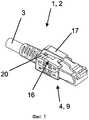
фиг.1 - схематический, перспективный вид предлагаемого в изобретении коннектора с освещаемой защитной крышкой фиксирующего язычка;figure 1 is a schematic, perspective view of the proposed invention in the connector with the illuminated protective cover of the locking tab;
фиг.2 - схематический перспективный вид элемента корпуса коннектора, несущего фиксирующий язычок,figure 2 is a schematic perspective view of an element of the housing of the connector carrying the locking tab,
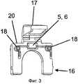
фиг.3 - еще один схематический перспективный вид элемента корпуса фиг.2,figure 3 is another schematic perspective view of a housing element of figure 2,
фиг.4 - схематический, перспективный местный вид представленного на фиг.1 коннектора, частично в разрезе,figure 4 is a schematic, perspective local view of the connector shown in figure 1, partially in section,
фиг.5 - схематический, перспективный вид сбоку коннектора, представленного на фиг.1 и фиг.4, с подключенным внешним источником токаFIG. 5 is a schematic perspective side view of the connector of FIG. 1 and FIG. 4 with an external current source connected.
фиг.6 - схематический вид кабеля с коннекторами на концах, частично в разрезе, и6 is a schematic view of a cable with connectors at the ends, partially in section, and
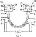
фиг.7 - схематический вид кабеля еще одной конструктивной формы с интегрированными в оба коннектора источниками тока и/или напряжения и переключателями, частично в разрезе.7 is a schematic view of a cable of yet another structural form with integrated current and / or voltage sources and switches and switches, partially in section, integrated into both connectors.
Как показано на фиг.6 и 7, кабель 3 с целью оптоэлектронной идентификации и детектирования обоих своих конечных участков имеет на каждом конечном участке 1, 2 по одному коннектору 4, 9. Каждый коннектор 4, 9 снабжен оптоэлектронными датчиками сигналов 5, 6. Оптоэлектронные датчики сигналов 5, 6 связаны проводами 7, 21, 22.As shown in FIGS. 6 and 7, for the purpose of optoelectronic identification and detection of both of its end sections,
Поэтому при подаче электроэнергии в электрический провод 7, 21, 22 оптоэлектронные датчики сигналов 5, 6 обоих конечных участков кабеля 1, 2 активируются для идентификации и детектирования относящихся к одному и тому же кабелю 3 конечных участков кабеля 1, 2 и относящихся к одному и тому же кабелю 3 оконечных коннекторов 4, 9. В случае представленных на фиг.6 и 7 конструктивных форм оптоэлектронные датчики сигналов 5, 6 предусмотрены непосредственно в корпусах 16 коннекторов 4, 9 на противоположных концах кабеля.Therefore, when power is supplied to the
На фиг.1-5 представлены корпусы вилок разъемов 16 или соответствующие, их части, как их предлагается использовать согласно изобретению.Figure 1-5 shows the housings of the
Показана конструктивная форма с освещаемой защитной крышкой фиксирующего язычка и оптическим индикатором 5, 6, которой изобретение, однако, никоим образом не ограничивается. Как видно, в частности, из фиг.1, фиг.2, фиг.3, фиг.4 и фиг.5, на корпусе вилки разъема 16 предусмотрена защитная крышка фиксирующего язычка 17, расположенная рядом с оптическим датчиком сигналов 5, 6.A structural form with an illuminated protective cover of the fixing tab and an
Обычно предусматривается минимум один оптоэлектронный датчик сигналов 5, 6 на элементе корпуса 20, который расположен рядом с местом крепления защитной крышки фиксирующего язычка 17 на корпусе 16. Рекомендуется выполнять защитную крышку фиксирующего язычка 17 с включением материала, который является, по крайней мере частично, светопроницаемым или просвечивающим, или опалесцирующим или прозрачным, или вызывающим рассеяние либо отражение света либо флуоресценцию.Usually, at least one
Оптический индикатор 5, 6 находится в представленной конструктивной форме под защитной крышкой фиксирующего язычка 17, так что свечение появляется под прозрачной защитной крышкой фиксирующего язычка, которая при необходимости может рассеивать, трансформировать (к примеру, путем флуоресценции) или же пропускать свет.The
Как показано на фиг.2, фиг.3, фиг.4 и фиг.5, на элементе корпуса 20 коннектора 4, на котором крепится защитная крышка фиксирующего язычка 17, предусмотрен один или несколько электропроводящих контактов 18. В частности, фиг.2, фиг.5 и фиг.6 показывают возможность реверсивное подключение внешнего источника питания 8 к контактам 18. В корпусе 20 контакты 18 связаны электрическим сигнальным проводом по меньшей мере с оптоэлектронным датчиком сигналов 5, 6 соответствующего коннектора 4, 9.As shown in FIG. 2, FIG. 3, FIG. 4 and FIG. 5, one or more electrically
Фиг.4 и фиг.6 показывают, что электропроводящие контакты 18 одного коннектора 4, 9 могут быть связаны одной или несколькими проходящими внутри кабеля контрольными жилами (проводниками) 21 и/или экраном кабеля 22.Figures 4 and 6 show that the electrically
Указанным минимум одним электрическим сигнальным проводом 7, 21, 22 для соединения датчиков сигналов 5, 6, расположенных на противоположных концах кабеля коннекторов 4, 9, является на фиг.4 контрольная жила 21 внутри кабеля.The specified at least one
Таким образом, корпус 16 каждого коннектора 4, 9 рекомендуется делать, как представлено, в частности, на фиг.1, фиг.4 и фиг.5, модульным, составным.Thus, the
Оптоэлектронные датчики сигналов 5, 6 могут быть лампами накаливания, светодиодами, светоизлучающими диодами (СИД) или люминесцентными диодами, которые при подаче на них тока становятся источниками излучения света в видимом диапазоне инфракрасного либо ультрафиолетового излучения.The
Как следует из фиг.2, фиг.5 и фиг.6, каждый коннектор 4, 9 может включать одно или несколько устройств 10, 11; 18 для подачи электроэнергии из внешнего источника тока 8 или источника напряжения в электропроводящее соединение 7, 21, 22.As follows from figure 2, figure 5 and 6, each
В частности, на фиг.7 показано, что каждый коннектор 4, 9 может включать один или несколько встроенных в него источников тока или источников напряжения 12, 13 для подачи электроэнергии, поступающей из источника тока или источника напряжения 12, 13 внутри кабеля, в электропроводящее соединение 7, 21, 22. Фиг.7 показывает также, что, в частности, при наличии встроенных в оба коннектора 4, 9 внутрикабельных источников тока или источников напряжения 12, 13 в состав каждого коннектора 4, 9 может входить один или несколько электрических переключателей 14, 15, предпочтительно включенных в цепь.In particular, FIG. 7 shows that each
К переключателям на коннекторе 14, 15 могут, к примеру, относиться сенсорные переключатели, фиксирующие сенсорные переключатели, выключатели с соленоидным приводом, релейные переключатели, тумблеры, пружинные фиксирующие язычки и защитные приспособления пружинных фиксирующих язычков.The switches on
Подача электроэнергии в электропроводящее соединение 7, 21, 22 может в зависимости от условий применения происходить непрерывно или в тактовом режиме.The supply of electricity to the electrically
Кабель 3 может быть, к примеру, линией электросвязи, электролинией передачи данных, линией энергоснабжения, сетевым кабелем, коммутационным шнуром или их комбинацией.
При соотнесении укрепленных в кросс-панели штекеров кабелей, которые подлежат перераспределению, в случае конструктивной формы, показанной на фиг.6, предлагается согласно изобретению действовать следующим образом. На конце кабеля 5 через подачу питания 10 к сигнальным проводам 7 подключается внешний источник тока 8. Благодаря подаче питания загораются светодиоды 5 и 6, связанные данными сигнальными проводами 7. Становится очевидным, который штекер в кросс-панели относится к кабелю, источник питания которого 8 был активирован.When correlating the cable plugs that are to be redistributed in the cross-panel, in the case of the structural form shown in FIG. 6, it is proposed according to the invention to proceed as follows. At the end of
В конструктивных формах, представленных схематически на фиг.7, вместо подачи тока источник тока посредством переключателя 14, 15 на соответствующем штекере связан с оптическим индикатором 5, 6, за счет чего происходит активация и загорание данного индикатора.In the structural forms shown schematically in Fig. 7, instead of supplying current, the current source through the
Путем детального описания различных конструктивных форм изобретения специалист, к которому обращено данное изобретение, очевидным образом сможет разработать альтернативные конструктивные формы и комментарии к воплощению изобретения. Описанные выше конструктивные формы должны лишь пояснить изобретение, которое может быть модифицировано в рамках указанной ниже формулы.By a detailed description of the various constructive forms of the invention, the person skilled in the art will obviously be able to develop alternative constructive forms and comments on the embodiment of the invention. The structural forms described above should only illustrate the invention, which can be modified within the framework of the following formula.
Список ссылочных обозначений:List of reference designations:
1. Конечный участок кабеля1. The end of the cable
2. Конечный участок кабеля2. The end of the cable
3. Кабель3. Cable
4. Коннектор на 34.
5. Датчик сигналов на 4.5. The signal sensor at 4.
6. Датчик сигналов на 9.6. The signal sensor at 9.
7. Электрический проводник7. Electric conductor
8. Внешний источник питания8. External power supply
9. Коннектор9. Connector
10. Подача питания10. Power supply
11. Устройство подачи питания11. Power supply device
12. Внешний / интегрированный источник тока / напряжения12. External / integrated current / voltage source
13. Внешний / интегрированный источник тока / напряжения13. External / integrated current / voltage source
14. Электрические переключатели14. Electric switches
15. Электрические переключатели15. Electric switches
16. Корпус вилки разъема (коннектора)16. Housing of the plug (connector)
17. Защитная крышка фиксирующего язычка как часть 1617. The protective cover of the locking tab as
18. Электрический контакт к 2018. Electrical contact to 20
19. Элемент корпуса 16 с защитной крышкой фиксирующего язычка 1719.
20. Контрольная жила20. Test lead
21. Экран кабеля.21. Cable screen.
Claims (12)
Translated fromRussian- прокладыванием кабеля по одному из предыдущих пунктов с: по меньшей мере, одним электрическим контрольным проводником; по меньшей мере, одним индикаторным элементом на вилке разъема на конце кабеля, который соединен с просвечивающим элементом корпуса кабеля;
и, по меньшей мере, одним активирующим элементом на вилке разъема на конце кабеля для подачи питания в электрический контрольный проводник;
- энергоснабжением индикаторного элемента подлежащего идентификации элемента кабеля путем подачи питания в электрический контрольный проводник от активирующего элемента, благодаря чему происходит активация индикатора на коннекторе и освещаемой поверхности корпуса коннектора; и
- идентификацией относящегося к кабелю коннектора согласно показаниям индикатора.12. A method for identifying cord connectors, characterized in:
- laying the cable according to one of the preceding paragraphs with: at least one electrical control conductor; at least one indicator element on the connector plug at the end of the cable, which is connected to the transmission element of the cable housing;
and at least one activating element on the plug of the connector at the end of the cable for supplying power to the electrical control conductor;
- power supply of the indicator element of the cable element to be identified by supplying power to the electrical control conductor from the activating element, due to which the indicator is activated on the connector and the illuminated surface of the connector body; and
- identification of the connector related to the cable according to the indicator.
Applications Claiming Priority (5)
| Application Number | Priority Date | Filing Date | Title |
|---|---|---|---|
| DE202007011630.6 | 2007-08-20 | ||
| DE202007011630UDE202007011630U1 (en) | 2007-08-20 | 2007-08-20 | Identifiable cable |
| DE202008001256.2 | 2008-01-28 | ||
| DE202008001256UDE202008001256U1 (en) | 2007-08-20 | 2008-01-28 | Identifiable cable |
| PCT/DE2008/001224WO2009024114A1 (en) | 2007-08-20 | 2008-07-24 | Identifiable cable |
Publications (2)
| Publication Number | Publication Date |
|---|---|
| RU2009141779A RU2009141779A (en) | 2011-07-10 |
| RU2475905C2true RU2475905C2 (en) | 2013-02-20 |
Family
ID=39339432
Family Applications (1)
| Application Number | Title | Priority Date | Filing Date |
|---|---|---|---|
| RU2009141779/07ARU2475905C2 (en) | 2007-08-20 | 2008-07-24 | Identifiable cable |
Country Status (5)
| Country | Link |
|---|---|
| EP (1) | EP2191542B1 (en) |
| DE (1) | DE202008001256U1 (en) |
| RU (1) | RU2475905C2 (en) |
| TW (1) | TW200909825A (en) |
| WO (1) | WO2009024114A1 (en) |
Families Citing this family (14)
| Publication number | Priority date | Publication date | Assignee | Title |
|---|---|---|---|---|
| TWI450263B (en)* | 2010-06-30 | 2014-08-21 | Apple Inc | Circuitry for active cable |
| US8327536B2 (en) | 2010-06-30 | 2012-12-11 | Apple Inc. | Method of manufacturing high-speed connector inserts and cables |
| KR101758968B1 (en) | 2010-06-30 | 2017-07-17 | 애플 인크. | Circuitry for active cable |
| US9112310B2 (en) | 2010-06-30 | 2015-08-18 | Apple Inc. | Spark gap for high-speed cable connectors |
| DE102010038929B4 (en)* | 2010-08-04 | 2022-01-27 | Maha Maschinenbau Haldenwang Gmbh & Co. Kg | Plug with bulb |
| EP2448071A1 (en)* | 2010-10-28 | 2012-05-02 | 3M Innovative Properties Company | Telecommunication connecting device |
| US20120226774A1 (en) | 2011-02-23 | 2012-09-06 | Apple Inc. | Display snooping |
| US9230416B2 (en)* | 2012-08-06 | 2016-01-05 | Finisar Corporation | Communication devices including a sensor configured to detect physical input |
| GB2507992B (en) | 2012-11-16 | 2015-01-28 | Ge Aviat Systems Ltd | Cable having audio recording and play back |
| TW201521405A (en) | 2013-11-29 | 2015-06-01 | 萬國商業機器公司 | Method, appliance and program product for locating a network cable connector |
| CN105278046A (en)* | 2014-07-23 | 2016-01-27 | 中兴通讯股份有限公司 | Object identification method and device |
| CN104391362B (en)* | 2014-12-05 | 2017-04-05 | 国家电网公司 | A kind of tail optical fiber and its detector |
| CN106154102A (en)* | 2016-07-29 | 2016-11-23 | 中航光电科技股份有限公司 | Cable identification module and composite cable assembly |
| CN115954725B (en)* | 2023-02-22 | 2023-09-26 | 苏州埃博斯电气有限公司 | Automobile circuit connector with communication abnormality monitoring function |
Citations (6)
| Publication number | Priority date | Publication date | Assignee | Title |
|---|---|---|---|---|
| JPH05250077A (en)* | 1992-01-07 | 1993-09-28 | Nec Corp | Cable end detecting system |
| US6577243B1 (en)* | 1999-12-14 | 2003-06-10 | Alan J. Brown | Method and apparatus for tracing remote ends of networking cables |
| UA67869C2 (en)* | 2002-09-10 | 2004-07-15 | Роман Іванович Кубай | Pin plug with a protection device |
| US7038135B1 (en)* | 2004-06-28 | 2006-05-02 | Avaya Technology Corp. | Embedded cable connection identification circuits |
| US20060232385A1 (en)* | 2005-04-13 | 2006-10-19 | Scherer Christopher B | Networking cable tracer system |
| RU2289889C2 (en)* | 2002-09-23 | 2006-12-20 | ДАТА-КОМПЛЕКС е.К. | Device for monitoring patch panels at distribution points in data transfer networks |
- 2008
- 2008-01-28DEDE202008001256Upatent/DE202008001256U1/ennot_activeExpired - Lifetime
- 2008-07-24EPEP08801064Apatent/EP2191542B1/ennot_activeRevoked
- 2008-07-24RURU2009141779/07Apatent/RU2475905C2/ennot_activeIP Right Cessation
- 2008-07-24WOPCT/DE2008/001224patent/WO2009024114A1/enactiveApplication Filing
- 2008-08-20TWTW097131671Apatent/TW200909825A/enunknown
Patent Citations (6)
| Publication number | Priority date | Publication date | Assignee | Title |
|---|---|---|---|---|
| JPH05250077A (en)* | 1992-01-07 | 1993-09-28 | Nec Corp | Cable end detecting system |
| US6577243B1 (en)* | 1999-12-14 | 2003-06-10 | Alan J. Brown | Method and apparatus for tracing remote ends of networking cables |
| UA67869C2 (en)* | 2002-09-10 | 2004-07-15 | Роман Іванович Кубай | Pin plug with a protection device |
| RU2289889C2 (en)* | 2002-09-23 | 2006-12-20 | ДАТА-КОМПЛЕКС е.К. | Device for monitoring patch panels at distribution points in data transfer networks |
| US7038135B1 (en)* | 2004-06-28 | 2006-05-02 | Avaya Technology Corp. | Embedded cable connection identification circuits |
| US20060232385A1 (en)* | 2005-04-13 | 2006-10-19 | Scherer Christopher B | Networking cable tracer system |
Also Published As
| Publication number | Publication date |
|---|---|
| WO2009024114A1 (en) | 2009-02-26 |
| DE202008001256U1 (en) | 2008-04-30 |
| WO2009024114A4 (en) | 2009-04-23 |
| RU2009141779A (en) | 2011-07-10 |
| EP2191542A1 (en) | 2010-06-02 |
| TW200909825A (en) | 2009-03-01 |
| EP2191542B1 (en) | 2012-11-28 |
Similar Documents
| Publication | Publication Date | Title |
|---|---|---|
| RU2475905C2 (en) | Identifiable cable | |
| US5666453A (en) | Fiber optic jumper cables and tracing method using same | |
| CN102273023B (en) | Patch cords with insertion detection and lighting capabilities | |
| RU2294001C2 (en) | Device for visual identification of cable wiring or pipelines | |
| US9912081B2 (en) | Lighted electrical connector housing | |
| CA2797629A1 (en) | Networking cable tracer system | |
| CN204706735U (en) | The telecommunication cable of telecommunication cable connector and Belt connector | |
| US9725280B2 (en) | Connecting device for measurement tapes in elevator devices | |
| CN105591243A (en) | Cable connector assembly | |
| US20160091673A1 (en) | Fiber optic connector with power | |
| CN105706458A (en) | Network cables including a device for visually marking them and a device for visually marking the ends of network cables | |
| CN212366352U (en) | Can look for optic fibre wire jumper at wire jumper both ends fast | |
| US7767957B2 (en) | Arrangement for monitoring electric devices on stray light arcs | |
| KR101607435B1 (en) | Device for identifying opitcal line with opticlal fiber calbes | |
| TWI436534B (en) | Intelligent structured cabling system and jack | |
| US9946038B1 (en) | Cable tracing type jumper cable | |
| DE102008006429C5 (en) | Identifiable cable | |
| US20220344879A1 (en) | Single pair ethernet connector | |
| DE102007039294A1 (en) | Identifiable and detectable cable e.g. patch cable, has optical, acoustic, electrical and/or perceptible oscillations producing signal generators electrically and conductively connected with each other by conductors | |
| CN209342337U (en) | A kind of quick hunting system of visible light | |
| EP2448071A1 (en) | Telecommunication connecting device | |
| CN212136811U (en) | Wire harness joint and wire harness connector | |
| CN109357844B (en) | Quick line hunting system of visible light | |
| CN212207630U (en) | Multifunctional loop on-off detector and long-distance cable core checking system | |
| CN113016109B (en) | Luminous flat cable structure |
Legal Events
| Date | Code | Title | Description |
|---|---|---|---|
| MM4A | The patent is invalid due to non-payment of fees | Effective date:20180725 |