RU2474874C2 - Method and apparatus for generating parametric model associated with geometry of three-dimensional objects - Google Patents
Method and apparatus for generating parametric model associated with geometry of three-dimensional objectsDownload PDFInfo
- Publication number
- RU2474874C2 RU2474874C2RU2007147335/08ARU2007147335ARU2474874C2RU 2474874 C2RU2474874 C2RU 2474874C2RU 2007147335/08 ARU2007147335/08 ARU 2007147335/08ARU 2007147335 ARU2007147335 ARU 2007147335ARU 2474874 C2RU2474874 C2RU 2474874C2
- Authority
- RU
- Russia
- Prior art keywords
- tree
- parameter
- control parameter
- active element
- setting
- Prior art date
Links
Images


Classifications
- G—PHYSICS
- G06—COMPUTING OR CALCULATING; COUNTING
- G06T—IMAGE DATA PROCESSING OR GENERATION, IN GENERAL
- G06T19/00—Manipulating 3D models or images for computer graphics
- G06T19/20—Editing of 3D images, e.g. changing shapes or colours, aligning objects or positioning parts
- G—PHYSICS
- G06—COMPUTING OR CALCULATING; COUNTING
- G06F—ELECTRIC DIGITAL DATA PROCESSING
- G06F30/00—Computer-aided design [CAD]
- G06F30/10—Geometric CAD
- G06F30/15—Vehicle, aircraft or watercraft design
- G—PHYSICS
- G06—COMPUTING OR CALCULATING; COUNTING
- G06F—ELECTRIC DIGITAL DATA PROCESSING
- G06F30/00—Computer-aided design [CAD]
- G06F30/20—Design optimisation, verification or simulation
- G—PHYSICS
- G06—COMPUTING OR CALCULATING; COUNTING
- G06F—ELECTRIC DIGITAL DATA PROCESSING
- G06F2113/00—Details relating to the application field
- G06F2113/28—Fuselage, exterior or interior
- G—PHYSICS
- G06—COMPUTING OR CALCULATING; COUNTING
- G06T—IMAGE DATA PROCESSING OR GENERATION, IN GENERAL
- G06T2200/00—Indexing scheme for image data processing or generation, in general
- G06T2200/24—Indexing scheme for image data processing or generation, in general involving graphical user interfaces [GUIs]
- G—PHYSICS
- G06—COMPUTING OR CALCULATING; COUNTING
- G06T—IMAGE DATA PROCESSING OR GENERATION, IN GENERAL
- G06T2219/00—Indexing scheme for manipulating 3D models or images for computer graphics
- G06T2219/20—Indexing scheme for editing of 3D models
- G06T2219/2021—Shape modification
Landscapes
- Engineering & Computer Science (AREA)
- Physics & Mathematics (AREA)
- Theoretical Computer Science (AREA)
- Geometry (AREA)
- General Physics & Mathematics (AREA)
- Computer Hardware Design (AREA)
- General Engineering & Computer Science (AREA)
- Evolutionary Computation (AREA)
- Computational Mathematics (AREA)
- Pure & Applied Mathematics (AREA)
- Mathematical Optimization (AREA)
- Mathematical Analysis (AREA)
- Aviation & Aerospace Engineering (AREA)
- Automation & Control Theory (AREA)
- Architecture (AREA)
- Computer Graphics (AREA)
- Software Systems (AREA)
- Stored Programmes (AREA)
- User Interface Of Digital Computer (AREA)
- Processing Or Creating Images (AREA)
- Image Generation (AREA)
Abstract
Description
Translated fromRussianОбласть техникиTechnical field
Настоящее изобретение касается генерирования параметрической модели, связанной с трехмерной геометрией детали или узла деталей.The present invention relates to the generation of a parametric model associated with the three-dimensional geometry of a part or assembly of parts.
Оно находит применение в моделировании геометрических форм (система автоматизированного проектирования, САПР), в программах цифрового управления для станков (система автоматизированного производства САП), в программах проведения технико-экономических исследований на ЭВМ и в программах управления базами данных.It finds application in modeling geometric shapes (computer-aided design system, CAD), in digital control programs for machine tools (computer-aided manufacturing system of CAD), in programs for conducting technical and economic studies on computers and in database management programs.
Предшествующий уровень техникиState of the art
Как правило, создание параметрической модели геометрии трехмерных объектов состоит в определении параметров детали в ее конечной конфигурации, например крыла самолета, соединенного с фюзеляжем.As a rule, the creation of a parametric model of the geometry of three-dimensional objects consists in determining the parameters of the part in its final configuration, for example, an airplane wing connected to the fuselage.
На практике, такое окончательное определение вписывается в замкнутый цикл оптимизации, в ходе которого несколько раз осуществляют ключевые этапы: определение, анализ и изменения.In practice, such a final definition fits into a closed loop of optimization, during which the key steps are carried out several times: determination, analysis and change.
Основным преимуществом программного обеспечения САПР является то, что оно позволяет полностью или частично интегрировать эти три этапа в одну и единственную операционную среду, при этом переход от одного этапа к другому происходит почти прозрачно.The main advantage of CAD software is that it allows you to fully or partially integrate these three stages into one and only operating environment, while the transition from one stage to another is almost transparent.
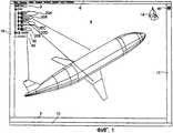
На фиг.1 показана операционная среда программного обеспечения САПР, называемого Catia, разработанного французской компанией Dassault Systèmes и выпускаемого в продажу компанией IBM. Операционная среда, отображенная на экране компьютера, в основном содержит дерево 2 спецификаций и графическую зону 4. Операционная среда дополнительно содержит панель 6 меню, стандартную панель 8 инструментов, диалоговую зону 10, стол 12, содержащий панель контекстного меню, зависящую от активного окна, буссоль 14, позволяющую ориентировать текущее изображение, значок 15 активного окна и панель 18 специальных средств или приложений.Figure 1 shows the operating environment of CAD software called Catia, developed by French company Dassault Systèmes and marketed by IBM. The operating environment displayed on the computer screen mainly contains a
Дерево 2 спецификаций является структурированным графическим отображением реализуемой модели, в данном случае самолета. В примере, показанном на фиг. 1, можно отметить, что работу осуществляют на активном элементе, называемом Продукт 1, при этом продукт содержит пять основных тел, обозначенных индивидуально как 20А «среда», 20В «фюзеляж.1», 20С «крыло», 20D «крыло симметрии» и 20Е «хвост», что одно основное тело состоит из приложений 40 и параметров управления 30.The
По мере определения детали в дерево модели добавляются новые элементы.As you define the part, new elements are added to the model tree.
Выбор элемента можно производить как в графической зоне 4, так и в дереве 2 спецификаций. Дерево спецификаций позволяет активировать контекстуальное меню по требуемому объекту.The element can be selected both in
Каждый элемент дерева спецификаций 2 может содержать параметры управления 30 и отношения (не показаны), которые позволяют получить геометрию трехмерного объекта или трехмерных объектов через определение функций, присутствующих в дереве спецификаций.Each element of the
Использование такого программного обеспечения САПР позволяет, таким образом, применить цифровой макет и совместно определить продукт и некоторые связанные с ним процессы.The use of such CAD software allows, thus, applying a digital layout and jointly defining a product and some associated processes.
Чаще всего определение трехмерной геометрической модели является объектом работы нескольких рабочих групп, как правило, организованных в разных местах, чаще всего транснациональных групп. Поэтому возникает потребность в легком и простом обмене параметрической информацией.Most often, the definition of a three-dimensional geometric model is the object of work of several working groups, usually organized in different places, most often transnational groups. Therefore, there is a need for an easy and simple exchange of parametric information.
На практике параметризация обеспечивается непосредственно функциональными возможностями самого программного обеспечения, в частности «CATIA». Для изменения значений параметров модели необходимо произвести перекомпиляцию приложения. Следует использовать стандартную функцию программного средства, чтобы изменить параметр. Вместе с тем, программные средства содержат модель в структурной организации, связанной с развитием конструкции, или в виде дерева подчинения.In practice, parameterization is provided directly by the functionality of the software itself, in particular CATIA. To change the values of the model parameters, it is necessary to recompile the application. Use the standard function of the software tool to change the parameter. At the same time, software contains a model in a structural organization related to the development of a structure, or in the form of a subordination tree.
Однако такое отображение относительно удалено от функционального подхода к профессиональной проблематике, связанной с концепцией параметрической модели.However, such a mapping is relatively remote from the functional approach to professional issues related to the concept of a parametric model.
Поэтому для пользователя, не являющегося специалистом в области программирования, не просто найти параметр, не зная, какой результат он хочет получить.Therefore, for a user who is not a specialist in programming, it is not easy to find a parameter without knowing what result he wants to get.
Настоящее изобретение призвано предложить решение этой проблемы.The present invention is intended to provide a solution to this problem.
Краткое изложение существа изобретенияSummary of the invention
Технической задачей настоящего изобретения является создание для пользователя редактора структурированных параметров, функционально близких к профессиональной проблематике, связанной с проектированием детали, чтобы получить упрощенный интерфейс для изменения параметров без изменения кода источника.The technical task of the present invention is to create for the user an editor of structured parameters that are functionally close to professional issues related to the design of the part in order to obtain a simplified interface for changing parameters without changing the source code.
Объектом настоящего изобретения является устройство генерирования трехмерной геометрической модели детали или узла деталей, при этом упомянутая модель отображается на экране компьютера в виде дерева спецификаций, содержащего, по меньшей мере, один элемент, определенный, по меньшей мере, одним параметром управления.An object of the present invention is a device for generating a three-dimensional geometric model of a part or assembly of parts, wherein said model is displayed on a computer screen in the form of a specification tree containing at least one element defined by at least one control parameter.
Согласно общему определению изобретения, устройство генерирования содержит преобразователь, выполненный с возможностью трансформации дерева спецификаций в графический интерфейс пользователя, в котором, по меньшей мере, одному активному элементу дерева соответствует диалоговое окно, содержащее, по меньшей мере, одно поле, связанное, по меньшей мере, с одним параметром управления активного элемента, при этом установка параметра управления может быть изменена пользователем при помощи редактора параметров, причем каждая установка параметра управления отображается в соответствующем поле диалогового окна и автоматически приводит к изменению установки параметра управления соответствующего активного элемента в дереве спецификаций.According to the general definition of the invention, the generating device comprises a converter configured to transform the specification tree into a graphical user interface, in which at least one active element of the tree corresponds to a dialog box containing at least one field associated with at least , with one control parameter of the active element, while the setting of the control parameter can be changed by the user using the parameter editor, each setting being paired with Control tra displayed in the corresponding field of the dialog and automatically results in setting a control parameter corresponding to a change in the specifications of the active element tree.
Таким образом, благодаря диалоговому окну в соответствии с настоящим изобретением пользователь может легко и напрямую изменять значения полей параметризации активного элемента, не будучи при этом специалистом информатики в области программных средств САПР. Кроме того, изменение параметров через диалоговое окно приводит к соответствующему изменению в дереве спецификаций. В результате пользователь-неспециалист получает возможность упрощенного и легкого доступа и изменения параметров управления активного элемента дерева спецификаций программного обеспечения САПР. Кроме того, благодаря изобретению изменение параметрической архитектуры не требует изменения кода источника.Thus, thanks to the dialog box in accordance with the present invention, the user can easily and directly change the values of the parameterization fields of the active element, without being an IT specialist in the field of CAD software. In addition, changing the parameters through the dialog box leads to a corresponding change in the specification tree. As a result, a non-specialist user gets the opportunity to simplify and easily access and change control parameters of the active element of the CAD software specification tree. In addition, thanks to the invention, changing the parametric architecture does not require changing the source code.
Согласно варианту выполнения, графический интерфейс дополнительно содержит графическое окно, содержащее геометрию соответствующего активного элемента, при этом установка упомянутого параметра визуально отображается в графическом окне.According to an embodiment, the graphical interface further comprises a graphical window containing the geometry of the corresponding active element, wherein the setting of said parameter is visually displayed in the graphical window.
Таким образом, параметры управления, в общих чертах определенные специалистом программного обеспечения САПР и заинтересовавшие пользователя-неспециалиста, можно непосредственно просматривать и изменять на графическом интерфейсе и/или в диалоговом меню в соответствии с настоящим изобретением.Thus, the control parameters, generally defined by a CAD software specialist and of interest to a non-specialist user, can be directly viewed and changed on the graphical interface and / or in the dialog menu in accordance with the present invention.
На практике, каждый элемент дерева спецификаций принадлежит к группе, образованной терминальными узлами и нетерминальными узлами.In practice, each element of the specification tree belongs to a group formed by terminal nodes and non-terminal nodes.
Например, каждому терминальному узлу соответствуют окно типа графического окна пользователя и редактор параметров.For example, each terminal node corresponds to a window such as a graphical user window and a parameter editor.
Точно так же каждому нетерминальному узлу соответствуют редактор параметров и множество закладок, при этом каждой закладке соответствует один подузел.Similarly, each non-terminal node has a parameter editor and many bookmarks, with each sub-node corresponding to one subnode.
Например, по меньшей мере, одной закладке соответствует графическое окно.For example, at least one bookmark corresponds to a graphic window.
Согласно другому варианту выполнения, редактор параметров является также редактором скрипта, в котором язык скрипта является, например, языком разметки типа XML.According to another embodiment, the parameter editor is also a script editor in which the script language is, for example, a markup language such as XML.
Согласно еще одному варианту выполнения, устройство генерирования дополнительно содержит устройство связи, выполненное с возможностью дистанционного обмена значениями полей параметризации для обеспечения корпоративной работы на расстоянии с участием других пользователей.According to another embodiment, the generating device further comprises a communication device configured to remotely exchange parameterization field values to provide corporate work at a distance with the participation of other users.
Объектом настоящего изобретения является также способ генерирования параметрической модели, связанной с трехмерной геометрией детали или узла деталей, при этом упомянутая модель отображается графически на экране компьютера в виде дерева спецификаций, содержащего, по меньшей мере, один элемент, определенный, по меньшей мере, одним параметром управления.The object of the present invention is also a method for generating a parametric model associated with the three-dimensional geometry of a part or assembly of parts, said model being displayed graphically on a computer screen in the form of a specification tree containing at least one element defined by at least one parameter management.
Согласно другим отличительным признакам настоящего изобретения, способ содержит следующие этапы:According to other features of the present invention, the method comprises the following steps:
упомянутое дерево спецификаций преобразуют в графический интерфейс пользователя, в котором, по меньшей мере, одному активному элементу дерева соответствует диалоговое окно, содержащее, по меньшей мере, одно поле, соответствующее, по меньшей мере, одному параметру управления активного элемента,said specification tree is transformed into a graphical user interface in which at least one active element of the tree corresponds to a dialog box containing at least one field corresponding to at least one control parameter of the active element,
пользователь изменяет установку параметра управления при помощи редактора параметров,the user changes the setting of the control parameter using the parameter editor,
каждую установку упомянутого параметра управления выводят в соответствующее поле диалогового окна,each setting of said control parameter is displayed in the corresponding field of the dialog box,
при этом установка параметра управления соответствующего активного элемента в дереве спецификаций автоматически изменяется.the setting of the control parameter of the corresponding active element in the specification tree is automatically changed.
Согласно варианту выполнения, способ дополнительно содержит этап, на котором установка параметра визуально отображается в графическом окне.According to an embodiment, the method further comprises the step of setting the parameter visually displayed in a graphics window.
Объектом настоящего изобретения является также носитель информации, считываемый машинной системой, характеризующийся тем, что содержит команды машинной программы, позволяющие осуществить вышеуказанный способ генерирования, когда программа загружается в машинную систему и выполняется системой.The object of the present invention is also a storage medium readable by a machine system, characterized in that it contains instructions of a machine program, allowing the above generation method to be implemented when the program is loaded into the machine system and executed by the system.
Объектом настоящего изобретения является также съемный носитель информации, частично или полностью считываемый машинной системой, характеризующийся тем, что содержит машинную программу, позволяющую осуществить вышеуказанный способ генерирования, когда программа загружается в машинную систему и выполняется этой системой.The object of the present invention is also a removable storage medium, partially or completely readable by a machine system, characterized in that it contains a computer program that allows the above generation method to be implemented when the program is loaded into the machine system and executed by this system.
Наконец, объектом настоящего изобретения является машинная программа, записанная на носителе информации, при этом упомянутая программа содержит команды, позволяющие осуществить вышеуказанный способ генерирования, когда программа загружается в машинную систему и выполняется этой системой.Finally, an object of the present invention is a computer program recorded on a storage medium, said program comprising instructions enabling the above generation method to be executed when the program is loaded into the computer system and executed by this system.
Краткое описание чертежейBrief Description of the Drawings
Другие отличительные признаки и преимущества настоящего изобретения будут более очевидны из нижеследующего описания со ссылками на прилагаемые чертежи, на которых:Other features and advantages of the present invention will be more apparent from the following description with reference to the accompanying drawings, in which:
Фиг. 1 - схематичный вид описанной выше операционной среды программного обеспечения САПР, согласно предшествующему уровню техники;FIG. 1 is a schematic view of the above CAD software operating environment according to the prior art;
Фиг. 2 - схема физических ресурсов компьютера, предназначенных для применения, согласно изобретению;FIG. 2 is a diagram of the physical resources of a computer for use in accordance with the invention;
Фиг. 3 - схематичный вид операционной среды, на которой методом наложения после запроса пользователя выводится диалоговое окно, согласно изобретению;FIG. 3 is a schematic view of an operating environment in which a dialog box according to the invention is displayed by an overlay method after a user request;
Фиг. 4 - схематичный отдельный вид диалогового окна на фиг. 3, согласно изобретению;FIG. 4 is a schematic separate view of the dialog box of FIG. 3, according to the invention;
Фиг. 5 - схематичный вид изменения значения установки параметра относительно значения, показанного на фиг. 4, при помощи диалогового окна, согласно изобретению;FIG. 5 is a schematic view of a change in a setting value of a parameter with respect to the value shown in FIG. 4 using a dialog box according to the invention;
Фиг. 6 - схематичный вид эффекта при изменении установки параметра, показанного на фиг. 5, в дереве спецификаций по сравнению с деревом, показанным на фиг. 1, согласно изобретению.FIG. 6 is a schematic view of the effect when changing the setting of the parameter shown in FIG. 5 in the specification tree compared to the tree shown in FIG. 1, according to the invention.
Описание предпочтительных вариантов воплощения изобретенияDESCRIPTION OF PREFERRED EMBODIMENTS
На фиг. 2 показаны физические ресурсы программируемого устройства 100, предназначенного для применения изобретения.In FIG. 2 shows the physical resources of a
Устройство 100 содержит шину связи 109, с которой соединены:The
центральный блок обработки 102 (микропроцессор, ЦПУ), который управляет обменами между различными элементами устройства;a central processing unit 102 (microprocessor, CPU) that controls exchanges between various elements of the device;
постоянное запоминающее устройство (ПЗУ) 101, которое может содержать программы в соответствии с настоящим изобретением (Прог1, Прог2);read-only memory (ROM) 101, which may comprise programs in accordance with the present invention (Pro1, Pro2);
оперативное запоминающее устройство (ОЗУ) 105;random access memory (RAM) 105;
жесткий диск 103, который может содержать вышеупомянутые программы;a
клавиатура 104;
экран 107;
дисковод 111, предназначенный для установки дискеты 110 и считывания с нее или записи на нее обработанных или обрабатываемых документов в соответствии с настоящим изобретением;a
интерфейс связи 106, соединенный с коммуникационной сетью 120, например сетью Интернет, при этом интерфейс выполнен с возможностью передачи и приема документов.a
Шина связи 109 обеспечивает коммуникацию и взаимный операционный обмен между различными элементами, интегрированными в устройство или связанными с этим устройством. Наличие шины не является ограничительным, и, в частности, центральный блок может передавать команды на любой элемент устройства напрямую или через другой элемент устройства.
Рабочий код каждой программы, позволяющий программируемому устройству осуществлять обработку в соответствии с настоящим изобретением, может храниться, например, на жестком диске 103 или в постоянном запоминающем устройстве 101.The working code of each program, allowing the programmable device to carry out processing in accordance with the present invention, can be stored, for example, on
Согласно варианту выполнения, дискета 110 может содержать документы, а также рабочий код вышеуказанных программ, который после считывания устройством сохраняется на жестком диске 103.According to an embodiment, the
Согласно другому варианту выполнения, рабочий код программ может быть получен через коммуникационную сеть через интерфейс 106 для сохранения таким же образом, как было указано выше.According to another embodiment, a working program code may be obtained via a communication network via an
Дискеты можно заменить любым другим носителем информации, например, таким как компактный диск (CD ROM) или карта памяти. Как правило, средство хранения информации, считываемое компьютером или микропроцессором, встроенное или не встроенное в устройство, в случае необходимости съемное, выполнено с возможностью записи одной или нескольких программ, исполнение которых позволяет применить способ в соответствии с настоящим изобретением.Floppy disks can be replaced with any other storage medium, such as a compact disk (CD ROM) or memory card. Typically, a means of storing information read by a computer or microprocessor, built-in or not built into the device, if necessary removable, is configured to record one or more programs, the execution of which allows you to apply the method in accordance with the present invention.
Как правило, программу или программы можно загрузить в средства запоминания устройства перед их исполнением.Typically, a program or programs can be loaded into the storage media of a device before they are executed.
Центральный блок 102 выдает команды и управляет исполнением команд или участков рабочего кода программы или нескольких программ, исполнение которых позволяет применить способ в соответствии с настоящим изобретением, при этом команды сохраняются на жестком диске 103, или в ПЗУ 101, или в других вышеуказанных средствах запоминания. При подаче напряжения программа или программы, хранящиеся в постоянной памяти, например на жестком диске 103 или в памяти ПЗУ 101, переводятся в оперативное запоминающее устройство ОЗУ 105, которое в этом случае должно содержать рабочий код программы или программ в соответствии с настоящим изобретением, а также регистры для запоминания переменных значений параметров, необходимых для применения настоящего изобретения.The
Следует отметить, что программируемое устройство, содержащее устройство в соответствии с настоящим изобретением, может быть запрограммированным устройством.It should be noted that a programmable device comprising a device in accordance with the present invention may be a programmed device.
Это устройство содержит в этом случае код машинной программы или программ, например, зафиксированный в проблемно-ориентированной специализированной интегральной микросхеме (ASIC).This device contains in this case the code of the machine program or programs, for example, fixed in a problem-oriented specialized integrated circuit (ASIC).
На фиг. 3 показана операционная среда цифрового трехмерного макета летательного аппарата, показано также дерево 2 спецификаций и графическое изображение летательного аппарата 4.In FIG. Figure 3 shows the operating environment of a digital three-dimensional mock-up of an aircraft; a
Выбирая один из активных элементов дерева 2 спецификаций, в данном случае элемент «фюзеляж.1» 20В, и активируя кнопку или значок 18А «редактирование параметров», находящийся на панели инструментов 18, на экран микрокомпьютера выводят второй графический интерфейс 50 методом наложения относительно первого графического интерфейса 4.Selecting one of the active elements of the tree of
Этот графический интерфейс 50 является диалоговым окном, содержащим, по меньшей мере, часть 54, связанную с геометрией соответствующего элемента. Графический интерфейс 50 содержит закладку 60 для каждого элемента модели 20В «фюзеляж.1». Закладки 60 обозначены позициями от 60А до 60F соответственно для элементов «общий вид», «главное тело», «поперечный разрез», «кабина», «цилиндр» и «хвост».This
В части 54 находится список 70 параметров управления, соответствующих выбранной закладке, в данном случае закладке 60С, соответствующей «поперечному разрезу».In
Параметры 70 обозначены позициями 70А-70К. Каждому параметру 70 соответствует поле 80, значение которого может быть изменено пользователем при помощи средств изменения, таких как лифт 82А или курсор 82Н. Каждый параметр содержит также селекционную кнопку 84.Parameters 70 are indicated by 70A-70K. Each parameter 70 corresponds to a field 80, the value of which can be changed by the user using means of change, such as
Значок 18А является сокращением, позволяющим подать команду выведения диалогового окна 50 в соответствии с настоящим изобретением. Эта команда генерирует редактор параметров, структурированно и функционально отображающий модель, не завися при этом напрямую от хронологического протокола конструкций детали или от дерева спецификаций. Редактор параметров содержит индивидуальные поля 80, предназначенные для редактирования, по меньшей мере, некоторых из параметров 70 модели. Поля 80 непосредственно связаны с параметрами модели.The icon 18A is an abbreviation for issuing a command to display a
Графический интерфейс 50 дополнен тремя кнопками: подтверждения «ОК» 90А, применения 90В и отмены 90С.The
Как показано на фиг. 4, пользователь выбирает в части 54 диалогового окна 50 параметр, который он собирается обрабатывать, изменять и/или просмотреть в части 52 окна 50. В данном случае пользователь выбирает параметр 70А, соответствующий высоте фюзеляжа в поперечном разрезе. Исходным значением, записанным в соответствующем поле 80А, является в данном случае 3000 мм. Пользователь просматривает часть геометрии, выраженную параметром 70А, в части 52 диалогового окна.As shown in FIG. 4, the user selects, in
Как показано на фиг. 5, пользователь хочет изменить значение установки параметра 70А по отношению к значению, показанному на фиг. 4. Например, в данном случае при помощи лифта 82А он меняет значение высоты (новое значение = 2000 мм) параметра 70А относительно поперечного сечения фюзеляжа. Эффект изменения в значении параметра отображается по существу в режиме реального времени (1-2 секунды) в графическом окне 52.As shown in FIG. 5, the user wants to change the setting value of
Выбор кнопки подтверждения 90А (ОК) позволяет автоматически включить новое значение параметра в совокупность параметров изделия.Selecting the
Как показано на фиг. 6, изменение значения параметра 70А при помощи окна 50, описанного со ссылками на фиг. 5, по существу автоматически приводит к соответствующему изменению в дереве 2 спецификаций и в геометрии (в данном случае уменьшение поперечного сечения фюзеляжа), отображенной в графическом интерфейсе 4, по сравнению с операционной средой 2 и 4, описанной со ссылками на фиг. 1.As shown in FIG. 6, changing the value of
На практике, преобразователь трансформирует дерево 2 спецификаций в графический интерфейс 50, 52, 54 пользователя, в котором, по меньшей мере, одному активному элементу 20В дерева 2 (фиг. 2-6), соответствует диалоговое окно, содержащее, по меньшей мере, одно поле 80А, соответствующее, по меньшей мере, одному параметру управления 70А активного элемента. На практике, преобразователь в соответствии с настоящим изобретением генерирует редактор структурированных параметров, который содержит поля, параметрируемые пользователем-неспециалистом для функционального приближения к профессиональной проблематике, связанной с проектированием детали.In practice, the converter transforms the
Установку параметров управления 70А пользователь, не являющийся специалистом в программном обеспечении САПР, может менять, выбрав значок 18А, который запускает редактор параметров в соответствии с настоящим изобретением. На практике, редактор параметров опирается на типовые функции редактирования параметров, имеющиеся в наличии в программном обеспечении САПР.The setting of
Согласно изобретению, редактор параметров группирует и структурирует параметры модели в диалоговом окне 50 при помощи типовых функций.According to the invention, the parameter editor groups and structures the model parameters in the
Каждая установка параметра управления выводится визуально в соответствующее поле 80 и автоматически приводит к изменению установки параметра управления соответствующего активного элемента в дереве 2 спецификаций. Таким образом, пользователь может легко и напрямую изменить значение параметра через диалоговое окно.Each setting of the control parameter is displayed visually in the corresponding field 80 and automatically leads to a change in the setting of the control parameter of the corresponding active element in the
Графическое окно 52 содержит геометрию соответствующего активного элемента 20В, при этом установка параметра отображается в графическом окне 52, что позволяет пользователю-неспециалисту визуально проверить эффект изменения значения параметра.The
На практике, преобразователь трансформирует каждый активный элемент в диалоговое окно в соответствии с выбранными правилами редактирования и преобразования.In practice, the converter transforms each active element into a dialog box in accordance with the selected editing and conversion rules.
Например, каждый элемент 20А, 20В, 20С, 20D, 20Е дерева спецификаций 2 принадлежит к группе, образованной терминальными узлами и нетерминальными узлами. Каждому терминальному узлу соответствуют визуальное окно 52 типа графического окна пользователя и редактор 18А параметров. Каждому нетерминальному узлу соответствуют редактор 18А параметров и множество закладок 60, каждой закладке 60 соответствует подузел 62.For example, each
На практике, редактор параметров является также редактором скрипта, например язык скрипта является языком разметки типа XML.In practice, the parameter editor is also a script editor, for example, the scripting language is a markup language such as XML.
Таким образом, при помощи интерфейса связи 106 можно в виде файлов XML обмениваться на расстоянии значениями параметрируемых полей 80. Такой обмен обеспечивает корпоративную работу на расстоянии с другими пользователями за счет обмена небольшими файлами, содержащими только изменения параметров в виде текстов или скриптов.Thus, using the
На практике, преобразователь представляет собой ряд дополнительных логических функций, добавляемых к программному обеспечению САПР при помощи механизма расширения, называемого «add on». Это расширение физически представляет собой ряд динамических библиотек и ресурсных файлов, которые могут принимать форму текстового файла, пиктограмм или файлов программного обеспечения САПР.In practice, the converter is a series of additional logic functions added to the CAD software using an extension mechanism called “add on”. This extension is physically a series of dynamic libraries and resource files that can take the form of a text file, icons, or CAD software files.
Правила редактирования могут различать две категории параметров управления: переменные параметры и неизменные параметры.Editing rules can distinguish between two categories of control parameters: variable parameters and constant parameters.
Программа преобразования в соответствии с настоящим изобретением запускается после открывания трехмерной модели, уже созданной программой САПР, такой как Catia, версия V5. Программа преобразования позволяет легко и напрямую изменять параметры трехмерной модели, не обладая углубленными знаниями программного обеспечения САПР и не прибегая к изменению кода источника.The conversion program in accordance with the present invention is launched after opening a three-dimensional model already created by a CAD program such as Catia, version V5. The conversion program allows you to easily and directly change the parameters of a three-dimensional model without having in-depth knowledge of CAD software and without resorting to changing the source code.
Claims (14)
Translated fromRussianпреобразуют дерево (2) спецификаций, поддерживаемое типовыми функциями редактирования параметров, имеющимися в наличии в программном обеспечении, выполняемом на вычислительной машине, в графический интерфейс (50, 54) пользователя, в котором, по меньшей мере, одному активному элементу (20В) дерева (2) соответствует диалоговое окно, содержащее, по меньшей мере, одно поле (80), соответствующее, по меньшей мере, одному параметру управления активного элемента,
изменяют установку параметра управления самим пользователем при помощи редактора (18А) параметров, представляющих модель, не зависящую от хронологического протокола конструкций детали или дерева спецификаций,
выводят каждую установку параметра управления в соответствующее поле (80) диалогового окна, при этом
автоматически изменяется установка параметра управления соответствующего активного элемента в дереве (2) спецификаций.10. A method for generating a parametric model associated with three-dimensional 3D geometry, developed by means of middleware running on a computer, part or assembly of parts, for its / their development, while the said model is displayed graphically on a computer screen in the form of a tree (2) specifications containing at least one element (20B), defined by at least one control parameter, characterized in that it contains the following steps:
transform the specification tree (2) supported by the typical parameter editing functions available in the software running on the computer into a graphical user interface (50, 54) in which at least one active element (20B) of the tree ( 2) there corresponds a dialog box containing at least one field (80) corresponding to at least one control parameter of the active element,
changing the setting of the control parameter by the user himself using the editor (18A) of parameters representing a model that is independent of the chronological protocol of part designs or specifications tree,
display each setting of the control parameter in the corresponding field (80) of the dialog box, while
the setting of the control parameter of the corresponding active element in the specification tree (2) automatically changes.
Applications Claiming Priority (3)
| Application Number | Priority Date | Filing Date | Title |
|---|---|---|---|
| FR0505029 | 2005-05-19 | ||
| FR0505029AFR2886030B1 (en) | 2005-05-19 | 2005-05-19 | METHOD AND DEVICE FOR GENERATING A PARAMETRIC MODEL RELATING TO 3D GEOMETRY |
| PCT/FR2006/001075WO2006123040A2 (en) | 2005-05-19 | 2006-05-12 | Method and device for generating a parametric model linked to a 3d geometry |
Publications (2)
| Publication Number | Publication Date |
|---|---|
| RU2007147335A RU2007147335A (en) | 2009-06-27 |
| RU2474874C2true RU2474874C2 (en) | 2013-02-10 |
Family
ID=35058136
Family Applications (1)
| Application Number | Title | Priority Date | Filing Date |
|---|---|---|---|
| RU2007147335/08ARU2474874C2 (en) | 2005-05-19 | 2006-05-12 | Method and apparatus for generating parametric model associated with geometry of three-dimensional objects |
Country Status (8)
| Country | Link |
|---|---|
| EP (1) | EP1889196A2 (en) |
| JP (1) | JP5009901B2 (en) |
| CN (1) | CN101198957B (en) |
| BR (1) | BRPI0612929A2 (en) |
| CA (1) | CA2608320A1 (en) |
| FR (1) | FR2886030B1 (en) |
| RU (1) | RU2474874C2 (en) |
| WO (1) | WO2006123040A2 (en) |
Cited By (1)
| Publication number | Priority date | Publication date | Assignee | Title |
|---|---|---|---|---|
| RU2651504C2 (en)* | 2013-02-28 | 2018-04-19 | Зе Боинг Компани | Object visualization system for vehicles, for example aircraft assembly |
Families Citing this family (12)
| Publication number | Priority date | Publication date | Assignee | Title |
|---|---|---|---|---|
| EP2266021A4 (en) | 2008-04-04 | 2014-01-01 | Landmark Graphics Corp | Systems and methods for correlating meta-data model representations and asset-logic model representations |
| US10552391B2 (en) | 2008-04-04 | 2020-02-04 | Landmark Graphics Corporation | Systems and methods for real time data management in a collaborative environment |
| US8692826B2 (en)* | 2009-06-19 | 2014-04-08 | Brian C. Beckman | Solver-based visualization framework |
| JP2011221718A (en) | 2010-04-07 | 2011-11-04 | Sony Corp | Generation device, generation method, and program |
| KR101307350B1 (en) | 2012-04-24 | 2013-09-11 | 국방과학연구소 | Method and apparatus for embodying instrument panel of reconfigurable flight simulator using graphic images |
| CN105488240A (en)* | 2014-10-11 | 2016-04-13 | 中国航空工业集团公司西安飞机设计研究所 | Rapid generating method for three-dimensional model of integral wing rib |
| US10437938B2 (en)* | 2015-02-25 | 2019-10-08 | Onshape Inc. | Multi-user cloud parametric feature-based 3D CAD system |
| US10423884B2 (en) | 2015-06-04 | 2019-09-24 | The Mathworks, Inc. | Extension of model-based design to identify and analyze impact of reliability information on systems and components |
| EP3567500B1 (en)* | 2018-05-09 | 2021-07-14 | Siemens Aktiengesellschaft | Preparation of a three-dimensional model for data transmission |
| CN109343842B (en) | 2018-10-09 | 2020-11-06 | 上海莉莉丝科技股份有限公司 | Method, system, apparatus and medium for displaying object in editor |
| CN110930511B (en)* | 2019-07-25 | 2023-03-31 | 上海钢通网络科技有限公司 | Support arrangement design editing method in steel bridge design |
| CN112100779B (en)* | 2020-08-21 | 2024-05-14 | 广州明珞装备股份有限公司 | Method, system, device and medium for generating electrical drawing |
Citations (6)
| Publication number | Priority date | Publication date | Assignee | Title |
|---|---|---|---|---|
| EP1122692A2 (en)* | 2000-02-03 | 2001-08-08 | Solidworks Corporation | Computer drawing system |
| US20020107673A1 (en)* | 2001-02-08 | 2002-08-08 | Haller Kirk D. | Automated connections of computer-aided design components |
| WO2003056470A1 (en)* | 2001-12-21 | 2003-07-10 | 3Dfacto Aps | A method, a computer system, and a computer program product for configuring a virtual representation of an assembly of a plurality of components |
| US20030200340A1 (en)* | 2002-04-18 | 2003-10-23 | Ingo Hutter | Method for generating a user interface on a HAVi device for the control of a Non-HAVi device |
| US6768486B1 (en)* | 2001-05-18 | 2004-07-27 | Autodesk, Inc. | Modifying subobjects of geometry objects based on per-subobject objects |
| EP1477916A2 (en)* | 2003-05-14 | 2004-11-17 | Incs Inc. | Method, system, and program for supporting mechanism design |
Family Cites Families (5)
| Publication number | Priority date | Publication date | Assignee | Title |
|---|---|---|---|---|
| JP2754540B2 (en)* | 1987-10-02 | 1998-05-20 | 松下電器産業株式会社 | Pulse counting type detector |
| US6360357B1 (en)* | 1999-06-10 | 2002-03-19 | Dassault Systems | Adding code in an application during runtime to enrich object behavior |
| US7176942B2 (en)* | 2001-03-23 | 2007-02-13 | Dassault Systemes | Collaborative design |
| GB2388002B (en)* | 2002-04-26 | 2004-05-12 | Oracle Int Corp | Graphical modelling system |
| JP3939310B2 (en)* | 2003-05-14 | 2007-07-04 | 株式会社インクス | Mechanism design support method, mechanism design support system, and mechanism design support program |
- 2005
- 2005-05-19FRFR0505029Apatent/FR2886030B1/ennot_activeExpired - Fee Related
- 2006
- 2006-05-12WOPCT/FR2006/001075patent/WO2006123040A2/enactiveApplication Filing
- 2006-05-12CACA002608320Apatent/CA2608320A1/ennot_activeAbandoned
- 2006-05-12JPJP2008511747Apatent/JP5009901B2/ennot_activeExpired - Fee Related
- 2006-05-12RURU2007147335/08Apatent/RU2474874C2/ennot_activeIP Right Cessation
- 2006-05-12CNCN2006800214659Apatent/CN101198957B/ennot_activeExpired - Fee Related
- 2006-05-12EPEP06764617Apatent/EP1889196A2/ennot_activeWithdrawn
- 2006-05-12BRBRPI0612929-3Apatent/BRPI0612929A2/ennot_activeApplication Discontinuation
Patent Citations (6)
| Publication number | Priority date | Publication date | Assignee | Title |
|---|---|---|---|---|
| EP1122692A2 (en)* | 2000-02-03 | 2001-08-08 | Solidworks Corporation | Computer drawing system |
| US20020107673A1 (en)* | 2001-02-08 | 2002-08-08 | Haller Kirk D. | Automated connections of computer-aided design components |
| US6768486B1 (en)* | 2001-05-18 | 2004-07-27 | Autodesk, Inc. | Modifying subobjects of geometry objects based on per-subobject objects |
| WO2003056470A1 (en)* | 2001-12-21 | 2003-07-10 | 3Dfacto Aps | A method, a computer system, and a computer program product for configuring a virtual representation of an assembly of a plurality of components |
| US20030200340A1 (en)* | 2002-04-18 | 2003-10-23 | Ingo Hutter | Method for generating a user interface on a HAVi device for the control of a Non-HAVi device |
| EP1477916A2 (en)* | 2003-05-14 | 2004-11-17 | Incs Inc. | Method, system, and program for supporting mechanism design |
Non-Patent Citations (1)
| Title |
|---|
| КАГАН Б.М. Электронные вычислительные машины и системы. - М.: Энергоатомиздат, 1991, с.143-145.* |
Cited By (1)
| Publication number | Priority date | Publication date | Assignee | Title |
|---|---|---|---|---|
| RU2651504C2 (en)* | 2013-02-28 | 2018-04-19 | Зе Боинг Компани | Object visualization system for vehicles, for example aircraft assembly |
Also Published As
| Publication number | Publication date |
|---|---|
| WO2006123040A3 (en) | 2007-05-10 |
| FR2886030B1 (en) | 2007-08-10 |
| CN101198957B (en) | 2012-06-06 |
| CA2608320A1 (en) | 2006-11-23 |
| JP2008541286A (en) | 2008-11-20 |
| JP5009901B2 (en) | 2012-08-29 |
| BRPI0612929A2 (en) | 2010-12-07 |
| RU2007147335A (en) | 2009-06-27 |
| WO2006123040A2 (en) | 2006-11-23 |
| EP1889196A2 (en) | 2008-02-20 |
| FR2886030A1 (en) | 2006-11-24 |
| CN101198957A (en) | 2008-06-11 |
Similar Documents
| Publication | Publication Date | Title |
|---|---|---|
| RU2474874C2 (en) | Method and apparatus for generating parametric model associated with geometry of three-dimensional objects | |
| US7139686B1 (en) | Report generator for a mathematical computing environment | |
| CN105653644B (en) | A page builder and page construction method | |
| US8209663B2 (en) | Dynamic generation of formatted user interfaces in software environments | |
| US6304790B1 (en) | System design/evaluation CAD system and program storage medium | |
| US8046735B1 (en) | Transforming graphical objects in a graphical modeling environment | |
| US20070038947A1 (en) | Method and device for generation of a parametric model associated with a 3D geometry | |
| CN112631585B (en) | XML-based rapid parameter interface configuration method | |
| CN116070305A (en) | Digital twin modeling realization system, method and storage medium | |
| JP4902567B2 (en) | Work procedure manual creation system and work procedure manual creation program | |
| CN119718308A (en) | Managing apps, such as user interfaces, methods, and systems for developing apps | |
| KR101367398B1 (en) | Method for mbd modeling based on computer engineering | |
| Bocevska et al. | An example of application design using solidworks application programming interface | |
| CN117215556A (en) | Modularized page rapid construction method, system, equipment and medium | |
| Tching et al. | IM-sgi: an interface model for shape grammar implementations | |
| KR102777736B1 (en) | Method for generating a prototype using screen images, and system implementing the same method | |
| Seffah | HCI design patterns as a building block in model-driven engineering | |
| KR20250144184A (en) | Method and system for changing design using generative ai | |
| CN118394318A (en) | Interaction method and device of large language model, electronic equipment and storage medium | |
| CN120631339A (en) | Method, equipment, medium and product for developing form editor for hybrid development | |
| KR20250098810A (en) | Method and system for designing web screen using generative ai | |
| Paquette et al. | Task model simulation using interaction templates | |
| Brüggemann-Klein et al. | Graphical User Interface Tool forDesigningModel-BasedUserInterfaces with UIML | |
| JP2025090523A (en) | Operator Prediction in Block Representation | |
| JP2002140653A (en) | Simulation data creation method, apparatus and recording medium |
Legal Events
| Date | Code | Title | Description |
|---|---|---|---|
| MM4A | The patent is invalid due to non-payment of fees | Effective date:20170513 |