RU2474031C2 - Method and device for electrical energy transmission (versions) - Google Patents
Method and device for electrical energy transmission (versions)Download PDFInfo
- Publication number
- RU2474031C2 RU2474031C2RU2010138863/07ARU2010138863ARU2474031C2RU 2474031 C2RU2474031 C2RU 2474031C2RU 2010138863/07 ARU2010138863/07 ARU 2010138863/07ARU 2010138863 ARU2010138863 ARU 2010138863ARU 2474031 C2RU2474031 C2RU 2474031C2
- Authority
- RU
- Russia
- Prior art keywords
- inverter
- frequency
- wire line
- rectifier
- wire
- Prior art date
Links
- 238000000034methodMethods0.000titleclaimsabstractdescription37
- 230000005540biological transmissionEffects0.000titleclaimsabstractdescription20
- 230000010355oscillationEffects0.000claimsabstractdescription12
- 239000003990capacitorSubstances0.000claimsdescription12
- 239000004020conductorSubstances0.000claims1
- 230000005611electricityEffects0.000abstractdescription5
- 238000006243chemical reactionMethods0.000abstract2
- 239000000126substanceSubstances0.000abstract1
- 238000004804windingMethods0.000description16
- 238000010586diagramMethods0.000description7
- 238000011084recoveryMethods0.000description4
- 244000309464bullSpecies0.000description2
- 238000004870electrical engineeringMethods0.000description1
- 230000005672electromagnetic fieldEffects0.000description1
- 230000006698inductionEffects0.000description1
- 239000012212insulatorSubstances0.000description1
- 239000002184metalSubstances0.000description1
- 230000002441reversible effectEffects0.000description1
- 230000007704transitionEffects0.000description1
Images

Classifications
- Y—GENERAL TAGGING OF NEW TECHNOLOGICAL DEVELOPMENTS; GENERAL TAGGING OF CROSS-SECTIONAL TECHNOLOGIES SPANNING OVER SEVERAL SECTIONS OF THE IPC; TECHNICAL SUBJECTS COVERED BY FORMER USPC CROSS-REFERENCE ART COLLECTIONS [XRACs] AND DIGESTS
- Y02—TECHNOLOGIES OR APPLICATIONS FOR MITIGATION OR ADAPTATION AGAINST CLIMATE CHANGE
- Y02T—CLIMATE CHANGE MITIGATION TECHNOLOGIES RELATED TO TRANSPORTATION
- Y02T10/00—Road transport of goods or passengers
- Y02T10/60—Other road transportation technologies with climate change mitigation effect
- Y02T10/72—Electric energy management in electromobility
Landscapes
- Electric Propulsion And Braking For Vehicles (AREA)
Abstract
Description
Translated fromRussianИзобретение относится к области электротехники, в частности к способу и устройству для передачи электрической энергии.The invention relates to the field of electrical engineering, in particular to a method and apparatus for transmitting electrical energy.
Известен способ и устройство для передачи электроэнергии по замкнутой цепи, состоящей из двух или более проводов, трансформаторных подстанций и линий электропередач (Электропередачи переменного и постоянного тока. Электротехнический справочник. - Энергоатомиздат. 1988. С.337-352).A known method and device for transmitting electricity in a closed circuit, consisting of two or more wires, transformer substations and power lines (Power transmission of alternating and direct current. Electrical reference book. - Energoatomizdat. 1988. S.337-352).
Недостатком известного способа и устройства является передача электрической энергии в одном направлении от генератора к потребителю энергии.The disadvantage of this method and device is the transmission of electrical energy in one direction from the generator to the energy consumer.
Известен реверсивный преобразователь напряжения для передачи электрической энергии между сетями переменного и постоянного тока, содержащий три инвертора-выпрямителя с автоматическим управлением работой второго инвертора-выпрямителя в режиме передачи электроэнергии от сети переменного тока в сеть постоянного тока автоматического нормального или ускоренного заряда аккумуляторной батареи сети напряжения постоянного тока, автоматического скоординированного управления работой третьего и первого инвертора-выпрямителя в режиме передачи энергии от сети напряжения постоянного тока с аккумуляторной батареей в сеть напряжения переменного тока (в режиме рекуперации энергии, при разряде аккумуляторной батареи сети напряжения постоянного тока), автоматического перехода к режиму рекуперации энергии после аварийного отключения источника напряжения сети переменного тока, автоматического возврата, при восстановлении напряжения в сети переменного тока, к режиму передачи электроэнергии от сети напряжения переменного тока в сеть напряжения постоянного тока (Пат. РФ №2343615, Бюл. №1, 10.01.2009).A reversible voltage converter is known for transferring electric energy between AC and DC networks, comprising three rectifier inverters with automatic control of the operation of a second inverter rectifier in the mode of transferring electricity from the AC network to the DC network of an automatic normal or accelerated battery charge of a DC voltage network current, automatic coordinated control of the third and first inverter-rectifier energy from the DC voltage mains with the battery to the AC voltage network (in the energy recovery mode, when the battery of the DC voltage network is discharged), automatic transition to the energy recovery mode after an emergency shutdown of the AC voltage source, automatic return, when restoration of voltage in the AC network, to the mode of transmission of electricity from the AC voltage network to the DC voltage network (Pat. RF №2343615, bull. No. 1, January 10, 2009).
Недостатком известных устройства и способа являются потери в линиях, составляющие от 5 до 20%, в зависимости от длины ЛЭП, и высокая стоимость оборудования в расчете на 1 км линии электропередачи.A disadvantage of the known device and method is the loss in the lines, comprising from 5 to 20%, depending on the length of the power lines, and the high cost of equipment per 1 km of power line.
Известен способ и устройство питания электротехнических устройств с использованием генератора переменного напряжения, подключаемого к потребителю, отличающегося тем, что напряжение генератора подают на низковольтную обмотку высокочастотного трансформаторного преобразователя, а один из выводов высоковольтной обмотки соединяют с одной из входных клемм электротехнического устройства, при этом изменением частоты генератора добиваются установления резонансных колебаний в образованной электрической цепи.A known method and device for powering electrical devices using an alternating voltage generator connected to a consumer, characterized in that the voltage of the generator is supplied to the low voltage winding of the high-frequency transformer converter, and one of the terminals of the high-voltage winding is connected to one of the input terminals of the electrical device, while changing the frequency generators achieve the establishment of resonant oscillations in the formed electrical circuit.
Устройство, реализующее данный способ, представляет собой источник переменного напряжения с регулируемой частотой, высокочастотный трансформатор, один вывод высоковольтной секции которого изолирован, а второй предназначен для подачи энергии потребителю (патент РФ №2108649, 1998, Авраменко С.В. Способ питания электротехнических устройств и устройство для его осуществления).A device that implements this method is an AC voltage source with an adjustable frequency, a high-frequency transformer, one output of the high-voltage section of which is isolated, and the second is designed to supply energy to the consumer (RF patent No. 2108649, 1998, S. Avramenko, Method for supplying electrical devices and device for its implementation).
Известно устройство для преобразования и передачи электрической энергии по однопроводной линии на большое расстояние, разработанное Н.Тесла в 1897 году. Согласно изобретению Н.Тесла, устройство состоит из двух трансформаторов, один для повышения, а другой для уменьшения потенциала тока, указанные трансформаторы имеют вывод обмотки с проводом большой длины, соединенный с линией, и другой вывод этой обмотки, примыкающий к обмотке из провода более короткой длины, соединен электрически с ней и с землей.A device for converting and transmitting electric energy through a single-wire line over a long distance, developed by N. Tesla in 1897, is known. According to the invention of N. Tesla, the device consists of two transformers, one to increase and the other to reduce the current potential, these transformers have a winding terminal with a long wire connected to the line, and another terminal of this winding adjacent to the winding from a shorter wire length, electrically connected to it and to the ground.
Повышающий трансформатор имеет первичную обмотку, соединенную с электрическим генератором повышенной частоты. Первичная обмотка намотана на вторичную высоковольтную обмотку, длина провода которой значительно больше длины первичной обмотки и приблизительно равна четверти длины волны электромагнитного поля в линии. В этом случае потенциал одного внутреннего вывода высоковольтной обмотки равен нулю, а потенциал другого наружного вывода будет максимальный. Внутренний конец высоковольтной вторичной обмотки соединен с линией передачи электрической энергии, а наружный конец вторичной обмотки и прилегающий вывод первичной обмотки в целях электробезопасности соединен с землей. Понижающий трансформатор выполнен аналогично. Выводы низковольтной обмотки соединены с электрической нагрузкой в виде ламп накаливания и электродвигателей. Однопроводная линия электропередач имеет длинные изоляторы на опорах для снижения потерь на утечку тока (Н.Тесла. Электрический трансформатор. Пат. США №593138 от 2.11.1897 г.).The step-up transformer has a primary winding connected to an increased frequency electric generator. The primary winding is wound on a secondary high-voltage winding, the wire length of which is much greater than the length of the primary winding and approximately equal to a quarter of the wavelength of the electromagnetic field in the line. In this case, the potential of one internal output of the high voltage winding is zero, and the potential of the other external output will be maximum. The inner end of the high voltage secondary winding is connected to the electric power transmission line, and the outer end of the secondary winding and the adjacent output of the primary winding are connected to earth for electrical safety purposes. The step-down transformer is made similarly. The findings of the low-voltage winding are connected to an electric load in the form of incandescent lamps and electric motors. A single-wire power line has long insulators on poles to reduce current leakage losses (N. Tesla. Electric transformer. US Pat. No. 593138 of November 2, 1897).
Известны способ и устройство передачи электрической энергии путем создания резонансных колебаний повышенной частоты в цепи, состоящей из высокочастотного генератора и двух, повышающего и понижающего, высокочастотных трансформаторов Тесла, передачи высоковольтного потенциала и электрической энергии по однопроводной линии к понижающему трансформатору Тесла, выпрямления тока и передачи электрической энергии нагрузке, резонансные колебания электромагнитной энергии с длиной волны λ=2LAB/n, где n - целое число, LAB - длина изолированной от земли электрической однопроводной линии, передают от настроенного на частоту высокочастотного генератора резонансного контура низковольтной обмотки повышающего высокочастотного трансформатора Тесла к резонансному контуру низковольтной обмотки понижающего трансформатора Тесла по изолированной от земли однопроводной электрической цепи, преобразуют реактивный ток в изолированной от земли электрической однопроводной линии в переменный ток высокой частоты, содержащий векторную сумму активного и реактивного токов, который затем преобразуют в постоянный ток, преобразуемый в переменный ток промышленной частоты (Пат. РФ №2555406. Бюл. №18, 27.06.2004 г.)A known method and device for transmitting electrical energy by creating high-frequency resonant oscillations in a circuit consisting of a high-frequency generator and two high-frequency and Tesla high-frequency transformers, transmission of high-voltage potential and electric energy through a single-wire line to a Tesla step-down transformer, rectification of current and transmission of electric power load, the resonant oscillations of electromagnetic energy of wavelength λ = 2LAB / n, where n - an integer, LAB - length isolated from s A single-wire electric line transmits from a Tesla step-up high-frequency transformer a resonant circuit of a low-voltage winding of a Tesla step-up transformer to a resonance circuit of a low-voltage winding of a Tesla step-down transformer through a single-wire electrical circuit isolated from earth, convert the reactive current in a single-wire electric line isolated from earth to high-voltage alternating current frequency containing the vector sum of the active and reactive currents, which then in form a constant current that is converted into alternating current of industrial frequency (Pat. RF №2555406. Bull. No. 18, June 27, 2004)
Указанные способ и устройство имеют малые потери в однопроводной линии и возможность передавать электрическую энергию на большое расстояние.The specified method and device have small losses in a single-wire line and the ability to transmit electrical energy over a long distance.
Недостатком известных способов и устройств является невозможность передавать электрическую энергию в двух направлениях вдоль однопроводной линии.A disadvantage of the known methods and devices is the inability to transmit electrical energy in two directions along a single-wire line.
Задачей изобретения является повышение эффективности передачи энергии, увеличение длины линий передач и возможность передачи электроэнергии по однопроводной линии в двух направлениях между двумя энергосистемами.The objective of the invention is to increase the efficiency of energy transfer, increasing the length of transmission lines and the ability to transfer electricity through a single-wire line in two directions between two power systems.
В результате использования предлагаемого изобретения повышается эффективность и снижаются потери при передаче электрической энергии стационарным и мобильным потребителям и электротранспортным средствам и появляется возможность рекуперации энергии и возврата энергии в сеть при торможении электротранспортного средства.As a result of the use of the present invention, the efficiency is increased and losses during the transmission of electric energy to stationary and mobile consumers and electric vehicles are reduced, and it becomes possible to recover energy and return energy to the network when braking an electric vehicle.
Указанный результат достигается тем, что в способе передачи электрической энергии путем создания резонансных колебаний от преобразователя частоты в цепи, состоящей из двух резонансных контуров, двух высокочастотных трансформаторов и однопроводной линии между ними, и передачи резонансных колебаний электромагнитной энергии от резонансного контура первого высокочастотного трансформатора к резонансному контуру второго высокочастотного трансформатора по однопроводной изолированной от земли электрической линии, преобразования тока высокой частоты в постоянный ток и затем в инверторе в переменный ток промышленной частоты, передачу электрической энергии осуществляют симметрично вдоль однопроводной линии в обоих направлениях путем создания резонансных колебаний от преобразователя-инвертора с каждой стороны линии, преобразования тока высокой частоты в постоянный ток и затем в переменный ток промышленной частоты в преобразователе-инверторе с каждой стороны однопроводной линии, при этом преобразователь частоты используют в качестве инвертора при приеме электрической энергии, а инвертор используют в качестве преобразователя частоты при передаче электрической энергии.This result is achieved in that in a method for transmitting electrical energy by creating resonant vibrations from a frequency converter in a circuit consisting of two resonant circuits, two high-frequency transformers and a single-wire line between them, and transmitting resonant vibrations of electromagnetic energy from the resonant circuit of the first high-frequency transformer to the resonant the circuit of the second high-frequency transformer through a single-wire electrical line isolated from the earth, converting current into high-frequency into direct current and then in the inverter into alternating current of industrial frequency, the electric energy is transferred symmetrically along a single-wire line in both directions by creating resonant oscillations from the inverter-converter on each side of the line, converting the high-frequency current to direct current and then to alternating current industrial frequency current in the inverter-converter on each side of the single-wire line, while the frequency converter is used as an inverter when receiving electric th power, and an inverter is used as the frequency converter with power transmission.
В варианте способа передачи электрической энергии электрическую энергию передают по n-однопроводным линиям в обоих направлениях вдоль каждой однопроводной линии, причем все однопроводные линии имеют точки пересечения между собой с электрическим контактом.In an embodiment of a method for transmitting electrical energy, electrical energy is transmitted along n-single-wire lines in both directions along each single-wire line, with all single-wire lines having intersection points with each other with the electrical contact.
В варианте способа передачи электрической энергии электрическую энергию передают между двумя отрезками однопроводной линии симметрично в обоих направлениях через воздушный конденсатор, одна обкладка конденсатора и первый отрезок однопроводной линии устанавливают стационарно, а вторая обкладка конденсатора и второй отрезок однопроводной линии, второй высокочастотный трансформатор, второй резонансный контур и преобразователь-инвертор устанавливают на мобильном электрическом транспортном средстве.In an embodiment of a method for transmitting electric energy, electric energy is transferred between two segments of a single-wire line symmetrically in both directions through an air condenser, one capacitor plate and a first segment of a single-wire line are stationary, and a second capacitor plate and a second segment of a single-wire line, a second high-frequency transformer, a second resonant circuit and the inverter-converter is mounted on a mobile electric vehicle.
В способе передачи электрической энергии путем создания резонансных колебаний от преобразователя частоты в цепи, состоящей из двух резонансных контуров и однопроводной линии между ними, преобразования тока высокой частоты в постоянный ток и затем в инверторе в переменный ток промышленной частоты передачу электрической энергии осуществляют между средним выводом первого резонансного контура и средним выводом второго резонансного контура симметрично вдоль однопроводной изолированной от земли электрической линии в обоих направлениях путем создания резонансных колебаний от преобразователя-инвертора с каждой стороны однопроводной линии, преобразования тока высокой частоты в постоянный ток и затем в переменный ток промышленной частоты в преобразователе-инверторе с каждой стороны однопроводной линии, при этом преобразователь частоты используют в качестве инвертора при приеме электрической энергии, а инвертор используют в качестве преобразователя частоты при передаче электрической энергии.In a method for transmitting electric energy by creating resonant oscillations from a frequency converter in a circuit consisting of two resonant circuits and a single-wire line between them, converting a high frequency current into direct current and then in an inverter into industrial frequency alternating current, electric energy is transferred between the middle terminal of the first resonant circuit and the middle terminal of the second resonant circuit symmetrically along a single-wire isolated from the earth electrical line in both directions by creating resonant oscillations from the inverter-converter on each side of the single-wire line, converting the high-frequency current to direct current and then into alternating current of industrial frequency in the inverter-converter on each side of the single-wire line, the frequency converter is used as an inverter when receiving electric energy and the inverter is used as a frequency converter when transmitting electrical energy.
В варианте способа передачи электрической энергии электрическую энергию передают по n-однопроводным линиям (n=1,2,3…) в обоих направлениях вдоль каждой однопроводной линии, причем все однопроводные линии имеют точки пересечения между собой с электрическим контактом.In an embodiment of the method for transmitting electric energy, electric energy is transmitted along n-single-wire lines (n = 1,2,3 ...) in both directions along each single-wire line, all single-wire lines having intersection points with each other with an electrical contact.
В варианте способа передачи электрической энергии электрическую энергию передают между двумя отрезками однопроводной линии симметрично в обоих направлениях через воздушный конденсатор, одна обкладка которого и первый отрезок однопроводной линии устанавливают стационарно, а вторая обкладка конденсатора и второй отрезок однопроводной линии, второй резонансный контур и преобразователь-инвертор устанавливают на мобильном электрическом транспортном средстве.In an embodiment of the method for transmitting electric energy, electric energy is transferred between two segments of a single-wire line symmetrically in both directions through an air condenser, one lining of which and the first segment of the single-wire line are fixed, and the second lining of the capacitor and the second segment of the single-wire line, the second resonant circuit and the inverter-converter installed on a mobile electric vehicle.
В устройстве для передачи электрической энергии, содержащем на входе выпрямитель преобразователя частоты и преобразователь частоты, два резонансных контура и два высокочастотных трансформатора, соединенные однопроводной линией, выпрямитель инвертора и инвертор, соединенные с нагрузкой, на входе и выходе устройства установлены многофункциональные блоки, совмещающие функции преобразователя частоты, выпрямителя, инвертора и блока управления, при этом на входе параллельно выпрямителю преобразователя частоты установлен дополнительно инвертор, соединенный через выпрямитель инвертора и блок управления с выходом преобразователя частоты и входом первого резонансного контура, а на выходе устройства параллельно инвертору установлен выпрямитель преобразователя частоты, соединенный через преобразователь частоты и блок управления с выходом второго резонансного контура и входом выпрямителя инвертора.In the device for transmitting electric energy, containing at the input a rectifier of a frequency converter and a frequency converter, two resonant circuits and two high-frequency transformers connected by a single-wire line, an inverter rectifier and an inverter connected to the load, multifunctional units are installed at the input and output of the device combining the functions of the converter frequency, rectifier, inverter and control unit, while the input parallel to the rectifier of the frequency converter is additionally installed nvertor coupled via a rectifier and an inverter control unit with the inverter output frequency and the input of the first resonance circuit, and the output unit is set parallel inverter inverter rectifier coupled via the frequency converter and control unit with the output of the second resonant circuit and the input of inverter rectifier.
В варианте устройства для передачи электрической энергии оно содержит n пересекающихся однопроводных линий (n=1,2,3…), электрически соединенных в точках пересечения, каждая однопроводная линия содержит на входе и выходе многофункциональные блоки, совмещающие функции преобразователя частоты, выпрямителя, инвертора и блока управления и которые соединены с однопроводной линией через резонансные контуры и высокочастотные трансформаторы.In an embodiment of a device for transmitting electrical energy, it contains n intersecting single-wire lines (n = 1,2,3 ...) electrically connected at the intersection points, each single-wire line contains multifunction blocks at the input and output that combine the functions of a frequency converter, a rectifier, an inverter, and control unit and which are connected to a single-wire line through resonant circuits and high-frequency transformers.
В варианте устройства для передачи электрической энергии однопроводная линия выполнена из двух частей, соединенных между собой через воздушный конденсатор, одна часть однопроводной линии вместе с многофункциональным блоком, совмещающим функции преобразователя частоты, выпрямителя, инвертора и блока управления, а также первым резонансным контуром и высокочастотным трансформатором и одна обкладка воздушного конденсатора установлены стационарно, а вторая обкладка конденсатора и вторая часть однопроводной линии вместе со вторым резонансным контуром, вторым высокочастотным трансформатором и многофункциональным блоком инвертор-выпрямитель-преобразователь частоты и блоком управления установлены на мобильном электрическом транспортном средстве.In an embodiment of a device for transmitting electrical energy, a single-wire line is made of two parts interconnected via an air condenser, one part of a single-wire line together with a multifunctional unit combining the functions of a frequency converter, a rectifier, an inverter and a control unit, as well as a first resonant circuit and a high-frequency transformer and one lining of the air condenser are installed stationary, and the second lining of the condenser and the second part of the single-wire line together with the second resonance An analog circuit, a second high-frequency transformer and a multifunctional inverter-rectifier-frequency converter and a control unit are mounted on a mobile electric vehicle.
В устройстве для передачи электрической энергии, содержащем на входе выпрямитель преобразователя частоты и преобразователь частоты, первый резонансный контур, однопроводную линию, второй резонансный контур, выпрямитель инвертора и инвертор, соединенные на выходе с нагрузкой, на входе и выходе устройства установлены многофункциональные блоки, совмещающие функции преобразователя частоты, выпрямителя, инвертора и блока управления, при этом однопроводная линия соединена со средними выводами первого, и второго резонансных контуров, на входе параллельно выпрямителю преобразователя частоты установлен дополнительный инвертор, который соединен через выпрямитель инвертора и блок управления с выходом преобразователя частоты и входом первого резонансного контура, а на выходе устройства параллельно инвертору установлен выпрямитель преобразователя частоты, который соединен через преобразователь частоты и блок управления со входом выпрямителя инвертора и выходом второго резонансного контура.In the device for transmitting electric energy, containing at the input a rectifier of a frequency converter and a frequency converter, a first resonant circuit, a single-wire line, a second resonant circuit, an inverter rectifier and an inverter connected to the load at the output, multi-functional units are installed at the input and output of the device combining functions a frequency converter, a rectifier, an inverter and a control unit, while a single-wire line is connected to the middle terminals of the first and second resonant circuits, on the input An additional inverter is installed in parallel to the frequency converter rectifier, which is connected through the inverter rectifier and the control unit to the output of the frequency converter and the input of the first resonant circuit, and at the device output, a frequency converter rectifier is installed in parallel with the inverter, which is connected through the frequency converter and the control unit to the input of the inverter rectifier and the output of the second resonant circuit.
В варианте устройства для передачи электрической энергии оно содержит n однопроводных линий (n=1,2,3…), электрически соединенных (n+1)-й однопроводной линией, каждая однопроводная линия содержит на входе и выходе многофункциональные блоки, совмещающие функции преобразователя частоты, выпрямителя, инвертора и блока управления, которые соединены с однопроводной линией через резонансные контуры.In an embodiment of a device for transmitting electrical energy, it contains n single-wire lines (n = 1,2,3 ...) electrically connected by the (n + 1) -th single-wire line, each single-wire line contains multifunction blocks at the input and output that combine the functions of a frequency converter , a rectifier, an inverter and a control unit, which are connected to a single-wire line through resonant circuits.
В варианте устройства для передачи электрической энергии однопроводная линия выполнена из двух частей, соединенных между собой через воздушный конденсатор, одна часть однопроводной линии с функциональным блоком, совмещающим функции преобразователя частоты, выпрямителя, инвертора и блока управления, который соединен с резонансным контуром, и одна обкладка воздушного конденсатора установлена стационарно, а вторая обкладка конденсатора и вторая часть однопроводной линии вместе с резонансным контуром с многофункциональным блоком инвертор-выпрямитель-преобразователь частоты и блок управления установлены на мобильном электрическом транспортном средстве.In an embodiment of a device for transmitting electrical energy, a single-wire line is made of two parts interconnected via an air condenser, one part of a single-wire line with a functional unit combining the functions of a frequency converter, a rectifier, an inverter, and a control unit that is connected to a resonant circuit, and one lining the air condenser is installed stationary, and the second lining of the condenser and the second part of the single-wire line together with a resonant circuit with a multifunctional Torr rectifier-inverter and a control unit mounted on the mobile electric vehicle.
Способ и устройство для передачи электрической энергии иллюстрируются на чертеже, где:The method and apparatus for transmitting electrical energy are illustrated in the drawing, where:
на фиг.1 показана блок-схема способа и устройства для передачи электрической энергии с двумя резонансными трансформаторами;figure 1 shows a block diagram of a method and device for transmitting electrical energy with two resonant transformers;
на фиг.2 блок-схема способа и устройства для передачи электрической энергии с двумя резонансными трансформаторами и многофункциональными блоками;figure 2 is a block diagram of a method and apparatus for transmitting electrical energy with two resonant transformers and multifunctional blocks;
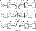
на фиг.3 блок-схема способа и устройства для передачи электрической энергии с тремя пересекающимися однопроводными линиями;figure 3 is a block diagram of a method and apparatus for transmitting electrical energy with three intersecting single-wire lines;
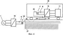
на фиг.4 блок-схема способа и устройства для передачи электрической энергии на мобильное электротранспортное средство;figure 4 is a block diagram of a method and device for transmitting electrical energy to a mobile electric vehicle;
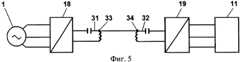
на фиг.5 показана блок-схема способа и устройства для передачи электрической энергии с двумя резонансными контурами;figure 5 shows a block diagram of a method and apparatus for transmitting electrical energy with two resonant circuits;
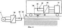
на фиг.6 блок-схема способа и устройства для передачи электрической энергии с двумя резонансными контурами для электроснабжения мобильного электротранспортного средства;Fig.6 is a block diagram of a method and apparatus for transmitting electrical energy with two resonant circuits for powering a mobile electric vehicle;
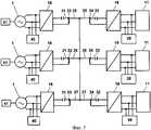
на фиг.7 блок-схема способа и устройства для передачи электрической энергии с тремя соединенными между собой однопроводными линиями.Fig. 7 is a flowchart of a method and apparatus for transmitting electrical energy with three single-wire lines interconnected.
Блок-схема способа и устройства для передачи электрической энергии на фиг.1 содержит источник питания 1, выпрямитель 2 преобразователя частоты 3, первый резонансный контур 4, первый высокочастотный трансформатор 5, однопроводную линию 6, второй высокочастотный трансформатор 7, второй резонансный контур 8, выпрямитель 9 инвертора 10 и электрическую нагрузку 11. Для обеспечения передачи электрической энергии по однопроводной линии 6 в двух противоположных направлениях на входе у источника питания 1 параллельно с выпрямителем 2 преобразователя частоты 3 установлен дополнительный инвертор 12, который через выпрямитель 13 инвертора 12 и блок управления 14 присоединен к выходу преобразователя частоты 3 и ко входу первого резонансного контура 4. У нагрузки 11 на выходе устройства параллельно инвертору 10 установлен выпрямитель 15 преобразователя частоты 16, который через блок управления 17 соединен с выходом второго резонансного контура 8 и входом выпрямителя 9 инвертора 10.The block diagram of the method and device for transmitting electrical energy in figure 1 contains a
На фиг.2 на входе и выходе устройства для передачи электрической энергии установлены многофункциональные блоки 18 и 19, каждый из которых выполняет функции преобразователя частоты, выпрямителя, инвертора и блока управления.In Fig.2, at the input and output of the device for transmitting electric energy,
На фиг.3 устройство для передачи электрической энергии содержит три пересекающиеся однопроводные линии 20, 21, 22, которые электрически соединены в точках пересечения 23. Каждая однопроводная линия содержит на входе и выходе многофункциональные блоки 18 и 19, выполняющие функции преобразователя частоты, выпрямителя, инвертора и блока управления. Многофункциональные блоки, 18 и 19 соединены с однопроводными линиями 20, 21 и 22 через резонансные контуры 4 и 8 и высокочастотные трансформаторы 5 и 7.In Fig. 3, the device for transmitting electric energy contains three intersecting single-
На фиг.4 однопроводная линия 24 выполнена из двух частей 25 и 26. Одна часть 25 однопроводной линии 24 установлена стационарно в виде кабеля, встроенного в дорожное покрытие 27. Однопроводная линия 24 присоединена к источнику питания 1 через многофункциональный блок преобразователь/инвертор 18, первый резонансный контур 4 и первый высокочастотный трансформатор 5, которые также установлены стационарно. Две части 25 и 26 однопроводной линии 24 соединены друг с другом через воздушный конденсатор 28, одна обкладка конденсатора 28 представляет часть 25 однопроводной кабельной линии 24 в дорожном покрытии 27. Вторая обкладка конденсатора 28 выполнена из металлической изолированной пластины 29, которая частью 26 однопроводной линии 24 соединена через второй высокочастотный трансформатор 7, второй резонансный контур 8 и многофункциональный блок 19 преобразователь/инвертор с электрической нагрузкой 11. Вторая часть 25 однопроводной линии 23, высокочастотный трансформатор 7, резонансный контур 8, многофункциональный блок 19 и электрическая нагрузка 11 установлены на мобильном электрическом транспортном средстве 30.4, the single-
На фиг.5 многофункциональный блок 18 преобразователь/инвертор на входе устройства присоединен к источнику питания 1 и первому резонансному контуру 31, а многофункциональный блок 19 преобразователь/инвертор на выходе устройства присоединен ко второму резонансному контуру 32 и к нагрузке 11. Однопроводная линия 6 присоединена к средним выводам 33 и 34 резонансных контуров 31 и 32.In Fig. 5, the multifunctional converter /
На фиг.6 в разрыв однопроводной линии 24 включен воздушный конденсатор 28. Одна часть 25 однопроводной линии 24 установлена стационарно и присоединена к среднему выводу 33 первого резонансного контура 31, который присоединен к стационарному источнику питания 1 через многофункциональный блок 18 преобразователь/инвертор. Вторая часть 26 однопроводной линии 24 соединена с обкладкой 29 воздушного конденсатора 28 и со средним выводом 34 второго резонансного контура 32. Резонансный контур 32 соединен через многофункциональный блок 19 преобразователь/инвертор с электрической нагрузкой 11. Все элементы электрической цепи устройства передачи электрической энергии, соединенные со второй частью 26 однопроводной линии 24, установлены на мобильном электрическом транспортном средстве 30.6, an
На фиг.7 устройство для передачи электрической энергии содержит три однопроводные линии 35, 36, 37, электрически соединенные между собой однопроводной линией 38 в точках 39, 40 и 41. Каждая однопроводная линия содержит на входе и выходе функциональные блоки 18 и 19, выполняющие функции преобразователя частоты, выпрямителя, инвертора и блока управления. Функциональные блоки 18 и 19 соединены с резонансными контурами 31 и 32, средние выводы 33 и 34 которых присоединены к однопроводным линиям 35, 36 и 37.7, the device for transmitting electrical energy contains three single-
Способ передачи электрической энергии реализуется следующим образом. В обычном режиме работы электрическую энергию передают от генератора 1 к нагрузке 11 по однопроводной линии 6. При этом блок управления 14 (фиг.1) сравнивает напряжение на входе и выходе блока 14 и при повышении напряжения на преобразователе частоты 3 соединяет преобразователь частоты 3 с резонансным контуром 4. Управляющий блок 17 при повышении напряжения на резонансном контуре 8 соединяет резонансный контур 8 с выпрямителем 9 инвертора 10 и с нагрузкой 11 (фиг.1). Многофункциональные блоки 18 на фиг.2, 3, 4, 5, 6, 7 при передаче энергии от генератора 1 к нагрузке 11 работают в режиме преобразователя частоты, а функциональные блоки 19 работают в режиме инвертора. При увеличении напряжения на нагрузке 11 за счет рекуперации энергии при торможении электрического транспортного средства (фиг.4 и 6) или при включении у потребителя нагрузки 11 (фиг.1, 2, 3, 5, 7) автономного генератора 39 (фиг.7) на основе дизель-генератора или солнечной батареи 3 (на фиг.1, 2, 3, 5, 7 не показано) блок управления 14 на фиг.1 или функциональный блок преобразователь/инвертор 19 на фиг.2, 3, 4, 5, 6, 7 присоединяет нагрузку 11 через выпрямитель 15 и преобразователь частоты 16 к резонансному контуру 8. Электрическую энергию передают (на фиг.1) через высокочастотный трансформатор 7, однопроводную линию 6, высокочастотный трансформатор 5 на резонансный контур 4. Блок управления 14 сравнивает напряжение на входе и выходе блока 14 и при повышении напряжения на резонансном контуре 4 присоединяет контур 4 к выпрямителю 13 инвертора 12. Передаваемую электрическую энергию вдоль однопроводной линии 6 от нагрузки 11 к генератору 1 используют в нагрузке 40 генератора 1 (фиг.7). При увеличении напряжения на шинах генератора 1 устройство управления 41 генератором 1 на фиг.7 уменьшает мощность генератора 1.The method of transmitting electrical energy is implemented as follows. In normal operation, electrical energy is transmitted from the
Примеры осуществления способа и устройства для передачи электрической энергии.Examples of the method and device for transmitting electrical energy.
Пример 1. Генератор 1 на фиг.3 имеет электрическую мощность 150 кВт. В качестве электрического транспортного средства используют троллейбус с мощностью электропривода нагрузки 11 100 кВт. Электрическая мощность многофункциональных блоков 18 и 19 преобразователь/инвертор 150 кВт. Рабочая частота генератора 1 50 Гц, рабочая частота однопроводной линии 6 25 кГц. Напряжение генератора 1 220/380 В. Напряжение в однопроводной кабельной линии 10 кВ. Длина стационарной части 25 однопроводной кабельной линии 6 10 км. Расстояние между обкладками 25 и 21 воздушного конденсатора 28 0,3 м, напряжение на нагрузке 11 220/380 В, частота 50 Гц. В качестве электропривода используют асинхронный электродвигатель с частотным регулятором числа оборотов. В нормальном режиме при передаче электрической энергии от генератора 1 к нагрузке 11 многофункциональный блок 18 работает в режиме преобразователя частот и многофункциональный блок 19 в режиме инвертора. При торможении троллейбуса механическая энергия торможения преобразуется в электрическую энергию, напряжение на входе асинхронного двигателя нагрузки повышается, и электрическую энергию передают от нагрузки 11 к генератору 1. При этом многофункциональный блок 19 работает в режиме преобразователя частоты, а многофункциональный блок 18 в режиме инвертора. Вместо генератора 1 может быть использована энергосистема или электрическая сеть из нескольких генераторов (фиг.6), а вместо троллейбуса - электроскутер, электровелосипед, электромобиль. При этом способ и устройство позволяют использовать несколько электрических транспортных средств при питании от однопроводной линии 6 или нескольких однопроводных линий (фиг.6) с рекуперацией энергии и передачей электрической энергии от нескольких электрических транспортных средств по одной или нескольким однопроводным линиям от потребителя нагрузки 11 к генератору 1 и в обратном направлении или отключает генератор 1. Функциональные блоки 19 на фиг 2, 3, 4, 5, 6, 7 при передаче электрической энергии от нагрузки 11 к генератору 1 работают в режиме преобразователя частоты, а функциональные блоки 18 - в режиме инвертора.Example 1. The
Пример 2. Три генератора 1 на фиг.7 образуют энергосистему, к которой подключены три однопроводные линии 25, 36, 37, которые соединены дополнительной однопроводной линией 38. Электрическую энергию передают от трех генераторов 1 к трем потребителям нагрузки 11, при этом многофункциональные блоки 18 работают в режиме преобразователя частоты, а многофункциональные блоки 19 - в режиме инвертора. Электрическая мощность каждого генератора 1500 кВт, напряжение 220/380 В, частота 50 Гц. Каждый генератор 1 имеет электрическую нагрузку 40 электрической мощностью 1-500 кВт, которая соединена с шинами генератора 1. У каждого потребителя нагрузки 11 установлен резервный генератор 39 электрической мощностью 500 кВт, напряжением 220/380 В, частотой 50 Гц. Электрическая мощность каждого потребителя нагрузки изменяется от 1 до 500 кВт, напряжение 220/380 В, частота 50 Гц, напряжение на однопроводных линиях 35, 36, 37, 38 30 кВ, частота 30 кГц. При включении одного, двух или трех генераторов 39 у потребителя нагрузки 11 напряжение на выходе многофункциональных блоков 18 и 19 преобразователь/инвертор повышается, и многофункциональные блоки 19 переключаются с режима инвертора в режим преобразователя частоты, а многофункциональные блоки 18 - из режима преобразователя частоты в режим инвертора. Электрическую энергию передают вдоль однопроводных линий 35, 36, 37 от генераторов 39 на стороне потребителя нагрузки 11 к нагрузкам 40 на стороне генераторов 1. В режиме неполных нагрузок 11 и 40 электрическую энергию передают по различным однопроводным линиям в различных, в том числе встречных направлениях, например, по однопроводной линии 35 от генератора 1 к нагрузке 11, а по однопроводным линиям 36 и 37 от генераторов 39 к нагрузке 40.Example 2. Three
Claims (12)
Translated fromRussianPriority Applications (1)
| Application Number | Priority Date | Filing Date | Title |
|---|---|---|---|
| RU2010138863/07ARU2474031C2 (en) | 2010-09-22 | 2010-09-22 | Method and device for electrical energy transmission (versions) |
Applications Claiming Priority (1)
| Application Number | Priority Date | Filing Date | Title |
|---|---|---|---|
| RU2010138863/07ARU2474031C2 (en) | 2010-09-22 | 2010-09-22 | Method and device for electrical energy transmission (versions) |
Publications (2)
| Publication Number | Publication Date |
|---|---|
| RU2010138863A RU2010138863A (en) | 2012-03-27 |
| RU2474031C2true RU2474031C2 (en) | 2013-01-27 |
Family
ID=46030554
Family Applications (1)
| Application Number | Title | Priority Date | Filing Date |
|---|---|---|---|
| RU2010138863/07ARU2474031C2 (en) | 2010-09-22 | 2010-09-22 | Method and device for electrical energy transmission (versions) |
Country Status (1)
| Country | Link |
|---|---|
| RU (1) | RU2474031C2 (en) |
Cited By (61)
| Publication number | Priority date | Publication date | Assignee | Title |
|---|---|---|---|---|
| RU2572360C2 (en)* | 2013-10-18 | 2016-01-10 | Федеральное государственное бюджетное научное учреждение "Всероссийский научно-исследовательский институт электрификации сельского хозяйства"(ФГБНУ ВИЭСХ) | Method and device for electrical energy transmission (versions) |
| RU2577522C2 (en)* | 2014-05-19 | 2016-03-20 | Федеральное государственное бюджетное научное учреждение "Всероссийский научно-исследовательский институт электрификации сельского хозяйства" (ФГБНУ ВИЭСХ) | Method and device for transmission of electric power |
| US9496921B1 (en) | 2015-09-09 | 2016-11-15 | Cpg Technologies | Hybrid guided surface wave communication |
| RU2626815C2 (en)* | 2015-10-14 | 2017-08-02 | Федеральное государственное бюджетное научное учреждение "Федеральный научный агроинженерный центр ВИМ" (ФГБНУ ФНАЦ ВИМ) | Method and device for transmission of electric power |
| US9859707B2 (en) | 2014-09-11 | 2018-01-02 | Cpg Technologies, Llc | Simultaneous multifrequency receive circuits |
| US9857402B2 (en) | 2015-09-08 | 2018-01-02 | CPG Technologies, L.L.C. | Measuring and reporting power received from guided surface waves |
| US9882397B2 (en) | 2014-09-11 | 2018-01-30 | Cpg Technologies, Llc | Guided surface wave transmission of multiple frequencies in a lossy media |
| US9882436B2 (en) | 2015-09-09 | 2018-01-30 | Cpg Technologies, Llc | Return coupled wireless power transmission |
| US9887587B2 (en) | 2014-09-11 | 2018-02-06 | Cpg Technologies, Llc | Variable frequency receivers for guided surface wave transmissions |
| US9887556B2 (en) | 2014-09-11 | 2018-02-06 | Cpg Technologies, Llc | Chemically enhanced isolated capacitance |
| US9885742B2 (en) | 2015-09-09 | 2018-02-06 | Cpg Technologies, Llc | Detecting unauthorized consumption of electrical energy |
| US9887558B2 (en) | 2015-09-09 | 2018-02-06 | Cpg Technologies, Llc | Wired and wireless power distribution coexistence |
| US9887585B2 (en) | 2015-09-08 | 2018-02-06 | Cpg Technologies, Llc | Changing guided surface wave transmissions to follow load conditions |
| US9887557B2 (en) | 2014-09-11 | 2018-02-06 | Cpg Technologies, Llc | Hierarchical power distribution |
| US9893403B2 (en) | 2015-09-11 | 2018-02-13 | Cpg Technologies, Llc | Enhanced guided surface waveguide probe |
| US9893402B2 (en) | 2014-09-11 | 2018-02-13 | Cpg Technologies, Llc | Superposition of guided surface waves on lossy media |
| US9899718B2 (en) | 2015-09-11 | 2018-02-20 | Cpg Technologies, Llc | Global electrical power multiplication |
| US9941566B2 (en) | 2014-09-10 | 2018-04-10 | Cpg Technologies, Llc | Excitation and use of guided surface wave modes on lossy media |
| US9960470B2 (en) | 2014-09-11 | 2018-05-01 | Cpg Technologies, Llc | Site preparation for guided surface wave transmission in a lossy media |
| US9973037B1 (en) | 2015-09-09 | 2018-05-15 | Cpg Technologies, Llc | Object identification system and method |
| US9997040B2 (en) | 2015-09-08 | 2018-06-12 | Cpg Technologies, Llc | Global emergency and disaster transmission |
| US10001553B2 (en) | 2014-09-11 | 2018-06-19 | Cpg Technologies, Llc | Geolocation with guided surface waves |
| US10027116B2 (en) | 2014-09-11 | 2018-07-17 | Cpg Technologies, Llc | Adaptation of polyphase waveguide probes |
| US10027131B2 (en) | 2015-09-09 | 2018-07-17 | CPG Technologies, Inc. | Classification of transmission |
| US10027177B2 (en) | 2015-09-09 | 2018-07-17 | Cpg Technologies, Llc | Load shedding in a guided surface wave power delivery system |
| US10033198B2 (en) | 2014-09-11 | 2018-07-24 | Cpg Technologies, Llc | Frequency division multiplexing for wireless power providers |
| US10033197B2 (en) | 2015-09-09 | 2018-07-24 | Cpg Technologies, Llc | Object identification system and method |
| US10031208B2 (en) | 2015-09-09 | 2018-07-24 | Cpg Technologies, Llc | Object identification system and method |
| US10063095B2 (en) | 2015-09-09 | 2018-08-28 | CPG Technologies, Inc. | Deterring theft in wireless power systems |
| US10062944B2 (en) | 2015-09-09 | 2018-08-28 | CPG Technologies, Inc. | Guided surface waveguide probes |
| US10074993B2 (en) | 2014-09-11 | 2018-09-11 | Cpg Technologies, Llc | Simultaneous transmission and reception of guided surface waves |
| US10079573B2 (en) | 2014-09-11 | 2018-09-18 | Cpg Technologies, Llc | Embedding data on a power signal |
| US10084223B2 (en) | 2014-09-11 | 2018-09-25 | Cpg Technologies, Llc | Modulated guided surface waves |
| US10101444B2 (en) | 2014-09-11 | 2018-10-16 | Cpg Technologies, Llc | Remote surface sensing using guided surface wave modes on lossy media |
| US10103452B2 (en) | 2015-09-10 | 2018-10-16 | Cpg Technologies, Llc | Hybrid phased array transmission |
| US10122218B2 (en) | 2015-09-08 | 2018-11-06 | Cpg Technologies, Llc | Long distance transmission of offshore power |
| US10135301B2 (en) | 2015-09-09 | 2018-11-20 | Cpg Technologies, Llc | Guided surface waveguide probes |
| US10141622B2 (en) | 2015-09-10 | 2018-11-27 | Cpg Technologies, Llc | Mobile guided surface waveguide probes and receivers |
| US10175203B2 (en) | 2014-09-11 | 2019-01-08 | Cpg Technologies, Llc | Subsurface sensing using guided surface wave modes on lossy media |
| US10175048B2 (en) | 2015-09-10 | 2019-01-08 | Cpg Technologies, Llc | Geolocation using guided surface waves |
| US10193595B2 (en) | 2015-06-02 | 2019-01-29 | Cpg Technologies, Llc | Excitation and use of guided surface waves |
| US10193229B2 (en) | 2015-09-10 | 2019-01-29 | Cpg Technologies, Llc | Magnetic coils having cores with high magnetic permeability |
| US10205326B2 (en) | 2015-09-09 | 2019-02-12 | Cpg Technologies, Llc | Adaptation of energy consumption node for guided surface wave reception |
| US10230270B2 (en) | 2015-09-09 | 2019-03-12 | Cpg Technologies, Llc | Power internal medical devices with guided surface waves |
| US10274527B2 (en) | 2015-09-08 | 2019-04-30 | CPG Technologies, Inc. | Field strength monitoring for optimal performance |
| US10312747B2 (en) | 2015-09-10 | 2019-06-04 | Cpg Technologies, Llc | Authentication to enable/disable guided surface wave receive equipment |
| US10324163B2 (en) | 2015-09-10 | 2019-06-18 | Cpg Technologies, Llc | Geolocation using guided surface waves |
| US10396566B2 (en) | 2015-09-10 | 2019-08-27 | Cpg Technologies, Llc | Geolocation using guided surface waves |
| US10408916B2 (en) | 2015-09-10 | 2019-09-10 | Cpg Technologies, Llc | Geolocation using guided surface waves |
| US10408915B2 (en) | 2015-09-10 | 2019-09-10 | Cpg Technologies, Llc | Geolocation using guided surface waves |
| US10447342B1 (en) | 2017-03-07 | 2019-10-15 | Cpg Technologies, Llc | Arrangements for coupling the primary coil to the secondary coil |
| US10498393B2 (en) | 2014-09-11 | 2019-12-03 | Cpg Technologies, Llc | Guided surface wave powered sensing devices |
| US10498006B2 (en) | 2015-09-10 | 2019-12-03 | Cpg Technologies, Llc | Guided surface wave transmissions that illuminate defined regions |
| US10560147B1 (en) | 2017-03-07 | 2020-02-11 | Cpg Technologies, Llc | Guided surface waveguide probe control system |
| US10559866B2 (en) | 2017-03-07 | 2020-02-11 | Cpg Technologies, Inc | Measuring operational parameters at the guided surface waveguide probe |
| US10559893B1 (en) | 2015-09-10 | 2020-02-11 | Cpg Technologies, Llc | Pulse protection circuits to deter theft |
| US10559867B2 (en) | 2017-03-07 | 2020-02-11 | Cpg Technologies, Llc | Minimizing atmospheric discharge within a guided surface waveguide probe |
| US10581492B1 (en) | 2017-03-07 | 2020-03-03 | Cpg Technologies, Llc | Heat management around a phase delay coil in a probe |
| US10630111B2 (en) | 2017-03-07 | 2020-04-21 | Cpg Technologies, Llc | Adjustment of guided surface waveguide probe operation |
| US10680306B2 (en) | 2013-03-07 | 2020-06-09 | CPG Technologies, Inc. | Excitation and use of guided surface wave modes on lossy media |
| US10998993B2 (en) | 2015-09-10 | 2021-05-04 | CPG Technologies, Inc. | Global time synchronization using a guided surface wave |
Citations (9)
| Publication number | Priority date | Publication date | Assignee | Title |
|---|---|---|---|---|
| US593138A (en)* | 1897-11-02 | Nikola Tesla | Electrical Transformer | |
| SU28581A1 (en)* | 1931-02-19 | 1932-12-31 | А.А. Чернышев | Electric power transmission device |
| SU68118A1 (en)* | 1943-08-11 | 1946-11-30 | Г.И. Бабат | Electrical transport device with contactless power transmission |
| US3719829A (en)* | 1970-04-10 | 1973-03-06 | Versar Inc | Laser beam techniques |
| DE4034669A1 (en)* | 1990-10-31 | 1992-05-07 | Joergen Brosow | METHOD FOR REMOTE TRANSMISSION OF ENERGY |
| RU2108649C1 (en)* | 1995-04-11 | 1998-04-10 | Станислав Викторович Авраменко | Method and device for feeding electrical equipment |
| RU2255406C2 (en)* | 2003-02-21 | 2005-06-27 | Государственное научное учреждение Всероссийский научно-исследовательский институт электрификации сельского хозяйства (ГНУ ВИЭСХ) | Method and device for electrical energy transmission |
| RU2342761C1 (en)* | 2007-09-07 | 2008-12-27 | Российская Академия сельскохозяйственных наук Государственное научное учреждение Всероссийский научно-исследовательский институт электрификации сельского хозяйства (ГНУ ВИЭСХ РОССЕЛЬХОЗАКАДЕМИИ) | Method and device for electric energy transmission (versions) |
| RU2009102852A (en)* | 2009-01-29 | 2010-08-10 | Российская Академия сельскохозяйственных наук Государственное научное учреждение Всероссийский научно-исследовательский институт э | METHOD FOR WIRELESS TRANSFER OF ELECTRIC ENERGY AND DEVICE FOR ITS IMPLEMENTATION |
- 2010
- 2010-09-22RURU2010138863/07Apatent/RU2474031C2/ennot_activeIP Right Cessation
Patent Citations (9)
| Publication number | Priority date | Publication date | Assignee | Title |
|---|---|---|---|---|
| US593138A (en)* | 1897-11-02 | Nikola Tesla | Electrical Transformer | |
| SU28581A1 (en)* | 1931-02-19 | 1932-12-31 | А.А. Чернышев | Electric power transmission device |
| SU68118A1 (en)* | 1943-08-11 | 1946-11-30 | Г.И. Бабат | Electrical transport device with contactless power transmission |
| US3719829A (en)* | 1970-04-10 | 1973-03-06 | Versar Inc | Laser beam techniques |
| DE4034669A1 (en)* | 1990-10-31 | 1992-05-07 | Joergen Brosow | METHOD FOR REMOTE TRANSMISSION OF ENERGY |
| RU2108649C1 (en)* | 1995-04-11 | 1998-04-10 | Станислав Викторович Авраменко | Method and device for feeding electrical equipment |
| RU2255406C2 (en)* | 2003-02-21 | 2005-06-27 | Государственное научное учреждение Всероссийский научно-исследовательский институт электрификации сельского хозяйства (ГНУ ВИЭСХ) | Method and device for electrical energy transmission |
| RU2342761C1 (en)* | 2007-09-07 | 2008-12-27 | Российская Академия сельскохозяйственных наук Государственное научное учреждение Всероссийский научно-исследовательский институт электрификации сельского хозяйства (ГНУ ВИЭСХ РОССЕЛЬХОЗАКАДЕМИИ) | Method and device for electric energy transmission (versions) |
| RU2009102852A (en)* | 2009-01-29 | 2010-08-10 | Российская Академия сельскохозяйственных наук Государственное научное учреждение Всероссийский научно-исследовательский институт э | METHOD FOR WIRELESS TRANSFER OF ELECTRIC ENERGY AND DEVICE FOR ITS IMPLEMENTATION |
Cited By (84)
| Publication number | Priority date | Publication date | Assignee | Title |
|---|---|---|---|---|
| US10680306B2 (en) | 2013-03-07 | 2020-06-09 | CPG Technologies, Inc. | Excitation and use of guided surface wave modes on lossy media |
| RU2572360C2 (en)* | 2013-10-18 | 2016-01-10 | Федеральное государственное бюджетное научное учреждение "Всероссийский научно-исследовательский институт электрификации сельского хозяйства"(ФГБНУ ВИЭСХ) | Method and device for electrical energy transmission (versions) |
| RU2577522C2 (en)* | 2014-05-19 | 2016-03-20 | Федеральное государственное бюджетное научное учреждение "Всероссийский научно-исследовательский институт электрификации сельского хозяйства" (ФГБНУ ВИЭСХ) | Method and device for transmission of electric power |
| US9941566B2 (en) | 2014-09-10 | 2018-04-10 | Cpg Technologies, Llc | Excitation and use of guided surface wave modes on lossy media |
| US10998604B2 (en) | 2014-09-10 | 2021-05-04 | Cpg Technologies, Llc | Excitation and use of guided surface wave modes on lossy media |
| US10224589B2 (en) | 2014-09-10 | 2019-03-05 | Cpg Technologies, Llc | Excitation and use of guided surface wave modes on lossy media |
| US10381843B2 (en) | 2014-09-11 | 2019-08-13 | Cpg Technologies, Llc | Hierarchical power distribution |
| US10027116B2 (en) | 2014-09-11 | 2018-07-17 | Cpg Technologies, Llc | Adaptation of polyphase waveguide probes |
| US10498393B2 (en) | 2014-09-11 | 2019-12-03 | Cpg Technologies, Llc | Guided surface wave powered sensing devices |
| US9887587B2 (en) | 2014-09-11 | 2018-02-06 | Cpg Technologies, Llc | Variable frequency receivers for guided surface wave transmissions |
| US9887556B2 (en) | 2014-09-11 | 2018-02-06 | Cpg Technologies, Llc | Chemically enhanced isolated capacitance |
| US10135298B2 (en) | 2014-09-11 | 2018-11-20 | Cpg Technologies, Llc | Variable frequency receivers for guided surface wave transmissions |
| US10193353B2 (en) | 2014-09-11 | 2019-01-29 | Cpg Technologies, Llc | Guided surface wave transmission of multiple frequencies in a lossy media |
| US10175203B2 (en) | 2014-09-11 | 2019-01-08 | Cpg Technologies, Llc | Subsurface sensing using guided surface wave modes on lossy media |
| US9887557B2 (en) | 2014-09-11 | 2018-02-06 | Cpg Technologies, Llc | Hierarchical power distribution |
| US9859707B2 (en) | 2014-09-11 | 2018-01-02 | Cpg Technologies, Llc | Simultaneous multifrequency receive circuits |
| US9893402B2 (en) | 2014-09-11 | 2018-02-13 | Cpg Technologies, Llc | Superposition of guided surface waves on lossy media |
| US10355481B2 (en) | 2014-09-11 | 2019-07-16 | Cpg Technologies, Llc | Simultaneous multifrequency receive circuits |
| US9882397B2 (en) | 2014-09-11 | 2018-01-30 | Cpg Technologies, Llc | Guided surface wave transmission of multiple frequencies in a lossy media |
| US9960470B2 (en) | 2014-09-11 | 2018-05-01 | Cpg Technologies, Llc | Site preparation for guided surface wave transmission in a lossy media |
| US10355480B2 (en) | 2014-09-11 | 2019-07-16 | Cpg Technologies, Llc | Adaptation of polyphase waveguide probes |
| US10101444B2 (en) | 2014-09-11 | 2018-10-16 | Cpg Technologies, Llc | Remote surface sensing using guided surface wave modes on lossy media |
| US10001553B2 (en) | 2014-09-11 | 2018-06-19 | Cpg Technologies, Llc | Geolocation with guided surface waves |
| US10153638B2 (en) | 2014-09-11 | 2018-12-11 | Cpg Technologies, Llc | Adaptation of polyphase waveguide probes |
| US10084223B2 (en) | 2014-09-11 | 2018-09-25 | Cpg Technologies, Llc | Modulated guided surface waves |
| US10320045B2 (en) | 2014-09-11 | 2019-06-11 | Cpg Technologies, Llc | Superposition of guided surface waves on lossy media |
| US10033198B2 (en) | 2014-09-11 | 2018-07-24 | Cpg Technologies, Llc | Frequency division multiplexing for wireless power providers |
| US10320200B2 (en) | 2014-09-11 | 2019-06-11 | Cpg Technologies, Llc | Chemically enhanced isolated capacitance |
| US10079573B2 (en) | 2014-09-11 | 2018-09-18 | Cpg Technologies, Llc | Embedding data on a power signal |
| US10177571B2 (en) | 2014-09-11 | 2019-01-08 | Cpg Technologies, Llc | Simultaneous multifrequency receive circuits |
| US10074993B2 (en) | 2014-09-11 | 2018-09-11 | Cpg Technologies, Llc | Simultaneous transmission and reception of guided surface waves |
| US10193595B2 (en) | 2015-06-02 | 2019-01-29 | Cpg Technologies, Llc | Excitation and use of guided surface waves |
| US10274527B2 (en) | 2015-09-08 | 2019-04-30 | CPG Technologies, Inc. | Field strength monitoring for optimal performance |
| US10320233B2 (en) | 2015-09-08 | 2019-06-11 | Cpg Technologies, Llc | Changing guided surface wave transmissions to follow load conditions |
| US9997040B2 (en) | 2015-09-08 | 2018-06-12 | Cpg Technologies, Llc | Global emergency and disaster transmission |
| US9857402B2 (en) | 2015-09-08 | 2018-01-02 | CPG Technologies, L.L.C. | Measuring and reporting power received from guided surface waves |
| US10122218B2 (en) | 2015-09-08 | 2018-11-06 | Cpg Technologies, Llc | Long distance transmission of offshore power |
| US9887585B2 (en) | 2015-09-08 | 2018-02-06 | Cpg Technologies, Llc | Changing guided surface wave transmissions to follow load conditions |
| US10467876B2 (en) | 2015-09-08 | 2019-11-05 | Cpg Technologies, Llc | Global emergency and disaster transmission |
| US10132845B2 (en) | 2015-09-08 | 2018-11-20 | Cpg Technologies, Llc | Measuring and reporting power received from guided surface waves |
| US9973037B1 (en) | 2015-09-09 | 2018-05-15 | Cpg Technologies, Llc | Object identification system and method |
| US10425126B2 (en) | 2015-09-09 | 2019-09-24 | Cpg Technologies, Llc | Hybrid guided surface wave communication |
| US9496921B1 (en) | 2015-09-09 | 2016-11-15 | Cpg Technologies | Hybrid guided surface wave communication |
| US10135301B2 (en) | 2015-09-09 | 2018-11-20 | Cpg Technologies, Llc | Guided surface waveguide probes |
| US9882606B2 (en) | 2015-09-09 | 2018-01-30 | Cpg Technologies, Llc | Hybrid guided surface wave communication |
| US10536037B2 (en) | 2015-09-09 | 2020-01-14 | Cpg Technologies, Llc | Load shedding in a guided surface wave power delivery system |
| US9887558B2 (en) | 2015-09-09 | 2018-02-06 | Cpg Technologies, Llc | Wired and wireless power distribution coexistence |
| US10062944B2 (en) | 2015-09-09 | 2018-08-28 | CPG Technologies, Inc. | Guided surface waveguide probes |
| US10516303B2 (en) | 2015-09-09 | 2019-12-24 | Cpg Technologies, Llc | Return coupled wireless power transmission |
| US10205326B2 (en) | 2015-09-09 | 2019-02-12 | Cpg Technologies, Llc | Adaptation of energy consumption node for guided surface wave reception |
| US10063095B2 (en) | 2015-09-09 | 2018-08-28 | CPG Technologies, Inc. | Deterring theft in wireless power systems |
| US10230270B2 (en) | 2015-09-09 | 2019-03-12 | Cpg Technologies, Llc | Power internal medical devices with guided surface waves |
| US10031208B2 (en) | 2015-09-09 | 2018-07-24 | Cpg Technologies, Llc | Object identification system and method |
| US10148132B2 (en) | 2015-09-09 | 2018-12-04 | Cpg Technologies, Llc | Return coupled wireless power transmission |
| US10033197B2 (en) | 2015-09-09 | 2018-07-24 | Cpg Technologies, Llc | Object identification system and method |
| US10027177B2 (en) | 2015-09-09 | 2018-07-17 | Cpg Technologies, Llc | Load shedding in a guided surface wave power delivery system |
| US10027131B2 (en) | 2015-09-09 | 2018-07-17 | CPG Technologies, Inc. | Classification of transmission |
| US9882436B2 (en) | 2015-09-09 | 2018-01-30 | Cpg Technologies, Llc | Return coupled wireless power transmission |
| US9885742B2 (en) | 2015-09-09 | 2018-02-06 | Cpg Technologies, Llc | Detecting unauthorized consumption of electrical energy |
| US10333316B2 (en) | 2015-09-09 | 2019-06-25 | Cpg Technologies, Llc | Wired and wireless power distribution coexistence |
| US10498006B2 (en) | 2015-09-10 | 2019-12-03 | Cpg Technologies, Llc | Guided surface wave transmissions that illuminate defined regions |
| US10312747B2 (en) | 2015-09-10 | 2019-06-04 | Cpg Technologies, Llc | Authentication to enable/disable guided surface wave receive equipment |
| US10141622B2 (en) | 2015-09-10 | 2018-11-27 | Cpg Technologies, Llc | Mobile guided surface waveguide probes and receivers |
| US10998993B2 (en) | 2015-09-10 | 2021-05-04 | CPG Technologies, Inc. | Global time synchronization using a guided surface wave |
| US10396566B2 (en) | 2015-09-10 | 2019-08-27 | Cpg Technologies, Llc | Geolocation using guided surface waves |
| US10408916B2 (en) | 2015-09-10 | 2019-09-10 | Cpg Technologies, Llc | Geolocation using guided surface waves |
| US10408915B2 (en) | 2015-09-10 | 2019-09-10 | Cpg Technologies, Llc | Geolocation using guided surface waves |
| US10175048B2 (en) | 2015-09-10 | 2019-01-08 | Cpg Technologies, Llc | Geolocation using guided surface waves |
| US10601099B2 (en) | 2015-09-10 | 2020-03-24 | Cpg Technologies, Llc | Mobile guided surface waveguide probes and receivers |
| US10559893B1 (en) | 2015-09-10 | 2020-02-11 | Cpg Technologies, Llc | Pulse protection circuits to deter theft |
| US10324163B2 (en) | 2015-09-10 | 2019-06-18 | Cpg Technologies, Llc | Geolocation using guided surface waves |
| US10103452B2 (en) | 2015-09-10 | 2018-10-16 | Cpg Technologies, Llc | Hybrid phased array transmission |
| US10193229B2 (en) | 2015-09-10 | 2019-01-29 | Cpg Technologies, Llc | Magnetic coils having cores with high magnetic permeability |
| US10355333B2 (en) | 2015-09-11 | 2019-07-16 | Cpg Technologies, Llc | Global electrical power multiplication |
| US10326190B2 (en) | 2015-09-11 | 2019-06-18 | Cpg Technologies, Llc | Enhanced guided surface waveguide probe |
| US9893403B2 (en) | 2015-09-11 | 2018-02-13 | Cpg Technologies, Llc | Enhanced guided surface waveguide probe |
| US9899718B2 (en) | 2015-09-11 | 2018-02-20 | Cpg Technologies, Llc | Global electrical power multiplication |
| RU2626815C2 (en)* | 2015-10-14 | 2017-08-02 | Федеральное государственное бюджетное научное учреждение "Федеральный научный агроинженерный центр ВИМ" (ФГБНУ ФНАЦ ВИМ) | Method and device for transmission of electric power |
| US10560147B1 (en) | 2017-03-07 | 2020-02-11 | Cpg Technologies, Llc | Guided surface waveguide probe control system |
| US10559866B2 (en) | 2017-03-07 | 2020-02-11 | Cpg Technologies, Inc | Measuring operational parameters at the guided surface waveguide probe |
| US10559867B2 (en) | 2017-03-07 | 2020-02-11 | Cpg Technologies, Llc | Minimizing atmospheric discharge within a guided surface waveguide probe |
| US10581492B1 (en) | 2017-03-07 | 2020-03-03 | Cpg Technologies, Llc | Heat management around a phase delay coil in a probe |
| US10447342B1 (en) | 2017-03-07 | 2019-10-15 | Cpg Technologies, Llc | Arrangements for coupling the primary coil to the secondary coil |
| US10630111B2 (en) | 2017-03-07 | 2020-04-21 | Cpg Technologies, Llc | Adjustment of guided surface waveguide probe operation |
Also Published As
| Publication number | Publication date |
|---|---|
| RU2010138863A (en) | 2012-03-27 |
Similar Documents
| Publication | Publication Date | Title |
|---|---|---|
| RU2474031C2 (en) | Method and device for electrical energy transmission (versions) | |
| RU2340064C1 (en) | Method and device for electrical energy transmission (versions) | |
| US10454290B2 (en) | Apparatus for transferring energy using onboard power electronics with high-frequency transformer isolation and method of manufacturing same | |
| US10763690B2 (en) | Vehicle-side charging circuit for a vehicle with electric drive, and method for operating a vehicle-side current converter, and use of at least one winding of a vehicle-side electric machine for intermediate storagectrical machine for buffer | |
| CN102421627B (en) | Charging device for vehicle | |
| RU2459340C2 (en) | Method and device for transmission of power | |
| KR101974506B1 (en) | Hybrid charging system for electric car | |
| EP2815913A1 (en) | Recharging system for electric vehicles | |
| KR101116498B1 (en) | Energy storage system | |
| CN111510030B (en) | A motor drive system and vehicle | |
| CN107733055B (en) | Charging system for vehicle-mounted power battery of oil-electricity hybrid power locomotive | |
| CN205141780U (en) | Integrated charger of on -vehicle intelligence of electric automobile | |
| KR102647079B1 (en) | Apparatus for charging single and 3 phase electric vehicles | |
| RU2326774C1 (en) | Converting device of the passangers car power supply system | |
| RU2612075C1 (en) | Locomotive traction converter | |
| RU2255405C2 (en) | Method and device for electrical energy transmission | |
| CN110112928B (en) | Electric energy transmission equipment | |
| KR20220069832A (en) | Method and apparatus for directly charging an electric vehicle at a dc current source | |
| Ota et al. | A capacitance design guideline of snubber capacitors for soft switching in bi-directional inductive power transfer system considering battery charging cycle | |
| JP2023520394A (en) | Magnetic resonance charging system | |
| RU2364524C1 (en) | Method of electric power supply to vehicle loads and system to this end | |
| KR20140078999A (en) | Wireless electric power supplying system for electric automobile | |
| US20250253668A1 (en) | Electrical grid-connected three-phase to three-phase direct matrix converter | |
| RU124074U1 (en) | HIGH VOLTAGE DC ELECTRICITY TRANSMISSION SYSTEM | |
| RU118804U1 (en) | DEVICE FOR REVERSE TRANSMISSION OF ELECTRIC ENERGY (OPTIONS) |
Legal Events
| Date | Code | Title | Description |
|---|---|---|---|
| MM4A | The patent is invalid due to non-payment of fees | Effective date:20121001 |