RU2473888C1 - Method of determining state of road surface - Google Patents
Method of determining state of road surfaceDownload PDFInfo
- Publication number
- RU2473888C1 RU2473888C1RU2011138712/28ARU2011138712ARU2473888C1RU 2473888 C1RU2473888 C1RU 2473888C1RU 2011138712/28 ARU2011138712/28 ARU 2011138712/28ARU 2011138712 ARU2011138712 ARU 2011138712ARU 2473888 C1RU2473888 C1RU 2473888C1
- Authority
- RU
- Russia
- Prior art keywords
- resonator
- frequency
- electromagnetic waves
- road
- road surface
- Prior art date
Links
- 238000000034methodMethods0.000titleclaimsabstractdescription24
- 230000010355oscillationEffects0.000claimsabstractdescription6
- 239000002344surface layerSubstances0.000claimsabstractdescription4
- 239000000126substanceSubstances0.000abstractdescription4
- XLYOFNOQVPJJNP-UHFFFAOYSA-NwaterSubstancesOXLYOFNOQVPJJNP-UHFFFAOYSA-N0.000description51
- 239000010410layerSubstances0.000description18
- 239000010426asphaltSubstances0.000description3
- 238000001556precipitationMethods0.000description3
- 230000005855radiationEffects0.000description3
- 238000004891communicationMethods0.000description2
- 238000010586diagramMethods0.000description2
- 229920002313fluoropolymerPolymers0.000description2
- 238000005259measurementMethods0.000description2
- 230000015572biosynthetic processEffects0.000description1
- 239000011248coating agentSubstances0.000description1
- 238000000576coating methodMethods0.000description1
- 230000007423decreaseEffects0.000description1
- 238000001514detection methodMethods0.000description1
- 230000005284excitationEffects0.000description1
- 238000011065in-situ storageMethods0.000description1
- 230000001678irradiating effectEffects0.000description1
- 239000000203mixtureSubstances0.000description1
- 239000002245particleSubstances0.000description1
- 238000012545processingMethods0.000description1
- 239000000523sampleSubstances0.000description1
- 239000013535sea waterSubstances0.000description1
- 239000002689soilSubstances0.000description1
- 239000002352surface waterSubstances0.000description1
- 238000002604ultrasonographyMethods0.000description1
Images

Landscapes
- Length-Measuring Devices Using Wave Or Particle Radiation (AREA)
Abstract
Description
Translated fromRussianИзобретение относится к измерительной технике и может быть применено для бесконтактного определения состояния поверхности дорожного полотна, на котором возможно образование слоя воды, снега или льда.The invention relates to measuring technique and can be used for non-contact determination of the state of the surface of the roadway, which may form a layer of water, snow or ice.
Известны различные способы определения состояния дорожных покрытий, основанные на различных принципах и связанные с измерением электрической емкости (US 5398547, 21.03.1995), электрической проводимости и сопротивления (US 4745803, 24.05.1988; US 4287472, 01.09.1981), с применением ультразвуковых волн (US 5095754, 17.03.1992), световых волн, в частности, инфракрасного излучения и др. (Winter В. Sensoren warnen vor Wasser oder Eis auf der Strasse // Sensor magazine. 1998. N.2. P.8). Однако они имеют определенные недостатки: некоторые из них являются контактными способами и характеризуются износом компонент применяемых измерительных устройств, связаны с применением линий связи между датчиками и электронными блоками; другие способы, являясь бесконтактными, чувствительны к погодным условиям и не могут определять толщину водного слоя.There are various methods for determining the condition of road surfaces, based on various principles and related to the measurement of electrical capacitance (US 5398547, 03.21.1995), electrical conductivity and resistance (US 4745803, 05.24.1988; US 4287472, 09.09.1981), using ultrasound waves (US 5095754, 03.17.1992), light waves, in particular infrared radiation, etc. (Winter B. Sensoren warnen vor Wasser oder Eis auf der Strasse // Sensor magazine. 1998. N.2. P.8). However, they have certain disadvantages: some of them are contact methods and are characterized by wear of the components of the applied measuring devices, associated with the use of communication lines between sensors and electronic units; other methods, being non-contact, are sensitive to weather conditions and cannot determine the thickness of the water layer.
Известны также микроволновые способы определения состояния дорожного покрытия (US 4690553, 01.09.1987; US 5686841, 11.11.1997; Hertl S., Schaffar G., Störi H. Contactless determination of the properties of water films on road // Journal of Physics E.: Scientific Instruments. 1988. Vol.21. N.10. P.955-958). Эти способы и реализующие их устройства позволяют производить бесконтактные измерения, определять и идентифицировать наличие воды, снега или льда на поверхности дорожного полотна и измерять их толщину. Однако известные способы имеют существенный недостаток: они не обеспечивают высокую точность измерения толщины слоя вещества (воды, снега или льда), который может быть очень тонким. Кроме того, эти способы достаточно сложны и имеют высокую стоимость реализации.Microwave methods for determining the state of pavement are also known (US 4690553, 09/01/1987; US 5686841, 11/11/1997; Hertl S., Schaffar G., Störi H. Contactless determination of the properties of water films on road // Journal of Physics E .: Scientific Instruments. 1988. Vol.21. N.10. P.955-958). These methods and devices that implement them allow you to make non-contact measurements, determine and identify the presence of water, snow or ice on the surface of the roadway and measure their thickness. However, the known methods have a significant drawback: they do not provide high accuracy in measuring the thickness of a layer of a substance (water, snow or ice), which can be very thin. In addition, these methods are quite complex and have a high implementation cost.
Известно также техническое решение (US 5497100, 05.03.1996), которое по технической сущности наиболее близко к предлагаемому способу и принято в качестве прототипа. Этот способ-прототип заключается в зондировании поверхности дороги частотно-модулированными электромагнитными волнами, приеме отраженных волн, получении множества значений амплитуд разностных сигналов, соответствующих принимаемым и излучаемым волнам, сравнении данного множества с множеством известных моделей поверхности и определении состояния дороги по результатам этого сравнения. Данный способ, как и вышеупомянутые способы, характеризуется невысокой точностью и сложен в реализации: процесс получения полезной информации связан со сложной функциональной обработкой принимаемых сигналов.A technical solution is also known (US 5497100, 03/05/1996), which, by its technical nature, is closest to the proposed method and is adopted as a prototype. This prototype method consists in sensing a road surface with frequency-modulated electromagnetic waves, receiving reflected waves, obtaining a plurality of difference signal amplitudes corresponding to the received and emitted waves, comparing this set with a plurality of known surface models and determining the state of the road from the results of this comparison. This method, like the aforementioned methods, is characterized by low accuracy and is difficult to implement: the process of obtaining useful information is associated with complex functional processing of the received signals.
Поэтому существует необходимость нахождения технического решения, свободного от указанных недостатков и обеспечивающего возможность проведения измерений с повышенной точностью и более простыми средствами.Therefore, there is a need to find a technical solution that is free of these drawbacks and provides the ability to measure with increased accuracy and simpler means.
Техническим результатом настоящего изобретения является повышение точности и упрощение процесса определения состояния покрытия дороги.The technical result of the present invention is to improve the accuracy and simplification of the process of determining the state of the road surface.
Технический результат в предлагаемом способе определения состояния поверхности дороги достигается тем, что контролируемый участок поверхности дороги зондируют частотно-модулированными электромагнитными волнами, принимают отраженные от этого участка поверхности электромагнитные волны, при этом в поверхностный слой зондируемого участка дороги встраивают резонатор с изменяющейся в соответствии с состоянием дороги резонансной частотой электромагнитных колебаний, которые возбуждают в нем зондирующими электромагнитными волнами, измеряют мощность отраженных от резонатора и принимаемых электромагнитных волн и по величине частоты, соответствующей минимуму принимаемой мощности, судят о состоянии поверхности дороги, при этом диапазон изменения частоты зондирующих электромагнитных волн выбирают из условия его превышения диапазона возможных значений резонансной частоты резонатора, соответствующих определяемому состоянию поверхности дороги.The technical result in the proposed method for determining the state of the road surface is achieved by the fact that the controlled section of the road surface is probed with frequency-modulated electromagnetic waves, electromagnetic waves reflected from this section of the surface are received, and a resonator is inserted into the surface layer of the probed section of the road, which changes in accordance with the state of the road the resonant frequency of electromagnetic waves that excite sounding electromagnetic waves in it, ism the power of the electromagnetic waves reflected from the resonator and received is lost and the state of the road is judged by the magnitude of the frequency corresponding to the minimum received power, and the frequency range of the probing electromagnetic waves is selected from the condition that it exceeds the range of possible resonant frequency of the resonator corresponding to the determined state of the road surface .
Предлагаемый способ поясняется чертежами.The proposed method is illustrated by drawings.
На фиг.1 приведена схема размещения устройства для реализации способа.Figure 1 shows the layout of the device for implementing the method.
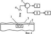
На фиг.2 изображена структурная схема устройства для реализации способа.Figure 2 shows a structural diagram of a device for implementing the method.
На фиг.3 изображен график зависимости мощности принимаемого сигнала от частоты.Figure 3 shows a graph of the received signal power versus frequency.
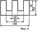
На фиг.4 приведен коаксиальный резонатор.Figure 4 shows a coaxial resonator.
На чертежах показаны коаксиальный резонатор 1, дорожное покрытие 2, слой воды, льда или снега 3, антенна 4, штанга 5, генератор 6, циркулятор 7, детектор 8, регистратор 9.The drawings show a
Сущность предлагаемого способа состоит в следующем.The essence of the proposed method is as follows.
Согласно данному способу, в дорожном полотне размещают чувствительный элемент в виде пассивного резонатора-отражателя электромагнитных волн, падающих на него. Относительное расположение антенны и резонатора такое, что волны, излучаемые антенной и отраженные данным резонатором, поступают на эту антенну. При этом нет необходимости иметь линии связи между погруженным чувствительным элементом и электронным блоком, расположенным вне дороги. В качестве такого пассивного резонатора-отражателя могут быть применены различные высокочастотные (ВЧ) и сверхвысокочастотные (СВЧ) резонаторы, встраиваемые в дорожное полотно в области контроля под приемо-передающей антенной. Электромагнитные волны, излучаемые этой антенной и отраженные от пассивного резонатора-отражателя, поступают на эту антенну. Возможно применение также и раздельных передающей и приемной антенн.According to this method, a sensitive element is placed in the roadway in the form of a passive resonator-reflector of electromagnetic waves incident on it. The relative location of the antenna and resonator is such that the waves emitted by the antenna and reflected by this resonator arrive at this antenna. In this case, there is no need for communication lines between the immersed sensitive element and the electronic unit located off the road. As such a passive resonator-reflector, various high-frequency (HF) and ultra-high-frequency (microwave) resonators can be used that are built into the roadway in the control area under the transmit-receive antenna. Electromagnetic waves emitted by this antenna and reflected from the passive resonator-reflector are fed to this antenna. It is also possible to use separate transmitting and receiving antennas.
В качестве чувствительного элемента, подверженного влиянию осадков (дождя, снега) с образованием на его поверхности слоя воды, снега или льда, могут быть использованы различные типы резонаторов, способных запасать электромагнитную энергию за счет энергии облучающих их электромагнитных волн (частично-открытых объемных резонаторов, резонаторов с колебаниями типа ТЕМ и др.). Для этого они должны иметь отверстия в полостях и т.п. для обеспечения такой возможности. В частности, таким резонатором может являться четвертьволновый коаксиальный резонатор 1, разомкнутый на одном из торцов (фиг.1). Он размещен в дорожном покрытии 2 (асфальте и др.) и, возможно, покрыт слоем воды, льда или снега 3. На открытой поверхности полости коаксиального резонатора 1 может быть размещена тонкая пластина диэлектрика с малыми значениями диэлектрической проницаемости и тангенса угла диэлектрических потерь, например фторопласта (на чертежах она не показана), герметично закрывающая полость резонатора. Верхняя поверхность резонатора 1 расположена копланарно с поверхностью дороги в контролируемой области. Открытый торец резонатора 1 направлен в сторону антенны 5, расположенной над контролируемой областью дорожного полотна там, где в дорожном покрытии расположен данный резонатор 1. Эта приемо-передающая антенна 5 закреплена с помощью штанги 6. Излучение антенны направлено вертикально вниз, а открытый торец резонатора направлен вверх, принимая излучение антенны и отражая его обратно по направлению к антенне. В зависимости от наличия или отсутствия слоя воды, льда или снега на дорожном полотне и его параметров (толщины, диэлектрической проницаемости) изменяется собственная (резонансная) частота ƒr резонатора 1.As a sensitive element subject to the influence of precipitation (rain, snow) with the formation of a layer of water, snow or ice on its surface, various types of resonators can be used that can store electromagnetic energy due to the energy of electromagnetic waves irradiating them (partially open volume resonators, resonators with oscillations of the TEM type, etc.). To do this, they must have holes in the cavities, etc. to provide such an opportunity. In particular, such a resonator can be a quarter-wave
С помощью антенны 5 пассивный резонатор 1 зондируют частотно-модулированными электромагнитными волнами СВЧ-диапазона частот. При этом диапазон изменения частоты зондирующих электромагнитных волн выбирают из условия его превышения диапазона значений резонансной частоты резонатора, соответствующих возможному состоянию поверхности дороги - наличию или отсутствию слоя воды, льда или снега в диапазоне возможных значений их толщины. Структурная схема измерительного устройства приведена на фиг.2. Здесь генератор 6 частотно-модулированных электромагнитных колебаний подсоединен через циркулятор 7 к антенне 5, зондирующей дорожное полотно 2, которое содержит пассивный резонатор 1 с покрывающим его, возможно, слоем 3 воды, снега или льда. Диапазон частот генератора 6 должен охватывать диапазон возможных изменений резонансной частоты пассивного резонатора 1, вызванных наличием слоя воды, льда или снега 3 на его открытой поверхности, направленной в сторону антенны 5. Электромагнитные волны, отраженные от данного резонатора 1 с изменяющейся в соответствии с состоянием дороги резонансной частотой электромагнитных колебаний, которые возбуждают в нем зондирующими электромагнитными волнами, поступают через циркулятор 7 на детектор 8; затем отраженный сигнал подается на регистратор 9. Когда изменяющаяся частота ƒ излучаемых электромагнитных волн совпадает с собственной (резонансной) частотой ƒr резонатора 1, мощность Р (амплитуда) принимаемого сигнала резко уменьшается вследствие возбуждения электромагнитных колебаний в резонаторе 1 (фиг.3). Определяя частоту, при которой имеет место минимум мощности Р (амплитуды) принимаемого сигнала и которая соответствует измеряемой резонансной частоте ƒr, можно определить параметры контролируемого поверхностного слоя воды, льда или снега 3. На фиг.3 кривая в виде сплошной линии соответствует исходной (без покрывающего слоя) зависимости P(ƒ) с резонансной частотой ƒr0; кривая в виде пунктирной линии соответствует текущей (с покрывающим слоем) зависимости P(ƒ) с резонансной частотой ƒr.Using the antenna 5, the
Для определения состояния поверхности дороги, обусловленного наличием на ее поверхности слоя осадков или его отсутствием, необходимо знать электрофизические параметры в СВЧ-диапазоне частот электромагнитных волн как самого дорожного полотна, в частности асфальтовых смесей, так и возможных веществ на его поверхности - воды, снега и льда. Так как в данном случае поверхность открытого торца резонатора размещена копланарно с поверхностью дороги, то осажденный слой воды, снега или льда присутствует непосредственно на этой поверхности. Поэтому в данном случае не следует принимать во внимание свойства асфальтового покрытия, а тонкая пластина диэлектрика на открытой поверхности полости резонатора слабо влияет на значение его собственной (резонансной) частоты (диэлектрическая проницаемость ε≈2,1 для фторопласта), то есть резонатор можно рассматривать как полый. Электрофизические параметры воды, снега и льда существенно отличаются друг от друга.To determine the state of the road surface due to the presence of a precipitation layer on its surface or its absence, it is necessary to know the electrophysical parameters in the microwave frequency range of electromagnetic waves of both the roadway, in particular asphalt mixtures, and possible substances on its surface - water, snow and ice. Since in this case the surface of the open end of the resonator is coplanar with the road surface, a deposited layer of water, snow, or ice is present directly on this surface. Therefore, in this case, the properties of the asphalt coating should not be taken into account, and a thin dielectric plate on the open surface of the cavity of the resonator weakly affects the value of its natural (resonant) frequency (dielectric constant ε≈2.1 for fluoroplastic), i.e., the resonator can be considered as hollow. The electrophysical parameters of water, snow and ice are significantly different from each other.
Электрофизические параметры воды, снега и льда.Electrophysical parameters of water, snow and ice.
Снег. Диэлектрическая проницаемость ε снега является функцией влагосодержания и плотности. Величина ε для сухого снега не зависит от частоты в диапазоне от примерно 1 МГц до, по крайней мере, 10 ГГц. Величина ε зависит от плотности снега, объема ледяной фракции и от формы частиц льда (Matzler С.Microwave permittivity of dry snow // IEEE Trans. on Geoscience and Remote Sensing. 1996. Vol.34. N.2. P.573-581). Так, если объем ледяной фракции изменяется от 0,05 до 0,5, то соответствующее изменение эффективной диэлектрической проницаемости сухого снега лежит в пределах от примерно 1,1 до 1,85. Значение мнимой части ε″ диэлектрической проницаемости ε для сухого снега меньше, чем 4×10⁻⁴ (для плотности снега менее чем 0,5 г/см3), для диапазона частот вблизи 1 ГГц (Kendra J.R., Ulaby F.T., Sarabandi K. Snow probe for in situ determination of wetness and density// IEEE Trans. on Geoscience and Remote Sensing. 1994. Vol.32. N.6. P.1152-1159). Диэлектрическая проницаемость ε имеет более высокие значения с увеличением влагосодержания W и плотности ρ снега. Так, если W=5,8%, то ε≈1,8 для ρ=0,41 г/см3, ε≈3,5 для ρ=0,58 г/см3 (Denoth A. The monopole-antenna: a practical snow and soil wetness sensor// IEEE Trans. on Geoscience and Remote Sensing. 1997. Vol.35. N.5. P.1371-1375).Snow. The dielectric constant ε of snow is a function of moisture content and density. The ε value for dry snow is independent of the frequency in the range from about 1 MHz to at least 10 GHz. The value of ε depends on the density of snow, the volume of the ice fraction and the shape of the ice particles (Matzler C. Microwave permittivity of dry snow // IEEE Trans. On Geoscience and Remote Sensing. 1996. Vol.34. N.2. P.573-581 ) So, if the volume of the ice fraction varies from 0.05 to 0.5, then the corresponding change in the effective dielectric constant of dry snow lies in the range from about 1.1 to 1.85. The imaginary part ε ″ dielectric constant ε for dry snow is less than 4 × 10⁻⁴ (for snow density less than 0.5 g / cm3 ), for the frequency range near 1 GHz (Kendra JR, Ulaby FT, Sarabandi K. Snow probe for in situ determination of wetness and density // IEEE Trans. On Geoscience and Remote Sensing. 1994. Vol.32. N.6. P.1152-1159). The dielectric constant ε has higher values with increasing moisture content W and density ρ of snow. So, if W = 5.8%, then ε≈1.8 for ρ = 0.41 g / cm3 , ε≈3.5 for ρ = 0.58 g / cm3 (Denoth A. The monopole-antenna : a practical snow and soil wetness sensor // IEEE Trans. on Geoscience and Remote Sensing. 1997. Vol.35. N.5. P.1371-1375).
Лед. Диэлектрическая проницаемость льда на частотах СВЧ-диапазона имеет величину ε=3,1-j·0,023 (Bianchi M., d'Ambrosio G., Massa R., Migliore M.D. Microwave devices for ice detection on aircraft // Journal of Microwave Power. 1996. Vol.31. N. 2. P. 83-86). Диэлектрические потери малы, лед может рассматриваться как диэлектрическое вещество с весьма малыми диэлектрическими потерями.Ice. The dielectric constant of ice at microwave frequencies is ε = 3.1-j · 0.023 (Bianchi M., d'Ambrosio G., Massa R., Migliore MD Microwave devices for ice detection on aircraft // Journal of Microwave Power. 1996. Vol.31. N. 2. P. 83-86). The dielectric losses are small, ice can be considered as a dielectric substance with very small dielectric losses.
Вода. Диэлектрическая проницаемость, коэффициент диэлектрических потерь воды зависит от многих факторов (свободного или связанного состояния, солесодержания, температуры, присутствующих включений, длины волны и др.). Вода является полярным диэлектриком, центры ее молекул с противоположными зарядами находятся на некотором расстоянии друг от друга. Максимальное значение частотной зависимости ε″ около частоты ƒ≈10 ГГц обусловлено увеличением потерь в воде вблизи частоты естественных колебаний ее молекул. Частотная зависимость комплексной диэлектрической проницаемости ε выражается на линейном участке зависимости ε″(ƒ) следующим соотношением для сырой воды: ε=84(1-j·108/42ƒ); 105≤ƒ≤3·108 Гц; для морской воды: ε=80(1-j·109/ƒ); 106≤ƒ≤109 Гц (Финкельштейн М.И., Мендельсон В.Л., Кутев В.А. Радиолокация слоистых земных покровов. M.: Советсткое радио. 1977. 176 с.). Ряд более подробных данных о значениях ε для воды при разных условиях содержатся в (Nyfors E.G., Vainikainen P. Industrial microwave sensors. Artech House, Inc. 1989. 351 p.).Water. The dielectric constant, the coefficient of dielectric loss of water depends on many factors (free or bound state, salinity, temperature, inclusions present, wavelength, etc.). Water is a polar dielectric, the centers of its molecules with opposite charges are at some distance from each other. The maximum value of the frequency dependence ε ″ near the frequency ƒ≈10 GHz is due to an increase in losses in water near the frequency of natural vibrations of its molecules. The frequency dependence of the complex permittivity ε is expressed on the linear plot of the ε ″ (ƒ) dependence by the following relation for raw water: ε = 84 (1-j · 108 / 42ƒ); 105 ≤ƒ≤3 · 108 Hz; for sea water: ε = 80 (1-j · 109 / ƒ); 106 ≤ƒ≤109 Hz (Finkelshtein M.I., Mendelssohn V.L., Kutev V.A. Radar location of layered earth covers. M .: Soviet radio. 1977. 176 p.). A series of more detailed data on ε values for water under different conditions are contained in (Nyfors EG, Vainikainen P. Industrial microwave sensors. Artech House, Inc. 1989. 351 p.).
Поскольку электрофизические параметры воды, снега и льда существенно отличаются друг от друга и единицы (что соответствует отсутствию такого слоя на дороге), то значения частоты ƒr и диапазоны ее изменения существенно отличаются при наличии того или иного слоя на поверхности дороги или при его отсутствии. Это позволяет определить, какой вид слоя осадков (вода, снег или лед) присутствует на дороге (или отсутствует), а также, по величине изменения частоты ƒr, найти его толщину.Since the electrophysical parameters of water, snow, and ice are significantly different from each other and unity (which corresponds to the absence of such a layer on the road), the frequency values ƒr and its variation ranges differ significantly in the presence or absence of a layer on the road surface. This allows you to determine what type of precipitation layer (water, snow or ice) is present on the road (or absent), and also, by the magnitude of the frequency change ƒr , find its thickness.
Возможные размеры (в миллиметрах) полого коаксиального резонатора 1 показаны на фиг.4. Резонансная частота такого резонатора составляет приблизительно 1,5 ГГц (наличие тонкой диэлектрической пластины на открытой поверхности его полости незначительно снижает эту частоту). Соответственно, частота генератора 6 должна охватывать возможные значения этой резонансной частоты.Possible dimensions (in millimeters) of the hollow
Помимо вышерассмотренного коаксиального резонатора, возможно применение в качестве отражающих резонаторов и других различных конструкций пассивных резонаторов, включая планарные устройства.In addition to the coaxial resonator discussed above, it is possible to use passive resonators, including planar devices, as reflecting resonators and other various designs.
Таким образом, данный способ позволяет достаточно просто и с высокой точностью определять состояние поверхности дороги. Он дает возможность фиксировать наличие или отсутствие на поверхности дороги слоя воды, снега или льда и производить их идентификацию.Thus, this method allows quite simply and with high accuracy to determine the state of the road surface. It makes it possible to record the presence or absence of a layer of water, snow or ice on the road surface and to make their identification.
Claims (1)
Translated fromRussianPriority Applications (1)
| Application Number | Priority Date | Filing Date | Title |
|---|---|---|---|
| RU2011138712/28ARU2473888C1 (en) | 2011-09-22 | 2011-09-22 | Method of determining state of road surface |
Applications Claiming Priority (1)
| Application Number | Priority Date | Filing Date | Title |
|---|---|---|---|
| RU2011138712/28ARU2473888C1 (en) | 2011-09-22 | 2011-09-22 | Method of determining state of road surface |
Publications (1)
| Publication Number | Publication Date |
|---|---|
| RU2473888C1true RU2473888C1 (en) | 2013-01-27 |
Family
ID=48807091
Family Applications (1)
| Application Number | Title | Priority Date | Filing Date |
|---|---|---|---|
| RU2011138712/28ARU2473888C1 (en) | 2011-09-22 | 2011-09-22 | Method of determining state of road surface |
Country Status (1)
| Country | Link |
|---|---|
| RU (1) | RU2473888C1 (en) |
Cited By (4)
| Publication number | Priority date | Publication date | Assignee | Title |
|---|---|---|---|---|
| RU2550778C1 (en)* | 2014-01-10 | 2015-05-10 | Учреждение Российской академии наук Институт проблем управления им. В.А. Трапезникова РАН | Method of determining state of road surface |
| RU2552272C1 (en)* | 2014-03-14 | 2015-06-10 | Федеральное государственное бюджетное учреждение науки Институт проблем управления им. В.А. Трапезникова Российской академии наук | Method of determining state of road surface |
| RU2637797C1 (en)* | 2016-07-22 | 2017-12-07 | Федеральное государственное бюджетное учреждение науки Институт проблем управления им. В.А. Трапезникова Российской академии наук | Method for determining state of road surface |
| RU2750563C1 (en)* | 2020-08-12 | 2021-06-29 | Федеральное государственное казенное военное образовательное учреждение высшего образования "Военный учебно-научный центр Военно-воздушных сил "Военно-воздушная академия имени профессора Н.Е. Жуковского и Ю.А. Гагарина" (г. Воронеж) Министерства обороны Российской Федерации | Method for remote identification of ice-snow cover state |
Citations (6)
| Publication number | Priority date | Publication date | Assignee | Title |
|---|---|---|---|---|
| JPS52152253A (en)* | 1976-06-11 | 1977-12-17 | Matsushita Electric Ind Co Ltd | Road surface condition detector |
| EP0600375A1 (en)* | 1992-11-30 | 1994-06-08 | Mitsubishi Chemical Corporation | Process for producing 2,6-naphthalenedicarboxylic acid |
| US5497100A (en)* | 1994-10-17 | 1996-03-05 | Hughes Aircraft Company | Surface condition sensing system |
| US5652522A (en)* | 1995-09-21 | 1997-07-29 | Hughes Electronics | Dielectric-loaded surface-condition sensor and method |
| JPH10293111A (en)* | 1997-04-17 | 1998-11-04 | Sanyo Denshi Syst Kk | Method and system for detecting freeze of pavement |
| WO2001073472A2 (en)* | 2000-03-31 | 2001-10-04 | G. Lufft Mess- Und Regeltechnik Gmbh | Device for measuring layer thicknesses |
- 2011
- 2011-09-22RURU2011138712/28Apatent/RU2473888C1/ennot_activeIP Right Cessation
Patent Citations (6)
| Publication number | Priority date | Publication date | Assignee | Title |
|---|---|---|---|---|
| JPS52152253A (en)* | 1976-06-11 | 1977-12-17 | Matsushita Electric Ind Co Ltd | Road surface condition detector |
| EP0600375A1 (en)* | 1992-11-30 | 1994-06-08 | Mitsubishi Chemical Corporation | Process for producing 2,6-naphthalenedicarboxylic acid |
| US5497100A (en)* | 1994-10-17 | 1996-03-05 | Hughes Aircraft Company | Surface condition sensing system |
| US5652522A (en)* | 1995-09-21 | 1997-07-29 | Hughes Electronics | Dielectric-loaded surface-condition sensor and method |
| JPH10293111A (en)* | 1997-04-17 | 1998-11-04 | Sanyo Denshi Syst Kk | Method and system for detecting freeze of pavement |
| WO2001073472A2 (en)* | 2000-03-31 | 2001-10-04 | G. Lufft Mess- Und Regeltechnik Gmbh | Device for measuring layer thicknesses |
Cited By (4)
| Publication number | Priority date | Publication date | Assignee | Title |
|---|---|---|---|---|
| RU2550778C1 (en)* | 2014-01-10 | 2015-05-10 | Учреждение Российской академии наук Институт проблем управления им. В.А. Трапезникова РАН | Method of determining state of road surface |
| RU2552272C1 (en)* | 2014-03-14 | 2015-06-10 | Федеральное государственное бюджетное учреждение науки Институт проблем управления им. В.А. Трапезникова Российской академии наук | Method of determining state of road surface |
| RU2637797C1 (en)* | 2016-07-22 | 2017-12-07 | Федеральное государственное бюджетное учреждение науки Институт проблем управления им. В.А. Трапезникова Российской академии наук | Method for determining state of road surface |
| RU2750563C1 (en)* | 2020-08-12 | 2021-06-29 | Федеральное государственное казенное военное образовательное учреждение высшего образования "Военный учебно-научный центр Военно-воздушных сил "Военно-воздушная академия имени профессора Н.Е. Жуковского и Ю.А. Гагарина" (г. Воронеж) Министерства обороны Российской Федерации | Method for remote identification of ice-snow cover state |
Similar Documents
| Publication | Publication Date | Title |
|---|---|---|
| Sihvola et al. | Snow fork for field determination of the density and wetness profiles of a snow pack | |
| US10101288B2 (en) | Wireless impedance spectrometer | |
| Bobrov et al. | Soil moisture measurement by the dielectric method | |
| Palandoken et al. | Novel microwave fluid sensor for complex dielectric parameter measurement of ethanol–water solution | |
| WO2014153263A1 (en) | Systems and methods for asphalt density and soil moisture measurements using ground penetrating radar | |
| CN110446918A (en) | For detecting the sensing system of material property | |
| Huang | Antenna sensors in passive wireless sensing systems | |
| CN101535844A (en) | Methods, systems, and computer program products for determining a property of construction material | |
| RU2473888C1 (en) | Method of determining state of road surface | |
| Rezaei et al. | A new 1.4-GHz soil moisture sensor | |
| Shah et al. | Microwaves see thin ice: A review of ice and snow sensing using microwave techniques | |
| Kilani et al. | Wireless microwave sensor network using split ring resonators for ice monitoring applications | |
| US20110169507A1 (en) | Methods and apparatus for the determination of moisture content | |
| Le Breton et al. | Monitoring snowpack SWE and temperature using RFID tags as wireless sensors | |
| Yigit et al. | Grain moisture detection by using a-scan radar measurement | |
| Karavayskiy et al. | The effect of clay content on the spectra of permetivity of mineral soils at positive temperatures | |
| RU2550778C1 (en) | Method of determining state of road surface | |
| Guattari et al. | Permittivity of sub-soil materials retrieved through transmission line model and GPR data | |
| Niknahad et al. | Tunable Microwave Waveguide Probe for non-Contact Ice Detection on Metallic Surfaces | |
| RU2637797C1 (en) | Method for determining state of road surface | |
| Al Takach et al. | Permittivity Extraction of Moist Soil for GPR Applications | |
| Bermond et al. | A microwave frequency range experiment for the measurement of snow density and liquid water content | |
| Calla et al. | Estimation of emissivity and scattering coefficient of low saline water contaminated by diesel in Cj band(5. 3 GHz) and Ku band(13. 4 GHz) | |
| Muller et al. | Optimising a modified free-space permittivity characterisation method for civil engineering applications | |
| Lu et al. | A phase delay line sensor for water quality monitoring based on spherical conformal reflectarray antenna |
Legal Events
| Date | Code | Title | Description |
|---|---|---|---|
| MM4A | The patent is invalid due to non-payment of fees | Effective date:20180923 |