RU2472927C2 - Solution mining method and system - Google Patents
Solution mining method and systemDownload PDFInfo
- Publication number
- RU2472927C2 RU2472927C2RU2011100474/03ARU2011100474ARU2472927C2RU 2472927 C2RU2472927 C2RU 2472927C2RU 2011100474/03 ARU2011100474/03 ARU 2011100474/03ARU 2011100474 ARU2011100474 ARU 2011100474ARU 2472927 C2RU2472927 C2RU 2472927C2
- Authority
- RU
- Russia
- Prior art keywords
- brine
- mineral
- depleted
- produced
- heat
- Prior art date
Links
- 238000000034methodMethods0.000titleclaimsabstractdescription77
- 238000005065miningMethods0.000titleclaimsabstractdescription22
- HPALAKNZSZLMCH-UHFFFAOYSA-Msodium;chloride;hydrateChemical compoundO.[Na+].[Cl-]HPALAKNZSZLMCH-UHFFFAOYSA-M0.000claimsabstractdescription436
- 239000012267brineSubstances0.000claimsabstractdescription434
- 229910052500inorganic mineralInorganic materials0.000claimsabstractdescription272
- 239000011707mineralSubstances0.000claimsabstractdescription272
- 239000013078crystalSubstances0.000claimsabstractdescription91
- 239000007788liquidSubstances0.000claimsabstractdescription80
- 238000000926separation methodMethods0.000claimsabstractdescription55
- 238000012546transferMethods0.000claimsabstractdescription48
- 238000001816coolingMethods0.000claimsabstractdescription46
- 239000007787solidSubstances0.000claimsabstractdescription35
- 238000000605extractionMethods0.000claimsabstractdescription29
- 239000012530fluidSubstances0.000claimsabstractdescription29
- 238000002425crystallisationMethods0.000claimsabstractdescription27
- 230000015572biosynthetic processEffects0.000claimsabstractdescription20
- 230000008021depositionEffects0.000claimsabstractdescription8
- 238000011161developmentMethods0.000claimsabstractdescription8
- 230000017525heat dissipationEffects0.000claimsabstractdescription5
- 238000004519manufacturing processMethods0.000claimsdescription44
- 238000004090dissolutionMethods0.000claimsdescription35
- 150000003839saltsChemical class0.000claimsdescription30
- 230000008025crystallizationEffects0.000claimsdescription26
- 238000002347injectionMethods0.000claimsdescription26
- 239000007924injectionSubstances0.000claimsdescription26
- 239000002245particleSubstances0.000claimsdescription26
- 230000008569processEffects0.000claimsdescription16
- 238000010438heat treatmentMethods0.000claimsdescription13
- 239000000047productSubstances0.000claimsdescription13
- 238000005086pumpingMethods0.000claimsdescription12
- 239000002244precipitateSubstances0.000claimsdescription11
- 238000009434installationMethods0.000claimsdescription8
- 238000001556precipitationMethods0.000claimsdescription8
- 239000002699waste materialSubstances0.000claimsdescription5
- 239000000463materialSubstances0.000claimsdescription4
- 230000001376precipitating effectEffects0.000claimsdescription3
- 239000011860particles by sizeSubstances0.000claimsdescription2
- 230000005540biological transmissionEffects0.000claims1
- 238000004891communicationMethods0.000claims1
- 238000007873sievingMethods0.000claims1
- 239000000243solutionSubstances0.000abstractdescription16
- 238000002386leachingMethods0.000abstractdescription10
- 230000007423decreaseEffects0.000abstractdescription5
- 239000000126substanceSubstances0.000abstractdescription2
- 235000010755mineralNutrition0.000description188
- WCUXLLCKKVVCTQ-UHFFFAOYSA-MPotassium chlorideChemical compound[Cl-].[K+]WCUXLLCKKVVCTQ-UHFFFAOYSA-M0.000description88
- 239000001103potassium chlorideSubstances0.000description44
- 235000011164potassium chlorideNutrition0.000description44
- XLYOFNOQVPJJNP-UHFFFAOYSA-NwaterSubstancesOXLYOFNOQVPJJNP-UHFFFAOYSA-N0.000description44
- 235000002639sodium chlorideNutrition0.000description41
- PALNZFJYSCMLBK-UHFFFAOYSA-Kmagnesium;potassium;trichloride;hexahydrateChemical compoundO.O.O.O.O.O.[Mg+2].[Cl-].[Cl-].[Cl-].[K+]PALNZFJYSCMLBK-UHFFFAOYSA-K0.000description15
- 238000005755formation reactionMethods0.000description14
- 239000010442haliteSubstances0.000description13
- 238000001704evaporationMethods0.000description11
- 239000002904solventSubstances0.000description11
- 230000008020evaporationEffects0.000description10
- TWRXJAOTZQYOKJ-UHFFFAOYSA-LMagnesium chlorideChemical compound[Mg+2].[Cl-].[Cl-]TWRXJAOTZQYOKJ-UHFFFAOYSA-L0.000description9
- 239000000725suspensionSubstances0.000description9
- 238000013461designMethods0.000description8
- 230000008901benefitEffects0.000description7
- 238000000151depositionMethods0.000description7
- 239000013505freshwaterSubstances0.000description7
- 239000007864aqueous solutionSubstances0.000description6
- 238000012423maintenanceMethods0.000description6
- 238000012545processingMethods0.000description6
- 239000006185dispersionSubstances0.000description5
- 229910001629magnesium chlorideInorganic materials0.000description5
- XAEFZNCEHLXOMS-UHFFFAOYSA-Mpotassium benzoateChemical compound[K+].[O-]C(=O)C1=CC=CC=C1XAEFZNCEHLXOMS-UHFFFAOYSA-M0.000description5
- 238000003860storageMethods0.000description5
- FAPWRFPIFSIZLT-UHFFFAOYSA-MSodium chlorideChemical compound[Na+].[Cl-]FAPWRFPIFSIZLT-UHFFFAOYSA-M0.000description4
- 239000011083cement mortarSubstances0.000description4
- 230000006378damageEffects0.000description4
- 238000000354decomposition reactionMethods0.000description4
- 230000001419dependent effectEffects0.000description4
- VNWKTOKETHGBQD-UHFFFAOYSA-NmethaneChemical compoundCVNWKTOKETHGBQD-UHFFFAOYSA-N0.000description4
- 229920006395saturated elastomerPolymers0.000description4
- ZLMJMSJWJFRBEC-UHFFFAOYSA-NPotassiumChemical compound[K]ZLMJMSJWJFRBEC-UHFFFAOYSA-N0.000description3
- 238000010586diagramMethods0.000description3
- 238000011978dissolution methodMethods0.000description3
- 239000000284extractSubstances0.000description3
- 239000012452mother liquorSubstances0.000description3
- 238000010587phase diagramMethods0.000description3
- 239000011591potassiumSubstances0.000description3
- 229910052700potassiumInorganic materials0.000description3
- 239000012047saturated solutionSubstances0.000description3
- 239000013049sedimentSubstances0.000description3
- QGZKDVFQNNGYKY-UHFFFAOYSA-NAmmoniaChemical compoundNQGZKDVFQNNGYKY-UHFFFAOYSA-N0.000description2
- KWYUFKZDYYNOTN-UHFFFAOYSA-MPotassium hydroxideChemical compound[OH-].[K+]KWYUFKZDYYNOTN-UHFFFAOYSA-M0.000description2
- UIIMBOGNXHQVGW-UHFFFAOYSA-MSodium bicarbonateChemical compound[Na+].OC([O-])=OUIIMBOGNXHQVGW-UHFFFAOYSA-M0.000description2
- 239000003125aqueous solventSubstances0.000description2
- 230000008859changeEffects0.000description2
- 239000011248coating agentSubstances0.000description2
- 238000000576coating methodMethods0.000description2
- 238000009826distributionMethods0.000description2
- 239000010419fine particleSubstances0.000description2
- -1howeverSubstances0.000description2
- 230000004941influxEffects0.000description2
- 239000000203mixtureSubstances0.000description2
- 239000003345natural gasSubstances0.000description2
- 229940072033potashDrugs0.000description2
- BWHMMNNQKKPAPP-UHFFFAOYSA-Lpotassium carbonateSubstances[K+].[K+].[O-]C([O-])=OBWHMMNNQKKPAPP-UHFFFAOYSA-L0.000description2
- 235000015320potassium carbonateNutrition0.000description2
- 238000011084recoveryMethods0.000description2
- 230000009467reductionEffects0.000description2
- 239000011435rockSubstances0.000description2
- 239000010802sludgeSubstances0.000description2
- 239000002002slurrySubstances0.000description2
- 238000005406washingMethods0.000description2
- 101100345589Mus musculus Mical1 geneProteins0.000description1
- 238000009825accumulationMethods0.000description1
- 229910021529ammoniaInorganic materials0.000description1
- 238000004458analytical methodMethods0.000description1
- 238000013459approachMethods0.000description1
- 239000013065commercial productSubstances0.000description1
- 238000010276constructionMethods0.000description1
- 238000005260corrosionMethods0.000description1
- 230000007797corrosionEffects0.000description1
- 239000012043crude productSubstances0.000description1
- 238000005553drillingMethods0.000description1
- 230000005611electricityEffects0.000description1
- 230000007613environmental effectEffects0.000description1
- 238000011010flushing procedureMethods0.000description1
- 239000007789gasSubstances0.000description1
- 230000020169heat generationEffects0.000description1
- 230000006872improvementEffects0.000description1
- 238000001727in vivoMethods0.000description1
- 239000002440industrial wasteSubstances0.000description1
- 230000000977initiatory effectEffects0.000description1
- 238000009413insulationMethods0.000description1
- 239000007791liquid phaseSubstances0.000description1
- 230000002035prolonged effectEffects0.000description1
- 230000005855radiationEffects0.000description1
- 238000009738saturatingMethods0.000description1
- 239000000565sealantSubstances0.000description1
- 235000017557sodium bicarbonateNutrition0.000description1
- 229910000030sodium bicarbonateInorganic materials0.000description1
- 239000011780sodium chlorideSubstances0.000description1
- 239000007790solid phaseSubstances0.000description1
- 238000004861thermometryMethods0.000description1
- 239000002562thickening agentSubstances0.000description1
- 238000011144upstream manufacturingMethods0.000description1
Images


Classifications
- E—FIXED CONSTRUCTIONS
- E21—EARTH OR ROCK DRILLING; MINING
- E21B—EARTH OR ROCK DRILLING; OBTAINING OIL, GAS, WATER, SOLUBLE OR MELTABLE MATERIALS OR A SLURRY OF MINERALS FROM WELLS
- E21B43/00—Methods or apparatus for obtaining oil, gas, water, soluble or meltable materials or a slurry of minerals from wells
- E21B43/28—Dissolving minerals other than hydrocarbons, e.g. by an alkaline or acid leaching agent
- E21B43/281—Dissolving minerals other than hydrocarbons, e.g. by an alkaline or acid leaching agent using heat
- F—MECHANICAL ENGINEERING; LIGHTING; HEATING; WEAPONS; BLASTING
- F16—ENGINEERING ELEMENTS AND UNITS; GENERAL MEASURES FOR PRODUCING AND MAINTAINING EFFECTIVE FUNCTIONING OF MACHINES OR INSTALLATIONS; THERMAL INSULATION IN GENERAL
- F16L—PIPES; JOINTS OR FITTINGS FOR PIPES; SUPPORTS FOR PIPES, CABLES OR PROTECTIVE TUBING; MEANS FOR THERMAL INSULATION IN GENERAL
- F16L9/00—Rigid pipes
- F16L9/18—Double-walled pipes; Multi-channel pipes or pipe assemblies
- F16L9/19—Multi-channel pipes or pipe assemblies
Landscapes
- Engineering & Computer Science (AREA)
- Mining & Mineral Resources (AREA)
- Geology (AREA)
- Life Sciences & Earth Sciences (AREA)
- General Engineering & Computer Science (AREA)
- Fluid Mechanics (AREA)
- Environmental & Geological Engineering (AREA)
- Physics & Mathematics (AREA)
- General Life Sciences & Earth Sciences (AREA)
- Geochemistry & Mineralogy (AREA)
- Mechanical Engineering (AREA)
- Heat Treatment Of Water, Waste Water Or Sewage (AREA)
- Seasonings (AREA)
- Organic Low-Molecular-Weight Compounds And Preparation Thereof (AREA)
- Extraction Or Liquid Replacement (AREA)
Abstract
Description
Translated fromRussianОбласть техники, к которой относится изобретениеFIELD OF THE INVENTION
Настоящее изобретение относится к области добычи полезных ископаемых, а точнее к разработке месторождений способом растворения (выщелачивания) минералов, обладающих растворимостью. Заявляется приоритет предварительной патентной заявки США 61/132294, поданной 17 июня 2008 года, и предварительной патентной заявки США 12/316398, поданной 13 декабря 2008 года, каждая из которых целиком включена в настоящее изобретение посредством ссылки.The present invention relates to the field of mining, and more specifically to the development of deposits by the method of dissolution (leaching) of minerals with solubility. Priority is claimed for U.S. Patent Application No. 61/132294, filed June 17, 2008, and U.S. Patent Application No. 12/316398, filed December 13, 2008, each of which is incorporated herein by reference in its entirety.
Уровень техникиState of the art
Множество ценных минералов добывают способом растворения подземных рудных пластов, включая эвапориты. В типичном случае, формируют камеру, закачивая растворитель, в качестве которого обычно используют воду, и насыщая получающийся раствор нужным минералом в возможной степени, прежде чем подавать его на поверхность в качестве добываемого рассола. Растворимость искомого минерала в добываемом рассоле зависит от температуры, причем подземная залежь минерала часто имеет температуру более высокую, чем наружная температура на поверхности, поэтому концентрация искомого минерала в добываемом рассоле сравнительно высока. На поверхности добываемый рассол часто транспортируют по трубопроводу на перерабатывающую фабрику, где его подвергают охлаждению в теплообменниках с искусственным холодом до температуры более низкой, чем наружная температура, чтобы за счет снижения температуры вызвать выпадение в осадок части растворенного минерала. С другой стороны, температуру добываемого рассола можно понизить за счет испарения растворителя, в качестве которого обычно используется вода, чтобы вызвать выпадение твердых кристаллов нужного минерала. Взвесь, содержащую кристаллы нужного минерала, подвергают обработке с целью извлечения кристаллов, при этом после извлечения кристаллов остается обедненный рассол. При селективном подземном растворении обедненный рассол может быть возвращен в исходную камеру. При неселективном растворении от обедненного рассола избавляются, как от производственных отходов. Охлаждение искусственным холодом и испарение являются энергоемкими и дорогостоящими процессами.Many valuable minerals are mined by dissolving underground ore formations, including evaporites. Typically, a chamber is formed by injecting a solvent, which is usually used as water, and saturating the resulting solution with the desired mineral as much as possible before applying it to the surface as a produced brine. The solubility of the desired mineral in the produced brine depends on temperature, and the underground mineral deposit often has a temperature higher than the external temperature on the surface, so the concentration of the desired mineral in the produced brine is relatively high. On the surface, the mined brine is often transported by pipeline to a processing plant, where it is cooled in heat exchangers with artificial cold to a temperature lower than the outside temperature, so that part of the dissolved mineral precipitates due to lowering the temperature. On the other hand, the temperature of the produced brine can be reduced by evaporation of the solvent, which is usually used as water, to cause the precipitation of solid crystals of the desired mineral. A suspension containing crystals of the desired mineral is subjected to processing in order to extract crystals, while after removing the crystals, a depleted brine remains. With selective underground dissolution, the depleted brine can be returned to the original chamber. With non-selective dissolution, depleted brine is disposed of as industrial waste. Artificial cold cooling and evaporation are energy-intensive and expensive processes.
В патенте США 3348883, включенном в настоящее изобретение посредством ссылки, раскрыто использование двух отдельных скважин, пробуренных в залежь минерала, имеющую сравнительно высокую температуру, причем одна из скважин используется в качестве нагнетательной, а другая - в качестве рассолозаборной. Теплый добываемый рассол подают на поверхность, где его охлаждают в испарительном теплообменнике с целью извлечения нужных минералов. Этот процесс не является оптимальным, так как испарение может приводить к выпадению в осадок нежелательных минералов, например галита, и при этом тепловая энергия добываемого рассола тратится впустую. При охлаждении за счет испарения будет оставаться лишь небольшая часть исходного добываемого рассола, при этом то, что останется, будет сильно загрязнено и будет непригодно для закачки в минеральный пласт. В случае частичного или полного испарения должна быть произведена замена значительного количества воды.US Pat. No. 3,348,883, incorporated herein by reference, discloses the use of two separate wells drilled into a mineral deposit having a relatively high temperature, one of the wells being used as an injection and the other as a pick-up. Warm mined brine is fed to the surface, where it is cooled in an evaporative heat exchanger in order to extract the necessary minerals. This process is not optimal, since evaporation can lead to precipitation of unwanted minerals, such as halite, and the thermal energy of the brine produced is wasted. During cooling due to evaporation only a small part of the initial brine will remain, while what remains will be heavily contaminated and unsuitable for injection into the mineral reservoir. In the case of partial or complete evaporation, a significant amount of water must be replaced.
В патенте США 3386768, включенном в настоящее изобретение посредством ссылки, предусмотрена циркуляция нагретой воды или нефти в затрубном кольцевом пространстве эксплуатационной скважины для поддержания температуры добываемого рассола и предотвращения выпадения кристаллов, что могло бы приводить к закупориванию канала трубы скважины солевыми отложениями. Воду или нефть нагревают в теплообменнике на поверхности и направляют вниз через кольцевое пространство скважины, примыкающее к трубе, по которой вверх движется добываемый рассол, при этом по достижении дна скважины нефть или вода возвращаются к теплообменнику через другое кольцевое пространство.US Pat. No. 3,386,768, incorporated herein by reference, provides for the circulation of heated water or oil in the annulus of a production well to maintain the temperature of the produced brine and prevent crystals from precipitating, which could lead to plugging of the borehole pipe with salt deposits. Water or oil is heated in the heat exchanger on the surface and sent down through the annular space of the well adjacent to the pipe along which the produced brine moves upward, and upon reaching the bottom of the well, oil or water is returned to the heat exchanger through another annular space.
В еще одном патенте США 5669734, включенном в настоящее изобретение посредством ссылки, описан процесс формирования подземной камеры для хранения природного газа в пластовой или куполообразной залежи соли. Патент обращается к проблеме ускорения формирования подземных камер в условиях холодного климата путем предварительного нагревания закачиваемой пресной воды за счет извлечения тепла из получаемого рассола. Для ускорения формирования подземной камеры выемку галита, который представляет собой соль - хлорид натрия, производят подземным растворением в теплой пресной закачиваемой воде, а подогрев холодной пресной воды снаружи производят, используя теплообменник, передающий тепло от получаемого рассола к холодной пресной воде. Задача описанного в патенте процесса заключается в создании камеры для хранения газа, и поэтому вопрос извлечения галита из добываемого рассола в патенте не обсуждается, однако получать галит простым понижением температуры рассола было бы не эффективно, поскольку растворимость галита очень слабо зависит от температуры. Нагревание пресной закачиваемой воды увеличивало скорость растворения галита в залежи, но не меняло существенным образом концентрацию галита в получаемом рассоле.Another US Pat. No. 5,669,734, incorporated herein by reference, describes a process for forming an underground chamber for storing natural gas in a reservoir or domed salt deposit. The patent addresses the problem of accelerating the formation of underground chambers in cold climates by preheating the injected fresh water by extracting heat from the resulting brine. To accelerate the formation of the underground chamber, the halite, which is a salt of sodium chloride, is extracted by underground dissolution in warm fresh pumped water, and cold fresh water is heated outside using a heat exchanger that transfers heat from the resulting brine to cold fresh water. The objective of the process described in the patent is to create a gas storage chamber, and therefore the issue of extracting halite from the produced brine is not discussed in the patent, however, obtaining halite by simply lowering the brine temperature would not be effective, since the solubility of halite is very weakly dependent on temperature. Heating fresh pumped water increased the rate of halite dissolution in the reservoir, but did not significantly change the concentration of halite in the resulting brine.
В патенте США 3058729, включенном в настоящее изобретение посредством ссылки, описан способ добычи калийной соли, хлорида калия, способом подземного растворения, при котором в калийную залежь закачивают водный раствор, и оставляют на несколько месяцев для растворения хлорида калия. Рассол богатый хлоридом калия извлекают и подают в мелкий охладительный бассейн со сравнительно низкой наружной температурой. Кристаллы хлорида калия выпадают в бассейн, а маточный рассол удаляют из бассейна. Небольшую часть маточного раствора очищают, а к большей части маточного рассола добавляют воду, чтобы получить водный раствор, который подают в калийную залежь. Указанный способ требует холодного климата или дополнительных средств для охлаждения добытого рассола.US Pat. No. 3,058,729, incorporated herein by reference, describes a method for extracting potassium salt, potassium chloride, an underground dissolution method in which an aqueous solution is pumped into a potassium deposit and allowed to dissolve potassium chloride for several months. Potassium chloride-rich brine is recovered and fed to a shallow cooling pool with a relatively low outside temperature. Potassium chloride crystals fall into the pool, and the mother liquor is removed from the pool. A small portion of the mother liquor is purified, and water is added to most of the mother liquor to obtain an aqueous solution that is fed to the potassium pool. The specified method requires a cold climate or additional means for cooling the extracted brine.
Добыча калийной соли, хлорида калия способом подземного растворения также описана в патенте США 3918916, включенном в настоящее изобретение посредством ссылки. В указанном патенте, согласно прилагаемой к нему фиг.6, рассол получают из калийной залежи, вначале охлаждают в многоступенчатом вакуум-кристаллизаторе, дополнительно охлаждают в теплообменном кристаллизаторе, содержащем кожухотрубные теплообменники, и далее охлаждают в станции атмосферной кристаллизации, в которой рассол стекает вниз через ряд порогов, а атмосферный воздух при помощи вентилятора продувается вверх, над порогами и выводится наружу, после чего, в зависимости от наружной температуры, если требуется, рассол дополнительно охлаждают в кристаллизаторе искусственного холода. По мере охлаждения полученный рассол превращается в пульпу, содержащую кристаллы хлорида калия. Кристаллы хлорида калия отделяют и извлекают, используя оборудование физического разделения, такое как циклон. В результате остается рассол с пониженной концентрацией хлорида калия - обедненный рассол. Часть обедненного рассола направляют для циркуляции в кожухотрубных теплообменниках теплообменного кристаллизатора с целью охлаждения добываемого рассола, при этом обедненный рассол нагревается. К подогретому обедненному рассолу добавляют пресную воду, чтобы получить раствор для закачки в калийную залежь, для растворения хлорида калия и образования добываемого рассола. Описанный в рассматриваемом патенте способ требует оборудования, которое является сравнительно дорогостоящим, сложным, непростым в обслуживании, и которое требует для своей работы большого количества энергии.The production of potassium salt, potassium chloride by the method of underground dissolution is also described in US patent 3918916, incorporated into the present invention by reference. In this patent, according to the attached FIG. 6, the brine is obtained from a potassium deposit, first cooled in a multi-stage vacuum crystallizer, further cooled in a heat exchange crystallizer containing shell-and-tube heat exchangers, and then cooled in an atmospheric crystallization station in which the brine flows down through a number of thresholds, and atmospheric air is blown up with a fan above the thresholds and is led out, after which, depending on the outside temperature, if necessary, the brine is additionally hlazhdayut in the mold of artificial cold. As cooling, the resulting brine turns into a pulp containing crystals of potassium chloride. Potassium chloride crystals are separated and recovered using physical separation equipment such as a cyclone. The result is a brine with a low concentration of potassium chloride - a depleted brine. Part of the depleted brine is sent for circulation in the shell-and-tube heat exchangers of the heat exchange crystallizer in order to cool the produced brine, while the depleted brine is heated. Fresh water is added to the warmed-up depleted brine to obtain a solution for injection into the potash deposit, to dissolve the potassium chloride and form the produced brine. The method described in this patent requires equipment that is relatively expensive, complex, difficult to maintain, and which requires a large amount of energy for its operation.
Раскрытие изобретенияDisclosure of invention
В одном варианте осуществления настоящего изобретения предлагается способ разработки месторождений подземным растворением, при котором оборудуют нагнетательный трубопровод, проходящий в минеральную залежь, содержащую нужный минерал. Нагнетательный трубопровод приспосабливают для передачи нагнетаемой жидкости в минеральную залежь с целью растворения нужного минерала и образования добываемого рассола. Оборудуют добывающий трубопровод, проходящий в минеральную залежь, и приспосабливают его для передачи добываемого рассола на поверхность земли. В нагнетательный трубопровод закачивают нагнетаемую жидкость, что заставляет добываемый рассол двигаться по добывающему трубопроводу. Добываемый рассол охлаждают в процессе его транспортирования через передающий трубопровод и один или более теплообменников в установку разделения. Охлаждение добываемого рассола приводит к выпадению нужного минерала в осадок и тем самым образованию пульпы, состоящей из твердых кристаллов нужного минерала, взвешенных в рассоле. Твердые кристаллы нужного минерала отделяют от рассола в установке разделения, тем самым формируя поток жидкого обедненного рассола и извлекая продукт в виде твердых кристаллов минерала. Обедненный рассол передают через один или более теплообменников к нагнетательному трубопроводу, и закачивают в скважину, как часть нагнетаемой жидкости или как нагнетаемую жидкость в целом. Осуществляют теплообмен между добываемым рассолом и обедненным рассолом в одном или более теплообменниках с целью охлаждения добываемого рассола и нагревания обедненного рассола. Кристаллизация минерала в продукт в виде твердых кристаллов происходит за счет понижения температуры добываемого рассола, которое имеет место на участке между минеральной залежью и установкой разделения вследствие отвода тепла от добываемого рассола. Отвод тепла от добываемого рассола осуществляется главным образом за счет передачи тепла от добываемого рассола к обедненному рассолу в теплообменнике и рассеяния тепла от добываемого рассола в окружающую среду, когда происходит транспортировка добываемого рассола в добывающем трубопроводе, одном или более теплообменниках и передающем трубопроводе к установке разделения. Предпочтительно при осуществлении способа не применять никакие теплообменники, в которых используются внешние источники энергии, и чтобы единственной потребляемой энергией была энергия, необходимая для перекачки жидкости по системе добычи. Предпочтительно подогревать обедненный рассол снова до температуры почти равной температуре минеральной залежи и осуществлять это без использования внешнего нагревания. Такой подогрев ускоряет выщелачивание и увеличивает уровень насыщения.In one embodiment of the present invention, there is provided a method for developing deposits by underground dissolution, in which an injection pipe is installed that extends into a mineral deposit containing the desired mineral. The discharge pipe is adapted to transfer the pumped liquid to a mineral deposit in order to dissolve the desired mineral and form a mined brine. A mining pipeline is installed that passes into a mineral deposit and is adapted to transfer the extracted brine to the surface of the earth. Injected fluid is pumped into the discharge pipe, which causes the produced brine to move through the production pipe. The produced brine is cooled during its transportation through a transfer pipe and one or more heat exchangers to a separation unit. Cooling the mined brine leads to the precipitation of the desired mineral in the sediment and thereby the formation of pulp, consisting of solid crystals of the desired mineral, suspended in the brine. Solid crystals of the desired mineral are separated from the brine in a separation unit, thereby forming a stream of depleted liquid brine and removing the product in the form of solid crystals of the mineral. The lean brine is passed through one or more heat exchangers to the injection pipe, and pumped into the well, as part of the injection fluid or as the injection fluid as a whole. A heat exchange is carried out between the produced brine and the depleted brine in one or more heat exchangers in order to cool the produced brine and heat the depleted brine. Crystallization of the mineral into a product in the form of solid crystals occurs due to a decrease in the temperature of the produced brine, which takes place in the area between the mineral deposit and the separation unit due to heat removal from the produced brine. Heat is removed from the produced brine mainly due to heat transfer from the produced brine to depleted brine in the heat exchanger and heat dissipation from the produced brine to the environment when the produced brine is transported in the producing pipeline, one or more heat exchangers and the transfer pipeline to the separation unit. Preferably, no heat exchangers using external energy sources are used in the process, and so that the only energy consumed is the energy needed to pump fluid through the production system. It is preferable to heat the depleted brine again to a temperature almost equal to the temperature of the mineral deposit and to do this without using external heating. Such heating accelerates leaching and increases the level of saturation.
В другом варианте осуществления настоящего изобретения предлагается способ добычи минерала подземным растворением из подземного источника минералов. Способ включает в себя оборудование нагнетательного трубопровода, проходящего в подземный источник минерала и приспособленного для передачи нагнетаемой жидкости в источник минерала с целью растворения минерала и образования добываемого концентрированного рассола, а также оборудование добывающего трубопровода, проходящего в источник минерала и приспособленного для передачи добываемого концентрированного рассола на поверхность земли. Нагнетаемую жидкость закачивают в нагнетательный трубопровод, а добываемый концентрированный рассол передают в оборудование для извлечения минерала, где минерал извлекают из добываемого концентрированного рассола, создавая поток обедненного рассола. Предусматривают теплообменник для обмена теплом между сравнительно теплым добываемым концентрированным рассолом и потоком сравнительно холодного обедненного рассола для охлаждения добываемого концентрированного рассола, так чтобы, благодаря пониженной температуре, происходила кристаллизация части минерала. Оборудование для извлечения минерала извлекает кристаллизованный минерал, чтобы сформировать поток минерала или пульпы. Поток обедненного рассола передают к нагнетательному трубопроводу, где он используется в качестве нагнетаемой жидкости, которая, если необходимо, может также содержать некоторую долю подпитывающей воды. Как вариант, подпитывающую воду можно добавлять в теплообменник по отдельной трубе.In another embodiment, the present invention provides a method for mining a mineral by underground dissolution from an underground source of minerals. The method includes the equipment of a discharge pipe passing into an underground mineral source and adapted to transfer the pumped liquid to a mineral source to dissolve the mineral and form a mined concentrated brine, as well as equipment of a production pipeline passing into a mineral source and adapted to transfer the mined concentrated brine to ground surface. The injected liquid is pumped into the discharge line, and the concentrated brine mined is transferred to the mineral extraction equipment, where the mineral is extracted from the concentrated brine produced, creating a depleted brine stream. A heat exchanger is provided for exchanging heat between the relatively warm produced concentrated brine and the relatively cold depleted brine stream to cool the produced concentrated brine so that, due to the lowered temperature, part of the mineral crystallizes. Mineral extraction equipment extracts crystallized mineral to form a stream of mineral or pulp. The depleted brine stream is passed to the discharge pipe, where it is used as the pumped liquid, which, if necessary, may also contain some proportion of the make-up water. Alternatively, make-up water can be added to the heat exchanger via a separate pipe.
Хотя в отношении определенных жидкостных потоков используются понятия «концентрированный» и «обедненный», в настоящем изобретении после растворения минерала рассол остается, по существу, насыщенным, но количество растворенного минерала в потоке жидкости меняется с температурой. Насыщенный рассол, имеющий определенную температуру при выходе из эксплуатационной скважины, именуется концентрированным рассолом. При охлаждении в концентрированном рассоле будут образовываться кристаллы, формируя жидкую пульпу - жидкость с взвешенными твердыми частицами. Твердые частицы могут быть удалены из пульпы при помощи различных устройств для разделения (оборудования для разделения). После того как твердые частицы будут удалены из пульпы, останется насыщенный рассол, который будет иметь более низкую температуру, чем концентрированный рассол, и будет именоваться обедненным рассолом (потоком обедненного рассола).Although the concepts of “concentrated” and “depleted” are used with respect to certain liquid streams, in the present invention, after dissolving the mineral, the brine remains essentially saturated, but the amount of dissolved mineral in the liquid stream varies with temperature. A saturated brine having a certain temperature when exiting a production well is called a concentrated brine. Upon cooling, crystals will form in concentrated brine, forming a liquid pulp - a liquid with suspended solids. Solids can be removed from the pulp using various separation devices (separation equipment). After the solids are removed from the pulp, a saturated brine will remain that will have a lower temperature than the concentrated brine and will be referred to as a depleted brine (depleted brine stream).
В предпочтительном варианте осуществления изобретения, для теплообмена между добываемым концентрированным рассолом и потоком обедненного рассола используют теплообменник типа «труба в трубе», при этом теплообменник типа «труба в трубе» служит в качестве основного средства для передачи добываемого концентрированного рассола к оборудованию для извлечения минерала и для передачи потока обедненного рассола к нагнетательному трубопроводу. Предпочтительно в добываемый концентрированный рассол вводить затравку для активизации кристаллизации минерала, в качестве которой использовать частицы минерала, извлеченные из добываемого концентрированного рассола.In a preferred embodiment of the invention, a pipe-in-pipe type heat exchanger is used for heat exchange between the produced concentrated brine and the depleted brine stream, the pipe-in-pipe heat exchanger serving as the main means for transferring the extracted concentrated brine to the mineral extraction equipment and for transmitting a depleted brine stream to a discharge line. Preferably, seed is added to the produced concentrated brine to activate crystallization of the mineral, for which particles of the mineral extracted from the extracted concentrated brine are used.
В еще одном варианте осуществления настоящего изобретения предлагается система, предназначенная для извлечения минерала из подземного источника минералов, в которой имеется нагнетательный трубопровод, проходящий с поверхности земли к подземному источнику минерала, и добывающий трубопровод, проходящий с поверхности земли к подземному источнику минералов для транспортирования теплого добываемого концентрированного рассола, содержащего минерал, из подземного источника к поверхности земли. Оборудование для получения минерала из добываемого концентрированного рассола выдает сравнительно холодный обедненный рассол, остающийся после извлечения кристаллов минерала из добываемого концентрированного рассола. Для теплообмена между сравнительно холодным обедненным рассолом и сравнительно теплым добываемым концентрированным рассолом предусмотрен теплообменник, где холодный обедненный рассол нагревается, чтобы получилась нагнетаемая жидкость, которую закачивают в нагнетательный трубопровод. Предпочтительно, чтобы теплообменник имел конструкцию типа «труба в трубе», однако можно использовать и теплообменники других типов, например кожухотрубные. Оборудование для получения минерала из добываемого концентрированного рассола в предпочтительном варианте содержит сепаратор, предпочтительно ситовый сепаратор типа реализуемого под товарным знаком VARISIEVE™, после которого предпочтительно установить центрифугу. Нижний слив с центрифуги содержит мелкие частицы, шламы, которые можно использовать в качестве затравочных частиц для активизации процесса кристаллизации в добываемом рассоле, когда он остывает в теплообменнике. В одном варианте осуществления, для извлечения затравочных частиц из обедненного оборотного рассола, содержащего шлам, используется вихревой сепаратор. Обедненный рассол транспортирует затравочные частицы обратно к теплообменнику, а вихревой сепаратор извлекает часть затравочных частиц, которые затем вводят в добываемый рассол вблизи торца теплообменника на его теплой стороне. В описании упомянут вихревой сепаратор, однако можно использовать любое устройство, способное отделять шламы или мелкие затравочные частицы от жидкости - обедненного оборотного рассола. В другом варианте осуществления предусмотрено оборудование для отделения и классификации частиц по размерам; таким образом производится сортировка некоторой доли извлеченного минерала по размерам частиц, и осуществляется ввод требуемого количества частиц нужного размера в обедненный оборотный рассол для последующего извлечения в вихревом сепараторе и ввода в теплый добываемый рассол для активизации образования кристаллов нужного размера.In yet another embodiment, the present invention provides a system for extracting a mineral from an underground source of minerals, in which there is a discharge pipe passing from the surface of the earth to an underground source of mineral, and a mining pipe passing from the surface of the earth to an underground source of minerals for transporting warm mined concentrated brine containing a mineral from an underground source to the surface of the earth. Equipment for producing mineral from mined concentrated brine produces a relatively cold depleted brine remaining after extraction of mineral crystals from mined concentrated brine. For heat exchange between a relatively cold depleted brine and a relatively warm mined concentrated brine, a heat exchanger is provided where the cold depleted brine is heated to produce a pumped liquid that is pumped into the discharge pipe. It is preferable that the heat exchanger be of a pipe-in-pipe design, but other types of heat exchangers, for example shell-and-tube, can also be used. Equipment for producing minerals from mined concentrated brine preferably comprises a separator, preferably a screen separator of the type sold under the trademark VARISIEVE ™, after which it is preferable to install a centrifuge. The bottom drain from the centrifuge contains fine particles, sludge that can be used as seed particles to activate the crystallization process in the produced brine when it cools in the heat exchanger. In one embodiment, a vortex separator is used to extract seed particles from a lean slurry containing brine. The depleted brine conveys the seed particles back to the heat exchanger, and the vortex separator extracts part of the seed particles, which are then introduced into the produced brine near the end of the heat exchanger on its warm side. A vortex separator is mentioned in the description, however, any device capable of separating sludge or small seed particles from a liquid — a depleted reverse brine — can be used. In another embodiment, equipment is provided for separating and classifying particles by size; Thus, a certain fraction of the extracted mineral is sorted by particle size, and the required number of particles of the desired size is introduced into the depleted reverse brine for subsequent extraction in the vortex separator and introduced into the warm produced brine to activate the formation of crystals of the desired size.
В одном из вариантов осуществления настоящего изобретения предлагается способ добычи минерала с участка, содержащего подземный источник минерала, и оборудованного нагнетательным трубопроводом, проходящим в источник минерала, для передачи нагнетаемой жидкости в указанный источник для растворения минерала и создания добываемого концентрированного рассола, и также оборудованного добывающим трубопроводом, проходящим в источник минерала, для передачи добываемого концентрированного рассола на поверхность земли. Способ включает в себя закачивание нагнетаемой жидкости в нагнетательный трубопровод, передачу добываемого концентрированного рассола к оборудованию для извлечения минерала, извлечение минерала из добываемого концентрированного рассола и, тем самым, формирование потока обедненного рассола и потока минерала, вывод потока обедненного рассола в отходы, подачу в теплообменник жидкости, растворяющей минерал, и обмен теплом в теплообменнике между добываемым концентрированным рассолом и растворяющей минерал жидкостью. В данном варианте осуществления растворяющая минерал жидкость охлаждает добываемый концентрированный рассол, тем самым, формируя в добываемом концентрированном рассоле кристаллизованные частицы минерала, при этом сама растворяющая минерал жидкость нагревается за счет добываемого концентрированного рассола. Нагнетаемая жидкость состоит из растворяющей минерал жидкости после нагревания последней в теплообменнике, при этом в качестве жидкости, растворяющей минерал, обычно используют пресную или соленую воду.In one of the embodiments of the present invention, there is provided a method for extracting a mineral from a site containing an underground source of mineral, and equipped with a discharge pipe passing into the source of the mineral, for transferring the pumped liquid to said source for dissolving the mineral and creating a produced concentrated brine, and also equipped with a producing pipe passing into the source of the mineral to transfer the extracted concentrated brine to the surface of the earth. The method includes pumping injected liquid into the discharge pipe, transferring the produced concentrated brine to the mineral extraction equipment, extracting the mineral from the extracted concentrated brine, and thereby forming a depleted brine stream and a mineral stream, withdrawing the depleted brine stream to waste, feeding it to a heat exchanger a mineral dissolving liquid and heat exchange in a heat exchanger between the produced concentrated brine and the mineral dissolving liquid. In this embodiment, the mineral-dissolving liquid cools the produced concentrated brine, thereby forming crystallized mineral particles in the produced concentrated brine, while the mineral-dissolving liquid itself is heated by the produced concentrated brine. The injected liquid consists of a mineral dissolving liquid after heating the latter in a heat exchanger, while fresh or salt water is usually used as the mineral dissolving liquid.
В другом своем аспекте настоящее изобретение представляет способ подготовки участка для выработки подземного источника минерала растворением, включающий установку нагнетательного трубопровода и добывающего трубопровода, проходящих между поверхностью земли и подземным источником, установку оборудования, предназначенного для получения минерала из добываемого рассола, установку теплообменника между добывающим трубопроводом и оборудованием, предназначенным для получения минерала, и установку трубопроводов и насоса, предназначенного для перекачки жидкости по контуру от добывающего трубопровода, через теплообменник, через оборудование, предназначенное для получения минерала, и вниз по нагнетательному трубопроводу, причем указанный теплообменник приспособлен к обмену теплом между жидкостью, поступающей из добывающего трубопровода, и жидкостью, поступающей от оборудования, предназначенного для получения минерала, при этом теплообменник рассчитан на использование в качестве основного и самого значимого средства для охлаждения жидкости, поступающей из добывающего трубопровода, и, следовательно - осаждения кристаллов минерала.In another aspect, the present invention provides a method for preparing a site for generating an underground mineral source by dissolving, including installing an injection pipe and a production pipe extending between the surface of the earth and the underground source, installing equipment designed to produce mineral from the produced brine, installing a heat exchanger between the mining pipe and equipment intended for mineral production, and installation of pipelines and a pump, designed o for pumping fluid along the circuit from the production pipeline, through a heat exchanger, through equipment designed to produce minerals, and down through the discharge pipe, said heat exchanger adapted to exchange heat between the liquid coming from the production pipeline and the liquid coming from equipment intended to obtain the mineral, while the heat exchanger is designed to be used as the main and most significant means for cooling the fluid coming from the mining about the pipeline, and, therefore, the deposition of mineral crystals.
Краткое описание чертежейBrief Description of the Drawings
Варианты выполнения настоящего изобретения будут подробнее описаны ниже со ссылками на прилагаемые чертежи, на которых:Embodiments of the present invention will be described in more detail below with reference to the accompanying drawings, in which:
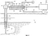
фиг.1а схематически изображает соответствующий настоящему изобретению способ разработки месторождения подземным растворением, при котором нагнетательный трубопровод устанавливают в одной скважине, которая ведет к минеральной залежи, а добывающий трубопровод устанавливают в другой скважине, которая ведет к минеральной залежи;figa schematically depicts a method for developing a field by underground dissolution according to the present invention, in which an injection pipeline is installed in one well that leads to a mineral deposit, and a production pipeline is installed in another well that leads to a mineral deposit;
фиг.1b схематически изображает соответствующий настоящему изобретению способ разработки месторождения подземным растворением, использующий заканчивание на два пласта, при котором и нагнетательный трубопровод, и добывающий трубопровод устанавливают в одной скважине, которая ведет к минеральной залежи;fig.1b schematically depicts a method for developing a field by underground dissolution according to the present invention, using completion in two formations, in which both the injection pipeline and the production pipeline are installed in one well, which leads to a mineral deposit;
фиг.2 схематически в упрощенном виде изображает соответствующий настоящему изобретению способ разработки месторождения подземным растворением, показывая, в частности, теплообменник для кристаллизации нужного минерала; иfigure 2 schematically in a simplified form depicts a method according to the present invention for developing a field by underground dissolution, showing, in particular, a heat exchanger for crystallization of the desired mineral; and
фиг.3 схематически в упрощенном виде изображает способ разработки месторождения подземным растворением, показывая, в частности, оборудование, которое может быть использовано в установке разделения для извлечения минерала (продукта) и для передачи обедненного рассола к теплообменнику в соответствии с настоящим изобретением.figure 3 schematically in a simplified form depicts a method of developing a field by underground dissolution, showing, in particular, equipment that can be used in the separation unit for the extraction of mineral (product) and for transferring depleted brine to a heat exchanger in accordance with the present invention.
Осуществление изобретенияThe implementation of the invention
Минералы ценных эвапоритов обычно получают традиционными способами разработки месторождений, способом подземного растворения (выщелачивания) или, извлекая их из озер, где минералы присутствуют в виде насыщенного раствора, как например, из Мертвого моря. В большинстве таких случаев необходимо получить раствор указанных минералов и обработать его так, чтобы нужные минералы выпали из раствора в осадок. Настоящее изобретение касается способа добычи подземным растворением, при котором производят закачку воды в рудное тело эвапорита, обычно в подземную залежь. Нужный минерал в залежи растворяют, а раствор, который содержит нужный минерал, передают на поверхность. На этом этапе нужный минерал извлекают из раствора. Одним из способов извлечения минерала является испарение, либо в испарительных бассейнах, если климат жаркий и сухой, либо, если климат иной, то за счет механического нагревания и испарения. Эти два способа обычно используют для добычи соли хлорида натрия - галита. Другой способ заключается в использовании искусственного холода в технологической установке для охлаждения почти насыщенного раствора, полученного при подземном растворении, чтобы вызвать выпадение минерала в осадок. Искусственное охлаждение эффективно для минералов, растворимость которых сильно зависит от температуры, например, калийных руд (сильвина или карналлита). В настоящем изобретении рассматриваются последние указанные типы минералов, растворимость которых зависит от температуры.Minerals of valuable evaporites are usually obtained by traditional methods of developing deposits, by underground dissolution (leaching) or by extracting them from lakes where the minerals are present in the form of a saturated solution, such as from the Dead Sea. In most such cases, it is necessary to obtain a solution of these minerals and process it so that the desired minerals precipitate from the solution. The present invention relates to a method of mining by underground dissolution, in which water is pumped into the ore body of evaporite, usually into an underground deposit. The desired mineral is dissolved in the deposit, and the solution that contains the desired mineral is transferred to the surface. At this stage, the desired mineral is extracted from the solution. One of the methods for extracting the mineral is evaporation, either in evaporation basins, if the climate is hot and dry, or if the climate is different, then due to mechanical heating and evaporation. These two methods are usually used for the extraction of sodium chloride salt - halite. Another way is to use artificial cold in a process unit to cool an almost saturated solution obtained by underground dissolution to cause the mineral to precipitate. Artificial cooling is effective for minerals whose solubility is highly dependent on temperature, for example, potash ores (sylvin or carnallite). The present invention contemplates the latter types of minerals whose solubility is temperature dependent.
Крупные соляные залежи галита, например, с куполообразной или котловинообразной структурой, проявляют тенденцию иметь более высокую температуру, чем другие зоны, из-за более высокой теплопроводности соли. Если залежь достаточно глубока, то за счет высокой теплопроводности повышенная температура на дне пласта создает более высокие температуры по всей толще пласта. Обычно эти температуры выше, чем нормальный геотермический градиент, который составляет приблизительно 3°С на 100 м. С другой стороны, если эвапорит просто залегает глубоко, и с ним не связано крупное соляное тело, геотермический градиент может сам по себе приводить к существенному увеличению температуры эвапорита по сравнению с температурой у поверхности. При использовании способа подземного растворения, в обоих указанных случаях появляется возможность выводить в осадок любые растворенные минералы за счет охлаждения добываемого рассола до наружной температуры, которая существует у поверхности. Какие минералы и в каких количествах будут выпадать в осадок, будет зависеть от перепада температуры у поверхности и от фазовой диаграммы системы растворенных минералов. Температуру добываемого рассола, по мере того как он поднимается к поверхности, желательно поддерживать как можно более высокой, чтобы эксплуатационная колонна не обрастала солью и не закупоривалась из-за образования осадка на стенке трубы по причине охлаждения. Падение температуры в эксплуатационной колонне должно быть минимизировано при помощи теплоизоляции, а минералы, которые осаждаются на стенках, следует удалять путем периодической промывки эксплуатационной колонны пресной водой.Large salt halite deposits, for example, with a dome-shaped or hollow-like structure, tend to have a higher temperature than other zones, due to the higher thermal conductivity of the salt. If the reservoir is deep enough, then due to the high thermal conductivity, the increased temperature at the bottom of the formation creates higher temperatures throughout the thickness of the formation. Typically, these temperatures are higher than the normal geothermal gradient, which is approximately 3 ° C per 100 m. On the other hand, if evaporite simply lies deep and does not have a large salt body connected to it, the geothermal gradient itself can lead to a significant increase in temperature evaporite compared to surface temperature. When using the underground dissolution method, in both of these cases it becomes possible to precipitate any dissolved minerals by cooling the produced brine to an external temperature that exists at the surface. Which minerals and in what quantities will precipitate will depend on the temperature difference at the surface and on the phase diagram of the system of dissolved minerals. The temperature of the produced brine, as it rises to the surface, it is desirable to maintain as high as possible so that the production string is not overgrown with salt and clogged due to the formation of sediment on the pipe wall due to cooling. The temperature drop in the production casing should be minimized by thermal insulation, and minerals that precipitate on the walls should be removed by periodically flushing the production casing with fresh water.
На фиг.1а показана система 10 для добычи залежи D минерала способом подземного растворения в соответствии с настоящим изобретением. В залежь D минерала проведена нагнетательная скважина 12 путем бурения ствола В1 скважины с поверхности в указанную залежь, постановки в скважине обсадной трубы 12 и закачки вокруг обсадной трубы цементного раствора С1 с целью герметизации кольцевого пространства между обсадной трубой 12 и земляной стенкой ствола В1 скважины. Оголовок 12а нагнетательной скважины обеспечивает доступ к скважине 12 и образует место присоединения с соответствующими шиберами и соединительными элементами трубопроводов. Аналогично, в стволе В2 выполнена добывающая скважина 14, оснащенная оголовком 14а, и загерметизированная цементным раствором С2, которая образует канал для добычи жидкости из залежи D. Может быть произведено разрушение залежи D с целью создания пути для течения жидкости сквозь залежь D от нагнетательной скважины 12 к добывающей скважине 14. Такое разрушение может быть произведено, например, закачкой жидкости в нагнетательную скважину 12 под очень высоким давлением. Растворитель, в качестве которого обычно выступает водный раствор, подают через трубу 16 в теплообменник 18, где растворитель подогревается. Подогретый растворитель через трубу 20 поступает в оголовок 12а скважины, и далее следует вниз по нагнетательной скважине 12 в залежь D минерала. Растворитель протекает сквозь залежь D минерала, растворяя один или более минералов залежи и образуя рассол, который является предметом добычи и в котором нужные растворенные минералы находятся в определенной концентрации. Температура залежи D и добываемого рассола выше, чем наружная температура на поверхности. Растворимость требуемого минерала(-ов) зависит от температуры, при этом насыщение рассола при высокой температуре происходит при более высокой концентрации, чем при низкой температуре. Таким образом, при более высокой температуре в данном объеме растворителя может быть растворено большее количество требуемого минерала, чем при более низкой температуре. Добываемый рассол течет вверх по добывающей скважине 14 к ее оголовку 14а и через трубу 22 поступает в теплообменник 18. Когда добываемый раствор проходит через теплообменник 18, он охлаждается, и в нем образуются твердые кристаллы нужного минерала, так как при более низкой температуре минерал имеет более низкую растворимость. Взвесь твердых кристаллов нужного минерала в рассоле проходит через трубу 24 и производится отделение и извлечение кристаллов, о чем говорилось выше.On figa shows a
На фиг.1b показан одиночный ствол В3 скважины, пробуренный в земле в минеральную залежь D. Нагнетательная обсадная труба I и добывающая обсадная труба Р загерметизированы в стволе В3 скважины цементным раствором С3. В оголовке Н скважины предусмотрены шиберы и точки присоединения к нагнетательной обсадной трубе I и добывающей обсадной трубе Р. Поскольку нагнетательная обсадная труба I и добывающая обсадная труба Р находятся в тесной близости друг к другу, разрушение залежи D. может оказаться необязательным. Водный раствор подают через магистраль 28 в теплообменник Е, где раствор подогревается, и затем через магистраль 30 поступает в нагнетательную обсадную трубу I. Водный раствор растворяет нужный минерал в залежи D, и получается теплый рассол, богатый указанным минералом, который выводится на поверхность через добывающую обсадную трубу Р. Добываемый рассол проходит через магистраль 32 и охлаждается в теплообменнике Е, при этом кристаллы требуемого минерала выпадают в осадок, образуя взвесь, которая через магистраль 34 поступает в устройство физического разделения (не показано).Fig. 1b shows a single wellbore B3 drilled in the earth into a mineral deposit D. The injection casing I and the producing casing P are sealed in the wellbore B3 with cement mortar C3. Gates and connection points to injection casing I and production casing P are provided in the well head H. Since injection casing I and production casing P are in close proximity to each other, the destruction of reservoir D. may not be necessary. The aqueous solution is fed through
На фиг.2 представлена упрощенная схема установки 40 для осуществления способа, соответствующего настоящему изобретению. Согласно фиг.2, в земле, в залежь М минерала пробурен одиночный ствол В4 скважины. Обсадная колонна или наружная труба 42 загерметизирована в стволе В4 скважины цементным раствором С4. Внутренняя труба 44 помещена внутрь наружной трубы 42, и образована концентрическая обсадная колонна. Наружная поверхность внутренней трубы 44 и внутренняя поверхность наружной трубы 42 определяют кольцевое пространство 42а, Кольцевое пространство 42а служит в качестве нагнетательного трубопровода, в то время как внутренняя труба 44 служит в качестве добывающего трубопровода. Водный раствор или растворитель подают к залежи М минерала через кольцевое пространство 42а. Нужный минерал растворяется, и образуется рассол, содержащий нужный минерал в сравнительно высокой концентрации. Рассол, который в силу повышенной температуры залежи М минерала является сравнительно теплым, выводят через внутреннюю трубу 44 и передают в оголовок 46 скважины. Такая концентрическая обсадная колонна играет роль теплообменника типа «труба в трубе», обладающего преимуществами - добываемый рассол стремится сохранить повышенную температуру, что уменьшает отложение солей в добывающем трубопроводе, а нагнетаемая жидкость может доставляться к залежи почти при той же температуре, что и температура самой залежи, что помогает предотвратить охлаждение залежи, и позволяет растворению происходить при наиболее высокой температуре, какая возможна в естественных условиях. Хотя предусмотрено, что обычно подъем рассола будет происходить через внутреннюю трубу 44, для этой цели может быть использована либо внутренняя труба 44, либо кольцевое пространство 42а, и направление движения жидкостей может быть изменено на обратное, в частности для удаления соли из добывающего трубопровода. Может быть использована любая из конструкций скважин, показанных на фиг.1а, 1b и 2, и для разработки минеральной залежи может быть использовано любое число скважин.Figure 2 presents a simplified diagram of the
Согласно фиг.2, в начале процесса воду W по трубе 48 подают в теплообменник 50 типа «труба в трубе», где вода проходит через кольцевое пространство 50а внутри теплообменника 50, и попадает в трубу 52, которая ведет к оголовку 46 скважины, и обеспечивает жидкостное соединение с кольцевым пространством 42а в концентрической обсадной колонне. Таким образом, через кольцевое пространство 42а нагнетательного канала производится подача пресной воды к минеральной залежи М для растворения нужного минерала (-лов). Когда температура воды выравнивается с температурой минеральной залежи М, вода растворяет нужный минерал(-лы) и образуется рассол, в котором концентрация нужного минерала сравнительно высока, причем его растворимость зависит от температуры. Таким образом, получается богатый минералом рассол, который выводят через внутреннюю трубу 44 и который следует через оголовок 46 скважины и трубу 54 к впускному отверстию 50b внутренней трубы 50 с теплообменника 50, Внутренняя труба 50 с проходит по длине теплообменника 50 к выпускному отверстию 50а, к которому присоединена труба 56. Добытый, богатый минералом рассол охлаждается по мере того как его теплота передается воде, протекающей по кольцевому пространству 50а. Поскольку растворимость искомого минерала зависит от температуры раствора, в котором минерал находится, указанный искомый минерал выпадает в осадок в виде твердых кристаллов внутри внутренней трубы 50с, по мере того как температура добываемого рассола падает, и образуется взвесь кристаллов в рассоле. Взвесь проходит по магистрали 56 в установку 58 разделения. Оборудование для разделения или извлечения минералов, находящееся внутри установки 58 разделения, удаляет твердые кристаллы нужного минерала из взвеси, оставляя рассол, из которого удалены кристаллы - обедненный рассол. Твердые кристаллы искомого минерала извлекают в виде продукта 60. Обедненный рассол имеет существенно более низкую температуру, чем теплый, богатый минералами добываемый рассол в магистрали 54, и существенно более низкую концентрацию растворенного в нем искомого минерала. Температура обедненного рассола примерно равна наружной температуре.According to figure 2, at the beginning of the process, water W through the
После того как выпавший в осадок минерал(-лы) будет удален из добываемого рассола и извлечен в виде продукта 60, обедненный рассол снова подают в скважину, направляя его через трубу 62 к насосу 64 высокого давления. Насос 64 нагнетает обедненный рассол через трубу 66 в кольцевое пространство 50а внутри теплообменника 50, возвращая, таким образом, обедненный рассол, чтобы он снова мог принять участие в разработке минеральной залежи М подземным растворением. Насос 64 повышает давление обедненного (оборотного) рассола настолько, чтобы этого давления было достаточно для переноса рассола к теплообменнику 50 и сквозь теплообменник 50 в камеру залежи М, и затем обратно через рассолоподъемную трубу 44 и теплообменник 50 к установке 58 разделения.After the precipitated mineral (s) are removed from the produced brine and recovered as
В установке 58 разделения минеральные частицы, которые в предпочтительном случае должны быть рассортированы по размерам, вводят в обедненный рассол для использования в качестве затравочных кристаллов в добываемом рассоле в магистрали 54 (эта операция на фиг.2 не показана). Установка 58 разделения должна иметь подходящее оборудование для отделения кристаллов нужного минерала от взвеси (пульпы), предпочтительно для отделения кристаллов в соответствии с их размером, и для ввода части указанных кристаллов в обедненный рассол для использования в качестве затравки в добываемом рассоле. Когда температура рассола падает, указанные кристаллы служат центрами кристаллизации. Далее, ввод затравки будет рассмотрен дополнительно. Обедненный рассол в трубе 66, который содержит затравочные кристаллы минерала, проходит через вихревой сепаратор 68, который отделяет большую часть затравочных кристаллов. Кристаллы минерала с выходящей струей сепаратора проходят по трубе 70 для ввода в добываемый рассол в магистраль 54 в точке перед впускным отверстием 50b теплообменника. На схеме изображен вихревой сепаратор, однако может быть использовано любое оборудование, пригодное для отделения затравочных кристаллов. Как вариант, может производиться передача раствора с затравочными кристаллами от установки 58 разделения к впускному отверстию 50b теплообменника на его теплой стороне. После того как в вихревом сепараторе 68 затравочные кристаллы будут отделены от обедненного оборотного рассола, сам обедненный рассол через трубу 72 и впускное отверстие 50е поступает в кольцевое пространство 50а на холодной стороне теплообменника 50, вблизи отверстия 50а для выпуска добываемого рассола. Впускное отверстие 50е выполнено в наружной трубе 50f, которая определяет наружную поверхность теплообменника 50. Кольцевое пространство 50а ограничено внутренней поверхностью наружной трубы 50f и наружной поверхностью внутренней трубы 50с.In
Температура обедненного рассола, выходящего из вихревого сепаратора 68 в трубу 72, в общем, равна или близка наружной температуре, которая, как правило, сравнительно более низкая, чем температура породы внутри минеральной залежи М, и температуры добываемого рассола в магистрали 54. Предпочтительно, чтобы теплообменник 50 имел конструкцию типа «труба в трубе» и имел очень большую длину, или был выполнен в виде ряда более коротких теплообменников указанной конструкции, соединенных последовательно. С другой стороны, теплообменник 50 может быть выполнен в виде ряда кожухотрубных теплообменников, соединенных параллельно, или, в соответствии с настоящим изобретением, могут быть также использованы любые подходящие средства теплообмена.The temperature of the depleted brine leaving the
Как показано на фиг.2, сравнительно холодный обедненный рассол поступает в кольцевое пространство 50а теплообменника 50 через впускное отверстие 50е. В кольцевом пространстве 50а данный обедненный рассол смешивается с водой из источника W, образуя нагнетаемую жидкость, и после запуска системы количество воды W может быть уменьшено до необходимого. Нагнетаемая жидкость проходит в кольцевом пространстве 50а встречно движению добываемого рассола в трубе 50с. Тепловая энергия теплого, богатого минералом добываемого рассола передается через стенку внутренней трубы 50с к нагнетаемой жидкости в кольцевом пространстве 50а, при этом происходит охлаждение добываемого рассола и нагревание нагнетаемой жидкости, которая включает в себя обедненный рассол из трубы 72 и подпитывающую воду из магистрали 48. Какое-то количество тепловой энергии вероятно будет потеряно - уйдет в окружающую среду через стенку наружной трубы 50f. В действительности, может оказаться желательным заглубить теплообменник 50 ниже поверхности земли, при этом поверхность земли образует теплоотвод со сравнительно постоянной температурой.As shown in FIG. 2, a relatively cold lean brine enters the
По мере того как добываемый рассол остывает, количество нужного минерала, которое может быть растворено в добываемом рассоле, снижается. Кристаллы нужного минерала образуются главным образом вокруг центров кристаллизации, созданных затравочными кристаллами, введенными в добываемый рассол через магистраль 70 из вихревого сепаратора 68, когда температура добываемого рассола понижается вследствие передачи тепловой энергии от добываемого рассола к нагнетаемой жидкости, состоящей из обедненного рассола и подпитывающей воды, которая движется в кольцевом пространстве 50а теплообменника 50. По мере того как добываемый рассол движется от впускного отверстия 50b теплой стороны теплообменника к выпускному отверстию 50а холодной стороны, образуется взвесь (пульпа), которую через магистраль 56 передают в установку 58 разделения. Твердые кристаллы нужного минерала отделяют и извлекают в виде продукта 60, а обедненный рассол насосом 64 снова возвращают в теплообменник 50. Пока обедненный раствор находится в установке 58, в него добавляют затравочные кристаллы минерала, а затем вместе с указанным обедненным рассолом, посредством насоса 64 через магистрали 62 и 66 затравочные кристаллы передают в вихревой сепаратор 68. Вихревой сепаратор 68 отделяет затравочные кристаллы минерала, которые передают по магистрали 70 и вводят в добываемый рассол в магистраль 54. Обедненный рассол, после того как в вихревом сепараторе 68 из него были извлечены затравочные кристаллы, поступает в теплообменник 50 через магистраль 72. Через магистраль 48 из источника W производится добавление требуемого количества пресной подпитывающей воды, чтобы образовать нагнетаемую жидкость, которая в теплообменнике 50 нагревается за счет добываемого рассола. Нагнетаемую жидкость через магистраль 52 подают в оголовок 46 скважины, и через кольцевое пространство 42а концентрической обсадной колонны закачивают в минеральную залежь М. Нагнетаемая жидкость, выходящая из теплообменника в магистраль 52, является достаточно теплой, поскольку от температуры близкой к наружной она была подогрета добываемым рассолом. В кольцевом пространстве 42а концентрической обсадной колонны нагнетаемая жидкость течет встречно движению добываемого рассола, который поднимается по внутренней трубе 44; при этом нагнетаемая жидкость создает теплоизолирующий слой, что одновременно препятствует существенной потере тепла добываемым рассолом, и способствует нагреванию нагнетаемой жидкости почти до температуры минеральной залежи М. Таким образом, нагнетаемая жидкость, поступающая в камеру минеральной залежи М, является достаточно нагретой, что увеличивает скорость растворения нужного минерала в залежи М и увеличивает количество нужного минерала, которое может быть растворено в данном количестве нагнетаемой жидкости, поскольку растворимость искомого минерала зависит от температуры нагнетаемой жидкости. По прошествии достаточного времени, необходимого для растворения нужного минерала, образуется более концентрированный, богатый минералом рассол (предмет добычи), температура которого, по существу, равна температуре залежи, при условии, что времени было достаточно для выравнивания температур. Добываемый рассол передают в теплообменник 50 по внутренней трубе 44 концентрической обсадной колонны и магистрали 54 для замыкания непрерывного цикла.As the mined brine cools down, the amount of mineral needed that can be dissolved in the mined brine decreases. Crystals of the desired mineral are formed mainly around crystallization centers created by seed crystals introduced into the produced brine through
По мере того как камера залежи М увеличивается в размерах, производят добавление пресной или соленой подпитывающей воды для заполнения пустот в залежи М, когда происходит выемка минерала. Источником W подпитывающей воды часто служит водяная скважина, бассейн, озеро или источник соленой воды, однако воду также можно привозить и хранить в цистерне. Воду предпочтительно добавлять в теплообменник 50, как показано на фиг.2, или в магистраль 72, однако подпитывающую воду можно вводить и в магистраль 62 возврата обедненного рассола в установке 58 разделения. Однако в этом случае обедненный рассол не может переносить затравочные кристаллы, поскольку в обедненном рассоле кристаллы минерала будут растворяться. Чтобы затравку все-таки осуществить, вблизи впускного отверстия 50b теплообменника 50 на его теплой стороне можно расположить затравочный бак с насосом для ввода затравки в добываемый рассол. Один затравочный бак может питать несколько добывающих скважин.As the chamber of the M deposit increases in size, fresh or salt feed water is added to fill the voids in the M deposit when the mineral is excavated. The source W of the feed water is often a water well, a pool, a lake or a source of salt water, however, water can also be brought and stored in a tank. Water is preferably added to the
На фиг.3 изображена упрощенная схема 70 соответствующего настоящему изобретению процесса для добычи и обработки карналлитовой пульпы. Карналлитовую пульпу получают способом, который был описан согласно фиг.2, а на фиг.3 представлен этапом 72. Хотя на фиг.3 это не показано, но этап 72 содержит операции, при которых в подземной минеральной залежи, содержащей карналлит в качестве искомого минерала, устанавливают концентрическую обсадную колонну. Нагнетаемая жидкость растворяет карналлит, и образуется жидкость, подлежащая добыче (добываемая жидкость), которая является сравнительно теплой и богатой карналлитом. Добываемую жидкость получают на этапе 72, и также на этапе 72 пропускают через внутреннюю трубу теплообменника типа «труба в трубе». На этапе 72 добываемую жидкость в теплообменнике подвергают охлаждению, и получают пульпу, содержащую кристаллы карналлита. По трубе 74 пульпу передают в установку 76 разделения, где пульпу направляют в сепаратор 78, который отделяет твердые кристаллы карналлита от жидкого рассола пульпы, при этом приблизительно 90-95% жидкого рассола - обедненного рассола - на этапе 72 возвращают по трубе 80 в теплообменник, где происходит передача тепла от добываемого рассола к обедненному рассолу с целью охлаждения добываемого рассола и нагревания обедненного рассола. Нагнетаемая жидкость содержит указанный подогретый обедненный рассол, который используется в контуре рециркуляции для дальнейшего растворения карналлита и дальнейшего образования добываемой жидкости на этапе 72.Figure 3 shows a simplified diagram 70 of a process according to the present invention for the extraction and processing of carnallite pulp. Carnallite pulp is obtained by the method described in FIG. 2, and in FIG. 3 it is represented by
Твердые кристаллы карналлита, удаленные из пульпы с помощью сепаратора 78, который может представлять собой ситовый сепаратор типа реализуемого под товарным знаком VARISIEVEТМ, вместе с жидким рассолом, который остается с твердыми кристаллами, передают по магистрали 82 в бак 84 разложения. По трубе 86 к кристаллам карналлита добавляют пресную воду, вызывая разложение карналлита на твердый хлорид калия, КСl, и жидкий рассол хлорида магния, MgCl2. Пульпу, содержащую твердый хлорид калия и жидкий хлорид магния, передают из бака 84 разложения по магистрали 88 в центрифугу 90. Центрифуга 90 отделяет твердый хлорид калия от жидкого хлорида магния. Жидкий рассол хлорида магния по трубе 92 поступает в бассейн-хранилище 94, площадь которого может доходить до 200000 м2. Продукт 96 - хлорид магния - извлекают из бассейна-хранилища 94 традиционными средствами. Твердый хлорид калия, извлеченный центрифугой 90, передают по линии 98, а затем 98а в сушильный аппарат 100, или по линии 98b - в бак 102 сырого хранения, откуда сырой продукт 104 - хлорид калия, может быть выгружен. Сушильный аппарат 100 удаляет воду из сырого хлорида калия, выдавая сухие твердые кристаллы KCl, которые по линии 106 передают на грохот 108. Грохот 108 разделяет частицы хлорида калия на различные классы по размерам, и эти разделенные кристаллы хлорида калия передают по одной или более линиям 110 в хранилища 112 сухого материала. Сухой продукт 114 - хлорид калия - грузят на автомобили или железнодорожные вагоны. В случае, если получаемые кристаллы недостаточно крупные, чтобы быть коммерческим продуктом, в схему может быть добавлен сгуститель и или уплотнитель.Carnallite solid crystals removed from the pulp using a
Какую-то часть частиц KCl определенного класса по размеру передают по линии 116 на всасывающий вход низкого давления насоса (не показан) нагнетания оборотного рассола. Линия 116 может представлять собой ленточный конвейер и бункер для ввода затравочных частиц хлорида калия в магистраль 80 с контролируемой скоростью. Твердые частицы хлорида калия, передаваемые с грохота 108 в магистраль 80 обедненного рассола, будут на этапе 72 служить в качестве затравки на стороне теплообменника, обращенной к добывающей трубе скважины, о чем говорилось выше согласно фиг.2. Обедненный оборотный рассол в магистрали 80 будет содержать мелкие частицы хлорида калия, которые прошли через сепаратор 78, поэтому дополнительная подача затравки по линии 116 является необязательной, но предпочтительно ее иметь. Если используется подача затравки через линию 116, то предпочтительный размер частиц или распределение частиц по размерам, и число частиц для оптимальной затравки следует определить экспериментальным путем. Считается, что подача меньшего числа более крупных затравочных кристаллов приводит к образованию более крупных кристаллов, за исключением ситуации подачи слишком малого количества, ибо если добавлять слишком мало затравочных кристаллов, то большая часть потока добываемого рассола окажется не охваченной затравкой. Оптимальный размер и количество затравочных кристаллов будет зависеть от участвующих в процессе минералов, условий теплообменника и конструкции. Интенсивность осаждения искомых минералов может также быть усилена введением в теплообменник рассола, содержащего растворенный минерал, который будет замещать искомый минерал. Примером этого может служить введение насыщенного раствора MgCl2 в рассол KCl в теплообменнике. В зависимости от условий, фазовая диаграмма данной смеси показывает, что может быть инициировано предпочтительное осаждение KCl. Также в патенте США 4283372, включенном в настоящее изобретение посредством ссылки, описан способ извлечения полезного щелочного компонента из руды, содержащей бикарбонат натрия, путем использования водного растворителя, содержащего аммиак.A certain part of KCl particles of a certain class in size is transferred via
Фиг.2 и 3 вместе дают упрощенное описание соответствующего настоящему изобретению способа подземного растворения источника минерала в месте его естественного залегания. Фиг.2 описывает получение рассола, содержащего искомый минерал, охлаждение рассола в теплообменнике, и тем самым инициирование выпадения искомого минерала в осадок, а также передачу тепла от добываемого рассола к обедненному рассолу, возвращаемому из установки разделения. Обедненный рассол используют для переноса затравочных кристаллов из установки разделения к теплообменнику, при этом вихревой сепаратор 68 извлекает затравочные кристаллы для их ввода в добываемый рассол в точке перед теплообменником. Фиг.3 иллюстрирует один вариант осуществления установки разделения, демонстрируя отделение и извлечение продукта искомого минерала и затравочных кристаллов, которые могут быть использованы, как затравка для добываемого рассола. Система теплообменника, описанная в настоящем изобретении, также полезна в ситуациях, когда необходимо или желательно выводить поток обедненного рассола в отходы. В этом случае, растворяющую минерал жидкость, в качестве которой обычно служит пресная или соленая вода, вводят в теплообменник, в то место, куда в ином случае производился бы ввод потока обедненного рассола, что приводит к охлаждению добываемого рассола и нагреванию растворяющей минерал жидкости перед ее закачкой в минеральную залежь.FIGS. 2 and 3 together give a simplified description of the method of underground dissolving a mineral source in accordance with the present invention in a place of its natural occurrence. Figure 2 describes the production of a brine containing the desired mineral, cooling the brine in the heat exchanger, and thereby initiating the precipitation of the desired mineral in the sediment, as well as the transfer of heat from the produced brine to the depleted brine returned from the separation unit. The depleted brine is used to transfer the seed crystals from the separation unit to the heat exchanger, while the
Что касается теплообменника 50 на фиг.2, то в настоящем изобретении применимы теплообменники многих типов при условии, что осаждающиеся кристаллы не закупоривают теплообменник, и удовлетворяются другие требования, такие как площадь теплопередачи. Однако теплообменник 50 типа «труба в трубе», изображенный на фиг.2, особенным образом подходит для рассматриваемой задачи по следующим причинам: он недорог, его можно собирать и ремонтировать в полевых условиях, на него легко нанести облицовку или покрытие для минимизации солевых отложений, его можно легко наращивать в длину с целью снижения среднего перепада температуры теплой жидкости по стенке теплообменника, и наконец теплообменник может быть использован в качестве важного узла для жидкостных соединений между скважиной и установкой разделения. Большой перепад температуры по стенке теплообменника способствует солевым отложениям. Кожухотрубные теплообменники, которые обычно используются в установках в силу их компактности, также могут быть применены, но им не свойственны вышеперечисленные преимущества. Возможна также установка теплообменника типа «труба в трубе» непосредственно в саму эксплуатационную скважину с использованием малых труб для ввода затравки или другого рассола, если требуется. Такая конструкция обычно не является предпочтительной из-за трудности обслуживания теплообменника. Однако при наличии опыта продолжительной работы с конкретным рудным телом, когда обслуживание поверхностного теплообменника стало минимальным, вариант встроенного в скважину теплообменника мог бы стать предпочтительным, в том отношении, что позволил бы воспользоваться концентрической обсадной колонной, которая уже находится на месте, для нагнетания жидкости в скважину и извлечения рассола из скважины. Конструкция концентрической обсадной колонны, показанная на фиг.2, позволяет эффективно наращивать теплообменник в скважину для увеличения площади поверхности теплообменника, хотя и не дает возможности вводить затравку или рассол в рассолоподъемную трубу 44 вблизи минеральной залежи М для ускорения процесса кристаллизации в добываемом рассоле, пока он находится в рассолоподъемной трубе 44.As for the
Может оказаться необходимым использование вспомогательного теплообменника в дополнение к теплообменнику 50 фиг.2, хотя такой теплообменник на чертеже не показан. Для множества, если не для большинства, рудных тел не характерен достаточно большой подъем температуры, который обеспечивал бы достаточное осаждение минерала на поверхности земли. В этом случае может быть использован вспомогательный наружный теплообменник. Вспомогательный теплообменник может быть установлен в магистрали 52 фиг.2 между теплообменником 50 и оголовком 46 скважины с целью нагревания нагнетаемой жидкости. Источником тепла для вспомогательного теплообменника может служить низкосортный природный газ, технологическое тепло, например, от энергетической станции, солнечное тепло, и т.п. По меньшей мере часть теплоты, создаваемой вспомогательным теплообменником, будет извлекаться теплообменником 50 из рассола, поступающего из подземной полости. Увеличение температуры нагнетаемой жидкости приведет к тому, что в добываемом рассоле концентрация искомого минерала будет более высокой, благодаря повышенной температуре указанного рассола. Является ли данный подход эффективным, зависит от стоимости вспомогательного источника энергии, и от стоимости альтернативных способов извлечения нужного минерала. Однако использование вспомогательного теплообменника для нагревания нагнетаемой жидкости имеет преимущества по сравнению с использованием системы охлаждения другого типа для понижения температуры добываемого рассола, так как можно использовать фактически любой источник вспомогательного тепла, оборудование отличается простотой (особенно теплообменник типа «труба в трубе»), и осуществляется эффективное извлечение и использование природной теплоты минеральной залежи. Если нагретый нагнетаемый рассол теплее, чем рудное тело, то предпочтительно использовать раздельные нагнетательный и добывающий трубопроводы, а не в виде концентрической обсадной колонны.It may be necessary to use an auxiliary heat exchanger in addition to the
В итоге, в настоящем изобретении предлагается система и способ для разработки месторождений подземным растворением, при котором теплообменник используют для охлаждения добываемого рассола, содержащего растворенный минерал и поступающего из рудного тела, так что указанный минерал выпадает в осадок, при этом обедненный холодный рассол после обмена теплом с добываемым рассолом нагревается, и его возвращают в подземную камеру для дальнейшего растворения минерала. Предпочтительно, чтобы теплообменник имел простую конструкцию типа «труба в трубе». Предпочтительно, чтобы теплообменник образовывал узел жидкостных соединений между скважиной и технологической установкой извлечения минерала, что сокращает затраты на трубные соединения. Как вариант, теплообменник типа «труба в трубе» может быть установлен в самой эксплуатационной скважине, а не на поверхности (или дополнительно к теплообменнику, установленному на поверхности), при этом, если требуется, к такому теплообменнику могут быть присоединены трубопроводы для ввода затравки или другого рассола.As a result, the present invention proposes a system and method for developing deposits by underground dissolution, in which a heat exchanger is used to cool the produced brine containing dissolved mineral and coming from the ore body, so that said mineral precipitates, while the depleted cold brine after heat exchange with the extracted brine heats up and is returned to the underground chamber for further dissolution of the mineral. Preferably, the heat exchanger has a simple pipe-in-pipe design. Preferably, the heat exchanger forms a node of fluid connections between the well and the mineral extraction processing unit, which reduces the cost of pipe connections. Alternatively, a pipe-in-pipe heat exchanger can be installed in the production well itself, and not on the surface (or in addition to the heat exchanger installed on the surface), and if necessary, pipelines can be connected to such a heat exchanger or another brine.
Предпочтительно, чтобы происходил теплообмен подогретого, вновь нагнетаемого рассола с трубой, по которой добываемый рассол поднимается в скважине из подземной полости, чтобы уменьшить охлаждение добываемого рассола и снизить осаждение минерала в рассолоподъемной трубе. Если необходимо, то между первым теплообменником и оголовком скважины можно разместить второй теплообменник с целью дополнительного нагревания обедненного, оборотного рассола, с чем в одиночку не способен справиться первый теплообменник, при этом во втором теплообменнике используется источник тепла иной, нежели теплота, поступающая от эксплуатационной скважины. Если требуется, площадь теплообменника можно увеличить, так чтобы уменьшить среднюю температуру по стенке внутренней трубы теплообменника, и таким образом понизить разность температур между стенкой и добываемым рассолом и тем самым снизить вероятность обрастания солями стенки теплообменника.Preferably, there is a heat exchange of the heated, newly pumped brine with a pipe through which the produced brine rises in the well from the underground cavity in order to reduce cooling of the produced brine and to reduce the deposition of the mineral in the brine pipe. If necessary, a second heat exchanger can be placed between the first heat exchanger and the borehole head to additionally heat the depleted, reverse brine, which the first heat exchanger cannot handle alone, while the second heat exchanger uses a heat source other than the heat from the production well . If required, the area of the heat exchanger can be increased so as to reduce the average temperature along the wall of the inner tube of the heat exchanger, and thus reduce the temperature difference between the wall and the produced brine, and thereby reduce the likelihood of fouling with the salts of the heat exchanger wall.
Настоящее изобретение, в качестве предпочтительной меры, также предусматривает использование затравочных кристаллов нужного минерала, отобранных по размеру и количеству, которые вводят в теплообменник со стороны подачи добываемого рассола с целью формирования центров кристаллизации, способствующих выпадению минерала в осадок, при этом количество вводимого затравочного материала и распределение его частиц по размерам определяют из условия получения определенного размера кристаллов минерала, выходящих из теплообменника, и минимизации солевых отложений на стенке теплообменника. В одном варианте осуществления, на той стороне теплообменника, где происходит выпадение осадка, наносят покрытие или облицовку веществом, которое минимизирует осаждение на стенке теплообменника.The present invention, as a preferred measure, also provides for the use of seed crystals of the desired mineral, selected in size and quantity, which are introduced into the heat exchanger from the supply side of the produced brine in order to form crystallization centers that contribute to the precipitation of the mineral, the amount of introduced seed material and the size distribution of its particles is determined from the condition of obtaining a certain size of mineral crystals emerging from the heat exchanger, and minimization uu salt deposits on the wall of the heat exchanger. In one embodiment, on the side of the heat exchanger where precipitation occurs, a coating or lining is applied with a substance that minimizes deposition on the wall of the heat exchanger.
Настоящее изобретение совершенствует, как способ осаждения, вызываемого искусственным охлаждением, так и испарительный способ. Что касается первого способа, то изобретение предусматривает технически гораздо более простые и гораздо менее затратные капиталовложения, и гораздо более низкие эксплуатационные затраты по количеству потребляемой энергии. Хотя согласно настоящему изобретению могут быть использованы как селективный, так и неселективный способы подземного растворения, селективный способ минимизирует количество используемой воды, главным образом, подпитывающей воды и воды для разложения минерала подобно карналлиту, при этом на поверхности почти не остается отходов. В этом сильное отличие от большинства проектов разработки месторождений способом подземного растворения. В рассматриваемом способе можно использовать пресную или соленую воду. Месторождение, в котором используется данный способ, может вполне стать одним из самых чистых среди существующих разрабатываемых месторождений. При неселективном способе разработки можно использовать соленую воду, при этом была бы предпочтительна подземная утилизация рассола. В зависимости от добываемого минерала, требования осуществлять разделение может и не быть, поскольку никакая соль в осадок не выпадает. По сравнению с испарительным способом, помимо упомянутых преимуществ имеются еще и более весомые. Отсутствуют потери воды на испарение, что было бы затратным и вредило экологии. Часто не требуется проводить разделение минералов на поверхности, и при данном способе не остается никаких хвостов, которые могли бы создать экологические проблемы.The present invention improves both the deposition method caused by artificial cooling and the evaporation method. As for the first method, the invention provides technically much simpler and much less expensive investments, and much lower operating costs in terms of the amount of energy consumed. Although both selective and non-selective underground dissolution methods can be used according to the present invention, the selective method minimizes the amount of water used, mainly feed water and water for the decomposition of the mineral like carnallite, with almost no waste remaining on the surface. This is a strong difference from most underground mining projects. In this method, you can use fresh or salt water. The field in which this method is used may well become one of the cleanest among existing developed fields. With a non-selective development method, salt water can be used, with underground disposal of brine would be preferable. Depending on the mined mineral, there may not be a requirement for separation, since no salt precipitates. Compared to the evaporative method, in addition to the advantages mentioned, there are also more significant ones. There is no loss of water due to evaporation, which would be costly and harm the environment. Often it is not necessary to separate the minerals on the surface, and with this method there are no tails left that could create environmental problems.
Если сравнить настоящее изобретение с типичным существующим способом добычи калийной соли подземным растворением, который описан в патенте США 3918916 и включен в настоящее изобретение посредством ссылки, то настоящее изобретение гораздо проще в осуществлении, менее затратно при сооружении установки, эксплуатации и техническом обслуживании, а также более надежно. В патенте 3918916 описан способ добычи хлорида калия подземным растворением, содержащий этапы, при которых:If we compare the present invention with a typical existing method for the extraction of potassium salt by underground dissolution, which is described in US Pat. reliably. Patent 3918916 describes a method for producing potassium chloride by underground dissolution, comprising the steps of:
(a) разрабатывают залежь калийной соли, нагнетая растворяющую жидкость в залежь, растворяя калийную соль указанной растворяющей жидкостью, и получая сравнительно теплый, богатый хлоридом калия рассол - добываемый рассол;(a) developing a potassium salt deposit by injecting the dissolving liquid into the deposit, dissolving the potassium salt with the indicated dissolving liquid, and obtaining a relatively warm brine rich in potassium chloride — a produced brine;
(b) передают добываемый рассол на первую ступень станции теплообменной кристаллизации, содержащей кожухотрубные теплообменники, тем самым понижая температуру добываемого рассола до образования пульпы, содержащей кристаллы хлорида калия - пульпы первой ступени;(b) transferring the produced brine to the first stage of a heat exchange crystallization station containing shell-and-tube heat exchangers, thereby lowering the temperature of the produced brine to the formation of a pulp containing crystals of potassium chloride — first stage pulps;
(c) передают пульпу первой ступени в охладитель второй ступени, содержащий атмосферный охладитель, в котором температура пульпы первой ступени дополнительно понижается за счет теплообмена, в котором используется холодный наружный воздух, и тем самым образуются дополнительные кристаллы хлорида калия в пульпе - пульпе второй ступени;(c) transferring the pulp of the first stage to a second-stage cooler containing an atmospheric cooler in which the temperature of the pulp of the first stage is further lowered by heat exchange using cold outside air, and thereby additional crystals of potassium chloride are formed in the pulp — a pulp of the second stage;
(d) передают пульпу второй ступени в станцию кристаллизации третьей ступени, содержащей охлаждение искусственным холодом, с целью снижения температуры пульпы второй ступени, и тем самым образования дополнительных кристаллов хлорида калия в пульпе - пульпе третьей ступени;(d) transfer the pulp of the second stage to the crystallization station of the third stage, containing cooling with artificial cold, in order to reduce the temperature of the pulp of the second stage, and thereby the formation of additional crystals of potassium chloride in the pulp is a pulp of the third stage;
(e) при помощи оборудования для физического разделения из пульпы третьей ступени извлекают кристаллы хлорида калия и получают сравнительно холодный обедненный рассол;(e) using physical separation equipment, crystals of potassium chloride are recovered from the pulp of the third stage and a relatively cold depleted brine is obtained;
(f) возвращают сравнительно холодный обедненный рассол на станцию теплообменной кристаллизации первой ступени, в которой за счет передачи тепла происходит охлаждение добываемого рассола и нагревание сравнительно холодного обедненного рассола, и тем самым получается подогретый обедненный рассол;(f) returning the relatively cold depleted brine to a first stage heat exchange crystallization station in which, due to heat transfer, the produced brine is cooled and the relatively cold depleted brine is heated, and thereby a heated depleted brine is obtained;
(g) используют подогретый обедненный рассол в составе растворяющей жидкости.(g) use a heated depleted brine in the composition of the solvent liquid.
Патент 3918916, в предпочтительном варианте осуществления предусматривает, что перед станцией теплообменной кристаллизации первой ступени добываемый рассол сначала пропускают через многоступенчатый вакуум-кристаллизатор. Настоящее изобретение представляет собой усовершенствование по сравнению с известным способом, описанным в патенте 3918916, в том отношении, что в настоящем изобретении исключены охладитель второй ступени и станция конечной кристаллизации. Атмосферный охладитель второй ступени патента 3918916, по существу, представляет собой башенный охладитель, в котором рассол стекает вниз через набор порогов, а вентилятор протягивает воздух вверх над порогами с целью охлаждения рассола за счет умеренного теплообмена и испарения воды из рассола. Теплота добываемого рассола теряется в атмосфере, а сам башенный охладитель сравнительно дорог в отношении его сооружения и обслуживания по сравнению с теплообменником настоящего изобретения. Во-вторых, теплообменник в настоящем изобретении полностью использует теплоту минеральной залежи, поскольку теплота добываемого рассола почти целиком извлекается в теплообменнике. Хотя станция теплообменной кристаллизации первой ступени, содержащая кожухотрубные теплообменники, и описанная в патенте 3918916, осуществляет теплообмен между добываемым рассолом и обедненным оборотным рассолом, отбор тепла от добываемого рассола весьма ограничен, чем объясняется необходимость иметь атмосферный охладитель второй ступени даже в условиях холодного климата, и дополнительную третью ступень искусственного охлаждения в условиях нехолодного климата. Теплообменник в настоящем изобретении рассчитан на эффективную передачу тепла от добываемого рассола к окружающей его среде, и имеет достаточную площадь теплопередачи между добываемым рассолом и обедненным оборотным рассолом, чтобы происходило достаточное охлаждение добываемого рассола, и извлечение существенно большего количества кристаллов хлорида калия, чем можно было бы извлечь, используя одну станцию теплообменной кристаллизации первой ступени без атмосферного (испарительного) охладителя второй ступени и без охладителя искусственного холода третьей ступени.Patent 3918916, in a preferred embodiment, provides that before the first stage heat transfer crystallization station, the produced brine is first passed through a multi-stage vacuum crystallizer. The present invention is an improvement over the known method described in patent 3918916, in that the second stage cooler and the final crystallization station are excluded in the present invention. The atmospheric cooler of the second stage of patent 3918916, essentially, is a tower cooler in which the brine flows down through a set of thresholds, and the fan draws air up above the thresholds in order to cool the brine due to moderate heat transfer and evaporation of water from the brine. The heat of the produced brine is lost in the atmosphere, and the tower cooler itself is relatively expensive in terms of its construction and maintenance compared to the heat exchanger of the present invention. Secondly, the heat exchanger in the present invention makes full use of the heat of the mineral deposit, since the heat of the brine produced is almost entirely recovered in the heat exchanger. Although the first-stage heat transfer crystallization station containing shell-and-tube heat exchangers described in patent 3918916 carries out heat exchange between the brine produced and the depleted recycled brine, heat extraction from the produced brine is very limited, which explains the need for a second-stage atmospheric cooler even in cold climates, and an additional third stage of artificial cooling in cold climates. The heat exchanger in the present invention is designed to efficiently transfer heat from the produced brine to its surroundings, and has a sufficient heat transfer area between the produced brine and the depleted recycled brine, so that the produced brine is sufficiently cooled and substantially more potassium chloride crystals are recovered than would be possible to extract, using one station of heat exchange crystallization of the first stage without atmospheric (evaporative) cooler of the second stage and without cooler art cold of the third stage.
Теплообменник в способе, соответствующем настоящему изобретению, постепенно снижает температуру добываемого рассола до значения, при котором требуемое или оптимальное количество добываемого минерала кристаллизуется в одной ступени, и в одном и простом устройстве, которым является теплообменник. Хотя в патенте 3918916 описаны несколько кожухотрубных теплообменников, в которых происходит передача некоторого ограниченного количества тепла от добываемого рассола к обедненному оборотному рассолу, в указанном патенте не рассматривается вопрос о достаточном понижении температуры добываемого рассола для адекватной кристаллизации искомого минерала путем использования только обедненного оборотного рассола и наружных условий, чтобы получить требуемое охлаждение добываемого рассола. Вместо этого в патенте 3918916 предусмотрено испарительное охлаждение второй ступени и охлаждение искусственным холодом третьей ступени. В настоящем изобретении, в частности, предусмотрен теплообменник типа «труба в трубе», который должен быть рассчитан на снижение температуры добываемого рассола на величину, сравнимую со снижением, которое могло бы быть достигнуто посредством теплообменников, испарительных охладителей и охладителей искусственного холода, описанных в патенте 3918916.The heat exchanger in the method corresponding to the present invention gradually reduces the temperature of the produced brine to a value at which the required or optimal amount of the extracted mineral crystallizes in one step and in one simple device, which is the heat exchanger. Although patent 3918916 describes several shell-and-tube heat exchangers in which a certain limited amount of heat is transferred from the produced brine to the depleted circulating brine, this patent does not address the issue of sufficiently lowering the temperature of the extracted brine for adequate crystallization of the desired mineral by using only the depleted circulating brine and external conditions to obtain the required cooling of the extracted brine. Instead, patent 3918916 provides for evaporative cooling of the second stage and cooling with artificial cold of the third stage. In the present invention, in particular, there is provided a pipe-in-pipe heat exchanger, which should be designed to reduce the temperature of the produced brine by an amount comparable to the decrease that could be achieved by heat exchangers, evaporative coolers and artificial cold coolers described in the patent 3,918,916.
Следовательно, по сравнению с патентом 3918916 настоящее изобретение обеспечивает преимущества, заключающиеся: (i) в исключении охладителя второй ступени и станции конечной кристаллизации, (ii) в использовании теплообменника типа «труба в трубе» вместо станции теплообменной кристаллизации первой ступени, содержащей кожухотрубные теплообменники для обмена теплом между добываемым рассолом и сравнительно холодным обедненным рассолом, при этом указанный теплообменник типа «труба в трубе» рассчитан на эффективную передачу тепла от добываемого рассола к окружающей его среде, и имеет достаточную площадь теплопередачи между добываемым рассолом и обедненным оборотным рассолом, чтобы происходило достаточное охлаждение добываемого рассола, и извлечение существенно большего количества кристаллов хлорида калия, чем можно было бы извлечь, используя одну станцию теплообменной кристаллизации первой ступени без испарительного охладителя второй ступени и без станции кристаллизации третьей ступени, в которой используется охлаждение искусственным холодом. Снижение температуры концентрированного добываемого рассола на участке между рассолоподъемной трубой и установкой разделения достигнуто без значимого использования испарительного охлаждения и без значимого использования искусственного холода. Снижение температуры концентрированного добываемого рассола на участке между рассолоподъемной трубой и установкой разделения достигнуто по существу за счет передачи тепловой энергии от концентрированного добываемого рассола к потоку обедненного рассола в одном или более теплообменниках, и за счет передачи тепловой энергии от концентрированного добываемого рассола к окружающей среде через трубу. Иными словами, обмен тепловой энергией происходит между концентрированным добываемым рассолом и обедненным рассолом в теплообменнике, предназначенном для охлаждения добываемого рассола и нагревания обедненного рассола, при этом тепловая энергия, теряемая при охлаждении добываемого рассола, возникает в виде тепла, нагревающего обедненный рассол, и в виде тепловой энергии, передаваемой окружающей среде через систему трубопроводов и через оборудование для разделения жидкой и твердой фазы, которое используется для извлечения твердых кристаллов нужного минерала.Therefore, compared with patent 3918916, the present invention provides the advantages of: (i) eliminating a second stage cooler and a final crystallization station, (ii) using a pipe-in-pipe heat exchanger instead of a first stage heat exchange crystallization station containing shell-and-tube heat exchangers for heat exchange between the produced brine and the relatively cold depleted brine, wherein said pipe-in-pipe type heat exchanger is designed to efficiently transfer heat from the produced about the brine to its environment, and has a sufficient heat transfer area between the produced brine and the depleted reverse brine so that the produced brine is sufficiently cooled and substantially more potassium chloride crystals are recovered than could be extracted using one heat transfer crystallization station of the first stage without evaporative cooler of the second stage and without a crystallization station of the third stage, which uses artificial cold cooling. Lowering the temperature of the concentrated mined brine in the area between the brine pipe and the separation unit was achieved without significant use of evaporative cooling and without significant use of artificial cold. The temperature reduction of the concentrated produced brine in the area between the brine lifting pipe and the separation unit is achieved essentially by transferring thermal energy from the concentrated produced brine to the depleted brine stream in one or more heat exchangers, and by transferring thermal energy from the concentrated produced brine to the environment through the pipe . In other words, the exchange of thermal energy occurs between the concentrated produced brine and the depleted brine in a heat exchanger designed to cool the produced brine and heat the depleted brine, while the thermal energy lost during cooling of the produced brine occurs in the form of heat heating the depleted brine, and in the form thermal energy transmitted to the environment through a piping system and through equipment for the separation of liquid and solid phases, which is used to extract solid cr Istallov necessary mineral.
В то время как способ добычи подземным растворением, описанный в патенте 3918916, требует искусственной энергии в форме электричества для привода вентилятора в испарительном охладителе и в системе охлаждения искусственным холодом, в теплообменной системе настоящего изобретения, которая используется для охлаждения добываемого рассола, для указанной задачи не используются никакие значимые источники искусственной энергии. Таким образом, теплообменная система настоящего изобретения действует, как одиночный кристаллизатор в сравнении со способом добычи подземным растворением, описанным в патенте 3918916, для которого требуется первая ступень, содержащая кожухотрубные теплообменники, система испарительного охлаждения второй ступени, в которой используется подобие башенного охладителя, и система искусственного охлаждения в качестве третьей ступени, если требуется в зависимости от наружных температурных условий. В настоящем изобретении окружающая среда в какой-то мере используется в качестве теплоотвода (за счет естественных конвективных потерь тепловой энергии) для охлаждения добываемого рассола, но большая часть тепловой энергии, которую теряет добываемый рассол (по мере того как он охлаждается до выпадения кристаллов), переходит в обедненный рассол и возвращается в минеральную залежь (так что потери тепловой энергии минеральной залежью минимальны). Если потери тепловой энергии в окружающую среду слишком велики, то в обедненный рассол следует добавлять вспомогательное тепло, прежде чем его нагнетать в минеральную залежь. Дополнительно, теплообменник, трубопроводы на поверхности и технологическое оборудование можно изолировать, чтобы снизить указанные потери.While the underground dissolution mining method described in patent 3918916 requires artificial energy in the form of electricity to drive a fan in an evaporative cooler and in an artificial cold cooling system, the heat exchange system of the present invention, which is used to cool the brine produced, does not no significant sources of artificial energy are used. Thus, the heat exchange system of the present invention acts as a single crystallizer in comparison with the underground dissolution mining method described in patent 3918916, which requires a first stage containing shell-and-tube heat exchangers, a second stage evaporative cooling system using a tower cooler type, and a system artificial cooling as a third stage, if required depending on the external temperature conditions. In the present invention, the environment is used to some extent as a heat sink (due to the natural convective loss of thermal energy) to cool the brine produced, but most of the thermal energy that the brine is lost (as it cools before crystals fall out), goes into depleted brine and returns to the mineral deposit (so that the loss of thermal energy from the mineral deposit is minimal). If the losses of thermal energy into the environment are too large, then auxiliary heat should be added to the depleted brine before it is pumped into the mineral deposit. Additionally, the heat exchanger, surface pipelines, and process equipment can be insulated to reduce these losses.
Далее, настоящее изобретение предусматривает наличие большого расстояния между оголовком скважины и установкой разделения, при этом согласно существующим техническим решениям для передачи добываемого рассола и/или пульпы к установке разделения была бы установлена труба, которая вероятно также содержала бы оборудование подобное описанному в патенте 3918916 для охлаждения добываемого рассола. В настоящем изобретении вокруг трубы, используемой для передачи добываемого рассола к установке разделения, соосно с ней установлена вторая труба, в результате чего получается соответствующий изобретению теплообменник типа «труба в трубе». Таким образом, по существу, все капитальные затраты и затраты на обслуживание кожухотрубных теплообменников, испарительных охладителей и охладителей с искусственным холодом, необходимые в патенте 3918916, сокращены до стоимости установки второй трубы вокруг первой трубы, чтобы получить соответствующий настоящему изобретению теплообменник типа «труба в трубе». Капитальные затраты и затраты на обслуживание соответствующего изобретению теплообменника типа «труба в трубе» минимальны в сравнении с кожухотрубными теплообменниками, испарительными охладителями и охладителями с искусственным холодом, описанными в патенте 3918916. Надежность и простота технического обслуживания соответствующего изобретению теплообменника типа «труба в трубе» являются дополнительными преимуществами и полезными качествами. На внутренние стенки трубы, несущей добываемый рассол через соответствующий изобретению теплообменник, можно легко нанести покрытие или облицовку с целью предотвращения солевых отложений на указанных внутренних стенках, при этом минимизация разности температур между добываемым рассолом на одной стороне теплообменника и обедненным рассолом на другой стороне дополнительно уменьшает тенденцию накопления соли на внутренних стенках трубы, транспортирующей добываемый рассол внутри теплообменника. Как говорилось выше, настоящее изобретение дает ряд полезных качеств и преимуществ по сравнению с существующими системами, типичный пример которых представлен патентом 3918916.Further, the present invention provides for a large distance between the wellhead and the separation unit, and according to existing technical solutions for transferring the produced brine and / or pulp to the separation unit, a pipe would be installed that probably also contained equipment similar to that described in patent 3918916 for cooling mined brine. In the present invention, a second pipe is arranged coaxially with the second pipe around the pipe used to transfer the produced brine to the separation unit, resulting in a pipe-in-pipe type heat exchanger according to the invention. Thus, essentially all of the capital and maintenance costs of shell-and-tube heat exchangers, evaporative coolers and artificial cold coolers required in patent 3918916 are reduced to the cost of installing a second pipe around the first pipe to obtain a pipe-in-pipe heat exchanger according to the present invention ". The capital and maintenance costs of the pipe-in-pipe heat exchanger according to the invention are minimal compared to shell-and-tube heat exchangers, evaporative coolers and artificial cold coolers described in patent 3918916. Reliability and ease of maintenance of the pipe-in-pipe heat exchanger corresponding to the invention are additional benefits and useful qualities. The inner walls of the pipe carrying the produced brine through a heat exchanger according to the invention can be easily coated or lined to prevent salt deposits on said inner walls, while minimizing the temperature difference between the produced brine on one side of the heat exchanger and the lean brine on the other side further reduces the tendency salt accumulation on the inner walls of the pipe transporting the produced brine inside the heat exchanger. As mentioned above, the present invention provides a number of useful qualities and advantages compared with existing systems, a typical example of which is presented in patent 3918916.
Что касается общего энергетического баланса, то имеют место потери тепловой энергии в виде рассеяния в окружающую среду во время обработки в оборудовании для извлечения минерала в установке разделения. Как следствие, обедненный рассол, передаваемый в теплообменник, имеет температуру близкую к наружной температуре, чем обеспечивается охлаждение добываемого рассола в теплообменнике. Однако, поскольку рассчитано, что сам теплообменник должен обеспечивать, по существу, все охлаждение добываемого рассола, кроме рассеяния тепла в окружающую среду, температура добываемого рассола на выходе из теплообменника также близка к наружной, хотя и более высокая, чем температура обедненного рассола. Разность между температурой добываемого рассола на выходе из теплообменника и температурой обедненного рассола на входе в теплообменник минимальна, что способствует минимизации солевых отложений на внутренней стенке теплообменника на стороне выхода добываемого рассола, где происходит выпадение минерала в осадок. Факторы, которые следует рассматривать в общем энергетическом балансе, включают в себя тепловую энергию, которой добываемый рассол будет обладать при его выходе из минеральной залежи, поскольку источником тепловой энергии является повышенная температура минеральной залежи по сравнению с наружной температурой на поверхности, потери в рассолоподъемной трубе, главным образом, в виде передачи тепла обедненному рассолу нагнетаемой жидкости в концентрической обсадной колонне, показанной на фиг.2, но также и окружающей земле от нагнетаемой жидкости и обедненного раствора, потери в виде рассеяния тепла в окружающую среду из оголовка скважины и трубопровода, расположенного между оголовком скважины и теплообменником, передачу тепла от добываемого рассола обедненному рассолу в одном или более теплообменниках, тепловые потери в виде рассеяния в окружающую среду из трубы или иного канала, используемого для соединения теплообменника с установкой разделения, тепловые потери в виде рассеяния в окружающую среду в установке разделения, приток тепла от перекачки обедненного рассола в теплообменник, приток тепла от излучения солнца, освещающего открытое оборудование и трубопроводы, тепловые потери в виде рассеяния в окружающую среду в контуре затравки, например, от вихревого сепаратора, и получение тепла обедненным рассолом, если используется вспомогательный нагреватель для нагревания обедненного рассола перед его нагнетанием в залежь. Теплопередача в окружающую среду зависит от наружной температуры, которая, как правило, меняется. Теплообменник типа «труба в трубе» можно заглубить в землю, что обеспечило бы достаточно постоянную наружную температуру и частично исключило вариации температуры добываемого рассола на выходе из теплообменника, хотя температура обедненного рассола все равно была бы подвержена изменениям, поскольку оборудование для разделения вероятнее всего было бы расположено на открытом воздухе. Как можно видеть, ряд факторов следует принять во внимание при конструировании одного или более теплообменников.With regard to the overall energy balance, there is a loss of thermal energy in the form of dispersion into the environment during processing in equipment for the extraction of minerals in the separation unit. As a result, the depleted brine transferred to the heat exchanger has a temperature close to the outside temperature, which ensures cooling of the produced brine in the heat exchanger. However, since it is calculated that the heat exchanger itself should provide essentially all cooling of the produced brine, except for the heat dissipation into the environment, the temperature of the produced brine at the outlet of the heat exchanger is also close to the outside, although higher than the temperature of the depleted brine. The difference between the temperature of the produced brine at the outlet of the heat exchanger and the temperature of the depleted brine at the entrance to the heat exchanger is minimal, which helps to minimize salt deposits on the inner wall of the heat exchanger on the outlet side of the extracted brine, where the mineral precipitates. Factors that should be considered in the overall energy balance include the thermal energy that the produced brine will have when it leaves the mineral deposit, since the source of thermal energy is the elevated temperature of the mineral deposit compared to the outside temperature on the surface, losses in the brine lift pipe, mainly in the form of heat transfer to the depleted brine of the injected fluid in the concentric casing shown in FIG. 2, but also to the surrounding earth from the injected fluids and depleted solution, losses in the form of heat dissipation into the environment from the wellhead and a pipe located between the wellhead and the heat exchanger, heat transfer from the produced brine to the depleted brine in one or more heat exchangers, heat losses in the form of dispersion into the environment from the pipe or another channel used to connect the heat exchanger to the separation unit, heat loss in the form of dispersion into the environment in the separation unit, heat influx from the pumping of depleted brine to a heat exchanger, heat influx from solar radiation illuminating open equipment and pipelines, heat loss in the form of dispersion into the environment in the seed circuit, for example, from a vortex separator, and heat generation by depleted brine if an auxiliary heater is used to heat the depleted brine before it is injected into the reservoir. Heat transfer to the environment depends on the outside temperature, which usually changes. The pipe-in-pipe heat exchanger can be buried in the ground, which would provide a fairly constant outside temperature and partially eliminate the temperature variations of the brine produced at the outlet of the heat exchanger, although the temperature of the depleted brine would still be subject to change, since separation equipment would most likely be located outdoors. As you can see, a number of factors should be taken into account when designing one or more heat exchangers.
В предпочтительном варианте осуществления, соответствующий изобретению теплообменник представляется в виде одиночного теплообменника типа «труба в трубе», имеющего очень большую длину, возможно порядка 1,6 км. Такой теплообменник можно построить на месте разработки месторождения. Одна установка разделения может обслуживать несколько эксплуатационных скважин, при этом добываемый рассол из каждой из эксплуатационных скважин можно передавать от скважины к установке разделения через теплообменник типа «труба в трубе». Однако для некоторых задач может быть предпочтительным сборку теплообменника осуществлять на заводе, или просто приобретать серийные теплообменники, какие производитель теплообменников выпускает для общего применения. Можно использовать теплообменники различных типов, и также можно использовать несколько теплообменников, соединенных последовательно или параллельно, или по смешанной схеме - последовательно и параллельно. Например, рынок предлагает серийный теплообменник типа «труба в трубе» стандартной длины. Тогда несколько таких изделий можно соединить последовательно, чтобы передавать добываемый рассол к установке разделения, осуществляя при этом теплообмен с обедненным рассолом. Выбор теплообменника и его конструкции должен основываться на таких факторах, как: капитальные затраты, эксплуатационные затраты, затраты на обслуживание - в частности, связанное с закупориванием солевыми отложениями и коррозией, а также простота монтажа и эксплуатации. Конструкция теплообменника должна обеспечивать, по существу, весь объем снижения температуры добываемого рассола, необходимый для достижения нужной производительности по добываемому минералу, с учетом чистых потерь тепловой энергии в виде рассеяния в окружающую среду.In a preferred embodiment, the heat exchanger according to the invention is presented as a single pipe-in-pipe heat exchanger having a very long length, possibly of the order of 1.6 km. Such a heat exchanger can be built at the field development site. One separation unit can serve several production wells, while the produced brine from each of the production wells can be transferred from the well to the separation unit through a pipe-in-pipe heat exchanger. However, for some tasks it may be preferable to assemble the heat exchanger at the factory, or simply purchase serial heat exchangers, which the manufacturer of heat exchangers produces for general use. You can use different types of heat exchangers, and you can also use several heat exchangers connected in series or in parallel, or in a mixed circuit - in series and in parallel. For example, the market offers a standard tube-in-tube serial heat exchanger. Then several such products can be connected in series to transfer the extracted brine to the separation unit, while exchanging heat with depleted brine. The choice of heat exchanger and its design should be based on such factors as: capital costs, operating costs, maintenance costs - in particular, associated with clogging with salt deposits and corrosion, as well as ease of installation and operation. The design of the heat exchanger should provide, essentially, the entire volume of reduction in the temperature of the produced brine, necessary to achieve the desired performance for the extracted mineral, taking into account the net loss of thermal energy in the form of dispersion into the environment.
Пример. Добыча руды сильвина способом подземного растворения.Example. Mining of sylvin ore by underground dissolution.
В иллюстрирующем гипотетическом примере плоское рудное тело эвапорита, состоящее из галита (NaCl) и сильвина (КСl) по данным скважинной термометрии имеет температуру 65,5°С. Рудное тело состоит из 50% галита и 50% сильвина, что позволяет производить селективное вымывание рудного тела. При селективном вымывании растворяется только более растворимый сильвин, а галит остается на месте. Разработку начинают с создания вруба в нижней части рудного тела. Это выполняют, устанавливая несмешивающуюся жидкость (нерастворитель), например, нефть, на уровне 1-1,5 м над основанием целевого рудного тела. Затем под слоем нерастворителя происходит растворение породы, и в радиальном направлении от скважины растет выработка. При этом получается круглая плоская камера высотой приблизительно 0,6 м и диаметром - 60 м. Как только вруб произведен, по прошествии приблизительно 100 дней, нерастворитель, который препятствовал выщелачиванию потолка вруба, удаляют и начинают эксплуатационное выщелачивание, вымывая верхнюю часть камеры. Скорость подачи нагнетаемого рассола регулируют так, чтобы концентрация добываемого рассола в камере была чуть ниже концентрации насыщения. Рассол поступает в теплообменник типа «труба в трубе» при температуре, приблизительно 62,8°С в состоянии полного насыщения с концентрацией KCl 16% согласно фазовой диаграмме KCl-NaCl-H2O, приводимой в литературе. Проходя через теплообменник, который может иметь длину порядка 1500 м (впрочем такую длину, какая необходимо), добываемый рассол остывает почти до местной наружной температуры около 15,5°С, при которой концентрация KCl падает приблизительно до 10% (падение концентрации около 6% по весу), что приводит к образованию взвеси кристаллов KCl в добываемом рассоле. Указанная взвесь (пульпа) течет в установку обработки или разделения, где твердые кристаллы KCl крупнее определенного размера отделяют и обрабатывают согласно фиг.3. Теперь уже обедненный рассол, из которого удалены твердые кристаллы, насосами высокого давления возвращают по отдельной трубе в теплообменник, где рассол нагревается за счет теплого добываемого рассола, и вводят обратно в подземную полость для продолжения процесса. Обедненный рассол, который выделен на станции разделения, по-прежнему насыщен солью KCl, но этот рассол имеет более низкую температуру равную наружной, и в этом рассоле при пониженной температуре может раствориться меньшее количество KCl. Поскольку в теплообменнике происходило выпадение в осадок KCl, а галита там не было, указанный рассол не насыщен галитом, и в этом смысле может рассматриваться, как обедненный рассол. Выщелачивание в полости продолжается до тех пор, пока не будет достигнута вершина рудного пласта, и потребуется бурить другую скважину, при условии, что у данной скважины имеется только один рудный пласт. Данный пример касается добычи сильвина подземным растворением, в отличие от добычи карналлита, при этом бак разложения фиг.3, который использовался в случае добычи карналлита способом подземного растворения, для добычи сильвина не нужен. Точные размеры теплообменника - длину, диаметр и площадь теплопередачи - следует определять числовым анализом с использованием конкретных условий проекта разработки месторождения. В данном примере, высокое содержание КСl в руде позволяет осуществить селективное выщелачивание. Однако в соответствии с настоящим изобретением может быть применено и неселективное выщелачивание. Если в рудном теле содержится, например, 25% КСl, то селективное выщелачивание, вероятно, не будет успешным. В этом случае, в теплообменник, в то место, куда ранее подавали оборотный обедненный рассол, можно вводить пресную или соленую воду. Эта пресная или соленая вода перед нагнетанием в пласт в теплообменнике нагревается за счет добываемого рассола, а увеличенная температура растворяющей жидкости ускоряет растворение и возможно количество КСl, транспортируемого в образующемся добываемом рассоле, что зависит от того, достигнуто ли равновесие с температурой рудного тела. Когда образовавшийся добываемый рассол проходит через центральную трубу теплообменника, КСl, как и раньше, выпадает в виде осадка, и подвергается отделению на установке. На этом этапе, однако, обедненный рассол отправляют в отходы, обычно в утилизационную скважину, но какая-то часть может быть также и продана для различного применения. Указанный рассол заменяют пресной или соленой водой, как говорилось выше. И снова, поскольку концентрация соли в оборотной воде слишком низка, чтобы такая вода могла поддерживать перенос затравочных кристаллов, требуется способ отдельного ввода затравки. Это может быть затравочный бак, о чем говорилось выше, или небольшой отдельный трубопровод подачи затравки.In an illustrative hypothetical example, the flat ore body of evaporite, consisting of halite (NaCl) and sylvin (KCl) according to borehole thermometry, has a temperature of 65.5 ° C. The ore body consists of 50% halite and 50% sylvin, which allows selective washing of the ore body. With selective leaching, only the more soluble sylvin dissolves, and the halite remains in place. Development begins with the creation of a cut in the lower part of the ore body. This is accomplished by installing an immiscible liquid (non-solvent), for example, oil, at a level of 1-1.5 m above the base of the target ore body. Then, under the non-solvent layer, dissolution of the rock occurs, and production increases in the radial direction from the well. This results in a round flat chamber with a height of approximately 0.6 m and a diameter of 60 m.As soon as the cut is made, after about 100 days, the non-solvent, which prevented the ceiling of the cut from being leached, is removed and operational leaching is started, washing the upper part of the chamber. The feed rate of the injected brine is controlled so that the concentration of produced brine in the chamber is slightly lower than the saturation concentration. The brine enters the pipe-in-pipe type heat exchanger at a temperature of approximately 62.8 ° C in a state of full saturation with a KCl concentration of 16% according to the KCl-NaCl-H2 O phase diagram given in the literature. Passing through a heat exchanger, which can have a length of the order of 1500 m (however, such a length as necessary), the produced brine cools down to almost a local external temperature of about 15.5 ° C, at which the KCl concentration drops to about 10% (concentration drop about 6% by weight), which leads to the formation of a suspension of KCl crystals in the produced brine. The specified suspension (pulp) flows into the processing or separation unit, where solid KCl crystals larger than a certain size are separated and processed according to FIG. 3. Now the depleted brine, from which the solid crystals have been removed, the high pressure pumps return through a separate pipe to the heat exchanger, where the brine is heated by the warm brine produced, and is introduced back into the underground cavity to continue the process. The depleted brine that was isolated at the separation station is still saturated with KCl salt, but this brine has a lower temperature equal to the outside, and less KCl can dissolve in this brine at lower temperature. Since KCl precipitated in the heat exchanger and there was no halite there, the indicated brine is not saturated with halite, and in this sense it can be considered as a depleted brine. Leaching in the cavity continues until the top of the ore bed is reached and another well is required to be drilled, provided that the well has only one ore bed. This example relates to the extraction of sylvin by underground dissolution, in contrast to the extraction of carnallite, while the decomposition tank of FIG. 3, which was used in the case of the extraction of carnallite by underground dissolution, is not needed for the extraction of sylvin. The exact dimensions of the heat exchanger — length, diameter, and heat transfer area — should be determined by numerical analysis using the specific conditions of the field development project. In this example, the high KCl content in the ore allows selective leaching. However, non-selective leaching can be applied in accordance with the present invention. If the ore body contains, for example, 25% KCl, then selective leaching is unlikely to be successful. In this case, fresh or salt water can be introduced into the heat exchanger, to the place where reverse depleted brine was previously supplied. This fresh or salty water is heated before being injected into the formation in the heat exchanger due to the produced brine, and the increased temperature of the dissolving liquid accelerates the dissolution and possibly the amount of KCl transported in the resulting produced brine, which depends on whether equilibrium is reached with the temperature of the ore body. When the resulting produced brine passes through the central pipe of the heat exchanger, KCl, as before, precipitates and is separated in the installation. At this stage, however, the depleted brine is sent to waste, usually to a recovery well, but some may also be sold for various applications. The specified brine is replaced with fresh or salt water, as mentioned above. Again, since the salt concentration in the recycled water is too low for such water to support the transfer of seed crystals, a method of separately introducing the seed is required. This can be a seed tank, as mentioned above, or a small separate seed supply pipe.
Из вышеприведенного описания изобретения для специалистов в данной области будет понятна возможность вариантности приемов, методик, материалов и оборудования. Предполагается, что все такие варианты, не выходящие за границы идеи и объема изобретения, включены в пункты прилагаемой формулы изобретения. Формула изобретения следует данному описанию, а пункты формулы включены в данное описание посредством ссылок для более детального описания изобретения.From the above description of the invention for specialists in this field will be clear the possibility of variations in techniques, methods, materials and equipment. It is assumed that all such options, not going beyond the idea and scope of the invention, are included in the paragraphs of the attached claims. The claims follow this description and the claims are incorporated herein by reference for a more detailed description of the invention.
Claims (21)
Translated fromRussianобеспечивают нагнетательный трубопровод, проходящий в минеральную залежь, содержащую нужный минерал, при этом нагнетательный трубопровод выполнен с возможностью передачи нагнетаемой жидкости в минеральную залежь с целью растворения нужного минерала и образования добываемого рассола,
обеспечивают добывающий трубопровод, проходящий в минеральную залежь и выполненный с возможностью передачи добываемого рассола на поверхность земли,
закачивают нагнетаемую жидкость в нагнетательный трубопровод,
охлаждают добываемый рассол в процессе его транспортирования через передающий трубопровод и один или более теплообменников в установку разделения, при этом охлаждение добываемого рассола приводит к выпадению нужного минерала в осадок и тем самым образованию пульпы, состоящей из твердых кристаллов нужного минерала, взвешенных в рассоле,
отделяют твердые кристаллы нужного минерала от рассола в установке разделения, тем самым формируя поток жидкого обедненного рассола и извлекая продукт в виде твердых кристаллов минерала,
передают обедненный рассол через один или более теплообменников к нагнетательному трубопроводу, при этом нагнетаемая жидкость содержит указанный обедненный рассол, и
осуществляют теплообмен между добываемым рассолом и обедненным рассолом в одном или более теплообменниках с целью охлаждения добываемого рассола и нагревания обедненного рассола, при этом кристаллизация минерала в продукт в виде твердых кристаллов происходит за счет понижения температуры добываемого рассола, которое имеет место на участке между минеральной залежью и установкой разделения вследствие отвода тепла от добываемого рассола, причем отвод тепла от добываемого рассола осуществляют главным образом за счет передачи тепла от добываемого рассола к обедненному рассолу в одном или более теплообменниках и рассеяния тепла от добываемого рассола в окружающую среду, когда происходит транспортировка добываемого рассола в добывающем трубопроводе, одном или более теплообменниках и передающем трубопроводе к установке разделения.1. A method of developing deposits by underground dissolution, comprising stages in which:
provide a discharge pipe passing into the mineral deposit containing the desired mineral, while the discharge pipe is configured to transfer the pumped liquid into the mineral deposit in order to dissolve the desired mineral and form a mined brine,
provide a mining pipeline passing into a mineral deposit and configured to transfer the produced brine to the surface of the earth,
pumping the injected liquid into the discharge pipe,
cooling the produced brine during its transportation through the transfer pipe and one or more heat exchangers to the separation unit, while cooling the produced brine leads to the precipitation of the desired mineral in the precipitate and thereby the formation of pulp consisting of solid crystals of the desired mineral suspended in the brine,
separating the solid crystals of the desired mineral from the brine in the separation unit, thereby forming a stream of depleted liquid brine and extracting the product in the form of solid crystals of the mineral,
transmitting the depleted brine through one or more heat exchangers to the discharge pipe, while the injected liquid contains the specified depleted brine, and
carry out heat exchange between the produced brine and depleted brine in one or more heat exchangers in order to cool the produced brine and heat the depleted brine, while the crystallization of the mineral in the product in the form of solid crystals occurs due to lowering the temperature of the produced brine, which takes place in the area between the mineral deposit and separation unit due to heat removal from the produced brine, and heat removal from the extracted brine is carried out mainly due to heat transfer from obyvaemogo brine to the depleted brine in the one or more heat exchangers and heat dissipation from the produced brine to the environment occurs when transporting the produced brine in the primary conduit, one or more heat exchangers and the transmitting duct to the separating device.
обеспечивают нагнетательный трубопровод, проходящий в подземный источник минерала в месте его естественного залегания, при этом нагнетательный трубопровод выполнен с возможностью передачи нагнетаемой жидкости в источник минерала с целью растворения минерала и образования добываемого концентрированного рассола,
обеспечивают добывающий трубопровод, проходящий в источник минерала и выполненный с возможностью передачи добываемого концентрированного рассола на поверхность земли,
закачивают нагнетаемую жидкость в нагнетательный трубопровод,
передают добываемый концентрированный рассол через кристаллизатор в установку разделения, при этом кристаллизацию в кристаллизаторе вызывают охлаждением добываемого концентрированного рассола, а указанный кристаллизатор состоит главным образом из системы теплообмена,
извлекают минерал из добываемого концентрированного рассола, тем самым создавая поток обедненного рассола и поток минерала,
передают поток обедненного рассола через систему теплообмена к нагнетательному трубопроводу, при этом нагнетаемая жидкость содержит указанный поток обедненного рассола, и
охлаждают добываемый концентрированный рассол в системе теплообмена посредством потока обедненного рассола.2. A method of developing deposits by underground dissolution, comprising stages in which:
provide a discharge pipe passing into the underground source of the mineral in the place of its natural occurrence, while the discharge pipe is configured to transfer the pumped liquid to the source of the mineral in order to dissolve the mineral and form a mined concentrated brine,
provide a mining pipeline passing into the source of the mineral and configured to transfer the extracted concentrated brine to the surface of the earth,
pumping the injected liquid into the discharge pipe,
the produced concentrated brine is transferred through a crystallizer to a separation unit, while crystallization in the crystallizer is caused by cooling the produced concentrated brine, and said crystallizer consists mainly of a heat exchange system,
extracting the mineral from the extracted concentrated brine, thereby creating a depleted brine stream and a mineral stream,
transmitting the depleted brine stream through the heat exchange system to the discharge pipe, wherein the injected liquid contains the depleted brine stream, and
cool the produced concentrated brine in a heat exchange system by means of a depleted brine stream.
обеспечивают нагнетательный трубопровод, проходящий в источник минералов, содержащий нужный минерал, при этом нагнетательный трубопровод выполнен с возможностью передачи нагнетаемой жидкости в источник минералов с целью растворения нужного минерала и образования добываемого концентрированного рассола,
обеспечивают добывающий трубопровод, проходящий в источник минералов и выполненный с возможностью передачи добываемого концентрированного рассола на поверхность земли,
закачивают нагнетаемую жидкость в нагнетательный трубопровод,
охлаждают добываемый концентрированный рассол в процессе его транспортирования к оборудованию для извлечения минерала, при этом охлаждение добываемого концентрированного рассола приводит к образованию кристаллов нужного минерала,
извлекают кристаллы нужного минерала из добываемого концентрированного рассола, тем самым создавая поток обедненного рассола и поток нужного минерала,
нагревают поток обедненного рассола в процессе его транспортирования к нагнетательному трубопроводу, при этом нагнетаемая жидкость содержит поток обедненного рассола, и
осуществляют теплообмен между добываемым концентрированным рассолом и потоком обедненного рассола с целью охлаждения добываемого концентрированного рассола и нагревания потока обедненного рассола, при этом добываемый концентрированный рассол охлаждают без использования испарительного охладителя и охладителя с искусственным холодом.13. A method for developing deposits by underground dissolution, comprising the steps of:
provide a discharge pipe passing into the source of minerals containing the desired mineral, while the discharge pipe is configured to transfer the pumped liquid to the source of minerals with the aim of dissolving the desired mineral and the formation of concentrated brine,
provide a mining pipeline passing into the source of minerals and configured to transfer the extracted concentrated brine to the surface of the earth,
pumping the injected liquid into the discharge pipe,
cooling the extracted concentrated brine during its transportation to the mineral extraction equipment, while cooling the extracted concentrated brine leads to the formation of crystals of the desired mineral,
crystals of the desired mineral are extracted from the extracted concentrated brine, thereby creating a depleted brine stream and a desired mineral stream,
heating the depleted brine stream in the process of transporting it to the discharge pipe, wherein the injected liquid contains a depleted brine stream, and
heat exchange is carried out between the produced concentrated brine and the depleted brine stream in order to cool the extracted concentrated brine and heat the depleted brine stream, while the extracted concentrated brine is cooled without the use of an evaporative cooler and an artificial cold cooler.
обеспечивают нагнетательный трубопровод, проходящий в минеральную залежь, содержащую нужный минерал, при этом нагнетательный трубопровод выполнен с возможностью передачи нагнетаемой жидкости в минеральную залежь с целью растворения нужного минерала и образования добываемого рассола,
обеспечивают добывающий трубопровод, проходящий в источник минералов и выполненный с возможностью передачи добываемого рассола на поверхность земли,
закачивают нагнетаемую жидкость в нагнетательный трубопровод,
охлаждают добываемый рассол в системе теплообмена, при этом охлаждение добываемого рассола приводит к образованию твердых кристаллов нужного минерала и тем самым к формированию соляной пульпы,
передают соляную пульпу в установку разделения без существенного дополнительного охлаждения,
разделяют соляную пульпу на продукт в виде минерала и обедненный рассол,
передают обедненный рассол в систему теплообмена,
осуществляют теплообмен между добываемым рассолом и обедненным рассолом с целью охлаждения добываемого рассола и нагревания обедненного рассола, и
передают обедненный рассол после его нагревания в системе теплообмена в нагнетательный трубопровод, причем нагнетаемая жидкость содержит указанный обедненный рассол,
при этом в системе теплообмена не применяют никаких значимых искусственных источников энергии для охлаждения добываемого рассола.14. A method of developing deposits by underground dissolution, comprising stages in which:
provide a discharge pipe passing into the mineral deposit containing the desired mineral, while the discharge pipe is configured to transfer the pumped liquid into the mineral deposit in order to dissolve the desired mineral and form a mined brine,
provide a mining pipeline passing into a source of minerals and configured to transfer the extracted brine to the surface of the earth,
pumping the injected liquid into the discharge pipe,
cooling the produced brine in a heat exchange system, while cooling the extracted brine leads to the formation of solid crystals of the desired mineral and thereby the formation of salt pulp,
transfer the salt pulp to the separation unit without significant additional cooling,
separating the salt pulp into a mineral product and depleted brine,
transfer the lean brine to the heat exchange system,
carry out heat exchange between the produced brine and the depleted brine in order to cool the produced brine and heat the depleted brine, and
transmit the depleted brine after heating in the heat exchange system in the discharge pipe, and the injected liquid contains the specified depleted brine,
however, in the heat exchange system, no significant artificial energy sources are used to cool the extracted brine.
нагнетательный трубопровод, проходящий с поверхности земли к подземному источнику минерала,
добывающий трубопровод, проходящий с поверхности земли к подземному источнику минералов, при этом добывающий трубопровод выполнен с возможностью транспортирования сравнительно теплого добываемого концентрированного рассола, содержащего минерал, из подземного источника к поверхности земли,
теплообменник для охлаждения добываемого рассола и осаждения кристаллов минерала с образованием пульпы,
оборудование для разделения и извлечения кристаллов минерала из пульпы, причем после извлечения кристаллов минерала из пульпы остается холодный обедненный рассол,
трубопровод и насос для передачи обедненного рассола к теплообменнику и через теплообменник, а также к нагнетательному трубопроводу и в нагнетательный трубопровод, при этом в теплообменнике разбавленный рассол нагревается за счет добываемого рассола, и
трубопровод для жидкостной связи между добывающим трубопроводом, теплообменником и оборудованием для отделения кристаллов минерала,
причем система не содержит испарительного охладителя или охладителя с искусственным холодом для охлаждения добываемого рассола.15. A system for extracting a mineral from an underground source of minerals, containing:
a discharge pipeline passing from the surface of the earth to an underground source of mineral,
a mining pipeline extending from the surface of the earth to an underground source of minerals, wherein the mining pipeline is configured to transport a relatively warm produced concentrated brine containing a mineral from an underground source to the surface of the earth,
a heat exchanger for cooling the produced brine and precipitating mineral crystals to form a pulp,
equipment for the separation and extraction of mineral crystals from the pulp, and after extraction of the mineral crystals from the pulp remains cold depleted brine,
a pipeline and a pump for transferring the depleted brine to the heat exchanger and through the heat exchanger, as well as to the discharge pipe and to the discharge pipe, while the diluted brine in the heat exchanger is heated by the produced brine, and
a pipeline for fluid communication between a production pipeline, a heat exchanger and equipment for separating mineral crystals,
moreover, the system does not contain an evaporative cooler or cooler with artificial cold for cooling the produced brine.
устанавливают нагнетательный трубопровод и добывающий трубопровод, проходящие между поверхностью земли и подземным источником,
устанавливают оборудование для получения минерала из добываемого рассола,
устанавливают теплообменник между добывающим трубопроводом и оборудованием для получения минерала, и
устанавливают трубопроводы и насос для перекачки жидкости по контуру от добывающего трубопровода, через теплообменник, через оборудование для получения минерала и вниз по нагнетательному трубопроводу,
причем указанный теплообменник выполнен с возможностью обмена теплом между жидкостью, поступающей из добывающего трубопровода, и жидкостью, поступающей от оборудования для получения минерала,
при этом теплообменник служит в качестве основного и самого значимого средства для охлаждения жидкости, поступающей из добывающего трубопровода, и тем самым для осаждения минерала, а способ не включает в себя установку испарительного охладителя или охладителя с искусственным холодом для охлаждения жидкости, поступающей из добывающего трубопровода.20. A method of preparing a site for the development of an underground source of mineral by dissolution, comprising the steps of:
establish an injection pipeline and a production pipeline passing between the surface of the earth and the underground source,
install equipment for obtaining mineral from mined brine,
install a heat exchanger between the mining pipeline and equipment for producing minerals, and
install pipelines and a pump for pumping liquid along the circuit from the production pipeline, through a heat exchanger, through mineral production equipment and down the discharge pipe,
wherein said heat exchanger is configured to exchange heat between a liquid coming from a production pipeline and a liquid coming from equipment for producing a mineral,
in this case, the heat exchanger serves as the main and most significant means for cooling the liquid coming from the production pipeline, and thereby for precipitating the mineral, and the method does not include the installation of an evaporative cooler or cooler with artificial cold for cooling the liquid coming from the production pipeline.
закачивают нагнетаемую жидкость в нагнетательный трубопровод,
обеспечивают теплообменник, причем способ не включает в себя использование испарительного охладителя или охладителя с искусственным холодом для охлаждения добываемого концентрированного рассола,
передают добываемый концентрированный рассол через теплообменник в оборудование для извлечения минерала,
извлекают минерал из добываемого концентрированного рассола, тем самым формируя поток обедненного рассола и поток минерала,
переводят поток обедненного рассола в отходы,
подают в теплообменник растворяющую минерал жидкость, осуществляют в теплообменнике обмен теплом между добываемым концентрированным рассолом и растворяющей минерал жидкостью, при этом растворяющая минерал жидкость охлаждает добываемый концентрированный рассол, тем самым формируя в добываемом концентрированном рассоле кристаллизованные частицы минерала, причем растворяющую минерал жидкость нагревают за счет добываемого концентрированного рассола, а нагнетаемую жидкость образуют из растворяющей минерал жидкости после ее нагрева в теплообменнике.21. The method of extracting mineral from a site containing an underground source of mineral and equipped with a discharge pipe passing into the source of mineral for transferring the pumped liquid to the specified source in order to dissolve the mineral and create a mined concentrated brine, and additionally equipped with a mining pipe passing into the source of mineral for transmission mined concentrated brine to the surface of the earth, containing stages in which:
pumping the injected liquid into the discharge pipe,
provide a heat exchanger, and the method does not include the use of an evaporative cooler or cooler with artificial cold for cooling the produced concentrated brine,
the extracted concentrated brine is transferred through a heat exchanger to the mineral extraction equipment,
the mineral is extracted from the extracted concentrated brine, thereby forming a depleted brine stream and a mineral stream,
transfer the stream of depleted brine into waste,
a mineral-dissolving liquid is supplied to the heat exchanger, heat is exchanged between the extracted concentrated brine and the mineral-dissolving liquid in the heat exchanger, while the mineral-dissolving liquid cools the produced concentrated brine, thereby forming crystallized mineral particles in the produced concentrated brine, and the mineral-dissolving liquid is heated by the produced concentrated brine, and the injected liquid is formed from a mineral-dissolving liquid after heating it in the heat exchanger.
Applications Claiming Priority (5)
| Application Number | Priority Date | Filing Date | Title |
|---|---|---|---|
| US13229408P | 2008-06-17 | 2008-06-17 | |
| US61/132,294 | 2008-06-17 | ||
| US12/316,398 | 2008-12-13 | ||
| US12/316,398US7857396B2 (en) | 2008-06-17 | 2008-12-13 | Method and system for solution mining |
| PCT/US2009/002963WO2009154676A1 (en) | 2008-06-17 | 2009-05-13 | Method and system for solution mining |
Publications (2)
| Publication Number | Publication Date |
|---|---|
| RU2011100474A RU2011100474A (en) | 2012-07-27 |
| RU2472927C2true RU2472927C2 (en) | 2013-01-20 |
Family
ID=41414065
Family Applications (1)
| Application Number | Title | Priority Date | Filing Date |
|---|---|---|---|
| RU2011100474/03ARU2472927C2 (en) | 2008-06-17 | 2009-05-13 | Solution mining method and system |
Country Status (10)
| Country | Link |
|---|---|
| US (3) | US7857396B2 (en) |
| EP (1) | EP2313609B1 (en) |
| CN (1) | CN102066692B (en) |
| AU (1) | AU2009260878B2 (en) |
| BR (1) | BRPI0915309B1 (en) |
| CA (1) | CA2666951C (en) |
| ES (1) | ES2623473T3 (en) |
| MX (1) | MX348221B (en) |
| RU (1) | RU2472927C2 (en) |
| WO (1) | WO2009154676A1 (en) |
Cited By (1)
| Publication number | Priority date | Publication date | Assignee | Title |
|---|---|---|---|---|
| RU2625358C2 (en)* | 2012-06-05 | 2017-07-13 | Вале С.А. | Potassium salts mining method from the underground deposit |
Families Citing this family (31)
| Publication number | Priority date | Publication date | Assignee | Title |
|---|---|---|---|---|
| US7857396B2 (en)* | 2008-06-17 | 2010-12-28 | Pinnacle Potash International, Ltd. | Method and system for solution mining |
| EP2159496A1 (en)* | 2008-08-29 | 2010-03-03 | Vito NV | Controller for energy supply systems |
| US8051902B2 (en)* | 2009-11-24 | 2011-11-08 | Kappes, Cassiday & Associates | Solid matrix tube-to-tube heat exchanger |
| US20110175428A1 (en)* | 2010-01-20 | 2011-07-21 | Harvey Haugen | Solution Mining and a Crystallizer for Use Therein |
| TW201240966A (en)* | 2011-03-18 | 2012-10-16 | Gtc Technology Us Llc | Energy recovery from mother liquid in paraxylene crystallization process |
| CN102364045A (en)* | 2011-10-20 | 2012-02-29 | 中盐金坛盐化有限责任公司 | Equipment special for exploitation of well and mine salt by solution and exploitation method thereof |
| SG11201402374SA (en)* | 2012-01-03 | 2014-09-26 | Exxonmobil Upstream Res Co | Method for production of hydrocarbons using caverns |
| CN102444396B (en)* | 2012-01-04 | 2016-08-03 | 李向东 | A kind of natural gas production method |
| CN102536174B (en)* | 2012-03-01 | 2015-09-09 | 邱世军 | A kind of longitudinal mining geothermal energy method |
| US20150053297A1 (en)* | 2012-04-02 | 2015-02-26 | Parker-Hannifin Corporation | Container wand assembly |
| US9284120B2 (en)* | 2012-05-25 | 2016-03-15 | Praxair Technology, Inc. | Methods for storing hydrogen in a salt cavern with a permeation barrier |
| CN103821678B (en)* | 2012-11-19 | 2021-02-09 | 张祁 | Geothermal power generation method by artificial karst cave |
| US20140262739A1 (en)* | 2013-03-12 | 2014-09-18 | Lightsail Energy, Inc. | Method of forming underground cavern and desalinization process |
| CA2822838C (en) | 2013-06-02 | 2015-11-03 | 101061615 Saskatchewan Ltd. | Improved solution mining method with horizontal fluid injection |
| CN103343680B (en)* | 2013-06-28 | 2015-12-23 | 湖南省湘衡盐化有限责任公司 | A kind of halogen mud earth-filling method |
| AU2014202934B2 (en)* | 2013-09-09 | 2016-03-17 | Korea Institute Of Geoscience And Mineral Resources (Kigam) | Apparatus and method for solution mining using cycling process |
| CA2966156C (en) | 2014-11-17 | 2019-02-12 | Exxonmobil Upstream Research Company | Liquid collection system |
| CN104533421A (en)* | 2014-12-24 | 2015-04-22 | 湖北双环科技股份有限公司 | Method for pressure air recycling of rock salt cavern |
| WO2016187428A1 (en) | 2015-05-19 | 2016-11-24 | The Mosaic Company | Reverse emulsions for cavity control |
| US9895728B2 (en)* | 2015-06-15 | 2018-02-20 | Athabasca Oil Corporation | Salt cavern washing with desalination and recycling of water |
| CN105858228B (en)* | 2016-04-26 | 2018-06-29 | 中南大学 | A kind of method of the two-tube hydraulic hoisting ore of deep-well |
| CN107795311B (en)* | 2017-11-16 | 2023-06-27 | 中国地质大学(武汉) | A gas well auxiliary liquid carrying system |
| US11041373B2 (en)* | 2018-03-13 | 2021-06-22 | Caverneer Holdings LLC | Brine management system for salt cavern development and operations |
| CN109899071B (en)* | 2019-04-04 | 2024-07-09 | 四川盐业地质钻井大队 | Well and mine salt horizontal well group oil pad control and production process |
| WO2021076759A1 (en)* | 2019-10-15 | 2021-04-22 | The Mosaic Company | Methods of improved cavern rubblization for enhanced potash recovery |
| US11959369B2 (en)* | 2021-04-28 | 2024-04-16 | Max E Ramey | Method for solution mining and recovery of beneficial minerals |
| US12228355B2 (en) | 2022-02-04 | 2025-02-18 | Kappes, Cassiday & Associates | Modular tube-to-tube solid-matrix heat exchanger |
| SA123441432B1 (en)* | 2022-03-17 | 2025-01-30 | أرامكو سيرفيسـيز كمبني | A method for enhancing subsurface gas storage in salt caverns |
| CN115977607B (en)* | 2022-12-19 | 2025-08-08 | 江西理工大学 | A method for in-situ leaching of ionic rare earth ore based on eddy current heating |
| CN116607928B (en)* | 2023-06-30 | 2023-10-20 | 核工业北京化工冶金研究院 | Well pattern optimization method for in-situ leaching exploitation |
| CN120211695B (en)* | 2025-05-29 | 2025-08-29 | 克拉玛依市三达新技术股份有限公司 | A stable gathering and transportation system and method for oilfield salt crystal produced fluid |
Citations (5)
| Publication number | Priority date | Publication date | Assignee | Title |
|---|---|---|---|---|
| US4815790A (en)* | 1988-05-13 | 1989-03-28 | Natec, Ltd. | Nahcolite solution mining process |
| SU1492024A1 (en)* | 1987-11-02 | 1989-07-07 | Ленинградский горный институт им.Г.В.Плеханова | Method and installation for producing saturated brine |
| US6022080A (en)* | 1996-08-03 | 2000-02-08 | Kavernen Bau- Und Betriebs-Gmbh | Process and system for the solution mining of evaporites and preparation of saline solutions |
| RU2221755C2 (en)* | 2002-04-01 | 2004-01-20 | Сукманский Олег Борисович | Method to produce inorganic boring reagent and installation for its implementation |
| US20060039842A1 (en)* | 2004-08-17 | 2006-02-23 | Sesqui Mining, Llc | Methods for constructing underground borehole configurations and related solution mining methods |
Family Cites Families (18)
| Publication number | Priority date | Publication date | Assignee | Title |
|---|---|---|---|---|
| US2099493A (en) | 1936-06-16 | 1937-11-16 | Vogt & Co Inc Henry | Double pipe heat exchanger |
| US2161800A (en)* | 1937-04-10 | 1939-06-13 | Cross Roy | Mining potash |
| US2869328A (en)* | 1953-10-12 | 1959-01-20 | Texas Co | Method and apparatus for operating underground storage caverns |
| US3034773A (en)* | 1958-03-24 | 1962-05-15 | Phillips Petroleum Co | Mining and extraction of ores |
| US3058729A (en)* | 1960-01-08 | 1962-10-16 | Pittsburgh Plate Glass Co | Solution mining method |
| US3366419A (en)* | 1964-11-12 | 1968-01-30 | Exxon Research Engineering Co | Process for solution mining kci deposits |
| US3348883A (en)* | 1965-12-27 | 1967-10-24 | Int Salt Co | Method for concomitant mining and beneficiation of soluble mineral |
| US3386768A (en)* | 1966-09-29 | 1968-06-04 | Int Salt Co | Mining and refining soluble minerals |
| US3918916A (en)* | 1972-04-21 | 1975-11-11 | Donald E Garrett | Plural chamber serial flow forced air cooled crystallizer |
| US4052857A (en) | 1976-10-06 | 1977-10-11 | The Dow Chemical Company | Geothermal energy from salt formations |
| US4283372A (en)* | 1979-04-09 | 1981-08-11 | Intermountain Research And Devel. Corp. | Recovery of alkali values from sodium bicarbonate-containing ore with ammonia |
| US4877519A (en)* | 1988-06-28 | 1989-10-31 | Cyanide Destruct Systems, Inc. | Reactor and heat exchanger system for cyanide waste water treatment |
| US5669734A (en)* | 1995-11-29 | 1997-09-23 | Texas Brine Corporation | Process for making underground storage caverns |
| JPH1123185A (en) | 1997-07-04 | 1999-01-26 | Denso Corp | Double tube type heat exchanger |
| JP4622173B2 (en)* | 2001-06-29 | 2011-02-02 | 株式会社Ihi | Cold storage device |
| ITMI20050847A1 (en) | 2005-05-11 | 2006-11-12 | Olmi Spa | JUNCTION BETWEEN COOLED TUBE AND NON-COOLED HOSE IN A DOUBLE PIPE HEAT EXCHANGER |
| US7857396B2 (en)* | 2008-06-17 | 2010-12-28 | Pinnacle Potash International, Ltd. | Method and system for solution mining |
| CN101665259A (en) | 2008-09-02 | 2010-03-10 | 中铝国际技术发展有限公司 | Ore pulp heat exchange method and system |
- 2008
- 2008-12-13USUS12/316,398patent/US7857396B2/enactiveActive
- 2009
- 2009-05-13AUAU2009260878Apatent/AU2009260878B2/enactiveActive
- 2009-05-13BRBRPI0915309Apatent/BRPI0915309B1/enactiveIP Right Grant
- 2009-05-13ESES09766990.7Tpatent/ES2623473T3/enactiveActive
- 2009-05-13EPEP09766990.7Apatent/EP2313609B1/enactiveActive
- 2009-05-13RURU2011100474/03Apatent/RU2472927C2/enactive
- 2009-05-13CNCN200980123069.0Apatent/CN102066692B/enactiveActive
- 2009-05-13WOPCT/US2009/002963patent/WO2009154676A1/enactiveApplication Filing
- 2009-05-13MXMX2010013904Apatent/MX348221B/enactiveIP Right Grant
- 2009-06-01CACA2666951Apatent/CA2666951C/enactiveActive
- 2010
- 2010-12-03USUS12/959,377patent/US8936320B2/enactiveActive
- 2014
- 2014-07-17USUS14/334,432patent/US20140326354A1/ennot_activeAbandoned
Patent Citations (5)
| Publication number | Priority date | Publication date | Assignee | Title |
|---|---|---|---|---|
| SU1492024A1 (en)* | 1987-11-02 | 1989-07-07 | Ленинградский горный институт им.Г.В.Плеханова | Method and installation for producing saturated brine |
| US4815790A (en)* | 1988-05-13 | 1989-03-28 | Natec, Ltd. | Nahcolite solution mining process |
| US6022080A (en)* | 1996-08-03 | 2000-02-08 | Kavernen Bau- Und Betriebs-Gmbh | Process and system for the solution mining of evaporites and preparation of saline solutions |
| RU2221755C2 (en)* | 2002-04-01 | 2004-01-20 | Сукманский Олег Борисович | Method to produce inorganic boring reagent and installation for its implementation |
| US20060039842A1 (en)* | 2004-08-17 | 2006-02-23 | Sesqui Mining, Llc | Methods for constructing underground borehole configurations and related solution mining methods |
Cited By (1)
| Publication number | Priority date | Publication date | Assignee | Title |
|---|---|---|---|---|
| RU2625358C2 (en)* | 2012-06-05 | 2017-07-13 | Вале С.А. | Potassium salts mining method from the underground deposit |
Also Published As
| Publication number | Publication date |
|---|---|
| BRPI0915309A2 (en) | 2015-10-27 |
| US20090309408A1 (en) | 2009-12-17 |
| WO2009154676A1 (en) | 2009-12-23 |
| AU2009260878B2 (en) | 2012-05-24 |
| EP2313609A4 (en) | 2013-08-28 |
| US7857396B2 (en) | 2010-12-28 |
| US8936320B2 (en) | 2015-01-20 |
| CN102066692B (en) | 2014-10-15 |
| CN102066692A (en) | 2011-05-18 |
| MX2010013904A (en) | 2011-03-24 |
| US20110080035A1 (en) | 2011-04-07 |
| AU2009260878A1 (en) | 2009-12-23 |
| EP2313609B1 (en) | 2017-03-15 |
| ES2623473T3 (en) | 2017-07-11 |
| RU2011100474A (en) | 2012-07-27 |
| EP2313609A1 (en) | 2011-04-27 |
| CA2666951C (en) | 2010-06-08 |
| US20140326354A1 (en) | 2014-11-06 |
| CA2666951A1 (en) | 2009-08-11 |
| BRPI0915309B1 (en) | 2019-08-27 |
| MX348221B (en) | 2017-06-02 |
Similar Documents
| Publication | Publication Date | Title |
|---|---|---|
| RU2472927C2 (en) | Solution mining method and system | |
| US8998345B2 (en) | Solution mining method with elongate sump | |
| US20130249272A1 (en) | Solution mining and a crystallizer for use therein | |
| US20190128567A1 (en) | Method and apparatus for repurposing well sites for geothermal energy production | |
| US20190346181A1 (en) | Fluid for use in power production environments | |
| US4220202A (en) | Apparatus for realization of rock exploitation method based on thermodynamic cycles utilizing in situ energy source | |
| US20110048005A1 (en) | Loop geothermal system | |
| GB2042027A (en) | Method of solution mining water-soluble salts | |
| CN102251759A (en) | Method for mining and machining water-soluble potassium salt mine | |
| EA004110B1 (en) | Sulfur storage method and system | |
| US6565715B1 (en) | Land-based desalination using buoyant hydrate | |
| US9895728B2 (en) | Salt cavern washing with desalination and recycling of water | |
| US3442553A (en) | Slurry mining of carnallite | |
| RU2327041C2 (en) | Bore-hole erlift bullet for mineral resourses hydromining | |
| Garrett | Solution mining | |
| RU2221755C2 (en) | Method to produce inorganic boring reagent and installation for its implementation | |
| CN103696751A (en) | Method for mining underground sodium sulfate decahydrate by drilling hot water dissolving | |
| CA3111218A1 (en) | Systems and methods for utilizing late life in situ reservoirs | |
| TW202204759A (en) | Method for configuring wellbores in a geologic formation | |
| RU2236578C1 (en) | Method for underground dissolution of salt deposits | |
| EA016453B1 (en) | Method for borehole mining of carnallite | |
| SE460595B (en) | Fresh water storage arrangement in underground tunnel | |
| Barry et al. | Delaware basin sulfur development |