RU2464195C2 - Structural element - Google Patents
Structural elementDownload PDFInfo
- Publication number
- RU2464195C2 RU2464195C2RU2010147867/11ARU2010147867ARU2464195C2RU 2464195 C2RU2464195 C2RU 2464195C2RU 2010147867/11 ARU2010147867/11 ARU 2010147867/11ARU 2010147867 ARU2010147867 ARU 2010147867ARU 2464195 C2RU2464195 C2RU 2464195C2
- Authority
- RU
- Russia
- Prior art keywords
- neck
- structural element
- adjusting sleeve
- element according
- groove
- Prior art date
Links
- 238000006073displacement reactionMethods0.000claimsabstractdescription17
- 230000000903blocking effectEffects0.000claimsdescription46
- 239000000126substanceSubstances0.000abstractdescription2
- 210000003739neckAnatomy0.000description59
- 238000009434installationMethods0.000description5
- 229910000831SteelInorganic materials0.000description4
- 238000004519manufacturing processMethods0.000description4
- 239000010959steelSubstances0.000description4
- 235000001674Agaricus brunnescensNutrition0.000description2
- 239000012634fragmentSubstances0.000description2
- 238000010276constructionMethods0.000description1
- 230000001419dependent effectEffects0.000description1
- 230000007613environmental effectEffects0.000description1
Images
Classifications
- B—PERFORMING OPERATIONS; TRANSPORTING
- B62—LAND VEHICLES FOR TRAVELLING OTHERWISE THAN ON RAILS
- B62D—MOTOR VEHICLES; TRAILERS
- B62D7/00—Steering linkage; Stub axles or their mountings
- B62D7/20—Links, e.g. track rods
- B—PERFORMING OPERATIONS; TRANSPORTING
- B60—VEHICLES IN GENERAL
- B60G—VEHICLE SUSPENSION ARRANGEMENTS
- B60G7/00—Pivoted suspension arms; Accessories thereof
- B60G7/001—Suspension arms, e.g. constructional features
- B—PERFORMING OPERATIONS; TRANSPORTING
- B62—LAND VEHICLES FOR TRAVELLING OTHERWISE THAN ON RAILS
- B62D—MOTOR VEHICLES; TRAILERS
- B62D17/00—Means on vehicles for adjusting camber, castor, or toe-in
- B—PERFORMING OPERATIONS; TRANSPORTING
- B60—VEHICLES IN GENERAL
- B60G—VEHICLE SUSPENSION ARRANGEMENTS
- B60G2204/00—Indexing codes related to suspensions per se or to auxiliary parts
- B60G2204/40—Auxiliary suspension parts; Adjustment of suspensions
- B60G2204/416—Ball or spherical joints
- B—PERFORMING OPERATIONS; TRANSPORTING
- B60—VEHICLES IN GENERAL
- B60G—VEHICLE SUSPENSION ARRANGEMENTS
- B60G2206/00—Indexing codes related to the manufacturing of suspensions: constructional features, the materials used, procedures or tools
- B60G2206/01—Constructional features of suspension elements, e.g. arms, dampers, springs
- B60G2206/10—Constructional features of arms
- B60G2206/11—Constructional features of arms the arm being a radius or track or torque or steering rod or stabiliser end link
- B60G2206/111—Constructional features of arms the arm being a radius or track or torque or steering rod or stabiliser end link of adjustable length
- B60G2206/1112—Manually, for alignment purposes
- F—MECHANICAL ENGINEERING; LIGHTING; HEATING; WEAPONS; BLASTING
- F16—ENGINEERING ELEMENTS AND UNITS; GENERAL MEASURES FOR PRODUCING AND MAINTAINING EFFECTIVE FUNCTIONING OF MACHINES OR INSTALLATIONS; THERMAL INSULATION IN GENERAL
- F16B—DEVICES FOR FASTENING OR SECURING CONSTRUCTIONAL ELEMENTS OR MACHINE PARTS TOGETHER, e.g. NAILS, BOLTS, CIRCLIPS, CLAMPS, CLIPS OR WEDGES; JOINTS OR JOINTING
- F16B2200/00—Constructional details of connections not covered for in other groups of this subclass
- F16B2200/69—Redundant disconnection blocking means
- Y—GENERAL TAGGING OF NEW TECHNOLOGICAL DEVELOPMENTS; GENERAL TAGGING OF CROSS-SECTIONAL TECHNOLOGIES SPANNING OVER SEVERAL SECTIONS OF THE IPC; TECHNICAL SUBJECTS COVERED BY FORMER USPC CROSS-REFERENCE ART COLLECTIONS [XRACs] AND DIGESTS
- Y10—TECHNICAL SUBJECTS COVERED BY FORMER USPC
- Y10T—TECHNICAL SUBJECTS COVERED BY FORMER US CLASSIFICATION
- Y10T403/00—Joints and connections
- Y10T403/29—Rotarily connected, differentially translatable members, e.g., turn-buckle, etc.
- Y10T403/295—Rotarily connected, differentially translatable members, e.g., turn-buckle, etc. having locking means
Landscapes
- Engineering & Computer Science (AREA)
- Mechanical Engineering (AREA)
- Chemical & Material Sciences (AREA)
- Combustion & Propulsion (AREA)
- Transportation (AREA)
- Mutual Connection Of Rods And Tubes (AREA)
- Joining Of Building Structures In Genera (AREA)
Abstract
Description
Translated fromRussianИзобретение относится к конструктивному элементу согласно ограничительной части пункта 1 формулы изобретения.The invention relates to a structural element according to the restrictive part of paragraph 1 of the claims.
В DE 19900264 А1 на примере поперечной рулевой тяги для транспортного средства описан конструктивный элемент по меньшей мере с одной снабженной проходимой с одной стороны в первом направлении вращения внутренней резьбой трубой, при этом в трубу на конце вкручена регулировочная втулка, которая имеет соответствующую наружную резьбу. В эту регулировочную втулку вкручена шейка шарового шарнира. Для этого шейка имеет наружную резьбу с противоположным первому направлению вращения ходом, которая соответствует внутренней резьбе регулировочной втулки. За счет перемещения регулировочной втулки, которая для этого имеет плоскость под ключ для приложения инструмента, можно сместить трубу и шейку в аксиальном направлении относительно друг друга. Это означает, что с вращением регулировочной втулки труба и шейка перемещаются друг к другу или друг от друга. Это обстоятельство обеспечивается за счет разнонаправленной резьбы. Благодаря этой возможности регулировки можно осуществить аксиальное продольное смещение конструктивного элемента относительно общей продольной срединной оси трубы, регулировочной втулки и шейки, что имеет значение прежде всего для представленного в данном документе примера поперечной рулевой тяги для транспортного средства для регулировки колеи транспортного средства. Однако за счет применения регулировочной втулки между трубой и шейкой необходимо предусмотреть два различных диаметра резьбы. Следствием этого является то, что сила, которая вводится по плоскости под ключ для смещения конструктивных деталей относительно друг друга, передается шаровым шарниром на трубу посредством резьбы различных диаметров. Тем самым меньшая по диаметру резьба представляет собой слабое место, которое при подобной поперечной рулевой тяге могло бы привести к выходу из строя. Кроме того, был установлен еще один недостаток подобных решений, который заключается в том, что шейка случайно выкручивается из принимающей ее регулировочной втулки настолько, что для передачи силы доступен только небольшой участок резьбы, или даже шейка полностью выходит из регулировочной втулки. Этот риск дополнительно увеличивается при повреждениях резьбы.DE 19900264 A1, using the example of a tie rod for a vehicle, describes a structural element with at least one internal pipe thread that is passable from one side in the first direction of rotation, and an adjustment sleeve that has a corresponding external thread is screwed into the pipe at the end. The neck of the ball joint is screwed into this adjustment sleeve. For this, the neck has an external thread with a stroke opposite to the first direction of rotation, which corresponds to the internal thread of the adjusting sleeve. By moving the adjusting sleeve, which for this has a turnkey plane for applying the tool, it is possible to move the pipe and the neck in the axial direction relative to each other. This means that with the rotation of the adjusting sleeve, the pipe and the neck move to each other or from each other. This circumstance is ensured by multidirectional threads. Due to this adjustment possibility, it is possible to carry out axial longitudinal displacement of the structural element relative to the common longitudinal median axis of the pipe, the adjusting sleeve and the neck, which is especially important for the example of the transverse steering link for the vehicle presented in this document for adjusting the track of the vehicle. However, by using an adjusting sleeve between the pipe and the neck, two different thread diameters must be provided. The consequence of this is that the force, which is introduced on a turnkey plane to displace the structural parts relative to each other, is transmitted by a ball joint to the pipe by means of threads of various diameters. Thus, the smaller diameter thread is a weak point, which with such a transverse steering tie rod could lead to failure. In addition, another drawback of such solutions was established, which consists in the fact that the neck is accidentally twisted from the adjusting sleeve receiving it so that only a small section of the thread is available for transmitting force, or even the neck completely leaves the adjusting sleeve. This risk is further increased in case of thread damage.
Для того чтобы предотвратить слишком большое выкручивание шейки из регулировочной втулки, DE 7732250 U1 предлагает решение, которое ограничивает аксиальный путь смещения трубы относительно шейки. Представленный в этом документе конструктивный элемент, имеющий схожую конструкцию по сравнению с ранее описанной поперечной рулевой тягой, также позволяет смещать регулировочную втулку посредством имеющейся для этого плоскости под ключ, в результате чего шейка и труба могут перемещаться в аксиальном направлении друг к другу. Однако особенностью данного варианта осуществления следует считать то, что обычно имеющееся на поперечных рулевых тягах резьбовое соединение для фиксации конструктивного элемента используется для того, чтобы закрепить блокирующий элемент на поперечной рулевой тяге. В данном примере блокирующий элемент выполнен из полосы листовой стали, которая имеет отогнутый концевой участок. Этот отогнутый концевой участок прилегает к выполненной для этого на шейке ровной поверхности. При рассмотрении в направлении вытягивания шейки последняя имеет также паз, в который входит изогнутый концевой участок полосы, если шейка выходит более допустимого аксиального пути смещения из резьбового соединения. Описанное в документе решение, хотя и позволяет явное ограничение аксиального пути при смещении конструктивного элемента, но производственно-технические расходы на производство ровной поверхности на шейке являются, однако, недостатком. К тому же этот вариант осуществления имеет существенные расходы на монтаж. Кроме того, еще один недостаток заключается в том, что полоса из листовой стали находится за пределами поперечной рулевой тяги и тем самым при использовании поперечной рулевой тяги по назначению в транспортных средствах нельзя исключать повреждения или деформацию полосы из листовой стали, в результате чего его работа, возможно, была бы нарушена. К тому же этот участок листовой стали подвержен усиленным воздействиям окружающей среды, и, следовательно, существует опасность, что он преждевременно подвергнется коррозии или же износится.In order to prevent the neck from twisting too much out of the adjusting sleeve, DE 7732250 U1 offers a solution that limits the axial path of the pipe displacement relative to the neck. The structural element presented in this document, which has a similar construction compared to the previously described transverse steering link, also allows you to shift the adjusting sleeve by means of a turnkey plane for this, as a result of which the neck and pipe can move axially to each other. However, it should be considered a feature of this embodiment that the threaded joint usually provided on the tie rods for fixing the structural element is used to fix the blocking element to the tie rod. In this example, the blocking element is made of a strip of sheet steel, which has a bent end portion. This bent end portion is adjacent to a smooth surface made for this purpose on the neck. When viewed in the direction of the neck extension, the latter also has a groove into which the curved end portion of the strip enters, if the neck exits a more permissible axial displacement path from the threaded connection. The solution described in the document, although it allows an explicit limitation of the axial path when the structural element is displaced, but the production and technical costs of producing a flat surface on the neck are, however, a drawback. In addition, this embodiment has significant installation costs. In addition, another drawback is that the strip of sheet steel is located outside the transverse tie rod and thus, when using the transverse tie rod for the intended purpose in vehicles, damage or deformation of the strip of sheet steel cannot be excluded, as a result of which its operation might have been broken. In addition, this section of sheet steel is subject to increased environmental influences, and therefore there is a danger that it prematurely corrodes or deteriorates.
Кроме того, в DE 10211066 А1 для поперечной рулевой тяги транспортного средства раскрывается конструктивный элемент с трубой, имеющей проходящую в первом направлении вращения внутреннюю резьбу, в которую на конце вкручена регулировочная втулка. При этом регулировочная втулка имеет противоположную первому направлению вращения внутреннюю резьбу с вкрученной в нее шейкой, путь смещения которой ограничивается соотнесенным с регулировочной втулкой блокирующим элементом, через который проходит шейка.In addition, DE 10211066 A1 discloses a structural element for a vehicle steering tie rod with a pipe having an internal thread extending in a first direction of rotation, into which an adjustment sleeve is screwed at the end. In this case, the adjusting sleeve has an internal thread opposite to the first direction of rotation with a neck screwed into it, the displacement path of which is limited by the blocking element associated with the adjusting sleeve through which the neck passes.
В основу изобретения положена техническая задача разработки конструктивного элемента с двумя смещаемыми относительно друг друга конструктивными элементами, которые позволяют легко выполняемое и надежное ограничение аксиального пути смещения.The basis of the invention is the technical task of developing a structural element with two structural elements displaced relative to each other, which allow easy and reliable limitation of the axial displacement path.
Изобретение решает эту техническую поставленную задачу посредством признаков пункта 1 формулы изобретения.The invention solves this technical task by the features of paragraph 1 of the claims.
Другие варианты осуществления изобретения указаны в последующих зависимых пунктах формулы изобретения.Other embodiments of the invention are indicated in the following dependent claims.
Конструктивный элемент с имеющей по меньшей мере с одной стороны проходящую в первом направлении вращения внутреннюю резьбу трубой, в которую с конца вкручена регулировочная втулка, при этом регулировочная втулка имеет проходящую противоположно первому направлению вращения внутреннюю резьбу с вкрученной в нее шейкой, путь смещения которой ограничен блокирующим элементом,A structural element with a pipe extending in at least one side of the internal thread in the first direction of rotation and into which the adjusting sleeve is screwed from the end, while the adjusting sleeve has an internal thread extending opposite to the first direction of rotation with the neck screwed in, the displacement path of which is limited by the blocking an element
при этом регулировочная втулка имеет пронзаемый шейкой блокирующий элемент, который был усовершенствован согласно изобретению в том отношении, что блокирующий элемент с возможностью ограниченной аксиальной подвижности установлен в имеющемся на наружной рабочей поверхности шейки пазу.wherein the adjusting sleeve has a neck-piercing blocking element, which has been improved according to the invention in that the blocking element with the possibility of limited axial mobility is installed in a groove on the outer working surface of the neck.
С помощью предлагаемого решения можно надежно и безопасность избежать нежелательного высвобождения деталей представленного конструктивного элемента. Доступный аксиально ограниченный путь смещения деталей конструктивных деталей относительно друг друга задан посредством этого варианта осуществления простым способом. На основании того обстоятельства, что шейка пронзает (проходит через) блокирующий элемент, блокирующий элемент может быть расположен внутри конструктивного элемента. Следствием этого является, что он, защищенный от механических, или термических, или же химических воздействий, представляет собой надежную фиксацию, которая гарантирована в течение всего срока службы конструктивного элемента. Однако предлагаемое решение имеет и другие преимущества, заключающиеся, например, в предотвращении несанкционированного движения смещения конструктивного элемента или в простой конструкции конструктивного элемента. Продукт без существенных расходов может быть непосредственно интегрирован в уже существующие продукты массового производства.Using the proposed solution, it is possible to reliably and safety avoid the unwanted release of parts of the structural element. An accessible axially limited path of displacement of structural parts relative to each other is defined by this embodiment in a simple manner. Based on the fact that the neck pierces (passes through) the blocking element, the blocking element can be located inside the structural element. The consequence of this is that it, protected from mechanical, or thermal, or chemical influences, is a reliable fixation, which is guaranteed throughout the life of the structural element. However, the proposed solution has other advantages, consisting, for example, in preventing unauthorized movement of the displacement of the structural element or in the simple design of the structural element. The product without significant costs can be directly integrated into existing mass production products.
Первое и особо простое осуществление изобретения предусматривает, что паз выполнен обегающим вдоль наружной рабочей поверхности шейки. Этот вариант представляет собой особо простую возможность изготовления. Наряду с обегающим (охватывающим) пазом в область изобретательской идеи входят также решения, при которых паз выполнен только на одной части периметра наружной рабочей поверхности шейки.The first and particularly simple implementation of the invention provides that the groove is made running along the outer working surface of the neck. This option is a particularly simple manufacturing opportunity. Along with the circumferential (covering) groove, the invention also includes solutions in which the groove is made only on one part of the perimeter of the outer working surface of the neck.
Предпочтительно блокирующий элемент должен устанавливаться в паз, выполненный во внутренней рабочей поверхности регулировочной втулки. Тем самым можно изготавливать регулировочную втулку вместе с блокирующим элементом в виде предварительно собранного конструктивного элемента, прежде чем будет выполняться окончательная сборка предлагаемого конструктивного элемента. Следовательно, таким образом был упрощен монтаж.Preferably, the blocking element should be mounted in a groove formed in the inner working surface of the adjusting sleeve. Thus, it is possible to produce the adjusting sleeve together with the blocking element in the form of a pre-assembled structural element, before the final assembly of the proposed structural element will be performed. Therefore, installation was thus simplified.
При этом усовершенствование этого решения заключается в том, что блокирующий элемент установлен в паз на внутренней рабочей поверхности регулировочной втулки без аксиального зазора, однако со свободным пространством в радиальном направлении. Радиальный зазор внутри паза для приема блокирующего элемента позволяет использовать собственную эластичность блокирующего элемента, которая имеет значение для монтажа конструктивного элемента.Moreover, the improvement of this solution lies in the fact that the blocking element is installed in the groove on the inner working surface of the adjusting sleeve without axial clearance, but with free space in the radial direction. The radial clearance inside the groove for receiving the blocking element allows you to use the own elasticity of the blocking element, which is important for the installation of the structural element.
Эта собственная эластичность согласно изобретению имеет то преимущество, что в соответствии с усовершенствованием изобретения блокирующий элемент имеет сквозное отверстие, ширина в свету которого соответствует наружным размерам паза шейки. Следствием этого является то, что при установленном конструктивном элементе блокирующий элемент прилегает поверхностью сквозного отверстия к поверхности паза шейки. Тем самым внутри паза присутствует аксиальная подвижность для того, чтобы таким образом определить путь смещения конструктивного элемента. Следовательно, во время движения смещения блокирующий элемент скользит своим сквозным отверстием вдоль паза шейки.This inherent elasticity according to the invention has the advantage that, in accordance with an improvement of the invention, the blocking element has a through hole, the width in the light of which corresponds to the outer dimensions of the groove of the neck. The consequence of this is that when the structural element is installed, the blocking element abuts the surface of the through hole to the surface of the neck groove. Thus, axial mobility is present inside the groove in order to thus determine the displacement path of the structural element. Therefore, during the displacement movement, the blocking element slides with its through hole along the groove of the neck.
Для упрощения монтажа предлагаемого конструктивного элемента предлагается, что шейка имеет грибовидный концевой элемент, а наружные габариты этого концевого элемента больше, чем ширина в свету сквозного отверстия блокирующего элемента. В этой связи становится понятным, что блокирующий элемент должен иметь собственную эластичность. При монтаже конструктивного элемента шейка своим грибовидным концевым элементом вводится в сквозное отверстие блокирующего элемента, который вследствие этого в силу своей собственной эластичности расширяется внутри паза регулировочной втулки в радиальном направлении и может быть направлен по грибовидному концевому элементу шейки. После выхода за пределы грибовидного концевого элемента шейки блокирующий элемент в силу свой собственной эластичности сжимается, в результате чего он имеет примерно сквозное отверстие, которое соответствует периметру наружной рабочей поверхности паза внутри шейки. Тем самым блокирующий элемент прилегает теперь в пазу шейки непосредственно к поверхности паза. Паз шейки имеет два боковых упорных фланца, которые ограничивают аксиальный путь смещения конструктивного элемента. Упорные фланцы служат в качестве упора для блокирующего элемента.To simplify the installation of the proposed structural element, it is proposed that the neck has a mushroom-shaped end element, and the outer dimensions of this end element are larger than the light width of the through hole of the blocking element. In this regard, it becomes clear that the blocking element must have its own elasticity. When mounting the structural element, the neck is inserted with its mushroom-shaped end element into the through hole of the blocking element, which, due to its own elasticity, expands radially inside the groove of the adjusting sleeve and can be guided along the mushroom-shaped end element of the neck. After going beyond the mushroom end element of the neck, the blocking element is compressed due to its own elasticity, as a result of which it has approximately a through hole that corresponds to the perimeter of the outer working surface of the groove inside the neck. Thus, the blocking element is now adjacent to the groove of the neck directly to the surface of the groove. The neck groove has two lateral stop flanges that limit the axial path of displacement of the structural element. The stop flanges serve as a stop for the blocking element.
Один вариант осуществления грибовидного концевого элемента шейки может быть таким, что концевой элемент шейки имеет шаровой, конический или конусный контур. При этом значение имеет только то, что наружные габариты шейки расширяются от ее конца к пазу, в результате чего при установке конструктивного элемента направленный через концевой элемент блокирующий элемент в силу своей собственной эластичности расширяет свое сквозное отверстие. За грибовидным концевым элементом находится паз шейки, в который затем входит блокирующий элемент.One embodiment of a mushroom-shaped neck end member may be such that the neck end member has a ball, cone, or cone contour. In this case, it is only important that the outer dimensions of the neck expand from its end to the groove, as a result of which, when the structural element is installed, the blocking element directed through the end element expands its through hole due to its own elasticity. Behind the mushroom-shaped end element is a groove in the neck, into which the blocking element then enters.
Кроме того, самим по себе способом известным регулировочная втулка может иметь на своей наружной, свободной, выходящей из трубы стороне плоскость под ключ для использования инструмента. Следовательно, эта плоскость под ключ служит для того, чтобы смещать конструктивный элемент, перенося вращательное движение на регулировочную втулку, которая на основании противоположного хода резьбы обуславливает смещение друг к другу или друг от друга трубы и шейки.In addition, by itself in a manner known per se, the adjusting sleeve may have a turnkey plane on its outer free, outgoing side of the pipe for use with the tool. Therefore, this turnkey plane serves to displace the structural element, transferring rotational movement to the adjusting sleeve, which, on the basis of the opposite thread stroke, causes the displacement of pipes and necks to each other or from each other.
Одна возможность применения предлагаемого конструктивного элемента заключается в том, что конструктивный элемент является составной частью поперечной рулевой тяги для транспортных средств и, следовательно, шейка является концом шейки корпуса шарового шарнира.One possibility of using the proposed structural element is that the structural element is an integral part of the tie rod for vehicles and, therefore, the neck is the end of the neck of the ball joint body.
При подобном применении также становится очевидным и упомянутое в начале преимущество, согласно которому предлагаемое решение может быть интегрировано без существенных дополнительных расходов непосредственно в текущее серийное производство. В поперечных рулевых тягах, которые уже используются и как они были объяснены в известных из уровня техники документах, уже имеются конструктивные детали - труба, регулировочная втулка и шейка. Необходимо только предусмотреть на шейке паз и выполнить грибовидный концевой элемент, поместить паз во внутреннюю втулку конструктивного элемента, в который может быть установлен предлагаемый блокирующий элемент. За счет этих небольших изменений можно использовать предлагаемый конструктивный элемент непосредственно для многочисленных вариантов использования.With such an application, the advantage mentioned at the beginning, according to which the proposed solution can be integrated without significant additional costs directly into the current mass production, also becomes obvious. In the tie rods, which are already in use and as they have been explained in documents known from the prior art, there are already structural parts - a pipe, an adjusting sleeve and a neck. It is only necessary to provide a groove on the neck and make a mushroom-shaped end element, place the groove in the inner sleeve of the structural element into which the proposed blocking element can be installed. Due to these small changes, the proposed structural element can be used directly for numerous use cases.
Далее изобретение подробно объясняется на примере прилагаемого чертежа. Показанный пример осуществления не представляет собой никаких ограничений представленным вариантом, а служит исключительно для пояснения принципа изобретения. Для наглядного объяснения предлагаемого принципа действия на фигурах показаны только значительно упрощенные принципиальные изображения, на которых не изображены несущественные для изобретения конструктивные детали. Однако это не означает, что подобных конструктивных деталей в предлагаемом решении нет.Further, the invention is explained in detail on the example of the attached drawing. The shown embodiment does not constitute any limitation of the presented embodiment, but serves solely to explain the principle of the invention. For a clear explanation of the proposed principle of action, the figures show only significantly simplified principal images that do not depict structural details that are not essential to the invention. However, this does not mean that there are no such structural details in the proposed solution.
Показано на:Shown on:
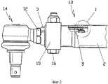
Фигура 1: увеличенное изображение фрагмента предлагаемого конструктивного элемента на примере поперечной рулевой тяги для транспортных средств, иFigure 1: an enlarged image of a fragment of the proposed structural element on the example of the transverse steering rod for vehicles, and
Фигура 2: концевой элемент поперечной рулевой тяги с предлагаемым конструктивным элементом.Figure 2: end element of the tie rod with the proposed structural element.
Представленный на фигуре 1 увеличенный фрагмент предлагаемого конструктивного элемента представляет собой составную часть поперечной рулевой тяги для транспортного средства. Фигура 1 при этом соответствует детали I на фигуре 2.Presented in figure 1 an enlarged fragment of the proposed structural element is an integral part of the transverse steering tie rod for a vehicle. Figure 1 thus corresponds to the detail I in figure 2.
Показанный конструктивный элемент имеет трубу 2 с внутренней резьбой 1. В эту внутреннюю резьбу 1 вкручена регулировочная втулка 3 с имеющейся на регулировочной втулке 3 наружной резьбой 17, соответствующей внутренней резьбе 1 трубы 2. Внутренняя втулка 3 на внутренней рабочей поверхности 8 имеет внутреннюю резьбу 4, которая служит для вкручивания шейки 5 в регулировочную втулку 3. Шейка 5 имеет для этого на своей наружной рабочей поверхности наружную резьбу 18. Для осуществления изобретения важно, что внутренняя резьба 1 трубы 2 и внутренняя резьба 4 регулировочной втулки 3 выполнены соответственно с противоположной друг другу резьбой. Если, например, внутренняя резьба 1 трубы является правой резьбой, то внутренняя резьба 4 регулировочной втулки 3 выполнена как левая резьба. Следствием этого является то, что при вращательном движении регулировочной втулки 3 вокруг не показанной общей продольной срединной оси конструктивных деталей - труба 2, регулировочная втулка 3 и шейка 5 - шейка 5 может смещаться относительно трубы 2. За счет этого возможно аксиальное перемещающее движение поперечной рулевой тяги. Кроме того, регулировочная втулка 3 имеет на конце паз 9, в который установлен ограниченно эластичный блокирующий элемент 6. Блокирующий элемент 6 может выходить внутри паза 8 в радиальном направлении. Аксиальная подвижность блокирующего элемента 6 внутри паза 9 не предусмотрена. Поэтому блокирующий элемент 6 прилегает своими двумя боковыми поверхностями к соответствующим ограничительным поверхностям паза 9. Кроме того, в шейке 5 расположен паз 7, который находится в области концевого участка шейки 5. Этот паз 7 с обеих сторон ограничивается упорным фланцем 19 или же 20. Участок между упорными фланцами 19 и 20 представляет собой максимально возможный путь смещения предлагаемого конструктивного элемента. Кроме того, блокирующий элемент 6 имеет сквозное отверстие 10, внутренняя поверхность которого непосредственно прилегает к наружной поверхности паза 7 шейки 5. В данном случае обеспечено скользящее движение в аксиальном направлении внутри паза 7. Кроме того, для предлагаемого решения важно, что концевой элемент 11 шейки выполнен грибовидной формы. В представленном на фигуре 1 примере грибовидный контур концевого элемента 11 шейки 5 достигается за счет нескольких переходящих друг в друга геометрических форм. Так, начинаясь на конце шейки 5, сменяют друг друга две конически выполненные геометрические формы с различными наклонами к продольной срединной оси. На стыке с конусными геометрическими формами концевого элемента 11 последний имеет круглоцилиндрическое поперечное сечение, которое со стороны паза переходит в упорный фланец 20.The shown structural element has a
Монтаж конструктивного элемента выполняется следующим образом.Installation of the structural element is as follows.
Сначала изготавливаются детали. Затем блокирующий элемент 6 вставляют в предусмотренный для этого в регулировочной втулке 3 паз 9. Блокирующий элемент 6 имеет собственную эластичность, которая позволяет при вкручивании шейки 5 в регулировочную втулку 3 сначала провести грибовидный концевой элемент 11 шейки 5 через сквозное отверстие 10 блокирующего элемента 6. В силу указанной собственной эластичности блокирующий элемент 6 расширяется при этом внутри паза 9 в радиальном направлении. Он скользит своим сквозным отверстием 10 по конусным геометрическим формам концевого элемента 11. После того как грибовидный концевой элемент 11 пройден, блокирующий элемент 6 входит в паз 7 шейки 5 и за счет своей собственной эластичности снова сжимается, в результате чего он прилегает к поверхности паза 7. Теперь по наружной резьбе 17 регулировочной втулки 3 во внутреннюю резьбу 1 трубы 2 может быть вкручен созданный таким образом частичный конструктивный элемент.Parts are made first. Then, the locking element 6 is inserted into the groove 9 provided for in the
На фигуре 2 для лучшего понимания предлагаемого изобретения представлен конструктивный элемент на примере поперечной рулевой тяги 13 для транспортного средства. Поперечная рулевая тяга 13, из которой здесь показан только концевой элемент, имеет трубу 2, в которую вкручена регулировочная втулка 3. Для смещения регулировочной втулки 3 на ее наружной рабочей поверхности имеется плоскость 12 под ключ. С помощью шейки 5, образующей шейку корпуса шарового шарнира, шаровой шарнир 1 связан с регулировочной втулкой 3. Для фиксации конструктивных деталей относительно друг друга служит зажимной хомут 15, который установлен на наружной рабочей поверхности трубы 2. Этот зажимной хомут 15 стягивается посредством резьбового соединения 16 и тем самым стягивает весь конструктивный элемент. Таким образом, более нельзя реализовать движение смещения после затягивания зажимного хомута. Как видно на изображении на фигуре 2, предлагаемый конструктивный элемент находится внутри трубы 2 показанной поперечной рулевой тяги 13, тем самым она защищается от загрязнений и механических повреждений.Figure 2 for a better understanding of the invention presents a structural element on the example of the
Список ссылочных обозначенийReference List
1 Внутренняя резьба (труба)1 Internal thread (pipe)
2 Труба2 pipe
3 Регулировочная втулка3 Adjustment sleeve
4 Внутренняя резьба (регулировочная втулка)4 Internal thread (adjusting sleeve)
5 Шейка5 neck
6 Блокирующий элемент6 Blocking element
7 Паз (в шейке)7 groove (in the neck)
8 Внутренняя рабочая поверхность (регулировочной втулки)8 Internal work surface (adjusting sleeve)
9 Паз (в регулировочной втулке)9 Groove (in the adjusting sleeve)
10 Сквозное отверстие (блокирующего элемента)10 Through hole (blocking element)
11 Концевой элемент11 End element
12 Плоскость под ключ12 Turnkey Plane
13 Поперечная рулевая тяга13 Tie rod
14 Шаровой шарнир14 Ball joint
15 Зажимной хомут15 clamping clamp
16 Наружная резьба (регулировочной втулки)16 External thread (adjusting sleeve)
18 Наружная резьба (шейки)18 External thread (necks)
19 Упорный фланец19 Thrust flange
20 Упорный фланец20 Thrust flange
Claims (19)
Translated fromRussianApplications Claiming Priority (2)
| Application Number | Priority Date | Filing Date | Title |
|---|---|---|---|
| DE102008001381.1 | 2008-04-25 | ||
| DE102008001381ADE102008001381B3 (en) | 2008-04-25 | 2008-04-25 | unit |
Publications (2)
| Publication Number | Publication Date |
|---|---|
| RU2010147867A RU2010147867A (en) | 2012-05-27 |
| RU2464195C2true RU2464195C2 (en) | 2012-10-20 |
Family
ID=40791149
Family Applications (1)
| Application Number | Title | Priority Date | Filing Date |
|---|---|---|---|
| RU2010147867/11ARU2464195C2 (en) | 2008-04-25 | 2009-04-07 | Structural element |
Country Status (8)
| Country | Link |
|---|---|
| US (1) | US8696232B2 (en) |
| KR (1) | KR101495390B1 (en) |
| CN (1) | CN102015418B (en) |
| BR (1) | BRPI0911641A8 (en) |
| DE (1) | DE102008001381B3 (en) |
| MX (1) | MX2010011559A (en) |
| RU (1) | RU2464195C2 (en) |
| WO (1) | WO2009129808A1 (en) |
Families Citing this family (5)
| Publication number | Priority date | Publication date | Assignee | Title |
|---|---|---|---|---|
| US8998228B2 (en)* | 2013-03-26 | 2015-04-07 | Powers and Sons, LLC | Steering attenuator assembly for motor vehicle |
| US9821843B1 (en)* | 2017-01-06 | 2017-11-21 | Robert Bosch Automotive Steering Llc | Tie rod |
| US11242889B2 (en) | 2019-08-29 | 2022-02-08 | The Boeing Company | Adjustable tie rods and related methods |
| RU2020103575A (en)* | 2020-01-28 | 2021-07-28 | Зе Боинг Компани | ADJUSTABLE CONNECTING ROD ASSEMBLIES WITH JOINT END AND APPROPRIATE METHODS |
| NL2035235B1 (en)* | 2023-06-30 | 2025-01-09 | Daf Trucks Nv | Track rod adjustment mechanism |
Citations (4)
| Publication number | Priority date | Publication date | Assignee | Title |
|---|---|---|---|---|
| DE7732250U1 (en)* | 1977-10-19 | 1978-02-09 | Adam Opel Ag, 6090 Ruesselsheim | TIE ROD FOR STEERING ROD IN MOTOR VEHICLES |
| RU2043940C1 (en)* | 1990-08-07 | 1995-09-20 | Фиат Ауто С.П.А. | Device to limit wheel locking angle |
| US5603583A (en)* | 1995-11-06 | 1997-02-18 | Trw Inc. | Tie rod assembly for vehicle steering linkages |
| DE10211066A1 (en)* | 2001-03-16 | 2002-09-19 | Dana Ind S A Piraporinha Diade | Adjustable steering tie rod with a helical locking device |
Family Cites Families (19)
| Publication number | Priority date | Publication date | Assignee | Title |
|---|---|---|---|---|
| SE359898B (en)* | 1972-01-19 | 1973-09-10 | Sandqvist Sune Allan | |
| US3829824A (en)* | 1973-05-18 | 1974-08-13 | E Pillischafske | Clamp bolt for an automotive vehicle battery |
| US4097163A (en)* | 1977-01-10 | 1978-06-27 | Tyee Aircraft, Inc. | Method of swage joining a rod end to a tube and the product thereof |
| FR2649062A1 (en)* | 1989-06-29 | 1991-01-04 | Irigny Mecanique | Device for connecting a ball joint to a motor vehicle steering linkage coupling bar |
| US5156482A (en)* | 1991-05-21 | 1992-10-20 | Owings Samuel S | Lockable turnbuckle |
| US5286133A (en)* | 1991-08-15 | 1994-02-15 | Trw Inc. | Joint for vehicle steering linkage |
| US5251995A (en)* | 1992-11-12 | 1993-10-12 | Chi Yi C | Coupling of a head set |
| US6264402B1 (en)* | 1995-12-26 | 2001-07-24 | Vickars Developments Co. Ltd. | Method and apparatus for forming piles in place |
| KR19990020434U (en)* | 1997-11-26 | 1999-06-15 | 김충열 | Manufacturing method of shock absorber |
| DE19900264C2 (en)* | 1999-01-07 | 2002-02-14 | Zf Lemfoerder Metallwaren Ag | Tie rod for motor vehicles |
| US6595714B2 (en)* | 2000-12-09 | 2003-07-22 | Tyee Aircraft | Swivel insert for a control rod |
| BR0101245B1 (en)* | 2001-03-20 | 2009-05-05 | Adjustable steering bar with longitudinal locking. | |
| US6902325B1 (en)* | 2001-09-06 | 2005-06-07 | Gkn Driveline North America, Inc. | Constant velocity joint and wheel hub assembly |
| KR100456921B1 (en) | 2002-05-31 | 2004-11-10 | 쌍용자동차 주식회사 | Tie rod of steering linkage for automobiles |
| US6902341B1 (en)* | 2002-12-12 | 2005-06-07 | Mark C. Rauschert | Turnbuckle linkage assembly |
| US7024827B2 (en)* | 2003-02-20 | 2006-04-11 | Gregory Enterprises, Inc. | Preconstruction anchoring system and method for buildings |
| US6966567B2 (en)* | 2003-05-09 | 2005-11-22 | The Pullman Company | One end adjustable torque rod |
| US7841144B2 (en)* | 2005-03-30 | 2010-11-30 | Valinge Innovation Ab | Mechanical locking system for panels and method of installing same |
| DE102009001535A1 (en)* | 2009-03-13 | 2010-09-16 | Zf Friedrichshafen Ag | Assembly, method of use of this assembly and tool for applying the method |
- 2008
- 2008-04-25DEDE102008001381Apatent/DE102008001381B3/ennot_activeExpired - Fee Related
- 2009
- 2009-04-07BRBRPI0911641Apatent/BRPI0911641A8/ennot_activeApplication Discontinuation
- 2009-04-07WOPCT/DE2009/050019patent/WO2009129808A1/enactiveApplication Filing
- 2009-04-07USUS12/989,122patent/US8696232B2/ennot_activeExpired - Fee Related
- 2009-04-07MXMX2010011559Apatent/MX2010011559A/ennot_activeApplication Discontinuation
- 2009-04-07KRKR1020107024032Apatent/KR101495390B1/ennot_activeExpired - Fee Related
- 2009-04-07CNCN200980114877.0Apatent/CN102015418B/ennot_activeExpired - Fee Related
- 2009-04-07RURU2010147867/11Apatent/RU2464195C2/ennot_activeIP Right Cessation
Patent Citations (4)
| Publication number | Priority date | Publication date | Assignee | Title |
|---|---|---|---|---|
| DE7732250U1 (en)* | 1977-10-19 | 1978-02-09 | Adam Opel Ag, 6090 Ruesselsheim | TIE ROD FOR STEERING ROD IN MOTOR VEHICLES |
| RU2043940C1 (en)* | 1990-08-07 | 1995-09-20 | Фиат Ауто С.П.А. | Device to limit wheel locking angle |
| US5603583A (en)* | 1995-11-06 | 1997-02-18 | Trw Inc. | Tie rod assembly for vehicle steering linkages |
| DE10211066A1 (en)* | 2001-03-16 | 2002-09-19 | Dana Ind S A Piraporinha Diade | Adjustable steering tie rod with a helical locking device |
Also Published As
| Publication number | Publication date |
|---|---|
| WO2009129808A1 (en) | 2009-10-29 |
| MX2010011559A (en) | 2010-11-12 |
| DE102008001381B3 (en) | 2010-01-07 |
| US8696232B2 (en) | 2014-04-15 |
| US20110038665A1 (en) | 2011-02-17 |
| BRPI0911641A8 (en) | 2019-01-29 |
| RU2010147867A (en) | 2012-05-27 |
| CN102015418A (en) | 2011-04-13 |
| KR20110005702A (en) | 2011-01-18 |
| BRPI0911641A2 (en) | 2018-03-27 |
| KR101495390B1 (en) | 2015-02-24 |
| CN102015418B (en) | 2015-06-17 |
Similar Documents
| Publication | Publication Date | Title |
|---|---|---|
| RU2464195C2 (en) | Structural element | |
| KR102493549B1 (en) | Fastening element and assembly with such a fastening element and a receiving element | |
| KR101452280B1 (en) | Tension clamp | |
| US7867099B2 (en) | Connecting arrangement between a shaft journal and a joint part | |
| BR102013010842A2 (en) | Profiled clamp | |
| RU2011141305A (en) | CROSS STEERING LINK | |
| CN103429944B (en) | Clamp ring secured by a threaded rod and two nuts | |
| CN102168776A (en) | Tube connection device | |
| US8689390B2 (en) | Wiper device | |
| US7832575B2 (en) | Articulated joint coupling | |
| KR20070086384A (en) | Device for securing add-on and support spaced apart | |
| JP2015169304A (en) | Resin member having flanged fastening member | |
| KR20210044269A (en) | Two-piece high-strength screw | |
| US10267308B2 (en) | Crosshead-piston rod assembly for a reciprocating compressor | |
| EP2395249A1 (en) | Segmented thread and connecting arrangement | |
| CN103765022A (en) | Ball-joint | |
| US9261146B2 (en) | Resilient joint member with space-saving collar bushing arrangement | |
| US6357564B1 (en) | Connection bearing with a line connection | |
| US11459932B2 (en) | Arrangement and method for fastening a tailpipe cover | |
| EP1867884B1 (en) | Improvements relating to vehicle steering | |
| RU2519597C2 (en) | Spherical joint pin and spherical joint | |
| CN106981803B (en) | But spacing revolution mechanic | |
| EP3626573B1 (en) | Structural link between two rail vehicle subassemblies and associated rail vehicle assembly | |
| KR101631509B1 (en) | Apparatus for preventing misassembling of a universal joint | |
| JP4178047B2 (en) | Rebar end fixing device |
Legal Events
| Date | Code | Title | Description |
|---|---|---|---|
| MM4A | The patent is invalid due to non-payment of fees | Effective date:20170408 |