RU2462799C1 - Waveguide ceramic filter - Google Patents
Waveguide ceramic filterDownload PDFInfo
- Publication number
- RU2462799C1 RU2462799C1RU2011112751/07ARU2011112751ARU2462799C1RU 2462799 C1RU2462799 C1RU 2462799C1RU 2011112751/07 ARU2011112751/07 ARU 2011112751/07ARU 2011112751 ARU2011112751 ARU 2011112751ARU 2462799 C1RU2462799 C1RU 2462799C1
- Authority
- RU
- Russia
- Prior art keywords
- filter
- holes
- metallized
- ceramic
- blind
- Prior art date
Links
Images


Landscapes
- Control Of Motors That Do Not Use Commutators (AREA)
Abstract
Description
Translated fromRussianИзобретение относится к радиотехнике СВЧ и предназначено для использования в устройствах частотной селекции, преимущественно, в сантиметровом и миллиметровом диапазонах длин волн.The invention relates to microwave radio engineering and is intended for use in frequency selection devices, mainly in the centimeter and millimeter wavelength ranges.
Известна конструкция фильтров на полых волноводах с поперечными плоскими емкостными и индуктивными диафрагмами и стержневыми индуктивными диафрагмами [Семенов Н.А. Техническая электродинамика. - М.: «Связь», 1973, с.394-397].A known design of filters on hollow waveguides with transverse flat capacitive and inductive diaphragms and rod inductive diaphragms [N. Semenov Technical electrodynamics. - M .: "Communication", 1973, S. 394-397].
Известна конструкция фильтра на полых волноводах с Е-плоскостными диафрагмами [патент US 2004/0017272 A1, Jan.29, 2004].A known design of a filter on hollow waveguides with E-planar diaphragms [patent US 2004/0017272 A1, Jan.29, 2004].
Одним из недостатков этих фильтров является необходимость применения специальных переходов для использования их в устройствах на микрополосковых и копланарных линиях, что увеличивает габариты изделия.One of the drawbacks of these filters is the need to use special transitions for use in devices on microstrip and coplanar lines, which increases the dimensions of the product.
Известна конструкция фильтра на основе металлизированного высокодобротного блока в форме прямоугольного параллелепипеда из термостабильной керамики, в котором сформирована цепочка резонаторов на связанных симметричных полосковых линиях с внутренними проводниками, образованными металлизированными отверстиями в керамическом блоке и металлизированными гранями блока, по схеме гребенчатых и встречно-стержневых фильтров с элементами связи в виде разомкнутых отрезков копланарных линий [патент RU 22480745 С1].A known filter design based on a metallized high-Q block in the form of a rectangular parallelepiped made of thermostable ceramic, in which a chain of resonators is formed on connected symmetrical strip lines with internal conductors formed by metallized holes in the ceramic block and metallized block faces, according to the comb and interdigital filter scheme with communication elements in the form of open segments of coplanar lines [patent RU 22480745 C1].
Фильтры изготавливаются по отработанной технологии, имеют малое затухание в полосе пропускания на частотах менее 10 ГГц. В более высокочастотном диапазоне размеры фильтров становятся миниатюрными, поскольку длина резонатора на основной ТЕМ-моде ~λ/4 (где λ - длина волны в диэлектрике), вследствие чего технологические погрешности оказывают сильное влияние на характеристики фильтра и затрудняют его реализацию. Кроме того, паразитные полосы пропускания объемных мод, располагающихся вблизи основной полосы пропускания, также ухудшают характеристики фильтра.Filters are manufactured using proven technology, have low attenuation in the passband at frequencies less than 10 GHz. In the higher frequency range, the filter sizes become miniature, since the resonator length on the main TEM mode is ~ λ / 4 (where λ is the wavelength in the dielectric), as a result of which technological errors strongly influence the filter characteristics and impede its implementation. In addition, the spurious passband of the surround modes located near the main passband also degrades the filter performance.
Наиболее близким по техническому решению является принятый за прототип волноводный керамический фильтр, состоящий из металлизированного керамического блока в форме прямоугольного параллелепипеда, в котором сформирована цепочка объемных резонаторов с непосредственной связью через плоские индуктивные диафрагмы, выполненные в виде металлизированных пазов со стороны узких стенок керамического блока, с элементами связи в виде емкостных площадок на нижней грани блока [патент US 2009/0231064 A1, Sep.17, 2009].The closest in technical solution is the waveguide ceramic filter adopted for the prototype, consisting of a metallized ceramic block in the shape of a rectangular parallelepiped, in which a chain of volume resonators is formed with direct coupling through flat inductive diaphragms made in the form of metallized grooves on the side of the narrow walls of the ceramic block, with communication elements in the form of capacitive pads on the lower edge of the block [patent US 2009/0231064 A1, Sep.17, 2009].
Фильтр работает на основной объемной моде прямоугольного резонатора H101 и в миллиметровом диапазоне длин волн, имеет размеры и топологию металлизации, легко реализуемую в типовом технологическом процессе.The filter operates on the main volumetric mode of the H101 rectangular resonator and in the millimeter wavelength range; it has dimensions and metallization topology that can be easily implemented in a typical technological process.
Недостатками прототипа являются отсутствие элементов настройки отдельных объемных резонаторов и элементов настройки связи для обеспечения согласования с входной и выходной линиями. Кроме того, глубокие пазы в керамическом блоке снижают механическую прочность фильтра.The disadvantages of the prototype are the lack of tuning elements of individual volume resonators and communication tuning elements to ensure coordination with the input and output lines. In addition, deep grooves in the ceramic block reduce the mechanical strength of the filter.
Техническим результатом заявляемого изобретения является расширение возможностей настройки фильтра для реализации большей номенклатуры изделий на основе базового керамического блока, а также увеличение его механической прочности.The technical result of the claimed invention is the expansion of the filter settings for the implementation of a larger product range based on the base ceramic block, as well as an increase in its mechanical strength.
Для достижения указанного выше технического результата предлагается керамический волноводный фильтр в виде металлизированного прямоугольного керамического блока, в котором сквозные металлизированные отверстия выполняют функции индуктивных стержневых диафрагм, элементами настройки резонаторов фильтра являются используемые в различных сочетаниях глухие металлизированные, глухие неметаллизированные, а также глухие и сквозные частично металлизированные отверстия, а подстройка согласования фильтра с входной и выходной линиями передачи после установки фильтра на плату производится за счет изменения длины короткозамкнутых отрезков копланарных линий на торцевых гранях керамического блока.To achieve the above technical result, a ceramic waveguide filter in the form of a metallized rectangular ceramic block is proposed, in which through metallized holes serve as inductive rod diaphragms, filter resonator tuning elements are deaf metallized, non-metallic deaf, and deaf and partially metallized through holes, and fine-tuning the matching of the filter with the input and output lines per cottages filter after installation on board is made by changing the length of short-circuited segments coplanar lines on the end faces of the ceramic block.
Применение индуктивных стержневых диафрагм позволяет повысить механическую прочность фильтра за счет меньшего изменения поперечного сечения керамического блока.The use of inductive rod diaphragms makes it possible to increase the mechanical strength of the filter due to a smaller change in the cross section of the ceramic block.
При этом металлизированные глухие отверстия увеличивают эквивалентную емкость резонатора, неметаллизированные глухие отверстия уменьшают эквивалентную емкость резонатора. Элементы в виде частично металлизированных глухих или сквозных отверстий позволяют как уменьшать, так и увеличивать эквивалентную емкость резонатора, что дает возможность увеличить номенклатуру изделий на основе базового керамического блока. Полностью металлизированные и неметаллизированные элементы настройки более технологичны, но смешанные элементы имеют больший диапазон изменения эквивалентной емкости резонатора.In this case, metallized blind holes increase the equivalent capacitance of the resonator, non-metallized blind holes reduce the equivalent capacitance of the resonator. Elements in the form of partially metallized blind or through holes can both reduce and increase the equivalent resonator capacity, which makes it possible to increase the product range based on the base ceramic block. Completely metallized and non-metallized tuning elements are more technologically advanced, but mixed elements have a larger range of variation in the equivalent capacitance of the resonator.
Возможность изменения длины короткозамкнутых отрезков копланарных линий на торцевых гранях керамического блока позволяет производить подстройку согласования фильтра с входной и выходной линиями передачи после установки фильтра на плату.The ability to change the length of short-circuited segments of coplanar lines on the end faces of the ceramic block allows you to adjust the matching of the filter with the input and output transmission lines after installing the filter on the board.
Принцип действия указанных элементов настройки можно пояснить с помощью теории малых возмущений объемных резонаторов [В.В.Никольский, Теория электромагнитного поля. М. Высшая школа 1961 г. стр.345-351]. При внесении в полость резонирующего объема возмущающего тела нарушается баланс энергии электрического и магнитного полей, вследствие чего резонансная частота резонатора изменяется на величину Δf, определяемую из отношения:The principle of operation of these tuning elements can be explained using the theory of small perturbations of volume resonators [V.V.Nikolsky, Theory of electromagnetic field. M. High School 1961 p. 345-351]. When a disturbing body is introduced into the cavity of the resonant volume, the energy balance of the electric and magnetic fields is violated, as a result of which the resonant frequency of the resonator changes by Δf, determined from the relation:

где:
где f0 - частота резонатора в отсутствие возмущающего тела;where f0 is the resonator frequency in the absence of a disturbing body;
f - частота резонатора при наличии возмущающего тела;f is the resonator frequency in the presence of a disturbing body;
ΔWE и ΔWH - изменение максимальной энергии электрического и магнитного полей при внесении в резонатор возмущающего тела;ΔWE and ΔWH is the change in the maximum energy of the electric and magnetic fields when a disturbing body is introduced into the resonator;
W0 - запасенная в резонаторе энергия электромагнитного поля.W0 - stored in the resonator energy of the electromagnetic field.
Элемент настройки в виде металлизированного отверстия можно трактовать как возмущающее тело в виде проводящего цилиндра, неметаллизированное отверстие - как диэлектрический цилиндр с диэлектрической проницаемостью ε0.A tuning element in the form of a metallized hole can be interpreted as a perturbing body in the form of a conducting cylinder, a non-metallic hole as a dielectric cylinder with a dielectric constant ε0 .
Количественно соотношения для определения Δf/f0 в первом приближении можно установить, если рассматривать звено фильтра как полуволновый резонатор на основе прямоугольного волновода с волной Н10 с диэлектрическим заполнением ε∂ (фиг.1).Quantitatively, the ratios for determining Δf / f0 in a first approximation can be established if we consider the filter link as a half-wave resonator based on a rectangular waveguide with wave H10 with dielectric filling ε∂ (Fig. 1).
Для проводящего цилиндра (металлизированное отверстие):For a conductive cylinder (metallized hole):

где R0 - радиус цилиндра;where R0 is the radius of the cylinder;
l - длина цилиндра;l is the length of the cylinder;
a, b, L - длина, ширина, высота резонатора.a, b, L - length, width, height of the resonator.
При введении проводящего цилиндра резонансная частота понижается, что можно трактовать как увеличение эквивалентной емкости резонатора.With the introduction of the conductive cylinder, the resonant frequency decreases, which can be interpreted as an increase in the equivalent capacitance of the resonator.
Для неметаллизированного отверстия:For non-metallic holes:

где εr - относительная, диэлектрическая проницаемость диэлектрика, заполняющего объем резонатора.where εr is the relative dielectric constant of the dielectric filling the cavity volume.
При введении неметаллизированного отверстия резонансная частота увеличивается, что можно трактовать как уменьшение эквивалентной емкости резонатора.With the introduction of a non-metallic hole, the resonant frequency increases, which can be interpreted as a decrease in the equivalent capacitance of the resonator.
В случае частично металлизированных отверстий влияния металлизированной и неметаллизированной частей отверстия складываются, что дает универсальный элемент настройки фильтра.In the case of partially metallized holes, the effects of the metallized and non-metallic parts of the hole are folded, which gives a universal filter setting element.
Сущность изобретения поясняется чертежами, где:The invention is illustrated by drawings, where:
фиг.1 - волноводный керамический фильтр;figure 1 - waveguide ceramic filter;
фиг.2 - разрез фильтра с глухими металлизированными и неметаллизированными отверстиями в качестве элементов настройки;figure 2 is a sectional view of a filter with blank metallic and non-metallic holes as tuning elements;
фиг.3 - разрез фильтра с глухими, частично металлизированными отверстиями;figure 3 is a sectional view of a filter with blind, partially metallized holes;
фиг.4 - разрез фильтра со сквозными частично металлизированными отверстиями;4 is a sectional view of a filter with through partially metallized holes;
фиг.5 - экспериментальная и расчетная АЧХ фильтра;figure 5 - experimental and calculated frequency response of the filter;
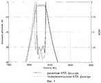
фиг.6 - исходная АЧХ фильтра и АЧХ настроенного фильтра.6 is the original frequency response of the filter and the frequency response of the tuned filter.
На фиг.1-4 и далее по тексту:Figure 1-4 onwards:
поз.1 - металлизированный керамический блок;Pos.1 - metallized ceramic block;
поз.2 - индуктивные стержневые диафрагмы;pos.2 - inductive rod diaphragms;
поз.3 - резонаторы;pos.3 - resonators;
поз.4 - входной элемент связи;pos.4 - input communication element;
поз.5 - выходной элемент связи.Pos.5 - output communication element.
Элементы настройки фильтра:Filter settings items:
поз.6 - глухие металлизированные отверстия;pos.6 - deaf metallized holes;
поз.7 - глухие неметаллизированные отверстия;pos.7 - deaf non-metallic holes;
поз.8 - глухие, частично металлизированные отверстия;Pos.8 - blind, partially metallized holes;
поз.9 - сквозные, частично металлизированные отверстия.Pos. 9 - through, partially metallized holes.
Несмотря на то что изобретение проиллюстрировано изображением волноводного керамического фильтра, представленного на фиг.1, количество резонаторов и элементов настройки, а также их вид могут быть другими. Число резонаторов определяется требуемой характеристикой фильтра и ограничивается допускаемыми потерями фильтра.Despite the fact that the invention is illustrated by the image of the waveguide ceramic filter shown in figure 1, the number of resonators and tuning elements, as well as their appearance may be different. The number of resonators is determined by the required filter characteristic and is limited by the permissible filter losses.
Предлагаемый волноводный фильтр выполнен в виде прямоугольного параллелепипеда из термостабильного керамического материала, на всех гранях которого нанесена металлизация (поз.1). В блоке сформированы одно, два или большее количество сквозных металлизированных отверстий в качестве индуктивных стержневых диафрагм (поз.2), формирующих в керамическом блоке цепочку связанных резонаторов (поз.3) с непосредственной связью. Входной (поз.4) и выходной (поз.5) элементы связи выполнены на нижней грани керамического блока в виде разомкнутых на концах отрезков копланарных линий и короткозамкнутых отрезков копланарных линий на торцевых гранях керамического блока. Глухие металлизированные отверстия (поз.6), глухие неметаллизированные отверстия (поз.7), глухие частично металлизированные отверстия (поз.8), а также сквозные частично металлизированные отверстия (поз.9) являются элементами настройки резонаторов фильтра.The proposed waveguide filter is made in the form of a rectangular parallelepiped of a thermostable ceramic material, on all faces of which metallization is applied (item 1). One, two or more through metallized holes are formed in the block as inductive rod diaphragms (pos. 2), forming a chain of coupled resonators (pos. 3) in a ceramic block with a direct connection. The input (pos. 4) and output (pos. 5) communication elements are made on the lower face of the ceramic block in the form of open segments of coplanar lines at the ends and short-circuit segments of coplanar lines on the end faces of the ceramic block. Blind metallized holes (key 6), blind non-metallized holes (key 7), blind partially metallized holes (key 8), as well as through partially metallized holes (key 9) are settings for filter resonators.
Керамический волноводный фильтр работает следующим образом.Ceramic waveguide filter operates as follows.
После поступления СВЧ сигнала на входной элемент (поз.4) осуществляется эффективный ввод энергии в фильтр, представляющий собой цепочку резонаторов с непосредственной связью, сформированных в металлизированном керамическом блоке с помощью индуктивных стержневых диафрагм (поз.2). Вывод энергии осуществляется посредством выходного элемента связи (поз.5). Вид характеристики фильтра определяется распределением взаимных связей резонаторов фильтра, которые, в свою очередь, определяются диаметром стержней индуктивных диафрагм.After the microwave signal arrives at the input element (item 4), energy is effectively input into the filter, which is a chain of resonators with direct coupling formed in a metallized ceramic block using inductive rod diaphragms (item 2). The energy output is carried out by means of the output coupling element (pos. 5). The type of filter characteristic is determined by the distribution of the mutual connections of the filter resonators, which, in turn, are determined by the diameter of the rods of inductive diaphragms.
Настройка резонаторов керамического волноводного фильтра осуществляется посредством настроечных элементов в виде глухих металлизированных отверстий (поз.6), глухих неметаллизированных отверстий (поз.7), глухих частично металлизированных отверстий (поз.8), а также сквозных частично металлизированных отверстий (поз.9). Описанные элементы настройки могут применяться в различных сочетаниях, обеспечивающих требуемую характеристику фильтра, размеры и вид элементов настройки определяются расчетно-экспериментальным путем. Согласование фильтра с входной и выходной линиями передачи после установки фильтра на плату обеспечивается регулировкой длины короткозамкнутого отрезка копланарной линии на торцевых гранях керамического блока.The resonators of the ceramic waveguide filter are tuned by means of tuning elements in the form of blind metallized holes (pos. 6), blind non-metallized holes (pos. 7), blind partially metallized holes (pos. 8), as well as through partially metallized holes (pos. 9) . The described settings can be used in various combinations that provide the required filter characteristic, the size and type of settings are determined by calculation and experimentation. Coordination of the filter with the input and output transmission lines after installing the filter on the board is provided by adjusting the length of the short-circuited segment of the coplanar line at the end faces of the ceramic block.
На основе предложенной конструкции был разработан и изготовлен полосно-пропускающий фильтр из термостабильной керамики с диэлектрической проницаемостью ε=37. Габаритные размеры фильтра составили 17×4,65×2,2 мм. Центральная частота фильтра f0=8300 МГц, ширина полосы пропускания по уровню 0,5 дБ-Δf=200 МГц, вносимое затухание в полосе пропускание авн - не более 3 дБ, гарантированное затухание агар - не менее 45 дБ. На фиг.5 - расчетная и экспериментальная АЧХ фильтра. На фиг.6 показаны исходная АЧХ фильтра после изготовления и АЧХ после настройки фильтра. Настройка производилась посредством изменения глубины глухих неметаллизированных отверстий и изменения площади металлизации глухих частично металлизированных отверстий.Based on the proposed design, a band-pass filter was developed and manufactured from thermostable ceramics with a dielectric constant ε = 37. The overall dimensions of the filter were 17 × 4.65 × 2.2 mm. The central frequency of the filter is f0 = 8300 MHz, the bandwidth at the level of 0.5 dB-Δf = 200 MHz, the attenuation in the passband andVn is not more than 3 dB, the guaranteed attenuation andgar - not less than 45 dB. Figure 5 - calculated and experimental frequency response of the filter. Figure 6 shows the initial frequency response of the filter after manufacture and frequency response after tuning the filter. The adjustment was made by changing the depth of the deaf non-metallized holes and changing the metallization area of the deaf partially metallized holes.
Claims (1)
Translated fromRussianPriority Applications (1)
| Application Number | Priority Date | Filing Date | Title |
|---|---|---|---|
| RU2011112751/07ARU2462799C1 (en) | 2011-04-01 | 2011-04-01 | Waveguide ceramic filter |
Applications Claiming Priority (1)
| Application Number | Priority Date | Filing Date | Title |
|---|---|---|---|
| RU2011112751/07ARU2462799C1 (en) | 2011-04-01 | 2011-04-01 | Waveguide ceramic filter |
Publications (1)
| Publication Number | Publication Date |
|---|---|
| RU2462799C1true RU2462799C1 (en) | 2012-09-27 |
Family
ID=47078622
Family Applications (1)
| Application Number | Title | Priority Date | Filing Date |
|---|---|---|---|
| RU2011112751/07ARU2462799C1 (en) | 2011-04-01 | 2011-04-01 | Waveguide ceramic filter |
Country Status (1)
| Country | Link |
|---|---|
| RU (1) | RU2462799C1 (en) |
Cited By (3)
| Publication number | Priority date | Publication date | Assignee | Title |
|---|---|---|---|---|
| RU2527192C1 (en)* | 2013-01-24 | 2014-08-27 | Открытое акционерное общество "Специальное конструкторско-технологическое бюро по релейной технике" (ОАО "СКТБ РТ") | Ceramic quasiplanar waveguide filter |
| RU2557753C1 (en)* | 2014-02-11 | 2015-07-27 | Открытое акционерное общество "Специальное конструкторско-технологическое бюро по релейной технике" (ОАО "СКТБ РТ") | Ceramic bandpass filter based on quasi-stationary resonators |
| CN111540985A (en)* | 2020-03-26 | 2020-08-14 | 横店集团东磁股份有限公司 | Ceramic filter and radio frequency device |
Citations (6)
| Publication number | Priority date | Publication date | Assignee | Title |
|---|---|---|---|---|
| US4673902A (en)* | 1983-11-25 | 1987-06-16 | Murata Manufacturing Co., Ltd. | Dielectric material coaxial resonator filter directly mountable on a circuit board |
| US5506553A (en)* | 1993-10-22 | 1996-04-09 | Murata Manufacturing Co., Ltd. | High-frequency filter |
| RU2091927C1 (en)* | 1992-07-28 | 1997-09-27 | Институт физики твердого тела и полупроводников АН Беларуси | Method for tuning coaxial dielectric cavity |
| RU34805U1 (en)* | 2003-07-28 | 2003-12-10 | Открытое акционерное общество "Научно-исследовательский институт "Феррит-Домен" | DIELECTRIC FILTER |
| RU36571U1 (en)* | 2003-10-29 | 2004-03-10 | Открытое акционерное общество "Научно-исследовательский институт "Феррит-Домен" | DIELECTRIC FILTER |
| RU54699U1 (en)* | 2005-08-03 | 2006-07-10 | Открытое акционерное общество "Специальное конструкторско-технологическое бюро по релейной технике" (ОАО "СКТБ РТ") | Microwave filter |
- 2011
- 2011-04-01RURU2011112751/07Apatent/RU2462799C1/ennot_activeIP Right Cessation
Patent Citations (6)
| Publication number | Priority date | Publication date | Assignee | Title |
|---|---|---|---|---|
| US4673902A (en)* | 1983-11-25 | 1987-06-16 | Murata Manufacturing Co., Ltd. | Dielectric material coaxial resonator filter directly mountable on a circuit board |
| RU2091927C1 (en)* | 1992-07-28 | 1997-09-27 | Институт физики твердого тела и полупроводников АН Беларуси | Method for tuning coaxial dielectric cavity |
| US5506553A (en)* | 1993-10-22 | 1996-04-09 | Murata Manufacturing Co., Ltd. | High-frequency filter |
| RU34805U1 (en)* | 2003-07-28 | 2003-12-10 | Открытое акционерное общество "Научно-исследовательский институт "Феррит-Домен" | DIELECTRIC FILTER |
| RU36571U1 (en)* | 2003-10-29 | 2004-03-10 | Открытое акционерное общество "Научно-исследовательский институт "Феррит-Домен" | DIELECTRIC FILTER |
| RU54699U1 (en)* | 2005-08-03 | 2006-07-10 | Открытое акционерное общество "Специальное конструкторско-технологическое бюро по релейной технике" (ОАО "СКТБ РТ") | Microwave filter |
Cited By (3)
| Publication number | Priority date | Publication date | Assignee | Title |
|---|---|---|---|---|
| RU2527192C1 (en)* | 2013-01-24 | 2014-08-27 | Открытое акционерное общество "Специальное конструкторско-технологическое бюро по релейной технике" (ОАО "СКТБ РТ") | Ceramic quasiplanar waveguide filter |
| RU2557753C1 (en)* | 2014-02-11 | 2015-07-27 | Открытое акционерное общество "Специальное конструкторско-технологическое бюро по релейной технике" (ОАО "СКТБ РТ") | Ceramic bandpass filter based on quasi-stationary resonators |
| CN111540985A (en)* | 2020-03-26 | 2020-08-14 | 横店集团东磁股份有限公司 | Ceramic filter and radio frequency device |
Similar Documents
| Publication | Publication Date | Title |
|---|---|---|
| JP5920868B2 (en) | Transmission line resonator, bandpass filter and duplexer | |
| Zhang et al. | Evanescent-mode substrate integrated waveguide (SIW) filters implemented with complementary split ring resonators | |
| CN103326093A (en) | Novel cross coupling substrate integrated waveguide band-pass filter | |
| US6445263B1 (en) | Dielectric resonator, dielectric filter, duplexer, and communication device | |
| CN108493534B (en) | A four-mode substrate integrated waveguide broadband filter | |
| RU2462799C1 (en) | Waveguide ceramic filter | |
| CN113330633B (en) | Miniature antenna filter and filter array | |
| Sirci et al. | Quasi-elliptic filter based on SIW combline resonators using a coplanar line cross-coupling | |
| CN110752425A (en) | Band-pass filter and communication device | |
| RU109618U1 (en) | WAVEGUIDE CERAMIC MICROWAVE FILTER WITH SETTING ELEMENTS | |
| Avinash et al. | Compact dual-mode microstrip bandpass filters with transmission zeros using modified star shaped resonator | |
| RU97867U1 (en) | MICRO-STRIP BAND FILTER | |
| CN108767382A (en) | The adjustable three moulds bandpass filter of electricity based on substrate integration wave-guide | |
| CN103887584A (en) | Miniaturized substrate integrated waveguide based on metamaterial | |
| RU2675206C1 (en) | Microstrip broadband band-pass filter | |
| CN104167578B (en) | Substrate integration wave-guide band pass filter | |
| Boutejdar et al. | Design of a new bandpass filter with sharp transition band using multilayer-technique and U-defected ground structure | |
| RU2590313C1 (en) | Strip harmonic filter | |
| Gowrish et al. | A tunable waveguide filter designed with a constantan absolute bandwidth U sing a single tuning element | |
| Hao et al. | Highly selective ultra wideband bandpass filters with quasi-elliptic function response | |
| Maleki et al. | A compact dual-band bandpass filter using microstrip meander loop and square loop resonators | |
| Belyaev et al. | A three-mode microstrip resonator and a miniature ultra-wideband filter based on it | |
| Sergienko et al. | Novel concept for microstrip stub resonant frequency control | |
| Tang et al. | Bandpass Filter with Ultra-Wideband External Suppression Based on Half Mode Substrate Integrated Waveguide | |
| RU2710386C2 (en) | Miniature bandpass filter |
Legal Events
| Date | Code | Title | Description |
|---|---|---|---|
| TC4A | Change in inventorship | Effective date:20121225 | |
| MM4A | The patent is invalid due to non-payment of fees | Effective date:20160402 | |
| NF4A | Reinstatement of patent | Effective date:20170303 | |
| MM4A | The patent is invalid due to non-payment of fees | Effective date:20210402 |