RU2456427C2 - Drilling bit with cutting element sintered together with rolling cutter housing - Google Patents
Drilling bit with cutting element sintered together with rolling cutter housingDownload PDFInfo
- Publication number
- RU2456427C2 RU2456427C2RU2009135273/03ARU2009135273ARU2456427C2RU 2456427 C2RU2456427 C2RU 2456427C2RU 2009135273/03 ARU2009135273/03 ARU 2009135273/03ARU 2009135273 ARU2009135273 ARU 2009135273ARU 2456427 C2RU2456427 C2RU 2456427C2
- Authority
- RU
- Russia
- Prior art keywords
- cone
- sintered
- cutting element
- cutting
- matrix
- Prior art date
Links
- 238000005520cutting processMethods0.000titleclaimsabstractdescription131
- 238000005553drillingMethods0.000titleclaimsabstractdescription29
- 238000005096rolling processMethods0.000titleabstract2
- 239000002245particleSubstances0.000claimsabstractdescription92
- 238000000034methodMethods0.000claimsabstractdescription59
- 239000000203mixtureSubstances0.000claimsabstractdescription56
- 239000002131composite materialSubstances0.000claimsabstractdescription47
- 239000011159matrix materialSubstances0.000claimsabstractdescription45
- 239000000463materialSubstances0.000claimsabstractdescription39
- 238000005245sinteringMethods0.000claimsabstractdescription35
- 239000007787solidSubstances0.000claimsabstractdescription24
- 230000004927fusionEffects0.000claimsabstractdescription6
- 238000002360preparation methodMethods0.000claimsabstract4
- PXHVJJICTQNCMI-UHFFFAOYSA-NNickelChemical compound[Ni]PXHVJJICTQNCMI-UHFFFAOYSA-N0.000claimsdescription35
- XEEYBQQBJWHFJM-UHFFFAOYSA-NIronChemical compound[Fe]XEEYBQQBJWHFJM-UHFFFAOYSA-N0.000claimsdescription32
- 239000000843powderSubstances0.000claimsdescription25
- 229910017052cobaltInorganic materials0.000claimsdescription20
- 239000010941cobaltSubstances0.000claimsdescription20
- GUTLYIVDDKVIGB-UHFFFAOYSA-Ncobalt atomChemical compound[Co]GUTLYIVDDKVIGB-UHFFFAOYSA-N0.000claimsdescription20
- 229910052759nickelInorganic materials0.000claimsdescription18
- 229910052742ironInorganic materials0.000claimsdescription16
- 239000011435rockSubstances0.000claimsdescription15
- 229910045601alloyInorganic materials0.000claimsdescription11
- 239000000956alloySubstances0.000claimsdescription11
- 229910052782aluminiumInorganic materials0.000claimsdescription9
- 229910052719titaniumInorganic materials0.000claimsdescription9
- 239000010936titaniumSubstances0.000claimsdescription9
- 229910052804chromiumInorganic materials0.000claimsdescription6
- RYGMFSIKBFXOCR-UHFFFAOYSA-NCopperChemical compound[Cu]RYGMFSIKBFXOCR-UHFFFAOYSA-N0.000claimsdescription5
- FYYHWMGAXLPEAU-UHFFFAOYSA-NMagnesiumChemical compound[Mg]FYYHWMGAXLPEAU-UHFFFAOYSA-N0.000claimsdescription5
- RTAQQCXQSZGOHL-UHFFFAOYSA-NTitaniumChemical compound[Ti]RTAQQCXQSZGOHL-UHFFFAOYSA-N0.000claimsdescription5
- XAGFODPZIPBFFR-UHFFFAOYSA-NaluminiumChemical compound[Al]XAGFODPZIPBFFR-UHFFFAOYSA-N0.000claimsdescription5
- 239000010949copperSubstances0.000claimsdescription5
- 229910052802copperInorganic materials0.000claimsdescription5
- 229910052749magnesiumInorganic materials0.000claimsdescription5
- 239000011777magnesiumSubstances0.000claimsdescription5
- 229910052721tungstenInorganic materials0.000claimsdescription5
- PZNSFCLAULLKQX-UHFFFAOYSA-NBoron nitrideChemical compoundN#BPZNSFCLAULLKQX-UHFFFAOYSA-N0.000claimsdescription4
- INAHAJYZKVIDIZ-UHFFFAOYSA-Nboron carbideChemical compoundB12B3B4C32B41INAHAJYZKVIDIZ-UHFFFAOYSA-N0.000claimsdescription4
- 229910003460diamondInorganic materials0.000claimsdescription4
- 239000010432diamondSubstances0.000claimsdescription4
- -1element carbidesChemical class0.000claimsdescription4
- 229910052735hafniumInorganic materials0.000claimsdescription4
- 150000001247metal acetylidesChemical class0.000claimsdescription4
- 229910052750molybdenumInorganic materials0.000claimsdescription4
- 229910052758niobiumInorganic materials0.000claimsdescription4
- 229910052710siliconInorganic materials0.000claimsdescription4
- 229910052715tantalumInorganic materials0.000claimsdescription4
- 229910052720vanadiumInorganic materials0.000claimsdescription4
- 229910052726zirconiumInorganic materials0.000claimsdescription4
- 229910052580B4CInorganic materials0.000claims3
- 229910052582BNInorganic materials0.000claims3
- PMHQVHHXPFUNSP-UHFFFAOYSA-Mcopper(1+);methylsulfanylmethane;bromideChemical compoundBr[Cu].CSCPMHQVHHXPFUNSP-UHFFFAOYSA-M0.000claims3
- 230000015572biosynthetic processEffects0.000abstractdescription10
- 239000000126substanceSubstances0.000abstractdescription6
- 238000005065miningMethods0.000abstract1
- UONOETXJSWQNOL-UHFFFAOYSA-Ntungsten carbideChemical compound[W+]#[C-]UONOETXJSWQNOL-UHFFFAOYSA-N0.000description20
- 210000003739neckAnatomy0.000description12
- 238000003754machiningMethods0.000description11
- 238000005755formation reactionMethods0.000description9
- 229910052751metalInorganic materials0.000description9
- 239000002184metalSubstances0.000description9
- 239000011230binding agentSubstances0.000description8
- 230000000875corresponding effectEffects0.000description6
- 238000007789sealingMethods0.000description6
- 239000012530fluidSubstances0.000description5
- 239000012634fragmentSubstances0.000description5
- 238000005461lubricationMethods0.000description5
- 229910001092metal group alloyInorganic materials0.000description5
- 238000013461designMethods0.000description4
- 238000003825pressingMethods0.000description4
- 229910000831SteelInorganic materials0.000description3
- 239000011651chromiumSubstances0.000description3
- 238000000576coating methodMethods0.000description3
- 238000005056compactionMethods0.000description3
- 229920001971elastomerPolymers0.000description3
- 238000000462isostatic pressingMethods0.000description3
- 238000003801millingMethods0.000description3
- 239000013618particulate matterSubstances0.000description3
- 238000012545processingMethods0.000description3
- 239000010959steelSubstances0.000description3
- 229910000601superalloyInorganic materials0.000description3
- INZDTEICWPZYJM-UHFFFAOYSA-N1-(chloromethyl)-4-[4-(chloromethyl)phenyl]benzeneChemical compoundC1=CC(CCl)=CC=C1C1=CC=C(CCl)C=C1INZDTEICWPZYJM-UHFFFAOYSA-N0.000description2
- 229910000851Alloy steelInorganic materials0.000description2
- IJGRMHOSHXDMSA-UHFFFAOYSA-NAtomic nitrogenChemical compoundN#NIJGRMHOSHXDMSA-UHFFFAOYSA-N0.000description2
- OKTJSMMVPCPJKN-UHFFFAOYSA-NCarbonChemical compound[C]OKTJSMMVPCPJKN-UHFFFAOYSA-N0.000description2
- 229910001374InvarInorganic materials0.000description2
- 239000000654additiveSubstances0.000description2
- 229910052799carbonInorganic materials0.000description2
- 239000011248coating agentSubstances0.000description2
- 238000010276constructionMethods0.000description2
- 238000007599dischargingMethods0.000description2
- 239000000806elastomerSubstances0.000description2
- 238000010891electric arcMethods0.000description2
- 238000005516engineering processMethods0.000description2
- 239000007789gasSubstances0.000description2
- 238000000227grindingMethods0.000description2
- NFFIWVVINABMKP-UHFFFAOYSA-NmethylidynetantalumChemical compound[Ta]#CNFFIWVVINABMKP-UHFFFAOYSA-N0.000description2
- 239000003921oilSubstances0.000description2
- 238000005498polishingMethods0.000description2
- 238000003303reheatingMethods0.000description2
- 230000003014reinforcing effectEffects0.000description2
- 239000012779reinforcing materialSubstances0.000description2
- 238000005476solderingMethods0.000description2
- 229910003468tantalcarbideInorganic materials0.000description2
- 238000012360testing methodMethods0.000description2
- 230000036346tooth eruptionEffects0.000description2
- MTPVUVINMAGMJL-UHFFFAOYSA-Ntrimethyl(1,1,2,2,2-pentafluoroethyl)silaneChemical compoundC[Si](C)(C)C(F)(F)C(F)(F)FMTPVUVINMAGMJL-UHFFFAOYSA-N0.000description2
- 229910018072Al 2 O 3Inorganic materials0.000description1
- PIGFYZPCRLYGLF-UHFFFAOYSA-NAluminum nitrideChemical compound[Al]#NPIGFYZPCRLYGLF-UHFFFAOYSA-N0.000description1
- QYEXBYZXHDUPRC-UHFFFAOYSA-NB#[Ti]#BChemical compoundB#[Ti]#BQYEXBYZXHDUPRC-UHFFFAOYSA-N0.000description1
- 229910000975Carbon steelInorganic materials0.000description1
- VYZAMTAEIAYCRO-UHFFFAOYSA-NChromiumChemical compound[Cr]VYZAMTAEIAYCRO-UHFFFAOYSA-N0.000description1
- 229910000617MangalloyInorganic materials0.000description1
- PWHULOQIROXLJO-UHFFFAOYSA-NManganeseChemical compound[Mn]PWHULOQIROXLJO-UHFFFAOYSA-N0.000description1
- 229910033181TiB2Inorganic materials0.000description1
- NRTOMJZYCJJWKI-UHFFFAOYSA-NTitanium nitrideChemical compound[Ti]#NNRTOMJZYCJJWKI-UHFFFAOYSA-N0.000description1
- 229910001315Tool steelInorganic materials0.000description1
- 238000005299abrasionMethods0.000description1
- 238000007792additionMethods0.000description1
- PNEYBMLMFCGWSK-UHFFFAOYSA-Naluminium oxideInorganic materials[O-2].[O-2].[O-2].[Al+3].[Al+3]PNEYBMLMFCGWSK-UHFFFAOYSA-N0.000description1
- 238000013459approachMethods0.000description1
- 230000000712assemblyEffects0.000description1
- 238000000429assemblyMethods0.000description1
- QVGXLLKOCUKJST-UHFFFAOYSA-Natomic oxygenChemical compound[O]QVGXLLKOCUKJST-UHFFFAOYSA-N0.000description1
- 239000010962carbon steelSubstances0.000description1
- 239000000919ceramicSubstances0.000description1
- 229910010293ceramic materialInorganic materials0.000description1
- 230000003749cleanlinessEffects0.000description1
- 150000001875compoundsChemical class0.000description1
- 238000004320controlled atmosphereMethods0.000description1
- 230000007423decreaseEffects0.000description1
- 238000012217deletionMethods0.000description1
- 230000037430deletionEffects0.000description1
- 238000000605extractionMethods0.000description1
- 239000004744fabricSubstances0.000description1
- 239000008187granular materialSubstances0.000description1
- 239000004519greaseSubstances0.000description1
- 239000011796hollow space materialSubstances0.000description1
- 210000004283incisorAnatomy0.000description1
- 229910001026inconelInorganic materials0.000description1
- 230000002452interceptive effectEffects0.000description1
- 239000000314lubricantSubstances0.000description1
- 230000001050lubricating effectEffects0.000description1
- 230000014759maintenance of locationEffects0.000description1
- 229910052748manganeseInorganic materials0.000description1
- 239000011572manganeseSubstances0.000description1
- 238000004519manufacturing processMethods0.000description1
- 230000013011matingEffects0.000description1
- 239000000155meltSubstances0.000description1
- 238000012986modificationMethods0.000description1
- 230000004048modificationEffects0.000description1
- 150000004767nitridesChemical class0.000description1
- 229910052757nitrogenInorganic materials0.000description1
- 239000011368organic materialSubstances0.000description1
- 239000001301oxygenSubstances0.000description1
- 229910052760oxygenInorganic materials0.000description1
- 230000000704physical effectEffects0.000description1
- 239000004014plasticizerSubstances0.000description1
- 229920001296polysiloxanePolymers0.000description1
- 229920002635polyurethanePolymers0.000description1
- 239000004814polyurethaneSubstances0.000description1
- 239000011148porous materialSubstances0.000description1
- 238000011160researchMethods0.000description1
- 239000005060rubberSubstances0.000description1
- 239000000565sealantSubstances0.000description1
- 238000007493shaping processMethods0.000description1
- HBMJWWWQQXIZIP-UHFFFAOYSA-Nsilicon carbideChemical compound[Si+]#[C-]HBMJWWWQQXIZIP-UHFFFAOYSA-N0.000description1
- 229910000679solderInorganic materials0.000description1
- 229910001220stainless steelInorganic materials0.000description1
- 239000010935stainless steelSubstances0.000description1
- 229920003051synthetic elastomerPolymers0.000description1
- 239000005061synthetic rubberSubstances0.000description1
- 238000009210therapy by ultrasoundMethods0.000description1
- WFKWXMTUELFFGS-UHFFFAOYSA-NtungstenChemical compound[W]WFKWXMTUELFFGS-UHFFFAOYSA-N0.000description1
- 239000010937tungstenSubstances0.000description1
- XLYOFNOQVPJJNP-UHFFFAOYSA-NwaterSubstancesOXLYOFNOQVPJJNP-UHFFFAOYSA-N0.000description1
- 238000003466weldingMethods0.000description1
- 230000003245working effectEffects0.000description1
Images


Classifications
- E—FIXED CONSTRUCTIONS
- E21—EARTH OR ROCK DRILLING; MINING
- E21B—EARTH OR ROCK DRILLING; OBTAINING OIL, GAS, WATER, SOLUBLE OR MELTABLE MATERIALS OR A SLURRY OF MINERALS FROM WELLS
- E21B10/00—Drill bits
- E21B10/46—Drill bits characterised by wear resisting parts, e.g. diamond inserts
- E21B10/50—Drill bits characterised by wear resisting parts, e.g. diamond inserts the bit being of roller type
Landscapes
- Engineering & Computer Science (AREA)
- Geology (AREA)
- Life Sciences & Earth Sciences (AREA)
- Mining & Mineral Resources (AREA)
- Physics & Mathematics (AREA)
- Environmental & Geological Engineering (AREA)
- Fluid Mechanics (AREA)
- Mechanical Engineering (AREA)
- General Life Sciences & Earth Sciences (AREA)
- Geochemistry & Mineralogy (AREA)
- Earth Drilling (AREA)
- Powder Metallurgy (AREA)
- Drilling Tools (AREA)
Abstract
Description
Translated fromRussianПритязание на приоритетPriority Claim
Настоящая заявка претендует на приоритет патентной заявки US 11/710091, поданной 23 февраля 2007 г., на "Буровой инструмент и режущие узлы, режущий элемент которых спечен с корпусом шарошки, и способы его использования".This application claims the priority of patent application US 11/710091, filed February 23, 2007, for "Drilling tools and cutting units, the cutting element of which is sintered with the roller cutter body, and methods for its use."
Область техникиTechnical field
Настоящее изобретение в общем относится к буровому инструменту, снабженному одной или более вращающимися шарошками. В частности, варианты осуществления настоящего изобретения относятся к способам формирования режущих узлов для такого бурового инструмента, в которых шарошка включает композитный материал "матрица-частицы", к режущим узлам, сформированным такими способами, и к буровому инструменту, включающему такие режущие узлы.The present invention generally relates to a drilling tool provided with one or more rotating cones. In particular, embodiments of the present invention relate to methods for forming cutting units for such a drilling tool, in which the cutter comprises a matrix-particle composite material, to cutting units formed by such methods, and to a drilling tool including such cutting units.
Предпосылки создания изобретенияBACKGROUND OF THE INVENTION
Инструмент для бурения земных пород, включающий долота для роторного бурения, обычно используется для бурения буровых скважин или скважин в земных породах. К одному из типов долот для роторного бурения относится шарошечное коническое долото (также называемое "шарошечным долотом"), которое обычно имеет несколько конических режущих элементов (часто называемых "шарошками" или "резцами"), прикрепленных к лапам, отходящим от корпуса долота. Например, корпус долота шарошечного конического долота может включать три отходящие лапы, на каждой из которых имеется шейка оси опорного подшипника. На каждой из шеек может быть установлена вращающаяся шарошка. Корпус долота также может включать верхний конец с резьбой для присоединения бурового долота к бурильной колонне.An earth drilling tool including rotary drill bits is typically used to drill boreholes or wells in earth formations. One type of rotary drill bit is a conical cone bit (also called “cone bit”), which usually has several conical cutting elements (often called “cone cutters” or “incisors”) attached to paws extending from the body of the bit. For example, a cone bit cone bit body may include three outgoing legs, each of which has a journal neck axis. A rotating cone can be mounted on each of the necks. The bit body may also include a threaded upper end for attaching the drill bit to the drill string.
В некоторых шарошечных конических долотах, вращающиеся шарошки могут включать вставки или прессованные пластинки, отформованные из композитного материала "матрица-частица" и закрепленные в сопряженных с ними отверстиях, выполненных в наружной поверхности корпуса шарошки. Вставки выступают из наружной поверхности корпуса шарошки таким образом, что захватывают и разрушают земную породу при прохождении вращающейся шарошки по поверхности земной породы в буровой скважине в процессе бурения. Подобные вставки могут быть сформированы прессованием порошковой смеси в пресс-форме. Порошковая смесь может включать множество твердых частиц (например, карбида вольфрама) и множество частиц, включающих матричный материал (например, металл или сплав металла). Спрессованная порошковая смесь может быть затем спечена с образованием вставки. В некоторых шарошечных конических долотах корпус вращающихся шарошек (или по меньшей мере наружные оболочки вращающихся шарошек) может быть выполнен из стали. Композитный материал "матрица-частица", из которого изготавливаются вставки, может иметь большую устойчивость к абразивному износу по сравнению с корпусом (или по меньшей мере наружной оболочкой) вращающихся шарошек. В процессе бурения износ корпуса вращающейся шарошки может стать настолько большим, что одна или более вставок может выпасть из отверстия, в котором она была закреплена, из-за чрезмерного износа корпуса шарошки вокруг отверстия.In some conical cone bits, rotary cones may include inserts or extruded plates molded from a matrix-particle composite material and secured in mating holes formed in the outer surface of the cone cone. The inserts protrude from the outer surface of the cone in such a way that they capture and destroy the rock during the passage of the rotating cone on the surface of the earth in the borehole during drilling. Such inserts can be formed by compressing the powder mixture in a mold. A powder mixture may include a plurality of solid particles (e.g., tungsten carbide) and a plurality of particles including matrix material (e.g., metal or metal alloy). The compressed powder mixture can then be sintered to form an insert. In some conical cone bits, the body of the rotating cones (or at least the outer shells of the rotating cones) can be made of steel. The matrix-particle composite material from which the inserts are made may have greater abrasion resistance compared to the rotary cone housing (or at least the outer shell). During drilling, the wear of the rotary cone body can become so large that one or more inserts can fall out of the hole in which it was fastened due to excessive wear of the cone body around the hole.
В других шарошечных конических долотах вращающиеся шарошки могут включать зубья, выполненные фрезерованием или механической обработкой непосредственно на наружной поверхности корпуса шарошки. После фрезерования зуба на него может быть нанесен материал твердосплавного упрочнения, а также на калибрующую поверхность и другие поверхности корпуса шарошки, соприкасающиеся с породой, для снижения износа этих поверхностей, соприкасающихся с породой. Материал твердосплавного упрочнения обычно включает композитный материал "матрица-частица". Например, материал твердосплавного упрочнения может включать зерна или гранулы из карбида вольфрама, заключенные в металле или сплаве металла.In other conical cone bits, rotary cones may include teeth made by milling or machining directly on the outer surface of the cone cone. After milling the tooth, carbide hardening material can be applied to it, as well as to the calibrating surface and other surfaces of the cone body in contact with the rock, to reduce wear on these surfaces in contact with the rock. Carbide hardening material typically includes a matrix-particle composite material. For example, carbide hardening material may include tungsten carbide grains or granules embedded in a metal or metal alloy.
Для нанесения твердосплавного упрочняющего композитного материала "матрица-частица" на поверхность детали, например, бурового инструмента, могут быть использованы различные известные способы. Например, из матричного материала может быть сформирована полая цилиндрическая трубка, которая может быть заполнена твердыми частицами (например, карбида вольфрама). По меньшей мере, один конец трубки может быть заглушен и помещен вблизи поверхности детали. Затем заглушенный конец трубки может расплавляться электрической дугой или пламенем горелки. При расплавлении трубки частицы карбида вольфрама внутри полой цилиндрической трубки смешиваются с расплавленным матричным материалом при его нанесении на деталь. В других способах вместо полой трубки, включающей матричный материал и заполненной твердыми частицами, может быть использован по существу сплошной стержень, включающий твердосплавный упрочняющий композитный материал "матрица-частица".For applying a carbide-reinforcing matrix-particle reinforcing composite material to the surface of a part, for example, a drilling tool, various known methods can be used. For example, a hollow cylindrical tube can be formed from the matrix material, which can be filled with solid particles (for example, tungsten carbide). At least one end of the tube may be plugged and placed near the surface of the part. Then, the plugged end of the tube can be melted by an electric arc or a flame of a torch. When the tube is melted, the tungsten carbide particles inside the hollow cylindrical tube are mixed with the molten matrix material when applied to the part. In other methods, instead of a hollow tube comprising a matrix material and filled with solid particles, a substantially solid rod may be used including a matrix-particle carbide reinforcing composite material.
Для нанесения твердосплавного упрочняющего материала на наружную поверхность детали может быть использована также и технология дуговой сварки (наплавки). Например, между электродом и областью на наружной поверхности детали, куда необходимо нанести твердосплавный упрочняющий материал, может быть сформирована электрическая дуга. Сквозь плазменную дугу или вблизи нее на область наружной поверхности детали может быть направлен поток порошковой смеси, включающий как твердые частицы, так и частицы, содержащие матричный материал. Выделяющееся в дуге тепло расплавляет по меньшей мере частицы матричного материала с образованием сварочной ванны на поверхности детали, которая в дальнейшем затвердевает, образуя твердосплавный упрочняющий композитный материал "матрица-частица".For the application of carbide hardening material on the outer surface of a part, the technology of arc welding (surfacing) can also be used. For example, an electric arc can be formed between the electrode and the region on the outer surface of the part where it is necessary to apply carbide reinforcing material. Through the plasma arc or near it, the flow of the powder mixture, including both solid particles and particles containing matrix material, can be directed to the region of the outer surface of the part. The heat generated in the arc melts at least particles of the matrix material to form a weld pool on the surface of the part, which subsequently hardens to form a matrix-particle carbide hardening composite material.
Нанесение твердосплавных упрочняющих покрытий может быть весьма трудоемким процессом, а достижение воспроизводимости толщины и однородности покрытия может вызывать сложности. Кроме того, нанесение твердосплавного упрочняющего материала на зубья вращающейся шарошки может ухудшить остроту режущих кромок зубьев. Может выполняться некоторая шлифовка твердосплавного покрытия для получения желаемой формы. В US 6766870 раскрыт способ придания нужной формы упрочненным зубьям посредством повторной механической обработки. Однако операция заточки упрочненных зубьев посредством шлифовки добавляет технологическую операцию и увеличивает трудоемкость и стоимость механических работ при изготовлении шарошечного конического долота.The application of carbide hardening coatings can be a very time-consuming process, and achieving reproducible thickness and uniformity of the coating can be difficult. In addition, the application of carbide reinforcing material on the teeth of a rotating cone can impair the sharpness of the cutting edges of the teeth. Some grinding of the carbide coating may be performed to obtain the desired shape. No. 6,766,870 discloses a method for shaping hardened teeth by repeated machining. However, the sharpening operation of hardened teeth by grinding adds a technological operation and increases the complexity and cost of mechanical work in the manufacture of cone bit.
Раскрытие изобретенияDisclosure of invention
В настоящем изобретении предлагается способ формирования режущих узлов для использования в буровом инструменте. Этот способ включает спекание не полностью спеченного корпуса шарошки до требуемой конечной плотности для вплавления по меньшей мере одного режущего элемента (в настоящем описании также называется вставкой) в корпус шарошки. Не полностью спеченный корпус шарошки может включать твердые частицы и матричный материал.The present invention provides a method for forming cutting units for use in a drilling tool. This method involves sintering the incompletely sintered cone body to the desired final density to weld at least one cutting element (also referred to as insert in the present description) into the cone body. An incompletely sintered cone body may include particulate matter and matrix material.
В настоящем изобретении также предлагается режущий узел для использования на буровом инструменте, имеющий один или более режущих элементов, спеченных совместно с корпусом шарошки и составляющих с ним единое целое. Как корпус шарошки, так и режущие элементы, могут включать композитный материал "матрица-частица". Состав материала корпуса шарошки может отличаться от состава материала по меньшей мере одного из режущих элементов.The present invention also provides a cutting unit for use on a drilling tool having one or more cutting elements sintered together with a cone body and constituting a whole with it. Both the cone body and the cutting elements may include a matrix-particle composite material. The composition of the material of the cone may differ from the composition of the material of at least one of the cutting elements.
Также предлагается буровой инструмент, имеющий по меньшей мере один такой режущий узел, закрепленный на шейке оси опорного подшипника с возможностью вращения.A drilling tool is also provided having at least one such cutting assembly mounted rotatably on the journal axis of the support bearing.
Описание чертежейDescription of drawings
В то время как описание завершается формулой, в которой конкретно определяются и ясно заявляются объекты настоящего изобретения, преимущества настоящего изобретения будут лучше понятны из приведенного ниже описания изобретения и приложенных чертежей, на которых:While the description concludes with a formula that specifically defines and clearly states the objects of the present invention, the advantages of the present invention will be better understood from the following description of the invention and the accompanying drawings, in which:
на фиг.1 представлен вид сбоку бурового долота в соответствии с вариантом осуществления настоящего изобретения;1 is a side view of a drill bit in accordance with an embodiment of the present invention;
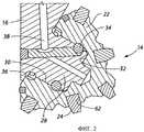
на фиг.2 представлен вид фрагмента сечения варианта осуществления вращающегося режущего узла, включающего шарошку, который может быть использован в буровом долоте, показанном на фиг.1;FIG. 2 is a fragmentary sectional view of an embodiment of a rotating cutting assembly including a cutter that can be used in the drill bit shown in FIG. 1;
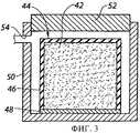
на фиг.3 схематически иллюстрируется способ формования шарошки вращающегося режущего узла в соответствии с вариантом осуществления настоящего изобретения;figure 3 schematically illustrates a method of forming a cone of a rotating cutting unit in accordance with an embodiment of the present invention;
на фиг.4 схематически иллюстрируется другой способ формования шарошки вращающегося режущего узла в соответствии с другим вариантом осуществления настоящего изобретения;4 schematically illustrates another method for forming a cone of a rotating cutting assembly in accordance with another embodiment of the present invention;
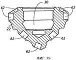
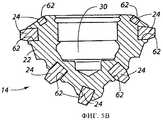
на фиг.5А-5В иллюстрируется один вариант осуществления способа, который может быть использован для формирования шарошки вращающегося режущего узла, в соответствии с настоящим изобретением, например вращающегося режущего узла, показанного на фиг.2;5A-5B illustrate one embodiment of a method that can be used to form the cone of a rotating cutting assembly in accordance with the present invention, for example the rotating cutting assembly shown in FIG. 2;
на фиг.6А-6В иллюстрируется другой вариант осуществления способа, который может быть использован для формирования шарошки вращающегося режущего узла, в соответствии с настоящим изобретением, например вращающегося режущего узла, показанного на фиг.2;6A-6B illustrate another embodiment of a method that can be used to form the cone of a rotating cutting assembly in accordance with the present invention, for example the rotating cutting assembly shown in FIG. 2;
на фиг.7 представлен вид сбоку другого варианта осуществления бурового долота в соответствии с настоящим изобретением;7 is a side view of another embodiment of a drill bit in accordance with the present invention;
на фиг.8 представлен вид фрагмента разреза, иллюстрирующий другой вариант осуществления вращающегося режущего узла, включающего шарошку, в соответствии с изобретением, который может быть использован в буровом долоте, показанном на фиг.7;Fig. 8 is a sectional fragment view illustrating another embodiment of a rotating cutting assembly including a cutter in accordance with the invention, which can be used in the drill bit shown in Fig. 7;
на фиг.9 представлен вид фрагмента разреза одного варианта осуществления конструкции зуба, который может быть использован при создании вращающегося режущего узла, например режущего узла, показанного на фиг.8;Fig.9 is a fragmentary sectional view of one embodiment of a tooth structure that can be used to create a rotating cutting assembly, such as the cutting assembly shown in Fig.8;
на фиг.10 представлен вид фрагмента разреза другого варианта осуществления конструкции зуба, который может быть использован при создании вращающегося режущего узла, например режущего узла, показанного на фиг.8.figure 10 presents a view of a fragment of a section of another embodiment of the construction of the tooth, which can be used to create a rotating cutting unit, for example, the cutting unit shown in Fig. 8.
Способы выполнения изобретенияMethods of carrying out the invention
Приведенные здесь чертежи не являются реальными изображениями какого-либо конкретного материала, устройства, системы или способа, а иллюстрируют идеализированные представления, используемые для описания изобретения. Кроме того, одни и те же элементы на разных чертежах могут иметь одинаковые цифровые обозначения.The drawings given here are not real images of any particular material, device, system or method, but illustrate idealized representations used to describe the invention. In addition, the same elements in different drawings may have the same numerical designations.
Термин "зеленый" (green) может использоваться в соответствующей литературе как эквивалент используемого в настоящем описании термина "неспеченный".The term "green" can be used in the relevant literature as an equivalent to the term "green" as used herein.
Термин "неспеченный (зеленый корпус) долота" в настоящем описании означает неспеченную конструкцию, содержащую множество отдельных частиц, скрепляемых связующим материалом.The term "green (green body) bit" in the present description means green structure, containing many individual particles bonded with a binder material.
Термин "коричневый" (brown) может использоваться в соответствующей литературе как эквивалент используемого в настоящем описании термина "частично спеченный".The term “brown” can be used in the relevant literature as an equivalent to the term “partially sintered” as used herein.
Термин "частично спеченный (коричневый) корпус долота" в настоящем описании означает частично спеченную конструкцию, содержащую множество частиц, по меньшей мере некоторые из которых частично срослись, с образованием по меньшей мере частичного соединения между соседними частицами. Частично спеченные корпуса могут быть сформированы посредством частичного спекания неспеченного корпуса.The term "partially sintered (brown) bit body" in the present description means a partially sintered structure containing many particles, at least some of which are partially fused, with the formation of at least partial connection between neighboring particles. Partially sintered bodies may be formed by partially sintering an unsintered body.
Термин "спекание" в настоящем описании означает уплотнение порошкового компонента, включающее удаление по меньшей мере части пор между частицами в исходном состоянии (сопровождается усадкой), в сочетании со слипанием и скреплением соседних частиц.The term "sintering" in the present description means the compaction of the powder component, including the removal of at least part of the pores between the particles in the initial state (accompanied by shrinkage), in combination with adhesion and bonding of neighboring particles.
Используемый здесь термин "сплав [металла]" (где [металл] представляет собой любой металл) означает технически чистый [металл] в составе сплавов металла, где процентное весовое содержание [металла] превышает процентное весовое содержание любого другого компонента сплава.As used herein, the term “[metal] alloy” (where [metal] is any metal) means technically pure [metal] in metal alloys, where the percentage weight content of [metal] exceeds the percentage weight content of any other alloy component.
Используемый здесь термин "состав материала" означает химический состав и микроструктуру материала. Другими словами, материалы, имеющие одинаковый химический состав, но различную микроструктуру, считаются имеющими различный состав материала.As used herein, the term “material composition” means the chemical composition and microstructure of the material. In other words, materials having the same chemical composition but different microstructure are considered to have different material composition.
Используемый здесь термин "карбид вольфрама" означает любой материал, содержащий химические соединения вольфрама и углерода, например WC, W2C и комбинации WC и W2C. Карбид вольфрама включает, например, литой карбид вольфрама, спеченный карбид вольфрама и макрокристаллический карбид вольфрама.The term “tungsten carbide” as used herein means any material containing chemical compounds of tungsten and carbon, for example WC, W2 C and combinations of WC and W2 C. Tungsten carbide includes, for example, cast tungsten carbide, sintered tungsten carbide and macrocrystalline tungsten carbide.
Глубина пробуриваемых буровых скважин продолжает увеличиваться по мере того, как уменьшается число нефтегазоносных пластов, залегающих на малой глубине. Это увеличение глубин буровых скважин приводит к тому, что требования к эксплуатационным характеристикам и долговечности долот приближаются к пределам, характерным для обычных буровых долот. Часто для пробуривания одной скважины требуется использовать несколько буровых долот, а замена бурового долота на бурильной колонне может быть дорогой процедурой.The depth of drilled boreholes continues to increase as the number of oil and gas strata occurring at shallow depths decreases. This increase in the depth of the boreholes leads to the fact that the requirements for the performance and durability of the bits approach the limits typical of conventional drill bits. Often, drilling a single well requires several drill bits, and replacing a drill bit on a drill string can be an expensive procedure.
В целях улучшения рабочих характеристик и долговечности долот для роторного бурения земных пород проводятся исследования новых композитных материалов "матрица-частицы". В качестве примера, не ограничивающего изобретение, корпуса долот с запрессованными резцами для роторного бурения земных пород, включающие такие композитные материалы "матрица-частицы", и способы формирования таких корпусов раскрыты в находящихся в рассмотрении патентных заявках US 11/271153, поданной 10 ноября 2005 г., и US 11/272439, также поданной 10 ноября 2005 г. Кроме того, буровые долота с вращающимися режущими узлами, содержащие шарошки, сформированные из таких композитных материалов "матрица-частицы", а также способы формирования таких шарошек, раскрыты в находящейся в рассмотрении патентной заявке US 11/487890, поданной 17 июля 2006 г.In order to improve the performance and durability of bits for rotary drilling of terrestrial rocks, research is being conducted on new matrix-particle composite materials. By way of non-limiting example, bit bodies with molded cutters for rotary drilling of rock including such matrix-particle composite materials, and methods for forming such bodies are disclosed in pending patent applications US 11/271153, filed November 10, 2005 G., and US 11/272439, also filed November 10, 2005. In addition, drill bits with rotating cutting units containing cutters formed from such matrix-particle composite materials, as well as methods for forming such cutters, indoor in the located in the pending patent application, US 11/487890, filed July 17, 2006
Буровое долото 10 в соответствии с вариантом осуществления настоящего изобретения показано на фиг.1. Буровое долото 10 включает корпус 12 долота и несколько вращающихся режущих узлов 14. Корпус 12 долота может включать несколько лап 16 долота, составляющих с ним единое целое, а в верхнем конце корпуса 12 долота может быть сделана резьба 18 для присоединения к бурильной колонне. Корпус 12 долота может иметь форсунки 20 для выпуска бурового раствора в буровую скважину, который в процессе бурения возвращается на поверхность вместе с осколками породы. Каждый из вращающихся режущих узлов 14 включает шарошку 22, содержащую композитный материал "матрица-частицы" и несколько режущих элементов, например показанные режущие вставки 24. Каждая шарошка 22 может иметь коническую калибрующую поверхность 26. Кроме того, каждая шарошка 22 может отличаться особой конфигурацией режущих вставок 24 или режущих элементов, благодаря которой шарошки 22 могут вращаться в непосредственной близости друг к другу, не мешая друг другу.A
На фиг.2 представлен вид сечения, иллюстрирующий один из вращающихся режущих узлов 14 бурового долота 10, показанного на фиг.1. Видно, что на каждой лапе долота имеется шейка 28 оси опорного подшипника. Шарошка 22 может закрепляться на шейке 28 оси опорного подшипника и вращаться вокруг нее. Каждая шарошка 22 может иметь центральную полость 30 цилиндрической формы и может образовывать поверхность подшипника скольжения, примыкающую к шейке 28 оси опорного подшипника. Полость 30 может включать плоский упорный бурт 32, который принимает нагрузку бурильной колонны, действующую на шарошку 22. Как показано в данном примере, шарошка 22 может удерживаться на шейке 28 оси опорного подшипника несколькими фиксирующими шариками 34, расположенными в соответствующих пазах на поверхностях полости 30 шарошки и шейки 28 оси опорного подшипника. Кроме того, узел 36 уплотнения может герметизировать зазор в подшипнике между полостью 30 шарошки и шейкой 28 оси опорного подшипника. Узел 36 уплотнения может представлять собой металлическое торцевое уплотнение, как это показано на чертеже, либо может быть узлом уплотнения другого типа, например эластомерным узлом уплотнения.FIG. 2 is a sectional view illustrating one of the
В зазоры подшипника между полостью 30 и шейкой 28 оси опорного подшипника может подаваться смазка по каналам 38 для смазки. Каналы 38 для смазки могут проходить к резервуару, включающему компенсатор 40 давления (см. фиг.1).Grease can be supplied to the bearing clearances between the
Как упоминалось выше, шарошка 22 может включать спеченный композитный материал "матрица-частицы", содержащий множество твердых частиц, распределенных по матричному материалу. В некоторых вариантах осуществления шарошка 22 может состоять, в основном, из композитного материала "матрица-частицы". Твердые частицы могут включать алмаз или керамические материалы, например карбиды, нитриды, оксиды и бориды (включая карбид бора (В4С)). В частности, твердые частицы могут включать карбиды или бориды на основе, например, W, Ti, Mo, Nb, V, Hf, Ta, Cr, Zr, Al и Si В качестве примера, не ограничивающего изобретение, материалы, которые могут быть использованы для формирования твердых частиц, включают карбид вольфрама (WC, W2C), карбид титана (TiC), карбид тантала (TaC), диборид титана (TiB2), карбиды хрома, нитрид титана (TiN), карбид ванадия (VC), оксид алюминия (Al2O3), нитрид алюминия (AlN), нитрид бора (BN) и карбид кремния (SiC). Кроме того, для получения заданных физических свойств и характеристик композитного материала "матрица-частицы" могут быть использованы комбинации различных твердых частиц. Твердые частицы могут быть получены с использованием известных технологий. Наиболее подходящие материалы для твердых частиц имеются на рынке, а создание других находится в пределах компетенции специалистов.As mentioned above,
Матричный материал может включать, например, сплавы на основе кобальта, железа, никеля, никеля и железа, кобальта и никеля, железа и кобальта, алюминия, меди, магния и титана. Матричный материал может также быть выбран из технически чистых элементов, например кобальта, алюминия, меди, магния, титана, железа и никеля. В качестве примера, не ограничивающего изобретение, матричный материал может включать углеродистую сталь, легированную сталь, нержавеющую сталь, инструментальную сталь, суперсплавы никеля или кобальта и сплавы на основе железа или никеля с малым температурным расширением, например INVAR®. В настоящем описании термином "суперсплав" обозначаются сплавы на основе железа, никеля и кобальта, имеющие по меньшей мере 12 мас.% хрома. В качестве других примеров сплавов, которые могут быть использованы в качестве матричного материала, можно упомянуть аустенитные стали, суперсплавы на основе никеля, например INCONEL® 625M или Rene 95, и сплавы типа INVAR®, обладающие коэффициентом температурного расширения, близким к коэффициенту температурного расширения твердых частиц, используемых в композитном материале с частицами. Согласование коэффициентов температурного расширения матричного материала и твердых частиц позволяет уменьшить остроту проблемы остаточных напряжений и термической усталости. Другим примером подходящего матричного материала может служить аустенитная марганцовистая сталь Хадфильда (железо с примерно 12 мас.% марганца и 1,1 мас.% углерода).The matrix material may include, for example, alloys based on cobalt, iron, nickel, nickel and iron, cobalt and nickel, iron and cobalt, aluminum, copper, magnesium and titanium. The matrix material may also be selected from commercially pure elements, such as cobalt, aluminum, copper, magnesium, titanium, iron and nickel. By way of non-limiting example, the matrix material may include carbon steel, alloy steel, stainless steel, tool steel, nickel or cobalt superalloys, and low temperature expansion iron or nickel based alloys such as INVAR®. In the present description, the term "superalloy" refers to alloys based on iron, nickel and cobalt having at least 12 wt.% Chromium. Other examples of alloys that can be used as matrix materials include austenitic steels, nickel-based superalloys, for example INCONEL® 625M or Rene 95, and INVAR® alloys with thermal expansion coefficients close to those of hard alloys particles used in a composite material with particles. Matching the coefficients of thermal expansion of the matrix material and solid particles can reduce the severity of the problem of residual stresses and thermal fatigue. Another example of a suitable matrix material is Hadfield austenitic manganese steel (iron with about 12 wt.% Manganese and 1.1 wt.% Carbon).
В одном варианте осуществления настоящего изобретения спеченный композитный материал "матрица-частицы" может включать множество частиц карбида вольфрама -400 меш по ASTM (стандарт Американского общества по испытанию материалов). Например, частицы карбида вольфрама могут в основном состоять из WC. В настоящем описании выражение "частицы -400 меш по ASTM" означает частицы, которые проходят через сито №400 согласно стандарту ASTM, как это указано в спецификации ASTM Е-11-04 под названием "Технические нормативы для проволочной ткани и сеток для целей тестирования". Такие частицы карбида вольфрама могут иметь диаметр примерно менее 38 микрон. Матричный материал может включать сплав металла, примерно 50 мас.% которого составляет кобальт и 50 мас.% - никель. Такие частицы карбида вольфрама могут составлять примерно от 60 до 95 мас.% композитного материала, а матричный материал может составлять примерно от 5 до 40 мас.% композитного материала. Более точно, частицы карбида вольфрама могут составлять примерно от 70 до 80 мас.% композитного материала, а матричный материал может составлять примерно от 20 до 30 мас.% композитного материала.In one embodiment of the present invention, the sintered matrix-particle composite material may include a plurality of ASTM (ASTM standard) tungsten carbide particles. For example, tungsten carbide particles can mainly consist of WC. In the present description, the expression "-400 mesh particles according to ASTM" means particles that pass through a No. 400 sieve according to the ASTM standard, as indicated in ASTM E-11-04, entitled "Technical specifications for wire cloth and mesh for testing purposes" . Such tungsten carbide particles may have a diameter of about less than 38 microns. The matrix material may include a metal alloy, about 50 wt.% Of which is cobalt and 50 wt.% - Nickel. Such tungsten carbide particles can comprise from about 60 to 95% by weight of the composite material, and matrix material can be from about 5 to 40% by weight of the composite material. More specifically, tungsten carbide particles can comprise from about 70 to 80% by weight of the composite material, and matrix material can be from about 20 to 30% by weight of the composite material.
В другом варианте осуществления настоящего изобретения спеченный композитный материал "матрица-частицы" может включать множество частиц карбида вольфрама -635 меш по ASTM. В данном описании выражение "частицы -635 меш по ASTM" означает частицы, которые проходят через сито №635 согласно стандарту ASTM, как это указано в спецификации ASTM Е11-04 под названием "Технические нормативы для проволочной ткани и сеток для целей тестирования". Такие частицы карбида вольфрама могут иметь диаметр менее примерно 20 микрон. Матричный материал может содержать сплав металла на основе кобальта, содержащий по существу технически чистый кобальт. Например, содержание кобальта в таком матричном материале может превышать примерно 98 мас.%. При этом частицы карбида вольфрама могут составлять примерно от 60 до 95 мас.% композитного материала, а матричный материал может составлять примерно от 5 до 40 мас.% композитного материала. После формирования шарошка 22 может обладать твердостью примерно в диапазоне от 75 до 92 единиц по шкале А по Роквеллу.In another embodiment of the present invention, the sintered matrix-particle composite may include multiple ASTM -635 mesh tungsten carbide particles. As used herein, the expression "-635 mesh particles according to ASTM" means particles that pass through a No. 635 sieve according to the ASTM standard, as specified in ASTM E11-04, entitled "Technical Specifications for Wire Cloth and Mesh for Testing". Such tungsten carbide particles may have a diameter of less than about 20 microns. The matrix material may comprise a cobalt-based metal alloy containing substantially technically pure cobalt. For example, the cobalt content in such a matrix material may exceed about 98 wt.%. In this case, tungsten carbide particles can comprise from about 60 to 95% by weight of the composite material, and matrix material can be from about 5 to 40% by weight of the composite material. After forming,
На фиг.3, 4 и 5А-5В иллюстрируются варианты осуществления способа, который может быть использован для формирования шарошки 22 и режущего узла 14, показанного на фиг.2. В общем, этот способ включает подготовку порошковой смеси, прессование порошковой смеси для формирования заготовки, формирования из заготовки неспеченного или частично спеченного корпуса шарошки и спекание неспеченного или частично спеченного корпуса шарошки до требуемой конечной плотности.Figures 3, 4 and 5A-5B illustrate embodiments of a method that can be used to form the
На фиг.3 иллюстрируется способ прессования порошковой смеси 42 для формирования неспеченной заготовки, которая может быть использована для формирования шарошки 22. Как показано на фиг.3, порошковая смесь 42 может прессоваться при существенно изостатическом давлении в пресс-форме или контейнере 44. Порошковая смесь 42 может включать множество описанных выше твердых частиц и множество частиц, содержащих матричный материал, также описанный ранее. В варианте осуществления порошковая смесь 42 также может включать одну или более добавок, например связующие вещества (например, органические материалы, например воск) для обеспечения конструктивной прочности спрессованного порошкового компонента, пластификаторы для повышения пластичности связующего вещества и смазывающие или уплотняющие добавки для снижения трения между частицами и обеспечения смазки при прессовании.Figure 3 illustrates the method of pressing the
Контейнер 44 может включать влагонепроницаемый деформируемый элемент 46. Например, влагонепроницаемый деформируемый элемент 46 может представлять собой по существу цилиндрический мешок, содержащий деформируемый и непроницаемый полимерный материал, который может представлять собой эластомер, например резина, синтетический каучук, силикон или полиуретан. Контейнер 44 также может включать герметизирующую плиту 48, которая по существу может обладать жесткостью. Деформируемый элемент 46 может быть заполнен порошковой смесью 42, которая в варианте осуществления при воздействии вибрации равномерно распределяется внутри деформируемого элемента 46. К деформируемому элементу 46 может быть прикреплена либо присоединена герметизирующая плита 48, обеспечивающая между ними влагонепроницаемое уплотнение.The
Контейнер 44 вместе с находящейся внутри порошковой смесью 42 может быть помещен в камеру 50 давления. Для обеспечения доступа внутрь камеры 50 давления может использоваться съемная крышка 52. Газ (например, воздух или азот) или текучая среда (например, вода или масло), которая может быть по существу несжимаемой, нагнетается в камеру 50 давления под высоким давлением через отверстие 54 посредством насоса (не показан). Под действием высокого давления текучей среды может происходить деформация деформируемого элемента 46, и давление текучей среды может передаваться порошковой смеси 42 по существу равномерно. Давление внутри камеры 50 давления при изостатическом прессовании может превышать 35 МПа (примерно 5000 фунтов/кв. дюйм). Более точно, давление внутри камеры 50 давления при изостатическом прессовании может превышать примерно 138 МПа (примерно 20000 фунтов/кв. дюйм).The
В других вариантах для уплотнения порошковой смеси 42 внутри эластичного контейнера 44 может создаваться вакуум, а к наружной поверхности деформируемого элемента 46 контейнера 44 может прикладываться давление более примерно 0,1 МПа (примерно 15 фунтов/кв. дюйм, например атмосферное). Изостатическим прессованием порошковой смеси 42 может быть отформована заготовка из неспеченного порошка, которая после прессования может быть извлечена из камеры 50 давления и контейнера 44 для выполнения механической обработки. В некоторых вариантах осуществления полученная заготовка может иметь в целом цилиндрическую конфигурацию.In other embodiments, a vacuum may be created to seal the
Фиг.4 иллюстрирует выполнение другого варианта способа прессования порошковой смеси 56 для формования неспеченной заготовки, который может быть использован при формировании шарошки 22, показанной на фиг.2. Выполнение способа, проиллюстрированного на фиг.4, включает формование заготовки с использованием жесткой пресс-формы 58, в камеру которой помещается порошковая смесь 56. Порошковая смесь 56 может быть аналогична порошковой смеси 42, используемой при выполнении способа, иллюстрируемого фиг.3. Полость пресс-формы 58 может иметь в целом коническую форму и использоваться для формовании заготовки в целом конической формы. В другом варианте полость может быть цилиндрической и может использоваться для формования цилиндрической заготовки. Поршень или плунжер 60 образует герметичное сочленение со стенками пресс-формы 58. На поршень 60 может воздействовать сила, и порошковая смесь может быть спрессована в неспеченную заготовку определенной формы, пригодную для ее механической обработки.Figure 4 illustrates the implementation of another variant of the method of pressing the
Неспеченная заготовка, отформованная способом, показанным на фиг.3 либо на фиг.4, может быть подвергнута механической обработке в неспеченном состоянии для формирования неспеченного корпуса 22А шарошки, показанного на фиг.5А. При осуществлении других способов неспеченная заготовка может быть частично спечена для формирования частично спеченной заготовки, и уже частично спеченная заготовка может быть подвергнута механической обработке для формирования частично спеченного корпуса шарошки (не показан). Плотность частично спеченной заготовки ниже плотности полностью спеченной, что облегчает ее механическую обработку. Неспеченные или частично спеченные структуры, например неспеченный корпус 22А шарошки, частично спеченный корпус шарошки либо неспеченная или частично спеченная заготовка, могут быть подвергнуты механической обработке практически так же, как и известные стальные шарошки. Однако, поскольку при дальнейшем спекании может возникнуть усадка, размеры неспеченных или частично спеченных структур должны быть заданы с припуском для компенсации усадки.An unsecured preform molded by the method shown in FIG. 3 or in FIG. 4 can be machined in an unsintered state to form an
На фиг.5А показан неспеченный корпус 22А шарошки, который может быть использован для формирования режущего узла 14 (фиг.1-2). Как показано на фиг.5А, в некоторых вариантах осуществления неспеченный корпус 22А шарошки может иметь общую форму, соответствующую требуемой окончательной форме шарошки 22, и может включать различные элементы, например центральную полость 30 для создания поверхности подшипника скольжения, прилегающей к шейке 28 оси опорного подшипника (фиг.2), и отверстия 62 для установки в них режущих вставок 24 (фиг.2).FIG. 5A shows an
При желании в отверстия 62 могут быть вставлены вытесняющие элементы 64 для сохранения нужного размера, формы и ориентации каждого из отверстий 62 во время последующего спекания. Вытесняющие элементы 64 могут включать штифты, размеры которых соответствуют требуемым окончательным размерам отверстия 62, которые должны быть сформированы в шарошке 22 для каждой вставки 24. Вытесняющие элементы 64 могут быть выполнены из материала, который сохраняет твердость и стабильность при температуре спекания, например керамики. Кроме того, вытесняющие элементы 64 могут быть выполнены из пористого и (или) полого материала для упрощения их извлечения из полученной после окончательного спекания шарошки 22. Диаметр отверстий 62 может быть больше, чем у вытесняющих элементов 64 перед спеканием, и они могут подвергнуться усадке в процессе спекания до диаметра вытесняющих элементов 64.If desired, displacing
В некоторых вариантах осуществления показанный на фиг.5А неспеченный корпус 22А может быть нагрет и спечен в печи до требуемой конечной плотности для формирования полностью спеченной шарошки 22, показанной на фиг.5Б. Полностью спеченная шарошка 22 на фиг.5Б показана с извлеченными после окончательного спекания вытесняющими элементами 64 (см. фиг.5А).In some embodiments, the
В некоторых вариантах осуществления печь может представлять собой вакуумную печь для создания вакуума в процессе спекания. В других вариантах осуществления печь может включать камеру давления для воздействия на шарошку избыточным давлением в процессе спекания. Кроме того, в печи может быть предусмотрено создание управляемой атмосферы. Например, в печи при спекании шарошки может создаваться атмосфера, лишенная кислорода.In some embodiments, the furnace may be a vacuum furnace to create a vacuum during sintering. In other embodiments, the implementation of the furnace may include a pressure chamber for acting on the cutter with excess pressure during sintering. In addition, a controlled atmosphere can be provided in the furnace. For example, in an oven during sintering of a cone, an atmosphere devoid of oxygen can be created.
В качестве примера, не ограничивающего изобретение, может потребоваться получение шарошки 22, включающей спеченный карбид вольфрама. Для формирования такой шарошки может быть отформован неспеченный корпус 22А шарошки включающий множество частиц, включающих карбид вольфрама и множество частиц, включающих матричный материал на основе кобальта, причем эти частицы скреплены друг с другом органическим связующим материалом. При осуществлении этих способов спекание неспеченного корпуса 22А шарошки может выполняться при температурах примерно в интервале 500°C и 1500°C. Температура спекания может быть различной для конкретных составов композитного материала "матрица-частицы".As an example, not limiting the invention, it may be necessary to obtain a
В процессе спекания неспеченный корпус 22А шарошки может испытывать усадку и уплотнение по мере того, как он спекается до конечной плотности, образуя шарошку 22. После спекания шарошка 22 может приобрести необходимую внешнюю конфигурацию, включая отверстия 62 и центральную полость 30. Для этих поверхностей может потребоваться некоторая дополнительная механическая обработка, либо она может и не понадобиться. Полость 30 либо другие поверхности после спекания могут быть подвергнуты механической обработке. Например, стенки отверстия полости 50 могут быть прошлифованы и отполированы для достижения требуемой чистоты поверхности.During sintering, the green
Как показано на фиг.5В, после завершения формирования шарошки 22 и удаления вытесняющих элементов 64 в отверстиях 62 могут быть закреплены режущие вставки 24. Размер и форма режущих вставок 24 могут выбираться так, чтобы обеспечивалась плотная и надежная тугая посадка режущих вставок 24 в отверстиях 62. В других вариантах осуществления режущие вставки 24 могут быть закреплены в отверстиях 62 посредством связующего вещества. В других вариантах осуществления режущие вставки 24 могут быть закреплены в отверстиях 62 посредством пайки или пайки тугоплавким припоем.As shown in FIG. 5B, after the formation of the
Центральная полость 30 может быть подвергнута чистовой механической обработке, и шарошка 22 может быть установлена на шейку 28 оси опорного подшипника обычным способом (фиг.2). Режущие вставки 24 могут быть сформированы отдельно от шарошки 22 аналогичным с шарошкой 22 способом. Хотя режущие вставки 24 могут быть выполнены из спеченного композитного материала "матрица-частицы", состав композитного материала "матрица-частицы" режущих вставок 24 может отличаться от состава композитного материала "матрица-частицы" шарошки 22.The
При осуществлении других способов, вместо того чтобы формировать неспеченную или частично спеченную заготовку, включающую спеченный композитный материал "матрица-частицы", и механически обрабатывать неспеченную или частично спеченную заготовку для получения неспеченного или частично спеченного корпуса шарошки, неспеченная заготовка может быть спечена до желаемой конечной плотности для получения полностью спеченной заготовки. Затем такая полностью спеченная заготовка может быть обработана механически для получения полностью спеченной шарошки 22, показанной на фиг.5Б, с использованием обычных технологий механической обработки или ультразвуковой обработки материалов. Поскольку механическая обработка полностью спеченной заготовки может представлять трудности, этот процесс может быть облегчен использованием ультразвуковой обработки. Например, технология ультразвуковой обработки может включать воздействие на инструмент высокочастотной вибрацией, под действием которой улучшается удаление материала с полностью спеченной заготовки.In other methods, instead of forming an unsintered or partially sintered preform including a sintered matrix-particle composite material, and machining an unsintered or partially sintered preform to obtain an unsintered or partially sintered cone body, the unsintered preform can be sintered to the desired final density to obtain a fully sintered billet. Then, such a fully sintered preform can be machined to produce the fully sintered
Фиг.6А-6В иллюстрируют другие варианты осуществления способа, который может быть использован для формирования режущего узла (например, показанного на фиг.3 режущего узла 14), в соответствии с настоящим изобретением. Как более подробно показано далее, способ в общем включает подготовку не спеченной до конца неспеченной или частично спеченной шарошки, имеющей несколько отверстий, введение вставок в отверстие в неспеченной или частично спеченной шарошке и спекание получившейся конструкции до требуемой конечной плотности для прикрепления вставок к шарошке. При этом вставки могут быть спечены совместно с шарошкой и составят с ней единое целое. В некоторых вариантах осуществления вставки могут включать не спеченные до конца неспеченные или частично спеченные вставки, и неспеченные или частично спеченные вставки могут быть спечены до требуемой конечной плотности одновременно с шарошкой. В других вариантах осуществления вставки могут быть полностью спечены, когда они вставлены в соответствующие отверстия неспеченной или частично спеченной шарошки.6A-6B illustrate other embodiments of a method that can be used to form a cutting assembly (for example, shown in FIG. 3 of a cutting assembly 14), in accordance with the present invention. As shown in more detail below, the method generally involves preparing an unsintered or partially sintered cone having several holes, inserting inserts into the hole in an unsintered or partially sintered cone, and sintering the resulting structure to the desired final density for attaching the inserts to the cone. In this case, the inserts can be sintered together with the cone and make up a single whole with it. In some embodiments, the inserts may include unsintered to the end unsintered or partially sintered inserts, and the unsintered or partially sintered inserts can be sintered to the desired final density simultaneously with the cone. In other embodiments, the inserts may be completely sintered when they are inserted into the corresponding openings of the green or partially sintered cone.
Далее вставки могут отличаться градиентом состава, изменяющегося от области или областей, прилегающих к границе раздела между вставками и шарошкой, и областью или областями вблизи поверхности, захватывающей породу, или поверхностями вставок. Например, для области вставок вблизи границы раздела между вставками и шарошкой состав материала может быть выбран так, чтобы облегчить или улучшить сцепление вставок с шарошкой, в то время как в области вблизи поверхности, захватывающей породу, или поверхности вставок, выбор состава материала может обеспечивать улучшение одного или более свойств или характеристик материала, например твердости, прочности, долговечности и износостойкости. В качестве примера, не ограничивающего изобретение, области вставок вблизи границы раздела между вставками и шарошкой могут имеет первый матричный материал, по существу аналогичный матричному материалу шарошки, в то время как области, прилегающие к поверхности, захватывающей породу, или поверхностям вставок, могут иметь второй матричный материал, выбор которого обеспечивает улучшение одного или более свойств вставок - твердости, прочности, долговечности и износостойкости. В таких вариантах осуществления концентрация во вставках первого матричного материала и второго матричного материала может изменяться либо непрерывно, либо ступенчато, между областями, прилегающими к границе раздела, и областями, прилегающими к поверхности, захватывающей породу.Further, the inserts may differ in the composition gradient, varying from the region or regions adjacent to the interface between the inserts and the cone, and the region or regions near the surface capturing the rock, or the surfaces of the inserts. For example, for the area of the inserts near the interface between the inserts and the cone, the composition of the material can be chosen so as to facilitate or improve the adhesion of the inserts to the cone, while in the area near the surface capturing the rock or the surface of the inserts, the choice of composition of the material can provide an improvement one or more material properties or characteristics, for example, hardness, strength, durability, and wear resistance. By way of non-limiting example, the regions of the inserts near the interface between the inserts and the cone may have a first matrix material substantially similar to the matrix material of the cone, while the regions adjacent to the rock entraining surface or the surfaces of the inserts may have a second matrix material, the choice of which ensures the improvement of one or more properties of the inserts - hardness, strength, durability and wear resistance. In such embodiments, the concentration in the inserts of the first matrix material and the second matrix material can vary either continuously or stepwise between the regions adjacent to the interface and the regions adjacent to the surface capturing the rock.
Как показано на фиг.6, неспеченный корпус 22А шарошки может быть сформирован или подготовлен иным путем, как это было описано в связи с фиг.5А. Может быть подготовлено несколько неспеченных режущих вставок 24А. Каждая из неспеченных режущих вставок 24А может включать множество твердых частиц и множество частиц, содержащих матричный материал, а частицы могут скрепляться друг с другом органическим связующим материалом. Как упоминалось выше, состав неспеченных режущих вставок 24А может отличаться от состава неспеченного корпуса 22А шарошки. Кроме того, неспеченные режущие вставки 24А могут отличаться градиентом состава, который изменяется от области или областей, прилегающих к границе раздела между вставками и шарошкой, и областью или областями вблизи поверхности, захватывающей породу, или поверхностями вставок, как об этом упоминалось выше.As shown in FIG. 6, the
При осуществлении некоторых способов, дополнительные неспеченные элементы или компоненты, помимо неспеченных режущих вставок 24А, также могут прикрепляться к неспеченному корпусу 22А шарошки перед спеканием. В качестве примера, не ограничивающего изобретение, один или более неспеченных опорных элементов 68А, определяющих опорные поверхности шарошки, могут быть закреплены внутри центральной области 30 неспеченного корпуса 22А шарошки. По аналогии с неспеченными режущими вставками 24А каждый из неспеченных опорных элементов 68А может включать множество твердых частиц и множество частиц, содержащих матричный материал, а состав неспеченных опорных элементов 68А может отличаться от состава неспеченного корпуса 22А шарошки.In some methods, additional non-sintered elements or components, in addition to the non-sintered cutting inserts 24A, can also be attached to the
Как показано на фиг.6Б, неспеченные режущие вставки 24А могут быть вставлены в отверстия 62 неспеченного корпуса 22А шарошки, а неспеченные опорные элементы 68А могут быть закреплены в заданных местах внутри центральной полости 30 неспеченного корпуса 22А шарошки.As shown in FIG. 6B, the green sintered inserts 24A can be inserted into the
В качестве примера, не ограничивающего изобретение, размеры и форма неспеченных режущих вставок 24А и отверстий 62 в неспеченном корпусе 22А шарошки могут быть выбраны так, чтобы обеспечивался средний зазор между ними примерно от 0,025 мм (0,001 дюйма) до 0,635 мм (0,025 дюйма). Такие зазоры также могут быть сделаны между неспеченными опорными элементами 68 и неспеченным корпусом 22А шарошки.By way of non-limiting example, the size and shape of the green sintered inserts 24A and holes 62 in the green
После того как различные неспеченные компоненты собраны с формированием конструкции, аналогичной показанной на фиг.6Б, конструкция может быть подвергнута спеканию до требуемой конечной плотности для формирования полностью спеченной конструкции, показанной на фиг.6В. В процессе спекания шарошка 22, включающая отверстия 62 и другие элементы, режущие вставки 24 или другие режущие элементы, и опорные элементы 68 могут испытывать усадку и уплотнение. Кроме того, режущие вставки 24 и опорные элементы 68 могут расплавиться и прикрепиться к шарошке 22. Другими словами, после спекания режущие вставки 24 и опорные элементы 68 могут оказаться спеченными в единое целое с шарошкой 22, образуя по существу единый режущий узел 14'.After various non-sintered components are assembled to form a structure similar to that shown in FIG. 6B, the structure can be sintered to the desired final density to form the fully sintered structure shown in FIG. 6B. During sintering, the
После того как режущий узел 14' был спечен до требуемой конечной плотности, механической обработкой и полировкой могут быть выполнены различные необходимые или желательные элементы режущего узла 14'. Например, опорные поверхности 70 на опорных элементах 68 могут быть отполированы. Полировкой опорных поверхностей 70 опорных элементов 68 можно добиться относительно гладкой поверхности и уменьшить трение на границе раздела между опорными элементами 68 и шейкой 28 оси опорного подшипника (фиг.2). Более того, посредством механической обработки и (или) полировки уплотнительной кромке 72 опорных элементов 68 могут быть приданы форма и гладкость поверхности, обеспечивающие герметизацию при контакте с уплотнителем из металла или эластомера или с уплотняющей поверхностью на корпусе 12 долота (фиг.2).After the
Неспеченные режущие вставки 24А и неспеченные опорные элементы 68А могут быть сформированы из композитного материала "матрица-частицы" в значительной мере тем же путем, что и неспеченный корпус 22А шарошки. Состав материала каждой из неспеченных режущих вставок 24А, неспеченных опорных элементов 68А и неспеченного корпуса 22А шарошки может выбираться по отдельности и индивидуально для получения физических и (или) химических свойств, приспособленных к условиям работы соответствующих компонентов. В качестве примера, не ограничивающего изобретение, состав неспеченных режущих вставок 24А может быть выбран так, чтобы сформировать режущие вставки 24, включающие композитный материал "матрица-частицы", обладающий твердостью, износостойкостью и (или) прочностью, отличающимися от соответствующих свойств композитного материала "матрица-частицы" шарошки 22.Unsecured cutting inserts 24A and
Режущие вставки 24 могут быть сформированы из композитных материалов "матрица-частицы" различного состава. Конкретный состав материала какой-либо вставки 24 может выбираться исходя из получения одного или более физического и (или) химического свойства, соответствующего конкретной пробуриваемой земной породе с использованием бурового долота 10 (фиг.1). Кроме того, на одной шарошке 22 могут использоваться режущие вставки 24 с различным составом материала.Cutting inserts 24 may be formed from matrix-particle composite materials of various compositions. The specific material composition of any
В качестве примера, не ограничивающего изобретение, в некоторых его вариантах осуществления режущие вставки 24 могут включать композитный материал "матрица-частицы", который содержит множество твердых частиц, твердость которых превышает твердость множества частиц композитного материала "матрица-частицы" шарошки 22. Другим примером, не ограничивающим изобретение, может служить концентрация твердых частиц в композитном материале "матрица-частицы" режущих элементов 24, которая может быть выше, чем концентрация твердых частиц в композитном материале "матрица-частицы" шарошки 22.By way of non-limiting example, in some embodiments, the cutting inserts 24 may include a matrix-particle composite material that contains a plurality of solid particles whose hardness exceeds the hardness of a plurality of particles of the cone matrix-
Несмотря на то что режущий узел 14', показанный на фиг.6В, включает шарошку 22, режущие вставки 24 и опорные элементы 68, предполагается, что в других вариантах осуществления режущий узел 14' может быть сформирован без отдельных неспеченных опорных элементов 68А, описанных здесь. Более того, как было показано выше, режущий узел 14' может быть сформирован путем объединения неспеченного корпуса 22А шарошки, неспеченных режущих вставок 24А и неспеченных опорных элементов 68А с получением неспеченной конструкции узла, с последующим спеканием неспеченной конструкции узла до требуемой конечной плотности. Этим вариантом, однако, изобретение также не ограничено, и способы, предусматриваемые другими вариантами осуществления изобретения, могут включать сборку неспеченных структур, частично спеченных структур, полностью спеченных структур либо их различных комбинаций, с последующим спеканием или повторным нагревом спеченных компонентов до температуры спекания для их сплавления с образованием единой интегральной конструкции режущего узла.Although the cutting
В то время как описанный выше режущий узел 14' включает шарошку 22, которая включает режущие структуры в виде вставок, настоящим изобретением также предусмотрены шарошки с зубчатыми режущими структурами, и варианты осуществления способов, в соответствии с настоящим изобретением, также могут быть использованы для формирования таких зубчатых режущих структур. Например, на фиг.7 показано другое долото 74 для бурения земных пород в соответствии с вариантом осуществления настоящего изобретения, включающее несколько режущих узлов 80, каждый из которых включает шарошку 88 с режущими зубьями 104.While the cutting
Как показано на фиг.7, буровое долото 74 имеет корпус 76, в верхнем конце которого может быть сделана резьба 78 для присоединения к бурильной колонне. Корпус 76 долота может включать три лапы 82 долота, составляющие с ним единое целое, на каждой из которых закреплена шейка 84 (не показана) оси опорного подшипника. В некоторых вариантах осуществления корпус 76 долота и шейки 84 оси опорного подшипника могут быть выполнены обычным путем из стального сплава. Кроме того, корпус 76 долота может включать форсунки 86 для выпуска бурового раствора в буровую скважину, который вместе с осколками породы возвращается на поверхность в процессе бурения.As shown in FIG. 7, the
Как показано на фиг.7, каждая шарошка 88 имеет несколько рядов режущих зубьев 104. Число зубьев 104, их форма и число рядов этих зубьев может варьироваться. Задняя торцевая поверхность 102 каждой шарошки 88 может быть окружена калибрующей поверхностью 106, которая определяет наружный диаметр долота 74. Как более подробно показано ниже, одна часть каждого зуба 104 может быть сформирована как единое целое вместе с корпусом каждой шарошки 88, а другая часть каждого зуба 104 может быть сформирована с использованием неспеченной или частично спеченной структуры, которая наплавляется на шарошку 88 в процессе спекания.As shown in FIG. 7, each
На фиг.8 представлен увеличенный вид фрагмента разреза одного из режущих узлов 80, закрепленного на шейке 84 оси опорного подшипника, на котором каждый из зубьев 104, вращающийся вокруг шарошки 88 в плоскости чертежа, показан так, что иллюстрирует так называемый "режущий профиль", определяемый режущими поверхностями всех зубьев 104 шарошки 88. Как показано на фиг.8, на каждой шейке 84 оси опорного подшипника бурового долота 74 может быть установлен один из режущих узлов 80. Каждая шарошка 88 режущих узлов 80 может включать центральную полость 90, которая образует поверхности подшипника скольжения, прилегающие к шейке 84 оси. Шарошка 88 может иметь плоский упорный бурт 92 и стопорный паз 94, сформированный в центральной полости 90. В такой конфигурации в стопорный паз 94 может быть установлено пружинное упорное кольцо 96, а на шейке 84 оси опорного подшипника может быть сделан сопряженный паз для фиксации положения шарошки 88 на шейке 84 оси опорного подшипника. Шарошка 88 также может иметь паз 98 уплотнения для установки в него уплотнителя 100. Паз 98 уплотнения может быть расположен вблизи задней торцевой поверхности 102 шарошки 88. В качестве примера, не ограничивающего изобретение, уплотнитель 100 может представлять собой эластомерное кольцо. В некоторых вариантах осуществления задняя торцевая поверхность 102 шарошки 88 может включать по существу плоскую кольцевую поверхность, окружающую входное отверстие центральной полости 90.On Fig presents an enlarged view of a fragment of a section of one of the cutting
В промежутки между центральной полостью 90 шарошки 88 и шейкой 84 оси опорного подшипника через каналы 108 для смазки может подаваться смазка. Каналы 108 для смазки могут соединяться с резервуаром, который включает компенсатор 110 давления (фиг.7).In the intervals between the
Шарошка 88 может включать композитный материал "матрица-частицы", как это было показано при описании шарошки 22, изображенной на фиг.2. По аналогии шарошка 88 может быть сформирована способами, по существу аналогичными тем, что были описаны ранее в отношении шарошки 22, со ссылками на фиг.3 и 4. В целом шарошка 88 может быть сформирована в виде неспеченной или частично спеченной заготовки, с механической обработкой неспеченной или частично спеченной заготовки для формирования неспеченного или частично спеченного корпуса шарошки и спеканием неспеченного или частично спеченного корпуса шарошки до требуемой конечной плотности.The
Фиг.9 иллюстрирует один вариант осуществления способа в соответствии с настоящим изобретением, который может быть использован для формирования режущего узла 80, показанного на фиг.7 и 8. Как показано в настоящем описании, при осуществлении некоторых способов в соответствии с настоящим изобретением неспеченный корпус 88А шарошки может быть получен путем механической обработки неспеченной заготовки. Неспеченный корпус 88А шарошки может включать несколько оснований 105А зуба. Каждое основание 105А зуба может включать выступающий элемент 116, а на каждом из выступающих элементов 116 может находиться неспеченная коронка 112. Неспеченные коронки 112 могут быть сформированы из тех же материалов и по существу теми же способами, что были описаны выше в отношении неспеченных режущих вставок 24А (фиг.6А-6Б). В некоторых вариантах осуществления неспеченные коронки 112 могут быть прикреплены к выступающим элементам 116 с использованием связующего вещества. Основания 105А зубьев, на которых закреплены неспеченные коронки 112, образуют группу неспеченных конструкций 104А зубьев.FIG. 9 illustrates one embodiment of a method in accordance with the present invention that can be used to form the cutting
После установки неспеченных коронок 112 на основания 105А зуба с образованием неспеченных конструкций 104А зубьев получившаяся конструкция может быть спечена до требуемой конечной плотности для получения полностью спеченного режущего узла 80, показанного на фиг.7 и 8.After installing the green sintered crowns 112 on the tooth bases 105A with the formation of green
Состав материала неспеченных коронок 112 и неспеченных корпусов 88А шарошки может быть по отдельности и индивидуально выбран для получения физических и (или) химических свойств, приспособленных к условиям работы соответствующих компонентов. В качестве примера, не ограничивающего изобретение, состав неспеченных коронок 112 может быть выбран так, чтобы сформировать после спекания неспеченных коронок 112 композитный материал "матрица-частицы", обладающий твердостью, износостойкостью и (или) прочностью, отличающимися от соответствующих свойств композитного материала "матрица-частицы" шарошки 88 (фиг.7 и 8).The material composition of the green sintered crowns 112 and the
На фиг.10 представлен другой вариант осуществления способа в соответствии с настоящим изобретением, который может быть использован для формирования режущего узла 80, показанного на фиг.7 и 8. Этот способ по существу аналогичен тем, что описывались ранее в отношении фиг.9. Может быть получен неспеченный корпус 88Б, который по существу аналогичен неспеченному корпусу 88А, показанному на фиг.9. Неспеченный корпус 88Б шарошки может, однако, включать несколько оснований 105Б зуба, в каждом из которых имеется отверстие 118. В этой конфигурации внутри каждого из отверстий 118 может быть установлен неспеченный штифт 114. Неспеченные штифты 114 могут быть сформированы из тех же материалов и по существу теми же способами, что были описаны ранее в отношении неспеченных режущих вставок 24А (фиг.6А-6Б) и неспеченных коронок 112 (фиг.9). В некоторых вариантах осуществления неспеченные штифты 114 могут быть закреплены внутри отверстий 118 с использованием связующего вещества. Основания 105Б зубьев, в которых закреплены неспеченные штифты 114, образуют группу неспеченных конструкций 104Б зубьев.Figure 10 shows another embodiment of the method in accordance with the present invention, which can be used to form the cutting
После установки неспеченных штифтов 114 в основания 105Б зуба для формирования неспеченных конструкций 104Б зубьев получившаяся конструкция может быть спечена до требуемой конечной плотности для получения полностью спеченного режущего узла 80, показанного на фиг.7 и 8.After installing the green sintered pins 114 in the tooth base 105B to form the green
Как было описано выше, режущий узел 80, показанный на фиг.7 и8, может быть сформирован путем объединения неспеченных корпусов 88А, 88Б шарошки с неспеченными коронками 112 и (или) неспеченными штифтами 114 для формирования неспеченного режущего узла, с последующим спеканием неспеченного режущего узла до требуемой конечной плотности. Настоящее изобретение не ограничено, однако, только описанными вариантами, и другие варианты осуществления способов в соответствии с настоящим изобретением могут включать сборку неспеченных структур, частично спеченных структур, полностью спеченных структур или любых их комбинаций, с последующим спеканием или повторным нагревом спеченных компонентов до температуры спекания для их сплавления с образованием единой интегральной конструкции режущего узла. В качестве примера, не ограничивающего изобретение, показанный на фиг.9 неспеченный корпус 88А шарошки может быть частично спечен для формирования частично спеченного корпуса шарошки (не показан), а неспеченные коронки 112 могут быть установлены на частично спеченный корпус шарошки. Затем полученная структура может быть спечена до получения конечной плотности для сплавления коронок с корпусами шарошки и образования зубьев 104 (фиг.7). В качестве другого примера, не ограничивающего изобретение, неспеченные штифты 114, показанные на фиг.10, могут быть частично спечены для формирования частично спеченных штифтов (не показаны), и частично спеченные штифты могут быть соединены с неспеченными корпусами 88Б шарошек. Затем полученная структура может быть спечена до конечной плотности для сплавления штифтов с корпусом шарошки и формирования зубьев 104 (фиг.7).As described above, the cutting
В то время как настоящее изобретение было изложено применительно к вариантам осуществления трехшарошечных долот для роторного бурения, буровой инструмент других типов, например расширители ствола скважин, долота для роторного бурения, инструмент для бурения восстающих выработок, гибридные буровые долота с запрессованными/вращающимися резцами, цилиндрические фрезы, проходческие фрезы и иные подобные известные конструкции также могут использовать настоящее изобретение и могут быть сформированы способами, реализующими настоящее изобретение. Более того, в то время как настоящее изобретение было описано здесь на примере конкретных предпочтительных вариантов осуществления, для специалистов должно быть понятно, что оно только этими вариантами не ограничивается. Напротив, в предпочтительных вариантах осуществления могут быть сделаны многочисленные добавления, изъятия и модификации, не выходящие за пределы области изобретения, определяемой приведенной ниже формулой. Кроме того, признаки одного варианта осуществления могут быть скомбинированы с признаками другого варианта осуществления, оставаясь в пределах области притязаний изобретения.While the present invention has been set forth with reference to embodiments of three-cone bits for rotary drilling, other types of drilling tools, such as boreholes, rotary drill bits, tool for drilling uphill workings, hybrid drill bits with pressed / rotary cutters, cylindrical cutters , milling cutters and other similar known constructions can also use the present invention and can be formed by methods that implement the present invention. retention. Moreover, while the present invention has been described herein by way of specific preferred embodiments, it should be understood by those skilled in the art that it is not limited to these options. In contrast, in preferred embodiments, numerous additions, deletions, and modifications can be made without departing from the scope of the invention defined by the following claims. Furthermore, features of one embodiment may be combined with features of another embodiment, while remaining within the scope of the invention.
Claims (20)
Translated fromRussianApplications Claiming Priority (2)
| Application Number | Priority Date | Filing Date | Title |
|---|---|---|---|
| US11/710,091 | 2007-02-23 | ||
| US11/710,091US20080202814A1 (en) | 2007-02-23 | 2007-02-23 | Earth-boring tools and cutter assemblies having a cutting element co-sintered with a cone structure, methods of using the same |
Publications (2)
| Publication Number | Publication Date |
|---|---|
| RU2009135273A RU2009135273A (en) | 2011-03-27 |
| RU2456427C2true RU2456427C2 (en) | 2012-07-20 |
Family
ID=39544969
Family Applications (1)
| Application Number | Title | Priority Date | Filing Date |
|---|---|---|---|
| RU2009135273/03ARU2456427C2 (en) | 2007-02-23 | 2008-02-21 | Drilling bit with cutting element sintered together with rolling cutter housing |
Country Status (7)
| Country | Link |
|---|---|
| US (1) | US20080202814A1 (en) |
| EP (1) | EP2122112B1 (en) |
| CN (1) | CN101657602A (en) |
| AT (1) | ATE534798T1 (en) |
| CA (1) | CA2678434A1 (en) |
| RU (1) | RU2456427C2 (en) |
| WO (1) | WO2008103413A1 (en) |
Cited By (1)
| Publication number | Priority date | Publication date | Assignee | Title |
|---|---|---|---|---|
| RU2744213C1 (en)* | 2020-04-29 | 2021-03-03 | Олег Викторович Барзинский | Cutting element for equipping drill bits |
Families Citing this family (58)
| Publication number | Priority date | Publication date | Assignee | Title |
|---|---|---|---|---|
| US9109429B2 (en) | 2002-12-08 | 2015-08-18 | Baker Hughes Incorporated | Engineered powder compact composite material |
| US9079246B2 (en) | 2009-12-08 | 2015-07-14 | Baker Hughes Incorporated | Method of making a nanomatrix powder metal compact |
| US9682425B2 (en) | 2009-12-08 | 2017-06-20 | Baker Hughes Incorporated | Coated metallic powder and method of making the same |
| US9101978B2 (en) | 2002-12-08 | 2015-08-11 | Baker Hughes Incorporated | Nanomatrix powder metal compact |
| US20060163774A1 (en)* | 2005-01-25 | 2006-07-27 | Norbert Abels | Methods for shaping green bodies and articles made by such methods |
| US7776256B2 (en) | 2005-11-10 | 2010-08-17 | Baker Huges Incorporated | Earth-boring rotary drill bits and methods of manufacturing earth-boring rotary drill bits having particle-matrix composite bit bodies |
| US8770324B2 (en) | 2008-06-10 | 2014-07-08 | Baker Hughes Incorporated | Earth-boring tools including sinterbonded components and partially formed tools configured to be sinterbonded |
| US7807099B2 (en) | 2005-11-10 | 2010-10-05 | Baker Hughes Incorporated | Method for forming earth-boring tools comprising silicon carbide composite materials |
| JP2008047869A (en)* | 2006-06-13 | 2008-02-28 | Hokuriku Seikei Kogyo Kk | Shower plate and manufacturing method thereof, and plasma processing apparatus, plasma processing method and electronic device manufacturing method using the shower plate |
| US8272295B2 (en)* | 2006-12-07 | 2012-09-25 | Baker Hughes Incorporated | Displacement members and intermediate structures for use in forming at least a portion of bit bodies of earth-boring rotary drill bits |
| US20090311124A1 (en)* | 2008-06-13 | 2009-12-17 | Baker Hughes Incorporated | Methods for sintering bodies of earth-boring tools and structures formed during the same |
| US8261632B2 (en) | 2008-07-09 | 2012-09-11 | Baker Hughes Incorporated | Methods of forming earth-boring drill bits |
| US8381844B2 (en) | 2009-04-23 | 2013-02-26 | Baker Hughes Incorporated | Earth-boring tools and components thereof and related methods |
| US20110042145A1 (en)* | 2009-05-04 | 2011-02-24 | Smith International, Inc. | Methods for enhancing a surface of a downhole tool and downhole tools having an enhanced surface |
| WO2010129507A2 (en)* | 2009-05-04 | 2010-11-11 | Smith International, Inc. | Roller cones, methods of manufacturing such roller cones, and drill bits incorporating such roller cones |
| US20110073233A1 (en)* | 2009-09-30 | 2011-03-31 | Baker Hughes Incorporated | Method of Applying Hardfacing Sheet |
| US9227243B2 (en) | 2009-12-08 | 2016-01-05 | Baker Hughes Incorporated | Method of making a powder metal compact |
| US10240419B2 (en) | 2009-12-08 | 2019-03-26 | Baker Hughes, A Ge Company, Llc | Downhole flow inhibition tool and method of unplugging a seat |
| US9127515B2 (en) | 2010-10-27 | 2015-09-08 | Baker Hughes Incorporated | Nanomatrix carbon composite |
| US9243475B2 (en) | 2009-12-08 | 2016-01-26 | Baker Hughes Incorporated | Extruded powder metal compact |
| US8528633B2 (en) | 2009-12-08 | 2013-09-10 | Baker Hughes Incorporated | Dissolvable tool and method |
| WO2011139519A2 (en) | 2010-04-28 | 2011-11-10 | Baker Hughes Incorporated | Earth-boring tools and methods of forming earth-boring tools |
| US9090955B2 (en) | 2010-10-27 | 2015-07-28 | Baker Hughes Incorporated | Nanomatrix powder metal composite |
| US9273518B2 (en) | 2010-10-29 | 2016-03-01 | Baker Hughes Incorporated | Methods of coupling components of downhole tools, downhole tools and components of downhole tools |
| US8631876B2 (en) | 2011-04-28 | 2014-01-21 | Baker Hughes Incorporated | Method of making and using a functionally gradient composite tool |
| US9080098B2 (en) | 2011-04-28 | 2015-07-14 | Baker Hughes Incorporated | Functionally gradient composite article |
| US9909365B2 (en) | 2011-04-29 | 2018-03-06 | Baker Hughes Incorporated | Downhole tools having mechanical joints with enhanced surfaces |
| US9139928B2 (en) | 2011-06-17 | 2015-09-22 | Baker Hughes Incorporated | Corrodible downhole article and method of removing the article from downhole environment |
| US20130014998A1 (en)* | 2011-07-11 | 2013-01-17 | Baker Hughes Incorporated | Downhole cutting tool and method |
| US9707739B2 (en) | 2011-07-22 | 2017-07-18 | Baker Hughes Incorporated | Intermetallic metallic composite, method of manufacture thereof and articles comprising the same |
| US8783365B2 (en) | 2011-07-28 | 2014-07-22 | Baker Hughes Incorporated | Selective hydraulic fracturing tool and method thereof |
| US9833838B2 (en) | 2011-07-29 | 2017-12-05 | Baker Hughes, A Ge Company, Llc | Method of controlling the corrosion rate of alloy particles, alloy particle with controlled corrosion rate, and articles comprising the particle |
| US9643250B2 (en) | 2011-07-29 | 2017-05-09 | Baker Hughes Incorporated | Method of controlling the corrosion rate of alloy particles, alloy particle with controlled corrosion rate, and articles comprising the particle |
| US9057242B2 (en) | 2011-08-05 | 2015-06-16 | Baker Hughes Incorporated | Method of controlling corrosion rate in downhole article, and downhole article having controlled corrosion rate |
| US9033055B2 (en) | 2011-08-17 | 2015-05-19 | Baker Hughes Incorporated | Selectively degradable passage restriction and method |
| US9856547B2 (en) | 2011-08-30 | 2018-01-02 | Bakers Hughes, A Ge Company, Llc | Nanostructured powder metal compact |
| US9109269B2 (en) | 2011-08-30 | 2015-08-18 | Baker Hughes Incorporated | Magnesium alloy powder metal compact |
| US9090956B2 (en) | 2011-08-30 | 2015-07-28 | Baker Hughes Incorporated | Aluminum alloy powder metal compact |
| US9643144B2 (en) | 2011-09-02 | 2017-05-09 | Baker Hughes Incorporated | Method to generate and disperse nanostructures in a composite material |
| US9133695B2 (en) | 2011-09-03 | 2015-09-15 | Baker Hughes Incorporated | Degradable shaped charge and perforating gun system |
| US9347119B2 (en) | 2011-09-03 | 2016-05-24 | Baker Hughes Incorporated | Degradable high shock impedance material |
| US9187990B2 (en) | 2011-09-03 | 2015-11-17 | Baker Hughes Incorporated | Method of using a degradable shaped charge and perforating gun system |
| US10077608B2 (en)* | 2011-12-30 | 2018-09-18 | Smith International, Inc. | Thermally stable materials, cutter elements with such thermally stable materials, and methods of forming the same |
| US9010416B2 (en) | 2012-01-25 | 2015-04-21 | Baker Hughes Incorporated | Tubular anchoring system and a seat for use in the same |
| US9068428B2 (en) | 2012-02-13 | 2015-06-30 | Baker Hughes Incorporated | Selectively corrodible downhole article and method of use |
| US9605508B2 (en) | 2012-05-08 | 2017-03-28 | Baker Hughes Incorporated | Disintegrable and conformable metallic seal, and method of making the same |
| US9816339B2 (en) | 2013-09-03 | 2017-11-14 | Baker Hughes, A Ge Company, Llc | Plug reception assembly and method of reducing restriction in a borehole |
| US10689740B2 (en) | 2014-04-18 | 2020-06-23 | Terves, LLCq | Galvanically-active in situ formed particles for controlled rate dissolving tools |
| CA2936851A1 (en) | 2014-02-21 | 2015-08-27 | Terves, Inc. | Fluid activated disintegrating metal system |
| US11167343B2 (en) | 2014-02-21 | 2021-11-09 | Terves, Llc | Galvanically-active in situ formed particles for controlled rate dissolving tools |
| US9910026B2 (en) | 2015-01-21 | 2018-03-06 | Baker Hughes, A Ge Company, Llc | High temperature tracers for downhole detection of produced water |
| US10378303B2 (en) | 2015-03-05 | 2019-08-13 | Baker Hughes, A Ge Company, Llc | Downhole tool and method of forming the same |
| US10221637B2 (en) | 2015-08-11 | 2019-03-05 | Baker Hughes, A Ge Company, Llc | Methods of manufacturing dissolvable tools via liquid-solid state molding |
| US10016810B2 (en) | 2015-12-14 | 2018-07-10 | Baker Hughes, A Ge Company, Llc | Methods of manufacturing degradable tools using a galvanic carrier and tools manufactured thereof |
| CN105603261A (en)* | 2016-02-20 | 2016-05-25 | 胡清华 | Plastic extrusion molding handpiece |
| CA3012511A1 (en) | 2017-07-27 | 2019-01-27 | Terves Inc. | Degradable metal matrix composite |
| US10487590B2 (en)* | 2017-07-28 | 2019-11-26 | Baker Hughes, A Ge Company, Llc | Cutting element assemblies and downhole tools comprising rotatable cutting elements and related methods |
| CN111687405B (en)* | 2019-03-16 | 2022-05-17 | 北京京泰金刚石制品有限公司 | Diamond bit matrix powder and method for manufacturing diamond bit |
Citations (8)
| Publication number | Priority date | Publication date | Assignee | Title |
|---|---|---|---|---|
| SU791263A3 (en)* | 1973-09-10 | 1980-12-23 | Дрессер Индастриз Инк (Фирма) | Cutting bit for rotational drilling |
| SU911003A1 (en)* | 1980-05-26 | 1982-03-07 | Всесоюзный научно-исследовательский и проектный институт тугоплавких металлов и твердых сплавов | Rock-breaking insert for drilling bits |
| EP0774528A1 (en)* | 1995-11-17 | 1997-05-21 | Camco International Inc. | Rolling cutter drill bits |
| WO1998013159A1 (en)* | 1996-09-24 | 1998-04-02 | Baker Hughes Incorporated | Drill bit manufacturing method |
| CA2340382A1 (en)* | 2000-03-09 | 2001-09-09 | Smith International Inc. | Polycrystalline diamond carbide composites |
| WO2005106183A1 (en)* | 2004-04-28 | 2005-11-10 | Tdy Industries, Inc. | Earth-boring bits |
| RU2270318C1 (en)* | 2004-07-08 | 2006-02-20 | Открытое акционерное общество "Волгабурмаш" (ОАО "Волгабурмаш") | Drilling bit with hard-alloy cutting structure |
| EP1716948A2 (en)* | 2005-04-26 | 2006-11-02 | Grant Prideco LP | Composite structure having a non-planar interface and method of making same |
Family Cites Families (90)
| Publication number | Priority date | Publication date | Assignee | Title |
|---|---|---|---|---|
| US2244052A (en)* | 1937-09-23 | 1941-06-03 | Gregory J Comstock | Method of forming hard cemented carbide products |
| US2299207A (en)* | 1941-02-18 | 1942-10-20 | Bevil Corp | Method of making cutting tools |
| US2507439A (en)* | 1946-09-28 | 1950-05-09 | Reed Roller Bit Co | Drill bit |
| US2906654A (en)* | 1954-09-23 | 1959-09-29 | Abkowitz Stanley | Heat treated titanium-aluminumvanadium alloy |
| US2950524A (en)* | 1955-06-02 | 1960-08-30 | John A Bitterli | Means for mounting cutter bits or blades |
| US2819958A (en)* | 1955-08-16 | 1958-01-14 | Mallory Sharon Titanium Corp | Titanium base alloys |
| US2819959A (en)* | 1956-06-19 | 1958-01-14 | Mallory Sharon Titanium Corp | Titanium base vanadium-iron-aluminum alloys |
| US3269469A (en)* | 1964-01-10 | 1966-08-30 | Hughes Tool Co | Solid head rotary-percussion bit with rolling cutters |
| US3368881A (en)* | 1965-04-12 | 1968-02-13 | Nuclear Metals Division Of Tex | Titanium bi-alloy composites and manufacture thereof |
| US3471921A (en)* | 1965-12-23 | 1969-10-14 | Shell Oil Co | Method of connecting a steel blank to a tungsten bit body |
| US3401759A (en)* | 1966-10-12 | 1968-09-17 | Hughes Tool Co | Heel pack rock bit |
| US3461983A (en)* | 1967-06-28 | 1969-08-19 | Dresser Ind | Cutting tool having hard insert in hole surrounded by hard facing |
| US3800891A (en)* | 1968-04-18 | 1974-04-02 | Hughes Tool Co | Hardfacing compositions and gage hardfacing on rolling cutter rock bits |
| US3660050A (en)* | 1969-06-23 | 1972-05-02 | Du Pont | Heterogeneous cobalt-bonded tungsten carbide |
| US3757879A (en)* | 1972-08-24 | 1973-09-11 | Christensen Diamond Prod Co | Drill bits and methods of producing drill bits |
| US3880971A (en)* | 1973-12-26 | 1975-04-29 | Bell Telephone Labor Inc | Controlling shrinkage caused by sintering of high alumina ceramic materials |
| US4017480A (en)* | 1974-08-20 | 1977-04-12 | Permanence Corporation | High density composite structure of hard metallic material in a matrix |
| US4047828A (en)* | 1976-03-31 | 1977-09-13 | Makely Joseph E | Core drill |
| JPS6041136B2 (en)* | 1976-09-01 | 1985-09-14 | 財団法人特殊無機材料研究所 | Method for manufacturing silicon carbide fiber reinforced light metal composite material |
| DE2722271C3 (en)* | 1977-05-17 | 1979-12-06 | Thyssen Edelstahlwerke Ag, 4000 Duesseldorf | Process for the production of tools by composite sintering |
| US4157122A (en)* | 1977-06-22 | 1979-06-05 | Morris William A | Rotary earth boring drill and method of assembly thereof |
| US4128136A (en)* | 1977-12-09 | 1978-12-05 | Lamage Limited | Drill bit |
| US4255165A (en)* | 1978-12-22 | 1981-03-10 | General Electric Company | Composite compact of interleaved polycrystalline particles and cemented carbide masses |
| JPS5937717B2 (en)* | 1978-12-28 | 1984-09-11 | 石川島播磨重工業株式会社 | Cemented carbide welding method |
| US4252202A (en)* | 1979-08-06 | 1981-02-24 | Purser Sr James A | Drill bit |
| CH646475A5 (en)* | 1980-06-30 | 1984-11-30 | Gegauf Fritz Ag | ADDITIONAL DEVICE ON SEWING MACHINE FOR TRIMMING MATERIAL EDGES. |
| DE3574738D1 (en)* | 1984-11-13 | 1990-01-18 | Santrade Ltd | SINDERED HARD METAL ALLOY FOR STONE DRILLING AND CUTTING MINERALS. |
| US4809903A (en)* | 1986-11-26 | 1989-03-07 | United States Of America As Represented By The Secretary Of The Air Force | Method to produce metal matrix composite articles from rich metastable-beta titanium alloys |
| US5593474A (en)* | 1988-08-04 | 1997-01-14 | Smith International, Inc. | Composite cemented carbide |
| US4919013A (en)* | 1988-09-14 | 1990-04-24 | Eastman Christensen Company | Preformed elements for a rotary drill bit |
| US4956012A (en)* | 1988-10-03 | 1990-09-11 | Newcomer Products, Inc. | Dispersion alloyed hard metal composites |
| US4923512A (en)* | 1989-04-07 | 1990-05-08 | The Dow Chemical Company | Cobalt-bound tungsten carbide metal matrix composites and cutting tools formed therefrom |
| US5000273A (en)* | 1990-01-05 | 1991-03-19 | Norton Company | Low melting point copper-manganese-zinc alloy for infiltration binder in matrix body rock drill bits |
| US5032352A (en)* | 1990-09-21 | 1991-07-16 | Ceracon, Inc. | Composite body formation of consolidated powder metal part |
| US5092412A (en)* | 1990-11-29 | 1992-03-03 | Baker Hughes Incorporated | Earth boring bit with recessed roller bearing |
| JPH05209247A (en)* | 1991-09-21 | 1993-08-20 | Hitachi Metals Ltd | Cermet alloy and its production |
| US5281260A (en)* | 1992-02-28 | 1994-01-25 | Baker Hughes Incorporated | High-strength tungsten carbide material for use in earth-boring bits |
| US5311958A (en)* | 1992-09-23 | 1994-05-17 | Baker Hughes Incorporated | Earth-boring bit with an advantageous cutting structure |
| SE9300376L (en)* | 1993-02-05 | 1994-08-06 | Sandvik Ab | Carbide metal with binder phase-oriented surface zone and improved egg toughness behavior |
| US5560440A (en)* | 1993-02-12 | 1996-10-01 | Baker Hughes Incorporated | Bit for subterranean drilling fabricated from separately-formed major components |
| US6068070A (en)* | 1997-09-03 | 2000-05-30 | Baker Hughes Incorporated | Diamond enhanced bearing for earth-boring bit |
| US5563107A (en)* | 1993-04-30 | 1996-10-08 | The Dow Chemical Company | Densified micrograin refractory metal or solid solution solution (mixed metal) carbide ceramics |
| US5351768A (en)* | 1993-07-08 | 1994-10-04 | Baker Hughes Incorporated | Earth-boring bit with improved cutting structure |
| GB9403819D0 (en)* | 1994-02-28 | 1994-04-20 | Univ Leeds | Control of parasites |
| US5433280A (en)* | 1994-03-16 | 1995-07-18 | Baker Hughes Incorporated | Fabrication method for rotary bits and bit components and bits and components produced thereby |
| US6209420B1 (en)* | 1994-03-16 | 2001-04-03 | Baker Hughes Incorporated | Method of manufacturing bits, bit components and other articles of manufacture |
| US5452771A (en)* | 1994-03-31 | 1995-09-26 | Dresser Industries, Inc. | Rotary drill bit with improved cutter and seal protection |
| US5543235A (en)* | 1994-04-26 | 1996-08-06 | Sintermet | Multiple grade cemented carbide articles and a method of making the same |
| US5778301A (en)* | 1994-05-20 | 1998-07-07 | Hong; Joonpyo | Cemented carbide |
| US5482670A (en)* | 1994-05-20 | 1996-01-09 | Hong; Joonpyo | Cemented carbide |
| US5762843A (en)* | 1994-12-23 | 1998-06-09 | Kennametal Inc. | Method of making composite cermet articles |
| US5679445A (en)* | 1994-12-23 | 1997-10-21 | Kennametal Inc. | Composite cermet articles and method of making |
| US5541006A (en)* | 1994-12-23 | 1996-07-30 | Kennametal Inc. | Method of making composite cermet articles and the articles |
| GB9500659D0 (en)* | 1995-01-13 | 1995-03-08 | Camco Drilling Group Ltd | Improvements in or relating to rotary drill bits |
| US5586612A (en)* | 1995-01-26 | 1996-12-24 | Baker Hughes Incorporated | Roller cone bit with positive and negative offset and smooth running configuration |
| US5589268A (en)* | 1995-02-01 | 1996-12-31 | Kennametal Inc. | Matrix for a hard composite |
| US5830256A (en)* | 1995-05-11 | 1998-11-03 | Northrop; Ian Thomas | Cemented carbide |
| US5697462A (en)* | 1995-06-30 | 1997-12-16 | Baker Hughes Inc. | Earth-boring bit having improved cutting structure |
| EP0753375B1 (en)* | 1995-07-03 | 2001-01-10 | Camco International Inc. | Hardfacing material for rolling cutter drill bits |
| US5662183A (en)* | 1995-08-15 | 1997-09-02 | Smith International, Inc. | High strength matrix material for PDC drag bits |
| SE513740C2 (en)* | 1995-12-22 | 2000-10-30 | Sandvik Ab | Durable hair metal body mainly for use in rock drilling and mineral mining |
| US5880382A (en)* | 1996-08-01 | 1999-03-09 | Smith International, Inc. | Double cemented carbide composites |
| US5765095A (en)* | 1996-08-19 | 1998-06-09 | Smith International, Inc. | Polycrystalline diamond bit manufacturing |
| SE510763C2 (en)* | 1996-12-20 | 1999-06-21 | Sandvik Ab | Topic for a drill or a metal cutter for machining |
| EP0966550B1 (en)* | 1997-03-10 | 2001-10-04 | Widia GmbH | Hard metal or cermet sintered body and method for the production thereof |
| DE19806864A1 (en)* | 1998-02-19 | 1999-08-26 | Beck August Gmbh Co | Reaming tool and method for its production |
| US6220117B1 (en)* | 1998-08-18 | 2001-04-24 | Baker Hughes Incorporated | Methods of high temperature infiltration of drill bits and infiltrating binder |
| US6287360B1 (en)* | 1998-09-18 | 2001-09-11 | Smith International, Inc. | High-strength matrix body |
| GB9822979D0 (en)* | 1998-10-22 | 1998-12-16 | Camco Int Uk Ltd | Methods of manufacturing rotary drill bits |
| US6499547B2 (en)* | 1999-01-13 | 2002-12-31 | Baker Hughes Incorporated | Multiple grade carbide for diamond capped insert |
| US6454030B1 (en)* | 1999-01-25 | 2002-09-24 | Baker Hughes Incorporated | Drill bits and other articles of manufacture including a layer-manufactured shell integrally secured to a cast structure and methods of fabricating same |
| US6200514B1 (en)* | 1999-02-09 | 2001-03-13 | Baker Hughes Incorporated | Process of making a bit body and mold therefor |
| US6254658B1 (en)* | 1999-02-24 | 2001-07-03 | Mitsubishi Materials Corporation | Cemented carbide cutting tool |
| SE519106C2 (en)* | 1999-04-06 | 2003-01-14 | Sandvik Ab | Ways to manufacture submicron cemented carbide with increased toughness |
| SE519603C2 (en)* | 1999-05-04 | 2003-03-18 | Sandvik Ab | Ways to make cemented carbide of powder WC and Co alloy with grain growth inhibitors |
| US6302224B1 (en)* | 1999-05-13 | 2001-10-16 | Halliburton Energy Services, Inc. | Drag-bit drilling with multi-axial tooth inserts |
| US6375706B2 (en)* | 1999-08-12 | 2002-04-23 | Smith International, Inc. | Composition for binder material particularly for drill bit bodies |
| US6511265B1 (en)* | 1999-12-14 | 2003-01-28 | Ati Properties, Inc. | Composite rotary tool and tool fabrication method |
| US6592985B2 (en)* | 2000-09-20 | 2003-07-15 | Camco International (Uk) Limited | Polycrystalline diamond partially depleted of catalyzing material |
| SE522845C2 (en)* | 2000-11-22 | 2004-03-09 | Sandvik Ab | Ways to make a cutter composed of different types of cemented carbide |
| US6454028B1 (en)* | 2001-01-04 | 2002-09-24 | Camco International (U.K.) Limited | Wear resistant drill bit |
| ATE517708T1 (en)* | 2001-12-05 | 2011-08-15 | Baker Hughes Inc | CONSOLIDATED HARD MATERIAL AND APPLICATIONS |
| KR20030052618A (en)* | 2001-12-21 | 2003-06-27 | 대우종합기계 주식회사 | Method for joining cemented carbide to base metal |
| US6766870B2 (en)* | 2002-08-21 | 2004-07-27 | Baker Hughes Incorporated | Mechanically shaped hardfacing cutting/wear structures |
| US7250069B2 (en)* | 2002-09-27 | 2007-07-31 | Smith International, Inc. | High-strength, high-toughness matrix bit bodies |
| US20040245024A1 (en)* | 2003-06-05 | 2004-12-09 | Kembaiyan Kumar T. | Bit body formed of multiple matrix materials and method for making the same |
| US7384443B2 (en)* | 2003-12-12 | 2008-06-10 | Tdy Industries, Inc. | Hybrid cemented carbide composites |
| US7513320B2 (en)* | 2004-12-16 | 2009-04-07 | Tdy Industries, Inc. | Cemented carbide inserts for earth-boring bits |
| US7687156B2 (en)* | 2005-08-18 | 2010-03-30 | Tdy Industries, Inc. | Composite cutting inserts and methods of making the same |
| US8268452B2 (en)* | 2007-07-31 | 2012-09-18 | Baker Hughes Incorporated | Bonding agents for improved sintering of earth-boring tools, methods of forming earth-boring tools and resulting structures |
- 2007
- 2007-02-23USUS11/710,091patent/US20080202814A1/ennot_activeAbandoned
- 2008
- 2008-02-21CNCN200880012075Apatent/CN101657602A/enactivePending
- 2008-02-21CACA002678434Apatent/CA2678434A1/ennot_activeAbandoned
- 2008-02-21RURU2009135273/03Apatent/RU2456427C2/ennot_activeIP Right Cessation
- 2008-02-21EPEP08725885Apatent/EP2122112B1/ennot_activeNot-in-force
- 2008-02-21WOPCT/US2008/002295patent/WO2008103413A1/enactiveApplication Filing
- 2008-02-21ATAT08725885Tpatent/ATE534798T1/enactive
Patent Citations (8)
| Publication number | Priority date | Publication date | Assignee | Title |
|---|---|---|---|---|
| SU791263A3 (en)* | 1973-09-10 | 1980-12-23 | Дрессер Индастриз Инк (Фирма) | Cutting bit for rotational drilling |
| SU911003A1 (en)* | 1980-05-26 | 1982-03-07 | Всесоюзный научно-исследовательский и проектный институт тугоплавких металлов и твердых сплавов | Rock-breaking insert for drilling bits |
| EP0774528A1 (en)* | 1995-11-17 | 1997-05-21 | Camco International Inc. | Rolling cutter drill bits |
| WO1998013159A1 (en)* | 1996-09-24 | 1998-04-02 | Baker Hughes Incorporated | Drill bit manufacturing method |
| CA2340382A1 (en)* | 2000-03-09 | 2001-09-09 | Smith International Inc. | Polycrystalline diamond carbide composites |
| WO2005106183A1 (en)* | 2004-04-28 | 2005-11-10 | Tdy Industries, Inc. | Earth-boring bits |
| RU2270318C1 (en)* | 2004-07-08 | 2006-02-20 | Открытое акционерное общество "Волгабурмаш" (ОАО "Волгабурмаш") | Drilling bit with hard-alloy cutting structure |
| EP1716948A2 (en)* | 2005-04-26 | 2006-11-02 | Grant Prideco LP | Composite structure having a non-planar interface and method of making same |
Cited By (1)
| Publication number | Priority date | Publication date | Assignee | Title |
|---|---|---|---|---|
| RU2744213C1 (en)* | 2020-04-29 | 2021-03-03 | Олег Викторович Барзинский | Cutting element for equipping drill bits |
Also Published As
| Publication number | Publication date |
|---|---|
| US20080202814A1 (en) | 2008-08-28 |
| CN101657602A (en) | 2010-02-24 |
| CA2678434A1 (en) | 2008-08-28 |
| WO2008103413A1 (en) | 2008-08-28 |
| RU2009135273A (en) | 2011-03-27 |
| EP2122112B1 (en) | 2011-11-23 |
| ATE534798T1 (en) | 2011-12-15 |
| EP2122112A1 (en) | 2009-11-25 |
Similar Documents
| Publication | Publication Date | Title |
|---|---|---|
| RU2456427C2 (en) | Drilling bit with cutting element sintered together with rolling cutter housing | |
| RU2457281C2 (en) | Drill bits based on composite "matrix-particles" with hard-alloy hardening and methods for producing and repair of such drill bits using hard-alloy materials | |
| RU2429104C2 (en) | Bore bit for rotor drilling and procedure for manufacture of bore bit with case of composite out of binding material with other particles | |
| US8043555B2 (en) | Cemented tungsten carbide rock bit cone | |
| US10076824B2 (en) | Polycrystalline diamond construction with controlled gradient metal content | |
| JP5514334B2 (en) | Modular fixed cutting edge boring bit, modular fixed cutting edge boring bit body and related method | |
| RU2464403C2 (en) | Drilling bit for rotary drilling, which has housing with boron carbide particles in matrix materials from aluminium or aluminium alloys, and its manufacturing method | |
| RU2412326C2 (en) | Bore bit for rotor drilling and procedure for its fabrication | |
| EP2089604B1 (en) | Earth-boring rotary drill bits including bit bodies comprising reinforced titanium or titanium-based alloy matrix materials, and methods for forming such bits | |
| EP2156003B1 (en) | Method of repairing diamond rock bit | |
| US8261632B2 (en) | Methods of forming earth-boring drill bits | |
| US20080156148A1 (en) | Methods and systems for compaction of powders in forming earth-boring tools | |
| CN103003011A (en) | Methods of forming at least a portion of earth-boring tools | |
| CN102985197A (en) | Methods of forming at least a portion of earth-boring tools, and articles formed by such methods | |
| US20090308662A1 (en) | Method of selectively adapting material properties across a rock bit cone |
Legal Events
| Date | Code | Title | Description |
|---|---|---|---|
| MM4A | The patent is invalid due to non-payment of fees | Effective date:20150222 |