RU2453995C1 - Method to receive radio signals from sources of radio radiations - Google Patents
Method to receive radio signals from sources of radio radiationsDownload PDFInfo
- Publication number
- RU2453995C1 RU2453995C1RU2010152956/07ARU2010152956ARU2453995C1RU 2453995 C1RU2453995 C1RU 2453995C1RU 2010152956/07 ARU2010152956/07 ARU 2010152956/07ARU 2010152956 ARU2010152956 ARU 2010152956ARU 2453995 C1RU2453995 C1RU 2453995C1
- Authority
- RU
- Russia
- Prior art keywords
- radio signals
- receiving
- radio
- points
- parameters
- Prior art date
Links
- 238000000034methodMethods0.000titleclaimsabstractdescription32
- 230000005855radiationEffects0.000titleabstractdescription4
- 238000005259measurementMethods0.000claimsabstractdescription34
- 230000014509gene expressionEffects0.000claimsabstractdescription5
- 238000004891communicationMethods0.000abstractdescription5
- 239000000126substanceSubstances0.000abstract1
- 238000004971IR microspectroscopyMethods0.000description17
- 238000012060immune response imagingMethods0.000description17
- 238000005516engineering processMethods0.000description5
- 230000005540biological transmissionEffects0.000description3
- 238000012360testing methodMethods0.000description3
- 238000004088simulationMethods0.000description2
- 238000004458analytical methodMethods0.000description1
- 238000013459approachMethods0.000description1
- 238000011161developmentMethods0.000description1
- 238000012545processingMethods0.000description1
- 230000001360synchronised effectEffects0.000description1
- 230000009897systematic effectEffects0.000description1
- 230000002123temporal effectEffects0.000description1
- 238000012546transferMethods0.000description1
Images

Landscapes
- Position Fixing By Use Of Radio Waves (AREA)
Abstract
Description
Translated fromRussianИзобретение относится к технике связи, а конкретнее - к способам приема радиосигналов от источников радиоизлучений (ИРИ), находящихся на объектах, в том числе подвижных, наземной пунктовой приемной системой, и может быть использовано преимущественно в радионавигационных системах для измерения пространственных координат и других характеристик ИРИ, функционально связанных с их координатами, в информационно-управляющих радиотехнических системах различного назначения и передаче информации. Способ может быть применен при испытаниях на полигонах летательных аппаратов в качестве метода, обеспечивающего выбор оптимальных измерительных систем и их рационального размещения на испытательной трассе, формировании автоматизированного комплекса обработки принятых радиосигналов и разработке алгоритмического и программного обеспечения оценки характеристик испытываемых объектов.The invention relates to communication technology, and more particularly, to methods for receiving radio signals from sources of radio emissions (IRI) located at objects, including mobile ones, by a ground receiving station, and can be used primarily in radio navigation systems for measuring spatial coordinates and other characteristics of IRI functionally related to their coordinates in information and control radio systems for various purposes and information transfer. The method can be applied when testing at aircraft ranges as a method for selecting the optimal measuring systems and their rational placement on the test track, forming an automated complex for processing received radio signals and developing algorithmic and software for evaluating the characteristics of the tested objects.
Реализация способа позволит одновременно обслуживать несколько ИРИ, контролировать наземными средствами перемещение в пространстве ИРИ, эффективно использовать ресурс связи, упростить соответствующие системы, увеличить их технико-экономическую эффективность с учетом всех компонентов, влияющих на стоимость и технические показатели. Для решения этих задач в первую очередь необходимо однозначное и точное измерение пространственных координат ИРИ.The implementation of the method will simultaneously serve several IRIs, control ground-based movement in the IRI space, effectively use the communication resource, simplify the corresponding systems, increase their technical and economic efficiency, taking into account all components that affect cost and technical indicators. To solve these problems, first of all, an unambiguous and accurate measurement of the spatial coordinates of the IRI is necessary.
Известны способы приема радиосигналов, используемые, в том числе, в системах измерения координат ИРИ и основанные на применении угломерных, дальномерных, разностно и суммарно-дальномерных и комбинированных методов определения местоположения объекта - носителя ИРИ с амплитудными, временными, частотными, фазовыми и импульсно-фазовыми методами измерения параметров радиосигналов [Патенты РФ №№2018855, 2115137, 2258242, 2309420, 2363117; Основы испытаний летательных аппаратов / Е.И.Кринецкий и др. Под ред. Е.И.Кринецкого. - М.: Машиностр., 1979, с.64-89; Радиотехнические системы / Ю.М.Казаринов и др. Под ред. Ю.М.Казаринова. - М.: ИЦ «Академия», 2008, гл.10; Быстров Р.П. и др. Пассивная радиолокация: методы обнаружения объектов. Под ред. Р.П.Быстрова и А.В.Соколова. - М.: Радиотехника, 2008, гл.6; Мельников Ю.П., Попов С.В. Радиотехническая разведка. Методы оценки эффективности местоопределения источников излучения. - М.: «Радиотехника», 2008, гл.5]. Известные способы имеют те или иные недостатки, например, необходимость механического перемещения антенной системы, недостаточную разрешающую способность по дальности, необходимость априорной информации о местоположении ИРИ, невозможность однозначного определения координат ИРИ, ненадежность и др.Known methods for receiving radio signals, used, inter alia, in systems for measuring the coordinates of IRI and based on the use of goniometric, rangefinder, difference and total rangefinder and combined methods for determining the location of an object - carrier of IRI with amplitude, time, frequency, phase and pulse-phase methods for measuring the parameters of radio signals [RF Patents No. 2018855, 2115137, 2258242, 2309420, 2363117; Fundamentals of Aircraft Testing / E.I. Krinetskiy et al. Ed. E.I.Krinetskogo. - M .: Mashinostr., 1979, p. 64-89; Radio engineering systems / Yu.M. Kazarinov et al. Ed. Yu.M. Kazarinova. - M .: IC "Academy", 2008, Ch. 10; Bystrov R.P. et al. Passive radar: methods for detecting objects. Ed. R.P. Bystrova and A.V. Sokolova. - M .: Radio engineering, 2008, chap. 6; Melnikov Yu.P., Popov S.V. Radio intelligence. Methods for assessing the effectiveness of the determination of radiation sources. - M .: "Radio Engineering", 2008, Ch. 5]. Known methods have certain disadvantages, for example, the need for mechanical movement of the antenna system, insufficient resolution in range, the need for a priori information about the location of the IRI, the inability to uniquely determine the coordinates of the IRI, unreliability, etc.
По критерию минимальной достаточности за прототип принят способ приема радиосигналов от источников радиоизлучений, находящихся на объектах, в том числе подвижных, и измерения информационных параметров, соответствующих радиосигналам и упомянутым объектам, наземной пунктовой приемной системой, фазовые центры приемных антенн каждого из приемных пунктов которой находятся в заданных точках в прямоугольной системе координат с началом координат в заданной точке 0, находящейся преимущественно на поверхности земли, с плоскостью (0, X, Y), касательной к поверхности земли в точке 0, и осью 0Z, направленной от земли, при котором, принимая синхронизировано радиосигналы от источника радиоизлучения и регистрируя моменты приема радиосигналов, например, по временным положениям их передних фронтов, измеряют разности времен между временами приемов радиосигналов на разных пунктах приемной системы [Патент РФ №2204145, 10.05.2003].According to the criterion of minimum sufficiency, the prototype adopted a method of receiving radio signals from radio sources located at objects, including mobile ones, and measuring information parameters corresponding to radio signals and the aforementioned objects, a ground receiving station, the phase centers of the receiving antennas of each of the receiving points located in given points in a rectangular coordinate system with the origin at a given
Преимуществом заявляемого способа приема радиосигналов от ИРИ, находящихся на объектах, наземной пунктовой приемной системой по сравнению с известными и прототипом является возможность повышения технико-экономической эффективности радиотехнических систем измерения пространственных координат и других характеристик объектов, функционально связанных с координатами. Это достигается тем, что на шести пунктах приема регистрируют моменты времени приема радиосигналов, передаваемых ИРИ. При этом фазовые центры антенн располагают определенным образом. Пространственные координаты определяют посредством косвенного измерения с использованием простых выражений, зависящих от измеренных разностей между временами приемов радиосигналов на пунктах. Более высокая точность достигается, в том числе, за счет возможности выбора из трех предлагаемых вариантов измерения координат ИРИ в каждой точке пространства наилучшего по точности. Это позволяет получить, в том числе, близкую к круговой зону действия реализующих его систем и существенно увеличивает объем этой зоны. Также способ исключает неоднозначность измерения координат и позволяет контролировать наземными средствами перемещение в пространстве источников радиоизлучений.The advantage of the proposed method for receiving radio signals from the IRI located at the facilities, ground receiving station in comparison with the known and prototype is the ability to improve the technical and economic efficiency of radio systems for measuring spatial coordinates and other characteristics of objects functionally related to the coordinates. This is achieved by the fact that at six points of reception, moments of time of reception of radio signals transmitted by the IRI are recorded. In this case, the phase centers of the antennas are positioned in a certain way. The spatial coordinates are determined by indirect measurement using simple expressions depending on the measured differences between the times of receiving radio signals at points. Higher accuracy is achieved, including due to the possibility of choosing from the three proposed options for measuring the coordinates of the IRI at each point in space the best in accuracy. This allows you to get, including close to the circular zone of action of the systems that implement it and significantly increases the volume of this zone. Also, the method eliminates the ambiguity of measuring coordinates and allows you to control ground-based movement in the space of radio sources.
Для достижения указанного технического результата в способе приема радиосигналов от источников радиоизлучений, находящихся на объектах, в том числе подвижных, и измерения информационных параметров, соответствующих радиосигналам и упомянутым объектам, наземной пунктовой приемной системой, фазовые центры приемных антенн каждого из приемных пунктов которой находятся в заданных точках в прямоугольной системе координат с началом координат в заданной точке 0, находящейся преимущественно на поверхности земли, с плоскостью (0, X, Y), касательной к поверхности земли в точке 0, и осью 0Z, направленной от земли, при котором, принимая синхронизировано радиосигналы от источника радиоизлучения и регистрируя моменты приема радиосигналов, например, по временным положениям их передних фронтов, измеряют разности времен между временами приемов радиосигналов на разных пунктах приемной системы, в соответствии с настоящим изобретением наземная пунктовая приемная система выполнена с шестью пунктами приема, упорядоченными заданным образом, причем в первой группе из трех пунктов приема преимущественно ненаправленными приемными антеннами, фазовые центры которых расположены на одинаковой заданной высоте Z=h1 в вершинах равностороннего треугольника с координатами на плоскости (0, X, Y), равными X1=0, Y1=2b;


l1=d6,1, w1=d5,1, u1=d3,1, p1=d2,1, s1=d4,1;l1 = d6.1 , w1 = d5.1 , u1 = d3.1 , p1 = d2.1 , s1 = d4.1 ;
l2=d5,2, w2=d4,2, u=d1,2, p2=d3,2, s2=d6,2;l2 = d5.2 , w2 = d4.2 , u = d1.2 , p2 = d3.2 , s2 = d6.2 ;
l3=d4,3, w3=d6,3, u3=d2,3, p3=d1,3, s3=d5,3,l3 = d4.3 , w3 = d6.3 , u3 = d2.3 , p3 = d1.3 , s3 = d5.3 ,
где di,j=сΔti,j, с - скорость распространения радиосигнала, для каждой упомянутой j-й группы измеряют параметрыwhere di, j = сΔti, j , с is the propagation speed of the radio signal, for each of the jth groups mentioned, the parameters are measured


по совокупностям параметров lj, wj, uj, pj и Мj, Nj измеряют параметрыthe parameters lj , wj , uj , pj and Mj , Nj measure the parameters
Aj=(2ljMj-Nj)2/b2, Bj=(2wjMj-Nj)2/b2,Aj = (2lj Mj -Nj )2 / b2 , Bj = (2wj Mj -Nj )2 / b2 ,
Cj=(2ujMj-Nj)2/a2, Dj=(2pjMj-Nj)2/a2Cj = (2uj Mj -Nj )2 / a2 , Dj = (2pj Mj -Nj )2 / a2
и по Мj и совокупности параметров Аj, Вj, Сj, Dj для каждой упомянутой j-той группы преимущественно измеряют параметр


и через них измеряют преимущественно пространственные координаты объекта (X0, Y0, Z0)and through them mainly the spatial coordinates of the object are measured (X0 , Y0 , Z0 )
X0=xjmαjm+yjmβjm, Y0=-xjmβjm+yjmαjm,X0 = xjm αjm + yjm βjm , Y0 = -xjm βjm + yjm αjm ,

где α1=1, β1=0; α2=-1/2,

указанные действия в упомянутом порядке повторяют при каждом приеме радиосигналов.these actions in the above order are repeated at each reception of radio signals.
В существующем уровне техники не выявлено источников информации, которые содержали бы сведения о способах того же назначения с указанной совокупностью отличительных признаков, что позволяет считать заявляемый способ новым и имеющим изобретательский уровень. Ниже изобретение описано более детально.In the current level of technology, no sources of information have been identified that would contain information about methods of the same purpose with the specified set of distinctive features, which allows us to consider the claimed method as new and having an inventive step. The invention is described in more detail below.
Сущность способа заключается в следующем.The essence of the method is as follows.
Источники радиоизлучений, находящиеся на объектах, в том числе подвижных, посылают радиосигналы. Их принимает наземная приемная система, фазовые центры приемных антенн каждого из приемных пунктов которой находятся в заданных точках в прямоугольной системе координат с началом координат в заданной точке 0, находящейся преимущественно на поверхности земли, с плоскостью (0, X, Y), касательной к поверхности земли в точке 0, и осью 0Z, направленной от земли. На приемных пунктах, принимая синхронизировано радиосигналы от источника радиоизлучения и регистрируя моменты приема радиосигналов, например, по временным положениям их передних фронтов, измеряют разности времен между временами приемов радиосигналов на разных пунктах приемной системы.Radio sources located at objects, including mobile ones, send radio signals. They are received by the ground-based receiving system, the phase centers of the receiving antennas of each of the receiving points of which are located at predetermined points in a rectangular coordinate system with the origin at a given
Технический результат, заключающийся в повышении технико-экономической эффективности радионавигационных систем измерения пространственных координат и других характеристик ИРИ, функционально связанных с его координатами, достигается за счет того, что наземная пунктовая передающая система выполнена с шестью пунктами передачи, упорядоченными заданным образом. При этом в первой группе из трех пунктов передачи передают радиосигналы преимущественно ненаправленными передающими антеннами, фазовые центры которых расположены на одинаковой заданной высоте Z=h1, в вершинах равностороннего треугольника с координатами на плоскости (0, X, У), равными X1=0, Y1=2b;


По совокупности измеренных указанных разностей времен Δti,j через параметрыAccording to the totality of the measured indicated time differences Δti, j through the parameters
l1=d6,1, w1=d5,1, u1=d3,1, p1=d2,1, s1=d4,1;l1 = d6.1 , w1 = d5.1 , u1 = d3.1 , p1 = d2.1 , s1 = d4.1 ;
l2=d5,2, w2=d4,2, u=d1,2, p2=d3,2, s2=d6,2;l2 = d5.2 , w2 = d4.2 , u = d1.2 , p2 = d3.2 , s2 = d6.2 ;
l3=d4,3, w3=d6,3, u3=d2,3, p3=d1,3, s3=d5,3,l3 = d4.3 , w3 = d6.3 , u3 = d2.3 , p3 = d1.3 , s3 = d5.3 ,
где di,j=cΔti,j, с - скорость распространения радиосигнала, для каждой упомянутой j-ой группы измеряют параметрыwhere di, j = cΔti, j , s is the propagation speed of the radio signal, for each of the j-th group mentioned, the parameters are measured


По совокупностям параметров lj, wj, uj, pj и Mj, Nj измеряют параметрыThe parameter sets lj , wj , uj , pj and Mj , Nj measure the parameters
Aj=(2ljMj-Nj)2/b2, Bj=(2wjMj-Nj)2/b2,Aj = (2lj Mj -Nj )2 / b2 , Bj = (2wj Mj -Nj )2 / b2 ,
Cj=(2ujMj-Nj)2/a2, Dj=(2pjMj-Nj)2/a2.Cj = (2uj Mj -Nj )2 / a2 , Dj = (2pj Mj -Nj )2 / a2 .
По Мj и совокупности параметров Аj, Вj, Сj, Dj для каждой упомянутой j-ой группы преимущественно измеряют параметр

и через них измеряют преимущественно пространственные координаты объекта - источника радиоизлучения (X0, Y0, Z0)and through them measure mainly the spatial coordinates of the object - the source of radio emission (X0 , Y0 , Z0 )
X0=xjmαjm+yjmβjm, Y0=-xjmβjm+yjmαjm,X0 = xjm αjm + yjm βjm , Y0 = -xjm βjm + yjm αjm ,

где α1=1, β1=0; α2=-1/2,
Указанные действия в упомянутом порядке повторяют при каждом приеме радиосигналов. Полученная информация, в том числе, может быть отображена с использованием цифровых карт местности и геоинформационных технологий.The indicated actions are repeated in the order mentioned at each reception of radio signals. The information received, including, can be displayed using digital maps of the area and geographic information technologies.
Можно уменьшить влияние на точность измерения координат случайных погрешностей измерений Δti,j, например, посредством многократного (N раз) повторения измерений, т.к. среднеквадратическая ошибка среднего значения в
Способ позволяет варьировать конфигурацию зоны действия радионавигационной системы и формировать ее в зависимости от поставленной задачи. Можно получать, в том числе, центрально-симметричные зоны, близкие к круговым, с погрешностью в зоне, не превышающей погрешности измерения координат на границе зоны. Способ обладает достаточным быстродействием измерения координат и параметров ИРИ при сохранении заданной точности и может быть реализован с помощью современной элементной базы и микропроцессорной техники.The method allows you to vary the configuration of the coverage area of the radio navigation system and form it depending on the task. It is possible to obtain, including centrally symmetric zones, close to circular, with an error in the zone not exceeding the error of coordinate measurement at the zone boundary. The method has sufficient speed measuring coordinates and parameters of the IRI while maintaining a given accuracy and can be implemented using modern element base and microprocessor technology.
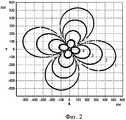
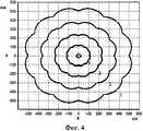
Проиллюстрируем возможности заявляемого способа на примерах математического моделирования измерения пространственных координат. Зададим для всех примеров одинаковые среднеквадратические ошибки σ отдельных измерений di,j, равные 0.6 м, высоты фазовых центров первых трех антенн (1, 2, 3) h1=1 м, высоты фазовых центров трех других антенн (4, 5, 6) h2=3 м,а=10 км, b=10 км, z=10 км. На фигурах звездочками отмечено расположение первых трех пунктов, а треугольниками - вторых трех пунктов, цифрами 1…4 отмечены границы зон, внутри которых среднеквадратические ошибки измерения значений дальностей от приемного пункта с индексом j до объекта dtj не превышают заданные (1-1 км, 2-0.5 км, 3-0.2 км, 4-0.05 км). На фиг.1 представлены результаты моделирования для j=1, на фиг.2 - для j=2, на фиг.3 - для j=3. Результаты моделирования для случая, когда в каждой точке пространства определяют индекс j=jm, для которого Кj минимальное, и определение координат производят для параметров, соответствующих этому jm, представлены на фиг.4. Такой подход позволяет получить близкую к круговой зону действия и существенно увеличить ее объем.We illustrate the capabilities of the proposed method on the examples of mathematical modeling of the measurement of spatial coordinates. For all examples, we set the same root-mean-square errors σ of individual measurements di, j equal to 0.6 m, the height of the phase centers of the first three antennas (1, 2, 3) h1 = 1 m, the heights of the phase centers of three other antennas (4, 5, 6 ) h2 = 3 m,a = 10 km, b = 10 km, z = 10 km. In the figures, asterisks indicate the location of the first three points, and triangles - the second three points, the numbers 1 ... 4 indicate the boundaries of the zones within which the standard errors of measuring the values of the distances from the receiving center with index j to the object dtj do not exceed the specified (1-1 km, 2-0.5 km, 3-0.2 km, 4-0.05 km). Figure 1 presents the simulation results for j = 1, figure 2 - for j = 2, figure 3 - for j = 3. The simulation results for the case when at each point in space the index j = jm is determined, for which Kj is minimal, and the coordinates are determined for the parameters corresponding to this jm , are presented in Fig. 4. This approach allows you to get close to the circular coverage area and significantly increase its volume.
Перечислим основные достоинства способа:We list the main advantages of the method:
- обеспечивает однозначное измерение пространственных координат объекта с заданной точностью,- provides an unambiguous measurement of the spatial coordinates of the object with a given accuracy,
- измерение координат реализуется с помощью современной элементной базы и микропроцессорной техники,- coordinate measurement is implemented using modern elemental base and microprocessor technology,
- эффективнее использует ресурс связи,- uses the communication resource more efficiently,
- одновременно обслуживает несколько ИРИ,- simultaneously serves several IRI,
- позволяет получить, в том числе, близкую к круговой зону действия реализующих его систем измерения пространственных координат с заданной точностью и существенно увеличивает ее объем.- allows you to get, including close to the circular zone of action of the systems for measuring spatial coordinates implementing it with a given accuracy and significantly increases its volume.
Результативность и эффективность использования заявляемого способа приема радиосигналов от источника радиоизлучения, находящегося на объекте, в том числе подвижном, и его приема наземной шестипунктовой приемной системой состоит в том, что он может быть применен на практике для развития и совершенствования радионавигационных систем измерения координат ИРИ, а также в других приложениях. Способ позволяет измерять их однозначно простыми по сравнению с известными методами.The effectiveness and efficiency of using the proposed method for receiving radio signals from a radio source located at the facility, including mobile, and its reception by a six-point ground receiving system consists in the fact that it can be applied in practice for the development and improvement of radio navigation systems for measuring the coordinates of IRI, and also in other applications. The method allows to measure them unambiguously simple in comparison with known methods.
Таким образом, отличительные признаки заявляемого способа обеспечивают появление новых свойств, не достигаемых в прототипе и аналогах. Проведенный анализ позволил установить: аналоги с совокупностью признаков, тождественных всем признакам заявленного технического решения, отсутствуют, что указывает на соответствие заявленного способа условию «новизны».Thus, the distinctive features of the proposed method provide the appearance of new properties not achieved in the prototype and analogues. The analysis made it possible to establish: analogues with a set of features identical to all the features of the claimed technical solution are absent, which indicates the conformity of the claimed method to the “novelty” condition.
Результаты поиска известных решений, в том числе, имеющих отношение к радиопеленгации, радионавигации, радиоуправлению и связи, с целью выявления признаков, совпадающих с отличительными от прототипа признаками заявленного способа, показали, что они не следуют явным образом из уровня техники. Также не выявлена известность влияния предусматриваемых существенными признаками заявленного изобретения действий на достижение указанного результата. Следовательно, заявленное изобретение соответствует условию патентоспособности «изобретательский уровень».The search results for known solutions, including those related to direction finding, radio navigation, radio control and communication, in order to identify signs that match the distinctive features of the prototype of the claimed method, showed that they do not follow explicitly from the prior art. Also, the popularity of the influence of the actions provided for by the essential features of the claimed invention on the achievement of the specified result was not revealed. Therefore, the claimed invention meets the condition of patentability "inventive step".
Claims (1)
Translated fromRussian


и через них измеряют преимущественно пространственные координаты объекта (X0,Y0,Z0)


где α1=1, β1=0; α2=-1/2,


указанные действия в упомянутом порядке повторяют при каждом приеме радиосигналов.A method of receiving radio signals from radio sources located on objects, including mobile ones, and measuring information parameters corresponding to radio signals and the aforementioned objects, a ground receiving station, phase centers of the receiving antennas of each of the receiving stations which are located at predetermined points in a rectangular coordinate system with the origin at a given point 0, located mainly on the surface of the earth, with the plane (0, X, Y) tangent to the surface of the earth at point 0, and the axis 0Z directed tons of land, in which, by synchronously receiving radio signals from a radio source and registering the moments of receiving radio signals, for example, by the temporary positions of their leading edges, the time differences between the times of receiving radio signals at different points of the receiving system are measured, characterized in that the ground-based point receiving system is made with six points of reception, ordered in a predetermined manner, and in the first group of three points of reception, mainly omnidirectional receiving antennas, phase centers of which located at the same given height Z = h1 , at the vertices of an equilateral triangle with coordinates on the plane (0, X, Y) equal to X1 = 0, Y1 = 2b;
and through them mainly the spatial coordinates of the object are measured (X0 , Y0 , Z0 )
where α1 = 1, β1 = 0; α2 = -1 / 2,
these actions in the above order are repeated at each reception of radio signals.
Priority Applications (1)
| Application Number | Priority Date | Filing Date | Title |
|---|---|---|---|
| RU2010152956/07ARU2453995C1 (en) | 2010-12-24 | 2010-12-24 | Method to receive radio signals from sources of radio radiations |
Applications Claiming Priority (1)
| Application Number | Priority Date | Filing Date | Title |
|---|---|---|---|
| RU2010152956/07ARU2453995C1 (en) | 2010-12-24 | 2010-12-24 | Method to receive radio signals from sources of radio radiations |
Publications (1)
| Publication Number | Publication Date |
|---|---|
| RU2453995C1true RU2453995C1 (en) | 2012-06-20 |
Family
ID=46681226
Family Applications (1)
| Application Number | Title | Priority Date | Filing Date |
|---|---|---|---|
| RU2010152956/07ARU2453995C1 (en) | 2010-12-24 | 2010-12-24 | Method to receive radio signals from sources of radio radiations |
Country Status (1)
| Country | Link |
|---|---|
| RU (1) | RU2453995C1 (en) |
Cited By (5)
| Publication number | Priority date | Publication date | Assignee | Title |
|---|---|---|---|---|
| RU2530239C1 (en)* | 2013-07-26 | 2014-10-10 | Владимир Петрович Панов | Radio signal transmission and reception method |
| RU2530240C1 (en)* | 2013-07-26 | 2014-10-10 | Владимир Петрович Панов | Radio signal transmission and reception method |
| WO2015012738A1 (en)* | 2013-07-26 | 2015-01-29 | Panov Vladimir Petrovich | Method for transmitting and receiving radio signals |
| WO2015012737A1 (en)* | 2013-07-26 | 2015-01-29 | Panov Vladimir Petrovich | Method for transmitting and receiving radio signals |
| WO2015012742A1 (en)* | 2013-07-26 | 2015-01-29 | Panov Vladimir Petrovich | Radio system |
Citations (4)
| Publication number | Priority date | Publication date | Assignee | Title |
|---|---|---|---|---|
| RU2018855C1 (en)* | 1991-04-22 | 1994-08-30 | Всесоюзный научно-исследовательский институт радиоаппаратуры | Aircraft radio navigation system |
| RU2115137C1 (en)* | 1994-05-11 | 1998-07-10 | Николай Егорович Армизонов | Range-finding method of location and components of vector of velocity of objects by radio signals of spacecraft of satellite radio navigation systems |
| RU2003118800A (en)* | 2003-06-23 | 2005-02-20 | Военно-космическа академи им. А.Ф. Можайского (RU) | DIFFERENCE-LONG-DIMENSIONAL METHOD OF MOVING THE SOURCE OF RADIO-RADIATION AND IMPLEMENTING ITS DEVICE |
| RU2263328C1 (en)* | 2004-05-24 | 2005-10-27 | Военный университет связи | Method and device for determining coordinates of radio emission source |
- 2010
- 2010-12-24RURU2010152956/07Apatent/RU2453995C1/enactive
Patent Citations (4)
| Publication number | Priority date | Publication date | Assignee | Title |
|---|---|---|---|---|
| RU2018855C1 (en)* | 1991-04-22 | 1994-08-30 | Всесоюзный научно-исследовательский институт радиоаппаратуры | Aircraft radio navigation system |
| RU2115137C1 (en)* | 1994-05-11 | 1998-07-10 | Николай Егорович Армизонов | Range-finding method of location and components of vector of velocity of objects by radio signals of spacecraft of satellite radio navigation systems |
| RU2003118800A (en)* | 2003-06-23 | 2005-02-20 | Военно-космическа академи им. А.Ф. Можайского (RU) | DIFFERENCE-LONG-DIMENSIONAL METHOD OF MOVING THE SOURCE OF RADIO-RADIATION AND IMPLEMENTING ITS DEVICE |
| RU2263328C1 (en)* | 2004-05-24 | 2005-10-27 | Военный университет связи | Method and device for determining coordinates of radio emission source |
Cited By (7)
| Publication number | Priority date | Publication date | Assignee | Title |
|---|---|---|---|---|
| RU2530239C1 (en)* | 2013-07-26 | 2014-10-10 | Владимир Петрович Панов | Radio signal transmission and reception method |
| RU2530240C1 (en)* | 2013-07-26 | 2014-10-10 | Владимир Петрович Панов | Radio signal transmission and reception method |
| WO2015012733A1 (en)* | 2013-07-26 | 2015-01-29 | Panov Vladimir Petrovich | Method for transmitting and receiving radio signals |
| WO2015012738A1 (en)* | 2013-07-26 | 2015-01-29 | Panov Vladimir Petrovich | Method for transmitting and receiving radio signals |
| WO2015012734A1 (en)* | 2013-07-26 | 2015-01-29 | Panov Vladimir Petrovich | Method for transmitting and receiving radio signals |
| WO2015012737A1 (en)* | 2013-07-26 | 2015-01-29 | Panov Vladimir Petrovich | Method for transmitting and receiving radio signals |
| WO2015012742A1 (en)* | 2013-07-26 | 2015-01-29 | Panov Vladimir Petrovich | Radio system |
Similar Documents
| Publication | Publication Date | Title |
|---|---|---|
| TWI345641B (en) | A method and system for locating a mobile radio receiver in a radio system with multiple transmitters | |
| US8280384B2 (en) | System and method for predicting location accuracy of a mobile unit | |
| RU2453996C1 (en) | System to receive radio signals at objects | |
| RU2453995C1 (en) | Method to receive radio signals from sources of radio radiations | |
| RU2624461C1 (en) | Method of determining coordinates of object | |
| RU2453997C1 (en) | System to receive radio signals from sources of radio radiations | |
| RU2453999C1 (en) | Method of receiving radio signals on objects | |
| RU2435304C1 (en) | Receiving and transmitting method of radio signals of ground radio beacons | |
| RU2465614C1 (en) | Method of receiving radio signals from radio sources | |
| Alamleh et al. | A weighting system for building RSS maps by crowdsourcing data from smartphones | |
| CN109597026B (en) | Multi-point positioning comprehensive simulation evaluation method and system | |
| RU2432682C1 (en) | Method of transmitting radio signals using radio-frequency sources | |
| RU2670976C1 (en) | Method for determining location of radio source with periodic structure of signal and rotating directed antenna | |
| Janicka et al. | An example and analysis for ambiguity resolution in the indoor ZigBee positioning system | |
| RU2714303C1 (en) | Difference-range-finding method for determining the location of a radio-frequency source in multipath propagation of radio waves | |
| RU2432680C1 (en) | Method of transmitting and receiving radio signals from ground-based radio beacons | |
| RU2432679C1 (en) | Method of transmitting and receiving radio signals from ground-based radio beacons | |
| RU2468380C1 (en) | System for receiving radio signals from radio sources | |
| RU2432678C1 (en) | Method of transmitting and receiving radio signals from ground-based radio beacons | |
| RU2436242C1 (en) | Method of transmitting radio signals using radio-frequency sources | |
| RU2432713C1 (en) | Method of transmitting radio signals using radio-frequency sources | |
| RU2436232C1 (en) | Method of transmitting and receiving radio signals from ground-based radio beacons | |
| RU2436261C1 (en) | Method of receiving radio signals from radio-requency source | |
| RU2436260C1 (en) | Method of transmitting and receiving radio signals from ground-based radio beacons | |
| RU2432677C1 (en) | Method of transmitting and receiving radio signals from ground-based radio beacons |
Legal Events
| Date | Code | Title | Description |
|---|---|---|---|
| PC41 | Official registration of the transfer of exclusive right | Effective date:20121229 |