RU2453298C2 - Air-permeable interface system for local low pressure - Google Patents
Air-permeable interface system for local low pressureDownload PDFInfo
- Publication number
- RU2453298C2 RU2453298C2RU2009124325/14ARU2009124325ARU2453298C2RU 2453298 C2RU2453298 C2RU 2453298C2RU 2009124325/14 ARU2009124325/14 ARU 2009124325/14ARU 2009124325 ARU2009124325 ARU 2009124325ARU 2453298 C2RU2453298 C2RU 2453298C2
- Authority
- RU
- Russia
- Prior art keywords
- gasket
- applicator
- reduced pressure
- tissue
- pad
- Prior art date
Links
- 239000004744fabricSubstances0.000claimsabstractdescription81
- 239000000463materialSubstances0.000claimsdescription15
- 238000004891communicationMethods0.000claimsdescription11
- 229920000642polymerPolymers0.000claimsdescription11
- 239000004952PolyamideSubstances0.000claimsdescription10
- 229920002647polyamidePolymers0.000claimsdescription10
- 229920002635polyurethanePolymers0.000claimsdescription10
- 239000004814polyurethaneSubstances0.000claimsdescription10
- 229920001059synthetic polymerPolymers0.000claimsdescription10
- 229920000098polyolefinPolymers0.000claimsdescription7
- XTXRWKRVRITETP-UHFFFAOYSA-NVinyl acetateChemical compoundCC(=O)OC=CXTXRWKRVRITETP-UHFFFAOYSA-N0.000claimsdescription6
- 239000004620low density foamSubstances0.000claimsdescription6
- 239000004677NylonSubstances0.000claimsdescription5
- 239000004372Polyvinyl alcoholSubstances0.000claimsdescription5
- DQXBYHZEEUGOBF-UHFFFAOYSA-Nbut-3-enoic acid;etheneChemical compoundC=C.OC(=O)CC=CDQXBYHZEEUGOBF-UHFFFAOYSA-N0.000claimsdescription5
- 229920001577copolymerPolymers0.000claimsdescription5
- 239000005038ethylene vinyl acetateSubstances0.000claimsdescription5
- 229920002313fluoropolymerPolymers0.000claimsdescription5
- 239000004811fluoropolymerSubstances0.000claimsdescription5
- 229920001778nylonPolymers0.000claimsdescription5
- 229920001200poly(ethylene-vinyl acetate)Polymers0.000claimsdescription5
- 229920002451polyvinyl alcoholPolymers0.000claimsdescription5
- 239000000155meltSubstances0.000claimsdescription2
- 239000004745nonwoven fabricSubstances0.000claims3
- 239000002759woven fabricSubstances0.000claims2
- 230000000694effectsEffects0.000abstractdescription2
- 239000000126substanceSubstances0.000abstractdescription2
- 239000003814drugSubstances0.000abstract2
- 238000009736wettingMethods0.000abstract1
- 210000001519tissueAnatomy0.000description90
- 239000012530fluidSubstances0.000description15
- 230000006835compressionEffects0.000description13
- 238000007906compressionMethods0.000description13
- 206010052428WoundDiseases0.000description9
- 208000027418Wounds and injuryDiseases0.000description8
- 230000004044responseEffects0.000description6
- 238000012546transferMethods0.000description6
- 238000010586diagramMethods0.000description5
- 238000012360testing methodMethods0.000description5
- 239000000017hydrogelSubstances0.000description4
- 230000000737periodic effectEffects0.000description4
- 238000002791soakingMethods0.000description4
- 230000008901benefitEffects0.000description3
- 230000014509gene expressionEffects0.000description3
- 239000003522acrylic cementSubstances0.000description2
- 230000009471actionEffects0.000description2
- 239000000853adhesiveSubstances0.000description2
- 230000001070adhesive effectEffects0.000description2
- 238000009530blood pressure measurementMethods0.000description2
- 230000003247decreasing effectEffects0.000description2
- 238000009826distributionMethods0.000description2
- 210000000416exudates and transudateAnatomy0.000description2
- 239000006260foamSubstances0.000description2
- 239000003292glueSubstances0.000description2
- 230000002706hydrostatic effectEffects0.000description2
- 239000004033plasticSubstances0.000description2
- 229920003023plasticPolymers0.000description2
- 125000006850spacer groupChemical group0.000description2
- 238000002560therapeutic procedureMethods0.000description2
- 229920001169thermoplasticPolymers0.000description2
- 239000004416thermosoftening plasticSubstances0.000description2
- 230000007704transitionEffects0.000description2
- XLYOFNOQVPJJNP-UHFFFAOYSA-NwaterSubstancesOXLYOFNOQVPJJNP-UHFFFAOYSA-N0.000description2
- 238000004026adhesive bondingMethods0.000description1
- 238000013459approachMethods0.000description1
- 239000011230binding agentSubstances0.000description1
- 210000000988bone and boneAnatomy0.000description1
- 210000000845cartilageAnatomy0.000description1
- 230000008859changeEffects0.000description1
- 210000002808connective tissueAnatomy0.000description1
- 238000010276constructionMethods0.000description1
- 238000004132cross linkingMethods0.000description1
- 238000005516engineering processMethods0.000description1
- 238000002474experimental methodMethods0.000description1
- 239000002657fibrous materialSubstances0.000description1
- 239000007789gasSubstances0.000description1
- 239000000499gelSubstances0.000description1
- 230000035876healingEffects0.000description1
- 210000003041ligamentAnatomy0.000description1
- 239000007788liquidSubstances0.000description1
- 238000005259measurementMethods0.000description1
- 238000000034methodMethods0.000description1
- 238000012986modificationMethods0.000description1
- 230000004048modificationEffects0.000description1
- 210000003205muscleAnatomy0.000description1
- 238000009581negative-pressure wound therapyMethods0.000description1
- 210000005036nerveAnatomy0.000description1
- 229920000728polyesterPolymers0.000description1
- 239000011148porous materialSubstances0.000description1
- 238000005096rolling processMethods0.000description1
- 238000005245sinteringMethods0.000description1
- 210000003491skinAnatomy0.000description1
- 210000002435tendonAnatomy0.000description1
- 230000009772tissue formationEffects0.000description1
- 230000002792vascularEffects0.000description1
- 238000003466weldingMethods0.000description1
- -1without limitationPolymers0.000description1
Images


Classifications
- A—HUMAN NECESSITIES
- A61—MEDICAL OR VETERINARY SCIENCE; HYGIENE
- A61F—FILTERS IMPLANTABLE INTO BLOOD VESSELS; PROSTHESES; DEVICES PROVIDING PATENCY TO, OR PREVENTING COLLAPSING OF, TUBULAR STRUCTURES OF THE BODY, e.g. STENTS; ORTHOPAEDIC, NURSING OR CONTRACEPTIVE DEVICES; FOMENTATION; TREATMENT OR PROTECTION OF EYES OR EARS; BANDAGES, DRESSINGS OR ABSORBENT PADS; FIRST-AID KITS
- A61F13/00—Bandages or dressings; Absorbent pads
- A61F13/05—Bandages or dressings; Absorbent pads specially adapted for use with sub-pressure or over-pressure therapy, wound drainage or wound irrigation, e.g. for use with negative-pressure wound therapy [NPWT]
- A—HUMAN NECESSITIES
- A61—MEDICAL OR VETERINARY SCIENCE; HYGIENE
- A61F—FILTERS IMPLANTABLE INTO BLOOD VESSELS; PROSTHESES; DEVICES PROVIDING PATENCY TO, OR PREVENTING COLLAPSING OF, TUBULAR STRUCTURES OF THE BODY, e.g. STENTS; ORTHOPAEDIC, NURSING OR CONTRACEPTIVE DEVICES; FOMENTATION; TREATMENT OR PROTECTION OF EYES OR EARS; BANDAGES, DRESSINGS OR ABSORBENT PADS; FIRST-AID KITS
- A61F13/00—Bandages or dressings; Absorbent pads
- A61F13/01—Non-adhesive bandages or dressings
- A61F13/01008—Non-adhesive bandages or dressings characterised by the material
- A61F13/01017—Non-adhesive bandages or dressings characterised by the material synthetic, e.g. polymer based
- A—HUMAN NECESSITIES
- A61—MEDICAL OR VETERINARY SCIENCE; HYGIENE
- A61F—FILTERS IMPLANTABLE INTO BLOOD VESSELS; PROSTHESES; DEVICES PROVIDING PATENCY TO, OR PREVENTING COLLAPSING OF, TUBULAR STRUCTURES OF THE BODY, e.g. STENTS; ORTHOPAEDIC, NURSING OR CONTRACEPTIVE DEVICES; FOMENTATION; TREATMENT OR PROTECTION OF EYES OR EARS; BANDAGES, DRESSINGS OR ABSORBENT PADS; FIRST-AID KITS
- A61F13/00—Bandages or dressings; Absorbent pads
- A61F13/01—Non-adhesive bandages or dressings
- A61F13/01021—Non-adhesive bandages or dressings characterised by the structure of the dressing
- A61F13/01029—Non-adhesive bandages or dressings characterised by the structure of the dressing made of multiple layers
- A—HUMAN NECESSITIES
- A61—MEDICAL OR VETERINARY SCIENCE; HYGIENE
- A61F—FILTERS IMPLANTABLE INTO BLOOD VESSELS; PROSTHESES; DEVICES PROVIDING PATENCY TO, OR PREVENTING COLLAPSING OF, TUBULAR STRUCTURES OF THE BODY, e.g. STENTS; ORTHOPAEDIC, NURSING OR CONTRACEPTIVE DEVICES; FOMENTATION; TREATMENT OR PROTECTION OF EYES OR EARS; BANDAGES, DRESSINGS OR ABSORBENT PADS; FIRST-AID KITS
- A61F13/00—Bandages or dressings; Absorbent pads
- A61F13/01—Non-adhesive bandages or dressings
- A61F13/01034—Non-adhesive bandages or dressings characterised by a property
- A61F13/01046—Air-vapor permeability
- A—HUMAN NECESSITIES
- A61—MEDICAL OR VETERINARY SCIENCE; HYGIENE
- A61F—FILTERS IMPLANTABLE INTO BLOOD VESSELS; PROSTHESES; DEVICES PROVIDING PATENCY TO, OR PREVENTING COLLAPSING OF, TUBULAR STRUCTURES OF THE BODY, e.g. STENTS; ORTHOPAEDIC, NURSING OR CONTRACEPTIVE DEVICES; FOMENTATION; TREATMENT OR PROTECTION OF EYES OR EARS; BANDAGES, DRESSINGS OR ABSORBENT PADS; FIRST-AID KITS
- A61F13/00—Bandages or dressings; Absorbent pads
- A61F13/02—Adhesive bandages or dressings
- A61F13/0203—Adhesive bandages or dressings with fluid retention members
- A—HUMAN NECESSITIES
- A61—MEDICAL OR VETERINARY SCIENCE; HYGIENE
- A61K—PREPARATIONS FOR MEDICAL, DENTAL OR TOILETRY PURPOSES
- A61K9/00—Medicinal preparations characterised by special physical form
- A61K9/70—Web, sheet or filament bases ; Films; Fibres of the matrix type containing drug
- A—HUMAN NECESSITIES
- A61—MEDICAL OR VETERINARY SCIENCE; HYGIENE
- A61M—DEVICES FOR INTRODUCING MEDIA INTO, OR ONTO, THE BODY; DEVICES FOR TRANSDUCING BODY MEDIA OR FOR TAKING MEDIA FROM THE BODY; DEVICES FOR PRODUCING OR ENDING SLEEP OR STUPOR
- A61M1/00—Suction or pumping devices for medical purposes; Devices for carrying-off, for treatment of, or for carrying-over, body-liquids; Drainage systems
- A61M1/71—Suction drainage systems
- A61M1/74—Suction control
- A61M1/75—Intermittent or pulsating suction
- A—HUMAN NECESSITIES
- A61—MEDICAL OR VETERINARY SCIENCE; HYGIENE
- A61M—DEVICES FOR INTRODUCING MEDIA INTO, OR ONTO, THE BODY; DEVICES FOR TRANSDUCING BODY MEDIA OR FOR TAKING MEDIA FROM THE BODY; DEVICES FOR PRODUCING OR ENDING SLEEP OR STUPOR
- A61M1/00—Suction or pumping devices for medical purposes; Devices for carrying-off, for treatment of, or for carrying-over, body-liquids; Drainage systems
- A61M1/90—Negative pressure wound therapy devices, i.e. devices for applying suction to a wound to promote healing, e.g. including a vacuum dressing
- A61M1/91—Suction aspects of the dressing
- A61M1/912—Connectors between dressing and drainage tube
- A61M1/913—Connectors between dressing and drainage tube having a bridging element for transferring the reduced pressure from the connector to the dressing
- A—HUMAN NECESSITIES
- A61—MEDICAL OR VETERINARY SCIENCE; HYGIENE
- A61M—DEVICES FOR INTRODUCING MEDIA INTO, OR ONTO, THE BODY; DEVICES FOR TRANSDUCING BODY MEDIA OR FOR TAKING MEDIA FROM THE BODY; DEVICES FOR PRODUCING OR ENDING SLEEP OR STUPOR
- A61M1/00—Suction or pumping devices for medical purposes; Devices for carrying-off, for treatment of, or for carrying-over, body-liquids; Drainage systems
- A61M1/90—Negative pressure wound therapy devices, i.e. devices for applying suction to a wound to promote healing, e.g. including a vacuum dressing
- A61M1/91—Suction aspects of the dressing
- A61M1/915—Constructional details of the pressure distribution manifold
Landscapes
- Health & Medical Sciences (AREA)
- Heart & Thoracic Surgery (AREA)
- Engineering & Computer Science (AREA)
- Life Sciences & Earth Sciences (AREA)
- Animal Behavior & Ethology (AREA)
- General Health & Medical Sciences (AREA)
- Public Health (AREA)
- Veterinary Medicine (AREA)
- Biomedical Technology (AREA)
- Vascular Medicine (AREA)
- Anesthesiology (AREA)
- Hematology (AREA)
- Bioinformatics & Cheminformatics (AREA)
- Chemical & Material Sciences (AREA)
- Medicinal Chemistry (AREA)
- Pharmacology & Pharmacy (AREA)
- Epidemiology (AREA)
- Media Introduction/Drainage Providing Device (AREA)
- Materials For Medical Uses (AREA)
- Surgical Instruments (AREA)
- Laminated Bodies (AREA)
Abstract
Description
Translated fromRussianПРЕДПОСЫЛКИ ИЗОБРЕТЕНИЯBACKGROUND OF THE INVENTION
1. Область Изобретения1. Field of Invention
Настоящая заявка на изобретение относится в целом к системам и способам для обеспечения лечения пониженным давлением ткани открытых ран и других участков ткани. Более конкретно, настоящая заявка относится к воздухопроницаемым интерфейсным системам для локального пониженного давления.The present application for the invention relates generally to systems and methods for providing treatment with reduced tissue pressure of open wounds and other tissue sites. More specifically, this application relates to breathable interface systems for local reduced pressure.
2. Описание Уровня Техники2. Description of the Level of Technology
Клинические исследования и практика показали, что обеспечение пониженного давления вблизи участка ткани усиливает и ускоряет рост новой ткани на участке ткани. Применения этого явления являются многочисленными, но применение пониженного давления было особенно успешным в лечении участков ткани и ран. Это лечение (часто упоминаемое в медицинском сообществе как "терапия раны отрицательным давлением", "терапия пониженным давлением" или "вакуумная терапия") обеспечивает много преимуществ, включая более быстрое заживление и ускоренное формирование гранулированной ткани.Clinical studies and practice have shown that providing reduced pressure near the tissue site enhances and accelerates the growth of new tissue on the tissue site. The applications of this phenomenon are numerous, but the use of reduced pressure has been particularly successful in treating tissue sites and wounds. This treatment (often referred to in the medical community as “negative pressure wound therapy”, “low pressure therapy” or “vacuum therapy”) provides many benefits, including faster healing and accelerated granular tissue formation.
Лечение ткани пониженным давлением было недавно популяризировано компанией Kinetic Concepts, Inc. из Сан-Антонио, Техас, посредством коммерчески доступной системы лечения ткани пониженным давлением линии VAC. В целом такие системы лечения ткани пониженным давлением содержат основанную на прокладке повязку, которую прикладывают к ткани и которая иногда упоминается как «интерфейс ткани» или «интерфейс раны».Low pressure tissue treatment was recently popularized by Kinetic Concepts, Inc. from San Antonio, Texas, through a commercially available VAC line low pressure tissue treatment system. In general, such low-pressure tissue treatment systems comprise a pad-based dressing that is applied to the tissue and which is sometimes referred to as a “tissue interface” or “wound interface”.
Повязки существующего уровня техники имеют, однако, несколько недостатков. Их трудно прикладывать к маленьким ранам, и их использование часто приводит к размачиванию периферии раны. Традиционно повязки довольно неудобны, ограничивая деятельность пациентов. Сидение на повязке или перекатывание по повязке может вызывать существенный дискомфорт пациента. Кроме того, эти действия могут сжимать повязку и вмешиваться в приложение пониженного давления к магистрали на участке ткани.The bandages of the prior art, however, have several disadvantages. They are difficult to apply to small wounds, and their use often leads to soaking the periphery of the wound. Traditionally, dressings are quite uncomfortable, limiting the activity of patients. Sitting on a bandage or rolling on a bandage can cause significant discomfort to the patient. In addition, these actions can compress the dressing and interfere with the application of reduced pressure to the line at the tissue site.
СУЩНОСТЬ ИЗОБРЕТЕНИЯSUMMARY OF THE INVENTION
Проблемы, свойственный этим традиционным повязкам, решены посредством улучшенной воздухопроницаемой интерфейсной системы для локального пониженного давления. Один иллюстративный вариант выполнения воздухопроницаемой интерфейсной системы содержит первую прокладку, вторую прокладку и слой ткани, причем все они размещены между салфеткой и аппликатором. Кроме того, повязка может содержать интерфейсный элемент для облегчения проточного сообщения трубопровода с повязкой. В качестве альтернативы, трубопровод может быть помещен в непосредственном контакте с повязкой или вставлен непосредственно в повязку, чтобы доставлять пониженное давление, которое затем распределяется к участку ткани через слой ткани и прокладки.The problems inherent in these traditional dressings have been resolved through an improved breathable interface system for local reduced pressure. One illustrative embodiment of a breathable interface system comprises a first pad, a second pad and a fabric layer, all of which are placed between the tissue and the applicator. In addition, the dressing may include an interface element to facilitate flow communication of the pipeline with the dressing. Alternatively, the conduit may be placed in direct contact with the dressing or inserted directly into the dressing to deliver reduced pressure, which is then distributed to the tissue site through a layer of fabric and gaskets.
В другом иллюстративном варианте выполнения воздухопроницаемая интерфейсная система может содержать слой, имеющий высокую скорость передачи влажности пара и быстро удаляющий влажность от периферии участка ткани и изолирующий периферию от эксудата, удаленного от участка ткани. Таким образом, эти иллюстративные варианты выполнения существенно устраняют или уменьшают размачивание вокруг участка ткани во время лечения ткани пониженным давлением, особенно вокруг маленьких участков ткани.In another illustrative embodiment, the breathable interface system may comprise a layer having a high vapor moisture transfer rate and rapidly removing moisture from the periphery of the tissue site and isolating the periphery from the exudate remote from the tissue site. Thus, these illustrative embodiments substantially eliminate or reduce soaking around a tissue site during low pressure tissue treatment, especially around small tissue sites.
Эти и другие иллюстративные варианты выполнения также могут содержать слой ткани, который обеспечивает дополнительные пути прохождения текучей среды, которые менее восприимчивы к схлопыванию под более высокими сжимающими нагрузками, улучшая, таким образом, эффективность лечения ткани пониженным давлением на активных пациентах. Эти дополнительные пути прохождения текучей среды также уменьшают время, необходимое для распределения пониженного давления к участку ткани, что увеличивает эффективность периодического лечения ткани пониженным давлением.These and other illustrative embodiments may also include a tissue layer that provides additional fluid paths that are less susceptible to collapse under higher compressive loads, thereby improving the effectiveness of treating tissue with reduced pressure in active patients. These additional fluid paths also reduce the time required to distribute the reduced pressure to the tissue site, which increases the effectiveness of the periodic treatment of the tissue with reduced pressure.
Один иллюстративный вариант выполнения содержит воздухопроницаемую интерфейсную систему, содержащую аппликатор, имеющий проходящее через него отверстие; салфетку, по существу покрывающую аппликатор; первую прокладку, расположенную между салфеткой и аппликатором; вторую прокладку, по существу покрывающую отверстие и расположенную между салфеткой и аппликатором, причем вторая прокладка расположена по существу смежно с первой прокладкой; слой ткани, расположенный по меньшей мере частично между второй прокладкой и салфеткой; и трубопровод пониженного давления, сообщающийся с одним из следующих элементов: первой прокладкой и слоем ткани для обеспечения подачи пониженного давления к отверстию; при этом салфетка прикреплена к аппликатору, покрывая первую прокладку, вторую прокладку и слой ткани, образуя по существу герметичную среду.One illustrative embodiment comprises a breathable interface system comprising an applicator having an opening passing therethrough; a napkin substantially covering the applicator; a first gasket located between the tissue and the applicator; a second gasket substantially covering the hole and located between the tissue and the applicator, the second gasket being located substantially adjacent to the first gasket; a fabric layer located at least partially between the second gasket and the tissue; and a reduced pressure pipe in communication with one of the following elements: a first gasket and a layer of fabric to provide a reduced pressure to the hole; wherein the napkin is attached to the applicator, covering the first pad, second pad and fabric layer, forming a substantially airtight environment.
Другой иллюстративный вариант выполнения содержит воздухопроницаемую интерфейсную систему, содержащую аппликатор, имеющий проходящее через него отверстие; салфетку, по существу покрывающую аппликатор; первую прокладку, расположенную между салфеткой и аппликатором; вторую прокладку, по существу покрывающую отверстие и расположенную между салфеткой и аппликатором, при этом вторая прокладка расположена по существу смежно с первой прокладкой; слой ткани, расположенный по меньшей мере частично между первой прокладкой и второй прокладкой и аппликатором; и трубопровод пониженного давления, сообщающийся с одним из следующих элементов: первой прокладкой и слоем ткани для обеспечения подачи пониженного давления к отверстию; при этом салфетка прикреплена к аппликатору, покрывая первую прокладку, вторую прокладку и слой ткани, образуя по существу герметичную среду.Another illustrative embodiment comprises a breathable interface system comprising an applicator having an opening passing therethrough; a napkin substantially covering the applicator; a first gasket located between the tissue and the applicator; a second gasket substantially covering the hole and located between the tissue and the applicator, the second gasket being located substantially adjacent to the first gasket; a fabric layer located at least partially between the first pad and the second pad and applicator; and a reduced pressure pipe in communication with one of the following elements: a first gasket and a layer of fabric to provide a reduced pressure to the hole; wherein the napkin is attached to the applicator, covering the first pad, second pad and fabric layer, forming a substantially airtight environment.
Еще один иллюстративный вариант выполнения содержит воздухопроницаемую интерфейсную систему, содержащую аппликатор, имеющий проходящее через него отверстие; салфетку, по существу покрывающую аппликатор; первую прокладку, расположенную между салфеткой и аппликатором; вторую прокладку, по существу покрывающую отверстие и расположенную между салфеткой и аппликатором, при этом вторая прокладка расположена по существу смежно с первой прокладкой; и слой ткани, расположенный по меньшей мере частично между первой прокладкой и второй прокладкой и салфеткой; и трубопровод пониженного давления, сообщающийся с одним из следующих элементов: первой прокладкой и слоем ткани для обеспечения подачи пониженного давления к отверстию; при этом салфетка прикреплена к аппликатору, покрывая первую прокладку, вторую прокладку и слой ткани, образуя по существу герметичную среду.Another illustrative embodiment comprises a breathable interface system comprising an applicator having an opening passing therethrough; a napkin substantially covering the applicator; a first gasket located between the tissue and the applicator; a second gasket substantially covering the hole and located between the tissue and the applicator, the second gasket being located substantially adjacent to the first gasket; and a fabric layer located at least partially between the first gasket and the second gasket and tissue; and a reduced pressure pipe in communication with one of the following elements: a first gasket and a layer of fabric to provide a reduced pressure to the hole; wherein the napkin is attached to the applicator, covering the first pad, second pad and fabric layer, forming a substantially airtight environment.
Еще один иллюстративный вариант выполнения содержит устройство для лечения ткани пониженным давлением, предназначенное для приложения лечения ткани пониженным давлением к участку ткани, содержащее аппликатор, имеющий проходящее через него отверстие; салфетку, по существу покрывающую аппликатор; первую прокладку, расположенную между салфеткой и аппликатором; вторую прокладку, по существу покрывающую отверстие и расположенную между салфеткой и аппликатором, при этом вторая прокладка расположена по существу смежно с первой прокладкой; слой ткани, расположенный по меньшей мере частично между второй прокладкой и салфеткой, при этом салфетка прикреплена к аппликатору, покрывая первую прокладку, вторую прокладку и слой ткани, образуя по существу герметичную среду; трубопровод пониженного давления, сообщающийся с одним из следующих элементов: первой прокладкой и слоем ткани для обеспечения подачи пониженного давления к отверстию; и источник пониженного давления, сообщающийся с трубопроводом пониженного давления для обеспечения подачи пониженного давления к участку ткани.Another illustrative embodiment comprises a device for treating tissue with reduced pressure, for applying a treatment for tissue with reduced pressure to a tissue site, comprising an applicator having an opening through it; a napkin substantially covering the applicator; a first gasket located between the tissue and the applicator; a second gasket substantially covering the hole and located between the tissue and the applicator, the second gasket being located substantially adjacent to the first gasket; a fabric layer located at least partially between the second gasket and the tissue, wherein the tissue is attached to the applicator, covering the first gasket, the second gasket and the tissue layer, forming a substantially airtight environment; a reduced pressure pipeline communicating with one of the following elements: a first gasket and a layer of fabric to provide a reduced pressure to the hole; and a reduced pressure source in communication with the reduced pressure pipe to provide reduced pressure to the tissue site.
Другие объекты, особенности и преимущества иллюстративных вариантов выполнения станут очевидными со ссылкой на приведенные ниже чертежи и подробное описание.Other objects, features, and advantages of illustrative embodiments will become apparent with reference to the drawings and detailed description below.
КРАТКОЕ ОПИСАНИЕ ЧЕРТЕЖЕЙBRIEF DESCRIPTION OF THE DRAWINGS
Фиг.1 представляет собой разобранный вид воздухопроницаемой интерфейсной системы в соответствии с иллюстративным вариантом выполнения изобретения;Figure 1 is an exploded view of a breathable interface system in accordance with an illustrative embodiment of the invention;
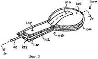
Фиг.2 представляет собой вид в аксонометрии воздухопроницаемой интерфейсной системы без салфетки, в соответствии с иллюстративным вариантом выполнения изобретения;Figure 2 is a perspective view of a breathable interface system without a wipe, in accordance with an illustrative embodiment of the invention;
Фиг.3 представляет собой вид снизу на аппликатор воздухопроницаемой интерфейсной системы, изображенной на Фиг.1 и 2, в соответствии с иллюстративным вариантом выполнения изобретения;Figure 3 is a bottom view of the applicator of the breathable interface system depicted in figures 1 and 2, in accordance with an illustrative embodiment of the invention;
Фиг.4 представляет собой вид в частичном разрезе воздухопроницаемой интерфейсной системы вдоль линий 4-4, изображенной на Фиг.2, в соответствии с иллюстративным вариантом выполнения изобретения;FIG. 4 is a partial cross-sectional view of a breathable interface system along lines 4-4 of FIG. 2, in accordance with an illustrative embodiment of the invention;
Фиг.5 представляет собой вид в частичном разрезе воздухопроницаемой интерфейсной системы в соответствии с другим иллюстративным вариантом выполнения изобретения;Figure 5 is a partial sectional view of a breathable interface system in accordance with another illustrative embodiment of the invention;
Фиг.6 представляет собой вид в частичном разрезе воздухопроницаемой интерфейсной системы в соответствии с другим иллюстративным вариантом выполнения изобретения;6 is a partial sectional view of a breathable interface system in accordance with another illustrative embodiment of the invention;
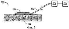
Фиг.7 представляет собой схематическую диаграмму системы лечения ткани пониженным давлением, имеющей воздухопроницаемую интерфейсную систему, выполненную в соответствии с иллюстративным вариантом выполнения изобретения;7 is a schematic diagram of a reduced pressure tissue treatment system having a breathable interface system in accordance with an illustrative embodiment of the invention;
Фиг.8 представляет собой диаграмму, на которой выполнено сравнение результатов экспериментов передачи давления на традиционной повязке и на воздухопроницаемой интерфейсной системе в соответствии с иллюстративным вариантом выполнения настоящего изобретения; иFIG. 8 is a diagram comparing the results of pressure transfer experiments on a conventional dressing and on a breathable interface system in accordance with an illustrative embodiment of the present invention; and
Фиг.9 представляет собой диаграмму, на которой выполнено сравнение времен отклика, когда подвергали периодическому приложению пониженного давления при сухих условиях традиционной повязки и воздухопроницаемой интерфейсной системы в соответствии с иллюстративным вариантом выполнения настоящего изобретения.Fig. 9 is a diagram for comparing response times when periodically applying reduced pressure under dry conditions of a traditional dressing and a breathable interface system in accordance with an illustrative embodiment of the present invention.
ПОДРОБНОЕ ОПИСАНИЕ ПРЕДПОЧТИТЕЛЬНОГО ВАРИАНТА ВЫПОЛНЕНИЯDETAILED DESCRIPTION OF THE PREFERRED EMBODIMENT
В последующем детальном описании предпочтительных вариантов выполнения делается ссылка на сопровождающие чертежи, которые являются частью этого описания и на которых посредством иллюстрации показаны конкретные предпочтительные варианты выполнения, в которых может быть осуществлено изобретение. Эти варианты выполнения описаны достаточно подробно, чтобы позволить специалистам осуществить изобретение на практике, при этом подразумевается, что могут быть осуществлены и другие варианты выполнения и что могут быть выполнены логические, структурные, механические, электрические и химические изменения, не отступая от сущности или объема изобретения. Чтобы избежать деталей, не нужных специалистам для осуществления изобретения, в описании может быть опущена конкретная информация, известная специалистам. Последующее детальное описание не должно, поэтому, пониматься в ограничивающем смысле, при этом область настоящего изобретения определяется только приложенной формулой изобретения.In the following detailed description of preferred embodiments, reference is made to the accompanying drawings, which are part of this description and which show by way of illustration specific preferred embodiments in which the invention may be practiced. These embodiments are described in sufficient detail to enable those skilled in the art to put the invention into practice, it being understood that other embodiments may be implemented and that logical, structural, mechanical, electrical and chemical changes can be made without departing from the spirit or scope of the invention . In order to avoid details not needed by those skilled in the art, specific information known to those skilled in the art may be omitted from the description. The following detailed description should not, therefore, be understood in a limiting sense, while the scope of the present invention is defined only by the attached claims.
Используемое в данном документе выражение «пониженное давление», как правило, относится к давлению, которое меньше давления окружающей среды на участке ткани, которая подвергается лечению. В большинстве случаев значение этого пониженного давления будет меньше атмосферного давления, при котором находится пациент. В качестве альтернативы пониженное давление может быть меньше гидростатического давления ткани на участке ее расположения. Несмотря на то, что для описания давления, подаваемого к участку ткани, можно использовать выражения «вакуум» и «отрицательное давление» фактическое давление, прикладываемое к участку ткани, может быть значительно меньше, чем давление, относящееся обычно к полному вакууму. Пониженное давление изначально может создавать в трубке или канале в области участка ткани поток текучей среды. Когда гидростатическое давление вокруг участка ткани приближается к заданному пониженному давлению, поток может ослабевать, и затем пониженное давление поддерживается на постоянном уровне. Если не указано иначе, давления, упомянутые в данном документе, являются манометрическими давлениями.As used herein, the expression "reduced pressure" generally refers to pressure that is less than the ambient pressure at the site of tissue being treated. In most cases, the value of this reduced pressure will be less than the atmospheric pressure at which the patient is. Alternatively, the reduced pressure may be less than the hydrostatic pressure of the tissue at its location. Although it is possible to use the expressions “vacuum” and “negative pressure” to describe the pressure applied to the tissue site, the actual pressure applied to the tissue site can be significantly less than the pressure typically associated with a full vacuum. The reduced pressure may initially create a fluid flow in the tube or channel in the area of the tissue site. When the hydrostatic pressure around the tissue site approaches a predetermined reduced pressure, the flow may weaken, and then the reduced pressure is maintained at a constant level. Unless otherwise specified, pressures mentioned herein are gauge pressures.
Выражение «участок ткани», которое используется в данном документе, как правило, относится к ране или повреждению, находящемуся на какой-либо ткани или внутри нее, включая, но не исключительно, костные, жировые, мышечные, нервные, кожные, сосудистые, соединительные ткани, хрящи, сухожилия или связки. Кроме того, выражение «участок ткани» может относиться к области любой ткани, которая не обязательно имеет рану или повреждение, а в которую нужно ввести новую ткань или стимулировать ее рост. Например, лечение пониженным давлением можно применять на некоторых областях ткани с целью роста новой ткани, которую можно взять и трансплантировать на другой участок ткани.The term “tissue site” as used herein generally refers to a wound or damage located on or within any tissue, including, but not limited to, bone, fat, muscle, nerve, skin, vascular, connective tissue, cartilage, tendons or ligaments. In addition, the expression “tissue site” may refer to the area of any tissue that does not necessarily have a wound or damage, and into which new tissue needs to be introduced or stimulated to grow. For example, treatment with reduced pressure can be applied to some areas of the tissue in order to grow new tissue, which can be taken and transplanted to another area of the tissue.
Со ссылкой на Фиг.1-3 показан иллюстративный вариант выполнения воздухопроницаемой интерфейсной системы 100. В этом варианте выполнения воздухопроницаемая интерфейсная система 100 содержит первую прокладку 102, вторую прокладку 104 и слой 106 ткани, причем все они размещены между салфеткой 108 и аппликатором 110. Воздухопроницаемая интерфейсная система 100 в целом имеет один конец 116, который расположен по существу смежно с участком ткани или сверху него, и другой конец 114, который в одном примере расположен дистально от конца 116. По меньшей мере частично между аппликатором 110 и первой прокладкой 102, ближе к концу 114, может быть помещен или расположен слой 106 ткани. По меньшей мере частично между второй прокладкой 104 и салфеткой 108, ближе к концу 116, может быть помещен или расположен слой 106 ткани. Слой 106 ткани проходит вдоль части верхней поверхности 124 второй прокладки 104 между второй прокладкой 104 и салфеткой 108. Как только слой 106 ткани достигает стороны 120 второй прокладки 104, он осуществляет переход около области 118 между стороной 120 второй прокладки 104 и стороной 122 первой прокладки 102, и далее проходит вдоль части нижней поверхности 126 первой прокладки 102 между первой прокладкой 102 и аппликатором 110.1-3, an illustrative embodiment of a
Фиг.2 представляет собой иллюстративный вариант выполнения воздухопроницаемой интерфейсной системы 200 без салфетки 108, помещенной сверху прокладок 102 и 104 и слоя 106 ткани исключительно в целях иллюстрации. Можно видеть, что слой 106 ткани проходит поверх верхней поверхности 124 второй прокладки 104 и ниже нижней поверхности 126 первой прокладки 102. Фиг.3 представляет собой иллюстративный вариант выполнения аппликатора 110, имеющего отверстие 302, которое проходит через аппликатор 110 по существу вблизи конца 116 аппликатора 110. Отверстие 302 предпочтительно расположено около участка ткани, чтобы обеспечить вытекание текучей среды из участка ткани к первой прокладке 102, второй прокладке 104, слою 106 ткани и трубопроводу 112 пониженного давления описанных здесь воздухопроницаемых интерфейсных систем.FIG. 2 is an illustrative embodiment of a
В иллюстративном варианте выполнения любой гидрогель или связующий агент может быть нанесен на отверстие 302 и аппликатор 110 для целей создания уплотнения контакта с участком ткани. Вторая прокладка 104 в целом размещена так, что она по существу покрывает отверстие 302, между салфеткой 108 и аппликатором 110, как показано на Фиг.4 и 6. На Фиг.5 отверстие 302 может быть по существу покрыто слоем 106 ткани, как описано в этом документе. Размер отверстия 302 может изменяться для обслуживания ран большего размера, но в одном варианте выполнения для небольших ран является выгодным размер приблизительно от 10 до приблизительно 20 мм.In an illustrative embodiment, any hydrogel or binding agent may be applied to the
Со ссылкой на Фиг.4 изображен иллюстративный вариант выполнения воздухопроницаемой интерфейсной системы 100. Отверстие 302 изображено проходящим через аппликатор 110. Кроме того, воздухопроницаемая интерфейсная система 100 может дополнительно содержать интерфейс 402, который облегчает проточное сообщение между первой прокладкой 102 и/или слоем 106 ткани и трубопроводом 112 пониженного давления. На Фиг.5 показан другой иллюстративный вариант выполнения воздухопроницаемой интерфейсной системы 500. В воздухопроницаемой интерфейсной системе 500 первая прокладка 102, вторая прокладка 104 и слой 106 ткани могут иметь различное расположение между салфеткой 108 и аппликатором 110. В этом иллюстративном варианте выполнения слой 106 ткани расположен между нижней поверхностью 126 первой прокладки 102 и нижней поверхностью 128 второй прокладки 104 и верхней поверхностью 132 аппликатора 110. Первая 102 и вторая прокладки 104 расположены или размещены сверху слоя 106 ткани. В этом иллюстративном варианте выполнения слой 106 ткани по существу покрывает отверстие 302. Со ссылкой на Фиг.6 изображен еще один иллюстративный вариант выполнения воздухопроницаемой системы 600. В этом иллюстративном варианте выполнения слой 106 ткани расположен между верхней поверхностью 124 второй прокладки 104 и верхней поверхностью 130 первой прокладки 102 и нижней поверхностью 136 салфетки 108.Referring to FIG. 4, an illustrative embodiment of a
В любой из воздухопроницаемых интерфейсных систем 100, 200, 500 и 600 трубопровод 112 пониженного давления может быть расположен в непосредственном контакте с первой прокладкой 102 и/или слоем 106 ткани. Трубопровод 112 пониженного давления может быть помещен в непосредственный контакт с первой прокладкой 102 или слоем 106 ткани путем непосредственного вставления его в первую прокладку 102 или в слой 106 ткани вблизи конца 114 воздухопроницаемой интерфейсной системы 100. В другом иллюстративном варианте выполнения воздухопроницаемые интерфейсные системы 100, 200, 500 и 600 могут дополнительно содержать интерфейс 402, как показано на Фиг.4 для облегчения проточного сообщения и потока между первой прокладкой 102 и/или слоем 106 ткани и трубопроводом 112 пониженного давления. В еще одном иллюстративном варианте выполнения трубопровод 112 пониженного давления может и не находиться в непосредственном контакте с первой прокладкой 102 и/или слоем 106 ткани, но в любом случае может находиться в проточном сообщении с первой прокладкой 102 и/или слоем 106 ткани.In any of the
В одном иллюстративном варианте выполнения сторона 120 второй прокладки 104 проходит между верхней поверхностью 124 и нижней поверхностью 128 второй прокладки 104. Нижняя поверхность 128 второй прокладки 104 может иметь площадь поверхности, которая может покрывать по существу всю или часть верхней поверхности 132 конца 116 аппликатора 110. Помимо этого, сторона 122 первой прокладки 102 проходит между верхней поверхностью 130 и нижней поверхностью 126 первой прокладки 102. Нижняя поверхность 126 первой прокладки 102 может иметь площадь поверхности, которая может покрывать по существу всю или часть конца 114 верхней поверхности 132 аппликатора 110.In one illustrative embodiment, the
Аппликатор 110 может иметь любой размер, необходимый, чтобы соответствующим образом обеспечивать эффективное покрытие и выполнение функций на участке ткани, как описано в этом документе. В одном аспекте аппликатор 110 имеет нижнюю поверхность 134, которая предпочтительно может осуществлять контакт с участком ткани. Конец 116 аппликатора 110 может иметь форму площади поверхности, которая отличается от формы площади поверхности конца 114 аппликатора 110. Например, площадь поверхности конца 116, как показано на Фиг.1, имеет по существу круглую форму. Однако, форма конца 116 аппликатора 110 может быть любой требуемой формы: симметричной, асимметричной или какой-либо другой, чтобы обеспечить покрытие участка ткани и выполнение функций, как описано в этом документе. В одном иллюстративном варианте выполнения конец 114 аппликатора 110 может иметь площадь поверхности, которая приближается к прямоугольной форме, однако, конец 114 аппликатора 110 может также иметь любую требуемую форму: симметричную, асимметричную или какую-либо другую, чтобы обеспечить покрытие участка ткани и выполнение функций, как описано в этом документе.
Предпочтительно, нижняя поверхность 136 салфетки 108 покрывает и прикрепляет первую прокладку 102, слой 106 ткани и вторую прокладку 104 к верхней поверхности 132 аппликатора 110. В одном аспекте аппликатор 110 и салфетка 108 герметизируются вместе по существу вокруг периметра или периферии их соответствующих форм. Предпочтительно, аппликатор 110 и салфетка 108 изолируют участок ткани от окружающей его среды и поддерживают пониженное давление на участке ткани, когда это пониженное давление приложено, как описано в этом документе. Аппликатор 110 может быть прикреплен к салфетке 108 любым подходящим клеем, таким как акриловый клей или гидрогель. Кроме того, аппликатор 110 может быть присоединен к салфетке 108 другими традиционно известными средствами, такими как, например, склеивание, пластыри, сварка, связывание и спекание. Как правило, гидрогель или другой благоприятный для ткани клей может быть нанесен на сторону, обращенную к ткани, или нижнюю поверхность 134, аппликатора 110, который затем помещают в участок ткани или в контакт с периметром участка ткани, чтобы прикрепить повязку к участку ткани.Preferably, the
В иллюстративном варианте выполнения первая прокладка 102 и вторая прокладка 104 могут представлять собой материал, известный в этой области техники, как подходящий для лечения ткани пониженным давлением, причем размер и форма этого материала могут варьироваться, чтобы его можно было разместить на участках ткани различных размеров и форм, как описано в этом документе. Предпочтительно, первая прокладка 102 и вторая прокладка 104 содержат множество проточных каналов или проходов для облегчения распределения пониженного давления или текучих сред к участку ткани или от него. В одном иллюстративном варианте выполнения первая прокладка 102 и вторая прокладка 104 представляют собой пористый пенопласт, который содержит соединенные между собой ячейки или поры, действующие как проточные каналы. В дополнение к вышеупомянутому, первая прокладка 102 и вторая прокладка 104 могут представлять собой материал, такой как пенопласт пониженной плотности с открытыми ячейками, который выполнена из ряда полимеров, включая, без ограничения, полиуретан, полиолефин, виниловый ацетат, поливинил алкоголь и их сополимеры. Кроме того, первая и вторая прокладки 102, 104 могут представлять собой тканые или нетканые материалы, включая 3-мерные тканые структуры. Прокладки могут также быть выполнены из синтетического полимера, включая такие материалы, как синтетический полиолефин, этиленовый виниловый ацетат и фторполимер. Первая прокладка 102 и вторая прокладка 104 могут также представлять собой любой другой тип пенопласта пониженной плотности с открытыми ячейками, такой как GranuFoam" и Whitefoam, которые изготовляются компанией Kinetic Concepts, Inc. из Сан-Антонио, Техас. Если используется пенопласт с открытыми ячейками, то пористость может варьироваться, но предпочтительно лежит между приблизительно 400 и 600 микронами. В качестве альтернативы, для конструирования первой прокладки 102 и второй прокладки 104 может быть использована марля или любой другой материал, подходящий для конкретного биологического применения. В конкретном иллюстративном варианте выполнения первая прокладка 102 и вторая прокладка 104 могут быть выполнены как одна единственная, унитарная прокладка. В другом иллюстративном варианте выполнения первая прокладка 102 и вторая прокладка 104 могут представлять собой часть многокомпонентной или многослойной прокладки. Предпочтительно, толщины первой прокладки 102 и второй прокладки 104 лежат в диапазоне от приблизительно 1 мм до приблизительно 50 мм, при этом в одном приложении от приблизительно 5 мм до приблизительно 20 мм, хотя могут быть использованы любые толщины.In an illustrative embodiment, the
В иллюстративном варианте выполнения слой 106 ткани может представлять собой тканый или нетканый материал, известный в этой области техники, размер и форма которого может варьироваться, чтобы он мог быть размещен на участках ткани различных размеров и формы, как описано в этом документе. Он может быть выполнен из любого волоконного материала, который поддерживает его структурную целостность, когда подвержен воздействию текучих сред, таких материалов как полиамид, полиолефин, нейлон, полиэстер, полиамид, покрытый полиуретаном, любая полимерная сетка, нетканый (с воздушной прослойкой) полимер, изготовленный аэродинамическим способом из расплава, или гибкий синтетический полимер. Слой 106 ткани может также быть тканью, покрытой клеем или гидрогелем для облегчения склеивания с участком ткани, когда слой 106 ткани проходит за аппликатор 110. Материал может быть соткан вместе, чтобы сформировать слой соответствующего размера, или же он может быть любым типом сетчатой структуры с открытой ячейкой соответствующего размера. Как проиллюстрировано на Фиг.1, слой 106 ткани может также быть сложен и иметь швы 140 для обеспечения дополнительных каналов и конструктивной жесткости. Сложенный слой ткани может быть сшит продольно вниз до середины, как показано на Фиг.2, вокруг краев, или в любой их комбинации. В качестве альтернативы сшиванию, сложенный слой ткани может быть прикреплен с помощью акрилового клея или любого другого подходящего связующего материала. Слой 106 ткани может также содержать несколько наложенных слоев, соединенных вместе любыми известными средствами. Толщина слоя 106 ткани может быть от приблизительно 1 мм до приблизительно 50 мм, или, в качестве альтернативы, от приблизительно 5 мм до приблизительно 20 мм, хотя могут быть использованы любые толщины.In an illustrative embodiment, the
Салфетка 108 может представлять собой гибкий материал, имеющий достаточно высокую скорость передачи пара влажности («MTVR»), чтобы предотвратить размачивание ткани, обычно больше, чем 600 мг/м2/день. В одном аспекте пластмассы и термопласты представляют собой пример подходящих материалов для салфетки 108. Как и салфетка 108, аппликатор 110 в целом выполнен из любого гибкого материала, имеющего достаточно высокий MTVR, такого как пластмассы и термопласты, чтобы предотвратить размачивание участка ткани.
Трубопровод 112 пониженного давления может представлять собой любой трубчатый трубопровод, канал или проход, через который может проходить газ, жидкость, гель или другая текучая среда и который может иметь больше, чем один внутренний канал. Хотя трубопровод 112 пониженного давления может быть негибким, предпочтительно, чтобы он был достаточно гибким для простоты использования и комфорта для пациента. Трубопровод пониженного давления выполнен для соединения с источником пониженного давления, чтобы обеспечить подачу пониженного давления.The reduced
В иллюстративном варианте выполнения воздухопроницаемые интерфейсные системы 100, 200, 500 и 600 могут быть легкими, низкопрофильными интерфейсными системами для небольших участков ткани низкой степени тяжести, но принципы изобретения могут быть легко распространены специалистом на большие, более обширные участки ткани, а также на многочисленные другие типы лечения ткани.In an exemplary embodiment, the
Снова со ссылкой на Фиг.1-6, отверстие 302 помещают поверх участка ткани, при этом источник 704 пониженного давления доставляет пониженное давление через трубопровод 112 пониженного давления к воздухопроницаемым интерфейсным системам 100, 200, 500 и 600. Отверстие 302 может быть единственным отверстием, как показано на чертежах, или любым количеством отверстий, проемов, щелей или подобных элементов, необходимых для обеспечения распределения пониженного давления и передачи текучей среды между участком ткани и первой прокладкой 102, второй прокладкой 104 и слоем 106 ткани. Как описано выше, первая прокладка 102 и вторая прокладка 104 могут содержать проходы или каналы, которые обеспечивают распределение пониженного давления по всем воздухопроницаемым интерфейсным системам 100, 200, 500 и 600, что обеспечивает удаление текучих сред от участка ткани через отверстие 302. Структура переплетений или сетки слоя 106 ткани обеспечивает дополнительные пути прохождения текучей среды, которые менее подвержены разрушению под действием сжимающих нагрузок, которые могут быть приложены к воздухопроницаемым интерфейсным системам 100, 200, 500 и 600, как те, с которыми сталкивается пациент, когда он поворачивается в кровати или иным образом вызывает сжатие повязки. Дополнительные пути прохождения текучей среды также уменьшают время, требуемое для распределения пониженного давления К участку ткани. Как подробно описано ниже, тестирование показало, что изменение давления посредством источника пониженного давления передаются к участку ткани намного быстрее, когда повязки выполнены в виде воздухопроницаемых интерфейсных систем 100, 200, 500 и 600.Again, with reference to FIGS. 1-6, the
Со ссылкой на Фиг.7 изображен иллюстративный вариант выполнения системы 700 лечения ткани пониженным давлением, включающей новые свойства воздухопроницаемой интерфейсной системы. Система 700 лечения ткани пониженным давлением содержит воздухопроницаемую интерфейсную систему 701, выполненную подобной другой описанной здесь воздухопроницаемой интерфейсной системе, которую применяют на участке 702 ткани для лечения. Воздухопроницаемая интерфейсная система 100 проточно сообщается с источником 704 пониженного давления посредством трубопровода 112 пониженного давления. В конкретных вариантах выполнения система 700 может также содержать контейнер 706, предназначенный для сбора текучих сред и других негазообразных эксудатов, извлеченных из 702.With reference to FIG. 7, an illustrative embodiment of a reduced pressure
Со ссылкой на Фиг.8, как по существу описано выше, изображена диаграмма, на которой показано сравнение результатов тестов передачи давления к традиционной повязке и к воздухопроницаемой интерфейсной системе 100. В этих тестах пониженное давление прикладывали к воздухопроницаемой интерфейсной системе 100, а воду прокачивали через каждую воздухопроницаемую интерфейсную систему 100, в то время как воздухопроницаемую интерфейсную систему 100 подвергали воздействию сжимающих сил в некотором диапазоне. Измерения давления проводились с обеих сторон сжимающих сил, чтобы определить эффективность каждого образца. Результаты, как показано на Фиг.8, демонстрируют, что воздухопроницаемая интерфейсная система 100, как описано выше, обеспечивает сообщение давления через сжимающую нагрузку в намного большей степени, чем традиционная повязка.With reference to FIG. 8, as essentially described above, a diagram is shown comparing the results of pressure transfer tests to a traditional dressing and to a
Поток воды был установлен равным приблизительно 20 мл/ч, а к традиционной повязке и воздухопроницаемой интерфейсной системе 100 была приложена сила сжатия приблизительно от 0 N до приблизительно 500-930 N. Ось Y 802 представляет собой величину пониженного давления или вакуума, измеряемую либо в насосе, либо в повязке/воздухопроницаемой интерфейсной системе 100. Ось Х 804 представляет собой продолжительность времени, истекшего от начала тестов. Линия 806 представляет собой величину пониженного давления в насосе для традиционной повязки, а линия 808 представляет собой величину пониженного давления на противоположной стороне повязки. Как можно видеть из Фиг.8, к традиционной повязке была приложена сила сжатия приблизительно 900 N, а величина измеренного пониженного давления у повязки была приблизительно 0 мм ртутного столба, как показано линией 808. В начале этапа 814 сила сжатия была снята, тем самым, величина измеренного пониженного давления у повязки увеличилась до приблизительно 120 мм ртутного столба. В конце этапа 814 была приложена сила сжатия величиной 525 N, при этом величина измеренного пониженного давления упала обратно до приблизительно 0 мм ртутного столба. Во время этого же этапа измеренное пониженное давление в повязке со стороны насоса, как показано с линией 806, осталось приблизительно на уровне 125 мм ртутного столба. Это показывает, что когда традиционная повязка находится под действием силы сжатия, падение пониженного давления через повязку приблизительно равно 0 мм ртутного столба. Точно также, на этапах 816, 818 и 820 силы сжатия были сняты и повторно приложены приблизительно на уровне в 250 N. Как можно видеть из Фиг.8, получаются по существу те же самые результаты. А именно, как только была приложена сила сжатия, измеренная величина пониженного давления через традиционную повязку упала до 0 мм ртутного столба, или до величины вблизи 0 мм ртутного столба.The water flow was set to approximately 20 ml / h, and a compression force of approximately 0 N to approximately 500 to 930 N was applied to the traditional dressing and
Наоборот, линия 810 представляет собой величину пониженного давления у насоса для воздухопроницаемой интерфейсной системы 100, а линия 812 представляет собой величину пониженного давления на противоположной стороне повязки. Как описано выше, к традиционной повязке была приложена сила сжатия, равная приблизительно 900 N, а величина измеренного пониженного давления на повязке была приблизительно 50 мм ртутного столба, как показано линией 812. В начале этапа 814 сила сжатия была снята, таким образом, величина измеренного пониженного давления в повязке увеличилась приблизительно до 120 мм ртутного столба. В конце этапа 814 была приложена сила сжатия с величиной 525 N, а величина измеренного пониженного давления была уменьшена приблизительно до 50 мм ртутного столба. Во время этого же самого этапа измеренное пониженное давление в повязке на стороне насоса, как показано с линией 810, остается равным приблизительно 125 мм ртутного столба. Это показывает, что в случае воздухопроницаемой интерфейсной системы 100 под действием силы сжатия величина пониженного давления все еще остается существенной. Точно также, на этапах 816, 818 и 820 силы сжатия были сняты и повторно приложены с величиной, равной приблизительно 250 N. Из Фиг.8 можно видеть, что получились еще более лучшие результаты. А именно, как только была приложена сила сжатия, равная приблизительно 250 N, измеренная величина пониженного давления через традиционную повязку увеличилась до величины приблизительно между 70 мм ртутного столба и 100 мм ртутного столба.On the contrary,
Со ссылкой на Фиг.9 изображена другая диаграмма, которая сравнивает времена отклика традиционной повязки и воздухопроницаемой интерфейсной системы 100, как по существу описано выше со ссылкой на Фиг.8, когда они подвергаются периодическому приложению пониженного давления при сухих условиях. Времена отклика, проиллюстрированные на Фиг.9, демонстрируют, что традиционная повязка откликается намного медленнее, чем описанная выше воздухопроницаемая интерфейсная система 100, когда она подвергнута воздействию этих условий.Referring to FIG. 9, another diagram is shown that compares the response times of a conventional dressing and a
Измерения давления были проведены с обеих сторон сил сжатия, чтобы определить времена отклика традиционной повязки по сравнению с описанной выше воздухопроницаемой интерфейсной системой 100. Результаты, как показано на Фиг.9, демонстрируют, что воздухопроницаемая интерфейсная система 100, как описано выше, обеспечивает более быстрые времена отклика к периодическому приложению и снятию пониженного давления. Ось Y 902 представляет собой величину пониженного давления, или вакуума, измеренного либо в насосе, либо в повязке/воздухопроницаемой интерфейсной системе 100. Ось Х 904 представляет собой продолжительность времени, истекшего с начала измерений. Линия 906 представляет собой величину пониженного давления, измеренного в насосе для традиционной повязки, а линия 908 представляет собой величину пониженного давления на противоположной стороне повязки. Линия 910 представляет собой величину пониженного давления, измеренного в насосе для воздухопроницаемой интерфейсной системы 100, а линия 912 представляет собой величину пониженного давления, измеренного на противоположной стороне воздухопроницаемой интерфейсной системы 100.Pressure measurements were taken on both sides of the compression forces to determine the response times of the traditional dressing compared to the
Как можно видеть на Фиг.9, пониженное давление периодически изменяется, увеличиваясь и уменьшаясь приблизительно между 0 мм ртутного столба и 125 мм ртутного столба. Линии 906 и 910 достаточно близко соответствуют друг другу, показывая, что имеется небольшое различие измеряемого пониженного давления во время тестов на стороне насоса повязки/воздухопроницаемой интерфейсной системе 100 во время периодического изменения пониженного давления. На другой стороне повязки, линия 908 показывает запаздывание во времени для достижения приложенного пониженного давления в традиционной повязке. Этот вывод следует из того, что форма линии 908 представляет собой дугу, показывая постепенное нарастание пониженного давления, прежде чем оно достигнет полного пониженного давления. Наоборот, линия 912 изображает резкие переходы, когда пониженное давление периодически повторяется, увеличиваясь и уменьшаясь, показывая, тем самым, что воздухопроницаемая интерфейсная система 100 обеспечивает улучшенный перенос текучей среды и отклик на пониженное давление, чем традиционная повязка.As can be seen in FIG. 9, the reduced pressure periodically changes, increasing and decreasing between approximately 0 mm Hg and 125 mm Hg.
Из предшествующего должно быть очевидно, что было описано изобретение, имеющее существенные преимущества. Хотя изобретение показано только в нескольких из его форм, оно не просто не ограничено, но и восприимчиво к различным изменениям и модификациям без отхода от сущности изобретения.From the foregoing, it should be apparent that an invention having significant advantages has been described. Although the invention is shown only in several of its forms, it is not only not limited, but also susceptible to various changes and modifications without departing from the essence of the invention.
Claims (25)
Translated fromRussianаппликатор, имеющий проходящее сквозь него отверстие,
салфетку, по существу, покрывающую аппликатор,
первую прокладку, расположенную между салфеткой и аппликатором,
вторую прокладку, по существу, покрывающую отверстие и расположенную между салфеткой и аппликатором, причем вторая прокладка расположена, по существу, смежно с первой прокладкой, и
слой ткани, расположенный, по меньшей мере, частично между второй прокладкой и салфеткой, и
трубопровод пониженного давления, сообщающийся с одним из следующих элементов: первой прокладкой и слоем ткани, для обеспечения доставки пониженного давления к отверстию,
при этом салфетка прикреплена к аппликатору, покрывая первую прокладку, вторую прокладку и слой ткани, образуя, по существу, герметичную среду.1. A breathable interface system for treating tissue with reduced pressure, comprising:
an applicator having a hole passing through it,
a napkin substantially covering the applicator,
the first gasket located between the tissue and the applicator,
a second gasket essentially covering the hole and located between the tissue and the applicator, the second gasket being located essentially adjacent to the first gasket, and
a fabric layer located at least partially between the second gasket and the tissue, and
a reduced pressure pipeline communicating with one of the following elements: the first gasket and a layer of fabric, to ensure the delivery of reduced pressure to the hole,
wherein the napkin is attached to the applicator, covering the first pad, second pad and fabric layer, forming a substantially airtight environment.
аппликатор, имеющий проходящее сквозь него отверстие,
салфетку, по существу, покрывающую аппликатор,
первую прокладку, расположенную между салфеткой и аппликатором,
вторую прокладку, по существу, покрывающую отверстие и расположенную между салфеткой и аппликатором, причем вторая прокладка расположена, по существу, смежно с первой прокладкой, и
слой ткани, расположенный, по меньшей мере, частично между первой прокладкой и второй прокладкой и аппликатором, и
трубопровод пониженного давления, сообщающийся с одним из следующих элементов: первой прокладкой и слоем ткани, для обеспечения доставки пониженного давления к отверстию;
при этом салфетка прикреплена к аппликатору, покрывая первую прокладку, вторую прокладку и слой ткани, образуя, по существу, герметичную среду.8. A breathable interface system for treating tissue with reduced pressure, comprising:
an applicator having a hole passing through it,
a napkin substantially covering the applicator,
the first gasket located between the tissue and the applicator,
a second gasket essentially covering the hole and located between the tissue and the applicator, the second gasket being located substantially adjacent to the first gasket, and
a fabric layer located at least partially between the first pad and the second pad and the applicator, and
a reduced pressure pipeline communicating with one of the following elements: a first gasket and a layer of fabric to ensure delivery of reduced pressure to the hole;
wherein the napkin is attached to the applicator, covering the first pad, second pad and fabric layer, forming a substantially airtight environment.
аппликатор, имеющий проходящее сквозь него отверстие,
салфетку, по существу, покрывающую аппликатор,
первую прокладку, расположенную между салфеткой и аппликатором,
вторую прокладку, по существу, покрывающую отверстие и расположенную между салфеткой и аппликатором, причем вторая прокладка расположена, по существу, смежно с первой прокладкой, и
слой ткани, расположенный, по меньшей мере, частично между первой прокладкой и второй прокладкой и салфеткой, и
трубопровод пониженного давления, сообщающийся с одним из следующих элементов: первой прокладкой и слоем ткани, для обеспечения доставки пониженного давления к отверстию,
при этом салфетка прикреплена к аппликатору, покрывая первую прокладку, вторую прокладку и слой ткани, образуя, по существу, герметичную среду.14. A breathable interface system for treating tissue with reduced pressure, comprising:
an applicator having a hole passing through it,
a napkin substantially covering the applicator,
the first gasket located between the tissue and the applicator,
a second gasket essentially covering the hole and located between the tissue and the applicator, the second gasket being located substantially adjacent to the first gasket, and
a fabric layer located at least partially between the first pad and the second pad and napkin, and
a reduced pressure pipeline communicating with one of the following elements: the first gasket and a layer of fabric, to ensure delivery of reduced pressure to the hole,
wherein the napkin is attached to the applicator, covering the first pad, second pad and fabric layer, forming a substantially airtight environment.
аппликатор, имеющий проходящее сквозь него отверстие,
салфетку, по существу, покрывающую аппликатор,
первую прокладку, расположенную между салфеткой и аппликатором,
вторую прокладку, по существу, покрывающую отверстие и расположенную между салфеткой и аппликатором, причем вторая прокладка расположена, по существу, смежно с первой прокладкой, и
слой ткани, расположенный, по меньшей мере, частично между второй прокладкой и салфеткой, при этом салфетка прикреплена к аппликатору, покрывая первую прокладку, вторую прокладку и слой ткани, образуя, по существу, герметичную среду,
трубопровод пониженного давления, сообщающийся с одним из следующих элементов: первой прокладкой и слоем ткани, для обеспечения доставки пониженного давления к отверстию, и
источник пониженного давления, сообщающийся с трубопроводом пониженного давления для доставки пониженного давления к участку ткани.20. A device for treating tissue with reduced pressure, intended for applying treatment of tissue with reduced pressure to a tissue site, containing:
an applicator having a hole passing through it,
a napkin substantially covering the applicator,
the first gasket located between the tissue and the applicator,
a second gasket essentially covering the hole and located between the tissue and the applicator, the second gasket being located substantially adjacent to the first gasket, and
a fabric layer located at least partially between the second gasket and the tissue, wherein the tissue is attached to the applicator, covering the first gasket, the second gasket and the tissue layer, forming a substantially sealed environment,
a reduced pressure pipeline communicating with one of the following elements: a first gasket and a layer of fabric to ensure delivery of reduced pressure to the hole, and
a reduced pressure source in communication with the reduced pressure pipe to deliver reduced pressure to the tissue site.
Applications Claiming Priority (2)
| Application Number | Priority Date | Filing Date | Title |
|---|---|---|---|
| US90046307P | 2007-02-09 | 2007-02-09 | |
| US60/900,463 | 2007-02-09 |
Publications (2)
| Publication Number | Publication Date |
|---|---|
| RU2009124325A RU2009124325A (en) | 2011-03-20 |
| RU2453298C2true RU2453298C2 (en) | 2012-06-20 |
Family
ID=39686472
Family Applications (1)
| Application Number | Title | Priority Date | Filing Date |
|---|---|---|---|
| RU2009124325/14ARU2453298C2 (en) | 2007-02-09 | 2008-02-08 | Air-permeable interface system for local low pressure |
Country Status (15)
| Country | Link |
|---|---|
| US (7) | US7880050B2 (en) |
| EP (5) | EP2109427B1 (en) |
| JP (1) | JP4801780B2 (en) |
| KR (1) | KR20090110934A (en) |
| CN (2) | CN101605519B (en) |
| AU (1) | AU2008216870B2 (en) |
| BR (1) | BRPI0806222B8 (en) |
| CA (1) | CA2674997C (en) |
| IL (1) | IL199777A0 (en) |
| MX (1) | MX2009008396A (en) |
| RU (1) | RU2453298C2 (en) |
| SG (1) | SG192307A1 (en) |
| TW (1) | TWI357341B (en) |
| WO (1) | WO2008100437A1 (en) |
| ZA (1) | ZA200904306B (en) |
Cited By (1)
| Publication number | Priority date | Publication date | Assignee | Title |
|---|---|---|---|---|
| RU2733721C1 (en)* | 2015-12-09 | 2020-10-06 | Эмиль ДРОШЕ | Plaster for skin care in wet environment |
Families Citing this family (153)
| Publication number | Priority date | Publication date | Assignee | Title |
|---|---|---|---|---|
| GB0224986D0 (en) | 2002-10-28 | 2002-12-04 | Smith & Nephew | Apparatus |
| US20100210986A1 (en)* | 2003-07-22 | 2010-08-19 | Sanders T Blane | Negative pressure wound treatment dressings and systems |
| GB0325129D0 (en) | 2003-10-28 | 2003-12-03 | Smith & Nephew | Apparatus in situ |
| GB0325130D0 (en) | 2003-10-28 | 2003-12-03 | Smith & Nephew | Apparatus with scaffold |
| US10058642B2 (en) | 2004-04-05 | 2018-08-28 | Bluesky Medical Group Incorporated | Reduced pressure treatment system |
| GB0508531D0 (en) | 2005-04-27 | 2005-06-01 | Smith & Nephew | Sai with ultrasound |
| CA2949821C (en) | 2005-09-06 | 2021-05-18 | Smith & Nephew, Inc. | Self contained wound dressing with micropump |
| US9820888B2 (en) | 2006-09-26 | 2017-11-21 | Smith & Nephew, Inc. | Wound dressing |
| EP1905465B2 (en) | 2006-09-28 | 2013-11-27 | Smith & Nephew, Inc. | Portable wound therapy system |
| US8267908B2 (en) | 2007-02-09 | 2012-09-18 | Kci Licensing, Inc. | Delivery tube, system, and method for storing liquid from a tissue site |
| CA2674997C (en)* | 2007-02-09 | 2012-08-14 | Kci Licensing, Inc. | A breathable interface system for topical reduced pressure |
| EP2129409B2 (en) | 2007-03-14 | 2021-11-24 | The Board of Trustees of the Leland Stanford Junior University | Devices for application of reduced pressure therapy |
| SE531259C2 (en)* | 2007-06-27 | 2009-02-03 | Moelnlycke Health Care Ab | Device for treating reduced pressure ulcers |
| EP2203137B1 (en) | 2007-10-11 | 2016-02-24 | Spiracur, Inc. | Closed incision negative pressure wound therapy device |
| EP2214612B1 (en) | 2007-11-21 | 2019-05-01 | Smith & Nephew PLC | Wound dressing |
| ES2715605T3 (en) | 2007-11-21 | 2019-06-05 | Smith & Nephew | Wound dressing |
| WO2009067711A2 (en) | 2007-11-21 | 2009-05-28 | T.J. Smith & Nephew, Limited | Suction device and dressing |
| GB0722820D0 (en) | 2007-11-21 | 2008-01-02 | Smith & Nephew | Vacuum assisted wound dressing |
| US20130096518A1 (en) | 2007-12-06 | 2013-04-18 | Smith & Nephew Plc | Wound filling apparatuses and methods |
| US11253399B2 (en) | 2007-12-06 | 2022-02-22 | Smith & Nephew Plc | Wound filling apparatuses and methods |
| GB0723875D0 (en) | 2007-12-06 | 2008-01-16 | Smith & Nephew | Wound management |
| GB0723872D0 (en) | 2007-12-06 | 2008-01-16 | Smith & Nephew | Apparatus for topical negative pressure therapy |
| GB2455962A (en) | 2007-12-24 | 2009-07-01 | Ethicon Inc | Reinforced adhesive backing sheet, for plaster |
| US8377017B2 (en)* | 2008-01-03 | 2013-02-19 | Kci Licensing, Inc. | Low-profile reduced pressure treatment system |
| AU2009214439B2 (en) | 2008-02-14 | 2014-09-25 | Solventum Intellectual Properties Company | Devices and methods for treatment of damaged tissue |
| AU2009221772B2 (en) | 2008-03-05 | 2015-01-22 | Solventum Intellectual Properties Company | Dressing and method for applying reduced pressure to and collecting and storing fluid from a tissue site |
| US9033942B2 (en) | 2008-03-07 | 2015-05-19 | Smith & Nephew, Inc. | Wound dressing port and associated wound dressing |
| US8021347B2 (en) | 2008-07-21 | 2011-09-20 | Tyco Healthcare Group Lp | Thin film wound dressing |
| US8298200B2 (en) | 2009-06-01 | 2012-10-30 | Tyco Healthcare Group Lp | System for providing continual drainage in negative pressure wound therapy |
| ITAR20080022A1 (en) | 2008-05-26 | 2009-11-27 | Daniele Guidi | DRAINAGE DEVICE, IN PARTICULAR FOR ASPIRATION IN CASE OF SUCTION THERAPIES, FISTULAS, SURGICAL WOUND DEFICIENCIES, DECUBITUS INJURIES, TRAUMAS AND SIMILAR INJURIES. |
| ES2658263T3 (en) | 2008-08-08 | 2018-03-09 | Smith & Nephew, Inc. | Continuous fiber wound dressing |
| US8158844B2 (en) | 2008-10-08 | 2012-04-17 | Kci Licensing, Inc. | Limited-access, reduced-pressure systems and methods |
| KR101644206B1 (en) | 2008-11-07 | 2016-08-10 | 케이씨아이 라이센싱 인코포레이티드 | Reduced-pressure, wound-treatment dressings and systems |
| CN102215799B (en)* | 2008-11-14 | 2013-09-18 | 凯希特许有限公司 | Fluid bag, system and method for storing fluid from a tissue site |
| CA2744548C (en) | 2008-11-25 | 2017-06-13 | Spiracur Inc. | Device for delivery of reduced pressure to body surfaces |
| US8361043B2 (en)* | 2009-01-07 | 2013-01-29 | Spiracur Inc. | Reduced pressure therapy of the sacral region |
| US8162907B2 (en) | 2009-01-20 | 2012-04-24 | Tyco Healthcare Group Lp | Method and apparatus for bridging from a dressing in negative pressure wound therapy |
| GB0902368D0 (en) | 2009-02-13 | 2009-04-01 | Smith & Nephew | Wound packing |
| JP5650199B2 (en) | 2009-04-10 | 2015-01-07 | スピレイカー・インコーポレイテッドSpiracur, Inc. | Method and apparatus for attaching a negative pressure closure therapy system for a closed incision |
| US8444614B2 (en) | 2009-04-10 | 2013-05-21 | Spiracur, Inc. | Methods and devices for applying closed incision negative pressure wound therapy |
| ES1070675Y (en) | 2009-05-20 | 2010-01-14 | Canada Juan Marquez | IMPROVED VACUUM TANK APPLICABLE AS POSTOPERATIVE COMPRESSION TREATMENT |
| US20100324516A1 (en)* | 2009-06-18 | 2010-12-23 | Tyco Healthcare Group Lp | Apparatus for Vacuum Bridging and/or Exudate Collection |
| AU2010341491B2 (en)* | 2009-12-22 | 2015-05-14 | Smith & Nephew, Inc. | Apparatuses and methods for negative pressure wound therapy |
| EP2525842B1 (en) | 2010-01-22 | 2017-03-22 | KCI Licensing, Inc. | Devices, systems, and methods for instillation of foamed fluid with negative pressure wound therapy |
| USD686738S1 (en)* | 2010-02-01 | 2013-07-23 | Convatec Technologies Inc. | Medical compress |
| US8791315B2 (en) | 2010-02-26 | 2014-07-29 | Smith & Nephew, Inc. | Systems and methods for using negative pressure wound therapy to manage open abdominal wounds |
| US8814842B2 (en)* | 2010-03-16 | 2014-08-26 | Kci Licensing, Inc. | Delivery-and-fluid-storage bridges for use with reduced-pressure systems |
| US9061095B2 (en) | 2010-04-27 | 2015-06-23 | Smith & Nephew Plc | Wound dressing and method of use |
| USRE48117E1 (en) | 2010-05-07 | 2020-07-28 | Smith & Nephew, Inc. | Apparatuses and methods for negative pressure wound therapy |
| GB201011173D0 (en) | 2010-07-02 | 2010-08-18 | Smith & Nephew | Provision of wound filler |
| CA140188S (en) | 2010-10-15 | 2011-11-07 | Smith & Nephew | Medical dressing |
| CA140189S (en) | 2010-10-15 | 2011-11-07 | Smith & Nephew | Medical dressing |
| CA2819032C (en) | 2010-11-25 | 2020-06-23 | Smith & Nephew Plc | Composition i-ii and products and uses thereof |
| GB201020005D0 (en) | 2010-11-25 | 2011-01-12 | Smith & Nephew | Composition 1-1 |
| USD714433S1 (en) | 2010-12-22 | 2014-09-30 | Smith & Nephew, Inc. | Suction adapter |
| RU2016111981A (en) | 2010-12-22 | 2018-11-27 | Смит Энд Нефью, Инк. | DEVICE AND METHOD FOR TREATING RAS WITH NEGATIVE PRESSURE |
| GB2488749A (en) | 2011-01-31 | 2012-09-12 | Systagenix Wound Man Ip Co Bv | Laminated silicone coated wound dressing |
| GB201106491D0 (en) | 2011-04-15 | 2011-06-01 | Systagenix Wound Man Ip Co Bv | Patterened silicone coating |
| WO2012170744A2 (en)* | 2011-06-07 | 2012-12-13 | Spiracur, Inc. | Solutions for bridging and pressure concentration reduction at wound sites |
| WO2013066426A2 (en) | 2011-06-24 | 2013-05-10 | Kci Licensing, Inc. | Reduced-pressure dressings employing tissue-fixation elements |
| US20150159066A1 (en) | 2011-11-25 | 2015-06-11 | Smith & Nephew Plc | Composition, apparatus, kit and method and uses thereof |
| JP6348065B2 (en)* | 2011-12-07 | 2018-06-27 | ケーシーアイ ライセンシング インコーポレイテッド | Granulation synthetic gauze for use with a vacuum treatment system |
| CN103987348B (en) | 2011-12-16 | 2016-05-11 | 凯希特许有限公司 | Releasable Medical Drapes |
| US10940047B2 (en) | 2011-12-16 | 2021-03-09 | Kci Licensing, Inc. | Sealing systems and methods employing a hybrid switchable drape |
| IN2014DN07626A (en)* | 2012-02-13 | 2015-05-15 | Bsn Medical Inc | |
| JP6250571B2 (en) | 2012-03-12 | 2017-12-20 | スミス アンド ネフュー ピーエルシーSmith & Nephew Public Limited Company | Pressure reducing apparatus and method |
| JP6400570B2 (en) | 2012-05-23 | 2018-10-10 | スミス アンド ネフュー ピーエルシーSmith & Nephew Public Limited Company | Apparatus and method for local negative pressure closure therapy |
| CN108186200B (en) | 2012-08-01 | 2021-08-10 | 史密夫及内修公开有限公司 | Wound dressing |
| WO2014020440A1 (en) | 2012-08-01 | 2014-02-06 | Smith & Nephew Plc | Wound dressing |
| AU2013344686B2 (en) | 2012-11-16 | 2018-06-21 | Solventum Intellectual Properties Company | Medical drape with pattern adhesive layers and method of manufacturing same |
| GB201222770D0 (en) | 2012-12-18 | 2013-01-30 | Systagenix Wound Man Ip Co Bv | Wound dressing with adhesive margin |
| EP2759310B2 (en) | 2013-01-28 | 2023-11-08 | Mölnlycke Health Care AB | Suction device |
| CN105407932A (en) | 2013-03-15 | 2016-03-16 | 史密夫及内修公开有限公司 | Wound dressing and method of treatment |
| EP2968647B1 (en) | 2013-03-15 | 2022-06-29 | Smith & Nephew plc | Wound dressing sealant and use thereof |
| US20160120706A1 (en) | 2013-03-15 | 2016-05-05 | Smith & Nephew Plc | Wound dressing sealant and use thereof |
| US10010658B2 (en) | 2013-05-10 | 2018-07-03 | Smith & Nephew Plc | Fluidic connector for irrigation and aspiration of wounds |
| EP3038667B1 (en) | 2013-08-26 | 2019-10-09 | KCI Licensing, Inc. | Dressing interface with moisture controlling feature and sealing function |
| US10946124B2 (en) | 2013-10-28 | 2021-03-16 | Kci Licensing, Inc. | Hybrid sealing tape |
| AU2014342903B2 (en) | 2013-10-30 | 2018-09-20 | Solventum Intellectual Properties Company | Dressing with differentially sized perforations |
| EP3062751B1 (en) | 2013-10-30 | 2017-08-09 | KCI Licensing, Inc. | Condensate absorbing and dissipating system |
| EP3527237B1 (en) | 2013-10-30 | 2020-09-09 | KCI Licensing, Inc. | Absorbent conduit and system |
| US9956120B2 (en) | 2013-10-30 | 2018-05-01 | Kci Licensing, Inc. | Dressing with sealing and retention interface |
| FR3015229B1 (en)* | 2013-12-19 | 2021-01-22 | Commissariat Energie Atomique | ARTICLE FOR ABSORBING A PHYSIOLOGICAL LIQUID, IN PARTICULAR DRESSING |
| EP3110379B1 (en) | 2014-02-28 | 2019-04-03 | KCI Licensing, Inc. | Hybrid drape having a gel-coated perforated mesh |
| US11026844B2 (en) | 2014-03-03 | 2021-06-08 | Kci Licensing, Inc. | Low profile flexible pressure transmission conduit |
| WO2015168681A1 (en) | 2014-05-02 | 2015-11-05 | Kci Licensing, Inc. | Fluid storage devices, systems, and methods |
| JP6640748B2 (en) | 2014-06-05 | 2020-02-05 | ケーシーアイ ライセンシング インコーポレイテッド | Dressing with fluid acquisition and dispensing features |
| US9770369B2 (en) | 2014-08-08 | 2017-09-26 | Neogenix, Llc | Wound care devices, apparatus, and treatment methods |
| WO2016100098A1 (en) | 2014-12-17 | 2016-06-23 | Kci Licensing, Inc. | Dressing with offloading capability |
| DK3288508T3 (en) | 2015-04-27 | 2020-03-09 | Smith & Nephew | REDUCED PRESSURE DEVICES |
| EP3574877B1 (en)* | 2015-05-08 | 2022-08-17 | 3M Innovative Properties Company | Low-acuity dressing with integral pump |
| US10076594B2 (en) | 2015-05-18 | 2018-09-18 | Smith & Nephew Plc | Fluidic connector for negative pressure wound therapy |
| EP3714916A1 (en) | 2015-07-29 | 2020-09-30 | Innovative Therapies Inc. | Wound therapy device pressure monitoring and control system |
| EP3741335B1 (en) | 2015-09-01 | 2023-05-24 | KCI Licensing, Inc. | Dressing with increased apposition force |
| EP3349807B1 (en) | 2015-09-17 | 2021-02-24 | 3M Innovative Properties Company | Hybrid silicone and acrylic adhesive cover for use with wound treatment |
| US12274823B2 (en) | 2015-11-20 | 2025-04-15 | Solventum Intellectual Properties Company | Medical system and dressing for use under compression |
| WO2017087163A1 (en) | 2015-11-20 | 2017-05-26 | Kci Licensing, Inc. | Medical system with flexible fluid storage bridge |
| WO2017094257A1 (en)* | 2015-11-30 | 2017-06-08 | ソニー株式会社 | Handheld tool for endoscopic surgery |
| WO2017148824A1 (en)* | 2016-03-04 | 2017-09-08 | Smith & Nephew Plc | Negative pressure wound therapy apparatus for post breast surgery wounds |
| EP3426206B1 (en) | 2016-03-07 | 2023-05-10 | Smith & Nephew plc | Wound treatment apparatuses and methods with negative pressure source integrated into wound dressing |
| USD798462S1 (en)* | 2016-04-01 | 2017-09-26 | Parapatch, Inc. | Clitoral adhesive device |
| CA3022184A1 (en) | 2016-04-26 | 2017-11-02 | Smith & Nephew Plc | Wound dressings and methods of use with integrated negative pressure source having a fluid ingress inhibition component |
| CA3038206A1 (en) | 2016-05-03 | 2017-11-09 | Smith & Nephew Plc | Optimizing power transfer to negative pressure sources in negative pressure therapy systems |
| WO2017191158A1 (en) | 2016-05-03 | 2017-11-09 | Smith & Nephew Plc | Systems and methods for driving negative pressure sources in negative pressure therapy systems |
| US11096831B2 (en) | 2016-05-03 | 2021-08-24 | Smith & Nephew Plc | Negative pressure wound therapy device activation and control |
| DK3481349T3 (en) | 2016-07-08 | 2021-07-12 | Convatec Technologies Inc | Flexible vacuum system |
| JP7208132B2 (en)* | 2016-08-12 | 2023-01-18 | ハキム,カーロス・エー | Externally programmable magnetic valve assembly and controller |
| US12420075B2 (en) | 2016-08-12 | 2025-09-23 | Ceredyn Biotechnology Llc | Externally programable magnetic valve assembly and controller |
| WO2018037075A1 (en) | 2016-08-25 | 2018-03-01 | Smith & Nephew Plc | Absorbent negative pressure wound therapy dressing |
| EP3519001B1 (en) | 2016-09-30 | 2025-05-21 | Smith & Nephew plc | Negative pressure wound treatment apparatuses and methods with integrated electronics |
| EP3551244A1 (en) | 2016-12-12 | 2019-10-16 | Smith & Nephew PLC | Pressure wound therapy status indication via external device |
| EP3589250A1 (en) | 2017-02-28 | 2020-01-08 | T J Smith & Nephew Limited | Multiple dressing negative pressure wound therapy system |
| EP3592312B1 (en) | 2017-03-08 | 2024-01-10 | Smith & Nephew plc | Negative pressure wound therapy device control in presence of fault condition |
| JP7121050B2 (en) | 2017-05-09 | 2022-08-17 | スミス アンド ネフュー ピーエルシー | Redundant control of negative pressure wound therapy systems |
| WO2018212849A1 (en)* | 2017-05-16 | 2018-11-22 | Kci Licensing, Inc. | An absorbent negative-pressure dressing system for use with post-surgical breast wounds |
| AU2018282159A1 (en) | 2017-06-07 | 2019-12-19 | 3M Innovative Properties Company | Composite dressings for improved granulation and reduced maceration with negative-pressure treatment |
| WO2018226691A1 (en) | 2017-06-07 | 2018-12-13 | Kci Licensing, Inc. | Methods for manufacturing and assembling dual material tissue interface for negative-pressure therapy |
| WO2018226707A1 (en) | 2017-06-07 | 2018-12-13 | Kci Licensing, Inc. | Composite dressings for improved granulation reduced maceration with negative-pressure treatment |
| JP7204685B2 (en) | 2017-06-07 | 2023-01-16 | スリーエム イノベイティブ プロパティズ カンパニー | A composite dressing that promotes granulation formation and reduces maceration in negative pressure therapy |
| AU2018282188A1 (en) | 2017-06-07 | 2019-12-19 | 3M Innovative Properties Company | Tissue contact interface |
| WO2018226744A1 (en) | 2017-06-07 | 2018-12-13 | Kci Licensing, Inc. | Peel and place dressing for negative -pressure treatment |
| WO2018226650A1 (en) | 2017-06-07 | 2018-12-13 | Kci Licensing, Inc. | Systems, apparatuses, and methods for negative-pressure treatment with reduced tissue in-growth |
| EP3634334B1 (en) | 2017-06-07 | 2023-05-24 | 3M Innovative Properties Company | Multi-layer wound filler for extended wear time |
| US10695227B2 (en) | 2017-06-07 | 2020-06-30 | Kci Licensing, Inc. | Methods for manufacturing and assembling dual material tissue interface for negative-pressure therapy |
| CN110996867A (en)* | 2017-06-12 | 2020-04-10 | 凯希特许有限公司 | Foamed and textured sintered polymeric wound fillers |
| CN111031976A (en)* | 2017-06-12 | 2020-04-17 | 凯希特许有限公司 | Fabric wound filler |
| EP3644914A1 (en)* | 2017-06-30 | 2020-05-06 | T J Smith & Nephew Limited | Negative pressure wound therapy apparatus |
| CA3074780A1 (en) | 2017-09-13 | 2019-03-21 | Smith & Nephew Plc | Negative pressure wound treatment apparatuses and methods with integrated electronics |
| GB201718070D0 (en) | 2017-11-01 | 2017-12-13 | Smith & Nephew | Negative pressure wound treatment apparatuses and methods with integrated electronics |
| US11432967B2 (en) | 2017-10-23 | 2022-09-06 | Kci Licensing, Inc. | Fluid bridge for simultaneous application of negative pressure to multiple tissue sites |
| WO2019084006A1 (en) | 2017-10-23 | 2019-05-02 | Kci Licensing, Inc. | Low profile distribution components for wound therapy |
| US12127916B2 (en) | 2017-10-23 | 2024-10-29 | Solventum Intellectual Properties Company | High-density evaporative bridge dressing |
| GB201718014D0 (en) | 2017-11-01 | 2017-12-13 | Smith & Nephew | Dressing for negative pressure wound therapy with filter |
| US11497653B2 (en) | 2017-11-01 | 2022-11-15 | Smith & Nephew Plc | Negative pressure wound treatment apparatuses and methods with integrated electronics |
| GB201718072D0 (en) | 2017-11-01 | 2017-12-13 | Smith & Nephew | Negative pressure wound treatment apparatuses and methods with integrated electronics |
| GB201718054D0 (en) | 2017-11-01 | 2017-12-13 | Smith & Nephew | Sterilization of integrated negative pressure wound treatment apparatuses and sterilization methods |
| USD851261S1 (en) | 2018-05-11 | 2019-06-11 | Avery Dennison Corporation | Medical connection pad |
| GB201811449D0 (en) | 2018-07-12 | 2018-08-29 | Smith & Nephew | Apparatuses and methods for negative pressure wound therapy |
| EP3829515A1 (en)* | 2018-08-01 | 2021-06-09 | KCI Licensing, Inc. | Soft-tissue treatment with negative pressure |
| GB201814158D0 (en) | 2018-08-31 | 2018-10-17 | Smith & Nephew | Blockage and leak detection in multiple dressing reduced pressure wound therapy systems |
| USD898925S1 (en) | 2018-09-13 | 2020-10-13 | Smith & Nephew Plc | Medical dressing |
| USD961782S1 (en)* | 2018-10-23 | 2022-08-23 | Kci Licensing, Inc. | Low-profile fluid conductor for tissue therapy |
| USD884195S1 (en)* | 2018-10-25 | 2020-05-12 | Kci Licensing, Inc. | Therapy device |
| USD888255S1 (en) | 2018-10-25 | 2020-06-23 | Kci Licensing, Inc. | Therapy device |
| GB201903774D0 (en) | 2019-03-20 | 2019-05-01 | Smith & Nephew | Negative pressure wound treatment apparatuses and methods with integrated electronics |
| GB201907716D0 (en) | 2019-05-31 | 2019-07-17 | Smith & Nephew | Systems and methods for extending operational time of negative pressure wound treatment apparatuses |
| GB202000574D0 (en) | 2020-01-15 | 2020-02-26 | Smith & Nephew | Fluidic connectors for negative pressure wound therapy |
| USD951428S1 (en)* | 2020-05-11 | 2022-05-10 | Xiamen Suneetek Medical Equipment Co., Ltd. | Suction disk for negative pressure wound therapy |
| WO2022034408A1 (en)* | 2020-08-13 | 2022-02-17 | Kci Manufacturing Unlimited Company | Offloading accessory for use with negative-pressure wound therapy dressings and systems |
| CN112515860A (en)* | 2020-12-26 | 2021-03-19 | 重庆柏纳伟晟新材料科技有限公司 | Breathable material for urine retention and preparation method of breathable material |
| EP4108197A1 (en) | 2021-06-24 | 2022-12-28 | Gradient Denervation Technologies | Systems for treating tissue |
| USD1095846S1 (en) | 2022-08-17 | 2025-09-30 | Fisher & Paykel Healthcare Limited | Tissue care device |
| USD1094725S1 (en) | 2023-07-11 | 2025-09-23 | Fisher & Paykel Healthcare Limited | Tissue care device |
Citations (4)
| Publication number | Priority date | Publication date | Assignee | Title |
|---|---|---|---|---|
| RU2000117170A (en)* | 2000-06-27 | 2002-08-10 | Юрий Николаевич Алексеев | METHOD FOR TREATING MYOFASCIAL PAINS AND DEVICE FOR ITS IMPLEMENTATION |
| US20040030304A1 (en)* | 2000-05-09 | 2004-02-12 | Kenneth Hunt | Abdominal wound dressing |
| WO2005123170A1 (en)* | 2004-06-21 | 2005-12-29 | Ethicon, Inc. | Wound dressings for vacuum therapy |
| WO2006100053A2 (en)* | 2005-03-24 | 2006-09-28 | Inmeditec Medizintechnik Gmbh | Vacuum therapy device |
Family Cites Families (239)
| Publication number | Priority date | Publication date | Assignee | Title |
|---|---|---|---|---|
| US1355846A (en) | 1920-02-06 | 1920-10-19 | David A Rannells | Medical appliance |
| US2547758A (en)* | 1949-01-05 | 1951-04-03 | Wilmer B Keeling | Instrument for treating the male urethra |
| US2632443A (en)* | 1949-04-18 | 1953-03-24 | Eleanor P Lesher | Surgical dressing |
| GB692578A (en) | 1949-09-13 | 1953-06-10 | Minnesota Mining & Mfg | Improvements in or relating to drape sheets for surgical use |
| US2682873A (en)* | 1952-07-30 | 1954-07-06 | Johnson & Johnson | General purpose protective dressing |
| NL189176B (en) | 1956-07-13 | 1900-01-01 | Hisamitsu Pharmaceutical Co | PLASTER BASED ON A SYNTHETIC RUBBER. |
| US2969057A (en)* | 1957-11-04 | 1961-01-24 | Brady Co W H | Nematodic swab |
| US3066672A (en) | 1960-09-27 | 1962-12-04 | Jr William H Crosby | Method and apparatus for serial sampling of intestinal juice |
| GB1052614A (en)* | 1964-06-04 | |||
| US3367332A (en)* | 1965-08-27 | 1968-02-06 | Gen Electric | Product and process for establishing a sterile area of skin |
| US3520300A (en)* | 1967-03-15 | 1970-07-14 | Amp Inc | Surgical sponge and suction device |
| FR1555589A (en)* | 1967-07-25 | 1969-01-31 | ||
| US3568675A (en)* | 1968-08-30 | 1971-03-09 | Clyde B Harvey | Fistula and penetrating wound dressing |
| US4141361A (en)* | 1970-02-09 | 1979-02-27 | Snyder Manufacturing Co., Incorporated | Evacuator |
| US3682180A (en) | 1970-06-08 | 1972-08-08 | Coilform Co Inc | Drain clip for surgical drain |
| BE789293Q (en)* | 1970-12-07 | 1973-01-15 | Parke Davis & Co | MEDICO-SURGICAL DRESSING FOR BURNS AND SIMILAR LESIONS |
| US3742952A (en)* | 1971-04-28 | 1973-07-03 | Alpha Ind Inc | Surgical suction pump assembly |
| US3779243A (en) | 1971-10-15 | 1973-12-18 | J Tussey | Contamination free surgical evacuator |
| US3763857A (en) | 1972-04-24 | 1973-10-09 | Kimberly Clark Co | Surgical drape |
| US3774611A (en) | 1972-06-08 | 1973-11-27 | J Tussey | Stabilized contamination free surgical evacuator |
| US3826254A (en)* | 1973-02-26 | 1974-07-30 | Verco Ind | Needle or catheter retaining appliance |
| DE2527706A1 (en)* | 1975-06-21 | 1976-12-30 | Hanfried Dr Med Weigand | DEVICE FOR THE INTRODUCTION OF CONTRAST AGENTS INTO AN ARTIFICIAL INTESTINAL OUTLET |
| DE2640413C3 (en) | 1976-09-08 | 1980-03-27 | Richard Wolf Gmbh, 7134 Knittlingen | Catheter monitor |
| NL7710909A (en)* | 1976-10-08 | 1978-04-11 | Smith & Nephew | COMPOSITE STRAPS. |
| GB1562244A (en) | 1976-11-11 | 1980-03-05 | Lock P M | Wound dressing materials |
| US4080970A (en)* | 1976-11-17 | 1978-03-28 | Miller Thomas J | Post-operative combination dressing and internal drain tube with external shield and tube connector |
| US4139004A (en)* | 1977-02-17 | 1979-02-13 | Gonzalez Jr Harry | Bandage apparatus for treating burns |
| US4184510A (en)* | 1977-03-15 | 1980-01-22 | Fibra-Sonics, Inc. | Valued device for controlling vacuum in surgery |
| US4165748A (en) | 1977-11-07 | 1979-08-28 | Johnson Melissa C | Catheter tube holder |
| US4245637A (en)* | 1978-07-10 | 1981-01-20 | Nichols Robert L | Shutoff valve sleeve |
| SE414994B (en)* | 1978-11-28 | 1980-09-01 | Landstingens Inkopscentral | VENKATETERFORBAND |
| GB2047543B (en)* | 1978-12-06 | 1983-04-20 | Svedman Paul | Device for treating tissues for example skin |
| US4266545A (en) | 1979-04-06 | 1981-05-12 | Moss James P | Portable suction device for collecting fluids from a closed wound |
| US4284079A (en) | 1979-06-28 | 1981-08-18 | Adair Edwin Lloyd | Method for applying a male incontinence device |
| US4261363A (en)* | 1979-11-09 | 1981-04-14 | C. R. Bard, Inc. | Retention clips for body fluid drains |
| US4569348A (en)* | 1980-02-22 | 1986-02-11 | Velcro Usa Inc. | Catheter tube holder strap |
| WO1981002516A1 (en) | 1980-03-11 | 1981-09-17 | E Schmid | Cushion for holding an element of grafted skin |
| US4297995A (en) | 1980-06-03 | 1981-11-03 | Key Pharmaceuticals, Inc. | Bandage containing attachment post |
| US4529402A (en)* | 1980-07-08 | 1985-07-16 | Snyder Laboratories, Inc. | Closed wound suction evacuator with rotary valve |
| US4333468A (en)* | 1980-08-18 | 1982-06-08 | Geist Robert W | Mesentery tube holder apparatus |
| US4465485A (en) | 1981-03-06 | 1984-08-14 | Becton, Dickinson And Company | Suction canister with unitary shut-off valve and filter features |
| US4392853A (en)* | 1981-03-16 | 1983-07-12 | Rudolph Muto | Sterile assembly for protecting and fastening an indwelling device |
| US4373519A (en)* | 1981-06-26 | 1983-02-15 | Minnesota Mining And Manufacturing Company | Composite wound dressing |
| US4392858A (en)* | 1981-07-16 | 1983-07-12 | Sherwood Medical Company | Wound drainage device |
| US4419097A (en) | 1981-07-31 | 1983-12-06 | Rexar Industries, Inc. | Attachment for catheter tube |
| AU550575B2 (en) | 1981-08-07 | 1986-03-27 | Richard Christian Wright | Wound drainage device |
| SE429197B (en) | 1981-10-14 | 1983-08-22 | Frese Nielsen | SAR TREATMENT DEVICE |
| DE3146266A1 (en)* | 1981-11-21 | 1983-06-01 | B. Braun Melsungen Ag, 3508 Melsungen | COMBINED DEVICE FOR A MEDICAL SUCTION DRAINAGE |
| SE431934B (en) | 1981-12-11 | 1984-03-12 | Carl Gustaf Kamme | ABSORPTION BODY WITH SEMIPERMEABLE MEMBRANE |
| US4551139A (en) | 1982-02-08 | 1985-11-05 | Marion Laboratories, Inc. | Method and apparatus for burn wound treatment |
| US4475909A (en) | 1982-05-06 | 1984-10-09 | Eisenberg Melvin I | Male urinary device and method for applying the device |
| EP0100148B1 (en) | 1982-07-06 | 1986-01-08 | Dow Corning Limited | Medical-surgical dressing and a process for the production thereof |
| NZ206837A (en) | 1983-01-27 | 1986-08-08 | Johnson & Johnson Prod Inc | Thin film adhesive dressing:backing material in three sections |
| US4548202A (en) | 1983-06-20 | 1985-10-22 | Ethicon, Inc. | Mesh tissue fasteners |
| US4540412A (en) | 1983-07-14 | 1985-09-10 | The Kendall Company | Device for moist heat therapy |
| US4543100A (en) | 1983-11-01 | 1985-09-24 | Brodsky Stuart A | Catheter and drain tube retainer |
| US4525374A (en)* | 1984-02-27 | 1985-06-25 | Manresa, Inc. | Treating hydrophobic filters to render them hydrophilic |
| US4837285A (en)* | 1984-03-27 | 1989-06-06 | Medimatrix | Collagen matrix beads for soft tissue repair |
| CA1286177C (en) | 1984-05-03 | 1991-07-16 | Smith And Nephew Associated Companies Plc | Adhesive wound dressing |
| US4897081A (en)* | 1984-05-25 | 1990-01-30 | Thermedics Inc. | Percutaneous access device |
| US5215522A (en)* | 1984-07-23 | 1993-06-01 | Ballard Medical Products | Single use medical aspirating device and method |
| GB8419745D0 (en)* | 1984-08-02 | 1984-09-05 | Smith & Nephew Ass | Wound dressing |
| US4872450A (en) | 1984-08-17 | 1989-10-10 | Austad Eric D | Wound dressing and method of forming same |
| US4655754A (en)* | 1984-11-09 | 1987-04-07 | Stryker Corporation | Vacuum wound drainage system and lipids baffle therefor |
| US4826494A (en)* | 1984-11-09 | 1989-05-02 | Stryker Corporation | Vacuum wound drainage system |
| US4605399A (en) | 1984-12-04 | 1986-08-12 | Complex, Inc. | Transdermal infusion device |
| US4664652A (en)* | 1985-02-07 | 1987-05-12 | Snyder Laboratories, Inc. | Wound evacuator |
| US5037397A (en) | 1985-05-03 | 1991-08-06 | Medical Distributors, Inc. | Universal clamp |
| US4640688A (en)* | 1985-08-23 | 1987-02-03 | Mentor Corporation | Urine collection catheter |
| US4710165A (en) | 1985-09-16 | 1987-12-01 | Mcneil Charles B | Wearable, variable rate suction/collection device |
| US4758220A (en)* | 1985-09-26 | 1988-07-19 | Alcon Laboratories, Inc. | Surgical cassette proximity sensing and latching apparatus |
| US4733659A (en)* | 1986-01-17 | 1988-03-29 | Seton Company | Foam bandage |
| EP0256060A1 (en) | 1986-01-31 | 1988-02-24 | OSMOND, Roger L. W. | Suction system for wound and gastro-intestinal drainage |
| US4838883A (en)* | 1986-03-07 | 1989-06-13 | Nissho Corporation | Urine-collecting device |
| US4735195A (en) | 1986-04-01 | 1988-04-05 | Blum Alvin S | Device encouraging periodic joint motion and muscle activity |
| JPS62281965A (en)* | 1986-05-29 | 1987-12-07 | テルモ株式会社 | Catheter and catheter fixing member |
| GB8621884D0 (en)* | 1986-09-11 | 1986-10-15 | Bard Ltd | Catheter applicator |
| GB2195255B (en) | 1986-09-30 | 1991-05-01 | Vacutec Uk Limited | Apparatus for vacuum treatment of an epidermal surface |
| US4743232A (en)* | 1986-10-06 | 1988-05-10 | The Clinipad Corporation | Package assembly for plastic film bandage |
| DE3634569A1 (en) | 1986-10-10 | 1988-04-21 | Sachse Hans E | CONDOM CATHETER, A URINE TUBE CATHETER FOR PREVENTING RISING INFECTIONS |
| JPS63135179A (en) | 1986-11-26 | 1988-06-07 | 立花 俊郎 | Subcataneous drug administration set |
| GB8628564D0 (en) | 1986-11-28 | 1987-01-07 | Smiths Industries Plc | Anti-foaming agent suction apparatus |
| GB8706116D0 (en)* | 1987-03-14 | 1987-04-15 | Smith & Nephew Ass | Adhesive dressings |
| US4787888A (en) | 1987-06-01 | 1988-11-29 | University Of Connecticut | Disposable piezoelectric polymer bandage for percutaneous delivery of drugs and method for such percutaneous delivery (a) |
| US4863449A (en) | 1987-07-06 | 1989-09-05 | Hollister Incorporated | Adhesive-lined elastic condom cathether |
| US5176663A (en)* | 1987-12-02 | 1993-01-05 | Pal Svedman | Dressing having pad with compressibility limiting elements |
| US4935087A (en) | 1987-12-14 | 1990-06-19 | The Kendall Company | Method of making an absorbent dressing |
| US4906240A (en)* | 1988-02-01 | 1990-03-06 | Matrix Medica, Inc. | Adhesive-faced porous absorbent sheet and method of making same |
| US4981474A (en)* | 1988-02-16 | 1991-01-01 | Baxter Travenol Laboratories, Inc. | Body fluid drainage device |
| US4985019A (en)* | 1988-03-11 | 1991-01-15 | Michelson Gary K | X-ray marker |
| GB8812803D0 (en) | 1988-05-28 | 1988-06-29 | Smiths Industries Plc | Medico-surgical containers |
| US4919654A (en)* | 1988-08-03 | 1990-04-24 | Kalt Medical Corporation | IV clamp with membrane |
| US5000741A (en) | 1988-08-22 | 1991-03-19 | Kalt Medical Corporation | Transparent tracheostomy tube dressing |
| US5215539A (en)* | 1988-10-12 | 1993-06-01 | Schoolman Scientific Corporation | Vacuum strip apparatus for surgery |
| US5059596A (en)* | 1989-01-16 | 1991-10-22 | Roussel Uclaf | Azabicyclo compounds |
| GB8906100D0 (en) | 1989-03-16 | 1989-04-26 | Smith & Nephew | Laminates |
| US5527293A (en)* | 1989-04-03 | 1996-06-18 | Kinetic Concepts, Inc. | Fastening system and method |
| US5261893A (en) | 1989-04-03 | 1993-11-16 | Zamierowski David S | Fastening system and method |
| US4969880A (en) | 1989-04-03 | 1990-11-13 | Zamierowski David S | Wound dressing and treatment method |
| US5100396A (en)* | 1989-04-03 | 1992-03-31 | Zamierowski David S | Fluidic connection system and method |
| US5000164A (en) | 1989-06-26 | 1991-03-19 | The United States Of America As Represented By The Secretary Of The Navy | Circulation enhancing apparatus |
| JP2719671B2 (en)* | 1989-07-11 | 1998-02-25 | 日本ゼオン株式会社 | Wound dressing |
| US5358494A (en) | 1989-07-11 | 1994-10-25 | Svedman Paul | Irrigation dressing |
| US5232453A (en) | 1989-07-14 | 1993-08-03 | E. R. Squibb & Sons, Inc. | Catheter holder |
| GB2235877A (en) | 1989-09-18 | 1991-03-20 | Antonio Talluri | Closed wound suction apparatus |
| US5112323A (en)* | 1990-02-08 | 1992-05-12 | Snyder Laboratories, Inc. | Wound evacuator |
| US5134994A (en) | 1990-02-12 | 1992-08-04 | Say Sam L | Field aspirator in a soft pack with externally mounted container |
| US5784811A (en) | 1990-03-15 | 1998-07-28 | Walter Mauch | Shoe insole |
| US5092858A (en)* | 1990-03-20 | 1992-03-03 | Becton, Dickinson And Company | Liquid gelling agent distributor device |
| US5149331A (en) | 1991-05-03 | 1992-09-22 | Ariel Ferdman | Method and device for wound closure |
| US5342329A (en) | 1991-10-11 | 1994-08-30 | Inmed Ltda. | Portable disposable device for post-surgical suction |
| US5278100A (en)* | 1991-11-08 | 1994-01-11 | Micron Technology, Inc. | Chemical vapor deposition technique for depositing titanium silicide on semiconductor wafers |
| US5645081A (en) | 1991-11-14 | 1997-07-08 | Wake Forest University | Method of treating tissue damage and apparatus for same |
| US5636643A (en) | 1991-11-14 | 1997-06-10 | Wake Forest University | Wound treatment employing reduced pressure |
| US5279550A (en)* | 1991-12-19 | 1994-01-18 | Gish Biomedical, Inc. | Orthopedic autotransfusion system |
| US5167613A (en) | 1992-03-23 | 1992-12-01 | The Kendall Company | Composite vented wound dressing |
| FR2690617B1 (en) | 1992-04-29 | 1994-06-24 | Cbh Textile | TRANSPARENT ADHESIVE DRESSING. |
| DE4306478A1 (en) | 1993-03-02 | 1994-09-08 | Wolfgang Dr Wagner | Drainage device, in particular pleural drainage device, and drainage method |
| US5342376A (en) | 1993-05-03 | 1994-08-30 | Dermagraphics, Inc. | Inserting device for a barbed tissue connector |
| US6241747B1 (en)* | 1993-05-03 | 2001-06-05 | Quill Medical, Inc. | Barbed Bodily tissue connector |
| US5344415A (en) | 1993-06-15 | 1994-09-06 | Deroyal Industries, Inc. | Sterile system for dressing vascular access site |
| US5449379A (en) | 1993-07-21 | 1995-09-12 | Alternative Compression Technologies, Inc. | Apparatus for applying a desired temperature and pressure to an injured area |
| US5437651A (en) | 1993-09-01 | 1995-08-01 | Research Medical, Inc. | Medical suction apparatus |
| US5549584A (en) | 1994-02-14 | 1996-08-27 | The Kendall Company | Apparatus for removing fluid from a wound |
| US5607388A (en)* | 1994-06-16 | 1997-03-04 | Hercules Incorporated | Multi-purpose wound dressing |
| US5556375A (en) | 1994-06-16 | 1996-09-17 | Hercules Incorporated | Wound dressing having a fenestrated base layer |
| US5664270A (en) | 1994-07-19 | 1997-09-09 | Kinetic Concepts, Inc. | Patient interface system |
| DE69505545T2 (en) | 1994-08-22 | 1999-03-11 | Kinetic Concepts Inc | WOUND DRAINAGE DEVICE |
| AU3351495A (en) | 1994-08-26 | 1996-03-22 | Reflexo Cc | Massage mat |
| DE29504378U1 (en) | 1995-03-15 | 1995-09-14 | MTG Medizinisch, technische Gerätebau GmbH, 66299 Friedrichsthal | Electronically controlled low-vacuum pump for chest and wound drainage |
| JP2706909B2 (en) | 1995-04-10 | 1998-01-28 | 辰彦 末永 | Insoles and shoes |
| DE19517699C2 (en)* | 1995-05-13 | 1999-11-04 | Wilhelm Fleischmann | Device for vacuum sealing a wound |
| US5688225A (en) | 1995-07-31 | 1997-11-18 | Walker; John W. | Therapeutic footwear |
| GB9523253D0 (en) | 1995-11-14 | 1996-01-17 | Mediscus Prod Ltd | Portable wound treatment apparatus |
| US6736787B1 (en)* | 1996-04-29 | 2004-05-18 | Mcewen James Allen | Apparatus for applying pressure waveforms to a limb |
| US5913838A (en)* | 1997-06-09 | 1999-06-22 | Reilly; Peter C. | Vibrating foot massage insole apparatus |
| NL1006457C2 (en) | 1997-07-03 | 1999-01-05 | Polymedics N V | Drainage system to be used with an open wound, element used for applying a drainage pipe or hose and method for applying the drainage system. |
| US7214202B1 (en) | 1997-07-28 | 2007-05-08 | Kci Licensing, Inc. | Therapeutic apparatus for treating ulcers |
| US6135116A (en) | 1997-07-28 | 2000-10-24 | Kci Licensing, Inc. | Therapeutic method for treating ulcers |
| US6290685B1 (en) | 1998-06-18 | 2001-09-18 | 3M Innovative Properties Company | Microchanneled active fluid transport devices |
| AU755496B2 (en) | 1997-09-12 | 2002-12-12 | Kci Licensing, Inc. | Surgical drape and suction head for wound treatment |
| GB9719520D0 (en) | 1997-09-12 | 1997-11-19 | Kci Medical Ltd | Surgical drape and suction heads for wound treatment |
| US6071267A (en)* | 1998-02-06 | 2000-06-06 | Kinetic Concepts, Inc. | Medical patient fluid management interface system and method |
| CA2231802A1 (en) | 1998-04-15 | 1999-10-15 | Serge Brie | An aerated cushioning structure with a variable density throughout |
| US6663610B1 (en)* | 1998-04-17 | 2003-12-16 | Leonard S. Schultz, M.D. | Smoke evacuation system |
| US6544202B2 (en) | 1998-08-12 | 2003-04-08 | Mcewen James Allen | Apparatus and method for applying an adaptable pressure waveform to a limb |
| US6129692A (en) | 1998-08-31 | 2000-10-10 | Inductive Technologies, Inc. | Neuropathy relief vacuum traction assist system for carpal tunnel relief |
| DE19844355A1 (en) | 1998-09-28 | 2000-04-06 | Rainer E Sachse | Adhesive wound dressing of flexible, membrane like material penetrable by air comprises integrated device which drains wound secretions or produces reduced pressure, or can be connected to an external suction system |
| US6488643B1 (en) | 1998-10-08 | 2002-12-03 | Kci Licensing, Inc. | Wound healing foot wrap |
| US6151807A (en)* | 1999-01-30 | 2000-11-28 | Qui; Yi-Ming | Health care shoe |
| US6178662B1 (en)* | 1999-02-02 | 2001-01-30 | David K. Legatzke | Dispersed-air footpad |
| US6287316B1 (en) | 1999-03-26 | 2001-09-11 | Ethicon, Inc. | Knitted surgical mesh |
| US7534240B1 (en) | 1999-04-02 | 2009-05-19 | Kci Licensing, Inc. | Negative pressure wound therapy system with provision for introduction of an agent |
| US7799004B2 (en) | 2001-03-05 | 2010-09-21 | Kci Licensing, Inc. | Negative pressure wound treatment apparatus and infection identification system and method |
| US6856821B2 (en) | 2000-05-26 | 2005-02-15 | Kci Licensing, Inc. | System for combined transcutaneous blood gas monitoring and vacuum assisted wound closure |
| GB9909301D0 (en) | 1999-04-22 | 1999-06-16 | Kci Medical Ltd | Wound treatment apparatus employing reduced pressure |
| US6991643B2 (en)* | 2000-12-20 | 2006-01-31 | Usgi Medical Inc. | Multi-barbed device for retaining tissue in apposition and methods of use |
| DE60025651T2 (en) | 1999-11-10 | 2006-07-06 | Unilever N.V. | Method for automatic dishwashing of soiled plastic articles |
| US6473920B2 (en) | 1999-11-12 | 2002-11-05 | Augustine Medical, Inc. | System for warming lower extremities of supine persons |
| US6764462B2 (en) | 2000-11-29 | 2004-07-20 | Hill-Rom Services Inc. | Wound treatment apparatus |
| US6361512B1 (en)* | 2000-02-23 | 2002-03-26 | Spencer L. Mackay | Massaging apparatus using inflatable bladders |
| ES2220734T3 (en) | 2000-02-24 | 2004-12-16 | Venetec International, Inc. | UNIVERSAL FIXING SYSTEM FOR CATETER. |
| GB2359755A (en) | 2000-03-03 | 2001-09-05 | Mediplus Ltd | Apparatus for assisting wound healing |
| US6471685B1 (en) | 2000-05-18 | 2002-10-29 | David James Johnson | Medical dressing assembly and associated method of using the same |
| US20010043943A1 (en) | 2000-05-22 | 2001-11-22 | Coffey Arthur C. | Combination SIS and vacuum bandage and method |
| RU2199300C2 (en)* | 2000-06-27 | 2003-02-27 | Алексеев Юрий Николаевич | Method and device for treating pains |
| US6855135B2 (en)* | 2000-11-29 | 2005-02-15 | Hill-Rom Services, Inc. | Vacuum therapy and cleansing dressing for wounds |
| US6685681B2 (en)* | 2000-11-29 | 2004-02-03 | Hill-Rom Services, Inc. | Vacuum therapy and cleansing dressing for wounds |
| US7763769B2 (en) | 2001-02-16 | 2010-07-27 | Kci Licensing, Inc. | Biocompatible wound dressing |
| US7070584B2 (en) | 2001-02-20 | 2006-07-04 | Kci Licensing, Inc. | Biocompatible wound dressing |
| US7700819B2 (en) | 2001-02-16 | 2010-04-20 | Kci Licensing, Inc. | Biocompatible wound dressing |
| US6540705B2 (en) | 2001-02-22 | 2003-04-01 | Core Products International, Inc. | Ankle brace providing upper and lower ankle adjustment |
| US6695824B2 (en)* | 2001-04-16 | 2004-02-24 | The United States Of America As Represented By The Secretary Of The Army | Wound dressing system |
| US7108683B2 (en)* | 2001-04-30 | 2006-09-19 | Kci Licensing, Inc | Wound therapy and tissue management system and method with fluid differentiation |
| US7645269B2 (en) | 2001-04-30 | 2010-01-12 | Kci Licensing, Inc. | Gradient wound treatment system and method |
| US6631568B2 (en) | 2001-07-31 | 2003-10-14 | Schering-Plough Healthcare Products, Inc. | Insole for fitness and recreational walking |
| US20030061733A1 (en)* | 2001-10-01 | 2003-04-03 | Nam Liong Enterprise Co.,Ltd. | Shock-absorbing insole for use in a shoe |
| US20030125649A1 (en) | 2001-10-31 | 2003-07-03 | Mcintosh Laura Janet | Method and system apparatus using temperature and pressure for treating medical disorders |
| EP1461113A4 (en) | 2001-12-26 | 2009-05-06 | Hill Rom Services Inc | Wound vacuum therapy dressing kit |
| AU2002359828A1 (en)* | 2001-12-26 | 2003-07-24 | Hill-Rom Services Inc. | Vented vacuum bandage and method |
| US6998510B2 (en) | 2002-02-04 | 2006-02-14 | Damage Control Surgical Technologies, Inc. | Method and apparatus for improved hemostasis and damage control operations |
| US8168848B2 (en)* | 2002-04-10 | 2012-05-01 | KCI Medical Resources, Inc. | Access openings in vacuum bandage |
| US20030216672A1 (en) | 2002-05-15 | 2003-11-20 | The Research Foundation Of State University Of New York | System and method for healing skin injuries |
| EP1509176B1 (en) | 2002-05-23 | 2006-08-23 | Otto Bock HealthCare, LP | Pulsating pressure chamber in a prosthetic limb |
| US20060100556A1 (en)* | 2002-06-27 | 2006-05-11 | Hargens Alan R | Method and device to enhance skin blood flow |
| JP2005536275A (en) | 2002-08-21 | 2005-12-02 | ヒル−ロム サービシズ,インコーポレイテッド | Wound packing to prevent wound closure |
| US7846141B2 (en) | 2002-09-03 | 2010-12-07 | Bluesky Medical Group Incorporated | Reduced pressure treatment system |
| US7520872B2 (en)* | 2002-09-13 | 2009-04-21 | Neogen Technologies, Inc. | Closed wound drainage system |
| US6979324B2 (en) | 2002-09-13 | 2005-12-27 | Neogen Technologies, Inc. | Closed wound drainage system |
| US7815616B2 (en)* | 2002-09-16 | 2010-10-19 | Boehringer Technologies, L.P. | Device for treating a wound |
| GB0224986D0 (en) | 2002-10-28 | 2002-12-04 | Smith & Nephew | Apparatus |
| US7976519B2 (en) | 2002-12-31 | 2011-07-12 | Kci Licensing, Inc. | Externally-applied patient interface system and method |
| GB0230344D0 (en)* | 2002-12-31 | 2003-02-05 | Filtvedt Marius | Device for applying a pulsating pressure to a local region of the body and applications thereof |
| CN1822874B (en)* | 2003-07-22 | 2010-10-13 | 凯希特许有限公司 | Negative pressure wound treatment dressing |
| US7942866B2 (en)* | 2003-08-28 | 2011-05-17 | Boehringer Technologies, L.P. | Device for treating a wound |
| GB0325120D0 (en) | 2003-10-28 | 2003-12-03 | Smith & Nephew | Apparatus with actives |
| GB0325126D0 (en) | 2003-10-28 | 2003-12-03 | Smith & Nephew | Apparatus with heat |
| US7282038B2 (en) | 2004-02-23 | 2007-10-16 | Tyco Healthcare Group Lp | Compression apparatus |
| US7909805B2 (en) | 2004-04-05 | 2011-03-22 | Bluesky Medical Group Incorporated | Flexible reduced pressure treatment appliance |
| US8062272B2 (en) | 2004-05-21 | 2011-11-22 | Bluesky Medical Group Incorporated | Flexible reduced pressure treatment appliance |
| US7884258B2 (en) | 2004-04-13 | 2011-02-08 | Boehringer Technologies, L.P. | Wound contact device |
| WO2005103174A2 (en)* | 2004-04-19 | 2005-11-03 | The Board Of Governors For Higher Education, State Of Rhode Island And Providence Plantations | Thermofluorescent pigments for security and safety applications |
| US8529548B2 (en) | 2004-04-27 | 2013-09-10 | Smith & Nephew Plc | Wound treatment apparatus and method |
| US7939251B2 (en)* | 2004-05-06 | 2011-05-10 | Roche Molecular Systems, Inc. | SENP1 as a marker for cancer |
| GB2415908A (en) | 2004-07-09 | 2006-01-11 | Ethicon Inc | Vacuum wound dressings |
| US7485112B2 (en)* | 2004-11-08 | 2009-02-03 | Boehringer Technologies, L.P. | Tube attachment device for wound treatment |
| DE102004055702B3 (en) | 2004-11-18 | 2005-11-24 | Johannes Schaub | Pressure and pull relieving plaster e.g. for treatment of abscesses at lower leg, has absorbing element and non absorbing pressure reduction element and at opposite surface adhesive film for fastening plaster on skin is provided |
| DE202004018245U1 (en) | 2004-11-24 | 2005-07-07 | Riesinger, Birgit | Drainage device for treating wounds using reduced pressure has absorption body with layer(s) of textile section enriched with super-absorbents enclosed by liquid transmissive sleeve; absorbed wound secretions remain in absorption body |
| DE102005007016A1 (en) | 2005-02-15 | 2006-08-24 | Fleischmann, Wilhelm, Dr.med. | Device for the treatment of wounds |
| US20060189909A1 (en) | 2005-02-24 | 2006-08-24 | Hurley Timothy B | Load relieving wound dressing |
| EP1872763B1 (en) | 2005-04-12 | 2010-12-22 | State Scientific Center of Russian Fed.-Inst. of Bio-Med. Probl. of the Rus. Acad. of Sciences | Device for preventing and treating locomotion disorders |
| DE102005026771B4 (en)* | 2005-06-10 | 2007-04-19 | Erdmann, Alfons, Dr. med. | Device for treating patients suffering from skin lesions distributed on the skin surface as well as body coverage |
| US7896825B2 (en) | 2005-06-17 | 2011-03-01 | Bridgepoint Medical, Inc. | Medical compression devices and methods |
| US20070027414A1 (en)* | 2005-07-28 | 2007-02-01 | Integra Lifesciences Corporation | Laminar construction negative pressure wound dressing including bioabsorbable material |
| CA2949821C (en) | 2005-09-06 | 2021-05-18 | Smith & Nephew, Inc. | Self contained wound dressing with micropump |
| CA2619925A1 (en) | 2005-09-07 | 2007-03-15 | Tyco Healthcare Group Lp | Wound dressing with vacuum reservoir |
| WO2007051599A1 (en) | 2005-11-02 | 2007-05-10 | Birgit Riesinger | Absorptive element to be mounted on human or animal skin surfaces |
| US7896823B2 (en) | 2006-01-17 | 2011-03-01 | Theranova, Llc | Method and apparatus for treating wound using negative pressure therapy |
| EP1986718B1 (en) | 2006-02-06 | 2015-10-28 | KCI Licensing, Inc. | Systems for improved connection to wound dressings in conjunction with reduced pressure wound treatment systems |
| US20070219585A1 (en) | 2006-03-14 | 2007-09-20 | Cornet Douglas A | System for administering reduced pressure treatment having a manifold with a primary flow passage and a blockage prevention member |
| US7615036B2 (en) | 2006-05-11 | 2009-11-10 | Kalypto Medical, Inc. | Device and method for wound therapy |
| US7779625B2 (en) | 2006-05-11 | 2010-08-24 | Kalypto Medical, Inc. | Device and method for wound therapy |
| SE0601536L (en)* | 2006-07-11 | 2008-01-12 | Moelnlycke Health Care Ab | Coil connection |
| US20080047164A1 (en)* | 2006-08-23 | 2008-02-28 | Soren Vindriis | Cushioning insole adjustment kit |
| US7997007B2 (en)* | 2006-09-15 | 2011-08-16 | Early Success, Inc. | Stimulus training system and apparatus to effectuate therapeutic treatment |
| WO2008036361A2 (en)* | 2006-09-19 | 2008-03-27 | Kci Licensing Inc. | Reduced pressure treatment system having blockage clearing and dual-zone pressure protection capabilities |
| DE102006047041A1 (en) | 2006-10-02 | 2008-04-10 | Birgit Riesinger | Areal absorbent body |
| ZA200802015B (en)* | 2006-10-27 | 2009-08-26 | Peter John Meffan | Insole |
| WO2008060475A2 (en) | 2006-11-09 | 2008-05-22 | Kci Licensing Inc. | Porous bioresorbable linked dressing comprising microspheres and methods of making same |
| RU2428208C2 (en) | 2007-02-09 | 2011-09-10 | КейСиАй Лайсензинг Инк. | System and method of low pressure control in tissue area |
| WO2008100446A2 (en) | 2007-02-09 | 2008-08-21 | Kci Licensing Inc. | Apparatus and method for administering reduced pressure treatment to a tissue site |
| CA2674997C (en)* | 2007-02-09 | 2012-08-14 | Kci Licensing, Inc. | A breathable interface system for topical reduced pressure |
| SE531259C2 (en) | 2007-06-27 | 2009-02-03 | Moelnlycke Health Care Ab | Device for treating reduced pressure ulcers |
| US8021347B2 (en) | 2008-07-21 | 2011-09-20 | Tyco Healthcare Group Lp | Thin film wound dressing |
| US8007481B2 (en) | 2008-07-17 | 2011-08-30 | Tyco Healthcare Group Lp | Subatmospheric pressure mechanism for wound therapy system |
| US8216198B2 (en) | 2009-01-09 | 2012-07-10 | Tyco Healthcare Group Lp | Canister for receiving wound exudate in a negative pressure therapy system |
| US8251979B2 (en) | 2009-05-11 | 2012-08-28 | Tyco Healthcare Group Lp | Orientation independent canister for a negative pressure wound therapy device |
| EP3072543B1 (en)* | 2011-04-21 | 2020-11-11 | Smith & Nephew plc | Blockage management |
| CR20160568A (en) | 2014-05-05 | 2017-03-31 | Lubrizol Advanced Mat Inc | HOMOGENOUS FILM COMPOSITIONS |
- 2008
- 2008-02-08CACA2674997Apatent/CA2674997C/enactiveActive
- 2008-02-08KRKR1020097018798Apatent/KR20090110934A/ennot_activeAbandoned
- 2008-02-08EPEP08725368.8Apatent/EP2109427B1/ennot_activeRevoked
- 2008-02-08MXMX2009008396Apatent/MX2009008396A/ennot_activeApplication Discontinuation
- 2008-02-08JPJP2009549121Apatent/JP4801780B2/enactiveActive
- 2008-02-08AUAU2008216870Apatent/AU2008216870B2/enactiveActive
- 2008-02-08WOPCT/US2008/001726patent/WO2008100437A1/enactiveApplication Filing
- 2008-02-08CNCN2008800041095Apatent/CN101605519B/enactiveActive
- 2008-02-08EPEP14186269.8Apatent/EP2818144B1/ennot_activeRevoked
- 2008-02-08EPEP18152937.1Apatent/EP3335680A1/ennot_activeWithdrawn
- 2008-02-08USUS12/069,245patent/US7880050B2/enactiveActive
- 2008-02-08EPEP16183065.8Apatent/EP3103423B1/ennot_activeRevoked
- 2008-02-08SGSG2012007431Apatent/SG192307A1/enunknown
- 2008-02-08BRBRPI0806222Apatent/BRPI0806222B8/enactiveIP Right Grant
- 2008-02-08RURU2009124325/14Apatent/RU2453298C2/enactive
- 2008-02-08CNCN201310189249.7Apatent/CN103284843B/enactiveActive
- 2008-02-08EPEP16183077.3Apatent/EP3106140B2/enactiveActive
- 2008-02-12TWTW097104968Apatent/TWI357341B/ennot_activeIP Right Cessation
- 2009
- 2009-06-19ZAZA200904306Apatent/ZA200904306B/enunknown
- 2009-07-09ILIL199777Apatent/IL199777A0/enunknown
- 2011
- 2011-01-27USUS13/015,209patent/US8148595B2/enactiveActive
- 2012
- 2012-03-26USUS13/430,088patent/US8680359B2/enactiveActive
- 2014
- 2014-02-26USUS14/191,150patent/US9198802B2/enactiveActive
- 2015
- 2015-10-28USUS14/925,784patent/US9526660B2/enactiveActive
- 2016
- 2016-12-05USUS15/369,242patent/US10335321B2/enactiveActive
- 2019
- 2019-05-15USUS16/412,519patent/US11382797B2/enactiveActive
Patent Citations (4)
| Publication number | Priority date | Publication date | Assignee | Title |
|---|---|---|---|---|
| US20040030304A1 (en)* | 2000-05-09 | 2004-02-12 | Kenneth Hunt | Abdominal wound dressing |
| RU2000117170A (en)* | 2000-06-27 | 2002-08-10 | Юрий Николаевич Алексеев | METHOD FOR TREATING MYOFASCIAL PAINS AND DEVICE FOR ITS IMPLEMENTATION |
| WO2005123170A1 (en)* | 2004-06-21 | 2005-12-29 | Ethicon, Inc. | Wound dressings for vacuum therapy |
| WO2006100053A2 (en)* | 2005-03-24 | 2006-09-28 | Inmeditec Medizintechnik Gmbh | Vacuum therapy device |
Cited By (1)
| Publication number | Priority date | Publication date | Assignee | Title |
|---|---|---|---|---|
| RU2733721C1 (en)* | 2015-12-09 | 2020-10-06 | Эмиль ДРОШЕ | Plaster for skin care in wet environment |
Also Published As
Similar Documents
| Publication | Publication Date | Title |
|---|---|---|
| RU2453298C2 (en) | Air-permeable interface system for local low pressure | |
| US20230105444A1 (en) | Negative pressure wound therapy apparatus | |
| EP3423123B1 (en) | Negative pressure wound therapy apparatus for post breast surgery wounds | |
| US20220062061A1 (en) | Negative pressure wound therapy apparatus | |
| AU2017213473B2 (en) | A breathable interface system for topical reduced pressure | |
| AU2013221917B2 (en) | A breathable interface system for topical reduced pressure | |
| HK1135307A (en) | A breathable interface system for topical reduced pressure |