RU2452520C2 - Device for introduction - Google Patents
Device for introductionDownload PDFInfo
- Publication number
- RU2452520C2 RU2452520C2RU2009107031/14ARU2009107031ARU2452520C2RU 2452520 C2RU2452520 C2RU 2452520C2RU 2009107031/14 ARU2009107031/14 ARU 2009107031/14ARU 2009107031 ARU2009107031 ARU 2009107031ARU 2452520 C2RU2452520 C2RU 2452520C2
- Authority
- RU
- Russia
- Prior art keywords
- introduction
- cannula
- needle
- introducing
- administration
- Prior art date
Links
- 238000002347injectionMethods0.000claimsabstractdescription59
- 239000007924injectionSubstances0.000claimsabstractdescription59
- 238000007920subcutaneous administrationMethods0.000claimsabstractdescription3
- 238000003780insertionMethods0.000claimsdescription172
- 230000037431insertionEffects0.000claimsdescription172
- 230000000903blocking effectEffects0.000claimsdescription5
- 239000012634fragmentSubstances0.000claimsdescription4
- 239000002184metalSubstances0.000claimsdescription3
- 238000001802infusionMethods0.000abstractdescription18
- 239000003814drugSubstances0.000abstractdescription7
- 229940079593drugDrugs0.000abstractdescription6
- 230000014759maintenance of locationEffects0.000abstractdescription6
- NOESYZHRGYRDHS-UHFFFAOYSA-NinsulinChemical compoundN1C(=O)C(NC(=O)C(CCC(N)=O)NC(=O)C(CCC(O)=O)NC(=O)C(C(C)C)NC(=O)C(NC(=O)CN)C(C)CC)CSSCC(C(NC(CO)C(=O)NC(CC(C)C)C(=O)NC(CC=2C=CC(O)=CC=2)C(=O)NC(CCC(N)=O)C(=O)NC(CC(C)C)C(=O)NC(CCC(O)=O)C(=O)NC(CC(N)=O)C(=O)NC(CC=2C=CC(O)=CC=2)C(=O)NC(CSSCC(NC(=O)C(C(C)C)NC(=O)C(CC(C)C)NC(=O)C(CC=2C=CC(O)=CC=2)NC(=O)C(CC(C)C)NC(=O)C(C)NC(=O)C(CCC(O)=O)NC(=O)C(C(C)C)NC(=O)C(CC(C)C)NC(=O)C(CC=2NC=NC=2)NC(=O)C(CO)NC(=O)CNC2=O)C(=O)NCC(=O)NC(CCC(O)=O)C(=O)NC(CCCNC(N)=N)C(=O)NCC(=O)NC(CC=3C=CC=CC=3)C(=O)NC(CC=3C=CC=CC=3)C(=O)NC(CC=3C=CC(O)=CC=3)C(=O)NC(C(C)O)C(=O)N3C(CCC3)C(=O)NC(CCCCN)C(=O)NC(C)C(O)=O)C(=O)NC(CC(N)=O)C(O)=O)=O)NC(=O)C(C(C)CC)NC(=O)C(CO)NC(=O)C(C(C)O)NC(=O)C1CSSCC2NC(=O)C(CC(C)C)NC(=O)C(NC(=O)C(CCC(N)=O)NC(=O)C(CC(N)=O)NC(=O)C(NC(=O)C(N)CC=1C=CC=CC=1)C(C)C)CC1=CN=CN1NOESYZHRGYRDHS-UHFFFAOYSA-N0.000abstractdescription4
- 102000004877InsulinHuman genes0.000abstractdescription2
- 108090001061InsulinProteins0.000abstractdescription2
- 208000027418Wounds and injuryDiseases0.000abstractdescription2
- 230000006378damageEffects0.000abstractdescription2
- 208000014674injuryDiseases0.000abstractdescription2
- 229940125396insulinDrugs0.000abstractdescription2
- 239000000126substanceSubstances0.000abstract1
- 239000000758substrateSubstances0.000description20
- 230000001960triggered effectEffects0.000description10
- 239000007788liquidSubstances0.000description4
- 238000009434installationMethods0.000description3
- 230000002093peripheral effectEffects0.000description3
- 230000003993interactionEffects0.000description2
- 238000004806packaging method and processMethods0.000description2
- 208000031872Body RemainsDiseases0.000description1
- 239000000853adhesiveSubstances0.000description1
- 238000004026adhesive bondingMethods0.000description1
- 230000001070adhesive effectEffects0.000description1
- 230000015572biosynthetic processEffects0.000description1
- 239000013039cover filmSubstances0.000description1
- 238000006073displacement reactionMethods0.000description1
- 239000012530fluidSubstances0.000description1
- -1for exampleSubstances0.000description1
- 238000007373indentationMethods0.000description1
- 230000000149penetrating effectEffects0.000description1
- 230000001681protective effectEffects0.000description1
- 230000001012protectorEffects0.000description1
- 230000000284resting effectEffects0.000description1
- 239000000243solutionSubstances0.000description1
- 230000007704transitionEffects0.000description1
- 238000003466weldingMethods0.000description1
Images


Classifications
- A—HUMAN NECESSITIES
- A61—MEDICAL OR VETERINARY SCIENCE; HYGIENE
- A61M—DEVICES FOR INTRODUCING MEDIA INTO, OR ONTO, THE BODY; DEVICES FOR TRANSDUCING BODY MEDIA OR FOR TAKING MEDIA FROM THE BODY; DEVICES FOR PRODUCING OR ENDING SLEEP OR STUPOR
- A61M5/00—Devices for bringing media into the body in a subcutaneous, intra-vascular or intramuscular way; Accessories therefor, e.g. filling or cleaning devices, arm-rests
- A61M5/14—Infusion devices, e.g. infusing by gravity; Blood infusion; Accessories therefor
- A61M5/158—Needles for infusions; Accessories therefor, e.g. for inserting infusion needles, or for holding them on the body
- A61M2005/1581—Right-angle needle-type devices
- A—HUMAN NECESSITIES
- A61—MEDICAL OR VETERINARY SCIENCE; HYGIENE
- A61M—DEVICES FOR INTRODUCING MEDIA INTO, OR ONTO, THE BODY; DEVICES FOR TRANSDUCING BODY MEDIA OR FOR TAKING MEDIA FROM THE BODY; DEVICES FOR PRODUCING OR ENDING SLEEP OR STUPOR
- A61M5/00—Devices for bringing media into the body in a subcutaneous, intra-vascular or intramuscular way; Accessories therefor, e.g. filling or cleaning devices, arm-rests
- A61M5/14—Infusion devices, e.g. infusing by gravity; Blood infusion; Accessories therefor
- A61M5/158—Needles for infusions; Accessories therefor, e.g. for inserting infusion needles, or for holding them on the body
- A61M2005/1585—Needle inserters
- A—HUMAN NECESSITIES
- A61—MEDICAL OR VETERINARY SCIENCE; HYGIENE
- A61M—DEVICES FOR INTRODUCING MEDIA INTO, OR ONTO, THE BODY; DEVICES FOR TRANSDUCING BODY MEDIA OR FOR TAKING MEDIA FROM THE BODY; DEVICES FOR PRODUCING OR ENDING SLEEP OR STUPOR
- A61M5/00—Devices for bringing media into the body in a subcutaneous, intra-vascular or intramuscular way; Accessories therefor, e.g. filling or cleaning devices, arm-rests
- A61M5/14—Infusion devices, e.g. infusing by gravity; Blood infusion; Accessories therefor
- A61M5/158—Needles for infusions; Accessories therefor, e.g. for inserting infusion needles, or for holding them on the body
- A61M2005/1586—Holding accessories for holding infusion needles on the body
- A—HUMAN NECESSITIES
- A61—MEDICAL OR VETERINARY SCIENCE; HYGIENE
- A61M—DEVICES FOR INTRODUCING MEDIA INTO, OR ONTO, THE BODY; DEVICES FOR TRANSDUCING BODY MEDIA OR FOR TAKING MEDIA FROM THE BODY; DEVICES FOR PRODUCING OR ENDING SLEEP OR STUPOR
- A61M5/00—Devices for bringing media into the body in a subcutaneous, intra-vascular or intramuscular way; Accessories therefor, e.g. filling or cleaning devices, arm-rests
- A61M5/14—Infusion devices, e.g. infusing by gravity; Blood infusion; Accessories therefor
- A61M5/158—Needles for infusions; Accessories therefor, e.g. for inserting infusion needles, or for holding them on the body
- A61M2005/1587—Needles for infusions; Accessories therefor, e.g. for inserting infusion needles, or for holding them on the body suitable for being connected to an infusion line after insertion into a patient
- A—HUMAN NECESSITIES
- A61—MEDICAL OR VETERINARY SCIENCE; HYGIENE
- A61M—DEVICES FOR INTRODUCING MEDIA INTO, OR ONTO, THE BODY; DEVICES FOR TRANSDUCING BODY MEDIA OR FOR TAKING MEDIA FROM THE BODY; DEVICES FOR PRODUCING OR ENDING SLEEP OR STUPOR
- A61M2205/00—General characteristics of the apparatus
- A61M2205/59—Aesthetic features, e.g. distraction means to prevent fears of child patients
- A—HUMAN NECESSITIES
- A61—MEDICAL OR VETERINARY SCIENCE; HYGIENE
- A61M—DEVICES FOR INTRODUCING MEDIA INTO, OR ONTO, THE BODY; DEVICES FOR TRANSDUCING BODY MEDIA OR FOR TAKING MEDIA FROM THE BODY; DEVICES FOR PRODUCING OR ENDING SLEEP OR STUPOR
- A61M25/00—Catheters; Hollow probes
- A61M25/01—Introducing, guiding, advancing, emplacing or holding catheters
- A61M25/06—Body-piercing guide needles or the like
- A61M25/0612—Devices for protecting the needle; Devices to help insertion of the needle, e.g. wings or holders
- A—HUMAN NECESSITIES
- A61—MEDICAL OR VETERINARY SCIENCE; HYGIENE
- A61M—DEVICES FOR INTRODUCING MEDIA INTO, OR ONTO, THE BODY; DEVICES FOR TRANSDUCING BODY MEDIA OR FOR TAKING MEDIA FROM THE BODY; DEVICES FOR PRODUCING OR ENDING SLEEP OR STUPOR
- A61M5/00—Devices for bringing media into the body in a subcutaneous, intra-vascular or intramuscular way; Accessories therefor, e.g. filling or cleaning devices, arm-rests
- A61M5/178—Syringes
- A61M5/31—Details
- A61M5/32—Needles; Details of needles pertaining to their connection with syringe or hub; Accessories for bringing the needle into, or holding the needle on, the body; Devices for protection of needles
- A61M5/3205—Apparatus for removing or disposing of used needles or syringes, e.g. containers; Means for protection against accidental injuries from used needles
- A61M5/321—Means for protection against accidental injuries by used needles
- A61M5/3243—Means for protection against accidental injuries by used needles being axially-extensible, e.g. protective sleeves coaxially slidable on the syringe barrel
Landscapes
- Health & Medical Sciences (AREA)
- Vascular Medicine (AREA)
- Engineering & Computer Science (AREA)
- Anesthesiology (AREA)
- Biomedical Technology (AREA)
- Heart & Thoracic Surgery (AREA)
- Hematology (AREA)
- Life Sciences & Earth Sciences (AREA)
- Animal Behavior & Ethology (AREA)
- General Health & Medical Sciences (AREA)
- Public Health (AREA)
- Veterinary Medicine (AREA)
- Infusion, Injection, And Reservoir Apparatuses (AREA)
Abstract
Description
Translated fromRussianОБЛАСТЬ ТЕХНИКИFIELD OF TECHNOLOGY
Изобретение относится к устройству для введения, например, канюли и инфузионного набора для дробного или непрерывного введения лекарственного препарата, такого, например, как инсулин. Устройство для введения обеспечивает, чтобы до, в процессе и после введения вводная игла оставалась невидимой для пациента.The invention relates to a device for introducing, for example, a cannula and an infusion set for fractional or continuous administration of a drug, such as, for example, insulin. The administration device ensures that, before, during and after administration, the insertion needle remains invisible to the patient.
УРОВЕНЬ ТЕХНИКИ ИЗОБРЕТЕНИЯBACKGROUND OF THE INVENTION
Патент США 6387078 имеет отношение к автоматическому устройству для вливания, которое вводит единичную отмеренную дозу заготовленного лекарственного средства внутримышечно или трансдермально, при этом устройство для вливания автоматически отводит иглу для подкожных инъекций назад в устройство после того, как инъекция выполнена. Пользователь прижимает дистальный конец устройства, т.е. конец с иглой, к месту инъекции и нажимает на пусковую кнопку. Это выводит блок плунжер-шприц из временного зацепления с корпусом. Блок плунжер-шприц совместно с соединением пружина-плунжер под действием напряженной приводной пружины отводятся от проксимального конца корпуса, т.е. от конца осуществления пуска. Приводная пружина продвигает вперед блок плунжер-шприц через отверстие в корпусе до тех пор, пока игла для подкожных инъекций не выйдет из корпуса и не войдет в ткань реципиента, а цилиндр шприца не коснется внутреннего дистального конца корпуса. В процессе такого перемещения возвратная пружина, расположенная между узлом шприца и зафиксированным дистальным концом корпуса, сжимается и переходит в напряженное состояние. Когда жидкость автоматического устройства для вливания выводится плунжером, который выталкивается вперед через внутреннее пространство цилиндра шприца, соединение пружина-плунжер входит в контакт с отсекателем, который выводит приводную пружину из зацепления с плунжером. В отсутствие воздействия пусковой пружины на блок плунжер-шприц, предварительно напряженная возвратная пружина заставляет блок плунжер-шприц отходить назад к проксимальному концу устройства, пока игла для подкожных инъекций не будет полностью отведена обратно в корпус.US Pat. No. 6,387,078 relates to an automatic infusion device that introduces a single metered dose of a prepared drug intramuscularly or transdermally, wherein the infusion device automatically takes the hypodermic needle back to the device after the injection is completed. The user presses the distal end of the device, i.e. end with the needle to the injection site and presses the start button. This disables the plunger-syringe unit from temporary engagement with the housing. The plunger-syringe block together with the spring-plunger connection under the action of a tense drive spring are discharged from the proximal end of the housing, i.e. from the end of the launch. A drive spring advances the plunger-syringe block through an opening in the housing until the hypodermic needle comes out of the housing and enters the recipient tissue and the syringe barrel touches the inner distal end of the housing. During this movement, the return spring located between the syringe assembly and the fixed distal end of the housing is compressed and goes into a stressed state. When the fluid of the automatic infusion device is discharged by a plunger that is pushed forward through the interior of the syringe barrel, the spring-plunger connection comes into contact with a shutter that disengages the drive spring from the plunger. In the absence of the impact of the trigger spring on the plunger-syringe unit, the prestressed return spring causes the plunger-syringe unit to retreat back to the proximal end of the device until the hypodermic needle is fully retracted back into the body.
Поскольку это автоматическое устройство для вливания ориентировано на введение отмеренной дозы заготовленного жидкого лекарственного средства, где плунжер в процессе введения выталкивает дозу заготовленного жидкого лекарственного средства из устройства, такое решение будет неприемлемым для использования при введении устройства для инъекций, т.к. удерживание и введение жидкости в стерильных условиях требует сложного устройства для инъекций, которое должно взаимодействовать с жидкостью.Since this automatic infusion device is focused on introducing a measured dose of the prepared liquid drug, where the plunger pushes the dose of the prepared liquid drug out of the device during administration, this solution will not be suitable for use when introducing the injection device, because holding and administering the liquid under sterile conditions requires a sophisticated injection device that must interact with the liquid.
В публикации WO 2005/046780 (Фиг.97-102) описано устройство, использованное для автоматического введения канюли инфузионного устройства в кожу пациента и последующего автоматического отвода назад вводной иглы. Устройство для введения имеет форму удлиненного цилиндра (длина примерно равна четырем диаметрам), который открыт с одного конца (1984) и снабжен средством для пуска на другом конце (1952). Когда инфузионный набор загружен на иглу (1968), стопорный элемент (1962) перемещается в направлении конца, снабженного средством для пуска пациентом, с использованием выступов (1974), причем к этим выступам имеется доступ через паз (1976) в корпусе до тех пор, пока зубцы (1956) стопорного элемента (1962) не войдут в зацепление с внешней поверхностью корпуса (страница 26, I. 24-27). Затем открытый конец (1984) помещают у кожи пациента и пусковое средство (1952) срабатывает. При срабатывании заплечики (1954) на средстве для пуска входят в зацепление, зубцы (1956) выталкиваются навстречу друг другу для того, чтобы вывести зубцы из зацепления с корпусом. Когда зубцы свободны от корпуса стопорный элемент, втулка иглы, корпус упора и сопряженное инфузионное устройство перемещаются первой пружиной в направлении открытого конца (1984). Устройство для введения перемещает инфузионное устройство в направлении кожи пациента и тем самым вводит иглу и канюлю инфузионного устройства. Когда канюля полностью введена, зубцы (1964) втулки (1965) иглы входят в зацепление с наклонными поверхностями (1972) муфты (1982), что приводит к выталкиванию зубцов (1964) по направлению друг к другу. Когда зубцы (1964) в достаточной степени вдавлены внутрь, чтобы освободить концы (1988) основной части (1980), тогда вторая пружина (1966) перемещает втулку (1965) иглы в направлении пускового средства (1952). Таким образом, игла удаляется из инфузионного устройства, оставляя инфузионное устройство на своем месте на коже, в то время как корпус упора остается в положении, примыкающем к открытому концу муфты так, что после удаления устройства для введения из кожи пациента корпус упора предохраняет пациента от дальнейшего контакта с иглой.The publication WO 2005/046780 (Figs. 97-102) describes a device used to automatically insert a cannula of an infusion device into the skin of a patient and then automatically retract the insertion needle. The insertion device is in the form of an elongated cylinder (approximately four diameters in length), which is open at one end (1984) and provided with a means for starting at the other end (1952). When the infusion set is loaded onto the needle (1968), the locking element (1962) moves towards the end provided with the means for starting the patient using protrusions (1974), and these protrusions are accessed through a groove (1976) in the housing until until the teeth (1956) of the locking element (1962) engage with the outer surface of the housing (page 26, I. 24-27). Then the open end (1984) is placed on the patient’s skin and the trigger (1952) is triggered. When triggered, the shoulders (1954) on the launching means engage, the teeth (1956) are pushed towards each other in order to disengage the teeth from the housing. When the teeth are free from the housing, the locking element, the needle sleeve, the stop housing and the associated infusion device are moved by the first spring in the direction of the open end (1984). The insertion device moves the infusion device in the direction of the patient’s skin and thereby inserts the needle and cannula of the infusion device. When the cannula is fully inserted, the teeth (1964) of the needle sleeve (1965) engage with the inclined surfaces (1972) of the sleeve (1982), which causes the teeth (1964) to be pushed towards each other. When the teeth (1964) are sufficiently pressed inward to release the ends (1988) of the main part (1980), then the second spring (1966) moves the needle sleeve (1965) in the direction of the launching means (1952). Thus, the needle is removed from the infusion device, leaving the infusion device in place on the skin, while the stop body remains in a position adjacent to the open end of the sleeve so that after removing the device for insertion from the patient’s skin, the stop body protects the patient from further contact with the needle.
Это устройство для введения является довольно сложным и используется для автоматического введения канюли инфузионного устройства в кожу пациента. Сложность этого блока иллюстрируется тем фактом, что две пружины соответственно смещают корпус в сторону от стопорного элемента, а корпус упора от втулки иглы, в то время как основная часть помещена между двумя системами пружин для передачи усилия от первой пружины ко второй пружине.This insertion device is quite complex and is used to automatically insert the cannula of the infusion device into the patient’s skin. The complexity of this block is illustrated by the fact that the two springs respectively bias the housing away from the locking element, and the stop housing from the needle sleeve, while the main part is placed between the two spring systems to transfer force from the first spring to the second spring.
Устройство для введения для медицинского оборудования описано также в DE 20110059, причем в этом документе первая часть для введения образована корпусом 6, а вторая часть для введения, т.е. та часть, которая соединена с вводной иглой, образована частью 27 плунжера. Первая часть для введения в этом устройстве закрыта в дистальном конце, где дистальный конец - это конец, противоположный концу, из которого выступает вперед инъекционная игла при срабатывании устройства. Пусковое средство этого устройства содержит две кнопки 24, 25 на боковой стороне цилиндрического устройства.An introduction device for medical equipment is also described in DE 2011 0059, wherein in this document the first administration part is formed by the
По настоящему изобретению первая часть 1 для введения выполнена в форме цилиндрической трубки, причем трубка открыта с обоих концов, а вторая часть 2 для введения, которая соединена с вводной иглой и функционирует как плунжер, выходит за пределы дистального конца первой части для введения как в отведенном назад, так и в выведенном вперед положении второй части для введения по отношению к первой части для введения. Подвижные части в настоящем изобретении - сравнительно большие, например, пусковое средство этого устройства может быть образовано второй частью для введения, и, как следствие, устройство весьма надежно и удобно в эксплуатации, т.к. пользователь лишь по одному внешнему виду устройства может понять, как оно работает.According to the present invention, the
СУЩНОСТЬ ИЗОБРЕТЕНИЯSUMMARY OF THE INVENTION
Задача изобретения заключается в обеспечении простого и недорогого инструмента для введения инфузионного устройства, который будет простым и безопасным в обращении для пользователя в процессе его использования и утилизации после использования.The objective of the invention is to provide a simple and inexpensive tool for introducing an infusion device that will be simple and safe to handle for the user during its use and disposal after use.
Изобретение касается устройства для введения канюли в подкожный слой пациента или чрескожно. Устройство содержит первую часть для введения и вторую часть для введения, часть для удерживания канюли, снабженную канюлей, а также инъекционную иглу, гдеThe invention relates to a device for introducing a cannula into the subcutaneous layer of a patient or transdermally. The device comprises a first part for administration and a second part for administration, a part for holding the cannula provided with a cannula, and also an injection needle, where
- вторая часть для введения соединена с инъекционной иглой, а инъекционная игла разъемным образом объединена с канюлей части для удерживания канюли,- the second part for insertion is connected to the injection needle, and the injection needle is detachably combined with the cannula of the part for holding the cannula,
- первая часть для введения накрывает инъекционную иглу в ее незадействованном положении, а в задействованном положении инъекционная игла выступает за пределы первой части для введения,- the first part for the introduction covers the injection needle in its idle position, and in the activated position, the injection needle extends beyond the first part for injection,
- по меньшей мере часть второй части для введения и первая часть для введения могут перемещаться относительно друг друга между по меньшей мере одним задействованным положением и по меньшей мере одним незадействованным положением, а, кроме того, вторая часть для введения выходит за пределы дистального конца первой части для введения, когда устройство находится в задействованном положении.- at least a part of the second part for the introduction and the first part for the introduction can be moved relative to each other between at least one involved position and at least one unused position, and, in addition, the second part for the introduction extends beyond the distal end of the first part for introduction when the device is in the engaged position.
Такое положение второй части для введения по отношению к первой части для введения позволяет использовать вторую часть для введения в качестве пускового средства. В одном варианте осуществления вторая часть для введения снабжена управляющим средством для вывода вводной иглы из кожи пациента.This position of the second part for the introduction in relation to the first part for the introduction allows you to use the second part for the introduction as starting means. In one embodiment, the second administration portion is provided with a control means for withdrawing the insertion needle from the patient’s skin.
Канюля может быть мягкой канюлей, вводимой в кожу пациента отдельной вводной иглой. В этом случае вводная игла крепится разъемным или неразъемным образом ко второй части для введения. Канюля также может представлять собой канюлю для самостоятельного внедрения, которая остается расположенной в коже пациента после введения. В этом случае канюля является вводной иглой, и в этом случае вводная игла/канюля крепится ко второй части для введения лишь перед введением.The cannula may be a soft cannula inserted into the patient's skin with a separate insertion needle. In this case, the insertion needle is attached in a detachable or one-piece manner to the second part for insertion. The cannula can also be a cannula for self-introduction, which remains located in the skin of the patient after administration. In this case, the cannula is an insertion needle, and in this case, the insertion needle / cannula is attached to the second part for insertion only before insertion.
В одном варианте осуществления упругий элемент способствует возвращению второй части для введения, соединенной с инъекционной иглой, из переднего положения, т.е. задействованного положения, в отведенное назад положение, т.е. незадействованное положение. Упругий элемент может содержать пружину, находящуюся в контакте соответственно с поверхностью второй части для введения и поверхностью первой части для введения.In one embodiment, the resilient member facilitates the return of the second administration portion connected to the injection needle from the forward position, i.e. the involved position, in the retracted position, i.e. unused position. The elastic element may include a spring in contact, respectively, with the surface of the second part for insertion and the surface of the first part for insertion.
По одному варианту осуществления по меньшей мере часть второй части для введения перемещается между по меньшей мере одним передним положением и по меньшей мере одним отведенным назад положением, охватывая первую часть для введения.In one embodiment, at least a portion of the second insertion portion moves between at least one forward position and at least one retracted position, spanning the first insertion portion.
По одному варианту осуществления вторая часть для введения и первая часть для введения снабжены взаимодействующим направляющим средством для направления перемещения со скольжением на определенном участке пути первой и второй частей для введения относительно друг друга.According to one embodiment, the second introduction part and the first introduction part are provided with cooperating guide means for guiding the sliding movement in a certain section of the path of the first and second introduction parts relative to each other.
По одному варианту осуществления устройства инъекционная игла неразъемным образом соединена со второй частью для введения. Это соответствует случаю, когда устройство для введения рассчитано на одноразовое использование.In one embodiment of the device, the injection needle is inseparably connected to the second injection part. This corresponds to the case when the device for introduction is designed for single use.
По второму варианту осуществления инъекционная игла разъемным образом соединена со второй частью для введения. Это соответствует случаю, когда устройство для введения, или по меньшей мере часть устройства для введения, рассчитаны на многоразовое использование. Если устройство для введения рассчитано на многоразовое использование, то первая и вторая части для введения могут быть соединены друг с другом разъемным образом, и тогда одна часть может быть использована повторно, в то время как другая часть - лишь один раз.According to a second embodiment, the injection needle is releasably connected to the second injection part. This corresponds to the case where the insertion device, or at least part of the insertion device, is designed to be reusable. If the introduction device is designed for reusable use, then the first and second parts for introduction can be connected to each other in a detachable manner, and then one part can be reused, while the other part only once.
По одному варианту осуществления первая часть для введения содержит средство для соединения разъемным образом с соответствующим приемным участком, расположенным на коже пациента, например приемным участком - частью подложки, закрепленной на коже пациента.In one embodiment, the first administration portion comprises means for releasably connecting to a corresponding receiving portion located on a patient’s skin, for example, a receiving portion, a portion of a substrate attached to a patient’s skin.
По одному варианту осуществления изобретения проксимальный конец первой части для введения выполнен в форме цилиндрической трубки, которая может быть разъемным образом соединена с соответствующим цилиндрическим участком, расположенным на некоторой поверхности на коже пациента, например, приемный участок может крепиться на базовой части, расположенной на коже пациента перед введением канюли удерживающей канюлю части.According to one embodiment of the invention, the proximal end of the first administration part is made in the form of a cylindrical tube, which can be detachably connected to a corresponding cylindrical section located on some surface on the patient’s skin, for example, the receiving section can be mounted on a base part located on the patient’s skin before insertion of the cannula of the cannula-holding part.
По одному варианту осуществления упругий элемент способствует возвращению второй части для введения из переднего положения в отведенное назад положение, при этом упругий элемент может быть образован, например, спиральной металлической пружиной, резиновым элементом и т.п.In one embodiment, the resilient member facilitates the return of the second part for insertion from the front position to the retracted position, wherein the resilient member can be formed, for example, by a spiral metal spring, a rubber member, or the like.
По одному варианту осуществления упругий элемент пребывает в несмещенном состоянии или лишь незначительно смещен, если первая и вторая части для введения находятся в незадействованном положении.In one embodiment, the resilient member is in an unbiased state or only slightly offset if the first and second introduction portions are in an unused position.
По одному варианту осуществления первая часть для введения опирается на поверхность, в то время как направляющее средство направляет инъекционную иглу второй части для введения сквозь поверхность и обратно назад.In one embodiment, the first insertion portion rests on the surface, while the guiding means guides the injection needle of the second injection portion through the surface and back to back.
По одному варианту осуществления первая часть для введения выполнена в виде секции трубы или фрагмента трубки, в то время как вторая часть для введения по меньшей мере частично выполнена в виде плунжера, соответствующего внутреннему пространству первой части для введения, т.е. некоторая часть второй части для введения может скользить между передним положением и отведенным назад положением, направляемая внутренними стенками первой части для введения.According to one embodiment, the first introduction part is made in the form of a pipe section or tube fragment, while the second introduction part is at least partially made in the form of a plunger corresponding to the interior of the first introduction part, i.e. some part of the second part for insertion can slide between the front position and the retracted position, guided by the inner walls of the first part for insertion.
По одному варианту осуществления устройство для введения снабжено средством для введения инъекционной иглы (6) вручную путем проталкивания вручную второй части для введения по направлению к поверхности для инъекции. Дальнейший отвод назад инъекционной иглы также может быть выполнен вручную путем втягивания второй части для введения в направлении от поверхность для инъекции.In one embodiment, the introduction device is provided with means for manually introducing the injection needle (6) by manually pushing the second part for insertion towards the surface for injection. Further retraction of the injection needle can also be done manually by pulling the second part for insertion away from the surface for injection.
По одному варианту осуществления часть, удерживающая иглу, второй части для введения, которая включает в себя инъекционную иглу, удерживается в первой части для введения, когда первая и вторая части для введения освобождены друг от друга.In one embodiment, the needle holding portion of the second injection portion, which includes the injection needle, is held in the first injection portion when the first and second administration parts are freed from each other.
Первая часть для введения выполнена в форме фрагмента трубки, открытого с обоих концов и имеющего круглое или угловое поперечное сечение.The first part for the introduction is made in the form of a fragment of a tube open at both ends and having a circular or angular cross section.
Устройство для введения может содержать средство блокировки, которое может заблокировать первую часть для введения по отношению ко второй части для введения в незадействованном положении. Средство блокировки может содержать выступающую часть, расположенную на внешней поверхности первой части для введения, объединенную с отверстием или щелью в поверхности второй части для введения.The insertion device may include locking means that can lock the first part for insertion with respect to the second part for insertion in an idle position. The locking means may include a protruding part located on the outer surface of the first part for the introduction, combined with a hole or slot in the surface of the second part for the introduction.
ОПРЕДЕЛЕНИЯDEFINITIONS
«Дистальный» - в этом тексте слово «дистальный» относится к частям, которые расположены в отдалении от кожи пациента в положении устройства в процессе введения, обычно на максимальном отдалении.“Distal” - in this text, the word “distal” refers to parts that are located away from the patient’s skin in the position of the device during administration, usually at the maximum distance.
«Проксимальный» - в этом тексте слово «проксимальный» относится к частям, которые расположены близко к коже пациента в положении устройства в процессе введения, обычно на минимальном расстоянии.“Proximal” - in this text the word “proximal” refers to parts that are located close to the patient’s skin in the position of the device during administration, usually at a minimum distance.
КРАТКОЕ ОПИСАНИЕ ЧЕРТЕЖЕЙBRIEF DESCRIPTION OF THE DRAWINGS
Варианты осуществления изобретения теперь будут описаны со ссылкой на фигуры, где:Embodiments of the invention will now be described with reference to the figures, where:
На Фиг.1 представлен вид в разрезе первого варианта осуществления изобретения устройства для введения, где устройство для введения установлено в приемник, а вводная игла находится в отведенном назад положении перед срабатыванием.Figure 1 presents a sectional view of a first embodiment of the invention of the introduction device, where the introduction device is installed in the receiver and the insertion needle is in the retracted position before being actuated.
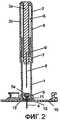
На Фиг.2 представлен вид в разрезе варианта осуществления по Фиг.1 в положении после срабатывания устройства для введения и введения канюли.FIG. 2 is a sectional view of the embodiment of FIG. 1 in the position after the device for insertion and insertion of the cannula is triggered.
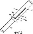
На Фиг.3 представлен вид сбоку устройства для введения по варианту осуществления, показанному на Фиг.1, перед установкой в приемник.FIG. 3 is a side view of the introduction device of the embodiment shown in FIG. 1 before being installed in the receiver.
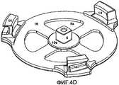
На Фиг.4А представлен вид сбоку устройства для введения по варианту осуществления, показанному на Фиг.1, после установки в приемник перед срабатыванием, на Фиг.4B-F представлен вид сбоку базовых частей, снабженных периферийными приемниками или центральным прямоугольным приемником для части, удерживающей канюлю, имеющей прямоугольный или круглый профиль.Fig. 4A is a side view of the introduction device of the embodiment shown in Fig. 1, after being installed in the receiver before actuation; Fig. 4B-F is a side view of base parts provided with peripheral receivers or a central rectangular receiver for the holding part a cannula having a rectangular or round profile.
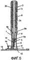
На Фиг.5 представлен вид в разрезе другого варианта осуществления изобретения устройства для введения, где устройство для введения установлено в приемник, а вводная игла находится в отведенном назад положении перед срабатыванием.5 is a cross-sectional view of another embodiment of the device for insertion, where the device for insertion is installed in the receiver and the insertion needle is in the retracted position before being triggered.
На Фиг.6 представлен вид в разрезе варианта осуществления по Фиг.5 в положении после срабатывания устройства для введения и введения канюли.FIG. 6 is a sectional view of the embodiment of FIG. 5 in the position after the device for insertion and insertion of the cannula is triggered.
На Фиг.7 представлен вид сбоку устройства для введения по варианту осуществления на Фиг.5, где первая часть для введения и вторая часть для введения находятся в собранном состоянии.FIG. 7 is a side view of the introduction device of the embodiment of FIG. 5, where the first part for administration and the second part for administration are in an assembled state.
На Фиг.8 представлен вид сбоку устройства для введения по варианту осуществления на Фиг.5, где первая часть для введения отделена от второй части для введения.FIG. 8 is a side view of the introduction device of the embodiment of FIG. 5, where the first administration part is separated from the second administration part.
На Фиг.9 представлен вид сбоку первой части для введения устройства для введения по варианту осуществления на Фиг.5.FIG. 9 is a side view of the first part for introducing the introducing device of the embodiment of FIG. 5.
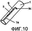
На Фиг.10 представлен другой вид сбоку первой части для введения устройства для введения по варианту осуществления на Фиг.5.Figure 10 presents another side view of the first part for introducing the device for introduction according to the embodiment of figure 5.
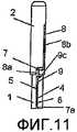
На Фиг.11 представлен вид сбоку устройства для введения по варианту осуществления на Фиг.5, где первая часть для введения помещена во вторую часть для введения.FIG. 11 is a side view of the introduction device of the embodiment of FIG. 5, where the first administration part is placed in the second administration part.
На Фиг.12 представлен вид сбоку устройства для введения по варианту осуществления на Фиг.11, где первая часть для введения повернута вправо.12 is a side view of the introduction device of the embodiment of FIG. 11, where the first introduction portion is rotated to the right.
На Фиг.13 представлен вид сбоку устройства для введения по варианту осуществления на Фиг.11, где устройство для введения находится в положении готовности к срабатыванию и введению канюли.FIG. 13 is a side view of the insertion device of the embodiment of FIG. 11, where the insertion device is in a standby position for deployment and insertion of the cannula.
На Фиг.14 представлен вид сбоку устройства для введения по варианту осуществления на Фиг.11, где устройство для введения установлено в приемник и готово к введению.FIG. 14 is a side view of the insertion device of the embodiment of FIG. 11, where the insertion device is installed in the receiver and is ready for insertion.
На Фиг.15 представлен вид сбоку устройства для введения по варианту осуществления на Фиг.11, где устройство для введения сработало, и введение канюли осуществлено.FIG. 15 is a side view of the insertion device of the embodiment of FIG. 11, where the insertion device has worked and the cannula has been inserted.
На Фиг.16 представлен вид сбоку устройства для введения по варианту осуществления на Фиг.11, где устройство для введения находится в положении после срабатывания и введения канюли и где вводная игла находится в отведенном назад положении.FIG. 16 is a side view of the insertion device of the embodiment of FIG. 11, where the insertion device is in position after the cannula has been triggered and inserted, and where the insertion needle is in the retracted position.
На Фиг.17 представлен вид сбоку первой части для введения устройства для введения по варианту осуществления на Фиг.11, где первая часть для введения удалена из второй части для введения для утилизации.On Fig presents a side view of the first part for the introduction of the device for the introduction of the embodiment of figure 11, where the first part for the introduction is removed from the second part for the introduction for disposal.
ПОДРОБНОЕ ОПИСАНИЕ ПРЕДПОЧТИТЕЛЬНЫХ ВАРИАНТОВ ОСУЩЕСТВЛЕНИЯDETAILED DESCRIPTION OF THE PREFERRED EMBODIMENTS
На Фиг.1 и 2 показан первый вариант осуществления устройства для введения по изобретению в незадействованном положении. На Фиг.1 показано устройство 1, 2 для введения в положении, когда оно еще не сработало, а на Фиг.2 показано устройство 1, 2 для введения в положении после срабатывания и возвращения в незадействованное положение.1 and 2 show a first embodiment of an apparatus for administering an invention in an idle position. Figure 1 shows a
Устройство 1, 2 для введения, показанное на Фиг.1 и 2, содержит первую часть 1 для введения и вторую часть 2 для введения, причем первая часть 1 для введения выполнена в форме фрагмента цилиндрической трубки, открытого с обоих концов и установленного со скольжением внутри второй части 2 для введения, при этом первая часть 1 для введения содержит направляющее средство в виде ответвления 7, которое перемещается по щели 8 второй части 2 для введения. Устройство 1, 2 для введения, кроме того, содержит упругий элемент 3 для возврата первой части 1 для введения в незадействованное положение после срабатывания, причем в незадействованном положении упругий элемент 3 находится в несмещенном состоянии или лишь незначительно смещен. Устройство 1, 2 для введения содержит также удерживающую иглу часть 9 с вводной иглой 6 для введения удерживающей канюлю части 5 в кожу пациента, причем удерживающая канюлю часть 5 содержит канюлю 4 и перегородку 5а. Устройство 1, 2 для введения может быть разъемным образом соединено с приемником 11, в котором удерживающая канюлю часть 5 может быть размещена и удерживаться посредством крюков 12 на приемнике 11, входящих в зацепление с выемками 13, образованными в удерживающей канюлю части 5. Приемник 11 установлен на подложке 10, которая может быть закреплена на коже пациента, например, посредством клейкой установочной площадки.The
Вариант осуществления по Фиг.1 и 2 рассчитан на одноразовое применение всего устройства 1, 2 для введения. В этом варианте осуществления имеется возможность расположить приемник 11 посредством подложки 10 на коже пациента, после чего ввести удерживающую канюлю часть 5 устройства 1, 2 для введения и выбросить устройство 1, 2 для введения с использованной вводной иглой 6 после введения удерживающей канюлю части 5, которая может иметь вид инфузионного набора. Вводная игла 6 в ходе инъекции остается невидимой для пользователя и эта острая игла не представляет опасности.The embodiment of FIGS. 1 and 2 is designed for a single use of the
По варианту осуществления на Фиг.1 и 2 приемник 11 на подложке 10 выполнен в форме цилиндрического выступа, стоящего вертикально, причем приемник 11 предназначен для прочного расположения на нем первой части 1 для введения, а также для приема и закрепления удерживающей канюлю части 5. Приемник 11 неразъемным образом крепится к базовой части 10 и может быть, например, отформован совместно с подложкой 10 или закреплен на подложке 10 после образования самой подложки 10, например, путем склеивания или сварки. Согласно Фиг.1 и 2 базовая часть 10 представлена как сравнительно плоская часть, однако базовая часть 10 может представлять собой любую конструкцию, позволяющую объединить приемник 11 и базовую часть 10 в один блок, который пользователь предпочтительно мог бы носить прямо на коже. Приемник 11 может быть размещен на периферийной части или центральной части подложки 10 для того, чтобы удерживающая канюлю часть 5 могла быть введена под различными углами. Удерживающая канюлю часть 5 может быть введена под углом А к дистальной поверхности подложки 10, отличном от 90°, обычно угол А лежит в пределах от 110° до 170°, где дистальная поверхность подложки 10 образует одну сторону угла, а введенная канюля 4 образует вторую сторону угла. По варианту осуществления на Фиг.1 и 2 приемник 11 расположен по центру подложки 10 с углом А введения, равным 90°.In the embodiment of FIGS. 1 and 2, the
Как показано на Фиг.1 и 2, приемник 11 снабжен крепежным средством, содержащим крюки 12, которые расположены перпендикулярно вертикальному цилиндрическому выступу и параллельно подложке 10. Крюки 12 соответствуют канавкам или выемкам 13, образованным в удерживающей канюлю части 5. Взаимодействие между выемками 13 удерживающей канюлю части 5 и крюками 12 приемника 11 на базовой части 10 обеспечивают крепление удерживающей канюлю части 5 к приемнику 11 после срабатывания устройства для введения. Когда удерживающая канюлю часть 5 и приемник 11 после введения соединены и прикреплены друг к другу, они образуют, к примеру, проход для инъекционной или инфузионной части, которая может быть соединена с переходной частью или фиксирующей частью, например, для части доставки, содержащей емкость и помпу.As shown in FIGS. 1 and 2, the
Как показано на Фиг.1 и 2, устройство 1, 2 для введения представляет собой блок, состоящий из двух частей, где каждая часть блока может быть выполнена как отформованная деталь. Первая часть 1 для введения и вторая часть 2 для введения выполнены как цилиндрические трубки, однако иные формы и профили трубки, такие как шестиугольная, восьмиугольная и т.п., также могут быть использованы. При поставке это одноразовое приспособление может быть в сборке с приемником 11, если оно поставляется в стерильной упаковке, или же оно может быть упаковано отдельно. Если это одноразовое приспособление идет в сборке с приемником 11 в стерильной упаковке, то пользователь сначала распаковывает это устройство в сборке и готовит базовую часть 10 для закрепления на коже пациента, например, путем удаления покровной пленки с установочной площадки, далее пользователь размещает подложку 10 на коже пациента, и, в заключении, вводит удерживающую канюлю часть 5, удаляет устройство 1, 2 для введения и избавляется от него. Если это одноразовое приспособление упаковано отдельно, то пользователь сначала распаковывает устройство 1, 2 для введения и вынимает из стерильной упаковки, затем помещает устройство для введения у кожи пациента, например, в приемник предварительно установленной подложки 10, и, в заключении, пользователь вводит удерживающую канюлю часть 5, удаляет устройство 1, 2 для введения и избавляется от устройства 1, 2 для введения, в котором на этот раз имеется загрязненная вводная игла 6.As shown in FIGS. 1 and 2, the
Первая часть 1 для введения, которая размещена в приемнике 11 на подложке 10, и вторая часть 2 для введения находятся в зацеплении друг с другом. Вторая часть 2 для введения содержит удерживающую иглу часть 9, которая несет вводную иглу 6 для проникновения в кожу пациента и в настоящем варианте осуществления с одноразовым применением эта вторая часть 2 для введения по существу образует удерживающую иглу часть 9. Удерживающая канюлю часть 5, которая несет мягкую канюлю 4, некоторым образом размещается на удерживающей иглу части 9, обычно за счет лишь трения между вводной иглой 6 и мягкой канюлей 4. Устройство 1, 2 для введения, кроме того, снабжено упругим элементом 3, который удерживает две части 1 и 2 для введения в определенном положении, т.е. упругий элемент 3 заставляет первую и вторую части 1, 2 занимать незадействованное положение. В этом варианте осуществления упругий элемент 3 образован спиральной металлической пружиной, однако упругий элемент 3 может быть любого вида, например, резиновым цилиндром и т.п., который может заставить две части 1 и 2 для введения занять незадействованное положение. Когда устройство 1, 2 для введения находится в положении перед срабатыванием, как показано на Фиг.1, упругий элемент 3 находится в несмещенном положении, а когда устройство 1, 2 для введения задействовано путем ручного вдавливания вниз второй части 2 для введения удерживающей канюлю части 5, упругий элемент 3 смещается.The
Как показано в деталях на Фиг.3, внешняя поверхность первой части 1 для введения снабжена выступом в виде цилиндрического ответвления 7, расположенным на части внешней поверхности первой части 1 для введения, который обращен к внутренней поверхности второй части 2 для введения. Ответвление 7 взаимодействует с отверстием в форме щели 8 второй части 2 для введения, причем упомянутая щель 8 содержит три части 8а, 8b и 8с по существу в форме буквы «Z», где длинная часть 8b практически параллельна направлению введения, короткая часть 8с по существу перпендикулярна направлению введения, а короткая часть 8а расположена под углом к короткой части 8с. Если ответвление 7 первой части 1 для введения находится в заблокированном положении в щели 8, т.е. это ответвление расположено в одной из коротких частей 8а или 8с щели 8, то устройство для введения заблокировано в направлении введения. Если упругий элемент 3 незначительно смещен в незадействованном положении, то ответвление 7 первой части 1 для введения поджимается в самый дальний конец короткой части 8а щели 8. Первая часть 1 для введения в этом варианте осуществления обеспечивает средство защиты от иглы до и после срабатывания устройства 1, 2 для введения.As shown in detail in FIG. 3, the outer surface of the
На Фиг.4А показано то же одноразовое устройство для введения, что и на Фиг.1 и 2, расположенное под некоторым углом, где устройство 1, 2 для введения готово к срабатыванию, т.е. в том же положении, что и на Фиг.1. Гибкая подложка 10 снабжена средством 14 крепления для закрепления устройства доставки (не показано), которое может содержать, например, емкость для лекарственного средства вместе со средством транспортировки в виде помпы и т.п.Fig. 4A shows the same disposable insertion device as in Figs. 1 and 2, located at a certain angle, where the
При срабатывании одноразового устройства 1, 2 для введения, показанного на Фиг.1, 2 и 4, с целью закрепления удерживающей канюлю части 5 в виде, например, инфузионного набора, инъекционной части или прохода 5, 11 на коже пациента вторая часть 2 для введения сначала поворачивается вокруг продольной оси, задаваемой направлением введения, для того, чтобы переместить ответвление 7 из коротких частей 8а и 8с щели 8 в угол между короткой частью 8с и длинной частью 8b щели 8, создавая, таким образом, возможность для ответвления 7 перемещаться в продольном направлении по длинной части 8b щели 8. Вторая часть 2 для введения после этого вручную вдавливается вниз в направлении пациента, смещая пружину 3, и в то же время ответвление 7 перемещается по длинной части 8b щели 8 в направлении дистального конца второй части 2 для введения, а удерживающая иглу часть 9 и удерживающая канюлю часть 5, благодаря вдавливанию второй части 2 для введения, одновременно перемещаются в направлении кожи пациента. Вводная игла 6 проникает в кожу и канюля вводится пациенту, когда устройство для введения достигает положения, соответствующего его полному срабатыванию. Как показано на Фиг.2, крюки 12 приемника 11 входят в зацепление с выемками 13 удерживающей канюлю части 5, тем самым прикрепляя удерживающую канюлю часть 5 к приемнику 11. Когда удерживающая канюлю часть 5 закреплена на приемнике 11 давление на вторую часть 2 для введения снимается путем прекращения давления вручную, что приводит к перемещению пружины 3 в свое несмещенное положение и, тем самым, к перемещению ответвления 7 по щели 8 в направлении самого отдаленного конца щели 8, и, в то же время, к перемещению вводной иглы 6 во внутреннее пространство первой части 1 для введения. Вторая часть 2 для введения после этого поворачивается и ответвление 7 заходит в короткую часть 8с щели 8 для блокировки первой части 1 и второй части 2 для введения, и, в то же время, для удерживания использованной вводной иглы 6 на своем месте внутри устройства 1, 2 для введения. В этом варианте осуществления обеспечивается одноразовое устройство 1, 2 для инъекций с защитой от иглы, где игла 6 всегда остается невидимой для пользователя, и такое устройство 1, 2 для инъекций может быть выброшено после использования без риска пораниться острой иглой.When the
На Фиг.4В-F показаны другие варианты осуществления базовой части 10 и соответствующей удерживающей канюлю части 5, должным образом расположенных устройством 1, 2 для инъекций по изобретению.FIGS. 4B-F show other embodiments of the
На Фиг.4В расположенный на периферии приемник имеет квадратный профиль, в который помещается удерживающая канюлю часть 5, имеющая круглый профиль. Для того, чтобы эту удерживающую канюлю часть 5 должным образом расположить на базовой части 10 требуется устройство 1, 2 для инъекций, которое имело бы квадратный наружный и круглый внутренний профиль, или, по меньшей мере, инструмент для введения, который имел бы части и поверхности, выполненные с возможностью вхождения в наружную зону в форме квадрата, образованную приемником, а также части и поверхности, которые обеспечили бы пространство для вхождения в него со скольжением круглого приспособления для удерживания канюли.4B, a peripherally located receiver has a square profile into which a cannula-holding
На Фиг.4С расположенный на периферии приемник имеет квадратный профиль, в который помещается удерживающая канюлю часть 5, имеющая квадратный профиль. Для того, чтобы эту удерживающую канюлю часть 5 должным образом расположить на базовой части 10 требуется устройство 1, 2 для инъекций, которое имело бы квадратный наружный и квадратный внутренний профиль, или, по меньшей мере, инструмент для введения, который имел бы части и поверхности, выполненные с возможностью вхождения в наружную зону в форме квадрата, образованную приемником, а также части и поверхности, которые обеспечили бы пространство для вхождения в него со скольжением квадратного приспособления для удерживания канюли.In FIG. 4C, a peripheral receiver has a square profile in which a cannula-holding
На Фиг.4D показан расположенный по центру приемник без вертикальных стенок, направляющий инструмент для введения для занятия своего положения. Вместо этого незначительно приподнятый контур центральной плиты 10а базовой части 10, соответствующей части проксимального конца инструмента для введения, обозначает верное положение инструмента для введения в процессе введения удерживающей канюлю части 5.Fig. 4D shows a centrally located receiver without vertical walls, a guide tool for insertion to take up its position. Instead, the slightly elevated contour of the
На Фиг.4Е показана базовая часть 10 с установленным по центру приемником, который имеет вертикальные стенки, обеспечивающие приемнику квадратный профиль. Базовая часть показана до введения в нее удерживающей канюлю части 5.FIG. 4E shows a
На Фиг.4F показан расположенный по центру приемник 11, имеющий квадратный профиль, в который помещена удерживающая канюлю часть 5, имеющая квадратный профиль.FIG. 4F shows a centrally located
В другом варианте осуществления, как показано на Фиг.5 и 6, устройство 1, 2 для введения предназначено для многократного использования. На Фиг.5 показано устройство 1, 2 для введения в еще незадействованном положении до введения, а на Фиг.6 показано устройство 1, 2 для введения в положении после срабатывания, где канюля уже введена.In another embodiment, as shown in FIGS. 5 and 6, the
Как показано на Фиг.5 и 6, устройство 1, 2 для инъекций содержит первую часть 1 для введения и вторую часть 2 для введения, причем первая часть 1 для введения установлена со скольжением внутри второй части 2 для введения с упругим элементом 3 для удерживания первой части 1 для введения и второй части 2 для введения на своих местах, а также для приведения в действие устройства 1, 2 для введения удерживающей канюлю части 5, снабженной канюлей 4 и перегородкой 5а, причем удерживающая канюлю часть 5 соединена с удерживающей иглу частью 9, которая снабжена вводной иглой 6 для введения канюли 4 в кожу пациента. В этом варианте осуществления удерживающая иглу часть 9 является отдельной удерживающей иглу частью 9, которая разъемным образом крепится к части 2 для введения, например, с помощью шпунтового соединения 9а, 9b. Устройство 1, 2 для введения разъемным образом соединено с приемником 11 посредством крюков 12 на приемнике 11, которые входят в зацепление с выемками 13, образованными в удерживающей канюлю части 5, причем приемник 11 установлен на базовой части 10, сама же базовая часть 10 закреплена на коже пациента. Подложка 10 снабжена средством 14 крепления для прикрепления устройства доставки (не показано).As shown in FIGS. 5 and 6, the
На Фиг.7 и 8 в деталях показано межкомпонентное соединение в состоящем из двух блоков устройстве 1, 2 для введения по настоящему изобретению, предназначенном для многократного использования. Первая часть 1 для введения на своей наружной поверхности снабжена выступом в виде цилиндрического ответвления 7, расположенным на поверхности, обращенной ко второй части 2 для введения. Ответвление 7 взаимодействует с отверстием в форме щели 8 во второй части 2 для введения, причем упомянутая щель 8 выполнена в форме по существу ступеньки с длинной продольной частью 8b, короткой продольной частью 8а и поперечной короткой частью 8с, которая разделяет две продольные части 8а и 8b, причем эти две продольные части 8а и 8b параллельны и сдвинуты относительно друг друга. Поперечная короткая часть 8с может быть снабжена непоказанным здесь положением покоя для ответвления 7, например, в виде углубления на проксимальном крае щели 8с, причем это углубление должно быть достаточно широким, чтобы ответвление 7 могло в него войти для того, чтобы необходимо было сжать вместе две части для введения прежде, чем ответвление могло переместиться либо влево, либо вправо. Короткая продольная часть 8а щели 8 образует отверстие на проксимальном крае второй части 2 для введения; короткая продольная часть 8а, таким образом, обеспечивает средство для соединения или разъединения первой части 1 для введения со второй частью 2 для введения. В этом варианте осуществления создается возможность обеспечить взаимодействие двух блоков устройства 1, 2 для введения, состоящего из двух блоков, и, тем самым, образовать средство защиты от иглы как до, так и после введения в действие устройства 1, 2 для введения удерживающей канюлю части 5.Figures 7 and 8 show in detail the interconnect in a two-
Когда устройство 1, 2 для введения находится в собранном виде ответвление 7 первой части 1 для введения расположено в продольной щели 8а второй части 2 для введения, и первая и вторая части для введения сжимаются вместе до тех пор, пока ответвление 7 достигнет угла между продольной щелью 8а и короткой поперечной частью 8с щели 8. После этого вторая часть 2 для введения поворачивается влево, располагая ответвление 7 в короткой поперечной части 8с щели 8, помещая, тем самым, устройство для введения в заблокированное положение. Упругий элемент 3 в этом положении находится в несмещенном состоянии или лишь незначительно смещен. Устройство 1, 2 для введения теперь готово к использованию. Таким же образом устройство для введения может быть разобрано путем поворота в обратную сторону второй части 2 для введения, что приводит к перемещению ответвления 7 из короткой поперечной части 8с щели 8 в короткую продольную щель 8а и отводу второй части 2 для введения от первой части 1 для введения, что приводит к выходу ответвления 7 через короткую продольную щель 8а и, тем самым, к освобождению первой части 1 для введения от второй части 2 для введения.When the
В этом варианте осуществления создается возможность удалить и утилизировать только первую часть 1 для введения и вводную иглу 6 состоящего из двух блоков устройства 1, 2 для введения и, тем самым, обеспечить возможность повторного использования второй части 2 для введения совместно с новой замещенной первой частью 1 для введения, включающей в себя новую вводную иглу 6. Кроме того, в этом варианте осуществления создается возможность для первой части 1 для введения образовать средство защиты от иглы как до, так и после введения в действие устройства 1, 2 для введения удерживающей канюлю части 5.In this embodiment, it is possible to remove and dispose of only the
Как показано в деталях на Фиг.9 и 10, первая часть 1 для введения по настоящему варианту осуществления с многократным использованием содержит ответвление 7 для зацепления со второй частью 2 для введения, а также средство в виде выступающего ответвления 9с, которое входит в зацепление с щелью 7а по существу L-образной формы для блокирования или разблокирования удерживающей иглу части 9 в процессе введения. Удерживающая иглу часть 9 содержит вводную иглу 6 (не показана), причем удерживающая иглу часть 9 прикреплена к удерживающей канюлю части 5.As shown in detail in FIGS. 9 and 10, the first
На Фиг.11-17 показано устройство 1, 2 для введения в действии. На Фиг.11 показана установка и сборка одноразовой первой части 1 для введения в многоразовую вторую часть 2 для введения. Ответвление 7 первой части 1 для введения устанавливается в короткую продольную щель 8а и перемещается к поперечной короткой части 8с, которая отделяет короткую продольную щель 8а от длинной продольной щели 8b в щели 8, имеющей форму ступени. Одноразовая первая часть 1 для введения содержит удерживающую иглу часть 9 с вводной иглой 6, прикрепленной к удерживающей канюлю части 5. Удерживающая иглу часть 9 зафиксирована по отношению ко второй части 2 для введения, а ответвление 9с, выступающее от внешней поверхности 1 удерживающей иглу части 9 входит в зацепление с щелью 7а первой части 1 для введения, при этом выступающее ответвление 9с установлено в короткой части L-образной щели 7а для обеспечения заблокированного положения удерживающей иглу части 9 по отношению к первой части 1 для введения. Таким образом, вводная игла 6 заблокирована внутри первой части 1 для введения и остается безопасной и скрытой от пациента.11-17 show a
На Фиг.12 первая часть 1 для введения устройства 1, 2 для введения поворачивается вправо, перемещая тем самым ответвление 7 в поперечную щель 8с, отделяющую короткую продольную щель 8а от длинной продольной щели 8b, таким образом обеспечивая блокирование первой части 1 для введения в продольном направлении по отношению ко второй части 2 для введения. Ответвление 9с удерживающей иглу части 9, благодаря повороту первой части 1 для введения, одновременно перемещается влево в короткую часть L-образной щели 7а, однако ответвление 9с остается в положении, когда удерживающая иглу часть 9 заблокирована в продольном направлении. Упругий элемент 3 для приведения в действие устройства 1, 2 для введения в этом положении находится в несмещенном состоянии или лишь незначительно смещен.12, the
На Фиг.13 показана установка ответвления 7 в конечной точке поворота первой части 1 для введения. Ответвление 7 достигло угла между длинной продольной щелью 8b и поперечной щелью 8с, и дальнейший поворот первой части 1 для введения невозможен. Ответвление 9с удерживающей иглу части 9 в процессе поворота первой части 1 для введения одновременно перемещается в угол по существу L-образной щели 7а, оставляя удерживающую иглу часть 9 в разблокированном положении. Упругий элемент 3 для приведения в действие устройства 1, 2 для введения по-прежнему находится в несмещенном положении. Таким образом, устройство 1, 2 для введения остается в положении, готовом для приведения в действие и введения канюли 4.On Fig shows the installation of the
На Фиг.14 показано то же устройство 1, 2 для введения, что и на Фиг.13, в положении готовности для приведения в действие и введения удерживающей канюлю части 5, где устройство 1, 2 для введения установлено в приемнике 11, соединенном с подложкой 10. Ответвление 7 находится в разблокированном положении в углу между длинной частью 8b щели 8 и короткой поперечной частью 8с.Fig. 14 shows the
На Фиг.15 показано приведение в действие устройства 1, 2 для введения. Вторая часть 2 для введения вручную поджимается вниз в направлении кожи пациента, тем самым смещая упругий элемент 3, и первая часть 1 для введения со скольжением входит во вторую часть 2 для введения. В то же время, оказываемое вручную давление заставляет ответвление 7 скользить по длинной продольной щели 8b второй части 2 для введения, а ответвление 9с - скользить по продольной щели 7а первой части 1 для введения, вследствие чего вводная игла 6 и канюля 4 выходят из первой части 1 для введения, вводная игла 6 прокалывает кожу пациента и вводит канюлю 4 пациенту. Удерживающая канюлю часть 5 входит в зацепление с приемником 11 на подложке 10, что обеспечивает закрепление удерживающей канюлю части 5 на приемнике 11.On Fig shows the actuation of the
На Фиг.16 показано устройство 1, 2 для введения, установленное на приемнике 11, причем приемник 11 соединен с подложкой 10. Устройство 1, 2 для введения показано в положении после введения пациенту канюли 4. Давление вручную на вторую часть 2 для введения прекращено, что приводит к перемещению упругого элемента 3 в несмещенное положение, а это приводит к скольжению ответвления 7 вниз по длинной продольной щели 8b к поперечной щели, отделяющей короткую продольную щель 8а от длинной продольной щели 8b, а ответвления 9с первой части 1 для введения - к скольжению вверх в продольной щели 7а. Таким образом, упругий элемент 3 отводит назад вводную иглу 6, прикрепленную к удерживающей иглу части 9, от удерживающей канюлю части 5 в первую часть 1 для введения, оставляя канюлю 4 в пациенте. Вторая часть 2 для введения поворачивается влево, что приводит к перемещению ответвления 7 в поперечную часть, разделяющую длинную и короткую продольные щели 8а, 8b, а ответвления 9с - к перемещению в короткую часть по существу L-образной щели 7а, тем самым блокируя первую часть для введения по отношению ко второй части для введения, а также блокируя удерживающую иглу часть 9 внутри первой части 1 для введения. Устройство 1, 2 для введения после этого следует безопасным образом вынуть из приемника 11, при этом вводная игла 6, не представляя опасности, находится внутри первой части 1 для введения и остается невидимой для пациента.FIG. 16 shows an
На Фиг.17 показана первая часть 1 для введения в положении после использования, где первая часть 1 для введения, включающая в себя использованную вводную иглу 6 (не показана), освобождена от второй части 2 для введения для утилизации. Удерживающая иглу часть 9 (не показана) заблокирована в первой части 1 для введения посредством ответвления 9с в по существу L-образной щели 7а, тем самым удерживая использованную вводную иглу 6 (не показана) внутри первой части 1 для введения по соображениям безопасности при утилизации.On Fig shows the
По настоящему варианту осуществления с многоразовым применением использованная вводная игла может быть безопасным образом как удалена, так и утилизирована после применения. Использованная первая часть для введения может быть заменена на новую первую часть для введения, содержащую новую иглу и удерживающую иглу часть, так же, как и новую удерживающую канюлю часть с новой канюлей, и собрана с использованной второй частью 2 для введения. Таким образом, создается возможность повторно использовать вторую часть для введения и заменять лишь первую часть для введения, тем самым сокращая расходы.In a reusable embodiment of the present embodiment, the used introductory needle can be safely removed and disposed of after use. The used first administration part can be replaced with a new first administration part containing a new needle and needle holding part, as well as a new cannula holding part with a new cannula, and assembled with the
Claims (17)
Translated fromRussianвторая часть (2) для введения содержит часть (9) для удерживания иглы с инъекционной иглой (6), а инъекционная игла (6) разъемным образом объединена с канюлей (4) части (5) для удерживания канюли, причем часть (9) для удерживания иглы либо составляет часть второй части (2) для введения, либо фиксирована относительно второй части (2) для введения,
первая часть (1) для введения накрывает инъекционную иглу (6) в ее незадействованном положении, а в задействованном положении инъекционная игла (6) выступает за пределы первой части (1) для введения,
по меньшей мере часть второй части (2) для введения и первая часть (1) для введения могут перемещаться относительно друг друга между по меньшей мере одним задействованным положением и по меньшей мере одним незадействованным положением,
а также вторая часть (2) для введения выходит за пределы дистального конца первой части (1) для введения, когда устройство находится в задействованном положении,
которое характеризуется тем, что упругий элемент (3) способствует переводу второй части (2) для введения, соединенной с инъекционной иглой (6), из переднего, т.е. задействованного положения, в отведенное назад, т.е. незадействованное положение.1. A device for introducing a cannula into the subcutaneous layer of a patient, said device comprising a first part (1) for administration and a second part (2) for administration, a part (5) for holding the cannula provided with a cannula (4), and an injection needle ( 6) where
the second part (2) for administration contains part (9) for holding the needle with the injection needle (6), and the injection needle (6) is detachably combined with the cannula (4) of part (5) for holding the cannula, and part (9) for holding the needle either forms part of the second part (2) for insertion, or is fixed relative to the second part (2) for insertion,
the first part (1) for injection covers the injection needle (6) in its idle position, and in the activated position, the injection needle (6) extends beyond the first part (1) for injection,
at least a portion of the second part (2) for administration and the first part (1) for administration can be moved relative to each other between at least one engaged position and at least one unused position,
and the second part (2) for insertion extends beyond the distal end of the first part (1) for insertion when the device is in the engaged position,
which is characterized in that the elastic element (3) facilitates the translation of the second part (2) for insertion connected to the injection needle (6) from the front, i.e. the involved position, in the laid back, i.e. unused position.
Applications Claiming Priority (5)
| Application Number | Priority Date | Filing Date | Title |
|---|---|---|---|
| US83494506P | 2006-08-02 | 2006-08-02 | |
| DKPA200601028 | 2006-08-02 | ||
| US60/834,945 | 2006-08-02 | ||
| DKPA200601028 | 2006-08-02 | ||
| PCT/DK2007/050104WO2008014792A1 (en) | 2006-08-02 | 2007-08-02 | Insertion device |
Publications (2)
| Publication Number | Publication Date |
|---|---|
| RU2009107031A RU2009107031A (en) | 2010-09-10 |
| RU2452520C2true RU2452520C2 (en) | 2012-06-10 |
Family
ID=40364154
Family Applications (1)
| Application Number | Title | Priority Date | Filing Date |
|---|---|---|---|
| RU2009107031/14ARU2452520C2 (en) | 2006-08-02 | 2007-08-02 | Device for introduction |
Country Status (11)
| Country | Link |
|---|---|
| US (1) | US20100004597A1 (en) |
| EP (1) | EP2046420B1 (en) |
| JP (1) | JP2009545342A (en) |
| KR (1) | KR20090037471A (en) |
| CN (1) | CN101500626B (en) |
| AU (1) | AU2007280851B2 (en) |
| CA (1) | CA2659077A1 (en) |
| MX (1) | MX2009000876A (en) |
| NO (1) | NO20090928L (en) |
| RU (1) | RU2452520C2 (en) |
| WO (1) | WO2008014792A1 (en) |
Cited By (2)
| Publication number | Priority date | Publication date | Assignee | Title |
|---|---|---|---|---|
| RU2574368C2 (en)* | 2010-06-30 | 2016-02-10 | Ритрэктэбл Текнолоджиз, Инк. | Medical device with retracted needle and movable piston seal |
| US9642970B2 (en) | 2010-06-30 | 2017-05-09 | Retractable Technologies, Inc. | Syringe with retractable needle and moveable plunger seal |
Families Citing this family (109)
| Publication number | Priority date | Publication date | Assignee | Title |
|---|---|---|---|---|
| US7381184B2 (en) | 2002-11-05 | 2008-06-03 | Abbott Diabetes Care Inc. | Sensor inserter assembly |
| USD902408S1 (en) | 2003-11-05 | 2020-11-17 | Abbott Diabetes Care Inc. | Analyte sensor control unit |
| MXPA06010784A (en) | 2004-03-26 | 2006-12-15 | Unomedical As | Injector device for infusion set. |
| US8062250B2 (en) | 2004-08-10 | 2011-11-22 | Unomedical A/S | Cannula device |
| US20090105569A1 (en) | 2006-04-28 | 2009-04-23 | Abbott Diabetes Care, Inc. | Introducer Assembly and Methods of Use |
| US8333714B2 (en) | 2006-09-10 | 2012-12-18 | Abbott Diabetes Care Inc. | Method and system for providing an integrated analyte sensor insertion device and data processing unit |
| US10226207B2 (en) | 2004-12-29 | 2019-03-12 | Abbott Diabetes Care Inc. | Sensor inserter having introducer |
| US9743862B2 (en) | 2011-03-31 | 2017-08-29 | Abbott Diabetes Care Inc. | Systems and methods for transcutaneously implanting medical devices |
| US7883464B2 (en) | 2005-09-30 | 2011-02-08 | Abbott Diabetes Care Inc. | Integrated transmitter unit and sensor introducer mechanism and methods of use |
| US20110190603A1 (en)* | 2009-09-29 | 2011-08-04 | Stafford Gary A | Sensor Inserter Having Introducer |
| US9572534B2 (en) | 2010-06-29 | 2017-02-21 | Abbott Diabetes Care Inc. | Devices, systems and methods for on-skin or on-body mounting of medical devices |
| US7731657B2 (en)* | 2005-08-30 | 2010-06-08 | Abbott Diabetes Care Inc. | Analyte sensor introducer and methods of use |
| US9398882B2 (en) | 2005-09-30 | 2016-07-26 | Abbott Diabetes Care Inc. | Method and apparatus for providing analyte sensor and data processing device |
| US20110073475A1 (en)* | 2009-08-29 | 2011-03-31 | Abbott Diabetes Care Inc. | Analyte Sensor |
| US7697967B2 (en) | 2005-12-28 | 2010-04-13 | Abbott Diabetes Care Inc. | Method and apparatus for providing analyte sensor insertion |
| US8512243B2 (en) | 2005-09-30 | 2013-08-20 | Abbott Diabetes Care Inc. | Integrated introducer and transmitter assembly and methods of use |
| US8571624B2 (en)* | 2004-12-29 | 2013-10-29 | Abbott Diabetes Care Inc. | Method and apparatus for mounting a data transmission device in a communication system |
| US20070027381A1 (en)* | 2005-07-29 | 2007-02-01 | Therasense, Inc. | Inserter and methods of use |
| US8029441B2 (en) | 2006-02-28 | 2011-10-04 | Abbott Diabetes Care Inc. | Analyte sensor transmitter unit configuration for a data monitoring and management system |
| US9788771B2 (en) | 2006-10-23 | 2017-10-17 | Abbott Diabetes Care Inc. | Variable speed sensor insertion devices and methods of use |
| US9259175B2 (en)* | 2006-10-23 | 2016-02-16 | Abbott Diabetes Care, Inc. | Flexible patch for fluid delivery and monitoring body analytes |
| US7985199B2 (en)* | 2005-03-17 | 2011-07-26 | Unomedical A/S | Gateway system |
| CA2612664A1 (en)* | 2005-06-28 | 2007-01-04 | Unomedical A/S | Packing for infusion set and method of applying an infusion set |
| EP1762259B2 (en) | 2005-09-12 | 2025-01-01 | Unomedical A/S | Inserter for an infusion set with a first and second spring units |
| US9521968B2 (en)* | 2005-09-30 | 2016-12-20 | Abbott Diabetes Care Inc. | Analyte sensor retention mechanism and methods of use |
| DK1962926T3 (en) | 2005-12-23 | 2009-09-28 | Unomedical As | injection device |
| US11298058B2 (en) | 2005-12-28 | 2022-04-12 | Abbott Diabetes Care Inc. | Method and apparatus for providing analyte sensor insertion |
| CA2636034A1 (en) | 2005-12-28 | 2007-10-25 | Abbott Diabetes Care Inc. | Medical device insertion |
| US20090218243A1 (en)* | 2006-02-13 | 2009-09-03 | Unomedical A/S | Packing for Injection Device |
| WO2007098771A2 (en)* | 2006-02-28 | 2007-09-07 | Unomedical A/S | Inserter for infusion part and infusion part provided with needle protector |
| CA2653631A1 (en) | 2006-06-07 | 2007-12-13 | Unomedical A/S | Inserter |
| CA2653764A1 (en) | 2006-06-09 | 2007-12-13 | Unomedical A/S | Mounting pad |
| JP2009545341A (en) | 2006-08-02 | 2009-12-24 | ウノメディカル アクティーゼルスカブ | Cannula and delivery device |
| EP1917990A1 (en) | 2006-10-31 | 2008-05-07 | Unomedical A/S | Infusion set |
| ATE514442T1 (en)* | 2007-02-02 | 2011-07-15 | Unomedical As | GATEWAY DEVICE |
| KR20090117749A (en)* | 2007-02-02 | 2009-11-12 | 우노메디컬 에이/에스 | Drug supply |
| WO2008092782A1 (en)* | 2007-02-02 | 2008-08-07 | Unomedical A/S | Injection site for injecting medication |
| WO2008150917A1 (en)* | 2007-05-31 | 2008-12-11 | Abbott Diabetes Care, Inc. | Insertion devices and methods |
| DK2150195T3 (en)* | 2007-06-06 | 2010-12-06 | Unomedical As | Gas sterilized packaging |
| EP2155311B1 (en) | 2007-06-20 | 2013-01-02 | Unomedical A/S | A method and an apparatus for making a catheter |
| WO2008155377A1 (en)* | 2007-06-20 | 2008-12-24 | Unomedical A/S | Cannula insertion device with automatic needle retraction comprising only one spring |
| US8002752B2 (en)* | 2007-06-25 | 2011-08-23 | Medingo, Ltd. | Protector apparatus |
| AU2008270327A1 (en) | 2007-07-03 | 2009-01-08 | Unomedical A/S | Inserter having bistable equilibrium states |
| DE602008005153D1 (en) | 2007-07-10 | 2011-04-07 | Unomedical As | INSERT WITH TWO SPRINGS |
| AU2008277763B2 (en)* | 2007-07-18 | 2011-11-10 | Unomedical A/S | Insertion device with pivoting action |
| EP2200677A1 (en)* | 2007-09-17 | 2010-06-30 | ICU Medical, Inc. | Insertion devices for infusion devices |
| AR070764A1 (en)* | 2007-12-07 | 2010-05-05 | Pyng Medical Corp | APPLIANCES AND METHODS TO ENTER OSEOS PORTALS |
| US20090204077A1 (en)* | 2008-02-13 | 2009-08-13 | Hasted Soren B | Moulded Connection Between Cannula and Delivery Part |
| WO2009098291A1 (en)* | 2008-02-08 | 2009-08-13 | Unomedical A/S | Assembly comprising inserter, cannula part and base part |
| KR20100132495A (en)* | 2008-02-08 | 2010-12-17 | 우노메디컬 에이/에스 | Injector assembly |
| ATE522240T1 (en)* | 2008-02-13 | 2011-09-15 | Unomedical As | SEAL BETWEEN A CANNULAR PART AND A FLUID PATH |
| US9566384B2 (en) | 2008-02-20 | 2017-02-14 | Unomedical A/S | Insertion device with horizontally moving part |
| US20110036844A1 (en)* | 2008-02-25 | 2011-02-17 | Unomedical A/S | Bubble Shaped Membrane and Use of Such Membrane in a Device |
| EP2293831A1 (en)* | 2008-07-07 | 2011-03-16 | Unomedical A/S | Inserter for transcutaneous device |
| BRPI0919548A2 (en)* | 2008-09-29 | 2015-12-08 | Unomedical As | insert package |
| AU2009331635A1 (en) | 2008-12-22 | 2011-06-23 | Unomedical A/S | Medical device comprising adhesive pad |
| US9402544B2 (en)* | 2009-02-03 | 2016-08-02 | Abbott Diabetes Care Inc. | Analyte sensor and apparatus for insertion of the sensor |
| JP5396980B2 (en)* | 2009-04-13 | 2014-01-22 | ニプロ株式会社 | Insertion device |
| WO2010138856A1 (en) | 2009-05-29 | 2010-12-02 | Abbott Diabetes Care Inc. | Medical device antenna systems having external antenna configurations |
| AU2010277755A1 (en) | 2009-07-30 | 2012-02-02 | Unomedical A/S | Inserter device with horizontal moving part |
| KR20120047896A (en) | 2009-08-07 | 2012-05-14 | 우노메디컬 에이/에스 | Delivery device with sensor and one or more cannulas |
| WO2011026130A1 (en)* | 2009-08-31 | 2011-03-03 | Abbott Diabetes Care Inc. | Inserter device including rotor subassembly |
| WO2011026150A1 (en)* | 2009-08-31 | 2011-03-03 | Abbott Diabetes Care Inc. | Flexible mounting unit and cover for a medical device |
| WO2011026149A1 (en)* | 2009-08-31 | 2011-03-03 | Abbott Diabetes Care Inc. | Mounting unit having a sensor and associated circuitry |
| EP3001194B1 (en) | 2009-08-31 | 2019-04-17 | Abbott Diabetes Care, Inc. | Medical devices and methods |
| WO2011041531A1 (en) | 2009-09-30 | 2011-04-07 | Abbott Diabetes Care Inc. | Interconnect for on-body analyte monitoring device |
| US9339599B2 (en) | 2009-12-21 | 2016-05-17 | Sorin Group Usa, Inc. | Self-dilating cannula |
| USD924406S1 (en) | 2010-02-01 | 2021-07-06 | Abbott Diabetes Care Inc. | Analyte sensor inserter |
| LT3622883T (en) | 2010-03-24 | 2021-08-25 | Abbott Diabetes Care, Inc. | Medical device inserters and processes of inserting and using medical devices |
| KR20130018783A (en) | 2010-03-30 | 2013-02-25 | 우노메디컬 에이/에스 | Medical device |
| US11064921B2 (en) | 2010-06-29 | 2021-07-20 | Abbott Diabetes Care Inc. | Devices, systems and methods for on-skin or on-body mounting of medical devices |
| EP2433663A1 (en) | 2010-09-27 | 2012-03-28 | Unomedical A/S | Insertion system |
| EP2436412A1 (en) | 2010-10-04 | 2012-04-04 | Unomedical A/S | A sprinkler cannula |
| EP2460553A1 (en)* | 2010-12-02 | 2012-06-06 | Debiotech S.A. | Device for inserting needles |
| USD694397S1 (en) | 2011-02-28 | 2013-11-26 | Abbott Diabetes Care Inc. | Medical device inserter |
| US8795253B2 (en) | 2011-04-05 | 2014-08-05 | Sorin Group Italia S.R.L. | Bi-directional perfusion cannula |
| ITFI20110116A1 (en)* | 2011-06-07 | 2012-12-08 | Mattia Glauber | ARTERIAL CANNULA FOR CARDIAC SURGERY. |
| WO2013050277A1 (en) | 2011-10-05 | 2013-04-11 | Unomedical A/S | Inserter for simultaneous insertion of multiple transcutaneous parts |
| EP2583715A1 (en) | 2011-10-19 | 2013-04-24 | Unomedical A/S | Infusion tube system and method for manufacture |
| US9440051B2 (en) | 2011-10-27 | 2016-09-13 | Unomedical A/S | Inserter for a multiplicity of subcutaneous parts |
| ES2666386T3 (en) | 2011-12-07 | 2018-05-04 | Becton, Dickinson And Company | Needle protection sets and infusion devices for use with them |
| CA2858199C (en) | 2011-12-07 | 2020-05-12 | Becton, Dickinson And Company | Infusion device with releasable fluid connector |
| EP2713879B1 (en) | 2011-12-11 | 2017-07-26 | Abbott Diabetes Care, Inc. | Analyte sensor devices, connections, and methods |
| USD747459S1 (en) | 2012-12-07 | 2016-01-12 | Becton, Dickinson And Company | Infusion set assembly |
| USD747458S1 (en) | 2012-12-07 | 2016-01-12 | Becton, Dickinson And Company | Infusion set insertion needle assembly |
| USD756504S1 (en) | 2012-12-07 | 2016-05-17 | Becton, Dickinson And Company | Infusion set base |
| WO2015118550A2 (en) | 2014-02-10 | 2015-08-13 | Elcam Medical Agricultural Cooperative Association Ltd. | Semi disposable auto injector |
| JP6509915B2 (en) | 2014-03-07 | 2019-05-08 | シー・アール・バード・インコーポレーテッドC R Bard Incorporated | Stabilization and guiding device for accessing embedded access port and related method |
| JP6409376B2 (en)* | 2014-07-09 | 2018-10-24 | 住友ベークライト株式会社 | Medical needle and support member for medical needle |
| CH709930A2 (en) | 2014-07-29 | 2016-01-29 | Tecpharma Licensing Ag | Insertion device for an infusion. |
| KR101644824B1 (en)* | 2014-10-22 | 2016-08-03 | 주식회사 원메드텍 | Tendon Catheter |
| US10213139B2 (en) | 2015-05-14 | 2019-02-26 | Abbott Diabetes Care Inc. | Systems, devices, and methods for assembling an applicator and sensor control device |
| WO2016183493A1 (en) | 2015-05-14 | 2016-11-17 | Abbott Diabetes Care Inc. | Compact medical device inserters and related systems and methods |
| US10850036B2 (en) | 2015-08-27 | 2020-12-01 | E3D Agricultural Cooperative Association | Reusable automatic injection device |
| US11260173B2 (en) | 2016-09-15 | 2022-03-01 | Becton, Dickinson And Company | Needle assembly for subcutaneous infusion set |
| US11071478B2 (en) | 2017-01-23 | 2021-07-27 | Abbott Diabetes Care Inc. | Systems, devices and methods for analyte sensor insertion |
| DE102018101283A1 (en)* | 2018-01-22 | 2019-07-25 | Eyesense Gmbh | Injector for transcutaneously introducing a sensor into a patient |
| WO2019147857A1 (en) | 2018-01-26 | 2019-08-01 | Bard Peripheral Vascular, Inc. | Systems and methods for locating and identifying an implanted medical device |
| EP3616736B1 (en)* | 2018-08-27 | 2022-04-06 | Roche Diabetes Care GmbH | Method and devices for receiving a cannula |
| CA3126999A1 (en) | 2019-02-22 | 2020-08-27 | Deka Products Limited Partnership | Infusion set and inserter assembly systems and methods |
| USD1002852S1 (en) | 2019-06-06 | 2023-10-24 | Abbott Diabetes Care Inc. | Analyte sensor device |
| EP4037546A1 (en)* | 2019-10-01 | 2022-08-10 | F. Hoffmann-La Roche AG | A holder for a medical device |
| CA3188510A1 (en) | 2020-08-31 | 2022-03-03 | Vivek S. RAO | Systems, devices, and methods for analyte sensor insertion |
| JP7581516B2 (en) | 2020-11-24 | 2024-11-12 | バード・ペリフェラル・バスキュラー・インコーポレーテッド | Access needle indicator system for locating and accessing subcutaneous medical devices - Patents.com |
| USD999913S1 (en) | 2020-12-21 | 2023-09-26 | Abbott Diabetes Care Inc | Analyte sensor inserter |
| USD1013864S1 (en) | 2021-08-26 | 2024-02-06 | Deka Products Limited Partnership | Fluid administration apparatus assembly |
| USD1043976S1 (en) | 2022-08-26 | 2024-09-24 | Deka Products Limited Partnership | Fluid transfer connector |
| USD1057941S1 (en) | 2022-08-26 | 2025-01-14 | Deka Products Limited Partnership | Patient care assembly component |
| USD1090862S1 (en) | 2022-08-26 | 2025-08-26 | Deka Products Limited Partnership | Adhering assembly for medical devices and the like |
Citations (2)
| Publication number | Priority date | Publication date | Assignee | Title |
|---|---|---|---|---|
| SU933100A1 (en)* | 1978-02-02 | 1982-06-07 | Всесоюзный научно-исследовательский и испытательный институт медицинской техники | Device for injection of needle into patalogically changed tissues at chronic injection treatment |
| US6776775B1 (en)* | 1999-12-23 | 2004-08-17 | Owais Mohammad | Hypodermic syringe needle assembly and method of making the same |
Family Cites Families (103)
| Publication number | Priority date | Publication date | Assignee | Title |
|---|---|---|---|---|
| US1592462A (en)* | 1921-03-08 | 1926-07-13 | Sanno & Hoskins Inc De | Guard for hypodermic needles |
| US2972779A (en)* | 1954-06-07 | 1961-02-28 | Baxter Don Inc | Plastic tubing process |
| US3059802A (en)* | 1959-10-30 | 1962-10-23 | Wiley D Mitchell | Portable tank construction |
| US3221739A (en)* | 1962-03-26 | 1965-12-07 | Rosenthal Sol Roy | Injection device |
| US3306291A (en)* | 1964-04-14 | 1967-02-28 | Burron Medical Prod Inc | Disposable sterile syringes, needle containers and the like having prestressed frangible portions therein |
| US3509879A (en)* | 1967-11-24 | 1970-05-05 | American Hospital Supply Corp | Parenteral liquid container having frangible part structure |
| US3519158A (en)* | 1968-09-27 | 1970-07-07 | Dave Chapman Goldsmith & Yamas | Aseptic connector and closure |
| US3615039A (en)* | 1969-07-28 | 1971-10-26 | Anderson Bros Mfg Co | Nestable container |
| US3575337A (en)* | 1969-08-21 | 1971-04-20 | Karan Paul Richard | Food package |
| US3670727A (en)* | 1970-04-16 | 1972-06-20 | American Hospital Supply Corp | Medical infusion set |
| US3783895A (en)* | 1971-05-04 | 1974-01-08 | Sherwood Medical Ind Inc | Universal parenteral fluid administration connector |
| US3788374A (en)* | 1972-01-26 | 1974-01-29 | Jintan Terumo Co | Parenteral solution bag |
| US3835862A (en)* | 1973-02-20 | 1974-09-17 | Kendall & Co | Sterile caps for a liquid drainage system and method |
| US3893448A (en)* | 1973-11-26 | 1975-07-08 | John W Brantigan | Catheter device for use in detecting gas in body fluids and tissue |
| US3986507A (en)* | 1975-04-16 | 1976-10-19 | Inpaco | Parenteral container |
| GB1580924A (en)* | 1977-06-24 | 1980-12-10 | Smiths Industries Ltd | Methods of hole-forming in plastics workpieces and products manufactured using such methods |
| US4508367A (en)* | 1979-01-09 | 1985-04-02 | Oreopoulos Dimitrios G | Connector |
| US4296786A (en)* | 1979-09-28 | 1981-10-27 | The West Company | Transfer device for use in mixing a primary solution and a secondary or additive substance |
| US4402407A (en)* | 1980-12-16 | 1983-09-06 | Maly George P | Sterilization chest |
| US4415393A (en)* | 1981-10-22 | 1983-11-15 | Baxter Travenol Laboratories, Inc. | Method of making a frangible port protector |
| US4543088A (en)* | 1983-11-07 | 1985-09-24 | American Hospital Supply Corporation | Self-sealing subcutaneous injection site |
| US4617019A (en)* | 1984-09-28 | 1986-10-14 | Sherwood Medical Company | Catheter |
| US4863016A (en)* | 1988-07-25 | 1989-09-05 | Abbott Laboratories | Packaging for a sterilizable calibratable medical device |
| US5514117A (en)* | 1988-09-06 | 1996-05-07 | Lynn; Lawrence A. | Connector having a medical cannula |
| US4970954A (en)* | 1990-01-09 | 1990-11-20 | Richard E. Hewitt | Self inking hand stamp |
| US5176643A (en)* | 1991-04-29 | 1993-01-05 | George C. Kramer | System and method for rapid vascular drug delivery |
| JP2604524B2 (en)* | 1991-08-23 | 1997-04-30 | 中村物産株式会社 | Package for wet liquid absorbent sheet with resealable openable lid with built-in barrier sheet |
| US5256149A (en)* | 1992-02-14 | 1993-10-26 | Ethicon, Inc. | Trocar having transparent cannula and method of using |
| US5919170A (en)* | 1993-02-01 | 1999-07-06 | Mentor Corporation | Urinary catheter |
| US5425715A (en)* | 1993-08-05 | 1995-06-20 | Survival Technology, Inc. | Reloadable injector |
| US5379895A (en)* | 1993-09-13 | 1995-01-10 | Minnesota Mining And Manufacturing Company | Package for surgical device |
| US5439473A (en)* | 1993-12-13 | 1995-08-08 | Modulohm A/S | Safety lancet |
| US5549577A (en)* | 1993-12-29 | 1996-08-27 | Ivac Corporation | Needleless connector |
| US5354337A (en)* | 1994-03-10 | 1994-10-11 | Hoy Asa T | Breast prosthesis support |
| DE4410876A1 (en)* | 1994-03-29 | 1995-10-05 | Fresenius Ag | Medical multi-chamber bag and process for its manufacture |
| GB9412301D0 (en)* | 1994-06-17 | 1994-08-10 | Safe T Ltd | Hollow-needle drugs etc applicators |
| DE69524254T2 (en)* | 1994-07-19 | 2002-07-25 | Novo Nordisk A/S, Bagsvaerd | NEEDLE MAGAZINE |
| US5658256A (en)* | 1994-08-22 | 1997-08-19 | Shields; Jack W. | Universal sharps shield |
| US6079432A (en)* | 1996-07-02 | 2000-06-27 | Paradis; Joseph R. | Control of fluid flow by oval shaped valve member containing a cam interface |
| US5709662A (en)* | 1996-08-23 | 1998-01-20 | Becton Dickinson France, S.A. | Cartridge for an injection device |
| US5807348A (en)* | 1996-11-27 | 1998-09-15 | Elcam Plastics | Needleless valve |
| US6607509B2 (en)* | 1997-12-31 | 2003-08-19 | Medtronic Minimed, Inc. | Insertion device for an insertion set and method of using the same |
| GB9708569D0 (en)* | 1997-04-29 | 1997-06-18 | Smiths Industries Ltd | Catheter and needle assemblies |
| US6375641B2 (en)* | 1997-10-01 | 2002-04-23 | Dr. Japan Co., Ltd. | Medical anesthetic needle |
| US6361523B1 (en)* | 1998-03-27 | 2002-03-26 | Venetec International, Inc. | Anchoring system for a medical article |
| US6224571B1 (en)* | 1997-11-14 | 2001-05-01 | Venetec International, Inc. | Medical line securement device |
| JP4194754B2 (en)* | 1998-01-12 | 2008-12-10 | モルソエ,クラウス | Syringe |
| US6053930A (en)* | 1998-05-11 | 2000-04-25 | Ruppert; Norbert | Single use lancet assembly |
| US20020173748A1 (en)* | 1998-10-29 | 2002-11-21 | Mcconnell Susan | Reservoir connector |
| WO2000029049A1 (en)* | 1998-11-13 | 2000-05-25 | Elan Pharma International Limited | Drug delivery systems and methods |
| US6302868B1 (en)* | 1998-12-22 | 2001-10-16 | Owais Mohammad | Retractable hypodermic needle assembly and method of making the same |
| US6334857B1 (en)* | 1999-01-11 | 2002-01-01 | Sims Portex Inc. | Needle protection apparatus used with a vial |
| US6210420B1 (en)* | 1999-01-19 | 2001-04-03 | Agilent Technologies, Inc. | Apparatus and method for efficient blood sampling with lancet |
| US6042570A (en)* | 1999-02-11 | 2000-03-28 | Dsu Medical Corporation | Needle point protection sheath |
| ES2197108T3 (en)* | 1999-07-27 | 2004-01-01 | Pharma Consult Ges.M.B.H. | DEVICES FOR AUTOMATICALLY INJECTING INJECTION LIQUIDS. |
| US6517508B1 (en)* | 1999-11-03 | 2003-02-11 | Dsu Medical Corporation | Set for blood processing |
| US7198618B2 (en)* | 1999-11-04 | 2007-04-03 | Tyco Healthcare Group Lp | Safety shield for medical needles |
| US6280420B1 (en)* | 1999-11-04 | 2001-08-28 | Specialized Health Products | Reaccessible medical needle safety devices and methods |
| US6139534A (en)* | 2000-01-24 | 2000-10-31 | Bracco Diagnostics, Inc. | Vial access adapter |
| ES2220734T3 (en)* | 2000-02-24 | 2004-12-16 | Venetec International, Inc. | UNIVERSAL FIXING SYSTEM FOR CATETER. |
| US6485461B1 (en)* | 2000-04-04 | 2002-11-26 | Insulet, Inc. | Disposable infusion device |
| PL191428B1 (en)* | 2000-04-06 | 2006-05-31 | Htl Strefa Sp Z Oo | Puncturing depth adjusting assembly for puncturing devices |
| US6620140B1 (en)* | 2000-06-30 | 2003-09-16 | Ethicon, Inc. | Method and an apparatus for a port access system |
| US7530964B2 (en)* | 2000-06-30 | 2009-05-12 | Elan Pharma International Limited | Needle device and method thereof |
| US6702779B2 (en)* | 2000-08-18 | 2004-03-09 | Becton, Dickinson And Company | Constant rate fluid delivery device with selectable flow rate and titratable bolus button |
| GB2370506B (en)* | 2000-10-04 | 2005-02-16 | Biocompatibles Ltd | Catheter tip |
| US6364113B1 (en)* | 2000-10-11 | 2002-04-02 | Corium Corporation | Resealable container |
| US6808514B2 (en)* | 2000-10-17 | 2004-10-26 | Patricia G. Schneider | Emergency medical dispensing card |
| US20020072720A1 (en)* | 2000-12-11 | 2002-06-13 | Hague Clifford W. | Rigid soluble materials for use with needle-less infusion sets, sensor sets and injection devices and methods of making the same |
| US7052483B2 (en)* | 2000-12-19 | 2006-05-30 | Animas Corporation | Transcutaneous inserter for low-profile infusion sets |
| US6387078B1 (en)* | 2000-12-21 | 2002-05-14 | Gillespie, Iii Richard D. | Automatic mixing and injecting apparatus |
| WO2002060979A2 (en)* | 2001-02-01 | 2002-08-08 | Solvay Draka, Inc. | Flexible monolayer elastomer films and bag for medical use |
| KR200232249Y1 (en)* | 2001-02-03 | 2001-10-25 | 이춘발 | Disposable Safety Syringe without Remainder |
| US6500155B2 (en)* | 2001-02-13 | 2002-12-31 | Churchill Medical Systems, Inc. | Safety angled indwelling needle and a protective shield for a safety angled indwelling needle |
| DE10117285B4 (en)* | 2001-04-06 | 2016-08-04 | Roche Diabetes Care Gmbh | cannula system |
| EP1383560B2 (en)* | 2001-04-06 | 2023-04-26 | F. Hoffmann-La Roche AG | Infusion set |
| US20020161332A1 (en)* | 2001-04-13 | 2002-10-31 | Kirk Ramey | Infusion set with tape |
| JP2003010326A (en)* | 2001-04-24 | 2003-01-14 | Mitsubishi Pencil Co Ltd | Needle protector assemblage, syringe equipped therewith and needle hub |
| JP2003010329A (en)* | 2001-04-24 | 2003-01-14 | Mitsubishi Pencil Co Ltd | Needle covering member and syringe equipped therewith |
| DE10120366A1 (en)* | 2001-04-25 | 2002-10-31 | Convenience Food Sys Wallau | Plastic packaging with at least one sealed knob |
| DK1256358T3 (en)* | 2001-05-09 | 2005-01-10 | Unomedical As | Infusion device for administration of a therapeutic drug |
| EP1815879A3 (en)* | 2001-05-18 | 2007-11-14 | Deka Products Limited Partnership | Infusion set for a fluid pump |
| AU2003213816B2 (en)* | 2002-03-08 | 2008-06-05 | Vicentra B.V. | Low profile, pivotal connection infusion assembly |
| EP1485158B1 (en)* | 2002-03-20 | 2008-01-16 | Manfred Sauer | Catheter |
| EP1386633A1 (en)* | 2002-08-02 | 2004-02-04 | Sergio Restelli | Safety catheter |
| US6755805B1 (en)* | 2002-09-13 | 2004-06-29 | Alan Reid | Needle device having enhanced safety |
| US7435238B2 (en)* | 2002-09-13 | 2008-10-14 | Alan Reid | Needle device having retractable needle providing enhanced safety |
| US6896666B2 (en)* | 2002-11-08 | 2005-05-24 | Kochamba Family Trust | Cutaneous injection delivery under suction |
| US7055713B2 (en)* | 2002-11-12 | 2006-06-06 | Sonoco Development, Inc. | Easy-opening closure for retortable container |
| EP2070825A1 (en)* | 2002-12-10 | 2009-06-17 | Rapid Action Packaging Limited | Carton for diagonally cut sandwiches |
| US7655000B2 (en)* | 2003-09-26 | 2010-02-02 | Tyco Healthcare Group Lp | Urology catheter |
| KR20060099520A (en)* | 2003-10-21 | 2006-09-19 | 노보 노르디스크 에이/에스 | Medical Skin Mounting Device |
| ES2377647T3 (en)* | 2003-10-31 | 2012-03-29 | Alza Corporation | Self-acting applicator for microprojection ordering |
| US7731691B2 (en)* | 2003-11-10 | 2010-06-08 | Smiths Medical Asd, Inc. | Subcutaneous infusion device and device for insertion of a cannula of an infusion device and method |
| US7431876B2 (en)* | 2003-11-14 | 2008-10-07 | Unomedical A/S | Injection moulding of a catheter |
| US7309326B2 (en)* | 2003-11-18 | 2007-12-18 | Icu Medical, Inc. | Infusion set |
| EP1704889B1 (en)* | 2004-01-16 | 2010-03-17 | Kabushiki Kaisha Top | Indwelling needle |
| MXPA06010784A (en)* | 2004-03-26 | 2006-12-15 | Unomedical As | Injector device for infusion set. |
| US8062250B2 (en)* | 2004-08-10 | 2011-11-22 | Unomedical A/S | Cannula device |
| US7441655B1 (en)* | 2005-04-01 | 2008-10-28 | Mike Hoftman | Transfer tray for surgical sharps |
| EP1762259B2 (en)* | 2005-09-12 | 2025-01-01 | Unomedical A/S | Inserter for an infusion set with a first and second spring units |
| KR20090117749A (en)* | 2007-02-02 | 2009-11-12 | 우노메디컬 에이/에스 | Drug supply |
| DE602008005153D1 (en)* | 2007-07-10 | 2011-04-07 | Unomedical As | INSERT WITH TWO SPRINGS |
- 2007
- 2007-08-02CACA002659077Apatent/CA2659077A1/ennot_activeAbandoned
- 2007-08-02USUS12/375,626patent/US20100004597A1/ennot_activeAbandoned
- 2007-08-02CNCN2007800288765Apatent/CN101500626B/ennot_activeExpired - Fee Related
- 2007-08-02MXMX2009000876Apatent/MX2009000876A/ennot_activeApplication Discontinuation
- 2007-08-02JPJP2009522091Apatent/JP2009545342A/enactivePending
- 2007-08-02AUAU2007280851Apatent/AU2007280851B2/ennot_activeCeased
- 2007-08-02EPEP07785772.0Apatent/EP2046420B1/enactiveActive
- 2007-08-02KRKR1020097003287Apatent/KR20090037471A/ennot_activeCeased
- 2007-08-02RURU2009107031/14Apatent/RU2452520C2/ennot_activeIP Right Cessation
- 2007-08-02WOPCT/DK2007/050104patent/WO2008014792A1/enactiveApplication Filing
- 2009
- 2009-02-27NONO20090928Apatent/NO20090928L/ennot_activeApplication Discontinuation
Patent Citations (2)
| Publication number | Priority date | Publication date | Assignee | Title |
|---|---|---|---|---|
| SU933100A1 (en)* | 1978-02-02 | 1982-06-07 | Всесоюзный научно-исследовательский и испытательный институт медицинской техники | Device for injection of needle into patalogically changed tissues at chronic injection treatment |
| US6776775B1 (en)* | 1999-12-23 | 2004-08-17 | Owais Mohammad | Hypodermic syringe needle assembly and method of making the same |
Cited By (2)
| Publication number | Priority date | Publication date | Assignee | Title |
|---|---|---|---|---|
| RU2574368C2 (en)* | 2010-06-30 | 2016-02-10 | Ритрэктэбл Текнолоджиз, Инк. | Medical device with retracted needle and movable piston seal |
| US9642970B2 (en) | 2010-06-30 | 2017-05-09 | Retractable Technologies, Inc. | Syringe with retractable needle and moveable plunger seal |
Also Published As
| Publication number | Publication date |
|---|---|
| CN101500626A (en) | 2009-08-05 |
| CA2659077A1 (en) | 2008-02-07 |
| KR20090037471A (en) | 2009-04-15 |
| AU2007280851B2 (en) | 2010-08-26 |
| US20100004597A1 (en) | 2010-01-07 |
| JP2009545342A (en) | 2009-12-24 |
| EP2046420A1 (en) | 2009-04-15 |
| RU2009107031A (en) | 2010-09-10 |
| EP2046420B1 (en) | 2014-03-26 |
| NO20090928L (en) | 2009-04-30 |
| CN101500626B (en) | 2012-08-22 |
| WO2008014792A1 (en) | 2008-02-07 |
| AU2007280851A1 (en) | 2008-02-07 |
| MX2009000876A (en) | 2009-02-04 |
Similar Documents
| Publication | Publication Date | Title |
|---|---|---|
| RU2452520C2 (en) | Device for introduction | |
| EP3554595B1 (en) | Safety needle devices | |
| RU2443436C2 (en) | Cannula and delivery device | |
| RU2578360C2 (en) | Injection device | |
| US10525213B2 (en) | Medicament delivery device | |
| EP1660158B1 (en) | Syringe with automatically triggered safety sleeve | |
| JP2008220934A (en) | Safety pen needle with passive protective shielding system | |
| CA3046934A1 (en) | Safety needle devices | |
| JP2024511226A (en) | Prefilled syringe safety devices and syringes, systems and instructions for use | |
| BRPI0714781A2 (en) | insertion device |
Legal Events
| Date | Code | Title | Description |
|---|---|---|---|
| MM4A | The patent is invalid due to non-payment of fees | Effective date:20130803 |