RU2450305C1 - Software-hardware system for automating monitoring and control - Google Patents
Software-hardware system for automating monitoring and controlDownload PDFInfo
- Publication number
- RU2450305C1 RU2450305C1RU2010134777/08ARU2010134777ARU2450305C1RU 2450305 C1RU2450305 C1RU 2450305C1RU 2010134777/08 ARU2010134777/08 ARU 2010134777/08ARU 2010134777 ARU2010134777 ARU 2010134777ARU 2450305 C1RU2450305 C1RU 2450305C1
- Authority
- RU
- Russia
- Prior art keywords
- bus
- redundant
- automation
- modules
- interface
- Prior art date
Links
- 238000012544monitoring processMethods0.000titleabstractdescription5
- 238000004891communicationMethods0.000claimsabstractdescription28
- 238000000034methodMethods0.000claimsabstractdescription24
- 230000008569processEffects0.000claimsabstractdescription16
- 238000012546transferMethods0.000claimsdescription14
- 238000004886process controlMethods0.000claimsdescription5
- 230000000694effectsEffects0.000abstract1
- 230000011664signalingEffects0.000abstract1
- 239000000126substanceSubstances0.000abstract1
- 230000005540biological transmissionEffects0.000description9
- 238000007726management methodMethods0.000description7
- 238000012545processingMethods0.000description7
- 230000006870functionEffects0.000description4
- 230000004044responseEffects0.000description4
- ZRPAUEVGEGEPFQ-UHFFFAOYSA-N2-[4-[2-(2,3-dihydro-1H-inden-2-ylamino)pyrimidin-5-yl]pyrazol-1-yl]-1-(2,4,6,7-tetrahydrotriazolo[4,5-c]pyridin-5-yl)ethanoneChemical compoundC1C(CC2=CC=CC=C12)NC1=NC=C(C=N1)C=1C=NN(C=1)CC(=O)N1CC2=C(CC1)NN=N2ZRPAUEVGEGEPFQ-UHFFFAOYSA-N0.000description3
- 230000001419dependent effectEffects0.000description3
- 230000036541healthEffects0.000description3
- 230000007257malfunctionEffects0.000description3
- HMUNWXXNJPVALC-UHFFFAOYSA-N1-[4-[2-(2,3-dihydro-1H-inden-2-ylamino)pyrimidin-5-yl]piperazin-1-yl]-2-(2,4,6,7-tetrahydrotriazolo[4,5-c]pyridin-5-yl)ethanoneChemical compoundC1C(CC2=CC=CC=C12)NC1=NC=C(C=N1)N1CCN(CC1)C(CN1CC2=C(CC1)NN=N2)=OHMUNWXXNJPVALC-UHFFFAOYSA-N0.000description1
- SXAMGRAIZSSWIH-UHFFFAOYSA-N2-[3-[2-(2,3-dihydro-1H-inden-2-ylamino)pyrimidin-5-yl]-1,2,4-oxadiazol-5-yl]-1-(2,4,6,7-tetrahydrotriazolo[4,5-c]pyridin-5-yl)ethanoneChemical compoundC1C(CC2=CC=CC=C12)NC1=NC=C(C=N1)C1=NOC(=N1)CC(=O)N1CC2=C(CC1)NN=N2SXAMGRAIZSSWIH-UHFFFAOYSA-N0.000description1
- YJLUBHOZZTYQIP-UHFFFAOYSA-N2-[5-[2-(2,3-dihydro-1H-inden-2-ylamino)pyrimidin-5-yl]-1,3,4-oxadiazol-2-yl]-1-(2,4,6,7-tetrahydrotriazolo[4,5-c]pyridin-5-yl)ethanoneChemical compoundC1C(CC2=CC=CC=C12)NC1=NC=C(C=N1)C1=NN=C(O1)CC(=O)N1CC2=C(CC1)NN=N2YJLUBHOZZTYQIP-UHFFFAOYSA-N0.000description1
- 238000012790confirmationMethods0.000description1
- 238000010276constructionMethods0.000description1
- 230000002950deficientEffects0.000description1
- 238000013461designMethods0.000description1
- 238000001514detection methodMethods0.000description1
- 238000010586diagramMethods0.000description1
- 238000005516engineering processMethods0.000description1
- 239000012634fragmentSubstances0.000description1
- 230000003993interactionEffects0.000description1
- 230000000737periodic effectEffects0.000description1
- 238000011084recoveryMethods0.000description1
- 230000036962time dependentEffects0.000description1
Images

Landscapes
- Hardware Redundancy (AREA)
- Small-Scale Networks (AREA)
Abstract
Description
Translated fromRussianИзобретение относится к автоматике и вычислительной технике и может быть использовано в системах автоматизированного контроля и управления промышленными объектами, включая тепловые и атомные электрические станции.The invention relates to automation and computer technology and can be used in systems of automated control and management of industrial facilities, including thermal and nuclear power plants.
Известен комплекс программно-аппаратных средств автоматизации контроля и управления технологическими процессами, включающий общую шину данных, контроллер, содержащий модули ввода/вывода, процессорный модуль (ПМ), при этом модули ввода/вывода и процессорный модуль соединены системной шиной VME-bus. Патент РФ №2279117, МПК G05B 19/418, 2006 г. Недостатки комплекса: низкая надежность, сложность конструкции контроллеров из-за использования многопроводной шины VME-bus.A well-known complex of software and hardware for automation of control and management of technological processes, including a common data bus, a controller containing input / output modules, a processor module (PM), while the input / output modules and the processor module are connected by a VME-bus system bus. RF patent No. 2279117, IPC G05B 19/418, 2006. Disadvantages of the complex: low reliability, the complexity of the design of the controllers due to the use of multi-wire VME-bus.
Известен комплекс на базе контроллера в виде базового блока, содержащего модуль-мастер с платой CPU в стандарте PC 104, и блока удаленного УСО, функциональные модули которого подключены к CPU базового блока по последовательной магистральной шине ST BUS, выполненной на базе интерфейса RS-485, базовые блоки связаны с компьютерами верхнего уровня по шине Ethernet. «Устройство программного управления TREI-5B-02», «Руководство по эксплуатации TREI1.421457.101-00.РЭ», 2008 г. Недостатки комплекса: отсутствие горячего резервирования на уровне модулей, что снижает надежность и повышает трудоемкость проектирования резервированных систем автоматизации на базе этого комплекса.A well-known complex based on the controller in the form of a base unit containing a master module with a CPU card in the PC 104 standard, and a remote USO unit, the functional modules of which are connected to the base unit CPU via a serial ST BUS bus based on the RS-485 interface, base units are connected to upper-level computers via the Ethernet bus. “TREI-5B-02 software control device”, “TREI1.421457.101-00.RE Operation Manual”, 2008. Disadvantages of the complex: lack of hot standby at the module level, which reduces reliability and increases the complexity of designing redundant automation systems based on this complex.
Известен комплекс программно-аппаратных средств автоматизации контроля и управления, в котором модули ввода/вывода и процессорные модули подключены к общей резервированной шине данных на базе Ethernet. Комплекс содержит модули управления, подключенные к общей шине данных, и рабочие станции и/или серверы, подключенные к общей шине данных для визуализации, архивирования и документирования данных, получаемых от модулей ввода/вывода, процессорных модулей и модулей управления. Патент Российской Федерации №2349949, МПК G05B 19/418, 2009 г. Недостатки комплекса: отсутствие горячего резервирования на уровне модулей, что снижает надежность и повышает трудоемкость проектирования резервированных систем автоматизации.A well-known complex of software and hardware automation control and management, in which the input / output modules and processor modules are connected to a common redundant data bus based on Ethernet. The complex contains control modules connected to a common data bus, and workstations and / or servers connected to a common data bus for visualizing, archiving and documenting data received from input / output modules, processor modules, and control modules. Patent of the Russian Federation No. 2349949, IPC G05B 19/418, 2009. Disadvantages of the complex: lack of hot standby at the module level, which reduces reliability and increases the complexity of designing redundant automation systems.
Известны резервированные системы автоматизации на базе программируемых контроллеров S7-400H и станций распределенного ввода/вывода ЕТ200М, в которых контроллеры подсоединены к шине Industrial Ethernet, выполненной по кольцевой топологии в виде одной кольцевой структуры последовательно соединенных сетевых коммутаторов. Контроллеры резервируют и подключают каждый контроллер к шине Industrial Ethernet no одному каналу. Станции ввода/вывода содержат нерезервируемые модули ввода/вывода и два нерезервируемых интерфейсных модуля. Сами станции ввода/вывода резервируют и подключают к двум резервируемым контроллерам по двум шинам Profibus-DP. К каждой шине подключен контроллер, выполняющий на шине функции ведущего абонента и один из двух интерфейсных модулей в каждой станции ввода/вывода, выполняющий на шине функции ведомого абонента. Связь двух нерезервируемых интерфейсных модулей станции с нерезервируемыми модулями ввода/вывода осуществлена по двум магистральным параллельным или последовательным шинам ("SIEMENS TELEPERM XP, The Process Control System for Economical Power Plant Control, System Overview, 1995", с.12). Каталог «Компоненты для комплексной автоматизации продукции фирмы SIEMENS» SIMATIC 2007 г. с.24-25, 138. Прототип. Недостатки прототипа: недостаточная надежность и дополнительная информационная нагрузка на программируемые контроллеры из-за отсутствия горячего резервирования на уровне интерфейсных модулей и модулей ввода/вывода, дополнительная задержка переключения на резерв при отказах сетевого оборудования шины Ethernet.Known redundant automation systems based on S7-400H programmable controllers and ET200M distributed input / output stations, in which the controllers are connected to the Industrial Ethernet bus, made according to the ring topology in the form of one ring structure of series-connected network switches. The controllers reserve and connect each controller to the Industrial Ethernet bus with no one channel. I / O stations contain non-redundant I / O modules and two non-redundant interface modules. The I / O stations themselves are redundant and connected to two redundant controllers via two Profibus-DP buses. A controller is connected to each bus, which performs the functions of the lead subscriber on the bus and one of two interface modules in each I / O station that performs the functions of the slave on the bus. The communication of two non-redundant interface modules of the station with non-redundant I / O modules was carried out via two main parallel or serial buses ("SIEMENS TELEPERM XP, The Process Control System for Economical Power Plant Control, System Overview, 1995", p.12). Catalog "Components for the integrated automation of SIEMENS products" SIMATIC 2007, p.24-25, 138. Prototype. Disadvantages of the prototype: lack of reliability and additional information load on the programmable controllers due to the lack of hot standby at the level of interface modules and I / O modules, additional delay in switching to the reserve in case of Ethernet network bus equipment failures.
Данное изобретение устраняет указанные недостатки.The invention eliminates these disadvantages.
Техническим результатом изобретения является повышение надежности, уменьшение задержки переключения на резерв при отказах сетевого оборудования и исключение потери данных, освобождение вычислительных ресурсов процессоров автоматизации от задач управления резервированием, снижение трудоемкости проектирования систем автоматизации.The technical result of the invention is to increase reliability, reduce the delay of switching to the reserve in case of network equipment failures and eliminate data loss, free the computing resources of automation processors from the tasks of managing redundancy, reduce the complexity of designing automation systems.
Технический результат достигается тем, что в комплексе программно-аппаратных средств автоматизации контроля и управления технологическими процессами, содержащем резервируемые процессоры автоматизации, системную шину, выполненную на базе Industrial Ethernet в виде кольцевой структуры связи последовательно соединенных сетевых коммутаторов, к которым подключены резервируемые процессоры автоматизации и верхний уровень управления, резервируемые станции ввода/вывода с двумя интерфейсными модулями и модулями связи с технологическим процессом, процессоры автоматизации снабжены собственными средствами управления передачей данных по интерфейсу Ethernet, образующими вместе с сетевыми коммутаторами и протоколами Ethernet шинную систему EN. Шина EN отличается от стандартной шины Ethernet прикладным протоколом передачи данных, который был разработан для передачи аналоговой и дискретной информации технологического процесса между абонентами низовой автоматики системы автоматизации (процессорами автоматизации), а также для передачи диагностической информации от абонентов низовой автоматики на верхний уровень управления. При этом согласно протоколу каждый абонент шины имеет доступ к шине для передачи данных в любое время и в каждой телеграмме Ethernet в поле данных передается одна телеграмма прикладного уровня. Физически шина EN выполнена из двух не связанных шин ENa и ENb в виде кольцевых структур последовательно соединенных сетевых коммутаторов, при этом каждый из двух резервируемых процессоров автоматизации подключен по одному каналу к сетевому коммутатору шины ENa, а по другому каналу к сетевому коммутатору шины ENb резервируемые процессоры автоматизации соединены друг с другом по отдельным последовательным интерфейсам и снабжены средствами управления горячим резервированием, станции ввода/вывода выполнены резервированными, содержащими резервируемые СП-модули (управляющие и измерительные модули связи с технологическим процессом), попарно связанные по сигнальным линиям связи и снабженные средствами управления горячим резервированием, и по два резервируемых интерфейсных модуля, связанных друг с другом по отдельным последовательным интерфейсам, и также снабженные средствами управления горячим резервированием, каждый из указанных интерфейсных модулей связан со всеми СП-модулями станции ввода/вывода по отдельным последовательным интерфейсам шины ввода/вывода, а каждая пара резервируемых процессоров автоматизации соединена с интерфейсными модулями станций ввода/вывода по локальной шинной системе ENL. Шина ENL, выполненная на базе интерфейса Ethernet, отличается от стандартной шины Ethernet прикладным протоколом передачи данных, который был разработан для циклического централизованного обмена данными технологического процесса по инициативе процессора автоматизации между процессором автоматизации, выполняющим обработку этих данных, и станциями ввода вывода данных технологического процесса. Согласно прикладному протоколу только один абонент шины (процессор автоматизации) имеет свободный доступ к шине ENL для передачи данных, остальные абоненты (станции ввода вывода с СП-модулями) могут передавать данные процессору автоматизации только по запросу последнего. В телеграмме шины ENL в поле данных передаются прикладные данные для всех СП-модулей станции ввода вывода. Физически шина ENL выполнена на базе интерфейса Industrial Ethernet, по крайней мере, с одним сетевым коммутатором, к которому по радиальной топологии связи подсоединены процессор автоматизации и интерфейсные модули станций ввода/вывода, при этом каждый из резервируемых процессоров автоматизации подключен к резервированной шине ENL, a через нее ко всем резервируемым интерфейсным модулям по двум каналам и перекрестным связям, по одному каналу через коммутатор собственной шины, по другому - через коммутатор шины партнера, а к другим портам коммутаторов подключены интерфейсные модули, к одному коммутатору подключен один из каждой пары интерфейсных модулей всех станций ввода/вывода, а к другому коммутатору второй интерфейсный модуль.The technical result is achieved by the fact that in the complex of hardware and software automation of control and process control, containing redundant automation processors, a system bus based on Industrial Ethernet in the form of a ring communication structure of series-connected network switches to which redundant automation processors and the upper control level, redundant I / O stations with two interface modules and process communication modules, rotsessory automation equipped with their own management tools for Ethernet interface data transfer, forms together with the network switches and protocols Ethernet bus system EN. The EN bus differs from the standard Ethernet bus by the applied data transfer protocol, which was developed for transferring analog and discrete process information between users of the lower automation of the automation system (automation processors), as well as for transmitting diagnostic information from subscribers of the lower automation to the upper control level. Moreover, according to the protocol, each bus subscriber has access to the bus for data transmission at any time and in each Ethernet telegram one data-level telegram is transmitted in the data field. Physically, the EN bus is made of two unconnected buses ENa and ENb in the form of ring structures of series-connected network switches, with each of the two redundant automation processors connected via one channel to the network switch of the bus ENa , and through the other channel to the network switch of the bus ENb redundant automation processors are connected to each other via separate serial interfaces and equipped with hot redundancy controls, I / O stations are redundant, containing redundant SP-modules (control and measuring modules for process communication) coupled via signal lines and equipped with hot redundancy controls, and two redundant interface modules connected to each other via separate serial interfaces, and also equipped with hot redundancy controls by redundancy, each of these interface modules is connected to all SP-modules of the I / O station via separate serial I / O bus interfaces, and each The range of redundant automation processors is connected to the interface modules of the I / O stations via the local bus system ENL. The ENL bus, based on the Ethernet interface, differs from the standard Ethernet bus by the application data transfer protocol, which was developed for cyclical centralized exchange of process data on the initiative of the automation processor between the automation processor that processes this data and the process data input / output stations. According to the application protocol, only one bus subscriber (automation processor) has free access to the ENL bus for data transfer, the remaining subscribers (input / output stations with SP modules) can transfer data only to the automation processor upon request of the latter. In the telegram of the ENL bus, the application data for all the SP modules of the I / O station is transmitted in the data field. Physically, the ENL bus is based on the Industrial Ethernet interface with at least one network switch to which the automation processor and the interface modules of the I / O stations are connected via a radial communication topology, with each of the redundant automation processors connected to the redundant ENL bus, a through it to all redundant interface modules via two channels and cross-connections, on one channel through a switch of its own bus, on the other through a switch of a partner bus, and to other ports a connected interface modules connected to the same switch one of each pair of interface units I / O stations, and the second to another switch interface module.
Сущность изобретения поясняется на фигурах 1-3.The invention is illustrated in figures 1-3.
На фиг.1 схематично представлена резервированная система автоматизации, где: 1 - сетевые коммутаторы для соединения с системой верхнего уровня, 2 - сетевые коммутаторы для соединения с процессорами автоматизации, 3 - резервируемые процессоры автоматизации, 4 - резервированная шина EN, 4а - шина ENa, 4b - шина ENb, 5 - сетевые коммутаторы шин ENL, 6 - резервированные шины ENL, 8 - резервируемые интерфейсные модули, 9 - резервируемые СП-модули, 10 - резервированные шины ввода/вывода, 11 - каналы связи СП-модулей с технологическим процессом.Figure 1 schematically shows a redundant automation system, where: 1 - network switches for connecting to a top-level system, 2 - network switches for connecting to automation processors, 3 - redundant automation processors, 4 - redundant EN bus, 4a - EN busa , 4b - bus ENb , 5 - network bus switches ENL, 6 - redundant buses ENL, 8 - redundant interface modules, 9 - redundant SP-modules, 10 - redundant I / O buses, 11 - communication channels of SP-modules with the process.
На фиг.2 представлена схема подключения резервированных процессоров автоматизации к резервированной шине EN, где: 1а, 1b - сетевые коммутаторы шин ENa и ENb для соединения с верхним уровнем, 2а, 2b - сетевые коммутаторы шин ENa и ENb для соединения с процессорами автоматизации, 2a(l+1), 2b(l+1) - коммутаторы шин ENa и ENb с функциями менеджера резервирования, l+1 - количество сетевых коммутаторов, 3 - резервируемые процессоры автоматизации, j - количество входов коммутаторов, 4 - резервированная шина EN, 4а - шина ENa, 4b - шина ENb.Figure 2 shows a diagram of the connection of redundant automation processors to a redundant bus EN, where: 1a , 1b - network switches of buses ENa and ENb for connecting to the upper level, 2a , 2b - network switches of buses ENa and ENb for connecting to automation processors, 2a (l + 1) , 2b (l + 1) - bus switches ENa and ENb with backup manager functions, l + 1 - number of network switches, 3 - redundant automation processors, j - the number of inputs of the switches, 4 - redundant bus EN, 4a - bus ENa , 4b - bus ENb .
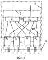
На фиг.3 схематично представлена резервированная станция ввода/вывода, где: 6 - фрагмент резервированной шины ENL, 7 - резервированная станция ввода/вывода, 8 - резервируемые интерфейсные модули, 9 - резервируемые СП-модули, 10 - резервированная шина ввода-вывода, 11 - каналы связи СП-модулей с технологическим процессом.Figure 3 schematically shows a redundant I / O station, where: 6 - a fragment of a redundant ENL bus, 7 - a redundant I / O station, 8 - redundant interface modules, 9 - redundant SP-modules, 10 - redundant I / O bus, 11 - communication channels of the SP modules with the technological process.
Резервированная система автоматизации, построенная на базе комплекса программно-аппаратных средств управления технологическими процессами (фиг.1), работает следующим образом.The redundant automation system, built on the basis of a set of software and hardware process control tools (figure 1), works as follows.
Процессоры автоматизации 3 выполняют прием данных технологического процесса от интерфейсных модулей 8 станций ввода/вывода 7 по шинам ENL 6, прием данных от других процессоров автоматизации 3 и системы верхнего уровня по шине EN 4, их обработку в соответствии с прикладными алгоритмами автоматизации и передачу данных и результатов обработки в интерфейсные модули 8 станций ввода/вывода 7 по шинам ENL 6, а также в другие процессоры автоматизации 3 и систему верхнего уровня по шине EN 4.Automation processors 3 receive process data from interface modules 8 I /
В резервированной системе автоматизации управление обменом данными по шинам EN, ENL и их обработку в соответствии с прикладными алгоритмами автоматизации выполняет один из резервируемых процессоров автоматизации, например, 311, называемый активным, другой процессор автоматизации, соответственно 312, называемый резервным, работает в режиме горячего резерва. Резервируемые процессоры автоматизации, например, 311, 312 связаны друг с другом по двум отдельным последовательным интерфейсам, по которым они получают информацию о работоспособности партнера, соответственно 312, 311, в соответствии с результатами самоконтроля. На основе оценки этой информации в соответствии с заданными критериями активный процессор автоматизации, например, 311 может быть переключен в состояние резервного процессора автоматизации, а резервный в состояние активного. Обмен данными по шине EN 4 активный процессор автоматизации 3, например, 311 производит только по одному из двух каналов, называемому активным, второй канал работает в режиме горячего резервирования.In a redundant automation system, the exchange of data on the EN, ENL buses and their processing in accordance with applied automation algorithms are performed by one of the redundant automation processors, for example, 311 , called active, another automation processor, respectively 312 , called backup, works in the mode hot reserve. Redundant automation processors, for example, 311 , 312 are connected to each other via two separate serial interfaces, through which they receive information about the partner’s performance, 312 , 311 , respectively, in accordance with the results of self-monitoring. Based on the assessment of this information in accordance with the specified criteria, the active automation processor, for example, 311 can be switched to the state of the backup automation processor, and the backup to the active state.
Резервированная шина EN 4 (фиг.2) построена на базе интерфейса Industrial Ethernet в виде двух непосредственно не связанных кольцевых структур последовательно соединенных сетевых коммутаторов (шины ENa и ENb) и обеспечивает сохранение работоспособности при любых двукратных и некоторых многократных отказах сетевого оборудования (сетевых коммутаторов, магистральных и абонентских линий связей). Каждый из двух резервируемых процессоров автоматизации 311, 312; … 3j1, 3j2, например, 311 подключен к шине EN 4 по двум каналам, по одному каналу к сетевому коммутатору шины ENa 4a, например 2a1, а по другому каналу к сетевому коммутатору шины ENb, соответственно 2b1, причем два резервируемых процессора автоматизации, например, 311 и 312 подключены к разным коммутаторам шин ENa и ENb, соответственно 2а1, 2b1 и 2a2, 2b2, а также соединены друг с другом по двум отдельным последовательным интерфейсам и имеют средства управления горячим резервированием. Передачу, прием и обработку данных производит только один из каждой пары резервируемых процессоров автоматизации 311, 312; … 3j1, 3j2, например, 311, называемый активным процессором автоматизации, и только по одному из двух каналов, называемому активным каналом, второй процессор автоматизации, соответственно 312, и второй канал активного процессора автоматизации, соответственно 311, называемыми резервными, работают в режиме горячего резерва.The
Обнаружение отказов магистральных связей в кольцевых шинах ENa 4a и ENb 4b и их восстановление осуществляют соответственно коммутаторы 2a(l+1) и 2b(l+1), назначаемые так называемыми менеджерами резервирования в соответствии со схемой построения виртуальных кольцевых сетей Ethernet. Менеджер резервирования, например, 2a(l+1) поддерживает кольцевую шину, соответственно ENa 4a, разомкнутой и контролирует целостность кольцевой шины, соответственно ENa 4a, путем передачи диагностических сообщений с одного конца и приема их с другого конца разомкнутого кольца. При отсутствии сообщений на приемном конце в случае отказа магистральной связи менеджер резервирования, соответственно 2a(l+1), замыкает кольцо и тем самым восстанавливает магистральную цепь передачи данных между абонентами 3 шины, соответственно ENa 4a.The failure detection of trunk communications in the
Восстановление работоспособности шины EN 4 при отказах абонентских связей и сетевых коммутаторов выполняют следующим образом. При отсутствии неисправностей в сетевом оборудовании каждый абонент шины EN 4, активный процессор автоматизации 3, например, 311 передает адресованные телеграммы с данными другим абонентам 3, например, 321 только по одной активной на данном сеансе связи шине, например шине ENa 4a, с квитированием их получения абонентом-получателем 3, соответственно 321, путем передачи им ответного сообщения (квитанции) абоненту-передатчику, соответственно 311. Прием телеграмм от других абонентов 3, например 321, каждый абонент шины EN 4, активный процессор автоматизации 3, например 311, производит по обеим шинам. Широковещательные телеграммы, т.е. телеграммы, адресованные всем абонентам шины EN 4, передают параллельно по двум шинам ENa и ENb без квитирования. Одновременно абонентские связи процессоров автоматизации 3 и коммутаторы 2, к которым процессоры автоматизации подключены, процессоры автоматизации контролируют стандартными средствами Ethernet и путем передачи диагностических сообщений в соответствии с протоколом шины EN 4. При отказе одного из каналов активного процессора автоматизации, например 311, зарегистрированного средствами контроля абонентских связей, процессор автоматизации 3, соответственно 311, инициирует процедуру обновления информации о состоянии каналов связи всех абонентов в каждом абоненте, для чего он посылает служебное широковещательное сообщение по другому исправному каналу с указанием отказавшего канала, номера абонента, у которого отказал канал, и номера абонента-отправителя телеграммы 3, соответственно 311, а все другие абоненты, например 321, получив телеграмму с одинаковым значением адреса абонента-отправителя 3, соответственно 311, и абонента, у которого отказал канал, соответственно 311, транслируют эти телеграммы другим абонентам 3, например 3j1, по обоим каналам и соответственно обеим шинам ENa и ENb, с указанием собственного адреса отправителя. Телеграммы с разными номерами абонента-отправителя 3, соответственно 321, и абонента с отказавшим каналом, соответственно 311, дальше не транслируются. Полученная каждым активным абонентом информация передается резервному абоненту. Таким образом, информация об отказавшем канале доставляется всем другим абонентам 3 шины EN 4 по одной из шин ENa или ENb. В результате выполнения этой процедуры каждый абонент сети 3 имеет информацию о текущем состоянии каналов связи других абонентов 3.Restoring the health of the
Перед каждым сеансом связи активный абонент-передатчик 3, например 311, производит проверку имеющейся у него информации о исправности собственных каналов и каналов абонента-получателя 3, например 321, в данном сеансе связи и затем производит передачу телеграммы по шине ENa или ENb, каналы подключения к которой обоих абонентов (передатчика и приемника) исправны. При передаче телеграммы абонент-отправитель 3, например 311, выполняет контроль доставки телеграммы абоненту-получателю, например 321, с помощью квитирования. В случае непоступления квитанции от абонента-получателя 3, например 321, при повторении передачи телеграммы n раз, абонент-отправитель, соответственно 311, считает, что абонент-получатель, соответственно 321, по данному каналу на данном сеансе связи не доступен, отмечает его в таблице состояния как недоступный по данному каналу и выбирает для связи другой канал, если он исправен, переводя его в режим активного (ранее активный канал переводится в резервное состояние) на данном сеансе связи. В случае недоступности абонента получателя 3, например 321, по обеим шинам, например, вследствие его неисправности или временного отключения, при исправных каналах передатчика 3, например и приемника, соответственно 321, или вследствие недоступности по одной шине, например ENa, при неисправности канала абонента-передатчика, соответственно 311, на другой шине, соответственно ENb, соответствующие каналы или канал абонент-передатчик, соответственно 311, отмечают как недоступные, при этом переключения на резервный абонент, соответственно 312, не производит. При следующем обращении абонента-передатчика, соответственно 311, к недоступному абоненту, соответственно 321, и не получении при этом квитанции от абонента-получателя, соответственно 321, передача телеграммы не повторяется. Таким образом, на каждом сеансе связи в зависимости от состояния каналов абонентов 3, участвующих в сеансе связи, абонент-передатчик 3, например 311, назначает активный канал связи, выбирая путь доставки телеграммы по шине ENa или ENb абоненту-получателю 3, например 321, который может принимать телеграммы по любой из шин ENa, ENb.Before each communication session, the active subscriber-transmitter 3, for example 311 , checks its available information about the health of its own channels and channels of the subscriber-recipient 3, for example 321 , in this communication session and then transmits a telegram via the bus ENa or ENb , the connection channels to which both subscribers (transmitter and receiver) are operational. When transmitting a telegram, the sending subscriber 3, for example 311 , controls the delivery of the telegram to the receiving subscriber, for example 321 , with an acknowledgment. If the receipt is not received from the recipient subscriber 3, for example 321 , when the telegram transmission is repeated n times, the sending subscriber, respectively 311 , considers that the recipient subscriber 321 , respectively, is not available on this channel in this communication session, marks it in the status table as unavailable on this channel and selects another channel for communication, if it is serviceable, putting it into active mode (the previously active channel is put into standby state) in this communication session. In case of inaccessibility of the subscriber of the recipient 3, for example 321 , on both buses, for example, due to its malfunction or temporary disconnection, when the channels of the transmitter 3, for example, and the receiver, 321 , respectively, or due to unavailability on one bus, for example ENa malfunctions of the subscriber-transmitter channel, respectively 311 , on the other bus, respectively ENb , the corresponding channels or the subscriber-transmitter channel, respectively 311 , are marked as unavailable, while switching to the backup subscriber, respectively 312 , do not produces. The next time the subscriber-transmitter, 311 , respectively, addresses an unavailable subscriber, 321 , respectively, and does not receive a receipt from the recipient, 321 , respectively, the transmission of the telegram is not repeated. Thus, at each communication session, depending on the state of the channels of the subscribers 3 participating in the communication session, the subscriber-transmitter 3, for example 311 , assigns an active communication channel, choosing the delivery path of the telegram via the bus ENa or ENb to the recipient 3, for example 321 , which can receive telegrams on any of the buses ENa , ENb .
Если у абонента-передатчика 3, например 311, оба канала неисправны или если неисправен один канал, например на шине ENa, и при этом у этого абонента-передатчика, соответственно 311, есть информация, что в сети имеется абонент-получатель 3, например 321, у которого неисправен канал на другой шине, соответственно ENb, то абонент-передатчик 3, соответственно 311, переходит в состояние резервного, а ранее резервный абонент 3, соответственно 312, переходит в состояние активного, при этом новый активный абонент инициирует процедуру обновления информации о состоянии каналов абонентов шины 3, посылая сообщение о состоянии своих каналов. Таким образом, при любых двух отказах в сетевом оборудовании шины EN работоспособность шины сохраняется.If the transmitter-subscriber 3, for example, 311 , both channels are faulty, or if one channel is faulty, for example, on the ENa bus, and at the same time, this transmitter-subscriber, respectively 311 , has information that there is a recipient 3 in the network , for example 321 , in which the channel on the other bus is defective, respectively ENb , then the subscriber-transmitter 3, respectively 311 , enters the standby state, and previously the standby subscriber 3, respectively 312 , enters the active state, while the new active subscriber initiates information update procedure on the state of the bus subscribers channels 3, sending a message about the status of its channels. Thus, with any two failures in the network equipment of the EN bus, the bus remains operational.
Интерфейсные модули 8 станций ввода/вывода 7 принимают по шинам ввода/вывода 10 данные технологического процесса от СП-модулей 9 для последующей передачи в процессоры автоматизации 3 по шинам ENL 6 и передают данные управления, принимаемые от процессоров автоматизации 3 по шинам ENL 6, в СП-модули 9 по шинам ввода/вывода 10. Прием и передачу данных по шине ENL 6 интерфейсные модули 8 выполняют только при поступлении им запросов от процессоров автоматизации 3.Interface modules 8 of I /
Шина ENL 6 осуществляет передачу данных в режиме полного дуплекса между процессором автоматизации 3 и интерфейсными модулями 8, при этом процессор автоматизации 3 является ведущим абонентом шины, имеющим право доступа к шине ENL 6 в любое время, а интерфейсные модули 8 - ведомыми абонентами шины, передающими или принимающими данные только по запросу от процессора автоматизации 3.The
Обмен данными с интерфейсными модулями 8 по шинам ENL 6 и их обработку процессоры автоматизации 3 выполняют циклически. В начале цикла процессоры автоматизации 3 выдают во все интерфейсные модули 8 служебную телеграмму начала цикла для синхронизации работы интерфейсных модулей. После передачи этой телеграммы процессоры автоматизации 3 производят поочередную передачу данных в интерфейсные модули 8, которые тут же передают поступившие данные поочередно в СП-модули 9, и поочередный прием данных от интерфейсных модулей 8, полученных ими от СП-модулей 9 в конце предыдущего цикла.Data exchange with interface modules 8 via
Интерфейсный модуль 8 сразу после получения от процессора автоматизации 3 телеграммы запроса приема данных или телеграммы с передаваемыми данными отправляет процессору автоматизации 3 телеграмму с ответными данными или телеграмму подтверждения получения данных. После завершения фазы обмена процессоры автоматизации производят обработку данных.The interface module 8 immediately after receiving from the automation processor 3 a telegram of a data reception request or a telegram with transmitted data sends an automation processor 3 a telegram with response data or a data receipt confirmation telegram. After the exchange phase is completed, the automation processors process the data.
В резервированной системе автоматизации управление обменом данными с интерфейсными модулями по шине ENL выполняет только активный процессор автоматизации, например 311, по одному из двух каналов, называемому активным, второй канал работает в режиме горячего резервирования. Активный процессор автоматизации 3 осуществляет обмен данными в режиме "запрос/ответ" только с одним из двух резервируемых интерфейсных модулей 8, например 81, называемым активным, в каждой резервированной станции ввода/вывода 7, например 71, путем обращения к нему по его адресу на шине ENL, второй интерфейсный модуль 8, соответственно 82, называемый резервным, работает в режиме горячего резервирования и не участвует в обмене данными по шине ENL. Резервируемые интерфейсные модули 81, 82 связаны друг с другом по двум отдельным последовательным интерфейсам, с помощью которых осуществляют опрос работоспособности друг друга и управление резервированием, т.е. переключением активного модуля 8, например 81, в резервное состояние, а ранее резервного модуля 8, соответственно 82, в активное состояние на основе оценки работоспособности партнера и собственной работоспособности по результатам оперативного самоконтроля. Управление горячим резервированием процессоров автоматизации 3 и интерфейсных модулей 8 выполняют, соответственно, средства резервирования процессоров автоматизации и интерфейсных модулей автоматически, эту задачу управления резервированием не нужно решать при создании каждого проекта управления технологическим процессом, что существенно снижает трудоемкость проектирования систем управления на базе данного комплекса средств автоматизации.In a redundant automation system management data exchange with the interface modules on the bus ENL performs only the active processor automation, e.g. March11, one of the two channels, called active, the second channel works in hot standby mode. Active automation processor 3 exchanges data in the "request / response" mode with only one of the two redundant interface modules 8, for example 81 , called active, in each redundant I /
Шины ENL резервированы, т.е. каждая резервированная шина ENL 6, например 61 имеет две шины, каждая из которых включает сетевой коммутатор (сетевые коммутаторы) 5, например 511, и все его соединения с процессорами автоматизации 3, соответственно 311, 312, и интерфейсными модулями, соответственно 81, всех станций ввода/вывода 71, … 7m. По двум каналам шины ENL 6 каждого процессора автоматизации 3, например, 311, 312 производят подключение по одному каналу процессора автоматизации 3, например 311, к собственной шине ENL 6 через ее сетевой коммутатор 5, соответственно через 511, и перекрестное подключение по другому каналу к шине ENL 6 процессора автоматизации-партнера 3, соответственно 312, через сетевой коммутатор 5, соответственно 512, этой шины. Таким образом, каждый процессор автоматизации 3 выполняет обмен данными с любым из двух резервируемых интерфейсных модулей 81, 82 в каждой резервированной станции ввода/вывода 71, … 7m, который в данный момент и в данной станции выполняет функции активного абонента на шине ENL.ENL buses are redundant, i.e. each
Ответные данные активный интерфейсный модуль 8, например 81, передает по собственной шине ENL в широковещательном режиме, т.е. всем абонентам на шине ENL, включая процессор автоматизации 3, например 311, а также подключенному к коммутатору 5, соответственно 511, через перекрестную связь второму процессору автоматизации 3, соответственно 312. Принимают эти данные только процессоры автоматизации, один из которых активный, например 311, а другой резервный, соответственно 312. Это исключает необходимость дополнительной периодической передачи текущих данных из активного процессора автоматизации 3, соответственно 311 в резервный процессор автоматизации 3, соответственно 312 (выполнения процедуры обновления принимаемых данных), и обеспечивает при этом безударное переключение на резерв без потери данных при меньшей информационной нагрузке на активный процессор автоматизации 3, соответственно 311, и меньшей задержки переключения. Передачу небольшого объема время зависимых результатов обработки данных из активного процессора автоматизации 3, например 311, в резервный, соответственно 312 (выполнение процедуры обновления время зависимых данных), производят так же через перекрестное подключение процессоров автоматизации 3 к шине ENL. Таким образом, обеспечивают безударное переключение на резерв с обновлением время зависимым данным без введения для этого отдельного интерфейса.The active interface module 8, for example, 81 , transmits the response data via its own ENL bus in broadcast mode, i.e. all subscribers on the ENL bus, including automation processor 3, for example 311 , and also connected to the switch 5, respectively 511 , through cross-connection to the second automation processor 3, respectively 312 . Only automation processors accept this data, one of which is active, for example 311 , and the other standby, 3 312 , respectively. This eliminates the need for additional periodic transmission of current data from the active automation processor 3, respectively 311 to the backup automation processor 3, respectively 312 (performing the procedure for updating the received data), and ensures shock-free switching to the reserve without data loss with less information load active automation processor 3, respectively 311 , and less switching delay. The transfer of a small amount of time dependent results of data processing from the active automation processor 3, for example 311 , to the backup, respectively 312 (the update procedure takes the time of the dependent data), is also performed through the cross-connection of automation processors 3 to the ENL bus. Thus, they provide a shockless switch to the reserve with updating time for dependent data without introducing a separate interface for this.
Резервированная станция ввода-вывода 7 (фиг.1, фиг.3) содержит пару резервируемых интерфейсных модулей 81, 82 и до k/2 пар резервируемых СП-модулей 9 (91, 92, … 9k-1, 9k), каждый из которых по отдельным последовательным интерфейсам резервированной шины ввода-вывода 10 подключен к обоим интерфейсным модулям 81, 82, при этом пары СП-модулей 91, 92, … 9k-1, 9k соединены по отдельным сигнальным линиям, с помощью которых осуществляют управлением резервированием модулей, т.е. переключением активного СП-модуля, например 91, в резервное состояние, а ранее резервного СП-модуля, например 92, в активное состояние на основе результатов оперативного самоконтроля. Активный интерфейсный модуль 8, например 81, запрашивает по собственным последовательным интерфейсам резервированной шины ввода/вывода 10 данные от всех активных СП-модулей 9, например модуля 91, и всех резервных СП-модулей 9, например модуля 92, которые поступают в активный интерфейсный модуль 8, соответственно 81, для передачи данных активных СП-модулей 9, соответственно 91, на следующем цикле из активного интерфейсного модуля 8, соответственно 81, в активный процессор автоматизации 3, например 311, и резервный процессор автоматизации 3, соответственно 312. Резервный интерфейсный модуль 8, соответственно 82, в свою очередь в конце цикла опрашивает активные и резервные СП-модули 91…9k по последовательным интерфейсам своей шины ввода/вывода одновременно с активным интерфейсным модулем 8, соответственно 81, но не передает принятые данные в процессоры автоматизации 3, например 311, 312, по шине ENL на следующем цикле, пока он работает в режиме горячего резерва. Это обеспечивает безударное переключение без потери данных резервного интерфейсного модуля 8, соответственно 82, в состояние активного и активного в состояние резервного при отказе активного интерфейсного модуля 8, соответственно 81, т.к. в резервном интерфейсном модуле 8, соответственно 82, имеются те же текущие входные данные, что и в активном. При этом не нужно выполнять специальную процедуру обновления данных в резервном интерфейсном модуле 8, соответственно 82, путем передачи их из активного интерфейсного модуля 8, соответственно 81, что сокращает время переключения на резерв и снижает информационную нагрузку интерфейсных модулей.The redundant I / O station 7 (Fig. 1, Fig. 3) contains a pair of redundant interface modules 81 , 82 and up to k / 2 pairs of redundant SP modules 9 (91 , 92 , ... 9k-1 , 9k ), each of which is connected via separate serial interfaces of the redundant I /
При отказе активного СП-модуля 9, например 91, резервный СП-модуль 9, соответственно 92, становится активным в результате их взаимодействия друг с другом по сигнальной линии связи. Активный интерфейсный модуль 8, например 81, определяет этот факт при очередном опросе ранее активного СП-модуля 9, соответственно 91. Информация, полученная от неисправного СП-модуля 9, соответственно 91, не является достоверной и активный интерфейсный модуль 8, соответственно 81, на следующем цикле передает в активный процессор автоматизации 3, например 311, по его запросу в начале этого цикла информацию, полученную им от резервного СП-модуля 9, соответственно 92. Таким образом, выполняют безударное переключение резерва на уровне СП-модулей 9, не используя для этого процедуру обновления текущих данных СП-модулей 9 и исключая потери данных и дополнительную задержку переключения на резерв. Обновление времени зависимых результатов предварительной обработки данных в СП-модулях 9 производят на каждом цикле в активном интерфейсном модуле, например 81, путем передачи этих результатов из области памяти активного интерфейсного модуля, соответственно 81, в которой сохраняются результаты обработки активных СП-модулей 9, например 91, в другую область памяти этого активного интерфейсного модуля 8, соответственно 81, в которой сохраняются данные резервных СП-модулей 9, например 92. Эта процедура также практически не вносит дополнительной задержки переключения СП-модулей на резерв, т.к. ее выполняют внутри одного интерфейсного модуля.In case of failure of the active SP module 9, for example, 91 , the standby SP module 9, respectively 92 , becomes active as a result of their interaction with each other over the signal line. The active interface module 8, for example, 81 , determines this fact during the next poll of the previously active SP module 9, respectively 91 . The information received from the faulty SP module 9, respectively 91 , is not reliable and the active interface module 8, respectively 81 , in the next cycle transfers to the active automation processor 3, for example 311 , upon request at the beginning of this cycle, information received by him from the backup SP-module 9, respectively 92 . Thus, they perform shock-free switching of the reserve at the level of SP-modules 9, without using the procedure for updating the current data of SP-modules 9 and excluding data loss and an additional delay in switching to reserve. The time update of the dependent results of preliminary data processing in the SP modules 9 is performed on each cycle in the active interface module, for example, 81 , by transferring these results from the memory area of the active interface module, respectively 81 , in which the processing results of the active SP modules 9 are stored , for example, 91 , to another memory area of this active interface module 8, respectively, 81 , in which the data of standby SP-modules 9, for example, 92 , are stored. This procedure also practically does not introduce any additional delay in switching the SP modules to the reserve, since it is performed inside one interface module.
При отказе активного интерфейсного модуля, например 81, его переключают в резервное состояние, а резервный модуль 8, соответственно 82, в активное состояние. Активный процессор автоматизации 3, например 31, определяет отказ интерфейсного модуля 8, соответственно 81, при очередном опросе активного интерфейсного модуля 8, соответственно 81, в начале цикла, и полученные от интерфейсного модуля 8, соответственно 81, данные не использует, т.к. они являются недостоверными. В конце этого цикла резервный интерфейсный модуль 8, соответственно 82, выполняет очередной опрос СП-модулей 9 и готовит данные для передачи активному процессору автоматизации 3, соответственно 311, на следующем цикле, в начале которого резервный интерфейсный модуль 8, соответственно 82, устанавливают в активное состояние. На этом цикле активный процессор автоматизации 3, например 311, по второму каналу шины ENL через перекрестную связь и сетевой коммутатор 5, соответственно 512, производит передачу данных в новый активный интерфейсный модуль 8, соответственно 82, и прием данных активных СП-модулей 9, например 91, подготовленных этим интерфейсным модулем 8, соответственно 82, на предыдущем цикле. Таким образом, исключают потери данных и минимизируют время при переключении резерва на уровне интерфейсных модулей 8.In case of failure of the active interface module, for example, 81 , it is switched to the standby state, and the standby module 8, respectively 82 , to the active state. The active automation processor 3, for example 31 , determines the failure of the interface module 8, respectively 81 , during the next poll of the active interface module 8, respectively 81 , at the beginning of the cycle, and does not use data received from the interface module 8, respectively 81 , because they are unreliable. At the end of this cycle, the redundant interface module 8, respectively 82 , performs another poll of the SP-modules 9 and prepares the data for transmission to the active automation processor 3, respectively 311 , in the next cycle, at the beginning of which the redundant interface module 8, respectively 82 , set to active. In this cycle, the active automation processor 3, for example 311 , through the second channel of the ENL bus through the cross-connection and the network switch 5, respectively 512 , transfers data to the new active interface module 8, respectively 82 , and receives data from active SP modules 9, for example, 91 prepared by this interface module 8, respectively 82 , in the previous cycle. Thus, they eliminate data loss and minimize time when switching the reserve at the level of interface modules 8.
Данные управления активный интерфейсный модуль, например 81, передает только в активные СП-модули 9, например 91. При отказе активного СП-модуля 9, соответственно 91, активный интерфейсный модуль 8, соответственно 81, передает данные управления в текущем цикле в резервный СП-модуль 9, соответственно 92, который стал активным. При отказе активного интерфейсного модуля 8, например 81, он блокирует передачу данных управления в СП-модули 9, активным становится резервный интерфейсный модуль 8, соответственно 82. Активный процессор автоматизации 3, например 311, при опросе активных интерфейсных модулей 8, соответственно 81, в начале следующего цикла определяет, что опрашиваемый интерфейсный модуль, соответственно 81, стал резервным и передает данные в ранее резервный интерфейсный модуль 8, соответственно 82, который стал активным и транслирует их в активные СП-модули, например в модуль 91.The active interface module, for example 81 , transfers control data only to active SP modules 9, for example 91 . In case of failure of the active SP module 9, respectively 91 , the active interface module 8, respectively 81 , transfers control data in the current cycle to the backup SP module 9, respectively 92 , which has become active. In case of failure of the active interface module 8, for example, 81 , it blocks the transfer of control data to the SP modules 9, the backup interface module 8, respectively, 82 becomes active. The active automation processor 3, for example 311 , when interrogating the active interface modules 8, respectively 81 , at the beginning of the next cycle determines that the interrogated interface module, respectively 81 , has become redundant and transfers data to the previously redundant interface module 8, respectively 82 , which became active and translates them into active SP-modules, for example, into module 91 .
Claims (1)
Translated fromRussianPriority Applications (1)
| Application Number | Priority Date | Filing Date | Title |
|---|---|---|---|
| RU2010134777/08ARU2450305C1 (en) | 2010-08-20 | 2010-08-20 | Software-hardware system for automating monitoring and control |
Applications Claiming Priority (1)
| Application Number | Priority Date | Filing Date | Title |
|---|---|---|---|
| RU2010134777/08ARU2450305C1 (en) | 2010-08-20 | 2010-08-20 | Software-hardware system for automating monitoring and control |
Publications (2)
| Publication Number | Publication Date |
|---|---|
| RU2010134777A RU2010134777A (en) | 2012-02-27 |
| RU2450305C1true RU2450305C1 (en) | 2012-05-10 |
Family
ID=45851724
Family Applications (1)
| Application Number | Title | Priority Date | Filing Date |
|---|---|---|---|
| RU2010134777/08ARU2450305C1 (en) | 2010-08-20 | 2010-08-20 | Software-hardware system for automating monitoring and control |
Country Status (1)
| Country | Link |
|---|---|
| RU (1) | RU2450305C1 (en) |
Cited By (2)
| Publication number | Priority date | Publication date | Assignee | Title |
|---|---|---|---|---|
| RU2760299C1 (en)* | 2021-03-03 | 2021-11-23 | Федеральное государственное унитарное предприятие «Всероссийский научно-исследовательский институт автоматики им.Н.Л.Духова» (ФГУП «ВНИИА») | Dual-redundant bus for automated monitoring and control systems of nuclear power plants and other industrial facilities |
| RU2837031C1 (en)* | 2024-08-30 | 2025-03-25 | Общество с ограниченной ответственностью "Эпотос-К" | Software and hardware complex of technical means of fire automation and security alarm for mobile vehicles |
Families Citing this family (1)
| Publication number | Priority date | Publication date | Assignee | Title |
|---|---|---|---|---|
| CN104669268B (en)* | 2013-11-26 | 2016-08-03 | 中国科学院沈阳自动化研究所 | A kind of redundancy underwater robot self-control system based on Hot Spare and method |
Citations (5)
| Publication number | Priority date | Publication date | Assignee | Title |
|---|---|---|---|---|
| EP0992867A1 (en)* | 1998-10-08 | 2000-04-12 | Schneider Automation | Distributed automation system |
| RU2216760C2 (en)* | 2001-11-13 | 2003-11-20 | Открытое акционерное общество "Система" | Automatic reservation system controlling fueling of cryogenic going-up unit |
| RU2279117C2 (en)* | 2004-08-04 | 2006-06-27 | Общество с ограниченной ответственностью Научно-производственное предприятие "КОМПЛЕКСЫ и СИСТЕМЫ" (ООО НПП "КОМПЛЕКСЫ и СИСТЕМЫ") | Complex of software-hardware means for automation of control over technological processes |
| RU2349949C2 (en)* | 2007-03-19 | 2009-03-20 | Открытое акционерное общество "Московский завод тепловой автоматики" | Complex of hardware-software means of control and management automation |
| RU87272U1 (en)* | 2009-04-29 | 2009-09-27 | Общество с ограниченной ответственностью "Синтез" | AUTOMATIC CONTROL SYSTEM FOR TECHNOLOGICAL PROCESS |
- 2010
- 2010-08-20RURU2010134777/08Apatent/RU2450305C1/enactive
Patent Citations (5)
| Publication number | Priority date | Publication date | Assignee | Title |
|---|---|---|---|---|
| EP0992867A1 (en)* | 1998-10-08 | 2000-04-12 | Schneider Automation | Distributed automation system |
| RU2216760C2 (en)* | 2001-11-13 | 2003-11-20 | Открытое акционерное общество "Система" | Automatic reservation system controlling fueling of cryogenic going-up unit |
| RU2279117C2 (en)* | 2004-08-04 | 2006-06-27 | Общество с ограниченной ответственностью Научно-производственное предприятие "КОМПЛЕКСЫ и СИСТЕМЫ" (ООО НПП "КОМПЛЕКСЫ и СИСТЕМЫ") | Complex of software-hardware means for automation of control over technological processes |
| RU2349949C2 (en)* | 2007-03-19 | 2009-03-20 | Открытое акционерное общество "Московский завод тепловой автоматики" | Complex of hardware-software means of control and management automation |
| RU87272U1 (en)* | 2009-04-29 | 2009-09-27 | Общество с ограниченной ответственностью "Синтез" | AUTOMATIC CONTROL SYSTEM FOR TECHNOLOGICAL PROCESS |
Cited By (4)
| Publication number | Priority date | Publication date | Assignee | Title |
|---|---|---|---|---|
| RU2760299C1 (en)* | 2021-03-03 | 2021-11-23 | Федеральное государственное унитарное предприятие «Всероссийский научно-исследовательский институт автоматики им.Н.Л.Духова» (ФГУП «ВНИИА») | Dual-redundant bus for automated monitoring and control systems of nuclear power plants and other industrial facilities |
| WO2022186723A1 (en)* | 2021-03-03 | 2022-09-09 | Федеральное государственное унитарное предприятие "Всероссийский научно-исследовательский институт автоматики им. Н.Л. Духова" (ФГУП "ВНИИА") | Dual-redundant bus for automated monitoring systems |
| EP4191424A4 (en)* | 2021-03-03 | 2024-03-06 | Federal State Unitary Enterprise "All-Russian Research Institute Of Automatics" (FSUE "VNIIA") | DOUBLE BUS FOR AUTOMATED CONTROL SYSTEMS |
| RU2837031C1 (en)* | 2024-08-30 | 2025-03-25 | Общество с ограниченной ответственностью "Эпотос-К" | Software and hardware complex of technical means of fire automation and security alarm for mobile vehicles |
Also Published As
| Publication number | Publication date |
|---|---|
| RU2010134777A (en) | 2012-02-27 |
Similar Documents
| Publication | Publication Date | Title |
|---|---|---|
| CN100524124C (en) | Redundant supervisory control system, and redundancy switching method of the same | |
| CN102144382B (en) | Method and system for the transfer of redundant server automatic fault | |
| US20110161538A1 (en) | Method and System for Implementing Redundant Network Interface Modules in a Distributed I/O System | |
| RU2431174C1 (en) | Backup software-hardware system for automatic monitoring and control | |
| JPH03106144A (en) | Mutual connection of network modules | |
| CN106444602A (en) | Security programmable logic controller communication system and communication method | |
| US8249084B2 (en) | Ring connection control circuit, ring switching hub, ring ethernet system, and ring connection controlling method | |
| US20160308651A1 (en) | Automation device for the redundant control of a bus subscriber | |
| CN105306559A (en) | Multi-partition message control system without central partition for regional power grid regulation and control system | |
| CN103166800B (en) | Message transmission method for dual-network redundant message bus in cross failure | |
| CN206470580U (en) | safety programmable logic controller communication system | |
| CN114342327A (en) | Method and coupled communication device for data transmission in a redundantly operable communication network | |
| CN101751020A (en) | High-availability function block redundancy method | |
| CN104505942B (en) | Power distribution automatic feeder terminal based on data bus and network thereof | |
| RU2450305C1 (en) | Software-hardware system for automating monitoring and control | |
| CN103200067A (en) | Dynamic virtual LANs to segregate data | |
| CN110247809B (en) | Communication control method of double-ring network control system | |
| CN110053650B (en) | Automatic train operation system, automatic train operation system architecture and module management method of automatic train operation system | |
| CN111740864A (en) | An out-of-band network port switching management method and system | |
| CN112260916B (en) | Communication circuit, communication network, and communication abnormality processing method | |
| RU2430400C1 (en) | Backup software-hadware system for automatic monitoring and control | |
| CN102088366B (en) | Single board information monitoring device and distributed single board information monitoring system | |
| CN104135411A (en) | Device and method of implementing multi-node communication based on RS232 interface | |
| Yoon et al. | RAPIEnet based redundancy control system | |
| CN114553878A (en) | Industrial control system active-standby operation power monitoring system based on LVS |