RU2449332C1 - Method of controlling liquid-crystal shutter for 3d glasses - Google Patents
Method of controlling liquid-crystal shutter for 3d glassesDownload PDFInfo
- Publication number
- RU2449332C1 RU2449332C1RU2010140061/28ARU2010140061ARU2449332C1RU 2449332 C1RU2449332 C1RU 2449332C1RU 2010140061/28 ARU2010140061/28 ARU 2010140061/28ARU 2010140061 ARU2010140061 ARU 2010140061ARU 2449332 C1RU2449332 C1RU 2449332C1
- Authority
- RU
- Russia
- Prior art keywords
- cycle
- time
- voltage
- liquid crystal
- crystal shutter
- Prior art date
Links
- 239000004973liquid crystal related substanceSubstances0.000titleclaimsabstractdescription46
- 238000000034methodMethods0.000titleclaimsdescription41
- 239000011521glassSubstances0.000titleclaimsdescription22
- 230000003287optical effectEffects0.000claimsabstractdescription32
- 230000005540biological transmissionEffects0.000claimsabstractdescription25
- 230000004044responseEffects0.000claimsdescription12
- 230000009471actionEffects0.000claimsdescription8
- 230000008569processEffects0.000claimsdescription5
- 230000007547defectEffects0.000abstractdescription28
- 239000000126substanceSubstances0.000abstractdescription7
- 230000015572biosynthetic processEffects0.000abstractdescription5
- 230000000694effectsEffects0.000abstractdescription4
- 230000002829reductive effectEffects0.000abstractdescription4
- 150000002500ionsChemical class0.000description10
- 230000035484reaction timeEffects0.000description6
- 230000007423decreaseEffects0.000description4
- 230000008859changeEffects0.000description3
- 238000003487electrochemical reactionMethods0.000description3
- 230000004907fluxEffects0.000description3
- 238000000926separation methodMethods0.000description3
- 238000001816coolingMethods0.000description2
- 238000005265energy consumptionMethods0.000description2
- 230000010287polarizationEffects0.000description2
- 230000009467reductionEffects0.000description2
- 239000003990capacitorSubstances0.000description1
- 238000000576coating methodMethods0.000description1
- 238000000354decomposition reactionMethods0.000description1
- 230000003247decreasing effectEffects0.000description1
- 230000003111delayed effectEffects0.000description1
- 230000006866deteriorationEffects0.000description1
- 239000003792electrolyteSubstances0.000description1
- 238000009713electroplatingMethods0.000description1
- 230000008030eliminationEffects0.000description1
- 238000003379elimination reactionMethods0.000description1
- 238000010438heat treatmentMethods0.000description1
- 239000012535impuritySubstances0.000description1
- 230000002427irreversible effectEffects0.000description1
- 230000007774longtermEffects0.000description1
- 239000000463materialSubstances0.000description1
- 239000000203mixtureSubstances0.000description1
- 230000003071parasitic effectEffects0.000description1
- 230000036961partial effectEffects0.000description1
- 239000010453quartzSubstances0.000description1
- 230000002441reversible effectEffects0.000description1
- VYPSYNLAJGMNEJ-UHFFFAOYSA-Nsilicon dioxideInorganic materialsO=[Si]=OVYPSYNLAJGMNEJ-UHFFFAOYSA-N0.000description1
- 239000000758substrateSubstances0.000description1
- 230000007704transitionEffects0.000description1
- 238000002834transmittanceMethods0.000description1
- 230000000007visual effectEffects0.000description1
Images


Landscapes
- Liquid Crystal (AREA)
Abstract
Description
Translated fromRussianИзобретение относится к средствам воспроизведения и наблюдения стереоскопических (объемных) изображений в телевидении, компьютерной технике, кинопрокате.The invention relates to means for reproducing and observing stereoscopic (volumetric) images in television, computer equipment, film distribution.
Известен способ наблюдения стереоскопических изображений с использованием стереоочков на основе жидкокристаллических (ЖК) затворов для воспроизведения стереоскопических (объемных) изображений (заявка RU №95113463, опубл. 20.04.97, МПК6 G03B 35/00; заявка RU №94039183, опубл. 10.09.96, МПК6 G06K 15/00; патент US №6943852, опубл. 13.09.05, МПК G02F 1/1335; патент US №6388797, опубл. 14.05.02, МПК G02F 1/01, G02F 1/1335; патент US №6266106, опубл. 24.07.01, МПК G02F 1/1335, G09G 3/00 и т.д.). Данный способ наблюдения стереоскопического изображения заключается в том, что на экране компьютерного монитора, телевизора либо на проекционном экране попеременно формируют первое и второе моноскопические («плоские») изображения соответственно левого и правого ракурсов трехмерной сцены с помощью первого и второго жидкокристаллических (ЖК) оптических затворов (световых клапанов, шторок), установленных в левом и правом окнах стереоочков, попеременно прерывают световые потоки синхронно с появлением изображений соответственно левого и правого ракурсов на экране. Поскольку в таком случае левый и правый глаза зрителя, снабженного стереоочками, раздельно воспринимают изображения соответственно левого и правого ракурсов трехмерной сцены, то в силу бинокулярных свойств зрения в сознании зрителя возникает объемное изображение сцены.A known method of observing stereoscopic images using stereo glasses based on liquid crystal (LCD) shutters to reproduce stereoscopic (volumetric) images (application RU No. 95113463, publ. 04/20/97, IPC6 G03B 35/00; application RU No. 94039183, publ. 10.09. 96, IPC6 G06K 15/00; US patent No. 6943852, publ. 13.09.05, IPC G02F 1/1335; US patent No. 6388797, publ. 14.05.02, IPC G02F 1/01, G02F 1/1335; US patent No. 6266106, publ. 24.07.01, IPC G02F 1/1335, G09G 3/00, etc.). This method of observing a stereoscopic image is that on the screen of a computer monitor, television or on a projection screen, the first and second monoscopic (“flat”) images of the left and right angles of the three-dimensional scene are alternately generated using the first and second liquid crystal (LCD) shutters (light valves, curtains) installed in the left and right windows of stereo glasses, intermittently interrupt the light flux in synchronization with the appearance of images correspondingly left right angles on the screen. Since in this case the left and right eyes of the viewer equipped with stereo glasses separately perceive the images of the left and right angles of the three-dimensional scene respectively, due to the binocular properties of vision, a three-dimensional image of the scene appears in the mind of the viewer.
В стереоочках наиболее часто используются затворы на основе электрически управляемых нематических (N) жидкокристаллических структур (ЖК-структур), в частности супертвист (STN) структуры с закруткой жидкокристаллических (ЖК) молекул более 90°, которые сами по себе обеспечивают достаточное качество - быстродействие и контраст переключения, а также ЖК структуры без закрутки (быстродействующие π-ячейки), которые обеспечивают достаточный контраст переключения при использовании пленочных оптических компенсаторов. Затвор состоит из двух скрещенных поляризаторов, между которыми расположена ЖК структура, которая меняет состояние поляризации проходящего света под действием управляющего напряжения, и, как следствие, соответственно изменяется интенсивность света, проходящего через затвор. Как правило, высокое значение управляющего напряжения закрывает затвор, низкое (нулевое) значение - открывает. Один цикл переключения (коммутации) стереоочками световых потоков состоит из двух смежных тактов «закрыто-открыто» для каждого окна (затвора) стереоочков.In stereo glasses, shutters based on electrically controlled nematic (N) liquid crystal structures (LCD structures) are most often used, in particular, super stranded (STN) structures with twist of liquid crystal (LCD) molecules of more than 90 °, which in themselves provide sufficient quality - speed and switching contrast, as well as spin-free LCD structures (high-speed π-cells), which provide sufficient switching contrast when using film optical compensators. The shutter consists of two crossed polarizers, between which there is an LCD structure that changes the state of polarization of the transmitted light under the influence of a control voltage, and, as a result, the intensity of the light passing through the shutter accordingly changes. Typically, a high value of the control voltage closes the shutter, a low (zero) value - opens. One cycle of switching (switching) with stereo glasses of light flux consists of two adjacent “closed-open” clock cycles for each window (shutter) of stereo glasses.
Оптимально использование беспроводных стереоочков (с батарейным питанием), как наиболее удобный для зрителей и единственно приемлемый вариант для больших залов просмотра. Технические решения по управлению затворами в таких стереочках должны удовлетворять не только условиям высокого качества сепарации ракурсов и долговечности работы ЖК затвора, но и условию экономичности (малого энергопотребления).The use of wireless stereo glasses (battery powered) is optimal, as the most convenient for viewers and the only acceptable option for large viewing rooms. Technical solutions for the control of shutters in such stereo glasses should satisfy not only the conditions of high quality separation of angles and the durability of the LCD shutter, but also the condition of economy (low power consumption).
Известен способ управления ЖК затвором в стереоочках (см. патент US №4792850, опубл. 20.12.88, МПК: G02F 1/13, H04N 13/00), заключающийся в том, что в каждом цикле переключения в первом такте, соответствующем закрытому состоянию затвора, на него (на его электрический вход) подают закрывающее управляющее напряжение в виде прямоугольного сигнала с несущей (частота fcarrier=1-2 кГц) амплитудой около 40 В, а во втором такте, соответствующем открытому затвору, на него подают нулевое либо минимальное напряжение.A known method of controlling an LCD shutter in stereo glasses (see US patent No. 4792850, publ. 20.12.88, IPC:
Такое управление обеспечивает высокий контраст переключения и большую долговечность работы ЖК затвора, поскольку время нахождения ЖК структуры под действием постоянного напряжения минимально из-за наличия достаточно высокочастотной несущей в управляющем сигнале. Однако данное управление характеризуется высоким энергопотреблением из-за наличия высокочастотной несущей fcarrier в управляющем сигнале, что вызывает многократную перезарядку электрической емкости ЖК структуры во время одного цикла переключения ЖК затвора. Число актов перезарядки емкости ЖК затвора в этом случае равно отношению частоты fcarrier управляющего сигнала к частоте Fcycle цикла переключения (кадровой частоте). Частота Fcycle цикла переключения ЖК затвора на практике должна быть не ниже 100-144 Гц с тем, чтобы не было мерцаний в наблюдаемом стереоизображении. Таким образом, на практике число актов (кратность) перезарядки емкости ЖК затвора во время одного цикла переключения затвора составляет около 15-20 для данного известного способа, что и ведет к большому среднему за цикл энергопотреблению.This control provides a high switching contrast and a long service life of the LCD shutter, since the residence time of the LCD structure under the action of a constant voltage is minimal due to the presence of a sufficiently high-frequency carrier in the control signal. However, this control is characterized by high power consumption due to the presence of a high-frequency carrier fcarrier in the control signal, which causes multiple recharging of the electric capacitance of the LCD structure during one cycle of switching the LCD shutter. The number of acts of recharging the capacity of the LCD shutter in this case is equal to the ratio of the frequency fcarrier of the control signal to the frequency Fcycle of the switching cycle (frame frequency). In practice, the frequency Fcycle of the LCD shutter switching cycle should be no lower than 100-144 Hz so that there is no flicker in the observed stereo image. Thus, in practice, the number of acts (multiplicity) of recharging the LCD shutter capacitance during one shutter switching cycle is about 15-20 for this known method, which leads to a large average power consumption per cycle.
Наиболее близким по технической сущности к заявляемому является способ управления ЖК затворами стереоочков (см. патент US №4792850, опубл. 20.12.88,), заключающийся в том, что в течение двух смежных n и n+1 циклов переключения ЖК затвора на его электрический вход подается следующий четырехтактный сигнал:The closest in technical essence to the claimed is a method for controlling the LCD shutters of stereo glasses (see US patent No. 4792850, publ. 20.12.88,), which consists in the fact that during two adjacent n and n + 1 cycles of switching the LCD shutter to its electric The input is the following four-stroke signal:
- в n и n+1 цикле в первом и третьем тактах, соответствующих закрытому затвору, на него подают прямоугольный сигнал постоянного уровня соответственно первой и второй полярности, причем вторая полярность противоположна первой,- in n and n + 1 cycles in the first and third clocks corresponding to the closed shutter, a rectangular signal of constant level, respectively, of the first and second polarity is applied to it, the second polarity being opposite to the first,
- в n и n+1 цикле во втором и четвертом тактах, соответствующих открытому затвору, на него подают нулевое напряжение.- in n and n + 1 cycles in the second and fourth clocks corresponding to the open shutter, zero voltage is applied to it.
Данный способ управления без использования несущей является максимально экономичным по энергопотреблению, поскольку перезарядка емкости ЖК затвора осуществляется только один раз за такт (два раза за цикл переключения). Такой способ управления используется в стереоочках производства фирм StereoGraphics Corp., Real D, nVidia (все фирмы - США), Samsung (Корея), XPAND (Словения) и ряда других, как наиболее подходящий для стереоочков с батарейным питанием.This control method without using a carrier is the most economical in energy consumption, since the LCD shutter capacitance is recharged only once per cycle (two times per switching cycle). This control method is used in stereo glasses manufactured by StereoGraphics Corp., Real D, nVidia (all firms are in the USA), Samsung (Korea), XPAND (Slovenia) and a number of others, as the most suitable for stereo glasses with battery power.
Однако такое управление ведет к появлению существенной неравномерности оптического пропускания в некоторых зонах апертуры затвора. Эта локальная неравномерность есть следствие электрохимических реакций, протекающих в ЖК веществе под действием застойного (остаточного) заряда, образующегося в ЖК затворе, являющемся электрической емкостью, обкладками которой служат прозрачные токопроводящие покрытия - электроды на плоских стеклянных пластинах (подложках) затвора, а диэлектриком - слой ЖК вещества. Различие в оптическом пропускании отдельных зон апертуры вследствие указанной неравномерности может достигать 100%. Это ведет как к появлению визуальных дефектов (артефактов) в апертуре, так и к частичному отсутствию надлежащего перекрытия светового потока изображения в указанных зонах, несмотря на подачу достаточного уровня закрывающего электрическое напряжения на затвор, что вызывает ухудшение качества наблюдаемого стереоизображения из-за недостаточно качественной сепарации левого и правого ракурсов в соответствующих участках изображений на экране. В таких участках экрана зритель наблюдает изображение с пониженным стереоэффектом либо без стереоэффекта. В долговременном плане наличие застойного заряда может привести даже к образованию необратимых оптических дефектов в апертуре затвора вследствие разложения ЖК вещества под действием электрохимических реакций.However, such control leads to the appearance of a significant nonuniformity of optical transmission in some areas of the shutter aperture. This local non-uniformity is a consequence of electrochemical reactions occurring in the LC substance under the action of a stagnant (residual) charge generated in the LC gate, which is an electric capacitance, the lining of which are transparent conductive coatings - electrodes on the glass shutter glass plates (substrates), and the dielectric as a layer LCD substances. The difference in optical transmission of individual zones of the aperture due to the indicated unevenness can reach 100%. This leads both to the appearance of visual defects (artifacts) in the aperture, and to the partial absence of proper overlap of the luminous flux of the image in these zones, despite the supply of a sufficient level of covering the electric voltage to the shutter, which causes a deterioration in the quality of the observed stereo image due to insufficient separation left and right angles in the corresponding sections of the images on the screen. In such areas of the screen, the viewer observes an image with a reduced stereo effect or without a stereo effect. In the long term, the presence of a stagnant charge can even lead to the formation of irreversible optical defects in the shutter aperture due to the decomposition of LC substances under the influence of electrochemical reactions.
Сущность изобретения заключается в следующем. Задача, на решение которой направлено заявляемое техническое решение, заключается в снижении энергопотребления при сохранении однородности оптического пропускания ЖК затвора за счет предотвращения появления в его апертуре оптических дефектов для ЖК структур любого вида.The invention consists in the following. The problem to which the claimed technical solution is directed is to reduce energy consumption while maintaining the uniformity of the optical transmission of the LCD shutter by preventing the appearance of optical defects in its aperture for any type of LCD structures.
Указанный технический результат достигается тем, что в способе управления жидкокристаллическим затвором для стереоочков, заключающемся в подаче на электрический вход жидкокристаллического затвора в смежных n и n+1 циклах переключения четырехтактного сигнала следующей формы: в n цикле в первый такт, соответствующий состоянию жидкокристаллического затвора с минимальным пропусканием и в n+1 цикле в третий такт, соответствующий состоянию жидкокристаллического затвора с минимальным оптическим пропусканием, подаче управляющего напряжения с амплитудой напряжения, большей порогового напряжения соответственно первой и второй полярностей, где вторая полярность противоположна первой, в n цикле во второй такт, соответствующий состоянию жидкокристаллического затвора с максимальным оптическим пропусканием, и в n+1 цикле в четвертый такт, соответствующий состоянию жидкокристаллического затвора с максимальным оптическим пропусканием и подаче нулевого управляющего напряжения, в n цикле длительностью T в первый такт сначала подают управляющее напряжение в виде биполярного прямоугольного сигнала длительностью T1, а затем подают нулевое напряжение в течение времени τ1, где T=T1+τ1, при этом в течение времени T1-τ подают управляющее напряжение первой полярности, а в течение времени τ подают управляющее напряжение второй полярности, а в n+1 цикле длительностью T в третий такт сначала подают управляющее напряжение в виде биполярного прямоугольного сигнала длительностью T1, а затем - нулевое напряжение в течение времени τ1, при этом в течение времени T1-τ подают управляющее напряжение второй полярности, а в течение времени τ подают управляющее напряжение первой полярности, при этом T=T1+τ1, а τ - время, величина которого достаточна для ликвидации действием управляющего напряжения одной полярности первичного заряда в жидкокристаллическом затворе, который образован в данном цикле действием напряжения другой полярности, но величина τ недостаточна для образования вторичного встречного заряда в том же цикле.The specified technical result is achieved by the fact that in the method of controlling the liquid crystal shutter for stereo glasses, which consists in supplying an electric input of a liquid crystal shutter in adjacent n and n + 1 cycles of switching a four-stroke signal of the following form: in the n cycle per first cycle, corresponding to the state of the liquid crystal shutter with a minimum transmission and in n + 1 cycle in the third cycle, corresponding to the state of the liquid crystal shutter with minimal optical transmission, applying a control voltage the amplitude of the voltage greater than the threshold voltage, respectively, of the first and second polarities, where the second polarity is opposite to the first, in the n cycle in the second cycle, corresponding to the state of the liquid crystal shutter with maximum optical transmission, and in n + 1 cycle in the fourth cycle, corresponding to the state of the liquid crystal shutter with the maximum by optical transmission and applying a zero control voltage, in the n cycle of duration T, the control voltage is first applied to the first cycle in the form of a bipolar direct ol signal duration T1, and then fed to a zero voltage during the time τ1, where T = T1 + τ1, wherein during the time T1 -τ fed control voltage of a first polarity, and during the time τ serves a second control voltage polarity, and in an n + 1 cycle of duration T, a control voltage in the form of a bipolar rectangular signal with a duration of T1 is first supplied to the third clock cycle, and then a zero voltage is applied for a time τ1 , while a second voltage is applied for a time T1 -τ polarity, and over time and τ is fed the control voltage of a first polarity, wherein T = T1 + τ1, and τ - time, the magnitude of which is sufficient to eliminate the influence of the control voltage of one polarity of the primary charge in the liquid crystal shutter, which is formed in a given cycle the action voltage of the other polarity, but the value of τ is insufficient for the formation of a secondary counter charge in the same cycle.
Кроме того, время τ выбирают равным времени реакции жидкокристаллического затвора на подачу закрывающего управляющего напряжения; время τ1 выбирают равным времени задержки процесса релаксации жидкокристаллического затвора после снятия закрывающего управляющего напряжения; время τ1 выбирают равным нулю, а время τ выбирают из интервала 0,1…1 мс.In addition, the time τ is chosen equal to the response time of the liquid crystal shutter to the supply of the closing control voltage; time τ1 is chosen equal to the delay time of the relaxation process of the liquid crystal shutter after removing the closing control voltage; the time τ1 is chosen equal to zero, and the time τ is selected from the interval 0.1 ... 1 ms.
Таким образом, технический результат достигается в предложенном способе тем, что в течение двух смежных циклов n и n+1 переключения ЖК затвора на его электрический вход подают четырехтактный сигнал следующей формы:Thus, the technical result is achieved in the proposed method by the fact that during two adjacent cycles n and n + 1 switching the LCD shutter, a four-stroke signal of the following form is supplied to its electrical input:
- в n цикле длительностью T в первом такте, соответствующем закрытому затвору, на него сначала подают управляющее напряжение в виде биполярного прямоугольного сигнала длительностью T1, а затем - нулевое напряжение в течение времени τ1, где T=T1+τ1, при этом в течение времени T1-τ подают напряжение первой полярности, а в течение времени τ подают напряжение второй полярности, противоположной первой полярности;- in an n cycle of duration T in the first cycle, corresponding to a closed gate, it is first supplied with a control voltage in the form of a bipolar rectangular signal of duration T1 , and then with zero voltage for a time τ1 , where T = T1 + τ1 , at this during a time T1 -τ voltage of the first polarity is applied, and during time τ a voltage of the second polarity opposite to the first polarity is applied;
- в n цикле во втором такте, соответствующем открытому затвору, на него подают нулевое напряжение;- in the n cycle in the second cycle, corresponding to the open gate, zero voltage is applied to it;
- в n+1 цикле длительностью T в третий такт, соответствующий закрытому затвору, на него сначала подают напряжение в виде биполярного прямоугольного сигнала длительностью T1, а затем - нулевое напряжение в течение времени τ1, при этом в течение времени T1-τ подают напряжение второй полярности, а в течение времени τ подают напряжение первой полярности;- in an n + 1 cycle of duration T in the third clock, corresponding to the closed gate, it is first supplied with a voltage in the form of a bipolar rectangular signal with a duration of T1 , and then with zero voltage for a time τ1 , while for a time T1 -τ supply voltage of the second polarity, and during the time τ supply voltage of the first polarity;
- в n+1 цикле в четвертый такт, соответствующий открытому затвору, на него подают нулевое напряжение,- in n + 1 cycle in the fourth cycle, corresponding to the open shutter, it is supplied with zero voltage,
при этом T=T1+τ1, а τ - время, величина которого достаточна для ликвидации действием напряжения одной полярности встречного заряда в ЖК структуре, образованного в данном цикле действием напряжения другой полярности, но недостаточна для образования вторичного встречного заряда в том же цикле.in this case, T = T1 + τ1 , and τ is the time, the value of which is sufficient to eliminate the oncoming charge in the LC structure by the action of a voltage of one polarity, formed in this cycle by the action of a voltage of a different polarity, but not enough to form a secondary counter charge in the same cycle .
В первом частном варианте способа время τ выбирают равным времени реакции затвора на подачу закрывающего напряжения.In a first particular embodiment of the method, the time τ is chosen equal to the response time of the gate to the supply of the closing voltage.
Во втором частном варианте способа время τ1 выбирают равным времени задержки процесса релаксации затвора после снятия закрывающего напряжения.In a second particular embodiment of the method, the time τ1 is chosen equal to the delay time of the shutter relaxation process after removing the closing voltage.
В третьем частном варианте осуществления способа время τ1=0, а время τ выбирают из интервала 0,1…1 мс.In the third particular embodiment of the method, the time τ1 = 0, and the time τ is selected from the interval 0.1 ... 1 ms.
Описанный способ управления ЖК затвором в силу отсутствия несущей в составе управляющих сигналов обеспечивает минимизацию энергопотребления при сохранении однородности оптического пропускания по апертуре, поскольку указанная форма управляющего сигнала исключает образование застойного (переходящего из одного цикла переключения в другой) заряда в ЖК структуре затвора, который мог бы привести к появлению оптических неравномерностей в его апертуре.The described method of controlling an LCD shutter due to the absence of a carrier in the composition of the control signals minimizes power consumption while maintaining the uniformity of optical transmission over the aperture, since this form of the control signal eliminates the formation of a stagnant (passing from one switching cycle to another) charge in the LCD shutter structure, which could lead to the appearance of optical irregularities in its aperture.
Сущность изобретения поясняется графическими материалами, описанием и примером конкретного исполнения.The invention is illustrated by graphic materials, a description and an example of a specific implementation.
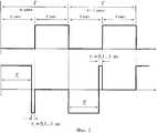
На фиг.1 изображены форма управляющего сигнала и оптическое состояние ЖК затвора согласно изобретению.Figure 1 shows the shape of the control signal and the optical state of the LCD shutter according to the invention.
На фиг.2 изображены форма управляющего сигнала и оптическое состояние ЖК затвора согласно третьему частному варианту способа.Figure 2 shows the shape of the control signal and the optical state of the LCD shutter according to the third particular variant of the method.
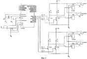
На фиг.3 дан пример электрической схемы согласно изобретению.Figure 3 gives an example of an electrical circuit according to the invention.
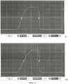
На фиг 4 - реальный оптический отклик жидкокристаллического затвора при различных вариантах управления, включая предлагаемый (см. фиг.4а) и прототипный (см. фиг.4б).In Fig 4 - the real optical response of the liquid crystal shutter in various control options, including the proposed (see figa) and prototype (see fig.4b).
На фиг.5 изображены фотографии различных вариантов проявления дефекта при известных способах управления: а, б, в, г.Figure 5 shows photographs of various options for the manifestation of a defect with known control methods: a, b, c, d.
На фиг.6 изображен рисунок дефекта при способе управления по патенту US №7502003, опубл. 19.01.01, МПК G09G 3/36.Figure 6 shows a drawing of a defect in the control method according to US patent No. 750503, publ. 01/19/01, IPC G09G 3/36.
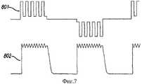
На фиг.7 изображены форма управляющего сигнала и оптический отклик ЖК затвора согласно способу устранения дефекта по патенту US №7502003.In Fig.7 shows the shape of the control signal and the optical response of the LCD shutter according to the method of eliminating the defect in US patent No. 750503.
Предлагаемый в данной заявке способ управления жидкокристаллического затвора с устранением неоднородности пропускания основан на анализе причин возникновения данного дефекта. Полученные факты свидетельствуют о том, что его вызывают электрохимические реакции, протекающие в жидкокристаллическом слое за время подачи однополярного меандра. Поскольку при используемом в стереовидении режиме времена T нахождения каждой шторки в открытом и закрытом состояниях равны, причем время релаксации τрл<T и каждый раз молекулы за время паузы успевают вернуться в исходное состояние, то такое управление эквивалентно работе на постоянном токе. Причем это - наихудший из возможных вариантов, так как затвор значительную часть времени находится в переходном состоянии заряда/разряда емкости и через него течет максимальный ток. В результате в жидкокристаллическом слое образовывается вторичный заряженный слой из ориентированных полем молекулярных диполей. Как известно из теории гальваники, плотность тока вблизи краев электрода неуправляемо возрастает из-за того, что ток идет не только по кратчайшему расстоянию, но и через весь объем электролита (см., например, www.polirovanie.ru/chromiumway.php) - каким является жидкий кристалл с находящимися в нем свободными ионами. Поэтому вторичный заряд формируется неравномерно и после замыкания контактов затвора на нулевой потенциал стекает с разной скоростью. Как следствие, в областях с увеличенным накопленным зарядом релаксация (возврат затвора в исходное светлое состояние) проходит со значительной задержкой. Иногда различие во временах релаксации на отдельных участках может быть двукратным. Причина, по которой управление высокочастотным (1…2 кГц) напряжением не дает дефекта неравномерности пропускания, состоит как раз в том, что в этом случае не образовывается устойчивый встречный заряд в жидкокристаллическом веществе.The method for controlling a liquid crystal shutter with the elimination of transmission inhomogeneity proposed in this application is based on an analysis of the causes of this defect. The facts obtained indicate that it is caused by electrochemical reactions that occur in the liquid crystal layer during the filing of a unipolar meander. Since, when used in stereo vision, the times T of each curtain in the open and closed states are equal, with the relaxation time τp <T and each time the molecules have time to return to their original state during a pause, this control is equivalent to direct current operation. Moreover, this is the worst possible option, since the shutter is in the transition state of the charge / discharge of the capacitance for a significant part of the time and the maximum current flows through it. As a result, a secondary charged layer of field-oriented molecular dipoles forms in the liquid crystal layer. As is known from the theory of electroplating, the current density near the edges of the electrode increases uncontrollably due to the fact that the current flows not only along the shortest distance, but also through the entire electrolyte volume (see, for example, www.polirovanie.ru/chromiumway.php) - what is a liquid crystal with free ions in it. Therefore, the secondary charge is formed unevenly and, after closing the gate contacts to zero potential, flows at different speeds. As a result, in regions with an increased accumulated charge, relaxation (the shutter returns to its original light state) takes place with a significant delay. Sometimes the difference in relaxation times in individual sections can be twofold. The reason why the control of the high-frequency (1 ... 2 kHz) voltage does not give a defect in transmission unevenness is precisely because in this case a stable counter charge does not form in the liquid crystal substance.
Предлагаемый способ управления ЖК затвором для стереоочков заключается в следующем (см. фиг.1). В смежных n и n+1 циклах переключения жидкокристаллического затвора на его электрический вход подают четырехтактный сигнал следующей формы:The proposed method for controlling the LCD shutter for stereo glasses is as follows (see figure 1). In adjacent n and n + 1 switching cycles of the liquid crystal shutter, a four-stroke signal of the following form is supplied to its electrical input:
- в n цикле длительностью T в первом такте, соответствующем закрытому затвору, на него сначала подают управляющее напряжение в виде биполярного прямоугольного сигнала длительностью T1, а затем - нулевое напряжение в течение времени τ1, где T=T1+τ1, при этом в течение времени T1-τ подают напряжение первой (положительной) полярности, а в течение времени τ подают напряжение второй (отрицательной) полярности;- in an n cycle of duration T in the first cycle, corresponding to a closed gate, it is first supplied with a control voltage in the form of a bipolar rectangular signal of duration T1 , and then with zero voltage for a time τ1 , where T = T1 + τ1 , at this during the time T1 -τ serves the voltage of the first (positive) polarity, and during the time τ serves the voltage of the second (negative) polarity;
- в n цикле во втором такте, соответствующем открытому затвору, на него подают нулевое напряжение;- in the n cycle in the second cycle, corresponding to the open gate, zero voltage is applied to it;
- в n+1 цикле длительностью T в третьем такте, соответствующем закрытому затвору, на него сначала подают напряжение в виде биполярного прямоугольного сигнала длительностью T1, а затем - нулевое напряжение в течение времени τ1, при этом в течение времени T1-τ подают напряжение второй (отрицательной) полярности, а в течение времени τ подают напряжение первой (положительной) полярности;- in an n + 1 cycle of duration T in the third clock corresponding to a closed gate, voltage is first applied to it in the form of a bipolar rectangular signal of duration T1 , and then zero voltage for a time τ1 , while for a time T1 -τ supply voltage of the second (negative) polarity, and during the time τ supply voltage of the first (positive) polarity;
- в n+1 цикле в четвертый такт, соответствующий открытому затвору, на него подают нулевое напряжение,- in n + 1 cycle in the fourth cycle, corresponding to the open shutter, it is supplied with zero voltage,
при этом T=T1+τ1, а τ - время, величина которого достаточна для ликвидации действием напряжения одной полярности встречного заряда в ЖК структуре, образованного в данном цикле действием напряжения другой полярности, но недостаточна для образования вторичного встречного заряда в том же цикле.in this case, T = T1 + τ1 , and τ is the time, the value of which is sufficient to eliminate the oncoming charge in the LC structure by the action of a voltage of one polarity, formed in this cycle by the action of a voltage of a different polarity, but not enough to form a secondary counter charge in the same cycle .
Согласно способу в тактах, соответствующих закрытому затвору, сначала прикладывают в течение времени T1-τ напряжение определенной полярности, а затем в течение времени τ действуют на затвор напряжением противоположной полярности, которое за счет быстрой переориентации всего массива ЖК молекул в направлении, противоположном тому, которое они имели до этого в течение времени T1-τ, компенсирует за время τ: встречный поверхностный заряд на обкладках-электродах ЖК затвора, встречный объемный заряд, образованный самими ЖК молекулами, которые являются электрическими диполями, а также дезинтегрирует (рассеивает) возможный встречный объемный заряд в ЖК слое, который может образовываться посторонними ионами-примесями в ЖК веществе. Чтобы вторичный встречный объемный заряд не образовался уже напряжением противоположной полярности, время τ приложения этого напряжения ограничивают только временем, необходимым лишь для компенсации (дезинтеграции) предыдущего заряда.According to the method, in the cycles corresponding to the closed gate, first a voltage of a certain polarity is applied over a period of time T1 -τ, and then for a time τ they act on the gate with a voltage of opposite polarity, which due to the rapid reorientation of the entire array of LC molecules in the opposite direction which they had previously during the time T1 -τ, compensates for the time τ: the counter surface charge on the electrodes of the LCD shutter electrode, the counter space charge formed by the LC molecules themselves, which are electric dipoles, and also disintegrates (dissipates) a possible counter space charge in the LC layer, which can be formed by foreign impurity ions in the LC substance. So that the secondary counter space charge is not already formed by a voltage of opposite polarity, the time τ of application of this voltage is limited only by the time necessary only for compensation (disintegration) of the previous charge.
Если вместо подачи закрывающего напряжения обратной полярности просто соединить между собой электроды ЖК затвора, то будет иметь место ликвидация только поверхностного электронного заряда на обкладках конденсатора, образованного электродами затвора. При этом более инерционный объемный заряд оставался бы в ЖК структуре, образуя переходящий из цикла в цикл застойный заряд, накапливающийся в определенных зонах апертуры затвора. Застойный заряд дезориентирует своим полем молекулы ЖК затвора в те такты циклов, когда для реализации открытого состояния на затвор не подается внешнее напряжение, и снижает в указанных зонах апертуры своим встречным внутренним полем поле внешнего управляющего напряжения в те такты, когда должно реализовываться закрытое состояние затвора по всей апертуре. В результате в указанных зонах происходит задержка релаксации жидкокристаллических молекул по сравнению с остальной площадью апертуры, создавая в итоге существенные оптические неравномерности (дефекты) по апертуре.If instead of applying a closing voltage of reverse polarity, simply connect the electrodes of the LCD shutter to each other, then only the surface electronic charge on the plates of the capacitor formed by the gate electrodes will be eliminated. In this case, a more inertial space charge would remain in the LC structure, forming a stagnant charge passing from cycle to cycle, accumulating in certain areas of the shutter aperture. The stagnant charge disorients the LC shutter molecules by its field during those cycles of cycles when external voltage is not applied to the shutter to realize the open state, and reduces the external control voltage field in the indicated zones of the aperture by those countercurrent fields when the shutter is closed in entire aperture. As a result, in these zones, the relaxation of liquid crystal molecules is delayed in comparison with the rest of the aperture area, resulting in significant optical irregularities (defects) in the aperture.
В первом частном варианте осуществления способа время τ выбирают равным времени реакции затвора (молекул ЖК структуры) на подачу закрывающего напряжения, что достаточно для компенсации первичного заряда, но недостаточно для образования паразитного вторичного заряда, поскольку в течение этого времени реализуется только быстрая переориентация ЖК молекул в новое состояние без создания условий образования вторичного заряда в объеме ЖК слоя, которые имеют место только при продолжающейся подаче напряжения неизменной полярности на слой ЖК молекул, находящихся в стационарном (уже переориентированном) состоянии.In the first particular embodiment of the method, the time τ is chosen equal to the response time of the shutter (molecules of the LC structure) to supply the closing voltage, which is sufficient to compensate for the primary charge, but not enough to form a parasitic secondary charge, since only fast reorientation of the LC molecules a new state without creating conditions for the formation of a secondary charge in the bulk of the LC layer, which occur only with continued supply of voltage of the same polarity to the LC layer molecules in a stationary (already reoriented) state.
Во втором частном варианте способа время τ1 выбирают равным времени задержки процесса релаксации затвора после снятия закрывающего напряжения. Известно, что после прекращения подачи напряжения молекулы в течение некоторого времени (в зависимости от амплитуды приложенного напряжения, угла закрутки ЖК-молекул и ориентации их относительно осей поляризации поляроидов - от 0.5 до 5 мс) оптическое пропускание ЖК-дисплея не изменяется.In a second particular embodiment of the method, the time τ1 is chosen equal to the delay time of the shutter relaxation process after removing the closing voltage. It is known that after the voltage supply of the molecule is stopped for some time (depending on the amplitude of the applied voltage, the angle of twist of the LCD molecules and their orientation relative to the polarization axes of the polaroids - from 0.5 to 5 ms), the optical transmission of the LCD display does not change.
Согласно второму частному варианту осуществления способа, в тактах, соответствующих закрытому затвору, уменьшают длительность приложения напряжения одной полярности в начале тактов на время τ1, равное времени задержки процесса релаксации затвора после снятия закрывающего напряжения, что уменьшает саму величину встречного заряда, подлежащего уничтожению в данном цикле приложением напряжения противоположной полярности. Очевидно, что сокращение времени подачи закрывающего напряжения на указанное время релаксации не изменяет заметно для глаза в течение этого времени оптическое состояние затвора, поэтому такое сокращение не сказывается на качестве сепарации изображений ракурсов сцены в течение каждого из указанных тактов, т.е. не сказывается на качестве наблюдаемого стереоизображения.According to a second particular embodiment of the method, in cycles corresponding to the closed gate, the voltage duration of applying the same polarity at the beginning of the cycles is reduced by a time τ1 equal to the delay time of the shutter relaxation process after removing the closing voltage, which reduces the amount of the oncoming charge to be destroyed in this cycle by applying voltage of opposite polarity. Obviously, the reduction in the time of applying the closing voltage to the indicated relaxation time does not noticeably change the optical state of the shutter for the eye during this time, therefore, this reduction does not affect the quality of the separation of the image of the scene angles during each of the indicated measures, i.e. does not affect the quality of the observed stereo image.
В третьем частном варианте осуществления способа (фиг.2) выбирают время τ1=0, а время τ выбирают из интервала 0,1…1 мс. Такой вариант соответствует управлению ЖК затвором, наиболее простому по форме управляющего сигнала и достаточно эффективному по реализации однородных оптических свойств по апертуре.In the third particular embodiment of the method (FIG. 2), the time τ1 = 0 is selected, and the time τ is selected from the interval 0.1 ... 1 ms. This option corresponds to the control of the LCD shutter, which is the simplest in the form of the control signal and quite effective in realizing uniform optical properties over the aperture.
На фиг.3 представлена электрическая схема устройства, с помощью которого реализуется форма управляющего напряжения в соответствии с изобретением.Figure 3 presents the electrical circuit of the device with which the form of the control voltage is realized in accordance with the invention.
Основной частью устройства управления является генератор сигналов, выполненный на микроконтроллере PIC16F873 (U1), с тактовой частотой 20 МГц, задаваемой кварцевым резонатором (G1).The main part of the control device is a signal generator made on a PIC16F873 microcontroller (U1), with a clock frequency of 20 MHz, set by a quartz resonator (G1).
Микроконтроллер вырабатывает сигналы, необходимые для управления ЖК-затворами, в соответствии с программой, записанной в память контроллера.The microcontroller generates the signals necessary to control the LCD shutters, in accordance with the program recorded in the controller's memory.
С выходов RB0-RB3 контроллера сигналы поступают на входы преобразователей уровня (транзисторы Q1-Q4 и резисторы R1-R4 и R6-R9).From the outputs RB0-RB3 of the controller, the signals are fed to the inputs of the level converters (transistors Q1-Q4 and resistors R1-R4 and R6-R9).
Преобразователи уровня необходимы для согласования уровней сигналов, вырабатываемых контроллером и сигналов управления аналоговыми ключами (U2, U3).Level converters are necessary for matching signal levels generated by the controller and analog key control signals (U2, U3).
Конкретно управление ЖК затворами производится подключением к контактам затворов напряжений 0 В и V1 (6-15 В) через аналоговые ключи.Specifically, the management of LCD shutters is done by connecting 0 V and V1 (6-15 V) voltage to the gate contacts via analog switches.
На фиг.4 представлены виды оптического отклика ЖК затвора при различных способах управления, включая предлагаемый и прототипный.Figure 4 presents the types of optical response of the LCD shutter with various control methods, including the proposed and prototype.
На фиг.4а показан отклик ЖК затвора в любом месте апертуры при управлении согласно предлагаемому способу (при значении τ=0,5 мс). Аналогичный вид имеет оптический отклик ЖК затвора на большей части апертуры при управлении согласно прототипу (патенту US №4792850).On figa shows the response of the LCD shutter anywhere in the aperture when controlled according to the proposed method (with a value of τ = 0.5 ms). A similar view has the optical response of the LCD shutter on most of the aperture when controlled according to the prototype (US patent No. 4792850).
На фиг.4б показан отклик того же ЖК затвора при управлении согласно прототипу (см. патент US №4792850) в местах наблюдаемого дефекта - неоднородности пропускания. Из фиг.4 видно, что различие во времени релаксации между управляемой согласно заявляемому изобретению ЖК-затвором (фиг.4а) и областью сформированной неоднородности пропускания (фиг.4б) составляет почти 1.5 мс.On figb shows the response of the same LCD shutter when controlled according to the prototype (see US patent No. 4792850) in places of the observed defect - transmission inhomogeneity. From Fig. 4 it can be seen that the difference in relaxation time between the LCD shutter controlled according to the claimed invention (Fig. 4a) and the region of the transmitted transmission inhomogeneity (Fig. 4b) is almost 1.5 ms.
Для сравнения однородности оптического пропускания по апертуре, получаемого с помощью изобретения, с аналогичными параметрами известных технических решений на фиг.5 приведены фотографии вариантов проявления дефекта в виде оптической неравномерности в форме точек, линий рамок, образующихся в апертуре ЖК затвора с использование STN-структуры с 270-градусной закруткой молекул в зависимости от геометрии апертуры затвора и с различной толщиной ЖК слоя при простом биполярном управлении (согласно патенту US №4792850). Напряжение при этом составляло 12 В, частота цикла 100…150 Гц.To compare the uniformity of the optical transmittance along the aperture obtained by the invention with the same parameters of the known technical solutions, Fig. 5 shows photographs of the manifestations of the defect in the form of optical unevenness in the form of dots, frame lines formed in the aperture of the LCD shutter using an STN structure with 270-degree swirling of molecules depending on the geometry of the aperture of the shutter and with different thicknesses of the LC layer with simple bipolar control (according to US patent No. 4792850). The voltage was 12 V, the cycle frequency 100 ... 150 Hz.
Аналогичные дефекты наблюдаются и при других вариантах закрутки жидкокристаллических молекул (на пи-ячейках, на твист-эффекте и т.д.). Характерным поведением является отсутствие какой-либо неравномерности в первые несколько минут эксплуатации, затем дефект начинает проявляться, сначала слабо, затем все сильнее. В этот период он имеет вид параллельных одной, двум или трем сторонам затвора полос, удаленных от края на расстояние от 2 до 8 мм, с усиленным пятном по краям (см. фиг.5а и фиг.5б). В зависимости от величины приложенного напряжения максимальная интенсивность неравномерности пропускания достигается через 15 мин, а в отдельных случаях - даже 2 часа. Затем неравномерность начинает уменьшаться и через некоторое время (обычно - в 3…4 раза превышающее время достижения максимальной неравномерности) остается только в одном из углов в виде вытянутого пятна размером от 2 до 6 мм (см. фиг.5в и фиг.5г). В дальнейшем этот дефект несколько теряет интенсивность, однако, к сожалению, вытягивается в сторону центра шторки. Кроме того, по периметру затвора формируется светлая рамка шириной до 8 мм, а в ограниченной ею центральной части - более темный многоугольник (стороны которого параллельны краям затвора, а одна из вершин содержит упомянутое пятно). Различие в пропускании этих двух участков достигает 50%. На всех стадиях развития дефекта он находится в поле зрения или требует закрытия до 25% краевой площади затвора, что недопустимо.Similar defects are also observed with other variants of the twist of liquid crystal molecules (on pi cells, on the twist effect, etc.). The characteristic behavior is the absence of any unevenness in the first few minutes of operation, then the defect begins to appear, first weakly, then more and more. During this period, it has the form of strips parallel to one, two, or three sides of the shutter, remote from the edge by a distance of 2 to 8 mm, with a reinforced spot at the edges (see Fig. 5a and Fig. 5b). Depending on the magnitude of the applied voltage, the maximum intensity of the transmission unevenness is reached after 15 minutes, and in some cases even 2 hours. Then the unevenness begins to decrease and after a while (usually 3 ... 4 times the time to reach maximum unevenness) remains only in one of the corners in the form of an elongated spot from 2 to 6 mm in size (see figv and figg). In the future, this defect somewhat loses its intensity, however, unfortunately, it stretches toward the center of the curtain. In addition, a light frame up to 8 mm wide is formed around the shutter perimeter, and a darker polygon (the sides of which are parallel to the shutter edges and one of the vertices contains the mentioned spot) is formed in the central part limited by it. The difference in transmission of these two sections reaches 50%. At all stages of the development of the defect, it is in sight or requires closure of up to 25% of the edge area of the shutter, which is unacceptable.
Аналогичный дефект для затворов на пи-ячейках - изначально отсутствующий, но появляющийся в одном и том же углу через некоторое время (от нескольких минут до часов) - описан в патенте US №7502003 "Method for eliminating pi-cell artifacts", опубл. 10.03.09, МПК G09G 3/36. На фиг.6 представлен рисунок этого дефекта при управлении согласно патенту US №4792850. Он имеет вид треугольников, примыкающих к краям апертуры. Причем при наличии нескольких электродных полос дефект (101) повторяется в одном и том же углу каждой электродной полосы жидкокристаллического затвора (102). По мнению авторов патента US №7502003, причиной дефекта, названного ими «ионная тень» ("ion shadow" defect), являются свободные ионы, загрязняющие жидкокристаллическое вещество.A similar defect for gates on pi-cells - initially absent, but appearing in the same corner after some time (from several minutes to hours) - is described in US patent No. 7502003 "Method for eliminating pi-cell artifacts", publ. 03/10/09,
Для исключения дефекта «ионной тени» авторы патента US №7502003 предложили новый тип формы управляющего сигнала, названный ими Alternating Unipolar Carrier System - система переменной однополярной несущей (частоты).To eliminate the “ion shadow” defect, the authors of US patent No. 7502003 proposed a new type of control signal shape, which they called the Alternating Unipolar Carrier System - a variable unipolar carrier (frequency) system.
На фиг.7 изображен этот сигнал (801) и соответствующий ему оптический отклик (802). Отмечается, что с ростом максимальной амплитуды напряжения «ионная тень» уменьшается, однако могут усилиться другие дефекты изображения (уменьшится динамический контраст, резче проявятся границы электродов). Поэтому данный патент предлагает искать компромисс между различными дефектами, т.е. не решает проблему до конца.7 shows this signal (801) and its corresponding optical response (802). It is noted that with an increase in the maximum voltage amplitude, the "ion shadow" decreases, but other image defects may intensify (dynamic contrast will decrease, the boundaries of the electrodes will appear more sharply). Therefore, this patent proposes to seek a compromise between various defects, i.e. doesn't solve the problem to the end.
Пример. На фиг.4 показан оптический отклик жидкокристаллического затвора с закруткой 270° и толщиной жидкокристаллического слоя 6 мкм. Видно, что при управлении напряжением U=12 В частотой 144 Гц время реакции составляет 0.5 мс. Для ЖК затвора 4-микронной толщины ЖК слоя время реакции 0.3 мс. Время релаксации для 6 мкм затвора составляет примерно 3.5 мс, для 4 мкм - около 2.5 мс, причем время задержки релаксации равно примерно 0.5 мс для 6-микронного зазора и 0.3 мкм - для 4-микронного.Example. Figure 4 shows the optical response of a liquid crystal shutter with a 270 ° swirl and a liquid crystal layer thickness of 6 μm. It is seen that when controlling the voltage U = 12 V at a frequency of 144 Hz, the reaction time is 0.5 ms. For an LCD shutter with a 4 micron thickness in the LC layer, the reaction time is 0.3 ms. The relaxation time for the 6 μm shutter is approximately 3.5 ms, for 4 μm it is about 2.5 ms, and the relaxation delay time is approximately 0.5 ms for the 6-micron gap and 0.3 μm for the 4-micron gap.
Отсюда для затвора с 6-микронной толщиной жидкокристаллического слоя был выбран вариант с длительностью части импульса противоположной полярности τ=0.5 мс, а для 4-микронной толщины - τ=0.3 мс. В процессе испытаний длительность T варьировалась в пределах 10…6.9 мс (что соответствует стандартному для стереовидения диапазону частот f=100…144 Гц). Амплитуда напряжения составляла 12 В.Hence, for the shutter with a 6-micron thickness of the liquid crystal layer, we chose the option with a pulse part duration of the opposite polarity τ = 0.5 ms, and for the 4-micron thickness, τ = 0.3 ms. During the tests, the duration T varied within 10 ... 6.9 ms (which corresponds to the standard frequency range for stereo vision f = 100 ... 144 Hz). The voltage amplitude was 12 V.
При работе в указанном режиме дефект или не образуется, или мало заметен даже после 96 часов непрерывной работы. Важным моментом является то, что затворы, управлявшиеся прямоугольным меандром (по патенту US №4792850) и имеющие сформировавшийся дефект, при управлении в режиме согласно фиг.2 были однородны по пропусканию.When working in the indicated mode, the defect either does not form or is hardly noticeable even after 96 hours of continuous operation. An important point is that the gates, controlled by a rectangular meander (according to US patent No. 4792850) and having a formed defect, when controlled in the mode according to figure 2 were uniform in transmission.
С изменением напряжения U время реакции τр изменяется по формулеWith a change in voltage U, the reaction time τp changes according to the formula
τр~1/(U2-U2 0), где U0 - пороговое напряжение.τp ~ 1 / (U2 -U20 ), where U0 is the threshold voltage.
Поэтому с уменьшением напряжения длительность τ кратковременного импульса противоположной полярности должна быть увеличена в соответствии с формулой зависимости времени реакции от напряжения. С увеличением напряжения длительность τ кратковременного импульса противоположной полярности должна быть уменьшена в соответствии с формулой зависимости времени реакции от напряжения. Естественно, в некоторых пределах при установленной величине τ допустимы любые колебания напряжений.Therefore, with decreasing voltage, the duration τ of a short-term pulse of opposite polarity should be increased in accordance with the formula for the dependence of the reaction time on voltage. With increasing voltage, the duration τ of a short-term pulse of opposite polarity should be reduced in accordance with the formula for the dependence of the reaction time on voltage. Naturally, within certain limits, with a fixed value of τ, any voltage fluctuations are permissible.
В частности, для 6-микронного затвора при длительности кратковременного импульса противоположной полярности τ=0.5 мс дефект неравномерности пропускания отсутствует или малозаметен при колебаниях напряжений от 10.5 до 15 В. Для 4-микронного затвора диапазон допустимых колебаний напряжения еще больше.In particular, for a 6-micron shutter with a short pulse of opposite polarity τ = 0.5 ms, the transmission unevenness is absent or not noticeable for voltage fluctuations from 10.5 to 15 V. For a 4-micron shutter, the range of permissible voltage fluctuations is even larger.
Поскольку время реакции экспоненциально зависит от температуры, аналогичное поведение наблюдается и при нагреве/охлаждении затвора. Правда, при охлаждении уменьшается и подвижность свободных ионов, что в какой-то степени компенсирует увеличение τр. По этим причинам диапазон температур, при которых режим был эффективен - от 15° до 40°C. Это перекрывает все возможные колебания температуры внутри отапливаемого/кондиционируемого помещения.Since the reaction time exponentially depends on temperature, a similar behavior is observed when heating / cooling the shutter. True, during cooling, the mobility of free ions also decreases, which to some extent compensates for the increase in τp . For these reasons, the temperature range at which the regime was effective is from 15 ° to 40 ° C. This covers all possible temperature fluctuations inside a heated / air-conditioned room.
Сравнение степени проявления дефекта неоднородности пропускания («ионной тени») и энергопотреблении затвора при равных длительностях закрытого состояния (кадровой частоте f) и амплитуде приложенного напряжения при различных способах управления приведено в таблице.A comparison of the degree of manifestation of the transmission inhomogeneity defect (“ion shadow”) and the shutter power consumption for equal durations of the closed state (frame frequency f) and the amplitude of the applied voltage for different control methods is given in the table.
Очевидно, что по совокупности параметров лучшее качество жидкокристаллического затвора для стереоочков обеспечивает предлагаемый способ управления.Obviously, in terms of the combination of parameters, the best quality of the liquid crystal shutter for stereo glasses provides the proposed control method.
Claims (4)
Translated fromRussianPriority Applications (1)
| Application Number | Priority Date | Filing Date | Title |
|---|---|---|---|
| RU2010140061/28ARU2449332C1 (en) | 2010-09-29 | 2010-09-29 | Method of controlling liquid-crystal shutter for 3d glasses |
Applications Claiming Priority (1)
| Application Number | Priority Date | Filing Date | Title |
|---|---|---|---|
| RU2010140061/28ARU2449332C1 (en) | 2010-09-29 | 2010-09-29 | Method of controlling liquid-crystal shutter for 3d glasses |
Publications (1)
| Publication Number | Publication Date |
|---|---|
| RU2449332C1true RU2449332C1 (en) | 2012-04-27 |
Family
ID=46297626
Family Applications (1)
| Application Number | Title | Priority Date | Filing Date |
|---|---|---|---|
| RU2010140061/28ARU2449332C1 (en) | 2010-09-29 | 2010-09-29 | Method of controlling liquid-crystal shutter for 3d glasses |
Country Status (1)
| Country | Link |
|---|---|
| RU (1) | RU2449332C1 (en) |
Citations (2)
| Publication number | Priority date | Publication date | Assignee | Title |
|---|---|---|---|---|
| US4792850A (en)* | 1987-11-25 | 1988-12-20 | Sterographics Corporation | Method and system employing a push-pull liquid crystal modulator |
| WO2008156790A1 (en)* | 2007-06-20 | 2008-12-24 | Real D | Zscreen® modulator with wire grid polarizer for stereoscopic projection |
- 2010
- 2010-09-29RURU2010140061/28Apatent/RU2449332C1/ennot_activeIP Right Cessation
Patent Citations (2)
| Publication number | Priority date | Publication date | Assignee | Title |
|---|---|---|---|---|
| US4792850A (en)* | 1987-11-25 | 1988-12-20 | Sterographics Corporation | Method and system employing a push-pull liquid crystal modulator |
| WO2008156790A1 (en)* | 2007-06-20 | 2008-12-24 | Real D | Zscreen® modulator with wire grid polarizer for stereoscopic projection |
Similar Documents
| Publication | Publication Date | Title |
|---|---|---|
| CN110618547B (en) | Liquid crystal display device and driving method thereof | |
| US6943852B2 (en) | Single cell liquid crystal shutter glasses | |
| EP2014102B1 (en) | High speed display shutter for autostereoscopic display | |
| US8848045B2 (en) | Stereoscopic flat panel display with a continuously lit backlight | |
| JP6227125B2 (en) | Liquid crystal display | |
| TW557384B (en) | Active matrix-type liquid crystal display device | |
| CN104865757A (en) | Display panel, display device and view angle control method of display panel | |
| CN102789097B (en) | Rotatable 3d display | |
| US20070195227A1 (en) | Glare protection device | |
| CN102073163B (en) | Method and device for driving dynamic fast response of liquid crystal lens | |
| JPS61227498A (en) | Stereoscopic television set | |
| WO2019064155A1 (en) | Active 3d shutter-glasses offering an improved level of image-brightness | |
| RU2449332C1 (en) | Method of controlling liquid-crystal shutter for 3d glasses | |
| US20110080535A1 (en) | Liquid crystal shutter and display system using the same | |
| US9396687B2 (en) | Method, apparatus, and system for controlling three dimensional displays | |
| US8848117B2 (en) | Display apparatus | |
| Choi et al. | Sub-millisecond switching of hybrid-aligned nematic liquid crystals | |
| RU2449333C1 (en) | Liquid-crystal shutter | |
| CN107367882B (en) | Liquid crystal lens structure, liquid crystal lens forming method, display panel and device | |
| RU2456649C1 (en) | Active liquid crystal stereoscopic glasses | |
| GB2534736A (en) | 3D display apparatus and 3D display method therefor | |
| RU2512095C1 (en) | High-speed low-voltage liquid crystal 3d glasses | |
| US8724041B2 (en) | Drive scheme for stereoscopic display polarization modulator and apparatus for same | |
| Galin et al. | How the electric-field parameters affect the optical response of a nematic liquid crystal | |
| Park et al. | P‐156: Flicker Effect Depending on the Density of Charge Impurities in the Cell |
Legal Events
| Date | Code | Title | Description |
|---|---|---|---|
| MM4A | The patent is invalid due to non-payment of fees | Effective date:20130930 |